
Occupant Protection System Page 12M–1
Page 12M–1
Section 12M
Occupant Protection System
ATTENTION
Before performing any Service Operation or other procedure described in this Section, refer to Section 00
WARNINGS, CAUTIONS AND NOTES for correct workshop practices with regard to safety and/or property
damage.
1 General Information............................................................................................................................... 2
1.1 Regular Cab – General Description......................................................................................................................2
1.2 Crew Cab – General Description...........................................................................................................................3
2 Service Operations – Crew Cab ........................................................................................................... 4
2.1 Rear Seatbelt Assembly ........................................................................................................................................4
Remove ...................................................................................................................................................................6
Reinstall ..................................................................................................................................................................7
2.2 Rear Seatbelt Buckle Assembly............................................................................................................................8
Remove ...................................................................................................................................................................8
Left-hand Side ....................................................................................................................................................8
Right-hand Side..................................................................................................................................................8
Reinstall ..................................................................................................................................................................9
2.3 Child Seat Anchors..............................................................................................................................................10
3 Diagnosis – Front Seatbelt Switch – Crew Cab................................................................................11
3.1 General Description.............................................................................................................................................11
3.2 Circuit Diagram.....................................................................................................................................................12
Connector Chart...................................................................................................................................................12
3.3 Diagnostic Procedures ........................................................................................................................................13
Circuit Description...............................................................................................................................................13
Test Description...................................................................................................................................................13
Notes on the Diagnostic Chart............................................................................................................................13
Diagnostic Chart...................................................................................................................................................13
4 Torque Wrench Specifications........................................................................................................... 15
Techline
Techline

Occupant Protection System Page 12M–2
Page 12M–2
1 General Information
With the following exceptions, MY 2004 VY Regular Cab and Crew Cab occupant protection system information carries
over from MY 2004 VY Series vehicles and MY 2003 VY Regular Cab vehicles.
• Crew Cab rear seat belts
• Crew Cab child restraint anchors
• Crew Cab driver's seatbelt buckle warning indicator switch
For information not contained within this Section, refer to Section 12M Occupant Protection System in the MY 2004 VY
and V2 Series Service Information and Section 12M Occupant Protection System in the MY 2003 VY Regular Cab
Service Information.
1.1 Regular Cab – General Description
The Occupant Protection System for MY 2004 VY Regular Cab carries over from MY 2003 VY Regular Cab vehicles.

Occupant Protection System Page 12M–3
Page 12M–3
1.2 Crew Cab – General Description
The MY 2004 VY Crew Cab uses unique rear seatbelt assemblies and mounting brackets, and stalk type rear seatbelt
buckles. There are child restraint anchors permanently attached to the vehicle chassis.
A seatbelt buckle warning indicator switch is fitted to the driver's seat in all Crew Cab vehicles. The wiring diagram and
diagnosis procedures for the driver's seatbelt buckle warning indicator switch are specific to MY 2004 VY Crew Cab
vehicles.
For occupant protection system information not contained within this Section, refer to Section 12M Occupant Protection
System in the MY 2004 VY and V2 Series Service Information.

Occupant Protection System Page 12M–4
Page 12M–4
2 Service Operations – Crew Cab
2.1 Rear Seatbelt Assembly
LT Section No. – 14-425
ATTENTION
The following fasteners have either micro encapsulation or incorporate a mechanical thread lock and should
only be used once. If in doubt, replacement is recommended when performing this operation:
!
!!
! Seatbelt Guide Attaching Bolt
!
!!
! Seatbelt Lower Anchor Bolt
!
!!
! Seatbelt Retractor Bracket Bolt
!
!!
! Seatbelt Buckle Assembly Attaching Bolt
Occupant Protection System Page 12M–5
Page 12M–5
NOTE:
The following chart is included to assist with
component identification.
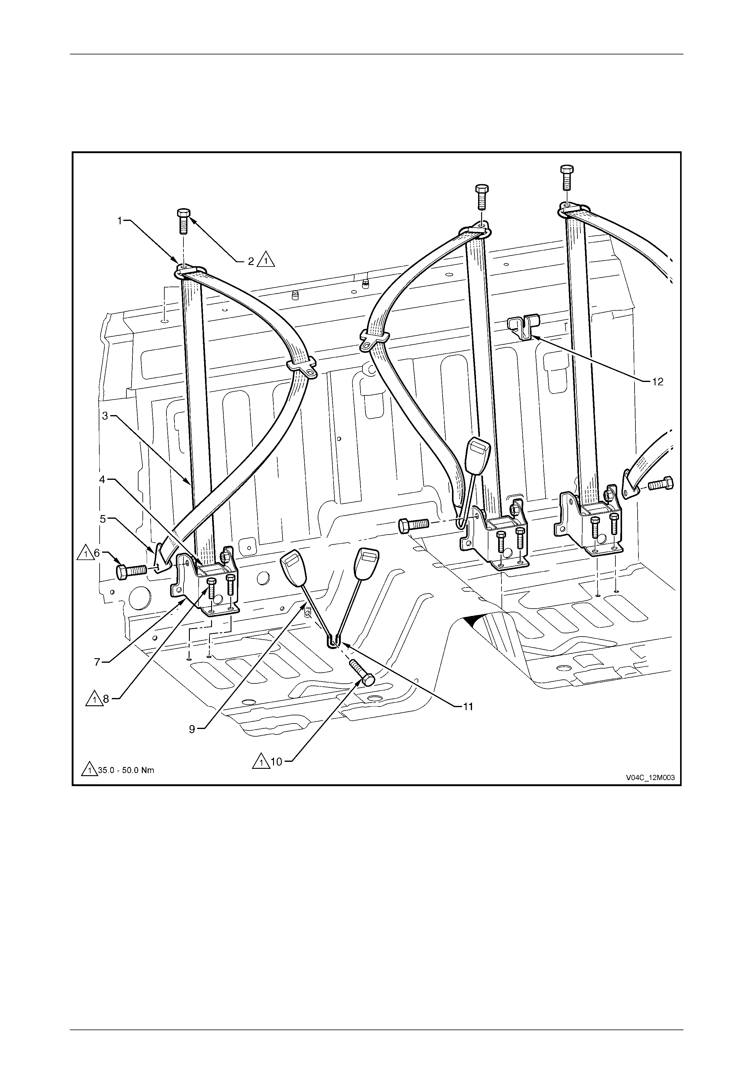
Figure 12M – 1
Legend
1 Seatbelt Guide
2 Seatbelt Guide Attaching Bolt
3 Seatbelt
4 Seatbelt Retractor
5 Seatbelt Lower Anchor
6 Seatbelt Lower Anchor B olt
7 Seatbelt Retractor Bracket
8 Seatbelt Ret ract o r Brack et B olt
9 Seatbelt Buckle Assembly
10 Seatbelt Buckl e Ass em bly Attaching Bol t
11 Seatbelt Buckle Bracket
12 Child Seat Anchor
Occupant Protection System Page 12M–6
Page 12M–6
Remove
NOTE
The seatbelt assemblies are similar in each of the
rear seating positions. The left-hand belt buckle
assembly is attached to the rear centre seatbelt
assembly.
1 Remove the rear seat cushion, refer to Section 1A7
Seat Assemblies.
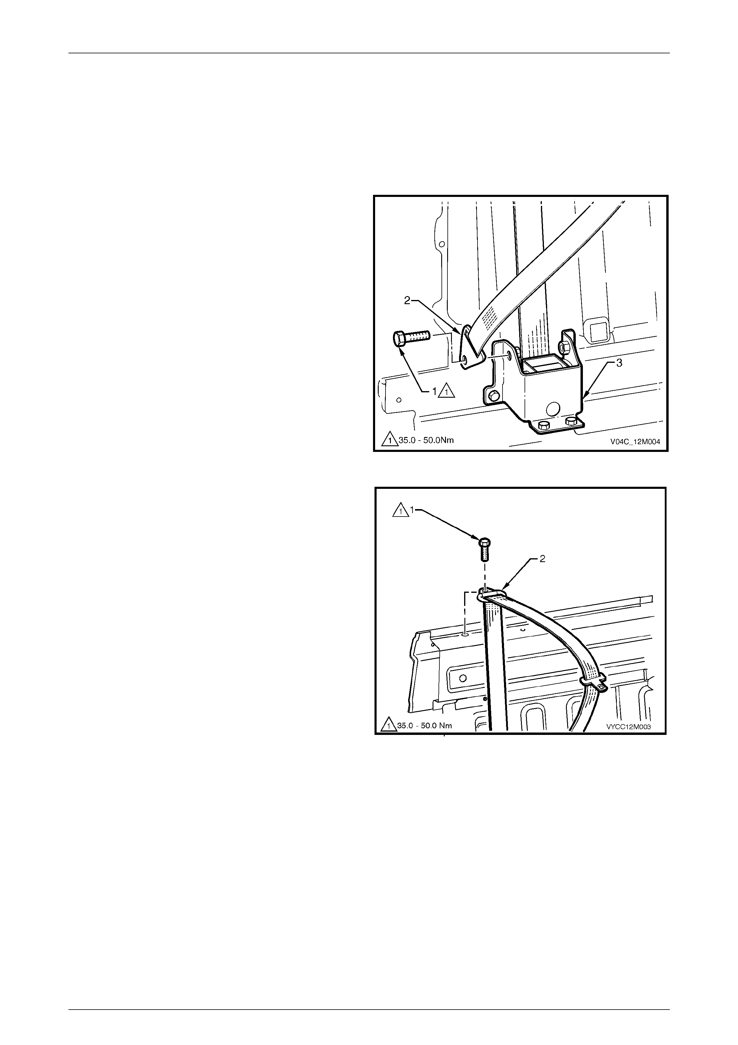
2 Remove the bolt (1) attaching the seatbelt anchor (2)
to the retractor bracket (3).
Figure 12M – 2
3 Remove the rear seat back, refer to Section 1A7 Seat
Assemblies.
4 Remove the upper cross-beam cover, refer to 1A8
Headlining and Interior Trim.
5 Remove the bolt (1) attaching the seatbelt gui de (2) to
the upper cross-beam.
Figure 12M – 3
Occupant Protection System Page 12M–7
Page 12M–7
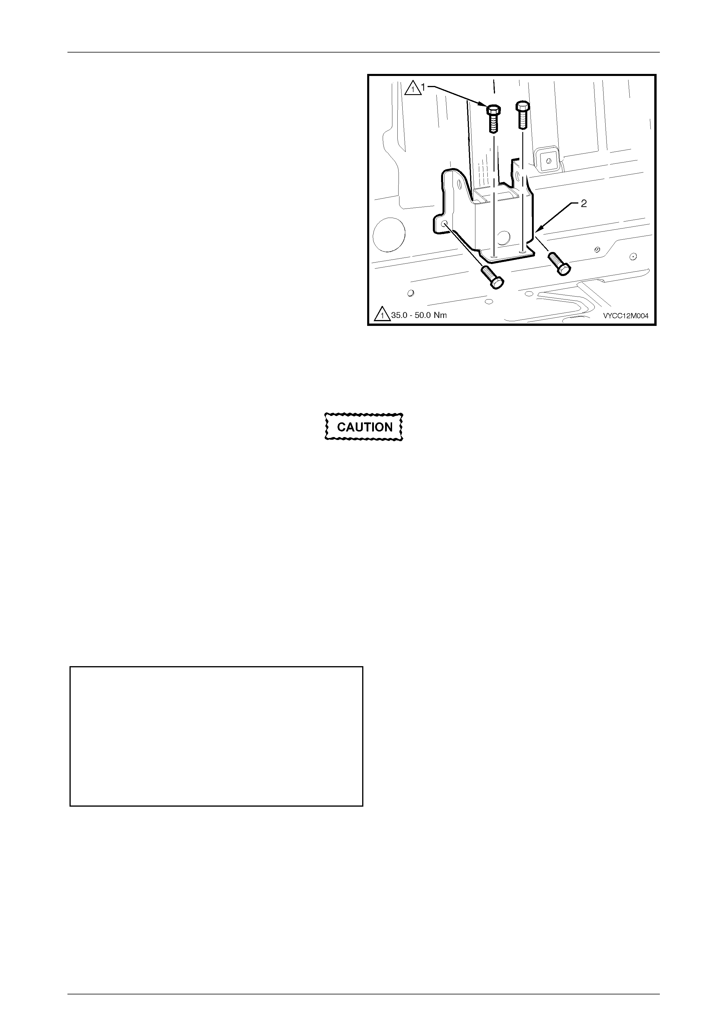
5 Remove the four bolts (1) attaching the retractor
bracket assembly (2) to the vehicle.
6 Remove the seatbelt assembly.
NOTE:
The retractor is permanently riveted to the
bracket.
Figure 12M – 4
Reinstall
If reinstalling the same retractor assembly,
inspect the anchor plates, guides and
retractor assembly for damage, and the
webbing for abrasions, fraying, cuts, etc.
Replace the seatbelt assembly with a new part
if any damage, etc. is found.
Reinstallation of the seatbelt assembly is the reverse of the removal procedure noting the following:
1 Ensure the webbing is not twisted.
2 Ensure that the threads of the retractor attaching bolts are adequately sealed with a caulking compound or a non-
hardening sealer.
3 Hand tighten all seatbelt bolts a minimum of five turns before using tools.
4 Tighten the bolts to the specified torque.
Seatbelt retractor bracket
mounting bolt torque specification................35 – 50 Nm
Seatbelt guide mounting
bolt torque specification................................35 – 50 Nm
Seatbelt anchor mounting
bolt torque specification................................35 – 50 Nm
Seatbelt bu ckle mounting
bolt torque specification................................35 – 50 Nm
5 Perform a functional check of the seatbelt to ensure correct operation.
Occupant Protection System Page 12M–8
Page 12M–8
2.2 Rear Seatbelt Buckle Assembly
LT Section No. – 14-425
ATTENTION
The following fasteners have either micro encapsulation or incorporate a mechanical thread lock and should
only be used once. If in doubt, replacement is recommended when performing this operation:
!
!!
! Seatbelt buckle assembly mounting bolt
Remove
Left-hand Side
NOTE:
The left-hand rear seatbelt buckle is part of the
rear centre seatbelt assembly.
For the service procedure, refer to 3.1 Rear Seatbelt Assembly.
Right-hand Side
Remove the rear seat cushion, refer to Section 1A7 Seat Assemblies.
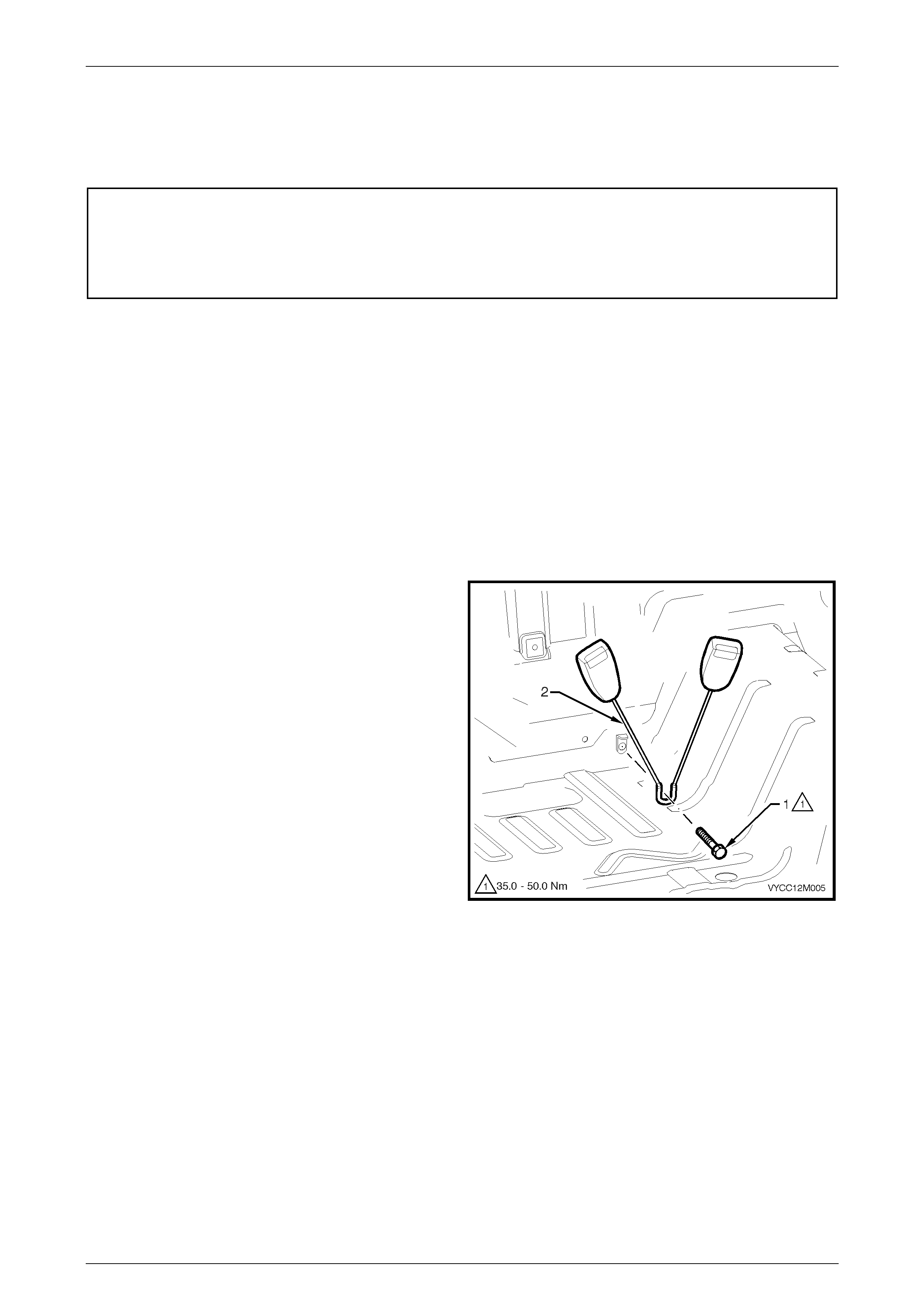
1 Remove the bolt (1) attaching the rear seatbelt buckle
anchor assembly (2) to the vehicle.
2 Remove the buckle assembly.
Figure 12M – 5
Occupant Protection System Page 12M–9
Page 12M–9
Reinstall
If reinstalling the same buckle assembly,
inspect the buckle for any damage. Replace
the buckle assembly with a new part if any
damage is found.
Installation of the seatbelt buckle assembly is the reverse of removal noting the following:
1 Hand tighten the seatbelt bolt a minimum of five turns before using tools.
2 Tighten the bolt to the specified torque.
Seatbelt buckle assembly mounting
bolt torque specification................................35 – 50 Nm
3 Perform a functional check of the seatbelt to ensure correct operation.
Occupant Protection System Page 12M–10
Page 12M–10
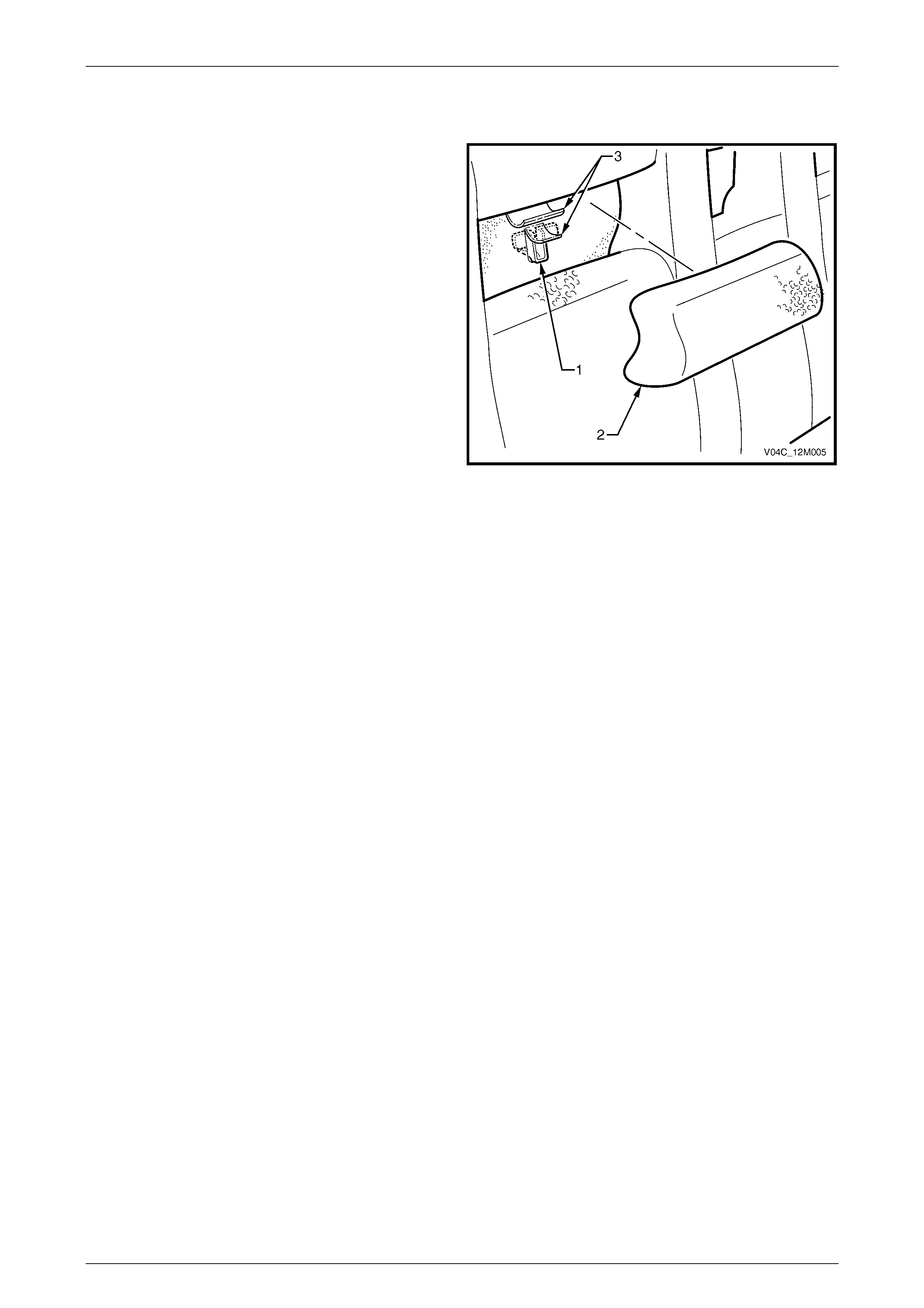
2.3 Child Seat Anchors
Three child seat anchors are permanently attached to the
vehicle. They are not serviced separately from the upper
rear body inner panel. For upper rear body inner panel
service operations, refer to Section 10B Body Rear in the
MY 2004 Regular Cab and Crew Cab Service Information
Supplement, Body Structure Repair.
Access to each child seat anchor (1) is gained by removing
the appropriate rear seat-back insert (2), refer to Section
1A7 Seat Assemblies, and lifting the material flaps (3)
covering the anchor.
When the child seat anchors are not in use, the rear seat-
back inserts should be fitted into place.
Figure 12M – 6

Occupant Protection System Page 12M–11
Page 12M–11
3 Diagnosis – Front Seatbelt
Switch – Crew Cab
3.1 General Description
When carrying out wiring checks as directed by the following diagnostic charts, use the adaptors contained in connector
test adaptor kit KM-609 and test lead set KM-609-20. This will prevent any possibility of spreading or damaging wire
harness terminals, which could cause a system intermittent failure.
Ensure that at the completion of any diagnostic procedure, all diagnostic tools are removed and all components are
correctly reconnected.
Occupant Protection System Page 12M–12
Page 12M–12
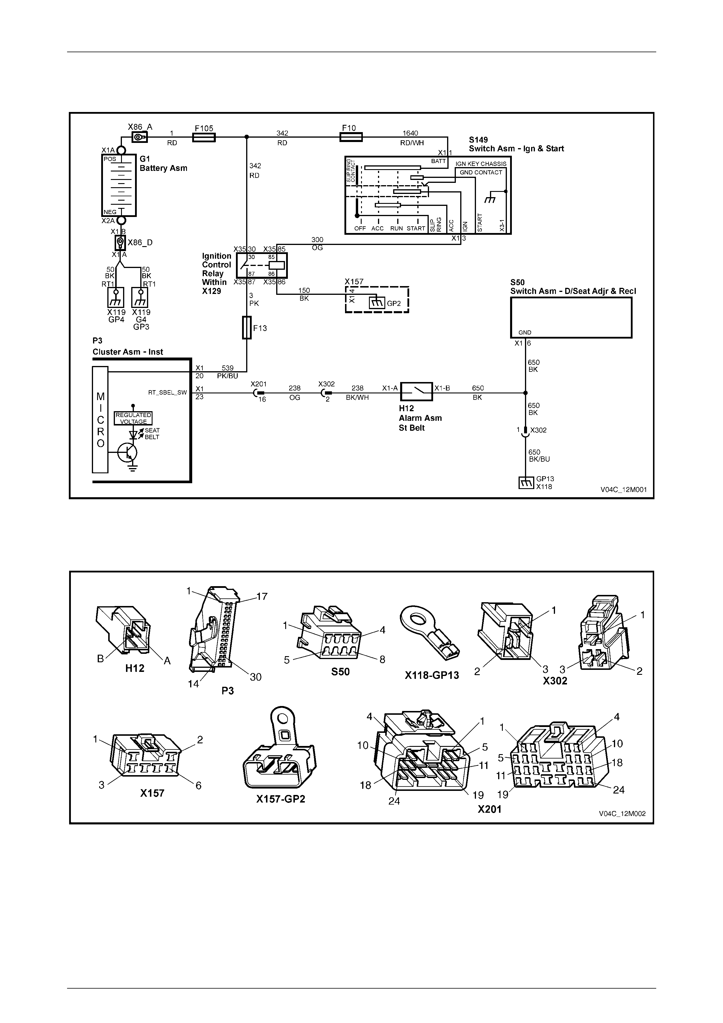
3.2 Circuit Diagram
Figure 12M – 7
Connector Chart
Figure 12M – 8

Occupant Protection System Page 12M–13
Page 12M–13
3.3 Diagnostic Procedures
Circuit Description
The purpose of the driver's seatbelt buckle warning indicator switch, H12, is to activate a seatbelt warning indicator
located in the instrument cluster assembly. The indicator is illuminated when the ignition is turned to the ON position and
the seatbelt is disengaged from the buckle.
When the seatbelt is buckled, the warning indicator switch is in an open circuit condition and when unbuckled the switch
is in a closed circuit condition.
TECH 2 can be used to check the driver's seatbelt buckle warning indicator switch operation, TECH 2 will only display
‘BUCKLED’ or ‘UN-BUCKLED’.
The seatbelt warning indicator will illuminate for four seconds when the ignition switch is turned to the ON position,
irrespective of the status of the driver's seatbelt buckle warning indicator switch.
Test Description
The following numbers refer to step numbers in the following diagnostic chart.
1 Checks if the seatbelt indicator illuminates when the ignition is turned on. This can indicate either a faulty
instrument cluster assembly or a faulty power circuit.
2 Checks if there is an intermittent fault in the circuit.
3 Checks if there is a faulty power circuit.
4 Checks the operation of the driver's seatbelt buckle warning indicator switch.
5 Checks continuity of circuit 650.
6 Checks continuity of circuit 238.
7 Checks the operation of the driver's seatbelt buckle warning indicator switch.
8 Checks for short circuit to ground in circuit 238.
Notes on the Diagnostic Chart
1 For all wiring harness fault diagnosis, refer to Section 12P Wiring Diagrams.
2 For wiring harness repairs, refer to Section 12P Wiring Diagrams.
3 Refer to Section 12O Fuses, Relays and Wiring Harnesses for harness routeing.
4 If at any time the fault is deemed to be intermittent, refer to Section 12P Wiring Diagrams.
5 For information on using and connecting Tech 2 to the vehicle, refer to Section 0C Tech 2.
Diagnostic Chart
Step Action Yes No
1 1 Install the TECH 2 to the DLC. Select BODY, INSTRUMENTS,
DATA DISPLAY and then INSTRUMENTS from the menu and
scroll down to DRIVERS SEATBELT. Refer to Note 5.
2 Unbuckle the driver's seat belt .
3 Turn the ignition on with the engine off.
Does the seatbelt warning indicator illuminate, and does the TECH 2
displa y ‘UN-BUCKLED’?
Go to Step 2. Go to Step 3.

Occupant Protection System Page 12M–14
Page 12M–14
Step Action Yes No
2 1 Turn the ignition switch off.
2 Buckle the driver's seatbelt.
3 Turn the ignition on with the engine off.
Does the seatbelt warning indicator extinguish after four seconds and
does the TECH 2 display ‘BUCKLED’?
Operation appears
to be normal. Check
for an intermittent
fault, refer to Note 4.
Go to Step 7.
3 1 Check that the following warning indicators illuminate when the
ignition is switched on with the engine off:
• ABS
• Brake
• SRS
• Generator
Do the above warning indicators illuminate when the ignition switch is
turned on with the engine off?
Go to step 4. Check continuity of
fuse F13,
fuse F105,
circuit 539, circui t 3
and circuit 342.
For additional
information, refer to
Section 12C
Instruments.
4 1 Turn the ignition off and disconnect connector H12.
2 Use a multimeter and Tool KM-609 at connector H12 to probe
the operation of the driver's seatbelt buckle warning indicator
switch. Refer to Note 1.
• Seatbelt unbuckled - continuity
• Seatbelt buckled - no continuity (open circuit)
Does the driver's seatbelt buckle warning indicator switch operate as
required?
Go to Step 5.
Replace the driver's
seatbelt bu ckl e and
pretensioner
assembly, refer to
Section 12M
Occupant Pr otection
System in the
MY 2003 VY and V2
Series Service
Information.
5 1 Turn the ignition off and disconnect connector H12.
2 Use a multimeter and Tool KM-609 to probe for continuity of
circuit 650 between connector H12 – X1 pin B and ground point
GP13 – X118. Refer to Note 1.
Is there continuity?
Go to Step 6. There is an open
circuit in circ uit 650.
Repair or replace
circuit 650 and/or
connector, refer to
Note 2.
6 1 Turn the ignition off and disconnect connector H12.
2 Use a multimeter and Tool KM-609 to probe for continuity of
circuit 238 between connector H12 – X1 pin A and
P3 – X1 pin 23. Refer to Note 1.
Is there continuity?
Replace the
instrument cluster
assembly, refer to
Section 12C
Instruments.
There is an open
circuit in circ uit 238.
Repair or replace
circuit 238 and/or
connector, refer to
Note 2.
7 1 Turn the ignition switch off and disconnect connector H12.
2 Turn the ignition on with the engine off.
Does the seatbelt warning indicator extinguish after four seconds and
does the TECH 2 display ‘BUCKLED’?
Go to step 8 Go to Step 4.
8 1 Turn the ignition off and disconnect connector H12.
2 Use a multimeter and Tool KM-609 to probe for a short circuit to
ground in circuit 238 between connector H12 – X1 pin A and
P3 – X1 pin 23. Refer to Note 1.
Is there a short circuit to ground?
Repair or replace
circuit 238, refer to
Note 4.
Replace the
instrument cluster
assembly, refer to
Section 12C
Instruments.
When all diagnosis and repairs are completed, check the system for correct operation.

Occupant Protection System Page 12M–15
Page 12M–15
4 Torque Wrench Specifications
ATTENTION
The following fasteners have either micro encapsulation or incorporate a mechanical thread lock and should
only be used once. If in doubt, replacement is recommended when performing this operation:
!
!!
! Seatbelt Guide Attaching Bolt
!
!!
! Seatbelt Lower Anchor Bolt
!
!!
! Seatbelt Retractor Bracket Bolt
!
!!
! Seatbelt Buckle Assembly Attaching Bolt
Front Seatbelt
Seatbelt Anchor Attaching Bolt........................................................ 35 – 50 Nm
Upper Seatbelt Guide Attaching Bolt...............................................35 – 50 Nm
Seatbelt Retractor Attaching Bolt.....................................................35 – 50 Nm
Rear Seatbelt
Seatbelt Guide Attaching Bolt..........................................................35 – 50 Nm
Seatbelt Lower Anchor Bolt.............................................................35 – 50 Nm
Seatbelt Retractor Bracket Bolt........................................................35 – 50 Nm
Seatbelt Buckle Assembly Attaching Bolt ........................................35 – 50 Nm