
Fuses, Rela ys and Wiring Harness es Page 12O–1
Page 12O–1
Section 12O
Fuses, Relays and Wiring Harne sses
ATTENTION
Before performing any Service Operation or other procedure described in this section, refer to Section 00
Warnings, Cautions and Notes for correct workshop practices with regard to safety and/or property damage.
1 General Information............................................................................................................................... 2
1.1 Fuses.......................................................................................................................................................................2
1.2 Circuit Breakers......................................................................................................................................................5
1.3 Fusible Links ..........................................................................................................................................................6
1.4 Relays......................................................................................................................................................................8
Passenger Compartment Relays ..........................................................................................................................8
Engine Compartment Relays.................................................................................................................................9
1.5 Diodes ...................................................................................................................................................................10
1.6 Wiring Harnesses.................................................................................................................................................11
1.7 Wiring Harness Connectors................................................................................................................................12
1.8 Electronic Control Device Locations..................................................................................................................13
2 Service Operations.............................................................................................................................. 17
3 Wiring Installation Diagrams.............................................................................................................. 18
3.1 Interior Body Wiring Harness – 1........................................................................................................................18
Regular Cab..........................................................................................................................................................18
3.2 Interior Body Wiring Harness – 2........................................................................................................................20
Crew Cab...............................................................................................................................................................20
3.3 Roof Lamp Harness – 1 .......................................................................................................................................22
Crew Cab...............................................................................................................................................................22
3.4 Roof Lamp Harness – 2 .......................................................................................................................................23
Crew Cab...............................................................................................................................................................23
3.5 Rear Wiring Harnesses – 1..................................................................................................................................24
Regular Cab..........................................................................................................................................................24
3.6 Rear Wiring Harnesses – 2..................................................................................................................................26
Regular Cab..........................................................................................................................................................26
3.7 Rear Wiring Harnesses – 3..................................................................................................................................27
Regular Cab..........................................................................................................................................................27
3.8 Rear Wiring Harnesses – 4..................................................................................................................................29
Crew Cab...............................................................................................................................................................29
3.9 Rear Wiring Harnesses – 5..................................................................................................................................31
Crew Cab...............................................................................................................................................................31
3.10 Rear Wiring Harnesses – 6..................................................................................................................................33
Crew Cab...............................................................................................................................................................33
Fuses, Rela ys and Wiring Harness es Page 12O–2
Page 12O–2
1 General Information
With the following exceptions, MY 2004 VY Regular Cab and Crew Cab Fuses, Relays and W iring Harnesses
information carries over from MY 2004 VY and V2 Series vehicles. For information not contained within this Section, refer
to Section 120 Fuses, Relays and W iring Harnesses in the MY 2004 VY and V2 Series Service Information.
• Fuses
• Circuit Breakers
• Fusible Lin ks
• Relays
• Diodes
• Wiring Harnesses
• Wiring Harnes ses Connectors
• Electronic Control Device Locations
• Interior Body Wiring Harness
• Roof Lamp Harness
• Rear Wiring Harnes ses
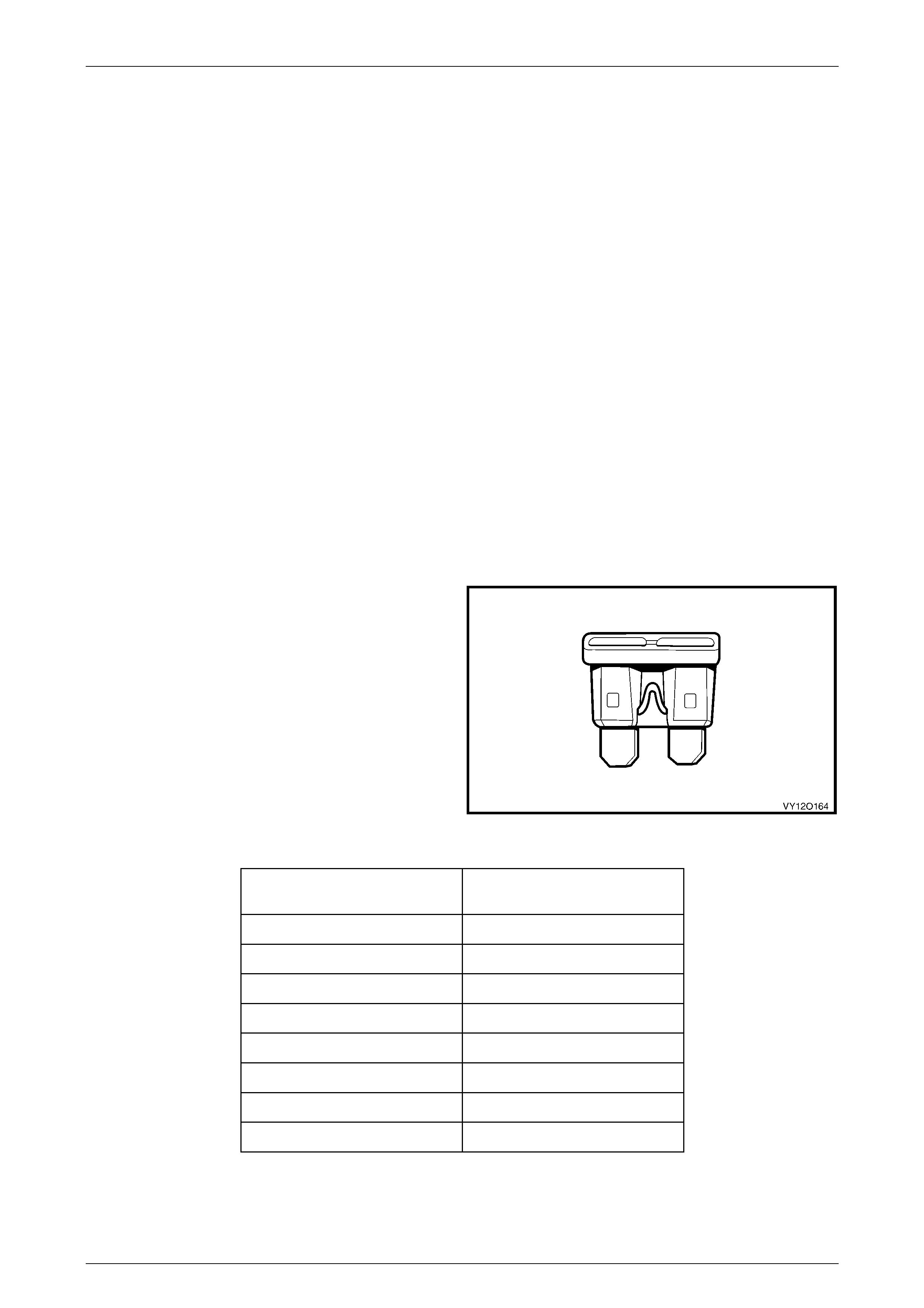
1.1 Fuses
Fuses are a blade type mini construction, with the current
rating in amps indicated on the top of the fuse assembly,
above the element, or identified by the plastic body colour of
the fuse. The fuse current ratings and corresponding colour
are listed in the following table.
Figure 12O – 1
Current Rating
(Amps) Fuse Colour
3 Violet
5 Tan
7.5 Brown
10 Red
15 Blue
20 Yellow
25 White
30 Green
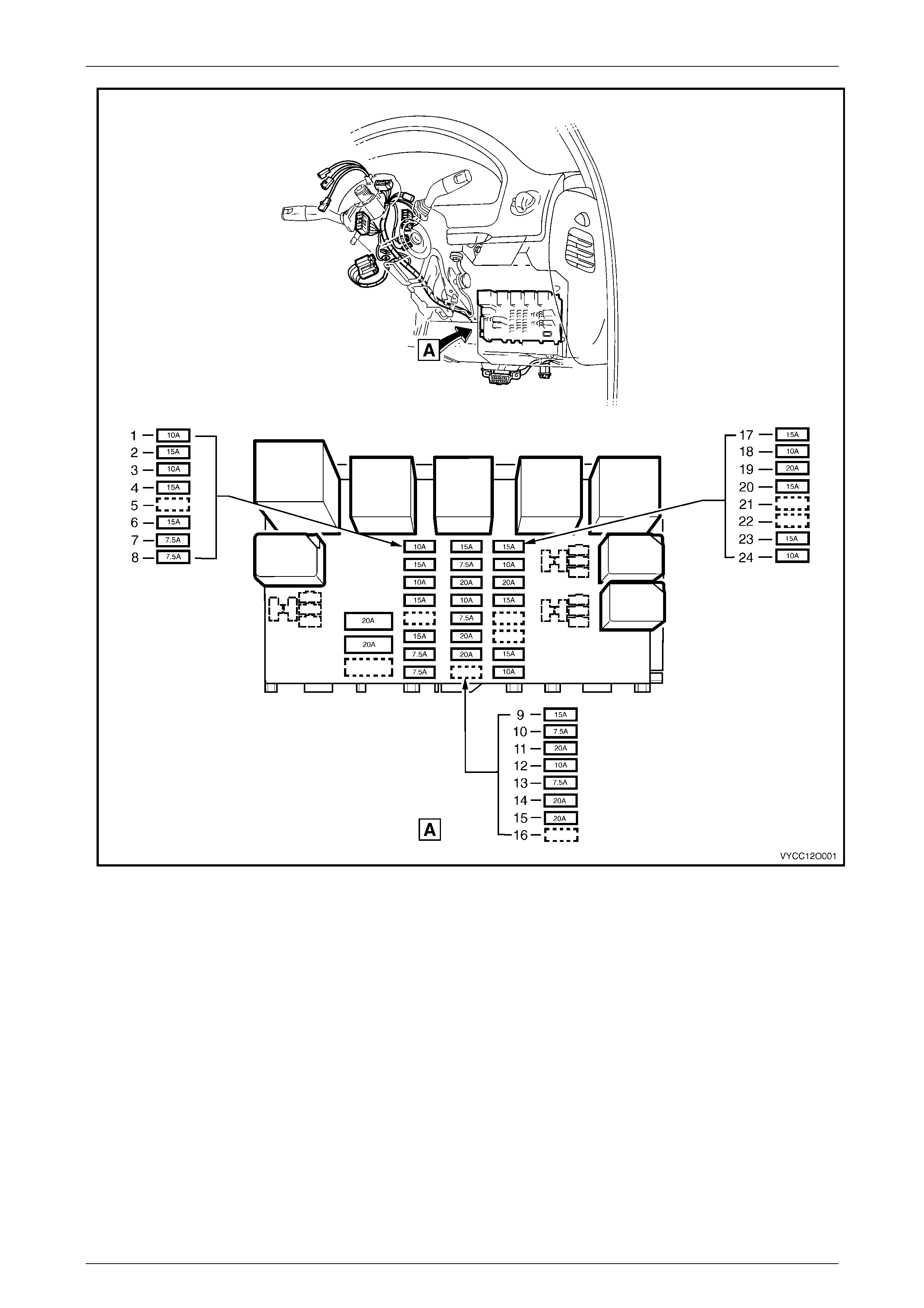
Fuses are located in two positions on MY 2004 Regular Cab and Crew Cab vehicles. One group is located in the
passenger compartment fuse and relay panel assembly. Refer to Figure 12O – 2. A label on the inside of the instrument
panel lower cover indicates the circuits protected by each fuse.
Fuses, Rela ys and Wiring Harness es Page 12O–3
Page 12O–3
Figure 12O – 2
Legend
1 F4 – Park Lamps Fuse (10A)
2 F5 – Stop Lamps Fuse (15A)
3 F6 – Interior Illumination Fuse (10A)
4 F7 – Hazard Lamps and Antenna Fuse (15A)
5 F8 – Spare
6 F9 – Horn Fuse (15A)
7 F10 – Ignition Fuse (7.5A)
8 F11 – Instrument Illuminat i on Fuse (7.5A)
9 F12 – Turn Signals & Back-up Lamps Fuse (15A)
10 F13 – Trip Computer, Instruments, Telematics & ECC
Fuse (7.5A)
11 F14 – Cigar Lighter Fuse (20A)
12 F15 – Cruise & Power Mirrors Fuse (10A)
13 F16 – Radio, Cell Phone & Navigation Fuse (7.5A)
14 F17 – Accessory Socket Fuse (20A)
15 F18 – Wiper Washer Fuse (20A)
16 F19 – Spare
17 F20 – Power Locks, Power Windows & Theft Horn
Fuse (15A)
18 F21 – Instruments & ECC Fuse (10A)
19 F22 – Heated Rear Window Fuse (20A)
20 F23 – Radio, Cell Phone & Navigation Fuse (15A)
21 F24 – Spare
22 F25 – Spare
23 F26 – SRS Fuse (15A)
24 F27 – Anti-lock Brakes Fuse (10A)
Fuses, Rela ys and Wiring Harness es Page 12O–4
Page 12O–4
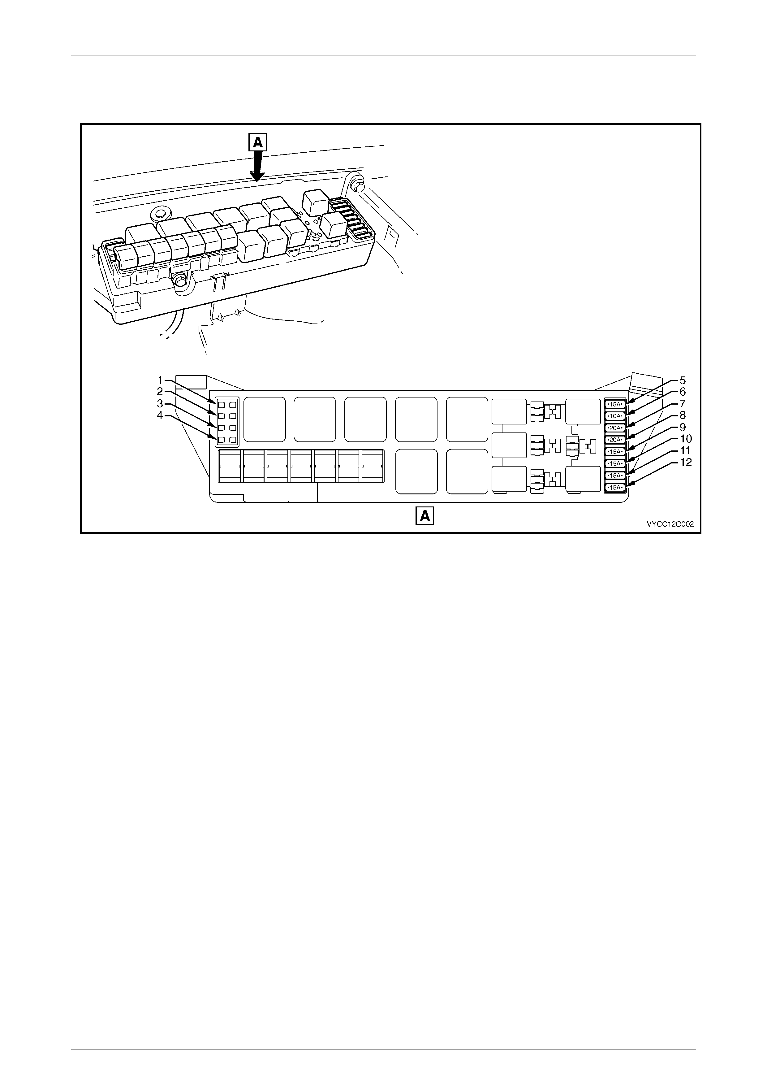
The second group of fuses are located in the engine compartment fuse and relay panel assembly, situated forward of
the right-hand side front suspension strut tower. A label on the inside of the panel cover indicates the circuits protected
by each fuse. Refer to Figure 12O – 3.
Figure 12O – 3
Legend
1 F36 – Spare
2 F37 – Spare
3 F38 – Spare
4 F39 – Spare
5 F28 – Fuel Pump Fuse (15A)
6 F29 – Engine, BCM & Telematics Fuse (10A)
7 F30 – Right-hand Headlamp Fuse (20A)
8 F31 – Left-hand Headlamp Fuse (20A)
9 F32 – Automatic Transmission Fuse (15A)
10 F33 – Engine Sensors Fuse (15A)
11 F34 – Fuel Injectors & Ignition Modules Fuse (15A)
12 F35 – Fuel Injectors & Ignition Modules Fuse (15A)
Fuses, Rela ys and Wiring Harness es Page 12O–5
Page 12O–5
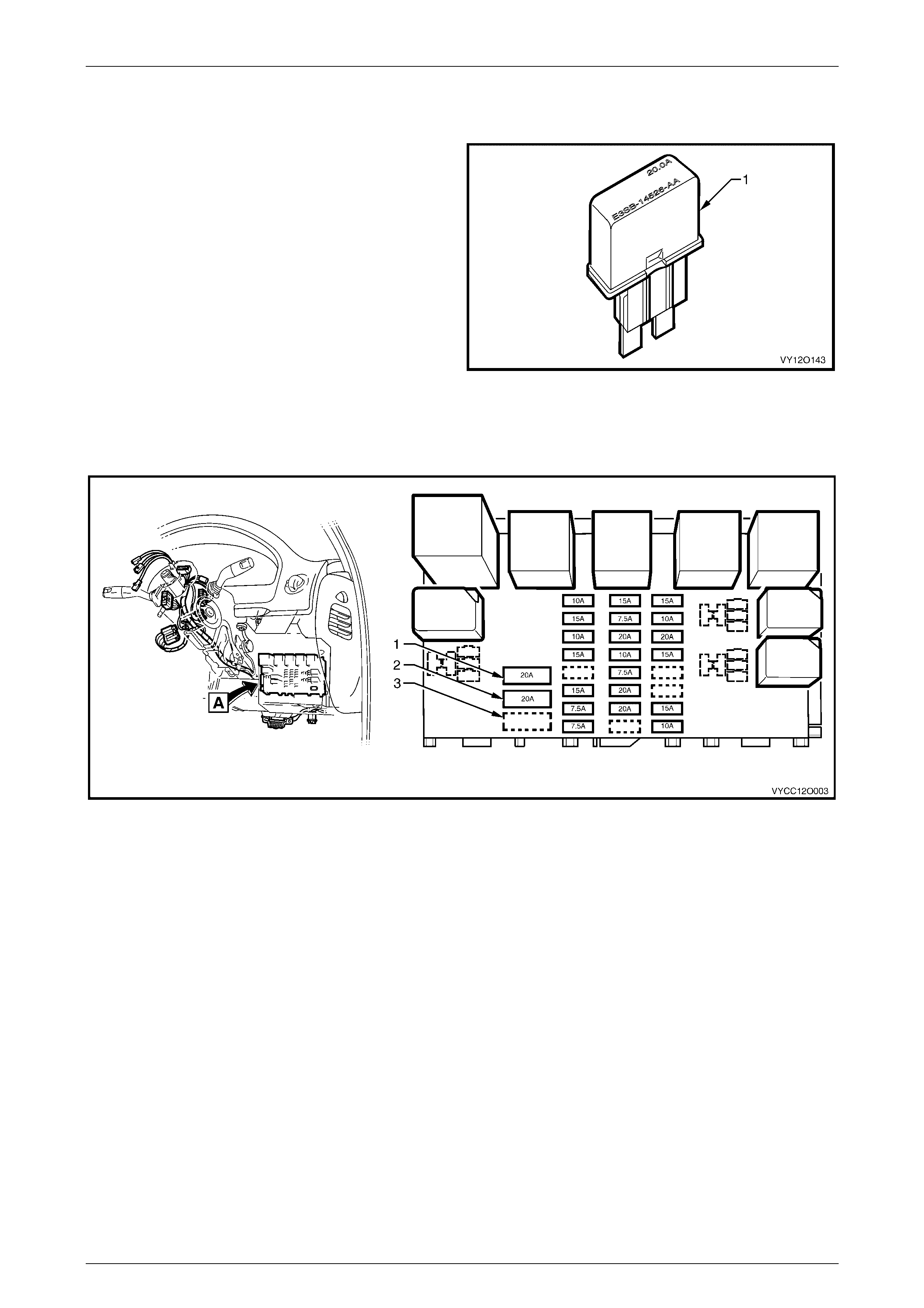
1.2 Circuit Breakers
A circuit breaker is a circuit protection device that will trip
when the circuit current exceeds its rating. The circuit
breaker is activated by heat and will reset after being
allowed to cool. The circ uit bre aker has a limi ted num ber of
tripping cycles before its tripping time will change. The
circuit breaker w ill cont inu e to open and close unti l the
cause of the excess current is corrected.
Figure 12O – 4
In the MY 2004 VY Regular Cab and Crew Cab vehicles all the circuit breakers are located in the passenger
compartment fuse and relay panel assembly and have a 20A current rating. A label on the inside of the panel cover
indicates the circuits protected by each circuit breaker. Refer to Figure 12O – 5.
Figure 12O – 5
Legend
1 F1 – Power Windows Circuit Breaker (20A)
2 F2 – Power Seats Circuit Breaker (20A) 3 F3 – Spare
Fuses, Rela ys and Wiring Harness es Page 12O–6
Page 12O–6
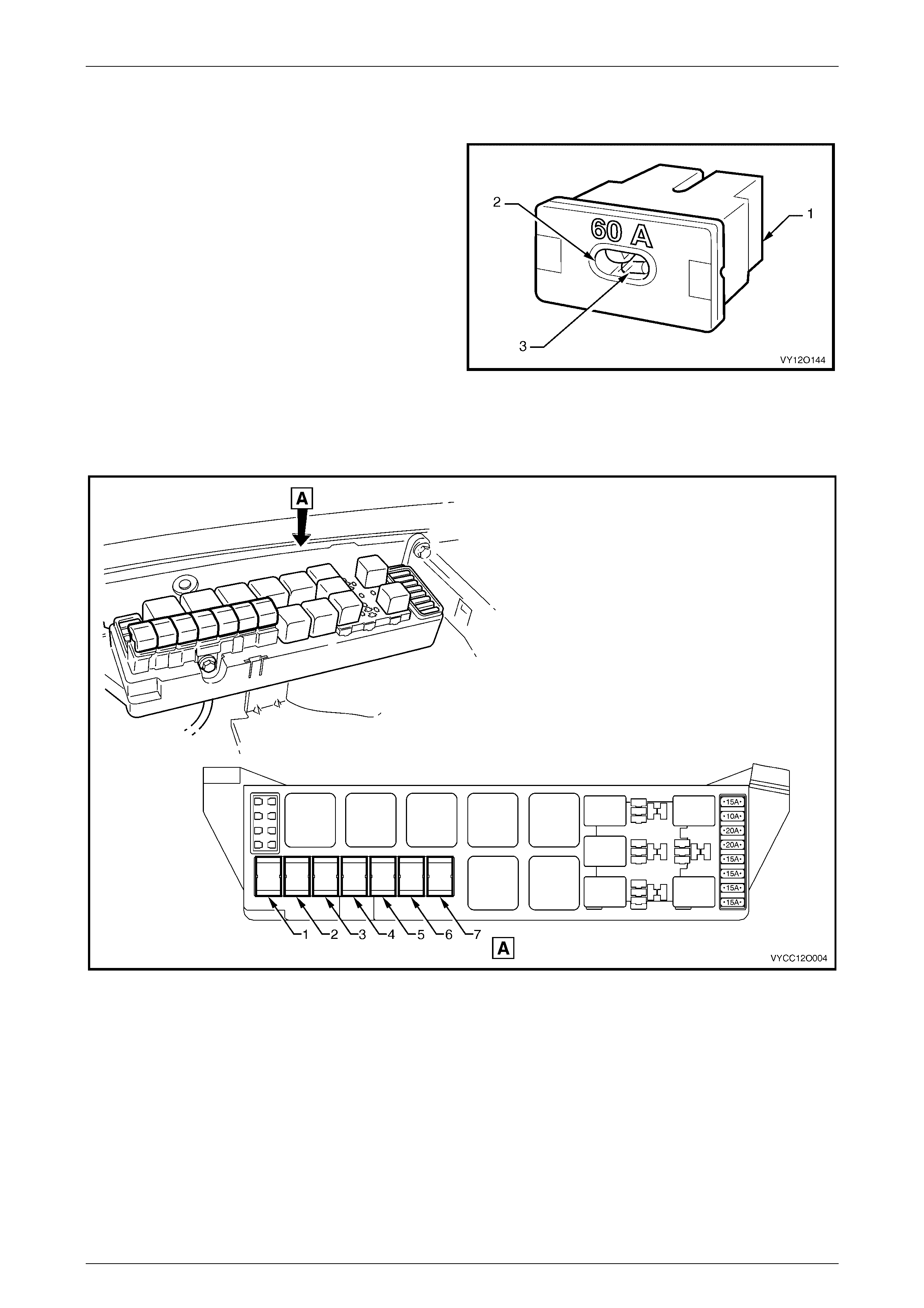
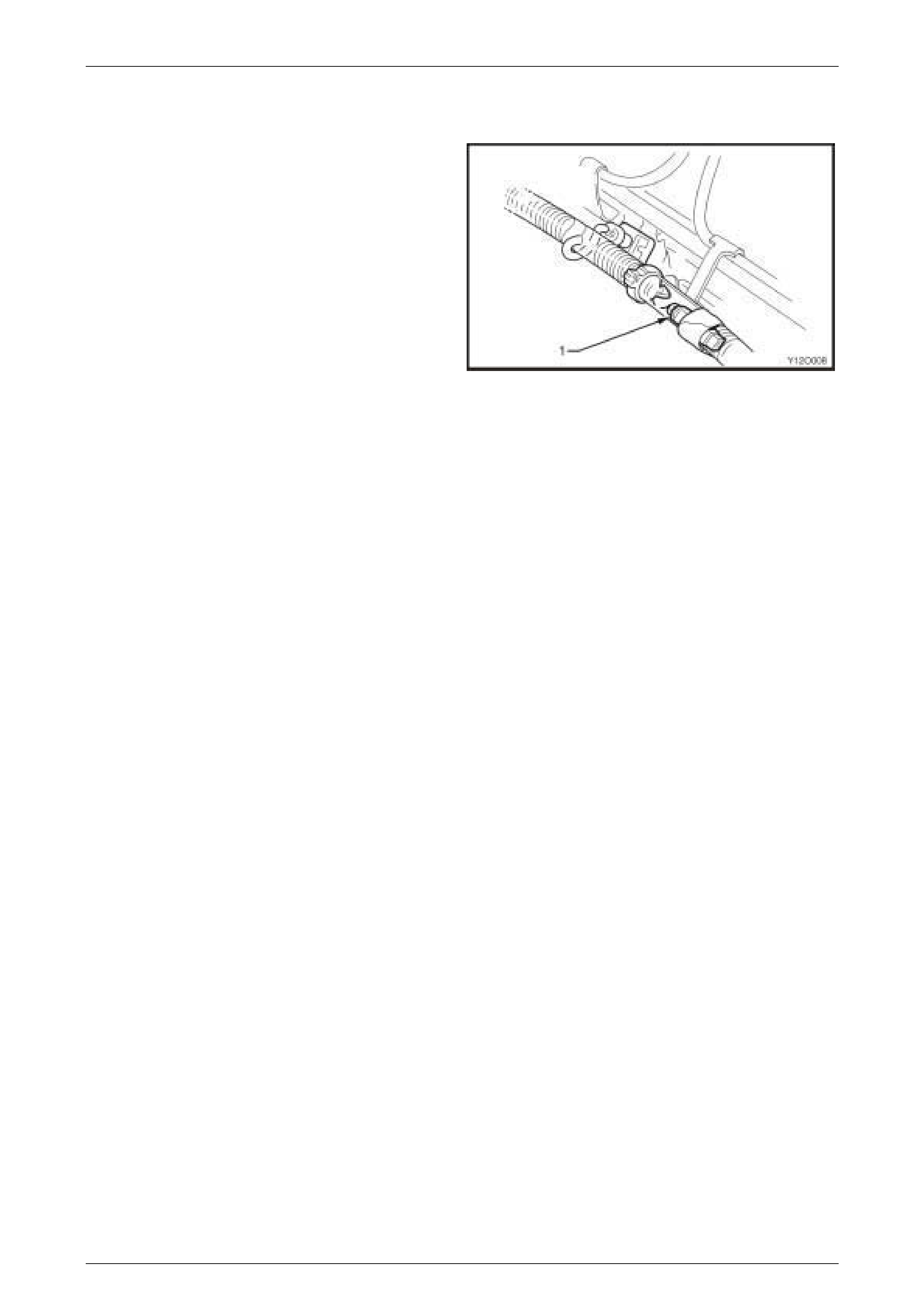
1.3 Fusible Links
The chassis and engine electrical wiring is protected against
short circuit damage by fusible links.
Plug-in type fusible links (1) have an inspection window (2)
that allows a visual check of the condition of the element (3).
Figure 12O – 6
The plug-in type fusible links are located in the engine compartment fuse and relay panel assembly. Refer to Figure
12O – 7 for the location and us age of the fusible links. A label on the inside of the panel cover indicates the circuits
protected by each fusible link.
Figure 12O – 7
Legend
1 F101 – Engine Cooling Large Fan (30A)
2 F102 – Lighting (60A)
3 F103 – Anti Lock Brakes (60A)
4 F104 – Engine (60A)
5 F105 – Main (60A)
6 F106 – Blower Fan (40A)
7 F107 – Engine Cooling Small Fan (30A)
Fuses, Rela ys and Wiring Harness es Page 12O–7
Page 12O–7
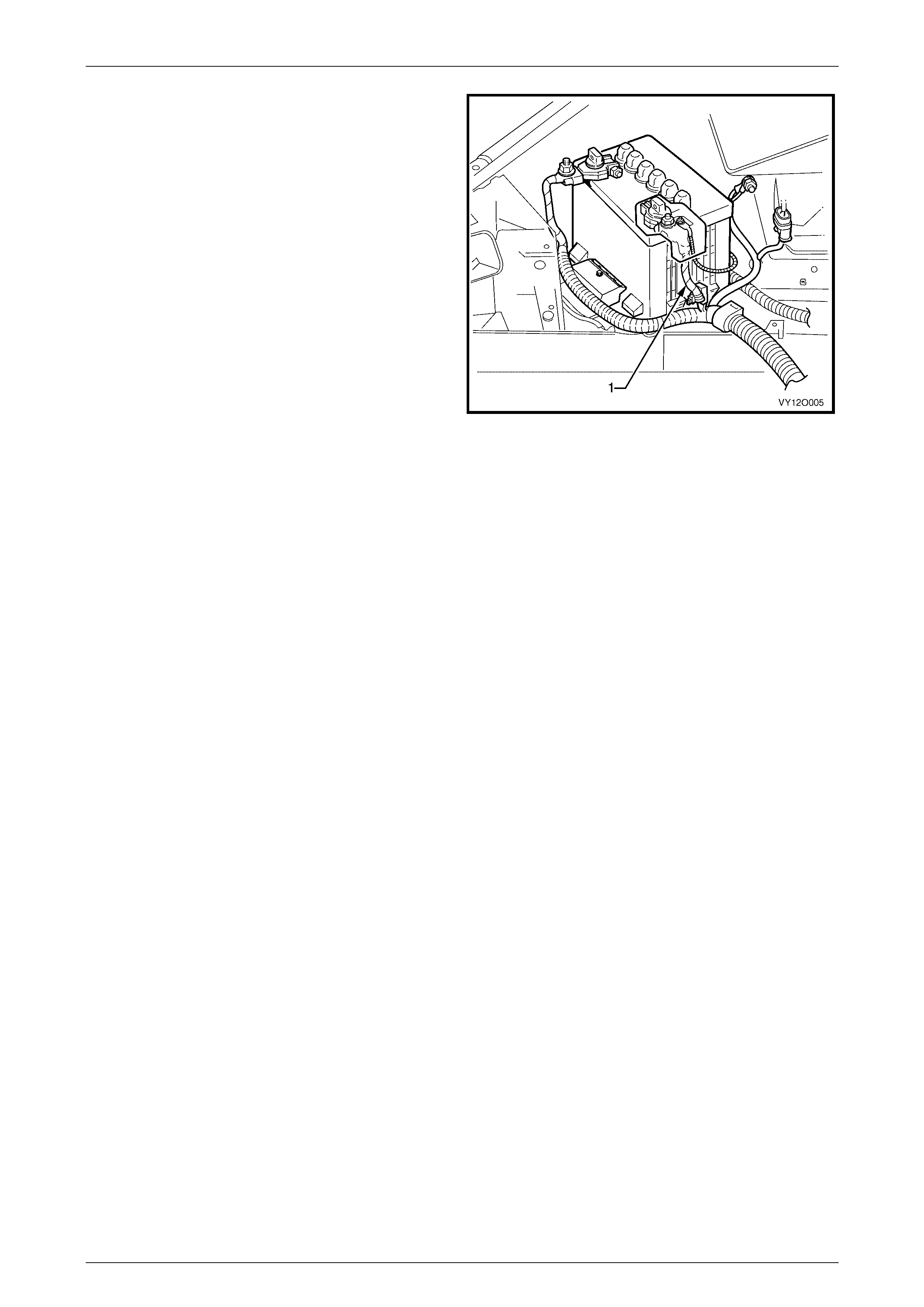
A one-wire type fusible link, consisting of an insulated fuse
wire (1) is attached to the battery harness with cable ties.
This is integrated as part of the battery harness and is
located adjace nt to the battery harness po sitiv e term ina l.
Figure 12O – 8
Fuses, Rela ys and Wiring Harness es Page 12O–8
Page 12O–8
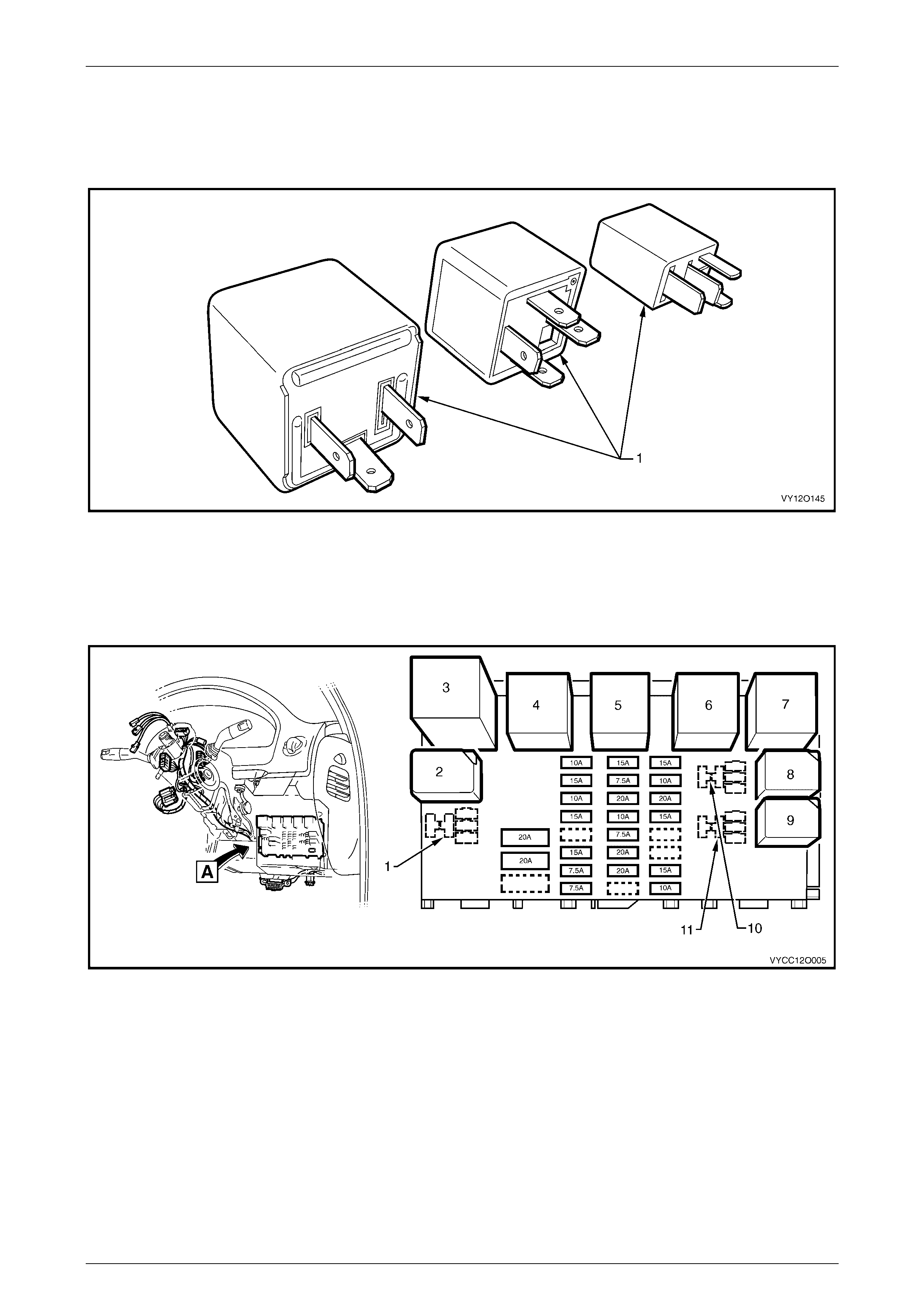
1.4 Relays
There are a variety of relay assemblies (1) used in the MY 2004 VY Regular Cab and Crew Cab vehicles. The relays are
located in the engine compartment and passenger compartment fuse and relay panel assemblies.
Figure 12O – 9
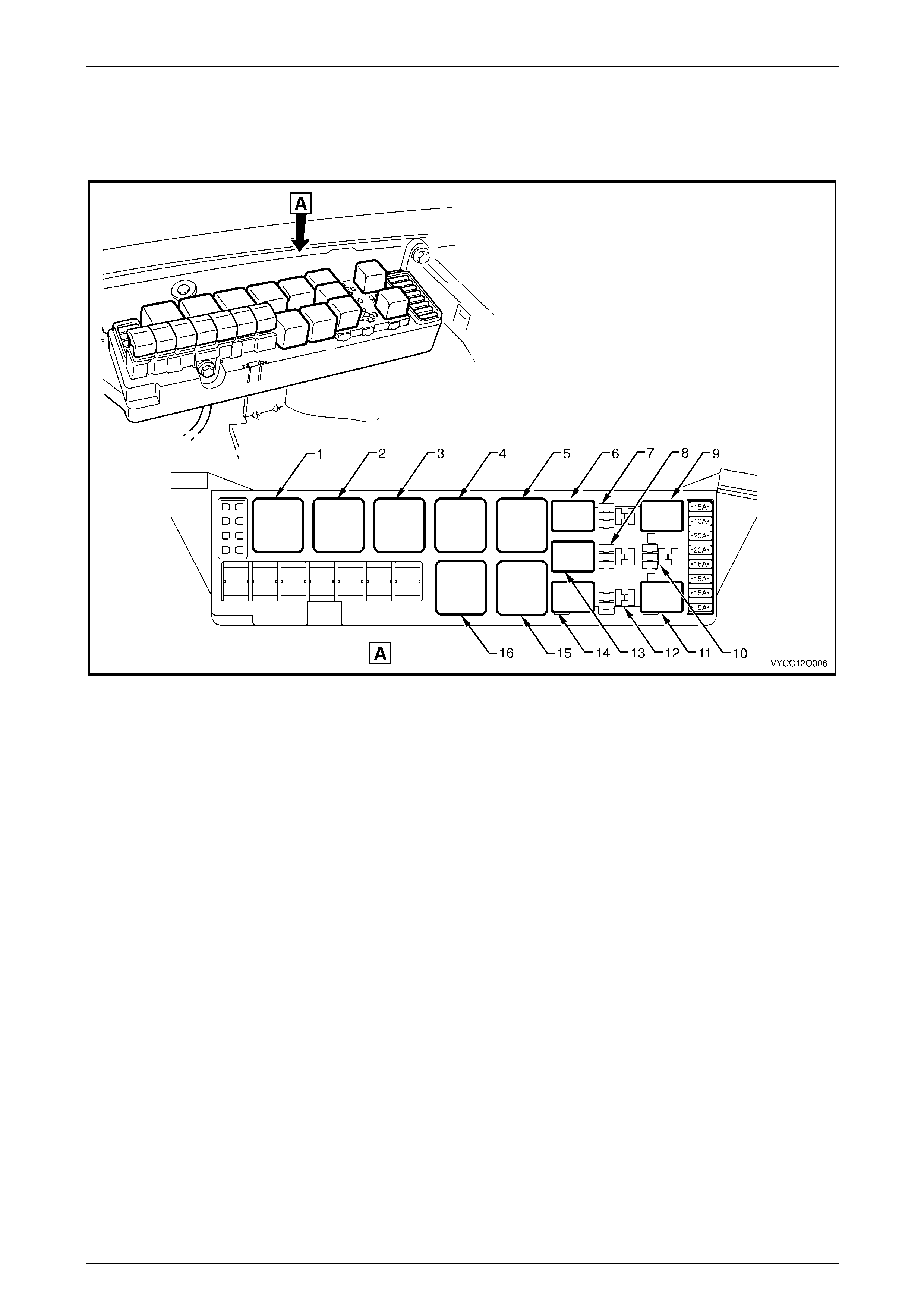
Passenger Compartment Relays
The passenger compartment fuse and relay panel assembly is located behind the instrument panel lower cover. A label
on the inside of the cover indicates the relay location and the circuits protected by each relay. Refer to Figure 12O – 10.
Figure 12O – 10
Legend
1 R17 – Spare
2 R18 – Relay Assembly – Park Lamps (4 Pi n Micro)
3 R19 – Flasher Assembly – Turn Signal (3 Pin)
4 R20 – Relay Assembly – Accessory Control (4 Pin Mini)
5 R21 – Relay Assembly – Ignition Control (4 P i n Mini)
6 R22 – Relay Assembly – Power Windows (4 Pin Mini)
7 R23 – Relay Assembly – Blower Inhibit (4 Pin Mini)
8 R24 – Relay Assembly – Interi or Illumi nation (4 Pin Mini)
9 R25 – Relay Assembly – Defog (4 Pin Micro)
10 R26 – Spare
11 R27 – Spare
Fuses, Rela ys and Wiring Harness es Page 12O–9
Page 12O–9
Engine Compartment Relays
The engine compartment fuse and relay panel assembly is located forward of the right-hand side front suspension strut
tower. A label on the inside of the cover indica tes the relay location and the circuits protected by each relay. Refer to
Figure 12O – 11.
Figure 12O – 11
Legend
1 R1 – Start Relay (4 Pin)
2 R2 – Blower Relay (4 Pin)
3 R3 – Headlamp Hi-beam Relay (4 Pin)
4 R4 – E.F.I. Relay (4 Pin)
5 R5 – Engine Cooling Fan Relay 2 – [V6] (4 Pin)
Engine Cooling Fan Relay 1 – [V8] (4 Pin)
6 R8 – Horn Relay (4 Pin Micro)
7 R9 – Spare
8 R12 – Spare
9 R10 – Fog Lamp Relay (4 Pin Micro)
10 R13 – Spare (4 Pin Micro)
11 R16 – Fuel Pump Relay (4 Pin Micro)
12 R15 – Spare
13 R11 – A/C Relay (4 Pin Micro)
14 R14 – Headlamp Lo-beam Relay (4 Pin Micro)
15 R7 – Engine Cooling Fan Relay 1 – [V6] (5 Pin)
Engine Cooling Fan Relay 2 – [V8] (5 Pin)
16 R6 – Engine Cooling Fan Relay 3 – [V8] (5 Pin)
Fuses, Rela ys and Wiring Harness es Page 12O–10
Page 12O–10
1.5 Diodes
All vehicles with air conditioning have an air conditioning
compressor clutch suppression diode (1) fitted to the engine
wiring harness.
For location of the air conditioning compressor clutch
feedback diode, refer to the following figures in Section 120
Fuses, Relays and Wiring Harnesses in the MY 2004 VY
and V2 Series Service Information.
a. 3.6 Powertrain Harness – 3, item 6.
b. 3.15 Powertrain Harness – 12, item 10.
Figure 12O – 12
Fuses, Rela ys and Wiring Harness es Page 12O–11
Page 12O–11
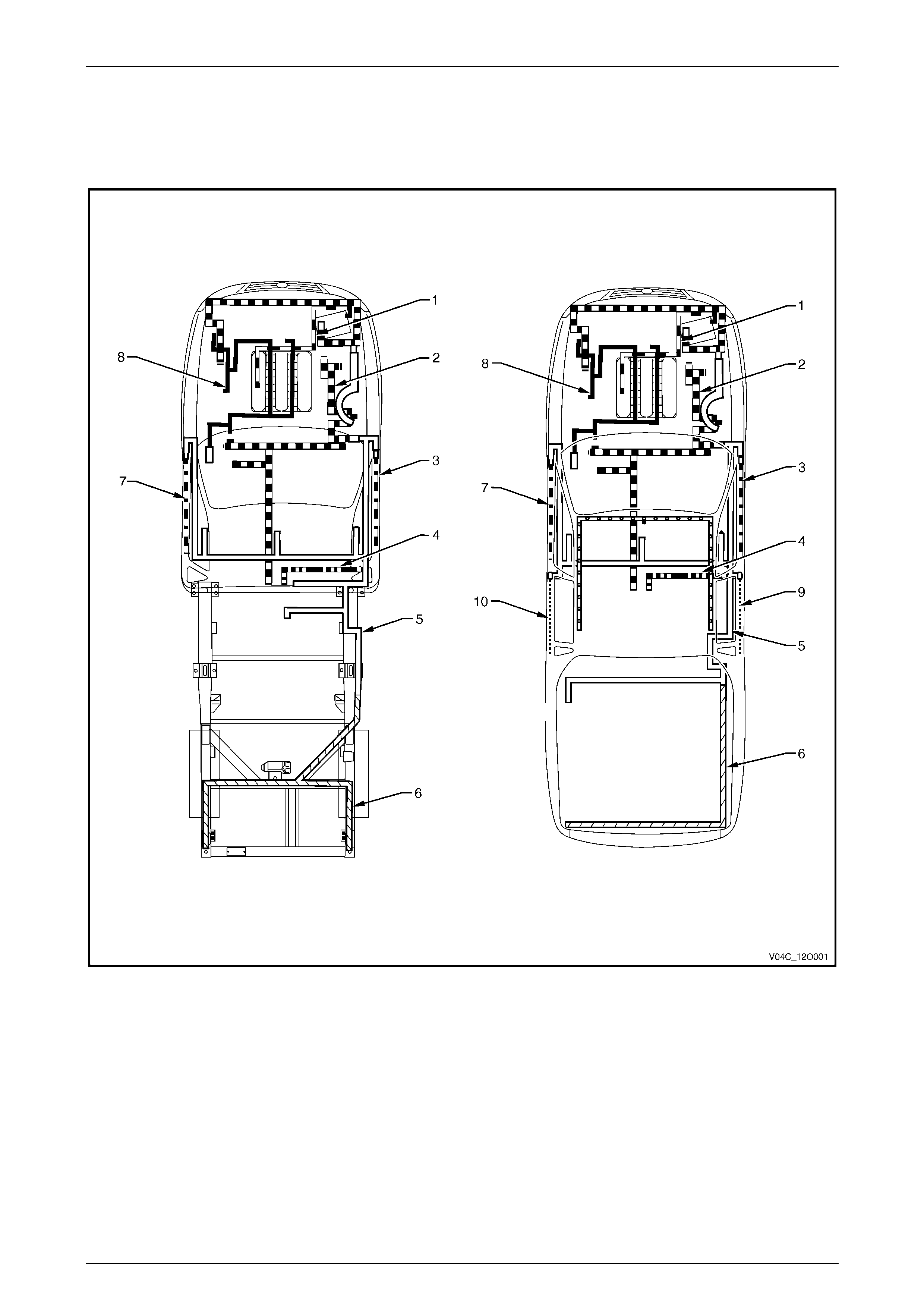
1.6 Wiring Harnesses
Refer to Figure 12O – 13 for the location of the wiring harnesses used in the MY 2004 VY Regular Cab and Crew Cab
vehicles. For a detailed layout of the various wiring harnesses and connectors refer to 3 W iring Installation Diagrams.
Figure 12O – 13
Legend
1 Battery Wiring Harness
2 Front Body Harness
3 Right-hand Front Door Wi ri ng Harness
4 Roof Lamp Harness
5 Body Wiring Harness
6 Rear Body Wiring Harness
7 Left-hand Front Door Wiring Harness
8 Powertrain Harness
9 Right-hand Rear Door W i ri ng Harness
10 Left-hand Rear Door Wiri ng Harness

Fuses, Rela ys and Wiring Harness es Page 12O–12
Page 12O–12
1.7 Wiring Harness Connectors
The majority of the wiring harness connectors used on MY 2004 VY Regular Cab and Crew Cab vehicles are of an
interlocking design.
The male and female connector bodies, when pushed together, cannot be pulled apart due to the presence of a locking
tang on the connector body. Some connectors have anti-backout combs fitted for increased connector termin al security.
Fuses, Rela ys and Wiring Harness es Page 12O–13
Page 12O–13
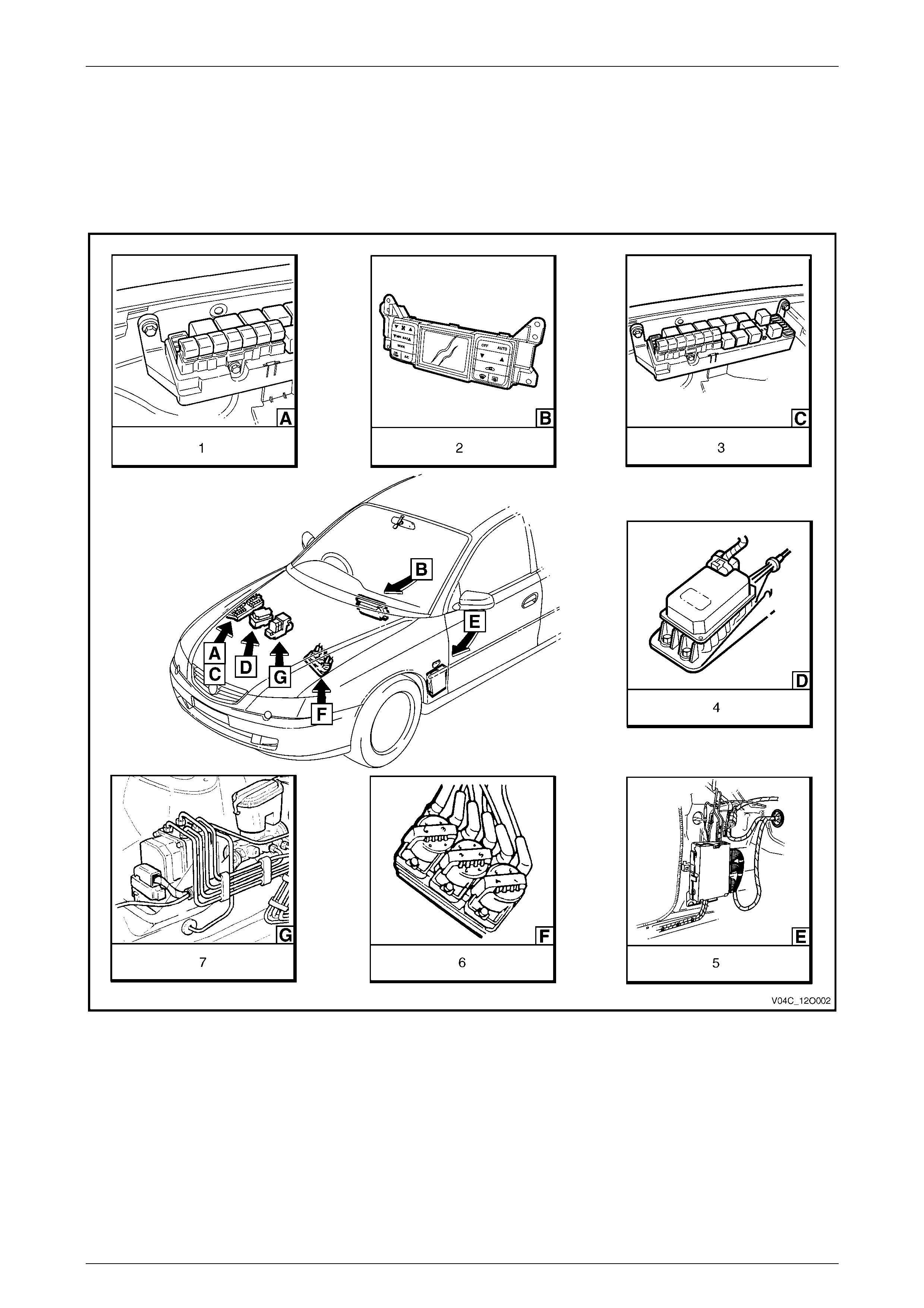
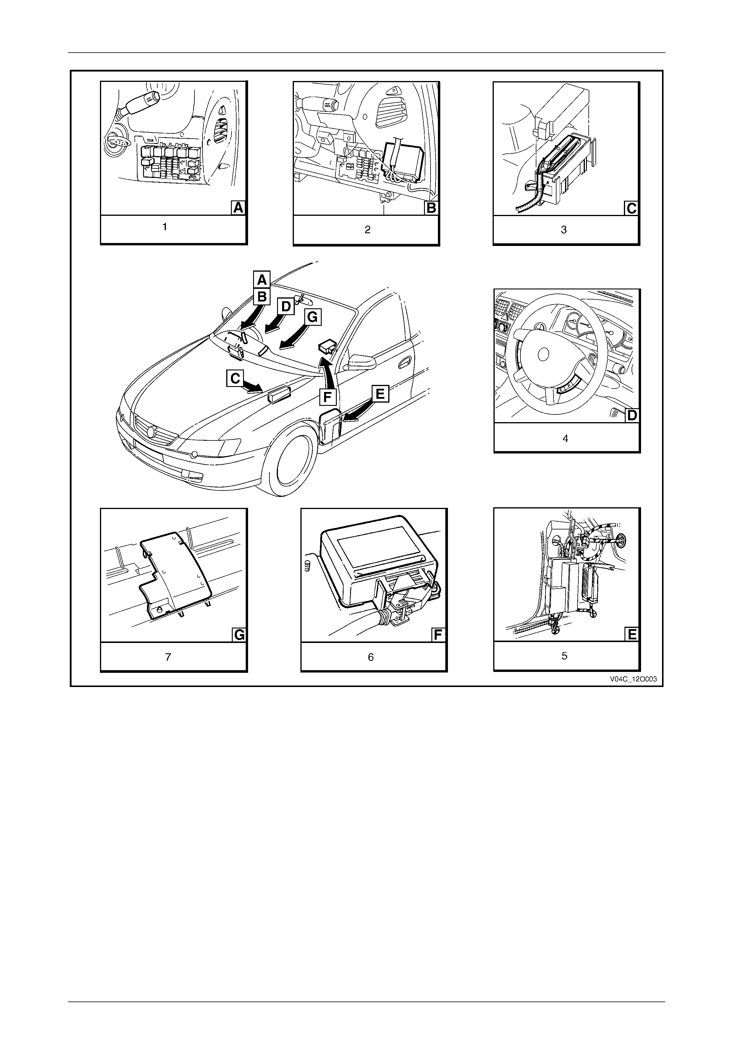
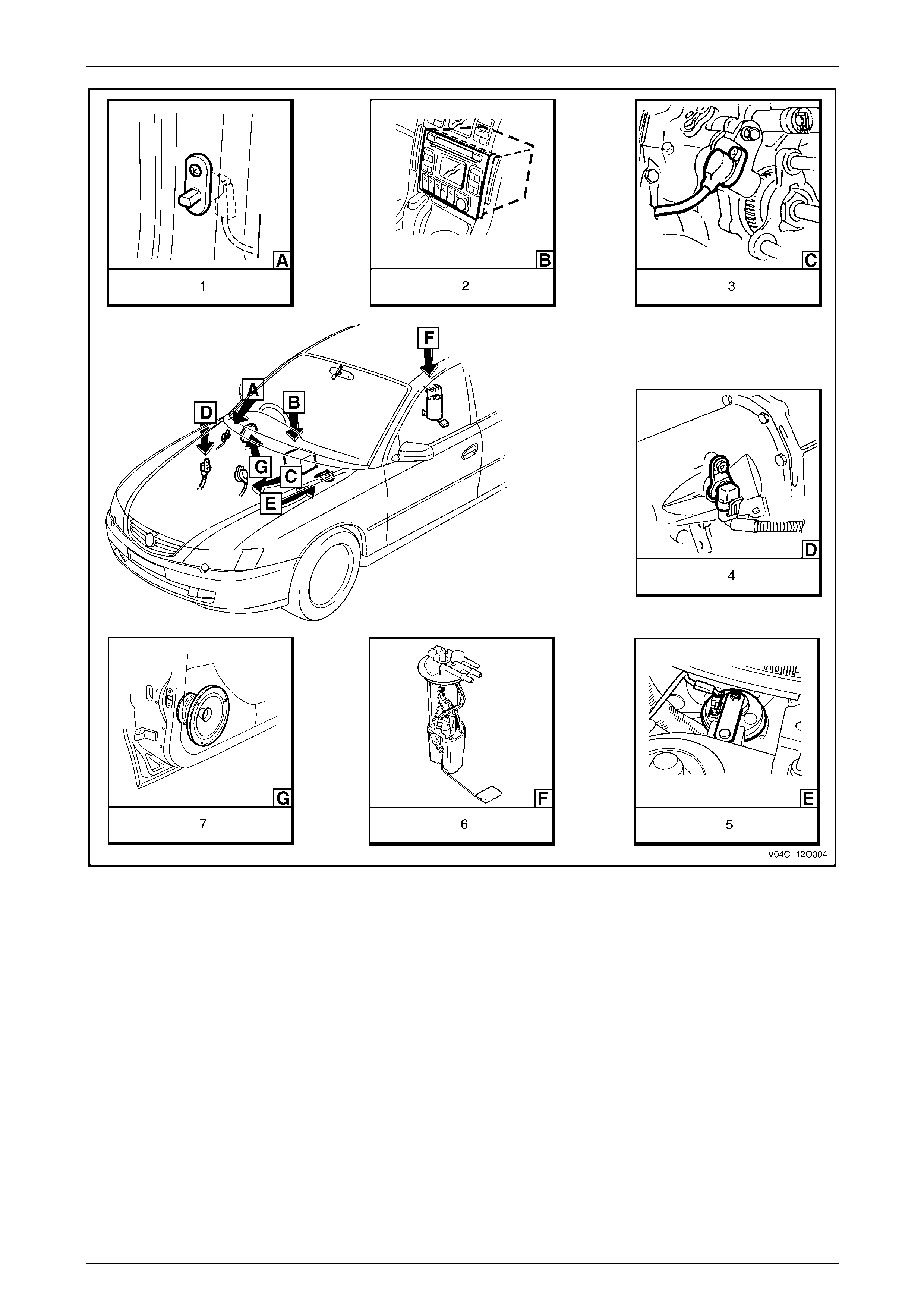
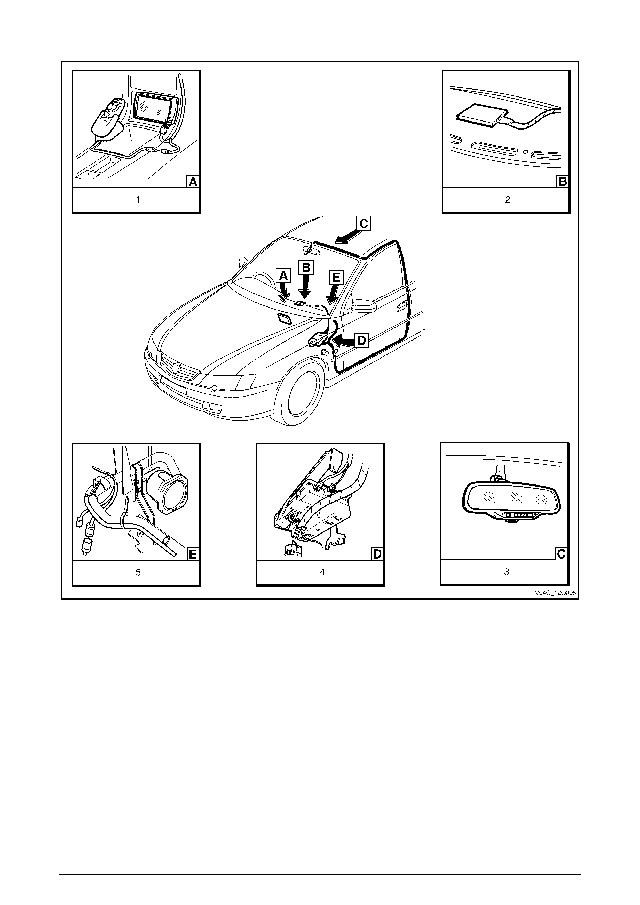
1.8 Electronic Control Device Locations
The following figures illustrate the location of the various electronic control devices fitted to MY 2004 VY Regular Cab
and Crew Cab vehicles.
Ensure that the precautionary and special handling instructions are followed (where applicable) for each electronic
control device as des cribed in the corresponding section s.
Figure 12O – 14
Legend
1 Fusible Links
2 Climate Control module
3 Relays & Fuses – Engine Compartm ent
4 Cruise Control Module
5 Powertrain Control Module (P CM) – V6 Engine
6 Direct Ignition System (DIS) Module – V6 Engine
7 ABS Hydraulic Modulator
Fuses, Rela ys and Wiring Harness es Page 12O–14
Page 12O–14
Figure 12O – 15
Legend
1 Relays & Fuses – Instrument P anel
2 Body Control Module
3 Powertrain Control Module – Gen III V8 Engine
4 Steering Wheel Radio & CD Player Control s
5 Powertrain Interface Module (PIM) – GEN III V8 Engine
6 Sensing & Diagnostic Module – Occupant Protection System
7 Ambient Light Sensor
Fuses, Rela ys and Wiring Harness es Page 12O–15
Page 12O–15
Figure 12O – 16
Legend
1 Door Ajar Warning Switch
2 Radio Assembly
3 Vehicl e Speed Sensor – Manual Transmiss i on
(V6 Shown, V8 Similar)
4 Vehicle Speed Sensor – Automatic Transmission
5 Anti-theft Horn
6 Modular Fuel Pump & Sender Assembly
7 Front Door Speaker Assembly
Fuses, Rela ys and Wiring Harness es Page 12O–16
Page 12O–16
Figure 12O – 17
Legend
1 Navigation S ystem Assembly
2 Telematics Antenna
3 Rear View Mirror Assembly with Telematics
4 Telematics Cont rol Module
5 Navigation S ystem Speaker

Fuses, Rela ys and Wiring Harness es Page 12O–17
Page 12O–17
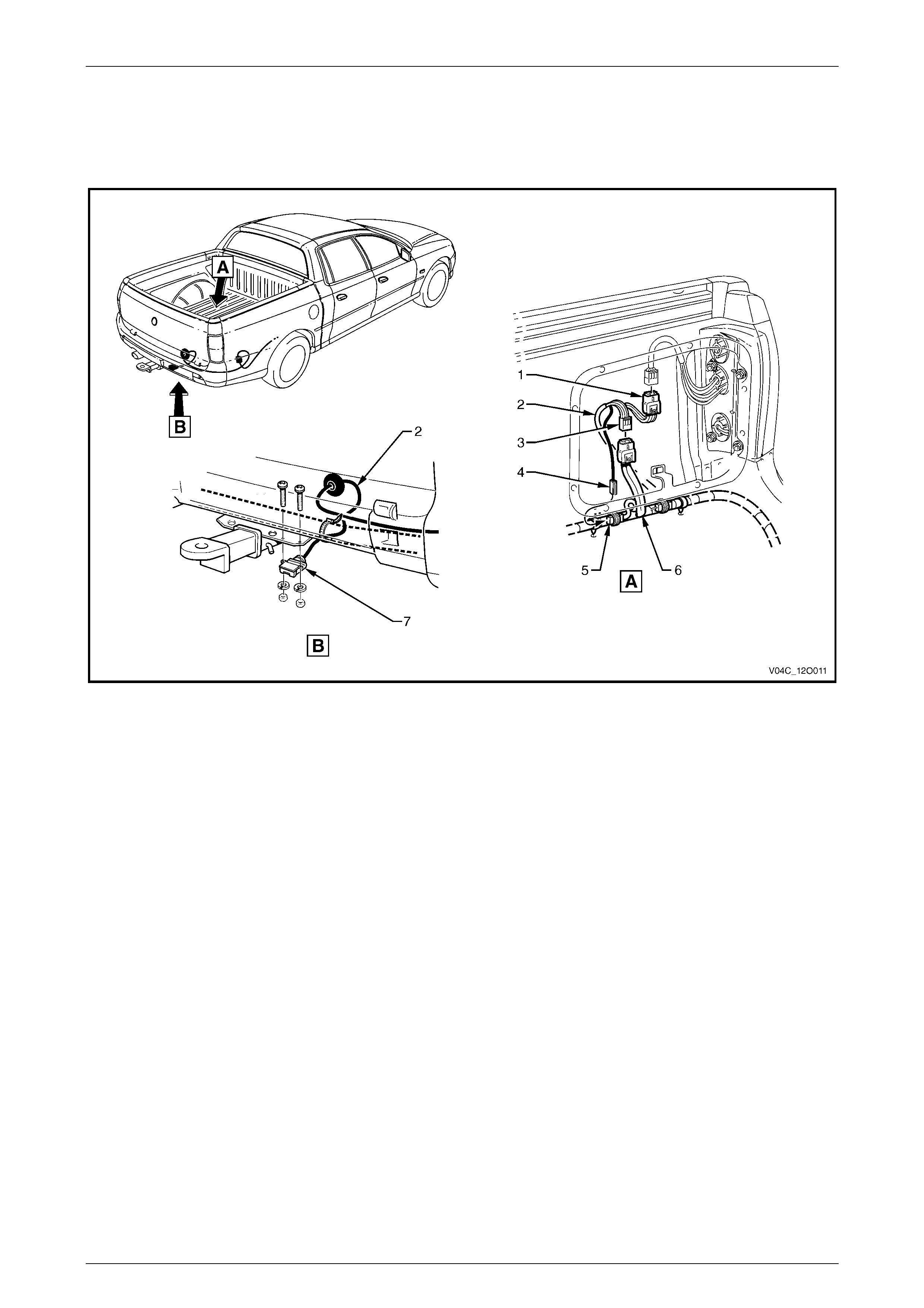
2 Service Operations
All the service operations associated with Fuses, Relays and Wiring Harnesses for MY 2004 VY Regular Cab and Crew
Cab vehicles carry over from those described in Section 12O Fuses, Relays and Wiring Harnesses in the MY 2004 VY
and V2 Series Service Information.
Fuses, Rela ys and Wiring Harness es Page 12O–18
Page 12O–18
3 Wiring Installation Diagrams
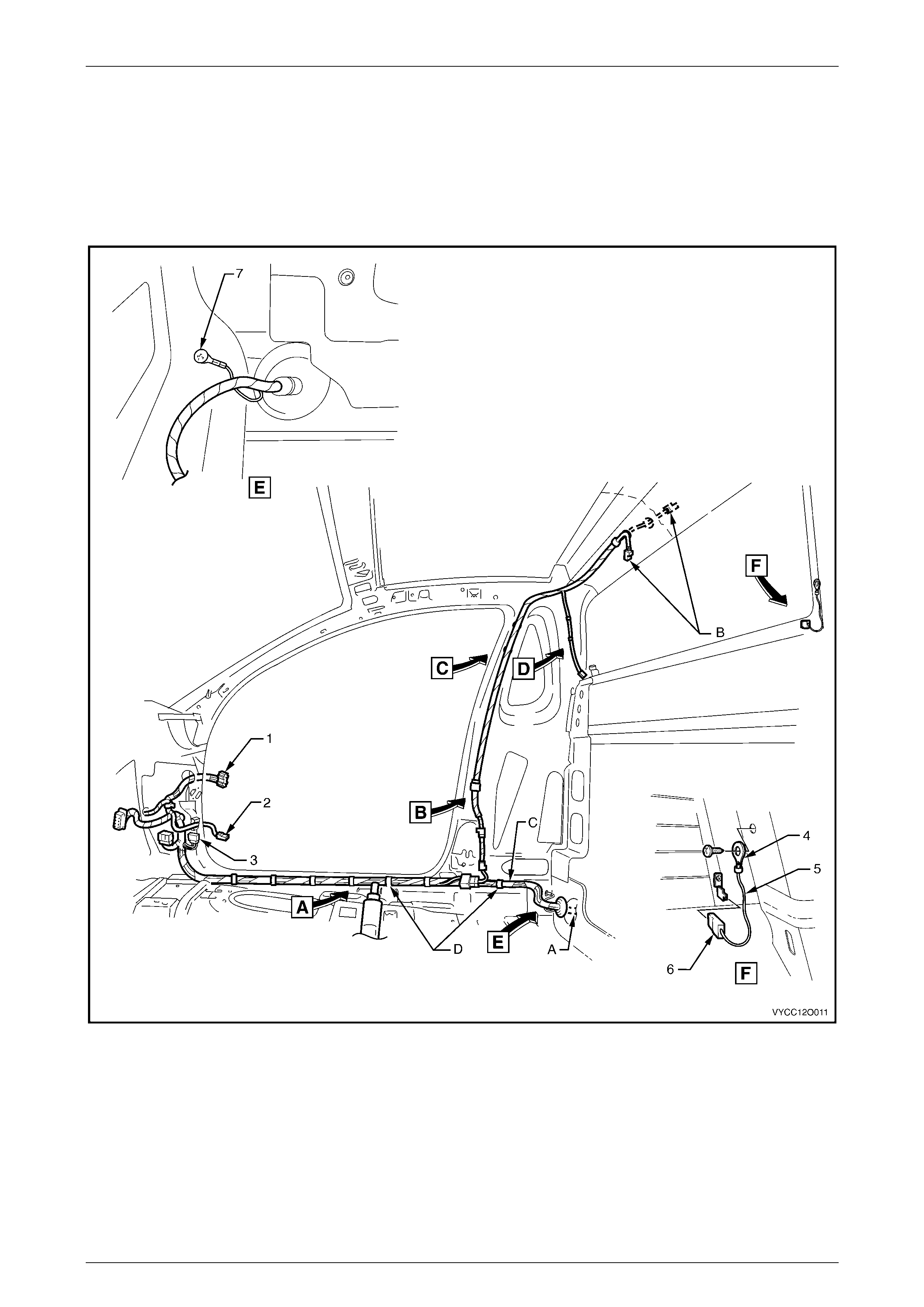
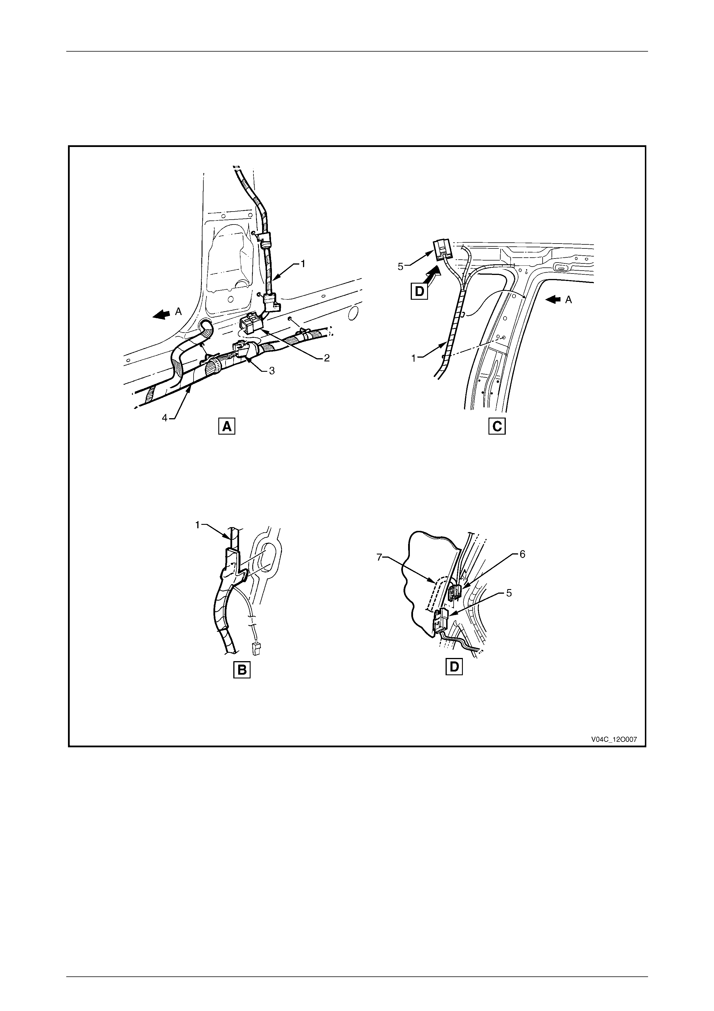
3.1 Interior Body Wiring Harness – 1
Regular Cab
Figure 12O – 18

Fuses, Rela ys and Wiring Harness es Page 12O–19
Page 12O–19
Legend
1 Body Wiring Harness to Right-hand Front Door Wi ri ng
Harness Connect or (X600)
2 Door Ajar Indicator Switch (S2)
3 Body Wiring Harness to Front Body Harness Connector
(X201)
4 Ground Lead Terminal (X118 – GP7)
5 Rear Window Defog Grid Ground Lead
6 Rear Window Defog Grid Connector (R22-X2)
7 Ground Lead Terminal (X118 – GP13)
A For harness continuat i on, ref er to
3.5 Rear Wiring Harnesses – 1.
B For harness continuat i on, ref er to
5.4 Roof Lamp Harness – 2 in MY 2004 VY and V2 Series
Service Information.
C For harness continuat i on, ref er to
5.2 Interior Body Wiring Harness – 2 i n MY 2004 VY and V2
Series Se r v ice Information .
D Harness clipped to underbody as shown.
For views A, B, C and D, refer to 5.3 Roof Lamp Harness – 1 in
MY 2004 VY and V2 Series Service Information.
Fuses, Rela ys and Wiring Harness es Page 12O–20
Page 12O–20
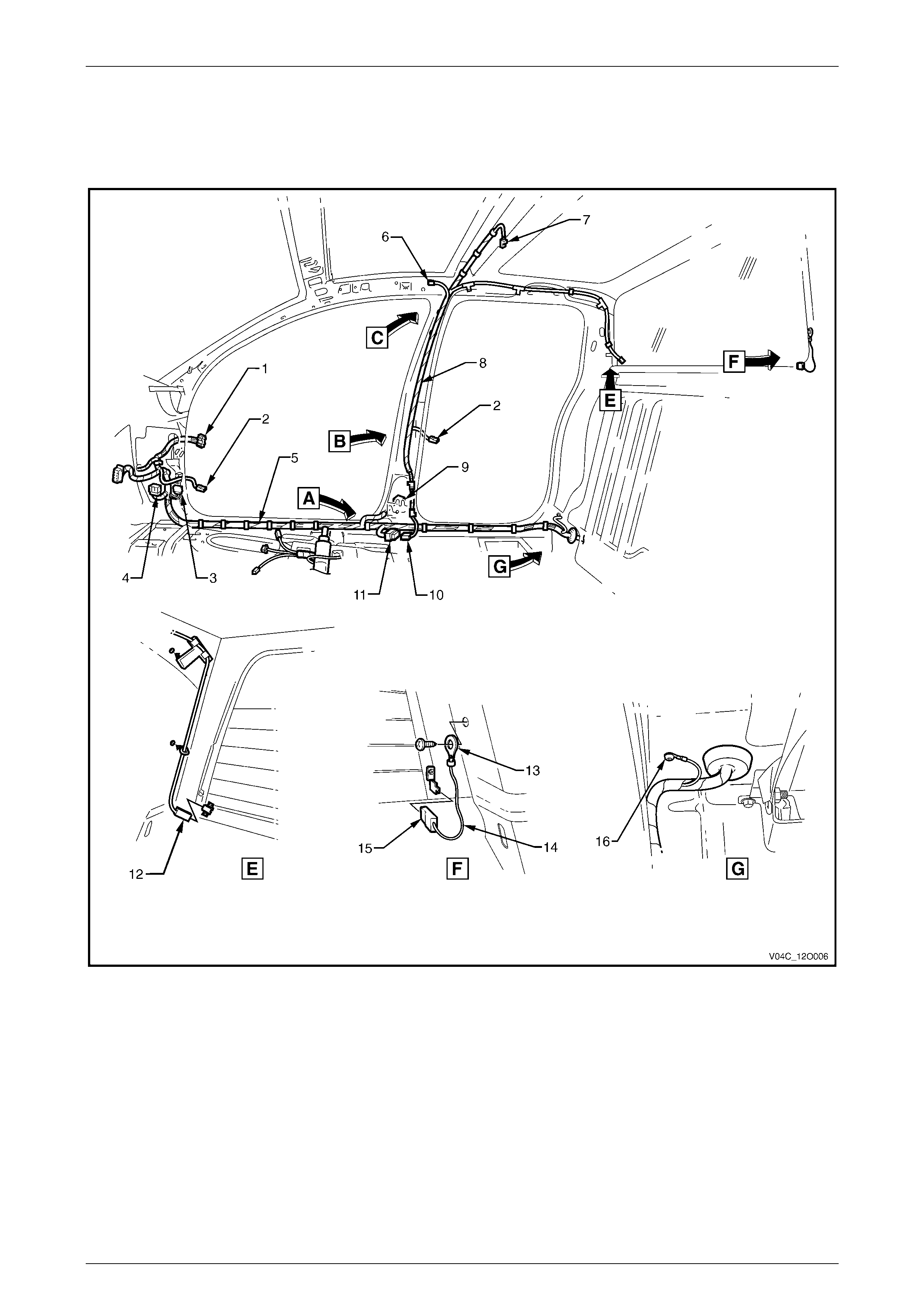
3.2 Interior Body Wiring Harness – 2
Crew Cab
Figure 12O – 19

Fuses, Rela ys and Wiring Harness es Page 12O–21
Page 12O–21
Legend
1 Body Wiring Harness to Right-hand Front Door Wi ri ng
Harness Connect or (X600)
2 Door Ajar Indicator Switch (S2)
3 Body Wiring Harness to Front Body Harness Connector
(X201)
4 Body Wiring Harness to Front Body Harness Connector
(X200)
5 Body Wiring Harness
6 Roof Lamp Harness to Visor Lamp Harness Connector
(X310)
7 Dome Lamp Connector (E67 – X1)
8 Roof Lamp Harness
9 Body Wiring Harness to Right-hand Rear Door Wiring
Harness Connect or (X800)
10 Roof Lamp Harness to Body Wiri ng Harness Connector
(X300)
11 Body Wiring Harness to Roof Lamp Harness Connector
(X300)
12 Rear Window Defog Grid Connector (R22 – X1)
13 Ground Lead Terminal (X118 – GP7)
14 Rear Window Defog Grid Ground Lead
15 Rear Window Defog Grid Connector (R22 – X2)
16 Ground Lead Terminal (X118 – GP13)
For views A, B and C, refer to 3. 3 Roof Lamp Harness – 1.
Fuses, Rela ys and Wiring Harness es Page 12O–22
Page 12O–22
3.3 Roof Lamp Harness – 1
Crew Cab
Figure 12O – 20
Legend
1 Roof Lamp Harness
2 Roof Lamp Harness to Body Wiri ng Harness Connector
(X300)
3 Body Wiring Harness to Roof Lamp Harness Connector
(X300)
4 Body Wiring Harness
5 Roof Lamp Harness to Visor Lamp Harness Connector
(X310)
6 Visor Lamp Harness to Roof Lamp Harness Connector
(X310)
7 Visor Lamp Harness
A Front of vehicle.
For location of views A, B and C, refer to
3.2 Interior Body Wiring Harness – 2.
Fuses, Rela ys and Wiring Harness es Page 12O–23
Page 12O–23
3.4 Roof Lamp Harness – 2
Crew Cab
Figure 12O – 21
Legend
1 Attachi ng Screws Dome Lamp
2 Dome Lamp Connector (E67 – X1)
3 Dome Lamp Assembly (Level 1)
4 Attaching Screws
5 Roof Console
6 Dome Lamp Connector (E67)
7 Reading Lamp Assembly
8 Reading Lamp Connect or (E94 – X1)
9 Reading Lamp Connect or (E94 – X2)
10 Reading Lamp Connect or (E94 – X3)
11 Reading Lamp Blanking Blank (Level 1)
12 Door Ajar Warning Switch
13 Attachi ng Screw Door Ajar Warning Switch
14 Door Ajar Warning Switch Connector (S2)
A. Front of vehicle.
B. Install l amp with switc h facing rear on ri ght-side, forward on
left-side.
Fuses, Rela ys and Wiring Harness es Page 12O–24
Page 12O–24
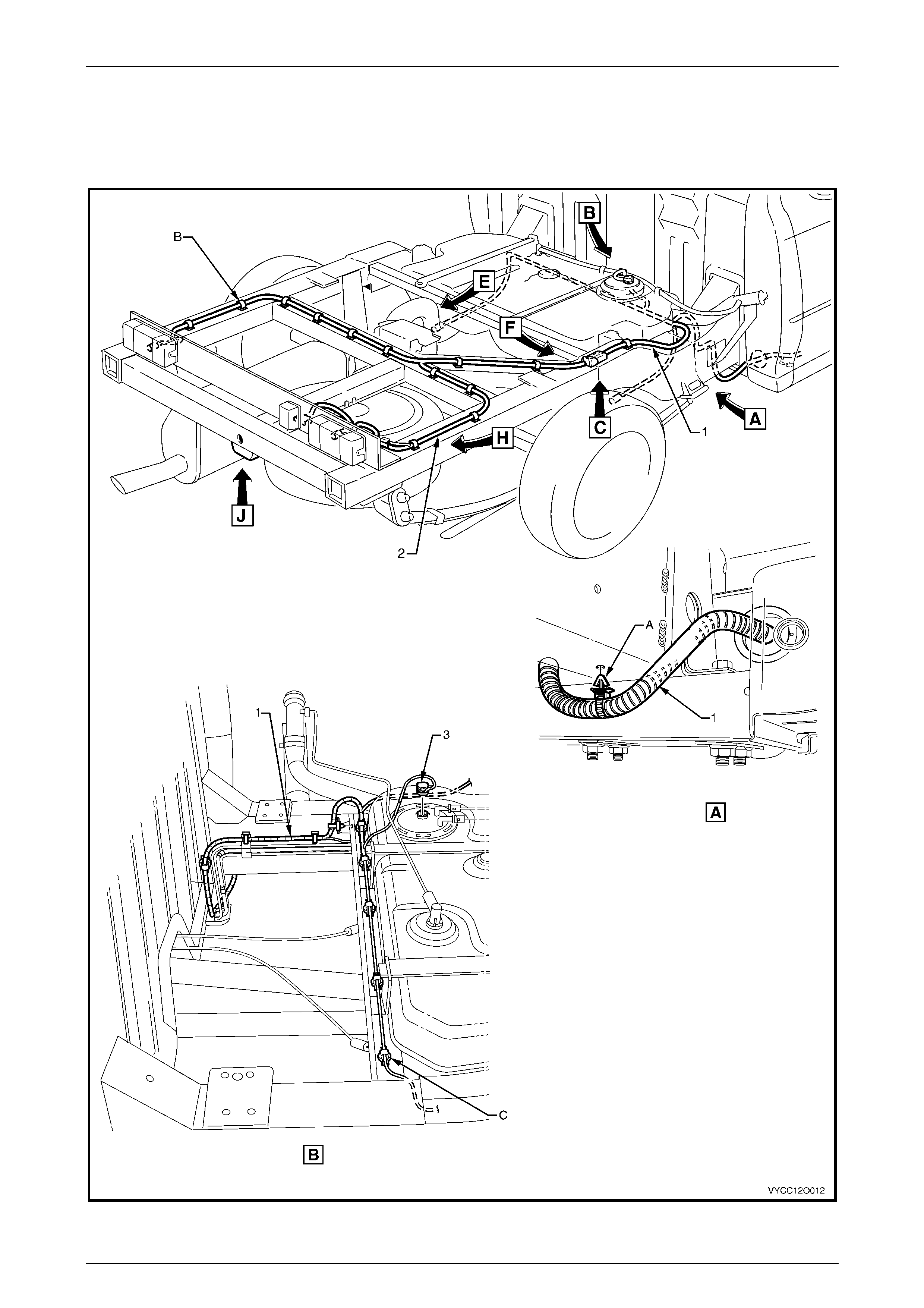
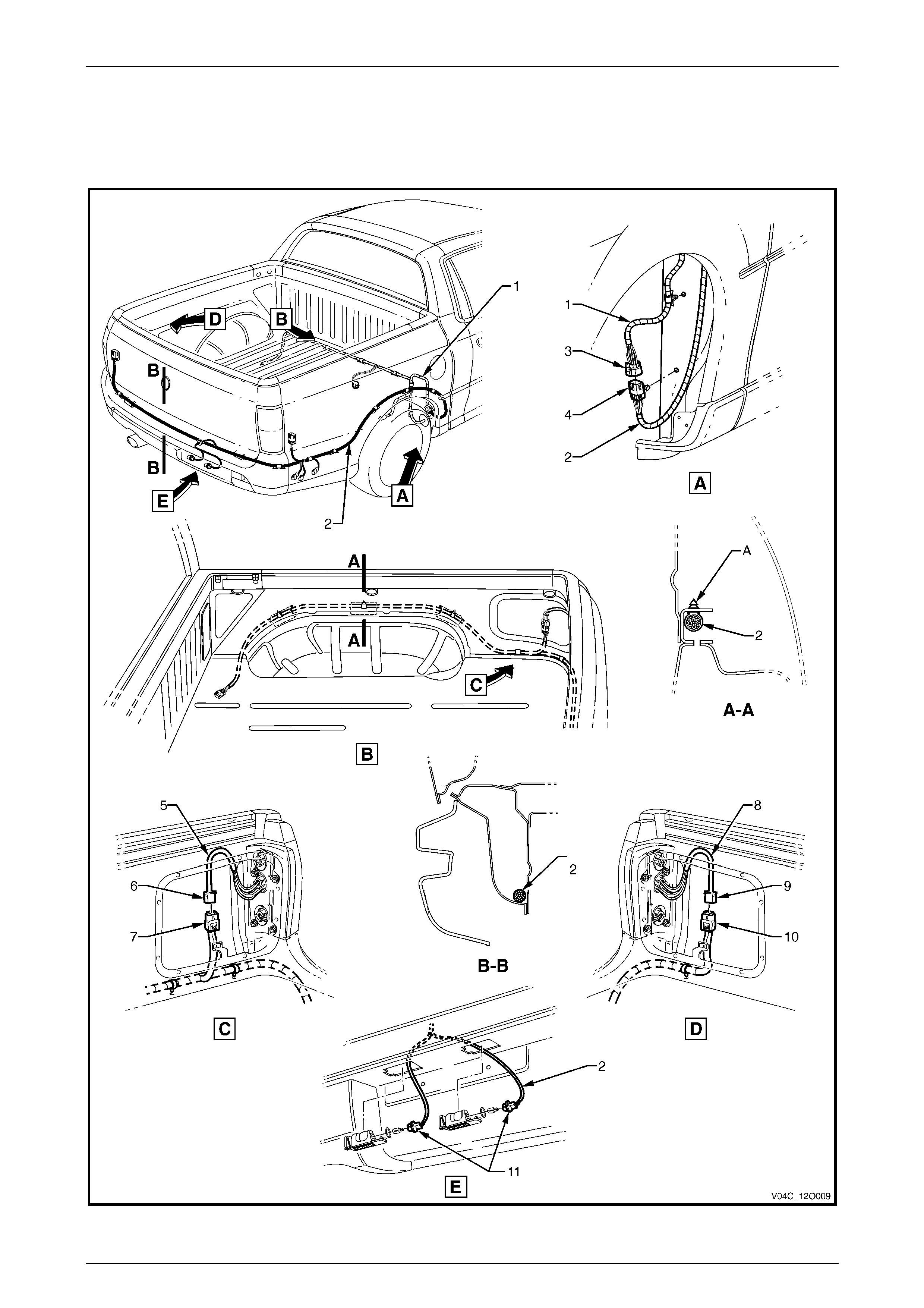
3.5 Rear Wiring Harnesses – 1
Regular Cab
Figure 12O – 22

Fuses, Rela ys and Wiring Harness es Page 12O–25
Page 12O–25
Legend
1 Body Wiring Harness
2 Rear Body Wiring Harness
3 Fuel Pump Assembly Connector (M8)
A Body wiring harness cli pped to underside of s ubfram e
assembly as shown (1 place).
B Rear body wiring harness c lipped to subframe assembly as
shown (12 places).
C Body wiring harness clipped to subframe assembly as
shown (9 places).
For views C, E & F, refer to 3.6 Rear Wiring Harnesses – 2.
For views H & J, refer to 3.7 Rear Wiring Harnesse s – 3.
Fuses, Rela ys and Wiring Harness es Page 12O–26
Page 12O–26
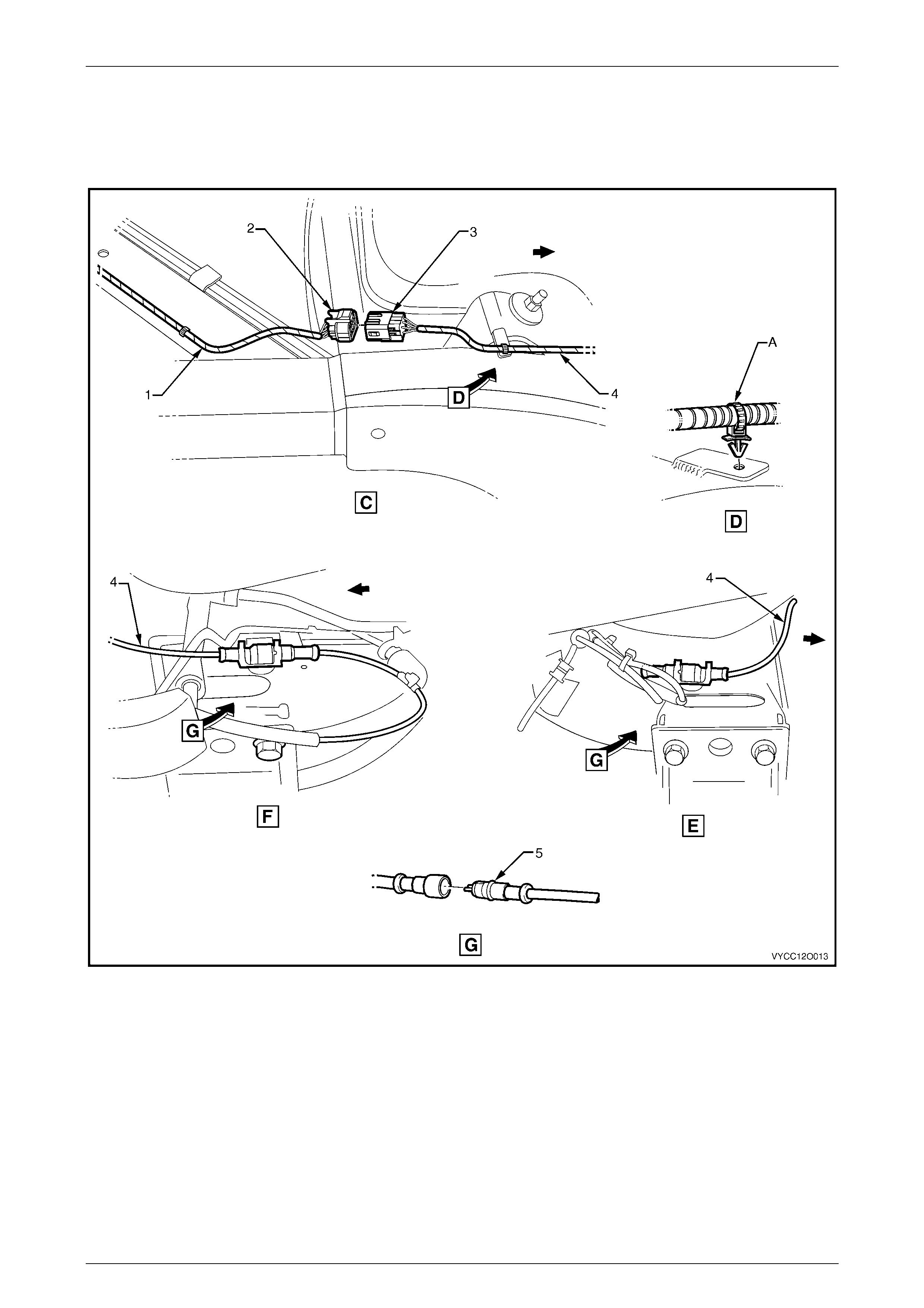
3.6 Rear Wiring Harnesses – 2
Regular Cab
Figure 12O – 23
Legend
1 Rear Body Wiring Harness
2 Rear Body Wiring Harness to Body Wiring Harness
Connector (X403)
3 Body Wiring Harness to Rear Body Wiring Harness
Connector (X403)
4 Body Wiring Harness
5 Rear Wheel Speed Sensor Connector (B76)
A Body wiring harness clipped to subframe assembly as
shown (1 place).
For location of views C, E & F, refer t o
3.5 Rear Wiring Harnesses – 1.
Fuses, Rela ys and Wiring Harness es Page 12O–27
Page 12O–27
3.7 Rear Wiring Harnesses – 3
Regular Cab
Figure 12O – 24

Fuses, Rela ys and Wiring Harness es Page 12O–28
Page 12O–28
Legend
1 Licence Plate Lam p Harness
2 Licence Plate Lam p Harness to Rear Body Wiring Harness
Connector (X909)
3 Rear Body Wiring Harness to Licence Plat e Lamp Harness
Connector (X909)
4 Rear Body Wiring Harness to Trailer Wiring Harness
Connector (X908)
5 Rear Body Wiring Harness to Right-hand Tai l Lamp Harness
Connector (X903)
6 Right-hand Tail Lamp Harness to Rear Body Wiring Harness
Connector (X903)
7 Right-hand Tail Lamp Harness
8 Left-hand Tail Lamp Harness
9 Left-hand Tail Lamp Harness t o Rear Body Wiri ng Harness
Connector (X904)
10 Rear Body Wiring Harness to Left-hand Tail Lam p Harness
Connector (X904)
11 Rear Body Wiring Harness
12 Trailer Wiring Harness to Rear Body Wiring Harness
Connector (X38A)
13 Trailer Wiring Harness
14 Trailer Wiring Harness to Right-hand Tai l Lamp Harness
Connector (X38B)
15 Trailer Wiring Harness to Rear Body Wiring Harness
Connector (X908)
16 Trailer Wiring Connector (X109)
For location of views H & J, refer to
3.5 Rear Wiring Harnesses – 1.
Fuses, Rela ys and Wiring Harness es Page 12O–29
Page 12O–29
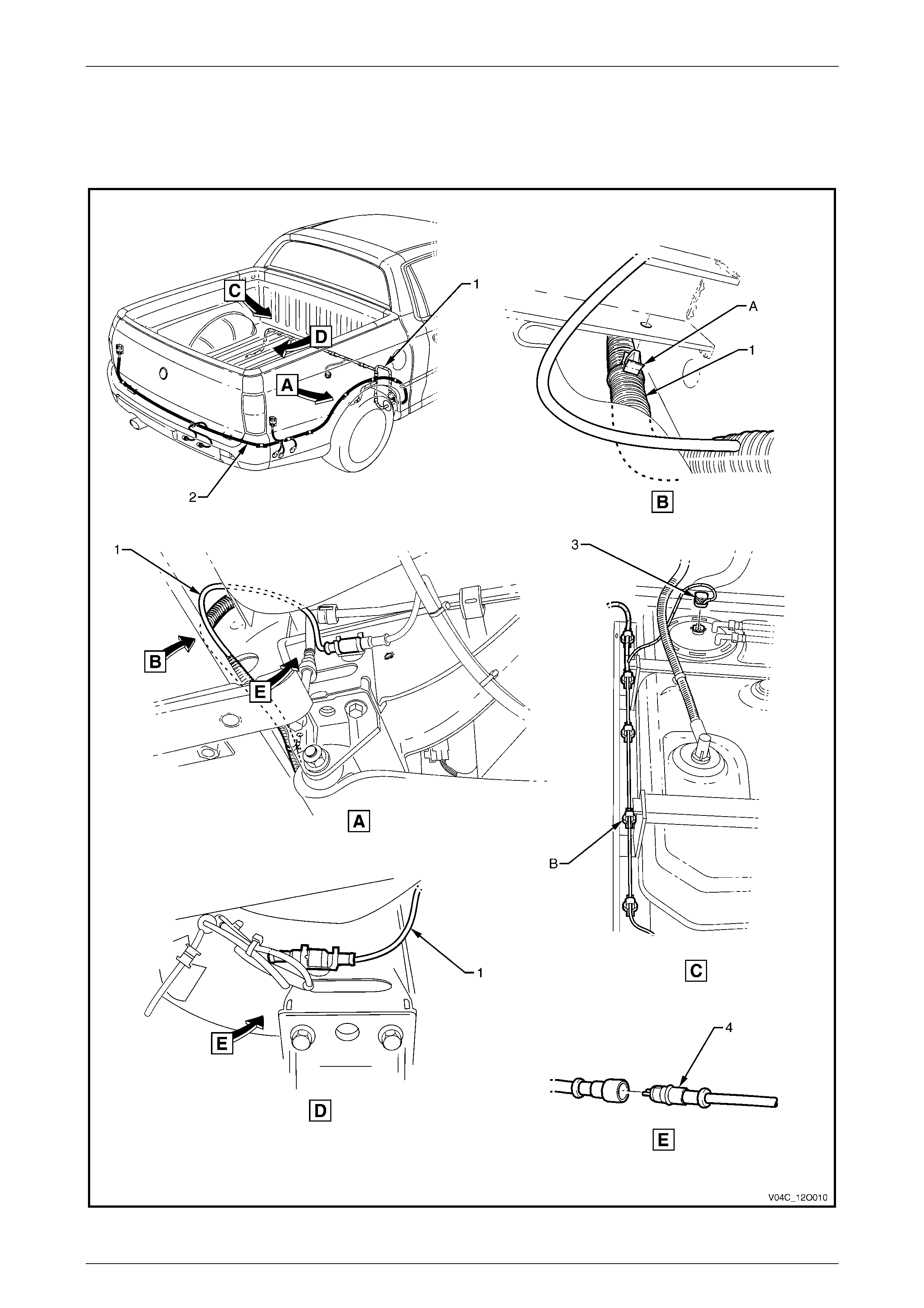
3.8 Rear Wiring Harnesses – 4
Crew Cab
Figure 12O – 25

Fuses, Rela ys and Wiring Harness es Page 12O–30
Page 12O–30
Legend
1 Body Wiring Harness
2 Rear Body Wiring Harness
3 Fuel Pump Assembly Connector (M8)
4 Rear Wheel Speed Sensor Connector (B76)
A Body wiring harness cli pped to underside of s ubfram e
assembly as shown.
B Body wiring harness clipped to subframe assembly as
shown.
Fuses, Rela ys and Wiring Harness es Page 12O–31
Page 12O–31
3.9 Rear Wiring Harnesses – 5
Crew Cab
Figure 12O – 26

Fuses, Rela ys and Wiring Harness es Page 12O–32
Page 12O–32
Legend
1 Body Wiring Harness
2 Rear Body Wiring Harness
3 Body Wiring Harness to Rear Body Wiring Harness
Connector (X403)
4 Rear Body Wiring Harness to Body Wiring Harness
Connector (X403)
5 Right-hand Tail Lamp Harness
6 Right-hand Tail Lamp Harness to Rear Body Wiring Harness
Connector (X903)
7 Rear Body Wiring Harness to Right-hand Tai l Lamp Harness
Connector (X903)
8 Left-hand Tail Lamp Harness
9 Left-hand Tail Lamp Harness t o Rear Body Wiri ng Harness
Connector (X904)
10 Rear Body Wiring Harness to Left-hand Tail Lam p Harness
Connector (X904)
11 Rear License Plate Lam p Connectors (E44)
A Rear body wiring harness clipped as shown (3 places ).
Fuses, Rela ys and Wiring Harness es Page 12O–33
Page 12O–33
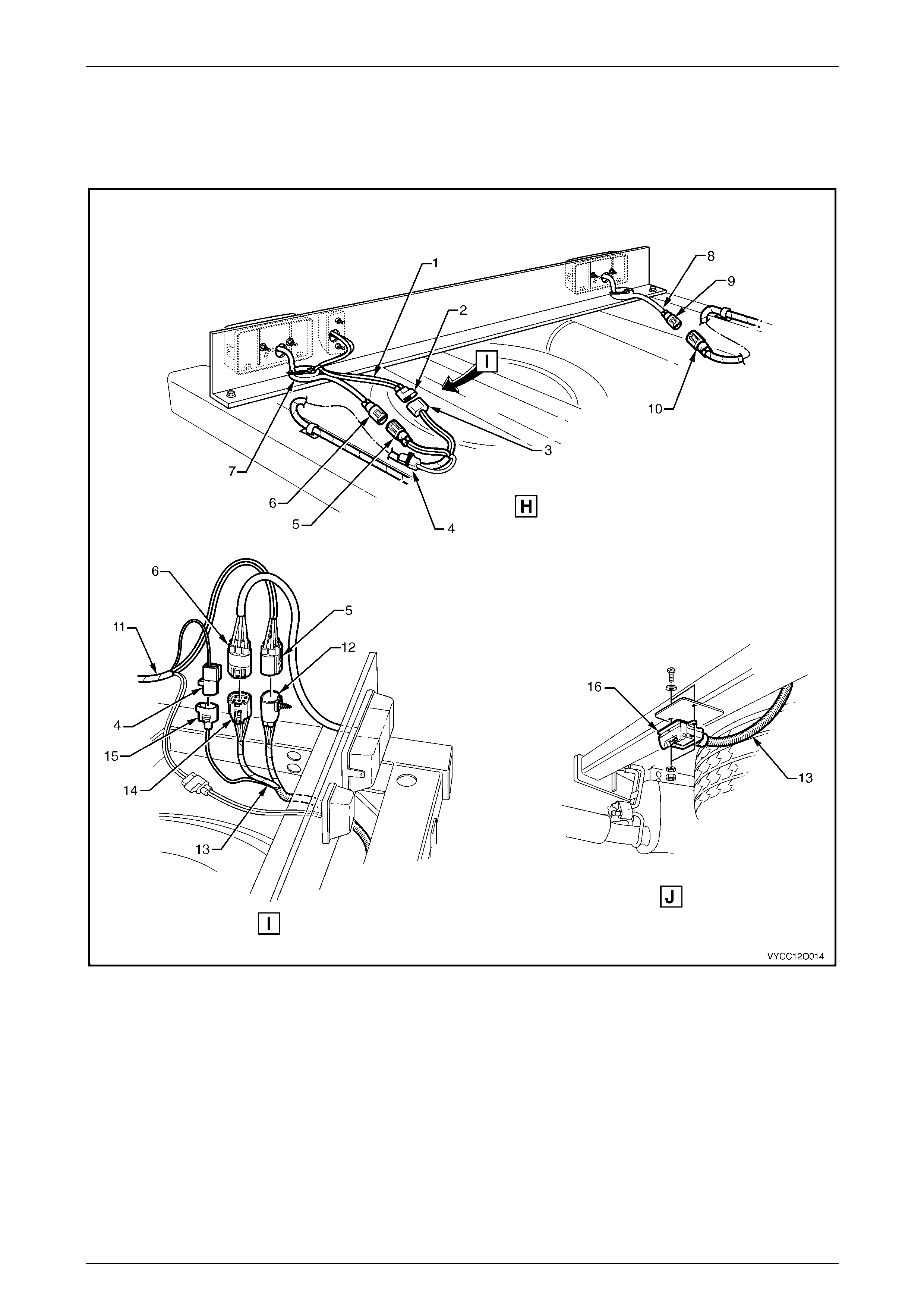
3.10 Rear Wiring Harnesses – 6
Crew Cab
Figure 12O – 27
Legend
1 Trailer Lamp Harness to Ri ght-hand Tail Lamp Harness
Connector (X38 – A)
2 Trailer Lamp Harness
3 Trailer Lamp Harness to Rear Body Wiring Harness
Connector (X38 – B)
4 Trailer Lamp Harness to Rear Body Wiring Harness
Connector (X908)
5 Rear Body Wiring Harness to Trailer Lamp Harness
Connector (X908)
6 Rear Body Wiring Harness
7 Trailer Lamp Harness Connect or (X109)