
HVAC Climate Control (Manual A/C) – Description and Operation Page 2A–1
Page 2A–1
Section 2A
HVAC Climate Control (Manual A/C)
Description and Operation
ATTENTION
Before performing any Service Operation or other procedure described in this Section, refer to Section 00
Warnings, Cautions and Notes for correct workshop practices with regard to safety and/or property damage.
1 General Information ...............................................................................................................................2
1.1 General Description............................................................................................................................................... 2
1.2 Vehicle Builds from Tag No. L171506 Onwards.................................................................................................. 3
1.3 Vehicle Builds Prior to Tag No. L171506 ............................................................................................................. 4
2 Cabin Ventilation – Crew Cab ...............................................................................................................5
Techline

HVAC Climate Control (Manual A/C) – Description and Operation Page 2A–2
Page 2A–2
1 General Information
The information contained within this Section relates specificall y to MY 2004 VY Regular Cab and Crew Cab vehicles.
However, most of the service information concerning MY 2004 VY Regular Cab vehicles is the same as that previously
published for MY 2003 VY Regular Cab vehicles. Accordingly, referenc es to MY 2003 VY Regular Cab vehicle
information are provided where appropriate.
For all other information regarding the descr iption and operation of the heating a nd ventilation system, refer to
Section 2A HVAC Climate Control (Manual A/C) – Description and Operation in the MY 2003 VY and V2 Series Service
Information.
1.1 General Description
The optional HVAC Climate Control (Manual A/C) system as fitted to MY 2004 VY Regul ar Cab a nd Crew Cab vehicles
is carried over from the previously released MY 2003 VY Series vehicles. Single-zone HVAC Occupant Climate Control
(Auto A/C) is also an available option.
The following engine cooling fan design and specifications apply:
• All V6 MY 2004 VY Regular Cab and Crew Cab vehicles use a high power cooli ng fan system which is identical to
that fitted to left-hand drive VY Series vehicles and MY 2 00 3 VY Regular Cab vehicles.
• All GEN III V8 MY 2004 VY Regular Cab and Crew Cab vehicles are fitted with a 430 W cooling fan system which
is identical to that fitted to MY 2003 VY Regular Cab vehicle s.
For more comprehensive information relating to the engine cooli ng fan system on
MY 2004 VY Regular Cab and Crew Cab vehicles fitted with GEN III V8 engines, refer to
Section 2A HVAC Climate Control (Manual A/C) – Description and Operation and
Section 6B3 Engine Co oling – GEN III V8 Engine, both in the MY 2003 VY Regular Cab Service Information.
The body ventilation flow and outlet insta llation locations are different in MY 2004 VY Crew Cab vehicles. Cabin
ventilation related inform ation for MY 2004 VY Crew Cab vehicles is detailed in this Section.
For detail of cabin ventilation relate d information for MY 2004 VY Regular Cab vehicles, refer to
Section 2A HVAC Climate Control (Manual A/C) – Description and Operation in the MY 2003 VY Regular Cab Service
Information.

HVAC Climate Control (Manual A/C) – Description and Operation Page 2A–3
Page 2A–3
1.2 Vehicle Builds from Tag No. L171506
Onwards
From Tag No. L171506 a revised HVAC unit has been fitted. For information specific to the revised unit, refer to
Section 2A HVAC Climate Control (Manual A/C) – Description and Operation in the MY 2004 VY and V2 Series Service
Information.
For all other information regarding the descr iption and operation of the heating a nd ventilation system, refer to
Section 2A HVAC Climate Control (Manual A/C) – Description and Operation in the MY 2003 VY and V2 Series Service
Information.

HVAC Climate Control (Manual A/C) – Description and Operation Page 2A–4
Page 2A–4
1.3 Vehicle Builds Prior to Tag No. L171506
For all information regarding the description and operation of the heating and ventilation system fitted to vehicles built
prior to Tag No. L171506, refer to Section 2A HVAC Climate Control (Manual A/C) – Description and Operation in the
MY 2003 VY and V2 Series Service Information.
HVAC Climate Control (Manual A/C) – Description and Operation Page 2A–5
Page 2A–5
2 Cabin Ventilation – Crew Cab
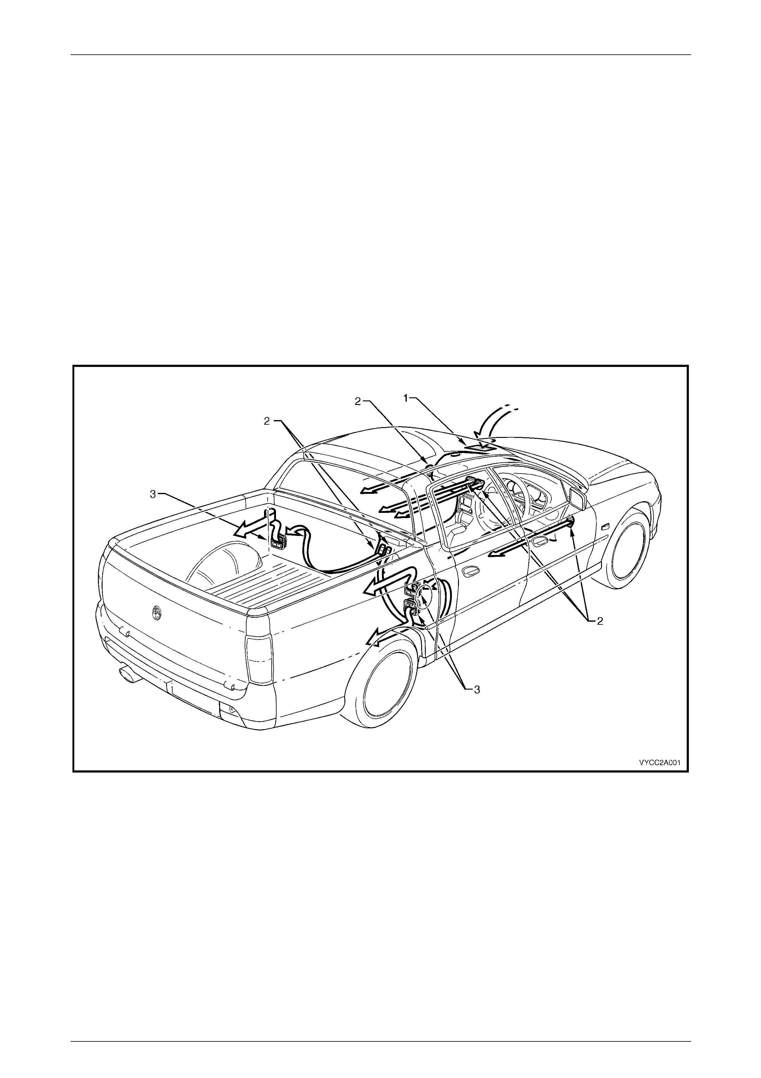
Air enters the heating, ventilation and air conditioning system (HVAC) from under the plenum chamber cover. The air
then passes through the blower motor / fan, evaporator and heater assemblies, to be cooled or heated as required. Air
leaves the HVAC unit and enters the vehicle interior through the centre, side, floor or demist outlets. The cabin ventilation
outlets through which the air is emitted depend on th e mode selected via the mode control.
When the cabin is sealed, i.e. all movable windows are fully up, air exits the cabin via the underside of the rear seat
cushion. Three body ventilation outlets are installed in the re ar inner panel. Two outlets are located on th e right-hand
side of the cabin and one is lo cated on the left-hand side of the cabin. After passing through the body ventilati on outlets,
the air enters the cavity between the inner rear body panel and the rear outer trim pane l. It leaves the vehicle via a small
air gap located around the entire lower and side perimeters of the rear outer trim panel. Refer to Figure 2A – 1.
The installation, function, performance and specifications of all other HVAC related components (excluding the operation
of the 430 W engine cooling fan system on GEN III V8 models) are identical to those applica ble to MY 2003 VY sedan,
wagon and utility vehicles.
Figure 2A – 1 shows the HVAC system cabin airflow as applicable to crew cab vehicles. For cabin ventilation information
relating to regular cab vehicles, refer to Section 2A, 2.1 Cabin Ventilation in the MY 2003 VY Regular Cab Service
Information.
Figure 2A – 1
Legend
1 HVAC Plenum Inlet 3 HVAC Body Air Outlet
2 HVAC Cabin Air Outlet