
HVAC Occupant Climate Control (Auto A/C) – Diagnostics Page 2F–1
Page 2F-1
Section 2F
HVAC Occupant Climate Control (Auto A/C)
– Diagnostics
ATTENTION
Before performing any Service Operation or other procedure described in this Section, refer to Section 00
Warnings, Cautions and Notes for correct workshop practices with regard to safety and/or property damage.
1 General Information ...............................................................................................................................2
2 Diagnostics.............................................................................................................................................3
3 Wiring Diagrams.....................................................................................................................................4
Connectors A13 – L7 ............................................................................................................................................. 5
Connectors M3 – X119........................................................................................................................................... 6
Connectors X126 – Y37 ......................................................................................................................................... 7
Wiring Diagram ...................................................................................................................................................... 8
Techline

HVAC Occupant Climate Control (Auto A/C) – Diagnostics Page 2F–2
Page 2F-2
1 General Information
The diagnostic information of the HVAC Occupant Climate Control (Auto A/C) system as fitted to
MY 2004 Crew Cab vehicles carries over from the information provided in
Section 2F HVAC Occupant Climate Control (Auto A/C) – Diag nostics in the MY 2003 VY and V2 Series Service
Information, noting the following:
• The TECH 2 model selection procedure is as detailed in this Section.
• HVAC Occupant Climate Control (Auto A/C) systems are not availa ble on V6 MY 2004 VY Crew Cab vehicles.
• GEN III V8 MY 2004 VY Crew Cab vehicles are fitted with a 430 W cooling fan s ystem which is id entical to that
fitted to MY 2003 VY Regular Cab vehicles. The wiring diagram information in this Section reflects this.
• Information which is particular to LHD vehicles is not applicable.
• From Tag No. L174938 a revised HVAC unit has been fitted. The information in this Secti on includes information
relevant to the revised HVAC unit.
For additional diagnosis information on MY 2004 Crew Cab vehicles, which is not contained within this Section, refer to
the following Sections as required:
• Section 2C HVAC Climate Control (Man ual A/C) – Service and Diagnosis in the MY 2003 VY and V2 Series
Service Information, for HVAC components and service procedures common to both Manual A/C and Auto A/C
systems.
• Section 2F HVAC Occupant Climate Control (Auto A/C) – Diag nostics in the MY 2003 VY and V2 Series Service
Information, for diagnostic information applicable only to the Auto A/C system.
HVAC Occupant Climate Control (Auto A/C) – Diagnostics Page 2F–3
Page 2F-3
2 Diagnostics
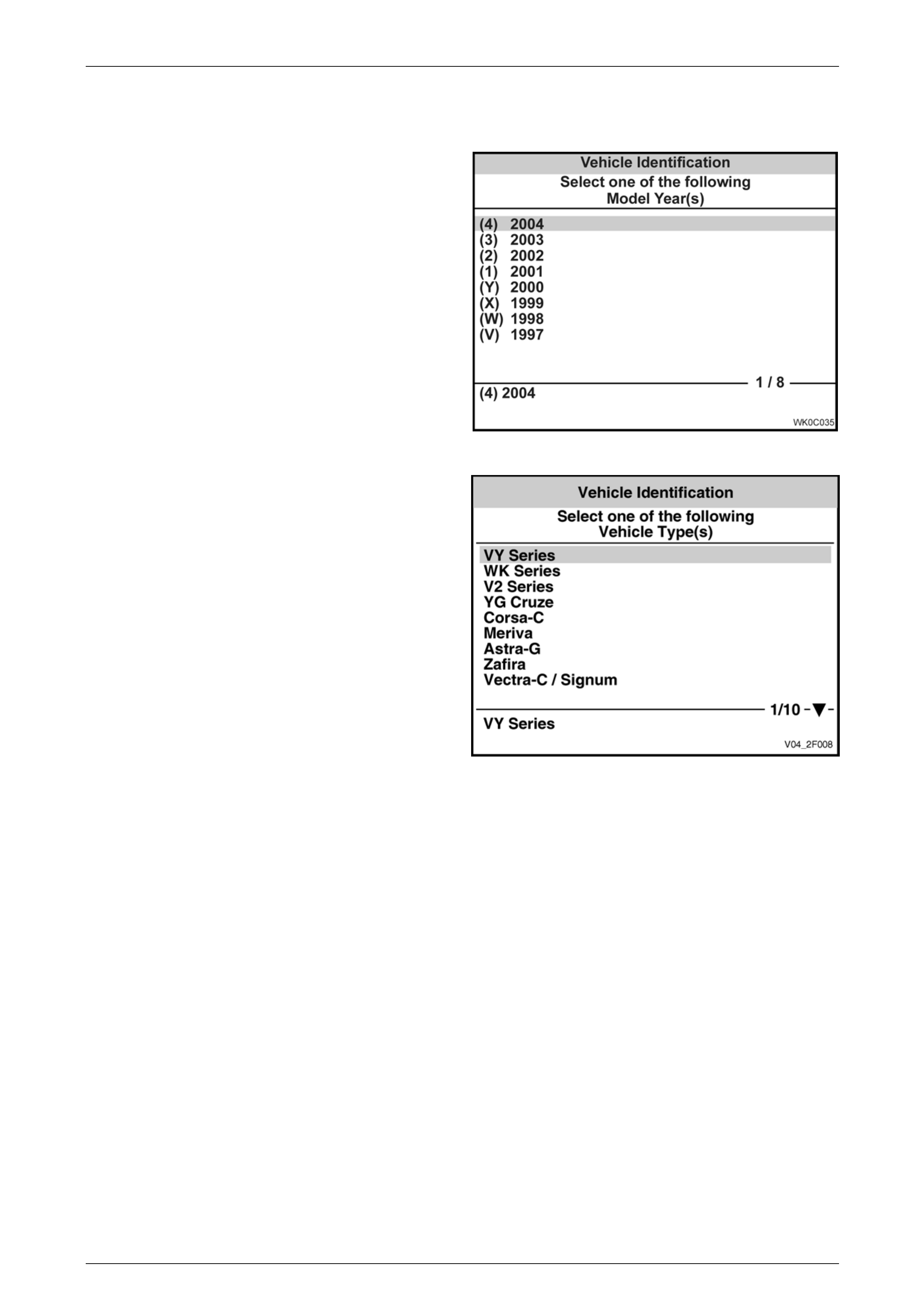
The diagnostic information access procedures are a
carry over from the MY 2003 VY Series except that the
Model Year selection on TECH 2 is now (4) 2004.
Figure 2F – 1
The Vehicle Type selection is VY Series.
Figure 2F – 2

HVAC Occupant Climate Control (Auto A/C) – Diagnostics Page 2F–4
Page 2F-4
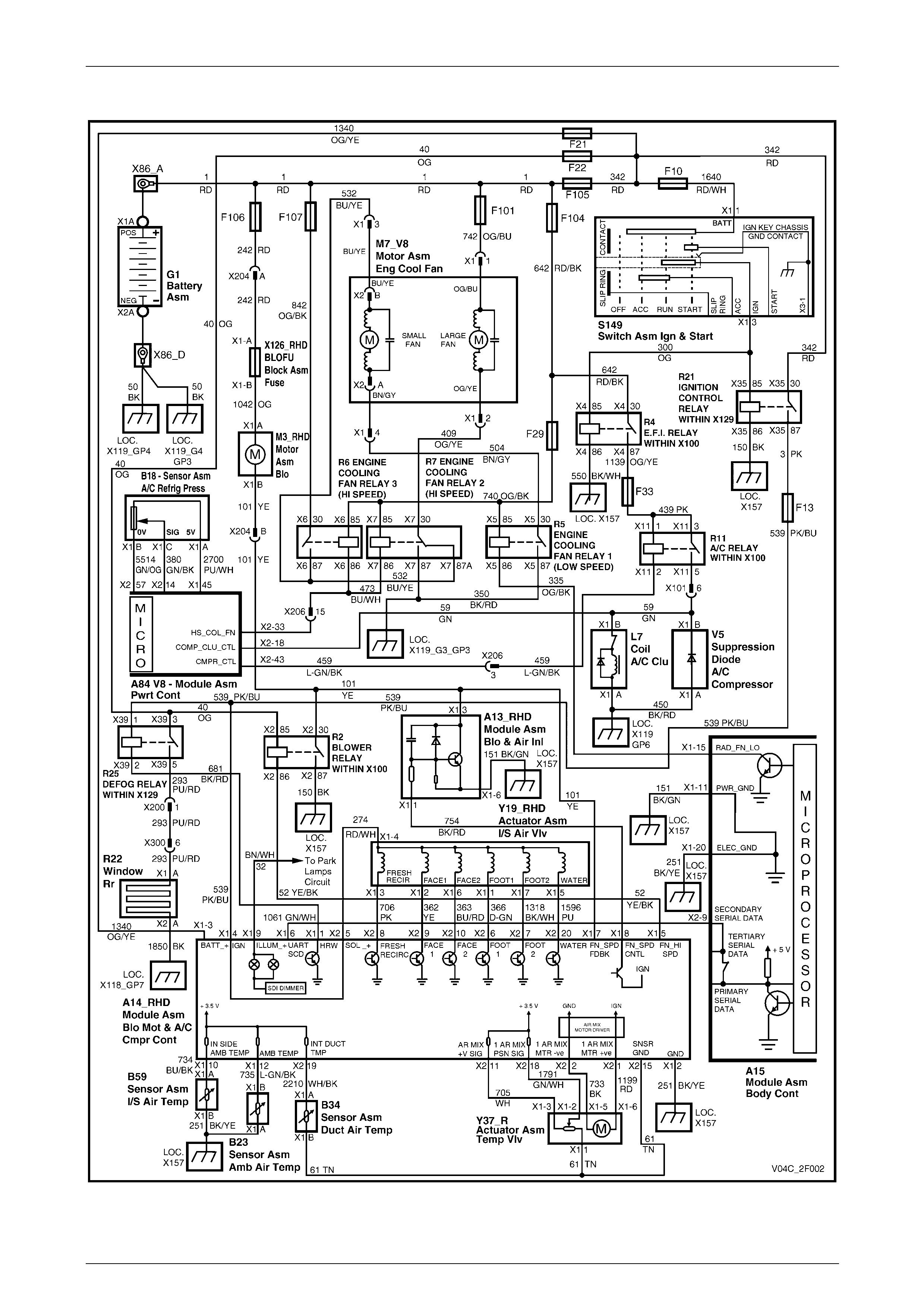
3 Wiring Diagrams
The following figures provide electrical connector diagrams and a wiring di agram applicable to
HVAC Occupant Climate Control (Auto A/C) systems as fitted to MY 2004 Crew Cab vehicles. When diagnosing circuit
faults, these diagrams should be used i n con junction with the diagnostic chart circuit diagrams provided in
Section 2F HVAC Occupant Climate Control (Auto A/C) – Diag nostics in the MY 2003 VY and V2 Series Service
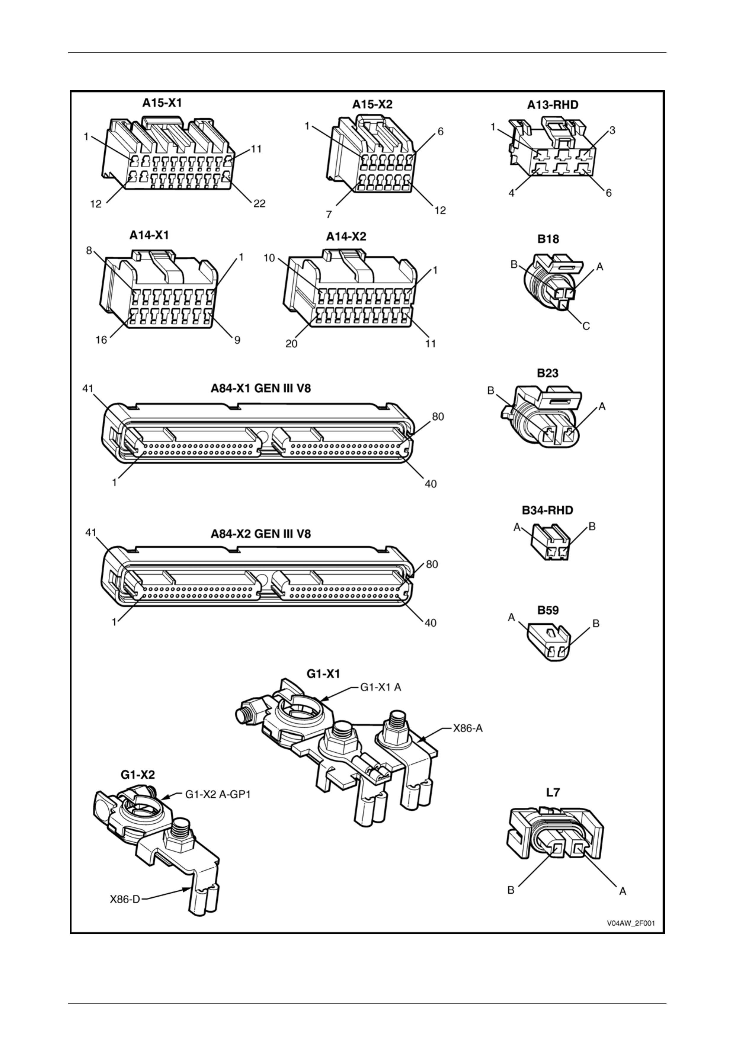
Information. The content of these figures is as follows:
• Electrical connectors (A13 – L7) – refer to Figure 2F – 3
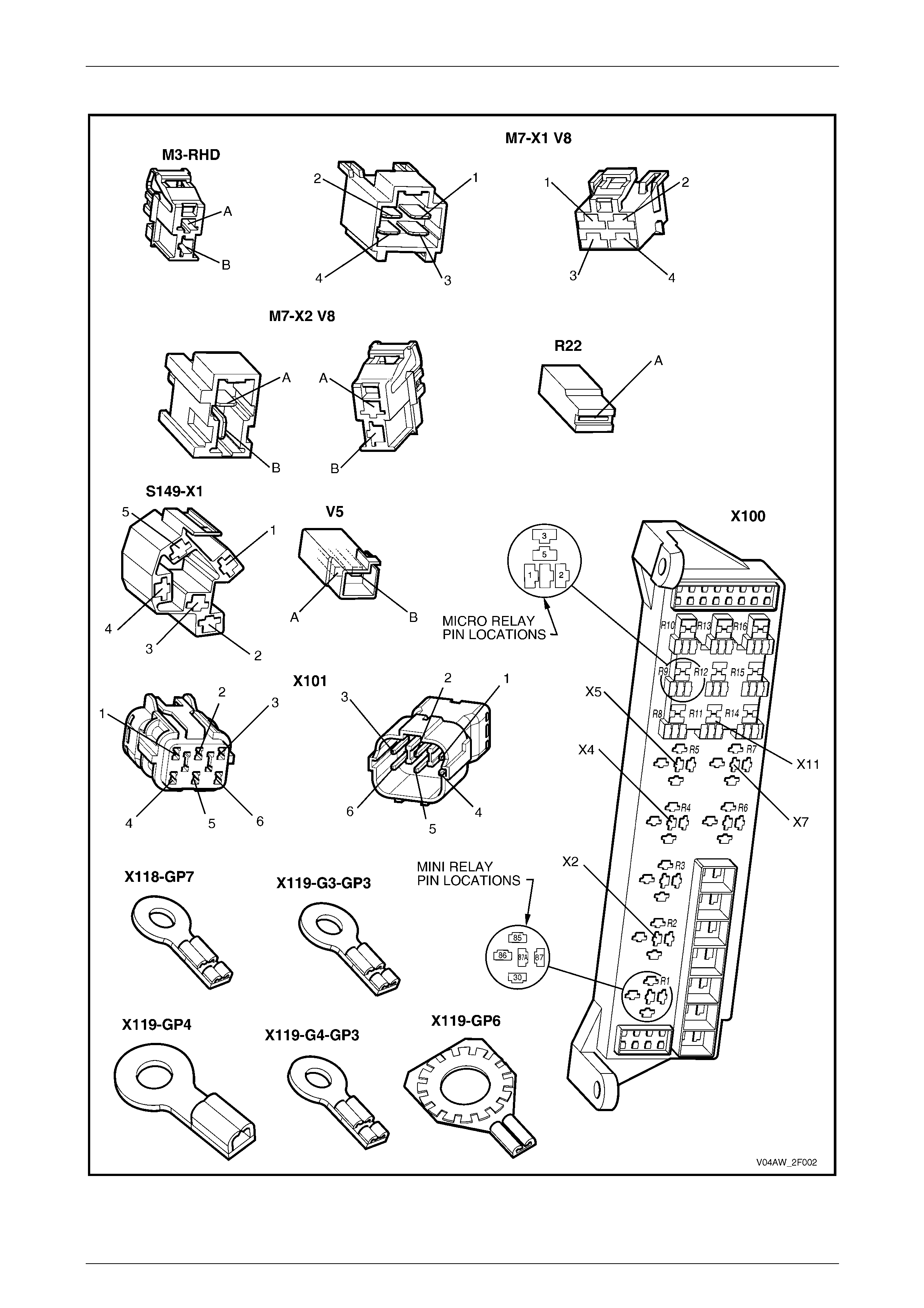
• Electrical connectors continued (M3 – X119) – refer to Figure 2F – 4
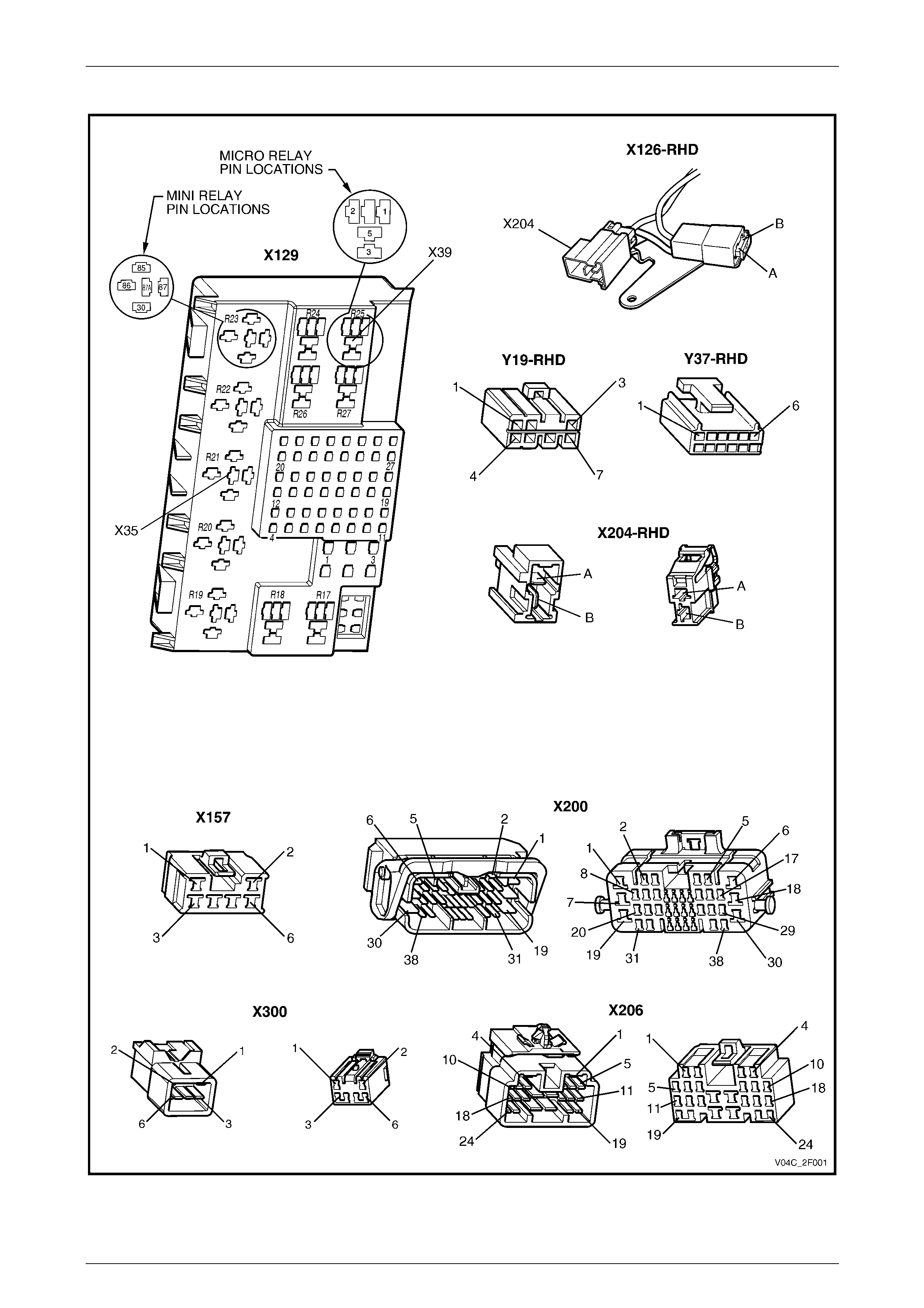
• Electrical connectors continued (X126 – Y37) – refer to Figure 2F – 5
• Wiring diagram – refer to Figure 2F – 6
NOTE
Prior to Tag No. L174938, the blower motor was
fitted with a built-in circuit breaker for motor
protection. The revised HVAC unit fitted from
Tag No. L174938 onwards uses an external
blade type fuse in lieu of the built-in circuit
breaker. For blower wiring information only, for
the built-in circuit breaker type motor, refer to
Section 2C, 9 Wiring Diagrams in the MY 2003
VY and V2 Series Service Information (RHD
vehicle information on ly).
In the following wiring diagram (Figure 2F – 6) all components are described and displayed in accordance with the
Integrated Vehicle Electrical Desig n (IVED) standard as applied to MY 2004 Crew Cab vehicles. To assist in wiring
diagram interpretation, refer to the following table:
IVED Description IVED Component Identification Common Description
Module Asm Blo & Air Inl A13_RHD Blower Motor Resistor
Module Asm Blo & A/C Cmpr A14_RHD OCC Control Module for RHD models
Module Asm Body Cont A15 Body Control Module
Module Asm Pwrt Cont A84_V8 GEN III V8 Powertrain Control Module
Sensor Asm A/C Refrig Press B18 A/C Pressure Transducer
Sensor Asm Amb Air Temp B23 Ambient Air Temperature Sensor
Sensor Asm Duct Air Temp B34_RHD Evaporative Temperature Sensor
Sensor Asm I/S Air Temp B59 In-car Temperature Sensor
Coil A/C Clu L7 Compressor Clutch
Motor Asm Blo M3_RHD Blower Motor
Motor Asm Eng Cool Fan M7_V8 GEN III V8 Cooling Fan System
Window Rr R22 Heated Rear Window
Switch Asm Ign & Start S149 Ignition Switch
Actuator Asm I/S Air Vlv Y19_RHD Solenoid Pack
Actuator Asm Temp Vlv Y37_R Driver’s Air Mix Door Motor for RHD models
The following table lists the IVED standard wire colour abbreviations:
BK Black D-GN Dark green L-GN Light green RD Red
BU Blue GN Green OG Orange TN Tan
BN Brown GY Grey PK Pink WH White
D-BU Dark blue L-BU Light blue PU Purple YE Yellow
NOTE
For electrical connector locations and
additional wiring diagram information refer to
Section 12P Wiring Diagrams.
HVAC Occupant Climate Control (Auto A/C) – Diagnostics Page 2F–5
Page 2F-5
Connectors A13 – L7
Figure 2F – 3
HVAC Occupant Climate Control (Auto A/C) – Diagnostics Page 2F–6
Page 2F-6
Connectors M3 – X119
Figure 2F – 4
HVAC Occupant Climate Control (Auto A/C) – Diagnostics Page 2F–7
Page 2F-7
Connectors X126 – Y37
Figure 2F – 5
HVAC Occupant Climate Control (Auto A/C) – Diagnostics Page 2F–8
Page 2F-8
Wiring Diagram
Figure 2F – 6