
Front Suspension Page 3-1
Page 3–1
Section 3
Front Suspension
ATTENTION
Before performing any Service Operation or other procedure described in this Section, refer to Section 00
CAUTIONS AND NOTES for correct workshop practices with regard to safety and/or property damage.
1 General Information............................................................................................................................... 2
2 Specifications......................................................................................................................................... 3
2.1 Front Strut, Damper and Spring............................................................................................................................3
Front Strut and Damper.........................................................................................................................................3
Front Strut Identification – With Spring...............................................................................................................3
Front Spring............................................................................................................................................................4
Front Spring Identification...................................................................................................................................4
Front Stabiliser Bar................................................................................................................................................4
Front Stabiliser Bar Identification........................................................................................................................4
2.2 Suspension Height, Trim Height and Front Wheel Alignment............................................................................5
Suspension and Trim Height – Regular Cab........................................................................................................5
Suspension and Trim Height – Crew Cab ............................................................................................................7
Front Wheel Alignment..........................................................................................................................................8
Techline
Techline
Techline

Front Suspension Page 3-2
Page 3–2
1 General Information
The front suspension for MY 2004 VY Regular Cab and MY 2004 VY Crew Cab Models, carries over from previous MY
2004 VY & V2 Series Models and MY 2003 VY Regular Cab Service Information, noting the following:
• A unique re-tuned front strut and damper assemblies.
• A unique front anti-roll bar and mounting bushes.
• Suspension and trim height.
For information relating to front suspension for MY 2004 VY Regular Cab and MY 2004 VY Crew Cab Models not
covered in this Section, refer to Section 3 Front Suspension in the MY 2004 VY & V2 Series Service Information and to
Section 3 Front Suspension in the MY 2003 VY Regular Cab Service Inform ation.
Front Suspension Page 3-3
Page 3–3
2 Specifications
2.1 Front Strut, Damper and Spring
Front Strut and Damper
Type...................................................................................McPherson Wet – non-service able
Piston Diameter............................................................................................................. 30 mm
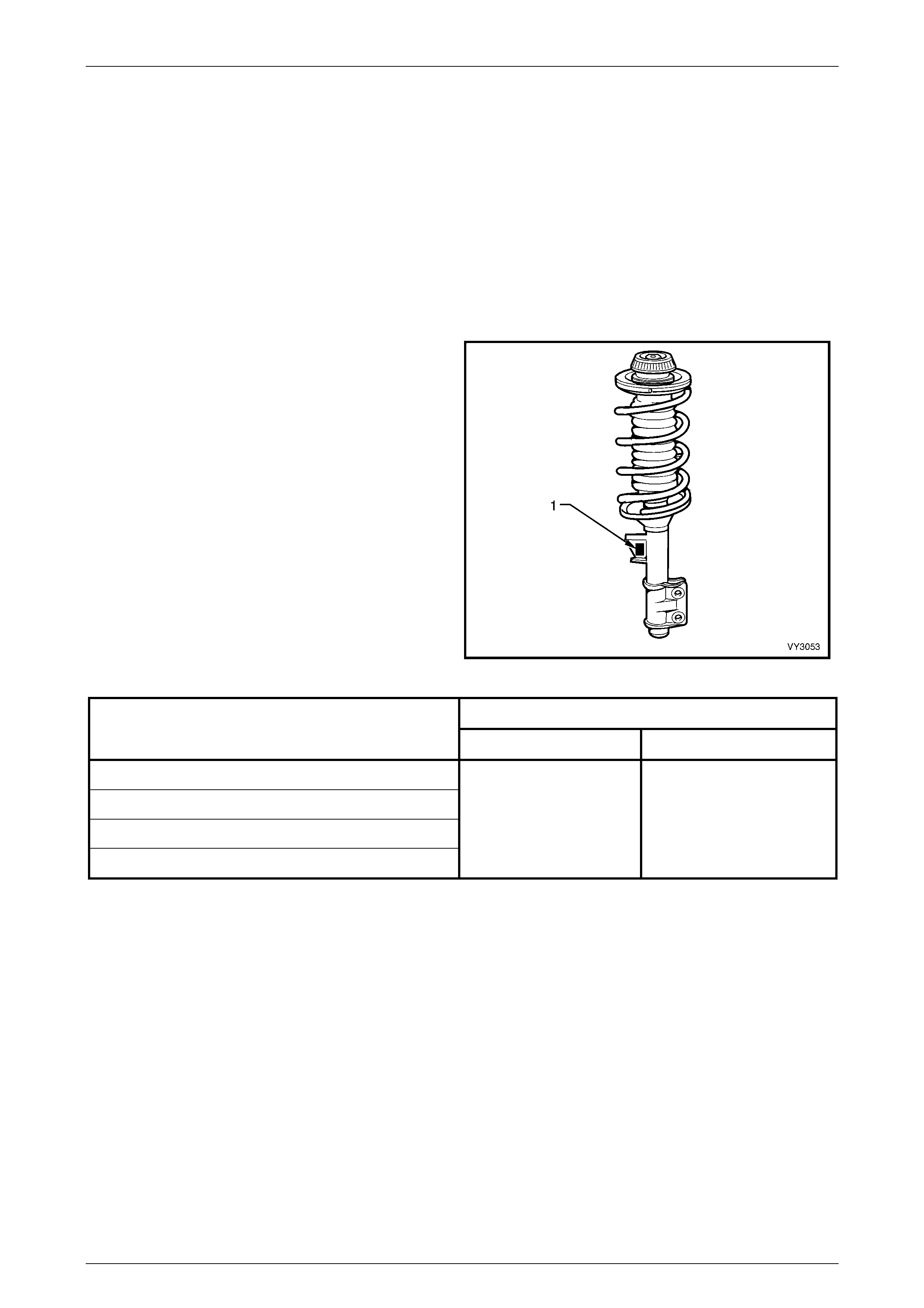
Front Strut Identification – With Spring
Identification of the front strut assemblies fitted to a
particular vehicle can be achieved by cross-referencing the
three-digit code provided on the production identification
tag (1) with the table below.
Figure 3-1
Identification Code
Application
Left Hand Right Hand
Regular Cab – V6
Regular Cab – V8
Crew Cab – V6
Crew Cab – V8
MJ MK
Front Suspension Page 3-4
Page 3–4
Front Spring
Type.....................................................................................................................Variable Coil
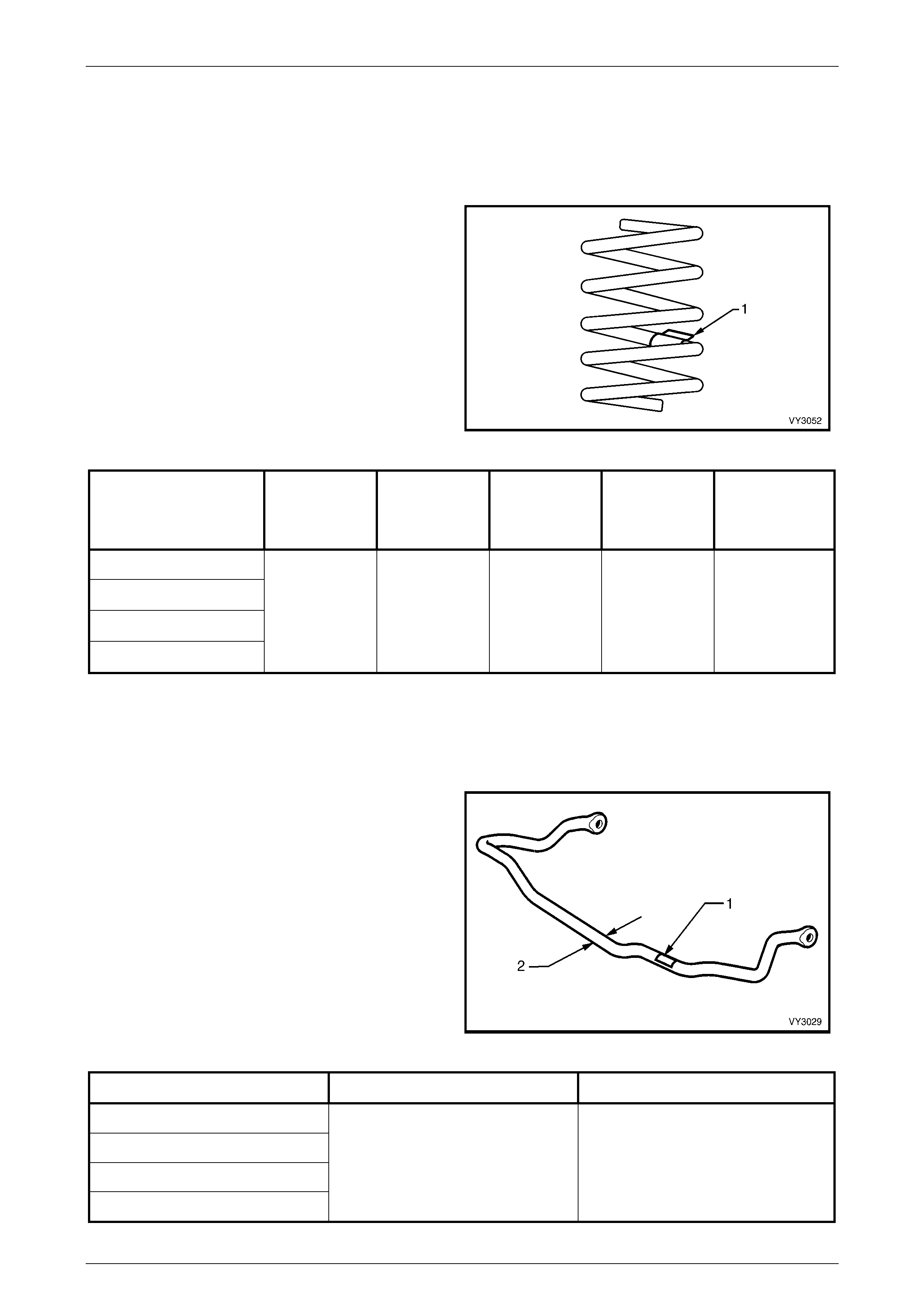
Front Spring Identification
Identification of the front spring fitted to a particular vehicle
can be achieved by cross-referencing the two digit code
provided on the production identification tag (1) with the
table below
Figure 3-2
Application Approximate
Number Coils Approximate
Free Length
(mm)
Inside
Diameter
(mm)
Prod. I.D.
Code
(Tag on
spring)
Spring Type &
Rate
Regular Cab – V6
Regular Cab – V8
Crew Cab – V6
Crew Cab – V8
5.74 367 136 ± 1.5 JN VARIABLE
27 - 35 N/mm
(3600 ± 110 N @
230 mm)
Front Stabiliser Bar
Type...........................................................................................................Torsional Steel Bar
Front Stabiliser Bar Identification
1 Stabiliser bar identification label.
2 Stabiliser bar.
Figure 3-3
Application Diameter Identification code
Regular Cab – V6
Regular Cab – V8
Crew Cab – V6
Crew Cab – V8
28.0 mm AA
Front Suspension Page 3-5
Page 3–5
2.2 Suspension Height, Trim Height and
Front Wheel Alignment
Suspension and Trim Height – Regular Cab
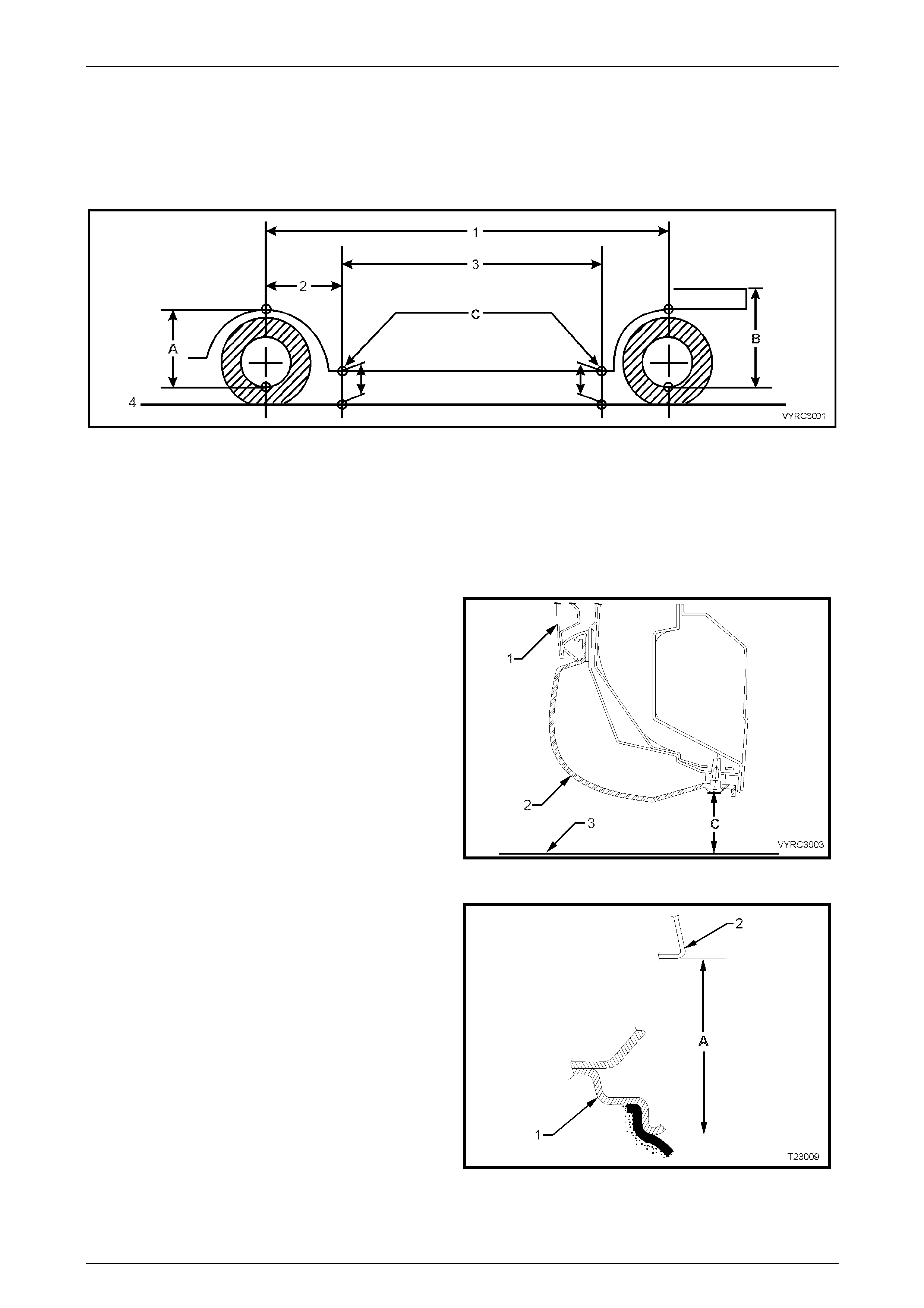
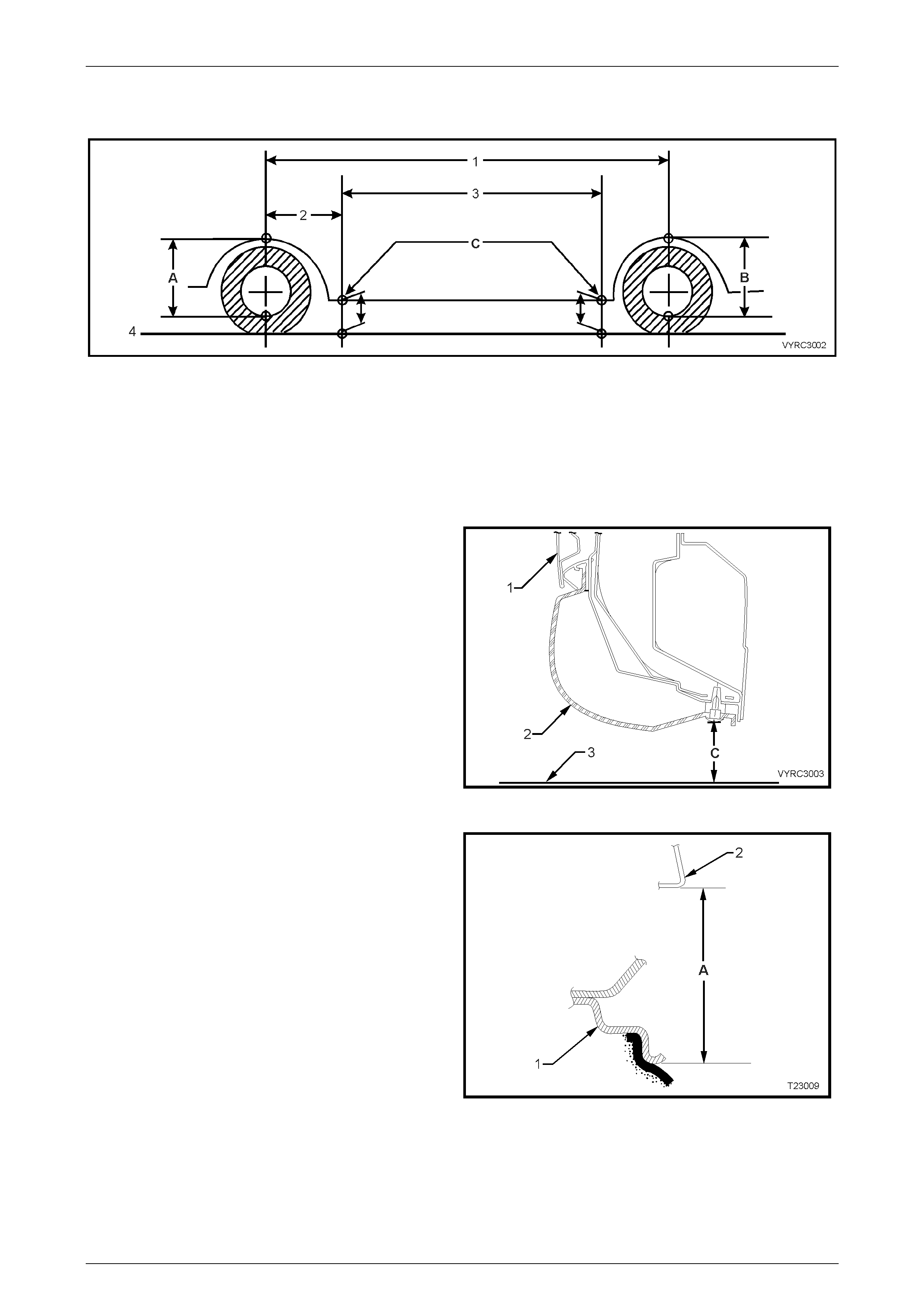
Figure 3-4
Legend
1 Wheelbase All Models – 3197 mm
2 Referenc e P oint : All Models – 584.5 mm
3 Trim Height S pacing All Models – 1500 mm
4 Ground Line
A Front Suspension Height Checki ng Locat i on
B Rear Suspension Height Check i ng Location
C Trim Height Checki ng Locations
Legend
1 Front Door Panel
2 Rocker Panel Moulding
3 Ground Line
C Trim Height:
Front Trim Height
– 212 mm (V6).
– 224 mm (V8)
Rear Trim Height
– 256 mm (V6).
– 268 mm (V8)
Figure 3-5
Legend
1 Front Wheel Rim
2 Front Wheel Arch Suspens i on Height Checking Locat i on
A Front Suspension Height
– 588 mm (V6).
– 600 mm (V8)
Figure 3-6
Front Suspension Page 3-6
Page 3–6
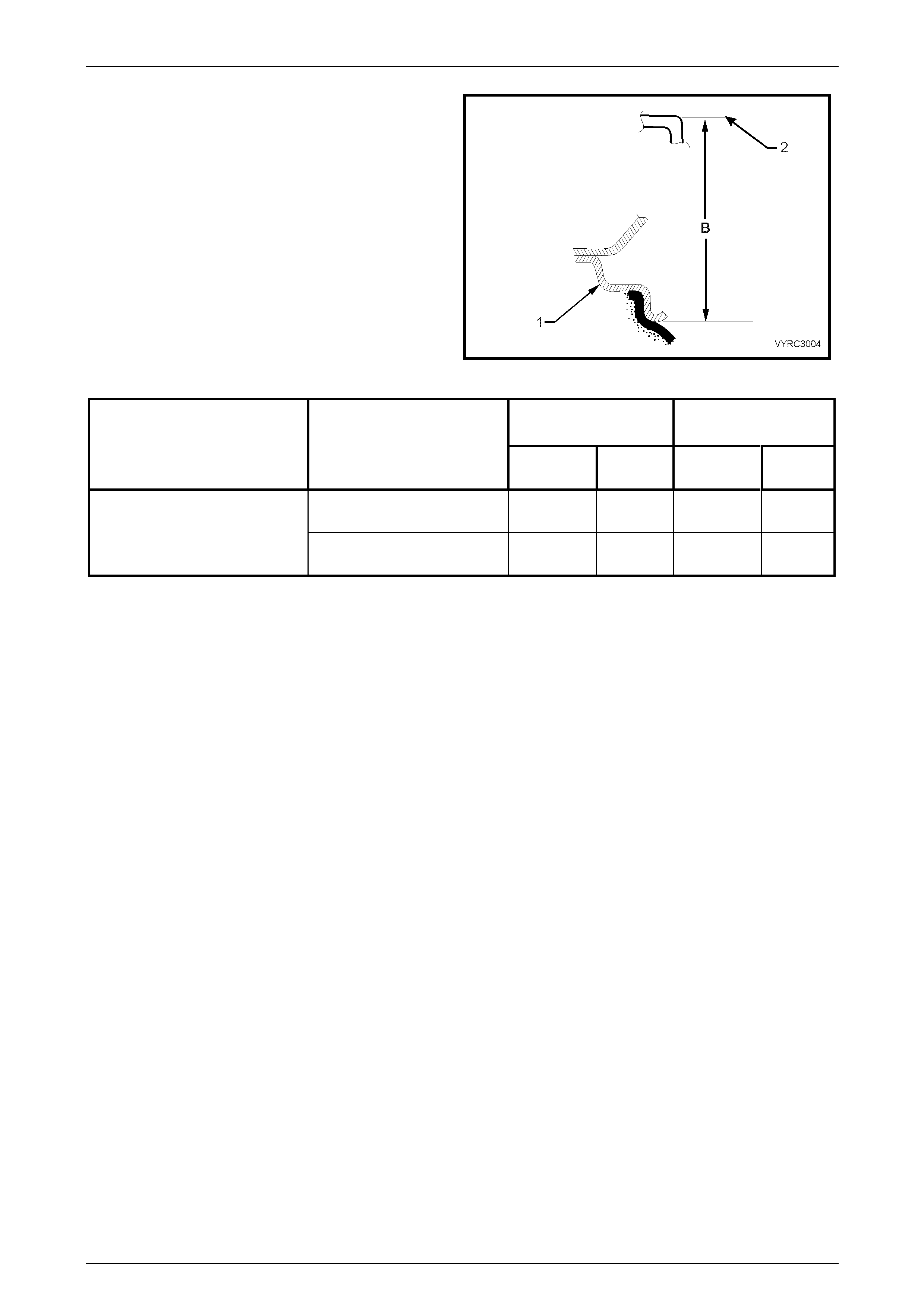
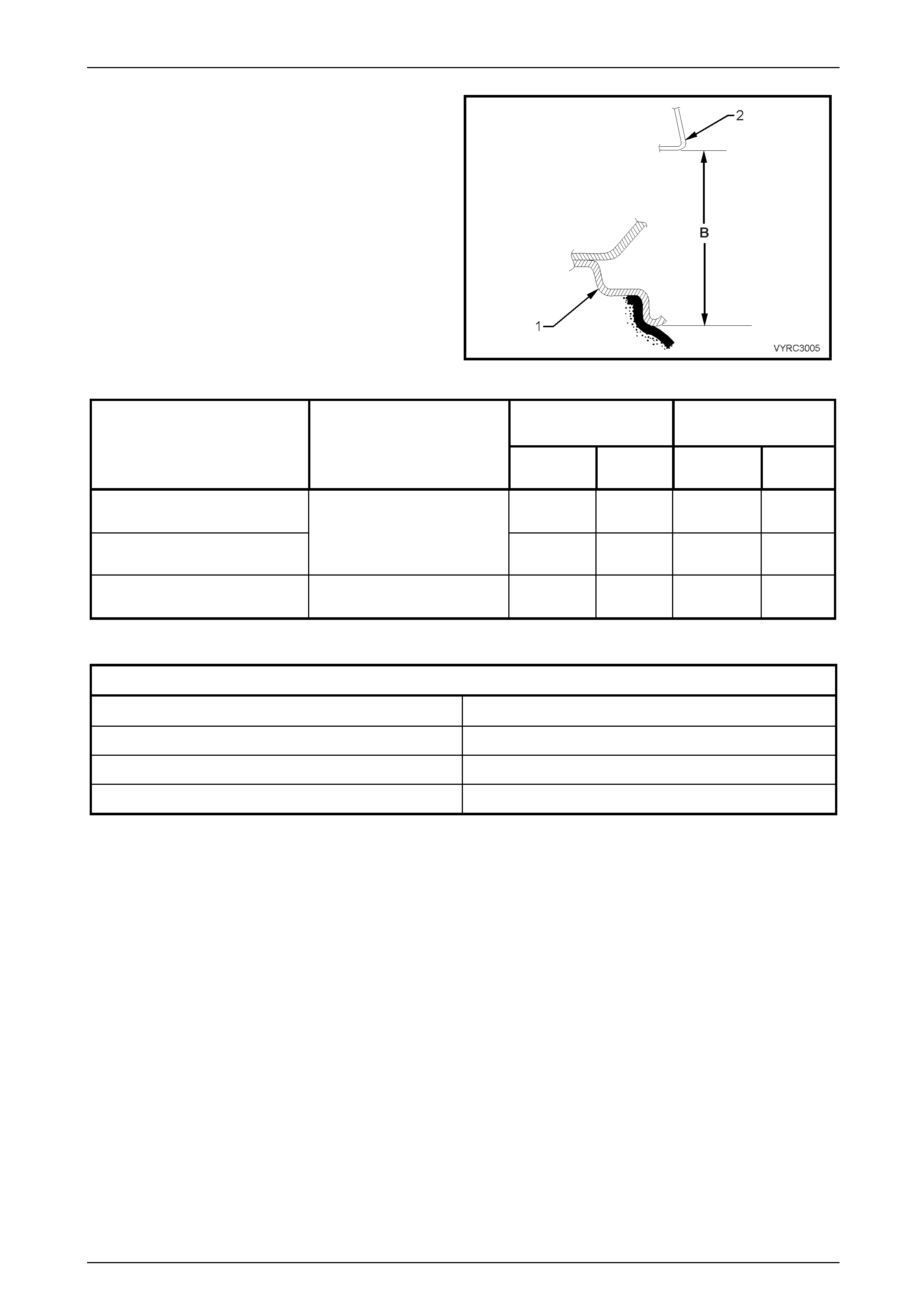
Legend
1 Rear Wheel Rim
2 Rear Chass is Sus pensi on Hei ght Check i ng locati on
B Rear Suspension Height
– 517 mm (V6).
– 529 mm (V8)
Figure 3-7
Suspension
Height (Mm) Trim
Height (Mm)
Vehicle
Description Engine
FRONT REAR FRONT REAR
V6 588 517 212 256
Regular Cab V8 600 529 224 268
Front Suspension Page 3-7
Page 3–7
Suspension and Trim Height – Crew Cab
Figure 3-8
Legend
1 Wheelbase All Models – 3197 mm
2 Referenc e P oint : All Models – 584.5 mm
3 Trim Height S pacing All Models – 1765 mm
4 Ground Line
A Front Suspension Height Checki ng Locat i on
B Rear Suspension Height Check i ng Location
C Trim Height Checki ng Locations
Legend
1 Front Door Panel
2 Rocker Panel Moulding
3 Ground Line
C Trim Height:
Front Trim Height
– 210 mm (Base V6)
– 216 mm (‘S’ V6)
– 210 mm (‘SS’ V8)
Rear Trim Height
– 240 mm (Base V6)
– 256 mm (‘S’ V6)
– 256 mm (‘SS’ V8)
Figure 3-9
Legend
1 Front Wheel Rim
2 Front Wheel Arch Suspens i on Height Checking Locat i on
A Front Suspension Height
– 592 mm (Base V6)
– 600 mm (‘S’ V6)
– 616 mm (‘SS’ V8)
Figure 3-10
FRONT SUSPENSION Page 3-9
04-June-2003 Page 3–9
Legend
1 Rear Wheel Rim
2 Rear Chassis Suspension Height Checking location
B Rear Suspension Height
– 670 mm (Base V6)
– 680 mm (‘S’ V6)
– 692 mm (‘SS’ V8)
Figure 3-11
Suspension
Height (Mm) Trim
Height (Mm)
Vehicle
Description Engine
FRONT REAR FRONT REAR
Crew Cab Base 592 670 210 240
Crew Cab ‘S’
V6 600 680 216 256
Crew Cab ‘SS’ V8 616 692 210 256
Front Wheel Alignment
Front Wheel Alignment At Kerb Weight With Fuel Tank Full
Camber 0° ± 30´
Caster 7° 45´ ± 1° 15´
Toe-In Degrees Total 0° 10´ ± 0° 10´
Toe-In Degrees Per Wheel 0° 5´ ± 0° 5´