Fuel Tank Page 8A1–1
Page 8A1–1
Section 8A1
Fuel Tank
ATTENTION
Before performing any service operation or other procedure described in this Section, refer to Section 00
Warnings, Cautions and Notes for correct workshop practices with regard to safety and/or property damage.
1 General Information............................................................................................................................... 2
1.1 Modular Fuel Pump and Sender Assembly..........................................................................................................5
Single Line Fuel Delivery System.........................................................................................................................5
V6 Engine...........................................................................................................................................................5
GEN III V8 Engine..............................................................................................................................................5
2 Service Operations................................................................................................................................ 6
2.1 Fuel Tank.................................................................................................................................................................6
Remove ...................................................................................................................................................................6
Reinstall ..................................................................................................................................................................8
2.2 Fuel Filler Neck and Splash Guard.......................................................................................................................9
Remove ...................................................................................................................................................................9
Reinstall ................................................................................................................................................................10
2.3 Fuel Pipe Arrangement........................................................................................................................................11
V6 Engine..............................................................................................................................................................11
GEN III V8 Engine.................................................................................................................................................13
3 Specifications....................................................................................................................................... 16
4 Torque Wrench Specifications........................................................................................................... 17
5 Special Tools........................................................................................................................................ 18

Fuel Tank Page 8A1–2
Page 8A1–2
1 General Information
With the following exceptions, MY 2004 VY Regular Cab and Crew Cab Fuel Tank information carries over from
MY 2004 VY Series vehicles and MY 2003 VY Regular Cab vehicles:
• removal and reinstallation of the fuel tank,
• removal and reinstallation of the fuel filler neck and splash guard.
• fuel pipe arrangement.
For fuel tank information not contained within this Section, refer to Section 8A1 Fuel Tank in the MY 2004 VY and V2
Series Service Information and Section 8A1 Fuel Tank in the MY 2003 VY Regular Cab Service Information.
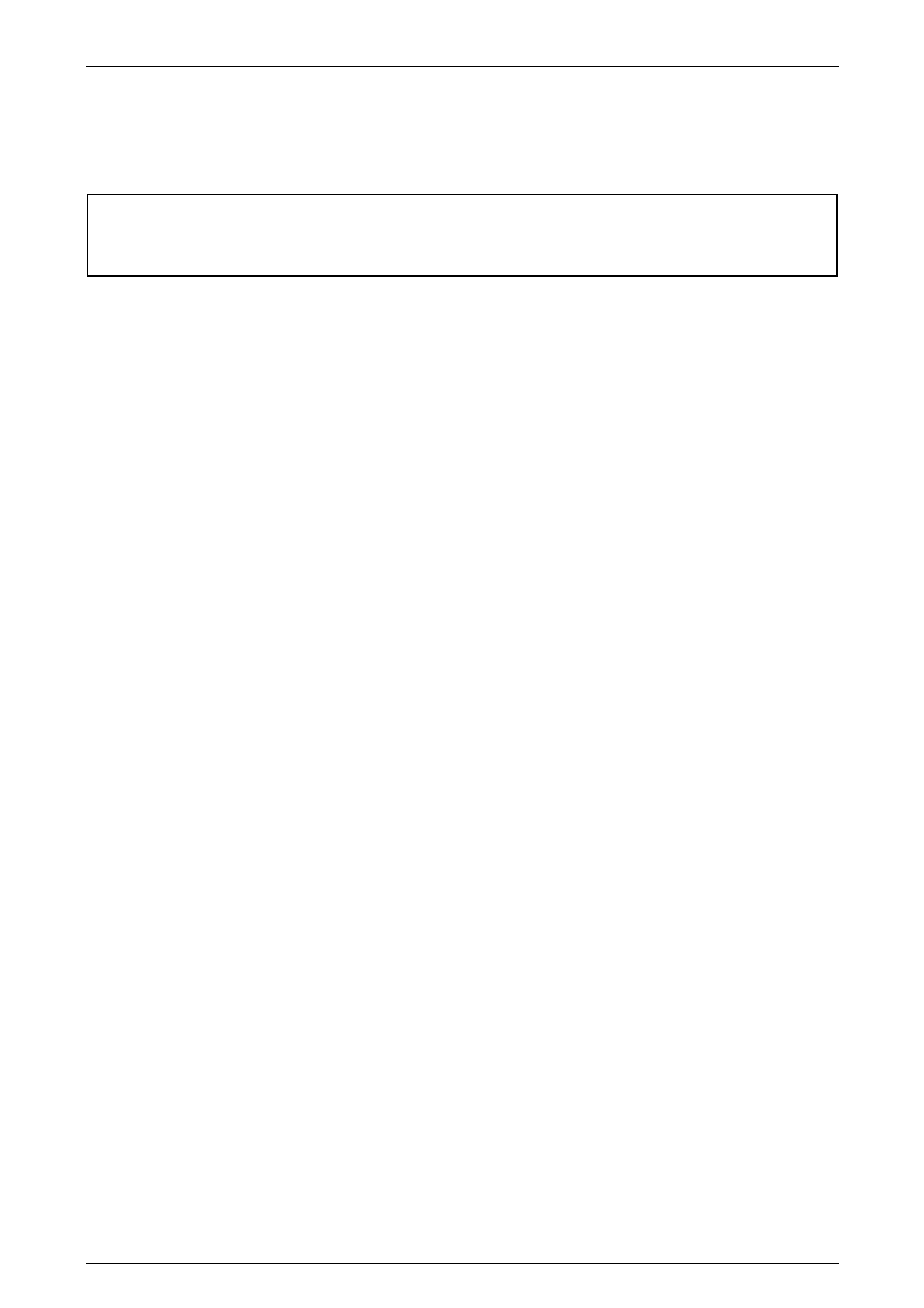
The 68.5-litre fuel tank (1) fitted to MY 2004 VY Regular Cab and Crew Cab vehicles is a 'W'-type high-density multi-
layer polyethylene construction, with a separate fuel filler neck (2), refer to Figure 8A1 – 1. The fuel filler neck consists of
a flexible rubber centre section with hose clamps either end and a steel upper pipe that incorporates the filler neck vent
fitting and counter-syphon mechanism. The fuel tank is fitted on removable fuel tank support straps underneath the load
floor front panel assembly.
A seal is fitted around the fuel filler neck where it is attached to the vehicle body. The fuel tank is retained by the fuel
tank 'H'-frame (3) that fits into keyed steel risers (4) welded to the forward chassis crossmember. A second fuel tank
mounting strap (5) also fits into a keyed steel riser welded to the forward chassis crossmember. The fuel tank 'H'-frame
and fuel tank mounting strap are anchored with a nut and spring washer to studs (6) welded to the rear chassis
crossmember.
The fuel tank is not repairable and, if damaged, must be replaced. A rollover valve (7) is fitted directly into the top of the
fuel tank, but is not serviceable.
Quick-connect fittings are used on the fuel feed (8) and fuel return lines (9) at both the modular fuel pump and sender
assembly (10) and engine ends. Quick-connect fittings are also used on the fuel tank vent line (11) and the fuel vapour
canister purge line (12) at the fuel vapour canister (13).
For vehicles fitted with the GEN III V8 engine, the modular fuel pump and sender assembly also incorporates a pressure
regulator; the pressure regulator on vehicles fitted with the V6 engine is located on the fuel rail in the engine bay.
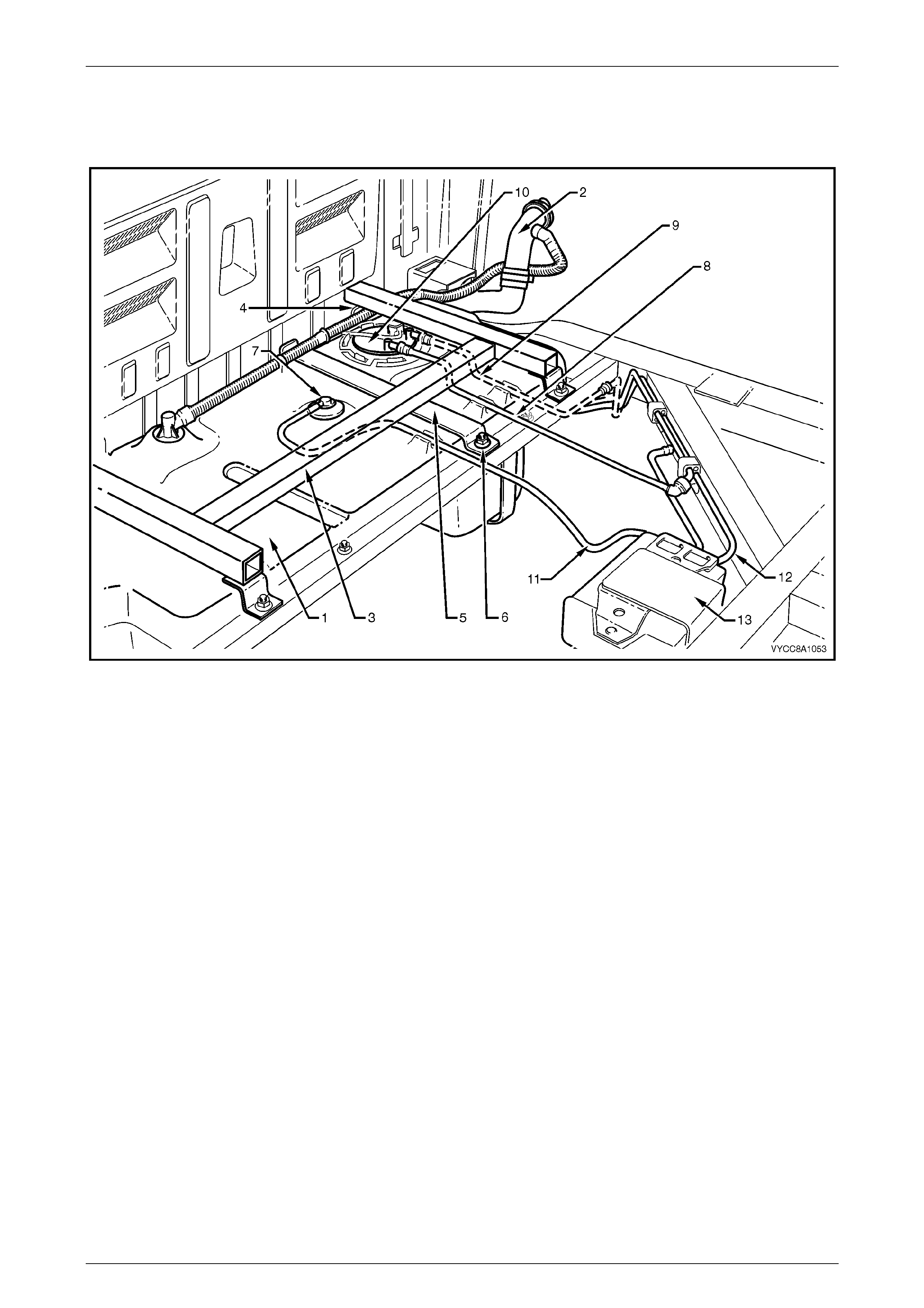
The in-tank, modular fuel pump and sender assembly includes a fuel pump and suction filter assembly (8), pressure
regulator holder (7), pressure regulator (6 — GEN III V8 only), reservoir (11), fuel level sender assembly (12), reservoir
jet pump (10) and cover (1), refer to Figure 8A1 – 2.
Servicing details for these and other fuel tank and fuel line related items are covered in this Section.
Both the fuel pump and suction filter assembly, and the fuel level sender assembly are serviceable items. For service
intervals of these items, refer to Section 0B Lubrication and Service.
Fuel Tank Page 8A1–3
Page 8A1–3
NOTE
Figure 8A1 – 1 is a generic illustration for V6 and
GEN III V8 Crew Cab vehicles.
Figure 8A1 – 1
Legend
1 Fuel Tank
2 Fuel Filler Neck
3 Fuel Tank 'H'-frame
4 Fuel Tank Mounting Strap Front
Anchoring Point
5 Fuel Tank Mounting Strap
6 Stud (3 places)
7 Rollover Valve
8 Fuel Feed Line
9 Fuel Return Line
(V6 Vehicles Only)
10 Modular Fuel Pump and
Sender Assembly
11 Fuel Tank Vent Line
12 Fuel Vapour Canister Purge Line
13 Fuel Vapour Canister
Fuel Tank Page 8A1–4
Page 8A1–4
NOTE
Figure 8A1 – 2 shows a modular fuel pump and
sender assembly for a GEN III V8 engine.
Figure 8A1 – 2
Legend
1 Modular Fuel Pump and Sender
Assembly Cover
2 Spring (2 places)
3 Shaft (2 places)
4 Circlip
5 Fuel Filter Assembly
6 Pressure Regulator
(GEN II I V8 only)
7 Pressure Regulator Holder
8 Fuel Pump and Suction Filter Assembly
9 Flapper Valve
10 Reservoir Jet Pump
11 Reservoir
12 Fuel Level Sender Assembly
13 Transfer Jet Pump
For additional information regarding the pressure regulator and fuel system electrical diagnostic procedures not
contained in this Section, refer to:
• Section 6C1 Powertrain — V6 Engine, and
• Section 6C3 Powertrain — GEN III V8 Engine.
Fuel Tank Page 8A1–5
Page 8A1–5
1.1 Modular Fuel Pump and Sender
Assembly
Single Line Fuel Delivery System
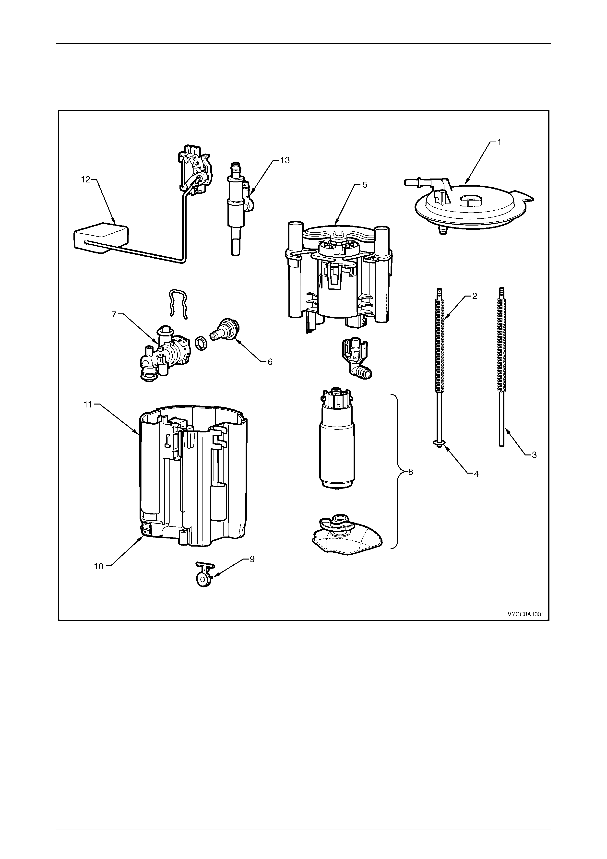
V6 Engine
Fuel is directed from the modular fuel pump and sender
assembly, then through the flexible fuel feed line (1) and on
to the engine bay and fuel rail.
When fuel line pressure exceeds the pre-determined value
of 400 kPa (+/–3 kPa), the pressure regulator attached to
the fuel rail opens, allowing excess fuel at system pressure
to return to the fuel tank via the fuel return line (2). This
process occurs continuously while the pump is operating.
A three-port fuel vapour canister (3) is mounted in a bracket
on a chassis crossmember behind the fuel tank. The fuel
vapour canister stores fuel tank vapour via the fuel tank
vent line (4) and releases it to the fuel vapour canister
purge line (5).
Figure 8A1 – 3
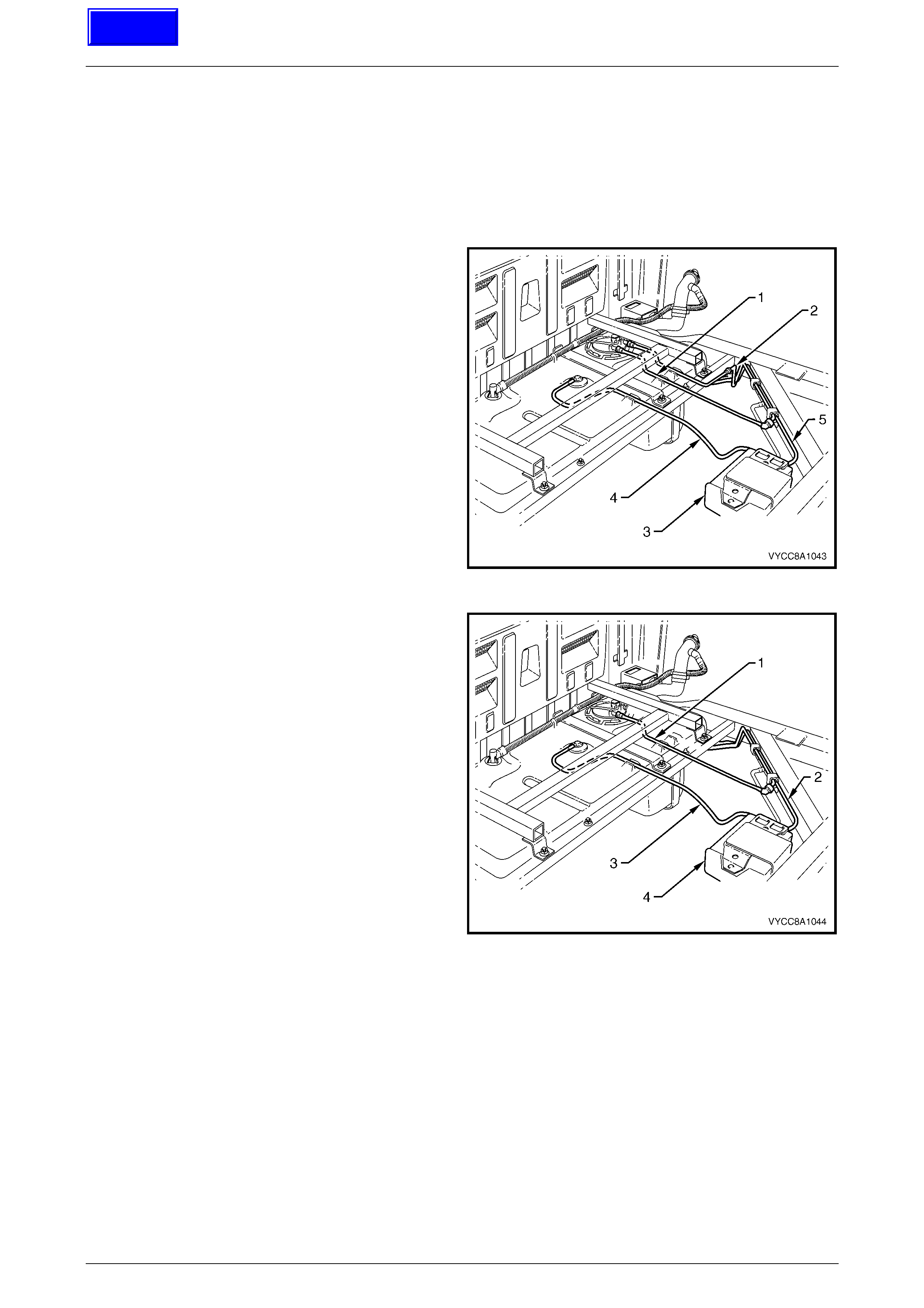
GEN III V8 Engine
Fuel is directed from the modular fuel pump and sender
assembly, then through the flexible fuel feed line (1) and on
to the engine bay and fuel rail.
When fuel line pressure exceeds the pre-determined value
of 400 kPa (+/–3 kPa), the pressure regulator in the modular
fuel pump and sender assembly opens, allowing excess fuel
at system pressure to return to the modular fuel pump and
sender assembly via the reservoir jet pump. This process
occurs continuously while the pump is operating.
A three-port fuel vapour canister (2) is mounted in a bracket
on a chassis crossmember behind the fuel tank. The fuel
vapour canister stores fuel tank vapour via the fuel tank
vent line (3) and releases it to the fuel vapour canister
purge line (4).
Figure 8A1 – 4
Techline
Fuel Tank Page 8A1–6
Page 8A1–6
2 Service Operations
2.1 Fuel Tank
Remove
A depressurised fuel system contains fuel in
the fuel filter and fuel lines that can be spilled
during service operations.
Fuel vapour remains in the fuel tank even
when completely empty. Seal all openings in
the fuel tank using suitable material or a
plastic plug. Ensure no naked flames or other
ignition sources are nearby. Ensure all
mobile phones (and transmission devices that
may cause any metal objects to become
unintentional receiving antennas) are
switched off.
Wear safety glasses when using compressed
air. Do not blow compressed air onto any
body part.
1 Depressurise the fuel system, refer to:
• For V6 engine vehicles only Section 6C1–3, 3.1 Fuel Pump Relay, or
• For GEN III V8 engine vehicles only Section 6C3–3, 3.7 Fuel Pressure Relief Procedure.
2 Remove fuel pump relay R16, refer to Section 12O, 1.4 Relays.
3 Remove the front inner side panel cover from the rear body to enable access to the fuel filler neck, refer to
Section 1B, Sheet Metal and Rear Subframe.
4 Remove the quick-connect fitting attaching the inlet breather pipe to the fuel filler neck, refer to 2.2 Fuel Filler Neck
and Splash Guard and Figure 8A1 – 5.
5 Cover the end of the inlet breather pipe and the inlet breather pipe connection on the fuel filler neck with a suitable
material to prevent foreign objects from entering.
6 Remove the rear body, refer to Section 1B, Sheetmetal and Rear Subframe.
7 Use compressed air to ensure that all dirt and foreign materials are removed from all fuel connections before the
parts are disconnected, refer to Figure 8A1 – 5.
8 Disconnect the modular fuel pump and sender assembly harness connector (1).
9 Tag, remove and cover the following items with a suitable material to prevent foreign objects from entering:
a the fuel feed line (5),
b for V6 engine vehicles only, fuel return line (6),
Fuel Tank Page 8A1–7
Page 8A1–7
NOTE
For information on quick-connect fittings for
Regular Cab and Crew Cab vehicles, refer to
MY 2003 VY and V2 Series Service Information,
Section 8A1 Fuel Tank, 2.10 Quick-connect
Fittings.
c the inlet breather pipe (8) from the vapour collector, and
d the fuel tank vent line (11).
10 Remove the modular fuel pump and sender assembly (3), refer to Section 8A1 Fuel Tank in the MY 2003 VY
Regular Cab Service Information.
Ensure fuel is pumped or syphoned from both
sides of the baffle in the fuel tank.
11 Drain the fuel tank by pumping or syphoning fuel through the hole in the fuel tank (from which the modular fuel
pump and sender assembly was removed) using commercially available equipment.
NOTE
A permanent floodgate restriction in the lower fuel
filler neck prevents the fuel tank from being
drained through the filler aperture.
NOTE
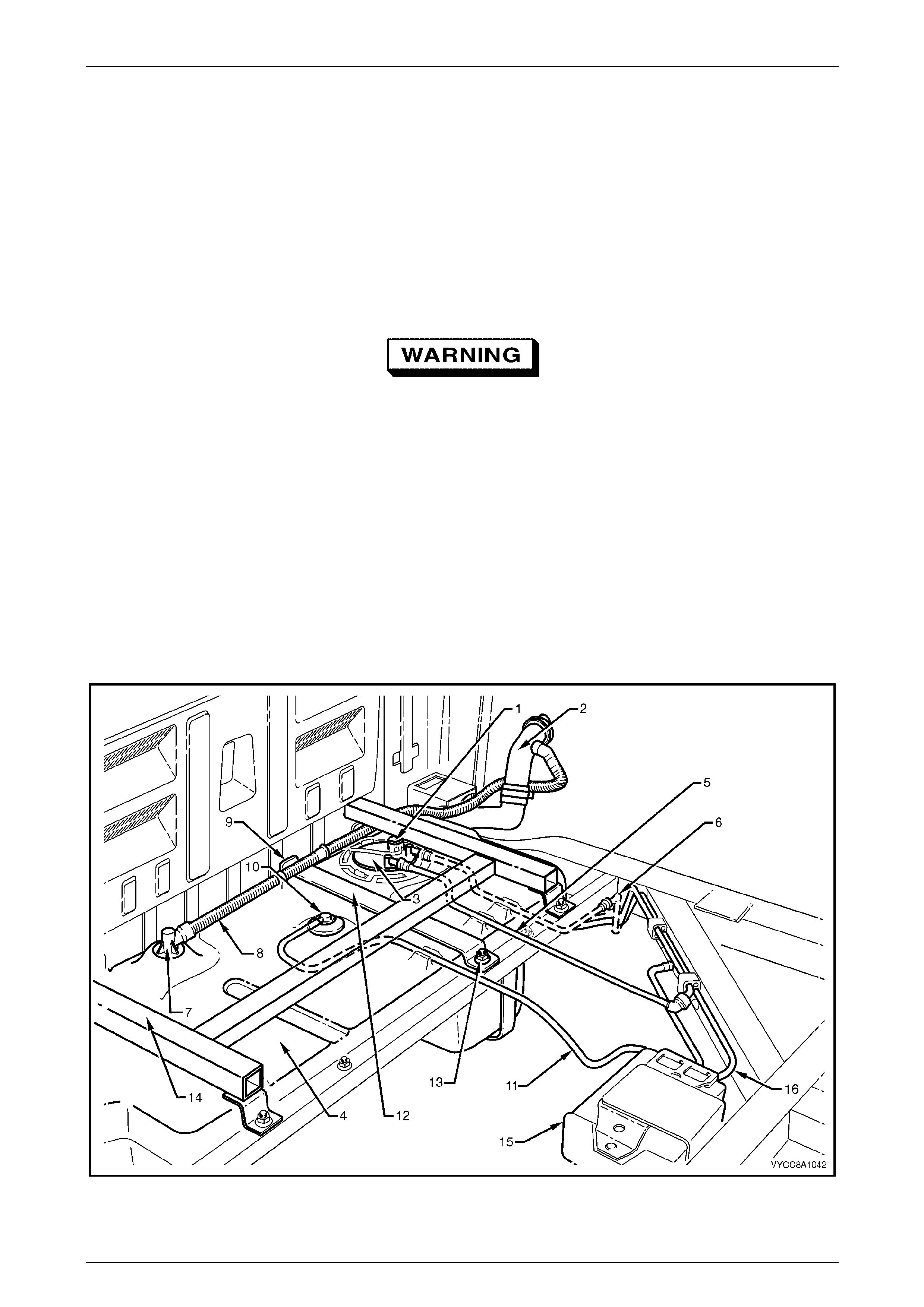
Figure 8A1 – 5 is a generic illustration for V6 and
GEN III V8 vehicles.
Figure 8A1 – 5
Fuel Tank Page 8A1–8
Page 8A1–8
Legend
1 Modular Fuel Pump and Sender
Assembl y Harness Connector
2 Fuel Filler Neck
3 Modular Fuel Pump and
Sender Assembly
4 Fuel Tank
5 Fuel Feed Line
6 Fuel Return Line
(V6 Vehicles Only)
7 Vapour Collector
8 Inlet Breather Pipe
9 Fuel Tank Mounting Strap Front
Anchoring Point (3 places)
10 Rollover Valve
11 Fuel Tank Vent Line
12 Fuel Tank Mounting Strap (1 place)
13 Stud (3 places)
14 Fuel Tank 'H'-frame (1 place)
15 Fuel Vapour Canister
16 Fuel Vapour Canister Purge Line
12 Loosen the screw clamp from the fuel tank end of the flexible fuel filler neck.
13 Remove the flexible fuel filler neck from the fuel tank.
14 Cover the flexible fuel filler neck with a suitable material to prevent foreign objects from entering.
15 Remove both nuts from the fuel tank 'H'-frame (14).
16 Remove the nut from the centre fuel tank mounting strap (12).
17 Lift the fuel tank 'H'-frame away from the front anchoring points and place in a safe location away from the
immediate worksite.
18 Lift the fuel tank mounting strap away from the front anchoring point and place in a safe location away from the
immediate worksite.
19 Remove the fuel tank from its support frame.
Reinstall
The installation procedure for the fuel tank is the reverse of the removal procedure, noting the following:
1 Ensure all parts are dust-free and clean before reinstalling.
2 Tighten the fuel tank 'H'-frame nuts to the correct torque specification.
3 Tighten the fuel tank mounting strap nut to the correct torque specification.
Fuel tank 'H'-frame
nuts torque specification......................... 20.0 – 25.0 Nm
Fuel tank mounting strap
nut torque specification .......................... 20.0 – 25.0 Nm
Fuel Tank Page 8A1–9
Page 8A1–9
2.2 Fuel Filler Neck and Splash Guard
Remove
A depressurised fuel system contains fuel in
the fuel filter and fuel lines that can be spilled
during service operations.
Fuel vapour remains in the fuel tank even
when completely empty. Seal all openings in
the fuel tank using suitable material or a
plastic plug. Ensure no naked flames or other
ignition sources are nearby. Ensure all
mobile phones (and transmission devices that
may cause any metal objects to become
unintentional receiving antennas) are
switched off.
Wear safety glasses when using compressed
air. Do not blow compressed air directly onto
any body part.
Ensure fuel is pumped or syphoned from both
sides of the baffle in the fuel tank.
1 Remove the modular fuel pump and sender assembly, refer to MY 2003 VY Series Service Information,
Section 8A1 Fuel Tank.
2 Drain the fuel tank by pumping or syphoning fuel through the hole in the fuel tank (from which the modular fuel
pump and sender assembly was removed) using commercially available equipment.
NOTE
A permanent floodgate restriction in the lower fuel
filler neck prevents the fuel tank from being
drained through the filler aperture.
Fuel Tank Page 8A1–10
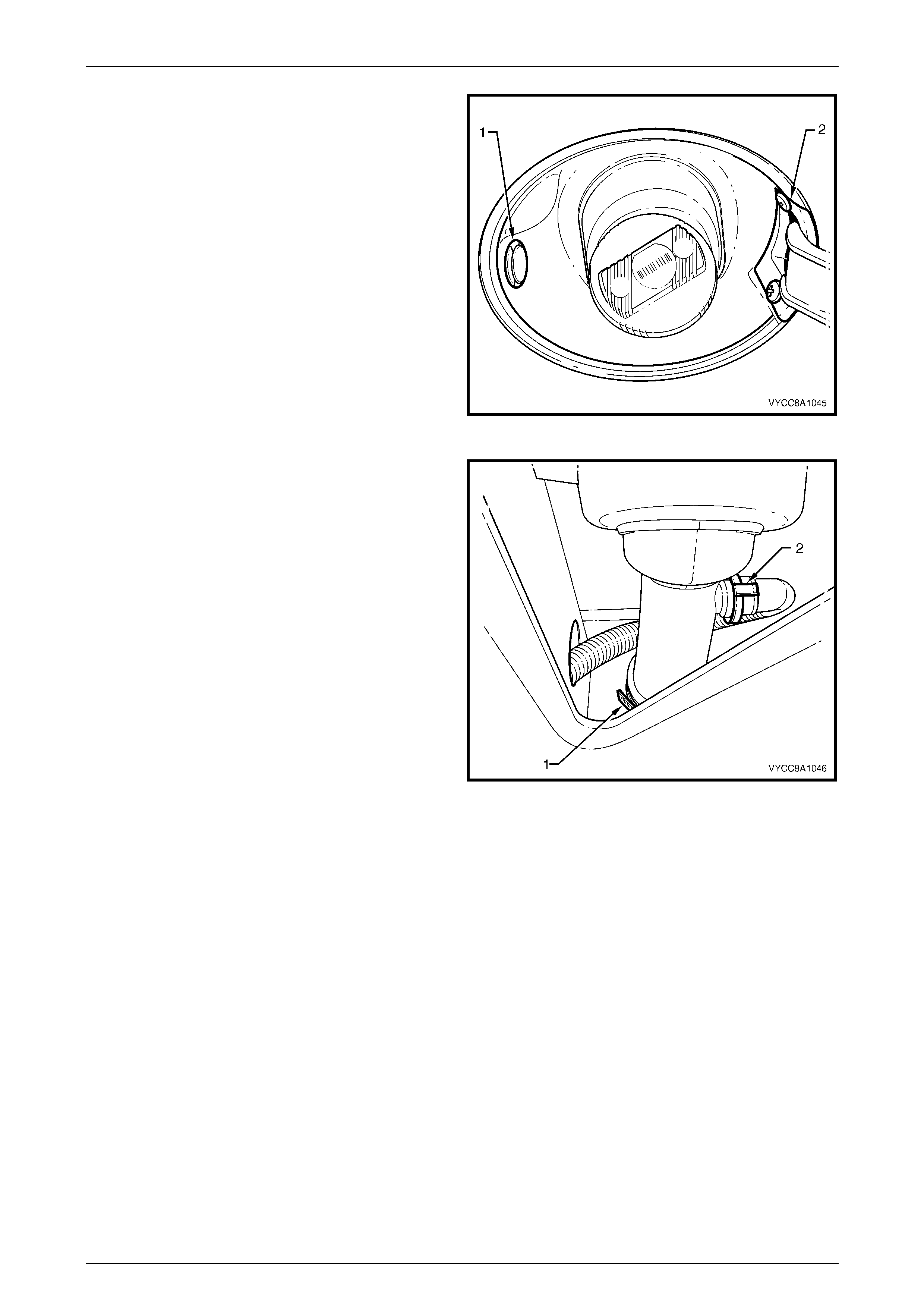
Page 8A1–10
3 Remove the grommet (1) from the left side of the fuel
filler splash guard.
4 Remove both screws (2) from the fuel filler door
opening.
5 Use compressed air to ensure that all dirt and foreign
materials are removed from the fuel filler cap and fuel
filler neck.
6 Remove the fuel filler cap from the fuel filler neck.
7 Remove the fuel filler splash guard by pulling it over
the fuel filler neck.
8 Replace the fuel filler cap onto the fuel filler neck.
Figure 8A1 – 6
9 Remove the front inner side panel cover, refer to
Section 1B, Sheet Metal.
10 Loosen and remove the screw clamp (1) holding the
flexible fuel inlet pipe onto the fuel filler neck.
11 Loosen and remove the quick-connect fitting (2)
holding the inlet breather pipe onto the fuel filler neck.
12 Cover the flexible fuel inlet pipe and inlet breather pipe
with a suitable material to prevent foreign objects from
entering.
Figure 8A1 – 7
Reinstall
The installation procedure is the reverse of the removal procedure, ensuring all parts are dust-free and clean before
reinstalling.

Fuel Tank Page 8A1–11
Page 8A1–11
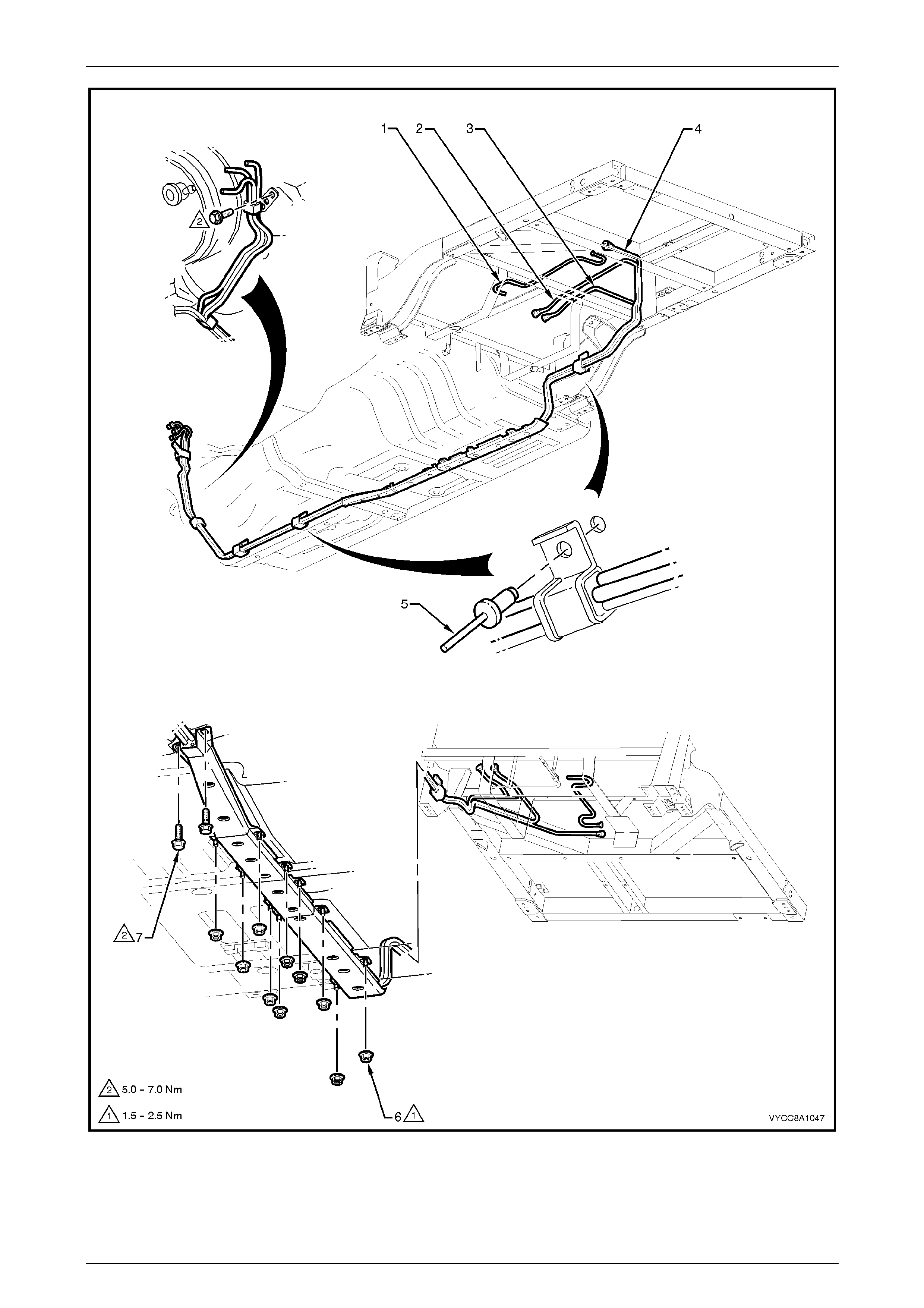
2.3 Fuel Pipe Arrangement
V6 Engine
Figure 8A1 – 8 illustrates the fuel pipe layout and location of other items relating to the fuel tank in vehicles with the V6
engine. For the fuel pipe arrangement for vehicles fitted with the LPG system, refer to Section 8A2 – LPG System in this
service information.
Fuel Tank Page 8A1–12
Page 8A1–12
Figure 8A1 – 8
Fuel Tank Page 8A1–13
Page 8A1–13
Legend
1 Fuel Tank Vent Line
2 Fuel Feed Line
3 Fuel Return Line
4 Fuel Vapour Canister Purge Line
5 Fuel Line Bracket Blind Rivet
6 Stone Guard Securing Nut (10 places)
7 Stone Guard Securing Bolt (2 places)
NOTE
For V6 engines, use special tool AU533 to
remove the fuel feed line (1) and fuel return
line (2) quick-connect fittings, refer to MY 2003
VY and V2 Series Service Information,
Section 8A1 Fuel Tank, 2.10 Quick-connect
Fittings.
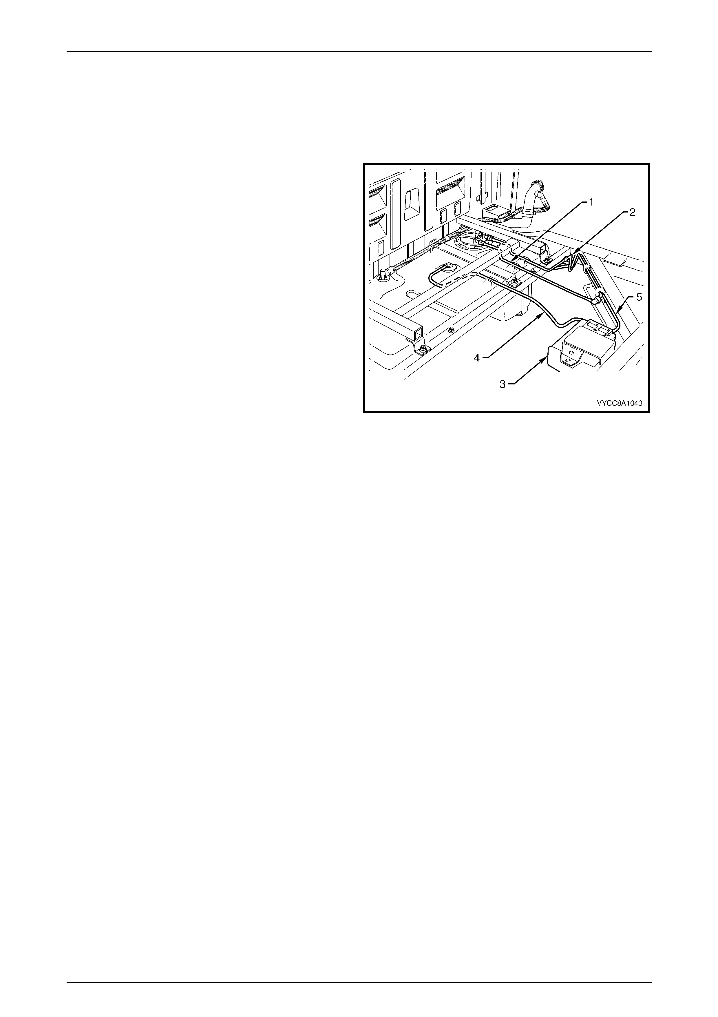
Figure 8A1 – 9
Legend
1 Fuel Feed Line
2 Fuel Return Line 3 Fuel Vapour Canister
4 Fuel Tank Vent Line 5 Fuel V apour Canister Purge Line
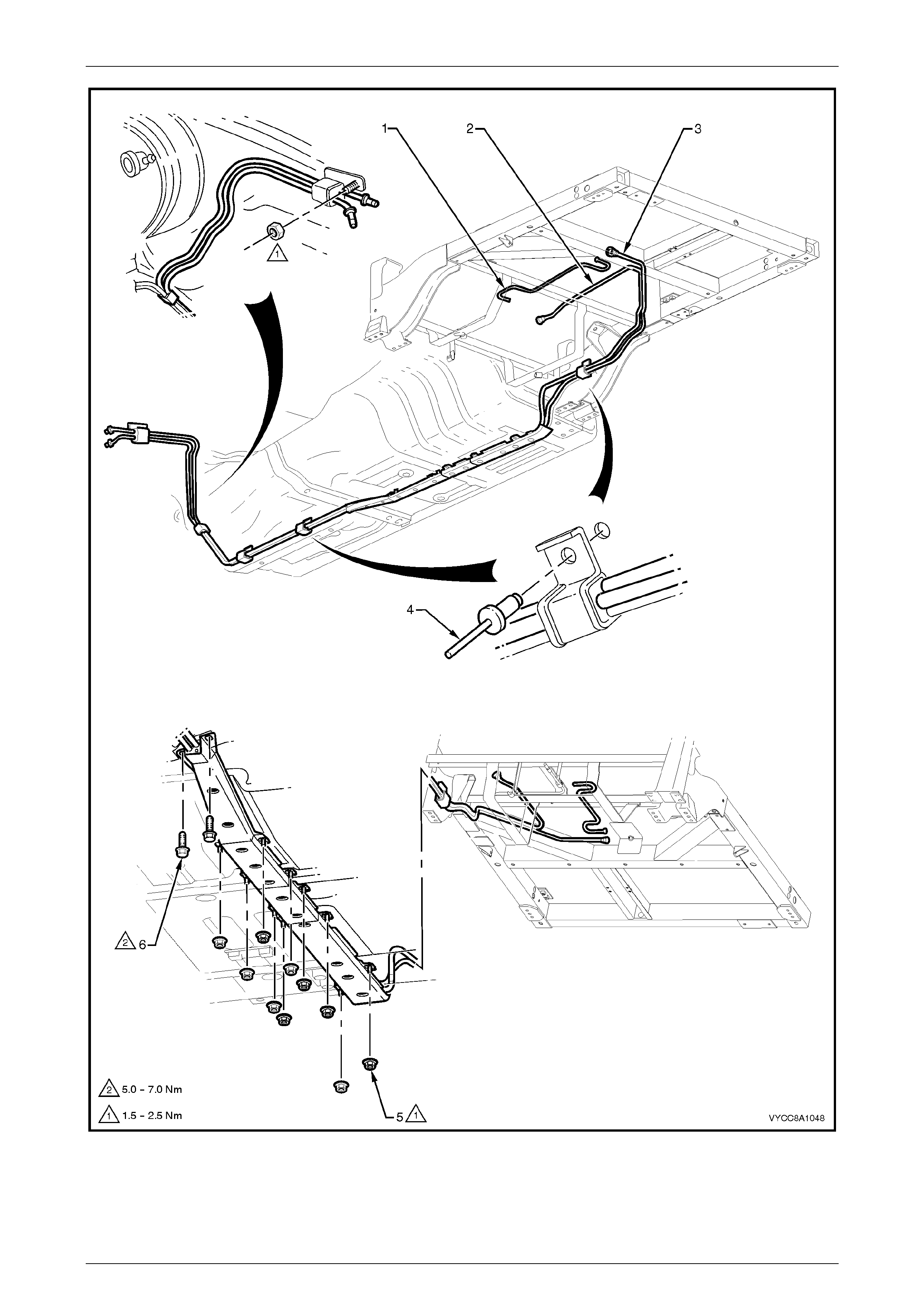
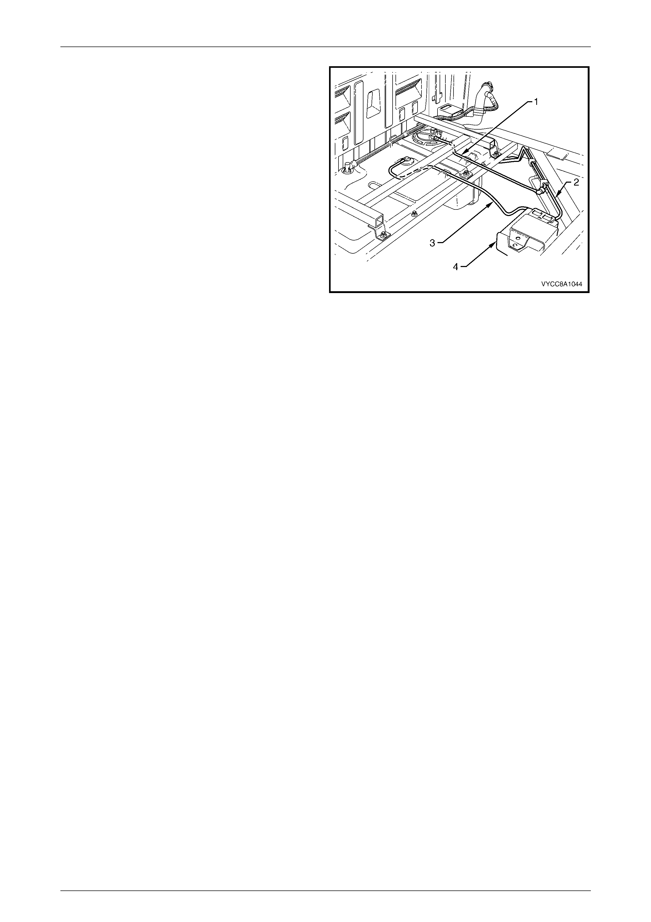
GEN III V8 Engine
Figure 8A1 – 10 illustrates the fuel pipe layout and location of other items relating to the fuel tank in vehicles with GEN III
V8 engine. For the fuel pipe arrangement for vehicles fitted with the LPG system, refer to Section 8A2 – LPG System in
this service information.
Fuel Tank Page 8A1–14
Page 8A1–14
Figure 8A1 – 10
Legend
1 Fuel Tank Vent Line
2 Fuel Feed Line 3 Fuel Vapour Canister Purge Line
4 Fuel Line Bracket Blind Rivet 5 Stone Guard Securing Nut (10 places)
6 Stone Guard Securing Bolt (2 places)
Fuel Tank Page 8A1–15
Page 8A1–15
NOTE
For GEN III V8 engines use special tool AU533
to remove the fuel feed line (1) quick-connect
fitting, refer to MY 2003 VY and V2 Series
Service Information, Section 8A1 Fuel Tank,
2.10 Quick-connect Fittings.
Figure 8A1 – 11
Legend
1 Fuel Feed Line
2 Fuel Vapour Canister Purge Line 3 Fuel Tank Vent Line
4 Fuel Vapour Canister

Fuel Tank Page 8A1–16
Page 8A1–16
3 Specifications
Fuel Tank Capacity:
..................................................................................................................................68.5 litres
Fuel Tank Material:
..........................................................................'W'-type high density multi-layer polyethylene
Fuel Filler Location:
.............................................................................................................right side of utility body
Fuel Pump Type:
........................................................................................................................... Single turbine
Pressure Regulator Location:
V6 Engine .............................................................................................................. Engine bay
GEN III V8 Engine ....................................................Modular fuel pump and sender assembly
Fuel Pump Location:
................................................................................................................................In fuel tank
Fuel Pump Regulated Pressure:
..................................................................................................................400 kPa (+/– 3 kPa)
Minimum Fuel Pump Flow Capacity (at Regulated Pressure):
............................................................................................................2.95 L/min @ 13.5 volts
Fuel Pump Current Draw (Steady State at Regulated Pressure):
................................................................................................................11.0 Amps maximum
O-rings:
pressure regulator (P/N 195306–0010).................................................................4.25 mm i.d.
pressure regulator holder — top (P/N 195506–0150) ...........................................7.52 mm i.d.
pressure regulator holder — bottom (P/N 167529–0010) .......................................8.2 mm i.d.
fuel pump outlet (P/N 167529–0010) ......................................................................8.2 mm i.d.
pressure regulator (P/N 195306–0110).................................................................15.4 mm i.d.

Fuel Tank Page 8A1–17
Page 8A1–17
4 Torque Wrench Specifications
Fuel Tank 'H'-frame Nuts...........................................................20.0 – 25.0 Nm
Fuel Tank Mounting Strap Nuts.................................................20.0 – 25.0 Nm
Stone Guard Securing Nut.............................................................1.5 – 2.5 Nm
Stone Guard Securing Bolt............................................................5.0 – 7.0 Nm
Fuel Tank Page 8A1–18
Page 8A1–18
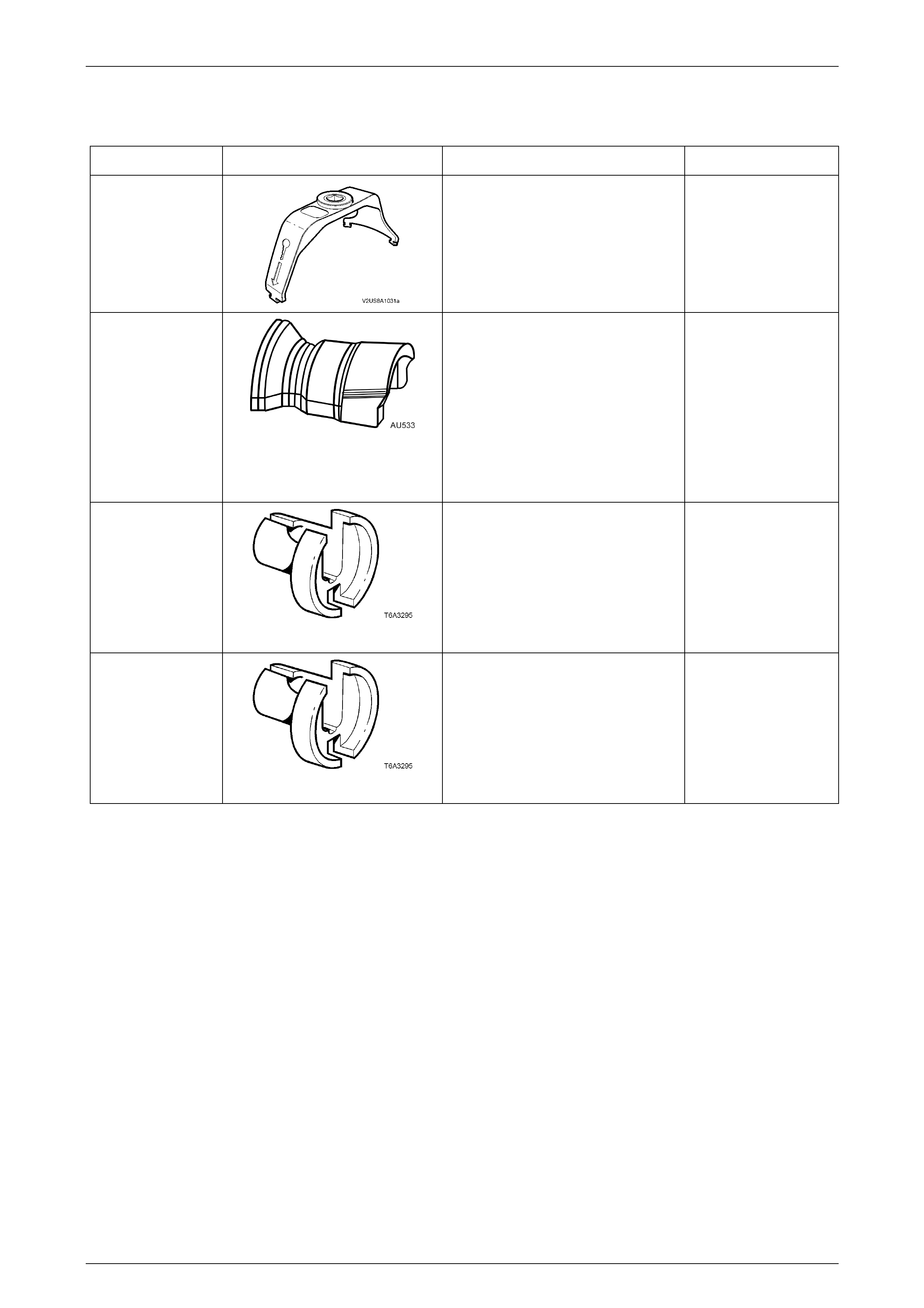
5 Special Tools
Tool Number Illustration Description Tool Classification
J45722
Modular fuel pump and sender
assembly lock ring remove and install
tool.
New release.
Mandatory
AU533
Quick-connect fitting release tool
Released in two sizes:
• Red for 5/16-inch fittings, and
• Blue for 3/8-inch fittings.
Commercially available under
P/N AUSP45.
Previously released.
Desirable
7370
Quick-connect release tool —
5/16-inch
Used for releasing fuel hose quick
connects at the dash panel and fuel
rail connections, after the fuel system
has been depres suri sed .
Previously released.
Mandatory
7371
Quick-connect release tool —
3/8-inch
Used for releasing fuel hose quick
connects at the dash panel and fuel
rail connections, after the fuel system
has been depres suri sed .
Previously released.
Mandatory