
Instrument P anel and Console Page 1A3–1
Page 1A3–1
Section 1A3
Instrument Panel and Console
ATTENTION
Before performing any service operation or other procedure described in this Section, refer to Section 00
Warnings, Cautions and Notes for correct workshop practices with regard to safety and/or property damage.
1 General Information............................................................................................................................... 2
2 Service Operations................................................................................................................................3
2.1 Armrest Assembly..................................................................................................................................................3
Disassemble ...........................................................................................................................................................3
Reassemble ............................................................................................................................................................3
3 Torque Wrench Specifications............................................................................................................. 4
Techline
Techline
Techline
Techline
Techline

Instrument P anel and Console Page 1A3–2
Page 1A3–2
1 General Information
With the following exception, MY 2004 VY and V2 Series Instrument Panel and Console information carries over from
MY 2003 VY and V2 Series:
• A latch clip is fitted to the floor console armrest assembly.
For information not contained within this Section, refer to Section 1A3 Instrument Panel and Console in the MY 2003 VY
and V2 Series Service Information.
Instrument P anel and Console Page 1A3–3
Page 1A3–3
2 Service Operations
2.1 Armrest Assembly
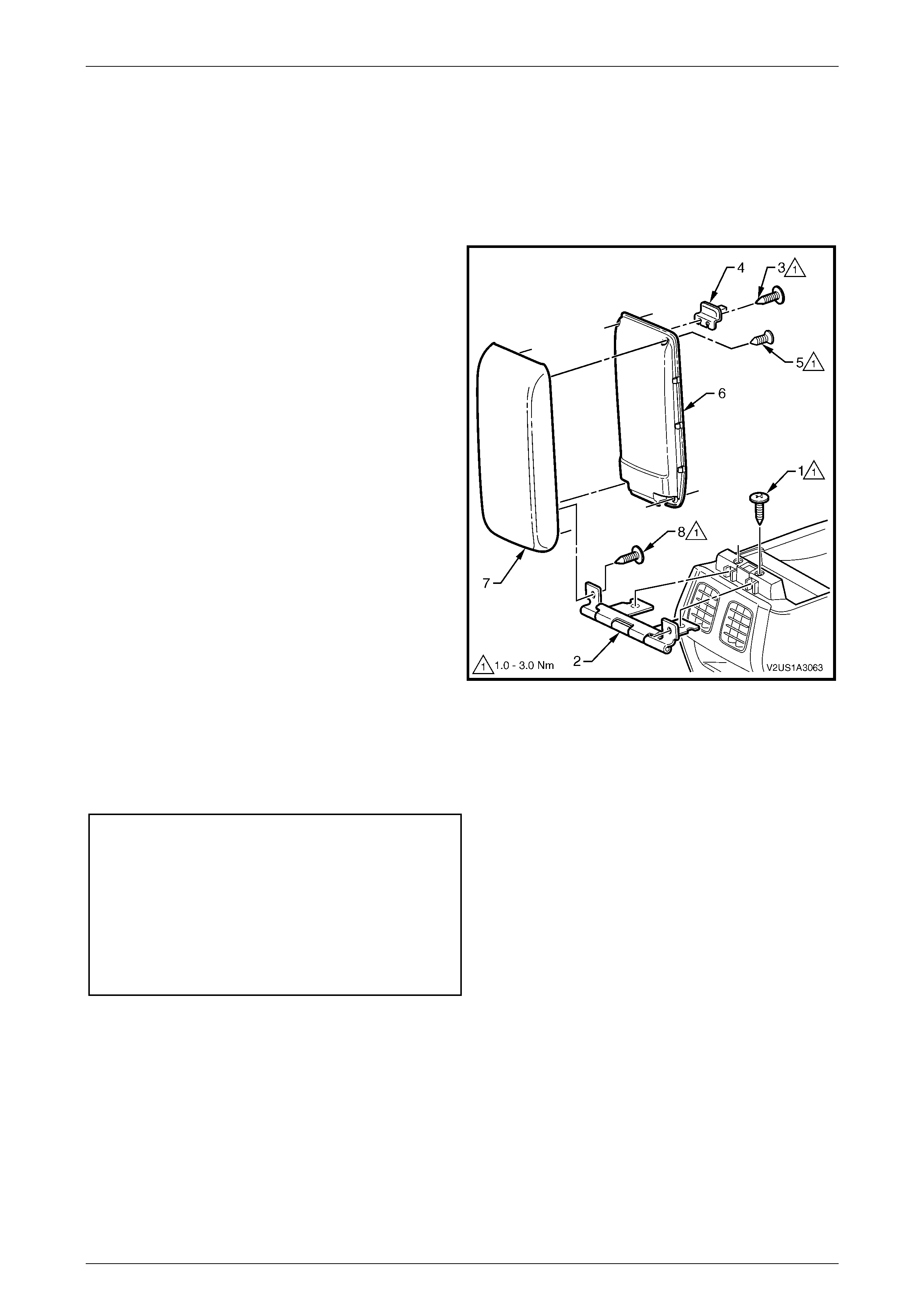
Disassemble
1 Remove both screw s (1) attac hing the floor co nsole
compartment armrest hinge (2) and armrest assembly
to the floor console.
2 Slide the armrest assembly rearward to remove the
hinge from the floor console.
3 Remove both screw s (3) attac hing the armre st
assembly latch clip (4) to the armrest assembly, then
remove the latch.
4 Remove the four screws (5) attaching the armrest
inner moulding (6) to the armrest outer moulding (7).
5 Unclip the armrest inner moulding at three places
along each side and remove from the armrest outer
moulding.
6 Remove both screw s (8) attac hing the hing e to the
armrest outer moulding, then remove the hinge.
Figure SectNum – 1
Reassemble
Reassembly of the armrest assembly is the reverse of the disassembly procedure noting the following torque
specifications:
Floor Console Compartment
Armrest Hinge Attaching
Screw Torque Specification.........................1.0 – 3.0 nm
Floor Console Compartment
Armrest Inner Attaching Screw
Torque Specification................................... 1.0 – 3.0 Nm
Armrest Assembly Latch
Clip Screw
Torque Specification................................... 1.0 – 3.0 Nm

Instrument P anel and Console Page 1A3–4
Page 1A3–4
3 Torque Wrench Specifications
Floor Console Compartment Armrest
Hinge Attaching Screws.................................................................1.0 – 3.0 nm
Floor Console Compartment Armrest
Inner Attaching Screws..................................................................1.0 – 3.0 Nm
Armrest Assembly Latch Clip Screws............................................1.0 – 3.0 Nm