
Headlining and Interior Trim Page 1A8–1
Page 1A8–1
Section 1A8
Headlining and Interior Trim
ATTENTION
Before performing any service operation or other procedure described in this Section, refer to Section 00
Warnings, Cautions and Notes for correct workshop practices with regard to safety and/or property damage.
1 General Information............................................................................................................................... 3
2 Service Operations - Sedan.................................................................................................................. 4
2.1 Centre Pillar Upper Trim Assembly......................................................................................................................5
Remove ...................................................................................................................................................................5
Reinstall ..................................................................................................................................................................6
2.2 Rear Window Trim Panel Assembly .....................................................................................................................7
Remove ...................................................................................................................................................................7
Disassemble ...........................................................................................................................................................7
Reassemble ............................................................................................................................................................7
Reinstall ..................................................................................................................................................................8
2.3 Roof Console..........................................................................................................................................................9
Level 1.....................................................................................................................................................................9
Level 2 and Level 3.................................................................................................................................................9
2.4 Headlining Assembly...........................................................................................................................................10
Remove .................................................................................................................................................................10
Reinstall ................................................................................................................................................................11
2.5 Rear End Trim Panel............................................................................................................................................12
Remove .................................................................................................................................................................12
Reinstall ................................................................................................................................................................12
2.6 Rear Compartment Floor Carpet Assembly.......................................................................................................13
Remove .................................................................................................................................................................13
Disassemble .........................................................................................................................................................13
Reassemble ..........................................................................................................................................................13
Reinstall ................................................................................................................................................................13
2.7 Quarter Inner Rear Side Carpet...........................................................................................................................14
Remove .................................................................................................................................................................14
Reinstall ................................................................................................................................................................14
2.8 Rear Seat Back Panel Carpet ..............................................................................................................................15
Remove .................................................................................................................................................................15
Reinstall ................................................................................................................................................................16
3 Service Operations - Wagon............................................................................................................... 17
3.1 Centre Pillar Upper Trim Assembly....................................................................................................................18
Remove .................................................................................................................................................................18
Reinstall ................................................................................................................................................................19
3.2 Roof Console........................................................................................................................................................20
Level 1...................................................................................................................................................................20
Level 2 and Level 3...............................................................................................................................................20
3.3 Headlining Assembly...........................................................................................................................................21
Remove .................................................................................................................................................................21
Reinstall ................................................................................................................................................................22
3.4 Luggage Tie Down Rails......................................................................................................................................23
Remove .................................................................................................................................................................23
Reinstall ................................................................................................................................................................24
Techline

Headlining and Interior Trim Page 1A8–2
Page 1A8–2
4 Service Operations - Coupe................................................................................................................ 25
4.1 Quarter Trim Panel Assembly.............................................................................................................................26
Remove .................................................................................................................................................................26
Disassemble .........................................................................................................................................................27
Quarter Trim Radio Speaker Grille...................................................................................................................27
Quarter Trim Insulator Assembly......................................................................................................................27
Quarter Trim Armrest Insert Assembly.............................................................................................................28
Reinstall ................................................................................................................................................................29
4.2 Centre Pillar Upper Trim Assembly....................................................................................................................30
Remove .................................................................................................................................................................30
Reinstall ................................................................................................................................................................30
4.3 Windshield Side Garnish.....................................................................................................................................31
Remove .................................................................................................................................................................31
Reinstall ................................................................................................................................................................31
4.4 Sunshade Assembly............................................................................................................................................32
Remove .................................................................................................................................................................32
Reinstall ................................................................................................................................................................32
4.5 Headlining Assembly...........................................................................................................................................33
Remove .................................................................................................................................................................33
Reinstall ................................................................................................................................................................34
4.6 Rear End Trim Panel............................................................................................................................................35
Remove .................................................................................................................................................................35
Reinstall ................................................................................................................................................................35
4.7 Rear Compartment Floor Carpet Assembly.......................................................................................................36
Remove .................................................................................................................................................................36
Disassemble .........................................................................................................................................................36
Reassemble ..........................................................................................................................................................36
Reinstall ................................................................................................................................................................36
4.8 Rear Seat Back Panel Carpet ..............................................................................................................................37
Remove .................................................................................................................................................................37
Reinstall ................................................................................................................................................................37
5 Torque Wrench Specifications........................................................................................................... 38

Headlining and Interior Trim Page 1A8–3
Page 1A8–3
1 General Information
With the following exceptions, MY 2004 VY and V2 Series Headlining and Interior Trim information carries over from
MY 2003 VY and V2 Series vehicles:
Sedan:
• Two clips are added to the centre pillar upper trim assembly
• The child restraint cover is changed on the rear window trim panel assembly
• For Level 1 vehicles, the dome lamp assembly is deleted and a roof console without switches is added
• The headlining assembly with a cut-out for the dome lamp assembly is discontinued
• Screw covers are added to rear end trim panel
• The handle is deleted from the rear compartment floor carpet assembly
• A retainer is added to the quarter inner rear side carpet
• A bead of adhesive is added to the lower edge of the rear seat back panel carpet
Wagon:
• Two clips are added to the centre pillar upper trim assembly
• For Level 1 vehicles, the dome lamp assembly is deleted and the roof console without switches is added
• The headlining assembly with a cut-out for the dome lamp assembly is discontinued
• Luggage tie down rails are added
Coupe:
• The quarter trim radio speaker grill is heat-staked to the quarter trim panel assembly
• The quarter trim armrest insert assembly is heat-staked to the quarter trim panel assembly
• Screw covers are added to rear end trim panel
• The handle is deleted from the rear compartment floor carpet assembly
• Two clips are added to the centre pillar upper trim assembly
• A clip replaces the screw on the windshield side garnish
• The sunshade assembly hinge is changed
• The driver footrest is changed to an alloy design
• Screw covers are added to rear end trim panel
• Two additional retainers are added to the rear seat back panel carpet
For Headlining and Interior Trim information not contained within this Section, refer to Section 1A8 Headlining and
Interior Trim in the MY 2003 VY and V2 Series Service information.
NOTE
When working on the body interior trim, clean
hands are essential and protective covering must
be placed over the interior trim.
Headlining and Interior Trim Page 1A8–4
Page 1A8–4
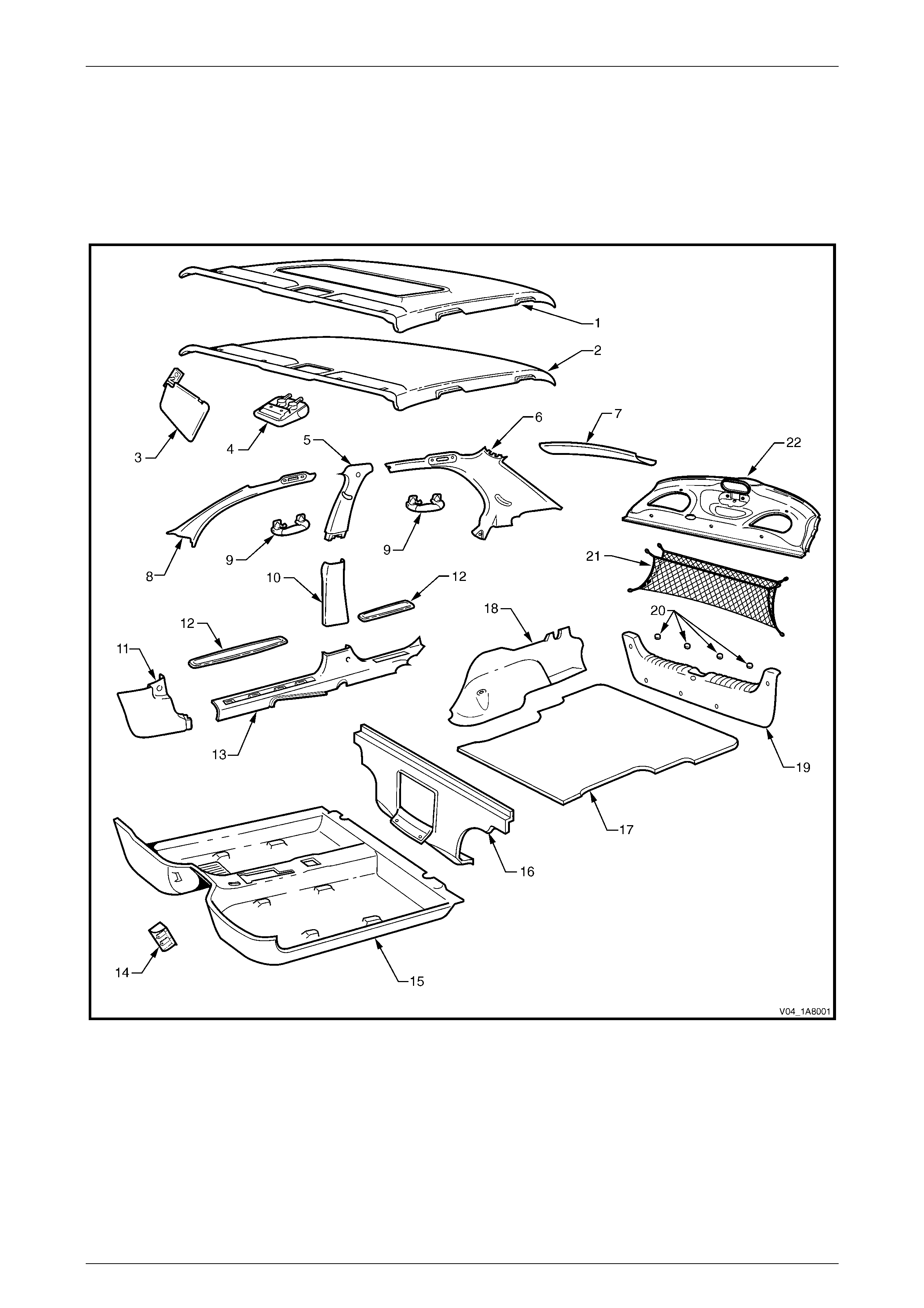
2 Service Operations - Sedan
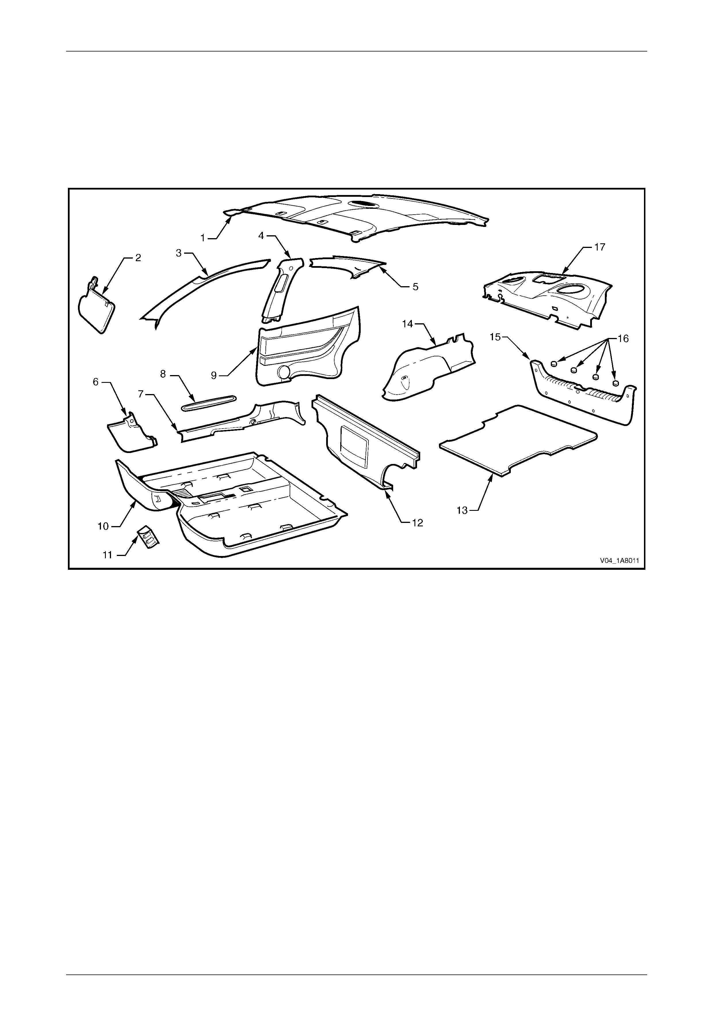
NOTE
The following chart is provided to assist with the
identification of the components.
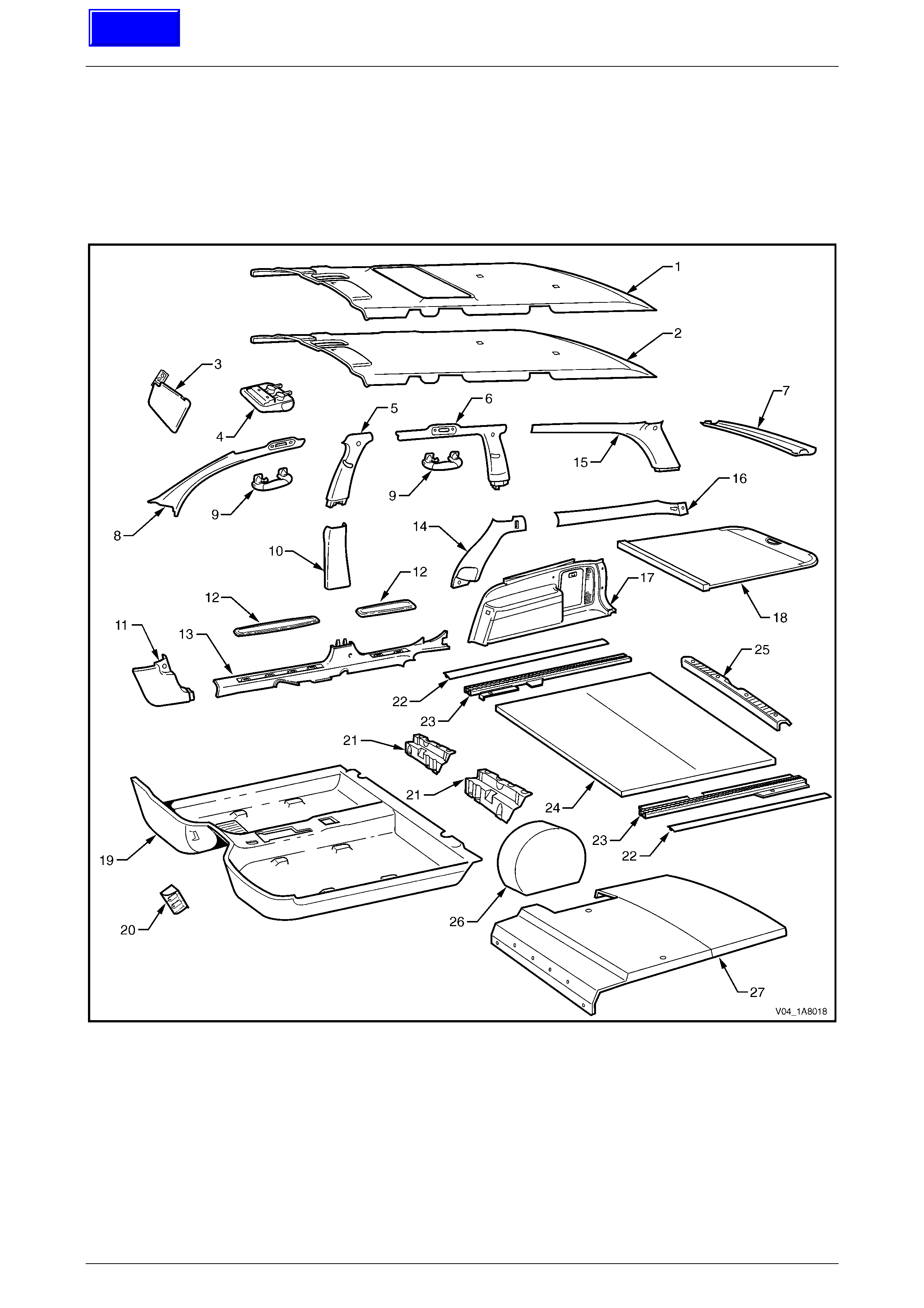
Figure 1A8 – 1
Headlining and Interior Trim Page 1A8–5
Page 1A8–5
Legend
1 Headlining Assembly With Sunroof
2 Headlining Assembly Without Sunroof
3 Sunshade Assembly
4 Roof Console
5 Centre Pillar Upper Trim Assembly
6 Body Lock Pillar Ga rn ish
7 Rear Window Upper Garnish
8 Windshield Side Garnish
9 Assist Handle
10 Centre Pillar Lower Trim
11 Hinge Pillar Trim Assembly
12 Side Sill Trim Plate
13 Side Sill Trim
14 Driver Footrest
15 Front Floor Carpet Assembly
16 Rear Seat Back P anel Carpet
17 Rear Com partment Floor Carpet Assembly
18 Quarter I nner Rear Side Carpet
19 Rear End Trim Panel
20 Screw Cover
21 Convenience Net
22 Rear Wi ndow Trim Panel Assembly
2.1 Centre Pillar Upper Trim Assembly
LT Section – 14-100
Remove
1 If required, first remove the following components:
a Remove the centre pillar lower trim, refer to Section 1A8, 2.2 Centre Pillar Lower Trim in the MY 2003 VY and
V2 Series Service Information.
b Remove the front lower seatbelt bolt, refer to Section 12M Occupant Protection System.
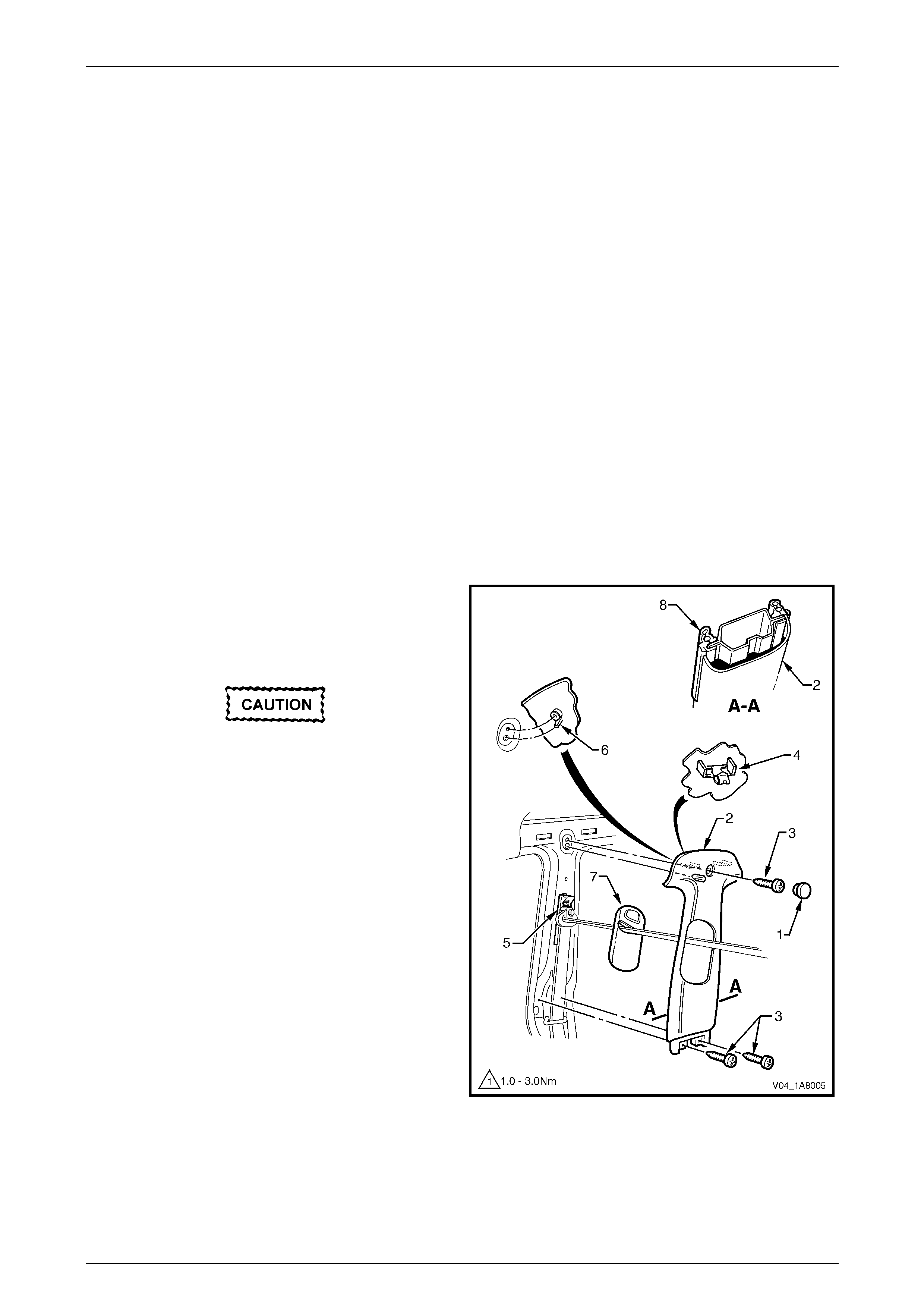
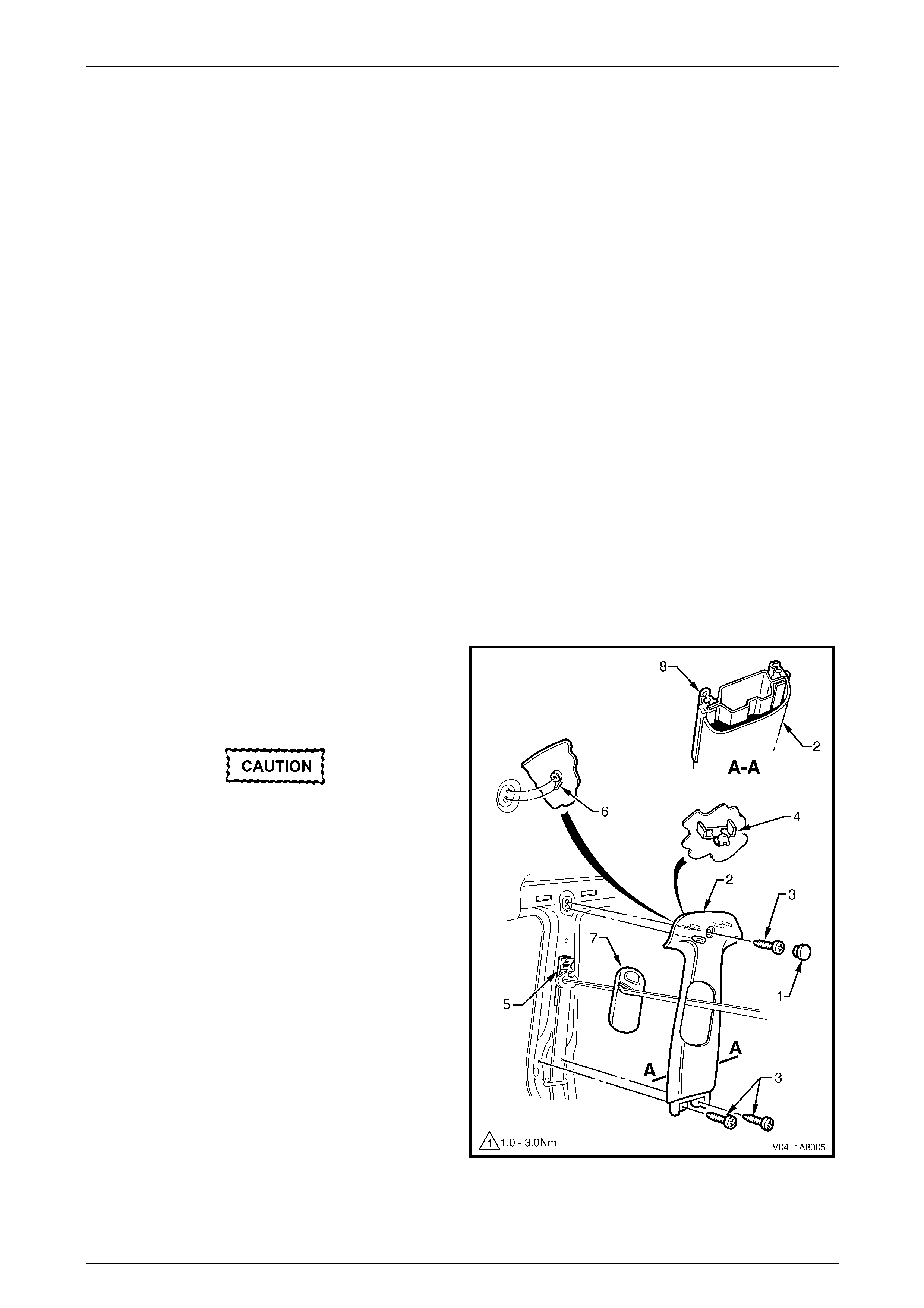
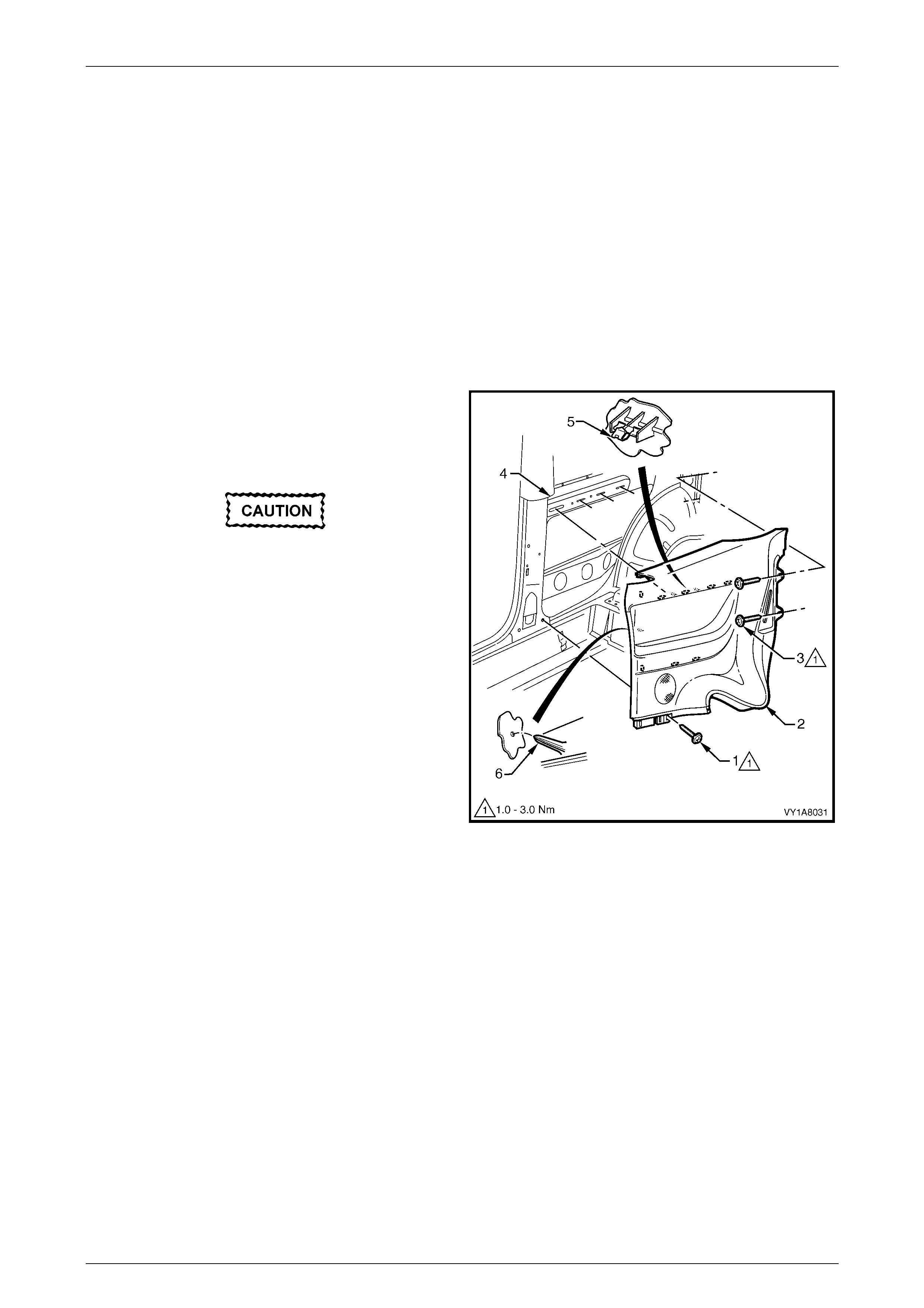
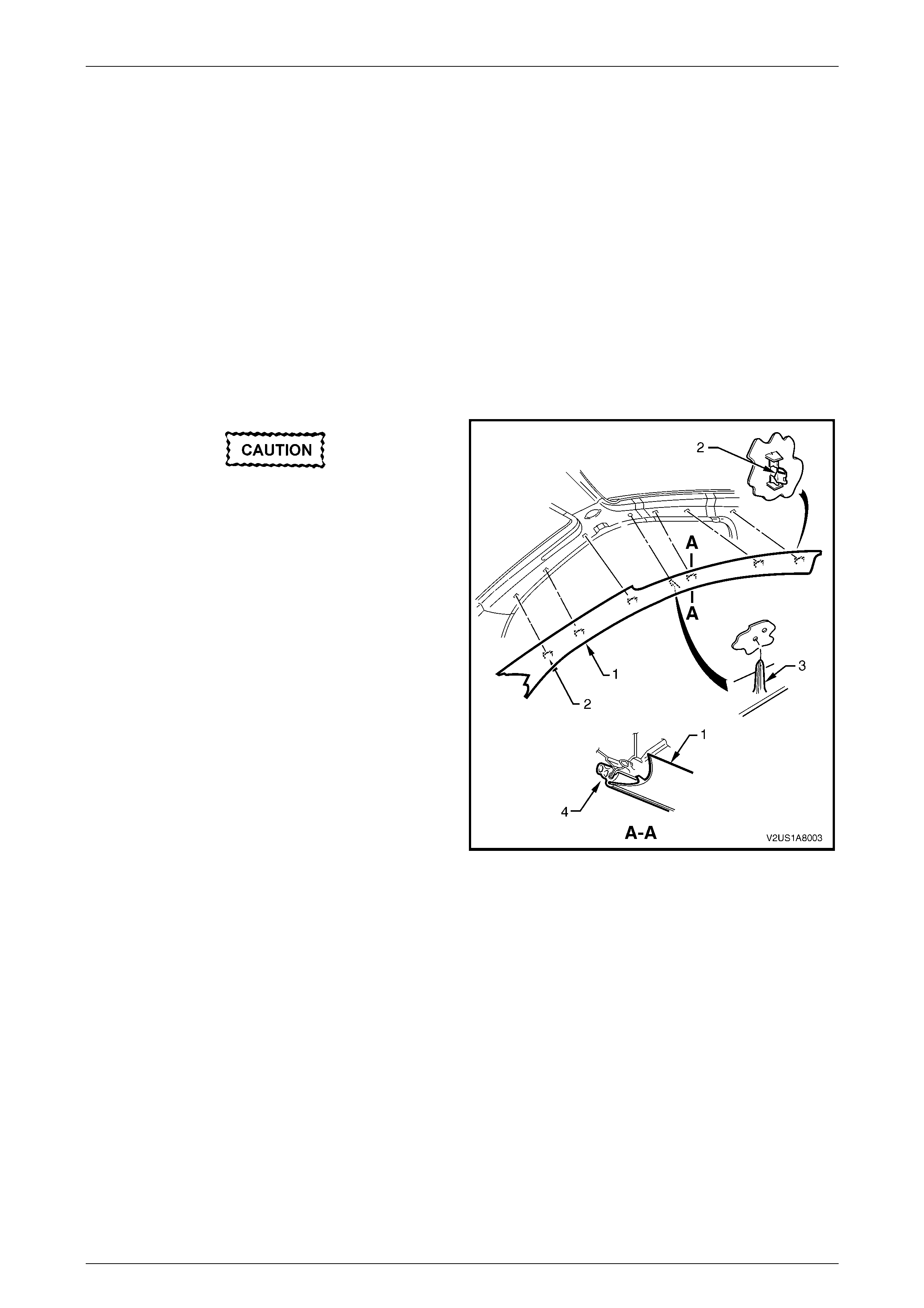
2 Remove the centre pillar cap (1) from the upper
attachment of the centre pillar upper trim assembly (2).
3 Remove the screws (3), in three places, securing the
centre pillar upper trim assembly.
When removing the centre pillar upper trim
assembly, take care not to damage the
locating pin (6) below the upper attaching
screw.
4 Pull the upper edge of the centre pillar upper trim
assembly away from the headlining assembly to
disengage the clips (4) and the seatbelt guide adjuster
assembly (5), if fitted.
5 Feed the seatbelt and anchor plate through the centre
pillar upper trim assembly and remove the centre pillar
upper trim assembly.
6 If required, remove the seatbelt adjuster trim (7) by
gently spreading the outer edges of the centre pillar
upper trim assembly and lifting out the seatbelt
adjuster trim.
Figure 1A8 – 2
Headlining and Interior Trim Page 1A8–6
Page 1A8–6
Reinstall
Reinstallation of the centre pillar upper trim assembly is the reverse of the removal procedure, noting the following:
1 If fitted, ensure that the seatbelt adjuster trim and the seatbelt guide adjuster assembly are in the fully up position
and are correctly aligned prior to installation of the centre pillar upper trim assembly.
2 Ensure that the locating pin below the upper attaching screw in the centre pillar upper trim assembly is correctly
aligned with the locating hole in the centre pillar.
3 Ensure that the leading edge of the centre pillar upper trim assembly engages the front door opening weatherstrip
assembly (8), refer to Figure 1A8 – 2.
4 Check seatbelt operation prior to tightening the centre pillar upper trim assembly attaching screws.
5 Tighten the fasteners to the specified torque.
Centre pillar upper trim assembly attaching
screw torque specification..........................1.0 – 3.0 Nm
Headlining and Interior Trim Page 1A8–7
Page 1A8–7
2.2 Rear Window Trim Panel Assembly
LT Section – 14-460
Remove
1 If required, first remove the following components:
a Remove both rear assist handles, refer to Section 1A8, 2.1 Assist Handle in the MY 2003 VY and V2 Series
Service Information.
b If fitted, remove the roof rail courtesy and reading lamp assembly, refer to Section 12B Lighting System.
c Partially remove the centre pillar upper trim assembly by removing the upper attaching screw, refer to
2.1 Centre Pillar Upper Trim Assembly.
d Remove the rear seat cushion assembly, refer to Section 1A7 Seat Assemblies.
e Remove the rear seat-back assembly, refer to Section 1A7 Seat Assemblies.
f Partially remove both body lock pillar garnishes, refer to Section 1A8, 2.6 Body Lock Pillar Garnish in the MY
2003 VY and V2 Series Service Information.
g Remove the lower centre seatbelt bolt, refer to Section 12M Occupant Protection System.
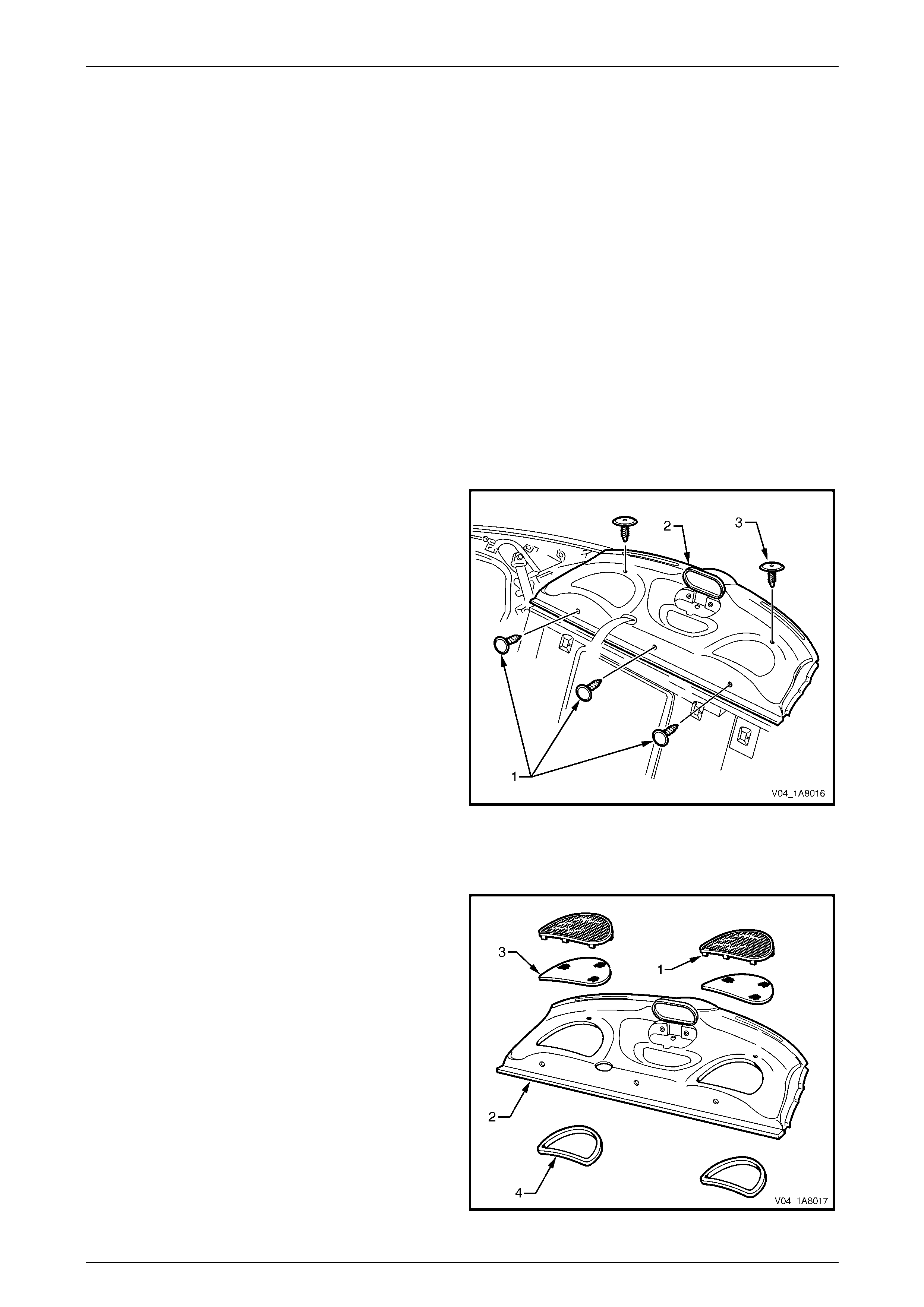
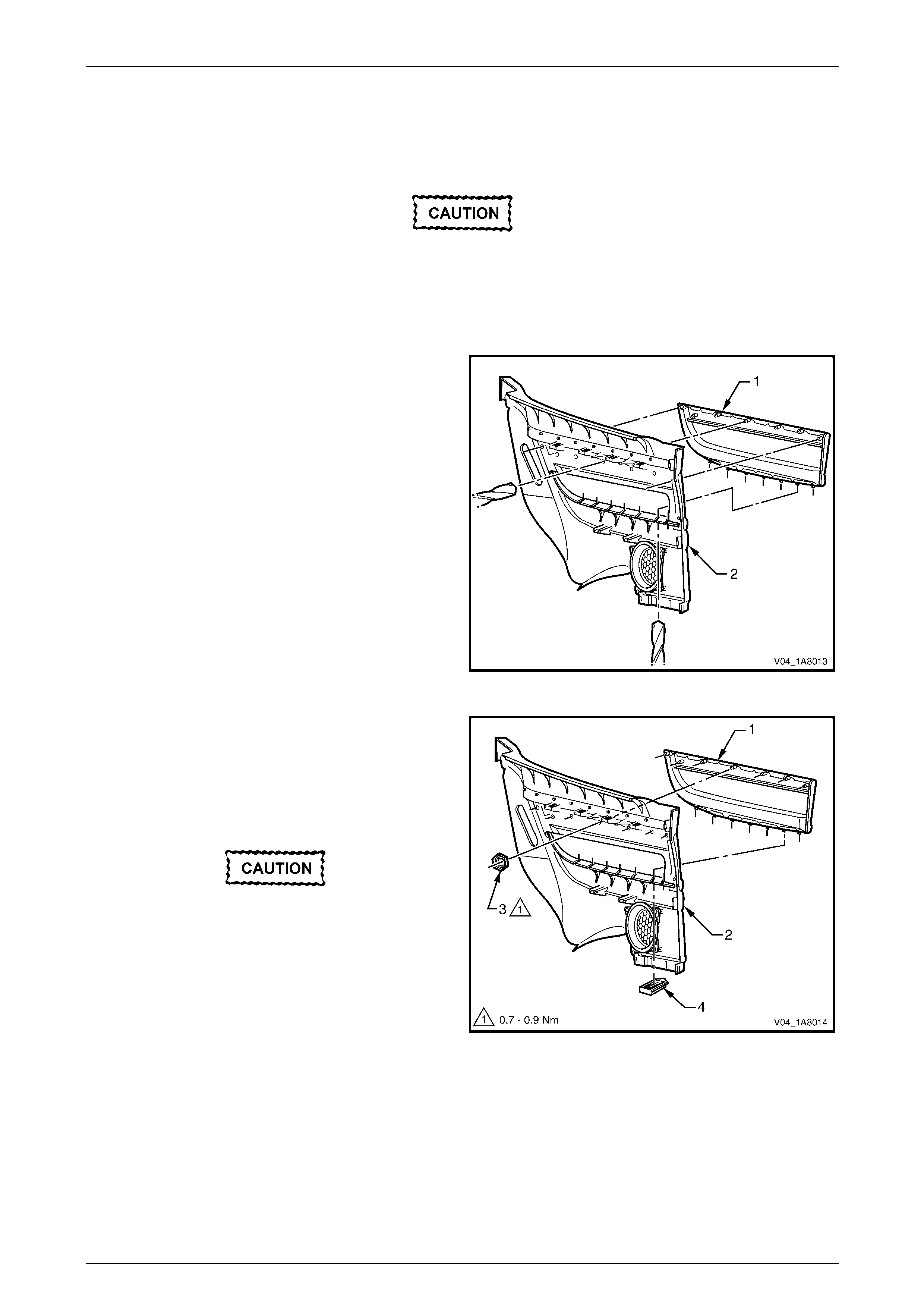
2 Remove the retainers (1), in three places, attaching
the forward edge of the rear window trim panel
assembly (2).
3 Remove the retainers (3), in two places, attaching the
upper surface of the rear window trim panel assembly.
4 Lift the front edge of the rear window trim panel
assembly and feed the seatbelt and anchor plate
through the seatbelt opening.
5 Remove the rear window trim panel assembly.
Figure 1A8 – 3
Disassemble
1 Bend the speaker grille tabs (1), in nine places, to a
vertical position and remove the speaker grille from
the rear window trim panel assembly (2).
2 Remove the dust seal (3) from the speaker grille.
3 Remove the speaker seal (4) from the rear window
trim panel assembly.
4 If required, repeat for the opposite side.
Reassemble
Reassembly of the rear window trim panel assembly is the
reverse of the disassembly procedure, noting the following:
1 Bend the speaker grille tabs, in nine places, to a
horizontal position to retain the speaker grille.
Figure 1A8 – 4

Headlining and Interior Trim Page 1A8–8
Page 1A8–8
Reinstall
Reinstallation of the rear window trim panel assembly is the reverse of the removal procedure, noting the following:
1 Where fitted, ensure that the speaker seals do not foul on the speaker assemblies.

Headlining and Interior Trim Page 1A8–9
Page 1A8–9
2.3 Roof Console
LT Section – 02-780
Level 1
For Level 1 vehicles, the dome lamp assembly is deleted and a roof console is added. The roof console is similar to the
roof console that is fitted to Level 2 and Level 3 vehicles, except that blanking plugs are fitted instead of console
switches.
For additional information, refer to Section 1A8, 2.11 Roof Console in the MY 2003 VY and V2 Series Service
Information.
Level 2 and Level 3
For Level 2 and Level 3 vehicles, refer to Section 1A8, 2.11 R oof Console in the MY 2003 VY and V2 Series Service
Information.

Headlining and Interior Trim Page 1A8–10
Page 1A8–10
2.4 Headlining Assembly
LT Section – 14-150
Remove
NOTE
If the vehicle is fitted with a sunroof:
• For HBD sunroof removal, refer to
Section 1F1 Sunroof.
• For online sunroof removal, refer to
Section 1F2 Sunroof.
1 If required, first remove the following components:
a Remove the fuse F6 from the passenger compartment fuse and relay panel assembly, refer to Section 12O
Fuses, Relays and Wiring Harnesses.
b Place protective covering over both front seats and the interior trim.
c Remove the rear seat cushion assembly, refer to Section 1A7 Seat Assemblies.
d Remove the rear seat-back assembly, refer to Section 1A7 Seat Assemblies.
f Remove the assist handles, in four places, refer to Section 1A8, 2.1 Assist Handle in the MY 2003 VY and V2
Series Service Information.
f If fitted, remove both roof rail courtesy and reading lamp assemblies, refer to Section 12B Lighting System.
g Partially remove both centre pillar upper trim assemblies by removing the upper attaching screw, refer to
2.1 Centre Pillar Upper Trim Assembly.
h Remove both windshield side garnishes, refer to Section 1A8, 2.5 Windshield Side Garnish in the MY 2003
VY and V2 Series Service Information.
i Remove both body lock pillar garnishes, refer to Section 1A8, 2.6 Body Lock Pillar Garnish in the MY 2003
VY and V2 Series Service Information.
j Remove the rear window upper garnish, refer to Section 1A8, 2.7 Rear Window Upper Garnish in the MY
2003 VY and V2 Series Service Information.
k Remove both sunshade assemblies, refer to Section 1A8, 2.10 Sunshade Assembly in the MY 2003 VY and
V2 Series Service Information.
l Remove the roof console, refer to 2.3 Roof Console.
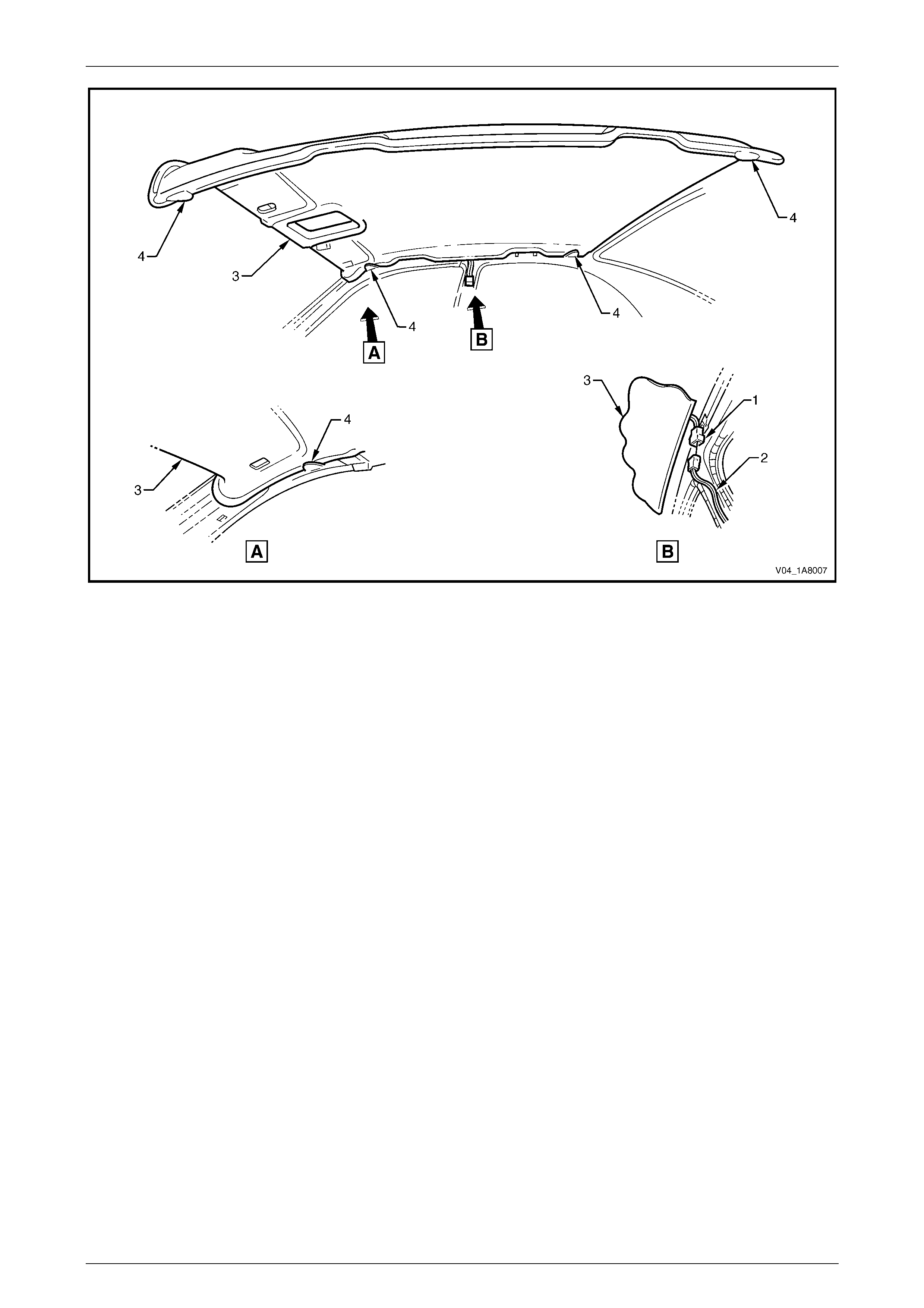
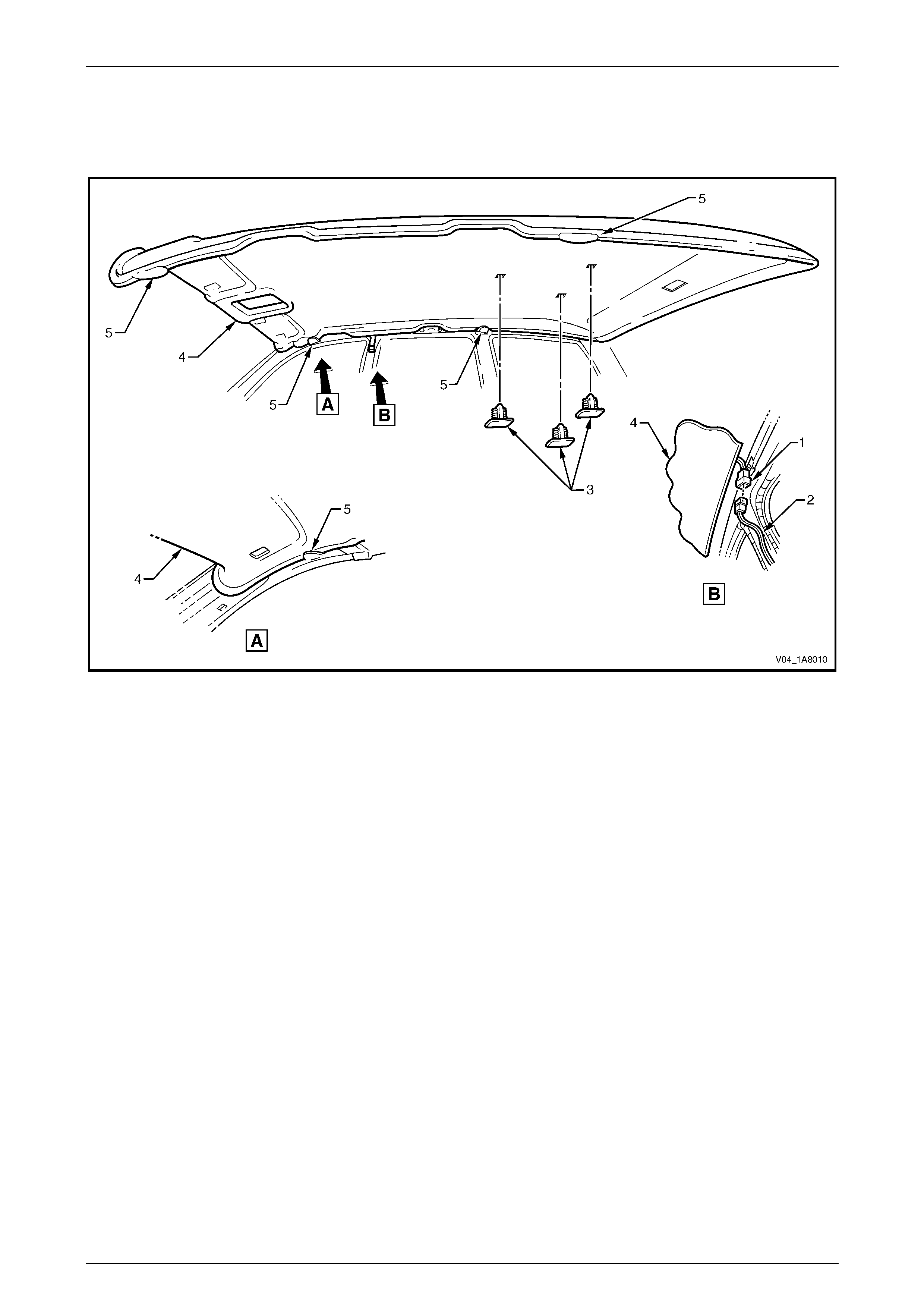
NOTE
It may be necessary to flex the headlining
assembly (3) down slightly to gain access to the
harness connector, refer to Figure 1A8 – 5.
2 Disconnect the headlining assembly harness (1) from the body harness connector (2), located above and slightly
forward of the right-hand centre pillar, refer to Figure 1A8 – 5.
3 With the aid of an assistant, flex the headlining assembly (3) to disengage the corners from the ‘D’ tabs (4), in four
places, on the sides of the roof panel.
4 Ease the headlining assembly from its position in the roof and turn the assembly so that it can be passed through
the passenger side front door and remove the headlining assembly from the vehicle.
Headlining and Interior Trim Page 1A8–11
Page 1A8–11
Figure 1A8 – 5
Reinstall
Reinstallation of the headlining assembly is the reverse of the removal procedure, noting the following:
1 Temporarily support the headlining assembly on the ‘D’ tabs before the trim components are reinstalled.
Headlining and Interior Trim Page 1A8–12
Page 1A8–12
2.5 Rear End Trim Panel
LT Section – 14-120
Remove
1 If required, partially remove the rear compartment lid weatherstrip, refer to Section 1A4 Hood, Rear Compartment
Lid, Liftgate and Endga te.
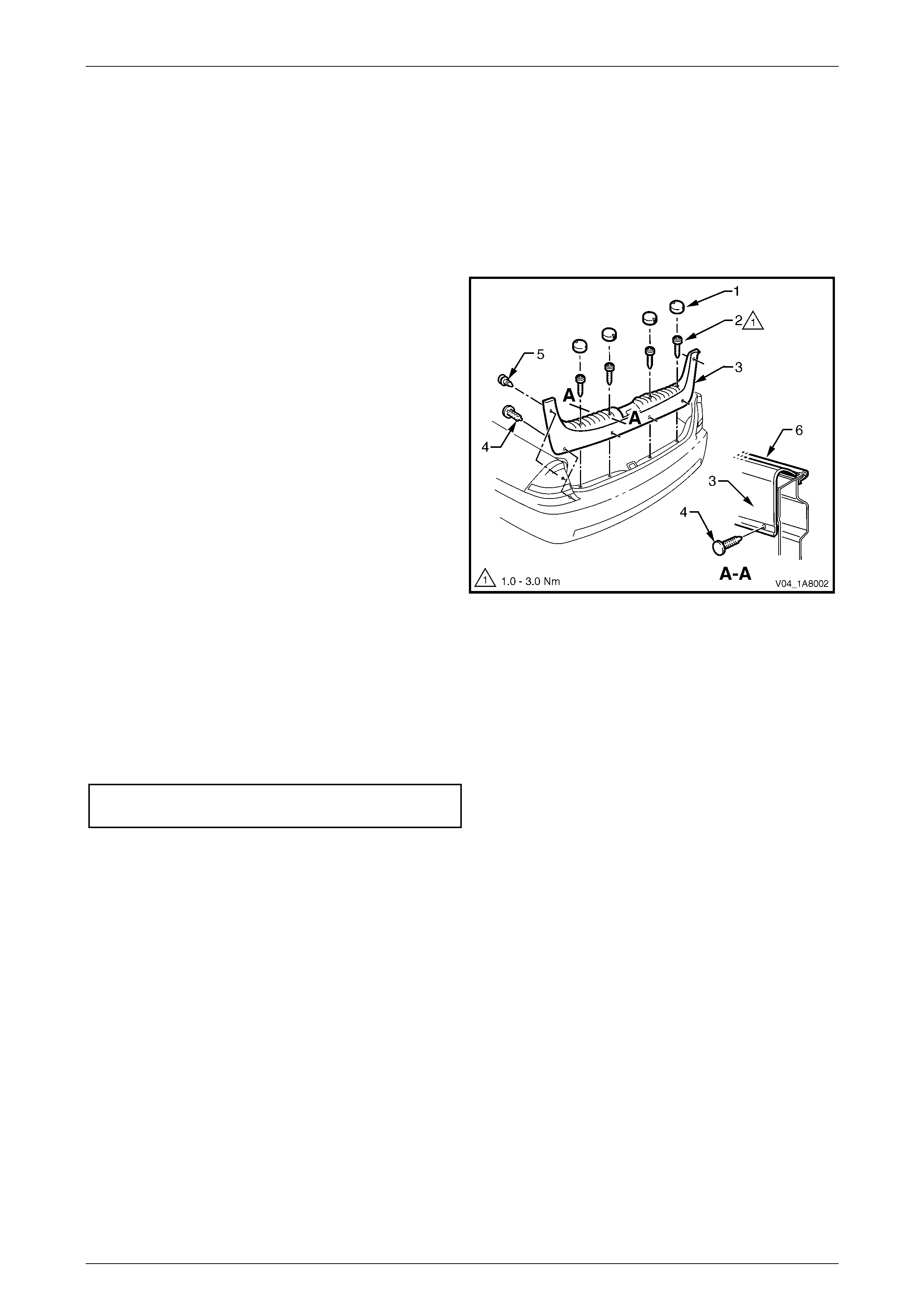
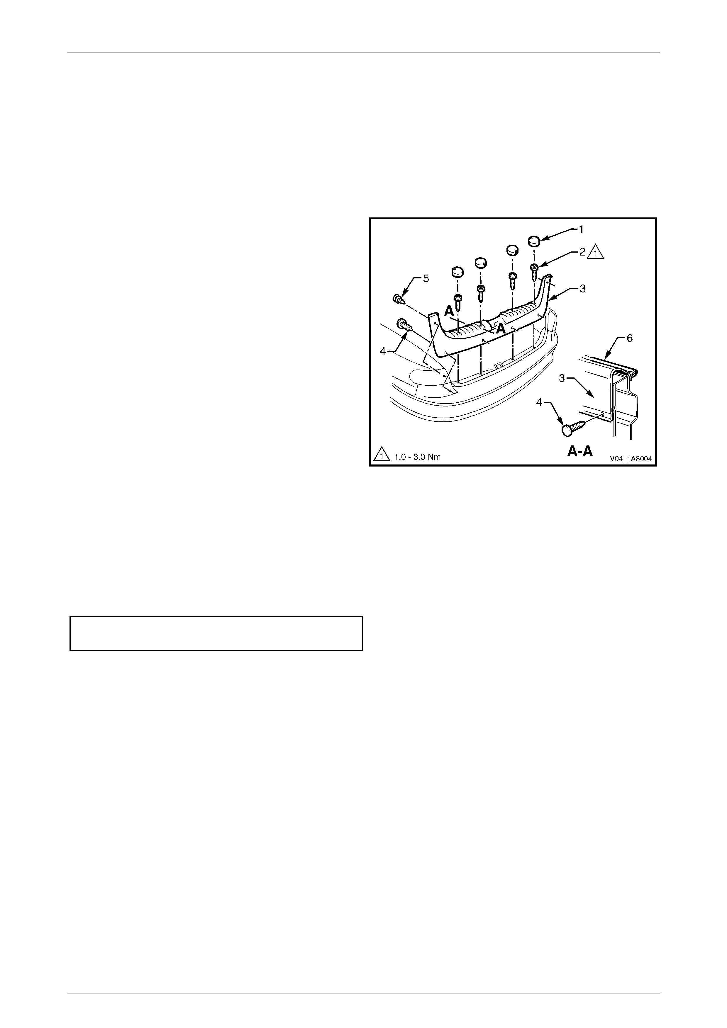
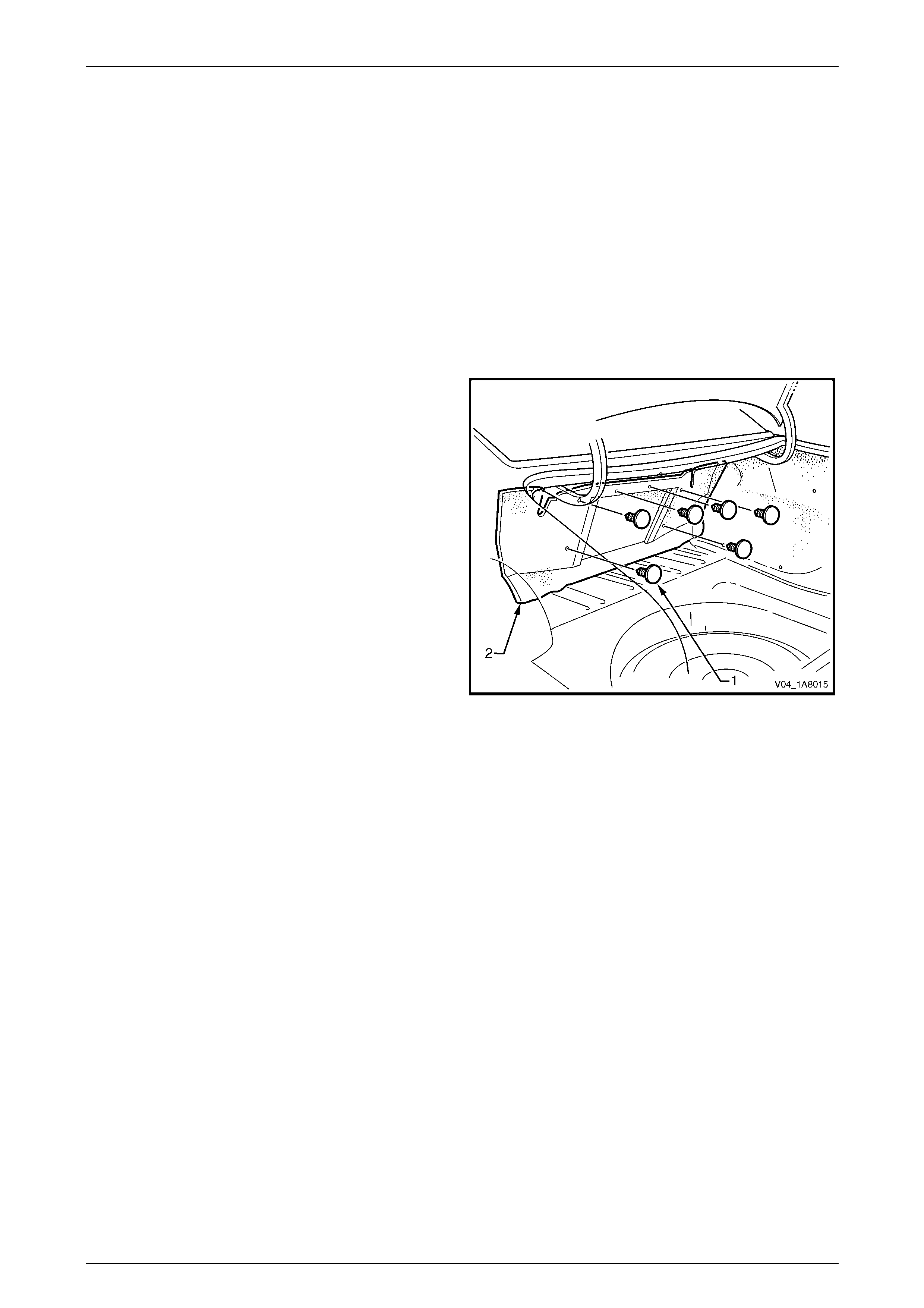
2 Remove the screw covers (1), in four places.
3 Remove the attaching screws (2), in four places, along
the ribbed upper surface of the rear end trim panel (3).
4 Remove the retainers (4), in four places, along the
lower inner edge of the rear end trim panel.
5 Remove the retainers (5), in two places, attaching the
upper sides of the rear end trim panel.
6 Carefully lift the rear end trim panel over the rear
compartment lid latch and clear of the rear
compartment.
Figure 1A8 – 6
Reinstall
Reinstallation of the rear end trim panel is the reverse of the removal procedure, noting the following:
1 Ensure that the outer edge of rear end trim panel engages the rear compartment lid weatherstrip (6), refer to Figure
1A8 – 6.
2 Tighten the fasteners to the specified torque.
Rear end trim panel attaching screw
torque specific atio n .................................... 1.0 – 3.0 Nm
3 Ensure that the notch on the outer screw covers point towards the front of the vehicle.
4 Ensure that the notch on the inner screw covers point towards the rear of the vehicle.

Headlining and Interior Trim Page 1A8–13
Page 1A8–13
2.6 Rear Compartment Floor Carpet
Assembly
LT Section – 14-480
Remove
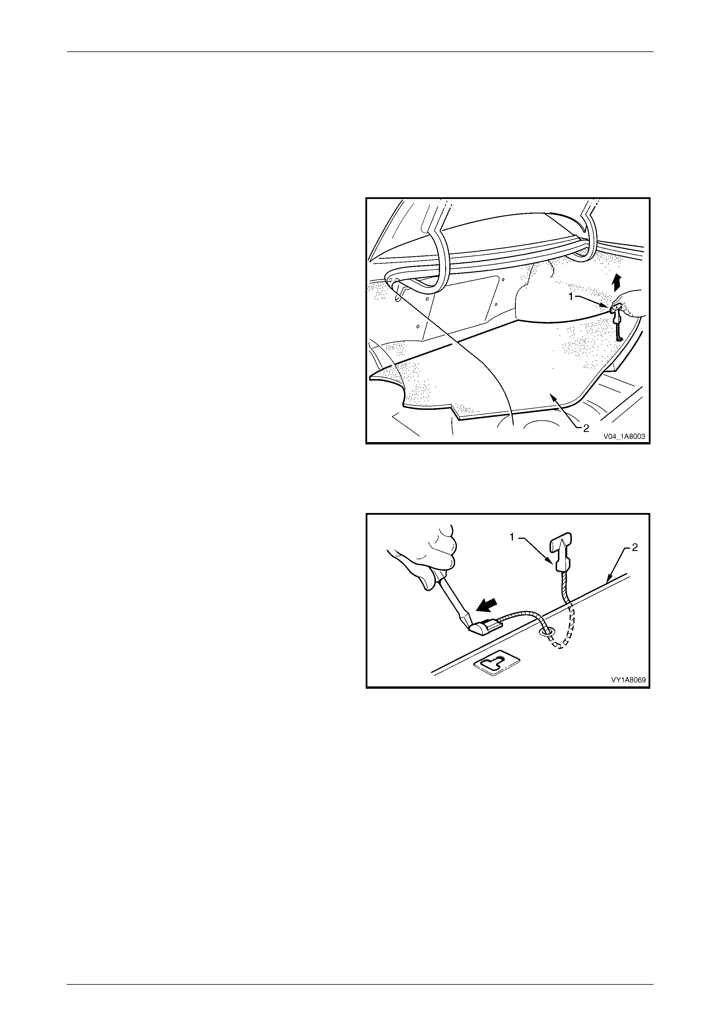
1 Open the rear compartment lid.
2 Grasp the rear compartment strap (1) on the rear
compartment flo or carpet assembly (2) and lift the rear
edge upward.
3 Lift the rear compartment floor carpet assembly from
the rear compartment.
Figure 1A8 – 7
Disassemble
1 Lever the rear compartment strap (1) out of the slot in
the rear compartment floor (2) and remove.
2 Feed the rear compartment strap through the hole in
the rear compartment floor carpet assembly and
remove.
Reassemble
Reassembly of the rear compartment floor carpet assembly
is the reverse of the disassembly procedure.
Figure 1A8 – 8
Reinstall
Reinstallation of the rear compartment floor carpet assembly is the reverse of the removal procedure.
Headlining and Interior Trim Page 1A8–14
Page 1A8–14
2.7 Quarter Inner Rear Side Carpet
LT Section – 14-480
Remove
1 If required, first remove the following components:
a Remove the rear end trim panel, refer to 2.5 Rear End Trim Panel.
b Remove the rear compartment floor carpet assembly, refer to 2.6 Rear Compartment Floor Carpet
Assembly.
2 Carefully prise off the rear shock absorber access hole cover (1), refer to Figure 1A8 – 9.
3 Carefully remove the retainers (2) and (3) away from the quarter inner rear side carpet (4).
4 Unhook the carpet flap from the rear compartment lid hinge bracket.
5 Carefully remove the quarter inner rear side carpet.
Figure 1A8 – 9
Reinstall
Reinstallation of the quarter inner rear side carpet is the reverse of the removal procedure.
Headlining and Interior Trim Page 1A8–15
Page 1A8–15
2.8 Rear Seat Back Panel Carpet
LT Section – 14-480
Remove
1 If required, first remove the following components:
a Remove the rear end trim panel, refer to 2.5 Rear End Trim Panel.
b Remove the rear compartment floor carpet assembly, refer to 2.6 Rear Compartment Floor Carpet
Assembly.
c Partially remove the front of the quarter inner rear side carpet, refer to 2.7 Quarter Inner Rear Side Carpet.
d Lower the rear seat-back centre armrest assembly, refer to Section 1A7 Seat Assemblies.
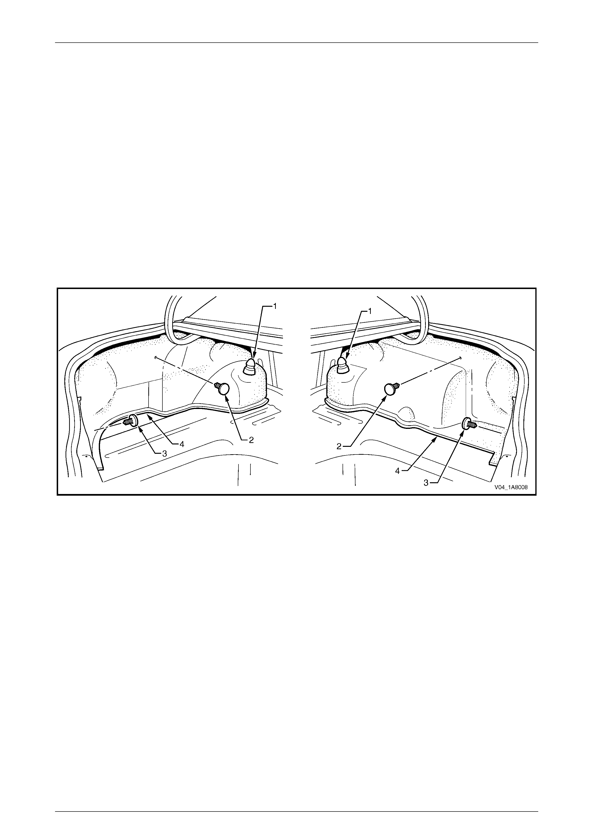
2 Carefully remove the retainers (1), in six places, from
the rear seat back panel carpet (2).
Figure 1A8 – 10
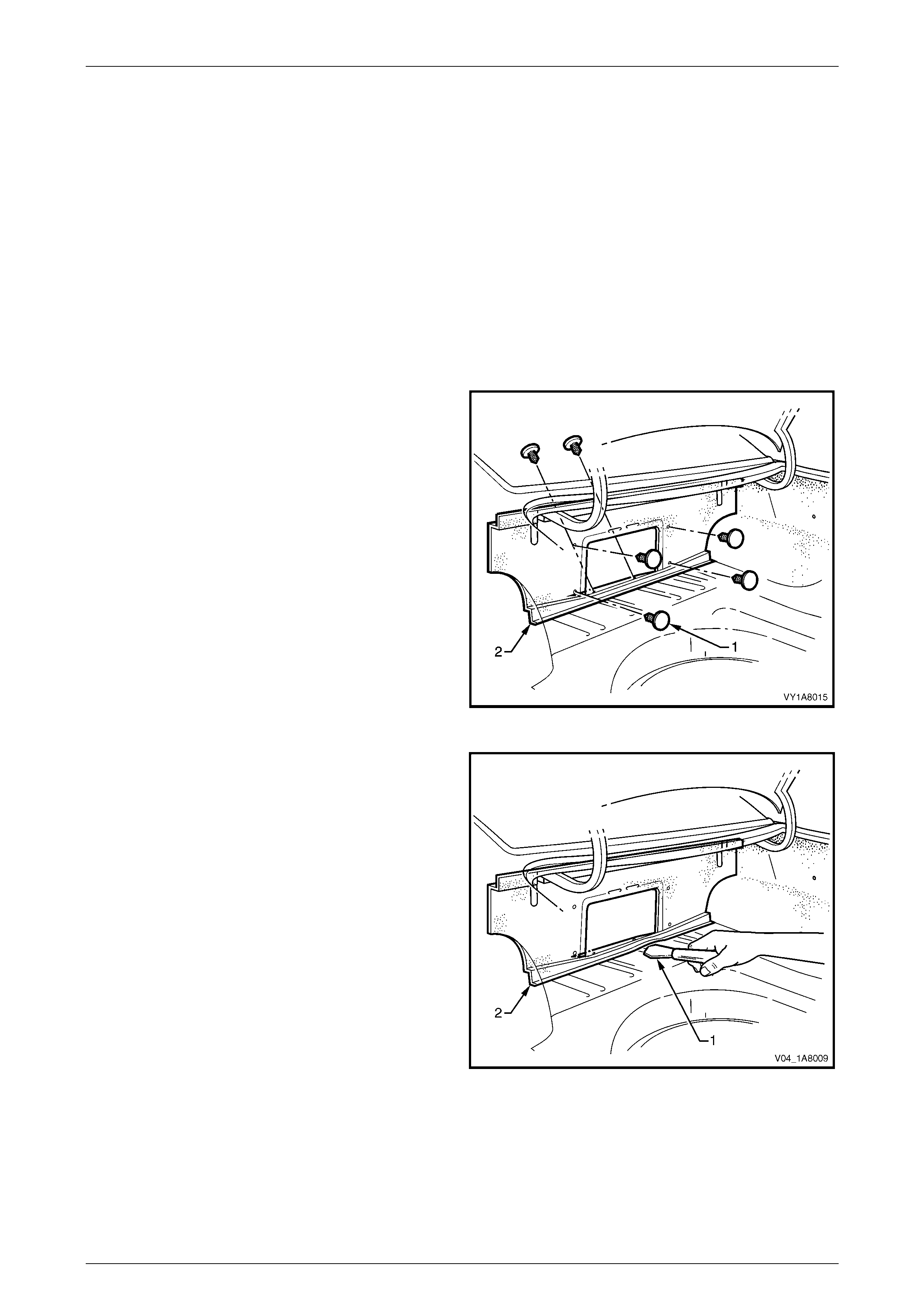
3 Using a knife or paint scraper (1), carefully prise along
the lower edge of the rear seat back panel carpet (2).
4 Remove the rear seat back panel carpet.
Figure 1A8 – 11

Headlining and Interior Trim Page 1A8–16
Page 1A8–16
Reinstall
Reinstallation of the rear seat back panel carpet is the reverse of the removal procedure, noting the following:
1 Use the existing adhesive bead to refasten the rear seat back panel carpet to the vehicle. If required, add a bead of
hot melt adhesive.
2 Ensure that the rear seat back panel carpet is fitted behind the quarter inner rear side carpet.
Headlining and Interior Trim Page 1A8–18
Page 1A8–18
Legend
1 Headlining Assembly With Sunroof
2 Headlining Assembly Without Sunroof
3 Sunshade Assembly
4 Roof Console
5 Centre Pillar Upper Trim Assembly
6 Body Lock Pillar Ga rn ish
7 Rear Window Upper Garnish
8 Windshield Side Garnish
9 Assist Handle
10 Centre Pillar Lower Trim
11 Hinge Pillar Trim Assembly
12 Side Sill Trim Plate
13 Side Sill Trim
14 Body Lock Pillar Lower Trim
15 Body Rear Corner Garnish
16 Quarter I nner Trim Upper
17 Quarter Inner Trim Panel Assembly
18 Luggage Shade Assembly
19 Front Floor Carpet Assembly
20 Driver Footrest
21 Rear Floor Filler Panel
22 Luggage Tie Down Rail Cover
23 Luggage Tie Down Rail
24 Rear Com partment Floor Carpet Assembly, Except LPG
25 Rear End Trim Panel
26 Spare Wheel Cover, With LPG
27 Rear Com partment Floor Carpet Assembly, With LPG
3.1 Centre Pillar Upper Trim Assembly
LT Section – 14-100
Remove
1 If required, first remove the following components:
a Remove the centre pillar lower trim, refer to Section 1A8, 3.2 Centre Pillar Lower Trim in the MY 2003 VY and
V2 Series Service Information.
b Remove the front lower seatbelt bolt, refer to Section 12M Occupant Protection System.
2 Remove the centre pillar cap (1) from the upper
attachment of the centre pillar upper trim assembly (2).
3 Remove the screws (3), in three places, securing the
centre pillar upper trim assembly.
When removing the centre pillar upper trim
assembly, take care not to damage the
locating pin (6) below the upper attaching
screw.
4 Pull the upper edge of the centre pillar upper trim
assembly away from the headlining assembly to
disengage the clips (4) and the seatbelt guide adjuster
assembly (5), if fitted.
5 Feed the seatbelt and anchor plate through the centre
pillar upper trim assembly and remove the centre pillar
upper trim assembly.
6 If required, remove the seatbelt adjuster trim (7) by
gently spreading the outer edges of the centre pillar
upper trim assembly and lifting out the seatbelt
adjuster trim.
Figure 1A8 – 13

Headlining and Interior Trim Page 1A8–19
Page 1A8–19
Reinstall
Reinstallation of the centre pillar upper trim assembly is the reverse of the removal procedure, noting the following:
1 If fitted, ensure that the seatbelt adjuster trim and the seatbelt guide adjuster assembly are in the fully up position
and are correctly aligned prior to installation of the centre pillar upper trim assembly.
2 Ensure that the locating pin below the upper attaching screw in the centre pillar upper trim assembly is correctly
aligned with the locating hole in the centre pillar.
3 Ensure that the leading edge of the centre pillar upper trim assembly engages the front door opening weatherstrip
assembly (8), refer to Figure 1A8 – 13.
4 Check seatbelt operation prior to tightening the centre pillar upper trim assembly attaching screws.
5 Tighten the fasteners to the specified torque.
Centre pillar upper trim assembly attaching
screw torque specification..........................1.0 – 3.0 Nm

Headlining and Interior Trim Page 1A8–20
Page 1A8–20
3.2 Roof Console
LT Section – 02-780
Level 1
For Level 1 vehicles, the dome lamp assembly is deleted and a roof console is added. The roof console is similar to the
roof console that is fitted to Level 2 and Level 3 vehicles, except that blanking plugs are fitted instead of console
switches.
For additional information, refer to Section 1A8, 3.14 Roof Console in the MY 2003 VY and V2 Series Service
Information.
Level 2 and Level 3
For Level 2 and Level 3 vehicles, refer to Section 1A8, 3.14 R oof Console in the MY 2003 VY and V2 Series Service
Information.

Headlining and Interior Trim Page 1A8–21
Page 1A8–21
3.3 Headlining Assembly
LT Section – 14-150
Remove
NOTE
If the vehicle is fitted with a sunroof:
• For HBD sunroof removal, refer to
Section 1F1 Sunroof.
• For online sunroof removal, refer to
Section 1F2 Sunroof.
1 If required, first remove the following components:
a Remove the fuse F6 from the passenger compartment fuse and relay panel assembly, refer to Section 12O
Fuses, Relays and Wiring Harnesses.
b Place protective covering over both front seats and the interior trim.
c Remove both rear seat bolster assemblies, refer to Section 1A7 Seat Assemblies.
d Remove the assist handles, in four places, refer to Section 1A8, 3.1 Assist Handle in the MY 2003 VY and V2
Series Service Information.
e If fitted, remove both roof rail courtesy and reading lamp assemblies, refer to Sect ion 12B Light ing Sys tem .
f Partially remove both centre pillar upper trim assemblies by removing the upper attaching screw, refer to
3.1 Centre Pillar Upper Trim Assembly.
g Remove both windshield side garnishes, refer to Section 1A8, 3.5 Windshield Side Garnish in the MY 2003
VY and V2 Series Service Information.
h Remove both body lock pillar lower trims, refer to Section 1A8, 3.6 Body Lock Pillar Lower Trim in the MY
2003 VY and V2 Series Service Information.
i Remove both body lock pillar garnishes, refer to Section 1A8, 3.7 Body Lock Pillar Garnish in the MY 2003
VY and V2 Series Service Information.
j Remove both quarter inner trim uppers, refer to Section 1A8, 3.8 Quarter Inner Trim Upper in the MY 2003
VY and V2 Series Service Information.
k Remove both body rear corner garnishes, refer to Section 1A8, 3.9 Body Rear Corner Garnish in the MY
2003 VY and V2 Series Service Information.
l Remove the rear window upper garnish, refer to Section 1A8, 3.10 Rear Window Upper Garnish in the MY
2003 VY and V2 Series Service Information.
m Remove both sunshade assemblies, refer to Section 1A8, 3.13 Sunshade Assembly in the MY 2003 VY and
V2 Series Service Information.
n Remove the roof console, refer to 3.2 Roof Console.
o Remove the rear compartment courtesy lamp from the headlining assembly, refer to Section 12B Lighting
System.
NOTE
It may be necessary to flex the headlining
assembly (4) down slightly to gain access to the
harness connec tor.
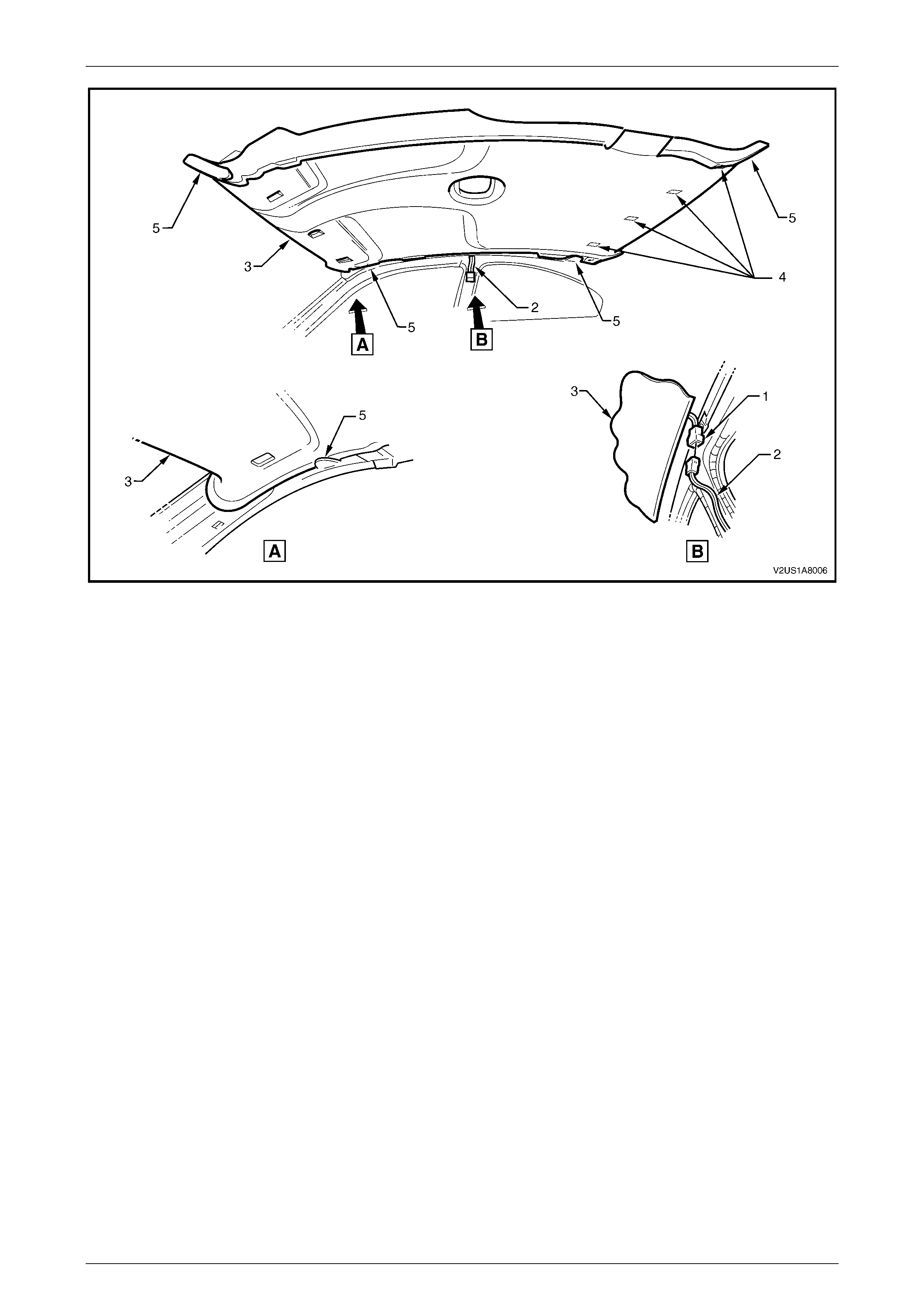
2 Disconnect the headlining assembly harness (1) from the body harness connector (2), located above and slightly
forward of the right-hand centre pillar, refer to Figure 1A8 – 14.
3 Using a suitable trim clip removal tool, carefully prise out the retainers (3), in three places, attaching the headlining
assembly (4) to the roof reinforcement.
Headlining and Interior Trim Page 1A8–22
Page 1A8–22
4 With the aid of an assistant, flex the headlining assembly to disengage the corners and centre from the ‘D’ tabs (5),
in four places, on the sides of the roof panel.
5 With the liftgate open, ease the headlining assembly from its position, removing the assembly through the liftgate
opening, refer to Figure 1A8 – 14.
Figure 1A8 – 14
Reinstall
Reinstallation of the headlining assembly is the reverse of the removal procedure, noting the following:
1 Temporarily support the headlining assembly on the ‘D’ tabs before the trim components are reinstalled.
Headlining and Interior Trim Page 1A8–23
Page 1A8–23
3.4 Luggage Tie Down Rails
LT Section –
Remove
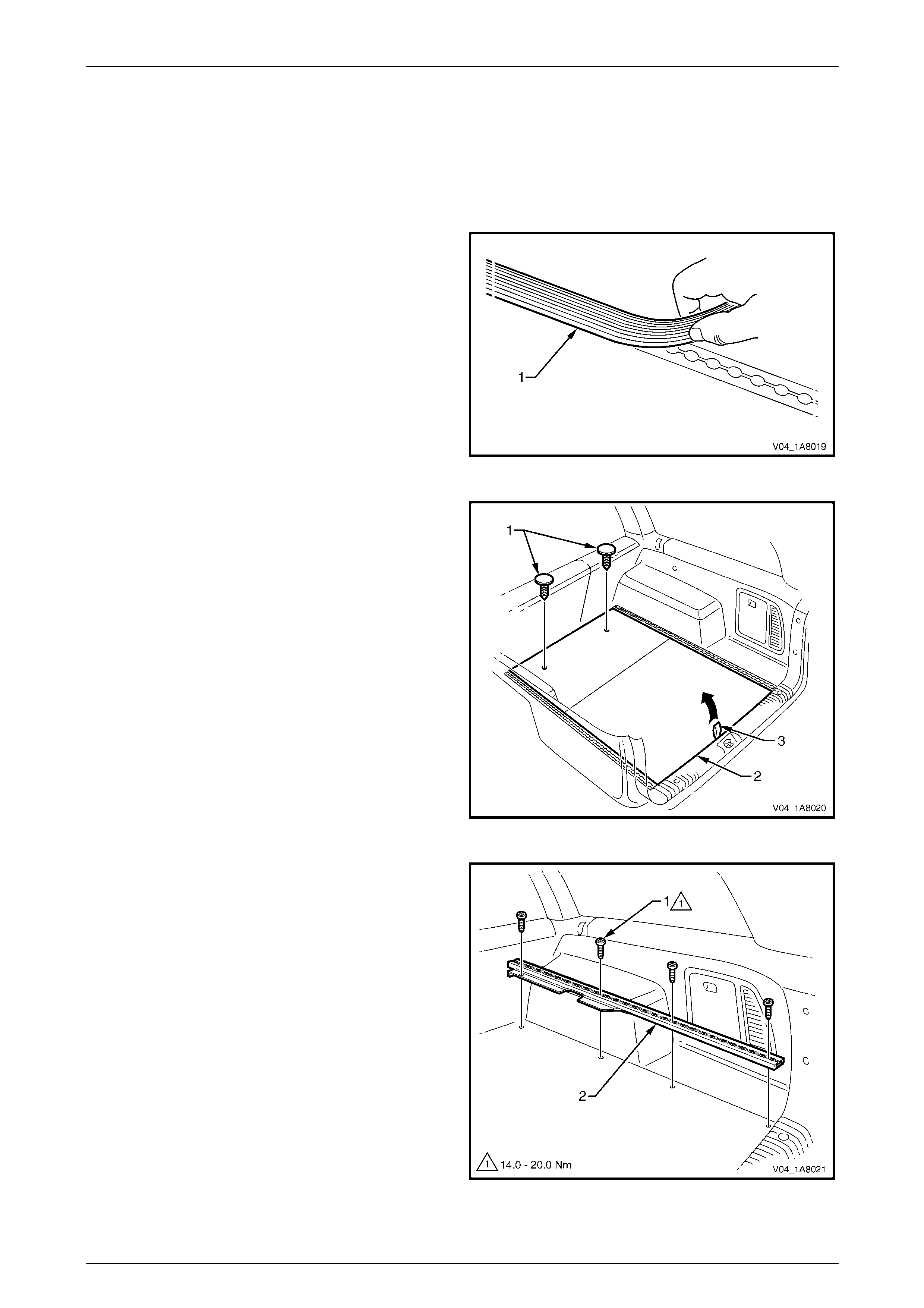
1 If fitted, remove the luggage tie down rail cover.
Figure 1A8 – 15
2 If LPG is not fitted:
a Remove the retainers (1), in two places, from the
front of the rear compartment floor carpet
assembly (2).
b Grasp the handle (3) on the rear compartment
floor carpet assembly and lift the rear edge
outward.
c Lift the rear compartment floor carpet assembly
from the rear, out through the liftgate opening.
3 If LPG is fitted:
a Remove the rear compartment floor carpet
assembly, refer to Section 1A8, 3.21 Rear
Compartment Floor Carpet Assembly and Spare
Wheel C over, With LPG in the MY 2003 VY and
V2 Series Service Information.
Figure 1A8 – 16
4 Remove the Torx screws (1), in four places, attaching
the luggage tie down rail to the vehicle.
5 Remove the luggage tie down rail (2) through the
liftgate opening.
6 If required, repeat from Step 4 for the opposite side of
the vehicle.
Figure 1A8 – 17

Headlining and Interior Trim Page 1A8–24
Page 1A8–24
Reinstall
Reinstallation of the luggage tie down rails is the reverse of the removal procedure, noting the following:
1 Tighten the fasteners to the specified torque.
Luggage tie down rail screw
torque specification ................................ 14.0 – 20.0 Nm
Headlining and Interior Trim Page 1A8–25
Page 1A8–25
4 Service Operations - Coupe
NOTE
The following chart is included to assist with the
identification of the components.
Figure 1A8 – 18
Legend
1 Headlining Assembly
2 Sunshade Assembly
3 Windshield Side Garnish
4 Centre Pillar Upper Trim Assembly
5 Body Rear Corner Garnish
6 Hinge Pillar Trim Assembly
7 Side Sill Trim
8 Side Sill Trim Plate
9 Quarter Trim Panel Assembly
10 Front Floor Carpet Assembly
11 Driver Footrest
12 Rear Seat Back P anel Carpet
13 Rear Com partment Floor Carpet Assembly
14 Quarter I nner Rear Side Carpet
15 Rear End Trim Panel
16 Screw Cover
17 Rear Window Trim Panel Assembly
Headlining and Interior Trim Page 1A8–26
Page 1A8–26
4.1 Quarter Trim Panel Assembly
LT Section – 14-100
Remove
1 If required, first remove the following components:
a Remove the rear seat cushion assembly, refer to Section 1A7 Seat Assemblies.
b Remove the rear seat-back assembly, refer to Section 1A7 Seat Assemblies.
c Remove the seat adjuster outer front cover, refer to Section 1A7 Seat Assemblies.
d Remove the side sill trim, refer to Section 1A8, 4.1 Side Sill Trim and Plate in the MY 2003 VY and V2 Series
Service Information.
2 Remove the screw (1) from the lower edge of the
quarter trim panel assembly (2).
3 Remove the screws (3), in two places, from the rear
edge of the quarter trim panel assembly.
When removing the quarter trim panel
assembly, take care not to damage the two
locating pins (6).
4 Starting at the lower edge of the centre pillar upper
trim assembly (4) and moving alternately clockwise
and anticlockwise, disengage the quarter trim panel
assembly attaching clips (5), in eight places, by
carefully manoeuvring the quarter trim panel assembly
away from the rear sheetmetal.
5 Remove the quarter trim panel assembly.
Figure 1A8 – 19

Headlining and Interior Trim Page 1A8–27
Page 1A8–27
Disassemble
Figure 1A8 – 20
Legend
1 Quarter Trim Panel Assembly
2 Quarter Trim Armrest Insert Assembly 3 Quarter Trim Radio Speaker Grille
4 Quarter Trim Insulator Assembly
Quarter Trim Radio Speaker Grille
The quarter trim radio speaker grill is permanently heat-staked to the quarter trim panel assembly and cannot be
serviced separately.
Quarter Trim Insulator Assembly
Remove
Take care not to tear the quarter trim
insulator assembly. Retain as much adhesive
as possible on the quarter trim insulator
assembly. Do not fold the quarter trim
insulator assembly. Store the quarter trim
insulator assembly in a flat location with the
adhesive facing away from objects.
1 Remove the quarter trim insulator assembly (1) from
the back of the quarter trim panel assembly (2) by
peeling the quarter trim insulator assembly slowly
across the quarter trim panel assembly.
Figure 1A8 – 21
Reinstall
Reinstallation of the quarter trim insulator assembly is the reverse of the removal procedure, noting the following:
1 If required, apply additional hot melt adhesive with a high softening point (e.g. 90°C).
2 Locate the quarter trim insulator assembly centrally within the quarter trim panel assembly and press firmly into
position.
Headlining and Interior Trim Page 1A8–28
Page 1A8–28
Quarter Trim Armrest Insert Assembly
Remove
A heat staked quarter trim armrest insert
assembly must be replaced if it is removed
from the quarter trim panel assembly.
1 If required, peel back the quarter trim insulator assembly from the upper portion of quarter trim panel assembly,
allowing access to the quarter trim armrest insert assembly attaching points.
2 If the quarter trim armrest insert assembly is retained
to the quarter trim panel assembly using heat stakes:
a Drill out the heat-stakes, in fourteen places,
retaining the quarter trim armrest insert
assembly (1) to the quarter trim panel
assembly (2).
Figure 1A8 – 22
3 If the quarter trim armrest insert assembly is retained
to the quarter trim panel assembly using nuts and
clips:
a Remove the clips (4), in seven places, by sliding
them away from the quarter trim panel
assembly (2).
Take care when removing the nuts (3), as the
rotating action may cut off the quarter trim
armrest insert assembly shafts to which the
nuts are attached. If a shaft is cut off, fit a
replacement quarter trim armrest insert
assembly.
b Remove the nuts (3), in seven places, attaching
the quarter trim armrest insert assembly (1) to
the quarter trim panel assembly. Figure 1A8 – 23
4 Before removal, prise the quarter trim armrest insert assembly away from quarter trim panel assembly. Slide the
quarter trim armrest insert assembly to the rear of the quarter trim panel assembly and remove.
Headlining and Interior Trim Page 1A8–29
Page 1A8–29
Reinstall
NOTE
A replacement quarter trim armrest insert
assembly is supplied with nuts and clips.
1 Ensure that the quarter trim armrest insert assembly (1) is sitting flush against the quarter trim panel assembly (2)
along the entire top contacting surface, refer to Figure 1A8 – 23.
2 Tighten the retaining nuts (3), in seven places, to the specified torque.
Quarter trim armrest insert assembly
retaining nut torque specification ................ 0.7 – 0.9 Nm
3 Install the clips (4), in seven places.
Reinstall
Reinstallation of the quarter trim panel assembly is the reverse of the removal procedure, noting the following:
1 Ensure that the locating pins are aligned with the locating holes before engaging the attaching clips. Also ensure
that the leading edge of the quarter trim panel assembly engages the door opening weatherstrip assembly.
2 Tighten the fasteners to the specified torque.
Quarter trim panel assembly attaching
screw torque specification..........................1.0 – 3.0 Nm

Headlining and Interior Trim Page 1A8–30
Page 1A8–30
4.2 Centre Pillar Upper Trim Assembly
LT Section – 14-100
Remove
1 If required, first remove the following components:
a Remove the rear seat cushion, refer to Section 1A7 Seat Assemblies.
b Remove the rear seat-back assembly, refer to Section 1A7 Seat Assemblies.
c Remove the seat adjuster outer front cover, refer to Section 1A7 Seat Assemblies.
d Remove the side sill trim, refer to Section 1A8, 4.1 Side Sill Trim and Plate in the MY 2003 VY and V2 Series
Service Information.
e Remove the quarter trim panel assembly, refer to 4.1 Quarter Trim Panel Assembly.
f Remove the front lower seatbelt bolt, refer to Section 12M Occupant Protection System.
2 Remove the centre pillar cap (1) from the upper
attachment of the centre pillar upper trim assembly (2).
3 Remove the screws (3), in three places, securing the
centre pillar upper trim assembly.
When removing the centre pillar upper trim
assembly, take care not to damage the
locating pin (6) below the upper attaching
screw.
4 Pull the upper edge of the centre pillar upper trim
assembly away from the headlining assembly to
disengage the centre pillar attaching clips (4) and the
seatbelt guide adjuster assembly (5).
5 Feed the seatbelt and anchor plate through the centre
pillar upper trim assembly and remove the centre pillar
upper trim assembly.
6 If required, remove the seatbelt adjuster trim (7) by
gently spreading the outer edges of the centre pillar
upper trim assembly and lifting out the seatbelt
adjuster trim.
Figure 1A8 – 24
Reinstall
Reinstallation of the centre pillar upper trim assembly is the reverse of the removal procedure, noting the following:
1 Ensure that the seatbelt adjuster trim and the seatbelt guide adjuster assembly are in the fully up position and are
correctly aligned prior to installation of the centre pillar upper trim assembly.
2 Ensure that the locating pin, below the upper attaching screw in the centre pillar upper trim assembly, is correctly
aligned with the locating hole in the centre pillar.
3 Ensure that the leading edge of the centre pillar upper trim assembly engages the front door opening
weatherstrip assembly (8), refer to Figure 1A8 – 24.
4 Check seatbelt operation prior to tightening the centre pillar upper trim assembly attaching screws.
5 Tighten the fasteners to the specified torque.
Centre pillar upper trim assembly attaching
screw torque specification..........................1.0 – 3.0 Nm
Headlining and Interior Trim Page 1A8–31
Page 1A8–31
4.3 Windshield Side Garnish
LT Section – 14-100
Remove
1 If required, first remove the following components:
a Remove the rear seat cushion assembly, refer to Section 1A7 Seat Assemblies.
b Remove the rear seat-back assembly, refer to Section 1A7 Seat Assemblies.
c Partially remove the rear portion of the side sill trim, refer to Section 1A8, 4.1 Side Sill Trim and Plate in the
MY 2003 VY and V2 Series Service Information.
d Remove the quarter trim panel assembly, refer to 4.1 Quarter Trim Panel Assembly.
e Remove the centre pillar upper trim assembly, refer to 4.2 Centre Pillar Upper Trim Assembly.
When removing the windshield side garnish,
take care not to damage the two locating
pins (3).
2 Starting at the upper rear edge of the windshield side
garnish (1), disengage the attaching clips (2), in six
places.
3 Remove the windshield side garnish.
Figure 1A8 – 25
Reinstall
Reinstallation of the windshield side garnish is the reverse of the removal procedure, noting the following:
1 Ensure that the windshield side garnish locating pins are aligned with the holes in the inner panel.
2 Ensure that the outer edge of the windshield side garnish engages the door opening weatherstrip assembly (4),
refer to Figure 1A8 – 25.
Headlining and Interior Trim Page 1A8–32
Page 1A8–32
4.4 Sunshade Assembly
LT Section – 14-050
Remove
1 Remove the fuse F6 from the passenger compartment
fuse and relay panel assembly, refer to Section 12O
Fuses, Relays and Wiring Harnesses.
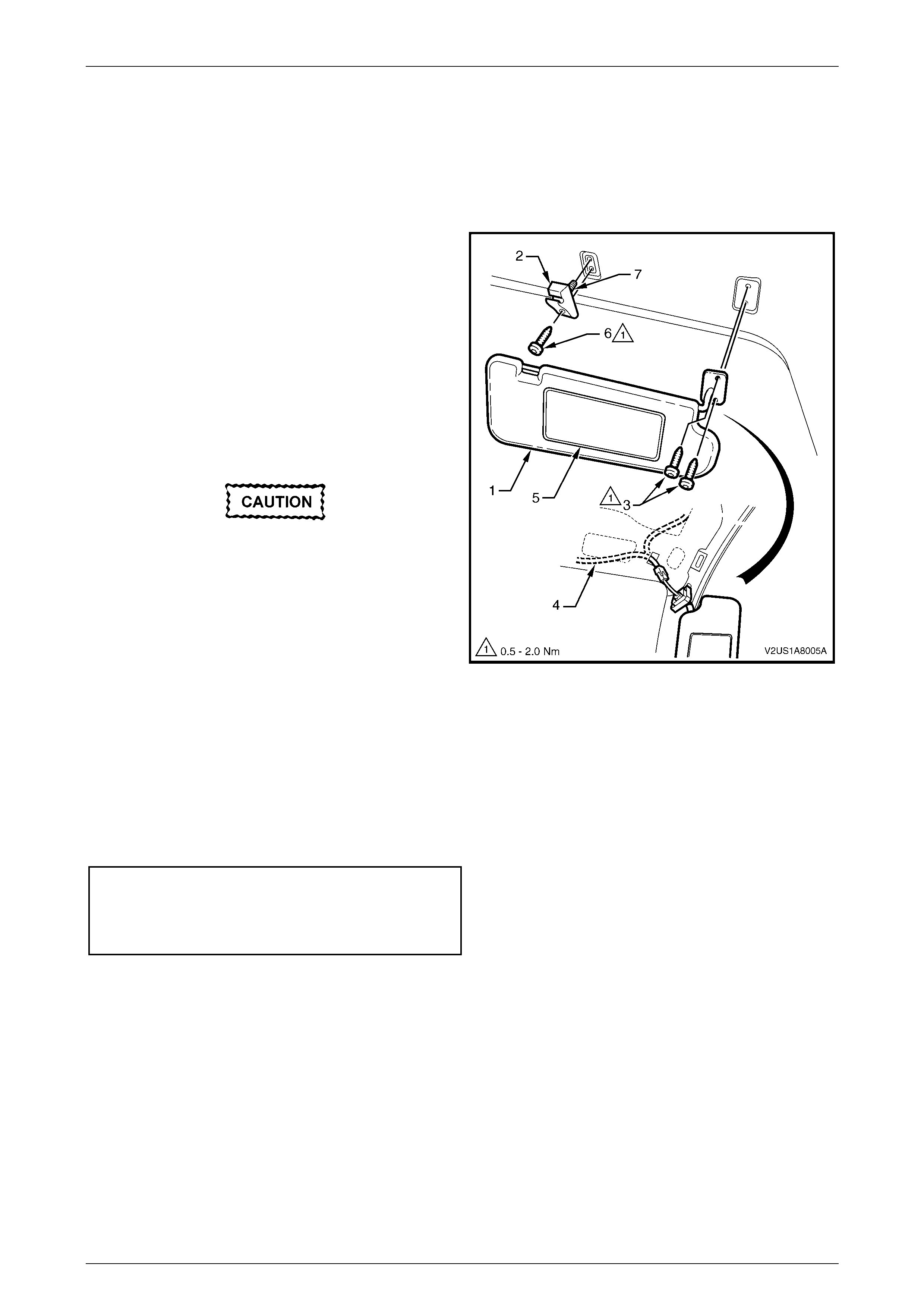
2 Unclip the sunshade assembly (1) from the sunshade
support (2) and rotate to gain acces s.
3 Remove the sunshade assembly attaching Torx
screws (3), in two places.
4 Pull the sunshade assembly away from the headlining
assembly and if fitted, disconnect the wiring
harness (4) from the illuminated vanity mirror (5).
5 Remove the sunshade assembly.
When removing the sunshade support, take
care not to damage the locating pin (7).
6 If required, remove the Torx screw (6) from the
sunshade support and remove the support from the
headlining assembly.
Figure 1A8 – 26
Reinstall
Reinstallation of the sunshade assembly is the reverse of the removal procedure, noting the following:
1 Ensure that the sunshade support is correctly located.
2 If fitted, reconnect the wiring harness to the sunshade assembly.
3 Tighten the fasteners to the specified torque.
Sunshade assem bly attaching screw s
torque specific atio n .................................... 0.5 – 2.0 Nm
Sunshade support atta ching screw s
torque specific atio n .................................... 0.5 – 2.0 Nm

Headlining and Interior Trim Page 1A8–33
Page 1A8–33
4.5 Headlining Assembly
LT Section – 14-150
Remove
1 If required, first remove the following components:
a Remove the fuse F6 from the passenger compartment fuse and relay panel assembly, refer to Section 12O
Fuses, Relays and Wiring Harnesses.
b Move both front seats to the rear access position.
c Place protective covering over both front seats and the interior trim.
d Remove the rear seat cushion assembly, refer to Section 1A7 Seat Assemblies.
e Remove the rear seat-back assembly, refer to Section 1A7 Seat Assemblies.
f Remove both side sill trims, refer to Section 1A8, 4.1 Side Sill Trim and Plate in the MY 2003 VY and V2
Series Service Information.
g Remove both quarter trim panel assemblies, refer to 4.1 Quarter Trim Panel Assembly.
h Remove both centre pillar upper trim assemblies, refer to 4.2 Centre Pillar Upper Trim Assembly.
i Remove both windshield side garnishes, refer to 4.3 Windshield Side Garnish.
j Remove both body rear corner garnishes, refer to Section 1A8, 4.5 Body Rear Corner Garnish in the MY
2003 VY and V2 Series Service Information.
k Remove both sunshade assemblies, refer to 4.4 Sunshade Assembly.
l Remove the dome lamp assembly, refer to Section 12B Lighting System.
NOTE
It may be necessary to flex the headlining
assembly (3) down slightly to gain access to the
harness connec tor.
2 Disconnect the headlining assembly harness (1) from the body harness connector (2), located above and slightly
forward of the right-hand centre pillar, refer to Figure 1A8 – 27.
3 Disengage the hook and loop fasteners (4), in four places, attaching the rear edge of the headlining assembly by
gently pulling down the headlining assembly in one corner and working across the rear edge.
4 With the aid of an assistant, flex the headlining assembly to disengage the corners from the ‘D’ tabs (5), in four
places, on the sides of the roof panel.
5 Carefully manoeuvre the headlining assembly from the vehicle.
Headlining and Interior Trim Page 1A8–34
Page 1A8–34
Figure 1A8 – 27
Reinstall
Reinstallation of the headlining assembly is the reverse of the removal procedure, noting the following:
1 Temporarily support the headlining assembly on the ‘D’ tabs before the trim components are reinstalled.
Headlining and Interior Trim Page 1A8–35
Page 1A8–35
4.6 Rear End Trim Panel
LT Section – 14-120
Remove
1 If required, partially remove the rear compartment lid weatherstrip, refer to Section 1A4 Hood, Rear Compartment
Lid, Liftgate and Endga te.
2 Remove the screw covers (1), in four places.
3 Remove the attaching screws (2), in four places, along
the ribbed upper surface of the rear end trim panel (3).
4 Remove the retainers (4), in four places, along the
lower inner edge of the rear end trim panel.
5 Remove the retainers (5), in two places, attaching the
upper sides of the rear end trim panel.
6 Carefully lift the rear end trim panel over the rear
compartment lid latch and clear of the rear
compartment.
Figure 1A8 – 28
Reinstall
Reinstallation of the rear end trim panel is the reverse of the removal procedure, noting the following:
1 Ensure that the outer edge of the rear end trim panel engages the rear compartment lid weatherstrip (6), refer to
Figure 1A8 – 28.
2 Tighten the fasteners to the specified torque.
Rear end trim panel attaching screw
torque specific atio n .................................... 1.0 – 3.0 Nm
3 Ensure that the notch on the outer screw covers point towards the front of the vehicle.
4 Ensure that the notch on the inner screw covers point towards the rear of the vehicle.
Headlining and Interior Trim Page 1A8–36
Page 1A8–36
4.7 Rear Compartment Floor Carpet
Assembly
LT Section – 14-480
Remove
1 Open the rear compartment lid.
2 Grasp the rear compartment strap (1) on the rear
compartment flo or carpet assembly (2) and lift the rear
edge upward.
3 Lift the rear compartment floor carpet assembly from
the rear compartment.
Figure 1A8 – 29
Disassemble
1 Lever the rear compartment strap (1) out of the slot in
the rear compartment floor (2) and remove.
2 Feed the rear compartment strap through the hole in
the rear compartment floor carpet assembly and
remove.
Reassemble
Reassembly of the rear compartment floor carpet assembly
is the reverse of the disassembly procedure.
Figure 1A8 – 30
Reinstall
Reinstallation of the rear compartment floor carpet assembly is the reverse of the removal procedure.
Headlining and Interior Trim Page 1A8–37
Page 1A8–37
4.8 Rear Seat Back Panel Carpet
LT Section – 14-480
Remove
1 If required, first remove the following components:
a Remove the rear end trim panel, refer to 4.6 Rear End Trim Panel.
b Remove the rear compartment floor carpet assembly, refer to 4.7 Rear Compartment Floor Carpet
Assembly.
c Partially remove the front of the quarter inner rear side carpet, refer to Section 1A8, 4.14 Quarter Inner Rear
Side Carpet in the MY 2003 VY and V2 Series Service Information.
2 Carefully remove the retainers (1), in six places, from
the rear seat back panel carpet (2).
3 Remove the rear seat back panel carpet.
Figure 1A8 – 31
Reinstall
Reinstallation of the rear seat back panel carpet is the reverse of the removal procedure, noting the following:
1 Ensure that the rear seat back panel carpet is fitted behind the quarter inner rear side carpet.

Headlining and Interior Trim Page 1A8–38
Page 1A8–38
5 Torque Wrench Specifications
Centre Pillar Upper Trim Assembly Attaching Screw.....................1.0 – 3.0 Nm
Rear End Trim Panel Attaching Screw ..........................................1.0 – 3.0 Nm
Luggage Tie Down Rail Screw...................................................14.0 – 20.0 Nm
Quarter Trim Armrest Insert Assembly Retaining Nut....................0.7 – 0.9 Nm
Quarter Trim Panel Assembly Attaching Screw.............................1.0 – 3.0 Nm
Sunshade Assembly Attaching Screws..........................................0.5 – 2.0 Nm
Sunshade Support Attaching Screws ............................................0.5 – 2.0 Nm