
Bumper Ba r s Page 1D–1
Page 1D–1
Section 1D
Bumper Bars
ATTENTION
Before performing any service operation or other procedure described in this Section, refer to Section 00
Warnings, Cautions and Notes for correct workshop practices with regard to safety and/or property damage.
1 General Information............................................................................................................................... 2
2 Service Operations – Domestic Level 3 .............................................................................................. 3
2.1 Front Bumper Fascia Assembly............................................................................................................................3
Remove ...................................................................................................................................................................3
Disassemble ...........................................................................................................................................................3
Radiator Grille Assembly....................................................................................................................................3
Lower Radiator Grille Assembly .........................................................................................................................3
Front Fog Lamp Assembly..................................................................................................................................3
Reinstall ..................................................................................................................................................................3
2.2 Rear Bumper Fascia Assembly.............................................................................................................................4
Remove ...................................................................................................................................................................4
Disassemble ...........................................................................................................................................................4
Rear Bumper Fascia Outer Lower Moulding.......................................................................................................4
Rear Bumper Fascia Outer Lower Moulding Mounting Bracket..........................................................................5
Rear Bumper Fascia Reflective Lens .................................................................................................................5
Rear Bumper Fascia Applique............................................................................................................................6
Towbar Opening Cover.......................................................................................................................................6
Reverse Parking Aid Components......................................................................................................................6
Reinstall ..................................................................................................................................................................6
3 Service Operations – Coupe................................................................................................................. 7
3.1 Rear Bumper Fascia...............................................................................................................................................7
Remove ...................................................................................................................................................................7
Disassemble ...........................................................................................................................................................8
Rear Bumper Fascia Anchor Plate Assembly.....................................................................................................8
Rear Bumper Fascia Bracket..............................................................................................................................9
Reinstall ..................................................................................................................................................................9
3 Torque Wrench Specifications........................................................................................................... 10

Bumper Ba r s Page 1D–2
Page 1D–2
1 General Information
With the following exceptions, MY 2004 VY and V2 Series Bumper Bars information carries over from MY 2003 VY
Series vehicles. For Bumper Bar information not contained within this Section, refer to Section 1D Bumper Bars in the
MY 2003 VY and V2 Series Service information.
• Domestic Level 3 front bumper fascia
• Level 2 and 3 rear bumper fascia
• Coupe rear bumper fascia
Domestic Level 3 vehicles are fitted with new front bumper fascia. A modified rear bumper fascia that includes rear lower
mouldings for Level 3 vehicles and an applique fitted to Level 2 and 3 vehicles.
The front fog lamps are now attached to the front bumper fascia and new radiator and lower radiator grille assemblies
are fitted. For service operations for the radiator grille assemblies refer to Section 1C Radiator Grille. The rear bumper
fascia is fitted with a new applique which houses reflective lenses on either side. The rear bumper fascia also includes
skirt extensions along each side of the bumper fascia.
Coupe vehicles are fitted with a revised rear bumper fascia introduced due to body modifications required for new market
vari ant s.
Although these bumper profiles may be a different, the paint masking areas are carry over, refer to Section 1D, 2.1 Paint
Systems in the MY 2003 VY and V2 Series Service Information.
For Model Level designations refer to Section 0A General Information.
Bumper Ba r s Page 1D–3
Page 1D–3
2 Service Operations – Domestic
Level 3
2.1 Front Bumper Fascia Assembly
LT Section – 10-150
Remove
For removal of the front bumper fascia assembly, refer to Section 1D, 2.2 Front Bumper Fascia Assembly in the MY 2003
VY and V2 Series Service Information.
Disassemble
Radiator Grille Assembly
For removal of the radiator grille assembly, refer to Section 1C, 2.1 Radiator Grille assembly.
Lower Radiator Grille Assembly
For removal of the lower radiator grille assembly, refer to Section 1C, 2.2 Lower Radiator Grille assembly.
Front Fog Lamp Assembly
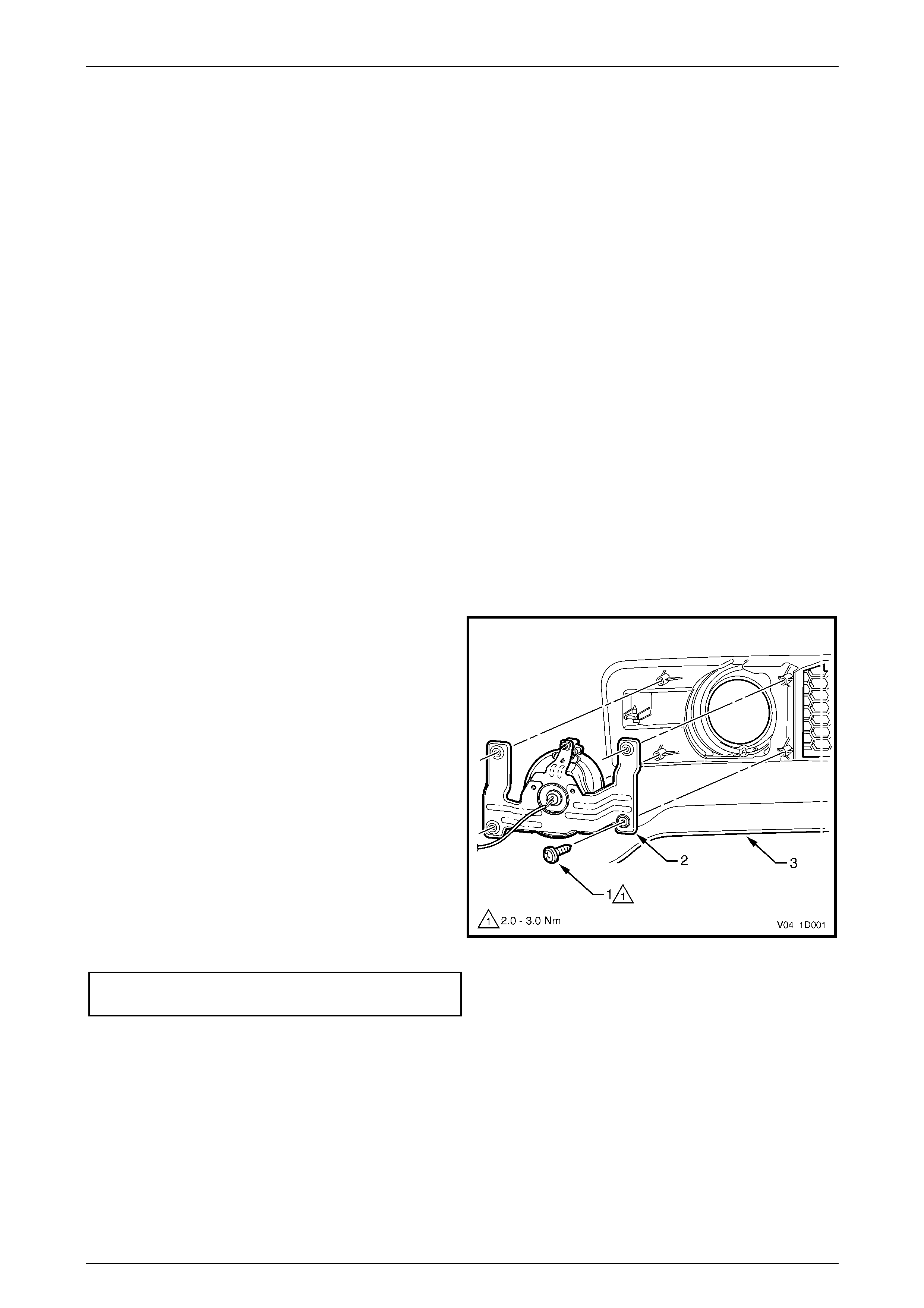
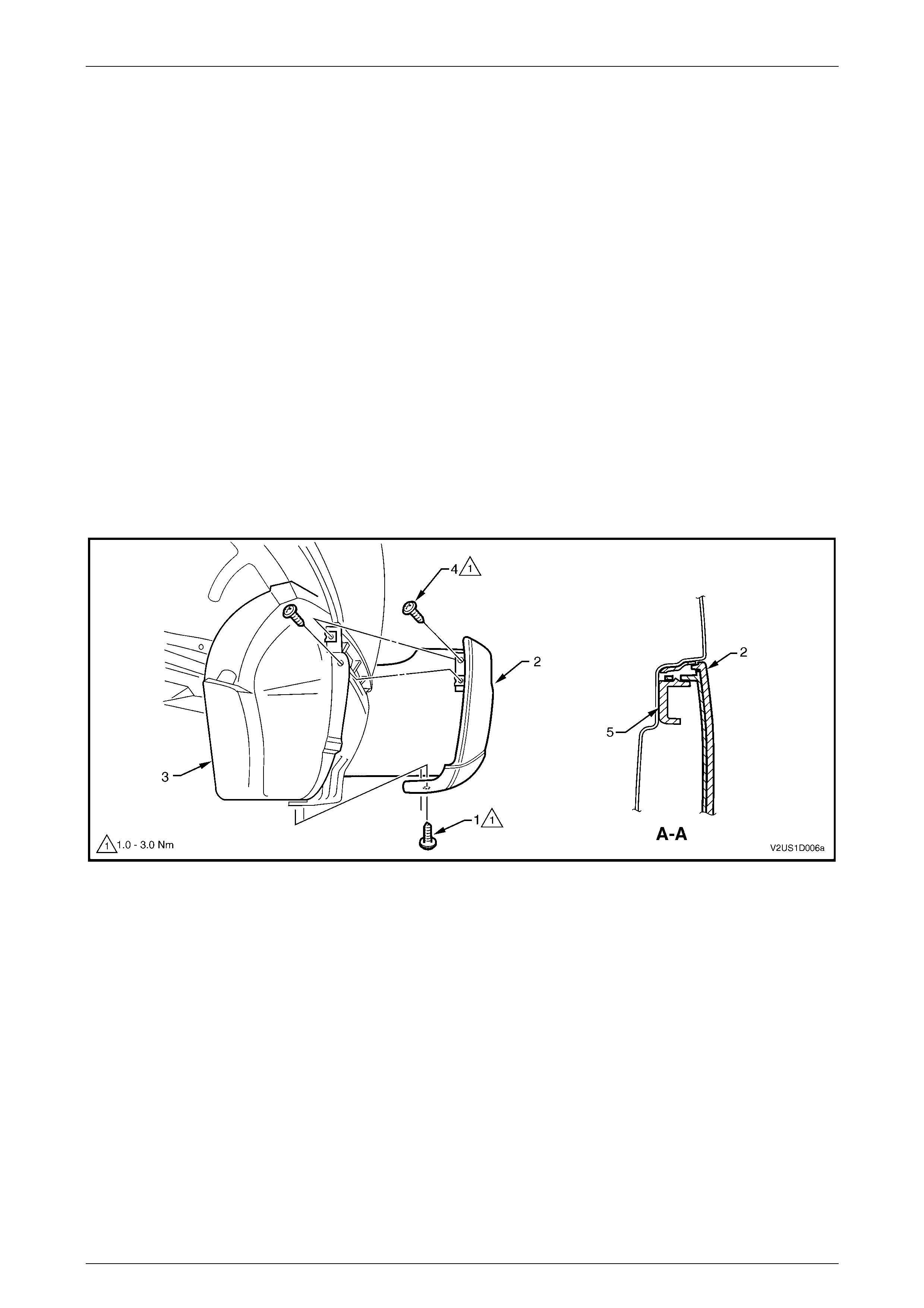
Remove
1 Remove the screw (1), four places, attaching the front
fog lamp assembly (2) to the front bumper fascia (3).
2 Remove the lamp assembly from the rear of the
bumper fascia.
NOTE
For further servicing of the front fog lamp
assembly, refer to Section 12B Lighting System.
Reinstall
Installation of the front fog lamp assembly is the reverse of
the removal. Tighten the screws to the specified torque.
NOTE
Following installation of the bumper fascia
assembly, aim the fog lamps, refer to
Section 12B Lighting System.
Front fog lamp assembly attaching
screw torque specification..........................2.0 – 3.0 Nm
Figure 1D – 1
Reinstall
For reinstallation of the front bumper fascia assembly, refer to Section 1D, 2.2 Front Bumper Fascia Assembly in the
MY 2003 VY and V2 Series Service Information.
Bumper Ba r s Page 1D–4
Page 1D–4
2.2 Rear Bumper Fascia Assembly
LT Section – 10-150
Remove
For removal of the rear bumper fascia assembly, refer to Section 1D, 2.5 Rear Bumper Fascia Assembly in the MY 2003
VY and V2 Series Service Information.
NOTE
Due to the addition of the rear bumper fascia
outer lower moulding, the screw attaching the
front lower section of the fascia to the rear
wheelhouse liner is accessed through a cutout in
the lower moulding.
Disassemble
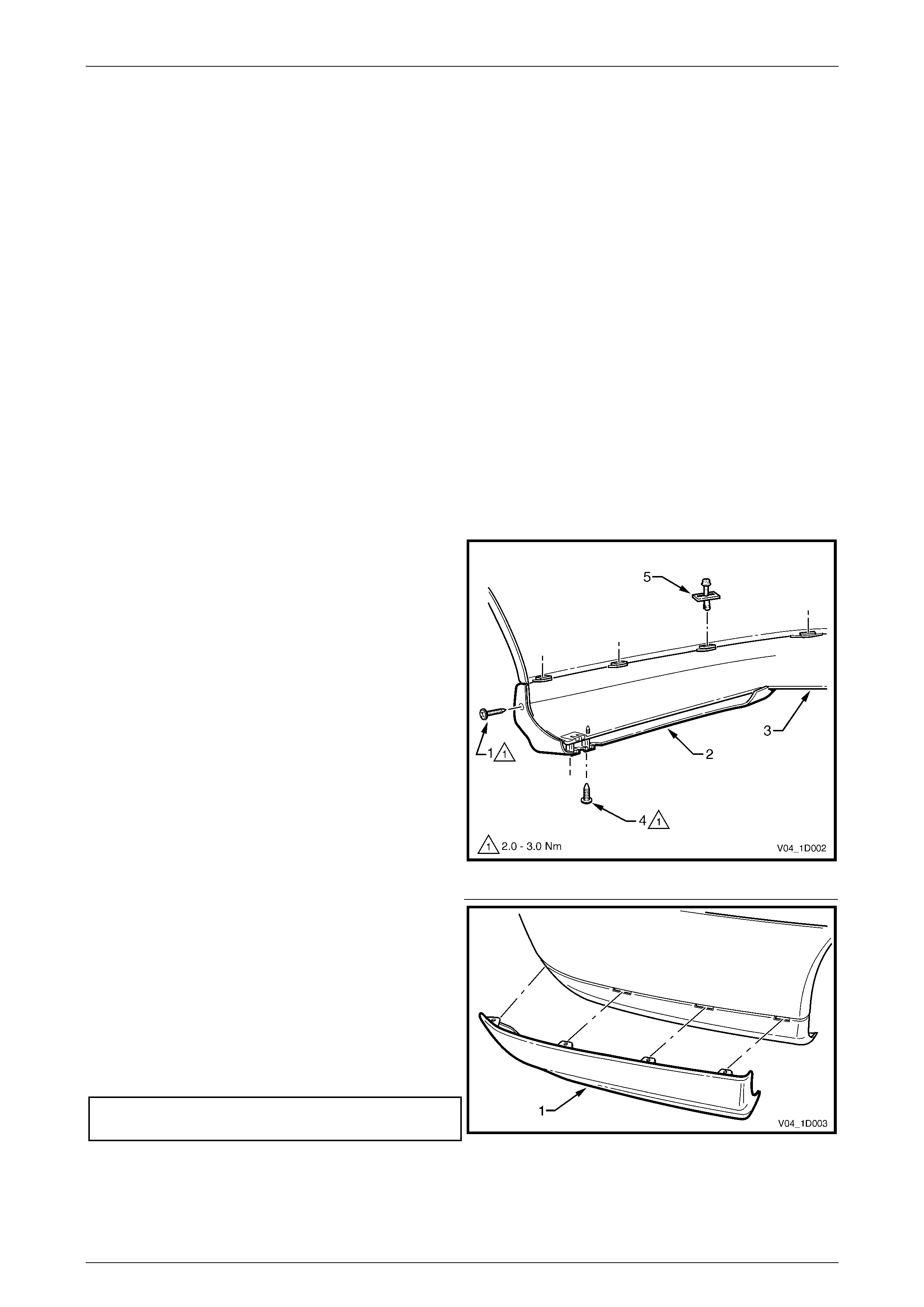
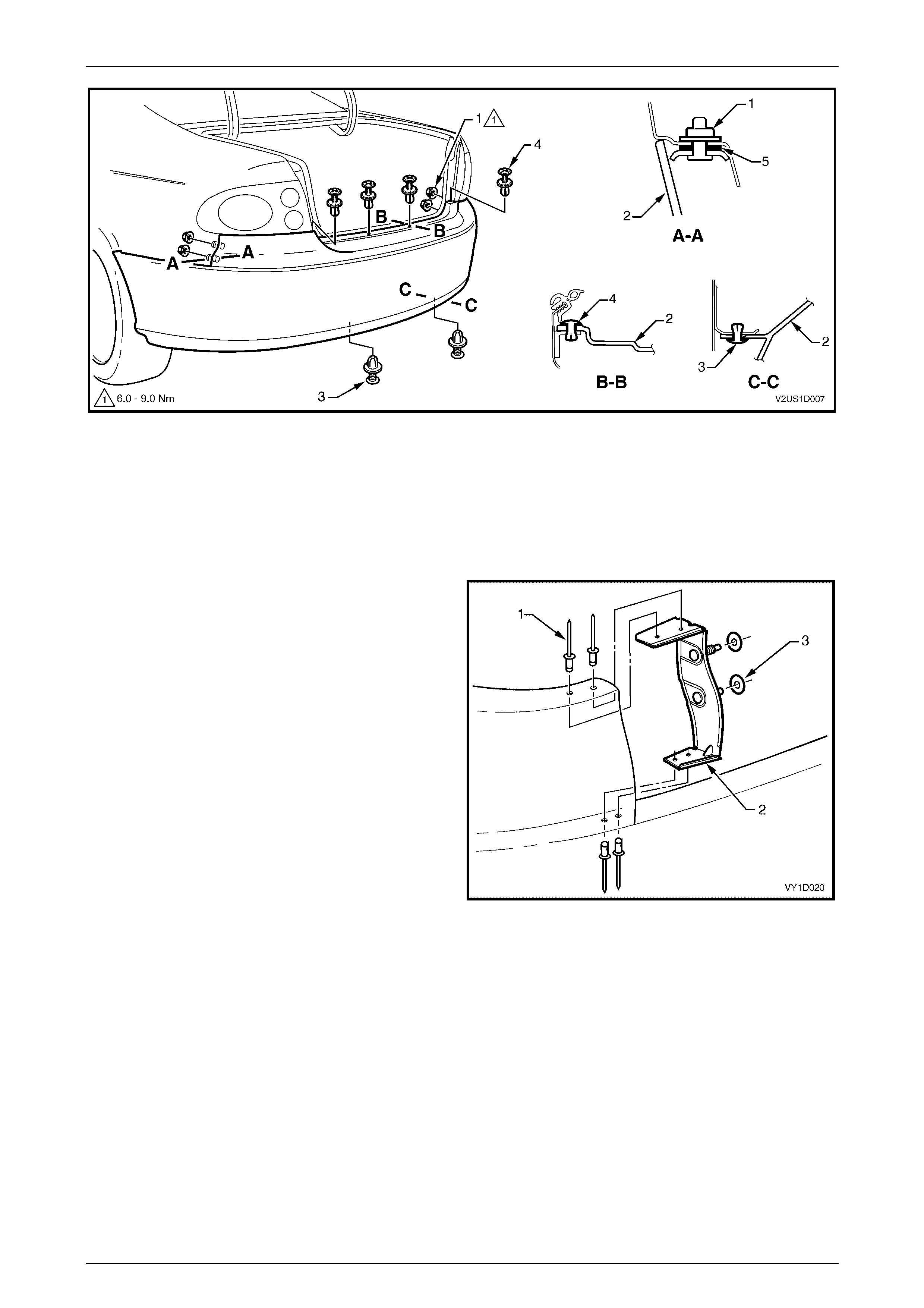
Rear Bumper Fascia Outer Lower Moulding
Remove
1 Remove screw (1) attaching the rear bumper fascia
outer lower moulding (2) to the rear bumper fascia (3).
2 Remove the screw (4), two places, attaching the outer
lower moulding to the outer lower moulding mounting
bracket.
3 Remove the retainer (5), four places, from the outer
lower moulding.
Figure 1D – 2
4 Withdraw the outer lower moulding (1) from the
bumper fascia, releasing the four lugs from the slots in
the bumper fascia.
5 Repeat for the opposite side as required.
Reinstall
Reinstallation of the rear bumper fascia outer lower
moulding is the reverse of the removal procedure. Tighten
the screws to the specified torque.
Rear bumper fascia outer lower moulding
attaching screw ..........................................2.0 – 3.0 Nm
Figure 1D – 3
Bumper Ba r s Page 1D–5
Page 1D–5
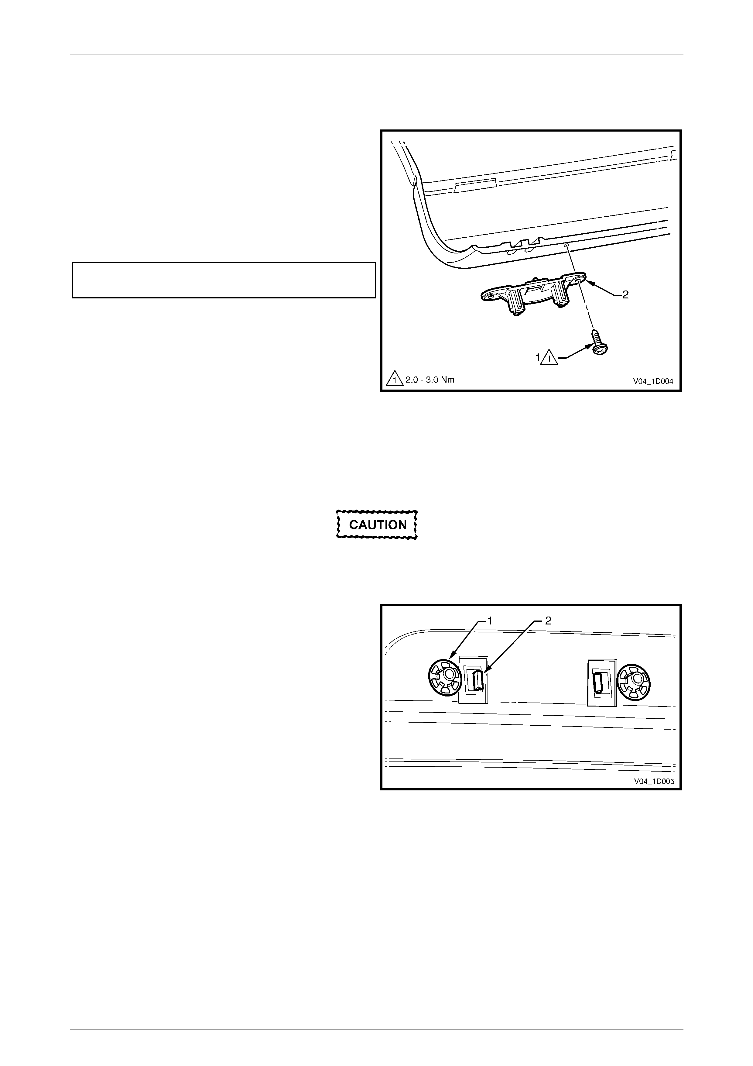
Rear Bumper Fascia Outer Lower Moulding Mounting Bracket
Remove
1 Remove screw (1) attaching the rear bumper fascia
outer lower moulding mounting bracket (2) to the rear
bumper fascia, and remove the bracket.
Reinstall
Reinstallation of the rear bumper fascia outer lower
moulding mounting bracket is the reverse of the removal
procedure. Tighten the screw to the specified torque.
Rear bumper fascia outer lower moulding
mounting bracket attaching screw.............. 2.0 – 3.0 Nm
Figure 1D – 4
Rear Bumper Fascia Reflective Lens
Remove
If the reflective lens is to be reused, take care
as the speed nuts can cut into and break the
lugs during removal.
1 Using a fine flat-blade screwdriver, prise the speed nut
(1), two places, attaching the rear bumper fascia
reflective lens (2) to the rear bumper fascia and
applique.
2 Unclip the reflective lens, two places from the applique
and remove.
Figure 1D – 5
Reinstall
Reinstallation of the rear bumper fascia reflective lens is the reverse of the removal procedure.
Bumper Ba r s Page 1D–6
Page 1D–6
Rear Bumper Fascia Applique
Remove
If the rear bumper fascia applique is to be
reused, take care as the retaining clips can
cut into and break the lugs during removal.
1 Remove the rear bumper fascia reflective lens as previously described.
2 Using a fine flat-blade screwdriver, prise the retaining clip (1) attaching the rear bumper fascia applique to the
bumper fascia, ten places, and remove the applique. Refer Figure 1D – 6
Figure 1D – 6
Reinstall
Reinstallation of the rear bumper fascia applique is the reverse of the removal procedure.
Towbar Opening Cover
For removal of the towbar opening cover, refer to Section 1D, 2.5 Rear Bumper Fascia Assembly in the MY 2003 VY and
V2 Series Service Information.
Reverse Parking Aid Components
For removal of the reverse parking aid components, refer to Section 1D, 2.5 Rear Bumper Fascia Assembly in the
MY 2003 VY and V2 Series Service Information.
Reinstall
For reinstallation of the rear bumper fascia, refer to Section 1D, 2.5 Rear Bumper Fascia Assembly in the MY2003 VY
and V2 Series Service Information.
Bumper Ba r s Page 1D–7
Page 1D–7
3 Service Operations – Coupe
3.1 Rear Bumper Fascia
LT Section – 10-150
If required, first remove the following components:
1 Rear end trim panel, refer to Section 1A8, 2.5 Rear End Trim Panel.
2 Quarter inner rear side carpet, refer to Section 1A8, 2.7 Quarter Inner Rear Side Carpet.
Remove
1 From each side of the vehicle:
a Remove the screw (1), two places, attaching the rear bumper fascia assembly (2) to the rear wheelhouse
liner (3), refer to Figure 1D – 7.
b Remove the screw (4), two places, attaching the rear bumper fascia assembly to the liner and rear bumper
fascia guide assembly (5).
c Carefully unclip the fascia assembly from the guide assembly by grasping the upper end of the fascia and
pulling away from the vehicle.
Figure 1D – 7
2 Remove the nut (1), two places each side, attaching the fascia assembly (2) to the vehicle, refer to Figure 1D – 8.
3 Remove the two retainers (3) from below the fascia assembly.
4 Remove the centre section of the rear compartment lid weatherstrip to allow access to the four upper retainers (4).
5 Remove the four upper retainers attaching the fascia assembly to the rear bumper fascia centre support assembly.
6 With the aid of an assistant remove the bumper fascia and store in a safe place.
Bumper Ba r s Page 1D–8
Page 1D–8
Figure 1D – 8
Disassemble
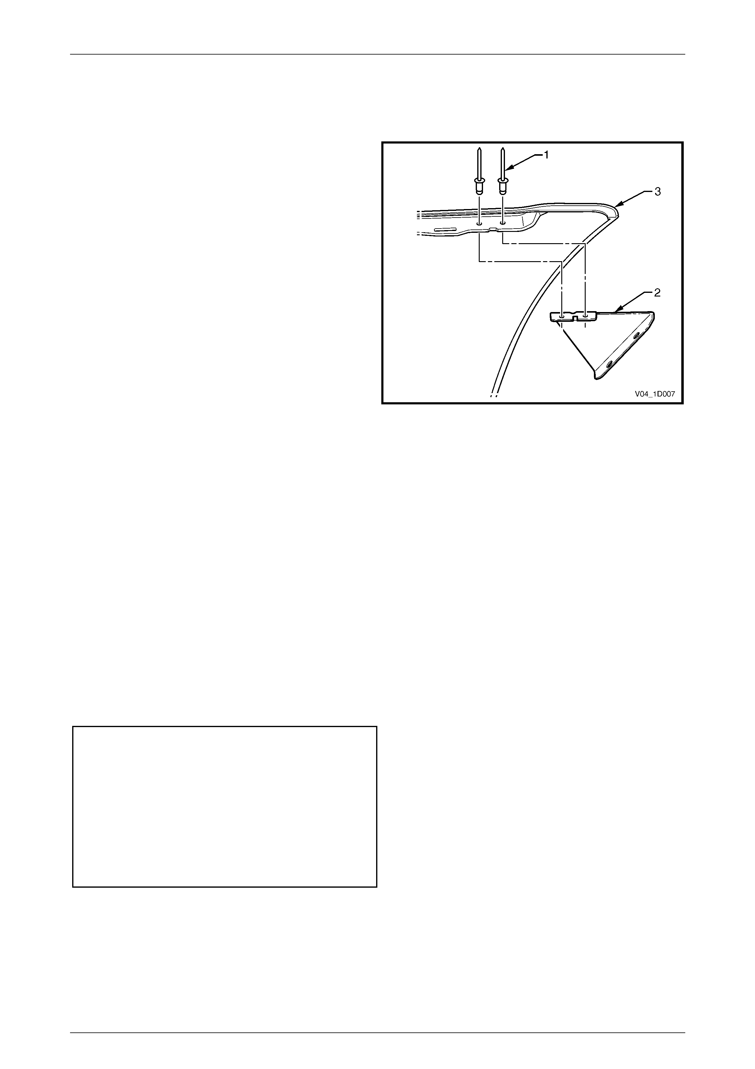
Rear Bumper Fascia Anchor Plate Assembly
Remove
1 Using a 3mm drill-bit, remove the four rivets (1)
attaching the anchor plate assembly (2) to the fascia
assembly.
NOTE
If reusing the fascia assembly, take care not to
enlarge the rivet holes.
2 Remove the plate assembly and if required the two
seals (3).
Reinstall
1 Fit the plate assembly with new 3mm pop rivets.
Figure 1D – 9
Bumper Ba r s Page 1D–9
Page 1D–9
Rear Bumper Fascia Bracket
Remove
1 Using a 3mm drill-bit, remove the two rivets (1)
attaching the rear bumper fascia bracket (2) to the
fascia assem bly (3).
NOTE
If reusing the fascia assembly, take care not to
enlarge the rivet holes.
2 Remove the bracket.
Reinstall
1 Fit the bracket with new 3mm pop rivets.
Figure 1D – 10
Reinstall
1 Refinish the bumper fascia assembly in accordance with the procedures in Section 1D, 2.1 Paint Systems in the
MY 2003 VY and V2 Series Service Information.
2 With the aid of an assistant, install the rear bumper fascia assembly onto the vehicle.
3 Install the two nuts (1) attaching the fascia assembly to the vehicle each side, refer to Figure 1D – 8. Do not tighten.
4 Insert the four retainers (4) across the rear compartment lid opening.
5 Insert the two retainers (3) below the fascia assembly.
6 Align the side of the fascia assembly to the quarter panel and clip the fascia assembly into the rear bumper fascia
guide assembly (5), refer to Figure 1D – 7. Repeat for the opposite side.
7 Install the two screws each side (4), attaching the fascia assembly to the rear bumper fascia guide assembly and
rear wheelhouse liner.
8 Install the screw (1), in two places, attaching the fascia assembly to the rear wheelhouse liner.
9 Tighten the two nuts each side and then the screws to the specified torque.
Rear bumper fascia assembly to
rear wheelhouse liner attaching
screw torque specification..........................1.0 – 3.0 Nm
Rear bumper fascia assembly to
rear bumper fascia guide assembly
attaching screw torque
specification................................................1.0 – 3.0 Nm
Rear bumper fascia assembly
attaching nut torque
specification................................................6.0 – 9.0 Nm

Bumper Ba r s Page 1D–10
Page 1D–10
3 Torque Wrench Specifications
Level 3
Fog Lamp Assembly Attaching Screw...........................................2.0 – 3.0 Nm
Rear Bumper Fascia Outer Lower Moulding Mounting
Bracket Attaching Screw................................................................2.0 – 3.0 Nm
Rear Bumper Fascia Outer Lower Moulding Attaching Screw.......2.0 – 3.0 Nm
Coupe
Rear Bumper Fascia Assembly to Rear Wheelhouse Liner
Attaching Screw.............................................................................1.0 – 3.0 Nm
Rear Bumper Fascia Assembly to Rear Bumper Fascia Guide
Assembly Attaching Screw ............................................................1.0 – 3.0 Nm
Rear Bumper Fascia Assembly Attaching Nut...............................6.0 – 9.0 Nm