
Seat Assemblies Page 1A7A–1
Page 1A7A–1
1A7A Seat Assemblies
(Build No 3L147832 Onwards)
ATTENTION
Before performing any Service Operation or other procedure described in this Section, refer to 00 Warnings,
Cautions and Notes for correct workshop practices with regard to safety and/or property damage.
1 General Information .............................................................................................................................15
1.1 Front Seat General Description.......................................................................................................................... 15
Seat Covers.......................................................................................................................................................... 16
Electric Seat Operation ....................................................................................................................................... 16
Raise/Lower Movement.................................................................................................................................... 16
Fore/Aft Movement........................................................................................................................................... 16
Recline Movement............................................................................................................................................ 17
Four-way and Six-way Movement Control........................................................................................................ 17
Eight-way Movement Control ........................................................................................................................... 17
Memory Seat Position System ......................................................................................................................... 18
Priority Keys (Domestic Level 3 Vehicles Only)................................................................................................ 18
Memory Buttons............................................................................................................................................... 19
Using the Exterior Mirrors................................................................................................................................. 19
EZ-entry System, Coupe.................................................................................................................................. 20
Active Head Restraints........................................................................................................................................ 21
1.2 Rear Seat General Description ........................................................................................................................... 22
Sedan.................................................................................................................................................................... 22
Wagon................................................................................................................................................................... 22
Coupe.................................................................................................................................................................... 22
2 Service Operations – Front Seat, Except Coupe...............................................................................23
2.1 Front Seat Usage Chart....................................................................................................................................... 23
How To Use This Chart........................................................................................................................................ 23
Domestic .......................................................................................................................................................... 23
Gulf States ....................................................................................................................................................... 24
Brazil ................................................................................................................................................................ 24
Front Seat Type 1................................................................................................................................................. 25
Front Seat Type 2................................................................................................................................................. 27
Front Seat Type 3................................................................................................................................................. 29
Front Seat Type 4................................................................................................................................................. 31
Front Seat Type 5................................................................................................................................................. 33
Front Seat Type 6................................................................................................................................................. 35
Front Seat Type 7................................................................................................................................................. 37
Front Seat Type 8................................................................................................................................................. 39
Front Seat Type 9................................................................................................................................................. 41
Front Seat Type 10............................................................................................................................................... 43
Front Seat Type 11............................................................................................................................................... 45
Front Seat Type 12............................................................................................................................................... 47
Front Seat Type 13............................................................................................................................................... 49
Front Seat Type 14............................................................................................................................................... 51
Front Seat Type 15............................................................................................................................................... 53
Front Seat Type 16............................................................................................................................................... 55
Front Seat Type 17............................................................................................................................................... 57
Front Seat Type 18............................................................................................................................................... 59
Front Seat Type 19............................................................................................................................................... 61
Front Seat Type 20............................................................................................................................................... 63
Techline
Techline
Techline
Techline
Techline

Seat Assemblies Page 1A7A–2
Page 1A7A–2
Front Seat Type 21............................................................................................................................................... 65
Front Seat Type 22............................................................................................................................................... 67
Front Seat Type 23............................................................................................................................................... 69
Front Seat Type 24............................................................................................................................................... 71
2.2 Fire Extinguisher Assembly................................................................................................................................ 73
Remove................................................................................................................................................................. 73
Reinstall................................................................................................................................................................ 73
2.3 Front Seat Assembly........................................................................................................................................... 74
Remove................................................................................................................................................................. 74
Reinstall................................................................................................................................................................ 76
Seat Memory Calibration, Front Seat Type 11................................................................................................... 77
2.4 Front Seat Outer Side Cover Assembly............................................................................................................. 79
Remove................................................................................................................................................................. 79
Disassemble......................................................................................................................................................... 80
Front Seat Adjustment Switch.......................................................................................................................... 80
Memory Position Switch Assembly................................................................................................................... 81
Reinstall................................................................................................................................................................ 81
2.5 Front Seat Inner Side Cover................................................................................................................................ 82
Remove................................................................................................................................................................. 82
Reinstall................................................................................................................................................................ 82
2.6 Front Seat-back Rear Cover Assembly.............................................................................................................. 83
Remove................................................................................................................................................................. 83
Disassemble......................................................................................................................................................... 84
Reassemble.......................................................................................................................................................... 84
Reinstall................................................................................................................................................................ 85
2.7 Front Seat Head Restraint Assembly................................................................................................................. 86
Remove................................................................................................................................................................. 86
Disassemble......................................................................................................................................................... 86
Reassemble.......................................................................................................................................................... 87
Reinstall................................................................................................................................................................ 87
2.8 Front Seat Head Restraint Sleeve....................................................................................................................... 88
Remove................................................................................................................................................................. 88
Reinstall................................................................................................................................................................ 88
2.9 Lumbar Support Knob Assembly....................................................................................................................... 89
Remove................................................................................................................................................................. 89
Reinstall................................................................................................................................................................ 89
2.10 Front Seat-back Pad and Cover Assembly........................................................................................................ 90
Remove................................................................................................................................................................. 90
Disassemble......................................................................................................................................................... 91
Reassemble.......................................................................................................................................................... 92
Reinstall................................................................................................................................................................ 92
2.11 Front Seat-back Frame Assembly...................................................................................................................... 93
Remove................................................................................................................................................................. 93
Disassemble......................................................................................................................................................... 94
Side Impact Airbag Assembly .......................................................................................................................... 94
Front Seat Dummy Block Insert Assembly....................................................................................................... 95
Lumbar Support Assembly............................................................................................................................... 95
Active Head Restraint Frame Assembly........................................................................................................... 97
Reinstall................................................................................................................................................................ 98
2.12 Seat Cable Tray and Memory Module ................................................................................................................ 99
Remove................................................................................................................................................................. 99
Reinstall.............................................................................................................................................................. 100
2.13 Track and Height Adjust Assembly.................................................................................................................. 101
Remove............................................................................................................................................................... 101
Reinstall.............................................................................................................................................................. 101
2.14 Front Seat Cushion Pad and Cover Assembly................................................................................................ 103
Remove............................................................................................................................................................... 103
Disassemble....................................................................................................................................................... 104
Reassemble........................................................................................................................................................ 105
Reinstall.............................................................................................................................................................. 106

Seat Assemblies Page 1A7A–3
Page 1A7A–3
2.15 Front Seat Cushion Frame Assembly.............................................................................................................. 107
Remove............................................................................................................................................................... 107
Disassemble....................................................................................................................................................... 107
Reassemble........................................................................................................................................................ 107
Reinstall.............................................................................................................................................................. 107
2.16 Front Seat Lift Motor Assemblies..................................................................................................................... 108
2.17 Front Seat Fore/Aft Movement Motor Assembly............................................................................................. 109
2.18 Front Seat-back Recline Motor Assembly ....................................................................................................... 110
2.19 Drive Motor Hall-effect Sensors........................................................................................................................ 111
3 Diagnostics – Front Seat RHD, Non -memory (Except Coup e) ......................................................112
3.1 Prerequisites...................................................................................................................................................... 112
Safety Requirements ......................................................................................................................................... 112
Equipment .......................................................................................................................................................... 112
Testing Procedures ........................................................................................................................................... 112
3.2 Mechanical Diagnosis – Two-Way/Four-Way Seat.......................................................................................... 113
Lumbar Support Inoperative............................................................................................................................. 113
Introduction .................................................................................................................................................... 113
Test Description ............................................................................................................................................. 113
Diagnostic Table............................................................................................................................................. 113
Seat Recline Forward and/or Back Function is Inoperative........................................................................... 114
Introduction .................................................................................................................................................... 114
Test Description ............................................................................................................................................. 114
Diagnostic Table............................................................................................................................................. 114
Seat Fore/Aft Movement Function is Inoperative or is Not Smooth.............................................................. 115
Introduction .................................................................................................................................................... 115
Test Description ............................................................................................................................................. 115
Diagnostic Table............................................................................................................................................. 115
3.3 Electrical Diagnosis – Four-way Driver’s Seat................................................................................................ 116
Wiring Diagram – Four-way Seat...................................................................................................................... 116
Connector Chart – Four-way Seat.................................................................................................................... 116
None of the Driver’s Seat Adjustment Switch Functions Operate................................................................. 117
Introduction .................................................................................................................................................... 117
Test Description ............................................................................................................................................. 117
Diagnostic Table Notes .................................................................................................................................. 118
Diagnostic Table............................................................................................................................................. 118
Front/Rear of the Driver's Seat Does Not Raise and/or Lower....................................................................... 120
Introduction .................................................................................................................................................... 120
Test Description ............................................................................................................................................. 120
Diagnostic Table Notes .................................................................................................................................. 120
Diagnostic Table............................................................................................................................................. 121
3.4 Four-way Seat Adjustment Switch Test........................................................................................................... 122
Test ..................................................................................................................................................................... 122
3.5 Electrical Diagnosis – Eight-way Passenger Seat .......................................................................................... 123
Wiring Diagram – Eight-way Passenger Seat.................................................................................................. 123
Connector Chart – Eight-way Passenger Seat................................................................................................ 123
Neither Seat Adjustment Switch Functions Operate...................................................................................... 124
Introduction .................................................................................................................................................... 124
Test Description ............................................................................................................................................. 124
Diagnostic Table Notes .................................................................................................................................. 124
Diagnostic Table............................................................................................................................................. 125
None of the Passenger’s Seat Adjustment Switch Functions Operate......................................................... 126
Introduction .................................................................................................................................................... 126
Test Description ............................................................................................................................................. 126
Diagnostic Table Notes .................................................................................................................................. 126
Diagnostic Table............................................................................................................................................. 127
Front/Rear of the Passenger’s Seat Does Not Raise and/or Lower............................................................... 128
Introduction .................................................................................................................................................... 128
Test Description ............................................................................................................................................. 128

Seat Assemblies Page 1A7A–4
Page 1A7A–4
Diagnostic Table Notes .................................................................................................................................. 128
Diagnostic Table............................................................................................................................................. 129
Passenger’s Seat Fore/Aft Function is Inoperative or Not Smooth............................................................... 130
Introduction .................................................................................................................................................... 130
Test Description ............................................................................................................................................. 130
Diagnostic Table Notes .................................................................................................................................. 130
Diagnostic Table............................................................................................................................................. 131
Passenger’s Seat Recline Forward and/or Aft Function is Inoperative ........................................................ 132
Introduction .................................................................................................................................................... 132
Test Description ............................................................................................................................................. 132
Diagnostic Table Notes .................................................................................................................................. 132
Diagnostic Table............................................................................................................................................. 133
3.6 Eight-way Seat Adjustment Switch Test.......................................................................................................... 134
Test ..................................................................................................................................................................... 134
4 Diagnostics – Front Seat LHD, Non-memory (Except Coupe).......................................................135
4.1 Prerequisites...................................................................................................................................................... 135
Safety Requirements ......................................................................................................................................... 135
Equipment .......................................................................................................................................................... 135
Testing Procedures ........................................................................................................................................... 135
4.2 Mechanical Diagnosis – Two-way/Four-way/Six-way Seat............................................................................. 136
Lumbar Support Inoperative............................................................................................................................. 136
Introduction .................................................................................................................................................... 136
Test Description ............................................................................................................................................. 136
Diagnostic Table............................................................................................................................................. 136
Seat-back Recline Forward and/or Aft Function is Inoperative..................................................................... 137
Introduction .................................................................................................................................................... 137
Test Description ............................................................................................................................................. 137
Diagnostic Table............................................................................................................................................. 137
Two-way/Four-way Seat Fore/Aft Movement Function is Inoperative or is Not Smooth............................. 138
Introduction .................................................................................................................................................... 138
Test Description ............................................................................................................................................. 138
Diagnostic Table............................................................................................................................................. 138
4.3 Electrical Diagnosis – Four-way/Six-way Seat................................................................................................ 139
Wiring Diagram – Four-way/Six-way Seat........................................................................................................ 140
Connector Chart – Four-way/Six-way Seat...................................................................................................... 141
Neither Seat Adjustment Switch Functions Operate...................................................................................... 142
Introduction .................................................................................................................................................... 142
Test Description ............................................................................................................................................. 142
Diagnostic Table Notes .................................................................................................................................. 142
Diagnostic Table............................................................................................................................................. 143
None of the Driver’s Seat Adjustment Switch Functions Operate................................................................. 144
Introduction .................................................................................................................................................... 144
Test Description ............................................................................................................................................. 144
Diagnostic Table Notes .................................................................................................................................. 144
Diagnostic Table............................................................................................................................................. 145
Front/Rear of the Driver's Seat Does Not Raise and/or Lower....................................................................... 146
Introduction .................................................................................................................................................... 146
Test Description ............................................................................................................................................. 146
Diagnostic Table Notes .................................................................................................................................. 146
Diagnostic Table............................................................................................................................................. 147
Driver’s Seat Fore/Aft Movement Function is Inoperative or not Smooth.................................................... 148
Introduction .................................................................................................................................................... 148
Test Description ............................................................................................................................................. 148
Diagnostic Table Notes .................................................................................................................................. 148
Diagnostic Table............................................................................................................................................. 149
None of the Passenger's Seat Adjustment Switch Functions Operate......................................................... 150
Introduction .................................................................................................................................................... 150
Test Description ............................................................................................................................................. 150

Seat Assemblies Page 1A7A–5
Page 1A7A–5
Diagnostic Table Notes .................................................................................................................................. 150
Diagnostic Table............................................................................................................................................. 151
Front/Rear of the Passenger's Seat Does Not Raise and/or Lower............................................................... 152
Introduction .................................................................................................................................................... 152
Test Description ............................................................................................................................................. 152
Diagnostic Table Notes .................................................................................................................................. 152
Diagnostic Table............................................................................................................................................. 153
4.4 Six-way Seat Adjustment Switch Test ............................................................................................................. 154
Test ..................................................................................................................................................................... 154
4.5 Mechanical Diagnosis – Eight-way Seat.......................................................................................................... 155
Lumbar Support Inoperative............................................................................................................................. 155
Introduction .................................................................................................................................................... 155
Test Description ............................................................................................................................................. 155
Diagnostic Table............................................................................................................................................. 155
4.6 Electrical Diagnosis – Eight-way Seat ............................................................................................................. 156
Wiring Diagram – Eight-way Seat..................................................................................................................... 157
Connector Chart – Eight-way Seat................................................................................................................... 158
Neither Seat Adjustment Switch Functions Operate...................................................................................... 159
Introduction .................................................................................................................................................... 159
Test Description ............................................................................................................................................. 159
Diagnostic Table Notes .................................................................................................................................. 159
Diagnostic Table............................................................................................................................................. 160
None of the Driver’s Seat Adjustment Switch Functions Operate................................................................. 161
Introduction .................................................................................................................................................... 161
Test Description ............................................................................................................................................. 161
Diagnostic Table Notes .................................................................................................................................. 161
Diagnostic Table............................................................................................................................................. 162
Front/Rear of the Driver’s Seat Does Not Raise and/or Lower....................................................................... 163
Introduction .................................................................................................................................................... 163
Test Description ............................................................................................................................................. 163
Diagnostic Table Notes .................................................................................................................................. 163
Diagnostic Table............................................................................................................................................. 164
Driver’s Seat Fore/Aft Movement Function is Inoperative or Not Smooth.................................................... 165
Introduction .................................................................................................................................................... 165
Test Description ............................................................................................................................................. 165
Diagnostic Table Notes .................................................................................................................................. 165
Diagnostic Table............................................................................................................................................. 166
Driver’s Seat-back Recline Forw ard and/or Aft Function is Inoperative....................................................... 167
Introduction .................................................................................................................................................... 167
Test Description ............................................................................................................................................. 167
Diagnostic Table Notes .................................................................................................................................. 167
Diagnostic Table............................................................................................................................................. 168
None of the Passenger’s Seat Adjustment Switch Functions Operate......................................................... 169
Introduction .................................................................................................................................................... 169
Test Description ............................................................................................................................................. 169
Diagnostic Table Notes .................................................................................................................................. 169
Diagnostic Table............................................................................................................................................. 170
Front/Rear of the Passenger’s Seat Does Not Raise and/or Lower............................................................... 171
Introduction .................................................................................................................................................... 171
Test Description ............................................................................................................................................. 171
Diagnostic Table Notes .................................................................................................................................. 171
Diagnostic Table............................................................................................................................................. 172
Passenger’s Seat Fore/Aft Movement Function is Inoperative or Not Smooth............................................ 173
Introduction .................................................................................................................................................... 173
Test Description ............................................................................................................................................. 173
Diagnostic Table Notes .................................................................................................................................. 173
Diagnostic Table............................................................................................................................................. 174
Passenger’s Seat-back Recline Forward and/or Aft Function is Inoperative............................................... 175
Introduction .................................................................................................................................................... 175
Test Description ............................................................................................................................................. 175

Seat Assemblies Page 1A7A–6
Page 1A7A–6
Diagnostic Table Notes .................................................................................................................................. 175
Diagnostic Table............................................................................................................................................. 176
5 Diagnostics – Front Seat Memory and Rear-v iew Mirror (Except Coupe)....................................177
5.1 Prerequisites...................................................................................................................................................... 177
Safety Requirements ......................................................................................................................................... 177
Equipment .......................................................................................................................................................... 177
Testing Procedures ........................................................................................................................................... 177
5.2 System Self Diagnosis ...................................................................................................................................... 178
Current DTCs...................................................................................................................................................... 178
History DTCs...................................................................................................................................................... 178
Clearing DTCs.................................................................................................................................................... 178
5.3 Tech 2 Diagnostics............................................................................................................................................ 179
Test Modes......................................................................................................................................................... 179
Mode F0: Diagnostic Trouble Codes.............................................................................................................. 179
Mode F1: Diagnostic Data Display................................................................................................................. 179
Mode F2: Snapshot........................................................................................................................................ 179
Mode F3: Miscellaneous Tests....................................................................................................................... 179
Mode F4: Additional Functions....................................................................................................................... 179
5.4 Tech 2 Test Modes and Displays for Diagnosis.............................................................................................. 180
System Select Menu.......................................................................................................................................... 180
Body Application Menu..................................................................................................................................... 180
System Identification......................................................................................................................................... 180
Application Menu............................................................................................................................................... 180
F0: Diagnostic Trouble Codes.......................................................................................................................... 181
F0: Read DTC Information ............................................................................................................................. 181
F1: Clear DTC Information ............................................................................................................................. 181
Diagnostic Trouble Codes................................................................................................................................. 181
F1: Diagnostic Data Display.............................................................................................................................. 182
F0: Inputs and Outputs................................................................................................................................... 182
F1: Memory.................................................................................................................................................... 185
F2: System Identification................................................................................................................................ 186
F2: Snapshot...................................................................................................................................................... 187
F3: Miscellaneous Tests.................................................................................................................................... 187
F0: Chime....................................................................................................................................................... 187
F1: LED.......................................................................................................................................................... 187
F2: Right Exterior Mirror................................................................................................................................. 187
F3: Left Exterior Mirror ................................................................................................................................... 187
F4: Front Vertical Motor.................................................................................................................................. 187
F5: Rear Vertical Mirror.................................................................................................................................. 187
F6: Horizontal Motor....................................................................................................................................... 187
F7: Recline Motor........................................................................................................................................... 187
F4: Additional Functions................................................................................................................................... 187
F0: Module Reset........................................................................................................................................... 187
5.5 Preliminary System Diagnosis.......................................................................................................................... 188
5.6 Diagnostic Tables.............................................................................................................................................. 189
Introduction........................................................................................................................................................ 189
5.7 Mechanical Diagnosis ....................................................................................................................................... 190
Lumbar Support Inoperative............................................................................................................................. 190
Introduction .................................................................................................................................................... 190
Test Description ............................................................................................................................................. 190
Diagnostic Table............................................................................................................................................. 190
5.8 Electrical Diagnosis – Memory Seat................................................................................................................. 191
Wiring Diagram .................................................................................................................................................. 191
Connector Chart................................................................................................................................................. 193
Initial Check........................................................................................................................................................ 194
Introduction .................................................................................................................................................... 194
Test Description ............................................................................................................................................. 194
Diagnostic Table............................................................................................................................................. 195

Seat Assemblies Page 1A7A–7
Page 1A7A–7
No Serial Data Communications to the Seat Memory Module....................................................................... 200
Introduction .................................................................................................................................................... 200
Test Description ............................................................................................................................................. 200
Diagnostic Table Notes .................................................................................................................................. 200
Diagnostic Table............................................................................................................................................. 201
Seat Adjustment Switch Inoperative................................................................................................................ 202
Introduction .................................................................................................................................................... 202
Test Description ............................................................................................................................................. 202
Diagnostic Table Notes .................................................................................................................................. 202
Diagnostic Table............................................................................................................................................. 203
Seat Front Lift Motor Inoperative...................................................................................................................... 204
Introduction .................................................................................................................................................... 204
Test Description ............................................................................................................................................. 204
Diagnostic Table Notes .................................................................................................................................. 204
Diagnostic Table............................................................................................................................................. 204
Seat Rear Lift Motor Inoperative....................................................................................................................... 205
Introduction .................................................................................................................................................... 205
Test Description ............................................................................................................................................. 205
Diagnostic Table Notes .................................................................................................................................. 205
Diagnostic Table............................................................................................................................................. 205
Seat Fore/Aft Movement Motor Inoperative..................................................................................................... 206
Introduction .................................................................................................................................................... 206
Test Description ............................................................................................................................................. 206
Diagnostic Table Notes .................................................................................................................................. 206
Diagnostic Table............................................................................................................................................. 206
Seat-back Recline Motor Inoperative ............................................................................................................... 207
Introduction .................................................................................................................................................... 207
Test Description ............................................................................................................................................. 207
Diagnostic Table Notes .................................................................................................................................. 207
Diagnostic Table............................................................................................................................................. 208
Memory Position Switch Inoperative ............................................................................................................... 209
Introduction .................................................................................................................................................... 209
Test Description ............................................................................................................................................. 209
Diagnostic Table Notes .................................................................................................................................. 209
Diagnostic Table............................................................................................................................................. 210
Seat Front Lift Motor Hall-effect Sensor Check............................................................................................... 211
Introduction .................................................................................................................................................... 211
Test Description ............................................................................................................................................. 211
Diagnostic Table Notes .................................................................................................................................. 211
Diagnostic Table............................................................................................................................................. 212
Seat Rear Lift Motor Hall-effect Sensor Check................................................................................................ 213
Introduction .................................................................................................................................................... 213
Test Description ............................................................................................................................................. 213
Diagnostic Table Notes .................................................................................................................................. 213
Diagnostic Table............................................................................................................................................. 214
Seat Fore/Aft Movement Motor Hall-effect Sensor Check.............................................................................. 215
Introduction .................................................................................................................................................... 215
Test Description ............................................................................................................................................. 215
Diagnostic Table Notes .................................................................................................................................. 215
Diagnostic Table............................................................................................................................................. 215
Seat-back Recline Motor Hall-effect Sensor Check........................................................................................ 216
Introduction .................................................................................................................................................... 216
Test Description ............................................................................................................................................. 216
Diagnostic Table Notes .................................................................................................................................. 216
Diagnostic Table............................................................................................................................................. 216
Priority Key Feature Inoperative....................................................................................................................... 217
Introduction .................................................................................................................................................... 217
Test Description ............................................................................................................................................. 217
Diagnostic Table Notes .................................................................................................................................. 217
Diagnostic Table............................................................................................................................................. 217

Seat Assemblies Page 1A7A–8
Page 1A7A–8
DTC 1 – Front Vertical Up Switch Stuck .......................................................................................................... 218
Introduction .................................................................................................................................................... 218
Test Description ............................................................................................................................................. 218
Diagnostic Table Notes .................................................................................................................................. 218
Diagnostic Table............................................................................................................................................. 218
DTC 2 – Front Vertical Down Switch Stuck...................................................................................................... 219
Introduction .................................................................................................................................................... 219
Test Description ............................................................................................................................................. 219
Diagnostic Table Notes .................................................................................................................................. 219
Diagnostic Table............................................................................................................................................. 219
DTC 3 – Rear Vertical Up Switch Stuck............................................................................................................ 220
Introduction .................................................................................................................................................... 220
Test Description ............................................................................................................................................. 220
Diagnostic Table Notes .................................................................................................................................. 220
Diagnostic Table............................................................................................................................................. 220
DTC 4 – Rear Vertical Down Switch Stuck....................................................................................................... 221
Introduction .................................................................................................................................................... 221
Test Description ............................................................................................................................................. 221
Diagnostic Table Notes .................................................................................................................................. 221
Diagnostic Table............................................................................................................................................. 221
DTC 5 – Horizontal Forward Switch Stuck....................................................................................................... 222
Introduction .................................................................................................................................................... 222
Test Description ............................................................................................................................................. 222
Diagnostic Table Notes .................................................................................................................................. 222
Diagnostic Table............................................................................................................................................. 222
DTC 6 – Horizontal Back Switch Stuck ............................................................................................................ 223
Introduction .................................................................................................................................................... 223
Test Description ............................................................................................................................................. 223
Diagnostic Table Notes .................................................................................................................................. 223
Diagnostic Table............................................................................................................................................. 223
DTC 7 – Recline Up Switch Stuck..................................................................................................................... 224
Introduction .................................................................................................................................................... 224
Test Description ............................................................................................................................................. 224
Diagnostic Table Notes .................................................................................................................................. 224
Diagnostic Table............................................................................................................................................. 224
DTC 8 – Recline Down Switch Stuck................................................................................................................ 225
Introduction .................................................................................................................................................... 225
Test Description ............................................................................................................................................. 225
Diagnostic Table Notes .................................................................................................................................. 225
Diagnostic Table............................................................................................................................................. 225
DTC 9 – Memory Button 1 Stuck....................................................................................................................... 226
Introduction .................................................................................................................................................... 226
Test Description ............................................................................................................................................. 226
Diagnostic Table Notes .................................................................................................................................. 226
Diagnostic Table............................................................................................................................................. 226
DTC 10 – Memory Button 2 Stuck..................................................................................................................... 227
Introduction .................................................................................................................................................... 227
Test Description ............................................................................................................................................. 227
Diagnostic Table Notes .................................................................................................................................. 227
Diagnostic Table............................................................................................................................................. 227
DTC 11 – Memory Button 3 Stuck..................................................................................................................... 228
Introduction .................................................................................................................................................... 228
Test Description ............................................................................................................................................. 228
Diagnostic Table Notes .................................................................................................................................. 228
Diagnostic Table............................................................................................................................................. 228
DTC 12 – Mirror DIP Button Stuck.................................................................................................................... 229
Introduction .................................................................................................................................................... 229
Test Description ............................................................................................................................................. 229
Diagnostic Table Notes .................................................................................................................................. 229
Diagnostic Table............................................................................................................................................. 229

Seat Assemblies Page 1A7A–9
Page 1A7A–9
DTC 13 – No Serial Data .................................................................................................................................... 230
DTC 14 – No Exterior Mirror Communications................................................................................................ 230
DTC 20 – Front Vertical Position Sensor Fault................................................................................................ 230
DTC 21 – Rear Vertical Position Sensor Fault................................................................................................. 230
DTC 22 – Horizontal Position Sensor Fault ..................................................................................................... 230
DTC 23 – Recline Position Sensor Fault.......................................................................................................... 230
DTC 24 – System Voltage Out of Range .......................................................................................................... 230
5.9 Memory Position Switch Test........................................................................................................................... 231
Remove............................................................................................................................................................... 231
Reinstall.............................................................................................................................................................. 231
Test ..................................................................................................................................................................... 231
5.10 Electrical Diagnosis – Rear-view Mirrors......................................................................................................... 232
Wiring Diagram .................................................................................................................................................. 232
Connector Chart................................................................................................................................................. 233
Initial Check........................................................................................................................................................ 234
Introduction .................................................................................................................................................... 234
Test Description ............................................................................................................................................. 234
Diagnostic Table............................................................................................................................................. 234
Mirror Dip Function Check................................................................................................................................ 237
Introduction .................................................................................................................................................... 237
Test Description ............................................................................................................................................. 237
Diagnostic Table............................................................................................................................................. 237
Mirror Heating Function Check......................................................................................................................... 238
Introduction .................................................................................................................................................... 238
Test Description ............................................................................................................................................. 238
Diagnostic Table............................................................................................................................................. 238
No Serial Data from Exterior Rear-view Mirrors.............................................................................................. 239
Introduction .................................................................................................................................................... 239
Test Description ............................................................................................................................................. 239
Diagnostic Table Notes .................................................................................................................................. 239
Diagnostic Table............................................................................................................................................. 240
No Serial Data – Right-hand Exterior Rear-view Mirror.................................................................................. 241
Introduction .................................................................................................................................................... 241
Test Description ............................................................................................................................................. 241
Diagnostic Table Notes .................................................................................................................................. 241
Diagnostic Table............................................................................................................................................. 241
No Serial Data – Left-hand Exterior Rear-view Mirror..................................................................................... 242
Introduction .................................................................................................................................................... 242
Test Description ............................................................................................................................................. 242
Diagnostic Table Notes .................................................................................................................................. 242
Diagnostic Table............................................................................................................................................. 242
Mirror Control Switch Inoperative.................................................................................................................... 243
Introduction .................................................................................................................................................... 243
Test Description ............................................................................................................................................. 243
Diagnostic Table Notes .................................................................................................................................. 243
Diagnostic Table............................................................................................................................................. 244
6 Service Operations – Front Seat, Coupe .........................................................................................245
6.1 Front Seat Usage Chart..................................................................................................................................... 245
How To Use This Chart...................................................................................................................................... 245
Domestic ........................................................................................................................................................ 245
Gulf States ..................................................................................................................................................... 245
Front Seat Type 1............................................................................................................................................... 246
Front Seat Type 2............................................................................................................................................... 248
Front Seat Type 3............................................................................................................................................... 250
Front Seat Type 4............................................................................................................................................... 252
6.2 Fire Extinguisher Assembly.............................................................................................................................. 254
Remove............................................................................................................................................................... 254
Reinstall.............................................................................................................................................................. 254

Seat Assemblies Page 1A7A–10
Page 1A7A–10
6.3 Front Seat Assembly......................................................................................................................................... 255
Remove............................................................................................................................................................... 255
Reinstall.............................................................................................................................................................. 257
Seat Memory Calibration, Front Seat Type 1................................................................................................... 258
6.4 Front Seat Outer Side Cover Assembly........................................................................................................... 260
Remove............................................................................................................................................................... 260
Disassemble....................................................................................................................................................... 261
Front Seat Adjustment Switch........................................................................................................................ 261
Memory Position Switch Assembly................................................................................................................. 262
EZ-entry Module............................................................................................................................................. 262
Reinstall.............................................................................................................................................................. 263
6.5 Front Seat Inner Side Cover.............................................................................................................................. 264
Remove............................................................................................................................................................... 264
Reinstall.............................................................................................................................................................. 264
6.6 Front Seat-back Rear Cover Assembly............................................................................................................ 265
Remove............................................................................................................................................................... 265
Disassemble....................................................................................................................................................... 266
Reassemble........................................................................................................................................................ 266
Reinstall.............................................................................................................................................................. 267
6.7 Front Seat Head Restraint Assembly............................................................................................................... 268
Remove............................................................................................................................................................... 268
Disassemble....................................................................................................................................................... 268
Reassemble........................................................................................................................................................ 269
Reinstall.............................................................................................................................................................. 269
6.8 Front Seat Head Restraint Sleeve..................................................................................................................... 270
Remove............................................................................................................................................................... 270
Reinstall.............................................................................................................................................................. 270
6.9 EZ-entry Release Lever and Escutcheon......................................................................................................... 271
Remove............................................................................................................................................................... 271
Reinstall.............................................................................................................................................................. 273
6.10 EZ-entry Switch and Release Cable Assembly ............................................................................................... 274
6.11 Lumbar Support Knob Assembly..................................................................................................................... 275
Remove............................................................................................................................................................... 275
Reinstall.............................................................................................................................................................. 275
6.12 Front Seat-back Pad and Cover Assembly...................................................................................................... 276
Remove............................................................................................................................................................... 276
Disassemble....................................................................................................................................................... 277
Reassemble........................................................................................................................................................ 278
Reinstall.............................................................................................................................................................. 278
6.13 Front Seat-back Frame Assembly.................................................................................................................... 279
Remove............................................................................................................................................................... 279
Disassemble....................................................................................................................................................... 280
EZ-entry Release Lever Retaining Clip and Return Spring............................................................................ 280
Side Impact Airbag Assembly ........................................................................................................................ 280
Front Seat Dummy Block Insert Assembly..................................................................................................... 281
Lumbar Support Assembly............................................................................................................................. 282
Active Head Restraint Frame Assembly......................................................................................................... 284
Reinstall.............................................................................................................................................................. 285
6.14 Seat Cable Tray and Memory Module .............................................................................................................. 286
Remove............................................................................................................................................................... 286
Reinstall.............................................................................................................................................................. 287
6.15 Track and Height Adjust Assembly.................................................................................................................. 288
Remove............................................................................................................................................................... 288
Reinstall.............................................................................................................................................................. 289
6.16 Front Seat Cushion Pad and Cover Assembly................................................................................................ 290
Remove............................................................................................................................................................... 290
Disassemble....................................................................................................................................................... 290
Reassemble........................................................................................................................................................ 291
Reinstall.............................................................................................................................................................. 292
6.17 Front Seat Cushion Frame Assembly.............................................................................................................. 293

Seat Assemblies Page 1A7A–11
Page 1A7A–11
Remove............................................................................................................................................................... 293
Disassemble....................................................................................................................................................... 293
Reassemble........................................................................................................................................................ 293
Reinstall.............................................................................................................................................................. 293
6.18 Front Seat Lift Motor Assemblies..................................................................................................................... 294
6.19 Front Seat Fore/Aft Movement Motor Assembly............................................................................................. 295
6.20 Front Seat-back Recline Motor Assembly ....................................................................................................... 296
6.21 Drive Motor Hall-effect Sensors........................................................................................................................ 297
7 Diagnostics – Front Seat, Coupe......................................................................................................298
7.1 Prerequisites...................................................................................................................................................... 298
Safety Requirements ......................................................................................................................................... 298
Equipment .......................................................................................................................................................... 298
Testing Procedures ........................................................................................................................................... 298
7.2 Mechanical Diagnosis, All................................................................................................................................. 299
Lumbar Support Inoperative............................................................................................................................. 299
Introduction .................................................................................................................................................... 299
Test Description ............................................................................................................................................. 299
Diagnostic Table............................................................................................................................................. 299
EZ-entry Lever Function Inoperative................................................................................................................ 300
Introduction .................................................................................................................................................... 300
Test Description ............................................................................................................................................. 300
Diagnostic Table............................................................................................................................................. 300
7.3 Electrical Diagnosis – Eight-way Seat, Non-memory ..................................................................................... 301
Neither Seat Adjustment Switch Functions Operate...................................................................................... 301
Introduction .................................................................................................................................................... 301
Circuit Description.......................................................................................................................................... 301
Test Description ............................................................................................................................................. 301
Diagnostic Table Notes .................................................................................................................................. 301
Diagnostic Table............................................................................................................................................. 302
EZ-entry Electrical Self Test Diagnosis – Eight-way Seat, Non-Memory ...................................................... 303
Introduction .................................................................................................................................................... 303
7.4 Electrical Diagnosis – Driver's Seat, Non-memory, LHD................................................................................ 304
Wiring Diagram – Driver's Seat, Non-memory, LHD ....................................................................................... 305
Connector Chart – Driver's Seat, Non-memory, LHD...................................................................................... 306
None of the Driver’s Seat Adjustment Switch Functions Operate................................................................. 307
Introduction .................................................................................................................................................... 307
Circuit Description.......................................................................................................................................... 307
Test Description ............................................................................................................................................. 307
Diagnostic Table Notes .................................................................................................................................. 307
Diagnostic Table............................................................................................................................................. 308
Front/Rear of the Driver’s Seat Does Not Raise and/or Lower....................................................................... 310
Introduction .................................................................................................................................................... 310
Circuit Description.......................................................................................................................................... 310
Test Description ............................................................................................................................................. 310
Diagnostic Table Notes .................................................................................................................................. 310
Diagnostic Table............................................................................................................................................. 311
Driver’s Seat Fore/Aft Function is Inoperative or Not Smooth ...................................................................... 312
Introduction .................................................................................................................................................... 312
Circuit Description.......................................................................................................................................... 312
Test Description ............................................................................................................................................. 312
Diagnostic Table Notes .................................................................................................................................. 312
Diagnostic Table............................................................................................................................................. 313
Driver’s Seat Recline Forward and/or Aft Function is Inoperative................................................................ 315
Introduction .................................................................................................................................................... 315
Circuit Description.......................................................................................................................................... 315
Test Description ............................................................................................................................................. 315
Diagnostic Table Notes .................................................................................................................................. 315
Diagnostic Table............................................................................................................................................. 316

Seat Assemblies Page 1A7A–12
Page 1A7A–12
Driver's Seat EZ-entry Switch Function is Inoperative................................................................................... 317
Introduction .................................................................................................................................................... 317
Circuit Description.......................................................................................................................................... 317
Test Description ............................................................................................................................................. 317
Diagnostic Table Notes .................................................................................................................................. 317
Diagnostic Table............................................................................................................................................. 317
Driver's Seat Return Switch Function is Inoperative...................................................................................... 318
Introduction .................................................................................................................................................... 318
Circuit Description.......................................................................................................................................... 318
Test Description ............................................................................................................................................. 318
Diagnostic Table Notes .................................................................................................................................. 318
Diagnostic Table............................................................................................................................................. 319
Driver's Seat Fore/Aft Movement Motor Hall-effect Sensor Test................................................................... 320
Introduction .................................................................................................................................................... 320
Circuit Description.......................................................................................................................................... 320
Test Description ............................................................................................................................................. 320
Diagnostic Table Notes .................................................................................................................................. 320
Diagnostic Table............................................................................................................................................. 320
Driver's Seat Occupant Sensing Mat Test....................................................................................................... 321
Introduction .................................................................................................................................................... 321
Circuit Description.......................................................................................................................................... 321
Test Description ............................................................................................................................................. 321
Diagnostic Table Notes .................................................................................................................................. 321
Diagnostic Table............................................................................................................................................. 321
7.5 Electrical Diagnosis – Passenger's Seat, Non-memory ................................................................................. 322
Wiring Diagram – Passenger's Seat, Non-memory, RHD............................................................................... 323
Wiring Diagram – Passenger's Seat, Non-memory, LHD................................................................................ 324
Connector Chart – Passenger's Seat, Non-memory, RHD and LHD.............................................................. 325
None of the Passenger’s Seat Adjustment Switch Functions Operate......................................................... 326
Introduction .................................................................................................................................................... 326
Circuit Description.......................................................................................................................................... 326
Test Description ............................................................................................................................................. 326
Diagnostic Table Notes .................................................................................................................................. 326
Diagnostic Table............................................................................................................................................. 327
Front/Rear of the Passenger’s Seat Does Not Raise and/or Lower............................................................... 329
Introduction .................................................................................................................................................... 329
Circuit Description.......................................................................................................................................... 329
Test Description ............................................................................................................................................. 329
Diagnostic Table Notes .................................................................................................................................. 329
Diagnostic Table............................................................................................................................................. 330
Passenger’s Seat Fore/Aft Function is Inoperative or Not Smooth............................................................... 331
Introduction .................................................................................................................................................... 331
Circuit Description.......................................................................................................................................... 331
Test Description ............................................................................................................................................. 331
Diagnostic Table Notes .................................................................................................................................. 331
Diagnostic Table............................................................................................................................................. 332
Passenger's Seat Recline Forward and/or Aft Function is Inoperative......................................................... 334
Introduction .................................................................................................................................................... 334
Circuit Description.......................................................................................................................................... 334
Test Description ............................................................................................................................................. 334
Diagnostic Table Notes .................................................................................................................................. 334
Diagnostic Table............................................................................................................................................. 335
Passenger's Seat EZ-entry Switch Function is Inoperative........................................................................... 336
Introduction .................................................................................................................................................... 336
Circuit Description.......................................................................................................................................... 336
Test Description ............................................................................................................................................. 336
Diagnostic Table Notes .................................................................................................................................. 336
Diagnostic Table............................................................................................................................................. 336
Passenger's Seat Return Switch Function is Inoperative .............................................................................. 337
Introduction .................................................................................................................................................... 337

Seat Assemblies Page 1A7A–13
Page 1A7A–13
Circuit Description.......................................................................................................................................... 337
Test Description ............................................................................................................................................. 337
Diagnostic Table Notes .................................................................................................................................. 337
Diagnostic Table............................................................................................................................................. 338
Passenger's Seat Fore/Aft Movement Motor Hall-effect Sensor Test ........................................................... 339
Introduction .................................................................................................................................................... 339
Circuit Description.......................................................................................................................................... 339
Test Description ............................................................................................................................................. 339
Diagnostic Table Notes .................................................................................................................................. 339
Diagnostic Table............................................................................................................................................. 339
Passenger's Seat Occupant Sensing Mat Test ............................................................................................... 340
Introduction .................................................................................................................................................... 340
Circuit Description.......................................................................................................................................... 340
Test Description ............................................................................................................................................. 340
Diagnostic Table Notes .................................................................................................................................. 340
Diagnostic Table............................................................................................................................................. 341
7.6 Electrical Diagnosis – Eight-way Seat, Memory.............................................................................................. 342
Neither Seat Adjustment Switch Functions Operate...................................................................................... 342
Introduction .................................................................................................................................................... 342
Circuit Description.......................................................................................................................................... 342
Test Description ............................................................................................................................................. 342
Diagnostic Table Notes .................................................................................................................................. 342
Diagnostic Table............................................................................................................................................. 343
EZ-entry and Memory Self Test Diagnosis ...................................................................................................... 344
Introduction .................................................................................................................................................... 344
7.7 Electrical Diagnosis – Driver's Seat, Memory, RHD........................................................................................ 345
Wiring Diagram – Driver's Seat, Memory, RHD ............................................................................................... 346
Connector Chart – Driver's Seat, Memory, RHD ............................................................................................. 348
None of the Driver’s Seat Adjustment Switch Functions Operate................................................................. 349
Introduction .................................................................................................................................................... 349
Circuit Description.......................................................................................................................................... 349
Test Description ............................................................................................................................................. 349
Diagnostic Table Notes .................................................................................................................................. 349
Diagnostic Table............................................................................................................................................. 350
Front/Rear of the Driver’s Seat Does Not Raise and/or Lower....................................................................... 352
Introduction .................................................................................................................................................... 352
Circuit Description.......................................................................................................................................... 352
Test Description ............................................................................................................................................. 352
Diagnostic Table Notes .................................................................................................................................. 353
Diagnostic Table............................................................................................................................................. 353
Driver’s Seat Fore/Aft Function is Inoperative or Not Smooth ...................................................................... 355
Introduction .................................................................................................................................................... 355
Circuit Description.......................................................................................................................................... 355
Test Description ............................................................................................................................................. 355
Diagnostic Table Notes .................................................................................................................................. 355
Diagnostic Table............................................................................................................................................. 356
Driver’s Seat Recline Forward and/or Aft Function is Inoperative................................................................ 358
Introduction .................................................................................................................................................... 358
Circuit Description.......................................................................................................................................... 358
Test Description ............................................................................................................................................. 358
Diagnostic Table Notes .................................................................................................................................. 358
Diagnostic Table............................................................................................................................................. 359
Driver's Seat EZ-entry Switch Function is Inoperative................................................................................... 361
Introduction .................................................................................................................................................... 361
Circuit Description.......................................................................................................................................... 361
Test Description ............................................................................................................................................. 361
Diagnostic Table Notes .................................................................................................................................. 361
Diagnostic Table............................................................................................................................................. 362
Driver's Seat Return Switch Function is Inoperative...................................................................................... 363
Introduction .................................................................................................................................................... 363

Seat Assemblies Page 1A7A–14
Page 1A7A–14
Circuit Description.......................................................................................................................................... 363
Test Description ............................................................................................................................................. 363
Diagnostic Table Notes .................................................................................................................................. 363
Diagnostic Table............................................................................................................................................. 364
Driver's Seat Fore/Aft Movement Motor Hall-effect Sensor Test................................................................... 365
Introduction .................................................................................................................................................... 365
Circuit Description.......................................................................................................................................... 365
Test Description ............................................................................................................................................. 365
Diagnostic Table Notes .................................................................................................................................. 365
Diagnostic Table............................................................................................................................................. 365
Driver's Seat-back Recline Motor Hall-effect Sensor Test ............................................................................. 366
Introduction .................................................................................................................................................... 366
Circuit Description.......................................................................................................................................... 366
Test Description ............................................................................................................................................. 366
Diagnostic Table Notes .................................................................................................................................. 366
Diagnostic Table............................................................................................................................................. 366
Driver's Seat Front Lift Motor Hall-effect Sensor Test.................................................................................... 367
Introduction .................................................................................................................................................... 367
Circuit Description.......................................................................................................................................... 367
Test Description ............................................................................................................................................. 367
Diagnostic Table Notes .................................................................................................................................. 367
Diagnostic Table............................................................................................................................................. 367
Driver's Seat Rear Lift Motor Hall-effect Sensor Test..................................................................................... 368
Introduction .................................................................................................................................................... 368
Circuit Description.......................................................................................................................................... 368
Test Description ............................................................................................................................................. 368
Diagnostic Table Notes .................................................................................................................................. 368
Diagnostic Table............................................................................................................................................. 368
Driver's Seat Occupant Sensing Mat Test....................................................................................................... 369
Introduction .................................................................................................................................................... 369
Circuit Description.......................................................................................................................................... 369
Test Description ............................................................................................................................................. 369
Diagnostic Table Notes .................................................................................................................................. 369
Diagnostic Table............................................................................................................................................. 369
Driver's Seat Memory Position Switch Test .................................................................................................... 370
Introduction .................................................................................................................................................... 370
Circuit Description.......................................................................................................................................... 370
Test Description ............................................................................................................................................. 370
Diagnostic Table Notes .................................................................................................................................. 370
Diagnostic Table............................................................................................................................................. 371
8 Service Operations – Rear Seat........................................................................................................372
8.1 Usage Charts...................................................................................................................................................... 372
S, SV8 and SS..................................................................................................................................................... 373
Coupe.................................................................................................................................................................. 374
8.2 Child Comforter Guide – Coupe ....................................................................................................................... 375
Remove............................................................................................................................................................... 375
Reinstall.............................................................................................................................................................. 376
9 Torque Wrench Specifications..........................................................................................................377
9.1 Front Seat........................................................................................................................................................... 377

Seat Assemblies Page 1A7A–15
Page 1A7A–15
1 General Information
This section describes the service an d diagnostic procedures for the seat assemblies fitted to MY 2004 VY and V2
Series vehicles (from build nu mber 3L147832 onwards) and is divided as follows for Service Operations:
• front seat assemblies for all models except coup e,
• front seat assemblies for coupe, and
• rear seat assemblies.
For Diagnosis the section is di vided as follows:
• front seat assemblies for right-hand drive vehicles, except coupe, fitted with non-memory seats,
• front seat assemblies for left-hand drive vehicles, except coupe, fitted with non-memory seats,
• front seat assemblies for vehicles, except coupe, fitted with memory seats, and
• front seat assemblies for coupe.
1.1 Front Seat General Description
For reasons of personal safety, the vehicle
must only be driven after the seat has been
adjusted to the correct driving position. Do
not adjust the driver’s seat when the vehicle
is moving as the seat could move away from
the driving position, causing loss of control.
Accessory and after mar ket seat covers MUST
NOT be fitted to any vehicle with side impact
airbags unless app roved by the man ufacturer.
Non-approved seat covers may inhibit the
operation of the side airbag, reducing the
protection otherwise provided to the
occupants during a side-impact collision.
The front seats fitted to MY 2004 VY and V2 Series vehicles , depending on vehicle Model Level, may feature:
• four, six or eight-way electric movement functions,
• side impact airbag assembl ies,
• cloth or leather trim,
• active head restraints,
• a driver's seat memory positio n system that integrates with other vehicle functions, and
• an EZ-entry system to aid rear seat access on coupe vehicles.
To identify the front seat type fitted to Sedan, Wagon and Utility vehicles, refer to 2.1 Front Seat Usage Chart, or for
Coupe vehicles refer to 6.1 Front Seat Usage Chart.
The front seatbelt buckle and pretens ioner assemblies are attached to the front seats. For service operations refer to
12M Occupant Protection System.
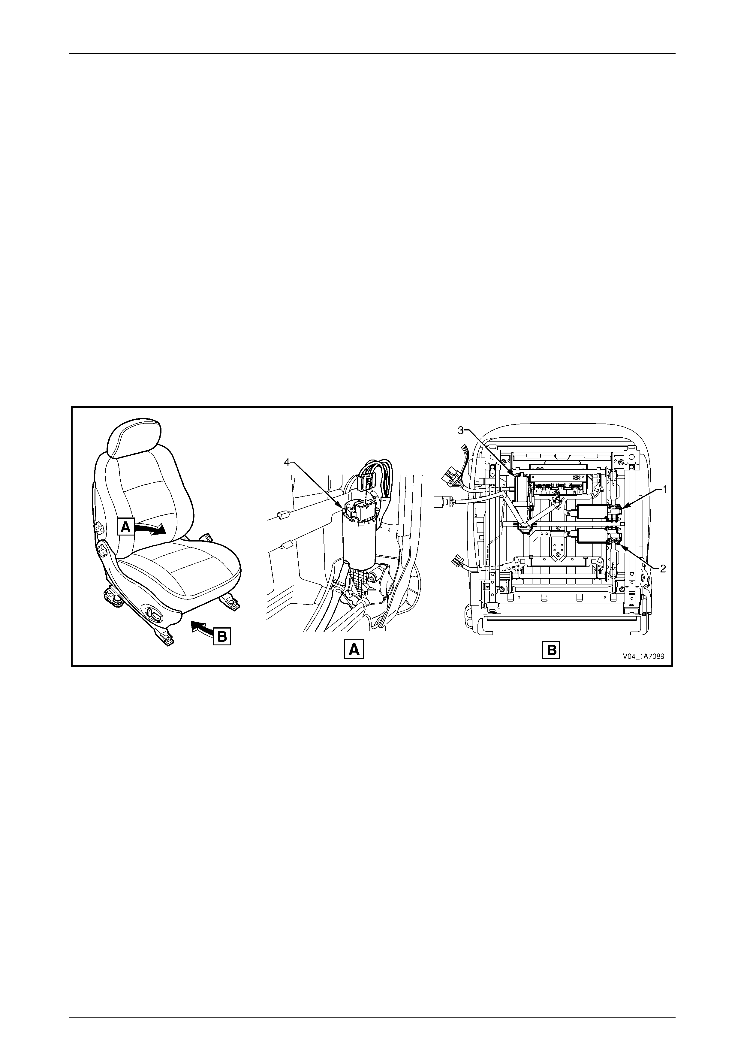
Seat Assemblies Page 1A7A–16
Page 1A7A–16
Seat Covers
Two seat cover construction methods are used for the front seat assemblies. Surebond t ype covers are n ot serviced
separately as they are glued to the seat pa d. Hook and Loop type covers are fully serviceable as they are attached within
the grooves of the seat pad with a Velcro type materia l.
Electric Seat Operation
Depending on Mode l Level of the vehicle, the following front seat electric movement functions are available:
• four-way – seat cushion front raise/lo wer and rear raise/lower,
• six-way – as four-way plus seat fore/aft, and
• eight-way – as six-way plus seat-back recline.
Referring to Figure 1A7A – 1, four electric motor and gearbox assemblies provide the movement of the front seat, one
each, where fitted, for:
• front raise/lower movement (1),
• rear raise/lower movement (2),
• seat fore/aft movement (3), and
• seat-back recline (4).
Figure 1A7A – 1
Each function is independentl y controlled. Alternatively, if desired the front and rear raise/lower movement can be
performed together to raise or lower the complete seat.
Raise/Lower Movement
Two lift motor and gearbox assemblies (1 and 2, refer to Figure 1A7A – 1) are attached to the inboard side of the track
and height adjust assembly; one for front and the other for rear raise/lower movement. When a lift motor is operati ng, it
drives the gearbox which draws in or extends a mating worm shaft. This in turn operates on an arm and cross-shaft.
The cross-shaft is connected to another arm on the opposite side of the track and height adjust assembly and allows the
raising or lowering of that portion (front or rear) of the seat.
Fore/Aft Movement
To provide seat fore/aft movement, the motor and gearbox assembly (3, refer to Figure 1A7A – 1) is connected to a shaft
geared at each end. Within e ach seat track, the shaft gear is meshed upon a rack, providing fore/aft movement.
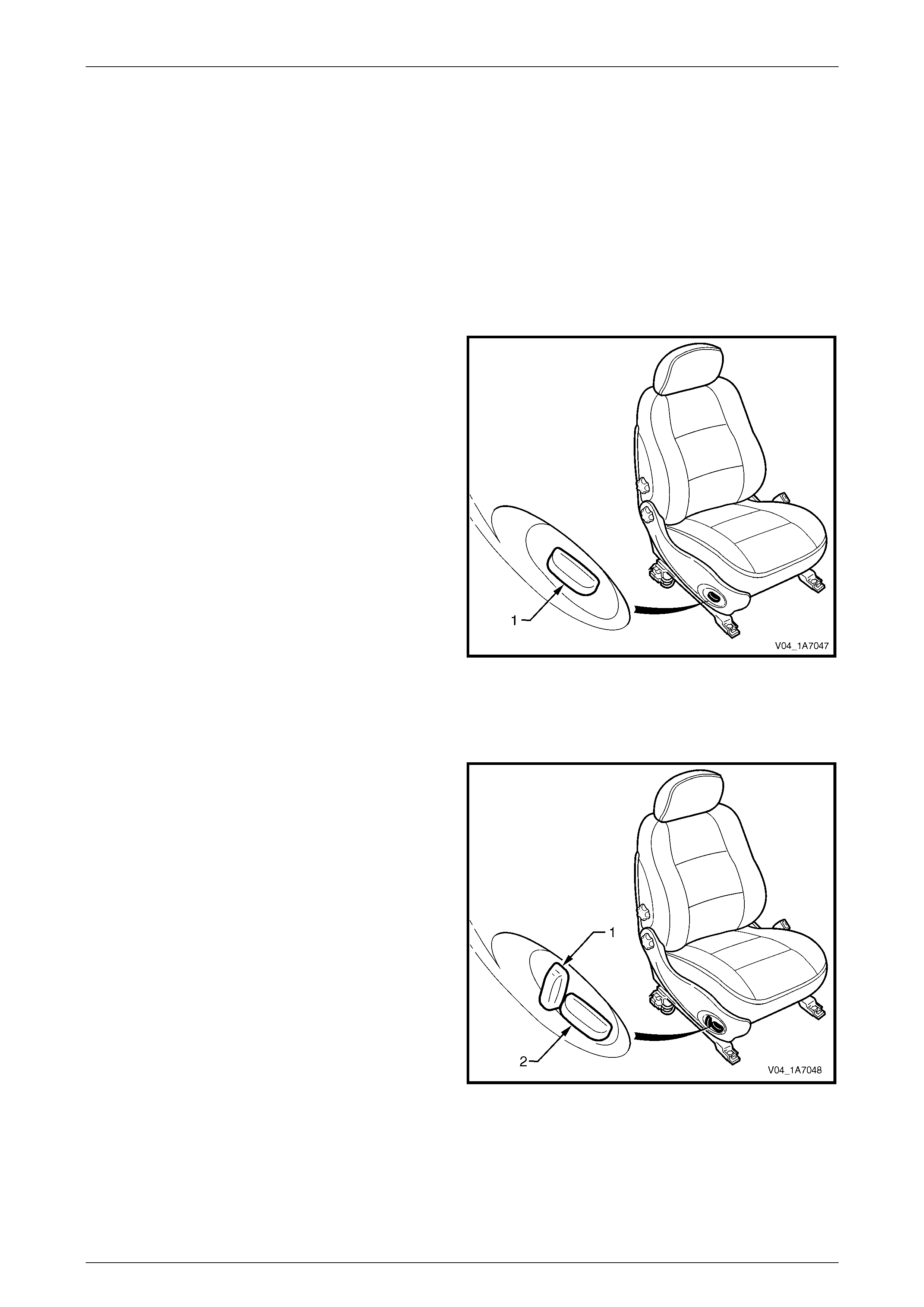
Seat Assemblies P age 1A7A–17
Page 1A7A–17
Recline Movement
Seat-back recline movement is provided by the recline motor and gearbox assembly (4, refer to Figure 1A7A – 1), which
is attached to the seat-back frame. A shaft from the gearbox is fitted with a drive gear at each end and is meshed with a
driven gear attached to each seat-back frame pivot. Motor operation causes rotation of the drive gear, which turns the
driven gear and seat-back frame, thereby altering the seat-back recline angle.
All motors reverse direction when the polarity at the wiring terminals is reversed, resulting in seat movement in the
opposite direction. During seat position adjustment, the drive motors will cease operation at the end of their travel via an
internal thermal cut-out switch, even if the seat adjustment switch is held on.
Components making up the seat-back recline mechanism and track and height adjust assembly are not serviced.
Four-way and Six-way Movement Control
Four-way and six-way seat movement is controlled by a
front seat adjustment switch (1), which is fitted to the outer
side of each front seat.
For the four-way seat, the switch provides independent
control of the front and rear raise/lower movements.
The six-way front seat adjustment switch provides fore/aft
movement in addition to the four-way movements.
To adjust the seat:
• Operate the switch up or down to raise/lower the seat.
• Operate the front of the switch up or down to
raise/lower the front of the seat.
• Operate the rear of the switch up or down to
raise/lower the rear of the seat.
• Operate the switch forward or backward to move the
seat fore/aft.
For further information, refer to the MY 2004 VY or V2
Series Owner's Handbook.
Figure 1A7A – 2
Eight-way Movement Control
The eight-way front seat adjustment switch has an
additional knob (1) which provides control of the seat-bac k
recline movement. The knob (2) provides the same
functions as six-way seats.
To adjust the seat recline:
• Operate the recline knob to adjust the angle of the
seat-back. The seat-back moves in the same direction
to which the switch is moved.
For Coupe vehicles, the seat-back recline switch is disabled
during operation of the EZ-entry function (refer to
EZ-entry System, Coupe, in this Section). The switch will be
enabled once the function is completed or cancelled. The
front seat adjustment switch is monitored by the EZ-entry
module during EZ-entry function and if the switch is
operated, the movement will be cancelled.
For further information, refer to the MY 2004 VY or V2
Series Owner's Handbook.
Figure 1A7A – 3
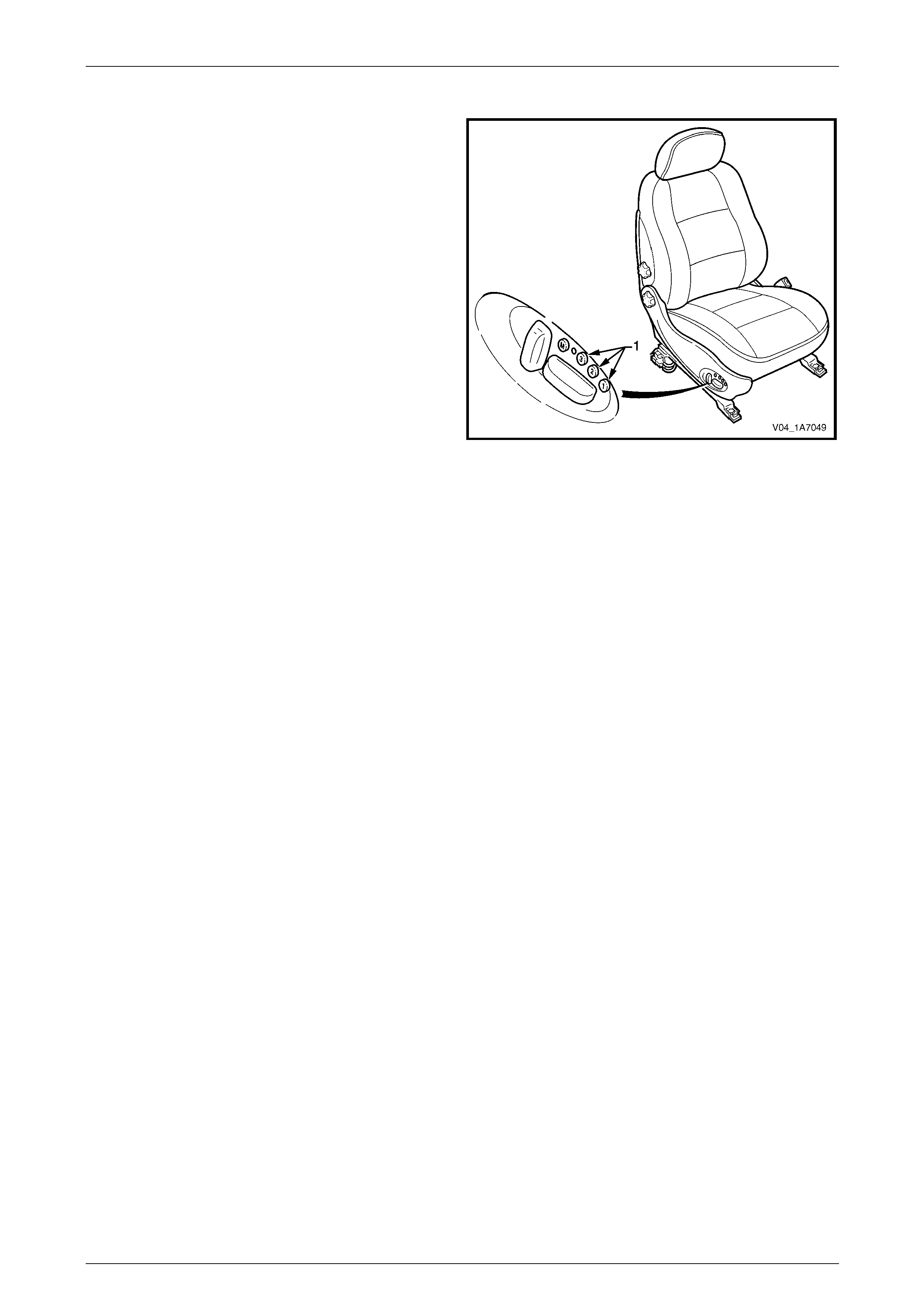
Seat Assemblies Page 1A7A–18
Page 1A7A–18
Memory Seat Position System
The driver’s seat in Domestic Level 3 and Coupe vehicles
are fitted with a memory seat position system.
The memory seat position system allo ws the driver to adjust
the seat to any of the positions stored in memory by
pressing one of the three memory buttons (1).
In addition, on keyless entry to Level 3 vehicles, the memory
seat position system through the Body Control Module
(BCM), recognises which ignition key has been used
(Priority 1 or Priority 2) and adjusts the seat position to the
driver’s preferred set position.
Audible and visual feedback for the various fu nctions of the
memory seat position system is provided. The s ystem has a
green LED and a chime, which are used to i ndicate memory
saves, the recall of priority memory numbers and for seat
diagnostic procedures.
Hall-effect sensors integrated into each of the motor
assemblies are used to monit or the positi on of the seat.
Figure 1A7A – 4
The seat memory module, mounted under the front seat, has a non-volatile memory. While disconnecting the battery will
not erase the seat memory settings, the seat will require recalibrating to reset the potentiometer stop values within the
memory control module.
NOTE
Some of the procedures relating to memory seat
diagnosis detailed in 5 Diagnostics – Front
Seat Memory and Rear-view Mirror (Except
Coupe) require the use of both the Priority 1 Key
and the Priority 2 Key.
Priority Keys (Domestic Level 3 Vehicles Only)
On Domestic Level 3 vehicles, the driver's seat movement is also a function of the priority keys. Priority key 1 and priority
key 2 move the driver's seat and exterior mirrors to the positions in which they were set when that key was last inserted
into the ignition switch. When the vehicle is unlock ed using the Unlock button on a priority key and that priority key is
inserted into the ignition switch, the vehicle identifies the priority key and:
• adjusts the position of the driver's seat,
• adjusts the position of the exterior mirrors to the last position used for that key, and
• if the mirror dip function is activated, adjusts the position of the passenger's exterior mirror when the transmission
selector is placed in reverse.
The driver's seat moves to the last position used for that priority key if:
• that was a memory button position, or
• the seat was adjusted without memorising the position.
The driver's seat moves to the alternate prio rity key position only after pressing the unlock button on the alternate priority
key. If the alternate priority key is not used to unlock the vehicle, that priority key will adjust all personalised settings (for
example, exterior mirror angles, radio and climate control), except the driver's seat.
If activated, the left exterior mirror dip function is linked to the seat and priority key memory (that is, each seat memory
position also stores the left exterior mirror DIP positio n, if activated).
For further information, refer to the MY 2004 VY Series Owner's Handbook.

Seat Assemblies Page 1A7A–19
Page 1A7A–19
Memory Buttons
The seat can store three different memory settings. To recall a stored memory seat and exterior mirror position, press
and hold one of the memory buttons. After the seat has reached its memorised position, release the me mory button. If
the memory button is released before the seat reaches its memorised position, the seat stops moving.
To change a memory position:
1 Adjust the seat with the eight-way front seat adjustment switch.
2 Adjust the exterior mirrors (including the dip positio n).
3 Place the transmission selector in either park or neutral, then turn on the ignition switch.
4 Press the mirror DIP / memory store button (1, 2 or 3) within five seconds. (Two audible chimes are generated
when a new memory position has been stored.)
5 Place the transmission select or in reverse and wait for the passenger's mirror to be returned from the DIP angle to
complete saving the mirror position into memory, refer to Using the Exterior Mirrors in this Section.
Using the Exterior Mirrors
The right exterior mirror and left exterior mirror can be adjusted using the rear-view mirror switch on the driver’s door
armrest when the ignition is on.
To operate the right exterior mirror or left exterior mirror:
1 Turn on the ignition s witch.
2 Move the rocker switch on the rear-view mirror switch to the position to control the right or left exterior mirror.
3 Press the rear-view mirror switch in one of the directions indicated by one of the moulded dots on the edge of the
rear-view mirror switch to move the mirror up, down, left or right.
Adjusting the DIP View
To change the mirror dip posit ion and save it in memory:
1 Turn on the ignition s witch.
2 Place the transmission select or in reverse.
3 Ensure the DIP angle is switched on; the left exterior mirror moves to the current DIP position.
4 Adjust the left exterior mirror using the rear-view mirror switch.
5 Place the transmission selector out of reverse.
6 Press the mirror DIP button, then the desired memory store button (1, 2 or 3) to save the mirror dip position into
memory.
For further information, refer to the MY 2004 VY Series Owner's Handbook.
Toggle DIP Function On / Off
When the mirror DIP function is activated, the left exterior mirror moves to the position set, typically enabling the driver to
see the kerb more clearly. If activated, the DIP function is operational when the ignition is on and the transmission
selector placed in reverse.
To toggle between the dip view and normal view, press the mirror DIP / memory store button.
• When the DIP function is turned on, two audible chimes are generated.
• When the DIP function is turned off, one audible chime is generated.
For further information, refer to the MY 2004 VY Series Owner's Handbook.
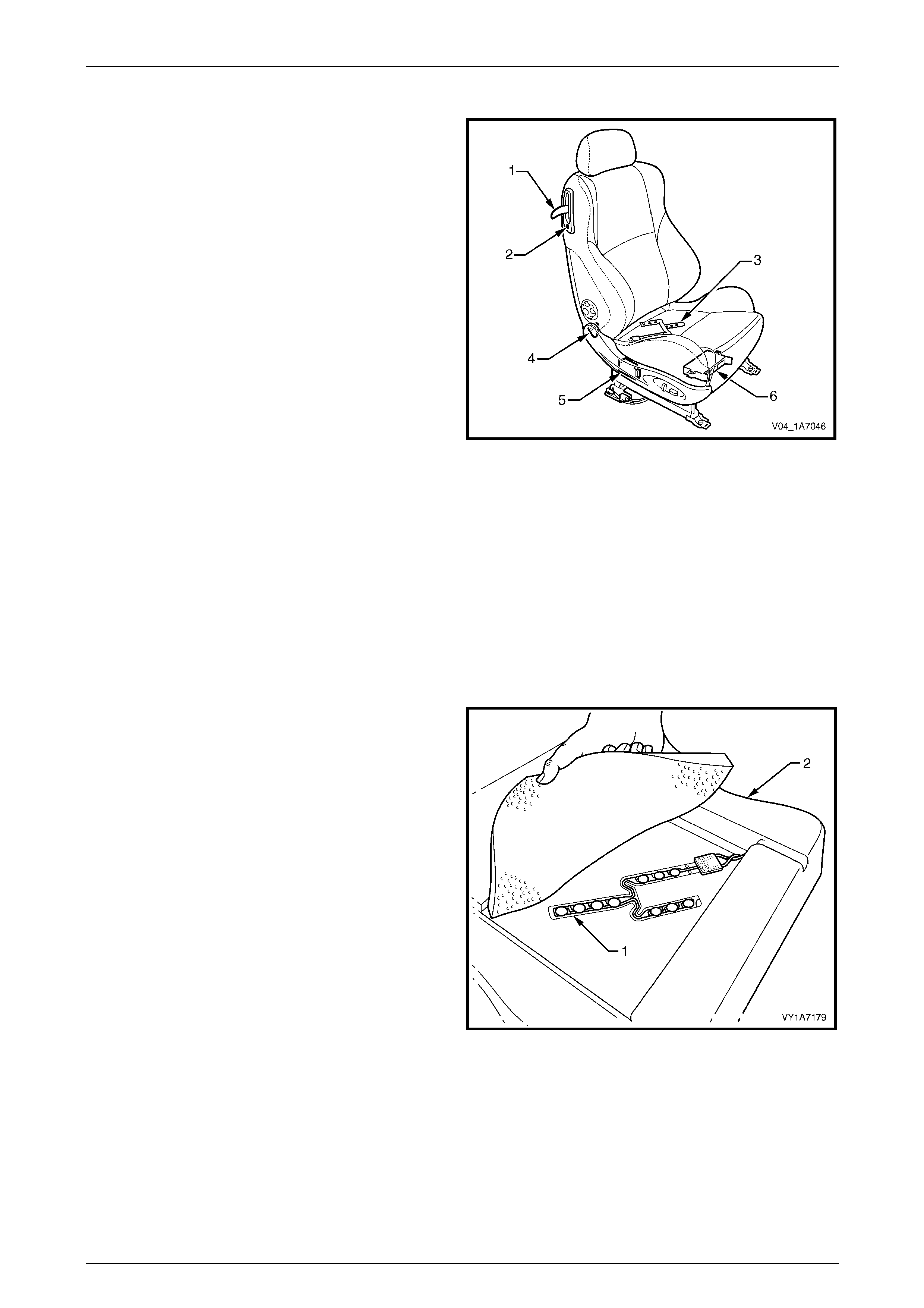
Seat Assemblies Page 1A7A–20
Page 1A7A–20
EZ-entry System, Coupe
The EZ-entry system provides a one touch mechanism to
move the front seat and allow rear seat passengers to enter
or exit the vehicle. The EZ-entry system comprises of:
• an EZ-entry release lever (1),
• a seat return switch (2),
• a passenger presence detection switch (3),
• an EZ-entry switch (4),
• an EZ-entry module (5) – vehicles without memory
function, and
• a memory module incorporating EZ-entry functions (6)
– vehicles with memory function.
When the EZ-entry release lever is un-latched, the seat-
back can be tilted for ward.
The EZ-entry module detects if the EZ-entry feature has
been activated via the EZ-entry switch and providing the
seat is not occupied, the seat will automatically move
forward until end of travel is reached.
Seat fore/ aft position is monitored by a sensor incorporated
with the fore/aft drive motor and recorde d in the EZ-entry
module.
To return the seat, the operator returns the seat-back to the
latched position and presses and holds the seat return
button. The seat will then return to it’s last recorded location.
If the seat return switch remains held, after a period of three
seconds the seat will resume its rearward movement for as
long as the switch is held or until the end of seat travel is
reached.
Figure 1A7A – 5
A passenger presence detection switch (1) is incorporated
into the front seat cushions (2).
Detection of a weight 15 kg or more over the passenger
presence detection switch (seat cushion) will cause the EZ-
entry module to either cancel fore/ aft movement or prevent
fore/ aft movement from commencing should the EZ-entry
function be initiated.
If weight detection causes the EZ-entry function to cease, a
period of one second must pass without weight before re-
start will commence.
The passenger presence detection switch is a pressur e
switch with a nominal high resistance cond ition with no
weight on the seat. The resistance decreases as the weight
is increased.
An integral diode is provided within the passenger presence
detection switch and is used by the module to verify
connection of the switch prior to for ward mov ement of the
seat during the operation of the EZ-entry function.
The module will test for the following conditions on the
passenger presence detection switch:
• either line connected to ground or battery, and
• either line open circuited.
Figure 1A7A – 6
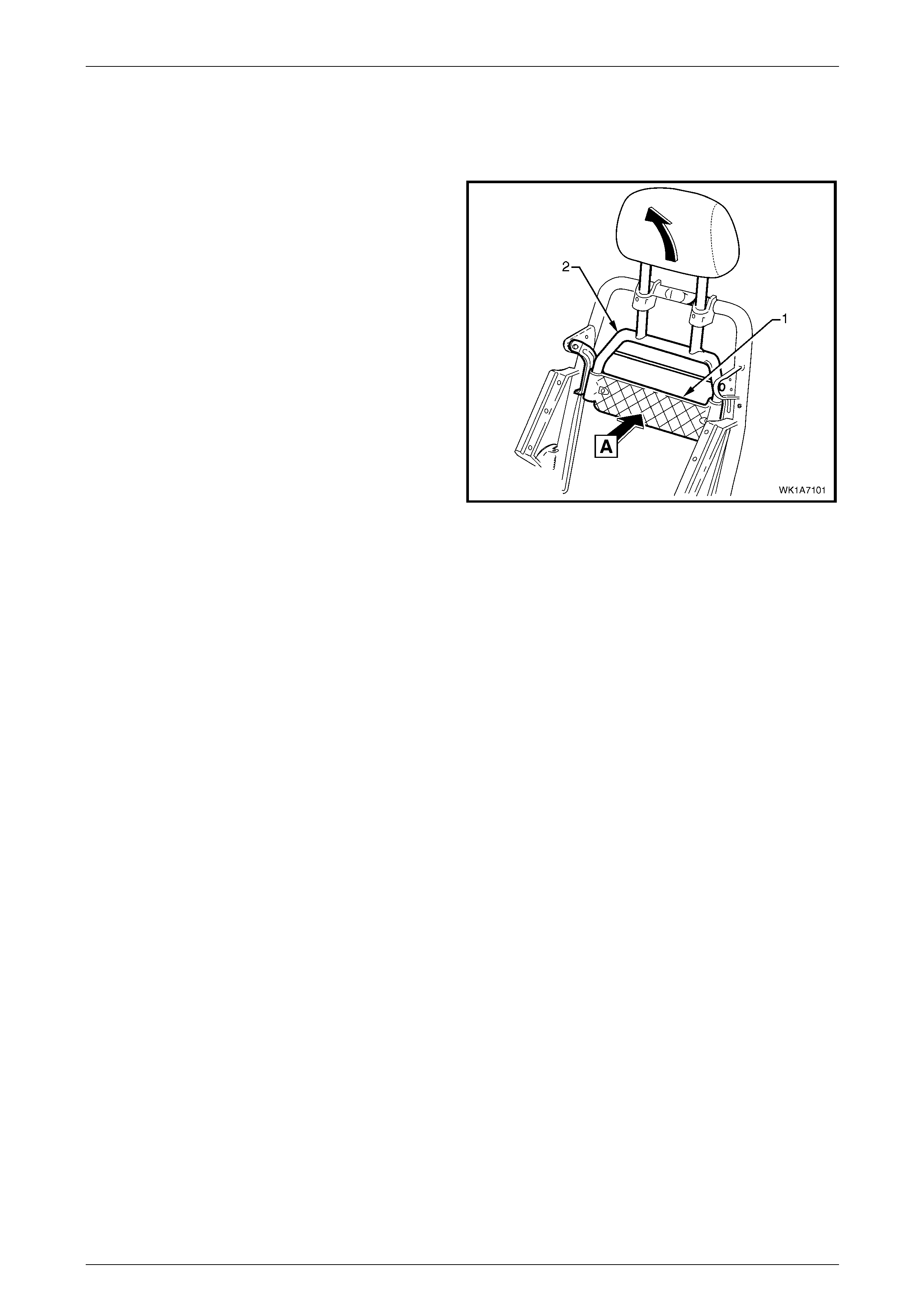
Seat Assemblies Page 1A7A–21
Page 1A7A–21
Active Head Restraints
The front seats fitted to Domestic Acclaim, Calais and all domestic and export Coupe veh icles feature active head
restraints. During a rear-end collision, active head restraints are designed to move upward and forward to support the
occupant's head and reduc e neck injuries.
The impact force from the collision pushes the vehicle (and
seat) forward. As the vehicle moves forward at a speed
greater than the occupant’s body can react to, the body is
moved into the seat (A) pushing on the active hea d restraint
support strap (1).
Due to the pivoting of the active head restrain t frame (2), the
frame along with the head rest raint moves upward and
forward, supporting and limiting rearward travel of the
occupant's head.
Figure 1A7A – 7

Seat Assemblies Page 1A7A–22
Page 1A7A–22
1.2 Rear Seat General Description
Sedan
With the following exceptions, MY 2004 VY S edan Rear Seat Assemblies information carries over from MY 2003 VY
Series vehicles:
• S, SV8, SS rear seat pad and cover.
MY 2004 VY Sedan S, SV8 and SS vehicles now use the hook and loop system for attaching the rear seat covers to the
seat pads. Hook and Loop refers to the seat cover be ing able to be attached to the seat pad with a Velcro type material
and both cover and pad being serviced as separate parts. Previously these seats have b een of Surebond construction.
Service operations carry over from MY 2003 VY SS Sedan leather hook and loop rear sea ts, noting an extra hook and
loop strip running across the rear of the seat cushion.
For a breakdown of the MY 2004 Sedan S, SV8 and SS rear seat assemblies, refer to 8.1 Usage Charts. For information
not contained within this Section, refer to 1A7, 6 Service Operations – Rear Seat, Sedan in the MY 2003 VY and V2
Series Service Information.
Wagon
MY 2004 VY Wagon Rear Seat Assembl ies information carries over from MY 2003 VY Wagon vehicles.
For all Rear Seat Assemblies information, refer to 1A7, 7 Service Operations – Rear Seat, Wagon in the MY 2003 VY
and V2 Series Service Information.
Coupe
With the following exception, MY 2004 V2 Coupe Rear Seat Assemblies information carries over from MY 2003 V2
Coupe vehicles:
• child comforter guide.
Where fitted, the child comforter guide is attached to the rear seat-back frame and is used to position the seat-belt in a
more comfortable position for smaller passengers such as childr en. W hen not in use, the child comforter guide stores
away in a small pouch on the side of the rear seat-back assembly.
For a breakdown of the MY 2004 Coupe rear seat assemblies, refer to 8.1 Usage Charts.
For service information not contained within this Section, refer to 1A7, 8 Service Operations – Rear Seat, Coupe in the
MY 2003 VY and V2 Series Service Information.

Seat Assemblies Page 1A7A–23
Page 1A7A–23
2 Service Operations – Front Seat,
Except Coupe
2.1 Front Seat Usage Chart
How To Use This Chart
Twenty four front seat configurations are fitted to MY 2004 VY Series vehicles. T he following usage chart is provided to
help determine the seat type fitted to the vehicle. This is important prior to repa irs being performed as the failed/dam aged
part may not be serviceable.
To determine the seat fitted to the vehicle, obtain the vehicle model, which seat requires attention and the seat cover
fabric. Then establish other features of the seat such as the electric movement functions. Using the ch art will lead to the
elimination of all other seat combinations, al lowing the identification of the typ e and the co nstruction of the seat. Finally,
refer to the Figure shown in Front Seat Type for a component breakdown of the front seat assembly.
1 Vehicle – Vehicle model identification.
2 Seating – Driver front seat or passenger front seat.
3 Fabric – Cloth or leather seat covers.
4 Movement – Indicates the number of movement functions of the seat:
• Two-way – Seat cushion mechanical fore/aft movement.
• Four-way – As two-way plus seat cushion electric front and rear raise/lower.
• Six-way – As four- way plus s eat cushion electric fore/aft movement.
• Eight-way – As six-way plus electric seat-back recline.
5 Memory – Indicates if a seat memory module is fitted.
6 SIAB – If the front seat is fitted with a side impact airbag assembly.
7 Construction – Surebond refers to the seat cover being glued to the seat pad. This type is serviced as a cover and
pad assembly only. Hook an d Loop refers to the seat cover being attached to the seat pad with a Velcro type
material and both being servi ced as separate parts.
8 Active Head Restrain t – Indicates whether standard height adjustable or active head restraints are fitted.
9 Front Seat Type – Identifies the seat type and provides reference to the following illustrations which show a
breakdown of the serviced component for each front seat assembly.
Domestic
Vehicle Seating Fabric Movement Memory SIAB Construction Active Head
Restraint Front Seat Type
(refer to)
Driver Cloth Four-way No Opt* Surebond No 1
(Figure 1A7A – 8)
Executive,
Base Utility
Passenger Cloth Two-way No Opt* Surebond No 2
(Figure 1A7A – 9)
Driver Cloth Four-way No Yes Surebond Yes 3
(Figure 1A7A – 10)
Acclaim
Passenger Cloth Two-way No Yes Surebond Yes 4
(Figure 1A7A – 11)
Driver Cloth/
Leather Four-way No Opt* Hook & Loop No 5
(Figure 1A7A – 12)
SV8, S,
S Utility
Passenger Cloth/
Leather Two-way No Opt* Hook & Loop No 6
(Figure 1A7A – 13)

Seat Assemblies Page 1A7A–24
Page 1A7A–24
Domestic
Vehicle Seating Fabric Movement Memory SIAB Construction Active Head
Restraint Front Seat Type
(refer to)
Driver Cloth/
Leather Four-way No Yes* Hook & Loop No 7
(Figure 1A7A – 14)
SS,
SS Utility
Passenger Cloth/
Leather Two-way No Yes* Hook & Loop No 8
(Figure 1A7A – 15)
Driver Cloth/
Leather Four-way No Yes Hook & Lo op No 9
(Figure 1A7A – 16)
Berlina
Passenger Cloth/
Leather Two-way No Yes Hook & Lo op No 10
(Figure 1A7A – 17)
Driver Cloth/
Leather Eight-way Yes Yes Hook & Lo op Yes 11
(Figure 1A7A – 18)
Calais
Passenger Cloth/
Leather Eight-way No Yes Hook & Lo op Yes 12
(Figure 1A7A – 19)
* Side impact airbag assemblies are not fitted to Utility vehicles
Gulf States
Vehicle Seating Fabric Movement Memory SIAB Construction Active Head
Restraint Front Seat Type
(refer to)
Passenger Cloth Two-way No No Surebond No 13
(Figure 1A7A – 20)
Lumina LS
Driver Cloth Six-way No No Surebond No 14
(Figure 1A7A – 21)
Passenger Cloth Eight-way No No Surebond No 15
(Figure 1A7A – 22)
Driver Cloth Eight-way No No Surebond No 16
(Figure 1A7A – 23)
Passenger Cloth Two-way No No Hook & Loop No 17
(Figure 1A7A – 24)
Lumina S
Driver Cloth Six-way No No Hook & Loop No 18
(Figure 1A7A – 25)
Passenger Cloth/
Leather Four-way No No Hook & Loop No 19
(Figure 1A7A – 26)
Lumina SS
Driver Cloth/
Leather Six-way No No Hook & Loop No 20
(Figure 1A7A – 27)
Passenger Cloth/
Leather Eight-way No No Hook & Loop No 21
(Figure 1A7A – 28)
Lumina LTZ
Driver Cloth/
Leather Eight-way No No Hook & Loop No 22
(Figure 1A7A – 29)
Brazil
Vehicle Seating Fabric Movement Memory SIAB Construction Active Head
Restraint Front Seat Type
(refer to)
Passenger Leather Eight-way No Yes Hook & Loop No 23
(Figure 1A7A – 30)
Omega CD
Driver Leather Eight-way No Yes Hook & Loop No 24
(Figure 1A7A – 31)
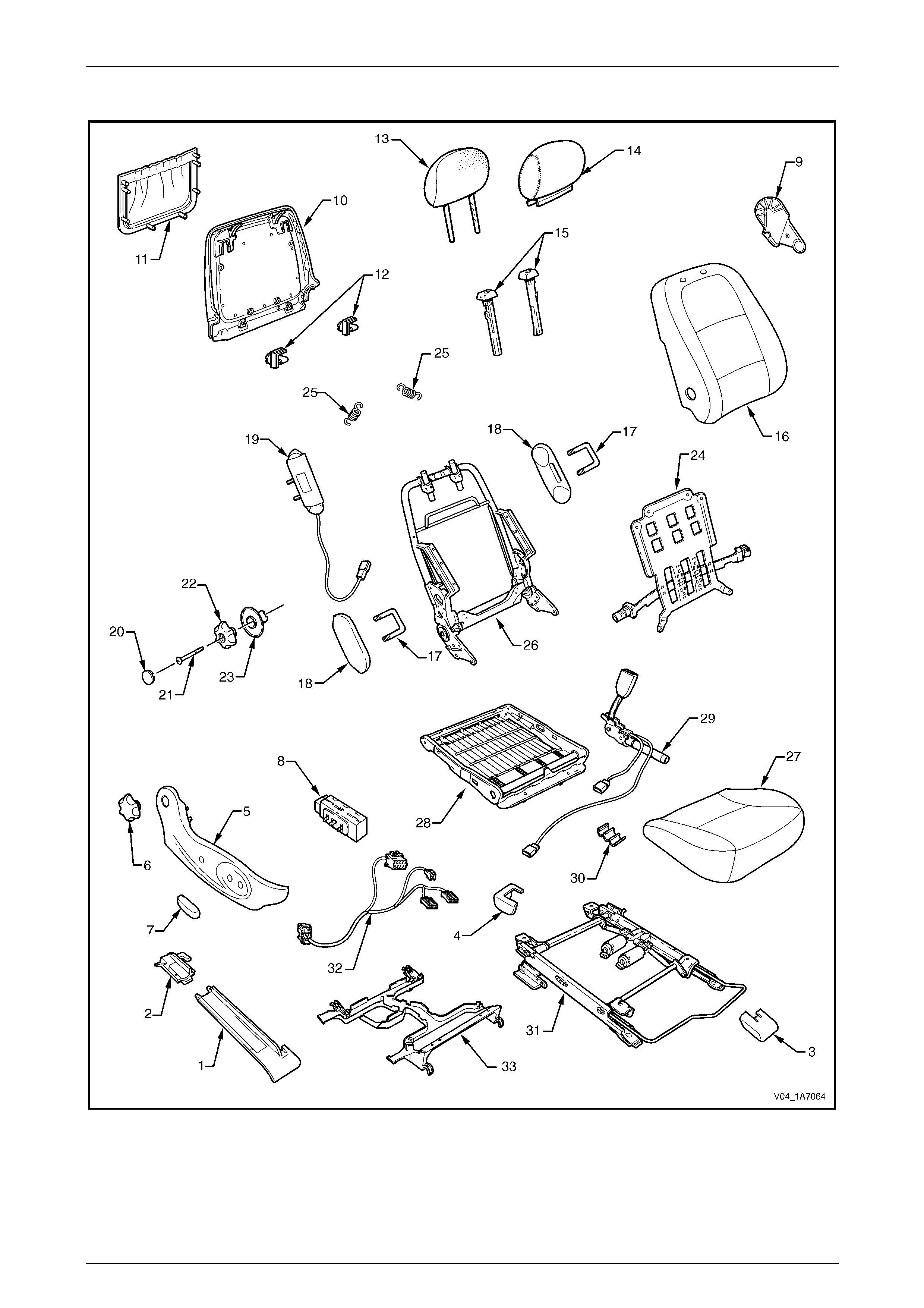
Seat Assemblies Page 1A7A–25
Page 1A7A–25
Front Seat Type 1
Figure 1A7A – 8

Seat Assemblies Page 1A7A–26
Page 1A7A–26
Legend
1 Front Seat Outer Front Cover
2 Front Seat Outer Rear Cover
3 Front Seat Inner Front Cover
4 Front Seat Inner Rear Cover
5 Front Seat Outer Side Cover
6 Recline Adjuster Knob
7 Front Seat Adjustment Switch Knob
8 Front Seat Adjustment Switch – Four-way
9 Front Seat Inner Side Cover
10 Front Seat-back Rear Cover
11 Front Seat-back Map Pocket#
12 Front Seat-back Cover Retaining Clips
13 Front Seat Head Restraint Pad Assembly
14 Front Seat Head Restraint Cover
15 Front Seat Head Restraint Sleeves
16 Front Seat-back Cover and Pad Assembly
17 Front Seat Dummy Block U-bolt*
18 Front Seat Dummy Block Insert*
19 Side Impact Airbag Assembly*
20 Lumbar Support Knob Cover
21 Lumbar Support Knob Screw
22 Lumbar Support Knob
23 Lumbar Support Deflector Ring
24 Lumbar Support Assembly
25 Lumbar Support Retaining Spring
26 Front Seat-back Frame Assembly
27 Front Seat Cushion Cover and Pad Assembly
28 Front Seat Cushion Frame Assembly
29 Seatbelt Buckle & Pretensioner Assembly
30 Wiring Harness Retaining Clip
31 Track and Height Adjust Assembly
32 Wiring Harness Assembly
33 Front Seat Cable Tray
* Side impact airbag assembl y is optional on Sedan and Wagon and not fitted to Utility vehicles. Front seat dummy block
assembly fitted to outer side when side impact airbag assembly not fitted.
# Front Seat-back map pocket not fitted to Utility vehicles.
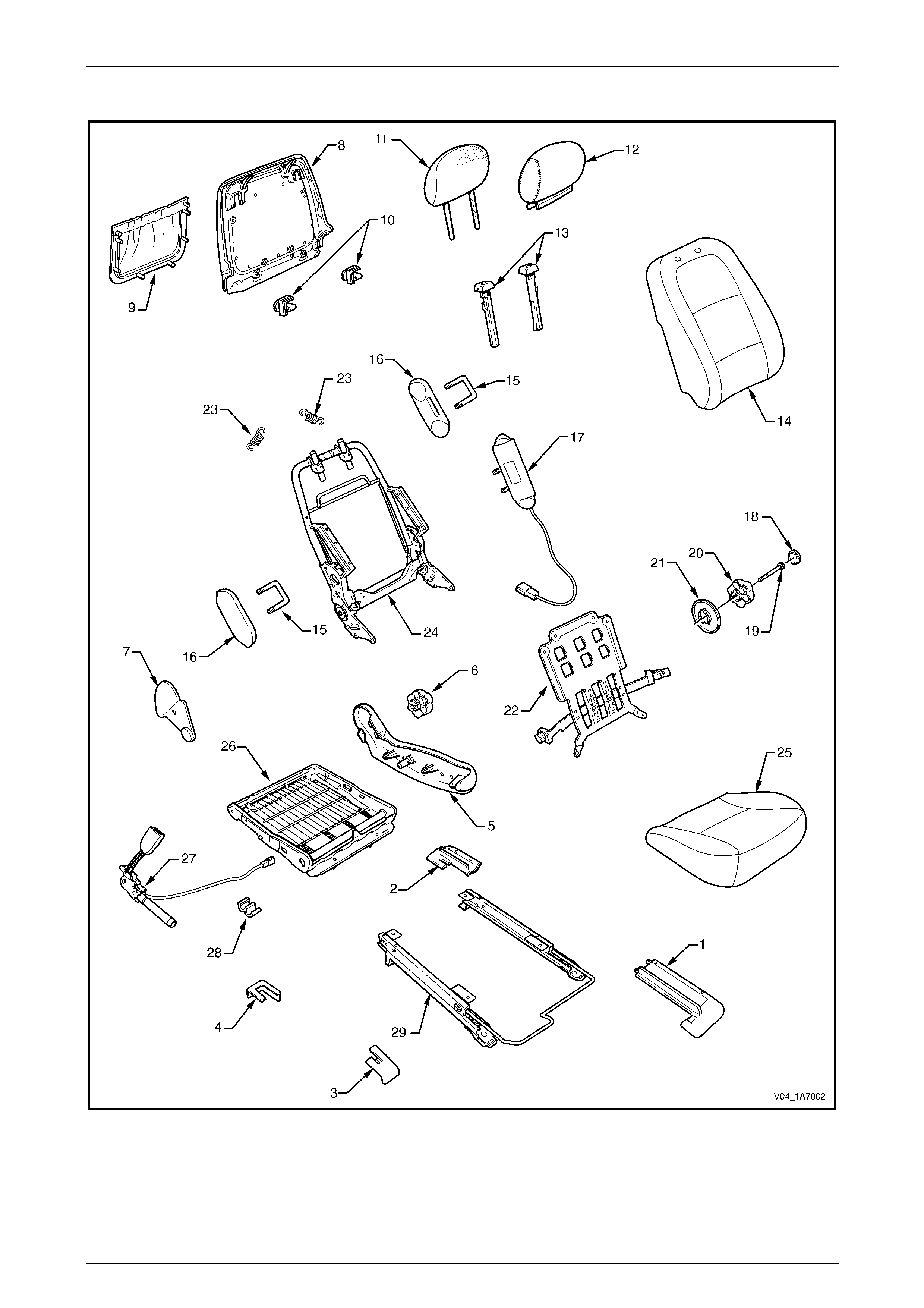
Seat Assemblies Page 1A7A–27
Page 1A7A–27
Front Seat Type 2
Figure 1A7A – 9

Seat Assemblies Page 1A7A–28
Page 1A7A–28
Legend
1 Front Seat Outer Front Cover
2 Front Seat Outer Rear Cover
3 Front Seat Inner Front Cover
4 Front Seat Inner Rear Cover
5 Front Seat Outer Side Cover
6 Recline Adjuster Knob
7 Front Seat Inner Side Cover
8 Front Seat-back Rear Cover
9 Front Seat-back Map Pocket#
10 Front Seat-back Cover Retaining Clips
11 Front Seat Head Restraint Pad Assembly
12 Front Seat Head Restraint Cover
13 Front Seat Head Restraint Sleeves
14 Front Seat-back Cover and Pad Assembly
15 Front Seat Dummy Block U-bolt*
16 Front Seat Dummy Block Insert*
17 Side Impact Airbag Assembly*
18 Lumbar Support Knob Cover
19 Lumbar Support Knob Screw
20 Lumbar Support Knob
21 Lumbar Support Deflector Ring
22 Lumbar Support Assembly
23 Lumbar Support Retaining Spring
24 Front Seat-back Frame Assembly
25 Front Seat Cushion Cover and Pad Assembly
26 Front Seat Cushion Frame Assembly
27 Seatbelt Buckle & Pretensioner Assembly
28 Wiring Harness Retaining Clip
29 Track and Height Adjust Assembly
* Side impact airbag assembl y is optional on Sedan and Wagon and not fitted to Utility vehicles. Front seat dummy block
assembly fitted to outer side when side impact airbag assembly not fitted.
# Front Seat-back map pocket not fitted to Utility vehicles.
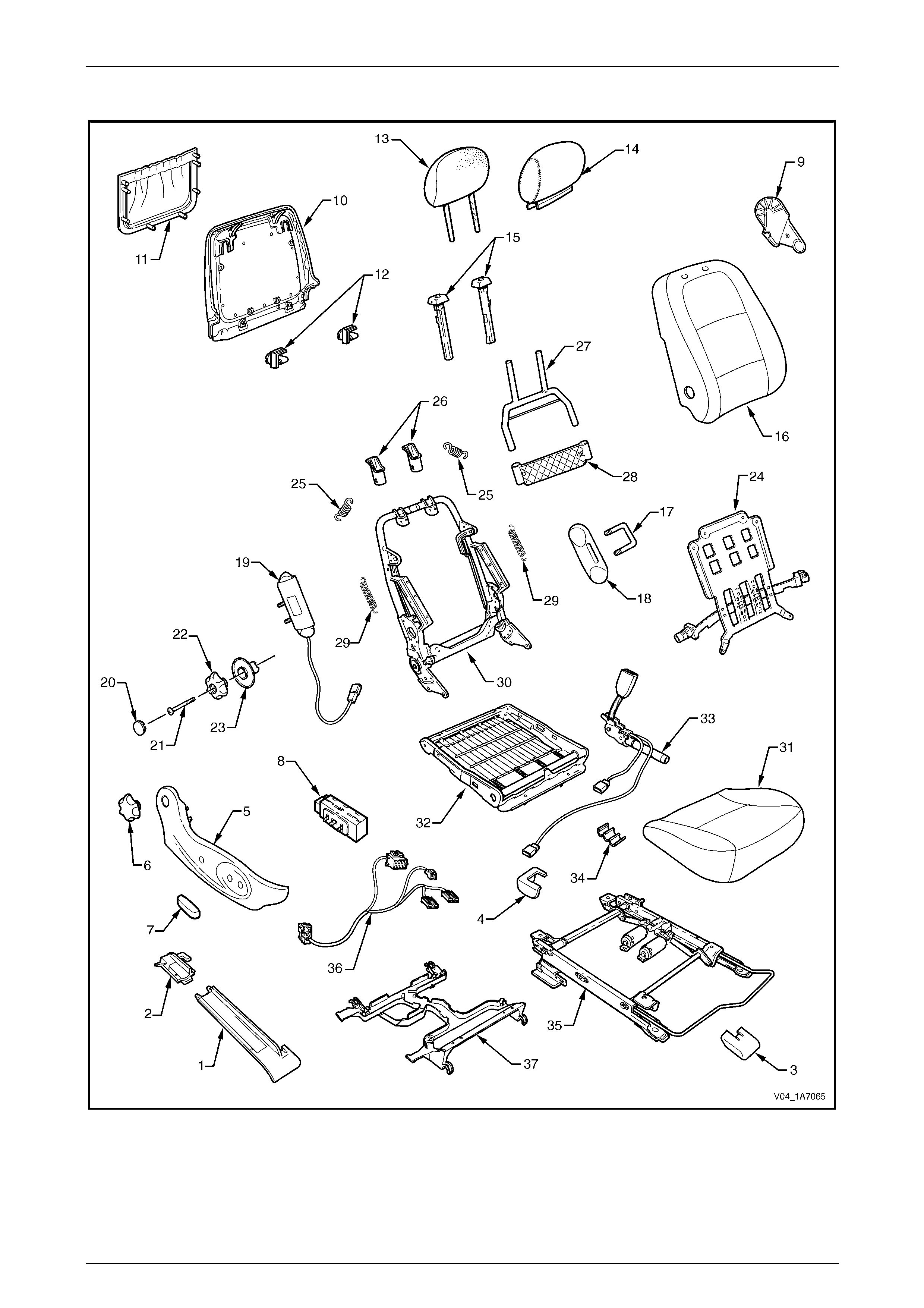
Seat Assemblies Page 1A7A–29
Page 1A7A–29
Front Seat Type 3
Figure 1A7A – 10

Seat Assemblies Page 1A7A–30
Page 1A7A–30
Legend
1 Front Seat Outer Front Cover
2 Front Seat Outer Rear Cover
3 Front Seat Inner Front Cover
4 Front Seat Inner Rear Cover
5 Front Seat Outer Side Cover
6 Recline Adjuster Knob
7 Front Seat Adjustment Switch Knob
8 Front Seat Adjustment Switch – Four-way
9 Front Seat Inner Side Cover
10 Front Seat-back Rear Cover
11 Front Seat-back Map Pocket
12 Front Seat-back Cover Retaining Clips
13 Front Seat Head Restraint Pad Assembly
14 Front Seat Head Restraint Cover
15 Front Seat Head Restraint Sleeves
16 Front Seat-back Cover and Pad Assembly
17 Front Seat Dummy Block U-bolt
18 Front Seat Dummy Block Insert
19 Side Impact Airbag Assembly
20 Lumbar Support Knob Cover
21 Lumbar Support Knob Screw
22 Lumbar Support Knob
23 Lumbar Support Deflector Ring
24 Lumbar Support Assembly
25 Lumbar Support Retaining Spring
26 Active Head Restraint Frame Sleeves
27 Active Head Restraint Frame Assembly
28 Active Head Restraint Frame Support Strap
29 Active Head Restraint Frame Retaining Spring
30 Front Seat-back Frame Assembly
31 Front Seat Cushion Cover and Pad Assembly
32 Front Seat Cushion Frame Assembly
33 Seatbelt Buckle & Pretensioner Assembly
34 Wiring Harness Retaining Clip
35 Track and Height Adjust Assembly
36 Wiring Harness Assembly
37 Front Seat Cable Tray

Seat Assemblies Page 1A7A–31
Page 1A7A–31
Front Seat Type 4
Figure 1A7A – 11

Seat Assemblies Page 1A7A–32
Page 1A7A–32
Legend
1 Front Seat Outer Front Cover
2 Front Seat Outer Rear Cover
3 Front Seat Inner Front Cover
4 Front Seat Inner Rear Cover
5 Front Seat Outer Side Cover
6 Recline Adjuster Knob
7 Front Seat Inner Side Cover
8 Front Seat-back Rear Cover
9 Front Seat-back Map Pocket
10 Front Seat-back Cover Retaining Clips
11 Front Seat Head Restraint Pad Assembly
12 Front Seat Head Restraint Cover
13 Front Seat Head Restraint Sleeves
14 Front Seat-back Cover and Pad Assembly
15 Front Seat Dummy Block U-bolt
16 Front Seat Dummy Block Insert
17 Side Impact Airbag Assembly
18 Lumbar Support Knob Cover
19 Lumbar Support Knob Screw
20 Lumbar Support Knob
21 Lumbar Support Deflector Ring
22 Lumbar Support Assembly
23 Lumbar Support Retaining Spring
24 Active Head Restraint Frame Sleeves
25 Active Head Restraint Frame Assembly
26 Active Head Restraint Frame Support Strap
27 Active Head Restraint Frame Retaining Spring
28 Front Seat-back Frame Assembly
29 Front Seat Cushion Cover and Pad Assembly
30 Front Seat Cushion Frame Assembly
31 Seatbelt Buckle & Pretensioner Assembly
32 Wiring Harness Retaining Clip
33 Track and Height Adjust Assembly
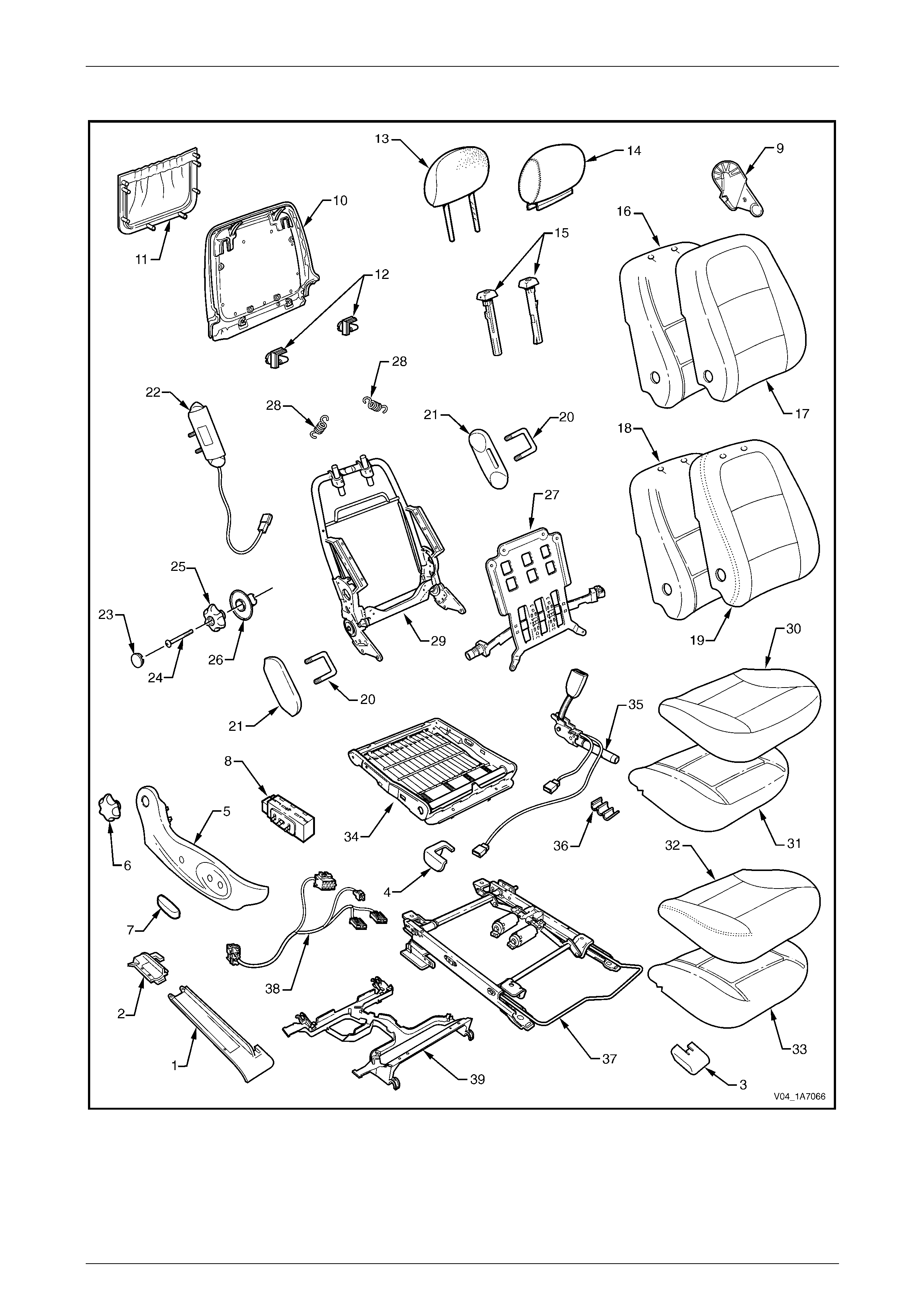
Seat Assemblies Page 1A7A–33
Page 1A7A–33
Front Seat Type 5
Figure 1A7A – 12

Seat Assemblies Page 1A7A–34
Page 1A7A–34
Legend
1 Front Seat Outer Front Cover
2 Front Seat Outer Rear Cover
3 Front Seat Inner Front Cover
4 Front Seat Inner Rear Cover
5 Front Seat Outer Side Cover
6 Recline Adjuster Knob
7 Front Seat Adjustment Switch Knob
8 Front Seat Adjustment Switch – Four-way
9 Front Seat Inner Side Cover
10 Front Seat-back Rear Cover
11 Front Seat-back Map Pocket#
12 Front Seat-back Cover Retaining Clips
13 Front Seat Head Restraint Pad Assembly
14 Front Seat Head Restraint Cover
15 Front Seat Head Restraint Sleeves
16 Front Seat-back Pad – Cloth Cover
17 Front Seat-back Cloth Cover
18 Front Seat-back Pad – Leather Cover
19 Front Seat-back Leather Cover
20 Front Seat Dummy Block U-bolt*
21 Front Seat Dummy Block Insert*
22 Side Impact Airbag Assembly*
23 Lumbar Support Knob Cover
24 Lumbar Support Knob Screw
25 Lumbar Support Knob
26 Lumbar Support Deflector Ring
27 Lumbar Support Assembly
28 Lumbar Support Retaining Spring
29 Front Seat-back Frame Assembly
30 Front Seat Cushion Cloth Cover
31 Front Seat Cushion Pad – Cloth Cover
32 Front Seat Cushion Leather Cover
33 Front Seat Cushion Pad – Leather Cover
34 Front Seat Cushion Frame Assembly
35 Seatbelt Buckle & Pretensioner Assembly
36 Wiring Harness Retaining Clip
37 Track and Height Adjust Assembly
38 Wiring Harness Assembly
39 Front Seat Cable Tray
* Side impact airbag assembl y is optional on Sedan and Wagon and not fitted to Utility vehicles. Front seat dummy block
assembly fitted to outer side when side impact airbag assembly not fitted.
# Front Seat-back map pocket not fitted to Utility vehicles.

Seat Assemblies Page 1A7A–35
Page 1A7A–35
Front Seat Type 6
Figure 1A7A – 13

Seat Assemblies Page 1A7A–36
Page 1A7A–36
Legend
1 Front Seat Outer Front Cover
2 Front Seat Outer Rear Cover
3 Front Seat Inner Front Cover
4 Front Seat Inner Rear Cover
5 Front Seat Outer Side Cover
6 Recline Adjuster Knob
7 Front Seat Inner Side Cover
8 Front Seat-back Rear Cover
9 Front Seat-back Map Pocket#
10 Front Seat-back Cover Retaining Clips
11 Front Seat Head Restraint Pad Assembly
12 Front Seat Head Restraint Cover
13 Front Seat Head Restraint Sleeves
14 Front Seat-back Pad – Cloth Cover
15 Front Seat-back Cloth Cover
16 Front Seat-back Pad – Leather Cover
17 Front Seat-back Leather Cover
18 Front Seat Dummy Block U-bolt*
19 Front Seat Dummy Block Insert*
20 Side Impact Airbag Assembly*
21 Lumbar Support Knob Cover
22 Lumbar Support Knob Screw
23 Lumbar Support Knob
24 Lumbar Support Deflector Ring
25 Lumbar Support Assembly
26 Lumbar Support Retaining Spring
27 Front Seat-back Frame Assembly
28 Front Seat Cushion Cloth Cover
29 Front Seat Cushion Pad – Cloth Cover
30 Front Seat Cushion Leather Cover
31 Front Seat Cushion Pad – Leather Cover
32 Front Seat Cushion Frame Assembly
33 Seatbelt Buckle & Pretensioner Assembly
34 Wiring Harness Retaining Clip
35 Track and Height Adjust Assembly
* Side impact airbag assembl y is optional on Sedan and Wagon and not fitted to Utility vehicles. Front seat dummy block
assembly fitted to outer side when side impact airbag assembly not fitted.
# Front Seat-back map pocket not fitted to Utility vehicles.
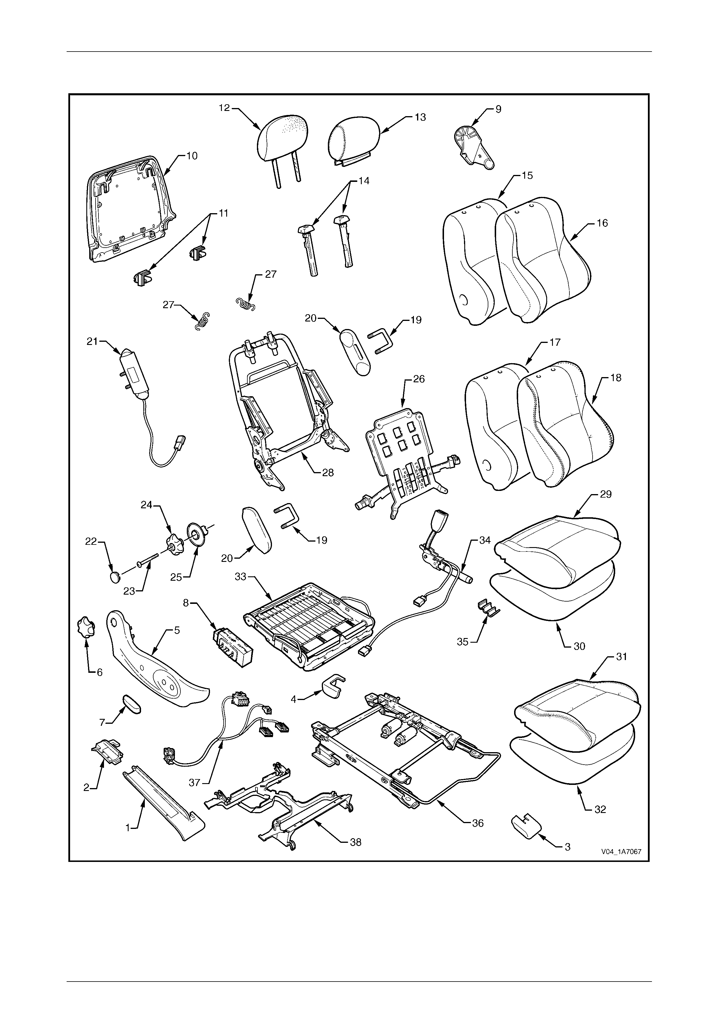
Seat Assemblies Page 1A7A–37
Page 1A7A–37
Front Seat Type 7
Figure 1A7A – 14

Seat Assemblies Page 1A7A–38
Page 1A7A–38
Legend
1 Front Seat Outer Front Cover
2 Front Seat Outer Rear Cover
3 Front Seat Inner Front Cover
4 Front Seat Inner Rear Cover
5 Front Seat Outer Side Cover
6 Recline Adjuster Knob
7 Front Seat Adjustment Switch Knob
8 Front Seat Adjustment Switch – Four-way
9 Front Seat Inner Side Cover
10 Front Seat-back Rear Cover Assembly#
11 Front Seat-back Cover Retaining Clips
12 Front Seat Head Restraint Pad Assembly
13 Front Seat Head Restraint Cover
14 Front Seat Head Restraint Sleeves
15 Front Seat-back Pad – Cloth Cover
16 Front Seat-back Cloth Cover
17 Front Seat-back Pad – Leather Cover
18 Front Seat-back Leather Cover
19 Front Seat Dummy Block U-bolt*
20 Front Seat Dummy Block Insert*
21 Side Impact Airbag Assembly*
22 Lumbar Support Knob Cover
23 Lumbar Support Knob Screw
24 Lumbar Support Knob
25 Lumbar Support Deflector Ring
26 Lumbar Support Assembly
27 Lumbar Support Retaining Spring
28 Front Seat-back Frame Assembly
29 Front Seat Cushion Cloth Cover
30 Front Seat Cushion Pad – Cloth Cover
31 Front Seat Cushion Leather Cover
32 Front Seat Cushion Pad – Leather Cover
33 Front Seat Cushion Frame Assembly
34 Seatbelt Buckle & Pretensioner Assembly
35 Wiring Harness Retaining Clip
36 Track and Height Adjust Assembly
37 Wiring Harness Assembly
38 Front Seat Cable Tray
* Side impact airbag assembly not fitted to Utility vehicles. Front seat dummy block assembly fitted to outer side when
side impact airbag assembl y not fitted.
# Net type map pocket is part of the front seat-back rear cover assembly. Front Seat-back map pockets are not fitted to
Utility vehicles.

Seat Assemblies Page 1A7A–39
Page 1A7A–39
Front Seat Type 8
Figure 1A7A – 15

Seat Assemblies Page 1A7A–40
Page 1A7A–40
Legend
1 Front Seat Outer Front Cover
2 Front Seat Outer Rear Cover
3 Front Seat Inner Front Cover
4 Front Seat Inner Rear Cover
5 Front Seat Outer Side Cover
6 Recline Adjuster Knob
7 Front Seat Inner Side Cover
8 Front Seat-back Rear Cover Assembly#
9 Front Seat-back Cover Retaining Clips
10 Front Seat Head Restraint Pad Assembly
11 Front Seat Head Restraint Cover
12 Front Seat Head Restraint Sleeves
13 Front Seat-back Pad – Cloth Cover
14 Front Seat-back Cloth Cover
15 Front Seat-back Pad – Leather Cover
16 Front Seat-back Leather Cover
17 Front Seat Dummy Block U-bolt*
18 Front Seat Dummy Block Insert*
19 Side Impact Airbag Assembly*
20 Lumbar Support Knob Cover
21 Lumbar Support Knob Screw
22 Lumbar Support Knob
23 Lumbar Support Deflector Ring
24 Lumbar Support Assembly
25 Lumbar Support Retaining Spring
26 Front Seat-back Frame Assembly
27 Front Seat Cushion Cloth Cover
28 Front Seat Cushion Pad – Cloth Cover
29 Front Seat Cushion Leather Cover
30 Front Seat Cushion Pad – Leather Cover
31 Front Seat Cushion Frame Assembly
32 Seatbelt Buckle & Pretensioner Assembly
33 Wiring Harness Retaining Clip
34 Track and Height Adjust Assembly
* Side impact airbag assembly not fitted to Utility vehicles. Front seat dummy block assembly fitted to outer side when
side impact airbag assembl y not fitted.
# Net type map pocket is part of the front seat-back rear cover assembly. Front Seat-back map pockets are not fitted to
Utility vehicles.
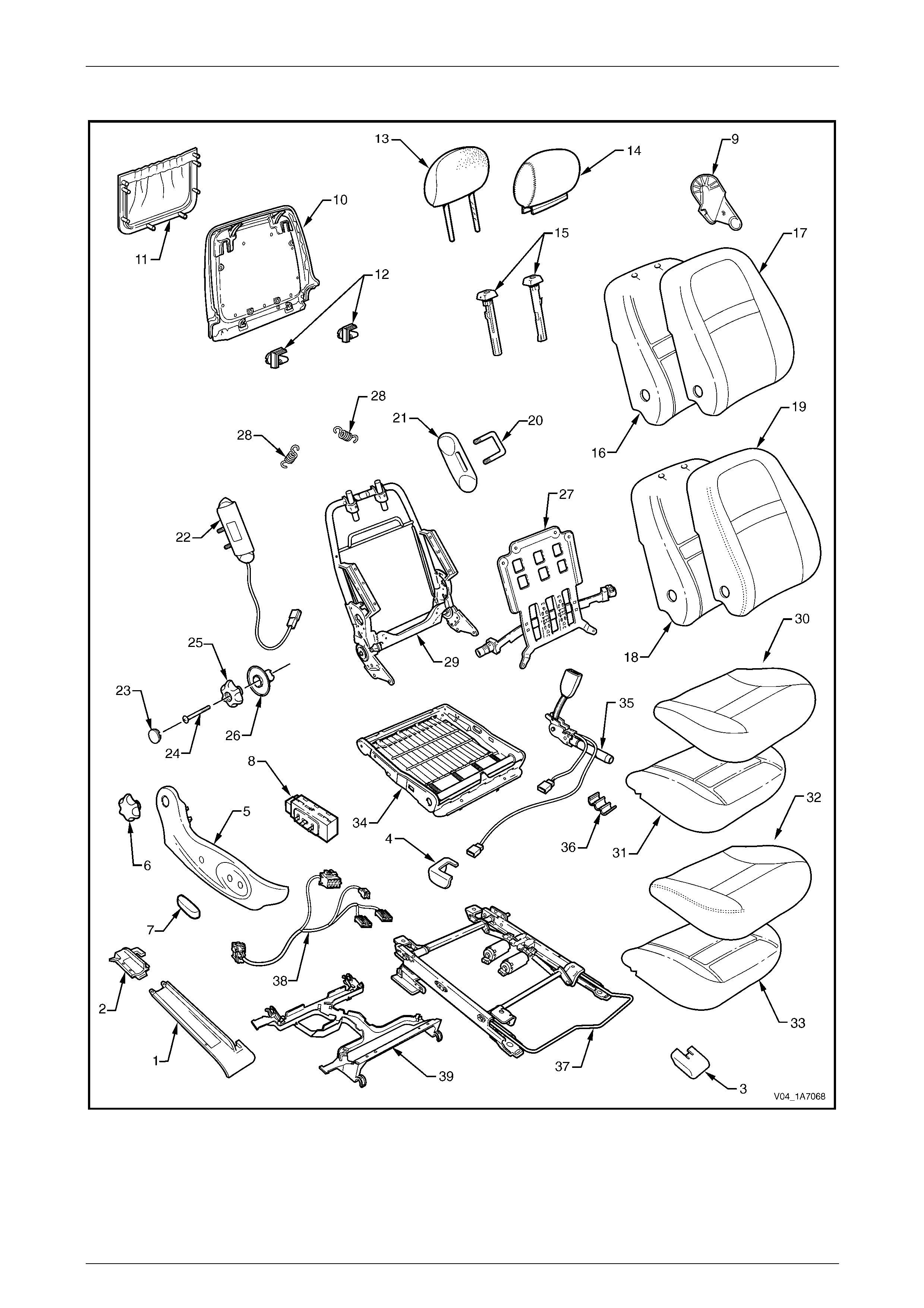
Seat Assemblies Page 1A7A–41
Page 1A7A–41
Front Seat Type 9
Figure 1A7A – 16

Seat Assemblies Page 1A7A–42
Page 1A7A–42
Legend
1 Front Seat Outer Front Cover
2 Front Seat Outer Rear Cover
3 Front Seat Inner Front Cover
4 Front Seat Inner Rear Cover
5 Front Seat Outer Side Cover
6 Recline Adjuster Knob
7 Front Seat Adjustment Switch Knob
8 Front Seat Adjustment Switch – Four-way
9 Front Seat Inner Side Cover
10 Front Seat-back Rear Cover
11 Front Seat-back Map Pocket
12 Front Seat-back Cover Retaining Clips
13 Front Seat Head Restraint Pad Assembly
14 Front Seat Head Restraint Cover
15 Front Seat Head Restraint Sleeves
16 Front Seat-back Pad – Cloth Cover
17 Front Seat-back Cloth Cover
18 Front Seat-back Pad – Leather Cover
19 Front Seat-back Leather Cover
20 Front Seat Dummy Block U-bolt
21 Front Seat Dummy Block Insert
22 Side Impact Airbag Assembly
23 Lumbar Support Knob Cover
24 Lumbar Support Knob Screw
25 Lumbar Support Knob
26 Lumbar Support Deflector Ring
27 Lumbar Support Assembly
28 Lumbar Support Retaining Spring
29 Front Seat-back Frame Assembly
30 Front Seat Cushion Cloth Cover
31 Front Seat Cushion Pad – Cloth Cover
32 Front Seat Cushion Leather Cover
33 Front Seat Cushion Pad – Leather Cover
34 Front Seat Cushion Frame Assembly
35 Seatbelt Buckle & Pretensioner Assembly
36 Wiring Harness Retaining Clip
37 Track and Height Adjust Assembly
38 Wiring Harness Assembly
39 Front Seat Cable Tray
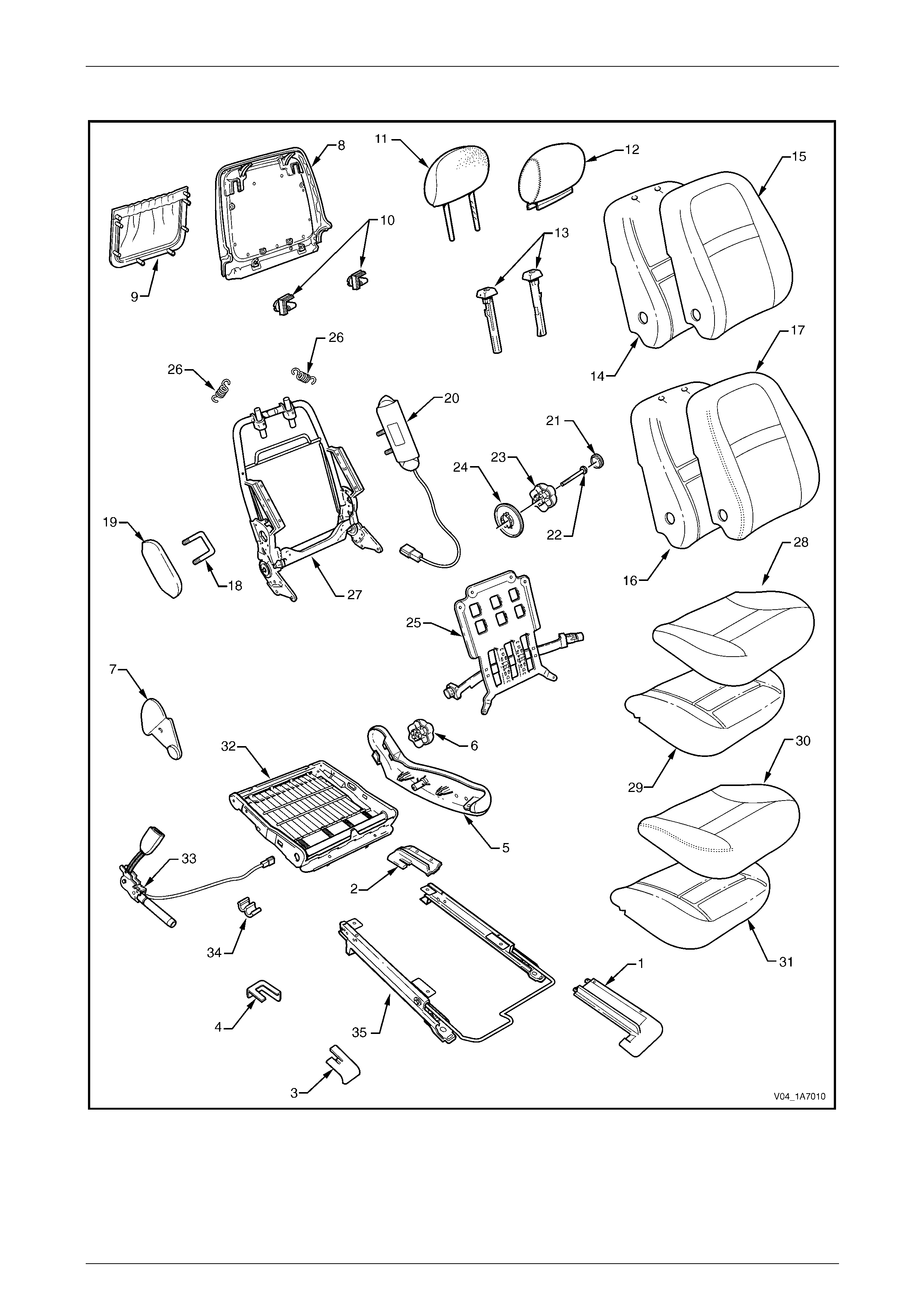
Seat Assemblies Page 1A7A–43
Page 1A7A–43
Front Seat Type 10
Figure 1A7A – 17

Seat Assemblies Page 1A7A–44
Page 1A7A–44
Legend
1 Front Seat Outer Front Cover
2 Front Seat Outer Rear Cover
3 Front Seat Inner Front Cover
4 Front Seat Inner Rear Cover
5 Front Seat Outer Side Cover
6 Recline Adjuster Knob
7 Front Seat Inner Side Cover
8 Front Seat-back Rear Cover
9 Front Seat-back Map Pocket
10 Front Seat-back Cover Retaining Clips
11 Front Seat Head Restraint Pad Assembly
12 Front Seat Head Restraint Cover
13 Front Seat Head Restraint Sleeves
14 Front Seat-back Pad – Cloth Cover
15 Front Seat-back Cloth Cover
16 Front Seat-back Pad – Leather Cover
17 Front Seat-back Leather Cover
18 Front Seat Dummy Block U-bolt
19 Front Seat Dummy Block Insert
20 Side Impact Airbag Assembly
21 Lumbar Support Knob Cover
22 Lumbar Support Knob Screw
23 Lumbar Support Knob
24 Lumbar Support Deflector Ring
25 Lumbar Support Assembly
26 Lumbar Support Retaining Spring
27 Front Seat-back Frame Assembly
28 Front Seat Cushion Cloth Cover
29 Front Seat Cushion Pad – Cloth Cover
30 Front Seat Cushion Leather Cover
31 Front Seat Cushion Pad – Leather Cover
32 Front Seat Cushion Frame Assembly
33 Seatbelt Buckle & Pretensioner Assembly
34 Wiring Harness Retaining Clip
35 Track and Height Adjust Assembly
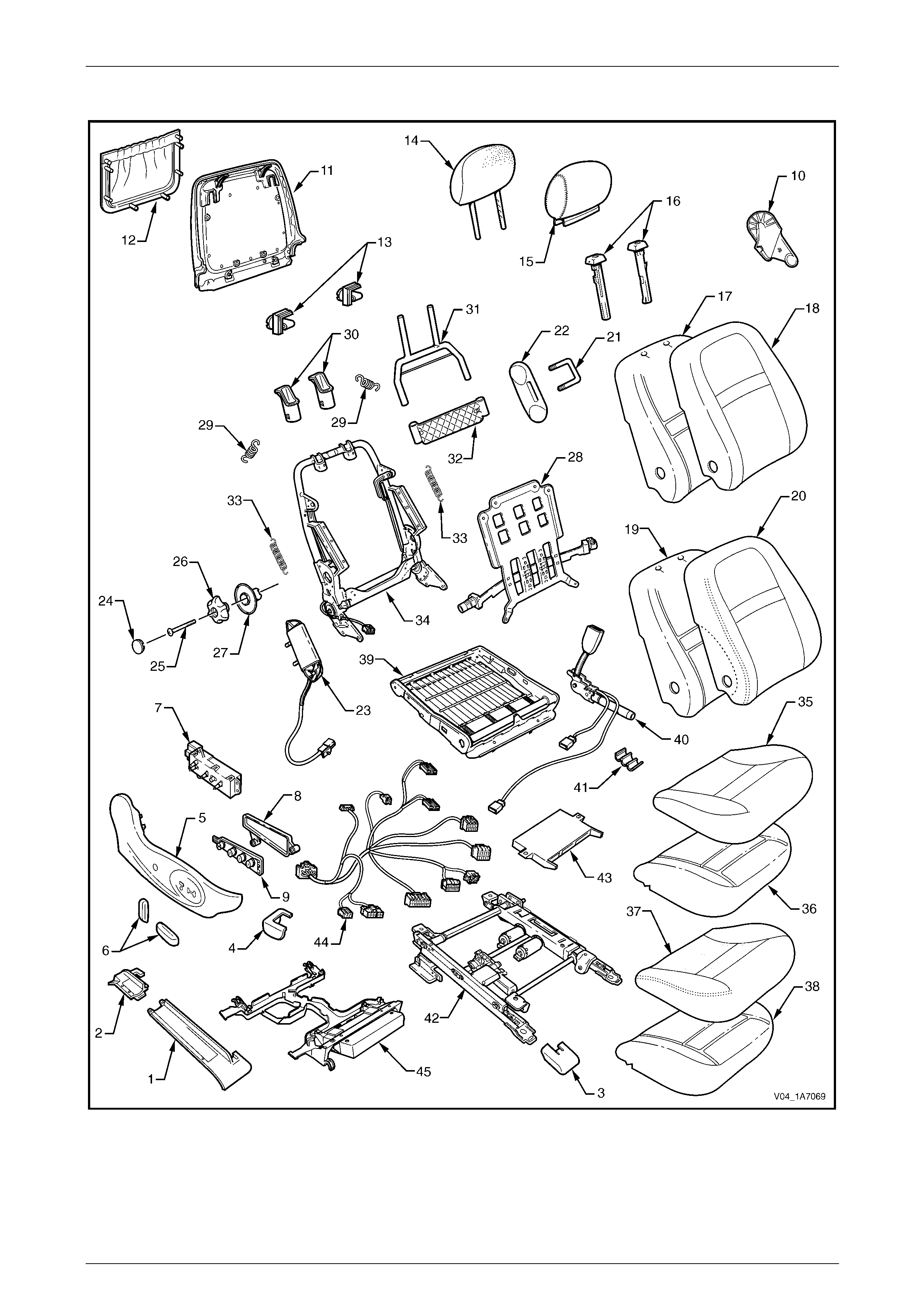
Seat Assemblies Page 1A7A–45
Page 1A7A–45
Front Seat Type 11
Figure 1A7A – 18

Seat Assemblies Page 1A7A–46
Page 1A7A–46
Legend
1 Front Seat Outer Front Cover
2 Front Seat Outer Rear Cover
3 Front Seat Inner Front Cover
4 Front Seat Inner Rear Cover
5 Front Seat Outer Side Cover
6 Front Seat Adjustment Switch Knobs
7 Front Seat Adjustment Switch – Eight-way
8 Memory Position Switch Cover
9 Memory Position Switch Assembly
10 Front Seat Inner Side Cover
11 Front Seat-back Rear Cover
12 Front Seat-back Map Pocket
13 Front Seat-back Cover Retaining Clips
14 Front Seat Head Restraint Pad Assembly
15 Front Seat Head Restraint Cover
16 Front Seat Head Restraint Sleeves
17 Front Seat-back Pad – Cloth Cover
18 Front Seat-back Cloth Cover
19 Front Seat-back Pad – Leather Cover
20 Front Seat-back Leather Cover
21 Front Seat Dummy Block U-bolt
22 Front Seat Dummy Block Insert
23 Side Impact Airbag Assembly
24 Lumbar Support Knob Cover
25 Lumbar Support Knob Screw
26 Lumbar Support Knob
27 Lumbar Support Deflector Ring
28 Lumbar Support Assembly
29 Lumbar Support Retaining Spring
30 Active Head Restraint Frame Sleeves
31 Active Head Restraint Frame Assembly
32 Active Head Restraint Frame Support Strap
33 Active Head Restraint Frame Retaining Spring
34 Front Seat-back Frame Assembly
35 Front Seat Cushion Cloth Cover
36 Front Seat Cushion Pad – Cloth Cover
37 Front Seat Cushion Leather Cover
38 Front Seat Cushion Pad – Leather Cover
39 Front Seat Cushion Frame Assembly
40 Seatbelt Buckle & Pretensioner Assembly
41 Wiring Harness Retaining Clip
42 Track and Height Adjust Assembly
43 Seat Memory Module
44 Wiring Harness Assembly
45 Front Seat Cable Tray
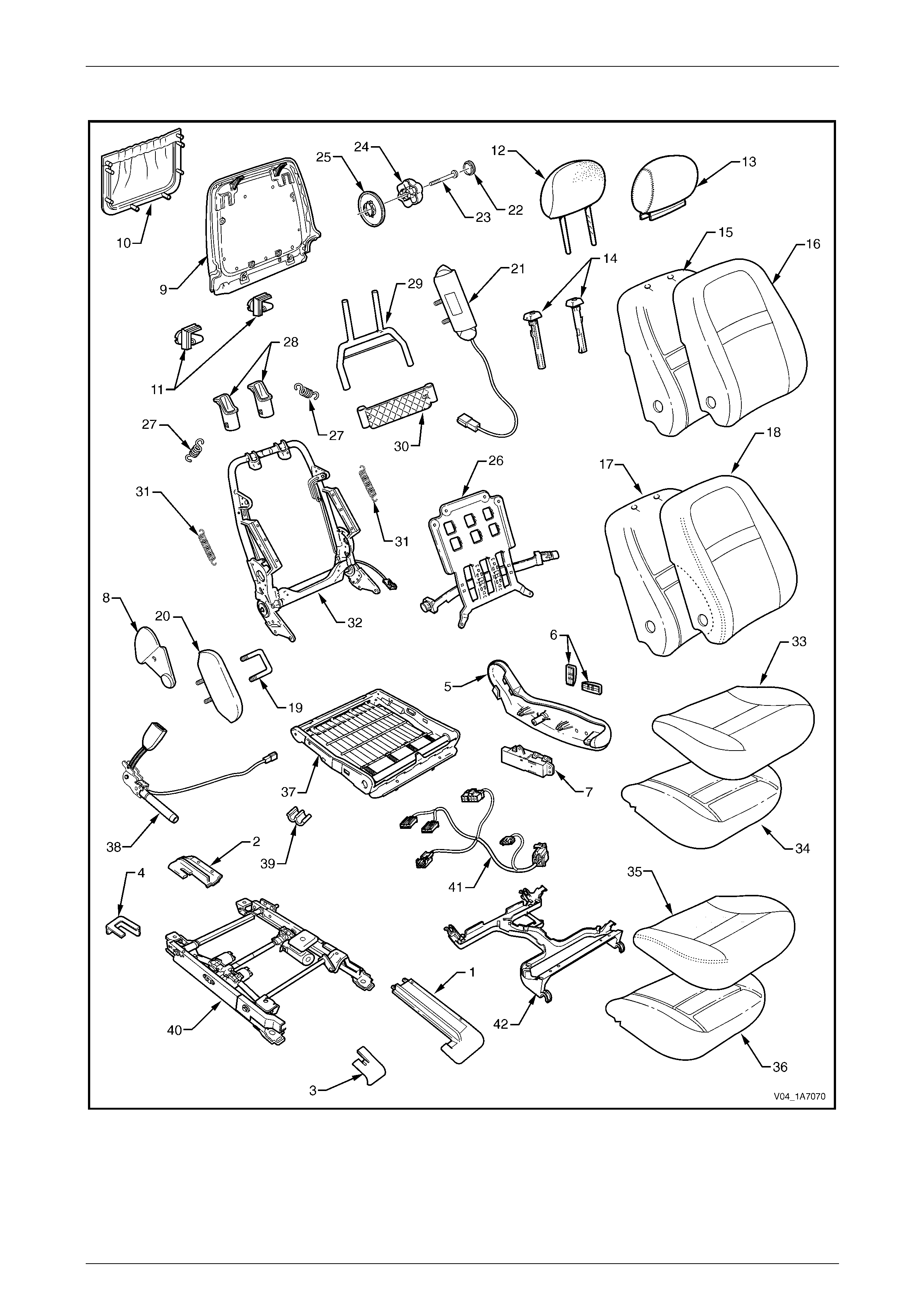
Seat Assemblies Page 1A7A–47
Page 1A7A–47
Front Seat Type 12
Figure 1A7A – 19

Seat Assemblies Page 1A7A–48
Page 1A7A–48
Legend
1 Front Seat Outer Front Cover
2 Front Seat Outer Rear Cover
3 Front Seat Inner Front Cover
4 Front Seat Inner Rear Cover
5 Front Seat Outer Side Cover
6 Front Seat Adjustment Switch Knobs
7 Front Seat Adjustment Switch – Eight-way
8 Front Seat Inner Side Cover
9 Front Seat-back Rear Cover
10 Front Seat-back Map Pocket
11 Front Seat-back Cover Retaining Clips
12 Front Seat Head Restraint Pad Assembly
13 Front Seat Head Restraint Cover
14 Front Seat Head Restraint Sleeves
15 Front Seat-back Pad – Cloth Cover
16 Front Seat-back Cloth Cover
17 Front Seat-back Pad – Leather Cover
18 Front Seat-back Leather Cover
19 Front Seat Dummy Block U-bolt
20 Front Seat Dummy Block Insert
21 Side Impact Airbag Assembly
22 Lumbar Support Knob Cover
23 Lumbar Support Knob Screw
24 Lumbar Support Knob
25 Lumbar Support Deflector Ring
26 Lumbar Support Assembly
27 Lumbar Support Retaining Spring
28 Active Head Restraint Frame Sleeves
29 Active Head Restraint Frame Assembly
30 Active Head Restraint Frame Support Strap
31 Active Head Restraint Frame Retaining Spring
32 Front Seat-back Frame Assembly
33 Front Seat Cushion Cloth Cover
34 Front Seat Cushion Pad – Cloth Cover
35 Front Seat Cushion Leather Cover
36 Front Seat Cushion Pad – Leather Cover
37 Front Seat Cushion Frame Assembly
38 Seatbelt Buckle & Pretensioner Assembly
39 Wiring Harness Retaining Clip
40 Track and Height Adjust Assembly
41 Wiring Harness Assembly
42 Front Seat Cable Tray
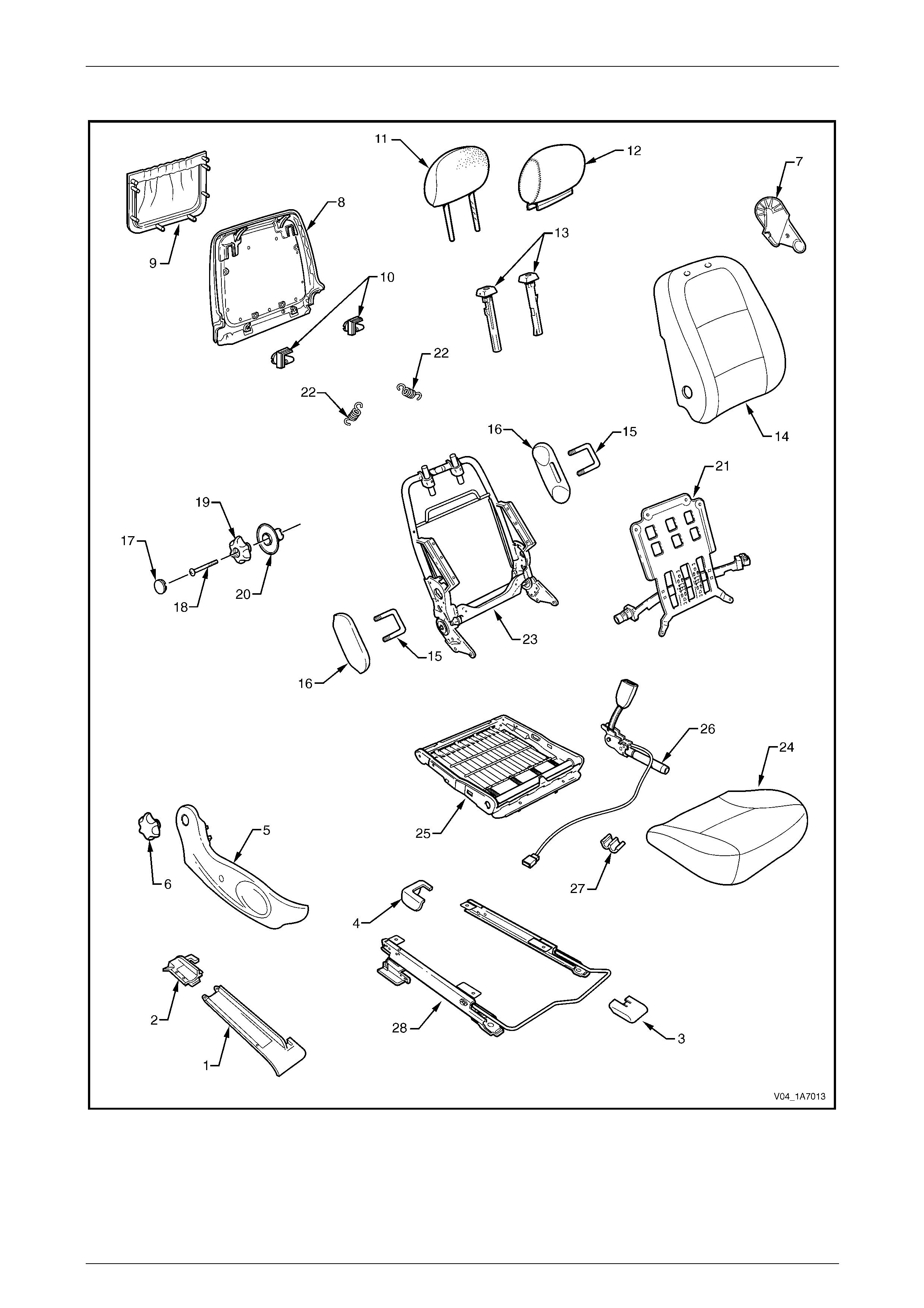
Seat Assemblies Page 1A7A–49
Page 1A7A–49
Front Seat Type 13
Figure 1A7A – 20

Seat Assemblies Page 1A7A–50
Page 1A7A–50
Legend
1 Front Seat Outer Front Cover
2 Front Seat Outer Rear Cover
3 Front Seat Inner Front Cover
4 Front Seat Inner Rear Cover
5 Front Seat Outer Side Cover
6 Recline Adjuster Knob
7 Front Seat Inner Side Cover
8 Front Seat-back Rear Cover
9 Front Seat-back Map Pocket
10 Front Seat-back Cover Retaining Clips
11 Front Seat Head Restraint Pad Assembly
12 Front Seat Head Restraint Cover
13 Front Seat Head Restraint Sleeves
14 Front Seat-back Cover and Pad Assembly
15 Front Seat Dummy Block U-bolt
16 Front Seat Dummy Block Insert
17 Lumbar Support Knob Cover
18 Lumbar Support Knob Screw
19 Lumbar Support Knob
20 Lumbar Support Deflector Ring
21 Lumbar Support Assembly
22 Lumbar Support Retaining Spring
23 Front Seat-back Frame Assembly
24 Front Seat Cushion Cover and Pad Assembly
25 Front Seat Cushion Frame Assembly
26 Seatbelt Buckle & Pretensioner Assembly
27 Wiring Harness Retaining Clip
28 Track and Height Adjust Assembly
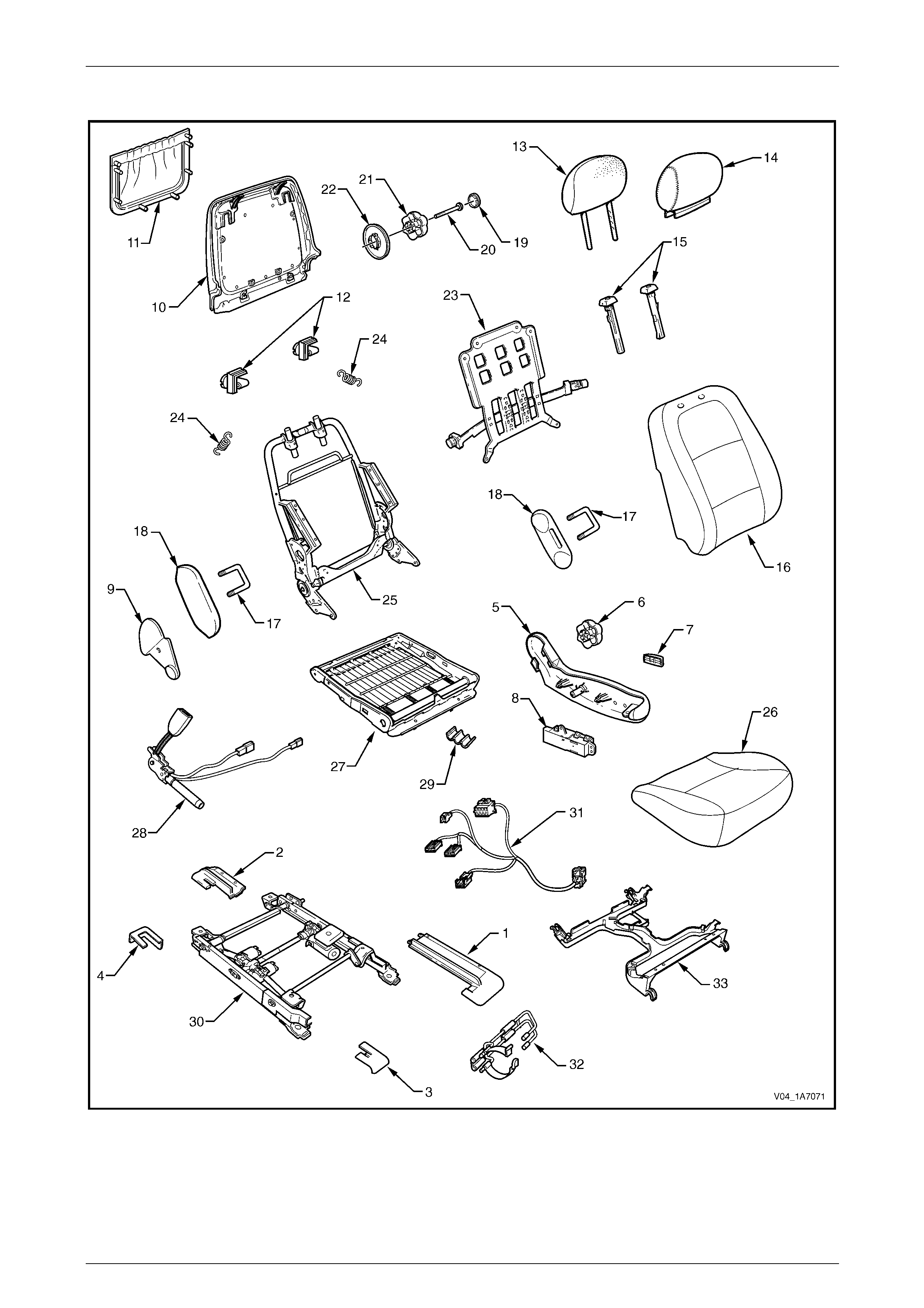
Seat Assemblies Page 1A7A–51
Page 1A7A–51
Front Seat Type 14
Figure 1A7A – 21

Seat Assemblies Page 1A7A–52
Page 1A7A–52
Legend
1 Front Seat Outer Front Cover
2 Front Seat Outer Rear Cover
3 Front Seat Inner Front Cover
4 Front Seat Inner Rear Cover
5 Front Seat Outer Side Cover
6 Recline Adjuster Knob
7 Front Seat Adjustment Switch Knob
8 Front Seat Adjustment Switch – Four-way
9 Front Seat Inner Side Cover
10 Front Seat-back Rear Cover
11 Front Seat-back Map Pocket
12 Front Seat-back Cover Retaining Clips
13 Front Seat Head Restraint Pad Assembly
14 Front Seat Head Restraint Cover
15 Front Seat Head Restraint Sleeves
16 Front Seat-back Cover and Pad Assembly
17 Front Seat Dummy Block U-bolt
18 Front Seat Dummy Block Insert
19 Lumbar Support Knob Cover
20 Lumbar Support Knob Screw
21 Lumbar Support Knob
22 Lumbar Support Deflector Ring
23 Lumbar Support Assembly
24 Lumbar Support Retaining Spring
25 Front Seat-back Frame Assembly
26 Front Seat Cushion Cover and Pad Assembly
27 Front Seat Cushion Frame Assembly
28 Seatbelt Buckle & Pretensioner Assembly
29 Wiring Harness Retaining Clip
30 Track and Height Adjust Assembly
31 Wiring Harness Assembly
32 Fire Extinguisher Mounting Bracket
33 Front Seat Cable Tray
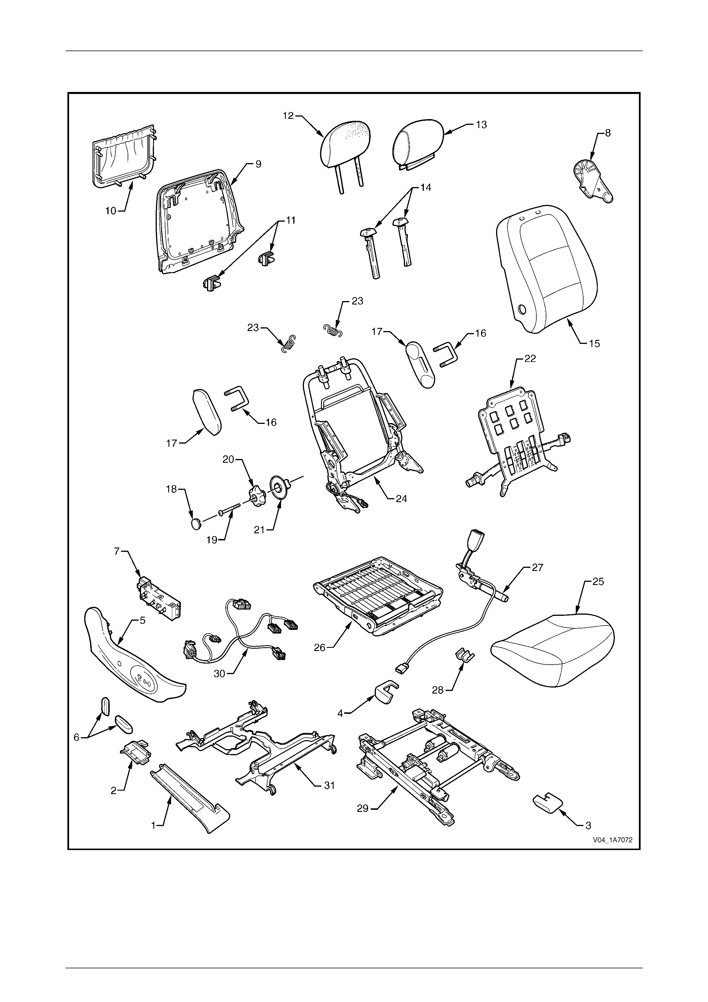
Seat Assemblies Page 1A7A–53
Page 1A7A–53
Front Seat Type 15
Figure 1A7A – 22

Seat Assemblies Page 1A7A–54
Page 1A7A–54
Legend
1 Front Seat Outer Front Cover
2 Front Seat Outer Rear Cover
3 Front Seat Inner Front Cover
4 Front Seat Inner Rear Cover
5 Front Seat Outer Side Cover
6 Front Seat Adjustment Switch Knobs
7 Front Seat Adjustment Switch – Eight-way
8 Front Seat Inner Side Cover
9 Front Seat-back Rear Cover
10 Front Seat-back Map Pocket
11 Front Seat-back Cover Retaining Clips
12 Front Seat Head Restraint Pad Assembly
13 Front Seat Head Restraint Cover
14 Front Seat Head Restraint Sleeves
15 Front Seat-back Cover and Pad Assembly
16 Front Seat Dummy Block U-bolt
17 Front Seat Dummy Block Insert
18 Lumbar Support Knob Cover
19 Lumbar Support Knob Screw
20 Lumbar Support Knob
21 Lumbar Support Deflector Ring
22 Lumbar Support Assembly
23 Lumbar Support Retaining Spring
24 Front Seat-back Frame Assembly
25 Front Seat Cushion Cover and Pad Assembly
26 Front Seat Cushion Frame Assembly
27 Seatbelt Buckle & Pretensioner Assembly
28 Wiring Harness Retaining Clip
29 Track and Height Adjust Assembly
30 Wiring Harness Assembly
31 Front Seat Cable Tray
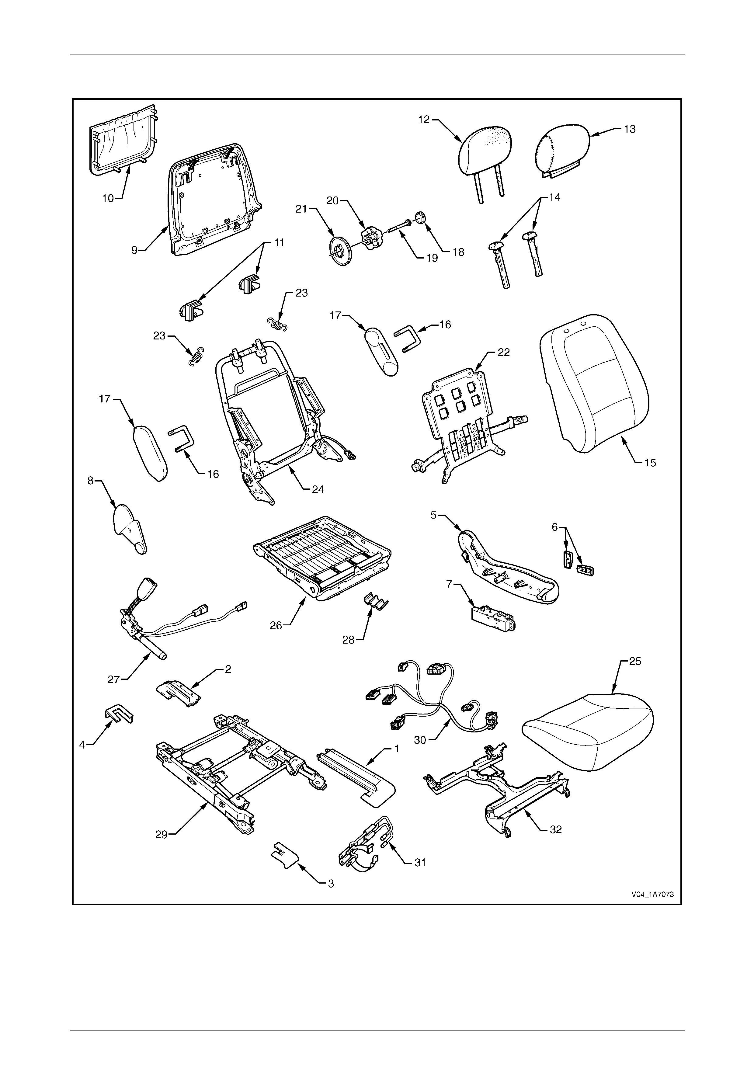
Seat Assemblies Page 1A7A–55
Page 1A7A–55
Front Seat Type 16
Figure 1A7A – 23

Seat Assemblies Page 1A7A–56
Page 1A7A–56
Legend
1 Front Seat Outer Front Cover
2 Front Seat Outer Rear Cover
3 Front Seat Inner Front Cover
4 Front Seat Inner Rear Cover
5 Front Seat Outer Side Cover
6 Front Seat Adjustment Switch Knobs
7 Front Seat Adjustment Switch – Eight-way
8 Front Seat Inner Side Cover
9 Front Seat-back Rear Cover
10 Front Seat-back Map Pocket
11 Front Seat-back Cover Retaining Clips
12 Front Seat Head Restraint Pad Assembly
13 Front Seat Head Restraint Cover
14 Front Seat Head Restraint Sleeves
15 Front Seat-back Cover and Pad Assembly
16 Front Seat Dummy Block U-bolt
17 Front Seat Dummy Block Insert
18 Lumbar Support Knob Cover
19 Lumbar Support Knob Screw
20 Lumbar Support Knob
21 Lumbar Support Deflector Ring
22 Lumbar Support Assembly
23 Lumbar Support Retaining Spring
24 Front Seat-back Frame Assembly
25 Front Seat Cushion Cover and Pad Assembly
26 Front Seat Cushion Frame Assembly
27 Seatbelt Buckle & Pretensioner Assembly
28 Wiring Harness Retaining Clip
29 Track and Height Adjust Assembly
30 Wiring Harness Assembly
31 Fire Extinguisher Mounting Bracket
32 Front Seat Cable Tray
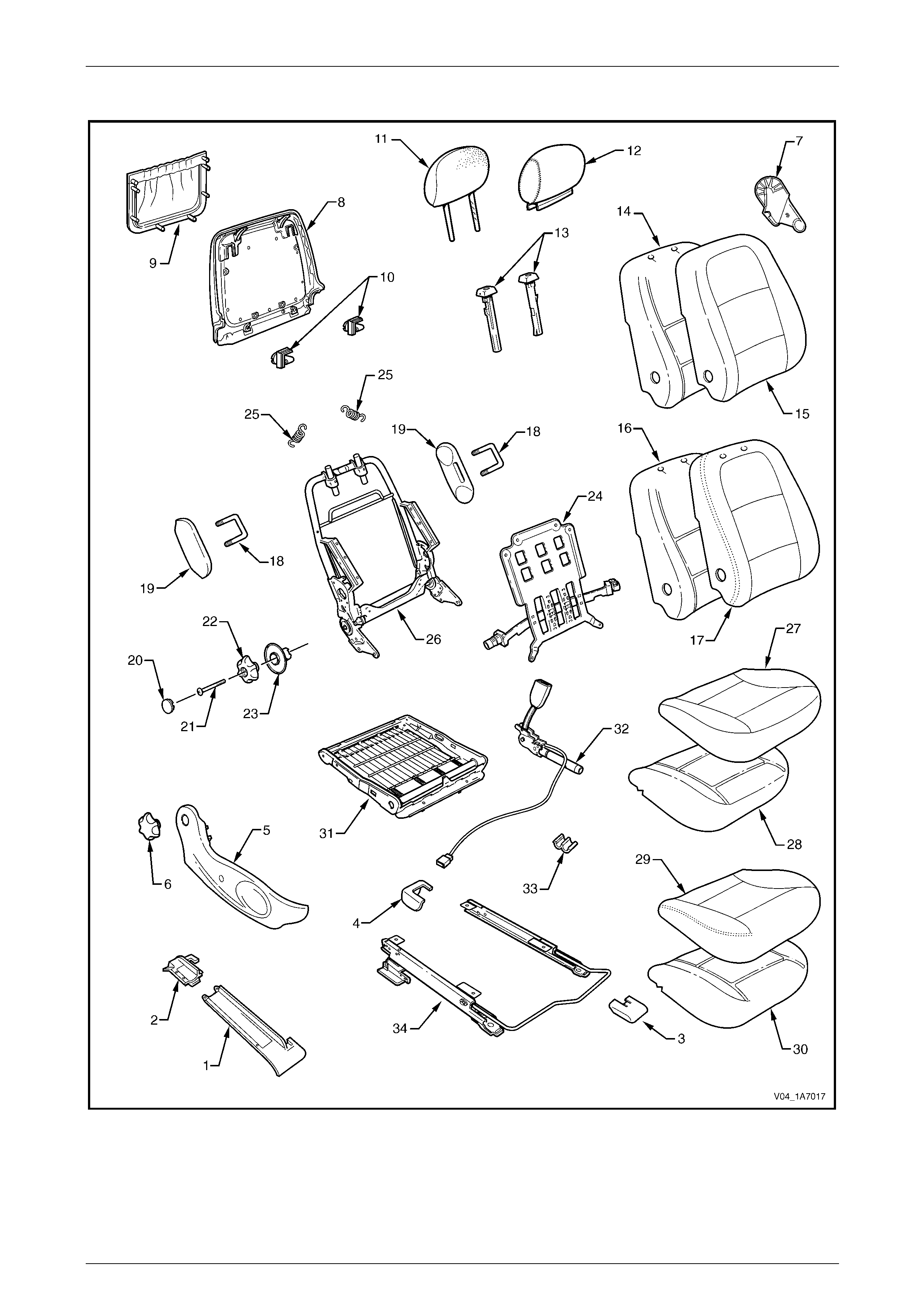
Seat Assemblies Page 1A7A–57
Page 1A7A–57
Front Seat Type 17
Figure 1A7A – 24

Seat Assemblies Page 1A7A–58
Page 1A7A–58
Legend
1 Front Seat Outer Front Cover
2 Front Seat Outer Rear Cover
3 Front Seat Inner Front Cover
4 Front Seat Inner Rear Cover
5 Front Seat Outer Side Cover
6 Recline Adjuster Knob
7 Front Seat Inner Side Cover
8 Front Seat-back Rear Cover
9 Front Seat-back Map Pocket
10 Front Seat-back Cover Retaining Clips
11 Front Seat Head Restraint Pad Assembly
12 Front Seat Head Restraint Cover
13 Front Seat Head Restraint Sleeves
14 Front Seat-back Pad – Cloth Cover
15 Front Seat-back Cloth Cover
16 Front Seat-back Pad – Leather Cover
17 Front Seat-back Leather Cover
18 Front Seat Dummy Block U-bolt
19 Front Seat Dummy Block Insert
20 Lumbar Support Knob Cover
21 Lumbar Support Knob Screw
22 Lumbar Support Knob
23 Lumbar Support Deflector Ring
24 Lumbar Support Assembly
25 Lumbar Support Retaining Spring
26 Front Seat-back Frame Assembly
27 Front Seat Cushion Cloth Cover
28 Front Seat Cushion Pad – Cloth Cover
29 Front Seat Cushion Leather Cover
30 Front Seat Cushion Pad – Leather Cover
31 Front Seat Cushion Frame Assembly
32 Seatbelt Buckle & Pretensioner Assembly
33 Wiring Harness Retaining Clip
34 Track and Height Adjust Assembly
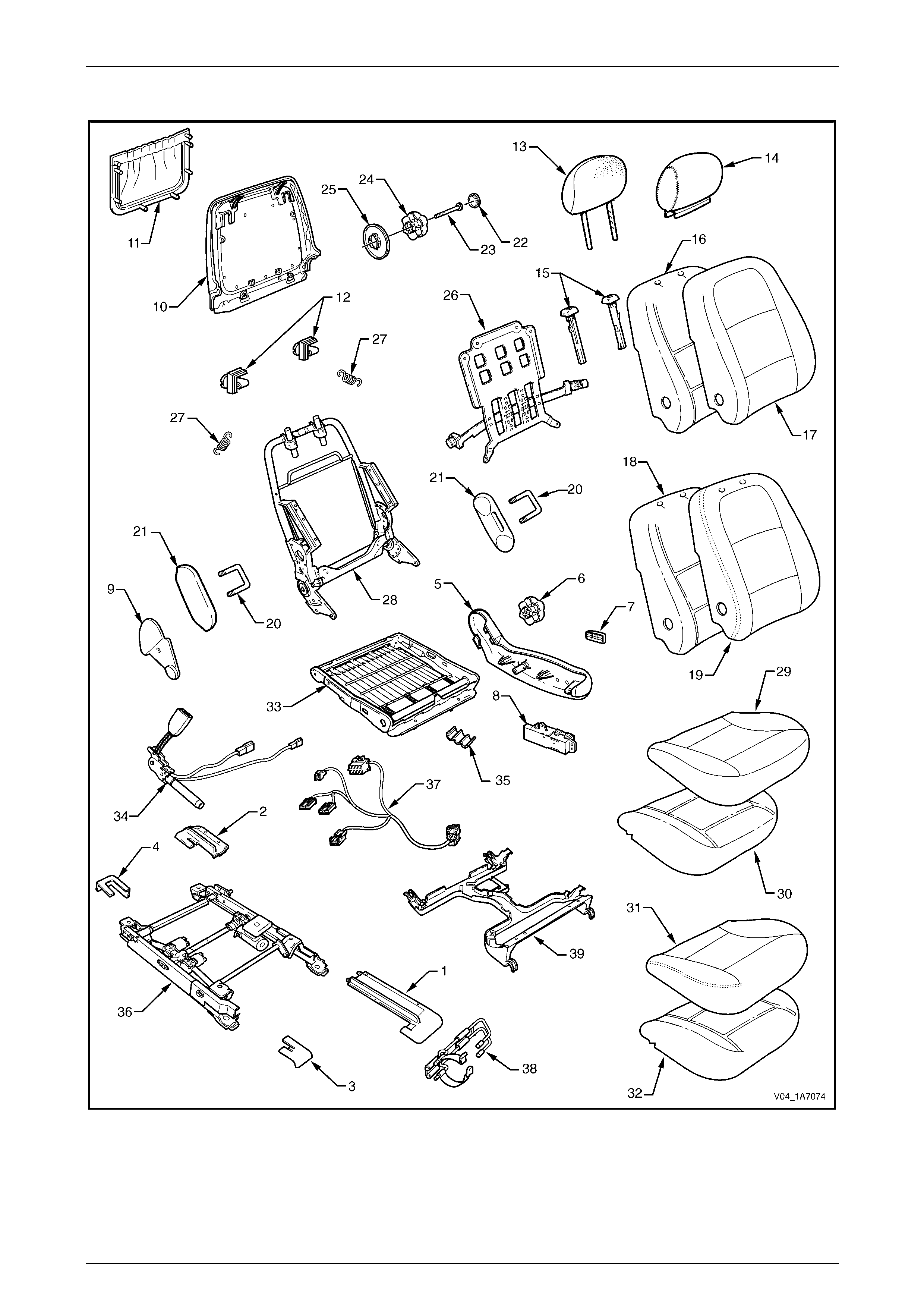
Seat Assemblies Page 1A7A–59
Page 1A7A–59
Front Seat Type 18
Figure 1A7A – 25

Seat Assemblies Page 1A7A–60
Page 1A7A–60
Legend
1 Front Seat Outer Front Cover
2 Front Seat Outer Rear Cover
3 Front Seat Inner Front Cover
4 Front Seat Inner Rear Cover
5 Front Seat Outer Side Cover
6 Recline Adjuster Knob
7 Front Seat Adjustment Switch Knob
8 Front Seat Adjustment Switch – Six-way
9 Front Seat Inner Side Cover
10 Front Seat-back Rear Cover
11 Front Seat-back Map Pocket
12 Front Seat-back Cover Retaining Clips
13 Front Seat Head Restraint Pad Assembly
14 Front Seat Head Restraint Cover
15 Front Seat Head Restraint Sleeves
16 Front Seat-back Pad – Cloth Cover
17 Front Seat-back Cloth Cover
18 Front Seat-back Pad – Leather Cover
19 Front Seat-back Leather Cover
20 Front Seat Dummy Block U-bolt
21 Front Seat Dummy Block Insert
22 Lumbar Support Knob Cover
23 Lumbar Support Knob Screw
24 Lumbar Support Knob
25 Lumbar Support Deflector Ring
26 Lumbar Support Assembly
27 Lumbar Support Retaining Spring
28 Front Seat-back Frame Assembly
29 Front Seat Cushion Cloth Cover
30 Front Seat Cushion Pad – Cloth Cover
31 Front Seat Cushion Leather Cover
32 Front Seat Cushion Pad – Leather Cover
33 Front Seat Cushion Frame Assembly
34 Seatbelt Buckle & Pretensioner Assembly
35 Wiring Harness Retaining Clip
36 Track and Height Adjust Assembly
37 Wiring Harness Assembly
38 Fire Extinguisher Mounting Bracket
39 Front Seat Cable Tray
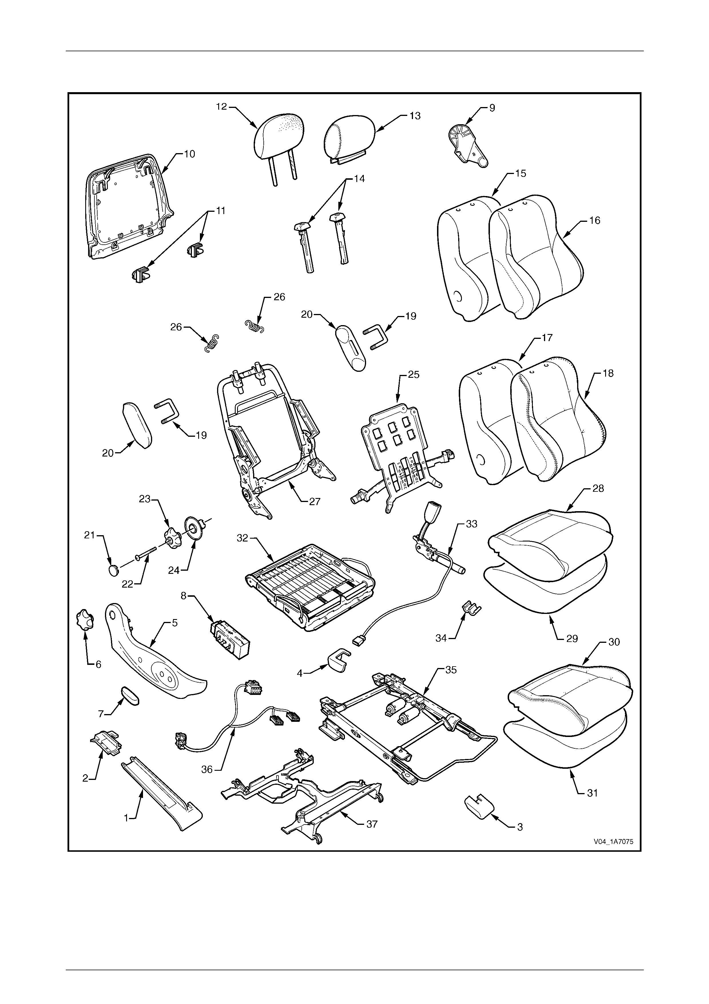
Seat Assemblies Page 1A7A–61
Page 1A7A–61
Front Seat Type 19
Figure 1A7A – 26

Seat Assemblies Page 1A7A–62
Page 1A7A–62
Legend
1 Front Seat Outer Front Cover
2 Front Seat Outer Rear Cover
3 Front Seat Inner Front Cover
4 Front Seat Inner Rear Cover
5 Front Seat Outer Side Cover
6 Recline Adjuster Knob
7 Front Seat Adjustment Switch Knob
8 Front Seat Adjustment Switch – Four-way
9 Front Seat Inner Side Cover
10 Front Seat-back Rear Cover Assembly#
11 Front Seat-back Cover Retaining Clips
12 Front Seat Head Restraint Pad Assembly
13 Front Seat Head Restraint Cover
14 Front Seat Head Restraint Sleeves
15 Front Seat-back Pad – Cloth Cover
16 Front Seat-back Cloth Cover
17 Front Seat-back Pad – Leather Cover
18 Front Seat-back Leather Cover
19 Front Seat Dummy Block U-bolt
20 Front Seat Dummy Block Insert
21 Lumbar Support Knob Cover
22 Lumbar Support Knob Screw
23 Lumbar Support Knob
24 Lumbar Support Deflector Ring
25 Lumbar Support Assembly
26 Lumbar Support Retaining Spring
27 Front Seat-back Frame Assembly
28 Front Seat Cushion Cloth Cover
29 Front Seat Cushion Pad – Cloth Cover
30 Front Seat Cushion Leather Cover
31 Front Seat Cushion Pad – Leather Cover
32 Front Seat Cushion Frame Assembly
33 Seatbelt Buckle & Pretensioner Assembly
34 Wiring Harness Retaining Clip
35 Track and Height Adjust Assembly
36 Wiring Harness Assembly
37 Front Seat Cable Tray
# Net type map pocket is part of the front seat-back rear cover assembly.
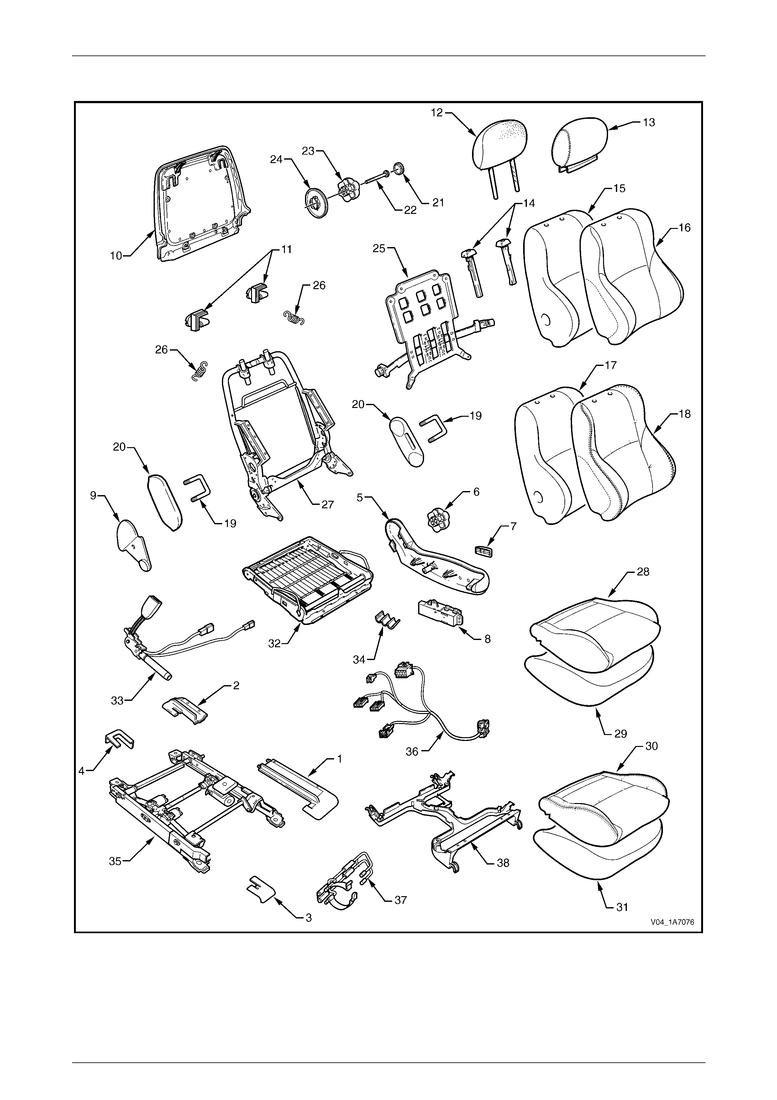
Seat Assemblies Page 1A7A–63
Page 1A7A–63
Front Seat Type 20
Figure 1A7A – 27

Seat Assemblies Page 1A7A–64
Page 1A7A–64
Legend
1 Front Seat Outer Front Cover
2 Front Seat Outer Rear Cover
3 Front Seat Inner Front Cover
4 Front Seat Inner Rear Cover
5 Front Seat Outer Side Cover
6 Recline Adjuster Knob
7 Front Seat Adjustment Switch Knob
8 Front Seat Adjustment Switch – Six-way
9 Front Seat Inner Side Cover
10 Front Seat-back Rear Cover Assembly#
11 Front Seat-back Cover Retaining Clips
12 Front Seat Head Restraint Pad Assembly
13 Front Seat Head Restraint Cover
14 Front Seat Head Restraint Sleeves
15 Front Seat-back Pad – Cloth Cover
16 Front Seat-back Cloth Cover
17 Front Seat-back Pad – Leather Cover
18 Front Seat-back Leather Cover
19 Front Seat Dummy Block U-bolt
20 Front Seat Dummy Block Insert
21 Lumbar Support Knob Cover
22 Lumbar Support Knob Screw
23 Lumbar Support Knob
24 Lumbar Support Deflector Ring
25 Lumbar Support Assembly
26 Lumbar Support Retaining Spring
27 Front Seat-back Frame Assembly
28 Front Seat Cushion Cloth Cover
29 Front Seat Cushion Pad – Cloth Cover
30 Front Seat Cushion Leather Cover
31 Front Seat Cushion Pad – Leather Cover
32 Front Seat Cushion Frame Assembly
33 Seatbelt Buckle & Pretensioner Assembly
34 Wiring Harness Retaining Clip
35 Track and Height Adjust Assembly
36 Wiring Harness Assembly
37 Fire Extinguisher Mounting Bracket
38 Front Seat Cable Tray
# Net type map pocket is part of the front seat-back rear cover assembly.
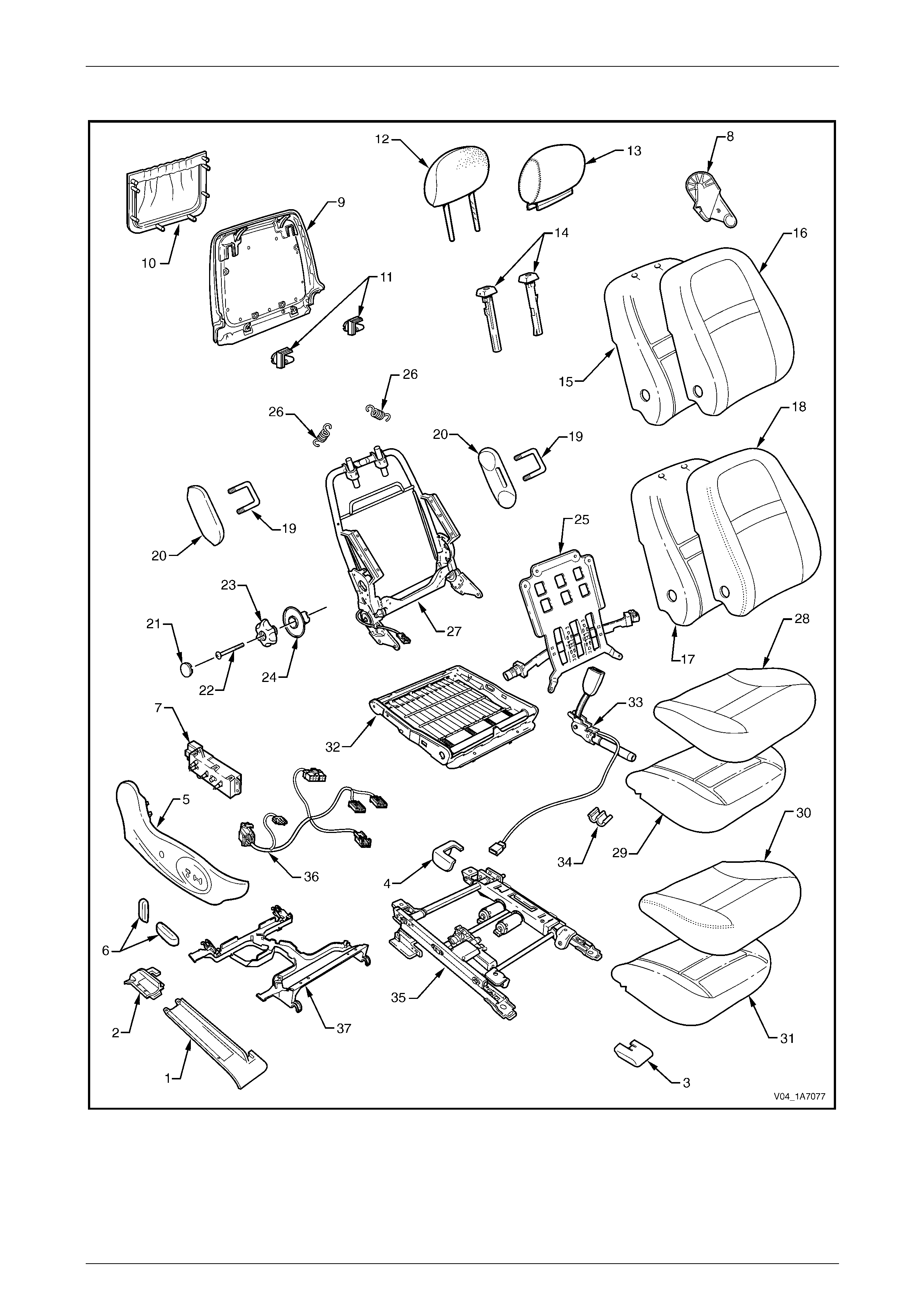
Seat Assemblies Page 1A7A–65
Page 1A7A–65
Front Seat Type 21
Figure 1A7A – 28

Seat Assemblies Page 1A7A–66
Page 1A7A–66
Legend
1 Front Seat Outer Front Cover
2 Front Seat Outer Rear Cover
3 Front Seat Inner Front Cover
4 Front Seat Inner Rear Cover
5 Front Seat Outer Side Cover
6 Front Seat Adjustment Switch Knobs
7 Front Seat Adjustment Switch – Eight-way
8 Front Seat Inner Side Cover
9 Front Seat-back Rear Cover
10 Front Seat-back Map Pocket
11 Front Seat-back Cover Retaining Clips
12 Front Seat Head Restraint Pad Assembly
13 Front Seat Head Restraint Cover
14 Front Seat Head Restraint Sleeves
15 Front Seat-back Pad – Cloth Cover
16 Front Seat-back Cloth Cover
17 Front Seat-back Pad – Leather Cover
18 Front Seat-back Leather Cover
19 Front Seat Dummy Block U-bolt
20 Front Seat Dummy Block Insert
21 Lumbar Support Knob Cover
22 Lumbar Support Knob Screw
23 Lumbar Support Knob
24 Lumbar Support Deflector Ring
25 Lumbar Support Assembly
26 Lumbar Support Retaining Spring
27 Front Seat-back Frame Assembly
28 Front Seat Cushion Cloth Cover
29 Front Seat Cushion Pad – Cloth Cover
30 Front Seat Cushion Leather Cover
31 Front Seat Cushion Pad – Leather Cover
32 Front Seat Cushion Frame Assembly
33 Seatbelt Buckle & Pretensioner Assembly
34 Wiring Harness Retaining Clip
35 Track and Height Adjust Assembly
36 Wiring Harness Assembly
37 Front Seat Cable Tray
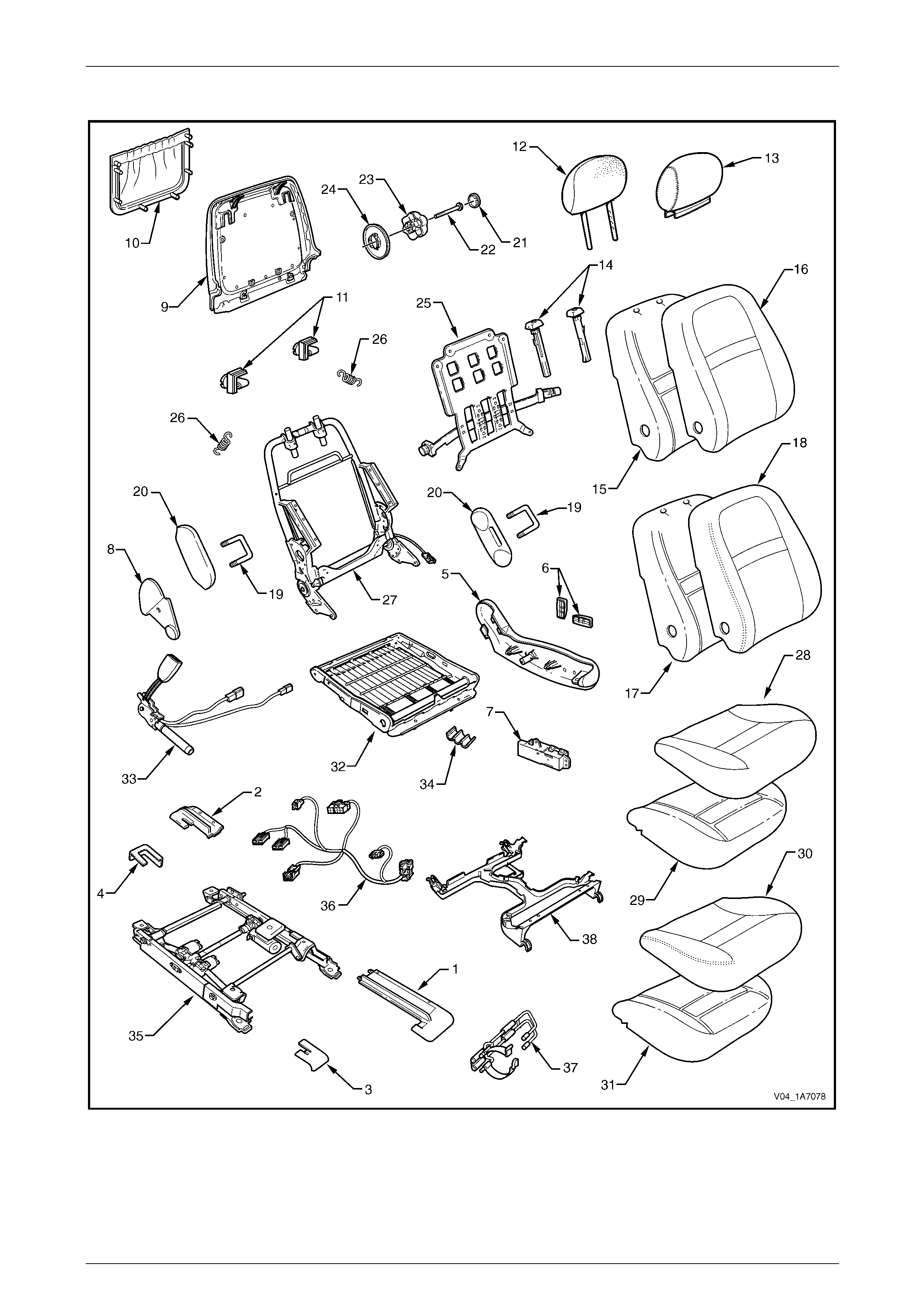
Seat Assemblies Page 1A7A–67
Page 1A7A–67
Front Seat Type 22
Figure 1A7A – 29

Seat Assemblies Page 1A7A–68
Page 1A7A–68
Legend
1 Front Seat Outer Front Cover
2 Front Seat Outer Rear Cover
3 Front Seat Inner Front Cover
4 Front Seat Inner Rear Cover
5 Front Seat Outer Side Cover
6 Front Seat Adjustment Switch Knobs
7 Front Seat Adjustment Switch – Eight-way
8 Front Seat Inner Side Cover
9 Front Seat-back Rear Cover
10 Front Seat-back Map Pocket
11 Front Seat-back Cover Retaining Clips
12 Front Seat Head Restraint Pad Assembly
13 Front Seat Head Restraint Cover
14 Front Seat Head Restraint Sleeves
15 Front Seat-back Pad – Cloth Cover
16 Front Seat-back Cloth Cover
17 Front Seat-back Pad – Leather Cover
18 Front Seat-back Leather Cover
19 Front Seat Dummy Block U-bolt
20 Front Seat Dummy Block Insert
21 Lumbar Support Knob Cover
22 Lumbar Support Knob Screw
23 Lumbar Support Knob
24 Lumbar Support Deflector Ring
25 Lumbar Support Assembly
26 Lumbar Support Retaining Spring
27 Front Seat-back Frame Assembly
28 Front Seat Cushion Cloth Cover
29 Front Seat Cushion Pad – Cloth Cover
30 Front Seat Cushion Leather Cover
31 Front Seat Cushion Pad – Leather Cover
32 Front Seat Cushion Frame Assembly
33 Seatbelt Buckle & Pretensioner Assembly
34 Wiring Harness Retaining Clip
35 Track and Height Adjust Assembly
36 Wiring Harness Assembly
37 Fire Extinguisher Mounting Bracket
38 Front Seat Cable Tray
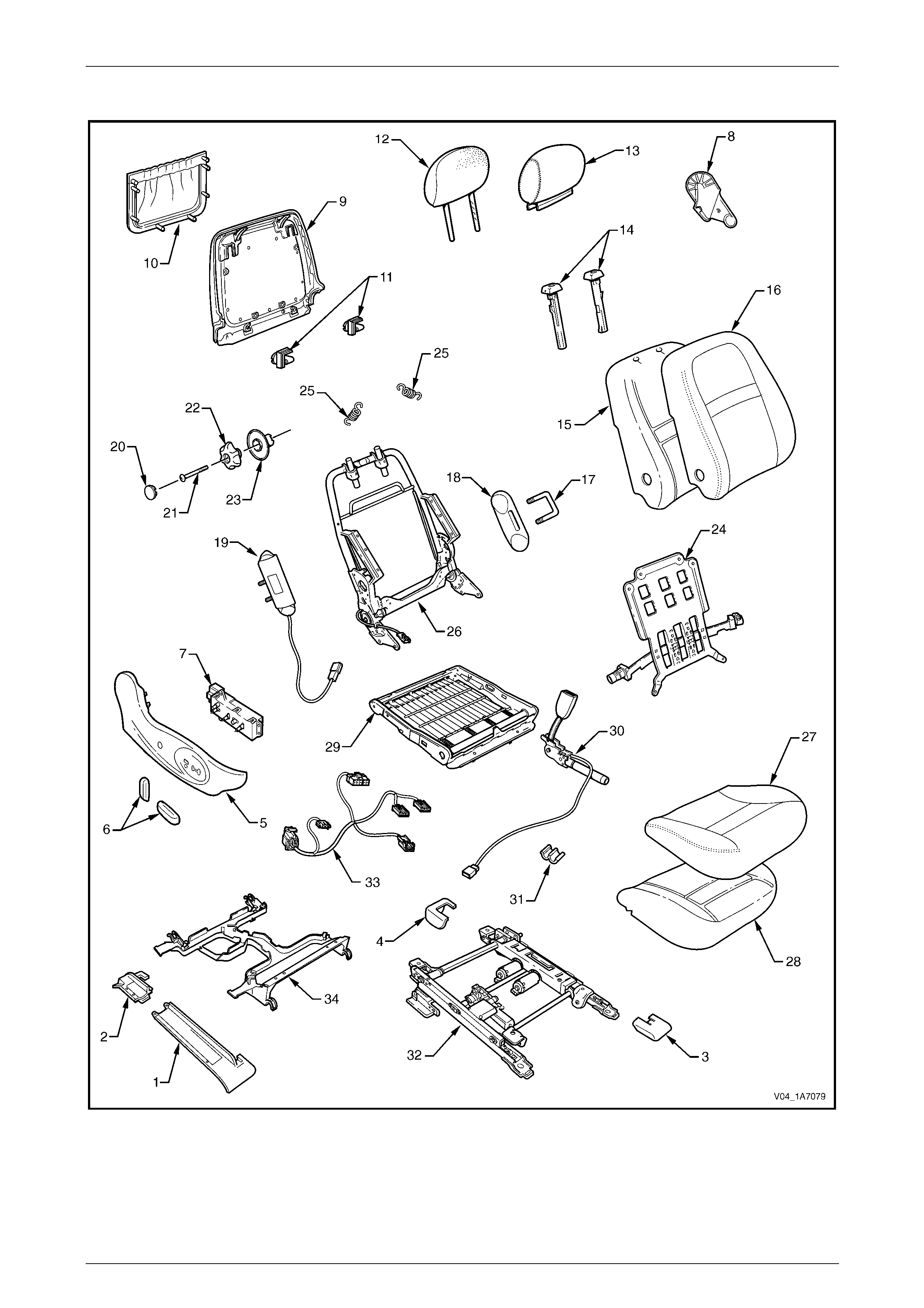
Seat Assemblies Page 1A7A–69
Page 1A7A–69
Front Seat Type 23
Figure 1A7A – 30

Seat Assemblies Page 1A7A–70
Page 1A7A–70
Legend
1 Front Seat Outer Front Cover
2 Front Seat Outer Rear Cover
3 Front Seat Inner Front Cover
4 Front Seat Inner Rear Cover
5 Front Seat Outer Side Cover
6 Front Seat Adjustment Switch Knobs
7 Front Seat Adjustment Switch – Eight-way
8 Front Seat Inner Side Cover
9 Front Seat-back Rear Cover
10 Front Seat-back Map Pocket
11 Front Seat-back Cover Retaining Clips
12 Front Seat Head Restraint Pad Assembly
13 Front Seat Head Restraint Cover
14 Front Seat Head Restraint Sleeves
15 Front Seat-back Pad
16 Front Seat-back Cover
17 Front Seat Dummy Block U-bolt
18 Front Seat Dummy Block Insert
19 Side Impact Airbag Assembly
20 Lumbar Support Knob Cover
21 Lumbar Support Knob Screw
22 Lumbar Support Knob
23 Lumbar Support Deflector Ring
24 Lumbar Support Assembly
25 Lumbar Support Retaining Spring
26 Front Seat-back Frame Assembly
27 Front Seat Cushion Cover
28 Front Seat Cushion Pad
29 Front Seat Cushion Frame Assembly
30 Seatbelt Buckle & Pretensioner Assembly
31 Wiring Harness Retaining Clip
32 Track and Height Adjust Assembly
33 Wiring Harness Assembly
34 Front Seat Cable Tray
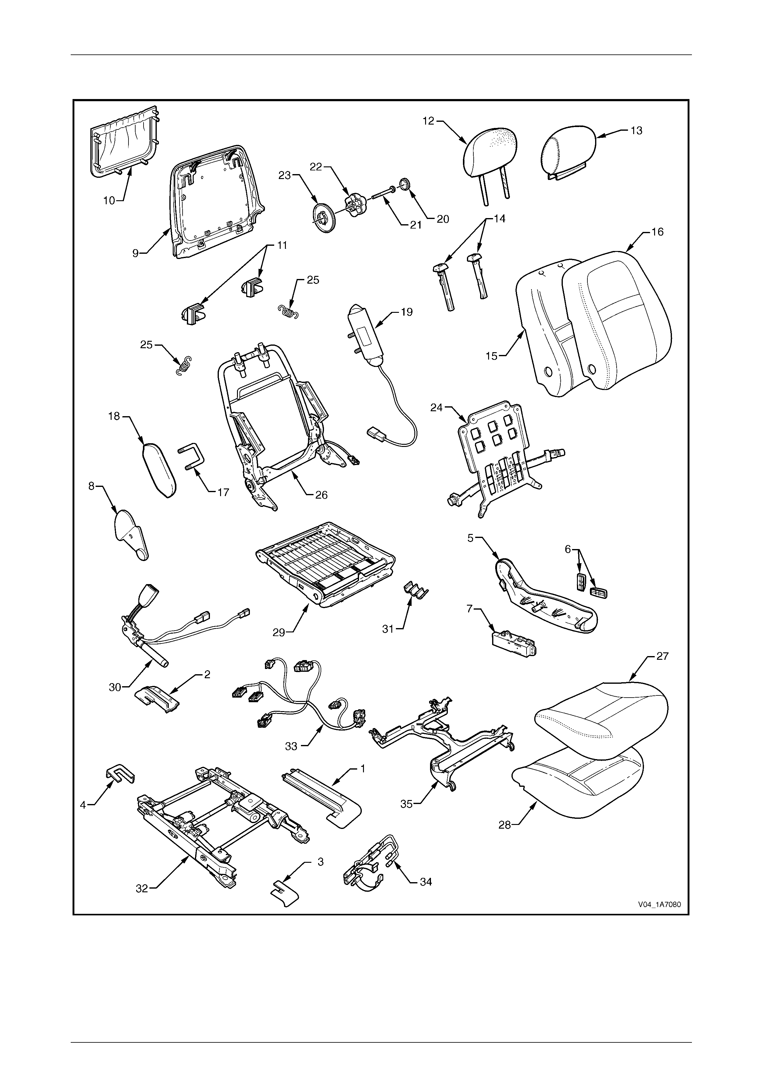
Seat Assemblies Page 1A7A–71
Page 1A7A–71
Front Seat Type 24
Figure 1A7A – 31

Seat Assemblies Page 1A7A–72
Page 1A7A–72
Legend
1 Front Seat Outer Front Cover
2 Front Seat Outer Rear Cover
3 Front Seat Inner Front Cover
4 Front Seat Inner Rear Cover
5 Front Seat Outer Side Cover
6 Front Seat Adjustment Switch Knobs
7 Front Seat Adjustment Switch – Eight-way
8 Front Seat Inner Side Cover
9 Front Seat-back Rear Cover
10 Front Seat-back Map Pocket
11 Front Seat-back Cover Retaining Clips
12 Front Seat Head Restraint Pad Assembly
13 Front Seat Head Restraint Cover
14 Front Seat Head Restraint Sleeves
15 Front Seat-back Pad
16 Front Seat-back Cover
17 Front Seat Dummy Block U-bolt
18 Front Seat Dummy Block Insert
19 Side Impact Airbag Assembly
20 Lumbar Support Knob Cover
21 Lumbar Support Knob Screw
22 Lumbar Support Knob
23 Lumbar Support Deflector Ring
24 Lumbar Support Assembly
25 Lumbar Support Retaining Spring
26 Front Seat-back Frame Assembly
27 Front Seat Cushion Cover
28 Front Seat Cushion Pad
29 Front Seat Cushion Frame Assembly
30 Seatbelt Buckle & Pretensioner Assembly
31 Wiring Harness Retaining Clip
32 Track and Height Adjust Assembly
33 Wiring Harness Assembly
34 Fire Extinguisher Mounting Bracket
35 Front Seat Cable Tray
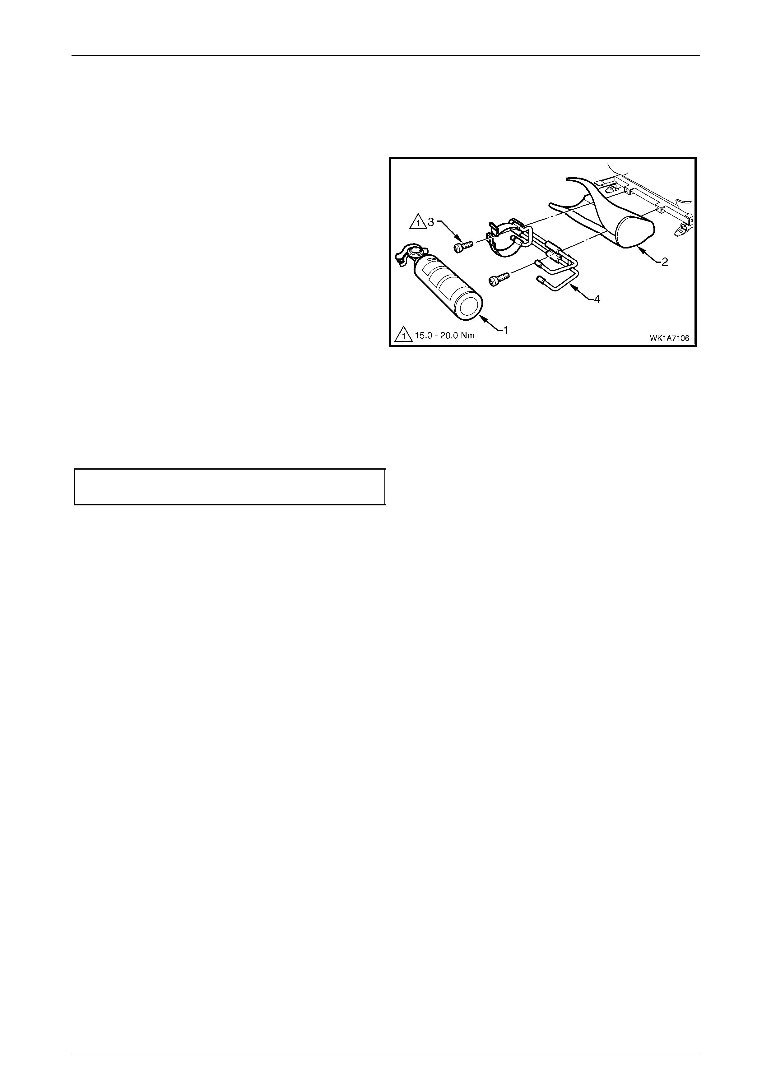
Seat Assemblies Page 1A7A–73
Page 1A7A–73
2.2 Fire Extinguisher Assembly
Remove
1 Remove the fire extinguisher (1) from the cover (2).
2 Remove the two screws (3) attaching the fire
extinguisher mounting br acket (4) to the track and
height adjust assembly.
3 Remove the bracket and cover from the track and
height adjust assembly. If required remove t he bracket
from the cover.
Figure 1A7A – 32
Reinstall
Reinstallation of the fire extinguisher assembly is the reverse of the removal procedure, noting the following:
Tighten the attaching screws to the correct torque specification.
Fire extinguisher mounting bracket
attaching screw torque specification.......15.0 – 20.0 Nm
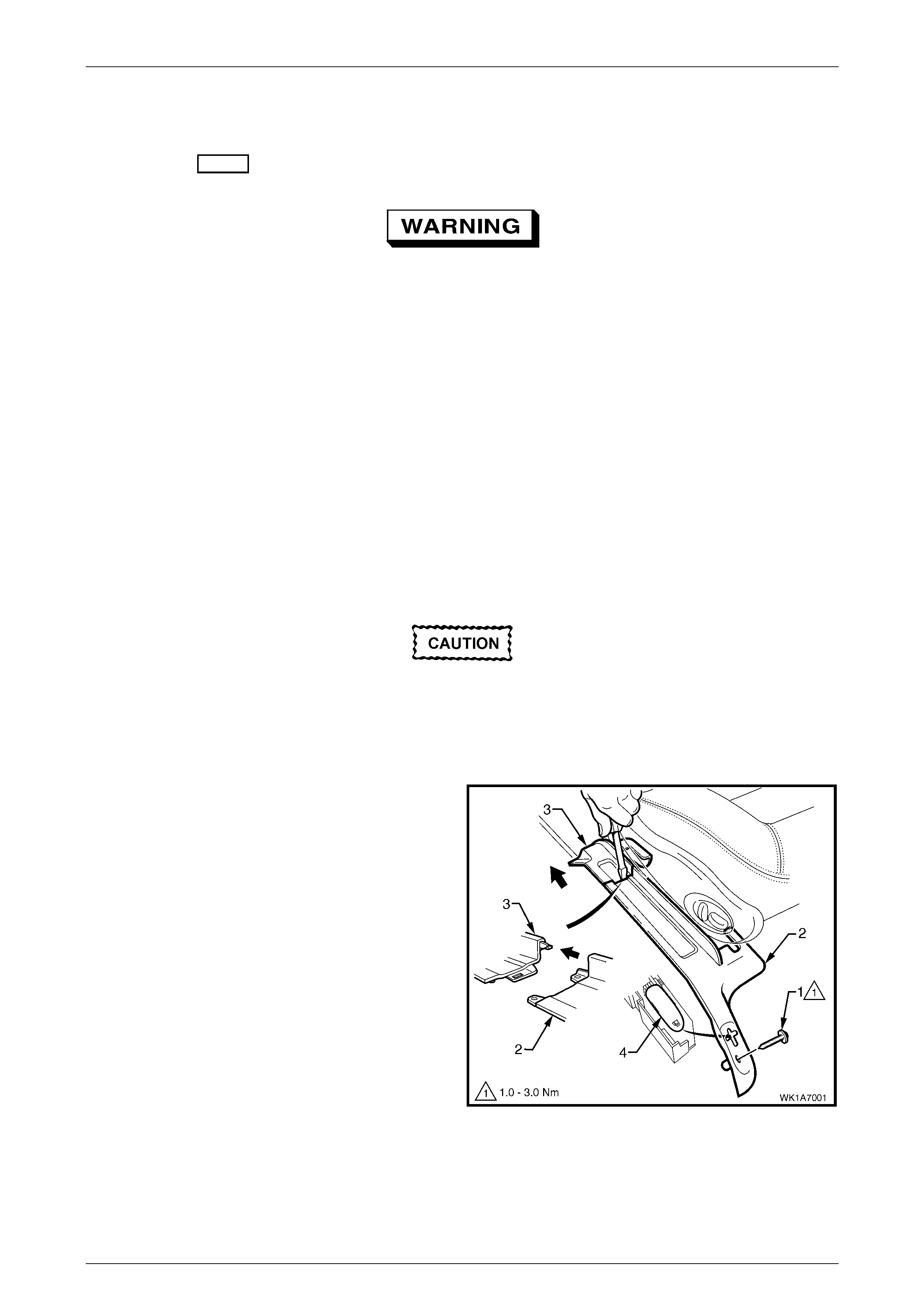
Seat Assemblies P age 1A7A–74
Page 1A7A–74
2.3 Front Seat Assembly
LT Section No. – 14-295
Before performing any service operation on a
front seat assembly fitted with side impact
airbags, ensure the occupant protection
system is disabled, refer to 12M Occupant
Protection System.
NOTE
If the seat assembly is to be disassembled, adjust
the seat assembly to its highest position before
disconnecting the power to the seat.
NOTE
Clean hands are essential when working on the
interior trim.
Remove
Disconnection of the battery affects certain
vehicle electronic systems. Refer to
00, 5 Battery Disconnection Procedures
before disconnecting the battery.
1 Disconnect the battery.
2 For the driver’s seat on right-hand drive vehicles,
(except utility, regular cab and crew cab), remove the
screw (1) atta ching the front seat outer front cover (2).
3 Using a small screwdriver, push in the centre of the
j
oin to separate the front cover and the front seat outer
rear cover (3).
4 Unclip the covers from the seat track and disengage
from the side sill trim.
5 Pull the covers apart and remove the rear cover.
6 For the driver’s seat on right-hand drive vehicles,
(except utility, regular cab and crew cab), slide the
front cover over the fuel filler door release lever (4)
and remove.
Figure 1A7A – 33
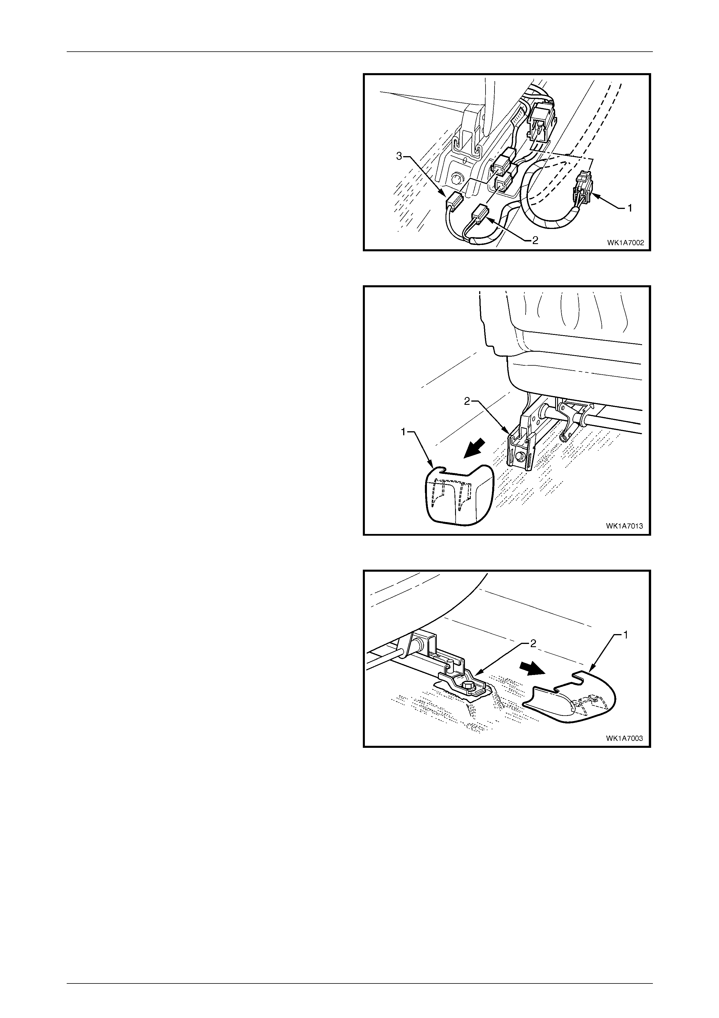
Seat Assemblies Page 1A7A–75
Page 1A7A–75
7 Disconnect the body wiring ha r ness connector (1), the
seatbelt pretensioner wiring connector (2) and the side
impact airbag wiring connector (3), if fitted.
Figure 1A7A – 34
8 Unclip the front seat inner rear cover (1) from the seat
track (2).
Figure 1A7A – 35
9 Unclip the front seat inner front cover (1) from the seat
track (2).
Figure 1A7A – 36
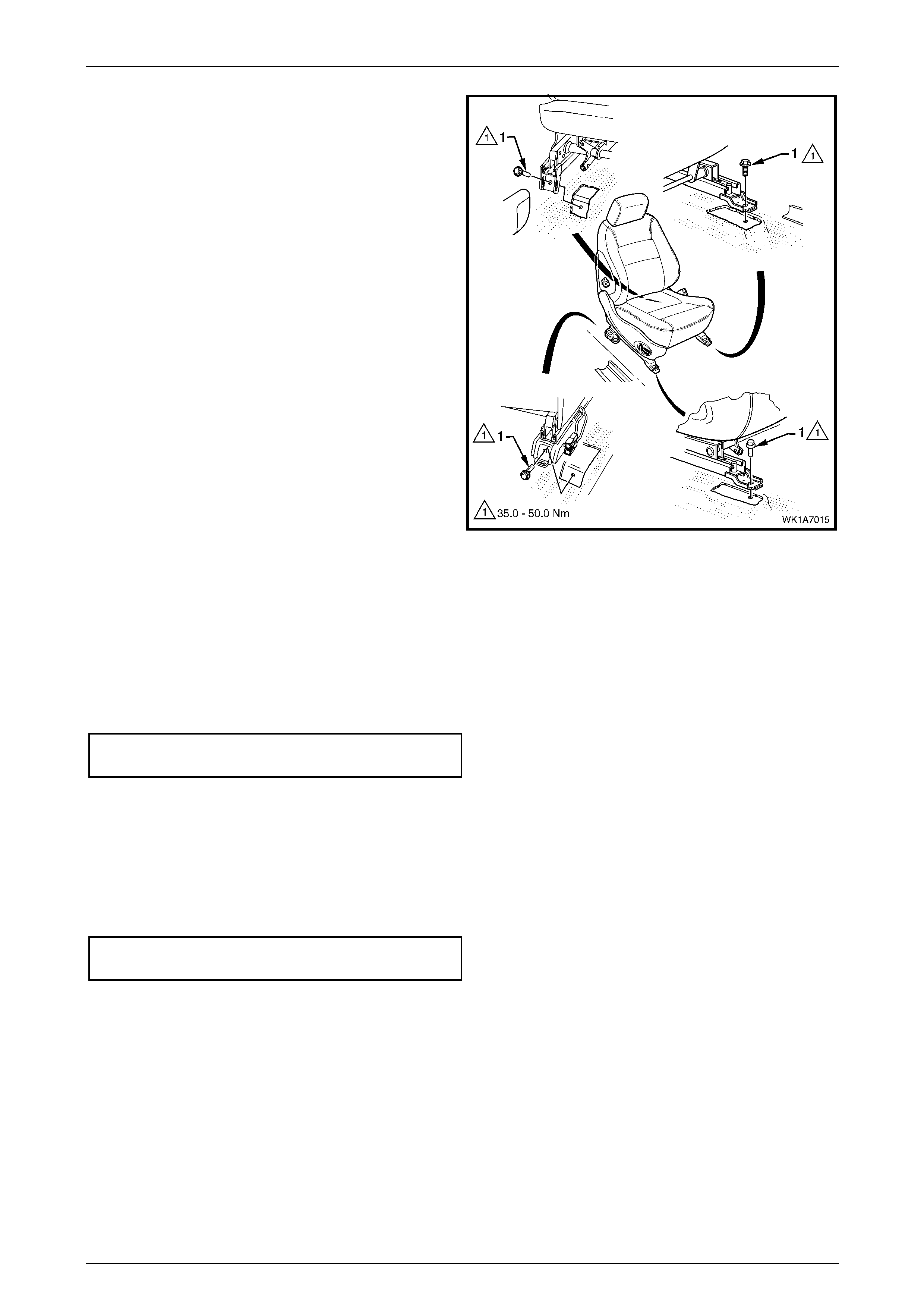
Seat Assemblies Page 1A7A–76
Page 1A7A–76
10 Remove the four screws (1) attaching the front seat to
the vehicle.
11 Remove the seat from the vehicle.
Figure 1A7A – 37
Reinstall
Reinstallation of the front seat assembly is the reverse of the removal procedure, noting the following:
1 Position the front seat assembly into the vehicle.
2 Install the four screws securing the front seat.
3 Tighten the attaching screws to the correct torque specification.
Front seat assembly attaching screw
torque specification.................................35.0 – 50.0 Nm
4 Connect the seat wiring harness connector, seatbelt pretensioner harness connector and the side impact airbag
connector.
5 Align the front seat outer cover’s retaining clips and push firmly to engage.
6 Push the front of the front seat outer cover do wn to engage the cover with the front of the seat rail.
7 For the driver’s side on right-hand drive vehicles, install the front seat outer cover attaching screw and tighten to the
specified torque.
Front seat outer front cover attaching
screw torque specification...........................1.0 – 3.0 Nm

Seat Assemblies Page 1A7A–77
Page 1A7A–77
8 Check the operation of the front seat functions. While checking the seat adjustment/operat ion, also check that the
seat wiring harnesses do not foul with any of the seat’s moveable components (i.e. seat motor drive shafts, etc.).
NOTE
Type 11 front seats will require seat memory
calibration to reinstate seat memory functions,
refer to Seat Memory Calibration, Front Seat
Type 11 in this Section.
9 Switch the ignition on and observe the airbag warning indicator in the instrument cluster.
• If no fault is detected, the airbag warning indicator shou ld illuminate for approximat ely five seconds while the
system performs a self-test, and then extinguish.
• If a fault is present, the airbag warning indic ator will remain illuminated and a warning chime may sound after
approximately three seconds. The warning message ‘SRS Airbag F ault’ is also displayed in the instrume nt
cluster multi-function display. To diagnose the fault, refer to 12M Occupant Protection.
Seat Memory Calibration, Front Seat Type 11
Whenever power is interrupted to the seat memory module, the following procedure must be performed to reinstate seat
memory functions.
Step Operation Result
1 1 Operate the seat adjustment switch to move the
seat forward.
2 Operate the seat adjustment switch for 1 second to
move the seat aft.
3 Operate the seat adjustment switch to move the
seat forward.
Seat will cease movement when track limit is
reached.
Seat will move aft.
Seat will cease movement when track limit is
reached.
2 1 Operate the seat adjustment switch to move the
seat aft.
2 Operate the seat adjustment switch for 1 second to
move the seat forward.
3 Operate the seat adjustment switch to move the
seat aft.
Seat will cease movement when track limit is
reached.
Seat will move for ward.
Seat will cease movement when track limit is
reached.
3 1 Operate the seat adjustment switch to raise the
front of the seat.
2 Operate the adjustment switch for 1 second to
lower the front of the seat.
3 Operate the seat adjustment switch to raise the
front of the seat.
Seat will cease movement when upper limit is
reached.
Se at wi ll lo wer .
Seat will cease movement when upper limit is
reached.
4 1 Operate the seat adjustment switch to lower the
front of the seat.
2 Operate seat adjustment switch for 1 second to
raise the front of the seat.
3 Operate the seat adjustment switch to lower the
front of the seat.
Seat will cease movement when lower limit is
reached.
Seat will raise.
Seat will cease movement when lower limit is
reached.
5 1 Operate the seat adjustment switch to raise the rear
of the seat.
2 Operate the seat adjustment switch for 1 second to
lower the rear of the seat.
3 Operate the seat adjustment switch to raise the rear
of the seat.
Seat will cease movement when upper limit is
reached.
Se at wi ll lo wer .
Seat will cease movement when upper limit is
reached.

Seat Assemblies Page 1A7A–78
Page 1A7A–78
Step Operation Result
6 1 Operate the seat adjustment switch to lower the
rear of the seat.
2 Operate the seat adjustment switch for 1 second to
raise the rear of the seat.
3 Operate the seat adjustment switch to lower the
rear of the seat.
Seat will cease movement when lower limit is
reached.
Seat will raise.
Seat will cease movement when lower limit is
reached.
7 1 Operate the seat adjustment switch to move the
seat-back aft.
2 Operate the seat adjustment switch for 1 second to
move the seat-back forward.
3 Operate the seat adjustment switch to move the
seat-back aft.
Hold switch until lower limit is reached. This
does not have to be mechanical limit.
Seat-back will move forward.
Hold switch until lower limit is reached. This
should be same position as in 1.
8 1 Operate the seat adjustment switch to move the
seat-back forward.
2 Operate the seat adjustment switch for 1 second to
move the seat-back aft.
3 Operate the seat adjustment switch to move the
seat-back forward.
Hold switch until upper lim it is reached. This
does not have to be mechanical limit.
Seat-back will move aft.
Hold switch until upper lim it is reached. This
should be same position as in 1.
9 Press the mirror dip/memory store (M) button for 1
second. Stores the calibration into memory. A three-
tone chime sounds to confirm storage.
To test that the seat limits have been correctly calibrated, perform the following:
Step Operation Result
1 Operate the seat adjustment switch in one direction
(fore/aft, raise/lower, etc.). Hold until seat stops.
2 Release the switch briefly. –
3 Operate the switch in the same direction and hold for 3
seconds. The motor will not operate for 2 seconds, then
operates for 0.5 second.
This is a limp-home function that allo ws the
seat to be manually adjusted should a sensor
fail.
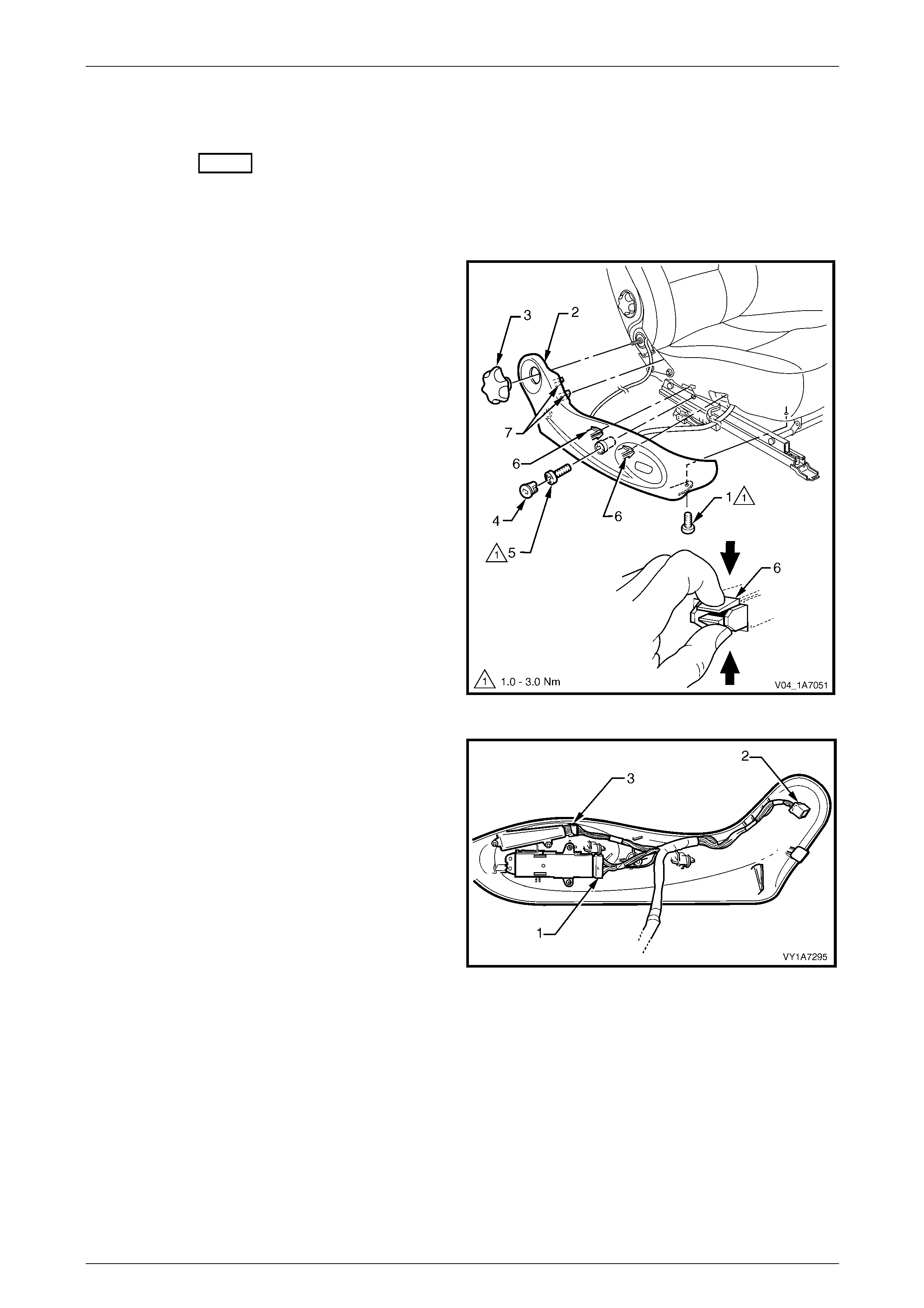
Seat Assemblies Page 1A7A–79
Page 1A7A–79
2.4 Front Seat Outer Side Cover Assembl y
LT Section No. – 14-322
Remove
1 Raise the seat to the full-up position.
2 Remove the screw (1) from the front of the front seat
outer side cover (2).
3 If required, carefully prise the recliner knob (3) from
the seat assembly.
4 Remove the plug (4) by rotating the plug a nti-
clockwise, one quarter of a turn.
4 Remove the screw (5) located behind the plu g.
5 Reach up under the seat assembly and squeeze
together the two retaining tangs (6), on the i nner side
of the side cover while gently pulling the cover.
6 Gently pull the side cover away from the seat to
disengage the two clips (7) attached to the seat-back
frame assembly.
NOTE
Only remove the side cover far enough away
from the seat cushion assembly to gain access
to the seat wiring harness connectors.
Figure 1A7A – 38
7 Where fitted, disconnect the front seat adjustment
switch connector (1), recline motor harness connector
(2) and the memory position switch connector (3) and
unclip the harness from the side cover.
8 Remove the side cover assembly.
Figure 1A7A – 39
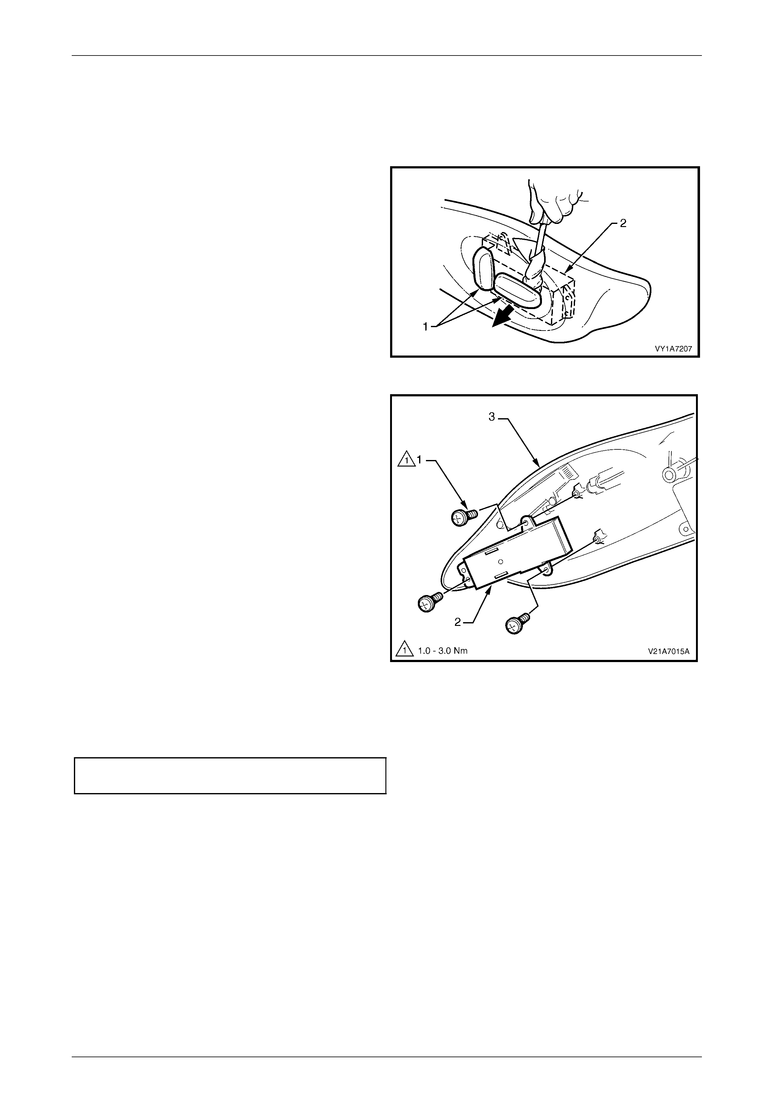
Seat Assemblies Page 1A7A–80
Page 1A7A–80
Disassemble
Front Seat Adjustment Switch
Remove
1 Depending on moveme nt functions, remove the one or
two adjustment knobs (1) from the front seat
adjustment switch (2), by carefully prising them free
with a small flat tip screwdriver wrapped in a clean
shop rag.
Figure 1A7A – 40
2 Remove the three screws (1) attaching the front seat
adjustment switch (2) to the front seat outer side
cover (3).
3 Remove the adjustment switch.
Figure 1A7A – 41
Reinstall
1 Tighten the attaching screws to the correct torque specification.
Front seat adjustment switch
attaching screw torque specification...........1.0 – 3.0 Nm
2 Push the knobs in until they click in place.
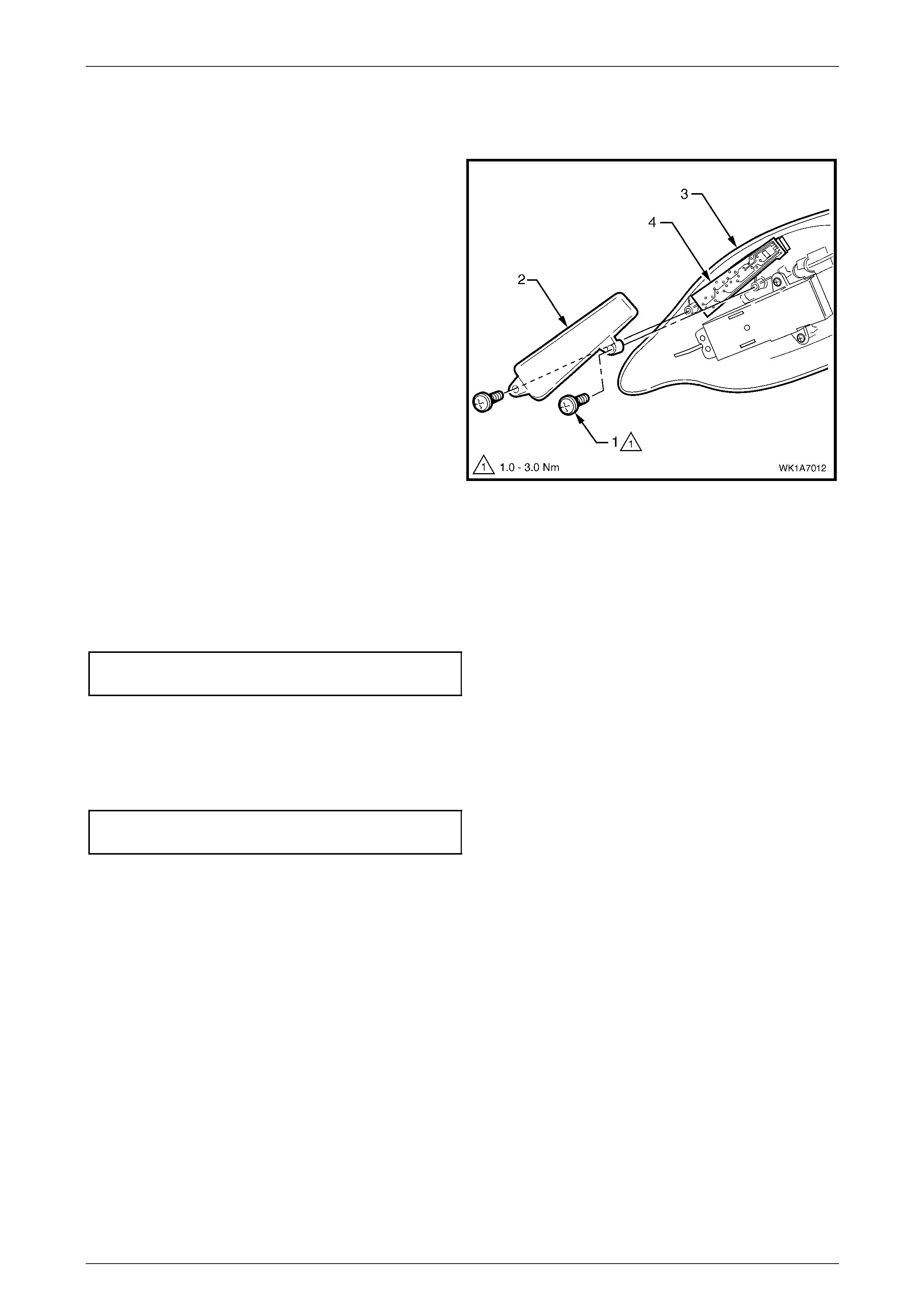
Seat Assemblies Page 1A7A–81
Page 1A7A–81
Memory Position Switch Assembly
Remove
1 Remove the two screws (1) attaching the memory
position switch cover (2) to the front seat outer side
cover (3).
2 Lift out the memory position switch assembly (4) from
its recess in the side cover.
3 As required, each position button can b e removed
from the switch.
Figure 1A7A – 42
Reinstall
Reinstallation of the memory position switch assembly is the reverse of the removal procedure, noting the following:
1 If removed, push the position buttons in until they click in place, ensuring correct orientation.
2 Tighten the attaching screws to the correct torque specification.
Memory position switch cover
attaching screw torque specification...........1.0 – 3.0 Nm
Reinstall
Reinstallation of the front seat outer side cover is the reverse of the removal procedure, noting the following:
1 Tighten the attaching screws to the correct torque specification.
Front seat outer side cover attaching
screw torque specification...........................1.0 – 3.0 Nm
2 If fitted, ensure the recliner knob is securely clipped in place.
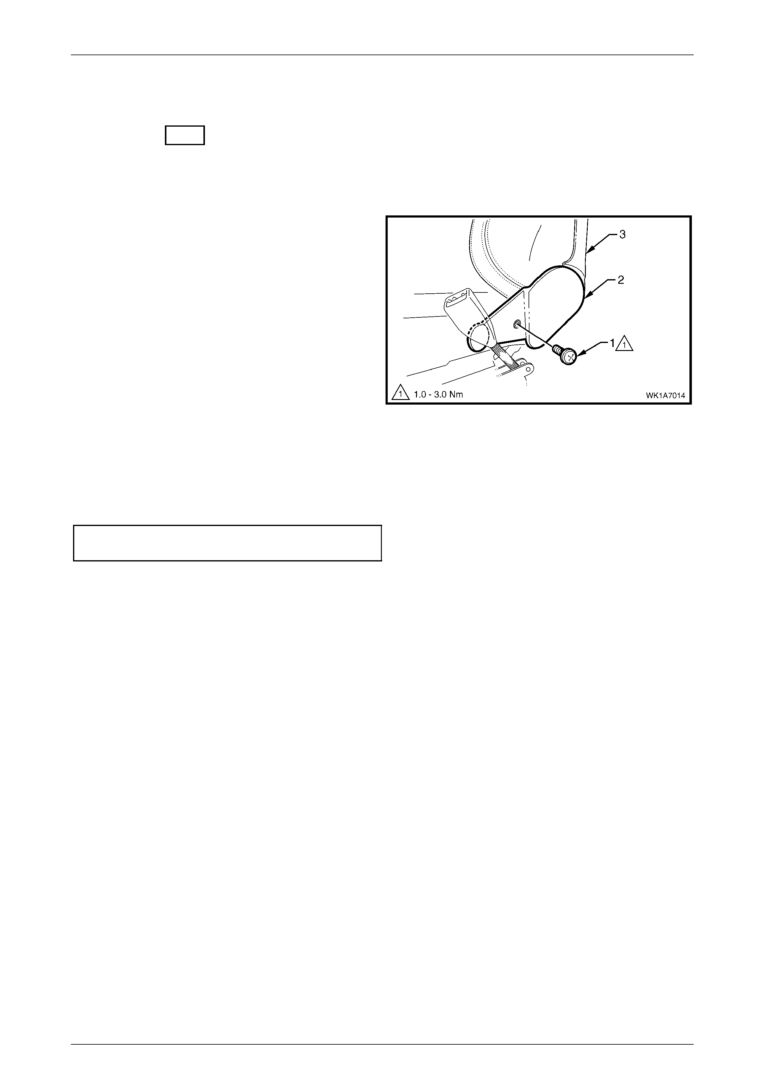
Seat Assemblies Page 1A7A–82
Page 1A7A–82
2.5 Front Seat Inner Side Cover
LT Section No. – 14-322
As required, remove the front seat assembly, refer to 2.3 Front Seat Assembly.
Remove
1 Remove the screw (1) attaching the front seat inner
side cover (2) to the seat assembly (3) and remove the
cover.
Figure 1A7A – 43
Reinstall
Reinstallation of the front seat inner side cover is the reverse of the removal procedure, noting the following:
Tighten the attaching screw to the correct torque specification.
Front seat inner side cover attachi ng
screw torque specification...........................1.0 – 3.0 Nm
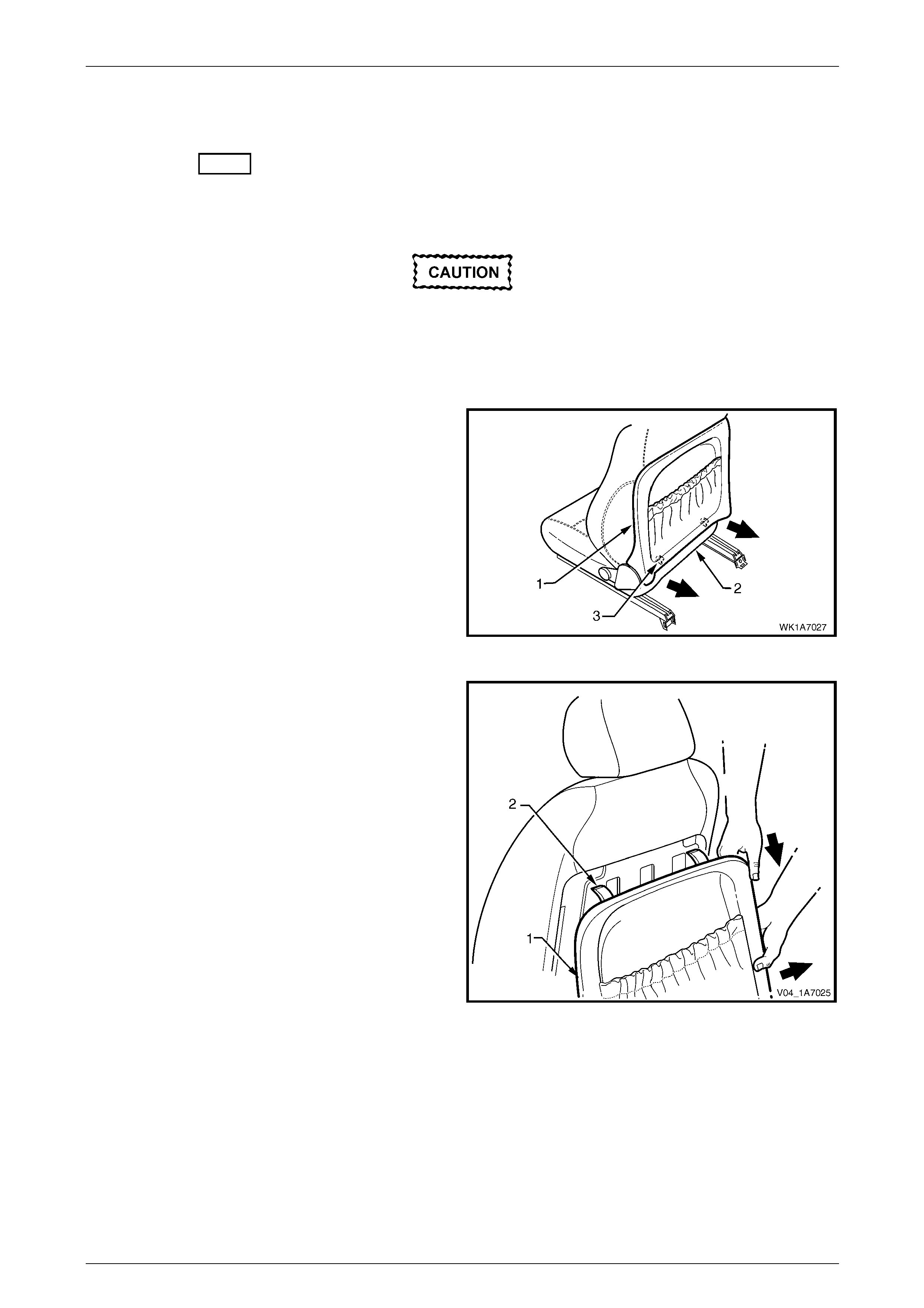
Seat Assemblies Page 1A7A–83
Page 1A7A–83
2.6 Front Seat-back Rear Cover Assembly
LT Section No. – 14-322
Remove
The following components will require
replacement when performing this operation.
• Two front seat-back rear cover retaining
clips.
1 Pull the lower corners of the front seat-back rear
cover (1) away from the seat (2), breaking the two
retaining clips (3).
Figure 1A7A – 44
2 While holding the lower portion of the front seat-back
rear cover (1) out, pull the cover down to release the
two upper retaining lugs (2).
3 Remove the cover.
Figure 1A7A – 45

Seat Assemblies Page 1A7A–84
Page 1A7A–84
Disassemble
When performing Step 1, take care when
removing the retaining clip (1) not to break
the front seat-back map pocket shafts on
which the reta ining clips are attached.
NOTE
This procedure cannot be performed on vehicles
that have the net type seat-back map pocket.
1 Remove the two retaining clips (1) attaching the front seat-back map pocket (2) to the front seat-back rear
cover (3), refer to Figure 1A7A – 46.
2 Remove the four screws (4) attaching the map pocket to the cover.
3 Remove the map pocket.
Figure 1A7A – 46
Reassemble
Reassembly of the front seat-back rear cover is the reverse of the removal procedure, noting the following:
Tighten the attaching screws to the correct torque specification.
Front seat-back map pocket attaching
screw torque specification...........................1.0 – 3.0 Nm
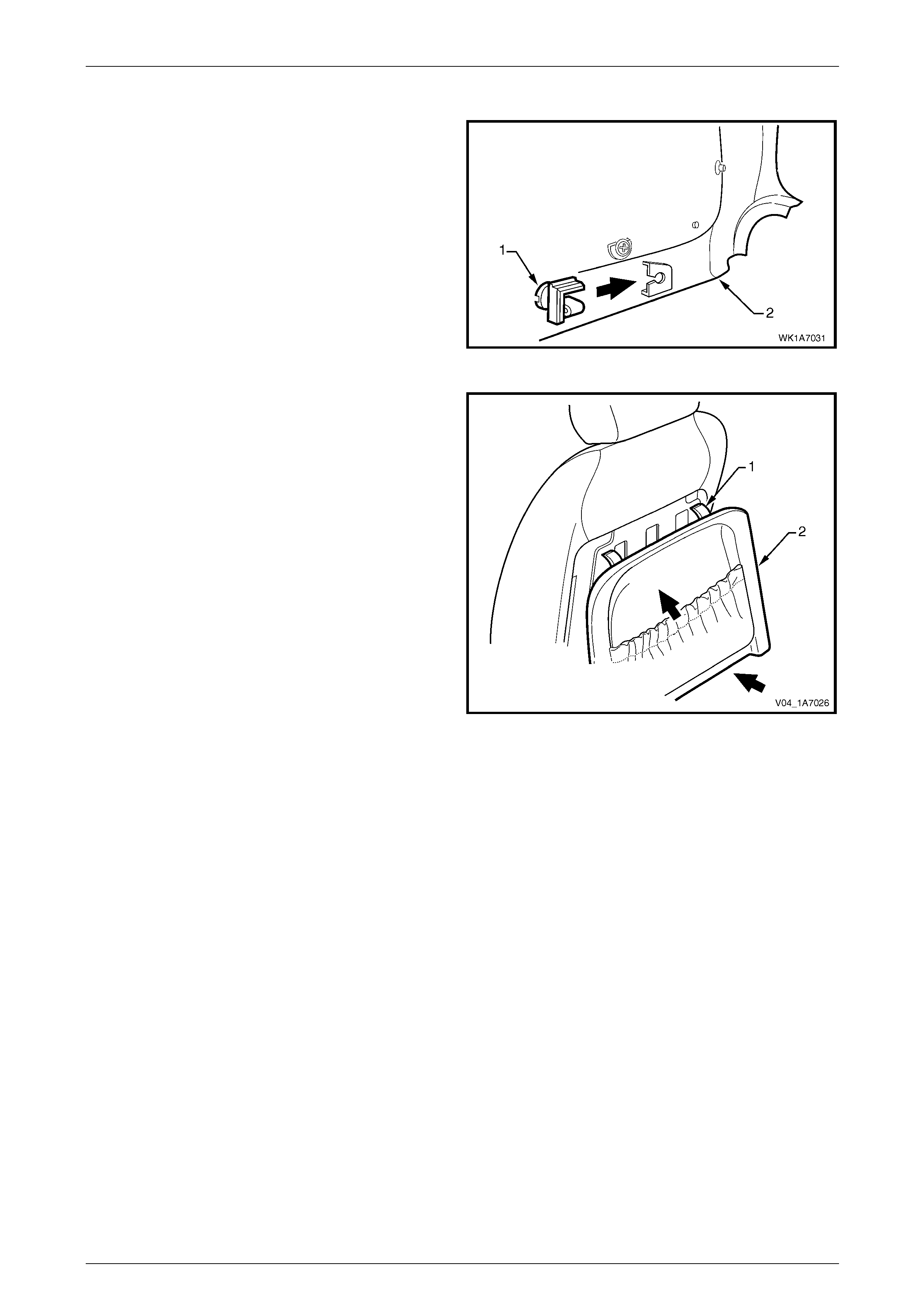
Seat Assemblies Page 1A7A–85
Page 1A7A–85
Reinstall
1 Replace the damaged retaining clip (1) on the front
seat-back rear cover (2), two places.
Figure 1A7A – 47
2 Align the two upper retaining l ugs (1) with the seat-
back.
3 Push the front seat-back rear cover (2) up and in at
the lower edge to engage the two lower retaining clips.
Figure 1A7A – 48
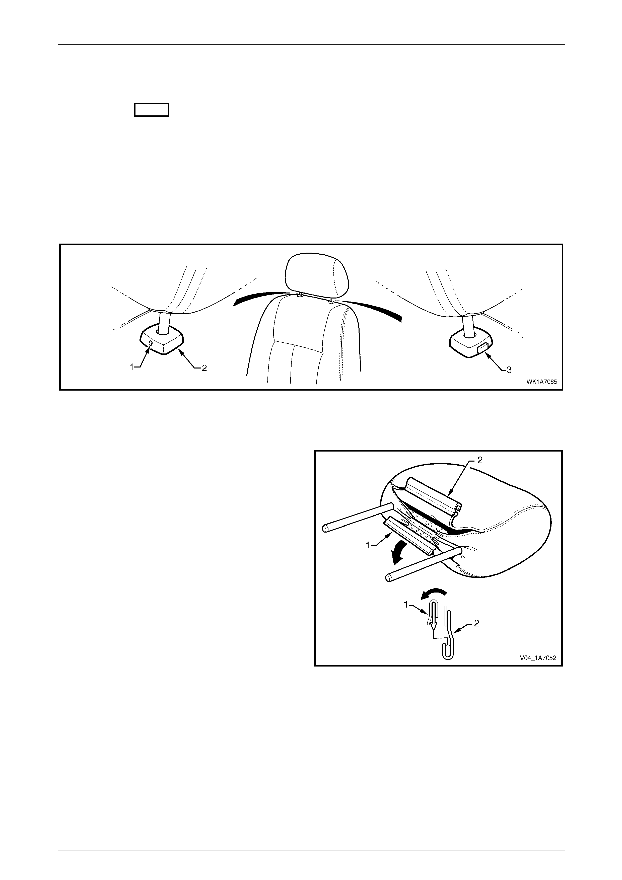
Seat Assemblies Page 1A7A–86
Page 1A7A–86
2.7 Front Seat Head Restraint Assembly
LT Section No. – 14-295
Remove
1 Raise the head restraint fully.
2 Insert a suitable size probe into the hole (1) in the right-hand head restraint sleeve (2), refer to F igure 1A7A – 49
3 Push the probe in slightly whil e applying slight upward pressure on the head restraint. Hold the upward pressure.
4 Depress the head restraint sleeve height adjuster lock (3) on the left-hand head restraint sleeve and remove the
head restraint.
Figure 1A7A – 49
Disassemble
1 Disengage the front head restraint cover J-stri p by
pulling the flap (1) back and out of flap (2) in the
direction shown.
Figure 1A7A – 50

Seat Assemblies Page 1A7A–87
Page 1A7A–87
2 Remove the four staples (1) retaining the cover (2) to
the head restraint pad assembly.
3 Remove the cover from the pad assemb ly.
Figure 1A7A – 51
Reassemble
Reassembly of the front seat head restraint assembly is the reverse of the removal procedure, noting the following:
Ensure the head restraint cover J-clip is fully enga ged and sits neatly in the recess in the head restraint pad.
Reinstall
Ensuring correct orientation of the head restraint, fit the head restraint shafts into the sleeves and p ush the head restraint
down.
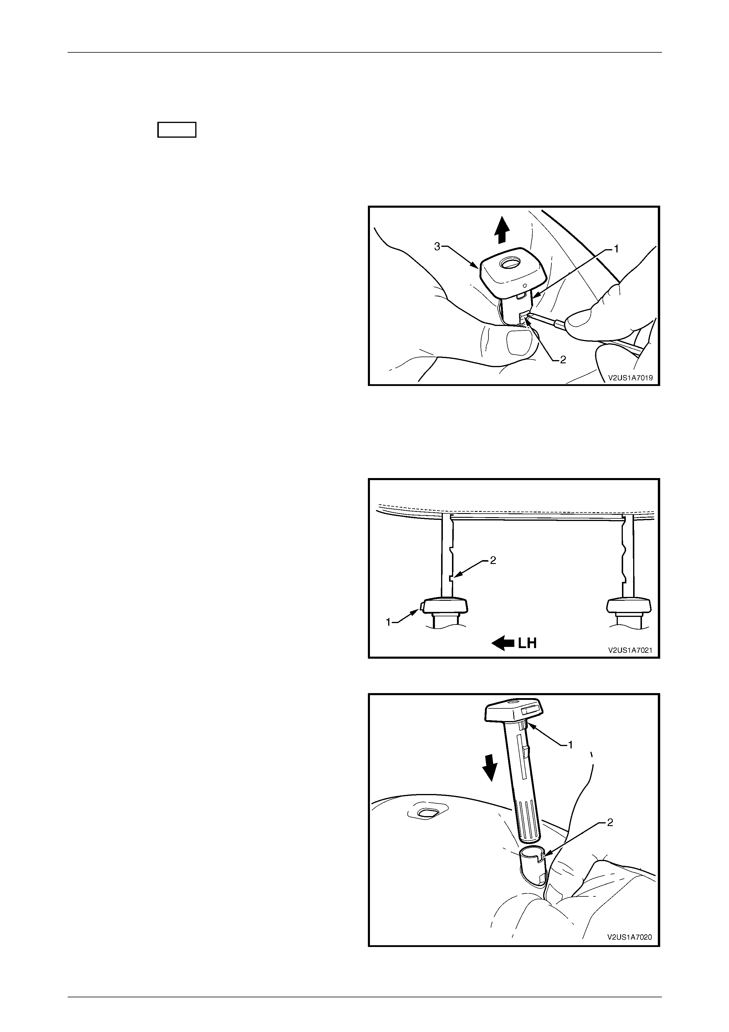
Seat Assemblies Page 1A7A–88
Page 1A7A–88
2.8 Front Seat Head Restraint Sleeve
LT Section No. – 14-275
As required, remove the front seat head restraint assembl y, refer to 2.7 Front Seat Head Restrai nt Assembl y.
Remove
1 Push down on the surrounding seat cover to reveal the
upper portion of the seat-back frame or active head
restraint frame (1).
2 Using a fine flat-blade screwdriver, depress the head
restraint sleeve retaining lug (2) and withdraw the
head restraint sleeve (3) from the frame.
3 Repeat for the remaining sleeve as required.
Figure 1A7A – 52
Reinstall
Reinstallation of the front seat head restraint sleeve is the reverse of the removal proce dure, noting the following:
NOTE
Ensure the sleeve with the height adjuster lock
(1) is installed on the left-hand side of the seat;
that is the side that corresponds to the lower
square notch (2) in the head restraint shaft.
Figure 1A7A – 53
1 Align the head restraint sleeve locatin g ribs (1 ) with
the notch (2) in the seat-back frame.
2 Insert the sleeve and ensure it clicks into place.
Figure 1A7A – 54
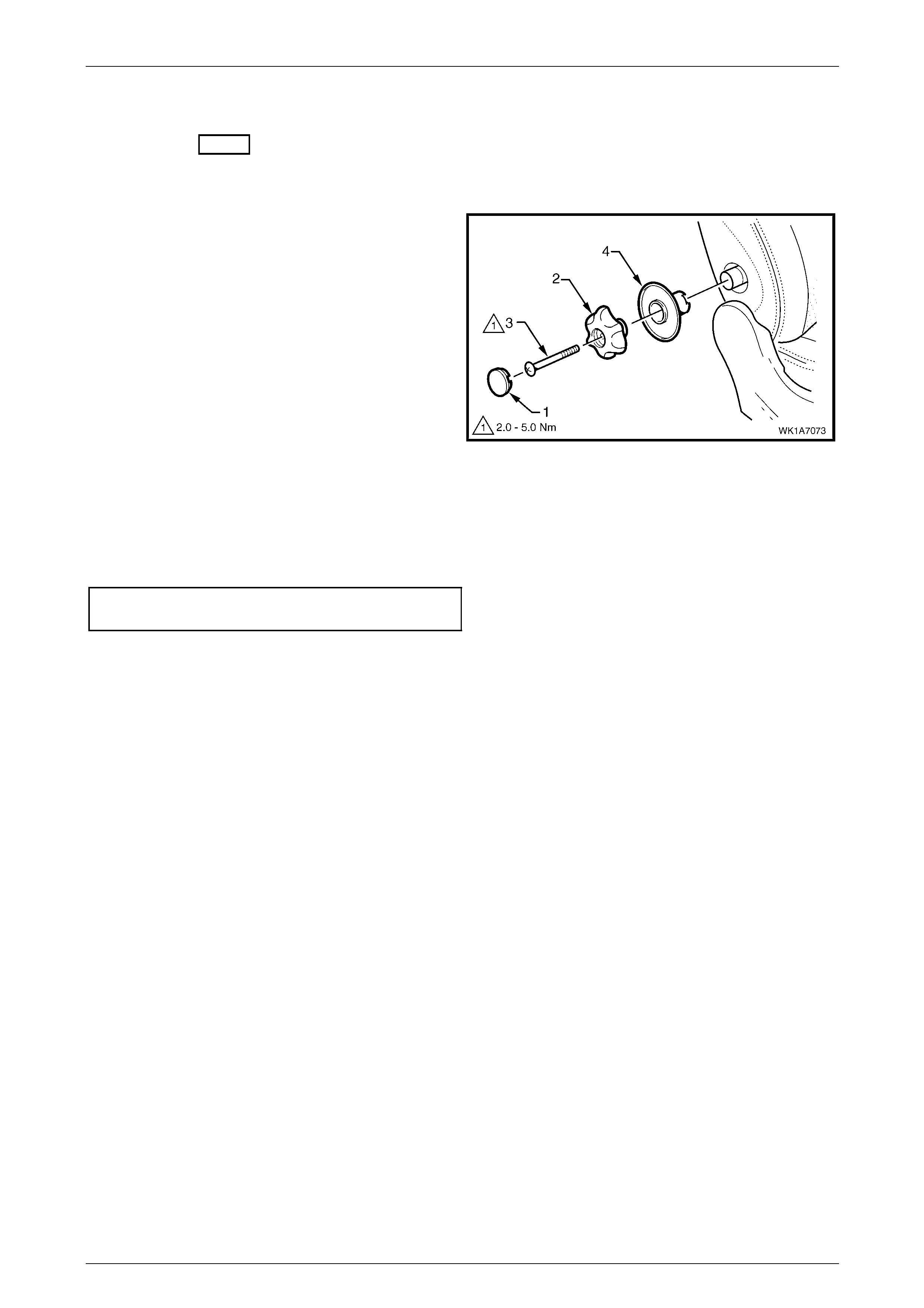
Seat Assemblies Page 1A7A–89
Page 1A7A–89
2.9 Lumbar Support Knob Assembly
LT Section No. – 14-275
Remove
1 Ensure the lumbar support is in the full off position.
2 Using a fine flat-blade scre w-driver, carefull y prise the
cap (1) from the lumbar support knob (2).
3 Remove the screw (3) attaching the knob to the
lumbar support shaft.
4 Pull the knob off the lumbar support shaft and remove
the lumbar support deflector ring (4).
NOTE
The knob is lightly clipped to the lumbar support
shaft and will ‘click-off’.
Figure 1A7A – 55
Reinstall
Reinstallation of the lumbar s upport knob assembly is the reverse of the removal procedure, noting the following:
Tighten the screw to the correct torque specification.
Lumbar support knob attachin g
screw torque specification...........................2.0 – 5.0 Nm
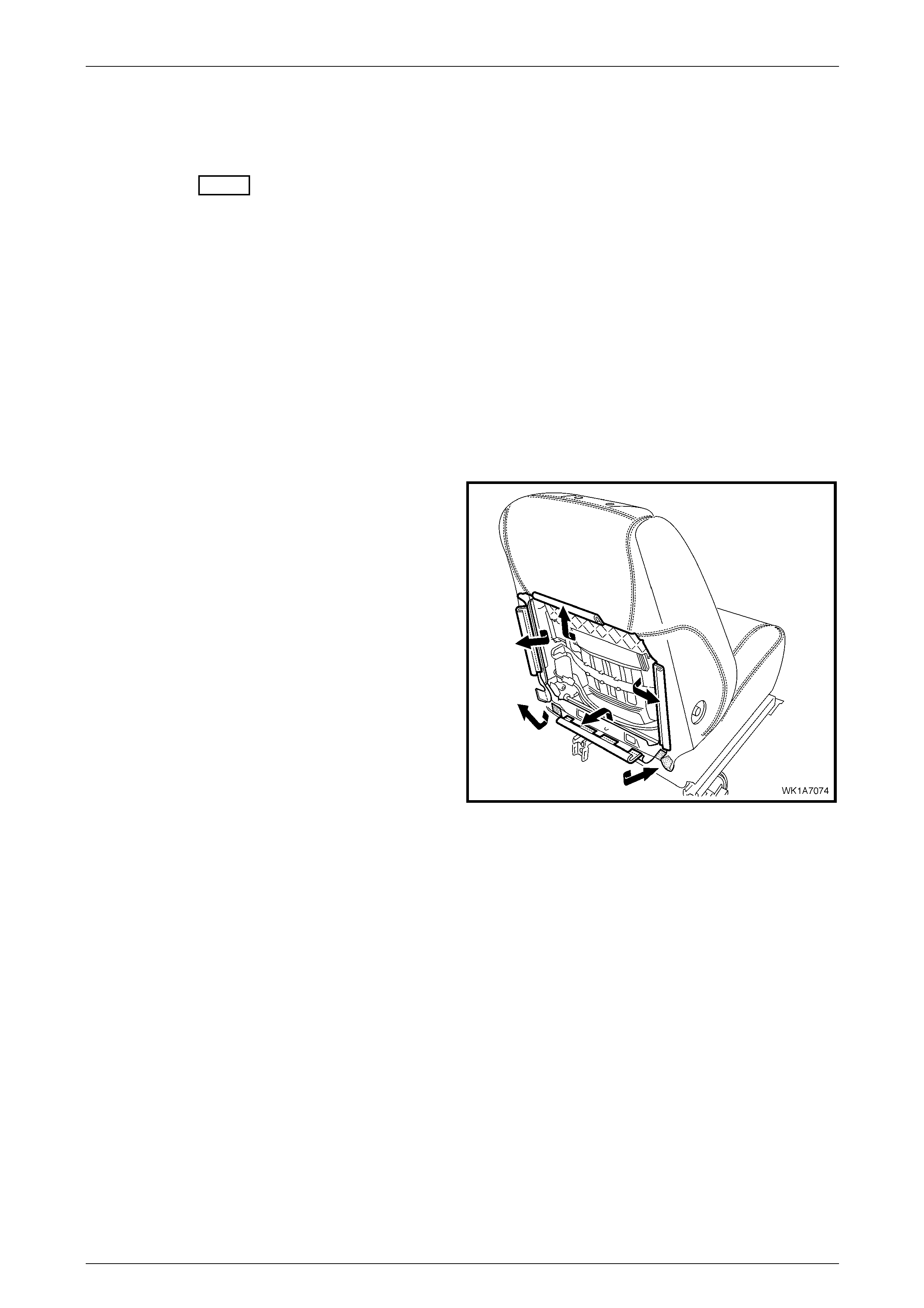
Seat Assemblies Page 1A7A–90
Page 1A7A–90
2.10 Front Seat-back Pad and Cover
Assembly
LT Section No. – 14-295
As required, remove the following compo nents:
1 Front seat assembly, refer to 2.3 Front Seat Assembly.
2 Front seat outer side cover assembly, refer to 2.4 Front Seat Outer Side Cover Assembly.
3 Front seat inner side cover, refer to 2.5 Front Seat Inner Side Cover.
4 Front seat-back rear cover assembly, refer to 2.6 Front Seat-back Rear Cover Assemb ly.
5 Front seat head restraint assembly, refer to 2.7 Front Seat Head Restraint Assembly.
6 Front seat head restraint sleeves, refer to 2.8 Front Seat Head Restraint Sleeve.
7 Lumbar support knob assembly, refer to 2.9 Lumbar Suppor t Knob Assembly.
Remove
1 Disengage the J-strips from the seat frame a nd the
Velcro tab at each lower corner.
2 Lift the cover and pad assembly up and away from the
seat-back frame, manoeuvring it over the seat-back
components such as the side impact airbag a nd
dummy block insert assemblies.
Figure 1A7A – 56
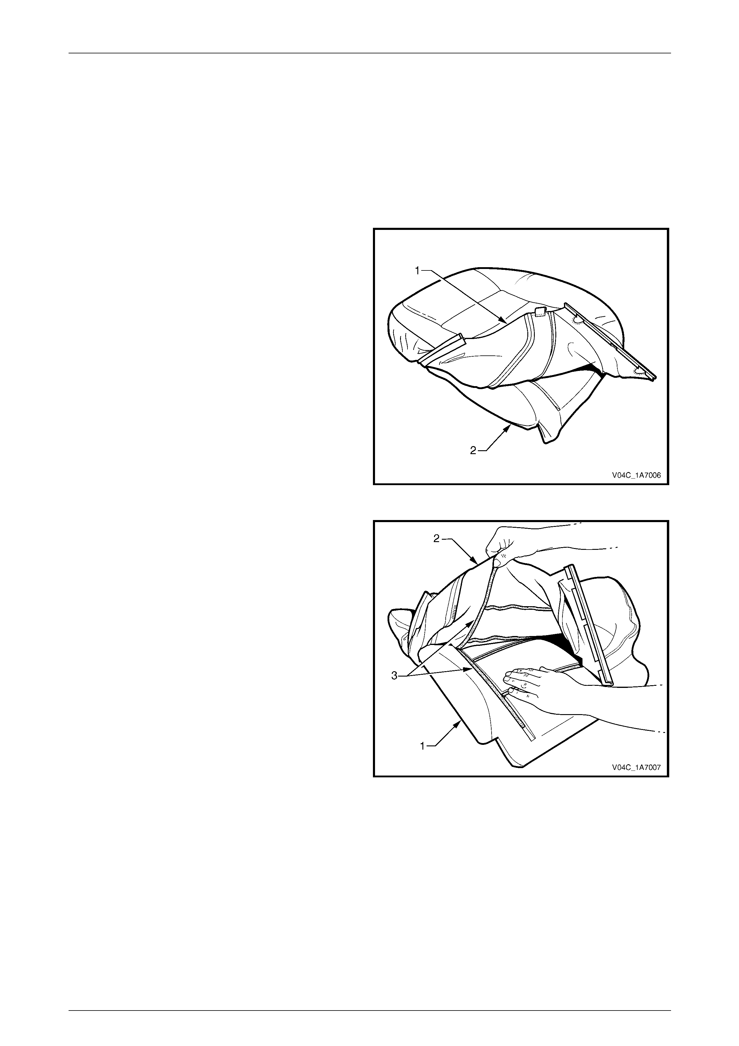
Seat Assemblies Page 1A7A–91
Page 1A7A–91
Disassemble
NOTE
The following illustrations show typical hook and
loop arrangement, which will vary according to
seat type.
Surebond type seat-back pad and cover
assemblies cannot be disassembled.
1 Fold the lower corners of the seat-back cove r (1) over
the seat-back pad (2).
Figure 1A7A – 57
2 While holding the front seat-back pad (1), pull the
lower corners of the front seat-back cover (2), upwards
and away from the pad to diseng age the hook and
loop strips (3).
3 Pull the cover up and over the upper ed ge of the pad.
Figure 1A7A – 58
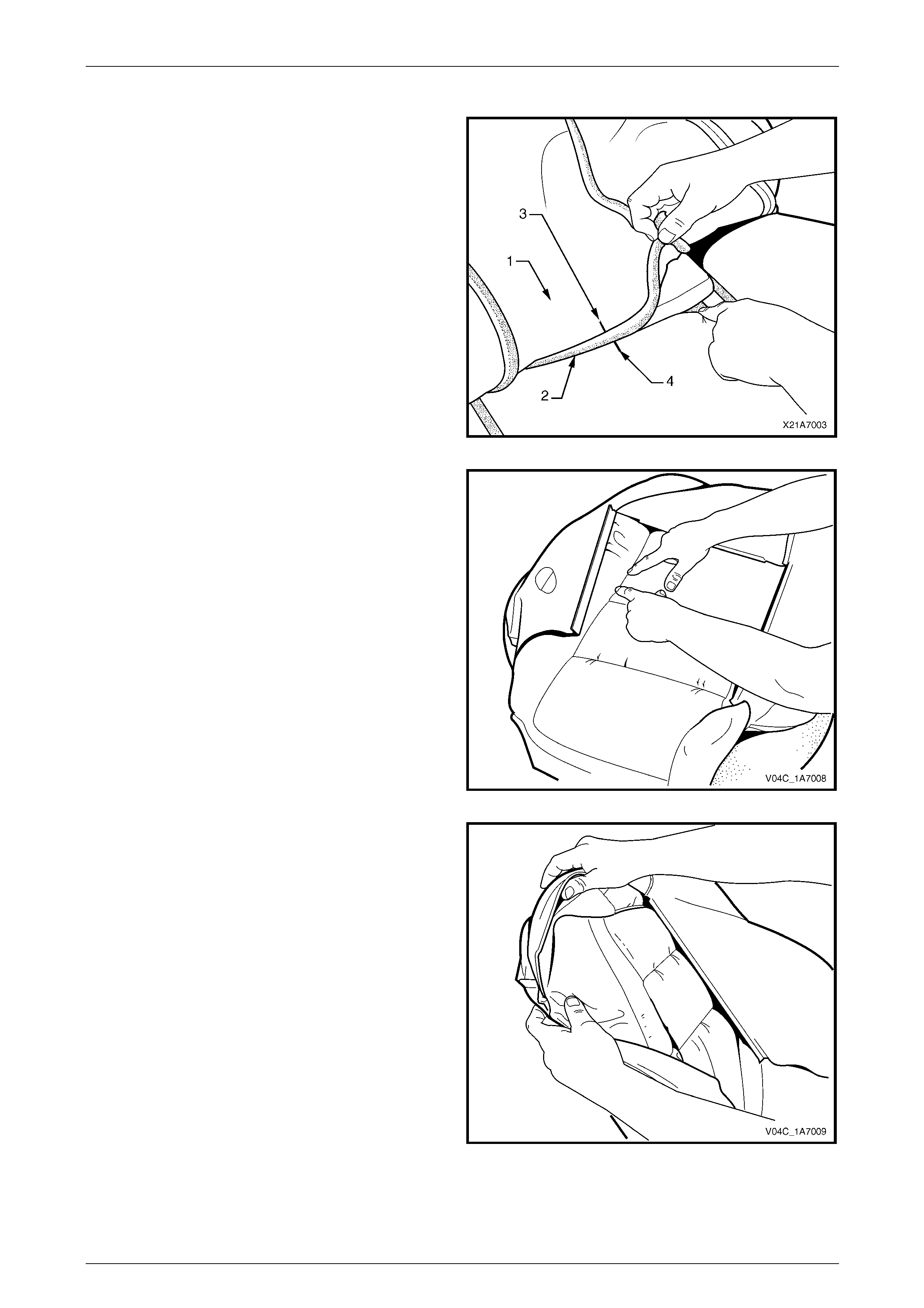
Seat Assemblies Page 1A7A–92
Page 1A7A–92
Reassemble
1 With the front seat-back cover (1) folded at the central
horizontal strip of hook and loop (2), align th e centre
mark (3) on the cover with the centre mark (4) on the
front seat-back pad.
2 Press the cover firmly into the corresponding groove i n
the pad to engage the hook and loop.
Figure 1A7A – 59
3 With the cover folded at the two vertical strips of the
hook and loop, press the cover firml y into the
corresponding grooves in the pad.
Figure 1A7A – 60
4 Roll the upper corners of the cover over the pad.
5 Roll the sides of the cover over the pad.
6 Roll the lower corners of the cover over the pad.
NOTE
Make sure the cover is fitted neatly by hand into
all corners and contours of the pad.
Figure 1A7A – 61
Reinstall
Reinstallation of the front seat -back pad and cover assembly is the reverse of the removal procedure.
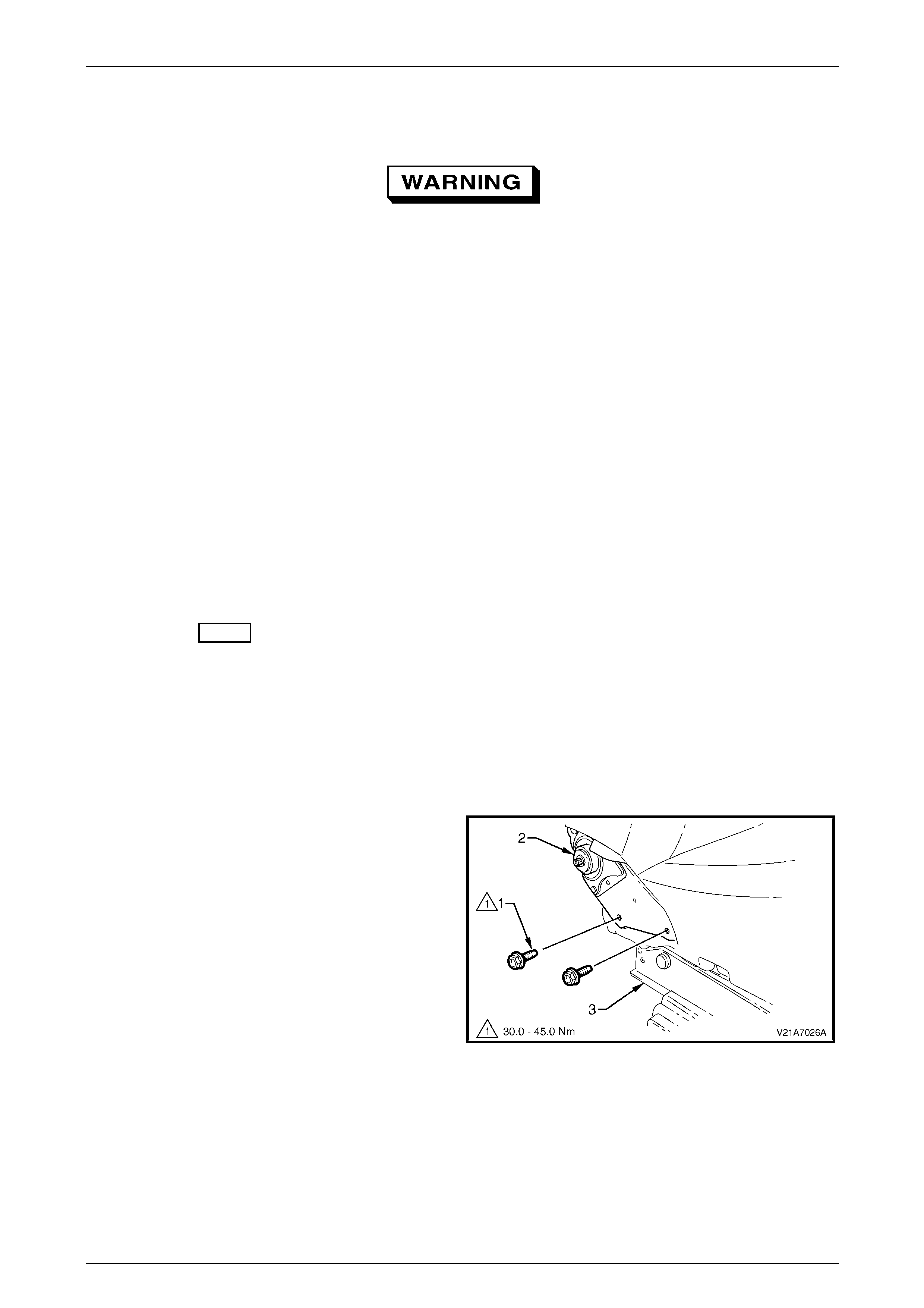
Seat Assemblies Page 1A7A–93
Page 1A7A–93
2.11 Front Seat-back Frame Assembly
When carrying a live (undeployed) side
impact airbag assembly or a front seat-back
frame assembly fitted with a (undeployed)
side impact airbag assembly, ensure the
airbag opening is pointed away from you.
Never carry the side impact airbag assembly
or seat-back frame assembly fitted w ith a side
impact airbag assembly by the airbag wiring
harness or connectors. In case of an
accidental deployment, the airbag will then
deploy with minimal chance of injury.
When placing a live side impact airbag
assembly or a fro nt seat-ba ck frame as sembly
fitted with a (undeployed) side impact airbag
assembly on a bench or other surface, alw ays
face the airbag opening up, away from the
surface. Never rest the airbag assembly or
seat-back frame with the airbag opening face
down. This is necessary so that a free space
is provided to allow the airbag to expand in
the unlikely event of accidental deployment.
Otherwise, personal injury may result.
LT Section No. – 14-275
As required remove the following c ompo nents:
1 Front seat assembly, refer to 2.3 Front Seat Assembly.
2 Front seat outer side cover assembly, refer to 2.4 Front Seat Outer Side Cover Assembly.
3 Front seat inner side cover, refer to 2.5 Front Seat Inner Side Cover.
Remove
1 Remove the two screws (1), each side, attaching the
seat-back assembly (2) to the front seat cushion frame
assembly (3).
2 As required, disconnect and detach the front seat-back
recline motor and side impact airbag wiring harnesses.
3 Remove the seat-back assembly.
Figure 1A7A – 62
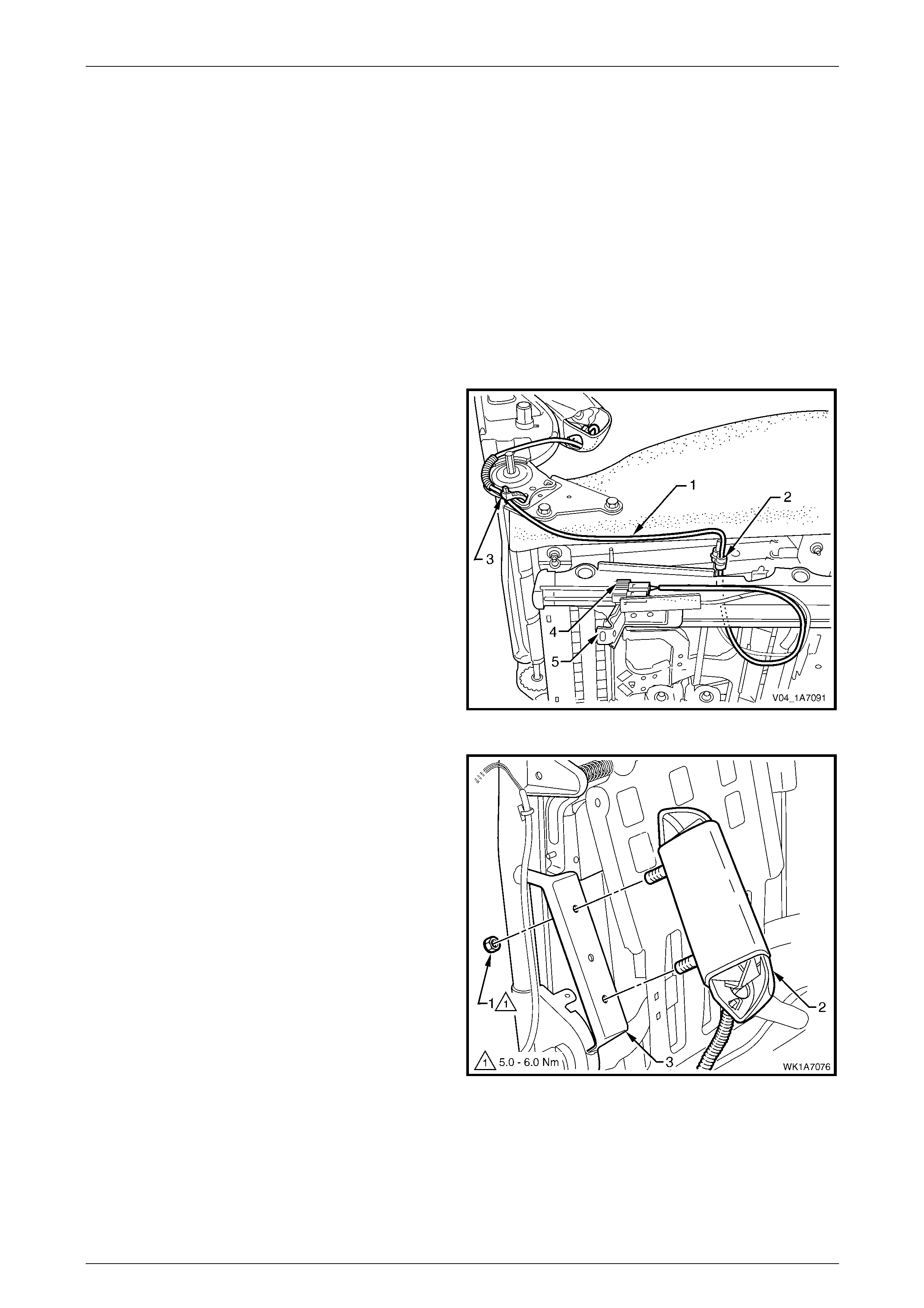
Seat Assemblies Page 1A7A–94
Page 1A7A–94
Disassemble
As required, remove the following compo nents:
1 Front seat-back rear cover assembly, refer to 2.6 Front Seat-back Rear Cover Assemb ly.
2 Front seat head restraint assembly, refer to 2.7 Front Seat Head Restraint Assembly.
3 Front seat head restraint sleeves, refer to 2.8 Front Seat Head Restraint Sleeve.
4 Lumbar support knob assembly, refer to 2.9 Lumbar Suppor t Knob Assembly.
5 Front seat-back pad and cover assembl y, refer to 2.10 Front Seat-back Pad and Cover Assembly.
Side Impact Airbag Assembly
Remove
1 As required, unclip the side im pact airbag wiring
harness (1) from the retaining clip (2) and cut the
cable tie (3) securing the harness to the front seat
cushion frame assembly, taking care not to damage
the wiring harness.
2 Unclip the wiring harness connector (4) from the track
and height adjust assembly (5).
Figure 1A7A – 63
3 Remove the lock-nut (1), two places, attaching the
side impact airbag assembl y ( 2) to the seat-b ack
frame (3) and airbag assembly.
Figure 1A7A – 64
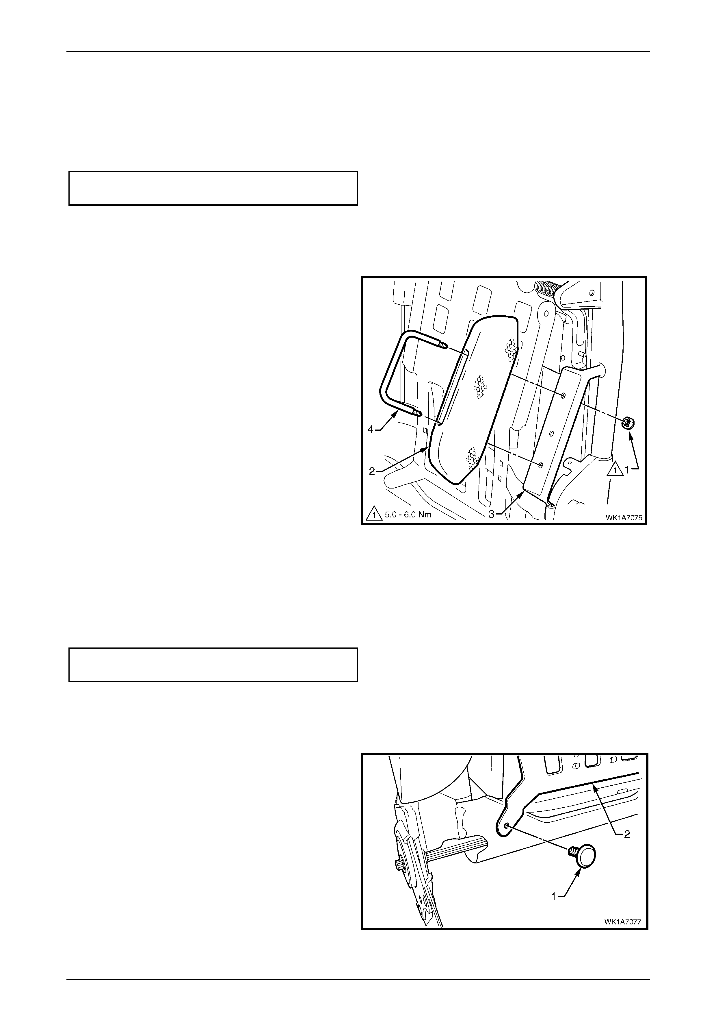
Seat Assemblies Page 1A7A–95
Page 1A7A–95
Reinstall
Reinstallation of the side impact airba g asse mbly is the reverse of the removal procedure, noting the following:
1 Ensure the conduit covering the wiring harness and the harness is positioned correctl y, refer to Figure 1A7A – 63.
2 Tighten the nuts to the correct torque specification.
Side impact airbag assembly attaching
nut torque specification...............................5.0 – 6.0 Nm
Front Seat Dummy Block Insert Assembly
Remove
1 Remove the lock-nut (1), two places, attaching the
front seat dummy block insert (2) to the seat-back
frame (3) and remove the dummy block insert
assembly.
2 If required, remove the dummy block U-bolt (4) from
the dummy block insert.
Figure 1A7A – 65
Reinstall
Reinstallation of the front seat dummy block insert assembly is the reverse of the removal procedure, noting the
following:
Tighten the nuts to the correct torque specification.
Front seat dummy block insert attaching
nut torque specification...............................5.0 – 6.0 Nm
Lumbar Support Assembly
Remove
1 Remove the retainer (1), two places, attaching the
lumbar support assembly (2) to the seat-back frame.
Figure 1A7A – 66
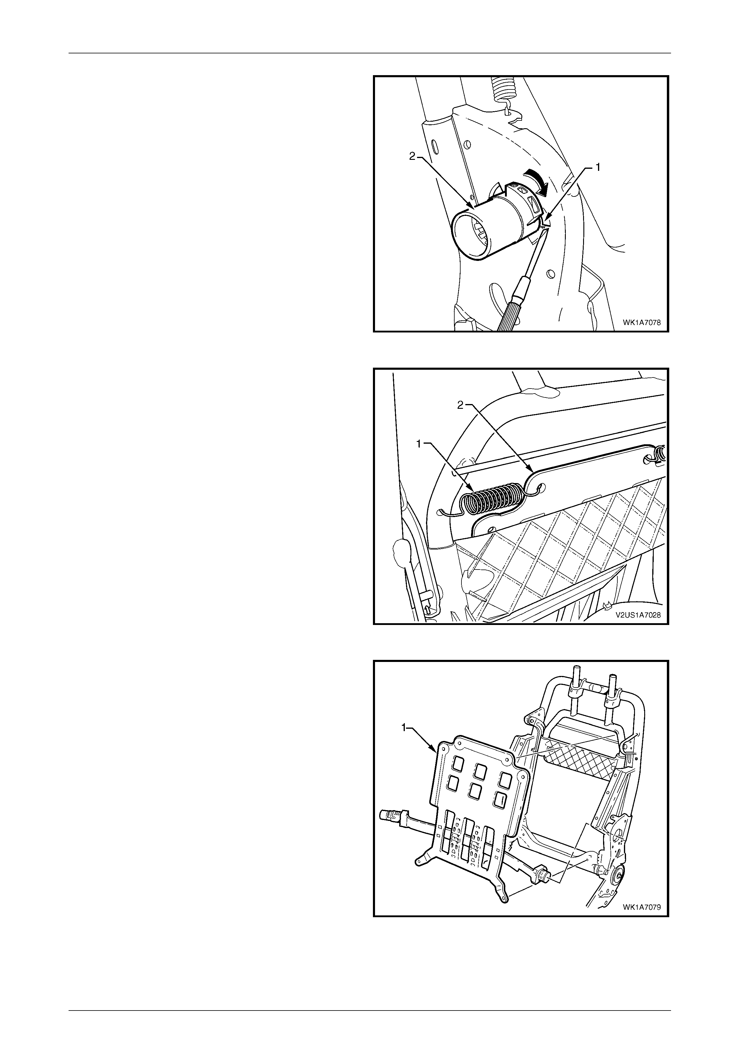
Seat Assemblies Page 1A7A–96
Page 1A7A–96
2 Depress the retaining tab (1) and from the inner side
of the seat-back frame, rotate the lumbar support
shaft (2) and withdraw from the seat-back frame.
3 Repeat for the opposite side.
Figure 1A7A – 67
4 Disconnect the spring (1), two places, attaching the
lumbar support assembly (2) to the seat-bac k frame or
active head restraint frame.
TIP
To aid spring remova l, pull the support asse mbly
toward the side that the spring is being remove d
to relieve spring tension.
Figure 1A7A – 68
5 Remove the lumbar support assembly (1).
Figure 1A7A – 69
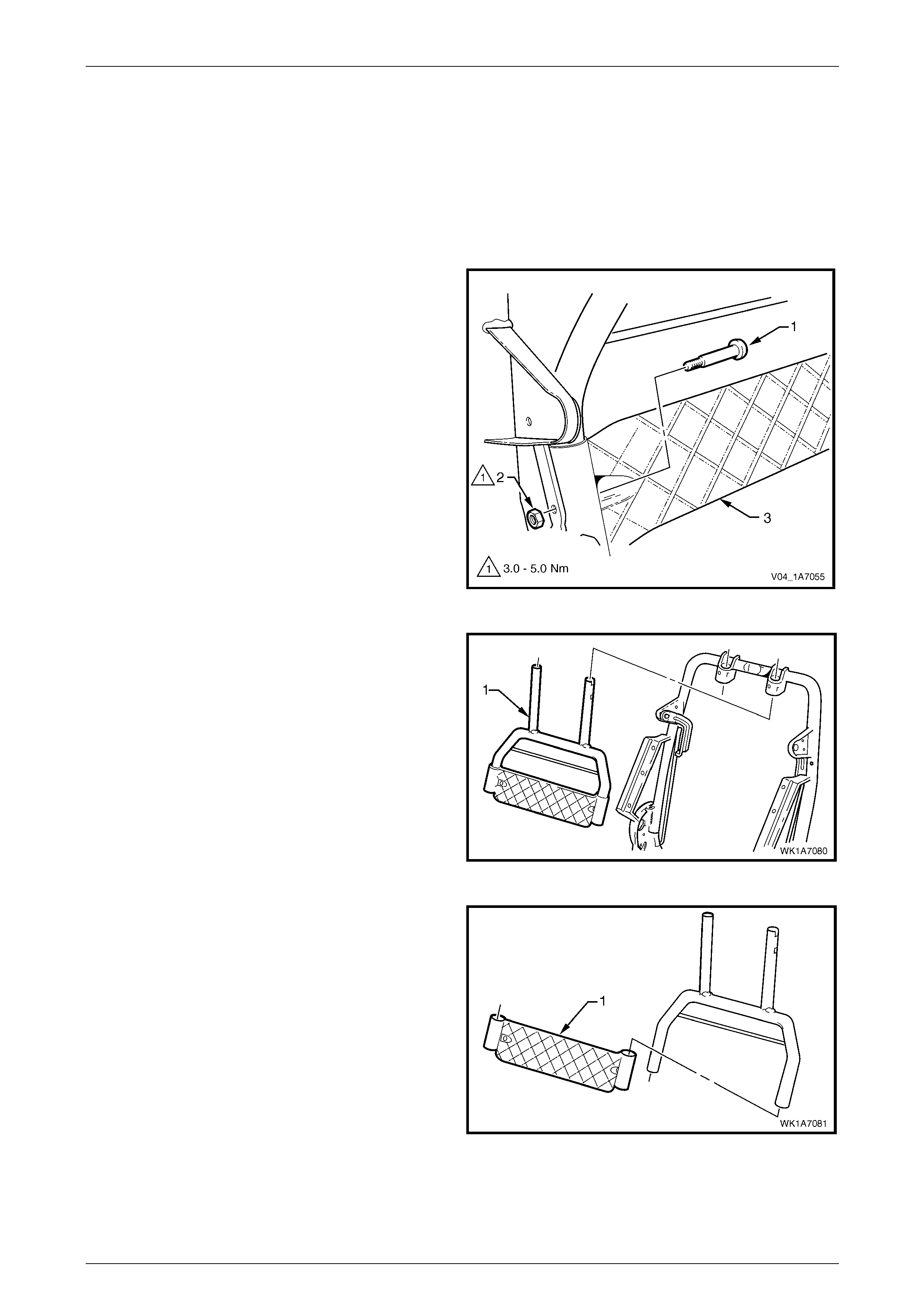
Seat Assemblies Page 1A7A–97
Page 1A7A–97
Reinstall
Reinstallation of the lumbar s upport assembly is the reverse of the removal procedure, noting the following:
Ensure the lumbar support assembl y is correctly seated on the cushion side of the active head restraint frame, where
fitted, with the black lumbar support shaft on the outer side of the seat.
Active Head Restraint Frame Assembly
Remove
1 Remove the screw (1) and nut (2), two places,
attaching the active head restraint frame assembly (3)
to the seat-back frame hinge.
Figure 1A7A – 70
2 Withdraw the active head restraint frame assembly (1)
downward to remove it from the seat-back frame and
remove.
Figure 1A7A – 71
3 If required, slide the support strap (1) from the active
head restraint frame.
Figure 1A7A – 72
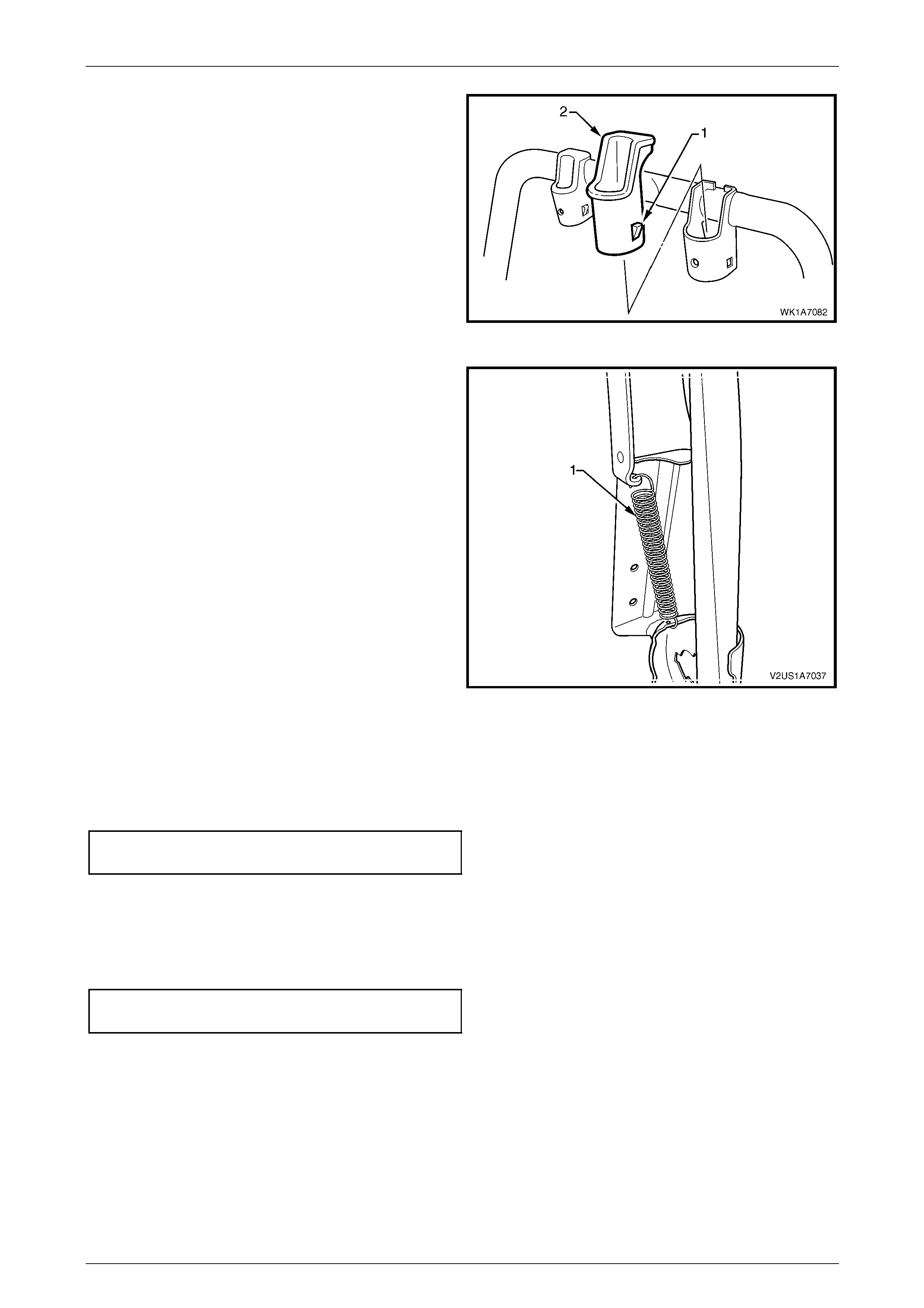
Seat Assemblies Page 1A7A–98
Page 1A7A–98
4 If required, depress the tab (1), two places, and
withdraw the active head restraint frame sleeve (2)
from the seat-back frame.
5 Repeat for the opposite sleeve as requ ired.
Figure 1A7A – 73
6 If required, remove the spring (1), from the active head
restraint frame hinge and seat-back frame.
7 Repeat for the opposite side as required.
Figure 1A7A – 74
Reinstall
Reinstallation of the active head restraint frame assembly is the reverse of the removal proced ure, noting the following:
Tighten the screws to the correct torque specification.
Active head restraint frame assembly
attaching screw torque specification...........3.0 – 5.0 Nm
Reinstall
Reinstallation of the front seat-back frame assembly is the reverse of the removal procedure, noting the following:
1 Tighten the attaching screws to the correct torque specific ation.
Front seat-back frame assembly
attaching screw torque specification.......30.0 – 45.0 Nm
2 Check the mechanical and ele c trical operation of the front seat.
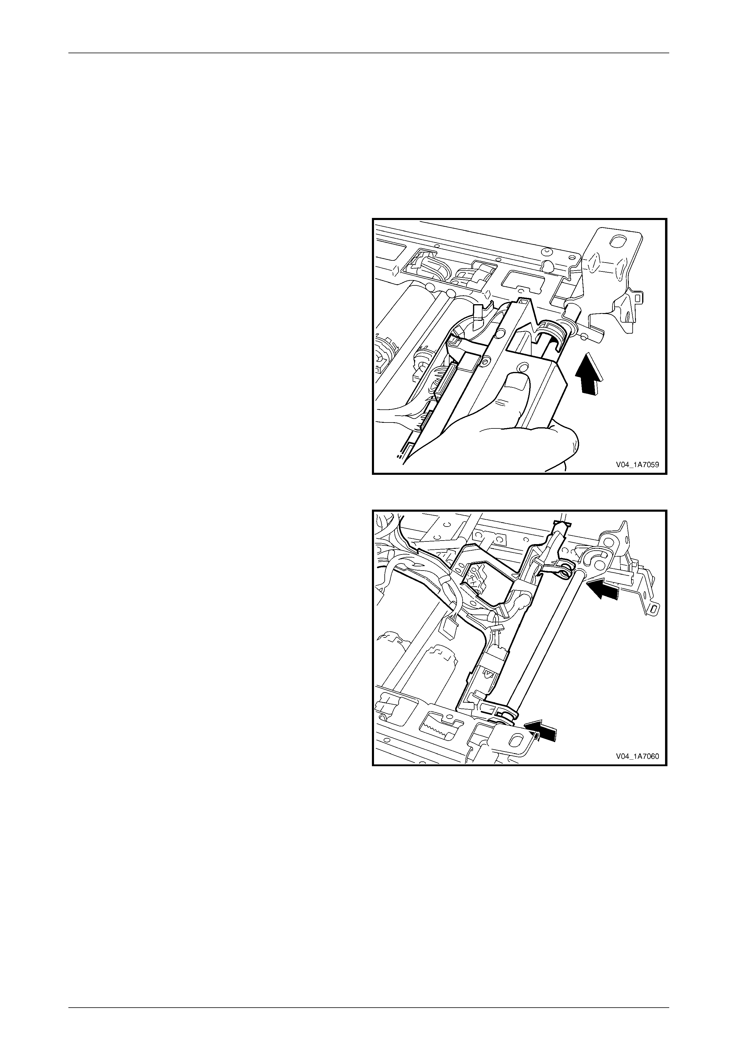
Seat Assemblies Page 1A7A–99
Page 1A7A–99
2.12 Seat Cable Tray and Memory Module
Remove
1 Remove the front seat assembly, refer to 2.3 Front Seat Assembly.
2 Remove the seat track and height adjust assembly, refer to 2.13 Track and Height Adjust Assembly.
3 Disconnect the wiring harness connectors as required.
4 Unclip the cable tray from the front of the seat track
and height adjust assembly.
Figure 1A7A – 75
5 Pull the cable tray forward to release it from the seat
track and height adjust assembly.
Figure 1A7A – 76
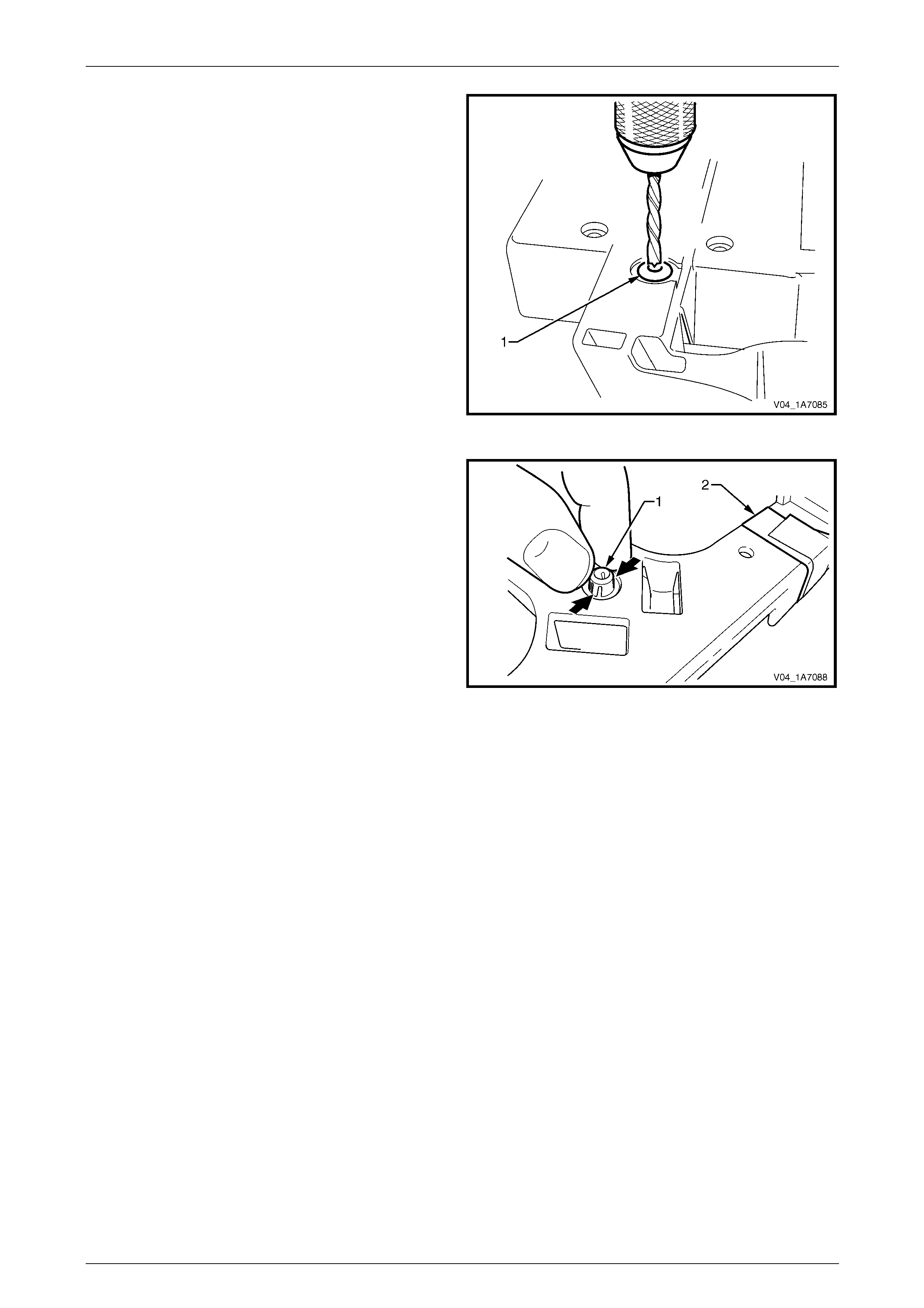
Seat Assemblies Page 1A7A–100
Page 1A7A–100
6 If required, use a 5 mm drill bit and dri ll out the pop
rivet (1), two places, securing the seat memor y
module to the cable tray.
7 Remove the seat memory module.
Figure 1A7A – 77
8 If required, remove the wiring harness from the cable
tray by squeezing the tabs on the harness clips (1)
and removing the tape (2) as required.
Figure 1A7A – 78
Reinstall
Reinstallation of the seat memor y module is the reverse of the removal procedure, noting the following:
1 Ensure the wiring harness an d connectors are correctly routed and attach ed securely.
2 Use new pop rivets.

Seat Assemblies Page 1A7A–101
Page 1A7A–101
2.13 Track and Height Adjust Assembly
The track and height adjust assembly
components are non-serviceable. If the track
and height adjust assembly, drive motors or
drive shafts require replacement, the entire
track and height adjust assembly must be
replaced.
LT Section No. – 14-275
Remove
1 Remove the front seat assembly, refer to 2.3 Front Seat Assembly.
2 Remove the front seat outer side cover assembl y, refer to 2.4 Front Seat Outer Side Cover Assembly.
3 As required, detach the wiring harness con nectors.
4 As required, detach the seatbelt pretensioner and side airbag wiring harnesses.
5 Remove the four nuts (1) attaching the track and
height adjust assembly (2) to the seat.
6 Remove the track and height adjust assembly.
7 If required, remove the cable tray and wiring harness
assembly, refer to 2.12 Seat Cable Tray and Memory
Module.
8 If required, remove the seatbelt buckle and
pretensioner assembly, refer to 12M Occupant
Protection System.
Figure 1A7A – 79
Reinstall
Reinstallation of the track and height adjust assembly is the reverse of the removal procedur e, noting the following:
1 Ensure the connectors are correctly routed and attached se curely, refer to Figure 1A7A – 80.
2 Tighten the nuts to the correct torque specification.
Track and height adjust asse mbly
attaching nut torque specification............24.0 – 32.0 Nm
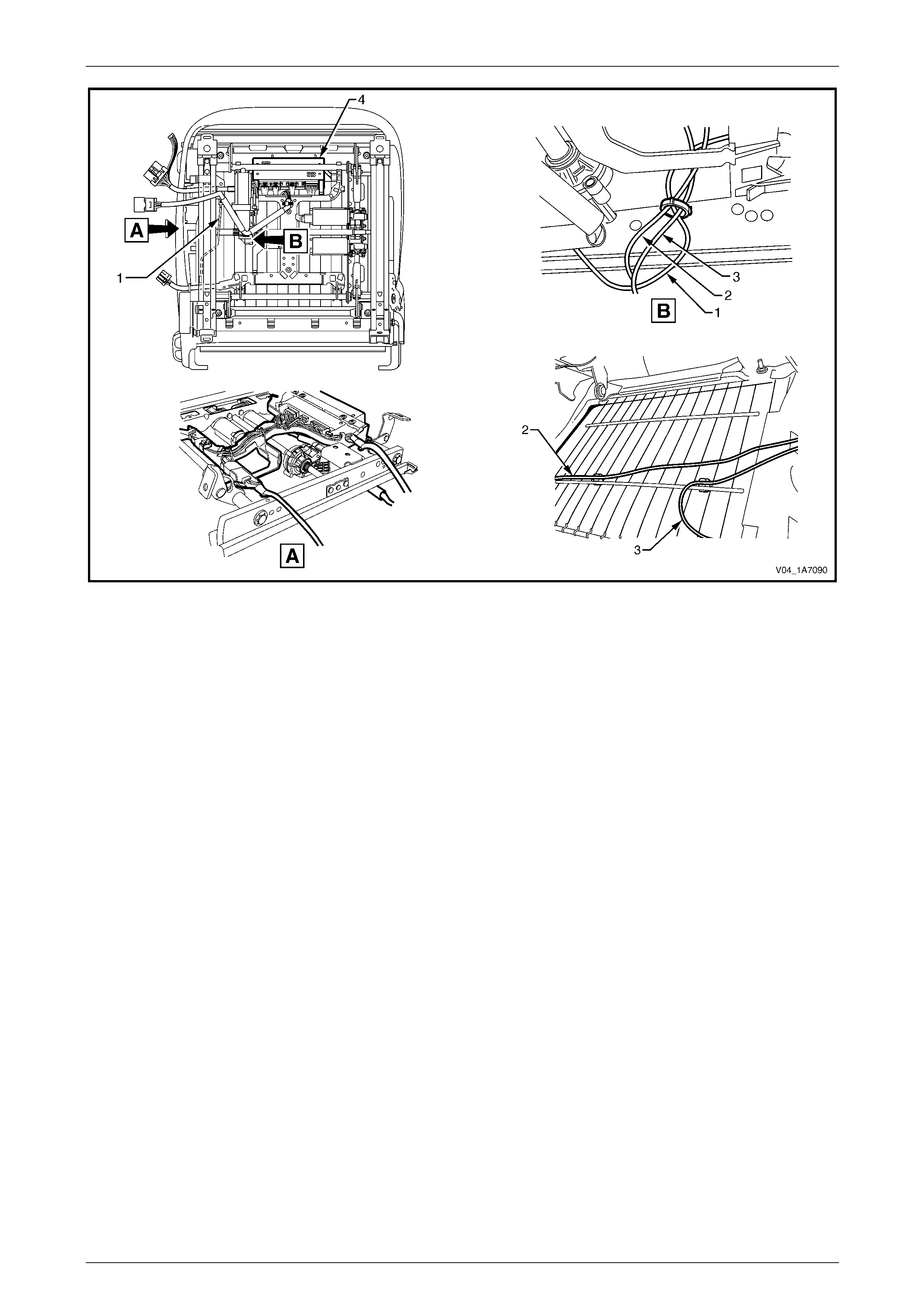
Seat Assemblies Page 1A7A–102
Page 1A7A–102
Figure 1A7A – 80
Legend
1 Ground Cable
2 Seatbelt Pretensioner Wiring Harness 3 Side Impact Inflatable Restraint Wiring Harness (where
fitted)
4 Seat Memory Module (where fitted)
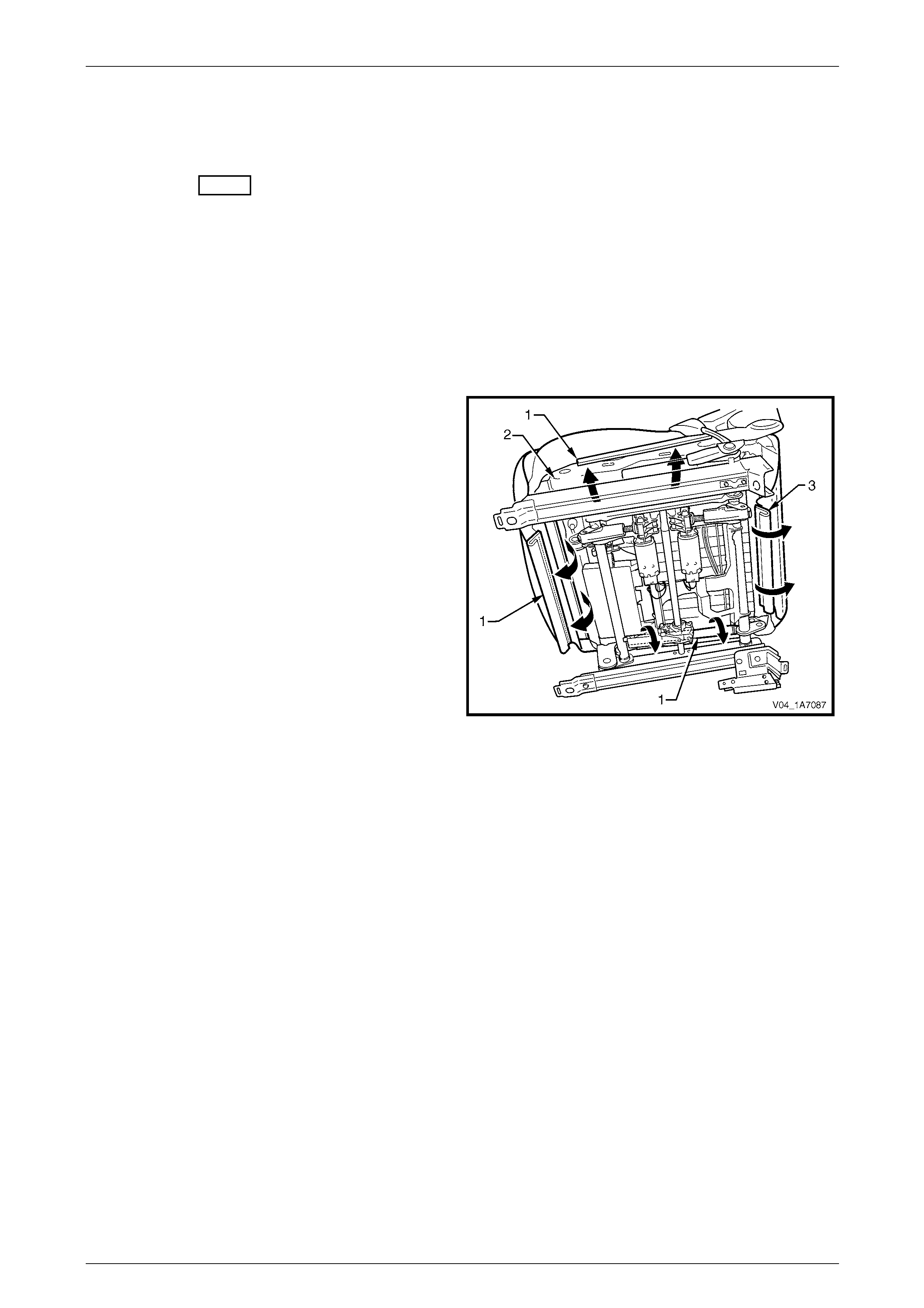
Seat Assemblies Page 1A7A–103
Page 1A7A–103
2.14 Front Seat Cushion Pad and Cover
Assembly
LT Section No. – 14-295
As required, remove the following compo nents:
1 Front seat assembly, refer to 2.3 Front Seat Assembly.
2 Front seat outer side cover assembly, refer to 2.4 Front Seat Outer Side Cover Assembly.
3 Front seat inner side cover, refer to 2.5 Front Seat Inner Side Cover.
4 Front seat-back frame assembly, refer to 2.11 Front Seat-back Frame Assembly.
Remove
1 From under the front seat cushion, disengage the front
and side J-strips (1) away from the seat frame (2).
2 Lift the cover and pad assembly a way from the seat
frame and then release the rear J-strip (3).
3 Remove the cover and pad assembly.
Figure 1A7A – 81
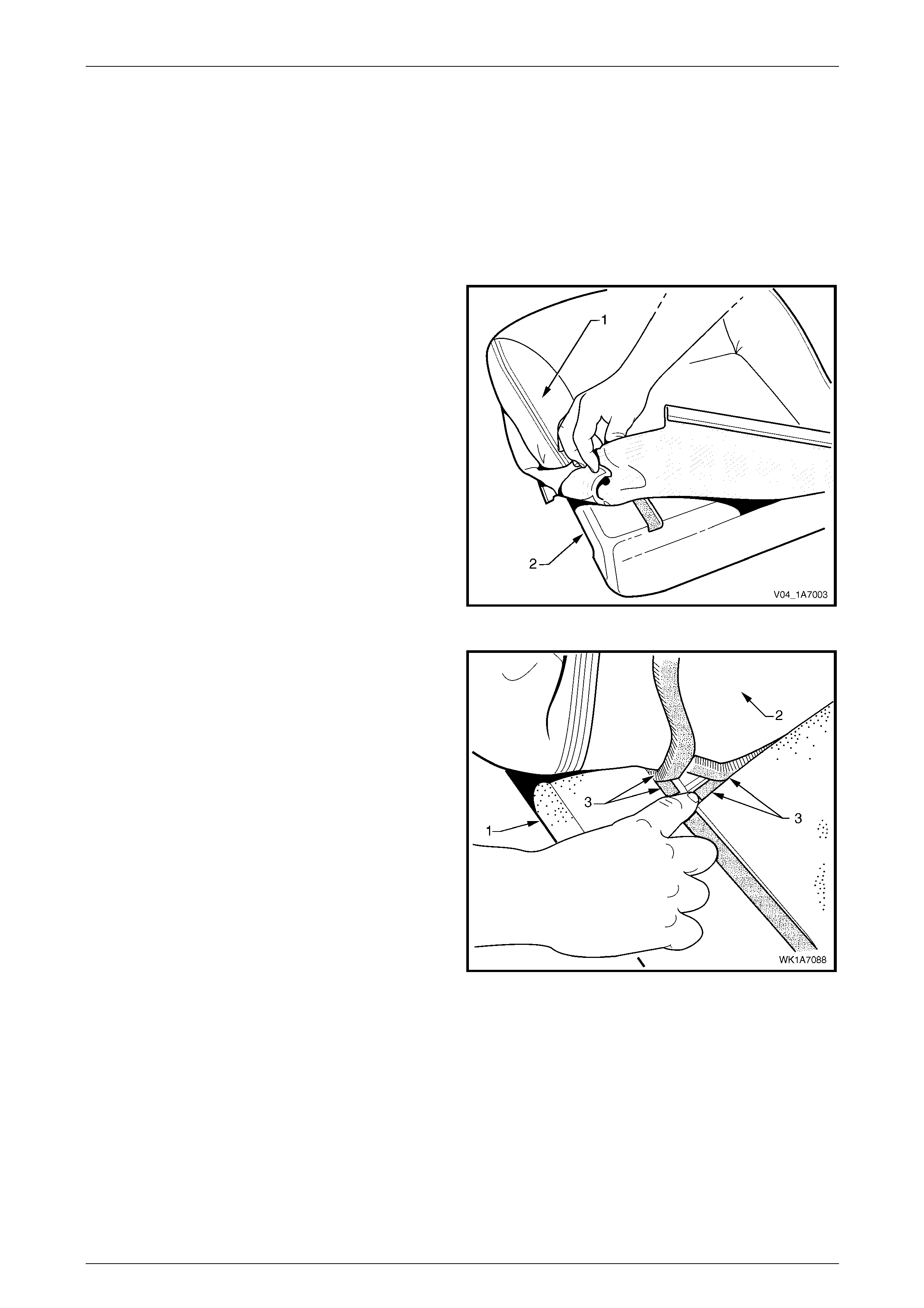
Seat Assemblies Page 1A7A–104
Page 1A7A–104
Disassemble
NOTE
The following illustrations show typical hook and
loop arrangement, which will vary according to
seat type.
Surebond type seat-back pad and cover
assemblies cannot be disassembled.
1 Fold the rear corners of the front seat cushion
cover (1) over the front seat cushion pad (2).
Figure 1A7A – 82
2 While holding the front seat cushi on pad (1), pull the
rear corners of the front seat cushion cover (2) forward
and away from the pad to diseng age the hook and
loop strips (3).
3 Pull the cover up and over the forward edge of the
pad.
Figure 1A7A – 83
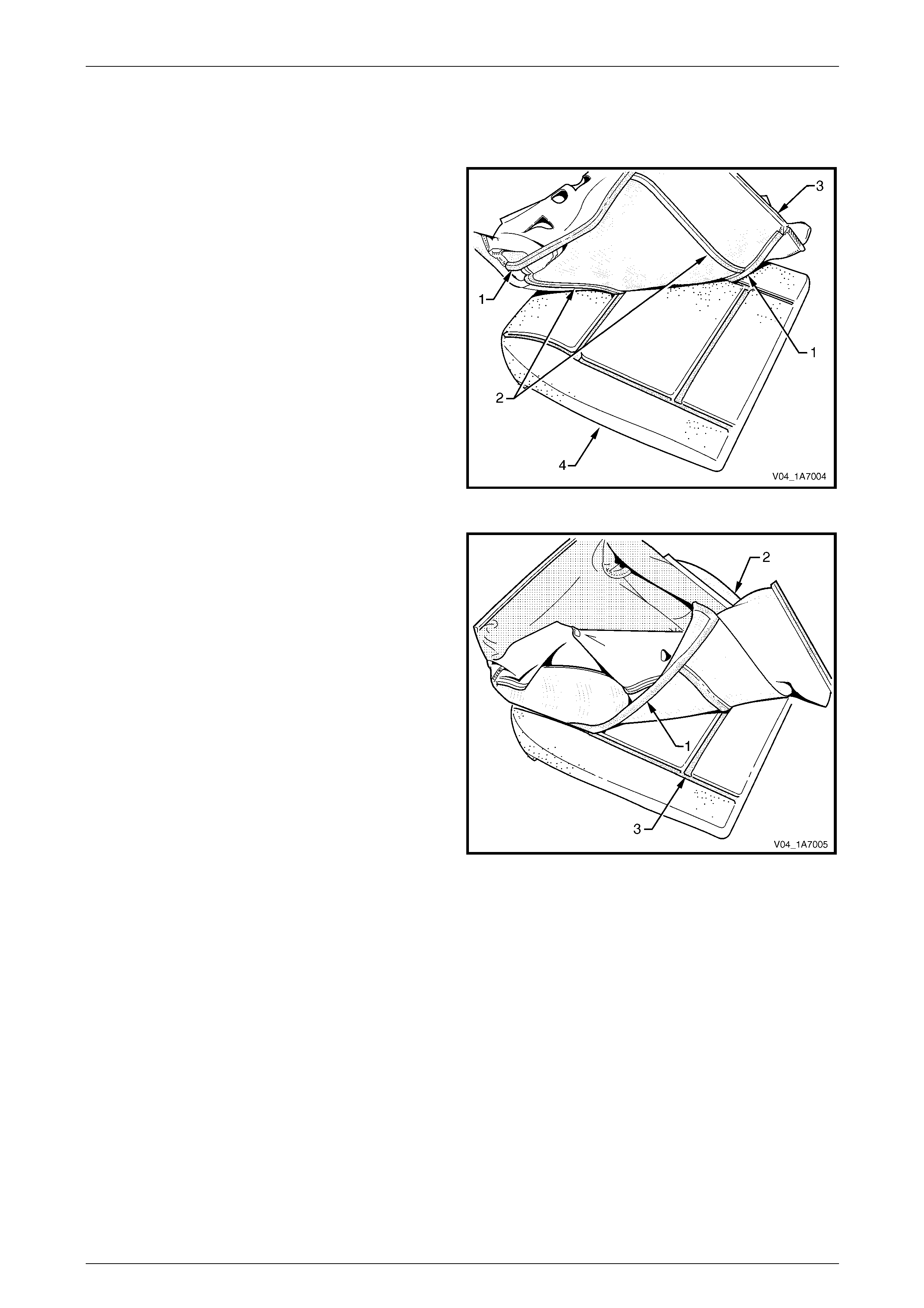
Seat Assemblies Page 1A7A–105
Page 1A7A–105
Reassemble
Reassembly of the front seat cushion pad is the reverse of the disassembly procedure n oting the following:
1 Align either of the outer hook and loop strips (1) and
the one or two cross hook and loop strips (2), on the
front seat cushion cover (3), with the front seat
cushion pad (4).
2 Press the folded edge of the cover firmly into the
corresponding groove in the pad to engage the hook
and loop strip.
Figure 1A7A – 84
3 Align and press the outer hook and loop strip (1), on
the cover (2), with the corresponding groove in the
pad (3).
Figure 1A7A – 85
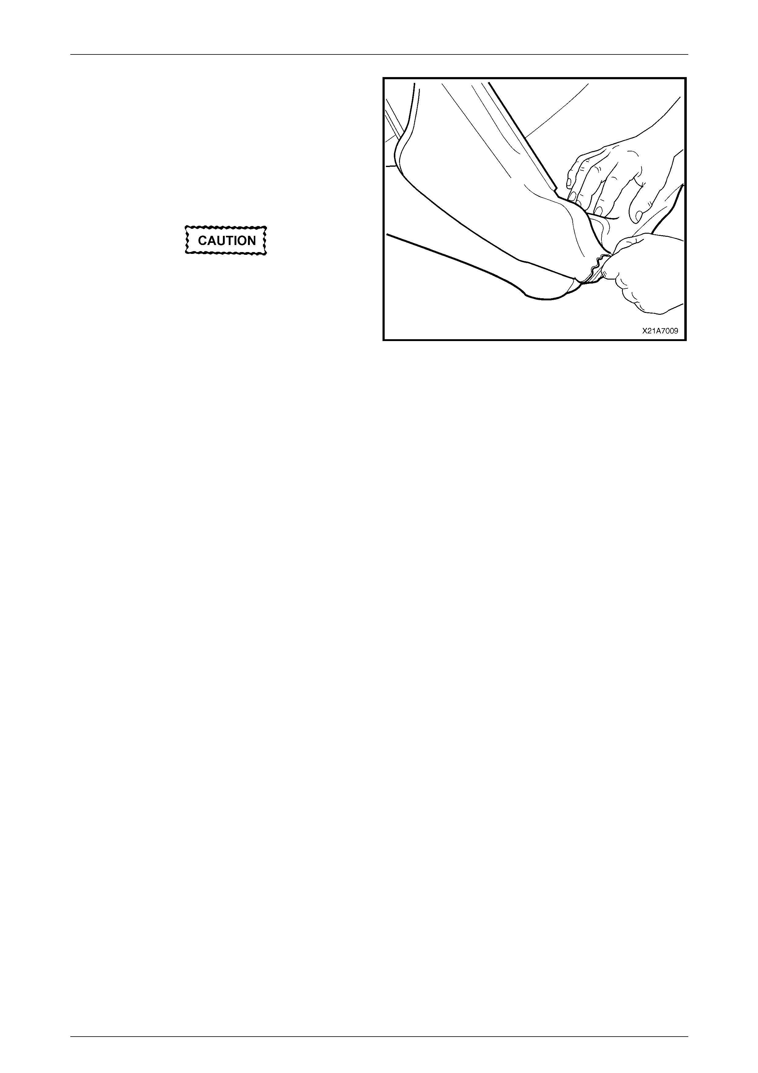
Seat Assemblies Page 1A7A–106
Page 1A7A–106
4 Roll the front corners of the cover over the pad.
5 Roll the sides of the cover over the pad.
6 Roll the rear corners of the cover over the pad.
NOTE
Make sure the pad is fitted neatly by hand into all
corners and contours of the seat cover.
Do not pull the cover onto the pad from
underneath using the J-strip to make it fit
neatly, as the fabric may be damaged.
Figure 1A7A – 86
Reinstall
Reinstallation of the front seat cushion pad and cover assembly is the reverse of the removal procedure.
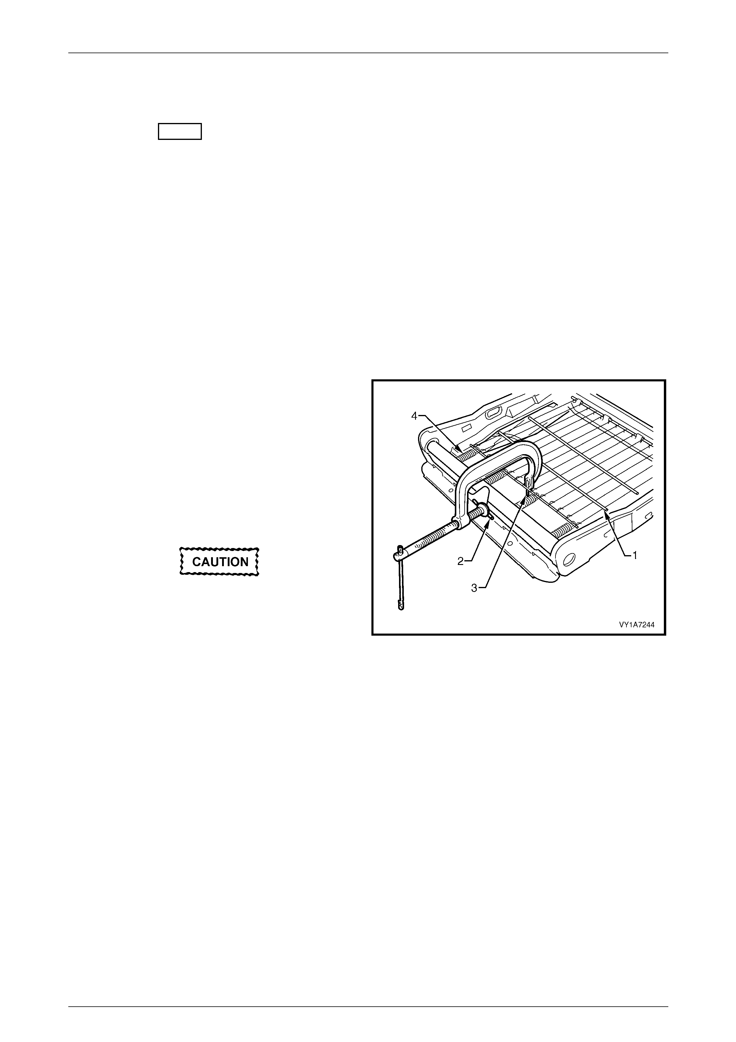
Seat Assemblies Page 1A7A–107
Page 1A7A–107
2.15 Front Seat Cushion Frame Assembly
LT Section No. – 14-275
Remove
As required remove the following c ompo nents:
1 Front seat assembly, refer to 2.3 Front Seat Assembly.
2 Front seat outer side cover assembly, refer to 2.4 Front Seat Outer Side Cover Assembly.
3 Front seat inner side cover, refer to 2.5 Front Seat Inner Side Cover.
4 Front seat-back frame assembly, refer to 2.11 Front Seat-back Frame Assembly.
5 Track and height adjust assembly, refer to 2.13 Track and Height Adjust Assembly.
6 Front seat cushion pad and cover assembly, refer to 2.14 Front Seat Cushion Pad and Cover Assembly.
Disassemble
1 To remove the suspension mat (1), modify a G-clamp
with a 5mm diameter metal dowel (2) welded to one
end and another appro ximate ly 40mm long and with a
2mm diameter pin (3) approxim ately 20mm long
welded to the other end.
2 Using the G-clamp, stretch the suspension mat far
enough to allow the four retaining springs (4 ) to be
removed from the seat cushion frame.
3 Back the G-clamp load off and remove the suspensio n
mat.
When using the G-clamp, use existing holes
in the suspension mat to ensure that mat
deformation does not occur.
Figure 1A7A – 87
Reassemble
Reassembly of the suspension mat is the reverse of the disassembl y proc edure.
Reinstall
Reinstallation of the front seat cushion frame assembly is the reverse of the removal pro cedure, noting the following:
1 Ensure all wiring is correctly connected and routed, refer to 12O Fuses, Relays and Wiring Harnesses.
2 Check the mechanical and ele c trical operation of the front seat.

Seat Assemblies Page 1A7A–108
Page 1A7A–108
2.16 Front Seat Lift Motor Assemblies
The front seat lift motor assemblies are non-serviceabl e items.
If a front seat lift motor assembly requires replacement, the track and height adjust assembly must be repl aced, refer to
2.13 Track and Height Adjust Assembly.

Seat Assemblies Page 1A7A–109
Page 1A7A–109
2.17 Front Seat Fore/Aft Movement Motor
Assembly
The front seat fore/aft movement motor assembl y is a non-serviceable item.
If the front seat fore/aft movement motor or drive shafts require replacement, the track and height adjus t assembly must
be replaced, refer to 2.13 Track and Height Adjust Assembly.

Seat Assemblies Page 1A7A–110
Page 1A7A–110
2.18 Front Seat-back Recline Motor Assembly
The front seat-back recline motor assembly is a non-serviceable item.
If the front seat-back recline motor assembly requires replacement, the fron t seat-back frame assembly must be
replaced, refer to 2.11 Front Seat-back Frame Assembly.

Seat Assemblies Page 1A7A–111
Page 1A7A–111
2.19 Drive Motor Hall-effect Sensors
The front seat drive motor hall-effect sensors are non-serviceable items.
If the front seat fore/aft movement and/or front seat lift motor hall-effect sensors require replacement, the track and
height adjust assembly must be replaced, refer to 2.13 Track and Heig ht Adjust Assembly.
If the seat-back recline motor hall-effect sensor requires replacement, the front seat-back frame assem bly must be
replaced, refer to 2.11 Front Seat-back Frame Assembly.

Seat Assemblies Page 1A7A–112
Page 1A7A–112
3 Diagnostics – Front Seat RHD,
Non-memory (Except Coupe)
3.1 Prerequisites
Safety Requirements
When operating the seat as part of any Steps
in the diagnostic tables, ensure that fingers
and limbs are clear of mo ving parts.
Equipment
The following equipment is required to diagnose the seats:
• an unpowered test lamp with a current dra w of less than 3 A, and
• a digital multimeter with a minimum impe dance of 10 MΩ.
Testing Procedures
The following points must be adhered to
when performing diagnostic testing on
components:
• Take care when using testing equipment
to diagnose wiring harness connectors. It
is preferred that the technician backprobe
the connector to avoid terminal damage.
• When tests are required on connector
terminals, use the adapters in the
connector adapter kit KM–609 to prevent
damage to the terminals.
• Unless the multimeter being used has an
auto-ranging function, ensure the correct
range is selected.
• When backpro bing connectors, ensure the
test lamp ground lead is connected to an
appropriate ground point on the vehicle.
Ensure this ground point is not part of the
circuit being tested.
NOTE
When following the steps in th e diagnostic tables,
perform them in the order cited. If the required
nominal value or result is not achi eved, rectif y t he
problem before proceeding any further.

Seat Assemblies Page 1A7A–113
Page 1A7A–113
3.2 Mechanical Diagnosis – Two-Way/Four-
Way Seat
Lumbar Support Inoperative
Introduction
This test is used to aid in diagnosing the lumbar support as sembly.
Test Description
The following numbers refer to the step numbers in the diagnostic table:
1 Checks if the lumbar support knob is properly engaging the lumbar support adjuster. Check the knob for cracks and
worn splines.
2 Checks if the lumbar support assembly is damage d or worn and if the retaining springs are serviceable and
securely attached to the seat back frame assembly.
3 Checks if the lumbar support assembly is serviceable and if the lumber support assembly strap is operating
correctly within the guide rails.
Diagnostic Table
Step Action Yes No
1 Remove the lumbar support knob, refer to 2.9 Lumbar Support Knob
Assembly.
Is the lumbar support adjust knob serviceable? Go to Step 2
Replace the knob,
refer to 2.9 Lumbar
Support Knob
Assembly
2 1 Remove the seat-back cover.
2 Inspect the lumbar support retainers and spri ngs.
Are the lumbar support retaining spri ngs serviceable and securel y
attached to the seat-back frame assembly? Go to Step 3
Replace or reattach
the retaining
springs, refer to
2.11 Front Seat-
back Frame
Assembly
3 1 Visually inspect the lumbar support assembly. Check for bro ken
or worn parts.
2 Check the strap running across the lumber s upport assembly is
serviceable and running freely within the guide rails.
NOTE
You may need to attach the lumber support knob to
actuate the strap.
Is the lumbar support assembly serviceabl e? System serviceable
Replace lumbar
support assembly
or resecure lumbar
support assembly
strap ensuring
strap is not binding
with guide rails,
refer to 2.11 Front
Seat-back Frame
Assembly
When all diagno sis and repairs are completed, check the system for correct operation.

Seat Assemblies Page 1A7A–114
Page 1A7A–114
Seat Recline Forward and/or Back Function is Inoperative
Introduction
This test is used to aid in diagnosing the manual recline function of the seat assembl y.
Test Description
The following numbers refer to the step numbers in the diagnostic table:
1 Checks if the recliner knob is properly engaging the recliner shaft. Check the knob for cracks and worn splines.
Diagnostic Table
Step Action Yes No
1 Remove the recliner knob, refer to 2.4 Front Seat Outer Side Cover
Assembly
Is the recliner knob serviceable?
Replace the front
seat-back frame
assembly, refer to
2.11 Front Seat-
back Frame
Assembly
Replace the
recliner knob, refer
to 2.4 Front Seat
Outer Side Cover
Assembly
When all diagno sis and repairs are completed, check the system for correct operation.

Seat Assemblies Page 1A7A–115
Page 1A7A–115
Seat Fore/Aft Movement Function is Inoperative or is Not Smooth
Introduction
This test is used to aid in diagnosi ng the fore/aft movement function of the seat being inoperative or the action of the seat
through the range of movement is not smooth.
Test Description
The following numbers refer to the step numbers in the diagnostic table:
1 Checks if there are any items obstructing the guide rails which may stop or hinder the seat movement.
2 Checks if the guide rails have adequate lubricant appli ed to provide a smooth operation for the seat.
3 Checks if the linkage assembly between the adjustment lever and lockin g tangs is worn or damaged. The lockin g
tangs must disengage from the guide rails be fore the seat will move.
4 Checks if the guide rails have been damaged. Any binding between the inner and outer guide rails will result in
poor operation of the fore and aft movement.
Diagnostic Table
Step Action Yes No
1 Are the guide rails free from obstructions? Go to Step 2 Remove the
obstructing item
2 Are the gui de rails adequately lubricated?
Go to Step 3
Apply a small
amount of grease
type NLGI No. 1
Lithium Grease
(with 9% Zinc
Oxide) to the rails
3 Do the lock ing tangs disengage the guide rails when the seat fore and
aft adjustment lever is raised to its full movement?
Go to Step 4
Replace the track
and height adjust
assembly, refer to
2.13 Track and
Height Adjust
Assembly
4 Do the guide rails bind at any point of travel during the fore and aft
movements of the seat? Replace the track
and height adjust
assembly, refer to
2.13 Track and
Height Adjust
Assembly System serviceable
When all diagno sis and repairs are completed, check the system for correct operation.
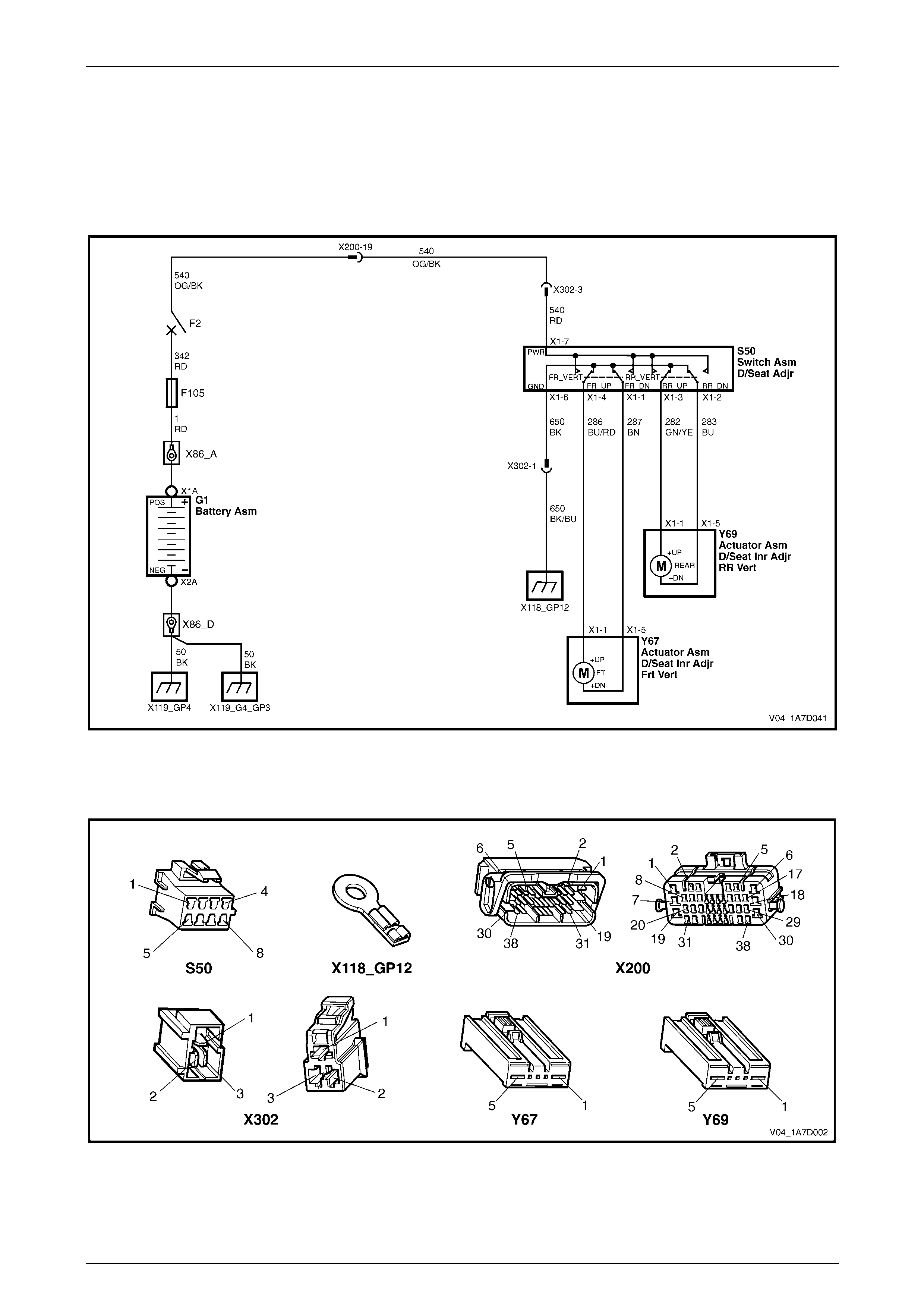
Seat Assemblies Page 1A7A–116
Page 1A7A–116
3.3 Electrical Diagnosis – Four-way Driver’s
Seat
The charts in this Section are used to aid in diagnosing faults on four-way driver’s seat assemblies. To aid in the use of
the diagnostic tables, refer to Wiring Diagram – Four-way Seat and Connector Chart – Four-way Seat in this Section.
Wiring Diagram – Four-way Seat
Figure 1A7A – 88
Connector Chart – Four-way Seat
Figure 1A7A – 89

Seat Assemblies Page 1A7A–117
Page 1A7A–117
None of the Driver’s Seat Adjustment Switch Functions Operate
Introduction
This test is used to aid in diagnosing the driver’s seat adjustment switch when none of the switch functions operate. The
test diagnoses the driver’s seat adjustment switch and associated power and ground circuits.
Test Description
The following numbers refer to the step numbers in the diagnostic table:
1 Checks if battery voltage is more than 11.5 V. The seat motors require mo re than 11.5 V to operate correctly.
2 Checks if circuit breaker F2 located on the passenger com partment fuse and relay panel assembl y is tripped.
Isolates if circuit breaker F2 is the fault affecting the circuit between the battery and conne ctor X200 pin 19.
3 Checks if fusible link F105 located on the engine compartment fuse and relay panel assembly is serviceable.
Isolates if the fusible link is the fault affecting the circuit between the battery and connector X200 pin 19.
4 Checks if all the connectors required for the seat to operate effectively are in place a nd positively connected.
5 Checks if there is battery power at connector S50 – X1 pi n 7. Isolates if there is a fault between the bat tery and
connector S50 – X1 pin 7.
6 Checks if there is battery power at connector X302 pi n 3. Isolates if there i s a fault in circuit 540 between
connectors S50 – X1 pin 7 and X302 p in 3.
7 Checks if there is battery voltage at connector X200 pin 19. Isolates if the fault is between the battery and
connector X200 pin 19.
8 Checks if there is battery voltage at circuit breaker F2. Isolates whether the fault is between the b attery and circuit
breaker F2 or bet ween circuit breaker F2 an d connector X200 pin 19.
9 Checks if there is battery voltage at fusible link F105. Isolates whether the fault is between the battery and fusible
link F105 or between fusible li nk F105 and circuit breaker F2.
10 Checks if the driver’s seat adjustment switch is serviceable.
11 Checks if the ground point associated with the system is serviceable.
12 Checks if there is continuity between connectors S50 – X1 pin 6 and X302 pin 1 which supplies the ground circuit
for the driver’s seat adjustment switch. Isolates whether there is a fault in circuit 650 bet ween the switch and
connector X302 pin 1 or between connector X302 pin 1 and the ground point.

Seat Assemblies Page 1A7A–118
Page 1A7A–118
Diagnostic Table Notes
1 For all wiring harness fault diagnoses, refer to 12P Wirin g Diagrams.
2 For wiring harness repairs, refer to 12P Wiring Diagrams.
3 Refer to 12O Fuses, Relays and Wiring Harnesses for harness routeing.
4 If the fault is deemed to be intermittent, refer to 12P Wiring Diagrams.
Diagnostic Table
Step Action Yes No
1 Check the battery voltage, refer to 12A Battery and Cables.
Is the battery voltage more than 11.5 V? Go to Step 2
Refer to 12A
Battery and Cables
for further
diagnosis
2 Inspect circuit breaker F2, refer to 12O Fuses, Relays and Wiring
Harness.
Is circuit breaker F2 tripped?
Allow the circuit
breaker to reset
(refer to Note 3).
If the circuit breaker
trips again, repair
or replace circuit
540 (refer to
Note 2) Go to Step 3
3 Inspect fusible link F105, refer to 12O Fuses, Relays and Wiring
Harness.
Is fuse F105 serviceable?
Go to Step 4
Replace the fusible
link.
If the fusible link
becomes
unserviceable
again, repair or
replace circuit 342
(refer to Note 2)
4 Are the following connectors secure (refer to Note 3)?
• S50
• X200
• X302
• Y67
• Y69 Go to Step 5
Ensure the
connectors are
secure
5 Backprobe connector S50 – X1 pin 7 with a test lamp (refer Note 1).
Does the test lamp illuminate? Go to Step 10 Go to Step 6
6 Backprobe connector X302 pin 3 with a test lamp (refer to Note 1).
Does the test lamp illuminate?
Repair or replace
circuit 540 between
connectors
X302 pin 3 and
S50 – X1 pin 7
(refer to Note 2) Go to Step 7
7 Backprobe connector X200 pin 19 with a test lamp (refer to Note 1).
Does the test lamp illuminate?
Repair or replace
circuit 540 between
connectors
X200 pin 19 an d
X302 pin 3 (refer to
Note 2) Go to Step 8

Seat Assemblies Page 1A7A–119
Page 1A7A–119
Step Action Yes No
8 1 Remove circuit breaker F2 from the passenger compartment
fuse and relay panel assembly.
2 Using a test lamp, probe connector X12 9 – X45 – 2 (refer to
Note 1).
Does the test lamp illuminate?
Repair or replace
circuit 540 between
circuit breaker F2
and connector
X200 pin 19 (refer
to Note 2) Go to Step 9
9 1 Remove fusible link F105.
2 Using a test lamp, probe connector X18-105 (refer to Note 1).
Does the test lamp illuminate?
Repair or replace
circuit 342 between
fusible link F105
and circuit breaker
F2 (refer to Note 2)
Repair or replace
circuit 1 between
the battery and
fusible link F105
(refer to Note 2)
10 1 Remove the driver’s seat adjustment switch from the seat, refer
to
2.4 Front Seat Outer Side Cover Assembly.
2 Test the driver’s seat adjustment switch, refer to 3.4 Four-way
Seat Adjustment Switch Test.
Is the driver’s seat adjustment switch serviceable? Go to Step 11
Replace the
driver’s seat
adjustment switch,
refer to 2.4 Front
Seat Outer Side
Cover Assembly
11 Ensure ground point X118 – GP12 (located in the middle of the
transmission tunnel) is secure and has good contact with the vehicle
structure.
Is the ground point secure to the vehicle with a good contact? Go to Step 12 Repair ground poi nt
12 1 Backprobe connector X302 pin 1 with a test lamp (refer Note 1).
2 Operate the driver’s seat adjustment switch in any of the
available directions.
Does the test lamp illuminate?
Repair or replace
circuit 650 between
connector X302 pin
1 and ground point
X118 – GP12 (refer
Note 2)
Repair or replace
circuit 650 between
connectors
S50 – X1 pin 6 and
X302 pin 1 (refer
Note 2)
When all diagno sis and repairs are completed, check the system for correct operation.

Seat Assemblies Page 1A7A–120
Page 1A7A–120
Front/Rear of the Driver's Seat Does Not Raise and/or Lower
Introduction
This test is used to aid in diagnosing the front and/or the rear of the driver's seat not raising and/or lowering. The test
diagnoses the driver’s seat ad justment switch and the motor circuits.
Test Description
The following numbers refer to the step numbers in the diagnostic table:
1 Checks if the driver's seat adjustment switch operates the seat in any direct ion. Isolates whether ther e is a battery
or ground fault affecting the seat operation.
2 Checks if all the connectors required for the seat to operate effectively are in place a nd positively connected.
3 Checks if the driver's seat adjustment switch is serviceable.
4 Confirms whether the rear of the seat raises or lowers. Isolates if the seat rear lift motor and circuit of the seat is the
fault.
5 Confirms whether the front of the seat raises or lo wers. Isolates if the seat front lift motor and circuit of the seat is
the fault.
6 Checks if there is battery power to the seat rear lift motor at connector Y69 – X1 pin 1. Isolates if there is a fault in
circuit 282 that supplies battery po wer to the motor to raise the rear of the seat.
7 Checks if there is battery power to the seat rear lift motor at connector Y69 – X1 pin 5. Isolates whether the fault is
in circuit 283 that supplies battery power to the motor to lower the rear of the seat or the motor is faulty. As
reversing the polarity changes the direction of the motor, this Step also confirms the ground circuit from Step 6 is
serviceable.
8 Checks if there is battery power to the seat front lift motor at connector Y67 – X1 pin 1. Isolates if there is a fault in
circuit 286 that supplies battery po wer to the motor to raise the front of the seat.
9 Checks if there is battery power to the seat front lift motor at connector Y67 – X1 pin 5. Isolates whether the fault is
in circuit 287 that supplies battery power to the motor to lower the front of the seat or the motor is faulty. As
reversing the polarity changes the direction of the motor, this Step also confirms the ground circuit from Step 8 is
serviceable.
Diagnostic Table Notes
1 For all wiring harness fault diagnoses, refer to 12P Wirin g Diagrams.
2 For wiring harness repairs, refer to 12P Wiring Diagrams.
3 Refer to 12O Fuses, Relays and Wiring Harnesses for harness routeing.
4 If the fault is deemed to be intermittent, refer to 12P Wiring Diagrams.

Seat Assemblies Page 1A7A–121
Page 1A7A–121
Diagnostic Table
Step Action Yes No
1 Does the driver's seat adjustment s witch operate the seat correctly in
any of the four directions?
Go to Step 2
Refer to None of
the Driver’s Seat
Adjustment Switch
Functions Operate
in this Section
2 Are the following connectors secure?
• S50
• Y69
• Y67 Go to Step 3
Ensure the
connectors are
secure
3 1 Remove the driver's seat adjustment switch from the seat, refer
to 2.4 Front Seat Outer Side Cover Assembly.
2 Test the driver's seat adjustment switch, refer to 3.4 Four-way
Seat Adjustment Switch Test.
Is the driver's seat adjustment switch serviceable? Go to Step 4
Replace the driver's
seat adjustment
switch, refer to 2.4
Front Seat Outer
Side Cover
Assembly
4 Operate the driver's seat adjustment switch to raise or lower the rear
of the seat.
Does the rear of the seat raise and lower? Go to Step 5 Go to Step 6
5 Operate the driver's seat adjustment switch to raise or lower the front
of the seat.
Does the front of the seat raise and lower? System serviceable Go to Step 8
6 1 Backprobe connector Y69 – X1 pin 1 with a test lamp (refer to
Note 1).
2 Operate the driver's seat adjustment switch to raise the rear of
the seat.
Does the test lamp illuminate? Go to Step 7
Repair or replace
circuit 282 (refer to
Note 2)
7 1 Backprobe connector Y69 – X1 pin 5 with a test lamp (refer to
Note 1).
2 Operate the driver's seat adjustment switch to lower the rear of
the seat.
Does the test lamp illuminate?
Replace the seat
rear lift motor, refer
to 2.16 Front Seat
Lift Motor
Assemblies
Repair or replace
circuit 283 (refer to
Note 2)
8 1 Backprobe connector Y67 – X1 pin 1 with a test lamp (refer to
Note 1).
2 Operate the driver's seat adjustment switch to raise the front of
the seat.
Does the test lamp illuminate? Go to Step 9
Repair or replace
circuit 286 (refer to
Note 2)
9 1 Backprobe connector Y67 – X1 pin 5 with a test lamp (refer to
Note 1).
2 Operate the driver's seat adjustment switch to lower the front of
the seat.
Does the test lamp illuminate?
Replace the seat
front lift motor, refer
to 2.16 Front Seat
Lift Motor
Assemblies
Repair or replace
circuit 287 (refer to
Note 2)
When all diagno sis and repairs are completed, check the system for correct operation.
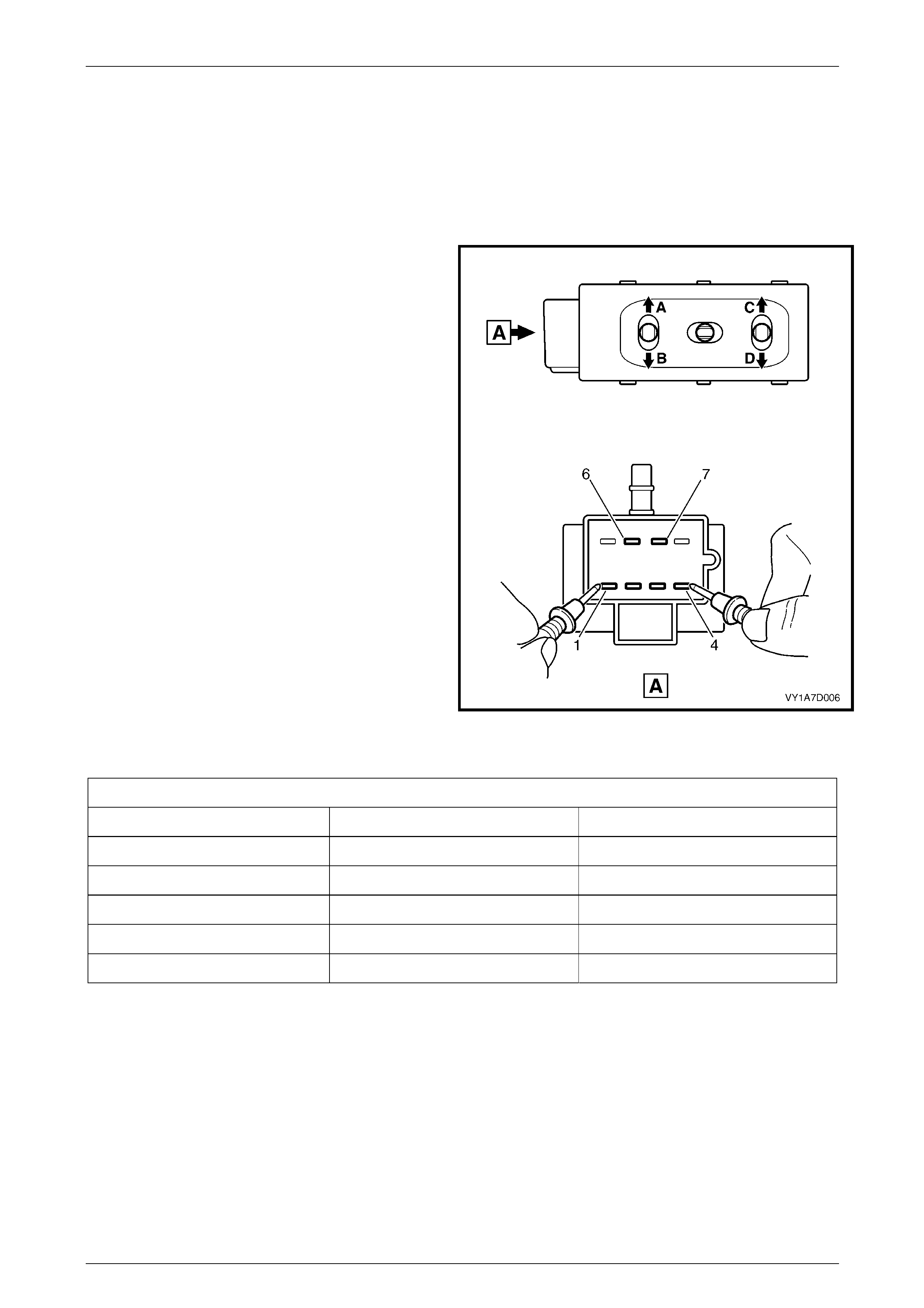
Seat Assemblies Page 1A7A–122
Page 1A7A–122
3.4 Four-way Seat Adjustment Switch Test
The switch is located on the outer side of the seat, attached to the inner side of the front seat outer side cover.
Test
1 Remove the four-way seat adjustment switch, refer to 2.4 Front Seat Outer Side Cover Assembly.
2 Place the switch in the positions as detailed i n the
chart in this Section. Place the probes of the
multimeter onto the terminals listed and take the
reading. Compare the reading to the chart.
3 If the switch fails any part of the test, replace the
switch assembly with a serviceable item.
4 Install the four-way seat adjustment s witch, refer to
2.4 Front Seat Outer Side Cover Assembly.
Figure 1A7A – 90
Four-way Seat Adjustment Switch
Switch Position Switch Terminals Indication If Switch Is Serviceable
Position A 3 and 7 Continuity
Position B 2 and 7 Continuity
Position C 4 and 7 Continuity
Position D 1 and 7 Continuity
Switch in the neutral position 6 and either 1, 2, 3 or 4 Continuity
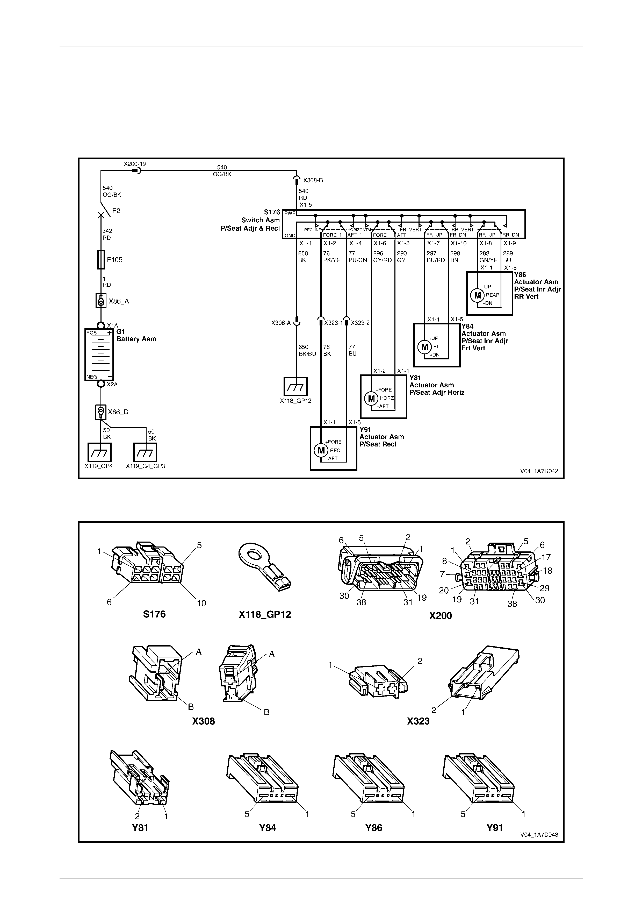
Seat Assemblies Page 1A7A–123
Page 1A7A–123
3.5 Electrical Diagnosis – Eight-way
Passenger Seat
The charts in this Section are used to aid in diagnosing faul ts on eight-way non-memory seat assemb lies. To aid in the
use of the diagnostic tables, refer to Wiring Diagram – Eight-way Passenger Seat and C onnector Chart – Eight-way
Passenger Seat in this Section.
Wiring Diagram – Eight-way Passenger Seat
Figure 1A7A – 91
Connector Chart – Eight-way Passenger Seat
Figure 1A7A – 92

Seat Assemblies Page 1A7A–124
Page 1A7A–124
Neither Seat Adjustment Switch Functions Operate
Introduction
This test is used to aid in diagnosing the seat power and ground circuits, if neither seat operates when either seat
adjustment switch is operated.
Test Description
The following numbers refer to the step numbers in the diagnostic table:
1 Checks if battery voltage is more than 11.5 V. The seat motors require mo re than 11.5 V to operate correctly.
2 Checks if circuit breaker F2 located on the passenger com partment fuse and relay panel assembl y is tripped.
Isolates if circuit breaker F2 is the fault affecting the circuit between the battery and conne ctor X200 pin 19.
3 Checks if fusible link F105 located on the engine compartment fuse and relay panel assembly is serviceable.
Isolates if the fusible link is the fault affecting the circuit between the battery and connector X200 pin 19.
4 Check if connector X200 is secure.
5 Checks if there is battery voltage at connector X200 pin 19. Isolates if the fault is between the battery and
connector X200 pin 19. If the fault in the circuit is between connectors X200 pin 19 and either X3 08 pin B or
X302 pin 3, only one seat will operate.
6 Checks if there is battery voltage at circuit breaker F2. Isolates whether the fault is between the b attery and circuit
breaker F2 or bet ween circuit breaker F2 an d connector X200 pin 19.
7 Checks if there is battery voltage at fusible link F105. Isolates whether the fault is between the battery and fusible
link F105 or between fusible li nk F 105 and circuit breaker F2.
8 Checks if the ground point associated with the system is serviceable.
Diagnostic Table Notes
1 For all wiring harness fault diagnoses, refer to 12P Wirin g Diagrams.
2 For wiring harness repairs, refer to 12P Wiring Diagrams.
3 Refer to 12O Fuses, Relays and Wiring Harnesses for harness routeing.
4 If the fault is deemed to be intermittent, refer to 12P Wiring Diagrams.

Seat Assemblies Page 1A7A–125
Page 1A7A–125
Diagnostic Table
Step Action Yes No
1 Check the battery voltage, refer to 12A Battery and Cables.
Is the battery voltage more than 11.5 V? Go to Step 2
Refer to 12A
Battery and Cables
for further
diagnosis
2 Inspect circuit breaker F2, refer to 12O Fuses, Relays and Wiring
Harnesses.
Is circuit breaker F2 tripped?
Allow the circuit
breaker to reset
(refer to Note 3).
If the circuit breaker
trips again, repair
or replace circuit
540 (refer to
Note 2) Go to Step 3
3 Inspect fusible link F105, refer to 12O Fuses, Relays and Wiring
Harnesses.
Is fuse F105 serviceable?
Go to Step 4
Replace the fusible
link.
If the fusible link
becomes
unserviceable
again, repair or
replace circuit 342
(refer to Note 2)
4 Is connector X200 secure? Go to Step 5 Ensure the
connector is secure
5 Backprobe connector X200 pin 19 with a test lamp (refer to Note 1).
Does the test lamp illuminate? Go to Step 8 Go to Step 6
6 1 Remove circuit breaker F2 from the passenger compartment
fuse and relay panel assembly.
2 Using a test lamp, probe connector X12 9 – X45 pin 2 (refer to
Note 1).
Does the test lamp illuminate?
Repair or replace
circuit 540 between
circuit breaker F2
and connector
X200 pin 19 (refer
to Note 2) Go to Step 7
7 1 Remove fusible link F105.
2 Using a test lamp, probe connector X18-105 (refer to Note 1).
Does the test lamp illuminate?
Repair or replace
circuit 342 between
fusible link F105
and circuit breaker
F2 (refer to Note 2)
Repair or replace
circuit 1 between
the battery and
fusible link F105
(refer to Note 2)
8 Ensure ground point X118 – GP12 (located in the middle of the
transmission tunnel) is secure and has good contact with the vehicle
structure.
Is the ground point secure to the vehicle with a good contact?
Repair or replace
circuit 650 (refer to
Note 2) Repair ground point
When all diagno sis and repairs are completed, check the system for correct operation.

Seat Assemblies Page 1A7A–126
Page 1A7A–126
None of the Passenger’s Seat Adjustment Switch Functions Operate
Introduction
This test is used to aid in diagnosing the passenger’s seat adjustment switch when none of the switch functions operate.
The test diagnoses the passenger’s seat adjustment switch and associated power and ground circuits.
Test Description
The following numbers refer to the step numbers in the diagnostic table:
1 Checks if all of the driver’s seat functions work. If none of them work, the fault is not isolated to the passenger’s
seat only.
2 Checks if there is battery power at connector X308 pin B. Isolates if there is a fault in circuit 540 between
connectors X200 pin 19 and X308 pin B.
3 Checks if all the connectors required for the seat to operate effectively are in place a nd positively connected.
4 Checks if there is battery power at connector S176 – X1 pin 5. Isolates if there is a fault in circuit 540 between
connectors S176 – X1 pin 5 and X308 pin B.
5 Checks if the passenger’s seat adjustment switch is serviceable.
6 Checks if there is continuity between connec tors S176 – X1 pin 1 and X308 pin A which supp lies the ground circuit
for the passenger’s seat adjustment s witch. Isolates whether there is a fault in circuit 650 between the switch and
connector X308 pin A or between connector X308 pin A and the ground point.
Diagnostic Table Notes
1 For all wiring harness fault diagnoses, refer to 12P Wirin g Diagrams.
2 For wiring harness repairs, refer to 12P Wiring Diagrams.
3 Refer to 12O Fuses, Relays and Wiring Harnesses for harness routeing.
4 If the fault is deemed to be intermittent, refer to 12P Wiring Diagrams.

Seat Assemblies Page 1A7A–127
Page 1A7A–127
Diagnostic Table
Step Action Yes No
1 Are all of the passenger’s seat adjustment switch functions
inoperative? Refer to Neither
Seat Adjustment
Switch Functions
Operate in this
Section Go to Step 2
2 Backprobe connector X308 pin B with a test lamp (refer to Note 1).
Does the test lamp illuminate?
Go to Step 3
Repair or replace
circuit 540 between
connectors
X200 pin 19 an d
X308 pin B (refer to
Note 2)
3 Are the following connectors secure (refer to Note 3)?
• S176
• X308
• Y81
• Y84
• Y86
• Y91 Go to Step 4
Ensure the
connectors are
secure
4 Backprobe connector S176 – X1 pin 5 with a test lamp (refer to Note
1).
Does the test lamp illuminate?
Go to Step 5
Repair or replace
circuit 540 between
connectors
S176 – X1 pin 5
and X308 pin B
(refer to Note 2)
5 1 Remove the passenger’s seat adjustment switch from the seat,
refer to 2.4 Front Seat Outer Side Cover Assembly.
2 Test the passenger’s seat adjustment switch, refer to 3.6 Eight-
way Seat Adjustment Switch Test.
Is the passenger’s seat adjustment s witch serviceable? Go to Step 6
Replace the
passenger’s seat
adjustment switch,
refer to 2.4 Front
Seat Outer Side
Cover Assembly
6 1 Backprobe connector X308 pin A with a test lamp (refer to Note
1).
2 Operate the passenger’s seat adjustment switch in any of the
available directions.
Does the test lamp illuminate?
Repair or replace
circuit 650 between
connector X308 pin
A and ground point
X118 – GP12 (refer
to Note 2)
Repair or replace
circuit 650 between
connectors
S176 – X1 pin 1
and X308 pin A
(refer to Note 2)
When all diagno sis and repairs are completed, check the system for correct operation.

Seat Assemblies Page 1A7A–128
Page 1A7A–128
Front/Rear of the Passenger’s Seat Does Not Raise and/or Lower
Introduction
This test is used to aid in diagnosing the front and/or the rear of the passenger’s seat not raising and/or lowering. The
test diagnoses the seat adjustment switch and the motor circuits.
Test Description
The following numbers refer to the step numbers in the diagnostic table:
1 Checks if the passenger’s seat adjustment switch operates the seat in any direction. Isolates whether the power
and/or ground circuits are at fault.
2 Checks if all the connectors required for the seat to operate effectively are in place a nd positively connected.
3 Checks if the passenger’s seat adjustment switch is serviceable.
4 Confirms whether the rear of the seat raises or lowers. Isolates if the rear lift motor and circuit of the seat is the
fault.
5 Confirms whether the front of the seat raises or lo wers. Isolates whether the front lift motor and circuit of the seat is
the fault.
6 Checks if there is battery power to the seat rear lift motor at connector Y86 – X1 pin 1. Isolates if there is a fault in
circuit 288 that supplies battery po wer to the motor to raise the rear of the seat.
7 Checks if there is battery power to the seat rear lift motor at connector Y86 – X1 pin 5. Isolates whether the fault is
in circuit 289 that supplies battery power to the motor to lower the rear of the seat or the motor is faulty. As the
direction of the motor is changed by reversing the polarity, this Step also confirms if the ground circuit from Step 6
is serviceable.
8 Checks if there is battery power to the seat front lift motor at connector Y84 – X1 pin 1. Isolates if there is a fault in
circuit 297 that supplies battery po wer to the motor to raise the front of the seat.
9 Checks if there is battery power to the seat front lift motor at connector Y84 – X1 pin 5. Isolates whether the fault is
in circuit 298 that supplies battery power to the motor to lower the front of the seat or the motor is faulty. As the
direction of the motor is changed by reversing the polarity, this Step also confirms if the ground circuit from Step 8
is serviceable.
Diagnostic Table Notes
1 For all wiring harness fault diagnoses, refer to 12P Wirin g Diagrams.
2 For wiring harness repairs, refer to 12P Wiring Diagrams.
3 Refer to 12O Fuses, Relays and Wiring Harnesses for harness routeing.
4 If the fault is deemed to be intermittent, refer to 12P Wiring Diagrams.

Seat Assemblies Page 1A7A–129
Page 1A7A–129
Diagnostic Table
Step Action Yes No
1 Does the passenger’s seat adjustment switch operate correctly in any
of the eight directions?
Go to Step 2
Refer to None of
the Passenger’s
Seat Adjustment
Switch Functions
Operate in this
Section
2 Are the following connectors secure (refer to Note 3)?
• S176
• Y84
• Y86 Go to Step 3
Ensure the
connectors are
secure
3 1 Remove the passenger’s seat adjustment switch from the seat,
refer to 2.4 Front Seat Outer Side Cover Assembly.
2 Test the passenger’s seat adjustment switch, refer to 3.6 Eight-
way Seat Adjustment Switch Test.
Is the passenger’s seat adjustment s witch serviceable? Go to Step 4
Replace the
passenger’s seat
adjustment switch,
refer to 2.4 Front
Seat Outer Side
Cover Assembly
4 Operate the passenger’s seat adjustment switch to raise or lower the
rear of the seat.
Does the rear of the seat raise and lo wer? Go to Step 5 Go to Step 6
5 Operate the passenger’s seat adjustment switch to raise or lower the
front of the seat.
Does the front of the seat raise and lower? System serviceable Go to Step 8
6 1 Backprobe connector Y86 – X1 pin 1 with a test lamp (refer to
Note 1).
2 Operate the passenger’s seat adjustment switch to raise the
rear of the seat.
Does the test lamp illuminate? Go to Step 7
Repair or replace
circuit 288 (refer to
Note 2)
7 1 Backprobe connector Y86 – X1 pin 5 with a test lamp (refer to
Note 1).
2 Operate the passenger’s seat adjustment switch to lower the
rear of the seat.
Does the test lamp illuminate?
Replace the seat
rear lift motor, refer
to 2.16 Front Seat
Lift Motor
Assemblies
Repair or replace
circuit 289 (refer to
Note 2)
8 1 Backprobe connector Y84 – X1 pin 1 with a test lamp (refer to
Note 1).
2 Operate the passenger’s seat adjustment switch to raise the
front of the seat.
Does the test lamp illuminate? Go to Step 9
Repair or replace
circuit 297 (refer to
Note 2)
9 1 Backprobe connector Y84 – X1 pin 5 with a test lamp (refer to
Note 1).
2 Operate the passenger’s seat adjustment switch to lower the
front of the seat.
Does the test lamp illuminate?
Replace the seat
front lift motor, refer
to 2.16 Front Seat
Lift Motor
Assemblies
Repair or replace
circuit 298 (refer to
Note 2)
When all diagno sis and repairs are completed, check the system for correct operation.

Seat Assemblies Page 1A7A–130
Page 1A7A–130
Passenger’s Seat Fore/Aft Function is Inoperative or Not Smooth
Introduction
This test is used to aid in diagnosing the fore/aft movement function of the passenger’s seat being in operative or the
action of the seat through the range of movement is not smooth. The test diagnoses the seat adjustment switch and the
motor circuits.
Test Description
The following numbers refer to the step numbers in the diagnostic table:
1 Checks if the passenger’s seat adjustment switch operates the seat in any direction. Isolates if there is battery
power to the switch assembly.
2 Checks if there are any items obstructing the guide rails, which may stop or hinder the seat movement.
3 Checks if the guide rails and drive shafts have adequate lubricant applied t o provide a smooth operation of the
seat.
4 Checks if the guide rails or drive shafts have been damaged. An y binding between the moving parts will result in
poor operation of the fore and aft movement.
5 Checks if all the connectors required for the seat to operate effectively are in place a nd positively connected.
6 Checks if the passenger’s seat adjustment switch is serviceable.
7 Checks if there is battery power to the seat fore/aft movement motor at connector Y81 – X1 pin 2. Isolates if there
is a fault in circuit 296 that supplies battery power to the motor to move the seat forward.
8 Checks if there is battery power to the seat fore/aft movement motor at connector Y81 – X1 pin 1. Isolates whether
the fault is in circuit 290 that supplies battery power to the motor to move the seat aft or the motor is faulty. As
reversing the polarity changes the direction of the motor, this Step also confirms if the ground circuit from Step 7 is
serviceable.
Diagnostic Table Notes
1 For all wiring harness fault diagnoses, refer to 12P Wirin g Diagrams.
2 For wiring harness repairs, refer to 12P Wiring Diagrams.
3 Refer to 12O Fuses, Relays and Wiring Harnesses for harness routeing.
4 If the fault is deemed to be intermittent, refer to 12P Wiring Diagrams.

Seat Assemblies Page 1A7A–131
Page 1A7A–131
Diagnostic Table
Step Action Yes No
1 Does the passenger’s seat adjustment switch operate the seat
correctly in any of the eight directions?
Go to Step 2
Refer to None of
the Passenger’s
Seat Adjustment
Switch Functions
Operate in this
Section
2 Are the guide rails free from obstructions? Go to Step 3 Remove the
obstructing item
3 Are the guide rails and drive shafts adequate ly lubricated?
Go to Step 4
Apply a small
amount of grease
type NLGI No. 1
Lithium Grease
(with 9% Zinc
Oxide)
4 Do the guide rails or drive shafts bind at any point of travel during the
fore and aft movement of the seat? Replace the track
and height adjust
assembly, refer to
2.13 Track and
Height Adjust
Assembly Go to Step 5
5 Are the following connectors secure (refer to Note 3)?
• S176
• Y81 Go to Step 6
Ensure the
connectors are
secure
6 1 Remove the passenger’s seat adjustment switch from the seat,
refer to 2.4 Front Seat Outer Side Cover Assembly.
2 Test the passenger’s seat adjustment switch, refer to 3.6 Eight-
way Seat Adjustment Switch Test.
Is the passenger’s seat adjustment s witch serviceable? Go to Step 7
Replace the
passenger’s seat
adjustment switch,
refer to 2.4 Front
Seat Outer Side
Cover Assembly
7 1 Backprobe connector Y81 – X1 pin 2 with a test lamp (refer to
Note 1).
2 Operate the passenger’s seat adjustment switch to move the
seat forward.
Does the test lamp illuminate? Go to Step 8
Repair or replace
circuit 296 (refer to
Note 2)
8 1 Backprobe connector Y81 – X1 pin 1 with a test lamp (refer to
Note 1).
2 Operate the passenger’s seat adjustment switch to move the
seat aft.
Does the test lamp illuminate?
Replace the seat
fore/aft movement
motor, refer to 2.17
Front Seat Fore/Aft
Movement Motor
Assembly
Repair or replace
circuit 290 (refer to
Note 2)
When all diagno sis and repairs are completed, check the system for correct operation.

Seat Assemblies Page 1A7A–132
Page 1A7A–132
Passenger’s Seat Recline Forward and/or Aft Function is Inoperative
Introduction
This test is used to aid in diagnosing the recline function of the passen ger’s seat being inoperative. T he test diagnoses
the seat adjustment switch and the motor circuits.
Test Description
The following numbers refer to the step numbers in the diagnostic table:
1 Checks if the passenger’s seat adjustment switch operates the seat in any direction. Isolates if there is battery
power to the switch assembly.
2 Checks if all the connectors required for the seat to operate effectively are in place a nd positively connected.
3 Checks if the passenger’s seat adjustment switch is serviceable.
4 Checks if there is battery power to the front seat-back recline motor at connector Y91 – X1 pin 1. Isolates if there is
a fault in circuit 76 that supplies battery power to the reclining motor to move the seat-back forward.
5 Isolates whether there is a fault in circuit 76 between connectors S176 – X1 pin 2 and X323 pin 1 or between
connectors X323 pin 1 and Y91 – X1 pin 1.
6 Checks if there is battery power to the front seat-back recline motor at connector Y91 – X1 pin 5. Isolates whether
the fault is in circuit 77 that supplies battery po wer to the reclining motor to move the seat-back aft or the reclin ing
motor is faulty. As reversing the polarity changes the direction of the motor, this Step also confirms if the groun d
circuit from Step 4 is serviceable.
7 Isolates whether there is a fault in circuit 77 between connectors S176 – X1 pin 4 and X323 pin 2 or between
connectors X323 pin 2 and Y91 – X1 pin 5.
Diagnostic Table Notes
1 For all wiring harness fault diagnoses, refer to 12P Wirin g Diagrams.
2 For wiring harness repairs, refer to 12P Wiring Diagrams.
3 Refer to 12O Fuses, Relays and Wiring Harnesses for harness routeing.
4 If the fault is deemed to be intermittent, refer to 12P Wiring Diagrams.

Seat Assemblies Page 1A7A–133
Page 1A7A–133
Diagnostic Table
Step Action Yes No
1 Does the passenger’s seat adjustment switch operate the seat
correctly in any of the eight directions?
Go to Step 2
Refer to None of
the Passenger’s
Seat Adjustment
Switch Functions
Operate in this
Section
2 Are the following connectors secure (refer to Note 3)?
• S176
• X323
• Y91 Go to Step 3
Ensure the
connectors are
secure
3 1 Remove the passenger’s seat adjustment switch from the seat,
refer to 2.4 Front Seat Outer Side Cover Assembly.
2 Test the passenger’s seat adjustment switch, refer to 3.6 Eight-
way Seat Adjustment Switch Test.
Is the passenger’s seat adjustment s witch serviceable? Go to Step 4
Replace the
passenger’s seat
adjustment switch,
refer to 2.4 Front
Seat Outer Side
Cover Assembly
4 1 Backprobe connector Y91 – X1 pin 1 with a test lamp (refer to
Note 1).
2 Operate the passenger’s seat adjustment switch to move the
seat-back forward.
Does the test lamp illuminate? Go to Step 6 Go to Step 5
5 1 Backprobe connector X323 pin 1 with a test lamp (refer to Note
1).
2 Operate the passenger’s seat adjustment switch to move the
seat-back forward.
Does the test lamp illuminate?
Repair or replace
circuit 76 between
connectors
X323 pin 1 and
Y91 – X1 pin 1
(refer to Note 2)
Repair or replace
circuit 76 between
connectors
S176 – X1 pin 2
and X323 pin 1
(refer to Note 2)
6 1 Backprobe connector Y91 – X1 pin 5 with a test lamp (refer to
Note 1).
2 Operate the passenger’s seat adjustment switch to move the
seat-back aft.
Does the test lamp illuminate?
Replace the front
seat-back recline
motor, refer to 2.18
Front Seat-back
Recline Motor
Assembly Go to Step 7
7 1 Backprobe connector X323 pin 2 with a test lamp (refer to Note
1).
2 Operate the passenger’s seat adjustment switch to move the
seat-back aft.
Does the test lamp illuminate?
Repair or replace
circuit 77 between
connectors
X323 pin 2 and
Y91 – X1 pin 5
(refer to Note 2)
Repair or replace
circuit 77 between
connectors
S176 – X1 pin 4
and X323 pin 2
(refer to Note 2)
When all diagno sis and repairs are completed, check the system for correct operation.
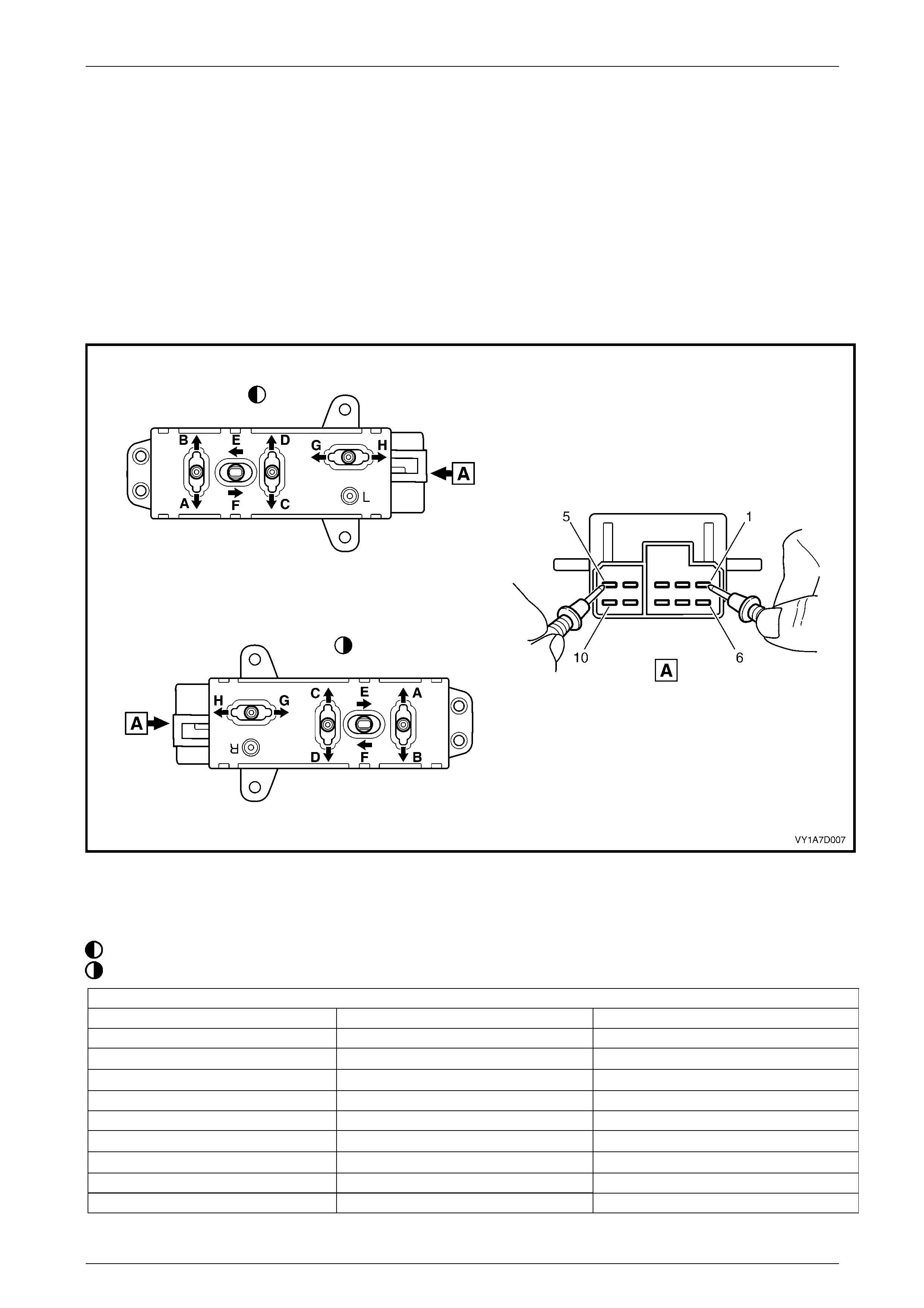
Seat Assemblies Page 1A7A–134
Page 1A7A–134
3.6 Eight-way Seat Adjustment Switch Test
The switch is located on the outer side of the seat, attached to the inner side of the front seat outer side cover.
Test
1 Remove the eight-way seat adjustment switch, refer to 2.4 Front Seat Outer Side Cover Assembly.
2 Place the switch in the positions as detailed i n the chart in this Section. Place the probes of the multimeter onto the
terminals listed and take the reading. Compare the reading to the chart.
3 If the switch fails any part of the test, replace the switch assembly with a serviceabl e item.
4 Install the eight-way seat adjustment switch, refer to 2.4 Front Seat Outer Side Cover Assembly.
Figure 1A7A – 93
Legend
Left-hand Switch
Right-hand Switch
Eight-way Seat Adjustment Switch
Switch Position Switch Terminals Indication If Switch Is Serviceable
Position A 10 and 5 Continuity
Position B 7 and 5 Continuity
Position C 9 and 5 Continuity
Position D 8 and 5 Continuity
Position E 6 and 5 Continuity
Position F 3 and 5 Continuity
Position G 2 and 5 Continuity
Position H 4 and 5 Continuity
Switch in the neutral position 1 and either 2, 3, 4, 6, 7, 8, 9 or 10 Continuity

Seat Assemblies Page 1A7A–135
Page 1A7A–135
4 Diagnostics – Front Seat LHD,
Non-memory (Except Coupe)
This Section provides charts to assist in the diagnosis and repa ir of front seats. Refer to 2.1 Front Seat Usage Chart for
a full listing of the different types of seats fitted to vehicles. Included in that Section are illustrated parts breakdowns of
the various seats.
4.1 Prerequisites
Safety Requirements
When operating the seat as part of any Steps
in the diagnostic tables, ensure that fingers
and limbs are clear of mo ving parts.
Equipment
The following equipment is required to diagnose the seats:
• an unpowered test lamp with a current dra w of less than 3 A, and
• a digital multimeter with a minimum impe dance of 10 MΩ.
Testing Procedures
The following points must be adhered to
when performing diagnostic testing on
components:
• Take care when using testing equipment
to diagnose wiring harness connectors. It
is preferred that the technician backprobe
the connector to avoid terminal damage.
• When tests are required on connector
terminals, use the adapters in the
connector adapter kit KM–609 to prevent
damage to the terminals.
• Unless the multimeter being used has an
auto-ranging function, ensure the correct
range is selected.
• When backpro bing connectors, ensure the
test lamp ground lead is connected to an
appropriate ground point on the vehicle.
Ensure this ground point is not part of the
circuit being tested.
NOTE
When following the steps in th e diagnostic tables,
perform them in the order cited. If the required
nominal value or result is not achi eved, rectif y t he
problem before proceeding any further.

Seat Assemblies Page 1A7A–136
Page 1A7A–136
4.2 Mechanical Diagnosis – Two-way/Four-
way/Six-way Seat
Lumbar Support Inoperative
Introduction
This test is used to aid in diagnosing the lumbar support as sembly.
Test Description
The following numbers refer to the step numbers in the diagnostic table:
1 Checks if the lumbar support knob is properly engaging the lumbar support adjuster. Check the knob for cracks and
worn splines.
2 Checks if the lumbar support assembly is damage d or worn and if the retaining springs are serviceable and
securely attached to the seat back frame assembly.
3 Checks if the lumbar support assembly is serviceable and if the lumber support assembly strap is operating
correctly within the guide rails.
Diagnostic Table
Step Action Yes No
1 Remov e the lu mbar support knob, refer to 2.9 Lumbar Support Knob
Assembly.
Is the lumbar support adjust knob serviceable? Go to Step 2
Replace the knob,
refer to 2.9 Lumbar
Support Knob
Assembly
2 1 Remov e the seat-back cover.
2 Inspect the lumbar support retainers and spri ngs.
Are the lumbar support retaining spri ngs serviceable and securel y
attached to the seat-back frame assembly? Go to Step 3
Replace or reattach
the retaining
springs, refer to
2.11 Front Seat-
back Frame
Assembly
3 1 Visually inspect the lumbar support assembl y. Check for broken
or worn parts.
2 Check the strap running across the lumber s upport assembly is
serviceable and running freely within the guide rails.
NOTE
You may need to attach the lumber support knob to
actuate the strap.
Is the lumbar support assembly serviceabl e? System serviceable
Replace lumbar
support assembly or
resecure lumbar
support assembly
strap ensuring strap
is not binding with
guide rails, refer to
2.11 Front Seat-
back Frame
Assembly
When all diagno sis and repairs are completed, check the system for correct operation.

Seat Assemblies Page 1A7A–137
Page 1A7A–137
Seat-back Recline Forward and/or Aft Function is Inoperative
Introduction
This test is used to aid in diagnosing the recline function of the seat assembly.
Test Description
The following numbers refer to the step numbers in the diagnostic table:
1 Checks if the recliner knob is properly engaging the recliner shaft. Check the knob for cracks and worn splines.
Diagnostic Table
Step Action Yes No
1 Remov e the re cliner knob, refer to 2.4 Front Seat Outer Side Cover
Assembly.
Is the recliner knob serviceable?
Replace the front
seat-back frame
assembly, refer to
2.11 Front Seat-
back Frame
Assembly
Replace the recliner
knob, refer to 2.4
Front Seat Outer
Side Cover
Assembly
When all diagno sis and repairs are completed, check the system for correct operation.

Seat Assemblies Page 1A7A–138
Page 1A7A–138
Two-way/Four-way Seat Fore/Aft Movement Function is Inoperative or is Not Smooth
Introduction
This test is used to aid in diagnosi ng the fore/aft movement function of the seat being inoperative or the action of the seat
through the range of movement is not smooth.
Test Description
The following numbers refer to the step numbers in the diagnostic table:
1 Checks if there are any items obstructing the guide rails which may stop or hinder the seat movement.
2 Checks if the guide rails have adequate lubricant appli ed to provide a smooth operation for the seat.
3 Checks if the linkage assembly between the adjustment lever and lockin g tangs is worn or damaged. The lockin g
tangs must disengage from the guide rails be fore the seat will move.
4 Checks if the guide rails have been damaged. Any binding between the inner and outer guide rails will result in
poor operation of the fore and aft movement.
Diagnostic Table
Step Action Yes No
1 Are the guide rails free from obstructions? Go to Step 2 Remove the
obstructing item
2 Are the gui de rails adequately lubricated?
Go to Step 3
Apply a small
amount of grease
type NLGI No. 1
Lithium Grease
(with 9% Zinc
Oxide) to the rails
3 Do the lock ing tangs disengage the guide rails when the seat fore and
aft adjustment lever is raised to its full movement?
Go to Step 4
Replace the track
and height adjust
assembly, refer to
2.13 Track and
Height Adjust
Assembly
4 Do the guide rails bind at any point of travel during the fore and aft
movements of the seat? Replace the track
and height adjust
assembly, refer to
2.13 Track and
Height Adjust
Assembly System serviceable
When all diagno sis and repairs are completed, check the system for correct operation.

Seat Assemblies Page 1A7A–139
Page 1A7A–139
4.3 Electrical Diagnosis – Four-wa y/Six-way
Seat
The charts in this Section are used to aid in diagnosing faults on four-way and six-way seat assemblies. To aid in the use
of the diagnostic tables, refer to Wiring Diagram – Four-way/Six-way Seat and Connector Chart – Four-way/Six-way Seat
in this Section.
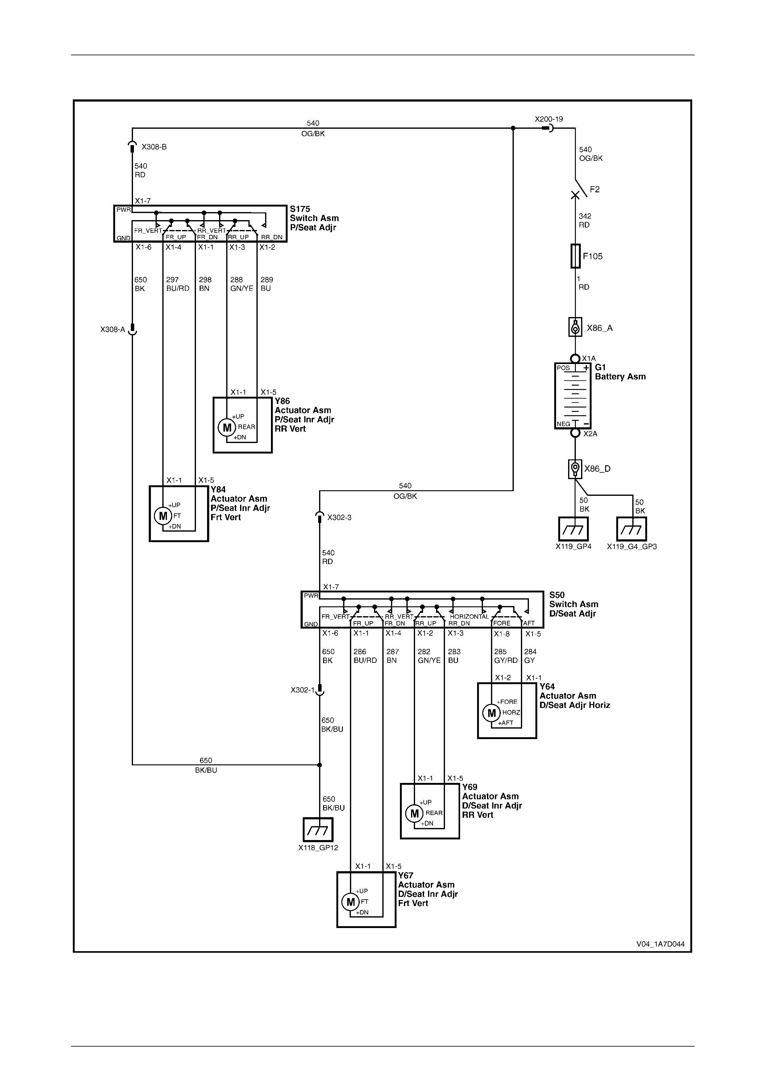
Seat Assemblies Page 1A7A–140
Page 1A7A–140
Wiring Diagram – Four-way/Six-way Seat
Figure 1A7A – 94
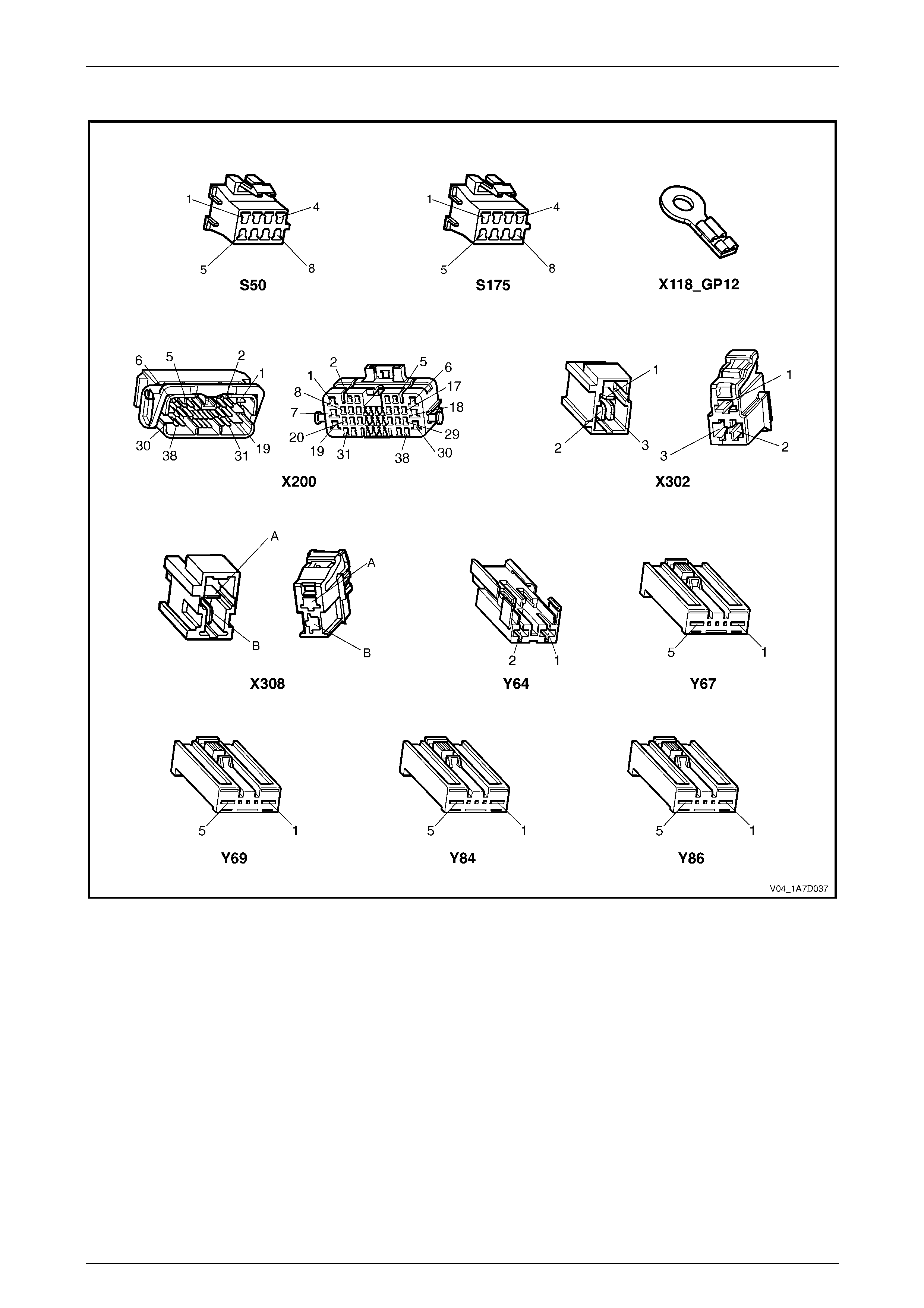
Seat Assemblies Page 1A7A–141
Page 1A7A–141
Connector Chart – Four-way/Six-way Seat
Figure 1A7A – 95

Seat Assemblies Page 1A7A–142
Page 1A7A–142
Neither Seat Adjustment Switch Functions Operate
Introduction
This test is used to aid in diagnosing the seat power and ground circuits, if neither seat operates when either seat
adjustment switch is operated.
Test Description
The following numbers refer to the step numbers in the diagnostic table:
1 Checks if battery voltage is more than 11.5 V. The seat motors require mo re than 11.5 V to operate correctly.
2 Checks if circuit breaker F2 located on the passenger com partment fuse and relay panel assembl y is tripped.
Isolates if circuit breaker F2 is the fault affecting the circuit between the battery and conne ctor X200 pin 19.
3 Checks if fusible link F105 located on the engine compartment fuse and relay panel assembly is serviceable.
Isolates if the fusible link is the fault affecting the circuit between the battery and connector X200 pin 19.
4 Checks if connector X200 is secure.
5 Checks if there is battery voltage at connector X200 pin 19. Isolates if the fault is between the battery and
connector X200 pin 19. If the fault in the circuit is between connectors X200 pin 19 and either X3 02 pin 3 or
X308 pin B, only o ne seat will operate.
6 Checks if there is battery voltage at circuit breaker F2. Isolates whether the fault is between the b attery and circuit
breaker F2 or bet ween circuit breaker F2 an d connector X200 pin 19.
7 Checks if there is battery voltage at fusible link F105. Isolates whether the fault is between the battery and fusible
link F105 or between fusible li nk F 105 and circuit breaker F2.
8 Checks if the ground point associated with the system is serviceable.
Diagnostic Table Notes
1 For all wiring harness fault diagnoses, refer to 12P Wirin g Diagrams.
2 For wiring harness repairs, refer to 12P Wiring Diagrams.
3 Refer to 12O Fuses, Relays and Wiring Harnesses for harness routeing.
4 If the fault is deemed to be intermittent, refer to 12P Wiring Diagrams.

Seat Assemblies Page 1A7A–143
Page 1A7A–143
Diagnostic Table
Step Action Yes No
1 Check the battery voltage, refer to 12A Battery and Cables.
Is the battery voltage more than 11.5 V? Go to Step 2
Refer to 12A Battery
and Cables for
further diagnosis
2 Inspect circuit breaker F2, refer to 12O Fuses, Relays and Wiring
Harness.
Is circuit breaker F2 tripped?
Allow the circuit
breaker to reset
(refer to Note 3).
If the circuit breaker
trips again, repair or
replace circuit 540
(refer to Note 2) Go to Step 3
3 Inspect fusible link F105, refer to 12O Fuses, Relays and Wiring
Harness.
Is fuse F105 serviceable?
Go to Step 4
Replace the fusible
link.
If the fusible link
becomes
unserviceable
again, repair or
replace circuit 342
(refer to Note 2)
4 Is connector X200 secure (refer to Note 3)? Go to Step 5 Ensure the
connector is secure
5 Backprobe connector X200 pin 19 with a test lamp (refer to Note 1).
Does the test lamp illuminate? Go to Step 8 Go to Step 6
6 1 Remov e circuit breaker F2 from the passenger compartment
fuse and relay panel assembly.
2 Using a test lamp, probe connector X12 9 - X45 – 2 (refer to Note
1).
Does the test lamp illuminate?
Repair or replace
circuit 540 between
circuit breaker F2
and connector
X200 pin 19 (refer to
Note 2) Go to Step 7
7 1 Remov e fusible link F105.
2 Using a test lamp, probe connector X18-105 (refer to Note 1).
Does the test lamp illuminate?
Repair or replace
circuit 342 between
fusible link F105
and circuit breaker
F2 (refer to Note 2)
Repair or replace
circuit 1 between
the battery and
fusible link F105
(refer to Note 2)
8 Ensure ground point X118 – GP12 (located in the middle of the
transmission tunnel) is secure and has good contact with the vehicle
structure.
Is the ground point secure to the vehicle with a good contact?
Repair or replace
circuit 650 (refer to
Note 2) Repair ground point
When all diagno sis and repairs are completed, check the system for correct operation.

Seat Assemblies Page 1A7A–144
Page 1A7A–144
None of the Driver’s Seat Adjustment Switch Functions Operate
Introduction
This test is used to aid in diagnosing the driver’s seat adjustment switch when none of the switch functions operate. The
test diagnoses the driver’s seat adjustment switch and associated power and ground circuits.
Test Description
The following numbers refer to the step numbers in the diagnostic table:
1 Checks if all of the passenger's seat functions work. If none of them work, the fault is not isolated to the driver’s
seat only.
2 Checks if there is battery power at connector X302 pi n 3. Isolates if there i s a fault in circuit 540 between
connectors X200 pin 19 and X302 pin 3.
3 Checks if all the connectors required for the seat to operate effectively are in place a nd positively connected.
4 Checks if there is battery power at connector S50 – X1 pi n 7. Isolates if there is a fault in circuit 540 between
connectors S50 – X1 pin 7 and X302 p in 3.
5 Checks if the driver’s seat adjustment switch is serviceable.
6 Checks if there is continuity between connectors S50 – X1 pin 6 and X302 pin 1 which supplies the ground circuit
for the driver’s seat adjustment switch. Isolates whether there is a fault in circuit 650 bet ween the switch and
connector X302 pin 1 or between connector X302 pin 1 and the ground point.
Diagnostic Table Notes
1 For all wiring harness fault diagnoses, refer to 12P Wirin g Diagrams.
2 For wiring harness repairs, refer to 12P Wiring Diagrams.
3 Refer to 12O Fuses, Relays and Wiring Harnesses for harness routeing.
4 If the fault is deemed to be intermittent, refer to 12P Wiring Diagrams.

Seat Assemblies Page 1A7A–145
Page 1A7A–145
Diagnostic Table
Step Action Yes No
1 Are all of the passen ger’s seat adjustment switch functions
inoperative? Refer to Neither
Seat Adjustment
Switch Functions
Operate in this
Section Go to Step 2
2 Backprobe connector X302 pin 3 with a test lamp (refer to Note 1).
Does the test lamp illuminate?
Go to Step 3
Repair or replace
circuit 540 between
connectors
X200 pin 19 an d
X302 pin 3 (refer to
Note 2)
3 Are the following connectors secure (refer to Note 3)?
• S50
• X302
• Y64
• Y67
• Y69 Go to Step 4
Ensure the
connectors are
secure
4 Backprobe connector S50 – X1 pin 7 with a test lamp (refer to Note 1).
Does the test lamp illuminate?
Go to Step 5
Repair or replace
circuit 540 between
connectors
S50 – X1 pin 7 and
X302 pin 3 (refer to
Note 2)
5 1 Remov e the driver’s seat adjustment switch from the seat, refer
to 2.4 Front Seat Outer Side Cover Assembly.
2 Test the driver’s seat adjustment switch, refer to 4.4 Six-way
Seat Adjustment Switch Test.
Is the driver’s seat adjustment switch serviceable? Go to Step 6
Replace the driver’s
seat adjustment
switch, refer to 2.4
Front Seat Outer
Side Cover
Assembly
6 1 Backprobe connector X302 pin 1 with a test lamp (refer to Note
1).
2 Operate the driver’s seat adjustment switch in any of the
available directions.
Does the test lamp illuminate?
Repair or replace
circuit 650 between
connector X302 pin
1 and ground point
X118 – GP12 (refer
to Note 2)
Repair or replace
circuit 650 between
connectors
S50 – X1 pin 6 and
X302 pin 1 (refer to
Note 2)
When all diagno sis and repairs are completed, check the system for correct operation.

Seat Assemblies Page 1A7A–146
Page 1A7A–146
Front/Rear of the Driver's Seat Does Not Raise and/or Lower
Introduction
This test is used to aid in diagnosing the front and/or the rear of the driver's seat not raising and/or lowering. The test
diagnoses the seat adjustmen t switch and the motor circuits.
Test Description
The following numbers refer to the step numbers in the diagnostic table:
1 Checks if the driver's seat adjustment switch assembly operates the seat in any direction. Isolates whether there is
a battery or ground fault affecting the seat operation.
2 Checks if all the connectors required for the seat to operate effectively are in place a nd positively connected.
3 Checks if the driver's seat adjustment switch is serviceable.
4 Confirms whether the rear of the seat raises or lowers. Isolates if the seat rear lift motor and circuit of the seat is the
fault.
5 Confirms whether the front of the seat raises or lo wers. Isolates if the seat front lift motor and circuit of the seat is
the fault.
6 Checks if there is battery power to the seat rear lift motor at connector Y69 – X1 pin 1. Isolates if there is a fault in
circuit 282 that supplies battery po wer to the motor to raise the rear of the seat.
7 Checks if there is battery power to the seat rear lift motor at connector Y69 – X1 pin 5. Isolates whether the fault is
in circuit 283 that supplies battery power to the motor to lower the rear of the seat or the motor is faulty. As
reversing the polarity changes the direction of the motor, this Step also confirms if the ground circuit from Step 6 is
serviceable.
8 Checks if there is battery power to the seat front lift motor at connector Y67 – X1 pin 1. Isolates if there is a fault in
circuit 286 that supplies battery po wer to the motor to raise the front of the seat.
9 Checks if there is battery power to the seat front lift motor at connector Y67 – X1 pin 5. Isolates whether the fault is
in circuit 287 that supplies battery power to the motor to lower the front of the seat or the motor is faulty. As
reversing the polarity changes the direction of the motor, this Step also confirms if the ground circuit from Step 8 is
serviceable.
Diagnostic Table Notes
1 For all wiring harness fault diagnoses, refer to 12P Wirin g Diagrams.
2 For wiring harness repairs, refer to 12P Wiring Diagrams.
3 Refer to 12O Fuses, Relays and Wiring Harnesses for harness routeing.
4 If the fault is deemed to be intermittent, refer to 12P Wiring Diagrams.

Seat Assemblies Page 1A7A–147
Page 1A7A–147
Diagnostic Table
Step Action Yes No
1 Does the dr iver's seat adjustment switch operate the seat correctly in
any of the six directions?
Go to Step 2
Refer to None of the
Driver’s Seat
Adjustment Switch
Functions Operate
in this Section
2 Are the following connectors secure (refer to Note 3)?
• S50
• Y67
• Y69 Go to Step 3
Ensure the
connectors are
secure
3 1 Remov e the dri v er' s seat adjustment switch from the seat, refer
to 2.4 Front Seat Outer Side Cover Assembly.
2 Test the driver's seat adjustment s witch, refer to 4.4 Six-way
Seat Adjustment Switch Test.
Is the driver's seat adjustment switch serviceable? Go to Step 4
Replace the driver's
seat adjustment
switch, refer to 2.4
Front Seat Outer
Side Cover
Assembly
4 Operate the dr iver's seat adjustment switch to raise or lower the rear
of the seat.
Does the rear of the seat raise and lo wer? Go to Step 5 Go to Step 6
5 Operate the dr iver's seat adjustment switch to raise or lower the front
of the seat.
Does the front of the seat raise and lower? System serviceable Go to Step 8
6 1 Backprobe connector Y69 – X1 pin 1 with a test lamp (refer to
Note 1).
2 Operate the driver's seat adjustment switch to raise the rear of
the seat.
Does the test lamp illuminate? Go to Step 7
Repair or replace
circuit 282 (refer to
Note 2)
7 1 Backprobe connector Y69 – X1 pin 5 with a test lamp (refer to
Note 1).
2 Operate the driver's seat adjustment switch to lower the rear of
the seat.
Does the test lamp illuminate?
Replace the seat
rear lift motor, refer
to 2.16 Front Seat
Lift Motor
Assemblies
Repair or replace
circuit 283 (refer to
Note 2)
8 1 Backprobe connector Y67 – X1 pin 1 with a test lamp (refer to
Note 1).
2 Operate the driver's seat adjustment switch to raise the front of
the seat.
Does the test lamp illuminate? Go to Step 9
Repair or replace
circuit 286 (refer to
Note 2)
9 1 Backprobe connector Y67 – X1 pin 5 with a test lamp (refer to
Note 1).
2 Operate the driver's seat adjustment switch to lower the front of
the seat.
Does the test lamp illuminate?
Replace the seat
front lift motor, refer
to 2.16 Front Seat
Lift Motor
Assemblies
Repair or replace
circuit 287 (refer to
Note 2)
When all diagno sis and repairs are completed, check the system for correct operation.

Seat Assemblies Page 1A7A–148
Page 1A7A–148
Driver’s Seat Fore/Aft Movement Function is Inoperative or not Smooth
Introduction
This test is used to aid in diagnosi ng the fore/aft movement function of the driver’s seat being inoperative or the action of
the seat through the range of movement is not smooth. The test diagnoses the seat adjustment switch and the motor
circuits.
Test Description
The following numbers refer to the step numbers in the diagnostic table:
1 Checks if the driver’s seat adjustment switch operates the seat in any direct ion. Isolates if there is battery power to
the switch assembly.
2 Checks if there are any items obstructing the guide rails, which may stop or hinder the seat movement.
3 Checks if the guide rails and drive shafts have adequate lubricant applied t o provide a smooth operation of the
seat.
4 Checks if the guide rails or drive shafts have been damaged. An y binding between the moving parts will result in
poor operation of the fore and aft movement.
5 Checks if all the connectors required for the seat to operate effectively are in place a nd positively connected.
6 Checks if the driver’s seat adjustment switch is serviceable.
7 Checks if there is battery power to the seat fore/aft movement motor at connector Y64 – X1 pin 2. Isolates if there
is a fault in circuit 285 that supplies battery power to the motor to move the seat forward.
8 Checks if there is battery power to the seat fore/aft movement motor at connector Y64 – X1 pin 1. Isolates whether
the fault is in circuit 284 that supplies battery power to the motor to move the seat aft or the motor is faulty. As
reversing the polarity changes the direction of the motor, this Step also confirms if the ground circuit from Step 7 is
serviceable.
Diagnostic Table Notes
1 For all wiring harness fault diagnoses, refer to 12P Wirin g Diagrams.
2 For wiring harness repairs, refer to 12P Wiring Diagrams.
3 Refer to 12O Fuses, Relays and Wiring Harnesses for harness routeing.
4 If the fault is deemed to be intermittent, refer to 12P Wiring Diagrams.

Seat Assemblies Page 1A7A–149
Page 1A7A–149
Diagnostic Table
Step Action Yes No
1 Does the dr iver’s seat adjustment switch operate the seat correctly in
any of the six directions?
Go to Step 2
Refer to None of the
Driver’s Seat
Adjustment Switch
Functions Operate
in this Section
2 Are the guide rails free from obstructions? Go to Step 3 Remove the
obstructing item
3 Are the gui de rails and drive shafts adequately lubricated?
Go to Step 4
Apply a small
amount of grease
type NLGI No. 1
Lithium Grease
(with 9% Zinc
Oxide)
4 Do the guide rails or drive shafts bind at any point of travel duri ng the
fore and aft movement of the seat? Replace the track
and height adjust
assembly, refer to
2.13 Track and
Height Adjust
Assembly Go to Step 5
5 Are the following connectors secure (refer to Note 3)?
• S50
• Y64 Go to Step 6
Ensure the
connectors are
secure
6 1 Remov e the driver’s seat adjustment switch from the seat, refer
to 2.4 Front Seat Outer Side Cover Assembly.
2 Test the driver’s seat adjustment switch, refer to 4.4 Six-way
Seat Adjustment Switch Test.
Is the driver’s seat adjustment switch serviceable? Go to Step 7
Replace the driver’s
seat adjustment
switch, refer to 2.4
Front Seat Outer
Side Cover
Assembly
7 1 Backprobe connector Y64 – X1 pin 2 with a test lamp (refer to
Note 1).
2 Operate the driver’s seat adjustment switch to move the seat
forward.
Does the test lamp illuminate? Go to Step 8
Repair or replace
circuit 285 (refer to
Note 2)
8 1 Backprobe connector Y64 – X1 pin 1 with a test lamp (refer to
Note 1).
2 Operate the driver’s seat adjustment switch to move the seat aft.
Does the test lamp illuminate?
Replace the seat
fore/aft movement
motor, refer to 2.17
Front Seat Fore/Aft
Movement Motor
Assembly
Repair or replace
circuit 284 (refer to
Note 2)
When all diagno sis and repairs are completed, check the system for correct operation.

Seat Assemblies Page 1A7A–150
Page 1A7A–150
None of the Passenger's Seat Adjustment Switch Functions Operate
Introduction
This test is used to aid in diagnosing the passenger's seat adjustment switch when none of the switch functions operate.
The test diagnoses the passenger's seat adjustment switch and associated power and ground circuits.
Test Description
The following numbers refer to the step numbers in the diagnostic table:
1 Checks if all of the driver's seat functions work. If none of them work, the fault is not isolated to the passenger's
seat.
2 Checks if there is battery power at connector X308 pin B. Isolates if there is a fault in circuit 540 between
connectors X200 pin 19 and X308 pin B.
3 Checks if all the connectors required for the seat to operate effectively are in place a nd positively connected.
4 Checks if there is battery power at connector S175 – X1 pin 7. Isolates if there is a fault in circuit 540 between
connectors S175 – X1 pin 7 and X308 pin B.
5 Checks if the passenger's seat adjustment switch is serviceable.
6 Checks if there is continuity between connec tors S175 – X1 pin 6 and X308 pin A which supp lies the ground circuit
for the passenger's seat adjustment switch. Isolates whether there is a fault in circuit 650 between the s witch and
connector X308 pin A or between connector X308 pin A and the ground point.
Diagnostic Table Notes
1 For all wiring harness fault diagnoses, refer to 12P Wirin g Diagrams.
2 For wiring harness repairs, refer to 12P Wiring Diagrams.
3 Refer to 12O Fuses, Relays and Wiring Harnesses for harness routeing.
4 If the fault is deemed to be intermittent, refer to 12P Wiring Diagrams.

Seat Assemblies Page 1A7A–151
Page 1A7A–151
Diagnostic Table
Step Action Yes No
1 Are all of the dr iver's seat adjustment switch functions inoperative? Refer to Neither
Seat Adjustment
Switch Functions
Operate in this
Section Go to Step 2
2 Backprobe connector X308 pin B with a test lamp (refer to Note 1).
Does the test lamp illuminate?
Go to Step 3
Repair or replace
circuit 540 between
connectors
X200 pin 19 an d
X308 pin B (refer to
Note 2)
3 Are the following connectors secure (refer to Note 3)?
• S175
• X308
• Y84
• Y86 Go to Step 4
Ensure the
connectors are
secure
4 Backprobe connector S175 – X1 pin 7 with a test lamp (refer to Note
1).
Does the test lamp illuminate?
Go to Step 5
Repair or replace
circuit 540 between
connectors
S175 – X1 pin 7 and
X308 pin B (refer to
Note 2)
5 1 Remov e the pa ssenger's seat adjustment switch from the seat,
refer to 2.4 Front Seat Outer Side Cover Assembly.
2 Test the passenger's seat adjustment switch, refer to 3.4 Four-
way Seat Adjustment Switch Test.
Is the passenger's seat adjustment s witch serviceable? Go to Step 6
Replace the
passenger's seat
adjustment switch,
refer to 2.4 Front
Seat Outer Side
Cover Assembly
6 1 Backprobe connector X308 pin A with a test lamp (refer to Note
1).
2 Operate the passenger's seat adjustment switch in any of the
available directions.
Does the test lamp illuminate?
Repair or replace
circuit 650 between
connector X308 pin
A and ground point
X118 – GP12 (refer
to Note 2)
Repair or replace
circuit 650 between
connectors
S175 – X1 pin 6 and
X308 pin A (refer to
Note 2)
When all diagno sis and repairs are completed, check the system for correct operation.

Seat Assemblies Page 1A7A–152
Page 1A7A–152
Front/Rear of the Passenger's Seat Does Not Raise and/or Lower
Introduction
This test is used to aid in diagnosing the front and/or the rear of the passenger's seat not raising and/or lowering. T he
test diagnoses the seat adjustment switch and the motor circuits.
Test Description
The following numbers refer to the step numbers in the diagnostic table:
1 Checks if the passenger's seat adjustment switch assembly operates the seat in any direction. Isolates if there is a
battery or ground fault affecting the seat operation.
2 Checks if all the connectors required for the seat to operate effectively are in place and positively connected.
3 Checks if the passenger's seat adjustment switch is serviceable.
4 Confirms whether the rear of the seat raises or lowers. Isolates if the seat rear lift motor and circuit of the seat is the
fault.
5 Confirms whether the front of the seat raises or lo wers. Isolates if the seat front lift motor and circuit of the seat is
the fault.
6 Checks if there is battery power to the seat rear lift motor at connector Y86 – X1 pin 1. Isolates if there is a fault in
circuit 288 that supplies battery po wer to the motor to raise the rear of the seat.
7 Checks if there is battery power to the seat rear lift motor at connector Y86 – X1 pin 5. Isolates whether the fault is
in circuit 289 that supplies battery power to the motor to lower the rear of the seat or the motor is faulty. As
reversing the polarity changes the direction of the motor, this Step also confirms if the ground circuit from Step 6 is
serviceable.
8 Checks if there is battery power to the seat front lift motor at connector Y84 – X1 pin 1. Isolates if there is a fault in
circuit 297 that supplies battery po wer to the motor to raise the front of the seat.
9 Checks if there is battery power to the seat front lift motor at connector Y84 – X1 pin 5. Isolates whether the fault is
in circuit 298 that supplies battery power to the motor to lower the front of the seat or the motor is faulty. As
reversing the polarity changes the direction of the motor, this Step also confirms if the ground circuit from Step 8 is
serviceable.
Diagnostic Table Notes
1 For all wiring harness fault diagnoses, refer to 12P Wirin g Diagrams.
2 For wiring harness repairs, refer to 12P Wiring Diagrams.
3 Refer to 12O Fuses, Relays and Wiring Harnesses for harness routeing.
4 If the fault is deemed to be intermittent, refer to 12P Wiring Diagrams.

Seat Assemblies Page 1A7A–153
Page 1A7A–153
Diagnostic Table
Step Action Yes No
1 Does the passenger's seat adjustment switch operate the seat
correctly in any of the four directions?
Go to Step 2
Refer to None of the
Passenger's Seat
Adjustment Switch
Functions Operate
in this Section
2 Are the following connectors secure (refer to Note 3)?
• S175
• Y84
• Y86 Go to Step 3
Ensure the
connectors are
secure
3 1 Remov e the pa ssenger's seat adjustment switch from the seat,
refer to 2.4 Front Seat Outer Side Cover Assembly.
2 Test the passenger's adjustm ent switch, refer to 3.4 Four-way
Seat Adjustment Switch Test.
Is the passenger's seat adjustment s witch serviceable ? Go to Step 4
Replace the
passenger's seat
adjustment switch,
refer to 2.4 Front
Seat Outer Side
Cover Assembly
4 Operate the passenger's seat adjustment switch to raise or lower the
rear of the seat.
Does the rear of the seat raise and lo wer? Go to Step 5 Go to Step 6
5 Operate the passenger's seat adjustment switch to raise or lower the
front of the seat.
Does the front of the seat raise and lower? System serviceable Go to Step 8
6 1 Backprobe connector Y86 – X1 pin 1 with a test lamp (refer to
Note 1).
2 Operate the passenger's seat adjustment switch to raise the rear
of the seat.
Does the test lamp illuminate? Go to Step 7
Repair or replace
circuit 288 (refer to
Note 2)
7 1 Backprobe connector Y86 – X1 pin 5 with a test lamp (refer to
Note 1).
2 Operate the passenger's seat adjustment switch to lower the
rear of the seat.
Does the test lamp illuminate?
Replace the seat
rear lift motor, refer
to 2.16 Front Seat
Lift Motor
Assemblies
Repair or replace
circuit 289 (refer to
Note 2)
8 1 Backprobe connector Y84 – X1 pin 1 with a test lamp (refer to
Note 1).
2 Operate the passenger's seat adjustment switch to raise the
front of the seat.
Does the test lamp illuminate? Go to Step 9
Repair or replace
circuit 297 (refer to
Note 2)
9 1 Backprobe connector Y84 – X1 pin 5 with a test lamp (refer to
Note 1).
2 Operate the passenger's seat adjustment switch to lower the
front of the seat.
Does the test lamp illuminate?
Replace the seat
front lift motor, refer
to 2.16 Front Seat
Lift Motor
Assemblies
Repair or replace
circuit 298 (refer to
Note 2)
When all diagno sis and repairs are completed, check the system for correct operation.
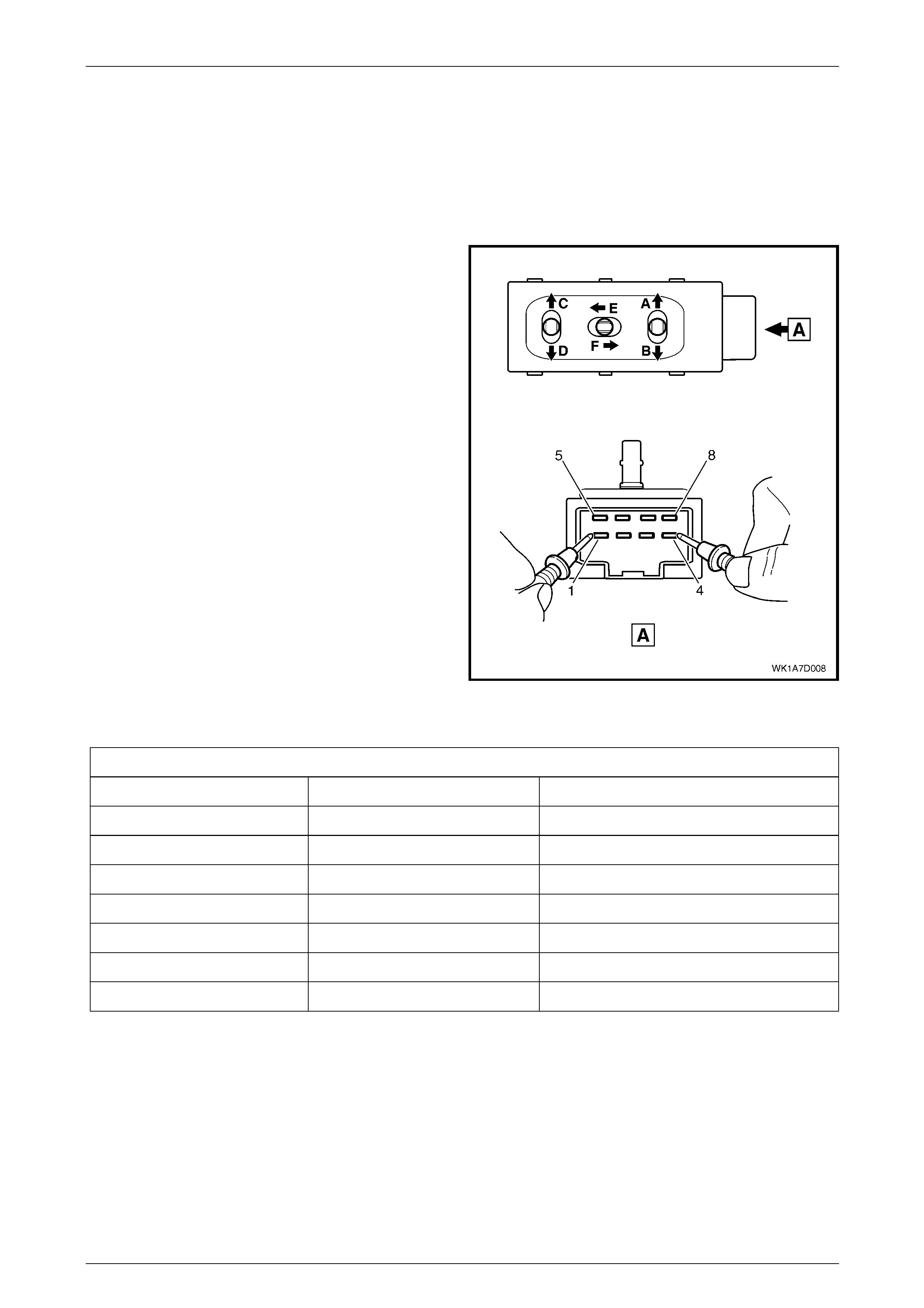
Seat Assemblies Page 1A7A–154
Page 1A7A–154
4.4 Six-way Seat Adjustment Switch Test
The switch is located on the outer side of the seat, attached to the inner side of the front seat outer side cover.
Test
1 Remove the six-way seat adjustment switch, refer to 2.4 Front Seat Outer Side Cover Assembly.
2 Place the switch in the positions as detailed i n the
chart in this Section. Place the probes of the
multimeter onto the terminals listed and take the
reading. Compare the reading to the chart.
3 If the switch fails any part of the test, replace the
switch assembly with a serviceable item.
4 Install the six-way seat adjust ment switch, refer to
2.4 Front Seat Outer Side Cover Assembly.
Figure 1A7A – 96
Six-way Seat Adjustment Switch
Switch Position Sw itch Terminals Indication if Switch is Serviceable
Position A 2 and 7 Continuity
Position B 3 and 7 Continuity
Position C 1 and 7 Continuity
Position D 4 and 7 Continuity
Position E 8 and 7 Continuity
Position F 5 and 7 Continuity
Switch in the neutral position 6 and either 1, 2, 3, 4, 5 or 8 Continuity

Seat Assemblies Page 1A7A–155
Page 1A7A–155
4.5 Mechanical Diagnosis – Eight-way Seat
Lumbar Support Inoperative
Introduction
This test is used to aid in diagnosing the lumbar support as sembly.
Test Description
The following numbers refer to the step numbers in the diagnostic table:
1 Checks if the lumbar support knob is properly engaging the lumbar support adjuster. Check the knob for cracks and
worn splines.
2 Checks if the lumbar support assembly is damage d or worn and that the retaining springs are serviceable and
securely attached to the seat back frame assembly.
3 Checks if the lumbar support assembly is serviceable and that the lumber support assembly strap is operating
correctly within the guide rails.
Diagnostic Table
Step Action Yes No
1 Remov e the lu mbar support knob, refer to 2.9 Lumbar Support Knob
Assembly.
Is the lumbar support adjust knob serviceable? Go to Step 2
Replace the knob,
refer to 2.9 Lumbar
Support Knob
Assembly
2 1 Remov e the seat-back cover.
2 Inspect the lumbar support retainers and spri ngs.
Are the lumbar support retaining spri ngs serviceable and securel y
attached to the seat-back frame assembly? Go to Step 3
Replace or reattach
the retaining
springs, refer to
2.11 Front Seat-
back Frame
Assembly
3 1 Visually inspect the lumbar support assembl y. Check for broken
or worn parts.
2 Check the strap running across the lumber s upport assembly is
serviceable and running freely within the guide rails.
NOTE
You may need to attach the lumber support knob to
actuate the strap.
Is the lumbar support assembly serviceabl e? System serviceable
Replace lumbar
support assembly or
resecure lumbar
support assembly
strap ensuring strap
is not binding with
guide rails, refer to
2.11 Front Seat-
back Frame
Assembly
When all diagno sis and repairs are completed, check the system for correct operation.

Seat Assemblies Page 1A7A–156
Page 1A7A–156
4.6 Electrical Diagnosis – Eight-way Seat
The charts in this Section are used to aid in diagnosing faults on eight-way seat assemblies. To aid in the use of the
diagnostic tables, refer to Wiring Diagram – Eight-wa y Seat and Connector Chart – Eight-way Seat in this Section.
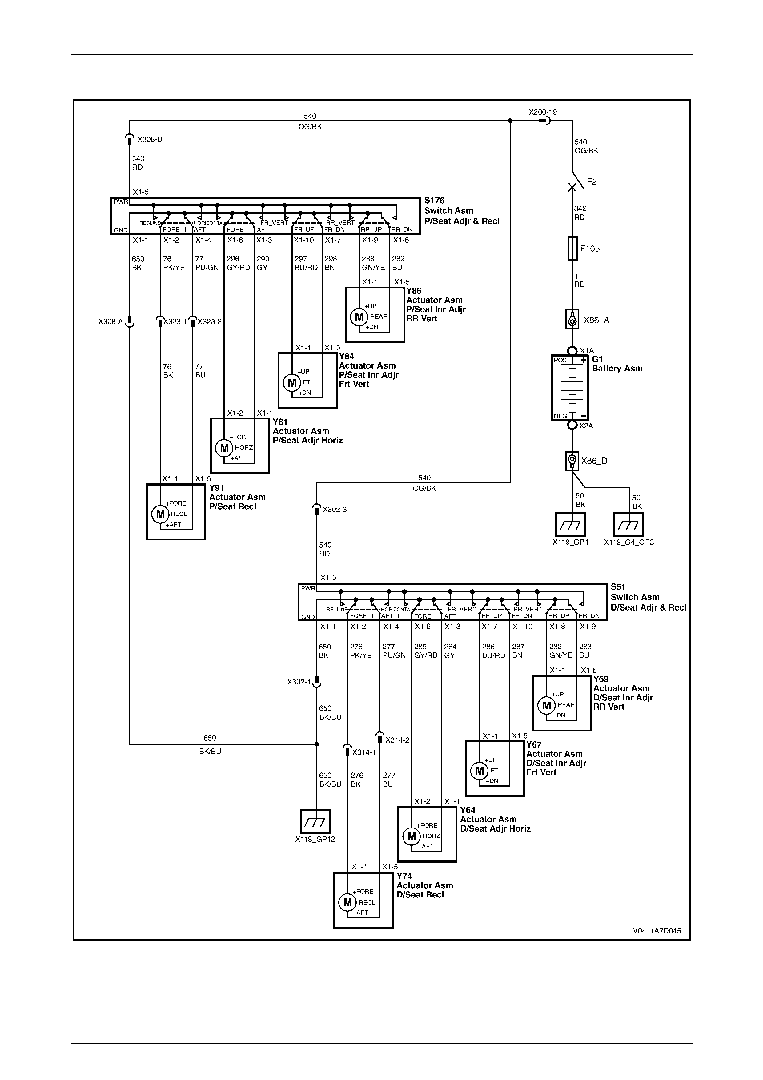
Seat Assemblies Page 1A7A–157
Page 1A7A–157
Wiring Diagram – Eight-way Seat
Figure 1A7A – 97
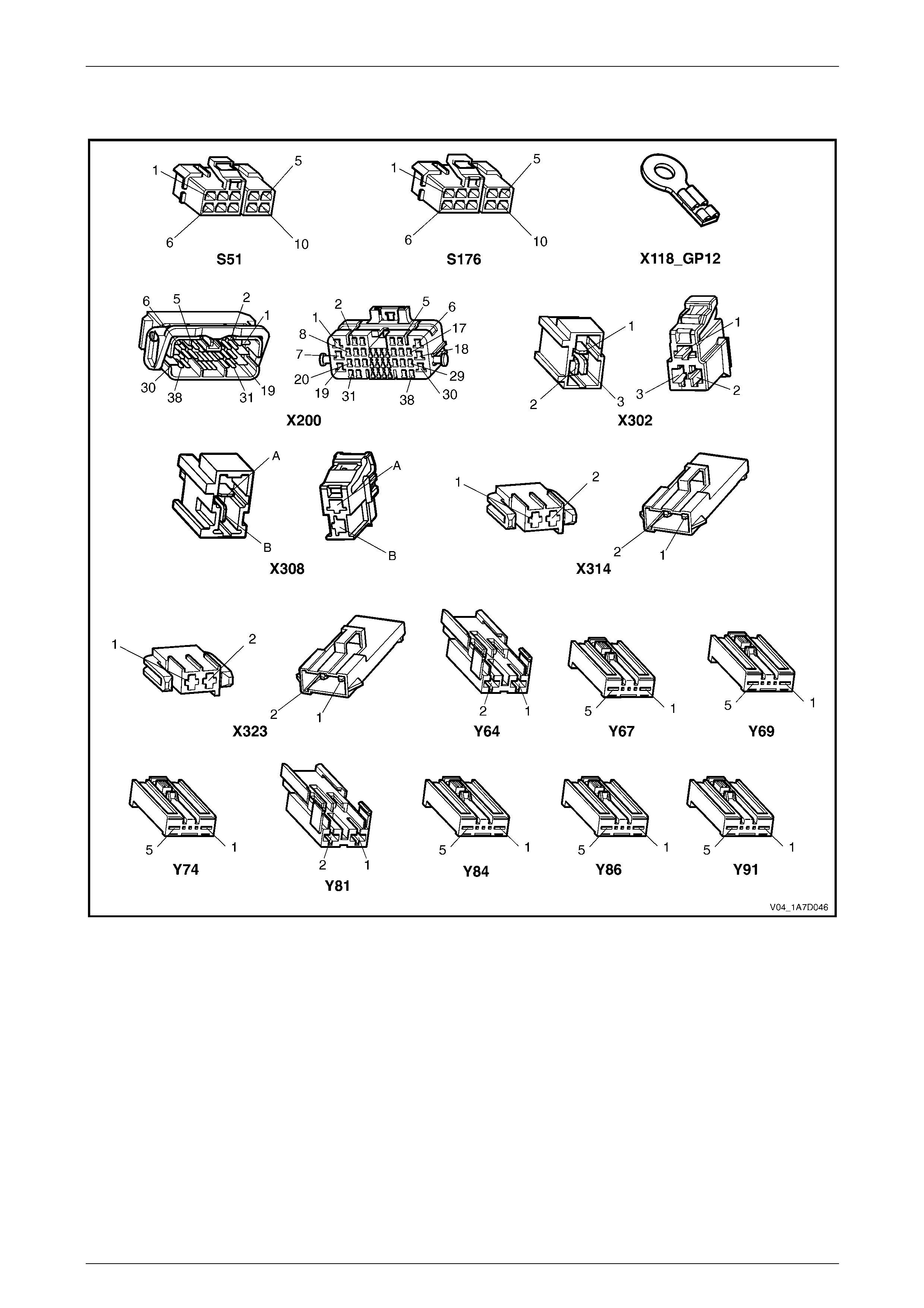
Seat Assemblies Page 1A7A–158
Page 1A7A–158
Connector Chart – Eight-way Seat
Figure 1A7A – 98

Seat Assemblies Page 1A7A–159
Page 1A7A–159
Neither Seat Adjustment Switch Functions Operate
Introduction
This test is used to aid in diagnosing the seat power and ground circuits, if neither seat operates when either seat
adjustment switch is operated.
Test Description
The following numbers refer to the step numbers in the diagnostic table:
1 Checks if battery voltage is more than 11.5 V. The seat motors require mo re than 11.5 V to operate correctly.
2 Checks if circuit breaker F2 located on the passenger com partment fuse and relay panel assembl y is tripped.
Isolates if circuit breaker F2 is the fault affecting the circuit between the battery and conne ctor X200 pin 19.
3 Checks if fusible link F105 located on the engine compartment fuse and relay panel assembly is serviceable.
Isolates if the fusible link is the fault affecting the circuit between the battery and connector X200 pin 19.
4 Checks if connector X200 is secure.
5 Checks if there is battery voltage at connector X200 pin 19. Isolates if the fault is between the battery and
connector X200 pin 19. If the fault in the circuit is between connectors X200 pin 19 and either X3 02 pin 3 or
X308 pin B, only o ne seat will operate.
6 Checks if there is battery voltage at circuit breaker F2. Isolates whether the fault is between the b attery and circuit
breaker F2 or bet ween circuit breaker F2 an d connector X200 pin 19.
7 Checks if there is battery voltage at fusible link F105. Isolates whether the fault is between the battery and fusible
link F105 or between fusible li nk F 105 and circuit breaker F2.
8 Checks if the ground point associated with the system is serviceable.
Diagnostic Table Notes
1 For all wiring harness fault diagnoses, refer to 12P Wirin g Diagrams.
2 For wiring harness repairs, refer to 12P Wiring Diagrams.
3 Refer to 12O Fuses, Relays and Wiring Harnesses for harness routeing.
4 If the fault is deemed to be intermittent, refer to 12P Wiring Diagrams.

Seat Assemblies Page 1A7A–160
Page 1A7A–160
Diagnostic Table
Step Action Yes No
1 Check the battery voltage, refer to 12A Battery and Cables.
Is the battery voltage more than 11.5 V? Go to Step 2
Refer to 12A Battery
and Cables for
further diagnosis
2 Inspect circuit breaker F2, refer to 12O Fuses, Relays and Wiring
Harnesses.
Is circuit breaker F2 tripped?
Allow the circuit
breaker to reset
(refer to Note 3).
If the circuit breaker
trips again, repair or
replace circuit 540
(refer to Note 2) Go to Step 3
3 Inspect fusible link F105, refer to 12O Fuses, Relays and Wiring
Harnesses.
Is fuse F105 serviceable?
Go to Step 4
Replace the fusible
link.
If the fusible link
becomes
unserviceable
again, repair or
replace circuit 342
(refer to Note 2)
4 Is connector X200 secure (refer to Note 3)? Go to Step 5 Ensure the
connector is secure
5 Backprobe connector X200 pin 19 with a test lamp (refer to Note 1).
Does the test lamp illuminate? Go to Step 8 Go to Step 6
6 1 Remov e circuit breaker F2 from the passenger compartment
fuse and relay panel assembly.
2 Using a test lamp, probe connector X12 9 – X45 pin – 2 (refer to
Note 1).
Does the test lamp illuminate?
Repair or replace
circuit 540 between
circuit breaker F2
and connector
X200 pin 19 (refer to
Note 2) Go to Step 7
7 1 Remov e fusible link F105.
2 Using a test lamp, probe connector X18-105 (refer to Note 1).
Does the test lamp illuminate?
Repair or replace
circuit 342 between
fusible link F105
and circuit breaker
F2 (refer to Note 2)
Repair or replace
circuit 1 between
the battery and
fusible link F105
(refer to Note 2)
8 Ensure ground point X118 – GP12 (located in the middle of the
transmission tunnel) is secure and has good contact with the vehicle
structure.
Is the ground point secure to the vehicle with a good contact?
Repair or replace
circuit 650 (refer to
Note 2) Repair ground point
When all diagno sis and repairs are completed, check the system for correct operation.

Seat Assemblies Page 1A7A–161
Page 1A7A–161
None of the Driver’s Seat Adjustment Switch Functions Operate
Introduction
This test is used to aid in diagnosing the driver’s seat adjustment switch when none of the switch functions operate. The
test diagnoses the driver’s seat adjustment switch and associated power and ground circuits.
Test Description
The following numbers refer to the step numbers in the diagnostic table:
1 Checks if all of the passenger seat functions work. If none of them work, the fault is not isolated to the driver’s seat.
2 Checks if there is battery power at connector X302 pi n 3. Isolates if there i s a fault in circuit 540 between
connectors X200 pin 19 and X302 pin 3.
3 Checks if all the connectors required for the seat to operate effectively are in place a nd positively connected.
4 Checks if there is battery power at connector S51 – X1 pi n 5. Isolates if there is a fault in circuit 540 between
connectors S51 – X1 pin 5 and X302 p in 3.
5 Checks if the driver’s seat adjustment switch is serviceable.
6 Checks if there is continuity between connectors S51 – X1 pin 1 and X302 pin 1 which supplies the ground circuit
for the driver’s seat adjustment switch. Isolates whether there is a fault in circuit 650 bet ween the switch and
connector X302 pin 1 or between connector X302 pin 1 and the ground point.
Diagnostic Table Notes
1 For all wiring harness fault diagnoses, refer to 12P Wirin g Diagrams.
2 For wiring harness repairs, refer to 12P Wiring Diagrams.
3 Refer to 12O Fuses, Relays and Wiring Harnesses for harness routeing.
4 If the fault is deemed to be intermittent, refer to 12P Wiring Diagrams.

Seat Assemblies Page 1A7A–162
Page 1A7A–162
Diagnostic Table
Step Action Yes No
1 Are all of the passen ger’s seat adjustment switch functions
inoperative? Refer to Neither
Seat Adjustment
Switch Functions
Operate in this
Section Go to Step 2
2 Backprobe connector X302 pin 3 with a test lamp (refer to Note 1).
Does the test lamp illuminate?
Go to Step 3
Repair or replace
circuit 540 between
connectors
X200 pin 19 an d
X302 pin 3 (refer to
Note 2)
3 Are the following connectors secure (refer to Note 3)?
• S51
• X302
• Y64
• Y67
• Y69
• Y74 Go to Step 4
Ensure the
connectors are
secure
4 Backprobe connector S51 – X1 pin 5 with a test lamp (refer to Note 1).
Does the test lamp illuminate?
Go to Step 5
Repair or replace
circuit 540 between
connectors
S51 – X1 pin 5 and
X302 pin 3 (refer to
Note 2)
5 1 Remov e the driver’s seat adjustment switch from the seat, refer
to 2.4 Front Seat Outer Side Cover Assembly.
2 Test the driver’s seat adjustment switch, refer to 3.6 Eight-way
Seat Adjustment Switch Test.
Is the driver’s seat adjustment switch serviceable? Go to Step 6
Replace the driver’s
seat adjustment
switch, refer to 2.4
Front Seat Outer
Side Cover
Assembly
6 1 Backprobe connector X302 pin 1 with a test lamp (refer to Note
1).
2 Operate the driver’s seat adjustment switch in any of the
available directions.
Does the test lamp illuminate?
Repair or replace
circuit 650 between
connector X302 pin
1 and ground point
X118 – GP12 (refer
to Note 2)
Repair or replace
circuit 650 between
connectors
S51 – X1 pin 1 and
X302 pin 1 (refer to
Note 2)
When all diagno sis and repairs are completed, check the system for correct operation.

Seat Assemblies Page 1A7A–163
Page 1A7A–163
Front/Rear of the Driver’s Seat Does Not Raise and/or Lower
Introduction
This test is used to aid in diagnosing the front and/or the rear of the driver’s seat not raising and/or lowering. T he test
diagnoses the seat adjustmen t switch and the motor circuits.
Test Description
The following numbers refer to the step numbers in the diagnostic table:
1 Checks if the driver’s seat adjustment switch operates the seat in any direction. Isolates if the power and ground
circuits are at fault.
2 Checks if all the connectors required for the seat to operate effectively are in place a nd positively connected.
3 Checks if the driver’s seat adjustment switch is serviceable.
4 Confirms whether the rear of the seat raises or lowers. Isolates if the seat rear lift motor and circuit of the seat is the
fault.
5 Confirms whether the front of the seat raises or lo wers. Isolates if the seat front lift motor and circuit of the seat is
the fault.
6 Checks if there is battery power to the seat rear lift motor at connector Y69 – X1 pin 1. Isolates if there is a fault in
circuit 282 that supplies battery po wer to the motor to raise the rear of the seat.
7 Checks if there is battery power to the seat rear lift motor at connector Y69 – X1 pin 5. Isolates whether the fault is
in circuit 283 that supplies battery power to the motor to lower the rear of the seat or the motor is faulty. As the
direction of the motor is changed by reversing the polarity, this Step also confirms if the ground circuit from Step 6
is serviceable.
8 Checks if there is battery power to the seat front lift motor at connector Y67 – X1 pin 1. Isolates if there is a fault in
circuit 286 that supplies battery po wer to the motor to raise the front of the seat.
9 Checks if there is battery power to the seat front lift motor at connector Y67 – X1 pin 5. Isolates whether the fault is
in circuit 287 that supplies battery power to the motor to lower the front of the seat or the motor is faulty. As the
direction of the motor is changed by reversing the polarity, this Step also confirms if the ground circuit from Step 8
is serviceable.
Diagnostic Table Notes
1 For all wiring harness fault diagnoses, refer to 12P Wirin g Diagrams.
2 For wiring harness repairs, refer to 12P Wiring Diagrams.
3 Refer to 12O Fuses, Relays and Wiring Harnesses for harness routeing.
4 If the fault is deemed to be intermittent, refer to 12P Wiring Diagrams.

Seat Assemblies Page 1A7A–164
Page 1A7A–164
Diagnostic Table
Step Action Yes No
1 Does the dr iver’s seat adjustment switch operate the seat correctly in
any of the eight directions?
Go to Step 2
Refer to None of the
Driver’s Seat
Adjustment Switch
Functions Operate
in this Section
2 Are the following connectors secure (refer to Note 3)?
• S51
• Y67
• Y69 Go to Step 3
Ensure the
connectors are
secure
3 1 Remov e the driver’s seat adjustment switch from the seat, refer
to 2.4 Front Seat Outer Side Cover Assembly.
2 Test the driver’s seat adjustment switch, refer to 3.6 Eight-way
Seat Adjustment Switch Test.
Is the driver’s seat adjustment switch serviceable? Go to Step 4
Replace the driver’s
seat adjustment
switch, refer to 2.4
Front Seat Outer
Side Cover
Assembly
4 Operate the driver’s seat adjustment switch to raise or lower the rear
of the seat.
Does the rear of the seat raise and lo wer? Go to Step 5 Go to Step 6
5 Operate the driver’s seat adjustment switch to raise or lower the front
of the seat.
Does the front of the seat raise and lower? System serviceable Go to Step 8
6 1 Backprobe connector Y69 – X1 pin 1 with a test lamp (refer to
Note 1).
2 Operate the driver’s seat adjustment switch to raise the rear of
the seat.
Does the test lamp illuminate? Go to Step 7
Repair or replace
circuit 282 (refer to
Note 2)
7 1 Backprobe connector Y69 – X1 pin 5 with a test lamp (refer to
Note 1).
2 Operate the driver’s seat adjustment switch to lower the rear of
the seat.
Does the test lamp illuminate?
Replace the seat
rear lift motor, refer
to 2.16 Front Seat
Lift Motor
Assemblies
Repair or replace
circuit 283 (refer to
Note 2)
8 1 Backprobe connector Y67 – X1 pin 1 with a test lamp (refer to
Note 1).
2 Operate the driver’s seat adjustment switch to raise the front of
the seat.
Does the test lamp illuminate? Go to Step 9
Repair or replace
circuit 286 (refer to
Note 2)
9 1 Backprobe connector Y67 – X1 pin 5 with a test lamp (refer to
Note 1).
2 Operate the driver’s seat adjustment switch to lower the front of
the seat.
Does the test lamp illuminate?
Replace the seat
front lift motor, refer
to 2.16 Front Seat
Lift Motor
Assemblies
Repair or replace
circuit 287 (refer to
Note 2)
When all diagno sis and repairs are completed, check the system for correct operation.

Seat Assemblies Page 1A7A–165
Page 1A7A–165
Driver’s Seat Fore/Aft Movement Function is Inoperative or Not Smooth
Introduction
This test is used to aid in diagnosi ng the fore/aft movement function of the driver’s seat being inoperative or the action of
the seat through the range of movement is not smooth. The test diagnoses the seat adjustment switch and the motor
circuits.
Test Description
The following numbers refer to the step numbers in the diagnostic table:
1 Checks if the driver’s seat adjustment switch operates the seat in any direct ion. Isolates if there is battery power to
the switch assembly.
2 Checks if there are any items obstructing the guide rails, which may stop or hinder the seat movement.
3 Checks if the guide rails and drive shafts have adequate lubricant applied t o provide a smooth operation of the
seat.
4 Checks if the guide rails or drive shafts have been damaged. An y binding between the moving parts will result in
poor operation of the fore and aft movement.
5 Checks if all the connectors required for the seat to operate effectively are in place a nd positively connected.
6 Checks if the driver’s seat adjustment switch is serviceable.
7 Checks if there is battery power to the seat fore/aft movement motor at connector Y64 – X1 pin 2. Isolates if there
is a fault in circuit 285 that supplies battery power to the motor to move the seat forward.
8 Checks if there is battery power to the seat fore/aft movement motor at connector Y64 – X1 pin 1. Isolates whether
the fault is in circuit 284 that supplies battery power to the motor to move the seat aft or the motor is faulty. As
reversing the polarity changes the direction of the motor, this Step also confirms if the ground circuit from Step 7 is
serviceable.
Diagnostic Table Notes
1 For all wiring harness fault diagnoses, refer to 12P Wirin g Diagrams.
2 For wiring harness repairs, refer to 12P Wiring Diagrams.
3 Refer to 12O Fuses, Relays and Wiring Harnesses for harness routeing.
4 If the fault is deemed to be intermittent, refer to 12P Wiring Diagrams.

Seat Assemblies Page 1A7A–166
Page 1A7A–166
Diagnostic Table
Step Action Yes No
1 Does the dr iver’s seat adjustment switch operate the seat correctly in
any of the eight directions?
Go to Step 2
Refer to None of the
Driver’s Seat
Adjustment Switch
Functions Operate
in this Section
2 Are the guide rails free from obstructions? Go to Step 3 Remove the
obstructing item
3 Are the gui de rails and drive shafts adequately lubricated?
Go to Step 4
Apply a small
amount of grease
type NLGI No. 1
Lithium Grease
(with 9% Zinc
Oxide)
4 Do the guide rails or drive shafts bind at any point of travel duri ng the
fore and aft movement of the seat? Replace the track
and height adjust
assembly, refer to
2.13 Track and
Height Adjust
Assembly Go to Step 5
5 Are the following connectors secure (refer to Note 3)?
• S51
• Y64 Go to Step 6
Ensure the
connectors are
secure
6 1 Remov e the driver’s seat adjustment switch from the seat, refer
to 2.4 Front Seat Outer Side Cover Assembly.
2 Test the driver’s seat adjustment switch, refer to 3.6 Eight-way
Seat Adjustment Switch Test.
Is the driver’s seat adjustment switch serviceable? Go to Step 7
Replace the driver’s
seat adjustment
switch, refer to 2.4
Front Seat Outer
Side Cover
Assembly
7 1 Backprobe connector Y64 – X1 pin 2 with a test lamp (refer to
Note 1).
2 Operate the driver’s seat adjustment switch to move the seat
forward.
Does the test lamp illuminate? Go to Step 8
Repair or replace
circuit 285 (refer to
Note 2)
8 1 Backprobe connector Y64 – X1 pin 1 with a test lamp (refer to
Note 1).
2 Operate the driver’s seat adjustment switch to move the seat aft.
Does the test lamp illuminate?
Replace the seat
fore/aft movement
motor, refer to 2.17
Front Seat Fore/Aft
Movement Motor
Assembly
Repair or replace
circuit 284 (refer to
Note 2)
When all diagno sis and repairs are completed, check the system for correct operation.

Seat Assemblies Page 1A7A–167
Page 1A7A–167
Driver’s Seat-back Recline Forward and/or Aft Function is Inoperative
Introduction
This test is used to aid in diagnosing the recline function of the driver’s seat being inoperative. The test diagnoses the
seat adjustment switch and the motor circuits.
Test Description
The following numbers refer to the step numbers in the diagnostic table:
1 Checks if the driver’s seat adjustment switch operates the seat in any direct ion. Isolates if there is battery power to
the switch assembly.
2 Checks if all the connectors required for the seat to operate effectively are in place a nd positively connected.
3 Checks if the driver’s seat adjustment switch is serviceable.
4 Checks if there is battery power to the seat-back recline motor at connect or Y74 – X1 pin 1. Isolates if there is a
fault in circuit 276 that supplies battery power to the motor to move the seat-back forward.
5 Isolates whether there is a fault in circuit 276 between connectors S51 – X1 pin 2 and X314 pin 1 or between
connectors X314 pin 1 and Y74 – X1 pin 1.
6 Checks if there is battery power to the seat-back recline motor at connector Y74 – X1 pi n 5. Isolates whether the
fault is in circuit 277 that supplies battery power to the motor to move the seat-back aft or the motor is faulty. As
reversing the polarity changes the direction of the motor, this Step also confirms if the ground circuit from Step 4 is
serviceable.
7 Isolates whether there is a fault in circuit 277 between connectors S51 – X1 pin 4 and X314 pin 2 or between
connectors X314 pin 2 and Y74 – X1 pin 5.
Diagnostic Table Notes
1 For all wiring harness fault diagnoses, refer to 12P Wirin g Diagrams.
2 For wiring harness repairs, refer to 12P Wiring Diagrams.
3 Refer to 12O Fuses, Relays and Wiring Harnesses for harness routeing.
4 If the fault is deemed to be intermittent, refer to 12P Wiring Diagrams.

Seat Assemblies Page 1A7A–168
Page 1A7A–168
Diagnostic Table
Step Action Yes No
1 Does the dr iver’s seat adjustment switch operate the seat correctly in
any of the eight directions?
Go to Step 2
Refer to None of the
Driver’s Seat
Adjustment Switch
Functions Operate
in this Section
2 Are the following connectors secure (refer to Note 3)?
• S51
• Y74 Go to Step 3
Ensure the
connectors are
secure
3 1 Remov e the driver’s seat adjustment switch from the seat, refer
to 2.4 Front Seat Outer Side Cover Assembly.
2 Test the driver’s seat adjustment switch, refer to 3.6 Eight-way
Seat Adjustment Switch Test.
Is the driver’s seat adjustment switch serviceable? Go to Step 4
Replace the driver’s
seat adjustment
switch, refer to 2.4
Front Seat Outer
Side Cover
Assembly
4 1 Backprobe connector Y74 – X1 pin 1 with a test lamp (refer to
Note 1).
2 Operate the driver’s seat adjustment switch to move the seat-
back forward.
Does the test lamp illuminate? Go to Step 6 Go to Step 5
5 1 Backprobe connector X314 pin 1 with a test lamp (refer to Note
1).
2 Operate the passenger’s seat adjustment switch to move the
seat-back forward.
Does the test lamp illuminate?
Repair or replace
circuit 276 between
connectors
X314 pin 1 and
Y74 – X1 pin 1
(refer to Note 2)
Repair or replace
circuit 276 between
connectors
S51 – X1 pin 2 and
X314 pin 1 (refer to
Note 2)
6 1 Backprobe connector Y74 – X1 pin 5 with a test lamp (refer to
Note 1).
2 Operate the driver’s seat adjustment switch to move the
seat-back aft.
Does the test lamp illuminate?
Replace the
seat-back recline
motor, refer to 2.18
Front Seat-back
Recline Motor
Assembly Go to Step 7
7 1 Backprobe connector X314 pin 2 with a test lamp (refer to Note
1).
2 Operate the passenger’s seat adjustment switch to move the
seat-back aft.
Does the test lamp illuminate?
Repair or replace
circuit 277 between
connectors
X314 pin 2 and
Y74 – X1 pin 5
(refer to Note 2)
Repair or replace
circuit 277 between
connectors
S51 – X1 pin 4 and
X314 pin 2 (refer to
Note 2)
When all diagno sis and repairs are completed, check the system for correct operation.

Seat Assemblies Page 1A7A–169
Page 1A7A–169
None of the Passenger’s Seat Adjustment Switch Functions Operate
Introduction
This test is used to aid in diagnosing the passenger’s seat adjustment switch when none of the switch functions operate.
The test diagnoses the passenger’s seat adjustment switch and associated power and ground circuits.
Test Description
The following numbers refer to the step numbers in the diagnostic table:
1 Checks if all of the driver’s seat functions work. If none of them work, the fault is not isolated to the passenger’s
seat.
2 Checks if there is battery power at connector X308 pin B. Isolates if there is a fault in circuit 540 between
connectors X200 pin 19 and X308 pin B.
3 Checks if all the connectors required for the seat to operate effectively are in place a nd positively connected.
4 Checks if there is battery power at connector S176 – X1 pin 5. Isolates if there is a fault in circuit 540 between
connectors S176 – X1 pin 5 and X308 pin B.
5 Checks if the passenger’s seat adjustment switch is serviceable.
6 Checks if there is continuity between connec tors S176 – X1 pin 1 and X308 pin A which supp lies the ground circuit
for the passenger’s seat adjustment s witch. Isolates whether there is a fault in circuit 650 between the switch and
connector X308 pin A or between connector X308 pin A and the ground point.
Diagnostic Table Notes
1 For all wiring harness fault diagnoses, refer to 12P Wirin g Diagrams.
2 For wiring harness repairs, refer to 12P Wiring Diagrams.
3 Refer to 12O Fuses, Relays and Wiring Harnesses for harness routeing.
4 If the fault is deemed to be intermittent, refer to 12P Wiring Diagrams.

Seat Assemblies Page 1A7A–170
Page 1A7A–170
Diagnostic Table
Step Action Yes No
1 Are all of the dr iver’s seat adjustment switch functions inoperative? Refer to Neither
Seat Adjustment
Switch Functions
Operate in this
Section Go to Step 2
2 Backprobe connector X308 pin B with a test lamp (refer to Note 1).
Does the test lamp illuminate?
Go to Step 3
Repair or replace
circuit 540 between
connectors X200 pin
19 and X308 pin B
(refer to Note 2)
3 Are the following connectors secure (refer to Note 3)?
• S176
• X308
• Y81
• Y84
• Y86
• Y91 Go to Step 4
Ensure the
connectors are
secure
4 Backprobe connector S176 – X1 pin 5 with a test lamp (refer to Note
1).
Does the test lamp illuminate?
Go to Step 5
Repair or replace
circuit 540 between
connectors
S176 – X1 pin 5 and
X308 pin B (refer to
Note 2)
5 1 Remov e the passenger’s seat adjustment switch from the seat,
refer to 2.4 Front Seat Outer Side Cover Assembly.
2 Test the passenger’s seat adjustment switch, refer to 3.6 Eight-
way Seat Adjustment Switch Test.
Is the passenger’s seat adjustment s witch serviceable? Go to Step 6
Replace the
passenger’s seat
adjustment switch,
refer to 2.4 Front
Seat Outer Side
Cover Assembly
6 1 Backprobe connector X308 pin A with a test lamp (refer to Note
1).
2 Operate the passenger’s seat adjustment switch in any of the
available directions.
Does the test lamp illuminate?
Repair or replace
circuit 650 between
connector X308 pin
A and ground point
X118 – GP12 (refer
to Note 2)
Repair or replace
circuit 650 between
connectors
S176 – X1 pin 1 and
X308 pin A (refer to
Note 2)
When all diagno sis and repairs are completed, check the system for correct operation.

Seat Assemblies Page 1A7A–171
Page 1A7A–171
Front/Rear of the Passenger’s Seat Does Not Raise and/or Lower
Introduction
This test is used to aid in diagnosing the front and/or the rear of the passenger’s seat not raising and/or lowering. The
test diagnoses the seat adjustment switch and the motor circuits.
Test Description
The following numbers refer to the step numbers in the diagnostic table:
1 Checks if the passenger’s seat adjustment switch operates the seat in any direction. Isolates whether the power
and/or ground circuits are at fault.
2 Checks if all the connectors required for the seat to operate effectively are in place a nd positively connected.
3 Checks if the passenger’s seat adjustment switch is serviceable.
4 Confirms whether the rear of the seat raises or lowers. Isolates if the rear lift motor and circuit of the seat is the
fault.
5 Confirms whether the front of the seat raises or lo wers. Isolates if the front lift motor and circuit of the seat is the
fault.
6 Checks if there is battery power to the seat rear lift motor at connector Y86 – X1 pin 1. Isolates if there is a fault in
circuit 288 that supplies battery po wer to the motor to raise the rear of the seat.
7 Checks if there is battery power to the seat rear lift motor at connector Y86 – X1 pin 5. Isolates whether the fault is
in circuit 289 that supplies battery power to the motor to lower the rear of the seat or the motor is faulty. As the
direction of the motor is changed by reversing the polarity, this Step also confirms if the ground circuit from Step 6
is serviceable.
8 Checks if there is battery power to the seat front lift motor at connector Y84 – X1 pin 1. Isolates if there is a fault in
circuit 297 that supplies battery po wer to the motor to raise the front of the seat.
9 Checks if there is battery power to the seat front lift motor at connector Y84 – X1 pin 5. Isolates whether the fault is
in circuit 298 that supplies battery power to the motor to lower the front of the seat or the motor is faulty. As the
direction of the motor is changed by reversing the polarity, this Step also confirms if the ground circuit from Step 8
is serviceable.
Diagnostic Table Notes
1 For all wiring harness fault diagnoses, refer to 12P Wirin g Diagrams.
2 For wiring harness repairs, refer to 12P Wiring Diagrams.
3 Refer to 12O Fuses, Relays and Wiring Harnesses for harness routeing.
4 If the fault is deemed to be intermittent, refer to 12P Wiring Diagrams.

Seat Assemblies Page 1A7A–172
Page 1A7A–172
Diagnostic Table
Step Action Yes No
1 Does the passenger’s seat adjustment switch operate the seat
correctly in any of the eight directions?
Go to Step 2
Refer to None of the
Passenger’s Seat
Adjustment Switch
Functions Operate
in this Section
2 Are the following connectors secure (refer to Note 3)?
• S176
• Y84
• Y86 Go to Step 3
Ensure the
connectors are
secure
3 1 Remov e the passenger’s seat adjustment switch from the seat,
refer to 2.4 Front Seat Outer Side Cover Assembly.
2 Test the passenger’s seat adjustment switch, refer to 3.6 Eight-
way Seat Adjustment Switch Test.
Is the passenger’s seat adjustment s witch serviceable? Go to Step 4
Replace the
passenger’s seat
adjustment switch,
refer to 2.4 Front
Seat Outer Side
Cover Assembly
4 Operate the passenger’s seat adjustment switch to raise or lower the
rear of the seat.
Does the rear of the seat raise and lo wer? Go to Step 5 Go to Step 6
5 Operate the passenger’s seat adjustment switch to raise or lower the
front of the seat.
Does the front of the seat raise and lower? System serviceable Go to Step 8
6 1 Backprobe connector Y86 – X1 pin 1 with a test lamp (refer to
Note 1).
2 Operate the passenger’s seat adjustment switch to raise the rear
of the seat.
Does the test lamp illuminate? Go to Step 7
Repair or replace
circuit 288 (refer to
Note 2)
7 1 Backprobe connector Y86 – X1 pin 5 with a test lamp (refer to
Note 1).
2 Operate the passenger’s seat adjustment switch to lower the
rear of the seat.
Does the test lamp illuminate?
Replace the seat
rear lift motor, refer
to 2.16 Front Seat
Lift Motor
Assemblies
Repair or replace
circuit 289 (refer to
Note 2)
8 1 Backprobe connector Y84 – X1 pin 1 with a test lamp (refer to
Note 1).
2 Operate the passenger’s seat adjustment switch to raise the
front of the seat.
Does the test lamp illuminate? Go to Step 9
Repair or replace
circuit 297 (refer to
Note 2)
9 1 Backprobe connector Y84 – X1 pin 5 with a test lamp (refer to
Note 1).
2 Operate the passenger’s seat adjustment switch to lower the
front of the seat.
Does the test lamp illuminate?
Replace the seat
front lift motor, refer
to 2.16 Front Seat
Lift Motor
Assemblies
Repair or replace
circuit 298 (refer to
Note 2)
When all diagno sis and repairs are completed, check the system for correct operation.

Seat Assemblies Page 1A7A–173
Page 1A7A–173
Passenger’s Seat Fore/Aft Movement Function is Inoperative or Not Smooth
Introduction
This test is used to aid in diagnosing the fore/aft movement function of the passenger’s seat being in operative or the
action of the seat through the range of movement is not smooth. The test diagnoses the seat adjustment switch and the
motor circuits.
Test Description
The following numbers refer to the step numbers in the diagnostic table:
1 Checks if the passenger’s seat adjustment switch operates the seat in any direction. Isolates if there is battery
power to the switch assembly.
2 Checks if there are any items obstructing the guide rails, which may stop or hinder the seat movement.
3 Checks if the guide rails and drive shafts have adequate lubricant applied t o provide a smooth operation of the
seat.
4 Checks if the guide rails or drive shafts have been damaged. An y binding between the moving parts will result in
poor operation of the fore and aft movement.
5 Checks if all the connectors required for the seat to operate effectively are in place a nd positively connected.
6 Checks if the passenger’s seat adjustment switch is serviceable.
7 Checks if there is battery power to the seat fore/aft movement motor at connector Y81 – X1 pin 2. Isolates if there
is a fault in circuit 296 that supplies battery power to the motor to move the seat forward.
8 Checks if there is battery power to the seat fore/aft movement motor at connector Y81 – X1 pin 1. Isolates whether
the fault is in circuit 290 that supplies battery power to the motor to move the seat aft or the motor is faulty. As
reversing the polarity changes the direction of the motor, this Step also confirms if the ground circuit from Step 7 is
serviceable.
Diagnostic Table Notes
1 For all wiring harness fault diagnoses, refer to 12P Wirin g Diagrams.
2 For wiring harness repairs, refer to 12P Wiring Diagrams.
3 Refer to 12O Fuses, Relays and Wiring Harnesses for harness routeing.
4 If the fault is deemed to be intermittent, refer to 12P Wiring Diagrams.

Seat Assemblies Page 1A7A–174
Page 1A7A–174
Diagnostic Table
Step Action Yes No
1 Does the passenger’s seat adjustment switch operate the seat
correctly in any of the eight directions?
Go to Step 2
Refer to None of the
Passenger’s Seat
Adjustment Switch
Functions Operate
in this Section
2 Are the guide rails free from obstructions? Go to Step 3 Remove the
obstructing item
3 Are the gui de rails and drive shafts adequately lubricated?
Go to Step 4
Apply a small
amount of grease
type NLGI No. 1
Lithium Grease
(with 9% Zinc
Oxide)
4 Do the guide rails or drive shafts bind at any point of travel duri ng the
fore and aft movement of the seat? Replace the track
and height adjust
assembly, refer to
2.13 Track and
Height Adjust
Assembly Go to Step 5
5 Are the following connectors secure (refer to Note 3)?
• S176
• Y81 Go to Step 6
Ensure the
connectors are
secure
6 1 Remov e the passenger’s seat adjustment switch from the seat,
refer to 2.4 Front Seat Outer Side Cover Assembly.
2 Test the passenger’s seat adjustment switch, refer to 3.6 Eight-
way Seat Adjustment Switch Test.
Is the passenger’s seat adjustment s witch serviceable? Go to Step 7
Replace the
passenger’s seat
adjustment switch,
refer to 2.4 Front
Seat Outer Side
Cover Assembly
7 1 Backprobe connector Y81 – X1 pin 2 with a test lamp (refer to
Note 1).
2 Operate the passenger’s seat adjustment switch to move the
seat forward.
Does the test lamp illuminate? Go to Step 8
Repair or replace
circuit 296 (refer to
Note 2)
8 1 Backprobe connector Y81 – X1 pin 1 with a test lamp (refer to
Note 1).
2 Operate the passenger’s seat adjustment switch to move the
seat aft.
Does the test lamp illuminate?
Replace the seat
fore/aft movement
motor, refer to 2.17
Front Seat Fore/Aft
Movement Motor
Assembly
Repair or replace
circuit 290 (refer to
Note 2)
When all diagno sis and repairs are completed, check the system for correct operation.

Seat Assemblies Page 1A7A–175
Page 1A7A–175
Passenger’s Seat-back Recline Forward and/or Aft Function is Inoperative
Introduction
This test is used to aid in diagnosing the recline function of the passen ger’s seat being inoperative. T he test diagnoses
the seat adjustment switch and the motor circuits.
Test Description
The following numbers refer to the step numbers in the diagnostic table:
1 Checks if the passenger’s seat adjustment switch operates the seat in any direction. Isolates if there is battery
power to the switch assembly.
2 Checks if all the connectors required for the seat to operate effectively are in place a nd positively connected.
3 Checks if the passenger’s seat adjustment switch is serviceable.
4 Checks if there is battery power to the seat-back recline motor at connect or Y91 – X1 pin 1. Isolates if there is a
fault in circuit 76 that supplies battery power to the motor to move the seat-back forward.
5 Isolates whether there is a fault in circuit 76 between connectors S176 – X1 pin 2 and X323 pin 1 or between
connectors X323 pin 1 and Y91 – X1 pin 1.
6 Checks if there is battery power to the seat-back recline motor at connector Y91 – X1 pi n 5. Isolates whether the
fault is in circuit 77 that supplies battery power to the motor to move the seat-back aft or the motor is faulty. As
reversing the polarity changes the direction of the motor, this Step also confirms if the ground circuit from Step 4 is
serviceable.
7 Isolates whether there is a fault in circuit 77 between connectors S176 – X1 pin 4 and X323 pin 2 or between
connectors X323 pin 2 and Y91 – X1 pin 5.
Diagnostic Table Notes
1 For all wiring harness fault diagnoses, refer to 12P Wirin g Diagrams.
2 For wiring harness repairs, refer to 12P Wiring Diagrams.
3 Refer to 12O Fuses, Relays and Wiring Harnesses for harness routeing.
4 If the fault is deemed to be intermittent, refer to 12P Wiring Diagrams.

Seat Assemblies Page 1A7A–176
Page 1A7A–176
Diagnostic Table
Step Action Yes No
1 Does the passenger’s seat adjustment switch operate the seat
correctly in any of the eight directions?
Go to Step 2
Refer to None of the
Passenger’s Seat
Adjustment Switch
Functions Operate
in this Section
2 Are the following connectors secure (refer to Note 3)?
• S176
• Y91 Go to Step 3
Ensure the
connectors are
secure
3 1 Remov e the passenger’s seat adjustment switch from the seat,
refer to 2.4 Front Seat Outer Side Cover Assembly.
2 Test the passenger’s seat adjustment switch, refer to 3.6 Eight-
way Seat Adjustment Switch Test.
Is the passenger’s seat adjustment s witch serviceable? Go to Step 4
Replace the
passenger’s seat
adjustment switch,
refer to 2.4 Front
Seat Outer Side
Cover Assembly
4 1 Backprobe connector Y91 – X1 pin 1 with a test lamp (refer to
Note 1).
2 Operate the passenger’s seat adjustment switch to move the
seat-back forward.
Does the test lamp illuminate? Go to Step 6 Go to Step 5
5 1 Backprobe connector X323 pin 1 with a test lamp (refer to Note
1).
2 Operate the passenger’s seat adjustment switch to move the
seat-back forward.
Does the test lamp illuminate?
Repair or replace
circuit 76 between
connectors
X323 pin 1 and
Y91 – X1 pin 1
(refer to Note 2)
Repair or replace
circuit 76 between
connectors
S176 – X1 pin 2 and
X323 pin 1 (refer to
Note 2)
6 1 Backprobe connector Y91 – X1 pin 5 with a test lamp (refer to
Note 1).
2 Operate the passenger’s seat adjustment switch to move the
seat-back aft.
Does the test lamp illuminate?
Replace the front
seat-back recline
motor, refer to 2.18
Front Seat-back
Recline Motor
Assembly Go to Step 7
7 1 Backprobe connector X323 pin 2 with a test lamp (refer to Note
1).
2 Operate the passenger’s seat adjustment switch to move the
seat-back aft.
Does the test lamp illuminate?
Repair or replace
circuit 77 between
connectors
X323 pin 2 and
Y91 – X1 pin 5
(refer to Note 2)
Repair or replace
circuit 77 between
connectors
S176 – X1 pin 4 and
X323 pin 2 (refer to
Note 2)
When all diagno sis and repairs are completed, check the system for correct operation.

Seat Assemblies Page 1A7A–177
Page 1A7A–177
5 Diagnostics – Front Seat
Memory and Rear-view Mirror
(Except Coupe)
5.1 Prerequisites
Safety Requirements
When operating the seat as part of any Steps
in the diagnostic tables, ensure that fingers
and limbs are clear of mo ving parts.
Equipment
The following equipment is required to diagnose the seats:
• an unpowered test lamp with a current dra w of less than 3 A, and
• a digital multimeter with a minimum impe dance of 10 MΩ.
Testing Procedures
The following points must be adhered to
when performing diagnostic testing on
components:
• Take care when using testing equipment
to diagnose wiring harness connectors. It
is preferred that the technician backprobe
the connector to avoid terminal damage.
• When tests are required on connector
terminals, use the adapters in the
connector adapter kit KM–609 to prevent
damage to the terminals.
• Unless the multimeter being used has an
auto-ranging function, ensure the correct
range is selected.
• When backpro bing connectors, ensure the
test lamp ground lead is connected to an
appropriate ground point on the vehicle.
Ensure this ground point is not part of the
circuit being tested.
NOTE
When following the steps in th e diagnostic tables,
perform them in the order cited. If the required
nominal value or result is not achi eved, rectif y t he
problem before proceeding any further.

Seat Assemblies Page 1A7A–178
Page 1A7A–178
5.2 System Self Diagnosis
The seat memory module can self-diagnose the driver's seat and the external rear-view mirrors. When a fault or failure is
detected, the seat memory mo dule sets a diagnosti c trouble code (DTC) that represents the fault or failure. A fault or
failure that sets a DTC may leave the seat and/or external rear-view mirrors partially or totally inoperative. If the seat
memory module detects a fault, the LED located next to the mirror dip / memory store (M) button on the memory position
switch assembly, illuminates constantly during that ignition cycle.
Current DTCs are stored by the seat memory module. When the fault conditions are no longer met, the DTC becomes a
History DTC.
Current DTCs
When Current DTCs are detected, they are stored by the seat memory module during the current ignition cycle. Current
DTCs are set or cleared based on the condition of the seat memory module during ignition ON or continuous monitoring
of the current ignitio n cycle.
NOTE
A Current DTC is identified on the Tech 2 display
by the word Current between the DTC number
and the DTC description. The word History
between the DTC number and the DTC
description indicates that the DTC displayed is a
History DTC.
Current DTCs are reset to History DTCs upon the next diagnostic test sequence that the fault conditions are not met.
Current DTCs can be cleared (changed to history DTC) by removing the fault conditions.
Tech 2 is unable to clear current DTCs if the fault conditions still exist; Tech 2 will display Clear DTC Information
Failed.
DTCs stored in the seat memory module can only be displayed and/or cleared using the Tech 2 diagnostic scan tool.
Tech 2 comm unicates with the seat memory module serial data using the Serial Data Link Connector (DLC) which is
attached to the instrument panel lower trim retainer, refer to 5.3 Tech 2 Diagnostics.
History DTCs
History DTCs are set upon the clearing of a current DTC fault condition. History DTCs are maintained by the seat
memory module over multiple ignition cycles. The seat memory module can only clear history DTCs from its memory by
a CLEAR DTCS serial data message from Tech 2.
Clearin g DTCs
After any system fault has been rectified, use Tech 2 Clear DTC selection to erase any fault codes stored in the seat
memory module, refer to 5.4 Tech 2 Test Modes and Displays for Diagnosis.
After DTCs have been cleared, verify proper
system operation and absence of any fault
codes. If Tech 2 displays Clear DTC
Information Failed after attempting to clear
DTCs, the fault condition still exists.
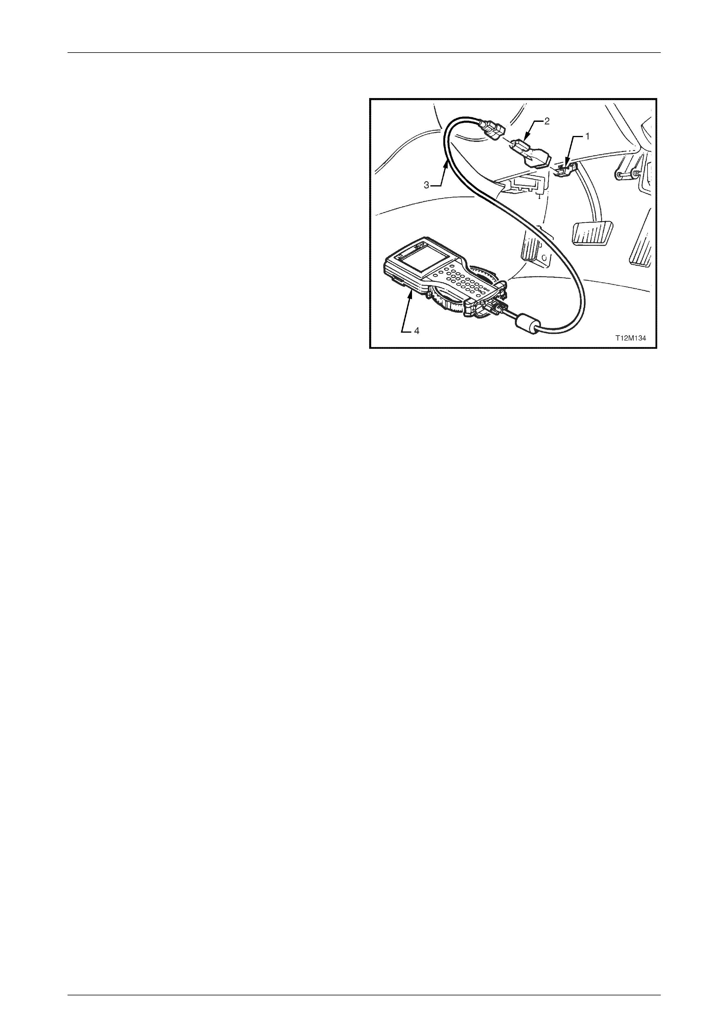
Seat Assemblies Page 1A7A–179
Page 1A7A–179
5.3 Tech 2 Diagnostics
Tech 2, with the appropriate software, cables and adapters,
when connected to the Serial Data Link Connector (DLC)
can read seat and exterior rear-view mirror serial data. The
DLC is attached to the instrument panel trim retainer
beneath the steering wheel.
1 DLC
2 DLC Adapter
3 DLC Cable
4 Tech 2
For additional general information on connecting and
operating Tech 2, refer to 0C Tech 2.
Figure 1A7A – 99
Test Modes
Tech 2 has five test modes for diagnosing the driver's seat and the external rear-view mirrors.
Mode F0: Diagnostic Trouble Codes
If F0: Diagnostic Trouble Codes is selected, a selection list is displayed which contains:
• F0: Read DTC Information – Once this mode is selected, both current and history Diagnostic Trouble Codes
(DTCs) stored in the seat memory module's memory may be displayed.
• F1: Clear DTC Information – Once this mode is selected, DTCs stored in the seat memory module's memory may
be cleared.
Mode F1: Diagnostic Data Display
If F1: Diagnostic Data Display is selected, a selection list is displayed which contains:
• F0: Inputs and Outputs – Once this mode is selected, a list of system components and their inputs, outputs and
their status is display ed .
• F1: Memory – Once this mode is selected, a list of each memory position and the position of each of the seat axes
is displayed.
• F2: System Identification – Once this is selected, details including serial number of the seat memory module are
displayed.
Mode F2: Snapshot
In this test mode, Tech 2 captures seat memory module data before and after a forced manual trigger.
Mode F3: Miscellaneous Tests
In this test mode, Tech 2 displays a list of eight tests that can be utilised to diagnose the driver's seat and the external
rear-view mirrors, refer to 5.4 Tech 2 Test Modes and Displays for Diagnosis for further information.
Mode F4: Additional Functions
In this test m o de, Tech 2 allows the technician to reset the seat, thus clearing all me m o ry positions, refer to
5.4 Tech 2 Test Modes and Displays for Diagnosis for further information.

Seat Assemblies Page 1A7A–180
Page 1A7A–180
5.4 Tech 2 Test Modes and Displays for
Diagnosis
A prerequisite to this diagnostic Section is for the user to be familiar with the proper use of Tech 2. T he following pages
illustrate only the major Tech 2 screen displays and provide a brief e xpla nation of their function for diagnosing the
driver's seat and the external rear-view mirrors. If additional information is required on the oper ation of Tech 2, reference
should be made to either 0C Tech 2 or the Tech 2 User's Guid e.
System Select Menu
With the Tech 2 connected to the DLC, and F0: Diagnostics selected from the Main Menu, the correct Model Year and
Vehicle Type must be selected for access to the System Select Menu.
Select F3: BODY.
This mode contains all functions to test, diag nose, monitor and program the vehicle's body systems including the driver's
seat and the external rear-view mirrors.
Body Application Menu
Once F3: Body has been selected from the System Select Menu, Seat and Exterior Mirror Memory Module can be
selected.
Select Seat and Exterior Mirror Memory Module.
When Seat and Exterior Mirror Memory Module is selected, the following two System Identification screens will
appear, which require action.
System Identification
Turn the ignition to the ON position with the engine not run ning (as requested) and press the Confirm soft key to
continue.
The System Identification Screen will then display information pertaining to the type of seat memory module fitted, serial
number, date of manufacture and other ancillary information. Press the Confirm soft key to continue to the Application
menu. The Identifier code for this seat is 201.
Always refer to the latest General Motors spare parts information for the correct part number.
Application Menu
The following functions will now be available:
• F0: Diagnostic Trouble Codes
• F1: Diagnostic Data Display
• F2: Snapshot
• F3: Miscellaneous Tests
• F4: Additional Functions

Seat Assemblies Page 1A7A–181
Page 1A7A–181
F0: Diagnostic Trouble Codes
If F0: Diagnostic Trouble Codes is selected from the Application menu, the following selection list is displayed:
F0: Read DTC Informa tion
If this mode is selected, a listing of all (if any) DTCs that have been set by the seat memory module will be displayed.
Information displayed with the DTC number/s that have been set, is a short description of what the DTC is, and whether
it is a current (fault present) or history (stored, but not necessarily on this ignition cycle) DTC. Refer to Diagnostic Trouble
Codes in this Section for the full listing of driver's seat and the external rear-view mirrors DTCs with the fault identified.
NOTE
If any DTCs are set, referenc e should be m ade t o
the relevant diagnostic tables in this Section.
F1: Clear DTC Informatio n
DTCs can be cleared in this mode by selecting F1: Clear DTC Information, pressing the ENTER button on T ech 2 and
confirming the action as instructed by Tech 2.
If DTC condition is present, Tech 2 will be unable to clear the DTC and will display Clear DTC Informati on Failed.
Diagnostic Trouble Codes
The following table sets out all the possible diagnostic trouble codes as indicated by Tech 2.
DTC Code Location Fault
1 Eight- way seat adjustme nt switch Front vertical up switch stuck
2 Eight- way seat adjustme nt switch Front vertical down switch stuck
3 Eight- way seat adjustment switch Rear vertical up switch stuck
4 Eight- way seat adjustment switch Rear vertical down switch stuck
5 Eight- way seat adjustment switch Horizontal forward switch stuck
6 Eight- way seat adjustment switch Horizontal back switch stuck
7 Eight- way seat adjustment switch Recline up s witch stuck
8 Eight- way seat adjustment switch Recline down switch stuck
9 Memory positio n switch assembly Memory button 1 stuck
10 Memory position switch assembly Memory button 2 stuck
11 Memory position switch assembly Memory button 3 stuck
12 Memory position switch assembly Mirror dip button stuck
13 Seat memory module No serial data
14 Exterior rear-view mirror circuit No exterior mirror communication
19 Seat memory module ECU malfunction
20 Seat front lift motor Front vertical p osition sensor fault
21 Seat rear lift motor Rear vertical position sensor fault
22 Seat fore / aft movement motor Horizontal position sensor fault
23 Seat-back recline motor Recline position sensor fault
24 Seat assembly System voltage out of range

Seat Assemblies Page 1A7A–182
Page 1A7A–182
F1: Diagnostic Data Display
When F1: Diagnostic Data Display is selected, three sub-headings are displayed by Tech 2.
F0: Inputs and Outputs
F0: Inputs and Outputs displays a list of data streams for various driver's seat and external rear-view mirror
components and their current status. The table in this Section lists all the data streams with a description.
Data Stream /
Screen Display Description
Memory 1 Button Displays the state of button 1 on the memory position switch.
If button 1 on the memory position s witch assembl y is stuck in the depressed position for
more than 8 seconds, DTC 9 will be set.
• Not Pressed / Pressed
Memory 2 Button Displays the state of button 2 on the memory position switch.
If button 2 on the memory position s witch assembl y is stuck in the depressed position for
more than 8 seconds, DTC 10 will set.
• Not Pressed / Pressed
Memory 3 Button Displays the state of button 3 on the memory position switch.
If button 3 on the memory position s witch assembl y is stuck in the depressed position for
more than 8 seconds, DTC 11 will set.
• Not Pressed / Pressed
Mirror DIP Button Displays the state of the mirror dip / memory store (M) button on the memory position
switch.
If the mirror DIP / memory store (M) button on the memory position switch assembly is
stuck in the depressed position for more than 8 seconds, DTC 12 will set.
• Not Pressed / Pressed
Front Vertical Switch Displays the state of the front lift switch on the seat adjustment switch.
If the front vertical switch is stuck in the up position for more than 8 seconds, DTC 1 will set.
If the front vertical switch is stuck in the down position for more than 8 seconds, DTC 2 will
set.
• Inactive / Up / Down
Rear Vertical Switch Displays the state of the rear lift switch on the seat adjustment switch.
If the rear vertical switch is stuck in the up position for more than 8 seconds, DTC 3 will set.
If the front vertical switch is stuck in the down position for more than 8 seconds, DTC 4 will
set.
• Inactive / Up / Down
Horizontal Switch Displays the state of the horizontal switch on the seat adjustment switch.
If the horizontal switch is stuck in the forward position for more than 8 seconds, DTC 5 will
set.
If the horizontal switch is stuck in the aft position for more than 8 seconds, DTC 6 will set.
• Inactive / Forward / Back
Recline Switch Displays the state of the recline switch on the seat adjustment switch.
If the recline switch is stuck in the forward position for more than 8 seconds, DTC 7 will set.
If the recline switch is stuck in the aft position for more than 8 seconds, DTC 8 will set.
• Inactive / Forward / Back

Seat Assemblies Page 1A7A–183
Page 1A7A–183
Data Stream /
Screen Display Description
Front Vertical Position
Sensor Displays if the front lift motor position sensor is connected.
• Connected / Not Connected
Front Vertical Position
Sensor Displ ays the current position of the front lift motor position sensor as a val ue in Steps. The
Steps will range from 0 to 65535.
• 0 – 65535 Steps (typical 31 488 – 33536)
Front Vertical Position
Maximum Limit Displays the maximum limit of travel up in Steps. This value depends on the calibration of
the seat.
This value should be high but never reach 65535 Steps. If the value d isplayed is 65535, the
seat has not been calibrated. Refer to 2.3 Front Seat Assembly to calibrate the seat.
• 0 – 65535 Steps (typical 31 488 – 33536)
Front Vertical Position
Minimum Limit Displays the minimum limit of travel down in Steps. This value depends on the calibration of
the seat.
This value should be low but never reach 0 Steps. If the value displayed is 0, the seat has
not been calibrated. Refer to 2.3 Front Seat Assembly to calibrate the seat.
• 0 – 65535 Steps (typical 31 488 – 33536)
Rear Vertical Position
Sensor Displ ays if the rear lift motor position sensor is connected.
• Connected / Not Connected
Rear Vertical Position
Sensor Displ ays the current position of the rear lift motor position sensor as a value in Steps. The
Steps will range from 0 to 65535.
• 0 – 65535 Steps (typical 31 488 – 33536)
Rear Vertical Position
Maximum Limit Displays the maximum limit of travel up in Steps. This value depends on the calibration of
the seat.
This value should be high but never reach 65535 Steps. If the value d isplayed is 65535, the
seat has not been calibrated. Refer to 2.3 Front Seat Assembly to calibrate the seat.
• 0 – 65535 Steps (typical 31 488 – 33536)
Rear Vertical Position
Minimum Limit Displays the minimum limit of travel down in Steps. This value depends on the calibration of
the seat.
This value should be low but never reach 0 Steps. If the value displayed is 0, the seat has
not been calibrated. Refer to 2.3 Front Seat Assembly to calibrate the seat.
• 0 – 65535 Steps (typical 31 488 – 33536)
Horizontal Position Sensor Displays if the fore/aft movement motor position sensor is c onnected.
• Connected / Not Connected
Horizontal Position Sensor Displays the current position of the fore/aft movement motor position sensor as a value in
Steps. The Steps will range from 0 to 65535.
• 0 – 65535 Steps (typical 20 480 – 40960)
Horizontal Position
Maximum Limit Displays the maximum limit of travel forward in Steps. This value depends on the calibration
of the seat.
This value should be high but never reach 65535 Steps. If the value d isplayed is 65535, the
seat has not been calibrated. Refer to 2.3 Front Seat Assembly to calibrate the seat.
• 0 – 65535 Steps (typical 20 480 – 40960)

Seat Assemblies Page 1A7A–184
Page 1A7A–184
Data Stream /
Screen Display Description
Horizontal Position
Minimum Limit Displays the minimum limit of travel aft in Steps. This value depends on the calibration of
the seat.
This value should be low but never reach 0 Steps. If the value displayed is 0, the seat has
not been calibrated. Refer to 2.3 Front Seat Assembly to calibrate the seat.
• 0 – 65535 Steps (typical 20 480 – 40960)
Recline Position Sensor Displays if the seat-back recline motor position sensor is connected.
• Connected / Not Connected
Recline Position Sensor Displays the current position of the seat-back recline motor position sensor as a value in
Steps. The Steps will range from 0 to 65535.
• 0 – 65535 Steps (typical 16 384 – 45056)
Recline Position Maximum
Limit Displays the maximum limit of travel forward in Steps. T his value depends on the calibration
of the seat.
This value should be high but never reach 65535 Steps. If the value d isplayed is 65535, the
seat has not been calibrated. Refer to 2.3 Front Seat Assembly to calibrate the seat.
• 0 – 65535 Steps (typical 16 384 – 45056)
Recline Position Minimum
Limit Displays the minimum limit of travel aft in Steps. This value depends on the calibration of
the seat.
This value should be low but never reach 0 Steps. If the value displayed is 0, the seat has
not been calibrated. Refer to 2.3 Front Seat Assembly to calibrate the seat.
• 0 – 65535 Steps (typical 16 384 – 45056)
Button Pack
Communication Displays whether there is serial data communication with the mirror control switch,
right-hand or left-hand rear-view mirrors. If there is communication with at least one of these
components, Tech 2 will displa y Okay. If there is no communications with all of the
components, Tech 2 will displa y Not Okay.
If there are no serial data communications, a DTC 14 will set.
• Okay / Not Okay
Right Exterior Mirror
Communication Displays if Tech 2 can communicate with the right-hand exterior rear-vie w mirror.
If there is not serial data communications with the right-hand exterior rear-vie w mirror, a
DTC 14 will set.
• Okay / Not Okay
Left Exterior Mirror
Communication Displays if Tech 2 can communicate with the left-hand exterior rear-view mirror.
If there is not serial data communications with the left-hand exterior rear-view mirror, a DTC
14 will set.
• Okay / Not Okay
Right Exterior Mirror Switch Displays the status of the mirror control switch, when the rocker switch is selected to right.
• Up / Down / Left / Right / Inactive
Left Exterior Mirror Switch Displays the status of the mirror control switch, when the rocker switch is selected to left.
• Up / Down / Left / Right / Inactive
Memory Recall Position In
Use Displays the status of the current memory recall of the seat assembly.
• Memory 1 / Memory 2 / Memory 3 / Priority 1 / Priority 2 / No Active Memory
Current Priority Displays what is the current priority that has been set when the vehicle is unlocked with
either priority key 1 or 2.
• Priority 1 / Priority 2 / No Active Memory

Seat Assemblies Page 1A7A–185
Page 1A7A–185
Data Stream /
Screen Display Description
Able To Recall Displays if the seat assembly has the ability to recall a memory position.
• Yes / No
Start Wait Active Only when there has been a cold-start reset will Tech 2 display No. A cold-start reset will
occur when module detects too much electro m agnetic interference (EMI) in the system. If
the Start Wait Active displays No, the system will still be operational.
• Yes / No
Able To Move When the seat is requested to move, the seat memory module monitors the amou nt of
Steps that a position sensor has taken during that movement. This inability to move at all or
quickly enough may be due to a physical restriction in that movement, or the battery not
having enough charge to power the particular motor adequately.
• Yes / No
Ignition Switch Displays the status of the ignition switch.
• On / Off / Accessory
Demist Request Displays the status of the rear demist system. This will be Yes when the rear demist button
is pressed.
• Yes / No
Reverse Gear Displays if the vehicle is in reverse gear.
• Inactive / Active
PRNDL Position Displays the position of the transmission selector.
• P / R / N / D / 3 / 2 / 1
F1: Memory
F1: MEMORY displays all the five memory settings availabl e. Within each of the memory settings the position of the seat
is displayed (in Steps) and if the mirror dip function is enabled.
Data Stream /
Screen Display Description
Memory 1 Mirror Dip Status Displ ays if the mirror dip function is enabled for Memory 1.
• Enabled / Disabled
Memory 1 Front Vertical
Position Displays the seat front vertical position (in Steps) that has been store d in Memory 1.
• 0 – 65535 Steps (typical 31 488 – 33536)
Memory 1 Rear Vertical
Position Displays the seat rear vertical position (in Steps) that has been stored in Memory 1.
• 0 – 65535 Steps (typical 31 488 – 33536)
Memory 1 Horizontal
Position Displays the seat horizontal position (in Steps) that has been stored in Memory 1.
• 0 – 65535 Steps (typical 20 480 – 40960)
Memory 1 Recline Position Displays the seat-back recline positi on (in Steps) that has been stored in Memory 1.
• 0 – 65535 Steps (typical 16 384 – 45056)
Memory 2 Mirror Dip Status Displ ays if the mirror dip function is enabled for Memory 2.
• Enabled / Disabled
Memory 2 Front Vertical
Position Displays the seat front vertical position (in Steps) that has been store d in Memory 2.
• 0 – 65535 Steps (typical 31 488 – 33536)
Memory 2 Rear Vertical
Position Displays the seat rear vertical position (in Steps) that has been stored in Memory 2.
• 0 – 65535 Steps (typical 31 488 – 33536)

Seat Assemblies Page 1A7A–186
Page 1A7A–186
Data Stream /
Screen Display Description
Memory 2 Horizontal
Position Displays the seat horizontal position (in Steps) that has been stored in Memory 2.
• 0 – 65535 Steps (typical 20 480 – 40960)
Memory 2 Recline Position Displays the seat-back recline positi on (in Steps) that has been stored in Memory 2.
• 0 – 65535 Steps (typical 16 384 – 45056)
Memory 3 Mirror Dip Status Displ ays if the mirror dip function is enabled for Memory 3.
• Enabled / Disabled
Memory 3 Front Vertical
Position Displays the seat front vertical position (in Steps) that has been store d in Memory 3.
• 0 – 65535 Steps (typical 31 488 – 33536)
Memory 3 Rear Vertical
Position Displays the seat rear vertical position (in Steps) that has been stored in Memory 3.
• 0 – 65535 Steps (typical 31 488 – 33536)
Memory 3 Horizontal
Position Displays the seat horizontal position (in Steps) that has been stored in Memory 3.
• 0 – 65535 Steps (typical 20 480 – 40960)
Memory 3 Recline Position Displays the seat-back recline positi on (in Steps) that has been stored in Memory 3.
• 0 – 65535 Steps (typical 16 384 – 45056)
Priority 1 Mirror Dip Status Displays if the mirror dip function is enabled for Priority 1.
• Enabled / Disabled
Priority 1 Front Vertical
Position Displays the seat front vertical position (in Steps) that has been stored in P riority 1.
• 0 – 65535 Steps (typical 31 488 – 33536)
Priority 1 Rear Vertical
Position Displays the seat rear vertical position (in Steps) that has been stored in Priority 1.
• 0 – 65535 Steps (typical 31 488 – 33536)
Priority 1 Horizontal
Position Displays the seat horizontal position (in Steps) that has been stored in Priority 1.
• 0 – 65535 Steps (typical 20 480 – 40960)
Priority 1 Recline Position Displays the seat-back recline position (in Steps) that has been stored in Priorit y 1.
• 0 – 65535 Steps (typical 16 384 – 45056)
Priority 2 Mirror Dip Status Displays if the mirror dip function is enabled for Priority 2.
• Enabled / Disabled
Priority 2 Front Vertical
Position Displays the seat front vertical position (in Steps) that has been stored in P riority 2.
• 0 – 65535 Steps (typical 31 488 – 33536)
Priority 2 Rear Vertical
Position Displays the seat rear vertical position (in Steps) that has been stored in Priority 2.
• 0 – 65535 Steps (typical 31 488 – 33536)
Priority 2 Horizontal
Position Displays the seat horizontal position (in Steps) that has been stored in Priority 2.
• 0 – 65535 Steps (typical 20 480 – 40960)
Priority 2 Recline Position Displays the seat-back recline position (in Steps) that has been stored in Priorit y 2.
• 0 – 65535 Steps (typical 16 384 – 45056)
F2: System Identification
F2: System Identification displays the specifications of the seat memory module, refer to System Identification within
this Section.

Seat Assemblies Page 1A7A–187
Page 1A7A–187
F2: Snapshot
In this mode, Tech 2 captures seat memory module data b efore and after a forced manual trigger.
F3: Miscellaneous Tests
In this mode, a list of tests are displayed that can be used to control certain functions of the driver's seat and the exterior
rear-view mirrors.
F0: Chime
When this test is selected, menu keys are availabl e. To activate the chime function of the seat memory module, press
the On key. The chime will then sound continuously. To turn off the chime, press the Off key. To return to
F3: Miscellaneous Tests menu, press the Quit key.
In this test, the input and output data is also displayed, refer to F0: Inputs and Outputs in this Section.
F1: LED
When this test is selected, menu keys are availabl e. To activate the LED function of the seat memory module, press the
Flash key. The LED will flash. To return to F3: Miscellaneous Tests menu, press the Quit key.
In this test, the input and output data is also displayed, refer to F0: Inputs and Outputs in this Section.
F2: Right Exterior Mirror
When this test is selected, the arrow keys on Tech 2 can be used to drive the right-hand exterior mirror in all four
directions. During this test the data stream for the right-hand exterior mirror will be displayed. The data stream will
change from off to the direction pressed.
F3: Left Exterior Mirror
When this test is selected, the arrow keys on Tech 2 can be used to drive the left-hand exterior mirror in all four
directions. During this test the data stream for the left-hand exterior mirror will be displayed. The data stream will change
from off to the direction pressed.
F4: Front Vertical Motor
When this test is selected, menu keys are available. To drive the front lift motor up, press the Up key and alternatively to
move the front lift motor down, press the Down key.
F5: Rear Vertical Mirror
When this test is selected, menu keys are available. To drive the rear lift motor up, press the Up key and alternatively to
move the rear lift motor down, press the Down key.
F6: Horizontal Motor
When this test is selected, menu keys are availabl e. To drive the seat fore/aft movement motor forward, press the
Forward key and alternatively to move the seat fore/aft movement motor aft, press the Back key.
F7: Recline Motor
When this test is selected, menu keys are availabl e. To drive the seat-back recline motor forward, press the Forward key
and alternatively to move the seat-back recline motor aft, press the Back key.
F4: Additional Functions
F0: Module Reset
This function clears all the preset memories i ncluding any priority key that the seat memory module has stored.
When this function is selected, menu keys are available. Tech 2 will prompt with the message Do you Really Want To
Reset. To reset the module, press the Yes key. If the technician does not want to reset the module, press the No key
and to return the F4: Additional Functions menu.

Seat Assemblies Page 1A7A–188
Page 1A7A–188
5.5 Preliminary System Diagnosis
Prior to starting any diagnosis, the technician should be familiar wi th the driver's seat and the external rear-view mirror
components and operation. For a description of the components and the system operation, refer to
1 General Information.
When investigating any complaint of a problem or malfuncti on, always begin diagnosis with a circuit check, refer to
5.8 Electrical Diagnosis – Memory Seat, Initial Check for a seat fault, or
5.10 Electrical Diagnosis – Rear-view Mirrors, Initial Check for an exterior rear-view mirror fault. If the complaint is of a
mechanical nature, refer to 5.7 Mechanical Diagnosis.
The diagnostic circuit check ensures that the driver's seat and the external rear-view mirrors are communicating on the
serial data line as well as assisting to identify the problem and to ascertain the appropriate diagnostic table in this
Section.

Seat Assemblies Page 1A7A–189
Page 1A7A–189
5.6 Diagnostic Tables
Introduction
The following diagnostic tables are designed to provide fast and efficient fault location and remedy. The diagnostic tables
include a chart, pertinent information, circuit diagrams, and where necessary, the steps are explained by the
corresponding numbered paragraphs.
When performing wiring checks as directed to by the diagnostic tables, rather than probe pins and co nnectors with
incorrect sized multimeter connectio ns, use the ad apters contained in connector test adapter kit Tool No. KM-609 and
test lead set Tool No. KM609-20. This will prevent any possibility of spreading or damaging wiring harness pins and
causing a system intermittent failure.

Seat Assemblies Page 1A7A–190
Page 1A7A–190
5.7 Mechanical Diagnosis
Lumbar Support Inoperative
Introduction
This test is used to aid in diagnosing the lumbar support as sembly.
Test Description
The following numbers refer to the step numbers in the diagnostic table:
1 Checks if the lumbar support knob is properly engaging the lumbar support adjuster. Check the knob for cracks and
worn splines.
2 Checks if the lumbar support assembly is damage d or worn and if the retaining springs are serviceable and
securely attached to the seat back frame assembly.
3 Checks if the lumbar support assembly is serviceable and if the lumber support assembly strap is operating
correctly within the guide rails.
Diagnostic Table
Step Action Yes No
1 Remov e the lu mbar support knob, refer to 2.9 Lumbar Support Knob
Assembly.
Is the lumbar support adjust knob serviceable? Go to Step 2
Replace the knob,
refer to 2.9 Lumbar
Support Knob
Assembly
2 1 Remov e the seat-back cover.
2 Inspect the lumbar support retainers and spri ngs.
Are the lumbar support retaining spri ngs serviceable and securel y
attached to the seat-back frame assembly? Go to Step 3
Replace or reattach
the retaining
springs, refer to
2.11 Front Seat-
back Frame
Assembly
3 1 Visually inspect the lumbar support assembl y. Check for broken
or worn parts.
2 Check the strap running across the lumber s upport assembly is
serviceable and running freely within the guide rails.
NOTE
You may need to attach the lumber support knob to
actuate the strap.
Is the lumbar support assembly serviceabl e? System serviceable
Replace lumbar
support assembly or
resecure lumbar
support assembly
strap ensuring strap
is not binding with
guide rails, refer to
2.11 Front Seat-
back Frame
Assembly
When all diagno sis and repairs are completed, check the system for correct operation.
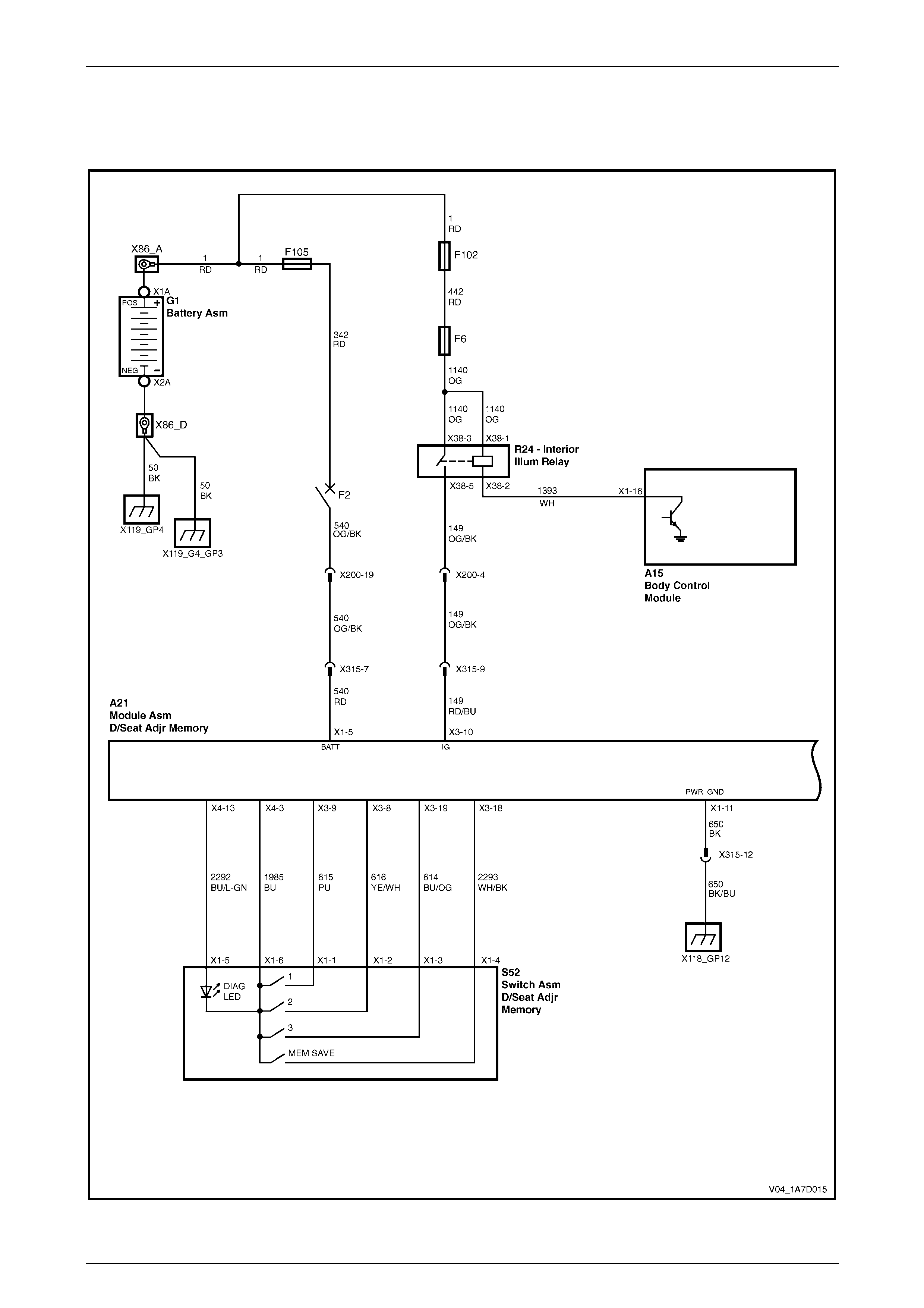
Seat Assemblies Page 1A7A–191
Page 1A7A–191
5.8 Electrical Diagnosis – Memory Seat
Wiring Diagram
Figure 1A7A – 100
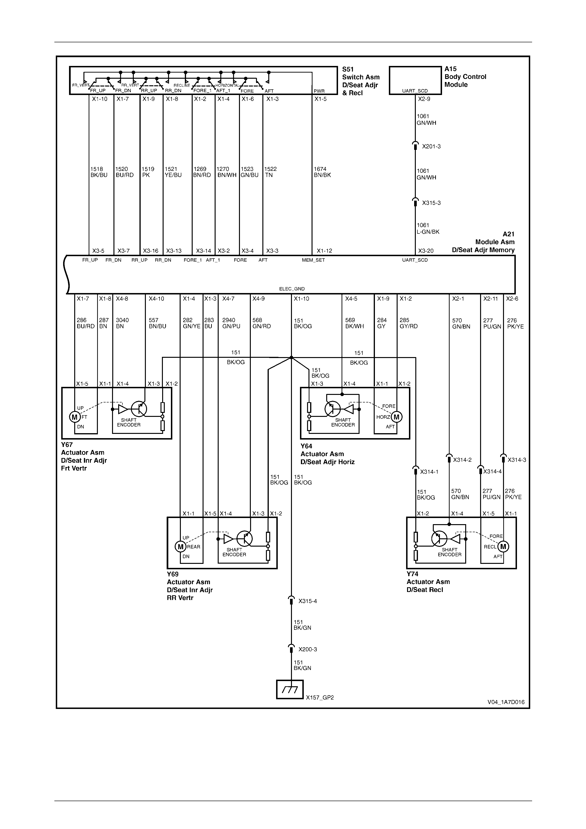
Seat Assemblies Page 1A7A–192
Page 1A7A–192
Figure 1A7A – 101
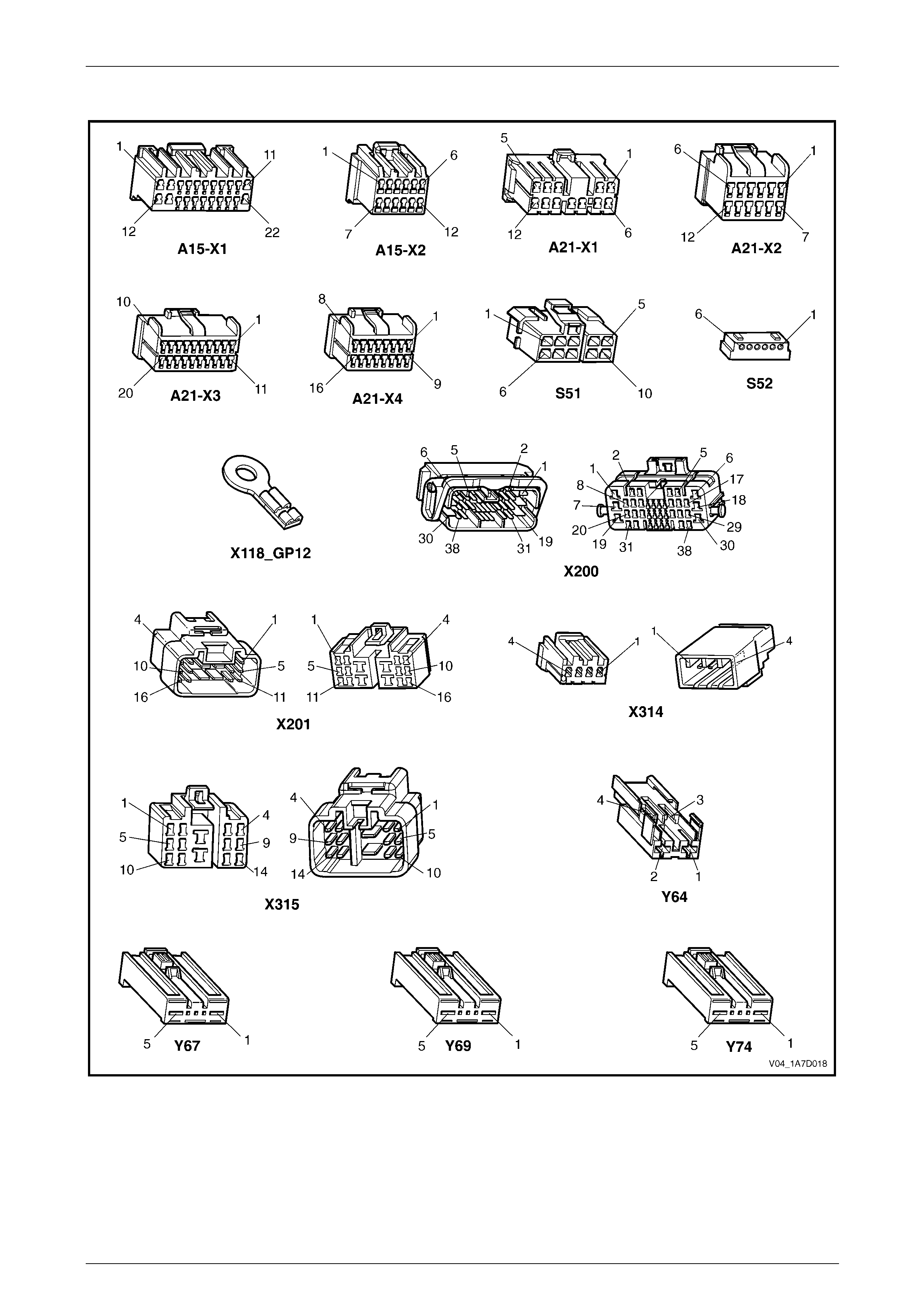
Seat Assemblies Page 1A7A–193
Page 1A7A–193
Connector Chart
Figure 1A7A – 102

Seat Assemblies Page 1A7A–194
Page 1A7A–194
Initial Check
Introduction
The driver's seat and exterior rear-view mirrors can be diagnosed using T ech 2. The diagnostic table tests each function
of the seat for correct operation.
Test Description
The following numbers refer to the step numbers in the diagnostic table:
1 Checks if the fault is isolated to the driver’s seat.
2 If Tech 2 cannot access the System Identification menu there is a problem with the power, serial data
communications or ground cir cuits to the memory module.
3 Checks if there are any current DTCs.
4-11 Checks if the seat adjustment switch is serviceable. Also checks if the associated motor circuits are serviceable.
12 Using Tech 2, checks if the memory position s witch assembly is operational.
13 Checks if the seat front lift motor hall-effect sensor is connected.
14 Checks if the seat front lift motor hall-effect sensor (in Steps) has an acceptable maximum, minimum value and
current seat position is within that rang e.
15 Checks if the seat rear lift motor hall-effect sensor is connected.
16 Checks if the seat rear lift motor hall-effect sensor (in Steps) has an acce ptable maximum, minimum val ue and
current seat position is within that rang e.
17 Checks if the seat horizontal motor hall-effect sensor is connected.
18 Checks if the seat horizontal motor hall-effect sensor (in Steps) has an acceptable maximum, minimum value and
current seat position is within that rang e.
19 Checks if the seat recline motor hall-effect sensor is connected.
20 Checks if the seat recline mot or hal l-effect sensor (in Steps) has an acceptable maximum, minimum value and
current seat position is within that rang e.
21 Checks if the seat memory module stores a different seat position for each of the three memory buttons. Checks if
when each of the memory buttons are pressed, the seat moves to the stored position and Tech 2 displays the
correct information.
22 Checks if the seat recalls a priority key memory position.

Seat Assemblies Page 1A7A–195
Page 1A7A–195
Diagnostic Table
Step Action Yes No
1 Are all of the passenger’s seat adjustment switch functions
inoperative? Refer to Neither
Seat Adjustment
Switch Functions
Operate in 4.6
Electrical Diagnosis
– Eight-way Seat Go to Step 2
2 1 Connect Tech 2 to the DLC.
2 On Tech 2 select:
Body / Seat and Exterior Mirror Memory Module.
3 Turn the ignition on when prompted.
Is the Seat and Exterior Mirror Module System Identification
specifications displayed? Go to Step 3
Refer to No Serial
Data
Communications to
the Seat Memory
Module in this
Section
3 On Tech 2 select:
Body / Seat and Exterior Mirror Memory Module / Diagnostic
Trouble Codes / Read DTC Information.
Are there any DTCs set?
Refer to the relevant
DTC diagnostic
table in this Section Go to Step 4
4 1 Connect Tech 2 to the DLC.
2 On Tech 2 select:
Body / Seat and Exterior Mirror Memory Module / Diagnostic
Data Display / Inputs and Outputs.
3 Scroll to Front Vertical Switch.
4 While monitoring Tech 2, operate the seat a djustme nt switch to
raise and lower the front of the seat.
Does Tech 2 display the fol lowing:
• Inactive when the switch is in the neutral position.
• Up when the switch is in the up positio n.
• Down when the switch is in the down positio n. Go to Step 5
Refer to Seat
Adjustment Switch
Inoperative in this
Section
5 During the test in Step 4, does the front of the seat move in the
following directions?
• When the switch is in the neutral position, the front of the seat
does not move.
• When the switch is in the up position, the front of the seat raises.
• When the switch is in the down position, the front of the seat
lowers.
NOTE
Ensure that the seat is not at its maximum limit of travel
before performing this test. Go to Step 6
Refer to Seat Front
Lift Motor
Inoperative in this
Section
6 1 On Tech 2 select:
Rear Seat Vertical Switch.
2 While monitoring Tech 2, operate the seat a djustme nt switch to
raise and lower the rear of the seat.
Does Tech 2 display the fol lowing:
• Inactive when the switch is in the neutral position.
• Up when the switch is in the up positio n.
• Down when the switch is in the down positio n. Go to Step 7
Refer to Seat
Adjustment Switch
Inoperative in this
Section

Seat Assemblies Page 1A7A–196
Page 1A7A–196
Step Action Yes No
7 During the test in Step 6, does the rear of the seat move in the
following directions?
• When the switch is in the neutral position, the rear of the seat
does not move.
• When the switch is in the up position, the rear of the seat raises.
• When the switch is in the down position, the rear of the seat
lowers.
NOTE
Ensure that the seat is not at its maximum limit of travel
before performing this test. Go to Step 8
Refer to Seat Rear
Lift Motor
Inoperative in this
Section
8 1 On Tech 2 select:
Horizontal Switch.
2 While monitoring Tech 2, operate the seat a djustme nt switch to
move the seat forward and aft.
Does Tech 2 display the fol lowing:
• Inactive when the switch is in the neutral position.
• Forward when the switch is in the forward position.
• Back when the switch is in the aft position. Go to Step 9
Refer to Seat
Adjustment Switch
Inoperative in this
Section
9 During the test in Step 8, does the seat move in the following
directions?
• When the switch is in the neutral position, the seat does not
move.
• When the switch is in the forward position, the seat moves
forward.
• When the switch is in the aft position, the seat moves aft.
NOTE
Ensure that the seat is not at its maximum limit of travel
before performing this test. Go to Step 10
Refer to Seat
Fore/Aft Movement
Motor Inoperative in
this Section
10 1 On Tech 2 select:
Recline Switch.
2 While monitoring Tech 2, operate the seat a djustme nt switch to
move the seat-back forward and aft.
Does Tech 2 display the fol lowing:
• Inactive when the switch is in the neutral position.
• Forward when the switch is in the forward position.
• Back when the switch is in the aft position. Go to Step 11
Refer to Seat
Adjustment Switch
Inoperative in this
Section

Seat Assemblies Page 1A7A–197
Page 1A7A–197
Step Action Yes No
11 During the test in Step 10, does the seat-back move in the following
directions?
• When the switch is in the neutral position, the seat-back does
not move.
• When the switch is in the forward position, th e seat-back moves
forward.
• When the switch is in the aft position, the seat-back moves aft.
NOTE
Ensure that the seat is not at its maximum limit of travel
before performing this test. Go to Step 12
Refer to Seat
Fore/Aft Movement
Motor Inoperative in
this Section
12 1 On Tech 2 select:
Memory Button 1.
2 While monitoring Tech 2, press the following buttons:
• Memory button 1
• Memory button 2
• Memory button 3
• Mirror dip / memory button
Does Tech 2 display Active next to the corresponding button? Go to Step 13
Refer to Memory
Position Switch
Inoperative in this
Section
13 On Tech 2 select:
Front Vertical Position Sensor.
Does Tech 2 display the hal l-effect sensor is Connected? Go to Step 14
Refer to Seat Front
Lift Motor Hall-effect
Sensor Check in
this Section
14 1 On Tech 2 select:
Front Vertical Position Maximum Limit.
2 Check the following values displayed on Tech 2:
• Front Vertical Maximum Position Limit. This should be
less than 65535 Steps.
• Front Vertical Minimum Position Limit. This should be
more than 0 Steps.
• Front Vertical Position Sensor. This value should be
between the minimum and maximum values. Go to Step 15
Disconnect battery
power from the seat
and perform the
calibration
procedure, refer to
2.3 Front Seat
Assembly
15 On Tech 2 select:
Rear Vertical Position Sensor.
Does Tech 2 display the hal l-effect sensor is Connected? Go to Step 16
Refer to Seat Rear
Lift Motor Hall-effect
Sensor Check in
this Section
16 1 On Tech 2 select:
Rear Vertical Position Maximum Limit.
2 Check the following values displayed on Tech 2:
• Rear Vertical Maximum Position Limit. This should be
less than 65535 Steps.
• Rear Vertical Minimum Position Limit. This should be
more than 0 Steps.
• Rear Vertical Position Sensor. This value should be
between the minimum and maximum values. Go to Step 17
Disconnect battery
power from the seat
and perform the
calibration
procedure, refer to
2.3 Front Seat
Assembly

Seat Assemblies Page 1A7A–198
Page 1A7A–198
Step Action Yes No
17 On Tech 2 select:
Horizontal Position Sensor.
Does Tech 2 show the hall-effect sensor is Connected? Go to Step 18
Refer to Seat
Fore/Aft Movement
Motor Hall-effect
Sensor Check in
this Section
18 1 On Tech 2 select:
Horizontal Position Maximum Limit.
2 Check the following values displayed on Tech 2:
• Horizontal Maximum Position Limit. This should be less
than 65535 Steps.
• Horizontal Minimum Position Limit. This should be more
than 0 Steps.
• Horizontal Position Sensor. This value should be
between the minimum and maximum values. Go to Step 19
Disconnect battery
power from the seat
and perform the
calibration
procedure, refer to
2.3 Front Seat
Assembly
19 On Tech 2 select:
Recline Position Sensor.
Does Tech 2 show the hall-effect sensor is Connected? Go to Step 20
Refer to Seat-back
Recline Motor
Inoperative in this
Section
20 1 On Tech 2 select:
Recline Position Maximum Limit.
2 Check the following values displayed on Tech 2:
• Recline Maximum Position Limit. This should be less
than 65535 Steps.
• Recline Minimum Position Limit. This should be more
than 0 Steps.
• Recline Position Sensor. This value should be between
the minimum and maximum values. Go to Step 21
Disconnect battery
power from the seat
and perform the
calibration
procedure, refer to
2.3 Front Seat
Assembly

Seat Assemblies Page 1A7A–199
Page 1A7A–199
Step Action Yes No
21 1 Store a new memory pos ition in each of the available positions
(Memory Button 1, 2 and 3), refer to 1 General Information for
instructions (or the Owner Manual).
NOTE
When a seat position is stored into the relevant memory
position, the seat will chime. For each of the memory
positions, confirm the chime.
2 After the last position has been stored in memory, move the seat
out of that position.
3 On Tech 2 select:
Memory Recall Position. Tech 2 should display No Active
Memory.
4 While monitoring Tech 2, press memor y but t on 1. The seat will
move to the stored position and Tech 2 will display Memory
Button 1 while the button is pressed. When the seat comes to a
stop and the button is released, does Tech 2 display Memory
Button 1.
5 While monitoring Tech 2, press memor y but t on 2. The seat will
move to the stored position and Tech 2 will display Memory
Button 2. When the seat comes to a stop and the button is
released, does Tech 2 display Memory Button 2.
6 While monitoring Tech 2, press memor y but t on 3. The seat will
move to the stored position and Tech 2 will display Memory
Button 3. When the seat comes to a stop, does Tech 2 display
Memory Button 3.
Does Tech 2 display the relevant memory positions as described in
this test? Go to Step 22
Replace the seat
memory module,
refer to 2.12 Seat
Cable Tray and
Memory Module
22 NOTE
To perform this test, both keys supplied with the vehicle
are needed.
1 On Tech 2 select:
Current Priority and ensure that No Active Memory is
displayed.
2 Disconnect Tech 2 from the vehicle.
3 Using the seat adjustment switch, move the seat to a new
position and lock the car with the Remote Control from Ke y 1.
4 Unlock the vehicle with the Remote Control from Key 1.
5 Connect Tech 2 to the DLC.
6 On Tech 2 select:
Body / Seat and Exterior Mirror Memory Module / Diagnostic
Data Display / Inputs and Outputs and scroll to Current
Priority.
Does Tech 2 display e ither Priority 1 or Priority 2? System serviceable
Refer to Priority Key
Feature Inoperative
in this Section
When all diagno sis an d repairs are completed, clear all DT Cs and check the system for correct operation.

Seat Assemblies Page 1A7A–200
Page 1A7A–200
No Serial Data Communications to the Seat Memory Module
Introduction
For Tech 2 to communicate with the seat memory module, the following must be satisfied:
• There must be no faults in the serial data bus. If there is a fault, it can be caused at any where on the bus and
consist of a short to ground or battery, or an open circuit.
• There must be power and ground circuit to the seat memory module.
If either of these problems exist, Tech 2 will not communicate with either the seat memory module or the entire serial
data bus, depending on where the fault is.
Refer to Wiring Diagram and Connector Chart in this Section to aid in diagnosing the se at memory module and
associated components.
Test Description
The following numbers refer to the step numbers in the diagnostic table:
1 Checks if Tech 2 is able to communicate with other modules in the vehicle. Isolates whether the problem is with the
seat memory module and its circuits or with the serial data bus.
2 Checks if circuit breaker F2 is serviceable.
3 Checks if there is battery supply to the seat memory module at connector A21 – X1.
4 Circuit 650 provides a ground circuit for the seat memory module. Checks if there is an open circuit in circuit 650.
5 Circuit 151 provides a ground circuit for the seat memory module. Checks if there is an open circuit in circuit 151.
6 Checks if there is continuity in the serial data line between the seat memory module and the BCM.
7 Checks if fusible link F105 is serviceable.
8 Checks for battery voltage at connector X200 pin 19. Isolates whether there is a fault in circuit 540 between
connectors X200 and A21–X1 or between X200 and circuit breaker F2.
Diagnostic Table Notes
1 For all wiring harness fault diagnoses, refer to 12P Wirin g Diagrams.
2 For wiring harness repairs, refer to 12P Wiring Diagrams.
3 Refer to 12O Fuses, Relays and Wiring Harnesses for harness routeing.
4 If the fault is deemed to be intermittent, refer to 12P Wiring Diagrams.

Seat Assemblies Page 1A7A–201
Page 1A7A–201
Diagnostic Table
Step Action Yes No
1 1 Connect Tech 2 to the DLC.
2 Turn the ignition to the ON position with the engine not running.
3 On Tech 2 select:
Body / DTC Check / DTC Check and press the Confirm soft
key when instructed. If No Data is displayed next to a control
module, there is no communication b etween Tech 2 and that
particular control module.
Can Tech 2 communicate with the BCM and the PCM? Go to Step 2 Refer to 12J Body
Control Module
2 1 Disconnect Tech 2 from the DLC.
2 Check the circuit breaker F2, located on the passenger
compartment fuse and relay panel.
Is the circuit breaker F2 serviceable?
Go to Step 3
Allow the circuit
breaker to reset
(refer to Note 3).
If the circuit breaker
trips again, repair or
replace circuit 540
(refer to Note 2)
3 Backprobe connector A21 – X1 pin 5 with a test lamp (refer to Note 1).
Does the test lamp illuminate? Go to Step 4 Go to Step 7
4 1 Disconnect connector A21 – X1 from the seat memory module.
2 Using a multimeter set to measure resistance, probe between
connector A21 – X1 pin 11 and a known ground (refer to
Note 1).
Does the multimeter indicate continuity? Go to Step 5
Repair or replace
circuit 650 (refer to
Note 2)
5 Using a multimeter set to measure resistance, probe between
connector A21 – X1 pin 10 and a known ground (refer to Note 1).
Does the multimeter indicate continuity? Go to Step 6
Repair or replace
circuit 151 (refer to
Note 2)
6 1 Disconnect connectors A21 – X3 from the seat memory module
and A15 – X2 from the BCM.
2 Using a multimeter set to measure resistance, probe between
connectors A21 – X3 pin 20 and A15 – X2 pin 9 (refer to
Note 1).
Does the multimeter indicate continuity?
Replace the seat
memory module,
refer to 2.12 Seat
Cable Tray and
Memory Module
Repair or replace
circuit 1061 (refer to
Note 2)
7 Check the fusible link F105, located on the engine compartment fuse
and relay panel assemb ly.
Is the fusible link F105 serviceable?
Go to Step 8
Replace the fusible
link F105.
If the fusible link
blows again, repair
or replace circuits 1,
342 and 540 (refer
to Note 1)
8 Backprobe connector X200 pin 19 with a test lamp (refer to Note 1).
Does the test lamp illuminate? Repair or replace
circuit 540 between
connectors X200
and A21 – X1 (refer
to Note 2)
Repair or replace
circuit 540 between
the circuit breaker
F2 and connector
X200 (refer to
Note 2)
When all diagno sis an d repairs are completed, clear all DT Cs and check the system for correct operation.

Seat Assemblies Page 1A7A–202
Page 1A7A–202
Seat Adjustment Switch Inoperative
Introduction
The seat adjustment switch provides manual control for the driver's seat. It is connected by a harness to the seat
memory module.
Refer to Wiring Diagram and Connector Chart in this Section to aid in diagnosing the se at memory module and
associated components.
Test Description
The following numbers refer to the step numbers in the diagnostic table:
2 Checks if there is battery power at connector A21 – X1 pin 12. Isolates if the seat memory module is fau lty.
3 Checks if there is battery power to the seat adjustment switch. Isolates if circuit 1674 is faulty.
4 Checks the seat adjustment switch for serviceability. Isolates if the seat adjustment switch is faulty.
5 Checks the harness connecting the seat adjustment switch to the seat memory module for a short to ground.
6 Checks the harness connecting the seat adjustment switch to the seat memory module for an open circuit. Isolates
whether the harness or the seat memory module is faulty.
Diagnostic Table Notes
1 For all wiring harness fault diagnoses, refer to 12P Wirin g Diagrams.
2 For wiring harness repairs, refer to 12P Wiring Diagrams.
3 Refer to 12O Fuses, Relays and Wiring Harnesses for harness routeing.
4 If the fault is deemed to be intermittent, refer to 12P Wiring Diagrams.

Seat Assemblies Page 1A7A–203
Page 1A7A–203
Diagnostic Table
Step Action Yes No
1 Has the Initial Check been performed?
Go to Step 2
Perform the Initial
Check in this
Section
2 Backprobe connector A21 – X1 pin 1 2 with a test lamp (refer to
Note 1).
Does the test lamp illuminate? Go to Step 3
Replace the seat
memory module,
refer to 2.12 Seat
Cable Tray and
Memory Module
3 Backprobe connector S51 – X1 pin 5 with a test lamp (refer to Note 1).
Does the test lamp illuminate? Go to Step 4
Repair or replace
circuit 1674 (refer to
Note 2)
4 Test the seat adjustment switch, refer to 3.6 Eight-way Seat
Adjustment Switch Test.
Is the seat adjustment switch serviceable? Go to Step 5
Replace the seat
adjustment switch,
refer to 2.4 Front
Seat Outer Side
Cover Assembly
5 Using a multimeter set to measure resistance, probe between the
following connectors and a known ground (refer to Note 1):
• S51 – X1 pin 10
• S51 – X1 pin 7
• S51 – X1 pin 9
• S51 – X1 pin 8
• S51 – X1 pin 2
• S51 – X1 pin 4
• S51 – X1 pin 6
• S51 – X1 pin 3
Does the multimeter indicate continuity in any of the above tests?
Repair or replace
the relevant circuit
that displays
continuity on the
multimeter (refer to
Note 2) Go to Step 6
6 1 Disconnect harness connector A21 – X3 from the seat memory
module.
2 Using a multimeter set to measure resistance, probe between
the following connectors (refer to Note 1):
• S51 – X1 pin 10 and A21 – X3 pin 5
• S51 – X1 pin 7 and A21 – X3 pin 7
• S51 – X1 pin 9 and A21 – X3 pin 16
• S51 – X1 pin 8 and A21 – X3 pin 13
• S51 – X1 pin 2 and A21 – X3 pin 14
• S51 – X1 pin 4 and A21 – X3 pin 2
• S51 – X1 pin 6 and A21 – X3 pin 4
• S51 – X1 pin 3 and A21 – X3 pin 3
Does the multimeter indicate continuity in all of the above tests?
Replace the seat
memory module,
refer to 2.12 Seat
Cable Tray and
Memory Module
Repair or replace
the relevant circuit
that does not
display continuity on
the multimeter (refer
to Note 2)
When all diagno sis an d repairs are completed, clear all DT Cs and check the system for correct operation.

Seat Assemblies Page 1A7A–204
Page 1A7A–204
Seat Front Lift Motor Inoperative
Introduction
The seat front lift motor is controlled by the seat memory module which provides power and ground for the motor. The
polarity of the motor is alternated to change the direction of the motor.
Refer to Wiring Diagram and Connector Chart in this Section to aid in diagnosing the se at memory module and
associated components.
Test Description
The following numbers refer to the step numbers in the diagnostic table:
2 Checks if there is battery power from the seat memory module to raise the front of the seat. Isolates if the seat
memory module is faulty.
3 Checks if there is battery power to the motor to raise the front of the seat. Isolates if circuit 286 is faulty.
4 Checks if there is battery power from the seat memory module to lower the front of the seat. Isolates if the seat
memory module is faulty.
5 Checks if there is battery power to the motor to lower the front of the seat. Isolates whether circuit 287 or the seat
motor is faulty.
Diagnostic Table Notes
1 For all wiring harness fault diagnoses, refer to 12P Wirin g Diagrams.
2 For wiring harness repairs, refer to 12P Wiring Diagrams.
3 Refer to 12O Fuses, Relays and Wiring Harnesses for harness routeing.
4 If the fault is deemed to be intermittent, refer to 12P Wiring Diagrams.
Diagnostic Table
Step Action Yes No
1 Has the Initial Check been performed?
Go to Step 2
Perform the Initial
Check in this
Section
2 1 Backprobe connector A21 – X1 pin 7 with a test lamp (refer to
Note 1).
2 Operate the seat adjustment switch to raise the front of the seat.
Does the test lamp illuminate? Go to Step 3
Replace the seat
memory module,
refer to 2.12 Seat
Cable Tray and
Memory Module
3 1 Backprobe connector Y67 – X1 pin 5 with a test lamp (refer to
Note 1).
2 Operate the seat adjustment switch to raise the front of the seat.
Does the test lamp illuminate? Go to Step 4
Repair or replace
circuit 286 (refer to
Note 2)
4 1 Backprobe connector A21 – X2 pin 7 with a test lamp (refer to
Note 1).
2 Operate the seat adjustment switch to lower the front of the seat.
Does the test lamp illuminate? Go to Step 5
Replace the seat
memory module,
refer to 2.12 Seat
Cable Tray and
Memory Module
5 1 Backprobe connector Y67 – X1 pin 1 with a test lamp (refer to
Note 1).
2 Operate the seat adjustment switch to lower the front of the seat.
Does the test lamp illuminate?
Replace the seat
front lift motor, refer
to 2.16 Front Seat
Lift Motor
Assemblies
Repair or replace
circuit 287 (refer to
Note 2)
When all diagno sis an d repairs are completed, clear all DT Cs and check the system for correct operation.

Seat Assemblies Page 1A7A–205
Page 1A7A–205
Seat Rear Lift Motor Inoperative
Introduction
The seat rear lift motor is controlled by the seat memory module which provides power and ground for the motor. The
polarity of the motor is alternated to change the direction of the motor.
Refer to Wiring Diagram and Connector Chart in this Section to aid in diagnosing the se at memory module and
associated components.
Test Description
The following numbers refer to the step numbers in the diagnostic table:
2 Checks if there is battery power from the seat memory module to raise the rear of the seat. Isolates if the seat
memory module is faulty.
3 Checks if there is battery power to the motor to raise the rear of the seat. Isolates if circuit 282 is faulty.
4 Checks if there is battery power from the seat memory module to lower the rear of the seat. Isolates if the seat
memory module is faulty.
5 Checks if there is battery power to the motor to lower the rear of the seat. Isolates whether circuit 283 or the seat
motor is faulty.
Diagnostic Table Notes
1 For all wiring harness fault diagnoses, refer to 12P Wirin g Diagrams.
2 For wiring harness repairs, refer to 12P Wiring Diagrams.
3 Refer to 12O Fuses, Relays and Wiring Harnesses for harness routeing.
4 If the fault is deemed to be intermittent, refer to 12P Wiring Diagrams.
Diagnostic Table
Step Action Yes No
1 Has the Initial Check been performed?
Go to Step 2
Perform the Initial
Check in this
Section
2 1 Backprobe connector A21 – X1 pin 4 with a test lamp (refer to
Note 1).
2 Operate the seat adjustment switch to raise the rear of the seat.
Does the test lamp illuminate? Go to Step 3
Replace the seat
memory module,
refer to 2.12 Seat
Cable Tray and
Memory Module
3 1 Backprobe connector Y69 – X1 pin 1 with a test lamp (refer to
Note 1).
2 Operate the seat adjustment switch to raise the rear of the seat.
Does the test lamp illuminate? Go to Step 4
Repair or replace
circuit 282 (refer to
Note 2)
4 1 Backprobe connector A21 – X1 pin 3 with a test lamp (refer to
Note 1).
2 Operate the seat adjustment switch to lower the rear of the seat.
Does the test lamp illuminate? Go to Step 5
Replace the seat
memory module,
refer to 2.12 Seat
Cable Tray and
Memory Module
5 1 Backprobe connector Y69 – X1 pin 5 with a test lamp (refer to
Note 1).
2 Operate the seat adjustment switch to lower the rear of the seat.
Does the test lamp illuminate?
Replace the seat
rear lift motor, refer
to 2.16 Front Seat
Lift Motor
Assemblies
Repair or replace
circuit 283 (refer to
Note 2)
When all diagno sis an d repairs are completed, clear all DT Cs and check the system for correct operation.

Seat Assemblies Page 1A7A–206
Page 1A7A–206
Seat Fore/Aft Movement Motor Inoperative
Introduction
The seat fore/aft movement motor is controlled by the seat memory module which provides power and ground for the
motor. The polarity of the motor is alternated to change the direction of the motor.
Refer to Wiring Diagram and Connector Chart in this Section to aid in diagnosing the se at memory module and
associated components.
Test Description
The following numbers refer to the step numbers in the diagnostic table:
2 Checks if there is battery power from the seat memory module to move the seat forward. Isolates if the seat
memory module is faulty.
3 Checks if there is battery power to the motor to move the seat forward. Isolates if circuit 285 is faulty.
4 Checks if there is battery power from the seat memory module to move the seat aft. Isolates if the seat memory
module is faulty.
5 Checks if there is battery power to the motor to move the seat aft. Isolates whether circuit 284 or the seat motor is
faulty.
Diagnostic Table Notes
1 For all wiring harness fault diagnoses, refer to 12P Wirin g Diagrams.
2 For wiring harness repairs, refer to 12P Wiring Diagrams.
3 Refer to 12O Fuses, Relays and Wiring Harnesses for harness routeing.
4 If the fault is deemed to be intermittent, refer to 12P Wiring Diagrams.
Diagnostic Table
Step Action Yes No
1 Has the Initial Check been performed?
Go to Step 2
Perform the Initial
Check in this
Section
2 1 Backprobe connector A21 – X1 pin 2 with a test lamp (refer to
Note 1).
2 Operate the seat adjustment switch to move the seat forward.
Does the test lamp illuminate? Go to Step 3
Replace the seat
memory module,
refer to 2.12 Seat
Cable Tray and
Memory Module
3 1 Backprobe connector Y64 – X1 pin 2 with a test lamp (refer to
Note 1).
2 Operate the seat adjustment switch to move the seat forward.
Does the test lamp illuminate? Go to Step 4
Repair or replace
circuit 285 (refer to
Note 2)
4 1 Backprobe connector A21 – X1 pin 9 with a test lamp (refer to
Note 1).
2 Operate the seat adjustment switch to move the seat aft.
Does the test lamp illuminate? Go to Step 5
Replace the seat
memory module,
refer to 2.12 Seat
Cable Tray and
Memory Module
5 1 Backprobe connector Y64 – X1 pin 1 with a test lamp (refer to
Note 1).
2 Operate the seat adjustment switch to move the seat aft.
Does the test lamp illuminate?
Replace the seat
fore/aft movement
motor, refer to 2.17
Front Seat Fore/Aft
Movement Motor
Assembly
Repair or replace
circuit 284 (refer to
Note 2)
When all diagno sis an d repairs are completed, clear all DT Cs and check the system for correct operation.

Seat Assemblies Page 1A7A–207
Page 1A7A–207
Seat-back Recline Motor Inoperative
Introduction
The seat-back recline motor is controll ed by the seat memory module which provides power and ground for the motor.
The polarity of the motor is alternated to change the direction of the motor.
Refer to Wiring Diagram and Connector Chart in this Section to aid in diagnosing the se at memory module and
associated components.
Test Description
The following numbers refer to the step numbers in the diagnostic table:
2 Checks if there is battery power from the seat memory module to move the seat-back forward. Isolates if the seat
memory module is faulty.
3 Checks if there is battery power to the motor to move the seat-back forward. Isolates if circuit 276 is faulty.
4 Isolates whether there is a fault in circuit 276 between connectors A21 – X2 pin 6 and X314 pin 3 or between
connectors X314 pin 3 and Y74 – X1 pin 1.
5 Checks if there is battery power from the seat memory module to move the seat-back aft . Isolates if the seat
memory module is faulty.
6 Checks if there is battery power to the motor to move the seat-back aft. Isolates whether circuit 277 or the seat
motor is faulty.
7 Isolates whether there is a fault in circuit 277 between connectors A21 – X2 pin 11 and X314 pin 4 or between
connectors X314 pin 4 and Y74 – X1 pin 5.
Diagnostic Table Notes
1 For all wiring harness fault diagnoses, refer to 12P Wirin g Diagrams.
2 For wiring harness repairs, refer to 12P Wiring Diagrams.
3 Refer to 12O Fuses, Relays and Wiring Harnesses for harness routeing.
4 If the fault is deemed to be intermittent, refer to 12P Wiring Diagrams.

Seat Assemblies Page 1A7A–208
Page 1A7A–208
Diagnostic Table
Step Action Yes No
1 Has the Initial Check been performed?
Go to Step 2
Perform the Initial
Check in this
Section
2 1 Backprobe connector A21 – X2 pin 6 with a test lamp (refer to
Note 1).
2 Operate the seat adjustment switch to move the seat-back
forward.
Does the test lamp illuminate? Go to Step 3
Replace the seat
memory module,
refer to 2.12 Seat
Cable Tray and
Memory Module
3 1 Backprobe connector Y74 – X1 pin 1 with a test lamp (refer to
Note 1).
2 Operate the seat adjustment switch to move the seat-back
forward.
Does the test lamp illuminate? Go to Step 5 Go to Step 4
4 1 Backprobe connector X31 4 pin 3 with a test lamp (refer to Note
1).
2 Operate the seat adjustment switch to move the seat-back
forward.
Does the test lamp illuminate?
Repair or replace
circuit 276 between
connectors
X314 pin 3 and
Y74 – X1 pin 1
(refer to Note 2)
Repair or replace
circuit 276 between
connectors
A21 – X2 pin 6 and
X314 pin 3 (refer to
Note 2)
5 1 Backprobe connector A21 – X2 pin 11 with a test lamp (refer to
Note 1).
2 Operate the seat adjustment switch to move the seat-back aft.
Does the test lamp illuminate? Go to Step 6
Replace the seat
memory module,
refer to 2.12 Seat
Cable Tray and
Memory Module
6 1 Backprobe connector Y74 – X1 pin 5 with a test lamp (refer to
Note 1).
2 Operate the seat adjustment switch to move the seat-back aft.
Does the test lamp illuminate?
Replace the
seat-back recline
motor, refer to 2.18
Front Seat-back
Recline Motor
Assembly Go to Step 7
7 1 Backprobe connector X31 4 pin 4 with a test lamp (refer to Note
1).
2 Operate the seat adjustment switch to move the seat-back aft.
Does the test lamp illuminate?
Repair or replace
circuit 277 between
connectors
X314 pin 4 and
Y74 – X1 pin 5
(refer to Note 2)
Repair or replace
circuit 277 between
connectors
A21 – X2 pin 11 and
X314 pin 4 (refer to
Note 2)
When all diagno sis an d repairs are completed, clear all DT Cs and check the system for correct operation.

Seat Assemblies Page 1A7A–209
Page 1A7A–209
Memory Position Switch Inoperative
Introduction
The memory position switch is connected to the seat memory module by a harness.
Refer to Wiring Diagram and Connector Chart in this Section to aid in diagnosing the se at memory module and
associated components.
Test Description
The following numbers refer to the step numbers in the diagnostic table:
2 Checks the memory position switch for serviceability. Isolates if the switch is faulty.
3 Checks the harness connecting the memory position switch to the seat memory module for a short to ground.
4 Checks the harness connecting the memory position switch to the seat memory module for an open circuit. Isolates
whether the harness or the seat memory module is at fault.
Diagnostic Table Notes
1 For all wiring harness fault diagnoses, refer to 12P Wirin g Diagrams.
2 For wiring harness repairs, refer to 12P Wiring Diagrams.
3 Refer to 12O Fuses, Relays and Wiring Harnesses for harness routeing.
4 If the fault is deemed to be intermittent, refer to 12P Wiring Diagrams.

Seat Assemblies Page 1A7A–210
Page 1A7A–210
Diagnostic Table
Step Action Yes No
1 Has the Initial Check been performed?
Go to Step 2
Perform the Initial
Check in this
Section
2 1 Remove the memory position s witch, refer to 2.4 Front Seat
Outer Side Cover Assembly.
2 Test the memory position switch, refer to 5.9 Memory Position
Switch Test.
Is the memory position switch serviceable? Go to Step 3
Replace the
memory position
switch, refer to 2.4
Front Seat Outer
Side Cover
Assembly
3 Using a multimeter set to measure resistance, probe between the
following connectors and a known ground (refer to Note 1):
• A21 – X3 pin 8
• A21 – X3 pin 9
• A21 – X3 pin 18
• A21 – X3 pin 19
• A21 – X4 pin 3
• A21 – X4 pin 13
Does the multimeter indicate continuity in any of the above tests?
Repair or replace
the relevant circuit
that displays
continuity on the
multimeter (refer to
Note 2) Go to Step 4
4 1 Disconnect connector S52 – X1 from the memory position
switch.
2 Using a multimeter set to measure resistance, probe between
the following connectors (refer to Note 1):
• A21 – X1 pin 3 and S52 – X1 pin 5
• A21 – X1 pin 4 and S52 – X1 pin 1
• A21 – X1 pin 5 and S52 – X1 pin 2
• A21 – X1 pin 6 and S52 – X1 pin 3
• A21 – X1 pin 7 and S52 – X1 pin 4
• A21 – X3 pin 15 and S52 – X1 pin 6
Does the multimeter indicate continuity in all of the above tests?
Replace the seat
memory module,
refer to 2.12 Seat
Cable Tray and
Memory Module
Repair or replace
the relevant circuit
that does not
display continuity on
the multimeter (refer
to Note 2)
When all diagno sis an d repairs are completed, clear all DT Cs and check the system for correct operation.

Seat Assemblies Page 1A7A–211
Page 1A7A–211
Seat Front Lift Motor Hall-effect Sensor Check
Introduction
The seat front lift motor hall-effect sensor provides a pulse signal to the seat memory module. This signal represents the
vertical position of the front of the seat.
Refer to Wiring Diagram and Connector Chart in this Section to aid in diagnosing the seat front lift motor hall-effect
sensor and associated circuits.
Test Description
The following numbers refer to the step numbers in the diagnostic table:
2 Checks if the hall-effect sensor connector is secure.
3 Checks the AC output from the hall-effect sensor during operation.
4 Checks if the ground circuit is serviceable.
5-6 Checks if there is continu ity between connectors Y67 – X1 and A21 – X4. Isolates if the hall-effect sensor is fault y.
Diagnostic Table Notes
1 For all wiring harness fault diagnoses, refer to 12P Wirin g Diagrams.
2 For wiring harness repairs, refer to 12P Wiring Diagrams.
3 Refer to 12O Fuses, Relays and Wiring Harnesses for harness routeing.
4 If the fault is deemed to be intermittent, refer to 12P Wiring Diagrams.
5 The AC voltage displayed will depend on the battery voltage supplied to the seat. At 16 V DC supply, the AC
voltage produced by the hall-effect sensor will be approximately 15 V. At 9 V DC supply, the AC voltage produced
by the hall-effect sensor will be approximatel y 8 V.

Seat Assemblies Page 1A7A–212
Page 1A7A–212
Diagnostic Table
Step Action Yes No
1 Has the Initial Check been performed?
Go to Step 2
Perform the Initial
Check in this
Section
2 1 Ensure connector Y67 – X1 is secure.
2 Connect Tech 2 to the DLC.
3 On Tech 2 select:
Body / Seat and Exterior Mirror Module / Diagnostic Data
Display / Inputs and Outputs.
4 Scroll to Front Vertical Position Sensor.
Does Tech 2 show the position sensor as Connected? Go to Step 3 Go to Step 4
3 1 Using a multimeter set to measure AC voltage, probe across
connector Y67 – X1 pins 2 and 4 (refer to No te 1).
2 Operate the seat adjustment switch to raise or lower the front of
the seat.
Does the multimeter display 8 – 15 V (refer to Note 5)?
Hall-effect sensor
and associated
wiring serviceable Go to Step 4
4 Using a multimeter set to measure resistance, probe between
connector Y67 – X1 pin 2 and a known ground (refer to Note 1).
Does the multimeter indicate continuity? Go to Step 5
Repair or replace
circuit 151 (refer to
Note 2)
5 1 Disconnect connector A21 – X4 from the seat memory module.
2 Using a multimeter set to measure resistance, probe between
connectors A21 – X4 pin 8 and Y67 – X1 pin 4 (refer to Note 1).
Does the multimeter indicate continuity? Go to Step 6
Repair or replace
circuit 3040 (refer to
Note 2)
6 Using a multimeter set to measure resistance, probe between
connectors A21 – X4 pin 10 and Y67 – X1 pin 3 (refer to Note 1).
Does the multimeter indicate continuity?
Replace the
hall-effect sensor,
refer to 2.19 Drive
Motor Hall-effect
Sensors
Repair or replace
circuit 557 (refer to
Note 2)
When all diagno sis an d repairs are completed, clear all DT Cs and check the system for correct operation.

Seat Assemblies Page 1A7A–213
Page 1A7A–213
Seat Rear Lift Motor Hall-effect Sensor Check
Introduction
The seat rear lift motor hall-effect sensor provides a pulse signal to the seat memory module. This signal represents the
vertical position of the rear of the seat.
Refer to Wiring Diagram and Connector Chart in this Section to aid in diagnosing the seat rear lift motor hall- effect
sensor and associated circuits.
Test Description
The following numbers refer to the step numbers in the diagnostic table:
2 Checks if the hall-effect sensor connector is secure.
3 Checks the AC output from the hall-effect sensor during operation.
4 Checks if the ground circuit is serviceable.
5-6 Checks if there is continu ity between connectors Y69 – X1 and A21 – X4. Isolates if the hall-effect sensor is fault y.
Diagnostic Table Notes
1 For all wiring harness fault diagnoses, refer to 12P Wirin g Diagrams.
2 For wiring harness repairs, refer to 12P Wiring Diagrams.
3 Refer to 12O Fuses, Relays and Wiring Harnesses for harness routeing.
4 If the fault is deemed to be intermittent, refer to 12P Wiring Diagrams.
5 The AC voltage displayed will depend on the battery voltage supplied to the seat. At 16 V DC supply, the AC
voltage produced by the hall-effect sensor will be approximately 15 V. At 9 V DC supply, the AC voltage produced
by the hall-effect sensor will be approximatel y 8 V.

Seat Assemblies Page 1A7A–214
Page 1A7A–214
Diagnostic Table
Step Action Yes No
1 Has the Initial Check been performed?
Go to Step 2
Perform the Initial
Check in this
Section
2 1 Ensure connector Y69 – X1 is secure.
2 Connect Tech 2 to the DLC.
3 On Tech 2 select:
Body / Seat and Exterior Mirror Module / Diagnostic Data
Display / Inputs and Outputs.
4 Scroll to Rear Vertical Position Senso r.
Does Tech 2 show the position sensor as Connected? Go to Step 3 Go to Step 4
3 1 Using a multimeter set to measure AC voltage, probe across
connector Y69 – X1 pins 2 and 4 (refer to No te 1).
2 Operate the seat adjustment switch to raise or lower the rear of
the seat.
Does the multimeter display 8 – 15 V (refer to Note 5)?
Hall-effect sensor
and associated
wiring serviceable Go to Step 4
4 Using a multimeter set to measure resistance, probe between
connector Y69 – X1 pin 2 and a known ground (refer to Note 1).
Does the multimeter indicate continuity? Go to Step 5
Repair or replace
circuit 151 (refer to
Note 2)
5 1 Disconnect connector A21 – X4 from the seat memory module.
2 Using a multimeter set to measure resistance, probe between
connectors A21 – X4 pin 7 and Y69 – X1 pin 4 (refer to Note 1).
Does the multimeter indicate continuity? Go to Step 6
Repair or replace
circuit 2940 (refer to
Note 2)
6 Using a multimeter set to measure resistance, probe between
connectors A21 – X4 pin 9 and Y69 – X1 pin 3 (refer to Note 1).
Does the multimeter indicate continuity?
Replace the
hall-effect sensor,
refer to 2.19 Drive
Motor Hall-effect
Sensors
Repair or replace
circuit 568 (refer to
Note 2)
When all diagno sis an d repairs are completed, clear all DT Cs and check the system for correct operation.

Seat Assemblies Page 1A7A–215
Page 1A7A–215
Seat Fore/Aft Movement Motor Hall-effect Sensor Check
Introduction
The seat fore/aft movement motor hall-effect sensor provides a pulse sign al to the seat memory module. This signal
represents the horizontal position of the seat.
Refer to Wiring Diagram and Connector Chart in this Section to aid in diagnosing the seat fore/aft movement motor
hall-effect sensor and associated circuits.
Test Description
The following numbers refer to the step numbers in the diagnostic table:
2 Checks if the hall-effect sensor connector is secure.
3 Checks the AC output from the hall-effect sensor during operation.
4 Checks if the ground circuit is serviceable.
5 Checks if there is continuity between harness connectors Y64 – X1 and A21 – X4. Isolates if the hall-effect sensor
is faulty.
Diagnostic Table Notes
1 For all wiring harness fault diagnoses, refer to 12P Wirin g Diagrams.
2 For wiring harness repairs, refer to 12P Wiring Diagrams.
3 Refer to 12O Fuses, Relays and Wiring Harnesses for harness routeing.
4 If the fault is deemed to be intermittent, refer to 12P Wiring Diagrams.
5 The AC voltage displayed will depend on the battery voltage supplied to the seat. At 16 V DC supply, the AC
voltage produced by the hall-effect sensor will be approximately 6 V. At 9 V DC suppl y, the AC volta ge produced by
the hall-effect sensor will be appro ximately 0.6 V.
Diagnostic Table
Step Action Yes No
1 Has the Initial Check been performed?
Go to Step 2
Perform the Initial
Check in this
Section
2 1 Ensure connector Y64 – X1 is secure.
2 Connect Tech 2 to the DLC.
3 On Tech 2 select:
Body / Seat and Exterior Mirror Module / Diagnostic Data
Display / Inputs and Outputs.
4 Scroll to Horizontal Position Sensor.
Does Tech 2 show the position sensor as Connected? Go to Step 3 Go to Step 4
3 1 Using a multimeter set to measure AC voltage, probe across
connector Y64 – X1 pins 3 and 4 (refer to No te 1).
2 Operate the seat adjustment switch to move the seat fore or aft.
Does the multimeter display 0 . 6 – 6 V (refer to Note 5)?
Hall-effect sensor
and associated
wiring serviceable Go to Step 4
4 Using a multimeter set to measure resistance, probe between
connector Y64 – X1 pin 3 and a known ground (refer to Note 1).
Does the multimeter indicate continuity? Go to Step 5
Repair or replace
circuit 151 (refer to
Note 2)
5 Using a multimeter set to measure resistance, probe between
connectors A21 – X4 pin 5 and Y64 – X1 pin 4 (refer to Note 1).
Does the multimeter indicate continuity?
Replace the
hall-effect sensor,
refer to 2.19 Drive
Motor Hall-effect
Sensors
Repair or replace
circuit 569 (refer to
Note 2)
When all diagno sis an d repairs are completed, clear all DT Cs and check the system for correct operation.

Seat Assemblies Page 1A7A–216
Page 1A7A–216
Seat-back Recline Motor Hall-effect Sensor Check
Introduction
The seat-back recline motor hall-effect sensor provides a pulse signal to the seat memory module. This signal represents
the recline position of the seat.
Refer to Wiring Diagram and Connector Chart in this Section to aid in diagnosing the seat-back recline motor hall-effect
sensor and associated circuits.
Test Description
The following numbers refer to the step numbers in the diagnostic table:
2 Checks if the hall-effect sensor connector is secure.
3 Checks the AC output from the hall-effect sensor during operation.
4 Checks if the ground circuit is serviceable.
5 Checks if there is continuity between harness connectors Y74 – X1 and A21 – X2. Isolates if the hall-effect sensor
is faulty.
Diagnostic Table Notes
1 For all wiring harness fault diagnoses, refer to 12P Wirin g Diagrams.
2 For wiring harness repairs, refer to 12P Wiring Diagrams.
3 Refer to 12O Fuses, Relays and Wiring Harnesses for harness routeing.
4 If the fault is deemed to be intermittent, refer to 12P Wiring Diagrams.
5 The AC voltage displayed will depend on the battery voltage supplied to the seat. At 16 V DC supply, the AC
voltage produced by the hall-effect sensor will be approximately 6 V. At 9 V DC suppl y, the AC volta ge produced by
the hall-effect sensor will be appro ximately 0.6 V.
Diagnostic Table
Step Action Yes No
1 Has the Initial Check been performed?
Go to Step 2
Perform the Initial
Check in this
Section
2 1 Ensure connector Y74 – X1 is secure.
2 Connect Tech 2 to the DLC.
3 On Tech 2 select:
Body / Seat and Exterior Mirror Module / Diagnostic Data
Display / Inputs and Outputs.
4 Scroll to Recline Position Sensor.
Does Tech 2 show the position sensor as Connected? Go to Step 3 Go to Step 4
3 1 Using a multimeter set to measure AC voltage, probe across
connector Y74 – X1 pins 2 and 4 (refer to No te 1).
2 Operate the seat adjustment switch to move the seat-back fore
or aft.
Does the multimeter display 0 . 6 – 6 V (refer to Note 5)?
Hall-effect sensor
and associated
wiring serviceable Go to Step 4
4 Using a multimeter set to measure resistance, probe between
connector Y74 – X1 pin 2 and a known ground (refer to Note 1).
Does the multimeter indicate continuity? Go to Step 5
Repair or replace
circuit 151 (refer to
Note 2)
5 Using a multimeter set to measure resistance, probe between
connectors A21 – X2 pin 1 and Y74 – X1 pin 4 (refer to Note 1).
Does the multimeter indicate continuity?
Replace the
hall-effect sensor,
refer to 2.19 Drive
Motor Hall-effect
Sensors
Repair or replace
circuit 570 (refer to
Note 2)
When all diagno sis an d repairs are completed, clear all DT Cs and check the system for correct operation.

Seat Assemblies Page 1A7A–217
Page 1A7A–217
Priority Key Feature Inoperative
Introduction
The priority key function int erfaces with numerous systems on the vehicle. When the ve hicle is unlocked using the
remote control, the seat memory module is activated by the interior illumination relay. Depend ing upon which key is used
(priority key 1 or priority key 2), the driver's seat moves to the position in which it was set when the vehicle was locked
using the remote control of that priority key.
NOTE
The priority key function also affects the exterior
rear-view mirror position.
Refer to Wiring Diagram and Connector Chart in this Section to aid in diagnosing the se at memory module and
associated components.
Test Description
The following numbers refer to the step numbers in the diagnostic table:
1 Checks if there is battery power supplied to the seat memory module from the interior illumination relay.
2 Checks if the interior illumination circuit operates correctly. Isolates whether circuit 149 is f aulty or there is a fault
with the interior illumination circuit and the BCM.
Diagnostic Table Notes
1 For all wiring harness fault diagnoses, refer to 12P Wirin g Diagrams.
2 For wiring harness repairs, refer to 12P Wiring Diagrams.
3 Refer to 12O Fuses, Relays and Wiring Harnesses for harness routeing.
4 If the fault is deemed to be intermittent, refer to 12P Wiring Diagrams.
Diagnostic Table
Step Action Yes No
1 With any vehicle door open, backprobe connector A21 – X3 pin 10
with a test lamp (refer to Note 1).
Does the test lamp illuminate?
Replace the seat
memory module,
refer to 2.12 Seat
Cable Tray and
Memory Module Go to Step 2
2 When the vehicle's door is op ened, does the interior light illumin ate? Repair or replace
circuit 149 between
connector
A21 – X1 pin 20 and
the interior
illumination rela y
R24 on the
passenger
compartment fuse
and relay panel
assembly (refer to
Note 2)
Check the interior
illumination rela y
R24 for
serviceability, refer
to 12J Body Control
Module, for priority
key diagnosis
When all diagno sis an d repairs are completed, clear all DT Cs and check the system for correct operation.

Seat Assemblies Page 1A7A–218
Page 1A7A–218
DTC 1 – Front Vertical Up Switch Stuck
Introduction
When a DTC 1 is set, the seat memory module receives an input indicating the seat front up function of the seat
adjustment switch has been activated for 8 secon ds or more.
Refer to Wiring Diagram and Connector Chart in this Section to aid in diagnosing the se at memory module and
associated components.
Test Description
The following numbers refer to the step numbers in the diagnostic table:
1 Checks if the seat adjustment switch is serviceable.
2 Checks if circuit 1518 is shorted to battery. Isolates whether circuit 151 8 or the seat memory module is at fault.
Diagnostic Table Notes
1 For all wiring harness fault diagnoses, refer to 12P Wirin g Diagrams.
2 For wiring harness repairs, refer to 12P Wiring Diagrams.
3 Refer to 12O Fuses, Relays and Wiring Harnesses for harness routeing.
4 If the fault is deemed to be intermittent, refer to 12P Wiring Diagrams.
Diagnostic Table
Step Action Yes No
1 Test the seat adjustment switch, refer to 3.6 Eight-way Seat
Adjustment Switch Test.
Is the seat adjustment switch serviceable? Go to Step 2
Replace the seat
adjustment switch,
refer to 2.4 Front
Seat Outer Side
Cover Assembly
2 1 Disconnect connector S51 – X1 from the seat adjustment switch.
2 Backprobe connector S51 – X1 pin 10 with a test lamp (refer to
Note 1).
Does the test lamp illuminate?
Repair or replace
circuit 1518 (refer to
Note 2)
Replace the seat
memory module,
refer to 2.12 Seat
Cable Tray and
Memory Module
When all diagno sis an d repairs are completed, clear all DT Cs and check the system for correct operation.

Seat Assemblies Page 1A7A–219
Page 1A7A–219
DTC 2 – Front Vertical Down Switch Stuck
Introduction
When a DTC 2 is set, the seat memory module receives an input indicating that the seat front down function of the seat
adjustment switch has been activated for 8 secon ds or more.
Refer to Wiring Diagram and Connector Chart in this Section to aid in diagnosing the se at memory module and
associated components.
Test Description
The following numbers refer to the step numbers in the diagnostic table:
1 Checks if the seat adjustment switch is serviceable.
2 Checks if circuit 1520 is shorted to battery. Isolates whether circuit 152 0 or the seat memory module is at fault.
Diagnostic Table Notes
1 For all wiring harness fault diagnoses, refer to 12P Wirin g Diagrams.
2 For wiring harness repairs, refer to 12P Wiring Diagrams.
3 Refer to 12O Fuses, Relays and Wiring Harnesses for harness routeing.
4 If the fault is deemed to be intermittent, refer to 12P Wiring Diagrams.
Diagnostic Table
Step Action Yes No
1 Test the seat adjustment switch assembly, refer to 3.6 Eight-way Seat
Adjustment Switch Test.
Is the seat adjustment switch serviceable? Go to Step 2
Replace the seat
adjustment switch,
refer to 2.4 Front
Seat Outer Side
Cover Assembly
2 1 Disconnect connector S51 – X1 from the seat adjustment switch.
2 Backprobe connector S51 – X1 pin 7 with a test lamp (refer to
Note 1).
Does the test lamp illuminate?
Repair or replace
circuit 1520 (refer to
Note 2)
Replace the seat
memory module,
refer to 2.12 Seat
Cable Tray and
Memory Module
When all diagno sis an d repairs are completed, clear all DT Cs and check the system for correct operation.

Seat Assemblies Page 1A7A–220
Page 1A7A–220
DTC 3 – Rear Vertical Up Switch Stuck
Introduction
When a DTC 3 is set, the seat memory module receives an input indicating that the seat rear up function of the seat
adjustment switch has been activated for 8 secon ds or more.
Refer to Wiring Diagram and Connector Chart in this Section to aid in diagnosing the se at memory module and
associated components.
Test Description
The following numbers refer to the step numbers in the diagnostic table:
1 Checks if the seat adjustment switch is serviceable.
2 Checks if circuit 1519 is shorted to battery. Isolates whether circuit 151 9 or the seat memory module is at fault.
Diagnostic Table Notes
1 For all wiring harness fault diagnoses, refer to 12P Wirin g Diagrams.
2 For wiring harness repairs, refer to 12P Wiring Diagrams.
3 Refer to 12O Fuses, Relays and Wiring Harnesses for harness routeing.
4 If the fault is deemed to be intermittent, refer to 12P Wiring Diagrams.
Diagnostic Table
Step Action Yes No
1 Test the seat adjustment switch, refer to 3.6 Eight-way Seat
Adjustment Switch Test.
Is the seat adjustment switch serviceable? Go to Step 2
Replace the seat
adjustment switch,
refer to 2.4 Front
Seat Outer Side
Cover Assembly
2 1 Disconnect connector S51 – X1 from the seat adjustment switch.
2 Backprobe connector S51 – X1 pin 9 with a test lamp (refer to
Note 1).
Does the test lamp illuminate?
Repair or replace
circuit 1519 (refer to
Note 2)
Replace the seat
memory module,
refer to 2.12 Seat
Cable Tray and
Memory Module
When all diagno sis an d repairs are completed, clear all DT Cs and check the system for correct operation.

Seat Assemblies Page 1A7A–221
Page 1A7A–221
DTC 4 – Rear Vertical Down Sw itch Stuck
Introduction
When a DTC 4 is set, the seat memory module receives an input indicating that the seat rear down function of the seat
adjustment switch has been activated for 8 secon ds or more.
Refer to Wiring Diagram and Connector Chart in this Section to aid in diagnosing the se at memory module and
associated components.
Test Description
The following numbers refer to the step numbers in the diagnostic table:
1 Checks if the seat adjustment switch is serviceable.
2 Checks if circuit 1521 is shorted to battery. Isolates whether circuit 152 1 or the seat memory module is at fault.
Diagnostic Table Notes
1 For all wiring harness fault diagnoses, refer to 12P Wirin g Diagrams.
2 For wiring harness repairs, refer to 12P Wiring Diagrams.
3 Refer to 12O Fuses, Relays and Wiring Harnesses for harness routeing.
4 If the fault is deemed to be intermittent, refer to 12P Wiring Diagrams.
Diagnostic Table
Step Action Yes No
1 Test the seat adjustment switch, refer to 3.6 Eight-way Seat
Adjustment Switch Test.
Is the seat adjustment switch serviceable? Go to Step 2
Replace the seat
adjustment switch,
refer to 2.4 Front
Seat Outer Side
Cover Assembly
2 1 Disconnect connector S51 – X1 from the seat adjustment switch.
2 Backprobe connector S51 – X1 pin 8 with a test lamp (refer to
Note 1).
Does the test lamp illuminate?
Repair or replace
circuit 1521 (refer to
Note 2)
Replace the seat
memory module,
refer to 2.12 Seat
Cable Tray and
Memory Module
When all diagno sis an d repairs are completed, clear all DT Cs and check the system for correct operation.

Seat Assemblies Page 1A7A–222
Page 1A7A–222
DTC 5 – Horizontal Forward Switch Stuck
Introduction
When a DTC 5 is set, the seat memory module receives an input indicating that the seat forward function of the seat
adjustment switch has been activated for 8 secon ds or more.
Refer to Wiring Diagram and Connector Chart in this Section to aid in diagnosing the se at memory module and
associated components.
Test Description
The following numbers refer to the step numbers in the diagnostic table:
1 Checks if the seat adjustment switch is serviceable.
2 Checks if circuit 1523 is shorted to battery. Isolates whether circuit 152 3 or the seat memory module is at fault.
Diagnostic Table Notes
1 For all wiring harness fault diagnoses, refer to 12P Wirin g Diagrams.
2 For wiring harness repairs, refer to 12P Wiring Diagrams.
3 Refer to 12O Fuses, Relays and Wiring Harnesses for harness routeing.
4 If the fault is deemed to be intermittent, refer to 12P Wiring Diagrams.
Diagnostic Table
Step Action Yes No
1 Test the seat adjustment switch, refer to 3.6 Eight-way Seat
Adjustment Switch Test.
Is the seat adjustment switch serviceable? Go to Step 2
Replace the seat
adjustment switch,
refer to 2.4 Front
Seat Outer Side
Cover Assembly
2 1 Disconnect connector S51 – X1 from the seat adjustment switch.
2 Backprobe connector S51 – X1 pin 6 with a test lamp (refer to
Note 1).
Does the test lamp illuminate?
Repair or replace
circuit 1523 (refer to
Note 2)
Replace the seat
memory module,
refer to 2.12 Seat
Cable Tray and
Memory Module
When all diagno sis an d repairs are completed, clear all DT Cs and check the system for correct operation.

Seat Assemblies Page 1A7A–223
Page 1A7A–223
DTC 6 – Horizontal Back Switch Stuck
Introduction
When a DTC 6 is set, the seat memory module receives an input indicating that the seat aft function of the seat
adjustment switch has been activated for 8 secon ds or more.
Refer to Wiring Diagram and Connector Chart in this Section to aid in diagnosing the se at memory module and
associated components.
Test Description
The following numbers refer to the step numbers in the diagnostic table:
1 Checks if the seat adjustment switch is serviceable.
2 Checks if circuit 1522 is shorted to battery. Isolates whether circuit 152 2 or the seat memory module is at fault.
Diagnostic Table Notes
1 For all wiring harness fault diagnoses, refer to 12P Wirin g Diagrams.
2 For wiring harness repairs, refer to 12P Wiring Diagrams.
3 Refer to 12O Fuses, Relays and Wiring Harnesses for harness routeing.
4 If the fault is deemed to be intermittent, refer to 12P Wiring Diagrams.
Diagnostic Table
Step Action Yes No
1 Test the seat adjustment switch, refer to 3.6 Eight-way Seat
Adjustment Switch Test.
Is the seat adjustment switch serviceable? Go to Step 2
Replace the seat
adjustment switch,
refer to 2.4 Front
Seat Outer Side
Cover Assembly
2 1 Disconnect connector S51 – X1 from the seat adjustment switch.
2 Backprobe connector S51 – X1 pin 3 with a test lamp (refer to
Note 1).
Does the test lamp illuminate?
Repair or replace
circuit 1522 (refer to
Note 2)
Replace the seat
memory module,
refer to 2.12 Seat
Cable Tray and
Memory Module
When all diagno sis an d repairs are completed, clear all DT Cs and check the system for correct operation.

Seat Assemblies Page 1A7A–224
Page 1A7A–224
DTC 7 – Recline Up Switch Stuck
Introduction
When a DTC 7 is set, the seat memory module receives an input indicating that the seat-back forward function of the
seat adjustment switch has been activated for 8 seconds or more.
Refer to Wiring Diagram and Connector Chart in this Section to aid in diagnosing the se at memory module and
associated components.
Test Description
The following numbers refer to the step numbers in the diagnostic table:
1 Checks if the seat adjustment switch is serviceable.
2 Checks if circuit 1269 is shorted to battery. Isolates whether circuit 126 9 or the seat memory module is at fault.
Diagnostic Table Notes
1 For all wiring harness fault diagnoses, refer to 12P Wirin g Diagrams.
2 For wiring harness repairs, refer to 12P Wiring Diagrams.
3 Refer to 12O Fuses, Relays and Wiring Harnesses for harness routeing.
4 If the fault is deemed to be intermittent, refer to 12P Wiring Diagrams.
Diagnostic Table
Step Action Yes No
1 1 Test the seat adjustment switch, refer to 3.6 Eight-way Seat
Adjustment Switch Test.
Is the seat adjustment switch serviceable? Go to Step 2
Replace the seat
adjustment switch,
refer to 2.4 Front
Seat Outer Side
Cover Assembly
2 1 Disconnect connector S51 – X1 from the seat adjustment switch.
2 Backprobe connector S51 – X1 pin 2 with a test lamp (refer to
Note 1).
Does the test lamp illuminate?
Repair or replace
circuit 1269 (refer to
Note 2)
Replace the seat
memory module,
refer to 2.12 Seat
Cable Tray and
Memory Module
When all diagno sis an d repairs are completed, clear all DT Cs and check the system for correct operation.

Seat Assemblies Page 1A7A–225
Page 1A7A–225
DTC 8 – Recline Down Switch Stuck
Introduction
When a DTC 8 is set, the seat memory module receives an input indicating that the seat-back aft function of the seat
adjustment switch has been activated for 8 secon ds or more.
Refer to Wiring Diagram and Connector Chart in this Section to aid in diagnosing the se at memory module and
associated components.
Test Description
The following numbers refer to the step numbers in the diagnostic table:
1 Checks if the seat adjustment switch is serviceable.
2 Checks if circuit 1270 is shorted to battery. Isolates whether circuit 127 0 or the seat memory module is at fault.
Diagnostic Table Notes
1 For all wiring harness fault diagnoses, refer to 12P Wirin g Diagrams.
2 For wiring harness repairs, refer to 12P Wiring Diagrams.
3 Refer to 12O Fuses, Relays and Wiring Harnesses for harness routeing.
4 If the fault is deemed to be intermittent, refer to 12P Wiring Diagrams.
Diagnostic Table
Step Action Yes No
1 Test the seat adjustment switch, refer to 3.6 Eight-way Seat
Adjustment Switch Test.
Is the seat adjustment switch serviceable? Go to Step 2
Replace the seat
adjustment switch,
refer to 2.4 Front
Seat Outer Side
Cover Assembly
2 1 Disconnect connector S51 – X1 from the seat adjustment switch.
2 Backprobe connector S51 – X1 pin 4 with a test lamp (refer to
Note 1).
Does the test lamp illuminate?
Repair or replace
circuit 1270 (refer to
Note 2)
Replace the seat
memory module,
refer to 2.12 Seat
Cable Tray and
Memory Module
When all diagno sis an d repairs are completed, clear all DT Cs and check the system for correct operation.

Seat Assemblies Page 1A7A–226
Page 1A7A–226
DTC 9 – Memory Button 1 Stuck
Introduction
When a DTC 9 is set, the seat memory module receives an input indicating that memory button 1 on the memory position
switch has been activated for 8 seconds or more.
Refer to Wiring Diagram and Connector Chart in this Section to aid in diagnosing the se at memory module and
associated components.
Test Description
The following numbers refer to the step numbers in the diagnostic table:
1 Checks if the memory position switch is serviceable.
2 Checks if circuit 615 is shorted to battery. Isolates whether circuit 615 or the seat memory module is at fault.
Diagnostic Table Notes
1 For all wiring harness fault diagnoses, refer to 12P Wirin g Diagrams.
2 For wiring harness repairs, refer to 12P Wiring Diagrams.
3 Refer to 12O Fuses, Relays and Wiring Harnesses for harness routeing.
4 If the fault is deemed to be intermittent, refer to 12P Wiring Diagrams.
Diagnostic Table
Step Action Yes No
1 1 Remov e the memory position switch, refer to 2.4 Front Seat
Outer Side Cover Assembly.
2 Test the memory position switch, refer to 5.9 Memory Position
Switch Test.
Is the memory position switch serviceable? Go to Step 2
Replace the
memory position
switch, refer to 2.4
Front Seat Outer
Side Cover
Assembly
2 1 Disconnect connector A21 – X3 from the seat memory module.
2 Backprobe connector A21 – X3 pin 9 with a test lamp (refer to
Note 1).
Does the test lamp illuminate?
Repair or replace
circuit 615 (refer to
Note 2)
Replace the seat
memory module,
refer to 2.12 Seat
Cable Tray and
Memory Module
When all diagno sis an d repairs are completed, clear all DT Cs and check the system for correct operation.

Seat Assemblies Page 1A7A–227
Page 1A7A–227
DTC 10 – Memory Button 2 Stuck
Introduction
When a DTC 10 is set, the seat memory module receiv es an input indicating that button 2 on the memory position switch
has been activated for 8 seconds or more.
Refer to Wiring Diagram and Connector Chart in this Section to aid in diagnosing the se at memory module and
associated components.
Test Description
The following numbers refer to the step numbers in the diagnostic table:
1 Checks if the memory position switch is serviceable.
2 Checks if circuit 616 is shorted to battery. Isolates whether circuit 616 or the seat memory module is at fault.
Diagnostic Table Notes
1 For all wiring harness fault diagnoses, refer to 12P Wirin g Diagrams.
2 For wiring harness repairs, refer to 12P Wiring Diagrams.
3 Refer to 12O Fuses, Relays and Wiring Harnesses for harness routeing.
4 If the fault is deemed to be intermittent, refer to 12P Wiring Diagrams.
Diagnostic Table
Step Action Yes No
1 1 Remov e the memory position switch, refer to 2.4 Front Seat
Outer Side Cover Assembly.
2 Test the memory position switch, refer to 5.9 Memory Position
Switch Test.
Is the memory position switch serviceable? Go to Step 2
Replace the
memory position
switch, refer to 2.4
Front Seat Outer
Side Cover
Assembly
2 1 Disconnect connector A21 – X3 from the seat memory module.
2 Backprobe connector A21 – X3 pin 8 with a test lamp (refer to
Note 1).
Does the test lamp illuminate?
Repair or replace
circuit 616 (refer to
Note 2)
Replace the seat
memory module,
refer to 2.12 Seat
Cable Tray and
Memory Module
When all diagno sis an d repairs are completed, clear all DT Cs and check the system for correct operation.

Seat Assemblies Page 1A7A–228
Page 1A7A–228
DTC 11 – Memory Button 3 Stuck
Introduction
When a DTC 11 is set, the seat memory module receiv es an input indicating that button 3 on the memory position switch
has been activated for 8 seconds or more.
Refer to Wiring Diagram and Connector Chart in this Section to aid in diagnosing the se at memory module and
associated components.
Test Description
The following numbers refer to the step numbers in the diagnostic table:
1 Checks if the memory position switch is serviceable.
2 Checks if circuit 614 is shorted to battery. Isolates whether circuit 614 or the seat memory module is at fault.
Diagnostic Table Notes
1 For all wiring harness fault diagnoses, refer to 12P Wirin g Diagrams.
2 For wiring harness repairs, refer to 12P Wiring Diagrams.
3 Refer to 12O Fuses, Relays and Wiring Harnesses for harness routeing.
4 If the fault is deemed to be intermittent, refer to 12P Wiring Diagrams.
Diagnostic Table
Step Action Yes No
1 1 Remov e the memory position switch, refer to 2.4 Front Seat
Outer Side Cover Assembly.
2 Test the memory position switch, refer to 5.9 Memory Position
Switch Test.
Is the memory position switch serviceable? Go to Step 2
Replace the
memory position
switch, refer to 2.4
Front Seat Outer
Side Cover
Assembly
2 1 Disconnect connector A21 – X3 from the seat memory module.
2 Backprobe connector A21 – X3 pin 19 with a test lamp (refer to
Note 1).
Does the test lamp illuminate?
Repair or replace
circuit 614 (refer to
Note 2)
Replace the seat
memory module,
refer to 2.12 Seat
Cable Tray and
Memory Module
When all diagno sis an d repairs are completed, clear all DT Cs and check the system for correct operation.

Seat Assemblies Page 1A7A–229
Page 1A7A–229
DTC 12 – Mirror DIP Button Stuck
Introduction
When a DTC 12 is set, the seat memory module receiv es an input indicating that the mirror dip / memory store button M
on the memory position s witch has been activ ated for 8 seconds or more.
Refer to Wiring Diagram and Connector Chart in this Section to aid in diagnosing the se at memory module and
associated components.
Test Description
The following numbers refer to the step numbers in the diagnostic table:
1 Checks if the memory position switch is serviceable.
2 Checks if circuit 2293 is shorted to battery. Isolates whether circuit 229 3 or the seat memory module is at fault.
Diagnostic Table Notes
1 For all wiring harness fault diagnoses, refer to 12P Wirin g Diagrams.
2 For wiring harness repairs, refer to 12P Wiring Diagrams.
3 Refer to 12O Fuses, Relays and Wiring Harnesses for harness routeing.
4 If the fault is deemed to be intermittent, refer to 12P Wiring Diagrams.
Diagnostic Table
Step Action Yes No
1 1 Remov e the memory position switch, refer to 2.4 Front Seat
Outer Side Cover Assembly.
2 Test the memory position switch, refer to 5.9 Memory Position
Switch Test.
Is the memory position switch serviceable? Go to Step 2
Replace the
memory position
switch, refer to 2.4
Front Seat Outer
Side Cover
Assembly
2 1 Disconnect connector A21 – X3 from the seat memory module.
2 Backprobe connector A21 – X3 pin 18 with a test lamp (refer to
Note 1).
Does the test lamp illuminate?
Repair or replace
circuit 2293 (refer to
Note 2)
Replace the seat
memory module,
refer to 2.12 Seat
Cable Tray and
Memory Module
When all diagno sis an d repairs are completed, clear all DT Cs and check the system for correct operation.

Seat Assemblies Page 1A7A–230
Page 1A7A–230
DTC 13 – No Serial Data
If DTC 13 is displayed by Tech 2, refer to No Serial Data Communications to the Seat Memory Module in this Section.
DTC 14 – No Exterior Mir r or Comm uni cations
If DTC 14 is displayed by Tech 2, refer to 5.10 Elec trical Diagnosis – Rear-view Mirrors, Initial Check.
DTC 20 – Front Vertical Position Sensor Fault
If DTC 20 is displayed by Tech 2, refer to Seat Front Lift Motor Hall-effect Sensor Check in this Section noting the
following:
The initial check does not have to be performed, therefore start the diagnostic procedure at Step 2.
DTC 21 – Rear Vertical Position Sensor Fault
If DTC 21 is displayed by Tech 2, refer to Seat Rear Lift Motor Hall-effect Sensor Check in this Section noting the
following:
The initial check does not have to be performed, therefore start the diagnostic procedure at Step 2.
DTC 22 – Horizontal Position Sensor Fault
If DTC 22 is displayed by Tech 2, refer to Seat Fore/Aft Movement Motor Hall -effect Sensor Check in this Section noting
the following:
The initial check does not have to be performed, therefore start the diagnostic procedure at Step 2.
DTC 23 – Recline Position Sensor Fault
If DTC 23 is displayed by Tech 2, refer to Seat-back Recline Motor Hall-effect Sensor Check in this Section noting the
following:
The initial check does not have to be performed, therefore start the diagnostic procedure at Step 2.
DTC 24 – System Voltage Out of Range
Replace the seat memory module, refer to 2.12 Seat Cable Tray and Memory Module.
Seat Assemblies Page 1A7A–231
Page 1A7A–231
5.9 Memory Position Switch Test
The switch is located on the outer side of the seat, attached to the inner side of the front seat outer side cover.
Remove
To remove the memory position switch, refer to 2.4 Front Seat Outer Side Cover Assembly.
Reinstall
To reinstall the memory position switch, refer to 2.4 Front Seat Outer Side Cover Assembly.
Test
1 Place the switch in the positions as detailed i n the chart in this Section. Place the probes of the multimeter onto the
terminals listed and take the reading. Compare the reading to the chart.
2 When testing the LED, ensure multimeter is set to diode range and Note polarity of probes.
3 If the switch fails any part of the test, replace the switch assembly with a serviceabl e item.
Figure 1A7A – 103
Right-hand Seat Memory Position Switch
Switch Depressed Switch Terminals Indication if Switch is Serviceable
------------ 6 and 1, 2, 3 and 4 Open circuit
Button 1 6 and 1 Continuity
Button 2 6 and 2 Continuity
Button 3 6 and 3 Continuity
Button M 6 and 4 Continuity
------------ 5 (+) probe and 6 (–) probe LED illuminated
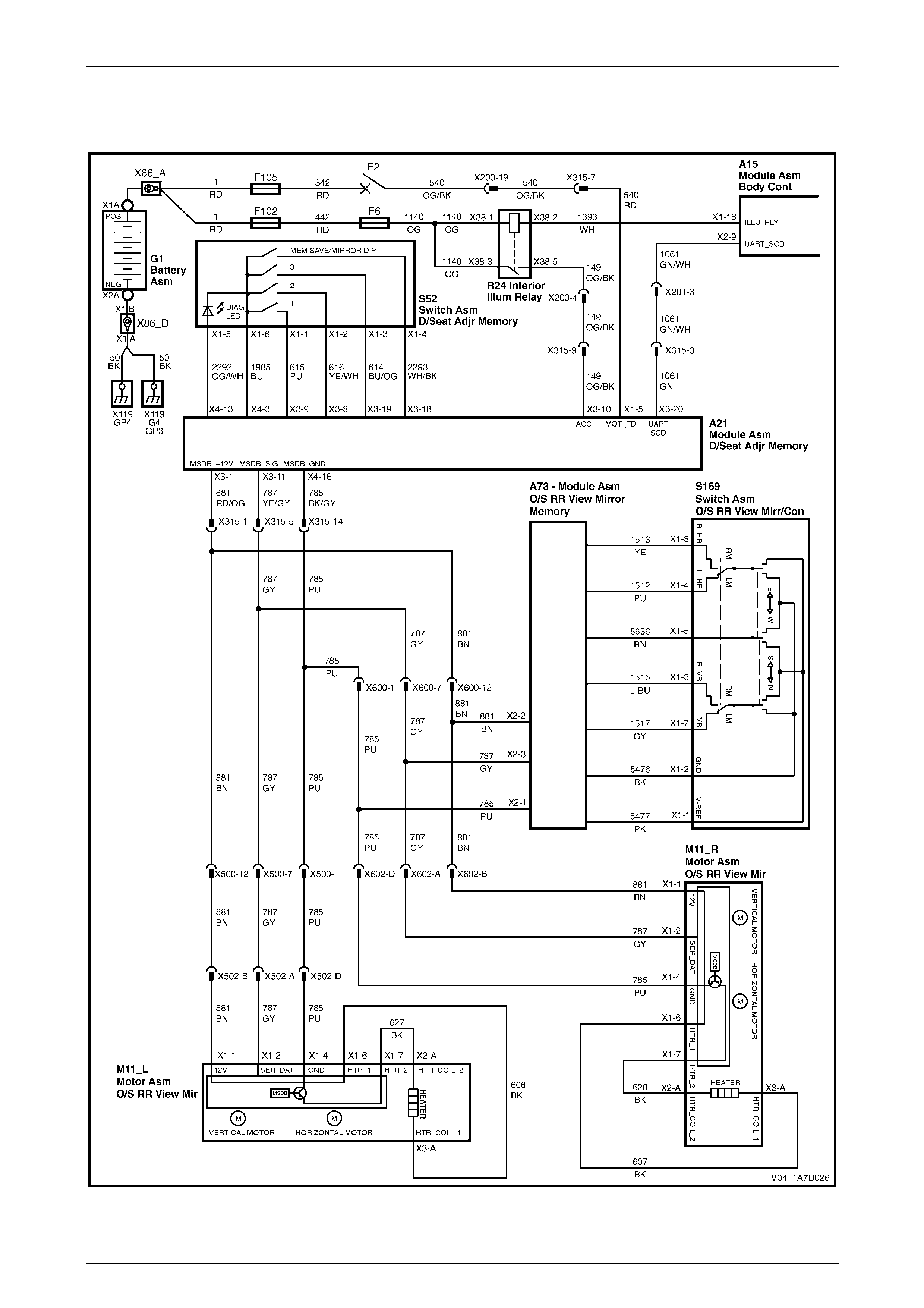
Seat Assemblies Page 1A7A–232
Page 1A7A–232
5.10 Electrical Diagnosis – Rear-view Mirrors
Wiring Diagram
Figure 1A7A – 104
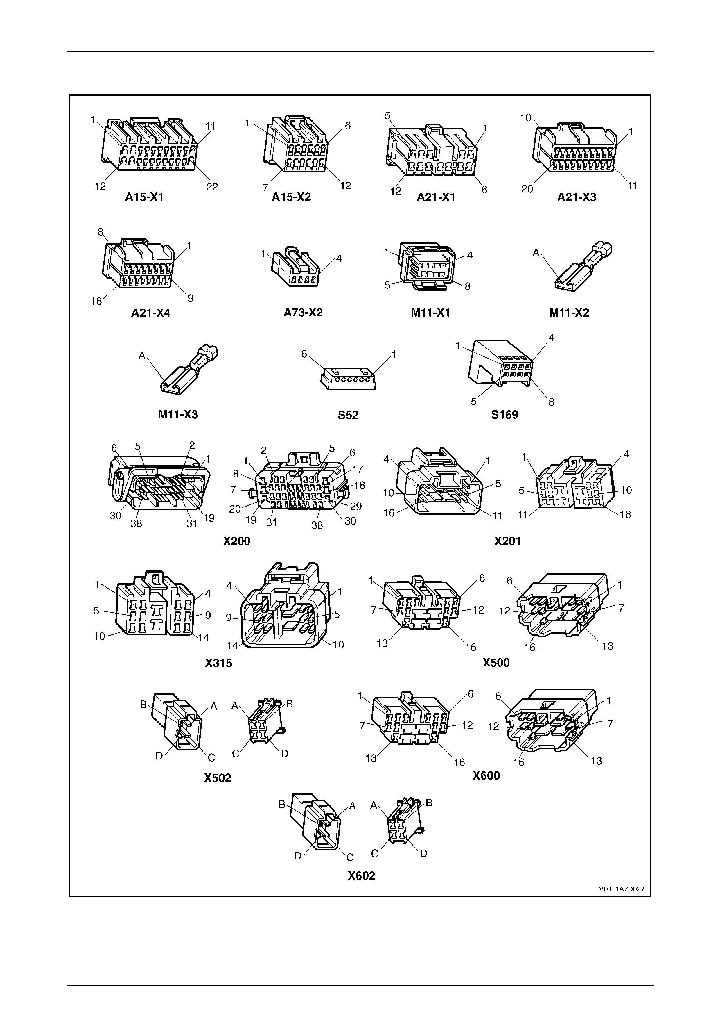
Seat Assemblies Page 1A7A–233
Page 1A7A–233
Connector Chart
Figure 1A7A – 105

Seat Assemblies Page 1A7A–234
Page 1A7A–234
Initial Check
Introduction
This operational check uses Tech 2 to test the functionality of the exterior rear-vie w mirrors and isolates which system is
faulty. The seat memory module provides electrical power, ground and serial data communications to the mirrors. As
described in 1 General Information, the mirrors can be controlled:
• manually by the mirror control switch located on the driver's door,
• by pressing any of the memory buttons on the memor y pos ition switch, and
• to dip when reversing (passenger’s mirror o nly).
Refer to 1 General Information for further details on the operation of the exterior rear-vie w mirror.
Refer to Wiring Diagram and Connector Chart in this Section to aid in diagnosing the e xterior rear-view mirrors and
associated components.
Test Description
The following numbers refer to the steps in the diagnostic table:
1 Checks if Tech 2 can communicate with the seat memory module.
2 Checks for existence of any diagnostic trouble codes.
3 Checks whether Tech 2 is receiving serial d ata from the exterior rear-view mirrors and the mirror control switch via
the rear-view mirror. All serial data communications need to be interrupted to these assemblies i n order for Tech 2
to indicate there is a problem.
4 Checks if serial data is being received at right exterior mirror only.
5 Checks if serial data is being received at left exterior mirror only.
6-9 Checks if the mirror control switch is serviceable. Isolates if the exterior re ar-view mirrors and circuits are
serviceable.
10 Checks if the mirror dip function is serviceable.
11 Checks if the mirror heating function is serviceable.
12 Checks if the memory recall function of the exterior rear-view mirrors is serviceable. This function is controlled by
the seat memory module which transmits a signal throu gh the serial bus to inform the mirrors what position they
should be in. The exterior rear-view mirror assemblies store the physical position within their o wn modules. If the
seat aspect of this feature is operational, the exterior rear-view mirror assembly is faulty and must be replaced.
Diagnostic Table
Step Action Yes No
1 1 Connect Tech 2 to the DLC.
2 On Tech 2 select:
Body / Seat and Exterior Mirror Memory Module.
3 Turn the ignition switch on.
Does the System Identification Screen displa y system information? Go to Step 2
There is a fault with
the seat memory
module
2 On Tech 2 select:
Body / Seat and Exterior Mirror Memory Module / Diagnostic
Trouble Codes / Read DTC Information.
Are there any diagnostic trou ble codes displayed? Go to appropriate
DTC table Go to Step 3

Seat Assemblies Page 1A7A–235
Page 1A7A–235
Step Action Yes No
3 1 On Tech 2 select:
Body / Seat and Exterior Mirror Memory Module /
Diagnostic Data Display / Inputs And Outputs.
2 Scroll to Button Pack Communication.
Does Tech 2 display Okay? Go to Step 4
Refer to No Serial
Data from Exterior
Rear-view Mirrors
in this Section
4 On Tech 2 select:
Right Exterior Mirror Communication.
Does Tech 2 display Okay? Go to Step 5
Refer to No Serial
Data – Right-hand
Exterior Rear-view
Mirror in this
Section
5 On Tech 2 select:
Left Exterior Mirror Communication.
Does Tech 2 display Okay? Go to Step 6
Refer to No Serial
Data – Left-hand
Exterior Rear-view
Mirror in this
Section
6 1 On Tech 2 select:
Body / Seat and Exterior Mirror Memory Module /
Diagnostic Data Display / Input and Output.
2 Scroll to Right Exterior Mirror Switch.
3 Monitor Tech 2.
4 Move the rocker switch on the rear-view mirror switch to the
position to control the right ext erior mirror.
5 Using the rear-view mirror switch:
• Press the mirror up switch.
• Press the mirror down switch.
• Press the mirror left switch.
• Press the mirror right switch.
Does Tech 2 display Up, Down , Left, then Right during operation? Go to Step 7
Refer to Mirror
Control Switch
Inoperative in this
Section
7 During the test in Step 6, does the right-hand exterior rear-view mirror
move in the following directions?
• When the switch is in the neutral position, the mirror does not
move.
• When the switch is in the up position, the mirror moves up.
• When the switch is in the down position, the mirror moves
down.
• When the switch is in the right position, the mirror moves righ t.
• When the switch is in the left position, the mirror moves left.
NOTE
Ensure that the mirror is not at its maximum limit of travel
in any direction when performing this test. Go to Step 8
Replace the
right-hand exterior
rear-view mirror
assembly, refer to
12H Rear-view
Mirrors

Seat Assemblies Page 1A7A–236
Page 1A7A–236
Step Action Yes No
8 1 On Tech 2 select:
Left Exterior Mirror Switch.
2 Monitor Tech 2.
3 Move the rocker switch on the rear-view mirror switch to the
position to control the left exterior mirror.
4 Using the rear-view mirror switch:
• Press the mirror up switch.
• Press the mirror down switch.
• Press the mirror left switch.
• Press the mirror right switch.
Does Tech 2 display Up, Down, Left, then Right during operation? Go to Step 9
Refer to Mirror
Control Switch
Inoperative in this
Section
9 During the test in Step 8, does the left-hand exterior rear-view mirror
move in the following directions?
• When the switch is in the neutral position, the mirror does not
move.
• When the switch is in the up position, the mirror moves up.
• When the switch is in the down position, the mirror moves
down.
• When the switch is in the right position, the mirror moves righ t.
• When the switch is in the left position, the mirror moves left.
NOTE
Ensure that the mirror is not at its maximum limit of travel
in any direction when performing this test. Go to Step 10
Replace the
left-hand exterior
rear-view mirror
assembly, refer to
12H Rear-view
Mirrors
10 Does the mirror dip function operate correctly? Refer to Mirror Dip
Function Check in
this Section Go to Step 11
11 Does the mirror heating function operate correctly? Refer to Mirror
Heating Function
Check in this
Section Go to Step 12
12 Does the memory recall function of the exterior rear-view mirrors
operate correctly? If both exterior
rear-view mirrors
are unable to recall
memory positions,
check the
functionality of the
seat, refer to Initial
Check in 5.8
Electrical Diagnosis
– Memory Seat.
If only one mirror is
unable to recall
memory positions,
replace the mirror
assembly, refer to
12H Rear-View
Mirrors System serviceable
When all diagno sis an d repairs are completed, clear all DT Cs and check the system for correct operation.

Seat Assemblies Page 1A7A–237
Page 1A7A–237
Mirror Dip Function Check
Introduction
The mirror dip function is operational when:
• the mirror dip function is enabled, refer to 1 General Information for details,
• a position for the passenger's exterior rear-view mirror is stored as the mirror dip, and
• the transmission selector must be placed in REVERSE position.
Test Description
The following numbers refer to the steps in the diagnostic table:
2 Checks if the mirror DIP function is enabled.
3 Checks if the mirror DIP function operates and is positioned correctly.
4 Checks if the mirror DIP function returns an Active messag e on Tech 2 when the transmission selector is placed in
REVERSE position. Isolates whether there is a fault with the seat memory module or with the serial data from the
transmission selector.
Diagnostic Table
Step Action Yes No
1 Has the Initial Check been performed?
Go to Step 2
Perform the Initial
Check in this
Section
2 1 On Tech 2 select:
Body / Seat and Exterior Mirror Memory Module /
Diagnostic Data Display / Memory.
2 Scroll to Priority 1.
Does Tech 2 display Mirror Dip Button as Enabled? Go to Step 3
Enable mirror DIP
function, refer to 1
General
Information.
Go to Step 3
3 1 Ensure the stored mirror DIP position is noticeably different
from the standard position of the left exterior mirror, refer to 1
General Information.
2 Check the mirror DIP function by placing the transmission
selector in reverse.
Does the mirror DIP function operate? System serviceable Go to Step 4
4 1 On Tech 2 select:
Body / Seat and Exterior Mirror Memory Module /
Diagnostic Data Display / Inputs And Outputs.
2 Scroll to Reverse Gear.
Does Tech 2 display Reverse Gear as Active?
Replace the seat
memory module,
refer to 2.12 Seat
Cable Tray and
Memory Module
Refer to 6C3
Powertrain
Management for V8
or
6C2 Powertrain
Management for V6
When all diagno sis an d repairs are completed, clear all DT Cs and check the system for correct operation.
Seat Assemblies Page 1A7A–238
Page 1A7A–238
Mirror Heating Function Check
Introduction
When the demist button on the instrument panel is pressed to activate the demist function, the request is sent via the
serial data bus to the exterior rear-view mirror assemblies.
Test Description
The following numbers refer to the steps in the diagnostic table:
2 Checks if Tech 2 confirms the demist function has been activated.
3 Checks if the heater element in the right-hand e xterior rear-view mirror operates when the ignition and rear windo w
demister are switched on.
4 Checks if the right-hand mirror heater element is servicea bl e. Isolates whether the heater element or the exterior
rear-view mirror assembly is at fault.
5 Checks if the heater element in the left-hand exterior rear-view mirror operates when the ignition and rear window
demister are switched on.
6 Checks if the left-hand mirror heater element is serviceable. Isolates whether the he ater element or the exterior
rear-view mirror assembly is at fault.
Diagnostic Table
Step Action Yes No
1 Has the Initial Check been performed?
Go to Step 2
Perform the Initial
Check in this
Section
2 1 On Tech 2 select:
Body / Seat and Exterior Mirror Memory Module /
Diagnostic Data Display / Input And Output.
2 Scroll to Demist Request.
3 Turn on the rear window demister.
Does Tech 2 display Demist Req uest as Yes? Go to Step 3
Refer to 12J Body
Control Module.
Go to Step 3
3 Operate the rear window demister for 2 – 3 minutes.
Does the right-hand exterior mirror feel warm? Go to Step 5 Go to Step 4
4
Turn off the rear window demister before removing
and replacing the righ t-hand exterior mirror glass.
Test the heater element of the right-hand ext erior re ar-view mirror,
refer to 12H Rear-view Mirrors.
Is the heater element serviceable?
Replace the
right-hand exterior
rear-view mirror
assembly, refer to
12H Rear-view
Mirrors
Replace the
right-hand exterior
rear-view mirror
glass, refer to 12H
Rear-view Mirrors.
Go to Step 5
5 Operate the rear window demister for 2 – 3 minutes.
Does the left-hand exterior mirror feel warm? System serviceable Go to Step 6
6
Turn off the rear window demister before removing
and replacing the left-hand exterior mirror glass.
Test the heater element of the left-hand exterior rear-view mirror,
refer to 12H Rear-view Mirrors.
Is the heater element serviceable?
Replace the
left-hand exterior
rear-view mirror
assembly, refer to
12H Rear-view
Mirrors
Replace the
left-hand exterior
rear-view mirror
glass, refer to 12H
Rear-view Mirrors
When all diagno sis an d repairs are completed, clear all DT Cs and check the system for correct operation.

Seat Assemblies Page 1A7A–239
Page 1A7A–239
No Serial Data from Exterior Rear-view Mirrors
Introduction
The exterior rear-view mirrors have a common power, ground and serial data connector at the seat memory module. If
the circuit is followed, there are two splices in each of the po wer, grou nd and data communication circuits. In this test, as
there are not serial data communications with any of the exterior rear-view mirrors, it is assumed that the fault will be in a
location common to all circuits.
Refer to Wiring Diagram and Connector Chart in this Section to aid in diagnosing the e xterior rear-view mirrors and
associated components.
Test Description
The following numbers refer to the steps in the diagnostic table:
2 Checks if the connectors which are common to the serial data communication for the exterior rear-vie w mirrors are
secure.
3 Checks if battery voltage is present for the exterior rear-view mirror system at the seat memory module.
4 Checks if the seat memory module is supplying a ground circuit for the exterior rear-view mirror system.
5 Checks the battery supply circuit for a short to ground.
6 Checks the ground circuit for a short to battery.
7 Checks if there is continuity in the serial data circuit between connectors A21 – X3 pin 11 and X500 p in 7. Isolates
whether there is an open circuit in circuit 787 that will affect both the exterior rear-view mirrors or the seat memory
module is faulty.
Diagnostic Table Notes
1 For all wiring harness fault diagnoses, refer to 12P Wirin g Diagrams.
2 For wiring harness repairs, refer to 12P Wiring Diagrams.
3 Refer to 12O Fuses, Relays and Wiring Harnesses for harness routeing.
4 If the fault is deemed to be intermittent, refer to 12P Wiring Diagrams.

Seat Assemblies Page 1A7A–240
Page 1A7A–240
Diagnostic Table
Step Action Yes No
1 Has the Initial Check been performed?
Go to Step 2
Perform the Initial
Check in this
Section
2 Ensure the following connectors are secure (refer to Note 3)?
• A21 – X3
• A21 – X4
• X315 Go to Step 3 Secure the relevant
connectors
3 1 Disconnect connectors A21 – X3 and A21 – X4 from the seat
memory module.
2 Using a multimeter set to measure voltage, probe between seat
memory module A21 – X3 pin 1 and a known ground (refer to
Note 1).
Does the multimeter indicate batter y voltage? Go to Step 4
Replace the seat
memory module,
refer to 2.12 Seat
Cable Tray and
Memory Module
4 Using a multimeter set to measure resistance, probe between seat
memory module A21 – X4 pin 16 and a known ground (refer to Note
1).
Does the multimeter indicate continuity? Go to Step 5
Replace the seat
memory module,
refer to 2.12 Seat
Cable Tray and
Memory Module
5 Using a multimeter set to measure resistance, probe between
connector A21 – X3 pin 1 and a known ground (refer to Note 1).
Does the multimeter indicate continuity?
Repair or replace
circuit 881 (refer to
Note 2) Go to Step 6
6 Using a multimeter set to measure voltage, probe between connector
A21 – X4 pin 16 and a known ground (refer to Note 1).
Does the multimeter indicate batter y voltage ?
Repair or replace
circuit 785 (refer to
Note 2) Go to Step 7
7 Using a multimeter set to measure resistance, probe between
connectors A21 – X3 pin 11 and X500 pin 7 (refer to Note 1).
Does the multimeter indicate continuity? Replace the seat
memory module,
refer to 2.12 Seat
Cable Tray and
Memory Module
Repair or replace
circuit 787 between
connector
A21 – X3 pin 11
and the first splice
on circuit 787 (refer
to Note 2)
When all diagno sis an d repairs are completed, clear all DT Cs and check the system for correct operation.

Seat Assemblies Page 1A7A–241
Page 1A7A–241
No Serial Data – Right-hand Exterior Rear-view Mirror
Introduction
Refer to Wiring Diagram and Connector Chart in this Section to aid in diagnosing the e xterior rear-view mirror and
associated components.
Test Description
The following numbers refer to the steps in the diagnostic table:
2 Checks if there is battery voltage supplied to the right-hand exterior rear-view mirror. Isolates if there is a fault in
circuit 881 between connecto rs X602 and A21 – X3.
3 Checks if the ground circuit for the right-hand exterior rear-view mirror is serviceable. Isolates if there is a fault in
circuit 785 between connecto rs X602 and A21 – X4.
4 Checks the serial data circuit for the right-hand exterior rear-view mirror for integrity. Isolates whether there is a
fault in circuit 787 between connectors A21 – X3 and X602 or the right-han d exterior rear-view mirror assembly is
faulty.
Diagnostic Table Notes
1 For all wiring harness fault diagnoses, refer to 12P Wirin g Diagrams.
2 For wiring harness repairs, refer to 12P Wiring Diagrams.
3 Refer to 12O Fuses, Relays and Wiring Harnesses for harness routeing.
4 If the fault is deemed to be intermittent, refer to 12P Wiring Diagrams.
Diagnostic Table
Step Action Yes No
1 Has the Initial Check been performed?
Go to Step 2
Perform the Initial
Check in this
Section
2 Backprobe connector X602 pin B with a test lamp (refer to Note 1).
Does the test lamp illuminate?
Go to Step 3
Repair or replace
circuit 881 between
connectors X602
and A21 – X3 (refer
to Note 2)
3 1 Disconnect harness connector X602.
2 Using a multimeter set to measure resistance, probe between
connector X602 pin D and a known ground (refer to Note 1).
Does the multimeter indicate continuity? Go to Step 4
Repair or replace
circuit 785 between
connectors X602
and A21 – X4 (refer
to Note 2)
4 1 Disconnect connector A21 – X3 from the seat memory module.
2 Using a multimeter set to measure resistance, probe between
connectors A21 – X3 pin 11 and X602 pin A (refer to Note 1).
Does the multimeter indicate continuity?
Replace the
right-hand exterior
rear-view mirror
assembly, refer to
12H Rear-view
Mirrors
Repair or replace
circuit 787 between
connectors
A21 – X3 and X602
(refer to Note 2)
When all diagno sis an d repairs are completed, clear all DT Cs and check the system for correct operation.

Seat Assemblies Page 1A7A–242
Page 1A7A–242
No Serial Data – Left-hand Exterior Rear-view Mirror
Introduction
Refer to Wiring Diagram and Connector Chart in this Section to aid in diagnosing the e xterior rear-view mirror and
associated components.
Test Description
The following numbers refer to the steps in the diagnostic table:
2 Checks if there is battery voltage supplied to the left-hand exterior rear-view mirror. Isolates if there is a fault in
circuit 881 between connecto rs X502 and A21 – X1.
3 Checks if the ground circuit for the left-hand exterior rear-view mirror is serviceable. Isolates if there is a fault in
circuit 785 between connecto rs X502 and A21 – X3.
4 Checks the serial data circuit for the left-hand exterior rear-view mirror for integrity. Isolates whether there is a fault
in circuit 787 between connectors A21 – X1 and X502 or the left-hand exterior rear-view mirror assembly is faulty.
Diagnostic Table Notes
1 For all wiring harness fault diagnoses, refer to 12P Wirin g Diagrams.
2 For wiring harness repairs, refer to 12P Wiring Diagrams.
3 Refer to 12O Fuses, Relays and Wiring Harnesses for harness routeing.
4 If the fault is deemed to be intermittent, refer to 12P Wiring Diagrams.
Diagnostic Table
Step Action Yes No
1 Has the Initial Check been performed?
Go to Step 2
Perform the Initial
Check in this
Section
2 Backprobe connector X502 pin B with a test lamp (refer to Note 1).
Does the test lamp illuminate?
Go to Step 3
Repair or replace
circuit 881 between
connectors X502
and A21 – X3 (refer
to Note 2)
3 1 Disconnect harness connector X502.
2 Using a multimeter set to measure resistance, probe between
connector X502 pin D and a known ground (refer to Note 1).
Does the multimeter indicate continuity? Go to Step 4
Repair or replace
circuit 785 between
connectors X502
and A21 – X4 (refer
to Note 2)
4 1 Disconnect connector A21 – X3 from the seat memory module.
2 Using a multimeter set to measure resistance, probe between
connectors A21 – X3 pin 11 and X502 pin A (refer to Note 1).
Does the multimeter indicate continuity?
Replace the
left-hand exterior
rear-view mirror
assembly, refer to
12H Rear-view
Mirrors
Repair or replace
circuit 787 between
connectors
A21 – X3 and X502
(refer to Note 2)
When all diagno sis an d repairs are completed, clear all DT Cs and check the system for correct operation.

Seat Assemblies Page 1A7A–243
Page 1A7A–243
Mirror Control Switch Inoperative
Introduction
When the mirror control switch is used, the signal that it generates is converted by the rear-view mirror module to serial
data. It is then transmitted over the serial data bus. The exterior rear-vie w mirrors then receive this serial data and move
the appropriate exterior rear-view mirror in the direction that was requested by the mirror control switch.
Refer to Wiring Diagram and Connector Chart in this Section to aid in diagnosing the e xterior rear-view mirrors and
associated components.
Test Description
The following numbers refer to the steps in the diagnostic table:
2 Checks if the mirror control switch is serviceable.
3 Checks if there is battery power to the rear-view mirror module. Isolates if there is a fault in circuit 881 bet ween
connectors A73 – X2 and A21 – X3.
4 Checks if there is battery power to the mirror control switch. Isolates if the rear-view mirror modul e is at fault.
5 Checks if the ground circuit for the rear-view mirror module i s serviceable. Isolates if there is a fault in circuit 785
between connectors A73 – X2 and A21 – X4.
6 Checks if the ground circuit for the mirror control switch is serviceable. Isolates if the rear-view mirror module is at
fault.
7 Checks if there is continuity on the serial data bus between connectors A73 – X2 and A21 – X3. Isolates whether
there is an open circuit in circuit 787 between connectors A73 – X2 and A21 – X3 or the rear-view memory module
is faulty.
Diagnostic Table Notes
1 For all wiring harness fault diagnoses, refer to 12P Wirin g Diagrams.
2 For wiring harness repairs, refer to 12P Wiring Diagrams.
3 Refer to 12O Fuses, Relays and Wiring Harnesses for harness routeing.
4 If the fault is deemed to be intermittent, refer to 12P Wiring Diagrams.

Seat Assemblies Page 1A7A–244
Page 1A7A–244
Diagnostic Table
Step Action Yes No
1 Has the Initial Check been performed?
Go to Step 2
Perform the Initial
Check in this
Section
2 Test the mirror control switch, refer to 12H Rear-view Mirrors.
Is the mirror control switch serviceable? Go to Step 3
Replace the mirror
control switch, refer
to 12H Rear-view
Mirrors
3 Backprobe connector A73 – X2 pin 2 with a test lamp (refer to
Note 1).
Does the test lamp illuminate?
Go to Step 4
Repair or replace
circuit 881 between
connectors
A73 – X2 and
A21 – X3 (refer to
Note 2)
4 Backprobe connector S169 – X1 pin 1 with a test lamp (refer to
Note 1).
Does the test lamp illuminate? Go to Step 5
Replace the
rear-view mirror
module, refer to
1A5 Front and Rear
Door Assemblies
5 Using a multimeter set to measure resistance, probe between
connector A73 – X2 pin 1 and a known ground (refer to Note 1).
Does the multimeter indicate continuity?
Go to Step 6
Repair or replace
circuit 785 between
connectors
A73 – X2 and
A21 – X4 (refer to
Note 2)
6 Using a multimeter set to measure resistance, probe between
connector S169 – X1 pin 2 and a known ground (refer to Note 1).
Does the multimeter indicate continuity? Go to Step 7
Replace the
rear-view mirror
module, refer to
1A5 Front and Rear
Door Assemblies
7 1 Disconnect connectors A21 – X3 from the seat memory module
and A73 – X2 from the rear-vie w mirror module.
2 Using a multimeter set to measure resistance, probe between
connectors A73 –X2 pin 3 and a A21 – X3 pin 11 (refer to Note
1).
Does the multimeter indicate continuity?
Replace the
rear-view mirror
module, refer to
1A5 Front and Rear
Door Assemblies
Repair or replace
circuit 787 between
connectors
A73 – X2 and
A21 – X3 (refer to
Note 2)
When all diagno sis an d repairs are completed, clear all DT Cs and check the system for correct operation.

Seat Assemblies Page 1A7A–245
Page 1A7A–245
6 Service Operations – Front Seat,
Coupe
6.1 Front Seat Usage Chart
How To Use This Chart
Four front seat configurations are fitted to MY 2004 V2 Coupe vehicles. The following usag e chart is provided to help
determine the seat type fitted to the vehicle. This is important prior to repai rs being perfor med as the failed/damaged part
may not be serviceable.
To determine the seat fitted to the vehicle, obtain the vehicle model, which seat requires attention and the seat cover
fabric. Then establish other features of the seat such as the electric movement functions. Using the ch art will lead to the
elimination of all other seat combinations, al lowing the identification of the typ e and the co nstruction of the seat. Finally,
refer to the Figure shown in Front Seat Type for a component breakdown of the front seat assembly.
1 Vehicle – Vehicle model identification.
2 Seating – Driver front seat or passenger front seat.
3 Fabric – Cloth or leather seat covers.
4 Movement – Indicates the number of movement functions of the seat:
• Eight-way – Seat cushion elec tric front and rear raise/lower, seat fore/aft movement and seat-back rec line.
5 Memory – Indicates if a seat memory module is fitted.
6 SIAB – If the front seat is fitted with a side impact airbag assembly.
7 Construction – Hook and Loop refers to the seat cover being attached to the seat pad with a Velcro type materia l
and both being serviced as separate parts.
8 Active Head Restrain t – Indicates whether standard height adjustable or active head restraints are fitted.
9 Front Seat Type – Identifies the seat type and provides reference to the following illustrations which show a
breakdown of the serviced component for each front seat assembly.
Domestic
Vehicle Seating Fabric Movement Memory SIAB Construction Active Head
Restraint Front Seat Type
(refer to)
Driver Leather Eight-way Yes Yes Hook & Loop Yes 1
(Figure 1A7A – 106)
CV8
Passenger Leather Eight-way No Yes Hook & Loop Yes 2
(Figure 1A7A – 107)
Gulf States
Vehicle Seating Fabric Movement Memory SIAB Construction Active Head
Restraint Front Seat Type
(refer to)
Passenger Leather Eight-way No Yes Hook & Loop Yes 3
(Figure 1A7A – 109)
Lumina
S & SS
Driver Leather Eight-way No Yes Hook & Loop Yes 4
(Figure 1A7A – 108)
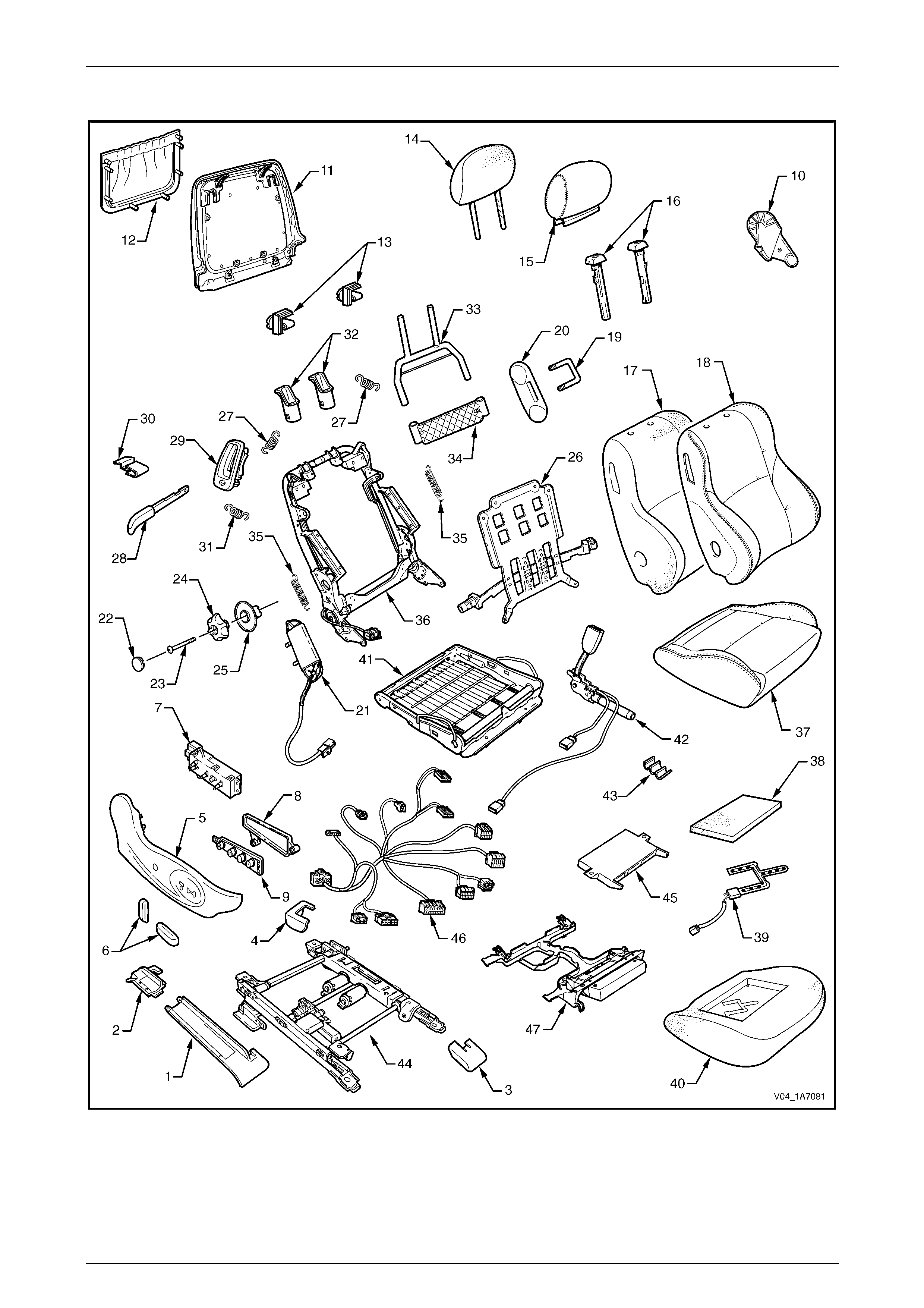
Seat Assemblies Page 1A7A–246
Page 1A7A–246
Front Seat Type 1
Figure 1A7A – 106

Seat Assemblies Page 1A7A–247
Page 1A7A–247
Legend
1 Front Seat Outer Front Cover
2 Front Seat Outer Rear Cover
3 Front Seat Inner Front Cover
4 Front Seat Inner Rear Cover
5 Front Seat Outer Side Cover
6 Front Seat Adjustment Switch Knobs
7 Front Seat Adjustment Switch – Eight-way
8 Memory Position Switch Cover
9 Memory Position Switch Assembly
10 Front Seat Inner Side Cover
11 Front Seat-back Rear Cover
12 Front Seat-back Map Pocket
13 Front Seat-back Cover Retaining Clips
14 Front Seat Head Restraint Pad Assembly
15 Front Seat Head Restraint Cover
16 Front Seat Head Restraint Sleeves
17 Front Seat-back Pad
18 Front Seat-back Cover
19 Front Seat Dummy Block U-bolt
20 Front Seat Dummy Block Insert
21 Side Impact Airbag Assembly
22 Lumbar Support Knob Cover
23 Lumbar Support Knob Screw
24 Lumbar Support Knob
25 Lumbar Support Deflector Ring
26 Lumbar Support Assembly
27 Lumbar Support Retaining Spring
28 EZ-entry Release Lever Assembly
29 EZ-entry Release Escutcheon Assembly
30 EZ-entry Release Lever Retaining Clip
31 EZ-entry Release Lever Return Spring
32 Active Head Restraint Frame Sleeves
33 Active Head Restraint Frame Assembly
34 Active Head Restraint Frame Support Strap
35 Active Head Restraint Frame Retaining Spring
36 Front Seat-back Frame Assembly
37 Front Seat Cushion Cover
38 Front Seat Cushion Upper Pad
39 Passenger Presence Detection Switch
40 Front Seat Cushion Pad
41 Front Seat Cushion Frame Assembly
42 Seatbelt Buckle & Pretensioner Assembly
43 Wiring Harness Retaining Clip
44 Track and Height Adjust Assembly
45 Seat Memory Module
46 Wiring Harness Assembly
47 Front Seat Cable Tray
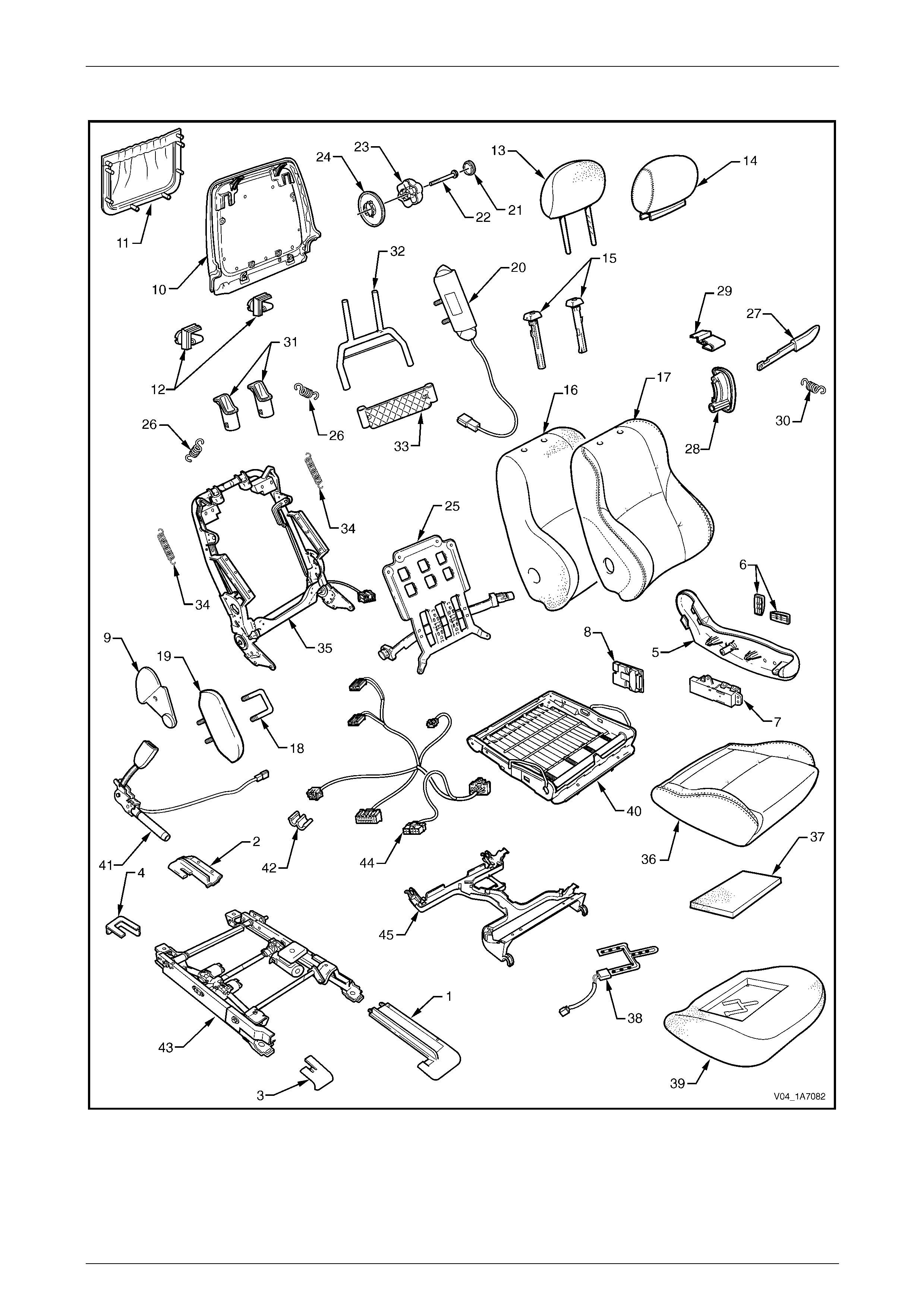
Seat Assemblies Page 1A7A–248
Page 1A7A–248
Front Seat Type 2
Figure 1A7A – 107

Seat Assemblies Page 1A7A–249
Page 1A7A–249
Legend
1 Front Seat Outer Front Cover
2 Front Seat Outer Rear Cover
3 Front Seat Inner Front Cover
4 Front Seat Inner Rear Cover
5 Front Seat Outer Side Cover
6 Front Seat Adjustment Switch Knobs
7 Front Seat Adjustment Switch – Eight-way
8 EZ-entry Module
9 Front Seat Inner Side Cover
10 Front Seat-back Rear Cover
11 Front Seat-back Map Pocket
12 Front Seat-back Cover Retaining Clips
13 Front Seat Head Restraint Pad Assembly
14 Front Seat Head Restraint Cover
15 Front Seat Head Restraint Sleeves
16 Front Seat-back Pad
17 Front Seat-back Cover
18 Front Seat Dummy Block U-bolt
19 Front Seat Dummy Block Insert
20 Side Impact Airbag Assembly
21 Lumbar Support Knob Cover
22 Lumbar Support Knob Screw
23 Lumbar Support Knob
24 Lumbar Support Deflector Ring
25 Lumbar Support Assembly
26 Lumbar Support Retaining Spring
27 EZ-entry Release Lever Assembly
28 EZ-entry Release Escutcheon Assembly
29 EZ-entry Release Lever Retaining Clip
30 EZ-entry Release Lever Return Spring
31 Active Head Restraint Frame Sleeves
32 Active Head Restraint Frame Assembly
33 Active Head Restraint Frame Support Strap
34 Active Head Restraint Frame Retaining Spring
35 Front Seat-back Frame Assembly
36 Front Seat Cushion Cover
37 Front Seat Cushion Upper Pad
38 Passenger Presence Detection Switch
39 Front Seat Cushion Pad
40 Front Seat Cushion Frame Assembly
41 Seatbelt Buckle & Pretensioner Assembly
42 Wiring Harness Retaining Clip
43 Track and Height Adjust Assembly
44 Wiring Harness Assembly
45 Front Seat Cable Tray
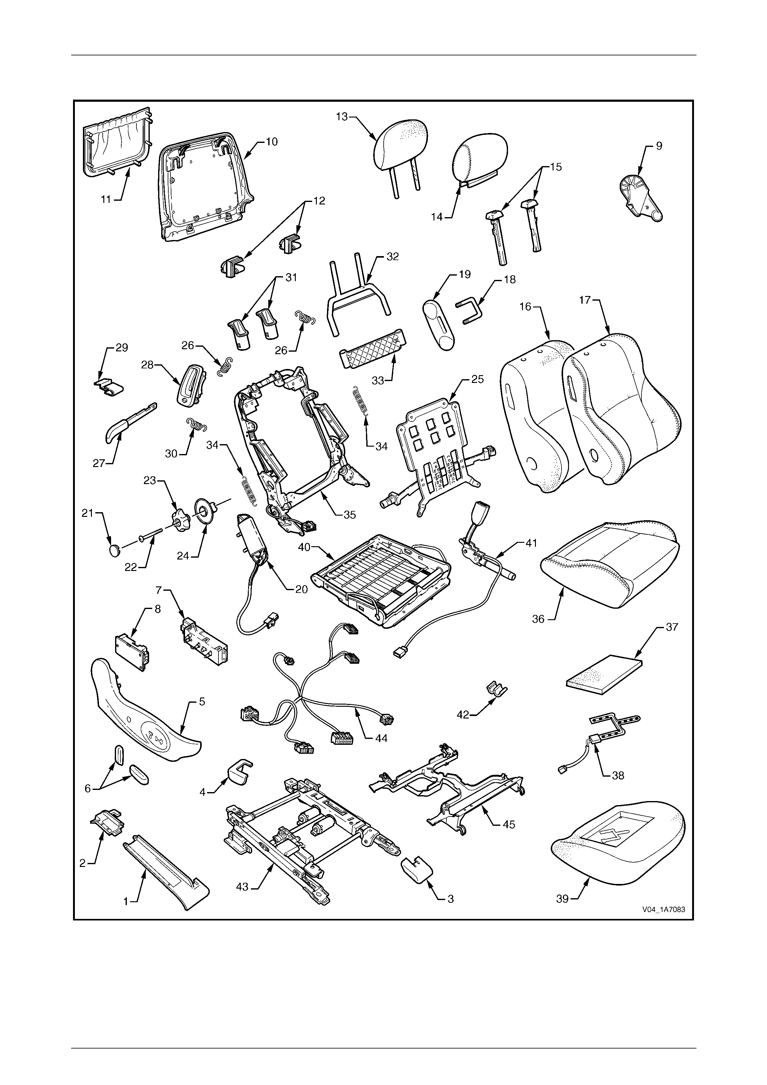
Seat Assemblies Page 1A7A–250
Page 1A7A–250
Front Seat Type 3
Figure 1A7A – 108

Seat Assemblies Page 1A7A–251
Page 1A7A–251
Legend
1 Front Seat Outer Front Cover
2 Front Seat Outer Rear Cover
3 Front Seat Inner Front Cover
4 Front Seat Inner Rear Cover
5 Front Seat Outer Side Cover
6 Front Seat Adjustment Switch Knobs
7 Front Seat Adjustment Switch – Eight-way
8 EZ-entry Module
9 Front Seat Inner Side Cover
10 Front Seat-back Rear Cover
11 Front Seat-back Map Pocket
12 Front Seat-back Cover Retaining Clips
13 Front Seat Head Restraint Pad Assembly
14 Front Seat Head Restraint Cover
15 Front Seat Head Restraint Sleeves
16 Front Seat-back Pad
17 Front Seat-back Cover
18 Front Seat Dummy Block U-bolt
19 Front Seat Dummy Block Insert
20 Side Impact Airbag Assembly
21 Lumbar Support Knob Cover
22 Lumbar Support Knob Screw
23 Lumbar Support Knob
24 Lumbar Support Deflector Ring
25 Lumbar Support Assembly
26 Lumbar Support Retaining Spring
27 EZ-entry Release Lever Assembly
28 EZ-entry Release Escutcheon Assembly
29 EZ-entry Release Lever Retaining Clip
30 EZ-entry Release Lever Return Spring
31 Active Head Restraint Frame Sleeves
32 Active Head Restraint Frame Assembly
33 Active Head Restraint Frame Support Strap
34 Active Head Restraint Frame Retaining Spring
35 Front Seat-back Frame Assembly
36 Front Seat Cushion Cover
37 Front Seat Cushion Upper Pad
38 Passenger Presence Detection Switch
39 Front Seat Cushion Pad
40 Front Seat Cushion Frame Assembly
41 Seatbelt Buckle & Pretensioner Assembly
42 Wiring Harness Retaining Clip
43 Track and Height Adjust Assembly
44 Wiring Harness Assembly
45 Front Seat Cable Tray
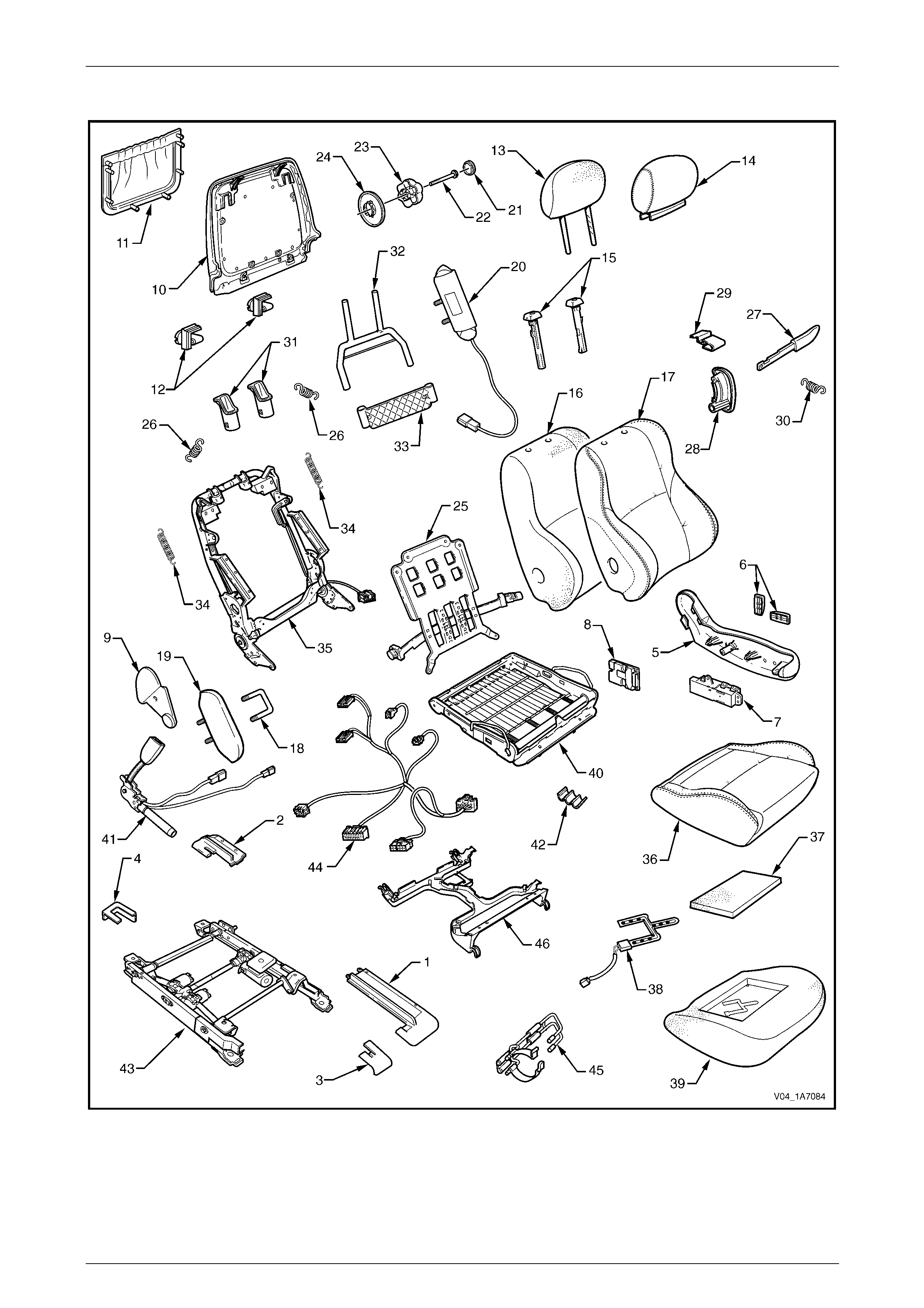
Seat Assemblies Page 1A7A–252
Page 1A7A–252
Front Seat Type 4
Figure 1A7A – 109

Seat Assemblies Page 1A7A–253
Page 1A7A–253
Legend
1 Front Seat Outer Front Cover
2 Front Seat Outer Rear Cover
3 Front Seat Inner Front Cover
4 Front Seat Inner Rear Cover
5 Front Seat Outer Side Cover
6 Front Seat Adjustment Switch Knobs
7 Front Seat Adjustment Switch – Eight-way
8 EZ-entry Module
9 Front Seat Inner Side Cover
10 Front Seat-back Rear Cover
11 Front Seat-back Map Pocket
12 Front Seat-back Cover Retaining Clips
13 Front Seat Head Restraint Pad Assembly
14 Front Seat Head Restraint Cover
15 Front Seat Head Restraint Sleeves
16 Front Seat-back Pad
17 Front Seat-back Cover
18 Front Seat Dummy Block U-bolt
19 Front Seat Dummy Block Insert
20 Side Impact Airbag Assembly
21 Lumbar Support Knob Cover
22 Lumbar Support Knob Screw
23 Lumbar Support Knob
24 Lumbar Support Deflector Ring
25 Lumbar Support Assembly
26 Lumbar Support Retaining Spring
27 EZ-entry Release Lever Assembly
28 EZ-entry Release Escutcheon Assembly
29 EZ-entry Release Lever Retaining Clip
30 EZ-entry Release Lever Return Spring
31 Active Head Restraint Frame Sleeves
32 Active Head Restraint Frame Assembly
33 Active Head Restraint Frame Support Strap
34 Active Head Restraint Frame Retaining Spring
35 Front Seat-back Frame Assembly
36 Front Seat Cushion Cover
37 Front Seat Cushion Upper Pad
38 Passenger Presence Detection Switch
39 Front Seat Cushion Pad
40 Front Seat Cushion Frame Assembly
41 Seatbelt Buckle & Pretensioner Assembly
42 Wiring Harness Retaining Clip
43 Track and Height Adjust Assembly
44 Wiring Harness Assembly
45 Fire Extinguisher Mounting Bracket
46 Front Seat Cable Tray

Seat Assemblies Page 1A7A–254
Page 1A7A–254
6.2 Fire Extinguisher Assembly
Remove
1 Remove the fire extinguisher (1) from the cover (2).
2 Remove the two screws (3) attaching the fire
extinguisher mounting br acket (4) to the track and
height adjust assembly.
3 Remove the bracket and cover from the track and
height adjust assembly. If required remove t he bracket
from the cover.
Figure 1A7A – 110
Reinstall
Reinstallation of the fire extinguisher assembly is the reverse of the removal procedure, noting the following:
Tighten the attaching screws to the correct torque specification.
Fire extinguisher mounting bracket
attaching screw torque specification.......15.0 – 20.0 Nm

Seat Assemblies Page 1A7A–255
Page 1A7A–255
6.3 Front Seat Assembly
LT Section No. – 14-295
Before performing any service operation on a
front seat assembly fitted with side impact
airbags, ensure the occupant protection
system is disabled, refer to 12M Occupant
Protection System.
NOTE
If the seat assembly is to be disassembled, adjust
the seat assembly to its highest position before
disconnecting the power to the seat.
NOTE
Clean hands are essential when working on the
interior trim.
Remove
Disconnection of the battery affects certain
vehicle electronic systems. Refer to
00, 5 Battery Disconnection Procedures
before disconnecting the battery.
1 Disconnect the battery.
2 For the driver’s seat on right-hand drive vehicles,
remove the screw (1) attaching the front seat outer
front cover (2).
3 Using a small screwdriver, push in the centre of the
join to separate the front cover and the front seat outer
rear cover (3).
4 Unclip the covers from the seat track and disengag e
from the side sill trim.
5 Pull the covers apart and remove the rear c over.
6 For the driver’s seat on right-hand dr ive vehicles, slide
the front cover over the fuel filler door release lever (4)
and remove.
Figure 1A7A – 111

Seat Assemblies Page 1A7A–256
Page 1A7A–256
7 Disconnect the body wiring ha r ness connector (1), the
seatbelt pretensioner wiring connector (2) and the side
impact airbag wiring connect or (3).
Figure 1A7A – 112
8 Unclip the front seat inner rear cover (1) from the seat
track (2).
Figure 1A7A – 113
9 Unclip the front seat inner front cover (1) from the seat
track (2).
Figure 1A7A – 114
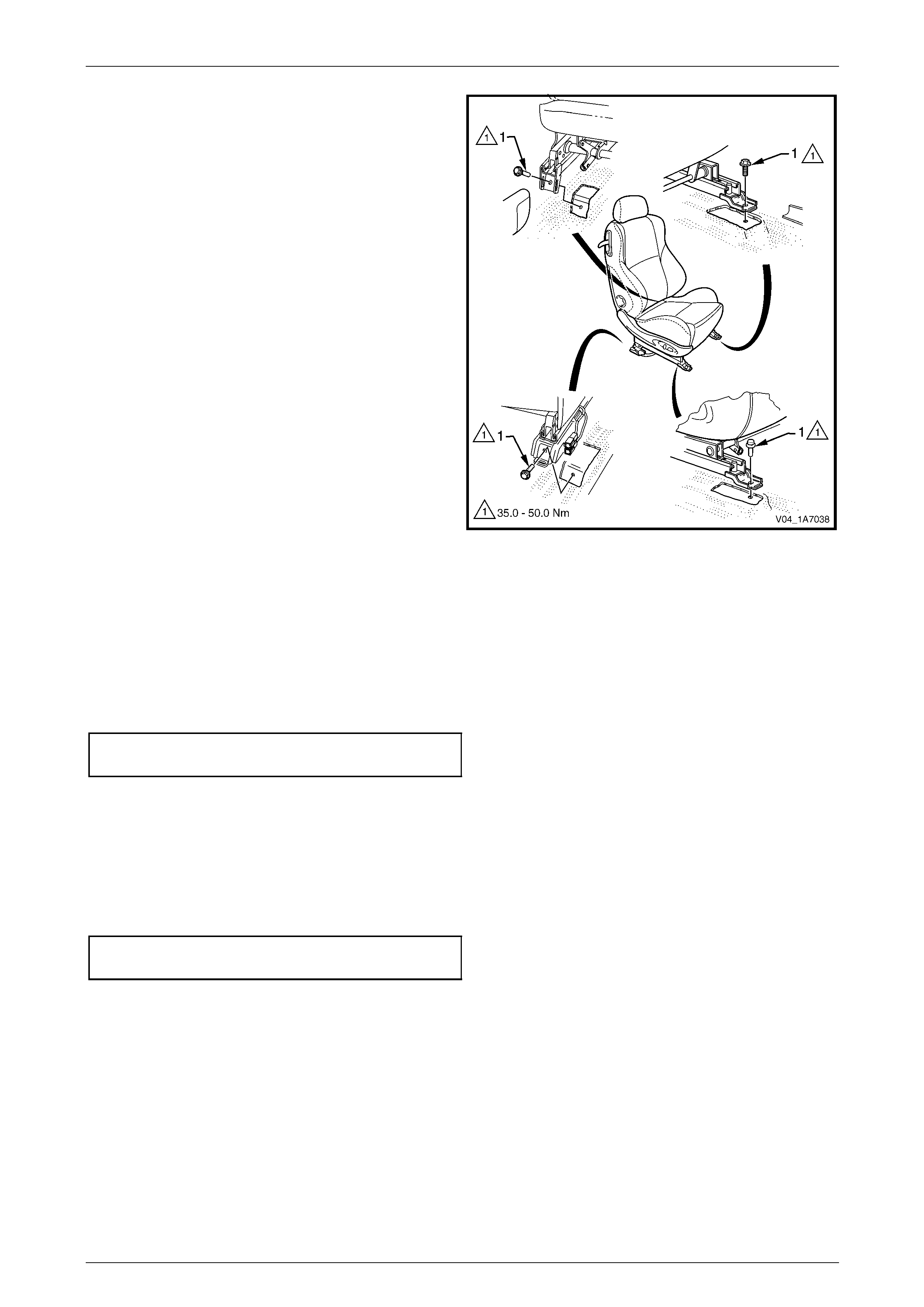
Seat Assemblies Page 1A7A–257
Page 1A7A–257
10 Remove the four screws (1) attaching the front seat to
the vehicle.
11 Remove the seat from the vehicle.
Figure 1A7A – 115
Reinstall
Reinstallation of the front seat assembly is the reverse of the removal procedure, noting the following:
1 Position the front seat assembly into the vehicle.
2 Install the four screws securing the front seat.
3 Tighten the attaching screws to the correct torque specification.
Front seat assembly attaching screw
torque specification.................................35.0 – 50.0 Nm
4 Connect the seat wiring harness connector, seatbelt pretensioner harness connector and the side impact airbag
connector.
5 Align the front seat outer cover’s retaining clips and push firmly to engage.
6 Push the front of the front seat outer cover do wn to engage the cover with the front of the seat rail.
7 For the driver’s side on right-hand drive vehicles, install the front seat outer cover attaching screw and tighten to the
specified torque.
Front seat outer front cover attaching
screw torque specification...........................1.0 – 3.0 Nm
8 Check the operation of the front seat functions. While checking the seat adjustment/operat ion, also check that the
seat wiring harnesses do not foul with any of the seat’s moveable components (i.e. seat motor drive shafts, etc.).
NOTE
Type 1 front seats will require seat memory
calibration to reinstate seat memory functions,
refer to Seat Memory Calibration, Front Seat
Type 1.

Seat Assemblies Page 1A7A–258
Page 1A7A–258
9 Switch the ignition on and observe the airbag warning indicator in the instrument cluster.
• If no fault is detected, the airbag warning indicator shou ld illuminate for approximat ely five seconds while the
system performs a self-test, and then extinguish.
• If a fault is present, the airbag warning indic ator will remain illuminated and a warning chime may sound after
approximately three seconds. The warning message ‘SRS Airbag F ault’ is also displayed in the instrume nt
cluster multi-function display. To diagnose the fault, refer to 12M Occupant Protection System.
Seat Memory Calibration, Front Seat Type 1
Whenever power is interrupted to the seat memory module, the following procedure must be performed to reinstate seat
memory functions.
Step Operation Result
1 1 Operate the seat adjustment switch to move the
seat forward.
2 Operate the seat adjustment switch for 1 second to
move the seat aft.
3 Operate the seat adjustment switch to move the
seat forward.
Seat will cease movement when track limit is
reached.
Seat will move aft.
Seat will cease movement when track limit is
reached.
2 1 Operate the seat adjustment switch to move the
seat aft.
2 Operate the seat adjustment switch for 1 second to
move the seat forward.
3 Operate the seat adjustment switch to move the
seat aft.
Seat will cease movement when track limit is
reached.
Seat will move for ward.
Seat will cease movement when track limit is
reached.
3 1 Operate the seat adjustment switch to raise the
front of the seat.
2 Operate the adjustment switch for 1 second to
lower the front of the seat.
3 Operate the seat adjustment switch to raise the
front of the seat.
Seat will cease movement when upper limit is
reached.
Se at wi ll lo wer .
Seat will cease movement when upper limit is
reached.
4 1 Operate the seat adjustment switch to lower the
front of the seat.
2 Operate seat adjustment switch for 1 second to
raise the front of the seat.
3 Operate the seat adjustment switch to lower the
front of the seat.
Seat will cease movement when lower limit is
reached.
Seat will raise.
Seat will cease movement when lower limit is
reached.
5 1 Operate the seat adjustment switch to raise the rear
of the seat.
2 Operate the seat adjustment switch for 1 second to
lower the rear of the seat.
3 Operate the seat adjustment switch to raise the rear
of the seat.
Seat will cease movement when upper limit is
reached.
Se at wi ll lo wer .
Seat will cease movement when upper limit is
reached.
6 1 Operate the seat adjustment switch to lower the
rear of the seat.
2 Operate the seat adjustment switch for 1 second to
raise the rear of the seat.
3 Operate the seat adjustment switch to lower the
rear of the seat.
Seat will cease movement when lower limit is
reached.
Seat will raise.
Seat will cease movement when lower limit is
reached.

Seat Assemblies Page 1A7A–259
Page 1A7A–259
Step Operation Result
7 1 Operate the seat adjustment switch to move the
seat-back aft.
2 Operate the seat adjustment switch for 1 second to
move the seat-back forward.
3 Operate the seat adjustment switch to move the
seat-back aft.
Hold switch until lower limit is reached. This
does not have to be mechanical limit.
Seat-back will move forward.
Hold switch until lower limit is reached. This
should be same position as in 1.
8 1 Operate the seat adjustment switch to move the
seat-back forward.
2 Operate the seat adjustment switch for 1 second to
move the seat-back aft.
3 Operate the seat adjustment switch to move the
seat-back forward.
Hold switch until upper lim it is reached. This
does not have to be mechanical limit.
Seat-back will move aft.
Hold switch until upper lim it is reached. This
should be same position as in 1.
9 Press the mirror dip/memory store (M) button for 1
second. Stores the calibration into memory. A three-
tone chime sounds to confirm storage.
To test that the seat limits have been correctly calibrated, perform the following:
Step Operation Result
1 Operate the seat adjustment switch in one direction
(fore/aft, raise/lower, etc.). Hold until seat stops.
2 Release the switch briefly. –
3 Operate the switch in the same direction and hold for 3
seconds. The motor will not operate for 2 seconds, then
operates for 0.5 second.
This is a limp-home function that allo ws the
seat to be manually adjusted should a sensor
fail.
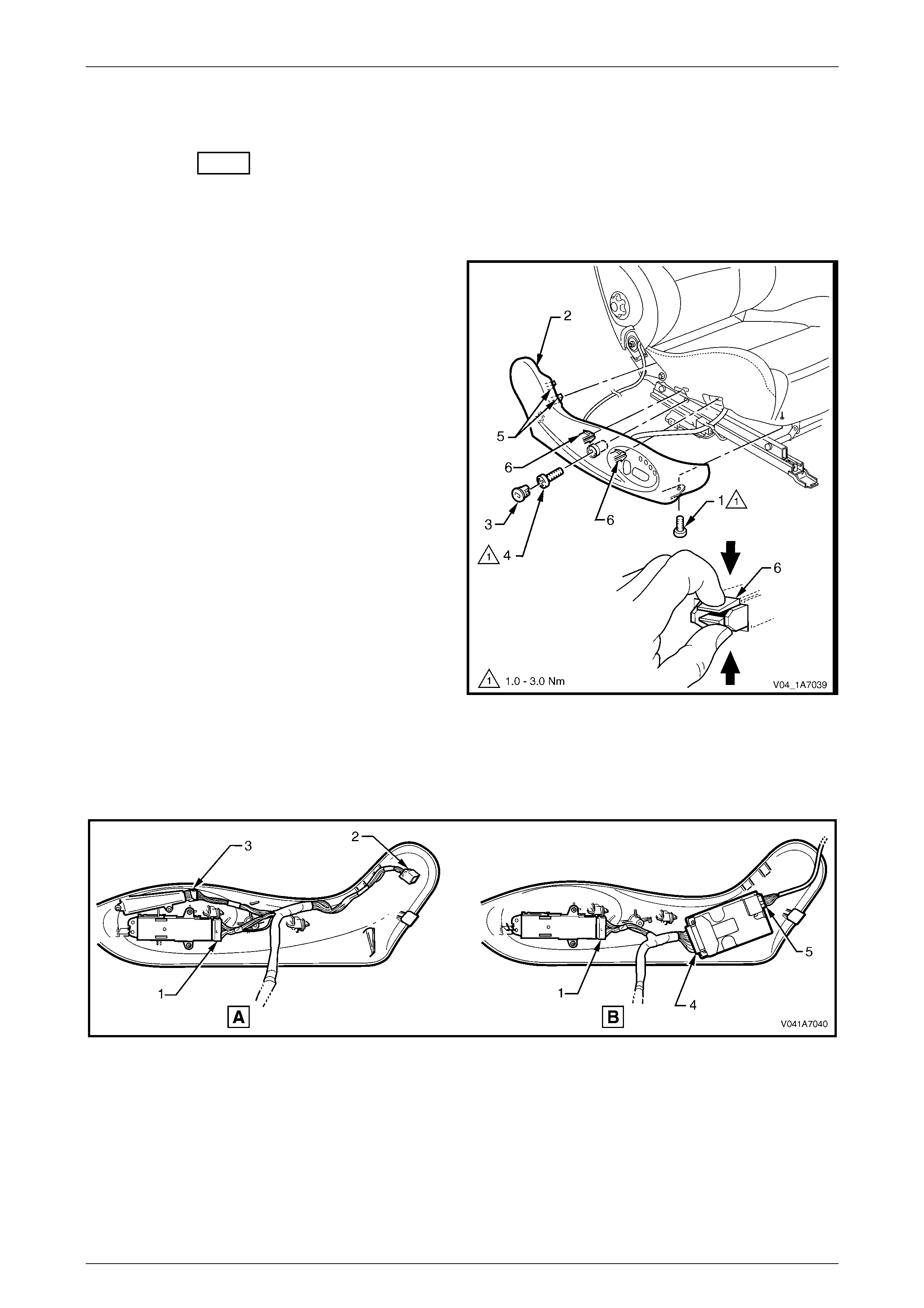
Seat Assemblies Page 1A7A–260
Page 1A7A–260
6.4 Front Seat Outer Side Cover Assembly
LT Section No. – 14-322
Remove
1 Raise the seat to the full-up position.
2 Remove the screw (1) from the front of the front seat
outer side cover (2).
3 Remove the plug (3) by rotating the plug anti-
clockwise, one quarter of a turn.
4 Remove the screw (4) located behind the plug.
5 Reach up under the seat assembly and squeeze
together the two retaining tangs (6), on the inner side
of the side cover while gently pulling the cover.
6 Gently pull the side cover away from the seat to
disengage the two clips (5) attached to the seat-back
frame assembly .
NOTE
Only remove the side cover far enough away
from the seat cushion assembly to gain access
to the seat wiring harness connectors.
7 Referring to Figure 1A7A – 118, for memory seats (A):
• Disconnect the front seat adj u stme nt switch
connector (1), recline motor harness connector
(2) and memory position switch connector (3)
and unclip the harness from the side cover.
For non-memory seats (B): Figure 1A7A – 116
Figure 1A7A – 117
• Disconnect the front seat adjustment switch connector (1), EZ-entry module connector (4) and the recline
motor harness connector (5) from the EZ-entry module and unclip the harness from the side cover.
8 Rem ove the side cove r asse mbly.
Figure 1A7A – 118

Seat Assemblies Page 1A7A–261
Page 1A7A–261
Disassemble
Front Seat Adjustment Switch
Remove
1 Remove the two adjus tment knobs (1) from the front
seat adjustment switch (2), by carefully prising them
free with a small fl at tip screwdriver wrapped in a clean
shop rag.
Figure 1A7A – 119
2 Remove the three screws (1) attaching the front seat
adjustment switch (2) to the front seat outer side
cover (3).
3 Remove the seat adjustment switch.
Figure 1A7A – 120
Reinstall
Reinstall atio n of the front seat adju stm ent switch is the reverse of the removal procedure, noting the following:
1 Tighten the attaching screws to the correct torque specific ation.
Front seat adjust ment sw itch
attaching screw torque specification...........1.0 – 3.0 Nm
2 Push the knobs in until they click in place.
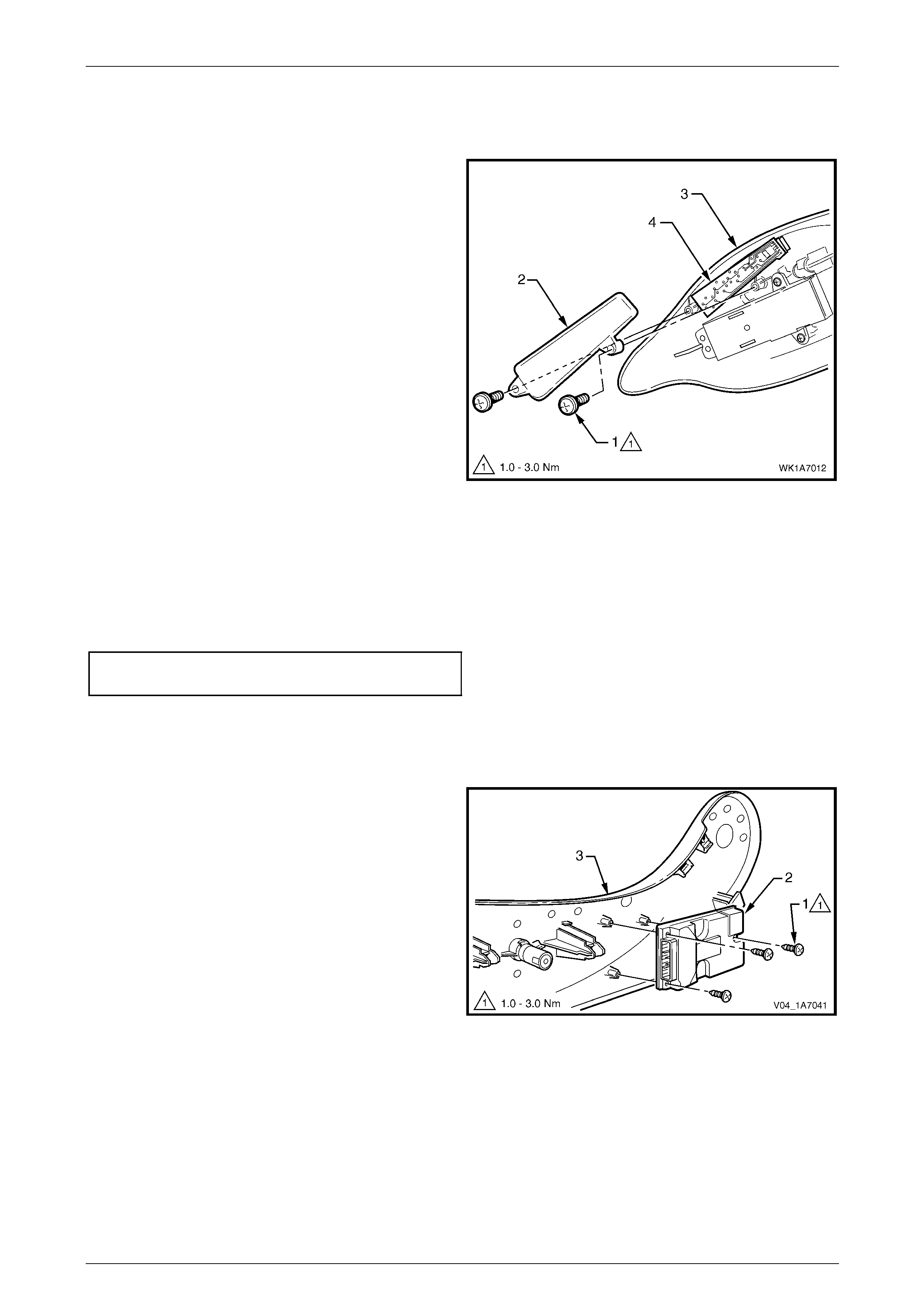
Seat Assemblies Page 1A7A–262
Page 1A7A–262
Memory Position Switch Assembly
Remove
1 Remove the two screws (1) attaching the memory
position switch cover (2) to the front seat outer side
cover (3).
2 Lift out the memory position switch assembly (4) from
its recess in the side cover.
3 As required, each position button can b e removed
from the switch.
Figure 1A7A – 120
Reinstall
Reinstallation of the memory position switch assembly is the reverse of the removal procedure, noting the following:
1 If removed, push the position buttons in until they click in place, ensuring correct orientation.
2 Tighten the attaching screws to the correct torque specification.
Memory position switch cover
attaching screw torque specification...........1.0 – 3.0 Nm
EZ-entry Module
Remove
1 Remove the three screws (1) attaching the EZ-entry
module (2) to the front seat outer side cover (3).
2 Remove the module.
Figure 1A7A – 121

Seat Assemblies Page 1A7A–263
Page 1A7A–263
Reinstall
Reinstallation of the EZ-entry module is the reverse of the removal procedure, noting the following:
Tighten the attaching screws to the correct torque specification.
EZ-entry module attaching screw
torque specification.....................................1.0 – 3.0 Nm
Reinstall
Reinstallation of the front seat outer side cover is the reverse of the removal procedure, noting the following:
Tighten the attaching screws to the correct torque specification.
Front seat outer side cover attaching
screw torque specification...........................1.0 – 3.0 Nm

Seat Assemblies Page 1A7A–264
Page 1A7A–264
6.5 Front Seat Inner Side Cover
LT Section No. – 14-322
As required, remove the front seat assembly, refer to 6.3 Front Seat Assembly.
Remove
1 Remove the screw (1) attaching the front seat inner
side cover (2) to the seat assembly (3) and remove the
cover.
Figure 1A7A – 122
Reinstall
Reinstallation of the front seat inner side cover is the reverse of the removal procedure, noting the following:
Tighten the attaching screw to the correct torque specification.
Front seat inner side cover attachi ng
screw torque specification...........................1.0 – 3.0 Nm

Seat Assemblies Page 1A7A–265
Page 1A7A–265
6.6 Front Seat-back Rear Cover Assembly
LT Section No. – 14-322
Remove
The following components will require
replacement when performing this operation.
• Two front seat-back rear cover retaining
clips.
1 Pull the lower corners of the front seat-back rear
cover (1) away from the seat (2), breaking the two
retaining clips (3).
Figure 1A7A – 123
2 While holding the lower portion of the front seat-back
rear cover (1) out, pull the cover down to release the
two upper retaining lugs (2).
3 Remove the cover.
Figure 1A7A – 124
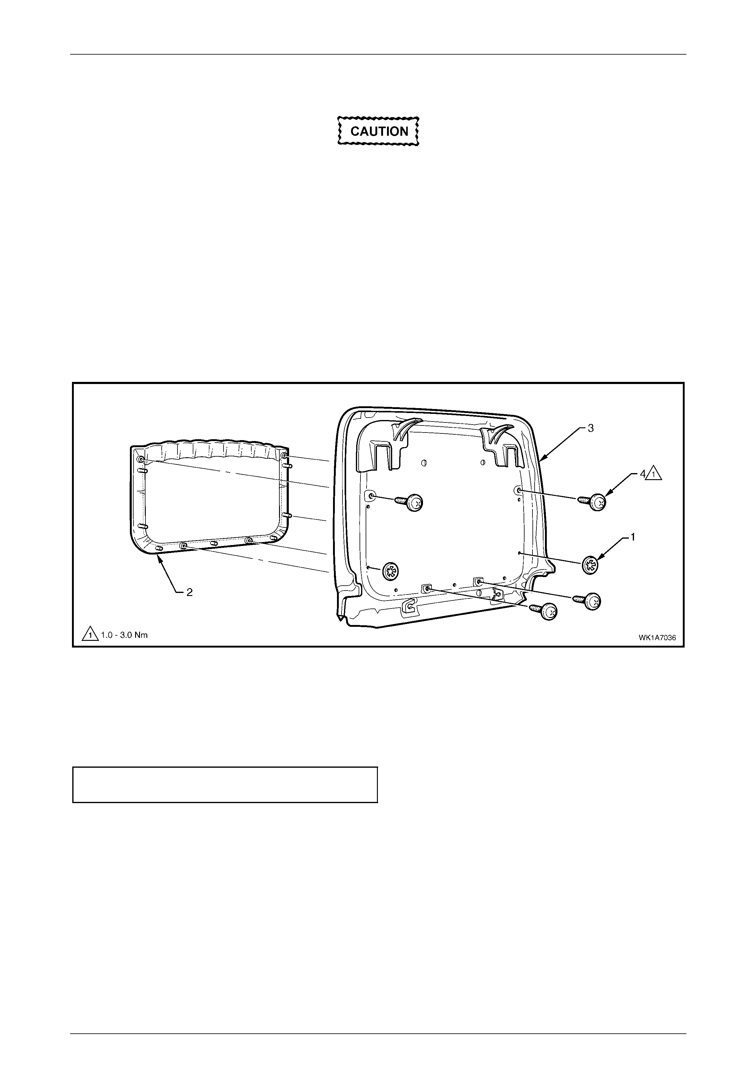
Seat Assemblies Page 1A7A–266
Page 1A7A–266
Disassemble
When performing Step 1, take care when
removing the retaining clip (1) not to break
the front seat-back map pocket shafts on
which the reta ining clips are attached.
NOTE
This procedure cannot be performed on vehicles
that have the net type seat-back map pocket.
1 Remove the two retaining clips (1) attaching the front seat-back map pocket (2) to the front seat-back rear
cover (3), refer to Figure 1A7A – 125.
2 Remove the four screws (4) attaching the map pocket to the cover.
3 Remove the map pocket.
Figure 1A7A – 125
Reassemble
Reassembly of the front seat-back rear cover is the reverse of the removal procedure, noting the following:
Tighten the attaching screws to the correct torque specification.
Front seat-back map pocket attaching
screw torque specification...........................1.0 – 3.0 Nm

Seat Assemblies Page 1A7A–267
Page 1A7A–267
Reinstall
1 Replace the damaged retaining clip (1) on the front
seat-back rear cover (2), two places.
Figure 1A7A – 126
2 Align the two upper retaining l ugs (1) with the seat-
back.
3 Push the front seat-back rear cover (2) up and in at
the lower edge to engage the two lower retaining clips.
Figure 1A7A – 127
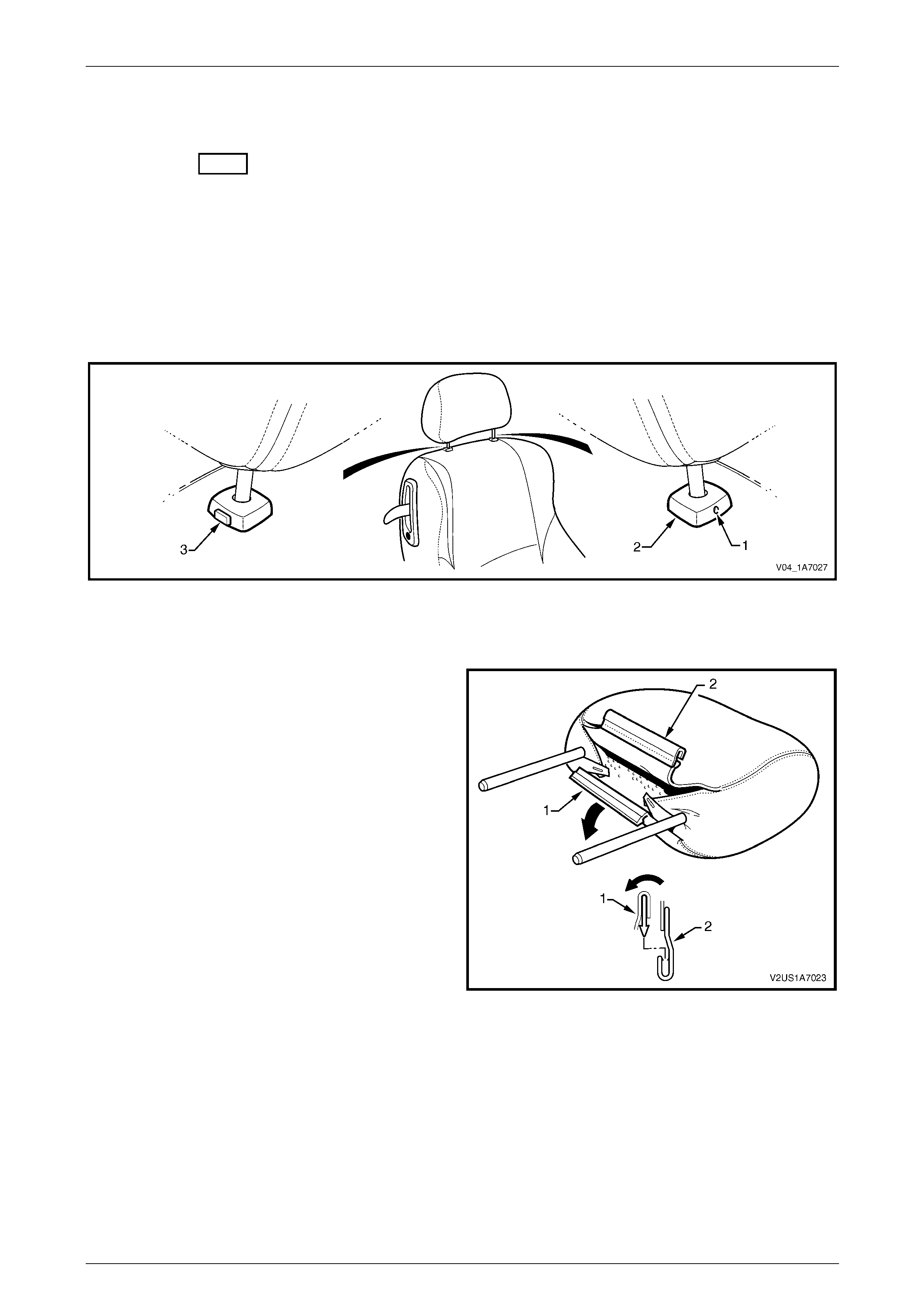
Seat Assemblies Page 1A7A–268
Page 1A7A–268
6.7 Front Seat Head Restraint Assembly
LT Section No. – 14-295
Remove
1 Raise the head restraint fully.
2 Insert a suitable size probe into the hole (1) in the right-hand head restraint sleeve (2), refer to Figure 1A7A – 128.
3 Push the probe in slightly whil e applying slight upward pressure on the head restraint. Hold the upward pressure.
4 Depress the head restraint sleeve height adjuster lock (3) on the left-hand head restraint sleeve and remove the
head restraint.
Figure 1A7A – 128
Disassemble
1 Disengage the front head restraint cover J-stri p by
pulling the flap (1) back and out of flap (2) in the
direction shown.
Figure 1A7A – 129
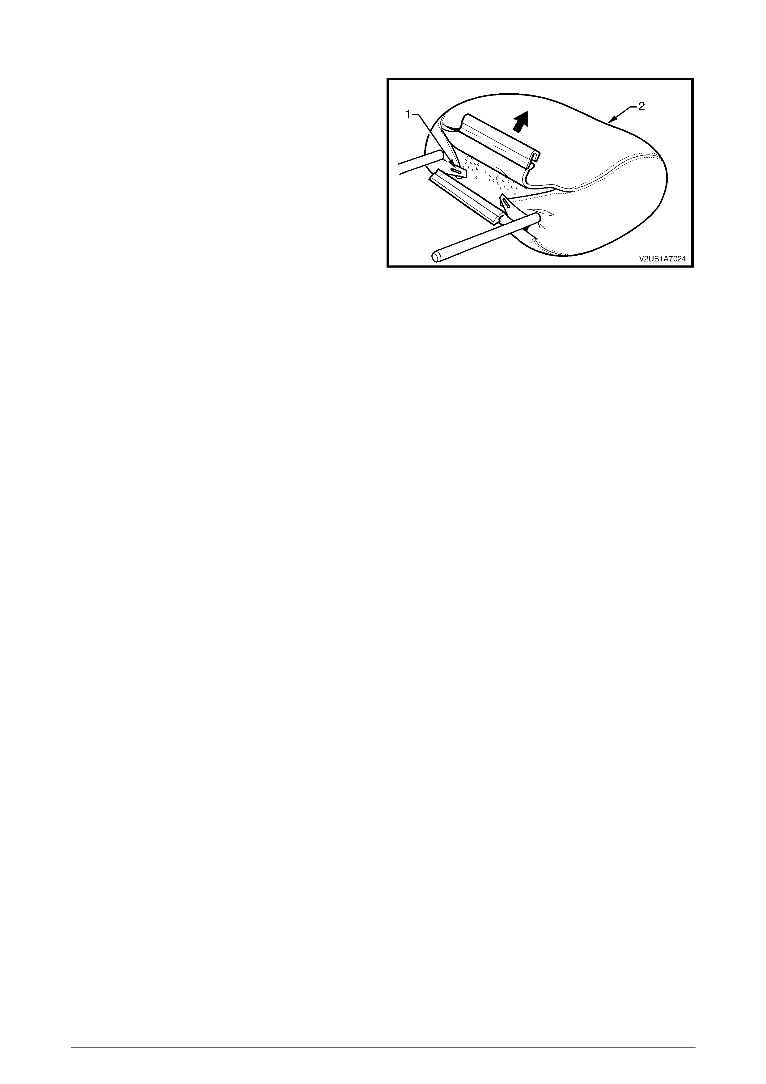
Seat Assemblies Page 1A7A–269
Page 1A7A–269
2 Remove the two staples (1) retaining the cover (2) to
the head restraint pad assembly.
3 Remove the cover from the pad assemb ly
Figure 1A7A – 130
Reassemble
Reassembly of the front seat head restraint assembly is the reverse of the removal procedure, noting the following:
1 Ensure the head restraint cover J-clip is fully enga ged.
Reinstall
Ensuring correct orientation of the head restraint, fit the head restraint shafts into the sleeves and p ush the head restraint
down.

Seat Assemblies Page 1A7A–270
Page 1A7A–270
6.8 Front Seat Head Restraint Sleeve
As required, remove the front seat head restraint assembl y, refer to 6.7 Front Seat Head Restrai nt Assembl y.
LT Section No. – 14-275
Remove
1 Push down on the surrounding seat cover to reveal the
upper portion of the seat-back frame or active head
restraint frame (1).
2 Using a fine flat-blade screwdriver, depress the head
restraint sleeve retaining lug (2) and withdraw the
head restraint sleeve (3) from the frame.
3 Repeat for the remaining sleeve as required.
Figure 1A7A – 131
Reinstall
Reinstallation of the front seat head restraint sleeve is the reverse of the removal proce dure, noting the following:
NOTE
Ensure the sleeve with the height adjuster
lock (1) is installed on the left-hand side of the
seat; that is the side that corresponds to the
lower square notch (2) in the head restraint
shaft.
Figure 1A7A – 132
1 Align the head restraint sleeve locatin g ribs (1 ) with
the notch (2) in the seat-back frame.
2 Insert the sleeve and ensure it clicks into place.
Figure 1A7A – 133
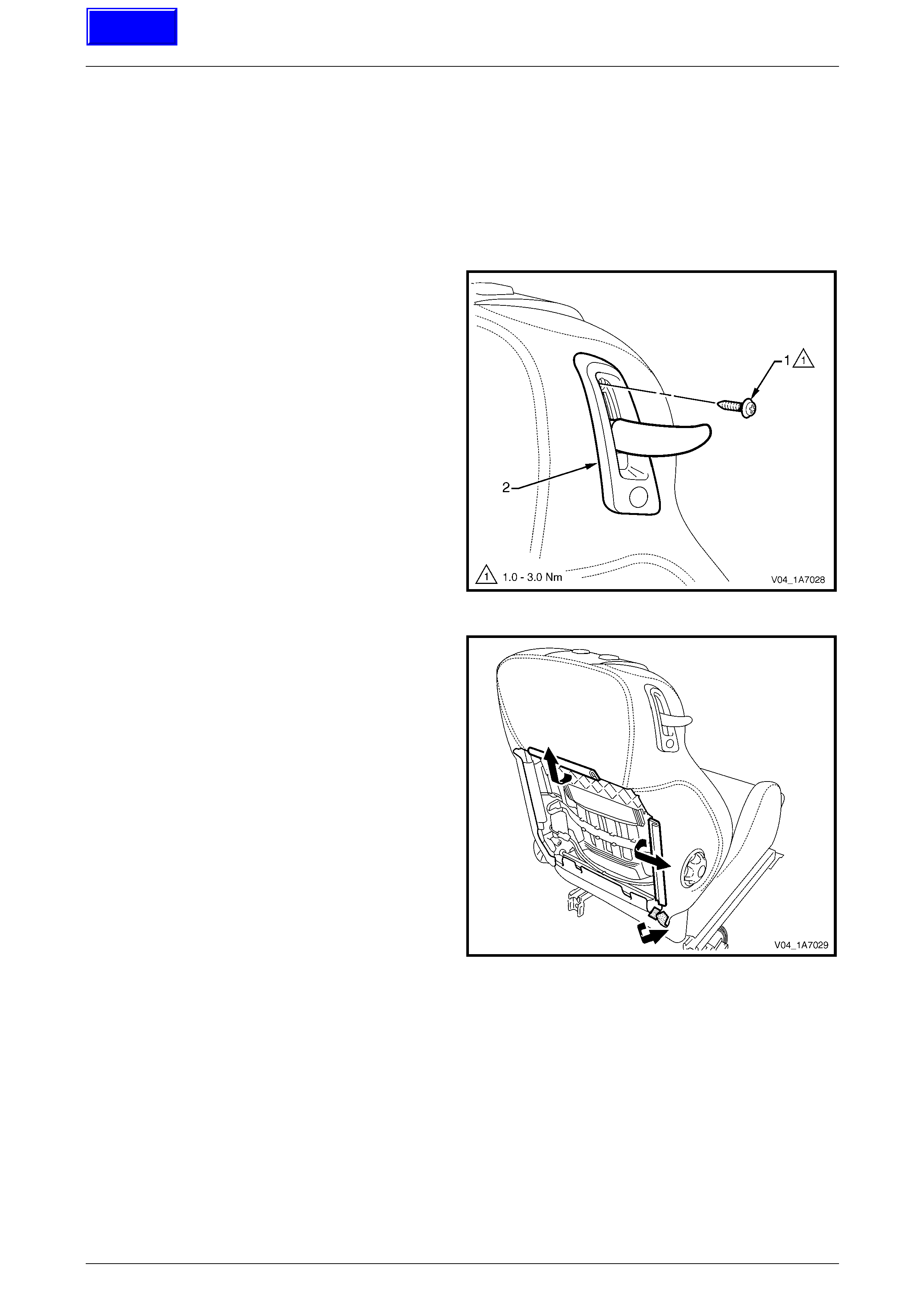
Seat Assemblies Page 1A7A–271
Page 1A7A–271
6.9 EZ-entry Release Lever and Escutcheon
LT Section No. –
1 Remove the front seat outer side cover, 6.4 Front Seat Outer Side Cover Assembl y.
2 Remove the front seat-back rear cover assembly, refer to 6.6 Front Seat-back Rear Cover Assembly.
Remove
1 Remove the screw (1) retaining the EZ-entry release
escutcheon assembly (2) to the seat-back frame.
Figure 1A7A – 134
2 Partly remove the front seat-back cover by
disengaging the upper and outer J-strips from the
seat-back frame and the Velcro tab at the lower
corner.
Figure 1A7A – 135
Techline
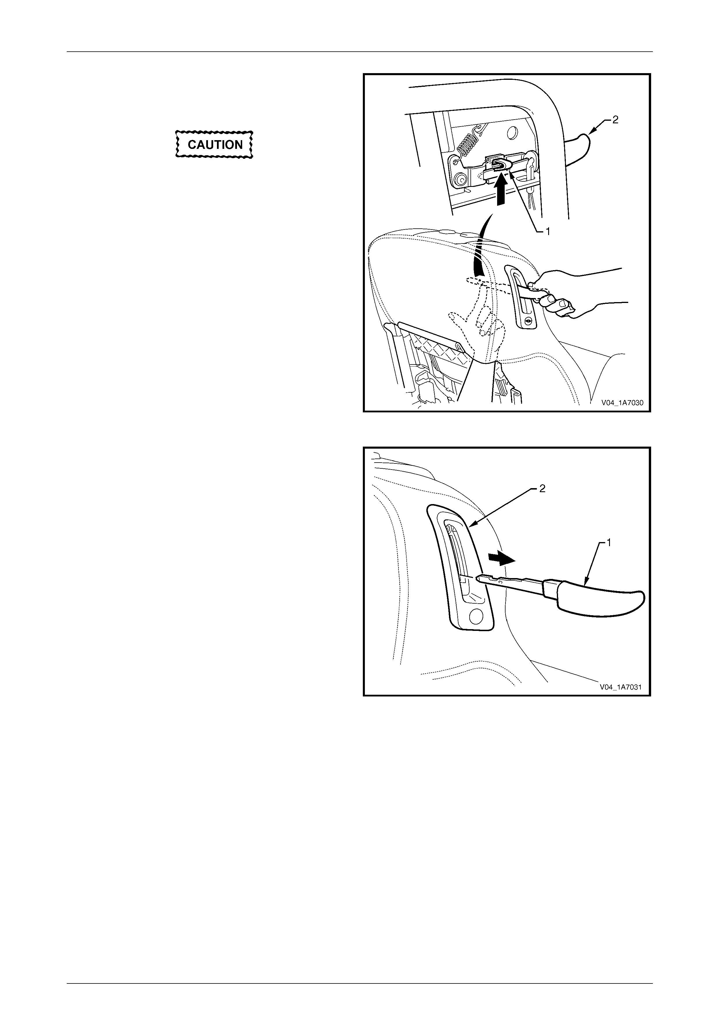
Seat Assemblies Page 1A7A–272
Page 1A7A–272
3 Carefully manoeuvre your hand behin d the seat pad
and push up on the retaining clip (1) retaining the
release lever (2).
Take care as there may be sharp edges in
this area.
Figure 1A7A – 136
4 While holding upward pressure on the retaining clip,
grasp the release lever (1) and pul l firmly away from
the seat-back to remove.
NOTE
It may be necessary to wriggle the lever to
loosen it in the escutcheon assembly (2).
Figure 1A7A – 137
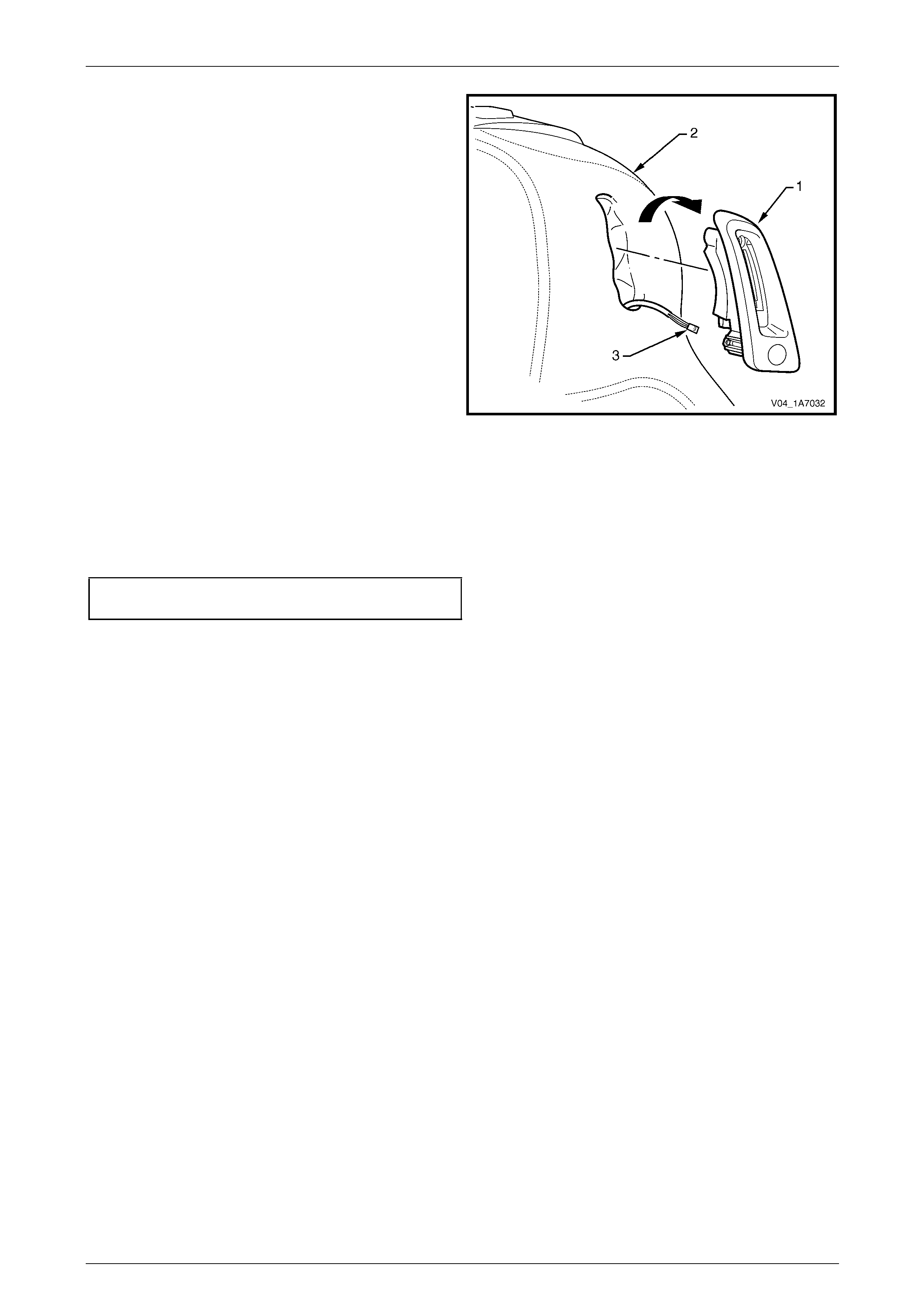
Seat Assemblies Page 1A7A–273
Page 1A7A–273
5 Partially remove the EZ-entry release escutcheon
assembly (1) from the front seat-back cover (2), by
rotating the top of the escutcheon outward and
disengaging the lower lug.
6 Disconnect the wiring harness connector (3) from the
seat return switch.
7 Remove the escutcheon assembly.
Figure 1A7A – 138
Reinstall
Reinstallation of the EZ-entry release lever and escutcheon assembly is the reverse of the removal procedur e, noting the
following:
1 Tighten the attaching screws to the correct torque specification.
EZ-entry release escutcheon assembly
attaching screw torque specification...........1.0 – 3.0 Nm
2 Ensure that the release lever retaining clip is correctly engaged by pulling firmly away from the seat and operating
the latch several times.

Seat Assemblies Page 1A7A–274
Page 1A7A–274
6.10 EZ-entry Switch and Release Cable
Assembly
Due to safety requirement constraints, certain components of the recliner mechanism, including the EZ-entr y switch and
release cable assembly, must not be removed or repl aced. If any part of the recliner mechanism requires replacement,
the entire front seat-back frame assembly must be replaced, refer to 6.13 Front Seat-back Frame Assembly.
Techline
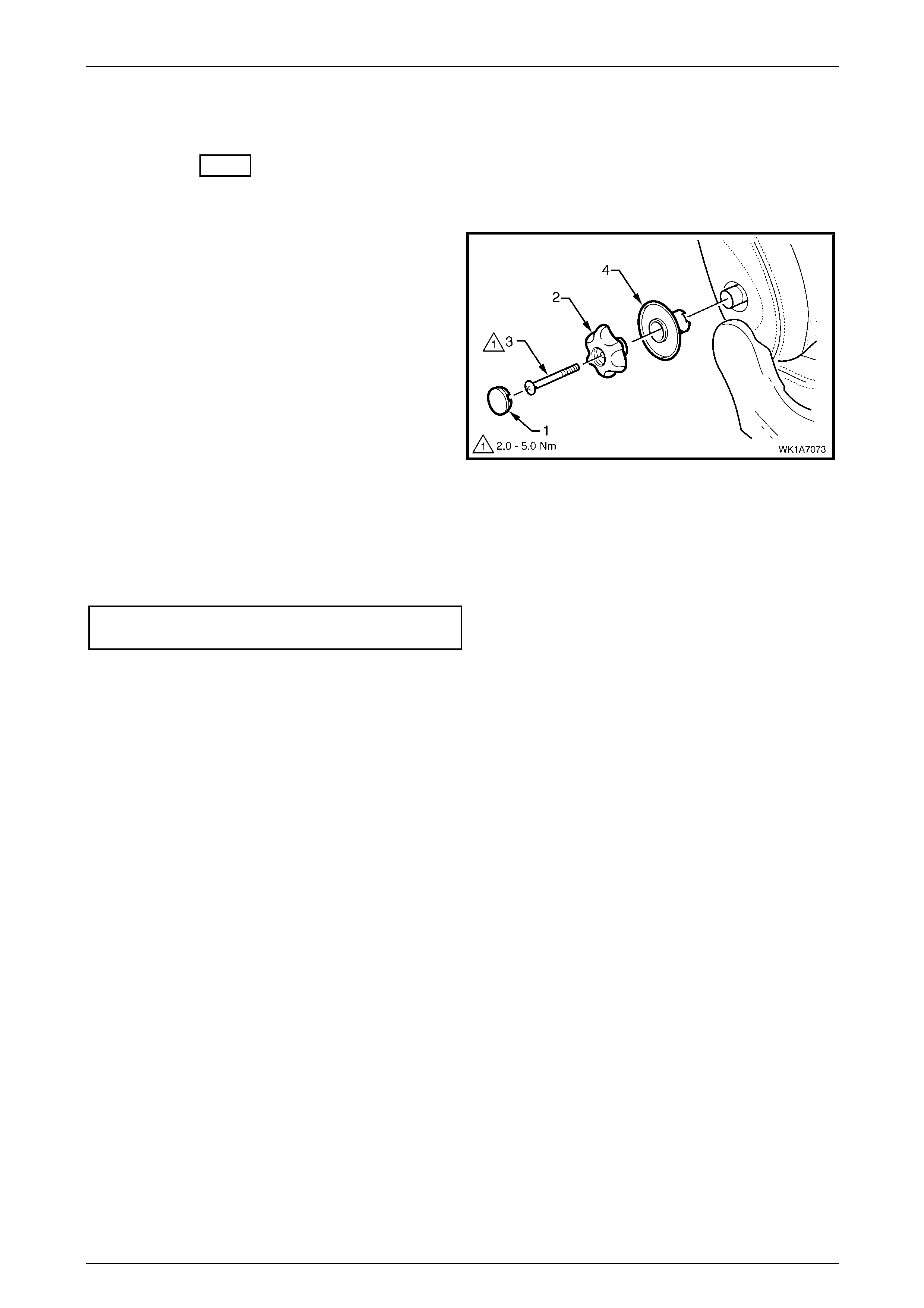
Seat Assemblies Page 1A7A–275
Page 1A7A–275
6.11 Lumbar Support Knob Assembly
LT Section No. – 14-275
Remove
1 Using a fine flat-blade scre w-driver, carefull y prise the
cap (1) from the lumbar support knob (2).
2 Remove the screw (3) attaching the knob to the
lumbar support shaft.
3 Pull the knob off the lumbar support shaft and remove
the lumbar support deflector ring (4).
NOTE
The knob is lightly clipped to the lumbar support
shaft and will ‘click-off’.
Figure 1A7A – 139
Reinstall
Reinstallation of the lumbar s upport knob assembly is the reverse of the removal procedure, noting the following:
Tighten the screw to the correct torque specification.
Lumbar support knob attachin g
screw torque specification...........................2.0 – 5.0 Nm
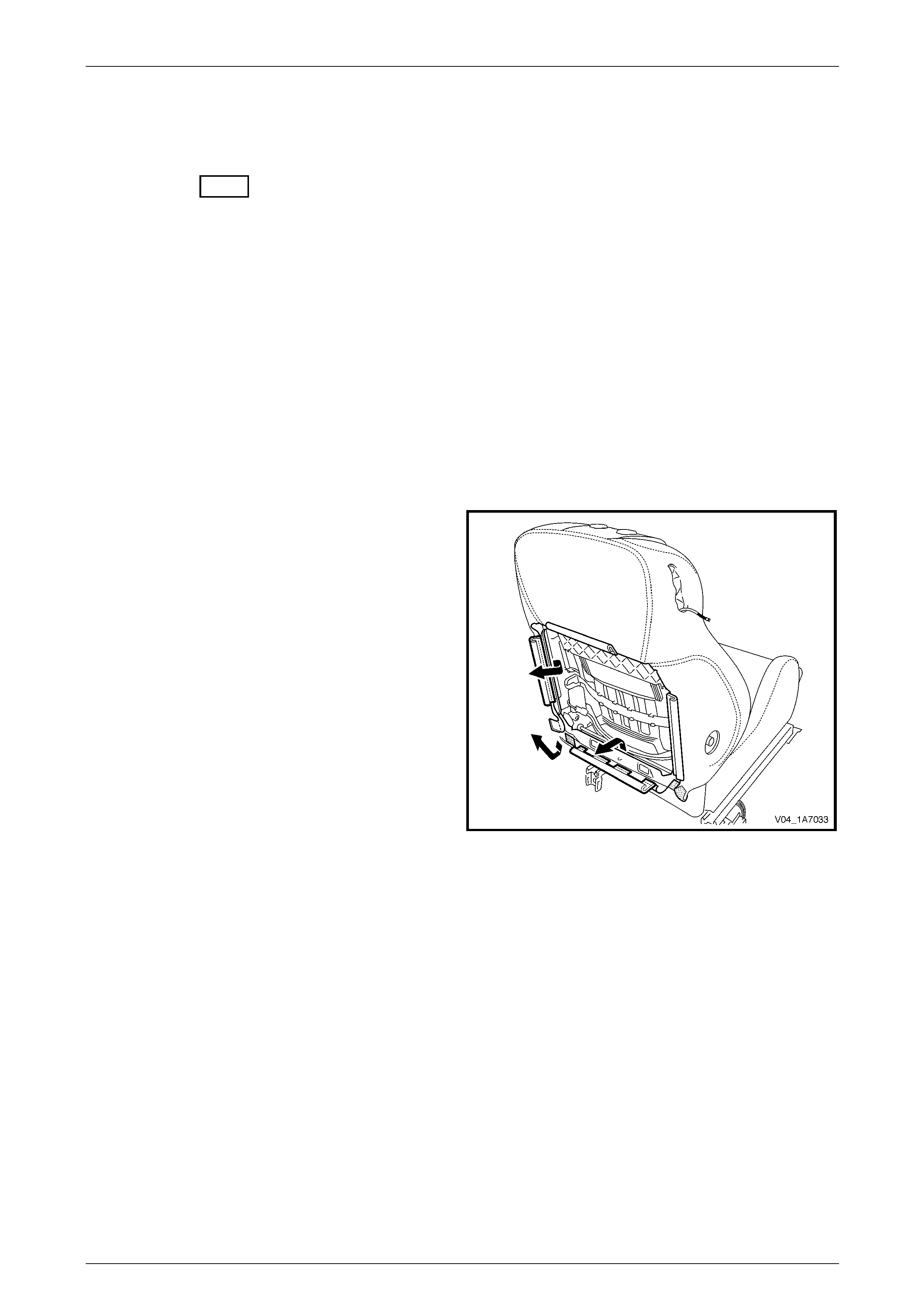
Seat Assemblies Page 1A7A–276
Page 1A7A–276
6.12 Front Seat-back Pad and Cover
Assembly
LT Section No. – 14-295
As required, remove the following compo nents:
1 Front seat assembly, refer to 6.3 Front Seat Assembly.
2 Front seat outer side cover assembly, refer to 6.4 Front Seat Outer Side Cover Assembly.
3 Front seat inner side cover, refer to 6.5 Front Seat Inner Side Cover.
4 Front seat-back rear cover assembly, refer to 6.6 Front Seat-back Rear Cover Assemb ly.
5 Front seat head restraint assembly, refer to 6.7 Front Seat Head Restraint Assembly.
6 Front seat head restraint sleeves, refer to 6.8 Front Seat Head Restraint Sleeve.
7 EZ-entry release lever and escutcheon assembly, refer to 6.9 EZ-entry Release Lever and Escutcheon.
8 Lumbar support knob assembly, refer to 6.11 Lumbar Support Knob Assembly.
Remove
1 Disengage the remainin g inner and lower J-strips from
the seat frame and the Velcro tab at the lower corner.
2 Lift the cover and pad assembly up and away from the
seat-back frame, manoeuvring it over the seat-back
components such as the side impact airbag a ssembly
and dummy block insert assembly.
Figure 1A7A – 140
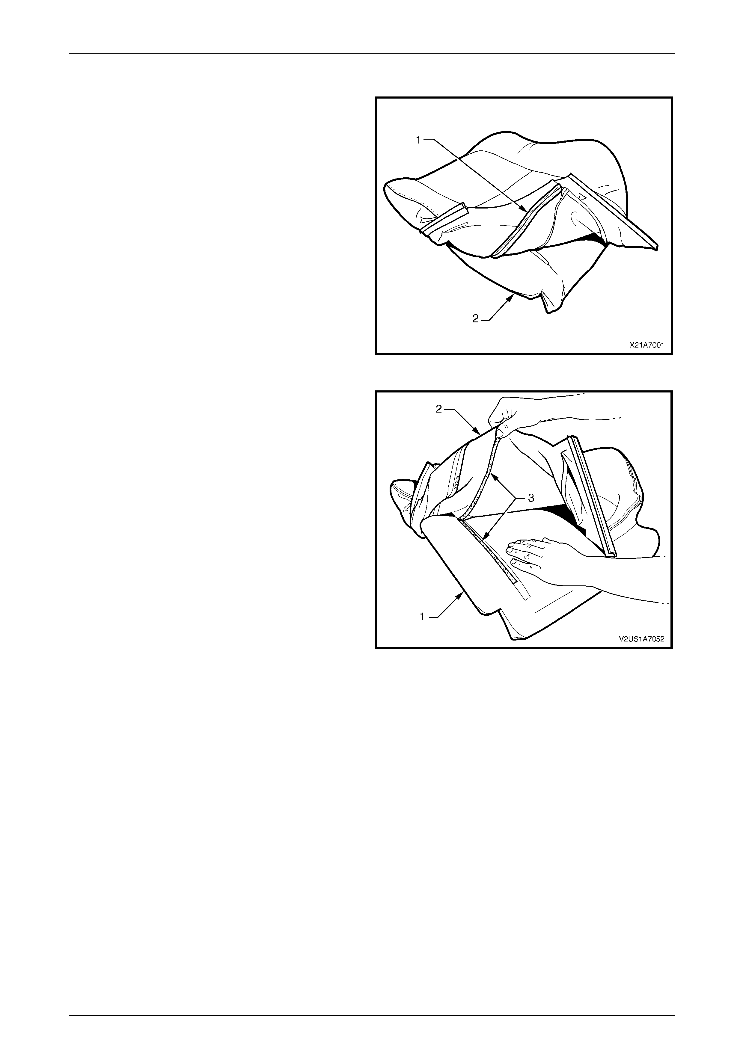
Seat Assemblies Page 1A7A–277
Page 1A7A–277
Disassemble
1 Fold the lower corners of the seat-back cove r (1) over
the seat-back pad (2).
Figure 1A7A – 141
2 While holding the front seat-back pad (1), pull the
lower corners of the front seat-back cover (2), upwards
and away from the pad to diseng age the hook and
loop strips (3).
3 Pull the cover up and over the upper ed ge of the pad.
Figure 1A7A – 142
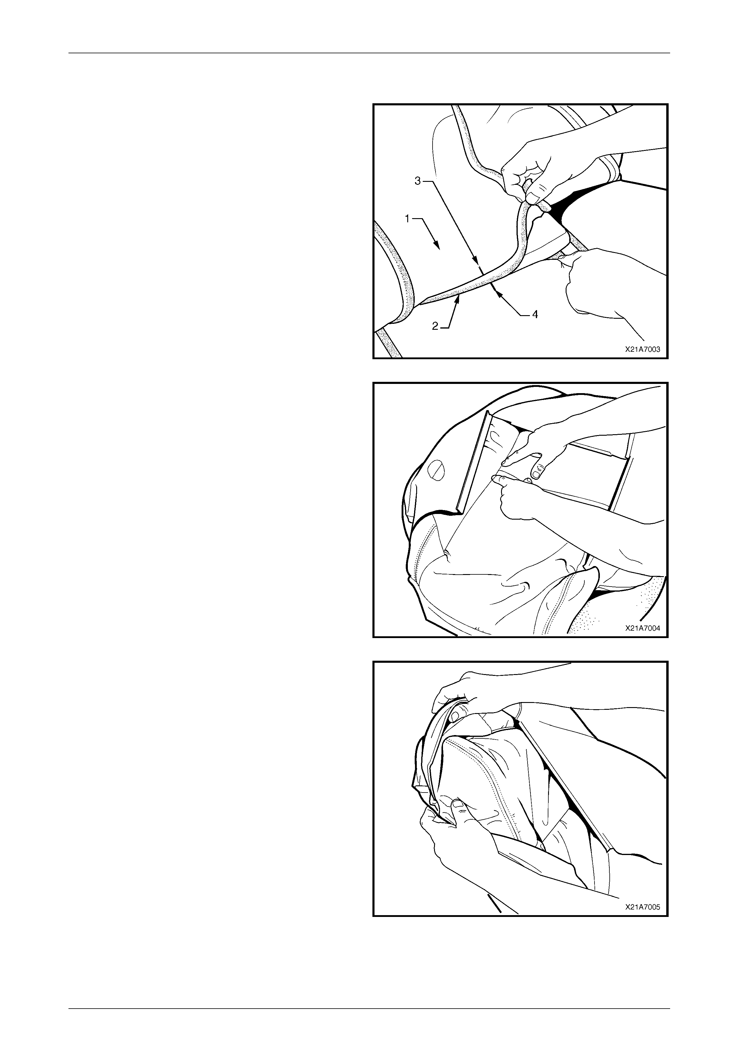
Seat Assemblies Page 1A7A–278
Page 1A7A–278
Reassemble
1 With the front seat-back cover (1) folded at the central
horizontal strip of hook and loop (2), align th e centre
mark (3) on the cover with the centre mark (4) on the
front seat-back pad.
2 Press the cover firmly into the corresponding groove i n
the pad to engage the hook and loop.
Figure 1A7A – 143
3 With the cover folded at the two vertical strips of the
hook and loop, press the cover firml y into the
corresponding grooves in the pad.
Figure 1A7A – 144
4 Roll the upper corners of the cover over the pad.
5 Roll the sides of the cover over the pad.
6 Roll the lower corners of the cover over the pad.
NOTE
Make sure the cover is fitted neatly by hand into
all corners and contours of the pad.
Figure 1A7A – 145
Reinstall
Reinstallation of the front seat -back pad and cover assembly is the reverse of the removal proced ure.

Seat Assemblies Page 1A7A–279
Page 1A7A–279
6.13 Front Seat-back Frame Assembly
When carrying a live (undeployed) side
impact airbag assembly or a front seat-back
frame assembly fitted with a (undeployed)
side impact airbag assembly, ensure the
airbag opening is pointed away from you.
Never carry the side impact airbag assembly
or seat-back frame assembly fitted w ith a side
impact airbag assembly by the airbag wiring
harness or connectors. In case of an
accidental deployment, the airbag will then
deploy with minimal chance of injury.
When placing a live side impact airbag
assembly or a fro nt seat-ba ck frame as sembly
fitted with a (undeployed) side impact airbag
assembly on a bench or other surface, alw ays
face the airbag opening up, away from the
surface. Never rest the airbag assembly or
seat-back frame with the airbag opening face
down. This is necessary so that a free space
is provided to allow the airbag to expand in
the unlikely event of accidental deployment.
Otherwise, personal injury may result.
LT Section No. – 14-275
As required remove the following c ompo nents:
1 Front seat assembly, refer to 6.3 Front Seat Assembly.
2 Front seat outer side cover assembly, refer to 6.4 Front Seat Outer Side Cover Assembly.
3 Front seat inner side cover, refer to 6.5 Front Seat Inner Side Cover.
Remove
1 Remove the two screws (1), each side, attaching the
seat-back assembly (2) to the front seat cushion frame
assembly (3).
2 As required, disconnect and detach the front seat-back
recline motor and side impact airbag wiring harnesses.
3 Remove the seat-back assembly.
Figure 1A7A – 146
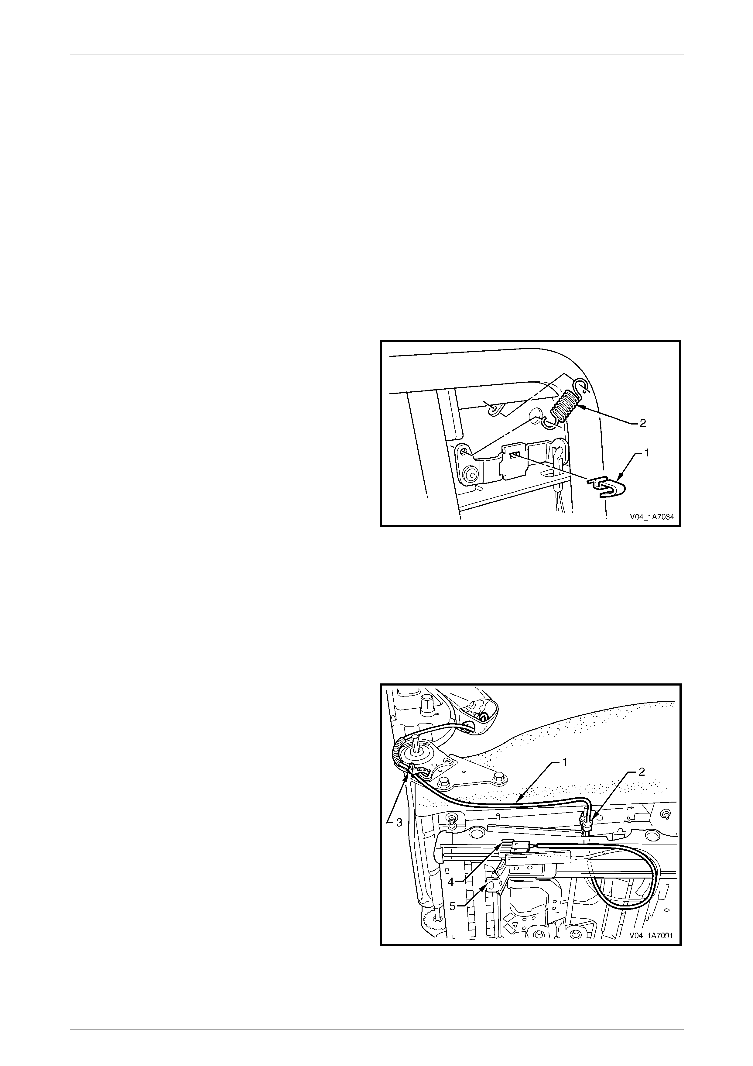
Seat Assemblies Page 1A7A–280
Page 1A7A–280
Disassemble
As required, remove the following compo nents:
1 Front seat-back rear cover assembly, refer to 6.6 Front Seat-back Rear Cover Assemb ly.
2 Front seat head restraint assembly, refer to 6.7 Front Seat Head Restraint Assembly.
3 Front seat head restraint sleeves, refer to 6.8 Front Seat Head Restraint Sleeve.
4 EZ-entry release lever and escutcheon assembly, refer to 6.9 EZ-entry Release Lever and Escutcheon.
5 Lumbar support knob assembly, refer to 6.11 Lumbar Support Knob Assembly.
6 Front seat-back pad and cover assembl y, refer to 6.12 Front Seat-back Pad and Cover Assembly.
EZ-entry Release Lever Retaining Clip and Return Spring
Remove
1 Prise the release lever retaining clip (1) from the
release mechanism.
2 Disconnect the return spring (2) from the release
mechanism and seat-back frame
Figure 1A7A – 147
Reinstall
Reinstallation of the EZ-entry release lever retaining clip and return spring is the reverse of the removal procedure.
Side Impact Airbag Assembly
Remove
1 As required, unclip the side im pact airbag wiring
harness (1) from the retaining clip (2) and cut the
cable tie (3) securing the harness to the front seat
cushion frame assembly, taking care not to damage
the wiring harness.
2 Unclip the wiring harness connector (4) from the track
and height adjust assembly (5).
Figure 1A7A – 148
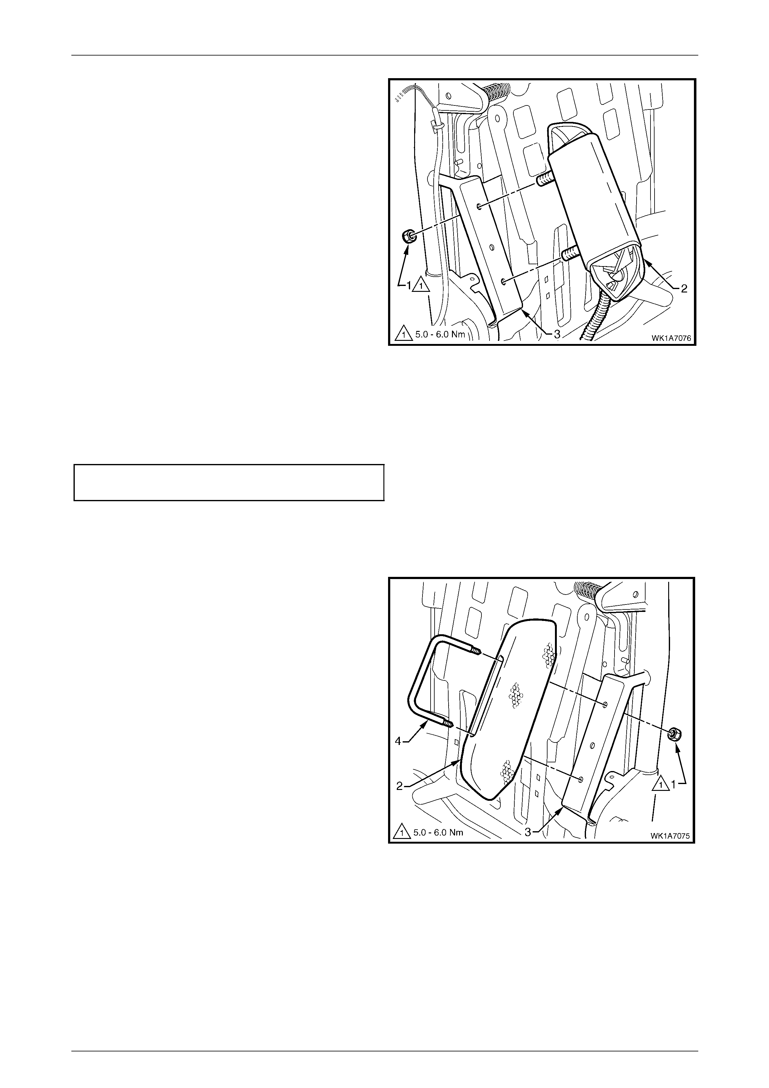
Seat Assemblies Page 1A7A–281
Page 1A7A–281
3 Remove the lock-nut (1), two places, attaching the
side impact airbag assembl y ( 2) to the seat-b ack
frame (3) and airbag assembly.
Figure 1A7A – 149
Reinstall
Reinstallation of the side impact airba g asse mbly is the reverse of the removal procedure, noting the following:
Tighten the nuts to the correct torque spec ification.
Side impact airbag assembly attaching
nut torque specification...............................5.0 – 6.0 Nm
Front Seat Dummy Block Insert Assembly
Remove
1 Remove the lock-nut (1), two places, attaching the
front seat dummy block insert (2) to the seat-back
frame (3) and remove the dummy block insert
assembly.
2 If required, remove the dummy block U-bolt (4) from
the dummy block insert.
Figure 1A7A – 150
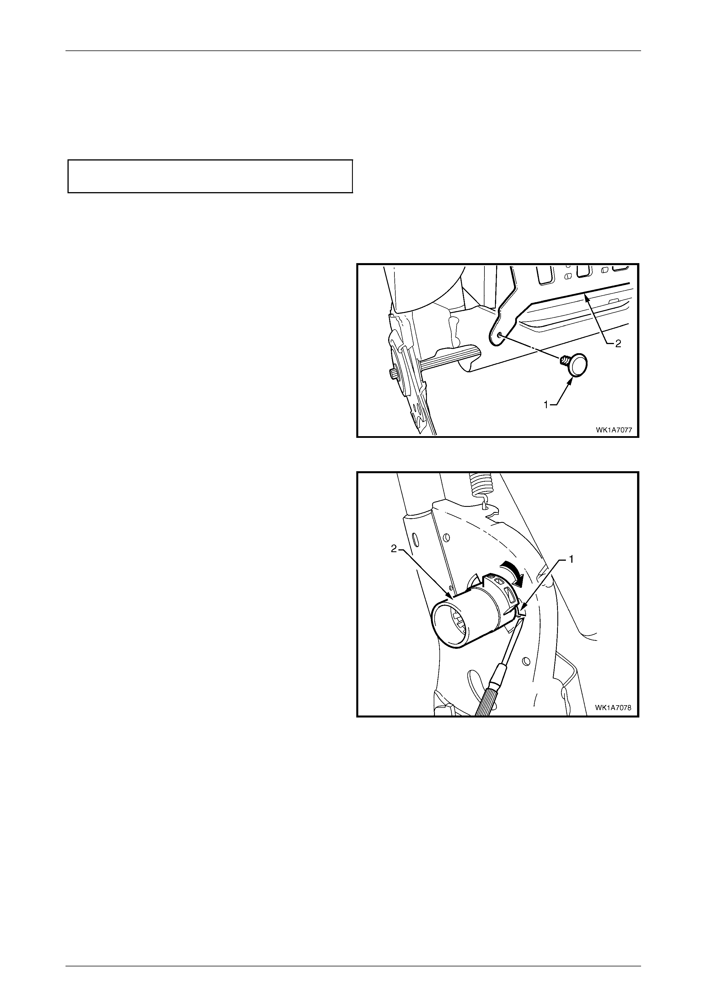
Seat Assemblies Page 1A7A–282
Page 1A7A–282
Reinstall
Reinstallation of the front seat dummy block insert assembly is the reverse of the removal procedure, noting the
following:
Tighten the nuts to the correct torque specification.
Front seat dummy block insert attaching
nut torque specification...............................5.0 – 6.0 Nm
Lumbar Support Assembly
Remove
1 Remove the retainer (1), two places, attaching the
lumbar support assembly (2) to the seat-back frame.
Figure 1A7A – 151
2 Depress the retaining tab (1) and from the inner side
of the seat-back frame, rotate the lumbar support
shaft (2) and withdraw from the seat-back frame.
3 Repeat for the opposite side.
Figure 1A7A – 152
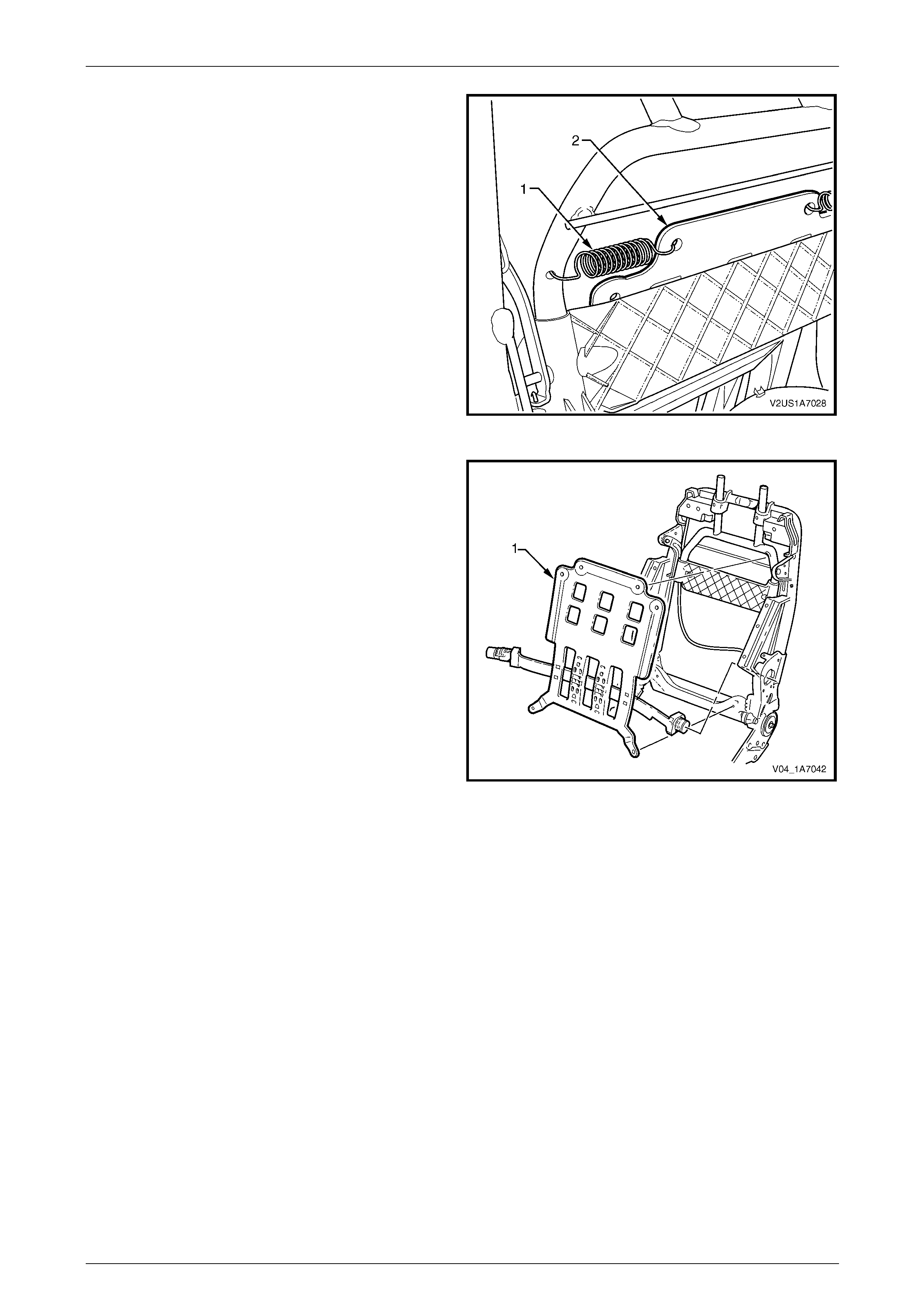
Seat Assemblies Page 1A7A–283
Page 1A7A–283
4 Disconnect the spring (1), two places, attaching the
lumbar support assembly (2) to the seat-bac k frame or
active head restraint frame.
TIP
To aid spring remova l, pull the support asse mbly
toward the side that the spring is being remove d
to relieve spring tension.
Figure 1A7A – 153
5 Remove the lumbar support assembly (1).
Figure 1A7A – 154
Reinstall
Reinstallation of the lumbar s upport assembly is the reverse of the removal procedure, noting the following:
Ensure the lumbar support assembl y is correctly seated on the cushion side of the active head restraint frame, where
fitted, with the black lumbar support shaft on the outer side of the seat.
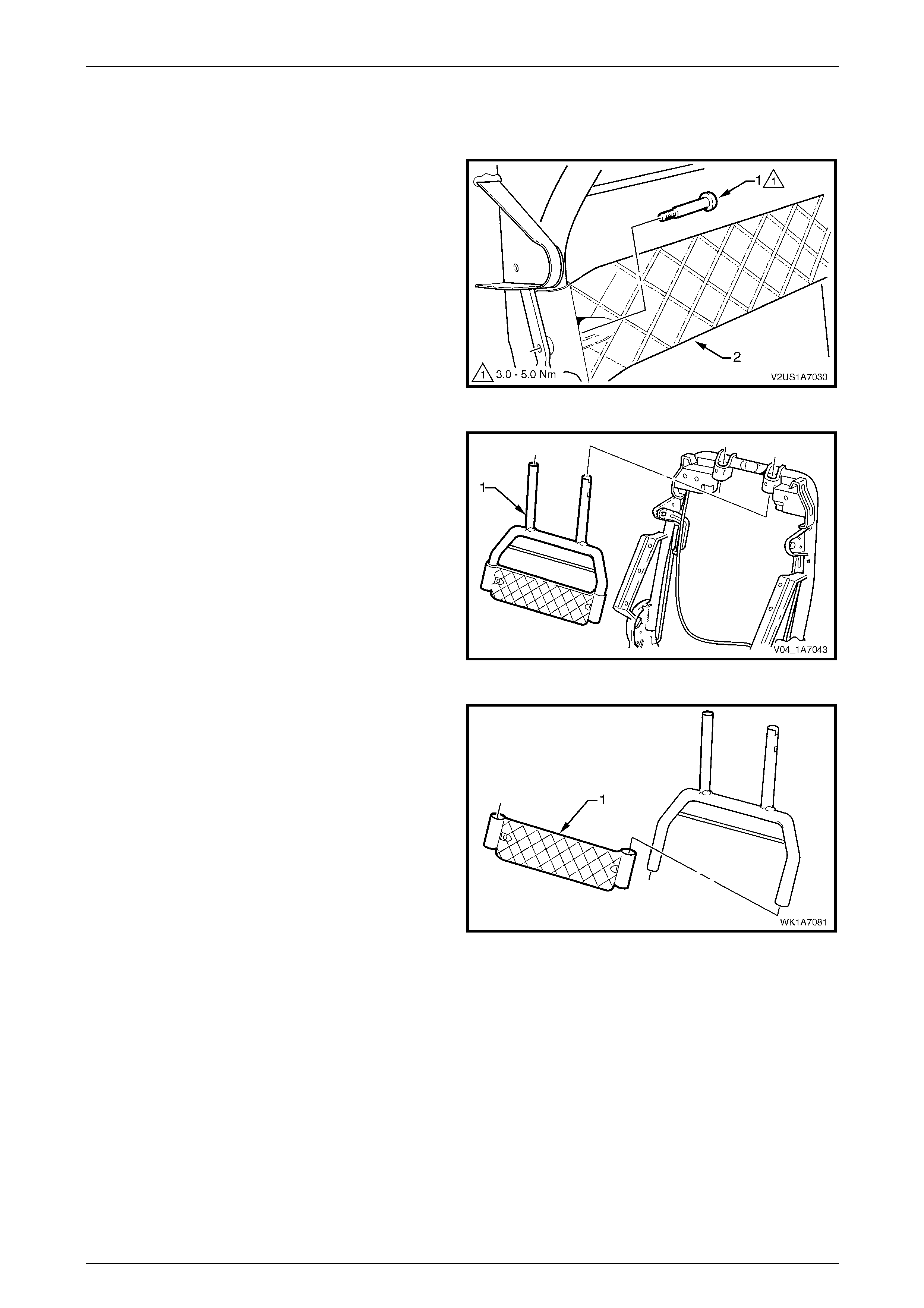
Seat Assemblies Page 1A7A–284
Page 1A7A–284
Active Head Restraint Frame Assembly
Remove
1 Remove the screw (1), two places, attaching the active
head restraint frame assembly (2) to the seat-back
frame hinge.
Figure 1A7A – 155
2 Withdraw the active head restraint frame assembly (1)
downward to remove it from the seat-back frame and
remove.
Figure 1A7A – 156
3 If required, slide the support strap (1) from the active
head restraint frame.
Figure 1A7A – 157
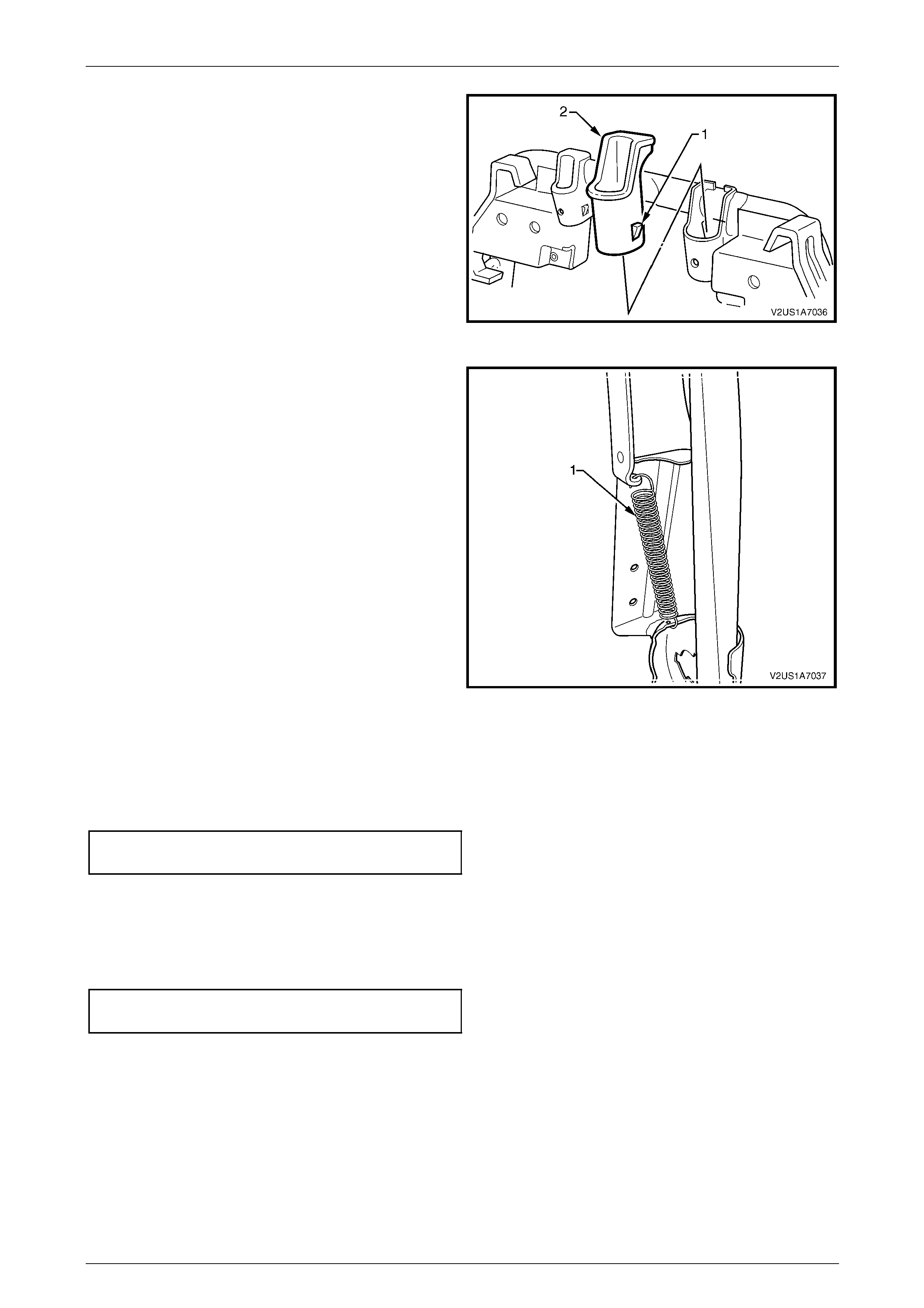
Seat Assemblies Page 1A7A–285
Page 1A7A–285
4 If required, depress the tab (1), two places, and
withdraw the active head restraint frame sleeve (2)
from the seat-back frame.
5 Repeat for the opposite sleeve as requ ired.
Figure 1A7A – 158
6 If required, remove the spring (1), from the active head
restraint frame hinge and seat-back frame.
7 Repeat for the opposite side as required.
Figure 1A7A – 159
Reinstall
Reinstallation of the active head restraint frame assembly is the reverse of the removal proced ure, noting the following:
Tighten the screws to the correct torque specification.
Active head restraint frame assembly
attaching screw torque specification...........3.0 – 5.0 Nm
Reinstall
Reinstallation of the front seat-back frame assembly is the reverse of the removal procedure, noting the following:
1 Tighten the screws to the correct torque specification.
Front seat-back frame assembly
attaching screw torque specification.......30.0 – 45.0 Nm
2 Check the mechanical and ele c trical operation of the front seat.
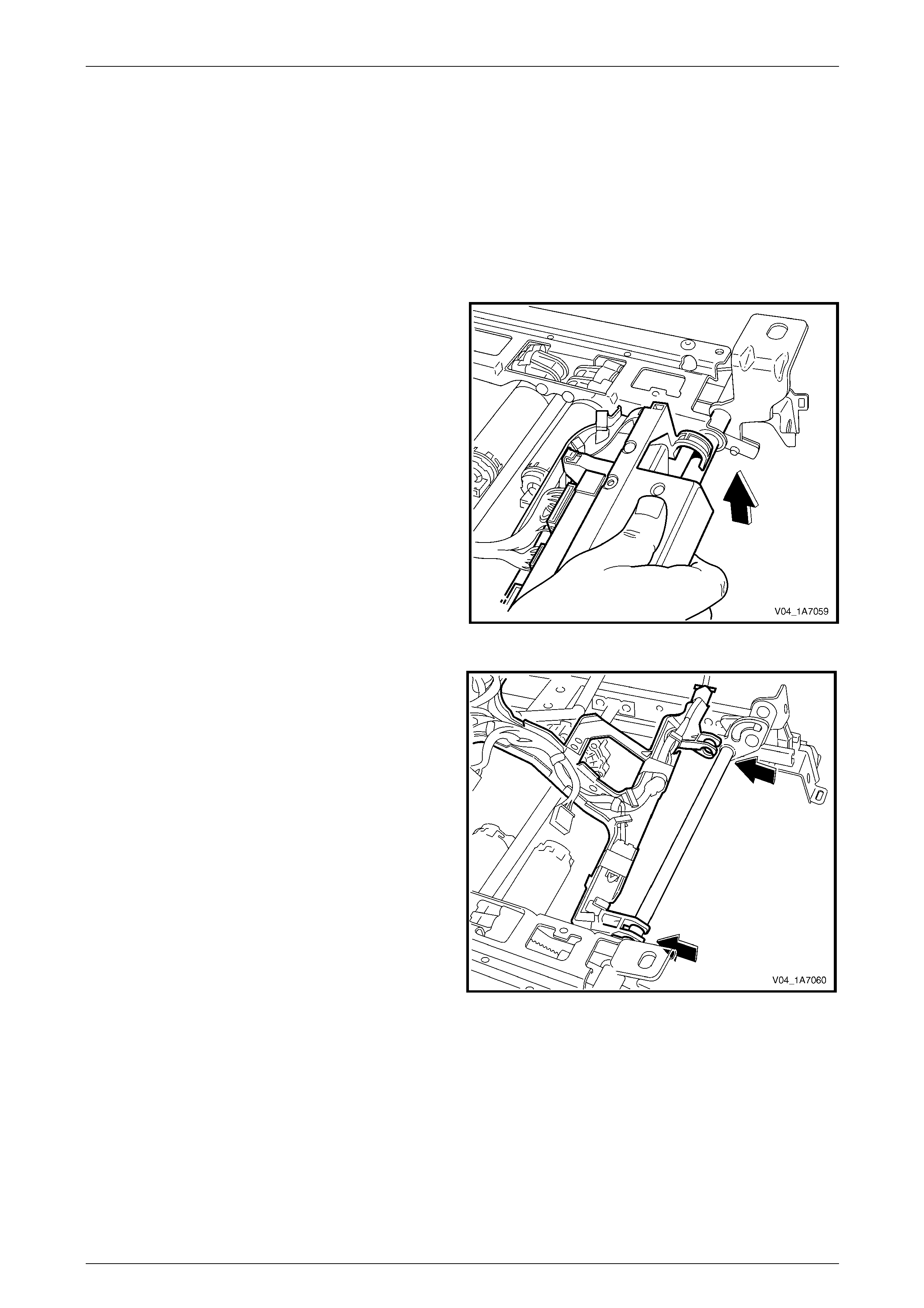
Seat Assemblies Page 1A7A–286
Page 1A7A–286
6.14 Seat Cable Tray and Memory Module
Remove
As required remove the following c ompo nents:
1 Front seat assembly, refer to 6.3 Front Seat Assembly.
2 Remove the seat track and height adjust assembly, refer to 6.15 Track and Height Adjust Assembly.
3 Disconnect the wiring harness connectors as required.
4 Unclip the cable tray from the front of the seat track
and height adjust assembly.
Figure 1A7A – 160
5 Pull the cable tray forward to release it from the seat
track and height adjust assembly.
Figure 1A7A – 161

Seat Assemblies Page 1A7A–287
Page 1A7A–287
6 If required, use a 5 mm drill bit to drill out the pop rivet,
(1), two places, securing the seat memory module to
the cable tray.
7 Remove the seat memory module.
Figure 1A7A – 162
8 If required, remove the wiring harness from the cable
tray by squeezing the tabs on the harness clips (1)
and removing the tape (2) as required.
Figure 1A7A – 163
Reinstall
Reinstallation of the seat memor y module is the reverse of the removal procedure, noting the following:
1 Ensure the wiring harness an d connectors are correctly routed and attach ed securely.
2 Use new pop rivets.
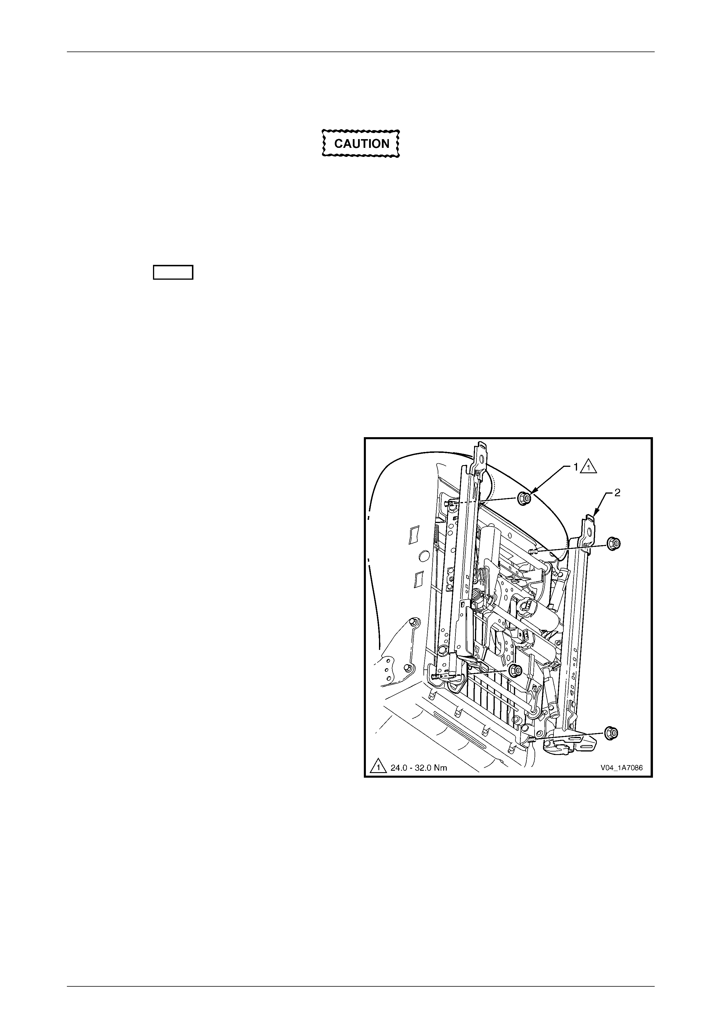
Seat Assemblies Page 1A7A–288
Page 1A7A–288
6.15 Track and Height Adjust Assembly
The track and height adjust assembly
components are non-serviceable. If the track
and height adjust assembly, drive motors or
drive shafts require replacement, the entire
track and height adjust assembly must be
replaced.
LT Section No. – 14-275
Remove
As required, remove the following compo nents:
1 Front seat assembly, refer to 6.3 Front Seat Assembly.
2 Front seat outer side cover assembly, refer to 6.4 Front Seat Outer Side Cover Assembly.
3 As required, detach the wiring harness con nectors.
4 As required, detach the seatbelt pretensioner and side airbag wiring harnesses.
5 Remove the four nuts (1) attaching the track and
height adjust assembly (2) to the seat.
6 Remove the track and height adjust assembly.
7 If required, remove the cable tray and wiring harness
assembly, refer to 6.14 Seat Cable Tray and Memory
Module.
8 If required, remove the seatbelt buckle and
pretensioner assembly, refer to 12M Occupant
Protection System.
Figure 1A7A – 164
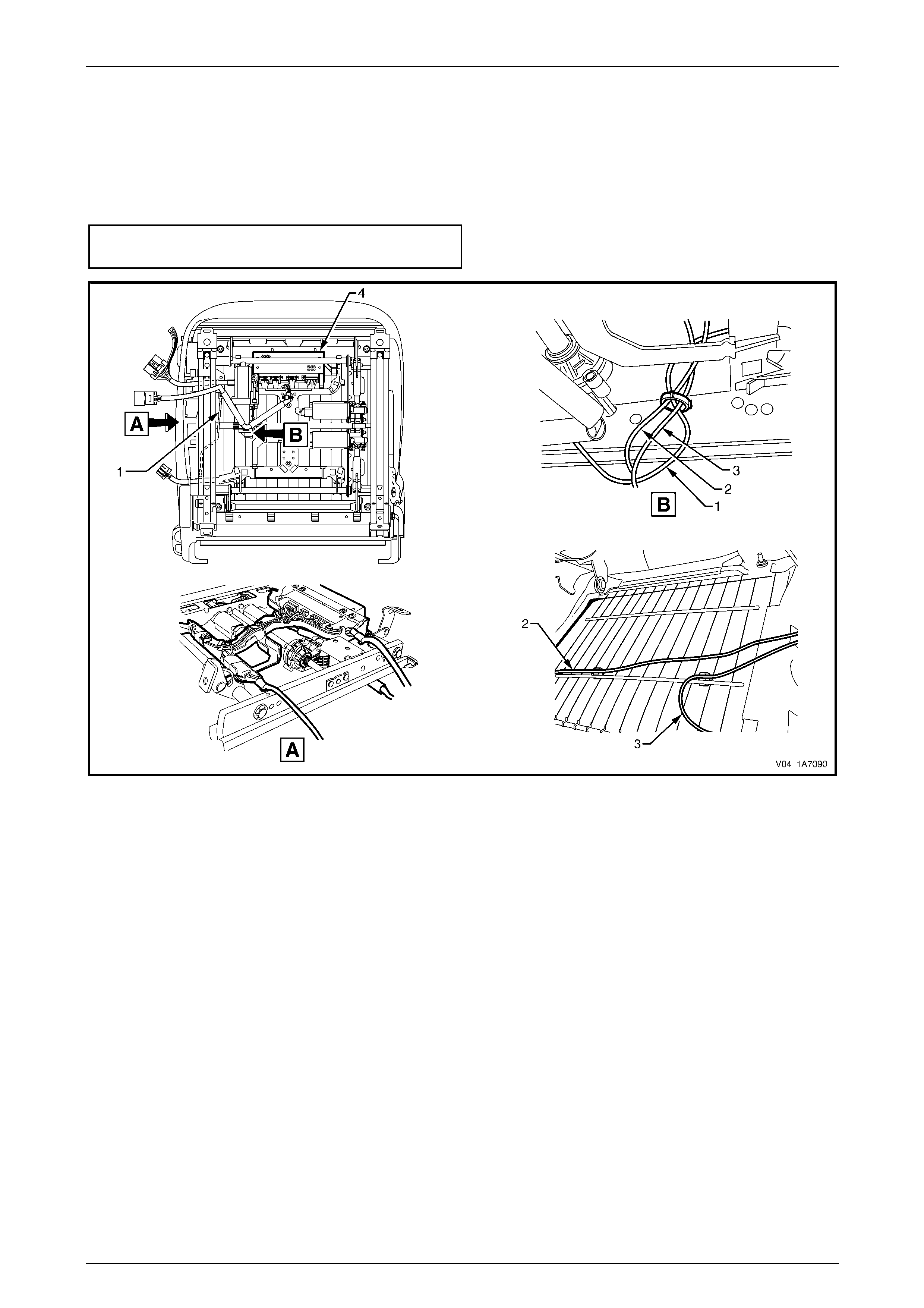
Seat Assemblies Page 1A7A–289
Page 1A7A–289
Reinstall
Reinstallation of the track and height adjust assembly is the reverse of the removal procedur e, noting the following:
1 Ensure the connectors are correctly routed and attached se curely, refer to Figure 1A7A – 165.
2 Tighten the nuts to the correct torque specification.
Track and height adjust asse mbly
attaching nut torque specification............24.0 – 32.0 Nm
Figure 1A7A – 165
1 Ground Cable
2 Seatbelt Pretensioner Wiring Harness 3 Side Impact Inflatable Restraint Wiring Harness (where
fitted)
4 Seat Memory Module (where fitted)
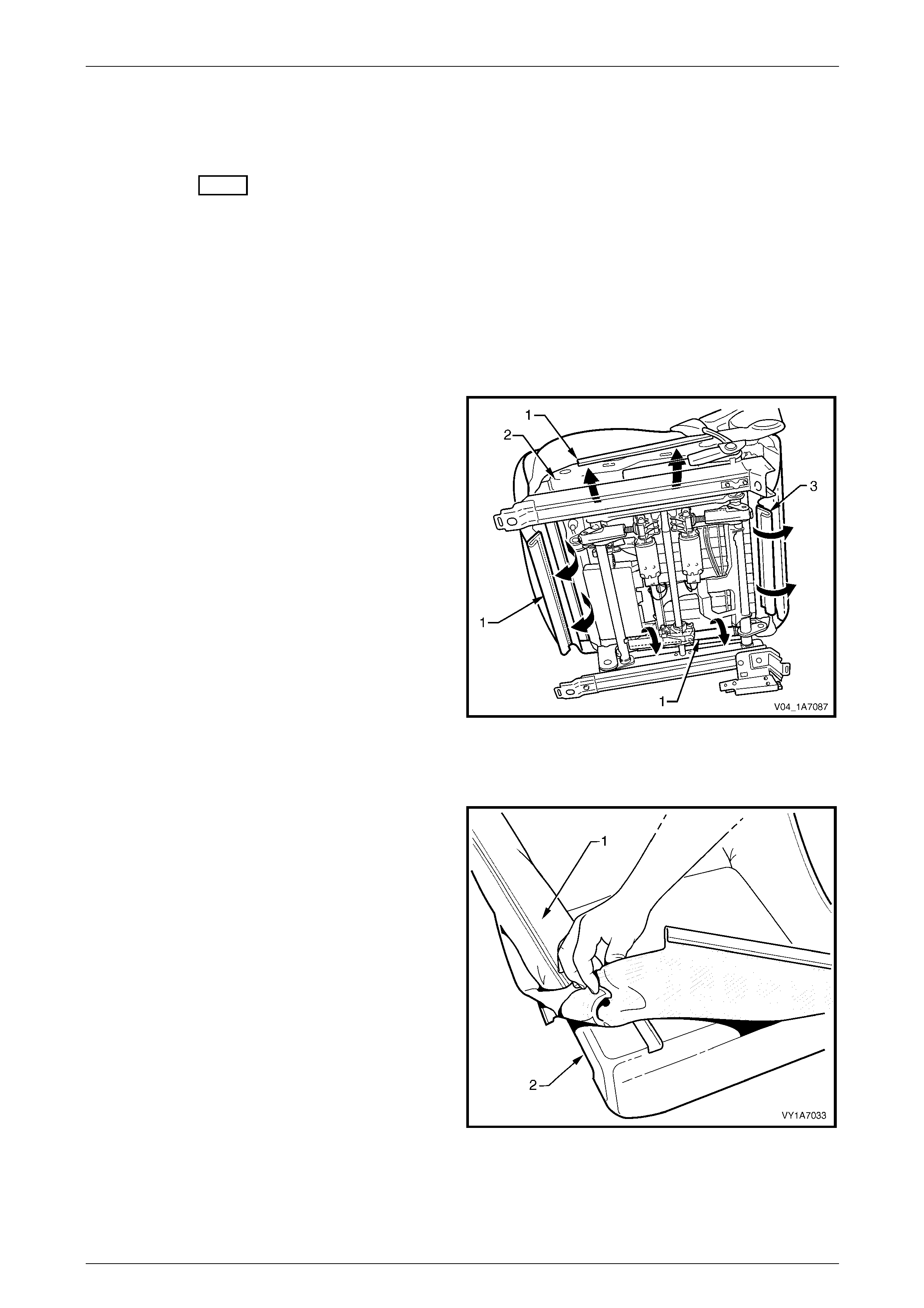
Seat Assemblies Page 1A7A–290
Page 1A7A–290
6.16 Front Seat Cushion Pad and Cover
Assembly
LT Section No. – 14-295
As required, remove the following compo nents:
1 Front seat assembly, refer to 6.3 Front Seat Assembly.
2 Front seat outer side cover assembly, refer to 6.4 Front Seat Outer Side Cover Assembly.
3 Front seat inner side cover, refer to 6.5 Front Seat Inner Side Cover.
4 Front seat-back frame assembly, refer to 6.13 Front Seat-back Frame Assembly.
Remove
1 From under the front seat cushion, disengage the front
and side J-strips (1) away from the seat frame (2).
2 Lift the cover and pad assembly a way from the seat
frame and then release the rear J-strip (3).
3 Disconnect the passenger pre s ence detection harness
connector (4).
4 Remove the cover and pad assembly.
Figure 1A7A – 166
Disassemble
1 Fold the rear corners of the front seat cushion
cover (1) over the front seat cushion pad (2).
Figure 1A7A – 167
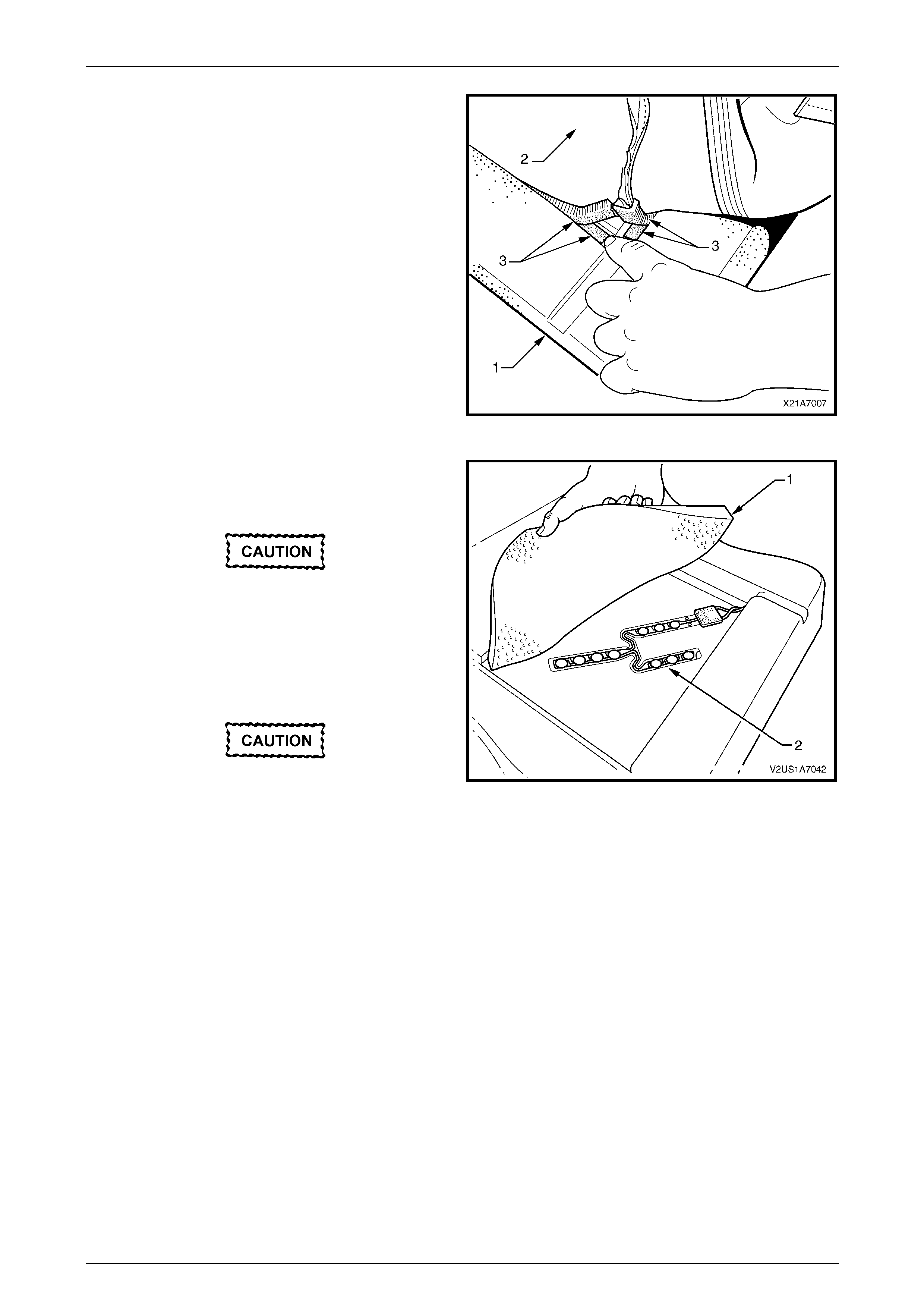
Seat Assemblies Page 1A7A–291
Page 1A7A–291
2 While holding the front seat cushi on pad (1), pull the
rear corners of the front seat cushion cover (2) forward
and away from the pad to diseng age the hook and
loop strips (3).
3 Pull the cover up and over the forward edge of the
pad.
Figure 1A7A – 168
4 If required, carefully peel back the upper cushion
pad (1) to expose the passenger prese nce detection
switch (2).
The upper cushion pad is glued to the
cushion pad along each edge. Take care not
to damage the pads.
5 Carefully lift-off the passenger presence detection
switch and pull the wiring harness through from the
underside of the cushion pad.
The wiring terminal is glued to the cushion
pad. Take care not to damage the switch or
pad. Figure 1A7A – 169
Reassemble
Reassembly of the front seat cushion pad is the reverse of the disassembly procedure n oting the following:
1 Ensure the passenger presence detection switch is correctly located in its depression in the cushion pad. Appl y
new adhesive to the upper cushion.
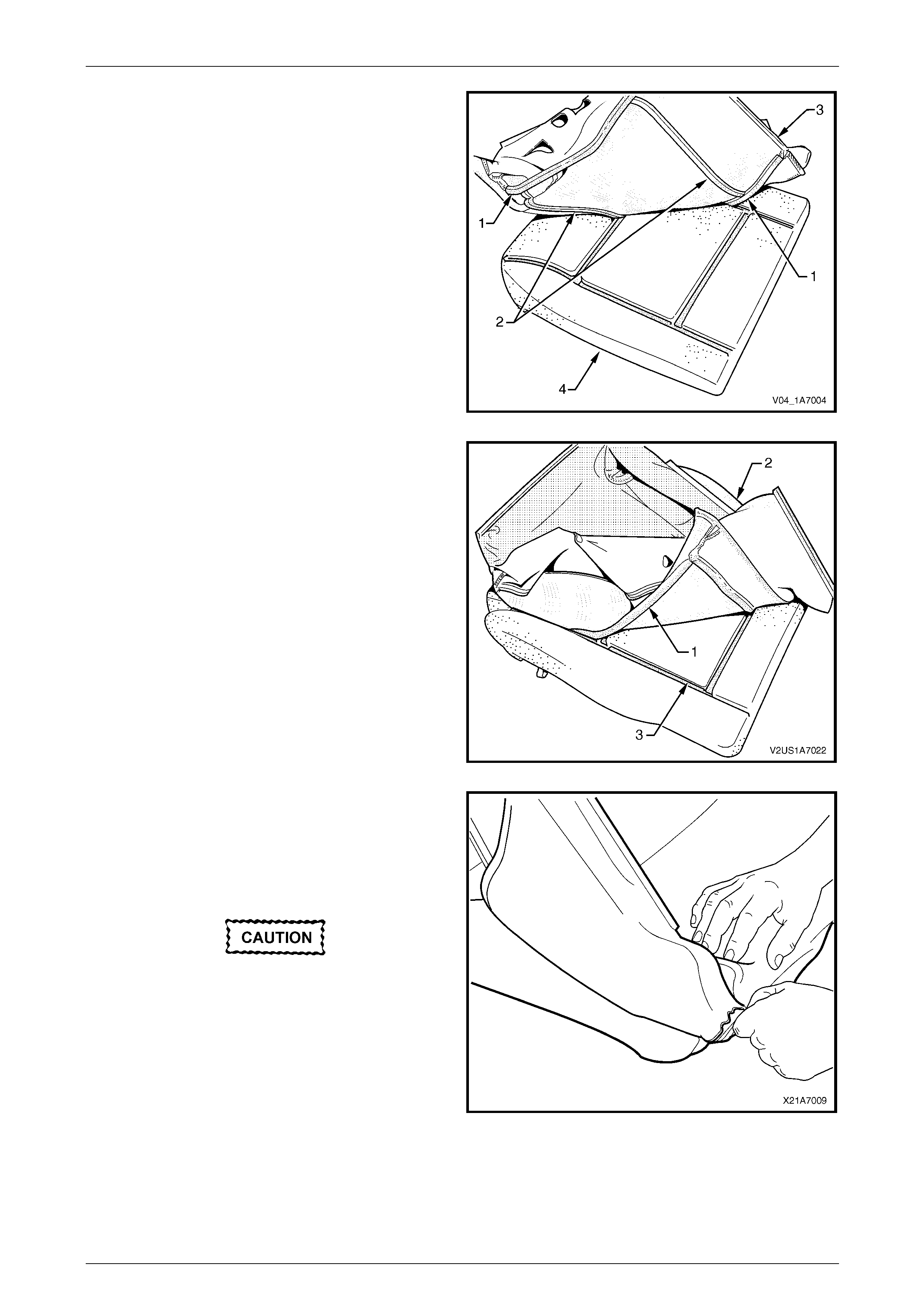
Seat Assemblies Page 1A7A–292
Page 1A7A–292
2 Align either of the outer hook and l oo p strips (1) and
the one or two cross hook and loop strips (2), on the
front seat cushion cover (3), with the front seat
cushion pad (4).
3 Press the folded edge of the cover firmly into the
corresponding groove in the pad to engage the hook
and loop strip.
Figure 1A7A – 170
4 Align and press the outer hook and loop strip (1), on
the cover (2), with the corresponding groove in the
pad (3).
Figure 1A7A – 171
5 Roll the front corners of the cover over the pad.
6 Roll the sides of the cover over the pad.
7 Roll the rear corners of the cover over the pad.
NOTE
Make sure the pad is fitted neatly by hand into all
corners and contours of the seat cover.
Do not pull the cover onto the pad from
underneath using the J-strip to make it fit
neatly, as the fabric may be damaged.
Figure 1A7A – 172
Reinstall
Reinstallation of the front seat cushion pad and cover assembly is the reverse of the removal procedure.
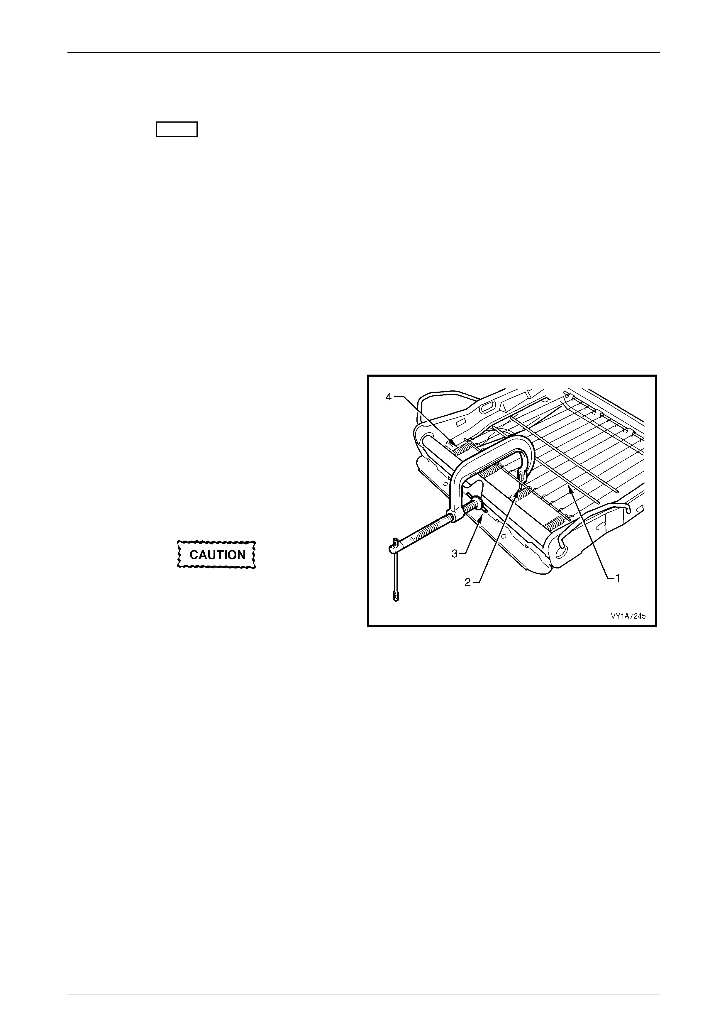
Seat Assemblies Page 1A7A–293
Page 1A7A–293
6.17 Front Seat Cushion Frame Assembly
LT Section No. – 14-275
Remove
As required remove the following components:
1 Front seat assembly, refer to 6.3 Front Seat Assembly .
2 Front seat outer side cover assembly, refer to 6.4 Front Seat Outer Side Cove r Assembly.
3 Front seat inner side cover, refer to 6.5 Front Seat Inner Si de Cover.
4 Front seat-back frame assembly, refer to 6.13 Front Seat-back Frame Assembly.
5 Track and height adjust assembly, refer to 6.15 Track and Height Adjust Assembly.
6 Front seat cushion pad and cover assembly, refer to 6.16 Front Seat Cushion Pad and Cover Assembly.
Disassemble
1 To remove the suspension mat (1), modify a G-clamp
with a 5mm diameter metal dowel (2) welded to one
end and another approximately 40mm long and with a
2mm diameter pin (3) approxi m ately 20mm long
welded to the other end.
2 Using the G-clamp, stretch the suspension mat far
enough to allow the four retaining springs (4) to be
removed from the seat cush io n frame.
3 Back the G-clamp load off and remove the suspension
mat.
When using the G-clamp, use existing holes
in the suspension mat to ensure that mat
deformation does not occur.
Figure 1A7A – 174
Reassemble
Reassembly of the suspension mat is the reverse of the disassembly procedure.
Reinstall
Reinstalla tion of the front seat cushion frame assembly is the reverse of the removal procedure, noting the following:
1 Ensure all wiring is correctly connected and routed, refer to 12O Fuses, Relays and Wiring Harnesses.
2 Check the mechanic al and ele ctri cal opera tio n of the front se at.

Seat Assemblies Page 1A7A–294
Page 1A7A–294
6.18 Front Seat Lift Motor Assemblies
The front seat lift motor assemblies are non-serviceabl e items.
If a front seat lift motor assembly requires replacement, the track and height adjust assembly must be repl aced, refer to
6.15 Track and Height Adjust Assembly.

Seat Assemblies Page 1A7A–295
Page 1A7A–295
6.19 Front Seat Fore/Aft Movement Motor
Assembly
The front seat fore/aft movement motor assembl y is a non-serviceable item.
If the front seat fore/aft movement motor or drive shafts require replacement, the track and height adjus t assembly must
be replaced, refer to 6.15 Track and Height Adjust Assembly.

Seat Assemblies Page 1A7A–296
Page 1A7A–296
6.20 Front Seat-back Recline Motor Assembly
The front seat-back recline motor assembly is a non-serviceable item.
If the front seat-back recline motor assembly requires replacement, the fron t seat-back frame assembly must be
replaced, refer to 6.13 Front Seat-back Frame Assembly.

Seat Assemblies Page 1A7A–297
Page 1A7A–297
6.21 Drive Motor Hall-effect Sensors
The front seat drive motor hall-effect sensors are non-serviceable items.
If the front seat fore/aft movement and/or front seat lift motor hall-effect sensors require replacement, the track and
height adjust assembly must be replaced, refer to 6.15 Track and Heig ht Adjust Assembly.
If the seat-back recline motor hall-effect sensor requires replacement, the front seat-back frame assem bly must be
replaced, refer to 6.13 Front Seat-back Frame Assembly.

Seat Assemblies Page 1A7A–298
Page 1A7A–298
7 Diagnostics – Front Seat, Coupe
This Section provides charts to assist in the diagnosis and repa ir of front seats. Refer to 6.1 Front Seat Usage C hart for
a full listing of the different types of seats fitted to Coupe vehicles. Included in that Section are ill ustrated parts
breakdowns of the various seats.
7.1 Prerequisites
Safety Requirements
When operating the seat as part of any Steps
in the diagnostic tables, ensure that fingers
and limbs are clear of mo ving parts.
Equipment
The following equipment is required to diagnose the seats:
• an unpowered test lamp with a current dra w of less than 3 A, and
• a digital multimeter with a minimum impe dance of 10 MΩ.
Testing Procedures
The following points must be adhered to
when performing diagnostic testing on
components:
• Take care when using testing equipment
to diagnose wiring harness connectors. It
is preferred that the technician backprobe
the connector to avoid terminal damage.
• When tests are required on connector
terminals, use the adapters in the
connector adapter kit KM–609 to prevent
damage to the terminals.
• Unless the multimeter being used has an
auto-ranging function, ensure the correct
range is selected.
• When backpro bing connectors, ensure the
test lamp ground lead is connected to an
appropriate ground point on the vehicle.
Ensure this ground point is not part of the
circuit being tested.
NOTE
When following the steps in th e diagnostic tables,
perform them in the order cited. If the required
nominal value or result is not achi eved, rectif y t he
problem before proceeding any further.

Seat Assemblies Page 1A7A–299
Page 1A7A–299
7.2 Mechanical Diagnosis, All
Lumbar Support Inoperative
Introduction
This test is used to aid in diagnosing the lumbar support as sembly.
Test Description
The following numbers refer to the step numbers in the diagnostic table:
1 Checks if the lumbar support knob is properly engaging the lumbar support adjuster. Check the knob for cracks and
worn splines.
2 Checks if the lumbar support assembly is damage d or worn and if the retaining springs are serviceable and
securely attached to the seat back frame assembly.
3 Checks if the lumbar support assembly is serviceable and if the lumber support assembly strap is operating
correctly within the guide rails.
Diagnostic Table
Step Action Yes No
1 Remov e the lu mbar support knob, refer to 6.11 Lumbar Support Knob
Assembly.
Is the lumbar support adjust knob serviceable? Go to Step 2
Replace the knob,
refer to 6.11
Lumbar Support
Knob Assembly
2 1 Remov e the seat-back cover.
2 Inspect the lumbar support retainers and spri ngs.
Are the lumbar support retaining spri ngs serviceable and securel y
attached to the seat-back frame assembly? Go to Step 3
Replace or reattach
the retaining
springs, refer to
6.12 Front Seat-
back Pad and Cover
Assembly
3 1 Visually inspect the lumbar support assembl y. Check for broken
or worn parts.
2 Check the strap running across the lumber s upport assembly is
serviceable and running freely within the guide rails.
NOTE
You may need to attach the lumber support knob to
actuate the strap.
Is the lumbar support assembly serviceabl e? System serviceable
Replace lumbar
support assembly or
resecure lumbar
support assembly
strap ensuring strap
is not binding with
guide rails, refer to
6.13 Front Seat-
back Frame
Assembly
When all diagno sis and repairs are completed, check the system for correct operation.

Seat Assemblies Page 1A7A–300
Page 1A7A–300
EZ-entry Lever Function Inoperative
Introduction
The EZ-entry lever arm uses a cable to release the seat-back. There is also an electrical component to the operation that
will drive the seat forward using front seat fo re/aft movement motor. This diagnostic table covers the mechanical aspect
of the lever arm and cable being ino perative.
Test Description
The following numbers refer to the step numbers in the diagnostic table:
1 Checks if the EZ-entry lever arm is serviceable. The lever arm engages a frame assembly which is connected to
EZ-entry cable assembly.
2 The EZ-entry lever arm and its spring clip are the only serviceable items a s far as the mechanical action of this
system is concerned. Due to safety requirements, if the EZ -entry lever function does not operate after the lever arm
has been checked for serviceabil ity and correct installation, the seat-back frame assembly must be replaced.
Diagnostic Table
Step Action Yes No
1 Remove the EZ-entry lever arm, refer to 6.9 EZ-entry Release Lever
and Escutcheon.
Is the EZ-entry lever arm serviceable? Go to Step 2
Replace the lever
arm, refer to 6.9
EZ-entry Release
Lever and
Escutcheon
2 Install the EZ-entry lever arm ensuring the spring clip and l ever arm
engage properly, refer to 6.9 EZ-entry Release Lever and
Escutcheon.
Does the EZ-entry lever function operate? System serviceable
Replace the front
seat-back frame
assembly, refer to
6.13 Front Seat-
back Frame
Assembly
When all diagno sis and repairs are completed, check the system for correct operation.

Seat Assemblies Page 1A7A–301
Page 1A7A–301
7.3 Electrical Diagnosis – Eight-way Seat,
Non-memory
Neither Seat Adjustment Switch Functions Operate
Introduction
This test is used to aid in diagnosing the seat power and ground circ uits if neither seat oper ates w hen eith er seat
adjustment switch is operated.
Circuit Description
Both front seats have common power and ground circuits. If either of these circuits become unserviceable, the electrical
operation of both seats will be affected.
Refer to the following diagrams in this Section to aid in diagnosing the seat adjustment switch and associated
components:
• Wiring Diagram – Driver's Seat, Non-memory, LHD and Connector Chart – Driver's Seat, Non-memory, LHD, or
• Wiring Diagram – Passenger's Seat, Non-memory, RHD and
Connector Chart – Passenger's Seat, Non-memory, RHD and LHD, or
• Wiring Diagram – Passenger's Seat, Non-memory, LHD and
Connector Chart – Passenger's Seat, Non-memory, RHD and LHD.
Test Description
The following numbers refer to the step numbers in the diagnostic table:
1 Checks if battery voltage is more than 11.5 V. The seat motors require more than 11.5 V to operate correctly.
2 Checks if circuit breaker F2 located on the passenger compartment fuse and relay panel assembly is tripped.
Isolates if circuit breaker F2 is the fault affecting the circuit between the battery and connector X200 pin 19.
3 Checks if fusible link F105 located on the engine compartment fuse and relay panel assembly is serviceable.
Isolates if the fusible link is the fault affecting the circuit between the battery and connector X200 pin 19.
4 Checks if connector X200 is secure.
5 Checks if there is battery voltage at connector X200 pin 19. Isolates if the fault is between the battery and
connector X200 pin 19. If the fault in the circuit is between connectors X200 pin 19 and either X308 pin B or
X315 pin 3, only one seat will operate.
6 Checks if there is battery voltage at circuit breaker F2. Isolates whether the fault is betwe en the battery and circuit
breaker F2 or between circuit breaker F2 and connector X200 pin 19.
7 Checks if there is battery voltage at fusible link F105. Isolates whether the fault is between the battery and fusible
link F105 or between fusible link F105 and circuit breaker F2.
8 Checks if the ground point associated with the system is serviceable.
Diagnostic Table Notes
1 For all wiring harness fault diagnoses, refer to 12P Wiring Diagram s.
2 For wiring harness repairs, refer to 12P Wiring Diagrams.
3 Refer to 12O Fuses, Relays and Wiring Harnesses for harness routeing.
4 If the fault is deemed to be intermittent, refer to 12P Wiring Diagrams.

Seat Assemblies Page 1A7A–302
Page 1A7A–302
Diagnostic Table
Step Action Yes No
1 Check the battery voltage, refer to 12A Battery and Cables.
Is the battery voltage more than 11.5 V? Go to Step 2
Refer to 12A
Battery and Cables
for further
diagnosis
2 Inspect circuit breaker F2 (refer to Note 3).
Is circuit breaker F2 tripped?
Allow the circuit
breaker to reset
(refer to Note 3).
If the circuit breaker
trips again, repair
or replace circuit
540 (refer to
Note 2) Go to Step 3
3 Inspect fusible link F105 (refer to Note 3).
Is fuse F105 serviceable?
Go to Step 4
Replace the fusible
link.
If the fusible link
becomes
unserviceable
again, repair or
replace circuit 342
(refer to Note 2)
4 Is connector X200 secure (refer to Note 3)? Go to Step 5 Ensure the
connector is secure
5 Backprobe connector X200 pin 19 with a test lamp (refer to Note 1).
Does the test lamp illuminate? Go to Step 8 Go to Step 6
6 1 Remove circuit breaker F2 from the passenger compartme nt
fuse and relay panel assembly.
2 Using a test lamp, probe connector X12 9 – X45 pin 2 (refer to
Note 1).
Does the test lamp illuminate?
Repair or replace
circuit 540 between
circuit breaker F2
and connector
X200 pin 19 (refer
to Note 2) Go to Step 7
7 1 Remove the fusible link F105.
2 Using a test lamp, probe connector X18-105 (refer to Note 1).
Does the test lamp illuminate?
Repair or replace
circuit 342 between
fusible link F105
and circuit breaker
F2 (refer to Note 2)
Repair or replace
circuit 1 between
the battery and
fusible link F105
(refer to Note 2)
8 Ensure the following ground point is secure and has good contact
with the vehicle structure:
• X118 – GP12 located in the middle of the transmission tunnel.
Is the ground point secure to the vehicle with a good contact?
Repair or replace
circuit 650 (refer to
Note 2) Repair ground point
When all diagno sis and repairs are completed, check the system for correct operation.

Seat Assemblies Page 1A7A–303
Page 1A7A–303
EZ-entry Electrical Self Test Diagnosis – Eight-w ay Seat, Non-Memory
Introduction
The non-memory type seat provides the technician with in-built diagnostics. The diag no sti c s indic ator is a green LED
located on the seat EZ-entry module. The LED can be viewed through the small hole in the outer side lower seat side
cover. To gain access, it is necessary to partially remove the seat outer side cover. Refer to
6.4 Front Seat Outer Side Cover Assembly.
The chart in this Section displays the error codes and fault description.
If the error code is above ten, the indication will consist of a single flash, a short delay and then the number of flashes
corresponding to the error. A longer delay will occur between error code indications.
EZ-entry Diagnostics
Flashes Description of Error Reference
2 No Passenger Pres ence Detector
(PPD) detected Driver's Seat Occupant Sensing Mat Test in 7.4 Electrical
Diagnosis – Driver's Seat, Non-memory, LHD or Passenger's
Seat Occupant Sensing Mat Test in 7.5 Electrical Diagnosis –
Passenger's Seat, Non-memory.
3 PPD weight detec ted > 15 kg Driver's Seat Occupant Sensing Mat Test in 7.4 Electrical
Diagnosis – Driver's Seat, Non-memory, LHD or Passenger's
Seat Occupant Sensing Mat Test in 7.5 Electrical Diagnosis –
Passenger's Seat, Non-memory.
6 Battery voltage low 12A Battery and Cables.
7 Button stuck detected 7.4 Electrical Diagnosis – Driver's Seat, Non-memory, LHD or
7.5 Electrical Diagnosis – Passenger's Seat, Non-memory
8 Dump latch active Driver's Seat EZ-entry Switch Function is Inoperative in
7.4 Electrical Diagnosis – Driver's Seat, Non-memory, LHD or
Passenger's Seat EZ-entry Switch Function is Inoperative in
7.5 Electrical Diagnosis – Passenger's Seat, Non-memory.
9 Return button active Driver's Seat Return Switch Function is Inoperative in
7.4 Electrical Diagnosis – Driver's Seat, Non-memory, LHD or
Passenger's Seat Return Switch Function is Inoperative in
7.5 Electrical Diagnosis – Passenger's Seat, Non-memory.
11 Forward track switch active 3.6 Eight-way Seat Adjustment Switch Test.
12 Reverse track switch active 3.6 Eight-way Seat Adjustment Switch Test.
13 Recliner forward switch active 3.6 Eight-way Seat Adjustment Switch Test.
14 Recliner backward switch active 3.6 Eight-way Seat Adjustment Switch Test.
15 At full forward position Driver’s Seat Fore/Aft Function is Inoperative or Not Sm ooth in
7.4 Electrical Diagnosis – Driver's Seat, Non-memory, LHD or
Passenger’s Seat Fore/Aft Function is Inoperative or Not Smooth
in 7.5 Electrical Diagnosis – Passenger's Seat, Non-memory.
16 At full rearward position Driver’s Seat Fore/Aft Function is Inoperative or Not Smooth in
7.4 Electrical Diagnosis – Driver's Seat, Non-memory, LHD or
Passenger’s Seat Fore/Aft Function is Inoperative or Not Smooth
in 7.5 Electrical Diagnosis – Passenger's Seat, Non-memory.

Seat Assemblies Page 1A7A–304
Page 1A7A–304
7.4 Electrical Diagnosis – Driver's Seat, Non-
memory, LHD
The charts in this Section are used to aid in diagnosing faults on the driver's ei ght-way seat, non-memory. To aid in the
use of the diagnostic tables, refer to Wiring Diagram – Driver's Seat, Non-memory, LHD and
Connector Chart – Driver's Seat, Non-memory, LHD in this Section.
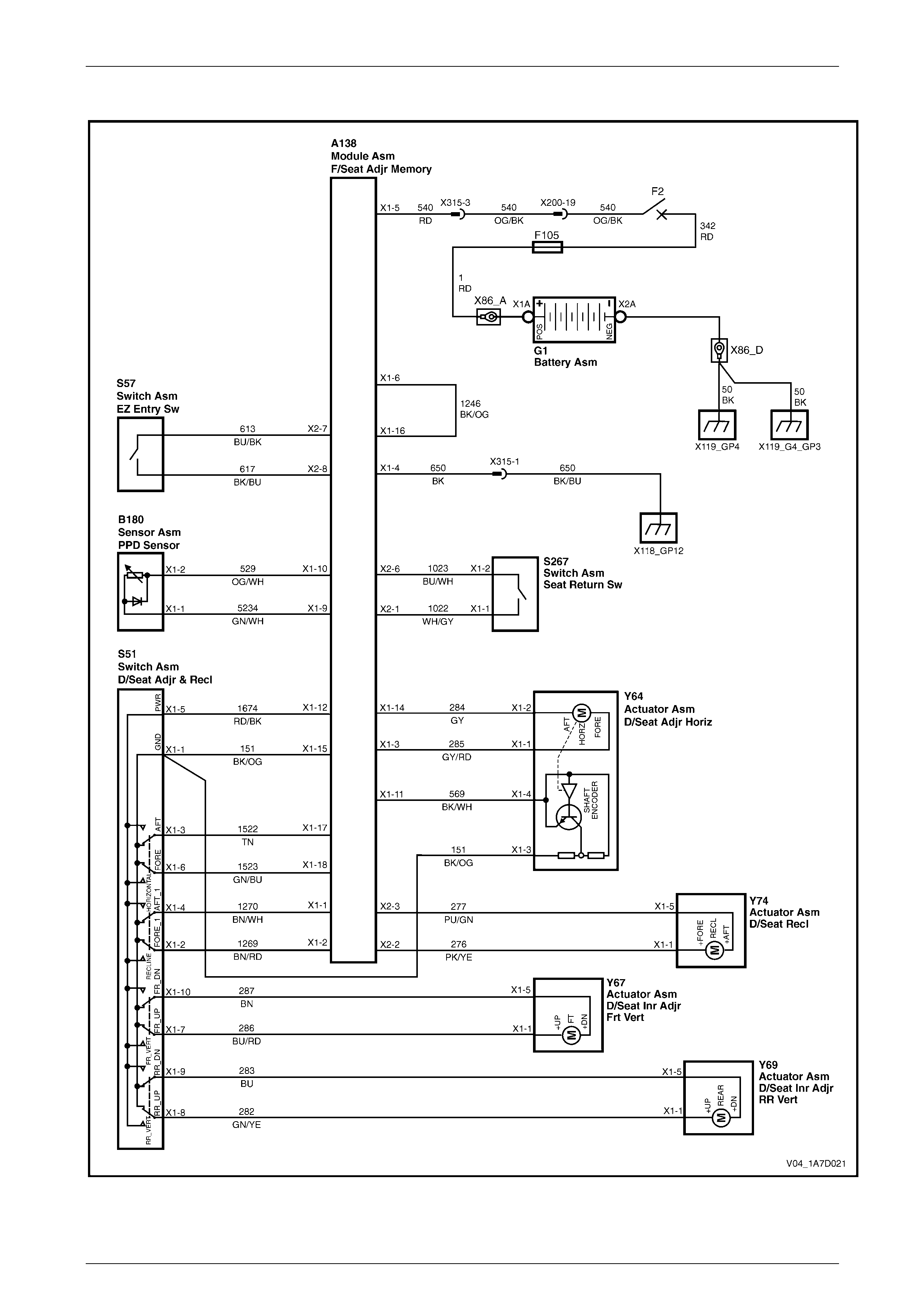
Seat Assemblies Page 1A7A–305
Page 1A7A–305
Wiring Diagram – Driver's Seat, Non-memory, LHD
Figure 1A7A – 174
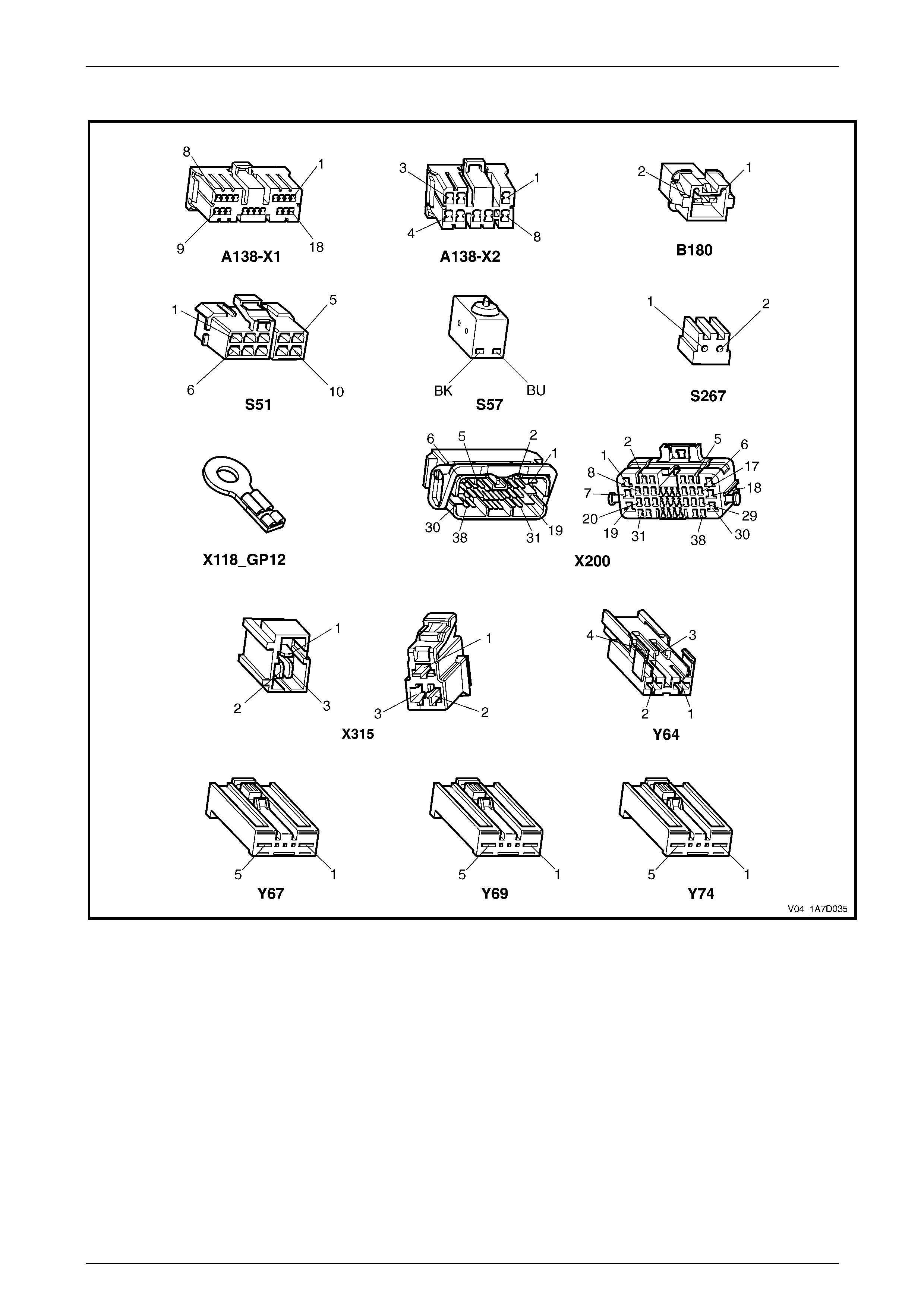
Seat Assemblies Page 1A7A–306
Page 1A7A–306
Connector Chart – Driver's Seat, Non-memory, LHD
Figure 1A7A – 175

Seat Assemblies Page 1A7A–307
Page 1A7A–307
None of the Driver’s Seat Adjustment Switch Functions Operate
Introduction
This test is used to aid in diagnosing the driver’s seat adjustment switch when none of the switch functions operate. The
test diagnoses the driver’s seat adjustment switch and associated power and ground circuits.
Circuit Description
The seat adjustment switch provides manual control for the driver's seat. It is connected by a harness to the seat EZ-
entry module, and the seat front lift and seat rear lift motors.
Refer to Wiring Diagram – Driver's Seat, Non -memory, LHD and Connector Chart – Driver's Seat, Non-memory, LHD in
this Section to aid in diagnosing the seat EZ-entry module and associated components.
Test Description
The following numbers refer to the step numbers in the diagnostic table:
1 Checks if all of the passenger’s seat functions work. If none of them work, the fault is not isolated to the driver’s
seat only.
2 Checks if there is battery power at connector X315 pi n 3. Isolates if there i s a fault in circuit 540 between
connectors X200 pin 19 and X315 pin 3.
3 Checks if all the connectors required for the seat to operate effectively are in place a nd positively connected.
4 Checks if there is battery power at connector A138 – X1 pin 5. Isolates if there is a fault in circuit 540 between
connectors A138 – X1 pin 5 and X315 pin 3.
5 Checks if there is battery power at connector A138 – X1 pin 12. Isolates if there is a fault with the EZ-entry module.
6 Checks if there is battery power at connector S51 – X1 pi n 5. Isolates if there is a fault in circuit 1674 between
connectors S51 – X1 pin 5 and A138 – X1 pin 12.
7 Checks if the driver’s seat adjustment switch is serviceable.
8 Checks if there is continuity between connectors S51 – X1 pin 1 and X315 pin 1 which supplies the ground circuit
for the driver’s seat adjustment switch. Isolates whether the re is a fault between the switch and connector
X315 pin 1 or bet ween con nector X315 pin 1 and the ground point.
9 Checks if there is continuity between connectors A138 – X1 pin 4 and X315 pin 1. Isolates whether there is a fault
between the seat adjustment switch and connector A138 – X1 pin 4 or between connectors A138 – X1 pin 4 and
X315 pin 1.
10 Checks if there is continuity between connector A138 – X1 pins 15 and 4. Isolates whether there is a fault between
the seat adjustment switch and connector A1 38 – X1 pin 15 or the EZ-entry module is at fault.
Diagnostic Table Notes
1 For all wiring harness fault diagnoses, refer to 12P Wirin g Diagrams.
2 For wiring harness repairs, refer to 12P Wiring Diagrams.
3 Refer to 12O Fuses, Relays and Wiring Harnesses for harness routeing.
4 If the fault is deemed to be intermittent, refer to 12P Wiring Diagrams.

Seat Assemblies Page 1A7A–308
Page 1A7A–308
Diagnostic Table
Step Action Yes No
1 Are all of the passenger’s seat adjustment switch functions
inoperative? Refer to Neither
Seat Adjustment
Switch Functions
Operate in 7.3
Electrical Diagnosis
– Eight-way Seat,
Non-memory Go to Step 2
2 Backprobe connector X315 pin 3 with a test lamp (refer to Note 1).
Does the test lamp illuminate?
Go to Step 3
Repair or replace
circuit 540 between
connectors
X200 pin 19 an d
X315 pin 3 (refer to
Note 2)
3 Are the following connectors secure (refer to Note 3)?
• A138
• S51
• X315
• Y64
• Y67
• Y69
• Y74 Go to Step 4
Ensure the
connectors are
secure (refer to
Note 1)
4 Backprobe connector A138 – X1 pin 5 with a test lamp (refer to
Note 1).
Does the test lamp illuminate?
Go to Step 5
Repair or replace
circuit 540 between
connectors
A138 – X1 pin 5
and X315 pin 3
(refer to Note 2)
5 Backprobe connector A138 – X1 pin 12 with a test lamp (refer to Note
1).
Does the test lamp illuminate?
Go to Step 6
Replace the
driver’s seat
EZ-entry module,
refer to 6.4 Front
Seat Outer Side
Cover Assembly
6 Backprobe connector S51 – X1 pin 5 with a test lamp (refer to
Note 1).
Does the test lamp illuminate? Go to Step 7
Repair or replace
circuit 1674 (refer
to Note 2)
7 1 Remove the driver’s seat adjustment switch from the seat, refer
to 6.4 Front Seat Outer Side Cover Assembly.
2 Test the driver’s seat adjustment switch, refer to 3.6 Eight-way
Seat Adjustment Switch Test.
Is the driver’s seat adjustment switch serviceable? Go to Step 8
Replace the
driver’s seat
adjustment switch,
refer to 6.4 Front
Seat Outer Side
Cover Assembly
8 1 Backprobe connector X315 pin 1 with a test lamp (refer to
Note 1).
2 Operate the driver’s seat adjustment switch in any of the
available directions.
Does the test lamp illuminate?
Repair or replace
circuit 650 between
connector
X315 pin 1 and
ground point
X118 – GP12 (refer
to Note 2) Go to Step 9

Seat Assemblies Page 1A7A–309
Page 1A7A–309
Step Action Yes No
9 1 Backprobe connector A138 – X1 pin 4 with a test lamp (refer to
Note 1).
2 Operate the driver’s seat adjustment switch in any of the
available directions.
Does the test lamp illuminate?
Repair or replace
circuit 650 between
connectors
A138 – X1 pin 4
and X315 pin 1
(refer to Note 2) Go to Step 10
10 1 Backprobe connector A138 – X1 pin 15 with a test lamp (refer
to Note 1).
2 Operate the driver’s seat adjustment switch in any of the
available directions.
Does the test lamp illuminate?
Replace the
driver’s seat
EZ-entry module,
refer to 6.4 Front
Seat Outer Side
Cover Assembly
Repair or replace
circuit 151 (refer to
Note 2)
When all diagno sis and repairs are completed, check the system for correct operation.

Seat Assemblies Page 1A7A–310
Page 1A7A–310
Front/Rear of the Driver’s Seat Does Not Raise and/or Lower
Introduction
This test is used to aid in diagnosing the front and/or the rear of the driver’s seat not raising and/or lowering. T he test
diagnoses the seat adjustmen t switch and the motor circuits.
Circuit Description
The seat front lift and seat rear lift motors are controlled by the seat adjustment switch, which provid es power and ground
for the motors. The polarity of the motors are alternated to change the direction of the motors.
Refer to Wiring Diagram – Driver's Seat, Non -memory, LHD and Connector Chart – Driver's Seat, Non-memory, LHD in
this Section to aid in diagnosing the seat adj ustment switch and associated components.
Test Description
The following numbers refer to the step numbers in the diagnostic table:
1 Checks if the driver’s seat adjustment switch operates the seat in any direction. Isolates if the power and ground
circuits are at fault.
2 Checks if all the connectors required for the seat to operate effectively are in place a nd positively connected.
3 Checks if the driver’s seat adjustment switch is serviceable.
4 Confirms whether the rear of the seat raises or lowers. Isolates if the seat rear lift motor and circuit of the seat is the
fault.
5 Confirms whether the front of the seat raises or lo wers. Isolates if the seat front lift motor and circuit of the seat is
the fault.
6 Checks if there is battery power to the seat rear lift motor at connector Y69 – X1 pin 1. Isolates if there is a fault in
circuit 282 that supplies battery po wer to the motor to raise the rear of the seat.
7 Checks if there is battery power to the seat rear lift motor at connector Y69 – X1 pin 5. Isolates whether the fault is
in circuit 283 that supplies battery power to the motor to lower the rear of the seat or the motor is faulty. As the
direction of the motor is changed by reversing the polarity, this Step also confirms if the ground circuit from Step 6
is serviceable.
8 Checks if there is battery power to the seat front lift motor at connector Y67 – X1 pin 1. Isolates if there is a fault in
circuit 286 that supplies battery po wer to the motor to raise the front of the seat.
9 Checks if there is battery power to the seat front lift motor at connector Y67 – X1 pin 5. Isolates whether the fault is
in circuit 287 that supplies battery power to the motor to lower the front of the seat or the motor is faulty. As the
direction of the motor is changed by reversing the polarity, this Step also confirms if the ground circuit from Step 8
is serviceable.
Diagnostic Table Notes
1 For all wiring harness fault diagnoses, refer to 12P Wirin g Diagrams.
2 For wiring harness repairs, refer to 12P Wiring Diagrams.
3 Refer to 12O Fuses, Relays and Wiring Harnesses for harness routeing.
4 If the fault is deemed to be intermittent, refer to 12P Wiring Diagrams.

Seat Assemblies Page 1A7A–311
Page 1A7A–311
Diagnostic Table
Step Action Yes No
1 Does the driver’s seat adjustment switch operate the seat correctly in
any of the eight directions?
Go to Step 2
Refer to None of
the Driver’s Seat
Adjustment Switch
Functions Operate
in this Section
2 Are the following connectors secure (refer to Note 3)?
• A138
• S51
• Y67
• Y69 Go to Step 3
Ensure the
connectors are
secure
3 1 Remove the driver’s seat adjustment switch from the seat, refer
to 6.4 Front Seat Outer Side Cover Assembly.
2 Test the driver’s seat adjustment switch, refer to 3.6 Eight-way
Seat Adjustment Switch Test.
Is the driver’s seat adjustment switch serviceable? Go to Step 4
Replace the
driver’s seat
adjustment switch,
refer to 6.4 Front
Seat Outer Side
Cover Assembly
4 Operate the driver’s seat adjustment switch to raise or lower the rear
of the seat.
Does the rear of the seat raise and lower? Go to Step 5 Go to Step 6
5 Operate the driver’s seat adjustment switch to raise or lower the front
of the seat.
Does the front of the seat raise and lower? System serviceable Go to Step 8
6 1 Backprobe connector Y69 – X1 pin 1 with a test lamp (refer to
Note 1).
2 Operate the driver’s seat adjustment switch to raise the rear of
the seat.
Does the test lamp illuminate? Go to Step 7
Repair or replace
circuit 282 (refer to
Note 2)
7 1 Backprobe connector Y69 – X1 pin 5 with a test lamp (refer to
Note 1).
2 Operate the driver’s seat adjustment switch to lower the rear of
the seat.
Does the test lamp illuminate?
Replace the seat
rear lift motor, refer
to 6.18 Front Seat
Lift Motor
Assemblies
Repair or replace
circuit 283 (refer to
Note 2)
8 1 Backprobe connector Y67 – X1 pin 1 with a test lamp (refer to
Note 1).
2 Operate the driver’s seat adjustment switch to raise the front of
the seat.
Does the test lamp illuminate? Go to Step 9
Repair or replace
circuit 286 (refer to
Note 2)
9 1 Backprobe connector Y67 – X1 pin 5 with a test lamp (refer to
Note 1).
2 Operate the driver’s seat adjustment switch to lower the front of
the seat.
Does the test lamp illuminate?
Replace the seat
front lift motor, refer
to 6.18 Front Seat
Lift Motor
Assemblies
Repair or replace
circuit 287 (refer to
Note 2)
When all diagno sis and repairs are completed, check the system for correct operation.

Seat Assemblies Page 1A7A–312
Page 1A7A–312
Driver’s Seat Fore/Aft Function is Inoperative or Not Smooth
Introduction
This test is used to aid in diagnosi ng the fore/aft movement function of the driver’s seat being inoperative or the action of
the seat through the range of movement is not smooth. The test diagnoses the seat adjustment switch and the motor
circuits.
Circuit Description
The seat fore/aft movement motor is controlled by the seat EZ-entry module which provides power and ground for the
motor. The polarity of the motor is alternated to change the direction of the motor.
Refer to Wiring Diagram – Driver's Seat, Non -memory, LHD and Connector Chart – Driver's Seat, Non-memory, LHD in
this Section to aid in diagnosing the seat fore/aft movement motor and associated components.
Test Description
The following numbers refer to the step numbers in the diagnostic table:
1 Checks if the driver’s seat adjustment switch operates the seat in any direct ion. Isolates if there is battery power to
the switch assembly.
2 Checks if there are any items obstructing the guide rails, which may stop or hinder the seat movement.
3 Checks if the guide rails and drive shafts have adequate lubricant applied t o provide a smooth operation of the
seat.
4 Checks if the guide rails or drive shafts have been damaged. An y binding between the moving parts will result in
poor operation of the fore and aft movement.
5 Checks if all the connectors required for the seat to operate effectively are in place a nd positively connected.
6 Checks if the driver’s seat adjustment switch is serviceable.
7 Checks if there is battery power to the seat fore/aft movement motor at connector Y64 – X1 pin 1. Isolates if there
is a fault between the switch and connector Y64 – X1 pin 1.
8 Checks if there is continuity between connectors S51 – X1 pin 6 and A138 – X1 pin 3. Isolates whether there is a
fault between the switch and connector A138 – X1 pin 3 or in circuit 285.
9 Checks if there is continuity between connectors S51 – X1 pin 6 and A138 – X1 pin 18. Isolates whether there is a
fault in circuit 1523 or the driver's seat EZ-entry module is at fault.
10 Checks if there is battery power to the seat fore/aft movement motor at connector Y64 – X1 pin 2. Isolates whether
there is a fault between the switch and connector Y64 – X1 pin 2 or the motor is faulty. As reversing the polarity
changes the direction of the motor, this Step also confirms if the ground circuit from Step 7 is serviceable.
11 Checks if there is continuity between connectors S51 – X1 pin 3 and A138 – X1 pin 14. Isolates whether there is a
fault between the switch and connector A138 – X1 pin 14 or in circuit 28 4.
12 Checks if there is continuity between connectors S51 – X1 pin 3 and A138 – X1 pin 17. Isolates whether there is a
fault in circuit 1522 or the driver's seat EZ-entry module is at fault.
Diagnostic Table Notes
1 For all wiring harness fault diagnoses, refer to 12P Wirin g Diagrams.
2 For wiring harness repairs, refer to 12P Wiring Diagrams.
3 Refer to 12O Fuses, Relays and Wiring Harnesses for harness routeing.
4 If the fault is deemed to be intermittent, refer to 12P Wiring Diagrams.

Seat Assemblies Page 1A7A–313
Page 1A7A–313
Diagnostic Table
Step Action Yes No
1 Does the driver’s seat adjustment s witch operate the seat correctly in
any of the eight directions?
Go to Step 2
Refer to None of
the Driver’s Seat
Adjustment Switch
Functions Operate
in this Section
2 Are the guide rails free from obstructions? Go to Step 3 Remove the
obstructing item
3 Are the guide rails and drive shafts ade quately lubricated?
Go to Step 4
Apply a small
amount of grease
type NLGI No. 1
Lithium Grease
(with 9% Zinc
Oxide)
4 Do the guide rails or drive shafts bind at any point of travel duri ng the
fore and aft movement of the seat? Replace the track
and height adjust
assembly, refer to
6.15 Track and
Height Adjust
Assembly Go to Step 5
5 Are the following connectors secure (refer to Note 3)?
• A138
• S51
• Y64 Go to Step 6
Ensure the
connectors are
secure
6 1 Remove the driver’s seat adjustment switch from the seat, refer
to 6.4 Front Seat Outer Side Cover Assembly.
2 Test the driver’s seat adjustment switch, refer to 3.6 Eight-way
Seat Adjustment Switch Test.
Is the driver’s seat adjustment switch serviceable? Go to Step 7
Replace the
driver’s seat
adjustment switch,
refer to 6.4 Front
Seat Outer Side
Cover Assembly
7 1 Backprobe connector Y64 – X1 pin 1 with a test lamp (refer to
Note 1).
2 Operate the driver’s seat adjustment switch to move the seat
forward.
Does the test lamp illuminate? Go to Step 10 Go to Step 8
8 1 Backprobe connector A138 – X1 pin 3 with a test lamp (refer to
Note 1).
2 Operate the driver’s seat adjustment switch to move the seat
forward.
Does the test lamp illuminate?
Repair or replace
circuit 285 (refer to
Note 2) Go to Step 9
9 1 Backprobe connector A138 – X1 pin 18 with a test lamp (refer
to Note 1).
2 Operate the driver’s seat adjustment switch to move the seat
forward.
Does the test lamp illuminate?
Replace the
driver’s seat
EZ-entry module,
refer to 6.4 Front
Seat Outer Side
Cover Assembly
Repair or replace
circuit 1523 (refer
to Note 2)
10 1 Backprobe connector Y64 – X1 pin 2 with a test lamp (refer to
Note 1).
2 Operate the driver’s seat adjustment switch to move the seat
aft.
Does the test lamp illuminate?
Replace the seat
fore/aft movement
motor, refer to 6.19
Front Seat Fore/Aft
Movement Motor
Assembly Go to Step 11

Seat Assemblies Page 1A7A–314
Page 1A7A–314
Step Action Yes No
11 1 Backprobe connector A138 – X1 pin 14 with a test lamp (refer
to Note 1).
2 Operate the driver’s seat adjustment switch to move the seat
aft.
Does the test lamp illuminate?
Repair or replace
circuit 284 (refer to
Note 2) Go to Step 12
12 1 Backprobe connector A138 - X1 pin 17 with a test lamp (refer to
Note 1).
2 Operate the driver’s seat adjustment switch to move the seat
aft.
Does the test lamp illuminate?
Replace the
driver’s seat EZ-
entry module, refer
to 6.4 Front Seat
Outer Side Cover
Assembly
Repair or replace
circuit 1522 (refer
to Note 2)
When all diagno sis and repairs are completed, check the system for correct operation.

Seat Assemblies Page 1A7A–315
Page 1A7A–315
Driver’s Seat Recline Forward and/or Aft Function is Inoperative
Introduction
This test is used to aid in diagnosing the recline function of the driver’s seat being inoperative. The test diagnoses the
seat adjustment switch and the motor circuits.
Circuit Description
The front seat-back recline motor is controlled by the seat EZ-entry module which provide s power and ground for the
motor. The polarity of the motor is alternated to change the direction of the motor.
Refer to Wiring Diagram – Driver's Seat, Non -memory, LHD and Connector Chart – Driver's Seat, Non-memory, LHD in
this Section to aid in diagnosing the seat recline motor and associated components.
Test Description
The following numbers refer to the step numbers in the diagnostic table:
1 Checks if the driver’s seat adjustment switch operates the seat in any direct ion. Isolates if there is battery power to
the switch assembly.
2 Checks if all the connectors required for the seat to operate effectively are in place a nd positively connected.
3 Checks if the driver’s seat adjustment switch is serviceable.
4 Checks if there is battery power to the seat recline motor at connector Y74 – X1 pin 1. Isolates if there is a fault
between the switch and con nector Y74 – X1 pin 1.
5 Checks if there is continuity between connectors S51 – X1 pin 2 and A138 – X2 pin 2. Isolates whether there is a
fault between the switch and connector A138 – X2 pin 2 or in circuit 276.
6 Checks if there is continuity between connectors S51 – X1 pin 2 and A138 – X1 pin 2. Isolates whether there is a
fault in circuit 1269 or the driver's seat EZ-entry module is at fault.
7 Checks if there is battery power to the seat recline motor at connector Y74 – X1 pin 5. Isolates whether there is a
fault between the switch and connector Y74 – X1 pin 5 or the motor is fault y. As reversing the polarity changes the
direction of the motor, this Step also confirms if the ground circuit from Step 4 is servicea ble.
8 Checks if there is continuity between connectors S51 – X1 pin 4 and A138 – X2 pin 3. Isolates whether there is a
fault between the switch and connector A138 – X2 pin 3 or in circuit 277.
9 Checks if there is continuity between connectors S51 – X1 pin 4 and A138 – X1 pin 1. Isolates whether there is a
fault in circuit 1270 or the driver's seat EZ-entry module is at fault.
Diagnostic Table Notes
1 For all wiring harness fault diagnoses, refer to 12P Wirin g Diagrams.
2 For wiring harness repairs, refer to 12P Wiring Diagrams.
3 Refer to 12O Fuses, Relays and Wiring Harnesses for harness routeing.
4 If the fault is deemed to be intermittent, refer to 12P Wiring Diagrams.

Seat Assemblies Page 1A7A–316
Page 1A7A–316
Diagnostic Table
Step Action Yes No
1 Does the driver’s seat adjustment s witch operate the seat correctly in
any of the eight directions?
Go to Step 2
Refer to None of
the Driver’s Seat
Adjustment Switch
Functions Operate
in this Section
2 Are the following connectors secure (refer to Note 3)?
• A138
• S51
• Y74 Go to Step 3
Ensure the
connectors are
secure
3 1 Remove the driver’s seat adjustment switch from the seat, refer
to 6.4 Front Seat Outer Side Cover Assembly.
2 Test the driver’s seat adjustment switch, refer to 3.6 Eight-way
Seat Adjustment Switch Test.
Is the driver’s seat adjustment switch serviceable? Go to Step 4
Replace the
driver’s seat
adjustment switch,
refer to 6.4 Front
Seat Outer Side
Cover Assembly
4 1 Backprobe connector Y74 – X1 pin 1 with a test lamp (refer to
Note 1).
2 Operate the driver’s seat adjustment switch to move the
seat-back forward.
Does the test lamp illuminate? Go to Step 7 Go to Step 5
5 1 Backprobe connector A138 – X2 pin 2 with a test lamp (refer to
Note 1).
2 Operate the driver’s seat adjustment switch to move the
seat-back forward.
Does the test lamp illuminate?
Repair or replace
circuit 276 (refer to
Note 2) Go to Step 6
6 1 Backprobe connector A138 – X1 pin 2 with a test lamp (refer to
Note 1).
2 Operate the driver’s seat adjustment switch to move the
seat-back forward.
Does the test lamp illuminate?
Replace the
driver’s seat
EZ-entry module,
refer to 6.4 Front
Seat Outer Side
Cover Assembly
Repair or replace
circuit 1269 (refer
to Note 2)
7 1 Backprobe connector Y74 – X1 pin 5 with a test lamp (refer to
Note 1).
2 Operate the driver’s seat adjustment switch to move the
seat-back aft.
Does the test lamp illuminate?
Replace the front
seat-back recline
motor, refer to 6.20
Front Seat-back
Recline Motor
Assembly Go to Step 8
8 1 Backprobe connector A138 – X2 pin 3 with a test lamp (refer to
Note 1).
2 Operate the driver’s seat adjustment switch to move the
seat-back aft.
Does the test lamp illuminate?
Repair or replace
circuit 277 (refer to
Note 2) Go to Step 9
9 1 Backprobe connector A138 – X1 pin 1 with a test lamp (refer to
Note 1).
2 Operate the driver’s seat adjustment switch to move the
seat-back aft.
Does the test lamp illuminate?
Replace the
driver’s seat
EZ-entry module,
refer to 6.4 Front
Seat Outer Side
Cover Assembly.
Repair or replace
circuit 1270 (refer
to Note 2).
When all diagno sis and repairs are completed, check the system for correct operation.

Seat Assemblies Page 1A7A–317
Page 1A7A–317
Driver's Seat EZ-entry Switch Function is Inoperative
Introduction
The EZ-entry function is designed so that when the seat-back is released with the EZ-entry lever, the seat will move to its
fully forward position using the seat fore/aft movement motor. Once the seat has moved to its fully for ward position,
power to the seat fore/aft movement motor will cease. A switch attached to the seat-back activates the seat fore/aft
movement motor when the recline of the seat-back is moved forward after being released using the EZ-entry lever. This
test is used to aid in diagnosing the EZ-entry function of the driver's seat being inoperative. T he test diagnoses the EZ-
entry switch and associated circuits.
Circuit Description
The EZ-entry switch is connected to the seat EZ-entry module b y a har ness. The EZ-entry switch is a normally open type
switch.
Refer to Wiring Diagram – Driver's Seat, Non -memory, LHD and Connector Chart – Driver's Seat, Non-memory, LHD in
this Section to aid in diagnosing the EZ-entry switch and associated components.
Test Description
The following numbers refer to the step numbers in the diagnostic table:
2 Checks if the seat fore/aft movement motor is serviceable.
3 Checks if there is battery power to the EZ-entry switch. Isolates if there is a fault with the driver's seat EZ-entry
module.
4 Checks if there is continuity between connector A138 – X2 pins 7 and 8. Isolates if the driver's seat EZ-entry
module is at fault.
Diagnostic Table Notes
1 For all wiring harness fault diagnoses, refer to 12P Wirin g Diagrams.
2 For wiring harness repairs, refer to 12P Wiring Diagrams.
3 Refer to 12O Fuses, Relays and Wiring Harnesses for harness routeing.
4 If the fault is deemed to be intermittent, refer to 12P Wiring Diagrams.
Diagnostic Table
Step Action Yes No
1 Is the EZ-entry self diagnosis LED (located on the seat control
module) flashing? Refer to EZ-entry
Electrical Self Test
Diagnosis – Eight-
way Seat, Non-
Memory in this
Section Go to Step 2
2 Does the seat move in the fore/aft direction when operated by the
driver's seat adjustment switch?
Go to Step 3
Refer to Driver’s
Seat Fore/Aft
Function is
Inoperative or Not
Smooth in this
Section
3 Backprobe connector A138 – X2 pin 7 with a test lamp (refer to
Note 1).
Does the test lamp illuminate?
Go to Step 4
Replace the driver’s
seat EZ-entry
module, refer to 6.4
Front Seat Outer
Side Cover
Assembly
4 1 Release the seat-back usi ng the EZ -entry lever.
2 Backprobe connector A138 – X2 pin 8 with a test lamp (refer to
Note 1).
Does the test lamp illuminate?
Replace the driver’s
seat EZ-entry
module, refer to 6.4
Front Seat Outer
Side Cover
Assembly
Replace the driver's
seat EZ-entry
switch, refer to 6.10
EZ-entry Switch
and Release Cable
Assembly
When all diagno sis and repairs are completed, check the system for correct operation.

Seat Assemblies Page 1A7A–318
Page 1A7A–318
Driver's Seat Return Switch Function is Inoperative
Introduction
The seat return switch is located on the escu tcheon at the top of the seat-back. The switch function is to move the seat in
an aft direction after the EZ-entry function has been used and the recli ne of the seat has been placed upright. With the
seat return switch continuously pressed, the seat will move to its fully aft position, pausing for 2 secon ds at the seat
position where the EZ-entr y lever was operated. The test diagnoses the seat return s witch and associated circuits.
Circuit Description
The driver’s seat return s witch is connected to the seat EZ-entry module by a harness. The driver’s seat return switch is
a normally open t ype switch.
Refer to Wiring Diagram – Driver's Seat, Non -memory, LHD and Connector Chart – Driver's Seat, Non-memory, LHD in
this Section to aid in diagnosing the driver’s seat return switch and associated components.
Test Description
The following numbers refer to the step numbers in the diagnostic table:
1 Checks if the seat fore/aft movement motor is serviceable.
2 Checks if the seat will move to its fully forward position when the seat-back is released using the EZ-entry lever.
Isolates if the EZ-entry switch function is serviceable.
3 Checks if the seat will move aft when the seat-back is in the upright position and the seat return switch is pressed.
Isolates if the seat return switch is serviceable.
4 Checks if the seat stops for 2 seconds at the position where the EZ-entry lever was released.
5 Checks if circuit 1246 is serviceable.
6 Checks the hall-effect sensor and associated circuits. Isolates whether the hall-effect sensor or the EZ-entry
module is faulty.
7 Checks if there is battery power at connector A138 – X2 pin 6. Isolates if there is a fault with the driver's seat
EZ-entry module.
8 Checks if there is continuity between connector A138 – X2 pins 1 and 6. Isolates if there is a fault with the seat
return switch and associated circuits.
9 Checks if there is continuity between connectors A138 – X2 pin 6 and S267 – X1 pin 2. Isolates if there is a fault in
circuit 1023.
10 Checks if there is continuity between connec tors S267 – X1 pin 1 and A138 – X2 pin 6. Isolates whether there is a
fault with the driver's seat return switch or in circuit 1022.
Diagnostic Table Notes
1 For all wiring harness fault diagnoses, refer to 12P Wirin g Diagrams.
2 For wiring harness repairs, refer to 12P Wiring Diagrams.
3 Refer to 12O Fuses, Relays and Wiring Harnesses for harness routeing.
4 If the fault is deemed to be intermittent, refer to 12P Wiring Diagrams.

Seat Assemblies Page 1A7A–319
Page 1A7A–319
Diagnostic Table
Step Action Yes No
1 Does the seat move in the fore/aft direction when operated by the
driver's seat adjustment switch?
Go to Step 2
Refer to Driver’s
Seat Fore/Aft
Function is
Inoperative or Not
Smooth in this
Section
2 1 Move the seat forward from the rear most position and note its
position on the track.
2 Release the seat-back using the EZ-entry lever.
Does the seat move forward? Go to Step 3
Refer to Driver's
Seat EZ-entry
Switch Function is
Inoperative in this
Section
3 1 Move the seat-back to the upright position.
2 Press and hold the the seat return switch.
Does the seat move aft? Go to Step 4 Go to Step 7
4 Does the seat stop for 2 seconds at the position from where it was
unlatched and then continue to the aft most position of the track? System serviceable Go to Step 5
5 1 Disconnect connector A138 – X1 from the driver’s seat EZ-entry
module.
2 Using a multimeter set to measure resistance, probe between
connector A138 – X1 pins 6 and 16 (refer to Note 1).
Does the multimeter indicate continuity? Go to Step 6
Repair or repl ace
circuit 1246 (refer
to Note 2)
6 Te st the seat fore/aft movement motor hall-effect sensor, refer to
Driver's Seat Fore/Aft Movement Motor Hall-effect Sensor Test in this
Section.
Is the hall-effect sensor and circuit serviceable?
Replace the
driver’s seat
EZ-entry module,
refer to 6.4 Front
Seat Outer Side
Cover Assembly
Repair or repl ace
the driver’s seat
fore/aft movement
motor hall-effect
sensor or circuit,
refer to 6.21 Drive
Motor Hall-effect
Sensors
7 1 Connect connector A138 – X1 to the driver’s seat EZ-entry
module.
2 Backprobe connector A138 – X2 pin 6 with a test lamp (refer to
Note 1).
Does the test lamp illuminate? Go to Step 8
Replace the
driver’s seat
EZ-entry module,
refer to 6.4 Front
Seat Outer Side
Cover Assembly
8 1 Backprobe connector A138 – X2 pin 1 with a test lamp (refer to
Note 1).
2 Press the seat return sw itc h.
Does the test lamp illuminate?
Replace the
driver’s seat
EZ-entry module,
refer to 6.4 Front
Seat Outer Side
Cover Assembly Go to Step 9
9 Backprobe connector S267 – X1 pin 2 with a test lamp (refer to
Note 1).
Does the test lamp illuminate? Go to Step 10
Repair or repl ace
circuit 1023 (refer
to Note 2)
10 1 Backprobe connector S267 – X1 pin 1 with a test lamp (refer to
Note 1).
2 Press the seat return sw itc h.
Does the test lamp illuminate?
Repair or repl ace
circuit 1022 (refer
to Note 2)
Replace the driver's
seat return switch,
refer to 6.9 EZ-
entry Release
Lever and
Escutcheon
When all diagnosis and repairs are completed, check the system for correct operation.

Seat Assemblies Page 1A7A–320
Page 1A7A–320
Driver's Seat Fore/Aft Movement Motor Hall-effect Sensor Test
Introduction
This test is used to aid in diagnosing the seat fore/aft movement motor hall-effect sensor and associated circuits.
Circuit Description
The seat fore/aft movement motor hall-effect sensor provides a pulse signal to the seat EZ-entry module. This signal
represents the horizontal position of the seat.
Refer to Wiring Diagram – Driver's Seat, Non -memory, LHD and Connector Chart – Driver's Seat, Non-memory, LHD in
this Section to aid in diagnosing the seat EZ-entry module and associated components.
Test Description
The following numbers refer to the step numbers in the diagnostic table:
1 Checks the AC output from the hall-effect sensor during operation.
2 Checks if the ground circuit is serviceable.
3 Checks if there is continuity between connectors Y64 – X1 and A138 – X1. Isolates if the hall- effect sensor is faulty.
Diagnostic Table Notes
1 For all wiring harness fault diagnoses, refer to 12P Wirin g Diagrams.
2 For wiring harness repairs, refer to 12P Wiring Diagrams.
3 Refer to 12O Fuses, Relays and Wiring Harnesses for harness routeing.
4 If the fault is deemed to be intermittent, refer to 12P Wiring Diagrams.
5 The AC voltage displayed will depend on the battery voltage supplied to the seat. At 16 V DC supply, the AC
voltage produced by the hall-effect sensor will be approximately 6 V. At 9 V DC suppl y, the AC volta ge produced by
the hall-effect sensor will be appro ximately 0.6 V.
Diagnostic Table
Step Action Yes No
1 1 Using a multimeter set to measure AC voltage, probe across
connector Y64 – X1 pins 3 and 4 (refer to No te 1).
2 Operate the seat adjustment switch to move the seat fore or aft.
Does the multimeter display 0 . 6 – 6 V (refer to Note 5)?
Hall-effect sensor
and associated
wiring serviceable Go to Step 2
2 Using a multimeter set to measure resistance, probe between
connector Y64 – X1 pin 3 and a known ground (refer to Note 1).
Does the multimeter indicate continuity? Go to Step 3
Repair or replace
circuit 151 (refer to
Note 2)
3 1 Disconnect connector A138 – X1 from the driver’s seat EZ -entry
module.
2 Using a multimeter set to measure resistance, probe between
connectors A138 – X1 pin 11 and Y64 – X1 pin 4 (refer to
Note 1).
Does the multimeter indicate continuity?
Replace the
hall-effect sensor,
refer to 6.21 ive
Motor Hall-effect
Sensors
Repair or replace
circuit 569 (refer to
Note 2)
When all diagno sis and repairs are completed, check the system for correct operation.

Seat Assemblies Page 1A7A–321
Page 1A7A–321
Driver's Seat Occupant Sensing Mat Test
Introduction
This test is used to aid in diagnosing the occupant sensing mat and associated circuits.
Circuit Description
The occupant sensing mat provides a signal to the seat EZ-entry module. T his signal represents the presence of a
passenger on the seat.
Refer to Wiring Diagram – Driver's Seat, Non -memory, LHD and Connector Chart – Driver's Seat, Non-memory, LHD in
this Section to aid in diagnosing the occupant sensing mat and associated circuits.
Test Description
The following numbers refer to the step numbers in the diagnostic table:
1 Checks diode forward resistance of the Passenger Presence Detector (PPD).
2 Checks diode reverse resistance of the PPD.
3 Checks diode reverse resistance of the PPD with weight on seat.
4 Checks if there is continuity between connectors B180 – X1 pin 1 and A138 – X1 pin 9. Isolates if there is a fault in
circuit 5234.
5 Checks if there is continuity between connectors B180 – X1 pin 2 and A138 – X1 pin 10. Isolates if there is a fault
in circuit 529.
Diagnostic Table Notes
1 For all wiring harness fault diagnoses, refer to 12P Wirin g Diagrams.
2 For wiring harness repairs, refer to 12P Wiring Diagrams.
3 Refer to 12O Fuses, Relays and Wiring Harnesses for harness routeing.
4 If the fault is deemed to be intermittent, refer to 12P Wiring Diagrams.
Diagnostic Table
Step Action Yes No
1 1 Disconnect connector B180 – X1 from the occupant sensing
mat.
2 Using a multimeter set to measure resistance, connect red ( +)
probe to pin 1 and black (–) probe to pin 2 of the occupant
sensing mat (refer to Note 1).
Does the multimeter indicate continuity? Go to Step 2
Replace the
occupant sensing
mat, refer to 6.16
Front Seat Cushion
Pad and Cover
Assembly
2 Using a multimeter set to measure resistance, connect red (+) probe
to pin 2 and black (–) probe to pin 1 of the occupant sensing mat
(refer to Note 1).
Does the multimeter indicate greater than 50 kΩ?
Go to Step 3
Replace the
occupant sensing
mat, refer to 6.16
Front Seat Cushion
Pad and Cover
Assembly
3 1 Place a weight greater than 15 kg on the seat.
2 Using a multimeter set to measure resistance, connect red ( +)
probe to pin 2 and black (–) probe to pin 1 of the occupant
sensing mat (refer to Note 1).
Does the multimeter indicate less than 50 kΩ? Go to Step 4
Replace the
occupant sensing
mat, refer to 6.16
Front Seat Cushion
Pad and Cover
Assembly
4 1 Disconnect connector A138 – X1 from the driver’s seat EZ-entry
module.
2 Using a multimeter set to measure resistance, probe between
connectors B180 – X1 pin 1 a nd A138 – X1 pin 9 (refer to Note
1).
Does the multimeter indicate continuity? Go to Step 5
Repair or replace
circuit 5234 (refer
to Note 2)
5 Using a multimeter set to measure resistance, probe between
connectors B180 – X1 pin 2 a nd A138 – X1 pin 10.
Does the multimeter indicate continuity?
Occupant sensing
mat and associated
wiring serviceable
Repair or replace
circuit 529 (refer to
Note 2)
When all diagno sis and repairs are completed, check the system for correct operation.

Seat Assemblies Page 1A7A–322
Page 1A7A–322
7.5 Electrical Diagnosis – Passenger's Seat,
Non-memory
The charts in this Section are used to aid in diagnosing faults on the passenger's seat, non-memory. To aid in the use of
the diagnostic tables, refer to Wiring Diagra m – Passenger's Seat, Non-memory, RHD and
Connector Chart – Passenger's Seat, Non-memory, RHD and LHD, or
Wiring Diagram – Passeng er's Seat, Non-memory, LHD and
Connector Chart – Passenger's Seat, Non-memory, RHD and LHD in this Section.

Seat Assemblies Page 1A7A–323
Page 1A7A–323
Wiring Diagram – Passenger's Seat, Non-memory, RHD
Figure 1A7A – 176
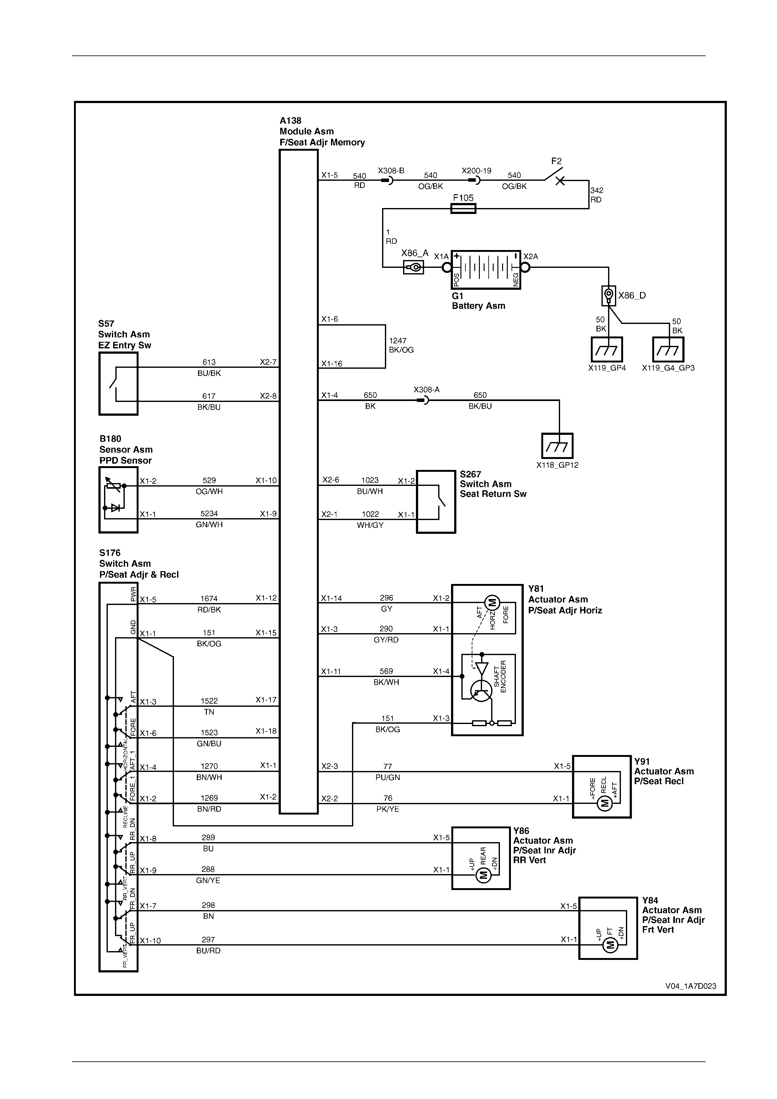
Seat Assemblies Page 1A7A–324
Page 1A7A–324
Wiring Diagram – Passenger's Seat, Non-memory, LHD
Figure 1A7A – 177
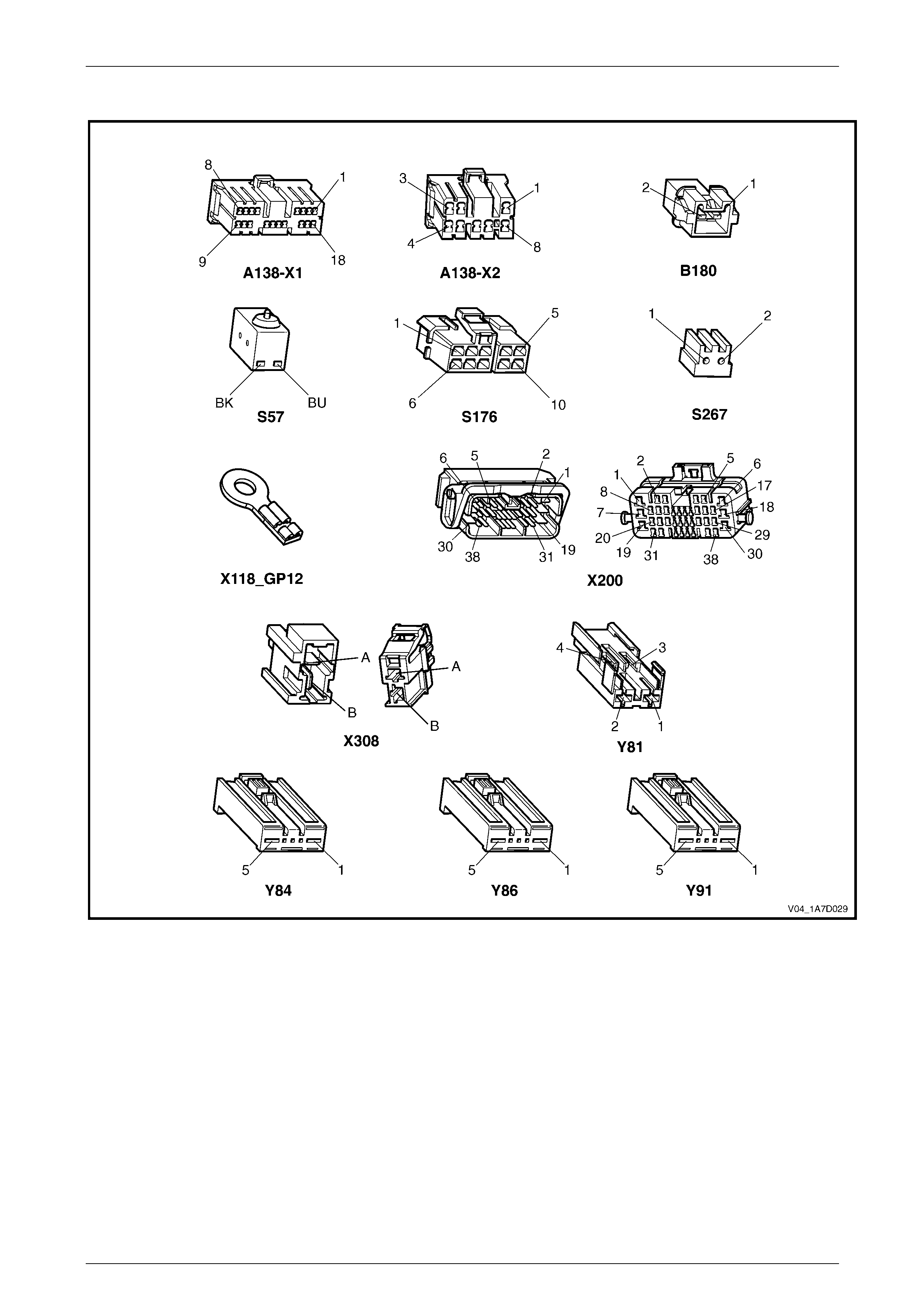
Seat Assemblies Page 1A7A–325
Page 1A7A–325
Connector Chart – Passenger's Seat, Non-memory, RHD and LHD
Figure 1A7A – 178

Seat Assemblies Page 1A7A–326
Page 1A7A–326
None of the Passenger’s Seat Adjustment Switch Functions Operate
Introduction
This test is used to aid in diagnosing the passenger’s seat adjustment switch when none of the switch functions operate.
The test diagnoses the passenger’s seat adjustment switch and associated power and ground circuits.
Circuit Description
The seat adjustment switch provides manual control for the passenger’s seat. It is connected by a harness to the seat
EZ-entry module, and the seat front lift and seat rear lift motors.
Refer to Wiring Diagram – Passenger' s Seat, Non-memory, RHD and
Connector Chart – Passenger's Seat, Non-memory, RHD and LHD, or
Wiring Diagram – Passeng er's Seat, Non-memory, LHD and
Connector Chart – Passenger's Seat, Non-memory, RHD and LHD in this Section to aid in diagnosing the seat EZ-entry
module and associated components.
Test Description
The following numbers refer to the step numbers in the diagnostic table:
1 Checks if all of the driver’s seat functions work. If none of them work, the fault is not isolated to the driver’s seat
only.
2 Checks if there is battery power at connector X308 pin B. Isolates if there is a fault in circuit 540 between
connectors X200 pin 19 and X308 pin B.
3 Checks if all the connectors required for the seat to operate effectively are in place a nd positively connected.
4 Checks if there is battery power at connector A138 – X1 pin 5. Isolates if there is a fault in circuit 540 between
connectors A138 – X1 pin 5 and X308 pin B.
5 Checks if there is battery power at connector A138 – X1 pin 12. Isolates if there is a fault with the EZ-entry module.
6 Checks if there is battery power at connector S176 – X1 pin 5. Isolates if there is a fault in circuit 1674 between
connectors S176 – X1 pin 5 a nd A138 – X1 pin 12.
7 Checks if the passenger’s seat adjustment switch is serviceable.
8 Checks if there is continuity between connectors S51 – X1 pin 1 and X308 pin A which supplies the ground circuit
for the driver’s seat adjustment switch. Isolates whether the re is a fault between the switch and connector
X308 pin A or between connector X308 pin A and the ground point.
9 Checks if there is continuity between connectors A138 – X1 pin 4 and X308 pin A. Isolates whether there is a fault
between the seat adjustment switch and connector A138 – X1 pin 4 or between connectors A138 – X1 pin 4 and
X308 pin A.
10 Checks if there is continuity between connector A138 – X1 pins 15 and 4. Isolates whether there is a fault between
the seat adjustment switch and connector A1 38 – X1 pin 15 or the EZ-entry module is at fault.
Diagnostic Table Notes
1 For all wiring harness fault diagnoses, refer to 12P Wirin g Diagrams.
2 For wiring harness repairs, refer to 12P Wiring Diagrams.
3 Refer to 12O Fuses, Relays and Wiring Harnesses for harness routeing.
4 If the fault is deemed to be intermittent, refer to 12P Wiring Diagrams.

Seat Assemblies Page 1A7A–327
Page 1A7A–327
Diagnostic Table
Step Action Yes No
1 Are all of the driver's seat adjustment switch functions inoperative? Refer to Neither
Seat Adjustment
Switch Functions
Operate in 7.3
ectrical Diagnosis –
Eight-way Seat,
Non-memory Go to Step 2
2 Backprobe connector X308 pin B with a test lamp (refer to Note 1).
Does the test lamp illuminate?
Go to Step 3
Repair or replace
circuit 540 between
connectors
X200 pin 19 an d
X308 pin B (refer to
Note 2)
3 Are the following connectors secure (refer to Note 3)?
• A138
• S176
• X308
• Y81
• Y84
• Y86
• Y91 Go to Step 4
Ensure the
connectors are
secure
4 Backprobe connector A138 – X1 pin 5 with a test lamp (refer to
Note 1).
Does the test lamp illuminate?
Go to Step 5
Repair or replace
circuit 540 between
connectors
A138 – X1 pin 5
and X308 pin B
(refer to Note 2)
5 Backprobe connector A138 – X1 pin 12 with a test lamp (refer to
Note 1).
Does the test lamp illuminate?
Go to Step 6
Replace the
passenger’s seat
EZ-entry module,
refer to 6.4 Front
Seat Outer Side
Cover Assembly
6 Backprobe connector S176 – X1 pin 5 with a test lamp (refer to
Note 1).
Does the test lamp illuminate? Go to Step 7
Repair or replace
circuit 1674 (refer
to Note 2)
7 1 Remove the passenger’s seat adjustment switch from the seat,
refer to 6.4 Front Seat Outer Side Cover Assembly.
2 Test the passenger’s seat adjustment switch, refer to 3.6 Eight-
way Seat Adjustment Switch Test.
Is the passenger’s seat adjustment s witch serviceable? Go to Step 8
Replace the
passenger’s seat
adjustment switch,
refer to 6.4 Front
Seat Outer Side
Cover Assembly
8 1 Backprobe connector X308 pin A with a test lamp (refer to
Note 1).
2 Operate the passenger’s seat adjustment switch in any of the
available directions.
Does the test lamp illuminate?
Repair or replace
circuit 650 between
connector
X308 pin A
and ground point
X118 – GP12 (refer
to Note 2) Go to Step 9

Seat Assemblies Page 1A7A–328
Page 1A7A–328
Step Action Yes No
9 1 Backprobe connector A138 – X1 pin 4 with a test lamp (refer to
Note 1).
2 Operate the passenger’s seat adjustment switch in any of the
available directions.
Does the test lamp illuminate?
Repair or replace
circuit 650 between
connectors
A138 – X1 pin 4
and X308 pin A
(refer to Note 2) Go to Step 10
10 1 Backprobe connector A138 – X1 pin 15 with a test lamp (refer
to Note 1).
2 Operate the passenger’s seat adjustment switch in any of the
available directions.
Does the test lamp illuminate?
Replace the
passenger’s seat
EZ-entry module,
refer to 6.4 Front
Seat Outer Side
Cover Assembly
Repair or replace
circuit 151 (refer to
Note 2)
When all diagno sis and repairs are completed, check the system for correct operation.

Seat Assemblies Page 1A7A–329
Page 1A7A–329
Front/Rear of the Passenger’s Seat Does Not Raise and/or Lower
Introduction
This test is used to aid in diagnosing the front and/or the rear of the passenger’s seat not raising and/or lowering. The
test diagnoses the seat adjustment switch and the motor circuits.
Circuit Description
The seat front lift and rear lift motors are controlled by the seat adjustment switch, which provides power and ground for
the motors. The polarity of the motors are alternated to change the direction of the motors.
Refer to Wiring Diagram – Passenger' s Seat, Non-memory, RHD and
Connector Chart – Passenger's Seat, Non-memory, RHD and LHD, or
Wiring Diagram – Passeng er's Seat, Non-memory, LHD and
Connector Chart – Passenger's Seat, Non-memory, RHD and LHD in this Section to aid in diagnosing the seat
adjustment switch and the motor circuits.
Test Description
The following numbers refer to the step numbers in the diagnostic table:
1 Checks if the passenger’s seat adjustment switch operates the seat in any direction. Isolates if the power and
ground circuits are at fault.
2 Checks if all the connectors required for the seat to operate effectively are in place a nd positively connected.
3 Checks if the passenger’s seat adjustment switch is serviceable.
4 Confirms whether the rear of the seat raises or lowers. Isolates if the seat rear lift motor and circuit of the seat is the
fault.
5 Confirms whether the front of the seat raises or lo wers. Isolates if the seat front lift motor and circuit of the seat is
the fault.
6 Checks if there is battery power to the seat rear lift motor at connector Y86 – X1 pin 1. Isolates if there is a fault in
circuit 288 that supplies battery po wer to the motor to raise the rear of the seat.
7 Checks if there is battery power to the seat rear lift motor at connector Y86 – X1 pin 5. Isolates whether the fault is
in circuit 289 that supplies battery power to the motor to lower the rear of the seat or the motor is faulty. As the
direction of the motor is changed by reversing the polarity, this Step also confirms if the ground circuit from Step 6
is serviceable.
8 Checks if there is battery power to the seat front lift motor at connector Y84 – X1 pin 1. Isolates if there is a fault in
circuit 297 that supplies battery po wer to the motor to raise the front of the seat.
9 Checks if there is battery power to the seat front lift motor at connector Y84 – X1 pin 5. Isolates whether the fault is
in circuit 298 that supplies battery power to the motor to lower the front of the seat or the motor is faulty. As the
direction of the motor is changed by reversing the polarity, this Step also confirms if the ground circuit from Step 8
is serviceable.
Diagnostic Table Notes
1 For all wiring harness fault diagnoses, refer to 12P Wirin g Diagrams.
2 For wiring harness repairs, refer to 12P Wiring Diagrams.
3 Refer to 12O Fuses, Relays and Wiring Harnesses for harness routeing.
4 If the fault is deemed to be intermittent, refer to 12P Wiring Diagrams.

Seat Assemblies Page 1A7A–330
Page 1A7A–330
Diagnostic Table
Step Action Yes No
1 Does the passenger’s seat adjustment switch operate the seat
correctly in any of the eight directions?
Go to Step 2
Refer to None of
the Passenger’s
Seat Adjustment
Switch Functions
Operate in this
Section
2 Are the following connectors secure (refer to Note 3)?
• A138
• S176
• Y84
• Y86 Go to Step 3
Ensure the
connectors are
secure
3 1 Remove the passenger’s seat adjustment switch from the seat,
refer to 6.4 Front Seat Outer Side Cover Assembly.
2 Test the passenger’s seat adjustment switch, refer to 3.6 Eight-
way Seat Adjustment Switch Test.
Is the passenger’s seat adjustment s witch serviceable? Go to Step 4
Replace the
passenger’s seat
adjustment switch,
refer to 6.4 Front
Seat Outer Side
Cover Assembly
4 Operate the passenger’s seat adjustment switch to raise or lower the
rear of the seat.
Does the rear of the seat raise and lo wer? Go to Step 5 Go to Step 6
5 Operate the passenger’s seat adjustment switch to raise or lower the
front of the seat.
Does the front of the seat raise and lower? System serviceable Go to Step 8
6 1 Backprobe connector Y86 – X1 pin 1 with a test lamp (refer to
Note 1).
2 Operate the passenger’s seat adjustment switch to raise the
rear of the seat.
Does the test lamp illuminate? Go to Step 7
Repair or replace
circuit 288 (refer to
Note 2)
7 1 Backprobe connector Y86 – X1 pin 5 with a test lamp (refer to
Note 1).
2 Operate the passenger’s seat adjustment switch to lower the
rear of the seat.
Does the test lamp illuminate?
Replace the seat
rear lift motor, refer
to 6.18 Front Seat
Lift Motor
Assemblies
Repair or replace
circuit 289 (refer to
Note 2)
8 1 Backprobe connector Y84 – X1 pin 1 with a test lamp (refer to
Note 1).
2 Operate the passenger’s seat adjustment switch to raise the
front of the seat.
Does the test lamp illuminate? Go to Step 9
Repair or replace
circuit 297 (refer to
Note 2)
9 1 Backprobe connector Y84 – X1 pin 5 with a test lamp (refer to
Note 1).
2 Operate the passenger’s seat adjustment switch to lower the
front of the seat.
Does the test lamp illuminate?
Replace the seat
front lift motor, refer
to 6.18 Front Seat
Lift Motor
Assemblies
Repair or replace
circuit 298 (refer to
Note 2)
When all diagno sis and repairs are completed, check the system for correct operation.

Seat Assemblies Page 1A7A–331
Page 1A7A–331
Passenger’s Seat Fore/Aft Function is Inoperative or Not Smooth
Introduction
This test is used to aid in diagnosing the fore/aft movement function of the passenger's seat being in operative or the
action of the seat through the range of movement is not smooth. The test diagnoses the seat adjustment switch and the
motor circuits.
Circuit Description
The seat fore/aft movement motor is controlled by the seat EZ-entry module which provides power and ground for the
motor. The polarity of the motor is alternated to change the direction of the motor.
Refer to Wiring Diagram – Passenger' s Seat, Non-memory, RHD and
Connector Chart – Passenger's Seat, Non-memory, RHD and LHD, or
Wiring Diagram – Passeng er's Seat, Non-memory, LHD and
Connector Chart – Passenger's Seat, Non-memory, RHD and LHD in this Section to aid in diagnosing the seat fore/aft
movement motor and associated components.
Test Description
The following numbers refer to the step numbers in the diagnostic table:
1 Checks if the passenger's seat adjustment switch operates the seat in any direction. Isolates if there is battery
power to the switch assembly.
2 Checks if there are any items obstructing the guide rails, which may stop or hinder the seat movement.
3 Checks if the guide rails and drive shafts have adequate lubricant applied t o provide a smooth operation of the
seat.
4 Checks if the guide rails or drive shafts have been damaged. An y binding between the moving parts will result in
poor operation of the fore and aft movement.
5 Checks if all the connectors required for the seat to operate effectively are in place a nd positively connected.
6 Checks if the passenger's seat adjustment switch is serviceable.
7 Checks if there is battery power to the seat fore/aft movement motor at connector Y81 – X1 pin 1. Isolates if there
is a fault between the switch and connector Y81 – X1 pin 1.
8 Checks if there is continuity between connectors S176 – X1 pin 6 and A138 – X1 pin 3. Isolates whether there is a
fault between the switch and connector A138 – X1 pin 3 or in circuit 290.
9 Checks if there is continuity between connectors S176 – X1 pin 6 and A138 – X1 pin 18. Isolates whether there is a
fault in circuit 1523 or the passenger's seat EZ-entry module is at fault.
10 Checks if there is battery power to the seat fore/aft movement motor at connector Y81 – X1 pin 2. Isolates whether
there is a fault between the switch and connector Y81 – X1 pin 2 or the motor is faulty. As reversing the polarity
changes the direction of the motor, this Step also confirms if the ground circuit from Step 7 is serviceable.
11 Checks if there is continuity between connec tors S176 – X1 pin 3 and A138 – X1 pin 14. Isolates whether there is a
fault between the switch and connector A138 – X1 pin 14 or in circuit 29 6.
12 Checks if there is continuity between connec tors S176 – X1 pin 3 and A138 – X1 pin 17. Isolates whether there is a
fault in circuit 1522 or the passenger's seat EZ-entry module is at fault.
Diagnostic Table Notes
1 For all wiring harness fault diagnoses, refer to 12P Wirin g Diagrams.
2 For wiring harness repairs, refer to 12P Wiring Diagrams.
3 Refer to 12O Fuses, Relays and Wiring Harnesses for harness routeing.
4 If the fault is deemed to be intermittent, refer to 12P Wiring Diagrams.

Seat Assemblies Page 1A7A–332
Page 1A7A–332
Diagnostic Table
Step Action Yes No
1 Does the passenger's seat adjustment switch operate the seat
correctly in any of the eight directions?
Go to Step 2
Refer to None of
the Passenger’s
Seat Adjustment
Switch Functions
Operate in this
Section
2 Are the guide rails free from obstructions? Go to Step 3 Remove the
obstructing item
3 Are the guide rails and drive shafts adequate ly lubricated?
Go to Step 4
Apply a small
amount of grease
type NLGI No. 1
Lithium Grease
(with 9% Zinc
Oxide)
4 Do the guide rails or drive shafts bind at any point of travel during the
fore and aft movement of the seat? Replace the track
and height adjust
assembly, refer to
6.15 Track and
Height Adjust
Assembly Go to Step 5
5 Are the following connectors secure (refer to Note 3)?
• A138
• S176
• Y81 Go to Step 6
Ensure the
connectors are
secure
6 1 Remove the passenger's seat adjustment switch from the seat,
refer to 6.4 Front Seat Outer Side Cover Assembly.
2 Test the passenger's seat adjustment switch, refer to 3.6 Eight-
way Seat Adjustment Switch Test.
Is the passenger's seat adjustment s witch serviceable? Go to Step 7
Replace the
passenger's seat
adjustment switch,
refer to 6.4 Front
Seat Outer Side
Cover Assembly
7 1 Backprobe connector Y81 – X1 pin 1 with a test lamp (refer to
Note 1).
2 Operate the passenger's seat adjustment switch to move the
seat forward.
Does the test lamp illuminate? Go to Step 10 Go to Step 8
8 1 Backprobe connector A138 – X1 pin 3 with a test lamp (refer to
Note 1).
2 Operate the passenger's seat adjustment switch to move the
seat forward.
Does the test lamp illuminate?
Repair or replace
circuit 290 (refer to
Note 2) Go to Step 9
9 1 Backprobe connector A138 – X1 pin 18 with a test lamp (refer
to Note 1).
2 Operate the passenger's seat adjustment switch to move the
seat forward.
Does the test lamp illuminate?
Replace the
passenger's seat
EZ-entry module,
refer to 6.4 Front
Seat Outer Side
Cover Assembly
Repair or replace
circuit 1523 (refer
to Note 2)
10 1 Backprobe connector Y81 – X1 pin 2 with a test lamp (refer to
Note 1).
2 Operate the passenger's seat adjustment switch to move the
seat aft.
Does the test lamp illuminate?
Replace the seat
fore/aft movement
motor, refer to 6.19
Front Seat Fore/Aft
Movement Motor
Assembly Go to Step 11

Seat Assemblies Page 1A7A–333
Page 1A7A–333
Step Action Yes No
11 1 Backprobe connector A138 – X1 pin 14 with a test lamp (refer
to Note 1).
2 Operate the passenger's seat adjustment switch to move the
seat aft.
Does the test lamp illuminate?
Repair or replace
circuit 296 (refer to
Note 2) Go to Step 12
12 1 Backprobe connector
A138 – X1 pin 17 with a test lamp (refer to Note 1).
2 Operate the passenger's seat adjustment switch to move the
seat aft.
Does the test lamp illuminate?
Replace the
passenger's seat
EZ-entry module,
refer to 6.4 Front
Seat Outer Side
Cover Assembly
Repair or replace
circuit 1522 (refer
to Note 2)
When all diagno sis and repairs are completed, check the system for correct operation.

Seat Assemblies Page 1A7A–334
Page 1A7A–334
Passenger's Seat Recline Forward and/or Aft Function is Inoperative
Introduction
This test is used to aid in diagnosing the recline function of the passenger's seat being inoperative. The test diagnoses
the seat adjustment switch and the motor circuits.
Circuit Description
The front seat-back recline motor is controlled by the seat EZ-entry module which provide s power and ground for the
motor. The polarity of the motor is alternated to change the direction of the motor.
Refer to Wiring Diagram – Passenger' s Seat, Non-memory, RHD and
Connector Chart – Passenger's Seat, Non-memory, RHD and LHD, or
Wiring Diagram – Passeng er's Seat, Non-memory, LHD and
Connector Chart – Passenger's Seat, Non-memory, RHD and LHD in this Section to aid in diagnosing the seat recline
motor and associated components.
Test Description
The following numbers refer to the step numbers in the diagnostic table:
1 Checks if the passenger's seat adjustment switch operates the seat in any direction. Isolates if there is battery
power to the switch assembly.
2 Checks if all the connectors required for the seat to operate effectively are in place a nd positively connected.
3 Checks if the passenger's seat adjustment switch is serviceable.
4 Checks if there is battery power to the seat recline motor at connector Y91 – X1 pin 1. Isolates if there is a fault
between the switch and con nector Y91 – X1 pin 1.
5 Checks if there is continuity between connectors S176 – X1 pin 2 and A138 – X2 pin 2. Isolates whether there is a
fault between the switch and connector A138 – X2 pin 2 or in circuit 76.
6 Checks if there is continuity between connectors S176 – X1 pin 2 and A138 – X1 pin 2. Isolates whether there is a
fault in circuit 1269 or the passenger's seat EZ-entry module is at fault.
7 Checks if there is battery power to the seat recline motor at connector Y91 – X1 pin 5. Isolates whether there is a
fault between the switch and connector Y91 – X1 pin 5 or the motor is fault y. As reversing the polarity changes the
direction of the motor, this Step also confirms if the ground circuit from Step 4 is servicea ble.
8 Checks if there is continuity between connectors S176 – X1 pin 4 and A138 – X2 pin 3. Isolates whether there is a
fault between the switch and connector A138 – X2 pin 3 or in circuit 77.
9 Checks if there is continuity between connectors S176 – X1 pin 4 and A138 – X1 pin 1. Isolates whether there is a
fault in circuit 1270 or the passenger's seat EZ-entry module is at fault.
Diagnostic Table Notes
1 For all wiring harness fault diagnoses, refer to 12P Wirin g Diagrams.
2 For wiring harness repairs, refer to 12P Wiring Diagrams.
3 Refer to 12O Fuses, Relays and Wiring Harnesses for harness routeing.
4 If the fault is deemed to be intermittent, refer to 12P Wiring Diagrams.

Seat Assemblies Page 1A7A–335
Page 1A7A–335
Diagnostic Table
Step Action Yes No
1 Does the passenger's seat adjustment switch operate the seat
correctly in any of the eight directions?
Go to Step 2
Refer to None of
the Passenger’s
Seat Adjustment
Switch Functions
Operate in this
Section
2 Are the following connectors secure (refer to Note 3)?
• A138
• S176
• Y91 Go to Step 3
Ensure the
connectors are
secure
3 1 Remove the passenger's seat adjustment switch from the seat,
refer to 6.4 Front Seat Outer Side Cover Assembly.
2 Test the passenger's seat adjustment switch, refer to 3.6 Eight-
way Seat Adjustment Switch Test.
Is the passenger's seat adjustment s witch serviceable ? Go to Step 4
Replace the
passenger's seat
adjustment switch,
refer to 6.4 Front
Seat Outer Side
Cover Assembly
4 1 Backprobe connector Y91 – X1 pin 1 with a test lamp (refer to
Note 1).
2 Operate the passenger's seat adjustment switch to move the
seat-back forward.
Does the test lamp illuminate? Go to Step 7 Go to Step 5
5 1 Backprobe connector A138 – X2 pin 2 with a test lamp (refer to
Note 1).
2 Operate the passenger's seat adjustment switch to move the
seat-back forward.
Does the test lamp illuminate?
Repair or replace
circuit 76 (refer to
Note 2) Go to Step 6
6 1 Backprobe connector A138 – X1 pin 2 with a test lamp (refer to
Note 1).
2 Operate the passenger's seat adjustment switch to move the
seat-back forward.
Does the test lamp illuminate?
Replace the
passenger's seat
EZ-entry module,
refer to 6.4 Front
Seat Outer Side
Cover Assembly
Repair or replace
circuit 1269 (refer
to Note 2)
7 1 Backprobe connector Y91 – X1 pin 5 with a test lamp (refer to
Note 1).
2 Operate the passenger's seat adjustment switch to move the
seat-back aft.
Does the test lamp illuminate?
Replace the front
seat-back recline
motor, refer to 6.20
Front Seat-back
Recline Motor
Assembly Go to Step 8
8 1 Backprobe connector A138 – X2 pin 3 with a test lamp (refer to
Note 1).
2 Operate the passenger's seat adjustment switch to move the
seat-back aft.
Does the test lamp illuminate?
Repair or replace
circuit 77 (refer to
Note 2) Go to Step 9
9 1 Backprobe connector A138 – X1 pin 1 with a test lamp (refer to
Note 1).
2 Operate the passenger's seat adjustment switch to move the
seat-back aft.
Does the test lamp illuminate?
Replace the
passenger's seat
EZ-entry module,
refer to 6.4 Front
Seat Outer Side
Cover Assembly
Repair or replace
circuit 1270 (refer
to Note 2)
When all diagno sis and repairs are completed, check the system for correct operation.

Seat Assemblies Page 1A7A–336
Page 1A7A–336
Passenger's Seat EZ-entry Switch Function is Inoperative
Introduction
The EZ-entry function is designed so that when the seat-back is released with the EZ-entry lever, the seat will move to its
fully forward position using the seat fore/aft movement motor. Once the seat has moved to its fully for ward position,
power to the seat fore/aft movement motor will cease. A switch attached to the seat-back activates the seat fore/aft
movement motor when the recline of the seat-back is moved forward after being released using the EZ-entry lever. This
test is used to aid in diagnosing the EZ-entry function of the passenger' s seat being inoperative. T he test diagnoses the
EZ-entry switch and associated circuits.
Circuit Description
The EZ-entry switch is connected to the seat EZ-entry module b y a har ness. The EZ-entry switch is a normally open type
switch.
Refer to Wiring Diagram – Passenger' s Seat, Non-memory, RHD and
Connector Chart – Passenger's Seat, Non-memory, RHD and LHD, or
Wiring Diagram – Passeng er's Seat, Non-memory, LHD and
Connector Chart – Passenger's Seat, Non-memory, RHD and LHD in this Section to aid in diagnosing the seat EZ-entry
switch and associated components.
Test Description
The following numbers refer to the step numbers in the diagnostic table:
2 Checks if the seat fore/aft movement motor is serviceable.
3 Checks if there is battery power to the EZ-entry switch. Isolates if there is a fault with the passenger's seat EZ-entry
module.
4 Checks if there is continuity between connector A138 – X2 pins 7 and 8. Isolates if the passenger's seat EZ-entry
module is at fault.
Diagnostic Table Notes
1 For all wiring harness fault diagnoses, refer to 12P Wirin g Diagrams.
2 For wiring harness repairs, refer to 12P Wiring Diagrams.
3 Refer to 12O Fuses, Relays and Wiring Harnesses for harness routeing.
4 If the fault is deemed to be intermittent, refer to 12P Wiring Diagrams.
Diagnostic Table
Step Action Yes No
1 Is the EZ-entry self diagnos is LED (loc ated on the seat control
module) flashing? Refer to EZ-entry
Electrical Self
Test Diagnosis –
Eight-way Seat,
Non-Memory in
this Section Go to Step 2
2 Does the seat move in the fore/aft direction whe n op erated by
the passenger's seat adjustment switch?
Go to Step 3
Refer to Passenger’s Seat
Fore/Aft Function is
Inoperative or Not Smooth
in this Section
3 Backprobe connector A138 – X2 pin 7 with a test lamp (refer to
Note 1).
Does the test lamp illuminate?
Go to Step 4
Replace the passenger's
seat EZ-entry module.
Refer to 6.4 Front Seat
Outer Side Cover
Assembly
4 1 Release the seat-back using the EZ-entry lever.
2 Backprobe connector A138 – X2 pin 8 with a test lamp
(refer to Note 1).
Does the test lamp illuminate?
Replace the
passenger's seat
EZ-entry module,
refer to 6.4 Front
Seat Outer Side
Cover Assembly
Replace the passenger's
seat EZ-entry switch, refer
to 6.10 EZ-entry Switch
and Release Cable
Assembly
When all diagno sis and repairs are completed, check the system for correct operation.

Seat Assemblies Page 1A7A–337
Page 1A7A–337
Passenger's Seat Return Switch Function is Inoperative
Introduction
The seat return switch is located on the escutcheon at the top of the seat-back. The switch function is to move the seat in
an aft direction after the EZ-entry function has been used and the recline of the seat has been placed upright. With the
seat return switch continuously pressed, the seat will move to its fully aft position, pausing for 2 seconds at the seat
position where the EZ-entry lever was operated. The test diagnoses the seat return switch and associated circuits.
Circuit Description
The passenger's seat return switch is connected to the seat EZ-entry module by a harness. The passenger's seat return
switch is a normally open type switch.
Refer to Wiring Diagram – Passenger's Seat, Non-memory, RHD and
Connector Chart – Passenger's Seat, Non-memory, RHD and LHD, or
Wiring Diagram – Passenger's Seat, Non-memory, LHD and
Connector Chart – Passenger's Seat, Non-memory, RHD and LHD in this Section to aid in diagnos ing the pas sen ger' s
seat return switch and associated components.
Test Description
The following numbers refer to the step numbers in the diagnostic table:
1 Checks if the seat fore/aft movement motor is serviceable.
2 Checks if the seat will move to its fully forward position when the seat-back is released using the EZ-entry lever.
Isolates if the EZ-entry switch function is serviceable.
3 Checks if the seat will move aft when the seat-back is in the upright position and the seat return switch is pressed.
Isolates if the seat return switch is serviceable.
4 Checks if the seat stops for 2 seconds at the position where the EZ-entry lever was released.
5 Checks if circuit 1247 is serviceable.
6 Checks the hall-effect sensor and associated circuits. Isolates whether the hall-effect sensor or the EZ-entry
module is faulty.
7 Checks if there is battery power at connector A138 – X2 pin 6. Isolates if there is a fault with the passenger’s seat
EZ-entry module.
8 Checks if there is continuity between connector A138 – X2 pins 1 and 6. Isolates if there is a fault with the seat
return switch and associated circuits.
9 Checks if there is continuity between connectors A138 – X2 pin 6 and S267 – X1 pin 2. Isolates if there is a fault in
circuit 1023.
10 Checks if there is continuity between connectors S267 – X1 pin 1 and A138 – X2 pin 6. Isolates whether there is a
fault with the passenger’s seat return switch or in circuit 1022.
Diagnostic Table Notes
1 For all wiring harness fault diagnoses, refer to 12P Wiring Diagram s.
2 For wiring harness repairs, refer to 12P Wiring Diagrams.
3 Refer to 12O Fuses, Relays and Wiring Harnesses for harness routeing.
4 If the fault is deemed to be intermittent, refer to 12P Wiring Diagrams.

Seat Assemblies Page 1A7A–338
Page 1A7A–338
Diagnostic Table
Step Action Yes No
1 Does the seat move in the fore/aft direction when operated by the
passenger' s seat adj ust men t switch?
Go to Step 2
Refer to
Passenger’s Seat
Fore/Aft Function is
Inoperative or Not
Smooth in this
Section
2 1 Move the seat forward from the rear most position and note its
position on the track.
2 Release the seat-back using the EZ-entry lever.
Does the seat move forward? Go to Step 3
Refer to
Passenger's Seat
EZ-entry Switch
Function is
Inoperative in this
Section
3 1 Move the seat-back to the upright position.
2 Press and hold the seat return switch.
Does the seat move aft? Go to Step 4 Go to Step 7
4 Does the seat stop for 2 seconds at the position from where it was
unlatched and then continue to the aft most position of the track? System serviceable Go to Step 5
5 1 Disconnect connector A138 – X1 from the passenger's seat EZ-
entry module.
2 Using a multimeter set to measure resistance, probe between
connector A138 – X1 pins 6 and 16 (refer to Note 1).
Does the multimeter indicate continuity? Go to Step 6
Repair or repl ace
circuit 1247 (refer
to Note 2)
6 Te st the seat fore/aft movement motor hall-effect sensor, refer to
Passenger's Seat Fore/Aft Movement Motor Hall-effect Sensor Test
in this Section.
Is the hall-effect sensor and circuit serviceable?
Replace the
passenger' s seat
EZ-entry module,
refer to 6.4 Front
Seat Outer Side
Cover Assembly
Repair or repl ace
the passenger's
seat fore/aft
moveme nt motor
hall-effect sensor or
circuit, refer to
6.21 Drive Motor
Hall-effect Sensors
7 1 Connect connector A138 – X1 to the passenger's seat EZ-entry
module.
2 Backprobe connector A138 – X2 pin 6 with a test lamp (refer to
Note 1).
Does the test lamp illuminate? Go to Step 8
Replace the
passenger' s seat
EZ-entry module,
refer to 6.4 Front
Seat Outer Side
Cover Assembly
8 1 Backprobe connector A138 – X2 pin 1 with a test lamp (refer to
Note 1).
2 Press the seat return sw itc h.
Does the test lamp illuminate?
Replace the
passenger' s seat
EZ-entry module,
refer to 6.4 Front
Seat Outer Side
Cover Assembly Go to Step 9
9 Backprobe connector S267 – X1 pin 2 with a test lamp (refer to
Note 1).
Does the test lamp illuminate? Go to Step 10
Repair or repl ace
circuit 1023 (refer
to Note 2)
10 1 Backprobe connector S267 – X1 pin 1 with a test lamp (refer to
Note 1).
2 Press the seat return sw itc h.
Does the test lamp illuminate?
Repair or repl ace
circuit 1022 (refer
to Note 2)
Replace the
passenger' s seat
return switch, refer
to 6.9 EZ-entry
Release Lever and
Escutcheon
When all diagnosis and repairs are completed, check the system for correct operation.

Seat Assemblies Page 1A7A–339
Page 1A7A–339
Passenger's Seat Fore/Aft Movement Motor Hall-effect Sensor Test
Introduction
This test is used to aid in diagnosing the seat fore/aft movement motor hall-effect sensor and as sociated circuits.
Circuit Description
The seat fore/aft movement motor hall-effect sensor provides a pulse signal to the seat EZ-entry module. This signal
represents the horizontal position of the seat.
Refer to Wiring Diagram – Passenger's Seat, Non-memory, RHD and
Connector Chart – Passenger's Seat, Non-memory, RHD and LHD, or
Wiring Diagram – Passenger's Seat, Non-memory, LHD and
Connector Chart – Passenger's Seat, Non-memory, RHD and LHD in this Section to aid in diagnosing t he seat EZ-entry
module and associated components.
Test Description
The following numbers refer to the step numbers in the diagnostic table:
1 Checks the AC output from the hall-effect sensor during operation.
2 Checks if the ground circ uit is serviceable.
3 Checks if there is continuity between connectors Y81 – X1 and A138 – X1. Isolates if the hall-effect sensor is faulty.
Diagnostic Table Notes
1 For all wiring harness fault diagnoses, refer to 12P Wiring Diagram s.
2 For wiring harness repairs, refer to 12P Wiring Diagrams.
3 Refer to 12O Fuses, Relays and Wiring Harnesses for harness routeing.
4 If the fault is deemed to be intermittent, refer to 12P Wiring Diagrams.
5 The AC voltage displayed will depend on the battery voltage supplied to the seat. At 16 V DC supply, the AC
voltage produced by the hall-effect sensor will be approximately 6 V. At 9 V DC supply, the AC voltage produced by
the hall-effect sensor will be approximately 0.6 V.
Diagnostic Table
Step Action Yes No
1 1 Using a multimeter set to measure AC voltage, probe across
connector Y81 – X1 pins 3 and 4 (refer to Note 1).
2 Operate the seat adjustment switch to move the seat fore or aft.
Does the multimeter display 0.6 – 6 V (refer to Note 5)?
Hall-effect sensor
and associated
wiring serviceable Go to Step 2
2 Using a multimeter set to measure resistance, probe between
connector Y81 – X1 pin 3 and a known ground (refer to Note 1).
Does the multimeter indicate continuity? Go to Step 3
Repair or repl ace
circuit 151 (refer to
Note 2)
3 1 Disconnect connector A138 – X1 from the passenger's seat
EZ-entry module.
2 Using a multimeter set to measure resistance, probe between
connectors A138 – X1 pin 11 and Y81 – X1 pin 4 (refer to
Note 1).
Does the multimeter indicate continuity?
Replace the
hall-effect sensor,
refer to 6.21 Drive
Motor Hall-effect
Sensors
Repair or repl ace
circuit 569 (refer to
Note 2)
When all diagnosis and repairs are completed, check the system for correct operation.

Seat Assemblies Page 1A7A–340
Page 1A7A–340
Passenger's Seat Occupant Sensing Mat Test
Introduction
This test is used to aid in diagnosing the occupant sensing mat and associated circuits.
Circuit Description
The occupant sensing mat provides a signal to the seat EZ-entry module. T his signal represents the presence of a
passenger on the seat.
Refer to Wiring Diagram – Passenger' s Seat, Non-memory, RHD and
Connector Chart – Passenger's Seat, Non-memory, RHD and LHD, or
Wiring Diagram – Passeng er's Seat, Non-memory, LHD and
Connector Chart – Passenger's Seat, Non-memory, RHD and LHD in this Section to aid in diagnosing the occupant
sensing mat and associated compo nents.
Test Description
The following numbers refer to the step numbers in the diagnostic table:
1 Checks diode forward resistance of the Passenger Presence Detector (PPD).
2 Checks diode reverse resistance of the PPD.
3 Checks diode reverse resistance of the PPD with weight on seat.
4 Checks if there is continuity between connectors B180 – X1 pin 1 and A138 – X1 pin 9. Isolates if there is a fault in
circuit 5234.
5 Checks if there is continuity between connectors B180 – X1 pin 2 and A138 – X1 pin 10. Isolates if there is a fault
in circuit 529.
Diagnostic Table Notes
1 For all wiring harness fault diagnoses, refer to 12P Wirin g Diagrams.
2 For wiring harness repairs, refer to 12P Wiring Diagrams.
3 Refer to 12O Fuses, Relays and Wiring Harnesses for harness routeing.
4 If the fault is deemed to be intermittent, refer to 12P Wiring Diagrams.

Seat Assemblies Page 1A7A–341
Page 1A7A–341
Diagnostic Table
Step Action Yes No
1 1 Disconnect connector B180 – X1 from the occupant sensing
mat.
2 Using a multimeter set to measure resistance, connect red (+)
probe to pin 1 and black (–) probe to pin 2 of the occupant
sensing mat (refer to Note 1).
Does the multimeter indicate continuity? Go to Step 2
Replace the
occupant sensing
mat, refer to 6.16
Front Seat Cushion
Pad and Cover
Assembly
2 Using a multimeter set to measure resistance, connect red (+) probe
to pin 2 and black (–) probe to pin 1 of the occupant sensing mat
(refer to Note 1).
Does the multimeter indicate greater than 50 kΩ? Go to Step 3
Replace the
occupant sensing
mat, refer to 6.16
Front Seat Cushion
Pad and Cover
Assembly
3 1 Place a weight greater than 15 kg on the seat.
2 Using a multimeter set to measure resistance, connect red (+)
probe to pin 2 and black (–) probe to pin 1 of the occupant
sensing mat (refer to Note 1).
Does the multimeter indicate less than 50 kΩ? Go to Step 4
Replace the
occupant sensing
mat, refer to 6.16
Front Seat Cushion
Pad and Cover
Assembly
4 1 Disconnect connector A138 – X1 from the passenger's seat
EZ-entry module (refer to Note 3).
2 Using a multimeter set to measure resistance, probe between
connectors B180 – X1 pin 1 and A138 – X1 pin 9.
Does the multimeter indicate continuity? Go to Step 5
Repair or repl ace
circuit 5234 (refer
to Note 2)
5 Using a multimeter set to measure resistance, probe between
connectors B180 – X1 pin 2 and A138 – X1 pin 10.
Does the multimeter indicate continuity?
Occupant sen sin g
mat and associated
wiring serviceable
Repair or repl ace
circuit 529 (refer to
Note 2)
When all diagnosis and repairs are completed, check the system for correct operation.

Seat Assemblies Page 1A7A–342
Page 1A7A–342
7.6 Electrical Diagnosis – Eight-way Seat,
Memory
Neither Seat Adjustment Switch Functions Operate
Introduction
This test is used to aid in diagnosing the seat power and ground circuits if neither seat operates when either seat
adjustment switch is operated.
Circuit Description
Both front seats have common power and gr ound circuits. If either of these circuits become unservicea bl e, the electrica l
operation of both seats will be affected.
The charts in this Section are used to aid in diagnosing faults on the driver's eight-way seat, Memory. To aid in the use of
the diagnostic tables, refer to Wiring Diagra m – Driver's Seat, Memory, RHD and
Connector Chart – Driver's Seat, Memory, RHD.
Test Description
The following numbers refer to the step numbers in the diagnostic table:
1 Checks if battery voltage is more than 11.5 V. The seat motors require mo re than 11.5 V to operate correctly.
2 Checks if circuit breaker F2 located on the passenger com partment fuse and relay panel assembl y is tripped.
Isolates if circuit breaker F2 is the fault affecting the circuit between the battery and conne ctor X200 pin 19.
3 Checks if fusible link F105 located on the engine compartment fuse and relay panel assembly is serviceable.
Isolates if the fusible link is the fault affecting the circuit between the battery and connector X200 pin 19.
4 Checks if connector X200 is secure.
5 Checks if there is battery voltage at connector X200 pin 19. Isolates if the fault is between the battery and
connector X200 pin 19. If the fault in the circuit is between connectors X200 pin 19 and either X3 15 pin 1 or
X308 pin B, only o ne seat will operate.
6 Checks if there is battery voltage at circuit breaker F2. Isolates whether the fault is between the b attery and circuit
breaker F2 or bet ween circuit breaker F2 an d connector X200 pin 19.
7 Checks if there is battery voltage at fusible link F105. Isolates whether the fault is between the battery and fusible
link F105 or between fusible li nk F 105 and circuit breaker F2.
8 Checks if the ground point associated with the system is serviceable.
Diagnostic Table Notes
1 For all wiring harness fault diagnoses, refer to 12P Wirin g Diagrams.
2 For wiring harness repairs, refer to 12P Wiring Diagrams.
3 Refer to 12O Fuses, Relays and Wiring Harnesses for harness routeing.
4 If the fault is deemed to be intermittent, refer to 12P Wiring Diagrams.

Seat Assemblies Page 1A7A–343
Page 1A7A–343
Diagnostic Table
Step Action Yes No
1 Check the battery voltage, refer to 12A Battery and Cables.
Is the battery voltage more than 11.5 V? Go to Step 2
Refer to 12A
Battery and Cables
for further diagnosis
2 Inspect circuit breaker F2 (refer to Note 3).
Is circuit breaker F2 tripped?
Allow the circuit
breaker to reset
(refer to Note 3).
If the circuit breaker
trips again, repair or
replace circuit 540
(refer to Note 2) Go to Step 3
3 Inspect fusible link F105 (refer to Note 3).
Is fusible link F105 serviceabl e?
Go to Step 4
Replace the fusible
link.
If the fusible link
becomes
unserviceable
again, repair or
replace circuit 342
(refer to Note 2)
4 Is connector X200 secure (ref er to Note 3)? Go to Step 5 Ensure the
connector is secure
5 Backprobe connector X200 pin 19 with a test lamp (refer to Note 1).
Does the test lamp illuminate? Go to Step 8 Go to Step 6
6 1 Remove circuit breaker F2 fro m the passenger compartment
fuse and relay panel assembly.
2 Using a test lamp, probe connector X12 9 – X45 pin 2 (refer to
Note 1).
Does the test lamp illuminate?
Repair or replace
circuit 540 between
circuit breaker F2
and connector
X200 pin 19 (refer
to Note 2) Go to Step 7
7 1 Remove the fusible link F105.
2 Using a test lamp, probe connector X18 - 105 (refer to Note 1).
Does the test lamp illuminate?
Repair or replace
circuit 342 between
fusible link F105
and circuit breaker
F2 (refer to Note 2)
Repair or replace
circuit 1 between
the battery and
fusible link F105
(refer to Note 2)
8 Ensure the follo wing ground poi nt is secure and has good contact with
the vehicle structure:
• X118 – GP12 located in the middle of the transmission tunnel.
Is the ground point secure to the vehicle with a good contact?
Repair or replace
circuit 650 (refer to
Note 2) Repair ground point
When all diagno sis and repairs are completed, check the system for correct operation.

Seat Assemblies Page 1A7A–344
Page 1A7A–344
EZ-entry and Memory Self Test Diagnosis
Introduction
The memory type seat provides the techn ician with in-built diagnostics. The diagnostics indicator is a green LED loc ated
on the memory position s witch. To enter the diagnostic mode, cycle the ignition while holding memory buttons 1 and 3 at
the same time.
The chart in this Section displays the error codes and fault description.
If the error code is above ten, the indication will consist of a single flash, a short delay and then the number of flashes
corresponding to the error. A longer delay will occur between error code indications.
EZ-entry and Memory Diagnostics
Flashes Description of Error Reference
2 No Passenger Presence Dete ctor
(PPD) detected Driver' s Seat Occupant Sensing Mat Test in 7.7 Electrical
Diagnosis – Driver's Seat, Memory, RHD.
3 PPD weight detected > 15 kg Driver's Seat Occupant Sensing Mat Test in 7.7 Electrical
Diagnosis – Driver's Seat, Memory, RHD.
4 Seat fore/aft movement motor
hall-effect sensor faulty Driver's Seat Fore/Aft Movement Motor Hall-effect Sensor Test in
7.7 Electrical Diagnosis – Driver' s Seat, Memory, RHD.
5 Seat rear lift motor hall-effect sensor
faulty Driver's Seat Rear Lift Motor Hall-effect Sensor Test in
7.7 Electrical Diagnosis – Driver' s Seat, Memory, RHD.
6 Seat front lift motor hall-effect sensor
faulty Driver's Seat Front Lift Motor Hall-effect Sensor Test in
7.7 Electrical Diagnosis – Driver' s Seat, Memory, RHD.
7 Seat-back recline motor hall-effect
sensor faulty Driver's Seat-back Recline Motor Hall-effect Sensor Test in
7.7 Electrical Diagnosis – Driver' s Seat, Memory, RHD.
8 Button stuck detected Driver's Seat Memory Position Switch Test in 7.7 Electrical
Diagnosis – Driver's Seat, Memory, RHD.
9 Dump latch active Driver's Seat EZ-entry Switch Function is Inoperative in
7.7 Electrical Diagnosis – Driver' s Seat, Memory, RHD.
11 Return button active Driver's Seat EZ-entry Switch Function is Inoperative in
7.7 Electrical Diagnosis – Driver' s Seat, Memory, RHD.
12 Forward track switch active 3.6 Eight-way Seat Adjustment Switch Test.
13 Reverse track switch active 3.6 Eight-way Seat Adjustment Switch Test.
14 Recliner forward switch active 3.6 Eight-way Seat Adjustment Switch Test.
15 Recliner backward switch active 3.6 Eight-way Seat Adjustment Switch Test.
16 Memory 1 button active Driver's Seat Memory Position Switch Test in 7.7 Electrical
Diagnosis – Driver's Seat, Memory, RHD.
17 Memory 2 button active Driver's Seat Memory Position Switch Test in 7.7 Electrical
Diagnosis – Driver's Seat, Memory, RHD.
18 Memory 3 button active Driver's Seat Memory Position Switch Test in 7.7 Electrical
Diagnosis – Driver's Seat, Memory, RHD.
19 Memory store M button active Driver's Seat Memory Position Switch Test in 7.7 Electrical
Diagnosis – Driver's Seat, Memory, RHD.

Seat Assemblies Page 1A7A–345
Page 1A7A–345
7.7 Electrical Diagnosis – Driver's Seat,
Memory, RHD
The charts in this Section are used to aid in diagnosing faults on the driver's eight-way seat, Memory. To aid in the use of
the diagnostic tables, refer to Wiring Diagra m – Driver's Seat, Memory, RHD and
Connector Chart – Driver's Seat, Memory, RHD.
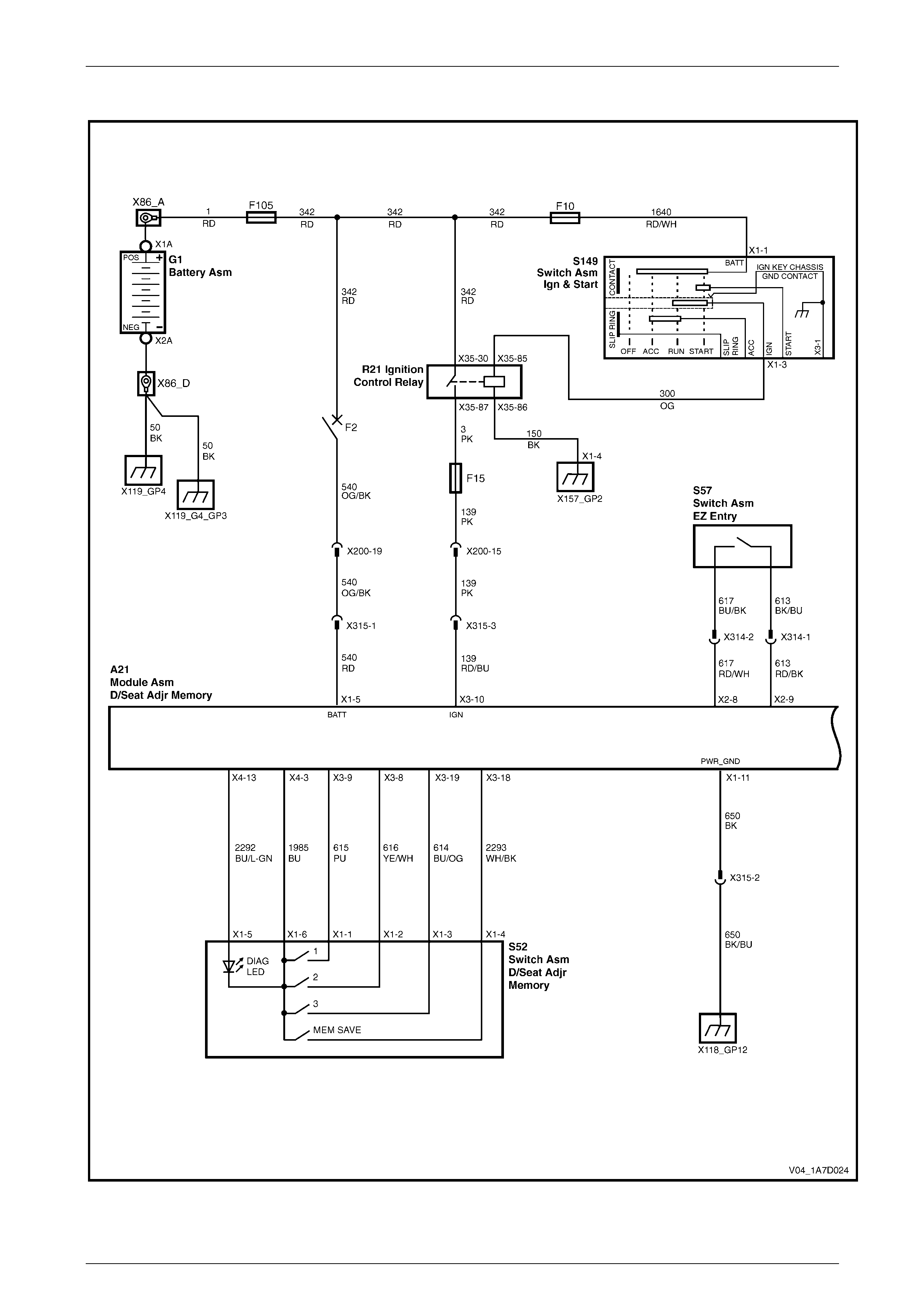
Seat Assemblies Page 1A7A–346
Page 1A7A–346
Wiring Diagram – Driver's Seat, Memory, RHD
Figure 1A7A – 179
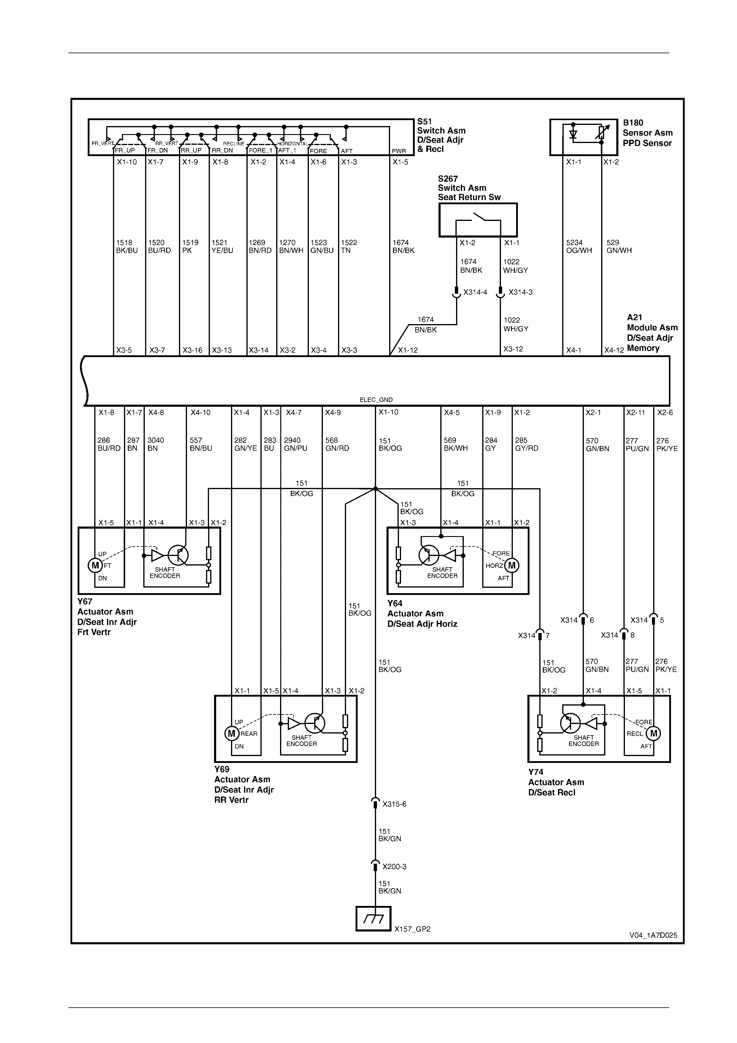
Seat Assemblies Page 1A7A–347
Page 1A7A–347
Figure 1A7A – 180
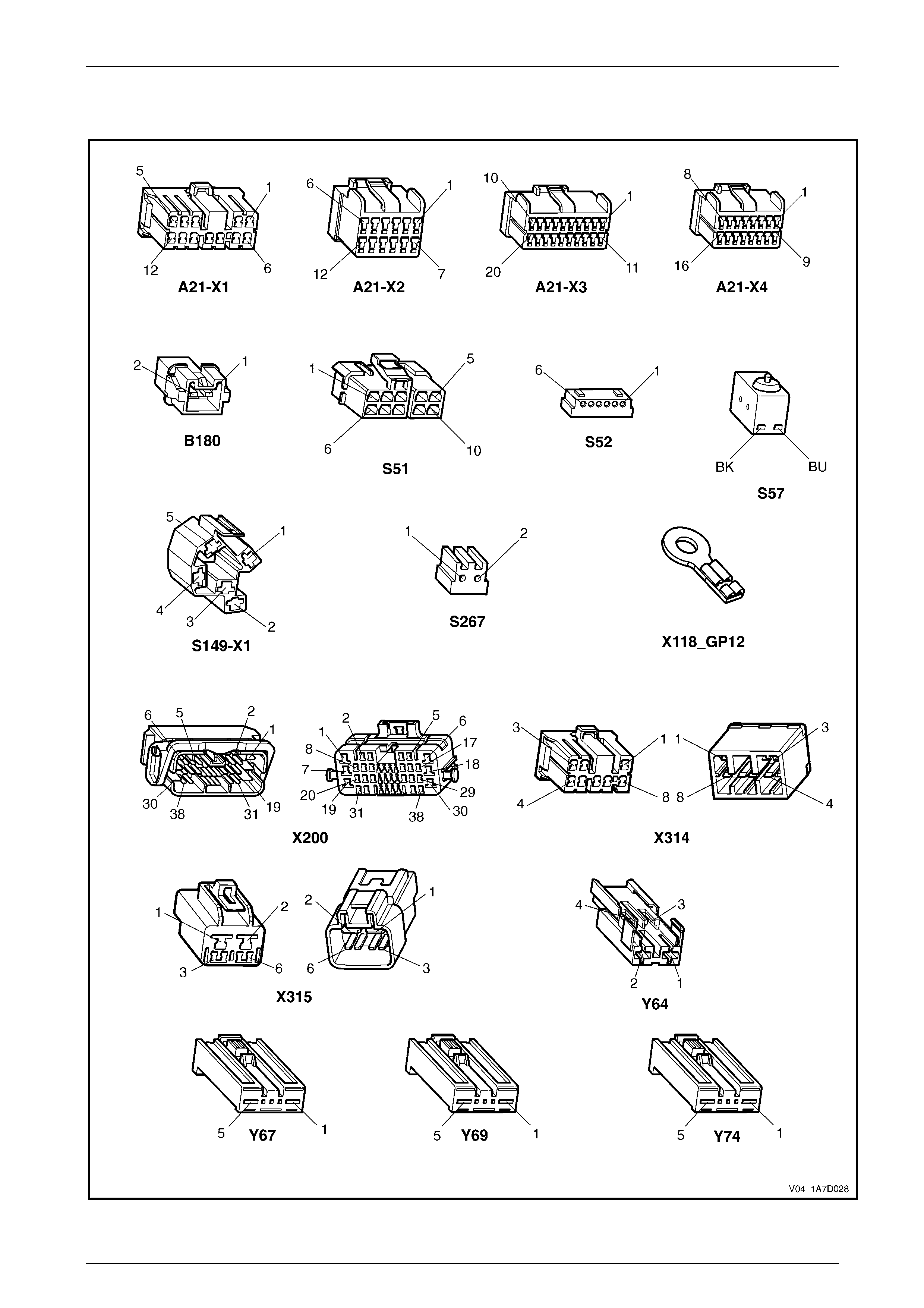
Seat Assemblies Page 1A7A–348
Page 1A7A–348
Connector Chart – Driver's Seat, Memory, RHD
Figure 1A7A – 181

Seat Assemblies Page 1A7A–349
Page 1A7A–349
None of the Driver’s Seat Adjustment Switch Functions Operate
Introduction
This test is used to aid in diagnosing the driver’s seat adjustment switch when none of the switch functions operate. The
test diagnoses the driver’s seat adjustment switch and associated power and ground circuits.
Circuit Description
The seat adjustment switch provides manual control for the driver's seat. It is connected by a harness to the seat
memory module, and the seat front lift and seat rear lift motors.
Refer to Wiring Diagram – Driver's Seat, Memory, RHD and Connector Chart – Driver's Seat, Memory, RHD in this
Section to aid in diagnosing the seat memory modul e and associated components.
Test Description
The following numbers refer to the step numbers in the diagnostic table:
1 Checks if all of the passenger seat functions work. If none of them work, the fault is not isolated to the driver’s seat
only.
2 Checks if there is battery power at connector X315 pin 1. Isolates if there is a fault in circuit 540.
3 Checks if all the connectors required for the seat to operate effectively are in place a nd positively connected.
4 Checks if there is battery power at connector A21 – X1 pi n 5.
5 Checks if there is battery power at connector A21 – X1 pi n 12. Isolates if there is a fault with the seat memory
module.
6 Checks if there is battery power at connector S51 – X1 pin 5. Isolates if there is a fault in circuit 1674.
7 Checks if the driver’s seat adjustment switch is serviceable.
8 Checks if there is continuity between connector X315 pin 2 and ground poi nt X118 – GP1 2. Isolates if there is a
fault in circuit 650.
9 Checks if there is continuity between connectors A21 – X1 pin 11 and X315 pin 2. Isolates if there is a fault in
circuit 650.
10 Checks if there is continuity between connector X200 pin 3 and ground point X157 – GP2. Isolates if there is a fault
in circuit 151.
11 Checks if there is continuity between connectors X315 pin 6 and X200 pin 3. Isolates if there is a fault in circuit 151.
12 Checks if there is continuity between connectors A21 – X1 pin 10 and X315 pin 6. Isolates if there is a fault in
circuit 151.
Diagnostic Table Notes
1 For all wiring harness fault diagnoses, refer to 12P Wirin g Diagrams.
2 For wiring harness repairs, refer to 12P Wiring Diagrams.
3 Refer to 12O Fuses, Relays and Wiring Harnesses for harness routeing.
4 If the fault is deemed to be intermittent, refer to 12P Wiring Diagrams.

Seat Assemblies Page 1A7A–350
Page 1A7A–350
Diagnostic Table
Step Action Yes No
1 Are all of the passenger’s seat adjustment switch functions
inoperative? Refer to Neither
Seat Adjustment
Switch Functions
Operate in 7.6
Electrical Diagnosis
– Eight-way Seat,
Memory Go to Step 2
2 Backprobe connector X315 pin 1 with a test lamp (refer to Note 1).
Does the test lamp illuminate?
Go to Step 3
Repair or replace
circuit 540 between
connectors
X200 pin 19 an d
X315 pin 1 (refer to
Note 2)
3 Are the following connectors secure (refer to Note 3)?
• A21
• S51
• X314
• X315
• Y64
• Y67
• Y69
• Y74 Go to Step 4
Ensure the
connectors are
secure
4 Backprobe connector A21 – X1 pin 5 with a test lamp (refer to
Note 1).
Does the test lamp illuminate?
Go to Step 5
Repair or replace
circuit 540 between
connectors
A21 – X1 pin 5 and
X315 pin 1 (refer to
Note 2)
5 Backprobe connector A21 – X1 pin 12 with a test lamp (refer to
Note 1).
Does the test lamp illuminate?
Go to Step 6
Replace the
driver’s seat
memory module,
refer to 6.14 Seat
Cable Tray and
Memory Module
6 Backprobe connector S51 – X1 pin 5 with a test lamp (refer to
Note 1).
Does the test lamp illuminate? Go to Step 7
Repair or replace
circuit 1674 (refer
to Note 2)
7 1 Remove the driver’s seat adjustment switch from the seat, refer
to 6.4 Front Seat Outer Side Cover Assembly.
2 Test the driver’s seat adjustment switch, refer to 3.6 Eight-way
Seat Adjustment Switch Test.
Is the driver’s seat adjustment switch serviceable? Go to Step 8
Replace the
driver’s seat
adjustment switch,
refer to 6.4 Front
Seat Outer Side
Cover Assembly
8 1 Remove connector A21 – X1 from the seat memory module
(refer to Note 3).
2 Using a multimeter set to measure resistance, probe between
connector X315 pin 2 and ground point X118 – GP12.
Does the multimeter indicate continuity? Go to Step 9
Repair or replace
circuit 650 between
connector
X315 pin 2 and
ground point
X118 – GP12 (refer
to Note 2)

Seat Assemblies Page 1A7A–351
Page 1A7A–351
Step Action Yes No
9 Using a multimeter set to measure resistance, probe between
connectors A21 – X1 pin 11 and X315 pin 2.
Does the multimeter indicate continuity?
Go to Step 10
Repair or replace
circuit 650 between
connectors
A21 – X1 pin 11
and X315 pin 2
(refer to Note 2)
10 Using a multimeter set to measure resistance , probe between
connectors X200 pin 3 and X157 – X1 pin 1.
Does the multimeter indicate continuity?
Go to Step 11
Repair or replace
circuit 151 between
connectors
X200 pin 3 and
X157 – X1 pin 1
(refer to Note 2)
11 Using a multimeter set to measure resistance , probe between
connectors X315 pin 6 and X200 p in 3.
Does the multimeter indicate continuity?
Go to Step 12
Repair or replace
circuit 151 between
connectors
X315 pin 6 and
X200 pin 3 (refer to
Note 2)
12 Using a multimeter set to measure resistance , probe between
connectors A21 – X1 pin 10 and X315 pin 6.
Does the multimeter indicate continuity?
Replace the driver's
seat memory
module, refer to
6.14 Seat Cable
Tray and Memory
Module
Repair or replace
circuit 151 between
connectors
A21 – X1 pin 10
and X315 pin 6
(refer to Note 2)
When all diagno sis and repairs are completed, check the system for correct operation.

Seat Assemblies Page 1A7A–352
Page 1A7A–352
Front/Rear of the Driver’s Seat Does Not Raise and/or Lower
Introduction
This test is used to aid in diagnosing the front and/or the rear of the driver’s seat not raising and/or lowering. T he test
diagnoses the seat adjustmen t switch and the motor circuits.
Circuit Description
The seat front lift and seat rear lift motors are controlled by the seat memory module, which provides power and ground
for the motors. The polarity of the motors are alternated to change the direction of the motors.
Refer to Wiring Diagram – Driver's Seat, Memory, RHD and Connector Chart – Driver's Seat, Memory, RHD in this
Section to aid in diagnosing the seat memory modul e and associated components.
Test Description
The following numbers refer to the step numbers in the diagnostic table:
1 Checks if the driver’s seat adjustment switch operates the seat in any direction. Isolates if the power and ground
circuits are at fault.
2 Checks if all the connectors required for the seat to operate effectively are in place a nd positively connected.
3 Checks if the driver’s seat adjustment switch is serviceable.
4 Confirms whether the rear of the seat raises or lowers. Isolates if the seat rear lift motor and circuit of the seat is the
fault.
5 Confirms whether the front of the seat raises or lo wers. Isolates if the seat front lift motor and circuit of the seat is
the fault.
6 Checks if there is battery power to the seat rear lift motor at connector Y69 – X1 pin 1. Isolates if there is a fault
between the switch and con nector Y69 – X1 pin 1 .
7 Checks if there is continuity between connectors S51 – X1 pin 9 and A21 – X1 pin 4. Isolates whether there is a
fault between the switch and connector A21 – X1 pin 4 or in circuit 282.
8 Checks if there is continuity between connectors S51 – X1 pin 9 and A21 – X3 pin 16. Isolates whether there is a
fault between the switch and connector A21 – X3 pin 16 or the seat memory module is at fault.
9 Checks if there is battery power to the seat rear lift motor at connector Y69 – X1 pin 5. Isolates whether there is a
fault between the switch and connector Y69 – X1 pin 5 or the motor is at fault.
10 Checks if there is continuity between connectors S51 – X1 pin 8 and A21 – X1 pin 3. Isolates whether there is a
fault between the switch and connector A21 – X1 pin 3 or in circuit 283.
11 Checks if there is continuity between connectors S51 – X1 pin 8 and A21 – X3 pin 13. Isolates whether there is a
fault between the switch and connector A21 – X3 pin 13 or the seat memory module is at fault.
12 Checks if there is battery power to the seat front lift motor at connector Y67 – X1 pin 5. Isolates if there is a fault
between the switch and con nector Y67 – X1 pin 5.
13 Checks if there is continuity between connectors S51 – X1 pin 10 and A21 – X1 pin 8. Isolates whether there is a
fault between the switch and connector A21 – X1 pin 8 or in circuit 286.
14 Checks if there is continuity between connectors S51 – X1 pin 10 and A21 – X3 pin 5. Isolates whether there is a
fault between the switch and connector A21 – X3 pin 5 or the seat memor y module is at fault.
15 Checks if there is battery power to the seat front lift motor at connector Y67 – X1 pin 1. Isolates whether there is a
fault between the switch and connector Y67 – X1 pin 1 or the motor is at fault.
16 Checks if there is continuity between connectors S51 – X1 pin 7 and A21 – X1 pin 7. Isolates whether there is a
fault between the switch and connector A21 – X1 pin 7 or in circuit 287.
17 Checks if there is continuity between connectors S51 – X1 pin 7 and A21 – X3 pin 7. Isolates whether there is a
fault between the switch and connector A21 – X3 pin 7 or the seat memor y module is at fault.

Seat Assemblies Page 1A7A–353
Page 1A7A–353
Diagnostic Table Notes
1 For all wiring harness fault diagnoses, refer to 12P Wirin g Diagrams.
2 For wiring harness repairs, refer to 12P Wiring Diagrams.
3 Refer to 12O Fuses, Relays and Wiring Harnesses for harness routeing.
4 If the fault is deemed to be intermittent, refer to 12P Wiring Diagrams.
Diagnostic Table
Step Action Yes No
1 Does the driver’s seat adjustment switch operate the seat correctly in
any of the eight directions?
Go to Step 2
Refer to None of
the Driver’s Seat
Adjustment Switch
Functions Operate
in this Section
2 Are the following connectors secure (refer to Note 3)?
• A21
• S51
• Y67
• Y69 Go to Step 3
Ensure the
connectors are
secure
3 1 Remove the driver’s seat adjustment switch from the seat, refer
to 6.4 Front Seat Outer Side Cover Assembly.
2 Test the driver’s seat adjustment switch, refer to 3.6 Eight-way
Seat Adjustment Switch Test.
Is the driver’s seat adjustment switch serviceable? Go to Step 4
Replace the
driver’s seat
adjustment switch,
refer to 6.4 Front
Seat Outer Side
Cover Assembly
4 Operate the driver’s seat adjustment switch to raise or lower the rear
of the seat.
Does the rear of the seat raise and lo wer? Go to Step 5 Go to Step 6
5 Operate the driver’s seat adjustment switch to raise or lower the front
of the seat.
Does the front of the seat raise and lower? System serviceable Go to Step 12
6 1 Backprobe connector Y69 – X1 pin 1 with a test lamp (refer to
Note 1).
2 Operate the driver’s seat adjustment switch to raise the rear of
the seat.
Does the test lamp illuminate? Go to Step 9 Go to Step 7
7 1 Backprobe connector A21 – X1 pin 4 with a test lamp (refer to
Note 1).
2 Operate the driver’s seat adjustment switch to raise the rear of
the seat.
Does the test lamp illuminate?
Repair or replace
circuit 282 (refer to
Note 2) Go to Step 8
8 1 Backprobe connector A21 – X3 pin 16 with a test lamp (refer to
Note 1).
2 Operate the driver’s seat adjustment switch to raise the rear of
the seat.
Does the test lamp illuminate?
Replace the driver's
seat memory
module, refer to
6.14 Seat Cable
Tray and Memory
Module
Repair or replace
circuit 1519 (refer
to Note 2)

Seat Assemblies Page 1A7A–354
Page 1A7A–354
Step Action Yes No
9 1 Backprobe connector Y69 – X1 pin 5 with a test lamp (refer to
Note 1).
2 Operate the driver’s seat adjustment switch to lower the rear of
the seat.
Does the test lamp illuminate?
Replace the seat
rear lift motor, refer
to 6.18 Front Seat
Lift Motor
Assemblies Go to Step 10
10 1 Backprobe connector A21 – X1 pin 3 with a test lamp (refer to
Note 1).
2 Operate the driver’s seat adjustment switch to lower the rear of
the seat.
Does the test lamp illuminate?
Repair or replace
circuit 283 (refer to
Note 2) Go to Step 11
11 1 Backprobe connector A21 – X3 pin 13 with a test lamp (refer to
Note 1).
2 Operate the driver’s seat adjustment switch to lower the rear of
the seat.
Does the test lamp illuminate?
Replace the driver's
seat memory
module, refer to
6.14 Seat Cable
Tray and Memory
Module
Repair or replace
circuit 1521 (refer
to Note 2)
12 1 Backprobe connector Y67 – X1 pin 5 with a test lamp (refer to
Note 1).
2 Operate the driver’s seat adjustment switch to raise the front of
the seat.
Does the test lamp illuminate? Go to Step 15 Go to Step 13
13 1 Backprobe connector A21 – X1 pin 8 with a test lamp (refer to
Note 1).
2 Operate the driver’s seat adjustment switch to raise the front of
the seat.
Does the test lamp illuminate?
Repair or replace
circuit 286 (refer to
Note 2) Go to Step 14
14 1 Backprobe connector A21 – X3 pin 5 with a test lamp (refer to
Note 1).
2 Operate the driver’s seat adjustment switch to raise the front of
the seat.
Does the test lamp illuminate?
Replace the driver's
seat memory
module, refer to
6.14 Seat Cable
Tray and Memory
Module
Repair or replace
circuit 1518 (refer
to Note 2)
15 1 Backprobe connector Y67 – X1 pin 2 with a test lamp (refer to
Note 1).
2 Operate the driver’s seat adjustment switch to lower the front of
the seat.
Does the test lamp illuminate?
Replace the seat
front lift motor, refer
to 6.18 Front Seat
Lift Motor
Assemblies Go to Step 16
16 1 Backprobe connector A21 – X1 pin 7 with a test lamp (refer to
Note 1).
2 Operate the driver’s seat adjustment switch to lower the front of
the seat.
Does the test lamp illuminate?
Repair or replace
circuit 287 (refer to
Note 2) Go to Step 17
17 1 Backprobe connector A21 – X3 pin 7 with a test lamp (refer to
Note 1).
2 Operate the driver’s seat adjustment switch to lower the front of
the seat.
Does the test lamp illuminate?
Replace the driver's
seat memory
module, refer to
6.14 Seat Cable
Tray and Memory
Module
Repair or replace
circuit 1520 (refer
to Note 2)
When all diagno sis and repairs are completed, check the system for correct operation.

Seat Assemblies Page 1A7A–355
Page 1A7A–355
Driver’s Seat Fore/Aft Function is Inoperative or Not Smooth
Introduction
This test is used to aid in diagnosi ng the fore/aft movement function of the driver’s seat being inoperative or the action of
the seat through the range of movement is not smooth. The test diagnoses the seat adjustment switch and the motor
circuits.
Circuit Description
The seat fore/aft movement motor is controlled by the seat memory module which provides power and ground for the
motor. The polarity of the motor is alternated to change the direction of the motor.
Refer to Wiring Diagram – Driver's Seat, Memory, RHD and Connector Chart – Driver's Seat, Memory, RHD in this
Section to aid in diagnosing the seat memory modul e and associated components.
Test Description
The following numbers refer to the step numbers in the diagnostic table:
1 Checks if the driver’s seat adjustment switch operates the seat in any direct ion. Isolates if there is battery power to
the switch assembly.
2 Checks if there are any items obstructing the guide rails, which may stop or hinder the seat movement.
3 Checks if the guide rails and drive shafts have adequate lubricant applied t o provide a smooth operation of the
seat.
4 Checks if the guide rails or drive shafts have been damaged. An y binding between the moving parts will result in
poor operation of the fore and aft movement.
5 Checks if all the connectors required for the seat to operate effectively are in place a nd positively connected.
6 Checks if the driver’s seat adjustment switch is serviceable.
7 Checks if there is battery power to the seat fore/aft movement motor at connector Y64 – X1 pin 3. Isolates if there
is a fault between the switch and connector Y64 – X1 pin 3.
8 Checks if there is continuity between connectors S51 – X1 pin 6 and A21 – X1 pin 2. Isolates whether there is a
fault between the switch and connector A21 – X1 pin 2 or in circuit 285.
9 Checks if there is continuity between connectors S51 – X1 pin 6 and A21 – X3 pin 4. Isolates whether there is a
fault between the switch and connector A21 – X3 pin 4 or the seat memor y module is at fault.
10 Checks if there is battery power to the seat fore/aft movement motor at connector Y64 – X1 pin 1. Isolates whether
there is a fault between the switc h an d connector Y64 – X1 pin 1 or the motor is at fault.
11 Checks if there is continuity between connectors S51 – X1 pin 3 and A21 – X1 pin 9. Isolates whether there is a
fault between the switch and connector A21 – X1 pin 9 or in circuit 284.
12 Checks if there is continuity between connectors S51 – X1 pin 3 and A21 – X3 pin 3. Isolates whether there is a
fault between the switch and connector A21 – X3 pin 3 or the seat memor y module is at fault.
Diagnostic Table Notes
1 For all wiring harness fault diagnoses, refer to 12P Wirin g Diagrams.
2 For wiring harness repairs, refer to 12P Wiring Diagrams.
3 Refer to 12O Fuses, Relays and Wiring Harnesses for harness routeing.
4 If the fault is deemed to be intermittent, refer to 12P Wiring Diagrams.

Seat Assemblies Page 1A7A–356
Page 1A7A–356
Diagnostic Table
Step Action Yes No
1 Does the driver’s seat adjustment switch operate the seat correctly in
any of the eight directions?
Go to Step 2
Refer to None of
the Driver’s Seat
Adjustment Switch
Functions Operate
in this Section
2 Are the guide rails free from obstructions? Go to Step 3 Remove the
obstructing item
3 Are the guide rails and drive shafts adequate ly lubricated?
Go to Step 4
Apply a small
amount of grease
type NLGI No. 1
Lithium Grease
(with 9% Zinc
Oxide)
4 Do the guide rails or drive shafts bind at any point of travel during the
fore and aft movement of the seat? Replace the track
and height adjust
assembly, refer to
6.15 Track and
Height Adjust
Assembly Go to Step 5
5 Are the following connectors secure (refer to Note 3)?
• A21
• S51
• Y64 Go to Step 6
Ensure the
connectors are
secure
6 1 Remove the driver’s seat adjustment switch from the seat, refer
to 6.4 Front Seat Outer Side Cover Assembly.
2 Test the driver’s seat adjustment switch, refer to 3.6 Eight-way
Seat Adjustment Switch Test.
Is the driver’s seat adjustment switch serviceable? Go to Step 7
Replace the
driver’s seat
adjustment switch,
refer to 6.4 Front
Seat Outer Side
Cover Assembly
7 1 Backprobe connector Y64 – X1 pin 2 with a test lamp (refer to
Note 1).
2 Operate the driver’s seat adjustment switch to move the seat
forward.
Does the test lamp illuminate? Go to Step 10 Go to Step 8
8 1 Backprobe connector A21 – X1 pin 2 with a test lamp (refer to
Note 1).
2 Operate the driver’s seat adjustment switch to move the seat
forward.
Does the test lamp illuminate?
Repair or replace
circuit 285 (refer to
Note 2) Go to Step 9

Seat Assemblies Page 1A7A–357
Page 1A7A–357
Step Action Yes No
9 1 Backprobe connector A21 – X3 pin 4 with a test lamp (refer to
Note 1).
2 Operate the driver’s seat adjustment switch to move the seat
forward.
Does the test lamp illuminate?
Replace the driver's
seat memory
module, refer to
6.14 Seat Cable
Tray and Memory
Module
Repair or replace
circuit 1523 (refer
to Note 2)
10 1 Backprobe connector Y64 – X1 pin 1 with a test lamp (refer to
Note 1).
2 Operate the driver’s seat adjustment switch to move the seat
aft.
Does the test lamp illuminate?
Replace the seat
fore/aft movement
motor, refer to 6.19
Front Seat Fore/Aft
Movement Motor
Assembly Go to Step 11
11. 1 Backprobe connector A21 – X1 pin 9 with a test lamp (refer to
Note 1).
2 Operate the driver’s seat adjustment switch to move the seat
aft.
Does the test lamp illuminate?
Repair or replace
circuit 284 (refer to
Note 2) Go to Step 12
12. 1 Backprobe connector A21 – X3 pin 3 with a test lamp (refer to
Note 1).
2 Operate the driver’s seat adjustment switch to move the seat
aft.
Does the test lamp illuminate?
Replace the driver's
seat memory
module, refer to
6.14 Seat Cable
Tray and Memory
Module
Repair or replace
circuit 1522 (refer
to Note 2)
When all diagno sis and repairs are completed, check the system for correct operation.

Seat Assemblies Page 1A7A–358
Page 1A7A–358
Driver’s Seat Recline Forward and/or Aft Function is Inoperative
Introduction
This test is used to aid in diagnosing the recline function of the driver’s seat being inoperative. The test diagnoses the
seat adjustment switch and the motor circuits.
Circuit Description
The front seat-back recline motor is controlle d by the seat memory module which provides power and ground for the
motor. The polarity of the motor is alternated to change the direction of the motor.
Refer to Wiring Diagram – Driver's Seat, Memory, RHD and Connector Chart – Driver's Seat, Memory, RHD in this
Section to aid in diagnosing the seat memory modul e and associated components.
Test Description
The following numbers refer to the step numbers in the diagnostic table:
1 Checks if the driver’s seat adjustment switch operates the seat in any direct ion. Isolates if there is battery power to
the switch assembly.
2 Checks if all the connectors required for the seat to operate effectively are in place a nd positively connected.
3 Checks if the driver’s seat adjustment switch is serviceable.
4 Checks if there is battery power to the seat recline motor at connector Y74 – X1 pin 1. Isolates if there is a fault
between the switch and con nector Y74 – X1 pin 1.
5 Checks if there is continuity between connectors S51 – X1 pin 2 and X314 pin 5. Isolates whether there is a fault
between the switch and connector X314 pin 5 or in circuit 276.
6 Checks if there is continuity between connectors S51 – X1 pin 2 and A21 – X2 pin 6. Isolates whether there is a
fault between the switch and connector A21 – X2 pin 6 or in circuit 276.
7 Checks if there is continuity between connectors S51 – X1 pin 2 and A21 – X3 pin 14. Isolates whether there is a
fault between the switch and connector A21 – X3 pin 14 or the seat memory module is at fault.
8 Checks if there is battery power to the seat recline motor at connector Y74 – X1 pin 5. Isolates whether there is a
fault between the switch and connector Y74 – X1 pin 5 or the motor is at fault.
9 Checks if there is continuity between connectors S51 – X1 pin 4 and X314 pin 8. Isolates whether there is a fault
between the switch and connector X314 pin 8 or in circuit 277.
10 Checks if there is continuity between connectors S51 – X1 pin 4 and A21 – X2 pin 11. Isolates whether there is a
fault between the switch and connector A21 – X2 pin 11 or in circuit 277.
11 Checks if there is continuity between connectors S51 – X1 pin 4 and A21 – X3 pin 2. Isolates whether there is a
fault between the switch and connector A21 – X3 pin 2 or the seat memor y module is at fault.
Diagnostic Table Notes
1 For all wiring harness fault diagnoses, refer to 12P Wirin g Diagrams.
2 For wiring harness repairs, refer to 12P Wiring Diagrams.
3 Refer to 12O Fuses, Relays and Wiring Harnesses for harness routeing.
4 If the fault is deemed to be intermittent, refer to 12P Wiring Diagrams.

Seat Assemblies Page 1A7A–359
Page 1A7A–359
Diagnostic Table
Step Action Yes No
1 Does the driver’s seat adjustment switch operate the seat correctly in
any of the eight directions?
Go to Step 2
Refer to None of
the Driver’s Seat
Adjustment Switch
Functions Operate
in this Section
2 Are the following connectors secure (refer to Note 3)?
• A21
• S51
• X314
• Y74 Go to Step 3
Ensure the
connectors are
secure
3 1 Remove the driver’s seat adjustment switch from the seat, refer
to 6.4 Front Seat Outer Side Cover Assembly.
2 Test the driver’s seat adjustment switch, refer to 3.6 Eight-way
Seat Adjustment Switch Test.
Is the driver’s seat adjustment switch serviceable? Go to Step 4
Replace the
driver’s seat
adjustment switch,
refer to 6.4 Front
Seat Outer Side
Cover Assembly
4 1 Backprobe connector Y74 – X1 pin 1 with a test lamp (refer to
Note 1).
2 Operate the driver’s seat adjustment switch to move the
seat-back forward.
Does the test lamp illuminate? Go to Step 8 Go to Step 5
5 1 Backprobe connector X314 pin 5 with a test lamp (refer to
Note 1).
2 Operate the driver’s seat adjustment switch to move the
seat-back forward.
Does the test lamp illuminate?
Repair or replace
circuit 276 between
connectors
X314 pin 5 and
Y74 – X1 pin 1
(refer to Note 2) Go to Step 6
6 1 Backprobe connector A21 – X2 pin 6 with a test lamp (refer to
Note 1).
2 Operate the driver’s seat adjustment switch to move the
seat-back forward.
Does the test lamp illuminate?
Repair or replace
circuit 276 between
connectors
A21 – X2 pin 6 and
X314 pin 5 (refer to
Note 2) Go to Step 7
7 1 Backprobe connector A21 – X3 pin 14 with a test lamp (refer to
Note 1).
2 Operate the driver’s seat adjustment switch to move the
seat-back forward.
Does the test lamp illuminate?
Replace the driver's
seat memory
module, refer to
6.14 Seat Cable
Tray and Memory
Module
Repair or replace
circuit 1269 (refer
to Note 2)

Seat Assemblies Page 1A7A–360
Page 1A7A–360
Step Action Yes No
8 1 Backprobe connector Y74 – X1 pin 5 with a test lamp (refer to
Note 1).
2 Operate the driver’s seat adjustment switch to move the
seat-back aft.
Does the test lamp illuminate?
Replace the front
seat-back recline
motor, refer to 6.20
Front Seat-back
Recline Motor
Assembly Go to Step 9
9 1 Backprobe connector X314 pin 8 with a test lamp (refer to
Note 1).
2 Operate the driver’s seat adjustment switch to move the
seat-back aft.
Does the test lamp illuminate?
Repair or replace
circuit 277 between
connectors
X314 pin 8 and
Y74 – X1 pin 5
(refer to Note 2) Go to Step 10
10 1 Backprobe connector A21 – X2 pin 11 with a test lamp (refer to
Note 1).
2 Operate the driver’s seat adjustment switch to move the
seat-back aft.
Does the test lamp illuminate?
Repair or replace
circuit 277 between
connectors
A21 – X2 pin 11
and X314 pin 8
(refer to Note 2) Go to Step 11
11 1 Backprobe connector A21 – X3 pin 2 with a test lamp (refer to
Note 1).
2 Operate the driver’s seat adjustment switch to move the
seat-back aft.
Does the test lamp illuminate?
Replace the seat
memory module,
refer to 6.14 Seat
Cable Tray and
Memory Module
Repair or replace
circuit 1270 (refer
to Note 2)
When all diagno sis and repairs are completed, check the system for correct operation.

Seat Assemblies Page 1A7A–361
Page 1A7A–361
Driver's Seat EZ-entry Switch Function is Inoperative
Introduction
The EZ-entry function is designed so that when the seat-back is released with the EZ-entry lever, the seat will move to its
fully forward position using the seat fore/aft movement motor. Once the seat has moved to its fully for ward position,
power to the seat fore/aft movement motor will cease. A switch attached to the seat-back activates the seat fore/aft
movement motor when the recline of the seat-back is moved forward after being released using the EZ-entry lever. This
test is used to aid in diagnosing the EZ-entry function of the driver's seat being inoperative. T he test diagnoses the EZ-
entry switch and associated circuits.
Circuit Description
The EZ-entry switch is connected to the seat memory module by a harness. The EZ-entry switch is a normally open type
switch.
Refer to Wiring Diagram – Driver's Seat, Memory, RHD and Connector Chart – Driver's Seat, Memory, RHD in this
Section to aid in diagnosing the seat EZ-entry switch and associated components.
Test Description
The following numbers refer to the step numbers in the diagnostic table:
1 Checks if the seat fore/aft movement motor is serviceable.
2 Checks if there is battery power to connector A21 – X2 pi n 9. Isolates if the driver's seat memory module is at fault.
3 Checks if there is continuity between connector A21 – X2 pins 9 and 8. Isolates if there is a fault with the EZ-entry
switch and associated circuits.
4 Checks if there is continuity between connectors A21 – X2 pin 9 and X314 pin 1. Isolates if there is a fault in circuit
613.
5 Checks if there is continuity between connectors A21 – X2 pin 9 and X314 pin 2. Isolates whether the EZ-entry
switch or circuit 617 is at fault.
Diagnostic Table Notes
1 For all wiring harness fault diagnoses, refer to 12P Wirin g Diagrams.
2 For wiring harness repairs, refer to 12P Wiring Diagrams.
3 Refer to 12O Fuses, Relays and Wiring Harnesses for harness routeing.
4 If the fault is deemed to be intermittent, refer to 12P Wiring Diagrams.

Seat Assemblies Page 1A7A–362
Page 1A7A–362
Diagnostic Table
Step Action Yes No
1 Does the seat move in the fore/aft direction when operated by the
driver's seat adjustment switch?
Go to Step 2
Refer to Driver’s
Seat Fore/Aft
Function is
Inoperative or Not
Smooth in this
Section
2 Backprobe connector A21 – X2 pin 9 with a test lamp (refer to
Note 1).
Does the test lamp illuminate?
Go to Step 3
Replace the driver's
seat memory
module, refer to
6.14 Seat Cable
Tray and Memory
Module
3 1 Release the seat-back using the EZ-entry lever.
2 Backprobe connector A21 – X2 pin 8 with a test lamp (refer to
Note 1).
Does the test lamp illuminate?
Replace the seat
memory module,
refer to 6.14 Seat
Cable Tray and
Memory Module Go to Step 4
4 Backprobe connector X314 pin 1 with a test lamp (refer to Note 1).
Does the test lamp illuminate?
Go to Step 5
Repair or replace
circuit 613 between
connectors
A21 – X2 pin 9 and
X314 pin 1 (refer to
Note 2)
5 Backprobe connector X314 pin 2 with a test lamp (refer to Note 1).
Does the test lamp illuminate?
Repair or replace
circuit 617 between
connectors
A21 – X2 pin 8 and
X314 pin 2 (refer to
Note 2)
Replace the driver's
seat EZ-entry
switch, refer to 6.10
EZ-entry Switch
and Release Cable
Assembly
When all diagno sis and repairs are completed, check the system for correct operation.

Seat Assemblies Page 1A7A–363
Page 1A7A–363
Driver's Seat Return Switch Function is Inoperative
Introduction
The seat return switch is located on the escu tcheon at the top of the seat-back. The switch function is to move the seat in
an aft direction after the EZ-entry function has been used and the recli ne of the seat has been placed upright. With the
seat return switch continuously pressed, the seat will move to its fully aft position, pausing for 2 secon ds at the seat
position where the EZ-entr y lever was operated. The test diagnoses the seat return s witch and associated circuits.
Circuit Description
The driver’s seat return s witch is connected to the seat memory module by a harness. The driver’s seat return switch is a
normally open type switch.
Refer to Wiring Diagram – Driver's Seat, Memory, RHD and Connector Chart – Driver's Seat, Memory, RHD in this
Section to aid in diagnosing the driver’s seat return switch and associated components.
Test Description
The following numbers refer to the step numbers in the diagnostic table:
1 Checks if the seat fore/aft movement motor is serviceable.
2 Checks if the seat will move to its fully forward position when the seat-back is released using the EZ-entry lever.
Isolates if the EZ-entry switch function is serviceable.
3 Checks if the seat will move aft when the seat-back is in the upright position and the seat return switch is pressed.
Isolates if the seat return switch is serviceable.
4 Checks if the seat stops for 2 seconds at the position that the EZ-entry lever was released.
5 Tests the hall-effect sensor and associated circuits. Isolates if the hall-effect sensor or the seat memory modul e is
faulty.
6 Checks if the seat return switch and circuit operates correctly. Isolates whether the seat return switch and circuit or
the seat memory module is faulty.
7 Checks if the seat return switch is serviceable.
8 Checks if there is battery power to connector X314 pin 4. Isolates if there is a fault in circuit 1674.
9 Checks if there is battery power to connector S267 – X1 pin 2. Isolates if there is a fault in circuit 1674 between
connector S267 – X1 pin 2 and X314 pin 4.
10 Checks if there is battery power to connector X314 pin 3 when the seat return switch is pressed. Isolates if there is
a fault in circuit 1022.
Diagnostic Table Notes
1 For all wiring harness fault diagnoses, refer to 12P Wirin g Diagrams.
2 For wiring harness repairs, refer to 12P Wiring Diagrams.
3 Refer to 12O Fuses, Relays and Wiring Harnesses for harness routeing.
4 If the fault is deemed to be intermittent, refer to 12P Wiring Diagrams.

Seat Assemblies Page 1A7A–364
Page 1A7A–364
Diagnostic Table
Step Action Yes No
1 Does the seat move in the fore/aft direction when operated by the
driver's seat adjustment switch?
Go to Step 2
Refer to Driver’s
Seat Fore/Aft
Function is
Inoperative or Not
Smooth in this
Section
2 1 Move the seat forward from the rear most position and note its
position on the track.
2 Release the seat-back using the EZ-entry lever.
Does the seat move forward? Go to Step 3
Refer to Driver's
Seat EZ-entry
Switch Function is
Inoperative in this
Section.
3 1 Move the seat-back to the upright position.
2 Press and hold the seat return switch.
Does the seat move aft? Go to Step 4 Go to Step 6
4 Does the seat stop for 2 seconds at the position from where it was
unlatched and then continue to the most aft position of the track? System serviceable Go to Step 5
5 1 Test the seat fore/aft movement motor hall-effect sensor, refer
to Driver's Seat Fore/Aft Movement Motor Hall-effect Sensor
Test in this Section.
Is the hall-effect sensor and circuit serviceable? Replace the seat
memory module,
refer to 6.14 Seat
Cable Tray and
Memory Module
Repair or repl ace
the driver’s seat
fore/aft movement
motor hall-effect
sensor or circuit,
refer to 6.21 Drive
Motor Hall-effect
Sensors
6 1 Backprobe connector A21 – X3 pin 12 with a test lamp (refer to
Note 1).
2 Press the seat return sw itc h.
Does the test lamp illuminate?
Replace the seat
memory module,
refer to 6.14 Seat
Cable Tray and
Memory Module Go to Step 7
7 1 Disconnect connector S267 – X1 from the seat return switch.
2 Using a multimeter set to measure resistance, probe across
seat return switch S267 pins 1 and 2:
3 With the seat return switch in the neutral position (not pressed)
the multimeter should indicate no continuity (open circuit).
4 With the seat return switch active (switch pressed) the
multimeter should indicate continuity (closed circuit).
Does the multimeter display as specified? Go to Step 8
Replace the driver's
seat return switch,
refer to 6.9 EZ-
entry Release
Lever and
Escutcheon
8 1 Connect connector S267 – X1 to the seat return switch.
2 Backprobe connector X314 pin 4 with a test lamp (refer to
Note 1).
Does the test lamp illuminate?
Go to Step 9
Repair or repl ace
circuit 1674
between
connectors
X314 pin 4 and
A21 – X1 pin 12
(refer to Note 2)
9 1 Backprobe connector S267 – X1 pin 2 with a test lamp (refer to
Note 1)
Does the test lamp illuminate?
Go to Step 10
Repair or repl ace
circuit 1674
between
connectors
X314 pin 4 and
S267 – X1 pin 2
(refer to Note 2)
10 1 Backprobe connector X314 pin 3 with a test lamp (refer to
Note 1).
2 Press the seat return sw itc h.
Does the test lamp illuminate?
Repair or repl ace
circuit 1022
between
connectors
X314 pin 3 and
A21 – X3 pin 12
(refer to Note 2)
Repair or repl ace
circuit 1022
between
connectors
X314 pin 3 and
S267 – X1 pin 1
(refer to Note 2)
When all diagnosis and repairs are completed, check the system for correct operation.

Seat Assemblies Page 1A7A–365
Page 1A7A–365
Driver's Seat Fore/Aft Movement Motor Hall-effect Sensor Test
Introduction
This test is used to aid in diagnosing the seat fore/aft movement motor hall-effect sensor and associated circuits.
Circuit Description
The seat fore/aft movement motor hall-effect sensor provides a pulse sign al to the seat memory module. This signal
represents the horizontal position of the seat.
Refer to Wiring Diagram – Driver's Seat, Memory, RHD and Connector Chart – Driver's Seat, Memory, RHD in this
Section to aid in diagnosing the seat memory modul e and associated components.
Test Description
The following numbers refer to the step numbers in the diagnostic table:
1 Checks the AC output from the hall-effect sensor during operation.
2 Checks if the ground circuit is serviceable.
3 Checks if there is continuity between connectors Y64 – X1 and A21 – X4. Isolates if the hall-effect senso r is faulty.
Diagnostic Table Notes
1 For all wiring harness fault diagnoses, refer to 12P Wirin g Diagrams.
2 For wiring harness repairs, refer to 12P Wiring Diagrams.
3 Refer to 12O Fuses, Relays and Wiring Harnesses for harness routeing.
4 If the fault is deemed to be intermittent, refer to 12P Wiring Diagrams.
5 The AC voltage displayed will depend on the battery voltage supplied to the seat. At 16 V DC supply, the AC
voltage produced by the hall-effect sensor will be approximately 6 V. At 9 V DC suppl y, the AC volta ge produced by
the hall-effect sensor will be appro ximately 0.6 V.
Diagnostic Table
Step Action Yes No
1 1 Using a multimeter set to measure AC voltage, probe across
connector Y64 – X1 pins 3 and 4 (refer to No te 1).
2 Operate the seat adjustment switch to move the seat fore or aft.
Does the multimeter display 0 . 6 – 6 V (refer to Note 5)?
Hall-effect sensor
and associated
wiring serviceable Go to Step 2
2 Using a multimeter set to measure resistance, probe between
connector Y64 – X1 pin 3 and a known ground (refer to Note 1).
Does the multimeter indicate continuity? Go to Step 3
Repair or replace
circuit 151 (refer to
Note 2)
3 1 Disconnect connector A21 – X4 from the driver’s seat memory
module.
2 Using a multimeter set to measure resistance, probe between
connectors A21 – X4 pin 5 and Y64 – X1 pin 4 (refer to Note 1).
Does the multimeter indicate continuity?
Replace the
hall-effect sensor,
refer to 6.21 Drive
Motor Hall-effect
Sensors
Repair or replace
circuit 569 (refer to
Note 2)
When all diagno sis and repairs are completed, check the system for correct operation.

Seat Assemblies Page 1A7A–366
Page 1A7A–366
Driver's Seat-back Recline Motor Hall-effect Sensor Test
Introduction
This test is used to aid in diagnosing the seat-back recline motor hall-effect sensor and associated circuits.
Circuit Description
The seat-back recline motor hall-effect sensor provides a pulse signal to the seat memory module. This signal represents
the recline position of the seat.
Refer to Wiring Diagram – Driver's Seat, Memory, RHD and Connector Chart – Driver's Seat, Memory, RHD in this
Section to aid in diagnosing the seat memory modul e and associated components.
Test Description
The following numbers refer to the step numbers in the diagnostic table:
1 Checks the AC output from the hall-effect sensor during operation.
2 Checks if the ground circuit is serviceable.
3-5 Checks if there is continu ity between connectors Y74 – X1 and A21 – X2. Isolates if the hall-effect sensor is fault y.
Diagnostic Table Notes
1 For all wiring harness fault diagnoses, refer to 12P Wirin g Diagrams.
2 For wiring harness repairs, refer to 12P Wiring Diagrams.
3 Refer to 12O Fuses, Relays and Wiring Harnesses for harness routeing.
4 If the fault is deemed to be intermittent, refer to 12P Wiring Diagrams.
5 The AC voltage displayed will depend on the battery voltage supplied to the seat. At 16 V DC supply, the AC
voltage produced by the hall-effect sensor will be approximately 6 V. At 9 V DC suppl y, the AC volta ge produced by
the hall-effect sensor will be appro ximately 0.6 V.
Diagnostic Table
Step Action Yes No
1 1 Using a multimeter set to measure AC voltage, probe across
connector Y74 – X1 pins 2 and 4 (refer to No te 1).
2 Operate the seat adjustment switch to move the seat-back fore
or aft.
Does the multimeter display 0 . 6 – 6 V (refer to Note 5)?
Hall-effect sensor
and associated
wiring serviceable Go to Step 2
2 Using a multimeter set to measure resistance, probe between
connector Y74 – X1 pin 2 and a known ground (refer to Note 1).
Does the multimeter indicate contin uity? Go to Step 4 Go to Step 3
3 Using a multimeter set to measure resistance, probe between
connector X314 pin 7 and a known ground (refer to Note 1).
Does the multimeter indicate continuity?
Repair or replace
circuit 151 between
connectors
X314 pin 7 and
Y74 – X1 pin 2
(refer to Note 2)
Repair or replace
circuit 151 between
connector
X314 pin 7 and
ground point (refer
to Note 2)
4 Using a multimeter set to measure resistance, probe between
connectors A21 – X2 pin 1 and Y74 – X1 pin 4 (refer to Note 1).
Does the multimeter indicate continuity?
Replace the
hall-effect sensor,
refer to 6.21 Drive
Motor Hall-effect
Sensors Go to Step 5
5 Using a multimeter set to measure resistance, probe between
connectors A21 – X2 pin 1 and X314 pin 6 (refer to Note 1).
Does the multimeter indicate continuity?
Repair or replace
circuit 151 between
connectors
A21 – X2 pin 1 and
X314 pin 6 (refer to
Note 2)
Repair or replace
circuit 151 between
connectors
Y74 – X1 pin 4 and
X314 pin 6 (refer to
Note 2)
When all diagno sis and repairs are completed, check the system for correct operation.

Seat Assemblies Page 1A7A–367
Page 1A7A–367
Driver's Seat Front Lift Motor Hall-effect Sensor Test
Introduction
This test is used to aid in diagnosing the seat front lift motor hall-effect sensor and associated circuits.
Circuit Description
The seat front lift motor hall-effect sensor provides a pulse signal to the seat memory module. This signal represents the
vertical position of the front of the seat.
Refer to Wiring Diagram – Driver's Seat, Memory, RHD and Connector Chart – Driver's Seat, Memory, RHD in this
Section to aid in diagnosing the seat memory modul e and associated components.
Test Description
The following numbers refer to the step numbers in the diagnostic table:
1 Checks the AC output from the hall-effect sensor during operation.
2 Checks if the ground circuit is serviceable.
3-4 Checks if there is continu ity between connectors Y67 – X1 and A21 – X4. Isolates if the hall-effect sensor is fault y.
Diagnostic Table Notes
1 For all wiring harness fault diagnoses, refer to 12P Wirin g Diagrams.
2 For wiring harness repairs, refer to 12P Wiring Diagrams.
3 Refer to 12O Fuses, Relays and Wiring Harnesses for harness routeing.
4 If the fault is deemed to be intermittent, refer to 12P Wiring Diagrams.
5 The AC voltage displayed will depend on the battery voltage supplied to the seat. At 16 V DC supply, the AC
voltage produced by the hall-effect sensor will be approximately 15 V. At 9 V DC supply, the AC voltage produced
by the hall-effect sensor will be approximatel y 8 V.
Diagnostic Table
Step Action Yes No
1 1 Using a multimeter set to measure AC voltage, probe across
connector Y67 – X1 pins 2 and 4 (refer to No te 1).
2 Operate the seat adjustment switch to raise or lower the front of
the seat.
Does the multimeter display 8 – 15 V (refer to Note 5)?
Hall-effect sensor
and associated
wiring serviceable Go to Step 2
2 Using a multimeter set to measure resistance, probe between
connector Y67 – X1 pin 2 and a known ground (refer to Note 1).
Does the multimeter indicate continuity? Go to Step 3
Repair or replace
circuit 151 (refer to
Note 2)
3 1 Disconnect connector A21 – X4 from the seat memory module.
2 Using a multimeter set to measure resistance, probe between
connectors A21 – X4 pin 8 and Y67 – X1 pin 4 (refer to Note 1).
Does the multimeter indicate continuity? Go to Step 4
Repair or replace
circuit 3040 (refer
to Note 2)
4 Using a multimeter set to measure resistance, probe between
connectors A21 – X4 pin 10 and Y67 – X1 pin 3 (refer to Note 1).
Does the multimeter indicate continuity?
Replace the
hall-effect sensor,
refer to 6.21 Drive
Motor Hall-effect
Sensors
Repair or replace
circuit 557 (refer to
Note 2)
When all diagno sis and repairs are completed, check the system for correct operation.

Seat Assemblies Page 1A7A–368
Page 1A7A–368
Driver's Seat Rear Lift Motor Hall-effect Sensor Test
Introduction
This test is used to aid in diagnosing the seat rear lift motor hall-effect sensor and associated circuits.
Circuit Description
The seat rear lift motor hall-effect sensor provides a pulse signal to the seat memory module. This signal represents the
vertical position of the rear of the seat.
Refer to Wiring Diagram – Driver's Seat, Memory, RHD and Connector Chart – Driver's Seat, Memory, RHD in this
Section to aid in diagnosing the seat memory modul e and associated components.
Test Description
The following numbers refer to the step numbers in the diagnostic table:
1 Checks the AC output from the hall-effect sensor during operation.
2 Checks if the ground circuit is serviceable.
3-4 Checks if there is continu ity between connectors Y69 – X1 and A21 – X4. Isolates if the hall-effect sensor is fault y.
Diagnostic Table Notes
1 For all wiring harness fault diagnoses, refer to 12P Wirin g Diagrams.
2 For wiring harness repairs, refer to 12P Wiring Diagrams.
3 Refer to 12O Fuses, Relays and Wiring Harnesses for harness routeing.
4 If the fault is deemed to be intermittent, refer to 12P Wiring Diagrams.
5 The AC voltage displayed will depend on the battery voltage supplied to the seat. At 16 V DC supply, the AC
voltage produced by the hall-effect sensor will be approximately 15 V. At 9 V DC supply, the AC voltage produced
by the hall-effect sensor will be approximatel y 8 V.
Diagnostic Table
Step Action Yes No
1 1 Using a multimeter set to measure AC voltage, probe across
connector Y69 – X1 pins 2 and 4 (refer to No te 1).
2 Operate the seat adjustment switch to raise or lower the front of
the seat.
Does the multimeter display 8 – 15 V (refer to Note 5)?
Hall-effect sensor
and associated
wiring serviceable Go to Step 2
2 Using a multimeter set to measure resistance, probe between
connector Y69 – X1 pin 2 and a known ground (refer to Note 1).
Does the multimeter indicate continuity? Go to Step 3
Repair or replace
circuit 151 (refer to
Note 2)
3 1 Disconnect connector A21 – X4 from the seat memory module.
2 Using a multimeter set to measure resistance, probe between
connectors A21 – X4 pin 7 and Y69 – X1 pin 4 (refer to Note 1).
Does the multimeter indicate continuity? Go to Step 4
Repair or replace
circuit 2940 (refer
to Note 2)
4 Using a multimeter set to measure resistance, probe between
connectors A21 – X4 pin 9 and Y69 – X1 pin 3 (refer to Note 1).
Does the multimeter indicate continuity?
Replace the
hall-effect sensor,
refer to 6.21 Drive
Motor Hall-effect
Sensors
Repair or replace
circuit 568 (refer to
Note 2)
When all diagno sis and repairs are completed, check the system for correct operation.

Seat Assemblies Page 1A7A–369
Page 1A7A–369
Driver's Seat Occupant Sensing Mat Test
Introduction
This test is used to aid in diagnosing the occupant sensing mat and associated circuits.
Circuit Description
The occupant sensing mat provides a signal to the seat memory module. T his signal represents the presence of a
passenger on the seat.
Refer to Wiring Diagram – Driver's Seat, Memory, RHD and Connector Chart – Driver's Seat, Memory, RHD in this
Section to aid in diagnosing the occupant sensing mat and associated components.
Test Description
The following numbers refer to the step numbers in the diagnostic table:
1 Checks diode forward resistance of the Passenger Presence Detector (PPD).
2 Checks diode reverse resistance of the PPD.
3 Checks diode reverse resistance of the PPD with weight on seat.
4 Checks if there is continuity between connectors B180 – X1 pin 1 and A21 – X4 pin 1. Isolates if there is a fault in
circuit 5234.
5 Checks if there is continuity between connectors B180 – X1 pin 2 and A21 – X4 pin 12. Isolates if there is a fault in
circuit 529.
Diagnostic Table Notes
1 For all wiring harness fault diagnoses, refer to 12P Wirin g Diagrams.
2 For wiring harness repairs, refer to 12P Wiring Diagrams.
3 Refer to 12O Fuses, Relays and Wiring Harnesses for harness routeing.
4 If the fault is deemed to be intermittent, refer to 12P Wiring Diagrams.
Diagnostic Table
Step Action Yes No
1 1 Disconnect connector B180 – X1 from the occupant sensing
mat.
2 Using a multimeter set to measure resistance, connect red ( +)
probe to pin 1 and black (–) probe to pin 2 of the occupant
sensing mat (refer to Note 1).
Does the multimeter indicate continuity? Go to Step 2
Replace the
occupant sensing
mat, refer to 6.16
Front Seat Cushion
Pad and Cover
Assembly
2 Using a multimeter set to measure resistance, connect red (+) probe
to pin 2 and black (–) probe to pin 1 of the occupant sensing mat
(refer to Note 1).
Does the multimeter indicate greater than 50 kΩ?
Go to Step 3
Replace the
occupant sensing
mat, refer to 6.16
Front Seat Cushion
Pad and Cover
Assembly
3 1 Place a weight greater than 15 kg on the seat.
2 Using a multimeter set to measure resistance, connect red ( +)
probe to pin 2 and black (–) probe to pin 1 of the occupant
sensing mat (refer to Note 1).
Does the multimeter indicate less than 50 kΩ? Go to Step 4
Replace the
occupant sensing
mat, refer to 6.16
Front Seat Cushion
Pad and Cover
Assembly
4 1 Disconnect connector A21 – X4 from the driver’s seat memory
module.
2 Using a multimeter set to measure resistance, probe between
connectors B180 – X1 pin 1 a nd A21 – X4 pin 1 (refer to
Note 1).
Does the multimeter indicate continuity? Go to Step 5
Repair or replace
circuit 5234 (refer
to Note 2)
5 Using a multimeter set to measure resistance, probe between
connectors B180 – X1 pin 2 a nd A21 – X4 pin 12 (refer to Note 1).
Does the multimeter indicate continuity?
Occupant sensing
mat and associated
wiring serviceable
Repair or replace
circuit 529 (refer to
Note 2)
When all diagno sis and repairs are completed, check the system for correct operation.

Seat Assemblies Page 1A7A–370
Page 1A7A–370
Driver's Seat Memory Position Switch Test
Introduction
This test is used to aid in diagnosing the seat memory position switch.
Circuit Description
The switch is located on the outer side of the seat, attached to the inner side of the front seat outer side cover. The
memory position switch is connected to the seat memor y module by a harness.
Refer to Wiring Diagram – Driver's Seat, Memory, RHD and Connector Chart – Driver's Seat, Memory, RHD in this
Section to aid in diagnosing the seat memory position switch and associated circuits.
Test Description
The following numbers refer to the step numbers in the diagnostic table:
1 Checks if the driver’s seat memory position switch is serviceable.
2 Checks if there is continuity between connectors S52 – X1 pin 5 and A21 – X4 pin 13. Isolates if there is a fault in
circuit 2292.
3 Checks if there is continuity between connectors S52 – X1 pin 6 and A21 – X4 pin 3. Isolates if there is a fault in
circuit 1985.
4 Checks if there is continuity between connectors S52 – X1 pin 1 and A21 – X3 pin 9. Isolates if there is a fault in
circuit 615.
5 Checks if there is continuity between connectors S52 – X1 pin 2 and A21 – X3 pin 8. Isolates if there is a fault in
circuit 616.
6 Checks if there is continuity between connectors S52 – X1 pin 3 and A21 – X3 pin 19. Isolates if there is a fault in
circuit 614.
7 Checks if there is continuity between connectors S52 – X1 pin 4 and A21 – X3 pin 18. Isolates if there is a fault in
circuit 2293.
Diagnostic Table Notes
1 For all wiring harness fault diagnoses, refer to 12P Wirin g Diagrams.
2 For wiring harness repairs, refer to 12P Wiring Diagrams.
3 Refer to 12O Fuses, Relays and Wiring Harnesses for harness routeing.
4 If the fault is deemed to be intermittent, refer to 12P Wiring Diagrams.

Seat Assemblies Page 1A7A–371
Page 1A7A–371
Diagnostic Table
Step Action Yes No
1 1 Remove the driver’s seat memory position switch from the seat,
refer to 6.4 Front Seat Outer Side Cover Assembly.
2 Test the driver’s seat memory position switch, refer to
5.9 Memory Position Switch Test.
Is the driver’s memory position switch serviceable? Go to Step 2
Replace the
driver’s memory
position switch,
refer to 6.4 Front
Seat Outer Side
Cover Assembly
2 Using a multimeter set to measure resistance, probe between
connectors S52 – X1 pin 5 and A21 – X4 pin 13 (refer to Note 1).
Does the multimeter indicate continuity? Go to Step 3
Repair or replace
circuit 2292 (refer
to Note 2)
3 Using a multimeter set to measure resistance, probe between
connectors S52 – X1 pin 6 and A21 – X4 pin 3 (refer to Note 1).
Does the multimeter indicate continuity? Go to Step 4
Repair or replace
circuit 1985 (refer
to Note 2)
4 Using a multimeter set to measure resistance, probe between
connectors S52 – X1 pin 1 and A21 – X3 pin 9 (refer to Note 1).
Does the multimeter indicate continuity? Go to Step 5
Repair or replace
circuit 615 (refer to
Note 2)
5 Using a multimeter set to measure resistance, probe between
connectors S52 – X1 pin 2 and A21 – X3 pin 8 (refer to Note 1).
Does the multimeter indicate continuity? Go to Step 6
Repair or replace
circuit 616 (refer to
Note 2)
6 Using a multimeter set to measure resistance, probe between
connectors S52 – X1 pin 3 and A21 – X3 pin 19 (refer to Note 1).
Does the multimeter indicate continuity? Go to Step 7
Repair or replace
circuit 614 (refer to
Note 2)
7 Using a multimeter set to measure resistance, probe between
connectors S52 – X1 pin 4 and A21 – X3 pin 18 (refer to Note 1).
Does the multimeter indicate continuity?
Memory position
switch and
associated wiring
serviceable
Repair or replace
circuit 2293 (refer
to Note 2)
When all diagno sis and repairs are completed, check the system for correct operation.

Seat Assemblies Page 1A7A–372
Page 1A7A–372
8 Service Operations – Rear Seat
8.1 Usage Charts
Usage charts are provided in 1A7 Seat Assemblies in the MY 2003 VY and V2 Series Service Information to help
determine the rear seat assembly components that are serviced. F or vehi cles not shown and for service procedures not
included in this Section, refer to 1A7 Seat Assemblies in the MY 2003 VY and V2 Series Service Information. Also refer
to 1.2 Rear Seat General Description for further information.
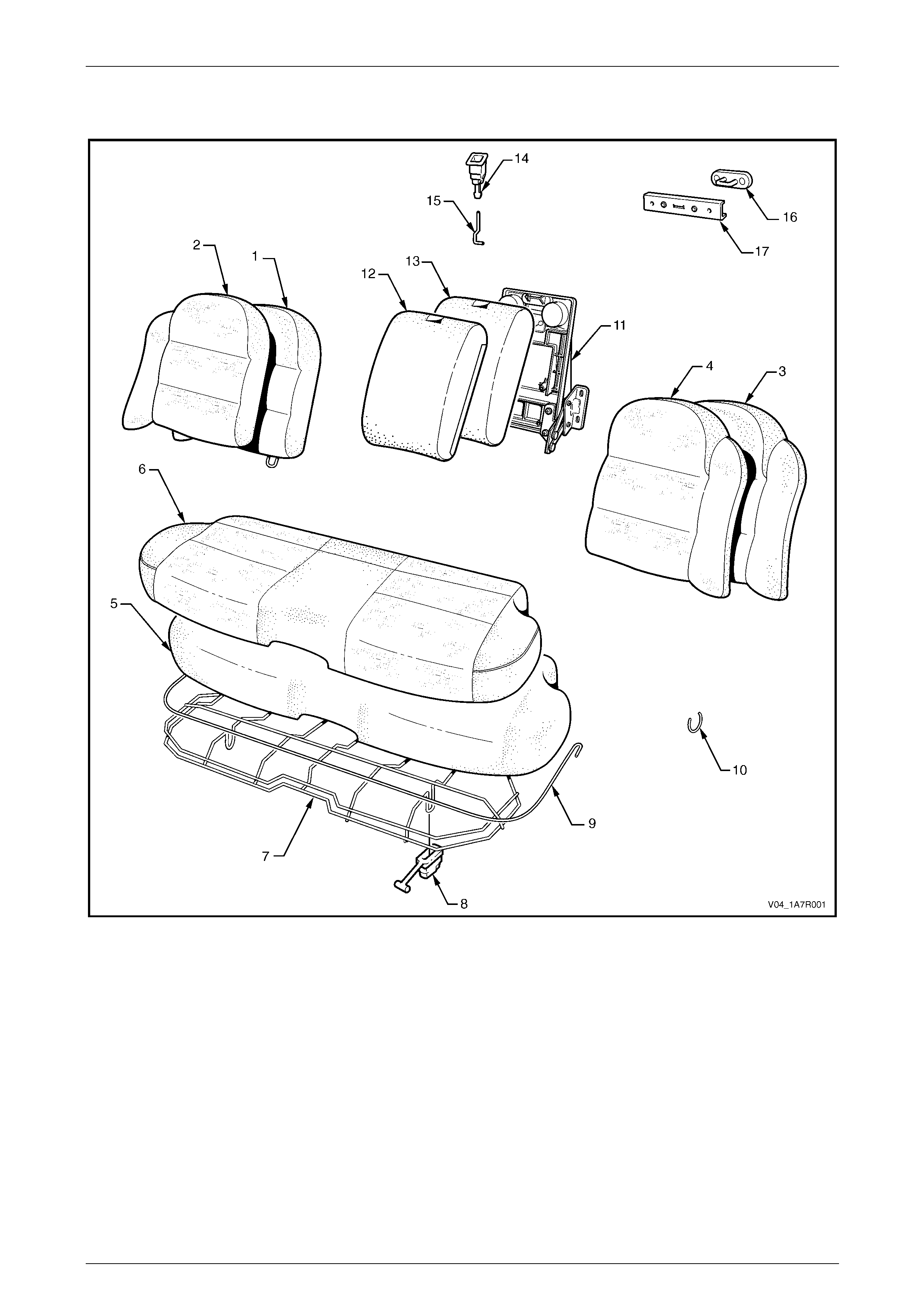
Seat Assemblies Page 1A7A–373
Page 1A7A–373
S, SV8 and SS
Figure 1A7A – 182
Legend
1 Rear Seat-back Pad – Right-hand
2 Rear Seat-back Cover – Right-hand
3 Rear Seat-back Pad – Left-hand
4 Rear Seat-back Cover – Left-hand
5 Rear Seat Cushion Pad
6 Rear Seat Cushion Cover Assembly
7 Rear Seat Cushion Frame Assembly
8 Rear Seat Cushion Release Handles (2 places)
9 Rear Seat Cushion Cover Retainer Wire
10 Hog Ring
11 Rear Seat Centre Tray Assembly *
12 Rear Seat-back Centre Cover
13 Rear Seat-back Centre Pad
14 Rear Seat-back Centre Release Button
15 Release Button Rod
16 Rear Seat-back Centre Striker
17 Rear Seat-back Centre Striker Cover
* Refer to 1A7, Rear Seat Usage Chart – Se dan in the MY 200 3 VY and V2 Series Service Information f or a complete
breakdown of the Rear Seat-back Centre T ray Assembly.
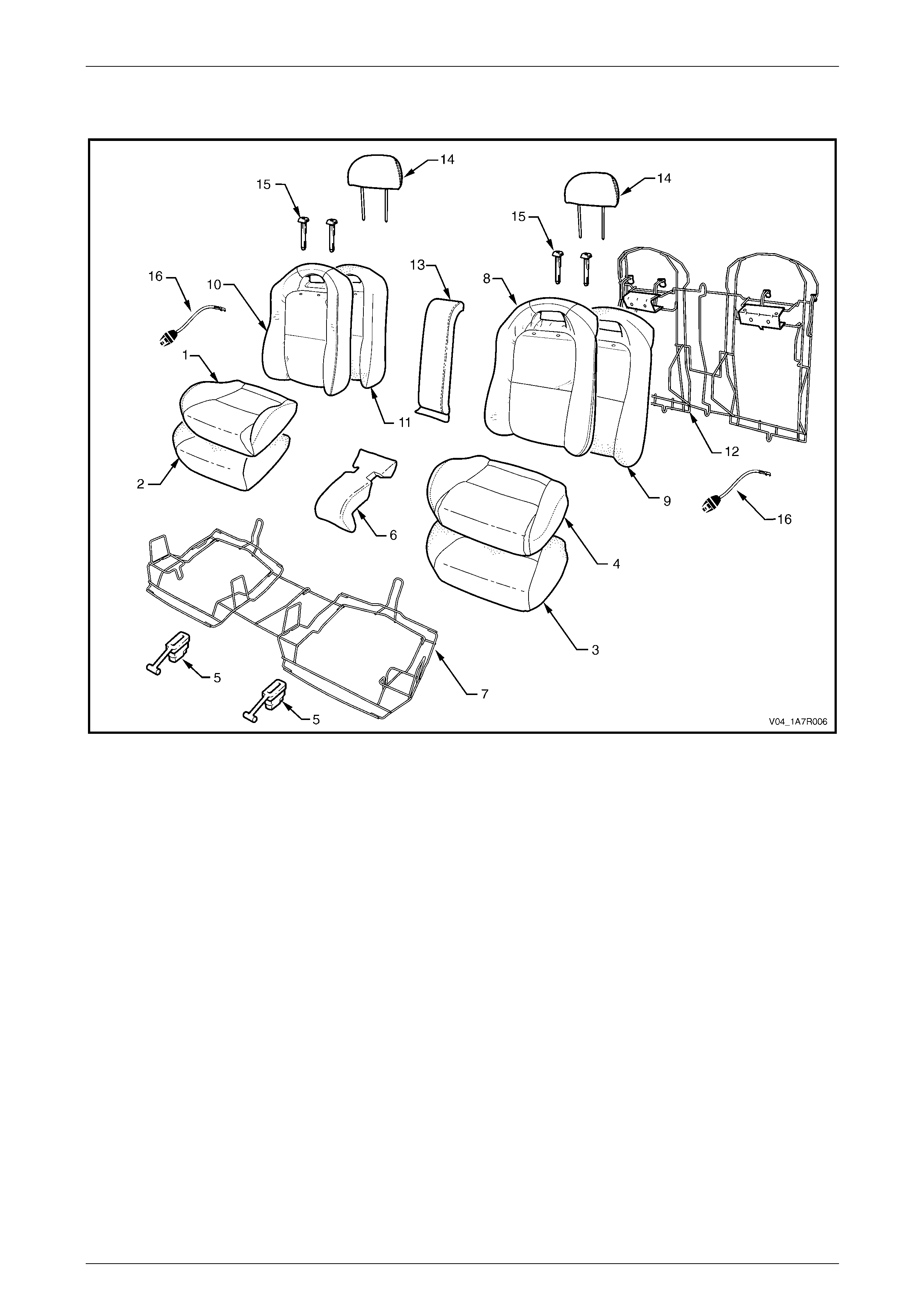
Seat Assemblies Page 1A7A–374
Page 1A7A–374
Coupe
Figure 1A7A – 183
Legend
1 Rear Seat Cushion Cover – Right-hand
2 Rear Seat Cushion Pad – Right-hand
3 Rear Seat Cushion Pad – Left-hand
4 Rear Seat Cushion Cover – Left-hand
5 Rear Seat Cushion Release Handle
6 Rear Seat Cushion Centre Escutcheon
7 Rear Seat Cushion Frame
8 Rear Seat-back Cover – Left-hand
9 Rear Seat-back Pad – Left-hand
10 Rear Seat-back Cover – Right-hand
11 Rear Seat-back Pad – Right-hand
12 Rear Seat-back Frame
13 Rear Seat-back Centre Escutcheon
14 Head Restraint
15 Head Restraint Sleeve (2 places each side)
16 Child Comforter Guide – (if fitted)
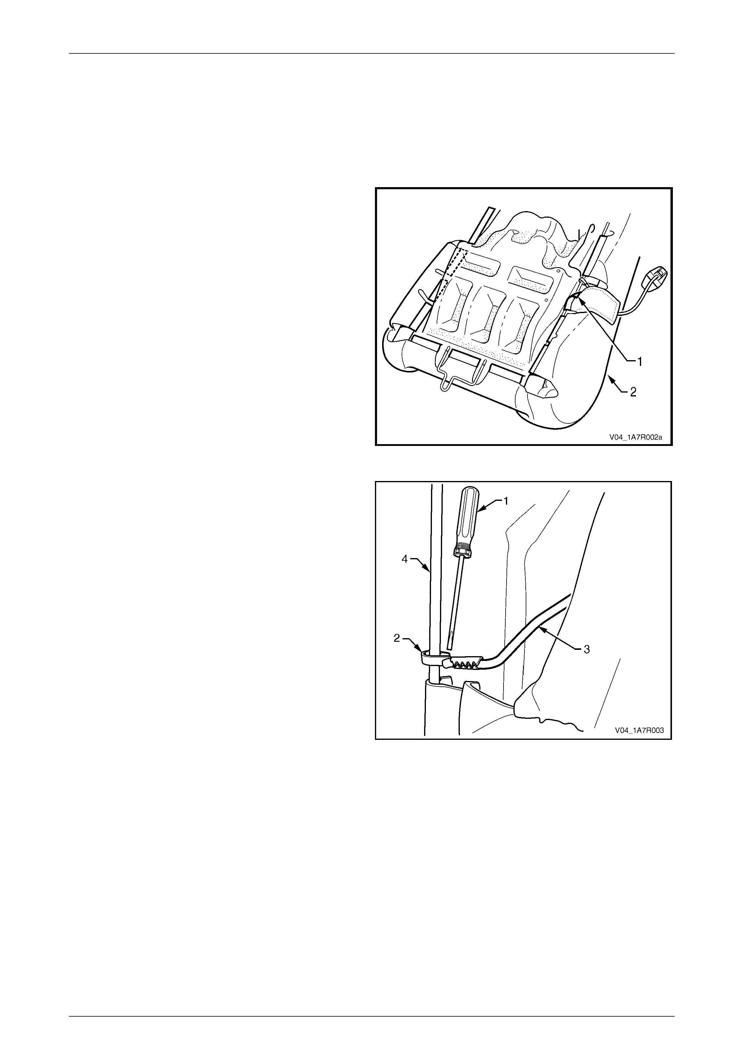
Seat Assemblies Page 1A7A–375
Page 1A7A–375
8.2 Child Comforter Guide – Coupe
Remove
1 Remove the rear seat-back assembly, refer to 1A7, 8.2 Rear Seat-back Assembly in the MY 2003 VY and V2
Series Service Information.
2 Unclip the J-strip (1) on the outer edge of the rear
seat-back assembly (2).
Figure 1A7A – 184
3 Using a suitable screwdriver (1), gently pris e open the
clip (2), attaching the child comforter guide strap (3) to
the seat-back frame (4).
4 Unclip the child comforter strap from the seat back
frame and carefully withdra w the child comforter guide
from the pouch in the rear seat-back cover.
Figure 1A7A – 185
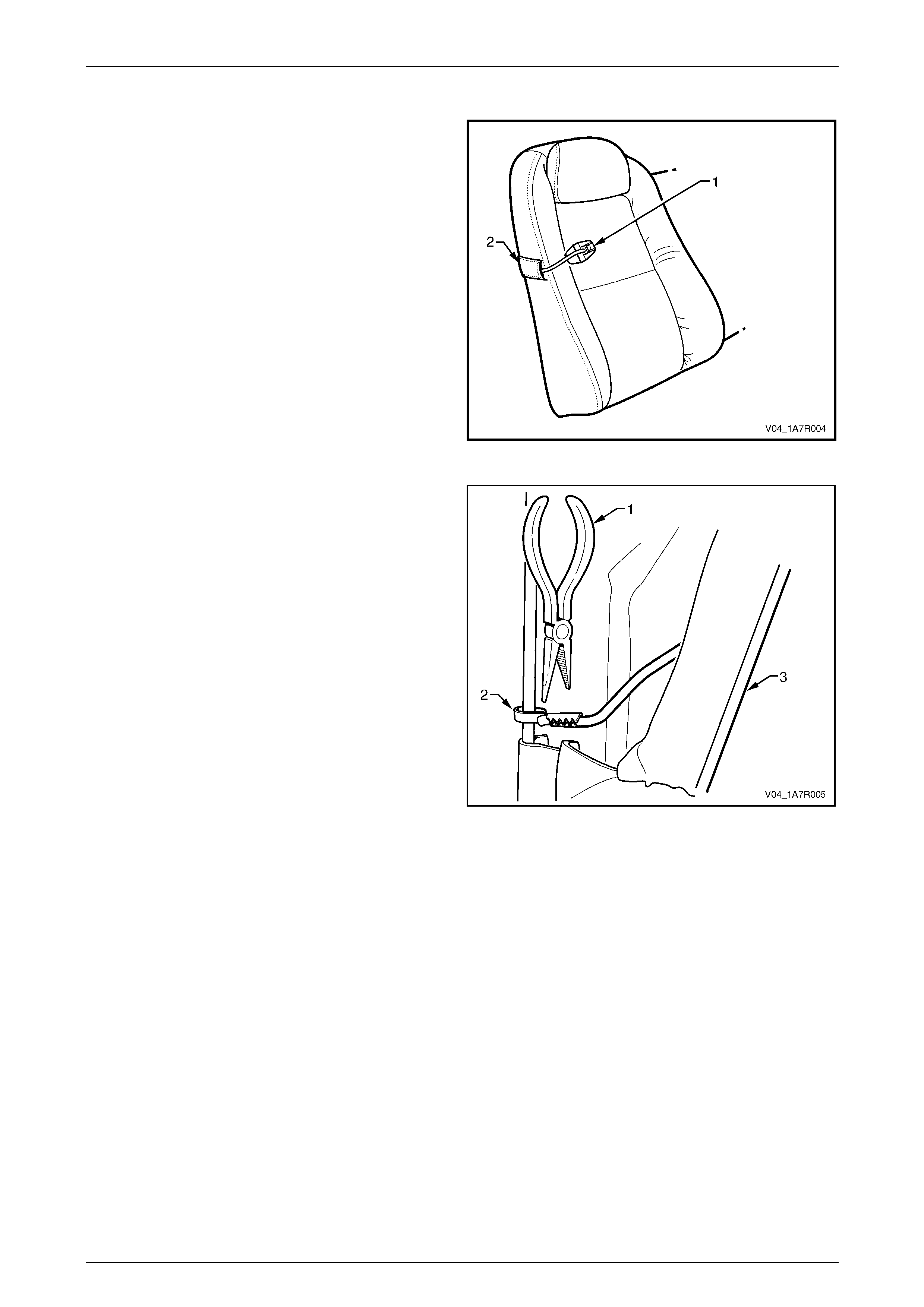
Seat Assemblies Page 1A7A–376
Page 1A7A–376
Reinstall
1 Insert the child comforter guide strap (1), through the
pouch in the rear seatback cover (2).
2 Clip the child comforter guide attaching clip onto the
rear seat-back frame, refer to Figure 1A7A – 187.
Figure 1A7A – 188
3 Using a suitable pair of pliers (1), gently squeeze the
end of the child comforter guide attaching clip (2)
closed.
4 Attach the J-strip (3) to the rear seat-back frame.
5 Reinstall the rear seat-back assembly, refer to
1A7, 8.2, Rear Seat-back Assembly in the MY 2003
VY and V2 Series Service Information.
Figure 1A7A – 189

Seat Assemblies Page 1A7A–377
Page 1A7A–377
9 Torque Wrench Specifications
9.1 Front Seat
Fire Extinguisher Mounting Bracket Attaching Screw................15.0 – 20.0 Nm
Front Seat Assembly Attaching Screw......................................35.0 – 50.0 Nm
Front Seat Outer Front Cover Attaching Screw.............................1.0 – 3.0 Nm
Front Seat Adjustment Switch Attaching Screw ............................1.0 – 3.0 Nm
Memory Position Switch Cover Attaching Screw...........................1.0 – 3.0 Nm
Front Seat Outer Side Cover Attaching Screw..............................1.0 – 3.0 Nm
Front Seat Inner Side Cover Attaching Screw...............................1.0 – 3.0 Nm
Front Seat-back Map Pocket Attaching Screw..............................1.0 – 3.0 Nm
Lumbar Support Knob Attaching Screw.........................................2.0 – 5.0 Nm
Side Impact Airbag Assembly Attaching Nut.................................5.0 – 6.0 Nm
Front Seat Dummy Block Insert Assembly Attaching Nut..............5.0 – 6.0 Nm
Active Head Restraint Frame Assembly Attaching Screw.............3.0 – 5.0 Nm
Front Seat-back Frame Assembly Attaching Screw..................30.0 – 45.0 Nm
Track and Height Adjust Assembly Attaching Nut.....................24.0 – 32.0 Nm
EZ-entry Module Attaching Screw.................................................1.0 – 3.0 Nm
EZ-entry Release Escutcheon Assembly Attaching Screw............1.0 – 3.0 Nm