
Instruments Page 12C–1
Page 12C–1
Section 12C
Instruments
ATTENTION
Before performing any Service Operation or other procedure described in this Section, refer to Section 00
Warnings, Cautions and Notes for correct workshop practices with regard to safety and/or property damage.
1 General Information............................................................................................................................... 2
1.1 General Description...............................................................................................................................................2
Instrument Cluster Programming.........................................................................................................................2
Fuel Sender Circuit Variations..............................................................................................................................2
Fuel Calibration......................................................................................................................................................2
TECH 2 Testing..................................................................................................................................................3
Fuel (Petrol) Sender Resistance .........................................................................................................................3
Speedometer Pulses ..........................................................................................................................................4
Seat Belt Warning Switch......................................................................................................................................5
Seat Belt Alarm Description................................................................................................................................5
2 Diagnostics............................................................................................................................................. 7
DTC 1 – Petrol Level Sender Signal Voltage Too Low........................................................................................7
Circuit Description...............................................................................................................................................7
Petrol Level Sender Signal Voltage Too Low Diagnostic Chart..........................................................................8
DTC 2 – Petrol Level Sender Signal Voltage Intermittent .................................................................................10
Circuit Description.............................................................................................................................................10
Petrol Level Sender Signal Voltage Intermittent Diagnostic Chart....................................................................11
DTC 3 – Petrol Level Sender Signal Voltage Too High .....................................................................................13
Circuit Description.............................................................................................................................................13
Petrol Level Sender Signal Voltage Too High Diagnostic Chart.......................................................................14
3 Specifications....................................................................................................................................... 16
Fuel Calibration Part Number..............................................................................................................................16
Speedometer Pulses............................................................................................................................................16
Techline
Techline
Techline
Techline
Techline
Techline
Techline
Instruments Page 12C–2
Page 12C–2
1 General Information
This Section provides information on the instrument clusters fitted to the MY 2004 VY and V2 Series vehicles. For all
other instrument cluster related information not covered in this Section, refer to Section 12C Instruments in the MY 2003
VY and V2 Series Service Information.
1.1 General Description
Instrument Cluster Programming
When an instrume nt clu ster is repla ced in a vehicle, the fuel gauge calibr ation, configura tion and speedomet er functions
must be programmed into the new instrument cluster using TECH 2. Some differences in configuration values exist
between the MY 2003 and MY 2004, VY and V2 Series vehicles. These differences are highlighted in this Section.
For more instrument cluster programming information, refer to Section 12C, 3.15 Program in the MY 2003 VY and V2
Series Service Information.
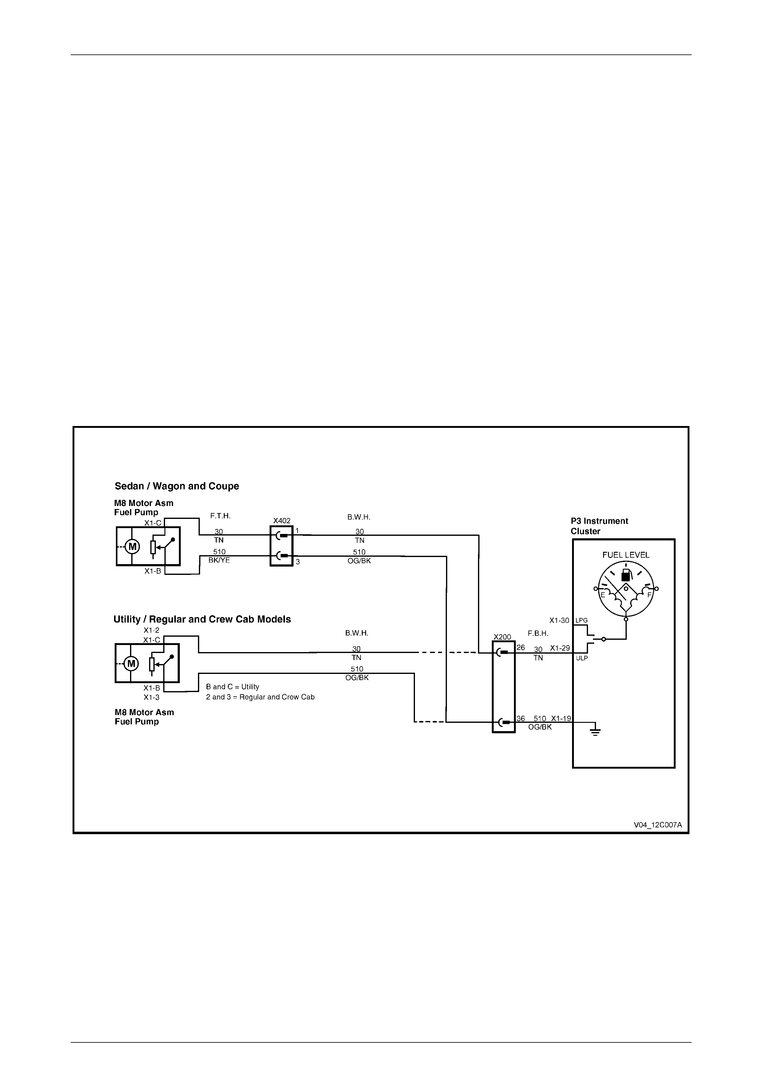
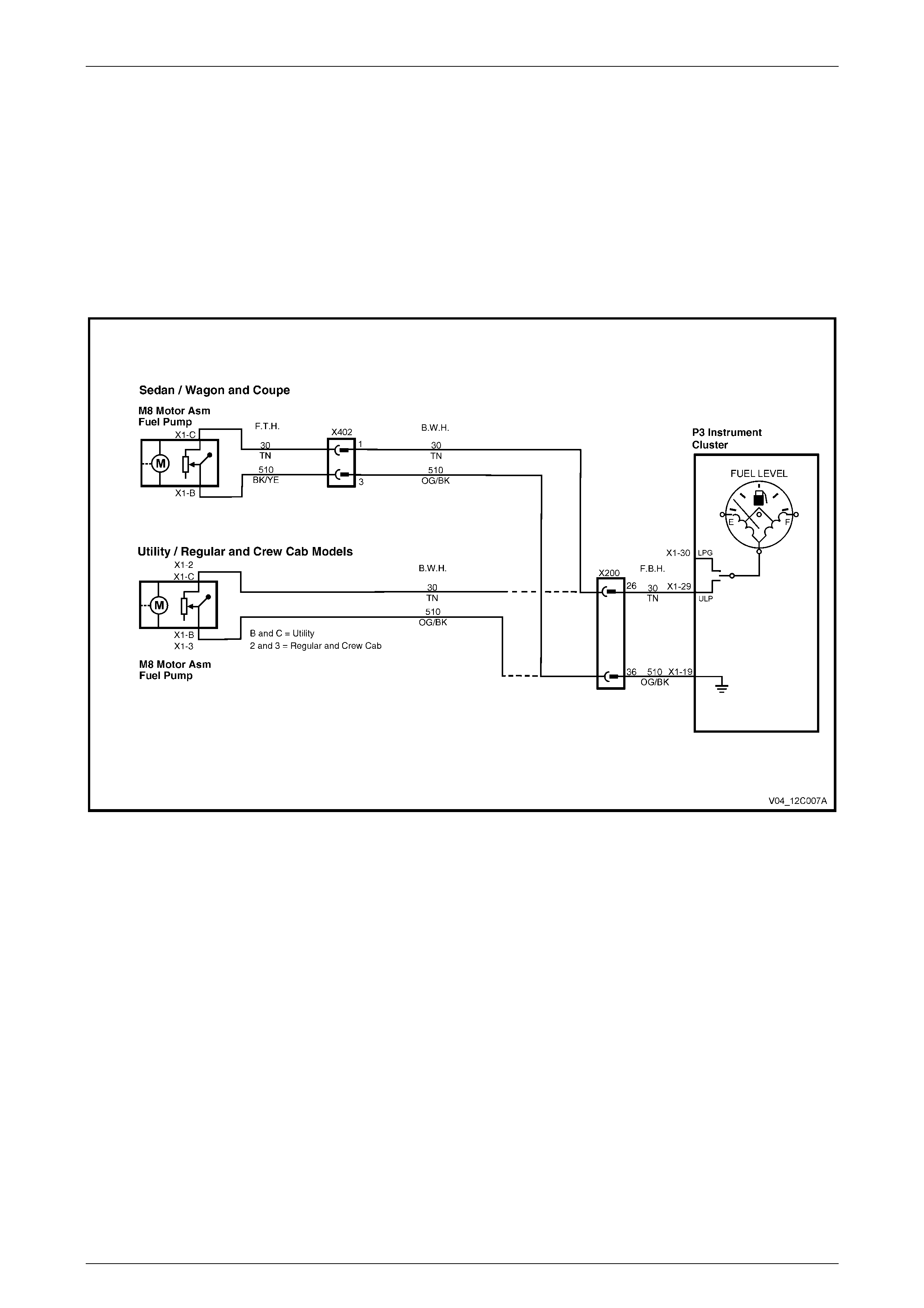
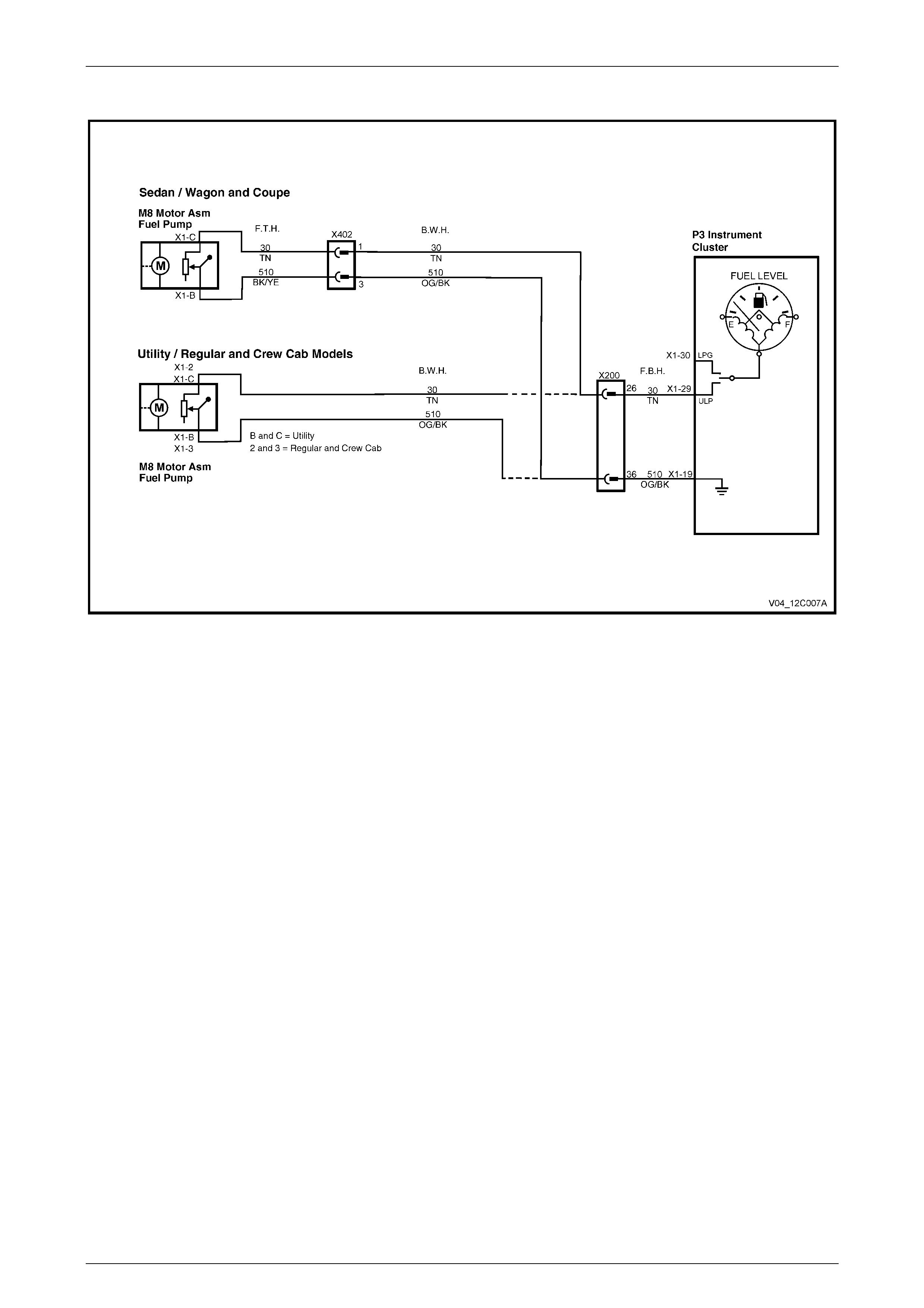
Fuel Sender Circuit Variations
There are two fuel sender circuits used in the MY 2004 VY and V2 Series vehicles. Refer to Figure 12C – 1. Both of
these circuits pass through a larger in-line terminal connector (X200) whereas in the MY 2003 VY and V2 Series
vehicles, this connector is X201.
Figure 12C – 1
Fuel Calibration
Calibration software compatible with the vehicle configuration must be applied to the instrument cluster. Fuel calibration
software is entered using TECH 2. A Code Index number, with a version number following, represents each fuel
calibration software program and is selected with TECH 2.
The MY 2004 VY and V2 Series vehicles are fitted with a different series of fuel sender assemblies than the MY 2003
Series vehicles. The resistance values of the sender assemblies have been reversed for the MY 2004 vehicles, making
them incompatible with the MY 2003 vehicles. For the MY 2004 vehicles, the same range values of 40 ± 5 ohms to
250 ± 5 ohms exist, but the lowest resistance value now indicates a full tank. A complete description of how to measure
Instruments Page 12C–3
Page 12C–3
the fuel level sender resistance values at the connector terminals is described in Section 8A1, 2.1 Modular Fuel Pump
and Sender Assembly in this Service Information.
For information relating to the removal of the fuel sender from the fuel tank, refer to one of the following references as
required, in the MY 2003 VY and V2 Series Service Information:
Section 8A1, 2.6 Modular Fuel Pump and Sender Assembly – Sedan, Wagon and Coupe
Section 8A1, 2.7 Modular Fuel Pump and Sender Assembly – Utility
Section 8A1, 2.8 Fuel Level Sender Assembly – V6 Supercharged and Vehicles Exported to Brazil
For correct fuel gauge operation, ensure that the correct instrument cluster, fuel tank and fuel level sender assembly
combination are fitted for the vehicle configuration. For confirmation of this, refer to the latest parts information.
NOTE
These fuel calibration software codes apply to all
MY 2004 VY and V2 Series models. For
calibration codes applicable to MY 2003 vehicles,
refer to Section 12C, 3.15 Program in the
MY 2003 VY and V2 Series Service Information.
Fuel Calibration Part Numbers and Code Index Numbers for MY 2004 VY and V2 Series vehicles are as follows:
Vehicle Model Market Body Style Engine Fuel Calibration
Code Part Number Code Index /
Version
VY Domestic Sedan V6 (not S/C) and V8 92160974 6 / 2
VY Domestic Wagon (inc AWD) V6 (not S/C) and V8 92160975 7 / 2
VY Export (not Brazil) Sedan V6 (not S/C) and V8 92160974 6 / 2
VY Export Wagon V6 (not S/C) 92160975 7 / 2
VY Export (Brazil) Sedan V6 92160977 9 / 1
VY Domestic / export Sedan V6 (S/C) 92160977 9 / 1
VY Domestic / export Utility V6 (not S/C) and V8 92160976 8 / 1
V2 Domestic Coupe V8 92160974 6 / 2
V2 Export Coupe V6 (not S/C) and V8 92160974 6 / 2
TECH 2 Testing
When TECH 2 is connected to the vehicle and is switched on, it determines what version of software is installed in the
instrument cluster. From this information, it recognises what type of seat belt switch hardware and fuel sender unit should
be fitted to the vehicle. The correct simulated values for testing of the instruments are then applied when required.
NOTE
Refer to the latest Parts Information to verify that
the correct instrument cluster, fuel tank and fuel
sender assembly are installed for the vehicle.
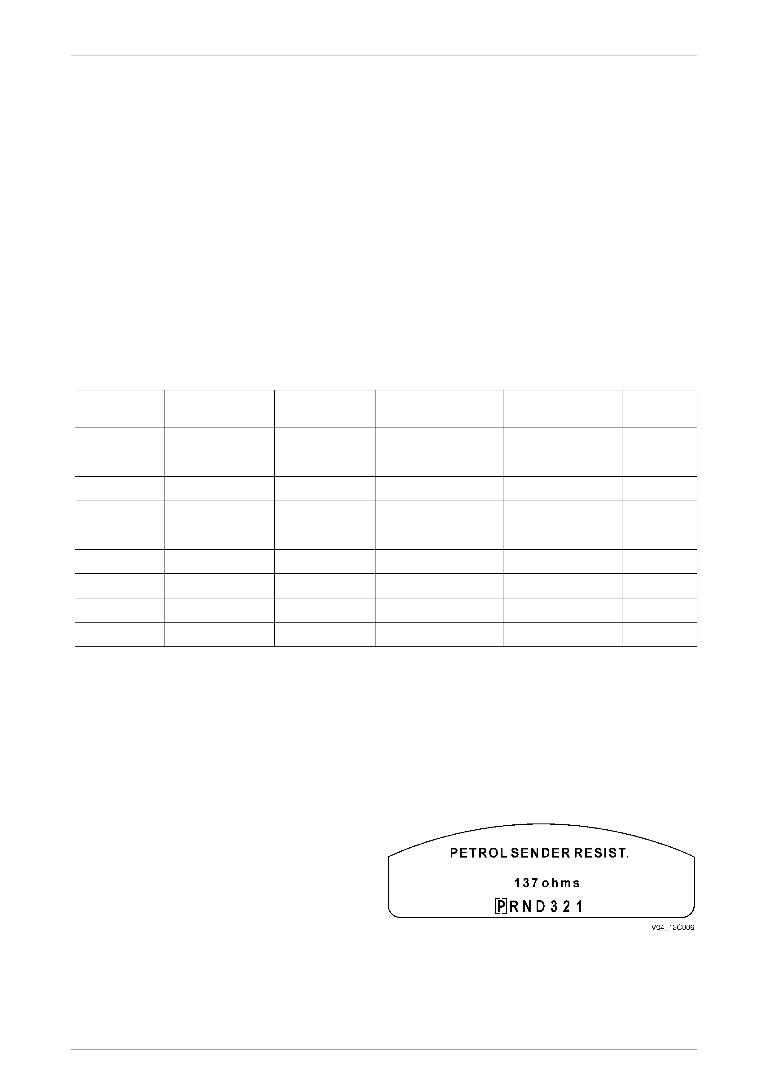
Fuel (Petrol) Sender Resistance
With the instrument cluster in Diagnostic Mode, the current
fuel sender resistance can be displayed. To access the
instrument cluster Diagnostic Mode, refer to Section 12C,
3.3 Ins trum ent Cluster Diagnostics in the MY 2003 VY and
V2 Series Service Information.
Figure 12C – 2
The fuel sender resistance should be between 40 ± 5 ohms and 250 ± 5 ohms. However, unlike MY 2003 Series VY and
V2 Series vehicles, this resistance should decrease as the tank is filled and increase as the tank is emptied.
Also refer to Section 12C, 3.15 Program in the MY 2003 VY and V2 Series Service Information.
Instruments Page 12C–4
Page 12C–4
Speedometer Pulse s
The speedometer Pulses Per Kilometre (PPK) values are shown in the following table for all MY 2004 VY and V2 Series
vehicles.
Bod y
Type Engine
Type Transmission
Type Tyre
Size PPK
Value
Sedan / Wagon V6 Auto / Man 205/65R15 6272
Sedan / Wagon V6 Auto / Man 225/60R15 6238
Sedan / Wagon V6 Auto / Man 215/60R16 6077
Sedan / Wagon V6 Auto / Man 225/55R16 6173
Sedan / Wagon V6 Auto / Man 225/50R16 6391
Sedan / Wagon V6 Auto / Man 235/45R17 6301
Sedan / Wagon V6 Auto / Man 225/50R17 6100
Utility V6 Auto 205/65R15 6272
Utility V6 Auto 225/55R16 6173
Utility V6 Auto 235/45R17 6300
Utility V6 Man 205/65R15 6450
Utility V6 Man 225/55R16 6307
Utility V6 Man 235/45R17 6480
Sedan / Wagon / Utility V8 Auto / Man 205/65R15 6272
Sedan / Wagon / Utility V8 Auto / Man 225/60R15 6238
Sedan / Wagon / Utility V8 Auto / Man 225/55R16 6173
Sedan / Wagon / Utility V8 Auto / Man 235/45R17 6301
Sedan / Wagon / Utility V8 Auto / Man 225/50R17 6100
Sedan / Wagon / Utility / Coupe V8 Auto / Man 235/40R18 6230
HSV V8 Auto 225/50ZR16 6355
HSV V8 Auto 235/45ZR17 6210
HSV V8 Auto 235/40ZR18 6210
HSV V8 T56 235/45ZR17 6300
HSV V8 T56 235/40ZR18 6300
HSV V8 Getrag 225/50ZR16 6355
HSV V8 Getrag 235/45ZR17 6210
HSV V8 Getrag 235/40ZR18 6210
NOTE
For PPK values relating to MY 2004 VY
Regular and Crew Cab Series vehicles, refer to
the speedometer pulse table provided in
Section 12C Instruments, in the MY 2004 VY
Regular and Crew Cab Series Service
Information.
Instruments Page 12C–5
Page 12C–5
Seat Belt Warning Switch
All MY 2004 VY or V2 Series vehicles (with the exception of the utilities) are now fitted with a seat belt warning alarm
indication for the driver’s seat belt only. This feature applies to both domestic and export vehicles.
Seat Belt Alarm Description
The seat belt warning light is designed to primarily remind the driver to fasten his or her seat belt and to remind the other
passengers to do the same.
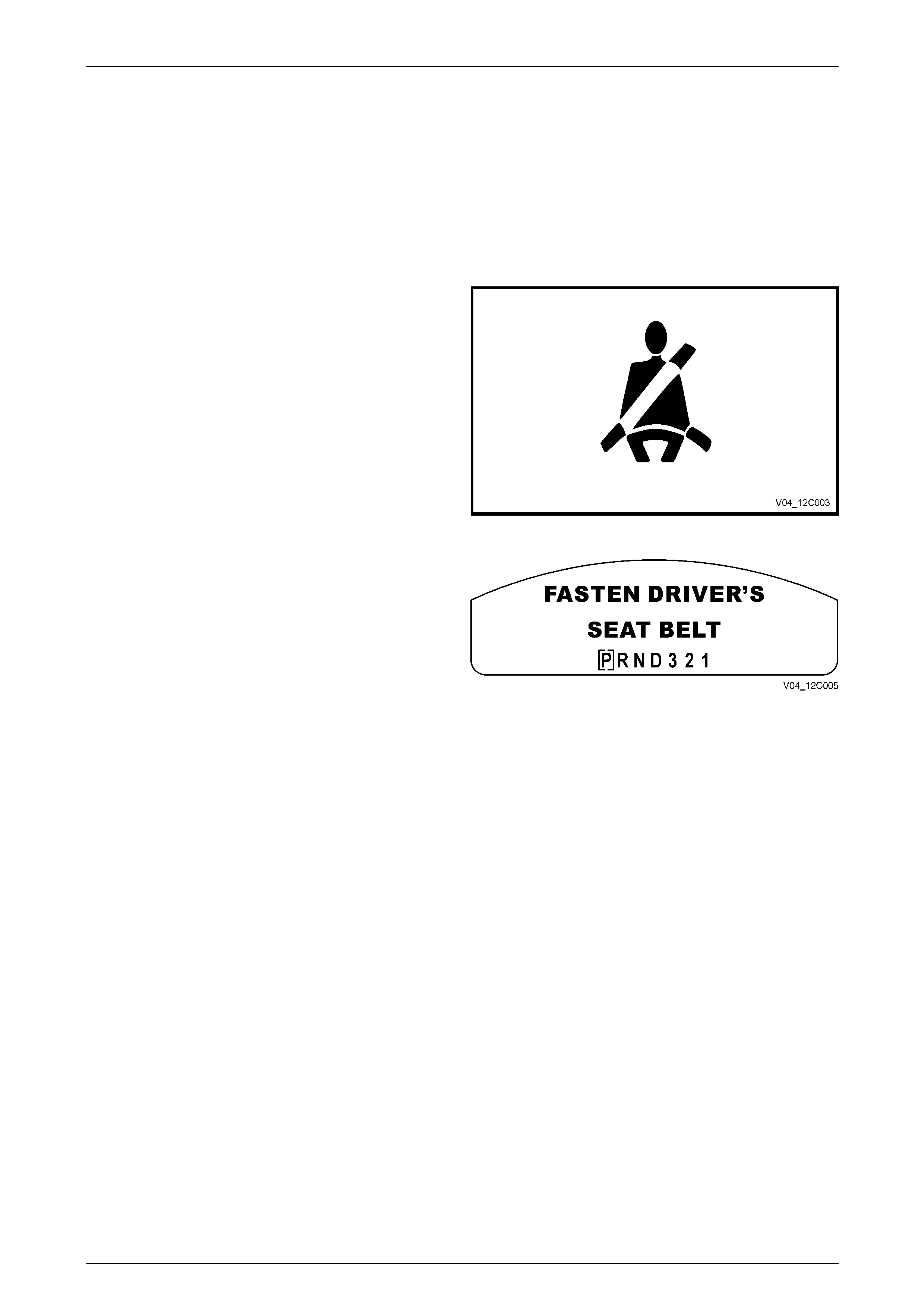
Sedan, Wagon and Coupe
Where the driver has buckled the seat belt
correctly before switching the ignition on, the
red Seat Belt warning indicator will remain
extinguished. However, if the driver’s seat belt
is not fastened at ignition on, the warning
indicator flashes for up to 60 seconds, or
extinguishes if the seat belt is fastened during
this time.
Figure 12C – 3
A ‘Fasten Driver’s Seat Belt’ warning message
also appears on the display of the instrument
cluster. If the driver’s seat belt still has not been
fastened after this 60 second period, the
indicator flashes for a further 90 seconds
before extinguishing if the seat belt has still not
been fastened.
Figure 12C – 4
The instrument cluster produces two sequences of chimes while the driver’s seat belt remains unbuckled after the
ignition has been turned on, or while the vehicle is moving. For more detailed information related to the chime function,
refer to Section 12C, 1.1 General Description in the MY 2003 VY and V2 Series Service Information.
Utility
When the ignition is first switched on, the seat belt warning indicator will be displayed for approximately 8 seconds before
extinguishing. The seat belt warning light is provided as an initial reminder to the driver to fasten the seat belt.
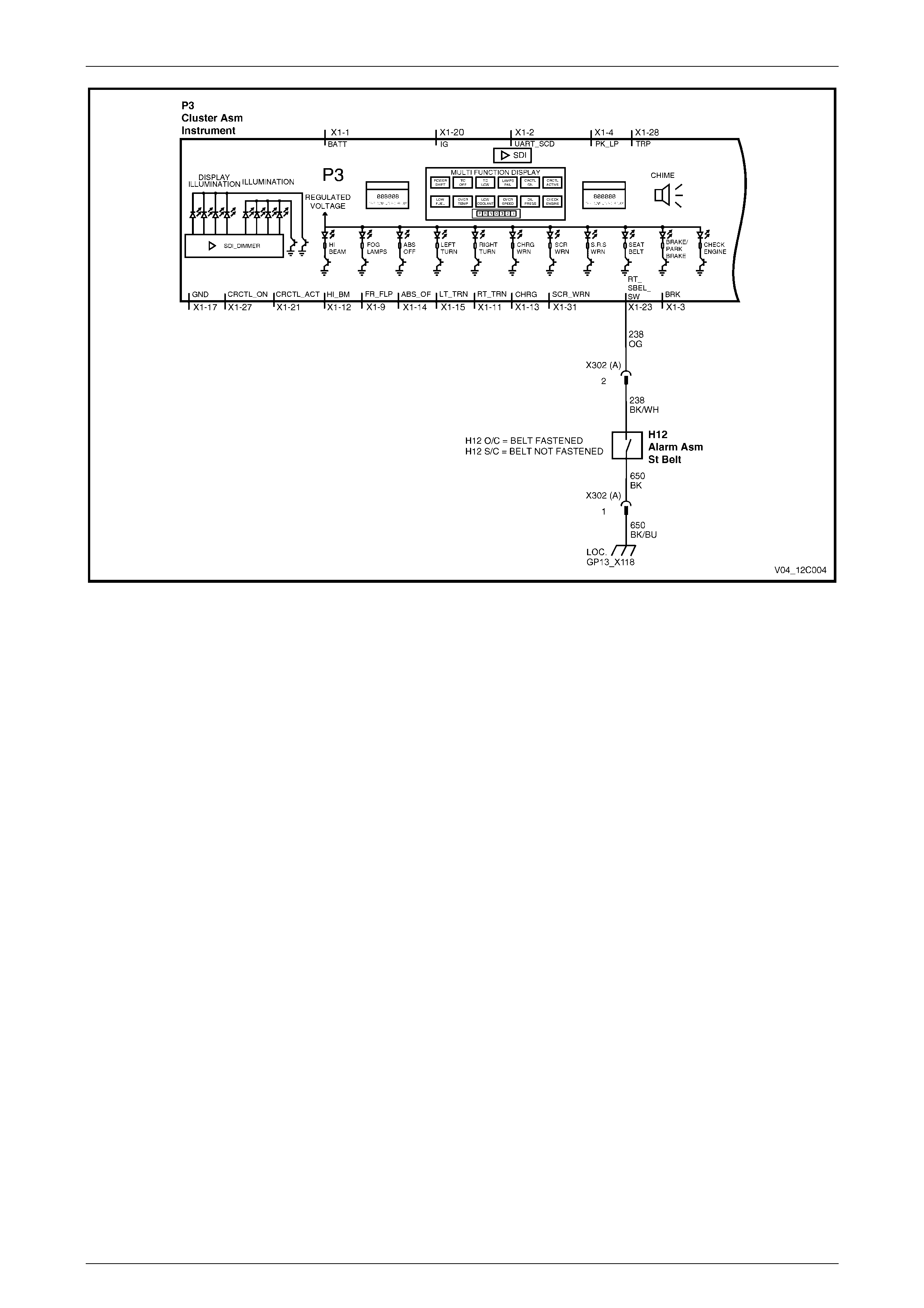
Electrical Wiring (Sedan, Wagon and Coupe)
The electrical wiring connec ting the switch located in the driver’s seat belt buckle to the P3 instrument cluster assembly
is shown in Figure 12C – 5. The seat buckle switch is integrated into the seat wiring harness via a three-way seat
connector.
For further inform ation relating to the seat belt buckle switch, refer to Section 12M Occupant Protection System.
Instruments Page 12C–6
Page 12C–6
Figure 12C – 5
Instruments Page 12C–7
Page 12C–7
2 Diagnostics
Due to the changes in vehicle wiring connectors and fuel sender units for MY 2004 VY and V2 Series vehicles (as
described earlier in this Section), as well as the introduction of the VY Series Regular and Crew Cab models, the
following Instrument Cluster Diagnostic charts have been revised to reflect these changes and are included in this
Section for use on those vehicles so affected.
A complete description of how to measure the fuel level sender resistance values at the connector terminals is described
in Section 8A1, 2.1 Modular Fuel Pump and Sender Assembly in this Service Information.
DTC 1 – Petrol Level Sender Signal Voltage Too Low
Figure 12C – 6
Circuit Description
The instrument cluster supplies a 12 volt reference voltage and a ground circuit to the fuel gauge sender unit. The fuel
sender provides a resistance value to the instrument cluster based on its position relative to the fuel level. The fuel
sender resistance will vary between 40 ± 5 ohms (full tank) and 250 ± 5 ohms (no fuel in the tank).
DTC 1 will set if the fuel sender resistance is less than 12.9 ohms for a period of 30 seconds. The DTC is reset when the
fuel sender resistance returns to its normal operating range for a period of 60 seconds. The DTC is logged as a History
DTC.
When a DTC 1 is set the fuel gauge will display the fuel tank level as empty irrespective of actual fuel level.
Diagnostic Aids
The TECH 2 diagnostic tool reads fuel sender position as a voltage between 0 and 5 volts. The fuel sender signal
resistance should be betw een 40 ± 5 ohms and 250 ± 5 ohms when the fuel sender is functioning correctly. The fuel
sender voltage should increase at a steady rate as the fuel level increases.
The multimeter allows continuity of the wiring harness to be checked. Harness voltage can also be confirmed at
connector locations.
Check for any damage to the harness which could cause an intermittent open or short to ground or backed-out terminals
at the instrument cluster connectors, broken connector locks, improperly formed or damaged terminals.

Instruments Page 12C–8
Page 12C–8
Petrol Level Sender Signal Voltage Too Low Diagnostic Chart
Step Action Value(s) Yes No
1 Was the Diagnostic Circ uit Check performed? Go to Step 2. Go to Diagnostic
Circuit Check chart
in Section 12C of
the MY 2003 VY
and V2 Series
Service Information.
2 Connect TECH 2 to the DLC.
Select Diagnostics / Model Year / Vehicle Model / Body
/ Instrument / Data Display / Instrument.
Scroll to the Fuel Level Sender Resistance signal.
Is the value as specified?
Less than
12.9 ohms Go to Step 3. Go to DTC 2 –
Petrol Level Sender
Signal Voltage
Intermittent
diagnost ic cha rt in
this Section.
3 From the Body Menu, select Miscellaneous Tests /
Gauge Control Tests / Fuel Gauge, and conduct the
test as directed by soft keys at the bottom of the
TECH 2 screen.
Does the fuel gauge operate correctly?
Go to Step 4. Replace the
instrument cluster.
Refer to
2.3 Instrument
Cluste r Assembly
in Section 12C of
the MY 2003 VY
and V2 Series
Service
Information.
4 Disconnect the battery. Refer to Section 00, 5 Battery
Disconnection Procedures.
Disconnect the body harness connector from the main
wiring harness connector X200.
Using an ohmmeter, check for continuity between
X200-26 circuit 30 and X200-36 circuit 510 on the main
wiring harness.
Using an ohmmeter, check for continuity between
X200-26 circuit 30 and a known good ground.
Is there continuity?
Go to Step 5. For Sedan / Wagon
and Coupe Models,
go to Step 6.
For Utility / Regular
Cab and Crew Cab
Models, go to
Step 8.
5 Remove the instrument cluster. Refer to 2.3 Instrument
Cluster Assembly in Section 12C of the MY 2003 VY
and V2 Series Service Information.
Using an ohmmeter, check for continuity between
X200-26 circuit 30 and X200-36 circuit 510 on the main
wiring harness.
Using an ohmmeter, check for continuity between
X200-26 circuit 30 and a known good ground.
Is there continuity?
Short circuit in main
wiring harness
between connector
X200 and
instrument cluster
connector P3.
Repair harness.
Replace the
instrument cluster.
Refer to
2.3 Instrument
Cluste r Assembly
in Section 12C of
the MY 2003 VY
and V2 Series
Service
Information.
6 Disconnect the fuel tank harness from the body
harness connector X402 located under the rear of the
vehicle.
Using an ohmmeter, check for continuity between
X402-1 circuit 30 and X402-3 circuit 510 on the body
harness connec tor.
Using an ohmmeter, check for continuity between
X402-1 circuit 30 and a known good ground.
Is there continuity?
Short circuit in body
harness betw een
X402 and X200.
Repair harness.
Go to Step 7.

Instruments Page 12C–9
Page 12C–9
Step Action Value(s) Yes No
7 Using an ohmmeter, check resistance across X402-1
circuit 30 and X402-3 circuit 510 on the fuel tank
harness.
Is the value as specified?
Between
40 ± 5 ohms
and
250 ± 5 ohms
Go to DTC 2 –
Petrol Level Sender
Signal Voltage
Intermittent
diagnost ic cha rt in
this Section.
Go to Step 8.
8 For Sedan / Wagon / Coup e and Utility:
Drain and remove the fuel tank. Refer to Sectio n 8A1,
2.1 Fuel Tank – Sedan and Wagon, 2.2 Fuel Tank –
Coupe or 2.3 Fuel Tank – Utility in the MY 2003 VY
and V2 Series Service Information as appropriate.
Using an ohmmeter, check for continuity between fuel
pump M8 connector X1-C circuit 30 and X1-B on the
fuel tank harness.
Using an ohmmeter, check for continuity between X1-C
circuit 30 and a known good ground.
For Regular and Crew Cab models:
Disconnect rear body harness connector X1 from the
modular fuel sen der assem bly M8.
Using an ohmmeter, check for continuity between X1-2
circuit 30 and M8 X1-3 on the rear body harness.
Using an ohmmeter, check for continuity between X1-2
circuit 30 and a known good ground.
Is there continuity?
Short circuit in
wiring harness
between the fuel
sender unit and
connector X402
(Sedan / Wagon
and Coupe) or
X200 (Utility /
Regular Cab and
Crew Cab). Repair
harness.
Replace faulty fuel
sender unit.
For Sedan / Wagon
/ Coupe or Utility,
refer to
Section 8A1, in the
MY 2003 VY and
V2 Series Service
Information.
For Regular Cab
and Crew Cab,
refer to
Section 8A1 of the
MY 2004 VY Series
Regular and Crew
Cab Service
Information.
9 1. From the Body Menu, select Diagnostic Trouble
Codes / Clear DTC Information on the TECH 2.
Has the DTC cleared?
End of diagnostic
checking. Refer to
corresponding
diagnost ic cha rt in
this Section or
Section 12C of the
MY 2003 VY and
V2 Series Service
Information.
WHEN ALL DIAG NOSIS AND REPAIRS ARE COMPLETED, CLEAR ALL DTC
AND VERIFY CORRECT OPERATION

Instruments Page 12C–10
Page 12C–10
DTC 2 – Petrol Level Sender Signal Voltage Intermittent
Figure 12C – 7
Circuit Description
The instrument cluster supplies a 12 volt reference voltage and a ground circuit to the fuel gauge sender unit. The fuel
sender provides a resistance value to the instrument cluster based on its position relative to the fuel level. The fuel
sender resistance will vary between 40 ± 5 ohms (full tank) and 250 ± 5 ohms (no fuel in the tank).
DTC 2 will set if there is an intermittent fault in the connection between the fuel sender and the instrument cluster. The
DTC is set when the fuel sender resistance is greater than 290 ohms for 30 seconds or if the fuel sender resistance is
less than 37.5 ohms for 30 seconds. The DTC is reset when the fuel sender is detected as being open circuit or short
circuit or the sender resistance is within its normal operating range for a period of 60 seconds. The DTC is logged as a
Histo r y DTC.
Diagnostic Aids
By manipulating the harnesses at the various connectors and points along the harness it is possible to isolate the cause
of the circuit interruption. By working through the chart in the specified order it is possible to work out which harness
contains the fault. This harness can then be removed and repaired.
The TECH 2 diagnostic tool reads fuel sender position as a voltage between 0 and 5 volts. The fuel sender signal
resistance should be betw een 40 ± 5 ohms and 250 ± 5 ohms when the fuel sender is functioning correctly. The fuel
sender voltage should increase at a steady rate as the fuel level increases.
The multimeter allows continuity of the wiring harness to be checked. Harness voltage can also be confirmed at
connector locations.
Check for any damage to the harness which could cause an intermittent open or short to ground or backed out terminals
at the instrument cluster connectors, broken connector locks, improperly formed or damaged terminals.

Instruments Page 12C–11
Page 12C–11
Petrol Level Sender Signal Voltage Intermittent Diagnostic Chart
Step Action Value(s) Yes No
1 Was the Diagnostic Circ uit Check performed? Go to Step 2. Go to Diagnostic
Circuit Check chart
in Section 12C of
the MY 2003 VY
and V2 Series
Service
Information.
2 Connect TECH 2 to the DLC.
Select Diagnostics / Model Year / Vehicle Model / Body
/ Instrument / Miscellaneous Tests / Gauge Control
Tests / Fuel Gauge, and conduct the test as directed by
soft keys at the bottom of the TECH 2 screen.
Does the fuel gauge operate correctly?
Go to Step 3. Replace the
instrument cluster.
Refer to
2.3 Instrument
Cluste r Assembly
in Section 12C of
the MY 2003 VY
and V2 Series
Service
Information.
3 From the Body Menu, select Diagnostic Trouble Codes
/ Clear DTC Information.
Turn the ignition off then on.
From the Body Menu, select Data Display / Instrument.
Scroll to the Fuel Level Sender Resistance signal.
Have an assistant manipulate the main wiring harness
between connector X200 and the instrument cluster
connector P3 to induce an intermittent fault.
Did the fuel level sender resistance vary during the
manipulations, or
Did DTC 2 set again?
Repair faulty main
wiring harness. Go to Step 4.
4 Have assistant mani pulate the body wiring harness
between connectors X200 and X402 (Sedan / Wagon
and Coupe) or X200 and X–1 for Utility / Regular and
Crew Cab models to induce an intermittent fault.
Did the fuel level sender resistance vary during the
manipulations, or
Did DTC 2 set again?
Repair faulty body
wiring harness. Go to Step 5.
5 For Sedan / Wagon / Coup e and Utility:
Drain and remove the fuel tank. Refer to Sectio n 8A1,
2.1 Fuel Tank – Sedan and Wagon, 2.2 Fuel Tank –
Coupe or 2.3 Fuel Tank – Utility in the MY 2003 VY
and V2 Series Service Information as appropriate.
For Regular Cab and Crew Cab:
Disconnect rear body harness connector X1 from the
modular fuel sen der as sembly .
For all models, have assistant manipulate the fuel tank
wiring harness between connector X402 (Sedan /
Wagon and Coupe) or X200 (Utility / Regular and Crew
Cab models) and the fuel sender connector X–1 to
induce an intermittent fault.
Did the fuel level sender resistance vary during the
manipulations, or
Did DTC 2 set again?
Repair faulty fuel
tank wiring
harness.
Replace faulty fuel
sender unit.
For Sedan / Wagon
/ Coupe or Utility,
refer to
Section 8A1, in the
MY 2003 VY and
V2 Series Service
Information.
For Regular Cab
and Crew Cab,
refer to
Section 8A1 of the
MY 2004 VY Series
Regular and Crew
Cab Service
Information.

Instruments Page 12C–12
Page 12C–12
Step Action Value(s) Yes No
6 From the Body Menu, select Diagnostic Trouble Codes
/ Clear DTC Information on the TECH 2.
Has the DTC cleared?
End of diagnostic
checking. Refer to
corresponding
diagnost ic cha rt in
this Section or
Section 12C of the
MY 2003 VY and
V2 Series Service
Information.
WHEN ALL DIAG NOSIS AND REPAIRS ARE COMPLETED, CLEAR ALL DTC
AND VERIFY CORRECT OPERATION
Instruments Page 12C–13
Page 12C–13
DTC 3 – Petrol Level Sender Signal Voltage Too High
Figure 12C – 8
Circuit Description
The instru ment cluster supp lies a 12 volt ref erence voltage and a ground circuit to the fuel gauge send er un it. The fuel
sender provides a resistance value to the instrument cluster based on its position relative to the fuel level. The fuel
sender resistance will vary between 40 ± 5 ohms (full tank) and 250 ± 5 ohms (no fuel in the tank).
DTC 3 will set if the fuel sender circuit provides a resistance above 290 ohms for a duration longer than 30 seconds. The
DTC is reset when the fuel sender resistance returns to its normal operating range for a period of 60 seconds. The DTC
is logged as a History DTC.
When a DTC 3 is set the fuel gauge will display the fuel tank level as empty irrespective of actual fuel level.
Diagnostic Aids
The TECH 2 diagnostic tool reads fuel sender position as a voltage between 0 and 5 volts. The fuel sender signal
resistance should be betw een 40 ± 5 ohms and 250 ± 5 ohms when the fuel sender is functioning correctly. The fuel
sender voltage should increase at a steady rate as the fuel level increases.
The multimeter allows continuity of the wiring harness to be checked. Harness voltage can also be confirmed at
connector locations.
Check for any damage to the harness, which could cause an intermittent open or short to ground or backed-out terminals
at the instrument cluster connectors, broken connector locks, improperly formed or damaged terminals.

Instruments Page 12C–14
Page 12C–14
Petrol Level Sender Signal Voltage Too High Diagnostic Chart
Step Action Value(s) Yes No
1 Was the Diagnostic Circ uit Check performed? Go to Step 2. Go to Diagnostic
Circuit Check chart
in Section 12C of
the MY 2003 VY
and V2 Series
Service
Information.
2 Connect TECH 2 to the DLC.
Select Diagnostics / Model Year / Vehicle Model / Body
/ Instrument / Data Display / Instrument.
Scroll to the Fuel Level Sender Resistance signal.
Is the value as specified?
Greater than
290 ohms Go to Step 3. Go to DTC 2 –
Petrol Level Sender
Signal Voltage
Intermittent
diagnost ic cha rt in
this Section.
3 From the Body Menu, select Miscellaneous Tests /
Gauge Control Tests / Fuel Gauge, and conduct the
test as directed by soft keys at the bottom of the
TECH 2 screen.
Does the fuel gauge operate correctly?
Go to Step 4. Replace the
instrument cluster.
Refer to
2.3 Instrument
Cluste r Assembly
in Section 12C of
the MY 2003 VY
and V2 Series
Service
Information.
4 Disconnect the battery. Refer to Section 00, 5 Battery
Disconnection Procedures.
Remove the instrument cluster. Refer to 2.3 Instrument
Cluster Assembly in Section 12C of the MY 2003 VY
and V2 Series Service Information
Disconnect the main wiring harness connector X200
from the body wiring harness.
Using an ohmmeter, check for continuity of circuit 30
between the instrument cluster P3, connector X1-29,
and main wiring harness connector X200-26.
Is there continuity?
Go to Step 5. Repair open circuit
in main wiring
harness, cir cui t 30.
5 Using an ohmmeter, check for continuity of circuit 510
between the instrument cluster P3, connector X1-19
and main wiring harness connector X200-36.
Is there continuity?
For Sedan / Wagon
and Coupe Models,
go to Step 6.
For Utility / Regular
Cab and Crew Cab
Models, go to
Step 8.
Repair open circuit
in main wiring
harness,
circuit 510.
6 Disconnect the body wiring harness connector X402
from the fuel tank harness.
Using an ohmmeter, check for continuity of circuit 30
between the main wiring harne ss connector X200-26
and the body wiring harness connector X402-1.
Is there continuity?
Go to Step 7. Repair open circuit
in body wiring
harness, cir cui t 30.
7 Using an ohmmeter, check for continuity of circuit 510
between the main wiring harne ss connector X200-36
and the body wiring harness connector X402-3.
Is there continuity?
Go to Step 8. Repair open circuit
in body wiring
harness,
circuit 510.

Instruments Page 12C–15
Page 12C–15
Step Action Value(s) Yes No
8 For Sedan / Wagon / Coup e and Utility:
Drain and remove the fuel tank. Refer to Sectio n 8A1,
2.1 Fuel Tank – Sedan and Wagon, 2.2 Fuel Tank –
Coupe or 2.3 Fuel Tank – Utility in the MY 2003 VY
and V2 Series Service Information as appropriate.
For all models:
Disconnect the wiring harness connector from the fuel
sender unit M8.
Using an ohmmeter, check for continuity of circuit 30
between the fuel tank wiring harness connector X1 and
the body wiring harness connector X402 (Sedan /
Wagon and Coupe) or main wiring harness connector
X200 (Utility / Regular and Crew Cab models).
Is there continuity?
Go to Step 9. Repair open circuit
in fuel tank wiring
harness, cir cui t 30.
9 Using an ohmmeter, check for continuity of circuit 510
between the fuel tank wiring harness connector X1 and
the body wiring harness connector X402 (Sedan /
Wagon and Coupe) or main wiring harness connector
X200 (Utility / Regular and Crew Cab models).
Is there continuity?
Go to Step 10. Repair open circuit
in fuel tank wiring
harness,
circuit 510.
10 Using an ohmmeter, check for continuity across the
fuel sender.
Is there continuity?
Replace the
instrument cluster.
Refer to
2.3 Instrument
Cluste r Assembly
in this Section.
Replace faulty fuel
sender unit.
For Sedan / Wagon
/ Coupe or Utility,
refer to
Section 8A1, in the
MY 2003 VY and
V2 Series Service
Information.
For Regular Cab
and Crew Cab,
refer to
Section 8A1 of the
MY 2004 VY Series
Regular and Crew
Cab Service
Information.
11 From the Body Menu, select Diagnostic Trouble Codes
/ Clear DTC Information on the TECH 2.
Has the DTC cleared?
End of diagnostic
checking. Refer to
corresponding
diagnost ic cha rt in
Section 12C of the
MY 2003 VY and
V2 Series Service
Information.
WHEN ALL DIAG NOSIS AND REPAIRS ARE COMPLETED, CLEAR ALL DTC
AND VERIFY CORRECT OPERATION

Instruments Page 12C–16
Page 12C–16
3 Specifications
Fuel Calibration Part Number
For fuel calibration, code index and version number specifications, refer to Fuel Calibration in this Section.
Speedometer Pulses
For Pulses Per Kilometre (PPK) specifications, refer to Speedom eter Pulses in this Section.