
Entertainment System Page 12D–1
Page 12D–1
Section 12D
Entertainment System
ATTENTION
Before performing any Service Operation or other procedure described in this Section, refer to Section 00
Warnings, Cautions and Notes for correct workshop practices with regard to safety and/or property damage.
1 General Information ...............................................................................................................................3
System 3 Entertainment System (Coupe Only)................................................................................................... 3
1.1 Power Antenna Operation..................................................................................................................................... 5
1.2 Horn Bar Stereo Control Operation...................................................................................................................... 6
Left-hand switch assembly (1)............................................................................................................................ 6
Right-hand switch assembly (2) ......................................................................................................................... 6
Horn Bar Stereo Control Wiring – Without Illumination....................................................................................... 7
Horn Bar Stereo Control Wiring – With Illumination............................................................................................ 8
1.3 On-glass Antenna System .................................................................................................................................... 9
Overview................................................................................................................................................................. 9
Antenna Systems................................................................................................................................................. 10
AM Antenna ..................................................................................................................................................... 10
FM Antennas.................................................................................................................................................... 10
A93 Antenna Module Overview........................................................................................................................ 12
N3 Antenna Amplifier Module Overview........................................................................................................... 13
A93 / N3 Antenna Amplifier Location................................................................................................................ 14
2 Service Operations...............................................................................................................................16
2.1 Power Antenna..................................................................................................................................................... 16
Power Antenna Switches .................................................................................................................................... 16
Power Antenna Assembly................................................................................................................................... 17
Remove............................................................................................................................................................ 17
Reinstall ........................................................................................................................................................... 18
Mast Replacement ............................................................................................................................................... 19
Checking Antenna Motor Operation................................................................................................................... 20
2.2 Antenna System (Coupe Only) ........................................................................................................................... 22
AM/FM Antenna Coil............................................................................................................................................ 22
Repair............................................................................................................................................................... 22
Antenna Amplifier Module .................................................................................................................................. 22
Remove............................................................................................................................................................ 22
Reinstall ........................................................................................................................................................... 23
3 Diagnostics...........................................................................................................................................24
3.1 TECH 2 Test Modes and Displays ...................................................................................................................... 24
Main Menu ............................................................................................................................................................ 24
Model Year....................................................................................................................................................... 24
3.2 Program – Audio System .................................................................................................................................... 25
F0: Program Code Index ..................................................................................................................................... 25
3.3 Audio System Diagnostic Procedures............................................................................................................... 27
Antenna System (Coupe Only) ........................................................................................................................... 28
Antenna System (Couple Only) Diagnostic Chart............................................................................................. 29
No Sound Or Distorted Sound............................................................................................................................ 32
Circuit Diagram – Sedan and Wagon............................................................................................................... 32
Circuit Diagram – Coupe.................................................................................................................................. 33
No Sound Or Distorted Sound Diagnostic Chart .............................................................................................. 34
Techline
Techline
Techline

Entertainment System Page 12D–2
Page 12D–2
Electric Antenna – Full Up / Down (Sedan and Wagon Only)........................................................................... 37
Full Up / Down Electric Antenna Diagnostic Chart ........................................................................................... 38
Subwoofer Amplifier............................................................................................................................................ 40
Subwoofer Amplifier Diagnostic Chart.............................................................................................................. 40
DTC 11 – Steering Wheel Remote Button Jammed – Without Illuminated Controls...................................... 43
Steering Wheel Remote Controls Diagnostic Chart.......................................................................................... 43
DTC 11 – Steering Wheel Remote Button Jammed – With illuminated Controls ........................................... 45
Steering Wheel Remote Controls Diagnostic Chart.......................................................................................... 45
4 Specifications.......................................................................................................................................47
4.1 Program Code Index Numbers ........................................................................................................................... 47
MY 2004 VY and V2 Series Audio System Code Index Chart ..........................................................................47
5 Torque Wrench Specifications............................................................................................................48
6 Special Tools .................................................................................................................. ......................49
Entertainment System Page 12D–3
Page 12D–3
1 General Information
With the following exceptions, MY 2004 VY and V2 Series Entertainment System information carries over from MY 2003
VY and V2 Series vehicles. For information not containe d in this Section, refer to Section 12D Entertainment System in
the MY 2003 VY and V2 Series Service Information.
• A new power antenna replaces the one fitted to MY 2003 VY Series vehicl es.
• The addition of illuminated switches for the Level 1 Acclaim Sedan and Wagon a nd for all Level 3 vehicles.
• For MY 2004 V2 Series vehicles:
• A on-glass antenna is fitted to the rear window.
• There is no mast antenna fitted to these vehicles.
• The system 3 audio head unit fascia is updated to reflect the deletion of the mast antenna.
• 2004 Model Year must be selected when navigating TECH 2 test modes and displays.
• New codes for the program code index function of TECH 2.
• Changes in the wiring relating to the following diagnostic proc edures:
• No Sound or Distorted Sound
• Electric Antenna – Full Up / Down
• Subwoofer Amplifier
• DTC 11 – Steering Wheel Remote Button Ja mmed
System 3 Entertainment System (Coupe Only)
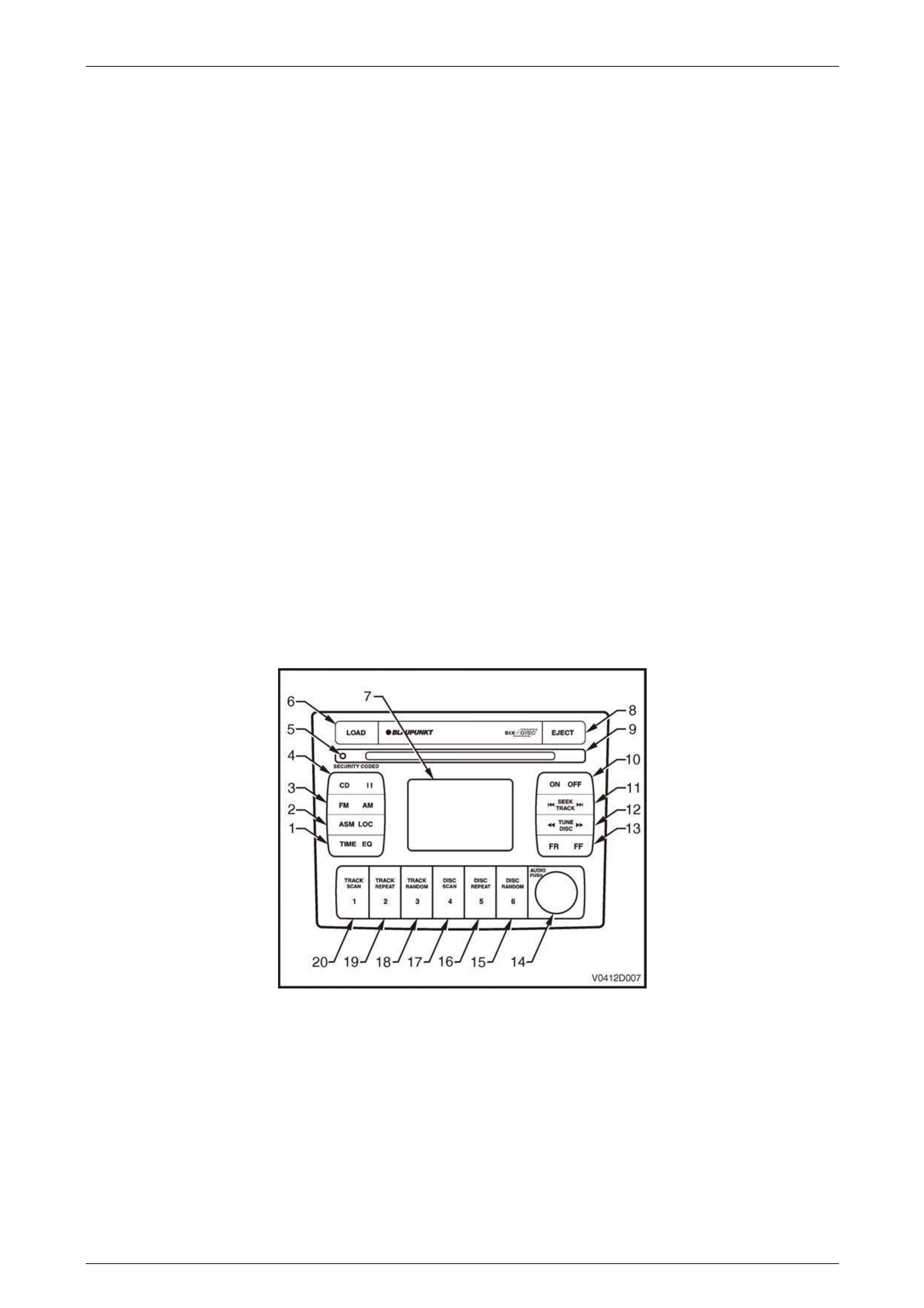
Figure 12D – 1 shows the System 3 radio / CD player fitted to all MY 2004 V2 Series vehicles.
Figure 12D – 1

Entertainment System Page 12D–4
Page 12D–4
Legend
1 Clock adjustment / Time display on/off
Equalizer On / Off setting
2 Automatic station memory storage
Local / distance search sensitivity
3 FM1 / FM2 / AM source button
4 CD source button
CD pause button
5 Security indicator light
CD Mode: Load, remove, wait indicator
6 CD load button
7 Information display
8 CD eject button
9 Disc load / remove slot
10 Radio On / Off
11 Radio Mode: Station seek
CD Mode: Track up / down
12 Radio Mode: Manual frequency select
CD Mode: Disc select
13 CD Mode: Track cue / review
14 Volume control
Push: Bass / Treble / Fader / Balance
15 CD Mode: CD Random
CD Mode: Disc 6 select
Radio Mode: Memory preset station 6
16 CD Mode: CD Repeat
CD Mode: Disc 5 select
Radio Mode: Memory preset station 5
17 CD Mode: CD Scan
CD Mode: Disc 4 select
Radio Mode: Memory preset station 4
18 CD Mode: Track Random
CD Mode: Disc 3 select
Radio Mode: Memory preset station 3
19 CD Mode: Track Repeat
CD Mode: Disc 2 select
Radio Mode: Memory preset station 2
20 CD Mode: Track Scan
CD Mode: Disc 1 select
Radio Mode: Memory preset station 1

Entertainment System Page 12D–5
Page 12D–5
1.1 Power Antenna Operation
The operation and fault diagnosis of the new power antenna is the same as for the antenna installed on MY 2003 VY
and V2 series vehicles. For information on the operation and diagnosis of the power antenna refer to Section
12D Entertainment System in the MY 2003 VY and V2 Series Service Informatio n.
For service information on the po wer antenna refer to 2.1 Power Antenna in this Section.
Entertainment System Page 12D–6
Page 12D–6
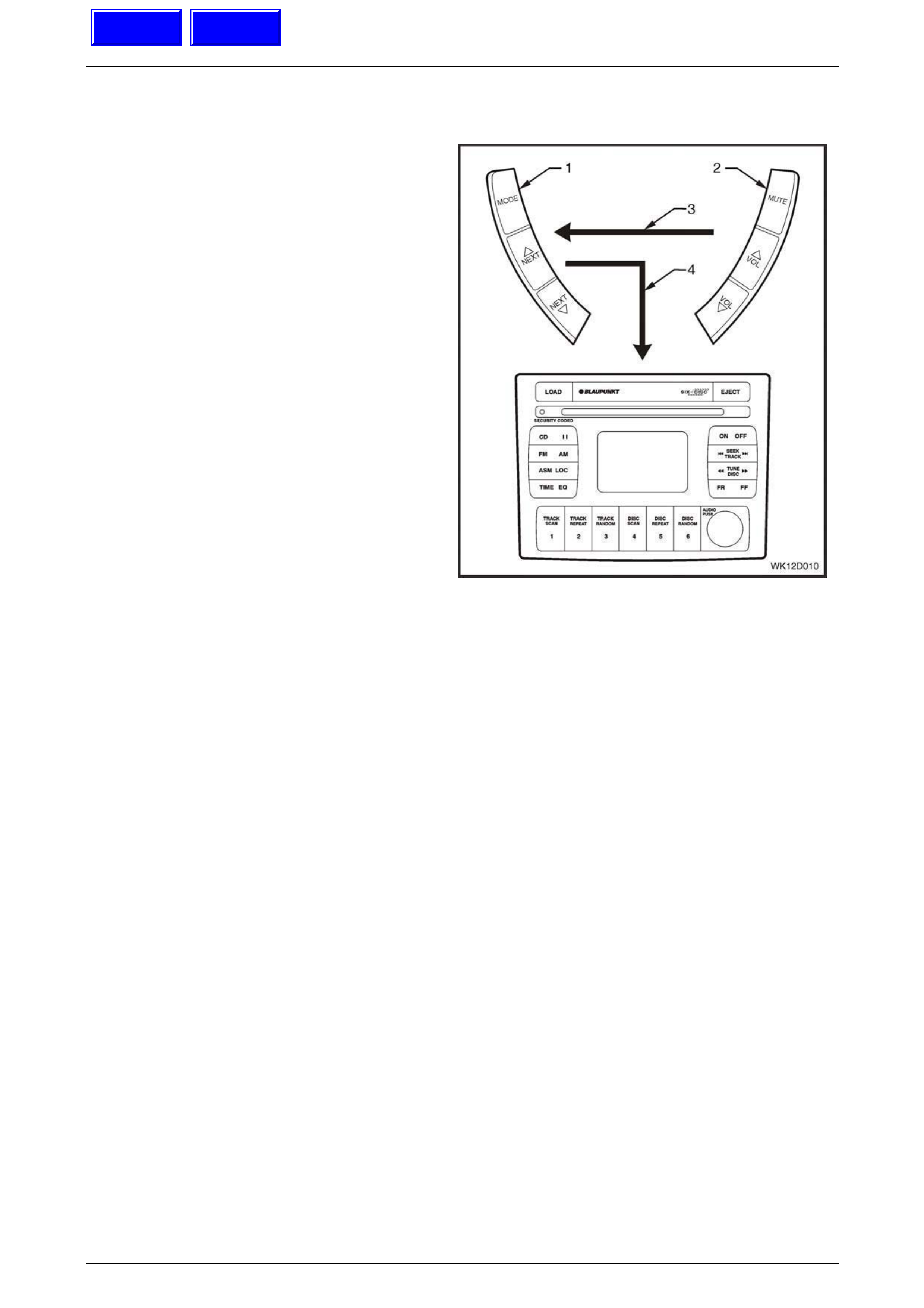
1.2 Horn Bar Stereo Control Operation
There are two major components of the horn bar stereo
control system. These components are as follows:
Left-hand switch assembly (1)
Located to the left-hand side of the horn bar, the left-
hand switch assembly has three momentary contact
switches that are used to control the mode of operation
and switching between preset stations.
The MODE button allo ws selection between the Radio
Mode of operation and the C D Mode.
If Radio Mode is selected, the NEXT UP button selects
the next preset station in the frequ ency band, while the
NEXT DOWN button selects the previous preset radio
station.
If CD Mode is selected, the NEXT UP button selects the
next track on the CD, while the NEXT DOWN button
selects the previous track. For CD Changer models,
pushing the NEXT UP and NEXT DOWN buttons
simultaneously changes the di sc.
Right-hand switch assembly (2)
Located to the right-hand side of the horn bar, the right-
hand switch assembly has three momentary contact
switches that are used to control the MUTE functio n as
well as the VOLUME UP and VOLUME DOWN.
Each control switch has a unique resistance value. When
a button is pressed on the horn bar contro l, the AHU
decides the function required by measuring the
resistance of the contact pressed.
Wiring (3) from the right-hand sw itch is connected to the
left-hand switch. The left-hand switch is conne cted to the
audio system head unit by a wiring loom (4). Figure 12D – 3
shows the wiring details for the non-illuminated horn bar
stereo controls and Figure 12D – 4 show s the w iring details
for the illuminated horn bar stereo controls.
Figure 12D – 2
A Multi-function Display (MFD) in the instrument panel can provide the driver with an almost line-of-sight view of the MFD
for ease of operation of the audio system from the horn bar buttons.
Normal display on the MFD durin g vehicle operation displays the normal trip computer functions, for example the
odometer (in the centre of the MFD screen) and the g ear selector position (displayed at the bottom of the MFD screen at
all times).
When the radio or a CD source is selected, the rad io band and frequency or the CD symbol replaces the trip computer
display for two seconds. The display then reverts to the trip computer display with the radio band and frequency or CD
and track indicator changing to a secon dary small icon located in the warning icon location on the left-hand side of the
MFD.
IMPORTANT
If a warning is activated, the warning will override
the CD and track indicators.
The display of audio system information on the MFD can be turned On or Off from the MFD. The default setting is On.
Refer to Section 12C, 1.8 Customisation Mod e in the MY 2003 VY and V2 Series Service Information for further detai ls.
For Level 1 Acclaim Sedan and W agons and all Level 3 Models, the horn bar stereo controls are illuminated whenever
the park lamps or headlam ps are turne d on. The intensity of the illuminat ion cannot be varied.
Techline
Techline
Entertainment System Page 12D–7
Page 12D–7
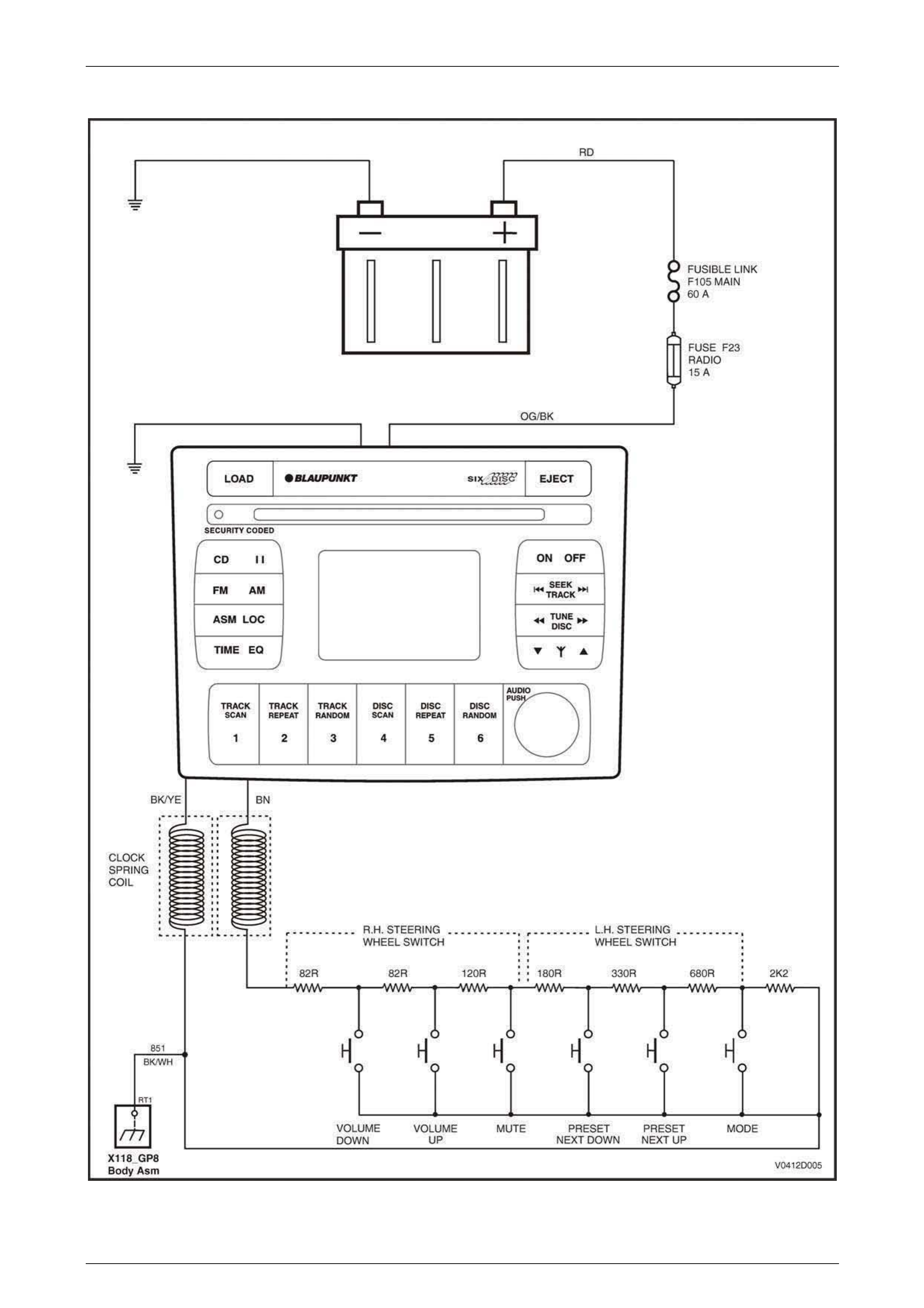
Horn Bar Stereo Control Wiring – Without Illumination
Figure 12D – 3
Entertainment System Page 12D–8
Page 12D–8
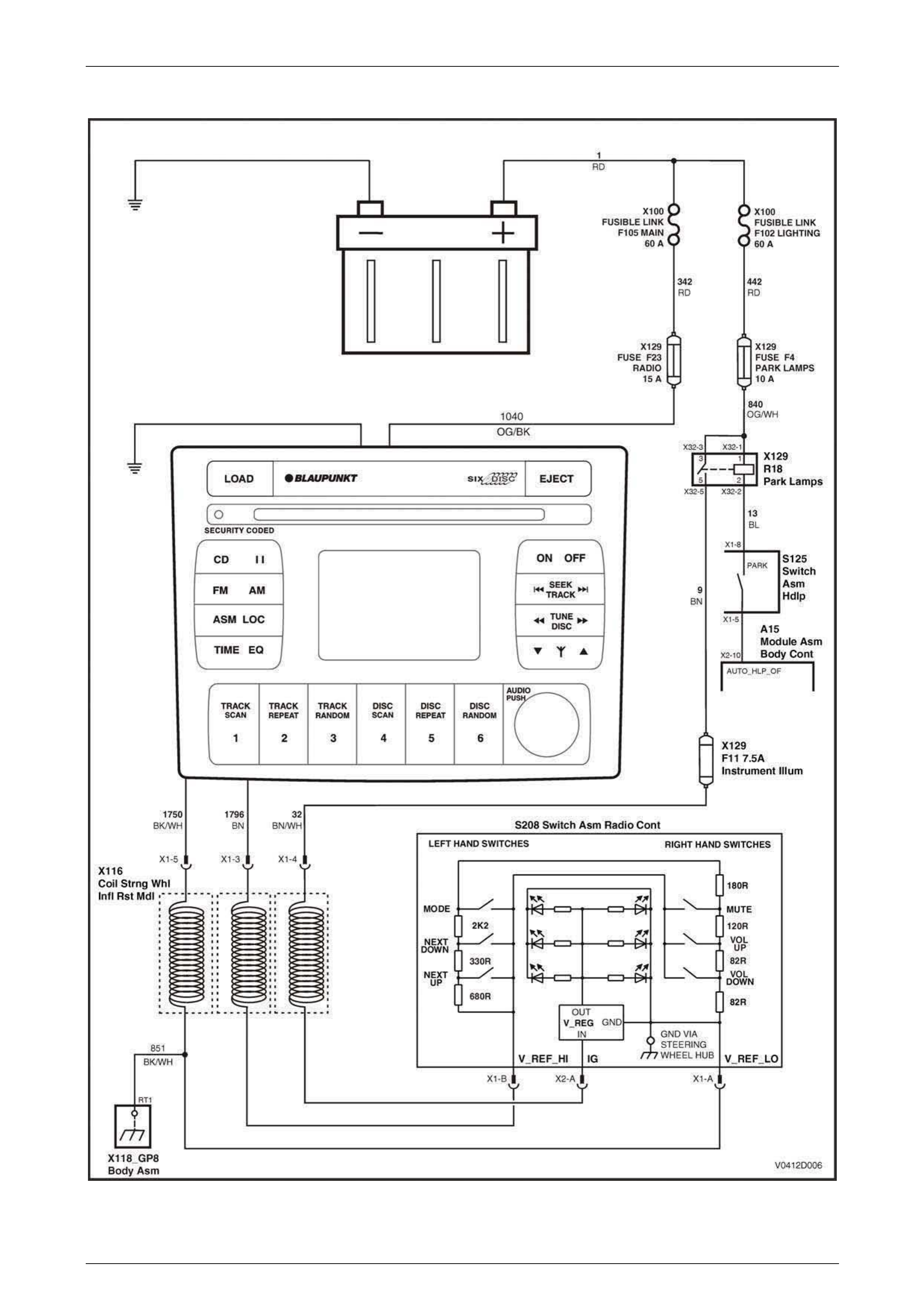
Horn Bar Stereo Control Wiring – With Illumination
Figure 12D – 4
Entertainment System Page 12D–9
Page 12D–9
1.3 On-glass Antenna System
Overview
For MY2004 V2 Series vehicles, an on-glass antenna on the rear window replaces the standard mast a ntenn a. The on-
glass antenna system consists of an antenna coil assembly L4, an antenna amplifier module A93 and connecting leads.
The antenna cabl e between the audio head unit and the antenna amplifier module is a t wo-piece coaxial cable with an in-
line connector located behind a panel in the left hand foot well.
The antenna coil assembly comprises two antennas, one for AM signals and another for FM signals, and these form an
integral part of the rear window glass. The FM antenn a coil is also used as the rear window demister element. The thin
conductors that form each antenna are laid on the inside of the glass, and two connectors are located on the side of the
rear window allowing connection of the antenna coils to the antenna amplifier module. The F M antenna coil / demister is
connected to body ground at X118_GP7, via circuit 185 0, which also includes an RF isolation coil.
The antenna amplifier module amplifies the small signals from the antenna coil assembly then transmits the amplified
signal to the audio system head unit antenna input via a coaxial cable, circuit 5172.
A single wire lead, circuit 314, from the audio system head unit provides the +12 V supply to the antenna amplifier
module for its operation.
The module is grounde d through its case to the vehicle body. To prevent interference, it is very important that the module
and coaxial cable are gro unded securely. Refer to Figure 12D – 10 and Figure 12D – 11 for the antenna interconnection
details.
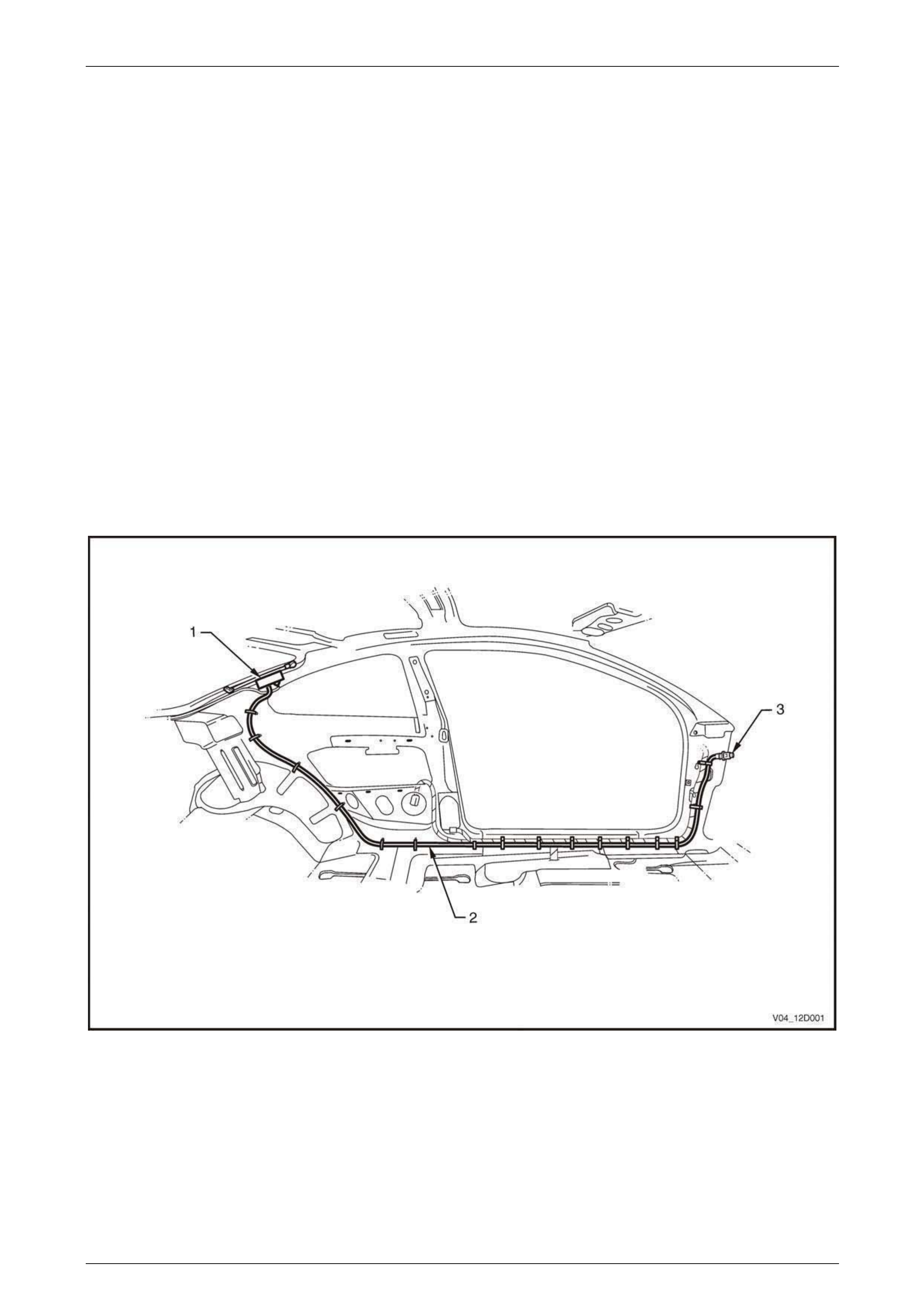
Figure 12D – 5 illustrates the location of the antenna amplifier module and the routin g of the antenna cable,
Figure 12D – 5
Legend
1 Antenna Amplifier Module A93
2 Antenna Cable 3 Antenna Cable In-line Connector X208
Entertainment System Page 12D–10
Page 12D–10
Antenna Systems
The MY2004 V2 Series vehicles are fitted with th ree on-g lass ante nna s mounted on the rea r w indow . This an tenna sy stem
eliminates the need fo r the use of a mast type an tenna on the veh icle. The antenna co il asse mbly comp ri ses th ree an ten nas
plus provision for an external mob ile phone an tenna. Refer to Figure 12 D – 6 and Fi gure 12D – 7.
Figure 12D – 6
AM Antenna
A single AM antenna system is mounted on the rear glass a ssembly (L4, X1-A). Refer also to item 2 in Figure 12D – 7.
FM Antennas
There are two FM antenna s ystems mounted on the rear glass assembly:
• A combined FM Main antenna and demister element (L4, X2-A; X3-A). Refer to item 4 in Figure 12D – 7.
• A FM Diversity antenna (W4). Refer to item 3 in Figure 12D – 7.
The thin conductors that form each antenna are fixed o n th e inside of the glass, and the antenna / demister electrical
connectors are located on the side of the rear window. The FM Main antenna / demister is connected to body ground at
X118_GP7, via circuit 1850, which also inc ludes an RF isolation coil.
The N3 Antenna Amplifier module amplifies the FM Diversity antenna sign als to help red uce noisy radio reception that
may be generated within the vehicle. This module is mounted in the C-pillar as shown at item 9 in Figure 12D – 10.
Entertainment System Page 12D–11
Page 12D–11
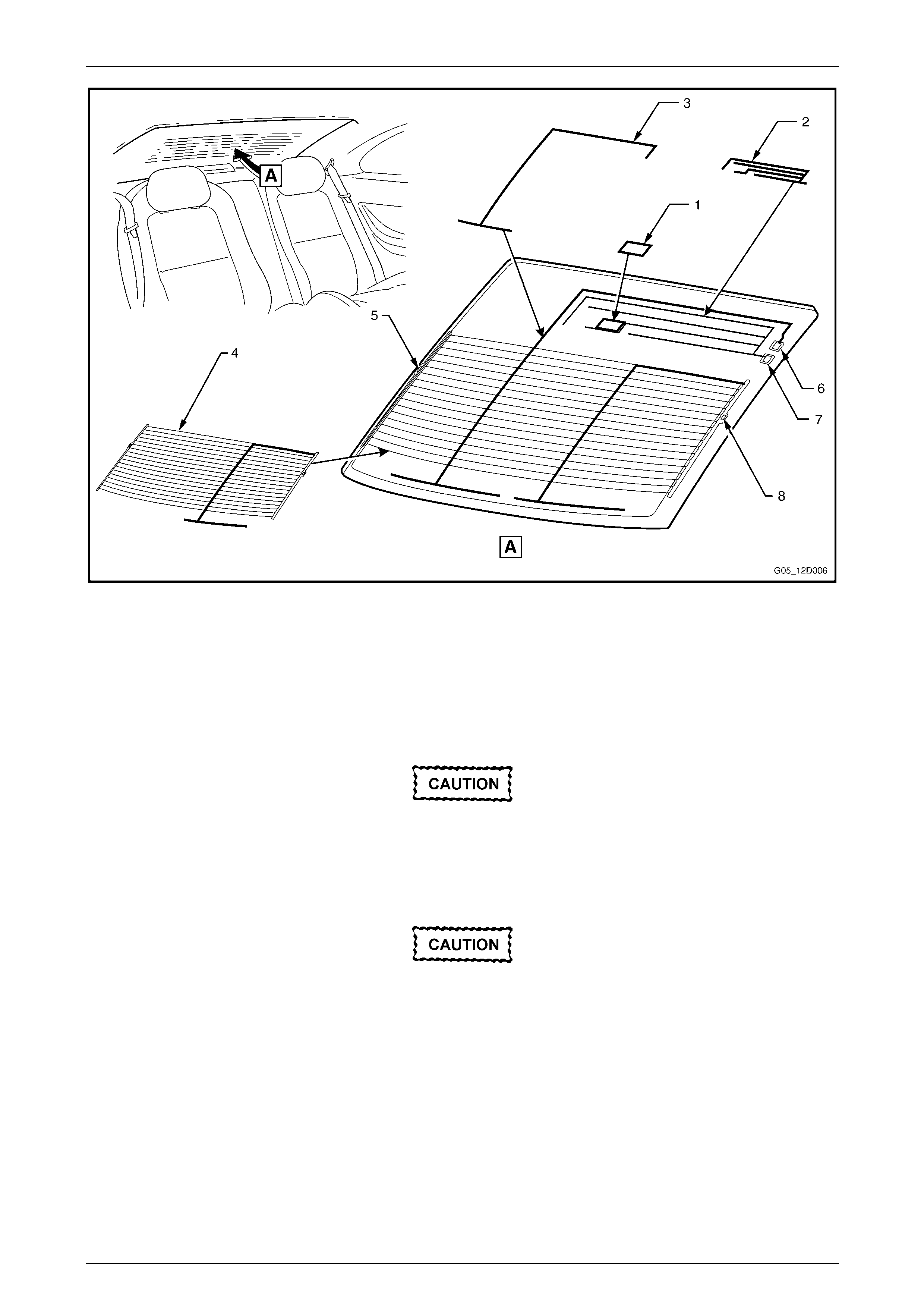
Figure 12D – 7
Legend
1 Mobile phone antenna pad location
2 AM antenna
3 FM Diversity antenna
4 FM Main antenna / Demister element
5 FM Main antenna ground / Demister element connection
6 FM Diversity antenna connection
7 AM antenna connection
8 FM Main antenna / Demister element connection
Window tinting is not recommended on any
glass that has printed antenna coils attached.
Metallic-based tint material significantly
reduces radio reception in both the AM and
FM bands, whereas dye-based tint material
reduces reception in the FM band.
Installation of a mobile phone antenna pad to
the surface of the on-glass antenna may lead
to interference betw een the audio system and
the mobile phone antenna. Figure 12D – 7
indicates the recommended location for the
mobile phone antenna pad in order to
minimise interference.
Entertainment System Page 12D–12
Page 12D–12
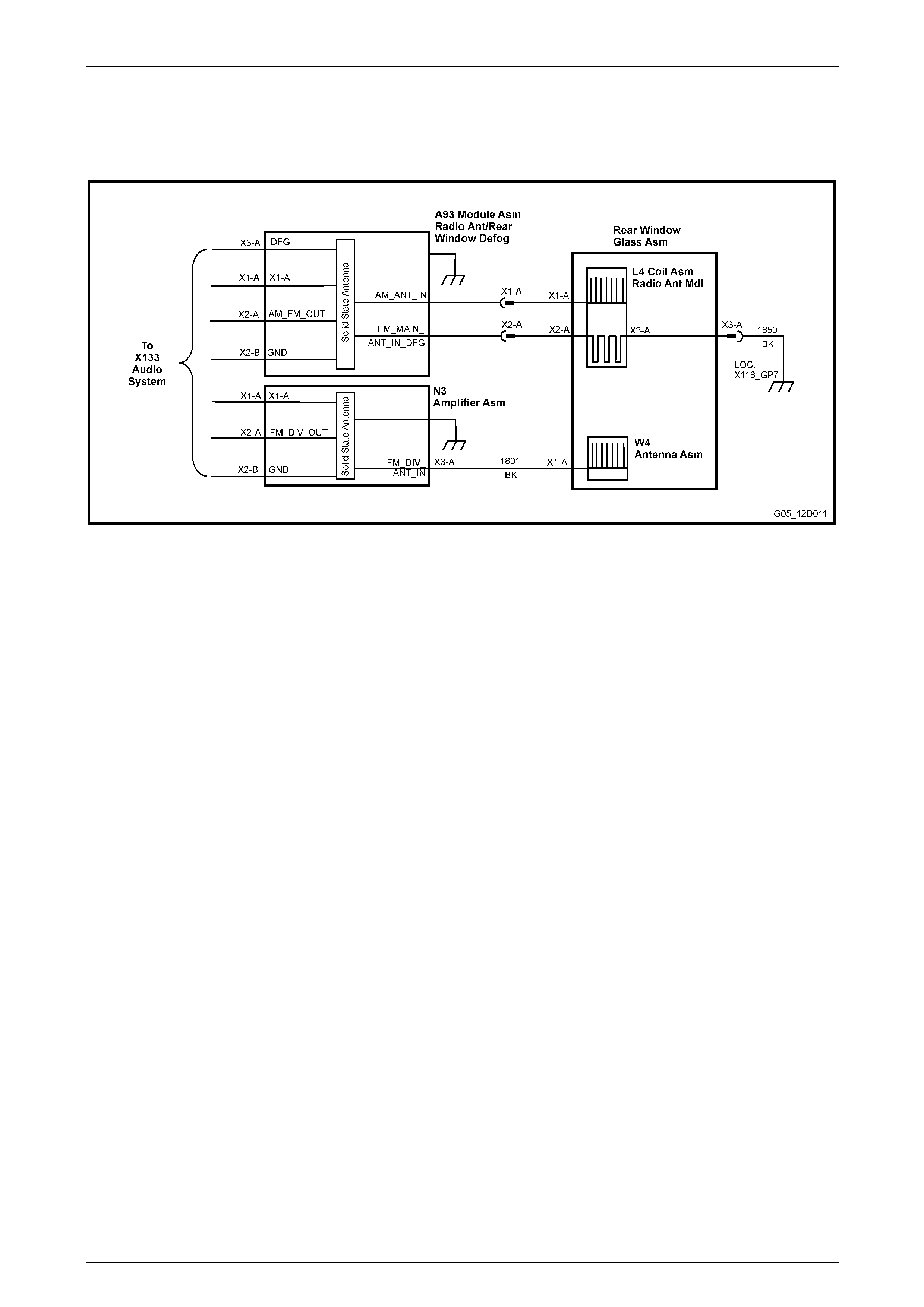
A93 Antenna Module Overview
The vehicle’s FM Main antenn a and its comb ined demister element connect to the audio system and demister circuit via
the A93 Module assembly and its connecti ng leads.
The AM antenna receives AM band radio signals and feeds them to a radio frequenc y amplifier located within the A93
module. Refer to Figure 12D – 8. Similar ly, the FM band radio signals are received b y the F M Main Antenna (i.e. via the
demister element) and are fed to the F M Main Antenna radio frequency amplifier also located within the A93 module.
Both of these amplifiers feed their amplified radio signals into a Radio Frequency Mixer (or combiner) unit. The output
signals of this unit contain radio signals of b oth the AM and FM Main antennas that are then fed into the antenna input of
the vehicle’s A133 AHU.
Figure 12D – 8
Circuit 5172 is a coaxial cable that carries the combined AM and FM Main antenna signals to the A133 AHU antenna
input. It is a two-piece coaxial cable with an in-line connector located behind a panel in the left-hand side footwell.
Circuit 314 is a single wire lead that originates from the A133 AHU unit, which provides the +12 V supply to the antenna
amplifier module.
The module is grounde d through its case to the vehicle body. To prevent interference, it is very important that the module
and coaxial cable are gro unded securely. Refer to Figure 12D – 10 and Figure 12D – 11 for the antenna interconnection
details.
Entertainment System Page 12D–13
Page 12D–13
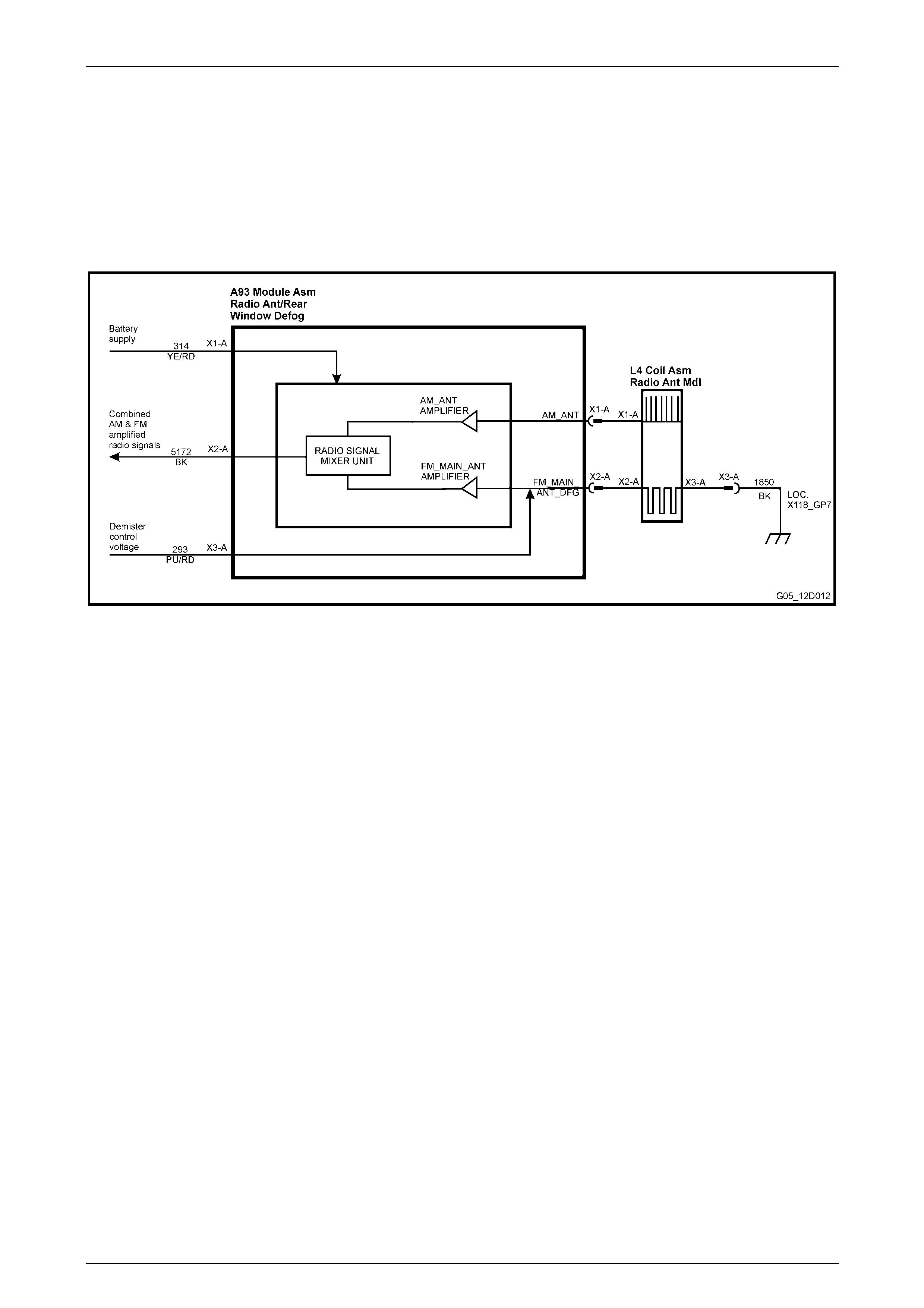
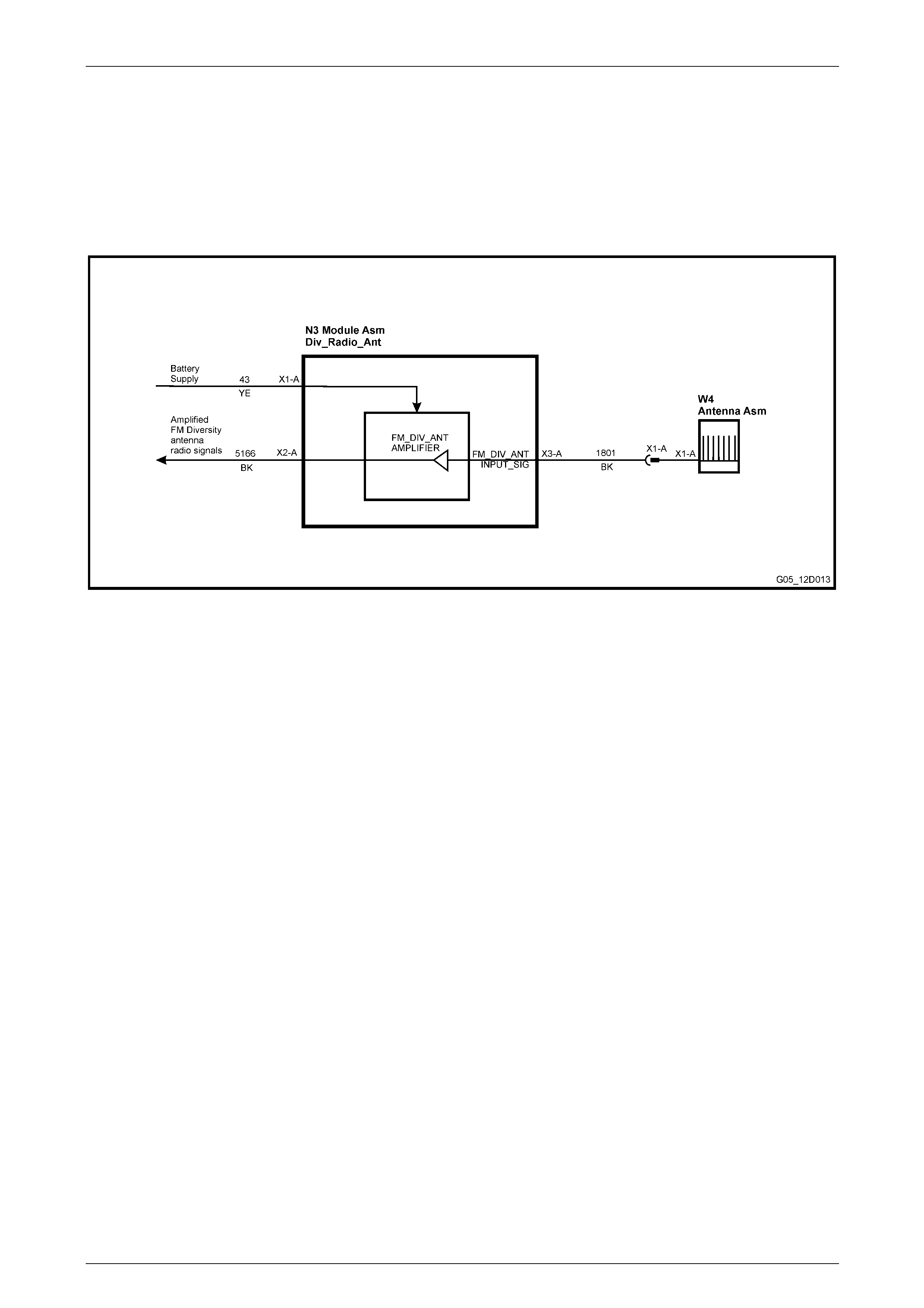
N3 Antenna Amplifier Module Overview
The vehicle’s FM Diversity antenna connects to the A133 AHU audio system via the N3 Amplifier assembly. This module
is shown as (item 9) in Figure 12D – 10. The routing of the FM Diversity antenna cable within the vehicle is shown in
Figure 12D – 5.
With reference to Figure 12D – 9, signals from the FM Diversity antenna are fed into terminal X3-A of the N3 module
(item 3 in Figure 12D – 7). These signals are amplified in a similar way the AM and FM Main antenna signals are
amplified. The output signals of the amplifier are then fed to the Diversity Antenna input conn ector of the A133 AHU via a
coaxial cable circuit 5166.
Figure 12D – 9
The antenna coil assembly comprises two antennas, one for AM signals (2) and another for FM signals (4), and these
form an integral part of the rear window glass. The FM antenna coil is also used as the rear window demister element.
The thin conductors that form each antenna are la id on the inside of the glass, and two connectors are located on the
side of the rear windo w allowing connection of the antenna coils to the a ntenn a amplifier module. The FM antenna
coil/demister is connected to body ground at X118_GP7, via circuit 1850, which also includes an RF isolation coil.
Entertainment System Page 12D–14
Page 12D–14
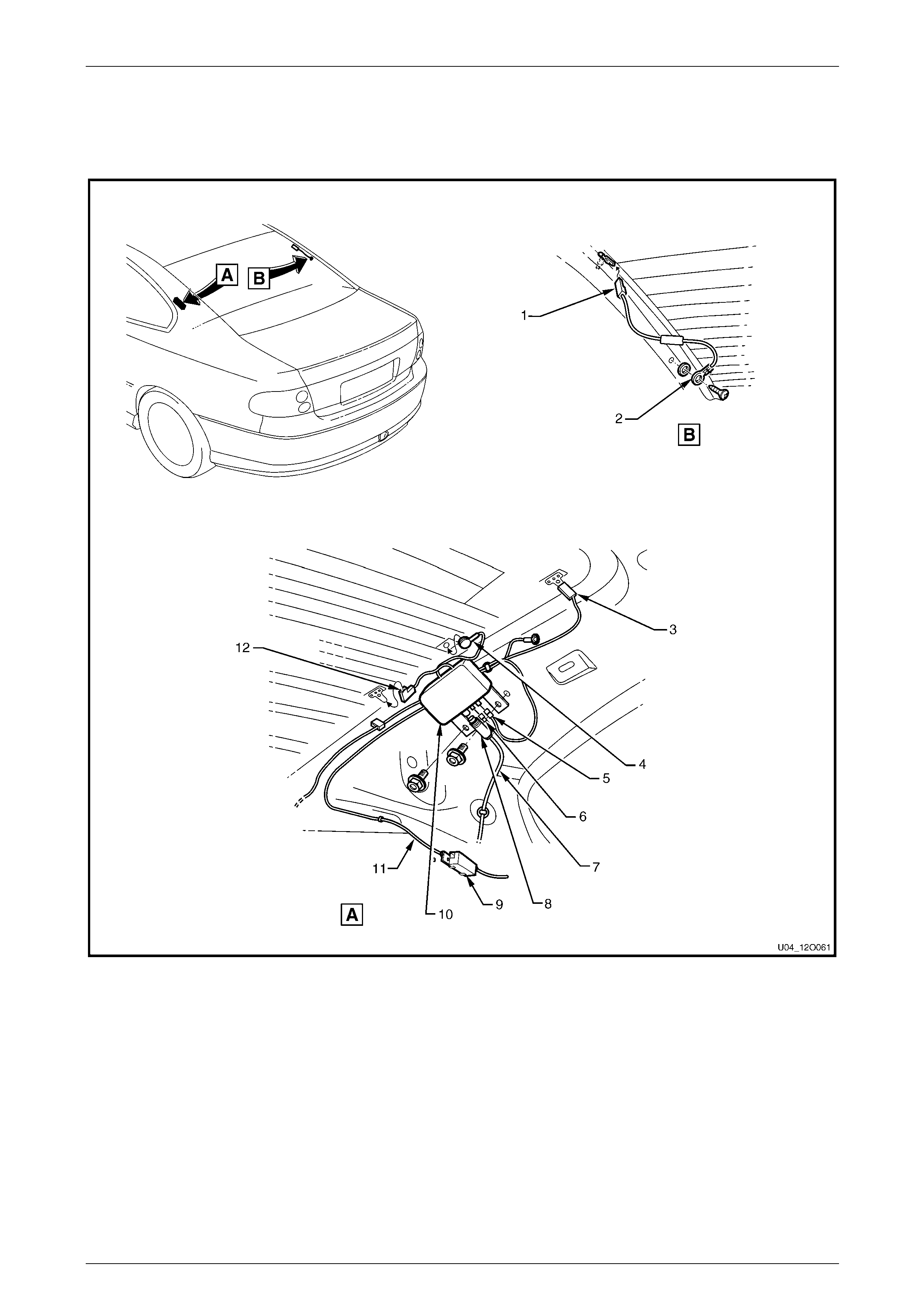
A93 / N3 Antenna Amplifier Location
The on-glass antenna s ystem consists of an antenna coil assembly that connects to an antenna amp lifier module A93
and connecting leads. Figure 12D – 10 illustrates the location of the antenna amplifier module and the routing of the
antenna cable, while Fi gure 12D – 11 illustrates the antenna amplifier mo dule and its connectors.
Figure 12D – 10
Legend
1 Antenna Amplifier Connector (L4 – L3)
2 Antenna Ground Lead Terminal (X118 – GP7)
3 Radio Diversity Connector (W4)
4 Antenna Grid Connector (L4 – X1)
5 Antenna and Rear Window Defog Control Module Connector
(A93 – X3)
6 Antenna and Rear Window Defog Control Module Connector
(A93 – X1)
7 Audio Antenna Harness
8 Antenna and Rear Window Defog Control Module Connector
(A93 – X2)
9 Diversity Antenna Amplifier Module
10 Antenna and Rear Window Defog Control Module
11 Body Wiring Harness
12 Defog Grid Connector (L4 – X2)
Entertainment System Page 12D–15
Page 12D–15
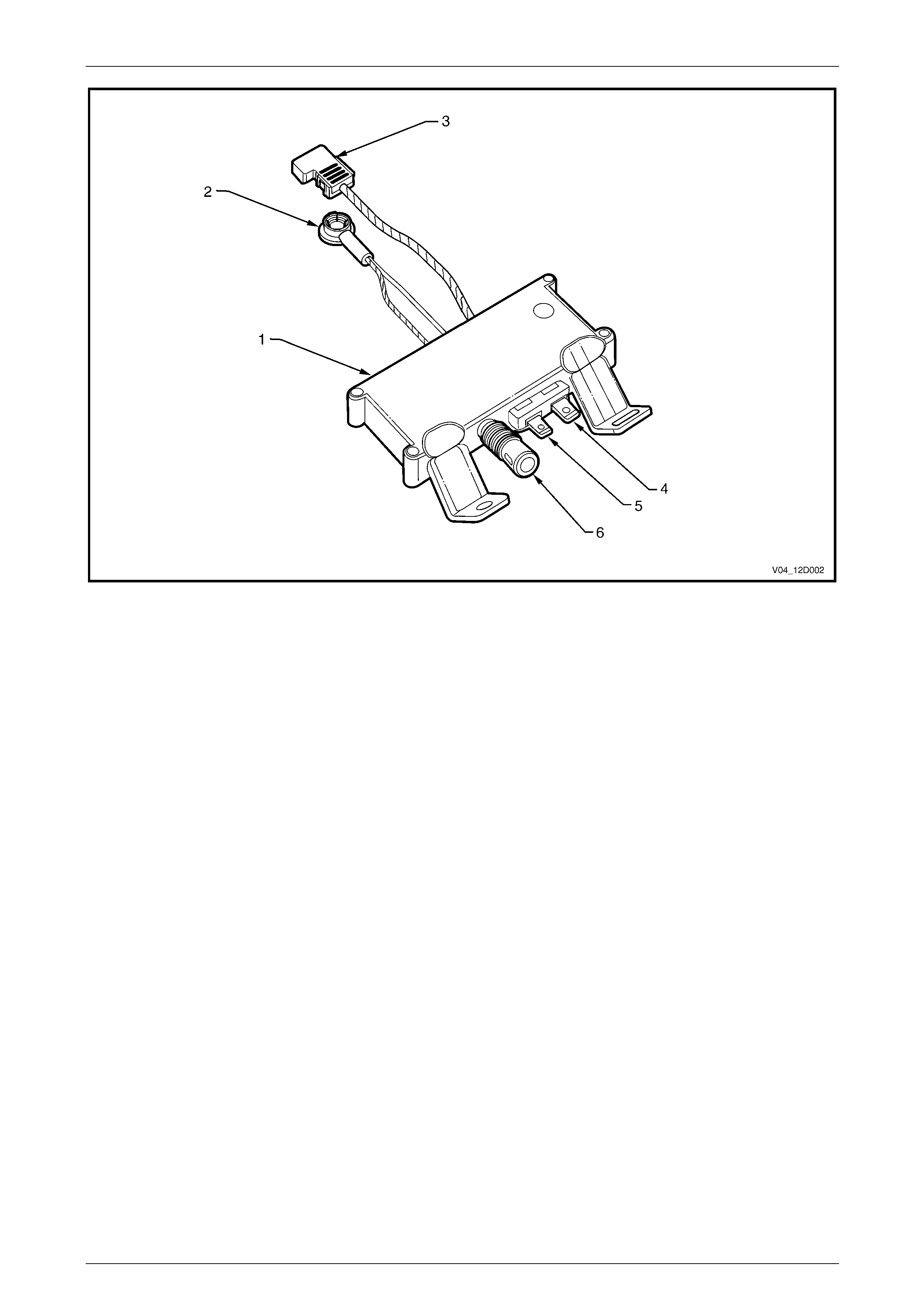
Figure 12D – 11
Legend
1 Antenna Amplifier Module A93
2 AM Antenna Coil Connector (L4 – X1)
3 FM Antenna Coil and Demist Connector (L4 – X2)
4 Rear Window Demist + 12 V Supply Connector (A93 – X3)
5 Antenna Amplifier Module + 12 V Supply Connector (A93 – X1)
6 Radio Signal (A93 – X2)

Entertainment System Page 12D–16
Page 12D–16
2 Service Operations
ATTENTION
All fasteners are important attaching parts as they affect the performance of vital components and / or could
result in major repair expense. W here specified in this section, fasteners MUST be replaced w ith parts of the
same part number or a GM approved equivalent. Do not use fasteners of an inferior quality or substitute
design.
Torque values must be used as specified during reassembly to ensure proper retention of all components.
Throughout this section, fastener torque wrench specifications may be accompanied with the following
identification marks:
Fasteners must be repl aced after loosening.
Vehicle must be at kerb height before final tightening.
Fasteners either ha ve micro encapsulated sealant ap plied or in corporate a mech anical thread lock and
should only be re-used once. If in doubt, replacement is recommended.
If one of these identification marks is present alongside a fastener torque wrench specification, the
recommendation regarding that fastener must be adhered to.
2.1 Power Antenna
Power Antenna Switches
The power antenna directi on al control switches are integr ated with the AHU and as such cannot be servic ed separately.

Entertainment System Page 12D–17
Page 12D–17
Power Antenna Assembly
LT Section No. 09–400
Remove
1 Ensure that the audio system is turned off and that the
antenna mast is in the fully retracted position.
2 From inside the vehicle, remove the appropriate side
hinge pillar trim assembly. Ref er to Section 1A8, 2.8
Hinge Pillar Trim Assembly in the MY2003 V Y and V2
Series Service Information. For RHD vehic les, remove
the left-hand side assembly, for LHD vehicl es remove
the right-hand side assembly.
3 For RHD models, leave the wiring harnesses
connected to the exposed Powertrain Contr ol Mod ule
(V6 models) or the Powertrain Interface Module (GEN
III models) and manoeuvre the module from the plastic
mounting bracket.
4 Remove the plastic mounting bracket. Refer to Section
6C1–3 Powertrain Control Module in the MY 2003 VY
and V2 Series Service Information.
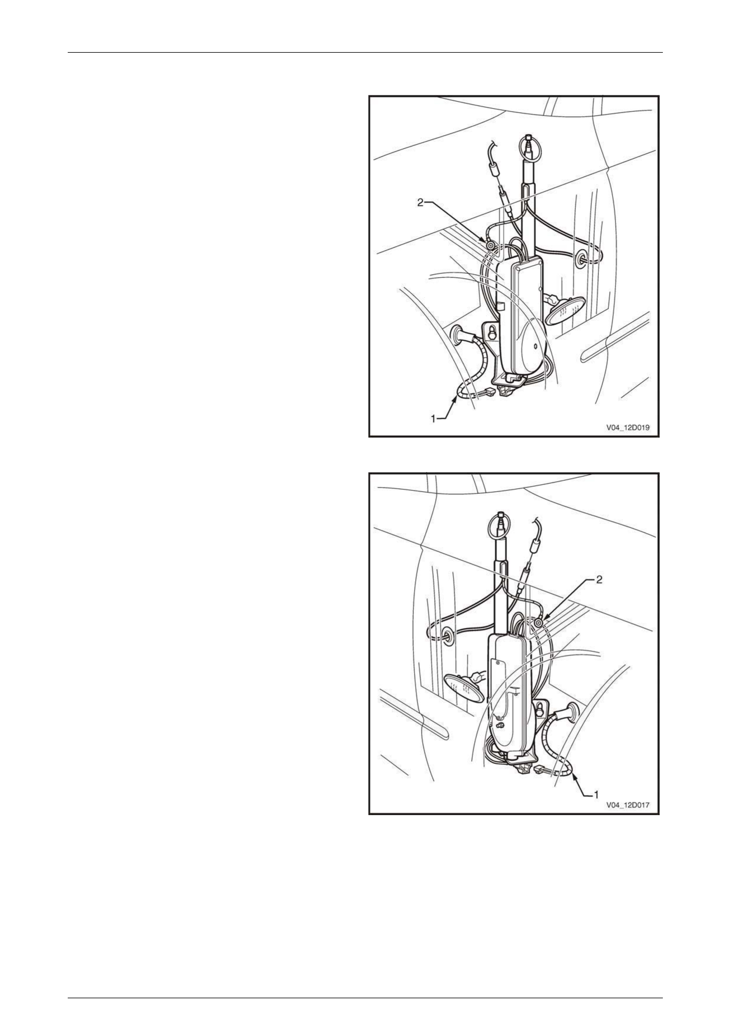
5 For all models disconnect the antenna lead (1) from
the connecting socket of the antenna extensi on lead.
NOTE
Figure 12D – 12 illustrates a RHD vehicle
installation. For LHD vehicles, installation is
similar but on the opposite side.
NOTE
Figure 12D – 13 illustrates a RHD antenna
assembly installation and Figure 12D – 14
illustrates a LHD antenna installation.
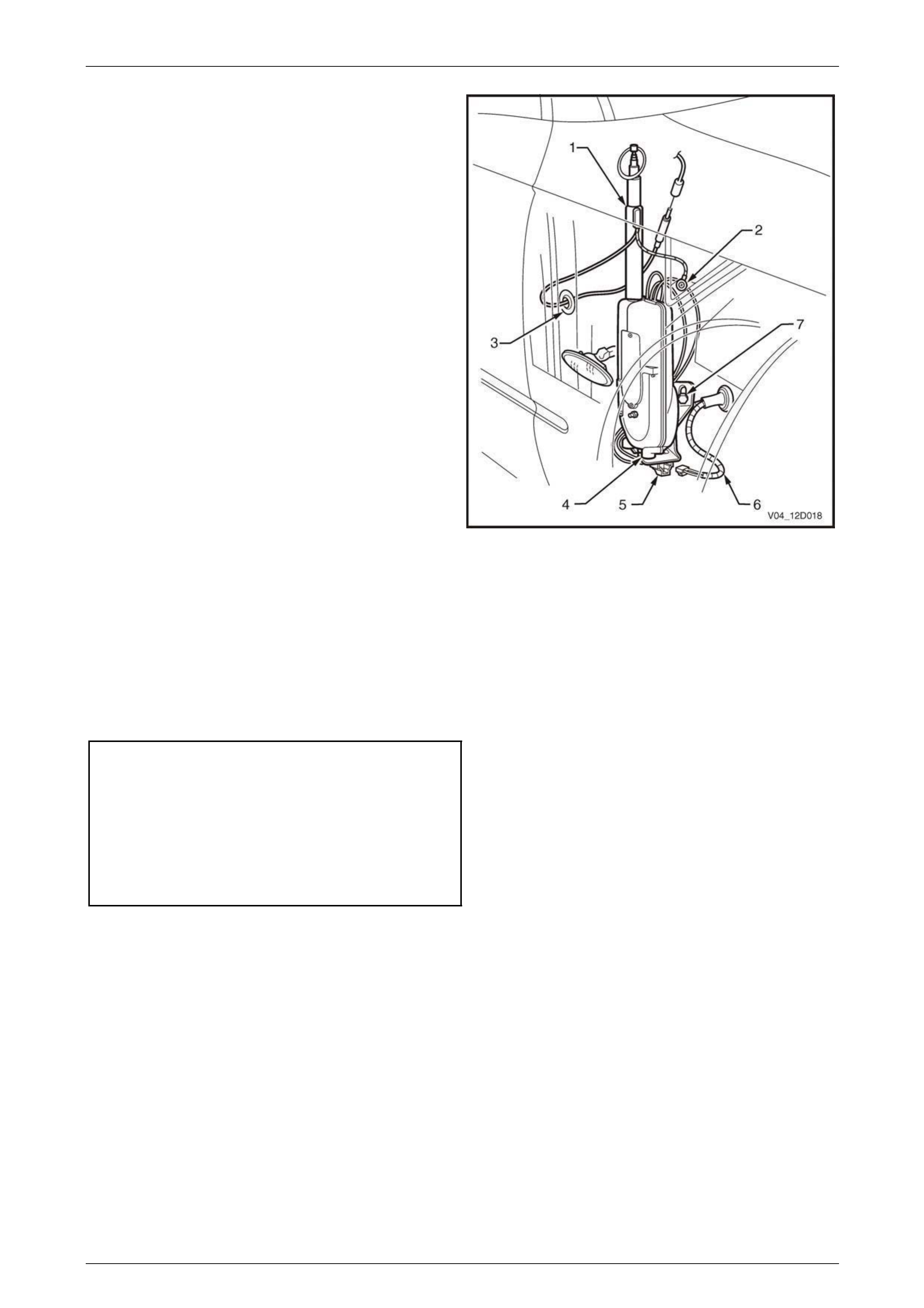
Figure 12D – 12
6 Remove the appropriate fender inner li ner. Refer to
Section 1A1, 3.1 Front Wheelhouse Liner in the
MY2003 VY and V2 Series Service Information.
7 Remove the screw (2) connecting the ground braid to
the inner fender ground terminal.
8 Disconnect the antenna power connector (6) from the
main wiring harness connector in the wheel well.
9 While supporting the antenna assembly (5), remove
the retaining bolt (7) from the antenna supp ort bracket.
10 Remove the antenna lead grommet (3) from the inner
fender panel and pull the l ead out from the passenger
compartment.
11 Withdraw the antenna (1) down through the bezel and
remove the antenna, complete with leads, grommet
and bracket.
12 Remove the two nuts (4) securing the antenna to the
mounting bracket.
Figure 12D – 13
Entertainment System Page 12D–18
Page 12D–18
Figure 12D – 14
Reinstall
Installation of the power antenna is the reverse of the removal procedure, taking note of the following:
1 Ensure that the cable and harness are routed correctly.
2 Ensure that the antenna and the ground lea ds are routed correctly and are securel y connected.
3 With the antenna pushed up against the stop in the bezel, tighten the bolt attaching the antenna brack et to the
inner fender panel to the correct torque specification.
Antenna bracket to inner fender
panel retaining bolt
torque specification.................................14.5 – 19.5 Nm
Antenna ground braid to inner fender
panel retaining screw
torque specification.....................................1.0 – 3.0 Nm
Antenna assembly to bracket nuts
torque specification...................................5.0 – 12.0 Nm
4 Check the antenna operation and the radio reception.

Entertainment System Page 12D–19
Page 12D–19
Mast Replacement
LT Section No. 09–400
The following procedure is for replacing a damaged or faulty antenn a mast and drive cable assembly.
1 Remove the power antenna assembly as previously described in this Section.
2 Remove the chrome-plated nut from the top end of the mast tube.
3 Extend the damaged antenn a mast as far as possib le by attaching the battery negative, via a jumper lead, to the
antenna mounting br acket and connect the battery positive to both the antenna red and white wire terminals.
4 At the end of the mast travel, pull out the mast and drive cable from the ant enna housing.
NOTE
If the mast is too badly damaged to extend, grip
the tip of mast with a pair of pliers and pull the
mast and drive cable assembly up and out from
the antenna housing.
5 If necessary, remove the contact spring (metal sleeve) from the old mast and drive cable and install onto the
replacement mast and drive cable.
6 Feed the end of the drive cable down the mast tube of the antenna housing with the serrated sid e of the drive ca ble
facing toward the centre of the housing. Continue to feed the drive cable down until it engages with the drive
mechanism.
NOTE
It may be necessary to twist the drive cable
clockwise and anti-clockwise slightly to enable
the end of cable to feed through the opening at
the base of the mast tube before it engages the
drive mechanism.
7 With an assistant holding the antenna and mast assembly, connect the antenna support bracket, via a jumper l ead,
to battery negative.
8 Momentarily connect battery positive to the antenna red wire. The drive mechanism should start to retract the drive
cable into the antenna housing.
9 With the drive cable engaged to the drive mechanism, reconnect battery positive to the antenna red wire and allow
the drive mechanism to wind in the drive cable and mast into the mast tube and housing.
10 At this stage the mast might be fully retracted into the mast tube and hous ing. Reconnect both the red and white
wires to battery positive and allow the mast to extend fully until the motor stops.
11 Disconnect the white wire from battery positive and allow the mast to fully retract.
12 Install the chrome-plated nut onto the mast tube and tighten the nut securely.
13 Install the power antenna assembly as descr ibed previously in this Section then check the antenna mast operation
and radio reception.
Entertainment System Page 12D–20
Page 12D–20
Checking Antenna Motor Operation
NOTE
The following ‘Checking Antenna Motor
Operation’ tests are made at the main wiring
harness-to-antenna motor connector located in
the wheel well. It will be necessary to remove the
front wheel liner to gain access to the connector.
Refer to Section 1A1, 3.1 Front Wheelhouse
Liner in the MY 2003 VY and V2 Series Service
Information.
NOTE
Figure 12D – 15 illustrates a RHD antenna
operational check and Figure 12D – 16
illustrates a LHD antenna operational ch eck.
Legend
1. Main wiring harness-to-antenn a motor connector
2. Ground braid
Figure 12D – 15
Figure 12D – 16

Entertainment System Page 12D–21
Page 12D–21
The voltages shown are measured to a g oo d ground point on the vehicle body.
Voltage on Antenna Harness W ires
Red White Action
12 V 12 V Antenna extends
12 V 0 V Antenna retracts
0 V 12 V Antenna does not move
0 V 0 V Antenna does not move
If the antenna motor does not correctly respond to the inputs as specified, ensure that a good ground conn ection is being
made through the mounting bracket by measuring the resistance from the bracket to a good ground point. If more than
1 ohm is recorded, remove the antenna assembly as described in this Section. Ensure that the bracket and body contact
surfaces are clean. If all OK, replace the po wer antenna ass embly. Check that the bl ack wire with the forked ground
connector (item 3 in Figure 12D – 15) is securel y attached to the antenna mounting bracket.
NOTE
If there is significant noise on the AM band (with
the radio tuned to a weak station outdoors), then
check the ground quality of the antenna at the
points previous ly mentioned. T he antenna gr ound
terminal has a large effect on the screen in L evel
1 vehicles. Also check the ground quality of the
ground braid (refer to Item 2 of Figure 12D – 15).
Entertainment System Page 12D–22
Page 12D–22
2.2 Antenna System (Coupe Only)
The antenna system consists of an antenna coil assembly L4, an antenna amplifier module A93 and connecting leads.
The antenna coil assembly comprises two antennas, one for AM signals and another for FM signals, and these form an
integral part of the rear window glass. The FM antenn a coil is also used as the rear window demister element. The thin
conductors that form each antenna are laid on the inside of the glass, and two connectors are located on the side of the
rear window allowing connection of the antenna coils to the antenna amplifier module.
The antenna amplifier module amplifies the small signals from the antenna coil assembly then transmits the amplified
signal to the radio’s antenna i nput. The module is located beneath the trim on the driver’s side of the rear parcel shelf.
The module is connected to the au dio system head unit via a coaxial lead, circuit 5172.
AM/FM Antenna Coil
Repair
1 To maintain optimum radio system performance, breaks in the antenna coil s must be repaired. Use a Repair Kit
available from automotive accessor y outl ets and follow the manufacturer’s instructions carefully.
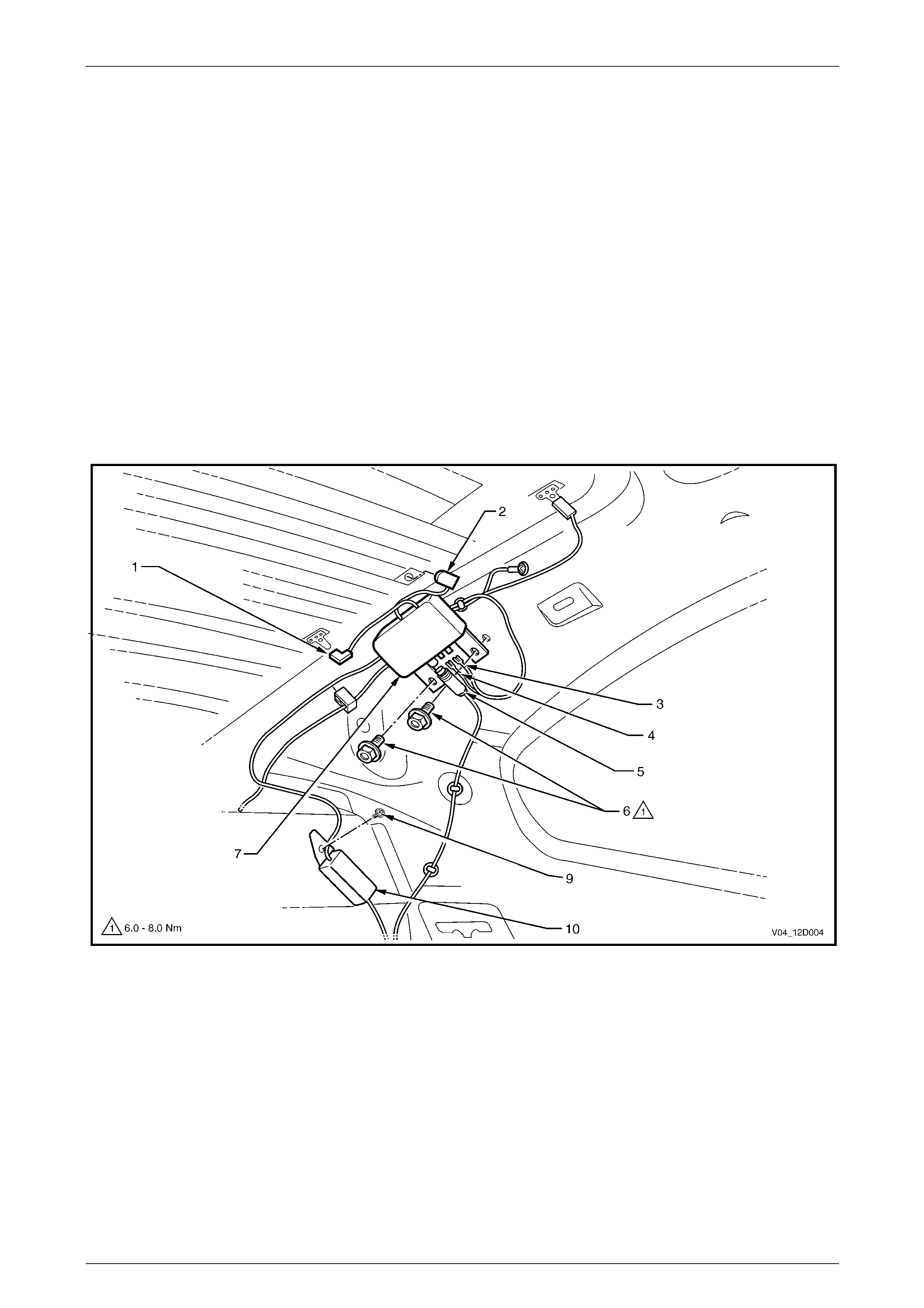
Antenna Amplifier Module
Figure 12D – 17
Remove
1 Ensure that the audio system is turned off.
2 Remove the left hand side body rear corner garnish. Refer to Section 1A8, 4.5 Body Rear Corner Garnish in the
MY 2003 VY and V2 Series Service Information.
3 Disconnect the FM antenna / demister connector (1) and the AM antenna connector (2) from the rear window
connectors.
4 Disconnect the three connectors (3, 4 and 5) from the antenna amplifier module (7).
5 Remove the two screws (6) securing the antenna amplifier module to the vehicle body.
6 Where fitted remove the screw (9) from the diversity antenna module (10) and remove th e wire from the body
harness.
7 Remove the module from the vehicle

Entertainment System Page 12D–23
Page 12D–23
Reinstall
Installation of the antenna amplifier modu le is the reverse of the removal procedure, noting the follo wing:
1 Tighten the module mounting screws to the correct torque specification.
Antenna Amplifier Module
Mounting Screw
Torque Specification ...................................6.0 – 8.0 Nm
Entertainment System Page 12D–24
Page 12D–24
3 Diagnostics
3.1 TECH 2 Test Modes and Displays
MY 2004 VY and V2 Series Entertainment System TECH 2 test mode and display information carries over from MY 2003
VY and V2 Series vehicles with the exception that the 2004 Model Year must be selected from the vehicle identification
menu.
Main Menu
Turn the ignition on and press the power button (PWR) on
the TECH 2.
The TECH 2 will perform a series of self-di ag nosing power
on self-tests (POST). Once this has been completed
successfully, the TECH 2 startup screen will be displayed.
Press the Enter key to continue.
The Main Menu screen is displayed.
Press the F0 function button or Select F0: Diagnostics by
using the arrow keys until F0: Diagnostics is highlighted and
press the Enter key.
VY12D050
Main Menu
F0:
F1:
F2:
F3:
F4:
Diagnostics
Service Programming System (SPS)
View Capture Data
Tool Options
Download/Upload Help
Figure 12D – 18
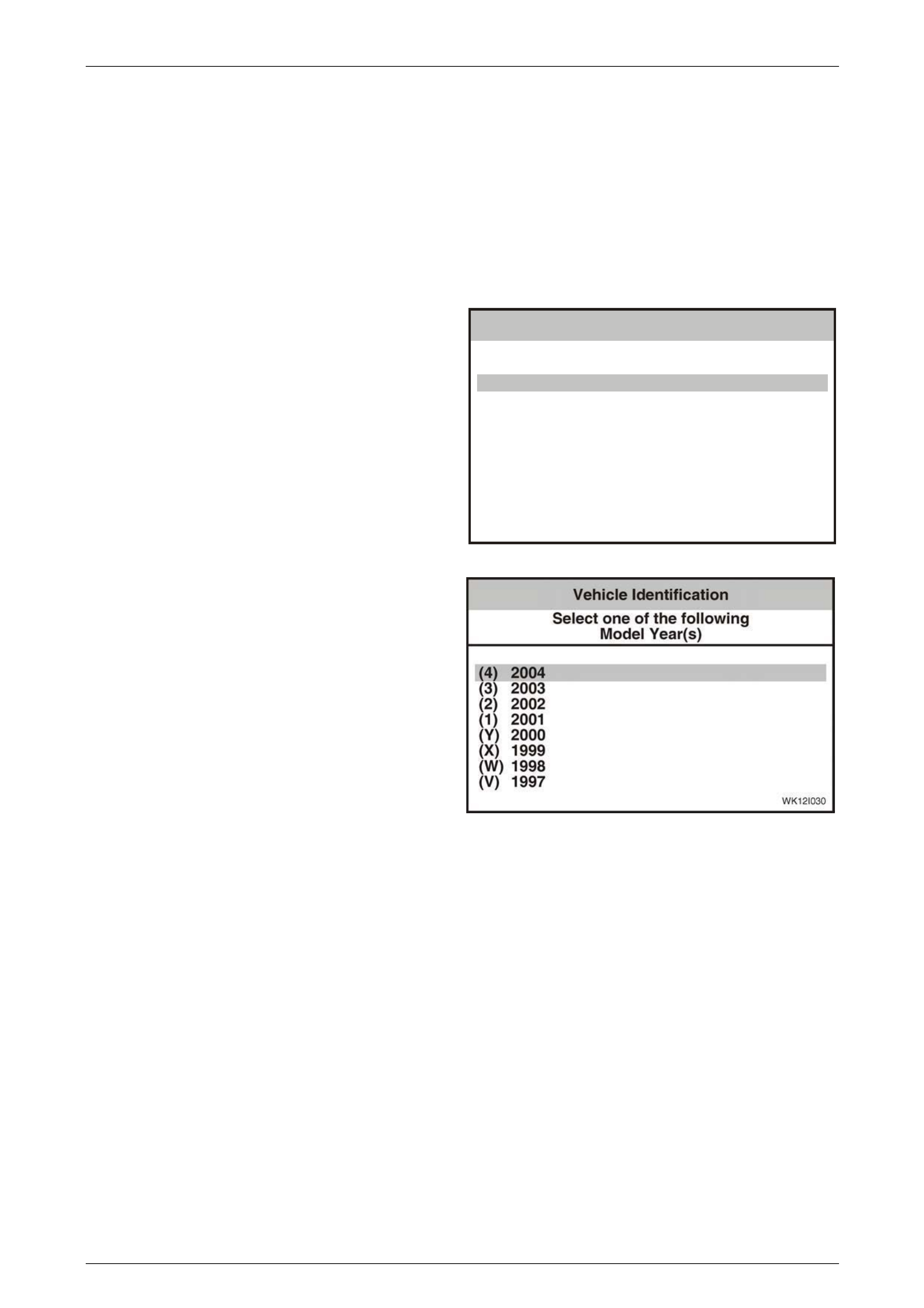
Model Year
Select 2004 from the Model Year list and pre ss Enter.
Figure 12D – 19
Entertainment System Page 12D–25
Page 12D–25
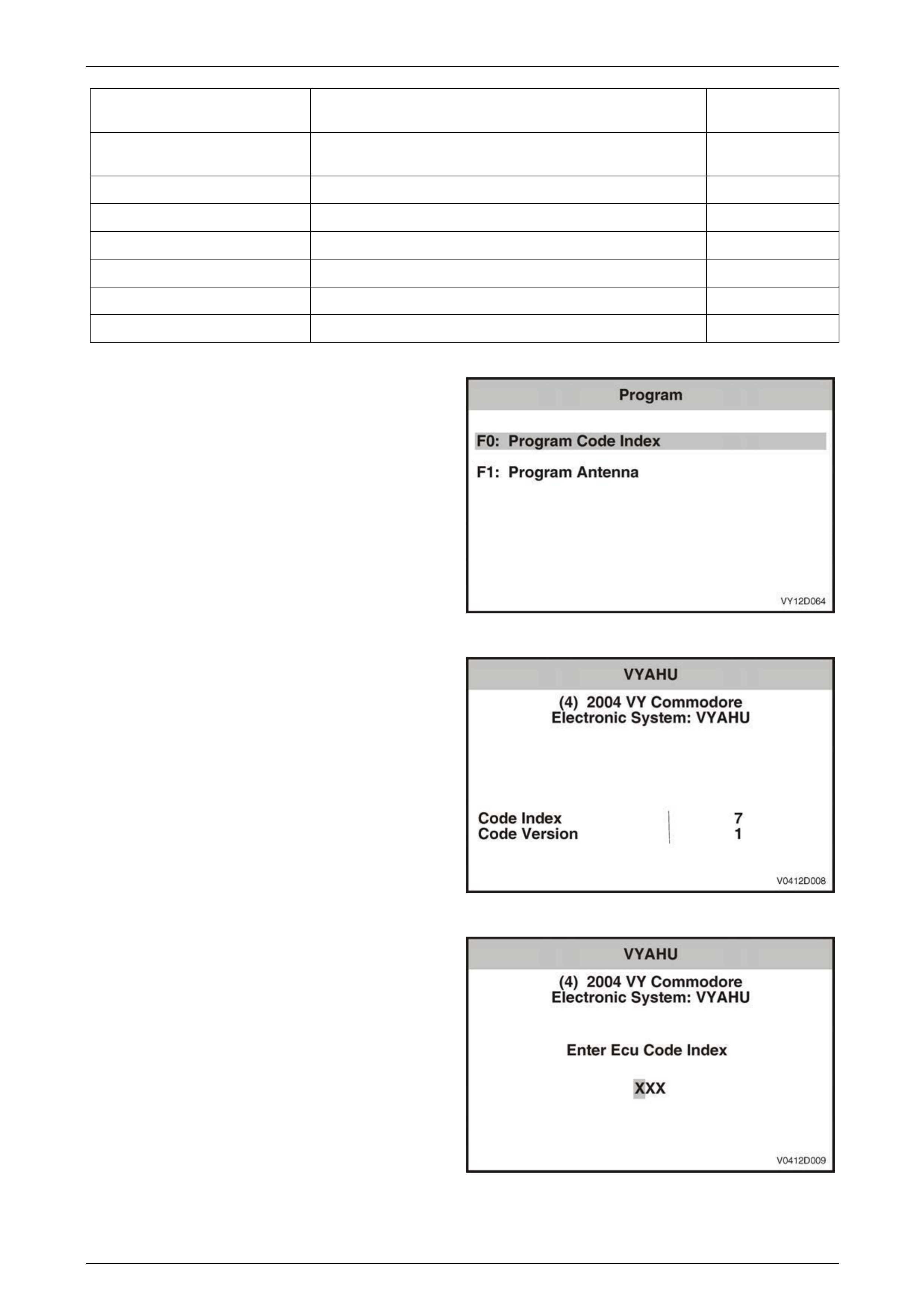
3.2 Program – Audio System
The Program function allo ws various Audi o System parameters to be programmed.
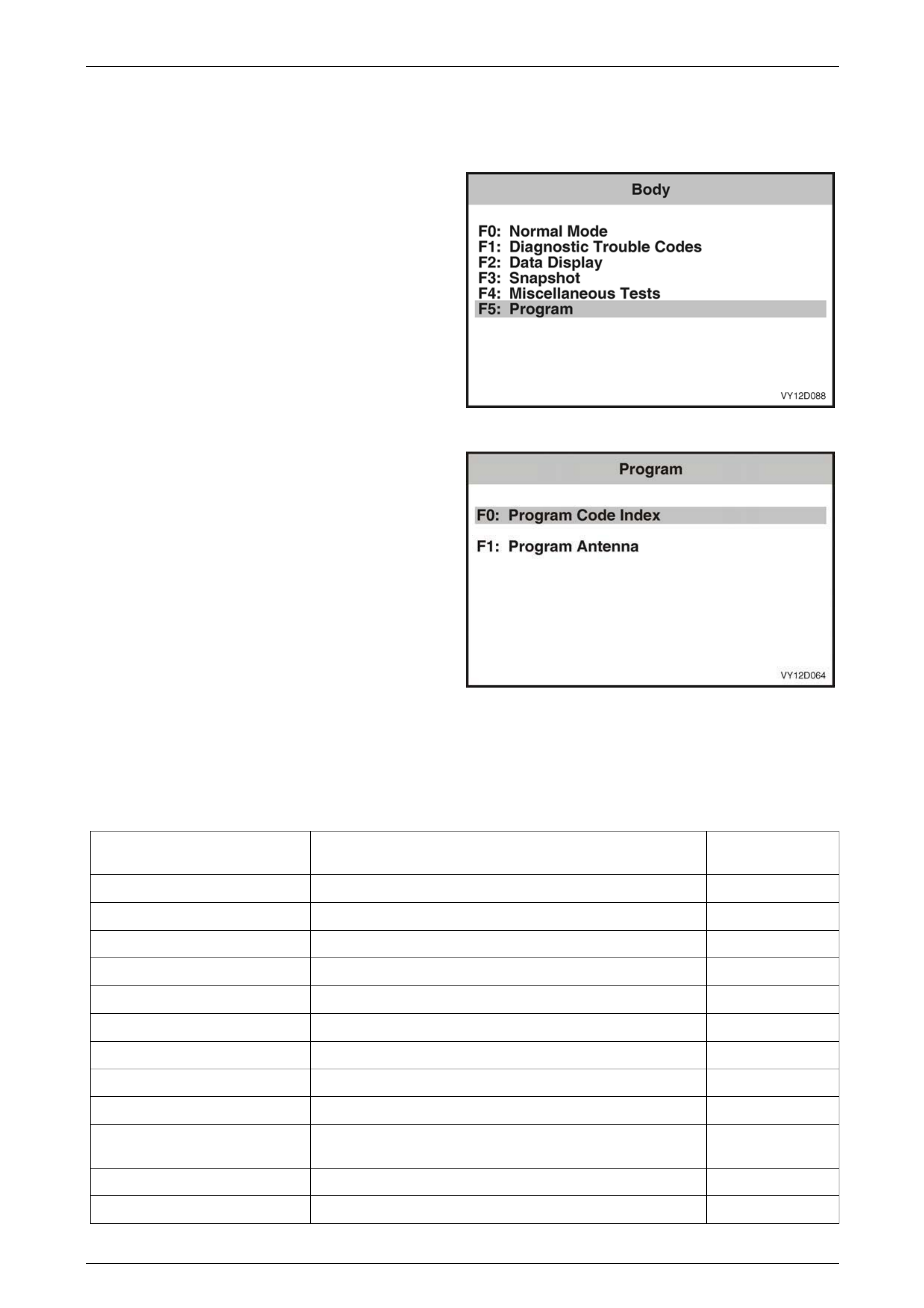
1 From the Body Menu select F5: Program and press
the Enter key.
Figure 12D – 20
2 Using the TECH 2 Up and Down arrows, select the
required item and then press the Enter key.
Figure 12D – 21
F0: Program Code Index
The Code Index number i dentifies the audio s ystem and vehicle configuration, and the Code Version number identifies
the software version. Only the Code Index nu m ber can be changed. The following table details the Code Index number s
for the various models in the MY 2004 VY and V2 Seri es vehicles.
Vehicle Audio System
Code Index
Number
Executive System 1 (Standard), System 3 (Optional) 007
Acclaim System 2 (Standard), System 3 (Optional) 007
Commodore S System 1 (Standard), System 3 (Optional) 007
Commodore SS System 3 007
Berlina System 3 007
Lumina LS (RHD) System 1 (Standard), System 3 (Optional) 007
Lumina S (RHD) System 1 (Standard), System 3 (Optional) 007
Lumina SS (RHD) System 3 007
Lumina LTZ (RHD) System 3 007
Lumina LS (LHD) System 1 Gulf States (Standard), System 3 Gulf States
(Optional) 008
Lumina SS (LHD) System 3 Gulf States 008
Lumina LTZ (LHD) System 3 Gulf States 008
Entertainment System Page 12D–26
Page 12D–26
Vehicle Audio System
Code Index
Number
S Coupe (LHD) System 1 Gulf States (Standard), System 3 Gulf States
(Optional) 008
Utility System 1 (Standard), System 3 (Optional) 009
Calais System 4 010
Coupe CV8 System 4 010
SS Coupe (LHD) System 4 Gulf States 011
Omega (LHD) System 4 Brazil 012
Lumina S (RHD) System 1 017
1 From the Program Menu select F 0: Program Cod e
Index and press the Enter key.
Figure 12D – 22
2 The Code Index number a nd the Code Version
number are displayed. To change the Code Index
number, press the Program soft key. To exit without
making a change, press the Okay soft key.
Figure 12D – 23
3 Enter the three-digit Code Index number, including
leading zeros, using the num eral keys on TECH 2.
4 Press the Enter key to continue, or the Exit key to exit
without making a change.
5 Follow any T ECH 2 screen prompts when
programming is completed.
Figure 12D – 24
Entertainment System Page 12D–27
Page 12D–27
3.3 Audio System Diagnostic Procedures
Figure 12D – 25
Entertainment System Page 12D–28
Page 12D–28
Antenna System (Coupe Only)
The antenna coil assembly comprises two antennas, one for AM signa ls and another for FM / FM2 signals, and these
form an integral part of the rear window glass. The CV8 model coupe also has a diversity antenna for augmented FM
reception. The FM / FM2 antenna coil is also used as the rear window demister element. The thin conductors that form
each antenna are laid on the inside of the glass, and two connectors are located on the side of the rear window allo wing
connection of the antenna coils to the antenna amplifier module. The FM antenna coil / demister is also connected to
body ground at X118_GP7, via circuit 1850.
The antenna amplifier module amplifies the small signals from the antenna coil assembly then transmits the amplified
signal to the radio’s antenna i nput. The module is located beneath the trim on the left han d side body rear corner garnish.
The module is connected to the au dio system head unit via a coaxial lead, circuit 5172.
A single wire lead, circuit 314, from the audio system head unit provides the +12 V supply to the antenna amplifier
module for its operation. The modu le is grounded through its case to the vehicle body. To prevent interference, it is very
important that the module and coaxial lead are grounded securely.
Figure 12D – 26

Entertainment System Page 12D–29
Page 12D–29
Antenna System (Couple Only) Diagnostic Chart
Step Action Value(s) Yes No
1 Was the Diagnostic Circuit Check performed? Go to Step 2. Go to Diagnostic
Circuit Check in
Section 12D,
3.12 Audio System
Diagnostic
Procedures in the
MY 2003 VY and V2
Series Service
Information.
2 Does the rear window have an after-market tint material
fitted? After-market window
tint material is not
recommended as
they can reduce
radio reception.
Replace the rear
window. Refer to
Section
1A6 Stationary
Windows in the
MY 2003 VY and V2
Series Service
Information.
Go to Step 3.
3 Turn the ignition on.
Select a known weak AM station.
Is the AM signal received?
Go to Step 4. Go to Step 14.
4 Is the AM signal noisier than usual? Go to Step 10. Go to Step 5.
5 Select a known weak FM station.
Check that the rear window demister is off.
Is the FM signal received?
Go to Step 9. Go to Step 6.
6 Inspect the FM antenna coil for damage.
Is the FM antenna coil damaged?
Repair the antenna
coil using an after-
market repair kit.
Go to Step 7.
7 Ensure that the FM antenna coil connectors are
securely connected at each side of the rear window.
Are the FM antenna coil connectors secure ly
connected?
Go to Step 8. Ensure that the
connectors are
securely connected.
8 Remove the left hand side body rear corner body
garnish. Refer to Section 1A8, 4.5 Body Rear Corner
Garnish in the MY 2003 VY and V2 Series Service
Information.
Inspect the antenna amplifier module and cable
connecting the FM antenna coil to the module for
damage.
Is either the cable or module damaged?
Replace the
damaged antenna
amplifier module.
Refer to 2.1
Antenna System
(Coupe Only) in this
Section, or replace
damaged coaxial
cable.
Replace the
defective antenna
amplifier module.
Refer to 2.1
Antenna System
(Coupe Only) in this
Section.
9 Turn the rear window demister on.
Did the FM reception weaken or did the background
noise increase?
Many broken
segments in the
antenna coil.
Replace the rear
window. Refer to
Section
1A6 Stationary
Windows in the
MY 2003 VY and V2
Series Service
Information.
Confirm fault with
customer.

Entertainment System Page 12D–30
Page 12D–30
Step Action Value(s) Yes No
10 Remove the left hand side body rear corner garnish.
Refer to Section 1A8, 4.5 Body Rear Corner Garnish i n
the MY 2003 VY and V2 Series Service Information..
The antenna amplifier modu le ground path is through
the mounting bolts. Check that the mounting bolts are
correctly installed and at the correct torque
specification.
Is the value as specified?
6 – 8 Nm Go to Step 11. Torque the
mounting bolts to
the correct
specification. If
reception does not
improve, replace the
antenna amplifier
module. Refer to 2.1
Antenna System
(Coupe Only) in this
Section.
11 Check that the antenna amplifier module connectors are
securely connected.
Are the antenna amplifier module con nectors securely
connected?
Go to Step 12. Ensure that the
connectors are
securely connected.
12 Check that the antenna coax cable between the
antenna amplifier module and the radio cradle is not
damaged and is securely connected.
Is the cable damaged or not secure ly connected?
Secure cable or
replace if damaged. Replace the
antenna amplifier
module. Refer to 2.1
Antenna System
(Coupe Only) in this
Section. Go to Step
13.
13 Check the audio system for correct operation.
Does the audio system operate correctl y?
End of diagnostics. Install the original
antenna amplifier
module. Refer to 2.1
Antenna System
(Coupe Only) in this
Section. Replace
the audio system
head unit. Refer to
Section 12D,
2.1 Audio System
Head Unit in the
MY 2003 VY and V2
Series Service
Information.
14 Remove the audio system head unit. Refer to Section
12D, 2.1 Audio System Head Unit in the MY 200 3 VY
and V2 Series Service Information.
Check that the antenna connec tor is plugged into the
radio cradle properly.
From inside the vehicle, remove the left hand side hinge
pillar trim assembly to gain access to the antenna
connector. Refer to Section 1A8, 2.8 Hinge Pillar Trim
Assembly in the MY 2003 VY and V2 Series Service
Information. Check that the antenna extensi on lead is
correctly connected to the front antenna lead.
Install the audio system head unit. Refer to Section
12D, 2.1 Audio System Head Unit in the MY 200 3 VY
and V2 Series Service Information.
Switch the audio system on.
Has the signal strength improv ed?
Incorrect
connection. Ensure
that all connections
are secure.
Go to Step 15.

Entertainment System Page 12D–31
Page 12D–31
Step Action Value(s) Yes No
15 Remove the audio system head unit. Refer to 2.1 Audio
System Head Unit in the MY 2003 VY and V 2 Series
Service Information.
Disconnect the antenna connector from the rear of the
radio cradle.
Using a digital ohmmeter, check the resistan ce between
ground and the centre core of the antenna coax cable.
Is the reading as specified?
10 kohms Go to Step 16. Repair or replace
defective coax
cable.
16 Remove the left hand side body rear corner garnish.
Refer to Section 1A8, 4.5 Body Rear Corner Garnish i n
the MY 2003 VY and V2 Series Service Information.
Check that the antenna amplifier module connectors are
securely connected to the module.
Are all antenna amplifier module connectors securely
connected?
Go to Step 17. Incorrect
connection. Ensure
that all connections
are secure.
17 Disconnect the antenna amplif ier module +12 V supply
connector X1-A (circuit 314) from the modu le.
Turn the radio on.
Using a digital multimeter, check the volta ge at
connector X1-A (circuit 314).
Is the voltage as specified?
Battery
voltage Replace the
antenna amplifier
module. Refer to 2.1
Antenna System
(Coupe Only) in this
Section.
Repair faulty circuit
314.
WHEN ALL DIAGNOSIS AND REPAIRS ARE COMPLETED AND VERIFY CORRECT OPERATION
Entertainment System Page 12D–32
Page 12D–32
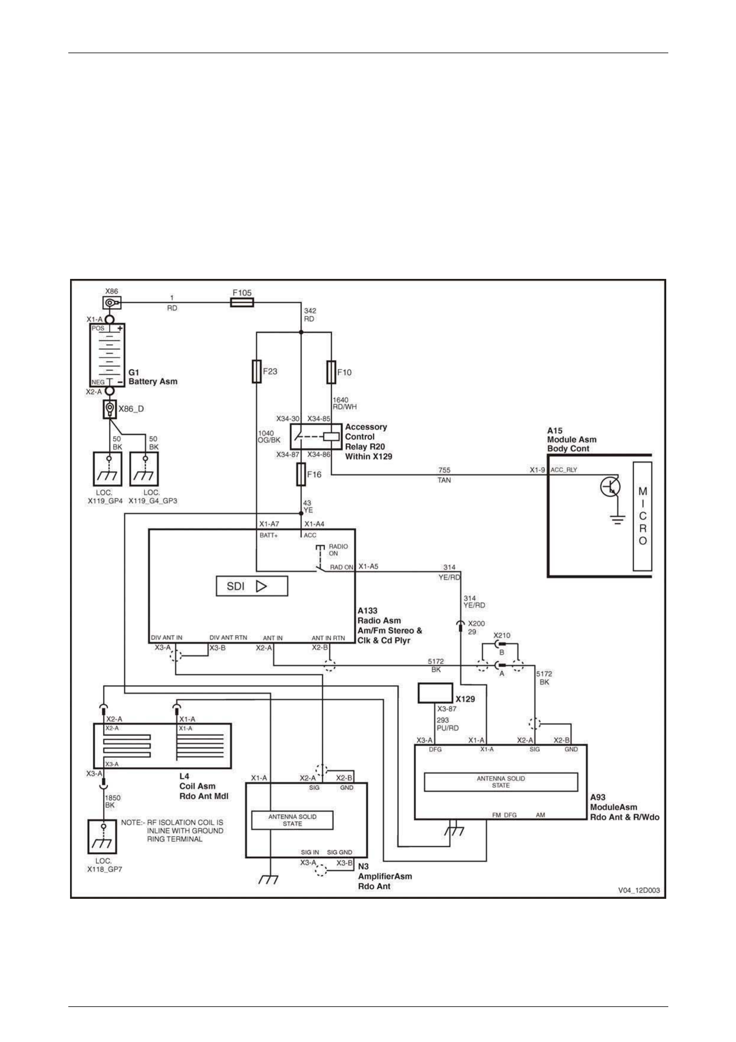
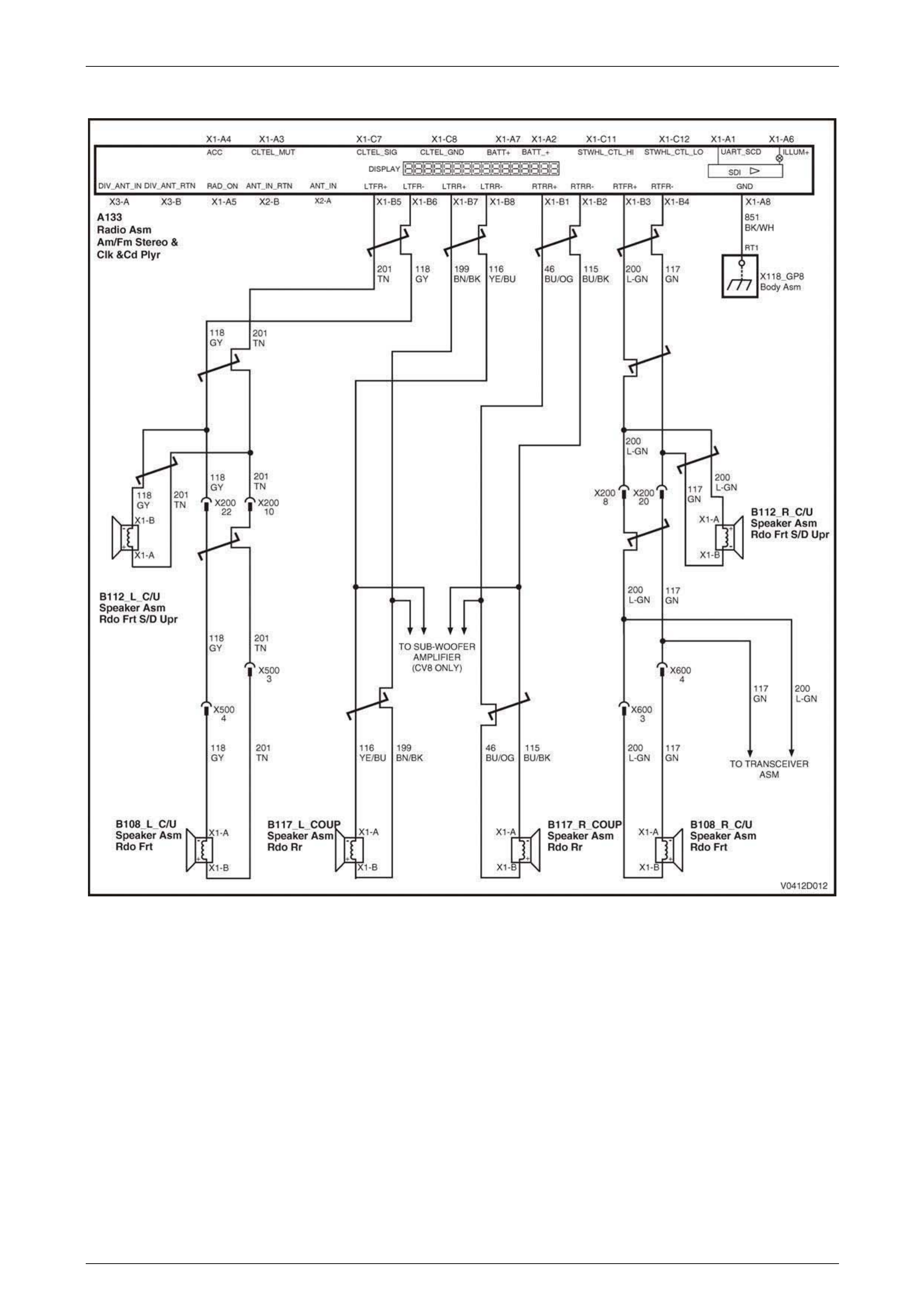
No Sound Or Distorted Sound
Circuit Diagram – Sedan and Wagon
Figure 12D – 27
Entertainment System Page 12D–33
Page 12D–33
Circuit Diagram – Coupe
Figure 12D – 28
The Audio Systems fitted to the MY2003 VY and V2 Series vehicles have modern ampl ifiers that deliver high po wer and
are internally protected against short circuits and connection to voltage sources.
Level 3 model vehicles feature a high power 4 x 30 W RMS amplifier that drives 2 ohm speakers in the doors and
tweeters in the instrument panel. Two subwoofers driven by a separate 2 x 40 W RMS amplifier are fitted to the parcel
shelf to increase the frequency resp onse of the system. Other models have 4 x 20 W RMS amplifiers. Speakers in these
vehicles are 4 ohms for the doors and 2 oh ms for the tweeters. The speaker circuit for Sedans and Wagons is ill ustrated
in Figure 12D – 27, while the circuit for Utiliti es and Coupe models is illustrated in Figure 12D – 28.
All Audio Systems have a Distortion Limitin g circuit. This circuit, when turned on, automaticall y limits the volume level to
the point where distortion begins. The amount of distortion will depend on the amount of bass in the music. Listen ers who
find that the music does not play loud enoug h with the distortion limiting circuit activated can either:
• reduce the amount of bass, or
• turn the distortion limiting off using the instrument cluster MFD (refer to Section 12C, 1.8 Customisation Mode –
Audio Distortion Limiting in the MY 2003 VY and V2 Series Service Information).

Entertainment System Page 12D–34
Page 12D–34
Damaged speakers and wiring may not cause a failure when played at low volume levels. At low volume the amplifier
may cope with the additional load caused by the damage. Problems may only become obvious when playing at loud
volume levels. Typical symptoms will be
• one speaker dropping out,
• two speakers dropping o ut, or
• all speakers dropping out.
When the amplifier has cooled, the output may resume from the affected speaker or speakers.
No Sound Or Distorted Sound Diagn ostic Chart
Step Action Value(s) Yes No
1 Was the Diagnostic Circuit Check performed? Go to Step 2. Go to Diagnostic
Circuit Check in
Section 12D, 3.12 of
the MY 2003 VY
and V2 Series
Service Information.
2 Turn the ignition to the Accessories position.
Switch the audio system on and set the volume at
medium level.
Play a CD.
Does the audio system turn on and seem normal apart
from no sound or distorted sound?
Go to Step 3. Go to Power On /
Off Diagnostic Chart
in Section 12D, 3.12
of the MY 2003 VY
and V2 Series
Service Information.
3 Set EQ to OFF, and Bass, Treble, Fader and Balance to
STD.
Use the Fader and Balance s ettings to check that each
speaker is operating, includin g the instrument panel
tweeters and rear parcel shelf subwoofers (if fitted).
Is no sound or distortion from one speaker onl y?
Go to Step 4. Go to Step 10.
4 Set Fader and Balance to STD.
Remove the audio system head unit. Refer to 2.1 Audio
System Head Unit in the MY 2003 VY and V 2 Series
Service Information.
Using a digital ohmmeter, check the resistan ce of the
defective speaker circuit at audio head unit c onnector
A133:
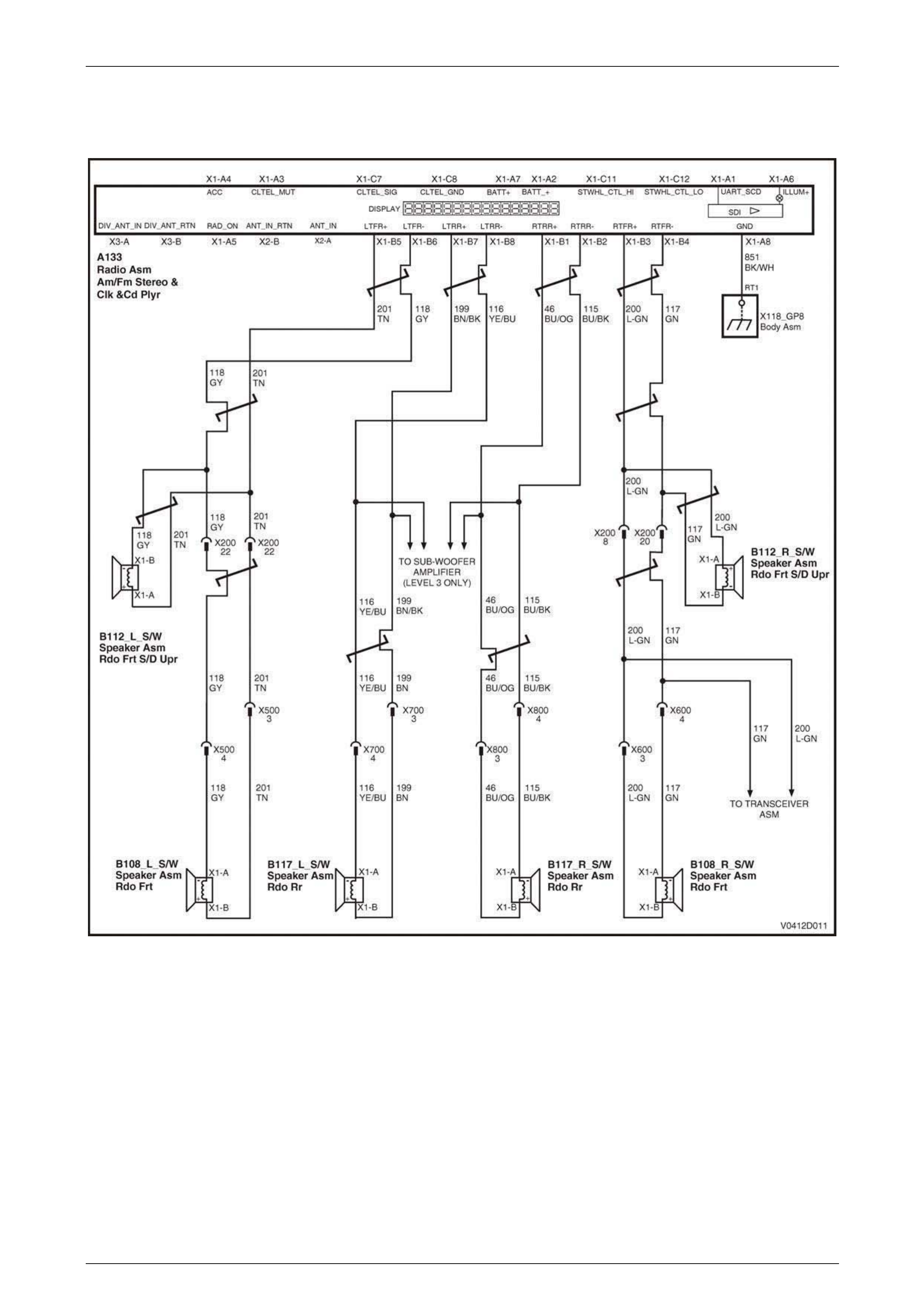
• Left Front – X1-B5 and X1-B6
• Left Rear – X1-B7 and X1-B8
• Right Front – X1-B3 and X1-B4
• Right Rear – X1-B1 and X1-B2
Is the value as specified?
Between
2 ohms and
4 ohms
Go to Step 5. Go to Step 10.
5 Remove the defective speaker. Refer to Section 12D,
2 Service Operations in the MY 2003 VY and V2 Series
Service Information.
Inspect the speaker for damage or foreign material.
Do the speaker terminals appear dam aged?
Remove foreign
material. Replace
speaker if damaged.
Refer to Section
12D, 2 Service
Operations in the
MY 2003 VY and V2
Series Service
Information.
Go to Step 6.
6 Has the speaker or speaker terminals been making
contact with body metal components? Rectify reason for
contact. Install
speaker.
Go to Step 7.

Entertainment System Page 12D–35
Page 12D–35
Step Action Value(s) Yes No
7 Using a digital ohmmeter, check the resistan ce across
the speaker terminals.
Is the value as specified?
Between
2 ohms and
4 ohms
Go to Step 8. Replace speaker.
Refer to Section
12D, 2 Service
Operations in the
MY 2003 VY and V2
Series Service
Information.
8 Using a digital ohmmeter, check for continuity between
each of the speaker circuits at audio hea d u nit
connector A133, and a known good ground:
• Left Front – X1-B5, circuit 201
• Left Front – X1-B6, circuit 118
• Left Rear – X1-B7, circuit 199
• Left Rear – X1-B8, circuit 116
• Right Front – X1-B3, circuit 200
• Right Front – X1-B4, circuit 117
• Right Rear – X1-B1, circuit 46
• Right Rear – X1-B2, circuit 115
Is any circuit shorted to ground?
Repair defective
circuit. Go to Step 9.
9 Using a digital voltmeter, check for voltage between
each of the speaker circuits at audio hea d u nit
connector A133, and a known good ground:
• Left Front – X1-B5, circuit 201
• Left Front – X1-B6, circuit 118
• Left Rear – X1-B7, circuit 199
• Left Rear – X1-B8, circuit 116
• Right Front – X1-B3, circuit 200
• Right Front – X1-B4, circuit 117
• Right Rear – X1-B1, circuit 46
• Right Rear – X1-B2, circuit 115
Is voltage indicated at any circuit?
0 volts Repair defective
circuit. Go to Step 10.
10 Using a digital ohmmeter, measure the resistance
between audio head un it connector A133, terminal X1-
A8, circuit 851 and body ground.
Is the value as specified?
Less than
1 ohm Go to Step 11. Repair defective
circuit 851.
11 Install the audio system head unit (refer to Section 12D,
2.1 Audio System Head Unit in the MY 2003 VY and V2
Series Service Information), and any sp eakers.
Turn the ignition to the Accessories position.
Switch the audio system on and play a CD.
Increase the volume to a loud level.
Allow the audio system to play for 5 minutes.
Has the problem appeared?
Go to Step 12. Confirm fault with
customer.
Entertainment System Page 12D–36
Page 12D–36
Step Action Value(s) Yes No
12 Allow the audio system to cool.
Using the Fader and balance settings, repeat Step 11
for the front and rear / left and right speakers.
Has the test found one speaker to be the cause?
Go to Step 13. Replace the audio
system head unit.
Refer to Section
12D, 2.1 Audio
System Head Unit in
the MY 2003 VY
and V2 Series
Service Information.
13 Replace the defective speaker. Refer to Section 12D,
2 Service Operations in the MY 2003 VY and V2 Series
Service Information.
Is the problem rectified?
End of diagnostics. Replace the audio
system head unit.
Refer to Section
12D, 2.1 Audio
System Head Unit in
the MY 2003 VY
and V2 Series
Service Information.
WHEN ALL DIAGNOSIS AND REPAIRS ARE COMPLETED, VERIFY CORRECT OPERATION
Entertainment System Page 12D–37
Page 12D–37
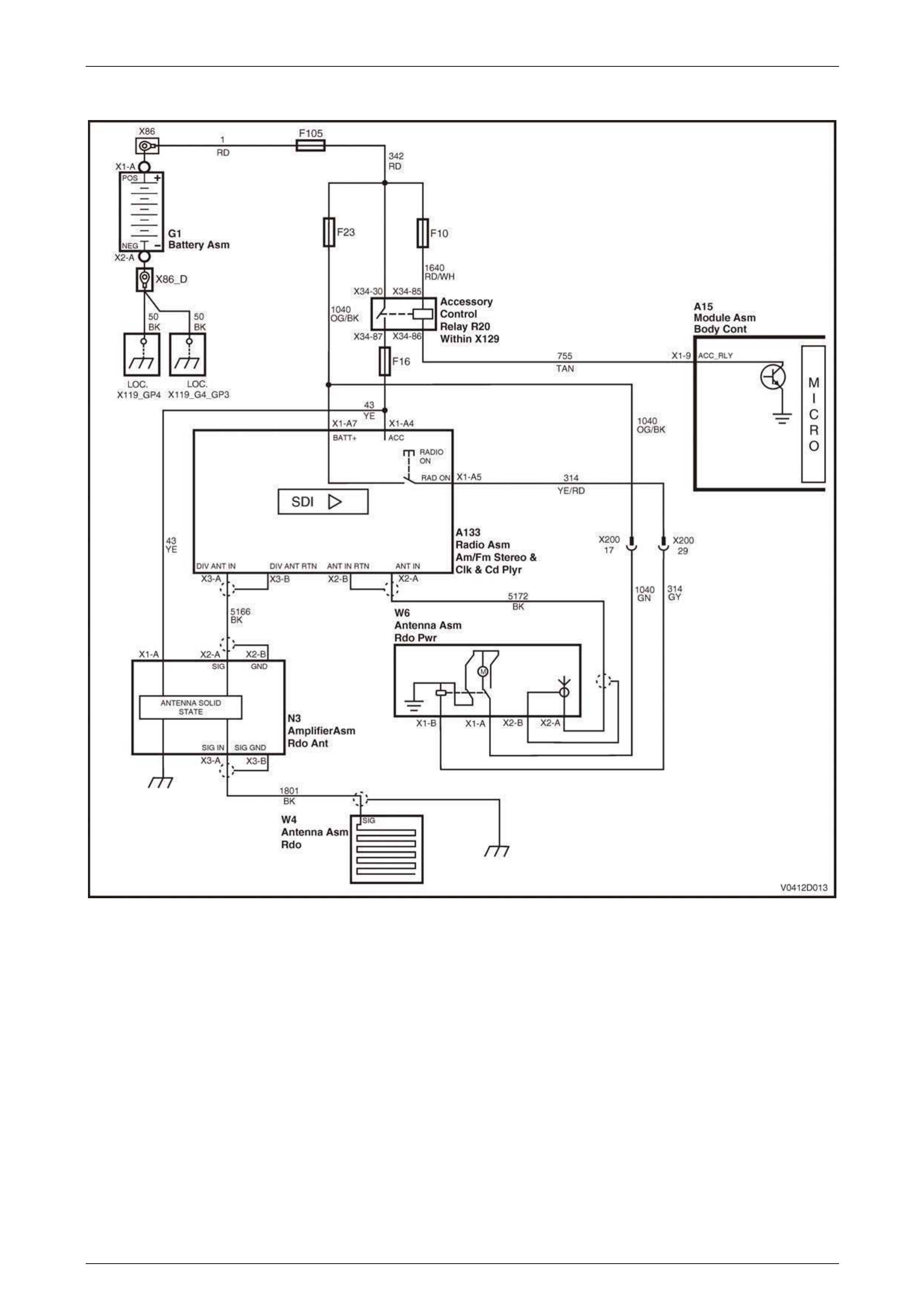
Electric Antenna – Full Up / Down (Sedan and Wagon Only)
Figure 12D – 29
Some models are fitted with a non-adjustable, fully up or down electric antenna system. In these vehicles when the aud io
system is in Radio Mode the electric antenna is fully raised. The antenna is retracted when the audio system is in CD
Mode, or turned off.
Battery voltage is applied at all times to the antenna motor via connector W6, terminal X1-A (circuit 1040), which is
protected by the RADIO fuse F23. Antenna operation is controlled from the audio system by the Radio On signal, circuit
314, which controls the internal antenna control relay via connector W6, terminal X1-B (circuit 314).
New Audio Systems are delive r ed with the antenna system disabled. This is to prevent the anten na raising and
potentially becoming damaged in the Assembly Plant. As the vehicle passes through final testing the antenna drive is
enabled and will remain enabl ed thereafter. In the event of an antenna system not functioning, verify that the antenna
system has been programmed correctly using TECH 2 (refer to 3.11 Program in the MY 2003 VY and V2 Series Service
Information).

Entertainment System Page 12D–38
Page 12D–38
Full Up / Down Electric Antenna Diagnostic Char t
Step Action Value(s) Yes No
1 Was the Diagnostic Circuit Check performed? Go to Step 2. Go to Diagnostic
Circuit Check in
Section 12D, 3.12 of
the MY 2003 VY
and V2 Series
Service Information.
2 Turn the audio system on.
Switch between Radio Mode and CD Mode (it may be
necessary to insert a CD).
Does the power antenna extend in Radio Mode and
retract in CD Mode?
Go to Step 14. Go to Step 3.
3 Connect TECH 2 to the DLC.
Select Diagnostics / Model Year / Vehicle Model / Body
/ Audio System / Data Display / Data List.
Scroll to Antenna Up in the TECH 2 menu.
Ensure that the audio system is turned on.
Switch between Radio Mode and CD Mode (it may be
necessary to insert a CD).
Does TECH 2 display REQUIRED in Radio Mode, and
NOT REQUIRED in CD Mode?
Go to Step 4. Enable the antenna
drive using TECH 2.
Refer to Section
12D, 3.11 Program
in the MY 2003 VY
and V2 Series
Service Information.
4 Remove the passenger’s side fender inn er lin er to gain
access to the antenna motor. Refer to Section 1A1, 3.1
Front Wheelhouse Liner in th e MY 2003 VY and V2
Series Service Information.
Check that the antenna is mounted correctl y and that all
bolts and electrical connections are tight.
Check that the head of the antenn a is visible through
the bezel on the fender and is not snagged on the
fender.
Check that the antenna mast is straight and not jammed
within the housing.
Are all checks OK?
Go to Step 5. Repair or replace
the antenna. Refer
to Section 12D,
2.7 Power Antenna
in the MY 2003 VY
and V2 Series
Service Information.
5 Connect a digital voltmeter between the power antenna
connector W6 terminal X1-A, circuit 1040 a nd a known
good ground.
Is the value as specified?
Battery
voltage Go to Step 8. Go to Step 6.
6 Disconnect the main wiring harness to body wiring
harness connector X200 (located above the BCM).
Using a digital ohmmeter, check for continuity of circuit
1040, between power antenna connector W6 terminal
X1-A, and harness connector X200, termin al 17.
Is the value as specified?
Continuity Go to Step 7. Repair faulty circuit.
7 Gain access the instrument panel fuse and relay panel
by pulling out wards on the up per edge of the instrument
panel lower trim panel to disengage the retaining clips.
Remove the RADIO fuse F23 from the instrument panel
fuse and relay panel.
Using a digital ohmmeter, check for continuity of circuit
1040, between harness conn ector X200, terminal 17,
and the output side of fuse F23.
Is the value as specified?
Continuity Check condition of
fuse and fuse holder
and repair as
necessary.
Repair faulty circuit.

Entertainment System Page 12D–39
Page 12D–39
Step Action Value(s) Yes No
8 Connect a digital voltmeter between the power antenna
connector W6 terminal X1-B, circuit 314 and a known
good ground.
Switch the audio system on and select FM Mode. Note
the voltage indication.
Switch the audio system off and note the voltage
indication.
Is the value as specified?
Radio Mode
= 10 V or
greater
Off = 0 V
Go to Step 13. Got to Step 9.
9 Remove the audio system head unit. Refer to Section
12D, 2.1 Audio System Head Unit in the MY 200 3 VY
and V2 Series Service Information.
Using a digital ohmmeter, check for continuity of circuit
314, between power antenna connector W 6 terminal
X1-B, and audio head unit connector A133, terminal
X1-A5.
Is the value as specified?
Continuity Go to Step 10. Go to Step 11.
10 Ensure that Step 2 was completed.
Is the Antenna Drive enabled?
Replace the audio
system head unit.
Refer to Section
12D, 2.1 Audio
System Head Unit in
this Section.
Complete Step 2
and test again.
11 Disconnect the main wiring harness to body wiring
harness connector X200 (located above the BCM).
Using a digital ohmmeter, check for continuity of circuit
314, between harness connector X2 00, terminal 29, and
audio head unit connector A1 33 terminal X1-A5.
Is the value as specified?
Continuity Go to Step 12. Repair faulty circuit
314.
12 Using a digital ohmmeter, check for continuity of circuit
314, between harness connector X2 00, terminal 29, and
power antenna connector W6 terminal X1-B.
Is the value as specified?
Continuity Confirm fault with
customer. Repair faulty circuit
314.
13 Using a digital ohmmeter, measure the resistance
between the body of the antenna motor and a known
good ground.
Is the value as specified?
Continuity Replace the
antenna. Refer to
Section 12D,
2.7 Power Antenna
in the MY 2003 VY
and V2 Series
Service Information.
Repair faulty
antenna ground
circuit. Check all
attachment bolts for
tightness.
14 Does the antenna raise and lower smoothly and fully? Confirm fault with
customer. Go to Step 15.
15 Clean the antenna mast.
Does the antenna raise and lower smoothly and fully?
Confirm the repair. Repl ace the
antenna. Refer to
Section 12D,
2.7 Power Antenna
in the MY 2003 VY
and V2 Series
Service Information.
WHEN ALL DIAGNOSIS AND REPAIRS ARE COMPLETED, VERIFY CORRECT OPERATION
Entertainment System Page 12D–40
Page 12D–40
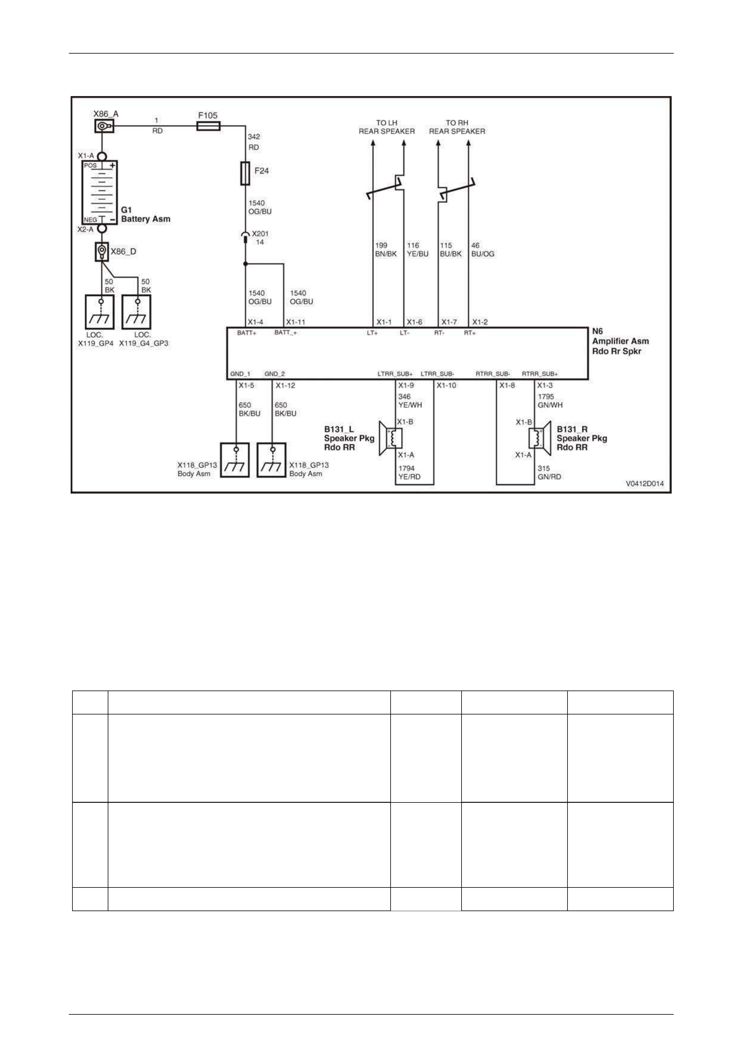
Subwoofer Amplifier
Figure 12D – 30
Level 3 models are fitted with an auxili ary amplifier to improve the low frequency output of the system using two parcel
shelf mounted subwoofer speakers. The unit is a two channel, high powered design that features self-protection circuitry
to stop overload in the event of damage to wiring or speakers, or high temperatures. Signal inputs to the amplifier are
taken from the corresponding left and right rear door sp eakers, as per the system diagram, and the signals are then
combined to produce a mono output.
Output gain can be varied by turnin g the small adjuster mounted on the end of the casing at the opposite end to the
connector. The centre position is the default setting. From the centre position the subwoofer effect can be increased by
6 dB or decreased by 3 dB from the factory setting for customers who prefer more or less subwoofer effect. A 10 Amp
fuse mounted in the end of the unit will protect the wiring in event of an internal amplifier failure.
Subwoofer Amplifier Diagnostic Ch art
Step Action Value(s) Yes No
1 Was the Diagnostic Circuit Check performed? Go to Step 2. Go to Diagnostic
Circuit Check in
Section 12D, 3.12 of
the MY 2003 VY
and V2 Series
Service Information.
2 Switch the audio system on, increase bass to
maximum, fade speakers to the rear, set balance to
STD, and adjust the volume to a medi um level.
Can you hear the subwoofer system operating from
inside the vehicle or in the rear compartmen t ?
Go to Step 7. Go to Step 3.
3 Are the corresponding rear door speakers operati ng? Go to Step 5. Go to Step 4.

Entertainment System Page 12D–41
Page 12D–41
Step Action Value(s) Yes No
4 Check the door speaker wiring for an open circuit or
short circuit and repair as necessary. Refer to No
Sound or Distorted Sound Diagnostic Chart in this
Section.
Test the audio system again a s detailed in Step 2.
Is the system working?
Return audio
system settings to
normal. Go to
Step 10.
Go to Step 5.
5 Remove the subwoofer amplifier, refer to Section 12D,
2.12 Subwoofer Amplifier in the MY 2003 VY and V2
Series Service Information.
Check the 10 A fuse located at end of the unit. Replace
if necessary.
Check the wiring connection on the subwoofer amplifier
wiring harness. Repair as necessary.
Using a digital voltmeter, check for battery voltage
between the following terminal s of amplifier connector
N6 and a known good ground. Repair as necessary:
• Terminal X1-4, circuit 1540.
• Terminal X1-11, circuit 1540.
Using a digital ohmmeter, check for continuity between
a known good ground and the following terminals of
amplifier connector N6. Repair as necessary:
• Terminal X1-5, circuit 650.
• Terminal X1-12, circuit 650.
Install the amplifier (refer to Section 12D,
2.12 Subwoofer Amplifier in the MY 2003 VY and V2
Series Service Information) and test the audio system
again as detailed in Step 2.
Is the system working?
End of diagnostics. Go to Step 6.
6 Check the wiring connections on the subwoofer
speakers for damage or incorrect connecti on. Repair as
necessary.
Using a digital ohmmeter, check for open circuit
between each of the speaker circuits and a known good
ground at amplifier connector N6. Repair as necessary.
Test the audio system again a s detailed in Step 2.
Is the system working?
End of diagnostics. Go to Step 7.
7 Disconnect the subwoofer amplifier conn ector N6.
Ensure that each subwoofer speaker con nector is firmly
connected to its speaker. Using a digital ohmmeter,
check for continuity between each of the speaker
circuits at amplifier connector N6.
• Left Speaker – X1-9, circuit 346 and X1-10, circuit
1794.
• Right Speaker – X1-3, circuit 1795 and X1-8,
circuit 315.
Is the value as specified?
Approximately
2 ohms Replace the
subwoofer amplifier.
Refer to Section
12D,
2.12 Subwoofer
Amplifier in the
MY 2003 VY and V2
Series Service
Information.
Go to Step 8.

Entertainment System Page 12D–42
Page 12D–42
Step Action Value(s) Yes No
8 Disconnect the subwoofer speaker connector on the
speaker that gives the faulty reading.
Using a digital ohmmeter, check for continuity between
the speaker terminals.
Is the value as specified?
Approximately
2 ohms Go to Step 9. Replace the
subwoofer speaker.
Refer to Section
12D, 2.5 Subwoofer
Speakers in the
MY 2003 VY and V2
Series Service
Information.
9 Repair open or short circuit in speaker wiring circuits
346, 1794, 315 or 1795 as appropriate.
Install the amplifier and speak ers and test the aud io
system again as detailed in Step 2.
Is the system working?
End of diagnostics. Replace the
subwoofer amplifier,
refer to Section
12D,
2.12 Subwoofer
Amplifier in the
MY 2003 VY and V2
Series Service
Information.
10 Are both speakers working equally and free from
unusual vibrations, buzzes or distortion? Verify fault with
customer. Go to Step 11.
11 Check the speaker cone for foreign materials, such as
screws, stones or wiring.
Verify the sealing foam on the rear window trim panel
assembly is seated correctly and not touching the
speaker cone. Repair as necessary.
Verify the rear window trim panel assembly is tightly
mounted and not free to vibrate.
Test the audio system again a s detailed in Step 2.
Is the system working as expected?
End of diagnostics. Replace the
subwoofer speaker.
Refer to Section
12D, Section 12D,
2.5 Subwoofer
Speakers in the
MY 2003 VY and V2
Series Service
Information.
WHEN ALL DIAGNOSIS AND REPAIRS ARE COMPLETED, VERIFY CORRECT OPERATION
Entertainment System Page 12D–43
Page 12D–43
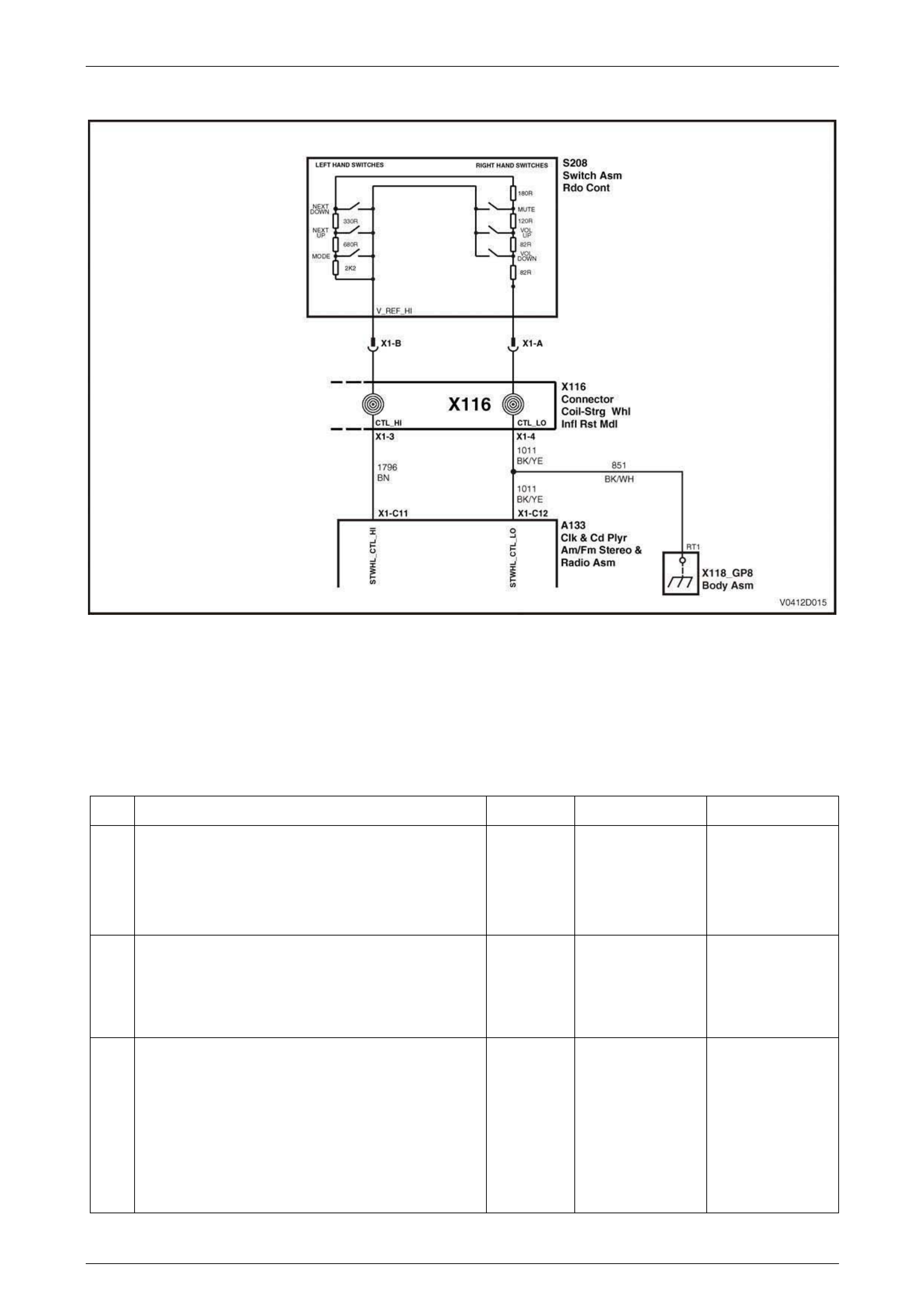
DTC 11 – Steering Wheel Remote Button Jammed – Without Illuminated Controls
Figure 12D – 31
Control buttons located on the steering wheel provide remote operatio n of various audio system functions. The remote
controls constitute a resistive net work. When a button is pressed, the change in resistance is interpreted by the radio a s
a button press, and the appropriate function is actioned.
With the ignition in either the Accessori es position or the On position, DTC 11 will set if a steering wheel control button
remains pressed or stuck for more than 30 seconds.
Steering Wheel Remote Controls Diagnostic Chart
Step Action Value(s) Yes No
1 Was the Diagnostic Circuit Check performed? Go to Step 2. Go to Diagnostic
Circuit Check in
Section 12D, 3.12 of
the MY 2003 VY
and V2 Series
Service Information.
2 Switch the audio head unit on.
Press each of the steering wheel remote con t rol buttons
and note if the unit follows the command.
Does the audio system operate as e xpected?
Confirm fault with
customer. Go to Step 3.
3 Connect TECH 2 to the DLC.
Select Diagnostics / Model Year / Vehicle Model / Body
/ Audio System / Data Display / Data List.
Scroll to Steering Wheel Remote Control in the TECH 2
menu.
Do not press any button.
Does TECH 2 display KEY RELEASED?
Go to Step 4. Go to Step 5.

Entertainment System Page 12D–44
Page 12D–44
Step Action Value(s) Yes No
4 Press each of the steering wheel remote con t rol buttons
in turn.
Does TECH 2 display the name of each button when
pressed?
Go to Step 8. Go to Step 6.
5 Remove the audio system head unit. Refer to Section
12D, 2.1 Audio System Head Unit in the MY 200 3 VY
and V2 Series Service Information.
Using a digital ohmmeter, measure the resistance at
audio head unit connector A1 33 between terminal X1-
C11, circuit 1796 and terminal X1-C12, circuit 1011.
Do not press any button.
Is the resistance as specified?
Between
3.5 kohms
and
3.9 kohms
Go to Step 7. Repair faulty circuit
1796 or 1011.
6 With the ohmmeter connected as in Step 5, press and
hold the MUTE button.
Is the resistance as specified?
Between
270 ohms
and
300 ohms
Go to Step 7. Replace steering
wheel remote
controls. Refer to
Section 12D,
2.11 Horn Bar
Stereo Controls in
the MY 2003 VY
and V2 Series
Service Information.
7 Using a digital ohmmeter, measure the resistance at
audio head unit connector A1 33 between terminal X1-
C11, circuit 1796 and a known good ground.
Using a digital ohmmeter, measure the resistance at
audio head unit connector A1 33 between terminal X1-
C12, circuit 1011 and a known good ground.
Is the resistance as specified?
Open circuit Go to Step 8. Repair faulty circuit
1796 or 1011.
8 Turn the headlamp s witch to the Park position.
Using a digital ohmmeter, measure the resistance at
audio head unit connector A1 33 between terminal X1-
C11, circuit 1796 and terminal X1-C12, circuit 1011.
Do not press any button.
Is the resistance as specified?
Between
3.5 kohms
and
3.9 kohms
Replace the audio
system head unit.
Refer to Section
12D, 2.1 Audio
System Head Unit in
the MY 2003 VY
and V2 Series
Service Information.
Repair faulty circuit
1796 or 1011.
WHEN ALL DIAGNOSIS AND REPAIRS ARE COMPLETED, CLEAR ALL DTCs AND VERIFY CORRECT
OPERATION
Entertainment System Page 12D–45
Page 12D–45
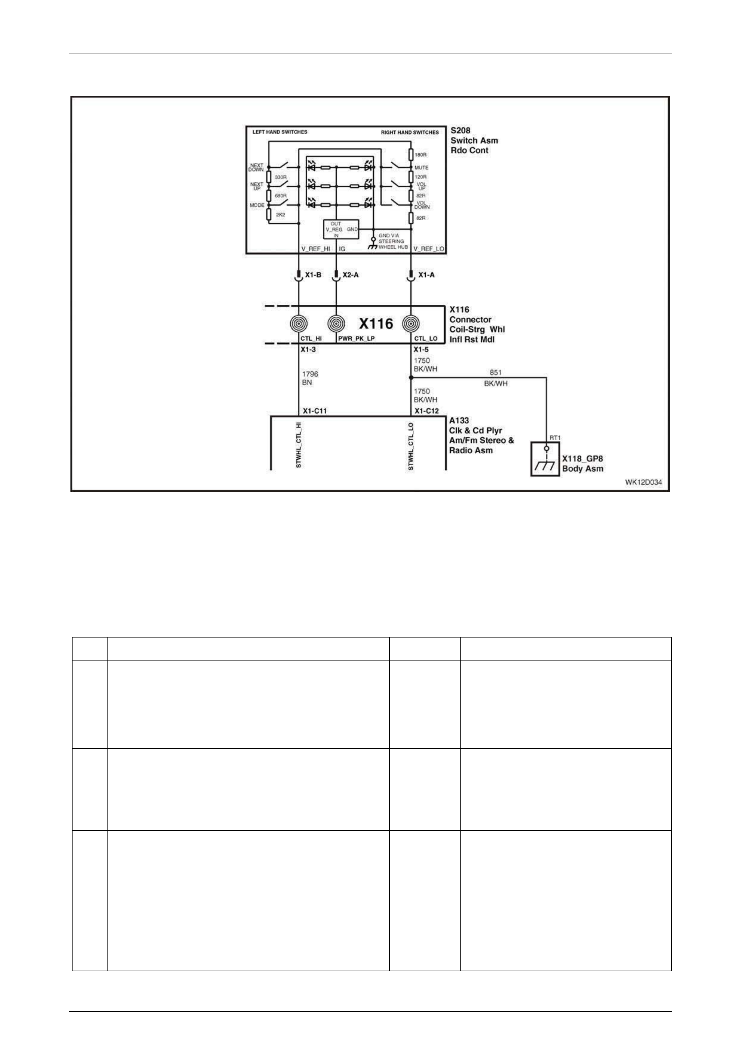
DTC 11 – Steering Wheel Remote Button Jammed – With illuminated Controls
Figure 12D – 32
Control buttons located on the steering wheel provide remote operatio n of various audio system functions. The remote
controls constitute a resistive net work. When a button is pressed, the change in resistance is interpreted by the radio a s
a button press, and the appropriate function is actioned.
With the ignition in either the Accessori es position or the On position, DTC 11 will set if a steering wheel control button
remains pressed or stuck for more than 30 seconds.
Steering Wheel Remote Controls Diagnostic Chart
Step Action Value(s) Yes No
1 Was the Diagnostic Circuit Check performed? Go to Step 2. Go to Diagnostic
Circuit Check in
Section 12D, 3.12 of
the MY 2003 VY
and V2 Series
Service Information.
2 Switch the audio head unit on.
Press each of the steering wheel remote con t rol buttons
and note if the unit follows the command.
Does the audio system operate as e xpected?
Confirm fault with
customer. Go to Step 3.
3 Connect TECH 2 to the DLC.
Select Diagnostics / Model Year / Vehicle Model / Body
/ Audio System / Data Display / Data List.
Scroll to Steering Wheel Remote Control in the TECH 2
menu.
Do not press any button.
Does TECH 2 display KEY RELEASED?
Go to Step 4. Go to Step 5.

Entertainment System Page 12D–46
Page 12D–46
Step Action Value(s) Yes No
4 Press each of the steering wheel remote con t rol buttons
in turn.
Does TECH 2 display the name of each button when
pressed?
Go to Step 8. Go to Step 6.
5 Remove the audio system head unit. Refer to Section
12D, 2.1 Audio System Head Unit in the MY 200 3 VY
and V2 Series Service Information.
Using a digital ohmmeter, measure the resistance at
audio head unit connector A1 33 between terminal X1-
C11, circuit 1796 and terminal X1-C12, circuit 1750.
Do not press any button.
Is the resistance as specified?
Between
3.5 kohms
and
3.9 kohms
Go to Step 7. Repair faulty circuit
1796 or 1750.
6 With the ohmmeter connected as in Step 5, press and
hold the MUTE button.
Is the resistance as specified?
Between
270 ohms
and
300 ohms
Go to Step 7. Replace steering
wheel remote
controls. Refer to
Section 12D,
2.11 Horn Bar
Stereo Controls in
the Section.
7 Using a digital ohmmeter, measure the resistance at
audio head unit connector A1 33 between terminal X1-
C11, circuit 1796 and a known good ground.
Using a digital ohmmeter, measure the resistance at
radio connector A133 between terminal X1-C12, circuit
1750 and a known good ground.
Is the resistance as specified?
Open circuit Go to Step 8. Repair faulty circuit
1796 or 1750.
8 Turn the headlamp s witch to the Park position.
Using a digital ohmmeter, measure the resistance at
audio head unit connector A1 33 between terminal X1-
C11, circuit 1796 and terminal X1-C12, circuit 1750.
Do not press any button.
Is the resistance as specified?
Between
3.5 kohms
and
3.9 kohms
Replace the audio
system head unit.
Refer to Section
12D, 2.1 Audio
System Head Unit in
the MY 2003 VY
and V2 Series
Service Information.
Repair faulty circuit
1796 or 1750.
WHEN ALL DIAGNOSIS AND REPAIRS ARE COMPLETED, CLEAR ALL DTCs AND VERIFY CORRECT
OPERATION

Entertainment System Page 12D–47
Page 12D–47
4 Specifications
4.1 Program Code Index Numbers
For the MY 2004 WK Series code index specifications, refer to 3.2 Program – Audio System in this Section.
MY 2004 VY and V2 Series Audio System Code Ind ex Chart
Vehicle Audio System
Code Index
Number
Executive System 1 (Standard), System 3 (Optional) 007
Acclaim System 2 (Standard), System 3 (Optional) 007
Commodore S System 1 (Standard), System 3 (Optional) 007
Commodore SS System 3 007
Berlina System 3 007
Lumina LS (RHD) System 1 (Standard), System 3 (Optional) 007
Lumina S (RHD) System 1 (Standard), System 3 (Optional) 007
Lumina SS (RHD) System 3 007
Lumina LTZ (RHD) System 3 007
Lumina LS (LHD) System 1 Gulf States (Standard), System 3 Gulf States
(Optional) 008
Lumina SS (LHD) System 3 Gulf States 008
Lumina LTZ (LHD) System 3 Gulf States 008
S Coupe (LHD) System 1 Gulf States (Standard), System 3 Gulf States
(Optional) 008
Utility System 1 (Standard), System 3 (Optional) 009
Calais System 4 010
Coupe CV8 System 4 010
SS Coupe (LHD) System 4 Gulf States 011
Omega (LHD) System 4 Brazil 012

Entertainment System Page 12D–48
Page 12D–48
5 Torque Wrench Specifications
Antenna Amplifier Module Mounting Screw......................................................... 6.0 – 8.0 Nm
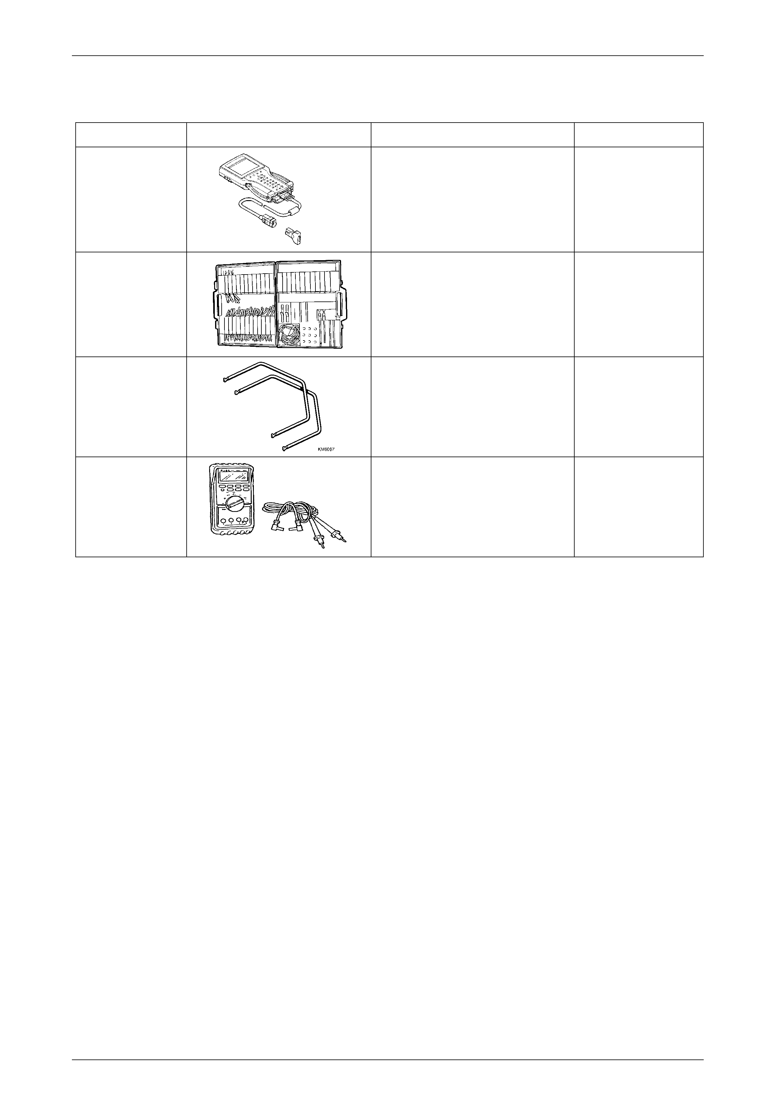
Entertainment System Page 12D–49
Page 12D–49
6 Special Tools
Tool Number Illustration Description Tool Classification
7000086I
TECH 2
DIAGNOSTIC SCAN TOOL
Used for diagnosis of vehicle electrical
system.
Previously released.
Mandatory
J35616-A
(KM609)
CONNECTOR TEST ADAPTOR KIT
Used when carrying out electric al
diagnostic circuit checks.
Previously released.
Desirable
KM6067
RADIO REMOVAL TOOLS
Used for removing VY audio unit from
it’s mounting location.
New tool for VY.
Mandatory
3588
(J39200)
DIGITAL MULTIMETER
Must have at least 10 MΩ input
impedance and be capable of reading
frequencies.
Previously released.
Available
Revised February 2003
BLAUPUNKT AUDIO REPLACEMENT / REPAIR
AUTHORISATION REQUEST FORM
Date: ……………….. Time: -………… am/pm Dealer Code: ……..…… Warranty: YES / NO
Contact Name:………………………… Dealer Name: ………………………………………….………………..……..
Phone No.: (………)………………… Dealer Address: ……………………………………………………………….
Fax No.: (………)……..……………… ……………………………………………………………………………………
R / O No:-……..………………… …………………………………………………………………………………….
Service Manager or Nominee Signature: ……………………………………………..……………………………………
Vehicle Detail s:
ISOVIN: ……………………………………………………. TAG No……………………………. Delivery Date:-………………….
Build Date: ……………………… Odometer:…………. Vehicle Model Code: eg VY Berlina, TS CD, JS etc. ………………
Audio System Details:
Holden Part Number
9………………………………..
Blaupunkt Serial Number of failed unit eg BP8382W0608664
BP…………………………..………………………………
Component Description: eg VY Acclaim single CD, JS CD Changer: …………………………………………………………
CD’s stuck inside? Yes No If Yes, complete CD ENCLOSED form and fax with the PRIOR APPROVAL FORM
AND attach a copy to the radio.
Is there any physical damage or modifications done to the unit? YES / NO (Please circle)
A. CUSTOMER COMPL AINT DETAILS
………………………………………………………………………………………………………………………
B. TITLE of DIAGNOSIS CHART(S) USED ie “Radio Illumination”
…………………………………………………………………………………..
Stored DTC’s.
C. FAULT DIAGNOSIS STEPS COMPLETED (insert applicable steps – refer Diagnosis Procedure)
D. DIAGNOSIS COMMENTS
………………………………………………………………………………………………………………………
NOTE: For Diagnostic assistance, please call Blaupunkt Service Centre on 1300 30 70 36.
Please return faul ty uni t using the provided return consignment note and original shipping
carton. To book courier, p lease call Mayne on 131 531, account number 3006ZT.
AUTHORISATION NUMBER (Blaupunkt to provide)
……………………………
FAX this completed for m to Blaupu nkt on (03) 9541 5432
Revised February 2003
CDs ENCLOSED
ATTENTION: This unit contains Custo m er’s CDs. Please be extra careful with th em, th e
customer would like them back as soon as possible.
Serial number of Radio/CD: BP
The following CDs are thought to be inside;
Eg. Queen – Greatest Hits
1
2
3
4
5
6
We woul d like the CDs returned to th e following add r ess;
Name: Phone: ( )
Address:
Suburb: State:
Post Code:
Returned by: (please p ri nt)
Dealership:
Date:
Blaupu nkt Service use: CDs removed:
1
2
3
4
5
6
Technician: Date:
Returned to abo ve on: (date)
Consignment Note:
Include this form with the faxed BLAUPUNKT AUDIO REPLACEMENT/REPAIR
AUTHORISATION REQUEST FORM, AND attach it to the unit being returned.
Please provide the Customer with a copy of this completed form, it is their
receipt for tracki ng the CDs.