
Reverse Park i ng Ai d Page 12F–1
Page 12F–1
Section 12F
Reverse Parking Aid
ATTENTION
Before performing any service operation or other procedure described in this Section, refer to Section 00
Warnings, Cautions and Notes for correct workshop practices with regard to safety and/or property damage.
1 General Information............................................................................................................................... 2
2 Diagnostics............................................................................................................................................. 3
2.1 Introduction ............................................................................................................................................................3
2.2 Wiring Diagram.......................................................................................................................................................4
2.3 Connector Chart.....................................................................................................................................................5
Techline

Reverse Park i ng Ai d Page 12F–2
Page 12F–2
1 General Information
With the following exceptions, MY 2004 VY and V2 Series Reverse Parking Aid information carries over from MY 2003
VY and V2 Series vehicles:
• For the automatic transmission, the park/neutral switch is changed from A83 to S187.
• Circuit 24 is changed from passing through connector X200 pin 2 to connector X201 pin 4.
• Connector X906 is installed in the opposite direction.
For Reverse Parking Aid information not contained within this Section, refer to Section 12F Reverse Parking Aid in the
MY 2003 VY and V2 Series Service information.

Reverse Park i ng Ai d Page 12F–3
Page 12F–3
2 Diagnostics
2.1 Introduction
Differences in the position of components and the circuit as compared to MY 2003 VY and V2 Series are:
• For the automatic transmission, the park/neutral switch is changed from A83 to S187.
• Circuit 24 is changed from passing through connector X200 pin 2 to connector X201 pin 4.
• Connector X906 is installed in the opposite direction.
The above changes in the circuit do not affect the diagnosis procedures.
Reverse Park i ng Ai d Page 12F–4
Page 12F–4
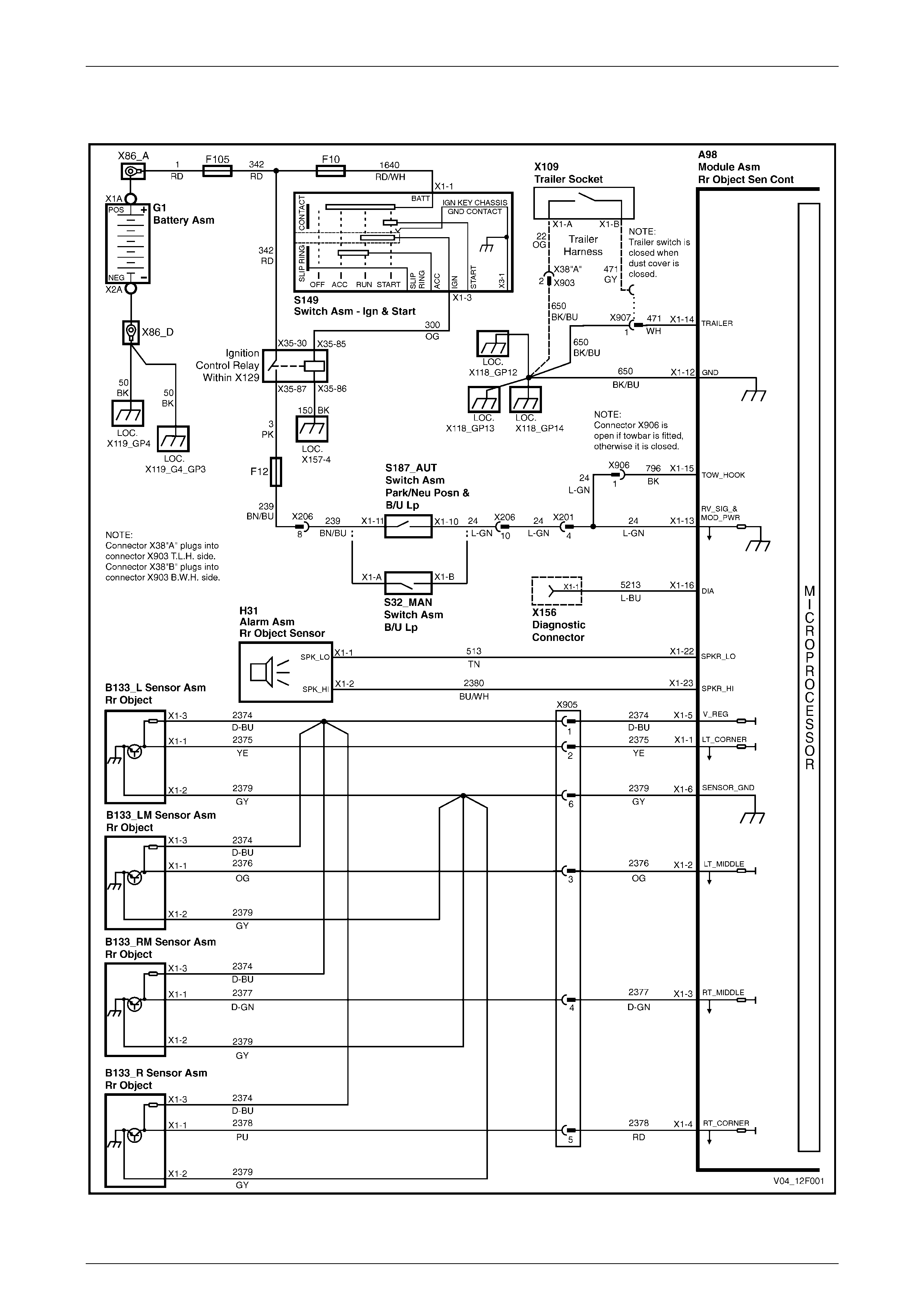
2.2 Wiring Diagram
Figure 12F – 1
Reverse Park i ng Ai d Page 12F–5
Page 12F–5
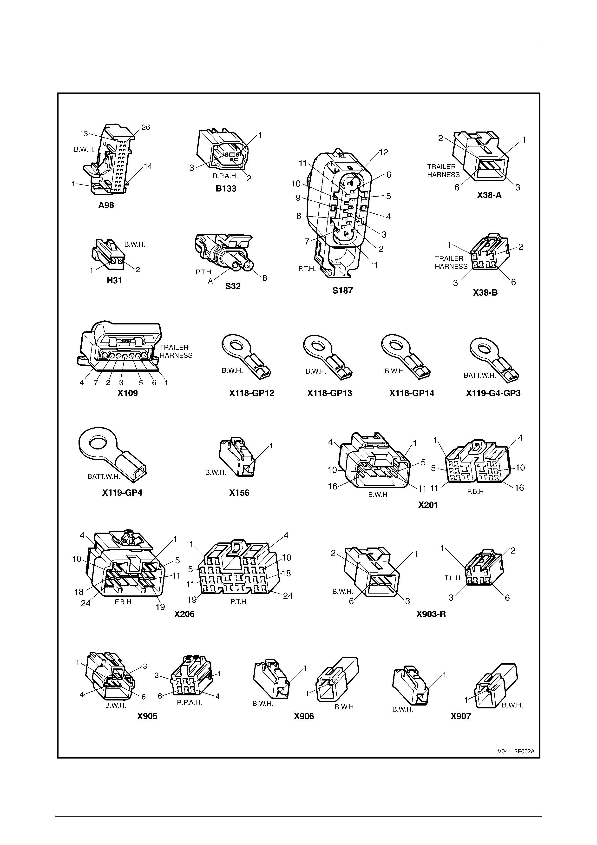
2.3 Connector Chart
Figure 12F – 2