
Navigation S ystem Page 12L–1
Page 12L–1
Section 12L
Navigation System
ATTENTION
Before performing any service operation or other procedure described in this Section, refer to Section 00
Warnings, Cautions and Notes for correct workshop practices with regard to safety and/or property damage.
1 General Information............................................................................................................................... 3
2 System Diagnosis.................................................................................................................................. 4
2.1 Prerequisites...........................................................................................................................................................4
Safety Requirements..............................................................................................................................................4
Equipment...............................................................................................................................................................4
Testing Procedures................................................................................................................................................4
2.2 Wiring Diagram.......................................................................................................................................................5
2.3 Connector Chart.....................................................................................................................................................6
2.4 Navigation System Does Not Start .......................................................................................................................7
Condition One.........................................................................................................................................................7
Introduction.........................................................................................................................................................7
Test Description..................................................................................................................................................7
Condition Two ........................................................................................................................................................8
Introduction.........................................................................................................................................................8
Test Description..................................................................................................................................................8
Condition Three....................................................................................................................................................10
Introduction.......................................................................................................................................................10
Test Description................................................................................................................................................10
2.5 No Response From Remote Control...................................................................................................................13
No Response From Remote Control...................................................................................................................13
Introduction.......................................................................................................................................................13
Test Description................................................................................................................................................13
Condition One.......................................................................................................................................................14
Introduction.......................................................................................................................................................14
Test Description................................................................................................................................................14
Condition Two ......................................................................................................................................................16
Introduction.......................................................................................................................................................16
Test Description................................................................................................................................................16
2.6 CD–ROM Error......................................................................................................................................................18
Condition One.......................................................................................................................................................18
Introduction.......................................................................................................................................................18
Test Description................................................................................................................................................18
Condition Two ......................................................................................................................................................18
Introduction.......................................................................................................................................................18
Test Description................................................................................................................................................18
Condition Three....................................................................................................................................................19
Introduction.......................................................................................................................................................19
Test Description................................................................................................................................................19
2.7 Audio Problems....................................................................................................................................................20
Introduction.......................................................................................................................................................20
Test Description................................................................................................................................................20
2.8 Guidance Problems..............................................................................................................................................21
Condition One.......................................................................................................................................................21
Introduction.......................................................................................................................................................21
Test Description................................................................................................................................................21

Navigation S ystem Page 12L–2
Page 12L–2
Condition Two ......................................................................................................................................................23
Introduction.......................................................................................................................................................23
Test Description................................................................................................................................................23
Condition Three....................................................................................................................................................23
Introduction.......................................................................................................................................................23
Test Description................................................................................................................................................23
Condition Four......................................................................................................................................................23
Introduction.......................................................................................................................................................23
Test Description................................................................................................................................................23
2.9 Display Quality .....................................................................................................................................................25
Introduction.......................................................................................................................................................25
Test Description................................................................................................................................................25
2.10 Display Dimming Inoperative..............................................................................................................................26
Introduction.......................................................................................................................................................26
Test Description................................................................................................................................................26
2.11 Vehicle Direction Incorrect..................................................................................................................................28
Introduction.......................................................................................................................................................28
Test Description................................................................................................................................................28
3 Processor Diagnostics........................................................................................................................ 30
3.1 Accessing Diagnostic Menu................................................................................................................................30
3.2 Read I/O State.......................................................................................................................................................31
3.3 Set I/O State..........................................................................................................................................................32
3.4 Read GPS Data.....................................................................................................................................................33
3.5 Read Error Memory..............................................................................................................................................34
Navigation S ystem Page 12L–3
Page 12L–3
1 General Information
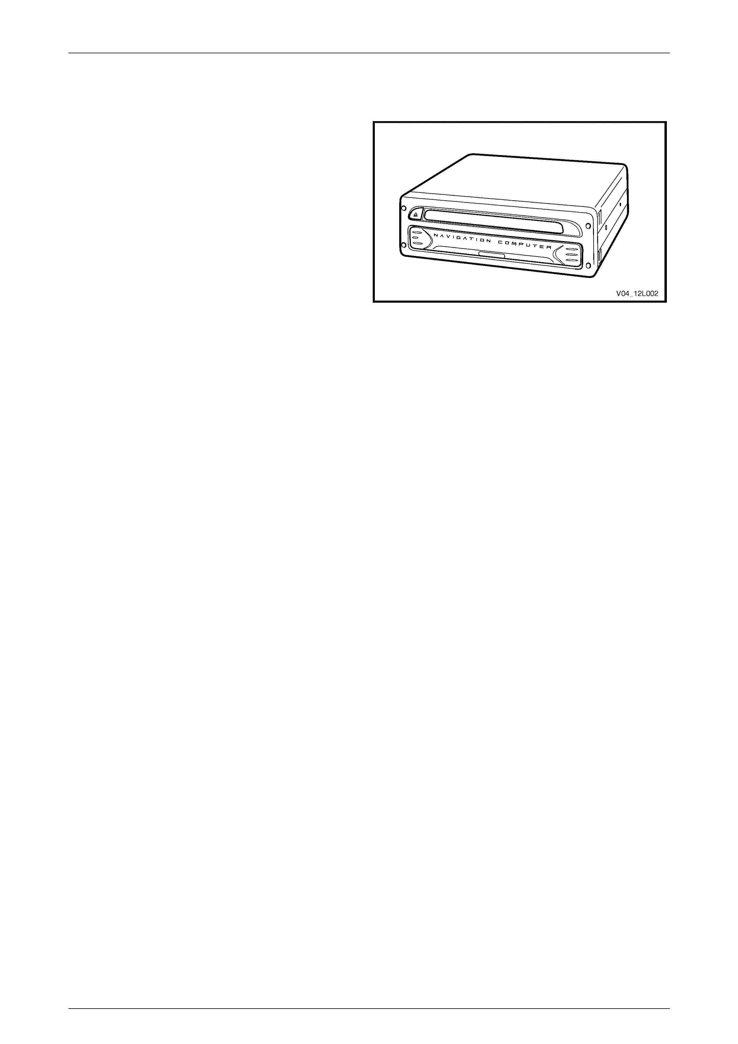
MY 2004 VY and V2 Series Navigation System has received
a running change to the system. As of 23 January 2004,
vehicles fitted with the Navigation System will have a new
model processor installed. If the vehicle was produced post
23 January 2004, or has the processor module displayed
fitted, the following diagnostic procedures will apply.
For all other diagnostics and service operations, refer to
Section 12L Navigation System in the MY 2003 VY and V2
Service Information.
Figure 12L – 1

Navigation S ystem Page 12L–4
Page 12L–4
2 System Diagnosis
Diagnostic tables contained in this Section, list both technical problems and common faults found due to improper use of
the navigation system. Figure 12L – 2 and Figure 12L – 3 should be used with the diagnostic tables to fault-find the
navigation sy ste m.
It is advantageous to read the Satellite Navigation Handbook Supplement supplied with the navigation system before
performing diagnosis on the system.
NOTE
If the processor assembly needs to be removed
or disconnected from the vehicle power supply,
ensure the processor assembly has shut down
completely. The red LED on the processor
assembly extinguishes when the processor
assembly is shut off. Allow approximately 30
seconds after the ignition is turned off for the
processor assembly to shut down.
2.1 Prerequisites
Safety Requirements
When operating the navigation system as part of any of the Steps in the diagnosis charts, ensure that fingers and limbs
are clear of moving parts.
Equipment
The following equipment is required to diagnose the navigation system:
1 An unpowered test lamp with a current draw of less than 3 A.
2 A digital multimeter with minimum impedance of 10 MΩ.
Testing Procedures
Adhere to the following points when performing diagnostic testing on navigation system components:
1 Care must be taken when using testing equipment to diagnose wiring harness connectors. The technician should
back-probe the connector to avoid terminal damage.
2 When tests are required on connector terminals, use the adapters in the connector adapter kit KM–609 to prevent
damage to the terminals.
3 Unless the multimeter being used has an auto-ranging function, ensure the correct range is selected.
4 When back-probing connectors, ensure the test lamp earth lead is connected to a suitable earth point on the
vehicle. Ensure this earth point is not part of the circuit being tested.
When following the Steps in the diagnosis
charts, ensure work is performed in the order
in which they are presented. If the required
nominal value or result is not achieved, rectify
the problem before proceeding.
Navigation S ystem Page 12L–5
Page 12L–5
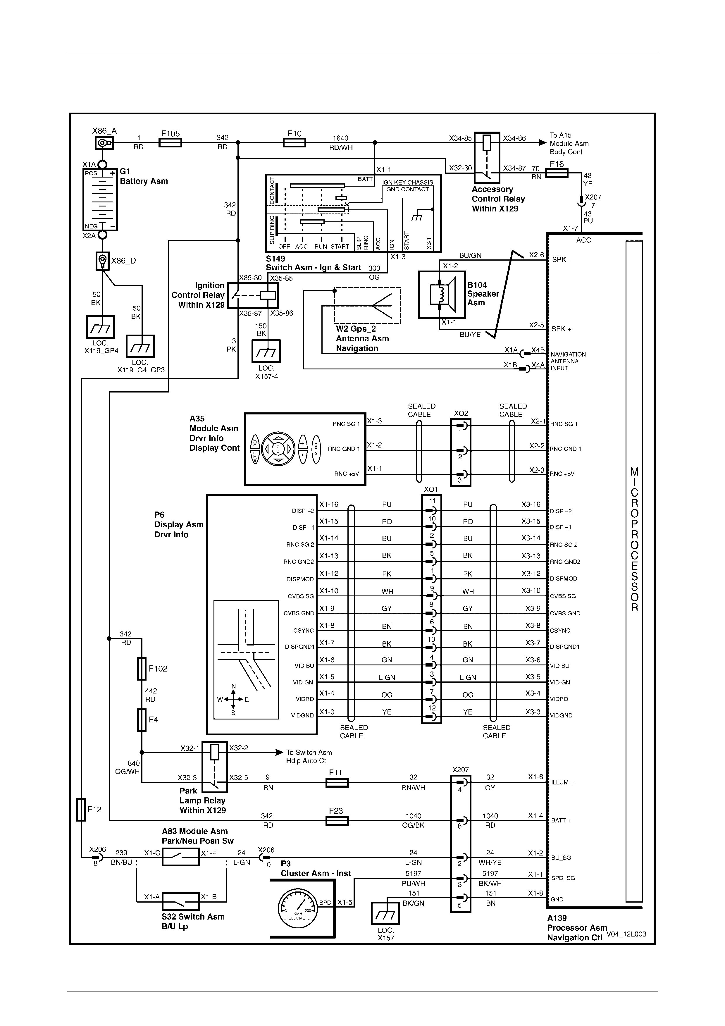
2.2 Wiring Diagram
Figure 12L – 2
Navigation S ystem Page 12L–6
Page 12L–6
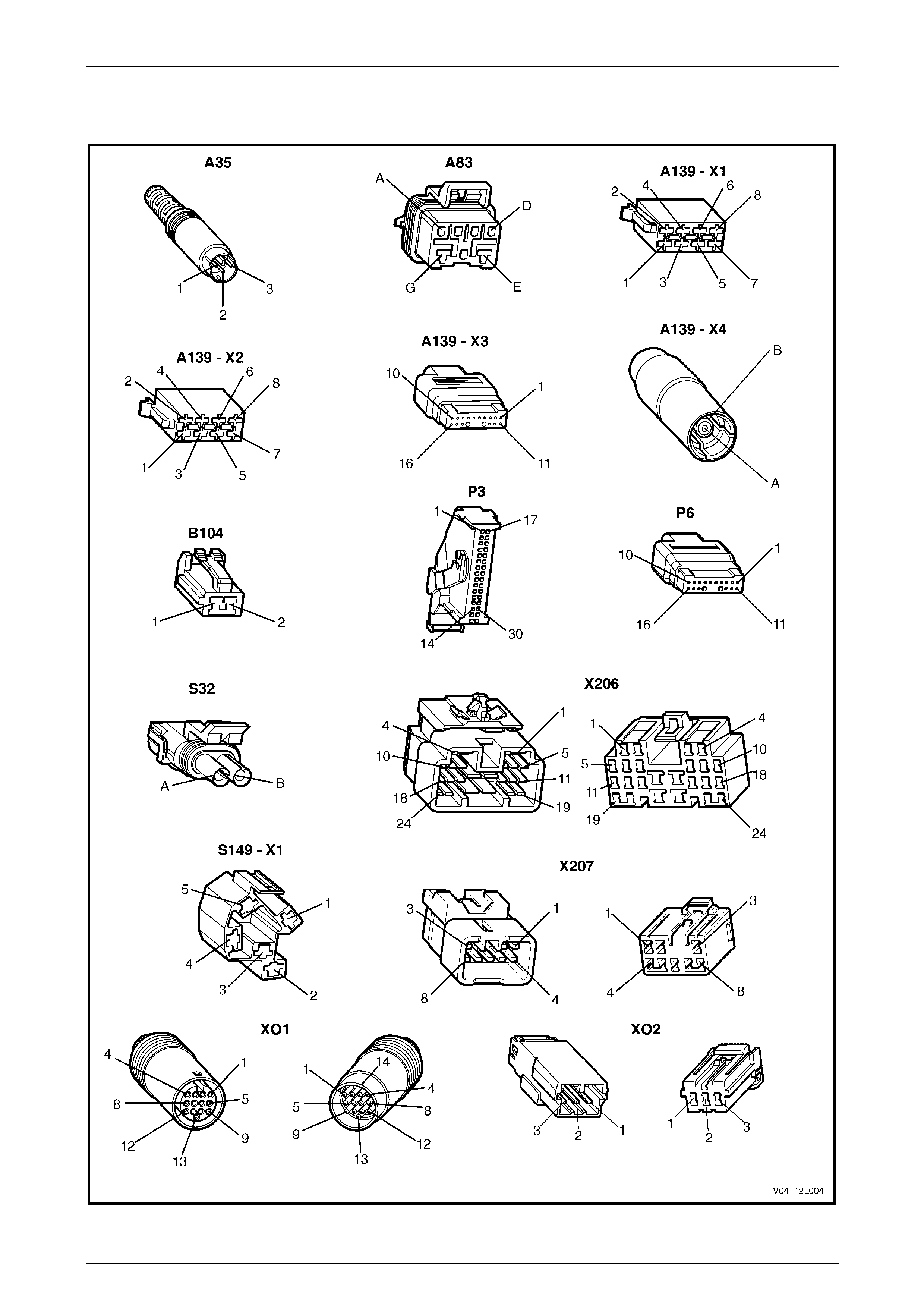
2.3 Connector Chart
Figure 12L – 3

Navigation S ystem Page 12L–7
Page 12L–7
2.4 Navigation System Does Not Start
Condition One
Introduction
Accessory power supplied to the processor assembly is used by the processor only as an indication that the vehicle is in
use and the navigation system is required. The battery supply provides powe r for the navigation system to operate. If the
processor does not receive accessory power, the navigation system can not operate because the navigation system can
not determine if the vehicle is in use.
The following symptoms are presented when accessory power is not supplied to the processor assembly with the ignition
switch in either the ACC or IGN position:
• There is no picture on the display.
• The red power LED on the processor assembly is flashing.
• The system does not respond to commands from the remote control.
If the red power LED flashes on the processor assembly, battery power and an earth circuit are present and serviceable.
To assist in the diagnosing the navigation system, refer to 2.2 Wiring Diagram and 2.3 Connector Chart.
Test Description
The numbers following refer to the Step numbers in the diagnostic chart.
1 Checks if the ignition switch is in the ACC or IGN position to supply accessory power to the vehicle. If accessory
power is not supplied to the vehicle when the ignition switch is in the ACC or IGN position, the fault does not lie with
the navigation system . Refer to Section 12J, 4.4 Accessory Power Circuit in the MY 2003 VY and V2 Service
Information for further diagnosis.
2 Checks that the connector required for accessory power to be supplied to the processor assembly is in place and
positively connected.
3 Checks if there is accessory power at the processor assembly. Isolates whether the supply of accessory power or
the processor assembly is at fault.
4 Checks if fuse F16 on the passenger compartment fuse and relay panel assembly is serviceable. Isolates whether
the fuse is the fault affecting the circuit between the accessory control relay and the processor assembly.
5 Checks if there is accessory power at the connector X207. Isolates whether the fault in the circuit is between
connector X207 and the processor, or X207 and the accessory control relay.
6 Checks if there is accessory power at fuse F16. Isolates whether the fault in the circuit is between fuse F16 and
connector X207, or between fuse F16 and the accessory power circuit.
Step Possible Cause / Remedy Yes No
1 Is the ignition switch in the ACC or IGN position? Go to Step 2. Turn the ignition
switch to the ACC
or IGN position.
2 Is connector A139 – X1 secure? Go to Step 3. Ensure that
connector A139 –
X1 is secure.
3 1 Back-probe connector A139 – X1 pin 7 with a test lamp.
Does the test lamp illuminate?
The processor
assembly is faulty.
Send the processor
assembly to the
vendor for further
assessment.
Contact Siemens
VDO Customer
Service on
1800 335 – 282
Go to Step 4.

Navigation S ystem Page 12L–8
Page 12L–8
Step Possible Cause / Remedy Yes No
4 1 Inspect fuse F16, refer to Section 12O, 2.1 Fuses.
Is fuse F16 blown? Replace fuse F16. Go to Step 5.
5 1 Remove the left-hand hinge pillar trim assembly to gain access
to connector XO1, refer to Section 1A8, 2.8 Hinge Pillar Trim
Assembly in the MY 2003 VY and V2 Service Information.
2 Back-probe connector X207 pin 7 with a test lamp.
Does the test lamp illuminate?
There is a fault in
circuit 43 between
connectors A139 –
X1 pin 7 and X207
pin 7. Repair or
replace circuit 43.
Go to Step 6.
6 1 Remove fuse F16 from the passenger compartment fuse and
relay panel assembly, refer to Section 12O, 2.1 Fuses.
2 Using a multimeter with the negative lead to earth, check if there
is battery voltage at connector X129 – X43 pin 16.
Is there battery voltage across the connector X129 – X43 pin 16?
A fault exists in
circuit 43 between
connector X207
pin 7 and connector
X129 – X43 pin 16.
Repair or replace
circuit 43.
A fault exists in
circuit 70 that
supplies accessory
power for the
navigation sy ste m.
Refer to Section
12J, 4.4 Accessory
Power Circuit in the
MY 2003 VY and V2
Service Information
for further diagnosis.
When all diagnosis and repairs are completed, check the system for correct operation.
Condition Two
Introduction
The battery power connection provides two functions to the navigation system. When the vehicle ignition switch is in the
ACC or IGN position, the processor determines that the vehicle is in use. The processor draws its power through the
battery supply circuit to supply the navigation system.
When the vehicle’s ignition is in the OFF position, the battery supply circuit provides power to the processor assembly to
allow the processor assembly to store data such as current location etc.
The following symptoms are presented when battery power is not supplied to the processor assembly:
• There is no picture on the display until the ignition switch is in either the ACC or IGN position.
• The red power LED on the processor assembly is extinguished.
To assist in diagnosing the navigation system, refer to 2.2 Wiring Diagram and 2.3 Connector Chart.
Test Description
The numbers following refer to the Step numbers in the diagnostic chart.
1 The red power LED illuminates if the 12 volt battery power and chassis earth are OK.
2 Checks that the connector required for battery power to be supplied to the proc essor assembly is in place and
positively connected.
3 Checks that battery voltage is more than 12 volts. The navigation system requires more than 12 volts to operate
correctly.
4 Checks if the fuse located on the rear of the proces sor assembly has not blown.
5 Checks if fuse F23 located on the passenger compartment fuse and relay panel as sembly has not blown.
6 Checks if there is battery voltage to the processor assembly. Isolates whether there is a fault between the battery
and the processor assembly, or the fault is in the earth circuit or processor assembly.
7 Checks if connector X207 is in place and positively connected. Connector X207 is part of the battery circuit and
earth circuit for the proce ssor ass emb ly .
8 Checks if there is battery voltage at connector X207 pin 8. Isolates whether there is a fault between connector
X207 and the processor assembly.

Navigation S ystem Page 12L–9
Page 12L–9
9 Checks if there is battery voltage at fuse F23 on the passenger compartment fuse and relay panel assembly.
Isolates whether there is a fault between fuse F23 and connector X207 pin 8, or between fusible link F105 and
fuse F23.
10 Checks if there is battery voltage at connector X139 – X1 pin 8. Isolates if there is a fault with the processor
assembly.
11 Checks if there is battery voltage at connector X207 pin 5. Isolates whether the fault is in earth circuit 151
(between connector X207 and the processor assembly), or between connectors X207 and X157.
Step Possible Cause / Remedy Yes No
1 1 Press the EJECT button on the processor.
Does the red LED illuminate?
If there is still no
response from the
system, refer to
CONDITION
THREE in this
Section.
Go to Step 2.
2 Is connector A139 – X1 secure? Go to Step 3. Ensure that
connector A139 –
X1 is secure.
3 1 Check the battery voltage, refer to Section 12A, 2.9 Battery in
the MY 2003 VY and V2 Service Information.
Is the battery voltage more than 12 V? Go to Step 4.
Refer to Section
12A, 2.9 Battery in
the MY 2003 VY
and V2 Service
Information for
further diagnosis .
4 1 Inspect the fuse on the rear of the processor assembly.
Is the fuse on the rear of the processor blown? Replace the fuse. Go to Step 5.
5 1 Inspect fuse F23, refer to Section 12O, 2.1 Fuses in the MY
2003 VY and V2 Service Information.
Is fuse F23 blown? Replace the fuse. Go to Step 6.
6 1 Back-probe connector A139 – X1 pin 4 with a test lamp.
Does the test lamp illuminate? Go to Step 10. Go to Step 7
7 1 Remove the left-hand hinge pillar trim assembly to gain access
to connector X207, refer to Section 1A8, 2.8 Hinge Pillar Trim
Assembly in the MY 2003 VY and V2 Service Information.
Is connector X207 secure?
Go to Step 8. Ensure that
connector X207 is
secure.
8 1 Back-probe connector X207 pin 8 with a test lamp.
Does the test lamp illuminate? Go to Step 9.
A fault exists in
circuit 1040
between connectors
X207 pin 8 and
A139 – X1 pin 4.
Repair or replace
circuit 1040.
9 1 Remove fuse F23 from the passenger fuse and relay panel
assembly.
2 Back-probe connector X129 – X42 pin 23 with a test lamp.
Does the test lamp illuminate?
A fault exists in
circuit 1040
between the
connector X129 –
X42 pin 23 and
X207. Repair or
replace circuit 104 0.
A fault exists in
circuit 342 betw een
fusible link F105
and connect or
X129 – X42 pin 23.
Repair or replace
circuit 342.

Navigation S ystem Page 12L–10
Page 12L–10
Step Possible Cause / Remedy Yes No
10 1 Back-probe connector A139 – X1 pin 8 with a test lamp.
Does the test lamp illuminate?
Go to Step 11.
The processor
assembly is faulty.
Send the processor
assembly to the
vendor for further
diagnosis.
Contact Siemens
VDO Customer
Service on
1800 335 – 282.
11 1 Back-probe connector X207 pin 5 with a test lamp.
Does the test lamp illuminate?
A fault exists in
circuit 151 betw een
connector X207
pin 5 and X157.
Repair or replace
circuit 151.
A fault exists in
circuit 151 betw een
connector A139 –
X1 pin 8 and X207
pin 8. Repair or
replace circuit 151.
When all diagnosis and repairs are completed, check the system for correct operation.
Condition Three
Introduction
When the vehi cle ignition switch is in the ACC or IGN position and the battery, accessory and earth circuits are
serviceable, the red LED on the proc essor assembly illuminates continuously.
The following conditions exist when there is power to the processor assembly, but there is no picture on the display:
• No picture on the display.
• Red power LED on the processor is illuminated.
To assist in diagnosing the navigation system, Refer to 2.2 Wiring Diagram and 2.3 Connector Chart.
Test Description
The numbers following refer to the Step numbers in the diagnostic chart.
1 Checks if the system is in an idle state. Attempts to restore system operation by using the remote control.
2 Checks if the system is in an idle state. Attempts to restore system operation by using the remote control. If the
system is restored, there is a fault in the remote control assembly when it is being used outside the cradle.
3 Checks that the battery voltage is above 12 V. The navigation system requires more than 12 V to operate correctly.
4 Navigation control buttons are located on top of the display. If the system responds when these buttons are
pressed, there is a problem with the remote control and associated circuits when the control is operated.
5 Checks if all the connectors required for the navigation system display to functi on correctly are in place and
positively connected.
6 Checks if there is continuity between connectors A139 – X3 and XO1 which is part of the navigation wiring
harness. This isolates whether the navigation wiring harness that supplies power to the display is at fault.
7 Checks if there is continuity between connectors P6 – X1 and XO1 which is part of the cockpit navigation wiring
harness. This isolates whether the cockpit navigation wiring harness that supplies power to the display is at fault.
8 Checks if the display assembly is the fault in the system. Isolates whether the fault is with the display assembly or
the processor assembly.
Step Possible Cause / Remedy Yes No
1 1 Remove the remote control from the remote control cradle.
2 Point the remote control at the display and press the OK button
to restore display operation.
Does th is activa te th e display?
System serviceable. Go to Step 2.

Navigation S ystem Page 12L–11
Page 12L–11
Step Possible Cause / Remedy Yes No
2 1 Seat the remote control in the remote control cradle and press
the OK button on the remote control.
Does th is activa te th e display?
Refer to
2.5 No Respon se
From Remote
Control, Condition
One.
Go to Step 3.
3 1 Check the battery voltage, refer to Section 12A, 2.9 Battery in
the MY 2003 VY and V2 Service Information.
Is the battery voltage more than 12 V? Go to Step 4.
Refer to Section
12A, 2.9 Battery in
the MY 2003 VY
and V2 Service
Information for
further diagnosis .
4 1 Remove the display assembly and the display assembly
mounting bracket, refer to Section 12L, 3.3 Navigation Display in
the MY 2003 VY and V2 Service Information Assembly.
2 Connect the connector P6 to the back of the display.
3 Operate the navigation system using the keys on top of the
display.
Does th is activa te th e display?
Refer to
2.5 No Respon se
From Remote
Control.
Go to Step 5.
5 Are the following connections secure:
• A139 – X3
• X01
• P6
Go to Step 6. Ensure the
connectors
are secure.
6 1 Remove the left-hand hinge pillar trim assembly to gain access
to connector XO1, refer to Section 1A8, 2.8 Hinge Pillar Trim
Assembly in the MY 2003 VY and V2 Service Information.
2 Using a multimeter, check for continuity between the following
connectors:
• A139 – X3 pin 16 and X01 pin 11
• A139 – X3 pin 15 and X01 pin 10
• A139 – X3 pin 14 and X01 pin 2
• A139 – X3 pin 13 and X01 pin 5
• A139 – X3 pin 12 and X01 pin 1
• S139 – X3 pin 10 and X01 pin 9
• A139 – X3 pin 9 and X01 pin 8
• A139 – X3 pin 8 and X01 pin 6
• A139 – X3 pin 7 and X01 pin 13
• A139 – X3 pin 6 and X01 pin 4
• A139 – X3 pin 5 and X01 pin 3
• A139 – X3 pin 4 and X01 pin 7
• A139 – X3 pin 3 and X01 pin 12
Is there continuity between all of the terminals of connectors A139 –
X3 and X01? Ensure resistance is minimal and consistent across all
pins tested.
Go to Step 7.
A fault exists in the
display cable which
is part of the
navigation wiring
harness. Repair or
replace the
navigation wiring
harness as requir ed.

Navigation S ystem Page 12L–12
Page 12L–12
Step Possible Cause / Remedy Yes No
7 1 Remove the display assembly, refer to Section 12L, 3.3
Navigation Display Assembly in the MY 2003 VY and V2 Service
Information.
2 Using a multimeter, check for continuity between the following
connectors:
• P6 – X1 pin 16 and X01 pin 11
• P6 – X1 pin 15 and X01 pin 10
• P6 – X1 pin 14 and X01 pin 2
• P6 – X1 pin 13 and X01 pin 5
• P6 – X1 pin 12 and X01 pin 1
• P6 – X1 pin 10 and X01 pin 9
• P6 – X1 pin 9 and X01 pin 8
• P6 – X1 pin 8 and X01 pin 6
• P6 – X1 pin 7 and X01 pin 13
• P6 – X1 pin 6 and X01 pin 4
• P6 – X1 pin 5 and X01 pin 3
• P6 – X1 pin 4 and X01 pin 7
• P6 – X1 pin 3 and X01 pin 12
Is there continuity between all of the terminals of connectors P6 – X1
and X01?
Go to Step 8.
A fault exists in the
display cable which
is part of the cockpit
navigation wiring
harness. Repair or
replace the cockpit
navigation wiring
harness as requir ed.
8 1 Replace the display assembly.
Does the display now operate?
System serv ic eabl e.
The processor
assembly is faulty.
Send the processor
assembly to the
vendor for further
assessment.
Contact Siemens
VDO Customer
Service on
1800 335 – 282.
When all diagnosis and repairs are completed, check the system for correct operation.

Navigation S ystem Page 12L–13
Page 12L–13
2.5 No Response From Remote Control
No Response From Remote Control
Introduction
The remote control sends signals to the processor assembly in either of two methods. In the first method, with the remote
control removed from the remote control cradle and pointed at the display assembly, the signal is received by the display
assembly, then transmitted through the display wiring harness to the processor assembly. In this case the power to
transmit the signal is from the remote control batteries.
The second method is with the remote control situated in the remote control cradle. In this case, signals from the remote
control transmit directly through the remote control cradle and its wiring harness to the processor assembly. The power
to transmit the signal from the remote control is provided by the vehicle via the processor assembly and remote control
cradle.
The following con diti ons ex ist when the remote control is inoperativ e:
• The navigation system is operational, with the title screen on the display.
• The navigation system does not respond to commands from the remote control.
Test Description
The numbers following refer to the Step numbers in the diagnostic chart.
1 Checks if there is any response from the remote control in any of its operating conditions. Isolates whether the
remote control or the system that transmits the signal to the processor is at fault.
2 Checks if the remote control functions correctly when operated from the cradle. Isolates whether the cradle and
associated circuitry is at fault.
3 Checks if the remote control functions correctly when operated through the display. Isolates whether the display
and associated circuitry is at fault.
4 Replaces the remote control with a serviceable item. Isolates whether the remote control or the processor is at
fault.
Step Possible Cause / Remedy Yes No
1 1 Place the remote control in the remote control cradle.
2 Press the ‘OK’ button on the remote control.
3 Remove the remote control from the remote control cradle.
4 Point the remote control at the display assembly and press the
‘OK’ button.
Does the system respond to the remote control during any part of the
procedure?
Go to Step 2. Go to Step 4.
2 1 Place the remote control in the remote control cradle.
2 Press the ‘OK’ button on the remote control.
Does the system respond when the remote control is operated from
the cradle?
Go to Step 3.
Refer to
2.5 No Response
From Remote
Control Conditi on
Two.
3 1 Remove the remote control from the remote control cradle.
2 Point the remote control at the display assembly and press the
‘OK’ button.
Does the system respond when the remote control is operated though
the display (that is, when it is not seated in the cradle)?
System servic eabl e
Refer to
2.5 No Response
From Remote
Control, Condition
One.

Navigation S ystem Page 12L–14
Page 12L–14
Step Possible Cause / Remedy Yes No
1 1 Place the remote control in the remote control cradle.
2 Press the ‘OK’ button on the remote control.
3 Remove the remote control from the remote control cradle.
4 Point the remote control at the display assembly and press the
‘OK’ button.
Does the system respond to the remote control during any part of the
procedure?
Go to Step 2. Go to Step 4.
2 1 Place the remote control in the remote control cradle.
2 Press the ‘OK’ button on the remote control.
Does the system respond when the remote control is operated from
the cradle?
Go to Step 3.
Refer to
2.5 No Response
From Remote
Control Conditi on
Two.
3 1 Remove the remote control from the remote control cradle.
2 Point the remote control at the display assembly and press the
‘OK’ button.
Does the system respond when the remote control is operated though
the display (that is, when it is not seated in the cradle)?
System servic eabl e
Refer to
2.5 No Response
From Remote
Control, Condition
One.
4 1 Replace the remote control with a serviceable item.
2 Repeat the processes in Step 1 and 2.
Does the system respond when the remote control is operated? System serv ic eabl e.
The processor
assembly is faulty.
Send the processor
assembly to the
vendor for further
assessment.
Contact Siemens
VDO Customer
Service on
1800 335 – 282
When all diagnosis and repairs are completed, check the system for correct operation
Condition One
Introduction
In this condition the title screen appears when the vehicle ignition switch is in the ACC or IGN position. The system does
not respond when the remote control is operated via the display (that is, when it is not seated in the remote control
cradle).
To assist in diagnosing the navigation system, Refer to 2.2 Wiring Diagram and 2.3 Connector Chart.
Test Description
The numbers following refer to the Step numbers in the diagnostic chart.
1 Checks if anything is preventing the transmission of commands between the remote control and the infrared screen
that is part of the display assembly.
2 After the batteries are changed, checks if the system responds when the remote control is operated via the display.
3 Checks that all the connectors required for the remote control to operate effectively are in place and positively
connected.
4 Checks if there is continuity between the relevant pins on the navigation wiring harness that transmit the signal
from the display assembly to the processor. Isolates whether the navigation wiring harness is at fault.
5 Checks if there is continuity between the relevant pins on the cockpit navigation wi ring harness that transmit the
signals from the display assembly to the processor. Isolates whether the cockpit navigation wiring harness is at
fault.
6 Isolates whether the remote control as at fault.

Navigation S ystem Page 12L–15
Page 12L–15
7 Replaces the display assembly with a serviceable item. Isolates whether the disp lay assembly or the processor is
at fault.
Step Possible Cause / Remedy Yes No
1 1 Remove any obstructions in front of the infrared screen on the
display.
2 Clean the infrared screen on the display.
3 Clean the infrared screen on the remote control.
Does the system respond when the remote control is operated though
the display (that is, when it is not seated in the cradle)?
System serviceable. Go to Step 2.
2 1 Replace the batteries in the remote control.
Does the system respond when the remote control is operated though
the display (that is, when it is not seated in the cradle)? System serviceable. Go to Step 3.
3 1 Remove the left-hand hinge pillar trim assembly to gain access
to connector XO1, refer to Section 1A8, 2.8 Hinge Pillar Trim
Assembly in the MY 2003 VY and V2 Service Information.
2 Check the following connectors are secured:
• A139 – X3
• XO1
• P6
Go to Step 4. Ensure the
connect ors are
secure.
4 1 Perform continuity checks on the following:
• A139 – X3 pin 14 to XO1 pin 2
• A139 – X3 pin 13 to XO1 pin 5
Is there continuity between connectors
A139 – X3 and XO1?
Go to Step 5. Repair or replace
the navigation wiring
harness as requir ed.
5 1 Remove the display assembly, refer to Section 12L, 3.3
Navigation Display Assembly in the MY 2003 VY and
V2 Service Inform ation.
2 Perform continuity checks on the following:
• P6 – X1 pin 14 to XO1 pin 2
• P6 – X1 pin 13 to XO1 pin 5
Is there continuity between connectors P6 – X1 and XO1?
Go to Step 6.
Repair or replace
the cockpit
navigation wiring
harness as requir ed.
6 1 Replace the remote control with a serviceable unit.
Does the system respond when the remote control is operated though
the display (that is, when it is not seated in the cradle)? System serviceable. Go to Step 7.
7 1 Replace the display with a serviceable item.
Does the system respond when the remote control is operated though
the display (that is, when it is not seated in the cradle)?
System serv ic eabl e.
The processor
assembly is faulty.
Send the processor
assembly to the
vendor for further
assessment.
Contact Siemens
VDO Customer
Service on
1800 335 – 282
When all diagnosis and repairs are completed, check the system for correct operation.

Navigation S ystem Page 12L–16
Page 12L–16
Condition Two
Introduction
In this condition the title screen appears when the vehicle ignition switch is in the ACC or IGN position.
The following conditions are presented:
• Title screen appears.
• System does not respond when the remote control is operated when installed correctly in the cradle.
To assist in diagnosing the navigation system, Refer to 2.2 Wiring Diagram and 2.3 Connector Chart.
Test Description
The numbers following refer to the Step numbers in the diagnostic chart.
1 Checks if the contacts between the remote control and the remote control cradle are clean and serviceable.
2 Checks that all connectors required for the remote control to operate effectively are in place and positively
connected.
3 Checks if there is continuity between the relevant pins on the navigation wiring harness that transmit the signal
from the remote control cradle to the processor. Isolates whether the navigation wiring harness is at fault.
4 Checks if there is continuity between the relevant pins on the cockpit navigation wiring harness that transmit signals
from the remote control cradle to the processor. Isolates whether the cockpit navigation wiring harness is at fault.
5 Isolates whether the remote control is at fault.
6 Replaces the remote control cradle with a serviceable item. Isolates whether the remote control cradle or the
processor is at fault.
Step Possible Cause / Remedy Yes No
1 1 Inspect the contacts on the base of the remote control and the
corresponding contacts in the remote control cradle
Are the contacts clean and serviceable? Go to Step 2.
Clean the contacts.
If the contacts are
damaged, replace
the affected part.
2 1 Remove the left-hand hinge pillar trim assembly to gain access
to connector XO2, refer to Section 1A8, 2.8 Hinge Pillar Trim
Assembly in the MY 2003 VY and V2 Service Information.
2 Remove the right-hand instrument panel extension side trim,
refer to Section 12L, 3.2 Remote Control Assembly in the MY
2003 VY and V2 Service Information.
3 Check the following connectors are secured:
• A139 – X2
• XO2
• A35
Go to Step 3. Ensure that the
connect ors are
secure.
3 1 Perform continuity checks on the following:
• A139 – X2 pin 1 to XO2 pin 1
• A139 – X2 pin 2 to XO2 pin 2
• A139 – X2 pin 3 to XO2 pin 3
Is there continuity between connectors
A139 – X3 and XO2?
Go to Step 4. Repair or replace
the navigation wiring
harness as requir ed.

Navigation S ystem Page 12L–17
Page 12L–17
Step Possible Cause / Remedy Yes No
4 1 Perform continuity checks for the following:
• A35 – X1 pin 3 to XO2 pin 1
• A35 – X1 pin 2 to XO2 pin 2
• A35 – X1 pin 1 to XO2 pin 3
Is there continuity between connectors
A35 – X1 and XO2?
Go to Step 5.
Repair or replace
the cockpit
navigation wiring
harness as requir ed.
5 1 Replace the remote control with a serviceable unit.
Does the system respond when the remote control is operated via the
remote control cradle? System serviceable. Go to Step 6.
6 1 Replace the remote control cradle assembly with a serviceable
item, refer to Section 12L, 3.2 Remote Control Assembly in the
MY 2003 VY and V2 Service Information.
Does the system respond when the remote control is operated via the
remote control cradle? System serv ic eabl e.
The processor
assembly is faulty.
Send the processor
assembly to the
vendor for further
assessment.
Contact Siemens
VDO Customer
Service on
1800 335 – 282
When all diagnosis and repairs are completed, check the system for correct operation.

Navigation S ystem Page 12L–18
Page 12L–18
2.6 CD–ROM Error
The CD–ROM is supplied as part of the navigation system. It contains all map and relevant information for Australia. The
CD–ROM must be inserted correctly in the processor for the navigation system to operate correctly.
Condition One
Introduction
When the vehicle ignition switch is in the ACC or IGN position and the navigation system is operational, the
NAVIGATION and ADDRESS book can not be selected via the remote control.
Test Description
The numbers following refer to the Step numbers in the diagnostic chart.
1 Checks if there is a CD–ROM inserted in the processor.
2 Checks if the CD–ROM is inserted correctly, or is dirty or damaged in some way. Isolates whether the CD–ROM or
the processor is at fault.
Step Possible Cause / Remedy Yes No
1 Is the map CD–ROM inserted in the processor assembly? Go to Step 2. Insert the CD–ROM
in the processor.
2 1 Remove the CD–ROM from the processor.
2 Inspect the CD–ROM surface.
Is the map CD–ROM scratched, dirty, damaged or inserted upside
down? Clean the CD–
ROM. Replace the
CD–ROM as
required.
The processor
assembly is faulty.
Send the processor
assembly to the
vendor for further
assessment.
Contact Siemens
VDO Customer
Service on
1800 335 –282
When all diagnosis and repairs are completed, check the system for correct operation.
Condition Two
Introduction
With the vehicle ignition switch in the ACC or IGN position, the CD–ROM ejects from the processor without somebody
pressing the EJECT button.
Test Description
The numbers following refer to the Step numbers in the diagnostic chart.
1 Checks if the CD–ROM is inserted correctly, or is dirty or damaged in some way. Isolates whether the CD–ROM or
the processor is at fault.
Step Possible Cause / Remedy Yes No
1 1 Remove the CD–ROM from the processor.
2 Inspect the CD–ROM surface.
Is the map CD–ROM scratched, dirty, damaged or inserted upside
down? Clean the CD–
ROM. Replace the
CD–ROM as
required.
The processor
assembly is faulty.
Send the processor
assembly to the
vendor for further
assessment.
Contact Siemens
VDO Customer
Service on
1800 335 –282
When all diagnosis and repairs are completed, check the system for correct operation.

Navigation S ystem Page 12L–19
Page 12L–19
Condition Three
Introduction
With the vehicle ignition switch in the ACC or IGN position, a message of “Please insert CD” or “Please insert correct
CD” is displayed.
Test Description
The numbers following refer to the Step numbers in the diagnostic chart.
1 Checks if the CD–ROM is inserted correctly, or is dirty or damaged in some way. Isolates whether the CD–ROM or
the processor is at fault.
Step Possible Cause / Remedy Yes No
1 Is the map CD–ROM scratched, dirty, faulty or inserted upside down?
Clean the CD–
ROM. Replace the
CD–ROM as
required.
The processor
assembly is faulty.
Send the processor
assembly to the
vendor for further
assessment.
Contact Siemens
VDO Customer
Service on
1800 335 –282
When all diagnosis and repairs are completed, check the system for correct operation.

Navigation S ystem Page 12L–20
Page 12L–20
2.7 Audio Problems
Introduction
With the vehicle ignition switch in the ACC or IGN position and the system operational and in use, there are no audio
commands through the speaker, but the system is displaying the guidanc e arrow.
Test Description
The numbers following refer to the Step numbers in the diagnostic chart.
1 Press the ‘+’ button on the remote control increases the audio level of the navigation system. If the system has
been muted, pressing the ‘+’ button will resort audio guidance. When the system is muted, there will be a symbol in
the form of a loudspeaker with a red diagonal line through it on the display.
2 Checks that all the connectors required for the speaker to operate effectively are in place and positively connected.
3 Checks if there is continuity in the navigation wiring harness that supplies power from the processor to the speaker.
Isolates whether the navigation wiring harness is at fault.
4 Check if the speaker has a resistance of 8 Ω acros s its t erminals. Isolates whether the speaker or the processor is
at fault.
Step Possible Cause / Remedy Yes No
1 1 Press the ‘+’ button on the remote control eig ht time s.
Is the word ‘louder’ audible through the navigation speaker? System
serviceable. Go to Step 2.
2 1 Check the following connectors are secure:
• A139 – X2
• B104
Go to Step 4. Ensure the
connect ors are
secure.
3 1 Perform continuity checks on the following:
• A139 – X2 pin 6 to B104 – X1 pin 2
• A139 – X2 pin 5 to B104 – X1 pin 1
Go to Step 5. Repair or replace
the navigation wiring
harness as requir ed.
4 1 Disconnect connector B104 from the navigation wiring harness.
2 Using a multimeter, measure the resistance across terminals
B104 – X1 pin 1 and pin 2 on the speaker side.
Is there a resistance of 8 Ω ac ross the B 104 – X1 pin 1 and pin 2?
The processor
assembly is faulty.
Send the processor
assembly to the
vendor for further
assessment.
Contact Siemens
VDO Customer
Service on
1800 335 –282
Replace the
speaker as sem bly .
When all diagnosis and repairs are completed, check the system for correct operation.

Navigation S ystem Page 12L–21
Page 12L–21
2.8 Guidance Problems
The processor continuously calculates the vehicle position. When a destination is entered, the processor calculates the
best possible route depending on the user's preferences. If the user does not follow the directions provided by the
processor, the processor must recalculate another route, then provide the user with new directions. Problems may occur
in guidance when the user does not follow the processor route instructions and makes a number of changes in directions
before the processor can recalculate the route. The processor eventually calculates the correct route, but must be given
some time. In this case, the user has obviously strayed from processor guidance instructions; the processor always
maintains the correct location of the vehicle.
Condition One
Introduction
With the navigation system operational and in use, incorrect guidance instructions are given by the processor.
Test Description
The numbers following refer to the Step numbers in the diagnostic chart.
1 With the navigation system operational and in MAP mode, the scale is not at a level that can show the correct
position of the vehicle. A change of scale may show a more accurate position.
2 If the system has been driven along straight long roads for excessive periods or has been recently disabled, the
navigation system may need calibrating.
3 Checks that the DIRECTION option in the SET I/O STATE menu is set to ACT_HIGH.
4 Checks that the proces sor is receiving an adequate GPS signal to ensure an accurate calculation of the position of
the vehicle. Isolates whether the GPS antenna is at fault.
5 Check that the processor ’s int ernal gy rosc ope is not faul ty .
6 Checks if the CD–ROM is out of date. This will especially affect people who travel into newly-developed areas.
7 Checks that the processor is receiving VSS. Isolates whether there is a VSS fault or the processor is faulty. If there
is a VSS fault, the check isolates whether it is contained in the navigation system or within the other systems of the
vehicle.
8 Checks for continuity between X207 and A139 at the processor. Isolates whether the fault is in the processor or the
navigation wiring harness.
Step Possible Cause / Remedy Yes No
1 1 Switch the system display to MAP mode in 100M scale.
Is the vehicle position now accurate? System
serviceable. Go to Step 2.
2 1 Calibrate the navigation system, refer to Section 12L,
3.10 Navigation System Calibration in the MY 2003 VY and V2
Service Information.
Is the vehicle position now accurate?
System
serviceable. Go to Step 3.
3 1 Using the remote control, access the SET I/O STATE menu,
refer to 3.3 Set I/O State.
2 Check tha t the DIRECTION is set to ACT_HIGH.
Is the DIRECTION set to ACT_HIGH?
Go to Step 4.
Change the
DIRECTION to
ACT_HIGH, refer to
3.3 Set I/O State.
4 1 Check that the connector A139 – X4 is secure to the rear of the
processor.
2 Ensure that the vehicle is outside with no major structures
around it that might cause a disruption in GPS reception.
3 Using the remote control, access the READ GPS DATA menu,
refer to 3.4 Read GPS Data.
Is the receiver state in either 3D or 2D POSITION?
Go to Step 5.
Replace the
antenna, refer to
Section 12L,
3.7 Navigation Gps
Antenna in the MY
2003 VY and V2
Service Informatio n.

Navigation S ystem Page 12L–22
Page 12L–22
Step Possible Cause / Remedy Yes No
5 1 Using the remote control, switch the system to MAP mode
Does the position arrow rotate while the vehicle is stationary?
Disconnect the
power from the
processor assembly
and allow the
system to reset.
If the vehicle
position arrow still
rotates after the
system has been
reset, send the
processor assembly
to the vendor for
further assessment.
Contact Siemens
VDO Customer
Service on
1800 335 – 282.
Go to Step 6.
6 1 Replace the CD–ROM.
2 Calibrate the system, refer to Section 12L, 3.10 Navigation
System Calibration in the MY 2003 VY and V2 Service
Information.
Is the vehicle position now accurate?
System
serviceable. Go to Step 7.
7 1 Using the remote control, access the READ I/O STATE menu,
refer to 3.2 Read I/O State.
2 Drive the vehicle at a speed greater than 5 km/h.
Is the SPEED PULSES reading greater than 0? The processor
assembly is faulty.
Send the processor
assembly to the
vendor for further
assessment.
Contact Siemens
VDO Customer
Service on
1800 335 – 282.
Check the VSS
circuit. Refer to:
Section 6C1-2A for
V6 in the MY 2003
VY and V2 Service
Information.
Section 6C2-2A for
V6 S/C in the MY
2003 VY and V2
Service Information
.
Section 6C3-2A for
GEN III in the MY
2003 VY and V2
Service Informatio n.
Go to Step 8 if there
is no fault found with
the VSS circuit.
8 1 Remove the left-hand hinge pillar trim assembly to gain
access to connector XO1, refer to Section 1A8, 2.8 Hinge Pillar Trim
Assembly in the MY 2003 VY and V2 Service Information.
2 Check the continuity between the following:
• A139 – X1 pin 1 to X207 pin 3
The processor
assembly is faulty.
Send the processor
assembly to the
vendor for further
assessment.
Contact Siemens
VDO Customer
Service on
1800 335 – 282.
Repair or replace
the navigation wiring
harness as requir ed.
When all diagnosis and repairs are completed, check the system for correct operation.

Navigation S ystem Page 12L–23
Page 12L–23
Condition Two
Introduction
With the navigation system operational and in use, a destination (eg CITY or ROAD etc.) is entered with the re mote
control, but is not recognised by the system.
Test Description
The numbers following refer to the Step numbers in the diagnostic chart.
1 Checks if the destination has been correctly entered.
2 Checks if the street number being entered is correct. Isolates whether the CD–ROM is out of date or the number
being entered is on a road that extends through more than one suburb.
Step Possible Cause / Remedy Yes No
1 1 Change the search criteria. Search by a region (eg Sydney) and
then by the road name.
Is the destination now recognised?
System
serviceable. Go to Step 2.
2 1 Replace the CD–ROM with the current version.
Is the destination now recognised?
System
serviceable.
When a long road
continues from one
suburb to the next
the house number
may restart in the
new suburb or
continue in
sequence from the
original suburb.
When all diagnosis and repairs are completed, check the system for correct operation.
Condition Three
Introduction
With the navigation system operational, the GUIDANCE function can not be selected.
Test Description
The numbers following refer to the Step numbers in the diagnostic chart.
1 There is only one instance when, with all other functions operating correctly, guidance can not be selected. This
occurs if a destinatio n has not been enter ed.
Step Possible Cause / Remedy Yes No
1 1 Enter the destination. System
serviceable.
When all diagnosis and repairs are completed, check the system for correct operation.
Condition Four
Introduction
With the navigation system operational, there are no guidance instructions after the destination has been entered and the
GUIDANCE function selected.
Test Description
The numbers following refer to the Step numbers in the diagnostic chart.
1 Checks if the GUIDANCE function has been selected and activated.
2 Ensures that, if the vehicle is on a road held within the navigation system database, the appropriate section of map
is displayed. The system does not give guidance instructions until the vehicle is on such a road.

Navigation S ystem Page 12L–24
Page 12L–24
Step Possible Cause / Remedy Yes No
1 1 Activate the GUIDANCE function.
Are guidance instructions restored? System
serviceable. Go to Step 2.
2 1 Ensure the vehicle is on a road held within the navigation
system database. If the vehicle is not on such a road, an arrow
appears in the top right-hand corner of the map screen.
Are guidance instructions restored?
If the location of the
vehicle is incorrect
when it has been
moved to a digitised
road, calibrate the
navigation sy ste m,
refer to Section 12L,
3.10 Navigation
System Calibration
in the MY 2003 VY
and V2 Service
Information.
When all diagnosis and repairs are completed, check the system for correct operation.

Navigation S ystem Page 12L–25
Page 12L–25
2.9 Display Quality
Introduction
With the navigation system operational, the display quality is poor.
Test Description
The numbers following refer to the Step numbers in the diagnostic chart.
1 Checks if there is a problem in the dimming circuit for the display. Th e display is designed to be bright during the
day and is dimmed when the park lights are turned on.
2 Checks the battery voltage is above 12 V. The navigation system requires more than 12 V to operate correctly.
3 Checks if the brightness of the display as at its maximum. Brightness can not be controlled by the remote control;
this is controlled from the top of the display .
4 Checks if there is continuity between connector A139 – X3 and XO1. There should be minimal resistance in the
harness, but it should be consistent across all pins. Any degradation in continuity could result in poor picture
quality.
5 Checks if there is continuity between connector XO1 and P6 –X1. There should be minimal resistance in the
harness, but it should be consistent across all pins. Any degradation in continuity could result in poor picture
quality.
Step Possible Cause / Remedy Yes No
1 1 Switch on the park lamps.
Is there any change in the display quality? Go to Step 2.
Refer to
2.10 Display
Dimming
Inoperative.
2 1 Check the battery voltage, refer to Section 12A, 2.9 Battery in
the MY 2003 VY and V2 Service Information.
Is the battery voltage more than 12 V? Go to Step 3.
Refer to Section
12A, 2.9 Battery in
the MY 2003 VY
and V2 Service
Information for
further diagnosis .
3 1 Remove the display assembly, refer to Section 12L,
3.3 Navigation Display Assembly in the MY 2003 VY and V2
Service Information.
2 Connect connector P6 to the rear of the display.
3 Using the controls on top of the display, increase the brightness.
Is the quality of the picture increased?
System
serviceable. Go to Step 4.
4. 1 Remove connector A139 – X3 from the rear of the processor.
2 Remove the left-hand hinge pillar trim assembly to gain access
to connector XO1, refer to Section 1A8, 2.8 Hinge Pillar Trim
Assembly in the MY 2003 VY and V2 Service Information.
3 Check the continuity of the navigation wiring harness between
the processor and the connector XO1, refer to Step 6, 2.4
Navigati on System Does Not Start, Condition Three. Ensure
resistance is minimal and consistent across all pins checked.
Is the navigation wiring harness serviceable?
Go to Step 5. Repair or replace
the navigation wiring
harness.
5 1 Remove connector P6 from the display.
2 Check the continuity of the cockpit nav iga t ion wiring har ne ss,
refer to Step 7, 2.4 Navigation System Does Not Start,
Condition Three. Ensure resistance is minimal and consistent
across all pins chec ke d.
Is the cockpit navigation wiring harness serviceable?
The display is faulty.
Replace the faulty
display with a
serviceable item.
Repair or replace
the cockpit
navigation wiring
harness.
When all diagnosis and repairs are completed, check the system for correct operation.

Navigation S ystem Page 12L–26
Page 12L–26
2.10 Display Dimming Inoperative
The display is designed to be bright during the day and dim when the park lamps are switched on.
Introduction
There are two conditions that can be presented when there is a fault in the circuitry that informs the processor that it is
either daytime or night time.
In the first case, the display does not dim when the park lamps are switched on. The second case is when the display is
dim during the daytime and bright when the park lamps are switched on.
Test Description
The numbers following refer to the Step numbers in the diagnostic chart.
1 Checks if the park lamps work. The processor receives a signal from the parks lamps when they are on, and dims
the display. Isolates whether the fault is in the park lamp relay and its power supply or on the circuit proceeding the
relay.
2 Checks that the LIGHT option in the SET I/O STATE menu is set to ACT_HIGH.
3 Checks if the fuse F11 on the passenger compartment fuse and relay panel assembly has not blown.
4 Checks if there is battery voltage at connector A139 – X1 pin 6. Isolates whether the processor or the circuit
supplying the signal to the processor is at fault.
5 Checks if there is battery voltage at connector X207 pin 4. Isolates whether circuit 32 between connector
X207 pin 4 and A139 – X1 pin 6 is at fault.
6 Checks if there is battery power to the fuse F11. Isolates whether circuit 32 between fuse F11 and connector
X207 pin 7 is at fault.
7 Checks if the relay R18 is serviceable. Isolates whether relay R18, circuit 9 (between relay R18 and fuse F11) or
the power supply to relay R18 is at fault.
Step Possible Cause / Remedy Yes No
1 1 Switch the park lamps on.
2 Visually check if the park lamps are on.
Are the park lamps illuminated?
Go to Step 2. Go to Step 7.
2 1 Using the remote control, access the SET I/O STATE menu,
refer to 3.3 Set I/O State.
2 Check that the LIGHT is set to ACT HIGH.
Does the dimming function operate correctly?
System
serviceable. Go to Step 3.
3 1 Inspect fuse F11, refer to Section 12O, 2.1 Fuses in the MY
2003 VY and V2 Service Information.
Is fuse F11 blown? Replace the fuse. Go to Step 4.
4 1 Switch the park lamps on.
2 Using a test lamp, back-probe connector A139 – X1 pin 6.
Does the test lamp illuminate?
The processor
assembly is faulty.
Send the processor
assembly to the
vendor for further
assessment.
Contact Siemens
VDO Customer
Service on 1800
335 282
Go to Step 5.

Navigation S ystem Page 12L–27
Page 12L–27
Step Possible Cause / Remedy Yes No
5 1 Remove the left-hand hinge pillar trim assembly to gain access
to connector XO1, refer to Section 1A8, 2.8 Hinge Pillar Trim
Assembly in the MY 2003 VY and V2 Service Information.
2 Switch the park lamps on.
3 Using a test lamp, back-probe connector X207 pin 4.
Does the test lamp illuminate?
There is a fault in
circuit 32 between
connector
X207 pin 7 and
A139 – X1 pin 6.
Repair or replace
circuit 32.
Go to Step 6.
6 1 Remove fuse F11 from the passenger compartment fuse and
relay panel.
2 Using a test lamp, back-probe connector X129 – X44 pin 11–1.
There is a fault in
circuit 32 between
fuse F11 and
connector
X207 pin 7. Repair
or replace circuit 32.
Go to Step 7.
7 1 Replace relay R18 located on the passenger compartment fuse
and relay panel.
2 Switch the park lamps on.
Are the park lamps illuminated?
There is a fault in
circuit 9 between
relay R18 and fuse
F11. Repair or
replace circuit 9.
There is a problem
in the power circuit
supplying park lamp
relay R18. Inspect
fuses F4, F102 and
F105. Diagnose
circuits 840, 342, 1
and 442.
When all diagnosis and repairs are completed, check the system for correct opera tion.

Navigation S ystem Page 12L–28
Page 12L–28
2.11 Vehicle Direction Incorrect
The vehicle direction changes 180 degrees when the car is in reverse gear. This is represented by the vehicle icon on
the display chang ing 180 degrees in direct io n.
Introduction
There are two conditions that can be presented when the circuitry that transmits vehicle reversing data to the processor
is faulty.
In the first case, the vehicle icon does not change direction by 180 degrees when the vehicle’s transmission is placed in
reverse. The second case is when the vehicle icon is pointing in the opposite direction to the travel of the vehicle.
Test Description
The numbers following refer to the Step numbers in the diagnostic chart.
1 Checks if the back-up lamps work. The processor receives a signal from the back-up lamp circuit when the back-up
lamps are on and reverses the direction of the vehicle. Isolates whether the fault is in the switch assembly and its
power supply, or on the circuit preceding the switch assembly.
2 Checks that the DIRECTION option in the SET I/O STATE menu is set to ACT_HIGH.
3 Checks there is a signal to connector A139 – X1 pin 2. Isolates whether the processor or the circuit supplying the
signal to the processor is at fault.
4 Checks if there is a signal at connector X207 pin 2. Isolates whether there is a fault in circuit 24 between connector
X207 and A139.
5 Checks if there is a signal at connector x206 pin 10 when the vehicle is in revers e gear. Isolates whether there is a
fault in circuit 24 between connector X206 and X207.
6 Checks if the fuse F12 on the passenger compartment fuse and relay panel assembly has not blown.
7 Checks if there is power to the back-up lamp switch for manual transmissions or, to the neutral start and back-up
lamp switch for automatic transmissions. Isolates whether there is a fault in the circuits supplying power to these
switches
8 Checks if the back-up lamp switch for manual transmissions or, to the neutral start and back-up lamp switch for
automatic transmissions is faulty. Isolates if the switch is at fault or circuit 24 between the switch and connector
X206 pin 10.
Step Possible Cause / Remedy Yes No
1 1 Place the ignition switch to the ON position.
2 Move the transmission selector into reverse.
3 Visually check whether the back-up lamps are on.
Are the back-up lamps illuminated?
Go to Step 2. Go to Step 7.
2 1 Using the remote control, access the SET I/O STATE menu,
refer to 3.3 Set I/O State.
2 Check the DIRECTION is set to ACT_HIGH.
Is the DIRECTION set to ACT_HIGH?
Go to Step 3.
Change the
DIRECTION to
ACT_HIGH, refer to
3.3 Set I/O State.
3 1 Place the ignition switch to the ON position.
2 Move the transmission selector into reverse.
3 Using a test lamp, back-probe connector A139 – X1 pin 2.
Does the test lamp illuminate?
The processor
assembly is faulty.
Send the processor
assembly to the
vendor for further
assessment.
Contact Siemens
VDO Customer
Service on 1800
335 282
Go to Step 4.

Navigation S ystem Page 12L–29
Page 12L–29
Step Possible Cause / Remedy Yes No
4 1 Remove the left-hand hinge pillar trim assembly to gain access
to connector X207, refer to Section 1A8, 2.8 Hinge Pillar Trim
Assembly in the MY 2003 VY and V2 Service Information.
2 Place the ignition switch to the ON position.
3 Move the transmission selector into reverse.
4 Using a test lamp, back-probe connector X207 pin 2.
Does the test lamp illuminate?
There is a fault in
circuit 24 between
connector
X207 pin 2 and
A139 – X1 pin 2.
Repair or replace
circuit 24.
Go to Step 5.
5 1 Place the ignition switch to the ON position.
2 Move the transmission selector into reverse.
3 Using a test lamp, back-probe connector X206 pin 10.
Does the test lamp illuminate?
There is a fault in
circuit 24 between
connector
X206 pin 10 and
X207 pin 2. Repair
or replace circuit 24.
Go to Step 6.
6 1 Inspect fuse F12, refer to Section 12O, 2.1 Fuses in the MY
2003 VY and V2 Service Information.
Is the fuse blown? Replace the fuse. Go to Step 7.
7 1 For manual transmissions:
a Disconnect connector S32 – X1 from the back-up lamp
switch.
b Using a test lamp, back-probe the connector
S32 – X1 pin A.
2 For automatic transmissions:
a Disconnect connector A83 – X1 from the neutral start and
back-up lamp switc h.
Does the test lamp illuminate?
Go to Step 8.
There is a problem
in the power circuit
supplying the
switch. Inspect
fuses the ignition
control relay and
fuse F105.
Diagnose cir cuit s
239, 3, 342 and 1.
8 1 For manual transmissions, test the back-up lamp switch, refer to:
• Section 7B1, 3.1 Back-Up Lamp Switch for V6 Manual
Transmission in the MY 2003 VY and V2 Service Information
• Section 7B2, 3.1 Back-Up Lamp Switch for GEN III Manual
Transmission in the MY 2003 VY and V2 Service Information
2 For automatic transmissions, test the neutral start and back -up
lamp switch, refer to Section 7C4, 3.4 Neutral Start And Back-
Up Lamp Switch in the MY 2003 VY and V2 Service Information.
Is the switch serviceable?
There is a fault in
circuit 24 between
the switch and
connector
X206 pin 10. Repair
or replace circuit 24.
Replace the
defective switch.
When all diagnosis and repairs are completed, check the system for correct operation.

Navigation S ystem Page 12L–30
Page 12L–30
3 Processor Diagnostics
The navigation processor software features a comprehensive diagnostic menu to monitor system signals and values.
This data can be used to determine if the navigation processor or vehicle peripherals are the cause of the incorrect
operation. Use the diagnostic screens and 4. SYSTEM DIAGNOSIS to pinpoint the nature and cause of the fault.
3.1 Accessing Diagnostic Menu
Use the remote control to operate the system. To select the various on-screen items, use the up, down, left and right
arrow buttons on the remote control. To activate those items, press the OK button.
1. From the START MENU, select SETTINGS.
2. From the SETTINGS MENU, select SYSTEM INFORMATION.
3. From the SYSTEM INFORMATION MENU, select DIAGNOSIS MENU, press OK, then enter 6330 into the CODE
input screen using the up arrow; press OK.
The screen now displays the various sub-menus for system interrogation.
NOTE
Wait for 2 seconds when viewing the values on
the diagnostic screens – the processor ‘polls’ the
various circuits approximatel y every 1.5 seconds.
Submenu Name Description
Read I/O State Shows the values and state of
each input from the vehicle
electrical sy ste m.
Set I/O State Allows the processor to react to
positive or negative vehicle
signals.
Read GPS Data Displays the current GPS receiver
condition.
Read Error Shows error event type and
frequency.
Demo Enables and disables the
demonstration mode.
Return Returns to START MENU.
Navigation S ystem Page 12L–31
Page 12L–31
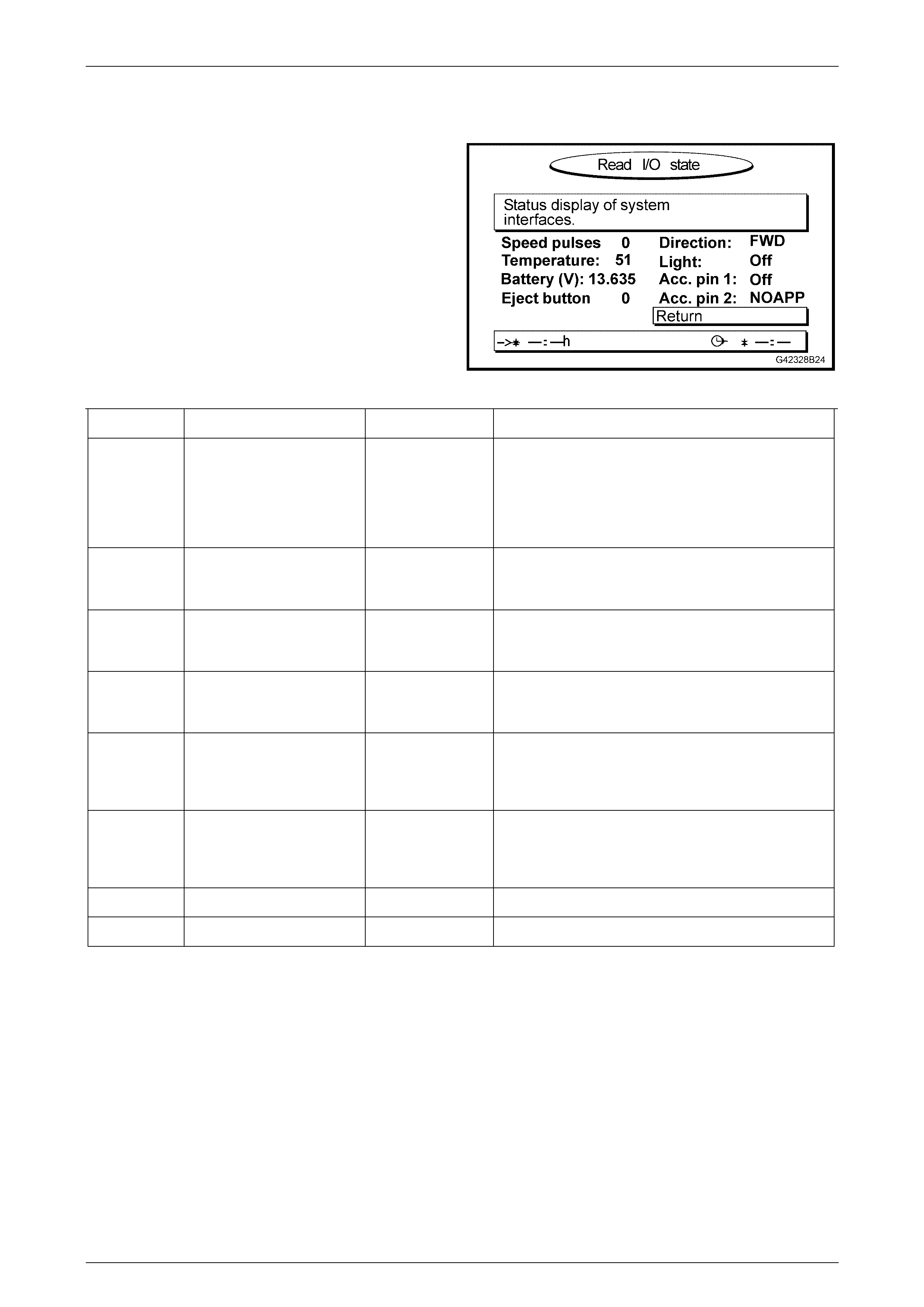
3.2 Read I/O State
This represents the READ I/O STATE screen. The RETURN
field is automatically highlighted to return to the START
MENU when OK on the remote control is pressed
Figure 12L – 4
Function Description Nominal Value Comment
Speed
Pulse Displays the number of
speedometer (VSS) pulses
per second being read by
the processor.
Approximately 100
at 60 km/h. If no pulses are shown while the vehicle is moving,
confirm the integrity of the VSS circuit. If the circuit is
OK, replace the processor assembly. The pulse value
should always be positive when the vehicle is
travelling forwards. Check the DIRECTION on the
same screen.
Temperature Displays the temperature
inside the navigation
processor.
45°C at 20°C
outside ambient
temperature.
System delivers specification to 70°C. Internal
processor fan turns on at 65°C and off at 60°C.
Battery (V) Displays the voltage level
present on the BA TT
circuit.
13 – 15 V Low values (below 11 V) cause deterioration in
picture quality. Low values (below 10 V) cause
unstable operation.
Eject button Displays the condition of
the eject button located on
the processor front panel.
0 (released)
I (pressed)
Direction Displays the current state
of the reverse lamp circuit. FWD while in P, N,
or FORWARD
gears.
If value displayed is REV while in PARK, NEUTRAL
or FORWARD gear, confirm the value set in SET I/O
STATE is ACT_HIGH. If the setting is incorrect,
change the setting from the SET I/O STATE screen.
Light Displays the current state
of the park lamp circuit. ON (lights on)
OFF (lights off)
If value displayed is ON when lights are off, confirm
the value set in the SET I/O STATE is ACT_HIGH. If
the setting is incorrect, change the setting from the
SET I/O STATE screen.
ACC. pin 1 Optional accessory input 1. OFF Not applicable.
ACC. pin 2 Optional accessory input 2. OFF Not applicable.
Navigation S ystem Page 12L–32
Page 12L–32
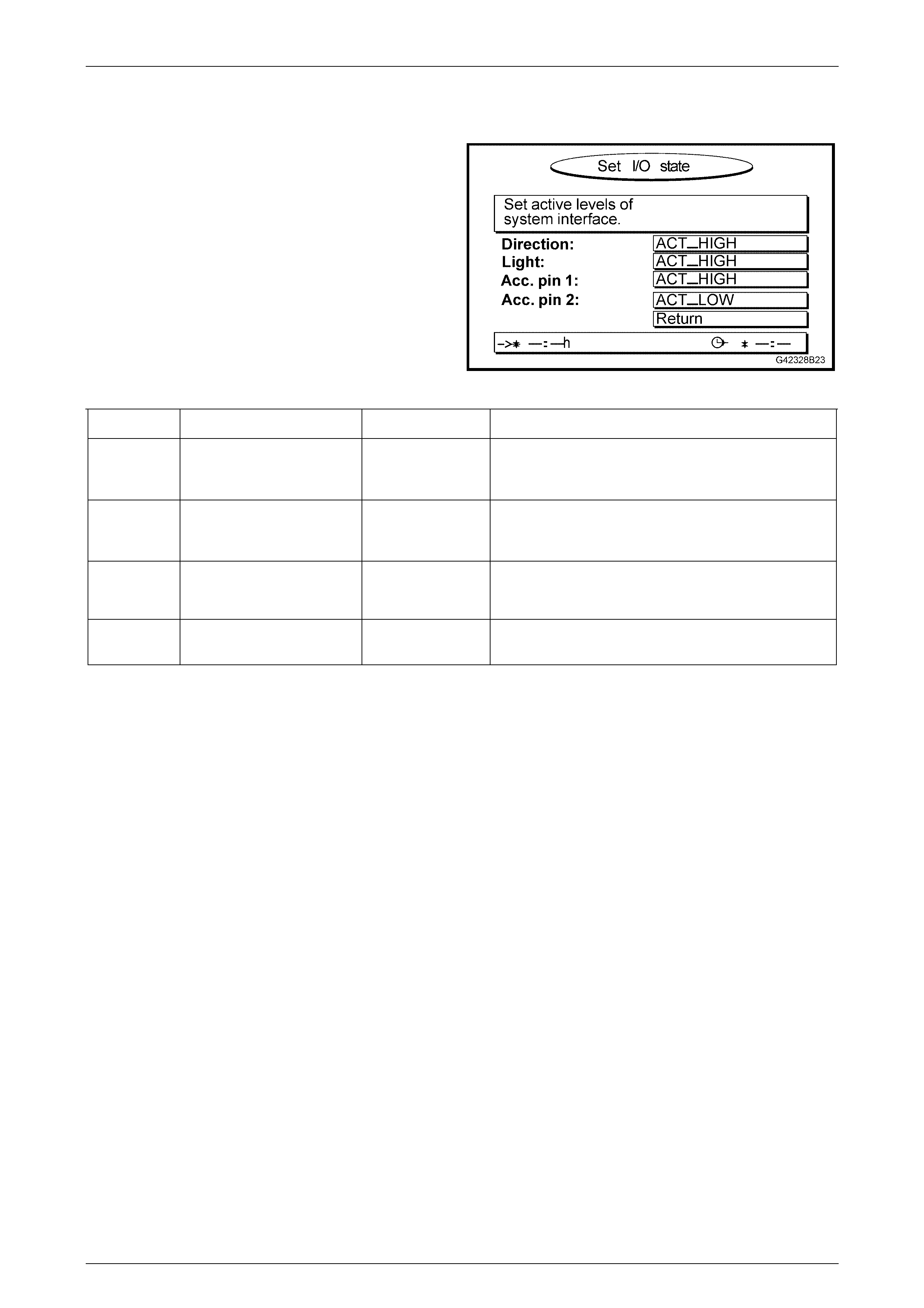
3.3 Set I/O State
This represents the SET I/O STATE screen. The RETURN
field is automatically highlighted to return to the START
MENU when the OK button on the remote control is
pressed.
Figure 12L – 5
Function Description Nominal Value Comment
Direction Sets the polarity of the
reverse lamp circuit for
processor purposes.
ACT_HIGH For positive polarity reverse lamps, this is the correct
setting.
Light Sets the polarity of the park
lamp circuit for processor
purposes.
ACT_HIGH For positive polarity park lamps, this is the correct
setting.
ACC. pin 1 Sets the polarity of optional
accessory input 1. ACT_HIGH These values may change when optional
navigation/multim edi a acce ss o r ies are conn ect ed.
ACC. pin 2 Sets the polarity of optional
accessory input 2. ACT_LOW These values may change when optional
navigation/multim edi a acce ss o r ies are conn ect ed.
For Holden Navigation System ins tallations, DIRECTION and LIGHT should be set to ACT_HIGH. ACC. pin 1 and ACC.
pin 2 are for system upgrades.

Navigation S ystem Page 12L–33
Page 12L–33
3.4 Read GPS Data
Ser v ice personnel commonly suspect bad s atellite reception as the cause of poor navigation system performance. GPS
data supplied to the processor is processed every few seconds to confirm the position calculated by the map-matching
software is correct. Good GPS data is essential to the system when it is first installed in the vehicle or when the vehicle is
moved from one location to another without the navigation system being active.
Within the navigation proc essor unit, there is a separate GPS receiver which receives GPS data from the antenna and
transmits calculated data to the processor. If the internal GPS receiver is faulty, the navigation processor must be
replaced.
Receiver State Description Comment
3D Position 3D data on the location of the vehicle is
available when the system receives data
from four or more satellites.
In this condition, the satellite icon on the guidance
screen is GREEN. This is the normal condition.
2D Position 2D data on the location of the vehicle is
available when the system receives data
from three or more satellites.
No geographic heig ht can be determ ined in this
mode. Positional accuracy is reduced.
The satellite icon on the guidance screen is RED.
This is not the normal conditi o n, but indic ates poor
or reduced reception.
Tracking Data from one satellite has been received by
the system. This condition is normally encountered when the
system is first powered up. The GPS receiver is in
this mode for up to 10 minutes depending upon
reception conditions.
The satellite icon on the guidance screen is RED.
Search SAT The system has a valid almanac and is
searching for satellites. This condition is normally encountered when the
system is first powered up. The GPS receiver is in
this mode for up to 10 minutes depending upon
reception conditions.
The satellite icon on the guidance screen is RED.
REC Error The system does not receive satellite signals. This condition usually occurs if the GPS antenna is
not connected or the cable is damaged. If the GPS
antenna and cable are serviceable, the GPS
receiver is faulty and should b e replace d.
The satellite icon on the guidance screen is RED.
COM Error The GPS receiver is not providing any data
to the navigation processor. Internal communication between the GPS receiver
and the navigation processor is not possible.
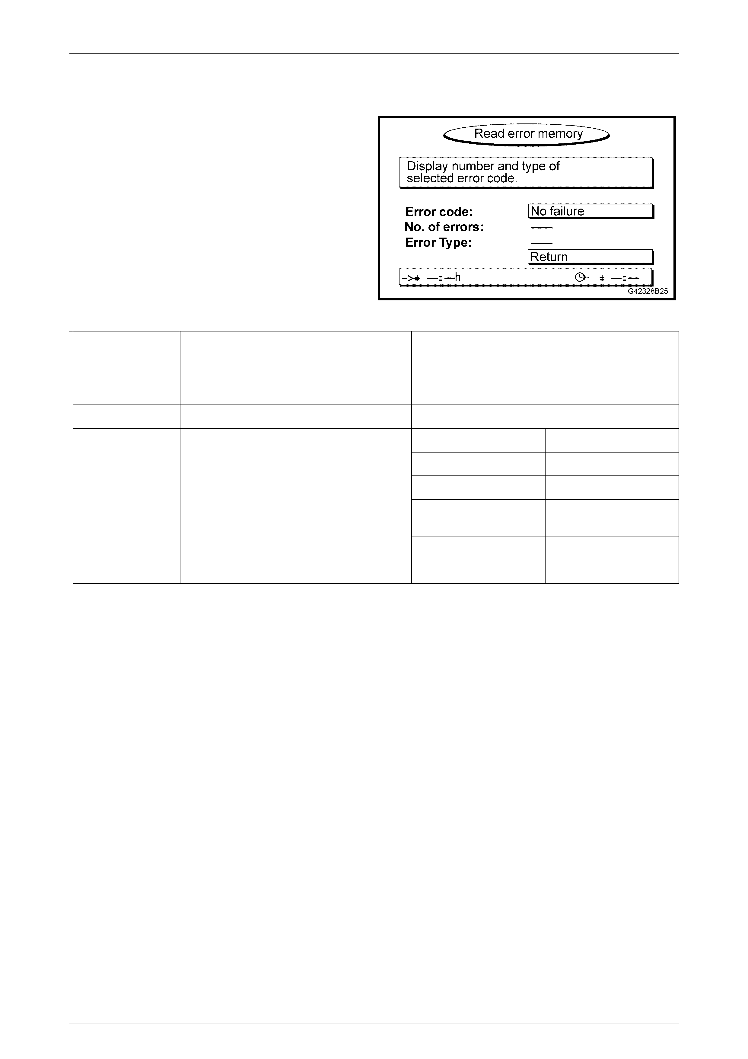
Navigation S ystem Page 12L–34
Page 12L–34
3.5 Read Error Memory
This represents the READ ERROR MEMORY screen. The
RETURN field is automatically highlighted to return to the
START MENU when the OK button on the remote control is
pressed.
The self-diagnosis function of the processor stores error
events to its internal memory. The errors detected may be
due to internal (processor) or external (environmental or
vehicle) conditions. You may need to view this screen when
asked by a technical consultant during fault diagnosis.
Figure 12L – 6
Menu Item Description Comment
Error Code Lists the errors that have occurred. Scroll through the errors using the < and > buttons.
Press OK when each error is highlighted to see a
description of the error.
No. of Errors The number of times the error has occurred.
SW Software error.
HW Hardware error.
SENSOR No VSS signal.
TEMP Temperature extreme
has caused system error.
GPS Lack of sat ell ite sig nal.
Error Type Shows the error type.
NO FAILURE No errors have occurred.