
Occupant Protection System Page 12M–1
Page 12M–1
Section 12M
Occupant Protection System
ATTENTION
Before performing any service operation or other procedure described in this Section, refer to Section 00
Warnings, Cautions and Notes for correct workshop practices with regard to safety and/or property damage.
1 General Information............................................................................................................................... 2
2 Diagnosis, Driver's Seatbelt Buckle Warning Indicator Switch........................................................ 3
2.1 General Description...............................................................................................................................................3
2.2 Wiring Diagrams, Except Coupe...........................................................................................................................4
Four-way and Six-way Seat...................................................................................................................................4
Eight-way Seat – Non-memory..............................................................................................................................4
Eight-way Seat – Memory, Pre 15 March 2004.....................................................................................................5
Eight-way Seat – Memory, Post 15 March 2004...................................................................................................5
2.3 Wiring Diagrams, Coupe........................................................................................................................................6
Eight-way Seat – Non-memory..............................................................................................................................6
Eight-way Seat – Memory, Pre 15 March 2004.....................................................................................................6
Eight-way Seat – Memory, Post 15 March 2004...................................................................................................7
2.4 Connector Charts...................................................................................................................................................8
All Seats, Pre 15 March 2004.................................................................................................................................8
All Seats, Post 15 March 2004...............................................................................................................................9
2.5 Diagnostic Procedures, Pre 15 March 2004.......................................................................................................10
Circuit Description...............................................................................................................................................10
Test Description...................................................................................................................................................10
Notes on the Diagnostic Chart............................................................................................................................10
Diagnostic Chart...................................................................................................................................................10
2.6 Diagnostic Procedures, Post 15 March 2004.....................................................................................................12
Circuit Description...............................................................................................................................................12
Test Description...................................................................................................................................................12
Notes on the Diagnostic Chart............................................................................................................................12
Diagnostic Chart...................................................................................................................................................12
Techline
Techline

Occupant Protection System Page 12M–2
Page 12M–2
1 General Information
With the following exceptions, MY 2004 VY and V2 Series Occupant Protection System information carries over from
MY 2003 VY and V2 Series vehicles.
• Driver's seatbelt buckle warning indicator switch
• Active head restraints
The seatbelt buckle warning indicator switch provides a signal to the instrument cluster which activates a reminder to the
driver to buckle the seatbelt. For further information on the instrument cluster, refer to Section 12C Instruments. The
seatbelt buckle warning indicator switch was previously fitted only to selected export models, but is now fitted to the
driver's seat in all models except Utility .
This Section describes the revised diagnosis procedures for the driver's seatbelt buckle warning indicator switch, and
provides updates to the appropriate wiring diagrams. This Section also includes the diagnosis procedures and circuit
diagrams for vehicles with seats incorporating a running change after 15 March 2004.
NOTE
The seats revised on 15 March 2004 are fitted
with a cable tray for the wiring harness. Refer to
Section 1A7A Seat Assemblies for further
information.
Active Head Restraints are fitted to the front seats of some models. For further information, refer to Section 1A7 Seat
Assemblies.
For information not contained within this Section, refer to Section 12M Occupant Protection System in the MY 2003 VY
and V2 Series Service Information.

Occupant Protection System Page 12M–3
Page 12M–3
2 Diagnosis, Driver's Seatbelt
Buckle Warning Indicator Switch
2.1 General Description
The following points must be adhered to when performing diagnostic testing on components:
• Care must be taken when using testing
equipment to diagnose wiring harness
connectors. It is preferred that the
technician back probe the connector to
avoid terminal damage.
• When tests are required on connector
terminals, utilise the adapters in the
connector adaptor kit KM–609 to prevent
damage to the terminals.
• Use only a digital multimeter with a
minimum impedance of 10 MΩ
ΩΩ
Ω.
• Unless the multimeter being used has an
auto-ranging function, ensure that the
correct range is selected.
• When back-probing connectors, ensure
the test lamp ground lead is connected to
a suitable ground point on the vehicle.
Ensure that this ground point is not part of
the circuit being tested.
NOTE
When following the Steps in the diagnosis charts,
the exact order of Steps should be observed. If
the required nominal value or result is not
achieved at any stage, the problem must be
rectified before proceeding any further.
Ensure that at the completion of any diagnostic procedure, all diagnostic tools are removed and all components are
correctly reconnected.
Occupant Protection System Page 12M–4
Page 12M–4
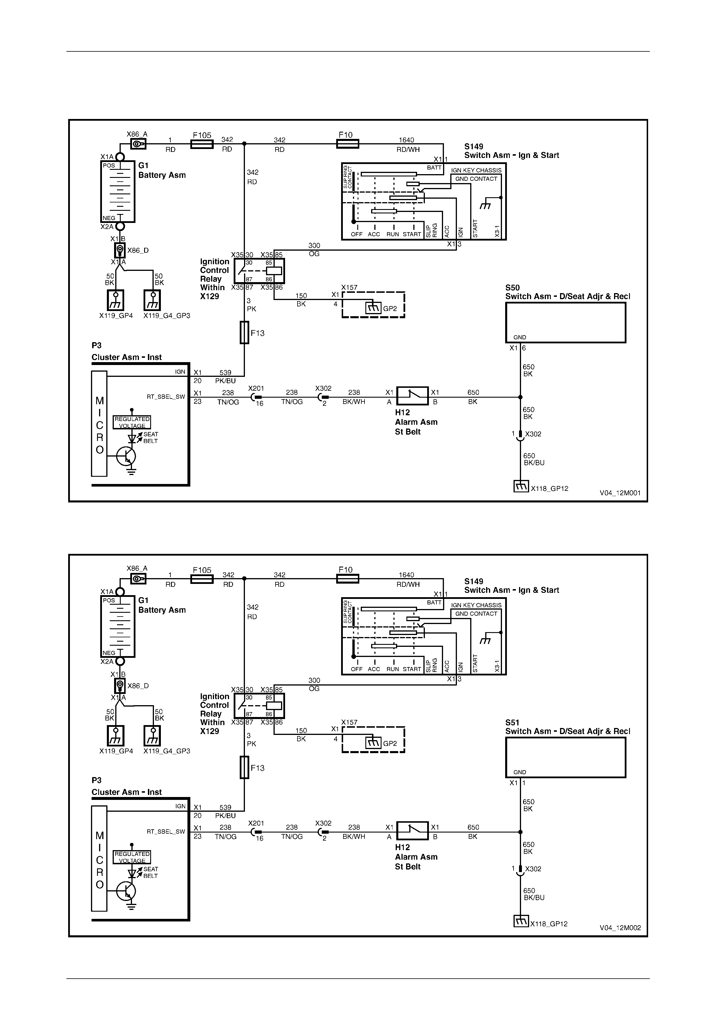
2.2 Wiring Diagrams, Except Coupe
Four-way and Six-way Seat
Figure 12M – 1
Eight-way Seat – Non-memory
Figure 12M – 2
Occupant Protection System Page 12M–5
Page 12M–5
Eight-way Seat – Memory, Pre 15 March 2004
Figure 12M – 3
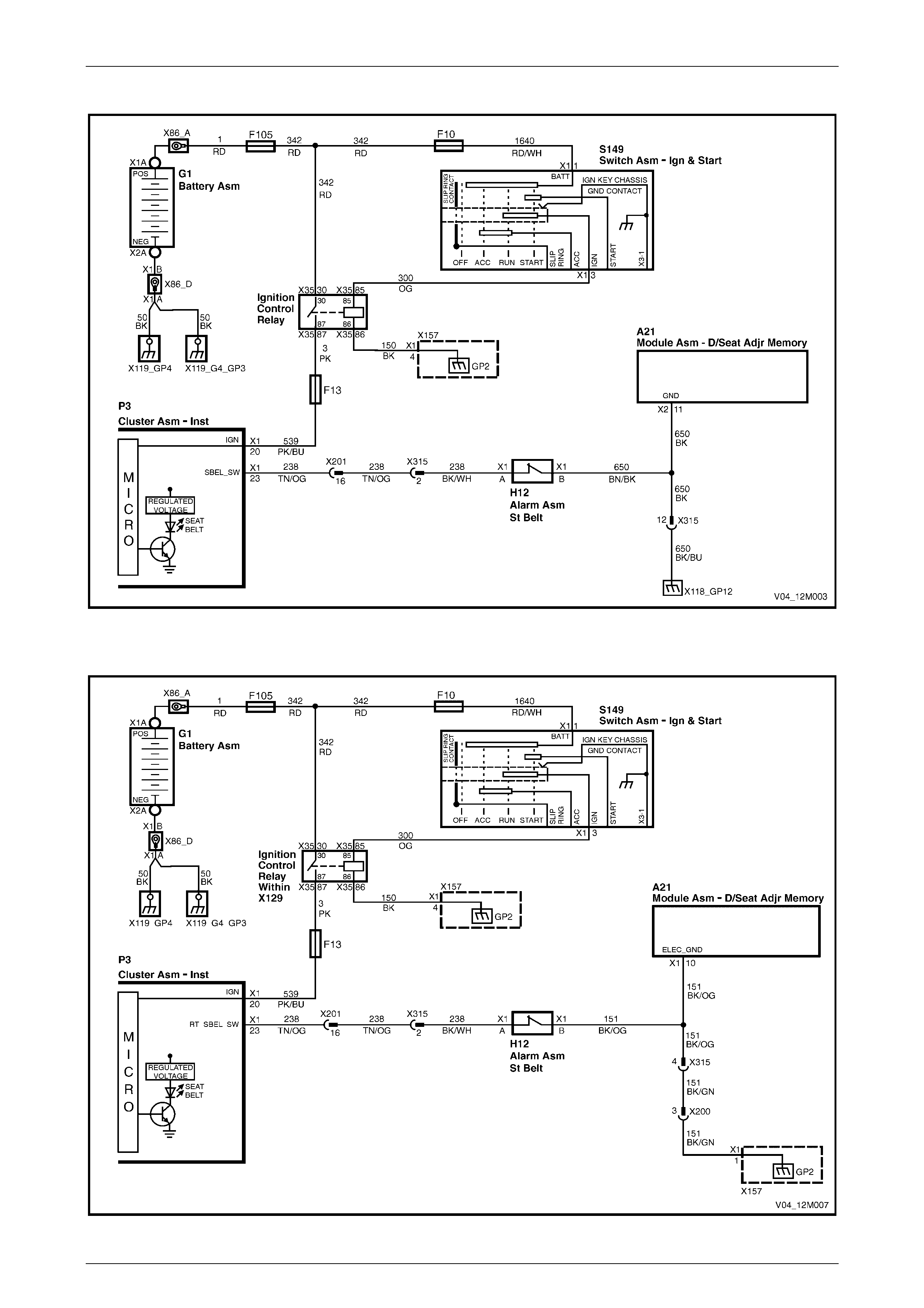
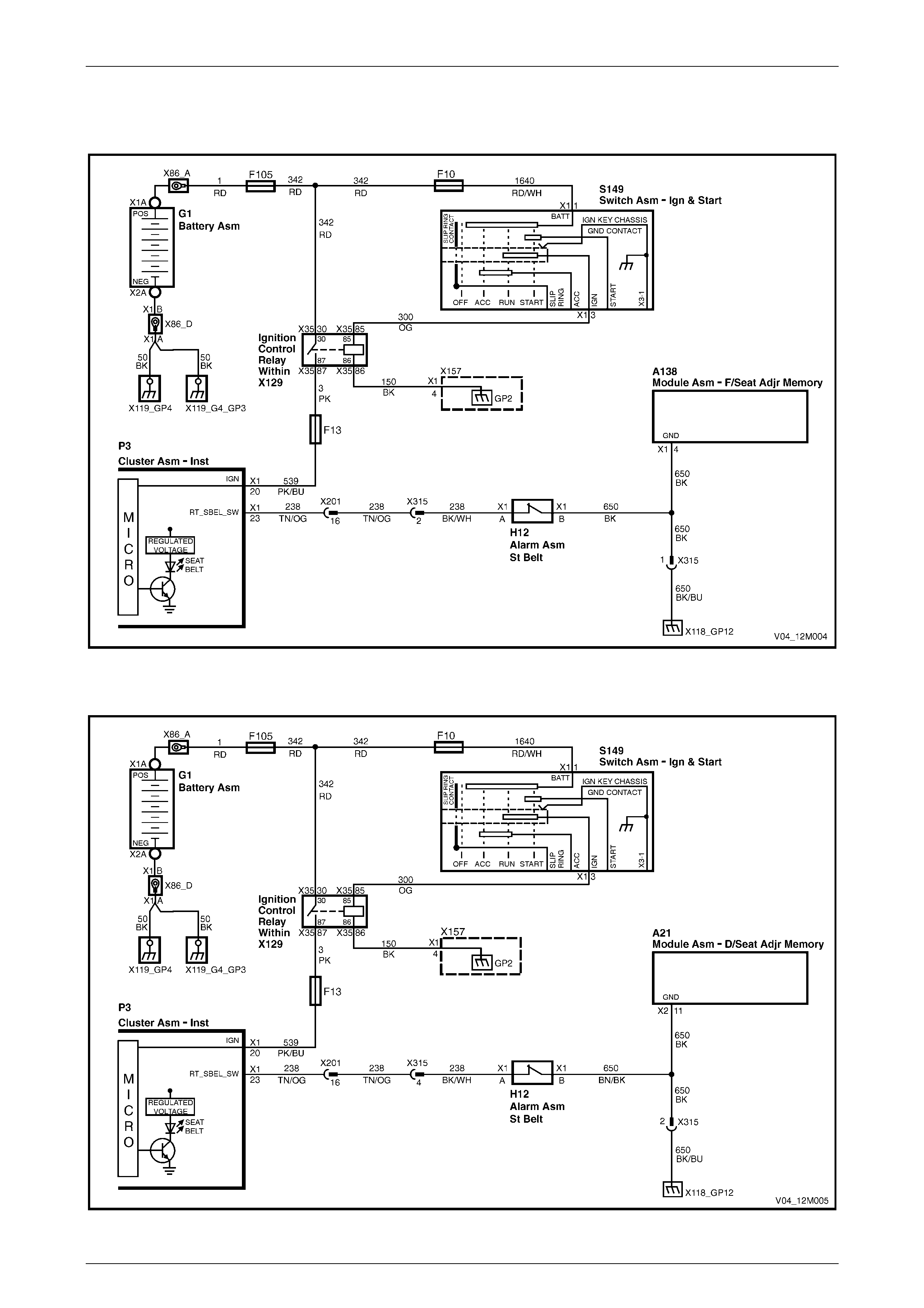
Eight-way Seat – Memory, Post 15 March 2004
Figure 12M – 4
Occupant Protection System Page 12M–6
Page 12M–6
2.3 Wiring Diagrams, Coupe
Eight-way Seat – Non-memory
Figure 12M – 5
Eight-way Seat – Memory, Pre 15 March 2004
Figure 12M – 6
Occupant Protection System Page 12M–7
Page 12M–7
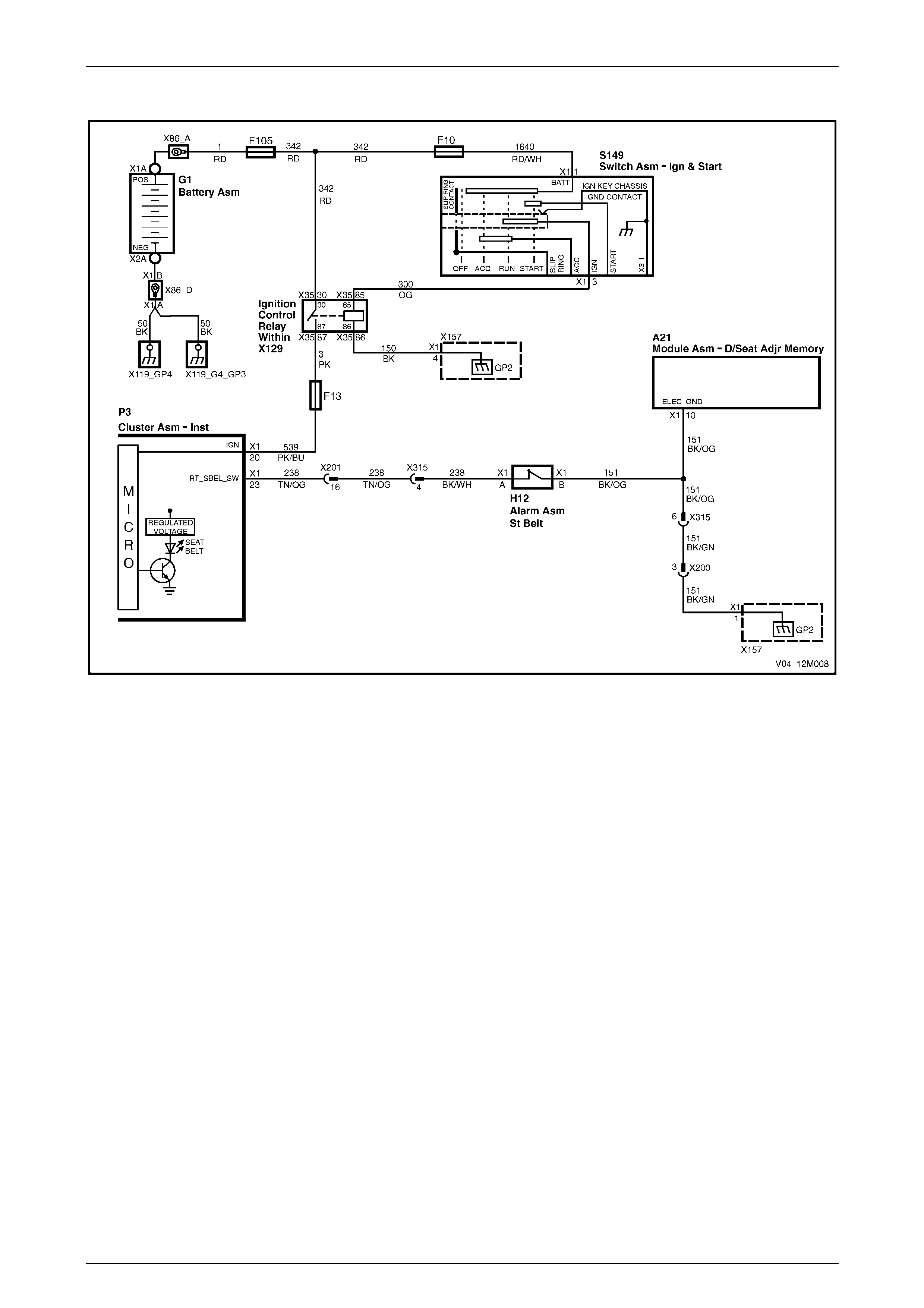
Eight-way Seat – Memory, Post 15 March 2004
Figure 12M – 7
Occupant Protection System Page 12M–8
Page 12M–8
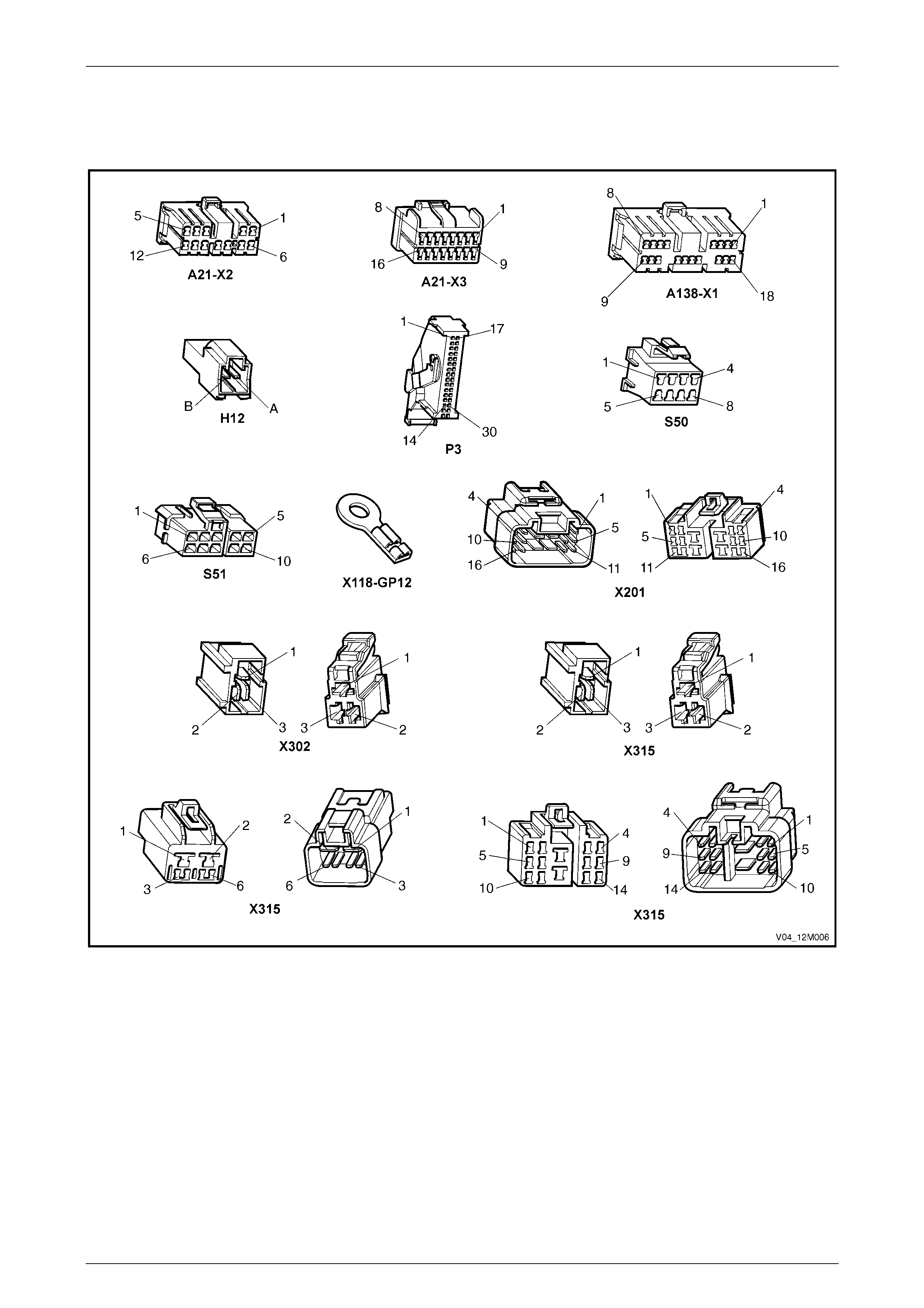
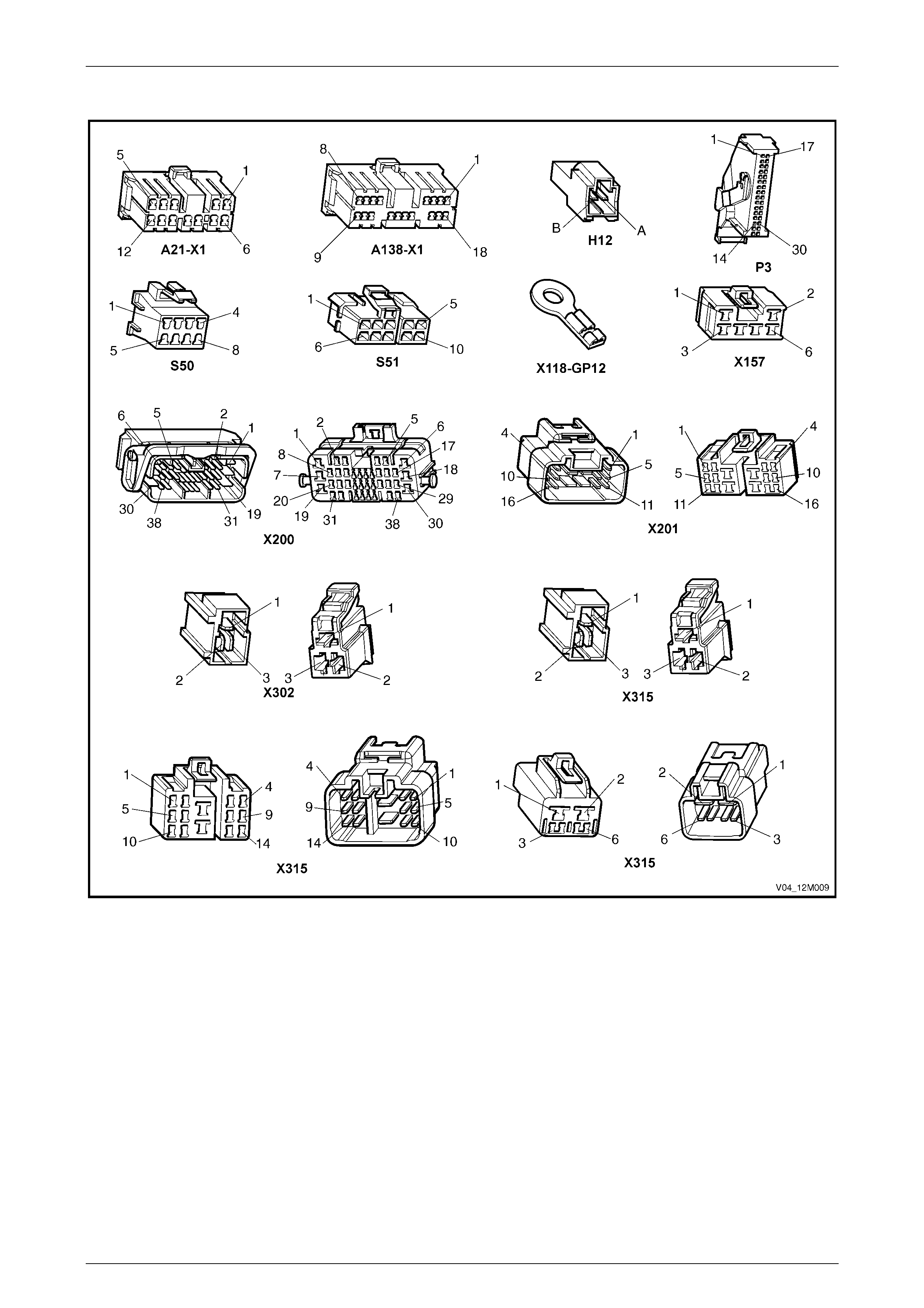
2.4 Connector Charts
All Seat s, Pre 15 March 2004
Figure 12M – 8
Occupant Protection System Page 12M–9
Page 12M–9
All Seat s, Post 15 March 2004
Figure 12M – 9

Occupant Protection System Page 12M–10
Page 12M–10
2.5 Diagnostic Procedures, Pre 15 March
2004
Circuit Description
The purpose of the driver's seatbelt buckle warning indicator switch, H12, is to activate a seatbelt warning indicator
located in the instrument cluster assembly. The indicator is illuminated when the ignition is turned to the ON position and
the seatbelt is disengaged from the buckle.
When the seatbelt is buckled, the warning indicator switch is in an open circuit condition and when unbuckled the switch
is in a closed circuit condition.
TECH 2 can be used to check the driver's seatbelt buckle warning indicator switch operation. TECH 2 will only display
BUCKLED or UN-BUCKLED.
The seatbelt warning indicator will illuminate for four seconds when the ignition switch is turned to the ON position,
irrespective of the status of the driver's seatbelt buckle warning indicator switch.
Test Description
The following numbers refer to the step numbers in the diagnostic chart.
1 Checks if the seatbelt indicator illuminates when the ignition is turned On. This can indicate either a faulty
instrument cluster assembly or a faulty power circuit.
2 Checks if there is an intermittent fault in the circuit.
3 Checks if there is a faulty power circuit.
4 Checks the operation of the driver's seatbelt buckle warning indicator switch.
5 Checks continuity of circuit 650.
6 Checks continuity of circuit 238.
7 Checks the operation of the driver's seatbelt buckle warning indicator switch.
8 Checks for short circuit to ground in circuit 238.
Notes on the Diagnostic Chart
1 For all wiring harness fault diagnosis, refer to Section 12P Wiring Diagrams.
2 For wiring harness repairs, refer to Section 12P Wiring Diagrams.
3 Refer to Section 12O Fuses, Relays and Wiring Harnesses for harness routeing.
4 If at any time the fault is deemed to be intermittent, refer to Section 12P Wiring Diagrams.
5 For information on using and connecting Tech 2 to the vehicle, refer to Section 0C Tech 2.
Diagnostic Chart
Step Action Yes No
1 1 Install the TECH 2 to the DLC. Select BODY, INSTRUMENTS,
DATA DISPLAY and then INSTRUMENTS from the menu and
scroll down to DRIVERS SEATBELT (refer to Note 5).
2 Unbuckle the driver's seat belt .
3 Turn the ignition On with the engine Off.
Does the seatbelt warning indicator illuminate, and does the TECH 2
display UN-BUCKLED? Go to Step 2. Go to Step 3.

Occupant Protection System Page 12M–11
Page 12M–11
Step Action Yes No
2 1 Turn the ignition switch Off.
2 Buckle the driver's seatbelt.
3 Turn the ignition On with the engine Off.
Does the seatbelt warning indicator extinguish after four seconds and
does the TECH 2 display BUCKLED?
Operation appears
to be normal.
Check for an
intermittent fault
(refer to Note 4). Go to Step 7.
3 1 Check that the following warning indicators illuminate when the
ignition is switched On with the engine Off:
• ABS
• Brake
• SRS
• Generator
Do the above warning indicators illuminate when the ignition switch is
turned On with the engine Off? Go to Step 4.
Refer to
Section 12C
Instruments.
4 1 Turn the ignition Off and disconnect connector H12.
2 Using a multimeter set to measure resistance, probe across the
driver's seatbelt buckle warning indicator switch terminals at
connector H12 (refer to Note 1).
3 The multimeter should indicate continuity when the seatbelt is
unbuckled and no continuity (open circuit) when the seatbelt is
buckled.
Does the multimeter indicate as specified? Go to Step 5.
Replace the driver's
seatbelt bu ckl e and
pretensioner
assembly, refer to
Section 12M
Occupant Pr otection
System in the
MY 2003 VY and V2
Series Service
Information.
5 1 Using a multimeter set to measure resistance, probe between
connector H12 – X1 pin B and a known ground (refer to Note 1).
Does the multimeter indicate continuity?
Go to Step 6.
There is an open
circuit in circ uit 650.
Repair or replace
circuit 650
(refer to Note 2).
6 1 Disconnect conn ect or P3 – X1.
2 Using a multimeter set to measure resistance, probe between
connectors H12 – X1 pin A and P3 – X1 pin 23 (refer to Note 1).
Does the multimeter indicate continuity?
Replace the
instrument cluster
assembly, refer to
Section 12C
Instruments.
There is an open
circuit in circ uit 238.
Repair or replace
circuit 238
(refer to Note 2).
7 1 Turn the ignition switch Off and disconnect connector H12.
2 Turn the ignition On with the engine Off.
Does the seatbelt warning indicator extinguish after four seconds and
does the TECH 2 display BUCKLED? Go to Step 4. Go to Step 8.
8 1 Disconnect conn ect or P3 – X1.
2 Using a multimeter set to measure resistance, probe between
connector H12 – X1 pin A and a known ground (refer to Note 1).
Does the multimeter indicate continuity?
There is a short
circuit to ground in
circuit 238.
Repair or replace
circuit 238
(refer to Note 4).
Replace the
instrument cluster
assembly, refer to
Section 12C
Instruments.
When all diagnosis and repairs are completed, check the system for correct operation.

Occupant Protection System Page 12M–12
Page 12M–12
2.6 Diagnostic Procedures, Post 15 March
2004
Circuit Description
The purpose of the driver's seatbelt buckle warning indicator switch, H12, is to activate a seatbelt warning indicator
located in the instrument cluster assembly. The indicator is illuminated when the ignition is turned to the ON position and
the seatbelt is disengaged from the buckle.
When the seatbelt is buckled, the warning indicator switch is in an open circuit condition and when unbuckled the switch
is in a closed circuit condition.
TECH 2 can be used to check the driver's seatbelt buckle warning indicator switch operation. TECH 2 will only display
BUCKLED or UN-BUCKLED.
The seatbelt warning indicator will illuminate for four seconds when the ignition switch is turned to the ON position,
irrespective of the status of the driver's seatbelt buckle warning indicator switch.
Test Description
The following numbers refer to the step numbers in the diagnostic chart.
1 Checks if the seatbelt indicator illuminates when the ignition is turned On. This can indicate either a faulty
instrument cluster assembly or a faulty power circuit.
2 Checks if there is an intermittent fault in the circuit.
3 Checks if there is a faulty power circuit.
4 Checks the operation of the driver's seatbelt buckle warning indicator switch.
5 Checks continuity of circuit 650 (for all non-memory seats).
6 Checks continuity of circuit 151 (only for eight-way memory seats).
7 Checks continuity of circuit 238.
8 Checks the operation of the driver's seatbelt buckle warning indicator switch.
9 Checks for short circuit to ground in circuit 238.
Notes on the Diagnostic Chart
1 For all wiring harness fault diagnosis, refer to Section 12P Wiring Diagrams.
2 For wiring harness repairs, refer to Section 12P Wiring Diagrams.
3 Refer to Section 12O Fuses, Relays and Wiring Harnesses for harness routeing.
4 If at any time the fault is deemed to be intermittent, refer to Section 12P Wiring Diagrams.
5 For information on using and connecting Tech 2 to the vehicle, refer to Section 0C Tech 2.
Diagnostic Chart
Step Action Yes No
1 1 Install the TECH 2 to the DLC. Select BODY, INSTRUMENTS,
DATA DISPLAY and then INSTRUMENTS from the menu and
scroll down to DRIVERS SEATBELT (refer to Note 5).
2 Unbuckle the driver's seat belt .
3 Turn the ignition On with the engine Off.
Does the seatbelt warning indicator illuminate, and does the TECH 2
display UN-BUCKLED? Go to Step 2. Go to Step 3.

Occupant Protection System Page 12M–13
Page 12M–13
Step Action Yes No
2 1 Turn the ignition switch Off.
2 Buckle the driver's seatbelt.
3 Turn the ignition On with the engine Off.
Does the seatbelt warning indicator extinguish after four seconds and
does the TECH 2 display BUCKLED?
Operation appears
to be normal.
Check for an
intermittent fault
(refer to Note 4). Go to Step 8.
3 1 Check that the following warning indicators illuminate when the
ignition is switched On with the engine Off:
• ABS
• Brake
• SRS
• Generator
Do the above warning indicators illuminate when the ignition switch is
turned On with the engine Off? Go to Step 4.
Refer to
Section 12C
Instruments.
4 1 Turn the ignition Off and disconnect connector H12.
2 Using a multimeter set to measure resistance, probe across the
driver's seatbelt buckle warning indicator switch terminals at
connector H12 (refer to Note 1).
3 The multimeter should indicate continuity when the seatbelt is
unbuckled and no continuity (open circuit) when the seatbelt is
buckled.
Does the multimeter indicate as specified?
Go to Step 5 for all
non-memory seats.
Go to Step 6 for all
eight-way memory
seats.
Replace the driver's
seatbelt bu ckl e and
pretensioner
assembly, refer to
Section 12M
Occupant Pr otection
System in the
MY 2003 VY and V2
Series Service
Information.
5 1 Using a multimeter set to measure resistance, probe between
connector H12 – X1 pin B and a known ground (refer to Note 1).
Does the multimeter indicate continuity?
Go to Step 7.
There is an open
circuit in circ uit 650.
Repair or replace
circuit 650
(refer to Note 2).
6 1 Using a multimeter set to measure resistance, probe between
connector H12 – X1 pin B and a known ground (refer to Note 1).
Does the multimeter indicate continuity?
Go to step 7.
There is an open
circuit in circ uit 151.
Repair or replace
circuit 151
(refer to Note 2).
7 1 Disconnect conn ect or P3 – X1.
2 Using a multimeter set to measure resistance, probe between
connectors H12 – X1 pin A and P3 – X1 pin 23 (refer to Note 1).
Does the multimeter indicate continuity?
Replace the
instrument cluster
assembly, refer to
Section 12C
Instruments.
There is an open
circuit in circ uit 238.
Repair or replace
circuit 238
(refer to Note 2).
8 1 Turn the ignition switch Off and disconnect connector H12.
2 Turn the ignition On with the engine Off.
Does the seatbelt warning indicator extinguish after four seconds and
does the TECH 2 display BUCKLED? Go to Step 4. Go to Step 9.
9 1 Disconnect conn ect or P3 – X1.
2 Using a multimeter set to measure resistance, probe between
connector H12 – X1 pin A and a known ground (refer to Note 1).
Does the multimeter indicate continuity?
There is a short
circuit to ground in
circuit 238.
Repair or replace
circuit 238
(refer to Note 4).
Replace the
instrument cluster
assembly, refer to
Section 12C
Instruments.
When all diagnosis and repairs are completed, check the system for correct operation.