
Wiring Diagrams Page 12P–1
Page 12P–1
Section 12P
Wiring Diagrams
ATTENTION
Before performing any Service Operation or other procedure described in this Section, refer to Section 00
Warnings, Cautions and Notes for correct workshop practices with regard to safety and/or property damage.
1 General Information ...............................................................................................................................2
2 IVED Electrical Schematics...................................................................................................................3
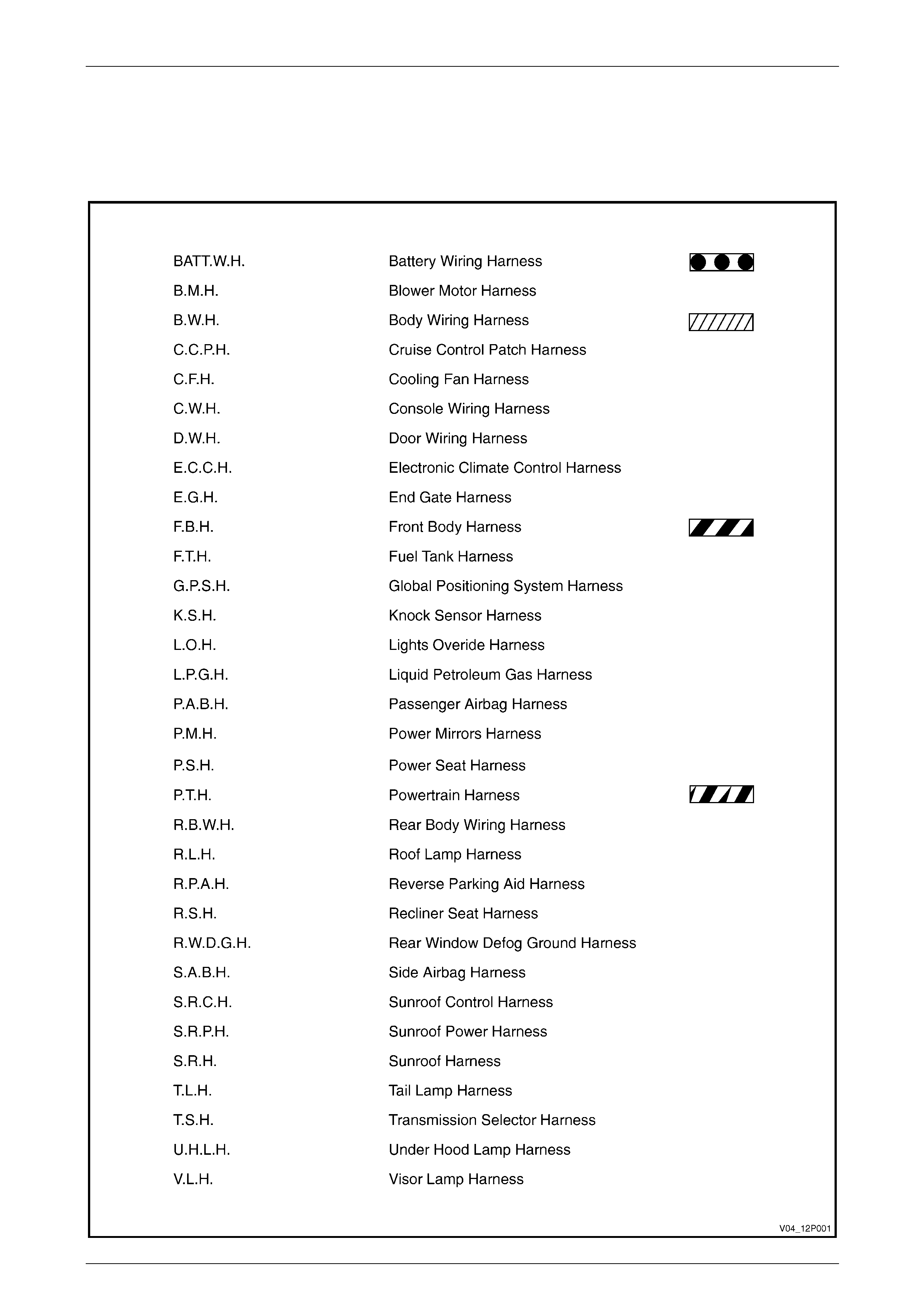
2.1 Wiring Harness Abbreviations.............................................................................................................................. 3
2.2 Contents ................................................................................................................................................................. 4
2.3 Component Location Charts................................................................................................................................. 5
Electrically Operated Mechanical Devices........................................................................................................... 5
Indicators, Alarms and Signal Devices................................................................................................................ 7
Inductors ................................................................................................................................................................ 7
Measurement, Display and Test Devices............................................................................................................. 8
Modules, Systems and Sub-Assemblies .............................................................................................................8
Motors................................................................................................................................................................... 10
Other Devices and Equipment............................................................................................................................ 11
Power Supplies.................................................................................................................................................... 12
Regulators and Amplifiers .................................................................................................................................. 12
Resistors .............................................................................................................................................................. 13
Semi Conductors................................................................................................................................................. 13
Switches ............................................................................................................................................................... 13
Transducers ......................................................................................................................................................... 15
Transmission Paths, Conductors and Antennas.............................................................................................. 17

Wiring Diagrams Page 12P–2
Page 12P–2
1 General Information
The wiring diagrams containe d in this Section are the specific systems wiring diagrams for MY 2004 VY and V2 Series
vehicles. Additional wiring harness and specific wiring harness installation information is contained in Section 12O,
Fuses, Relays and Wiring Harnesses.
Refer to Section 12P, Wiring Diagrams of the MY 2003 VY Series Service Information for add itional information on
developing a diagnostic procedure for the electrical circuit diagnosis, electrical circuit test procedures, diagnostic tests,
wiring repair procedures and reading 12P Wiring Diagrams.
Wiring Diagrams Page 12P–3
Page 12P–3
2 IVED Electrical Schematics
2.1 Wiring Harness Abbreviations

Wiring Diagrams Page 12P–4
Page 12P–4
2.2 Contents
System wiring diagram description Diagram sheet no.
Aftermarket provisions 128
Brakes 028 to 029
Charge / energy store 109
Engine 001 to 023
Engine / transmission cool ing 042 to 044
Entertainment 099 to 104
Entry control 065 to 068
Exterior lighting 071 to 088
Fuel storage and handling 030 to 033
Fuse chart and relay box l ayout 00A
Ground points and paths 00B to 00D
Horn 108
HVAC 034 to 041
Integrating component 131 to 139
Integrating function 140
Interior lighting 053 to 062
Memory seats 050A to 052
Mirrors 089 to 092
Moveable roof 070
Occupant information 095 to 098B
Occupant protection 063 to 064
Power and ground distribution 110 to 127
Power seats 045 to 049B
Po we r wi n do w s 069
Serial data links 129 to 130
Telephone 106 to 107
Theft deterrent 105
Transmission 024 to 027
Washer / wipers 093 to 094

Wiring Diagrams Page 12P–5
Page 12P–5
2.3 Component Location Charts
Electrically Operated Mechanical Devices
Component Code Location
Actuator temperature valve (air mix motor) Y037_RHD 034.23
034.41
Actuator temperature valve (air mix motor) Y037_LHD 036.30
Boost control valve Y142 015.33
Canister purge solenoid valve Y123 013.34
015.40
002.13
Drivers seat adjuster horizontal actuator Y064 046A.23
046B.23
047A.16
047B.16
049A.18
049B.20
050A.16
050B.24
051B.24
052.06
Drivers seat belt Y128 063.39
064.43
Drivers seat inner adjuster front vert actuator Y067 045.16
045.44
046A.15
046B.15
047A.19
047B.19
049A.10
049B.10
050A.06
050B.15
051B.15
052.16
Drivers seat inner adjuster rear vert actuator Y069 045.20
045.48
046A.19
046B.19
047A.23
047B.23
049A.06
049B.06
050A.06
050B.15
051B.15
052.27
Drivers seat recline actuator Y074 047A.12
047B.12
049A.13
049B.13
050A.10
050B.33
051B.33
052.38
E.G.R. valve Y056 009.14

Wiring Diagrams Page 12P–6
Page 12P–6
Component Code Location
Front side door lock actuator Y013 065.11
065.43
066.06
066.50
Fuel control solenoid valv e Y143 FCSV 021.20
022.20
023.20
Fuel control solenoid valv e Y143 LOSV 021.40
022.40
023.40
Fuel tank filler door lock Y010 067.27
Heater water shut off Y018 036.21
Idle speed control Y020 001.14
011.49
017.46
Inside air valve vacuum solenoid pack Y019_LHD 036.35
Inside air valve vacuum solenoid pack Y019_RHD 034.31
Lift gate lock Y023 065.53
066.25
Passengers seat adjuster horizontal actuator Y081 047A.41
047B.41
047C.11
047C.41
048A.17
048B.17
048C.20
048D.20
Passengers seat belt Y129 063.29
064.34
Passengers seat inner adjuster front vert actuator Y084 046A.39
046B.39
047A.45
047B.45
047C.15
047C.45
048A.09
048B305
048C.05
048D.05
Passengers seat inner adjuster rear vert actuator Y086 046A.43
046B.43
047A.49
047B.49
047C.19
047C.49
048A.09
048B.09
048C.09
048D.09
Passengers seat recline actuator Y091 047A.37
047B.37
047C.07
047C.37
048A.13
048B.13
048C.13
048D.13

Wiring Diagrams Page 12P–7
Page 12P–7
Component Code Location
Rear compartment lid latch a c tuator Y029 068.36
Rear side door lock actuator Y031 065.22
065.32
066.17
066.33
Reverse lock out solenoid Y144 003.51
Throttle actuator Y038 003.27
Indicators, Alarms and Signal Devices
Component Code Location
Rear object sensor alarm H031 097.15
Seat belt alarm H012 045.06
045.33
046A.05
046B.05
047A.03
047B.03
049A.53
049B.45
050A.54
050B.45
051A.06
051B.45
Inductors
Component Code Location
A/C clutch L007 040.37
Fuel injector L002 005.04
005.10
005.17
005.23
005.29
005.35
005.42
005.48
012.06
012.11
012.17
012.22
012.28
012.34
018.09
018.15
018.22
018.28
018.34
018.40
Radio antenna module L004 100.30
Wiring Diagrams Page 12P–8
Page 12P–8
Measurement, Display and Test Devices
Component Code Location
Driver information P006 098A.37
098B.37
Instruments P003 020.48
028.44
095.28
109.43
Modules, Systems and Sub-Assemblies
Component Code Location
Blower & air inlet A013_LHD 038.27
Blower & air inlet A013_RHD 037.26
Blower motor & A/C compressor A014 034.28
036.28
Body control A015 028.35
035.40
039.40
065.14
066.46
068.24
068.36
069.04
069.11
069.14
069.40
069.44
069.51
072.15
073.13
093.24
094.23
095.18
100.25
105.11
105.24
105.37
105.46
108.06
132.28
133.28
134.28
135.28
136.28
137.28
138.28
139.28
Communication centre call A158 092.07
107.26
Cruise control A018 020.39
095.34
Daytime running lamp control A025 071.32
Driver information displa y control A035 098A.16
098B.16

Wiring Diagrams Page 12P–9
Page 12P–9
Component Code Location
Drivers seat adjuster memory A021 050A.27
050B.27
051A.28
051B.28
052.28
091.12
Electronic braking & traction control A037 028.24
029.28
Electronic ignition control module A040L 006.21
Electronic ignition control module A040R 006.39
Electronic ignition control module A040_V6 010.42
Electronic ignition control module A040_SCV6 016.42
Front seat adjuster memory module A138 048A.32
048B.32
048C.32
048D.32
049A.32
049B.32
Front side rail inflator restraint A096 064.24
064.38
Fuel pump module A047 032.29
033.29
Fuel sender & pump control module A055 021.37
022.37
023.37
Heater & A/C evaporator module A060 035.35
039.36
Inflation restraint sensor A065 063.26
064.25
Inflation restraint side impact sensor A066 064.30
064.46
Instrument panel inflator restraint module A062 063.11
064.03
Navigation control module A139 098A.27
098B.27
Outside rear view mirror memory A073 091.28
Powertrain control module A084_V6 008.28
009.28
010.28
011.28
012.28
013.28
021.12
022.12
023.12
025.28
Powertrain control module A084_V6SC 014.28
015.28
016.28
017.28
018.28
019.28
024.28

Wiring Diagrams Page 12P–10
Page 12P–10
Component Code Location
Powertrain control module A084_V8 001.28
002.28
003.28
004.28
005.28
006.28
007.28
020.18
026.28
028.13
Powertrain interface module A005 130.28
Radio antenna and re ar window control module A093 041.06
100.28
Radio, clock & CD player A133 099.28
100.28
Rear object sensor control A098 097.27
Steering wheel inflator restraint module A106 063.32
064.15
Sunroof control module A108 070.24
Throttle actuator control module A111 003.26
Windshield wiper pulse control module A121 093.50
Motors
Component Code Location
Blower motor M003_LHD 038.28
039.11
Blower motor M003_RHD 035.17
037.27
Engine cooling fans M007 042.32
043.28
044.33
Front side door window regulator M010 069.11
069.44
Fuel pump motor M008 030.42
031.31
032.46
033.46
Outside rear view mirror motor M011 051A.44
051B.35
089.28
089.44
090.28
090.44
091.08
091.50
Rear side door window regulator M014 069.19
069.32
Rear window wiper motor M012 094.41
Starter motor M015 109.20
Sunroof actuator M016 070.28
Windshield wiper & windshield washer M019 093.38
Windshield wiper motor M017 093.09

Wiring Diagrams Page 12P–11
Page 12P–11
Other Devices and Equipment
Component Code Location
Automatic transmission control pos ition indicator lamp E125 053.53
055.11
057.04
058.07
060.03
Dome lamp E067 054.08
056.08
057.32
058.34
060.31
Front floor console compartm ent lamp E016 062.29
Front fog lamp E069 088.19
088.27
Front side door courtes y lamp E072 053.02
053.18
Front side turn signal lamp E075 078.08
078.45
082.08
082.45
083.08
083.45
Headlamp E083 072.37
072.50
073.37
073.50
074.04
074.48
084.08
084.52
High mounted stop lamp E079_C 087.01
087.14
High mounted stop lamp E079_S/W 087.26
High mounted stop lamp E079_U 087.20
High mounted stop lamp E080 087.08
Ignition lock cylinder bulb E030 053.48
055.33
057.14
058.22
060.14
Inside rear view mirror E124 092.17
092.49
107.24
Instrument panel compartment lamp E082 055.40
057.08
058.15
060.08
062.42
Reading lamp E094 054.36
054.45
056.32
056.41
057.42
057.49
060.42
060.49

Wiring Diagrams Page 12P–12
Page 12P–12
Component Code Location
Rear compartment courtesy l amp E036 056.51
057.20
060.20
062.13
Rear licence plate lamp E044_S_C 087.39
087.45
Rear licence plate lamp E044_U 087.52
Rear licence plate lamp E044_W 087.33
Rear side door courtes y lamp E099 053.07
053.13
Rear turn signal lamp E101 078.14
078.39
082.14
082.39
083.14
083.39
Step well lamp E105 053.37
053.42
055.18
055.25
Stop/tail lamp E048 074.11
074.40
084.18
084.44
Back/up lamp E056 079.20
079.32
080.20
080.31
081.22
081.36
Sun shade lamp E120 054.20
054.26
056.19
056.25
Turn signal lamp E076 078.02
078.51
082.02
082.51
083.02
083.51
Under hood lamp E107 084.01
Power Supplies
Component Code Location
Battery G001 109.04
Generator G008 109.36
Regulators and Amplifiers
Component Code Location
Radio antenna amplifier N003 100.10
Radio rear speaker amplifier N006 101.26
103.28
104.27
Wiring Diagrams Page 12P–13
Page 12P–13
Resistors
Component Code Location
Blower motor resistor R006_LHD 039.26
Blower motor resistor R006_RHD 035.26
Defog grid R022 041.14
041.22
041.30
Semi Conductors
Component Code Location
Engine wiring harness fuse diode V005 040.43
067.19
068.43
Switches
Component Code Location
Auto/trans shift lock park S021 027.21
Automatic transmission shift program S022 024.51
025.52
026.51
Backup lamp switch S032 077.32
Brake pressure differential S037 095.03
Clutch pedal position s witch S042 011.40
Cruise control release and clutch pedal position S046 020.05
Cruise control switch S043 020.33
Door ajar indicator switch S002 139.05
139.17
139.22
Door lock switch S063 065.03
066.41
Driver seat adjuster & recline S051 047A.16
047B.16
049A.15
049B.15
050A.11
050B.11
051A.13
051B.10
Driver seat adjuster memory switch S052 050A.42
050B.30
051A.34
051B.24
Driver seat adjuster switch S050 045.27
046.18
Electronic traction control switch S073 028.46
Engine coolant level switch S084 004.04
Engine oil pressure indicator switch S087 013.15
017.04

Wiring Diagrams Page 12P–14
Page 12P–14
Component Code Location
EZ entry switch S057 048A.40
048B.40
048C.40
048D.40
049A.40
049B.35
050A.30
050B.44
Front top stowage compartment lamp switch S094 062.29
Fuel filler door release S191 067.29
Fuel type indicator switch S118 021.09
022.09
023.09
Hazard warning S120 075.20
076.22
Headlamp automatic control switch S125 072.16
073.14
Hood theft deterrent S135 105.38
Ignition & start switch S149 140.30
Instrument panel compartment lamp switch S142 055.40
057.08
058.15
060.08
062.42
Interior lamp switch S156 059.38
060.37
061.38
Outside rear view mirror remote control switch S169 089.25
090.26
091.29
Park brake switch S181 095.07
Passenger seat adjuster & recline S175 046.41
Passenger seat adjuster & recline S176 047.12
PRNDL switch S187 024.41
025.41
026.41
077.24
113.32
Radio control switch S208 131.14
Rear compartment courtesy lamp switch S189 056.51
057.30
062.14
105.23
Rear compartment lid release S195 068.24
Seat return position switch S267 048.38
049.38
050.35
Side window (master) switch S222 069.28
Side window switch S221 069.23
069.33
Steering wheel horn S007 108.23

Wiring Diagrams Page 12P–15
Page 12P–15
Component Code Location
Stop lamp, traction & cruise control releas e switch S220 020.05
020.24
027.31
085.28
086.28
Sun roof S228 070.28
Trip odometer reset switch S237 095.26
096.28
Turn signal & headlamp switch S231 072.18
073.16
075.35
076.32
Windshield wiper & washer switch S247 093.22
094.12
Transducers
Component Code Location
A/C refrigeration pressure sensor B018 001.51
011.29
015.08
Ambient air temperature sensor B023 034.08
036.08
Ambient light sensor B055 132.11
Barometric pressure sensor B026_V6 011.20
Camshaft position sensor B028_V6 010.37
016.37
Camshaft position sensor B028_V8 004.34
Crankshaft position sensor B030_V6 010.50
016.50
Crankshaft position sensor B030_V8 004.50
Drivers seat front vertical adjuster position sensor B137 050A.20
052.16
Drivers seat horizontal adjuster position sensor B138 049A.28
050A.34
052.06
Drivers seat rear vertical adjuster position sensor B140 050A.24
052.26
Drivers seat recline position sensor B139 050A.28
052.38
Duct air temperature sensor B034_RHD 034.14
Duct air temperature sensor B034_LHD 036.14
Engine coolant temperature sensor B039 002.34
011.05
017.11
Engine oil pressure sensor B042 001.34
Front seat horizontal adjuster position sensor B142 048A.28
048B.28
Front wheel speed sensor B052 028.03
028.13

Wiring Diagrams Page 12P–16
Page 12P–16
Component Code Location
Heated oxygen sensor B056_L 002.06
009.26
015.26
Heated oxygen sensor (position 2) B057_R 002.24
009.46
015.49
Horn B009 105.11
108.37
108.47
Inside air temperature sensor B059 034.02
036.02
Intake air temperature sensor B064 001.43
009.03
015.18
Knock sensor B065_SNSR1 004.16
Knock sensor B065_SNSR2 004.22
Knock sensor B065_V6 013.02
013.08
019.02
019.08
M.A.P. Sensor B067_V8 001.25
M.A.S.S. Airflow sensor B068 001.03
013.24
019.21
Navigation speaker assembly B104 098A.48
098B.48
Oxygen sensor B070_L 009.35
Oxygen sensor B070_R 009.50
PPD sensor B180 048A.31
048B.31
048C.28
048D.28
049A.31
048B.31
050A.24
050B.38
Radio front speaker dash upp er B112 101.01
101.53
102.04
102.50
104.02
104.53
Radio RH & LH front speaker B108 101.07
101.48
102.11
102.44
104.08
104.47
Radio RH & LH rear speaker B117 101.15
101.39
102.21
102.34
104.17
104.38

Wiring Diagrams Page 12P–17
Page 12P–17
Component Code Location
Rear object sensor B133 097.06
097.17
097.28
097.40
Rear speaker radio amplifier B131 103.28
103.41
Rear wheel speed sensor B076 028.23
028.33
Throttle position sensor B082 003.07
011.12
017.21
Transmission Paths, Conductors and Antennas
Component Code Location
Navigation antenna W002 098A.39
098B.39
107.37
107.44
Radio diversity antenna W004 100.12
Radio power antenna W006 100.49
135.43