
HVAC Climate Control (Manual A/C) – Removal and Installation Page 2B–1
Page 2B–1
Section 2B
HVAC Climate Control (Manual A/C) –
Removal and Installation
ATTENTION
Before performing any Service Operation or other procedure described in this Section, refer to Section 00
Warnings, Cautions and Notes for correct workshop practices with regard to safety and/or property damage.
1 General Information ...............................................................................................................................2
1.1 RHD Vehicle Builds from Tag No. L171506 Onwards......................................................................................... 2
1.2 RHD Vehicle Builds Prior to Tag No. L171506..................................................................................................... 3
1.3 LHD Vehicles.......................................................................................................................................................... 4
2 Service Operations.................................................................................................................................5
2.1 Evaporator Core – RHD......................................................................................................................................... 5
Remove................................................................................................................................................................... 5
Install ...................................................................................................................................................................... 7
2.2 Blower Motor and Fan – RHD................................................................................................................................ 8
Remove................................................................................................................................................................... 8
Install ...................................................................................................................................................................... 8
3 Torque Wrench Specifications..............................................................................................................9
Techline
Techline
Techline

HVAC Climate Control (Manual A/C) – Removal and Installation Page 2B–2
Page 2B–2
1 General Information
With the following exception, MY 2004 VY and V2 Series HVAC Climate Control (Manual A/C) – Removal and
Installation information carries over from MY 2003 VY and V2 Series vehicles.
• From Tag No. L171506 a revised HVAC unit has been fitted to RHD vehicles.
1.1 RHD Vehicle Builds from Tag No.
L171506 Onwards
From Tag No. L171506 a revised HVAC unit has been fitted to RHD vehicles. The information in this Section appli es to
the revised HVAC unit.
For all other information regarding the remov al and installation of the heating and ventilation system, refer to
Section 2B HVAC Climate Control (Manual A/C) – Removal and Installation in the MY 2003 VY and V2 Series Service
Information.

HVAC Climate Control (Manual A/C) – Removal and Installation Page 2B–3
Page 2B–3
1.2 RHD Vehicle Builds Prior to Tag No.
L171506
For all information regarding the remov al and installation of the heating and ventilation system fitted to RHD vehicles built
prior to Tag No. L171506, refer to Section 2B HVAC Climate Control (Manual A/C) – Removal and Installation in the
MY 2003 VY and V2 Series Service Information.

HVAC Climate Control (Manual A/C) – Removal and Installation Page 2B–4
Page 2B–4
1.3 LHD Vehicles
For all information regarding the removal and installation of the heating and ventilation system fitted to LHD vehicles,
refer to Section 2B HVAC Climate Control (Manual A/C) – Removal and Installation in the MY 2003 VY and V2 Series
Service Information.
HVAC Climate Control (Manual A/C) – Removal and Installation Page 2B–5
Page 2B–5
2 Service Operations
ATTENTION
All fasteners are important attaching parts as they affect the performance of vital components and / or could
result in major repair expense. W here specified in this Section, fasteners MUST be replaced w ith parts of the
same part number or a GM approved equivalent. Do not use fasteners of an inferior quality or substitute
design.
Torque values must be used as specified during reassembly to ensure proper retention of all components.
Throughout this Section, fastener torque wrench specifications may be accompanied with the following
identification marks:
Fasteners must be repl aced after loosening.
Vehicle must be at kerb height before final tightening.
Fasteners either ha ve micro encapsu lated sealant ap plied or in corporate a mech anical thread lo ck and
should only be re-used once. If in doubt, replacement is recommended.
If one of these identification marks is present alongside a fastener torque wrench specification, the
recommendation regarding that fastener must be adhered to.
2.1 Evaporator Core – RHD
LT Section – 08-150
Remove
1 Remove the HVAC unit, refer to Section 2B,
3 Heating, Ventilation and Air Conditioning (HVAC)
Unit in the MY 2003 VY and V2 Series Service
Information.
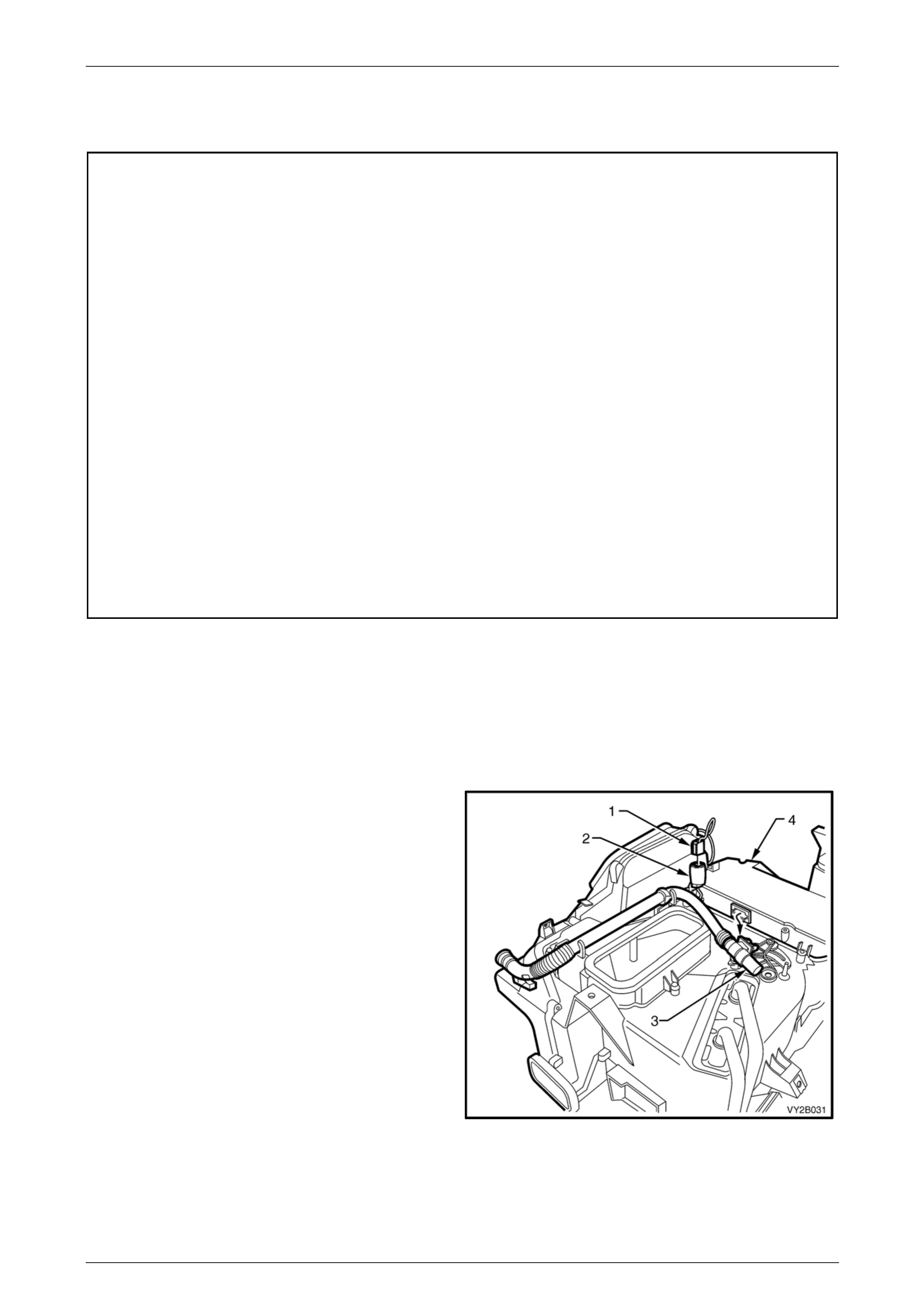
2 On OCC (Auto A/C) units, disconnect the OCC
wiring harness connector (1) from the evaporative
temperature sensor connector (2). Remove the
venturi pipe (3) from the evaporator cover (4).
Figure 2B – 1
HVAC Climate Control (Manual A/C) – Removal and Installation Page 2B–6
Page 2B–6
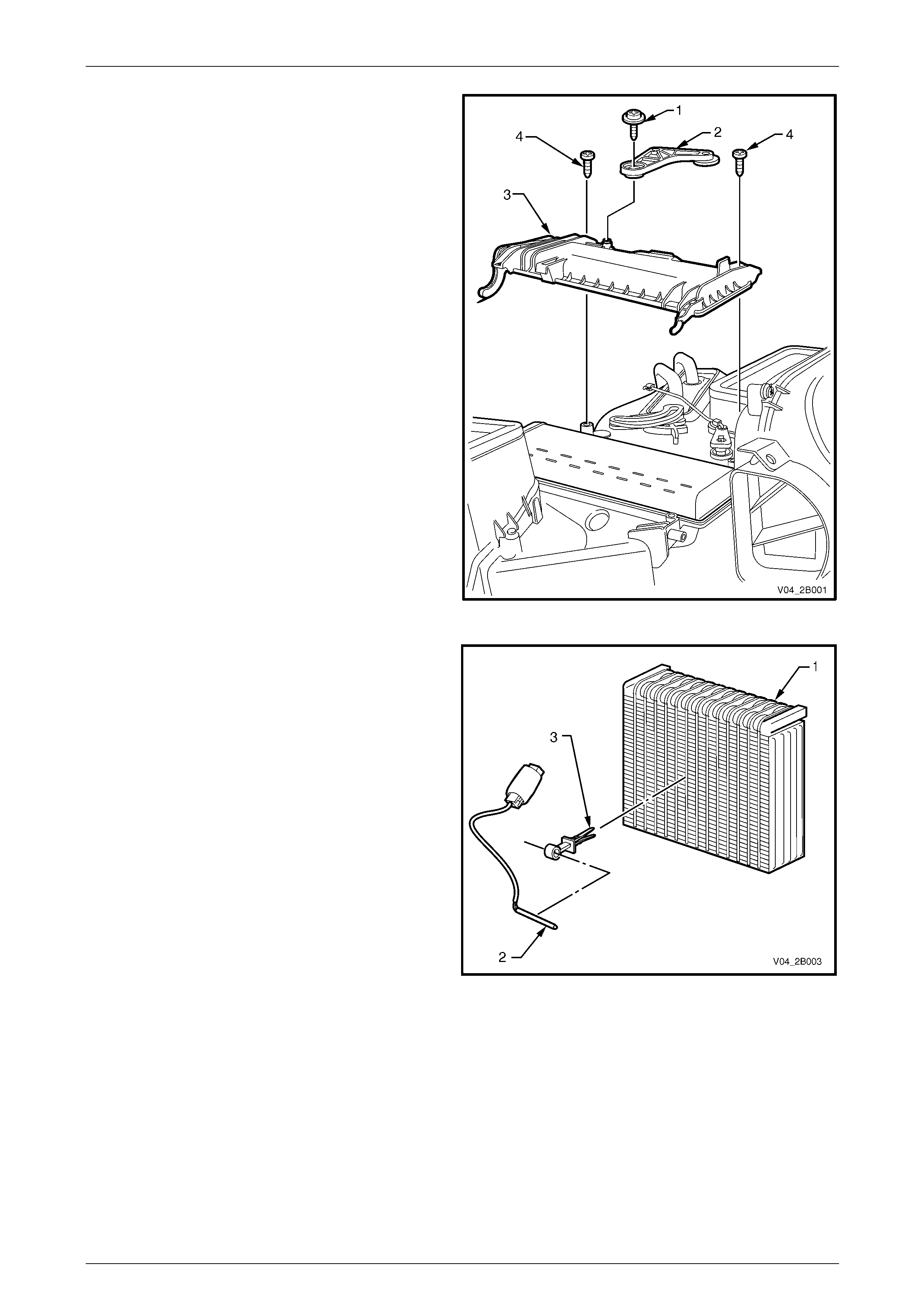
3 Remove the screw (1) and washer holding th e air
mix door quadrant lever (2) to the evaporator
cover (3) and move the quadrant lever asid e.
4 Remove the two screws (4) from the evaporator
cover, swing the cover open and remove it.
5 Carefully remove the evaporat or core from its cavity
in the HVAC case.
Figure 2B – 2
6 On OCC (Auto A/C) units, if the evaporator core (1)
is to be replaced, remove the evaporative
temperature sensor (2) by removing its mounting
clip (3) from the core.
Figure 2B – 3

HVAC Climate Control (Manual A/C) – Removal and Installation Page 2B–7
Page 2B–7
Install
Installation of the evaporator core is a reversal of removal procedures, noting the following:
NOTE
On OCC (Auto A/C) units, install the evaporative
temperature sensor in the correct location on the
evaporator core. Refer to Section 2E,
2.4 Evaporative Temperature Sensor in the
MY 2003 VY and V2 Series Service Information.
1 Tighten all screws to the specified torque.
Evaporator cover screw torque
specification................................................1.0 – 3.0 Nm
Air mix quadrant lever attaching
screw torque specification...........................1.0 – 3.0 Nm
2 Install the HVAC unit, refer to Section 2B, 3 Heating, Ventilation and Air Conditioning (HVAC) Unit in the
MY 2003 VY and V2 Series Service Information.
CAUTION
The total quantity of lubricating oil in the air
conditioning system must be maintained. If a
compressor, evaporator, condenser, filter
drier receiver, hose or pipe is to be replaced,
a specified quantity of lubricating oil must be
added to the system to compensate for oil
removed with the original component. Refer
to Section 2C, 2.4 Lubricating Oil Compensation
in the MY 2003 VY and V2 Series Service
Information.
3 Evacuate and charge the system with 775 – 825 g of R134a refrigerant, refer to
Section 2C, 2.1 System Charging and Evacuation in the MY 2003 VY and V2 Series Service Information.
HVAC Climate Control (Manual A/C) – Removal and Installation Page 2B–8
Page 2B–8
2.2 Blower Motor and Fan – RHD
LT Section – 08-150
Remove
1 Remove the left-hand side instrument panel lower
trim plate assembly, refer to Section 1A3, 3.1
Instrument Panel Lower Trim Plate Assembly in
the MY 2003 VY and V2 Series Service
Information.
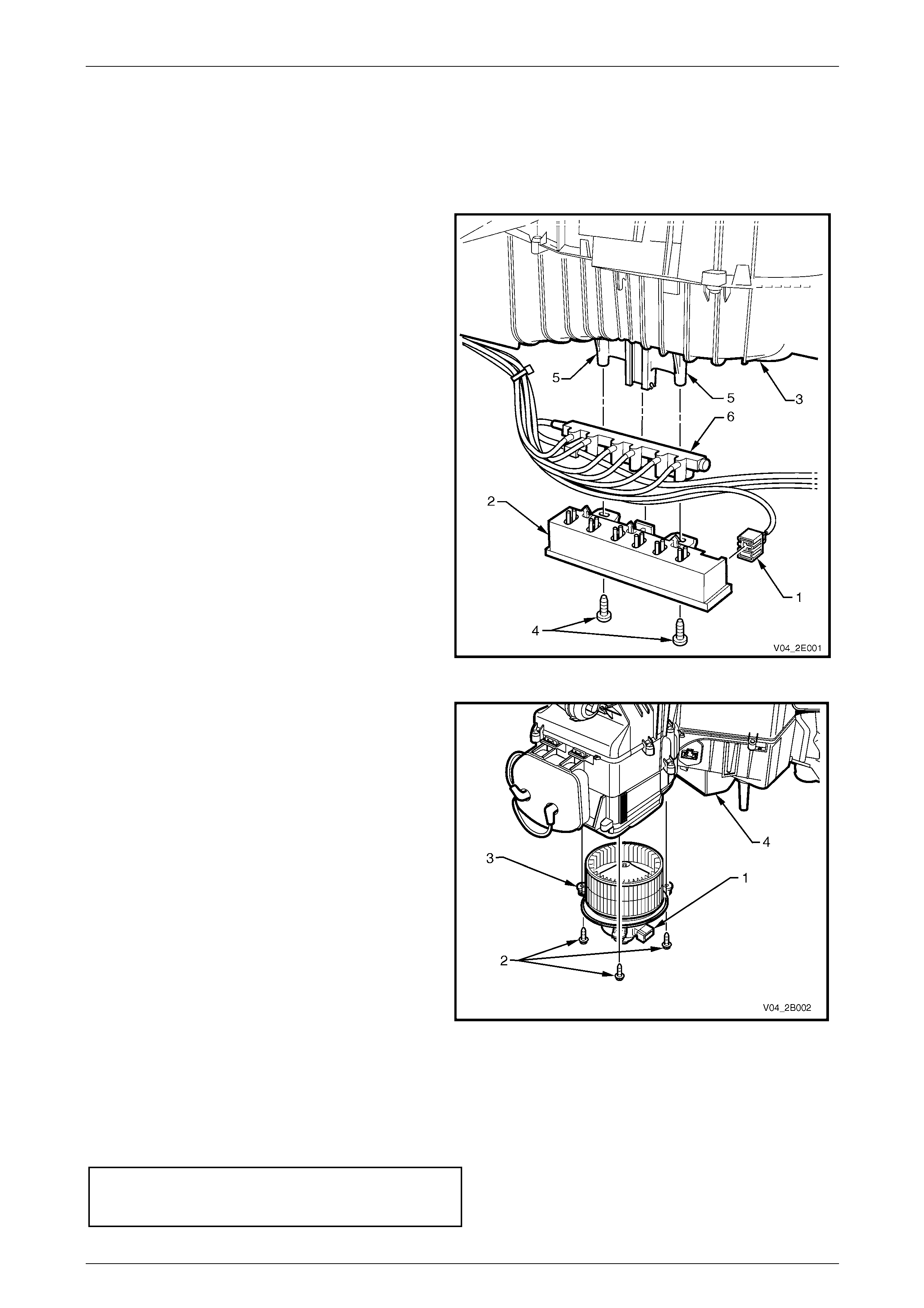
2 On OCC (Auto A/C) units, disconnect the OCC
wiring harness connector from the left-hand end of
the solenoid pack (1).
Figure 2B – 4
3 Disconnect the body wiring harness connector
from the blower motor sub-harness connector (1)
4 Remove the three screws (2) securing the blower
motor and fan assembly (3) to the HVAC unit (4)
and remove the assembly. Note that the screw
closer to the rear of the vehicle also secures the
fuse mounting bracket to the blower motor and fan
assembly mounting flange.
Figure 2B – 5
Install
Installation of the blower motor and fan assembly is a reversal of removal procedures, noting the following:
1 Tighten all screws to the specified torque.
Blower motor and fan assembly
mounting flange attaching scre w
torque specification.....................................1.0 – 3.0 Nm

HVAC Climate Control (Manual A/C) – Removal and Installation Page 2B–9
Page 2B–9
3 Torque Wrench Specifications
Evaporator Cover Screw ...............................................................1.0 – 3.0 Nm
Air Mix Quadrant Lever Attaching Screw.......................................1.0 – 3.0 Nm
Blower Motor and Fan Assembly Mounting F lange
Attaching Screw ............................................................................1.0 – 3.0 Nm