
HVAC Climate Control (Manual A/C) – Servicing and Diagnosis Page 2C–1
Page 2C–1
Section 2C
HVAC Climate Control (Manual A/C)
– Servicing and Diagnosis
ATTENTION
Before performing any Service Operation or other procedure described in this Section, refer to Section 00
Warnings, Cautions and Notes for correct workshop practices with regard to safety and/or property damage.
1 General Information ...............................................................................................................................2
1.1 RHD Vehicle Builds from Tag No. L171506 Onwards......................................................................................... 2
1.2 RHD Vehicle Builds Prior to Tag No. L171506..................................................................................................... 3
1.3 LHD Vehicles.......................................................................................................................................................... 4
2 Wiring Diagrams.....................................................................................................................................5
Connectors A15 – M7 ............................................................................................................................................ 7
Connectors M7 – X119........................................................................................................................................... 8
Connectors X119 – X206 ....................................................................................................................................... 9
Wiring Diagram: HVAC Climate Control (Manual A/C) System – V6 (LHD)..................................................... 10
Wiring Diagram: HVAC Climate Control (Manual A/C) System – V6 (RHD)..................................................... 11
Wiring Diagram: HVAC Climate Control (Manual A/C) System – SCV6 (RHD)................................................ 12
Wiring Diagram: HVAC Climate Control (Manual A/C) System – GEN III V8 (LHD)........................................ 13
Wiring Diagram: HVAC Climate Control (Manual A/C) System – GEN III V8 (RHD)........................................ 14
Techline
Techline
Techline

HVAC Climate Control (Manual A/C) – Servicing and Diagnosis Page 2C–2
Page 2C–2
1 General Information
With the following exceptions, MY 2004 VY and V2 Series H VAC Climate Control (Manual A/C) – Servicing and
Diagnosis information carr ies over from MY 2003 VY and V2 Series vehicles.
• From Tag No. L171506 a revised HVAC unit has been fitted to RHD vehicles. The information in this Section
includes information relevant to the revise d HVAC unit.
• There are minor differences in wiring – refer to 2 Wiring Diagrams.
1.1 RHD Vehicle Builds from Tag No.
L171506 Onwards
From Tag No. L171506 a revised HVAC unit has been fitted to RHD vehicles. The information in this Section appli es to
the revised HVAC unit.
For all other information regarding the servici ng and diagnosis of the heating and ventilation s ystem, refer to
Section 2C HVAC Climate Control (Man ual A/C) – Servicing and Diagnosis in the MY 2003 VY and V2 Series Service
Information.

HVAC Climate Control (Manual A/C) – Servicing and Diagnosis Page 2C–3
Page 2C–3
1.2 RHD Vehicle Builds Prior to Tag No.
L171506
For all information regarding the servic ing and diagnosis of the heating and ventilation system (other than electrical
connector and wiring diagram informati on) fitted to RHD vehicles built prior to Tag No. L171506, refer to
Section 2C HVAC Climate Control (Man ual A/C) – Servicing and Diagnosis in the MY 2003 VY and V2 Series Service
Information.
For electrical connector and wiring diagram information for all RHD vehicles, irrespective of tag number,
refer to 2 Wiring Diagrams in this section.

HVAC Climate Control (Manual A/C) – Servicing and Diagnosis Page 2C–4
Page 2C–4
1.3 LHD Vehicles
For all information regarding the servicing and diagnosis of the heating and ventilation sys tem
(other than electrical connect or and wiring diagram information) fitted to LHD vehicles, refer to
Section 2C HVAC Climate Control (Man ual A/C) – Servicing and Diagnosis in the MY 2003 VY and V2 Series Service
Information.
For electrical connector and wiring diagram information for all LHD vehicles, refer to 2 Wiring Diagrams in this section.
HVAC Climate Control (Manual A/C) – Servicing and Diagnosis Page 2C–5
Page 2C–5
2 Wiring Diagrams
The following figures provide electrical connector diagrams and wiring diagrams applicab le to HVAC Climate Control
(Manual A/C) systems as fitted to MY 2004 VY and V2 Series veh icles. T hese diagrams should be used as an aid to
diagnosing circuit faults. The content of these figures is as follows:
• Electrical connectors (A15 – M7) – refer to Figure 2 C – 1
• Electrical connectors continued (M7 – X119) – refer to F igure 2C – 2
• Electrical connectors continued (X119 – X206) – refer to Figure 2C – 3
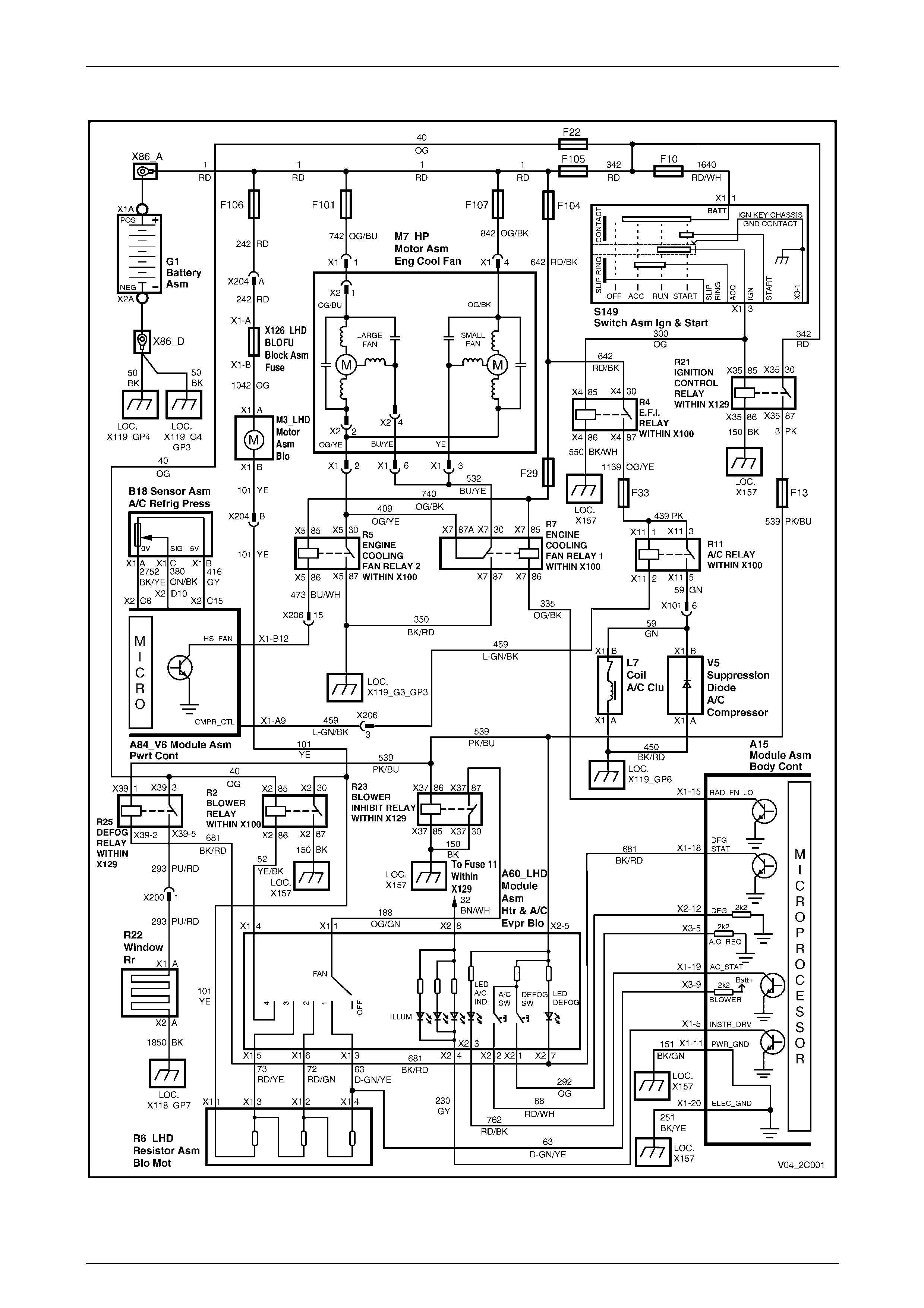
• Wiring diagram: HVAC Climate Control (Manual A/C) System, V6 (LHD) – refer to Figure 2C – 4
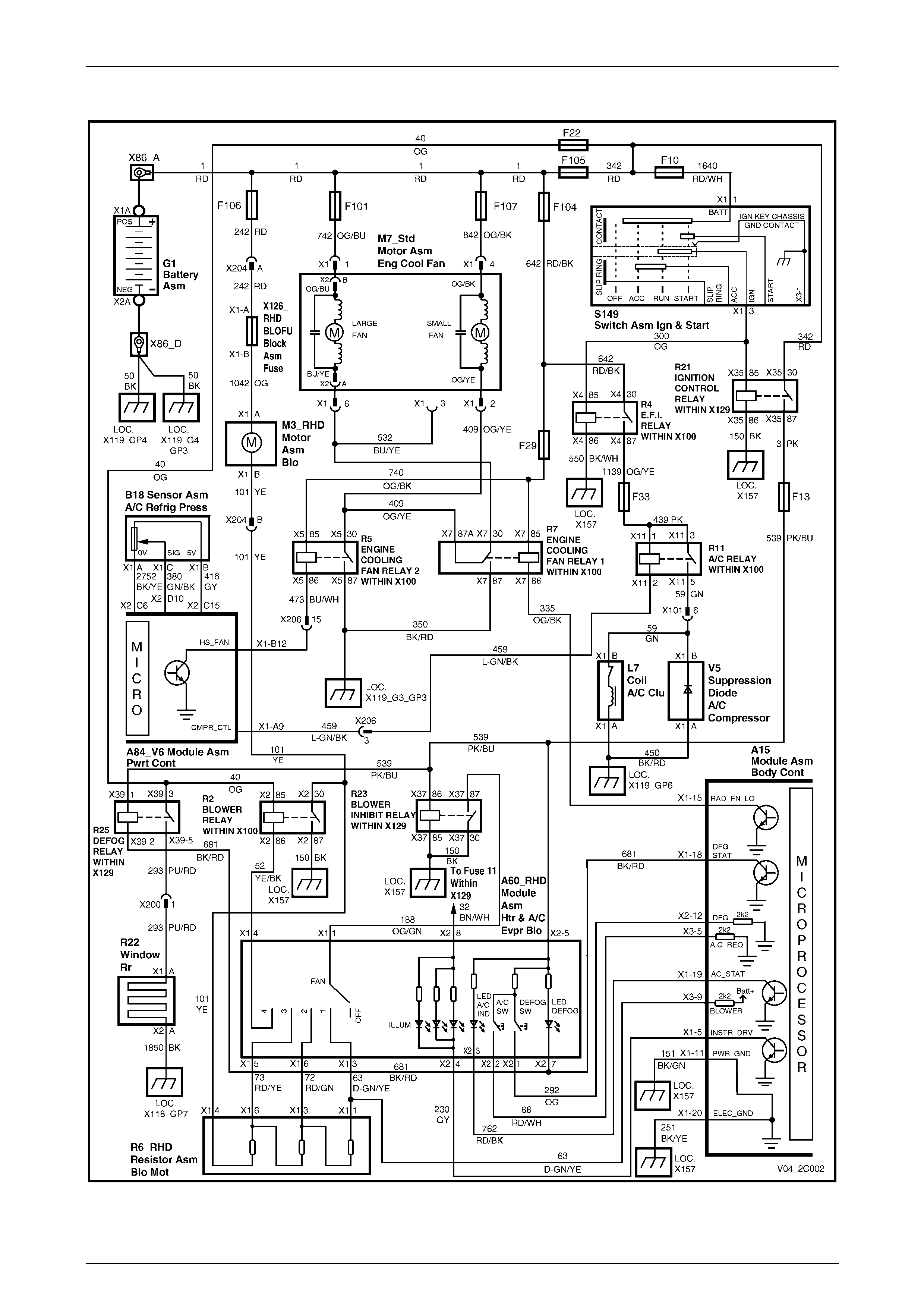
• Wiring diagram: HVAC Climate Control (Manual A/C) System, V6 (RHD) – refer to Figure 2C – 5
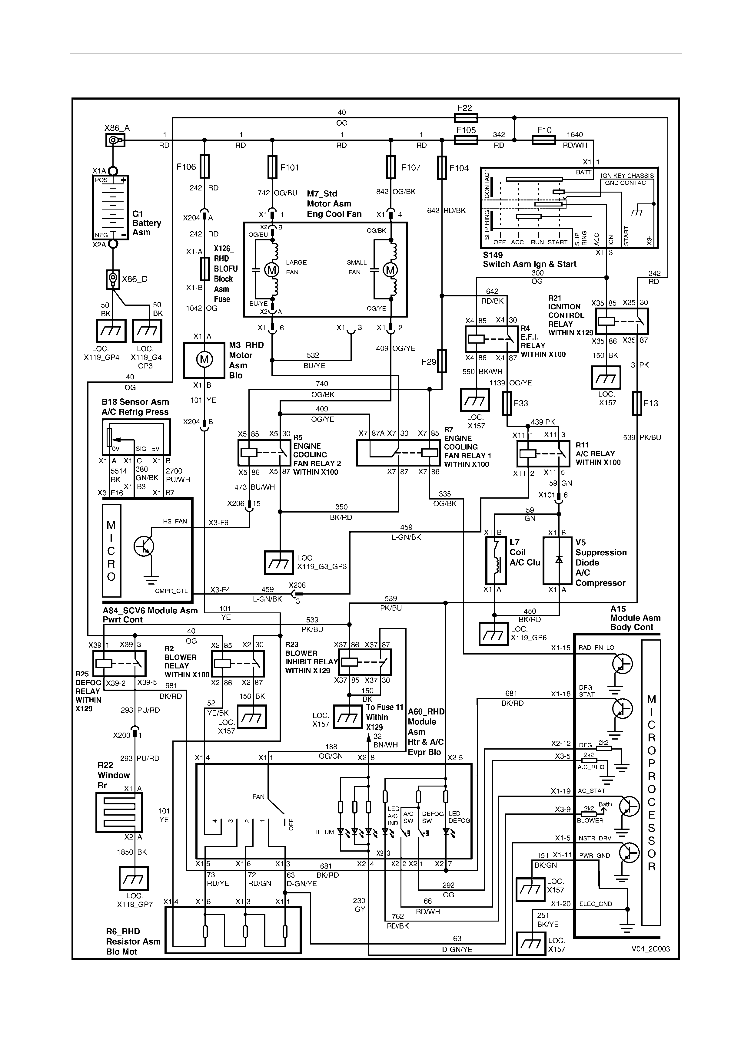
• Wiring diagram: HVAC Climate Control (Manual A/C) System, SCV6 (RHD) – refer to Figure 2C – 6
• Wiring diagram: HVAC Climate Control (Manual A/C) System, GEN III V8 (LHD) – refer to Figure 2C – 7
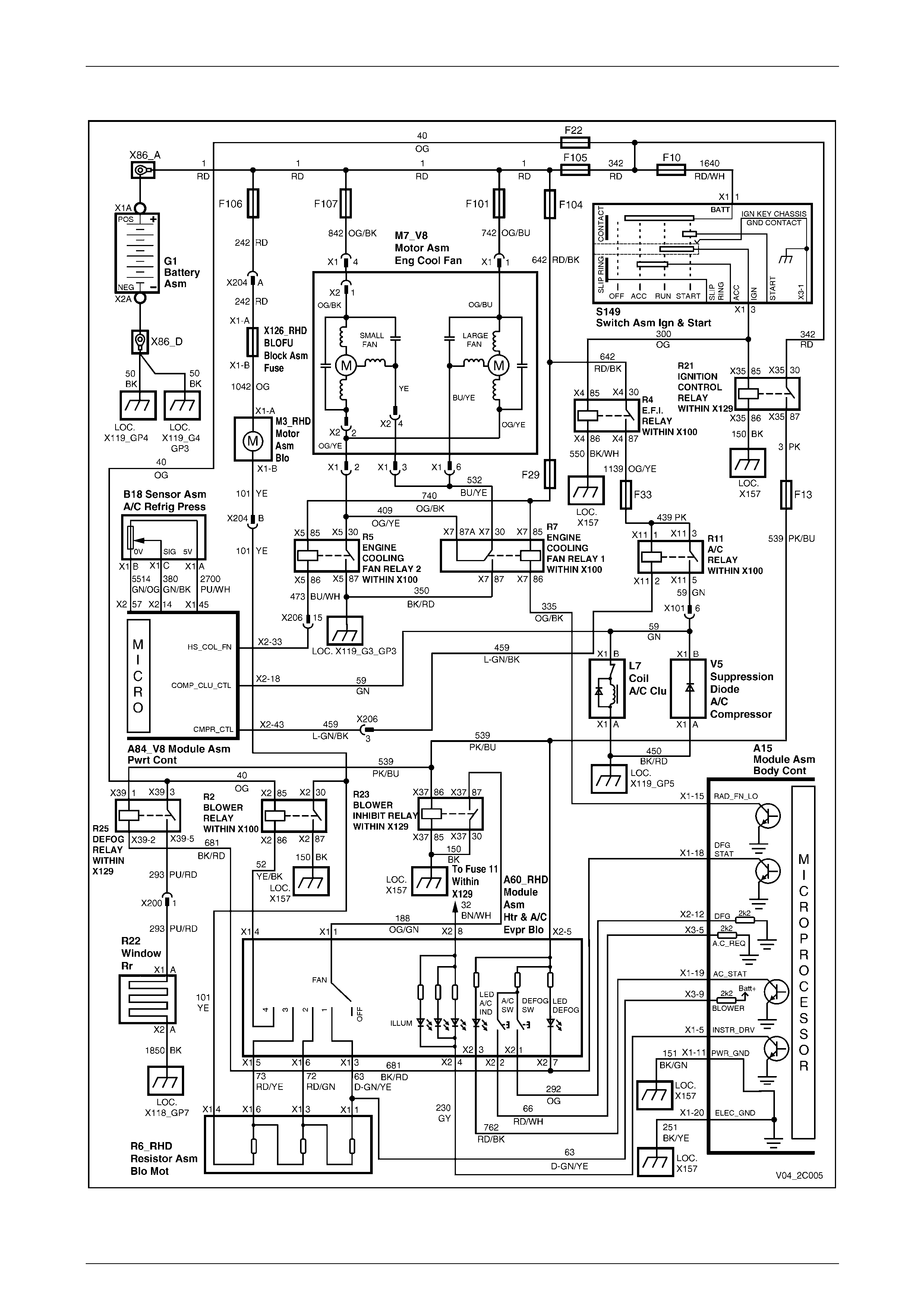
• Wiring diagram: HVAC Climate Control (Manual A/C) System, GEN III V8 (RHD) – refer to Figure 2C – 8
NOTE
Prior to Tag No. L171506, on RHD vehicles the
blower motor was fitted with a built-in circuit
breaker for motor protection. The revised HVAC
unit fitted to RHD vehicles from Tag No. L171506
onwards uses an external blade type fuse in
place of the built-in circuit breaker. For blower
wiring information only, for the built-in circuit
breaker type motor, refer to Section 2C, 9 Wiring
Diagrams in the MY 2003 VY and V2 Series
Service Information (RHD vehicle information
only).
For wiring diagrams related to the Occupant Climate Control (Auto A/C) system as fitted to MY 2004 VY and V2 Series
vehicles, refer to Section 2F, 3 Wiring Diagrams.
In the following wiring diagrams (Figures 2C – 4 to Figure 2C – 8 inclusive) all components are described and displayed
in accordance with the Integrated Vehicle Electrical Design (IVED) standard as applied to MY 2004 VY and V2 Series
vehicles. To assist in wiring diagram interpretation, refer to the following table:
IVED Description IVED Component
Identification Common Description
Module Asm Body Cont A15 Body Control Module
Module Asm Htr & A/C Evpr Blo A60 Manual HVAC Controller
Module Asm Pwrt Cont A84_SCV6 SCV6 Powertrain Control Module
Module Asm Pwrt Cont A84_V6 V6 Powertrain Control Module
Module Asm Pwrt Cont A84_V8 GEN III V8 Powertrain Control Module
Sensor Asm A/C Refrig Press B18 A/C Pressure Transducer
Coil A/C Clu L7 Compressor Clutch
Motor Asm Blo M3 Blower Motor
Motor Asm Eng Cool Fan M7_HP V6 High Power Cooling Fan System
Motor Asm Eng Cool Fan M7_V6 V6 Standard Cooling Fan S ys tem
Motor Asm Eng Cool Fan M7_V8 GEN III V8 Cooling Fan System
Resistor Asm Blo Mot R6 Blower Motor Resistor
Window Rr R22 Heated Rear Window
Switch Asm Ign & Start S149 Ignition Switch

HVAC Climate Control (Manual A/C) – Servicing and Diagnosis Page 2C–6
Page 2C–6
The following table lists the IVED standard wire colour abbreviations:
BK Black D-GN Dark green L-GN Light green RD Red
BU Blue GN Green OG Orange TN Tan
BN Brown GY Grey PK Pink WH White
D-BU Dark blue L-BU Light blue PU Purple YE Yellow
NOTE
For electrical connector locations and additional
wiring diagram information refer to Section 12P
Wiring Diagrams.
HVAC Climate Control (Manual A/C) – Servicing and Diagnosis Page 2C–7
Page 2C–7
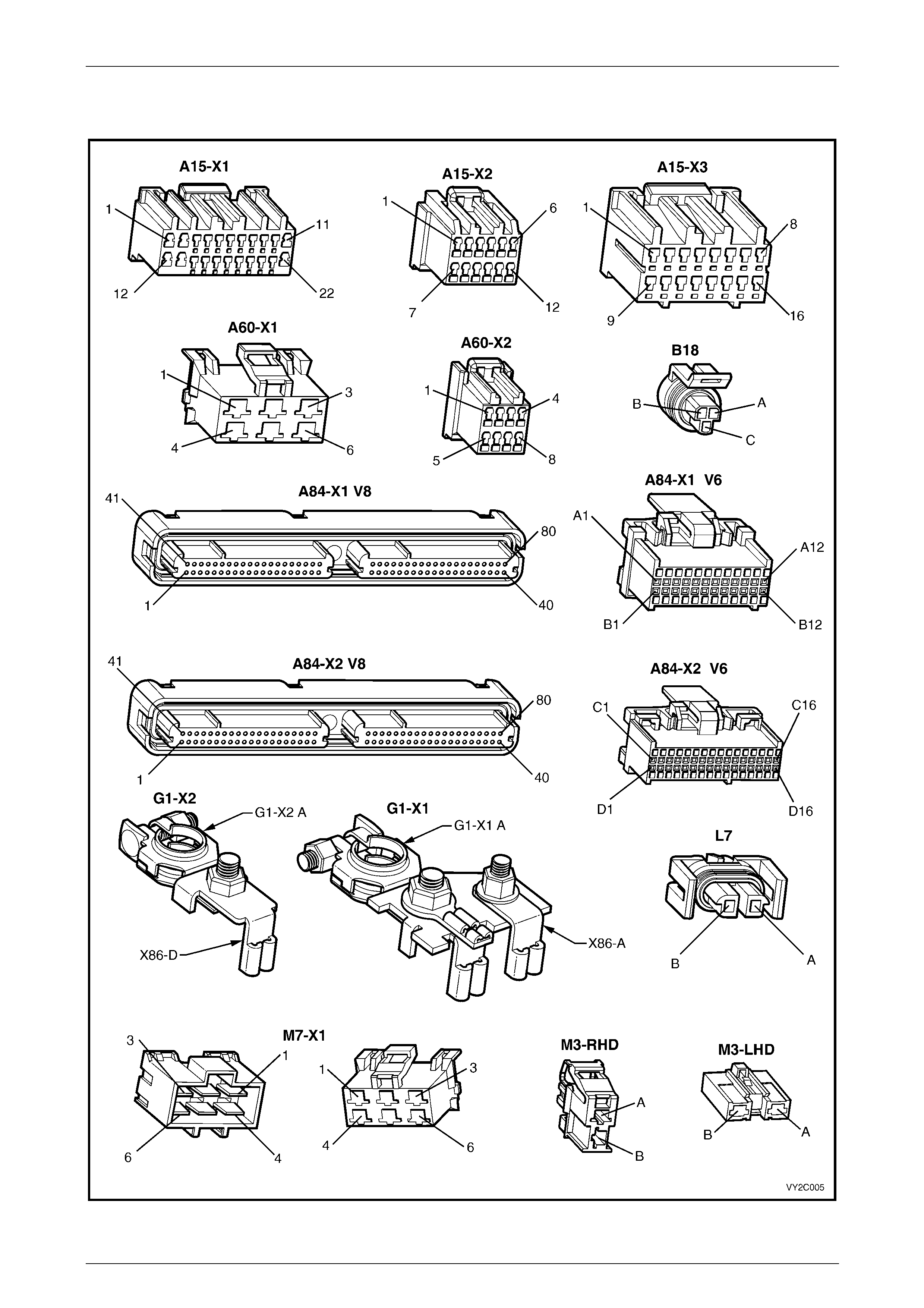
Connectors A15 – M7
Figure 2C – 1
HVAC Climate Control (Manual A/C) – Servicing and Diagnosis Page 2C–8
Page 2C–8
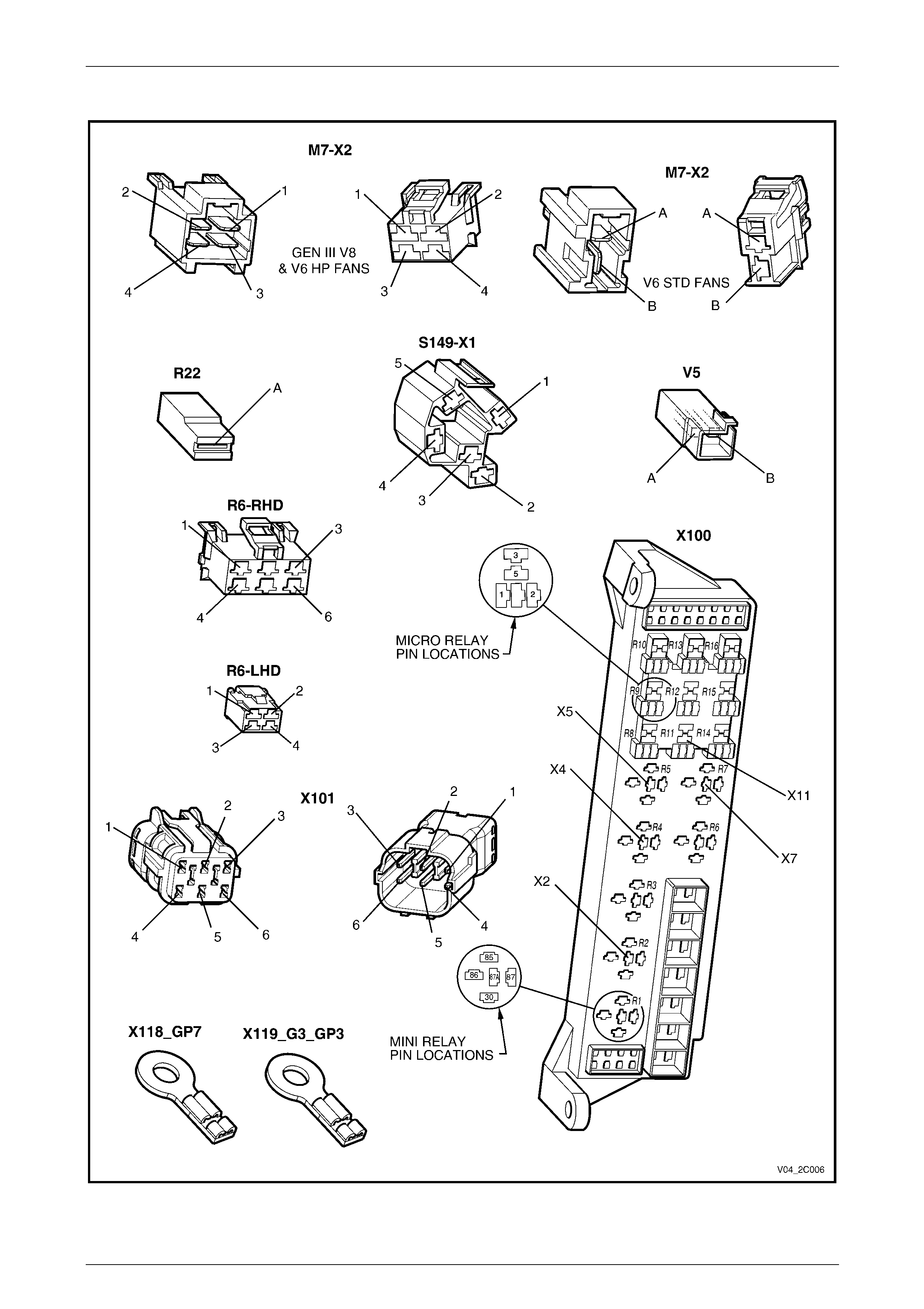
Connectors M7 – X119
Figure 2C – 2
HVAC Climate Control (Manual A/C) – Servicing and Diagnosis Page 2C–9
Page 2C–9
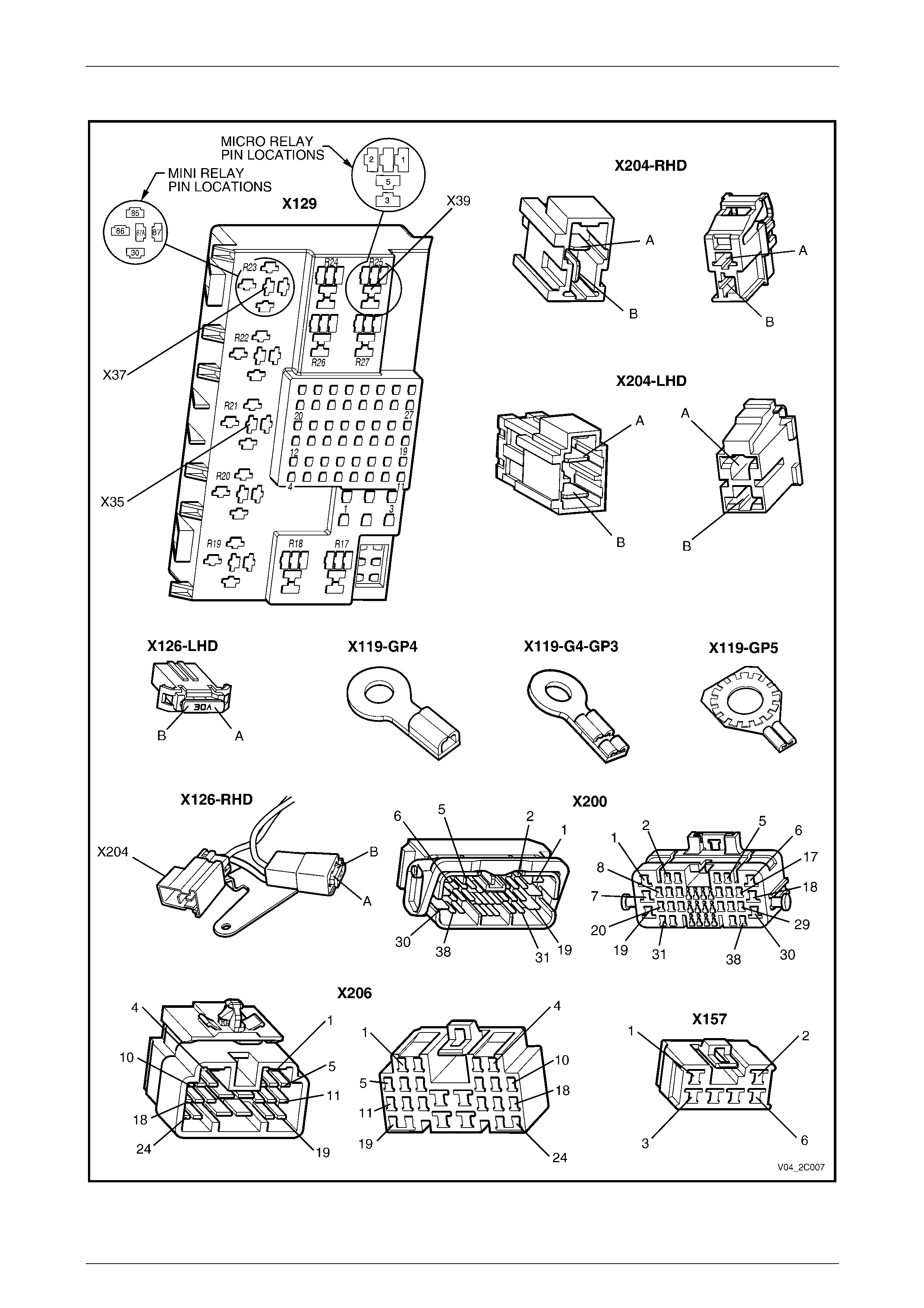
Connectors X119 – X206
Figure 2C – 3
HVAC Climate Control (Manual A/C) – Servicing and Diagnosis Page 2C–10
Page 2C–10
Wiring Diagram: HVAC Climate Control (Manual A/C) System – V6 (LHD)
Figure 2C – 4
HVAC Climate Control (Manual A/C) – Servicing and Diagnosis Page 2C–11
Page 2C–11
Wiring Diagram: HVAC Climate Control (Manual A/C) System – V6 (RHD)
Figure 2C – 5
HVAC Climate Control (Manual A/C) – Servicing and Diagnosis Page 2C–12
Page 2C–12
Wiring Diagram: HVAC Climate Control (Manual A/C) System – SCV6 (RHD)
Figure 2C – 6

HVAC Climate Control (Manual A/C) – Servicing and Diagnosis Page 2C–13
Page 2C–13
Wiring Diagram: HVAC Climate Control (Manual A/C) System – GEN III V8 (LHD)
Figure 2C – 7
HVAC Climate Control (Manual A/C) – Servicing and Diagnosis Page 2C–14
Page 2C–14
Wiring Diagram: HVAC Climate Control (Manual A/C) System – GEN III V8 (RHD)
Figure 2C – 8