
HVAC Occupant Climate Control (Auto A/C) – Description and Operation Page 2D–1
Page 2D–1
Section 2D
HVAC Occupant Climate Control (Auto A/C)
– Description and Operation
ATTENTION
Before performing any Service Operation or other procedure described in this Section, refer to Section 00
Warnings, Cautions and Notes for correct workshop practices with regard to safety and/or property damage.
1 General Information ...............................................................................................................................2
1.1 RHD Vehicle Builds from Tag Nos. L174938 (single zone) and L173857 (dual zone) Onwards...................... 2
1.2 RHD Vehicle Builds Prior to Tag Nos. L174938 (single zone) and L173857 (dual zone) .................................. 3
1.3 LHD Vehicles.......................................................................................................................................................... 4
2 Heating, Ventilation and Air Conditioning Unit – RHD.......................................................................5
2.1 Assembled Views................................................................................................................................................... 5
2.2 Exploded View........................................................................................................................................................ 7
2.3 Vacuum Solenoid Pack ......................................................................................................................................... 8
3 Specifications.........................................................................................................................................9
HVAC Unit – RHD................................................................................................................................................... 9
Techline
Techline
Techline
Techline
Techline
Techline
Techline

HVAC Occupant Climate Control (Auto A/C) – Description and Operation Page 2D–2
Page 2D–2
1 General Information
With the following exceptions, MY 2004 VY and V2 Series HVAC Occupant Climate Control (Auto A/C) – Descripti on and
Operation information carries over from MY 2003 VY and V2 Series vehicles.
• From Tag Nos. L174938 (single zone) and L173857 (dual zone) revised HVAC units have been fitted to RHD
vehicles.
1.1 RHD Vehicle Builds from Tag Nos.
L174938 (single zone) and L173857 (dual
zone) Onwards
From Tag Nos. L174938 (single zone) and L173857 (dual zone) revised HVAC units have been fitted to RHD vehicles.
The information in this Section applies to the revised HVAC units.
For all other information regarding the descr iption and operation of the he ating and ventilation system, refer to
Section 2D HVAC Occupant Climate Contro l (Auto A/C) – Description and Operation in the MY 2003 VY and V2 Series
Service Information.

HVAC Occupant Climate Control (Auto A/C) – Description and Operation Page 2D–3
Page 2D–3
1.2 RHD Vehicle Builds Prior to Tag Nos.
L174938 (single zone) and L173857 (dual
zone)
For all information regarding the description and oper ation of the heating and ventil ation system fitted to
RHD vehicles built prior to T ag Nos. L1749 38 (single zone) and L173 857 (dual zone), refer to
Section 2D HVAC Occupant Climate Contro l (Auto A/C) – Description and Operation in the MY 2003 VY and V2 Series
Service Information.

HVAC Occupant Climate Control (Auto A/C) – Description and Operation Page 2D–4
Page 2D–4
1.3 LHD Vehicles
For all information regarding the description and operation of the heating and ventilation system fitted to LHD vehicles,
refer to Section 2D HVAC Occupant Climate Control (Auto A/C) – Description a nd Operation in the MY 2003 VY and V2
Series Service Information.
HVAC Occupant Climate Control (Auto A/C) – Description and Operation Page 2D–5
Page 2D–5
2 Heating, Ventilation and Air
Conditioning Unit – RHD
The revised HVAC units inco rporate a different evaporator cover assembly, evaporator air seals and blower motor and
fan assembly. A cover is not fitted over the blower motor and fan assembly and the mounting arrangement of the
solenoid pack has been revised.
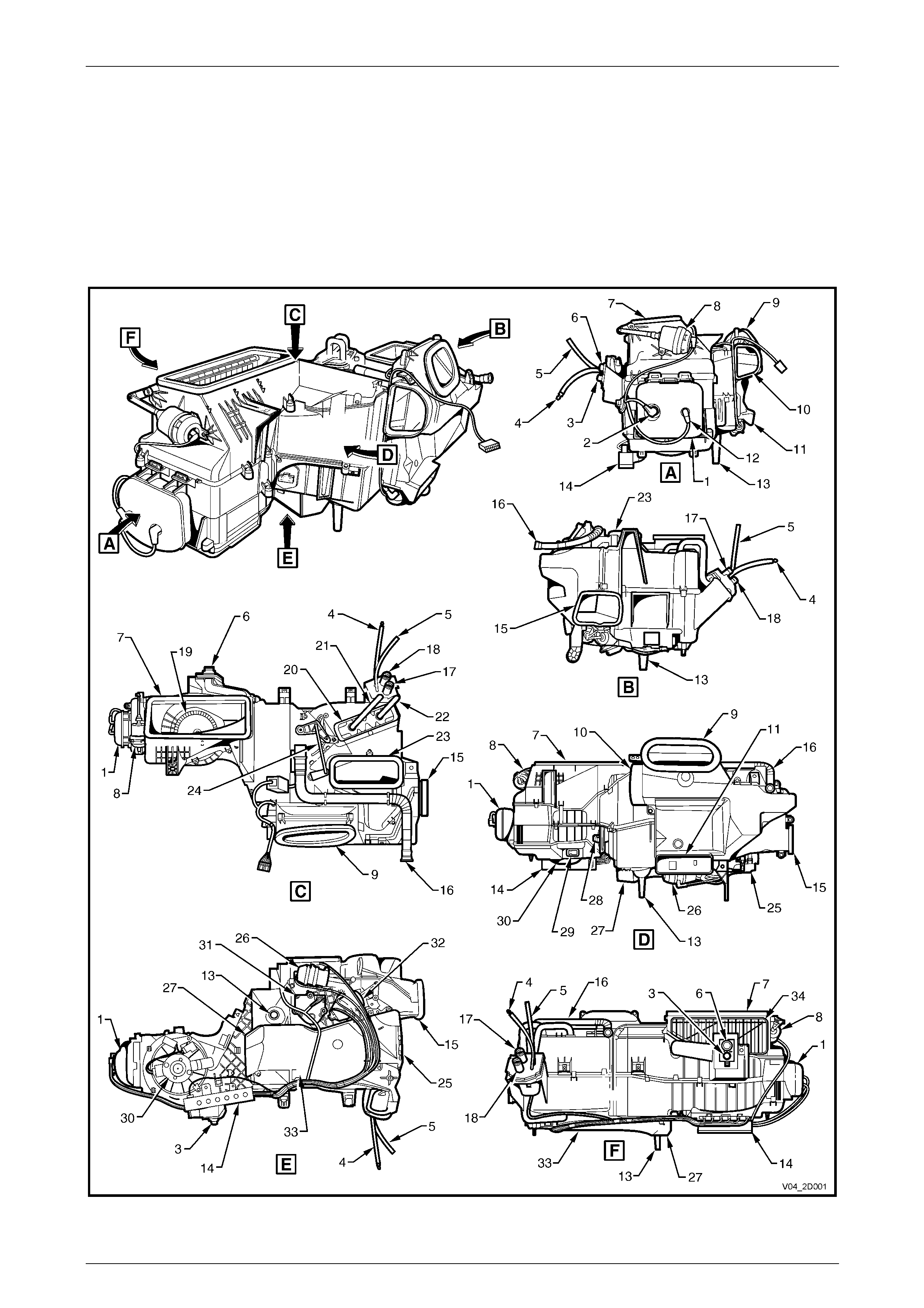
2.1 Assembled Views
Figure 2D – 1

HVAC Occupant Climate Control (Auto A/C) – Description and Operation Page 2D–6
Page 2D–6
Legend for Figure 2D – 1
1 Vacuum tank
2 Vacuum connector (from inlet manifold)
3 A/C high pressure port
4 Vacuum line to water valve
5 Vacuum line to inlet manifold
6 A/C low pressure port
7 HVAC air inlet
8 Intake actuator
9 Face vent outlet
10 Side duct outlet – LHS
11 Rear duct outlet
12 Vacuum connector from solenoid pack
13 Drain tube
14 Vacuum solenoid pack
15 Side duct outlet – RHS
16 Aspirator tube
17 Heater core inlet
18 Heater core outlet
19 Blower fan
20 Heater core
21 Heater core outlet pipe
22 Heater core inlet pipe
23 Demist outlet
24 Air mix door rod
25 Foot vent outlet – RHS
26 Face actuator
27 Foot vent outlet – LHS
28 Blower motor resistor
29 Blower motor connector
30 Blower motor
31 Air mix door motor
32 Foot actuator
33 Foot duct
34 Recirculation door
HVAC Occupant Climate Control (Auto A/C) – Description and Operation Page 2D–7
Page 2D–7
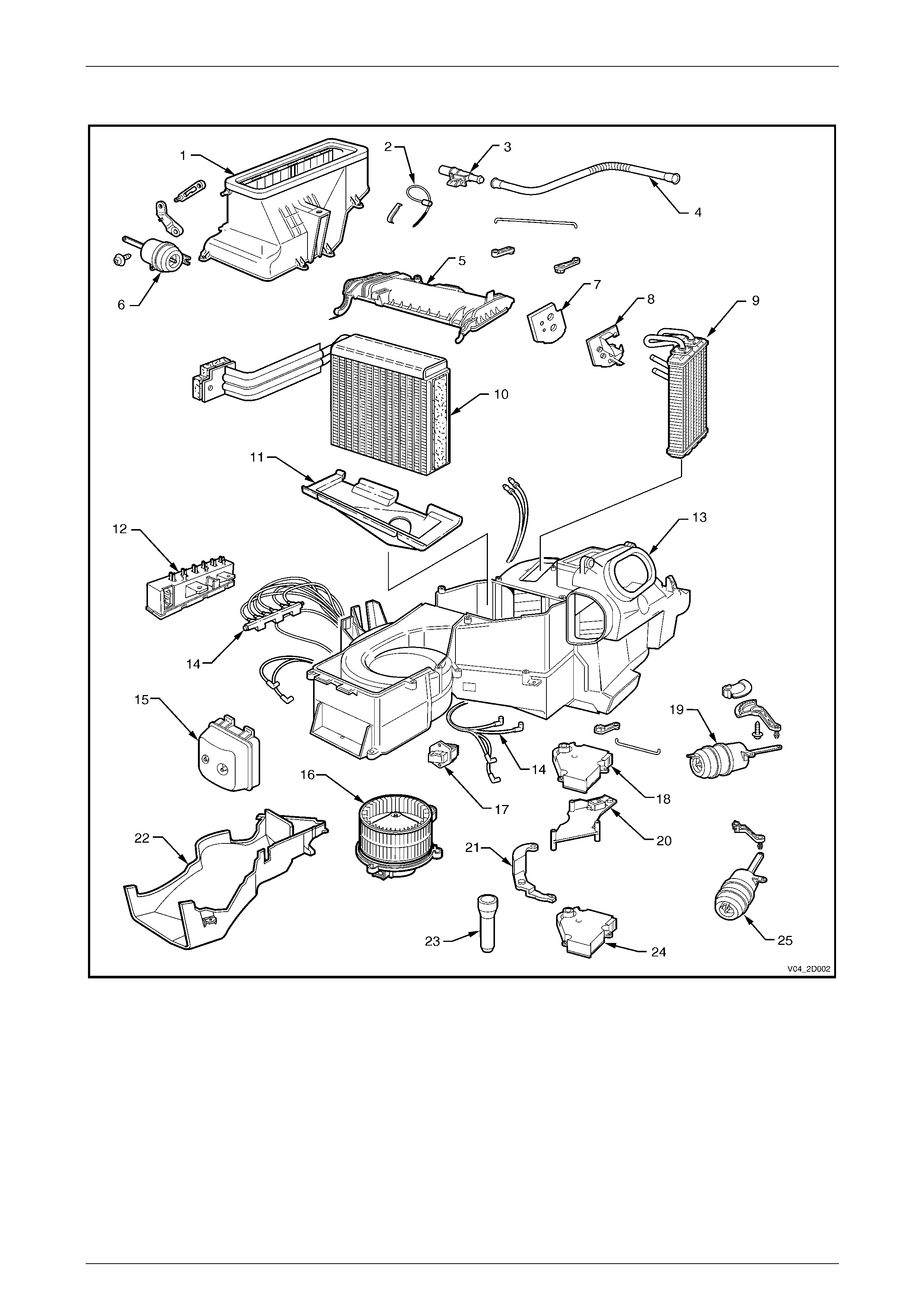
2.2 Exploded View
Figure 2D – 2
Legend
1 Fresh/recirculate housing
2 Evaporative temperature sensor
3 Aspirator venturi
4 Aspirator tube
5 Evaporator core cover
6 Intake actuator
7 Heater pipe seal
8 Heater pipe retainer
9 Heater core
10 Evaporator
11 Insulator
12 Vacuum solenoid pack
13 HVAC unit case
14 Vacuum tube harness
15 Vacuum tank
16 Blower motor and fan
17 Blower motor resistor
18 Air mix door motor – single zone
(passenger on dual zone)
19 Foot actuator
20 Air mix door motor mounting bracket
21 Lever – dual zone
22 Foot duct
23 Drain tube
24 Air mix door motor – driver
25 Face actuator
HVAC Occupant Climate Control (Auto A/C) – Description and Operation Page 2D–8
Page 2D–8
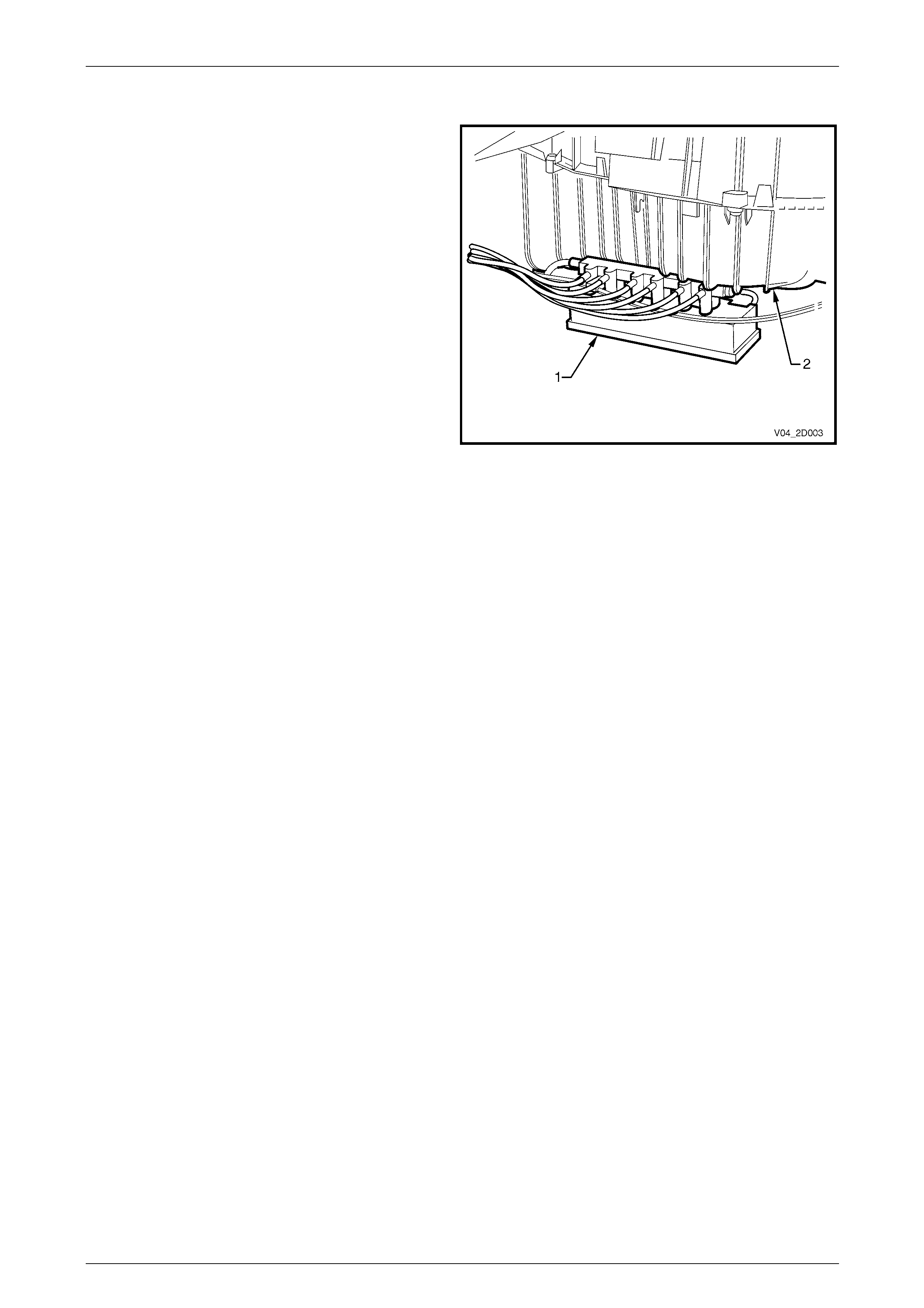
2.3 Vacuum Solenoid Pack
In the revised HVAC units, there is no blower motor
cover and the vacuum solenoid pack (1) is mounted on
the bottom of the HVAC case (2) near the blo wer motor
and towards the front of the vehicle.
Figure 2D – 3

HVAC Occupant Climate Control (Auto A/C) – Description and Operation Page 2D–9
Page 2D–9
3 Specifications
With the following exceptions, which apply to the revised HVAC unit fitted to RHD vehicles from Tag Nos. L174938
(single zone) and L173857 (dual zone) onwards, all specification data carries over from MY 2003 VY and V2 Series
vehicles. Refer to Section 2D, 5 Specifications in the MY 2003 VY and V2 Series Service Information.
HVAC Unit – RHD
Blower Fan Assembly:
Motor Power .................................................................................................................. 300 W
Motor Current ................................................................................................................... 25 A
Fan Drum Diameter.....................................................................................................157 mm
Fan Drum Height ...........................................................................................................90 mm
Number of Fan Blades..........................................................................................................45