
HVAC Occupant Climate Control (Auto A/C) – Diagnostics Page 2F–1
Page 2F-1
Section 2F
HVAC Occupant Climate Control (Auto A/C)
– Diagnostics
ATTENTION
Before performing any Service Operation or other procedure described in this Section, refer to Section 00
Warnings, Cautions and Notes for correct workshop practices with regard to safety and/or property damage.
1 General Information ...............................................................................................................................2
1.1 RHD Vehicle Builds from Tag Nos. L174938 (single zone) and L173857 (dual zone) Onwards...................... 2
1.2 RHD Vehicle Builds Prior to Tag Nos. L174938 (single zone) and L173857 (dual zone) .................................. 3
1.3 LHD Vehicles.......................................................................................................................................................... 4
2 Diagnostics.............................................................................................................................................5
3 Wiring Diagrams.....................................................................................................................................6
Connectors A13 – M3 ............................................................................................................................................ 8
Connectors M7 – X119........................................................................................................................................... 9
Connectors X126 – Y37 ....................................................................................................................................... 10
Wiring Diagram: HVAC Occupant Climate Control (Auto A/C) System – V6 (LHD)........................................ 11
Wiring Diagram: HVAC Occupant Climate Control (Auto A/C) System – V6 (RHD)....................................... 12
Wiring Diagram: HVAC Occupant Climate Control (Auto A/C) System – SCV6 (RHD) .................................. 13
Wiring Diagram: HVAC Occupant Climate Control (Auto A/C) System – Gen III V8 (LHD)............................ 14
Wiring Diagram: HVAC Occupant Climate Control (Auto A/C) System – Gen III V8 (RHD) ........................... 15
Techline
Techline
Techline
Techline
Techline

HVAC Occupant Climate Control (Auto A/C) – Diagnostics Page 2F–2
Page 2F-2
1 General Information
With the following exceptions, MY 2004 VY and V2 Series HVAC Occupant Climate Control (Auto A/C) – Diagnostics
information carries over from MY 2003 VY and V2 Series vehicl es.
• From Tag Nos. L174938 (single zone) and L173857 (dua l zone) revised HVAC units have been fitted to RHD
vehicles.
• There are minor differences in wiring – refer to 3 Wiring Diagrams.
1.1 RHD Vehicle Builds from Tag Nos.
L174938 (single zone) and L173857 (dual
zone) Onwards
From Tag Nos. L174938 (single zone) and L173857 (dual zone) revised HVAC units have been fitted to RHD vehicles.
The information in this Section applies to the revised HVAC units.
For all other information regarding diagn osis of the heating and ventilation system, refer to
Section 2F HVAC Occupant Climate Control (Auto A/C) – Diag nostics in the MY 2003 VY and V2 Serie s Service
Information.

HVAC Occupant Climate Control (Auto A/C) – Diagnostics Page 2F–3
Page 2F-3
1.2 RHD Vehicle Builds Prior to Tag Nos.
L174938 (single zone) and L173857 (dual
zone)
For all information regarding diagnosis of the heating and ventilation system fitted to RHD vehicles built prior to Tag Nos.
L174938 (single zone) and L173857 (dual zone), other than electrical connector and wiring diagram information, refer to
Section 2F HVAC Occupant Climate Control (Auto A/C) – Diag nostics in the MY 2003 VY and V2 Serie s Service
Information.
For electrical connector and wiring diagram information for all RHD vehicles, irrespective of tag number, refer to
3 Wiring Diagrams in this section.

HVAC Occupant Climate Control (Auto A/C) – Diagnostics Page 2F–4
Page 2F-4
1.3 LHD Vehicles
For all information regarding d iagnosis of the heating and ventilation s ystem fitted to LHD vehicles, refer to
Section 2F HVAC Occupant Climate Control (Auto A/C) – Diag nostics in the MY 2003 VY and V2 Serie s Service
Information.
For electrical connector and wiring diagram information for all LHD vehicles, refer to 3 Wiring Diagrams in this section.
HVAC Occupant Climate Control (Auto A/C) – Diagnostics Page 2F–5
Page 2F-5
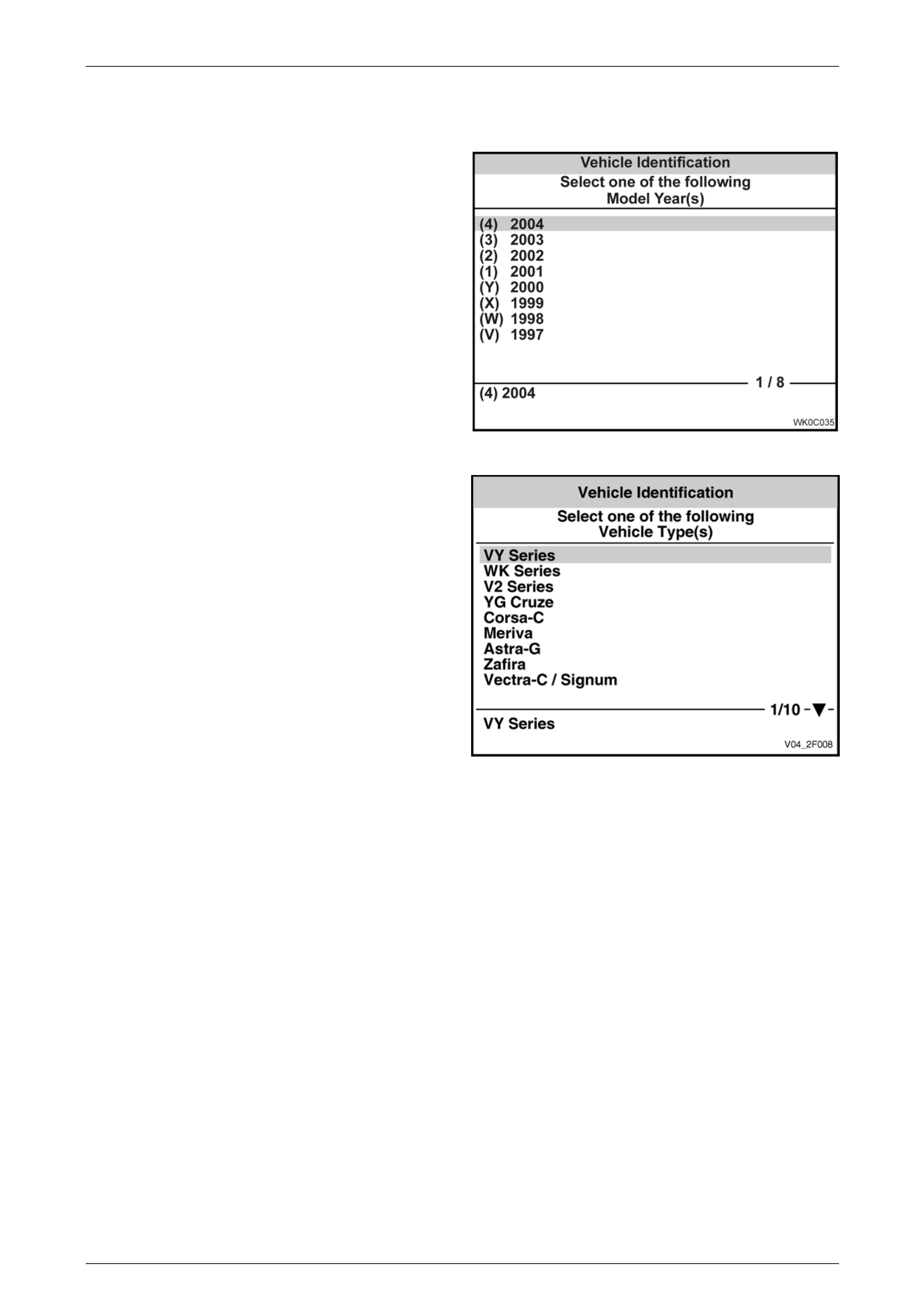
2 Diagnostics
The diagnostic information acc ess procedures are a
carry over from the MY 2003 VY and V2 Series except
that the Model Year selection on TECH 2 is now
(4) 2004.
Figure 2F – 1
The Vehicle Type selection is VY Series.
Figure 2F – 2

HVAC Occupant Climate Control (Auto A/C) – Diagnostics Page 2F–6
Page 2F-6
3 Wiring Diagrams
The following figures provide electrical connector and wiring diagrams applicabl e to HVAC Occupant Climate
Control (Auto A/C) systems fitted to MY 2004 VY and V2 Series vehicles. When diagnosing circuit faults, these
diagrams should be used in conjunction with the diagnostic chart circuit diagrams provi ded in
Section 2F HVAC Occupant Climate Control (Auto A/C) – Diagnostics in the MY 2003 VY and V2 Series Service
Information. The content of these figures is as follows:
• Electrical connectors (A13 – M3) – refer to Figure 2F – 3
• Electrical connectors continued (M7 – X119) – refer to Figure 2F – 4
• Electrical connectors continued (X126 – Y37) – refer to Figure 2F – 5
• Wiring diagrams – refer to Figure 2F – 6 to Figure 2F – 10 inclusive
NOTE
For RHD vehicles built prior to Tag Nos. L1749 38
(single zone) and L173857 (dual zone), the
blower motor was fitted with a built-in circuit
breaker for motor protection. The revised HVAC
units fitted to RHD vehicles from Tag Nos.
L174938 (single zone) and L173857 (dual zone)
onwards use an e xternal bl ad e t ype fuse i n l ieu of
the built-in circuit breaker. For blower wiring
information only, for the built-in circuit breaker
type motor, refer to Section 2F, 5 Wiring
Diagrams in the MY 2003 VY and V2 Series
Service Information.
In the following wiring diagrams (Figure 2F – 6 to Figure 2F – 10 inclusive) all components are descri bed and displayed
in accordance with the Integrated Vehicle Electrical Design (IVED) standard as applied to MY 2004 VY and V2 Series
vehicles. To assist in wiring diagram interpretation, refer to the following table:
IVED Description IVED Component
Identification Common Description
Module Asm Blo & Air Inl A13 Blower Motor Resistor
Module Asm Blo Mot & A/C Cmpr Cont A14 OCC Control Module
Module Asm Body Cont A15 Body Control Module
Module Asm Pwrt Cont A84_SCV6 SCV6 Powertrain Control Module
Module Asm Pwrt Cont A84_V6 V6 Powertrain Control Module
Module Asm Pwrt Cont A84_V8 GEN III V8 Powertrain Control Module
Sensor Asm A/C Refrig Press B18 A/C Pressure Transducer
Sensor Asm Amb Air Temp B23 Ambient Air Temperature Sensor
Sensor Asm Duct Air Temp B34 Evaporative Temperature Sensor
Sensor Asm I/S Air Temp B59 In-car Temperature Sensor
Coil A/C Clu L7 Compressor Clutch
Motor Asm Blo M3 Blower Motor
Motor Asm Eng Cool Fan M7_HP V6 High Power Cooling Fan System
Motor Asm Eng Cool Fan M7_V6 V6 Standard Cooling Fan S ys tem
Motor Asm Eng Cool Fan M7_V8 GEN III V8 Cooling Fan System
Window Rr R22 Heated Rear Window
Switch Asm Ign & Start S149 Ignition Switch
Actuator Asm Htr Wat Shutoff Vlv Y18 Water Valve Vacuum Solenoid Valve for LHD models
Actuator Asm I/S Air Vlv Y19 Solenoid Pack
Actuator Asm Temp Vlv Y37_LHD Air Mix Door Motor for LHD models
Actuator Asm Temp Vlv Y37_L Passenger’s Air Mix Door Motor for RHD models
Actuator Asm Temp Vlv Y37_R Driver’s Air Mix Door Motor for RHD models

HVAC Occupant Climate Control (Auto A/C) – Diagnostics Page 2F–7
Page 2F-7
The following table lists the IVED standard wire colour abbreviations:
BK Black D-GN Dark green L-GN Light green RD Red
BU Blue GN Green OG Orange TN Tan
BN Brown GY Grey PK Pink WH White
D-BU Dark blue L-BU Light blue PU Purple YE Yellow
NOTE
For electrical connector locations and additional
wiring diagram information refer to Section 12P
Wiring Diagrams.
HVAC Occupant Climate Control (Auto A/C) – Diagnostics Page 2F–8
Page 2F-8
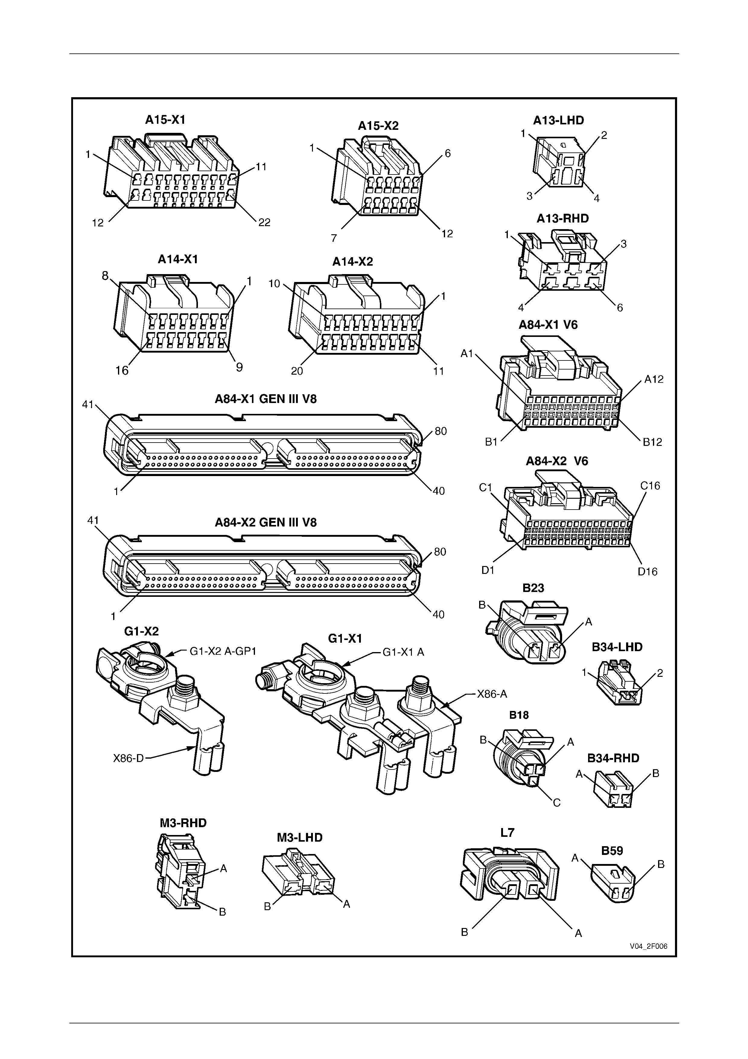
Connectors A13 – M3
Figure 2F – 3
HVAC Occupant Climate Control (Auto A/C) – Diagnostics Page 2F–9
Page 2F-9
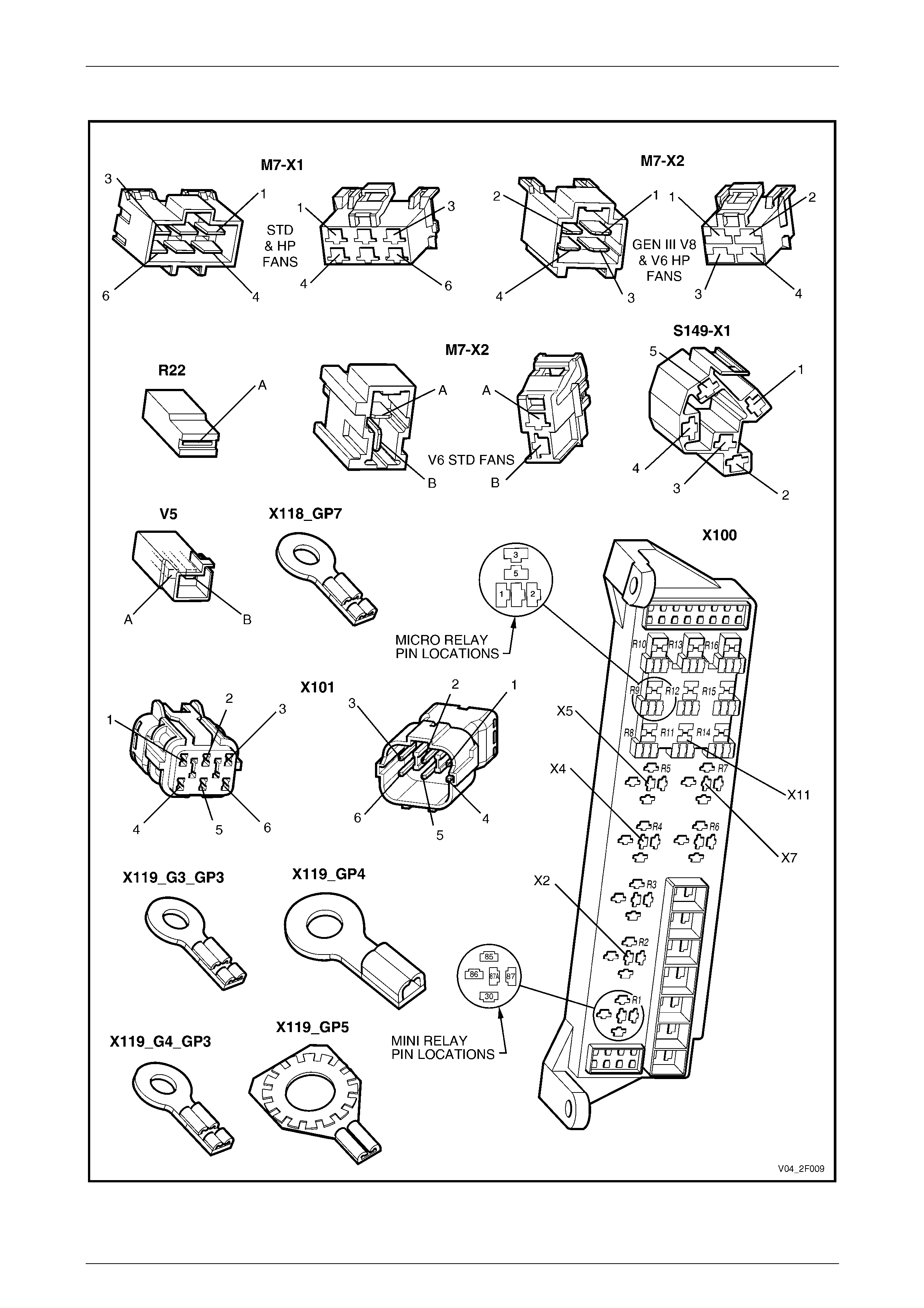
Connectors M7 – X119
Figure 2F – 4
HVAC Occupant Climate Control (Auto A/C) – Diagnostics Page 2F–10
Page 2F-10
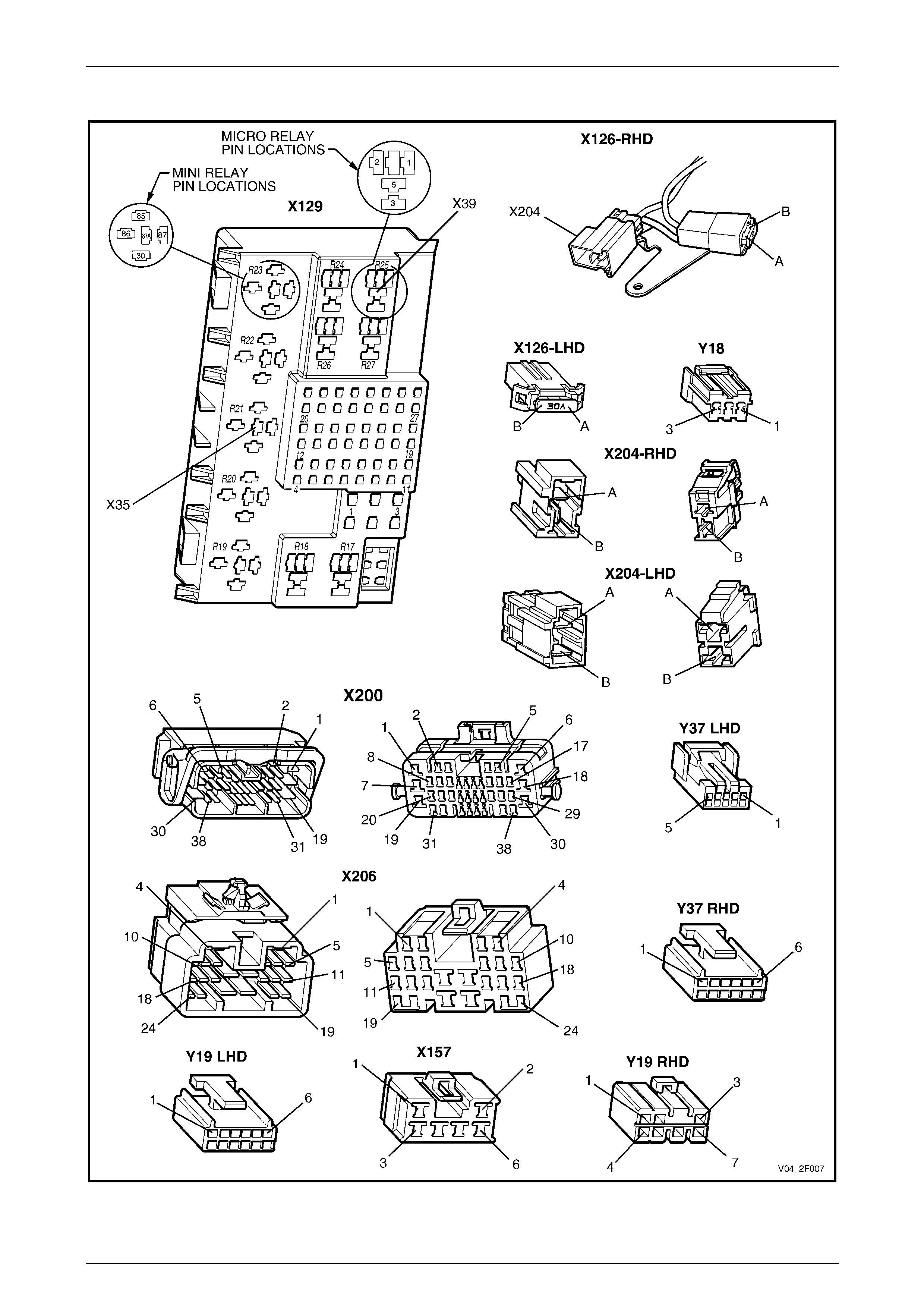
Connectors X126 – Y37
Figure 2F – 5
HVAC Occupant Climate Control (Auto A/C) – Diagnostics Page 2F–11
Page 2F-11
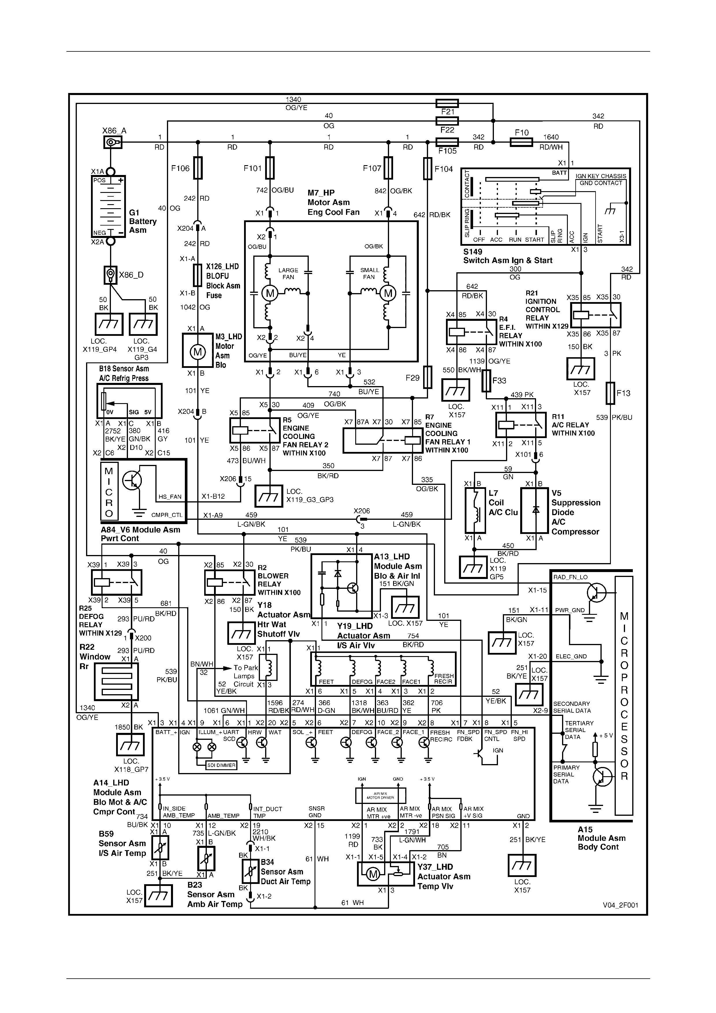
Wiring Diagram: HVAC Occupant Climate Control (Auto A/C) System – V6 (LHD)
Figure 2F – 6
HVAC Occupant Climate Control (Auto A/C) – Diagnostics Page 2F–12
Page 2F-12
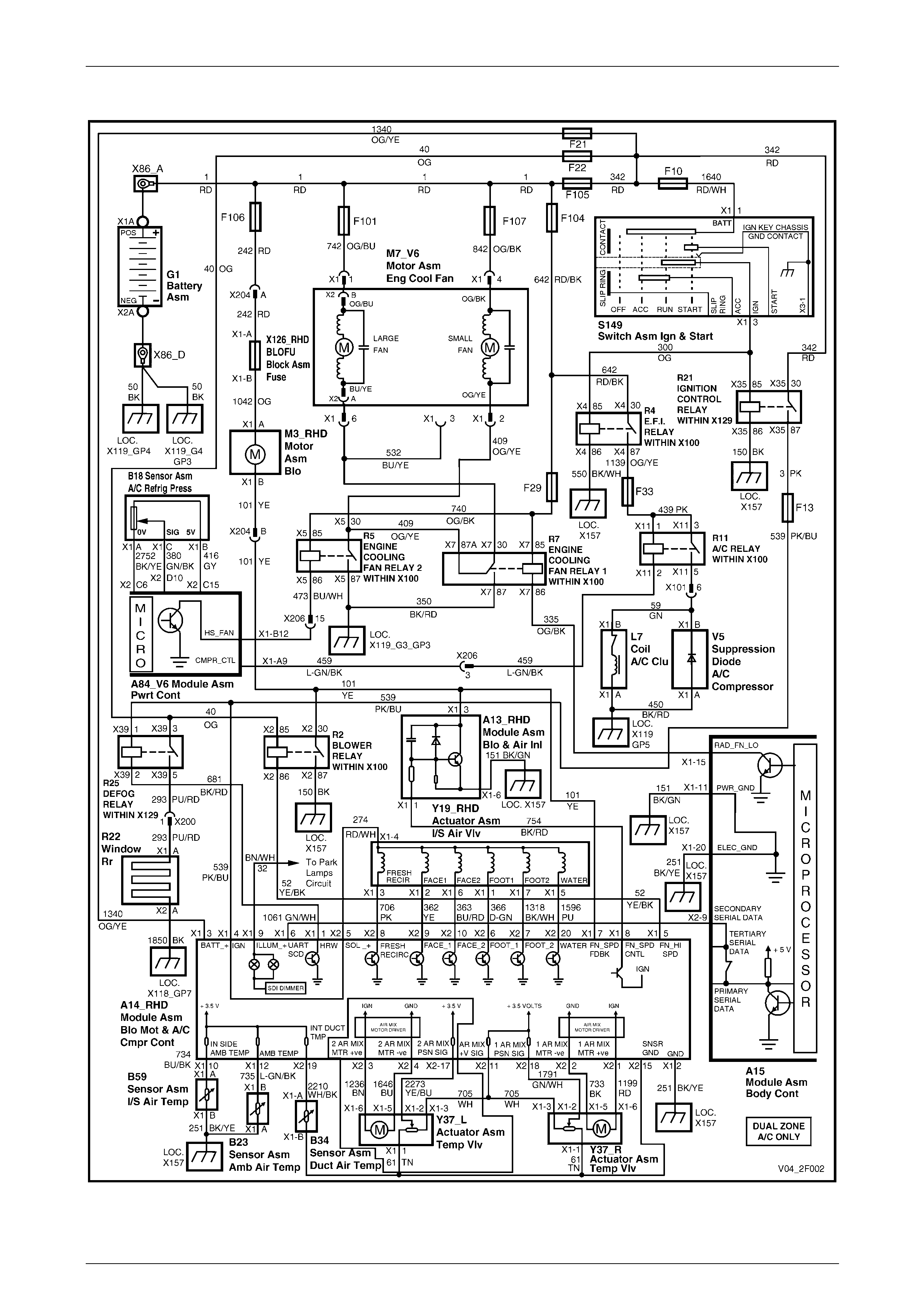
Wiring Diagram: HVAC Occupant Climate Control (Auto A/C) System – V6 (RHD)
Figure 2F – 7
HVAC Occupant Climate Control (Auto A/C) – Diagnostics Page 2F–13
Page 2F-13
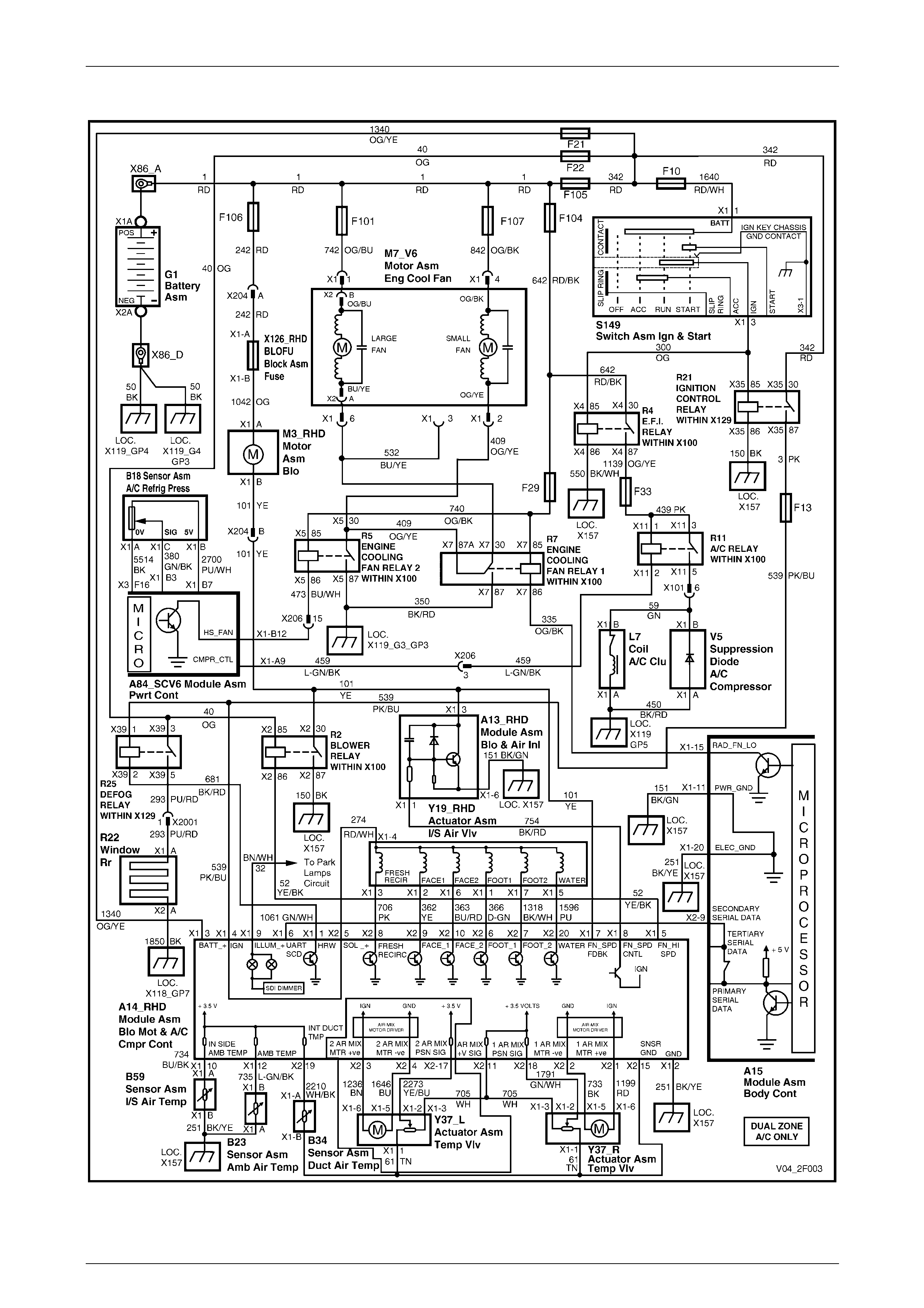
Wiring Diagram: HVAC Occupant Climate Control (Auto A/C) Syste m – SCV6 (RHD)
Figure 2F – 8
HVAC Occupant Climate Control (Auto A/C) – Diagnostics Page 2F–14
Page 2F-14
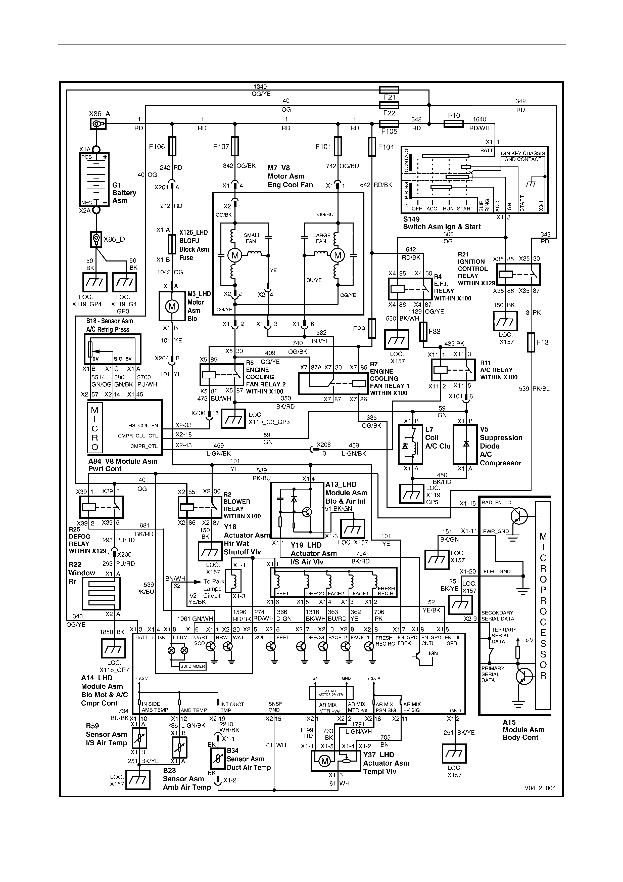
Wiring Diagram: HVAC Occupant Climate Control (Auto A/C) System – Gen III V8 (LHD)
Figure 2F – 9

HVAC Occupant Climate Control (Auto A/C) – Diagnostics Page 2F–15
Page 2F-15
Wiring Diagram: HVAC Occupant Climate Control (Auto A/C) Syste m – Gen III V8 (RHD)
Figure 2F – 10