
Engine Mechanical – GEN III V8 Engine Page 6A3–1
Page 6A3–1
Section 6A3
Engine Mechanical –
GEN III V8 Engine
ATTENTION
Before performing any service operation or other procedure described in this Section, refer to Section 00
Warnings, Cautions and Notes for correct workshop practices w ith regard to safety and/or property damage.
1 General Information............................................................................................................................... 2
1.1 General Description...............................................................................................................................................3
Oil Pan.....................................................................................................................................................................3
Positive Crankcase Ventilation.............................................................................................................................4
Water Pump ............................................................................................................................................................5
Exhaust System......................................................................................................................................................5
2 Service Operation.................................................................................................................................. 6
2.1 Engine Oil Level Check..........................................................................................................................................6
2.2 PCV Oil Separator ..................................................................................................................................................7
Remove ...................................................................................................................................................................7
Clean and Inspect ..................................................................................................................................................7
Reinstall..................................................................................................................................................................8
3 Specifications......................................................................................................................................... 9
4 Torque Wrench Specification............................................................................................................. 10
Techline
Techline
Techline
Techline
Techline
Techline

Engine Mechanical – GEN III V8 Engine Page 6A3–2
Page 6A3–2
1 General Information
With the following exceptions, MY 2004 VY and V2 Series GEN III V8 Engine Mechanical Service Information carries
over from MY 2003 VY Series vehicles. For information not contained within this Section, refer to Section 6A3, Engine
Mechanical – Gen III V8 Engine in the MY 2003 VY and V2 Series Service Information.
• New oil pan.
• New Positive Crankcase Ventilation (PCV) system.
• Revised oil checking procedure.
• New wate r pump.
• New exhaust system.
• Specification Changes:
• New engine oil specification.
• New spark plug specification.
• New piston clearances specification.
Engine Mechanical – GEN III V8 Engine Page 6A3–3
Page 6A3–3
1.1 General Description
Oil Pan
NOTE
The changes in the engine oil pan design do not
affect the oil pan service procedure. Where the
service procedure includes the removal of the oil
pan, refer to Section 6A3, Engine Mechanical –
Gen III V8 Engine in the MY 2003 VY and V2
Series Service Information.
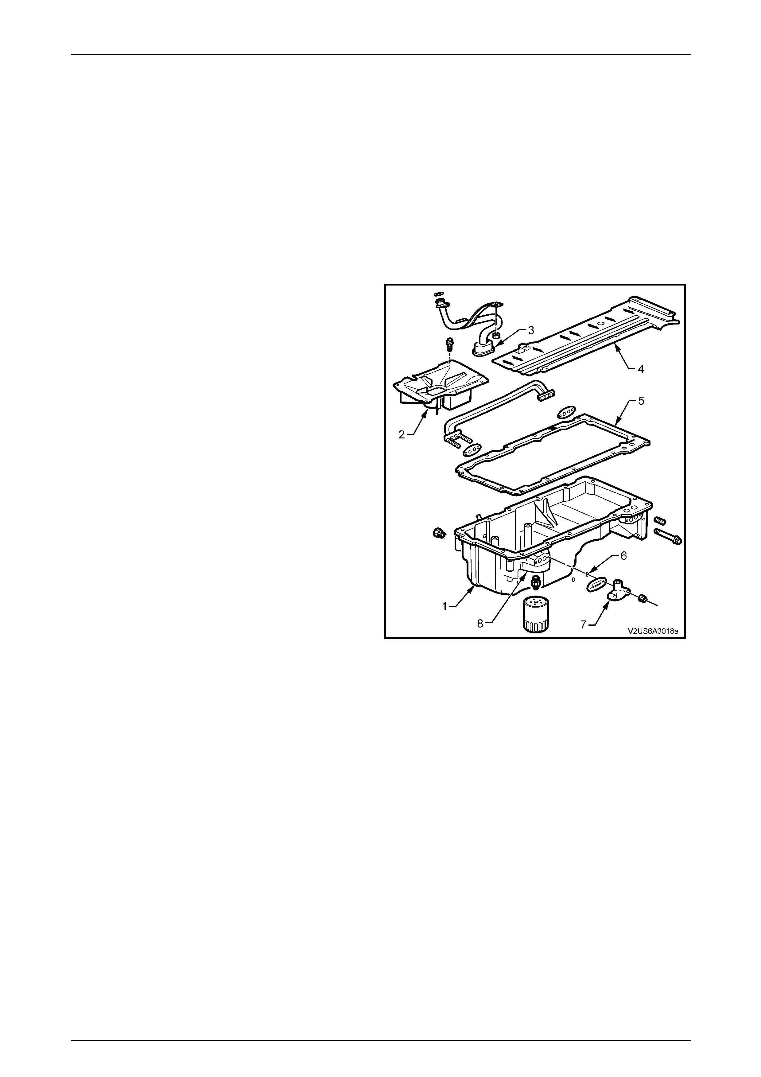
To prevent oil starvation and oil aeration during
acceleration, braking and cornering manoeuvres, the new
engine oil pan (1) and oil pan baffle plate (2) features the
following:
• Dams and return oil ridges are integrated with the oil
pan baffle plate to improve the flow of return oil back
into the oil pump pick-up screen (3) area. This
minimises oil migration during acceleration, braking
and cornering manoeuvres.
• Increased engine oil capacity.
In addition, a crankshaft oil deflector (4) mounted to the
main bearing caps further improves the flow of return oil by:
• Controlling windage.
• Removing return oil from the crankshaft.
• Facilitating the return oil drain back into the oil pan.
• Reducing engine oil aeration.
The oil pan is made from cast aluminium and is an integral
part of the powertrain structure. The oil pan provides a 360°
mounting for the automatic or manual transmission.
The oil pan gasket (5) is a controlled compression
aluminium carrier gasket using silicone material as a
sealing agent.
Two O-ring seals (6) are fitted to the oil transfer cover (7)
studs to prevent oil leak along the studs.
The oil filter mounting boss (8) is incorporated in the oil pan
design.
Figure 7B2 – 1
Engine Mechanical – GEN III V8 Engine Page 6A3–4
Page 6A3–4
Positive Crankcase Ventilation
The engine ventilation system was developed to remove the
engine combustion blow-by vapours and minimise the
following:
• Crankcase pressure build-up
• Oil deterioration
• Oil consumption
• Evaporative/exhaust emissions
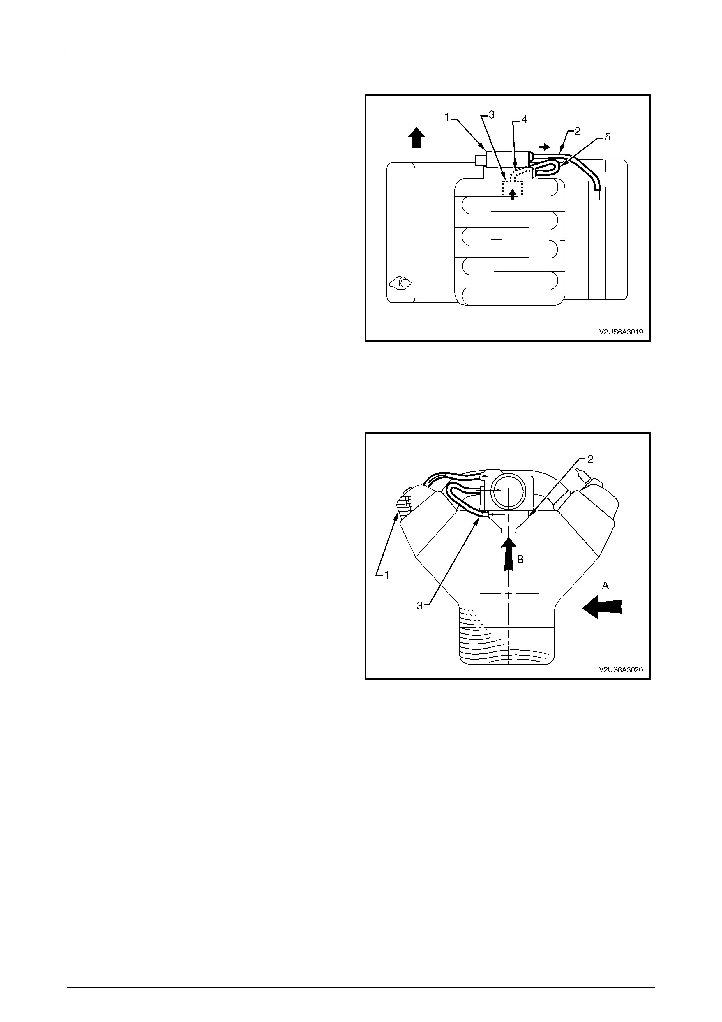
During normal idle and part throttle operation, filtered fresh
air is routed from upstream of the throttle body (1) blade
to the front of the right rocker cover via the fresh air inlet
hose (2).
Blow-by gas (oil vapour) in the crankcase valley passes
through the oil separator (3) and then flows through the
fixed internal flow-restricting orifice (4).
Via the foul air hose (5), the blow-by gas is directed from
the valley cover right-hand corner to the inlet manifold
downstream of the throttle body.
Under heavy load operation and high engine speeds, an
acceptable reverse flow condition may occur in the fresh air
inlet hose.
Figure 7B2 – 2
During sustained maximum lateral acceleration (A), the
outboard rocker cover may be overloaded with oil (1). If the
blow-by gas is drawn from the rocker cover as in previous
design, oil may be ingested into the intake manifold.
The Central Valley Ventilation System is designed to
eliminate oil ingestion during severe vehicle cornering
manoeuvres.
Instead of the blow-by gas being drawn from the rocker
cover, a high efficiency oil separator (2) in conjunction with
an internal flow-restricting orifice (3) is fitted under the
valley cover to draw the blow-by gas from the
crankcase (B).
NOTE
Where a service procedure includes the removal
of a Positive Crankcase (PCV) System
component that is not covered in this Section,
refer to Section 6E3, Emission Control – Gen III
V8 Engine. Figure 7B2 – 3
Engine Mechanical – GEN III V8 Engine Page 6A3–5
Page 6A3–5
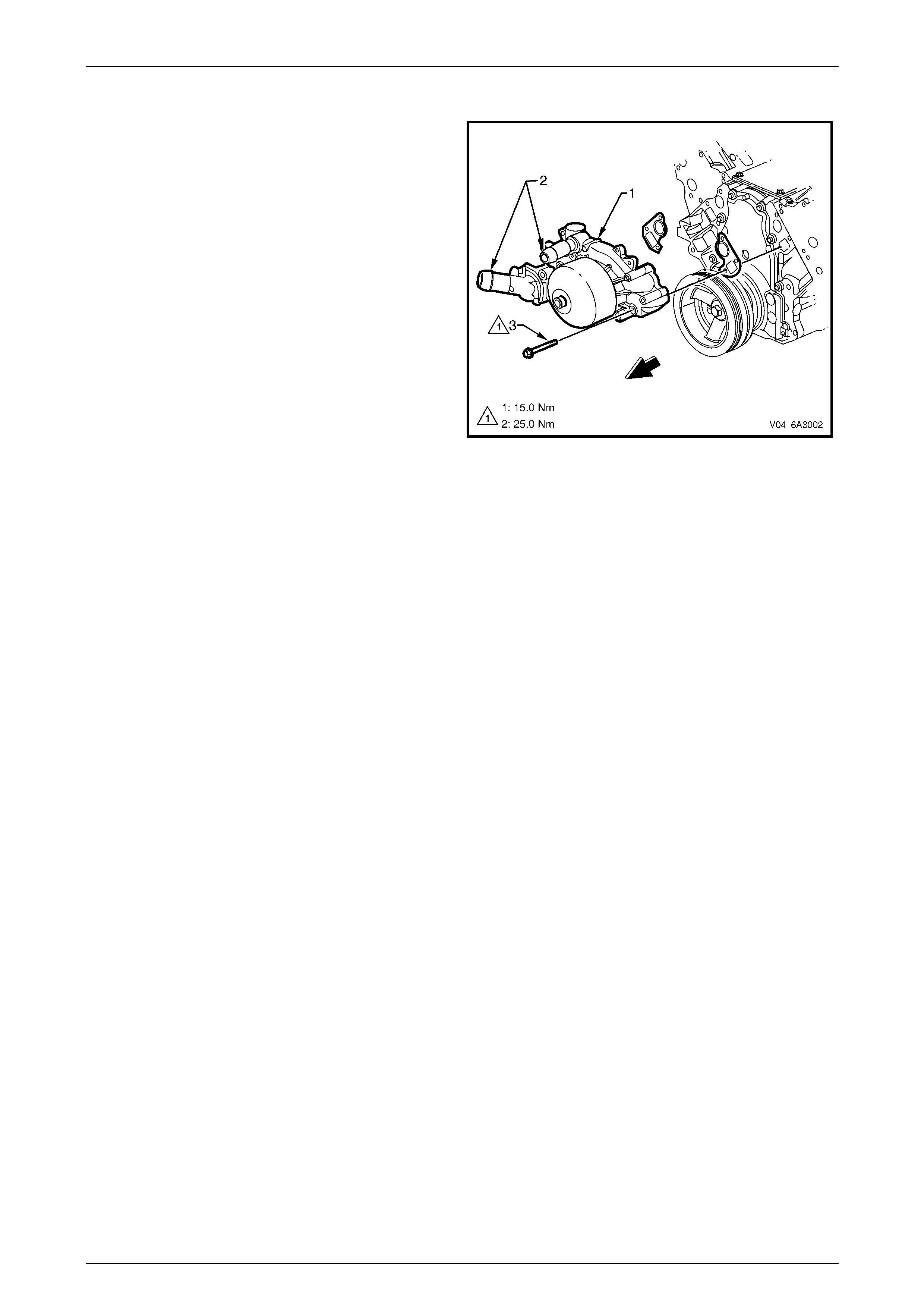
Water Pump
The length of the water pump (1) inlet and outlet tubes (2)
has been extended for easier coolant hose installation and
to improve the coolant rubber hose fit to the water pump.
NOTE
The changes in the water pump design do
not affect the water pump service procedure. For
water pump service procedure, refer to Section
6B3, Engine Cooling – Gen III V8 in the MY
2003 VY and V2 Series Service Information.
Figure 7B2 – 4
Exhaust System
Where a service procedure includes the removal of an exhaust system component, refer to Section 8B, Exhaust
System.
Engine Mechanical – GEN III V8 Engine Page 6A3–6
Page 6A3–6
2 Service Operation
2.1 Engine Oil Level Check
1 The engine must be at normal operating temperature (drive the vehicle for 15 minutes).
2 Park the vehicle on a level surface.
• Do not check the oil level for at least 10
minutes after the engine is switched-off.
This allows time for the oil to drain back
into the oil pan.
• A sloping surface will affect the accuracy
of the measurement.
3 Remove the dipstick and wipe clean.
4 Reinstall the dipstick. Ensure that it is fully seated. Leave for several seconds and remove slowly to avoid
smearing the oil (level); then hold the dipstick horizontally to prevent the oil (level) moving along the dipstick.
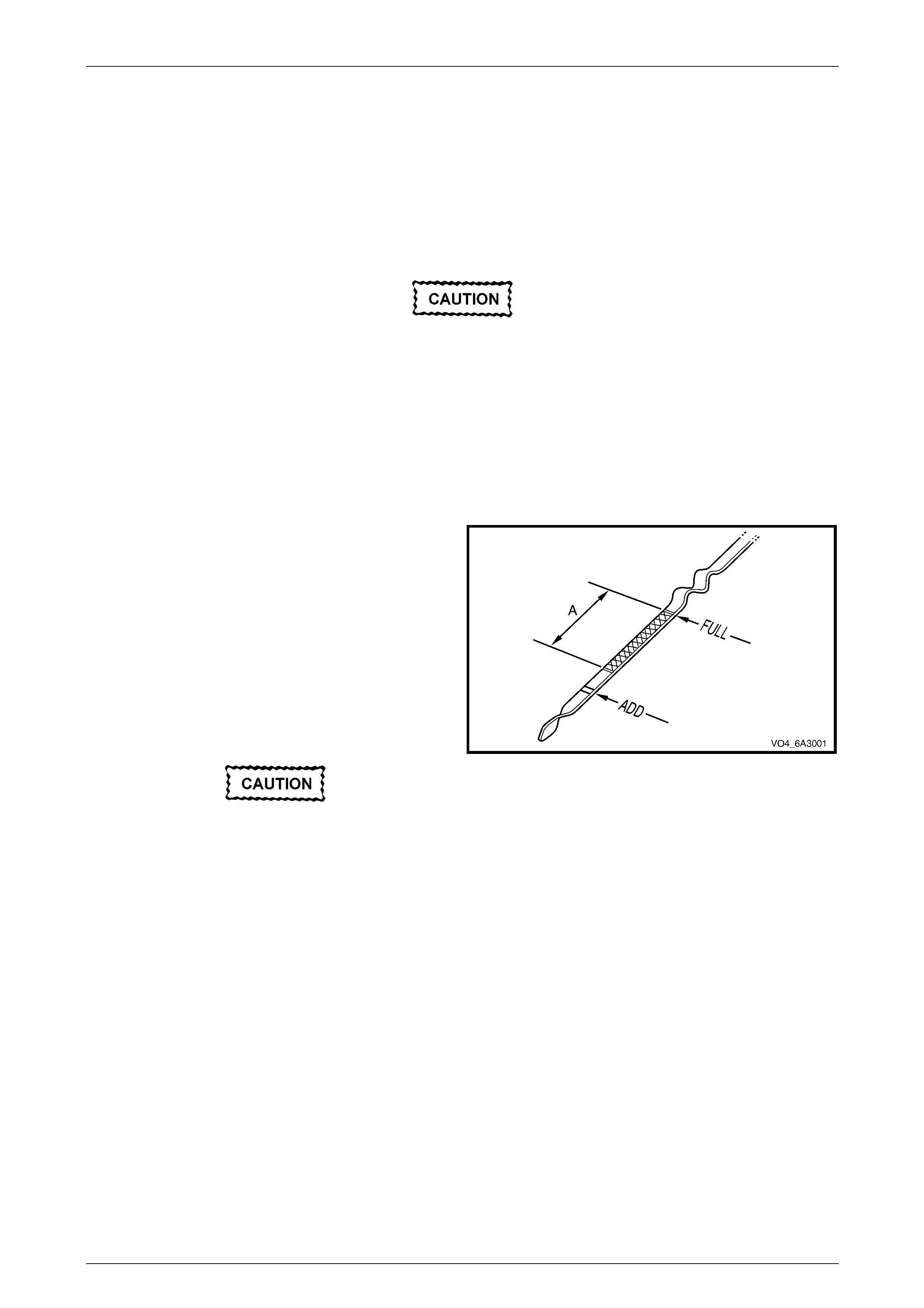
5 Observe the oil level where it passes over the centre
line of the dipstick.
NOTE
As an easy guide for how much oil to add, the
crosshatch area (A) represents 1-litre of oil and
the ADD mark represents 1.6 litres of oil is
required.
6 If the level is lower than, or close to the ADD mark,
top-up the engine with enough oil to reach the FULL
mark.
Do not fill over the FULL mark.
7 Allow several minutes for the added oil to drain down
into the oil pan then recheck the oil level.
Figure 7B2 – 5
Engine Mechanical – GEN III V8 Engine Page 6A3–7
Page 6A3–7
2.2 PCV Oil Separator
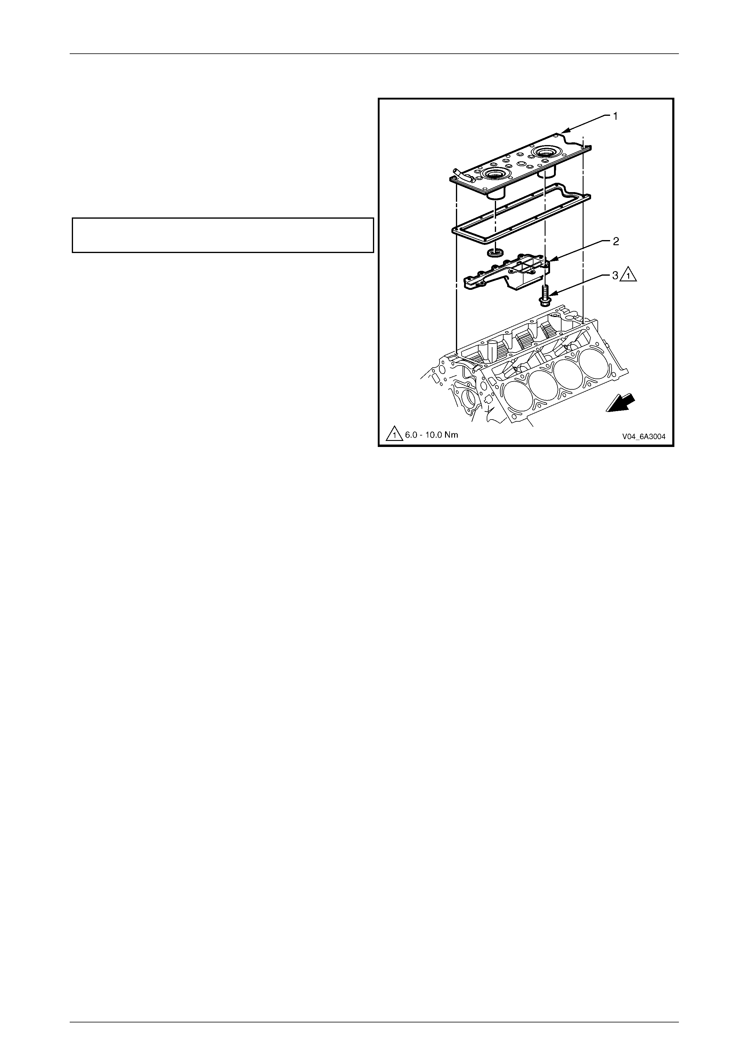
Remove
1 Remove the engine valley cover (1). Refer to Section
6A3, Engine Mechanical – Gen III V8 Engine in the
MY 2003 VY and V2 Series Service Information.
2 Remove the bolt (2) attaching the PCV oil separator
(3) to the engine valley cover.
3 Remove the PCV oil separator from the engine valley
cover.
Figure 7B2 – 6
Clean and Inspect
1 Thoroughly wash all components in a suitable
cleaning solvent.
2 Ensure that the fixed internal flow-restricting orifice (1)
is not blocked.
3 Ensure that the engine valley cover (2) to PCV oil
separator (3) mating surfaces are free of burrs and
traces of old sealant.
4 Inspect the PCV oil separator for cracks or defects.
Wear safety glasses w hen using compressed
air to avoid eye injury.
5 Blow-dry all components using compressed air.
Figure 7B2 – 7
Engine Mechanical – GEN III V8 Engine Page 6A3–8
Page 6A3–8
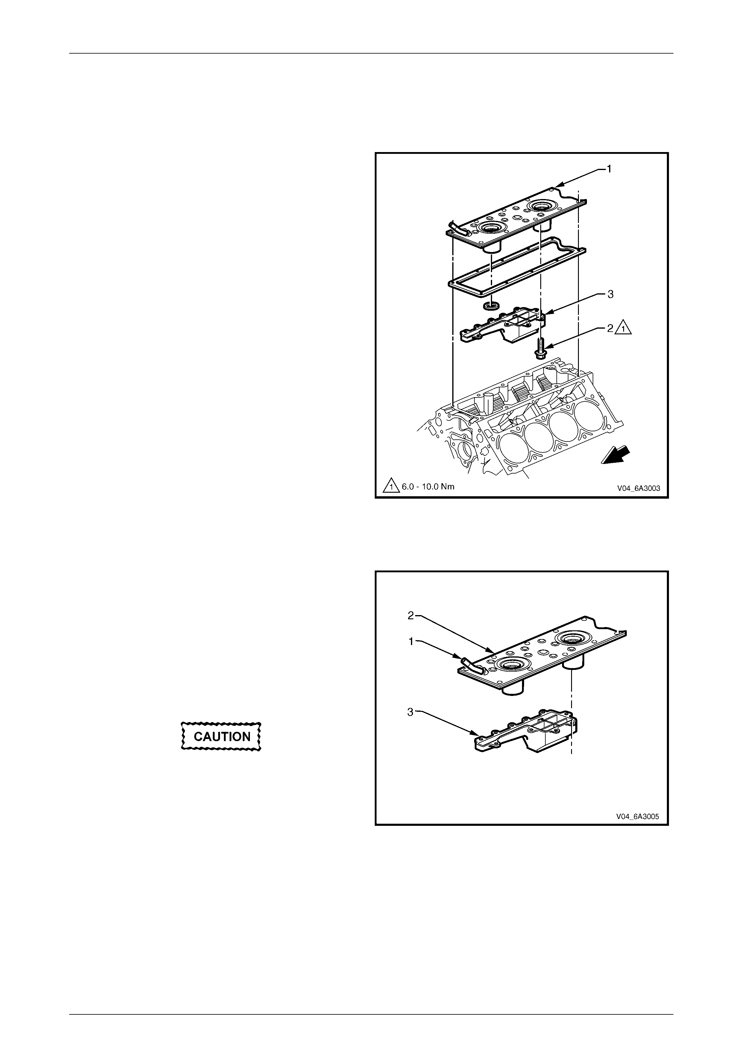
Reinstall
1 Apply sealant to the engine valley cover (1) to PCV oil
separator (2) mating surfaces.
2 Reinstall the PCV oil separator to the engine valley
cover.
3 Reinstall the bolt (3) attaching the PCV oil separator
to the engine valley cover and tighten to the correct
torque specification.
PCV oil separator attaching bolt
torque specification..................................6.0 – 10.0 Nm
4 Reinstall the engine valley cover. Refer to Section
6A3, Engine Mechanical – Gen III V8 Engine in the
MY 2003 VY and V2 Series Service Information.
Figure 7B2 – 8

Engine Mechanical – GEN III V8 Engine Page 6A3–9
Page 6A3–9
3 Specifications
Spark Plug
Type..............................................................................................................AC Delco 41-985
Gap.......................................................................................................1.02 +0.08 / -0.07 mm
Lubrication System
Oil Capacity (without Oil Filter Change)......................................................................5.7 litres
Oil Capacity (with Oil Filter Change)...........................................................................6.2 litres
Dry Engine Oil Capacity..............................................................................................6.5 litres
Oil Pressure (Minimum-Hot) ................................................................... 45 kPa @ 1,000 rpm
.............................................................................................................. 125 kPa @ 2,000 rpm
.............................................................................................................. 165 kPa @ 4,000 rpm
Oil Type.........................................................................................................10W - 30 SJ GF2
Piston
Piston Outside Diameter (at Size Point & incl. coating)...........................98.995 - 99.027 mm
Piston Skirt Dimensional Variation.........................................................0.032 mm (Maximum)
Piston to Bore Clearance (Service Limit)
Interference.............................................................................................................. 0.027 mm
Clearance ................................................................................................................ 0.023 mm
Piston Pin
Pin Clearance to Piston Bore (Service Limit)............................ 0.008 - 0.016 mm (Maximum)
Pin Diameter................................................................................................23.997 - 24.0 mm
Pin Fit in Connecting Rod......................................................0.020 - 0.043 mm (Interference)

Engine Mechanical – GEN III V8 Engine Page 6A3–10
Page 6A3–10
4 Torque Wrench Specification
PCV oil separator attaching bolt..................................................6.0 – 10.0 Nm