
Engine Cooling – Gen III V8 Engine Page 6B3–1
Page 6B3–1
Section 6B3
Engine Cooling – Gen III V8 Engine
ATTENTION
Before performing any service operation or other procedure described in this Section, refer to Section 00
Warnings, Cautions and Notes for correct workshop practices with regard to safety and/or property damage.
1 General Information............................................................................................................................... 2
1.1 General Description...............................................................................................................................................2
Water Pump ............................................................................................................................................................2
Thermostat..............................................................................................................................................................3
Engine Cooling – Gen III V8 Engine Page 6B3–2
Page 6B3–2
1 General Information
With the following exceptions, MY 2004 VY and V2 Series GEN III V8 Engine Cooling System Service Information
carries over from MY 2003 VY Series vehicles. For information not contained within this Section, refer to Section 6B3,
Engine Cooling – Gen III V8 Engine in the MY 2003 VY and V2 Series Service Information.
• New water pump
• New thermostat
1.1 General Description
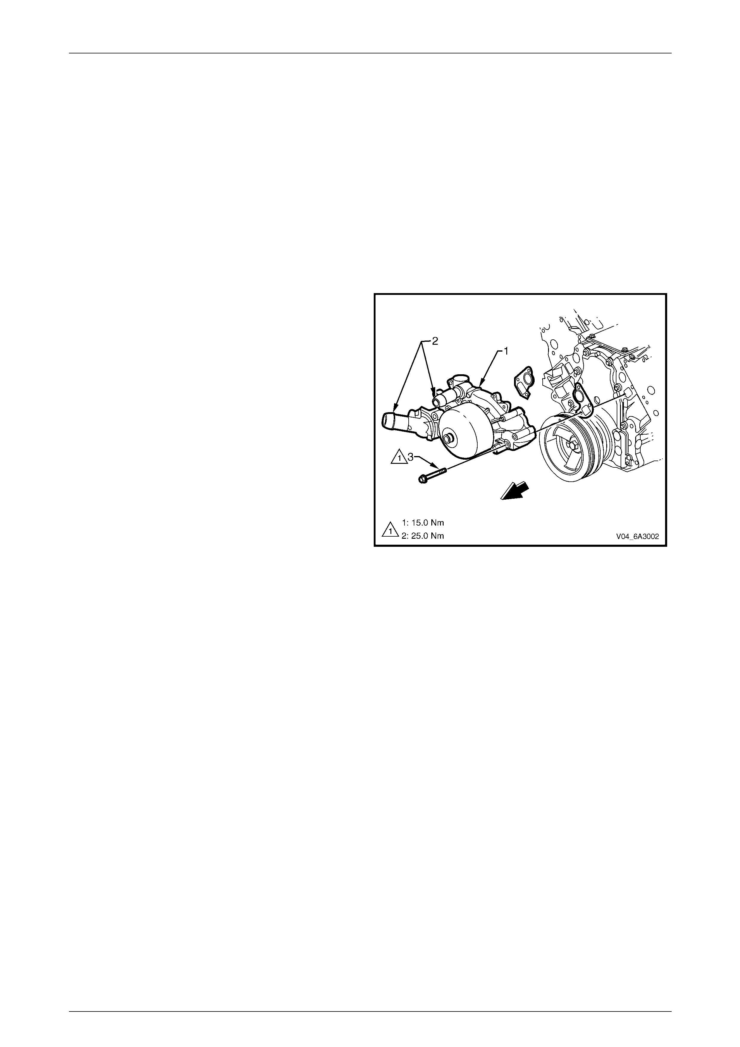
Water Pump
The length of the water pump (1) inlet and outlet tubes (2)
has been extended for easier coolant hose installation and
to improve the coolant rubber hose fit to the water pump.
NOTE
The changes in the water pump design do
not affect the water pump service procedure.
For water pump service procedure, refer to
Section 6B3, Engine Cooling – Gen III V8 in the
MY 2003 VY and V2 Series Service Information.
Figure 6B3 – 1
Engine Cooling – Gen III V8 Engine Page 6B3–3
Page 6B3–3
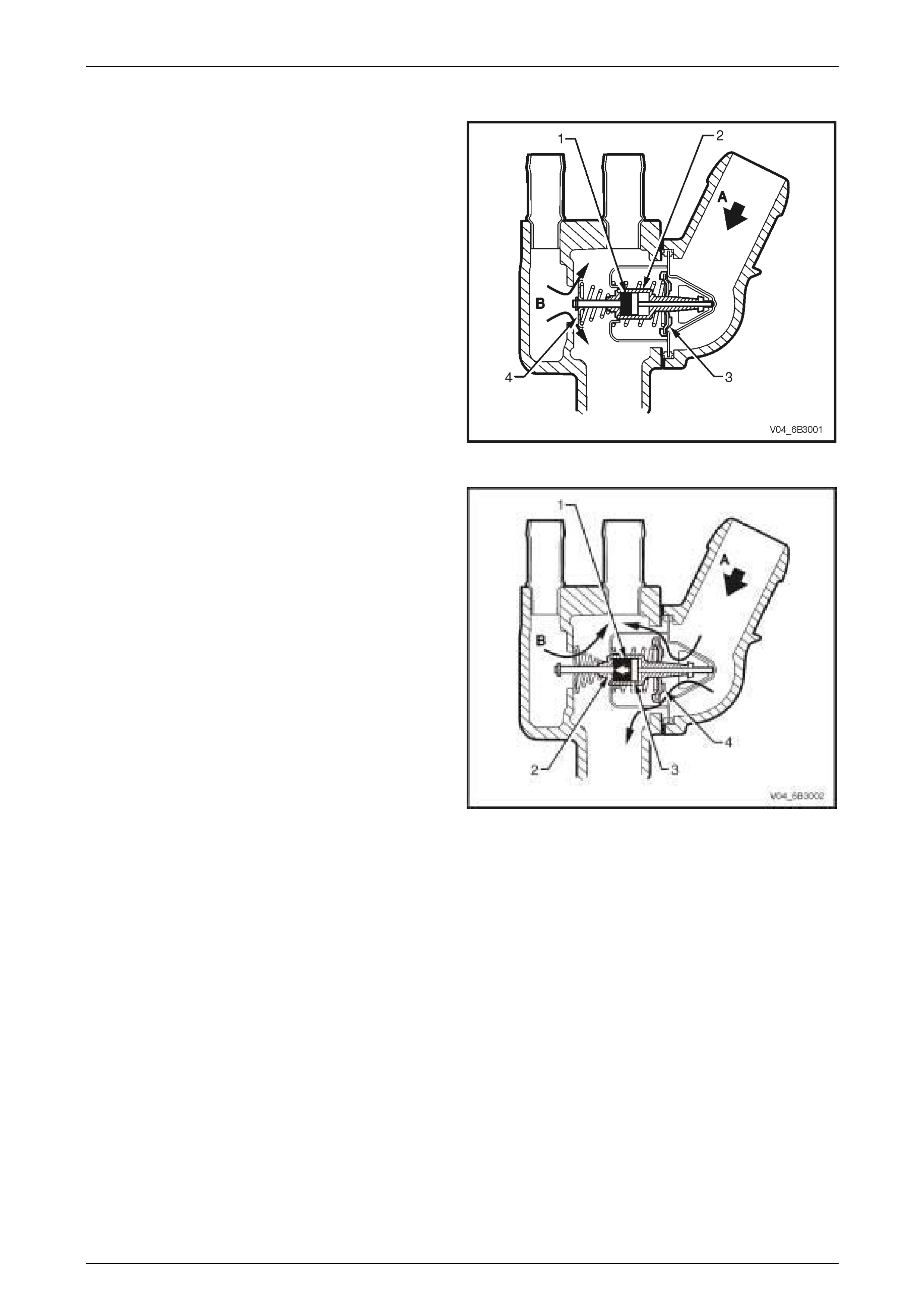
Thermostat
A wax pellet type thermostat is used to provide fast engine
warm up and to regulate the coolant temperature by
controlling the coolant flow.
The wax pellet (1) located in the thermostat brass body (2)
expands when heated and contracts when cooled.
When the engine coolant is cold, the flow control valve (3)
prevents coolant flow (A) from the radiator to the engine.
With the wax pellet contracted, the bypass valve (4) is held
open and allows coolant (B) circulating within the engine to
flow over the thermostat assembly.
The coolant flow over the thermostat assembly heats-up the
wax pellet at the same rate as the temperature increase in
the engine.
Figure 6B3 – 2
When the coolant warms up, the wax pellet (1) expands
pushing the thermostat brass body base (2) against the
piston and pin (3) causing the brass body to move within
the thermostat assembly.
As the thermostat brass body moves back, the flow control
valve (4) attached to the thermostat brass body moves with
it and allows the coolant from the radiator (A) to flow into
the engine. At the same time, the bypass valve begins to
close.
When the bypass valve is closed, a reduced flow of coolant
will continue to bypass via large crescent shaped bleed
holes located on the bypass valve. This prevents hydraulic
lock of the heater system and allows some engine bypass
coolant (B) to flow over the thermostat assembly.
The rate that the control valve opens is balanced between
the force exerted by the expanding wax, and the combining
force exerted by the bypass valve spring and the flow
control spring.
This controlled coolant flow during cold start and initial
warming of the engine provides a controlled warming cycle
necessary to control exhaust emissions during the critical
warm-up period.
NOTE
The changes in the thermostat design do not
affect the thermostat principle of operation and
service procedure. For water pump service
procedure, refer to Section 6B3, Engine Cooling
– Gen III V8 in the MY 2003 VY and V2 Series
Service Information.
Figure 6B3 – 3