
Powertrain Management - V6 Engine Page 6C1–1
Page 6C1–1
Section 6C1
Powertrain Management – V6 Engine
ATTENTION
Before performing any Service Operation or other procedure described in this Section, refer to Section 00
Cautions And Notes for correct workshop practices with regard to safety and/or property damage.
1 General Information............................................................................................................................... 3
1.1 Euro II Emission Standard.....................................................................................................................................3
1.2 Wiring Diagrams.....................................................................................................................................................4
Vehicles That Are Not Euro II Compliant............................................................................................................12
Vehicles That Comply With Euro II Standards...................................................................................................13
Vehicles With A High Pow e r Fan Pack...............................................................................................................14
Vehicles With A Standard Fan Pack ...................................................................................................................15
1.3 Clutch Pedal Calibration Switch .........................................................................................................................16
2 Diagnosis.............................................................................................................................................. 17
2.1 Euro II Emission Standards.................................................................................................................................17
2.2 Wiring Diagrams...................................................................................................................................................18
Vehicles That Are Not Euro II Compliant............................................................................................................26
Vehicles That Comply With Euro II Standards...................................................................................................27
Vehicles With A High Pow e r Fan Pack...............................................................................................................28
Vehicles With A Standard Fan Pack ...................................................................................................................29
2.3 Clutch Pedal Calibration Switch .........................................................................................................................30
Introduction ..........................................................................................................................................................30
Circuit Description...............................................................................................................................................30
Test Description...................................................................................................................................................30
Notes on the Diagnostic Chart............................................................................................................................31
3 Diagnostic Tables................................................................................................................................ 32
3.1 Euro II Emission Controls....................................................................................................................................32
3.2 Wiring Diagrams...................................................................................................................................................33
Vehicles That Are Not Euro II Compliant............................................................................................................41
Vehicles That Comply With Euro II Standards...................................................................................................42
Vehicles With A High Pow e r Fan Pack...............................................................................................................43
Vehicles With A Standard Fan Pack ...................................................................................................................44
4 Symptoms............................................................................................................................................. 45
4.1 Euro II Emission Controls....................................................................................................................................45
5 Functional Checks............................................................................................................................... 46
5.1 Euro II Emission Standard...................................................................................................................................46
5.2 Wiring Diagrams...................................................................................................................................................47
Vehicles That Are Not Euro II Compliant............................................................................................................55
Vehicles That Comply With Euro II Standards...................................................................................................56
Vehicles With A High Pow e r Fan Pack...............................................................................................................57
Vehicles With A Standard Fan Pack ...................................................................................................................58
6 Service Operations.............................................................................................................................. 59
6.1 Euro II Emission Standard...................................................................................................................................59
Techline

Powertrain Management - V6 Engine Page 6C1–2
Page 6C1–2
6.2 Clutch Pedal Calibration Switch .........................................................................................................................60
Remove .................................................................................................................................................................60
Test........................................................................................................................................................................60
Reinstall ................................................................................................................................................................60
7 Specifications....................................................................................................................................... 61
8 Torque Wrench Specifications........................................................................................................... 62
9 Special Tools........................................................................................................................................ 63

Powertrain Management - V6 Engine Page 6C1–3
Page 6C1–3
1 General Information
With the following exceptions, MY 2004 VY and V2 V6 engine powertrain management system General Information
carries over from MY 2003 VY and V2 Series vehicles and MY 2004 WK Series vehicles. For info rmation not contained
in this Section, refer to:
• Section 6C1-1 – General Information – V6 Engine in the MY 2003 VY and V2 Series Service Information, and
• Section 6C1 Powertrain Management – V6 Engine in the MY 2004 WK Series Service Information.
1.1 Euro II Emission Standard
MY 2004 VY and V2 Series vehicles must meet Euro II emission standards by January 2004. MY 2004 WK Series
vehicles already comply with Euro II standards. For further information on Euro II emission standards refer to
Section 6E1 Emission Control and Section 8B Exhaust System.
• For all MY 2004 VY and V2 Series vehicles produced for the domestic market that are built before 01 Jan 04, refer
to Section 6C1-1 – General Information – V6 Engine in the MY 2003 VY and V2 Series Service Information.
NOTE
Refer to the relevant MY 2004 VY and V2 Series
Section for all external references contained in
the MY 2003 VY and V2 Series, Section 6C1
Powertrain Management. This is to verify that
there are no differences in the MY 2004 VY and
V2 Series Service information that will effect the
service procedures referred from the MY 2003
VY and V2 Service information.
• For all MY 2004 VY and V2 Series vehicles produced for the domestic market that are built after 01 Jan 04, refer to
Section 6C1 Powertrain Management – V6 Engine in the MY 2004 WK Series Service Information.
NOTE
Refer to the relevant MY 2004 VY and V2 Series
Section for all external references contained in
the MY 2004 W K Series, Section 6C1 Powertrain
Management. This is to verify that there are no
differences in the MY 2004 VY and V2 Series
Service information that will effect the service
procedures referred from the MY 2004 WK
Service information.
• For all MY 2004 VY and V2 Series vehicles produced for the Gulf States and Thailand, refer to
Section 6C1 Powertrain Management – V6 Engine in the MY 2004 WK Series Service Information.
NOTE
Refer to the relevant MY 2004 VY and V2 Series
Section for all external references contained in
the MY 2004 W K Series, Section 6C1 Powertrain
Management. This is to verify that there are no
differences in the MY 2004 VY and V2 Series
Service information that will effect the service
procedures referred from the MY 2004 WK
Service information.

Powertrain Management - V6 Engine Page 6C1–4
Page 6C1–4
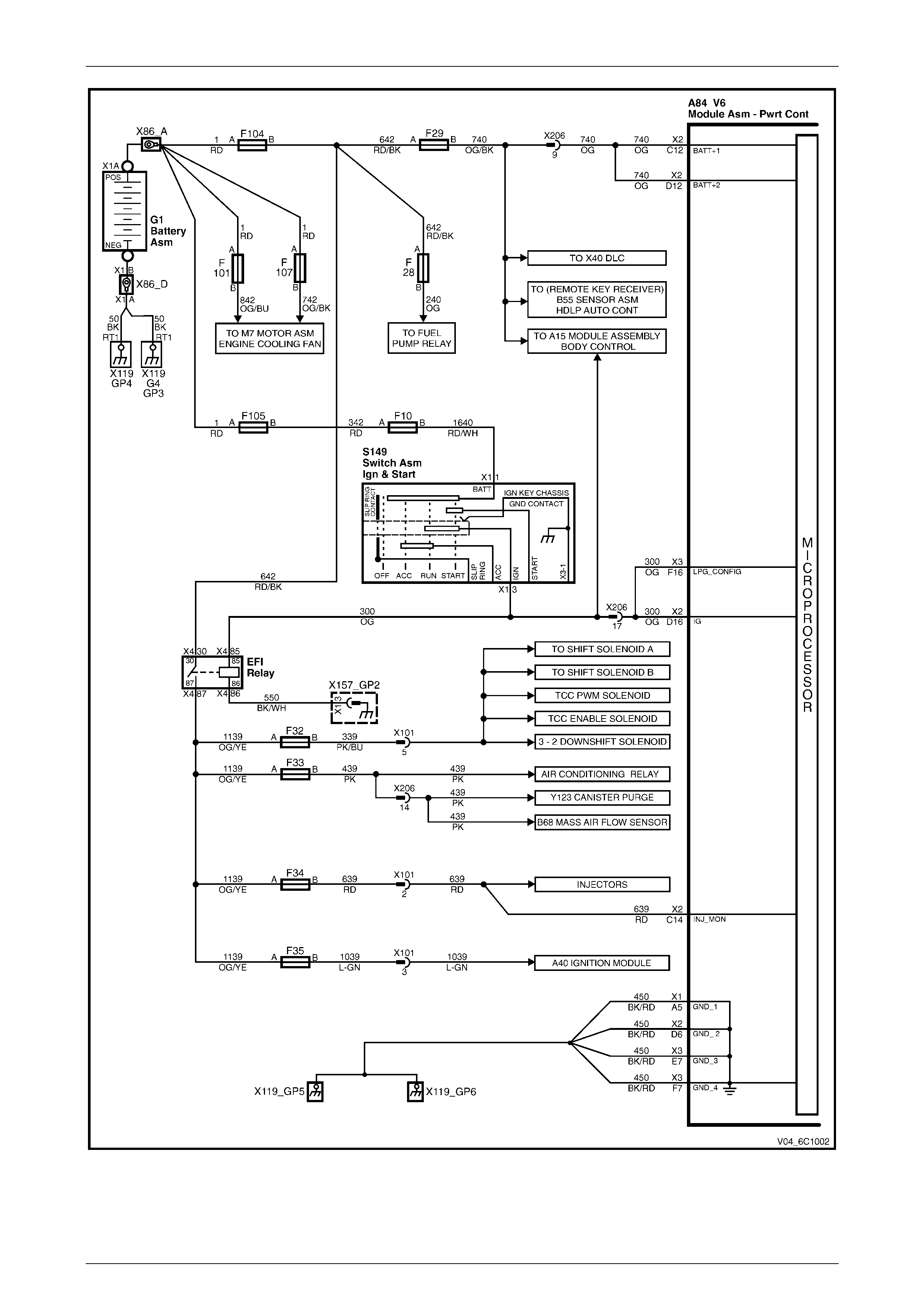
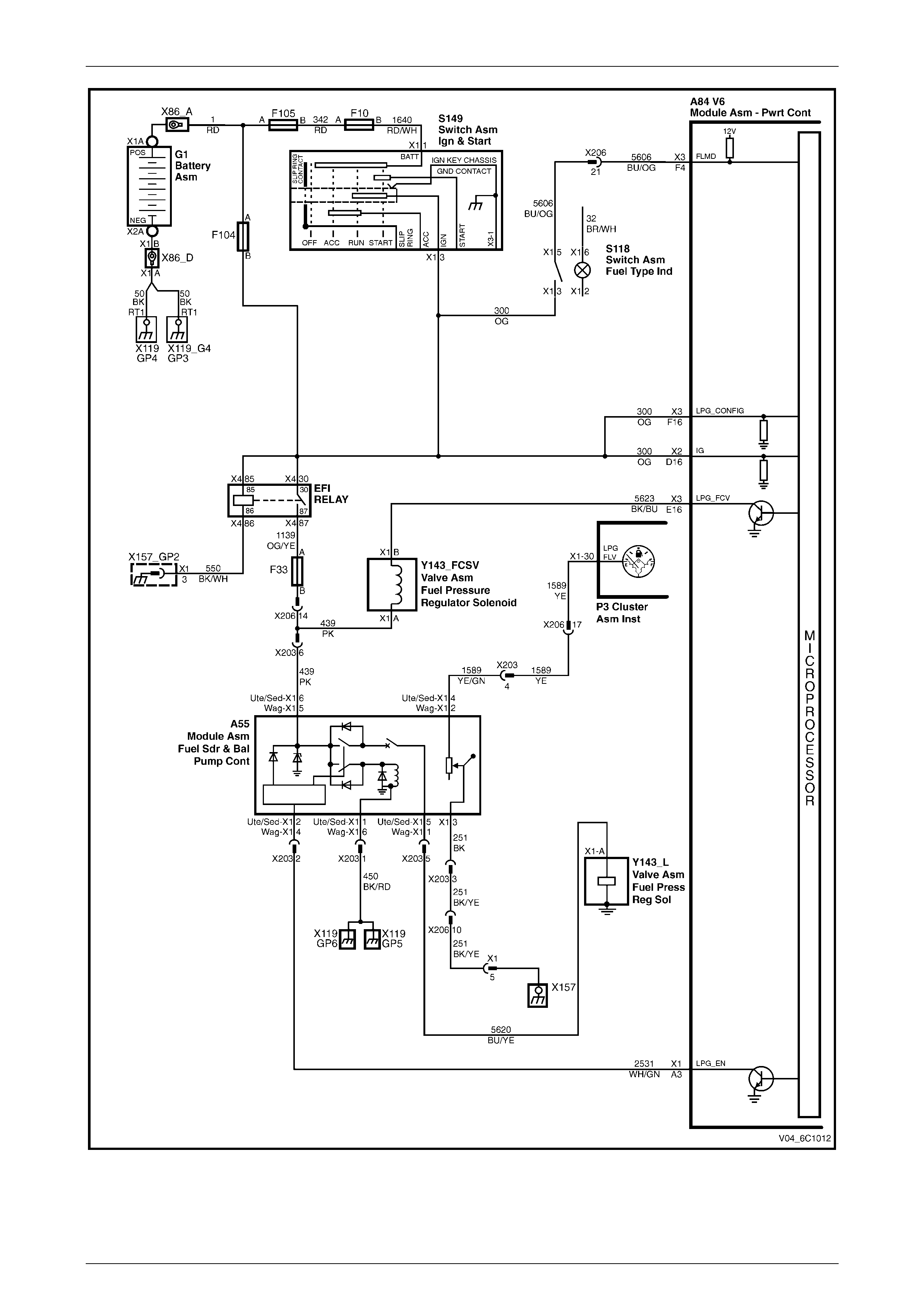
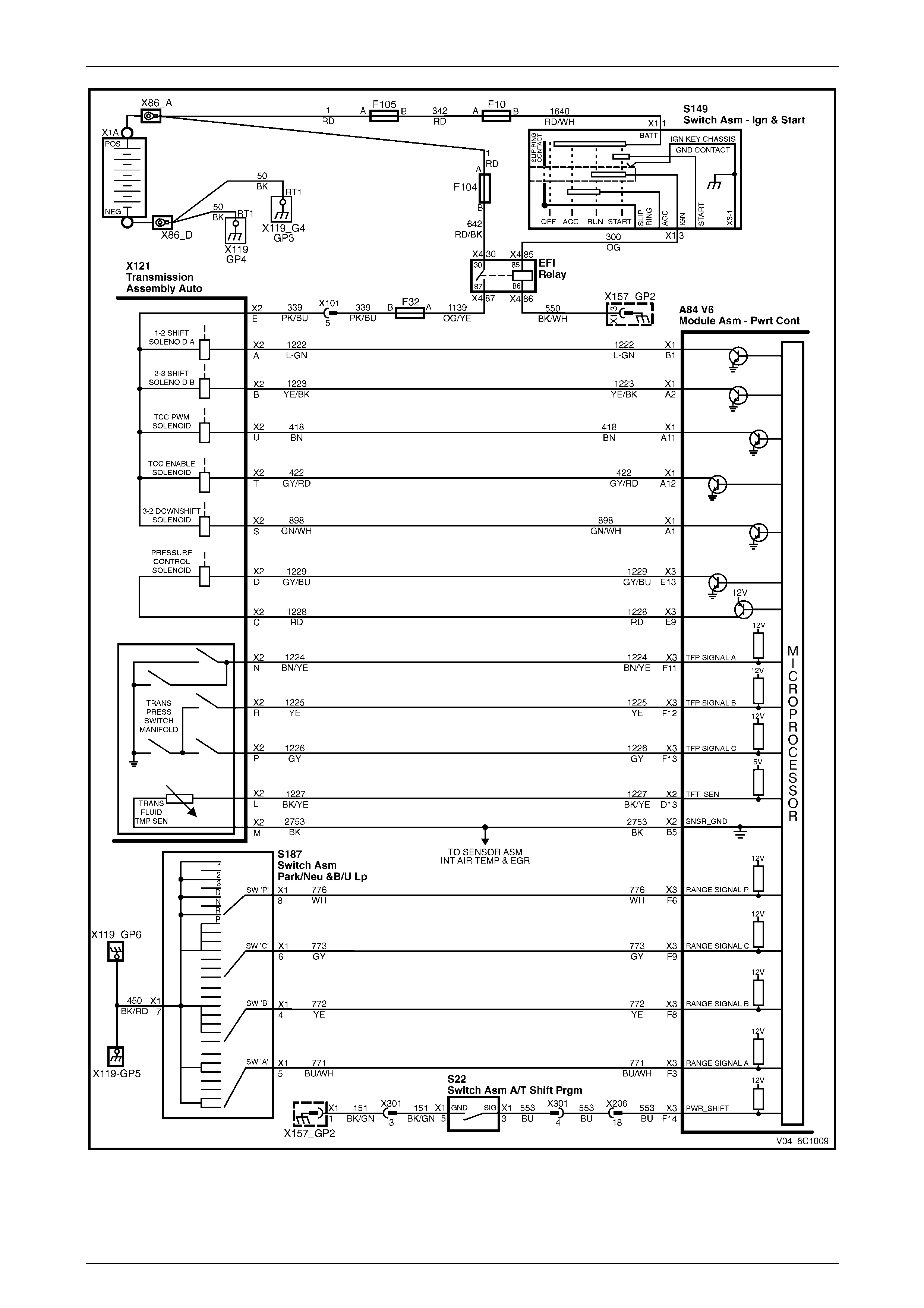
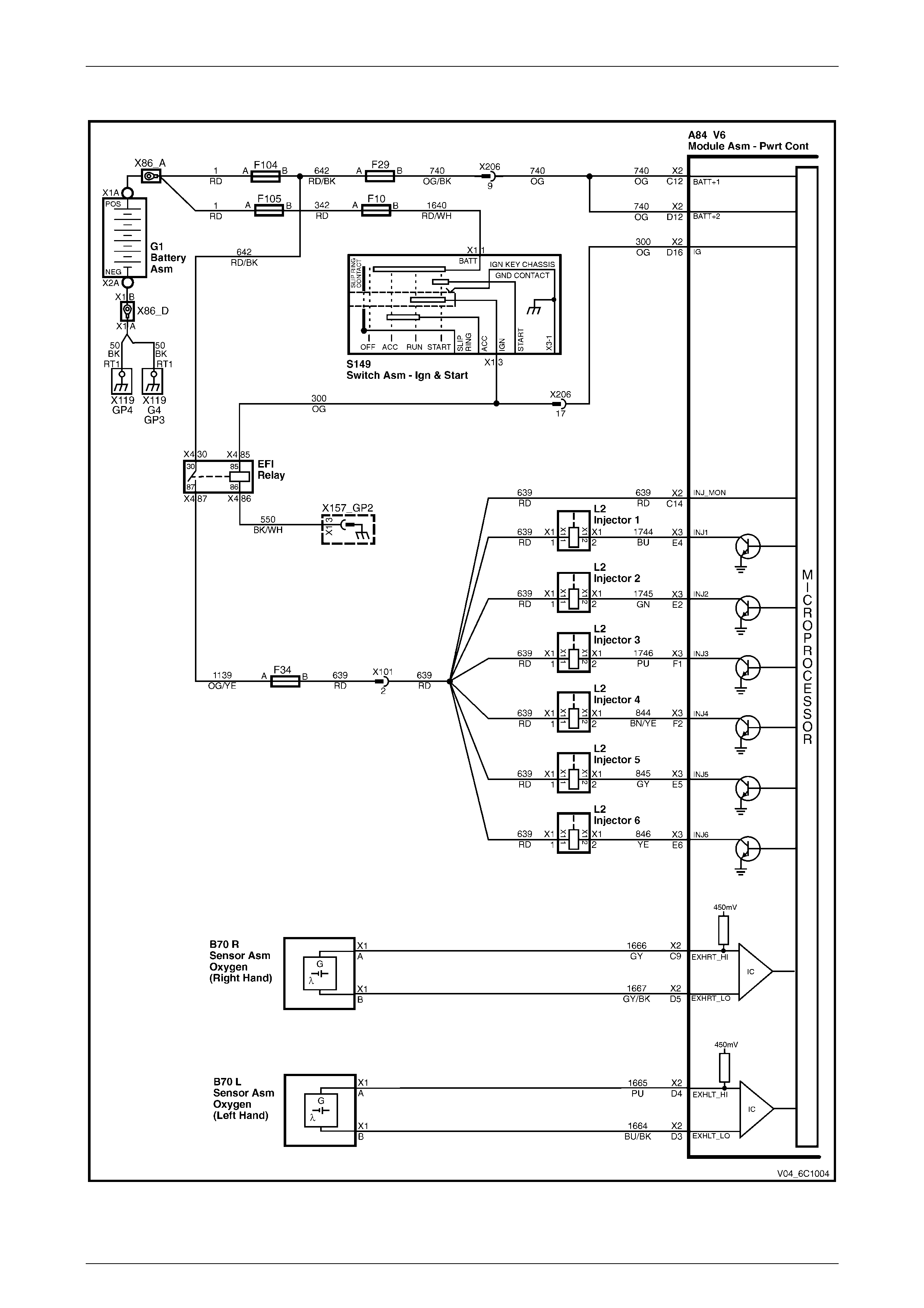
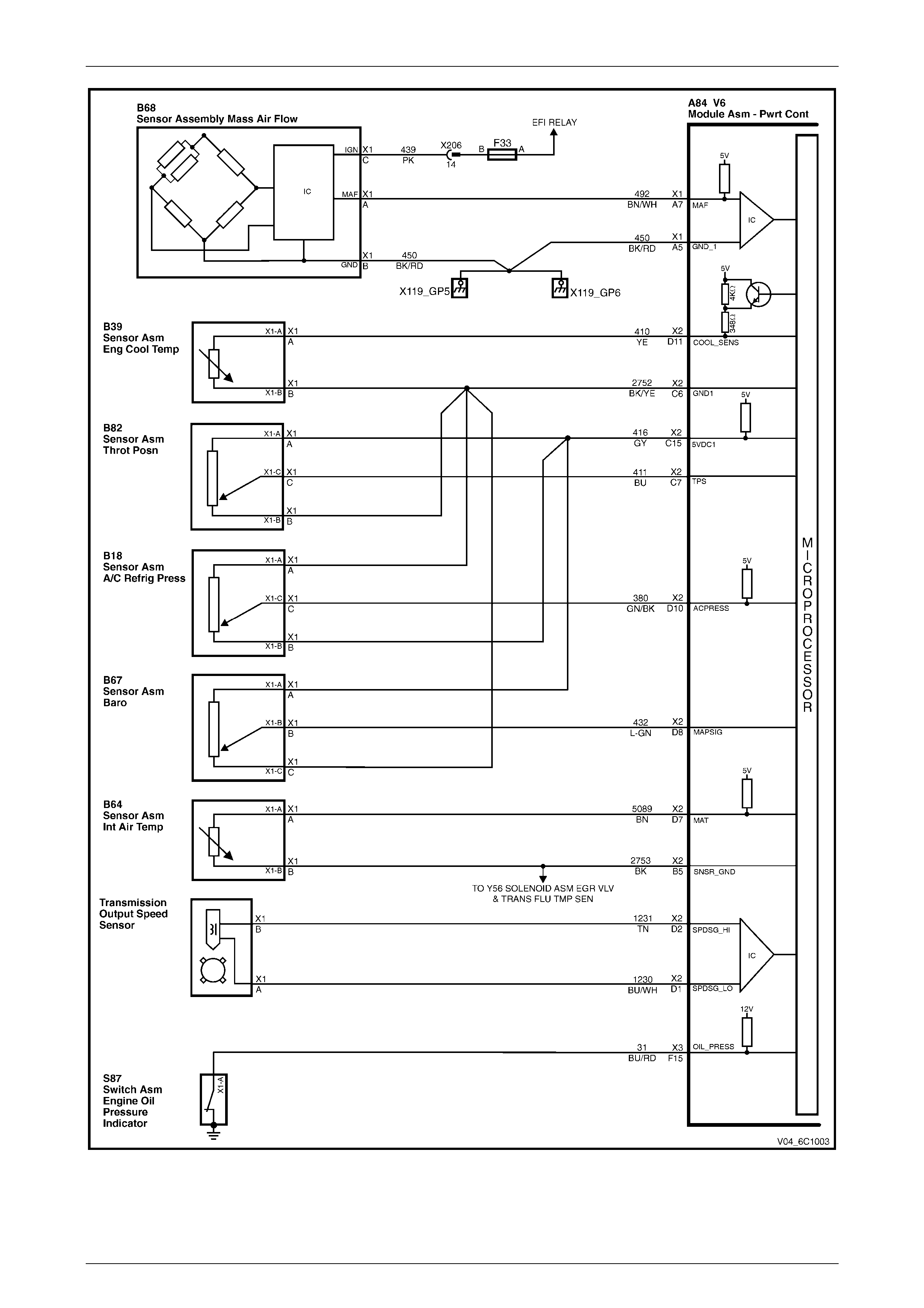
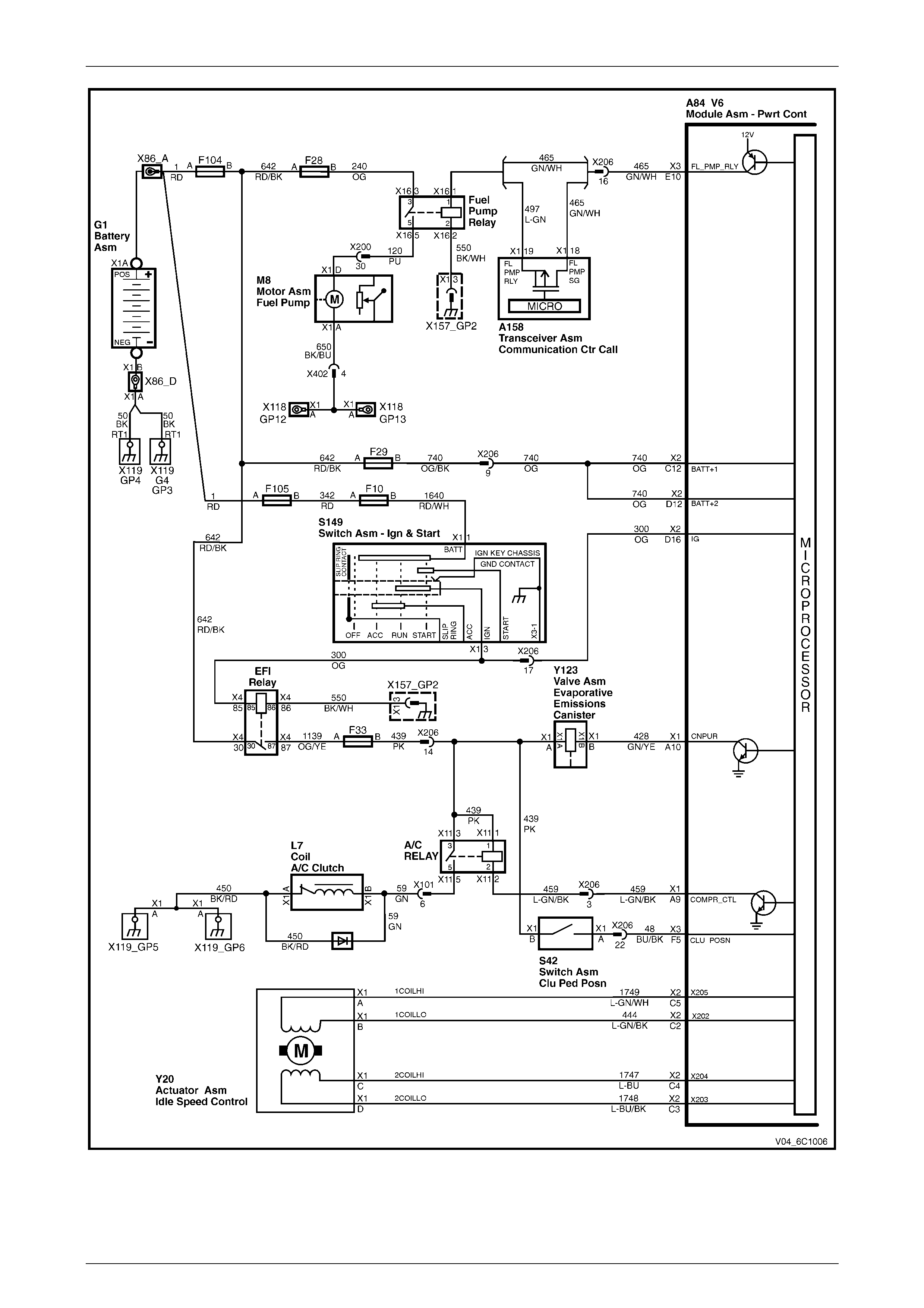
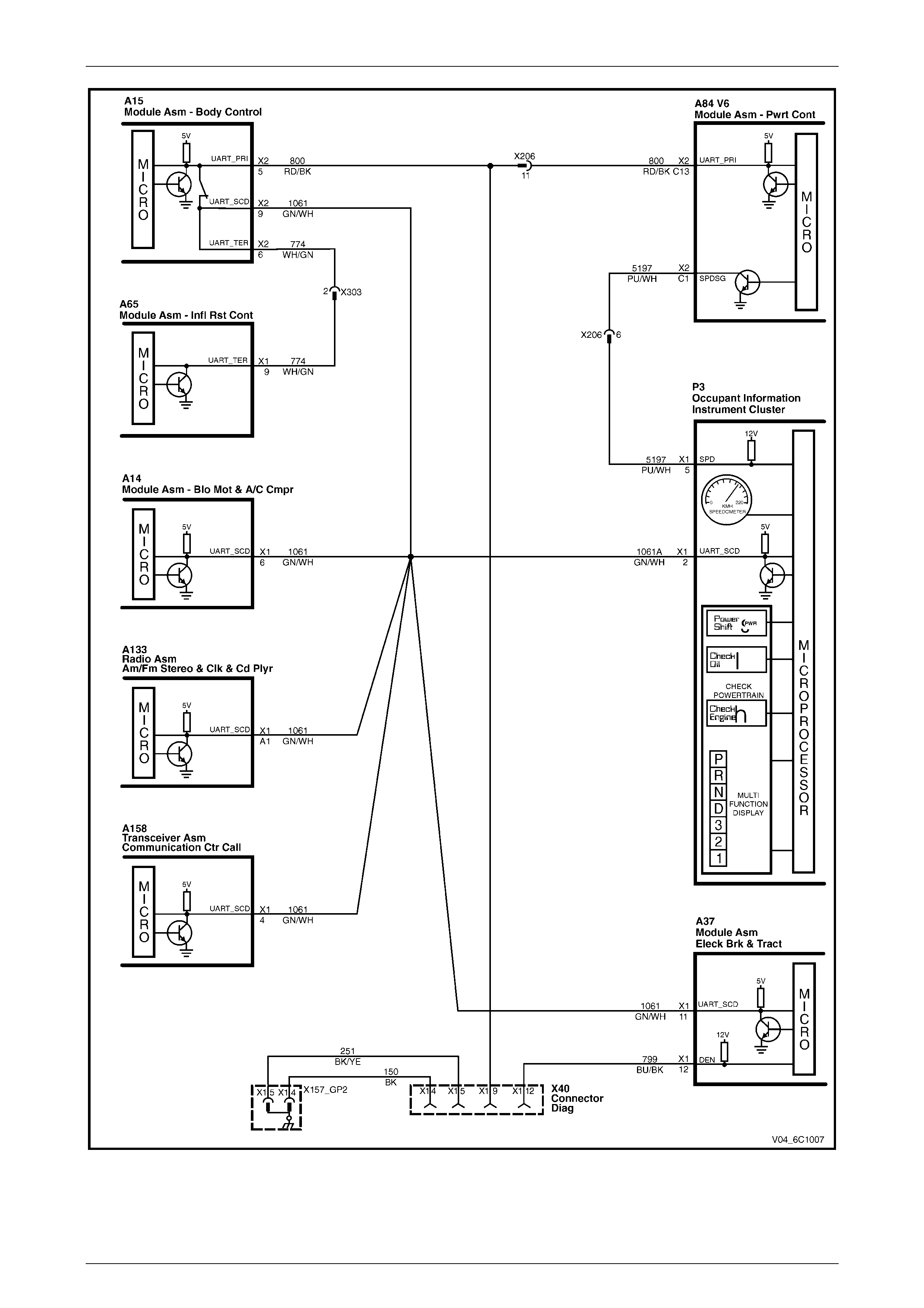
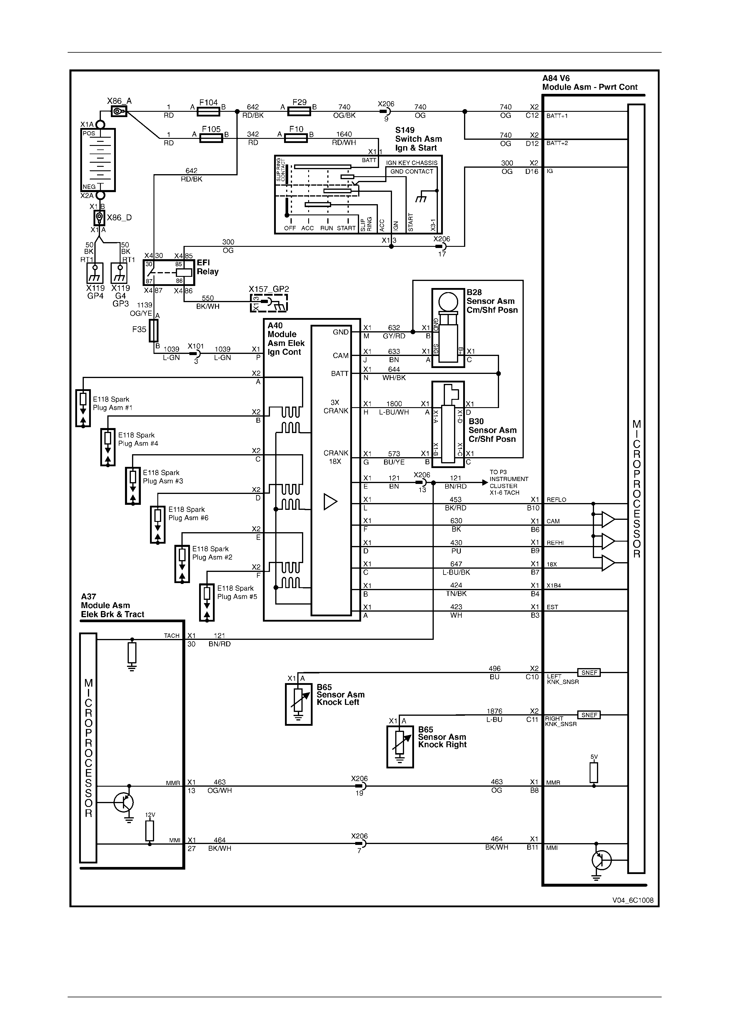
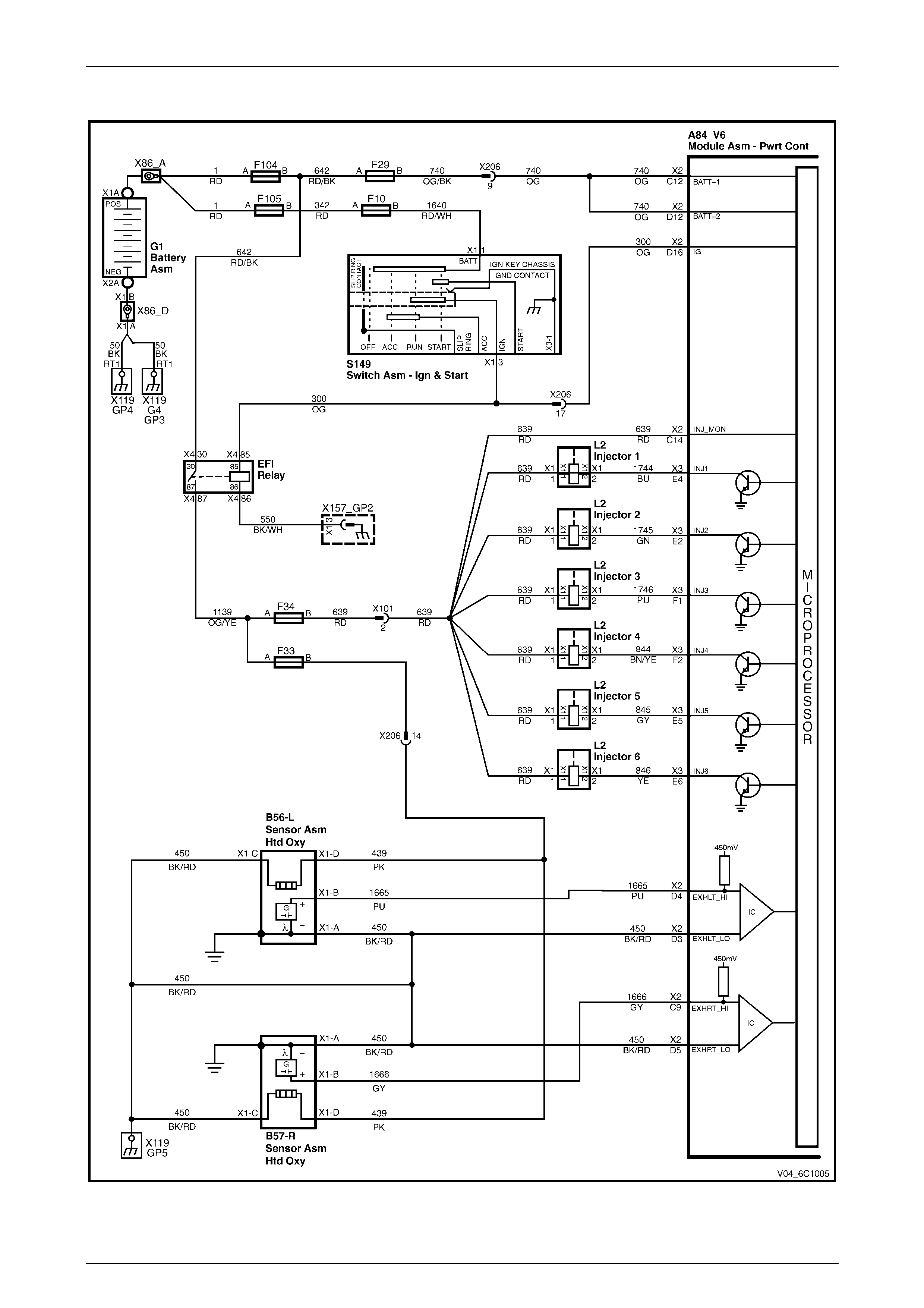
1.2 Wiring Diagrams
Several changes have taken place in the wiring diagrams for MY 2004 VY and V2 vehicles. These include:
• Introduction of heated oxygen sensors (HO2S).
• Clutch calibration position switch circuit has been added.
• Circuit numbers have changed.
• Circuit wiring has changed colours.
• Terminal numbers and locations have changed.
• Component num ber s have ch anged .
When performing any electrical tests or diagnosis as detailed in Section 6C1 Powertrain Management – V6 Engine in the
MY 2003 VY and V2 or MY 2004 WK Service Information, re fer to the correct wiring diagram in this Section.
Powertrain Management - V6 Engine Page 6C1–5
Page 6C1–5
Figure 6C1 – 1

Powertrain Management - V6 Engine Page 6C1–6
Page 6C1–6
Figure 6C1 – 2

Powertrain Management - V6 Engine Page 6C1–7
Page 6C1–7
Figure 6C1 – 3

Powertrain Management - V6 Engine Page 6C1–8
Page 6C1–8
Figure 6C1 – 4

Powertrain Management - V6 Engine Page 6C1–9
Page 6C1–9
Figure 6C1 – 5

Powertrain Management - V6 Engine Page 6C1–10
Page 6C1–10
Figure 6C1 – 6
Powertrain Management - V6 Engine Page 6C1–11
Page 6C1–11
Figure 6C1 – 7

Powertrain Management - V6 Engine Page 6C1–12
Page 6C1–12
Vehicles That Are Not Euro II Compliant
Figure 6C1 – 8

Powertrain Management - V6 Engine Page 6C1–13
Page 6C1–13
Vehicles That Comply With Euro II Standards
Figure 6C1 – 9

Powertrain Management - V6 Engine Page 6C1–14
Page 6C1–14
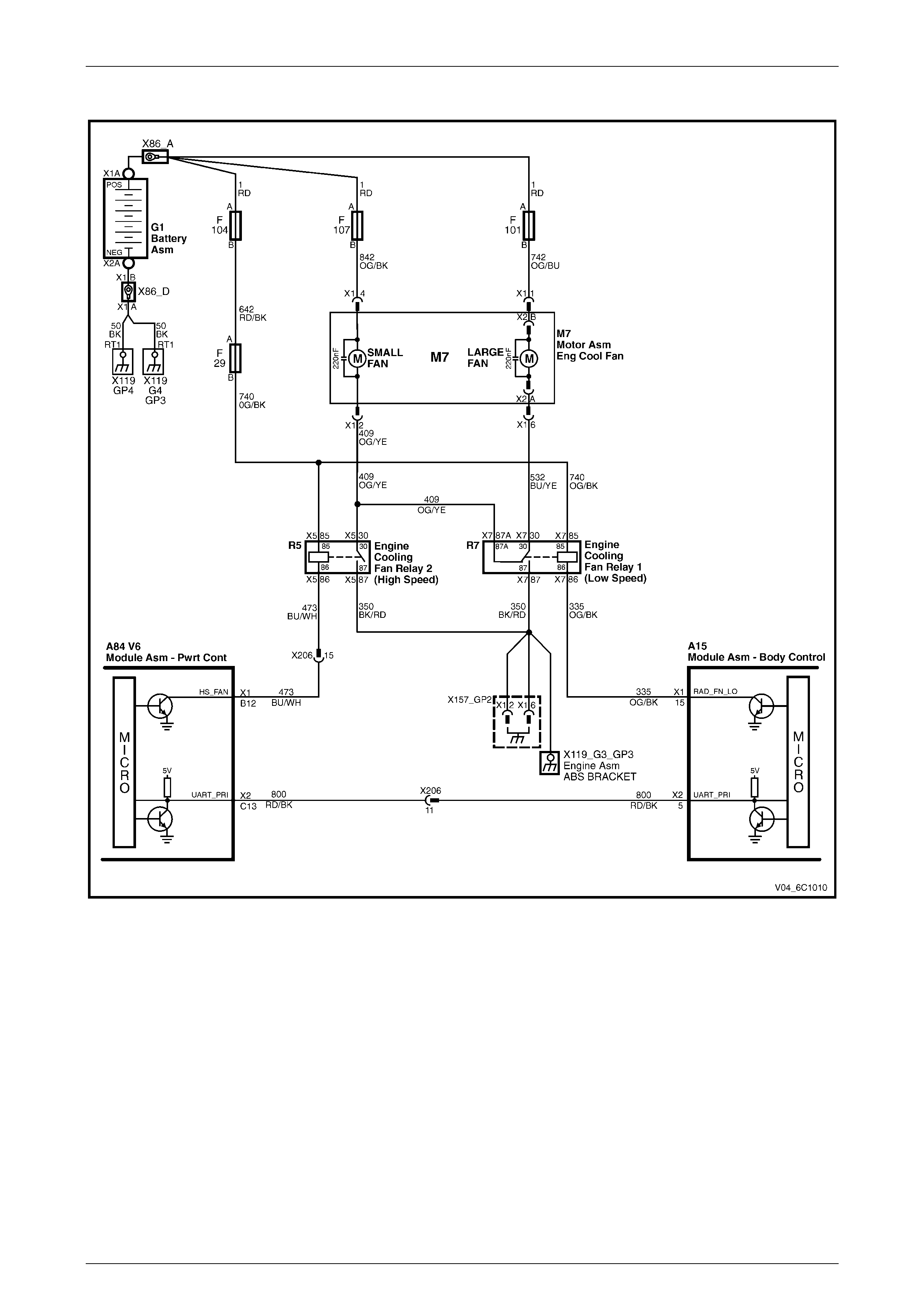
Vehicles With A High Power Fan Pack
Figure 6C1 – 10
Powertrain Management - V6 Engine Page 6C1–15
Page 6C1–15
Vehicles With A Standard Fan Pack
Figure 6C1 – 11

Powertrain Management - V6 Engine Page 6C1–16
Page 6C1–16
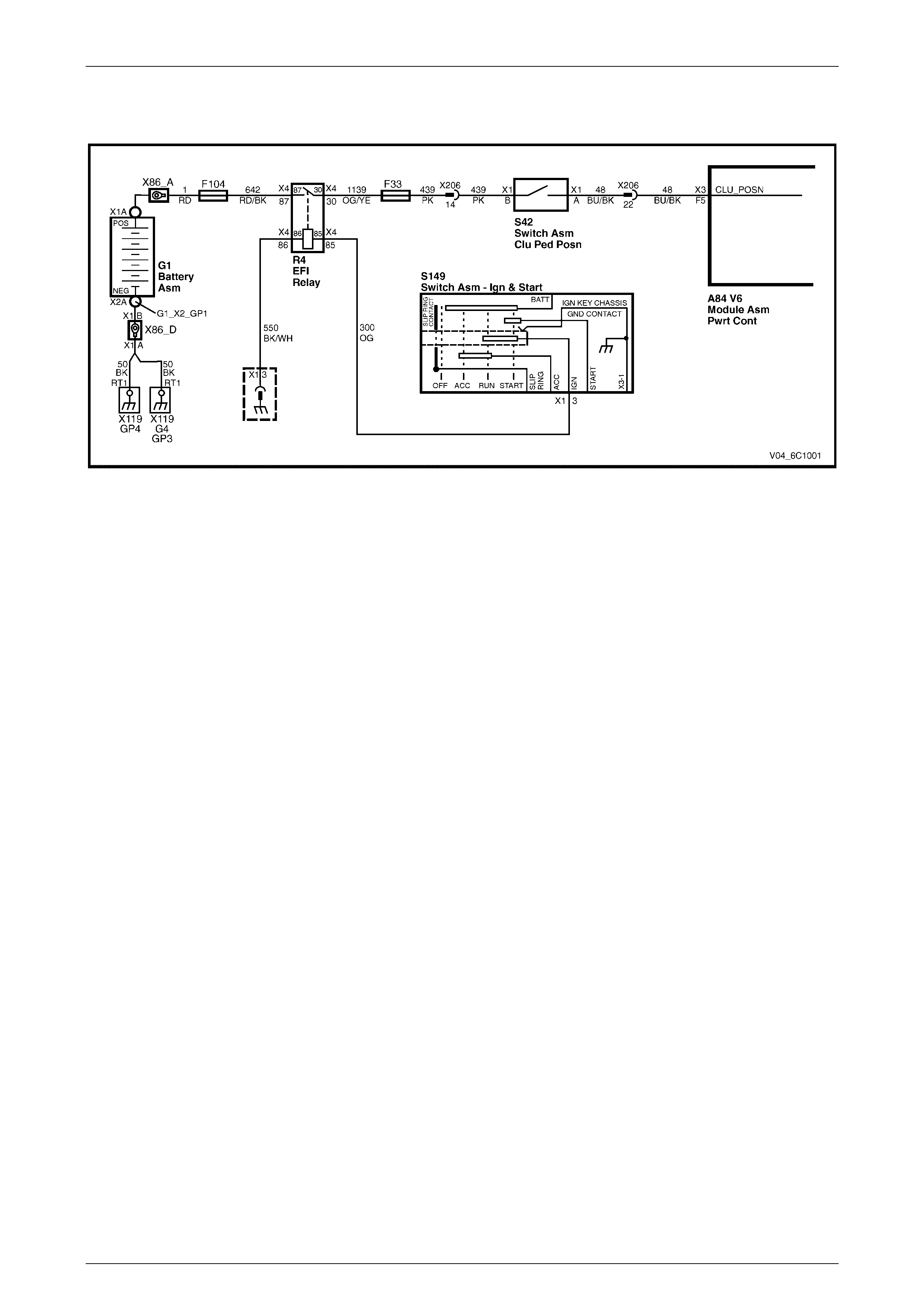
1.3 Clutch Pedal Calibration Switch
A clutch pedal calibration switch has been introduced to improve shift quality during gear changes. When the throttle is
closed the powertrain control module (PCM) checks whether the clutch is pressed or released. Based on this, the PCM
then controls ignition timing to reduce engine flare or drive train clunk.
Refer to Figure 6C1 – 12 for the following description.
The EFI relay is energised when the ignition switch is in the ON position thus supplying power to the clutch pedal
calibration switch. When the clutch pedal is released, the clutch pedal calibration switch S42 is open and will not allow
battery voltage to flow through to the PCM A84 V6. When the clutch is pressed, the clutch pedal calibration switch is
closed allowing battery voltage to the PCM.
Figure 6C1 – 12

Powertrain Management - V6 Engine Page 6C1–17
Page 6C1–17
2 Diagnosis
With the following exceptions, MY 2004 VY and V2 V6 engine powertrain management system Diagnosis carries over
from MY 2003 VY Series vehicles and MY 2004 WK Series vehicles. For info rmation not contained in this Section, refer
to:
• Section 6C1-2 – Diagnosis – V6 Engine in the MY 2003 VY and V2 Series Service Informatio n, and
• Section 6C1 Powertrain Management – V6 Engine in the MY 2004 WK Series Service Information.
2.1 Euro II Emission Standards
MY 2004 VY and V2 Series vehicles must meet Euro II emission standards by January 2004. MY 2004 WK Series
vehicles already comply with Euro II standards. For further information on Euro II emission standard s refer to
Section 6E1 Emission Control and Section 8B Exhaust System.
• For all MY 2004 VY and V2 Series vehicles produced for the domestic market that are built before 01 Jan 04, refer
to Section 6C1-2– Diagnosis – V6 Engine in the MY 2003 VY and V2 Series Service Information.
NOTE
Refer to the relevant MY 2004 VY and V2 Series
Section for all external references contained in
the MY 2003 VY and V2 Series, Section 6C1
Powertrain Management. This is to verify that
there are no differences in the MY 2004 VY and
V2 Series Service information that will effect the
service procedures referred from the MY 2003
VY and V2 Service information.
• For all MY 2004 VY and V2 Series vehicles produced for the domestic market that are built after 01 Jan 04, refer to
Section 6C1 Powertrain Management – V6 Engine in the MY 2004 WK Series Service Information.
NOTE
Refer to the relevant MY 2004 VY and V2 Series
Section for all external references contained in
the MY 2004 W K Series, Section 6C1 Powertrain
Management. This is to verify that there are no
differences in the MY 2004 VY and V2 Series
Service information that will effect the service
procedures referred from the MY 2004 WK
Service information.
• For all MY 2004 VY and V2 Series vehicles produced for the Gulf States and Thailand, refer to
Section 6C1 Powertrain Management – V6 Engine in the MY 2004 WK Series Service Information.
NOTE
Refer to the relevant MY 2004 VY and V2 Series
Section for all external references contained in
the MY 2004 W K Series, Section 6C1 Powertrain
Management. This is to verify that there are no
differences in the MY 2004 VY and V2 Series
Service information that will effect the service
procedures referred from the MY 2004 WK
Service information.

Powertrain Management - V6 Engine Page 6C1–18
Page 6C1–18
2.2 Wiring Diagrams
Several changes have taken place in the wiring diagrams for MY 2004 VY and V2 vehicles. These include:
• Introduction of heated oxygen sensors (HO2S).
• Clutch calibration position switch circuit has been added.
• Circuit numbers have changed.
• Circuit wiring has changed colours.
• Terminal numbers and locations have changed.
• Component num ber s have ch anged .
When performing any electrical tests or diagnosis as detailed in Section 6C1 Powertrain Management – V6 Engine in the
MY 2003 VY and V2 or MY 2004 WK Service Information, refer to the correct wiring diagram in this Section.

Powertrain Management - V6 Engine Page 6C1–19
Page 6C1–19
Figure 6C1 – 13

Powertrain Management - V6 Engine Page 6C1–20
Page 6C1–20
Figure 6C1 – 14

Powertrain Management - V6 Engine Page 6C1–21
Page 6C1–21
Figure 6C1 – 15

Powertrain Management - V6 Engine Page 6C1–22
Page 6C1–22
Figure 6C1 – 16

Powertrain Management - V6 Engine Page 6C1–23
Page 6C1–23
Figure 6C1 – 17
Powertrain Management - V6 Engine Page 6C1–24
Page 6C1–24
Figure 6C1 – 18

Powertrain Management - V6 Engine Page 6C1–25
Page 6C1–25
Figure 6C1 – 19
Powertrain Management - V6 Engine Page 6C1–26
Page 6C1–26
Vehicles That Are Not Euro II Compliant
Figure 6C1 – 20

Powertrain Management - V6 Engine Page 6C1–27
Page 6C1–27
Vehicles That Comply With Euro II Standards
Figure 6C1 – 21

Powertrain Management - V6 Engine Page 6C1–28
Page 6C1–28
Vehicles With A High Power Fan Pack
Figure 6C1 – 22

Powertrain Management - V6 Engine Page 6C1–29
Page 6C1–29
Vehicles With A Standard Fan Pack
Figure 6C1 – 23
Powertrain Management - V6 Engine Page 6C1–30
Page 6C1–30
2.3 Clutch Pedal Calibration Switch
Figure 6C1 – 24
Introduction
A clutch pedal calibration switch has been introduced to improve shift quality during gear changes. When the throttle is
closed the PCM checks whether the clutch is depressed or released. Based on this the PCM then controls ignition timing
to reduce engine flare or drive-train clunk.
If the clutch pedal is depressed with the throttle closed, ignition-timing advance is reduced quickly. This reduces engine
flair. If the throttle is closed with the clutch pedal left engaged, ignition-timing advance is reduced slowly. This reduces
clunk and bump characteristics from the transmission.
The switch is arranged so that it is open circuit with the cl utch pedal released. When the clutch is pressed the plunger is
depressed and the switch is closed circuit.
If the clutch pedal calibration switch fails in an open circuit position the most obvious symptom would be engine flair on
gear changes.
If the clutch pedal calibration switch fails in the closed position engine r.p.m. will reduce more quickly than normal. Some
driveline clunk may be evident if the throttle is closed when driving. This effect will only be slight, and possibly more
noticeable in the lower gears.
Circuit Description
Once the EFI relay is energised, power is taken from fuse 33 and supplied to the clutch pedal ca libration switch. When
the clutch pedal is depressed, the switch is closed and a signal is sent to the PCM.
Test Description
The following numbers refer to step numbers in the following diagnostic chart.
1 Checks whether fuse F33 is serviceable and whether there is a short to ground in circuit 439.
2 Isolates whether the clutch pedal calibration switch is at fault.
3 Checks if there is battery power to the clutch pedal calibration switch S42. Isolates whether there is an open-circuit
in circuit 439.
4 Checks for battery voltage at the PCM with the clutch pedal calibration switch open. Isolates whether there is a
short-circuit to battery in circuit 48.
5 Checks for battery voltage at the PCM with the clutch pedal calibration switch closed. Isolates whether there is a
fault in circuit 48 or the PCM is at fault.
Powertrain Management - V6 Engine Page 6C1–31
Page 6C1–31
Figure 6C1 – 25
Notes on the Diagnostic Chart
1 For all wiring harness fault diagnosis, refer to Section 12P Wiring Diagrams.
2 For wiring harness repairs, refer to Section 12P Wiring Diagrams.
3 Refer to Section 12O Fuses, Relays and Wiring Harnesses for harness routeing.
4 If at any time the fault is deemed to be intermittent, refer to Section 12P Wiring Diagrams.
Step Action Yes No
1 1 Check the fuse F33 (refer to Note 3).
Is the fuse serviceable?
Go to step 2. Replace fuse.
If the fuse blows
again. Check circuit
439 for a short-
circuit to ground.
(refer to Note 2).
2 1 Test the clutch pedal calibration switch, refer to 6.2 Clutch
Pedal Calibration Switch.
Is the clutch pedal calibration switch serviceable?
Go to Step 3. Replace the cl utch
pedal calibration
switch, refer to
6.2 Clutch Pedal
Calibration Switch
3 1 Ensure that the clutch pedal is released.
2 Turn the ignition to the ON position.
3 Backprobe between the clutch pedal calibration switch
connector S42 – X1 pin B and a known ground.
Does the test lamp illuminate?
Go to Step 4. There is an open-
circuit in circuit 439.
Repair or replace
circuit 439
(refer to Note 2).
4 1 Ensure that the clutch pedal is released.
2 Ensure that the ignition is in the ON position.
3 Disconnect A84 V6 – X3 from the PCM.
4 Probe between harness connector A84 V6 – X3 pin F5 and a
known ground with a test lamp.
Does the test lamp illuminate?
There is a
short-circuit to
battery in circ uit 48.
Repair or replace
circuit 48. (refer to
note 2).
Go to step 5.
5 1 Ensure that the clutch pedal is pressed.
2 Ensure that the ignition is in the ON position.
3 Probe between harness connector A84 V6 – X3 pin F5 and a
known ground with a test lamp.
Does the test lamp illuminate?
Replace the PCM Check for an open
or short-circuit in
circuit 48.
Repair or replace
circuit 48
(refer to Note 2).
When all diagnosis and repairs are completed, check the system for correct operation.

Powertrain Management - V6 Engine Page 6C1–32
Page 6C1–32
3 Diagnostic Tables
With the following exceptions MY 2004 VY and V2 V6 engine powertrain management system Diagnosis Tables carries
over from MY 2003 VY Series vehicles and MY 2004 WK Series vehicles. For information not contained in this Section,
refer to:
• Section 6C1-2A – Diagnostic Tables – V6 Engine in the MY 2003 VY and V2 Series Service Information, and
• Section 6C1 Powertrain Management – V6 Engine in the MY 2004 WK Series Service Information.
3.1 Euro II Emission Controls
MY 2004 VY and V2 Series vehicles must meet Euro II emission standards by January 2004. MY 2004 WK Series
vehicles already comply with Euro II standards. For further information on Euro II emission standards refer to Section
6E1 Emission Control and Section 8B Exhaust System.
• For all MY 2004 VY and V2 Series vehicles produced for the domestic market that are built before 01 Jan 04, refer
to Section 6C1-2A – Diagnosis Tables – V6 Engine in the MY 2003 VY and V2 Series Service Information.
NOTE
Refer to the relevant MY 2004 VY and V2 Series
Section for all external references contained in
the MY 2003 VY and V2 Series, Section 6C1
Powertrain Management. This is to verify that
there are no differences in the MY 2004 VY and
V2 Series Service information that will effect the
service procedures referred from the MY 2003
VY and V2 Service information.
• For all MY 2004 VY and V2 Series vehicles produced for the domestic market that are built after 01 Jan 04, refer to
Section 6C1 Powertrain Management – V6 Engine in the MY 2004 WK Series Service Information.
NOTE
Refer to the relevant MY 2004 VY and V2 Series
Section for all external references contained in
the MY 2004 W K Series, Section 6C1 Powertrain
Management. This is to verify that there are no
differences in the MY 2004 VY and V2 Series
Service information that will effect the service
procedures referred from the MY 2004 WK
Service information.
• For all MY 2004 VY and V2 Series vehicles produced for the Gulf States and Thailand, refer to
Section 6C1 Powertrain Management – V6 Engine in the MY 2004 WK Series Service Information.
NOTE
Refer to the relevant MY 2004 VY and V2 Series
Section for all external references contained in
the MY 2004 W K Series, Section 6C1 Powertrain
Management. This is to verify that there are no
differences in the MY 2004 VY and V2 Series
Service information that will effect the service
procedures referred from the MY 2004 WK
Service information.

Powertrain Management - V6 Engine Page 6C1–33
Page 6C1–33
3.2 Wiring Diagrams
Several changes have taken place in the wiring diagrams for MY 2004 VY and V2 vehicles. These include:
• Introduction of heated oxygen sensors (HO2S).
• Clutch calibration position switch circuit has been added.
• Circuit numbers have changed.
• Circuit wiring has changed colours.
• Terminal numbers and locations have changed.
• Component numbers have changed.
When performing any electrical tests or diagnosis as detailed in Section 6C1 Powertrain Management – V6 Engine in the
MY 2003 VY and V2 or MY 2004 WK Service Information, refer to the correct wiring diagram in this Section.

Powertrain Management - V6 Engine Page 6C1–34
Page 6C1–34
Figure 6C1 – 26
Powertrain Management - V6 Engine Page 6C1–35
Page 6C1–35
Figure 6C1 – 27
Powertrain Management - V6 Engine Page 6C1–36
Page 6C1–36
Figure 6C1 – 28

Powertrain Management - V6 Engine Page 6C1–37
Page 6C1–37
Figure 6C1 – 29

Powertrain Management - V6 Engine Page 6C1–38
Page 6C1–38
Figure 6C1 – 30

Powertrain Management - V6 Engine Page 6C1–39
Page 6C1–39
Figure 6C1 – 31

Powertrain Management - V6 Engine Page 6C1–40
Page 6C1–40
Figure 6C1 – 32

Powertrain Management - V6 Engine Page 6C1–41
Page 6C1–41
Vehicles That Are Not Euro II Compliant
Figure 6C1 – 33

Powertrain Management - V6 Engine Page 6C1–42
Page 6C1–42
Vehicles That Comply With Euro II Standards
Figure 6C1 – 34

Powertrain Management - V6 Engine Page 6C1–43
Page 6C1–43
Vehicles With A High Power Fan Pack
Figure 6C1 – 35

Powertrain Management - V6 Engine Page 6C1–44
Page 6C1–44
Vehicles With A Standard Fan Pack
Figure 6C1 – 36

Powertrain Management - V6 Engine Page 6C1–45
Page 6C1–45
4 Symptoms
With the following exceptions MY 2004 VY and V2 V6 engine powertrain management system Symptoms carries over
from MY 2003 VY Series vehicles and MY 2004 WK Series vehicles. For info rmation not contained in this Section, refer
to:
• Section 6C1-2B – Symptoms – V6 Engine in the MY 2003 VY and V2 Series Service Information, and
• Section 6C1 Powertrain Management – V6 Engine in the MY 2004 WK Series Service Information.
4.1 Euro II Emission Controls
MY 2004 VY and V2 Series vehicles must meet Euro II emission standards by January 2004. MY 2004 WK Series
vehicles already comply with Euro II standards. For further information on Euro II emission standard s refer to
Section 6E1 Emission Control and Section 8B Exhaust System.
• For all MY 2004 VY and V2 Series vehicles produced for the domestic market that are built before 01 Jan 04, refer
to Section 6C1-2B – Symptoms – V6 Engine in the MY 2003 VY and V2 Series Service Information.
NOTE
Refer to the relevant MY 2004 VY and V2 Series
Section for all external references contained in
the MY 2003 VY and V2 Series, Section 6C1
Powertrain Management. This is to verify that
there are no differences in the MY 2004 VY and
V2 Series Service information that will effect the
service procedures referred from the MY 2003
VY and V2 Service information.
• For all MY 2004 VY and V2 Series vehicles produced for the domestic market that are built after 01 Jan 04, refer to
Section 6C1 Powertrain Management – V6 Engine in the MY 2004 WK Series Service Information.
NOTE
Refer to the relevant MY 2004 VY and V2 Series
Section for all external references contained in
the MY 2004 W K Series, Section 6C1 Powertrain
Management. This is to verify that there are no
differences in the MY 2004 VY and V2 Series
Service information that will effect the service
procedures referred from the MY 2004 WK
Service information.
• For all MY 2004 VY and V2 Series vehicles produced for the Gulf States and Thailand, refer to
Section 6C1 Powertrain Management – V6 Engine in the MY 2004 WK Series Service Information.
NOTE
Refer to the relevant MY 2004 VY and V2 Series
Section for all external references contained in
the MY 2004 W K Series, Section 6C1 Powertrain
Management. This is to verify that there are no
differences in the MY 2004 VY and V2 Series
Service information that will effect the service
procedures referred from the MY 2004 WK
Service information.

Powertrain Management - V6 Engine Page 6C1–46
Page 6C1–46
5 Functional Checks
With the following exceptions, MY 2004 VY and V2 V6 engine powertrain management system Functional Checks
information carries over from MY 2003 VY Series vehicles and MY 2004 WK Series vehicles. For information not
contained in this Section, refer to:
• Section 6C1-2C – Functional Checks – V6 Engine in the MY 2003 VY and V2 Series Service Information, and
• Section 6C1 Powertrain Management – V6 Engine in the MY 2004 WK Series Service Information.
5.1 Euro II Emission Standard
MY 2004 VY and V2 Series vehicles must meet Euro II emission standards by January 2004. MY 2004 WK Series
vehicles already comply with Euro II standards. For further information on Euro II emission standard s refer to
Section 6E1 Emission Control and Section 8B Exhaust System.
• For all MY 2004 VY and V2 Series vehicles produced for the domestic market that are built before 01 Jan 04, refer
to Section 6C1-2C – Functional Checks – V6 Engine in the MY 2003 VY and V2 Series Service Information.
NOTE
Refer to the relevant MY 2004 VY and V2 Series
Section for all external references contained in
the MY 2003 VY and V2 Series, Section 6C1
Powertrain Management. This is to verify that
there are no differences in the MY 2004 VY and
V2 Series Service information that will effect the
service procedures referred from the MY 2003
VY and V2 Service information.
• For all MY 2004 VY and V2 Series vehicles produced for the domestic market that are built after 01 Jan 04, refer to
Section 6C1 Powertrain Management – V6 Engine in the MY 2004 WK Series Service Information.
NOTE
Refer to the relevant MY 2004 VY and V2 Series
Section for all external references contained in
the MY 2004 W K Series, Section 6C1 Powertrain
Management. This is to verify that there are no
differences in the MY 2004 VY and V2 Series
Service information that will effect the service
procedures referred from the MY 2004 WK
Service information.
• For all MY 2004 VY and V2 Series vehicles produced for the Gulf States and Thailand, refer to
Section 6C1 Powertrain Management – V6 Engine in the MY 2004 WK Series Service Information.
NOTE
Refer to the relevant MY 2004 VY and V2 Series
Section for all external references contained in
the MY 2004 W K Series, Section 6C1 Powertrain
Management. This is to verify that there are no
differences in the MY 2004 VY and V2 Series
Service information that will effect the service
procedures referred from the MY 2004 WK
Service information.

Powertrain Management - V6 Engine Page 6C1–47
Page 6C1–47
5.2 Wiring Diagrams
Several changes have taken place in the wiring diagrams for MY 2004 VY and V2 vehicles. These include:
• Introduction of heated oxygen sensors (HO2S).
• Clutch calibration position switch circuit has been added.
• Circuit numbers have changed.
• Circuit wiring has changed colours.
• Terminal numbers and locations have changed.
• Component numbers have changed.
When performing any electrical tests or diagnosis as detailed in Section 6C1 Powertrain Management – V6 Engine in the
MY 2003 VY and V2 or MY 2004 WK Service Information, refer to the correct wiring diagram in this Section..

Powertrain Management - V6 Engine Page 6C1–48
Page 6C1–48
Figure 6C1 – 37

Powertrain Management - V6 Engine Page 6C1–49
Page 6C1–49
Figure 6C1 – 38

Powertrain Management - V6 Engine Page 6C1–50
Page 6C1–50
Figure 6C1 – 39
Powertrain Management - V6 Engine Page 6C1–51
Page 6C1–51
Figure 6C1 – 40
Powertrain Management - V6 Engine Page 6C1–52
Page 6C1–52
Figure 6C1 – 41

Powertrain Management - V6 Engine Page 6C1–53
Page 6C1–53
Figure 6C1 – 42

Powertrain Management - V6 Engine Page 6C1–54
Page 6C1–54
Figure 6C1 – 43

Powertrain Management - V6 Engine Page 6C1–55
Page 6C1–55
Vehicles That Are Not Euro II Compliant
Figure 6C1 – 44
Powertrain Management - V6 Engine Page 6C1–56
Page 6C1–56
Vehicles That Comply With Euro II Standards
Figure 6C1 – 45

Powertrain Management - V6 Engine Page 6C1–57
Page 6C1–57
Vehicles With A High Power Fan Pack
Figure 6C1 – 46

Powertrain Management - V6 Engine Page 6C1–58
Page 6C1–58
Vehicles With A Standard Fan Pack
Figure 6C1 – 47

Powertrain Management - V6 Engine Page 6C1–59
Page 6C1–59
6 Service Operations
With the following exceptions, MY 2004 VY and V2 V6 engine powertrain management system Service Operations
information carries over from MY 2003 VY Series vehicles and MY 2004 WK Series vehicles. For information not
contained in this Section, refer to:
• Section 6C1-3 – Service Operations – V6 Engine in the MY 2003 VY and V2 Series Service Information, and
• Section 6C1 Powertrain Management – V6 Engine in the MY 2004 WK Series Service Information.
6.1 Euro II Emission Standard
MY 2004 VY and V2 Series vehicles must meet Euro II emission standards by January 2004. MY 2004 WK Series
vehicles already comply with Euro II standards. For further information on Euro II emission standards refer to
Section 6E1 Emission Control and Section 8B Exhaust System.
• For all MY 2004 VY and V2 Series vehicles produced for the domestic market that are built before 01 Jan 04, refer
to Section 6C1-3 – Service Operations – V6 Engine in the MY 2003 VY and V2 Series Service Information.
NOTE
Refer to the relevant MY 2004 VY and V2 Series
Section for all external references contained in
the MY 2003 VY and V2 Series, Section 6C1
Powertrain Management. This is to verify that
there are no differences in the MY 2004 VY and
V2 Series Service information that will effect the
service procedures referred from the MY 2003
VY and V2 Service information.
• For all MY 2004 VY and V2 Series vehicles produced for the domestic market that are built after 01 Jan 04, refer to
Section 6C1 Powertrain Management – V6 Engine in the MY 2004 WK Series Service Information.
NOTE
Refer to the relevant MY 2004 VY and V2 Series
Section for all external references contained in
the MY 2004 W K Series, Section 6C1 Powertrain
Management. This is to verify that there are no
differences in the MY 2004 VY and V2 Series
Service information that will effect the service
procedures referred from the MY 2004 WK
Service information.
• For all MY 2004 VY and V2 Series vehicles produced for the Gulf States and Thailand, refer to
Section 6C1 Powertrain Management – V6 Engine in the MY 2004 WK Series Service Information.
NOTE
Refer to the relevant MY 2004 VY and V2 Series
Section for all external references contained in
the MY 2004 W K Series, Section 6C1 Powertrain
Management. This is to verify that there are no
differences in the MY 2004 VY and V2 Series
Service information that will effect the service
procedures referred from the MY 2004 WK
Service information.
Powertrain Management - V6 Engine Page 6C1–60
Page 6C1–60
6.2 Clutch Pedal Calibration Switch
Remove
To remove the clutch pedal calibration switch, refer to Section 7A1, 2.2 Clutch Pedal Calibration.
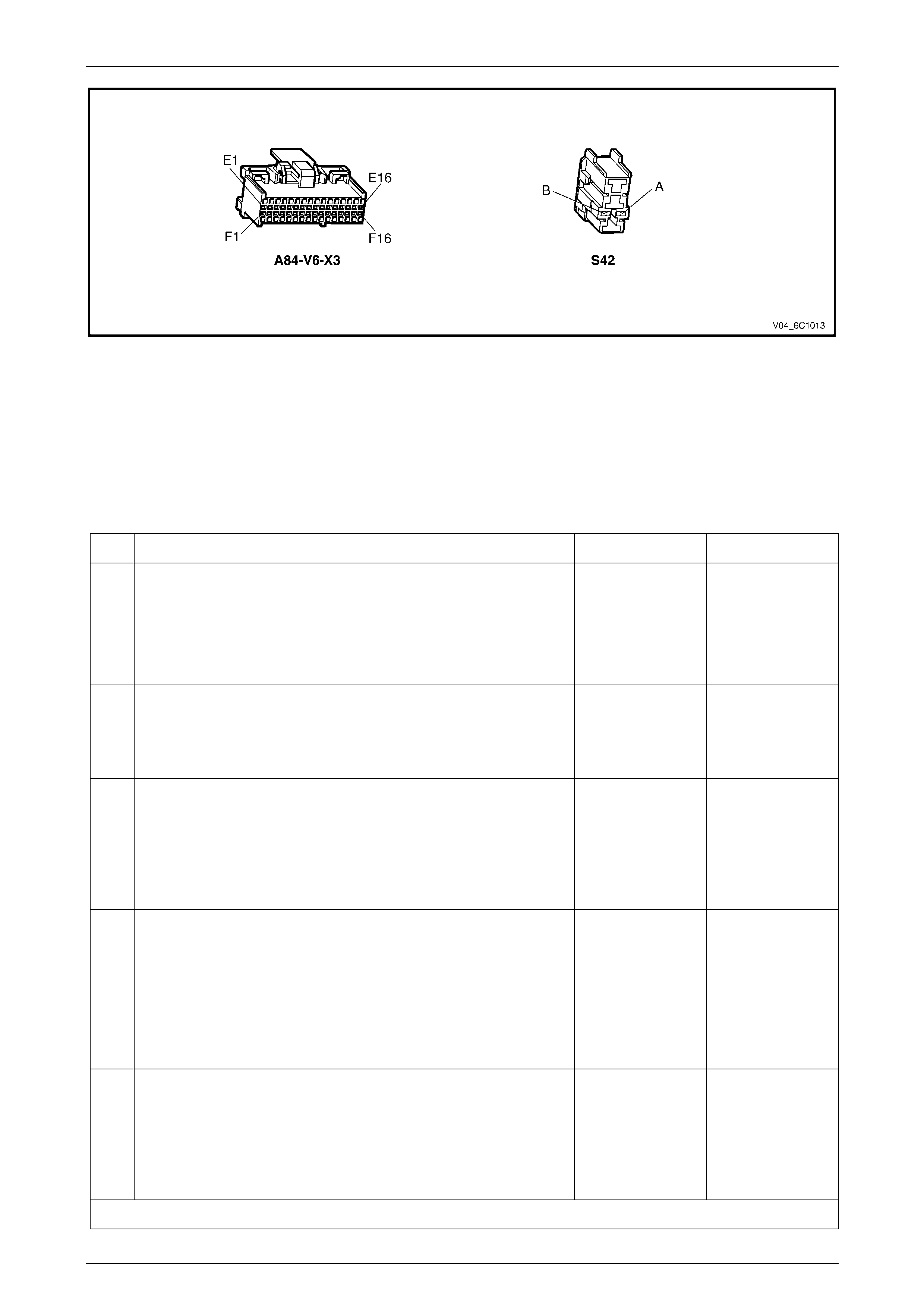
Test
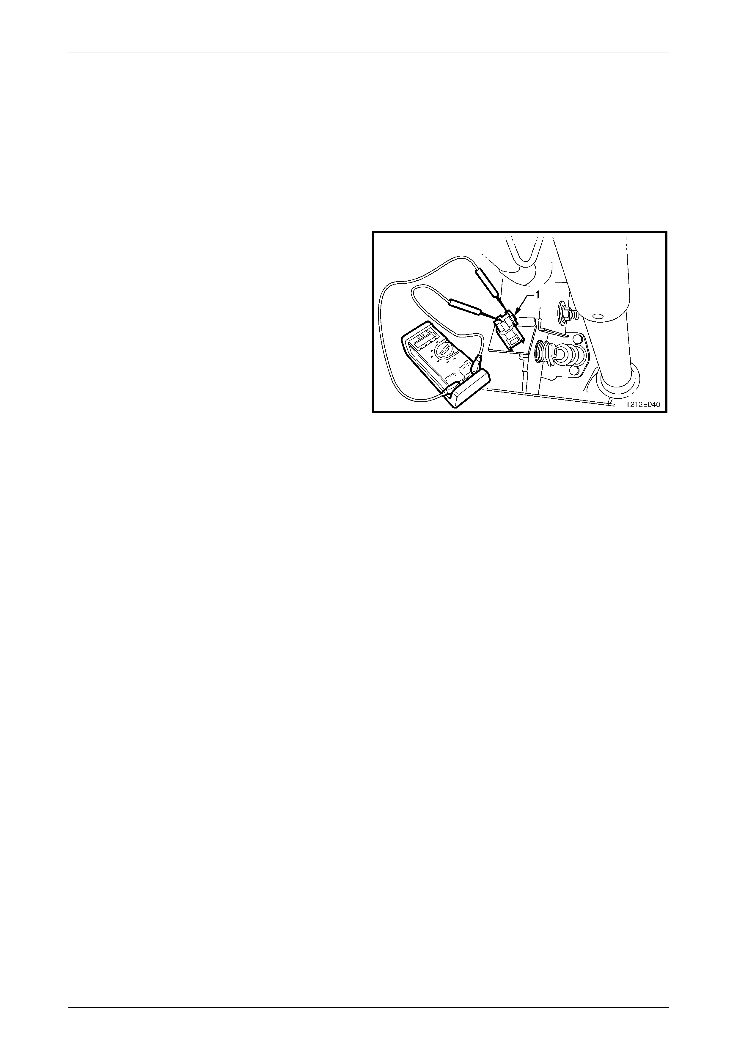
The testing of the clutch pedal calibration switch can be performed in situ.
1 With a multimeter, probe between S42 – X1 pin A and
B and check for continuity in the following conditions:
a With the pedal released, the multimeter should
display an open-circuit.
b With the clutch pedal depressed, the multimeter
should disp lay continuity.
If either of the above tests fail, replace the clutch pedal
calibration switch as detailed in this Section..
Figure 6C1 – 48
Reinstall
To install the clutch pedal calibration switch, refer to Section 7A1, 2.2 Clutch Pedal Calibration Switch.

Powertrain Management - V6 Engine Page 6C1–61
Page 6C1–61
7 Specifications
MY 2004 VY and V2 V6 engine powertrain management system Specifications carries over from MY 2003 VY Series
vehicles and MY 2004 WK Series vehicles.
• For all MY 2004 VY and V2 Series vehicles produced for the domestic market that are built before 01 Jan 04, refer
to Section 6C1-4 – Specifications – V6 Engine in the MY 2003 VY and V2 Series Service Information.
NOTE
Refer to the relevant MY 2004 VY and V2 Series
Section for all external references contained in
the MY 2003 VY and V2 Series, Section 6C1
Powertrain Management. This is to verify that
there are no differences in the MY 2004 VY and
V2 Series Service information that will effect the
service procedures referred from the MY 2003
VY and V2 Service information.
• For all MY 2004 VY and V2 Series vehicles produced for the domestic market that are built after 01 Jan 04, refer to
Section 6C1 Powertrain Management – V6 Engine in the MY 2004 WK Series Service Information.
NOTE
Refer to the relevant MY 2004 VY and V2 Series
Section for all external references contained in
the MY 2004 W K Series, Section 6C1 Powertrain
Management. This is to verify that there are no
differences in the MY 2004 VY and V2 Series
Service information that will effect the service
procedures referred from the MY 2004 WK
Service information.
• For all MY 2004 VY and V2 Series vehicles produced for the Gulf States and Thailand, refer to
Section 6C1 Powertrain Management – V6 Engine in the MY 2004 WK Series Service Information.
NOTE
Refer to the relevant MY 2004 VY and V2 Series
Section for all external references contained in
the MY 2004 W K Series, Section 6C1 Powertrain
Management. This is to verify that there are no
differences in the MY 2004 VY and V2 Series
Service information that will effect the service
procedures referred from the MY 2004 WK
Service information.

Powertrain Management - V6 Engine Page 6C1–62
Page 6C1–62
8 Torque Wrench Specifications
MY 2004 VY and V2 V6 engine powertrain management system Torque Wrench Specifications info rmation carries over
from MY 2003 VY Series vehicles and MY 2004 WK Series vehicles.
• For all MY 2004 VY and V2 Series vehicles produced for the domestic market that are built before 01 Jan 04, refer
to Section 6C1-5 – Torque Wrench Specifications – V6 Engine in the MY 2003 VY and V2 Series Service
Information.
• For all MY 2004 VY and V2 Series vehicles produced for the domestic market that are built after 01 Jan 04, refer to
Section 6C1 Powertrain Management – V6 Engine in the MY 2004 WK Series Service Information.
• For all MY 2004 VY and V2 Series vehicles produced for the Gulf States and Thailand, refer to
Section 6C1 Powertrain Management – V6 Engine in the MY 2004 WK Series Service Information.

Powertrain Management - V6 Engine Page 6C1–63
Page 6C1–63
9 Special Tools
MY 2004 VY and V2 V6 engine powertrain management system Special Tools carries over from MY 2003 VY Series
vehicles and MY 2004 WK Series vehicles.
• For all MY 2004 VY and V2 Series vehicles produced for the domestic market that are built before 01 Jan 04, refer
to Section 6C1-6 – Special Tools – V6 Engine in the MY 2003 VY and V2 Series Service Information.
• For all MY 2004 VY and V2 Series vehicles produced for the domestic market that are built after 01 Jan 04, refer to
Section 6C1 Powertrain Management – V6 Engine in the MY 2004 WK Series Service Information.
• For all MY 2004 VY and V2 Series vehicles produced for the Gulf States and Thailand, refer to
Section 6C1 Powertrain Management – V6 Engine in the MY 2004 WK Series Service Information.