
Powertrain Management - GEN III V8 Engine Page 6C3–1
Page 6C3–1
Section 6C3
Powertrain Management - GEN III V8 Engine
ATTENTION
Before performing any Service Operation or other procedure described in this Section, refer to Section 00
Cautions And Notes for correct workshop practices with regard to safety and/or property damage.
1 General Information............................................................................................................................... 2
1.1 Euro II Emission Standard.....................................................................................................................................2
1.2 Spark Plugs.............................................................................................................................................................3
1.3 Crankcase Ventilation System..............................................................................................................................4
Description..............................................................................................................................................................4
Result of Incorrect Operation................................................................................................................................5
2 Diagnosis................................................................................................................................................ 6
3 Diagnostic Tables.................................................................................................................................. 7
4 Symptoms............................................................................................................................................... 8
5 Functional Checks................................................................................................................................. 9
6 Service Operations.............................................................................................................................. 10
6.1 Spark Plugs...........................................................................................................................................................10
6.2 Crankcase Ventilation System............................................................................................................................11
Test........................................................................................................................................................................11
Clearing the Restricting Orifice...........................................................................................................................11
7 Specifications....................................................................................................................................... 12
7.1 Ignition System.....................................................................................................................................................12
8 Torque Wrench Specifications........................................................................................................... 13
9 Special Tools........................................................................................................................................ 14
Techline

Powertrain Management - GEN III V8 Engine Page 6C3–2
Page 6C3–2
1 General Information
With the following exceptions, MY 2004 VY and V2 Series GEN III V8 engine powertrain management system General
Information carries over from MY 2004 WK Series Service Information. For information not contained in this Section,
refer to Section 6C3 – Powertrain Management – GEN III V8 in the MY 2004 WK Service Information.
• Vehicles comply with Euro II standards.
• New spark plugs with new gap specification.
• Crankcase venti lati on sy stem has been revise d.
1.1 Euro II Emission Standard
All MY 2004 VY and V2 Series vehicles equipped with a GEN III V8 engine comply with Euro II emission standards. For
further information on Euro II emission standards refer to Section 6E3 Emission Control and Section 8B Exhaust System.

Powertrain Management - GEN III V8 Engine Page 6C3–4
Page 6C3–4
1.3 Crankcase Ventilation System
Description
The engine ventilation system was developed to remove the engine combustion blow-by vapours and minimise the
following:
• crankcase pres sure build-up,
• oil deterioration,
• oil consumpti on, and
• evaporative/exhaust emissions.
During normal idle and part throttle operation, this crankcase ventilation system provides a fresh air flow through the
crankcase before being metered through a fixed orifice and into the intake manifold.
The positive crankcase ventilation system (PCV) does not include a PCV valve, as on previous models. Instead a fixed
internal flow-restricting orifice and an oil separator are included in the system. For service procedure of the oil separator,
refer to Section 6A3 Engine Mechanical-GEN lll V8 Engine.
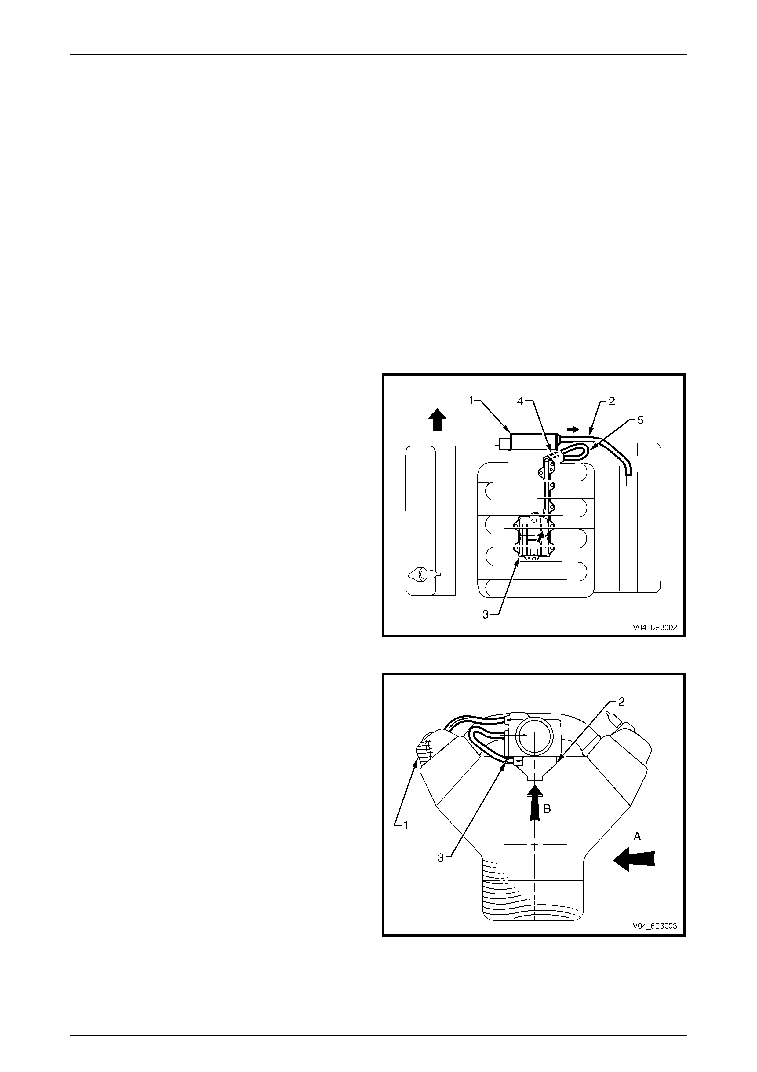
Filtered fresh air is routed from upstream of the throttle
body (1) blade to the front of the right rocker cover via the
fresh air inlet hose (2).
Blow-by gas (oil vapour) in the crankcase valley passes
through the oil separator (3) before flowing through a fixed
internal flow-restricting orifice (4).
Via the foul air hose (5), the blow-by gas is directed from the
valley cover right-hand corner to the inlet manifold
downstream of the throttle body.
Under heavy load operation and high engine speeds, an
acceptable reverse flow condition may occur in the fresh air
inlet hose.
Figure SectNum – 1
The central valley ventilation system is designed to
eliminate oil ingestion during severe vehicle cornering
manoeuvres.
During sustai ned maximum lateral acc eler atio n (A), the
outboard rocker cover may be overloaded with oil (1).
The blow-by gas is prevented from being drawn from the
rocker cover and oil being ingested into the intake manifold.
Instead, the high efficiency oil separator (2), in conjunction
with the fixed internal flow-restriction orifice (3), is fitted
under the valley cover to draw the blow-by gas (B), from the
crankcase.
Figure SectNum – 2

Powertrain Management - GEN III V8 Engine Page 6C3–5
Page 6C3–5
Result of Incorrect Operation
Should the fixed orifice become plugged or partially blocked; a hose became kinked, split or damaged; adverse
conditio ns cou ld resu lt.
A plugged or partially plugged orifice may cause:
• oil leaks, and
• sludge build-up in the engine.
A leaking hose in the engine ventilation system may cause:
• high idle speed
• sludge build-up in the engine.

Powertrain Management - GEN III V8 Engine Page 6C3–6
Page 6C3–6
2 Diagnosis
MY 2004 VY and V2 Series GEN III V8 engine powertrain management system Diagnosis carries over from MY 2004
WK Series Service Information. Refer to Section 6C3 – Powertrain Management – GEN III V8 in the MY 2004 WK
Service Information.

Powertrain Management - GEN III V8 Engine Page 6C3–7
Page 6C3–7
3 Diagnostic Tables
MY 2004 VY and V2 Series GEN III V8 engine powertrain management system Diagnostic Tables carries over from MY
2004 WK Series Service Information. Refer to Section 6C3 – Powertrain Management – GEN III V8 in the MY 2004 WK
Service Information.

Powertrain Management - GEN III V8 Engine Page 6C3–8
Page 6C3–8
4 Symptoms
MY 2004 VY and V2 Series GEN III V8 engine powertrain management system Symptoms carries over from MY 2004
WK Series Service Information. Refer to Section 6C3 – Powertrain Management – GEN III V8 in the MY 2004 WK
Service Information.

Powertrain Management - GEN III V8 Engine Page 6C3–9
Page 6C3–9
5 Functional Checks
MY 2004 VY and V2 Series GEN III V8 engine powertrain management system Functional Checks carries over from MY
2004 WK Series Service Information. Refer to Section 6C3 – Powertrain Management – GEN III V8 in the MY 2004 WK
Service Information.

Powertrain Management - GEN III V8 Engine Page 6C3–10
Page 6C3–10
6 Service Operations
With the following exceptions, MY 2004 VY and V2 Series GEN III V8 engine powertrain management system Service
Operations carries over from MY 2004 WK Series Service Information. For information not contained in this Section, refer
to Section 6C3 – Powertrain Management – GEN III V8 in the MY 2004 WK Service Information.
• A new spark plug with a revised spark plug gap specification has been introduced.
• The crankcase ventilation system has been revised
6.1 Spark Plugs
Although the spark plugs have been revised, the service operations are carry over from MY 2004 WK Series vehicles.
The new spark plug has a revised spark plug gap.
Spark Plug Gap
GEN III V8 Engine...............................1.0 mm ± 0.1 mm
Powertrain Management - GEN III V8 Engine Page 6C3–11
Page 6C3–11
6.2 Crankcase Ventilation System
Test
1 Remove the engine dress cover, refer to
Section 6C3-3 – Service Operations – GEN III V8
in the MY2003 VY and V2 Service Information.
2 Disconnect the fresh air rubber hose (2) from the
throttle body (1).
3 With the normalised engine running at idle speed,
place a finger over the end of the disconnected
hose (2) and check for the presence of vacuum.
4 If there is no vacuum or little indication that a vacuum
exists, check for plugged / cracked / damaged
hoses (2 and 5).
5 If no problem is found check for a plugged/partially
plugged restricting orifice (4) in the oil separator (3)
outlet and clean. Refer to Clearing the Restricting
Orifice in this service operation.
Figure SectNum – 3
Clearing the Restricting Orifice
1 Remove the engine dress cover, refer to
Section 6C3-3 – Service Operations – GEN III V8
in the MY2003 VY and V2 Service Information.
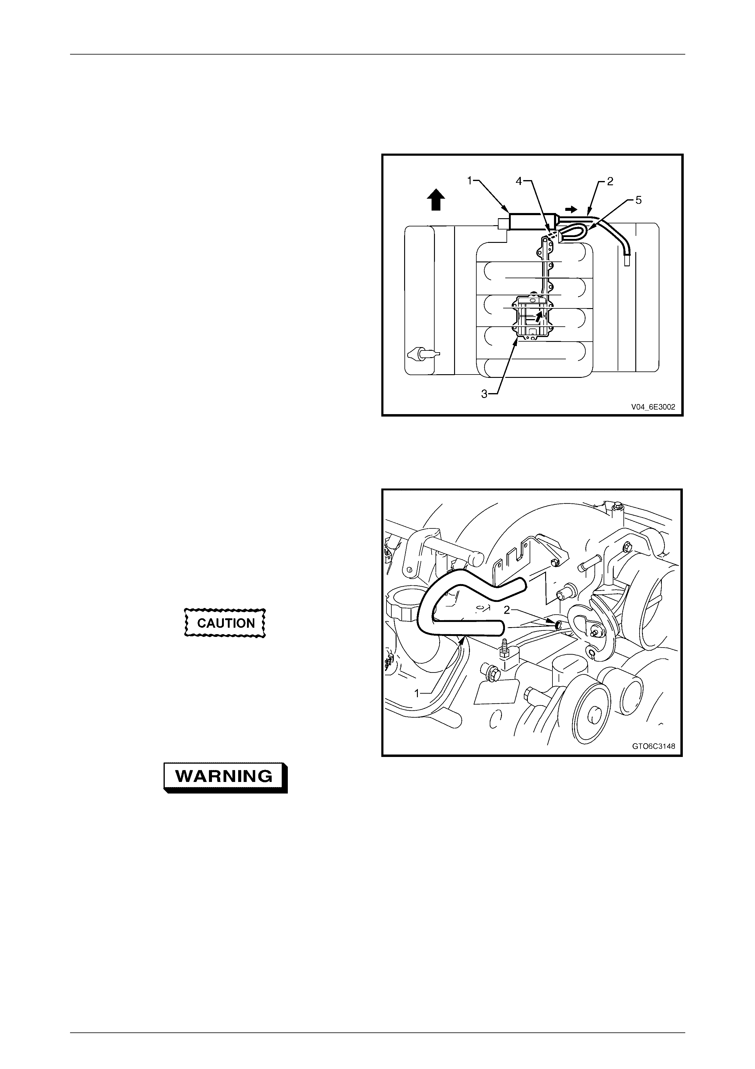
2 Remove the crankcase to throttle body hose (1).
3 Check for engine sludge build-up in the PCV tube (2)
that exits from the oil separator.
The orifice is a calibrated size for this engine
specification and is not to be altered in any
way.
4 Using a suitable probe (e.g. pipe cleaner, or similar)
clean the PCV tube orifice, ensuring that the probe
does not enlarge the 2.5 mm orific e diam eter.
Wear eye protection to avoid injury.
5 After installing suitable eye protection, use
compressed air to clean any dislodged material from
the PCV exit tube (2).
6 Reinstall the crankcase to throttle body hose (1).
7 Start and run the engine, then test the crankcase
ventilation system, refer to Test in this Section.
8 Reinstall the engine dres s cov er, refer to
Section 6C3-3 – Service Operations – GEN III V8
in the MY2003 VY and V2 Service Information.
Figure SectNum – 4

Powertrain Management - GEN III V8 Engine Page 6C3–12
Page 6C3–12
7 Specifications
With the following exceptions, MY 2004 VY and V2 Series GEN III V8 engine powertrain management system
Specifications carries over from MY 2004 WK Series Service Information. For information not contained in this Section,
refer to Section 6C3 – Powertrain Management – GEN III V8 in the MY 2004 WK Service Information.
• A new spark plug with a revised spark plug gap specification has been introduced.
7.1 Ignition System
Spark Plugs........................................................................................................Denso 41-986
Spark Plug Gap.............................................................................................1.0 mm ± 0.1 mm
Spark Plug Lead Resistance.....................................................................700 Ohm maximum
Ignition Module..............................................Integrated Circuit, incorporating the Ignition Coil

Powertrain Management - GEN III V8 Engine Page 6C3–13
Page 6C3–13
8 Torque Wrench Specifications
MY 2004 VY and V2 Series GEN III V8 engine powertrain management system Torque Wrench Specifications
carries over from MY 2004 WK Series Service Information. For information not contained in this Section, refer to
Section 6C3 – Powertrain Management – GEN III V8 in the MY 2004 WK Service Information.

Powertrain Management - GEN III V8 Engine Page 6C3–14
Page 6C3–14
9 Special Tools
MY 2004 VY and V2 Series GEN III V8 engine powertrain management system Special Tools carries over from MY 2004
WK Series Service Information. For information not contained in this Section, refer to Section 6C3 – Powertrain
Management – GEN III V8 in the MY 2004 WK Service Information.