
Emission Control – V8 Engine Page 6E3–1
Page 6E3–1
Section 6E3
Emission Control – V8 Engine
ATTENTION
Before performing any service operation or other procedure described in this Section, refer to Section 00
Warnings, Cautions and Notes for correct workshop practices with regard to safety and/or property damage.
1 General Information............................................................................................................................... 2
1.1 Euro 2 Emissions Standards.................................................................................................................................2
1.2 Vehicle Emission Control Information Label.......................................................................................................3
1.3 Emission Management ..........................................................................................................................................4
1.4 Positive Crankcase Ventilation.............................................................................................................................5
Description..............................................................................................................................................................5
Result of Incorrect Operation................................................................................................................................6
1.5 Evaporation Emission Control..............................................................................................................................7
1.6 Three-Way Catalytic Converter.............................................................................................................................8

Emission Control – V8 Engine Page 6E3–2
Page 6E3–2
1 General Information
With the following exceptions, MY 2004 VY and V2 Series Emission Control – GEN III V8 Engine information carries over
from MY 2003 VY and V2 Series vehicles:
• the vehicle has been configured to comply with the Euro 2 vehicle emission standards,
• vehicle emission control information label,
• positive crankcase ventilation,
• oil separator, and
• three way catalytic converters.
For information not contained within this Section, refer to Section 6E3 Emission Control – GEN III V8 Engine in the
MY 2003 VY and V2 Series Service Information.
1.1 Euro 2 Emissions Standards
The vehicle has been configured to comply with Euro 2 vehicle emissions standards by modifying the exhaust system.
Euro 2 is a European standard which aims at setting vehicle emissions targets to encourage vehicle manufacturers to
reduce harmful vehicle emissions such as carbon monoxide (CO), hydrocarbons (HC) and the various oxides of
nitrogen (NOx).
For further information on Euro 2 emissions and the revised exhaust system, refer to Section 8B Exhaust System.
Australian Design Rule 79/00 implements the 'Euro 2' exhaust and evaporative emissions requirements for light vehicles
to reduce air pollution. The following tests are prescribed:
• average tailpipe emissions after a cold start,
• carbon monoxide emission at idling speed,
• emission of crankcase gases,
• evaporative em is sion s, and
• durability of pollution-control devices.
Emission Control – V8 Engine Page 6E3–3
Page 6E3–3
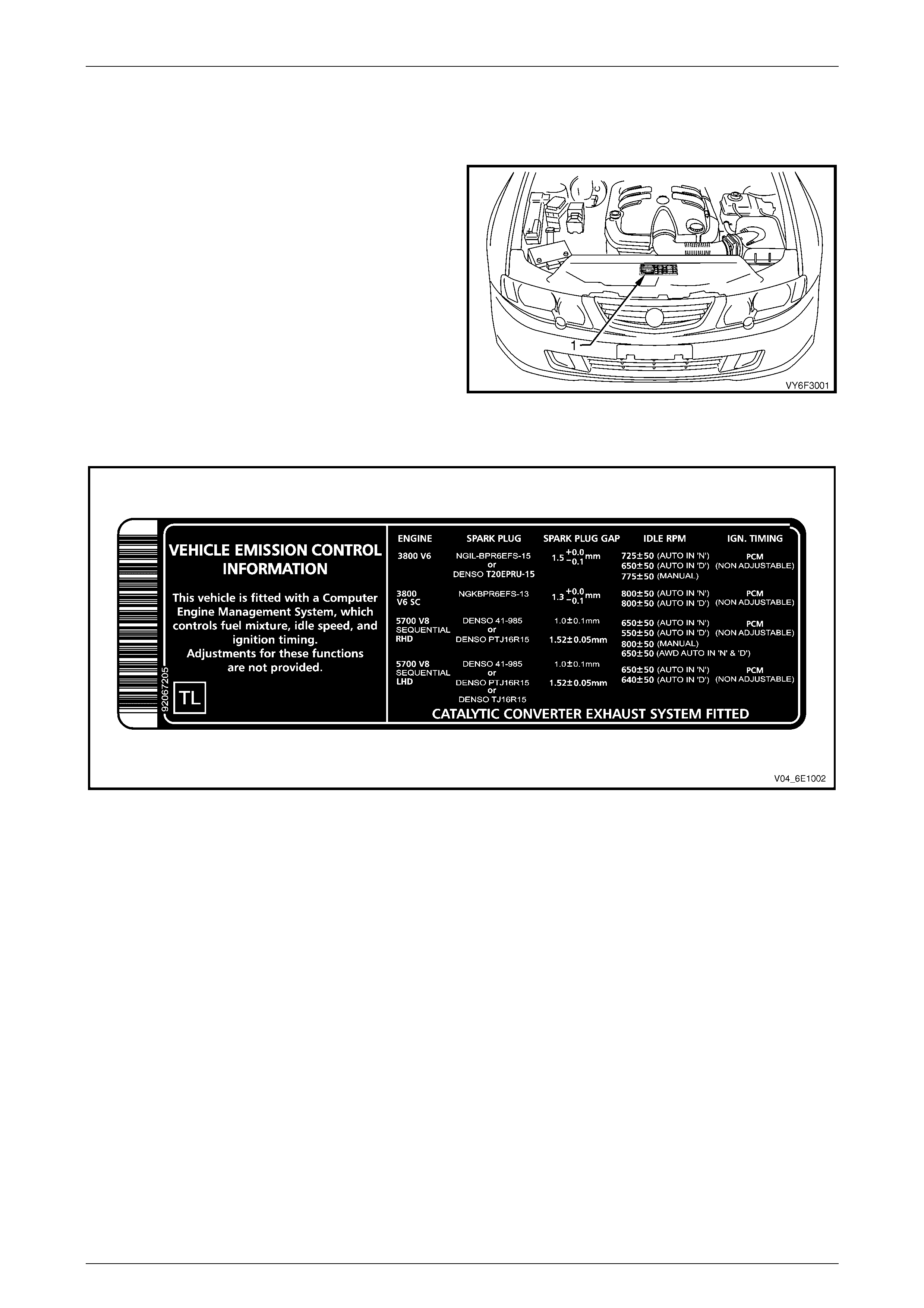
1.2 Vehicle Emission Control Information
Label
The vehicle emission control information label (1) is located
in the engine compartment on the grain free area of the
radiator shroud.
The label contains important engine tune conditions to
achieve the correct em is sion lev els, and sho uld be referred
to before making any adjus tm ents.
Refer to Figure 6E3 – 2 for a view of the vehicle emission
control information label.
Figure 6E3 – 1
Figure 6E3 – 2
Emission Control – V8 Engine Page 6E3–4
Page 6E3–4
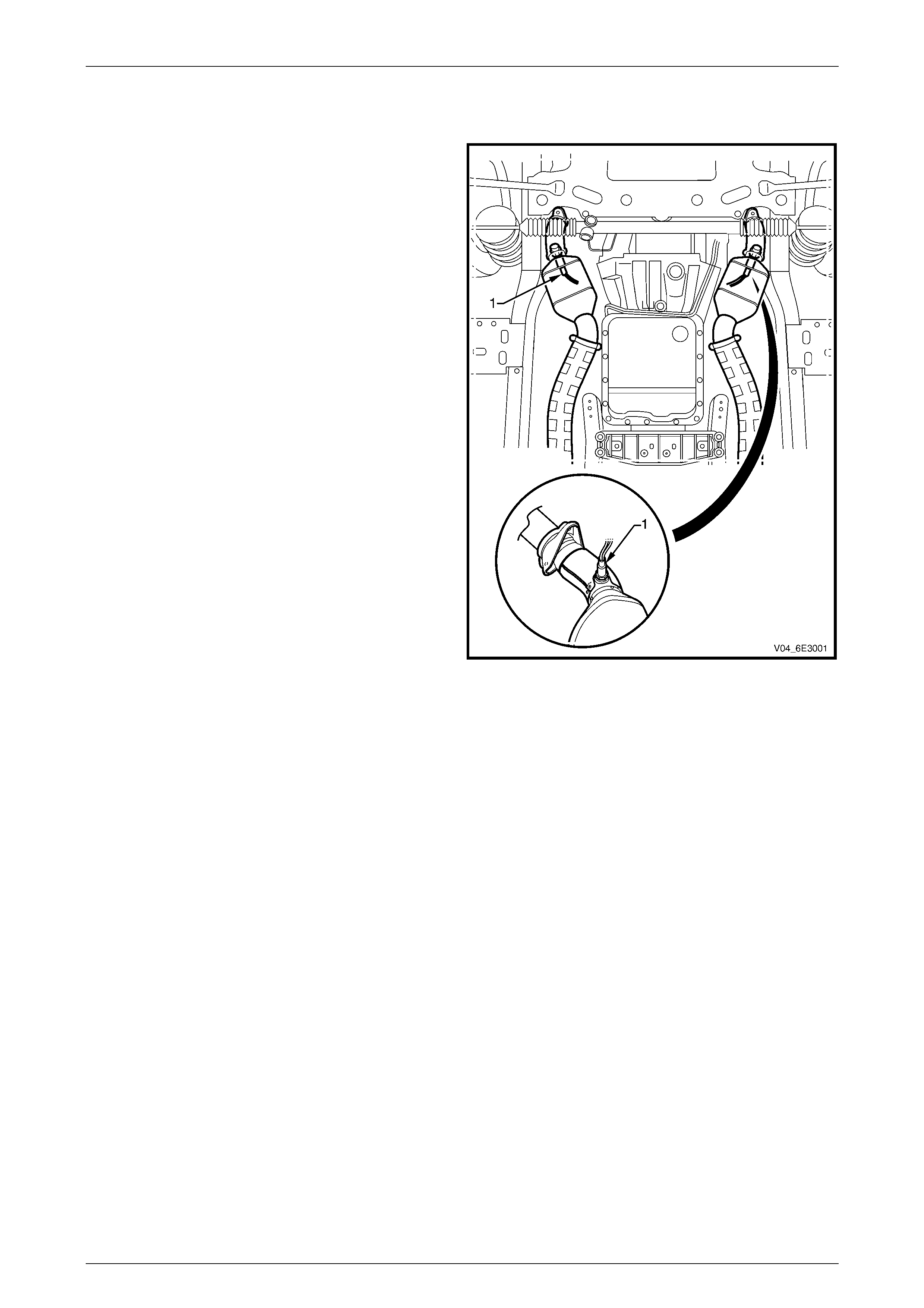
1.3 Emission Management
To comply with Euro 2 emission standard, with the
exception of the dual oxygen sensors (1) and the two re-
designed catalytic converters (2) being relocated, the
emission management carries over from MY 2003 VY
Series vehicles. Refer to Section 6E3 Emission Control
– GEN III V8 Engine in the MY 2003 VY and V2 Series
Service Information.
Each of the two oxygen sensors is located just upstream of
each catalytic converter, in the exhaust system.
For service procedures of the heated oxygen sensors, refer
to Section 6C3 Powertrain Management – GEN III V8
Engine.
NOTE
Automatic transmission is shown, manual
transmission is similar .
Figure 6E3 – 3
Emission Control – V8 Engine Page 6E3–5
Page 6E3–5
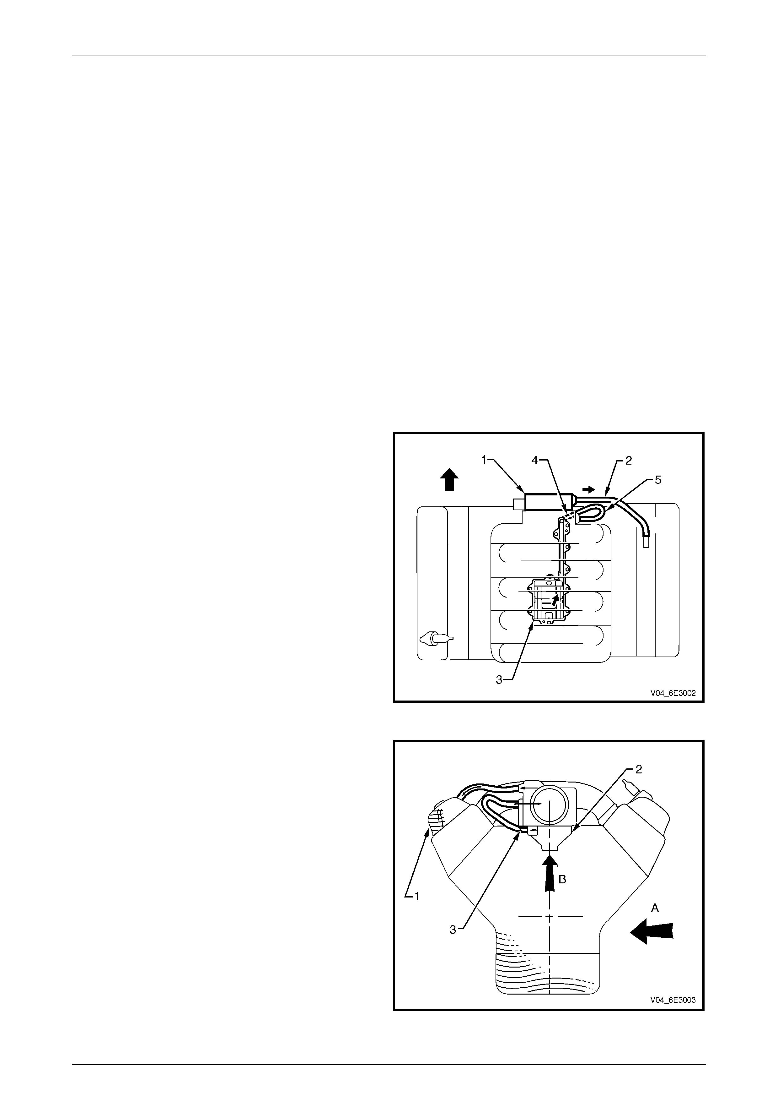
1.4 Positive Crankcase Ventilation
Description
The engine ventilation system was developed to remove the engine combustion blow-by vapours and minimise the
following:
• crankcase pres sure build-up,
• oil deterioration,
• oil consumpti on, and
• evaporative/exhaust emissions.
During normal idle and part throttle operation, this crankcase ventilation system provides a fresh air flow through the
crankcase, before being metered through a fixed orifice and into the intake manifold.
The positive crankcase ventilation system (PCV) does not include a PCV valve as on the previous model. Instead a fixed
internal flow-restricting orifice and an oil separator are included in the system.
For service procedure of the oil separator, refer to Section 6A3 Engine Mechanical – GEN III V8 Engine.
For testing of the positive crankcase ventilation system, refer to Section 6C3 Powertrain Management – GEN III V8
Engine.
Filtered fresh air is routed from upstream of the throttle
body (1) blade to the front of the right rocker cover via the
fresh air inlet hose (2).
Blow-by gas (oil vapour) in the crankcase valley passes
through the oil separator (3) before flowing through a fixed
internal flow-restricting orifice (4).
Via the foul air hose (5), the blow-by gas is directed from the
valley cover right-hand corner to the inlet manifold
downstream of the throttle body.
Under heavy load operation and high engine speeds, an
acceptable reverse flow condition may occur in the fresh air
inlet hose.
Figure 6E3 – 4
The Central Valley Ventilation System is designed to
eliminate oil ingestion during severe vehicle cornering
manoeuvres.
During sustai ned maximum lateral acc eler atio n (A), the
outboard rocker cover may be overloaded with oil (1).
The engine ventilation syste m prev ents the blow -by gas
from flowing directly from the rocker cover to the inlet
manifold and oil being ingested into the intake manifold.
Instead, the high efficiency oil separator (2), in conjunction
with the fixed internal flow-restricting orifice (3), is fitted
under the valley cover to draw the blow-by gas (B) from the
crankcase.
Figure 6E3 – 5

Emission Control – V8 Engine Page 6E3–6
Page 6E3–6
Result of Incorrect Operation
Should the fixed orifice become plugged or partially blocked; a hose became kinked, split or damaged; adverse
conditio ns cou ld resu lt.
A plugged or partially plugged orifice may cause:
• oil leaks, and
• sludge build-up in the engine.
A leaking hose in the engine ventilation system may cause:
• high idle speed, and
• sludge build-up in the engine.

Emission Control – V8 Engine Page 6E3–7
Page 6E3–7
1.5 Evaporation Emission Control
The evaporative emission control system carries over from MY 2003 VY and V2 Series vehicles. Refer to S ection 6E3
Emission Control – GEN III V8 Engine in the MY 2003 VY and V2 Series Service Information.
For information related to the EVAP canister purge valve control, refer to Section 6C3-1 General Information – GEN III
V8 Engine in the MY 2003 VY and V2 Series Service Information.
Emission Control – V8 Engine Page 6E3–8
Page 6E3–8
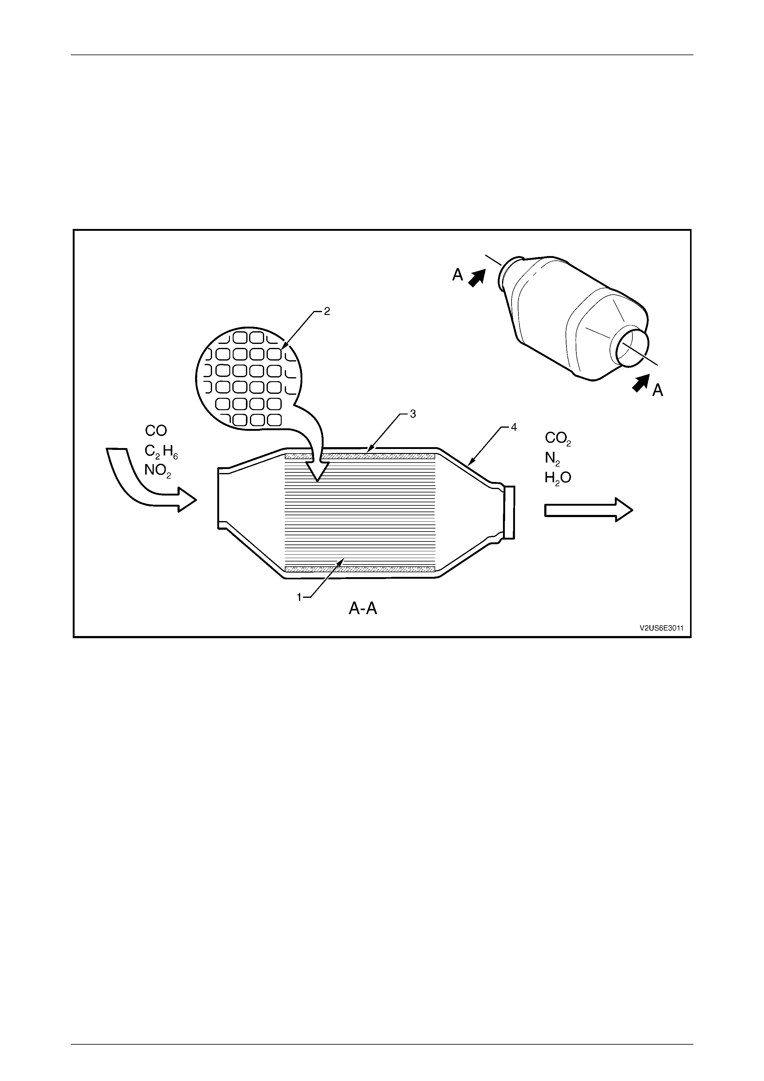
1.6 Three-Way Catalytic Converter
To comply with Euro 2 emission standard the three way catalytic converter configuration has been optimised with two
close-coupled catalytic converters fitted to the exhaust system. For a description of the three way catalytic converter
close-coupling, its location and service, refer to Section 8B Exhaust System.
For a view of the Euro 2 three way catalytic converter refer to Figure 6E3 – 6.
The three way catalytic converter principle of operation carries over from MY 2003 VY and V2 Series vehicles, refer to
Section 6E3 Emission Control – GEN III V8 Engine in the MY 2003 VY and V2 Series Service Information.
Figure 6E3 – 6
Legend
1 Ceramic Monolith
2 Cross Sect i on of Ceram ic Monolith 3 Ceramic Mat Securing Monolith
4 Stainless Steel Shell