
Clutch – V6 Engine Page 7A1–1
Page 7A1–1
Section 7A1
Clutch – V6 Engine
ATTENTION
Before performing any service operation or other procedure described in this Section, refer to Section 00
Warnings, Cautions and Notes for correct workshop practices with regard to safety and/or property damage.
1 General Information............................................................................................................................... 2
2. Service Operations................................................................................................................................3
2.1 Clutch Master Cylinder Pushrod...........................................................................................................................3
Disconnect..............................................................................................................................................................3
Reconnect...............................................................................................................................................................3
2.2 Clutch Pedal Calibration Switch ...........................................................................................................................4
Remove ...................................................................................................................................................................4
Reinstall ..................................................................................................................................................................4

Clutch – V6 Engine Page 7A1–2
Page 7A1–2
1 General Information
With the following exceptions, MY 2004 VY and V2 Series Clutch – V6 Engine Information carries over from MY 2003 VY
and V2 Series vehicles. For information not contained within this Section, refer to Section 7A1 Clutch – V6 Engine in the
MY 2003 VY and V2 Series Service Information.
• A clutch pedal calibration switch has been fitted to all manual vehicles with a V6 engine
• The clutch master cylinder push rod to the clutch pedal pivot pin ha s a quick connect fitting
NOTE
For clutch pedal calibration switch information,
refer to Section 6C1-1- General Information - V6
Engine.
Clutch – V6 Engine Page 7A1–3
Page 7A1–3
2. Service Operations
2.1 Clutch Master Cylinder Pushrod
NOTE
For information relating to the clutch
master cylinder assembly, refer to
Section 7A1, 3.5 Clutch Master Cylinder in
MY 2003 VY and V2 Series Service Information.
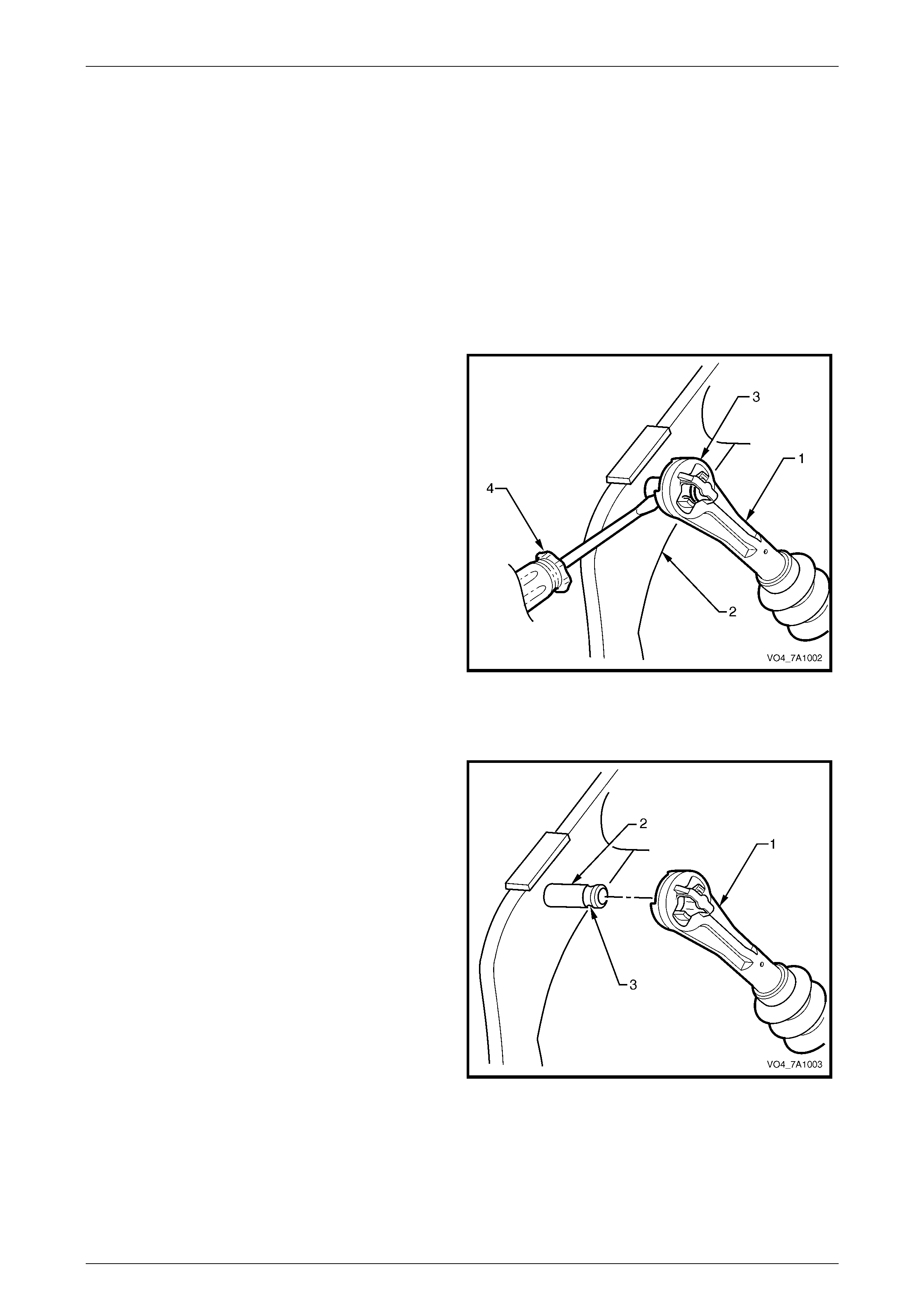
Disconnect
1. Disconnect the clutch master cylinder push rod (1)
from the pin attached to the clutch pedal (2) by prising
the pushrod quick connect fitting (3) with a
screwdriver (4).
Figure 7A1 – 1
Reconnect
1 Reinstall the clutch master cylinder push rod (1) to the
clutch pedal pivot pin (2), ensuring that the quick
connect retaining clips are fully engaged in the
groove (3).
Figure 7A1 – 2
Clutch – V6 Engine Page 7A1–4
Page 7A1–4
2.2 Clutch Pedal Calibration Switch
Remove
Disable the Occupant Protection System.
Refer to Section 12M, Occupant Protection
System.
1 Disconnect the battery ground lead.
2 As required, first remove the following components:
a Driver side instrument panel lower trim plate assembly, refer to Section 1A3, Instrument Panel and Console.
b Instrument panel lower trim panel assembly, refer to Section 1A3, Instrument Panel and Console.
c Instrument panel lower trim panel retainer, refer to Section 1A3, Instrument Panel and Console.
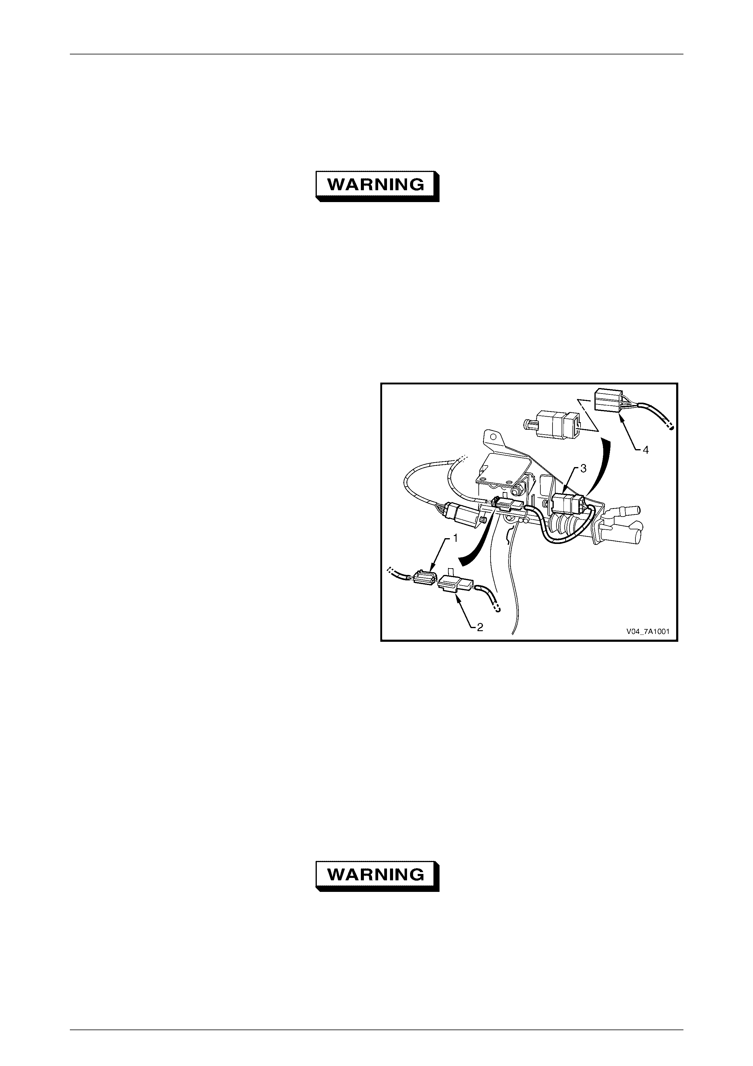
3 Disconnect the main wiring harness connector (1) from
the clutch pedal calibration switch patch harness
connector (2).
4 Remove the clutch pedal calibration switch patch
harness connec tor fr om the cl utch ped al supp ort
bracket by prising the two retaining tabs with a
screwdriver to release the tabs.
4 Remove the clutch pedal position switch (3) by rotating
the switch counter-clockwise a 1/4 of a turn, then pull
to free the switch bayonet lugs.
4. Disconnect the clut ch pedal calibration switch patch
harness connector (4) from the clutch pedal position
switch.
Figure 7A1 – 3
Reinstall
1 Reinstall the clutch pedal calibration switch patch harness connector (4) to the clutch pedal calibration switch, refer
to Figure 7A1 – 3.
2 Install the clutch pedal calibration switch by rotating it a 1/4 of a turn clockwise to lock the switch bayonet lugs.
2 Clip the clutch pedal calibration switch patch harness connector (2) to the clutch pedal support bracket.
3 Reinstall the main wiring harness connector to the clutch pedal calibration switch patch harness.
4 Reinstall all removed instrument panel components in the reverse order to that off the removal operations.
Enable the Occupant Protection System.
Refer to Section 12M, Occupant Protection
System.
5 Road test the vehicle to check the clutch pedal calibration switch operation. For clutch pedal calibration switch
information, refer to Section 6C1-2-Diagnosis - V6 Engine.