
Manual Transmission – GEN III V8 Engine Page 7B2–1
Page 7B2–1
Section 7B2
Manual Transmission – GEN III V8 Engine
ATTENTION
Before performing any service operation or other procedure described in this Section, refer to Section 00
Warnings, Cautions and Notes for correct workshop practices w ith regard to safety and/or property damage.
1 General Information............................................................................................................................... 2
2 Major Service Operations ..................................................................................................................... 3
2.1 Remote Control Shift Mechanism.........................................................................................................................3
Remove ...................................................................................................................................................................3
Disassemble...........................................................................................................................................................4
Clean and Inspect ..................................................................................................................................................5
Clean..................................................................................................................................................................5
Inspect................................................................................................................................................................5
Reassemble............................................................................................................................................................6
Reinstall..................................................................................................................................................................8
3 Torque Wrench Specifications............................................................................................................. 9
Techline
Techline
Techline
Techline
Techline
Techline

Manual Transmission – GEN III V8 Engine Page 7B2–2
Page 7B2–2
1 General Information
With the following exceptions, MY 2004 VY and V2 Series GEN III V8 Manual Transmission Service Information carries
over from MY 2003 VY and V2 Series vehicles. For information not contained within this Section, refer to Section 7B2,
Manual Transmission in the MY 2003 VY and V2 Series Service Information.
• Bridged washer fitted to the remote shifter mechanism.
• New exhaust system fitted to the MY 2004 VY and V2 Series vehicles.
This Section covers the revi sed Service Information for the MY 2004 VY and V2 Series GEN III V8 Manual Transmission
remote shifter mechanism. Where the manual transmission service procedure includes the removal of an exhaust
system component, refer to Section 8B, Exhaust System.
Manual Transmission – GEN III V8 Engine Page 7B2–3
Page 7B2–3
2 Major Service Operations
2.1 Remote Control Shift Mechani sm
Remove
1 Remove the transmission assembly from the vehicle. Refer to Section 7B2, Manual Transmission – Gen III V8 in
the MY 2003 VY Series and V2 Series Service Information.
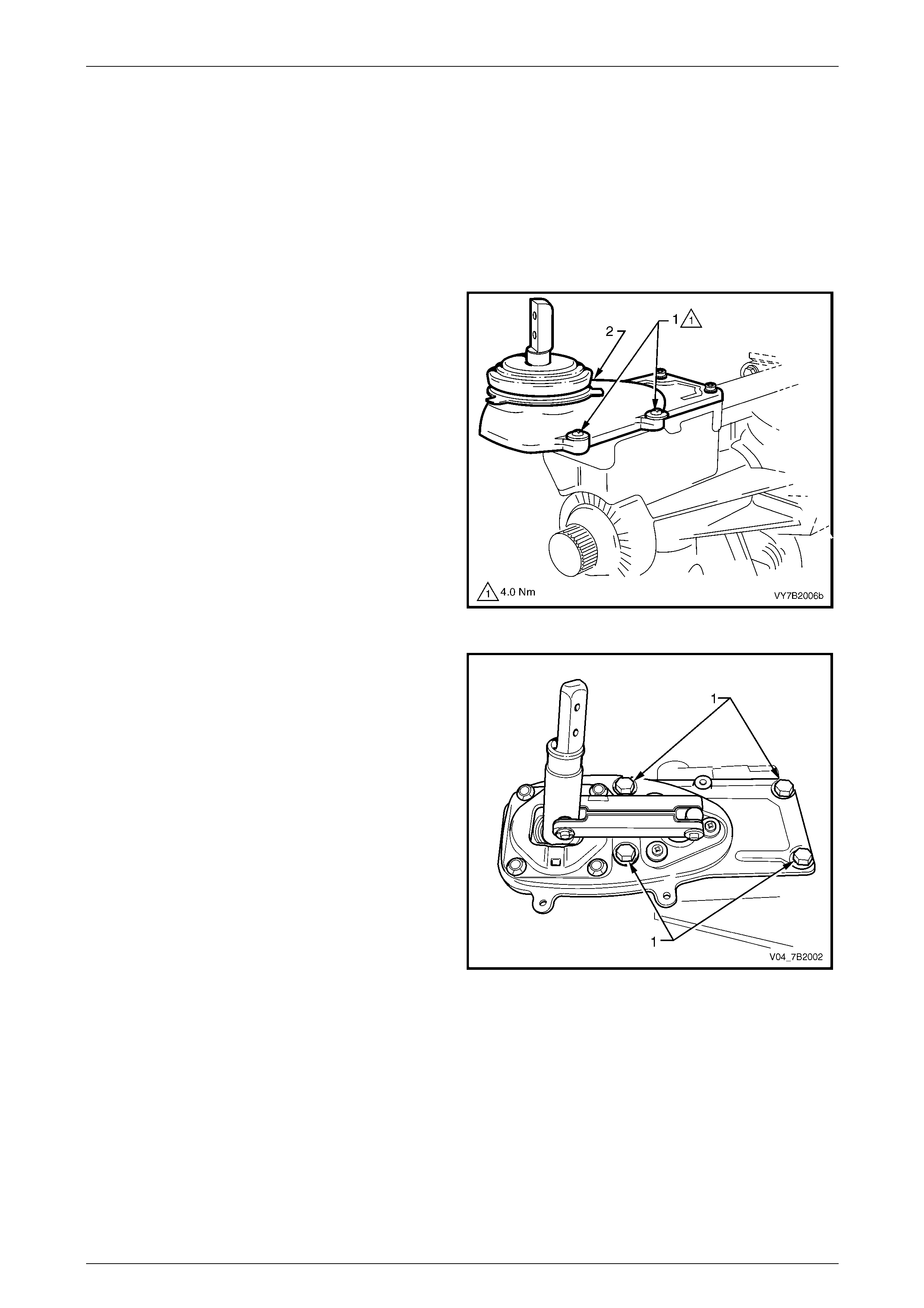
2 Remove the screws (1) attaching the shift lever cover
to the shifter assembly.
3 Remove the shifter lever cover (2) from the shifter
assembly.
Figure 7B2 – 1
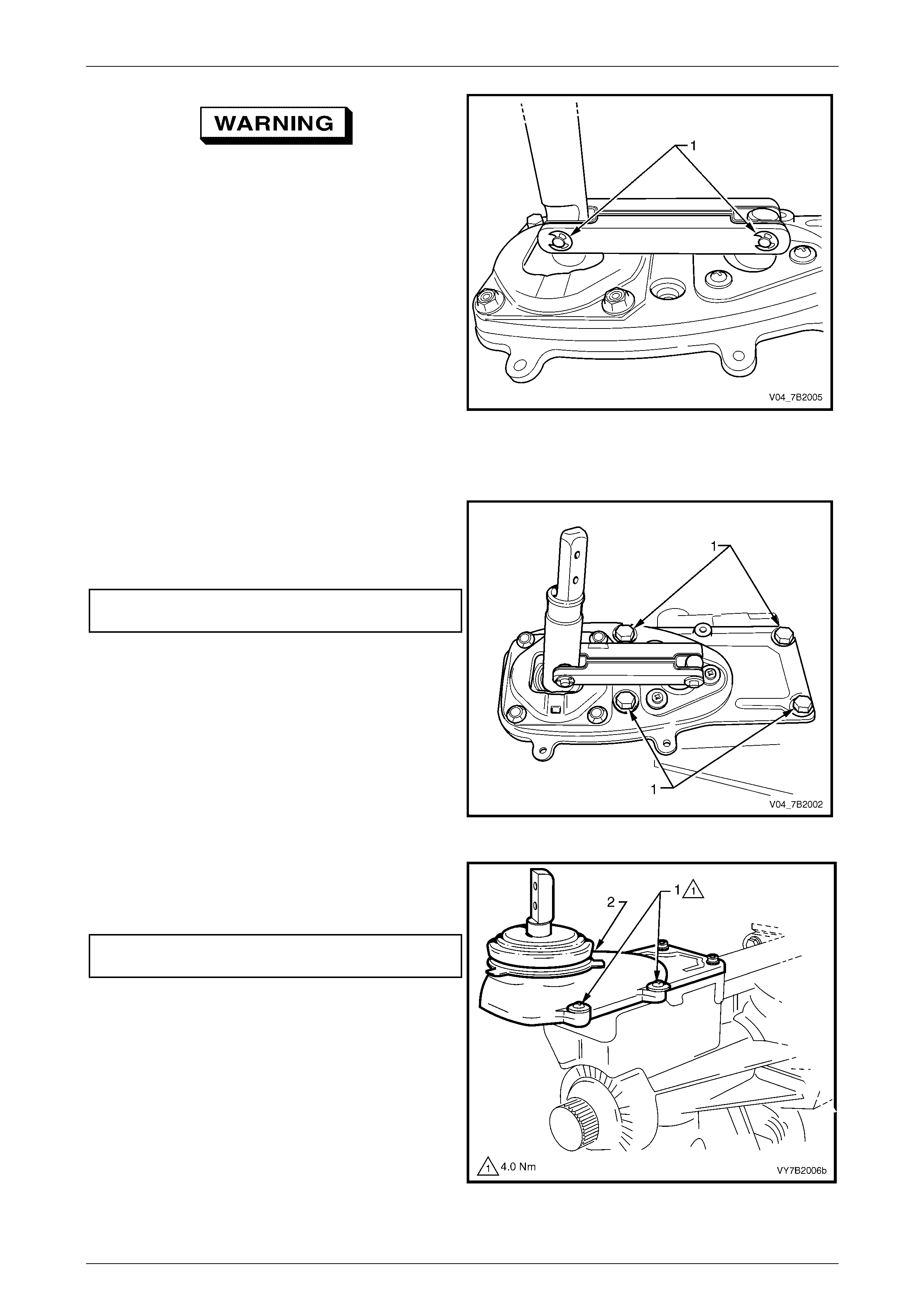
4 Shift the transmission into 2nd or 4th gear.
5 Remove the bolts (1) attaching the shifter assembly to
the transmission extension housing.
6 Tap the shifter assembly with a rubber or plastic
hammer to break the seal.
7 Remove the shifter assembly from the transmission
extension housing.
Figure 7B2 – 2
Manual Transmission – GEN III V8 Engine Page 7B2–4
Page 7B2–4
Disassemble
Wear safety glasses to avoid possible eye
injury.
1 Using a small screwdriver, remove both E-clips (1)
from the shifter lever pins.
Figure 7B2 – 3
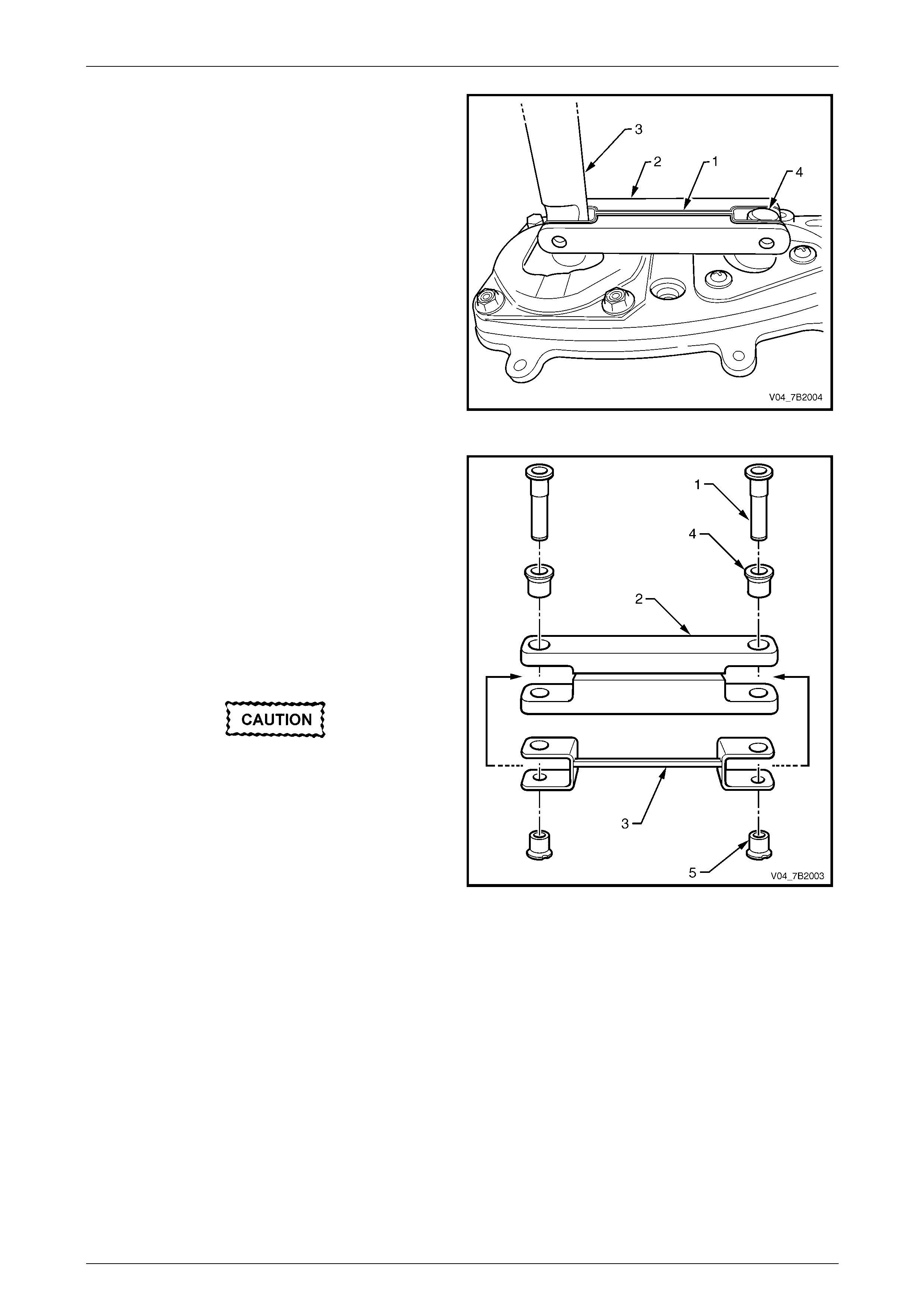
2. Tap the two pivot pins (1) free from the bridging piece
(2).
The pivot pins are designed to be
interference fit to the remote shifter shaft and
the selector pivot. Therefore, the pivot pins
must be replaced after removal.
NOTE
The remote shifter shaft and the selector pivot
are not shown for clarity of illustration.
3 Remove the bridged washer (3) located on the
bridging piece.
4 Remove both the large (4) and small (5) bushes from
the bridging piece.
Figure 7B2 – 4
Manual Transmission – GEN III V8 Engine Page 7B2–5
Page 7B2–5
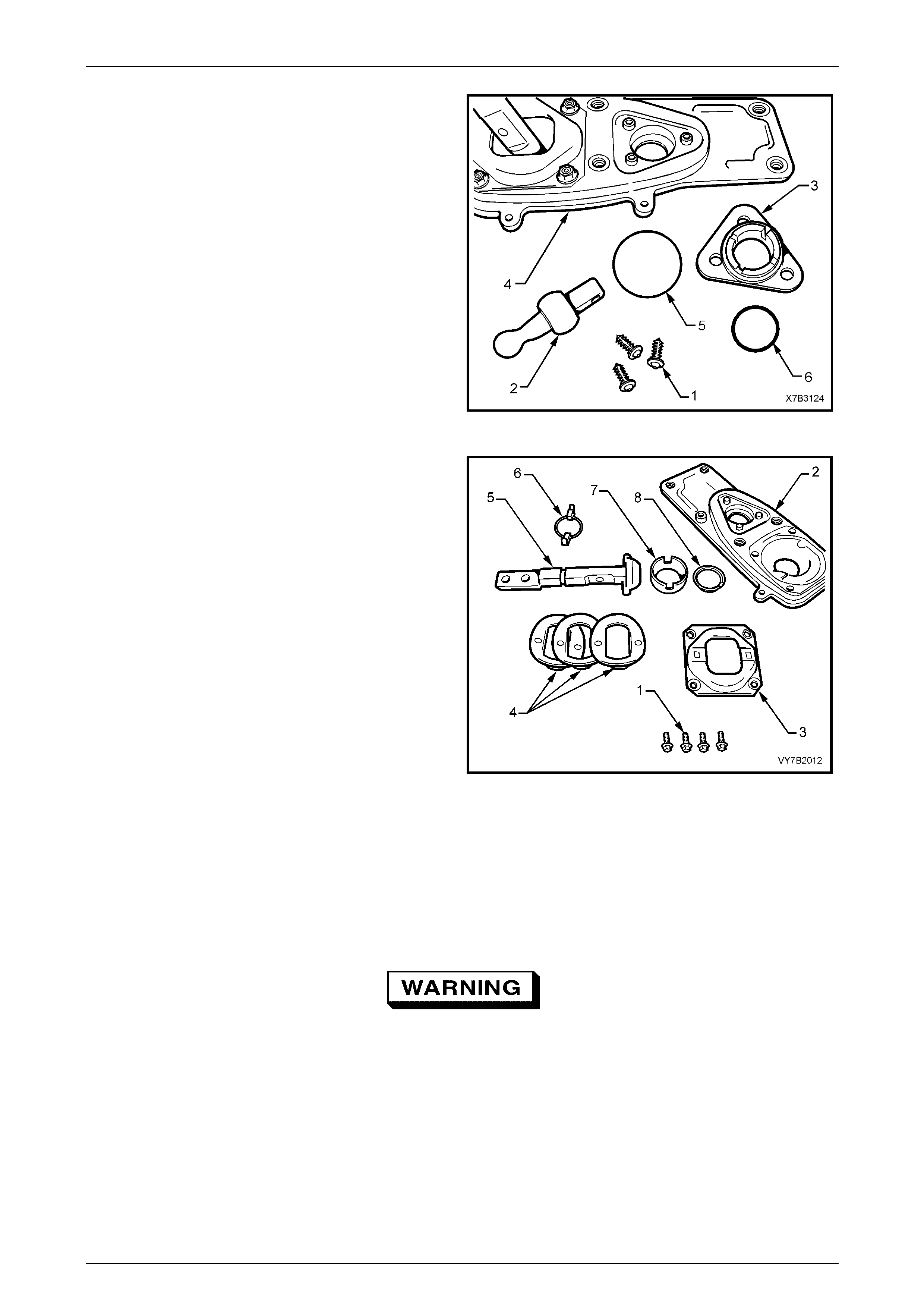
5 Remove the selector pivot seat (3) self-tapping
screws (1).
6 Remove the remote selector pivot (2) and the pivot
seat from the baseplate (4).
7 Remove the O-ring seals (5 and 6) from the pivot
seat.
8 Support the pivot seat assembly in a soft jaw bench
vice.
9 Using a rubber or plastic hammer, tap the ball end of
the selector pivot until it separates from of the pivot
seat.
Figure 7B2 – 5
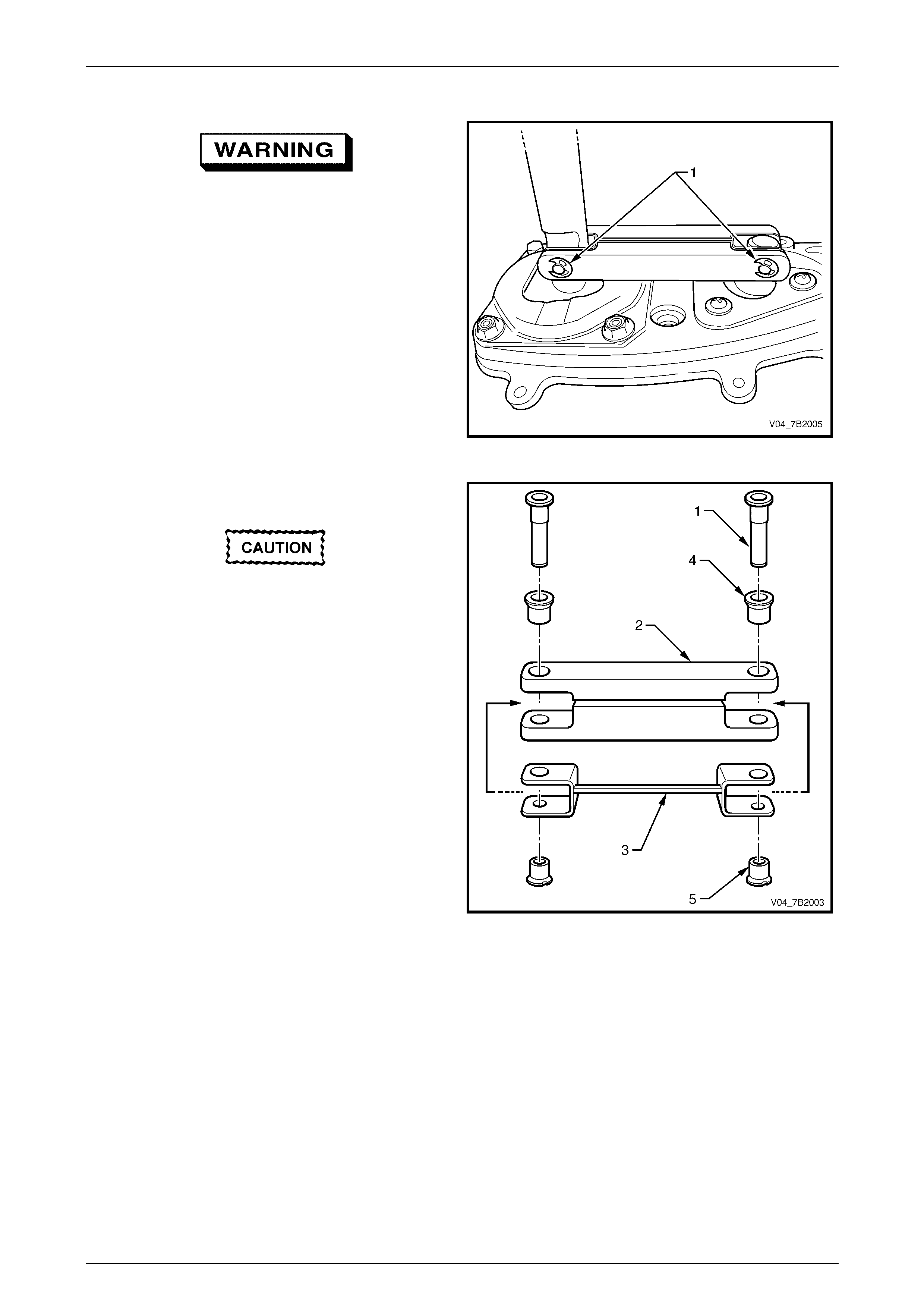
10 Remove the bolts (1) retaining the remote shift shaft
plate to the base plate (2).
11 Remove the remote shift shaft plate (3) from the base
plate.
12 Remove the wave springs (4), remote shifter shaft (5)
and guide (6) from the base plate.
13 Remove the ball seat (7) and seat support ring (8)
from the base plate.
Figure 7B2 – 6
Clean and Inspect
Clean
1 Remove the rubber insulating bushes and seal from the extension housing.
2 Thoroughly wash all components in a suitable cleaning solvent.
Wear safety glasses to avoid eye injury.
3 Blow-dry all components using compressed air.
Inspect
1 Inspect pins, bushes, ball seats and other components for wear or damage. Replace as required.
2 Inspect the O-ring seal at the front pivot assembly, the cover plate insulating rubber bushes and seal to the
extension housing for deterioration or damage. Replace as required.
Manual Transmission – GEN III V8 Engine Page 7B2–6
Page 7B2–6
Reassemble
Reassembly is the reverse of the disassembly procedure except for the following:
1 Apply 10% molybdenum disulphide grease such as Molybond GA 10 or equivalent to all moving parts in the rear
remote shifter assembly.
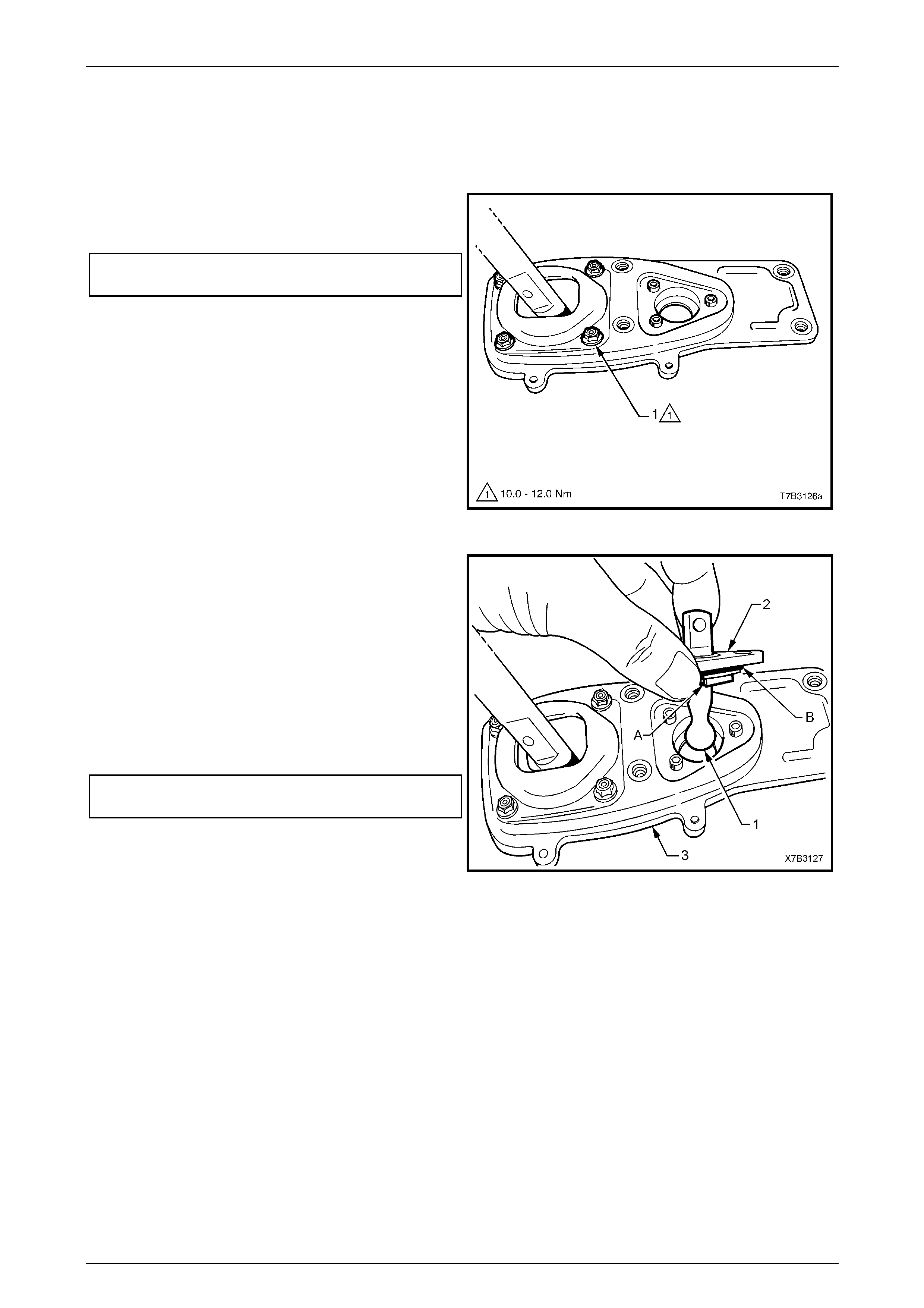
2 Reinstall the bolts (1) retaining the remote shift lever
plate to the baseplate and tighten to the correct torque
specification.
Rear remote shift lever plate
bolt torque specification ..........................10.0 - 12.0 Nm
Figure 7B2 – 7
3 Apply NLGI No. 4 EP grease to the ball socket of the
front selector pivot (1).
4 Using a rubber or plastic hammer, tap the front
selector pivot until fully seated in the pivot seat (2).
5 Install the O-ring seals (A) and (B) to the selector pivot
seat.
6 Reinstall the front selector pivot assembly to the
baseplate (3).
7 Install the selector pivot assembly retaining screws
and tighten to the correct torque specification.
Front selector pivot seat
screw torque specification................................... 4.0 Nm
Figure 7B2 – 8
Manual Transmission – GEN III V8 Engine Page 7B2–7
Page 7B2–7
8 Insert the bridged washer (1) into the bridging
piece (2).
9 Position the bridging piece into the remote shifter
shaft (3) and the selector pivot (4).
Figure 7B2 – 9
10 Lubricate both the new large (4) and small (5) bushes
with NLGI No. 4 EP grease or equivalent.
11 Install the new bushes into the bridging piece (2).
NOTE
The remote shifter shaft and the selector pivot
are not shown for clarity of illustration.
12 Insert the new pivot pins (1) into its correct location in
the bridging piece.
13 Tap the new pivot pins into the bridging piece until
fully seated.
The pivot pins are designed to be
interference fit to the remote shifter shaft and
the selector pivot. Therefore, the pivot pin
should not free float in the remote shifter
shaft and the selector pivot.
Figure 7B2 – 10
Manual Transmission – GEN III V8 Engine Page 7B2–8
Page 7B2–8
Wear safety glasses to avoid possible eye
injury.
14 Fit new E-clips (1) to secure the pivot pin.
Figure 7B2 – 11
Reinstall
1 Install the shifter assembly to the extension housing.
2 Install the shifter assembly insulating grommets and
the retaining bolts (1) and tighten to the correct torque
specification.
Shifter assembly retaining
bolt torque specification .........................15.0 – 20.0 Nm
Figure 7B2 – 12
3 Install the shifter cover (2) over the shifter assembly.
4 Install the shifter cover screw (1) and tighten to the
correct torque specification.
Shifter cover retaining
screw torque specification................................... 4.0 Nm
5 Reinstall the transmission assembly into the vehicle.
Refer to Section 7B2, Manual Transmission – Gen III
V8 in the MY 2003 VY Series and V2 Series Service
Information.
Figure 7B2 – 13

Manual Transmission – GEN III V8 Engine Page 7B2–9
Page 7B2–9
3 Torque Wrench Specifications
Front Selector Pivot Seat Screw.............................................................4.0 Nm
Shifter Assembly Retaining Bolt................................................15.0 – 20.0 Nm
Shifter Cover Retaining Screw................................................................ 4.0 Nm