
Exhaust System Page 8B–1
Page 8B–1
Section 8B
Exhaust System
IMPORTANT
Before performing any service operation or other procedure described in this Section, refer to Section 00
Warnings, Cautions and Notes for correct w orkshop practices with regard to safety and/or property damage.
1 General Information............................................................................................................................... 3
1.1 Emission Reductions.............................................................................................................................................3
Catalytic Converter Close Coupling.....................................................................................................................3
Euro 2 Emissions Standards.................................................................................................................................3
1.2 Exhaust System Configurations...........................................................................................................................4
V6 Engine Exhaust System ...................................................................................................................................4
V6 Supercharged Engine Exhaust System..........................................................................................................5
Gen III V8 Engine Exhaust System .......................................................................................................................5
Standard Exhaust...............................................................................................................................................5
Performance Exhaust.........................................................................................................................................6
2 Service Operations - V6......................................................................................................................... 8
2.1 Service Notes .........................................................................................................................................................8
Catalytic Converter.................................................................................................................................................8
2.2 Exhaust System......................................................................................................................................................9
2.3 Complete Exhaust System Assembly.................................................................................................................10
Remove .................................................................................................................................................................10
Reinstall................................................................................................................................................................12
2.4 Rear Exhaust Assembly.......................................................................................................................................13
Remove .................................................................................................................................................................13
Reinstall................................................................................................................................................................13
2.5 Intermediate Single Pipe and Muffler Exhaust Assembly ................................................................................14
Remove .................................................................................................................................................................14
Reinstall................................................................................................................................................................15
2.6 Intermediate Y-pipe Exhaust Assembly.............................................................................................................16
Remove .................................................................................................................................................................16
Reinstall................................................................................................................................................................17
2.7 Front Exhaust Assemblies..................................................................................................................................18
Remove .................................................................................................................................................................18
Reinstall................................................................................................................................................................20
2.8 Tightening Sequence...........................................................................................................................................21
3 Service Operations – GEN III V8......................................................................................................... 23
3.1 Service Notes .......................................................................................................................................................23
Catalytic Converter...............................................................................................................................................23
3.2 Exhaust System....................................................................................................................................................24
3.3 Complete Exhaust System Assembly.................................................................................................................26
Remove .................................................................................................................................................................26
Reinstall................................................................................................................................................................28
3.4 Rear Exhaust Assembly.......................................................................................................................................30
Remove .................................................................................................................................................................30
Reinstall................................................................................................................................................................31
3.5 Intermediate Exhaust Assembly.........................................................................................................................32
Remove .................................................................................................................................................................32
Reinstall................................................................................................................................................................33

Exhaust System Page 8B–2
Page 8B–2
3.6 Front Exhaust Assemblies..................................................................................................................................34
Remove .................................................................................................................................................................34
Reinstall................................................................................................................................................................35
3.7 Tightening Sequence...........................................................................................................................................37
4 Service Operations – Heat Shields .................................................................................................... 39
4.1 Exhaust System Heat Shields.............................................................................................................................39
4.2 Rear Muffler Underbody Mounted Heat Shield..................................................................................................41
Remove .................................................................................................................................................................41
Reinstall................................................................................................................................................................41
4.3 Intermediate Muffler Underbody Mounted Heat Shield.....................................................................................42
Remove .................................................................................................................................................................42
Reinstall................................................................................................................................................................42
4.4 Front Foil Underbody Mounted Heat Shields ....................................................................................................43
Remove .................................................................................................................................................................43
Reinstall................................................................................................................................................................43
4.5 Front Exhaust Assemblies On-Pipe Heat Shields – Pre-Catalytic Converter .................................................44
5 Exhaust System Clearances............................................................................................................... 45
5.1 V6 Exhaust System Clearances..........................................................................................................................45
5.2 GEN III V8 Exhaust System Clearances .............................................................................................................46
6 Torque Wrench Specifications........................................................................................................... 47

Exhaust System Page 8B–3
Page 8B–3
1 General Information
With the following exceptions, MY 2004 VY and V2 Series Exhaust System information carries over from MY 2003 VY
and V2 Series vehicles:
• heat shields,
• V6 exhaust system for domestic vehicles produced after the start of 2004,
• V6 exhaust system for vehicles produced for export to the Gulf States and Thailand,
• V6 Supercharged exhaust system for vehicles produced after the start of 2004, and
• V8 exhaust system for all vehicles.
For Exhaust System information not contained within this Section, refer to Section 8B Exhaust System in the MY 2003
VY and V2 Series Service information.
1.1 Emission Reductions
Through developments in various vehicle emissions reduction systems, significant reductions in emissions have been
achieved on MY 2004 VY and V2 Series vehicles. The developments have been primarily concerned with refinements in
engine calibration and the optimisation of exhaust system catalytic converter configurations. The major modifications
made to reduce emissions from previous Series vehicles includes the incorporation of two close coupled catalytic
converters on V6 and V8 vehicles. Catalytic converter internal material specifications have been revised on V6
Supercharged vehicle exhaust systems.
Catalytic Converter Close Coupling
As optimum catalytic converter performance is reached above 500°C, a close coupling of the catalytic converter with the
exhaust manifold ensures that upon engine startup, the engine exhaust gasses can heat the catalytic converter to
optimum temperatures in as short a time as possible. This period of catalytic converter warm up is often referred to as
catalytic converter ‘light up’.
Euro 2 Emissi ons St andar ds
With the following exceptions, MY 2004 VY and V2 Series vehicles meet Euro 2 emissions standards:
• V6 exhaust system for domestic vehicles produced before the start of 2004,
• V6 exhaust system for vehicles produced for export to Brazil and Indonesia, and
• V6 supercharged exhaust system for vehicles produced before the start of 2004.
The Euro 2 emissions standard is a European standard which aims at setting vehicle emissions targets to encourage
vehicle manufacturers to reduce harmful vehicle emissions such as carbon monoxide (CO), hydrocarbons (HC) and the
various oxides of nitrogen (NOx).
For further information on catalytic converter construction and operation, refer to Section 8B, 1.2 Exhaust Catalytic
Converter in the MY 2003 VY and V2 Series Service Information.
Exhaust System Page 8B–4
Page 8B–4
1.2 Exhaust System Configurations
V6 Engine Exhaust System
The complete system has been revised, except for the rear exhaust assembly, which carries over from MY 2003 VY and
V2 Series vehicles. The system incorporates two close-coupled catalytic converters, two heated oxygen sensors, on-
pipe heat shielding and reconfigured front and intermediate exhaust assemblies.
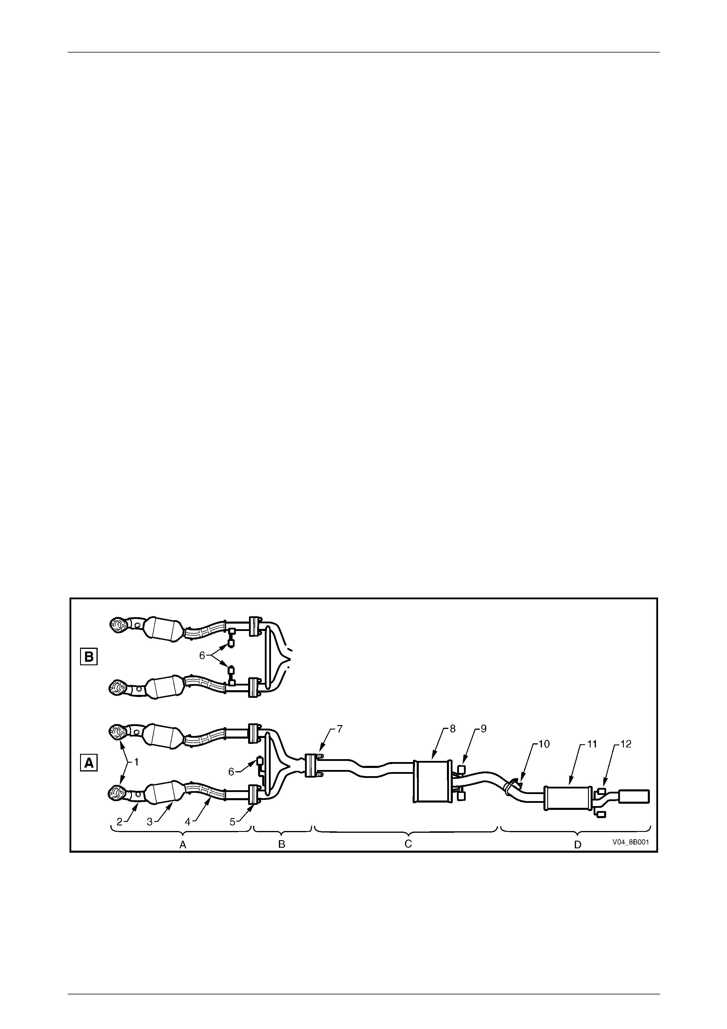
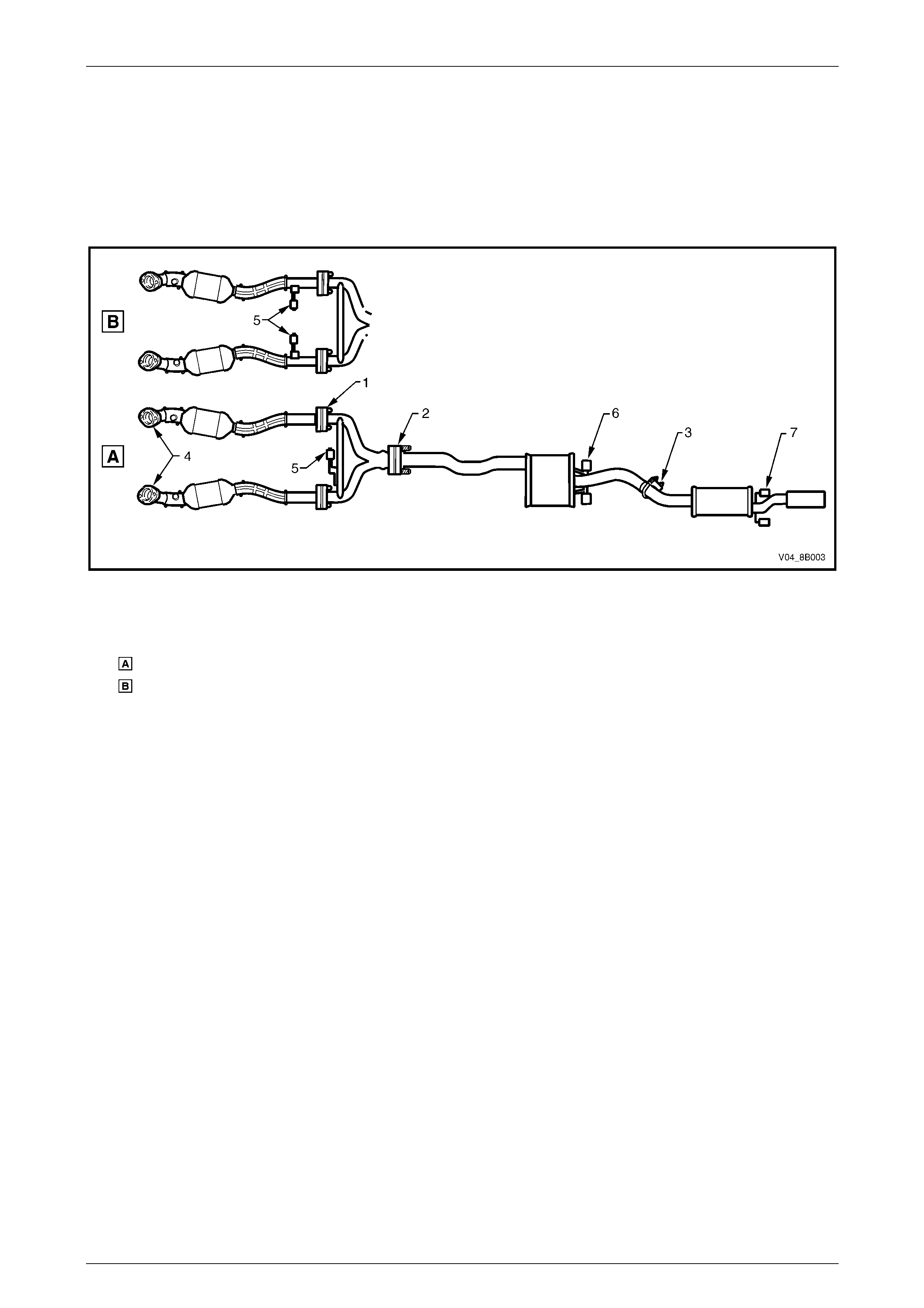
Refer to Figure 8B – 1 for the following.
The V6 engine exhaust manifolds are connected to a pair of stainless steel front pipes by flange joints (1). Each front
pipe runs into a close-coupled three-way catalytic converter (3) and then continues from the rear of the three-way
catalytic converter to join up with the intermediate Y-pipe exhaust assembly. These pipes are joined by gasketed flange
joints (5). The intermediate Y-pipe exhaust assembly merges into a single pipe and joins up with the intermediate single
pipe and muffler exhaust assembly with a swivel flange joint (7), fitted with an internal sealing ring. The swivel flange
joint is held together with a pair of attaching stepped bolts and coil springs. Combined, the Y-pipe and the single pipe
and muffler assemblies (items B and C) are identified as the intermediate exhaust assembly.
The single pipe of the intermediate exhaust assembly runs on into the muffler (8) and extends from the rear of the
muffler to join up with the pipe of the rear exhaust assembly. These two pipes are joined together with a slip joint and a
U-clamp (10).
For the automatic transmission (view A), the front of the exhaust assembly is supported by a support rubber (6) attached
to a hanger connected to the transmission extension housing and to a cross brace and peg assembly welded across the
intermediate Y-pipe exhaust assembly.
For the manual transmission (view B), the front of the exhaust assembly is supported by two support rubbers (6)
attached to hangers welded to the front exhaust assemblies.
The intermediate single pipe and muffler exhaust assembly is supported by two support rubbers (9) that are attached to
hangers welded to the vehicle underbody and to pegs welded to the rear of the intermediate muffler. The rear exhaust
assembly is supported by two support rubbers (12) that are attached to hangers welded to the vehicle underbody and to
pegs welded to the tailpipe just downstream of the rear muffler (11).
The support rubbers are a common part for all locations and are secured by retainer clips at the underbody hangers for
the intermediate and rear exhaust. Flanged pegs are used at other locations.
Pre-catalytic converter on-pipe heat shields (2) and post-catalytic converter on-pipe heat shields (4) are used along
each pipe of the front exhaust assemblies. Metal plate heat shields attached to the underbody are used above the
intermediate and rear mufflers. Foil plate heat shields are attached to the underbody just to the rear of each catalytic
converter.
Figure 8B – 1

Exhaust System Page 8B–5
Page 8B–5
Legend
View Automatic Transmission
View Manual Transmission
A Front Exhaust Assem bli es
B Intermediate Y-pi pe Exhaust
Assembly
C Intermediate Si ngl e Pipe and
Muffler Exhaust Assembly
D Rear Exhaust Assembly
1 Manifold to Front P i pe Fl ange Joint
2 Pre-cat al yt i c Converter Heat S hi el d s
and Oxygen Sensor Mounting Boss
3 Catalytic Converter
4 Post -catalyti c Converter Heat S h i el ds
5 Front Pipe t o Intermedi ate Y-pipe
Flange Joint
6 Support Rubber(s)
7 Swivel Flange Joint
8 Intermediate Muffler
9 Intermediate Muff l er Support Rubbers
10 Intermediate to Rear Pipe Slip Joint and
U-clamp
11 Rear Muffler
12 Rear Muffler Support Rubbers
V6 Supercharged Engine Exhaust System
The exhaust system for vehicles fitted with V6 supercharged engines carry over from MY 2003 VY except for revised
catalytic converter internal material specifications. This change to the catalytic converter will not affect the service
operations.
Gen III V8 Engine Exhaust System
The exhaust systems fitted to vehicles with the Gen III V8 engine have revised front exhaust assemblies. These
incorporate close-coupled catalytic converters, revised under body heat shield configuration and new on-pipe heat
shields.
Two exhaust system configurations, Standard and Performance, are available for vehicles fitted with the GEN III V8
engine. The exhaust system configuration installed will depend on the specifications of the particular vehicle.
Standard Exhaust
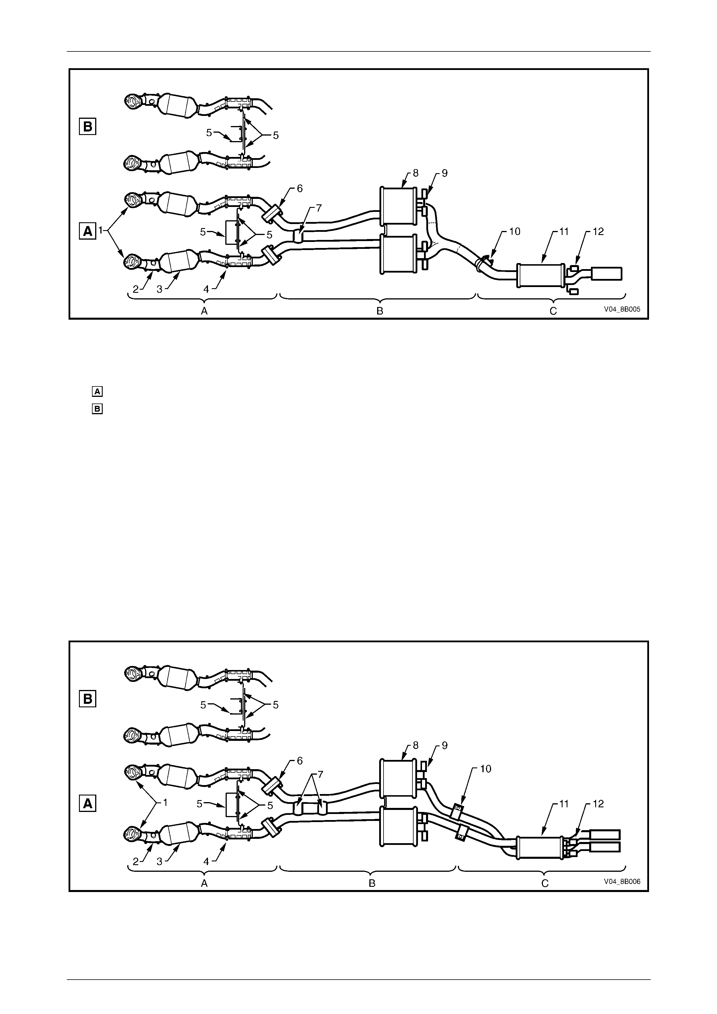
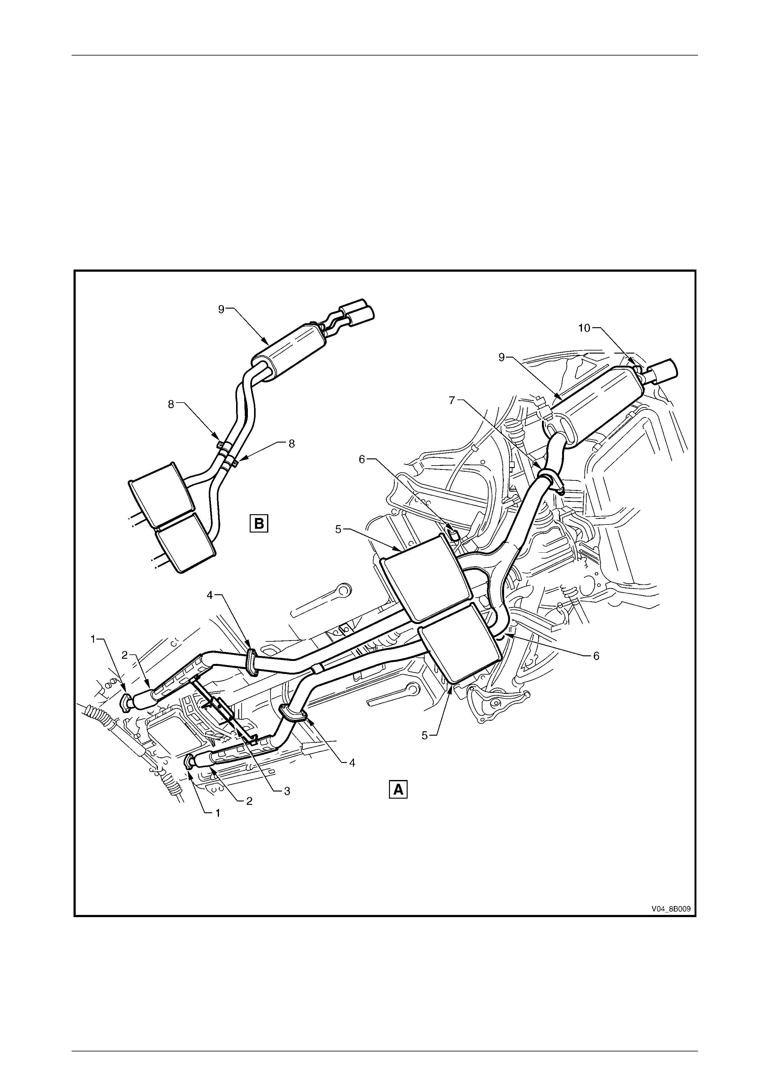
Refer to Figure 8B – 2 for the following.
The GEN III V8 engine exhaust manifolds are connected to a pair of stainless steel front exhaust pipes by flange
joints (1). A dual pipes exhaust system is retained past the twin intermediate mufflers (8). The pipes then converge into
a single pipe that is joined to the rear exhaust assembly with a slip joint and U-clamp (10).
A catalytic converter (3) is welded to each front exhaust pipes, which are connected with the twin intermediate exhaust
pipes with a gasketed flange joint (6).
The front of the exhaust assembly is supported by a cross brace and transmission mount (5), which bridges between
each of the front exhaust pipes and is bolted onto the transmission extension housing.
The two intermediate exhaust pipes are stiffened by a welded bridging piece, located before the twin intermediate
mufflers. The bridging piece also functions as an exhaust balance pipe (7). The intermediate exhaust assembly is
supported by two pairs of support rubbers (9) attached to hangers welded to the vehicle underbody and to pegs welded
to the rear of the intermediate mufflers (8). The rear exhaust assembly is supported by two support rubbers (12)
attached to hangers welded to the vehicle underbody and to pegs welded to the rear tail pipe.
The support rubbers are a common part for all locations and are secured by retainer clips at the underbody hangers for
the intermediate and rear exhaust. Flanged pegs are used at other locations.
Pre-catalytic converter on-pipe heat shields (2) and post-catalytic converter on-pipe heat shields (4) are used along
each pipe of the front exhaust assemblies. Metal plate heat shields attached to the underbody are used above the
intermediate and rear mufflers. Foil plate heat shields are attached to the underbody, just to the rear of each catalytic
converter.
Exhaust System Page 8B–6
Page 8B–6
Figure 8B – 2
Legend
View Automatic Transmission
View Manual Transmission
A Front Exhaust Assem bli es
B Intermediate Exhaust A ssem bl y
C Rear Exhaust Assembly
1 Manifold to Front P i pe Fl ange Joint
2 Pre-cat al yt i c Converter Heat S hi el ds
and Oxygen Sensor Mounting Boss
3 Catalytic Converter
4 Post -catalyti c Converter Heat S h i el ds
5 Cross B rac e and Transmi ssion Mount
6 Front to Int ermediate P i pe Fl ange Joint
7 Exhaust Balance Pipe
8 Intermediate Muffler
9 Intermediate Muff l er Support Rubbers
10 Intermediate to Rear Pipe Slip Joint and
U-clamp
11 Rear Muffler
12 Rear Muffler Support Rubbers
Performance Exhaust
Refer to Figure 8B – 3 for the following.
The front exhaust assemblies of the performance exhaust system are identical to the standard front exhaust assemblies.
The intermediate exhaust assembly incorporates two exhaust balance pipes (7) welded at points before the twin
intermediate mufflers (8). The pipes running from the intermediate mufflers are joined to the rear exhaust pipes with
individual slip joints and ring clamps (10). The rear exhaust pipes join to a single rear muffler (11), which features dual
tail exhaust pipes.
Figure 8B – 3

Exhaust System Page 8B–7
Page 8B–7
Legend
View Automatic Transmission
View Manual Transmission
A Front Exhaust Assem bli es
B Intermediate Exhaust A ssem bl y
C Rear Exhaust Assembly
1 Manifold to Front P i pe Fl ange Joint
2 Pre-cat al yt i c Converter Heat S hi el ds
and Oxygen Sensor Mounting Boss
3 Catalytic Converter
4 Post -catalyti c Converter Heat S h i el ds
5 Cross B rac e and Transmi ssion Mount
6 Front to Int ermediate P i pe Fl ange Joint
7 Exhaust Balance Pipes
8 Intermediate Muffler
9 Intermediate Muff l er Support Rubbers
10 Intermediate to Rear Pipe Slip Joints
and Ring Clam ps
11 Rear Muffler
12 Rear Muffler Support Rubbers

Exhaust System Page 8B–8
Page 8B–8
2 Service Operations - V6
2.1 Service Notes
When installing any exhaust system component, care must be taken to install each component in the correct
relationship with other components. Ensure that the correct assembly, installation, tightening sequence, tightening
torque and clearances for the system involved are observed.
The incorrect assembly of exhaust system
components can frequently be the cause of
rattles and ‘booms' due to incorrect
alignment or clearance of body or suspension
parts. Ensure that the correct tightening
sequence is observed upon installation of
exhaust system components.
NOTE
Service operations on exhaust system
components must be carried out with all parts at
ambient temperatures to ensure that correct
clearances are maintained.
Catalytic Converter
Catalytic converters are serviced as part of the complete front exhaust pipe assemblies only. If removing or replacing
either of the front exhaust pipe assemblies, ensure that a gasket is installed on the front pipe to intermediate Y-pipe
flange joint upon reassembly. Check flange gaskets for damage and replace if necessary.
Exhaust System Page 8B–9
Page 8B–9
2.2 Exhaust System
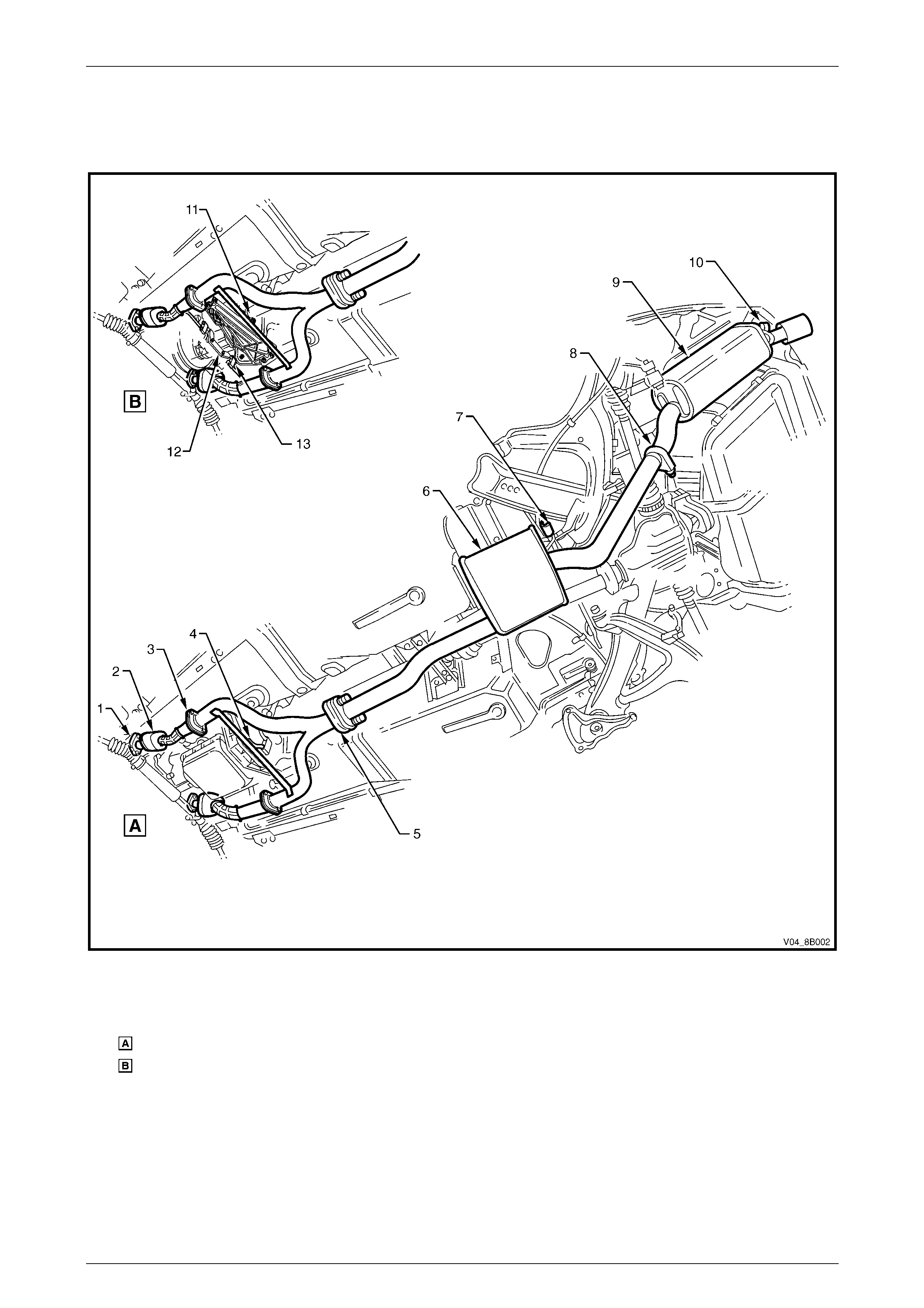
Figure 8B – 4 illustrates the exhaust system configurations used with V6 vehicles.
Figure 8B – 4
Legend
View Automatic Transmission
View Manual Transmission
1 Manifold to Front P i pe Fl ange Joint
2 Catalytic Converter
3 Front pipe to I nt ermediate Y -pi pe Fl ange
Joint
4 Intermediate Y-pi pe B race and Support
Rubber
5 Swivel Flange Joint
6 Intermediate Muffler
7 Intermediate Muff l er Support Rubbers
8 Intermediate to Rear Pipe Slip Joint and
U-clamp
9 Rear Muffler
10 Rear Muffler Support Rubbers
11 Intermediate Y-pipe Brace
12 Transmission Mount
13 Support Rubber
Exhaust System Page 8B–10
Page 8B–10
2.3 Complete Exhaust System Assembly
Remove
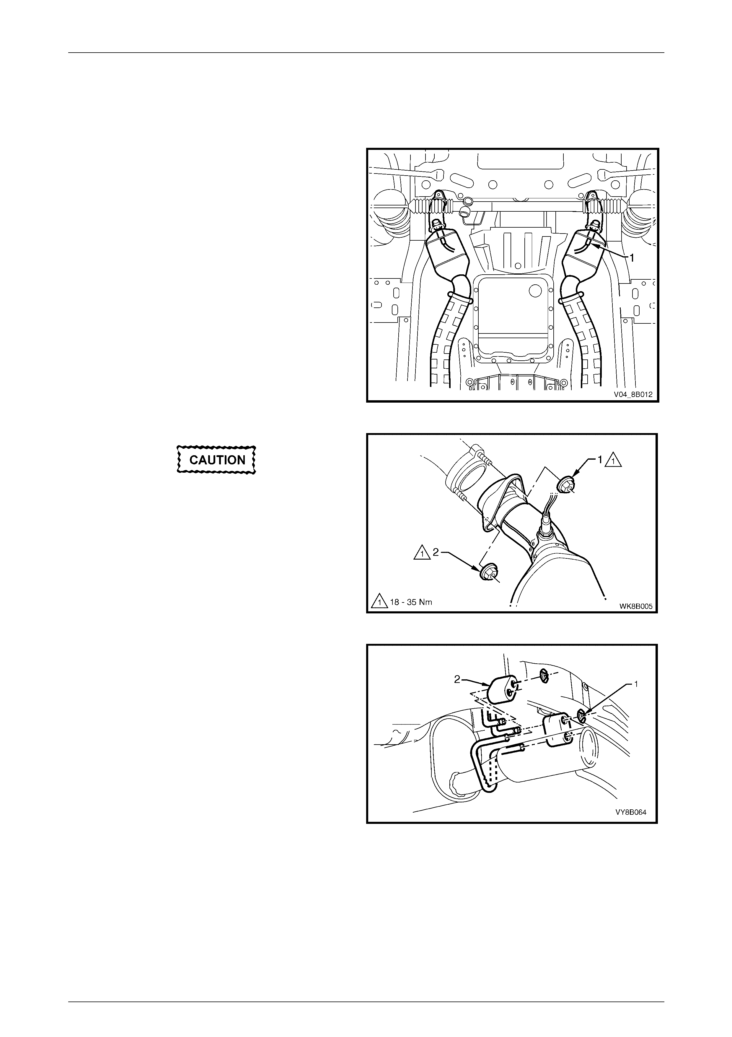
1 Disconnect the wiring harness connectors from each
of the two oxygen sensors (1).
NOTE
Automatic transmission shown, manual
transmission similar.
Figure 8B – 5
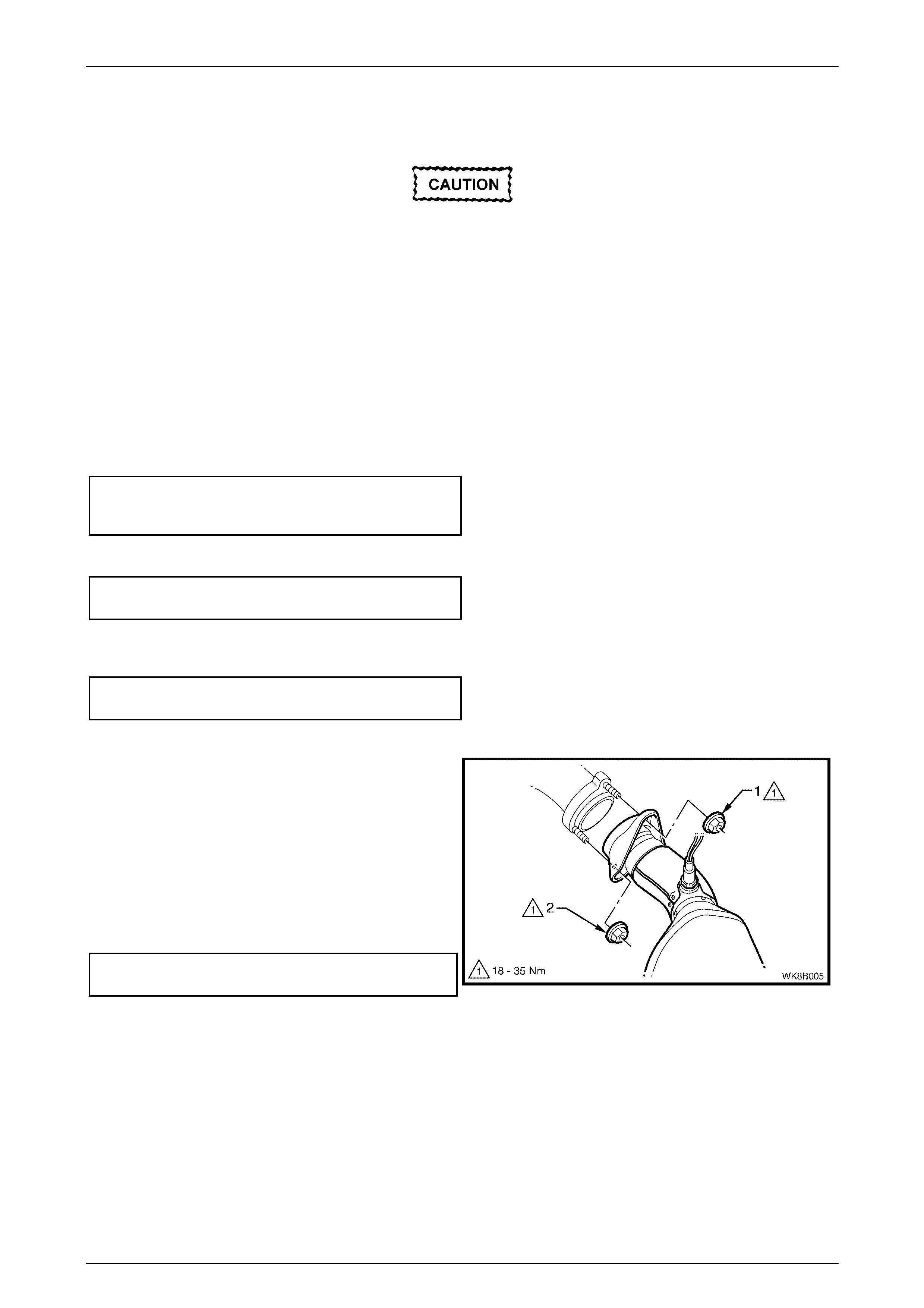
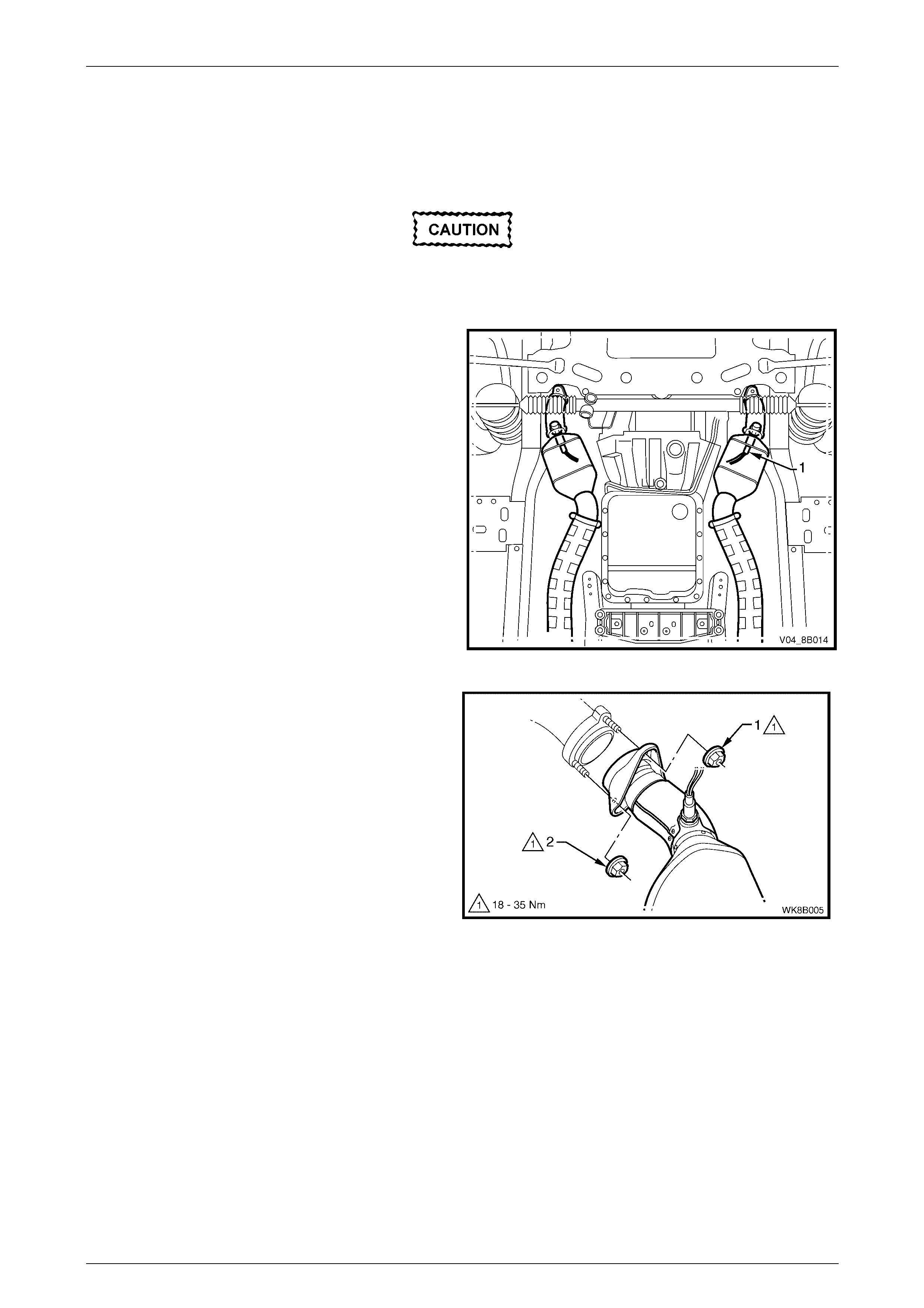
Ensure that the exhaust assembly is
properly supported to avoid damage and
undue stress on the flange / slip joints.
2 Support the exhaust system.
3 Remove the upper (1) then lower (2) attaching nuts
from the manifold to front pipe flange joint studs on
both sides.
Figure 8B – 6
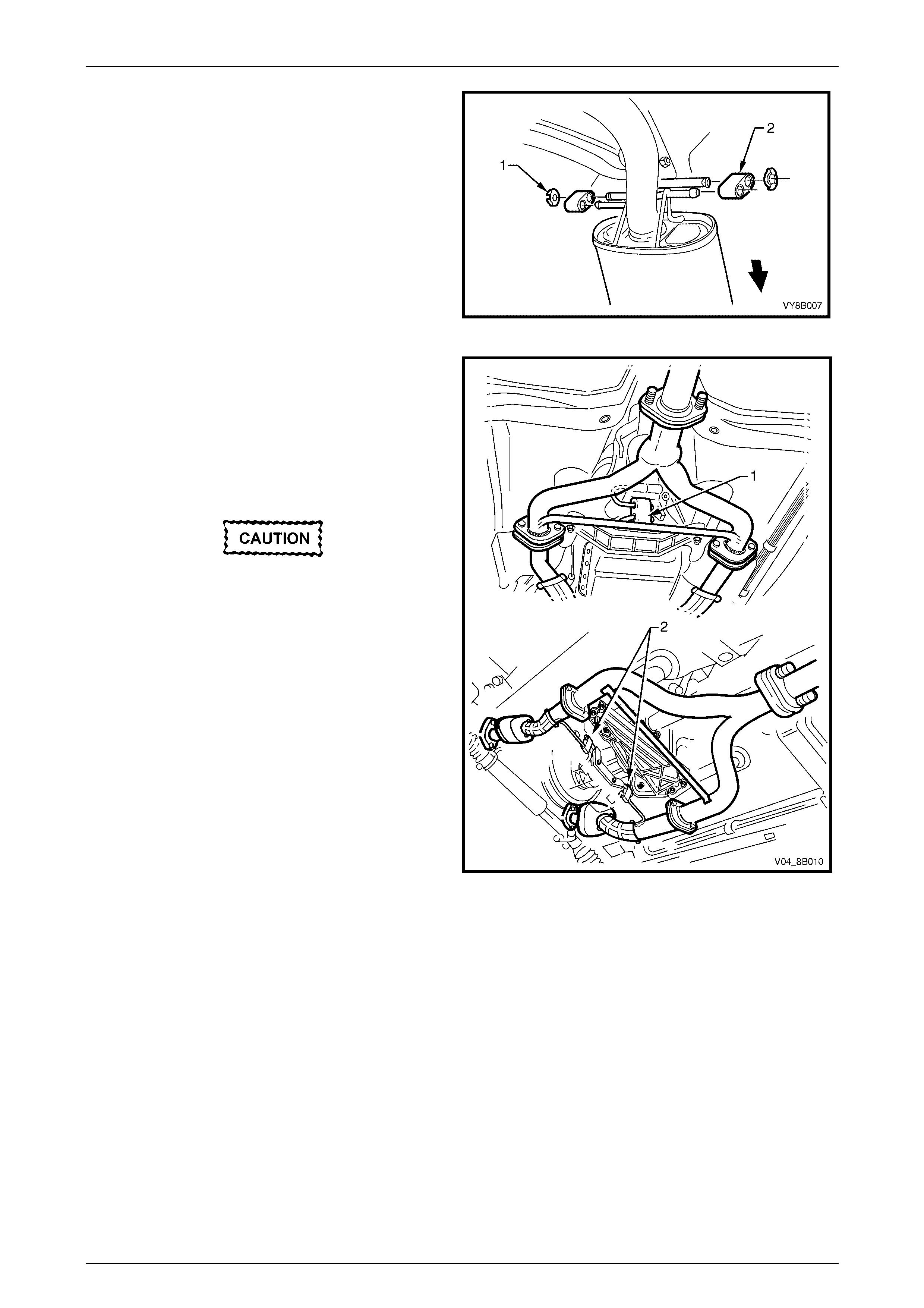
4 Disconnect the rear muffler from the underbody
hangers by removing the two retainer clips (1) and
rear muffler support rubbers (2).
Figure 8B – 7
Exhaust System Page 8B–11
Page 8B–11
5 Disconnect the intermediate muffler from the
underbody hangers by removing the two retainer
clips (1) and the two intermediate muffler support
rubbers (2).
Figure 8B – 8
6 Disconnect the front exhaust assemblies.
a For automatic transmission, remove the support
rubber (1) from the peg welded to the
intermediate exhaust Y-pipe brace.
b For manual transmission, remove the support
rubber (2), in two places, from the peg welded
to the front exhaust assemblies.
Take care not to damage the exhaust gas
oxygen sensors.
7 Carefully lower and remove the exhaust assembly
from the vehicle.
Figure 8B – 9
Exhaust System Page 8B–12
Page 8B–12
Reinstall
Installation of the complete exhaust system is the reverse of the removal procedure, noting the following points:
1 Support the exhaust system at all times.
2 Clean the threads of the manifold to front pipe flange joint studs and nuts with a suitable cleaning solvent.
3 Apply a high temperature anti-seize compound to the manifold to front pipe flange joint studs, then align the flange
over the studs.
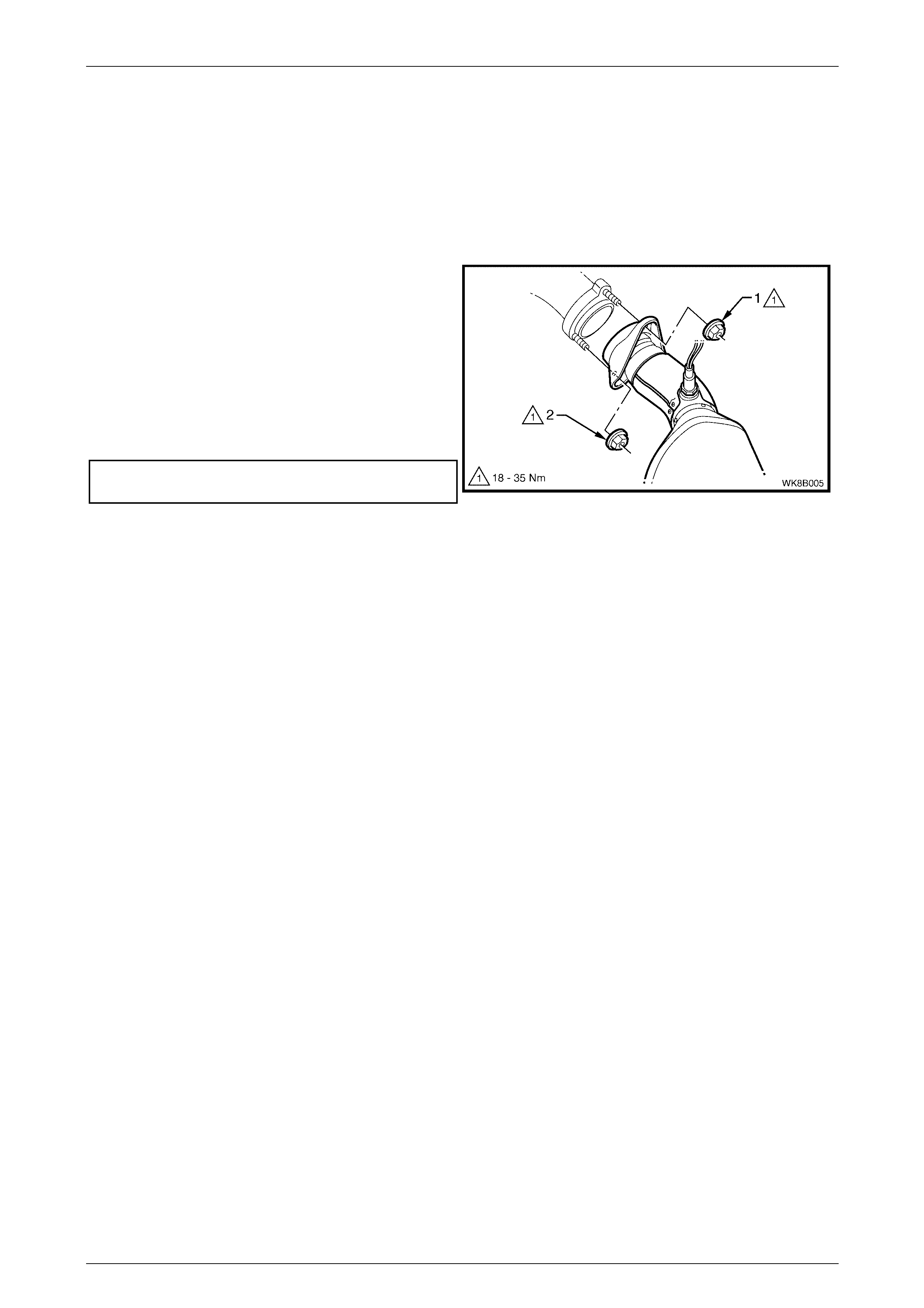
4 Hand tighten the upper attaching nut (1) to the stud
on both sides.
5 Hand tighten the lower attaching nut (2) to the stud
on both sides.
6 Tighten the upper and then the lower attaching nuts
so that approximately equal amounts of stud thread
are showing.
7 Tighten the upper and then the lower attaching nuts
to the specified torque.
Manifold to front pipe flange joint studs
attaching nuts torque specification........ 18.0 – 35.0 Nm
Figure 8B – 10
8 Ensure that all support rubbers are under load.
9 Check the exhaust system for clearances, refer to 5.1 V6 Exhaust System Clearances. If the clearances are not
within tolerance, loosen off all fasteners and perform the tightening sequence procedure, refer to 2.8 Tightening
Sequence.
10 Connect the wiring harness connectors for each of the two oxygen sensors.
Exhaust System Page 8B–13
Page 8B–13
2.4 Rear Exhaust Assembly
Remove
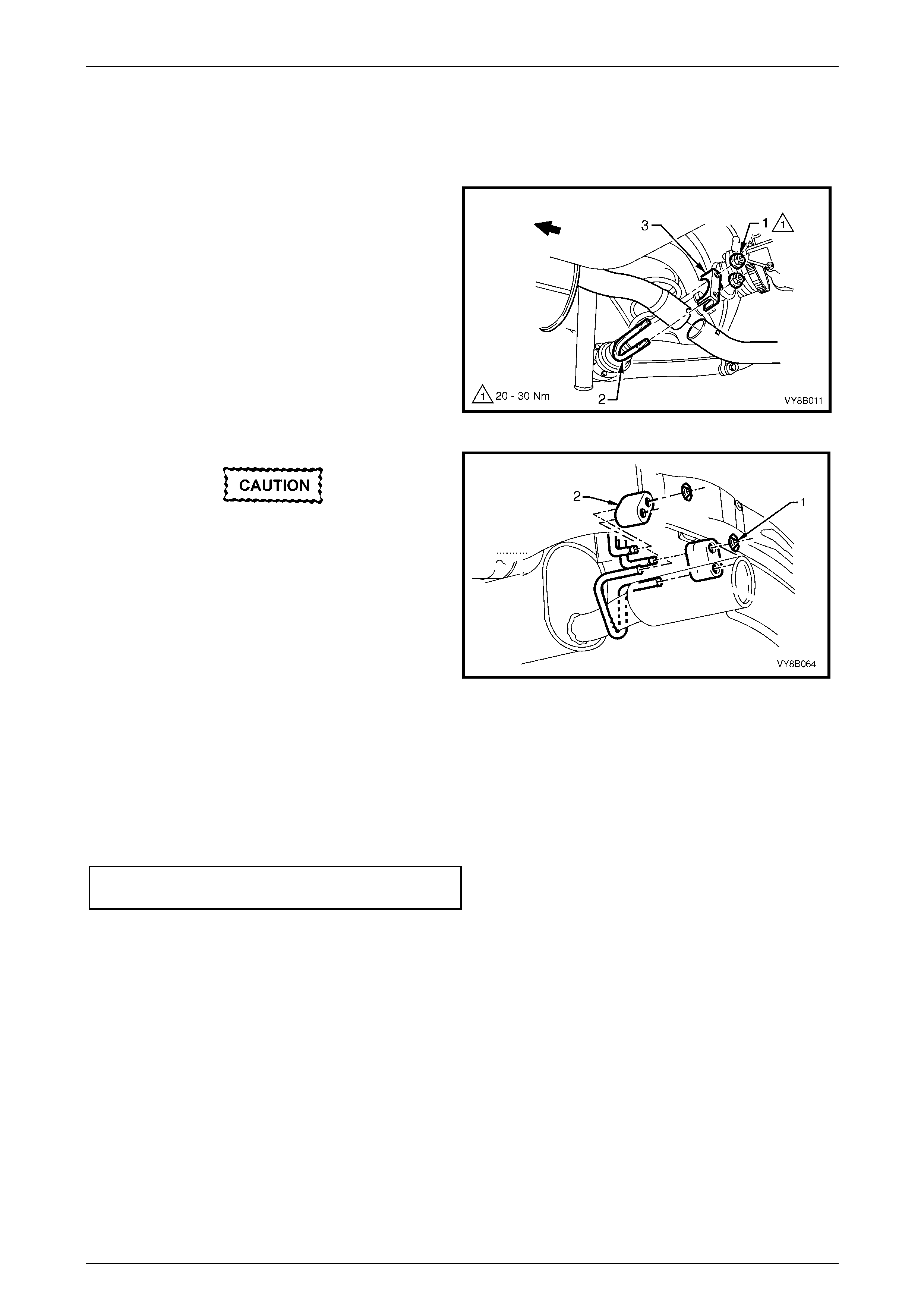
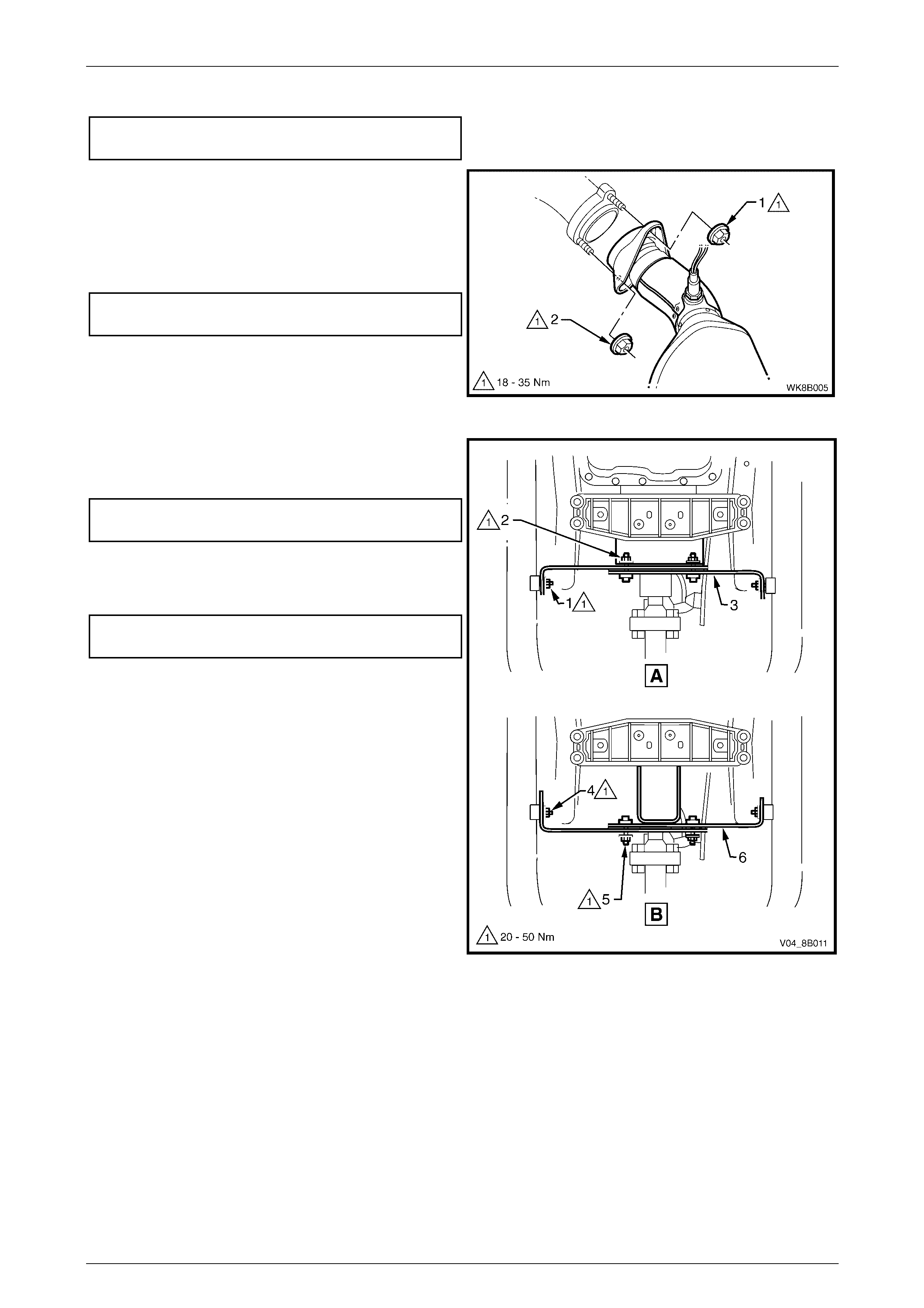
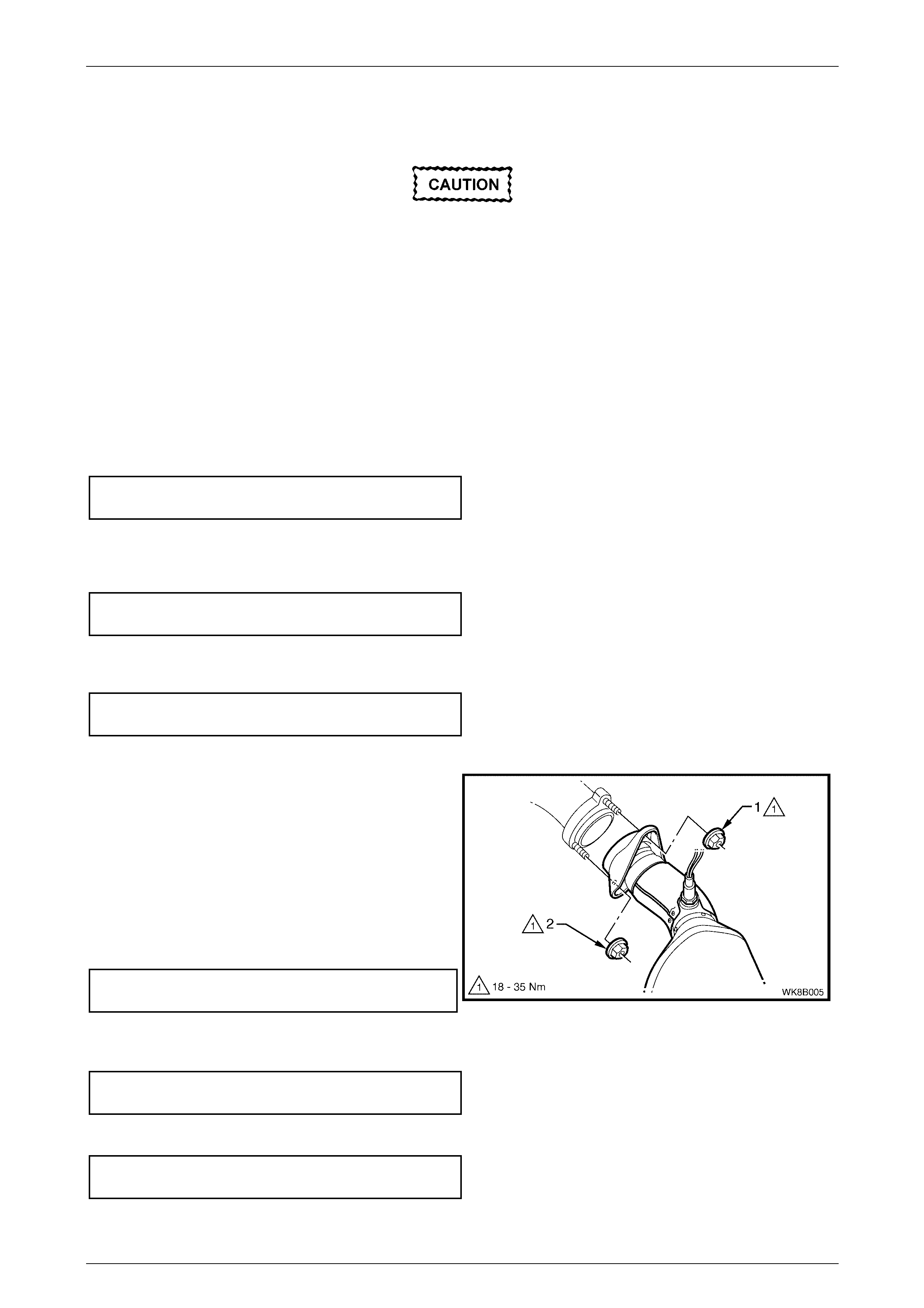
1 Remove the two retaining nuts (1), the slip joint
U-bolt (2) and clamp (3) from the intermediate to rear
pipe slip joint.
Figure 8B – 11
Ensure that the rear exhaust assembly is
properly supported to avoid damage and
undue stress on the slip joint.
2 Support the rear exhaust assembly, then remove the
two underbody hanger retainer clips (1) and the two
rear muffler support rubbers (2) from the underbody
hangers.
3 Carefully slide the rear exhaust pipe out of the
intermediate exhaust pipe end slip joint and remove
the rear exhaust assembly.
Figure 8B – 12
Reinstall
Installation of the rear exhaust assembly is the reverse of the removal procedure, noting the following:
1 Ensure that the rear exhaust pipe slides unobstructed into the intermediate exhaust pipe slip joint, and that the
alignment key is positioned in the slip joint channel.
2 Tighten the slip joint U-clamp attaching nuts to the specified torque, refer to Figure 8B – 11.
Slip joint U-clamp attaching nuts
torque specification................................20.0 – 30.0 Nm
3 Ensure that all support rubbers are under load.
4 Check the exhaust system for clearances, refer to 5.1 V6 Exhaust System Clearances. If the clearances are not
within tolerance, loosen off all fasteners and perform the tightening sequence procedure, refer to 2.8 Tightening
Sequence.
Exhaust System Page 8B–14
Page 8B–14
2.5 Intermediate Single Pipe and Muffler
Exhaust Assembly
Remove
Ensure that the exhaust assembly is properly
supported to avoid damage and undue stress
on the flange / slip joints.
1 Remove the rear exhaust assembly, refer to 2.4 Rear Exhaust Assembly.
2 Support the intermediate single pipe and muffler
exhaust assembly and remove the two attaching
stepped bolts (1) and springs (2) from the swivel
flange joint.
NOTE
Automatic transmission shown, manual
transmission similar.
3 Separate the intermediate single pipe and muffler
exhaust assembly from the intermediate Y-pipe
exhaust assembly and remove the sealing ring (3)
from within the swivel flange joint.
Figure 8B – 13
4 Remove the two retainer clips (1) and intermediate
muffler support rubbers (2) from the underbody
hangers and remove the intermediate single pipe and
muffler exhaust assembly.
Figure 8B – 14

Exhaust System Page 8B–15
Page 8B–15
Reinstall
Installation of the intermediate single pipe and muffler exhaust assembly is the reverse of the removal procedure, noting
the following:
1 Support the exhaust system at all times.
2 Clean the threads of the stepped attaching bolts and swivel flange joint with a suitable cleaning solvent.
3 Check the condition of the sealing ring upon reinstallation and replace if necessary.
4 Tighten the swivel flange joint attaching stepped bolts to the specified torque, refer to Figure 8B – 13.
5 Ensure that all support rubbers are under load.
6 Check the exhaust system for clearances, refer to 5.1 V6 Exhaust System Clearances. If the clearances are not
within tolerance, loosen off all fasteners and perform the tightening sequence procedure, refer to 2.8 Tightening
Sequence.
Swivel flange joint attaching stepped
bolts torque specification ....................... 40.0 – 50.0 Nm
Exhaust System Page 8B–16
Page 8B–16
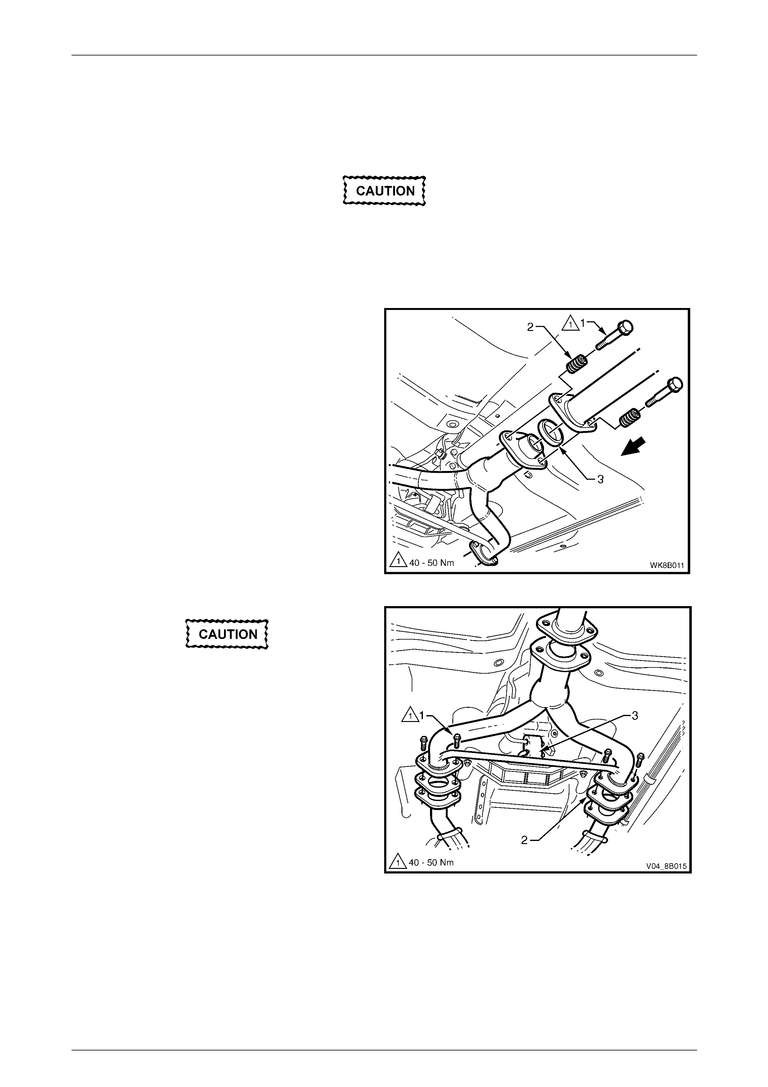
2.6 Intermediate Y-pipe Exhaust Assembly
Remove
Ensure that the intermediate exhaust
assembly is properly supported to avoid
damage and undue stress on the flange / slip
joints.
1 Support the intermediate exhaust assembly and
remove the two stepped attaching bolts (1) and
springs (2) from the swivel flange joint.
NOTE
Automatic transmission shown, manual
transmission similar.
2 Separate the intermediate single pipe and muffler
exhaust assembly and remove the sealing ring (3)
from within the swivel flange joint.
Figure 8B – 15
For the automatic transmission, support the
front exhaust assembly as well as the
intermediate exhaust assembly.
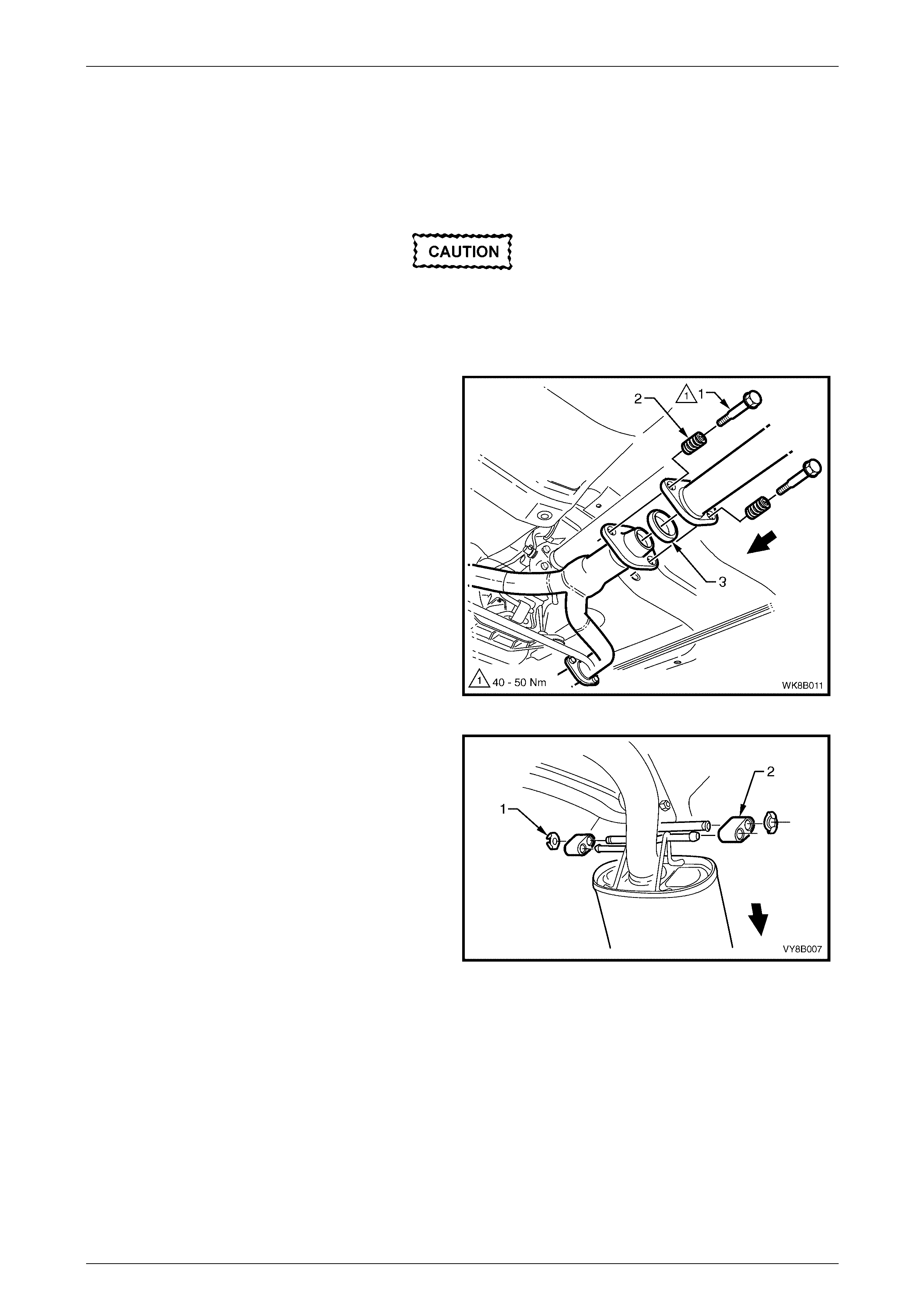
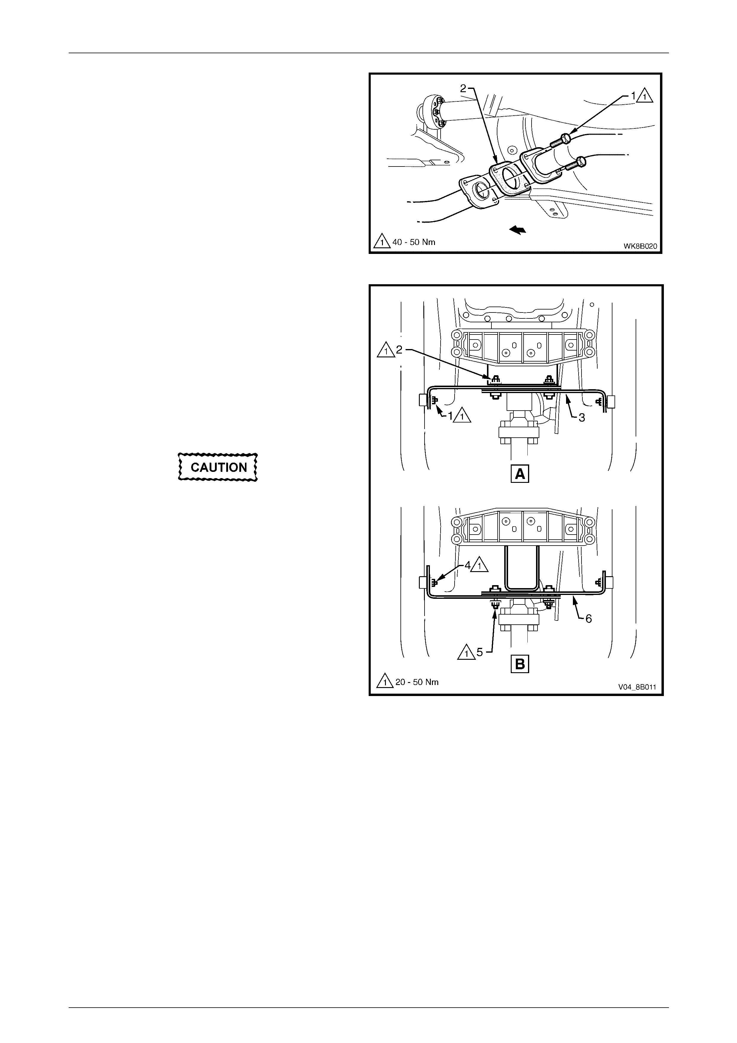
3 Remove the pairs of attaching bolts (1) from each
front pipe to intermediate Y-pipe flange joint and
remove both flange gaskets (2).
NOTE
Automatic transmission shown, manual
transmission similar.
4 For the automatic transmission, remove the support
rubber (3) from the cross brace peg.
5 Remove the intermediate Y-pipe exhaust assembly.
Figure 8B – 16

Exhaust System Page 8B–17
Page 8B–17
Reinstall
Installation of the intermediate Y-pipe exhaust assembly is the reverse of the removal procedure, noting the following
points:
1 Support the exhaust system at all times.
2 Clean the threads of all attaching bolts and flanges with a suitable cleaning solvent.
3 Check the condition of the front pipe to intermediate Y-pipe flange joint gaskets, and swivel flange joint sealing ring
upon reinstallation, replace if necessary.
4 Tighten the swivel flange joint attaching stepped bolts to the specified torque, refer to Figure 8B – 15.
Swivel flange joint attaching stepped
bolts torque specification ....................... 40.0 – 50.0 Nm
5 Tighten the front pipe to intermediate Y-pipe flange joint attaching bolts to the specified torque, refer to
Figure 8B – 16.
Front pipe to intermediate Y-pipe
flange joint attaching bolts
torque specification................................40.0 – 50.0 Nm
6 Ensure that all support rubbers are under load.
7 Check the exhaust system for clearances, refer to 5.1 V6 Exhaust System Clearances. If the clearances are not
within tolerance, loosen off all fasteners and perform the tightening sequence procedure, refer to 2.8 Tightening
Sequence.
Exhaust System Page 8B–18
Page 8B–18
2.7 Front Exhaust Assemblies
Remove
Ensure that the front / intermediate exhaust
assemblies are properly supported to avoid
damage and undue stress on the flange / slip
joints.
1 Disconnect the wiring harness connectors from the
oxygen sensors (1).
NOTE
Automatic transmission shown, manual
transmission similar.
Figure 8B – 17
2 Support the front or intermediate exhaust assemblies
as follow:
a support the front exhaust assemblies for
automatic transmission vehicles
b support the intermediate exhaust assembly for
manual transmission vehicles.
3 Remove the pairs of attaching bolts (1) from each
front pipe to intermediate Y-pipe flange joint and
remove both flange gaskets (2).
NOTE
Automatic transmission shown, manual
transmission similar.
Figure 8B – 18
Exhaust System Page 8B–19
Page 8B–19
4 Remove the upper (1) then lower (2) attaching nuts
from the manifold to front pipe flange joint studs on
both sides.
Figure 8B – 19
5 Disconnect the front exhaust assembly as follow:
a For automatic transmission, remove the support
rubber (1) from the peg welded to the cross
brace of the intermediate Y-pipe exhaust
assembly.
b For manual transmission, remove the support
rubber (2), in two places, from the peg welded
to the front exhaust assemblies.
Take care not to damage the exhaust gas
oxygen sensors.
6 Carefully lower and remove the front exhaust
assemblies from the vehicle.
Figure 8B – 20
Exhaust System Page 8B–20
Page 8B–20
Reinstall
Installation of the front exhaust assemblies is the reverse of the removal procedure, noting the following points:
1 Support the exhaust system at all times.
2 Clean the threads of the attaching bolts, nuts, studs and flanges with a suitable cleaning solvent.
3 Check the condition of the front pipe to intermediate Y-pipe flange joint gaskets upon reinstallation and replace if
necessary.
4 Apply a high temperature anti-seize compound to the manifold to front pipe flange joint studs, then align the flange
over the studs.
5 Tighten the front pipe to intermediate Y-pipe flange joint attaching bolts to the specified torque, refer to
Figure 8B – 18.
Front pipe to intermediate Y-pipe
flange joint attaching bolts
torque specification................................40.0 – 50.0 Nm
6 Hand tighten the upper attaching nut (1) to the stud
on both sides.
7 Hand tighten the lower attaching nut (2) to the stud
on both sides.
8 Tighten the upper and then the lower attaching nuts
so that approximately equal amounts of stud thread
are showing.
9 Tighten the upper and then the lower attaching nuts
to the specified torque.
Manifold to front pipe flange joint studs
attaching nuts torque specification........ 18.0 – 35.0 Nm
Figure 8B – 21
10 Ensure that all support rubbers are under load.
11 Check the exhaust system for clearances, refer to 5.1 V6 Exhaust System Clearances. If the clearances are not
within tolerance, loosen off all fasteners and perform the tightening sequence procedure, refer to 2.8 Tightening
Sequence.
12 Connect the wiring harness connectors for each of the two oxygen sensors.
Exhaust System Page 8B–21
Page 8B–21
2.8 Tightening Sequence
Ensure that the exhaust assembly is properly
supported to avoid damage and undue stress
on the flange / slip joints.
This procedure is only to be performed if the exhaust system positioning is not to specification.
Refer to Figure 8B – 23 for the following.
NOTE
Ensure that all fasteners mentioned in the
following steps 1 to 5 are loose before
conducting this procedure.
1 Tighten each of the front pipe to intermediate Y-pipe flange joint attaching bolts (1) to the specified torque.
Front pipe to intermediate Y-pipe
flange joint attaching bolts
torque specification................................40.0 – 50.0 Nm
2 Tighten the swivel flange joint attaching stepped bolts (2) to the specified torque.
Swivel flange joint attaching stepped
bolts torque specification ....................... 40.0 – 50.0 Nm
3 Check that the rear exhaust pipe aligning key is fully seated within the intermediate to rear pipe slip joint channel.
Position the U-clamp (3) along the slip joint and tighten the pair of attaching nuts to the specified torque.
Slip joint U-clamp attaching nuts
torque specification................................20.0 – 30.0 Nm
4 Tighten the manifold to front pipe flange joint (4) studs nuts as follow.
a Hand tighten the upper attaching nut (1) to the
stud on both sides, refer to Figure 8B – 22.
b Hand tighten the lower attaching nut (2) to the
stud on both sides.
c Tighten the upper and then the lower attaching
nuts so that approximately equal amounts of
stud thread are showing.
d Tighten the upper and then the lower attaching
nuts to the specified torque.
Manifold to front pipe flange joint studs
attaching nuts torque specification........ 18.0 – 35.0 Nm
Figure 8B – 22
5 Ensure that all support rubbers (5, 6 and 7) are under load. If this is not achieved, loosen the respective joints in
the reverse order to steps 1 to 4. Load the underbody hangers, re-tighten and check in the sequence described
from steps 1 to 5.
Exhaust System Page 8B–22
Page 8B–22
NOTE
The exhaust system should be self-aligning
and not require further adjustment, provided
Step 5 is achieved. To ensure that
correct clearances are maintained throughout
the complete exhaust system, refer to
5.1 V6 Exhaust System Clearances for the
correct values.
Figure 8B – 23
Legend
View Automatic Transmission
View Manual Transmission
1 Front Pipe t o Intermedi ate Y-pipe
Flange Joint
2 Swivel Flange Joint
3 Intermediate to Rear Pipe Slip Joint and
U-clamp
4 Manifold to Front P i pe Fl ange Joint
5 Support Rubber(s)
6 Intermediate Muff l er Support Rubbers
7 Rear Muffler Support Rubbers

Exhaust System Page 8B–23
Page 8B–23
3 Service Operations – GEN III V8
3.1 Service Notes
Two exhaust system configurations, Standard and Performance, are available for vehicles fitted with the GEN III V8
engine. The type installed will depend on the specifications of the particular vehicle.
When installing any exhaust system component, care must be taken to install each component in the correct
relationship with other components. Ensure that correct assembly, installation, tightening sequence, tightening torque
and clearance for the system involved is observed.
The incorrect assembly of exhaust system
components can frequently be the cause of
rattles and ‘booms' due to incorrect
alignment or clearance of body or suspension
parts. Ensure that the correct tightening
sequence is observed upon installation of
exhaust system components.
NOTE
Service operations on exhaust system
components must be carried out with all parts at
ambient temperatures to ensure correct
clearances are maintained.
Catalytic Converter
Catalytic converters are serviced as part of the complete front exhaust pipe assemblies only. If removing or replacing
either of the front exhaust pipe assemblies, ensure that a gasket is installed on the front to intermediate pipe flange joint
upon reassembly. Check flange gaskets for damage and replace if necessary.
Exhaust System Page 8B–24
Page 8B–24
3.2 Exhaust System
The following removal and installation service operations should be referred to when conducting work on Standard and
Performance exhaust systems, refer to 1.2 Exhaust System Configurations, Figure 8B – 2 and Figure 8B – 3
respectively.
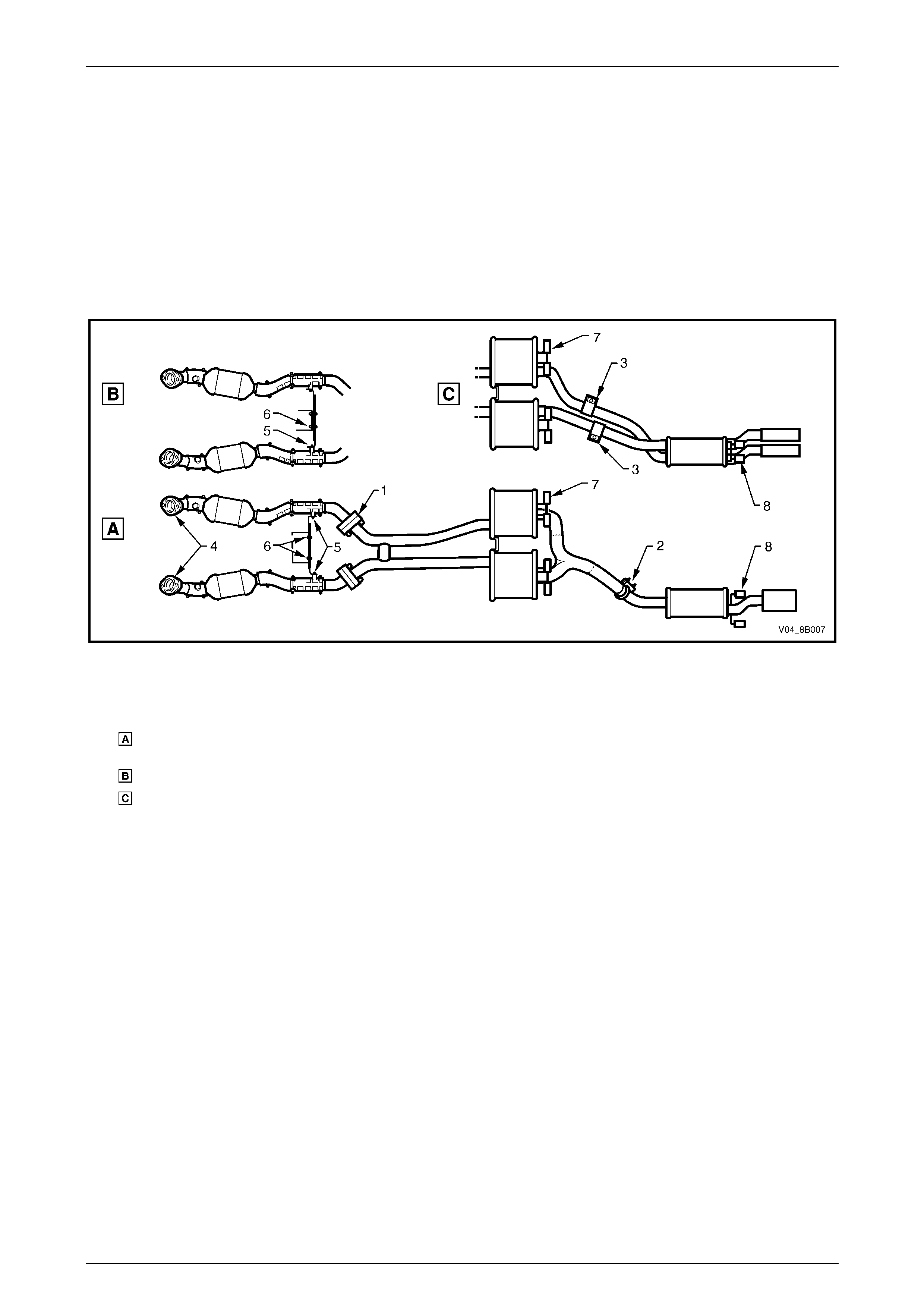
Figure 8B – 24 provides a reference to the location of relevant exhaust system removal and installation components.
NOTE
Automatic transmission shown, manual
transmission similar
Figure 8B – 24

Exhaust System Page 8B–25
Page 8B–25
Legend
View Standard Exhaust
View Performance Exhaust
1 Manifold to Front P i pe Fl ange Joint
2 Catalytic Converter
3 Cross B rac e and Transmi ssion Mount
4 Front to Int ermediate P i pe Fl ange Joint
5 Intermediate Muffler
6 Intermediate Muff l er Support Rubbers
7 Intermediate to Rear Pipe Slip Joint and
U-clamp
8 Intermediate to Rear Pipe Slip Joint and
Ring Clam p
9 Rear Muffler
10 Rear Muffler Support Rubbers
Exhaust System Page 8B–26
Page 8B–26
3.3 Complete Exhaust System Assembly
Remove
Ensure that the exhaust assembly is properly
supported to avoid damage and undue stress
on the flange / slip joints.
1 Disconnect the wiring harness connectors from each
of the two oxygen sensors (1).
NOTE
Automatic transmission shown, manual
transmission similar.
Figure 8B – 25
2 Support the exhaust system.
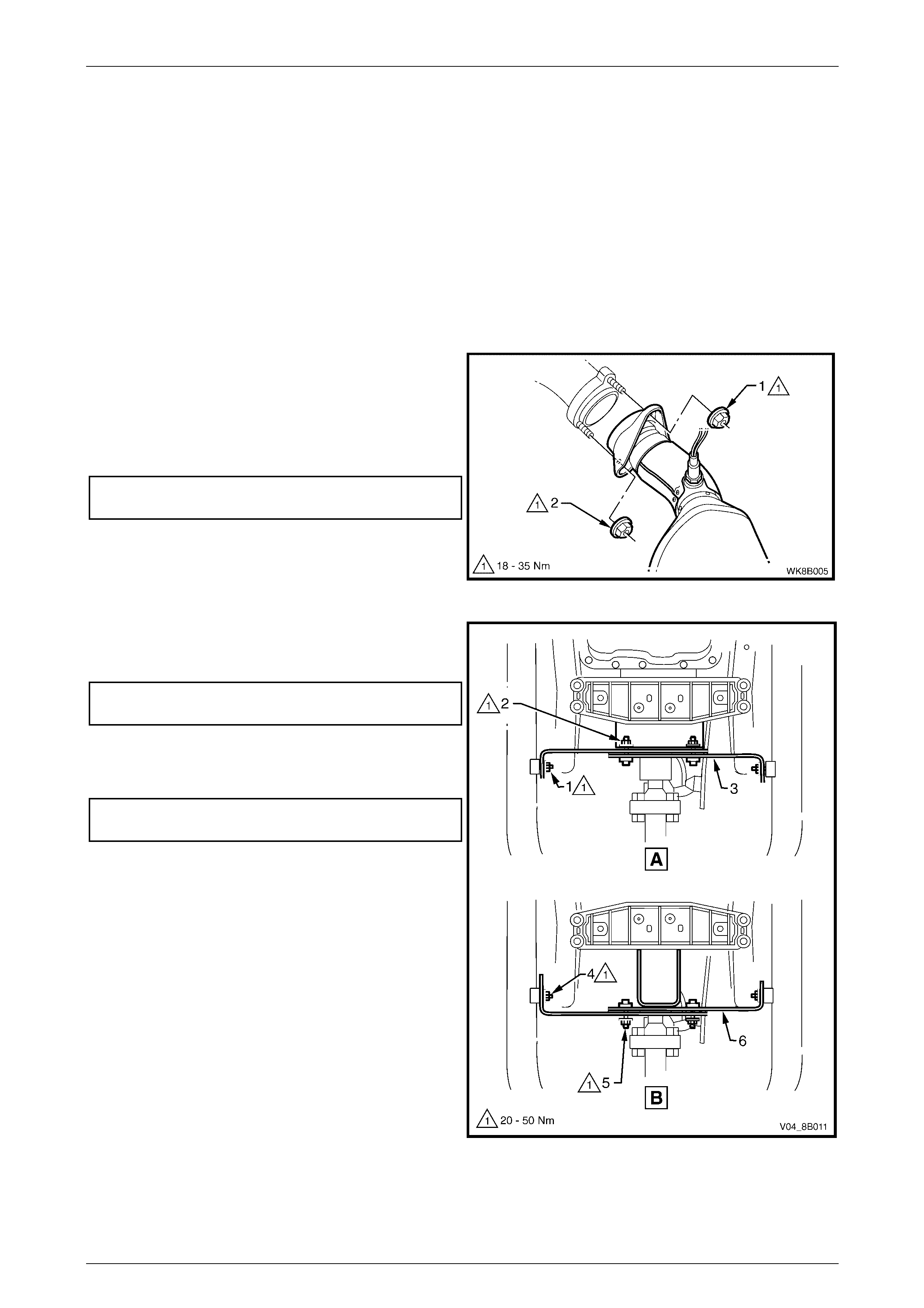
3 Remove the upper (1) then lower (2) attaching nuts
from the manifold to front pipe flange joint studs on
both sides.
Figure 8B – 26
Exhaust System Page 8B–27
Page 8B–27
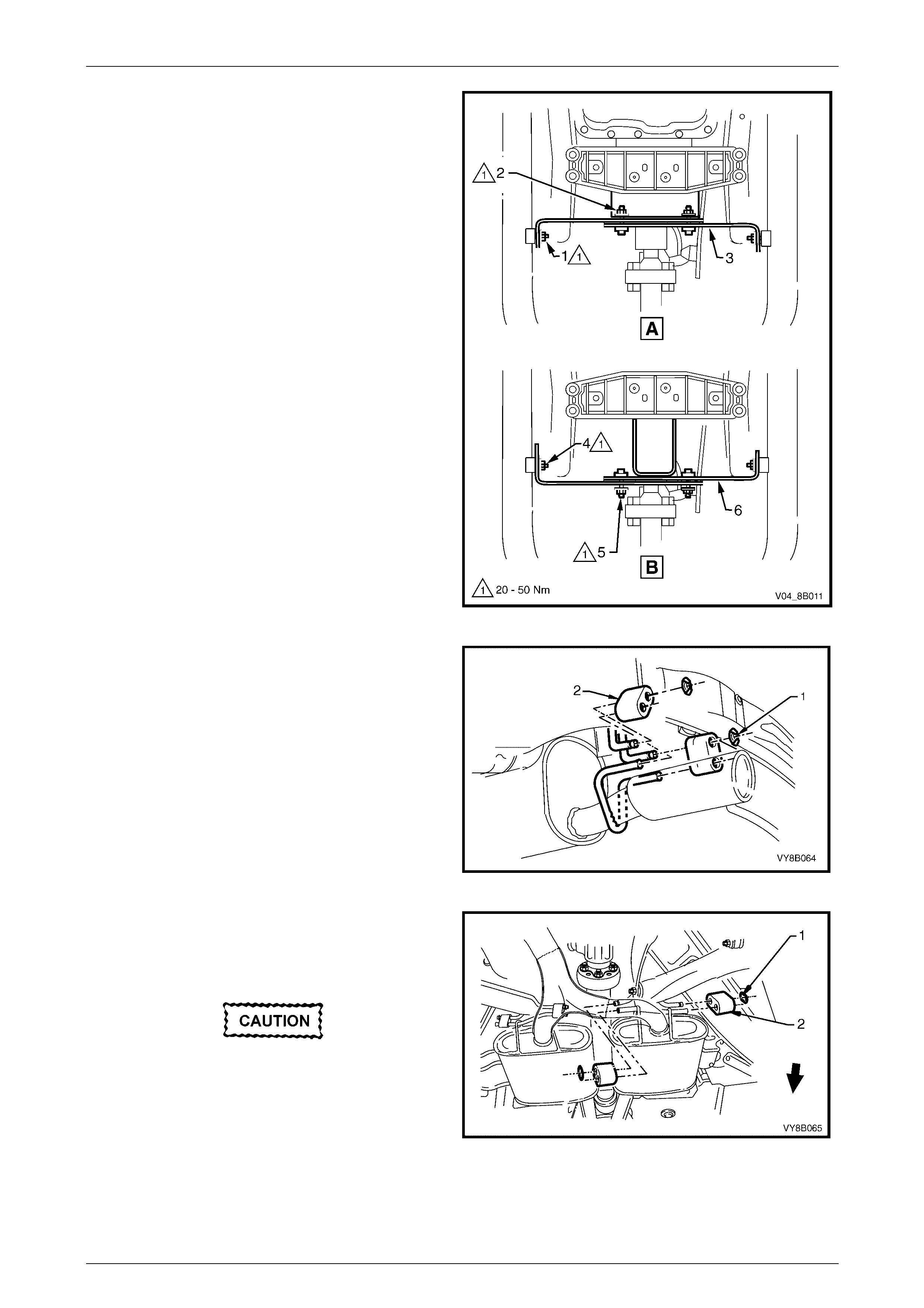
4 Remove the cross brace and transmission mount
nuts as follows:
a For the automatic transmission (view A),
remove the cross brace and transmission
mount nuts (1 and 2) and remove the cross
brace and transmission mount (3).
b For the manual transmission (view B), remove
the cross brace and transmission mount
nuts (4 and 5) and remove the cross brace and
transmission mount (6).
Figure 8B – 27
5 Disconnect the rear muffler from the underbody
hangers by removing the two retainer clips (1) and
rear muffler support rubbers (2).
Figure 8B – 28
6 Disconnect the two intermediate mufflers from the
underbody hangers by removing the four retainer
clips (1) and the four intermediate muffler support
rubbers (2).
Take care not to damage the exhaust gas
oxygen sensors.
7 Carefully lower and remove the exhaust assembly
from the vehicle.
Figure 8B – 29
Exhaust System Page 8B–28
Page 8B–28
Reinstall
Installation of the complete exhaust system is the reverse of the removal procedure, noting the following points:
1 Support the exhaust system at all times.
2 Clean the threads of the manifold to front pipe flange joint studs and nuts with a suitable cleaning solvent.
3 Apply a high temperature anti-seize compound to the manifold to front pipe flange joint studs, then align the flange
over the studs.
4 Hand tighten the upper attaching nut (1) then the lower attaching nut (2) to the studs on both sides, refer to Figure
8B – 30.
5 Install the cross brace and transmission mount (3 or 6) depending on transmission type, hand tighten the attaching
nuts, refer to Figure 8B – 31.
6 Tighten the manifold to front pipe flange joint studs
upper attaching nut (1) and then lower attaching
nut (2) so that approximately equal amounts of stud
thread are showing.
7 Tighten the upper and then the lower attaching nuts to
the specified torque.
Manifold to front pipe flange joint studs
attaching nuts torque specification.........18.0 – 35.0 Nm
Figure 8B – 30
8 Tighten the cross brace to front exhaust pipe nuts (1)
automatic transmission or nuts (4) manual
transmission, to the specified torque.
Cross brace to front exhaust pipe
nut torque specification..........................20.0 – 50.0 Nm
9 Tighten the cross brace bracket attaching nuts (2)
automatic transmission or nuts (5) manual
transmission, to the specified torque.
Cross brace bracket attaching
nuts torque specification ........................20.0 – 50.0 Nm
Figure 8B – 31
10 Ensure that all support rubbers are under load.

Exhaust System Page 8B–29
Page 8B–29
11 Check the exhaust system for clearances, refer to 5.2 GEN III V8 Exhaust System Clearances. If the clearances
are not within tolerance, loosen off all fasteners and perform the tightening sequence procedure, refer to
3.7 Tightening Sequence.
12 Connect the wiring harness connectors for each of the two oxygen sensors.
Exhaust System Page 8B–30
Page 8B–30
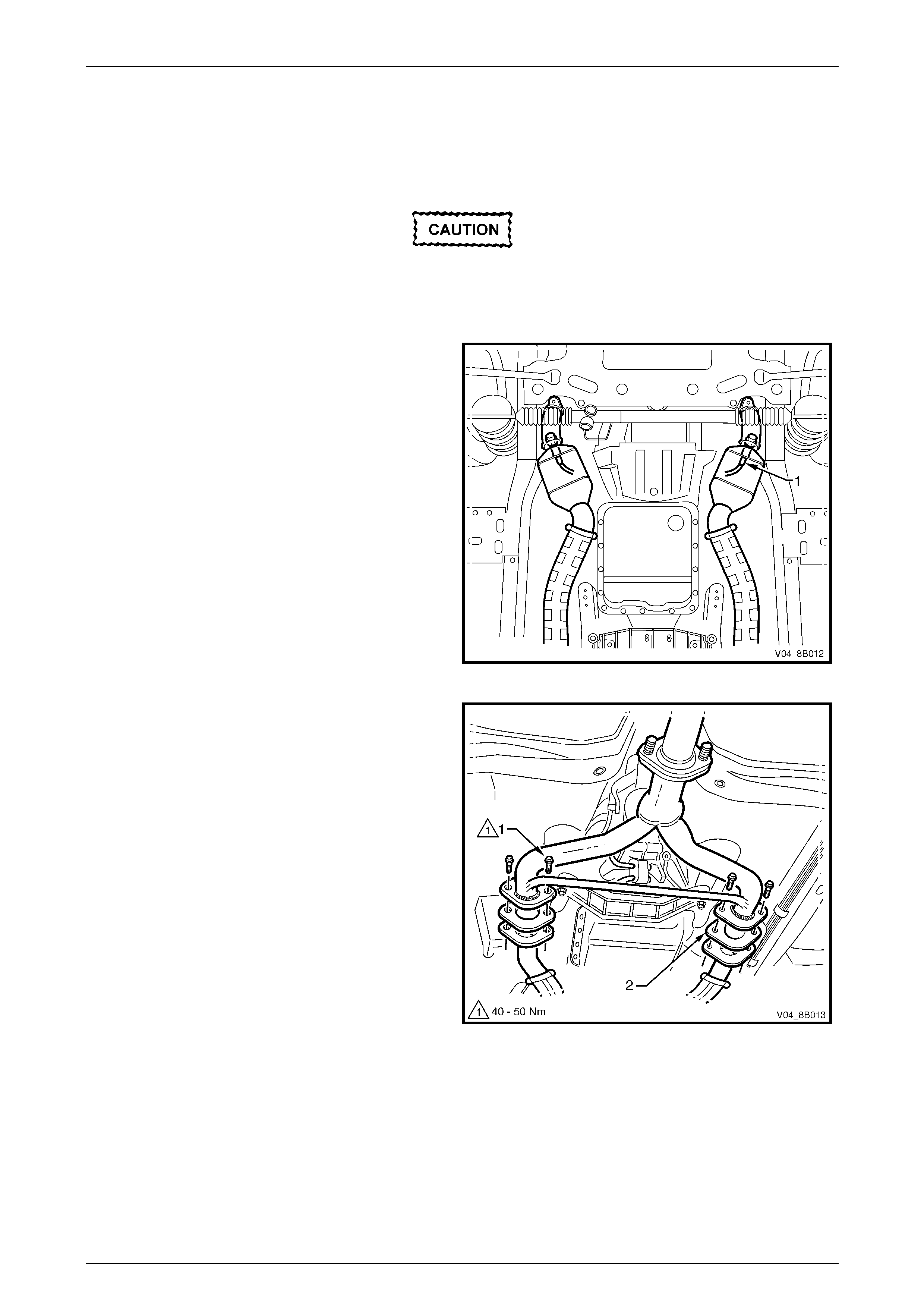
3.4 Rear Exhaust Assembly
Remove
Ensure that the rear exhaust assembly is
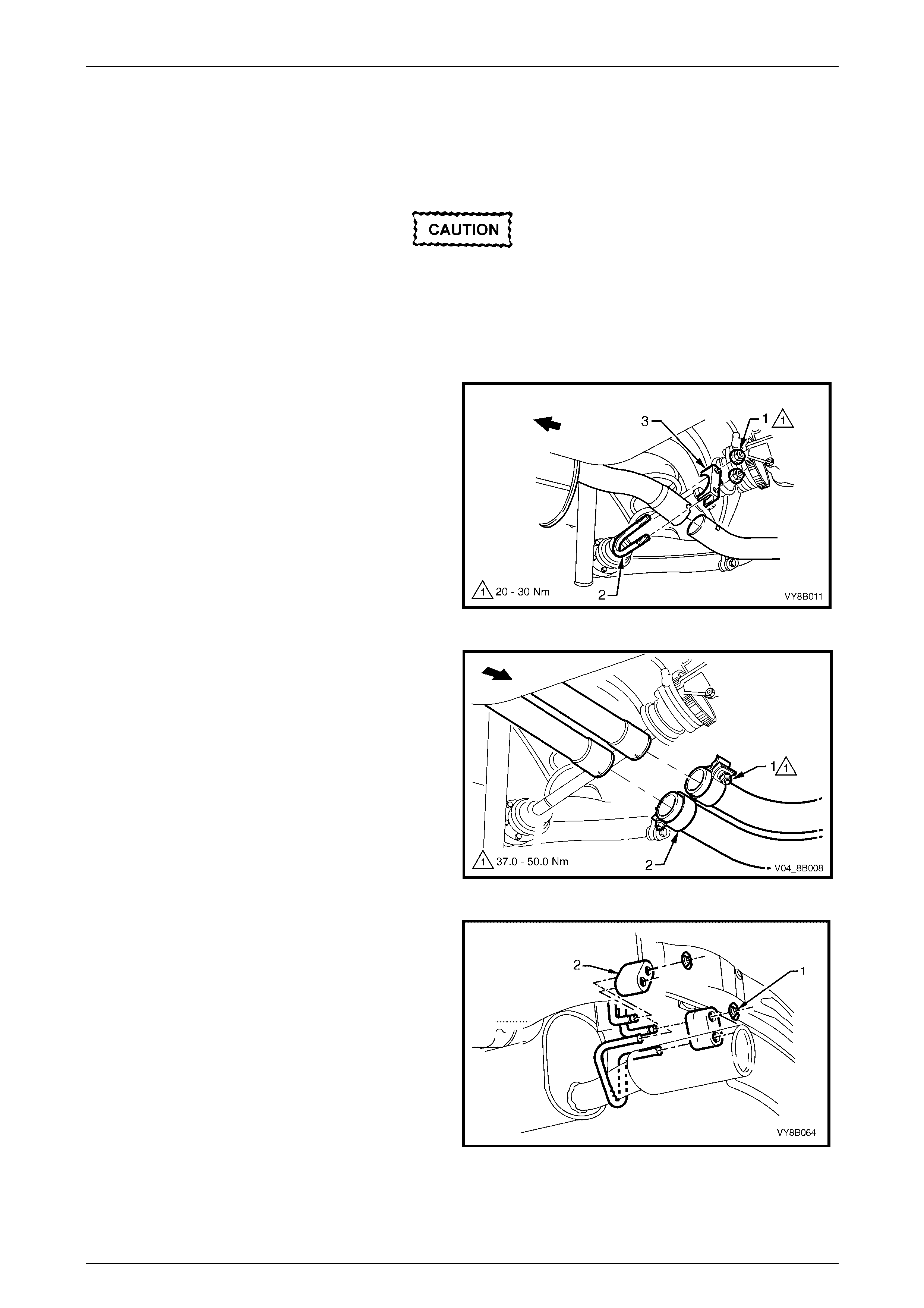
properly supported to avoid damage and
undue stress on the flange / slip joints.
1 Remove the intermediate to rear pipe slip joint U-clamp or ring clamps as follow.
a For standard exhaust, remove the two retaining
nuts (1), the slip joint U-bolt (2) and clamp (3)
from the intermediate to rear pipe slip joint.
Figure 8B – 32
b For performance exhaust, loosen the attaching
nut (1) for each of the two intermediate to rear
pipe slip joint ring clamp (2).
Figure 8B – 33
3 Support the rear exhaust assembly, then remove the
two underbody hanger retainer clips (1) and the two
rear muffler support rubbers (2) from the underbody
hangers.
NOTE
Standard exhaust shown, performance exhaust
similar.
4 Carefully slide the rear exhaust assembly out of the
intermediate exhaust pipe/s end slip joint/s.
5 Remove the rear exhaust assembly.
Figure 8B – 34

Exhaust System Page 8B–31
Page 8B–31
Reinstall
Installation of the rear exhaust assembly is the reverse of the removal procedure, noting the following points:
1 Ensure that the rear exhaust pipe/s slides unobstructed into the intermediate exhaust pipe/s slip joint/s, and that
the alignment key/s is positioned in the slip joint/s channel/s.
2 For standard exhaust, evenly tighten the slip joint U-clamp nuts to the correct torque specification, refer to Figure
8B – 32.
Slip joint U–clamp attaching nut
torque specification................................20.0 – 30.0 Nm
3 For performance exhaust, tighten each slip joint ring clamp attaching nut to the correct torque specification, refer
to Figure 8B – 33.
Slip joint ring clamp attaching nut
torque specification................................37.0 – 50.0 Nm
4 Ensure that all support rubbers are under load.
5 Check the exhaust system for clearances, refer to 5.2 GEN III V8 Exhaust System Clearances. If the clearances
are not within tolerance, loosen off all fasteners and perform the tightening sequence procedure, refer to
3.7 Tightening Sequence.
Exhaust System Page 8B–32
Page 8B–32
3.5 Intermediate Exhaust Assembly
Remove
Ensure that the exhaust assembly is properly
supported to avoid damage and undue stress
on the flange / slip joints.
1 Remove the rear exhaust assembly, refer to 3.4 Rear Exhaust Assembly.
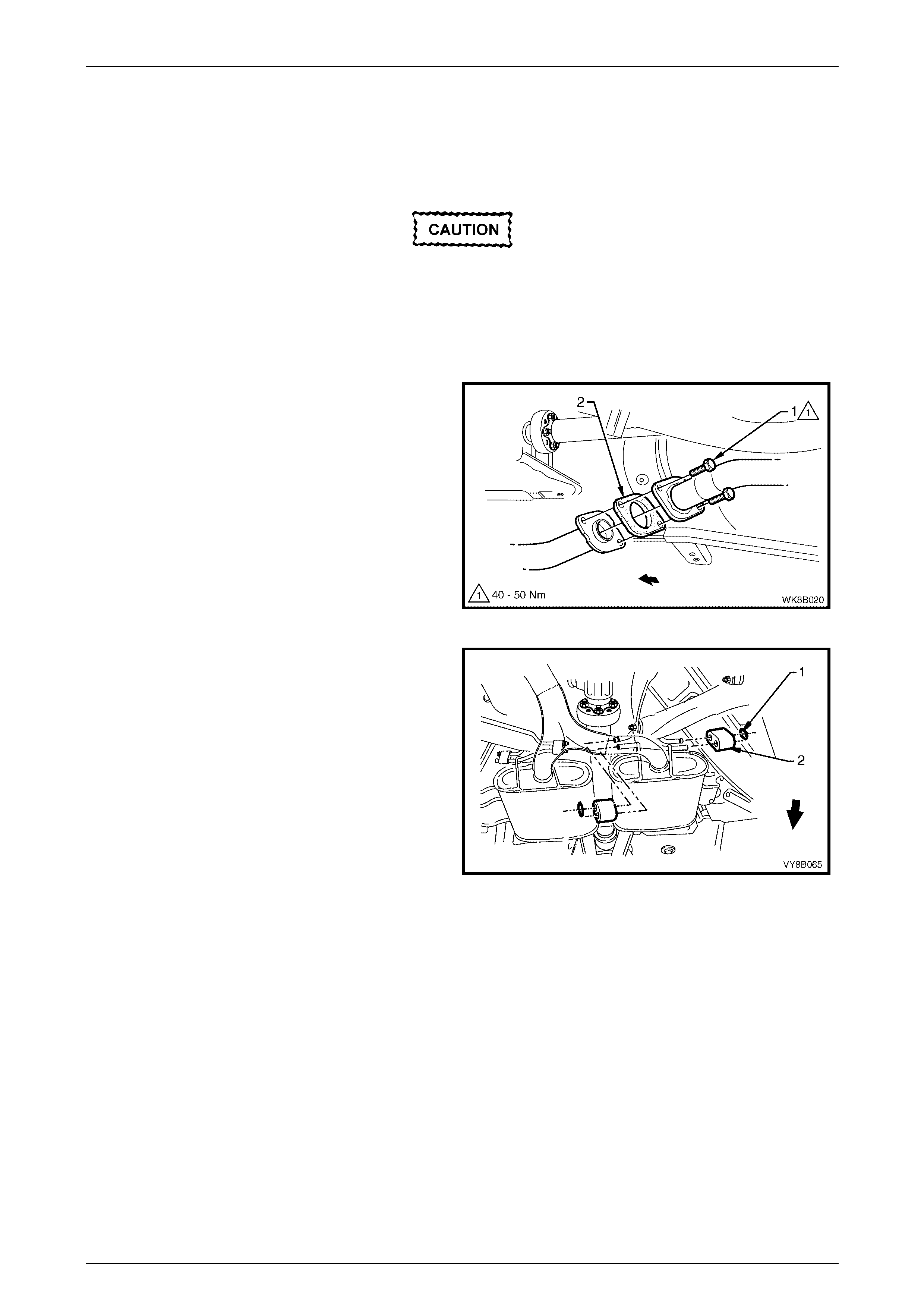
2 Support the intermediate exhaust assembly and
remove the two attaching bolts (1) from each of the
two front to intermediate pipe flange joints.
3 Separate the intermediate exhaust assembly from the
front exhaust assembly and remove the gasket (2)
from between each of the two front to intermediate
pipe flange joints.
Figure 8B – 35
4 Remove the pair of retainer clips (1) and intermediate
muffler support rubbers (2) from the underbody
hangers of the right-hand side and left-hand side
intermediate mufflers and remove the intermediate
exhaust assembly.
Figure 8B – 36

Exhaust System Page 8B–33
Page 8B–33
Reinstall
Installation of the intermediate exhaust assembly is the reverse of the removal procedure, noting the following points:
1 Support the exhaust system at all times.
2 Clean the threads of all attaching bolts and flanges with a suitable cleaning solvent.
3 Check the condition of the two front to intermediate pipe flange joint gaskets upon reinstallation and replace if
necessary.
4 Tighten the front to intermediate pipe flange joint attaching bolts to the specified torque, refer to Figure 8B – 35.
Front to intermediate pipe flange joint
attaching bolts torque specification........40.0 – 50.0 Nm
5 Ensure that all support rubbers are under load.
6 Check the exhaust system for clearances, refer to 5.2 GEN III V8 Exhaust System Clearances. If the clearances
are not within tolerance, loosen off all fasteners and perform the tightening sequence procedure, refer to
3.7 Tightening Sequence.

Exhaust System Page 8B–34
Page 8B–34
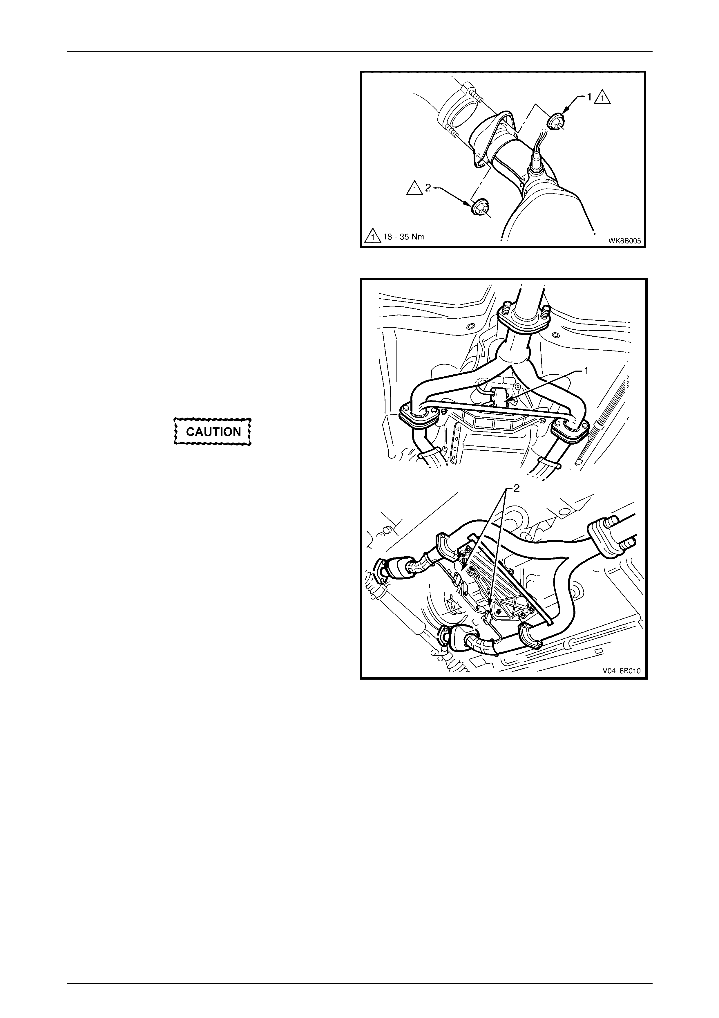
3.6 Front Exhaust Assemblies
Remove
Ensure that the front / intermediate exhaust
assemblies are properly supported to avoid
damage and undue stress on the flange / slip
joints.
1 Disconnect the wiring harness connectors from each
of the two oxygen sensors (1).
NOTE
Automatic transmission shown, manual
transmission similar.
Figure 8B – 37
2 Support the front exhaust assemblies and the
intermediate exhaust assembly.
3 Remove the upper (1) and lower (2) attaching nuts
from the manifold to front pipe flange joint studs on
both sides.
Figure 8B – 38
Exhaust System Page 8B–35
Page 8B–35
4 Remove the two attaching bolts (1) from each front to
intermediate pipe flange joint .
5 Separate the intermediate exhaust assembly from the
front exhaust assemblies and remove the gasket (2)
from between each of the two front to intermediate
pipe flange joints.
Figure 8B – 39
6 Remove the cross brace and transmission mount
nuts as follows:
a For the automatic transmission (view A),
remove the cross brace and transmission
mount nuts (1 and 2) and remove the cross
brace and transmission mount (3).
b For the manual transmission (view B), remove
the cross brace and transmission mount
nuts (4 and 5) and remove the cross brace and
transmission mount (6).
Take care not to damage the oxygen
sensors.
7 Carefully lower and remove the front exhaust
assemblies from the vehicle.
Figure 8B – 40
Reinstall
Installation of the front exhaust assembly is the reverse of the removal procedure, noting the following points:
1 Support the exhaust system at all times.
2 Clean the threads of the attaching bolts, nuts, studs and flanges with a suitable cleaning solvent.
3 Check the condition of the front to intermediate pipe flange joint gaskets upon reinstallation and replace if
necessary.
4 Apply a high temperature anti-seize compound to the manifold to front pipe flange joint studs, then align the flange
over the studs.
5 Hand tighten the front to intermediate pipe flange joint attaching bolts (1), refer to Figure 8B – 39.
6 Hand tighten the manifold to front pipe flange joint studs upper attaching nut (1) then the lower attaching nut (2) on
both sides, refer to Figure 8B – 41.
7 Install the cross brace and transmission mount (3 or 6) depending on transmission type and hand tighten the
attaching nuts, refer to Figure 8B – 42.
Exhaust System Page 8B–36
Page 8B–36
8 Tighten the front to intermediate pipe flange joint attaching bolts to the specified torque, refer to Figure 8B – 39.
Front to intermediate pipe flange joint
attaching bolts torque specification........40.0 – 50.0 Nm
9 Tighten the manifold to front pipe flange joint studs
upper attaching nut (1) and then lower attaching
nut (2) so that approximately equal amounts of stud
thread are showing.
10 Tighten the upper and then the lower attaching nuts to
the specified torque.
Manifold to front pipe flange joint studs
attaching nuts torque specification.........18.0 – 35.0 Nm
Figure 8B – 41
11 Tighten the cross brace to front exhaust pipe nuts (1)
automatic transmission or nuts (4) manual
transmission, to the specified torque.
Cross brace to front exhaust pipe
nut torque specification..........................20.0 – 50.0 Nm
12 Tighten the cross brace bracket attaching nuts (2)
automatic transmission or nuts (5) manual
transmission, to the specified torque.
Cross brace bracket attaching
nuts torque specification ........................20.0 – 50.0 Nm
Figure 8B – 42
13 Ensure that all support rubbers are under load.
14 Check the exhaust system for clearances, refer to 5.2 GEN III V8 Exhaust System Clearances. If the clearances
are not within tolerance, loosen off all fasteners and perform the tightening sequence procedure, refer to
3.7 Tightening Sequence.
15 Connect the wiring harness connector to the relevant oxygen sensor.
Exhaust System Page 8B–37
Page 8B–37
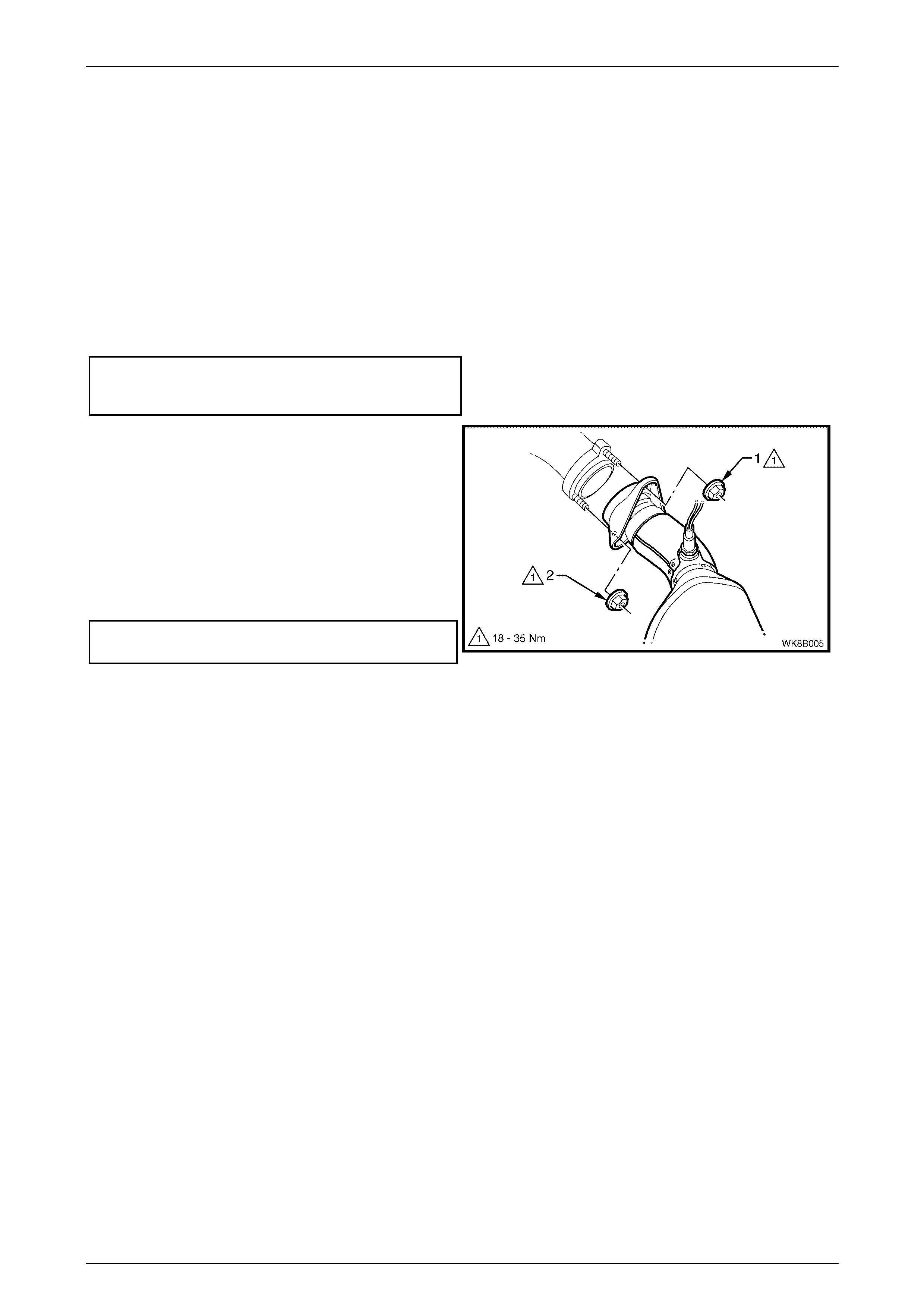
3.7 Tightening Sequence
Ensure that the exhaust assembly is properly
supported to avoid damage and undue stress
on the flange / slip joints.
This procedure is only to be performed if the exhaust system positioning is not to specification.
Refer to Figure 8B – 44 for the following:
NOTE
Ensure that all fasteners mentioned in the
following steps 1 to 8 are loose before
conducting this procedure.
1 Tighten each of the front to intermediate pipe flange joint attaching bolts (1) to the specified torque.
Front to intermediate pipe flange joint
attaching bolts torque specification........40.0 – 50.0 Nm
2 For a standard exhaust system, check that the rear exhaust pipe aligning key is fully seated within the intermediate
to rear pipe slip joint channel. Position the U-clamp (2) along the slip joint and tighten the pair of attaching nuts to
the specified torque.
Slip joint U-clamp attaching nuts
torque specification................................20.0 – 30.0 Nm
3 For a performance exhaust system, position each ring clamp (3) over each of the two intermediate to rear pipe slip
joints and tighten each attaching nut to the specified torque.
Slip joint ring clamp attaching nut
torque specification................................37.0 – 50.0 Nm
4 Tighten the manifold to front pipe flange joint (4) studs nuts as follow.
a Hand tighten the upper attaching nut (1) to the
stud on both sides, refer to Figure 8B – 43.
b Hand tighten the lower attaching nut (2) to the
stud on both sides.
c Tighten the upper and then the lower attaching
nuts so that approximately equal amounts of
stud thread are showing.
d Tighten the upper and then the lower attaching
nuts to the specified torque.
Manifold to front pipe flange joint studs
attaching nuts torque specification........ 18.0 – 35.0 Nm
Figure 8B – 43
5 Tighten the cross brace to front exhaust pipe nuts (5) to the specified torque.
Cross brace to front exhaust pipe
nut torque specification..........................20.0 – 50.0 Nm
6 Tighten the cross brace bracket attaching nuts (6) to the specified torque.
Cross brace bracket attaching
nuts torque specification ........................20.0 – 50.0 Nm
Exhaust System Page 8B–38
Page 8B–38
7 Ensure that all support rubbers (7 and 8) are under load. If this is not achieved, loosen the respective joints in the
reverse order to steps 1 to 6. Load the underbody hangers, re-tighten and check in the sequence described from
steps 1 to 7.
NOTE
The exhaust system should be self-aligning
and not require further adjustment, provided
Step 7 is achieved. To ensure that
correct clearances are maintained throughout
the complete exhaust system, refer to
5.2 GEN III V8 Exhaust System Clearances for
the correct values.
Figure 8B – 44
Legend
View Standard Exhaust
Automatic Transmission
View Manual Transmission
View Performance Exhaust
1 Front to Int ermediate P i pe Fl ange Joint
2 Intermediate to Rear Pipe Slip Joint and
U-clamp
3 Intermediate to Rear Pipe Slip Joints
and Ring Clam p
4 Manifold to Front P i pe Fl ange Joint
5 Cross B rac e to Front Exhaust P i pe Nut s
6 Cross B race Brack et Attaching Nuts
7 Intermediate Muff l er Support Rubbers
8 Rear Muffler Support Rubbers
Exhaust System Page 8B–39
Page 8B–39
4 Service Operations – Heat
Shields
4.1 Exhaust System Heat Shields
To avoid the possibility of personal injury by
burns, allow the exhaust system to cool down
before attempting this operation.
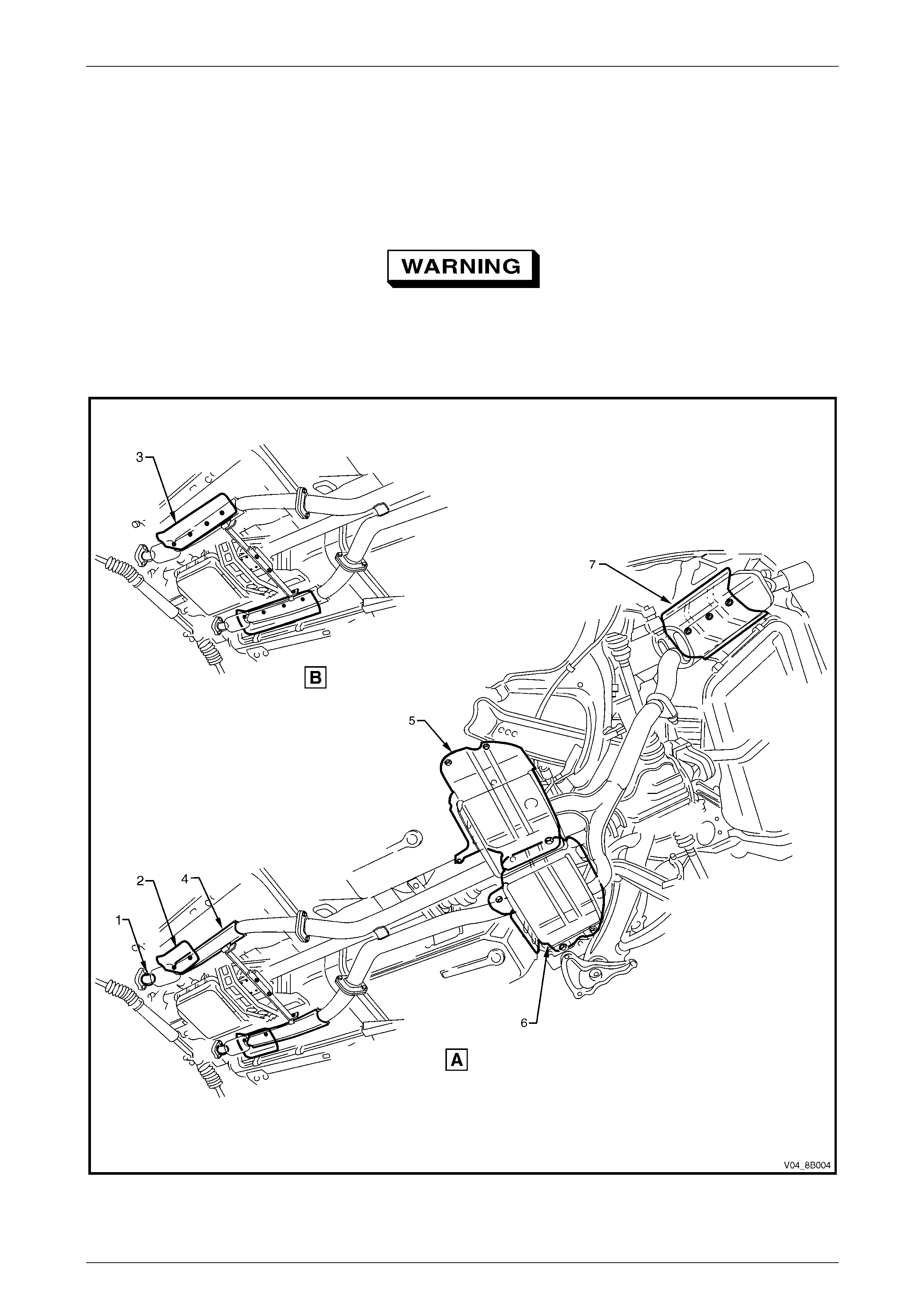
Figure 8B – 45 provides a reference to the location of heat shields.
Figure 8B – 45

Exhaust System Page 8B–40
Page 8B–40
Legend
View Euro 2 Compl i ance
View Non-euro 2 Compli ance
1 Pre-cata l yt i c Converter On-pipe Heat
Shield
2 Front Foil Heat Shield – Euro 2
3 Front Foil Heat Shield – Non-euro 2
4 Post -catalyti c Converter On-pipe Heat
Shield
5 Intermediate Muff l er Heat Shield
6 Intermediate Muff l er Heat Shield – V 6
Supercharged Engine and Gen III V8
Engine
7 Rear Muffler Heat Shield – All V ehi cles
Except Utility
NOTE
V8 automatic transmission shown, manual
transmission and V6 similar.
Exhaust System Page 8B–41
Page 8B–41
4.2 Rear Muffler Underbody Mounted Heat
Shield
Remove
1 If required, remove the rear exhaust assembly. For V6, refer to 2.4 Rear Exhaust Assembly. For V8, refer to
3.4 Rear Exhaust Assembly.
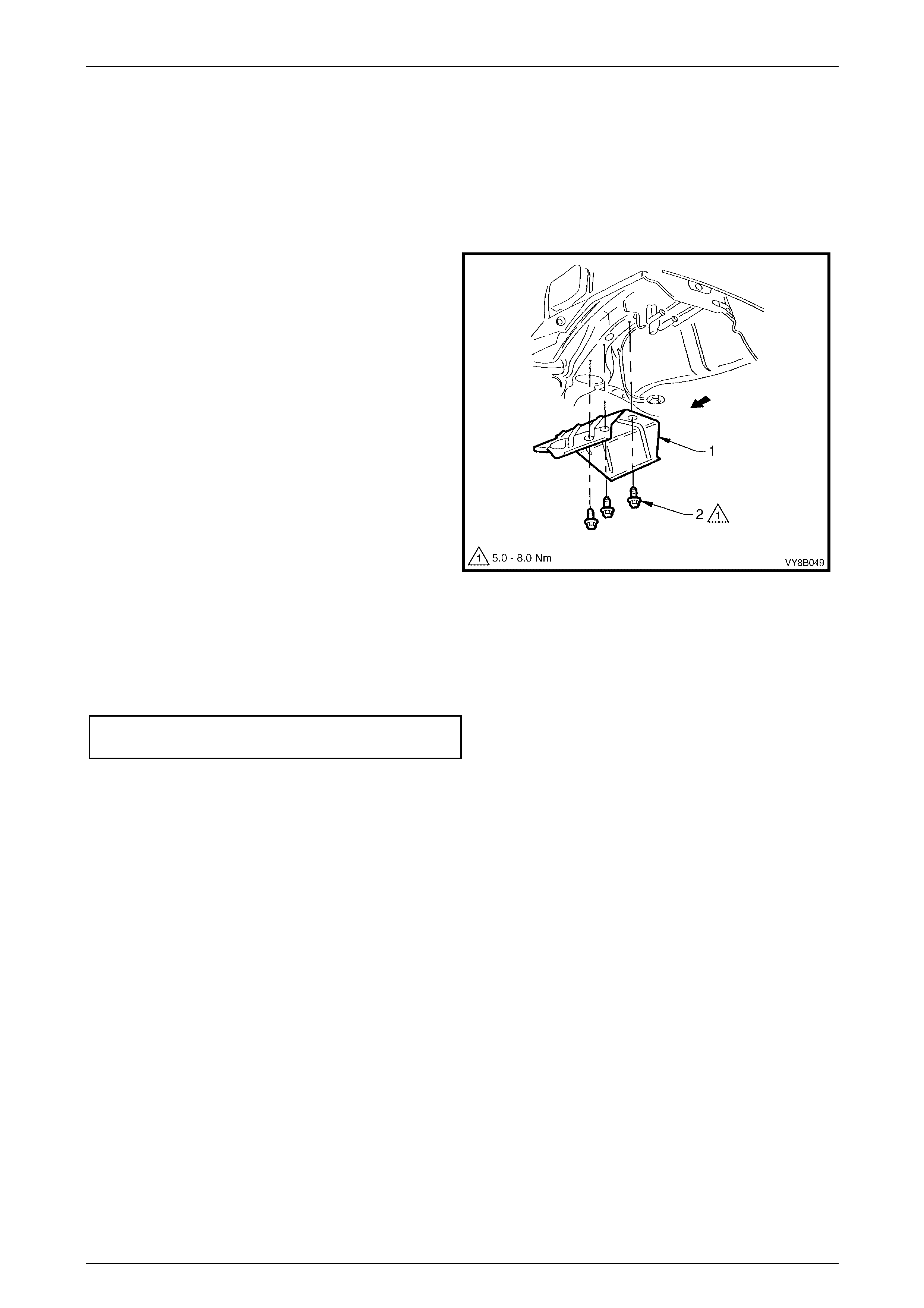
2 Remove the rear muffler heat shield (1) by removing
the three attaching screws (2).
Figure 8B – 46
Reinstall
Installation of the rear muffler heat shield is the reverse of the removal procedure, noting the following:
1 Tighten the rear muffler heat shield attaching screws to the correct torque specification, refer to Figure 8B – 46.
Rear muffler heat shield attaching
screws torque specification........................5.0 – 8.0 Nm
Exhaust System Page 8B–42
Page 8B–42
4.3 Intermediate Muffler Underbody Mounted
Heat Shield
Remove
1 If required, remove the intermediate exhaust assembly. For V6, refer to 2.5 Intermediate Single Pipe and Muffler
Exhaust Assembly. For V8, refer to 3.5 Intermediate Exhaust Assembly.
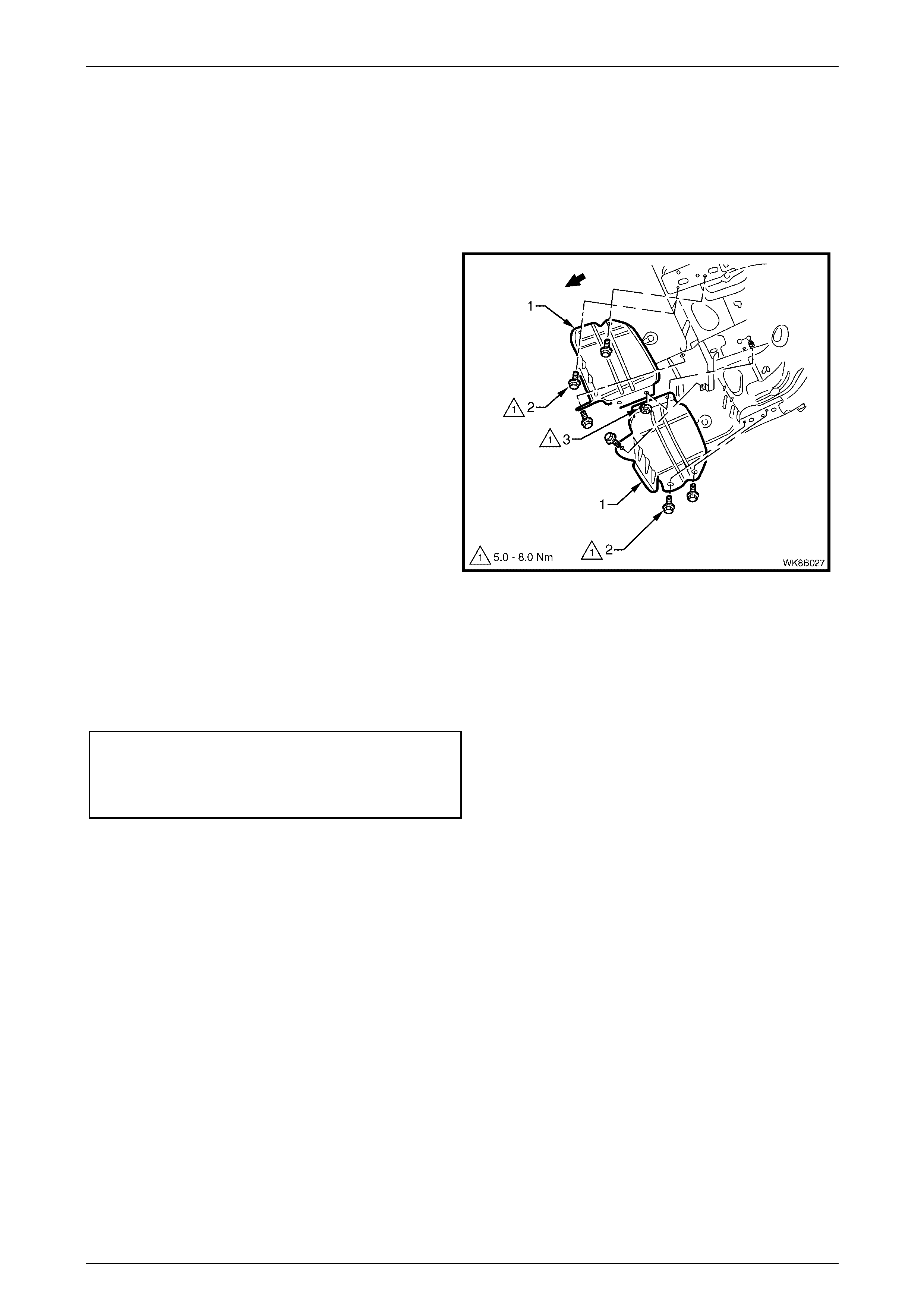
NOTE
For V6 vehicles, there is only one intermediate
muffler heat shield installed above the single
intermediate muffler.
2 Remove the intermediate muffler heat shield/s (1) by
removing the attaching screws (2) and the single
nut (3).
Figure 8B – 47
Reinstall
Installation of the intermediate muffler heat shield/s is the reverse of the removal procedure, noting the following:
1 Tighten the intermediate muffler heat shield attaching screws (2) and nut (3) to the correct torque specification,
refer to Figure 8B – 47.
Intermediate muffler heat shield
attaching screws torque specification........5.0 – 8.0 Nm
Intermediate muffler heat shield
attaching nut torque specification .............. 5.0 – 8.0 Nm
Exhaust System Page 8B–43
Page 8B–43
4.4 Front Foil Underbody Mounted Heat
Shields
Remove
1 If required, remove the front exhaust assemblies. For V6, refer to 2.7 Front Exhaust Assemblies. For V8, refer to
3.6 Front Exhaust Assemblies.
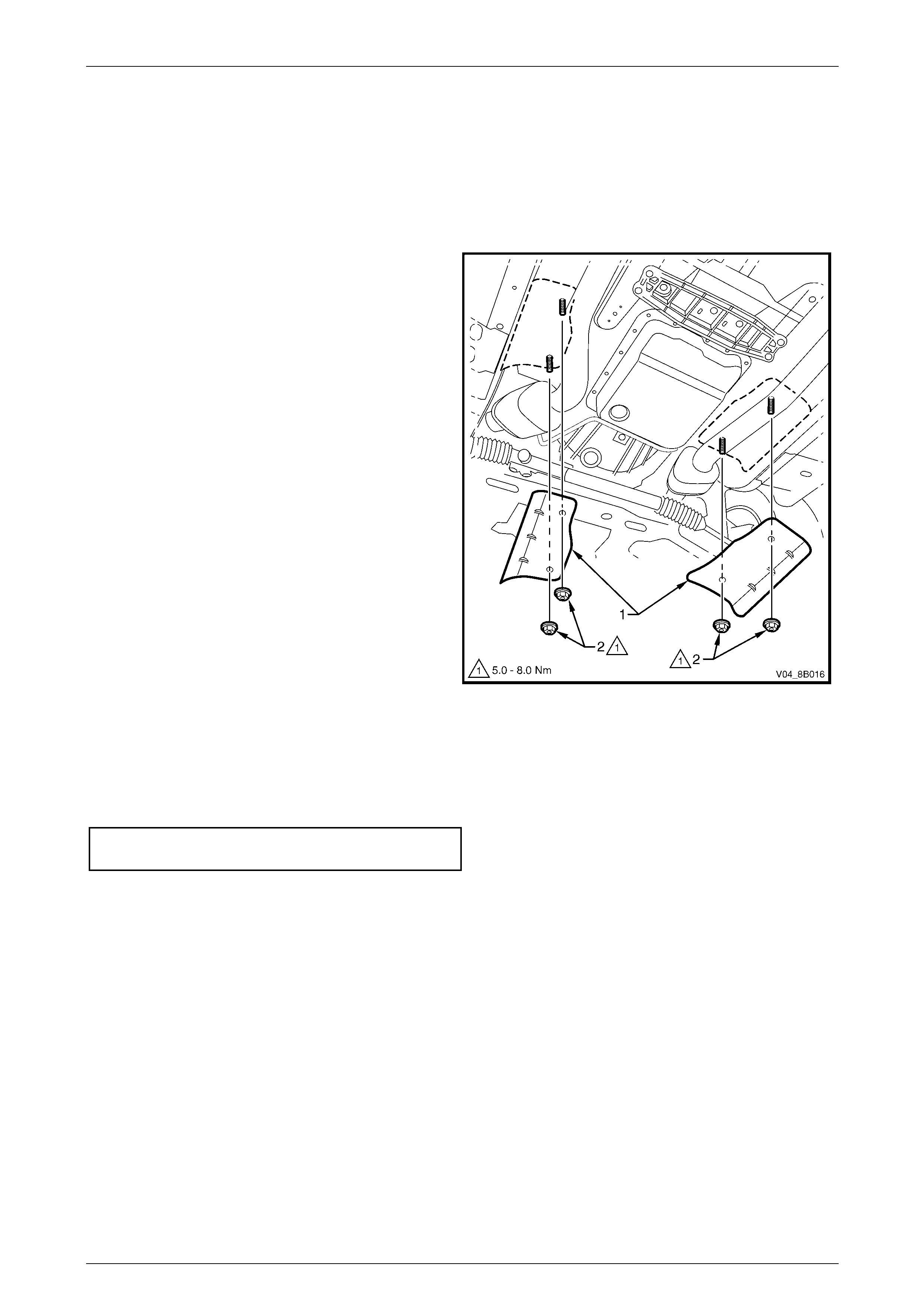
2 Remove the two front foil heat shields (1) by
removing the pair of attaching nuts (2) for each front
foil heat shield.
NOTE
Automatic transmission shown, manual
transmission similar.
NOTE
If longer front foil heat shields are fitted, then
four nuts are used to retain each front foil heat
shield. Longer front foil heat shields are fitted to
the following vehicles:
• Domestic vehicles fitted with V6 engine
produced before the start of 2004.
• Vehicles fitted with a V6 supercharged
engine.
• Vehicles produced for export to Brazil and
Indonesia.
Figure 8B – 48
Reinstall
Installation of the front foil heat shields is the reverse of the removal procedure, noting the following:
1 Tighten the front foil heat shields attaching nuts (2) to the correct torque specification, refer to Figure 8B – 48.
Front foil heat shields
attaching nuts torque specification.............5.0 – 8.0 Nm


Exhaust System Page 8B–45
Page 8B–45
5 Exhaust System Clearances
5.1 V6 Exhaust System Clearances
Check all exhaust system components for adequate underbody clearance when parts are at ambient temperature.
Adjust or replace parts as necessary.
Information not available at time of publication.

Exhaust System Page 8B–46
Page 8B–46
5.2 GEN III V8 Exhaust System Clearances
Check all exhaust system components for adequate underbody clearance when parts are at ambient temperature.
Adjust or replace parts as necessary.
Information not available at time of publication.

Exhaust System Page 8B–47
Page 8B–47
6 Torque Wrench Specifications
Manifold to Front Pipe Flange Joint Studs Attaching Nuts ........18.0 – 35.0 Nm
Slip Joint U-clamp Attaching Nuts.............................................20.0 – 30.0 Nm
Swivel Flange Joint Attaching Stepped Bolts ............................40.0 – 50.0 Nm
Front Pipe To Intermediate Y-Pipe Flange Joint
Attaching Bolts...........................................................................40.0 – 50.0 Nm
Cross Brace to Front Exhaust Pipe Nut.....................................20.0 – 50.0 Nm
Cross Brace Bracket Attaching Nuts .........................................20.0 – 50.0 Nm
Slip Joint Ring Clamp Attaching Nut..........................................37.0 – 50.0 Nm
Front to Intermediate Pipe Flange Joint Attaching Bolts ...........40.0 – 50.0 Nm
Rear Muffler Heat Shield Attaching Screws...................................5.0 – 8.0 Nm
Intermediate Muffler Heat Shield Attaching Screws ......................5.0 – 8.0 Nm
Intermediate Muffler Heat Shield Attaching Nut.............................5.0 – 8.0 Nm
Front Foil Heat Shields Attaching Nuts..........................................5.0 – 8.0 Nm