
TECH 2 Page 0C–1
Section 0C
TECH 2
ATTENTION
Before performing any Service Operation or other procedure described in this Section, refer to Section 00
WARNINGS, CAUTIONS AND NOTES for correct workshop practices with regard to safety and/or property
damage.
1 General Information ...............................................................................................................................3
1.1 Features Of The TECH 2........................................................................................................................................ 5
Display.................................................................................................................................................................... 6
Screen Areas.......................................................................................................................................................... 7
Keypad.................................................................................................................................................................... 8
Keypad Layout....................................................................................................................................................... 8
Soft Keys ................................................................................................................................................................ 8
Selection Keys ....................................................................................................................................................... 9
Action Keys............................................................................................................................................................ 9
Function Keys........................................................................................................................................................9
Help Key ................................................................................................................................................................. 9
Control Keys........................................................................................................................................................... 9
Thumb Action......................................................................................................................................................... 9
PCMCIA Card........................................................................................................................................................ 10
Vehicle Communication Interface Module......................................................................................................... 11
Serial Ports........................................................................................................................................................... 12
Adapters for TECH 2............................................................................................................................................ 13
1.2 Connections......................................................................................................................................................... 14
2 Programming TECH 2..........................................................................................................................15
2.1 General Information............................................................................................................................................. 15
Standard Update.................................................................................................................................................. 16
Custom Update .................................................................................................................................................... 17
3 Using TECH 2 On The Vehicle.............................................................................................................20
3.1 Connecting The TECH 2 To The Vehicle............................................................................................................ 20
3.2 Vehicle Application Menu ................................................................................................................................... 22
3.3 Engine Application Menu.................................................................................................................................... 23
V6 Engine ............................................................................................................................................................. 24
V6 Engine TECH 2 Functions .......................................................................................................................... 24
V8 GEN III.............................................................................................................................................................. 28
V8 GEN III Engine TECH 2 Functions.............................................................................................................. 28
V8 GEN IV ............................................................................................................................................................. 31
V8 GEN IV Engine TECH 2 Functions ............................................................................................................. 31
3.4 Transmission Application Menu......................................................................................................................... 35
Automatic Transmission..................................................................................................................................... 35
4L60E / 4L65E Automatic Transmission TECH 2 Functions ............................................................................ 36
5L40E Automatic Transmission TECH 2 Functions.......................................................................................... 38
GEN III Automatic Transmission ........................................................................................................................ 40
GEN III Automatic Transmission TECH 2 Functions........................................................................................ 40
Service Programming System.......................................................................................................................... 42
BCM Link To PCM/PIM.................................................................................................................................... 42
3.5 Chassis Application Menu .................................................................................................................................. 43
ABS/TC/ESP 8.0 ................................................................................................................................................... 44
ABS/TC/ESP 8.0 TECH 2 Functions................................................................................................................ 44
Page 0C–1
Techline
Techline
Techline
Techline
Techline
Techline

TECH 2 Page 0C–2
ABS/TC 5.3............................................................................................................................................................ 46
ABS/TC 5.3 TECH 2 Functions........................................................................................................................ 46
TPMS (Tyre Pressure Monitoring System)......................................................................................................... 48
TPMS (Tyre Pressure Monitoring System) TECH 2 Functions.........................................................................48
3.6 Body Application Menu....................................................................................................................................... 50
Body Control Module........................................................................................................................................... 51
Body Control Module TECH 2 Functions.......................................................................................................... 51
Powertrain Interface Module (GMLAN) .............................................................................................................. 57
Powertrain Interface Module (GMLAN) TECH 2 Functions.............................................................................. 57
Powertrain Interface Module (Class 2)............................................................................................................... 59
Powertrain Interface Module (Class 2) TECH 2 Functions............................................................................... 59
Supplemental Restraint System (SRS) .............................................................................................................. 61
SRS TECH 2 Functions.................................................................................................................................... 61
Instrument ............................................................................................................................................................ 62
Instrument TECH 2 Functions.......................................................................................................................... 62
Multi Function Display......................................................................................................................................... 66
Multi Function Display TECH 2 Functions........................................................................................................ 66
Occupant Climate Control................................................................................................................................... 68
OCC TECH 2 Functions................................................................................................................................... 68
Telematics Module............................................................................................................................................... 72
Telematics TECH 2 Functions.......................................................................................................................... 72
Audio System....................................................................................................................................................... 75
Audio System TECH 2 Functions..................................................................................................................... 75
Premium Sound Amplifier (PSA)........................................................................................................................ 77
Premium Sound Amplifier (PSA) TECH 2 Functions........................................................................................ 77
Audio Interface Module (AIM) ............................................................................................................................. 78
Audio Interface Module (AIM) TECH 2 Functions ............................................................................................ 79
DVD Player ........................................................................................................................................................... 80
DVD Player TECH 2 Functions ........................................................................................................................ 80
Seat and Exterior Mirror Memory Module.......................................................................................................... 81
Seat and Exterior Mirror Memory Module TECH 2 Functions .......................................................................... 81
Auxiliary Gauge TECH 2 Functions.................................................................................................................. 83
3.7 On Board Diagnostic (OBD)................................................................................................................................ 84
4 TIS Approval .........................................................................................................................................85
4.1 General Information............................................................................................................................................. 85
4.2 Security Access................................................................................................................................................... 86
Security Access procedure................................................................................................................................. 86
5 Service Programming System (SPS)..................................................................................................89
5.1 General Information............................................................................................................................................. 89
5.2 SPS Process......................................................................................................................................................... 90
6 TECH 2 Diagnosis ................................................................................................................................98
6.1 General Information........................................................................................................................................... 101
6.2 Test Description................................................................................................................................................. 102
6.3 TECH 2 Diagnostic Chart .................................................................................................................................. 103
7 Special Tools ......................................................................................................................................104
Page 0C–2

TECH 2 Page 0C–3
1 General Information
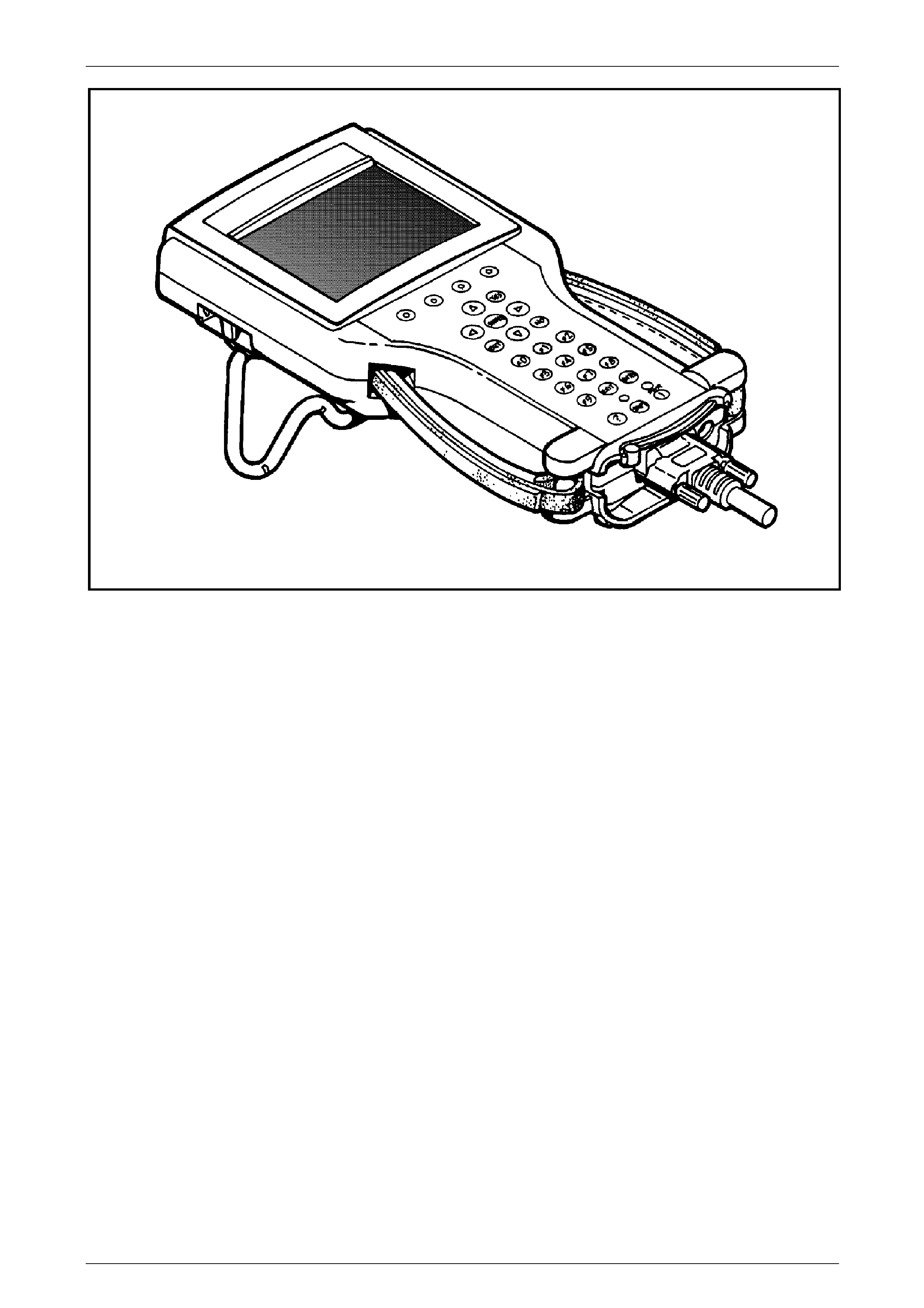
The TECH 2 is a hand-held diagnostic computer design ed specifically to help you diagnose and repair electronic
systems used on Holden vehi cles.
When the TECH 2 is attached to a vehicle it can be a very versatile tool. With its large, easy-to-read display, the TECH 2
guides you step-by-step throu gh the testing procedures. You respond to the TECH 2 through the keyboard commanding
it to:
• Conduct the test you want to run
• Retrieve the diagnostic data you want
• Control the function you want to monitor
The TECH 2 gets its power from the vehicle to be tested and communicates or interfaces with the vehicle electronic
systems through the Data Link Connector (DLC). T E CH 2 c an communicate with the following control modules, if the
vehicle is equipped with these systems.
• Body Control Module (BCM).
• Instrument
• Powertarin Interface Module (PIM)
• Engine Control Module (ECM).
• Powertrain Control Module (PCM).
• Antilock Braking System / Traction Control / Elecronic Stability Control System (ABS/TC/ESP).
• Antilock Braking System / Electronic Traction Control System (ABS/ETC).
• Transmission Control module (TCM)
• Supplemental Restraint System (SRS).
• Occupant Climate Control (OCC)
• Telematics Control Module
• Audio System (“Radio”)
• Tyre Pressure Monitoring System (TPMS)
• Multi Function Display (MFD)
• Seat and Exterior Mirror Module (MSM)
• Premium Sound Amplifier
• Audio Interface module (AIM)
• DVD Player
When connected to the DLC, the TECH 2 can read Diagnosti c Trouble Codes (DTCs) and dia gnostic data. Depending on
the application selected, TECH 2 can also control some systems for troubleshooting or automatic testing.
Page 0C–3
TECH 2 Page 0C–4
Figure 0C – 1
Page 0C–4
TECH 2 Page 0C–5
1.1 Features Of The TECH 2
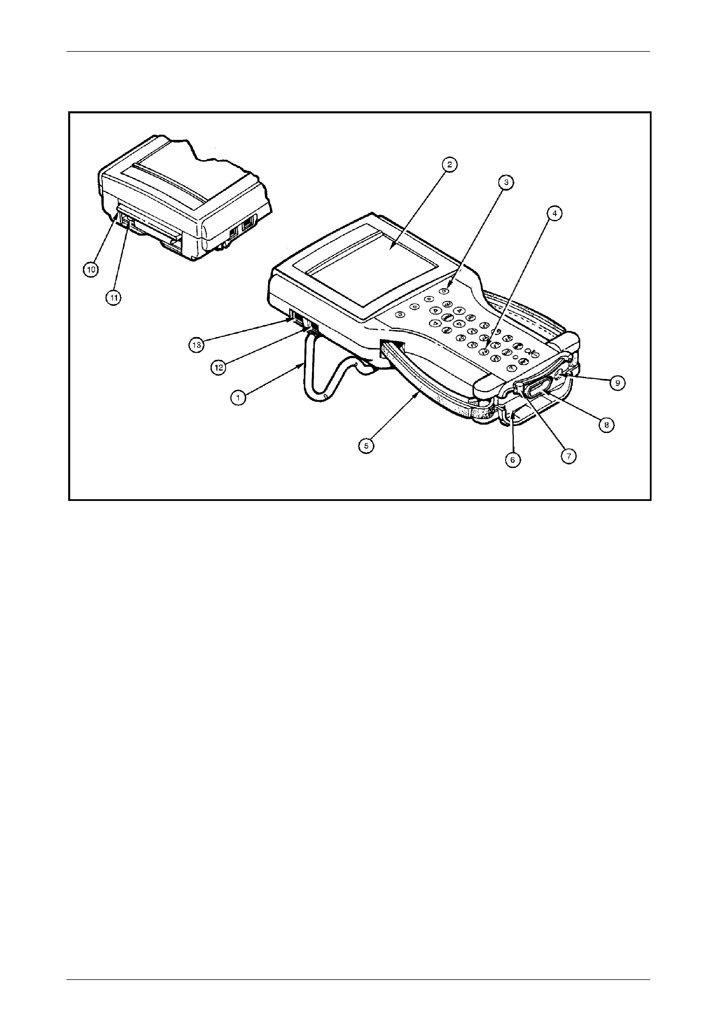
Figure 0C – 2
Legend:
1. Tilt Stand 6. Vehicle Communication Interface (VCI) 11. PCMCIA Release Button
2. Display 7. VCI Latching Lever 12. RS-232 Communication Port
3. Soft Keys 8. DLC Connector 13. RS-485 Communication Port
4. Keypad 9. Power Jack
5. Adjustable Hand Strap 10. PCMCIA Cover
Page 0C–5
TECH 2 Page 0C–6
Display
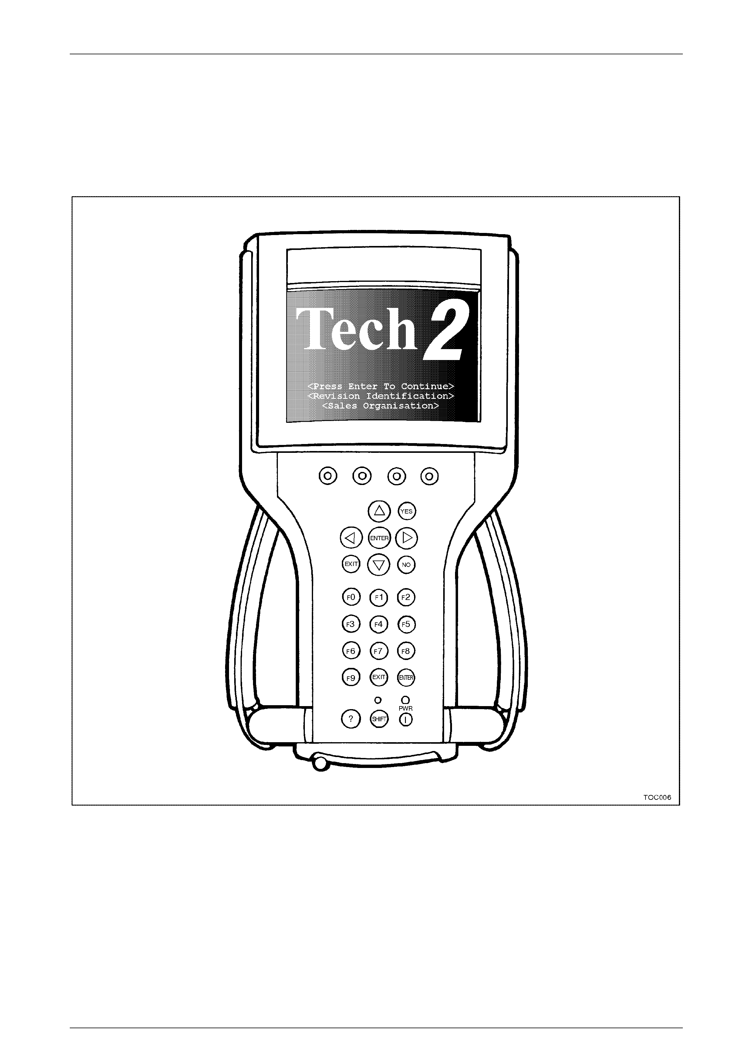
A large screen, Monochrome Liquid Crystal Display (LCD) that measures 100 x 76 mm is used on the TECH 2. This
allows nine parameters to be seen on screen at the same time. The screen has graphics capa bilities that allow graphs to
be plotted on the screen to aid diagnosis. The tool may, in the future, allo w some additio nal graphic images to be
displayed that will help dia gnose vehicle systems.
The TECH 2 has an adjustable contrast control to allow the user to change brightness and contrast of the display.
Figure 0C – 3
Page 0C–6
TECH 2 Page 0C–7
Screen Areas
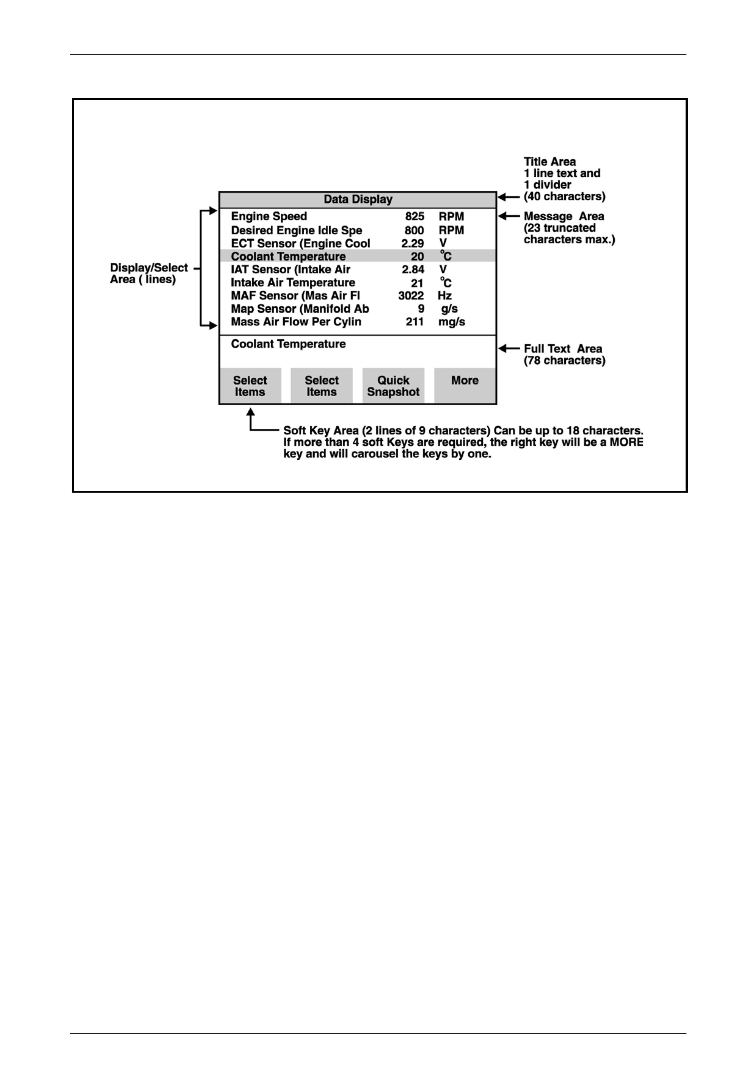
Figure 0C – 4
The screen is broken down into five areas. By looking at the information that is displayed in each area, the user ma y use
the tool more efficiently.
• Title area
• Message area
• Display/select area
• Full text area*
• Soft key area
*The "full text" area is always a complete description of the highlighted line in the "display/ s elect" area.
Page 0C–7
TECH 2 Page 0C–8
Keypad
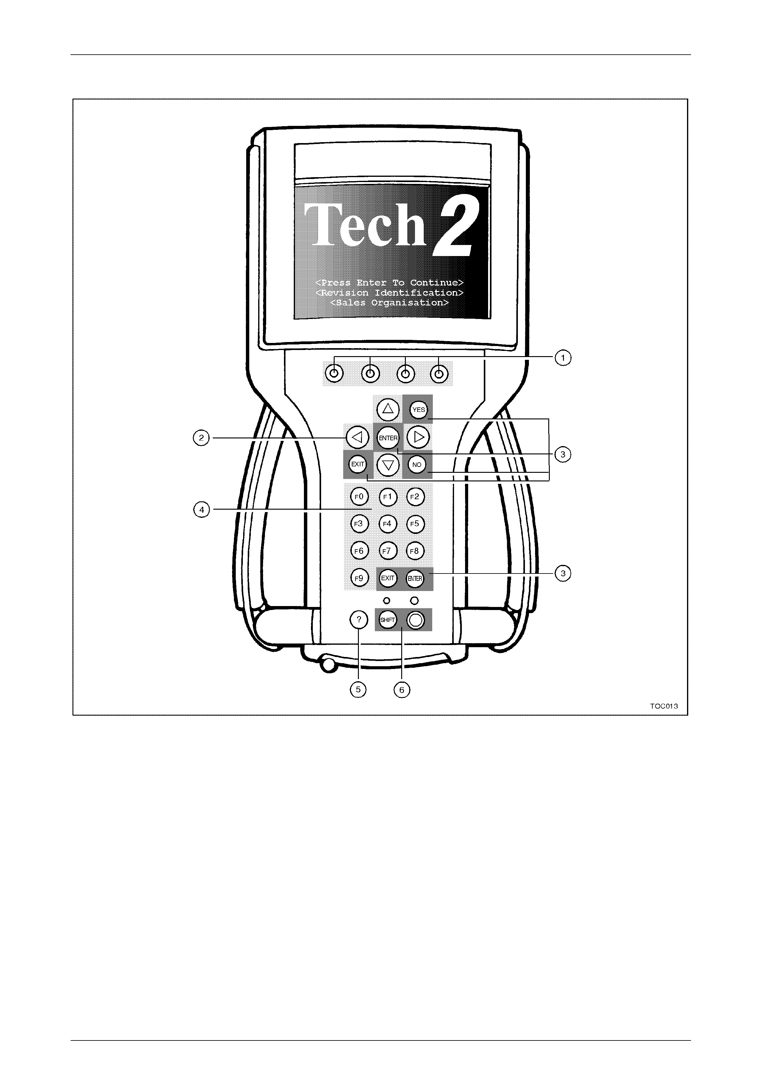
Figure 0C – 5
Legend:
1. Soft Keys 3. Action Keys 5. Help Key
2. Selection Keys 4. Function Keys 6. Control Keys
Keypad Layout
The keypad of the TECH 2 contains 27 keys. Within these keys are 23 keys that are pre-defined and four keys which are
referred to as soft keys. The soft key usage will change depending on which part of an application is being used.
Following is a definition of the key usage for the pre-defined keys.
Soft Keys
There are four keys on the TECH 2 that will have changing usage within an app lication. Soft key functions are software
driven. This means that the soft key function may change in different areas of the software. The left most soft key at the
Main Menu will be used to Clear Vehic le, while in Snapshot the same key position may change Units. The ability of the
soft keys to perform different tool operations at different times increases the versatility of the TECH 2.
Page 0C–8

TECH 2 Page 0C–9
Selection Keys
The arrow keys are used for screen movement to make a selecti on. There are four arrow keys. The Up and Down arrows
move the highlight bar one line at a time. If they are held, the highlight bar will scroll. The Left and Right arro w keys will
move the highlight a page at a time. Left arrow moves the hi ghlight up (previous page) and Right arrow moves the
highlight down (next page). The arrow keys are used to move the highlight bar to a position to make a selection, or to
move the display to allow more information to be viewed.
Action Keys
There are a group of keys that are referred to as Action ke ys. As the name implies, action keys will make an action take
place on the TECH 2 tool. The action keys are YES, NO, ENTER, and EXIT.
YES — Confirms a positive response to a question.
NO — Confirms a negative response to a question.
ENTER (2 keys) — Indicates a selection has been made.
EXIT (2 keys) — Returns the user to a previous menu selection.
Function Keys
The function keys (F0 - F9) allow direct selection of a cho ice from a menu.
Help Key
Help (?) accesses a tool help function that is specific to the current operation of the TECH 2.
Control Keys
There are two keys that are used to control the TECH 2 itself. These are the SHIFT and PWR (Power) keys. The SHIFT
key will access screen contrast control. To adjust contrast during the current power cycle of the TECH 2, use the
following procedure.
Press the SHIFT key (The yellow light will turn on).
Use the Up arrow to Increase screen brightness and contrast or the Down arrow to Decrease screen brightness and
contrast.
Press the SHIFT key (the yellow light will turn off).
This procedure will only adjust the contrast for the duration of this power cycle of the TECH 2. If the power is turned off
and then back on again, the contrast will change to a default value. The default setting is covere d in the TECH 2 User’s
Guide.
Be aware that if the yellow SHIFT light is on, only the Up/Down arrow keys and the EXIT keys are active.
There is a PWR (Power) switch for TECH 2 that will control turning the TECH 2 on and off. A green ind icator will
illuminate when the TECH 2 is s witched on.
Thumb Action
The TECH 2 is designe d for one handed operation. The unit is balanced to allow one hand to comfortably hold and
operate the tool. Straps on the sides of the tool are adjustable to help hold the TECH 2 in one hand. The keypad
configuration is designed for thumb usage while holding the tool in either the left or right hand. It is suggested to use the
selection and action keys instead of the function keys, as some TECH 2 screens require making selections from a list on
screen. In these cases there may not be a function key equivalent.
Page 0C–9

TECH 2 Page 0C–10
PCMCIA Card
Figure 0C – 6
Legend:
1. PCMCIA Release Button 3. Empty Lower PCMCIA Slot 1 5. PCMCIA Cover
2. In Use Upper PCMCIA Slot 0 4. TECH 2 PCMCIA Card 6. Underneath Side of TECH 2
The TECH 2 uses a Personal Computer Memory Card Industry Association (PCMCIA) standard memory card for storage
of diagnostic functions and applicati ons. The memory card has a capacity of 32 Megabytes. T he PCMCIA card is
accessed through a door on top of the TECH 2, and should not normally require removal. There are two PCMCIA slots in
TECH 2, slot zero which is closest to the screen and the second slot that is identified as slot one. To remove the card,
push the arrow button pointing to card to be remove d. Cards are notche d to allow insertion only one way. When re-
inserting the card make sure that it fully seat s into the TECH 2.
If you are using a 32 Megabyte PCMCIA card, the card should be installed into slot zero. If you are using 2 PCMCIA
cards, one in each slot, you can switch between cards by pressing the SHIFT key, then press either the RIGHT or LEFT
arrow key. TECH 2 will then toggle between the card in slot 0 to the card in slot 1. Once TECH 2 has toggled between
cards, press the SHIFT key again.
The TECH 2 has the capabi lity of storing two snapsh ots. T his will allow comparison of before/after type conditions on a
vehicle being serviced.
NOTE
The PCMCIA card is sensitive to magnetism and
static electricity so care should be taken in the
handling of the card.
A write protect slide mechanism is on the top edge of the ca rd. T he correct position is to the middle of the card
(unlocked). If the write protect is in the locked position, snapshots will not be able to be stored, and Service Programming
System (SPS) will not work.
TECH 2 and PCMCIA card can be updated b y connecting to Technical Information System (TIS).
The software that operates the TECH 2 is stored on the PCMCIA card. The contents of the card are not distinct
applications. All of the applications share a single database of informatio n on the PCMCIA card.
Page 0C–10
TECH 2 Page 0C–11
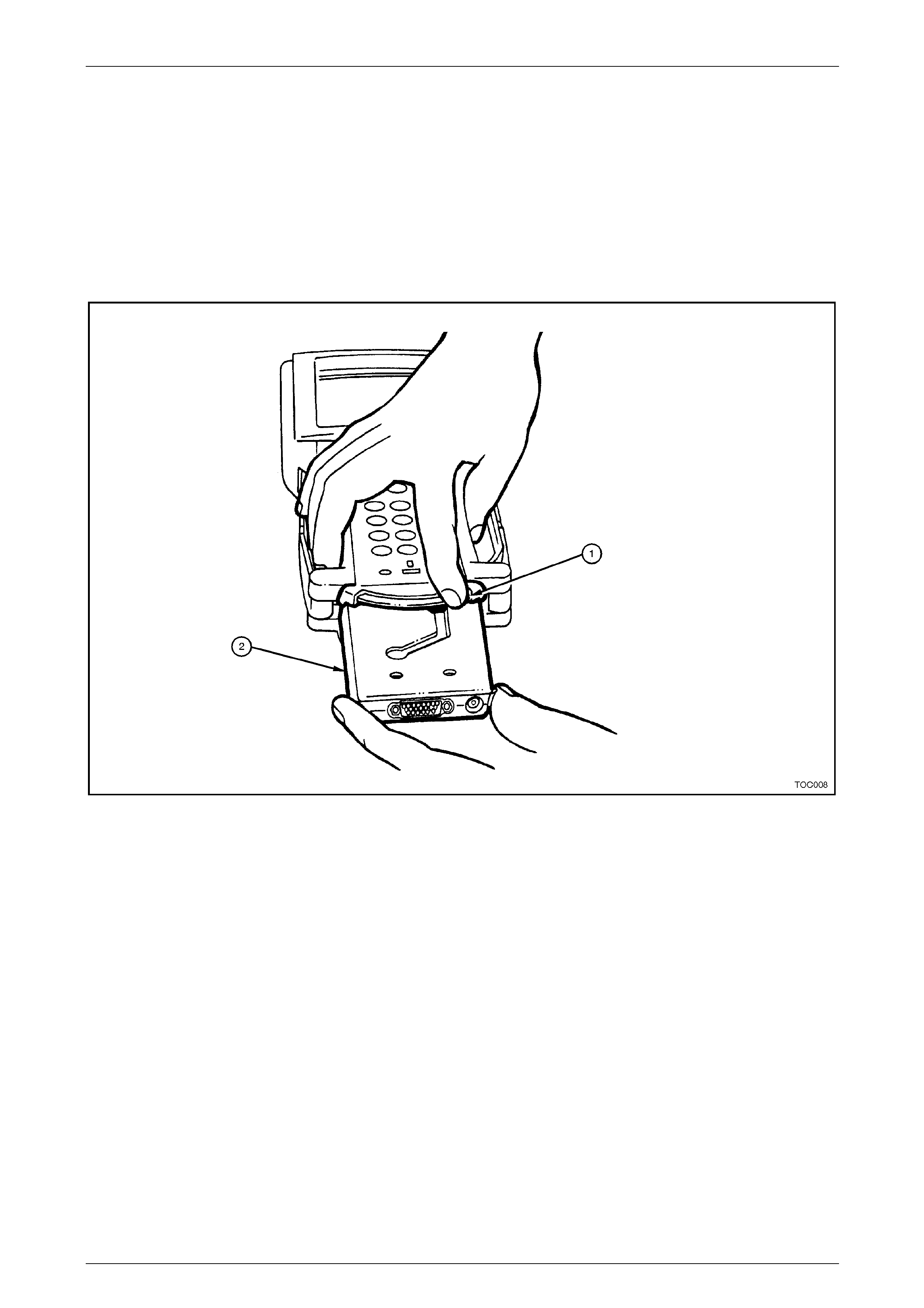
Vehicle Communication Interface Module
The TECH 2 uses a Vehicle Communication Interface (VCI) module, located in the bottom of the unit to act as an
interface between the vehicle and the internal workings of the TECH 2. This allows the TECH 2 to communicate to many
different types of data systems on vehicles.
Data is transmitted between the vehicle and the TECH 2 through the DL C cable. Power for the TECH 2 is also sent
through the VCI module. Power can either come through the DLC cable or from the power jack on the bottom of the VCI
module. Internally, the VCI module protects the TECH 2 against reverse polarity power connections.
During normal usage of the TECH 2, there is no reason to remove the VCI module. In the future, if different types of data
communication are used on the vehicle, the VCI module could be changed to extend the useful life of the TE CH 2 even
further. To remove the VCI module, refer to the TECH 2 User's Guide.
Figure 0C – 7
Legend:
1. VCI Module Lever (moved all the way to the right) 2. VCI Module
Page 0C–11
TECH 2 Page 0C–12
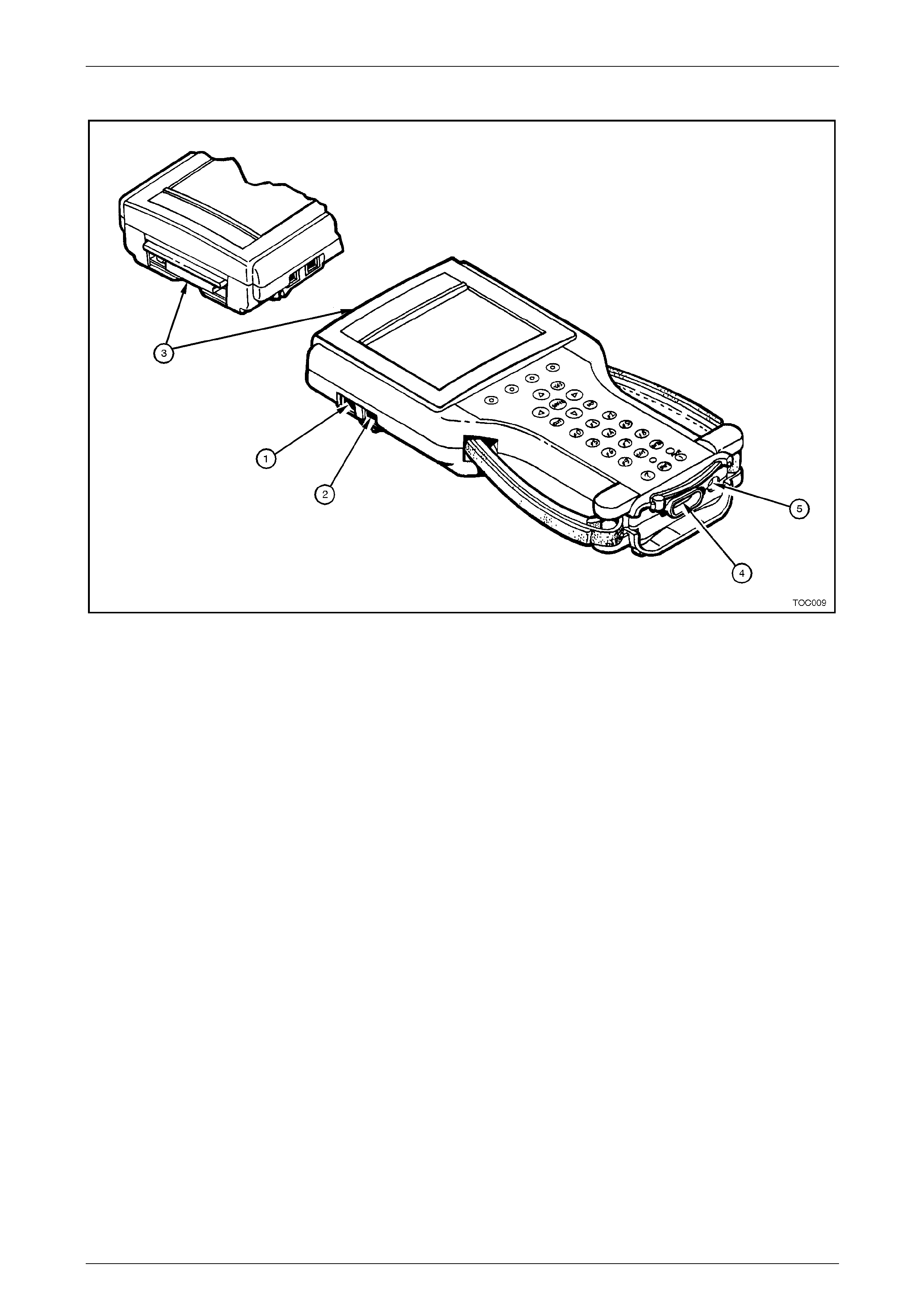
Serial Ports
Figure 0C – 8
Legend:
1. RS-485 Port 3. PCMCIA Slots 5. Power Jack Connector
2. RS-232 Port 4. DLC Connector
TECH 2 also has two serial port connections for communication to other computers. These ports are the RS-232 and the
RS-485. The RS-232 is used for conn ecting to TIS for updating the contents of applications on the TECH 2. To perform
Service Programming System with the TECH 2 the RS-232 port is also used.
The RS-485 is currently not used, but may in the future allow for other tool capabilities.
Page 0C–12
TECH 2 Page 0C–13
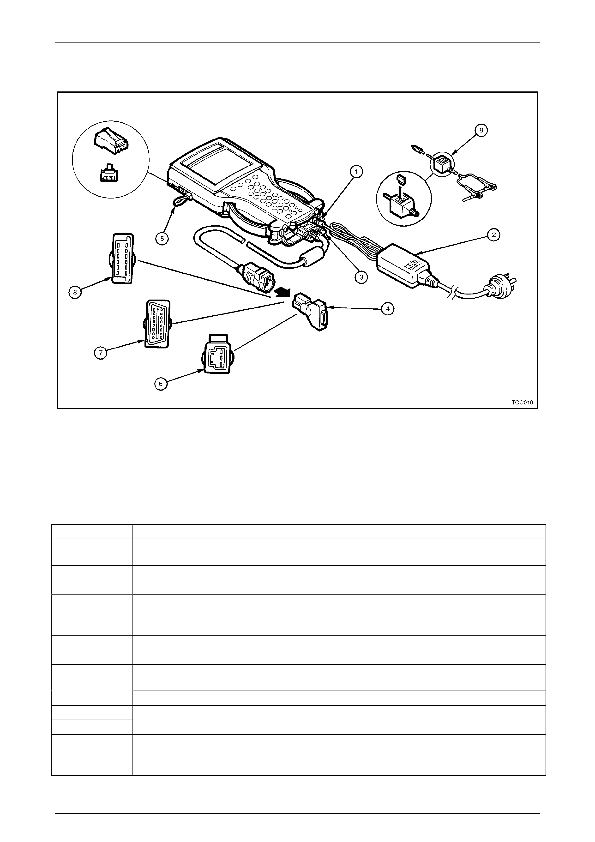
Adapters for TECH 2
The TECH 2 includes a selection of cables and adapters to accommodate a variety of operating conditions and functions.
Figure 0C – 9
Legend:
1. Power Jack 4. DLC Loopback Connector 7. SAE 16/19 Pin Adapter
2. Power Supply 5. RS-232 Loopback Connector 8. NAO 12/19 Pin Adapter
3. DLC Cable 6. Opel/Isuzu/Geo 3/19 Pin Adapter 9. Battery Power Cable
Product Number Product Name
3000115 Universal 100 - 240 Volt AC p ower supply with wall sock et cable (3000114). This adapter should only
be used for powering the TECH 2 while away from the vehicle such as while connected to TI S.
3000095 DLC Cable.
3000096 Cigarette Lighter Power Cable - Supplies 12V power to the T ECH 2.
3000097 Battery Power Cable - Supplies 12V power to the TECH 2.
3000098 SAE 16/19 Pin Adapter - Connects the TECH 2 to some 199 5 vehicles, and most 1996 and ne wer
vehicles.
3000099 NAO 12/19 Adapter - Allows the TECH 2 to connect on vehicles built prior to 1996.
3000102 Opel/Isuzu/Geo 3/19 Adapter.
3000109 DLC Loopback Connector - Used to dia gnose the DLC capability of the TECH 2. It can either be
connected to the end of the DLC cable or to the DLC cable connection point on the tool.
3000110 RS 232 Cable.
3000111 RS 232 DB9 Adapter.
3000112 RS 232 Loopback Connector
3000116 Storage Case.
3000118
J45080 32 Megabyte PCMCIA Card
Page 0C–13
TECH 2 Page 0C–14
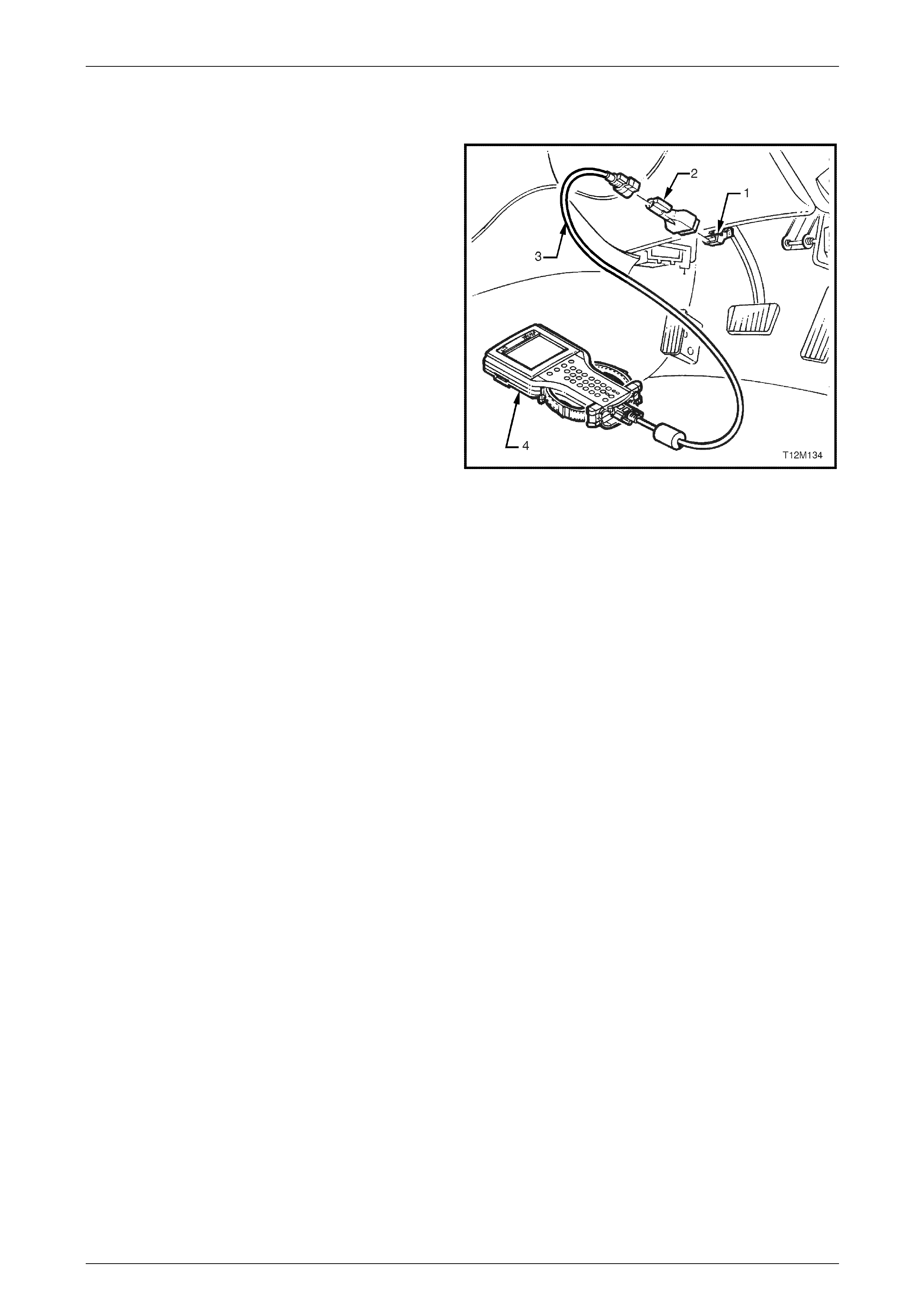
1.2 Connections
To use the TECH 2 (4), proper connections will need to
be made. These connections include power and the DLC
(1). Power for the TECH 2 normally comes from the DLC.
If no power is available at the DLC, or if using the TECH 2
away from the vehicle, another source of power should be
used. On-vehicle power connection may also come from
the cigarette lighter adapter or from the battery clip
adapter. When using one of the adapters (2), connect to
the jack at the back of the DLC cable (3) connection. The
12V adapters have fuses in them to help prot ect the
TECH 2 wiring.
The TECH 2 AC po wer adapter should NOT be used
while the TECH 2 is connected to a vehicle as data errors
may occur. Instead, the AC power adapter is designed to
be used while operating TECH 2 away from vehicle. T he
TECH 2 will work between 8-20 volts and about 0.75
amps.
The TECH 2 will also at times be require d to be
connected to a Personal Computer (PC) to communicate
with the Technical Information System (TIS). This
connection is made via the RS-232 comm unication port.
A hardware key is required when the Service
Programming System (SPS) is being utilised
Figure 0C – 10
Page 0C–14
TECH 2 Page 0C–15
2 Programming TECH 2
2.1 General Information
Before TECH 2 can be used on a vehicle it will have to be pr ogrammed with the latest software. TECH 2 programming is
used to update TECH 2. TIS 2000 contains the current TECH 2 applications (program) and one preceding version. TECH
2 can be programmed using the following procedure.
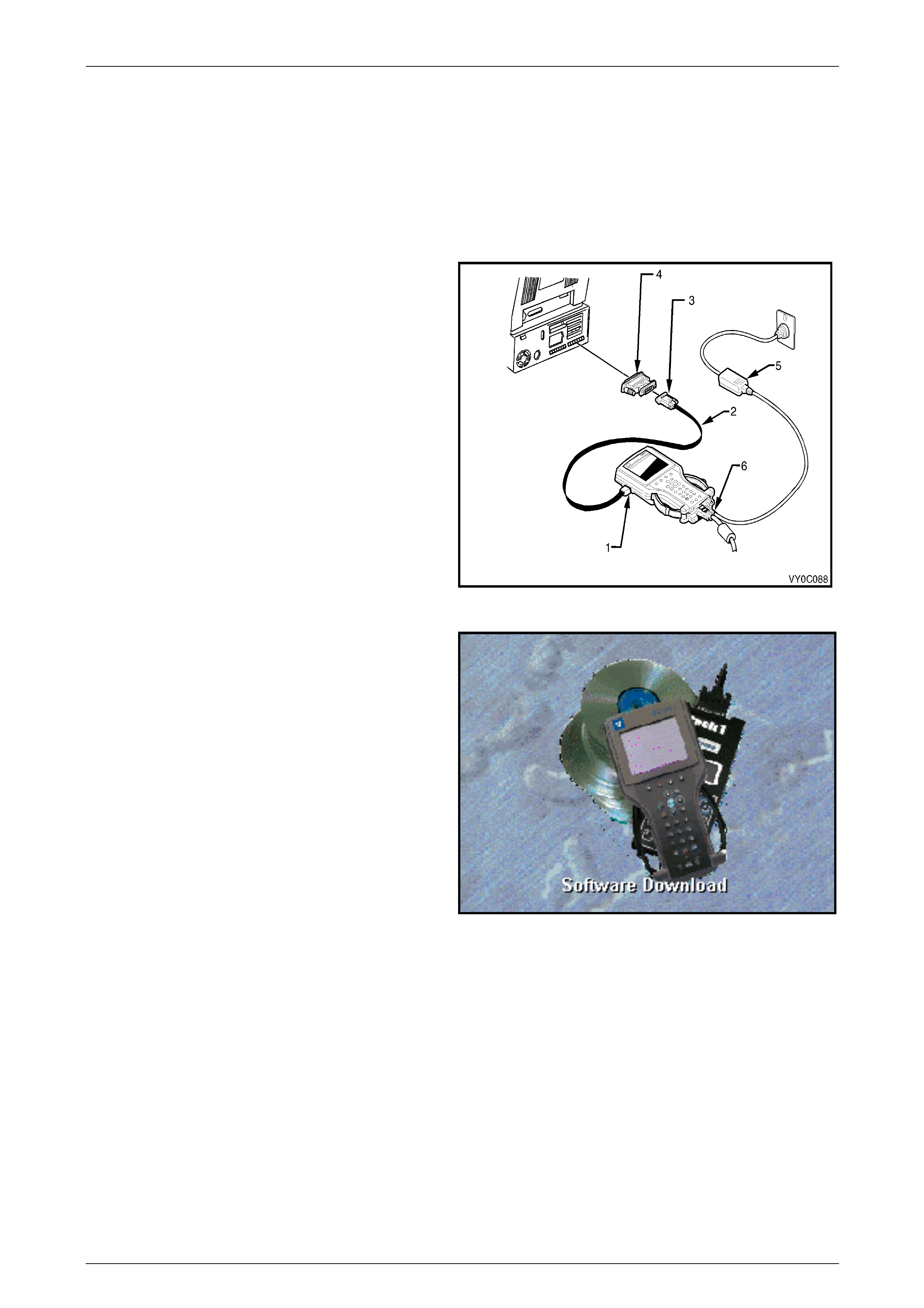
1 Connect the RS-232 cable (2 ) to the TECH 2 RS-
232 communication port (1).
2 Connect the other end of the RS-232 cabl e (2) to
the DB-9 adapter (3) and then connect the DB-9
adapter to the serial communication port of your
computer.
NOTE
If your computer has a 25 pin serial
communication port you will need to fit the
25/9 pin adapter (4) between the nine pin
DB-9 adapter (3) and the computers serial
communication port.
3 Connect the AC power supply (5) to the T ECH 2
power jack (6).
4 Press the PWR button to turn on TECH 2.
Figure 0C – 11
5 From the TIS 2000 Main Menu, click on the
Software Download icon.
Figure 0C – 12
There are two download mo des: Standard and Custom. Standard installs the latest soft ware version of the currentl y
programmed language and make onto the TECH 2. Custom allows you to perform backdating, install d ifferent make
software or alternate languages onto the TECH 2.
Page 0C–15
TECH 2 Page 0C–16
Standard Update
The procedure for performing a standard TECH 2 update using the T I S 2000 Software Download is as follows:
1 Connect the TECH 2 to the PC using the RS-232 ca ble, DB-9 adapter and the 25/9 pin adapter if requ ired.
2 Power up the TECH 2 using the AC power suppl y that comes standard with the TECH 2 kit.
NOTE
TECH 2 must be at the Title Screen.
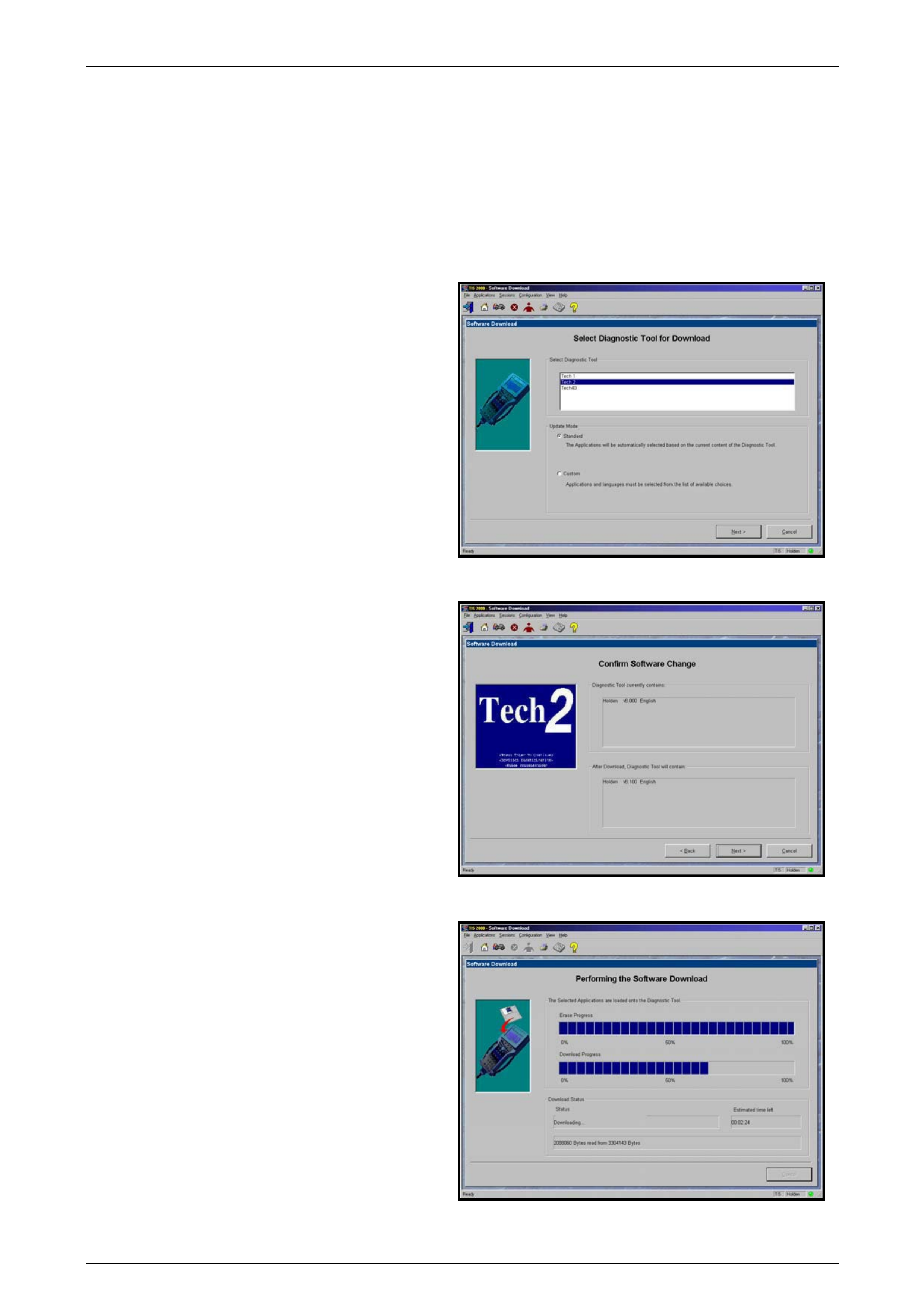
3 At the TIS 2000 Select Diagnostic Tool for
Download screen highlight your selection (TECH
2) and select the Standard update mode.
After making your selections, click Next>. A
message will appear indicating the PC is rea ding
the contents of the diagnostic tool.
Figure 0C – 13
4 The PC will display a Confirm Software Change
screen showing what software version the TECH 2
currently contains and what it will contain after the
software download. Click Next> to continue.
Figure 0C – 14
5 A Performing the Software Download screen will
appear. It tracks the status of the software
download.
Figure 0C – 15
Page 0C–16
TECH 2 Page 0C–17
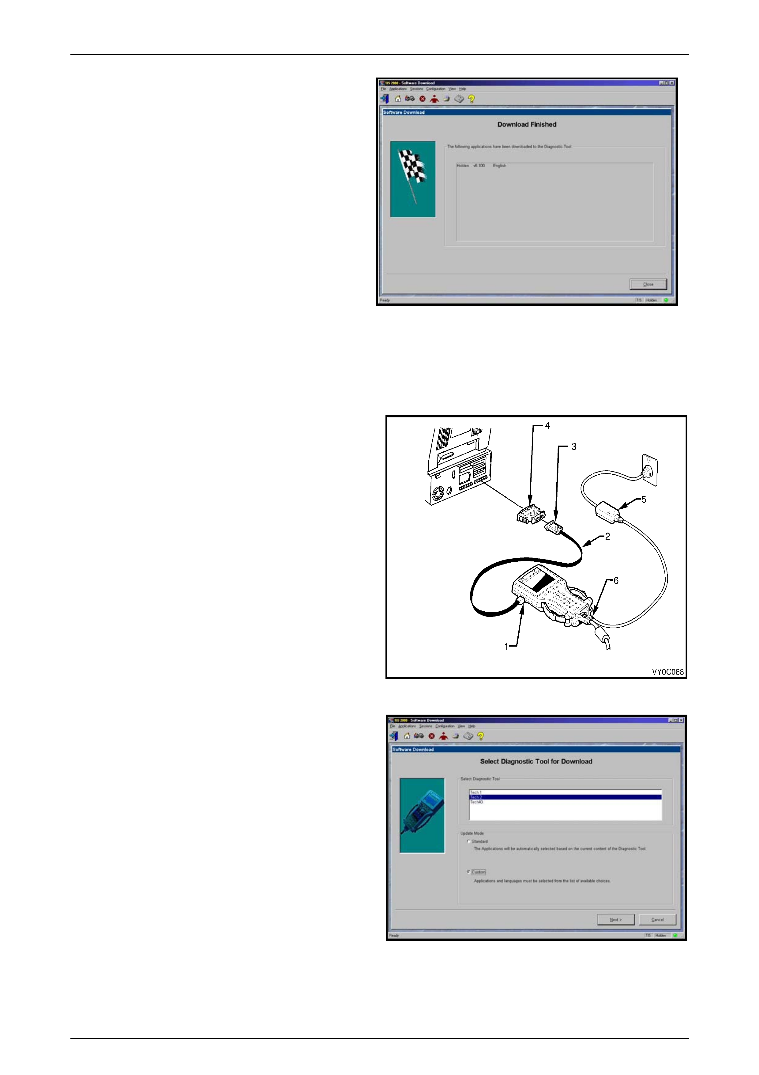
6 When the software download is complete, a
Download Finished screen appe ars. Click on
Close to close the application. The scan tool now
contains the latest software.
Figure 0C – 16
Custom Update
A custom update is used to backdate the TECH 2, install Non-Holden software or install different language software.
After selecting Custom as the update mode from the selection screen, do the following:
1 Connect the TECH 2 to the PC using the RS-232
cable (2), DB-9 adapter (3) and the 25/9 pin adapter
(4) if required.
2 Power up the TECH 2 using the AC po wer suppl y (5)
that comes standard with the TECH 2 kit.
NOTE
TECH 2 must be at the Title Screen.
Figure 0C – 17
3 At the TIS 2000 Select Diagnostic Tool for
Download screen highlight your selection (TECH 2)
and select the Custom update mode.
After making your selections, click Next>. A
message will appear indicatin g the PC is rea ding the
contents of the diagnostic tool.
Figure 0C – 18
Page 0C–17
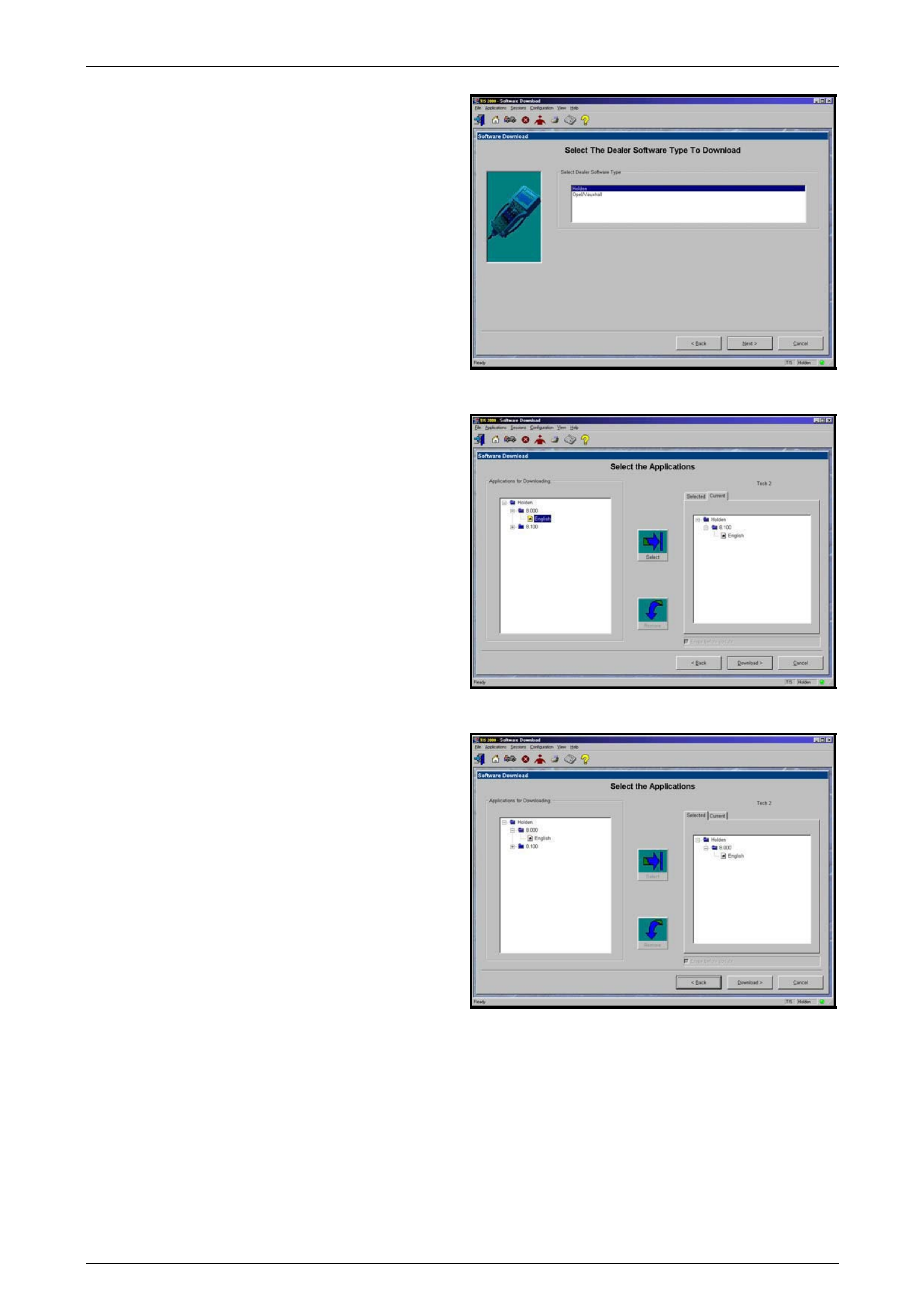
TECH 2 Page 0C–18
4 The Select The Dealer Software Type to
Download screen will then be displayed. Select the
desired software type and the click Next> to
continue.
Figure 0C – 19
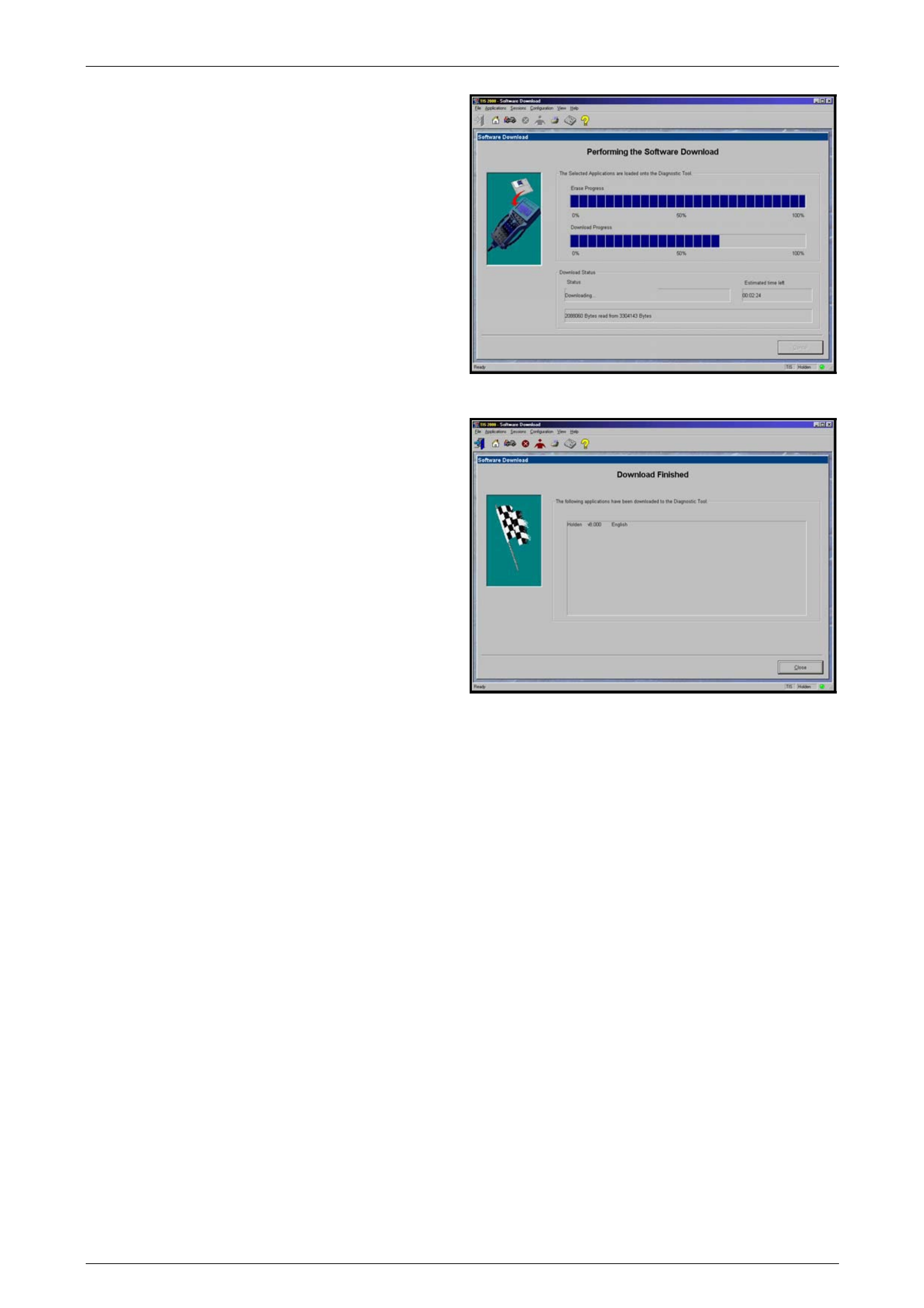
5 A Select the Applications screen will appear . The
left side of the screen lists software release
numbers. Click on the “+” sign to see a list of
different languages for each release.
6 Select the desired software version and l anguage by
either double-clicking or clicking the Select icon. The
selected software will appear in the right side of the
screen.
To compare the current and selected TECH 2
software, click on the Current or Selected tabs on
the right side of the screen.
Figure 0C – 20
7 Click on Download> to begin the update.
Figure 0C – 21
Page 0C–18
TECH 2 Page 0C–19
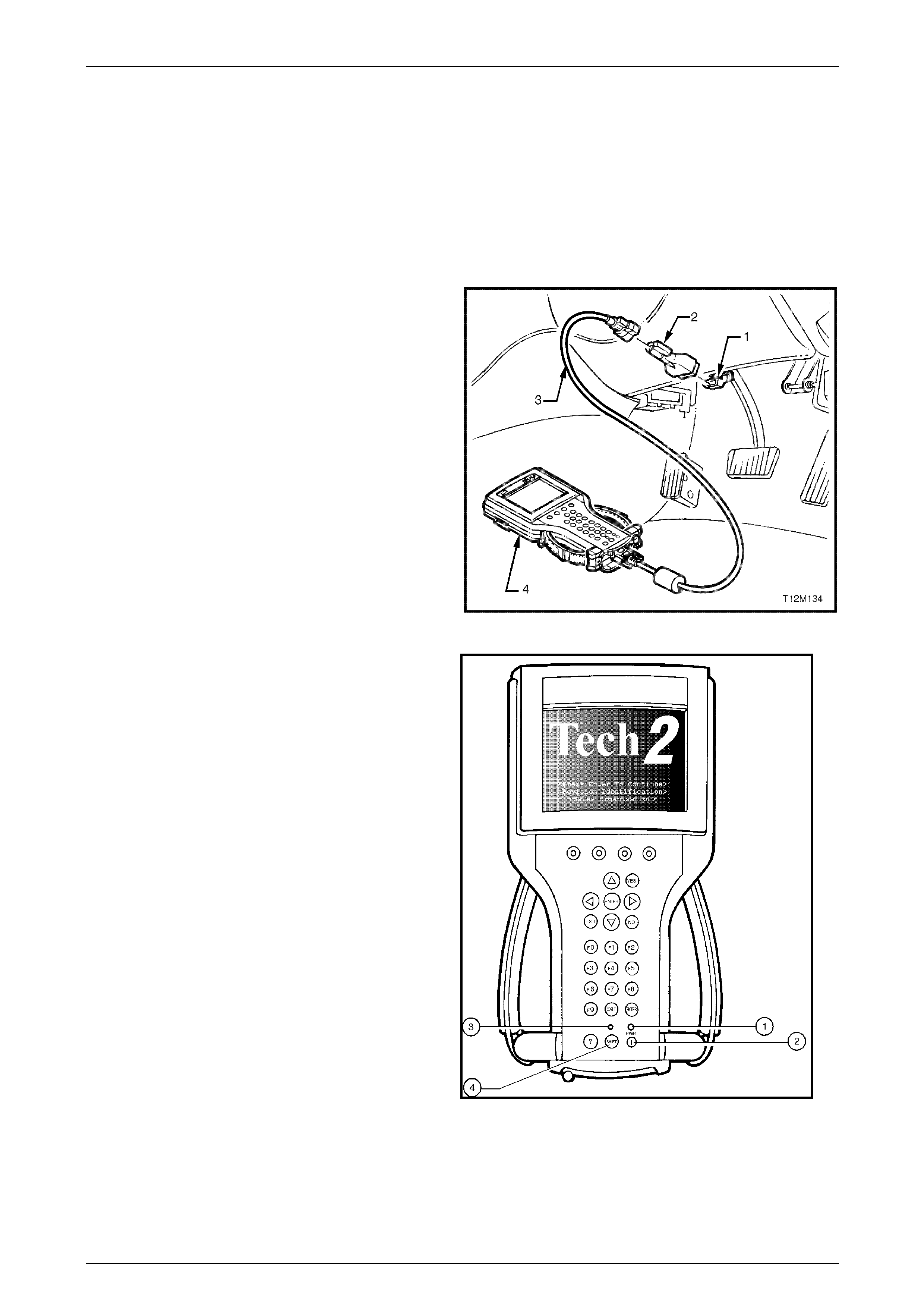
8 A Performing the Software Download screen will
appear. It tracks the status of the software download.
Figure 0C – 22
9 When the software download is complete, a
Download Finished screen appe ars. Click on Close
to close the application. The TECH 2 now contains
the selected software.
Figure 0C – 23
Page 0C–19
TECH 2 Page 0C–20
3 Using TECH 2 On The Vehicle
3.1 Connecting The TECH 2 To The Vehicle
NOTE
The following TIS 2000 and TECH 2 screen
displays may very with different applications and
versions of TIS 2000 and T E CH 2 software.
1 Connect TECH 2 (4) to the vehicle DLC (1), wit h the
DLC cable (3) and the 16/19 pin DLC adapter (2).
NOTE
When working on a vehicle with the GMLAN
serial data protocol, a CANdi Module will have
to be fitted between the DLC cable and the
16/19 pin DLC adapter.
Figure 0C – 24
2 Switch the unit on by pressing the power button (2).
A green light (1) should come on indicating that the
tool is receiving power.
NOTE
At this time the technician should see the
Power On Self Test (POST) run. The POST is
a built in diagnostic self test for the TECH 2
that should find most common system faults.
The POST is run on every power up to
ensure the best operation of the tool. After the
completion of the POST, the TECH 2 unit will
briefly show the POST results. If POST
passes, the tool will continue onto the title
screen. If POST fails, results of all tests will
be displayed, and this sho uld show which test
failed. POST failures may be classified as
fatal or non-fatal. A fatal error will not allow
the user to continue using the tool. Failure of
the keypad would be an example of a fatal
error. Non-fatal errors found during the POST
will allow continued use of the TECH 2, but
with some limitations. If either a fatal or non-
fatal error occurs, refer to the Troubleshooting
section of the TECH 2 User's Guide.
Legend:
1. Power Status Indicator Light
2. PWR (Power) Key
3. SHIFT Key Status Indicator Light
4. SHIFT Key
3 At the TECH 2 title screen press the ENTER
key to continue.
Figure 0C – 25
Page 0C–20

TECH 2 Page 0C–21
4 A selection can be made from the Main Menu, either by using a function key or by using the arrow keys to highlight
a menu choice and pressin g ENTER.
NOTE
You will then need to supply some additional
information to the TECH 2. This requires
navigation through a series of lists (called
picklists). On some menus or picklists, the user
can use a function ke y to mak e a menu s ele ction,
but most of the picklists require using the
selection and action keys. If a mistake is made i n
the selection process, or if a different application
or function is desired, press EXIT to back up one
level. Within an application, there may be soft
keys that are available for use. These soft keys
allow access to additional tool functions without
exiting a current tool functi on. Soft ke ys are made
up of sets that will appear together. To see the
next set of soft keys, select the More soft key.
The TECH 2 Main Menu contains the following:
• F0: Diagnostics: Contains all functions to test, diagnos e, monitor and pr ogram the different vehicle systems.
• F1: Service Programming System (SPS): SPS is used in conjunction with Technical Information System
(TIS) 2000 to program vehicle control units.
• F2: View Capture Data: Contains all functions to work with one or two previously recorded snapshots on one
or two vehicles. This function is to enable the viewing of captured data without a vehicle.
• F3: Tool Options: Contains the TECH 2 self test, set clock, set units, set screen contrast and Getting
Started.
• F4: Download/Upload Help: Contains help information on the downloading and uploading from the TECH 2
to the TIS 2000.
5 Select F0: Diagnostic from the main menu
6 Select the correct Model Year, 2005 with the arrow keys and the press ENTER. The Main Menu Vehicle
Identification screen will the n be displayed.
7 Select the correct Vehicle Type, VZ and WL Series with the arrow keys and the press ENTER. The Diagnostics
Menu will then be displayed.
8 The desired system can be selected from the Diagnostics menu with the function keys or with arrow keys and then
press ENTER.
• F0: Vehicle: This function allows you to check that the TECH 2 can communicate with the various Electronic
Control Modules of the vehicle bein g tested.
• F1: Engine: Contains all functions to test, diagnose, and monitor the engine systems that communicate with
the TECH 2 via the ECM Engine Control Mo dule or Powertrain Control Module (PCM).
• F2: Transmission: Contains all functions to test, diagnose, monitor and program the transmission systems
that communicate with the TECH 2 via the Transmission Control Module (TCM) or Powertrain Control Module
(PCM).
• F3: Chassis: Contains all functions to test, diagnose, monitor and program the vehicles chassis systems;
ABS/TC/ESP 8.0, ABS/TC 5.3 and Tyre Pressure Monitoring System (TPMS) control modules.
• F4: Body: Contains all functions to test, diagnose, monitor and program the vehicles body s ystems; Body
Control Module, Powertrain Interface Module, Supplemental Restraint System, Instruments, Multi Function
Display, Occupant Climate Control, Telematics Module, Audio System, Premium Sound Amplifier, Audi o
Interface Module, DVD Player and Seat & Exterior Mirror Memory Module.
• F5: On Board Diagnostic (OBD): This function allows you to check EOBD Readiness Codes, OBD Data and
Freeze Frame Data.
Page 0C–21

TECH 2 Page 0C–22
3.2 Vehicle Application Menu
1 Select Vehicle from the Diagnostic menu with the arrow keys, then press ENTER.
2 Select F0: Module/ECU Presence Check, then press ENTER.
3 Turn on the ignition and pr ess the Confirm soft key.
4 TECH 2 will check communication with the following control modules/functional systems:
• Body Control Module
• Instrument
• Powertrain Interface Module
• Engine
• ABS
• Automatic Transmission
• Airbag SRS
• Occupant Climate Control
• Telematics Control Module
• Audio System
• TPMS (Tyre Pressure Monitoring System)
• Multi Function Display
• Seat and Exterior Mirror Module
• Premium Sound Amplifier
• Audio Interface Module
• DVD Player
5 When the Module/ECU Presence Check has been completed, press the Identif. soft key.
6 The next screen will display the diagnostic data identifi ers for each module listed in the Module/ECU Pres ence
Check.
7 Press the Back soft key, to return to the Module/ECU Presence Check screen.
8 Press the Confirm soft key, to return to the Vehicle menu screen,
Page 0C–22

TECH 2 Page 0C–23
3.3 Engine Application Menu
1 Select engine from the Diagnostics menu with the arrow keys, then press ENTER.
The following selections are available in the Vehicle Id en tification menu:
• V6 Engine
• V8 GEN III
• V8 GEN IV
2 Select the correct engine from the Vehicle Id en tification menu.
3 Turn on the ignition and pr ess the Confirm soft key.
NOTE
NOTE: If TECH 2 is able to communicate with the
ECM the Engine identification information will be
displayed. If TECH 2 is unable to communicate
with the ECM, TECH 2 will display “Waiting for
Data” if a V8 GEN III was selected or “No
Communication With Vehicle” if V6 or GEN IV
has been selected.
4 The engine identification scre en will display the items that will identify data relating to the ECU that is being
diagnosed.
NOTE
This information will vary with engine type and
software level.
5 Press the Confirm soft key again.
6 The Engine application menu will then be displayed.
The following functions are available in the Engine application menu:
• Diagnostic Trouble Codes
• Data Display
• OBD Data (V6 and GEN IV Engines)
• Snapshot
• Actuator Test (V6 and GEN IV Engines)
• Miscellaneous T ests (GEN III Engine)
• Additional Functions (V6 and GEN IV Engines)
• Programming
• Function Tests (GEN III Engine)
NOTE
Functions may vary dependin g on the application
selected. For further information refer to
• Section 6C1-2 Engine Management – V6 –
Diagnostics
• Section 6C3-2 Powertrain Management –
GEN III V8 – Diagnostics
• Section 6C4 Powertrain Management – GEN
IV V8.
Page 0C–23

TECH 2 Page 0C–24
V6 Engine
1 Select V6 Engine from the Vehicle Identification menu.
2 Turn on the ignition and pr ess the Confirm soft key.
NOTE
If TECH 2 is unable to communicate with the
ECM, TECH 2 will display “No Communication
With Vehicle” if V6 has been selected.
3 The next screen gives yo u the option of going to the engine identifier screen or directly to the engine applica t ion
menu.
• To go to the engine identification screen, press the Info soft key.
• To go directly to the engine application menu, press the Confirm soft key.
4 The engine identification scre en will display the following items; Identifier, Partnumber, Hardware Partnumber,
Software Version Number, Software Partnumber, ECU Di agnostic Address, Hard ware Key Num ber, VIN Digit 1-10,
VIN Digit 11-17
5 Press the Confirm soft key
6 The Engine application menu will then be displayed.
The following functions are available in the Engine application menu:
• F0: Diagnostic Trouble Codes
• F1: Data Display
• F2: OBD Data
• F3: Snapshot
• F4: Actuator Test
• F5: Additional Functions
• F6: Programming
V6 Engine TECH 2 Functions
F0: Diagnostic Trouble Codes
In this test mode, DTCs stored by the ECM can be displa yed or clear ed. When entering this mode there are an additional
three modes:
• F0: Read DTC Information: All DTC(s) stored in the ECM memory will be displayed.
• F1: Clear Engine & Transmission DTC(s): Clears all current DTC(s) in the ECM and TCM memory.
• F2: Freeze Frame: Sho ws Freeze F rame information. Freeze Frames are types of snapshots stored in the memory
of the ECM.
F1: Data Display
This mode displays data parameters for the engine being diagnosed. When e nte ring this mode, there are an additional
12 modes;
• Engine Data 1: In this test mode, the TECH 2 continuously monitors and displays various engine management
data parameters.
• Engine Data 2: In this test mode, the TECH 2 continuously monitors and displays various engine management
data parameters.
• EVAP Data: In this test mode, the TECH 2 continuously monitors and displays various engine management data
parameters relating to the EVAP (evaporative emission control) operation.
• Fuel Trim Data: In this test mode, the TECH 2 continuously monitors and displays various engine management
data parameters relating to the fuel trim adapt operation.
Page 0C–24

TECH 2 Page 0C–25
• O2 Sensor Data: In this test mode, the TECH 2 continuously monitors and displays various eng ine management
data parameters relating to the O2 sensor operation.
• TAC Data: In this test mode, the TECH 2 continuously monitors and displays various engi ne management data
parameters relating to the TAC (Throttle Actuator Control) operation.
• Camshaft Position Actuator Data: In this test mode, the TECH 2 continuously monitors and displays various
engine management data parameters relating to the camshaft position actuator operation.
• Cooling/HVAC Data: In this test mode, the TECH 2 continuously monitors and displays various engine
management data parameters relating to the engine cooling and HVAC (Heating, Ventilation and Cooling)
operation.
• Cruise/Traction Data: In this test mode, the TECH 2 continuously monitors and displays various engine
management data parameters relating to the Cruise Control and Traction Control operation.
• Electrical/Theft Data: In this test mode, the TECH 2 continuousl y monitors and displays various engin e
management data parameters.
• Instrument Data: In this test mode, the TECH 2 continuously monitors and displays various engine management
data parameters relating to the IPC (Instrument Panel Cl uster) operation.
• ODM Data: In this test mode, the TECH 2 continuously monitors and displa ys various engine management data
parameters relating to the ODM (Output Driver Module) operation.
F2: OBD Data
In this test mode, the TECH 2 scan tool displays engine management data parameters relating to OBD (On Board
Diagnostic) for the engine bei ng diagnosed.
F3: Snapshot
In this test mode, the TECH 2 scan tool captures data before and after a snapshot triggering condition which may or may
not set a DTC.
F4: Actuator Test
In this test mode, the TECH 2 performs software override commands of the ECM, to assist in problem isolation during
diagnostics. When entering this mode there are an additional nine modes.
NOTE
Confirm that there are no DTC(s) stored in the
ECM before any actuator tests are performed.
• CMP Actuator System
When entering this mode, there are an additional four modes:
• F0: Intake CMP Actuator Bank 1: This test allows the user to control the angle of the Bank 1 Intake
Camshaft Position Actuator Solenoid.
Preconditions and running conditions: Engine running, coolant temperature above 80oC, vehicle speed 0
km/h, transmission is in Park or Neutral.
• F1: Intake CMP Actuator Bank 2: This test allows the user to control the angle of the Bank 2 Intake
Camshaft Position Actuator Solenoid.
Preconditions and running conditions: Engine running, coolant temperature above 80oC, vehicle speed 0
km/h, transmission is in Park or Neutral.
• F2: Exhaust CMP Actuator Bank 1: This test allows the user to control the angle of the Bank 1 Exha ust
Camshaft Position Actuator Solenoid.
Preconditions and running conditions: Engine running, coolant temperature above 80oC, vehicle speed 0
km/h, transmission is in Park or Neutral.
• F3: Exhaust CMP Actuator Bank 2: This test allows the user to control the angle of the Bank 2 Exha ust
Camshaft Position Actuator Solenoid.
Preconditions and running conditions: Engine running, coolant temperature above 80oC, vehicle speed 0
km/h, transmission is in Park or Neutral.
Page 0C–25

TECH 2 Page 0C–26
• Fan Relays: When entering this mode, there are an additional three modes:
• F0: Fan Relay 1: This test allows the user to turn on and off the fan relay 1.
Preconditions and running conditions: Air Conditioning Off
• F1: Fan Relays 2 and 3: This test allows the user to turn on and off the fan relay 2 and 3.
Preconditions and running conditions: Air Conditioning Off
• F2: Fan Relays 1, 2 and 3: This test allows the user to turn on and off the fan relay 1,2 and 3.
Preconditions and running conditions: Air Conditioning Off
• Fuel Pump Relay Test: This test allows the user to command the fuel pump relay on and off.
• Electronic Throttle Control Test: This test allows the user to increase or decre ase the throttle valve in 10 perc ent
increments.
Preconditions and running conditions: Ignition On and engine not running.
• A/C Relay Test: This test allows the user to turn on and off the A/C Relay.
Preconditions and running conditions: Ignition On.
• Alternator L Terminal: This test allows the user to turn on and off the commanded state of the voltage regulator i n
the alternator. On displays a commanded state of 99% while Off displays a commanded state of 0%.
Preconditions and running conditions: Engine running.
• EVAP Purge Solenoid: This test allows the user to control the EVAP purge solenoid valve. The normal
commanded state is NONE. The system will increase or decrease the amount of purge by changing the duty cycle
of the purge valve in 10 percent increments within a range of 0-100 percent. The system remains in the
commanded state until cancelled by the TECH 2.
NOTE
The EVAP Purge Solenoid Command parameter
may not change states when using this output
control.
• Intake Manifold Runner Control Solenoid: This test allows the user to turn the IMRC (Intake Manifold Runner
Control) ground circuit on and off.
Preconditions and running conditions: Ignition On.
• Engine Speed Control: This test allows the user to increase or decrease the engine idle speed in 20 to 30 RPM
increments from the base idle speed to 1600 RPM.
Preconditions and running conditions: Engine temperature above 80oC, Engine running, transmission is in Park or
Neutral.
The engine will crank and start during the
starter relay test.
• Starter Relay Test: This test allows the user to turn the starter relay On.
Preconditions and running conditions: Apply parking brake, ignition On and engine not running, press an d hold
brake pedal, transmission is in Park or Neutral.
• Fuel injector Balance: This test allows the user to check the fuel flow through each injector while the engine is not
running. A fuel pressure gauge has to be connected to the fuel rail. TECH 2 first turns on the fuel pump. After
pressure is established the fuel pump is turned off again and the injector is turned on for a predetermined time.
Pressure drop has to be read afterwards on the fuel gauge for each injecto r. This can be performed only once per
injector.
Preconditions and running conditi ons: Engine not running, vehicle speed 0 km/h.
Page 0C–26

TECH 2 Page 0C–27
• Power Balance: This test allows the user to turn off each inj ector sequentially for five seconds, while the engine
RPM is monitored. At the end the test the minimum RPM for each cylinder is displa yed.
Preconditions and running conditions: Engine temperature above 80oC, No Vehicle Speed, engine ru nning at idle,
air conditioning turned off and the engine cooling fans are turned on.
F5: Additional Functions
When entering this mode, there are an additional two modes:
• F0: System Identification: In this mode, the TECH 2 will display the engine identification screen.
• F1: Security Information: In this mode, the TECH 2 will display various engine manag ement data parameters
relating to the security system.
F6: Programming
When entering this mode, there are an additional four modes:
• F0: BCM Link To ECM/PIM: If one or more of ECM, PIM or BCM have been replaced, the modules must be
security linked to each other. If this linking procedure is not performed, the vehicle will not crank or run. For
additional information regarding TECH 2 and this linking procedure, refer to Section 12J Body Control Module.
NOTE
After an ECU Reset, the ignition switch must be
turned Off for at least 10 seconds then turned On
for at least 1 minute, before commencing
communications between TECH 2 and the ECU.
Precondition: TIS approval (TIS 2000 Security Access) must be obtained and the four digit security code entered
into TECH 2 and the theft deterrent s ystem must be disarmed and the ignition must be switched On with a
programmed remote coded k ey.
• F1: Reset ECU: This function will erase the security link between the Engine Control Module and the Powertrain
Interface Module. If this procedure is performed, the vehicle will not crank or run. A BCM Link To ECM/PIM
procedure will have to be perf ormed. F or additional information regarding BCM Link To ECM/PIM procedure,
Section 12J Body Control Module.
NOTE
After an ECU Reset, the ignition switch must be
turned Off for at least 10 seconds then turned On
for at least 1 minute, before commencing
communications between TECH 2 and the ECU.
Precondition: The four digit security code must be entered into TECH 2 and the theft deterrent system must be
disarmed and the ignition mus t be switched On with a programmed remote coded key.
• F2: Fuel Trim Reset: This function resets the fuel trim data values learnt by the ECM.
• F3: Throttle Body Relearn: In this test mode, the TECH 2 commands the throttle plate from the rest position to full
closed, then to around 10 percent open. This procedure takes about 6-8 seconds. If any faults occur in the T A C
system, a DTC sets. At the start of this procedure, the TECH 2 Electronic Throttle Control Learn Counte r parameter
should display 0, then count up to 11 after the procedure is completed. If the counter did not start at 0, or if the
counter did not end at 11, a fault has occurred and a DTC should set.
Page 0C–27

TECH 2 Page 0C–28
V8 GEN III
1 Select V8 GEN III from the Vehicle Identification menu.
2 Turn on the ignition and pr ess the Confirm soft key.
NOTE
NOTE: If TECH 2 is able to communicate with the
ECM the Engine identification information will be
displayed. If TECH 2 is unable to communicate
with the ECM, TECH 2 will display “Waiting for
Data”.
3 The engine identification scre en will display the following items; Partnumber, Operating S/W Level, Operating S/W
Calibration, Engine Calibrati o n, Transmission Calibration.
4 Press the Confirm soft key
5 The Engine application menu will then be displayed.
The following functions are available in the Engine application menu:
• F0: Diagnostic Trouble Codes
• F1: Data Display
• F2: Snapshot
• F3: Miscellaneous Tests
• F4: Programming
• F5: Function Tests
V8 GEN III Engine TECH 2 Functions
F0: Diagnostic Trouble Codes
In this test mode, DTCs stored by the PCM maybe displayed or cleared. When F0: Diagnostic Trouble C odes is selected
there are an additional four modes:
• F0: Read DTC Info Ordered By Priority: DTC(s) will be displayed in numerical order.
• F1: Clear DTC Information: Clears all DTC(s) in the PCM memory. Also clears Freeze Frame/Failure Records, so
before clearing DTC(s), be sure to retrieve Fr eeze Frame / Failure Record information.
• F2: DTC Information: Shows DTC(s) which are set that match the criteria. Each DTC has it's own page of
information. If multiple DTCs are set, the user must page through the dis play of codes.
• F0: History: This DTC search will display only DTC(s) that are stored in the PCM memory as valid faults.
• F1: MIL SVS or Message Requ ested: This DTC search will display on ly DTC(s) for which the PCM is
requesting the Check Powertrain Lamp to turn "ON".
• F2: Last Test Failed: This DTC search will di splay only DTC( s) that failed the last time the test ran.
• F3: Test Failed Since Code Cleared: This DTC search will display all DTC(s) that have reported a test
failure since the last time DTC(s) were cleared.
• F4: Not Ran Since Code Cleared: This DTC search will display only DTCs that have not ran since DTCs
were last cleared. Any displayed DTCs have not run, therefore their con dition (passing or failing) is unknown.
• F5: Failed This Ignition: This DTC search will displ ay all DTCs that have faile d at least once during the
current ignition cycle.
• F3: Freeze Frame / Failure Records: Shows Freeze Frame / Failure Records inform ation. Freeze Frame / Failure
Records are types of snapshots stored in the memory of the PCM and contain 3 2 data parameters.
Page 0C–28

TECH 2 Page 0C–29
F1: Data Display
This mode displays data parameters for the controller being diagnosed. When entering this mode, there are five modes;
• F0: Engine Data 1: In this test mode, the TECH 2 continuously monitors and displays various engine management
data parameters.
• F1: Engine Data 2: In this test mode, the TECH 2 continuously monitors and displays various engine management
data parameters.
• F2: Throttle Actuator Control: In this test mode, the TECH 2 continuously monitors and displays system data
relating to the Throttle Actuator Control system.
• F3: Cruise Control: In this test mode, the TECH 2 continuously monitors and displays system data relating to the
Cruise Control system.
• F4: Fuel Trim Data: In this test mode, the TECH 2 continuously monitors and displays system data, such as:
engine speed data, engine coolant temperature, heated oxygen sensor, Fuel Trim Cell etc.
F2: Snapshot
In this test mode, the TECH 2 scan tool captures data before and after a snapshot triggering condition which may or may
not set a DTC.
F3: Miscellaneous Tests
In this test mode, the TECH 2 performs software override commands of the PCM, to assist in problem isolation during
diagnostics. . When entering this mode there are an additional seven mo des.
• F0: Output Tests
• F0: Fuel Pump: Fuel Pump Relay can be commanded on and off.
• F1: A/C Clutch: A/C Compressor Clutch can be commanded on and off.
• F2: Check Powertrain Lamp: Service vehi cle Soon status indicator located in the instrument panel centre
display can be commanded on and off.
• F3: Canister Purge: Canister Purge can be commanded on (100%) and off (0%).
• F1: Reset Cells: Resets all Long Term Fuel Trim values to 0%
• F2: 02 Loop Status: With the engine running, Open or Closed Loop fuel control ca n be commanded.
• F3: Fan Relays: When entering this mod e, there are an additional three modes:
• F0: Fan Relay 1: This test allows the user to turn on and off the fan relay 1.
Preconditions and running conditions: Air Conditioning Off
• F1: Fan Relay 2 and 3: This test allows the user to turn on and off the fan relay 2 and 3.
Preconditions and running conditions: Air Conditioning Off
• F2: Fan Relay 1, 2 and 3: This test allows the user to turn on and off the fan relay 1,2 and 3.
Preconditions and running conditions: Air Conditioning Off
• F4: Fuel Gauge: This test allows the user to increase or decrease the fuel gauge pointer in increments of
approximately one eighth (1/8th).
• F5: 02 Sensor heater Control: O2 Sensor heater can be commanded on (100%) and off (0%).
• F6: TAC System: When entering this mode, there is o ne additional mode:
• F0: Engine Speed Control: This test allows the user to increase or decrease engine speed in increments of
50 RPM.
Preconditions and running conditions: Engine running and vehicle speed 0 km/h.
Page 0C–29

TECH 2 Page 0C–30
F4: Programming
When entering this mode, there is one additional mode:
• F0: BCM Link To PCM/PIM: If one or more of PCM, PIM or BCM have been replaced, the modules must be
security linked to each other. If this linking procedure is not performed, the vehicle will not crank or run. For
additional information regarding TECH 2 and this linking procedure, refer to Section 12J Body Control Module.
F5: Function Tests
In this test mode, TECH 2 performs various automated tests to assist in problem isolation duri ng trouble shooting. To
operate any of the Function Tests, simply select the appropriate test mode from the Function Test application men u an d
follow the instructions as per TECH 2. When the F unction T ests option is selected, the following options will become
available.
• F0: Power Balance: This function automatically turns off each injector sequentially for five secon ds, while the
engine RPM is monitored. At the end of the test the minimum RPM for each cylinder is displayed.
Preconditions: Vehicle speed less than two km/h, engine running at id le, air conditioning turned off and the engine
cooling fans are turned on.
• F1: Wiring Harness: During this function test TECH 2 monitors the following in puts: RPM, ECT , MAF, TPS,
Battery Voltage, Injector Voltage and VSS. If a change occurs in these circuits greater than the limits listed bel ow,
the TECH 2 logs the failure and prompts the technician to check the appropriate circuit.
Parameter RPM ECT MAF TPS IAT Bat. V Inj. V VSS
Tolerance 100 RPM 0.5 V 300 Hz 0.5 V 0.5 V 2 V 2 V 2 km/h
Preconditions: Engine running , vehicle speed less than t wo km/h.
• F2: Fuel Injector Balance: This function is designed to check the fuel flow through each injector while the engine
is not running. A fuel pressure gauge has to be connected to the fuel rail. TECH 2 first turns on the fuel pump. After
pressure is established the fuel pump is turned off again and the injector is turned on for a predetermined time.
Pressure drop has to be read afterwards on the fuel gauge for each injecto r. This can be performed only once per
injector.
Preconditions: Vehicle speed less than 2 km/h, engine not running.
Page 0C–30

TECH 2 Page 0C–31
V8 GEN IV
1 Select V8 GEN IV from the Vehicle Identification menu.
2 Turn on the ignition and pr ess the Confirm soft key.
NOTE
If TECH 2 is unable to communicate with the
ECM, TECH 2 will display “No Communication
With Vehicle” if GEN IV has been selected.
3 The next screen gives yo u the option of going to the engine identifier screen or directly to the engine applica t ion
menu.
• To go to the engine identification screen, press the Info soft key.
• To go directly to the engine application menu, press the Confirm soft key.
4 The engine identification scre en will display the following items; Identifier, Partnumber, Hardware Number, Alpha
Code, Software Version Number, Software Partnumber, ECU Diagnostic Address, Hardware Key Number, VIN
Digit 1-10, VIN Digit 11-17
5 Press the Confirm soft key
6 The Engine application menu will then be displayed.
The following functions are available in the Engine application menu:
• F0: Diagnostic Trouble Codes
• F1: Data Display
• F2: OBD Data
• F3: Snapshot
• F4: Actuator Test
• F5: Additional Functions
• F6: Programming
V8 GEN IV Engine TECH 2 Functions
F0: Diagnostic Trouble Codes
In this test mode, DTCs stored by the ECM can be displa yed or clear ed. When entering this mode there are an additional
three modes:
• F0: Read DTC Info Ordered By Priority: DTC(s) will be displayed in numerical order.
• F1: Clear Engine & Transmission DTC(s): Clears all current DTC(s) in the ECM and TCM memory.
• F2: Freeze Frame/Failure Record s: Shows Freeze Frame/Failure R ocord information. Freeze Frames/Failure
Records are types of snapshots stored in the memory of the ECM.
F1: Data Display
This mode displays data parameters for the engine being diagnosed. When e nte ring this mode, there are an additional
12 modes;
• Engine Data: In this test mode, the TECH 2 continuously monitors and displays various e ngine management data
parameters.
• EVAP Data: In this test mode, the TECH 2 continuously monitors and displays various engine management data
parameters relating to the EVAP (evaporative emission control) operation.
• Fuel Trim Data: In this test mode, the TECH 2 continuously monitors and displays various engine management
data parameters relating to the fuel trim adapt operation.
• O2 Sensor Data: In this test mode, the TECH 2 continuously monitors and displays various eng ine management
data parameters relating to the O2 sensor operation.
Page 0C–31

TECH 2 Page 0C–32
• TAC Data: In this test mode, the TECH 2 continuously monitors and displays various engi ne management data
parameters relating to the TAC (Throttle Actuator Control) operation.
• Instrument Data: In this test mode, the TECH 2 continuously monitors and displays various engine management
data parameters relating to the IPC (Instrument Panel Cl uster) operation.
• Cruise/Traction Data: In this test mode, the TECH 2 continuously monitors and displays various engine
management data parameters relating to the Cruise Control and Traction Control operation.
• Cooling/HVAC Data: In this test mode, the TECH 2 continuously monitors and displays various engine
management data parameters relating to the engine cooling and HVAC (Heating, Ventilation and Cooling)
operation.
• Electrical/Theft Data: In this test mode, the TECH 2 continuousl y monitors and displays various engin e
management data parameters.
• ODM Data: In this test mode, the TECH 2 continuously monitors and displa ys various engine management data
parameters relating to the ODM (Output Driver Module) operation.
• Transmission Data: In this test mode, the TECH 2 continuously monitors and displa ys various engine
management data parameters relating to the Transmission.
F2: OBD Data
In this test mode, the TECH 2 scan tool displays engine management data parameters relating to OBD (On Board
Diagnostic) for the engine bei ng diagnosed.
F3: Snapshot
In this test mode, the TECH 2 scan tool captures data before and after a snapshot triggering condition which may or may
not set a DTC.
F4: Actuator Test
In this test mode, the TECH 2 performs software override commands of the ECM, to assist in problem isolation during
diagnostics. When entering this mode there are an additional 11 modes.
NOTE
Confirm that there are no DTC(s) stored in the
ECM before any actuator tests are performed.
• Fan Relays: When entering this mode, there are an additional three modes:
• F0: Fan Relay 1: This test allows the user to turn on and off the fan relay 1.
Preconditions and running conditions: Air Conditioning Off
• F1: Fan Relays 2 and 3: This test allows the user to turn on and off the fan relay 2 and 3.
Preconditions and running conditions: Air Conditioning Off
• F2: Fan Relays 1, 2 and 3: This test allows the user to turn on and off the fan relay 1,2 and 3.
Preconditions and running conditions: Air Conditioning Off
• Fuel Pump Relay Test: This test allows the user to command the fuel pump relay on and off.
Preconditions and running conditi ons: Vehicle Speed at 0 km/h.
• Electronic Throttle Control Test: This test allows the user to increase or decre ase the throttle valve in 10 perc ent
increments.
Preconditions and running conditions: Ignition On and engine not running.
• A/C Relay Test: This test allows the user to turn on and off the A/C Relay.
Preconditions and running conditions: Ignition On.
• Alternator L Terminal: This test allows the user to turn on and off the commanded state of the voltage regulator i n
the alternator. On displays a commanded state of 99% while Off displays a commanded state of 0%.
Preconditions and running conditions: Engine running.
Page 0C–32

TECH 2 Page 0C–33
• EVAP Purge Solenoid: This test allows the user to control the EVAP purge solenoid valve. The normal
commanded state is NONE. The system will increase or decrease the amount of purge by changing the duty cycle
of the purge valve in 10 percent increments within a range of 0-100 percent. The system remains in the
commanded state until cancelled by the TECH 2.
• Engine Speed Control: This test allows the user to increase or decrease the engine idle speed in 20 to 30 RPM
increments from the base idle speed to 1600 RPM.
Preconditions and running conditi ons: Engine running, transmission is in Park or Neutral.
The engine will crank for 10 seconds during
the starter relay test.
• Starter Relay Test: This test allows the user to turn the starter relay On.
Preconditions and running conditions: Apply parking brake, ignition On and engine not running, press an d hold
brake pedal, transmission is in Park or Neutral.
• Malfunction Indicator (MI) Test: This test allows the user to turn the Malfunction Indicator Lamp Off and On.
Preconditions: Ignition On and engine not run nin g.
• Fuel injector Balance: This test allows the user to check the fuel flow through each injector while the engine is not
running. A fuel pressure gauge has to be connected to the fuel rail. TECH 2 first turns on the fuel pump. After
pressure is established the fuel pump is turned off again and the injector is turned on for a predetermined time.
Pressure drop has to be read afterwards on the fuel gauge for each injecto r. This can be performed only once per
injector.
Preconditions and running conditi ons: Engine not running, vehicle speed 0 km/h.
• Power Balance: This test allows the user to turn off each inj ector sequentially for five seconds, while the engine
RPM is monitored. At the end the test the minimum RPM for each cylinder is displa yed.
Preconditions and running conditions: Engine temperature above 80oC, No Vehicle Speed, engine ru nning at idle,
air conditioning turned off and the engine cooling fans are turned on.
F5: Additional Functions
When entering this mode, there are an additional two modes:
• F0: System Identification: In this mode, the TECH 2 will display the engine identification screen.
• F1: Security Information: In this mode, the TECH 2 will display various engine manag ement data parameters
relating to the security system.
F6: Programming
When entering this mode, there are an additional two modes:
• F0: BCM Link To ECM/PIM: If one or more of ECM, PIM or BCM have been replaced, the modules must be
security linked to each other. If this linking procedure is not performed, the vehicle will not crank or run. For
additional information regarding TECH 2 and this linking procedure, refer to Section 12J Body Control Module.
NOTE
After an ECU Reset, the ignition switch must be
turned Off for at least 10 seconds then turned On
for at least 1 minute, before commencing
communications between TECH 2 and the ECU.
Precondition: TIS approval (TIS 2000 Security Access) must be obtained and the four digit security code entered
into TECH 2 and the theft deterrent s ystem must be disarmed and the ignition must be switched On with a
programmed remote coded k ey.
• F1: Reset ECU: This function will erase the security link between the Engine Control Module and the Powertrain
Interface Module. If this procedure is performed, the vehicle will not crank or run. A BCM Link To ECM/PIM
procedure will have to be perf ormed. F or ad ditional information regarding BCM Link To ECM/PIM procedure, refer
to Section 12J Body Control Module.
Page 0C–33

TECH 2 Page 0C–34
NOTE
After an ECU Reset, the ignition switch must be
turned Off for at least 10 seconds then turned On
for at least 1 minute, before commencing
communications between TECH 2 and the ECU.
Precondition: The four digit security code must be entered into TECH 2 and the theft deterrent system must be
disarmed and the ignition mus t be switched On with a programmed remote coded key.
Page 0C–34

TECH 2 Page 0C–35
3.4 Transmission Application Menu
1 Select the correct transmission from the Diagnostics menu with the arrow keys, then press ENTER.
The following selections are available in the Diagnostics menu:
• Automatic Transmission
• GEN III Automatic Transmission
2 Turn on the ignition and pr ess the Confirm soft key.
NOTE
If TECH 2 is unable to communicate with the
TCM, TECH 2 will display “No Communication
With Vehicle”.
3 The transmission identification screen will then be displayed.
4 Press the Confirm Soft Key.
5 The transmission application menu will then be displayed.
The following functions are available in the transmission application menu:
• F0: Diagnostic Trouble Codes
• F1: Data Display
• F2: Snapshot
• F3: Additional Functions
• F4: Miscellaneous Tests
• F5: Programming
NOTE
Functions may vary dependin g on the application
selected. For further information refer to
Section 7C2 Automatic Transmission – 4L60E –
Electrical Diagnosis or Section 7D2 Automatic
Transmission – 4L65E – Electrical Diagnosis or
Section 7E2 Automatic Transmission – 5L40E –
Electrical Diagnosis.
Automatic Transmission
1 Select Automatic Transmissi on from the Diagnostics menu with the arrow keys, then press ENTER.
2 Turn on the ignition and pr ess the Confirm soft key.
NOTE
If TECH 2 is unable to communicate with the
TCM, TECH 2 will display “No Communication
With Vehicle”.
3 The next screen will give you the option of going directl y to the trans mission identificatio n screen or to the
transmission application menu.
• To go to the transmission identification screen, press the Info soft key.
• To go directly to the transmission application menu, press the Confirm soft key.
4 The transmission identificatio n screen will display the following items; Identifier, Partnumber, Hardware
Partnumber, Alpha Code, Software Version Number, Soft ware Partnumber, VIN Digit 1-10, VIN Digit 11-17.
NOTE
This information will vary with transmission type
and software level.
Page 0C–35

TECH 2 Page 0C–36
5 Press the Confirm soft key
6 The transmission application menu will then be displayed.
The following functions are available in the transmission application menu:
• F0: Diagnostic Trouble Codes
• F1: Data Display
• F2: Snapshot
• F3: Additional Functions
• F4: Miscellaneous Tests
• F5: Programming
4L60E / 4L65E Automatic Transmission TECH 2 Functions
F0: Diagnostic Trouble Codes
In this test mode, DTCs stored by the TCM can be displayed or cleared. When entering this mode there are an additional
two modes:
• F0: Read DTC Information: All DTC(s) stored in the TCM memory will be displayed.
• F1: Clear Engine & Transmission DTC(s): Clears all current DTC(s) in the ECM and TCM memory.
• F2: Freeze Frame: Sho ws Freeze F rame information. Freeze Frames are types of snapshots stored in the memory
of the TCM.
F1: Data Display
This mode displays data parameters for the transmission being diagnosed. When entering this mode, ther e are an
additional nine modes;
• F0: Transmission Data: In this test mode, the TECH 2 continuously monitors and displays various transmission
data parameters.
• F1: TCC Data: In this test mode, the TECH 2 continuously monitors and displays various transmission data
parameters relating to the torque converter clutch operati on.
• F2: 1-2 Shift Data: In this test mode, the TECH 2 continuously monitors and displays various transm ission data
parameters relating to the 1-2 shift operatio n.
• F3: 2-3 Shift Data: In this test mode, the TECH 2 continuously monitors and displays various transm ission data
parameters relating to the 2-3 shift operatio n.
• F4: 3-4 Shift Data: In this test mode, the TECH 2 continuously monitors and displays various transm ission data
parameters relating to the 3-4 shift operatio n.
• F5: Pressure Control Solenoid Data: In this test mode, the TECH 2 continuously monitors and displays various
transmission data parameters relating to the pressure control solenoid operation.
• F6: Transmission Adapts: This mode displays data parameters for the transmission being diagnosed. When
entering this mode, there are an additional five modes;
• F0: 1-2 Adapt Data: In this mode T ECH 2 continuously monitors and displa ys 1-2 TAP cell data parameters.
• F1: 2-3 Adapt Data: In this mode T ECH 2 continuously monitors and displa ys 2-3 TAP cell data parameters.
• F2: 3-4 Adapt Data: In this mode T ECH 2 continuously monitors and displa ys 3-4 TAP cell data parameters.
• F4: Steady State Adapt Data: In this mode T E CH 2 continuously monitors and displays Steady State TAP
data parameters.
• F7: System Identification: In this mode, the TECH 2 will display the transmission identification screen. T he
following items will be displa yed; Identifier, Partnumber, Hardware Partnumber, Alpha Cod e, Software Version
Number, Software Partnumber.
NOTE
This information will vary with transmission type
and software level. Press the Confirm soft key.
Page 0C–36

TECH 2 Page 0C–37
F2: Snapshot
In this test mode, the TECH 2 scan tool captures data before and after a snapshot triggering condition which may or may
not set a DTC.
F3: Additional Functions
When entering this mode, there is one additional mode:
• F0: System Identification: In this mode, the TECH 2 will display the transmission identification screen.
F4: Miscellaneous Tests
NOTE
Confirm that there are NO DTC(s) stored in the
TCM before carry out any miscellaneous tests.
In this test mode, the TECH 2 performs software override commands of the TCM, to assist in problem isol ation during
diagnostics. When entering this mode, there are an additional nine modes;
• F0: TCC Solenoid: This test allows the user to turn on-off the TCC On-Off Solenoid.
Preconditions and running conditi ons: Engine not running.
• F1: TCC PWM Solenoid: The user will have the ability to control the TCC PWM duty cycle. Although it is possible
to command a full range of solenoid duty cycle, this function will only turn on and off the solenoid; 100% and 0 %
PWM.
Preconditions and running conditions: Ignition On and engine not running.
• F2: TCC Apply: This test performs an on - off control of the TCC. TECH 2 commands the TCM to apply the TCC.
Preconditions and running conditions: Drive Vehicle Above 50 km/h (31 m/ph).
• F3: Shift Solenoid A: This test allows the user to turn on and off the Shift Solenoid A.
Preconditions and running conditions: Ignition On and engine not running.
• F4: Shift Solenoid B: This test allows the user to turn on and off the Shift Solenoid B.
Preconditions and running conditions: Ignition On and engine not running.
• F5: 3/2 Downshift Solenoid: This test allows the user to turn on and off the 3-2 Downshift Solenoid.
Preconditions and running conditi ons: Engine not running.
• F6: Gear Control: This test allows the user to incrementally command shift solenoid states to correspond to
relative gear states. The TCM will only allow single shift incr ements or decrements and does not allo w a shift if it
causes the engine RPM to exceed a cali brated limit.
Preconditions and running conditi ons: Engine running, transmission in Drive.
• F7: Pressure Control Solenoid (PCS): This test allows the user to control the state of the pressure control
solenoid in increments of 100 mA.
Preconditions and running conditi ons: Engine running at idle speed, transmission in Park
F5: Programming
• F0: Reset TAP Cells: In this mode, the TECH 2 clears or resets all TAP cell val ues stored in the TCM to zero
Preconditions and running conditions: Ignition On.
Page 0C–37

TECH 2 Page 0C–38
5L40E Automatic Transmission TECH 2 Functions
F0: Diagnostic Trouble Codes
In this test mode, DTCs stored by the TCM can be displayed or cleared. When entering this mode there are an additional
two modes:
• F0: Read DTC Information: All DTC(s) stored in the TCM memory will be displayed.
• F1: Clear Engine & Transmission DTC(s): Clears all current DTC(s) in the ECM and TCM memory.
• F2: Freeze Frame: Sho ws Freeze F rame information. Freeze Frames are types of snapshots stored in the memory
of the TCM.
F1: Data Display
This mode displays data parameters for the transmission being diagnosed. When entering this mode, ther e are an
additional nine modes;
• F0: Transmission Data: In this test mode, the TECH 2 continuously monitors and displays various transmission
data parameters.
• F1: TCC Data: In this test mode, the TECH 2 continuously monitors and displays various transmission data
parameters relating to the torque converter clutch operati on.
• F2: 1-2 Shift Data: In this test mode, the TECH 2 continuously monitors and displays various transm ission data
parameters relating to the 1-2 shift operatio n.
• F3: 2-3 Shift Data: In this test mode, the TECH 2 continuously monitors and displays various transm ission data
parameters relating to the 2-3 shift operatio n.
• F4: 3-4 Shift Data: In this test mode, the TECH 2 continuously monitors and displays various transm ission data
parameters relating to the 3-4 shift operatio n.
• F5: 4-5 Shift Data: In this test mode, the TECH 2 continuously monitors and displays various transm ission data
parameters relating to the 4-5 shift operatio n.
• F6: Pressure Control Solenoid Data: In this test mode, the TECH 2 continuously monitors and displays various
transmission data parameters relating to the pressure control solenoid operation.
• F7: Transmission Adapts: This mode displays data parameters for the transmission being diagnosed. When
entering this mode, there are an additional five modes;
• F0: 1-2 Adapt Data: In this mode T ECH 2 continuously monitors and displa ys 1-2 TAP cell data parameters.
• F1: 2-3 Adapt Data: In this mode T ECH 2 continuously monitors and displa ys 2-3 TAP cell data parameters.
• F2: 3-4 Adapt Data: In this mode T ECH 2 continuously monitors and displa ys 3-4 TAP cell data parameters.
• F3: 4-5 Adapt Data: In this mode T ECH 2 continuously monitors and displa ys 4-5 TAP cell data parameters.
• F4: Steady State Adapt Data: In this mode T E CH 2 continuously monitors and displays Steady State TAP
data parameters.
• F8: System Identification: In this mode, the TECH 2 will display the transmission identification screen. T he
following items will be displa yed; Identifier, Partnumber, Hardware Partnumber, Alpha Cod e, Software Version
Number, Software Partnumber, VIN Digit 1-10, VIN Digit 11-17.
NOTE
This information will vary with transmission type
and software level. Press the Confirm soft key.
F2: Snapshot
In this test mode, the TECH 2 scan tool captures data before and after a snapshot triggering condition which may or may
not set a DTC.
Page 0C–38

TECH 2 Page 0C–39
F3: Additional Functions
When entering this mode, there is one additional mode:
• F0: System Identification: In this mode, the TECH 2 will display the transmission identification screen.
F4: Miscellaneous Tests
NOTE
Confirm that there are NO DTC(s) stored in the
TCM before carry out any miscellaneous tests.
In this test mode, the TECH 2 performs software override commands of the TCM, to assist in problem isol ation during
diagnostics. When entering this mode, there are an additional nine modes;
• F0: TCC PWM Solenoid: The user will have the ability to control the TCC PWM duty cycle. Although it is possible
to command a full range of solenoid duty cycle, this function will only turn on and off the solenoid; 100% and 0 %
PWM.
Preconditions and running conditions: Ignition On and engine not running.
• F1: TCC Apply: This test performs an on - off control of the TCC. TECH 2 commands the TCM to apply the TCC.
Preconditions and running conditions: Drive Vehicle Above 50 km/h (31 m/ph).
• F2: Shift Solenoid A: This test allows the user to turn on and off the Shift Solenoid A.
Preconditions and running conditions: Ignition On and engine not running.
• F3: Shift Solenoid B: This test allows the user to turn on and off the Shift Solenoid B.
Preconditions and running conditions: Ignition On and engine not running.
• F4: Shift Solenoid C: This test allows the user to turn on and off the Shift Solenoid C.
Preconditions and running conditions: Ignition On and engine not running.
• F5: Gear Control: This test allows the user to incrementally command shift solenoid states to correspond to
relative gear states. The TCM will only allow single shift incr ements or decrements and does not allo w a shift if it
causes the engine RPM to exceed a cali brated limit.
Preconditions and running conditi ons: Engine running, transmission in Drive.
• F6: High Side Driver 1: This test allows the user to turn the solenoid voltage supply on and off.
Preconditions and running conditions: Ignition On and engine not running.
• F7: High Side Driver 2: This test allows the user to turn the solenoid voltage supply on and off.
Preconditions and running conditions: Ignition On and engine not running.
• F8: Pressure Control Solenoid (PCS): This test allows the user to control the state of the pressure control
solenoid in increments of 100 mA. T he test will start at a value equal to actual line pressure, approximately 97 mA.
Preconditions and running conditi ons: Engine running at idle speed, transmission in Park
F5: Programming
• F0: Reset TAP Cells: In this mode, the TECH 2 clears or resets all TAP cell val ues stored in the TCM to zero
Preconditions and running conditions: Ignition On.
Page 0C–39

TECH 2 Page 0C–40
GEN III Automatic Transmission
1 Select GEN III Automatic Transmission from the Diagnostics menu with the arrow keys, then press ENTER.
2 Turn on the ignition and pr ess the Confirm soft key.
NOTE
If TECH 2 is unable to communicate with the
TCM, TECH 2 will display “No Communication
With Vehicle”.
3 The transmission identificatio n screen will display the following items; Part number, Operating S/W Level, Operating
S/W Calibration, Engine Calibration, Transmission Calibration.
NOTE
This information will vary with transmission type
and software level.
4 Press the Confirm soft key
5 The transmission application menu will then be displayed.
The following functions are available in the transmission application menu:
• F0: Diagnostic Trouble Codes
• F1: Data Display
• F2: Snapshot
• F3: Miscellaneous Tests
• F4: Function Tests
GEN III Automatic Transmission TECH 2 Functions
F0: Diagnostic Trouble Codes
In this test mode, DTCs stored by the PCM maybe displayed or cleared. When F0: Diagnostic Trouble Codes an there
are an additional four modes:
• F0: Read DTC Info Ordered By Priority: DTC(s) will be displayed in numerical order.
• F1: Clear DTC Information: Clears all DTC(s) in the PCM memory. Also clears Freeze Frame/Failure Records, so
before clearing DTC(s), be sure to retrieve Fr eeze Frame / Failure Record information.
• F2: DTC Information: Shows DTC(s) which are set that match the criteria. Each DTC has it's own page of
information. If multiple DTCs are set, the user must page through the dis play of codes.
• F0: History: This DTC search will display only DTC(s) that are stored in the PCM memory as Valid Faults.
• F1: MIL SVS or Message Requested: This DTC search will display only DTC(s) for which the PCM is
requesting the Check Powertrain Lamp to turn "ON".
• F2: Last Test Failed: This DTC search will display only DTC(s) that failed the last time the test ran.
• F3: Test Failed Since Code Cleared: This DTC search will display all DTC(s) that have reported a test
failure since the last time DTCs were cleared.
• F4: Not Ran Since Code Cleared: This DTC search will display onl y DTC(s) that have not ran since DTC(s)
were last cleared. Any displayed DT C(s) have not run, there f ore their condition (passing o r failing) is
unknown.
• F5: Failed This Ignition: This DTC search will displ ay all DTC(s) that have failed at least once during the
current ignition cycle.
• F3: Freeze Frame / Failure Records: Shows Freeze Frame / Failure Records inform ation. Freeze Frame / Failure
Records are types of snapshots stored in the memory of the PCM and contain 3 2 data parameters.
Page 0C–40

TECH 2 Page 0C–41
F1: Data Display
This mode displays data parameters for the controller being diagnosed. When entering this mode, there are three
additional modes;
• F0: Transmission Data: In this test mode, the TECH 2 continuously monitors and displays transmission data, such
as: engine speed, transmission coolant temperature etc.
• F1: 1-2 Adapt Data: In this test mode, the TECH 2 scan tool continuousl y monitors and displays 1-2 shift adapt
data, such as: Adapt Cell, Adapt Pressure.
• F2: 2-3 Adapt Data: In this test mode, the TECH 2 scan tool continuousl y monitors and displays 2-3 shift adapt
data, such as: Adapt Cell, Adapt Pressure.
F3: Snapshot
In this test mode, the TECH 2 scan tool captures data before and after a sn apshot triggering condition which may
or may not set a DTC.
F4: Miscellaneous Tests
In this test mode, the TECH 2 performs software override commands of the PCM, to assist in problem isolation during
diagnostics.
• F0: Shift Solenoids:
• F0: 1-2 Shift Solenoid A: This test allows the user to turn on and off the 1-2 Shift Solenoid A. TECH 2 takes
control of both solenoids (A and B), so in this case solenoid B will be turned off.
Preconditions: No vehicle speed.
• F1: 2-3 Shift Solenoid B: This test allows the user to turn on and off the 2-3 Shift Solenoid B. TECH 2 takes
control of both solenoids (A and B), so in this case solenoid A will be turned off.
Preconditions: No vehicle speed.
• F2: 3-2 Downshift Solenoid: This test allows the user to turn on and off the 3-2 Downshift Solenoid.
Preconditions: No vehicle speed.
• F3: Gear Control: This function allows the user to incrementally command shift solenoid states to
correspond to relative gear states. Only single shift increments or decrements will be allowed and the test has
a limit of 4200 RPM.
Preconditions and running conditions: Engine running, transmission in Dri ve and vehicle speed less than 2
km/h.
• F1: Torque Converter Clutch (TCC):
• F0: TCC Solenoid: This test allows the user to command the control of the TCC On-Off Solenoid, by
pressing the On and Off Soft Keys.
Preconditions and running conditi ons: Engine not running.
• F1: TCC PWM Solenoid: The user will have the ability to control the TCC PWM duty cycle. Although it is
possible to command a full range of solenoid duty cycle, this function will only turn the solenoid on and off;
100% and 0% PWM.
Preconditions and running conditi ons: Engine not running.
• F2: TCC Apply: This test allows the user to command the PCM to apply the TCC.
Preconditions and running conditions: Vehicle speed above 50 kph.
• F2: Pressure Control Solenoid (PCS): This function allows the user to control state of the pressure control
solenoid in increments of 100 mA.
Preconditions and running conditions: Engine running.
• F3: Reset TAP Cells: This test allows the user to reset the Transmission Adapt (TAP) cells by pressing the Reset
soft key.
Preconditions: None
Page 0C–41

TECH 2 Page 0C–42
F5: Function Tests
In this test mode, TECH 2 performs various automated tests to assist in problem isolation during trouble shooting. To
operate any of the Function Tests, simply select the appropriate test mode from the Function Test application men u an d
follow the instructions as per TECH 2. When the F unction T ests option is selected, the following options will become
available.
• F0: Transmission Fluid Pressure (TFP): The Transmission Fluid Pressure (TFP) function test will prove the
different gear shift states. Therefore it is required to select each gear manually and the according states of the TFP
switches are checked. The result will be displayed as Test Passed ! or Test Failed !.
Preconditions and running conditions: Vehicle speed less than 2 km/h, engine running at idle.
• F1: Wiring Harness: T his function determines if the parameters (RPM, VSS, TFP A, TFP B, TFP C, Shift A, Shift
B, PCS, TFT, TCC) are remaining stable if the wiring harness is wiggled.
Preconditions and running conditions: Vehicle speed less than 2 km/h, engine running at a stable idle.
Limits :
Parameter RPM VSS TFP A TFP B TFP C Shift A Shift B PCS TFT TCC
Tolerance 100 RPM 2 km/h NCOS NCOS NCOS NCOS NCOS 0.5 A 0.5 V NCOS
NCOS = No Change of State
Service Programming System
The VY GEN III V8 PCM contains an EEPROM (Flash Memory) which is non removable. The PCM is programmed from
the factory with the proper calibrations for vehicle operation. In the event that the PCM is replaced, or an updated
calibration is required to correct a vehicle's operating condition, a new calibr ation will have to be down loaded to the PCM
EEPROM (Flash Memory). Down loading is accomplished through the vehicle DLC using the TECH 2 Service
Programming System (SPS) and the Technical Information System (TIS) 2000. For further SPS information refer to
5 Service Programming System (SPS) in this Section.
BCM Link To PCM/PIM
If one or more of PCM, PIM or BCM have been replaced, the modules must be security linked to each other. If the
procedure is not performed, the vehicle will not crank or run.
For additional information regardi ng TECH 2 and this linking procedure, refer to Section 12J Body Control Module.
Page 0C–42

TECH 2 Page 0C–43
3.5 Chassis Application Menu
1 Select the required function from the Chassis menu with the arrow keys, then press ENTER.
The following selections are available in the Chassis menu:
• ABS/TC/ESP 8.0
• ABS/TC 5.3
• TPMS (Tyre Pressure Monitoring System)
2 Turn on the ignition and pr ess the Confirm soft key.
NOTE
NOTE: If TECH 2 is unable to communicate with
the selected module, TECH 2 will display “No
Communication With Vehicle”.
3 The next screen will either giv e you the option of going directly to the identifier screen of the function selected in
step 1 or to the application menu of the function selected in step 1.
• To go to the identification screen, press the Info soft key.
• To go directly to the application menu, press the Confirm soft key.
4 The chassis application menu will then be displ ayed.
The following functions are available in the chassis application menu:
• F0: Normal Mode
• F1: Diagnostic Trouble Codes
• F2: Data Display
• F3: Snapshot
• F4: Miscellaneous Tests
• F5: Program
NOTE
Functions may vary dependin g on the application
selected. For further information refer to Section
5B ABS / TCS / ESP – General Information.
Page 0C–43

TECH 2 Page 0C–44
ABS/TC/ESP 8.0
1 Select ABS/TC/ESP 8.0 from the Vehicle Identification menu with the arrow keys, then press ENTER.
2 Turn on the ignition and pr ess the Confirm soft key.
3 TECH 2 will then determine the type of system that is fitted to the vehicle.
4 The next screen gives yo u the option of going directly to the Chassis ( ABS/TC/ESP 8.0) Identifier screen or to the
Chassis (ABS/TC/ESP 8.0) Application menu.
• To go to the Chassis (ABS/TC/ESP 8.0) Identification screen, press the Info soft key.
• To go directly to the Chassis (ABS/TC/ESP 8.0) Application menu, press the Confirm soft key.
5 The chassis identification screen will display the following items; Identifier, Partnumber, Hard ware Partnumber,
Software Version Number, VIN Digit 1-10, VIN Digit 11-17, Hardware Key Number.
6 Press the Confirm soft key
7 The Chassis Application menu will then be displayed.
The following functions are available in the Chassis Application menu:
• F0: Diagnostic Trouble Codes
• F1: Data Display
• F2: Snapshot
• F3: Miscellaneous Tests
• F4: Program
ABS/TC/ESP 8.0 TECH 2 Functions
F0: Diagnostic Trouble Codes
In this test mode, DTCs stored by the ABS/TC/ESP 8.0 ECU can be displayed or cleared. When entering this mode there
are an additional two modes:
• F0: Read DTC Information: All DTC(s) stored in the ABS/TC/ESP 8.0 ECU memory will be displayed. If there is
more than one DTC set, the next DTC can be viewed by pressing the Next DTC soft key. To exit the Read DTC
Information screen, press the Abort soft key.
• F1: Clear DTC Information: Clears all DTC(s) in the ABS/TC/ESP 8.0 ECU memory. DTC(s) can be cleared by
following the instructions on the screen, and pressing the Clear DTC soft key.
F1: Data Display
This test mode displays data parameters for the ABS system being diagnosed. When entering this mode, there are an
additional three modes;
• F0: Data List: In this test mode, the TECH 2 continuously monitors and displays various ABS data parameters.
NOTE
This data list can only be accessed if vehicle
speed is below 10 km/h. Once data list has been
accessed data will be available above 10 km/h.
However ABS/TC/ESP will be off.
• F1: Configuration: In this mode TECH 2 displays the current Configuration of the ECU.
• F2: System Identification: In this mode, the TECH 2 will display the EC U identification information.
F2: Snapshot
In this test mode, the TECH 2 scan tool captures data before and after a snapshot triggering condition which may or may
not set a DTC. The purpose of the snapshot test mode is to help isolate an intermittent or transient pro ble m by storing
data parameters just before and just after a prob lem occurs.
F3: Miscellaneous Tests
NOTE
Confirm that NO DTC(s) are stored in the ECU
before carry out any miscell an eous tests.
Page 0C–44

TECH 2 Page 0C–45
In this test mode, miscellaneous tests are available on the ABS/TC/ESP 8.0 system that will help identify proper
operation. In this mode faults can be further identifi ed by testing and observing the test results. To exit a ny miscellaneous
test press the Quit Soft Key or the EXIT Key. When entering this mode, there are an additional five modes;
• F0: ABS Telltale Test: Provides a means of testing the correct operation of the ABS telltale via the instru ment
panel and the ‘ABS Fault’ animation via the instrument panel centre display.
Preconditions and running conditi ons: No DTC(s), Ignition On and vehicle speed at 0 km/h.
• F1: ESP Telltale Test: Provides a means of testing the correct operation of the ‘ESP Off’ animation vi a the
instrument panel centre display.
Preconditions and running conditi ons: No DTC(s), Ignition On and vehicle speed at 0 km/h.
• F2: EBD Telltale Test: Provides a means of testing the corr ect operation of the Pak Brake and brake Fail warning
telltale via the instrument panel.
Preconditions and running conditi ons: No DTC(s), Ignition On and vehicle speed at 0 km/h.
• F3: Solenoid Tests: These tests indicate whether a specific solen oid valve in the hydraulic modulator releases and
holds pressure to assigned h ydraulic wheel circuits. When this test mode is selected the following tests are
available:
• F0: Front Left Solenoid Valve Test
• F1: Front Right Solenoid Valve Test
• F2: Rear Right Solenoid Valve Test
• F3: Rear Left Solenoid Valve Test
• F4: Front Left ESP Channel Test
• F5: Front Right ESP Channel Test
• F6: Rear Right ESP Channel Test
• F7: Rear Left ESP Channel Test
Preconditions and running conditi ons: No DTC(s), Ignition On and vehicle speed at 0 km/h.
• F4: Brake Bleed: This function assists the technicia n to bleed the brake hydraulic system. F ollow the bleed
sequence on the TECH 2 screen to ensure the complete hydraulic system is been bled.
Preconditions and running conditi ons: No DTC(s), Ignition On and vehicle speed at 0 km/h.
F4: Program
In this test mode, TECH 2 allows the programming of various features relating to the ABS/TC and ABS/ESP 8.0 ECU.
When the F4: Program option is selected, the following choices will become available.
• F0: Program Configuration: Once F0: Program Configuration has been selected TECH 2 will display a list
containing all current ABS/TC and ABS/ESP 8.0 ECU configuration settings.
The following is a list of options that can be config ured.
Precondition: Ignition On.
• Engine Type: HFV6 2.8L LP1 / HFV6 3.6L LY7 / HFV6 3.6L LE0 / V8 Gen4 6.0L L76 / HFV6 3.6L LW2 / V8
Gen4 6.0L LS2.
• Transmission Type: AT 4L60E M30 / AT 4L65E M32 / AT 5L40E RWD M82 / AT 5L40E AWD MX5 /
MT 6 Spd T56 MM6 / MT 6SpdAisin MV5 / MT 6 Spd T 56 M12 / AT 4L65E AWD MD6 / AT 4L60E AWD MK2.
• Vehicle Type: 4 Door SWB Sedan / 2 Door Coupe / 5 Door RWD Wagon / 5 Door AWD Wagon /
4 Door LWB Sedan / 2 Door utilit y / Regular Cab / Crew Cab.
• Suspension Type: FE 1 Standard / FE2 & Calais / China & Korea
• F1: Calibrate Steering Angle Sensor: In this mode, the TECH 2 allows the user to calibrate the Steering Angle
Sensor.
Preconditions and running conditi ons: Igniton On, manual wheel alignment within specifi cation, front wheels and
steering wheel in straight ahead position ± 5o.
• F2: Program VIN: In this mode, the TECH 2 allows the user to program the vehicle identification n umber into the
ABS/TC/ESP 8.0 ECU. Use the TECH 2 arrow keys to enter the vehicle information number.
Preconditions and running conditions: Ignition On.
Page 0C–45

TECH 2 Page 0C–46
ABS/TC 5.3
1 Select ABS/TC 5.3 from the Vehicle Id entification menu with the arrow keys, then press ENTER.
2 Turn on the ignition and pr ess the Confirm soft key.
3 The chassis identification screen will display the control module Partnumber, S ystem Identification and if the
system is an ABS or an ABS/ETC system.
4 Press the Confirm soft key and the ABS/ETC screen will then be displayed.
5 Press the Confirm soft key.
6 The Chassis Application menu will then be displayed.
The following functions are available in the Chassis Application menu:
• F0: Normal mode
• F1: Diagnostic Trouble Codes
• F2: Data Display
• F3: Snapshot
• F4: Miscellaneous Tests
• F5: Program
ABS/TC 5.3 TECH 2 Functions
F0: Normal Mode
In this test mode, TECH 2 will display various ABS/ETC data parameters that are being transmitted to other control
modules via the serial data circuit normal mode message.
F1: Diagnostic Trouble Codes
In this test mode, DTCs stored by the ABS/TC 5.3 ECU can be displayed or cleared. When entering this mode there are
an additional two modes:
• F0: Read DTC’s: Displays a listing of all (if any) DTC’s numbers that have been set by the ABS or ABS/ETC ECU.
To obtain further information about a particular DTC, press the relevant function key and a DTC data list will be
displayed. From the information provided in this data list, you can determine when the DTC occurred and the
operating conditions of the system at the time.
• F1 Clear DTC’s: DTC’s can be cleared by pressing the Yes soft key.
F2: Data Display
If the F2: DATA DISPLAY mode is selected, an additi onal application menu will appear giving the operator the option of
selecting ABS or ABS/ETC data while the system is either active or disabled.
• F0: Active ABS/ETC: While the two data lists offer similar i nformation, the active data list has the advantage of
monitoring the ABS or ABS/ETC systems while it they are oper ational, aidin g in the d iagnosis of intermittent faults.
• F1: ABS/ETC Disabled: If the disabled data list is selected, the ABS warning lamp will be illuminated and the
system will become disabled.
F3: Snapshot
The snapshot mode will help to identify problems cause d by speed sensor signals that may cause intermittent operation
of the ABS or ABS/ETC systems.
The SNAPSHOT mode captures data before and after a forced manual trigger condition.
F4: Miscellaneous Tests
In the miscellaneous tests mode, functional tests are available on the ABS and ABS/ETC systems that will help identify
proper operation. In this mode, error conditio ns can be further identified by testing and observing the test results.
Page 0C–46

TECH 2 Page 0C–47
In the miscellaneous tests mode the following tests can be performed:
• F0: Solenoids: These tests indicate whether a specific solenoid valve in the h ydraulic modulator releases and
holds pressure to assigned h ydraulic wheel circuits. When this mode is selected the following tests are available.
• Front Left Solenoid Valve Test
• Front Right Solenoid Valve Test
• Rear Solenoid Valve Test (ABS Only)
• Rear Left Solenoid Valve Test (ABS/ETC Only)
• Rear Right Solenoid Valve Test (ABS/ETC Only)
• TC Solenoid Valve Test (ABS/ETC Only)
• F1: Auto Test: The auto test is performed automatically by the control module once during each ignition cycle
when the vehicle reaches app roximately 12 km/h. When selected, TE CH 2 can also command the ABS/ETC
control module to perform this test. The auto test cycles each solenoid valve and the pump motor briefl y to check
component operation. If any error is detected during this test, the control module will set a DTC and the ABS and or
TRAC OFF warnings will be illuminated.
• F2: Brake Bleed: This function assists the technicia n to bleed the brake hydraulic system and is divided into two
parts for each hydraulic circuit; a primary bleed and a secondary bleed. A primary bleed i s a manual bleed of each
hydraulic circuit. During the secondary bleed, the ABS or ABS/ETC control module, via a TECH 2 command,
activates the solenoid and pump motor so that any air in these components is expell ed.
Page 0C–47

TECH 2 Page 0C–48
TPMS (Tyre Pressure Monitoring System)
1 Select TPMS (Tyre Pressure Mo nitoring System) from the Vehicle Identification menu with the arrow keys,
then press ENTER.
2 Turn on the ignition and pr ess the Confirm soft key.
3 The chassis identification screen will display the following items; Identifier, Partnumber, Software Version Number,
Production Date, Module Serial number, Code Index, Code Version, TIS Hardware Key Serial Number.
4 Press the Confirm soft key
7 The Chassis Application menu will then be displayed.
The following functions are available in the Chassis Application menu:
• F0: Normal mode
• F1: Diagnostic Trouble Codes
• F2: Data Display
• F3: Snapshot
• F4: Additional Functions
• F5: Programming
TPMS (Tyre Pressure Monitoring System) TECH 2 Functions
F0: Normal mode
In this test mode, TECH 2 will display various TPMS data parameters that are being continually transmitted to other
control modules via the serial data circuit normal mode message.
F1: Diagnostic Trouble Codes
In this test mode, DTCs stored by the TPMS ECU can be displayed or cleared. When entering this mod e there are an
additional two modes:
• F0: Read DTC Information: All DTC(s) stored in the TPMS ECU memory will be displa yed. If there is more than
one DTC set, the next DTC can be viewed by pressing the Next DTC soft key. To exit the Read DTC Information
screen, press the Abort soft key.
• F1: Clear DTC Information: Clears all DTC(s) in the TPMS ECU memory. DTC(s) can be cleared by following the
instructions on the screen, and pressi ng the Clear DTC soft key.
F2: Data Display
This test mode displays data parameters for the TPMS system. When entering this mode, there are an additional three
modes;
• F0: TPMS Data: In this test mode, the TECH 2 continuously monitors and displ ays various TPMS data parameters.
• F1: Transmitter ID Data: In this mode TECH 2 displays the identification data of each transmitter.
• F2: Threshold Data: In this mode, the TECH 2 will display the threshold data of the TPMS being diag nosed.
F3: Snapshot
In this test mode, the TECH 2 scan tool captures data before and after a snapshot triggering condition which may or may
not set a DTC. The purpose of the snapshot test mode is to help isolate an intermittent or transient pro ble m by storing
data parameters just before and just after a prob lem occurs.
F4: Additional Functions
When entering this mode, there is one additional mode:
• F0: System Identification: In this mode, the TECH 2 will display the T P MS identification screen.
Page 0C–48

TECH 2 Page 0C–49
F5: Programming
When entering this mode, there is one additional mode:
• F0: Program Code index: This programming mode allows the technician to program the TPMS Code Index. When
selected the current code index and code version are displaye d. If the Modify soft key is pressed the TECH 2 will
program TPMS ECU with the latest avail ab le code index.
Page 0C–49

TECH 2 Page 0C–50
3.6 Body Application Menu
1 Select the required application from the Vehicle Identification menu with the arrow keys, then press ENTER.
The following selections are available in the Body menu:
• Body Control Module
• Powertrain Interface Module
• SRS
• Instrument
• Multi Function Display
• Occupant Climate Control
• Telematics Module
• Audio System
• Premium Sound Amplifier
• Audio Interface Module
• DVD Player
• Seat and Exterior Mirror Memory Module
• Auxiliary Gauges
2 Turn on the ignition and pr ess the Confirm soft key.
3 The System Identification screen will then display the relevant identificati on information of the application selected
in step one.
4 Press the Confirm soft key.
5 The Body Application menu will then be displayed.
6 The following functions are available in the Body Application menu:
• F0: Normal Mode
• F1: Diagnostic Trouble Codes
• F2: Data Display
• F3: Snapshot
• F4: Miscellaneous Tests
• F5: Program
• F6: Security
NOTE
Functions may vary dependin g on the application
selected. For further information refer to
Section 12J Body Control Module.
Page 0C–50

TECH 2 Page 0C–51
Body Control Module
Depending on the level of BCM some functions may not be available. Functions that are av ailable for each level of BCM
can be identified by the following abbreviations:
• ALL = All levels of BCM
• HI = High
• LU = Lux
• MI = Mid
• MIAL = Mid with alarm enabled
• LO = Low
• LOAL = Low with alarm enabled
Body Control Module TECH 2 Functions
F0: Normal Mode
In this mode, the TECH 2 monitors the communic ation b etween control modules on the serial data line. The information
displayed on the TECH 2 screen in this mode is what the BCM is communicating to the other modu les via the serial data
circuit normal mode message.
F1: Diagnostic Trouble Codes
The following functions will be available in this mode:
• F0: Read DTC Information (All): A listing of all (if any) DTC’s that have been set by the BCM will be di splayed,
TECH 2 will also display the following information for the five most recent DTCs.
Times Occurred and the Ignition Cycles since the DTC was last set.
• F1: Read Alarm Code Information (HI, LU, MIAL & LOAL): A description of stored alarm codes (if any) and if the
Alarm Code is Trigged or History.
• F2: Clear DTC and Alarm Code Information (HI, LU, MIAL & LOAL): Simply select this option, then press the
Enter button on TECH 2 and confirm the action as instructed by TECH 2. Performing this function will clear all
DTCs information and alarm codes.
• Clear DTC Information (MI & LO): Simply select this option, then press the Enter button on TECH 2 and confirm
the action as instructed by TECH 2. Performing this function will clear all DTCs information.
F2: Data Display (ALL)
This mode displays data para meters for the BCM being diagnosed. When entering this mode, the numbers of data list
available will depend o n the level of the BCM.
NOTE
When the TECH 2 first communicates with the
BCM, it also determines what level of BCM is
fitted to the vehicle and therefore only the
relevant data list will be displayed.
The BCM has four main data lists, Inputs and Outputs, BCM Internal Status, Serial Data Inputs and System Identificatio n.
The information in these data list contains a ll the serial data available to the TECH 2, the remaining data lists contain
system specific information for the four main data lists.
• Inputs and Outputs (All): In this test mode, the TECH 2 continuously monitors and displays all BCM input and
output data parameters.
• BCM Internal Status (All): In this test mode, the TECH 2 continuously monitors and displays the status of all BCM
functions.
• Serial Data Inputs (All): In this test mode, the TECH 2 continuously monitors and displays all BCM serial data
inputs used by the BCM.
Page 0C–51

TECH 2 Page 0C–52
• User Settings (All except Hi & LUX): In this test mode, the TECH 2 continuously monitors and displays the
current BCM user settings.
• Priority 1 User settings (Hi & Lux): In this test mode, the TECH 2 continuously monitors and displays the current
priority 1 BCM user settings.
• Priority 2 User settings (HI & Lux): In this test mode, the TECH 2 continuously monitors and displays the current
priority 2 BCM user settings.
• Alarm / Theft Deterrent (All except MI & LO): In this test mode, the TECH 2 continuously monitors and displays
all BCM alarm and theft deterrent system inputs, outputs and system status information.
• Theft Deterrent (MI & LO): In this test mode, the TECH 2 continuously monitors and displays all BCM theft
deterrent system inputs, outputs and system status information.
• Central Door Locking (All): In this test mode, the TECH 2 continuously monitors and displays all centra l door
locking system inputs, outputs and status information.
• Power Windows (All except LO & LOAL): In this test mode, the TECH 2 continuously monitors and displays all
power window system inputs, outputs and status information.
• Wipers (All): In this test mode, the TECH 2 continuously monitors and displays all wiper system inputs, outputs
and status information.
• Headlamps (All): In this test mode, the TECH 2 continuously monitors and displays all h eadlamp system inputs,
outputs and status information.
• Instrument Illumination (All): In this test mode, the TECH 2 continuously monitors and displays all inst rument
illumination system inputs, outputs and status information.
• Interior Illumination (All): In this test mode, the TECH 2 continuously monitors and displays all interior illumi nation
system inputs, outputs and status information.
• Rear Lamp Failure (Lux): In this test mode, the TECH 2 continuously monitors and displays all interior rear lamp
failure system inputs, outputs and status information.
• Air Conditioning Interface (All except Hi & LUX): In this test mode, the TECH 2 continuously monitors and
displays all interior air conditioning interface inputs, outputs and status information.
• Antenna (HI & LUX): In this test mode, the TECH 2 continuously monitors and displays all antenna inputs, outputs
and status information.
• System Identification (All): In this test mode, the TECH 2 continuously and displays the BCM identification
information. This data list is the same as the information displayed on the system identification screen.
F3: Snapshot
In this test mode, TECH 2 captures BCM data before a nd after a selected trigger point. T he purpose of the SNAPSHOT
test mode is to help isolate an intermittent or transi ent problem by storing BCM data parameters just before and just after
a problem occurs. Snapshot is available for all data lists.
F4: Miscellaneous Tests
In this test mode, TECH 2 performs various functional tests to assist in problem isolation during trouble shooting. When
entering this mode, the numbers of tests available will depend on the level of the BCM. The relevant data list is also
displayed during the Test.
When the TECH 2 first communicates with the BCM, it also determines what level of BCM is fitted to the vehicle and
therefore only the relevant miscellaneous tests will be displa yed.
Additional application menu screens will be displayed for Lamps, Wiper Tests, and Security Systems.
• Lamps: If lamps are selected, an additional application menu will be displayed offering additional functional tests of
the vehicle’s lighting system.
• Interior Lamp (All): With the dome lamp switch in either the Door or On position, TECH 2 can command the
BCM to switch on and off the interior lighting.
Preconditions: Ignition and Interior lamp ON.
• Headlamps (All): In this mode with the igniti on off and the headlamps and park lam ps turned on, TECH 2
commands the BCM to switch off and on the vehicle park la mps and headlamps.
Preconditions: Ignition OFF and Headlamps ON.
Page 0C–52

TECH 2 Page 0C–53
• Indicators (All): In this mode, TECH 2 commands the BCM to switch ON and OFF the turn signal i nd icator
lamps, including the warning lamps in the instrument cluster.
Precondition: Ignition and Headl amps ON.
• Instrument Illumination (All): In this mode, TECH 2 commands the BCM to brighten or dim the instrument
cluster and trip computer illuminati on lamps.
Precondition: Ignition ON.
• Auto Lights On (ALL): In this mode, with the ignition on and the headlamp switch in the Auto position, TECH
2 commands the BCM to turn the headlamps on and off.
Precondition: Headlamps S witch in the Auto positio n.
• Rear Lamp Bulb Fail (Lux): In this mode and with ignition switched ON, TECH 2 commands the BCM to
switch on and off Rear Lamp Bulb Failure Warning in the instrument cluster.
Precondition: Ignition ON.
• Rear Stop Lamp Bulb Fail (HI): In this mode and with ignition switched ON, TECH 2 comman ds the BCM to
switch on and off Rear Stop Lamp Failure Warning in the instrument cluster.
Precondition: Ignition ON.
• Rear Lamp Fuse Fail (HI): In this mode and with ignition switched ON, TECH 2 commands the BCM to
switch on and off Rear Lamp Fuse Failure W arni ng in the instrument cluster.
Precondition: Ignition ON.
• Data Bus Isolator (ALL): In this mode, the BCM data bus isolator switch can be opened or closed.
To check if the data bus isolator is operating, while commanding the data bus isolator ope n with TECH 2, start
engine and monitor the trip computers “instant fuel consumption” display while varying the engine speed. When the
data bus isolator switch is opened, the trip computers instant fuel consumption display will not update.
Precondition: Ignition ON.
• Central Locking (ALL): In this mode, TECH 2 commands the BCM to operate all door lock actuators.
Precondition: Ignition OFF.
• Rear Compartment (ALL): In this mode, TECH 2 commands the BCM to activate the sedan rear compartment
lock actuator.
Precondition: Ignition ON.
• Wipers (ALL): In this mode an additional application menu will be displayed offering extra functional tests of the
vehicles wiper system.
• Front Wipers (ALL): In this mode, the front windshield wipers can be driven On and Off.
Precondition: Ignition ON.
• Rear Wipers (LU, MI & MIAL)
In this mode, the rear screen wipers can be driven On and Off.
Precondition: Ignition ON.
• Power Windows (HI, LU, MI & MIAL): If Power Windo ws is selected, an additional application menu will be
displayed offering extra functi onal tests of the vehicles window system.
• Driver’s Window Auto Down (HI, LU, MI & MIAL): In this mode, the driver’s window can be driven down.
Precondition: Ignition ON, driver's window in fully up position.
• Front Passenger’s Window Auto Dow n (HI, LU, MI& MIAL): In this mode, the front passenger's window
can be driven down.
Precondition: Ignition ON, front passenger's window in fully up position.
• Power Window Relay (HI, LU, MI& MIAL): In this mode, TECH 2 can command the BCM to turn the power
window relay ON and OFF.
Precondition: Ignition ON.
Page 0C–53

TECH 2 Page 0C–54
• Antenna (HI, LU): In this mode, TECH 2 commands the BCM to raise or lower the antenna.
Precondition: Ignition ON.
• Horn (ALL): In this mode, the horn can be commanded ON and OFF.
Precondition: Ignition ON.
• Interior Illumination Relay (ALL): In this mode, TECH 2 commands the interior illumi nation relay ON or OF F.
Preconditions: Ignition and Interior Light ON.
• Accessory Relay (ALL): In this mode, TECH 2 commands the accessory relay on or off.
Precondition: Ignition OFF.
• A/C LED (MI, MIAL, LO & LOAL): In this mode, TECH 2 commands the BCM to switch the A/C On/Off switch LED
ON and OFF.
Precondition: Ignition ON.
• Heated Rear Window (MI, MIAL, LO & LOAL): In this mode, the rear window demister can be turned on and off.
When switched on, the heated rear window switch LED is illuminated and the relay can be heard to operate.
Precondition: Ignition ON.
• Security System (ALL): If the security system mode is selected, an additional application menu will be displayed
offering additional functional tests of the vehicles security system.
• Security LED (ALL): In this mode, TECH 2 commands the BCM to turn the theft deterrent alert indicator LED
ON and OFF.
Precondition: Ignition ON.
• Theft Deterrent Horn, (HI, LUX, MIDAL, LOAL): In this mode, the theft deterrent horn can be commanded
ON and OFF.
Precondition: Ignition ON.
• Key Priority (HI & Lux): In this mode, the priority key status can be switched from priority one to priori ty two
or priority two to priority one.
Precondition: Ignition ON.
F5: Program
In this test mode, TECH 2 allows the programming of various features by turning the feature On or Off, or adjusting
settings (ie. Battery Saver Shutdown Time). For High Series BCMs the settings are only changed for the priority key that
is in the ignition when the programming function occurs.
To operate any of the programming features, simply select the appropriate function to be change d from the Program
Application Menu and follow the screen instructions.
When the Program option is selected, the following will become avai lable.
• F0: User Settings: Once User Setting has been selected TECH 2 will display a list containing all current User
Settings. To change a setting scroll to the setting you wish to change and the press the Modify Soft Key or the
ENTER key. Then enter or select the setting you require and press ENTER. Once you have changed the setting to
the required values press the Program Soft Key and the values you have selected will be programmed in to the
BCM. The following is a list of the programmable user settings.
Precondition: Ignition ON.
• Instrument Illumination (ALL): The instrument illuminati on memory can be set from 35% to 100%.
• Headlamps Off Delay Time: The headlamps off delay time can be adjuste d from 0 to 180 seconds. The
default headlamps of delay time is one sec ond.
• Approach Illumination Delay Time (ALL): The approach illumination delay time can be adjusted from 0 to
90 seconds. The default approach illumination dela y time is 30 seconds.
• Auto Headlamp (ALL): All vehicles will have the auto he adlamps sensitivity set to a default value of normal.
If the driver requests the lights to come on later (when it is darker), the sensitivity of the twilight sentinel
should be adjusted to “late”. If the driver requests the lights to come on earlier (when it is lighter), the
sensitivity of the twilight senti nel should be adjusted to “Early”.
Page 0C–54

TECH 2 Page 0C–55
• Interior Lamp Timeout (ALL): The interior lamp timeout can be adjusted from 0 to 255 seconds. T he default
interior lamp timeout is 30 seconds.
• Ignition Off Interior Lamp Timeout: The ignition off interior lamp timeout can be adjusted from 1 to 255
seconds. The default interior lamp timeout is 30 seconds.
• Two Stage Unlock (ALL): The two stage door unlock feature can be turned ON or OFF. When turned ON,
one press of remote coded key u nlock b utton will unlock the driver’s door only, a second pr ess will open all
doors. When turned OFF, one press of remot e coded key unlock button will unlock all doors.
• Autolock in Drive (ALL): The autolock in drive feature can be turned ON or OFF. When turned ON, all doors
will lock when drive or reverse is selecte d, o nly for vehicles equipped with automatic transmissions.
• Door Lock Indication (ALL): The door lock indication can be change form indicators only to indicators and
horn.
• Accessory Relay Timeout: The accessory relay time timeout can be changed from ignition off to driver’s
door open. If the ignition off is selected the accessory relay will be turned of when the ignition is s witched off.
If driver’s door is selected then the accessory rela y will be turned of once the ignition is turned off and the
driver’s door is opened or is open.
• F1: Options (ALL): Once Options has been selected TECH 2 will display a list containing all current Options. To
change a setting scroll to the setting you wish to change and the press the Modify Soft Key or the ENTER ke y.
Then enter or select the option you require an d the press Modify. Once you have changed the Options to the
required values press the Program Soft Ke y and the values you have selected will be progr ammed in to the BCM.
The following is a list of the programmable Options.
Precondition: Ignition ON.
• Antenna Height Memory (HI & LU): The antenna height memory can be turned ON or OFF , when ON the
BCM will return the antenna mast to the last know antenna mast height, each time the radio is turned on.
When OFF the antenna mast will fully extend each time the radio is switched ON.
• Pre-Delivery Mode (ALL): Pre-delivery mode is a function of the battery saver feature, whe n enabled the
vehicle to enter battery saver mode after only three minutes, regardless of the battery saver setting. When
disabled the normal batter saver setting will be used.
• Battery Saver Shutdown Time (ALL): In this mode the battery saver shutdown mode time can be changed
to switch off after 3 minutes to 255 minutes. The default battery saver shutdown time is 65 minutes.
• Rear Wiper Continuous in Reverse (LU, MI & MIAL): The rear wiper continuous in reverse be enabled or
disabled. By disabling this feat ure, it will prevent the rear wiper continuously sweeping the tailgate screen
when the front intermittent wiper is activated and reverse gear is selected.
• Intermittent Wiper Speed (MI, MIAL, LO & LOAL): In this mode, the intermittent speed can be changed
from Fixed (8 seconds) to Variable, when in the variable mode the wiper dwell will vary from 8 seconds to 3
seconds dependant on the road speed of the vehicle.
• F2: Set Key to Priority 1 (HI & LU): The remote key in the ignition switch can be set to become the priority one
key. Provided it is not already the priority one key.
• F3: Learn BCM Settings (ALL): In this mode the TECH 2 will read and store the current BCM User Settings.
• F4: Program Learnt BCM Settings (ALL): In this mode the current user settings stored in TECH 2 from “Learn
BCM Settings” can be progra mmed into a new BCM, provided the BCM has the same identifier.
F6: Security
In this test mode, TECH 2 provides the user with the capability of; linking the BCM to the PCM/PIM, reading security
information and programming security features.
NOTE
A precondition to all security features is: The six
digit BCM security number must be entered, the
theft deterrent system must be disarmed and the
ignition must be switched On with a programmed
remote coded key. When a GMLAN ECM has
been replaced a four digit security code must also
be entered to link the ECM to the PIM. TIS
approval (TIS 2000 Security Access) is also
required when linking the BCM to the PIM/ECM,
PCM, AIM or programming a remote key.
Page 0C–55

TECH 2 Page 0C–56
When the security option is selected, the fol lowing choices will become available.
• BCM Link to ECM/PCM/PIM (ALL): If BCM, PCM or PIM is replaced, the BCM must be linked to the PCM/PIM
otherwise, the vehicle will be immoblised.
Precondition: TIS approval (T IS 2000 Security Access) must be obtained and the BCM security number entered
into TECH 2 and the theft deterrent s ystem must be disarmed and the ignition must be switched On with a
programmed remote coded key to allow the BCM to PCM/PIM linking.
• Security Information (ALL): In this mode, the radio pin, mechanical key number and the serial number of the
Hardware Key that was used when the BCM to PCM/PIM link was performed is also displayed.
Precondition: The BCM security number must be entered into TECH 2 and the theft deterrent system must be
disarmed and the ignition mus t be switched On with a programmed remote coded key.
• Remote Key Information (ALL): In this mode, TECH 2 will display the serial number of the Hardware Key used
during the remote key programming procedure. If the number displayed next a remote key is 12, that remote key
was programmed at the vehicle assembly plant.
• Program (ALL): In this mode, the following information or features can be programmed or enabled.
• Radio PIN (ALL): Allows programming of the radio PIN number. If a BCM is replaced, the radio PIN number
should be obtained from the origin al BCM or security card and then programmed into the replacement BCM.
Precondition: The BCM security number must be entered into TECH 2 and the theft deterrent system must be
disarmed and the ignition mus t be switched On with a programmed remote coded key.
• Mechanical Key Number (ALL): Allows programming of the mechanical key number. If a BCM is replaced,
the mechanical key number should be obtained from the original BCM or security card and then programmed
into the replacement BCM.
Precondition: The BCM security number must be entered into TECH 2 and the theft deterrent system must be
disarmed and the ignition mus t be switched On with a programmed remote coded key.
• Alarm Enable (MI, LO): In this mode the alarm option can be enabled. After enabling the alarm option, TECH
2 will exit the system and the technician will then have to reselect the system in order for TECH 2 to make
changes to the data list and available functions.
NOTE
Once the alarm has been enabled it cannot be
disabled.
• Program Remote Key (ALL): This mode allow you to program a new remote key. During remote key
programming the serial number of the Hardware Key used during enable programming is stored in the BCM.
Precondition: TIS approval (T IS 2000 Security Access) must be obtained and the BCM security number
entered into TECH 2 and the theft deterrent s ystem must be disarmed and the ignition must be switched On
with a programmed remote coded key.
• AIM Link to BCM (LU & HI): This linking function allows the technician to link the Audio Interface Module (AIM) to
the BCM. This function must be performed if the AIM or the BCM, has been replaced. If the AIM is not linked to the
BCM the DVD Player will not operate.
Page 0C–56

TECH 2 Page 0C–57
Powertrain Interface Module (GMLAN)
1 Select Powertrain Interface Module from the Vehicle Identification menu with the arrow keys, then press ENTER.
2 Turn on the ignition and pr ess the Confirm soft key.
3 TECH 2 will then determine the confi guration of the PIM fitted to the vehicle and display the identification screen.
4 Press the Confirm soft key.
5 The Body Application menu will then be displayed.
6 The following functions are available in the Body Application menu:
• F0: Normal Mode
• F1: Diagnostic Trouble Codes
• F2: Data Display
• F3: Snapshot
• F4: Miscellaneous Tests
• F5: Program
• F6: Security
Powertrain Interface Module (GMLAN) TECH 2 Functions
F0: Normal Mode
When entering this mode, there are two additional modes:
• F0: ECM/TCM Normal Mode: In this test mode, TECH 2 will display various engine and transmission data
parameters that are being cont inually transmitted to other control modules via the seri al data circuit normal mode
message.
• F1: ABS/TC/ESP Normal Mode: In this test mode, TECH 2 will display various data par ameters that are being
continually transmitted from the ABS/TC/ESP 8.0 ECU to other control modules via the serial data circuit normal
mode message.
F1: Diagnostic Trouble Codes
In this test mode, PIM DTCs can be displayed or clear ed. When enteri ng this mode there are an additional two modes:
• F0: Read DTC Information: All current DTC(s) stored in the PIM will be displayed. If there is more than one DTC
set, the next DTC can be viewed by pressing the Next DTC soft key. To exit the Read DTC Information screen,
press the Abort or Quit soft key.
• F1: Clear DTC Information: Clears all DTC(s) in the PIM. DTC(s) can be cleared by following the instru ctions on
the TECH 2 screen.
F2: Data Display
• F0: Data List: In this mode, the TECH 2 continuously monitors and displays all PIM data parameters.
• F1: System Indentification: In this mode, the TECH 2 displays the PIM identification information. This data list is
the same as the information displayed on the system identification screen.
F3: Snapshot
In the “F3: Snapshot” mode, TECH 2 enables the user to capture data before and after a forced manual trigger.
F4: Miscellaneous Tests
In this test mode, the TECH 2 performs software override commands of the PIM, to assist in problem isolation dur ing
diagnostics.
• F0: Cruise Control: The cruise enabled status indicator located in the instrument panel centre display can be
commanded on when the Enable soft key is pressed and the cruis e off status ind icator can be commanded on
when the Off soft key is pressed
Precondition: Ignition ON.
Page 0C–57

TECH 2 Page 0C–58
• F1: Hill Descent Control: The hill descent control on status indicator located in the instrument panel centre display
can be commanded on when the On soft key is pressed and the hill descen t off status indicator can be
commanded on when the Off soft key is pressed
Precondition: Ignition ON.
• F2: HDC Brake Lamp Relay (Hill Desc.): In this test mode TECH 2 allows the user to command the rear brake
lights on by activating the hill descent control brake lamp relay.
Precondition: Ignition ON.
• F3: Active Select: The active select enabled status indicator located in the instrument centre display can be
commanded on when the Enable soft key is pressed and the active select off status indicator can be commanded
on when the Off soft key is pressed
Precondition: Park brake on, brake lamp switch on, engine running and tra nsmissio n in drive.
• F4: Shift pattern: The power shift status indicator located in the instrument centre display can be commande d on
when the Power soft key is pressed and the normal shift status indicator c an be commanded on when the Normal
soft key is pressed
Precondition: Ignition ON.
• F5: Reverse Lamp Relay: In this test mode TECH 2 allows the user to command the reverse lights on by
activating the reverse lamp relay
Precondition: Ignition ON.
• F6: Front parking Aid: In this test mode TECH 2 allows the user to command the front parking aid warning tone
on and off.
Precondition: Ignition ON.
F5: Program
When entering this mode there are an additional three mod es
• F0: Program ECU: In this mode TECH 2 allows the user to program various vehicle option configurations and the
VIN into the PIM.
Once F0: Program ECU has been selected TECH 2 will display a list containi ng all vehicle option confi gurations
that are currently programmed into the PIM.
Precondition: TIS approval (TIS 2000 Security Access) must be obtained and the theft deterrent system must be
disarmed and the ignition mus t be switched On with a programmed remote coded key.
The following is a list of options that can be config ured.
• Engine Type: HFV6 2.8L LP1, HFV6 3.6L LY7, HFV6 3.6L LE0, V8 Gen4 6.0L L76, HFV6 3.6L LW2, V8
Gen4 6.0L LS2.
• Transmission Type: AT 4L60E M30, AT 4L65E M32, AT 5L40E RWD M82, AT 5L40E AWD MX5,
MT 6 Spd T56 MM6, MT 6SpdAisin MV5, MT 6 Spd T56 M12, AT 4L65E AWD MD6, AT 4L60E AWD MK2.
• Vehicle Type: 4 Door SWB Sedan, 2 Door Coupe, 5 Door RW D W agon, 5 Door AWD Wagon,
4 Door LWB Sedan, 2 Door utility, Regular Cab, Crew Cab.
• Suspension Type: FE 1 Standard, FE2 & Calais, China & Korea
• Cruise Control: Not Present, Present
• Air Conditioning: Not Present, Present
• ABS T ype: None, ABS, ABS/T C, ABS/ESP
• TPMS (Tyre Pressure Monitorin g System): Not Present, Present
• All Wheel Drive (AWD): Not Present, Present
• F1: Program Configuration: In this mode TECH 2 allows the user to program the same vehicl e option
configurations that can be programmed in F0: Program ECU but does not give you the option of programming the
VIN into the PIM.
• F2: Program VIN: In this mode TECH 2 allows the user to program the VIN into the PIM.
Page 0C–58

TECH 2 Page 0C–59
F6: Security
When entering this mode, there are an additional three modes:
• F0: BCM Link to ECM/PIM: In this test mode, TECH 2 provides the user with the capabilit y of linking the BCM to
the ECM/PIM. If the BCM, ECM or PIM is replaced, the BCM must be linked to the ECM/PIM otherwise, the vehicle
will be immobilised.
Precondition: TIS approval (TIS 2000 Security Access) must be obtained and the BCM security number and four
digit security code entered int o TECH 2. The theft deterrent system must be disarmed and the ignition must be
switched On with a programmed remote coded ke y to allow the BCM to ECM/PIM linking.
• F1: Reset PIM: In this test mode, TECH 2 provides the user with the capabilit y resetting the PIM. The PIM may
need to be reset if it is to be used in another vehicle.
Precondition: TIS approval (TIS 2000 Security Access) must be obtained and the four digit security code entered
into TECH 2 and the theft deterrent s ystem must be disarmed and the ignition must be switched On with a
programmed remote coded k ey.
• F2: Security Information: In this test mode, TECH 2 will display various PIM data parameters relating to the
security system
Powertrain Interface Module (Class 2)
1 Select Powertrain Interface Module from the Vehicle Identification menu with the arrow keys, then press ENTER.
2 Turn on the ignition and pr ess the Confirm soft key.
3 TECH 2 will then determine the confi guration of the PIM fitted to the vehicle and display the identification screen.
4 Press the Confirm soft key.
5 The Body application menu will then be displayed.
6 The following functions are available in the Body Application menu:
• F0: Normal Mode
• F1: Diagnostic Trouble Codes
• F2: Data Display
• F3: Snapshot
• F4: Miscellaneous Tests
• F5: Program
• F6: Security
Powertrain Interface Module (Class 2) TECH 2 Functions
F0: Normal Mode
When entering this mode, there are two additional modes:
• F0: PCM Normal Mode: In this test mode, TECH 2 will display various PCM data parameters that are being
continually transmitted to other control modules via the seri al data circuit normal mode message.
• F1: ABS - TC Normal Mode: In this test mode, TECH 2 will display various data parameters that are being
continually transmitted from the ABS/TC 5.3 ECU to other control modules via the serial data circuit normal mode
message.
F1: Diagnostic Trouble Codes
In this test mode, PIM DTCs can be displayed or clear ed. When enteri ng this mode there are an additional two modes:
• F0: Read DTC Information: All current DTC(s) stored in the PIM will be displayed. If there is more than one DTC
set, the next DTC can be viewed by pressing the Next DTC soft key. To exit the Read DTC Information screen,
press the Abort or Quit soft key.
• F1: Clear DTC Information: Clears all DTC(s) in the PIM. DTC(s) can be cleared by following the instru ctions on
the TECH 2 screen.
Page 0C–59

TECH 2 Page 0C–60
F2: Data Display
• F0: Data List: In this mode, the TECH 2 continuously monitors and displays all PIM data parameters.
• F1: System Indentification: In this mode, the TECH 2 displays the PIM identification information. This data list is
the same as the information displayed on the system identification screen.
F3: Snapshot
In the “F3: Snapshot” mode, TECH 2 enables the user to capture data before and after a forced manual trigger.
F4: Miscellaneous Tests
In this test mode, the TECH 2 performs software override commands of the PIM, to assist in problem isolation dur ing
diagnostics.
• F0: Starter Relay: The starter relay can be commanded on and off. If the starter relay is commanded off the
engine will not crank when the igniti on key is turned to the start position.
• F1: Cruise Control: In this test mode TECH 2 allows the user to command the cruise control output state on and
off, by pressing the Enable and Off soft keys. This test will not change the state of any status indicators located in
the instrument panel centre display. T o confirm correct operation the cruise control on/off circuit must be checked
at the PIM with a digital volt meter.
Precondition: Ignition ON.
• F2: Cruise Control Cancel: In this test mode TECH 2 allows the user to command the cruise control off. The
ACTIVE status indicator located in the instru ment panel centre display can be commanded off and the cruise
control will be cancelled when the Cancel soft key is pressed.
Precondition: Cruise control active.
• F3: Front parking Aid: In this test mode TECH 2 allows the user to command the front parking aid warning tone
on and off.
Precondition: Ignition ON.
F5: Program
When entering this mode there are an additional three mod es
• F0: Program ECU: In this mode TECH 2 allows the user to program the PIM as an All Wheel Drive or Rear Wheel
Drive variant and to program the VIN into the PIM.
• F1: Program Variant Configuration: In this mode TECH 2 allows the user to program t he PIM as an All Wheel
Drive or Rear Wheel Drive va riant.
• F2: Program VIN: In this mode TECH 2 allows the user to program the VIN into the PIM.
F6: Security
In this test mode, TECH 2 provides the user with the capabilit y of: linking the BCM to the PCM/PIM.
• F0: BCM Link to PCM/PIM: In this test mode, TECH 2 provides the user with the capabilit y of linking the BCM to
the PCM/PIM. If the BCM, PCM or PIM is replaced, the BCM must be linked to the PCM/PIM otherwise, the vehicle
will be immobilised.
Precondition: TIS approval (T IS 2000 Security Access) must be obtained and the BCM security number entered
into TECH 2 and the theft deterrent s ystem must be disarmed and the ignition must be switched On with a
programmed remote coded key to allow the BCM to PCM/PIM linking.
Page 0C–60

TECH 2 Page 0C–61
Supplemental Restraint System (SRS)
1 Select SRS from the Vehicle Identification m enu with the arrow keys, then press ENTER.
2 Turn on the ignition and pr ess the Confirm soft key.
3 The System Identification screen will then display the following information: Part number, Production Date, Module
Type, VAP Process Number, Vehicle Identification Number.
4 Press the Confirm soft key.
5 The SRS application menu will then be displayed.
6 The following functions are available in the SRS application menu:
• F0: Normal Mode
• F1: Diagnostic Trouble Codes
• F2: Data Display
• F3: Snapshot
NOTE
Functions may vary dependin g on the application
selected. For further information refer to
Section 12M Occupant Protection System.
SRS TECH 2 Functions
F0: Normal Mode
In this mode, the TECH 2 monitors the communic ation b etween control modules on the serial data line. The information
displayed on the TECH 2 screen in this mode is what the Sensing Diagn ostic Module (SDM) is communicating to the
other modules via the serial data line.
F1: Diagnostic Trouble Codes
In this test mode, DTCs stored by the SRS SDM can be displayed or cle ared. When F1: Diagnostic Tr ouble Codes is
selected there are an additional two modes:
• F0: Read DTC Information: If this mode is selected, a listing of all (if any) DTCs that have been set will be
displayed. Information displayed with the DTC number/s that have been set is; a short description of what the DTC
is and whether it is a current (fault present) or history (stored, but not necessarily on this ignition cycle) DTC.
• F1: Clear DTC Information: DTCs can be cleared in this mode by simply selecting F1: Clear DTC Information,
pressing the ENTER button on TECH 2 and confirming the action as instructed by TECH 2.
F2: Data Display
In this test mode, TECH 2 displays the status of inputs and outputs of the SRS.
NOTE
When the TECH 2 is communicating with the
SRS SDM, it also determines what type of SDM
is fitted to the vehicle and therefore only the
relevant data list parameters will b e displayed.
F3: Snapshot
In the “F3: Snapshot” mode, TECH 2 enables the user to capture data before and after a forced manual trigger.
Page 0C–61

TECH 2 Page 0C–62
Instrument
1 Select Instrument from the Vehicle Identification menu with the arro w keys, then press ENTER.
2 Turn on the ignition and pr ess the Confirm soft key.
3 The System Identification screen will then display the following information: Identifier, Pa rt Number, Production
Date, Software Version, Instrument Type, Fuel Calibration, Code version, Code Index, VAP Process Number, TIS
Hardware Key Serial Number, TAG Number, Country.
4 Press the Confirm soft key.
5 The Instrumen t ap plication menu will then be displaye d.
6 The following functions are available in the Instrument application menu:
• F0: Normal Mode
• F1: Diagnostic Trouble Codes
• F2: Data Display
• F3: Snapshot
• F4: Miscellaneous Tests
• F5: Program
NOTE
Functions may vary dependin g on the application
selected. For further information refer to
Section 12C Instrumentation.
Instrument TECH 2 Functions
F0: Normal Mode
In this mode, the TECH 2 monitors the communic ation b etween control modules on the serial data line. The information
displayed on the TECH 2 screen in this mode is what the instrument is com municating to the other modules via the serial
data circuit normal mode message.
F1: Diagnostic Trouble Codes
The following functions will be available in this mode:
• F0: Read DTC Information: If this mode is selected, a listing of all (if any) DTCs that have been set by the
instrument cluster will be displayed. The TECH 2 will also display if the DTC is Current or History
• F1: Clear DTC Information: DTC can be cleared in this mode by simply selecting F1: Clear DTC Information and
pressing the Yes Soft Key.
F2: Data Display
This mode displays data parameters for the instrument being diagnosed. When F2: Data Displa y is s elected there are
four additional modes available.
• Instrument: In this data display the TECH 2 continuously monitors and displays all i nstrument data parameters.
• Inputs: In this data display the TECH 2 continuously monitors and displa ys all input data parameters used b y the
instrument.
• Trip Computer: In this data display the TECH 2 continuously monitors and displays all trip computer data
parameters.
• Configuration: In this data display the TECH 2 displays the current instrument Configuration and options.
• Tyre Pressure Data: In this data display the TECH 2 continuously monitors and displays all tyre pressure monitor
data parameters.
• System Identification: In this data display the TECH 2 displays the instrument ide ntification information.
Page 0C–62

TECH 2 Page 0C–63
F3: Snapshot
In this test mode, TECH 2 captures the selected data list data before and after a selected trigger point. The purpose of
the snapshot test mode is to help isolate an intermittent or transient problem by storing instrument data parameters just
before and just after a problem occurs.
F4: Miscellaneous Tests
Miscellaneous Tests allows for the testing of various components of the instrument cluster , such as warning lamps,
illumination and gauges to assist in problem isolation duri ng trouble shooting. When this mode is selected, the following
options will become availa ble. To exit any miscellaneous test, press the Quit Soft Key or the EXIT Key.
• F0: Chime: The operation of the chime can be tested, this test causes a 1 kHz tone will be emitted from the
instrument.
• F1: Gauge Control Tests: Allows the TECH 2 user to force known values into the speedometer, tachometer,
engine coolant temperatur e gauge and fuel gauge to verify their correct operation.
• F0: Speedometer: This function controls the speedometer. Commanded vehicle speed c an be adjusted up
or down in 20 km/h steps from 0 km/h to a maximum value of 220 km/h. The test is conducted using the Up
and Down soft keys.
• F1: Tachometer: This functions controls the tachometer. Commanded engine speed can be adjusted u p and
down in 500 RPM steps with a maximum value of 7000 RPM. The test is conducted using the Up and Down
soft keys.
• F2: Temperature Gauge: This function controls the temperature gauge. There are three steps when testing
the temperature gauge; cold, mid and hot. T he test is conducted using the Up and Down soft keys.
• F3: Fuel Gauge: This function controls the fuel gauge. There are three steps when testing the fuel gauge;
empty, half and full. The test is conducted using the Up and Down soft keys.
• F2: Illumination: There are three separate illumination segments within the instrument, MFD / LCDs, Pointers and
Dials This function control allows the user to individually control these segments. The illumination of the following
can be adjusted in increments of 20% from 0% to 100%.
• F0: MFD / LCD
• F1: Pointers
Preconditions: Park lamp switch turned On.
• F2: Dials
• Self Test: The self test is activated by pressing the On Soft Key, pressing the Off Soft key will deactivate the self
test. For the actual Self Test patterns displayed refer to Section 12C Instrumentation. The self test performs the
following:
• The temperature gauge and the fuel g auge are set to the half-way mark (50%).
• The tachometer is set to 3000 RPM.
• The speedometer is set to 100 km/h.
• The chime is activated at 1 kHz.
• The telltale LED’s that are driven by microprocessor are illuminate d. These are SRS, Brake Park/Fail,
Passenger Seat Belt, Driver Seat belt, Alternator Warning and Shift Up (HSV only).
• All segments of the MFD (centre display) and the side LCD’s (triple-window cluster only) are illuminated.
• MFD (centre display) Tests: The MFD (centre display) test is activated by pressing the On Soft Key, pressing the
Off Soft key will deactivate the MFD (centre display) test. For the actual MFD (centre display) patterns displa yed
refer to Section 12C Instrumentation.
• LCD (side displays) Tests: T he LCD (side displays) test is activated by pressing the On Soft Key, pressing the
Off Soft key will deactivate the LCD (side displays) test.. For the actual LCD (side displays) patterns displayed refer
to Section 12C Instrumentation.
Page 0C–63

TECH 2 Page 0C–64
F5: Program
In this test mode, TECH 2 allows the programming of vario us instrument features and configur ation b y enabling or
disabling the feature. When the F5: Program option is selected, the following choices will become available.
• Fuel Gauge Calibration: In this mode, the current fuel gauge calibration code index and version are displaye d, as
well as providing the operator the option of reprogramming the instrument with a fuel gauge calibration code file.
Each fuel gauge calibration code file is sp ecific for the fuel tank size and fuel sender unit resistance and can be
identified by a specific part number and the Code Index and version number. For further information refer to
Section 12C Instrumentation.
• Configuration: Once Configuration has been selected TECH 2 will display a list containing all current instrument
configuration settings. Selection req uire d will be flashing at the top of the screen and the setting that needs to be
configured will have <select> displayed to the right of the configuration setting.
To change a setting scroll to the setting and press the Modify Soft Key or the ENTER key. Then enter or select the
option you require and then press ENTER or the Modify Soft Key. Once you have changed the configuration to the
required settings press the Program Soft Key and the settings you have selected will be programmed in to the
instrument.
NOTE
Not all settings are available for all configurations.
The following is a list of the Configuration Se ttings.
Precondition: Ignition ON.
• Country: Australia/New Zealand, Middle East, South Africa, Brazil, Indonesia, Thailand/Malaysia, China,
Brunei/Fiji, South Korea, Other Country
• Engine Type:
• V6
• V8
• Speedometer Pulses:
Used to set the speedometer Pulses Per Kilometre (PPK) for the correct vehicle type and tyre size. For PPK
values refer to Section 12C Instrumentation.
• SRS Configuration:
• No SRS
• 2 Loop SRS (a 2-loop system is for vehicles with pre-tensioners only)
• 3 Loop SRS (a 3-loop system is for vehicles with pre-tensioners an d driver’s air bag only)
• 4 Loop SRS (a 4-loop system is for vehicles with pre-tensioners, driver’s ai r bag and front passenger’s
air bag only).
• 6 Loop SRS (a 6-loop system is for vehicles with pre-tensioners, driver’s air bag, front passenger’s air
bag and side air bags)
• Transmission Type: Manual Transmission, 4 Speed Automatic, 5 Speed Automatic
• Police Mode:
• No
• Yes
NOTE
Press the Yes soft Key for Police vehicles only,
for all other vehicles Press the No soft key.
• Seat Belt Warning:
• Off
• On
Page 0C–64

TECH 2 Page 0C–65
At the completion of the configuration selecti on, a summary screen will be displayed. If you wish to program these
configuration settings press the Program Soft Key, if you do not wish to program these options, press the Abort
Soft Key.
• Odometer: Used to program the odometer reading into a new instrument.
CAUTION
The Instrument odometer value can only be
programmed once.
It is only possible to program the instrument odometer value if the current value reads less than 100 km and only
after TIS approval (Security Access) has bee n obtained from TIS 2000. The odometer can onl y be programmed to
a value greater than the current value.
• Speedometer Calibration
If the Police Mode has been turned On, the speedometer calibr ation option will be available. This allows the
speedometer to be calibrat ed in increments of 1%.
• Reset Service Interval: Used to reset the Service Interval reminder if it is active.
• Reset Trip Computer Setting: Used to reset the following trip computer settings.
• Trip Distance Calibration
• Fuel Used Calibration
Page 0C–65

TECH 2 Page 0C–66
Multi Function Display
1 Select Multi Function Display (MFD) from the Vehicle Identification menu with the arrow keys, then press ENTER.
2 Turn on the ignition and pr ess the Confirm soft key.
3 The System Identification screen will then display the following information: Identifier, Soft ware Version, EEPROM
Version, Hardware Version, Manufactur e C hange Index, Production Date, Partnumber, TAG Number, Code Index,
Code Version, 12/24 Hour Clock, VAP Process Number
4 Press the Confirm soft key.
5 the Multi Function Display application menu will then be displayed.
6 The following Multi Function Display functions are available:
• F0: Normal Mode
• F1: Diagnostic Trouble Codes
• F2: Data Display
• F3: Snapshot
• F4: Miscellaneous Tests
• F5: Program
NOTE:
Functions may vary dependin g on the application
selected. For further Multi Function Display
information refer to Section 12I Multi Function
Display.
Multi Function Display TECH 2 Functions
Normal Mode
In this test mode, TECH 2 will display various Multi Function Displa y data parameters that are being transmitted to the
audio system AHU via the Multi Function Display serial data circuit.
Diagnostic Trouble Cod es
In this test mode, DTCs stored by the Multi Function Display can be displa yed or cleared. When F1: Diagnostic T r ouble
Codes is selected there is an add itional two modes:
• F0: Read DTC Information: If this mode is selected, a listing of all (if any) DTCs that have been set will be
displayed. Information displayed with the DTC number/s that have been set is; a short description of the DTC, and
if the DTC is current or history.
• F1: Clear DTC Information: Once F1: Clear DTC Information has been selected, DTCs can be cleared by simply
pressing the Yes soft key.
Data Display
When entering this mode the f ollowing data lists are available:
• Data List: In this test mode, TECH 2 displays the status of inputs and outputs of the Multi Function Displa y.
• System Identification: In this test mode, the TECH 2 displays the Multi Function Display identification information.
This data list is the same as the information displaye d on the system identification screen.
Snapshot
In this test mode, TECH 2 captures the data list data before and after a selected trigger point. The purpose of the
snapshot test mode is to help isolate an intermittent or transient problem by storing instrument data p ara meters just
before and just after a problem occurs.
Page 0C–66

TECH 2 Page 0C–67
Miscellaneous Tests
Miscellaneous Tests allows for the testing of the Multi Function Display to assist in problem isolation during trouble
shooting. When this mode is selected, the following options will become availabl e. To exit any miscellaneous test press
the Quit soft key or the EXIT key.
• Park Lamp Switch: This miscellaneous test allows you to simulate the park lamp switch input. T his is achieved by
using the Up and Down soft keys.
Precondition: Turn Park Lamps ON.
• All Segments: In this miscellaneous test all the segments in the audio display can be turned Off and On using the
Off and On soft keys.
Precondition: Turn Park Lamps Off.
• Chequered Pattern: In this miscellaneous test the segments in the audio display can be turned Off and On in a
chequered pattern using the Off, On and Inverse soft keys.
Precondition: Turn Park lamps Off.
Program
• Program Code Index: This programming mode allows the technician to pr ogram the MFD clock to 12 Hour or 24
Hour. The current code index and code version and the MFD clock mode, 12 or 24 hour are displayed, as well as
providing the operator the option to modifying the code index. If the Modify soft key is pressed the operator can
then select 12 Hour Clock or 24 Ho ur Clock.
Page 0C–67

TECH 2 Page 0C–68
Occupant Climate Control
1 Select Occupant Climate Control from the Vehicle Identification menu with the arrow keys, then press ENTER.
2 Turn on the ignition and pr ess the Confirm soft key.
3 The System Identification screen will then display the following information: Software Version, Hardware Version,
EEPROM Version, Production Date, Identifier, Part Number, VIN, Code Index, Code Version, Zone Configuration,
Drive Configuration.
4 Press the Confirm soft key.
5 the Occupant Climate Control (OCC) applicatio n menu will then be displayed.
6 The following functions are available in the OCC application menu:
• F0: Normal Mode
• F1: Diagnostic Trouble Codes
• F2: Data Display
• F3: Snapshot
• F4: Miscellaneous Tests
• F5: Program
NOTE
Functions may vary dependin g on the application
selected. For further information refer to
Section 2B HVAC Climate Control (Manual A/C)
– Servicing and Diagnosis or Section 2E HVAC
Occupant Climate Control (Auto A/C) –
Diagnostics.
OCC TECH 2 Functions
F0: Normal Mode
In this test mode, TECH 2 will display various OCC data parameters that are being transmitted to other control modules
via the serial data circuit normal mode mes sage.
F1: Diagnostic Trouble Codes (DTC)
The following functions will be available in this mode:
• F0: Read DTC Information: In this mode TECH 2 will display a listing of all (if any) Diagnostic Trouble C odes, and
if the DTC is Current or History.
NOTE
If any DTC’s are set, reference should be
made to the relevant diagnostic charts in
Section 2B HVAC Climate Control (Manual A/C)
– Servicing and Diagnosis or Section 2E HVAC
Occupant Climate Control (Auto A/C) –
Diagnostics.
• F1: Clear DTC Information: Once F1: Clear DTC Information has been selected, DTCs can be cleared by
pressing the Yes soft key and following the instructions on the TECH 2 screen.
F2: Data Display
If the F2: Data Display mode is selected, an additional menu will appear giving the operator the option of selecting four
additional modes.
• F0: Data list: This data list displays inputs and outputs of the OCC.
Page 0C–68

TECH 2 Page 0C–69
• F1: Switch Data: This data list provides the operator with OCC switch data, this allows the operator to test the
function of each OCC module switch. To test the OCC switches; activate each switch on the OCC module and view
the TECH 2 screen to see if the display changes status from OFF to ON.
NOTE
The OCC module buttons will need to be held
down when carrying out this test due to a slight
delay in information transfer.
• F2: System Identification: This data list provides OCC system identification information.
• F3: Air Mix Door Calibration Positions: This data list allow you to display and if requir ed snapshot the last
Programmed Air Mix Door calibration values. These values will only change after a Calibrate Air Mix Door
programming function has been performed.
F3: Snapshot
In this test mode, the TECH 2 captures OCC data before and after a select ed trigger point.
F4: Miscellaneous Tests
In the Miscellaneous Test mode, functional t ests are available on the OCC systems that will help identify proper
operation. In this mode, error conditions can be further identified by testing and observing the results.
In the Miscellaneous Test mode, the following tests can be performed:
• Drivers Air Mix Door: T he purpose of this test is to monitor the face vent to verify that a temperature change takes
place when opening and closing the air mix door, in dicating both air mix motor and door movement.
Pre-conditions: Engine running at operating temperature.
The Drivers Side Air Mix Door test can be conducted by using the increase/decrease soft keys on TECH 2 open
and close the air mix door.
When the door is open (increase), the temp erature at the centre vent should increase.
When the door is closed (decrease), the temperature at the centre vent should decrease.
• Passenger Air Mix Door: The purpose of this test is to monitor the face vent to verify that a temperature change
takes place when opening a nd closing the air mix door, ind icating both air mix motor and door movement.
Pre-conditions: Engine running at operating temperature.
The Passenger Side Air Mix Door test can be conducted by using the increase/decrease soft keys on TECH 2
open and close the air mix do or.
When the door is open (increase), the temp erature at the centre vent should increase.
When the door is closed (decrease), the temperature at the centre vent should decrease.
NOTE
This test is not available on single zone systems.
• Blower Speed: The purpose of this test is to ensure that all blower speeds are preset and the blower motor circuit
is functional.
Pre-condition: Engine running
Using the increase soft key on TECH 2, command the blower fan to maximum.
Using the decrease soft ke y on TECH 2, command the blower fan to minimum.
NOTE
Percentage values (%) are dependant on vehicle
battery voltage.
Page 0C–69

TECH 2 Page 0C–70
• Maximum Fan Relay: The purpose of this test is to ensure a circuit exists between the OCC module, the relay and
the blower fan.
The Maximum Fan Rel ay test can be conducted by using the On soft key to activate the relay and maximu m fan
speed and the Off soft key to deactivate relay and turn blower speed off.
• LCD Display Test: The purpose of this test is to ensure all segments are displayed on the OCC module LCD
screen. Using the On/Off soft keys on TECH 2, to activate and deactivate the LCD full segment display.
• Outlet Mode: The purpose of this test is to ensure that vacuum solenoids, vacuum supply and mode doors are
functional.
Pre-condition - Engine running.
The Outlet Mode test can be conducted by using the N ext Mod e and Previous Mode Soft Keys on TECH 2 to
select through each mode pos ition:
Foot (When the Foot Mode is select ed, air is distributed from the floor).
Foot/Face (When the Foot/Face Mode is selected, air is distributed from the floor and the face vents).
Face (On dual zone systems, when the Face is selected, air will be distributed from the left, right and the centre
face vent).
Demist/Foot (When the Demist/Foot Mode is selected, air is distributed from demist ducts and the floor).
Demist (only). (When the Demist Mode is selected, air is distributed from demist ducts only).
The OCC Module LCD indicates the operating mode, in each mode the blower fan speed four will automatically be
selected.
• Illumination: The purpose of this test is to check the operation of the OCC illumination circuit.
The brightness of the OCC display can be controlled from 0% to 100%. T his is ach ieved by using the Increase and
Decrease Soft Keys.
• Front Demist LED: The purpose of this test is to check the operation of the Front Demist LED.
The Front Demist LED test can be conducted by pressing the On and Off Soft Keys to command the LED On and
Off.
• Rear Demist LED: The purpose of this test is to check the operation of the Rear Demist LED.
The Rear Demist LED test can be conducted by pressing the On and Off Soft Keys to command the LED On and
Off.
• Rear Demist Relay: The purpose of this tes t is to check the operation of circuit from OCC control module to relay.
The Rear Demist Relay test can be conducted by pressing the On and 4 Soft Keys to command the heated rear
window relay On and Off.
• A/C Request: The purpose of this test is to ensure OCC Module, wiring, compressor relay and compressor clutch
are functional.
Pre-condition: Engine running .
The A/C Request test can be conducted by using the On and Off Soft Keys to command the A/C Compressor
Clutch On and Off.
Blower fan speed four will automatically be selected.
NOTE
A three second delay until compressor clutch
engagement will occur, this is normal.
Page 0C–70

TECH 2 Page 0C–71
• Solenoids: Purpose of test: To ensure the OCC Module, electrical circuit is OK. This test allows you to test the
following:
• Face 1 Solenoid
• Face 2 Solenoid
• Foot 1 Solenoid
• Foot 2 Solenoid
• Fresh / Recirculation Recirc Solenoid
• Water Valve Solenoid
Using the On and Off soft keys to command the solenoid On and Off and listen or feel for the solenoids being activated
(clicking).
F5: Program
In this mode, TECH 2 allows the programming of the OCC control module.
When the Program option is selected, the following two choices will be available:
• F0: Calibrate Air Mix Door - In this mode, the air mix door(s) may be re-calibrated/programmed so they drive to
the full hot and full cold stops.
The calibration mode driv es the air mix doors to their minimum and maximum positions and compares the actual
voltage values to kno wn base values. If they are outside the minimum and maximum valu es stored in the OCC
memory, the OCC will use the new calibrated values.
When the air mix doors ar e re-calibrated TE CH 2 will display the percentage of variation between the base value
and the pre-calibrated value. If this variation is greater than 5%, a noticeable difference should be felt and could
have contributed to a customer complaint.
If the air mix doors calibration errors TECH 2 will display an Air Mix Door Calibration Error, and set an air mix door
calibration error DTC. If a error does occur press the Confirm Soft Key and TECH 2 will displa y an Air Mix Door
Calibration Error Data List.
• F1: Program Code Index - In this mode, the current code index and code version are displayed, as well as
providing the operator the option of reprogramming the code index.
NOTE
Although OCC control modules are supplied with
a pre-programmed code version, in some cases
the TECH 2 software version maybe latter,
therefore, all new OCC control modules should
be reprogrammed using TECH 2. If the OCC
software version is latter than the TECH 2
version, TECH 2 will display “TECH 2 does not
include data for this code index”, indicating that
programming will not be necessary.
Page 0C–71

TECH 2 Page 0C–72
Telematics Module
1 Select Telematics Module from the Vehicle Identification menu with the arrow keys, then press ENTER.
2 Turn on the ignition and pr ess the Confirm soft key.
3 The System Identification screen will then display the following information: I dentifier (Diagnostic Data Identifier),
Partnumber (telematics module part number), roduction D ate (telematics module production date), Software
Version Number(telematics module software version number), SIM Serial Number, Telematics module serial
number, Code Index (software index number), Code Version (software version number), VAP Process Number
(vehicle assembly plant proce ss number), TIS Hardware Key Number (TIS 2000 Hardware Key Number), VIN Digit
1-10 (Vehicle Identification Number d igits 1-10), VIN Digit 11-17 (Vehicle Identification Number digits 1 1-17).
4 Press the Confirm soft key.
5 The Telematics Module application menu will then be displayed.
6 The following functions are available in the Telematics Module application menu:
• F0: Data Display
• F1: Snapshot
• F2: Miscellaneous Tests
• F3: Additional Functions
• F4: Program
NOTE
Functions may vary dependin g on the application
selected. For further information refer to
Section 12K Telematics.
Telematics TECH 2 Functions
F0: Diagnostic Trouble Codes
In this test mode, Telematics DTCs can be displaye d or cleared. When F0: Diagnostic Trouble Codes is selected there
are an additional two modes:
• F0: Read DTC Information: A listing of all (if any) DTC’s that have been set by the Telematics Module will b e
displayed. T E CH 2 will also display the following DTC information; Times Occurred and the Ignition Cycles since
the DTC was last set.
• F1: Clear DTC Information: Clears all current Telematics DTC(s).
F1: Data Display
• F0: Inputs and Outputs: In this test mode, TECH 2 displays the status of inputs and outputs of the telematics
module.
• F1: Global Positioning System: In this test mode, TECH 2 displays the telematics module Global Positioning
System (GPS) information.
• F2: GSM: In this test mode, TECH 2 displays the telematics module Global System for Mobil e (GSM)
Communications information.
• F3: GSM Call Register: In this test mode, TECH 2 displays the telematics module Global System for Mobile
(GSM) Communications Call Register information. The Call Register contains the last ten calls the telematics
module has made or has received.
• F4: System Identification: In this test mode, TECH 2 displays telematics modu le system identification information.
F2: Snapshot
In the F1: Snapshot mode, TECH 2 enables the user to capture data before and after a forced manual trigg er.
Page 0C–72

TECH 2 Page 0C–73
F3: Miscellaneous Tests
Miscellaneous Tests allows for the testing of various components of the telematics system, such as the status LEDs,
radio mute or fuel pump circuit to assist in problem isol ation durin g trouble shooting. Each test will run for five seconds.
Further activation of the soft key will run the test for another five seconds. When this mode is selected, the following
options will become availa ble.
• Fuel Pump Circuit: Provides a means of activating and deactivating the fuel pum p isolation circuit.
Precondition: System not in pre delivery mode.
• Red Status LED: Provides a means of turning the red status LED on and off.
Precondition: System not in pre delivery mode.
• Green Status LED: Provides a means of turning the green status LED on and off.
Precondition: System not in Pre delivery mod e.
• Keypad Supply Voltage: This test provides the means of turning the supply voltage from the telematics module to
the keypad on and off.
Precondition: System not in pre delivery mode.
• Audio System Mute: Provides a means of activating and deactivating the telematics audio system mute circuit.
When activated, the radio shoul d mute and display “Phone”.
Precondition: System not in pre delivery mode.
• Backup Battery Charger: Provides a means of activating and deactivating the telematics backup battery charging
circuit.
Precondition: System not in pre delivery mode.
• Unlock Doors: Provides a means of u nlocking the doors. TECH 2 will first request you to lock all doors. Once all
the doors are locked, and the unlock soft ke y is depressed, the telematics module will send a request to the BCM
via the serial data bus, and the BCM will then unlock all doors.
Precondition: System not in pre delivery mode.
• Indicators: Provides a means of flashing the indicators. When this test is activated, the telematics module will send
a request to the BCM to turn the indicators on and off, and the BCM will then command the indicators on and off.
Precondition: System not in pre delivery mode.
• Audio Output: Provides a means of switching between the two audio outputs, either the audio system or the RHF
speaker. When the Audio Syst em soft key is depressed, the telematics module will generate a test tone that will be
sent to the Audio Head Unit (AHU).
Precondition: System not in pre delivery mode.
F4: Additional Functions
In this test mode, TECH 2 allows you to reset the GSM Call Regist er, Backup Battery Timer and the Telematics Module.
• F0: GSM Call Register Reset: This function allows you to reset the GSM call register.
• F1: Backup Battery Timer R eset: This function allows you to reset the backup battery timer. This function should
only be carried out if the backup battery has been replaced.
NOTE
TIS Approval (Security Access) is required to
reset the back up battery timer.
• F2: Telematics Module Reset: This function allows you to reset the telematics module.
• F3: SIM Reset: In this function, TECH 2 will reset the SIM number if required. If T ECH 2 determines that a SIM
Number reset is not required, SIM Reset Not Req uire d will be displayed.
Page 0C–73

TECH 2 Page 0C–74
F5: Program
In this mode, TECH 2 allows the programmin g of the telematics module. W hen the Program option is selected, the
following two choices will be available:
• F0: Operating Mode: This programming mode allo ws you to select the system operating mode via the appropriate
soft key.
• Service Mode: In this mode only the Holden Assist button will operate.
• Active: In this mode, the tele matics module is fully functional.
• Sleep: In this mode, the telematics module only monitors the inputs required for it to be “woken” from sleep
mode.
• Pre Delivery Mode: Vehicles will be delivered to the retailer with the telematics modu le in the pre delivery
mode. In the pre delivery mode the telematics system is turned off. The pre delivery mode must be disabled
and the telematics module placed in service mode during the pre delivery inspection.
NOTE
TIS Approval (Security Access) is required to
disable or enable pre del ivery mode.
• F1: Program Code Index: In this mode, the code index and programmed code versio n are displayed, as well as
providing the operator the opti on of reprogramming the code version.
• Code Index: The code index identifies the telematics software level. A higher number indicates the latest
version of software.
• Code Version: The code version identifies the calibration level, and each software level ma y have differe nt
code versions. A higher number indicates the latest version of calibration.
NOTE
During the Program Code Index procedure, the
radio will not operate and the MFD/radio will
display “CODE _ _ _ _”. You do not have to
enter the radio PIN. When the Program Code
Index procedure has been completed, cycle the
ignition Off then On and turn the radio on to
return the MFD/radio to normal.
Page 0C–74

TECH 2 Page 0C–75
Audio System
1 Select Audio System from the Vehicle Identification menu with the arrow keys, then press ENTER.
2 Turn on the ignition and pr ess the Confirm soft key.
3 The System Identification screen will then display the following information: Identifier, Pa rtnumber, Production Date,
Main Software Version, Panel Software Version, Serial Number, VAP Process Number, Code Index, Code Versio n,
VIN Digit 1-10, VIN Digits 11-17.
4 Press the Confirm soft key.
5 The audio system application menu will then be displayed.
6 The following functions are available in the audio s ystem application menu:
• F0: Normal Mode
• F1: Diagnostic Trouble Codes
• F2: Data Display
• F3: Snapshot
• F4: Miscellaneous Tests
• F5: Program
NOTE
Functions may vary dependin g on the application
selected. For further information refer to
Section 12D Entertainment System.
Audio System TECH 2 Functions
F0: Normal Mode
In this test mode, TECH 2 will display various audio system data parameters that are being transmitted to other control
modules via the normal mode message on the seri al data circuit.
F1: Diagnostic Trouble Codes
The following functions will be available in this mode:
• F0: Read DTC Information: In this mode TECH 2 will display a listing of all (if an y) Diagnostic Trouble Codes.
NOTE
If any DTC’s are set, reference should be made
to the relevant diagnostic charts in
Section 12D Entertainment Systems.
• F1: Clear DTC Information: Once F1: Clear DTC Information has been selected, DTCs can be cleared by
pressing the Yes soft key and following the instructions on the TECH 2 screen.
F2: Data Display
• F0: Data List: In this test mode, the TECH 2 continuously monitors and displays all audio system data parameters.
• F1: System Identification: In this test mode, the TECH 2 displays the audio system identification information.
F3: Snapshot
In this test mode, the TECH 2 captures audio system data displays information before and after a Manual Trigger point.
Page 0C–75

TECH 2 Page 0C–76
F4: Miscellaneous Test
In the miscellaneous test mode, functional test are available on the audio system that will help identify proper operation.
In this test mode, error conditions can be further identified by testing and o bservi ng the results.
In the Miscellaneous Test mode, the follo wing tests can be performed:
• Speed Dependant Volume: The purpose of this test is to manually control the speed dependant volume. TECH 2
simulates an increase in road speed the audio volume should then increase accord ingly, by using the Decrease
and Increase Soft Keys.
Precondition: Turn the Radio On.
• Priority Key Selection: The purpose of this test is to switch the audio syst em between priorities one and t wo. The
Audio system can be switched from priority one to priority two or priorit y two to priority one using the Priority 1 and
Priority 2 Soft Keys.
• Illumination: This miscellaneous test allows you to control the brightness of the audio display, from 35% to 100%.
This is achieved by using the Up and Down Soft Keys.
Precondition: Park Lamps On.
• Antenna (Main / Diversity): This miscellaneous test allows you to switch between the main and diversity
antennas. This is achieved by using the Main Antenna and Divers. Antenna Soft Keys.
Precondition: Turn the Radio On.
NOTE
Radio will be turned Off after the Quit Soft Key
has been pressed.
• Antenna Up / Down: This miscellaneous test allows you to command the antenna Up or Down using the Up and
Down Soft Keys.
Precondition: Turn the Radio On.
NOTE
Radio will be turned Off after the Quit Soft Key
has been pressed.
• LED: In this miscellaneous test the LED can be commanded Off and On, using the Off and On Soft Keys.
Precondition: Turn the Radio Off.
• Display: In this miscellaneous test all the segments in the audio displa y can be turned Off and On using the Off
and On Soft Keys.
Precondition: Turn the Radio On.
• Power (On / Off): In this miscellaneous test the audio system can be commanded Off and On using the Off and
On Soft Keys.
NOTE
Radio will be turned Off after the Quit Soft Key
has been pressed.
• Radio Band: In this miscellaneous test the radio can be commanded to switch between FM and AM. When the FM
soft key is pressed the radio will switch to FM1 Preset 1, if the AM soft key is pressed the r adio will switch to AM 1
Preset 1.
Precondition: Turn the Radio On.
• Preset Memory: In this miscellaneo us test, each in dividual radio preset can be selected. This is achieved by using
the Next and Back Soft Keys or following the instructions displayed on the TECH 2 screen.
Precondition: Turn the Radio On.
• Audio: In this miscellaneous test, the bass and treble of each individual channel can be controlled. This is
achieved by using the appropriate Soft Keys.
Precondition: Turn the Radio On.
Page 0C–76

TECH 2 Page 0C–77
• CD Function: In this miscellaneous test the CD functions can be controlled. This is achieved by using the
appropriate Soft Keys.
Precondition: Turn the Radio On.
• Eject CD: This test allows you to eject all CDs of a single CD. This is achieved by using the Eject All and Eject
Single CD soft keys. During this test the current CD status is displayed. At the beginning of the test, if there is no
CD in the unit, the user will be prompt to insert a CD.
Precondition: Turn the Radio On.
• Audio Source: In this miscellaneous test, the audio source can be switched from Tuner to CD to external Sourc e
eg. Phone or DVD. This is achieved by using the Radio, CD or External Source Soft Keys.
Precondition: Turn the Radio On.
F5: Program
• F0: Program Code Index: In this mode, the current code index and code version are displayed, as well as
providing the operator the option of reprogramming the code index.
• F1: Program Antenna: The Audio Head Units are delivered to the assembly plant with the antenna drive disabled.
This programming mode al lows the Antenna Drive to be enable d by pressing the Okay Soft Key.
Premium Sound Amplifier (PSA)
1 Select Premium Sound Amplifier (PSA) from the Vehicle Identification menu with the arrow keys, then press
ENTER.
2 Turn on the ignition and pr ess the Confirm soft key.
3 The System Identification screen will then display the following information: Identifier, Pa rtnumber, Production Date,
Main Software Version, DSP Software Version, Serial Number, VAP Process Number, Code Index, Code Version,
VIN Digit 1-10, VIN Digit 11-17.
4 Press the Confirm soft key.
5 The Premium Sound Amplifier application menu will then be displayed.
6 The following Premium Sound Amplifier functions are available:
• F0: Diagnostic Trouble Codes
• F1: Data Display
• F2: Snapshot
• F3: Miscellaneous Tests
• F4: Program
NOTE
Functions may vary dependin g on the application
selected. For further Premium Sound Amplifier
information refer to Section 12D Entertainment
System.
Premium Sound Amplifier (PSA) TECH 2 Functions
F0: Diagnostic Trouble Codes
In this test mode, DTCs stored by the Premium Sound Amplifier can be displayed or cleared. When F1: Diagnostic
Trouble Codes is selected there are an additiona l two modes:
• F0: Read DTC Information: If this mode is selected, a listing of all (if any) DTCs that have been set will be
displayed. T he following information is displayed with each DTC number/s that have been set; a short description of
the DTC, if the DTC is current (fault present) or history (stored, but not necessaril y present on this ignition cycle),
the number of times the DTC has Occurred and the Ignition Cycles since the DTC was last set.
• F1: Clear DTC Information: Once F1: Clear DTC Information has been selected, DTCs can be cleared by
pressing the Yes soft key and following the instructions on the TECH 2 screen.
Page 0C–77

TECH 2 Page 0C–78
F1: Data Display
When entering this mode the f ollowing data lists are available:
• F0: Data List: In this test mode, TECH 2 displays the status of inputs and outputs of the Premium Sound Amplifier.
• F1: System Identification: In this test mode, the TECH 2 displays the Premium Sound A m plifier identification
information. This data list is the same as the information displayed on the system identification screen.
F2: Snapshot
In this test mode, TECH 2 captures the data list data before and after a selected trigger point. The purpose of the
snapshot test mode is to help isolate an intermittent or transient problem by storing instrument data p ara meters just
before and just after a problem occurs.
F3: Miscellaneous Tests
Miscellaneous Tests allo ws for the testing of the PSA to assist in problem isolati on during trouble shooting. When this
mode is selected, the following options will become available. To exit any miscellaneous test, press the Quit soft key or
the EXIT key.
• F0: PSA (On / Off): This miscellaneous test allows the user to command the PSA on and off using the On and Off
Soft keys.
• F1: Mute: This miscellaneous test allows you to mute the PSA using the Mute and Unmute soft keys.
• F2: Gain: This miscellaneous test allows the gain for each channel to be controlled by using the Decrease and
Increase soft keys. The Next Channel soft key is used to switch between the following channels: Front Speaker
and Tweeter, Rear and Roof Speaker an d Sub-Woofer.
• F3: Speaker: This miscellaneous test allows the active speaker channel to be changed by the user from the Tech
2. During this test the PSA generates a test tone which is sent to the selected speaker channel, the test tone can
be commanded on and off using the On and Off soft keys. The Next Speaker soft key is used to switch between
the following speaker channels: Loudspeaker Front right, Loudspeaker Front Left, Loudspeaker Rear Right,
Loudspeaker Rear Left, Sub-Woofer Right and Sub-Woofer Left.
• F4: Equalizer: This miscellaneous test allows you to verify that the WK/WL specific equaliser can be switched On
and Off using the WK/WL and Off Soft keys.
Program
• F0: Program Code Index: This programming mode allows the technician to program th e PSA Code Index. When
selected the current code index and cod e version are displayed. If the Program soft key is pressed the op erator
can then enter the desired code index.
Audio Interface Module (AIM)
1 Select Audio Interface Module (AIM) from the Vehicle Identification menu with the arrow keys, then press
ENTER.
2 Turn on the ignition and pr ess the Confirm soft key.
3 The System Identification screen will then display the following information: Identifier, Partnumber, Software
Version Number, Serial Number.
4 Press the Confirm soft key.
5 The Audio Interface Module application menu will then be displayed.
6 The following Audio Interface Module functions are available:
• F0: Diagnostic Trouble Codes
• F1: Data Display
• F2: Snapshot
• F3: Miscellaneous Tests
• F4: Security
Page 0C–78

TECH 2 Page 0C–79
NOTE
Functions may vary dependin g on the application
selected. For further Audio Interface Module
information refer to Section 12D Entertainment
System.
Audio Interface Module (AIM) TECH 2 Functions
F0: Diagnostic Trouble Codes
In this test mode, DTCs stored by the Audio Interface Module can be disp layed or cleared. When F1: Diagnostic Trouble
Codes is selected there is an add itional two modes:
• F0: Read DTC Information: If this mode is selected, a listing of all (if any) DTCs that have been set will be
displayed. Information displayed with the DTC number/s that have been set is; a short description of the DTC, if the
DTC is current (fault present) or history (stored, but not necessarily present on this ignition cycle), the number of
times the DTC has Occurred and the Ignition Cycles since the DTC was last set.
• F1: Clear DTC Information: Once F1: Clear DTC Information has been selected, DTCs can be cleared by
pressing the Yes soft key and following the instructions on the TECH 2 screen.
F1: Data Display
• Data List: In this test mode, TECH 2 displays the status of inputs and outputs of the AIM.
• System Identification: In this test mode, the TECH 2 displays the AIM identification information. This data list is
the same as the information displayed on the system identification screen.
F2: Snapshot
In this test mode, TECH 2 captures the data list data before and after a selected trigger point. The purpose of the
snapshot test mode is to help isolate an intermittent or transient problem by storing instrument data p ara meters just
before and just after a problem occurs.
F3: Miscellaneous Tests
Miscellaneous Tests allows for the testing of the Audio Interface Module to assist in problem isolation during trouble
shooting. When this mode is selected, the following options will become available. To exit any miscellaneous test, press
the Quit soft key or the EXIT key .
• DVD Illumination Level Control: This miscellaneous test allows you to control the DVD illumination from the
Audio Interface Module. This is achiev ed by using the Decrease and Increase soft keys or the Left and Right
arrow keys. On exiting this test TECH 2 will request that the drivers door be opened and the ignition is cycled Off
and On.
Precondition: None.
F4: Security
• AIM Link to BCM: This linking function allows the technician to link the AIM to the BCM. This function must be
performed if the AIM or the BCM has been replaced. If the AIM is not linked to the BCM the DVD Pla yer will not
operate.
NOTE
TIS Approval (Security Access) is required to
carry out the AIM Link to BCM procedure.
Page 0C–79

TECH 2 Page 0C–80
DVD Player
1 Select DVD Player from the Vehicle Identifi cation menu with the arrow keys, then press ENTER.
2 Turn on the ignition and pr ess the Confirm soft key.
3 The System Identification screen will then displa y the following information: Partnumber, Productio n Da te, Software
Version Number, Hardware Version Number, Serial Number, Vehicle Identification Number.
4 Press the Confirm soft key.
5 The DVD Player application menu will then be displayed.
6 The following DVD Player functions are available:
• Diagnostic Trouble Codes
• Data Display
• Program
• Security
NOTE
Functions may vary dependin g on the application
selected. For further Audio Interface Module
information refer to Section 12D Entertainment
System.
DVD Player TECH 2 Fun ctions
Diagnostic Trouble Cod es
In this test mode, DTCs stored by the DVD Player can be displayed or cle ared. When F1: Diagnostic Tr ouble Codes is
selected there are an additional two modes:
• F0: Read DTC Information: If this mode is selected, a listing of all (if any) DTCs that have been set will be
displayed. Information displayed with the DTC number/s that have been set is; a short description of the DTC, if the
DTC is current (fault present) or history (stored, but not necessarily present on this ignition cycle).
• F1: Clear DTC Information: Once F1: Clear DTC Information has been selected, DTCs can be cleared by
pressing the Yes soft key and following the instructions on the TECH 2 screen.
Data Display
When entering this mode the f ollowing data list is availa ble:
• System Identification: In this test mode, the TECH 2 displays the DVD Player identificati on information. This data
list is the same as the information displayed on the system identification screen.
Program
• F0: Program Region Code: This programming function allows the technician to program the DVD Player regi on
code and video format. New DVD players will be programmed to region 1 and NTSC video format. Once
programming has been sel ected Tech 2 will display the curr ent region code and video format, and the re gion code
and video format to be programmed. W hen the Program soft ke y is pressed Tech 2 will program the region code
and video format. Programming function can only be performed once if the region code and video format have
already be programmed Tech 2 will display “Selected Programming Not Possible”.
Security
• AIM Link to BCM: This linking function allows the technician to technician to link the Audio Interface Module to the
BCM. This function must be performed if the Audio Interface Modul e or the BCM has been replaced. If the Audio
Interface Module is not linked to the BCM the DVD Player will not operate.
NOTE
TIS Approval (Security Access) is required to
carry out the AIM Link to BCM procedure.
Page 0C–80

TECH 2 Page 0C–81
Seat and Exterior Mirror Memory Module
1 Select Seat and Exterior Mirror Memory Module from the Vehicle Identification menu with the arrow keys, then
press ENTER.
2 Turn on the ignition and pr ess the Confirm soft key.
3 The System Identification screen will then display the following information: Identifier, Partnumber, Software
Version Hardware Version, Module Type, Module Serial Number, Seat Assembly Serial Number, Date of Module
Manufacture.
4 Press the Confirm soft key.
5 The Seat and Exterior Mirror Memory Module application menu will then be displayed.
6 The following Seat and Exterior Mirror Mem ory Module functions are available:
• F0: Diagnostic Trouble Codes
• F1: Diagnostic Data Display
• F2: Snapshot
• F3: Miscellaneous Tests
• F4: Additional Functions
NOTE
Functions may vary dependin g on the application
selected. For further Seat and Exterior
Mirror Memory Module information refer to
Section 1A7 Seat Assemblies
Seat and Exterior Mirror Memory Module TECH 2 Functions
F0: Diagnostic Trouble Codes
In this test mode, DTCs stored by the Seat and Exterior Mirror Memory Modul e can be displayed or clear ed. When F0:
Diagnostic Trouble Cod es is selected there is an additional two modes:
• F0: Read DTC Information: If this mode is selected, a listing of all (if any) DTCs that have been set will be
displayed. Information displayed with the DTC number/s that have been set is; a short description of the DTC, if the
DTC is current (fault present) or history (stored, but not necessarily present on this ignition cycle), the number of
times the DTC has occurred and the Ignition Cycles since the DTC was last set.
• F1: Clear DTC Information: Once F1: Clear DTC Information has been selected, DTCs can be cleared by
pressing the Yes soft key and following the instructions on the TECH 2 screen.
F1: Diagnostic Data Display
• F0: Inputs and Outputs: In this test mode, TECH 2 displays the status of inputs and outputs of the Seat and
Exterior Mirror Memory Module.
• F1: Memory: In this test mode, TECH 2 displays the current driver’s seat position memory locations.
• F2: System Identification: In this test mode, the TECH 2 displays the Seat and Exterior Mirror Memory Module
identification information. This data list is the same as the information displayed on the system identification screen.
F2: Snapshot
In this test mode, TECH 2 captures the data list information before and after a selected tri gger point. The purpose of the
snapshot test mode is to help isolate an intermittent or transient problem by storing instrument data p ara meters just
before and just after a problem occurs.
Page 0C–81

TECH 2 Page 0C–82
F3: Miscellaneous Tests
Miscellaneous T ests allows for the testing of the Seat and Exterior Mirror Memory Module to assist in problem isolation
during trouble shooting. Whe n this mode is selected, the following options will become available. To exit any
miscellaneous test, press the Quit soft key or the EXIT key.
• F0: Chime: This miscellaneous test allows the technician to control the S eat and Exterior Mirror Memory Module
chime. This is achieved by using the Off and On soft keys.
Precondition: None.
• F1: LED: This miscellaneous test allows the technician to control the Seat and Exterior Mirror Memory Module
LED. This is achieved by using the Flash soft key. When the Flash soft key is pressed the LED will flash on and off
eight times.
Precondition: None.
• F2: Right Exterior Mirror: This miscellaneous test allows the technician to control the Right Exterior Mirror. This is
achieved by using the Left, Right, Up and Down arrow keys. Each key press will allow two seconds of mirror
movement.
Precondition: None.
• F3: Left Exterior Mirror: This miscellaneous test allows the technician to control the Left Exterior Mirror using the
Left, Right, Up and Down arrow keys. Each key press will allow two seconds of mirror movement.
Precondition: None.
• F4: Front Vertical Motor: This miscellaneous test allows the technician to control the front vertical motor either up
or down using the Up and Down soft keys. Each soft key press will allow two seconds of seat movement.
Precondition: Ignition Off.
• F5: Rear Vertical Motor: This miscellaneous test allows the technician to control the rear vertical using the Up and
Down soft keys. Each soft key press will allow two seconds of seat movement.
Precondition: Ignition Off.
• F6: Horizontal Motor: This miscellaneous test allows the technician to cont rol the horizontal motor using the Back
and Forward soft keys. Each soft key press will allow two seconds of seat movement.
Precondition: Ignition Off.
• F7: Recline Motor: This miscellaneous test allo ws the tech nician to contro l the recline motor using the Back and
Forward soft keys. Each soft key press will allow two seconds of seat movement.
Precondition: Ignition Off.
F4: Additional Functions
NOTE
F4: Additional Functions is only available for
Seat and Exterior Memory Mirror Modul es with an
identifier of 0202. Refer to the System
Identification screen to confirm the Seat and
Exterior Memory Mirror Module Identifier.
• F0: Reset Module: This reset function will reset the Seat and Exterior Mirror Memory Module. Once reset all seat
and mirror memory locations will b e erased.
Auxiliary Gauge
1 Select Auxiliary Gauge from the Vehicle Identification menu with the arrow keys, then press ENTER.
2 Turn on the ignition and pr ess the Confirm soft key.
3 The System Identification screen will then display the following information: Identifier, Software Version.
4 Press the Confirm soft key.
5 The Auxilary Gauge menu will then be displayed.
Page 0C–82

TECH 2 Page 0C–83
6 The following Auxiliar y Gauge functions are available:
• F0: Diagnostic Trouble Codes
• F1: Data Display
• F2: Snapshot
• F3: Actuator Tests
Auxiliary Gauge TECH 2 Functions
F0: Diagnostic Trouble Codes
In this test mode, DTCs stored by the Auxiliary Gauge Module can be displayed or cle ared. When F0: Diagnostic Trouble
Codes is selected there is an add itional two modes:
• F0: Read DTC Information: If this mode is selected, a listing of all (if any) DTCs that have been set will be
displayed. Information displayed with the DTC number/s that have been set is; a short description of the DTC, if the
DTC is current (fault present) or history (stored, but not necessarily present on this ignition cycle).
• F1: Clear DTC Information: Once F1: Clear DTC Information has been selected, DTCs can be cleared by
pressing the Yes soft key and following the instructions on the TECH 2 screen.
F1: Data Display
• Data List: In this test mode, TECH 2 displays the status of inputs and outputs of the Auxiliary Gauge Module.
NOTE
The maximum Dial Illumination Level value =
39% and the maximum Pointer Illumination Level
= 78%.
• System Identification: In this test mode, the TECH 2 displa ys the Auxiliary Gauge Module identificati on
information. This data list is the same as the information displayed on the system identification screen.
F2: Snapshot
In this test mode, TECH 2 captures the data list data before and after a selected trigger point. The purpose of the
snapshot test mode is to help isolate an intermittent or transient problem by storing instrument data p ara meters just
before and just after a problem occurs.
F3: Actuator Tests
Actuator Tests allows for the testing of the Auxiliary Gauge Modu le to assist in problem isolation durin g troub le shooting.
When this mode is selected, the following options will become available. To exit any actuator test, press the Quit soft key
or the EXIT key.
• F0: Oil Pressure: This actuator test allo ws the technician to control the oil pressure gauge. The gauge can be
adjusted in increments of 20% . The test is conducted by pressing the Increase and Decrease soft keys.
Precondition: None.
• F1: Battery Voltage: This actuator test allows the technician to control the battery voltage gauge. The gauge can
be adjusted in increments of 20%. The test is conducte d by pressing the Increase and Decrease soft keys.
Precondition: None.
• F2: Dial Illumination: This actuator test allows the technician to control the illumination of the auxiliary gauge dial.
The illumination level can b e adjusted in increments of 20% . The test is conducted by pressing the Increase and
Decrease soft keys.
Precondition: None.
• F3: Pointer Illumination: This actuator test allows the technician to control the illumination of the auxiliary gauge
pointer. The illumination leve l can be adjusted in increments of 20%. The test is conducted by pressing the
Increase and Decrease soft keys.
Precondition: None.
Page 0C–83

TECH 2 Page 0C–84
3.7 On Board Diagnostic (OBD)
1 Select On Board Diagnostic (OBD) from the Diagnostics menu with the arrow keys, then press ENTER.
The following selections are available in the On Board Diagnostic (OBD) menu:
• F0: EOBD Readiness Codes: TECH 2 displays the status of the EOBD system readiness tests. The status
can be; “Not Supported”, “Not Completed” or “Completed”.
• Not Supported: The EOBD readiness test is not supported by the ECM software.
• Not Completed: The EOBD readiness test has not ran.
• Completed: The EOBD readiness test has ran and passed.
• F1: OBD Data: This data list contains OBD data list parame ters, some parameters may not be applicable if
not supported by the ECM software.
• F2: Freeze Frame: TECH 2 displays Freeze Frame information. F r eeze Frames are OBD emission related
snapshots stored in the memory of the ECM.
Page 0C–84

TECH 2 Page 0C–85
4 TIS Approval
4.1 General Information
Certain programming functions performed with Tech 2 are pr ohibited without TIS approval . TIS approval can be obtained
by clicking on the Securit y Access icon o n th e TIS 2000 Application Select ion Screen.
Page 0C–85
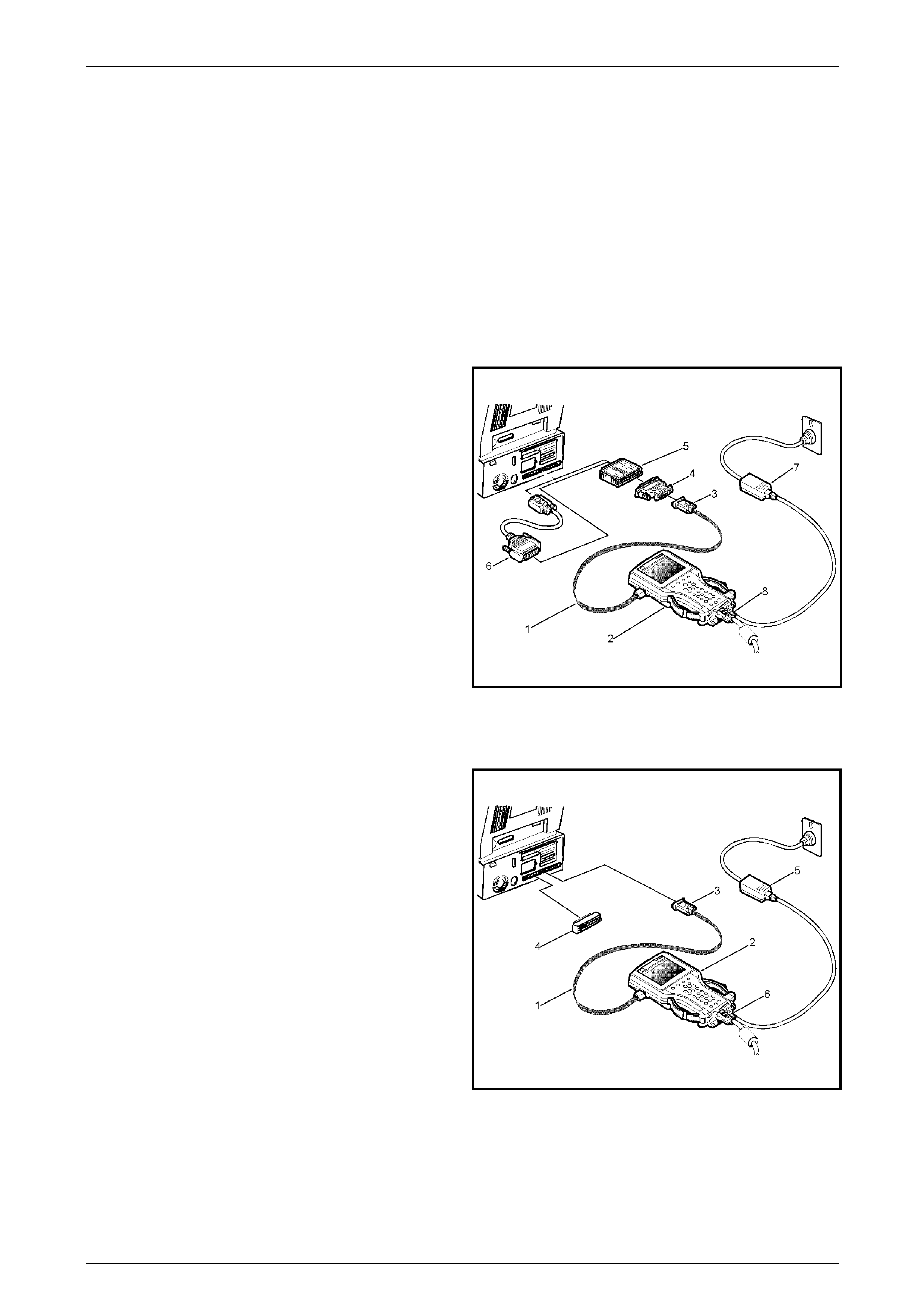
TECH 2 Page 0C–86
4.2 Security Access
Security Access is used in order to prevent unauthorised persons from programming certain security functions.
After a Tech 2 security programming function has been sel ected, the Tech 2 will display: Please get programming
approval from TIS!
To enable these programmin g procedures they must be approved by the TIS 2000 Security Access function and Tech 2
must be connected to TIS 2000 using the RS232 interface and a registered security hardware key. Without this security
hardware key, an error message is given by TIS 2000.
Security Access procedure
1 If your security hardware key is the serial t ype, go to step 2. If your hardware key is the parallel type, go to step 7. If
your hardware key is the USB type, go to ste p 12.
2 Connect the RS-232 cable (1) to the Tech 2 (2)
RS-232 communication port.
3 Connect the other end of the RS-232 cabl e to the
DB-9 adapter (3) and then connect the DB-9
adapter to the 25/9 pin adapter (4).
4 Connect the 25/9 pin adapter to the Seria l Security
Hardware Key (5) and then connect the Serial
Security Hardware Key to the serial port of a
Personal Computer (PC) with TIS 2000 insta lled.
NOTE
If your PC has a 9 pin serial communication
port you will need to fit the 9/25 pin adapter
(6) between the hardware key and the serial
port of the TIS 2000 PC.
5 Connect the power supply (7) to the T ECH 2 power
supply jack (8). Press the PWR button to turn on
Tech 2. Tech 2 should now be at the title displa y
screen.
Figure 0C – 26
6 Now go to step 16.
7 Connect the RS-232 cable (1) to the Tech 2 (2)
RS-232 communication port.
8 Connect the other end of the RS-232 cabl e to the
DB-9 adapter (3) and then connect the DB-9
adapter to the Comms port of the Personal
Computer (PC) with TIS 2000 installed.
9 Connect the Parallel Security Hardware Key (4) to
the serial port of the Personal Computer (PC) with
TIS 2000 installed.
10 Connect the power supply (5) to the TECH 2 power
supply jack (6). Press the PWR button to turn on
Tech 2. Tech 2 should now be at the title displa y
screen.
11 Now go to step 16.
Figure 0C – 27
Page 0C–86
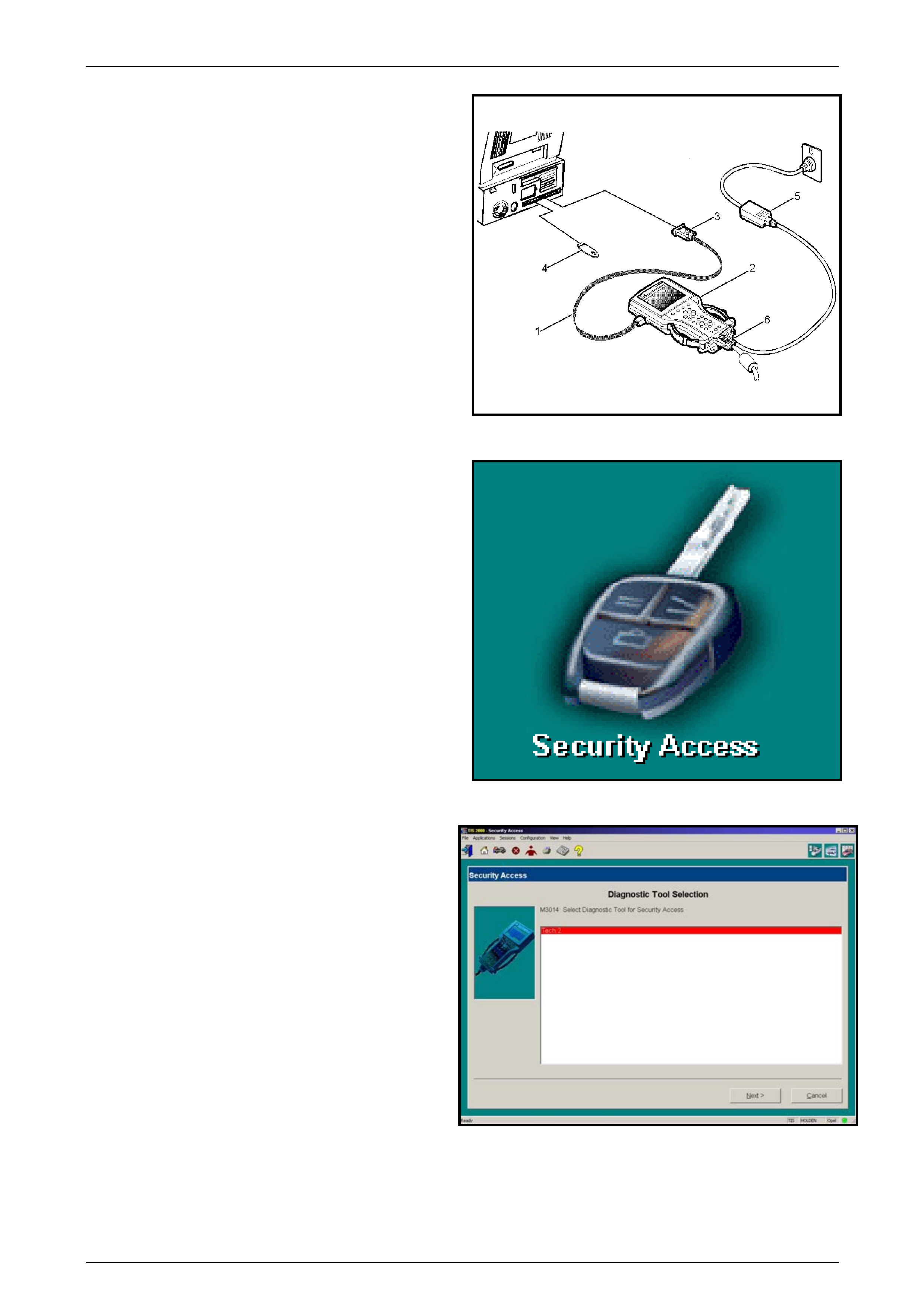
TECH 2 Page 0C–87
12 Connect the RS-232 cable (1) to the Tech 2 (2)
RS-232 communication port.
13 Connect the other end of the RS-232 cable to the
DB-9 adapter (3) and then connect the DB-9
adapter to the Comms port of the Personal
Computer (PC) with TIS 2000 installed.
14 Connect the USB Security Hardware Key (4) to the
USB port of the Personal Computer (PC) with TIS
2000 installed.
15 Connect the power supply (5) to the TECH 2 power
supply jack (6). Press the PWR button to turn on
Tech 2. Tech 2 should now be at the title displa y
screen.
Figure 0C – 28
16 From the TIS 2000 main menu, click on the
Security Access icon to start the application.
Figure 0C – 29
17 Select diagnostic tool (Tech 2) for Security Access.
18 Select Next> to continue.
Figure 0C – 30
Page 0C–87
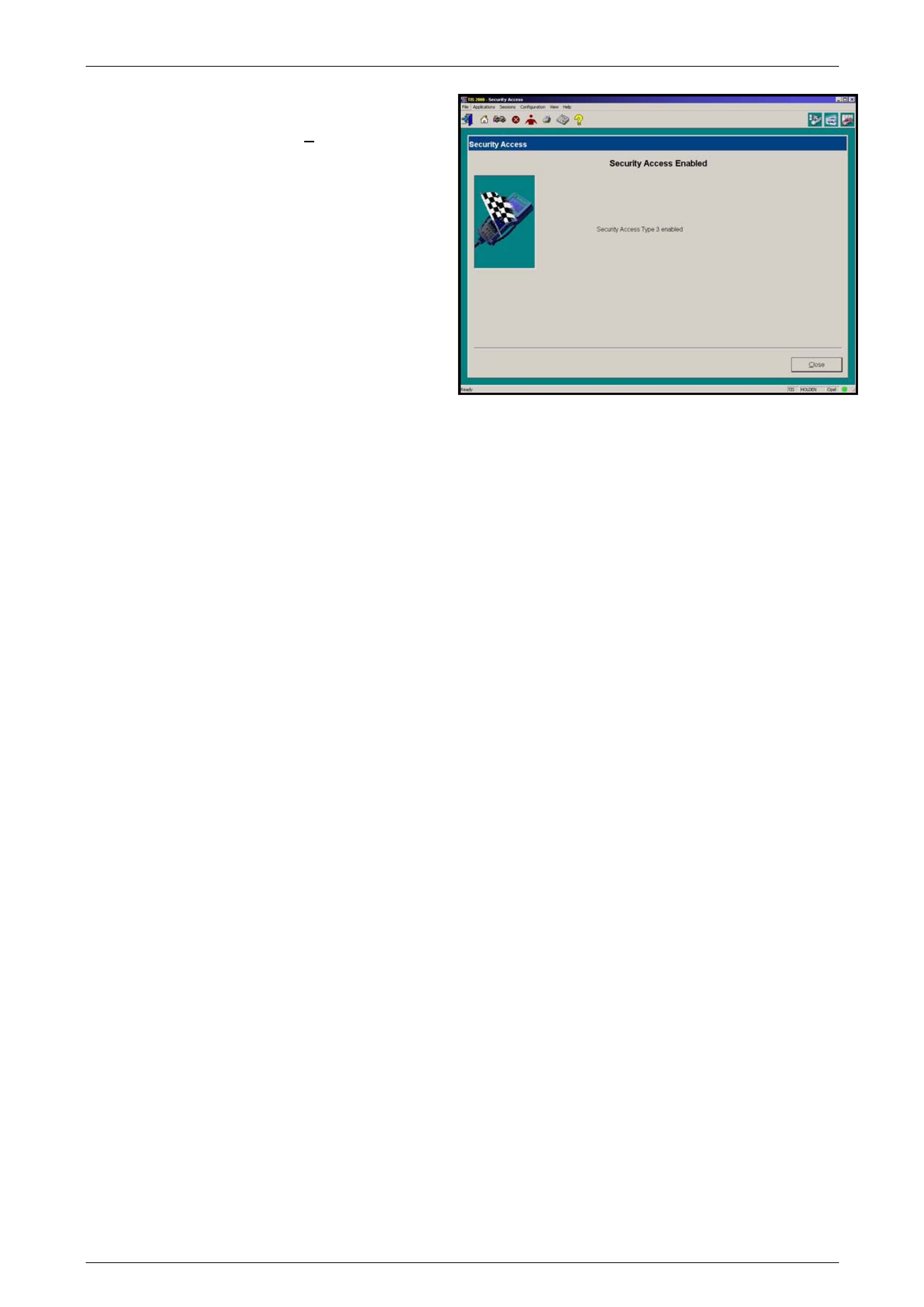
TECH 2 Page 0C–88
19 When the process is complete, a Security Access
Enabled, Securit y Access Type 2 and or 3 enabled
screen appears. Click on the Close button to close
the application.
Figure 0C – 31
20 Reconnect the Tech 2 to the vehicle DL C and reselect the programming function, you will now be permitted to
complete the programming function.
Page 0C–88

TECH 2 Page 0C–89
5 Service Programming System
(SPS)
5.1 General Information
On the VZ and WL Series Models equipped with either a HFV6 V6 engine or GEN III and GEN IV V8 engine the
ECM/PCM contains an EEPROM (Flash Memory) which is non removable. The ECM/PCM is programmed from the
factory with the proper calibrations for vehicle operation. In the event that the ECM/PCM is replaced, or an updated
calibration is required to correct a vehicle's operating condition, the ECM/PCM will have to be progr ammed with the new
calibration. Programming is accomplished through the vehicle DLC using the TECH 2 Service Programming System
(SPS) and TIS 2000.
A service replacement ECM/PCM will not be programmed. DTC P0601 an d P0602 indicates that the PCM is not
programmed or that programming h as malf unctioned. For further DTC information and diagnostic procedures refer to
Section 6C1-2 Engine Manag ement – V6 – Diagnostics and Section 6C3-2 Po wertrain Mana gement – GEN III V8 –
Diagnostics
NOTE
If you are installing a new ECM/PCM ensure that
the correct PCM is fitted to the vehicle. Refer to
the latest parts listing for part number
identification.
The following TIS 2000 and T E CH 2 screen displays will vary with different applications and versions of T IS 2000 and
TECH 2 software.
Page 0C–89
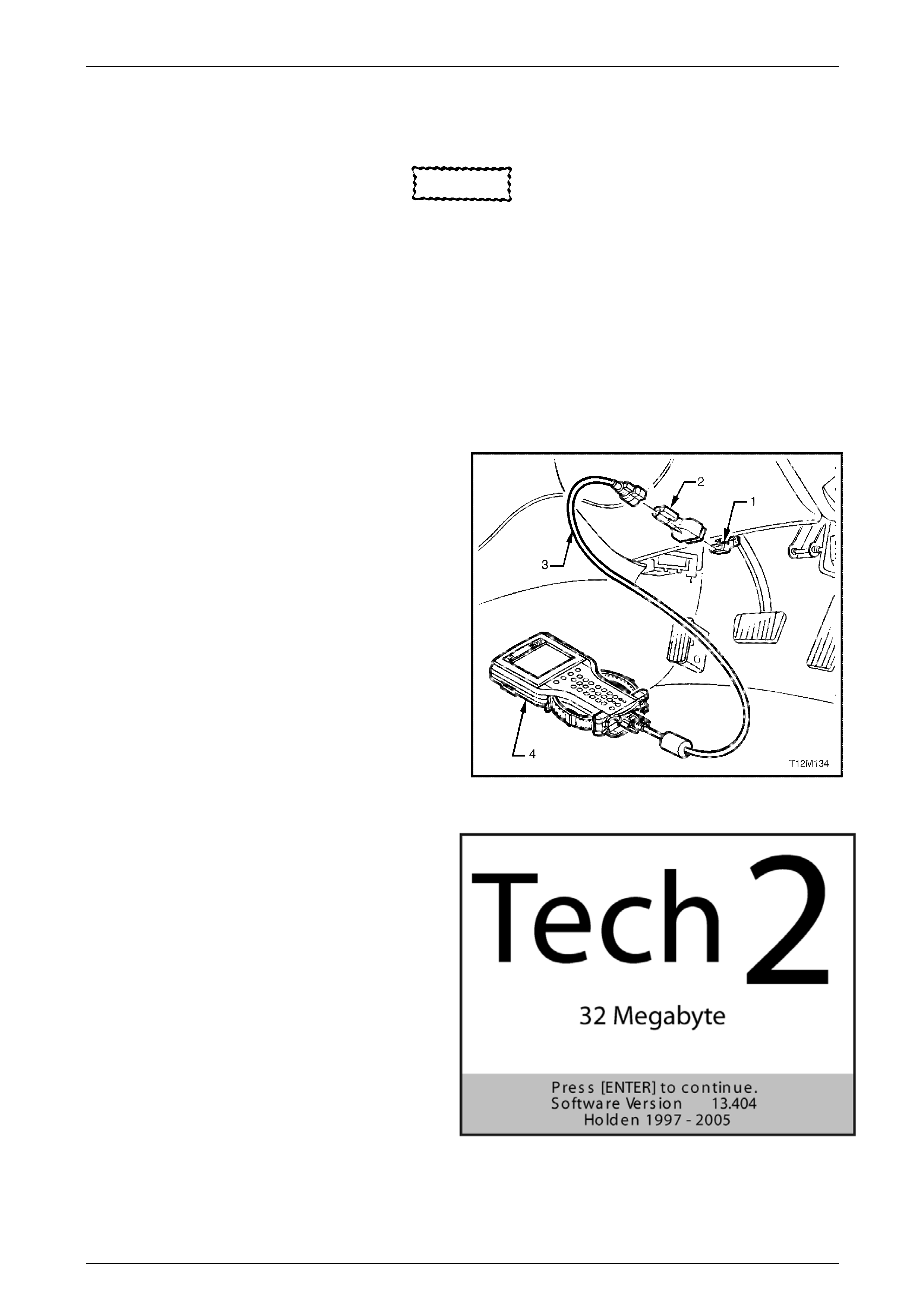
TECH 2 Page 0C–90
5.2 SPS Process
CAUTION
Before performing SPS inspect the TECH 2
DLC cable and the DLC connector and
terminals for damage. Any damage that
causes an open circuit during the
programming procedure could result in
irreparable damage to the ECM/PCM.
Battery voltage must be between 12 and 14
volts. The vehicle to be programmed must not
be connected to a battery charger during the
programming procedure. Incorrect battery
voltage could cause programming failure
and/or ECM/PCM failure.
1 Connect DLC cable (3) to TECH 2 (4) and DLC
adapter (2) and then 16/19 pin DLC adapter to
DLC (1).
NOTE
When working on a vehicle with the GMLAN
serial data protocol, a CANdi Module will
have to be fitted between the DLC cable and
the 16/19 pin DLC adapter.
2 Press the TECH 2 PWR button to turn on TECH 2.
Figure 0C – 32
3 When the TECH 2, title screen is displayed, press
ENTER to continue.
Figure 0C – 33
4 Select F1: Service Programming System (SPS).
5 Select F0: Request Info and follow the instructions on the screen.
Page 0C–90
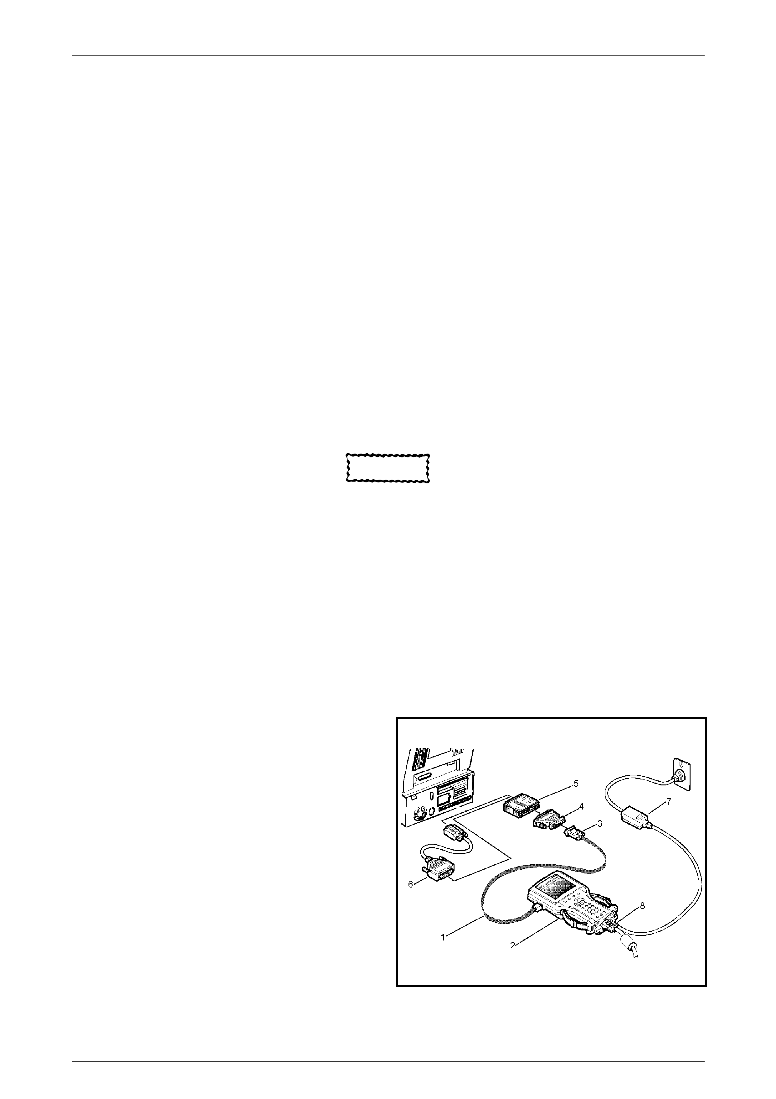
TECH 2 Page 0C–91
6 If there is data already stored, TECH 2 will display the stored data. Press the Continue Soft Key to request new
information
7 If there is no data stored in TECH 2 then a Model Year sel ection screen will be displayed.
8 Using the arrow keys select the correct Model Year for the vehicle you are working on and press ENTER
9 TECH 2 will then display a Vehicle Type(s) selection screen. Select the appropriate vehicle type with the arrow
keys and then press ENTER.
10 TECH 2 will then display the System Selection Menu screen. The desired system can be selected from the System
Selection menu with the function keys or with arrow keys and then press ENTER.
• F0: Engine: Select the appropriate engine for the vehicle you are working on with the arrow keys and then
press ENTER. The following is an example of available engine options; 5.7L V8 LS1, 6.0L V8 LS2, 3.6L V6
LE0, 3.6L V6 LW2, 3.6L V6 LY7.
• F1: Transmission
• F2: Body: Select the appropriate system you are working on with the arrow keys and then press ENTER.
11 Turn the ignition off and then press the Okay soft key to continue.
12 When Ignition switched off! is displayed, ensure that the ignition is switched off and then press the Okay soft key
to continue.
13 Turn off all power consuming devices! (i.e. A/C. Radio, Headlamps etc). Turn on ignition with engine of f! Be sure
the battery is fully charged. Press the Okay soft key to continue.
CAUTION
The battery must be fully charged and it
MUST not be connected to a battery charger
during the SPS process.
14 The TECH 2 will then read and display the Vehicle Identification N umber (VIN) and ECU data. Follow the
instructions displayed o n the TECH 2 screen.
NOTE
If programming a Service Replacement
ECM/TCM/PCM the VIN will not be displayed.
15 Connect the TECH 2 and security hard ware ke y to the serial port of a Persona l Computer (PC) with TIS 2000
installed. If your security hardware key is the serial type, go to step 16. If your hardware key is the parallel type, go
to step 21. If your hardware key is the USB type, go to step 26.
16 Connect the RS-232 cable (1) to the Tech 2 (2)
RS-232 communication port.
17 Connect the other end of the RS-232 cable to the
DB-9 adapter (3) and then connect the DB-9
adapter to the 25/9 pin adapter (4).
18 Connect the 25/9 pin adapter to the Serial Se curity
Hardware Key (5) and then connect the Serial
Security Hardware Key to the serial port of a
Personal Computer (PC) with TIS 2000 insta lled.
NOTE
If your PC has a 9 pin serial communication
port you will need to fit the 9/25 pin adapter
(6) between the Security Hardware Key and
the serial port of the TIS 2000 PC.
19 Connect the power supply (7) to the TECH 2 power
supply jack (8). Press the PWR button to turn on
Tech 2. Tech 2 should now be at the title displa y
screen.
Figure 0C – 34
Page 0C–91
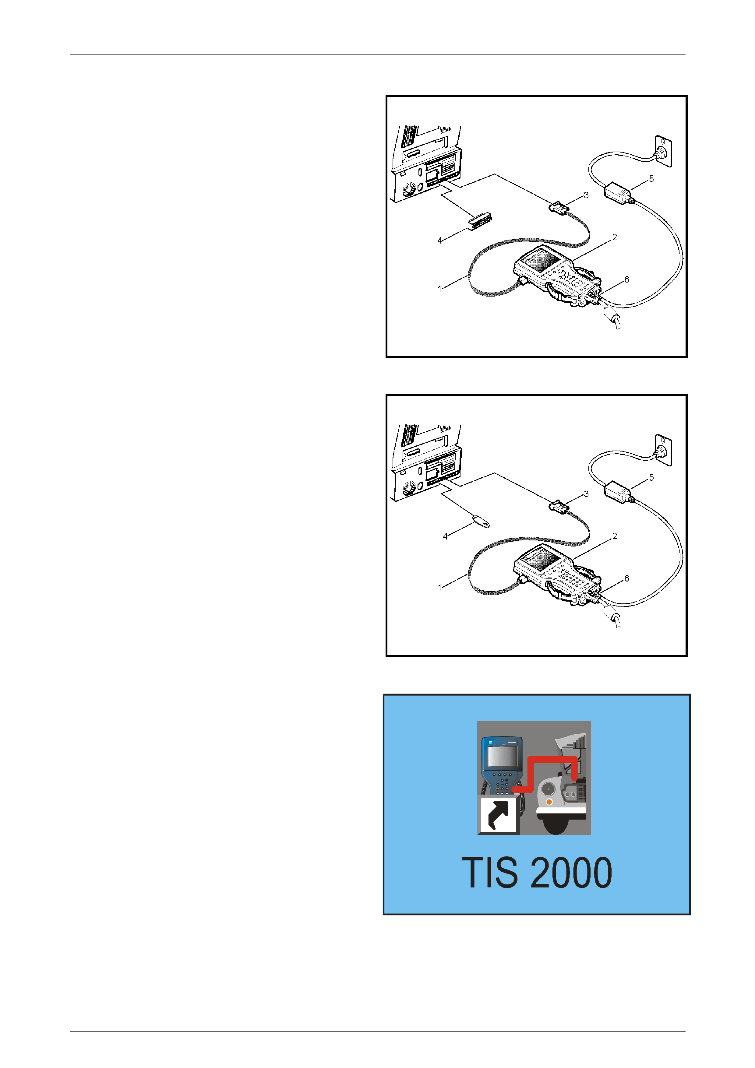
TECH 2 Page 0C–92
20 Now go to step 30.
21 Connect the RS-232 cable (1) to the Tech 2 (2)
RS-232 communication port.
22 Connect the other end of the RS-232 cable to the
DB-9 adapter (3) and then connect the DB-9
adapter to the Comms port of the Personal
Computer (PC) with TIS 2000 installed.
23 Connect the Parallel Security Hardware Key (4) to
the serial port of the Personal Computer (PC) with
TIS 2000 installed.
24 Connect the power supply (5) to the TECH 2 power
supply jack (6). Press the PWR button to turn on
Tech 2. Tech 2 should now be at the title displa y
screen.
25 Now go to step 30.
Figure 0C – 35
26 Connect the RS-232 cable (1) to the Tech 2 (2)
RS-232 communication port.
27 Connect the other end of the RS-232 cable to the
DB-9 adapter (3) and then connect the DB-9
adapter to the Comms port of the Personal
Computer (PC) with TIS 2000 installed.
28 Connect the USB Security Hardware Key (4) to the
USB port of the Personal Computer (PC) with TIS
2000 installed.
29 Connect the power supply (5) to the TECH 2 power
supply jack (6). Press the PWR button to turn on
Tech 2. Tech 2 should now be at the title displa y
screen.
Figure 0C – 36
30 Open TIS 2000 by double clicking the TI S 2000
Icon.
Figure 0C – 37
Page 0C–92
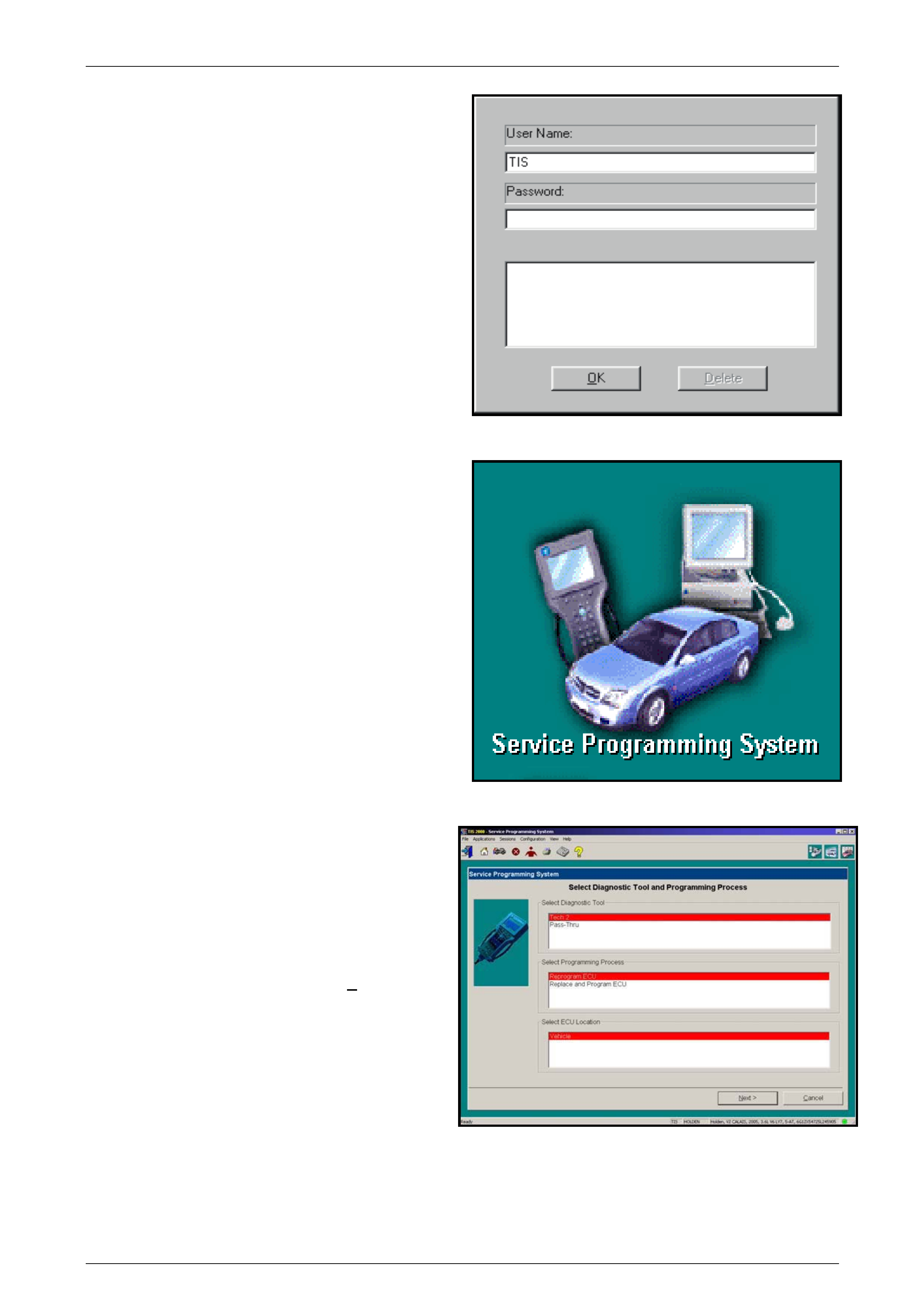
TECH 2 Page 0C–93
31 The default user of TIS2000 i s called "TIS". This
user does not have a pass word. Click the "OK"
icon to continue.
Figure 0C – 38
32 From the TIS 2000 Main Menu click on the SPS
icon to start the SPS application.
NOTE
If TIS 2000 does not detect a hardware key
the following error message will be displayed.
E666: Access to Service Programming
Server was denied.
Figure 0C – 39
33 At Select Diagnostic Tool and Programming
Process click on desired selections for:
• Diagnostic tool being used: TECH 2.
• Whether you are reprogramming an existing
control unit or programming a ne w control unit.
• Select ECU location: Vehicle.
34 After making your selections, select Next>.
Figure 0C – 40
Page 0C–93
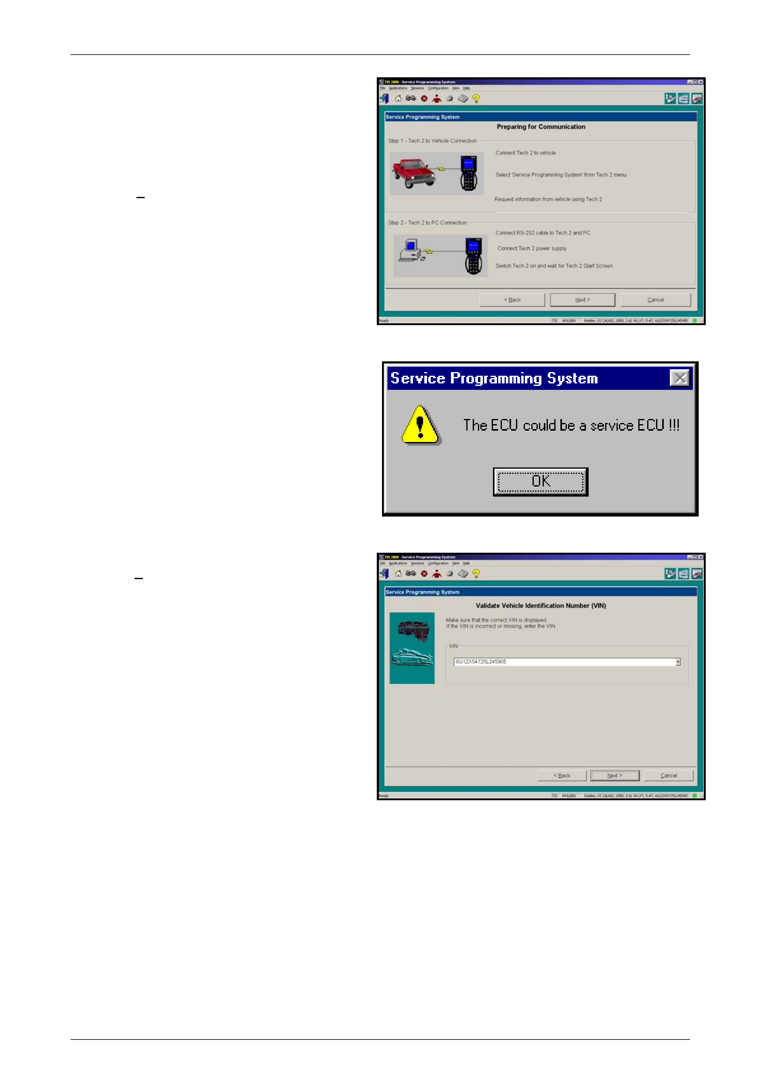
TECH 2 Page 0C–94
NOTE
At this point you should have already
Requested Info from the Vehicle and T ECH 2
should be connected to the serial port of a
Personal Computer (PC) with TIS 2000
installed.
35 Select Next>. to continue.
Figure 0C – 41
NOTE
If a Service ECU has been installed the
warning opposite will be displayed at this
time, select OK to continue.
Figure 0C – 42
36 Confirm VIN or enter correct VIN, if required, then
select Next>.
Figure 0C – 43
Page 0C–94
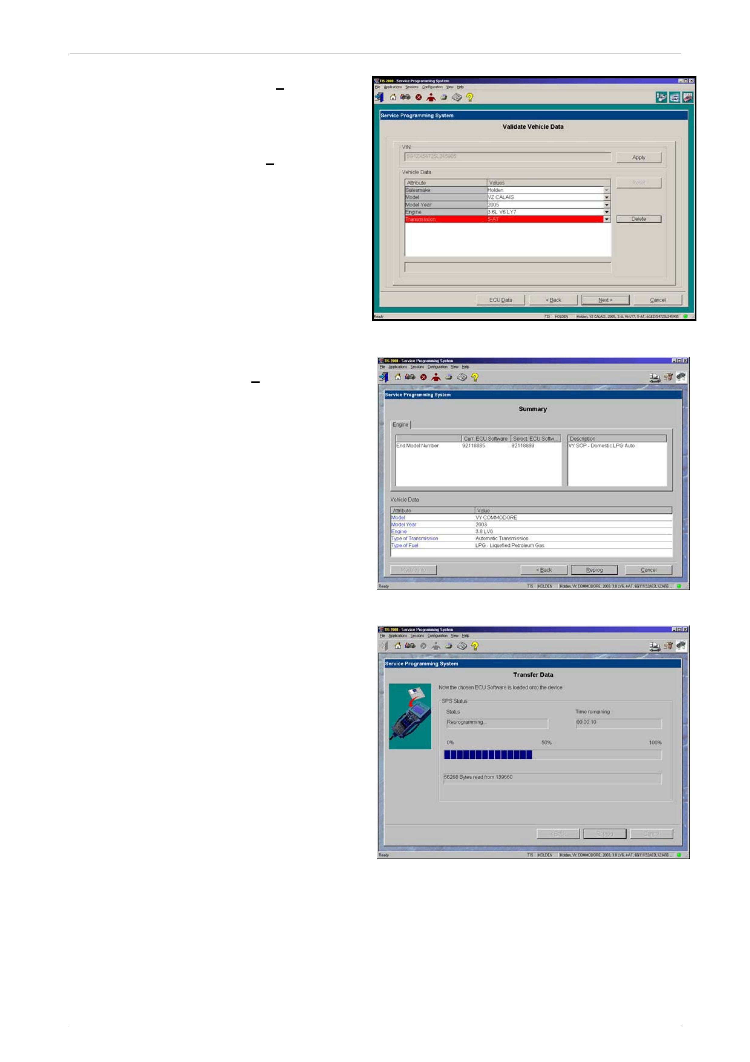
TECH 2 Page 0C–95
37 If the vehicle data is correct Select Next> to
continue.
38 If you wish to change any of the programming
options, select the option you wish to change and
then select delete. A list of the options available will
then be displayed and the sel ect Next> to continue
NOTE
The options selected must match the vehicle.
Figure 0C – 44
39 A Summary screen will app ear, allowing you to
confirm your selection. Select Reprog to continue.
Figure 0C – 45
40 A Transfer Data screen will appear. Select Reprog
button to initiate download of new calibration file to
TECH 2. The screen will track progress of
download.
Figure 0C – 46
Page 0C–95
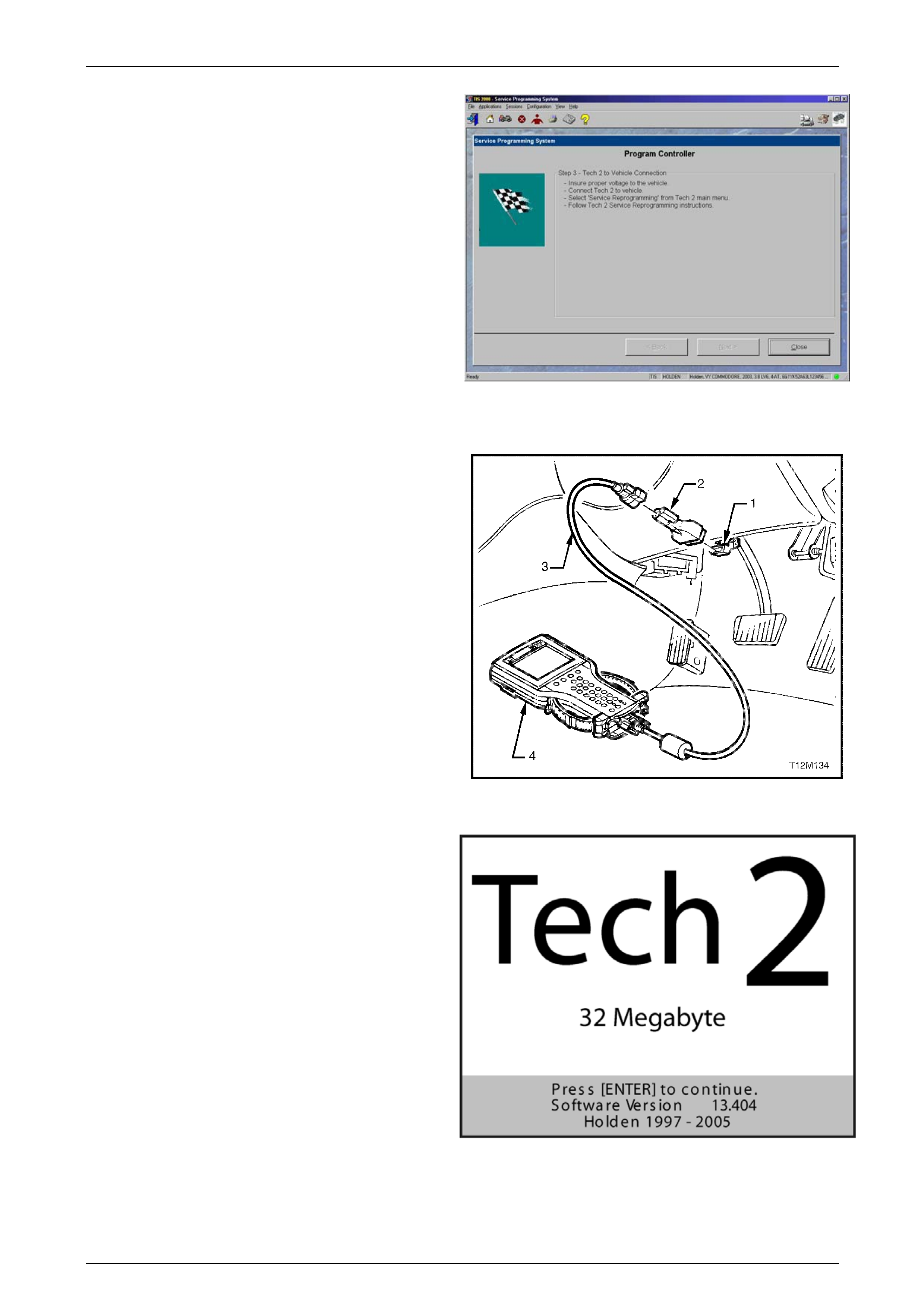
TECH 2 Page 0C–96
41 After download is complete a screen will appear
instructing you to connect T ECH 2 to vehic le to
complete programming process. Close the SPS
application to return to T IS 2000 main menu; power
down and then disconnect TECH 2 from PC.
Figure 0C – 47
42 Return to the vehicle and complete the SPS process.
43 Connect DLC cable (3) to TECH 2 (4) and DLC
adapter (2) and then 16/19 pin DLC adapter to
DLC (1).
NOTE
When working on a vehicle with the GMLAN
serial data protocol, a CANdi Module will
have to be fitted between the DLC cable and
the 16/19 pin DLC adapter.
44 Press the TECH 2 PWR button to turn on TECH 2.
Figure 0C – 48
45 When the TECH 2, title screen is displayed, press
ENTER to continue.
Figure 0C – 49
46 Select F1: Service Programming System (SPS).
47 F1: Program ECU will be flashing on the TECH 2 display. TECH 2 is ready for ECU programming.
Page 0C–96

TECH 2 Page 0C–97
48 Select F1: Program ECU and follow the instructions on the TECH 2 screen.
49 Turn off all power consuming devices! (i.e. A/C. Radio, Headlamps etc). Turn on ignition with engine of f! Be sure
the battery is fully charged. Press the Okay soft key to continue.
CAUTION
The battery must be fully charged and it
MUST not be connected to a battery charger
during the SPS process.
50 TECH 2 will begin programming the ECU. The TECH 2 screen display will indicate the progress of the do wnload as
a percentage.
51 Programming successful ! will be displayed when progr amming is completed.
52 Press the Exit soft key.
53 Turn off TECH 2 and disconnect it from the vehicle DLC.
54 Turn off Ignition.
NOTE
If a Service ECM/PCM or a ECM/PCM from
another vehicle has been installed, a BCM to
ECM/PCM/PIM Link will have to be performed.
Refer to Section 12J Body Control Module.
Page 0C–97
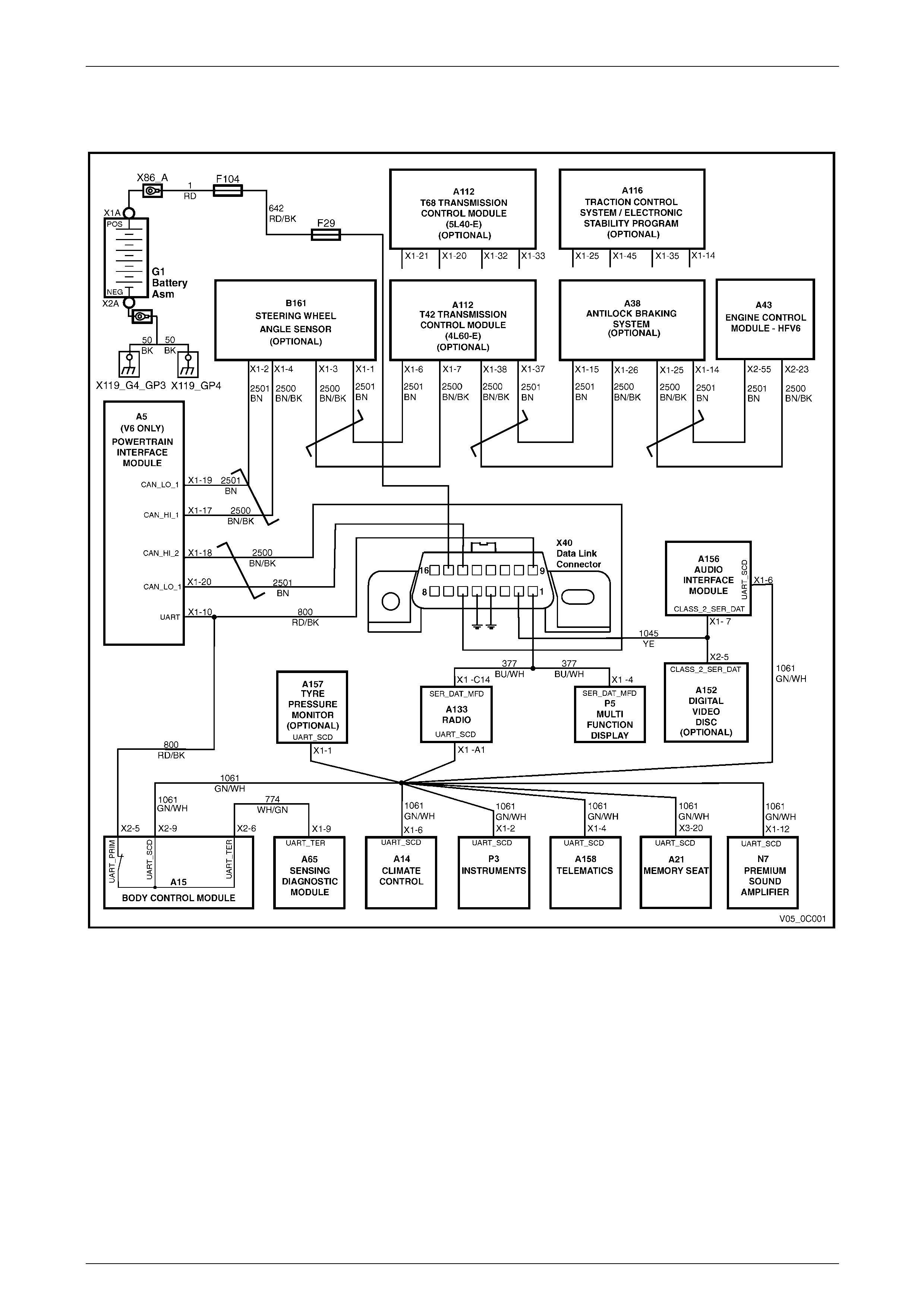
TECH 2 Page 0C–98
6 TECH 2 Diagnosis
Figure 0C – 50 – V6 Serial Data Commu nications
Page 0C–98
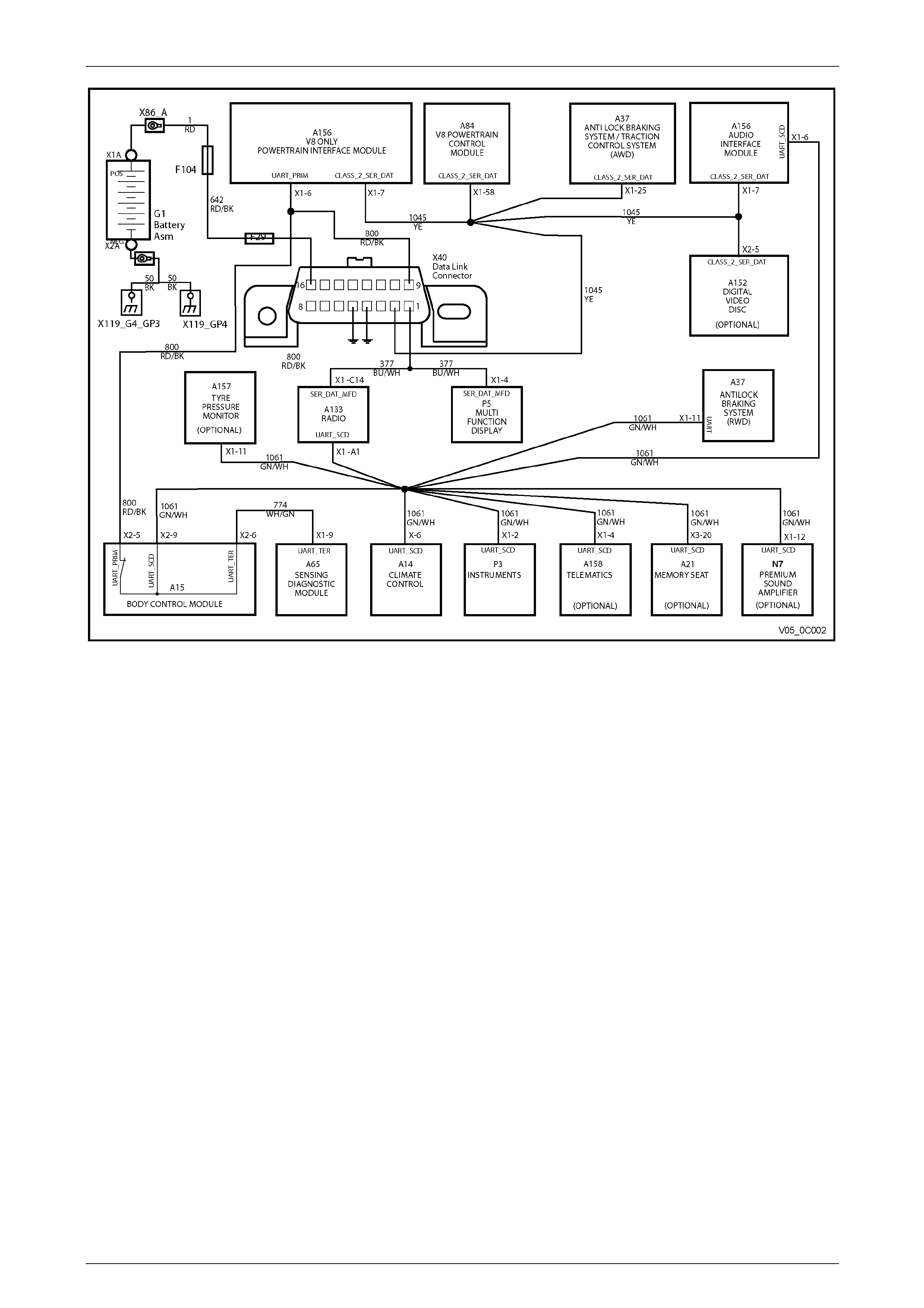
TECH 2 Page 0C–99
Figure 0C – 51 – GEN III Serial Data Communications
Page 0C–99
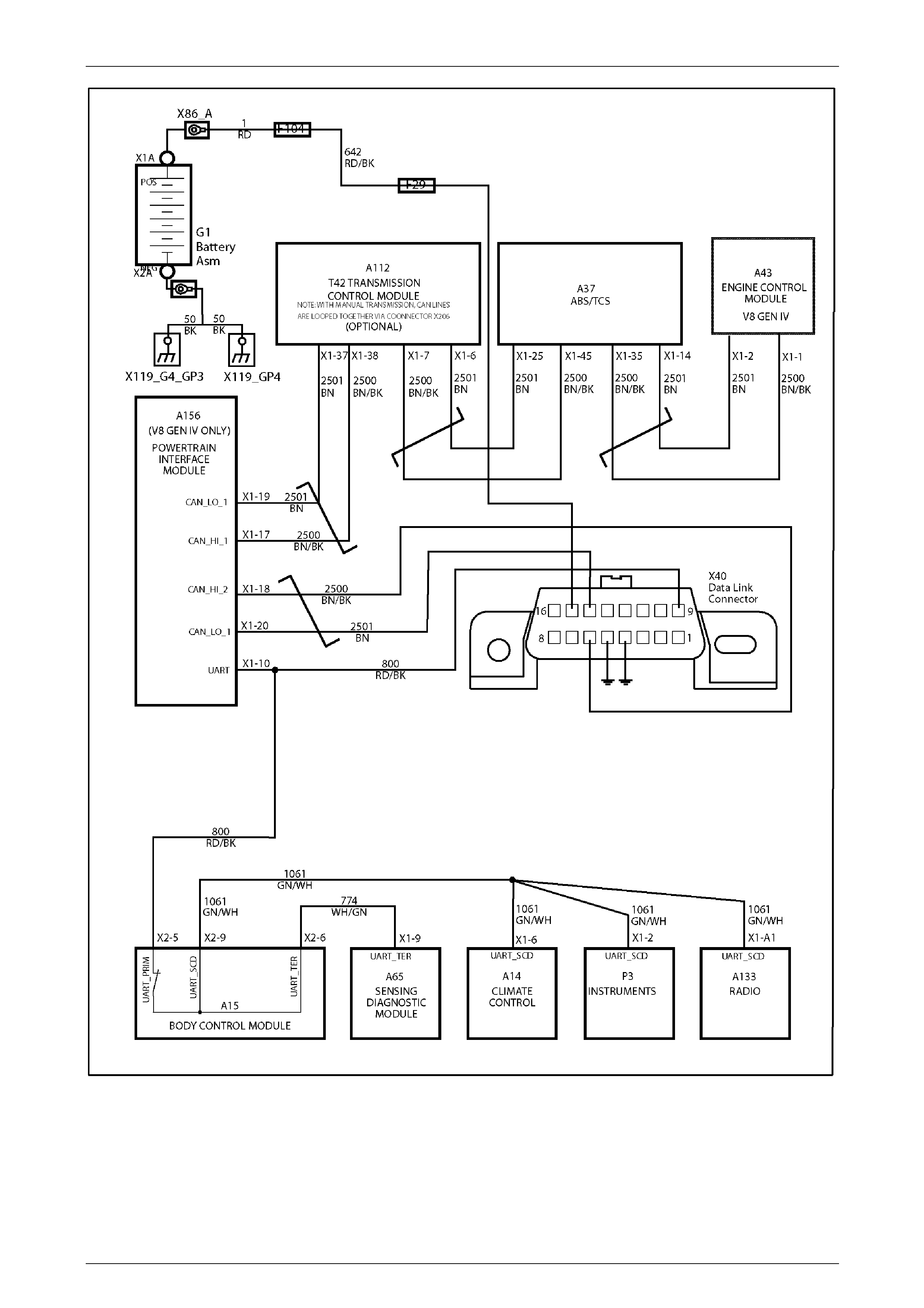
TECH 2 Page 0C–100
Figure 0C – 52 – GEN IV Serial Data Communications
Page 0C–100

TECH 2 Page 0C–101
6.1 General Information
Power supply for TECH 2 is from fusible link F104 and fuse F29 via circuit 740 (OG/BK wire) to terminal 16 of the DLC.
The ground circuit is via terminal 4 and circuit 150 (Black wire). The serial data ground circuit is via terminal 5 of the DL C
and circuit 251 (Black/Yello w wire).
TECH 2 can communicate with the vehicles electronic control mod ules via three types of serial data protocol, depending
on the type of engine fitted to the vehicle.
The three types of serial data communication available between the various electronic control modules in the vehicle
range are;
• Universal Asynchronous Receive and Transmit (UART) protocol.
• Class II.
• General Motors Local Area Network (GMLAN) for the Alloytec range of V6 engines.
The following describes which circuits are used by TECH 2 to communicate with specific electronic control modules for
vehicles fitted with the Alloytec range of V6 engines.
• The primary UART serial data circuit 80 0 (Red/Black wire) is connected to terminal 9 of the DLC (X40), the PIM
(A5) and the BCM (A15).
• The secondary UART serial data circuit 1061 (Green/White wire) is connected to the BCM (A15) and the following
modules; OCC (A14), instrument (P3), telematics module ( A158), memory seat and mirror module (A21), PSA
(N7), AIM (A156), radio (A133) and TPMS (A157).
• The tertiary serial data circuit 744 (White/Gre en wire) is connected to the BCM (A15) and the SDM (A65).
NOTE
Both the secondary and tertiar y serial data circuit
are connected to the primary serial data circuit
via the BCM serial data bus isolator.
• The class II serial data circuit 1045 (Yell ow wire) is connected to terminal 2 of the DLC (X40) the AIM (A156) and
DVD (A152).
• The GMLAN HI serial data circuit 2500 (Bro wn/Black wire) and GMLAN LO serial data circuit 2501 (Bro wn wire) are
connected to terminals 6 and 14 respectiv ely of the DLC (X40) the PIM (A5), steering wheel angle sen sor (B161),
TCM (A112), ABS/TC/ESP module (A38/A116) and ECM (A43).
The following describes which circuits are used by TECH 2 to communicate with the specific electronic control modul es
for vehicles fitted with the GEN III V8 engine.
• The primary UART serial data circuit 80 0 (Red/Black wire) is connected to terminal 9 of the DLC (X40), the PIM
(A5) and the BCM (A15).
• The secondary UART serial data circuit 1061 (Green/White wire) is connected to the BCM (A15) and the following
modules; OCC (A14), instrument (P3), telematics module ( A158), memory seat and mirror module (A21), PSA
(N7), AIM (A156), radio (A133), TPMS (A157) and for a rear wheel drive vehicle, the ABS (A37).
• The tertiary serial data circuit 744 (White/Gre en wire) is connected to the BCM (A15) the SDM (A65).
NOTE
Both the secondary and tertiar y serial data circuit
are connected to the primary serial data circuit
via the BCM serial data bus isolator.
• The class II serial data circuit 1045 (Yell ow wire) is connected to terminal 2 of the DLC (X40) the AIM (A156) and
DVD (A152), PCM (A84) and the for an all wheel drive vehicle, the ABS/TC module (A37).
Page 0C–101

TECH 2 Page 0C–102
6.2 Test Description
The numbers below refer to step numbers in the TECH 2 diagnostic chart.
1 Checks if TECH 2 is being powered up.
2 Checks if TECH 2 is programmed with the latest version software.
3 Checks if fusible link F104 is OK.
4 Checks if fuse F29 is OK.
5 Checks if battery voltage is available for TECH 2.
6 Checks if a ground circuit is available for TECH 2.
8 All vehicle circuits have been found to be OK, fault must be with TECH 2 or an intermitted fault is causing TECH 2
not to operate correctly.
X40
Figure 0C – 53
Page 0C–102

TECH 2 Page 0C–103
6.3 TECH 2 Diagnostic Chart
STEP ACTION VALUE YES NO
1 1 Connect TECH 2 to the vehicle DLC, (X40) wit h the
DLC cable and the 16/19 pin adapter.
2 Switch on TECH 2 by pressing the PWR button.
Does a green light abov e the PWR button come ON?
Go to Step 2. Go to Step 3.
2 1 Does TECH 2 Title Screen illuminate and display:
“TECH 2
32 Megabyte
Press [ENTER] To Continue
Software Version: 13.600
Holden 1997 – 2005”
(Software Version should be greater than 13.600)
Go to Step 3. Program TECH 2
refer to
2 Programming
TECH 2
in this Section.
3 Is Fusible link F104 OK? Go to Step 4. Replace fusible link
and check cause of
blown fusible link.
Verify Repair.
4 Is Fuse F29 OK? Go to Step 5. Replace fuse and
check cause of
blown fuse.
Verify Repair.
5 1 Check for voltage between DLC (X40) terminals 4
and 16.
Is voltage at specified value?
B+ Go to Step 7. Go to Step 6.
6 1 Ignition off.
2 Check for voltage between DLC (X40) terminals 16
and a known good ground.
Is voltage above specified value?
B+ Repair open in
circuit 150 between
DLC Connector
terminal 4 and
ground connector
X157_GP2.
Verify Repair.
Repair open in
circuit 740 and 642
between DLC
connector X40
terminal 16 and
fusible link F104.
Verify Repair.
7 1 Perform TECH 2 Self Test using 240 V AC power
supply. (Refer to TECH 2 User’s Guide).
Does TECH 2 pass Self Test?
Go to Step 8. Repair T ECH 2 or
CANdi Module.
8 1 Perform a CANdi Diagnostics test using 240 V AC
power supply. (Refer to TECH 2 User’s Guide).
Does TECH 2 pass the CANdi dia gnostic test?
TECH 2 is
functioning
correctly.
If you cannot
communicate with a
specific control
module, refer to
system specific
diagnostics.
Repair TECH 2 or
CANdi Module.
Page 0C–103

TECH 2 Page 0C–104
7 Special Tools
TOOL NO. REF
IN TEXT TOOL DESCRIPTION COMMENTS
TECH 2 TECH 2
Previously released
Technical Information System
(TIS) 2000 TIS 2000 CD ROM
Version 32.0B
Tech 2 Ve r.
Holden 11.200
May
2002
CD No 1
TIS2000
Data Copyright 2001 All
rights reserved SOFTWARE
copy right 2001 Servic e
Operations General Motors
Corp All Rights Reserved
This dis c contai ns copyri
g
hted
materia l. Any reproduction or
publi cati on of thi s information
wit hout the expres sed writt en
permissi on o f Ada m Opel
AG,Russel sheim, is prohibited
Released Monthly
Page 0C–104