
General Information Page 0A–1
Section 0A
General Information
ATTENTION
Before performing any Service Operation or other procedure described in this Section, refer to 00 Warnings,
Cautions and Notes for correct workshop practices with regard to safety and/or property damage.
1 General Information ...............................................................................................................................3
1.1 Summary of Changes and New Features ............................................................................................................ 3
1.2 MY2006 VZ Update Series O ver view .................................................................................................................... 4
Continuing Models: ............................................................................................................................................... 4
Engines:.................................................................................................................................................................. 4
Alloytec V6 – General:........................................................................................................................................ 4
Alloytec V6: ........................................................................................................................................................ 4
Alloytec High Output V6: .................................................................................................................................... 4
GEN IV V8:......................................................................................................................................................... 4
Transmissions: ...................................................................................................................................................... 5
Chassis / Mechanical............................................................................................................................................. 5
Steering.............................................................................................................................................................. 5
Suspension – Front and Rear ............................................................................................................................ 5
2 Major Option Codes ...............................................................................................................................6
3 Mechanical Information.......................................................................................................................10
3.1 Hoist Pad Locations ............................................................................................................................................ 10
3.2 Model Availability and Equipment...................................................................................................................... 12
3.3 Powertrain Combinations ................................................................................................................................... 13
3.4 Engine Data.......................................................................................................................................................... 14
3.5 Manual Transmission Ratios .............................................................................................................................. 15
3.6 Automatic Transmission Ratios......................................................................................................................... 16
3.7 AWD Transfer Case Data..................................................................................................................................... 17
4 Body Information..................................................................................................................................18
4.1 Body Dimensions................................................................................................................................................. 18
Wagon................................................................................................................................................................... 18
Utility..................................................................................................................................................................... 18
Crew Cab .............................................................................................................................................................. 18
4.2 Vehicle Weights ................................................................................................................................................... 19
Definition of Terms.............................................................................................................................................. 19
Kerb Mass........................................................................................................................................................ 19
Gross Vehicle Mass (GVM).............................................................................................................................. 19
Carrying Capacity............................................................................................................................................. 19
Payload............................................................................................................................................................ 19
Gross Combined Mass (GCM)......................................................................................................................... 19
Maximum Rear Axle Load................................................................................................................................19
Wagon................................................................................................................................................................... 20
Utility (RWD)......................................................................................................................................................... 20
Crew Cab (RWD) .................................................................................................................................................. 20
Calculating Payload............................................................................................................................................. 21
5 Fuel Consumption Label .....................................................................................................................22
Page 0A–1

General Information Page 0A–2
6 Information Labels, Plates and Serial Numbers................................................................................23
6.1 Body Locations.................................................................................................................................................... 23
6.2 Safety Compliance Plate ..................................................................................................................................... 24
6.3 Body and Option Identification Plate................................................................................................................. 25
Model .................................................................................................................................................................... 25
Body No................................................................................................................................................................ 25
Trim....................................................................................................................................................................... 25
Paint...................................................................................................................................................................... 25
Built....................................................................................................................................................................... 25
Susp...................................................................................................................................................................... 25
Engine, Transmission and Axle.......................................................................................................................... 25
A/C......................................................................................................................................................................... 25
6.4 Vehicle Identification Number............................................................................................................................. 26
VIN Plate ............................................................................................................................................................... 26
VIN Body Stamping.............................................................................................................................................. 27
6.5 Vehicle Identification Numberin g System ......................................................................................................... 28
7 Major Component Serial Numbers .....................................................................................................29
7.1 Engine Serial Number.......................................................................................................................................... 29
Alloytec V6 ........................................................................................................................................................... 29
GEN IV V8 ............................................................................................................................................................. 30
7.2 Transmission Serial Number .............................................................................................................................. 31
Automatic Transmission – 5-speed 5L40E, RWD and AWD............................................................................. 31
Automatic Transmission – 4-speed 4L60E and 4L65E, RWD........................................................................... 31
Automatic Transmission – 4-speed 4L60E and 4L65E, AWD........................................................................... 32
Transfer Case Assembly..................................................................................................................................... 32
Manual Transmission – Aisin AY6 6-speed....................................................................................................... 33
Manual Transmission – Tremec T56 6-speed.................................................................................................... 33
7.3 Final Drive Assembly Serial Number ................................................................................................................. 35
Front Final Drive – AWD...................................................................................................................................... 35
Rear Final Drive.................................................................................................................................................... 35
IRS Final Drive................................................................................................................................................. 35
Beam Axle Final Drive...................................................................................................................................... 35
Page 0A–2

General Information Page 0A–3
1 General Information
1.1 Summary of Changes and New Features
With the release of the new VE and WM series sedans, there are a number of MY2006 VZ vehicles that continue to be
produced. The purpose of this service information is to provide details abou t these continuing vehicles and to describe
any changes that may be included, that have resulted from the design and/or oper ation of the new vehicles.
Apart from the features discussed for these MY2006 VZ Update models, refer to the specific Service Information
Sections
Page 0A–3

General Information Page 0A–4
1.2 MY2006 VZ Update Series Overview
Continuing Models:
RWD Station Wagon – Executive, Acclaim and Berlina levels. Mechanically, the only change is that no V8 is available.
AWD Station Wagon, levels 1, 2 and 3 – M echanically, the only changes are that the HFV6 and 5L40-E automatic
transmission is now the only powertrain system available for fitment to these models.
Utility – Base, ‘SV6’ and ‘SS’ levels – The SV6 is a new model, replacing the ‘S’. The 'SV6’.
Crew Cab – Base, ‘S’ and ‘SS’ models – Only in RWD.
Engines:
Alloytec V6 – General:
• All V6 engine variants are fitted with Morse ( or ‘Silent’) camshaft drive chains, with a corresponding tooth
shape change to the sprockets . T his change results in a reduction in engine noise.
• All V6 engine variants feature digital camshaft sensors replacing the a nalogue design previously used.
• All Alloytec engines share th e same coolant outlet housing and pressure cap, which is a new design,
with changed test procedures for the pressure cap and system pressure testing. Refer to
Section 6B1 Cooling S ystem – V6 for further details.
Alloytec V6:
• (P/O LE0) – As standard fitment to the Executive, Acclaim and Berlina Wagons and the base Utility, there are
some changes to the camshaft drive chain design, that results in some other modifications required to
accommodate those changes.
• LPG (P/O LW2) is now available for factory fitment as an option on Executive / Acclaim Wagon and base
Utility with the 4L60-E automatic transmissi on fitted as standard.
Alloytec High Output V6:
• (P/O LY7) – Fitted as standard to the ‘SV6’ Utility and optional on remaining VZ models, this engine has also
undergone changes to the camshaft drive ch ain design.
GEN IV V8:
• Introduced as a Euro III compliant V8 engine from January 1, 2006 as P/O L76, this engine now has the
designation of P/O L98 and in corporates design changes such as:
• The camshaft timing chain tensioner design has change d.
• The earlier engine (P/O L76) was fitted with the ‘Displacement on Demand’ (DoD) mechanical
hardware, even though the electronics were not activated. This P/O L98 engine has these mechanical
features removed.
• Fitted to ‘SS’ models the GEN IV V8 engine has the 6 speed manual transmission (P/O/ MM6) fitted as
standard, with the 4L65-E automatic transmission as an option (P/O M32):
For more specific information on the engines available, refer to Section 6A1 Engine Mechanical – V6 and
Section 6A4 Engine Mechanical – GEN IV V8.
Page 0A–4

General Information Page 0A–5
Transmissions:
• The 6 speed Aisin manual transmission (P/O MV5) carries over as standard fitment to base models, the SV6
Utility, the Police specification wagon and Crew Cab variants.
• The 6 speed Tremec manual t r ansmission (P/O MM6) is standard fitment to those VZ vehicles fitted with the
GEN IV V8 engine. The transmission is a carryover from earlier models except for a shortened input shaft
that resulted from a change to the crankshaft spigot bearing.
• The 4 speed 4L60-E automatic transmission (P/O M30) is stand ard fitment to the base, Acclaim and Berli na
Wagons. The transmission is also standard fitment to any LPG V6 engine (P/O LW2) and Police sp ecification,
Crew Cab optioned vehicles. The transmission is optional on the Alloytec V6 eng ine (P/O LE0).
• Applications for the 4L65-E automatic transmission (P/O M32) carries over from earlier V8 engined models,
plus the Thunder ‘SS’ Utility. The engine idle sped for these models has been reduced by 50 rpm.
• Minor calibration changes have also been made, as a part of the noise and vibration reduction and fue l
economy improvements on V6 Crew Cab variants. Essentially, these changes result in a revision to the
ECCC semi lock-up at 69 km/h and retuned shift patterns to suit. Refer to Section 7C3 Hydrau lic and
Mechanical Diagnosis, 4L 60-E Automatic Transmission.
Chassis / Mechanical
Steering
A new power steering rack design is to be phased in for all MY2006 VZ Update ve hicles, except AW D models. For more
specific information, refer to Section 9 Steering.
Suspension – Front and Rear
Crew Cab models have had some revisions made to the front and rear suspension systems.
Front Suspens on i
i
All Crew Cab models have a VY series front suspension setup that include s:
• The front stabiliser bar links have a single ball joint at the lower end, with threaded, rubber dampene d upper
mounting.
• The front struts change to accommodate the changed stabiliser bar mounting po ints.
• The front shock absorber damping char acteristics have also been modified.
Rear Suspens on and Rear Axle
To reduce noise and vibration characteristics, some minor rear suspension tuning has been undertaken, that includes:
• The mass dampers previously mounted to the rear leaf springs on V6 engined variants, have been relocated to the
rear axle housing cover. This also results in a changed final drive rear housing that is now cast alloy, instead of
pressed steel.
• The rear stabiliser bar has been deleted from all Crew Cab variants.
• The final drive ratio on manual transmission Crew Cab models has been modifi ed to 3.08:1. This ratio is now
common to both manual and automatic transmission variants.
Page 0A–5

General Information Page 0A–6
2 Major Option Codes
Option Code Description
81I Anthracite interior trim
9C1 Police options pack National
A31 Power windows (Front and rear – 4 door)
A32 Power windows (Front – 2door)
A88 Active head restraints
A8J Acclaim Pack
A9D ‘S’ Pack / SV6
A9F ‘SS’ Pack
AG3 Adjuster, driver seat 8-Way power (memory)
AH5 Adjuster, driver seat 8-Way power (no memory)
AH6 Adjuster, driver seat 4-Way power
AH7 Adjuster, passenger seat 4-Wa y power
AH8 Adjuster, passenger seat 8-Wa y power
AJ2 Rear folding jump seat
AJ3 Restraint, driver inflatable (airbag)
AJ6 Adjuster, drivers seat 6-way power
AJ7 Restraint, driver, passenger and side inflatable (airbags)
AK5 Restraint, driver and passenger’s inflatable (airbags)
AK8 Restraint, system seat, shoulder 3 point
AL6 Restraint, cargo
AQ9 Seats, reclining bucket
AX2 Key, common, vehicular unique
B58 Mats, anthracite front/rear
C41 Heater and demister w/fan
C60 HVAC manual control
C61 HVAC automatic control (OCC – single zone)
C95 Lamp, dome and reading (Not with CC5 on sedan an d wagon)
CC5 Sunroof
CF5 Sunroof, Holden By Design
CJ2 HVAC dual zone
D42 Retracting roller cargo blind
D75 Exterior door handles – Body colour
DL6 Exterior mirrors – Body colour scalp
DP2 Exterior mirrors – Black scalp
D7R Exterior mirrors – Satin scalp
E13 Equipment additional New Zealand
Page 0A–6

General Information Page 0A–7
Option Code Description
E18 Interior door handles, satin chrome
F46 AWD powertrain
FE1 Suspension, soft ride
FE2 Suspension, sports
FR1 Suspension, country pack
FX3 Suspension, level ride
G44 Axle, 3.07:1 rat io, 8.00” diff, rear (G3 V8A)
G80 Differential (LSD)
GS9 Axle 3.46 ratio, 8.00” diff, rear (Wagon and Utes V8 manual transmission)
GT4 3.73:1 Final drive axle ratio, 8.00” diff, rear (Sedan V8 6SMT)
GT9 Axle, 2.87ratio, 8.00” diff rear (or GU2 2.73, 8.0”) (V6M and V6 5SAT)
GU4 Axle, 3.08:1 ratio, 7.5” diff rear
J65 Brake System, power front and rear disc
JF5 Alloy pedals
JL4 Electronic Stability Program (ESP), Electronic Brake Assist (EBA),
Alloytec V6
JL9 Anti-lock brake system (ABS)
K30 Cruise control
K69 Keys, additional set
LE0 Engine, 3.6 Alloytec V6 4Valve EF I base – Unleaded Fuel
L98 Engine, 6.0 GEN IV V8
LY7 Alloytec ’High Output’ 3.6 litre V6 engi ne MY 2006 VZ Update
LW2 Engine, 3.6 Alloytec V6 4Valve EFI base – LPG Fuel
M12 Transmission, 6-speed manual (T56, high ratio) – GEN IV V8
M30 Transmission, 4-speed automatic (4L60E) – with Alloytec V6 and
GEN III V8.
M32 Transmission, 4-speed autom atic (4L6 5E) – heavy duty, GEN IV V8
M82 Transmission, 5-speed automatic (5L40E) – with Alloytec High Output’ V6
engine
MD6 Transmission, 4-speed automatic (4L6 5E) – AWD, heavy duty, GEN IV V8
MK2 Transmission, 4-speed automatic (4L6 0E) – AWD, Alloytec V6
MM6 Transmission, 6-speed manual (T56, low ratio) – GEN III V8
MV5 Transmission, 6-speed manual (D173) – Alloytec V6
N40 Power steering (non road speed sens itive)
N46 Steering wheel, 4 spoke non-l eather
N81 Wheel, full size spare
N87 Wheel, 8.00 x 18 alloy road (SS)
N88 Wheels, 7.50 x 17 alloy road – 730 kg capacity
N93 Wheels, low series (AWD)
Page 0A–7

General Information Page 0A–8
Option Code Description
NC6 Performance exhaust, V8
NK4 Steering wheel, sports leather with controls W 1Y
NP5 Steering wheel, leather covered with controls W1Y
NW9 Traction control (with ABS only)
PF4 Wheel, 7.00 x 16 al loy road – 900 kg capacity
PG1 Wheel, 6.0 x 15 steel road
PH1 Wheel, 7.0 x 15 steel road
PH9 Wheel, 7.0 x 15 alloy road (Acclaim)
PZ9 Wheel, 8.0 x 17 all oy road – 730 kg capacity
QAH Tyre, P205/65 R15 95H
QBB Tyre, P225/55 R17 97H
QCI Wheel, 7.0 x 16 steel road
QFH Tyre, 215/60 R16 95V
QHK Tyre, 215/65 R15C 95V – 900 kg capacity
QIJ Tyre, 215/65 R16C 95V – 950 kg capacity
QNZ Tyre, 235/45 R17 93V
QQQ Tyre, 225/50 R16 92V
QUG Tyre, 235/40 R18 91W
QWH Tyre, 225/60 R15 96V (L1 and 9C1, L1 and V8)
QXC Tyre, 225/55 R16 95V
QZA Tyre, 205/65 R15 99H
R4Y Goodyear tyre brand
R5B Dunlop tyre brand
R5C Bridgestone tyre bran d
R5D Yokohama tyre brand
RHD Vehicle, Right-hand drive
T82 Daytime running lights (headlamps-on), Telstra
U08 Dual note horns
U11 Instrument cluster, certified speedometer (with A8V / 9C1)
U19 Metric Speedometer
U1C Audio system, 60W single CD, full up / down power antenna
U1V Audio system, 60W CD changer in head unit and preset equaliser, full
up / down power antenna
U1V Audio system, 60W CD changer in head unit and preset equaliser, full
up / down power antenna
U1V Audio system, 60W CD changer in head unit and preset equaliser, height
adjustable power antenna
U1X Audio s ystem, 200W multi CD in head unit, height adjustable antenna and
preset equaliser
Page 0A–8

General Information Page 0A–9
Option Code Description
U32 Entertainment Package, rear seat player DVD (only with premium so und
system and leather steering wheel)
U5K Fleet Telematics
U75 Antenna, power
U77 Antenna, rear glass
U94 Antenna, manual retractable and lock able
UD4 Over-speed alarm and light indicator (120 km/h)
UD7 Assist, rear park (RPA)
UE1 Telematics (Holden Assist)
UJ8 Cluster, instrument (including trip computer)
UL5 Delete Radio
UN0 Audio system, 60W CD, full up / down power antenna and preset equaliser
UX6 Speaker system, dual front (with A8V / 9C1)
UY4 Navigation system
V55 Carrier, roof luggage
V5B HSV Pack
V5D Niche shop
V5E HBD Pack
V5Z Safety compliance plate delete
V5K Fleet Telematics
V7A Seat, rear, vinyl (with 9C3)
V87 Certification label (with V9Y)
VC5 Window shipping label (Mo del / option codes and descriptions – with V9Y)
VDQ Roof luggage carrier (required with sunroof on AWD wagon)
VR6 Shipping tie down provision (with V9Y)
W1Y Steering Wheel, audio controls
WBK Delete style side box
XS4 Roo bar
XW6 Paint, metallic finish
YC3 High series package (Exterior – AWD wagon)
YE4 Aluminium tray
Page 0A–9
General Information Page 0A–10
3 Mechanical Information
3.1 Hoist Pad Locations
When using a trolle y jack to raise the vehicle, it is important that the jack b e positione d under the suspension cross
member or hoist pad locations. Do not jack under a suspension control arm. The vehicle should always be supported by
jack stands at the hoist pad locations when raised.
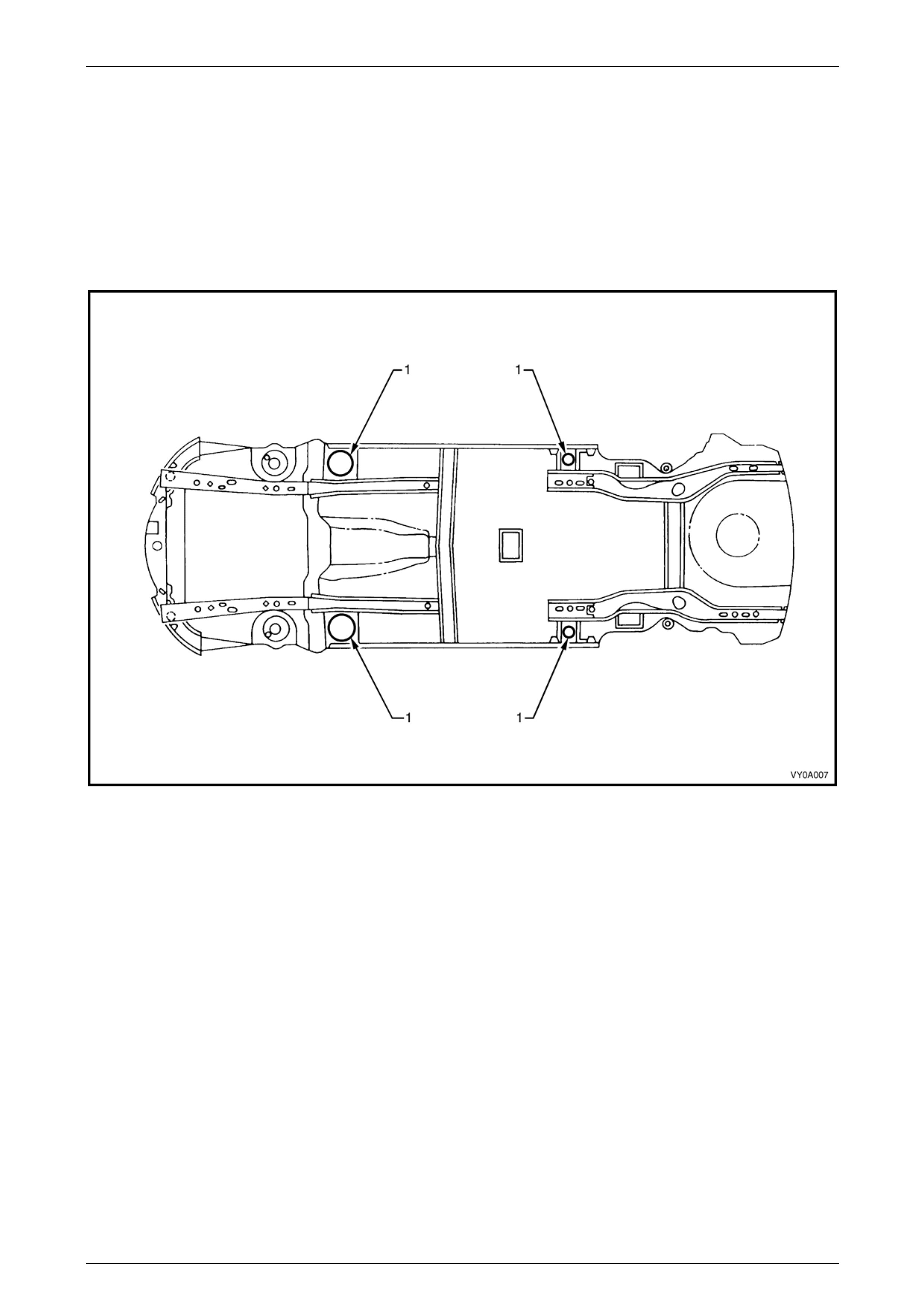
Figure 0A – 1 shows the hoist pad locations (1) on Sedan, Wagon and Utility vehicles.
Figure 0A – 1
Page 0A–10

General Information Page 0A–11
Figure 0A – 2 shows the hoist pad locations (1) on Crew cab vehicles.
Figure 0A – 2
Page 0A–11
General Information Page 0A–12
3.2 Model Availability and Equipment
Transmission
Body
Type Level Engine Standard Optional
Base Alloytec (LE0) 6 Spd. Manual (MV5) 4 Spd. Automatic (M30)
Base LPG (LW2) Alloytec (LW2) 4 Spd. Automatic (M30) —
SV6 Alloytec High Output (LY7) 6 Spd. Manual (MV5) 5 Spd. Automatic (M82)
Utility
(80)
SS and Thunder SS GEN IV V8 (L98) 6 Spd. Manual (MM6) 4 Spd. Automatic (M32)
Base Alloytec (LE0) 4 Spd. Automatic (M30) —
Base LPG (LW2) Alloytec (LW2) 4 Spd. Automatic (M30) —
Acclaim Alloytec (LE0) 4 Spd. Automatic (M30) —
Acclaim LPG (LW2) Alloytec (LW2) 4 Spd. Automatic (M30) —
RWD
Wagon
(35)
Berlina Alloytec (LE0) 4 Spd. Automatic (M30) —
SX6 Alloytec High Output (LY7) 5 Spd. Automatic (MX5) —
CX6 Alloytec High Output (LY7) 5 Spd. Automatic (MX5) —
AWD
Wagon
(35) LX6 Alloytec High Output (LY7) 5 Spd. Automatic (MX5)
Base Alloytec (LE0) 6 Spd. Manual (MV5) 4 Spd. Automatic (M30)
S Alloytec (LE0) 6 Spd. Manual (MV5) 4 Spd. Automatic (M30)
Crew Cab
(43)
SS GEN IV V8 (L98) 6 Spd. Man ual (MM6) 4 Spd. Automatic (M32)
NOTE
For tyre and wheel information, refer to
Section 10 Wheels and Tyres in this Service
Information.
Page 0A–12

General Information Page 0A–13
3.3 Powertrain Combinations
Engine Transmission Type
First Gear
Ratio Final Drive
Ratio
6-speed Manual - P/O MV5 4.475:1 2.87:1
Alloytec V6 3.6 litre ULP (LE0)
ULP (LE0) and LPG (LW2) 4-speed Automatic (4L60-E) – P/O M30 3.06:1 3.08:1
Alloytec High Output V6 3.6 litre
ULP (LY7) 6-speed Manual - P/O MV5 – P/O MV5 4.475:1 2.87:1
5-speed Automatic (5L40-E) – P/O M82 3.42:1 3.08:1
Alloytec High Output V6 3.6 litre
ULP (LY7) AWD System
5-speed Automatic (5L40-E) – P/O MX5 3.42:1 3.45:1
6-speed Manual – P/O MM6 2.66:1 3.46:1
GEN IV V8 6.0 litre ULP (L98) 4-speed Automatic (4L65E) – P/O M32 3.06:1 3.07:1
Page 0A–13

General Information Page 0A–14
Page 0A–14
3.4 Engine Data
Engine Designation 3.6 litre
Alloytec V6
(LE0)
3.6 litre
Alloytec V6
LPG (LW2)
3.6 litre
Alloytec High
Output V6
(LY7)
6.0 litre
GEN IV V8
(L98 ULP)
Piston Displacement
Nominal – cm3 3,564 3,564 3,564 5967
Compression Ratio 10.2:1 10.2:1 10.2:1 10.4:1
Number of Cylinders 6 6 6 8
Bore x Stroke – mm 94 X 85.6 94 X 85.6 94 x 85.6 101.6 X 92
Taxable H.P.
RAC or SAE 32.9 32.9 32.9 51.2
RWD (SV6 Ute)
A/T 190 @ 6,500
M/T 187 @ 6,000
Power kW
ECE @ rpm (MY 06) 172 @ 6,000 165 @ 6,000 AWD Wagon
188 @ 6,500
260 @ 5600
RWD
Wagon / Base Ute
320 @ 2,800
RWD (SV6 Ute)
335 @ 3,200
Torque N.m
ECE @ rpm Crew Cab
320 @ 2,400
320 @ 2,800
AWD Wagon
330 @ 3,600
510 @ 4400
General Information Page 0A–15
3.5 Manual Transmission Ratios
Speed
Ratio
6-speed
Aisin AY6
P/O MV5
6-speed
Tremec T56
P/O MM6
6-speed
Tremec T56
P/O M12
1st 4.475:1 2.66:1 2.97:1
2nd 2.577:1 1.78:1 2.07:1
3rd 1.633:1 1.30:1 1.43:1
4th 1.193:1 1.00:1 1.00:1
5th 1.000:1 0.74:1 0.84:1
6th 0.752:1 0.50:1 0.57:1
Reverse 3.954:1 2.90:1 3.28:1
Page 0A–15

General Information Page 0A–16
3.6 Automatic Transmission Ratios
Speed Ratio 4-speed
(4L60-E / 4L65-E) 5-speed
(5L40-E)
1st 3.06:1 3.42:1
2nd 1.63:1 2.21:1
3rd 1.00:1 1.60:1
4th 0.70:1 1.00:1
5th — 0.75:1
Reverse 2.29:1 3.03:1
Page 0A–16

General Information Page 0A–17
3.7 AWD Transfer Case Data
Manufacturer New Venture Gear (NVG)
Model NV124
Type Full Time AWD
Torque Split 38 / 62 per cent, front to rear
Final Drive Ratio 3.45:1
Page 0A–17
General Information Page 0A–18
4 Body Information
4.1 Body Dimensions
Wagon
RWD Wagon AWD Wagon
Body Dimensions – mm Level 1 Level 2 Levels 1, 2 & 3
Vehicle Length 5033 5044 5047.5
Vehicle Width (Excludi ng mirrors) 1847 1847 1934
Vehicle Height 1528.5 1528.5 1654.3
Wheelbase @ Curb Weight 2939 2939 2947
Overhang – Front 933.7 948.8 942.2
Overhang – Rear 1156.7 1156.7 1158
Track – Front @ Curb Weight 1569 1569 1617
Track – Rear @ Curb Weight 1577 1577 1623
Utility
Body Dimensions – mm Base ‘SV6’ ‘SS’ & Thunder
Vehicle Length 5051.5 5056.8 5058.4
Vehicle Width (Excludi ng mirrors) 1845 1845 1845
Vehicle Height 1487 1488 1457
Wheelbase @ Curb Weight 2939 2939 2939
Overhang – Front 939.0 944.2 943.7
Overhang – Rear 1173.7 1173.8 1175.9
Track – Front @ Curb Weight 1569 1559 1559
Track – Rear @ Curb Weight 1577 1587 1577
Crew Cab
Crew Cab – RWD
Body Dimensions – mm Base ‘S’ ‘SS’
Vehicle Length (With tonneau) 5306 5306 5311
Vehicle Width 1870 1870 1870
Vehicle Height 1500 1512 1513
Wheelbase @Curb Weight 3206 3206 3206
Overhang – Front 941 938 941
Overhang – Rear (With tonneau) 1179 1171 1171
Track – Front 1569 1559 1559
Track – Rear 1597 1587 1587
Running Ground Clearance (Minimum) 185 197 198
Page 0A–18

General Information Page 0A–19
4.2 Vehicle Weights
Definition of Terms
Kerb Mass
Kerb mass is the mass of the base vehicle in running order, unoccupied and unladen with all fluid reservoirs filled to
normal capacity, includ ing fuel, and with all standard equipment (without rear tray on regular cab). The kerb masses
listed are estimates based on pre-production vehicles, and although correct at the time of printing, are subject to change.
When the actual weight of a particular vehicl e is needed, it is recommended that the vehicle be weighe d on a suitable
weighbridge.
Where air conditioning is not fitted as standard equipment, the following must be added to the kerb weights listed:
Air Conditioning – V6:...................................................................................................15.4 kg
With the delete tub option on Crew Cab models exercised, delete 132 kg.
Gross Vehicle Mass (GVM)
Gross Vehicle Mass (GVM) is the accepted safe maximum combined mass that the vehicle is allowed to carry when fully
loaded. This includes luggage, passengers and a full tank of fuel.
Carrying Capacity
Carrying capacity is the maximum capacity of the vehicle for the carriage of all non-standard items including cargo
carrying device s (for example, tray or body, if applicable), the cargo itse lf, occupants, optional equipment and
accessories. Light commercial vehicles, depending on their model and specification, have different carrying capacities.
Carrying capacity can be calculated by subtracting the figure for the vehicle’s kerb mass from the vehicle’s GVM. Refer
to the applicable table in this section.
Payload
Payload is the mass of cargo that the finished vehic le is permitted to carry having regard to the aggregate mass of the
vehicle’s kerb mass, optional equipment, accessories, cargo carrying device (if applicable) and occupants. It is important
to calculate the intended payload accurately. When towing, the weight on the tow bar ball must also be i ncluded. Tow bar
mass and hitch load must be deducted from the payload figures. Use the payload calculation table in this Section to
assist.
Gross Combined Mass (GCM)
Gross Combined Mass (GCM) is the maximum allowable combined mass of the vehicle with driver, passengers,
luggage, a full tank of fuel and the weight of a loaded trailer or carava n. Consideration needs to be taken into account
when the trailer or caravan has either no br akes, over-run brakes or electric brakes as the GCM specifica t ion can alter
depending on which braking system the towed vehicle is fitt ed with. GCM must not exceed GVM (unless the towed
caravan or trailer has brakes).
Maximum Rear Axle Load
Maximum rear axle load is the maxim um for all conditions.
NOTE
Figures quoted, are estimates only for base
models and are measured in kilograms (kg).
Page 0A–19
General Information Page 0A–20
Wagon
RWD AWD
Base (Non A/C) Acclaim Berlina SX6 SX6 LX6
Vehicle Weights – kg
Auto LPG Auto LPG Auto Auto Auto Auto
Kerb Mass 1624 1728 1649 1754 1665 1893 1901 1955
Axle Load – Front 1060 1060 1060 1060 1060 1200 1200 1200
Axle Load – Rear 1300 1350 1300 1350 1300 1300 1340 1340
Gross Vehicle Mass
(GVM) NA NA NA NA NA 2500 2500 2500
Payload (2 Pass +
Cargo) 480 480 480 480 480 480 480 480
Utility (RWD)
Base (Non A/C) ‘SV6’ ‘SS’ Thunder ‘SS’
Vehicle Weights – kg Man Auto LPG Man Auto Man Auto Man Auto
Kerb Mass – V6 1532 1531 1642 1574 1581 — — — —
Payload (2 Pass +
Cargo) – V6 833 834 723 701 694 — — — —
Kerb Mass – V8 — — — — — 1625 1635 1648 1658
Payload (2 Pass +
Cargo) – V8 — — — — — 650 640 487 477
Axle Load – Front 1015 1015 1015 1015 1015 1015 1015 1015 1015
Axle Load – Rear 1350 1350 1350 1260 1260 1260 1260 1120 1120
Gross Vehicle Mass
(GVM) 2365 2365 2365 2275 2275 2275 2275 2135 2135
Crew Cab (RWD)
Base (Non A/C) ‘S’ ‘SS’
Vehicle Weights – kg Man Auto Man Auto Man Auto
Kerb Mass: 1745 1745 1775 1775 1837 1835
Axle Load – Front 1180 1180 1180 1180 1180 1180
Axle Load – Rear 1800 1800 1800 1800 1460 1460
Payload – Pass. & Luggage 1031 1081 1001 1051 698 700
Gross Vehicle Mass 2776 2826 2776 2826 2535 2535
Page 0A–20

General Information Page 0A–21
Calculating Payload
STEP 1: Calculate Carrying Capacity
Parameter Weight (kg)
Gross Vehicle Mass (GVM)
Kerb Mass
Carrying Capacity = GVM – Kerb Mass
STEP 2: Calculate Total Weight of Extras
Occupants
Air conditioning
Tow bar, tongue and hitch
Roo bar
Cargo liner
Fitted rear body / tray
Tonneau cover
Sports bar
Fitted tool boxes
Other
= Total Weight of Extras
STEP 3: Calculate Payload
Carrying Capacity (from Step 1)
Total Weight of Extras (from Step 2)
Payload = Carrying Capacity – Total of Weight Extras
Page 0A–21
General Information Page 0A–22
5 Fuel Consumption Label
From 1 January 2004, ADR 81/01 req uires that all new
domestic vehicles displaye d for sale have a label similar to
that shown in Figure 0A – 3, attached to the windscreen.
The ‘Comparative fuel consumption’ figure and
‘Comparative Carbon Dioxide emissions’ value quoted are
the results of tests carried out in accordance with the ECE
R101/00. This new Australian standard for fuel
consumption and Carbon Diode emission testing
harmonises our emission and consumption standards with
those recognised internationally. Each vehicle is tested
under identical conditions. The tests therefore enable a
comparison to be made between vehicles.
The label should be removed from the windsc reen
immediately prior to the vehicle being delivered to the
owner.
Figure 0A – 3
Page 0A–22
General Information Page 0A–23
6 Information Labels, Plates and
Serial Numbers
A unique Vehicle Identificatio n Number (VIN) identifies the complete vehicl e. This number is stamped or attached to the
vehicle body at the locations shown below. Major mechanical components also have serial numbers and / or
identification labels in various locations. It is essential that when compilin g warranty claims or product and field reports,
that the Vehicle Identification Number (VIN) is quoted in conjunction with the identification data of the co mponent
affected.
NOTE
For tyre placard information, refer to
Section 10 Wheels and Tyres. For HVAC label
information, refer to Section 2A HVAC Climate
Control (Manual A/C).
6.1 Body Locations
Figure 0A – 4
Legend
1 Body and Option Identification plate – Left-hand
side of the Front Panel Upper
2 Safety Compliance plate – ‘B’ pillar
3 Vehicle Identification Number (VIN) plate – Under
the Windscreen
4 Carpet flap
5 Vehicle Identification Number (VIN) – Under front
seat carpet flap
Page 0A–23
General Information Page 0A–24
6.2 Safety Compliance Plate
The safety compliance plate is located on th e ‘B’ pillar assembly, either above or below the door lock striker, dependent
on body type (refer to Figure 0A – 4 for the location. For an indic ation of the information contained in the Safety
Compliance Plate, refer to Figure 0A-5.
The safety compliance plate is stamped with the following
information:
• Compliance plate approval number.
• Vehicle category code.
• Name appearing on compliance plate appro v al.
• Make / Model.
• Gross Vehicle Mass (GVM). This is the maximum
loaded mass at which the vehicle complies with the
approved design rules. Not required for passenger
vehicles (required for utilit y and crew cab vehicles).
• Seating capacity: The number of adult positions for
which seat belts are provided.
• Date of manufacture: The day, month and year that
the vehicle is manufactured.
• Vehicle Identification Number (VIN).
Figure 0A – 5
Page 0A–24
General Information Page 0A–25
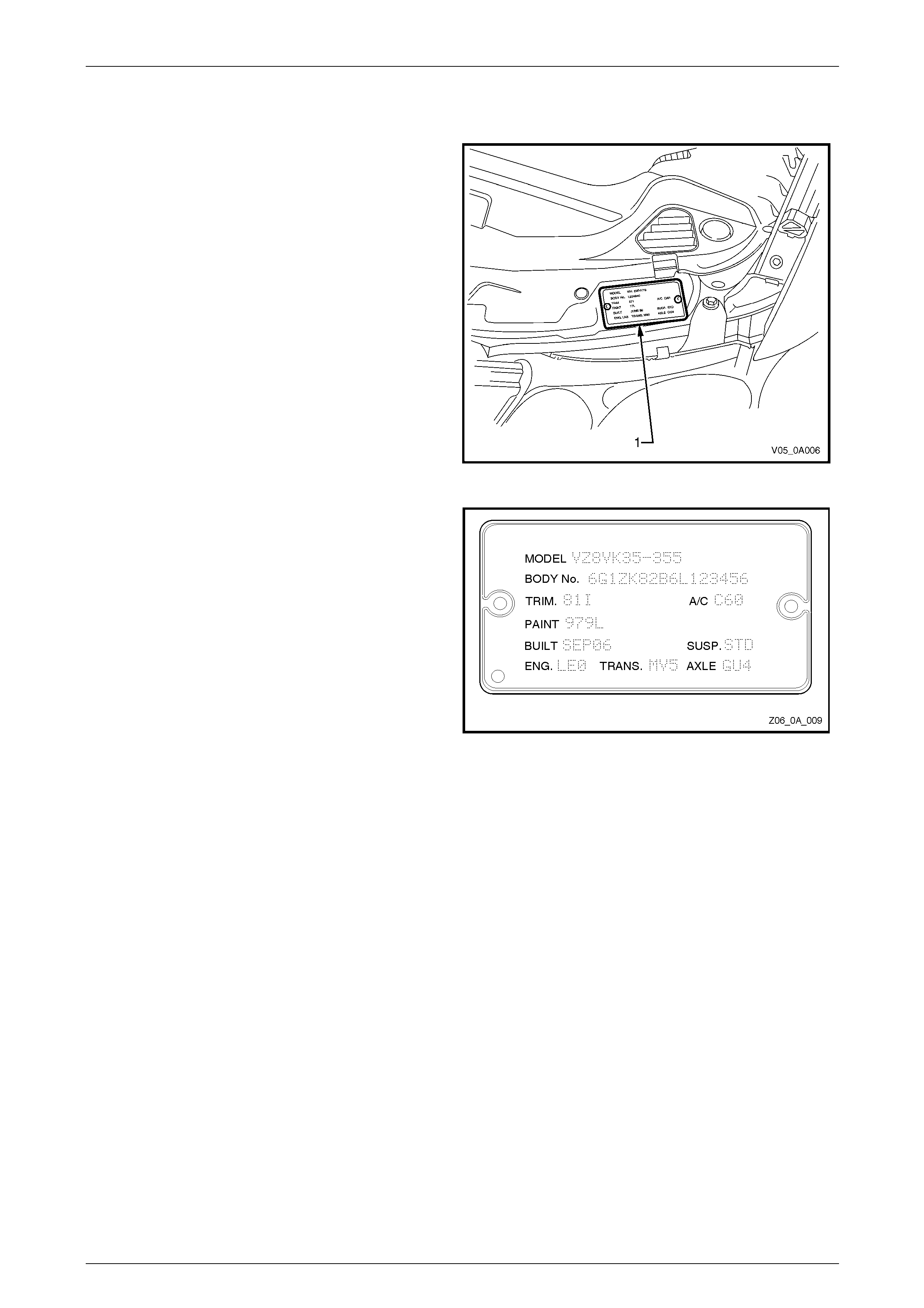
6.3 Body and Option Identification Plate
The Body and Option Identification Plate (1) is located on
the front panel assembly and is stamped with the following
information:
Model
Combination of letters and n umbers identifying the body
style, the mechanical pack and smart pack o ptions.
A listing of production and smart pack option numbers can
be found by referring to the latest spare parts information
for the applicable model.
Body No
Vehicle Identification Number (VIN).
Trim
Trim combination.
Paint
Exterior paint material and colour ide ntification.
Built
The date of manufacture by calendar month and year in
which the body shell and power train are conjoined and the
vehicle is driven or moved from the producti on line.
Susp
Suspension option code identif ication.
STD (FE1) identifies vehicles with standard suspension.
FE2 identifies vehicles with sport suspensio n.
FR1 identifies vehicles with country pack suspension.
Engine, Transmission and Axle.
Identification option codes for specific engine, transmission
and rear axle (final drive).
A/C
C60 identifies vehicles fitted with air conditioni ng.
C61 Identifies vehicles fitted with single zone automatic
climate control air conditioning.
CJ2 identifies vehicles fitted with dual zone automatic
climate control air conditioning.
Figure 0A – 6
Figure 0A – 7
Page 0A–25
General Information Page 0A–26
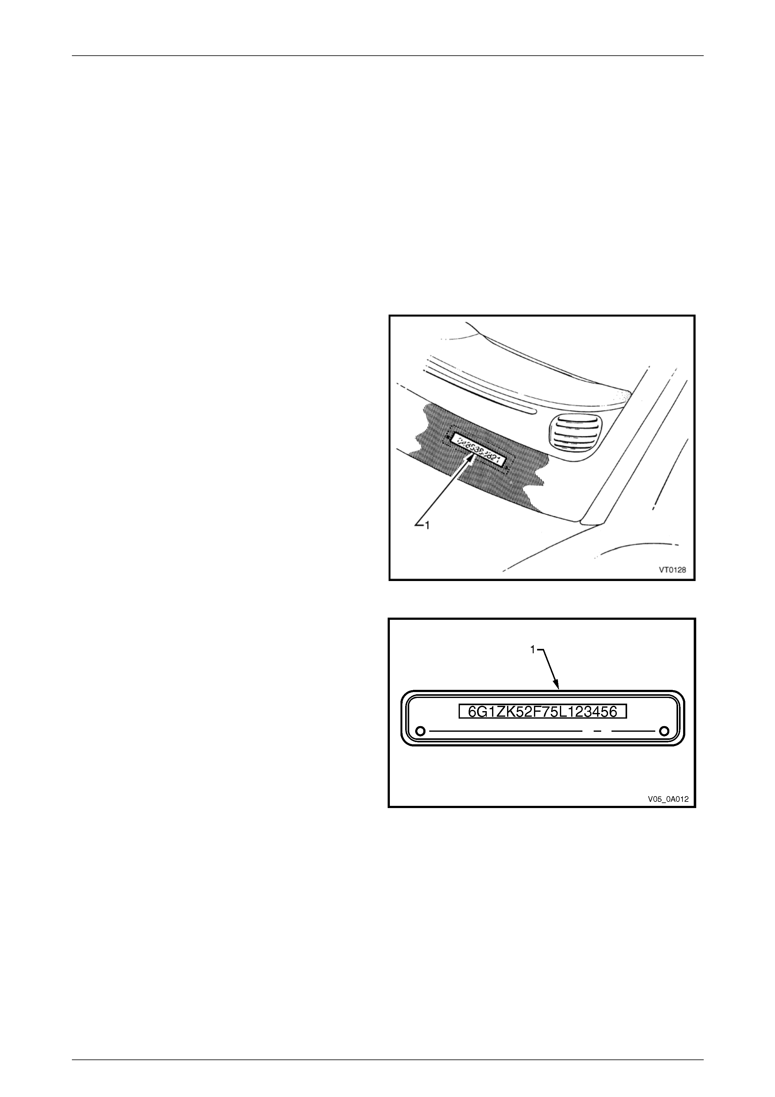
6.4 Vehicle Identification Number
The Vehicle Identification Numbering (VIN) system is based on the uniform Car Model D esignation System. This
identifies the vehicle in one coded series of characters.
The Vehicle Identification Number is positioned in the following l ocations.
1 VIN plate under the windscreen – viewed through the windscreen aperture.
2 Body and option identification plate – left-hand ‘B’ pillar.
3 Safety compliance plate – dash panel.
4 Stamping in the front floor panel under the front right-hand seat.
VIN Plate
The VIN Plate (1) is located under the windscreen and is
viewed through the windscreen aperture.
Figure 0A – 8
Figure 0A–10 sho ws the VIN plat e (1) that is located under
the windscreen aperture and is attached to the dash panel
assembly with unique rosette headed rivets.
Figure 0A – 9
Page 0A–26
General Information Page 0A–27
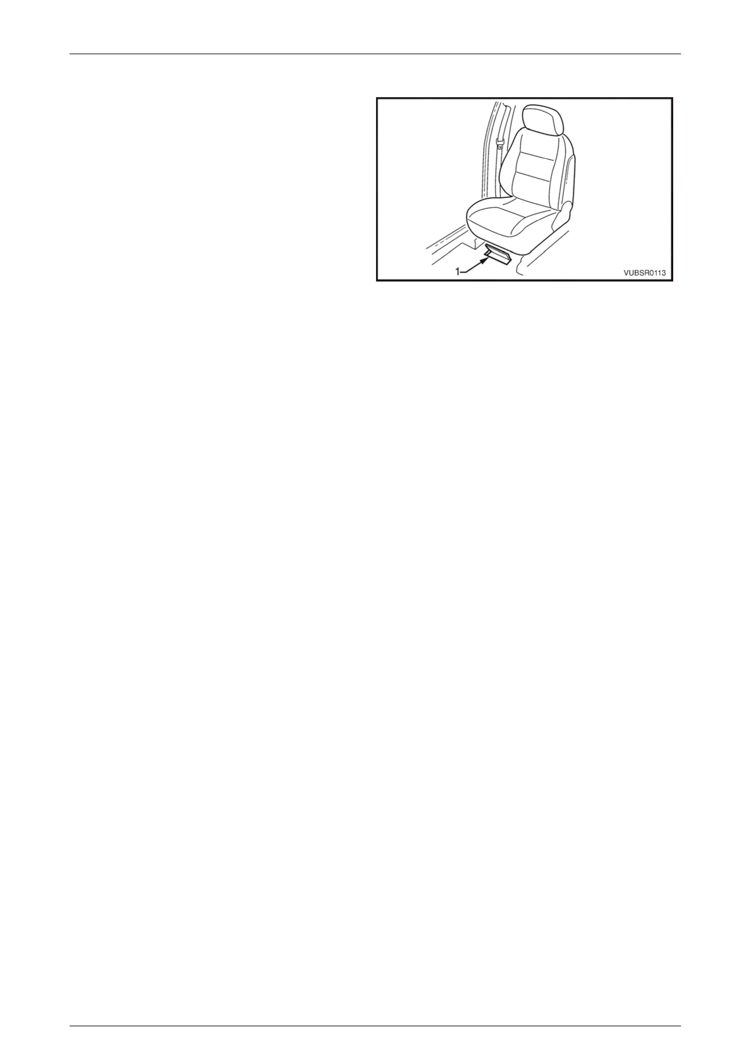
VIN Body Stamping
The VIN is stamped into the front floor panel under the
right-hand front seat. The VIN (1) is visible by lifting the
carpet flap.
NOTE
If the front floor panel assembly is to be
replaced, the VIN will be lost. Contact your loca l
Road Traffic Authority prior to replacing the
panel to obtain the correct procedure for
renumbering the vehic le.
NOTE
A replacement body shell assembly is stamped
during manufacture with a unique VIN that
identifies it as a replacement part.
NOTE
If an error is made to the VIN stamping during
manufacture, it is lined out so that it remains
legible and the correct number is stamped
underneath.
Figure 0A – 10
Page 0A–27
General Information Page 0A–28
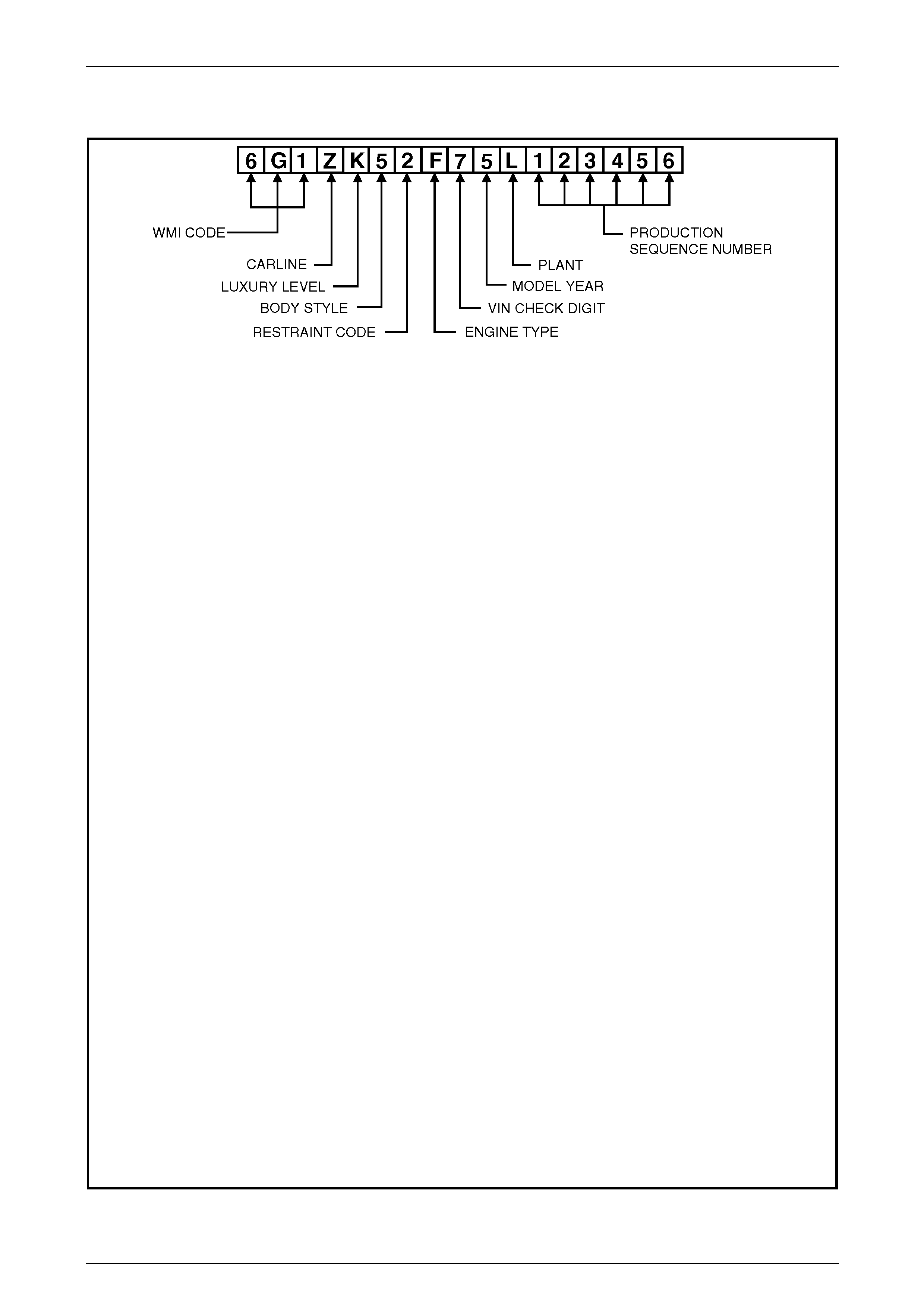
6.5 Vehicle Identification Numbering System
WMI CODE: 6 – Oceania
G – Australia
1 – Holden
CARLINE: Z – VZ series
LUXURY LEVEL: K – Level 1
L – Level 2
M – AWD
X – Level 3
BODY STYLE: 0 – 2 door regular cab (03)
3 – 4 door crew cab (43)
4 – 2 door utility (80)
5 – 4 door sedan (69)
8 – 5 door station wagon (35)
RESTRAINT CODE: 1 – Active (manual) seat belts
2 – Active (manual) seat belts with driver and passenger i nflatable restraint
system – frontal
3 – Active (manual) seat belts with driver inflatable restraint system – frontal
4 – Active (manual) seat belts with driver and passenger i nflatable restraint
system – frontal and side
ENGINE TYPE: B – 3.6 litre Alloytec V6 engine – Petrol
7 – 3.6 litre Alloytec High Output V6 engine (MY06)
H – 6.0 litre GEN IV V8 Engine
N – 3.6 litre Alloytec V6 Engine – LPG
VIN CHECK DIGIT: Calculated check digit
MODEL YEAR: 5 – 2005
6 – 2006
7 – 2007
PLANT: L – Adelaide (Elizabeth) South Australia
PRODUCTION SEQUENCE NUMBER: 123456 – Sequential Production Serial Number
NOTE
The production sequence number is sequentially all ocated to each vehicle, regardless of vehicle type.
Figure 0A – 11
Page 0A–28
General Information Page 0A–29
7 Major Component Serial
Numbers
7.1 Engine Serial Number
Alloytec V6
The engine serial number (1) is located on the machined
pad at the left rear of the cylinder block.
With the location change, it is now necessary to rais e the
vehicle to view the engine number.
The following is a breakdown of the engine serial number,
using the example of LE0*061870560*:
LE0 = Engine Broadcast Code (Regular Production
Option (RPO) code.
(LE0 = Alloytec V6
LY7 = Alloytec High Output – V6
LW2 = Alloytec V6 LPG)
* = Number Limiter (has no meaning)
06 = Build Year (‘06’ = 2006)
187 = Julia n Date (‘123’ = Built on day 123)
0560 = Four Digit D aily Build Sequence Number
* = Number Limiter (has no meaning)
Figure 6A1 – 1
To identify the engine and its application, there ma y be a sticker app lied to the engine front, that is used during
manufacture. Examples of these engine Broadcast Codes are:
B/Code Application
H7R LY7 Alloytec High Output Automatic RWD
H7S LY7 Alloytec High Output Manual RWD
H7Q LY7 Alloytec High Output Automatic AWD
HBL LE0 Alloytec Automatic RWD
HBM LE0 Alloytec Manual RWD
HNE LW2 Alloytec LPG Automatic RWD
Page 0A–29
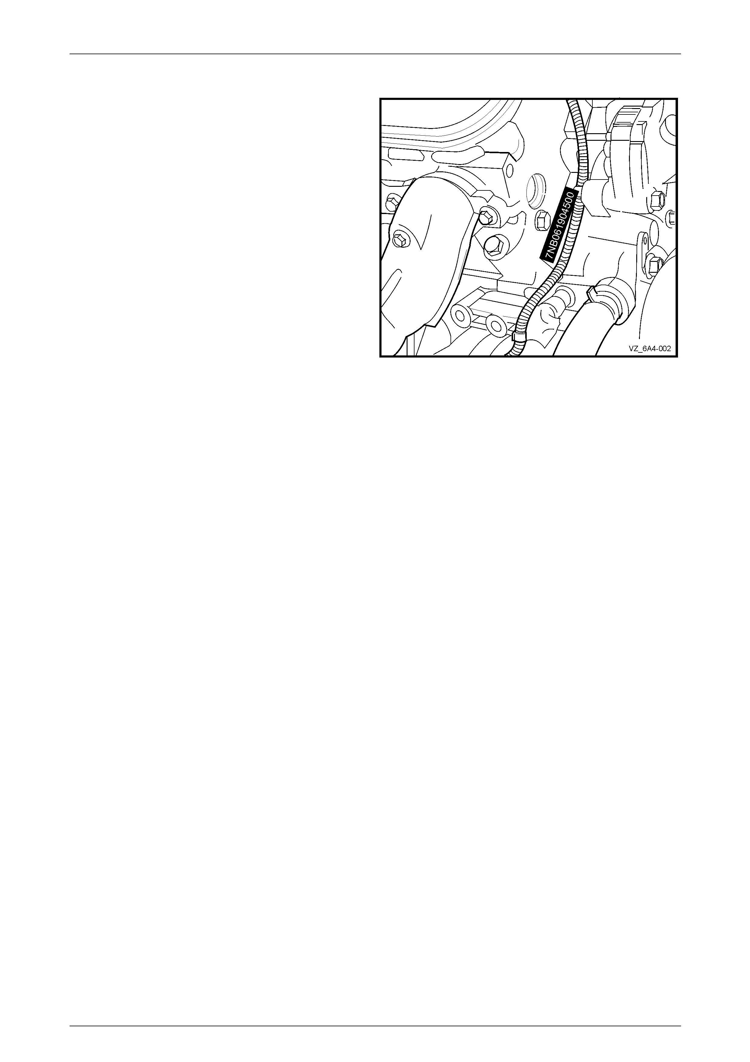
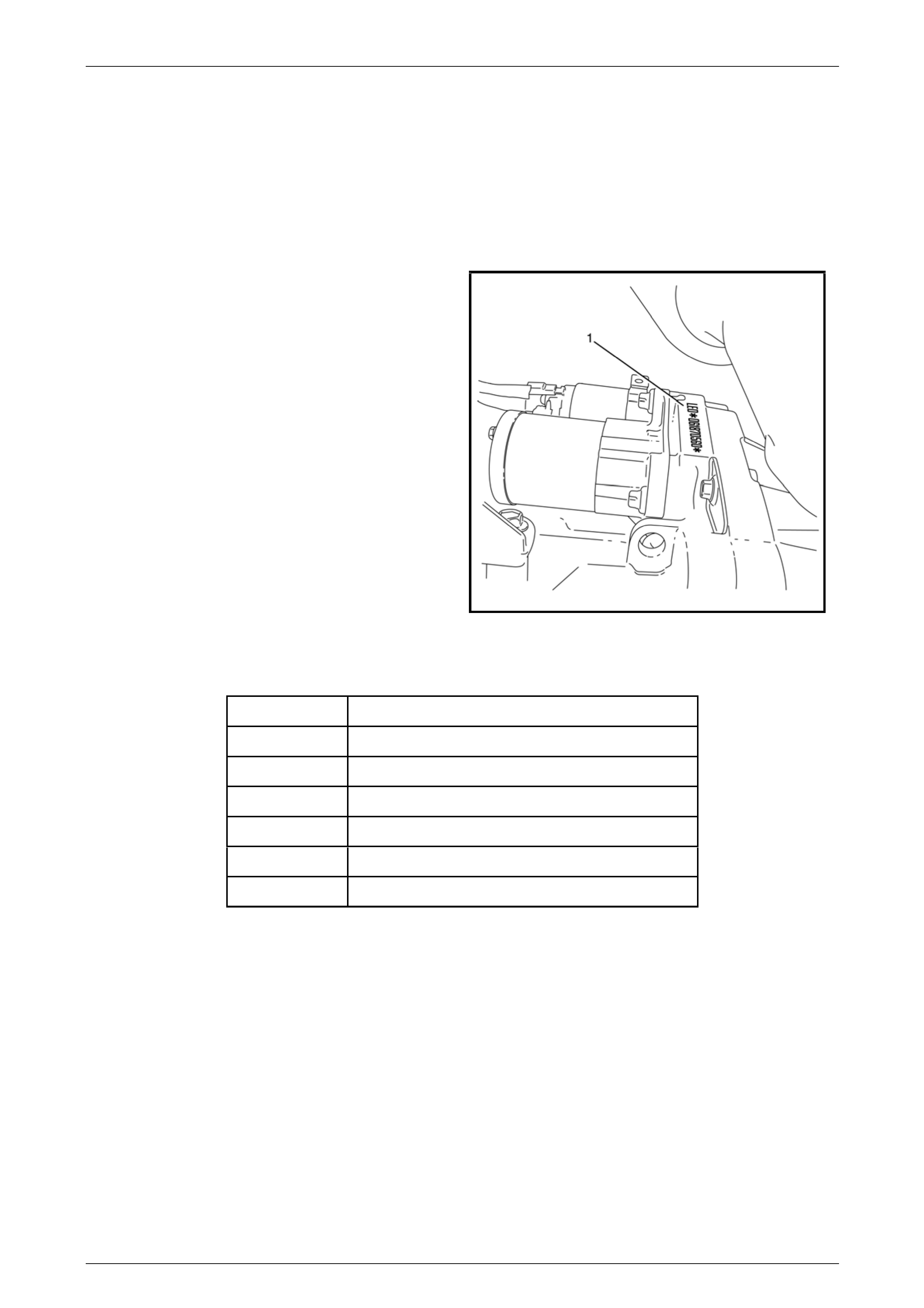
General Information Page 0A–30
GEN IV V8
The GEN IV V8 engine serial number is located on the
right-hand side at the front of the engine cylinder block and
is prefixed by the letters 7NB or CAK.
The following is a breakdown of the engine numbering
system using 7NB061904500 as an example:
Engine No.
Example Code Explanation
7NB Engine: GEN IV V8 Automatic
CAK Engine: GEN IV V8 Manual
06 Build Year (‘06’ = 2006)
190 Julian Date (‘190’ = built on day 190)
4500 Four Digit Build Sequenc e Number
Figure 0A – 12
Page 0A–30
General Information Page 0A–31
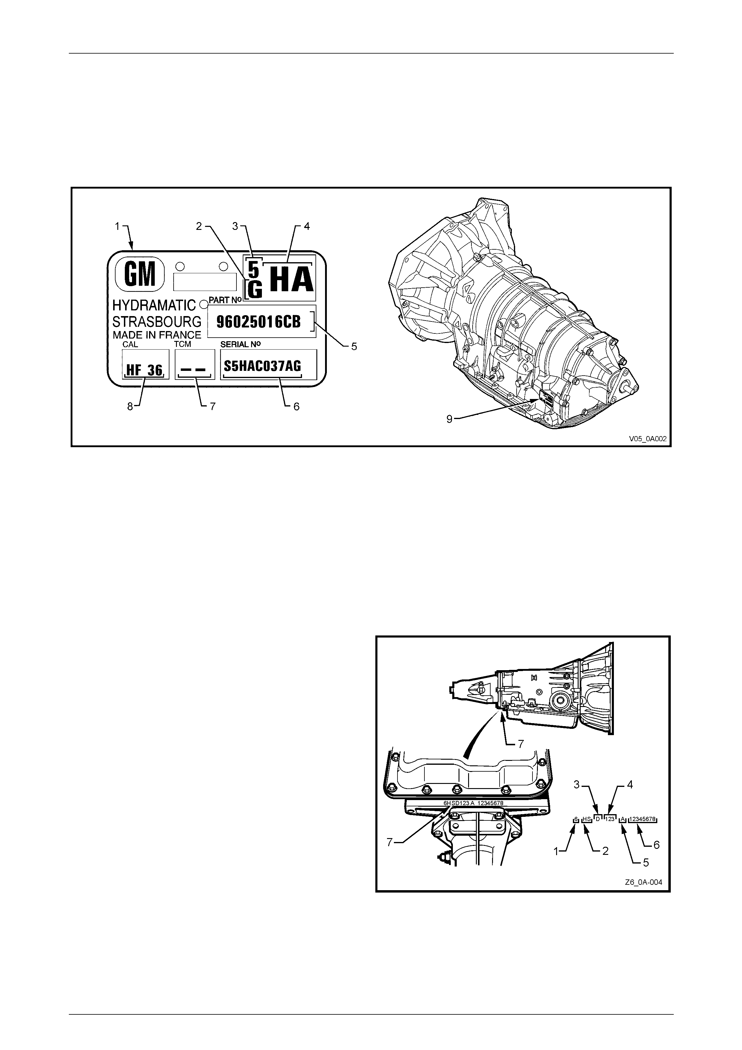
7.2 Transmission Serial Number
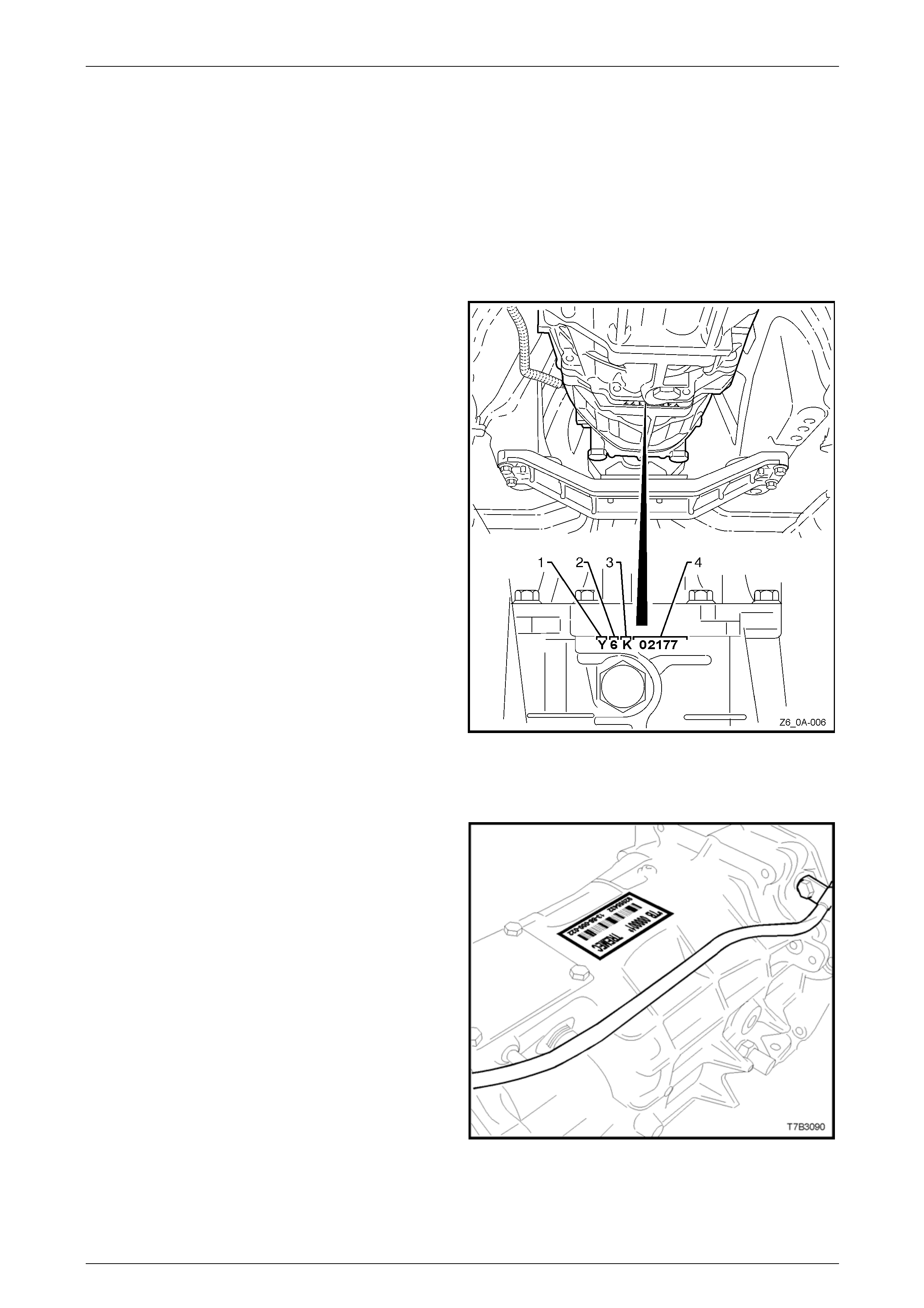
Automatic Transmission – 5-speed 5L40E, RWD and AWD
A transmission identification p late (item 1 in Figure 0A – 13) is located on the left hand rear side of the transmission
case.
Figure 0A – 13
Legend
1 Production or Service New Identification Plate
2 Transmission Family
3 Model Year
4 Alpha Code: HA = RWD 3.6 L V6, HB = AWD 3.6 L V6
5 Part Number
6 Serial Number
7 Manufacture Date
8 Calibration Code
9 I.D. Tag Location
Automatic Transmission – 4-speed 4L60E and 4L65E, RWD
The automatic transmission serial number is stamped into a
machined surface at the rear und erside of the transmission
centre case (7).
Legend
1 Model Year (‘'6' = 2006, ‘7 ’= 2007
2 Model:
HS – 3.6 litre Alloytec MY06
HB – 6.0 litre GEN IV V8 L98
3 Transmission Model Identifier:
D – 4L60-E / 4L65-E
4 Julian Date (or day of year)
5 Shift Built (A, B, J = first shift C, H, W = second shift)
6 Individual Transmission Serial Number
7 Transmission Identification Number Location
Figure 0A – 14
Page 0A–31
General Information Page 0A–32
Automatic Transmission – 4-speed 4L60E and 4L65E, AWD
The automatic transmission serial number is stamped into a
machined surface located at the rear u nd erside of the
transmission centre case, between the rear ext ension
housing and the transmission fluid pan.
Legend
1 Model Year (‘6' = 2006, ‘7’ = 2007)
2 Model: AWD Wagon
HT – 3.6 litre Alloytec V6 4L60E (with ISS)
HC – 6.0 litre GEN IV V8 4L65E (with ISS Crew Cab Only)
3 Transmission Model Identifier:
D – 4L60-E / 4L65-E
4 Julian Date (or day of year)
5 Shift Built (A, B, J = first shift C, H, W = second shift)
6 Individual Transmission Serial Number
Figure 6B1 – 1
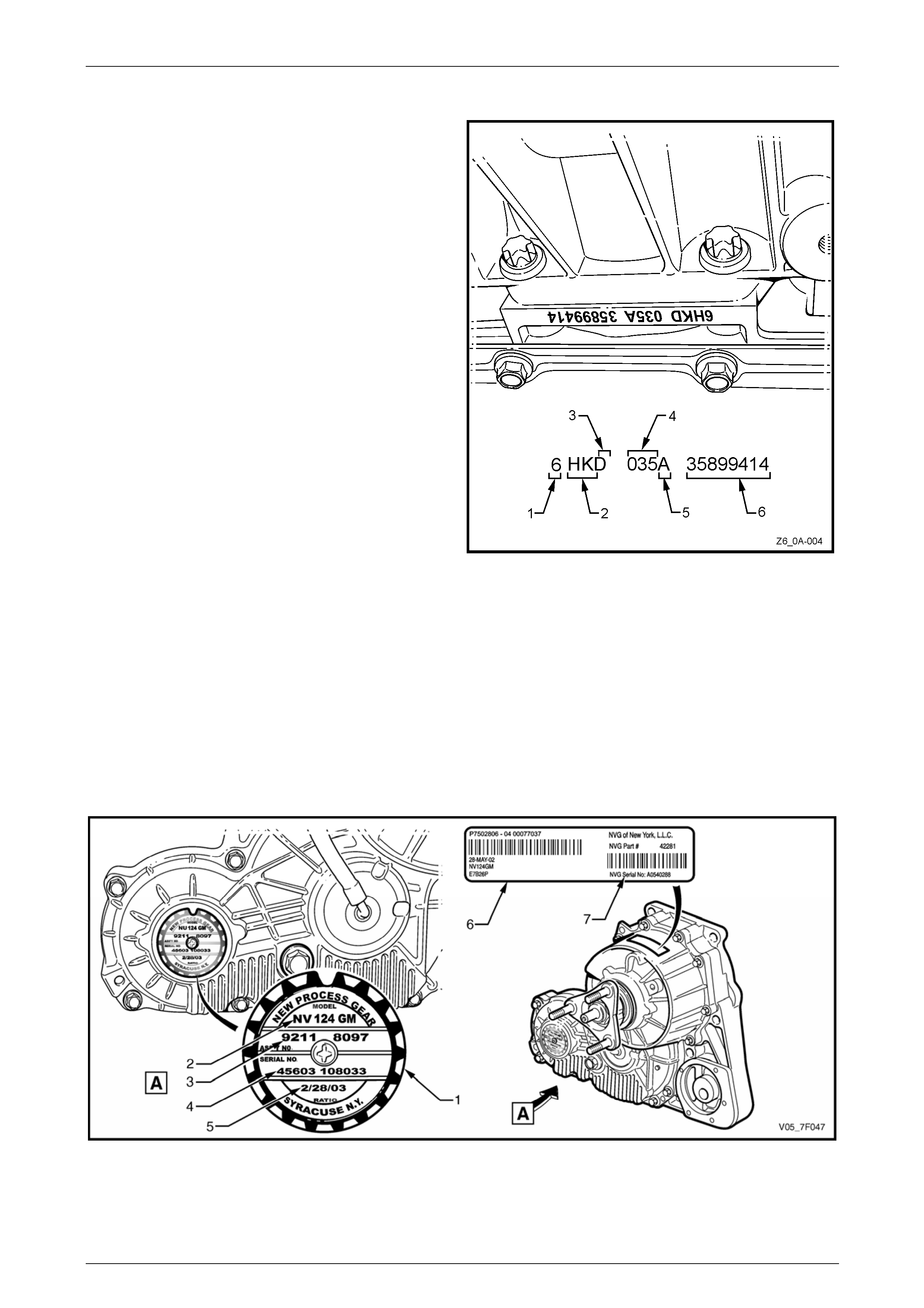
Transfer Case Assembly
An identification tag (1) is attached to the left side of the transfer case rear housing in the location shown.
The identification tag provides the following informati on that may be required for the procurement of correct service parts:
• Model number (2)
• Assembly part number (3)
• Manufacturer part number (4)
• Build date (5)
Figure 0A – 15
Page 0A–32
General Information Page 0A–33
NOTE
Although marked as serial nu mber, the number at
location (4) on the identification tag is the
manufacturer part number
If the identification tag is removed or is dislodged during service operations, it must be kept with the assembly.
An identification label (6) is located at the top of the transfer case rear housing in the loc ation shown and provides similar
information as the identification tag as well as the transfer case serial num ber (7) as shown.
Manual Transmission – Aisin AY6 6-speed
The Aisin AY6 6-speed manual transmissi on (P/O MV5)
serial number is stamped into the und erside of the middle
case.
Legend
1 Transmission Model Identifier (‘Y’ = AY6)
2 Model Year (‘5’ = 2005, ‘6’ = 2006, etc.)
3 Month of Production (‘A’ = January, ‘B’ = February, etc.)
4 Five Digit Monthly Sequence number.
Figure 0A – 16
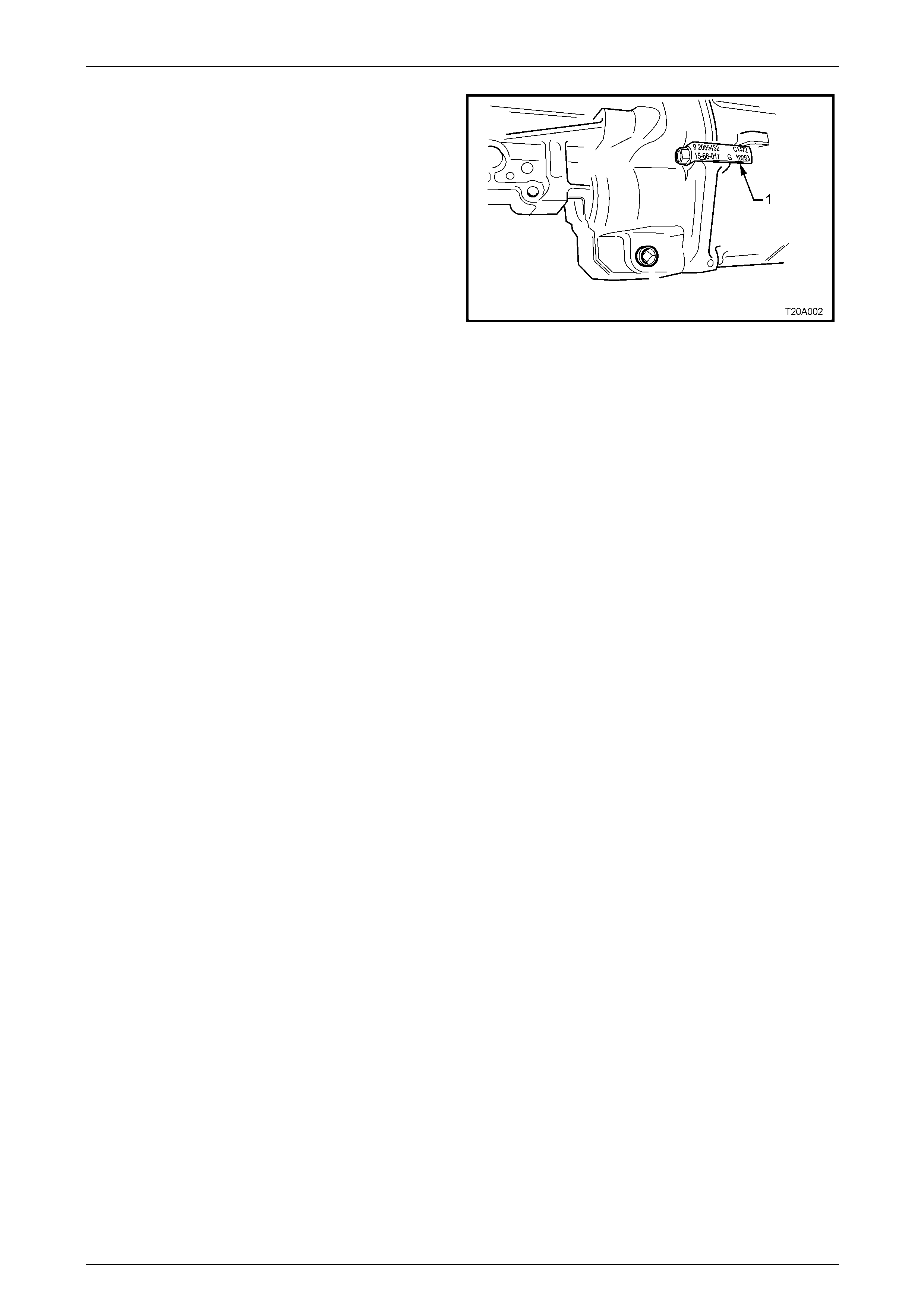
Manual Transmission – Tremec T56 6-speed
The Borg-Warner (Tremec) T56 6-sp eed manual
transmission serial number is located on a self-adhesive
decal attached to the top of the transmission case.
This number provides coded information that could be
significant to parts interpretation and should be referred to
when ordering replacement parts.
Figure 0A – 17
Page 0A–33
General Information Page 0A–34
An identification tag (1) is also attached to the transmission
under an extension housi ng bolt, on the right-hand side.
Figure 0A – 18
Page 0A–34
General Information Page 0A–35
7.3 Final Drive Assembly Serial Number
Front Final Drive – AWD
An identification label (1) is adhered to the front final drive
assembly on the left side towards the rear of the housing.
The label contains the Holden Part Number for the
assembly, the serial number of the assembly as well as
the final drive ratio.
The front final drive assembly is attached to the left-hand
side of the engine oil pan.
Figure 0A – 19
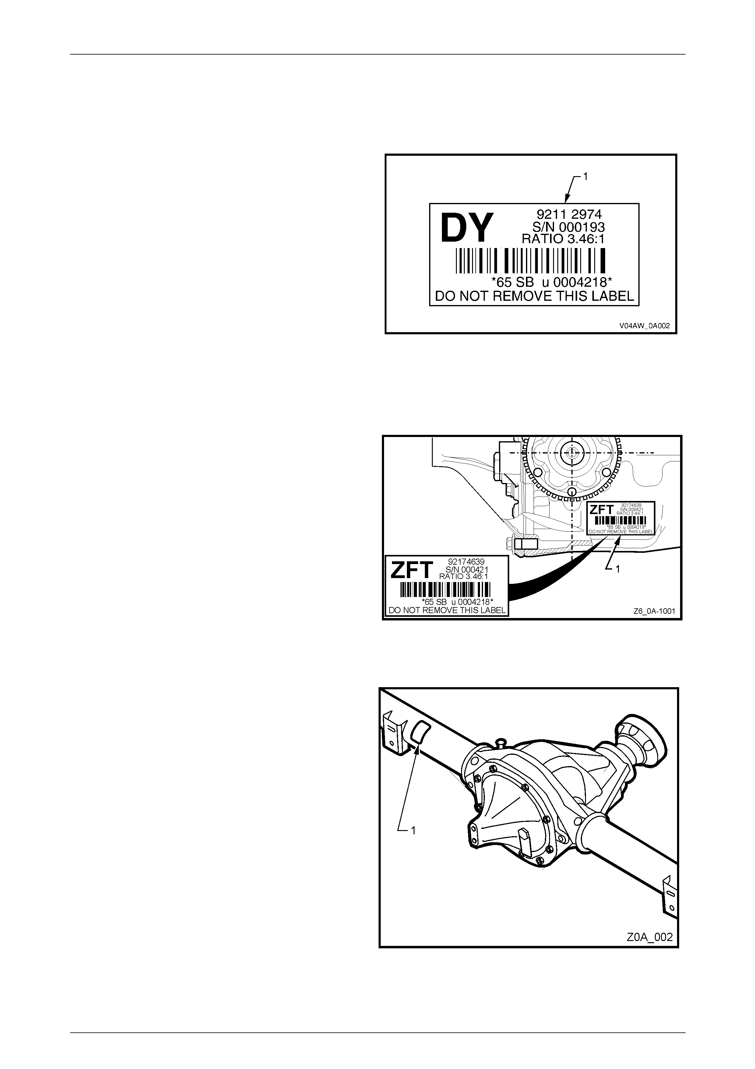
Rear Final Drive
IRS Final Drive
An identification tag is adhered to the final drive assembly to
the right-hand side of the carrier housing. The tag carries
the part number for the assembly, the final drive ratio and
the serial number of the assembly.
Figure 0A – 20
Beam Axle Final Drive
An identification tag is adhered to the left side of the rear
axle tube (1).
The tag carries the necessary identification information to
positively identify the axle applicatio n
Figure 0A – 21
Page 0A–35