
Body Page 1A1–1
Page 1A1–1
Section 1A1
Body
ATTENTION
Before performing any service operation or other procedure described in this Section, refer to Section 00
Warnings, Cautions and Notes for correct w orkshop practices wi th regard to safety and/or property damage.
1 General Information...............................................................................................................................4
2 Body Leak Diagnosis.............................................................................................................................5
3 Body Lubrication....................................................................................................................................6
4 Lock Cylinders and Keys.......................................................................................................................7
5 Plastic Components...............................................................................................................................8
5.1 Common to all Vehicles ........................................................................................................................................ 8
Exterior............................................................................................................................................................... 8
Interior.............................................................................................................................................................. 11
5.2 Sedan Unique....................................................................................................................................................... 13
Exterior............................................................................................................................................................. 13
Interior.............................................................................................................................................................. 13
5.3 Wagon Unique...................................................................................................................................................... 14
Exterior............................................................................................................................................................. 14
Interior.............................................................................................................................................................. 14
5.4 Utility Unique........................................................................................................................................................ 16
Exterior............................................................................................................................................................. 16
5.5 Regular Cab Unique............................................................................................................................................. 17
Exterior............................................................................................................................................................. 17
5.6 Crew Cab Unique................................................................................................................................................. 19
Exterior............................................................................................................................................................. 19
5.7 Coupe Unique....................................................................................................................................................... 21
Exterior............................................................................................................................................................. 21
5.8 AWD Wagon Unique ............................................................................................................................................ 22
Exterior............................................................................................................................................................. 22
5.9 Plastic Types........................................................................................................................................................ 23
6 Wheelhouse Liners ..............................................................................................................................24
6.1 Front Wheelhouse Liner (except AWD).............................................................................................................. 24
Remove................................................................................................................................................................. 24
Reinstall................................................................................................................................................................ 25
6.2 Front Wheelhouse Liner, AWD ........................................................................................................................... 26
Remove................................................................................................................................................................. 26
Reinstall................................................................................................................................................................ 27
6.3 Rear Wheelhouse Liner, Sedan and Wagon...................................................................................................... 28
Remove................................................................................................................................................................. 28
Reinstall................................................................................................................................................................ 29
Techline

Body Page 1A1–2
Page 1A1–2
6.4 Rear Wheelhouse Liner, Utility........................................................................................................................... 30
Remove................................................................................................................................................................. 30
Reinstall................................................................................................................................................................ 30
6.5 Rear Wheelhouse Liner, Crew Cab..................................................................................................................... 31
Remove................................................................................................................................................................. 31
Reinstall................................................................................................................................................................ 31
6.6 Rear Wheelhouse Liner, Coupe.......................................................................................................................... 32
Remove................................................................................................................................................................. 32
Reinstall................................................................................................................................................................ 32
6.7 Rear Wheelhouse Liner, AWD Wagon................................................................................................................ 33
Remove................................................................................................................................................................. 33
Reinstall................................................................................................................................................................ 34
6.8 Rear Wheelhouse Liner, AWD Crew Cab........................................................................................................... 35
Remove................................................................................................................................................................. 35
Reinstall................................................................................................................................................................ 35
6.9 Rear Mudflap, Crew Cab...................................................................................................................................... 36
Remove................................................................................................................................................................. 36
Reinstall................................................................................................................................................................ 36
7 Fuel Filler Door Assemblies and Cable Assemblies ........................................................................37
7.1 Fuel Filler Door Assembly, Sedan...................................................................................................................... 37
Remove................................................................................................................................................................. 37
Disassemble......................................................................................................................................................... 38
Lock Spring ...................................................................................................................................................... 38
Moulding........................................................................................................................................................... 38
Reassemble.......................................................................................................................................................... 38
Lock Spring ...................................................................................................................................................... 38
Moulding........................................................................................................................................................... 38
Reinstall................................................................................................................................................................ 39
7.2 Fuel Filler Door Assembly, Wagon..................................................................................................................... 40
Remove................................................................................................................................................................. 40
Disassemble......................................................................................................................................................... 40
Reassemble.......................................................................................................................................................... 41
Reinstall................................................................................................................................................................ 41
7.3 Fuel Filler Door Assembly, Utility and Crew Cab.............................................................................................. 42
Remove................................................................................................................................................................. 42
Reinstall................................................................................................................................................................ 43
7.4 Fuel Filler Door Assembly, Coupe...................................................................................................................... 44
Remove................................................................................................................................................................. 44
Disassemble......................................................................................................................................................... 44
Lock Spring ...................................................................................................................................................... 44
Moulding........................................................................................................................................................... 44
Reassemble.......................................................................................................................................................... 45
Lock Spring ...................................................................................................................................................... 45
Moulding........................................................................................................................................................... 45
Reinstall................................................................................................................................................................ 45
7.5 Fuel Filler Door Lock Cable Assembly, Sedan.................................................................................................. 46
Remove................................................................................................................................................................. 46
Reinstall................................................................................................................................................................ 47
7.6 Fuel Filler Door Lock Cable Assembly, Wagon................................................................................................. 48
Remove................................................................................................................................................................. 48
Reinstall................................................................................................................................................................ 49
7.7 Fuel Filler Door Lock Cable Assembly, Coupe.................................................................................................. 50
Remove................................................................................................................................................................. 50
Reinstall................................................................................................................................................................ 51

Body Page 1A1–3
Page 1A1–3
8 Drain Tubes, Utility...............................................................................................................................52
8.1 Rear Floor Panel Drain Tube............................................................................................................................... 52
Remove................................................................................................................................................................. 52
Reinstall................................................................................................................................................................ 52
8.2 Rear Window Panel Drain Tube Assembly........................................................................................................ 53
Remove................................................................................................................................................................. 53
Reinstall................................................................................................................................................................ 53
9 Body Braces..........................................................................................................................................54
9.1 Front Suspension Strut Brace............................................................................................................................ 54
Remove................................................................................................................................................................. 54
Reinstall................................................................................................................................................................ 54
9.2 Rear Underbody Air Deflector, Coupe................................................................................................................ 55
Remove................................................................................................................................................................. 55
Reinstall................................................................................................................................................................ 56
9.3 Rear Underbody Brace, Coupe........................................................................................................................... 57
Remove................................................................................................................................................................. 57
Reinstall................................................................................................................................................................ 57
9.4 Back Body Opening Frame Assembly, Coupe.................................................................................................. 58
Remove................................................................................................................................................................. 58
Reinstall................................................................................................................................................................ 59
10 Inner Rear Body Panel.........................................................................................................................60
10.1 Inner Rear Body Panel, Regular Cab.................................................................................................................. 60
Remove................................................................................................................................................................. 60
Reinstall................................................................................................................................................................ 61
10.2 Inner Rear Body Panel, Crew Cab...................................................................................................................... 62
Remove................................................................................................................................................................. 62
Reinstall................................................................................................................................................................ 63
11 Torque Wrench Specifications ...........................................................................................................64

Body Page 1A1–4
Page 1A1–4
1 General Information
This Section contains the service procedures for body components not specific to other Sections of this Service
Information Package such as:
• Body Leak Diagnosis
• Body Lubrication
• Lock Cylinders and Keys
• Wheelhouse Liners
• Fuel Filler Doors and Cables
• Drain Tubes, Utility
• Body Braces
• Inner rear body panel, Regular Cab and Crew Cab

Body Page 1A1–5
Page 1A1–5
2 Body Leak Diagnosis
Diagnosis of body leaks can be complicated as the appearance of dust or water at one point within the vehicle can be
caused by seepage through any one, or more possible locations. For example the cause of wet front floor coverings
could be either water entering past the door weatherstrip, through the door inner panel, between the windshield and its
adhesive compound or through any one of the joins in the body structure. Therefore, the point or points of water or dust
entry must be established before effective resealing can be carried out.
Water leak diagnosis is usually performed by having an assistant spray a gentle fan of water from a hose around the
suspected area until the leak can be generated. Removal of various trim components from the inside may be required to
determine point of entry. Narrowing down the water spray to the point of greatest water flow will assist in determining the
point of entry.
Dust entry quite often requires the following of signs of dust entry around seals or vent inlets or outlets, etc.
Once detected, repair the area by replacing faulty components or applying the correct sealer or adhesive.

Body Page 1A1–6
Page 1A1–6
3 Body Lubrication
Careless or excessive application of body
lubricants can cause staining of the paint
finish and interior trim, damage clothing, and
become a trap for dirt. Use lubricants
sparingly and remove any excess
immediately.
The moving mechanical parts of the body which have metal to metal contact are lubricated at assembly of the vehicle.
Operating conditions, whether normal or otherwise, determine the effective life of the lubricant and for this reason
lubrication in service is important. Equally important is the type of lubricant to be used.
Listed below are the body lubrication points. For the recommended lubricants and maintenance schedule refer to
Section 0B Lubrication and Service.
Parts Readily Accessible:
• Hood Pilot Pin Assembly
• Hood Lock Assembly
• Hood Hinges Door Hinge Pins
• Door Check Assemblies
• Door Lock Cylinder
• Door Lock Striker
• Door Lock Assembly Fork
• Rear Compartment Lid Hinge
• Rear Compartment Lid Latch
• Liftgate or Endgate Hinge
• Liftgate Lock Cylinder Liftgate or Endgate Latch
• Ignition Lock Cylinder
• Instrument Panel Compartment Lock Cylinder
Parts Concealed Requirin g Disassembly:
• Door Window Regulator
• Door Window Guides and Runners
• Door Lock Mechanism
• Rear Compartment Lid Lock Mechanism
• Liftgate or Endgate Lock Mechanism
• Front Seat Adjuster
• Driver’s Seat Height Adjuster
Body Page 1A1–7
Page 1A1–7
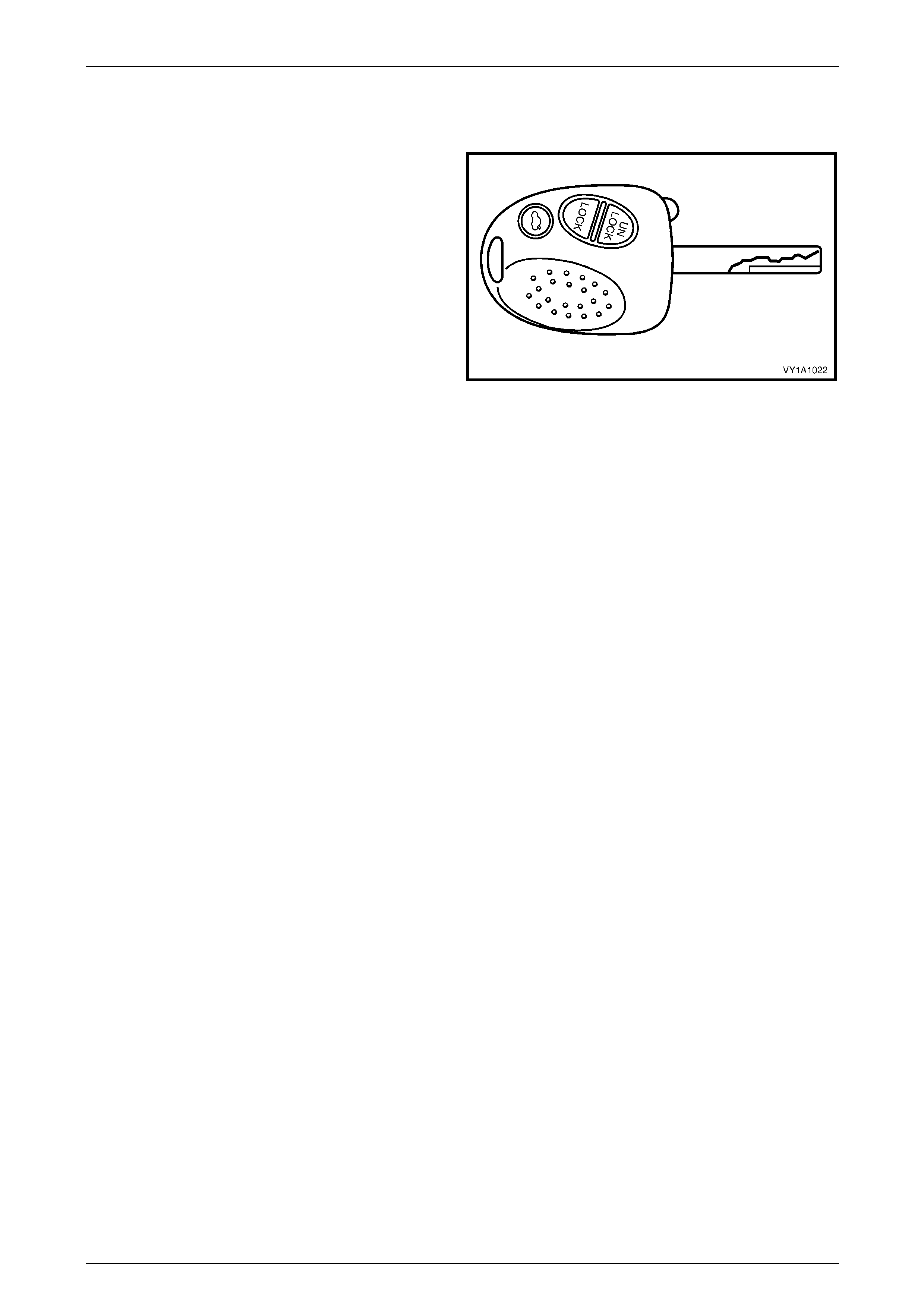
4 Lock Cylinders and Keys
A common-key locking system operates the door and
ignition locks. A unique key is provided for the instrument
panel compartment.
All vehicles have a lock cylinder on the driver’s door handle
assembly. Wagon models also have a lock cylinder in the
liftgate handle push button assembly.
The door and ignition key features a remote function that
activates the central locking system and anti-theft system
from a distance of several metres. Inserting the key into the
lock cylinder incorporated in the driver’s door handle also
performs this same function.
A separate button on the remote key for Sedan and Coupe
models opens the rear compartment lid. On AWD Wagon
models this button opens the liftgate window. The liftgate
lock for Wagon models is operated as part of the central
locking system.
Figure 1A1 – 1
NOTE
The key identification number is located on the
vehicle security card, stored with the owner’s
manual. It is essential that this key number be
available should a replacement key be required.
In the event of a key replacement, the Body Control Module (BCM) will require reprogramming to accept the new key,
refer to Section 12J Body Control Module for reprogramming and further information regarding the anti-theft system.
For service procedures for the lock cylinders refer to:
All vehicles:
• Driver’s door lock cylinder, refer to Section 1A5 Front and Rear Door Assemblies.
• Ignition lock cylinder, refer to Section 9 Steering.
Wagon vehicles only:
• Liftgate handle lock cylinder, refer to Section 1A4 Hood, Rear Compartment Lid, Liftgate and Endgate.
Body Page 1A1–8
Page 1A1–8
5 Plastic Components
Plastic components are used throughout the vehicle. The following table is included to assist with the identification and
plastic composition of common components. Refer to 5.9 Plastic Types for a description and handling notes for each
different plastic composition. The plastic components used can also vary from vehicle to vehicle.
NOTE
Most components are also identified with the
material code in an inconspicuous location.
5.1 Common to all Vehicles
Exterior
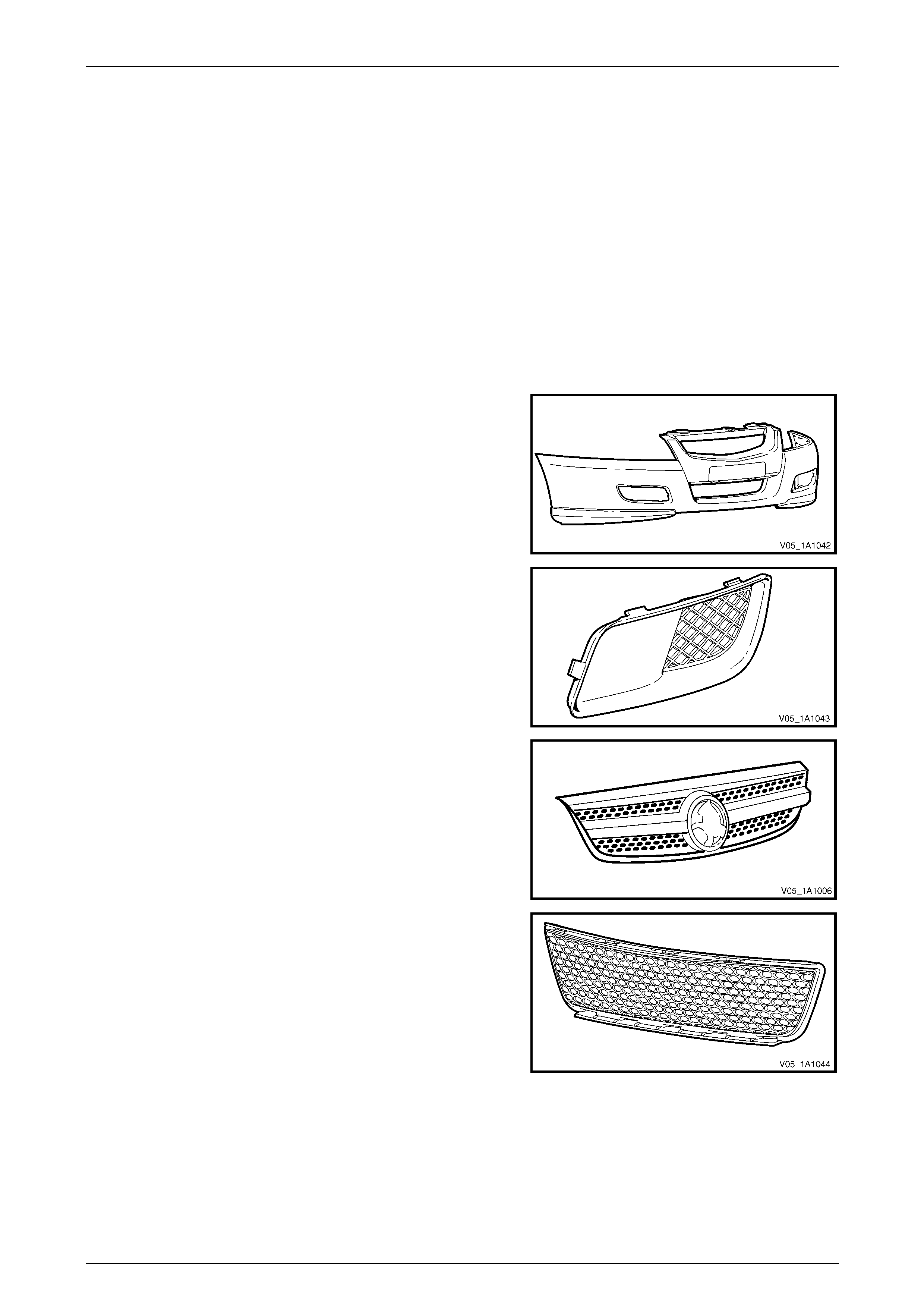
Front Bumper Fascia
Material: PP
Front Bumper Access Hole Cover, Level 1
Material: PP
Radiator Grille Assembly
Material: Painted – ABS, Unpainted – ASA
Lower Radiator Grille
Material: PP
Body Page 1A1–9
Page 1A1–9
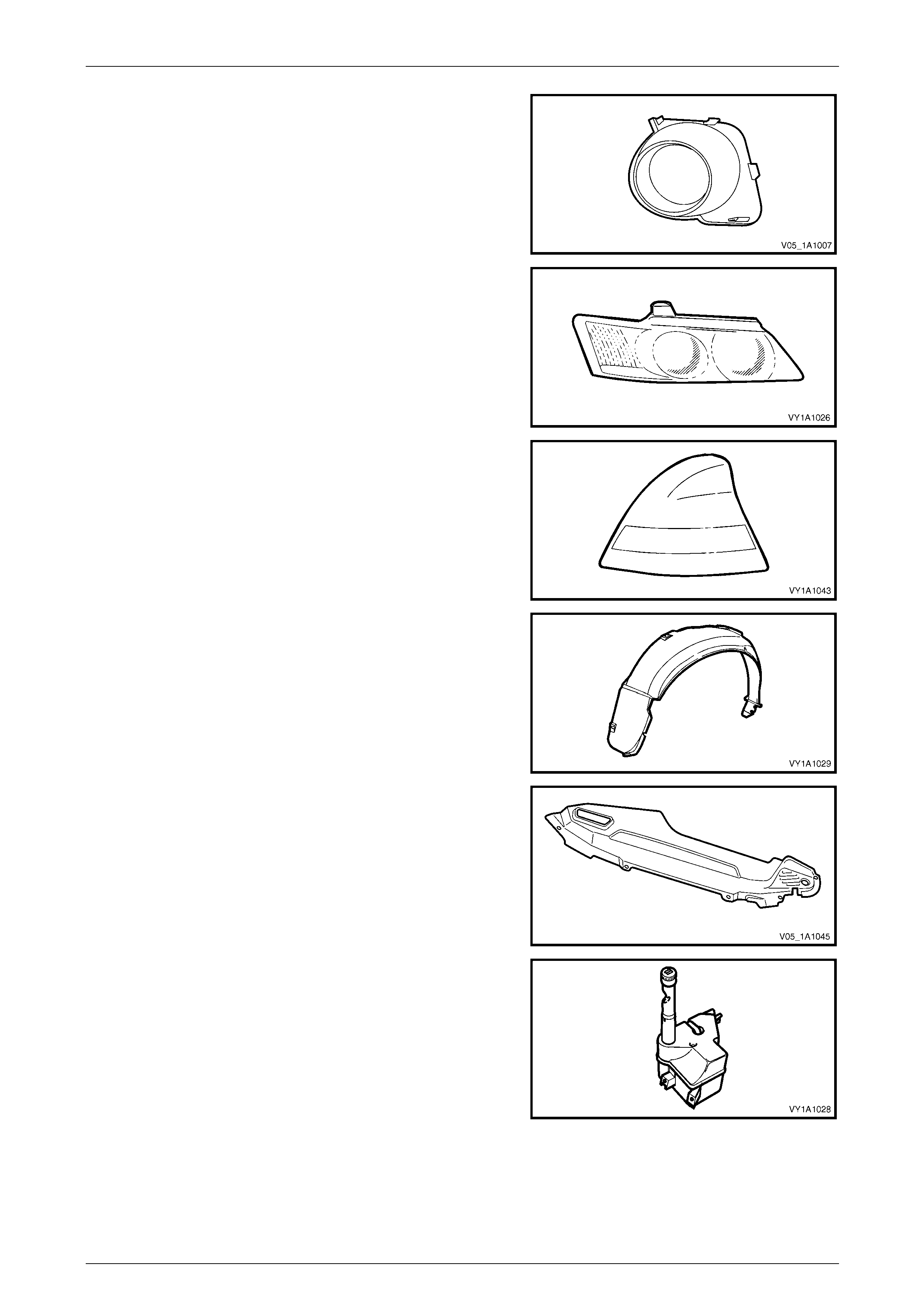
Front Fog lamp Bezel Assembly
Material: Inner – ASA, Outer – ABS
Headlamp Assembly
Material: Lens – PC, Housing – PP/T30
Tail lamp Assembly
Material: Lens - PMMA, Housing – ABS
Wheelhouse Liner
Material: PP
Upper Radiator Air Baffle
Material: PP
Radiator Overflow Reservoir Assembly
Material: PP
Body Page 1A1–10
Page 1A1–10
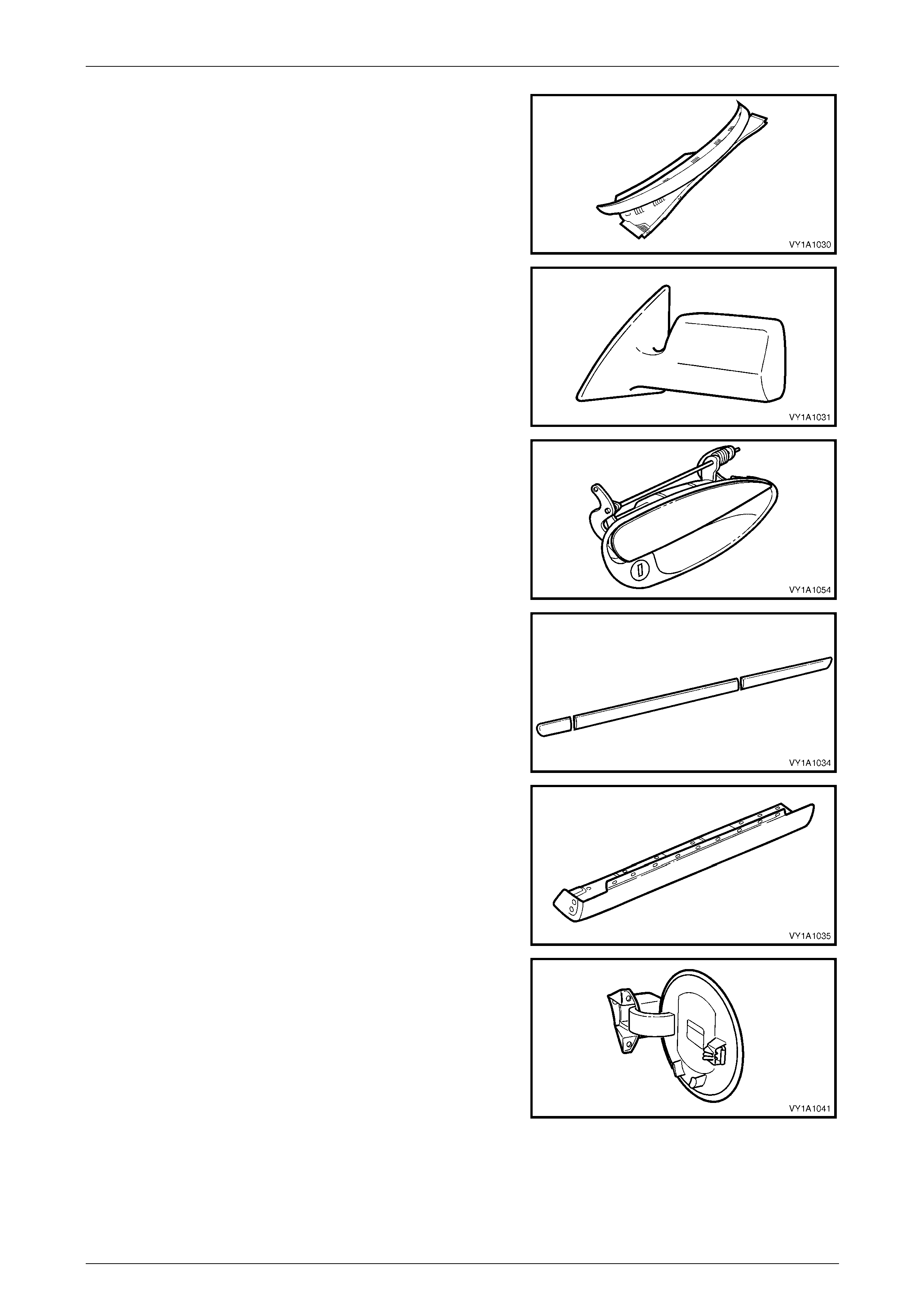
Plenum Cover Assembly
Material: PP
Outside Rear View Mirror Housing
Material: Painted – ABS, Unpainted - ASA / PC
Door Handle Assembly
Material: PA 66
Body Side Moulding
Material: ASA
Rocker Panel Moulding Assembly
Material: PP
Fuel Filler Door
Material: PPE / PA
Body Page 1A1–11
Page 1A1–11
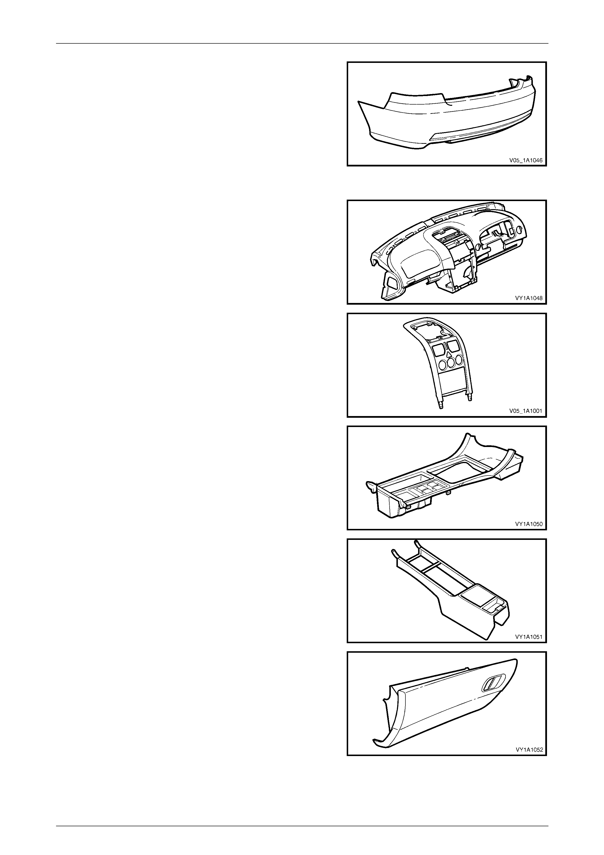
Rear Bumper Fascia
Material: PP
Interior
Instrument Panel Pad Assembly
Material: Carrier – ABS, Pad Substrate – PP, Foam – PVC, Skin - ABS
Instrument Panel Centre Trim Assembly
Material: PC/ABS
Floor Console Cover Assembly
Material: PC/ABS
Front Floor Console
Material: PP
Instrument Panel Compartment
Material: PP
Body Page 1A1–12
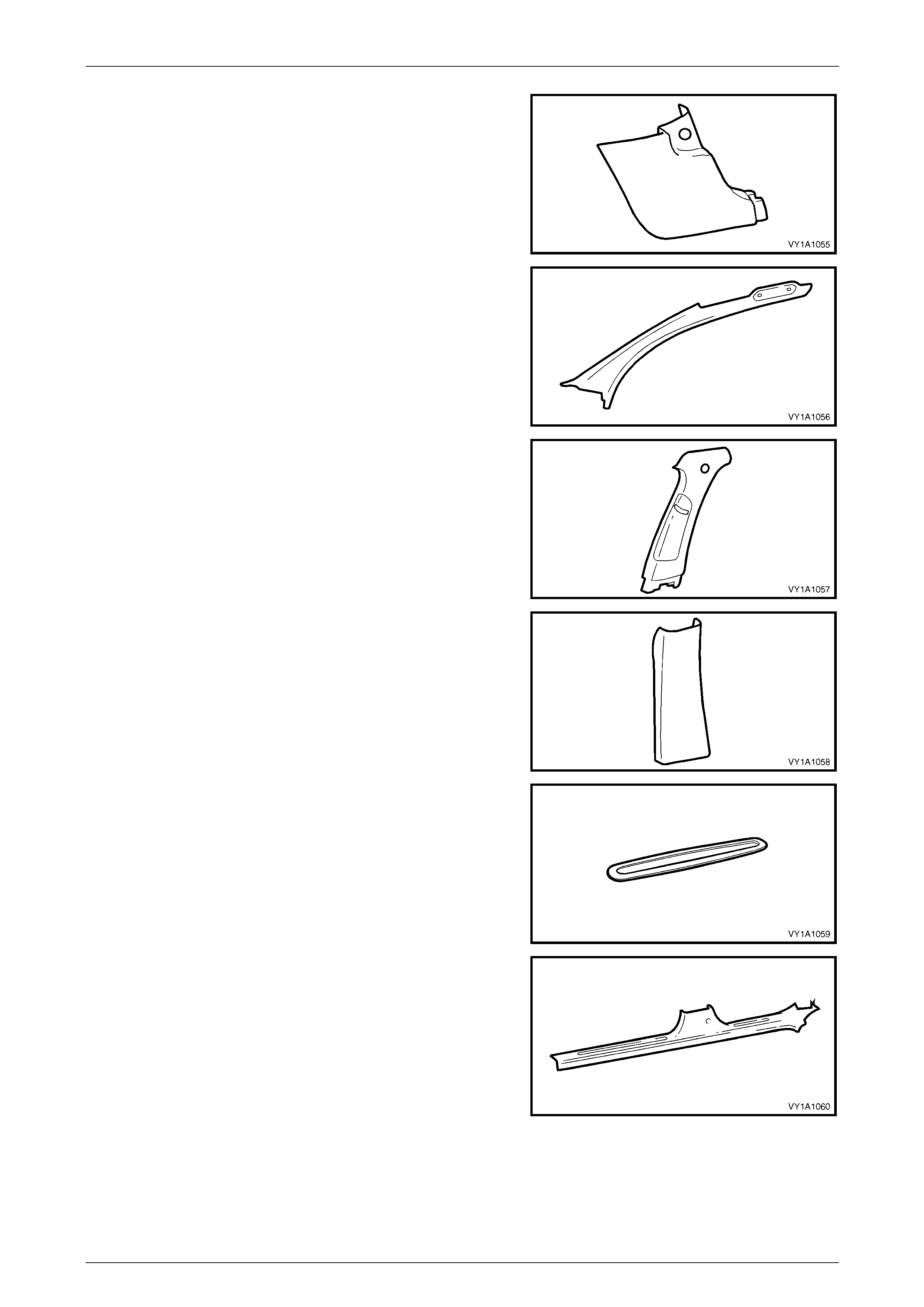
Page 1A1–12
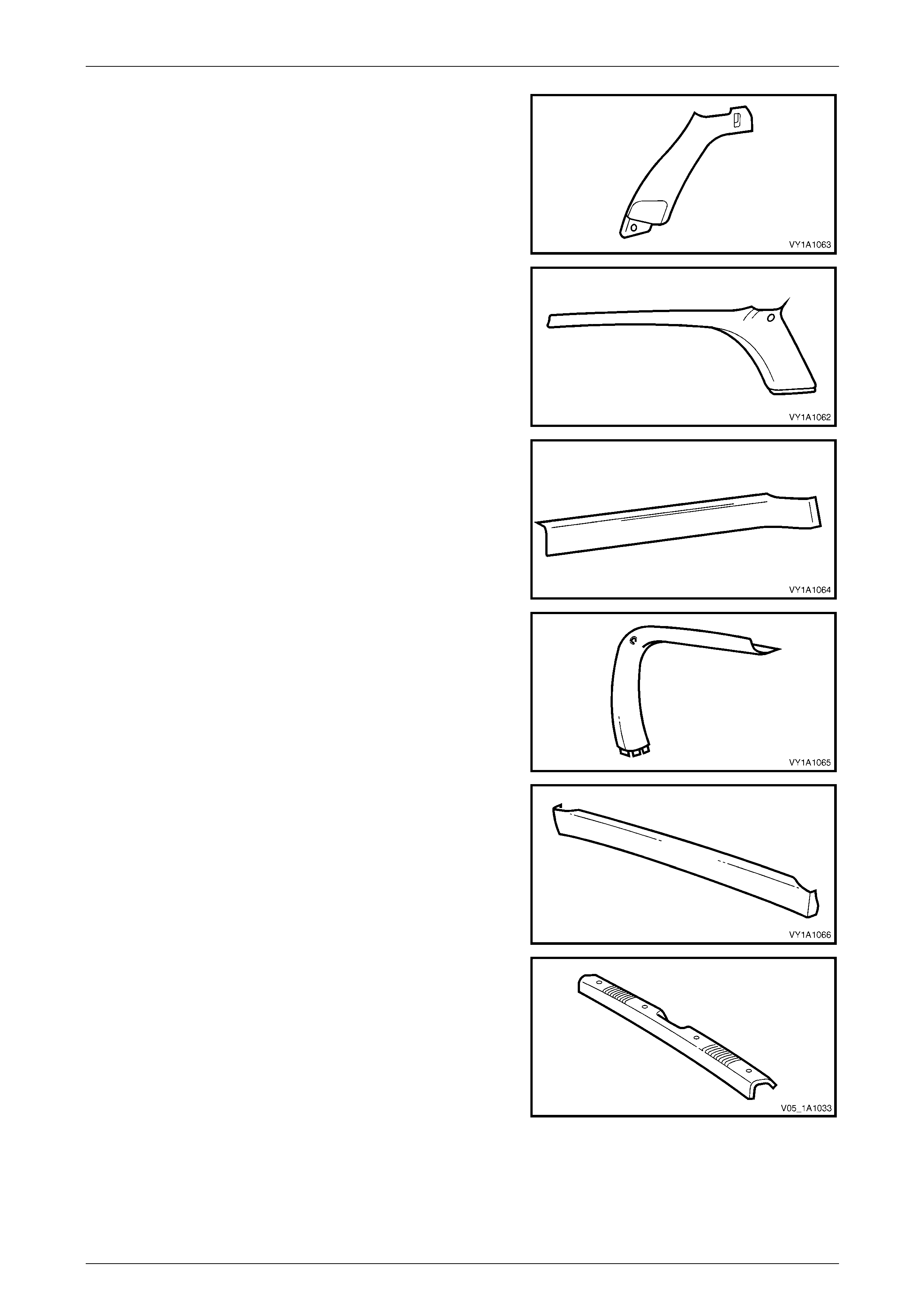
Hinge Pillar Trim
Material: PP
Windscreen Side Garnish
Material: PP
Centre Pillar Upper Trim
Material: PP
Centre Pillar Lower Trim
Material: PP
Side Sill Trim Plate
Material: PP
Side Sill Trim
Material: PP
Body Page 1A1–13
Page 1A1–13
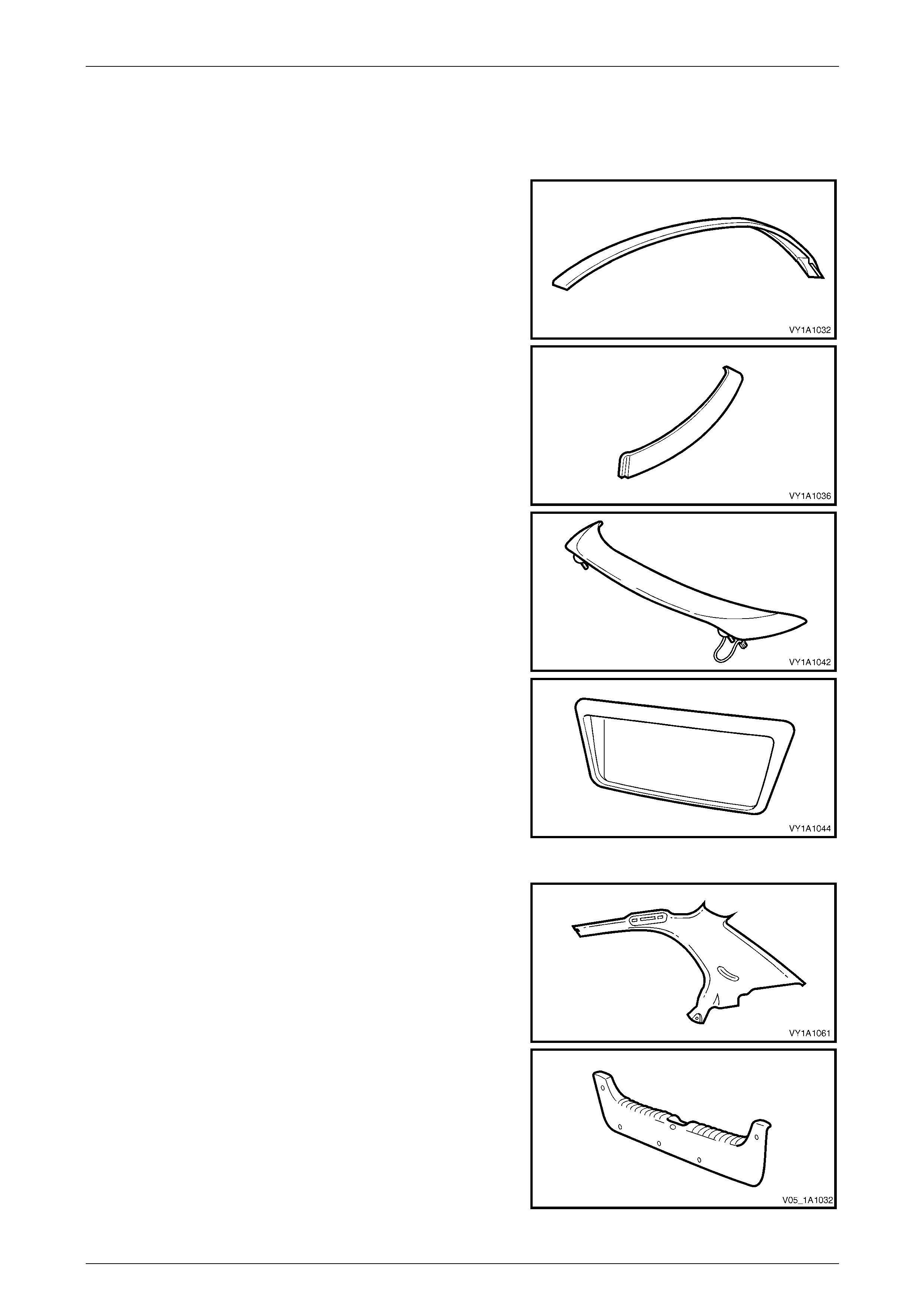
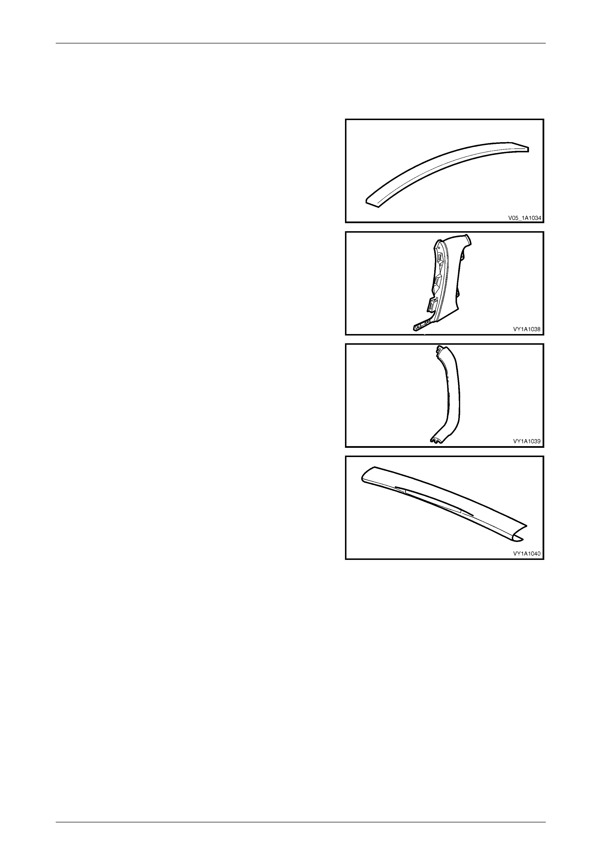
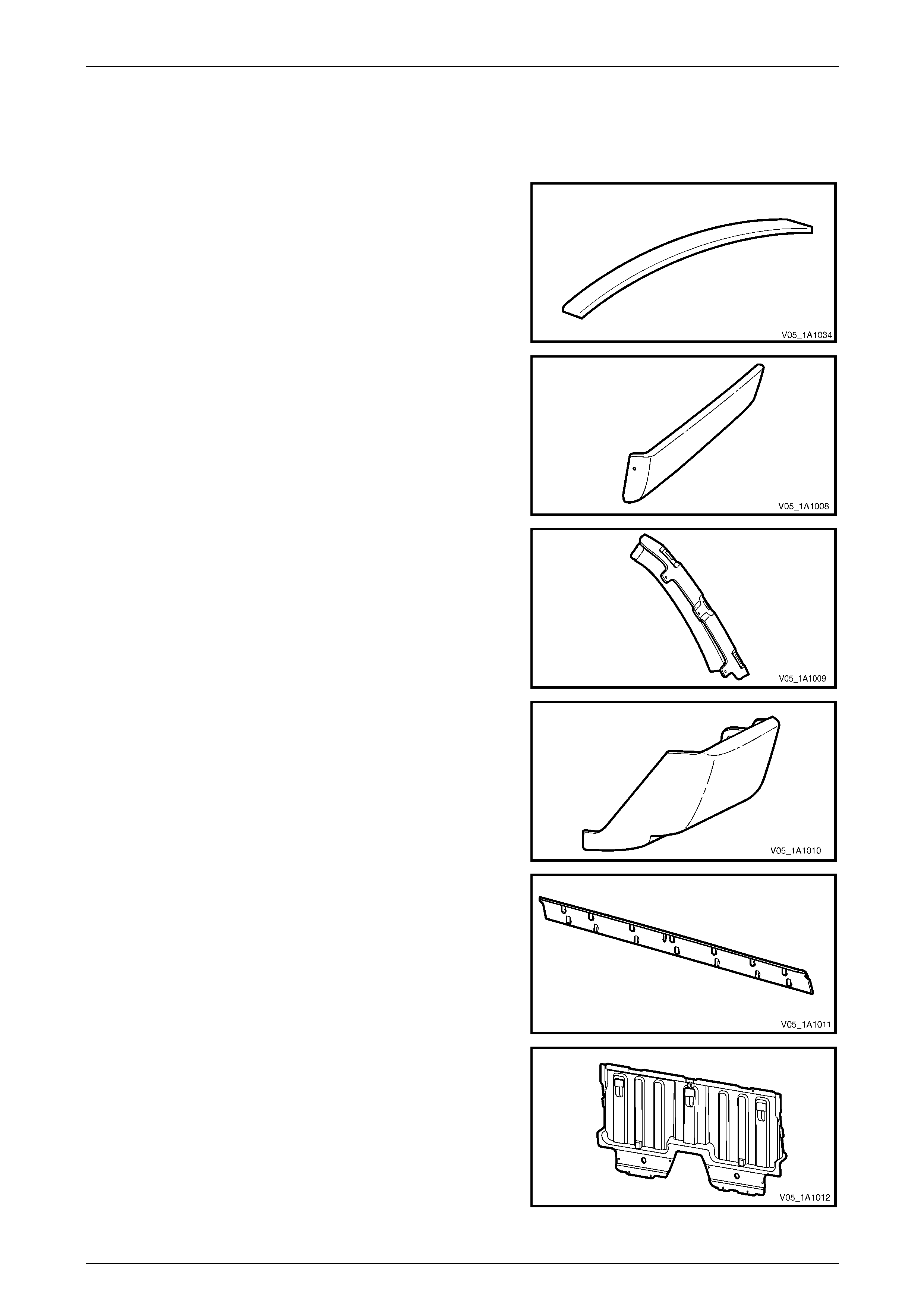
5.2 Sedan Unique
Exterior
Roof Panel Joint Moulding Assembly
Material: PVC
Quarter Panel Belt Moulding
Material: PPE/PA-M20
Rear Spoiler Assembly
Material: ABS
Rear Compartment Lid Appliqué Assembly
Material: ABS
Interior
Body Lock Pillar Garnish
Material: PP
Rear End Trim Panel
Material: PP
Body Page 1A1–14
Page 1A1–14
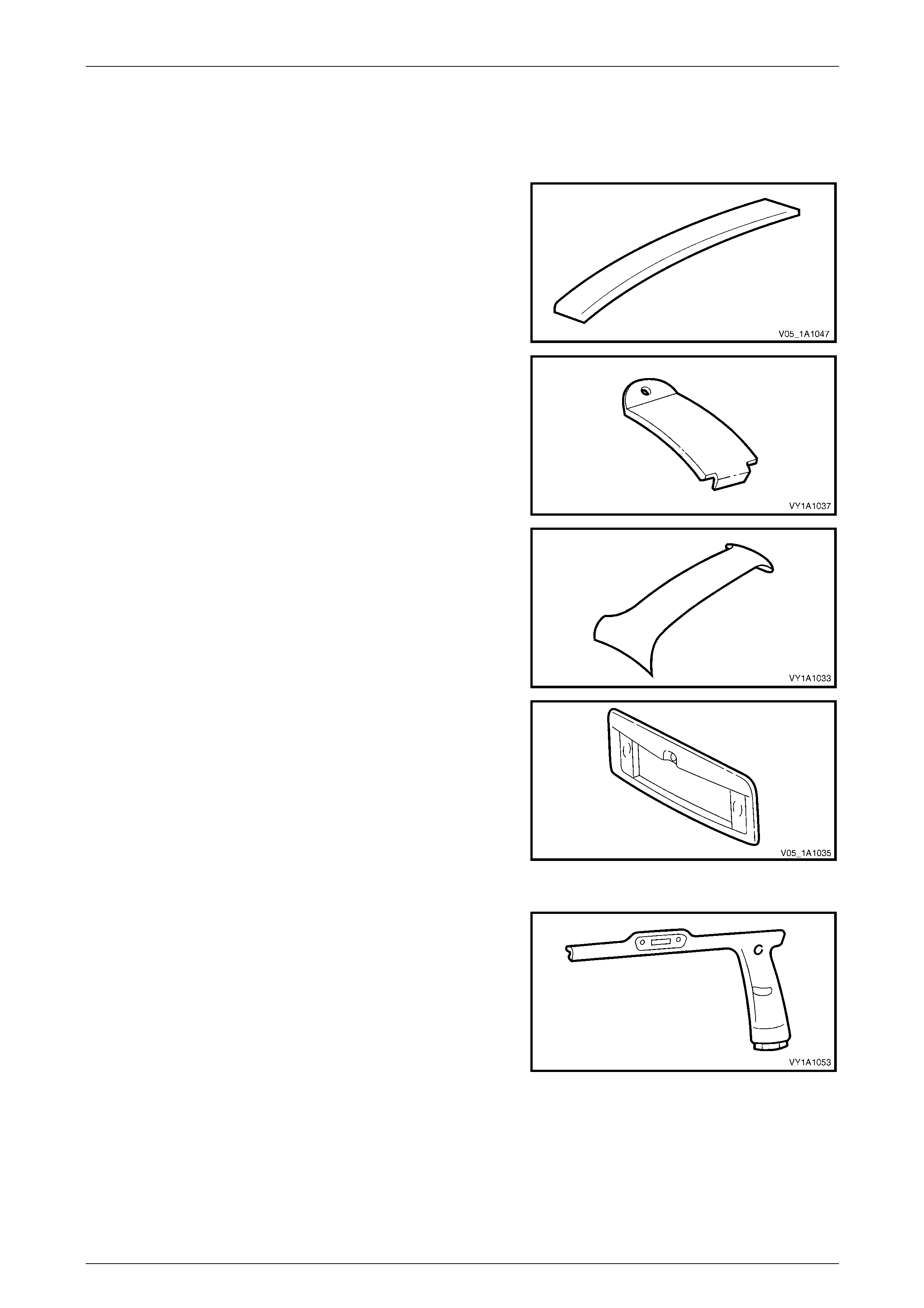
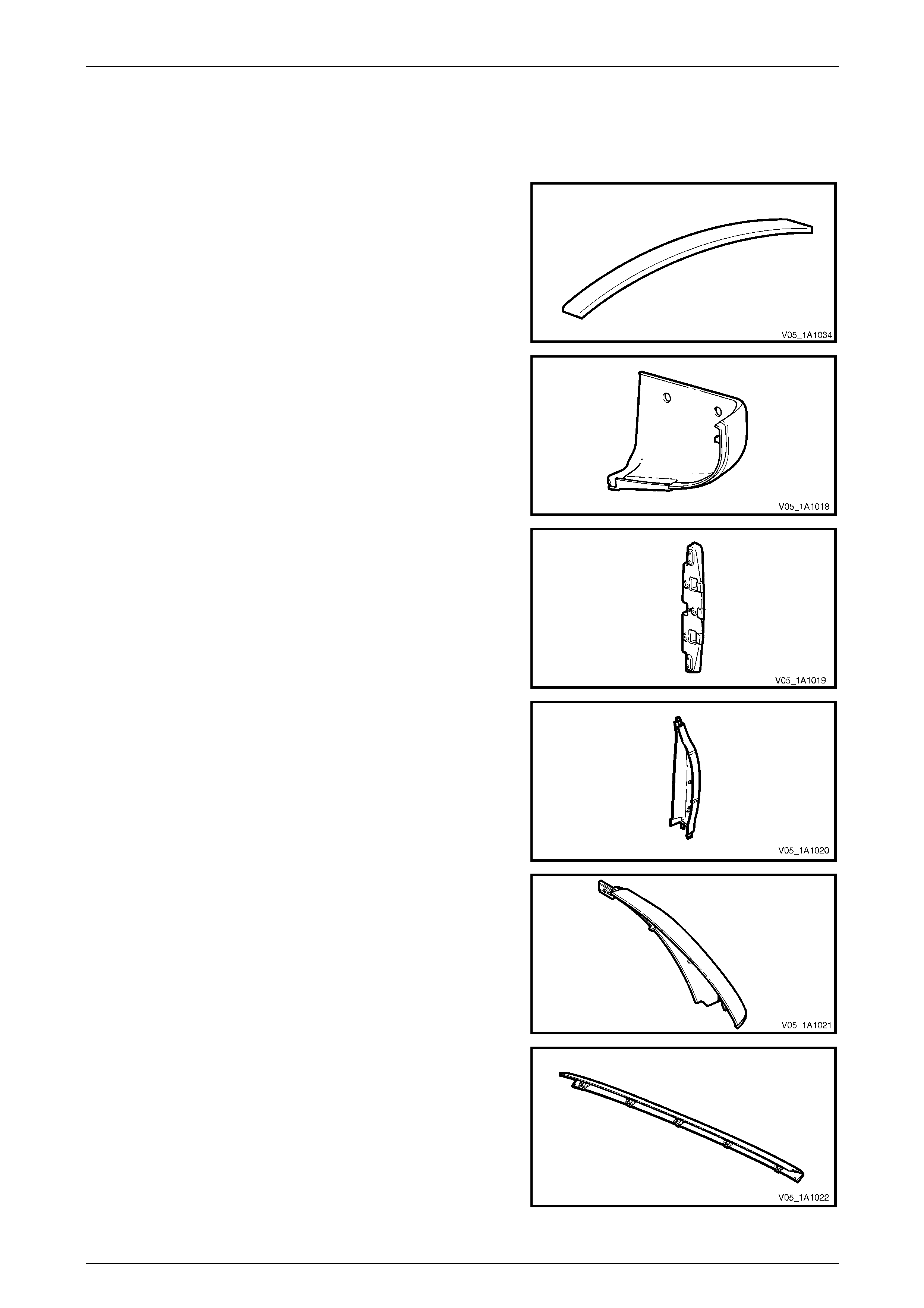
5.3 Wagon Unique
Exterior
Roof Panel Joint Moulding Assembly
Material: PVC
Roof Panel Joint Finish Moulding
Material: PP M20
Liftgate Air Deflector Assembly
Material: PC/ABS
Liftgate Appliqué Assembly
Material: ABS
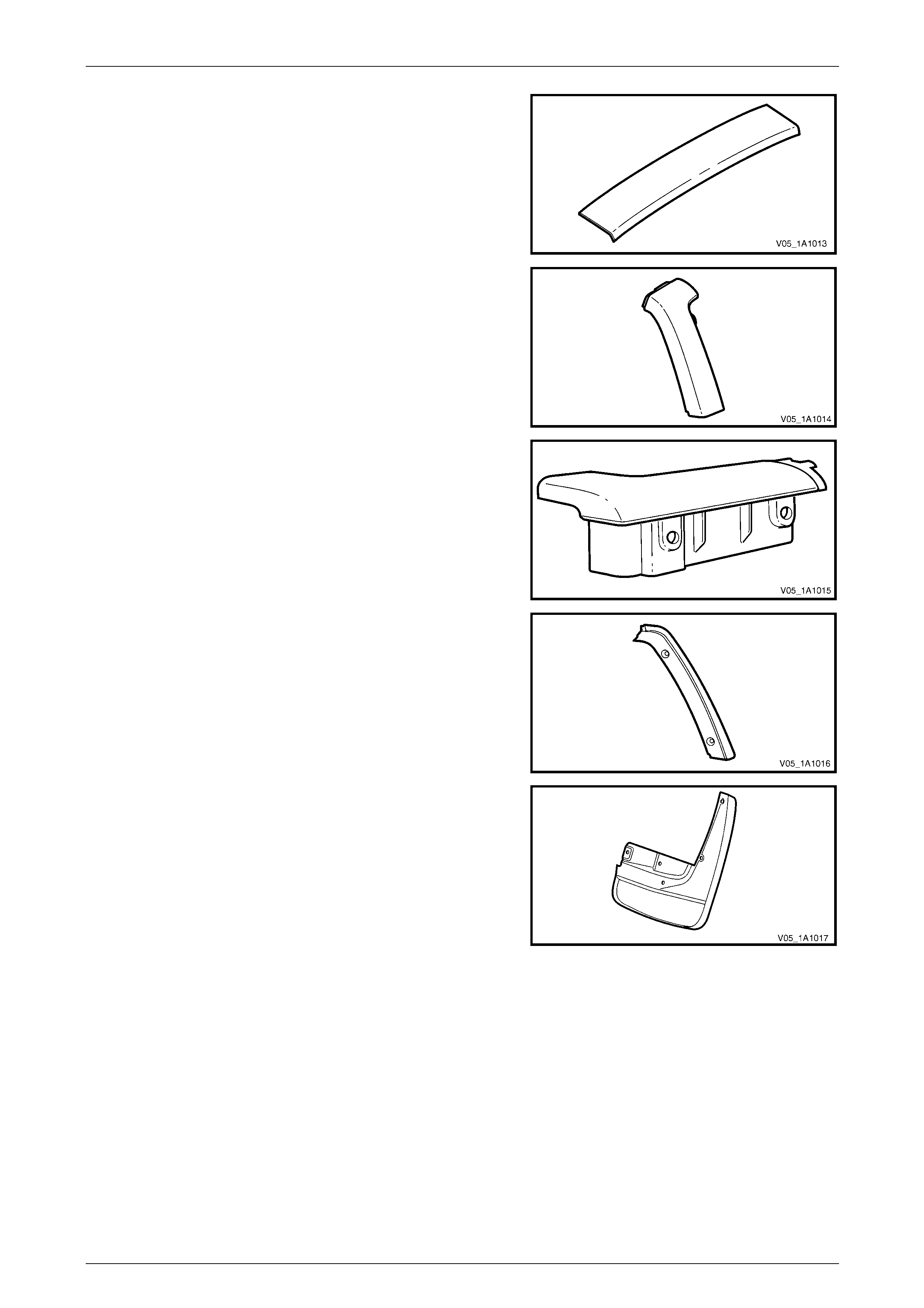
Interior
Body Lock Pillar Garnish
Material: PP
Body Page 1A1–15
Page 1A1–15
Body Lock Pillar Lower Trim
Material: PP
Body Lock Corner Garnish
Material: PP
Quarter Inner Trim Upper
Material: PP
Liftgate Window Upper Garnish
Material: PP
Liftgate Window Lower Garnish
Material: PP
Rear End Trim Panel
Material: PP
Body Page 1A1–16
Page 1A1–16
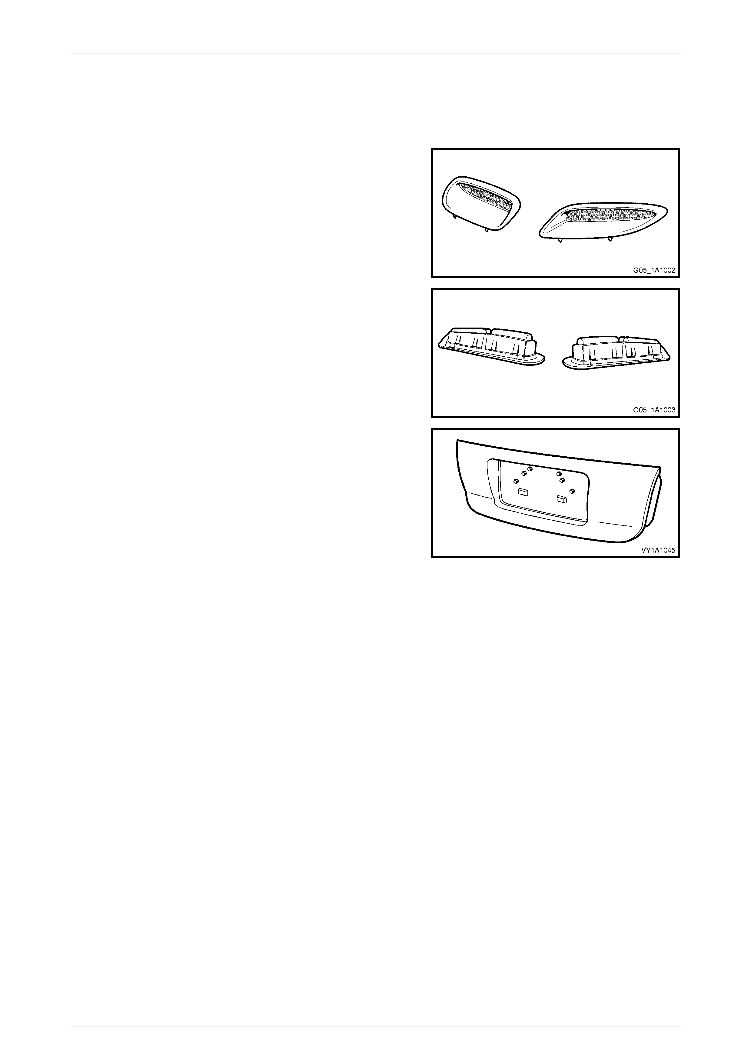
5.4 Utility Unique
Exterior
Roof Panel Joint Moulding Assembly
Material: PP
Rear Quarter Window Moulding
Material: ABS / PC-M6
Rear Window Side Moulding Assembly
Material: ABS / PC-M6
Rear Window Upper Moulding Assembly
Material: ABS / PC-M6
Body Page 1A1–17
Page 1A1–17
5.5 Regular Cab Unique
Exterior
Roof Panel Joint Moulding Assembly
Material: PP
Rocker Panel Rear Moulding Assembly
Material: PP
Body Side Rear Trim Panel Bracket
Material: Nylon 30% F/Glass
Body Side Rear Trim Panel
Material: ABS / PC
Rear Quarter Window Side Moulding Assembly
Material: ABS / PC- M6
Rear Quarter Window Upper Moulding Assembly
Material: ABS / PC- M6
Body Page 1A1–18
Page 1A1–18
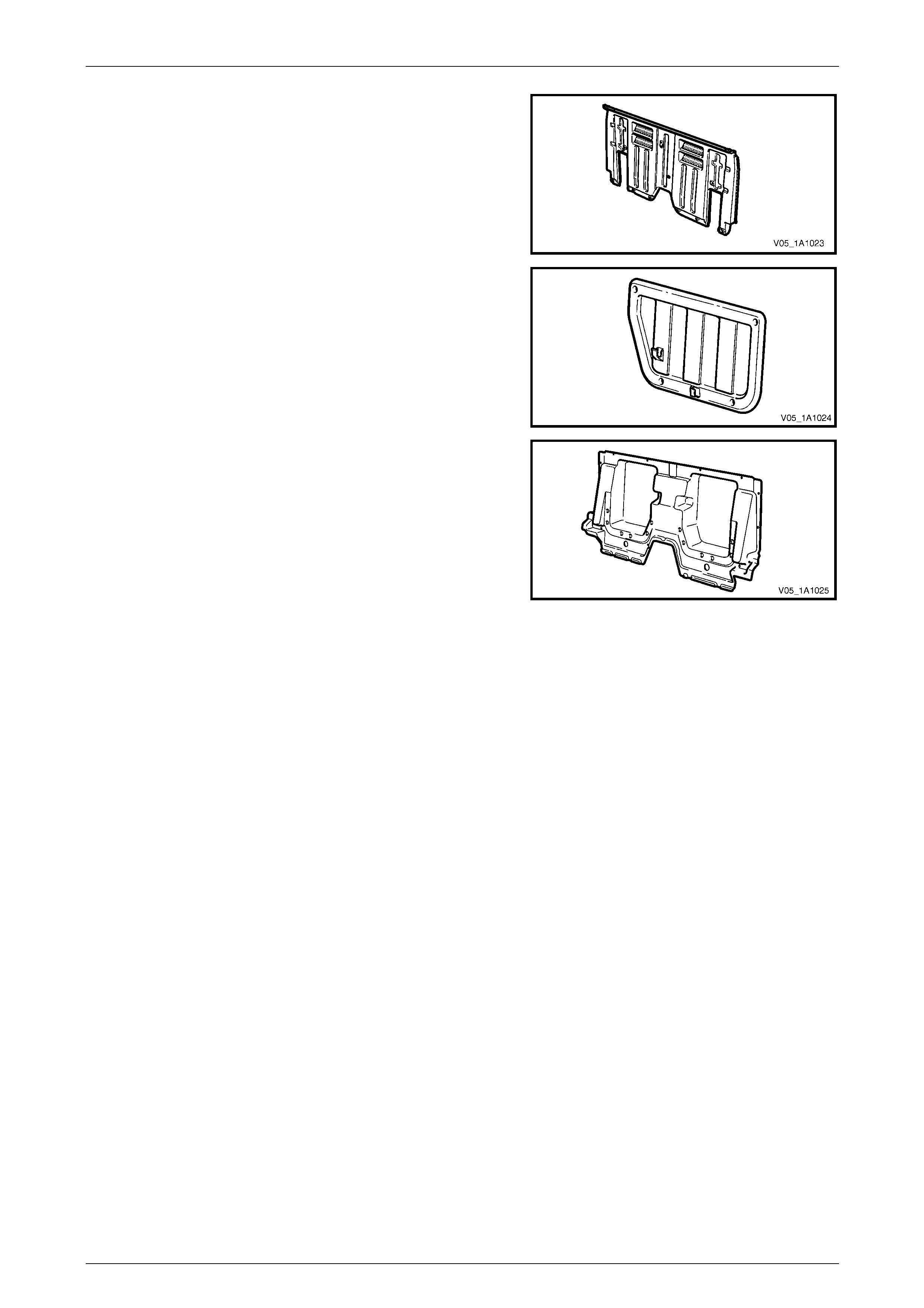
Body Rear Outer Panel Assembly
Material: 10% Fibreglass filled PC
Rear Seatback Body Panel Trim Panel Assembly
Material: PP
Body Rear Inner Panel
Material: UP
Body Page 1A1–19
Page 1A1–19
5.6 Crew Cab Unique
Exterior
Roof Panel Joint Moulding Assembly
Material: PVC
Rear Body Rear Rocker Moulding
Material: Mineral Filled PP
Body Lock Pillar Trim Retainer Moulding
Material: Mineral Filled PP
Rear Body Front Rocker Moulding
Material: PP
Rear Window Lower Finisher
Material: ABS / PC
Inner Rear Body Panel
Material:
10% GF Recycled PP
Body Page 1A1–20
Page 1A1–20
Rear Header Trim Assembly
Material: ABS / PC
Body Lock Pillar Trim
Material: ABS / PC
Rear Body Front Rail Cover
Material: Mineral Filled PP
Body Lock Pillar Door Finisher
Material: ABS / PC
Rear Mudflap
Material: PP
Body Page 1A1–21
Page 1A1–21
5.7 Coupe Unique
Exterior
Hood Scoop Assembly
Material: PC/ABS
Hood Scoop Air Duct
Material: Rubber modified PP
Rear Compartment Lid Appliqué Assembly
Material: ABS
Body Page 1A1–22
Page 1A1–22
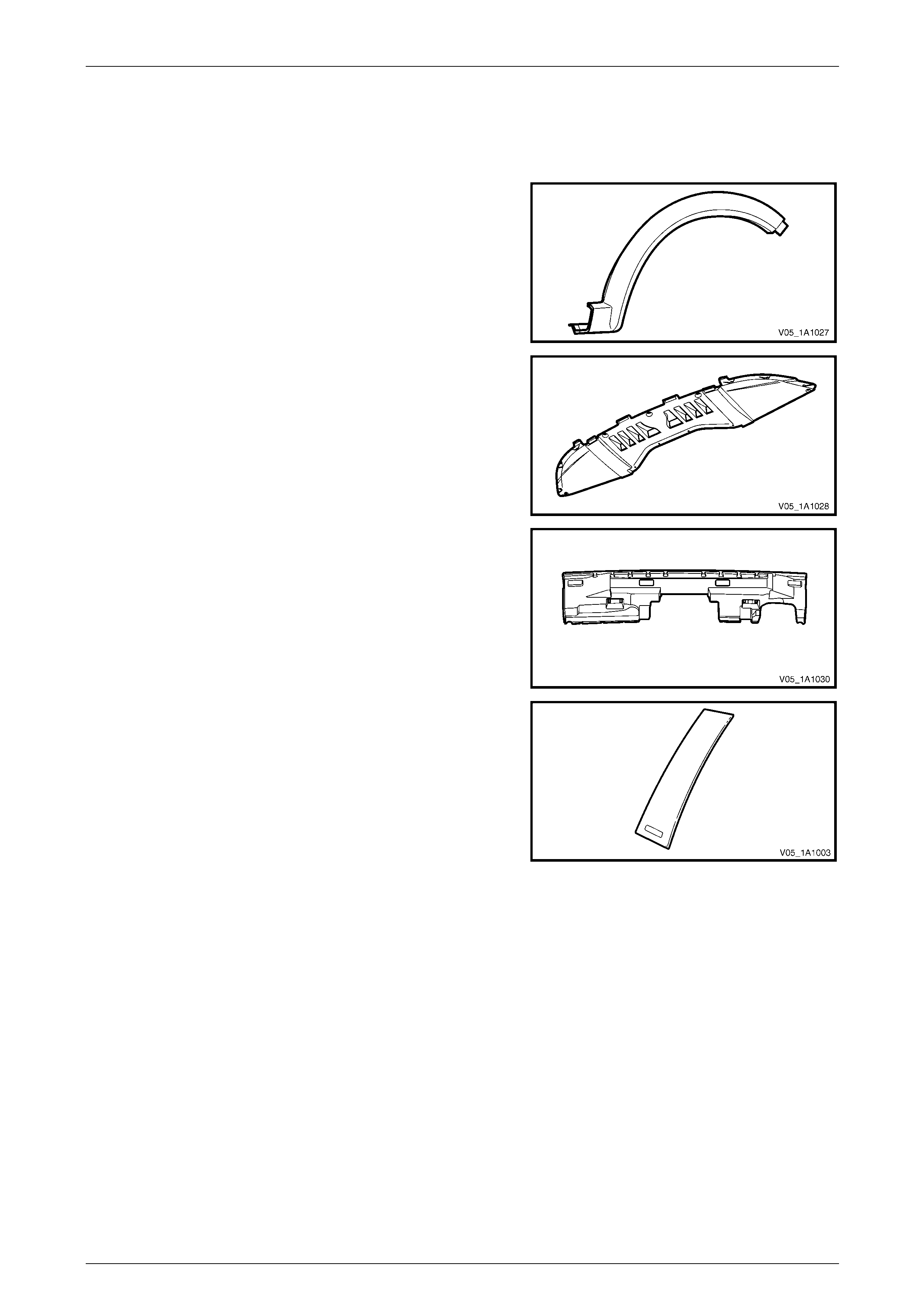
5.8 AWD Wagon Unique
Exterior
Front Wheelhouse Opening Flare
Rear Wheelhouse Opening Flare
Material: PP
Front Bumper Fascia Undertray
Material: PP
Rear Bumper Fascia Filler
Material: PP Foam
Rear Quarter Window Appliqué
Material: ABS / PC

Body Page 1A1–23
Page 1A1–23
5.9 Plastic Types
The repair procedure for plastic body parts must conform with the type of plastic material.
Precautions to be taken with plastic parts are detailed in the following chart:
Code Material Name Heat Resisting
Temp* °C Resistance to
Alcohol or Gasoline NOTES
ABS Acrylonitrile
Butadiene Styrene
Resin
80 Alcohol is harmless if applied only
for short time in small amounts (i.e.
quick wiping to remove grease).
Avoid gasoline and organic
or aromatic solvents.
ASA Acrylate Styrene
Acrylonitrile 80 Alcohol is harmless if applied only
for short time in small amounts (i.e.
quick wiping to remove grease).
Avoid gasoline and organic
or aromatic solvents.
PC Polycarbonate 120 Alcohol is harmless. Avoid gasoline, brake fluid,
wax, wax removers and
organic solvents.
PMMA Polymethyl
Methacrylate 80 Alcohol is harmless if applied only
for short time in small amounts. Avoid dipping or immersing
in alcohol, gasoline, solvents,
etc.
PE Polyethylene 80 Alcohol and gasoline are harmless. Most solvents are harmless.
PP /
PP67 Polypropylene 80 Alcohol and gasoline are harmless. Most solvents are harmless.
PPE Polyphenylene
Ether 100 Alcohol and gasoline are harmless if
applied only for a short time in small
amounts (i.e. quick wiping to remove
grease).
Avoid dipping or immersing
in alcohol, gasoline, solvents,
etc.
PU Polyurethane
Foam 100 Alcohol and gasoline are harmless if
applied only for a short time in small
amounts (i.e. quick wiping to remove
grease).
Avoid dipping or immersing
in alcohol, gasoline, solvents,
etc.
PVC Polyvinyl Chloride 80 Alcohol and gasoline are harmless if
applied only for short time in small
amounts. (i.e. quick wiping to
remove grease).
Avoid dipping or immersing
in alcohol, gasoline, solvents,
etc.
TPO Thermoplastic
Olefin 80 Alcohol is harmless.
Gasoline is harmless if applied only
for short time in small amounts.
Most solvents are harmless
but avoid dipping or
immersing in alcohol,
gasoline, solvents, etc.
PPE/
PA-M20 Modified
Polypropylene
Ether and
Polyamide Alloy
190 Alcohol and gasoline are harmless if
applied only for a short time in small
amounts (i.e. quick wiping to remove
grease).
Avoid dipping or immersing
in alcohol, gasoline, solvents,
etc.
Body Page 1A1–24
Page 1A1–24
6 Wheelhouse Liners
LT Section No. — 12–425
6.1 Front Wheelhouse Liner (except AWD)
Remove
1 Remove the front road wheel, refer to Section 10 Wheels and Tyres.
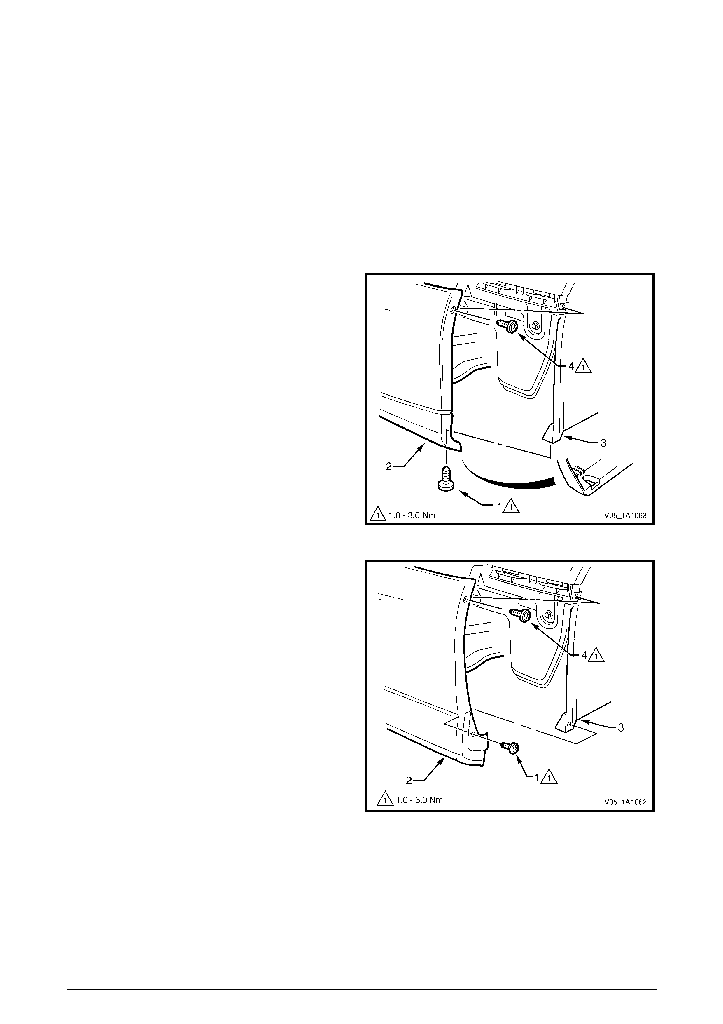
2 Depending on vehicle complete either step a or b:
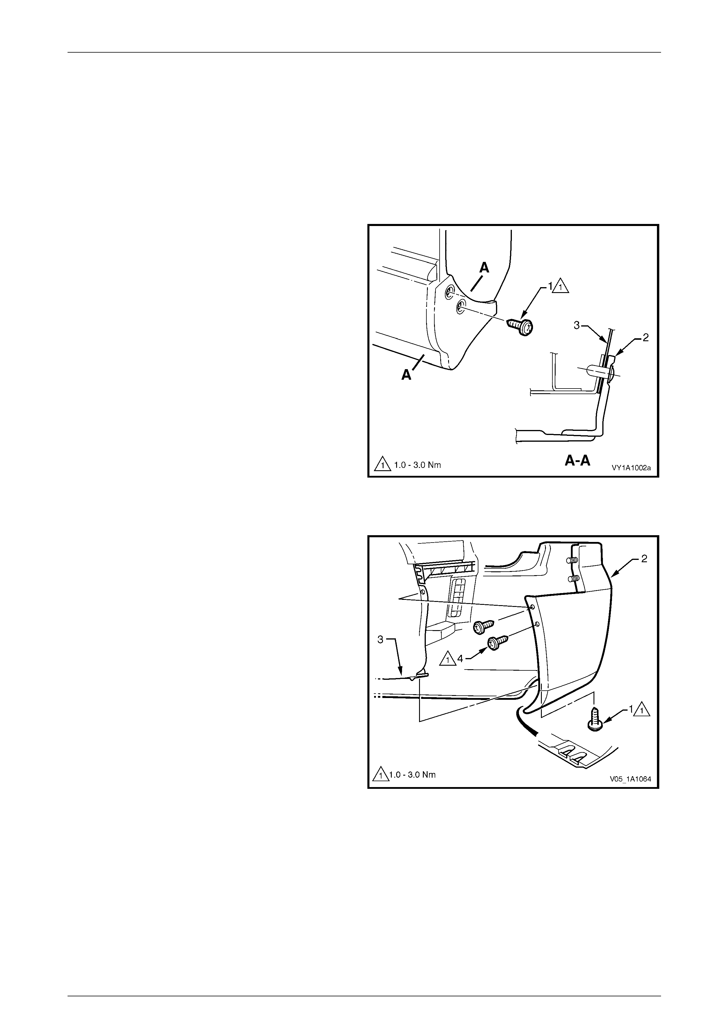
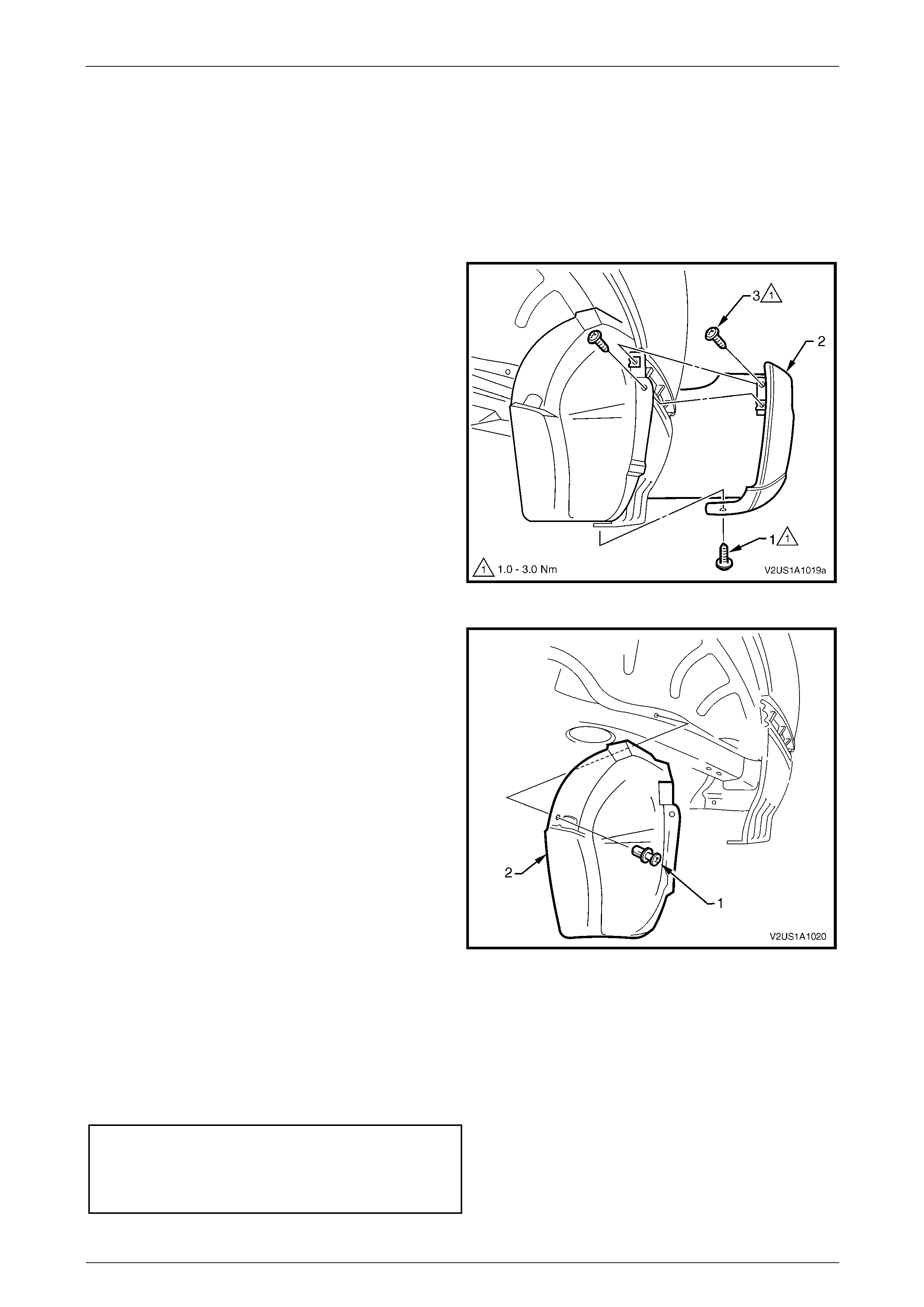
a Remove the screw (1) attaching the front bumper
fascia assembly (2) to the wheelhouse liner (3).
To aid in removal of the liner remove the screw
(4) attaching the fascia assembly to the vehicle.
Figure 1A1 – 2
b Remove the screw (1) attaching the front bumper
fascia assembly (2) to the front wheelhouse liner
(3). To aid in removal of the liner remove the
screw (4) attaching the fascia assembly to the
vehicle.
Figure 1A1 – 3
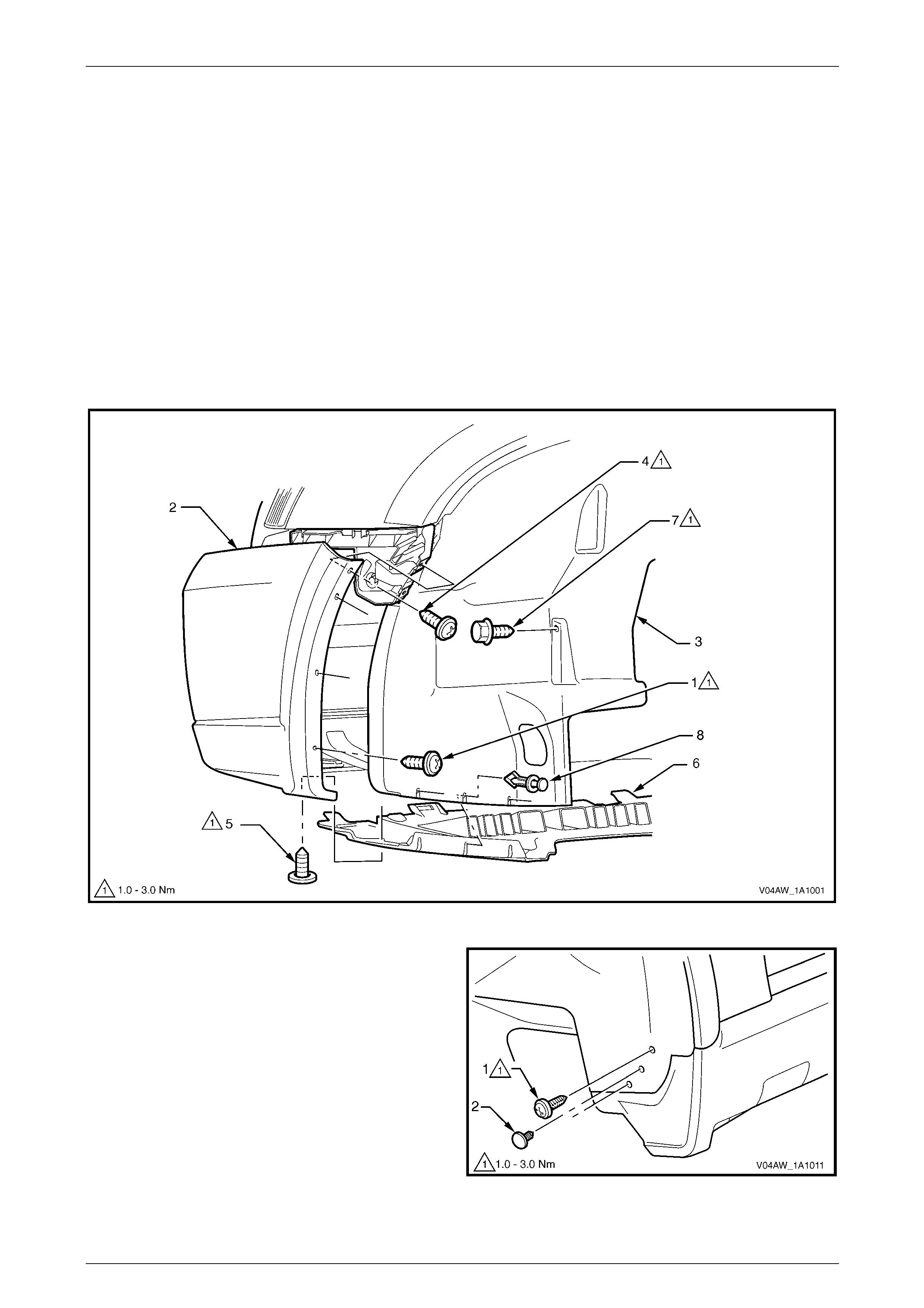
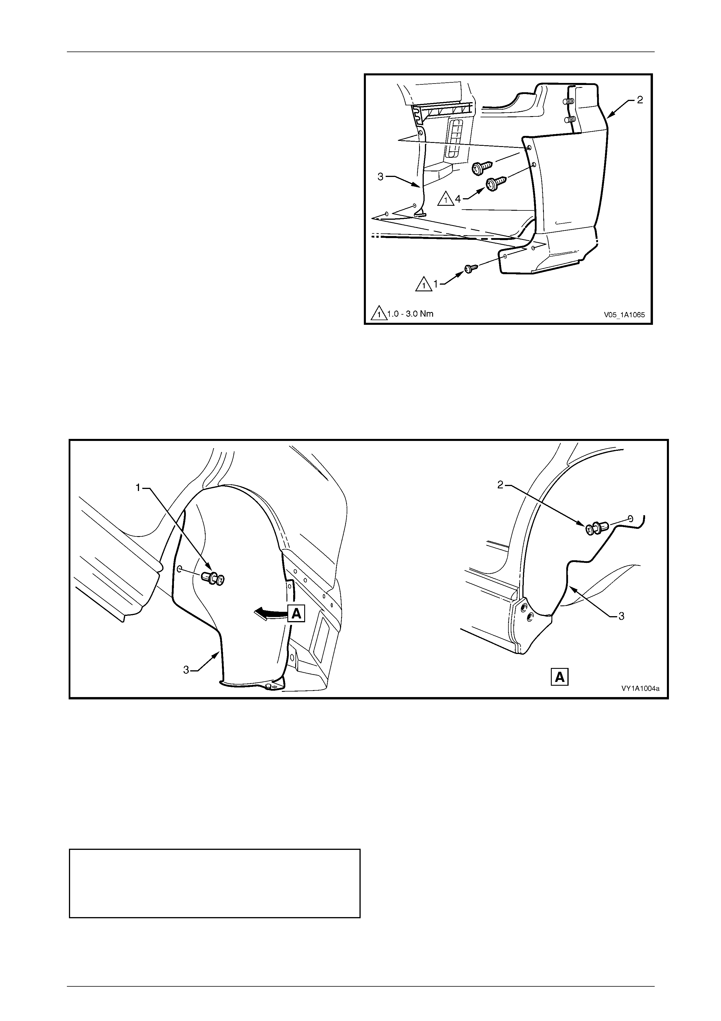
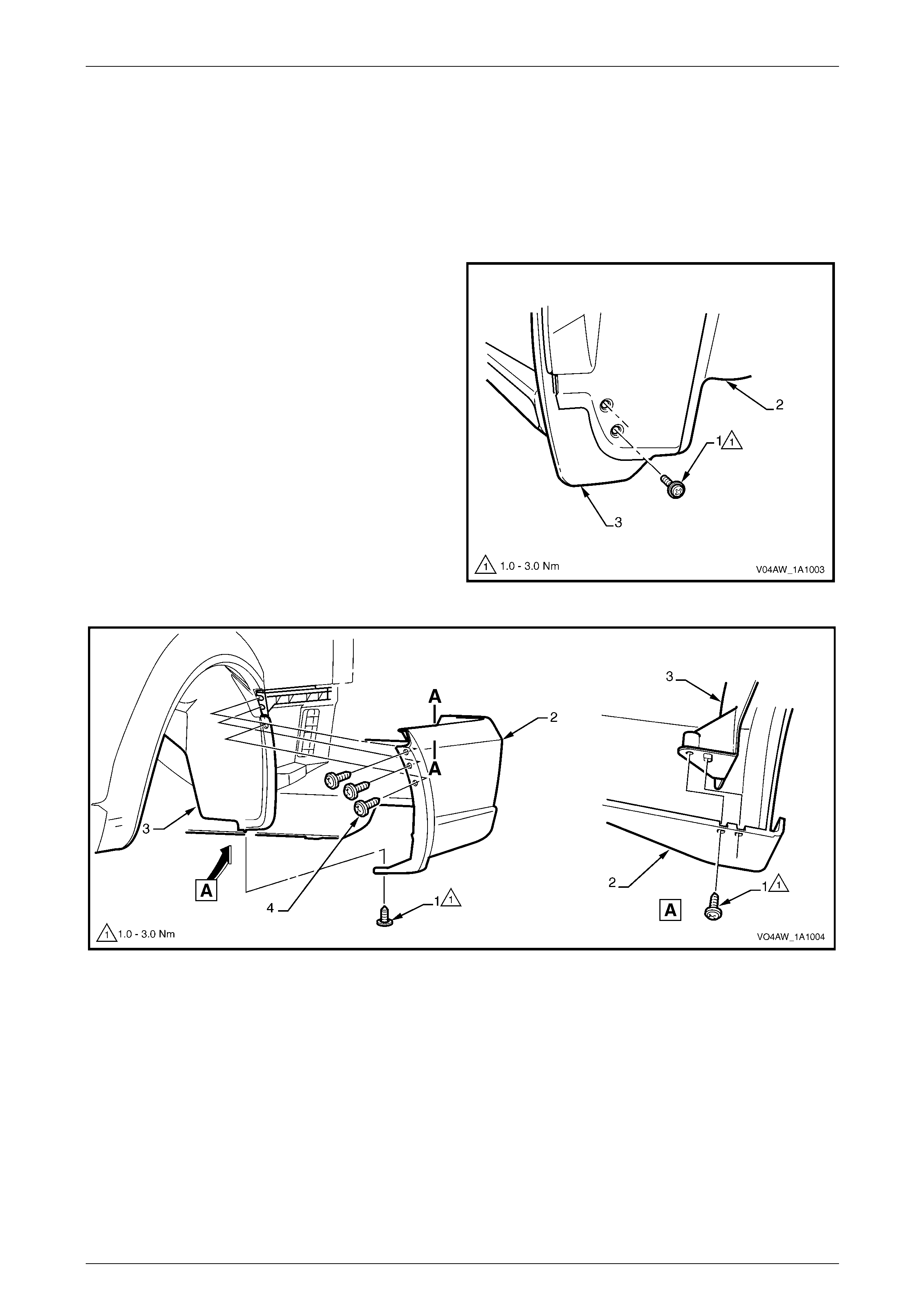
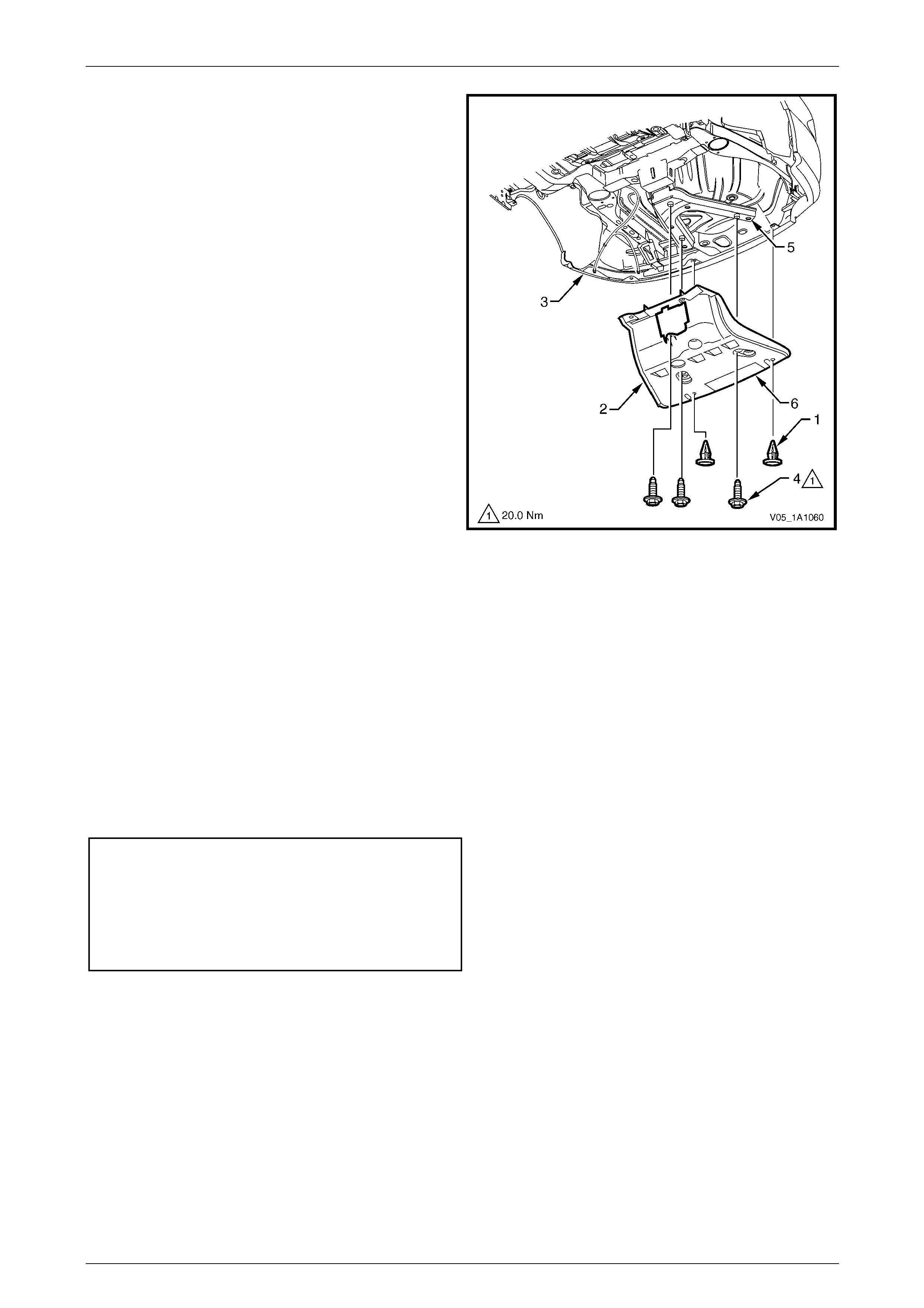
3 Referring to Figure 1A1 – 4, remove the two screws (1) attaching the liner (2) to the fender.
4 Remove the four retainers (4) attaching the liner to the vehicle.
5 Remove the liner.
Body Page 1A1–25
Page 1A1–25
Figure 1A1 – 4
Reinstall
Reinstallation of the front wheelhouse liner is the reverse of the removal procedure, noting the following:
1 Ensure the wheelhouse liner is correctly positioned, refer to Figure 1A1 – 4.
2 Tighten the screws to the correct torque specification.
Front wheelhouse liner attaching
screw torque specification...........................1.0 – 3.0 Nm
Front bumper fascia assembly attaching
screw torque specification...........................1.0 – 3.0 Nm
Body Page 1A1–26
Page 1A1–26
6.2 Front Wheelhouse Liner, AWD
LT Section No. — 12–425
Remove
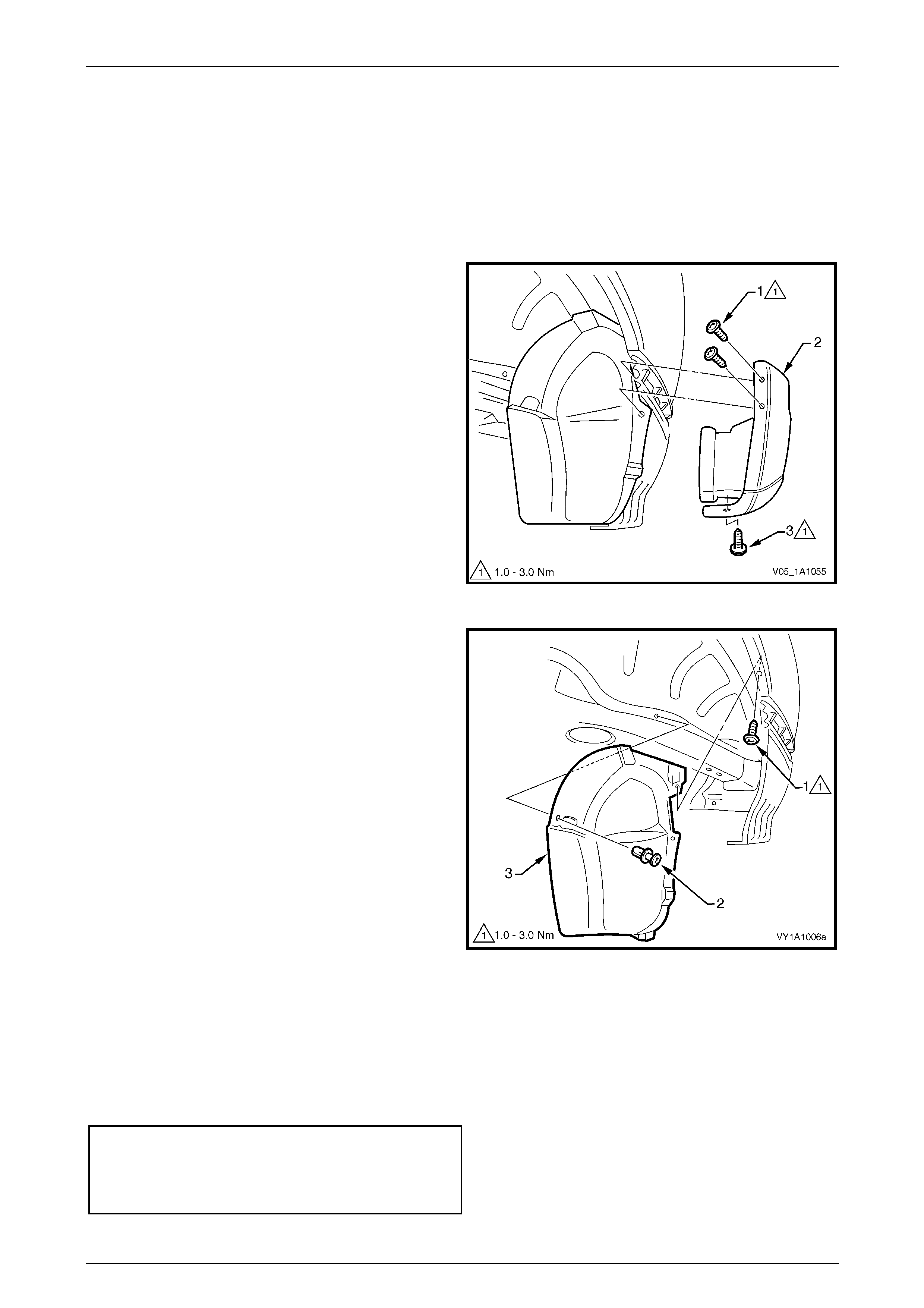
1 Remove the front road wheel, refer to Section 10 Wheels and Tyres.
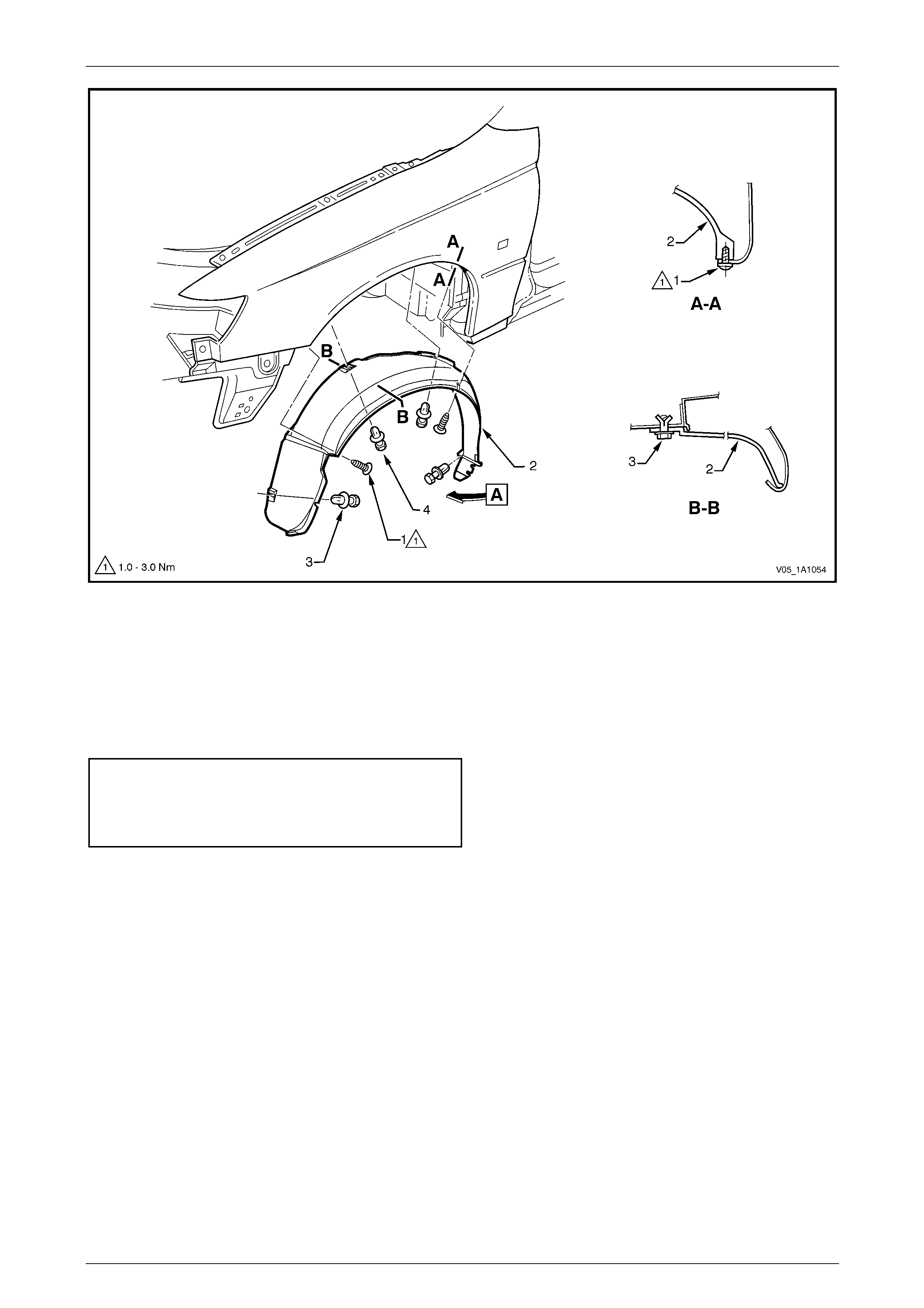
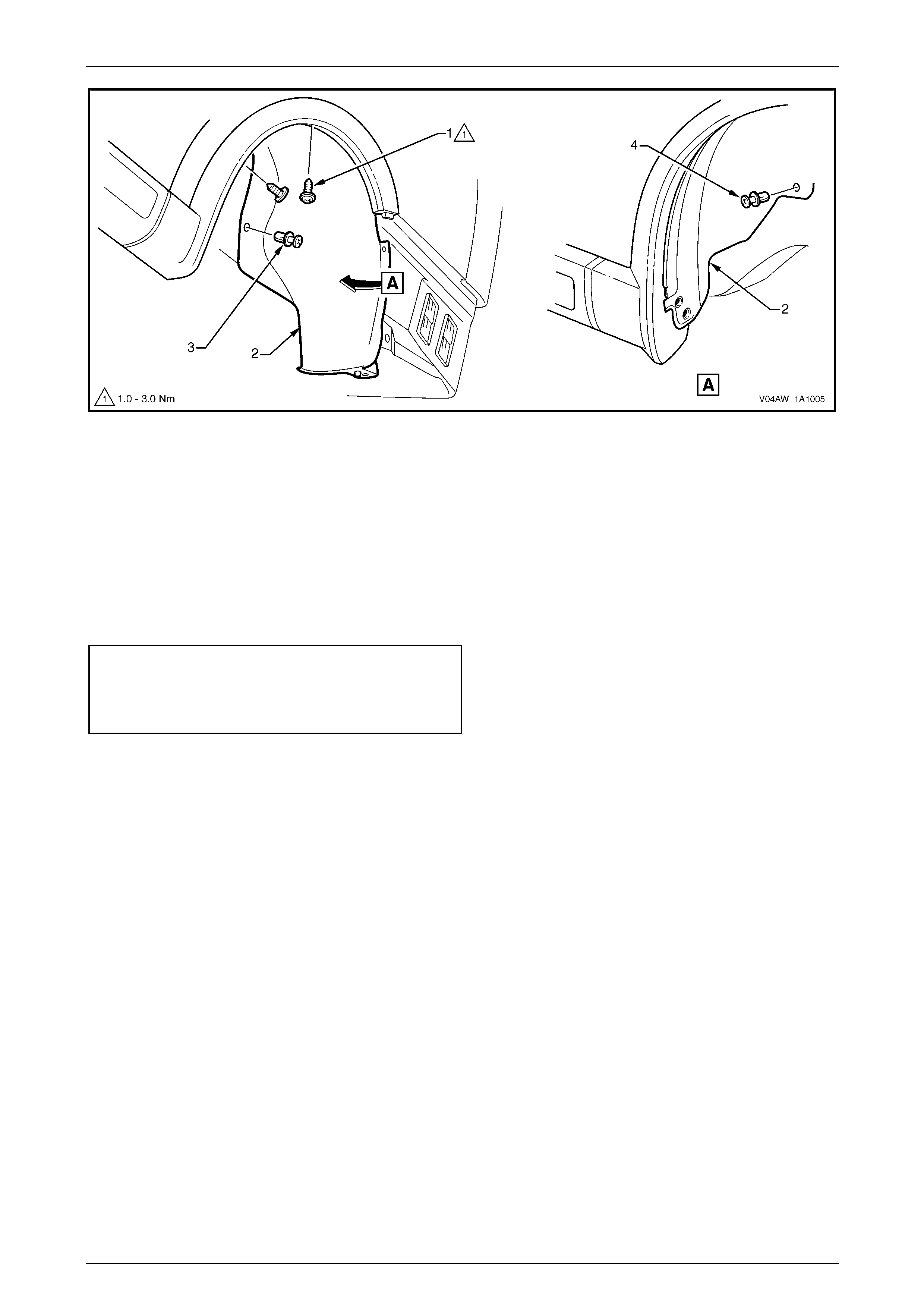
2 Remove the screw (1), two places, attaching the front bumper fascia assembly (2) to the wheelhouse liner (3),
refer to Figure 1A1 – 5.
3 To aid in removal of the liner, remove screw (4), two places, attaching the fascia assembly to the vehicle and
screw (5) attaching the fascia to the fascia undertray (6).
4 Remove screw (7) attaching the liner to the vehicle.
5 Remove the retainer (8), three places, attaching the liner to the fascia undertray.
Figure 1A1 – 5
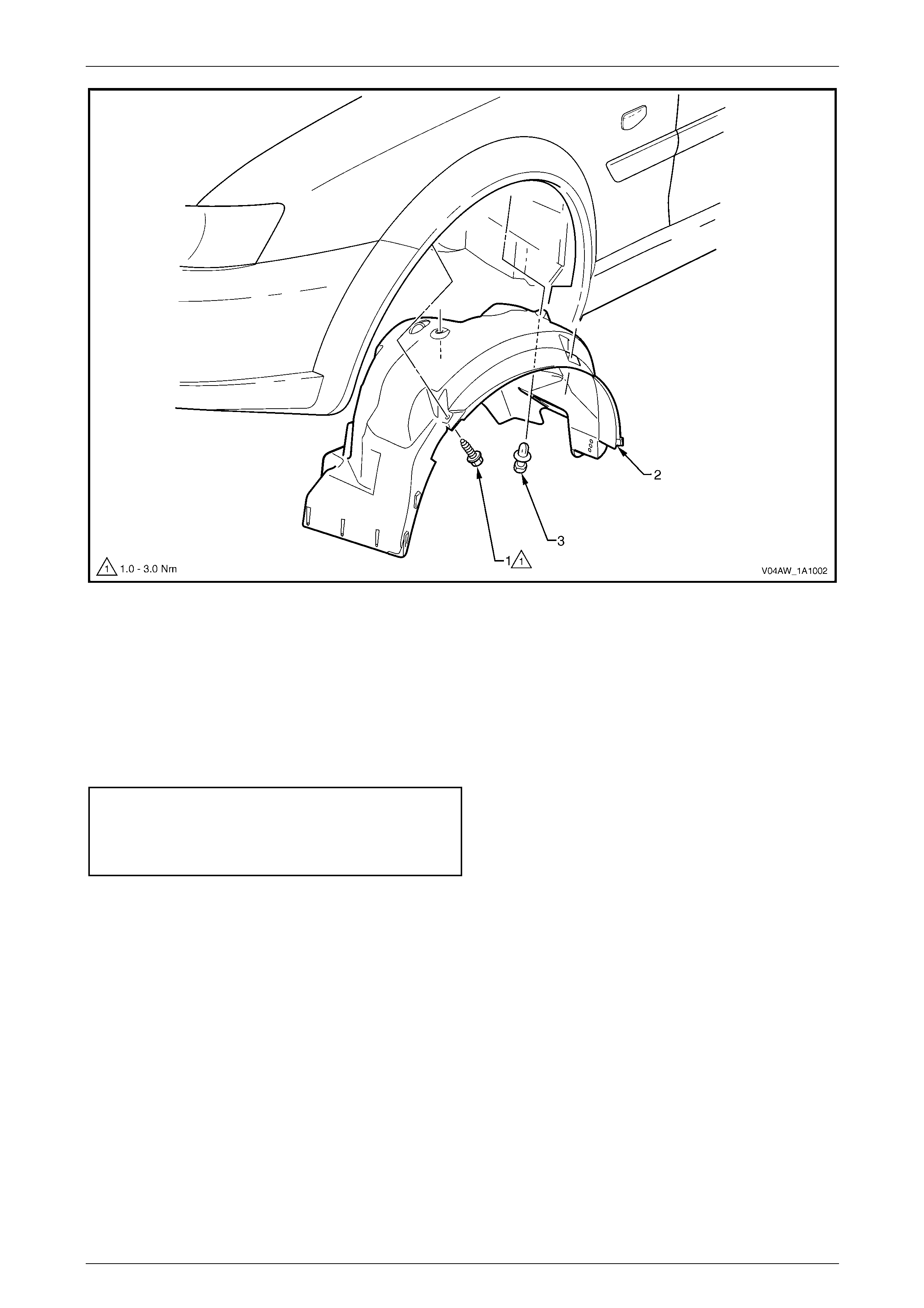
6 Remove the screw (1), two places, attaching the liner
to the vehicle.
7 Remove the retainer (2), attaching the liner to the
vehicle.
8 Remove the screw (1), two places, attaching the liner
(2) to the flare and fender, refer to Figure 1A1 – 7.
9 Remove the retainer (3), two places, attaching the liner
to the vehicle.
Figure 1A1 – 6
Body Page 1A1–27
Page 1A1–27
Figure 1A1 – 7
10 Manipulate the liner from behind the wheelhouse flare and bumper fascia and remove.
Reinstall
Reinstallation of the wheelhouse liner is the reverse of the removal procedure, noting the following:
1 Ensure the wheelhouse liner is correctly positioned. Refer to Figure 1A1 – 5.
2 Tighten the screws to the correct torque specification.
Front wheelhouse liner attaching
screw torque specification...........................1.0 – 3.0 Nm
Front bumper fascia assembly attaching
screw torque specification...........................1.0 – 3.0 Nm
Body Page 1A1–28
Page 1A1–28
6.3 Rear Wheelhouse Liner, Sedan and
Wagon
LT Section No. — 12–425
Remove
1 Remove the rear road wheel, refer to Section 10 Wheels and Tyres.
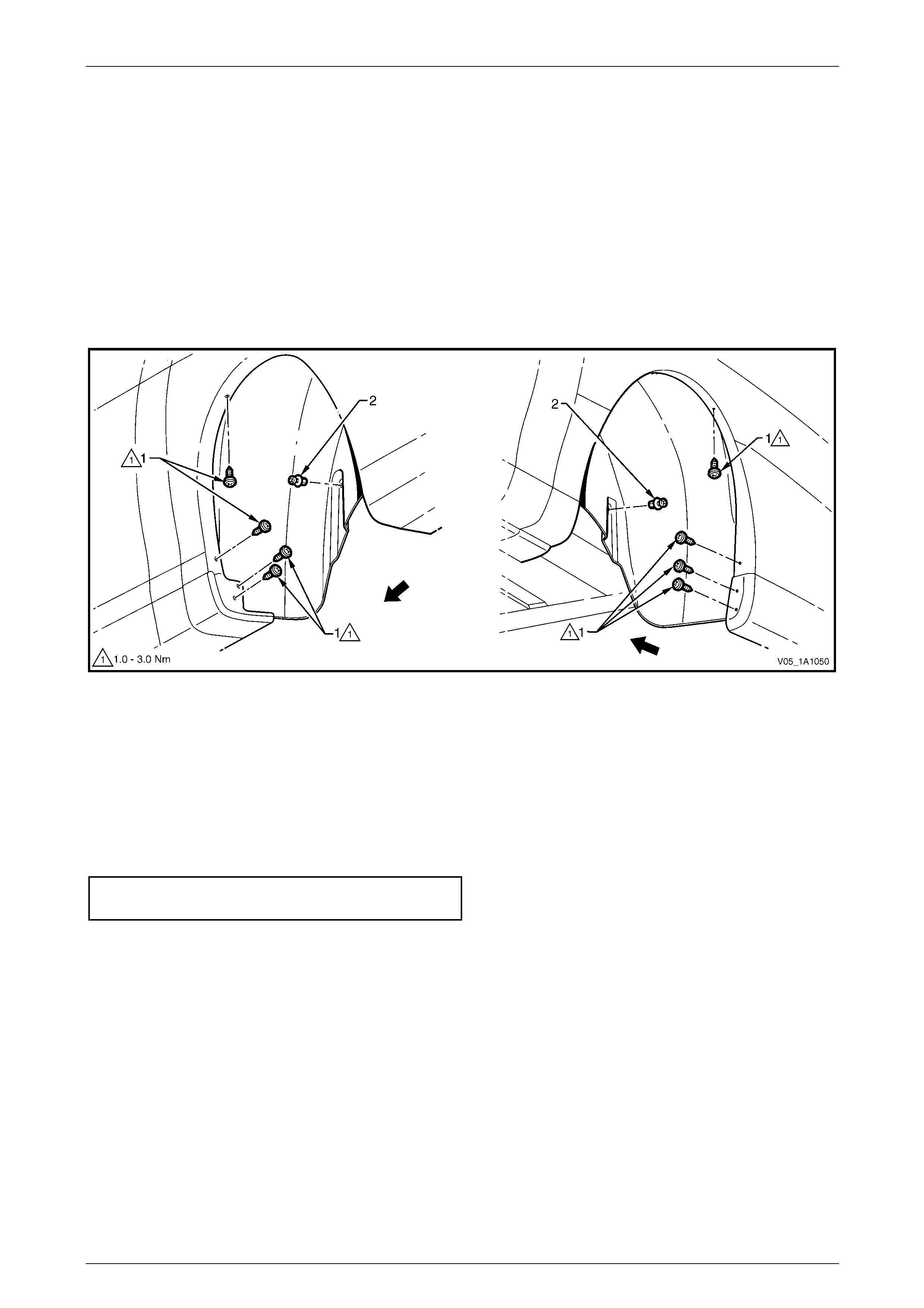
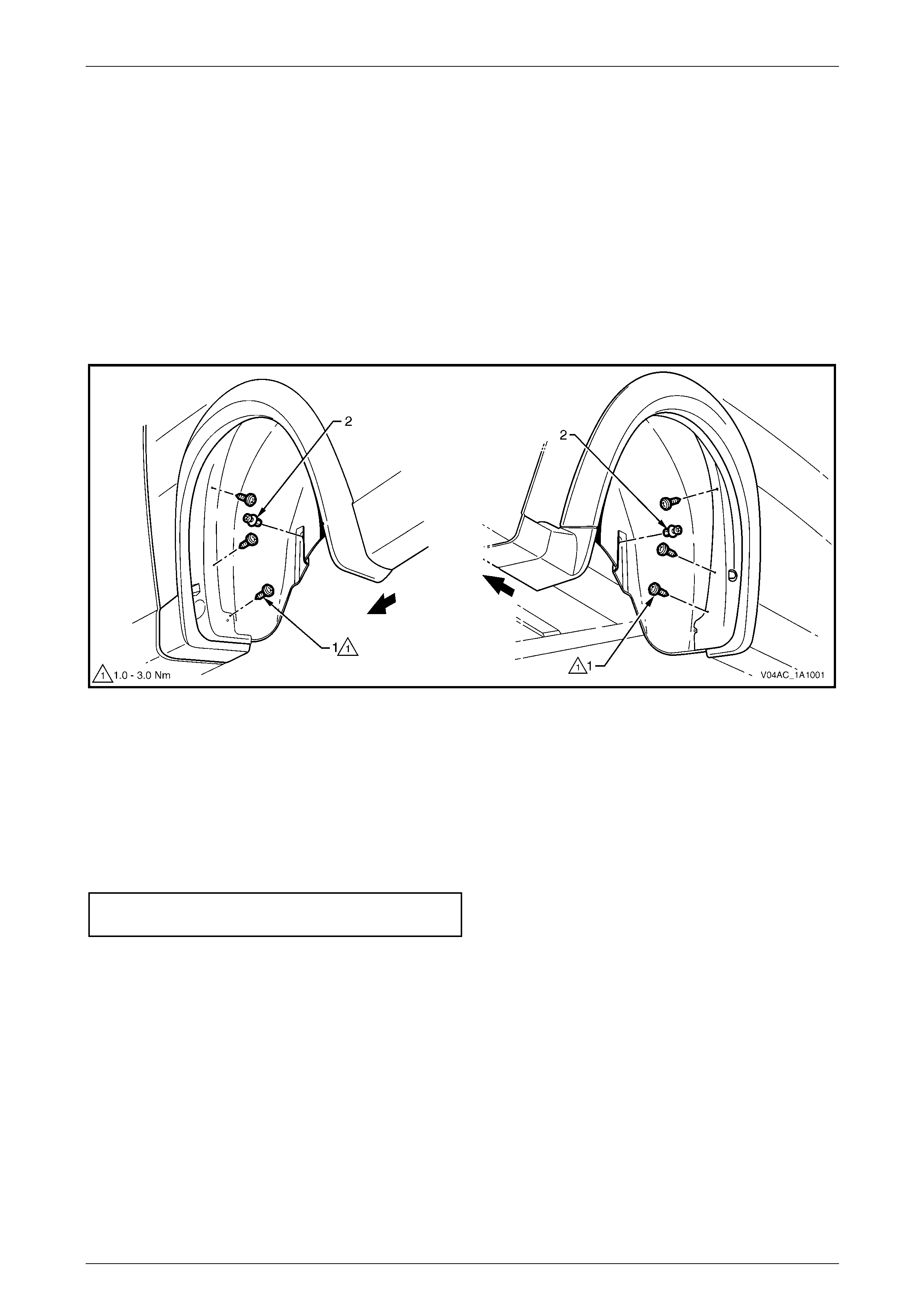
2 Remove the screw (1), two places, attaching the
rocker panel moulding assembly (2) and wheelhouse
liner (3).
Figure 1A1 – 8
3 Depending on vehicle complete either step a or b:
a Remove the screw (1) attaching the rear bumper
fascia assembly (2) to the rear wheelhouse liner
(3). Remove the two screws (4) attaching the
fascia assembly to the liner and rear bumper
fascia guide.
Figure 1A1 – 9
Body Page 1A1–29
Page 1A1–29
b Remove the screw (1) attaching the rear bumper
fascia assembly (2) to the rear wheelhouse liner
(3). Remove the two screws (4) attaching the
fascia assembly to the liner and rear bumper
fascia guide.
Figure 1A1 – 10
4 To aid removal of the wheelhouse liner partially unclip the bumper fascia from the fascia guide.
5 Referring to Figure 1A1 – 11, remove the retainer (1) and (2) attaching the liner (3) to the wheelhouse panel.
6 Manipulate the liner from behind the rocker panel moulding assembly and bumper fascia, disengage the locating
lug at the base of the liner and remove.
Figure 1A1 – 11
Reinstall
Reinstallation of the rear wheelhouse liner is the reverse of the removal procedure, noting the following:
1 Ensure the liner is correctly located behind the rocker panel moulding assembly and rear bumper fascia assembly.
Refer to Figure 1A1 – 9.
2 Tighten the screws to the correct torque specification.
Rocker panel moulding assembly
attaching screw torque specification ...........1.0 – 3.0 Nm
Rear bumper fascia assembly
attaching screw torque specification ...........1.0 – 3.0 Nm
Body Page 1A1–30
Page 1A1–30
6.4 Rear Wheelhouse Liner, Utility
LT Section No. — 12–425
Remove
1 Remove the rear road wheel, refer to Section 10 Wheels and Tyres.
2 Remove the two screws (1) attaching the rear bumper
fascia (2) to the bumper guide and wheelhouse liner.
3 Remove the screw (3) attaching the rear bumper
fascia to the wheelhouse liner and rear bumper fascia
guide.
4 To aid removal of the wheelhouse liner partially unclip
the fascia from the fascia guide.
Figure 1A1 – 12
5 Remove the screw (1) and retainer (2) attaching the
wheelhouse liner (3) to the vehicle.
NOTE
Some vehicles may have a screw in place of the
retainer.
6 Manipulate the liner from behind the bumper fascia,
disengage the locating lug at the base of the liner and
remove.
Figure 1A1 – 13
Reinstall
Reinstallation of the rear wheelhouse liner is the reverse of the removal procedure, noting the following:
1 Ensure the liner is correctly located behind the rear bumper fascia assembly. Refer to Figure 1A1 – 12.
2 Tighten the screws to the correct torque specification.
Rear wheelhouse liner attaching
screw torque specification...........................1.0 – 3.0 Nm
Rear bumper fascia assembly
attaching screw torque specification ...........1.0 – 3.0 Nm
Body Page 1A1–31
Page 1A1–31
6.5 Rear Wheelhouse Liner, Crew Cab
LT Section No. — 12–425
Remove
1 Remove the rear road wheel, refer to Section 10 Wheels and Tyres.
2 Remove the rear mudflap, refer to 6.9 Rear Mudflap, Crew Cab.
3 Remove the eight screws (1), attaching the wheelhouse liner to the body, refer to Figure 1A1 – 14.
4 Remove the two retainers (2), attaching the wheelhouse liner to the body.
Figure 1A1 – 14
5 From the rear of the vehicle, gently pull the liner down and remove.
Reinstall
Reinstallation of the rear wheelhouse liner is the reverse of the removal procedure, noting the following:
1 Ensure the wheelhouse liner is correctly positioned. Refer to Figure 1A1 – 14.
2 Tighten the screws to the correct torque specification.
Rear wheelhouse liner attaching
screw torque specification...........................1.0 – 3.0 Nm
Body Page 1A1–32
Page 1A1–32
6.6 Rear Wheelhouse Liner, Coupe
LT Section No. — 12–425
Remove
1 Remove the rear road wheel, refer to Section 10 Wheels and Tyres.
2 Remove the screw (1) attaching the rear bumper
fascia (2) to the wheel liner.
3 Remove the two screws (3) attaching the rear bumper
fascia to the wheelhouse liner and rear bumper fascia
guide.
4 Partially unclip the fascia from the fascia guide.
Figure 1A1 – 15
5 Remove the retainer (1) attaching the wheelhouse
liner (2) to the vehicle.
6 Manipulate the liner from within the wheelhouse and
remove.
Figure 1A1 – 16
Reinstall
Reinstallation of the rear wheelhouse liner is the reverse of the removal procedure, noting the following:
1 Ensure the liner is correctly located behind the rear bumper fascia. Refer to Figure 1A1 – 15.
2 Tighten the screws to the correct torque specification.
Rear wheelhouse liner attaching
screw torque specification...........................1.0 – 3.0 Nm
Rear bumper fascia assembly attaching
screw torque specification...........................1.0 – 3.0 Nm
Body Page 1A1–33
Page 1A1–33
6.7 Rear Wheelhouse Liner, AWD Wagon
LT Section No. — 12–425
Remove
1 Remove the rear road wheel, refer to Section 10 Wheels and Tyres.
2 Remove the screw (1), two places, attaching the
wheelhouse liner (2) and rocker panel moulding
assembly (3) to the vehicle.
3 Referring to Figure 1A1 – 18, remove the screw (1),
attaching the rear bumper fascia assembly (2) to the
wheelhouse liner (3).
4 Remove the three screws (4), attaching the rear
bumper fascia assembly to the liner and rear bumper
fascia guide.
5 To aid removal of the wheelhouse liner partially unclip
the fascia from the guide.
Figure 1A1 – 17
Figure 1A1 – 18
6 Remove the two screws (1), attaching the liner (2) to the flare and rear quarter panel, refer to Figure 1A1 – 19.
7 Remove the retainer (3) and (4) attaching the liner (2) to the wheelhouse panel.
Body Page 1A1–34
Page 1A1–34
Figure 1A1 – 19
8 Manipulate the liner from behind the wheelhouse flare and bumper fascia and remove.
Reinstall
Reinstallation of the rear wheelhouse liner is the reverse of the removal procedure, noting the following:
1 Ensure the wheelhouse liner is correctly positioned, refer to Figure 1A1 – 17.
2 Engage the pin on the liner with the hole in the rear bumper fascia, refer to Figure 1A1 – 18.
3 Tighten the screws to the correct torque specification.
Rear wheelhouse liner attaching
screw torque specification...........................1.0 – 3.0 Nm
Rear bumper fascia assembly attaching
screw torque specification...........................1.0 – 3.0 Nm
Body Page 1A1–35
Page 1A1–35
6.8 Rear Wheelhouse Liner, AWD Crew Cab
LT Section No. — 12–425
Remove
1 Remove the rear road wheel, refer to Section 10 Wheels and Tyres.
2 Remove the rear mudflap, refer to 6.9 Rear Mudflap, Crew Cab.
3 Remove the six screws (1), attaching the wheelhouse liner to the wheelhouse inner flare extension,
refer to Figure 1A1 – 20.
4 Remove the two retainers (2), attaching the wheelhouse liner to the body.
Figure 1A1 – 20
5 Manipulate the liner from behind the wheelhouse flare and remove.
Reinstall
Reinstallation of the rear wheelhouse liner is the reverse of the removal procedure, noting the following:
1 Ensure the wheelhouse liner is correctly positioned.
2 Tighten the screws to the correct torque specification.
Rear wheelhouse liner attaching
screw torque specification...........................1.0 – 3.0 Nm
Body Page 1A1–36
Page 1A1–36
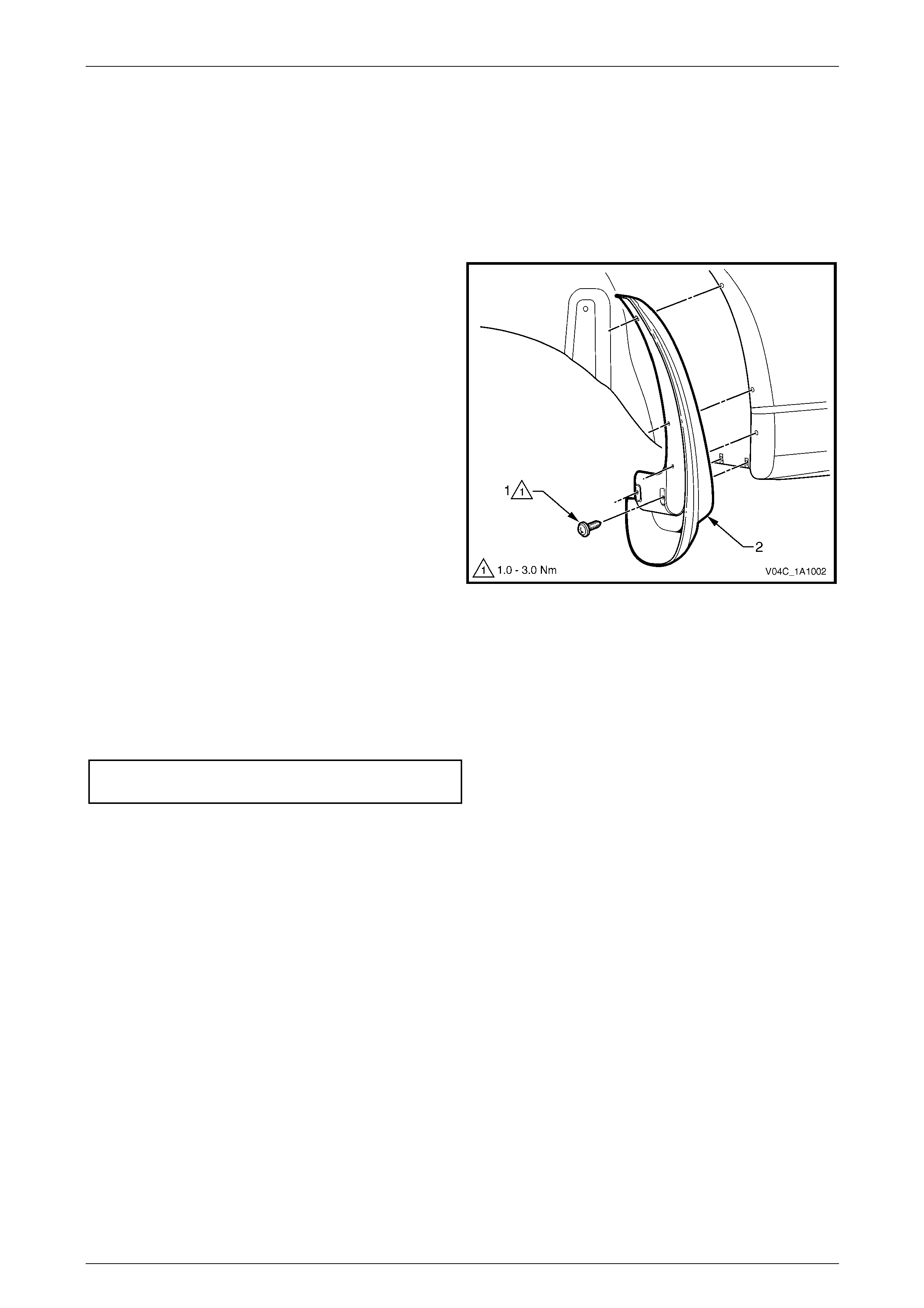
6.9 Rear Mudflap, Crew Cab
LT Section No. — XX–XXX
Remove
1 Remove the rear road wheel, refer to Section 10 Wheels and Tyres.
2 Remove the screw (1), five places, attaching the rear
mudflap (2) to the rear body and remove the mudflap.
Figure 1A1 – 21
Reinstall
Reinstallation of the rear mudflap is the reverse of the removal procedure, noting the following:
1 Ensure the mudflap is correctly positioned. Refer to Figure 1A1 – 21.
2 Tighten the nuts to the correct torque specification.
Rear mudflap attaching
screw torque specification...........................1.0 – 3.0 Nm
Body Page 1A1–37
Page 1A1–37
7 Fuel Filler Door Assemblies and
Cable Assemblies
If the fuel filler door assembly is being
replaced, the warning labels affixed to the
inside of the door must also be replaced.
The fuel filler door assembly is painted the vehicle body colour. A new fuel filler door assembly is supplied unpainted with
the moulding and lock spring (Sedan and Coupe only) unattached. If repainting an existing door, the moulding and lock
spring will need to be removed as described in this procedure. After painting and before reinstallation, the moulding and
lock spring must be fitted as described in this procedure.
Paint the door using the correct materials and techniques for PPE/PA resin (Polyphenylene/Polyamide). As the materials
and techniques required differ between paint brands, refer to the technical data supplied by your paint manufacturer.
7.1 Fuel Filler Door Assembly, Sedan
LT Section No. — 03–028
Remove
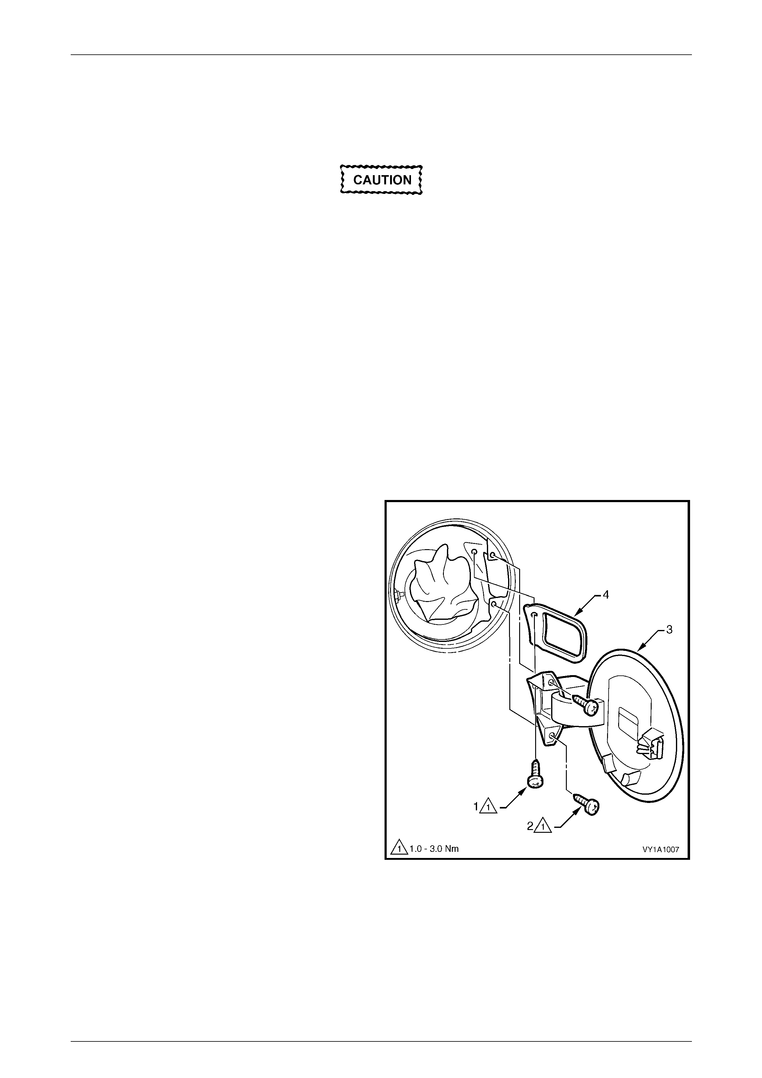
1 Open the fuel filler door by operating the release lever.
2 Remove the fuel filler cap and cover the opening with
a clean rag as required.
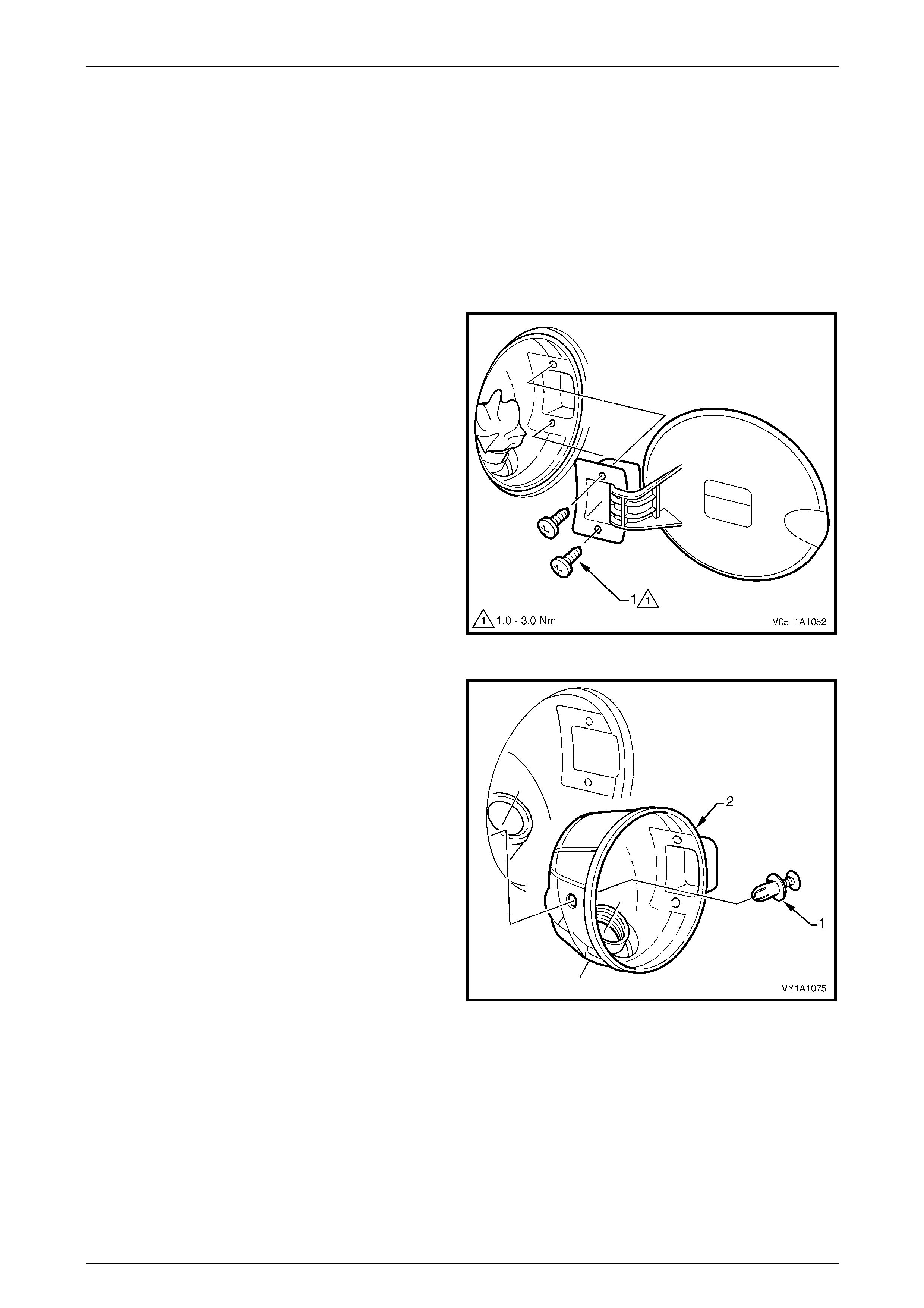
3 Remove the screw (1) and two screws (2) attaching
the fuel filler door assembly (3) to the vehicle body.
4 Remove the door assembly by withdrawing it rearward,
ensuring the gasket (4) is also removed.
NOTE
When withdrawing the fuel filler door from the
fuel filler pocket, a slight interference between
the rear edge of the plastic hinge section and the
fuel filler neck may occur. In this instance it will
be necessary to flex the rear edge of the fuel
filler door hinge slightly.
Figure 1A1 – 22

Body Page 1A1–38
Page 1A1–38
Disassemble
Lock Spring
Take care when removing the lock spring.
The lock spring has several barbs that will
cut into its mounting surface. Take care not
to excessively damage the surface onto
wh ich the lock spring is mounted.
Remove the lock spring (1) by inserting a small flat bladed
screwdriver and levering the spring outwards.
Moulding
The moulding (2) is seated in the recess (3) around the
circumference of the door and is affixed with superglue gel.
Removal may be difficult, but by carefully peeling the
moulding from the door, it is possible to remove It will not be
able to be reused.
NOTE
To aid removal, the moulding can be cut around
the inner (4) and outer sides (5) using a sharp
knife. Figure 1A1 – 23
Reassemble
Lock Spring
Push the spring fully onto the mounting tab.
Moulding
Use of superglue can be harmful and can
damage paintwork. Carefully read and follow
all directions and cautions with the product
prior to its use.
1 Carefully apply Loctite 454 (Superglue Gel) or equivalent into the fuel filler door recess around the complete
circumference.
2 Ensuring the moulding is correctly orientated, immediately fit it into the recess and leave the adhesive to cure.
Body Page 1A1–39
Page 1A1–39
Reinstall
Reinstallation of the fuel filler door assembly is the reverse of the removal procedure, noting the following:
1 If a new door assembly is being installed, or the door has been repainted, install the moulding and lock spring onto
the flap by following the reassemble procedure.
2 Tighten the screws to the correct torque specification.
Fuel filler door assembly attaching
screw torque specification...........................1.0 – 3.0 Nm
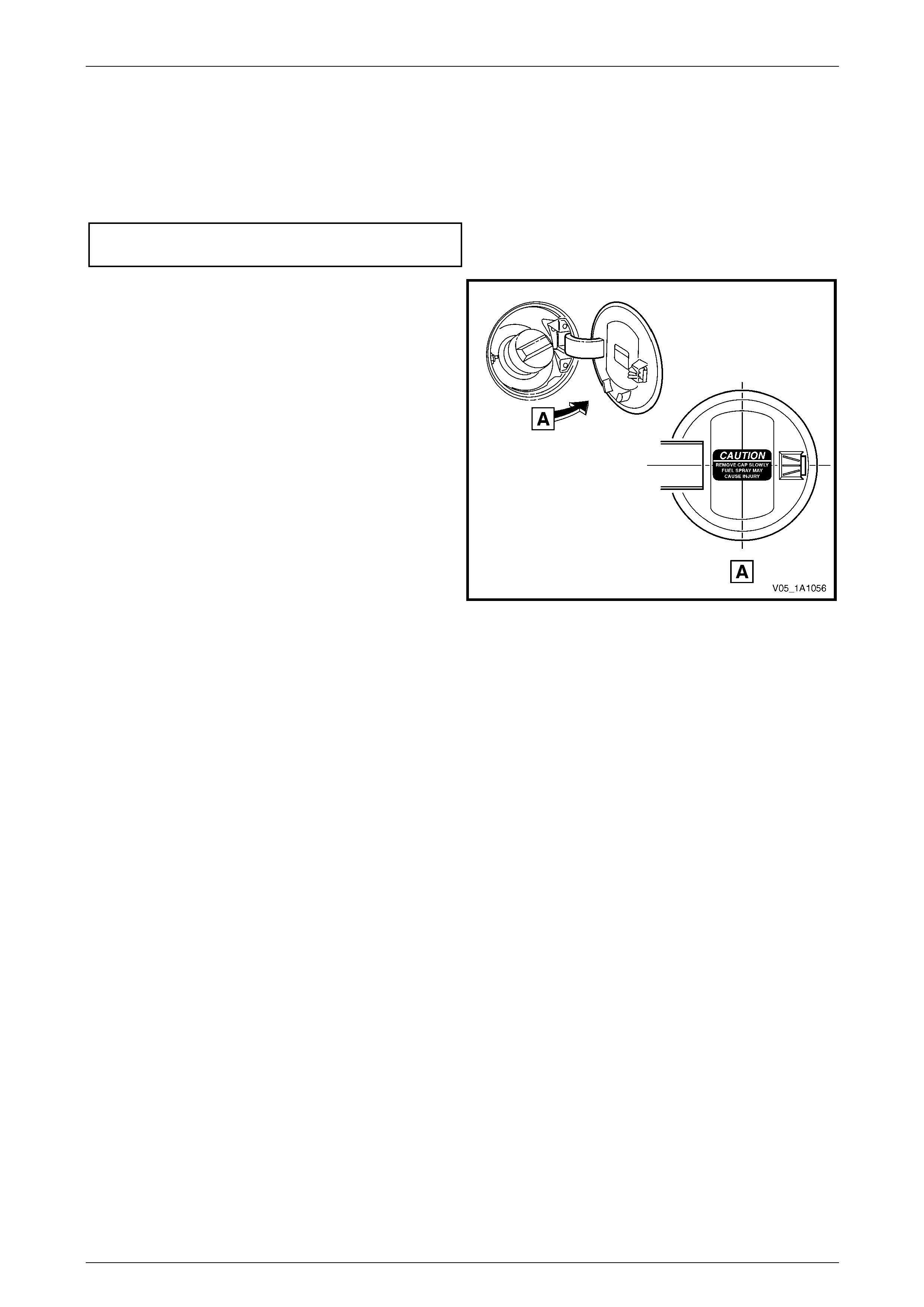
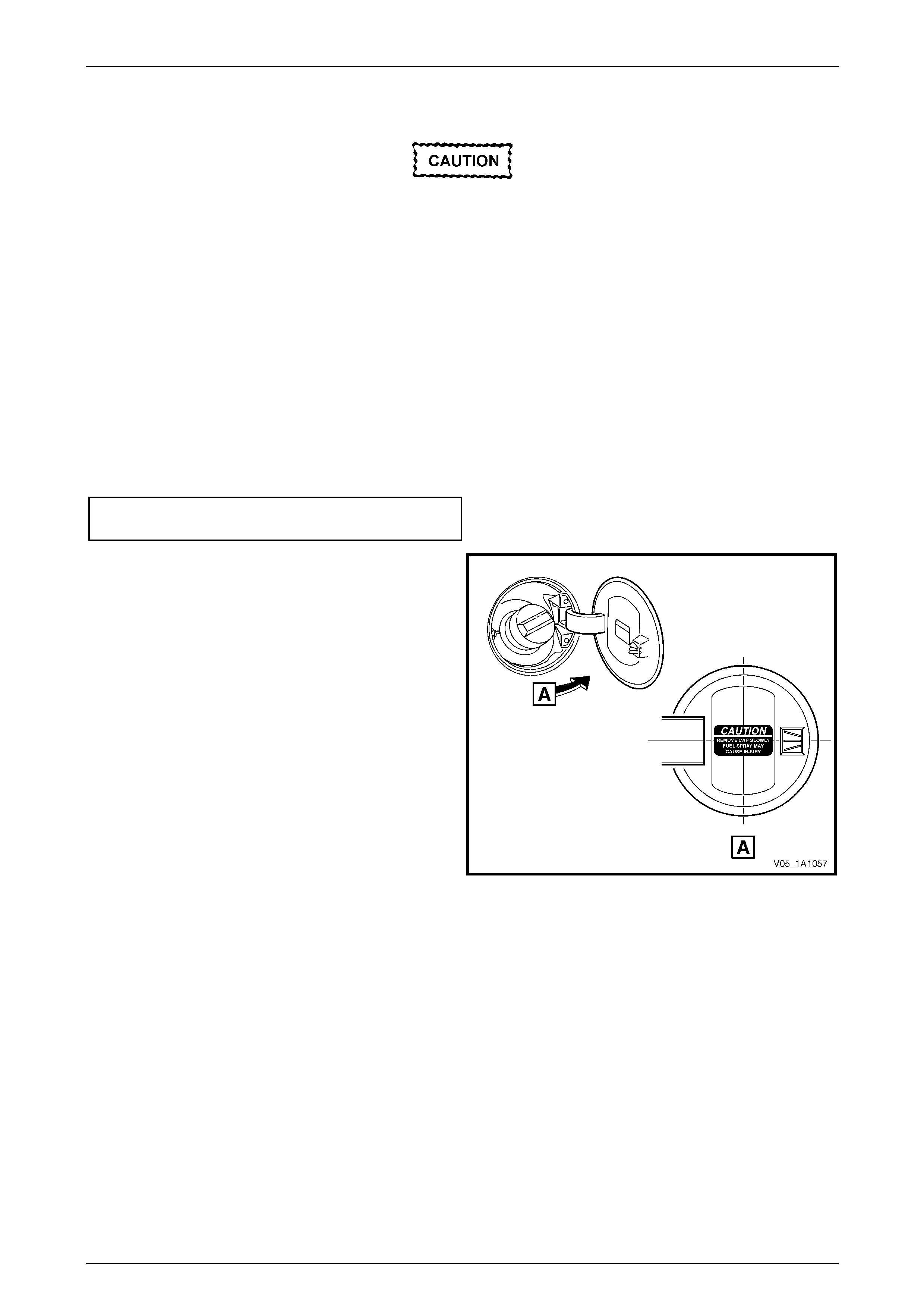
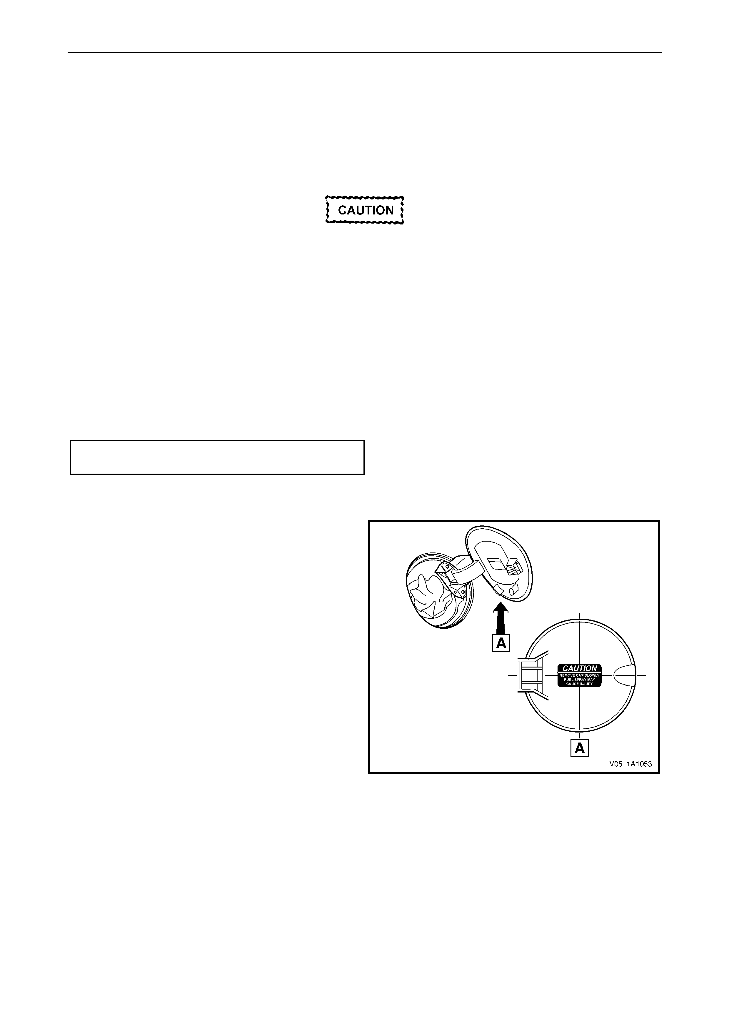
3 If the door has been replaced, apply a new label in the
position shown.
NOTE
Prior to affixing the label, ensure the surface is
clean and dry. Avoid touching the back of the
label.
4 Ensure the fuel filler door closes without the need of
excess force and is flush with the surrounding panel.
Figure 1A1 – 24
Body Page 1A1–40
Page 1A1–40
7.2 Fuel Filler Door Assembly, Wagon
LT Section No. — 03–028
Remove
1 Open the fuel filler door by operating the release lever.
2 Remove the fuel filler cap and cover the opening with a clean rag as required.
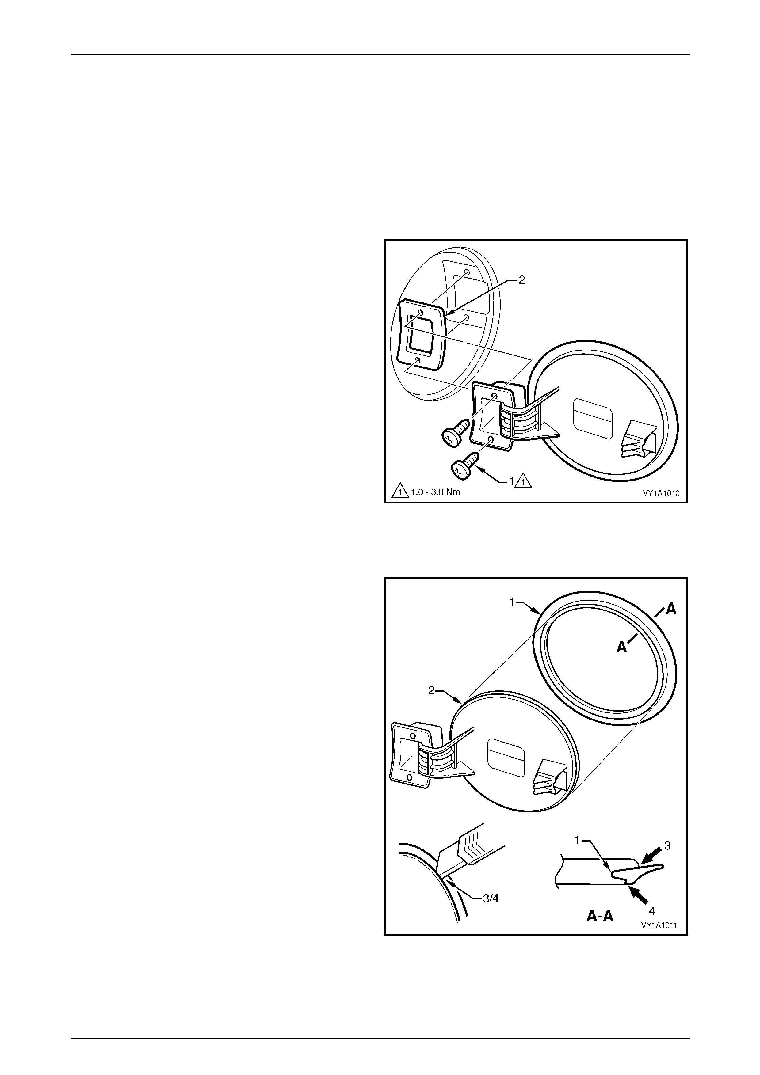
3 Remove the two screws (1) attaching the fuel filler
door assembly.
4 Remove the door assembly by withdrawing it rearward,
ensuring the gasket (2) is also removed.
Figure 1A1 – 25
Disassemble
The moulding (1) is seated in the recess (2) around the
circumference of the door and is affixed with superglue gel.
Removal may be difficult, but by carefully peeling the
moulding from the door, it is possible to remove. It will not
be able to be reused.
NOTE
To aid removal, the moulding can be cut around
the inner (3) and outer sides (4) using a sharp
knife.
Figure 1A1 – 26
Body Page 1A1–41
Page 1A1–41
Reassemble
Use of superglue can be harmful and can
damage paintwork. Carefully read and follow
all directions and cautions with the product
prior to its use.
1 To install the moulding, carefully apply Loctite 454 (Superglue Gel) or equivalent into the fuel filler door recess
around the complete circumference.
2 Ensuring the moulding is correctly orientated, immediately fit it into the recess and leave the adhesive to cure.
Reinstall
Reinstallation of the fuel filler door assembly is the reverse of the removal procedure, noting the following:
1 If a new door assembly is being installed, following painting of the door flap, install the moulding by reversing the
disassembly procedure.
2 Tighten the screws to the correct torque specification.
Fuel filler door assembly attaching
screw torque specification...........................1.0 – 3.0 Nm
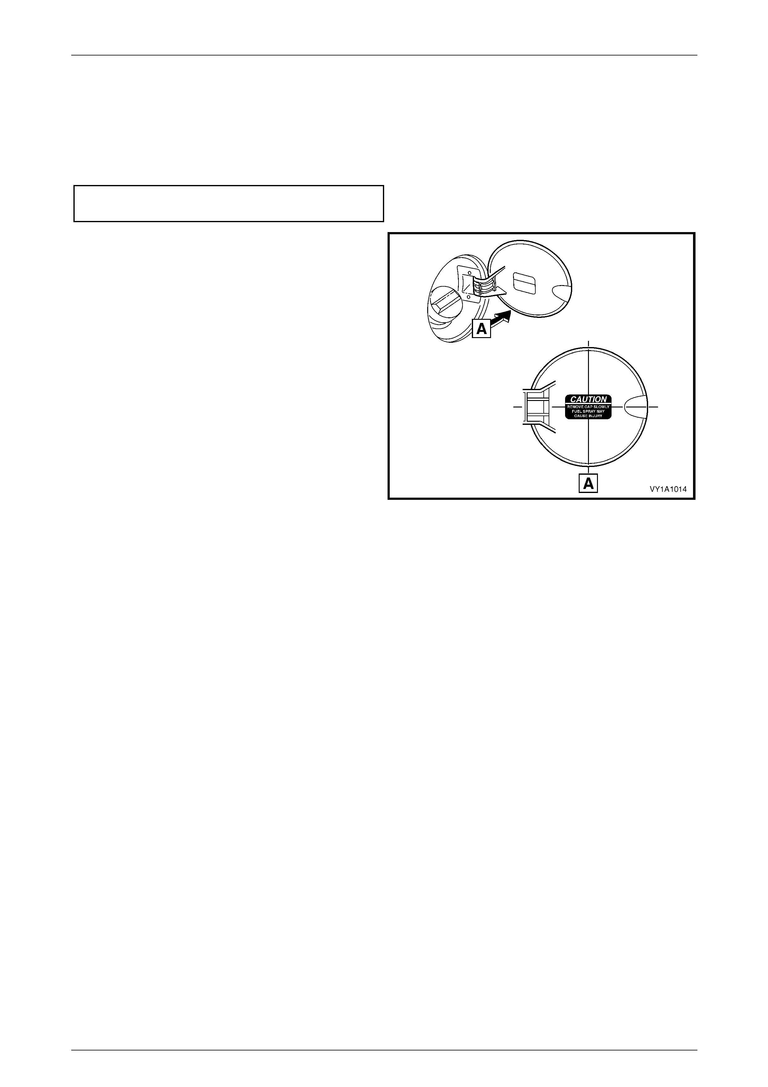
3 If the door has been replaced, apply a new label in the
position shown.
NOTE
Prior to affixing the label ensure the surface is
clean and dry. Avoid touching the back of the
label.
4 Ensure the fuel filler door closes without the need of
excess force and is flush with the surrounding panel.
Figure 1A1 – 27
Body Page 1A1–42
Page 1A1–42
7.3 Fuel Filler Door Assembly, Utility and
Crew Cab
LT Section No. — 03–028
Remove
1 Open the fuel filler door by hand.
2 Remove the fuel filler cap and cover the opening with a clean rag as required.
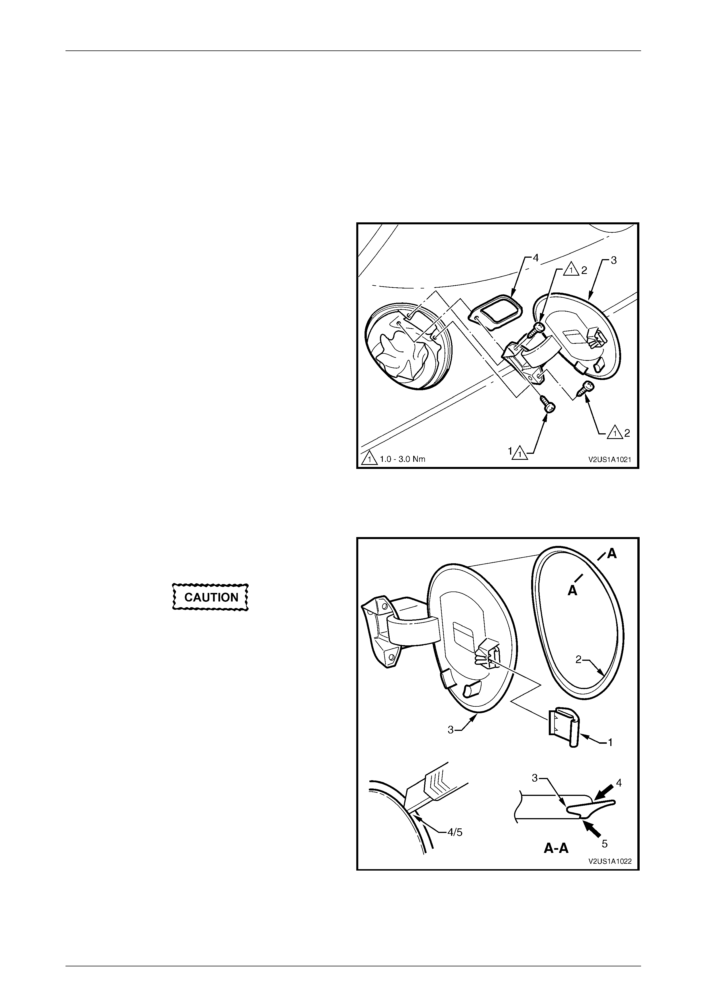
3 Remove the two screws (1) attaching the fuel filler
door assembly.
4 Remove the door assembly by withdrawing it towards
the rear of the car.
Figure 1A1 – 28
5 If required, remove the retainer (1) from the inner
opening of the fuel filler pipe seal (2).
6 Remove the seal by sliding it over the filler neck.
Figure 1A1 – 29
Body Page 1A1–43
Page 1A1–43
Reinstall
Reinstallation of the fuel filler door assembly is the reverse of the removal procedure, noting the following:
1 If a new door assembly is being installed, following painting of the door flap, install the moulding by reversing the
disassembly procedure.
2 Tighten the screws to the correct torque specification.
Fuel filler door assembly attaching
screw torque specification...........................1.0 – 3.0 Nm
3 If the door has been replaced, apply a new label in the
position shown.
NOTE
Prior to affixing the label, ensure the surface is
clean and dry. Avoid touching the back of the
label.
4 Ensure the fuel filler door closes without the need of
excess force and is flush with the surrounding panel.
Figure 1A1 – 30
Body Page 1A1–44
Page 1A1–44
7.4 Fuel Filler Door Assembly, Coupe
LT Section No. — 03–028
Remove
1 Open the fuel filler door by operating the release lever.
2 Remove the fuel filler cap and cover the opening with a clean rag as required.
3 Remove the screw (1) and the two screws (2)
attaching the fuel filler door assembly (3).
4 Remove the door assembly by withdrawing it rearward,
ensuring the gasket (4) is also removed.
Figure 1A1 – 31
Disassemble
Lock Spring
Take care when removing the lock spring.
The lock spring has several barbs that will
cut into its mounting surface. Take care not
to excessively damage the surface onto
wh ich the lock spring is mounted.
Remove the lock spring (1) by inserting a small screwdriver
and levering the spring outwards.
Moulding
The moulding (2) is seated in the recess (3) around the
circumference of the door and is affixed with superglue gel.
Removal may be difficult, but by carefully peeling the
moulding from the door, it is possible to remove the
moulding. It will not be able to be reused.
NOTE
To aid removal, the moulding can be cut around
the inner (4) and outer sides (5) using a sharp
knife. Figure 1A1 – 32
Body Page 1A1–45
Page 1A1–45
Reassemble
Lock Spring
Push the spring fully onto the mounting tab.
Moulding
Use of superglue can be harmful and can
damage paintwork. Carefully read and follow
all directions and cautions with the product
prior to its use.
1 Carefully apply Loctite 454 (Superglue Gel) or equivalent into the fuel filler door recess around the complete
circumference.
2 Ensuring the moulding is correctly orientated, immediately fit it into the recess and leave the adhesive to cure.
Reinstall
Reinstallation of the fuel filler door assembly is the reverse of the removal procedure, noting the following:
1 Tighten the screws to the correct torque specification.
Fuel filler door assembly attaching
screw torque specification...........................1.0 – 3.0 Nm
2 If a new door assembly is being installed, following painting of the door flap, install the moulding and lock spring by
reversing the disassembly procedure.
3 If the door has been replaced, apply a new label in the
position shown.
NOTE
Prior to affixing the label ensure the surface is
clean and dry. Avoid touching the back of the
label.
4 Ensure the fuel filler door closes without the need of
excess force and is flush with the surrounding panel.
Figure 1A1 – 33
Body Page 1A1–46
Page 1A1–46
7.5 Fuel Filler Door Lock Cable Assembly,
Sedan
LT Section No. — 03–028
Remove
1 As required, remove the following components:
a Right-hand side sill trim and quarter inner rear side carpet, refer to Section 1A8 Headlining and Interior Trim.
b Right hand rear seat-back assembly and seat cushion assembly, refer to Section 1A7 Seat Assemblies.
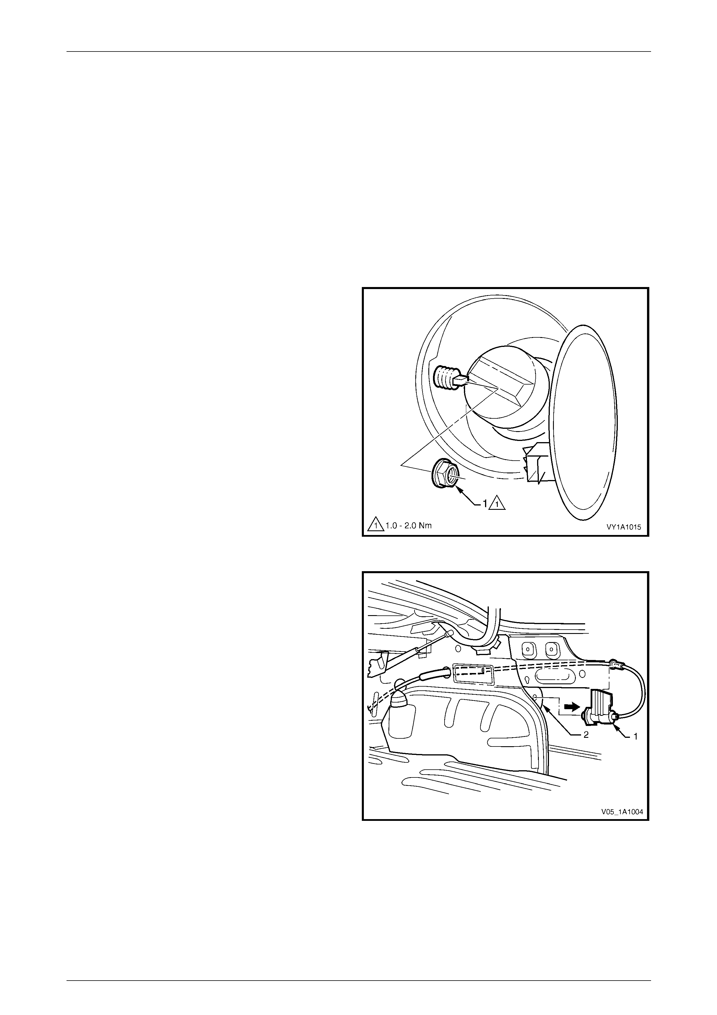
2 Open the fuel filler door by operating the release lever.
3 Remove the nut (1) from inside the fuel filler housing.
NOTE
Take care not to damage the plastic nut.
Figure 1A1 – 34
4 From within the rear compartment, pull the cable
assembly (1) rearward to remove it from the fuel filler
housing (2).
Figure 1A1 – 35

Body Page 1A1–47
Page 1A1–47
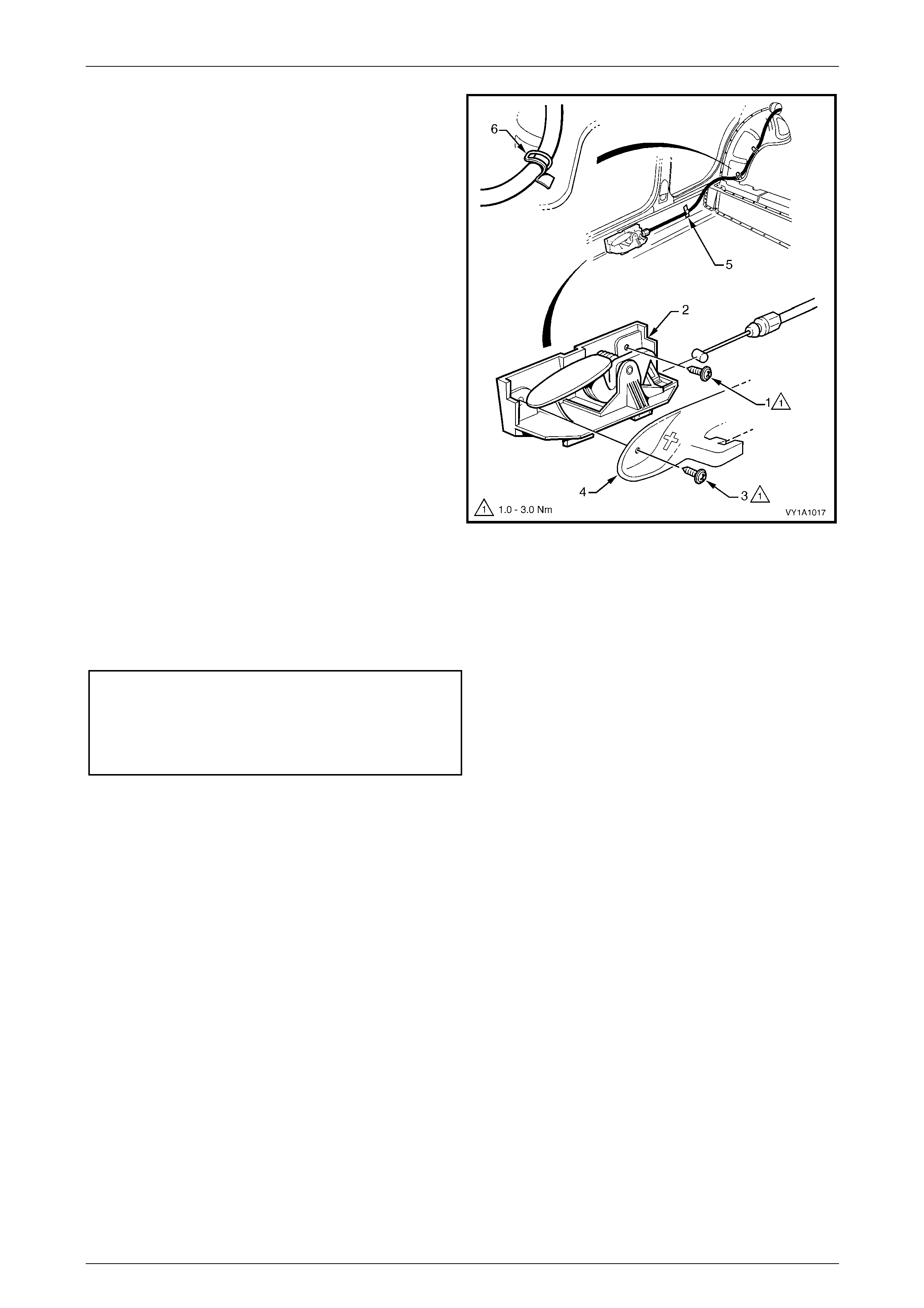
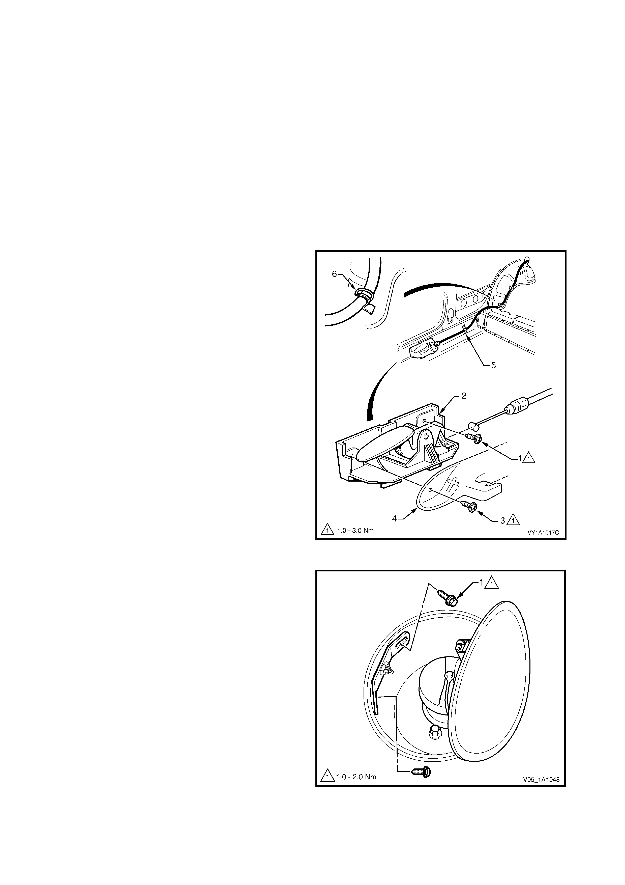
5 From inside the vehicle, remove the screw (1)
attaching the cable assembly lever (2) to the rocker
panel.
NOTE
Screw (3) and the front seat outer side cover (4)
should have been removed during step 1, they
are shown here for reference.
6 Remove the tape (5) and bend the retaining tabs (6) to
release the cable assembly.
7 Remove the cable assembly from the vehicle, feeding
it through the back panel upper.
8 If required, unclip the cable from the release lever.
Figure 1A1 – 36
Reinstall
Reinstallation of the fuel filler door lock cable assembly is the reverse of the removal procedure, noting the following:
1 Tighten the nuts and screws to the correct torque specification.
Fuel filler door lock cable assembly
latch nut torque specification.......................1.0 – 2.0 Nm
Fuel filler door cable assembly
release lever attaching screw
torque specification.....................................1.0 – 3.0 Nm
2 Ensure the cable assembly is routed correctly and is fitted with the tab up as shown in Figure 1A1 – 35.
3 Check the cable assembly operates correctly and the plunger completely retracts prior to closing the fuel filler door.
If satisfactory, close the door ensuring it does not require excess force. The door should spring ajar when the
release is operated.
Body Page 1A1–48
Page 1A1–48
7.6 Fuel Filler Door Lock Cable Assembly,
Wagon
LT Section No. — 03–028
Remove
1 As required, remove the following components:
a Right-hand side sill trim, refer to Section 1A8 Headlining and Interior Trim.
b Right-hand quarter inner trim upper, body lock pillar lower trim and quarter inner trim panel assembly,
refer to Section 1A8 Headlining and Interior Trim.
c Right-hand rear seat bolster assembly refer to Section 1A7 Seat Assemblies.
2 Fold the rear seat backrest to the horizontal position.
3 Open the fuel filler door by operating the release lever.
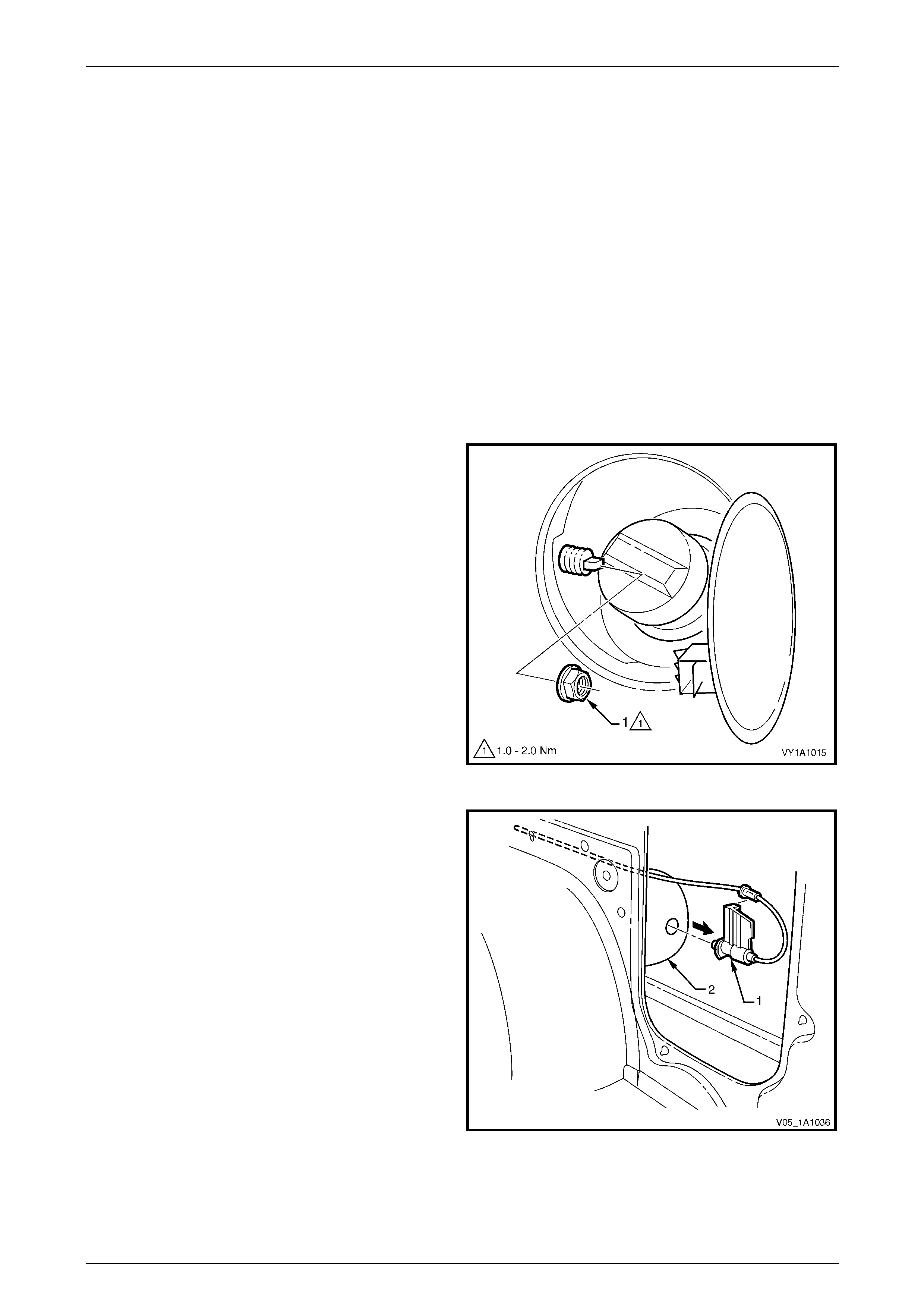
4 Remove the nut (1) from inside the fuel filler housing.
NOTE
Take care not to damage the plastic nut.
Figure 1A1 – 37
5 From within the rear compartment, pull the cable
assembly (1) rearward to remove it from the fuel filler
housing (2).
Figure 1A1 – 38
Body Page 1A1–49
Page 1A1–49
6 From inside the vehicle, remove the screw (1)
attaching the cable assembly lever (2) to the rocker
panel.
NOTE
Screw (3) and the front seat outer side cover (4)
should have been removed during step 1, they
are shown here for reference.
7 Remove the tape (5) and bend the retaining tabs (6) to
release the cable assembly.
8 Remove the cable assembly from the vehicle.
9 If required, unclip the cable from the release lever.
Figure 1A1 – 39
Reinstall
Reinstallation of the fuel filler door lock cable assembly is the reverse of the removal procedure, noting the following:
1 Tighten the nuts and screws to the correct torque specification.
Fuel filler door lock cable assembly
latch nut torque specification.......................1.0 – 2.0 Nm
Fuel filler door cable assembly
release lever attaching screw
torque specification.....................................1.0 – 3.0 Nm
2 Ensure the cable assembly is routed correctly and is fitted with the tab up as shown in Figure 1A1 – 38.
3 Check the cable assembly operates correctly and the plunger completely retracts prior to closing the fuel filler door.
If satisfactory, close the door ensuring it does not require excess force. The door should spring ajar when the
release is operated.
Body Page 1A1–50
Page 1A1–50
7.7 Fuel Filler Door Lock Cable Assembly,
Coupe
LT Section No. — 03–028
Remove
1 As required, remove the following components:
a Right-hand side sill trim and quarter inner rear side carpet, refer to Section 1A8 Headlining and Interior Trim.
b Right hand rear seat-back assembly and seat cushion assembly, refer to Section 1A7 Seat Assemblies.
2 Open the fuel filler door by operating the release lever.
3 From inside the vehicle, remove the screw (1)
attaching the cable assembly lever (2) to the rocker
panel.
NOTE
Screw (3) and the front seat outer side cover (4)
should have been removed during step 1, they
are shown here for reference.
4 Remove the tape (5) and bend the retaining tabs (6) to
release the cable assembly.
5 Unclip the cable from the release lever.
6 Pull the cable through the back panel upper into the
rear compartment.
Figure 1A1 – 40
7 From within the fuel filler housing, remove the two
screws (1) that attach the cable assembly.
8 Pull the cable assembly from the vehicle through the
fuel filler housing.
Figure 1A1 – 41

Body Page 1A1–51
Page 1A1–51
Reinstall
Reinstallation of the fuel filler door lock cable assembly is the reverse of the removal procedure, noting the following:
1 Tighten the screws to the correct torque specification.
Fuel filler door lock cable assembly
latch screw torque specification ..................1.9 – 2.1 Nm
Fuel filler door cable assembly
release lever attaching screw
torque specification.....................................1.0 – 3.0 Nm
2 Ensure the cable assembly is routed correctly.
3 Check the cable assembly operates correctly and the plunger completely retracts prior to closing the fuel filler door.
If satisfactory, close the door ensuring it does not require excess force. The door should spring ajar when the
release is operated.
Body Page 1A1–52
Page 1A1–52
8 Drain Tubes, Utility
8.1 Rear Floor Panel Drain Tube
LT Section No. — 99–150
NOTE
If the tube becomes blocked or restricted, clear
the obstruction with a length of wire.
Remove
NOTE
Although not shown, the drain tube can be
removed with the fuel tank in place.
1 Remove the front load floor panel, refer to Section 1B Sheetmetal.
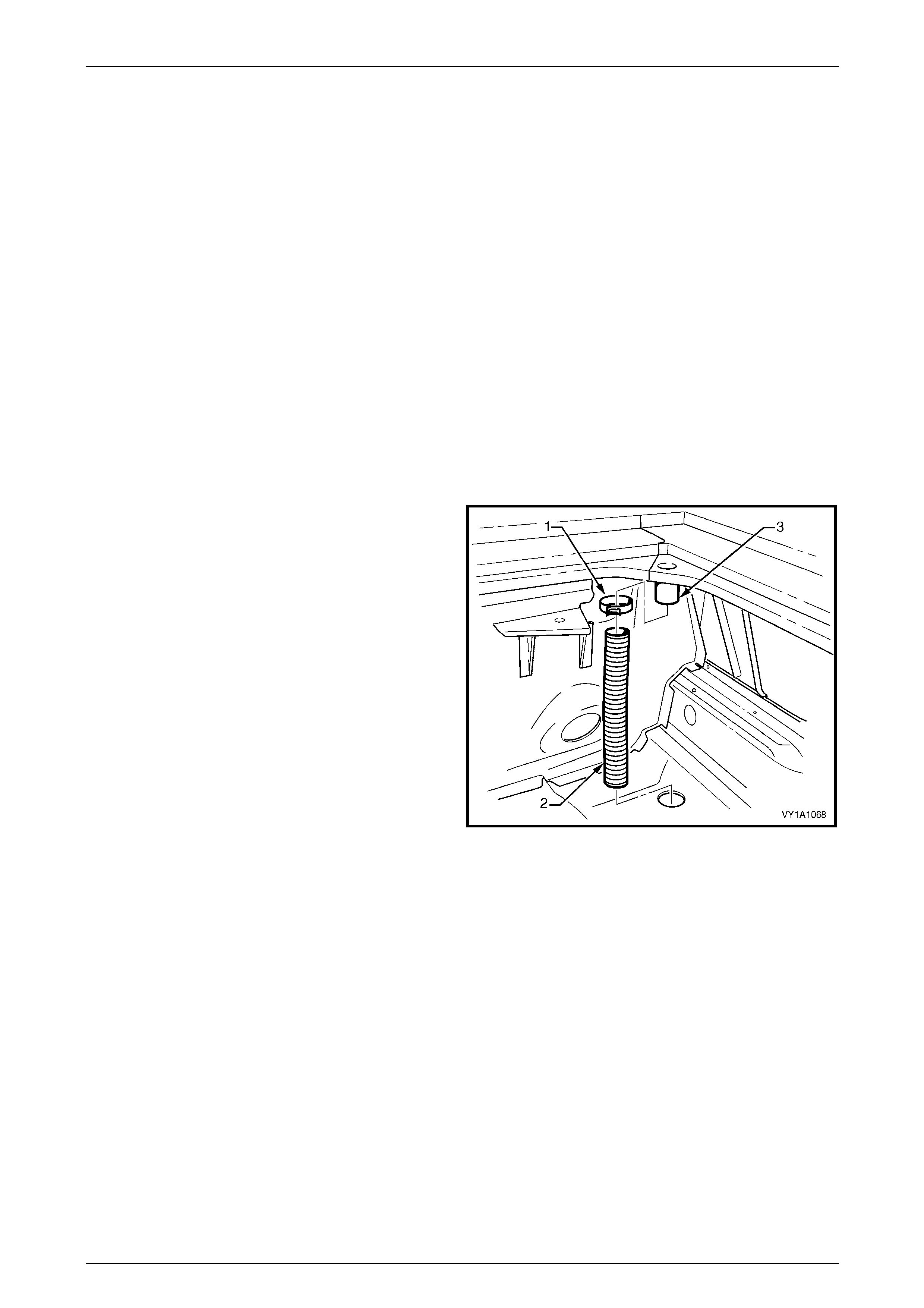
2 Using a pair of pliers, loosen the clamp (1) and slide it
down the rear floor panel drain tube (2).
3 Prise the tube from the floor panel outlet (3).
4 Withdraw the tube from the hole in the floor panel and
remove.
Figure 1A1 – 42
Reinstall
Reinstallation of the rear floor panel drain tube is the reverse of the removal procedure, ensuring the tube and clamp are
correctly seated.
Body Page 1A1–53
Page 1A1–53
8.2 Rear Window Panel Drain Tube
Assembly
LT Section No. — 99–150
NOTE
If the tube becomes blocked or restricted, clear
the obstruction with a length of wire.
Remove
NOTE
Although not shown, the drain tube can be
removed with the fuel tank in place.
1 As required, remove the following components:
a Rear window side moulding assembly and rear quarter window moulding
refer to Section 1A9 Exterior Ornamentation.
b Front load floor panel, refer to Section 1B Sheetmetal.
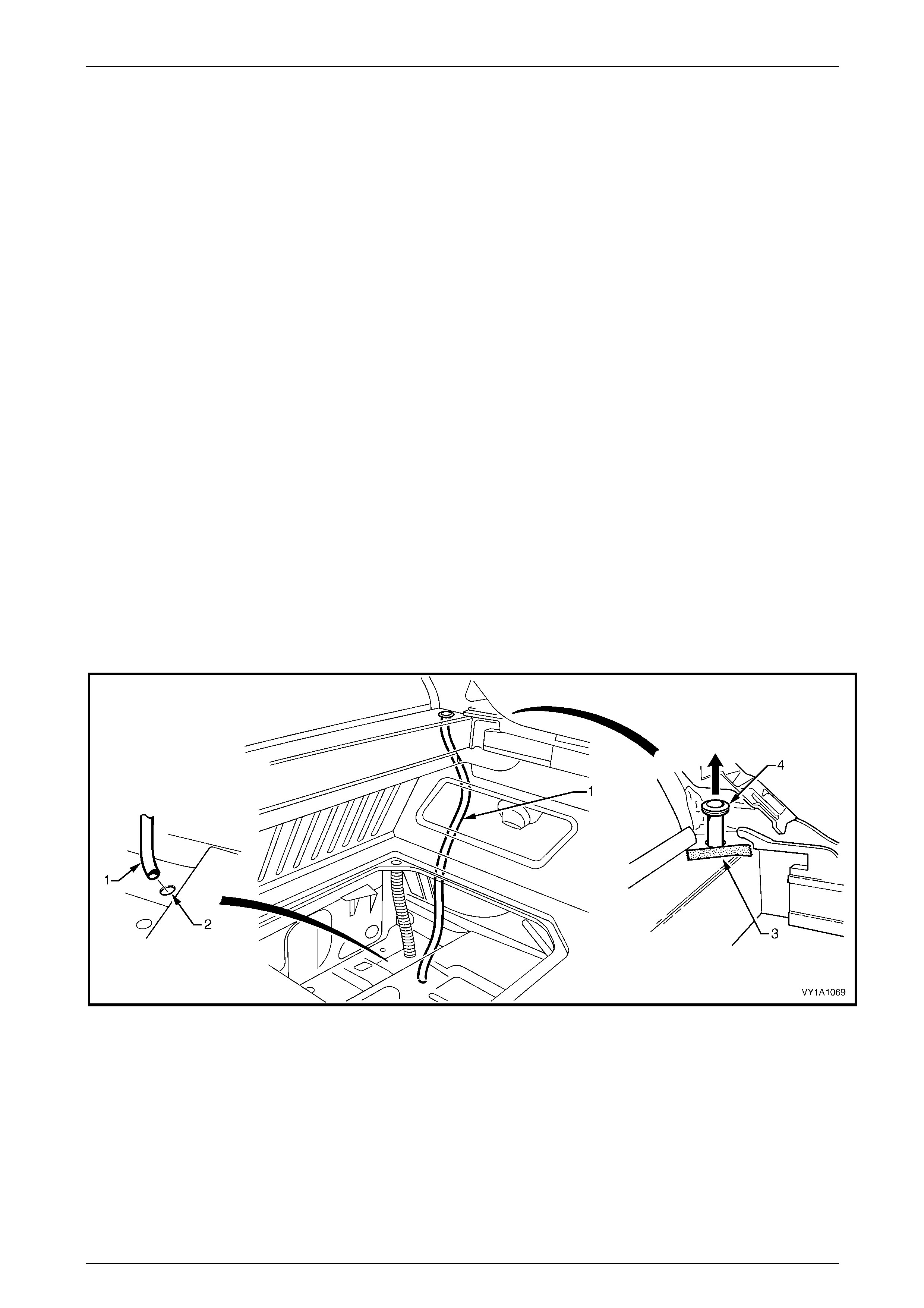
2 Remove the rear window panel drain tube assembly (1) from the hole in the floor panel (2),
refer to Figure 1A1 – 43.
3 Protect the paintwork on the panel adjacent to the tube assembly with a piece of tape (3).
4 Using a fine flat blade screwdriver, prise the tube assembly grommet (4) from the panel.
5 Pull the tube assembly through the hole in the panel and remove.
Figure 1A1 – 43
Reinstall
Reinstallation of the rear window panel drain tube assembly is the reverse of removal, ensuring the tube is correctly
seated.

Body Page 1A1–54
Page 1A1–54
9 Body Braces
9.1 Front Suspension Strut Brace
LT Section No. — XX–XXX
Remove
1 Remove the nut (1), four places, attaching the front
suspension strut brace to the suspension strut towers.
2 Remove the brace.
Figure 1A1 – 44
Reinstall
Reinstallation of the front suspension strut brace is the reverse of the removal procedure. Tighten the nuts to the correct
torque specification.
Front suspension strut brace attaching
nut torque specification......................................30.0 Nm

Body Page 1A1–55
Page 1A1–55
9.2 Rear Underbody Air Deflector, Coupe
LT Section No. — XX–XXX
Remove
NOTE
If desired, the rear underbody air deflector and
rear underbody brace can be removed as an
assembly, refer to 9.3 Rear Underbody Brace,
Coupe in place of step 7.
1 Disconnect the two ABS wiring harness connectors (1)
from the two retainers (2).
2 Unclip the ABS wiring harness (3) from the rear
underbody air deflector (4).
Figure 1A1 – 45
3 Remove the two bolts (1) attaching the rear underbody
air deflector (2) to the vehicle.
4 Disconnect the two ABS wiring harness
connectors (3).
5 Feed the ABS wiring harness (4) through the hole (5)
in the underbody air deflector.
Figure 1A1 – 46
Body Page 1A1–56
Page 1A1–56
6 Remove the two retainers (1), attaching the rear
underbody air deflector (2) to the bumper fascia (3).
7 With the aid of an assistant to support the rear
underbody air deflector, remove the three screws (4),
attaching it to the rear underbody brace (5).
8 Remove the rear underbody air deflector.
Figure 1A1 – 47
Reinstall
NOTE
A replacement rear underbody air deflector may
be delivered with the delivery hook flap (6), refer
to Figure 1A1 – 47, in the folded position. If so,
once installed remove the two retainers holding
the flap in the folded position, unfold the flap and
use the same retainers to secure the flap to the
rear bumper fascia.
Reinstallation of the rear underbody air deflector is the reverse of the removal procedure. Tighten the nuts and screws to
the correct torque specification.
Rear underbody air deflector to cross
member bolt torque specification .......................20.0 Nm
Rear underbody air deflector to cross
member nut torque specification........................20.0 Nm
Rear underbody air deflector to rear
underbody brace screw torque specification......20.0 Nm
Body Page 1A1–57
Page 1A1–57
9.3 Rear Underbody Brace, Coupe
LT Section No. — XX–XXX
Remove
1 Remove, completely or partially (up to step 6), the rear underbody air deflector, refer to
9.2 Rear Underbody Air Deflector, Coupe.
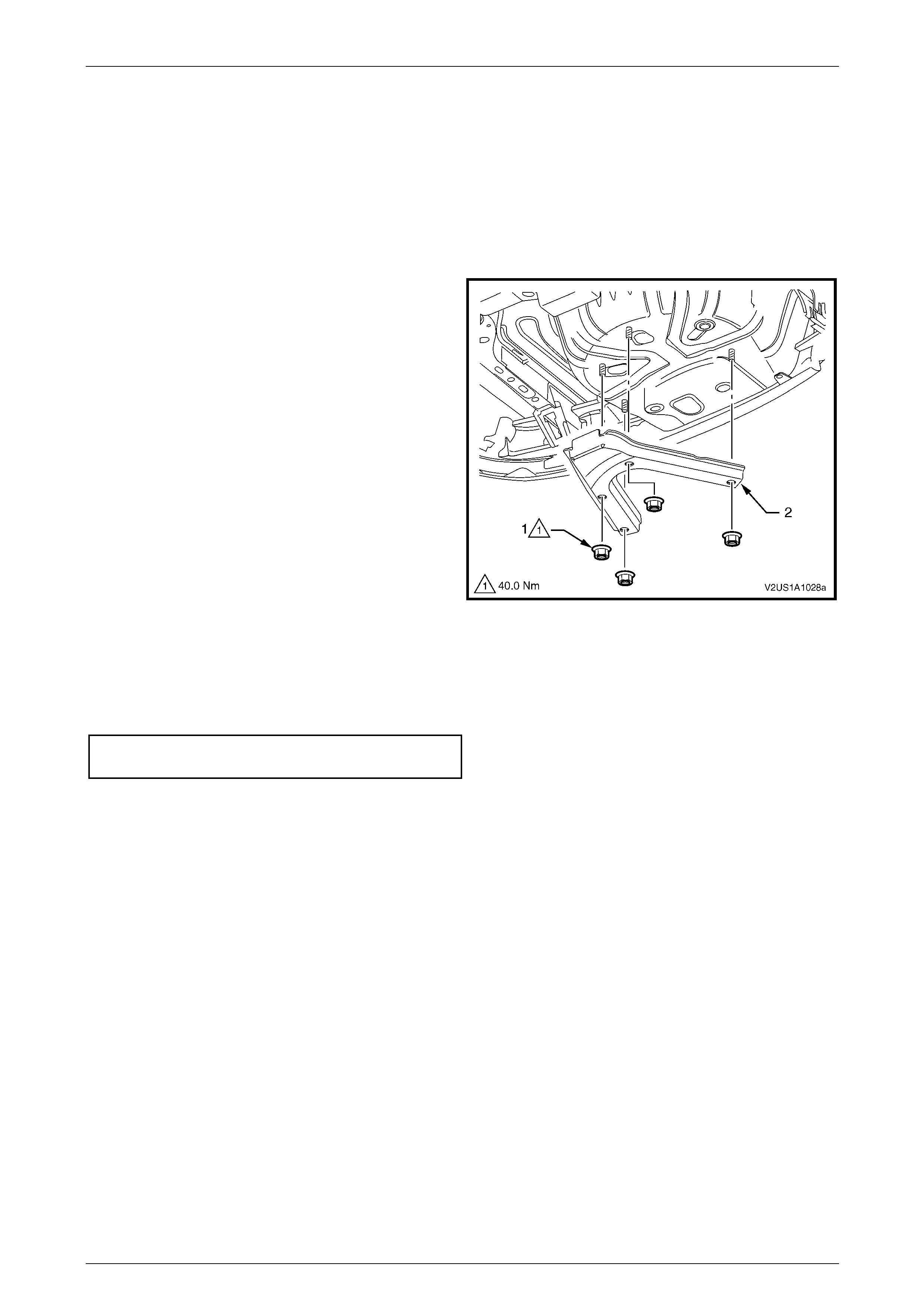
2 Remove the four nuts (1), attaching the rear
underbody brace (2) to the underbody of the vehicle.
3 Remove the rear underbody brace.
Figure 1A1 – 48
Reinstall
Reinstallation of the rear underbody brace is the reverse of the removal procedure. Tighten the nuts to the correct torque
specification.
Rear underbody brace attaching nut
torque specification............................................40.0 Nm
Body Page 1A1–58
Page 1A1–58
9.4 Back Body Opening Frame Assembly,
Coupe
LT Section No. — XX–XXX
Remove
1 Remove the quarter inner rear side carpet and fuel tank cage carpet,
refer to Section 1A8 Headlining and Interior Trim.
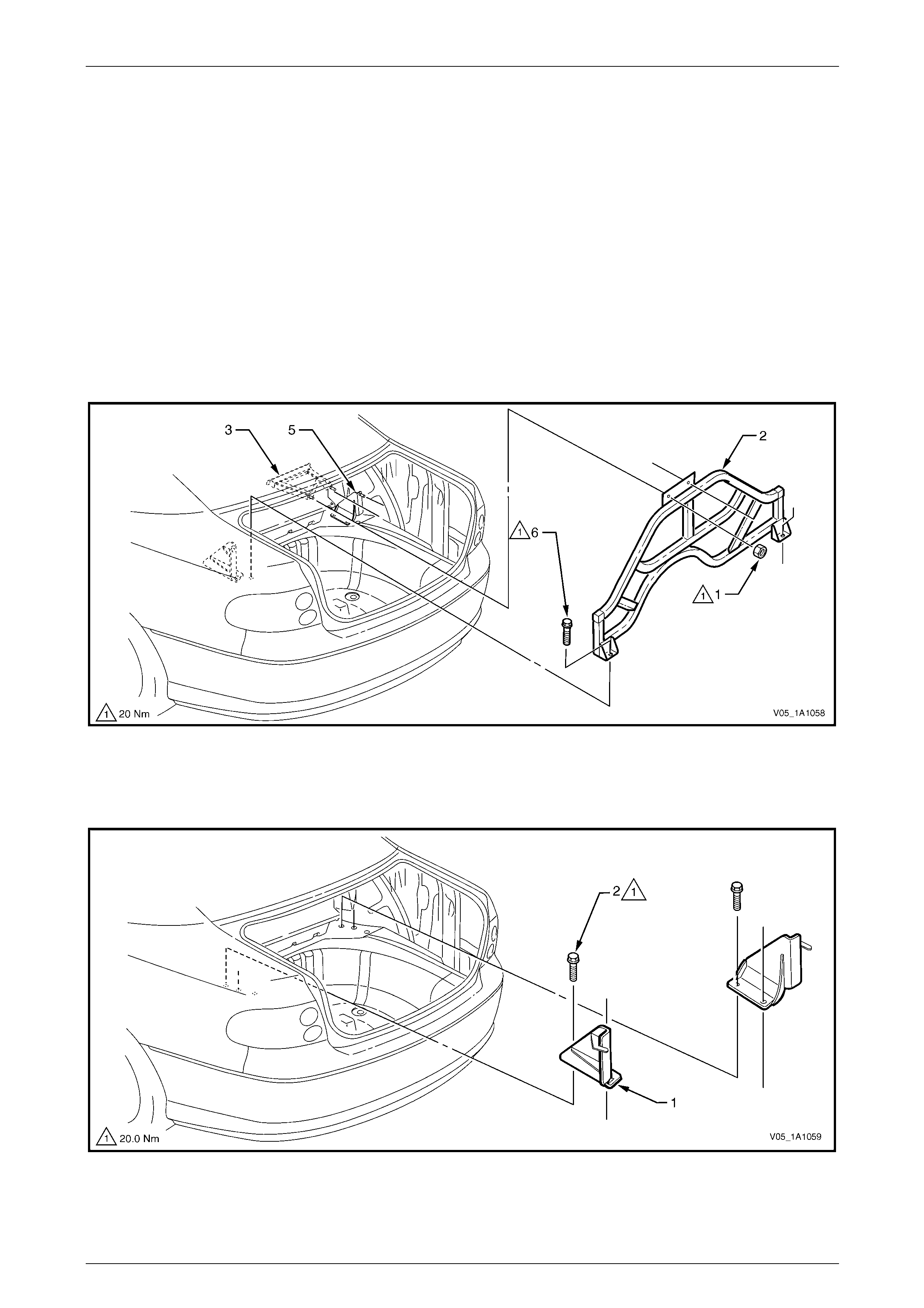
2 Remove nut (1), two places, attaching the back body opening frame assembly (2) to the rear compartment panel
frame (3), refer to Figure 1A1 – 49.
3 Remove the bolt (6), one place on each side.
4 Lean the frame assembly forward off the studs and remove from the rear compartment of the vehicle.
Figure 1A1 – 49
5 For each bracket (1), remove bolt (2), two places, refer to Figure 1A1 – 50.
6 Remove the bracket from the vehicle.
Figure 1A1 – 50

Body Page 1A1–59
Page 1A1–59
Reinstall
Reinstallation of the back body opening frame assembly the reverse of the removal procedure. Tighten the nuts to the
correct torque specification.
Back body opening frame assembly to
rear compartment panel frame nut
torque specification............................................20.0 Nm
Back body opening frame assembly
to body bolt torque specification.........................60.0 Nm
Back body opening frame assembly
to underbody side rail bracket nut
torque specification............................................20.0 Nm
Body Page 1A1–60
Page 1A1–60
10 Inner Rear Body Panel
10.1 Inner Rear Body Panel, Regular Cab
LT Section No. — XX–XXX
Remove
1 As required, remove the following components:
a Front seat assemblies, or move them to the fully forward position, refer to Section 1A7 Seat Assemblies.
b Floor console, refer to Section 1A3 Instrument Panel and Console.
c Centre pillar lower trim, refer to Section 1A9 Exterior Ornamentation.
d Side sill trim and plate, body lock pillar upper trim and rear seat back body panel trim assembly,
refer to Section 1A8 Headlining and Interior Trim.
e Child seat restraint, refer to Section 12M Occupant Protection System.
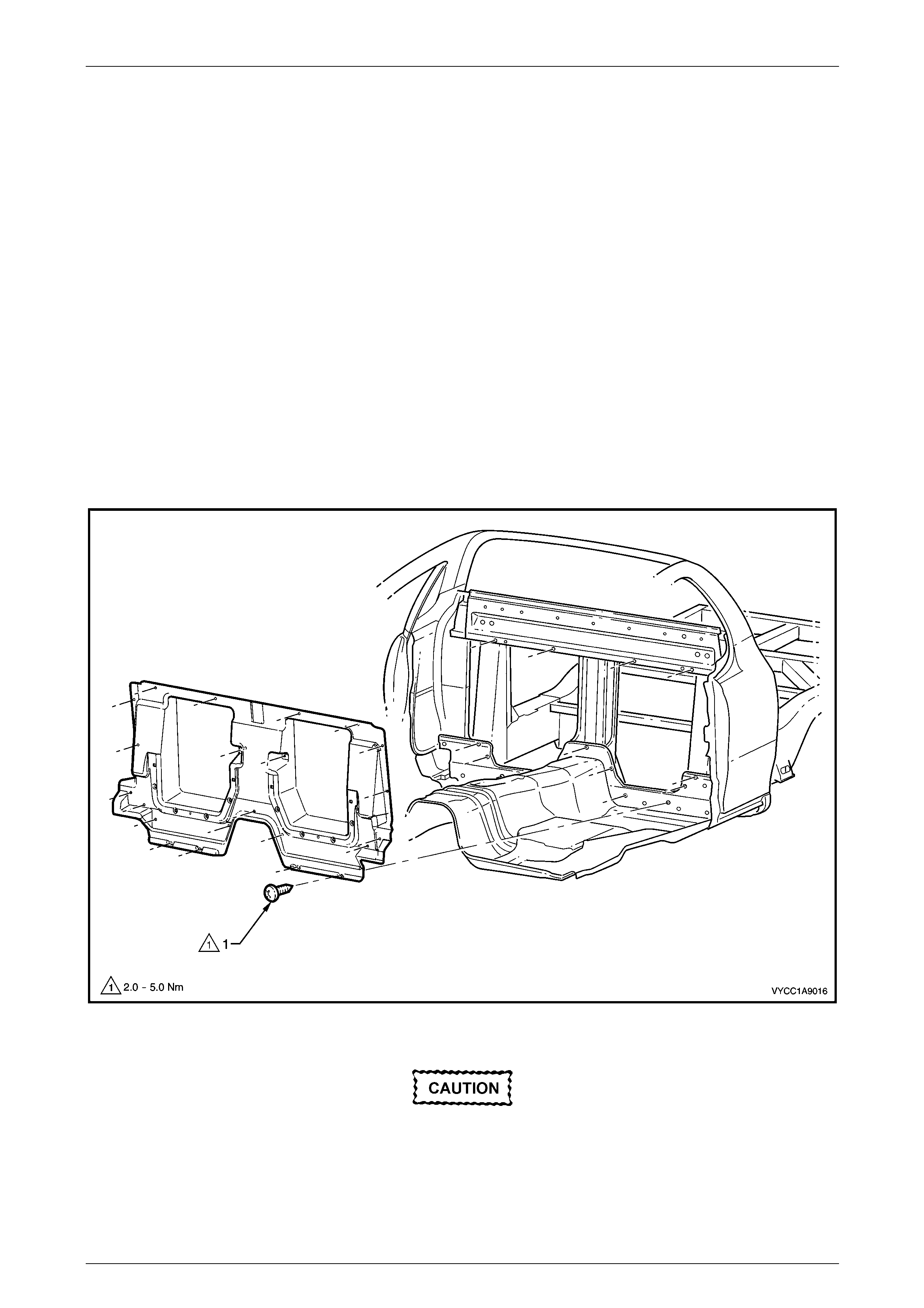
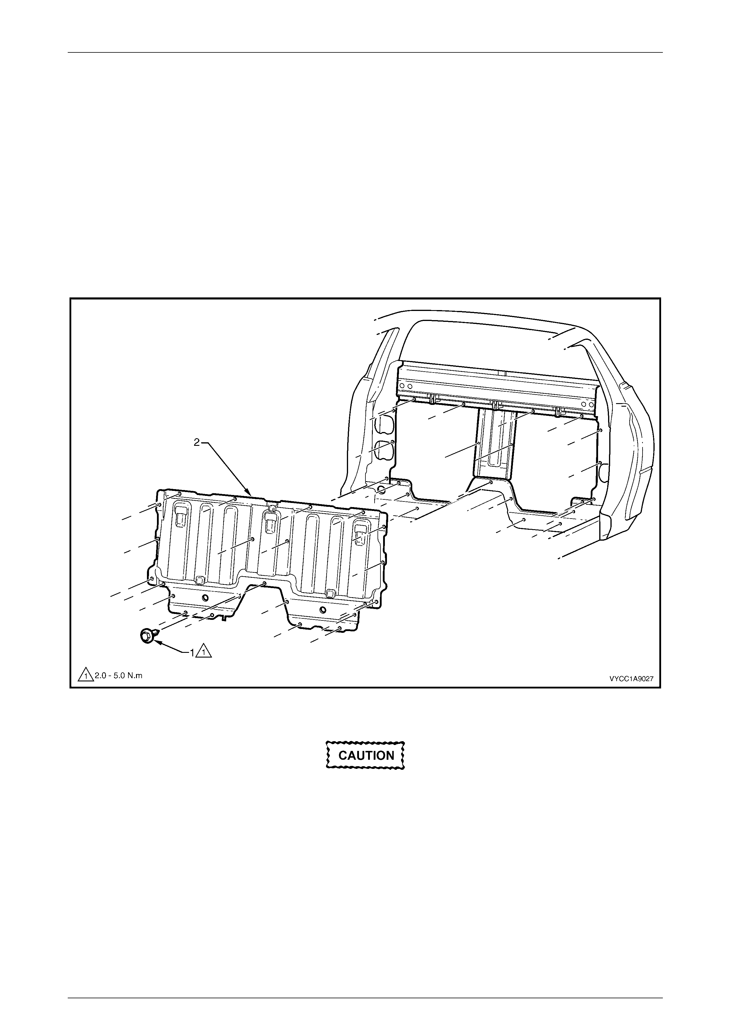
2 Remove the screw (1), 23 places, attaching the inner rear body panel to the cab, refer to Figure 1A1 – 51.
Figure 1A1 – 51
During removal the sealer of the inner rear
body panel can be messy. To avoid damage
cover the interior trim as appropriate.
Body Page 1A1–61
Page 1A1–61
NOTE
Softening the sealer with a heat gun around the
perimeter of the body panel will aid removal.
3 Using a suitable screwdriver, lever the inner rear body panel forward to dislodge the sealer from the body and
remove the panel through the passenger door.
Reinstall
1 As required clean off any residual sealer from the surfaces of the inner rear body panel and the body.
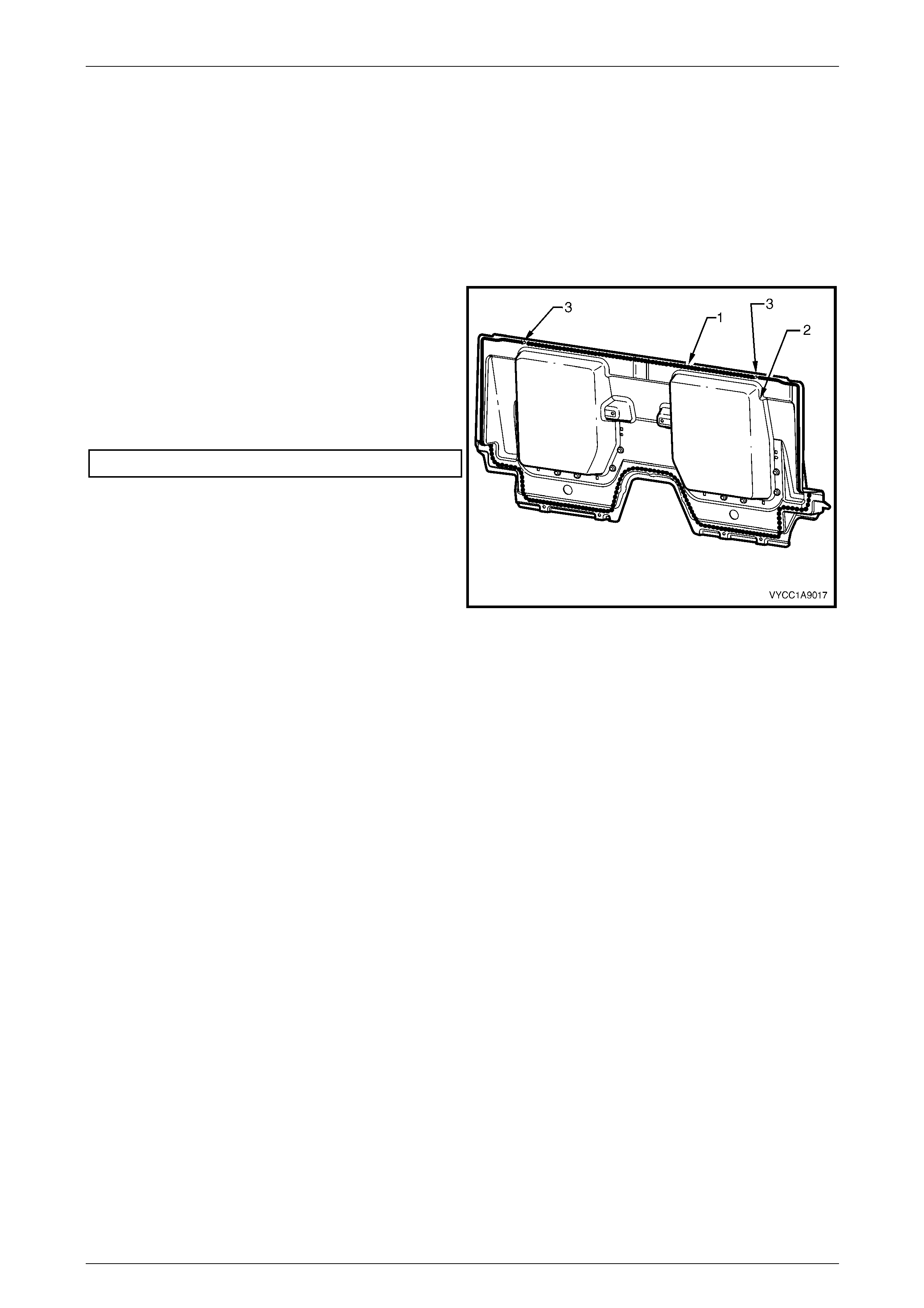
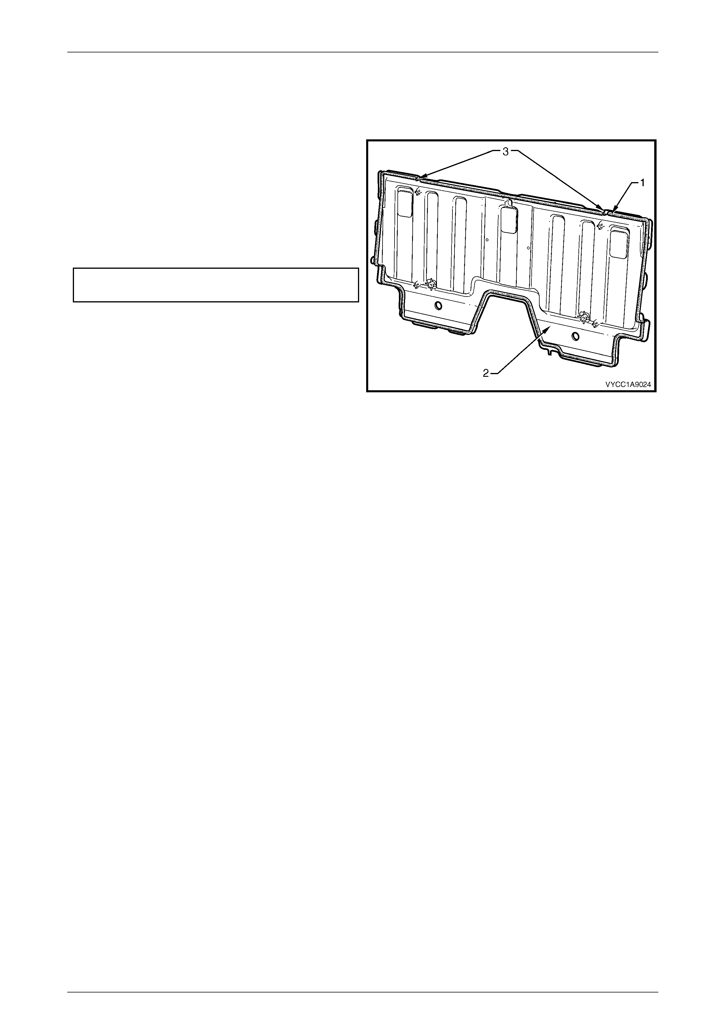
2 Apply a bead of mastic sealer (1) or similar around the
edges of the inner rear body panel (2).
3 Using the data pin (3) on the inner rear body panel,
position the panel onto the body.
4 Install the screw (1), 23 places, attaching the inner
rear body panel, refer to Figure 1A1 – 51.
5 Tighten the screws to the correct torque specification.
Inner rear body panel attaching screw........2.0 – 5.0 Nm
6 Reinstall any removed components.
Figure 1A1 – 52
Body Page 1A1–62
Page 1A1–62
10.2 Inner Rear Body Panel, Crew Cab
LT Section No. — XX–XXX
Remove
1 As required, remove the following components:
a Rear seat-back assembly, refer to Section 1A7 Seat Assemblies.
b Upper cross beam cover, refer to Section 1A8 Headlining and Interior Trim.
c Child seat restraint and seatbelts, refer to Section 12M Occupant Protection System.
2 Remove the screw (1), 23 places, attaching the inner rear body panel (2), to the body, refer to Figure 1A1 – 53.
Figure 1A1 – 53
During removal the sealer of the inner rear
body panel can be messy. To avoid damage
cover the interior trim as appropriate.
NOTE
Softening the sealer with a heat gun around the
perimeter of the body panel will aid removal.
3 Using a suitable screwdriver, lever the inner rear body panel forward to loosen the sealer and remove the panel
through the rear door.
Body Page 1A1–63
Page 1A1–63
Reinstall
1 Clean off any residual sealer from the surfaces of the inner rear body panel and body.
2 Ensure the NVH foam is fitted in the correct location, refer to Section 1A9 Exterior Ornamentation.
3 Apply a bead of mastic sealer (1) or similar around
the edges of the inner rear body panel (2).
4 Using the data pins (3) on the inner rear body panel,
align the panel to the body.
5 Reinstall the 23 screws attaching the inner rear body
panel.
6 Tighten the screws to the correct torque specification.
Inner rear body panel attaching screw
torque specification...................................2.0 – 5.0 Nm
7 Reinstall any removed components.
Figure 1A1 – 54

Body Page 1A1–64
Page 1A1–64
11 Torque Wrench Specifications
Front Wheelhouse Liner Attaching Screw....................................1.0 – 3.0 Nm
Front Bumper Fascia Assembly Attaching Screw........................1.0 – 3.0 Nm
Rocker Panel Moulding Assembly Attaching Screw....................1.0 – 3.0 Nm
Rear Bumper Fascia Assembly Attaching Screw ........................1.0 – 3.0 Nm
Rear Wheelhouse Liner Attaching Screw....................................1.0 – 3.0 Nm
Rear Mudflap Attaching Screw....................................................1.0 – 3.0 Nm
Fuel Filler Door Assembly Attaching Screw.................................1.0 – 3.0 Nm
Fuel Filler Door Lock Cable Assembly Latch Nut ........................1.0 – 2.0 Nm
Fuel Filler Door Cable Assembly Release Lever
Attaching Screw...........................................................................1.0 – 3.0 Nm
Fuel Filler Door Cable Assembly Latch Screw.............................1.9 – 2.1 Nm
Front Suspension Strut Brace Attaching Nut......................................30.0 Nm
Rear Underbody Air Deflector to Crossmember Bolt..........................20.0 Nm
Rear Underbody Air Deflector to Crossmember Nut...........................20.0 Nm
Rear Underbody Air Deflector to Rear Underbody Brace Screw ........20.0 Nm
Rear Underbody Brace Attaching Nut ................................................40.0 Nm
Back Body Opening Frame Assembly to Rear Compartment
Panel Frame Nut ................................................................................20.0 Nm
Back Body Opening Frame Assembly to Body Attaching Bolt ........... 60.0 Nm
Back Body Opening Frame Assembly to Underbody Side
Rail Bracket Nut .................................................................................20.0 Nm
Inner Rear Body Panel Attaching Screw......................................2.0 – 5.0 Nm