
Body Dimensions Page 1A2–1
Page 1A2–1
Section 1A2
Body Dimensions
ATTENTION
Before performing any Service Operation or other procedure described in this Section, refer to Section 00
Warnings, Cautions and Notes for correct workshop practices with regard to safety and/or property damage.
1 General Information ...............................................................................................................................3
2 Service Operations.................................................................................................................................4
2.1 Underbody Dimensions – Projected .................................................................................................................... 4
Sedan...................................................................................................................................................................... 4
Measuring Points................................................................................................................................................ 4
Dimensions ........................................................................................................................................................ 5
Wagon and AWD Wagon.......................................................................................................................................6
Measuring Points................................................................................................................................................ 6
Dimensions ........................................................................................................................................................ 7
Coupe...................................................................................................................................................................... 8
Measuring Points................................................................................................................................................ 8
Dimensions ........................................................................................................................................................ 9
Utility..................................................................................................................................................................... 10
Measuring Points.............................................................................................................................................. 10
Dimensions ...................................................................................................................................................... 11
Regular Cab and AWD Regular Cab................................................................................................................... 12
Measuring Points.............................................................................................................................................. 13
Dimensions ...................................................................................................................................................... 14
Crew Cab and AWD Crew Cab............................................................................................................................ 15
Measuring Points.............................................................................................................................................. 16
Dimensions ...................................................................................................................................................... 17
2.2 Upperbody Dimension – Actual.......................................................................................................................... 18
Front Dimensions ................................................................................................................................................ 18
All Vehicles....................................................................................................................................................... 18
Side and Interior Dimensions ............................................................................................................................. 19
Sedan............................................................................................................................................................... 19
Wagon and AWD Wagon ................................................................................................................................. 20
Coupe............................................................................................................................................................... 21
Utility ................................................................................................................................................................ 22
Regular Cab and AWD Regular Cab................................................................................................................ 23
Crew Cab and AWD Crew Cab........................................................................................................................ 24
Rear Dimensions.................................................................................................................................................. 25
Sedan............................................................................................................................................................... 25
Wagon and AWD Wagon ................................................................................................................................. 26
Coupe............................................................................................................................................................... 27
Utility ................................................................................................................................................................ 28
Crew Cab and AWD Crew Cab Rear Body...................................................................................................... 29

Body Dimensions Page 1A2–2
Page 1A2–2
2.3 Suspension Frame and Transmission Support Alignment.............................................................................. 30
Front Suspension Frame Assembly................................................................................................................... 31
Transmission Support......................................................................................................................................... 31
Except AWD Vehicles ...................................................................................................................................... 31
AWD Vehicles .................................................................................................................................................. 32
Rear Suspension Frame Assembly.................................................................................................................... 33
Except AWD Wagon......................................................................................................................................... 33
AWD Wagon .................................................................................................................................................... 35
3 Torque Wrench Specifications............................................................................................................38
4 Special Tools ........................................................................................................................................39

Body Dimensions Page 1A2–3
Page 1A2–3
1 General Information
Correct alignment of the body structure is essential to ensur e the vehicle performs as intended. A body structure that is
outside design tolerances ca n suffer difficult operation and poor fitment of the doors, hood, rear compartment lid, liftgate
or endgate. Suspension performance and vehicle handling can also suffer and noise vibration and harshness may
become evident.
The body structure should ther efore be aligned to within ± 1.5 mm of the dimensions specified in the relevant service
information for the particular vehicle.
As a minimum, these dimensions shoul d be accurately checked with a trammel gauge consisting of a parallel bar or rod
fitted with two adjustable trammels.
In preparation for an underbody alignment check, the vehicle must be correctly set-up on a level surface, preferably
using a measuring or jigging system specifically designed for the task of checking and correcting vehicle body alignment.
NOTE
• The dimensions provided for the underbody
are projected, that is, the measuring points
are transposed onto a two dimensional (flat)
surface and the measurements are taken
along the one plane.
• All upperbody measurements are actual, that
is, the distance from point to point.
Incorrect alignment of the front suspension frame and transmission support can have an adverse affect on the vehicle’s
performance and introduce n oise, vibration and harshness.
Although there are some minor differences b etween AWD vehicles and their conventional two wheel drive variants,
service procedures and dimensio ns are the same. Where there are differences in the procedures, dimensions or
measuring points, the relevant service information is pr ovided.
Any time a suspension frame and/or the tra nsmission support is removed, the y must be aligned correctly when
reinstalled, refer to 2.3 Suspension Frame and Transmission Support.
Body Dimensions Page 1A2–4
Page 1A2–4
2 Service Operations
2.1 Underbody Dimensions – Projected
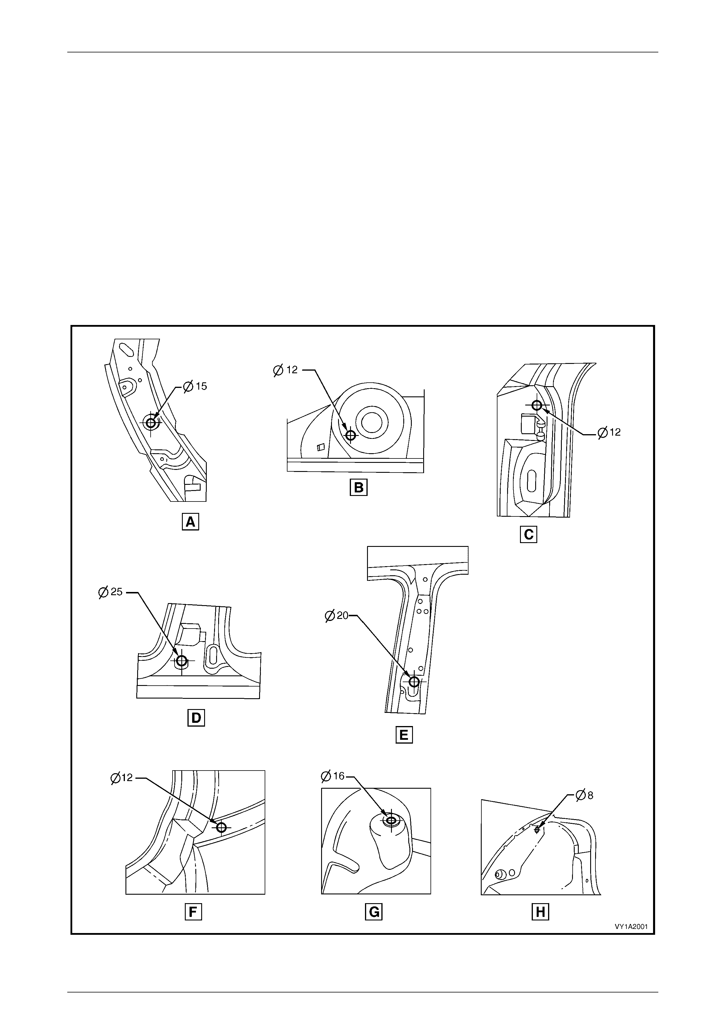
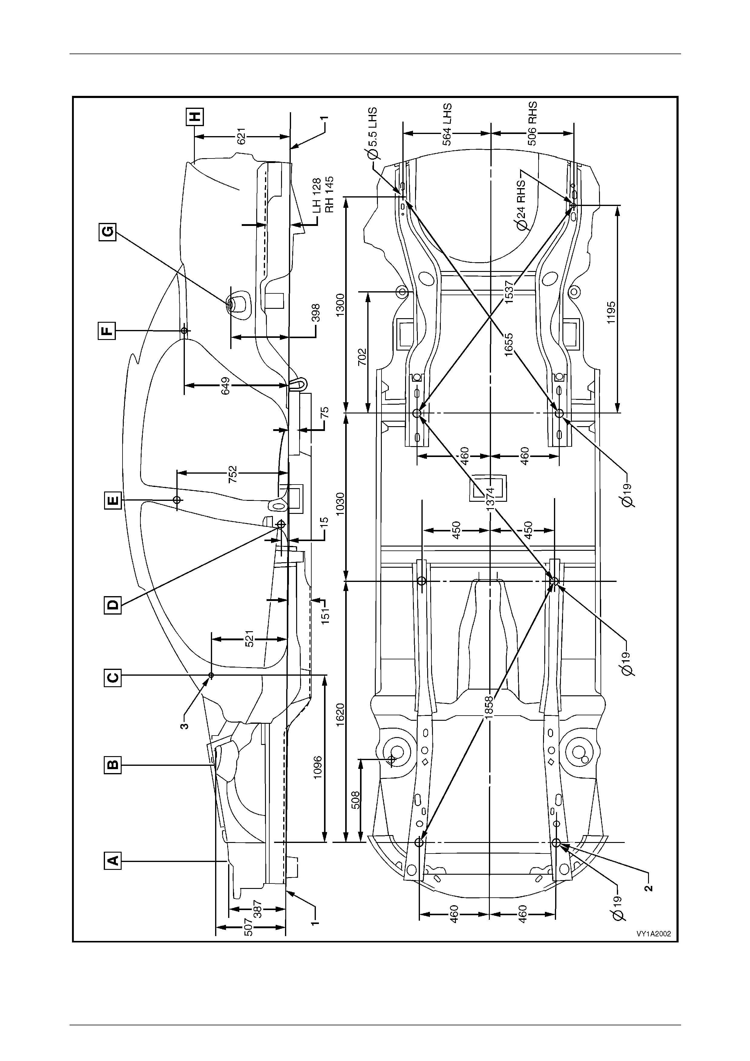
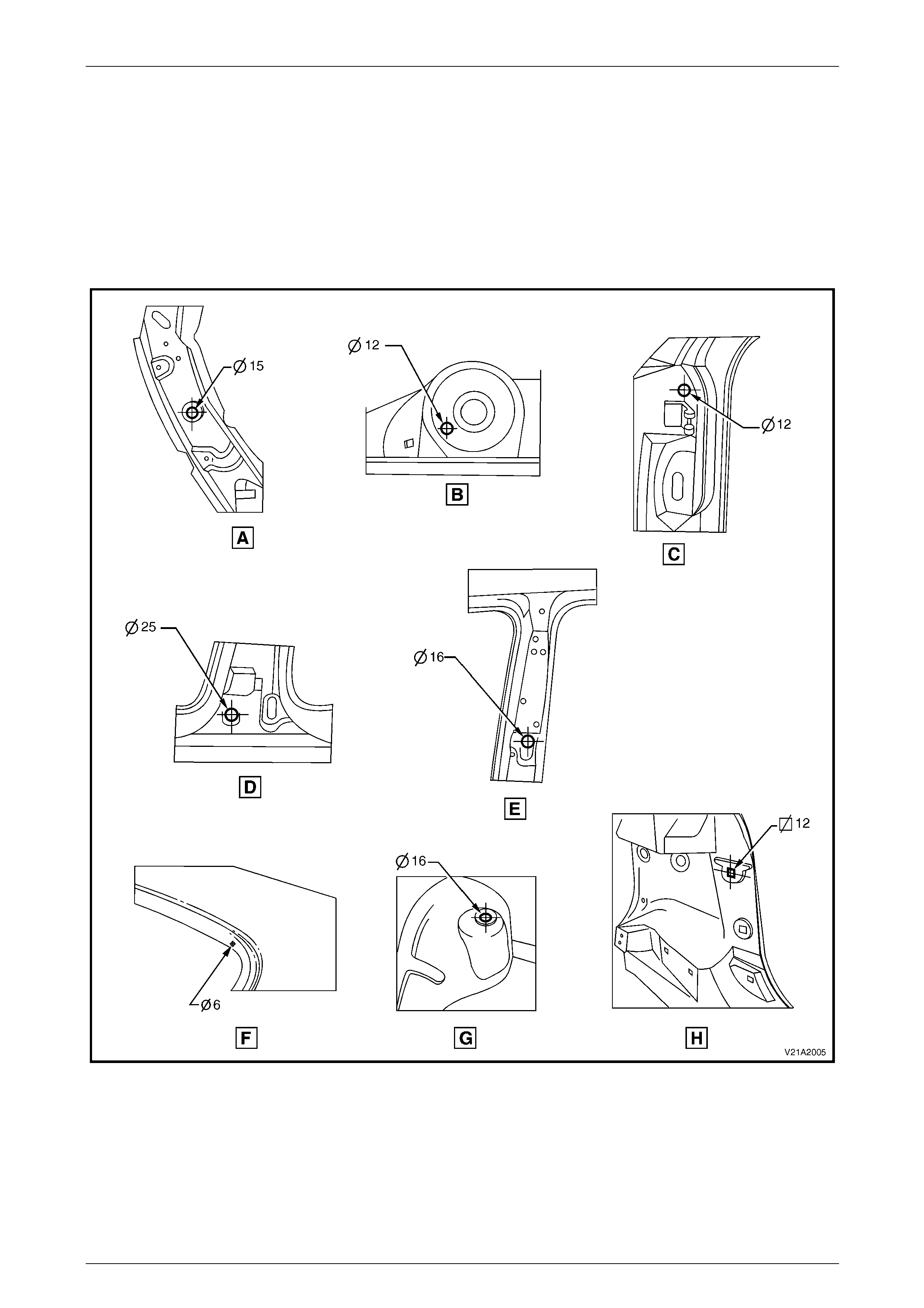
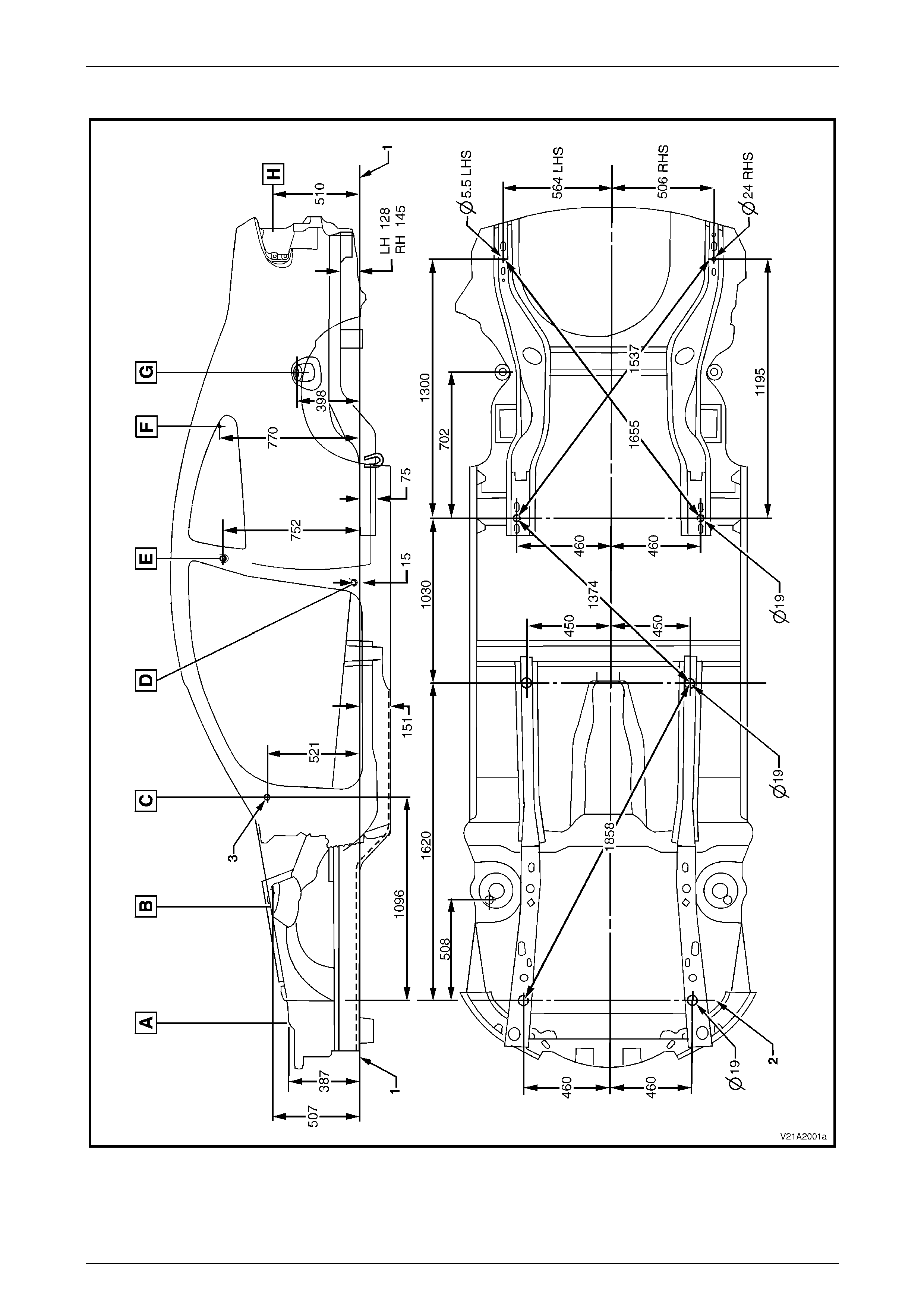
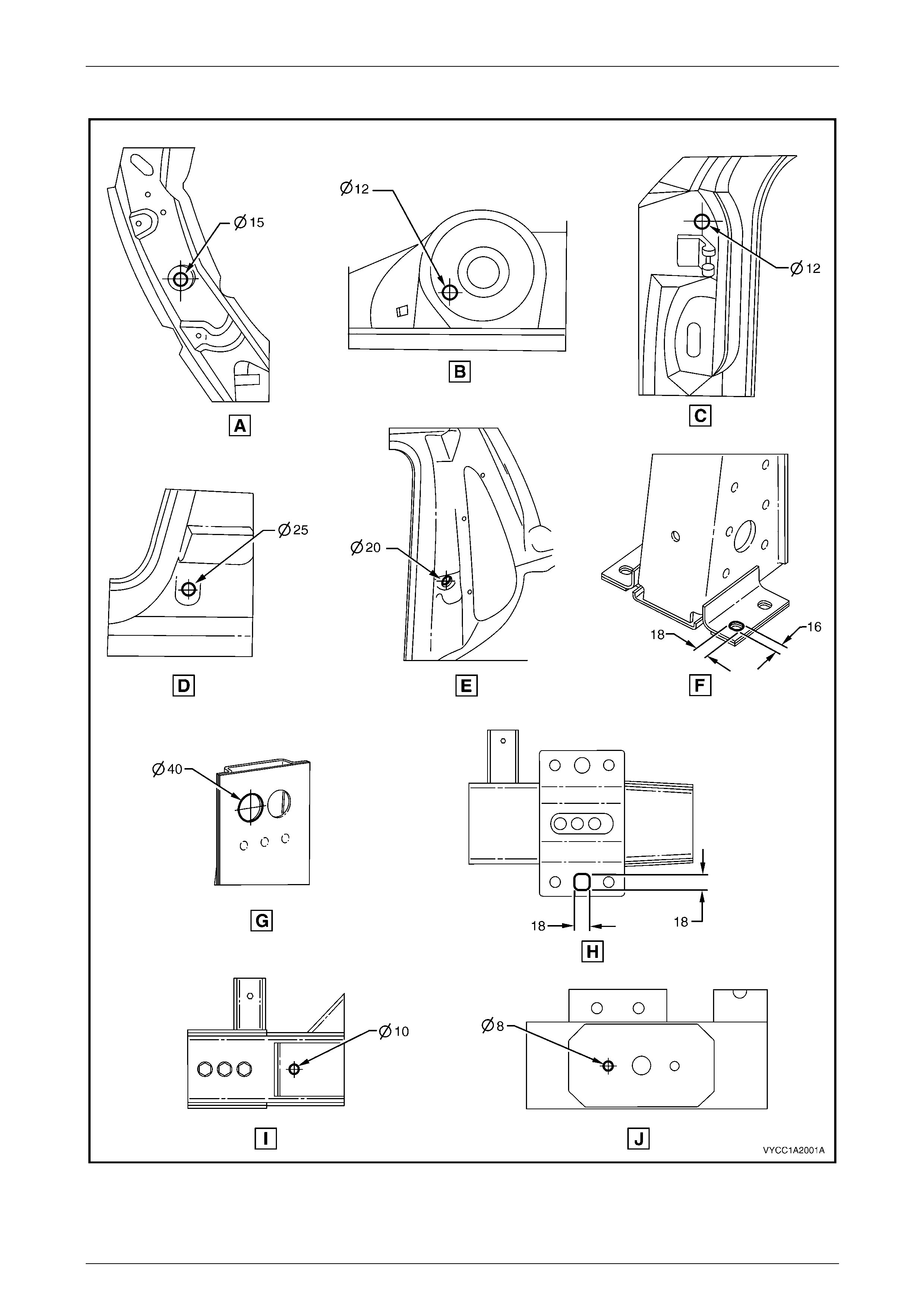
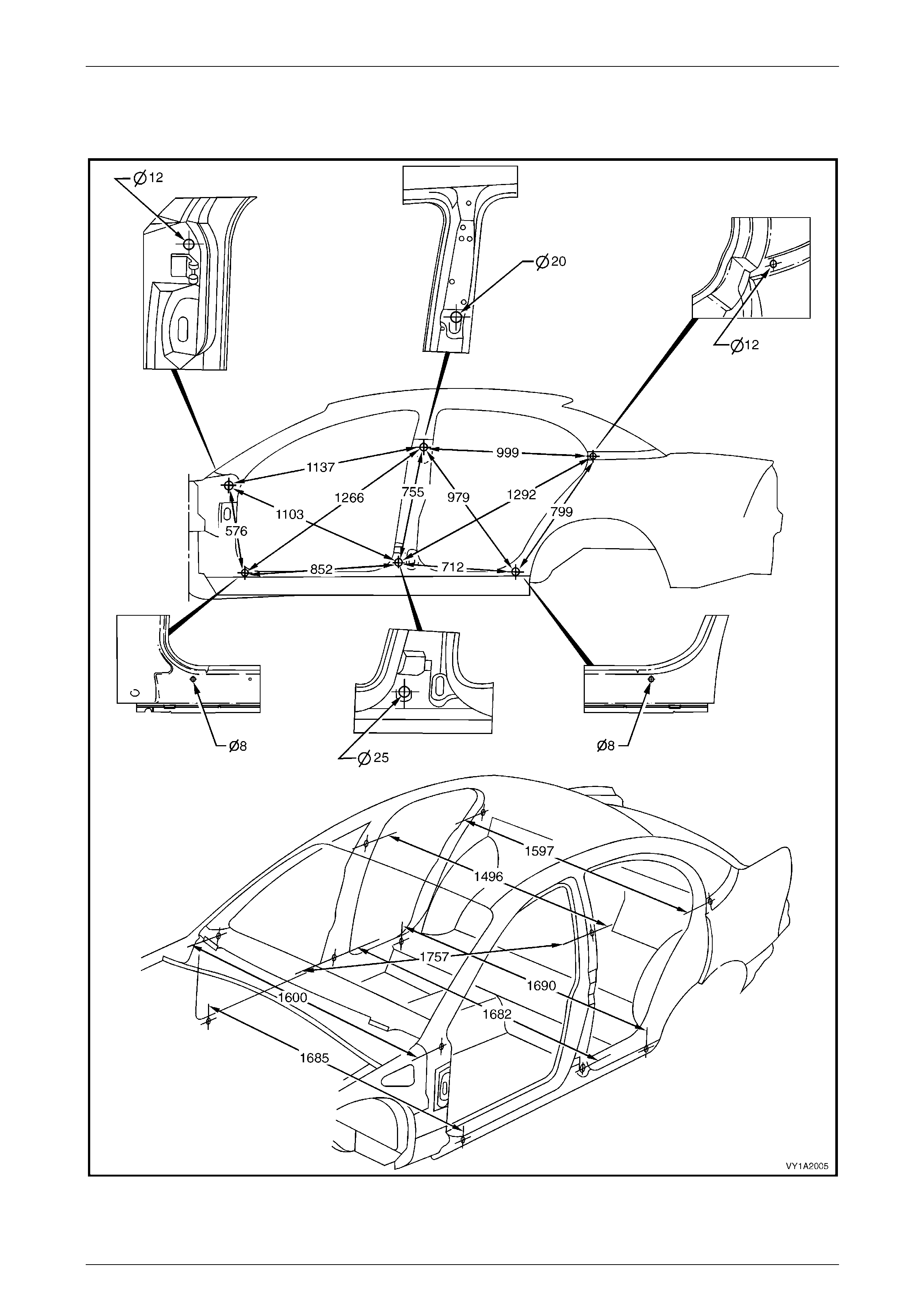
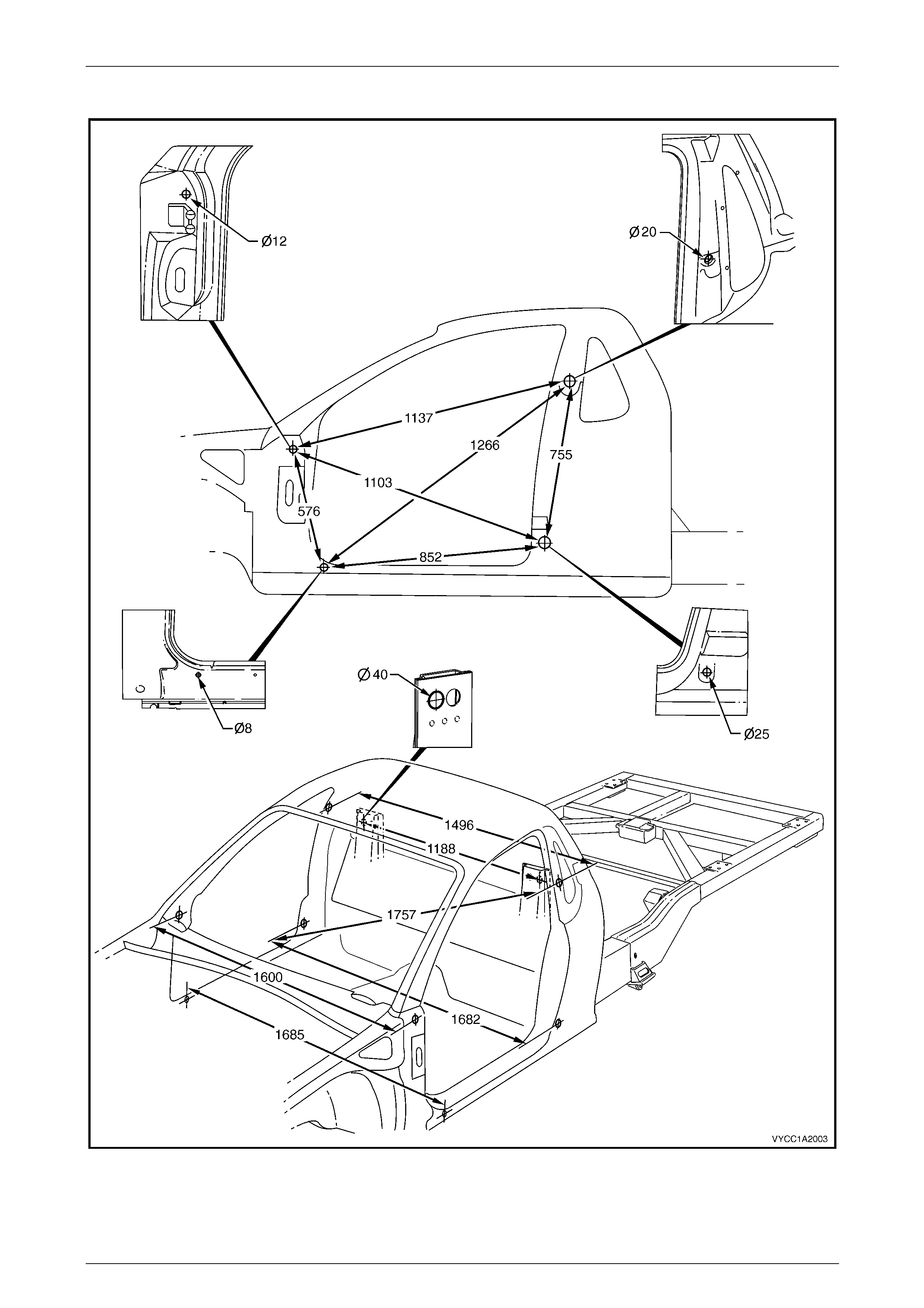
Sedan
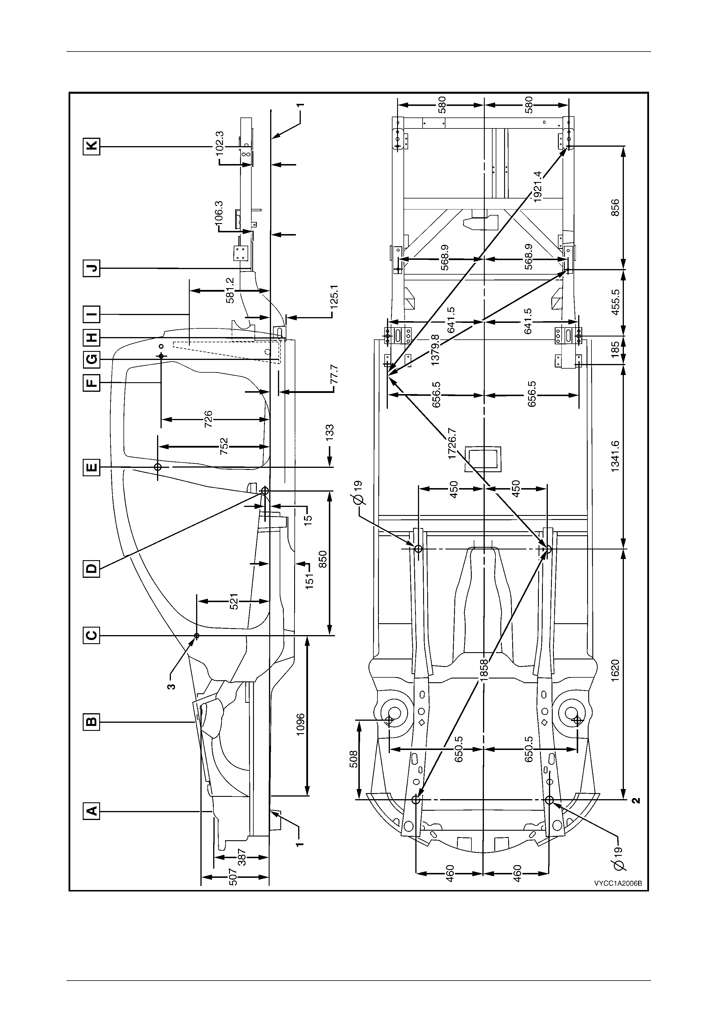
All dimensions are given in millimetres and are measured from the centre of holes, on the outer side of the metal surface.
The main datum surface (1) is the underside of each front side ra il assembly, refer to Figure 1A2 – 2.
The main datum hole (2) is a 19 mm hole on the underside of each front side rail assembly, refer to Figure 1A2 – 2.
The dash panel assembly attaching hole (3) in Figure 1A2 – 2 is also the same datum h ol e dep icted at View C, in
Figure 1A2 – 1.
Measuring Points
Figure 1A2 – 1
Body Dimensions Page 1A2–5
Page 1A2–5
Dimensions
Figure 1A2 – 2
Body Dimensions Page 1A2–6
Page 1A2–6
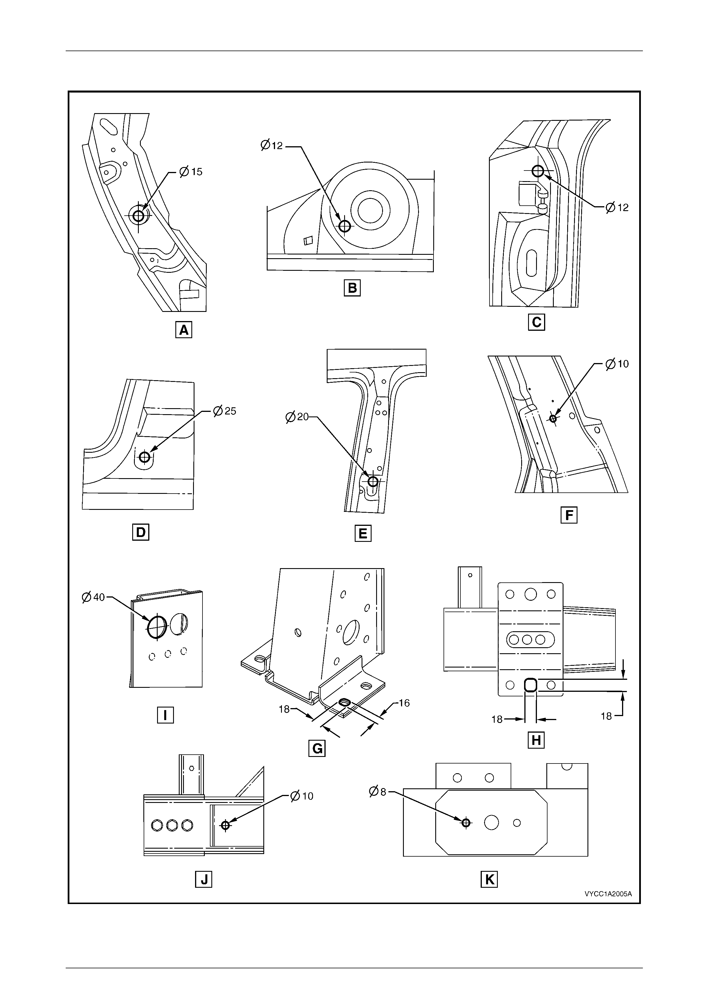
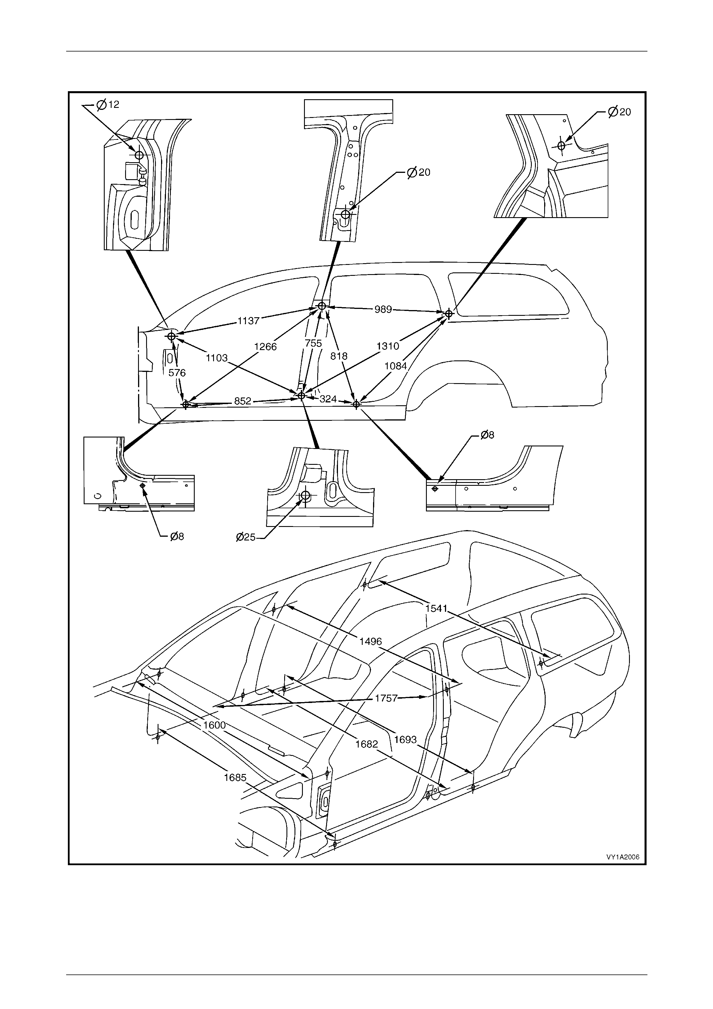
Wagon and AWD Wagon
All dimensions are given in millimetres and are measured from the centre of holes, on the outer side of the metal surface.
The main datum surface (1) is the underside of each front side ra il assembly, refer to Figure 1A2 – 4.
The main datum hole (2) is a 19 mm hole on the underside of each front side rail assembly, refer to Figure 1A2 – 4.
The dash panel assembly attaching hole (3) in Figure 1A2 – 4 is also the same datum h ol e dep icted at View C, in
Figure 1A2 – 3.
Measuring Points
Figure 1A2 – 3
Body Dimensions Page 1A2–7
Page 1A2–7
Dimensions
Figure 1A2 – 4
Body Dimensions Page 1A2–8
Page 1A2–8
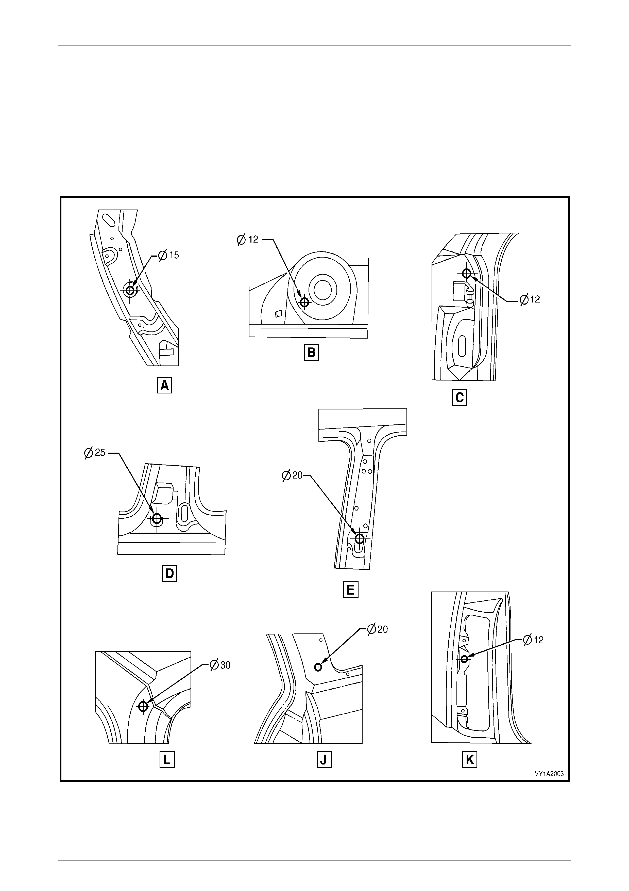
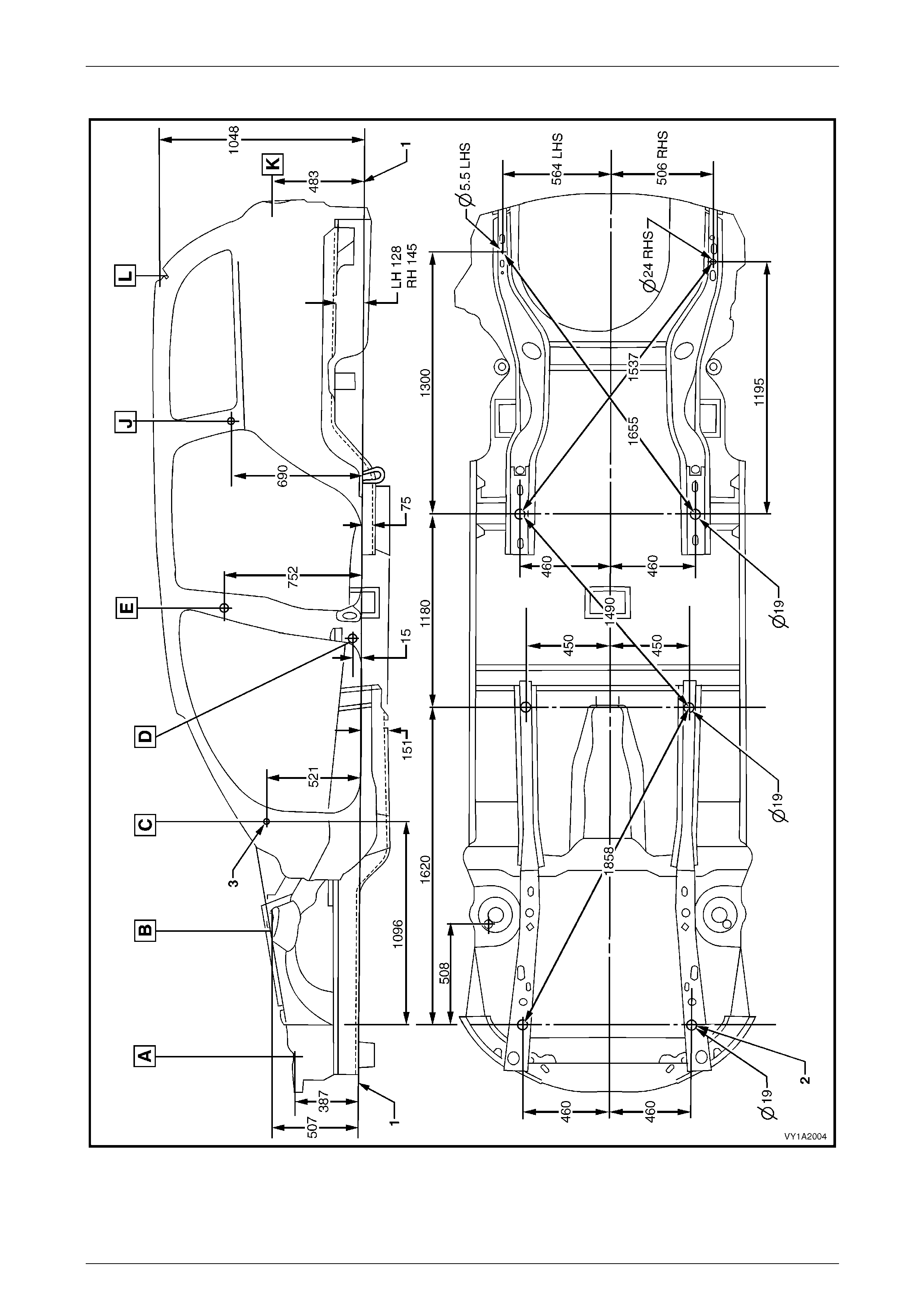
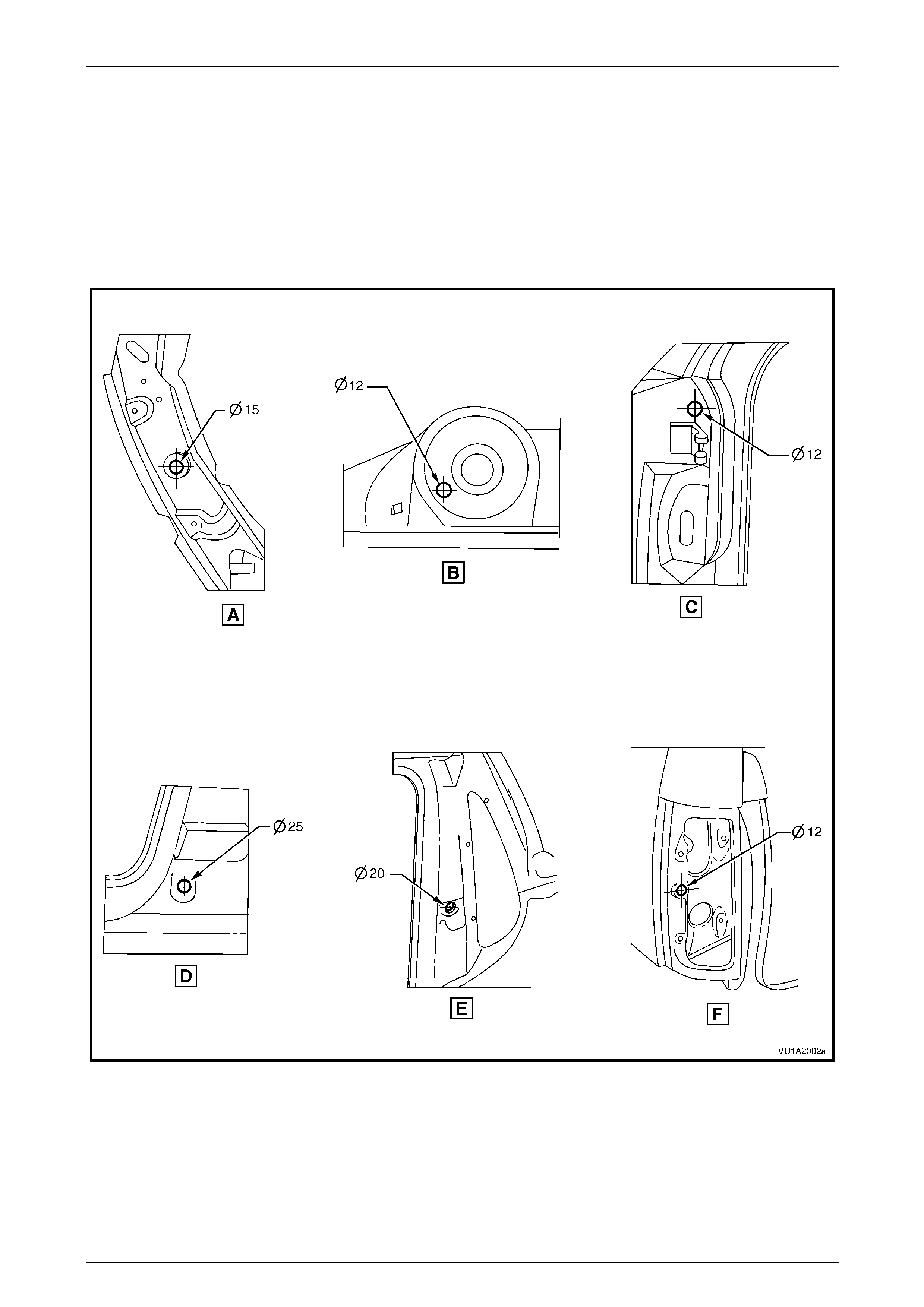
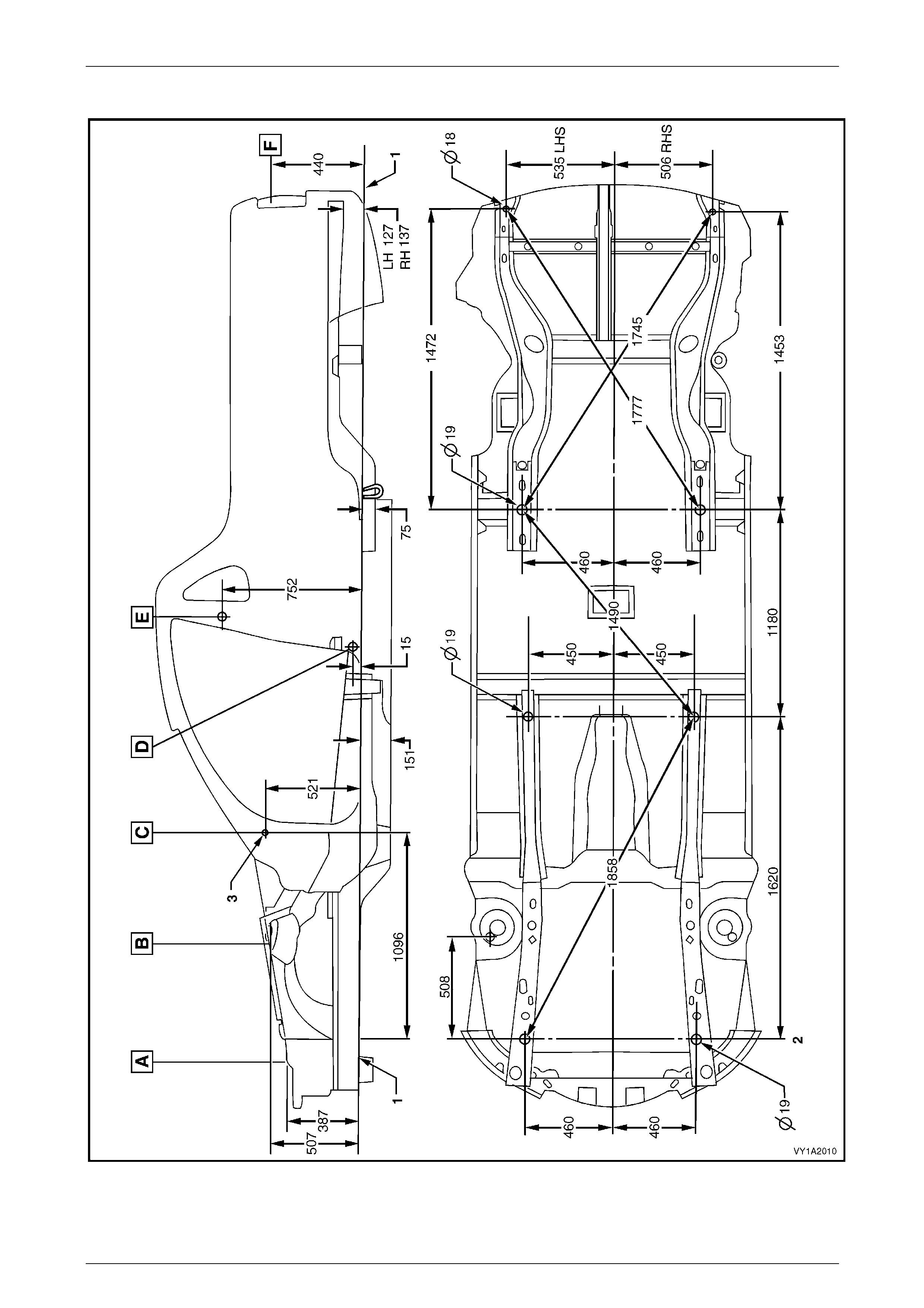
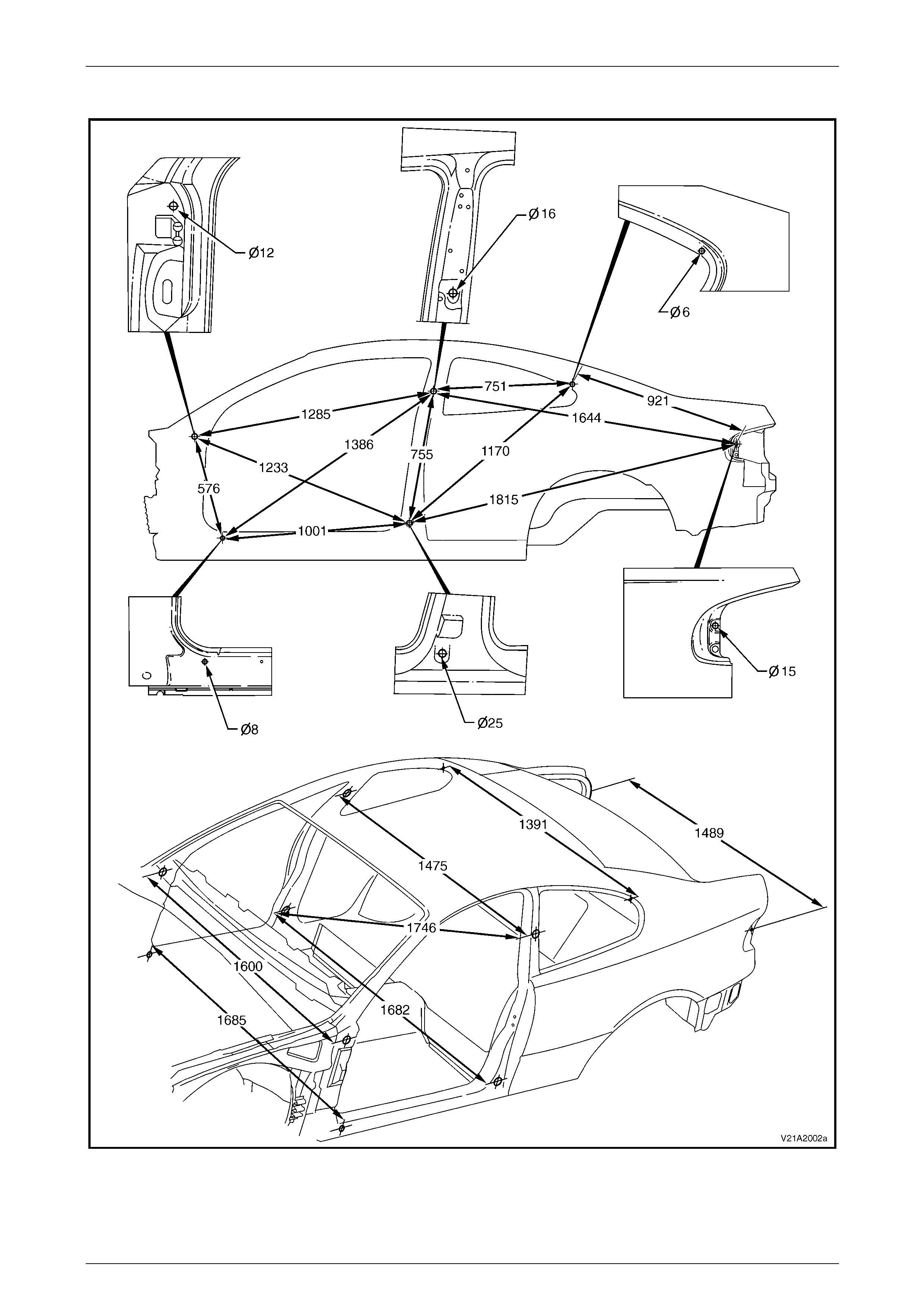
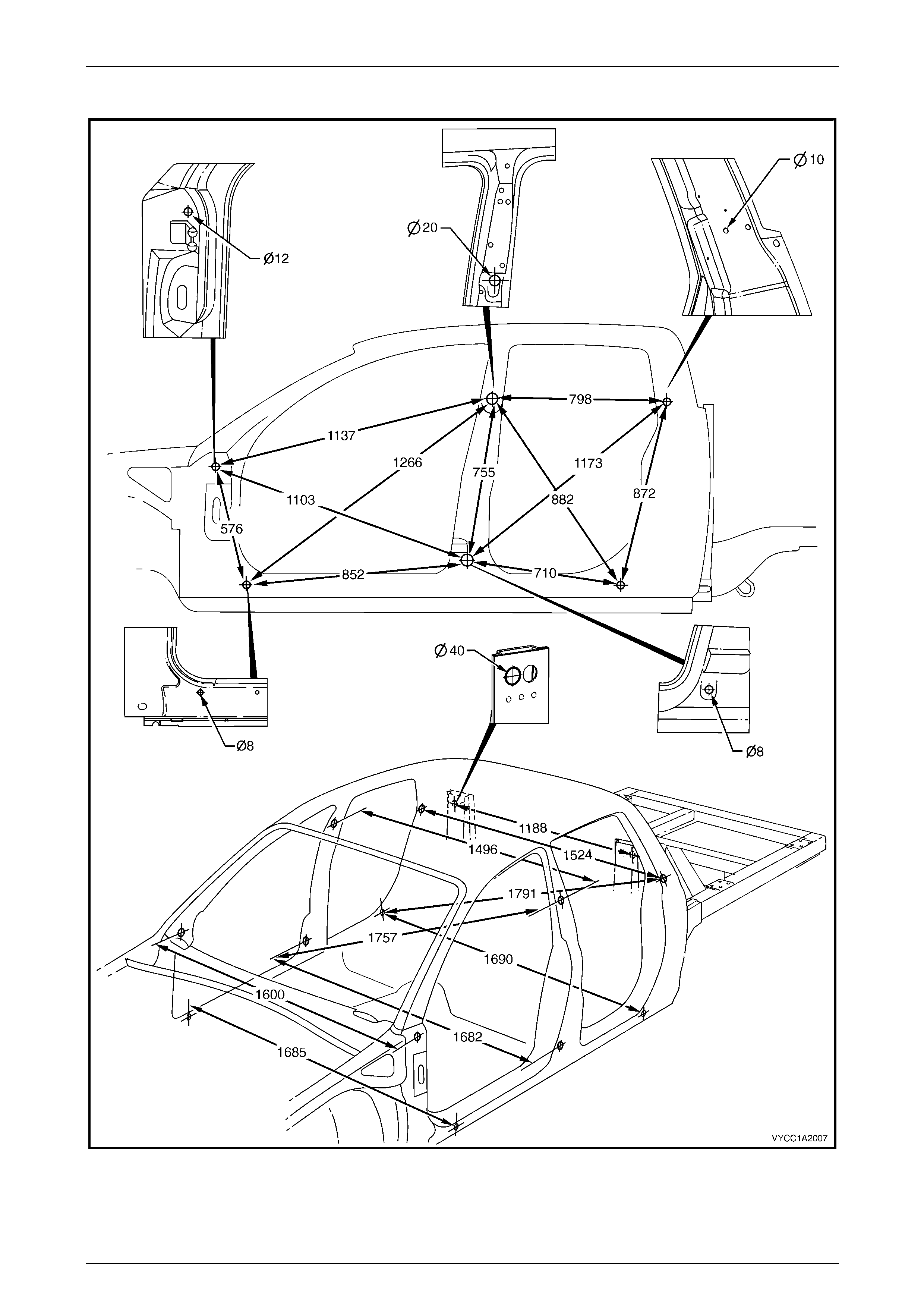
Coupe
All dimensions are given in millimetres and are measured from the centre of holes, on the outer side of the metal surface.
The main datum surface (1) is the underside of each front side ra il assembly, refer to Figure 1A2 – 6.
The main datum hole (2) is a 19 mm hole on the underside of each front side rail assembly, refer to Figure 1A2 – 6.
The dash panel assembly attaching hole (3) in Figure 1A2 – 6 is also the same datum h ol e dep icted at View C, in
Figure 1A2 – 5.
Measuring Points
Figure 1A2 – 5
Body Dimensions Page 1A2–9
Page 1A2–9
Dimensions
Figure 1A2 – 6
Body Dimensions Page 1A2–10
Page 1A2–10
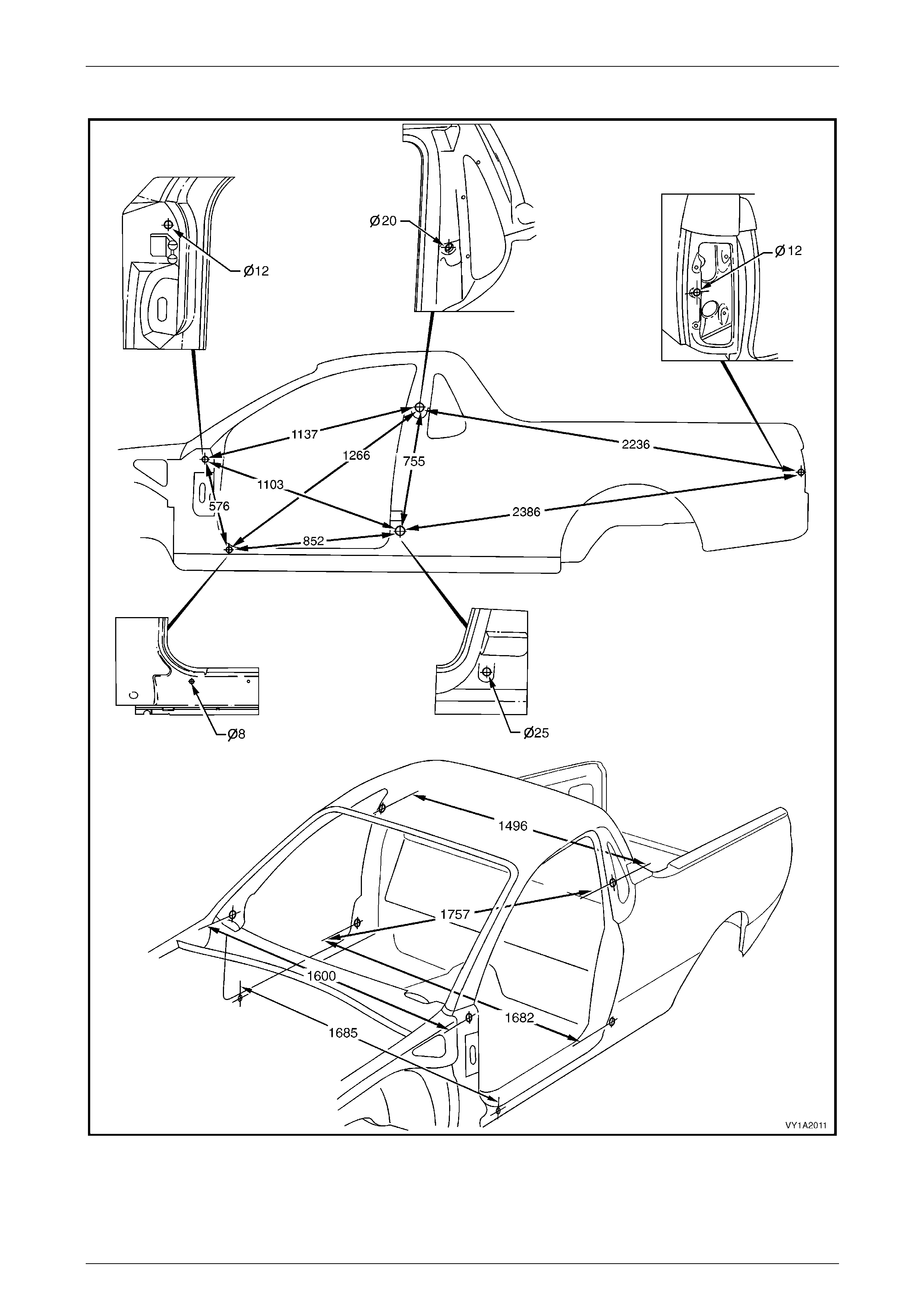
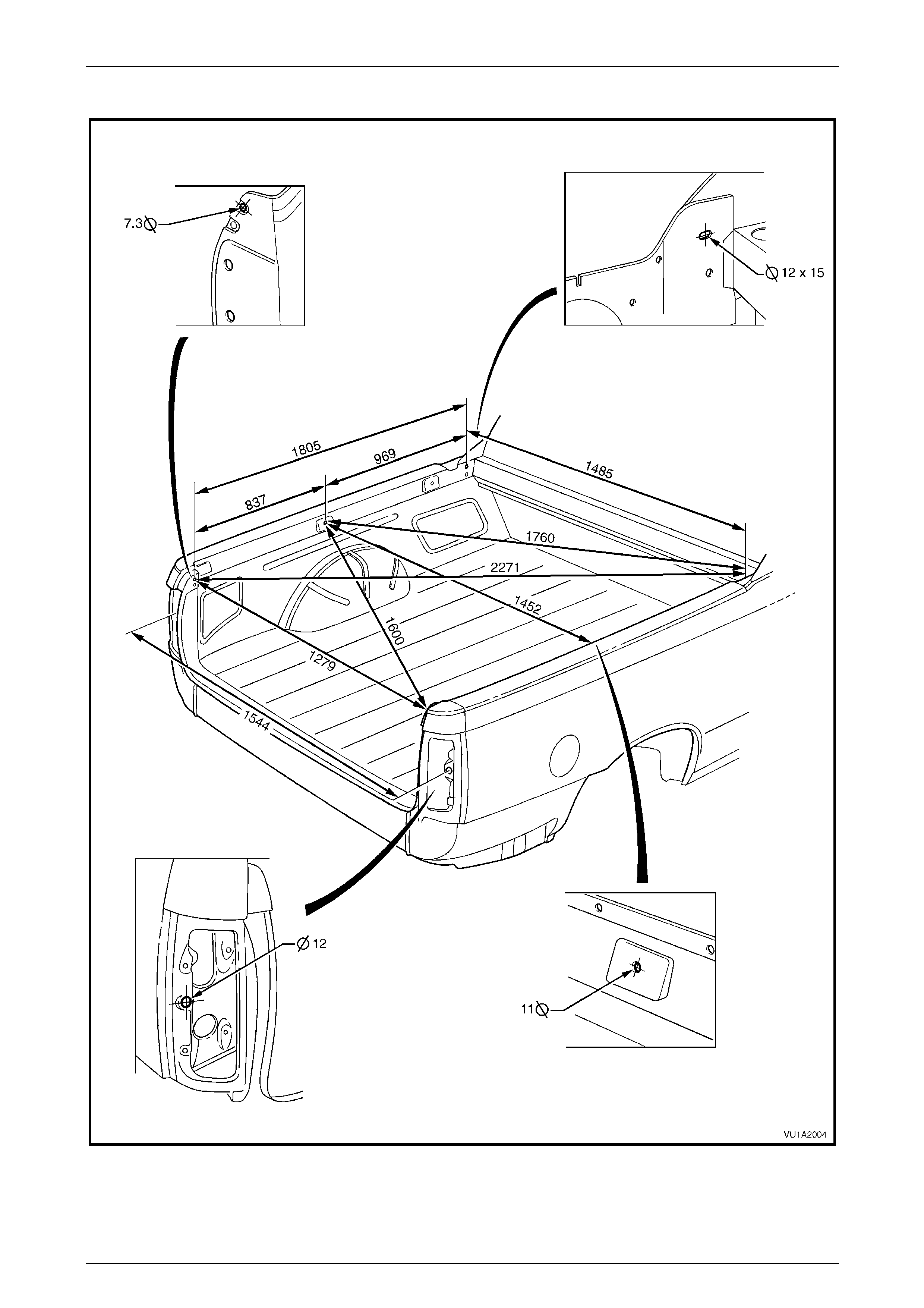
Utility
All dimensions are given in millimetres and are measured from the centre of holes, on the outer side of the metal surface.
The main datum surface (1) is the underside of each front side ra il assembly, refer to Figure 1A2 – 8.
The main datum hole (2) is a 19 mm hole on the underside of each front side rail assembly, refer to Figure 1A2 – 8.
The dash panel assembly attaching hole (3) in Figure 1A2 – 8 is also the same datum h ol e dep icted at View C, in
Figure 1A2 – 7.
Measuring Points
Figure 1A2 – 7
Body Dimensions Page 1A2–11
Page 1A2–11
Dimensions
Figure 1A2 – 8

Body Dimensions Page 1A2–12
Page 1A2–12
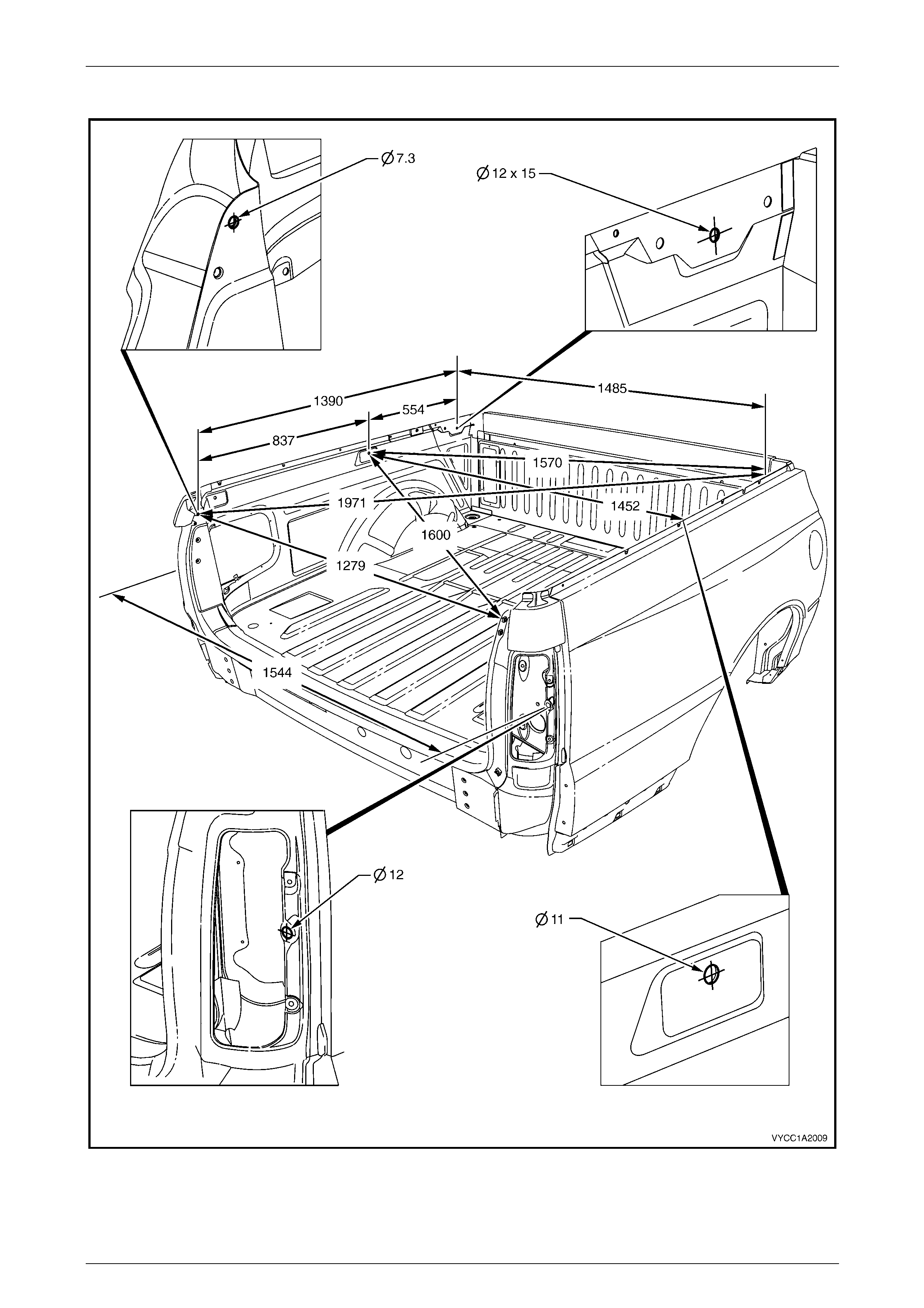
Regular Cab and AWD Regular Cab
All dimensions are given in millimetres and are measured from the centre of holes, on the outer side of the metal surface.
The main datum surface (1) is the underside of each front side ra il assembly, refer to Figure 1A2 – 10.
The main datum hole (2) is a 19 mm hol e on the underside of each front side rail assembly, refer to Figure 1A2 – 10.
The dash panel assemb ly attaching hole (3) in Figure 1A2 – 10 is also the same datum hole depicted at View C, in
Figure 1A2 – 9.
Body Dimensions Page 1A2–13
Page 1A2–13
Measuring Points
Figure 1A2 – 9

Body Dimensions Page 1A2–14
Page 1A2–14
Dimensions
Figure 1A2 – 10

Body Dimensions Page 1A2–15
Page 1A2–15
Crew Cab and AWD Crew Cab
All dimensions are given in millimetres and are measured from the centre of holes, on the outer side of the metal surface.
The main datum surface (1) is the underside of each front side ra il assembly, refer to Figure 1A2 – 12.
The main datum hole (2) is a 19 mm hol e on the underside of each front side rail assembly, refer to Figure 1A2 – 12.
The dash panel assemb ly attaching hole (3) in Figure 1A2 – 12 is also the same datum hole depicted at View C, in
Figure 1A2 – 11.
Body Dimensions Page 1A2–16
Page 1A2–16
Measuring Points
Figure 1A2 – 11
Body Dimensions Page 1A2–17
Page 1A2–17
Dimensions
Figure 1A2 – 12
Body Dimensions Page 1A2–18
Page 1A2–18
2.2 Upperbody Dimension – Actual
Front Dimensions
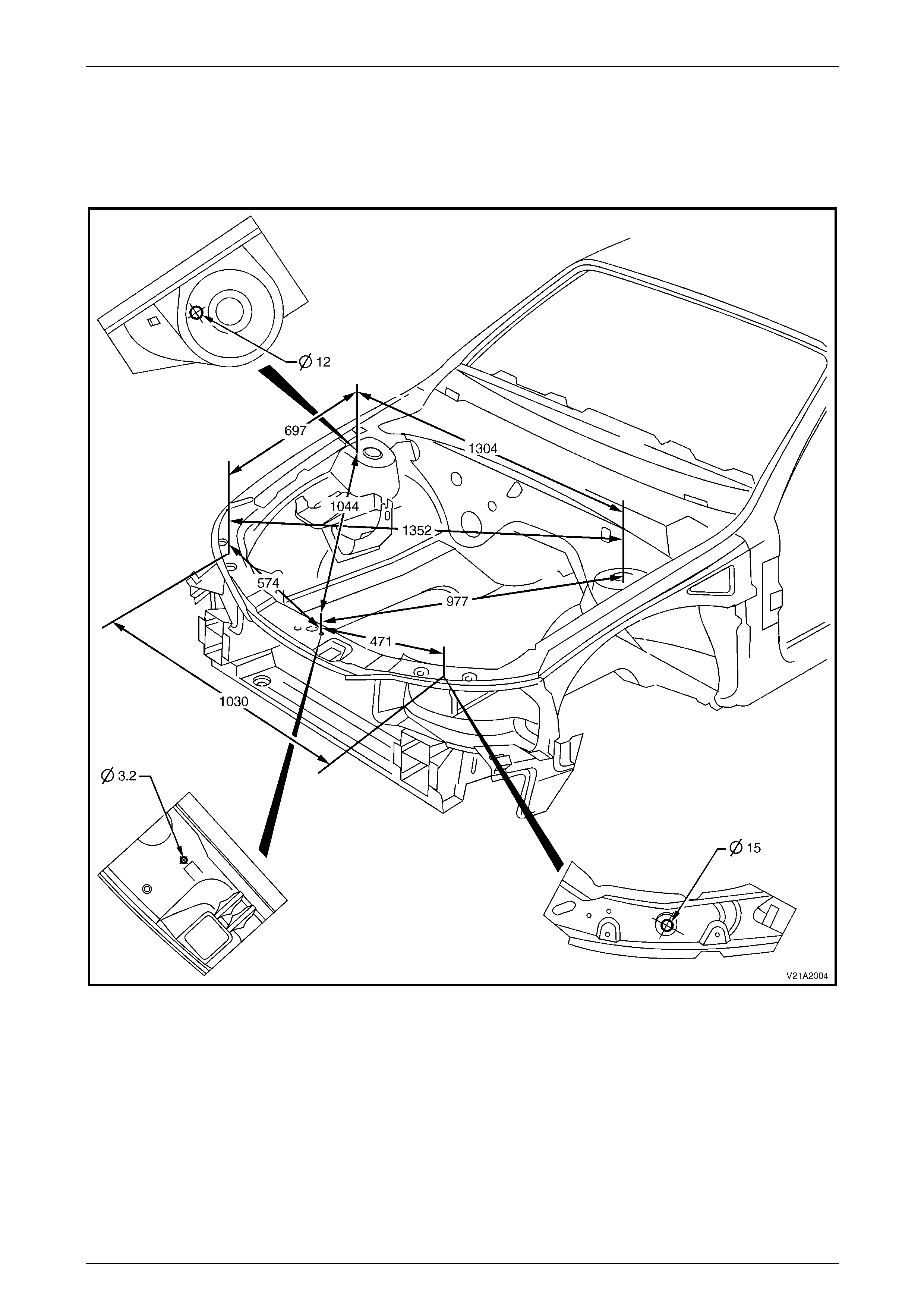
All Vehicles
Figure 1A2 – 13
Body Dimensions Page 1A2–19
Page 1A2–19
Side and Interior Dimensions
Sedan
Figure 1A2 – 14
Body Dimensions Page 1A2–20
Page 1A2–20
Wagon and AWD Wagon
Figure 1A2 – 15
Body Dimensions Page 1A2–21
Page 1A2–21
Coupe
Figure 1A2 – 16
Body Dimensions Page 1A2–22
Page 1A2–22
Utility
Figure 1A2 – 17
Body Dimensions Page 1A2–23
Page 1A2–23
Regular Cab and AWD Regular Cab
Figure 1A2 – 18
Body Dimensions Page 1A2–24
Page 1A2–24
Crew Cab and AWD Crew Cab
Figure 1A2 – 19
Body Dimensions Page 1A2–25
Page 1A2–25
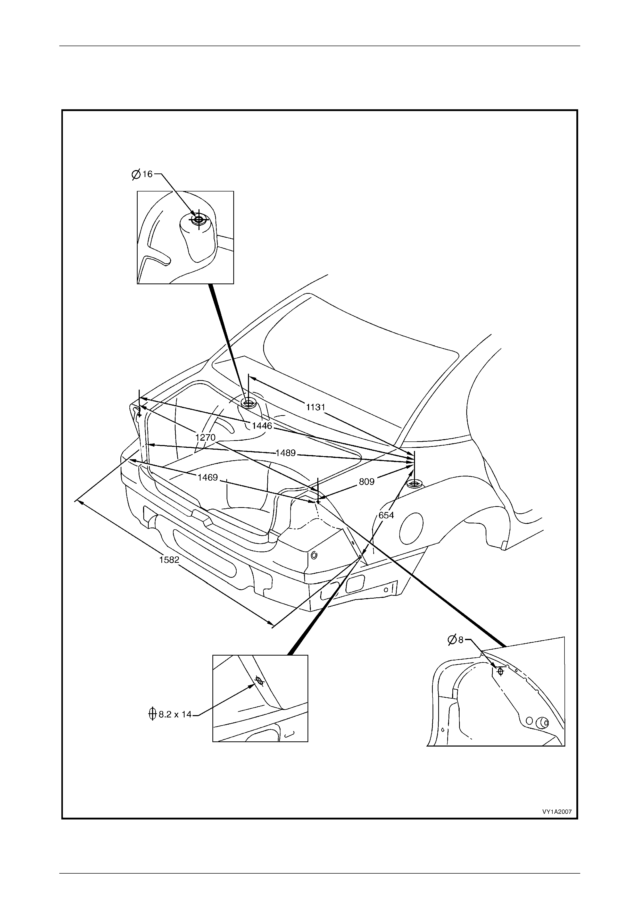
Rear Dimensions
Sedan
Figure 1A2 – 20

Body Dimensions Page 1A2–26
Page 1A2–26
Wagon and AWD Wagon
Figure 1A2 – 21
Body Dimensions Page 1A2–27
Page 1A2–27
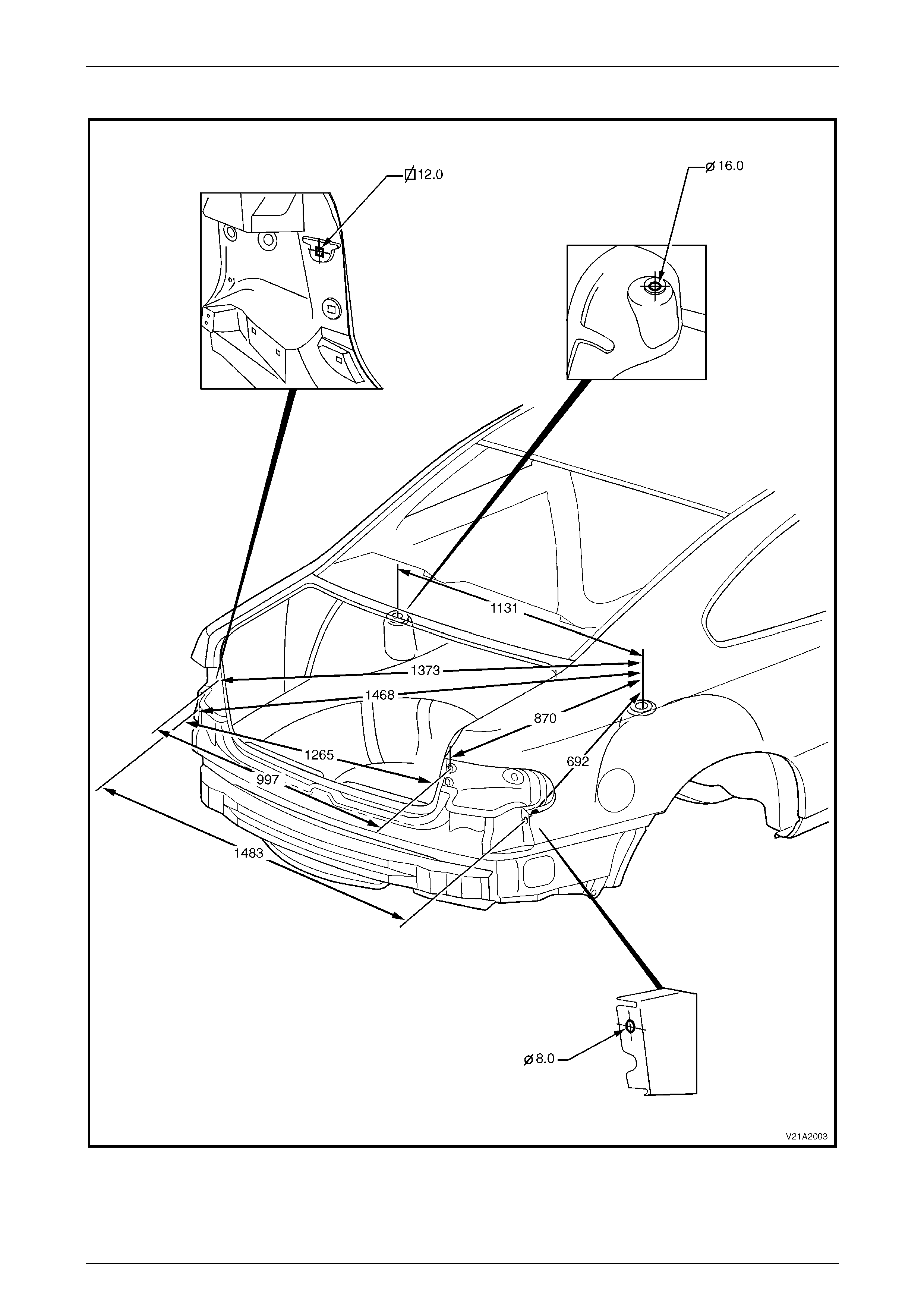
Coupe
Figure 1A2 – 22
Body Dimensions Page 1A2–28
Page 1A2–28
Utility
Figure 1A2 – 23
Body Dimensions Page 1A2–29
Page 1A2–29
Crew Cab and AW D Crew Cab Rear Body
Figure 1A2 – 24
Body Dimensions Page 1A2–30
Page 1A2–30
2.3 Suspension Frame and Transmission
Support Alignment
ATTENTION
All rear suspension fasteners are important attaching parts as they affect the performance of vital
components and/or could result in major repair expense. Where specified in this section, fasteners MUST be
replaced with parts of the same part num ber or a GM appro ved equivalent. Do n ot use fasteners o f an inferior
quality or substitute design.
Torque values must be used as specified during reassembly to ensure proper retention of all suspension
components.
Throughout this Section, fastener torque wrench specifications may be accompanied with the following
Identification marks:
Fasteners must be repl aced after loosening.
Fasteners either have micro encapsulated sealant applied or incorporate a mechanical thread lock and
should only be re-used once. If in doubt, replacement is recommended.
If one of these identification marks is present alongside a fastener torque wrench specification, the
recommendation regarding that fastener must be adhered to.
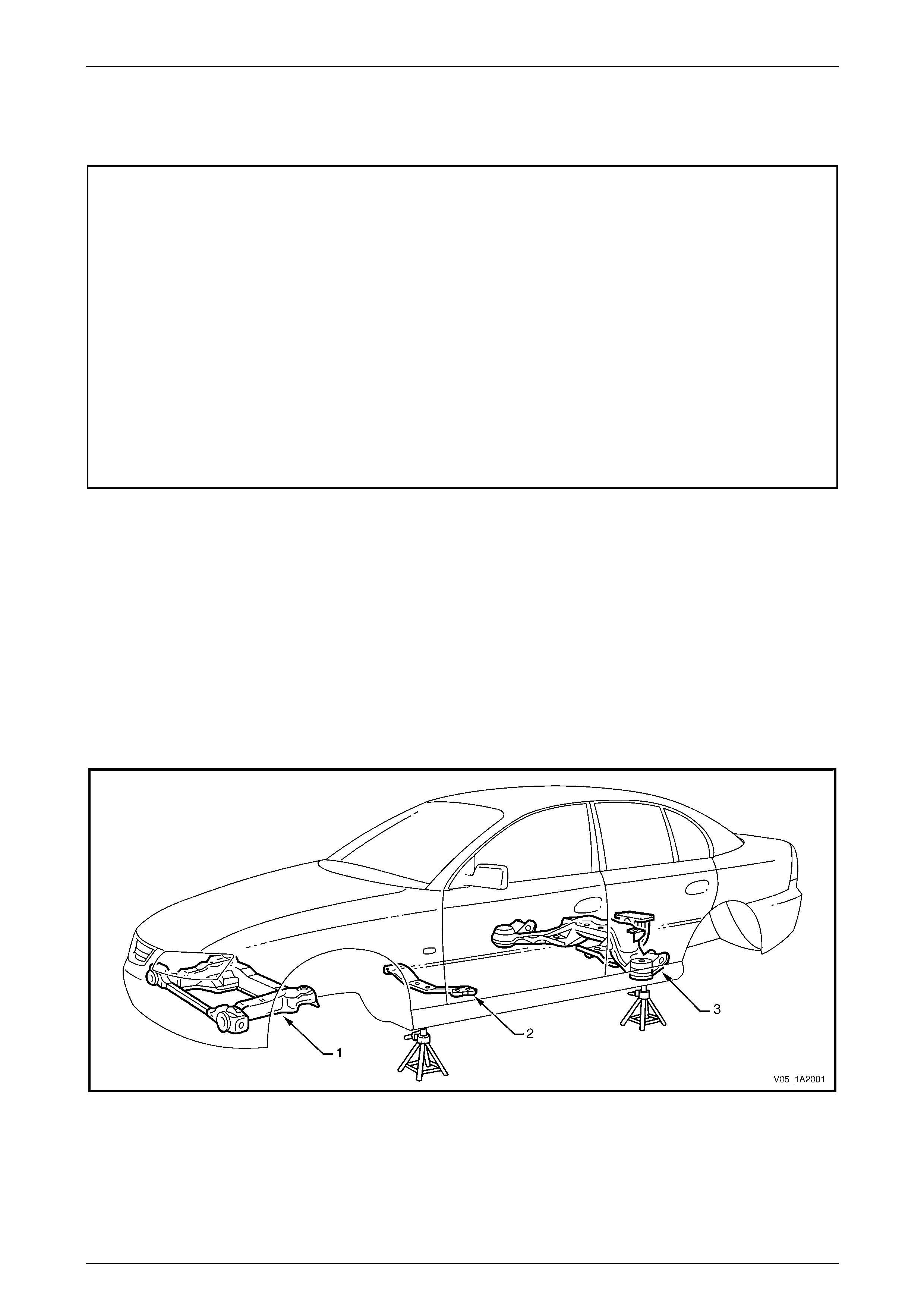
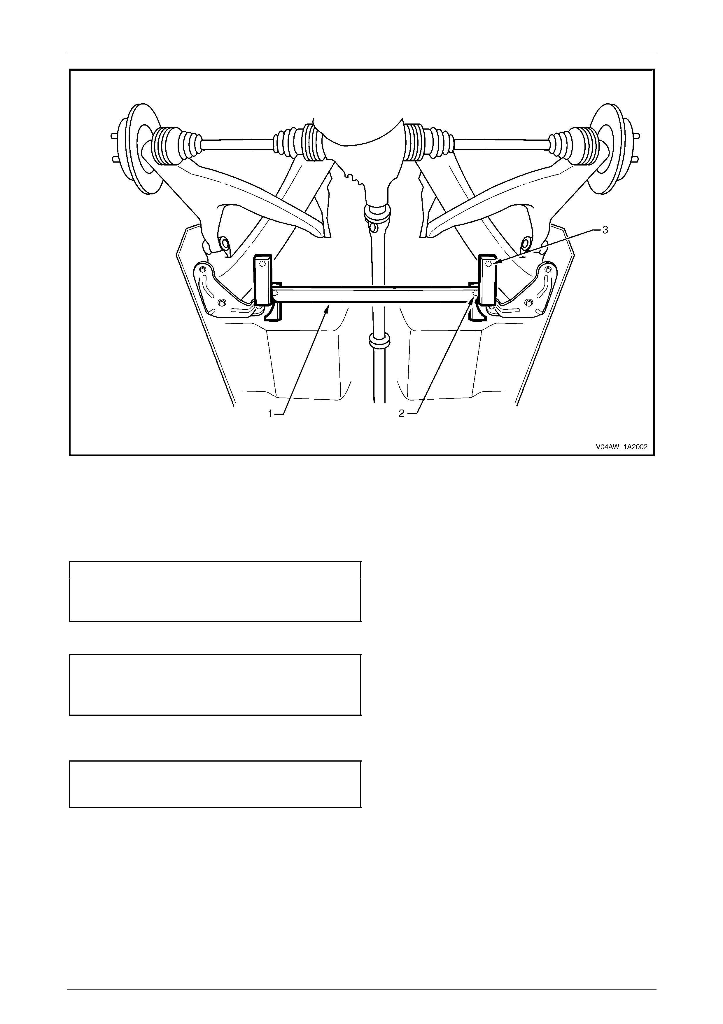
The front suspension frame assembly (1), transmission su pport (2) an d rear suspension frame assembly (3) will require
re-alignment if they have been removed during repair work, or if they have been disturbed as a result of a vehicle
collision, refer to Figure 1A2 – 25.
NOTE
Regular Cab and Cre w Cab vehicles are not fitted
with a rear suspension frame assemb ly. The rear
suspension for these vehicles does not require
any specific alignment proce dures.
Correct underbody alignment i s essential as any misalignment can adversely affect suspension performance. The
underbody alignment should therefore be checked and aligned, if required , to the dimensions specified in this Section
prior to performing the following alig nment procedures.
Figure 1A2 – 25
Body Dimensions Page 1A2–31
Page 1A2–31
Front Suspension Frame Assembly
LT Section No. 06-200
NOTE
While there are differences in the construction of
the front suspension frame assembly fitted to
AWD vehicles, the installation and alignment
procedures are the same as for 2WD vehic les.
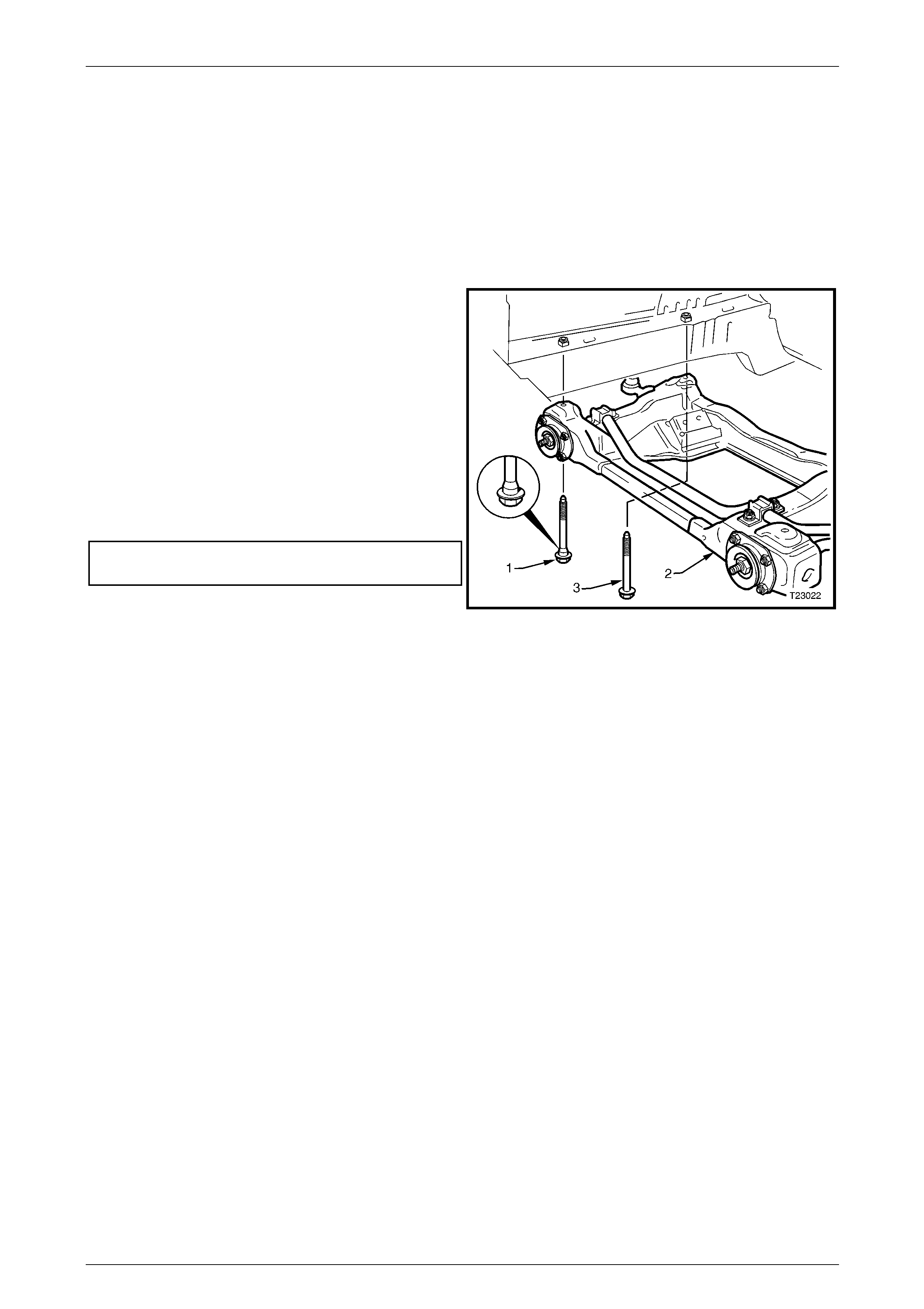
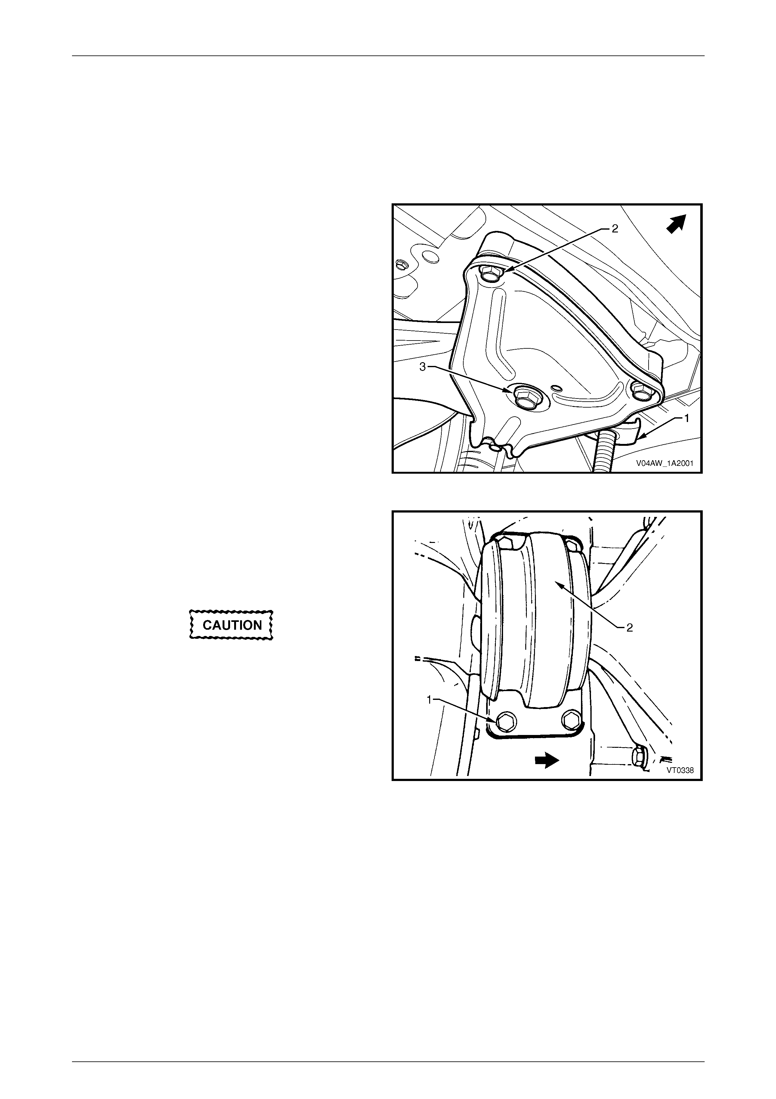
1 When reinstalling the front suspension frame
assembly, install the two front, black coloured, stepped
shank bolts (1) and tighten to the correct torque
specification. This will correctly align the frame
assembly (2) to the front side rail assemblies.
NOTE
Prior to installation of the frame assembly,
ensure the vehicle underbo dy alignment is within
specification.
2 Install the two rear, silver coloured, straight shanked
bolts (3) to the two rear positions and tighten them to
the correct torque specification.
Front suspension frame assembly
mounting bolt torque specification.......120.0 – 125.0 Nm
Figure 1A2 – 26
Transmission Support
LT Section No. 04-020
Except AWD Vehicles
1 Using chassis stands, suppor t the vehicle at the hoist pad locations, refer to Section 0A General Information.
2 From underneath the vehicle, support the transmission with a trolley jack. Raise the jack slightly to take some
weight off the transmission mount.
NOTE
As required, place a block of wood on the j ack to
protect the transmission.
Body Dimensions Page 1A2–32
Page 1A2–32
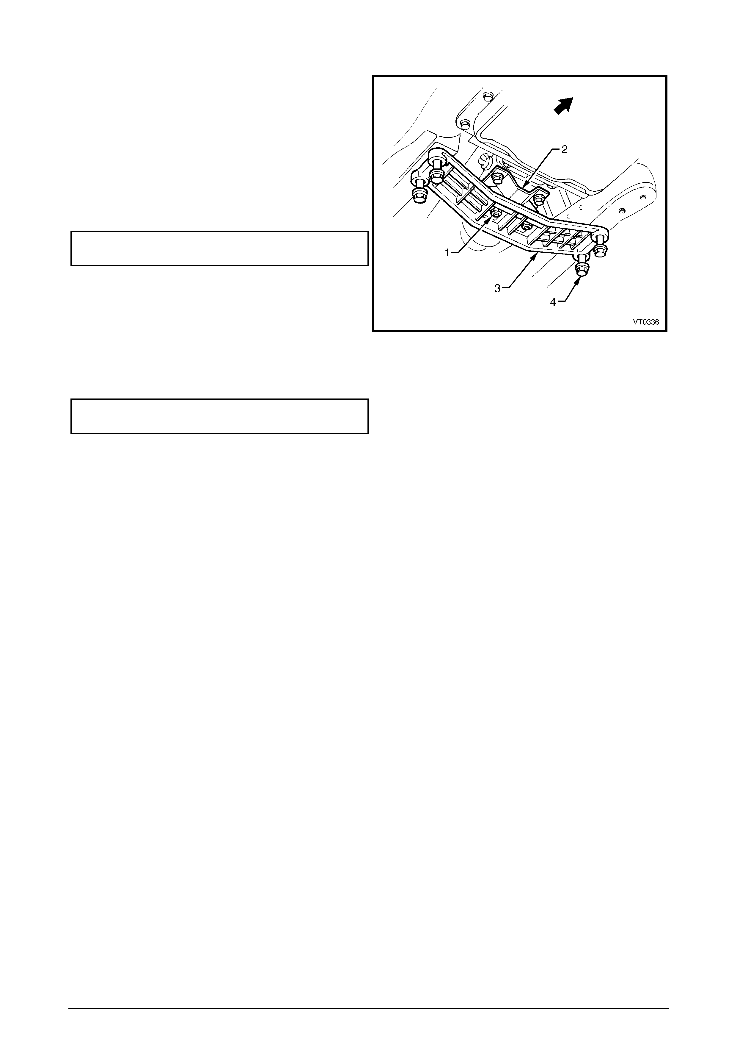
3 Remove the two nuts (1) attaching the transmission
mount assembly (2) to the transmission support (3),
shown typical.
4 Loosen the four bolts (4) attaching the trans mission
support to the underbody.
5 Centralise the transmission support within the bolt
holes.
6 Tighten the four bolts to the correct torque
specification.
Transmission support attachin g bolt
torque specification.................................50.0 – 65.0 Nm
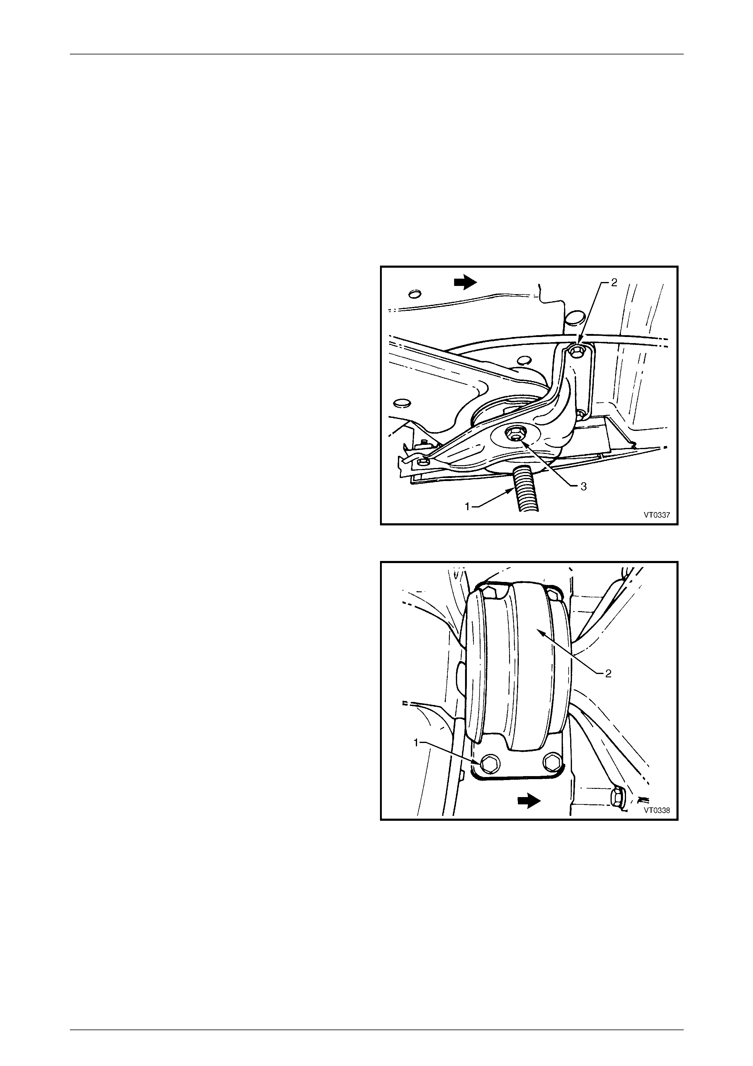
7 With the help of an assistant, manoeuvre th e
transmission to ensure that the studs (1) (from which
the M8 nuts have been removed) protrudin g throu gh
the transmission support are centralised within the
stud holes.
8 Reinstall the M8 nuts attachin g the transmission
mount to the transmission support and tighten to the
specified torque.
Transmission mount attachin g nut
torque specification.................................20.0 – 30.0 Nm
Figure 1A2 – 27
AWD Vehicles
A transmission rear crossmember and trans fer case rear mounting bracket is fitted to AWD vehicles to accommodate the
transfer case. While no specific alignment proced ures are required, it is important to either mark the position of the bolts
and the crossmember to body relationship before removal, or ensure that the holes are centralised before re-assembly.
For further information refer to Section 7F Transfer Case and Adapter Hous ing.
Body Dimensions Page 1A2–33
Page 1A2–33
Rear Suspension Frame Assembly
LT Section No. 07-150A
Except AWD Wagon
NOTE
The rear suspension frame assembly centring
tool needs to be held in position during the
alignment procedure. Therefore, assistance will
be required to complete this operation.
1 Using chassis stands (1), support the vehicle at hoist
pad locations, refer to Section 0A General Information.
2 Remove the road wheels, refer to
Section 10, Wheels and Tyres.
3 Remove the intermediate muffler and pipe assembly
together with the rear muffler and pipe assembly, refer
to Section 8B Exhaust System.
4 From underneath the vehicle, support the final drive
assembly with a trolley jack. Raise the jack slightly to
take some of the weight off the final drive mount.
5 Loosen the rear suspens ion support insulator bracket
bolt (2), three places. Repeat for the opposite side.
6 Loosen the rear frame assembly attaching bolt (3).
Repeat for the opposite side.
Figure 1A2 – 28
7 Loosen the final drive rear mount (2) bolt (1), four
places.
8 Fit the rear suspension centring tool No C H46839
(AU458) (1), refer to Figure 1A2 – 30.
NOTE
The rear crossmember centring tool locates into
the 19 mm diameter body datum holes (2)
positioned forward of the rear suspension frame
assembly.
Figure 1A2 – 29
Body Dimensions Page 1A2–34
Page 1A2–34
Figure 1A2 – 30
9 With the help of an assistant, manoeuvre th e rear suspension assembly until the location pins (3) of the rear
crossmember centring tool engage the alignment ho les on the rear frame assembly.
10 Tighten the rear suspension frame assembly attaching bolt (3) to the specified torque, refer to Figure 1A2 – 28.
Repeat for the opposite side.
Rear suspension frame assembly
attaching bolt torque specificat ion
Stage 1 .......................125.0 Nm
Stage 2 ...............Turn 30° – 40°
11 Tighten the final drive rear mount bolt (1), four places, to the specified torque, refer to Figure 1A2 – 29.
Final drive rear mount attaching
bolt torque specification
Stage 1 ..............30.0 – 40.0 Nm
Stage 2 ...............Turn 55° – 65°
12 Tighten the rear suspension support insulator bracket bolt (2), three places, to the specified torque, refer to
Figure 1A2 – 28. Repeat for the opposite side.
Rear suspension support insulator
bracket attaching bolt torque
specification............................................60.0 – 85.0 Nm
13 Remove the rear crossmember centring tool, refer to Figure 1A2 – 3 0.
14 Gently lower the trolley jack and remove from under the vehicle.
15 Reinstall the road wheels, refer to Section 10 Wheels and Tyres.
16 Remove the vehicle from the chassis stands.
Body Dimensions Page 1A2–35
Page 1A2–35
AWD Wagon
NOTE
The rear suspension frame assembly centring
tool needs to be held in position during the
alignment procedure. Therefore, assistance will
be required to complete this operation.
1 Using chassis stands (1) support the vehic le at hoist
pad locations, refer to Section 0A General Information.
2 Remove the rear wheels, refer to
Section 10 Wheels and Tyres.
3 Remove the intermediate muffler and pipe assembly
together with the rear muffler and pipe assembly, refer
to Section 8B Exhaust System.
4 From underneath the vehicle, support the final drive
assembly with a trolley jack. Raise the jack slightly to
take some of the weight off the final drive mount.
5 Loosen the rear suspens ion support insulator bracket
bolt (2), three places. Repeat for the opposite side.
6 Loosen the rear frame assembly attaching bolt (3).
Repeat for the opposite side.
Figure 1A2 – 31
7 Loosen the final drive rear mount (2) bolt (1), four
places.
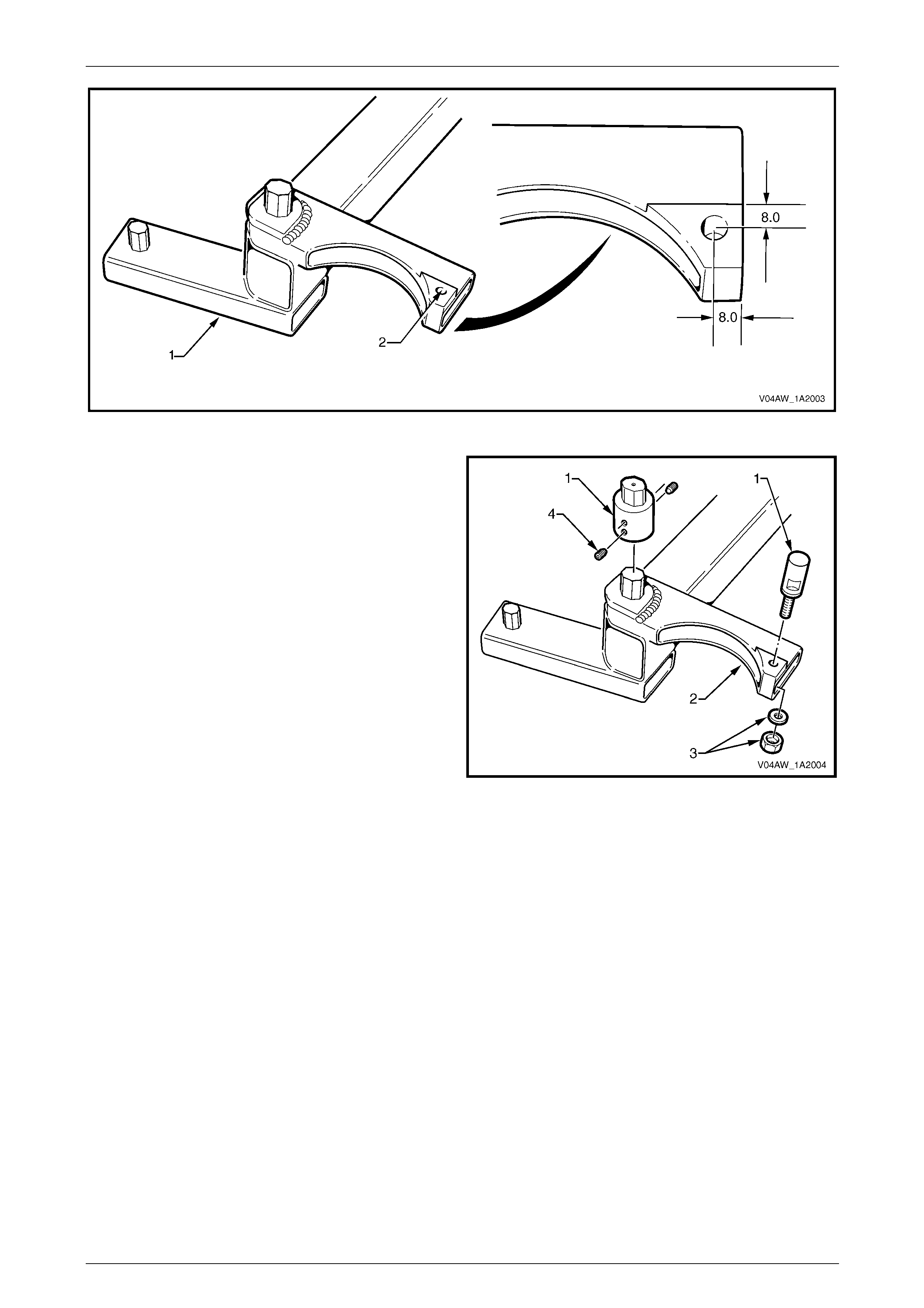
8 If required, modify the rear crossmember centring tool
No CH-46839 (AU458) (1) as follows, refer to
Figure 1A2 – 33:
Do not attempt to drill the hole in the rear
crossmember centring tool without a drill
press, as the tool will be rendered inaccurate
if the hole is not drilled square to the surface
of the tool.
a) Mount the rear crossmember centring tool in a
drill press.
b) Drill a 6 mm hole (2) through the landing o n the
top surface of the tool, 8.0 mm from the edges
as shown.
c) Repeat steps a) and b) for the other end of the
tool.
Figure 1A2 – 32
Body Dimensions Page 1A2–36
Page 1A2–36
Figure 1A2 – 33
9 Fit the rear crossmember centring tool adaptor pins No
CH47621 (1) to the rear crossmember centring tool
(2). Fit and tighten the nut and washer (3). Tighten the
grub screws (4).
NOTE
Ensure that the adaptor pins with the hexagonal
heads are fitted onto the sid e of the tool with the
hexagonal pins.
10 Fit rear crossmember centring tool (1) to the vehicle,
refer to Figure 1A2 – 35.
NOTE
The rear crossmember centring tool locates into
19 mm diameter body datum holes (2)
positioned forward of the rear suspension frame
assembly.
Figure 1A2 – 34

Body Dimensions Page 1A2–37
Page 1A2–37
Figure 1A2 – 35
11 With the help of an assistant, manoeuvre th e rear suspension assembly until the location pins of the rear
crossmember centring tool engage the alignm ent holes (3) on the rear frame assembly.
12 Tighten the rear suspension frame assembly attaching bolt (3) to the specified torque, refer to Figure 1A2 – 31.
Repeat for the opposite side.
Rear suspension frame assembly
attaching bolt torque specificat ion
Stage 1 .......................125.0 Nm
Stage 2 ...............Turn 30° – 40°
13 Tighten the final drive rear mount bolt (1), four places, to the specified torque, refer to Figure 1A2 – 32.
Final drive rear mount attaching
bolt torque specification
Stage 1 ..............30.0 – 40.0 Nm
Stage 2 ...............Turn 55° – 65°
14 Tighten the rear suspension support insulator bracket bolt (2), three places, to the specified torque, refer to
Figure 1A2 – 31. Repeat for the opposite side.
Rear suspension support insulator
bracket attaching bolt torque
specification............................................60.0 – 85.0 Nm
15 Remove the rear crossmember centring tool, refer to Figure 1A2 – 3 5.
16 Gently lower the trolley jack and remove from under the vehicle.
17 Reinstall the road wheels, refer to Section 10 Wheels and Tyres.
18 Remove the vehicle from the chassis stands.

Body Dimensions Page 1A2–38
Page 1A2–38
3 Torque Wrench Specifications
ATTENTION
All rear suspension fasteners are important attaching parts as they affect the performance of vital
components and/or could result in major repair expense. Where specified in this section, fasteners MUST be
replaced with parts of the same part num ber or a GM appro ved equivalent. Do n ot use fasteners o f an inferior
quality or substitute design.
Torque values must be used as specified during reassembly to ensure proper retention of all suspension
components.
Throughout this Section, fastener torque wrench specifications may be accompanied with the following
Identification marks:
Fasteners must be repl aced after loosening.
Fasteners either have micro encapsulated sealant applied or incorporate a mechanical thread lock and
should only be re-used once. If in doubt, replacement is recommended.
If one of these identification marks is present alongside a fastener torque wrench specification, the
recommendation regarding that fastener must be adhered to.
Front Suspension Frame Assembly Attaching Bolt............120.0 – 125.0 Nm
Transmission Support Attaching Bolt ........................................50.0 – 65.0 Nm
Transmission Mount Attaching Nut............................................20.0 – 30.0 Nm
Rear Suspension Frame Assembly Attaching Bolt
Stage 1...............................................................................................125.0 Nm
Stage 2....................................................................................... Turn 30° – 40°
Final Drive Rear Mount Attaching Bolt
Stage 1......................................................................................30.0 – 40.0 Nm
Stage 2....................................................................................... Turn 55° – 65°
Rear Suspension Support Insulator Bracket Attaching Bolt.......60.0 – 85.0 Nm
Body Dimensions Page 1A2–39
Page 1A2–39
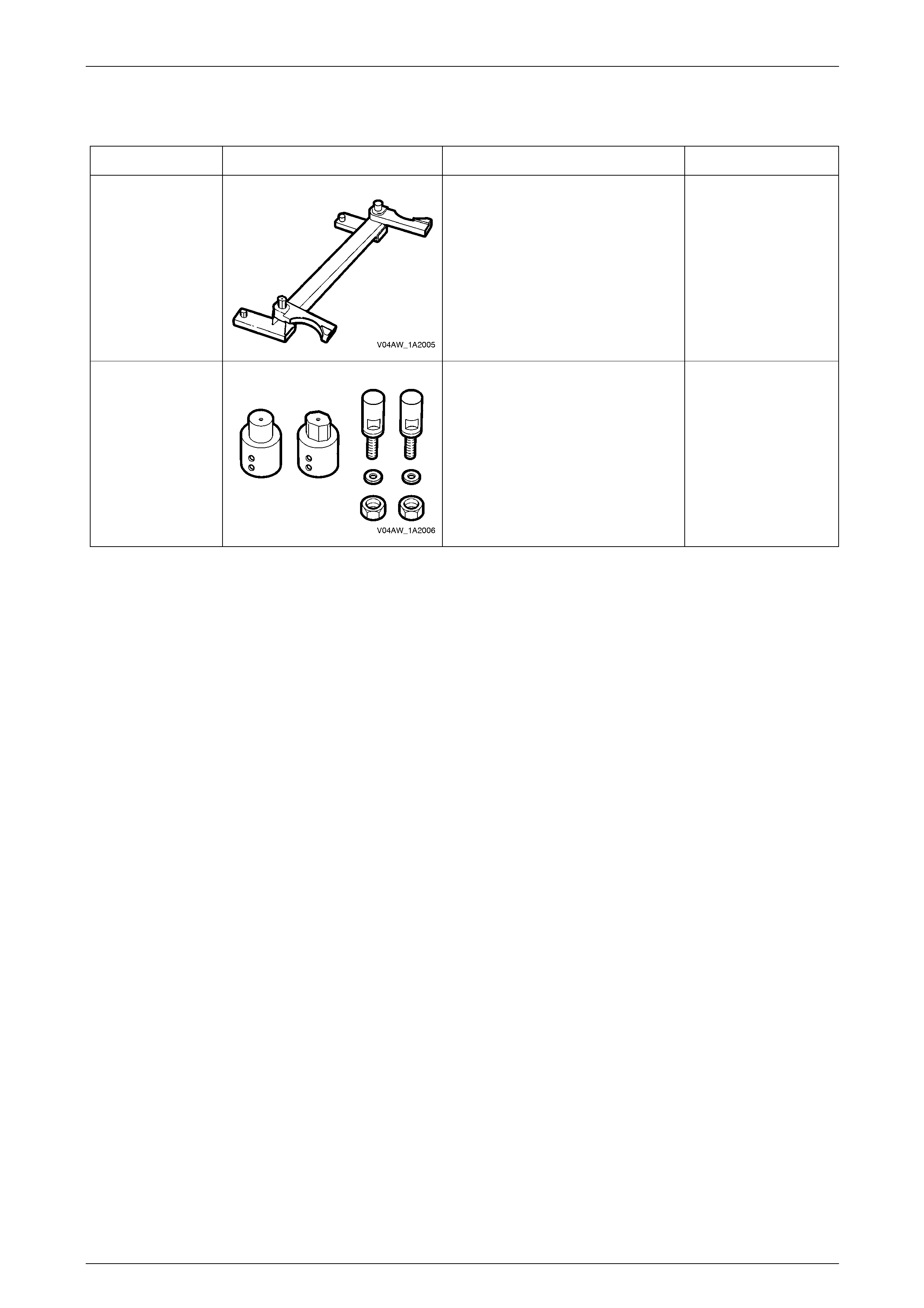
4 Special Tools
Tool Number Illustration Description Tool Classification
CH46839
Also released as
(AU458)
Rear Crossmember Centring Tool.
Previously released. Mandatory.
CH47621 Rear Crossmember Centring Tool
Adaptor Pins. Mandatory.