
Hood, Rear Compartment Lid, Liftgate and Endgate Page 1A4–1
Page 1A4–1
Section 1A4
Hood, Rear Compartment Lid, Liftgate and
Endgate
ATTENTION
Before performing any service operation or other procedure described in this Section, refer to Section 00
Warnings, Cautions and Notes for correct workshop practices with regard to safety and/or property damage.
1 General Information ...............................................................................................................................7
2 Service Operations — Hood, Except Coupe........................................................................................8
2.1 Hood Primary Latch Striker Assembly................................................................................................................. 8
Remove................................................................................................................................................................... 8
Reinstall.................................................................................................................................................................. 8
Adjust...................................................................................................................................................................... 9
2.2 Hood Primary Latch Spring................................................................................................................................. 10
Remove................................................................................................................................................................. 10
Reinstall................................................................................................................................................................ 10
2.3 Hood Primary Latch Release Cable Assembly.................................................................................................. 11
Remove................................................................................................................................................................. 11
Reinstall................................................................................................................................................................ 12
2.4 Hood Secondary Latch Assembly...................................................................................................................... 13
Remove................................................................................................................................................................. 13
Reinstall................................................................................................................................................................ 13
2.5 Hood Insulator...................................................................................................................................................... 14
Remove................................................................................................................................................................. 14
Reinstall................................................................................................................................................................ 14
2.6 Hood Strut Assembly .......................................................................................................................................... 15
Remove................................................................................................................................................................. 15
Reinstall................................................................................................................................................................ 15
2.7 Hood Front Moulding Assembly......................................................................................................................... 16
Remove................................................................................................................................................................. 16
Disassemble......................................................................................................................................................... 16
Reassemble.......................................................................................................................................................... 17
Reinstall................................................................................................................................................................ 17
2.8 Hood and Hinge Assemblies............................................................................................................................... 18
Remove................................................................................................................................................................. 18
Reinstall................................................................................................................................................................ 19
Adjust.................................................................................................................................................................... 20
Fender Alignment............................................................................................................................................. 20
Hood Alignment................................................................................................................................................ 20
Techline
Techline

Hood, Rear Compartment Lid, Liftgate and Endgate Page 1A4–2
Page 1A4–2
3 Service Operations — Hood, Coupe ..................................................................................................22
3.1 Hood Primary Latch Striker Assembly............................................................................................................... 22
Remove................................................................................................................................................................. 22
Reinstall................................................................................................................................................................ 22
Adjust.................................................................................................................................................................... 23
3.2 Hood Primary Latch Spring................................................................................................................................. 24
Remove................................................................................................................................................................. 24
Reinstall................................................................................................................................................................ 24
3.3 Hood Primary Latch Release Cable Assembly.................................................................................................. 25
Remove................................................................................................................................................................. 25
Reinstall................................................................................................................................................................ 26
3.4 Hood Secondary Latch Assembly...................................................................................................................... 27
Remove................................................................................................................................................................. 27
Reinstall................................................................................................................................................................ 27
3.5 Hood Air Scoop Inlet Duct................................................................................................................................... 28
Remove................................................................................................................................................................. 28
Reinstall................................................................................................................................................................ 28
3.6 Hood Insulator...................................................................................................................................................... 29
Remove................................................................................................................................................................. 29
Reinstall................................................................................................................................................................ 29
3.7 Hood Air Scoop Assembly.................................................................................................................................. 30
Remove................................................................................................................................................................. 30
Reinstall................................................................................................................................................................ 31
3.8 Hood Strut Assembly .......................................................................................................................................... 32
Remove................................................................................................................................................................. 32
Reinstall................................................................................................................................................................ 32
3.9 Hood and Hinge Assemblies............................................................................................................................... 33
Remove................................................................................................................................................................. 33
Reinstall................................................................................................................................................................ 34
Adjust.................................................................................................................................................................... 34
Fender Alignment............................................................................................................................................. 35
Hood Alignment................................................................................................................................................ 35
4 Service Operations — Rear Compartment Lid, Sedan.....................................................................37
4.1 Rear Compartment Lid Carpet............................................................................................................................ 37
Remove................................................................................................................................................................. 37
Reinstall................................................................................................................................................................ 37
4.2 Rear Compartment Lid Appliqué Assembly...................................................................................................... 38
Remove................................................................................................................................................................. 38
Disassemble......................................................................................................................................................... 39
Reassemble.......................................................................................................................................................... 39
Reinstall................................................................................................................................................................ 39
4.3 Rear Spoiler Assembly........................................................................................................................................ 40
Introduction.......................................................................................................................................................... 40
Remove................................................................................................................................................................. 40
Disassemble......................................................................................................................................................... 41
High-mount Stop Lamp Assembly.................................................................................................................... 41
Spoiler Insert — SV6 and SV8......................................................................................................................... 41
Reassemble.......................................................................................................................................................... 41
High-mount Stop Lamp Assembly.................................................................................................................... 41
Spoiler Insert — SV6 and SV8......................................................................................................................... 41
Reinstall................................................................................................................................................................ 42
4.4 Rear Compartment Lid Latch Assembly............................................................................................ ................ 44
Remove................................................................................................................................................................. 44
Reinstall................................................................................................................................................................ 44
4.5 Rear Compartment Lid Actuator Assembly ....................................................................................................... 45
Remove................................................................................................................................................................. 45
Reinstall................................................................................................................................................................ 45

Hood, Rear Compartment Lid, Liftgate and Endgate Page 1A4–3
Page 1A4–3
4.6 Rear Compartment Lid Release Cable Assembly............................................................................................. 46
Remove................................................................................................................................................................. 46
Reinstall................................................................................................................................................................ 47
4.7 Rear Compartment Lid Strut Assembly............................................................................................................. 48
Remove................................................................................................................................................................. 48
Reinstall................................................................................................................................................................ 48
4.8 Rear Compartment Lid Assembly ...................................................................................................................... 49
Remove................................................................................................................................................................. 49
Reinstall................................................................................................................................................................ 50
Adjust.................................................................................................................................................................... 51
4.9 Rear Compartment Lid Hinge Assembly ........................................................................................................... 52
Remove................................................................................................................................................................. 52
Reinstall................................................................................................................................................................ 52
4.10 Rear Compartment Lid Striker Assembly.......................................................................................................... 53
Remove................................................................................................................................................................. 53
Reinstall................................................................................................................................................................ 53
4.11 Rear Compartment Lid Weatherstrip ................................................................................................................. 54
Remove................................................................................................................................................................. 54
Reinstall................................................................................................................................................................ 54
5 Service Operations — Rear Compartment Lid, Coupe.....................................................................55
5.1 Rear Compartment Lid Carpet............................................................................................................................ 55
Remove................................................................................................................................................................. 55
Reinstall................................................................................................................................................................ 55
5.2 Rear Compartment Lid Appliqué Assembly...................................................................................................... 56
Remove................................................................................................................................................................. 56
Disassemble......................................................................................................................................................... 58
Reassemble.......................................................................................................................................................... 58
Reinstall................................................................................................................................................................ 59
5.3 Rear Compartment Lid Latch Assembly............................................................................................ ................ 60
Remove................................................................................................................................................................. 60
Reinstall................................................................................................................................................................ 60
5.4 Rear Compartment Lid Actuator Assembly ....................................................................................................... 61
Remove................................................................................................................................................................. 61
Reinstall................................................................................................................................................................ 61
5.5 Rear Compartment Lid Release Cable Assembly............................................................................................. 62
Remove................................................................................................................................................................. 62
Reinstall................................................................................................................................................................ 63
5.6 Rear Compartment Lid Strut Assembly............................................................................................................. 64
Remove................................................................................................................................................................. 64
Reinstall................................................................................................................................................................ 64
5.7 Rear Compartment Lid Assembly ...................................................................................................................... 65
Remove................................................................................................................................................................. 65
Reinstall................................................................................................................................................................ 66
Adjust.................................................................................................................................................................... 67
5.8 Rear Compartment Lid Hinge Assembly ........................................................................................................... 68
Remove................................................................................................................................................................. 68
Reinstall................................................................................................................................................................ 68
5.9 Rear Compartment Lid Striker Assembly.......................................................................................................... 69
Remove................................................................................................................................................................. 69
Reinstall................................................................................................................................................................ 69
5.10 Rear Compartment Lid Weatherstrip ................................................................................................................. 70
Remove................................................................................................................................................................. 70
Reinstall................................................................................................................................................................ 70

Hood, Rear Compartment Lid, Liftgate and Endgate Page 1A4–4
Page 1A4–4
6 Service Operations — Liftgate, Wagon..............................................................................................71
6.1 Liftgate Window Lower Garnish......................................................................................................................... 71
Remove................................................................................................................................................................. 71
Reinstall................................................................................................................................................................ 71
6.2 Liftgate Lower Trim Panel................................................................................................................................... 72
Remove................................................................................................................................................................. 72
Reinstall................................................................................................................................................................ 72
6.3 Liftgate Inside Handle.......................................................................................................................................... 73
Remove................................................................................................................................................................. 73
Reinstall................................................................................................................................................................ 73
6.4 Liftgate Window Upper Garnish ......................................................................................................................... 74
Remove................................................................................................................................................................. 74
Reinstall................................................................................................................................................................ 74
6.5 Liftgate Appliqué Assembly................................................................................................................................ 75
Remove................................................................................................................................................................. 75
Disassemble......................................................................................................................................................... 76
Reassembly.......................................................................................................................................................... 76
Reinstall................................................................................................................................................................ 76
6.6 Liftgate Handle Push-button Assembly............................................................................................................. 77
Remove................................................................................................................................................................. 77
Disassemble......................................................................................................................................................... 77
Reassemble.......................................................................................................................................................... 78
Reinstall................................................................................................................................................................ 78
6.7 Liftgate Latch Assembly ..................................................................................................................................... 79
Remove................................................................................................................................................................. 79
Reinstall................................................................................................................................................................ 79
6.8 Liftgate Actuator Assembly ................................................................................................................................ 80
Remove................................................................................................................................................................. 80
Reinstall................................................................................................................................................................ 80
6.9 Liftgate Air Deflector Assembly.......................................................................................................................... 81
Remove................................................................................................................................................................. 81
Reinstall................................................................................................................................................................ 82
6.10 Rear Window Wiper Assembly ........................................................................................................................... 83
Replace................................................................................................................................................................. 83
6.11 Rear Window Washer Nozzle and Hose Assemblies........................................................................................ 84
Replace................................................................................................................................................................. 84
6.12 High-mount Stop Lamp Assembly ..................................................................................................................... 85
Replace................................................................................................................................................................. 85
6.13 Liftgate Strut Assembly....................................................................................................................................... 86
Remove................................................................................................................................................................. 86
Reinstall................................................................................................................................................................ 86
6.14 Rear Compartment Courtesy Lamp Switch Assembly..................................................................................... 87
Remove................................................................................................................................................................. 87
Reinstall................................................................................................................................................................ 87
6.15 Liftgate Bumper ................................................................................................................................................... 88
Remove................................................................................................................................................................. 88
Reinstall................................................................................................................................................................ 88
6.16 Liftgate Assembly................................................................................................................................................ 89
Remove................................................................................................................................................................. 89
Disassemble......................................................................................................................................................... 90
Reassemble.......................................................................................................................................................... 91
Reinstall................................................................................................................................................................ 91
Adjust.................................................................................................................................................................... 91

Hood, Rear Compartment Lid, Liftgate and Endgate Page 1A4–5
Page 1A4–5
6.17 Liftgate Striker Assembly .................................................................................................................................... 93
Remove................................................................................................................................................................. 93
Reinstall................................................................................................................................................................ 93
Adjust.................................................................................................................................................................... 93
6.18 Liftgate Weatherstrip Assembly......................................................................................................................... 94
Remove................................................................................................................................................................. 94
Reinstall................................................................................................................................................................ 94
7 Service Operations — Liftgate, AWD Wagon....................................................................................95
7.1 Liftgate Window Lower Garnish......................................................................................................................... 95
Remove................................................................................................................................................................. 95
Reinstall................................................................................................................................................................ 95
7.2 Liftgate Lower Trim Panel................................................................................................................................... 96
Remove................................................................................................................................................................. 96
Reinstall................................................................................................................................................................ 96
7.3 Liftgate Window Upper Garnish ......................................................................................................................... 97
Remove................................................................................................................................................................. 97
Reinstall................................................................................................................................................................ 97
7.4 Liftgate Window Release Assembly................................................................................................................... 98
Remove................................................................................................................................................................. 98
Disassemble......................................................................................................................................................... 99
Liftgate Window Release Actuator ................................................................................................................... 99
Liftgate Window Latch Assembly.................................................................................................................... 101
Liftgate Window Microswitch.......................................................................................................................... 102
Reinstall.............................................................................................................................................................. 102
7.5 Liftgate Switch ................................................................................................................................................... 103
7.6 Liftgate Appliqué Assembly.............................................................................................................................. 104
Remove............................................................................................................................................................... 104
Disassemble....................................................................................................................................................... 105
Reassemble........................................................................................................................................................ 105
Reinstall.............................................................................................................................................................. 105
7.7 Liftgate Handle Push-button Assembly........................................................................................................... 106
Remove............................................................................................................................................................... 106
Disassemble....................................................................................................................................................... 106
Reassemble........................................................................................................................................................ 107
Reinstall.............................................................................................................................................................. 107
7.8 Liftgate Air Deflector Assembly........................................................................................................................ 108
Remove............................................................................................................................................................... 108
Disassemble....................................................................................................................................................... 109
Reassemble........................................................................................................................................................ 109
Reinstall.............................................................................................................................................................. 109
7.9 Liftgate Window Assembly ............................................................................................................................... 110
Remove............................................................................................................................................................... 110
Disassemble....................................................................................................................................................... 112
Liftgate Window Striker and Handle............................................................................................................... 112
Liftgate Window Strut Ball Stud...................................................................................................................... 113
Reinstall.............................................................................................................................................................. 113
7.10 Liftgate Window Hinge ...................................................................................................................................... 114
Remove............................................................................................................................................................... 114
Reinstall.............................................................................................................................................................. 114
7.11 Liftgate Window Strut........................................................................................................................................ 115
Remove............................................................................................................................................................... 115
Reinstall.............................................................................................................................................................. 115

Hood, Rear Compartment Lid, Liftgate and Endgate Page 1A4–6
Page 1A4–6
7.12 Liftgate Window Upper Strut Bracket .............................................................................................................. 116
Remove............................................................................................................................................................... 116
Reinstall.............................................................................................................................................................. 116
7.13 Liftgate Window Weatherstrip .......................................................................................................................... 117
Remove............................................................................................................................................................... 117
Reinstall.............................................................................................................................................................. 117
7.14 Liftgate Assembly.............................................................................................................................................. 118
Remove............................................................................................................................................................... 118
Disassemble....................................................................................................................................................... 119
Reassemble........................................................................................................................................................ 120
Reinstall.............................................................................................................................................................. 120
Adjust.................................................................................................................................................................. 121
7.15 Liftgate Weatherstrip Assembly....................................................................................................................... 123
Remove............................................................................................................................................................... 123
Reinstall.............................................................................................................................................................. 123
8 Service Operations — Endgate, Utility.............................................................................................124
8.1 Endgate Inner Panel Access Hole Cover......................................................................................................... 124
Remove............................................................................................................................................................... 124
Reinstall.............................................................................................................................................................. 124
8.2 Endgate Lock Anchor Plate Assembly ............................................................................................................ 125
Remove............................................................................................................................................................... 125
Reinstall.............................................................................................................................................................. 125
8.3 Endgate Latch Assembly and Endgate Latch Bracket Assembly ................................................................. 126
Remove............................................................................................................................................................... 126
Reinstall.............................................................................................................................................................. 126
8.4 Endgate Striker and Endgate Cable Assembly ............................................................................................... 127
Remove............................................................................................................................................................... 127
Reinstall.............................................................................................................................................................. 127
8.5 Endgate Upper Moulding Assembly................................................................................................................. 128
Remove............................................................................................................................................................... 128
Reinstall.............................................................................................................................................................. 128
8.6 Endgate Assembly............................................................................................................................................. 129
Remove............................................................................................................................................................... 129
Reinstall.............................................................................................................................................................. 129
Adjust.................................................................................................................................................................. 130
8.7 Endgate Hinge Assembly.................................................................................................................................. 131
Remove............................................................................................................................................................... 131
Reinstall.............................................................................................................................................................. 131
8.8 Endgate Weatherstrip Assembly...................................................................................................................... 132
Remove............................................................................................................................................................... 132
Reinstall.............................................................................................................................................................. 132
9 Service Operations — Endgate, Crew Cab and AWD Crew Cab...................................................133
9.1 Endgate Latch Bracket and Cable Assembly, and Endgate Striker .............................................................. 133
Remove............................................................................................................................................................... 133
Reinstall.............................................................................................................................................................. 134
10 Torque Wrench Specifications..........................................................................................................135
10.1 Hood – Except Coupe........................................................................................................................................ 135
10.2 Hood – Coupe..................................................................................................................................................... 136
10.3 Rear Compartment Lid – Sedan........................................................................................................................ 137
10.4 Rear Compartment Lid – Coupe....................................................................................................................... 138
10.5 Liftgate – Wagon................................................................................................................................................ 139
10.6 Liftgate – AWD Wagon ...................................................................................................................................... 140
10.7 Endgate – Utility................................................................................................................................................. 141
10.8 Endgate – Crew Cab and AWD Crew Cab........................................................................................................ 142

Hood, Rear Compartment Lid, Liftgate and Endgate Page 1A4–7
Page 1A4–7
1 General Information
This Section describes the service proc edures for the hood assembly, rear compartment lid ass embly, liftgate assembly
and endgate assembly.
A new-style hood is fitted that is common to all models except Coupe. A hood front moulding is fitted to Level 2 and 3
Sedan and Wagon vehicles that integrates with the radiator grille when the hood is closed. A new hood panel assembly
is fitted to Coupe vehicles that has two hood scoop assemblies. The hood insulator has new holes to allow for the fitting
of air inlet ducts that allow air to pass through while restricting water and foreign objects.
The hood release mecha nism is common to all models and uses a cabl e and lever arrangement. The release lever is
located below the driver’s side of the instrument panel.
The rear compartment lid latch assembly is operated by an actuator which is controlled by a release switch located in the
instrument panel compartment, or by a button on the igniti on key. A rear compartment lid release cable is fitted to provide
entry to the rear compartment in case of a power failure. A handle that operates the release is accessible from behind
the rear seat centre for Sedan or under the right-hand rear seat head restraint for Coupe vehicles.
The liftgate latch on the Wagon is operated via a push-button on the handle assembly. Locking is provid ed through the
vehicle’s central locking system or manually with the ignition key. For AWD Wagon vehicles, the hinged liftgate windo w
assembly can be released an d opened while the liftgate assembly remains closed.
The endgate is common to both Utility and Crew Cab vehicles, but the endgate on the Utility can open to a near-v ertical
position. Due to the full-width rear bumper assembly, it is limited to a horizontal position on the Crew Cab.

Hood, Rear Compartment Lid, Liftgate and Endgate Page 1A4–8
Page 1A4–8
2 Service Operations — Hood,
Except Coupe
2.1 Hood Primary Latch Striker Assembly
LT Section No. — 12–050
Remove
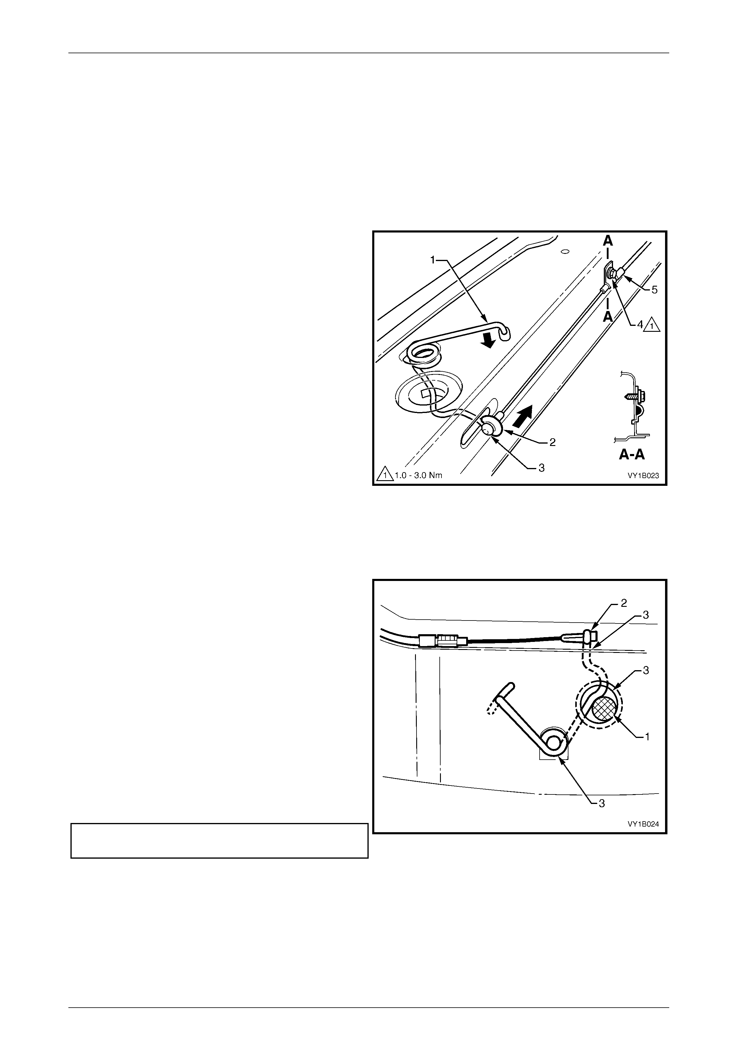
1 Raise the hood.
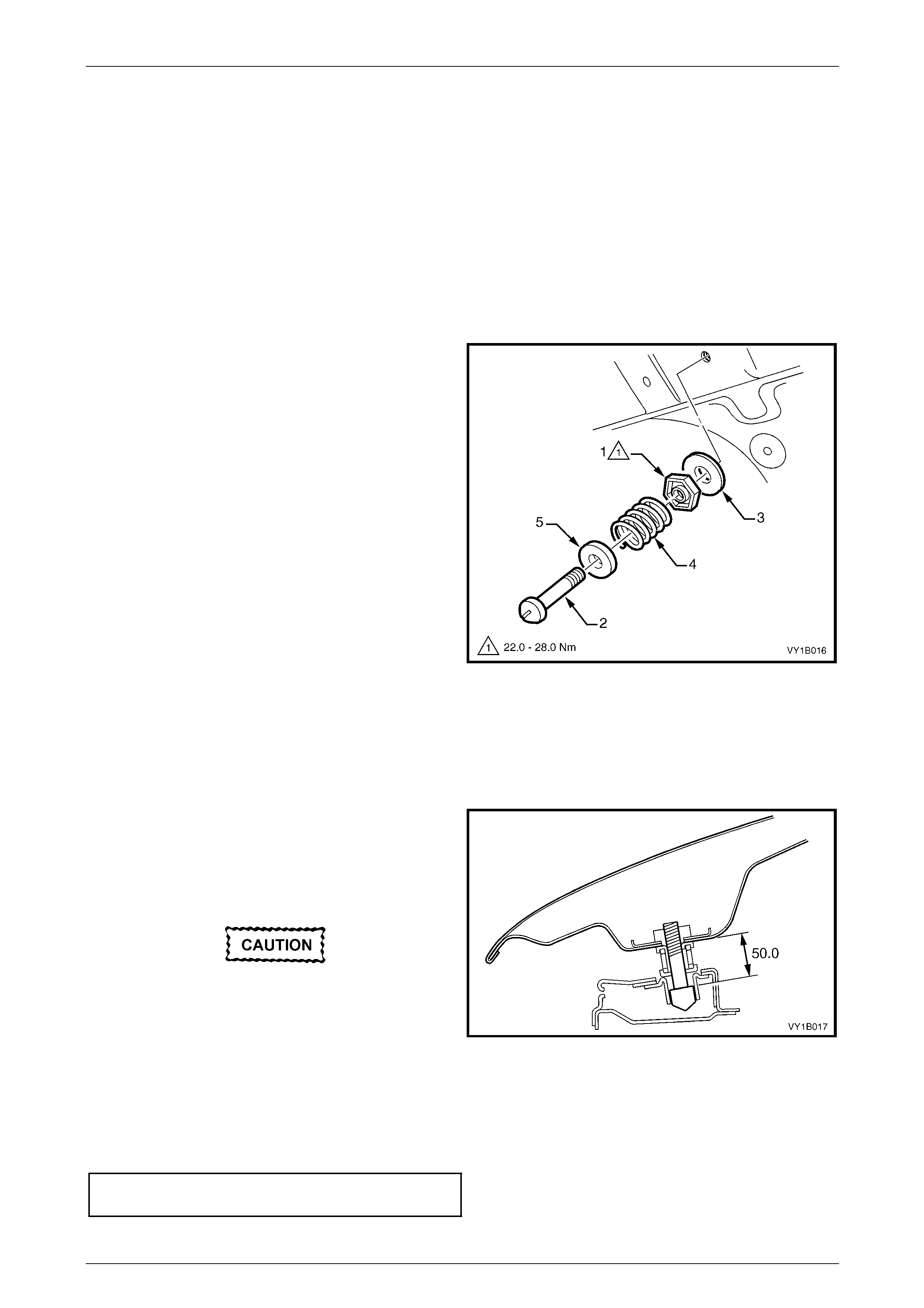
2 Loosen the hood primary latch striker nut (1).
3 Using a flat-bladed screwdrive r , unscrew the hood
primary latch striker bolt (2) and remove the assembly.
4 If required, remove the washer (3), nut, hood pop-up
spring (4) and hood pop-up s prin g retain er (5).
Figure 1A4 – 1
Reinstall
Reinstallation of the hood primary latch striker assembly is the reverse of the removal procedure, noting the following:
1 Reassemble the hood primary latch striker assembly components as required.
2 Install the hood primary latch striker assemb ly to the
hood and tighten the hood primary latch striker bolt to
achieve a nominal length of 50 mm.
3 Apply a lubricant (NLGI No. 1 lithium grease or
equivalent) to the end of the striker bolt.
Do not push the hood closed as damage to
the panel surface may occur. If it does not
close on the first attempt, try again from a
slightly greater height.
Figure 1A4 – 2
4 Close the hood by dropping it from a height of about 300 mm.
5 If required, adjust the usable length of the striker bolt, refer to Adjust in this Section.
6 Tighten the hood primary latch striker nut to the correct torque specification.
Hood primary latch striker nut
torque specification.................................22.0 – 28.0 Nm

Hood, Rear Compartment Lid, Liftgate and Endgate Page 1A4–9
Page 1A4–9
Adjust
1 Check the difference in height between the front of the hood and the fenders, refer to F igure 1A4 – 1 7.
2 To adjust the usable length of the hood primary latch striker bolt:
a Open the hood.
b Loosen and hold the hood primar y latch striker nut while rotating the hood primary latch striker bolt with a flat-
bladed screwdriver.
c If required, set the hood adjust bumper to align the hood height, refer to 2.8 Hood and Hinge Assemblies.
3 Tighten the striker nut to the correct torque specification, ref er to Reinstall i n this Section.
Hood, Rear Compartment Lid, Liftgate and Endgate Page 1A4–10
Page 1A4–10
2.2 Hood Primary Latch Spring
LT Section No. — 12–050
Remove
1 Raise the hood.
2 Remove the radiator upper shroud, refer to Section 6B1 Engine Cooling – V6 or
Section 6B3 Engine Cooling – GEN III V8.
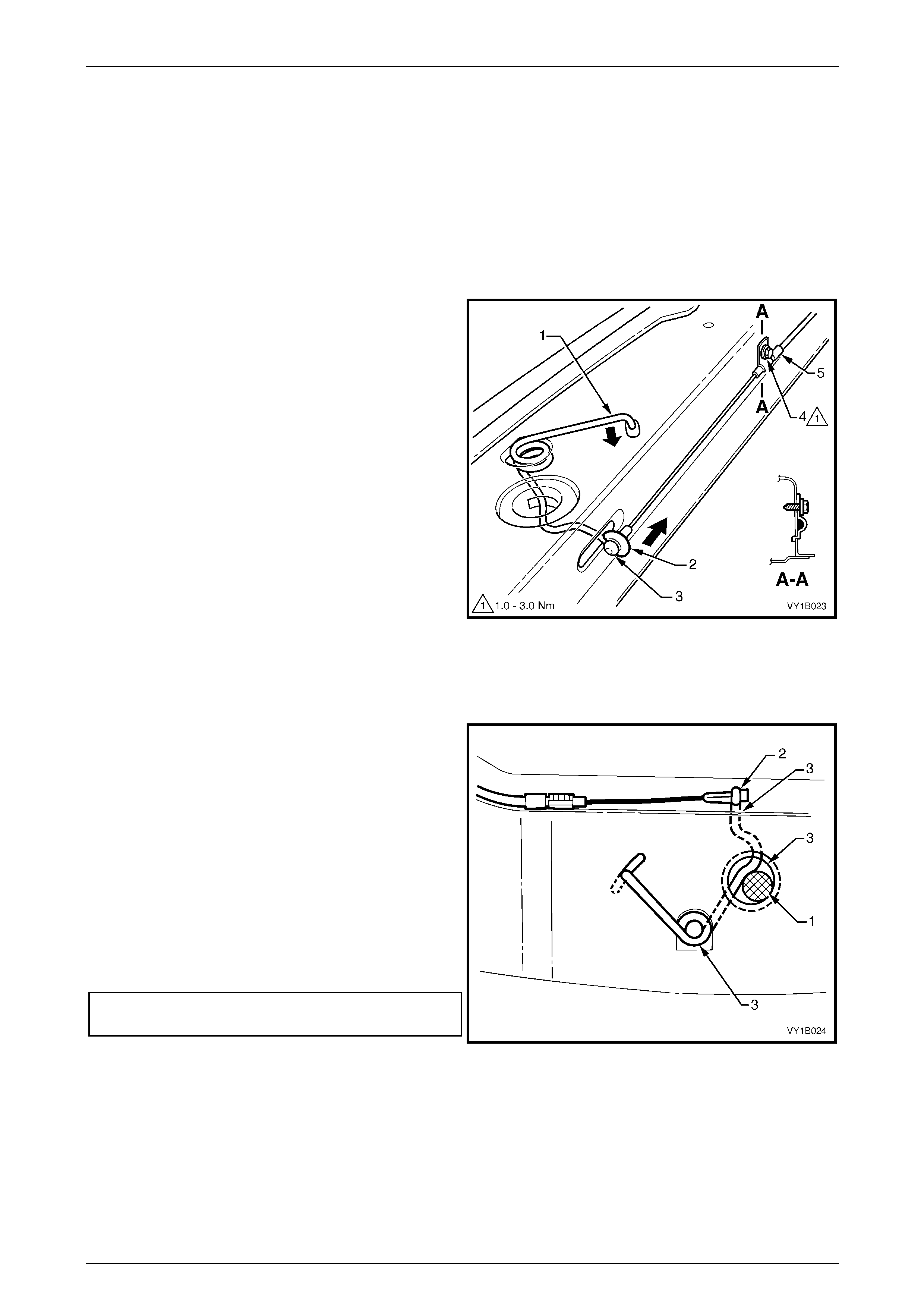
3 Using a pair of pliers, grasp th e hood primary latch
spring at point (1) and carefully dis en gage it from the
front panel in the direction shown.
4 Slide the cable end of the hood primary latch
spring (2) to the open position in the direction shown
to clear the latch hole.
5 Unhook the hood primary latch release cable
assembly (3) from the latch spring.
6 Grasp the end of the latch spring at point (1), rotate to
vertical and manipulate the section of the spri ng in the
front panel out through the spring co il hole.
Figure 1A4 – 3
Reinstall
Reinstallation of the hood primary latch spring is the reverse of the removal procedure, noting the follo wing:
1 Check the hood primary latch release cable
adjustment by inserting a 16 mm pin (1) between the
spring and the latch hole and check there is no
clearance between the inner cable ferrule and the
spring (2).
2 If required, loosen the hood primary latch release
cable retainer screw (4), refer to Figure 1A4 – 3, and
adjust the latch release cable.
NOTE
Ensure the outer cable ferrule (5), refer to
Figure 1A4 – 3, is positioned before the retainer.
3 Tighten the retainer screw to the correct torque
specification.
Hood primary latch release cable
retainer screw torque specification..............1.0 – 3.0 Nm
Figure 1A4 – 4
4 Remove the 16 mm pin and check the hood primary latch spring for correct operation.
5 Apply NLGI No. 1 lithium grease or equivalent to the following locations, refer to the three points (3) indicated in
Figure 1A4 – 4:
• spring slot,
• latch hole to a depth of the spring slot, and
• spring coils.
Hood, Rear Compartment Lid, Liftgate and Endgate Page 1A4–11
Page 1A4–11
2.3 Hood Primary Latch Release Cable
Assembly
LT Section No. — 12–050
Remove
1 If required:
a Remove the radiator upper shroud, refer to Section 6B1 Engine Cooling – V6 or
Section 6B3 Engine Cooling – GEN III V8.
b Remove the right-hand instrument panel o uter cover, refer to Section 1A3 Instrument Panel and Console.
c Detach the wiring harness former from the right-ha nd strut tower,
refer to Section 12O Fuses, Relays and Wiring Harnesses.
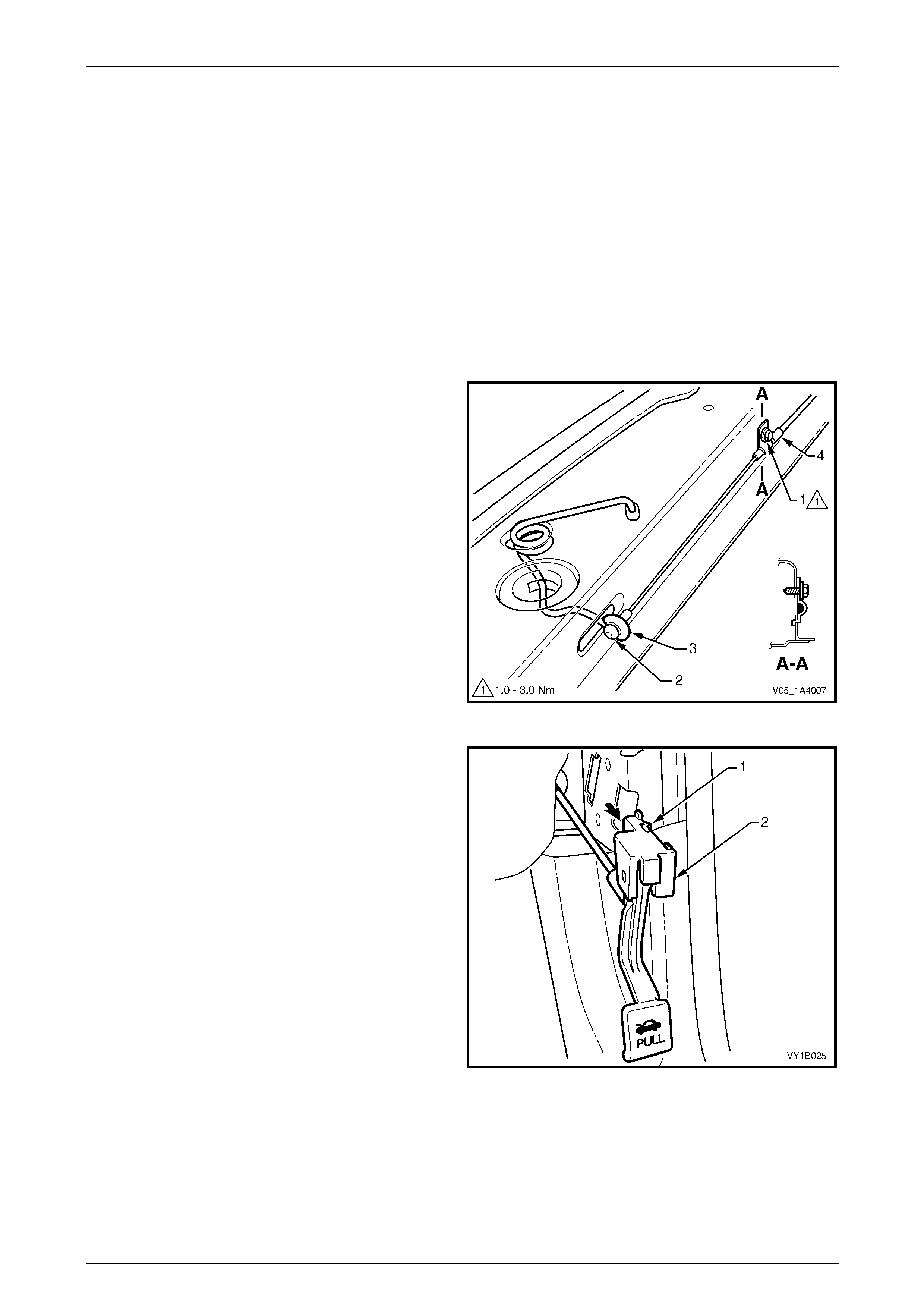
2 Remove the hood primary latch release cable retainer
screw (1) from the outer cable ferrule (4).
3 Unhook the hood primary latch release cable
assembly (2) from the hood primary latch spr ing (3).
Figure 1A4 – 5
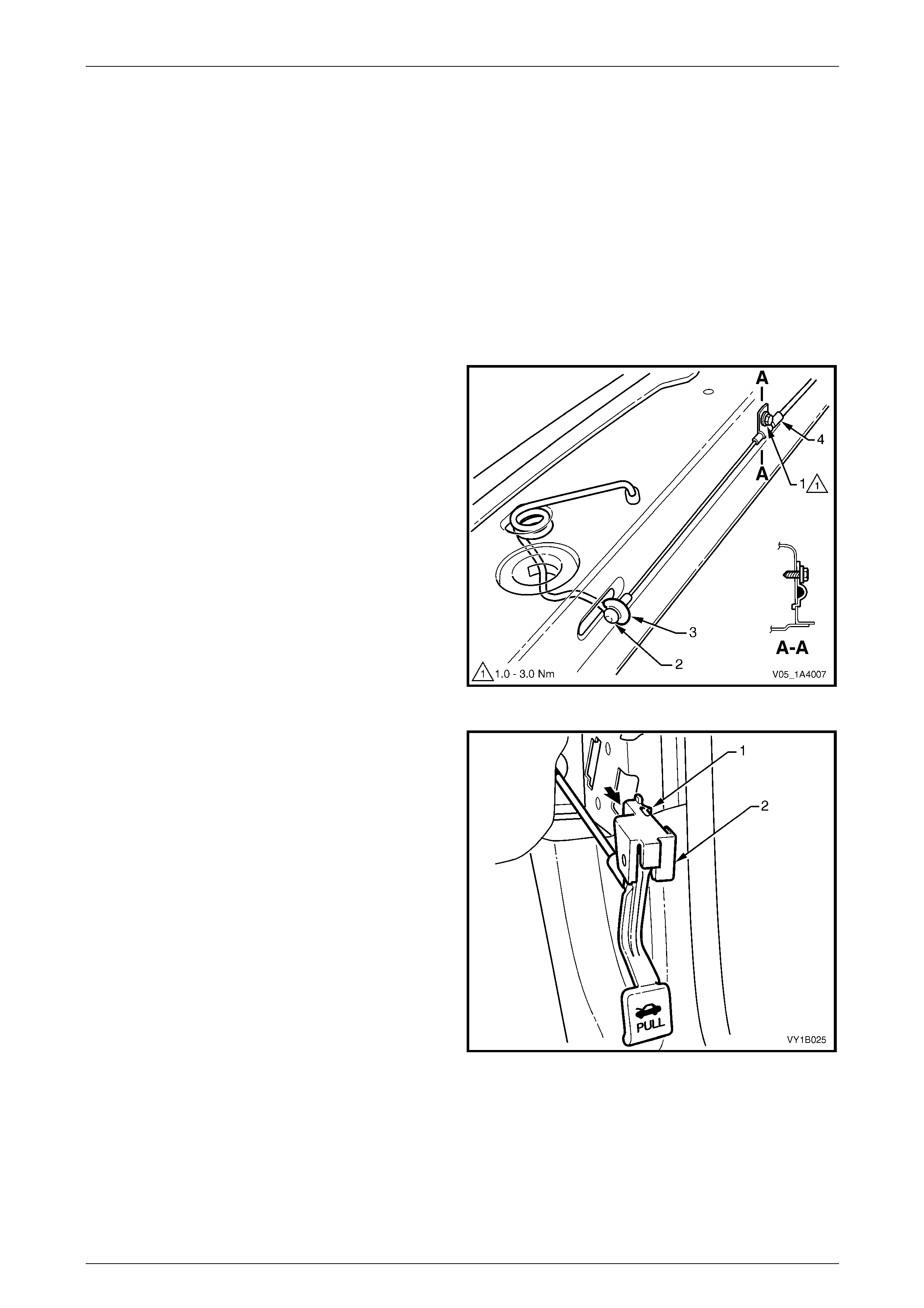
4 From inside the vehicle, using a fine flat-bl aded
screwdriver, lever the retaining tab (1) from the top
and bottom of the hood release lever ass emb ly (2) and
slide the hood release lever assembly rearward.
Figure 1A4 – 6
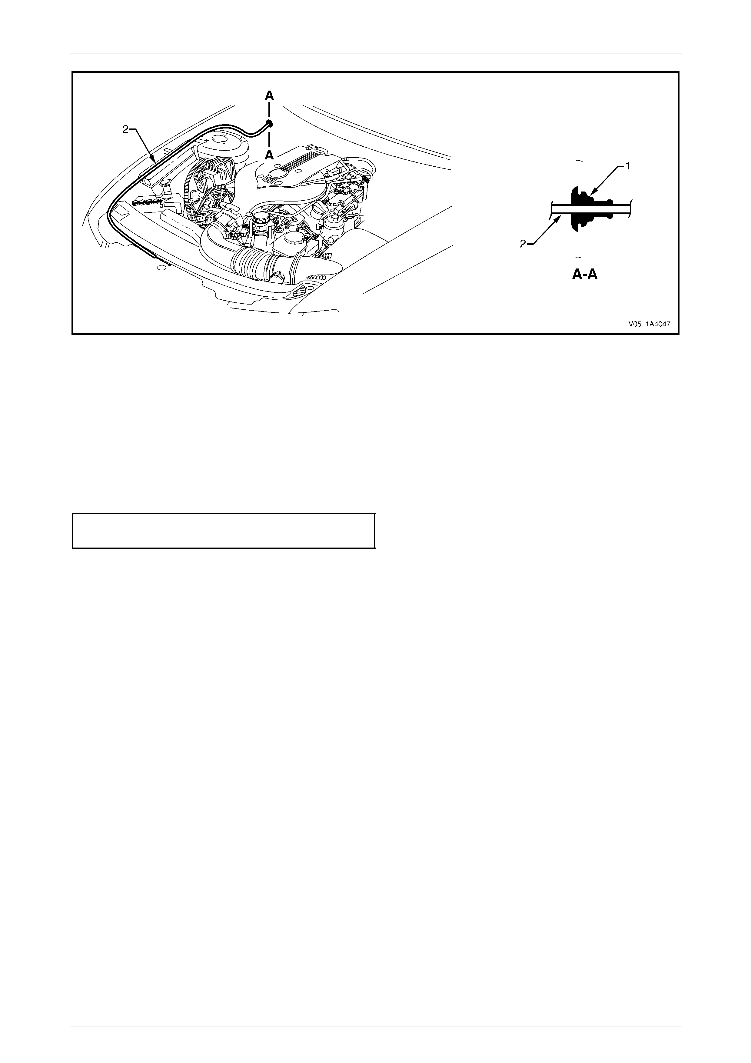
5 From within the engine compartment, push the gromm et (1) through the dash panel, refer to Figure 1A4 – 7.
6 Withdraw the cable assembly (2) from behind the fuse and relay box, across the dash panel and into the passenger
compartment.
Hood, Rear Compartment Lid, Liftgate and Endgate Page 1A4–12
Page 1A4–12
Figure 1A4 – 7
Reinstall
Reinstallation of the hood primary latch release cable ass embly is the reverse of the removal procedure, noting the
following:
1 Ensure the outer cable ferrule (4), refer to Figure 1A4 – 5 is positioned before the retainer.
2 Ensure the cable assembly is correctl y routed and there are no sharp bends in the cable.
3 Tighten the hood primary latch release cable retai ner screw to the correct torque specification.
Hood primary latch release cable
retainer screw torque specification..............1.0 – 3.0 Nm
4 Check the cable adjustment, refer to 2.2 Hood Primary Latch Spring.
5 Attach a spring scale to the lower edge of the hood release lever assembly. The effort required to release the hood
should not exceed 40 Nm.
Hood, Rear Compartment Lid, Liftgate and Endgate Page 1A4–13
Page 1A4–13
2.4 Hood Secondary Latch Assembly
LT Section No. — 12–050
Remove
NOTE
Replace the secondar y latch rivet when removing
the hood secondary latch assembly.
1 Raise the hood.
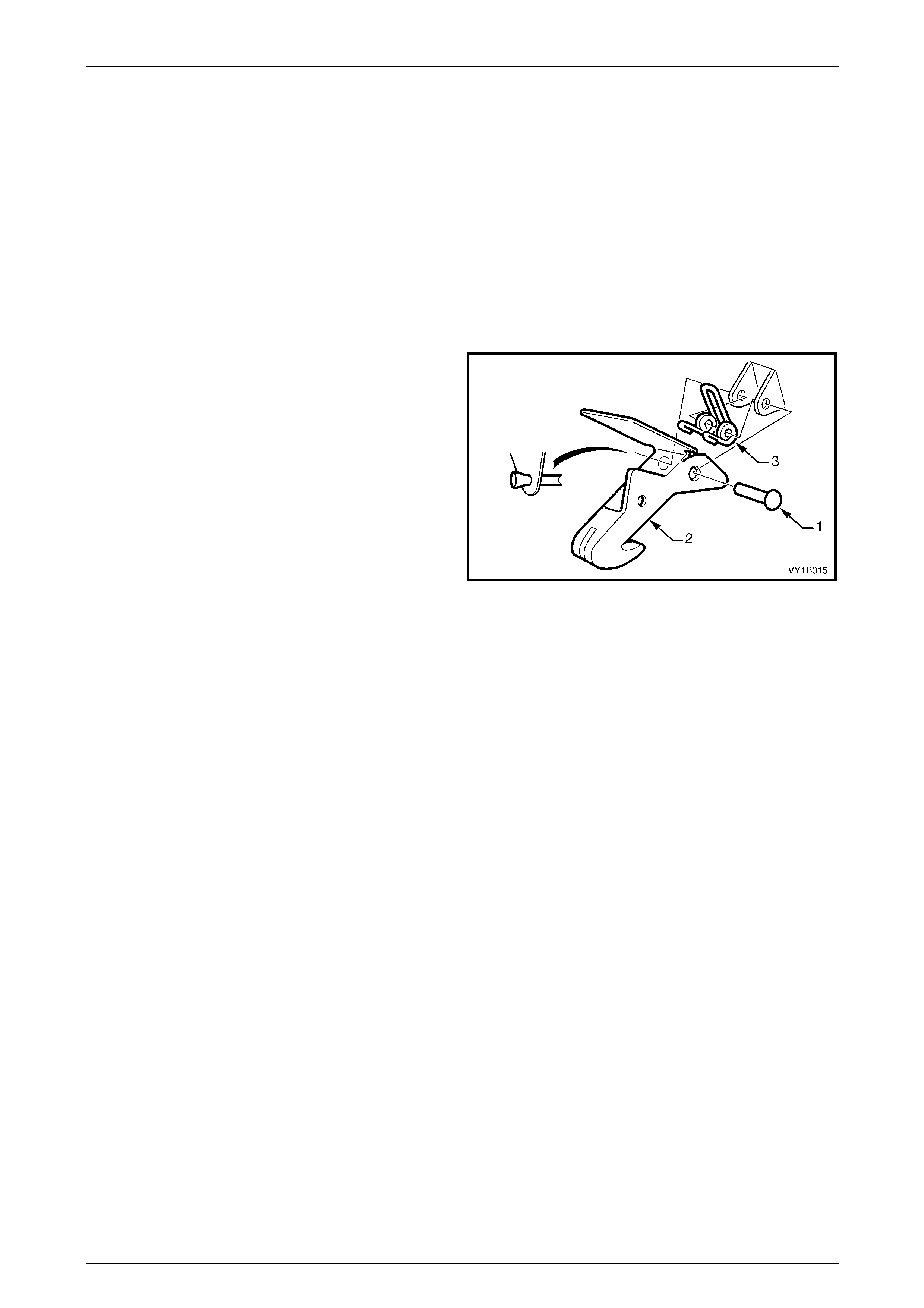
2 Carefully cut the end of the secondar y latch ri vet (1)
securing the hood secondary latch (2) and hood
secondary latch spring (3) to the hood.
NOTE
Take care not to damage the paintwork.
3 Using a pin punch, extract the rivet to remove the latch
and latch spring.
Figure 1A4 – 8
Reinstall
1 Lubricate the new secondar y latch rivet with NLGI No. 1 lithium grease or equivalent.
2 While holding t he hood secondary latch and hood secondary latch spring in position on the hood, insert the new
secondary latch rivet. Ensure the latch spring is correctly oriented, refer to Figure 1A4 – 8.
3 Crimp the end of the rivet to secure it in place.
4 Test the operation of the hood secondary latch assembly.
Hood, Rear Compartment Lid, Liftgate and Endgate Page 1A4–14
Page 1A4–14
2.5 Hood Insulator
LT Section No. — 12–050
Remove
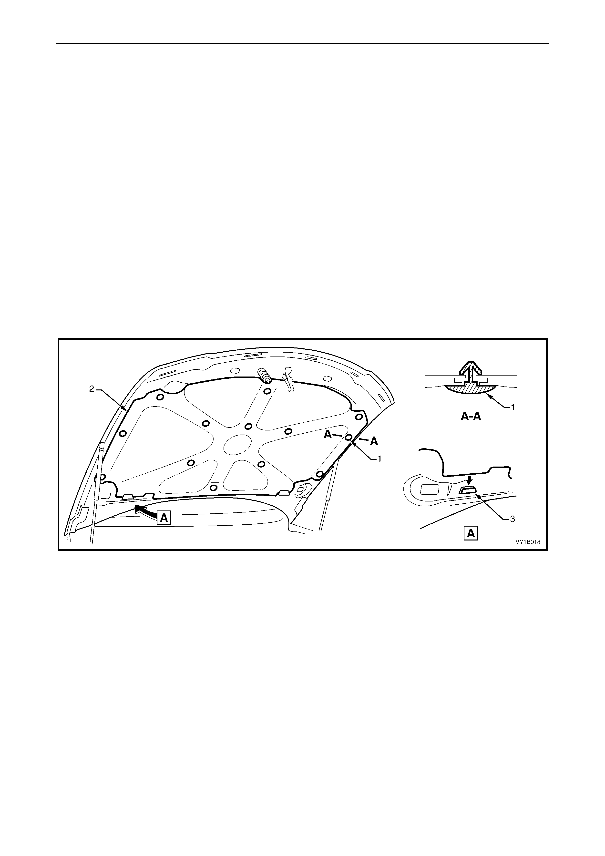
NOTE
The hood insulator retainers may require
replacement when performing this operation.
1 Raise the hood.
2 Beginning at the rear of the hood and working toward the front, remove the hood insulator retainer (1), 13 places,
attaching the hood insulator (2) to the hood, refer to Figure 1A4 – 9.
NOTE
Take care not to crush or damage the hood
insulator.
3 Slide the insulator from the tabs (3) in the hood inn er pa nel and remove the insulator.
Figure 1A4 – 9
Reinstall
Reinstallation of the hood insulator is the reverse of the removal procedure.
Hood, Rear Compartment Lid, Liftgate and Endgate Page 1A4–15
Page 1A4–15
2.6 Hood Strut Assembly
LT Section No. — 12–050
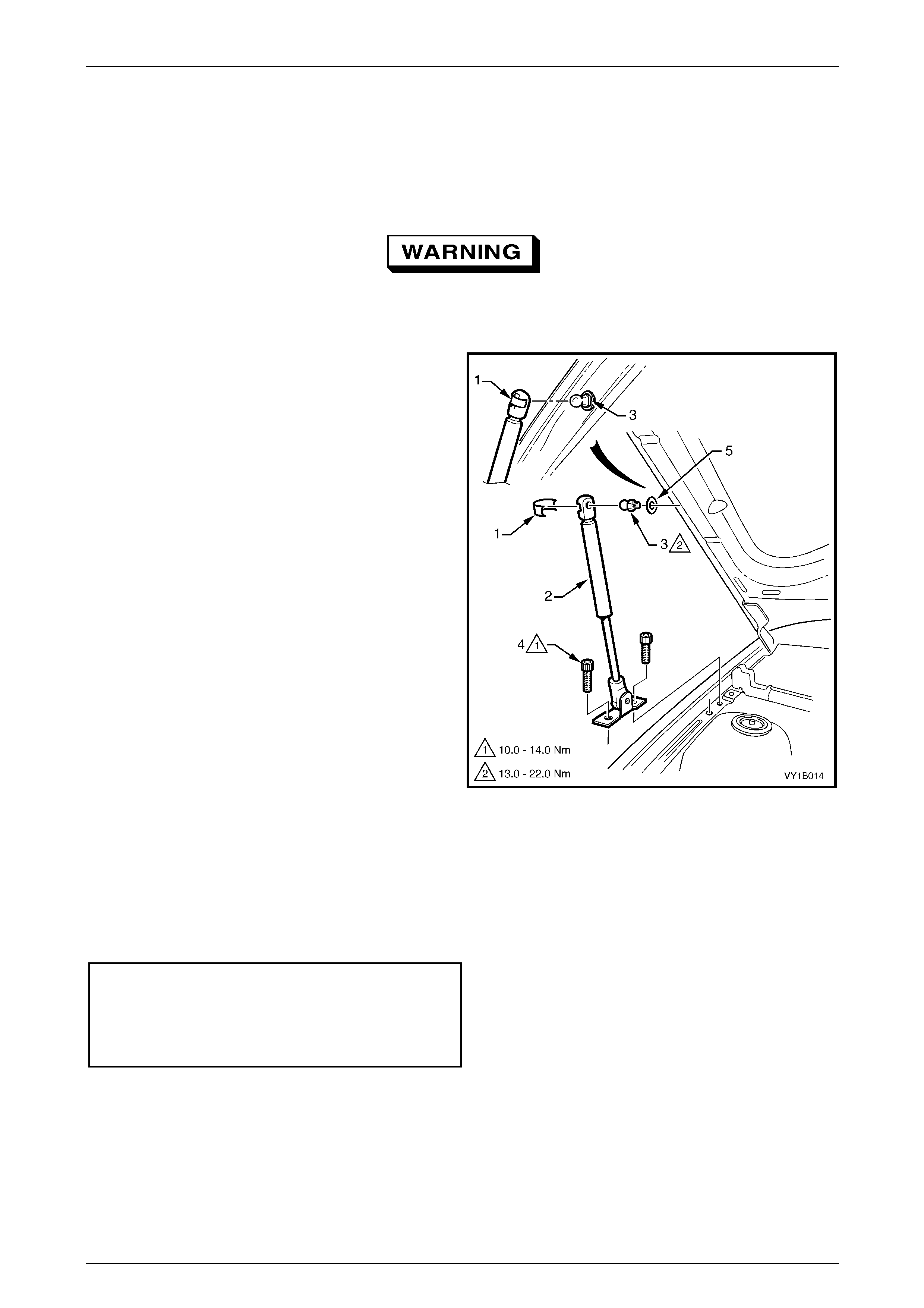
Remove
The hood struts contain pressurised gas. Do
not subject them to extreme heat, p ressure or
physical damage.
1 With the aid of an assistant to support the hood, use a
fine flat-bladed screwdriver to remove the retainer (1)
securing the hood strut assembly (2) to the hood strut
ball stud (3).
NOTE
The retainer can spring off the hood strut
assembly and be easily lost.
2 Remove the two Torx-head screws (4), attaching the
strut assembly to the fender.
3 Disconnect the strut assembly from the hood and
remove.
4 If required, unscrew the hood strut ball stud and
washer (5) from the hood.
Figure 1A4 – 10
Reinstall
Reinstallation of the hood strut assembly is the reverse of the removal procedure, noting the following:
1 Apply a small amount of NLGI No. 1 lithium grease or equivalent to the inside of the strut ball cup.
2 Tighten the fasteners to the correct torque specification.
Hood strut ball stud
torque specification.................................13.0 – 22.0 Nm
Hood strut assembly
to fender attaching screw
torque specification.................................10.0 – 14.0 Nm
3 Check for correct operation of the hood strut assembly.
Hood, Rear Compartment Lid, Liftgate and Endgate Page 1A4–16
Page 1A4–16
2.7 Hood Front Moulding Assembly
LT Section No. — XX–XXX
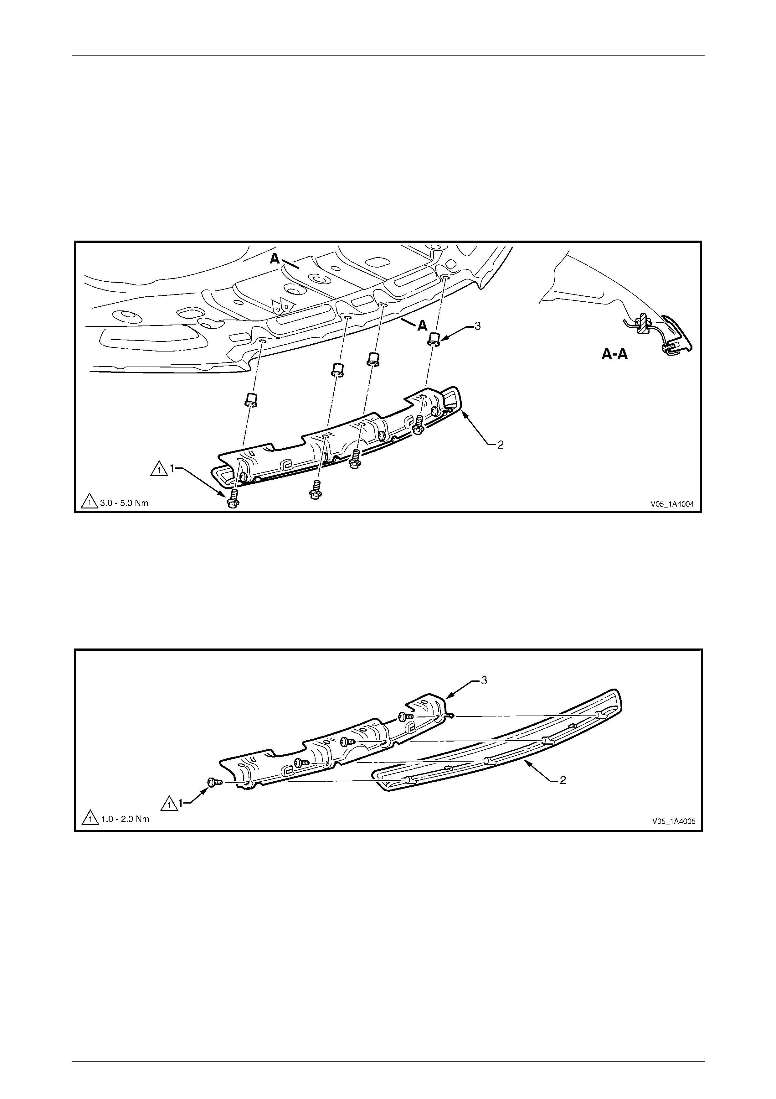
Remove
1 Raise the hood.
2 Remove the four screws (1) attaching the front moulding assembl y (2) to the hood inner panel and rem ove the
moulding assembly.
Figure 1A4 – 11
Disassemble
1 Remove the four screws (1) attaching the hood front moulding (2) to the hood moulding mounting bracket (3),
refer to Figure 1A4 – 12.
2 Unclip the moulding from the mounting bracket and remove.
Figure 1A4 – 12

Hood, Rear Compartment Lid, Liftgate and Endgate Page 1A4–17
Page 1A4–17
Reassemble
Reassembly of the hood front moulding assembly is the reverse of the disassembly procedur e. Tighten the screws to the
correct torque specification.
Hood front moulding attaching
screw torque specification...........................1.0 – 2.0 Nm
Reinstall
Reinstallation of the hood front moulding assembly is the reverse of the remova l procedure, noting the follo wing:
Use only M5 nutserts for this application;
some generic nutserts may not be suitable.
1 If a new hood has been fitted, install four M5 nutserts (3), refer to Figure 1A4 – 11, into the holes in the hood inner
panel using a commercially-available nutsert gun.
2 Tighten the screws to the correct torque specification.
Hood front moulding assembly
screw torque specification...........................3.0 – 5.0 Nm
Hood, Rear Compartment Lid, Liftgate and Endgate Page 1A4–18
Page 1A4–18
2.8 Hood and Hinge Assemblies
LT Section No. — 12–425
Remove
1 If required, remove the following components:
a Hood primary latch striker assembly, refer to 2.1 Hood Primary Latch Striker Assembly.
b Hood secondary latch assemb ly, refer to 2.4 Hood Secondary Latch Assembly.
c Hood insulator, refer to 2.5 Hood Insulator.
d Where fitted, the hood front moulding assembl y, refer to 2.7 Hood Front Moulding Assembly.
2 Raise and support the hood.
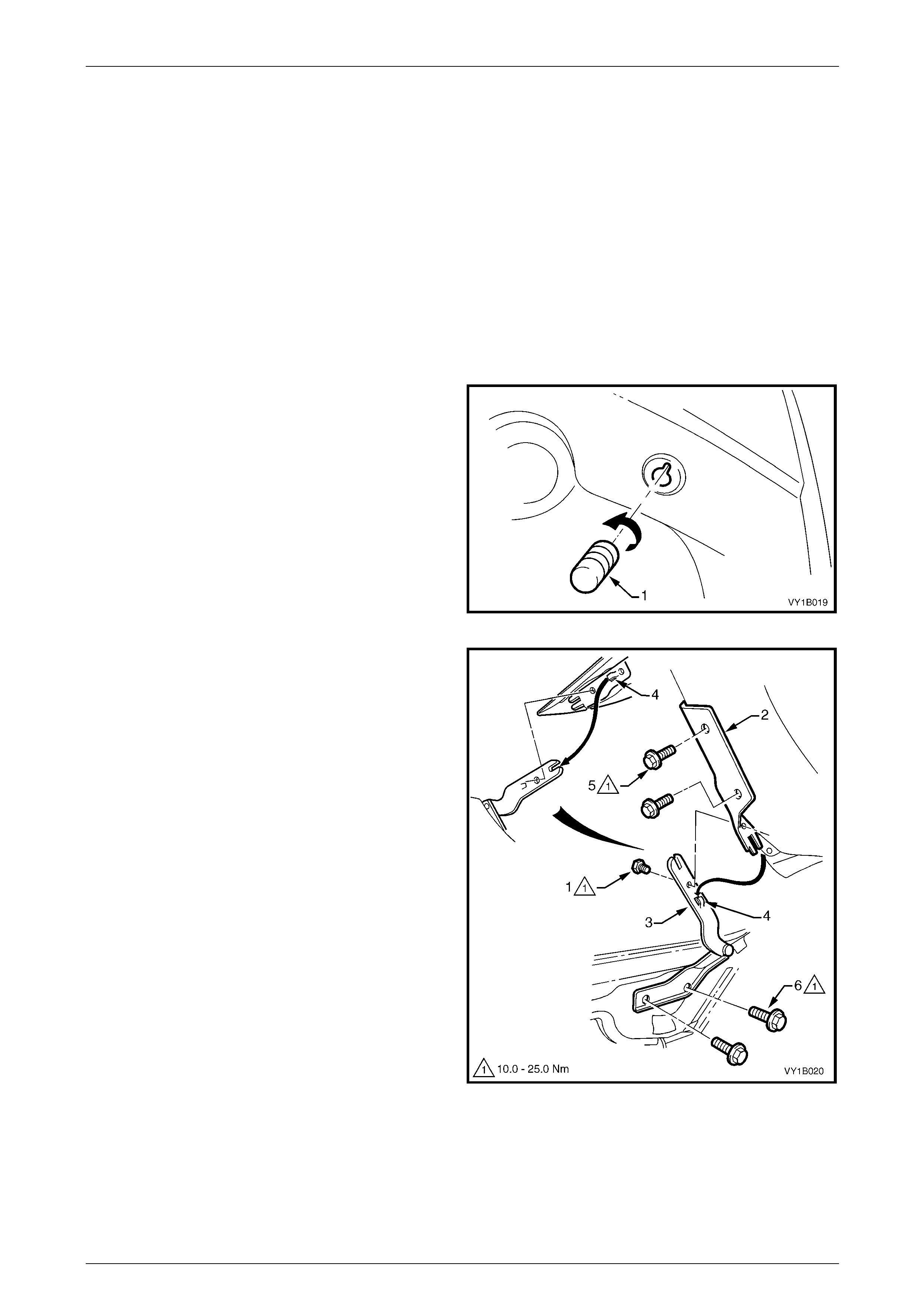
3 If required, unscrew and remove the hood adjust
bumper (1), three places, from the centre and on each
side of the hood.
4 Disconnect the hood strut assemblies from the hood,
refer to 2.6 Hood Strut Assembly.
NOTE
The lower end of the hood strut assembly does
not need to be removed.
Figure 1A4 – 13
5 To remove the hood:
NOTE
Alignment of the hood is not required if the
following method is used to remove the hood.
a If the hood will be reinstalled:
(1) Remove the screw (1) attaching the upper
hinge section (2) and lower hinge
section (3) from each hood and hing e
assembly.
(2) With the aid of an assistant, slide the hood
out of the locating tabs (4) and remove the
hood.
NOTE
Alignment of the hood may be required if the
following method is used to remove the hood.
b If a new hood will be installed:
(1) Remove the two screws (5) attaching the
upper hinge section to the hood from each
hood and hinge assembly.
(2) With the aid of an assistant, remove the
hood.
Figure 1A4 – 14
6 If required, remove the lower hinge section, refer to Figure 1 A4 – 14:
a Remove the screw (1) attaching the upper hinge section (2) and lower hinge section (3).
b Remove the plenum cover assembly, refer to Section 12N Wipers, Washers and Horn.
c Remove the two screws (6) attaching the lower hinge section to the body and remove the lo wer section.
Hood, Rear Compartment Lid, Liftgate and Endgate Page 1A4–19
Page 1A4–19
Reinstall
Reinstallation of the hood and hinge assemblies is the rev erse of the removal procedure, noting the following:
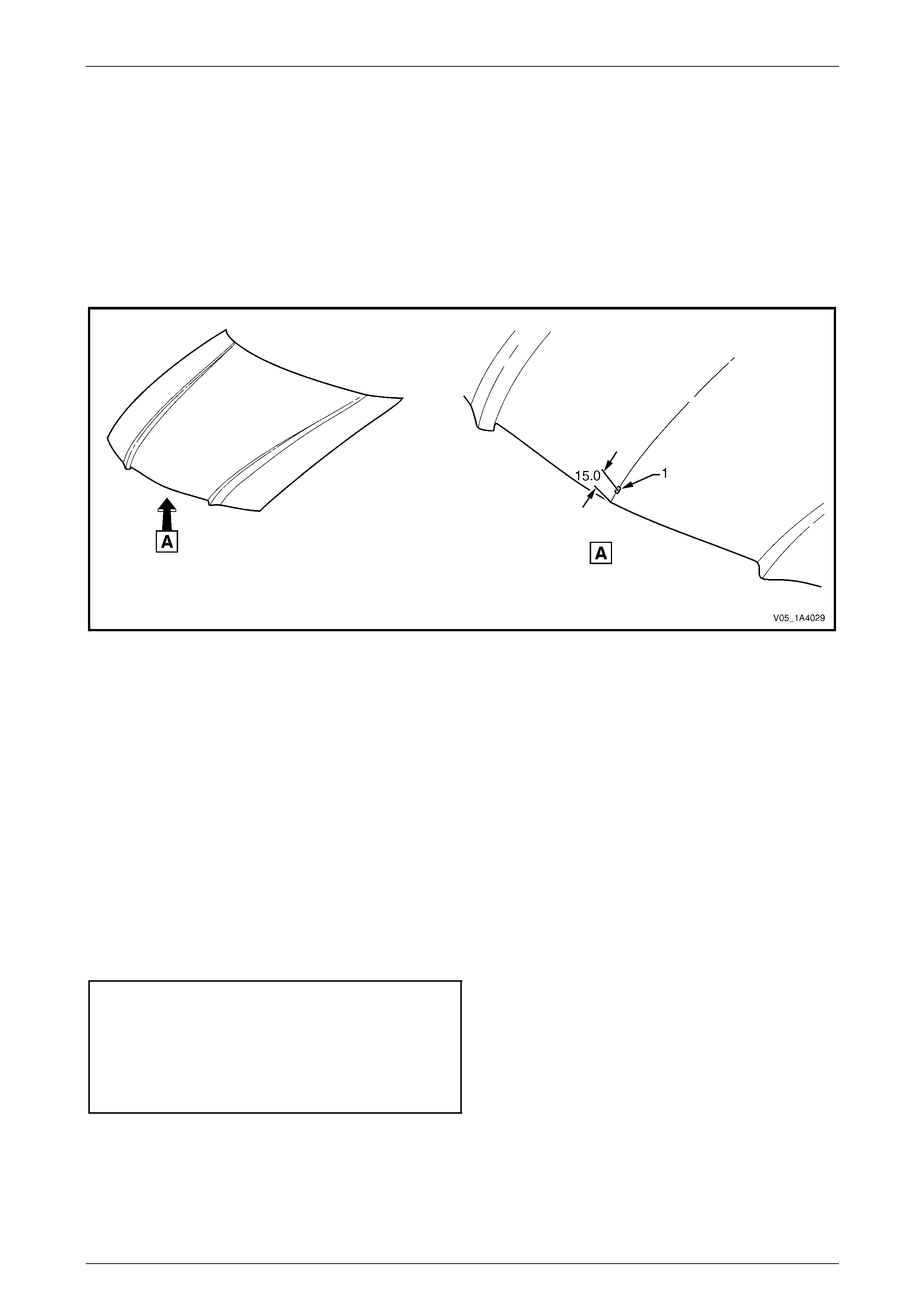
1 If fitting a replacement hood on either a Leve l 2 or 3 vehicle, before refinishing the hood panel drill a hole to
accommodate the hood front mouldin g, refer to F igure 1A4 – 15:
a Measure along the hood centre-line and mark the centre point of the hole (1).
b Drill a 3 mm pilot hole through the outer panel only.
c Enlarge and slot the hole to a width of 5 mm wide by 7 mm long.
d Remove any burrs as required.
Figure 1A4 – 15
2 If the lower hinge sections were removed from the body:
a Reinstall the lower hinge sections and, if possible, align them with any existing marks. Otherwise, install the
lower hinge sections with the screws centrally in their holes.
b Temporarily tighten the screws.
3 If the upper hinge sections were removed from the hood:
a With the aid of an assistant, reinstall the upper hinge sections to the hood and, if possible, alig n them with
any existing marks. Otherwise, install the upper hinge sections with the screws centrally in their holes.
b Temporarily tighten the screws.
4 If the screw attaching the upper hinge section and lower hinge section were removed:
a With the aid of an assistant, slide the hood and upper hing e sections onto the lower hinge sections, ensuring
the upper hinge sections and lower hinge sections are correctly seated together.
b Tighten the screws to the correct torque specification.
Upper hinge section attaching
screw torque specification.......................10.0 – 25.0 Nm
Lower hinge section attaching
screw torque specification.......................10.0 – 25.0 Nm
Hood hinge scre w
torque specification.................................10.0 – 25.0 Nm
5 Install the hood adjust bumpers to their original position or half-way along the thread, refer to Figure 1A4 – 13.
6 Install or reconnect the hood strut assemblies, refer to 2.6 Hood Strut Assembly.
7 If required, adjust the hood, refer to Adjust in this Section.
8 If removed, reinstall the plenum cover assembly, refer to Section 12N Wipers, Washers and Horn.
Hood, Rear Compartment Lid, Liftgate and Endgate Page 1A4–20
Page 1A4–20
Adjust
Correct alignment of the hood is critical to its operation and to the aesthetics of the vehicle. If the fenders are not
correctly positioned, the hood can not be aligned correctly.
Depending upon the repa irs performed, it may be advantageous to p erform a measurement check between the fenders
before adjusting the hood.
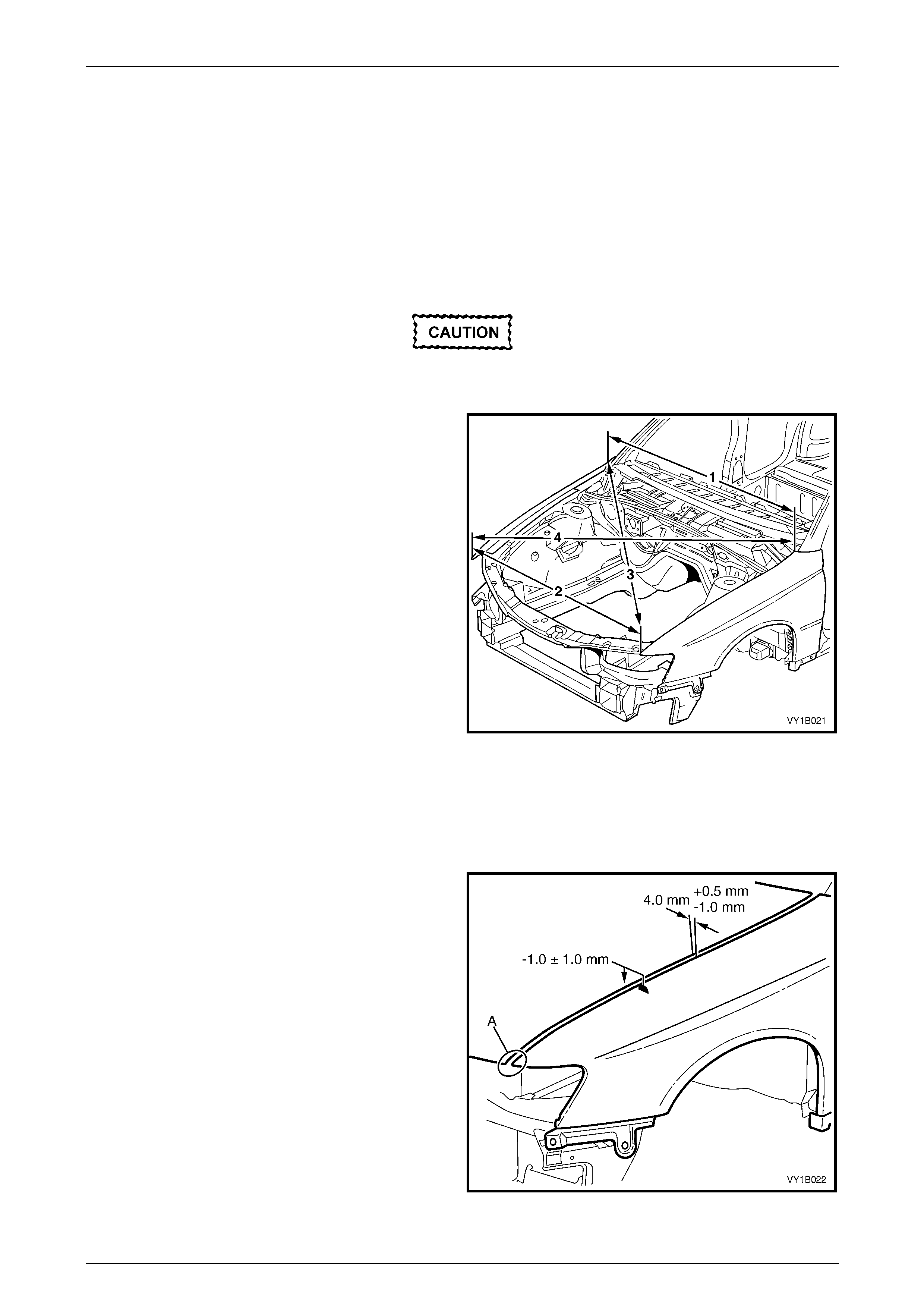
Fender Alignment
1 Check the distance between the front doors and fen ders are correct. If not correct, rectify before proceeding, refer
to Section 1B Sheetmetal.
Paint damage may occur. Use care and, if
required, touch up any paint damage.
2 Measure the distance between the rear of each
fender (1). This distance should be the width of the
rear of the hood plus 8.0 mm. If not, adjust the
fenders, refer to Section 1B Sheetmetal.
3 Measure the distance between the front of each
fender (2). This should be the width of the front of the
hood plus 8.0 mm. If not, adjust the fenders, refer to
Section 1B Sheetmetal.
4 Measure the distance between a suitable point at the
rear of the left-hand fender and front of the right-hand
fender (3). Note the length.
5 Measure the distance between the opposite fender
points (4). This measurement must be within 1.5 mm
of result (3).
6 If the measurements are correct, align the hood as
follows. If not, adjust the fenders, refer to
Section 1B Sheetmetal.
Figure 1A4 – 16
Hood Alignment
1 If fitted, remove the hood primary latch striker assembly, refer to 2.1 Hood Primary Latch Striker Assembl y.
2 Carefully close the hood, ensuring each side does not contact the fenders.
3 Check the alignment of the hood for:
• Length:
Compare to the front edge of the fenders; they
should be equal at point A.
• Width of gap:
Compare the gap bet ween the hoo d and the side
of each fender; the gap must be 4.0 mm
(+0.5 mm / –1.0 mm).
• Consistency of gap:
Compare the gap bet ween the hoo d and each
fender at the front, middle and rear; the gap
should be even.
• Height:
Compare the height of the hood with the fenders
at each corner; the hood height must be –1 mm
(±1.0 mm).
Figure 1A4 – 17
Hood, Rear Compartment Lid, Liftgate and Endgate Page 1A4–21
Page 1A4–21
4 Open the hood and, if required:
• Loosen the screws attaching the hood to both upper hinge sections for fore and aft adjustment, refer to
Figure 1A4 – 14.
• Loosen the scre ws attaching both lower hinge sections to the body for rear height adjustment. If required, this
also provides fore and aft adjustment, refer to Figure 1A4 – 14.
• Turn the hood adjust bumper clockwise to lower the front of the hood or anticlockwise to raise the front of the
hood, refer to Figure 1A4 – 13.
NOTE
Do not make all adjustments at once. Perform
one adjustment, then carefully close the hood;
check its position and make further adjustments
until the correct alignment is a c hieved.
5 Install the hood primary latch striker assemb ly, refer to 2.1 Hood Primary Latch Striker Assembly.
6 Lower the hood while watching the alignment of the hood primary latch striker assembly and the latch hole.
7 Check the hood primary latch striker bolt do es not foul the latch hole and the hood alignment does not alter. If
required, adjust the hood primary latch striker bolt position.
Do not push the hood closed as damage to
the panel surface may occur. If it does not
close on the first attempt, try again from a
slightly greater height.
8 Close the hood by dropping it from a height of approximately 300 mm.
9 Check the height difference between the front of the hood and both fenders:
a If required, adjust the usable length of the hood primary latch striker bolt by loosening the hood primary latch
striker nut and rotating the hood primary latch striker bolt with a flat-bladed screwdriver, refer to
Figure 1A4 – 1.
b If required, adjust the hood adjust bumpers, refer to Figure 1A4 – 13.
10 Tighten the screws and nuts to the correct torque specification.
Upper hinge section attaching
screw torque specification.......................10.0 – 25.0 Nm
Lower hinge section attaching
screw torque specification.......................10.0 – 25.0 Nm
Hood primary latch striker nut
torque specification.................................22.0 – 28.0 Nm
11 Recheck the alignment of the hood.
Hood, Rear Compartment Lid, Liftgate and Endgate Page 1A4–22
Page 1A4–22
3 Service Operations — Hood,
Coupe
3.1 Hood Primary Latch Striker Assembly
LT Section No. — 12–050
Remove
1 Raise the hood.
2 Loosen the hood primary latch striker nut (1).
3 Using a flat-bladed screwdrive r , unscrew the hood
primary latch striker bolt (2) and remove the assembly.
4 If required, remove the washer (3), nut, hood pop-up
spring (4) and hood pop-up s prin g retain er (5).
Figure 1A4 – 18
Reinstall
Reinstallation of the hood primary latch striker assembly is the reverse of the removal procedure, noting the following:
1 Reassemble the hood primary latch striker assembly components as required.
2 Install the hood primary latch striker assemb ly to the
hood and tighten the hood primary latch striker bolt to
achieve a nominal length of 50 mm.
3 Apply a lubricant (NLGI No. 1 lithium grease or
equivalent) to the end of the striker bolt.
Do not push the hood closed as damage to
the panel surface may occur. If it does not
close on the first attempt, try again from a
slightly greater height.
Figure 1A4 – 19
4 Close the hood by dropping it from a height of about 300 mm.
5 If required, adjust the usable length of the striker bolt, refer to Adjust in this Section.
6 Tighten the hood primary latch striker nut to the correct torque specification.
Hood primary latch striker nut
torque specification.................................22.0 – 28.0 Nm

Hood, Rear Compartment Lid, Liftgate and Endgate Page 1A4–23
Page 1A4–23
Adjust
1 Check the difference in height between the front of the hood and the fenders, refer to F igure 1A4 – 3 5.
2 To adjust the usable length of the hood primary latch striker bolt:
a Open the hood.
b Loosen and hold the hood primar y latch striker nut while rotating the hood primary latch striker bolt with a flat-
bladed screwdriver.
c If required, set the hood adjust bumper to align the hood height, refer to 3.9 Hood and Hinge Assemblies.
3 Tighten the striker nut to the correct torque specification, ref er to Reinstall i n this Section.
Hood primary latch striker nut
torque specification.................................22.0 – 28.0 Nm
Hood, Rear Compartment Lid, Liftgate and Endgate Page 1A4–24
Page 1A4–24
3.2 Hood Primary Latch Spring
LT Section No. — 12–050
Remove
1 Raise the hood.
2 Remove the radiator upper shroud, refer to Section 6B3 Engine Cooling – GEN III V8.
3 Using a pair of pliers, grasp th e hood primary latch
spring at point (1) and carefully dis en gage it from the
front panel in the direction shown.
4 Slide the cable end of the hood primary latch
spring (2) to the open position in the direction shown
to clear the latch hole.
5 Unhook the hood primary latch release cable
assembly (3) from the latch spring.
6 Grasp the end of the latch spring at point (1), rotate to
vertical and manipulate the section of the spri ng in the
front panel out through the spring co il hole.
Figure 1A4 – 20
Reinstall
Reinstallation of the hood primary latch spring is the reverse of the removal procedure, noting the follo wing:
1 Check the hood primary latch release cable
adjustment by inserting a 16 mm pin (1) between the
spring and the latch hole and check there is no
clearance between the inner cable ferrule and the
spring (2).
2 If required, loosen the hood primary latch release
cable retainer screw (4), refer to Figure 1A4 – 20, and
adjust the latch release cable.
NOTE
Ensure the outer cable ferrule (5), refer to
Figure 1A4 – 20, is positioned before the
retainer.
3 Tighten the retainer screw to the correct torque
specification.
Hood primary latch release cable
retainer screw torque specification..............1.0 – 3.0 Nm Figure 1A4 – 21
4 Remove the 16 mm pin and check the hood primary latch spring for correct operation.
5 Apply NLGI No. 1 lithium grease or equivalent to the following locations, refer to the three points (3) indicated in
Figure 1A4 – 21:
• spring slot,
• latch hole to a depth of the spring slot, and
• spring coils.
Hood, Rear Compartment Lid, Liftgate and Endgate Page 1A4–25
Page 1A4–25
3.3 Hood Primary Latch Release Cable
Assembly
LT Section No. — 12–050
Remove
1 If required:
a Remove the radiator upper shroud, refer to Section 6B3 Engine Cooling – GEN III V8.
b Remove the right-hand instrument panel o uter cover, refer to Section 1A3 Instrument Panel and Console.
c Detach the wiring harness former from the right-ha nd strut tower,
refer to Section 12O Fuses, Relays and Wiring Harnesses.
2 Remove the hood primary latch release cable retainer
screw (1) from the outer cable ferrule (4).
3 Unhook the hood primary latch release cable
assembly (2) from the hood primary latch spr ing (3).
Figure 1A4 – 22
4 From inside the vehicle, using a fine flat-bl aded
screwdriver, lever the retaining tab (1) from the top
and bottom of the hood release lever ass emb ly (2) and
slide the hood release lever assembly rearward.
Figure 1A4 – 23
5 From within the engine compartment, push the gromm et (1) through the dash panel, refer to Figure 1A4 – 24.
6 Withdraw the hood primary latch release cabl e assembly (2) from behind the fuse and relay box and into the
passenger compartment.
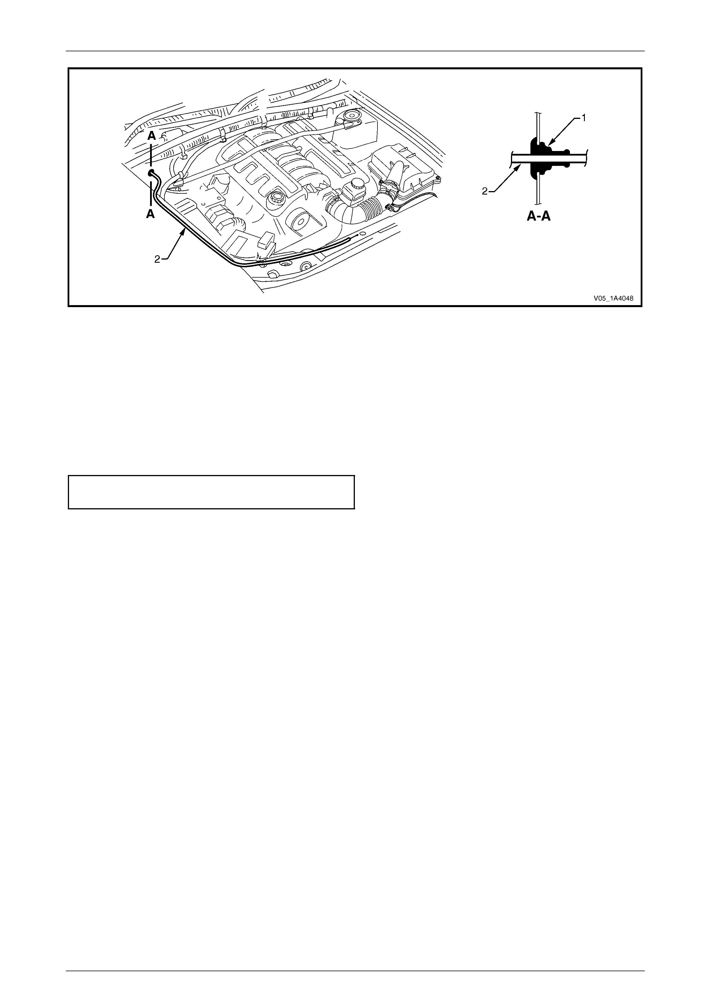
Hood, Rear Compartment Lid, Liftgate and Endgate Page 1A4–26
Page 1A4–26
Figure 1A4 – 24
Reinstall
Reinstallation of the hood primary latch release cable ass embly is the reverse of the removal procedure, noting the
following:
1 Ensure the outer cable ferrule (4), refer to Figure 1A4 – 22, is positioned before the retainer.
2 Ensure the cable assembly is correctl y rout ed and there are no sharp bends in the cable.
3 Tighten the hood primary latch release cable retai ner screw to the correct torque specification.
Hood primary latch release cable
retainer screw torque specification..............1.0 – 3.0 Nm
4 Check the cable adjustment, refer to 3.2 Hood Primary Latch Spring.
5 Attach a spring scale to the lower edge of the hood release lever assembly. The effort required to release the hood
should not exceed 40 Nm.

Hood, Rear Compartment Lid, Liftgate and Endgate Page 1A4–27
Page 1A4–27
3.4 Hood Secondary Latch Assembly
LT Section No. — 12–050
Remove
NOTE
Replace the secondar y latch rivet when removing
the hood secondary latch assembly.
1 Raise the hood.
2 Carefully cut the end of the secondar y latch ri vet (1)
securing the hood secondary latch (2) and hood
secondary latch spring (3) to the hood.
NOTE
Take care not to damage the paintwork.
3 Using a pin punch, extract the rivet to remove the latch
and latch spring.
Figure 1A4 – 25
Reinstall
1 Lubricate the new secondar y latch rivet with NLGI No. 1 lithium grease or equivalent.
2 While holding t he hood secondary latch and hood secondary latch spring in position on the hood, insert the new
secondary latch rivet. Ensure the latch spring is correctly oriented, refer to Figure 1A4 – 25.
3 Crimp the end of the rivet to secure it in place.
4 Test the operation of the hood secondary latch assembly.
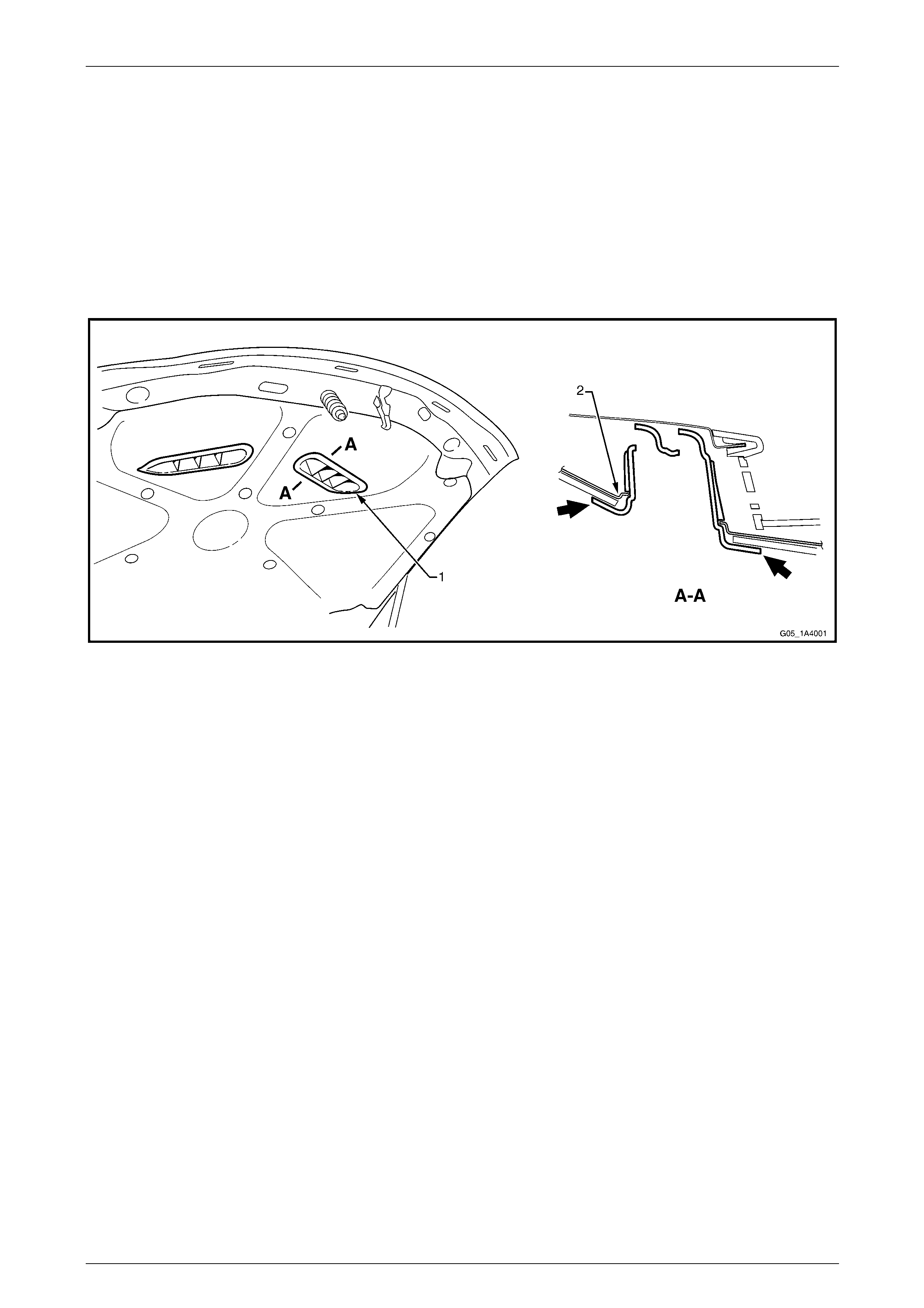
Hood, Rear Compartment Lid, Liftgate and Endgate Page 1A4–28
Page 1A4–28
3.5 Hood Air Scoop Inlet Duct
Remove
1 Raise the hood.
2 Gently squeeze the edges of the hood air scoop inlet duct (1) in the directions shown, to disengage the retaining
tabs attaching the hood air scoop inlet duct to the hood inner panel (2), refer to Figure 1A4 – 26.
3 Remove the hood air scoop inlet duct.
4 If required, repeat step 1 to step 3 inclusive to remove the h ood air scoop inlet duct on the opposite side.
Figure 1A4 – 26
Reinstall
Reinstallation of the hood air scoop inlet duct is the reverse of the removal procedure, ensuring it is seated correctly.
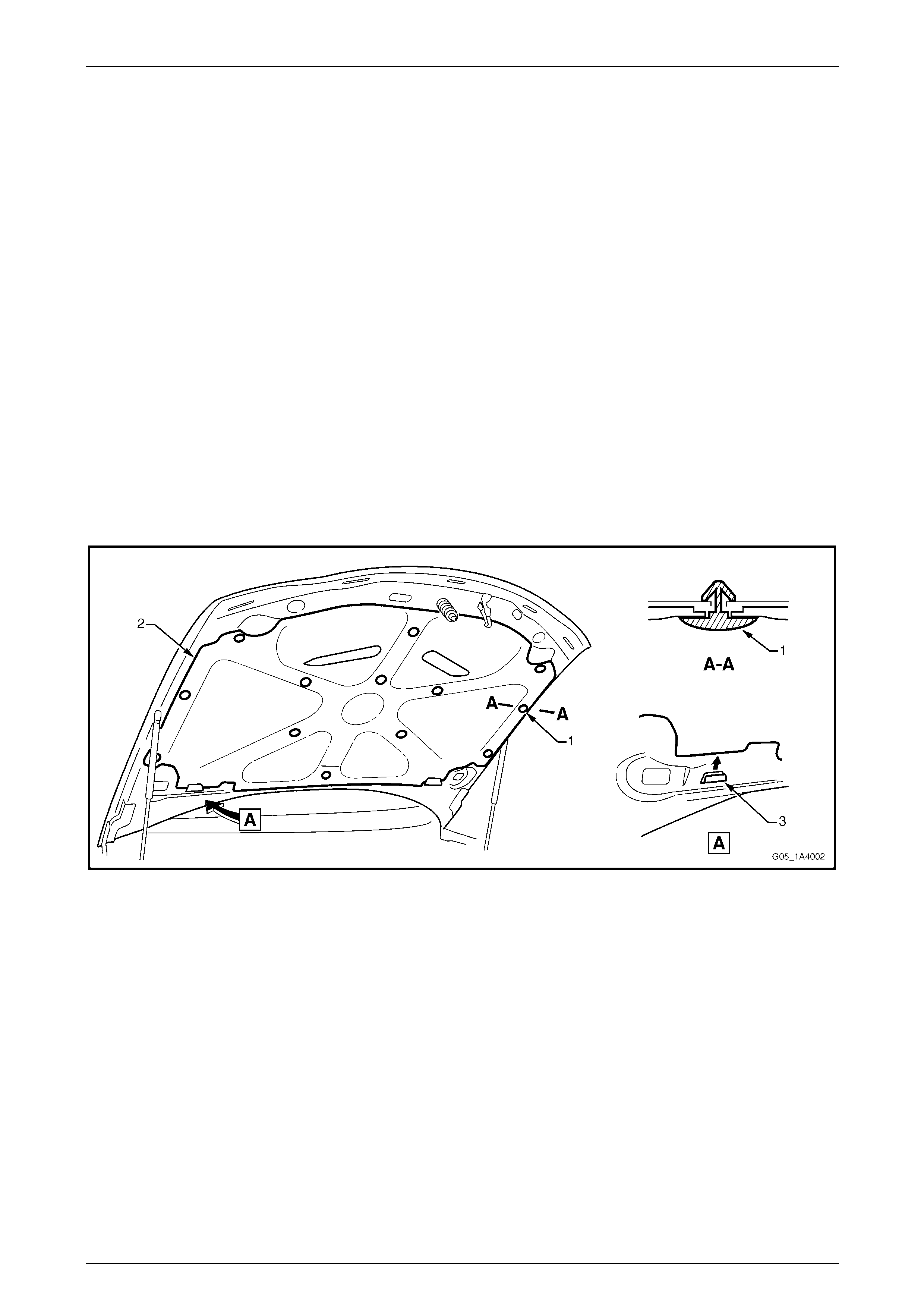
Hood, Rear Compartment Lid, Liftgate and Endgate Page 1A4–29
Page 1A4–29
3.6 Hood Insulator
LT Section No. — 12–050
Remove
NOTE
The hood insulator retainers may require
replacement when performing this operation.
1 Raise the hood.
2 Remove the hood air scoop inlet ducts, refer to 3.5 Hood Air Scoop Inlet Duct.
3 Beginning at the rear of the hood and working toward the front, remove the hood insulator retainer (1), 13 places,
attaching the hood insulator (2) to the hood, refer to Figure 1A4 – 27.
NOTE
Take care not to crush or damage the hood
insulator.
4 Slide the insulator from both tabs (3) in the hood inner panel, then remove the insulator.
Figure 1A4 – 27
Reinstall
Reinstallation of the hood insulator is the reverse of the removal procedure.
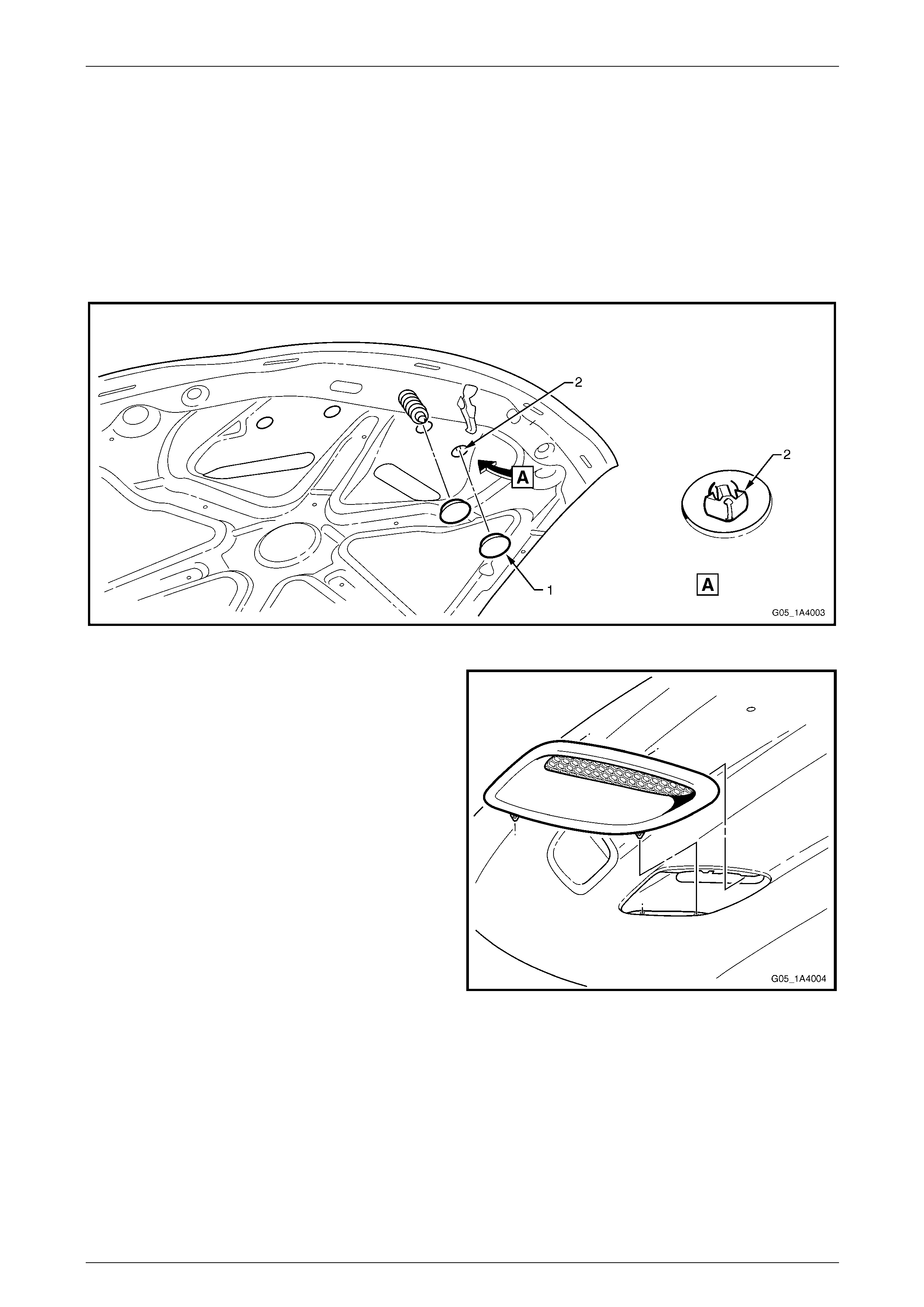
Hood, Rear Compartment Lid, Liftgate and Endgate Page 1A4–30
Page 1A4–30
3.7 Hood Air Scoop Assembly
Remove
1 Raise the hood.
2 Remove the hood insulator, refer to 3.6 Hood Insulator.
3 From under the hood, remove the two grommets (1), refer to Figure 1A4 – 28.
4 Release the retainers (2), two places, attaching the hood air scoop assembly.
Figure 1A4 – 28
5 From the above the hood, carefully lift the front edge
of the hood air scoop assembly and move it forward to
disengage the rear retaining lugs.
6 If required, repeat step 3 to step 5 inclusive for the
hood air scoop assembly on the opposite side.
Figure 1A4 – 29
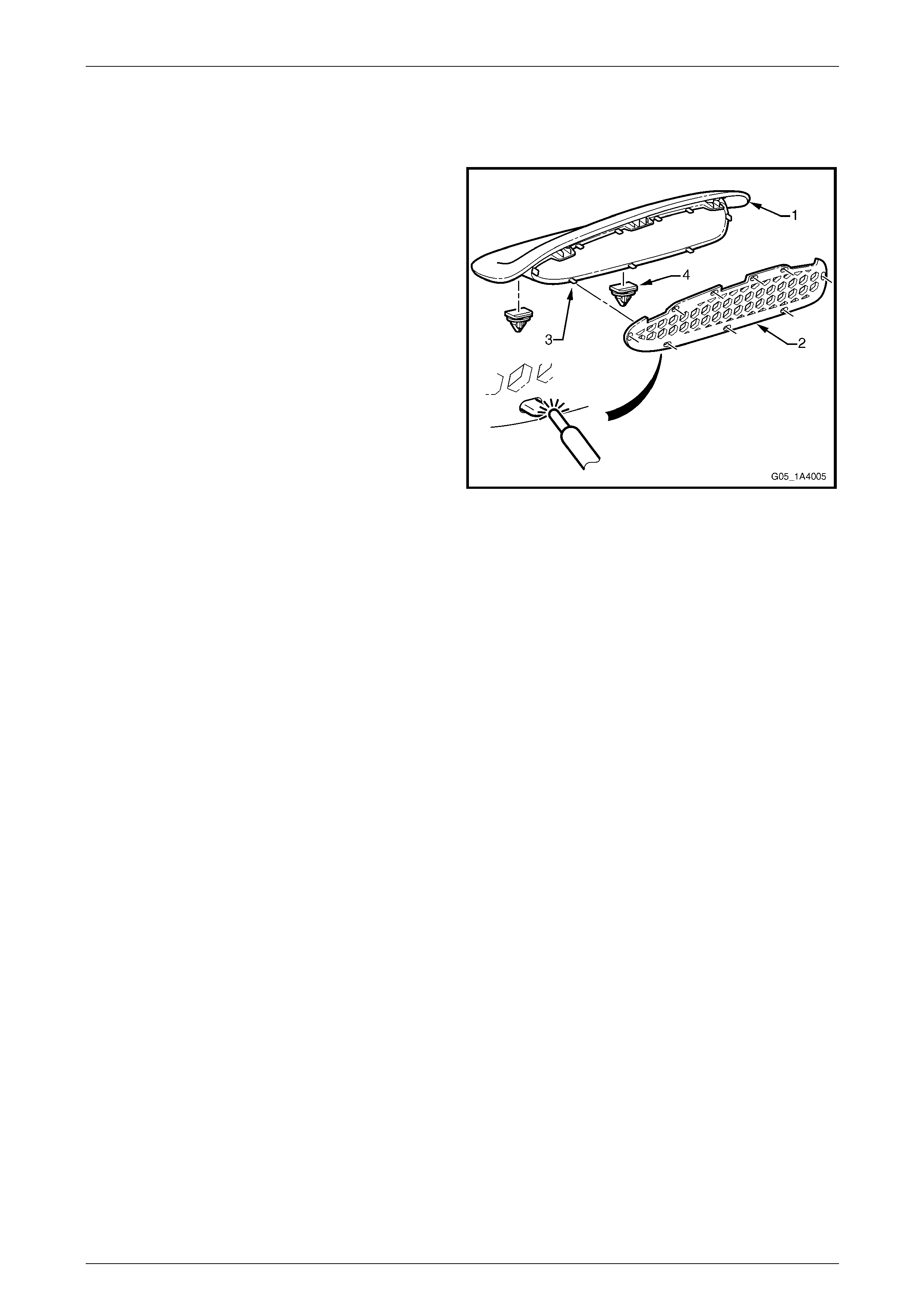
Hood, Rear Compartment Lid, Liftgate and Endgate Page 1A4–31
Page 1A4–31
Reinstall
Reinstallation of the hood air scoop assembly is the reverse of the removal proced ur e, noting the following:
1 To enable painting of the hood air scoo p (1), it is
supplied separate from the hood air sco op grille (2).
After painting the hood air scoop:
a Attach the hood air scoop grille onto the nine
mounting lugs (3).
b Using a soldering iron, carefully melt over the
lugs to secure the hood air scoop grille in place.
2 If required, install the two retainers (4), to the
underside of the hood air scoop.
Figure 1A4 – 30

Hood, Rear Compartment Lid, Liftgate and Endgate Page 1A4–32
Page 1A4–32
3.8 Hood Strut Assembly
LT Section No. — 12–050
Remove
The hood struts contain pressurised gas. Do
not subject them to extreme heat, p ressure or
physical damage.
1 With the aid of an assistant to support the hood, use a
fine flat-bladed screwdriver to remove the retainer (1)
securing the hood strut assembly (2) to the hood strut
ball stud (3).
NOTE
The retainer can spring off the hood strut
assembly and be easily lost.
2 Remove the two Torx-head screws (4) attaching the
strut assembly to the fender.
3 Disconnect the strut assembly from the hood and
remove.
4 If required, unscrew the hood strut ball stud and
washer (5) from the hood.
Figure 1A4 – 31
Reinstall
Reinstallation of the hood strut assembly is the reverse of the removal procedure, noting the following:
1 Apply a small amount of NLGI No. 1 lithium grease or equivalent to the inside of the strut ball cup.
2 Tighten the fasteners to the correct torque specification.
Hood strut ball stud
torque specification.................................13.0 – 22.0 Nm
Hood strut assembly
to fender attaching screw
torque specification.................................10.0 – 14.0 Nm
3 Check for correct operation of the hood strut assembly.
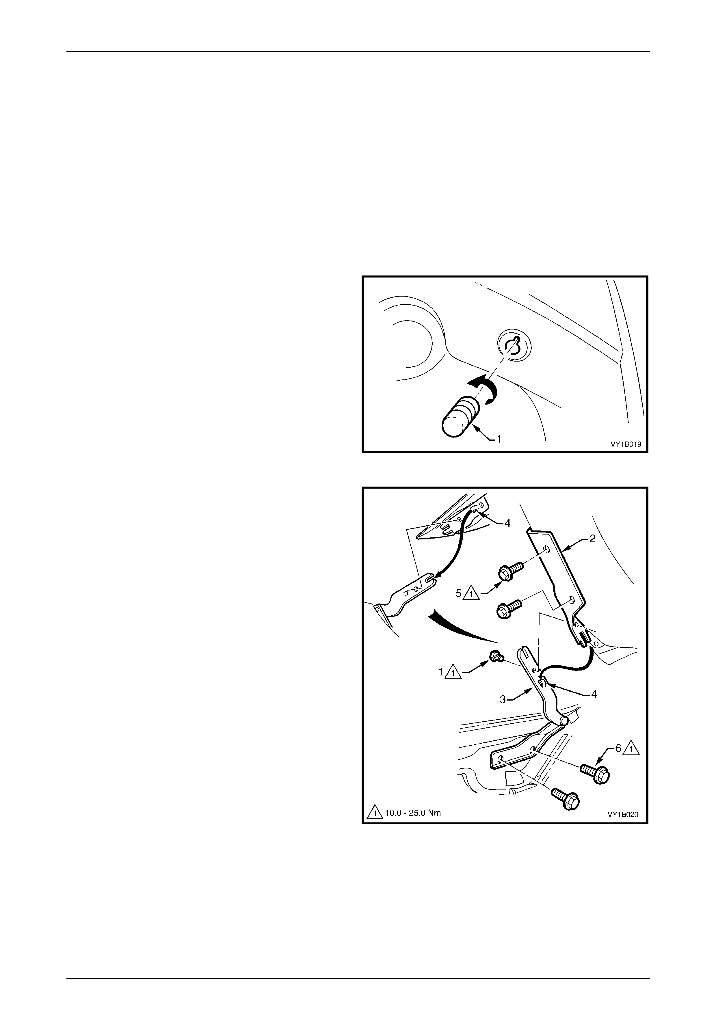
Hood, Rear Compartment Lid, Liftgate and Endgate Page 1A4–33
Page 1A4–33
3.9 Hood and Hinge Assemblies
LT Section No. — 12–425
Remove
1 If required, remove the following components:
a Hood primary latch striker assembly, refer to 3.1 Hood Primary Latch Striker Assembly.
b Hood secondary latch assemb ly, refer to 3.4 Hood Secondary Latch Assembly.
c Hood insulator, refer to 3.6 Hood Insulator.
2 Raise and support the hood.
3 If required, unscrew and remove the hood adjust
bumper (1), three places, from the centre and on each
side of the hood.
4 Disconnect the hood strut assemblies from the hood,
refer to 3.8 Hood Strut Assembly.
NOTE
The lower end of the hood strut assembly does
not need to be removed.
Figure 1A4 – 32
5 To remove the hood:
NOTE
Alignment of the hood is not required if the
following method is used to remove the hood.
a If the hood will be reinstalled:
(1) Remove the screw (1) attaching the upper
hinge section (2) and lower hinge
section (3) from each hood and hing e
assembly.
(2) With the aid of an assistant, slide the hood
out of the locating tabs (4) and remove the
hood.
NOTE
Alignment of the hood may be required if the
following method is used to remove the hood.
b If a new hood will be installed:
(1) Remove the two screws (5) attaching the
upper hinge section to the hood from each
hood and hinge assembly.
(2) With the aid of an assistant, remove the
hood. Figure 1A4 – 33
6 If required, remove the lower hinge section, refer to Figure 1 A4 – 33:
a Remove the screw (1) attaching the upper hinge section (2) and lower hinge section (3).
b Remove the plenum cover assembly, refer to Section 12N Wipers, Washers and Horn.
c Remove the two screws (6) attaching the lower hinge section to the body and remove the lo wer section.

Hood, Rear Compartment Lid, Liftgate and Endgate Page 1A4–34
Page 1A4–34
Reinstall
Reinstallation of the hood and hinge assemblies is the rev erse of the removal procedure, noting the following:
1 If the lower hinge sections were removed from the body:
a Reinstall the lower hinge sections and, if possible, align them with any existing marks. Otherwise, install the
lower hinge sections with the screws centrally in their holes.
b Temporarily tighten the screws.
2 If the upper hinge sections were removed from the hood:
a With the aid of an assistant, reinstall the upper hinge sections to the hood and, if possible, alig n them with
any existing marks. Otherwise, install the upper hinge sections with the screws centrally in their holes.
b Temporarily tighten the screws.
3 If the screw attaching the upper hinge section and lower hinge section were removed:
a With the aid of an assistant, slide the hood and upper hing e sections onto the lower hinge sections, ensuring
the upper hinge sections and lower hinge sections are correctly seated together.
b Tighten the screws to the correct torque specification.
Upper hinge section attaching
screw torque specification.......................10.0 – 25.0 Nm
Lower hinge section attaching
screw torque specification.......................10.0 – 25.0 Nm
Hood hinge scre w
torque specification.................................10.0 – 25.0 Nm
4 Install the hood adjust bumpers to their original position or half-way along the thread, refer to Figure 1A4 – 32.
5 Install or reconnect the hood strut assemblies, refer to 3.8 Hood Strut Assembly.
6 If required, adjust the hood, refer to Adjust in this Section.
7 If removed, reinstall the plenum cover assembly, refer to Section 12N Wipers, Washers and Horn.
Adjust
Correct alignment of the hood is critical to its operation and to the aesthetics of the vehicle. If the fenders are not
correctly positioned, the hood can not be aligned correctly.
Depending upon the repa irs performed, it may be advantageous to p erform a measurement check between the fenders
before adjusting the hood.
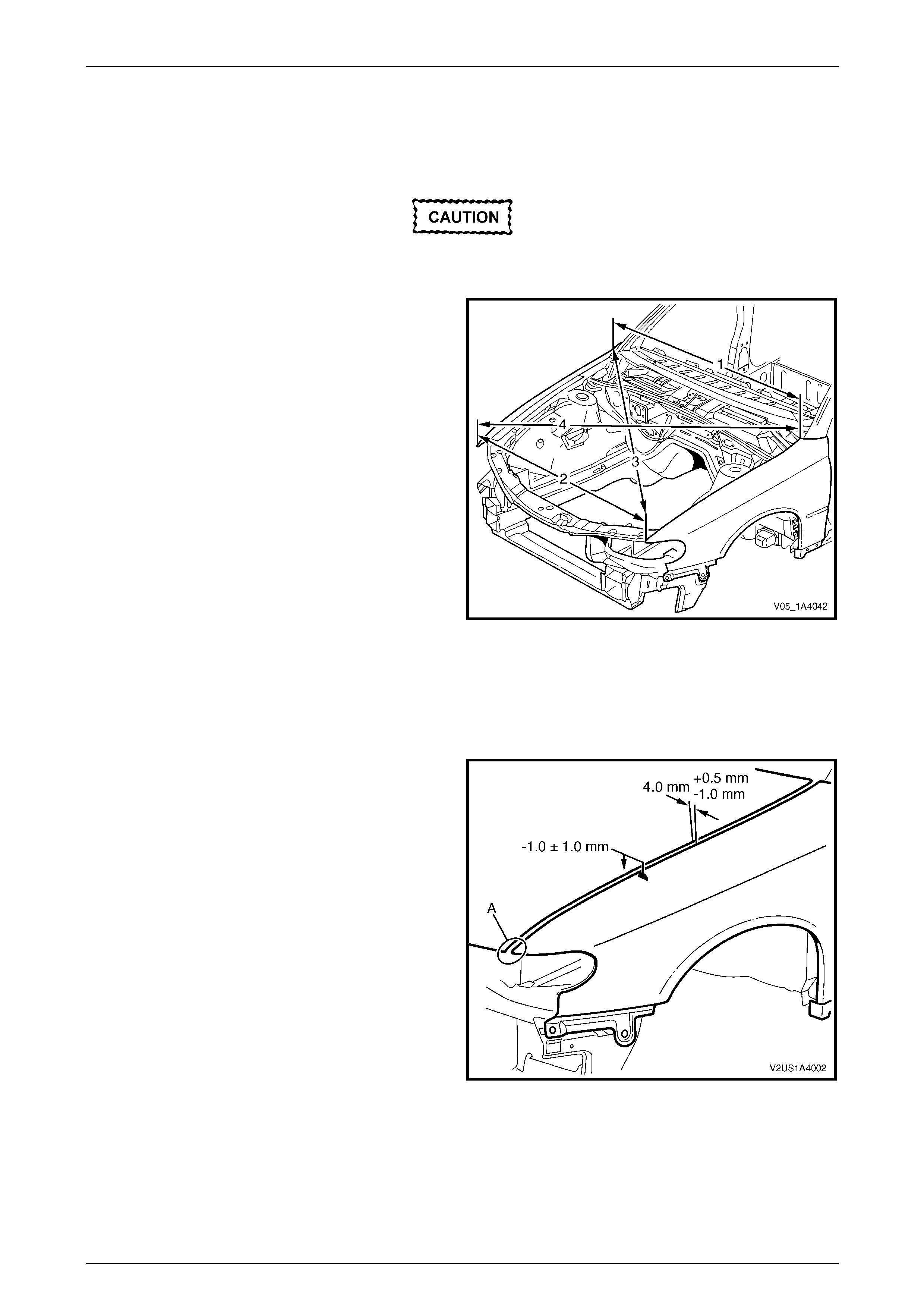
Hood, Rear Compartment Lid, Liftgate and Endgate Page 1A4–35
Page 1A4–35
Fender Alignment
1 Check the distance between the front doors and fen ders are correct. If not correct, rectify before proceeding, refer
to Section 1B Sheetmetal.
Paint damage may occur. Use care and, if
required, touch up any paint damage.
2 Measure the distance between the rear of each
fender (1). This distance should be the width of the
rear of the hood plus 8.0 mm. If not, adjust the
fenders, refer to Section 1B Sheetmetal.
3 Measure the distance between the front of each
fender (2). This should be the width of the front of the
hood plus 8.0 mm. If not, adjust the fenders, refer to
Section 1B Sheetmetal.
4 Measure the distance between a suitable point at the
rear of the left-hand fender and front of the right-hand
fender (3). Note the length.
5 Measure the distance between the opposite fender
points (4). This measurement must be within 1.5 mm
of result (3).
6 If the measurements are correct, align the hood as
follows. If not, adjust the fenders, refer to
Section 1B Sheetmetal.
Figure 1A4 – 34
Hood Alignment
1 If fitted, remove the hood primary latch striker assembly, refer to 3.1 Hood Primary Latch Striker Assembl y.
2 Carefully close the hood, ensuring each side does not contact the fenders.
3 Check the alignment of the hood for:
• Length:
Compare to the front edge of the fenders; they
should be equal at point A.
• Width of gap:
Compare the gap bet ween the hoo d and the side
of each fender; the gap must be 4.0 mm
(+0.5 mm / –1.0 mm).
• Consistency of gap:
Compare the gap bet ween the hoo d and each
fender at the front, middle and rear; the gap
should be even.
• Height:
Compare the height of the hood with the fenders
at each corner; the hood height must be –1 mm
(±1.0 mm).
Figure 1A4 – 35

Hood, Rear Compartment Lid, Liftgate and Endgate Page 1A4–36
Page 1A4–36
4 Open the hood and, if required:
• Loosen the screws attaching the hood to both upper hinge sections for fore and aft adjustment, refer to
Figure 1A4 – 33.
• Loosen the scre ws attaching both lower hinge sections to the body for rear height adjustment. If required, this
also provides fore and aft adjustment, refer to Figure 1A4 – 33.
• Turn the hood adjust bumper clockwise to lower the front of the hood or anticlockwise to raise the front of the
hood, refer to Figure 1A4 – 32.
NOTE
Do not make all adjustments at once. Perform
one adjustment, then carefully close the hood;
check its position and make further adjustments
until the correct alignment is a c hieved.
5 Install the hood primary latch striker assemb ly, refer to 3.1 Hood Primary Latch Striker Assembly.
6 Lower the hood while watching the alignment of the hood primary latch striker assembly and the latch hole.
7 Check the hood primary latch striker bolt do es not foul the latch hole and the hood alignment does not alter. If
required, adjust the hood primary latch striker bolt position.
Do not push the hood closed as damage to
the panel surface may occur. If it does not
close on the first attempt, try again from a
slightly greater height.
8 Close the hood by dropping it from a height of approximately 300 mm.
9 Check the height difference between the front of the hood and both fenders:
a If required, adjust the usable length of the hood primary latch striker bolt by loosening the hood primary latch
striker nut and rotating the hood primary latch striker bolt with a flat-bladed screwdriver, refer to
Figure 1A4 – 18.
b If required, adjust the hood adjust bumpers, refer to Figure 1A4 – 32.
10 Tighten the screws and nuts to the correct torque specification.
Upper hinge section attaching
screw torque specification.......................10.0 – 25.0 Nm
Lower hinge section attaching
screw torque specification.......................10.0 – 25.0 Nm
Hood primary latch striker nut
torque specification.................................22.0 – 28.0 Nm
11 Recheck the alignment of the hood.
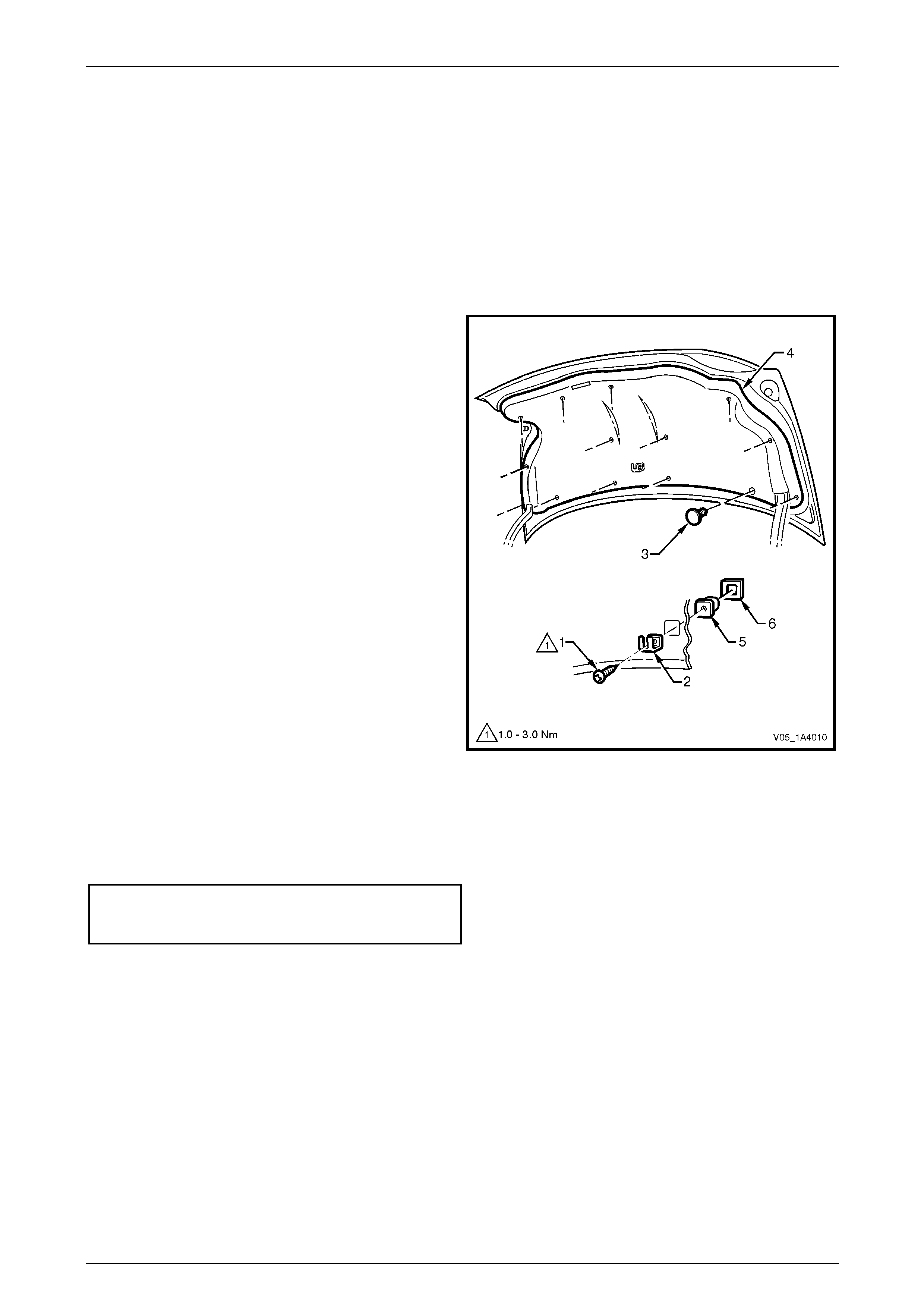
Hood, Rear Compartment Lid, Liftgate and Endgate Page 1A4–37
Page 1A4–37
4 Service Operations — Rear
Compartment Lid, Sedan
4.1 Rear Compartment Lid Carpet
LT Section No. — 14–480
Remove
1 Remove the screw (1) attaching the spare wheel
stowage cover hook (2).
2 Using a suitable trim clip removal tool, remove the
retainer (3), 14 places, attaching the rear compartment
lid carpet (4).
3 Remove the carpet from the rear compartment lid.
4 If required, prise the nut (5) and washer (6) from the
rear compartment lid with a fine flat-bladed
screwdriver.
Figure 1A4 – 36
Reinstall
Reinstallation of the rear com partment lid carpet is the reverse of the removal procedure. Tighten the screw to the correct
torque specification.
Spare wheel stowage cover
hook attaching screw
torque specification.....................................1.0 – 3.0 Nm
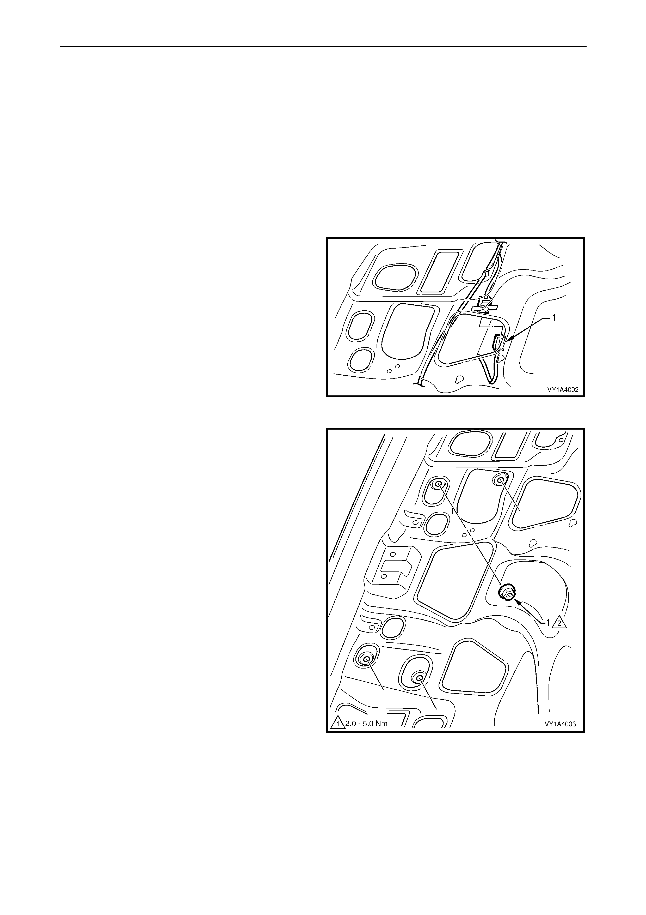
Hood, Rear Compartment Lid, Liftgate and Endgate Page 1A4–38
Page 1A4–38
4.2 Rear Compartment Lid Appliqué
Assembly
LT Section No. — 02–375
Remove
1 If required, remove the:
a Rear compartment lid carpet, refer to 4.1 Rear Compartment Lid Carpet.
b Licence plate.
2 From within the rear compartment lid cavity,
disconnect the rear licence plate lamp wiring
connector (1).
Figure 1A4 – 37
3 From within the rear compartment lid cavity, remove
nut (1), four places, attaching the rear compartment lid
appliqué assembl y to the rear compartment lid.
Figure 1A4 – 38
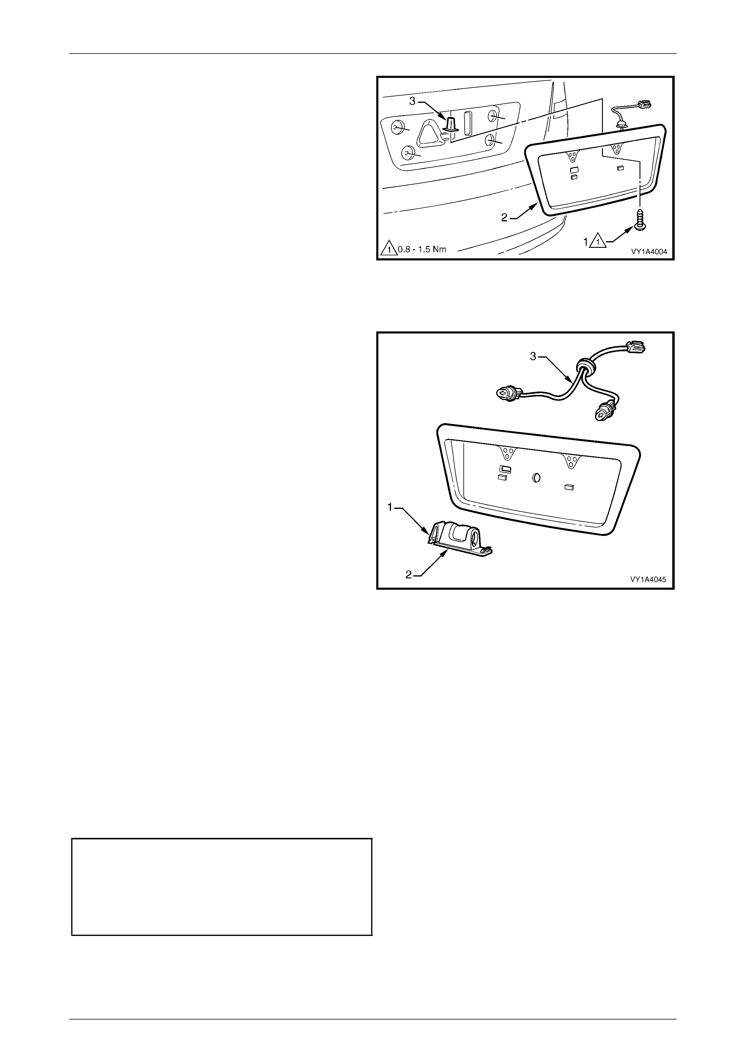
Hood, Rear Compartment Lid, Liftgate and Endgate Page 1A4–39
Page 1A4–39
4 Remove the screw (1) attaching the rear compartment
lid appliqué assembly (2) to the rear com partment lid.
5 Partially remove the appliqué assembly from the rear
compartment lid.
6 Remove the rear licence plate lamp wiring harness
grommet and disconnect the rear licence plate lamp
wiring harness.
7 Remove the appliqué assemb ly.
8 If required, remove the retainer (3) from the rear
compartment lid.
Figure 1A4 – 39
Disassemble
1 Press the tab (1) and remove the rear licence plate
lamp housing (2) from the rear compartment lid
appliqué assembl y.
2 Rotate the bulb socket and remove it from the rear
licence plate lamp housing.
3 Repeat for the remaining rear licence plate lamp
housing.
4 Remove the rear licence plate lamp wiring harness
assembly (3) from behind the appliqué assembly.
Figure 1A4 – 40
Reassemble
Reassembly of the rear compartment lid app liqué assembly is the reverse of the disassembly procedur e, ensuring the
rear licence plate lamp wiring harn ess is routed so it clears the edge of the rear compartment lid a ppliqué assembly.
Reinstall
Reinstallation of the rear compartment lid appliqué assembly is the reverse of the removal procedure, noting the
following:
1 Ensure the seals are correctly fitted.
2 Ensure the appliqué assembly does not pinch the rear licence plate lamp wiring harness.
3 Tighten the screws and nuts to the correct torque specification.
Rear compartment lid appliqué
assembly attaching screw
torque specification.....................................0.8 – 1.5 Nm
Rear compartment lid appliqué
assembly attaching nut
torque specification.....................................2.0 – 5.0 Nm
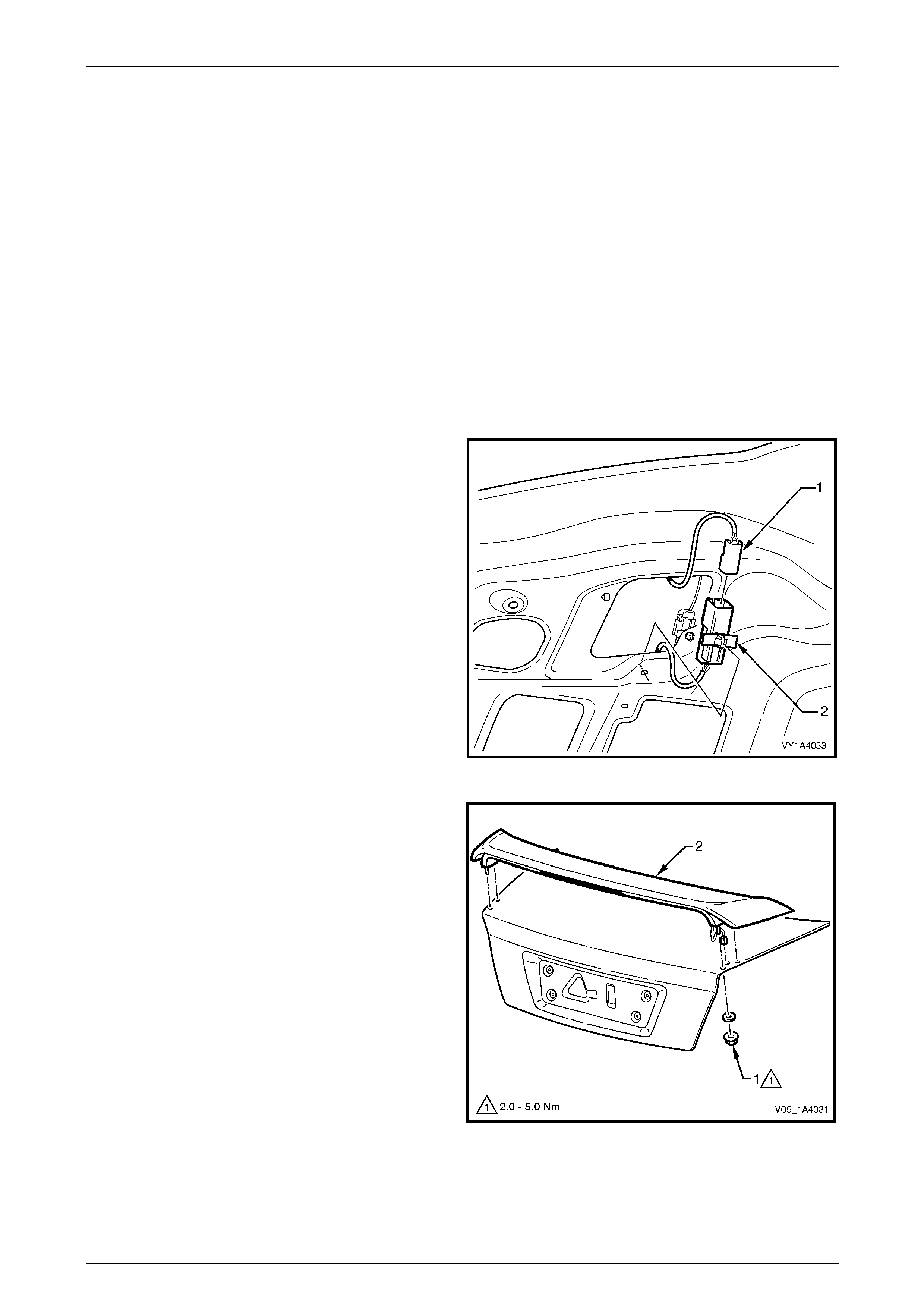
Hood, Rear Compartment Lid, Liftgate and Endgate Page 1A4–40
Page 1A4–40
4.3 Rear Spoiler Assembly
LT Section No. — 10–350
Introduction
Paint new rear spoiler assemblies before installation. Refer to Section 1D Bumper Bars for further information on painting
plastic components or refer to the instructions provided by your paint manufacturer for Acrylonitrile Butadiene St yrene
Resin (ABS):
• For SV6 and SV8 vehicles, the rear spoiler i s painted in the body colour of the vehicle; the insert is finished in skirt
black.
• For SS vehicles, the upper surface of the rear spoiler is painted in the b ody colour of the vehicle; the undersid e
surface is finished in skirt black. A groove in the underside of the rear spoiler is used as the colour separation point.
Remove
1 If required, remove the rear compartment lid carpet, refer to 4.1 Rear Compartment Lid Carpet.
2 From within the rear compartment lid cavity,
disconnect the rear spoiler wiring harness
connector (1).
NOTE
The body wiring harness side of the rear spoiler
wiring harness connector is attached to the rear
compartment lid with a clip (2).
Figure 1A4 – 41
3 Remove the nut (1) and seals, four places, attaching
the rear spoiler assembly (2) to the rear com partment
lid.
4 Remove the rear spoiler while withdrawing the high-
mount stop lamp connector from the rear compartment
lid cavity.
Figure 1A4 – 42
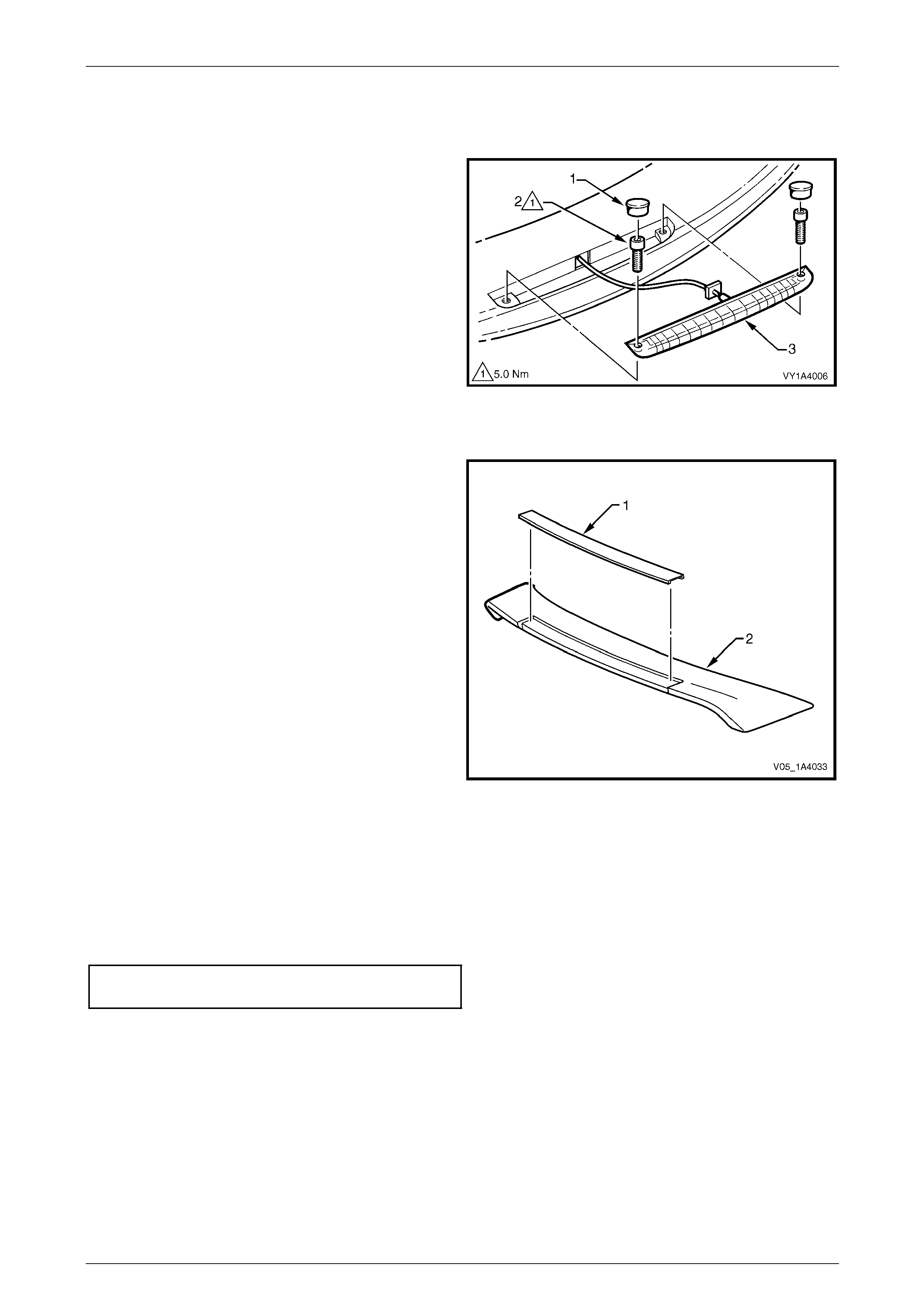
Hood, Rear Compartment Lid, Liftgate and Endgate Page 1A4–41
Page 1A4–41
Disassemble
High-mount Stop Lamp Assembly
1 Prise the two screw caps (1) from the underside of the
rear spoiler.
2 Remove the two screws (2) attaching the high-mount
stop lamp assembly (3) to the rear spoiler.
3 To aid reinstallation, tie a length of string to the rear
spoiler wiring harness connector.
4 Withdraw the rear spoiler wiring harness through the
rear spoiler, untie the string and remove the high-
mount stop lamp assembly. Leave the string in the
cavity.
Figure 1A4 – 43
Spoiler Insert — SV6 and SV8
1 Protect the spoiler paint with tape or a clean rag.
2 Using a paint scraper or similar, begin at one end and
carefully prise the spoiler i nsert (1) from the spoiler (2).
Cut through the double-sided tape.
NOTE
Warming the spoiler insert with a heat-lamp or
heat-gun will assist removal of the double-sided
tape.
3 Remove any remaining double-sided tape an d
adhesive from the spoiler and/ or insert. Clean the
surfaces with Prepsol or equivalent.
Figure 1A4 – 44
Reassemble
High-mount Stop Lamp Assembly
1 Tie the string to the rear spoiler wiring har ness connector and manipulate it through the rear spoiler cavity. If
required, make a hook from a length of wire to aid pulling the wiring connector through.
2 Tighten the two screws to the correct torque specification.
High-mount stop lamp assembly
attaching screw torque specification....................5.0 Nm
3 Fit the screw caps.
Spoiler Insert — SV6 and SV8
1 If required, clean the spoiler and insert surface with Prepsol or equiva lent.
2 If reusing the insert, apply new polyet hylene double-sided tape (3M 4 42 8 or equ ivalent). Trim back the tape slightly
away from the edge of the insert.
3 Remove the backing paper from the double-sided tape.
4 Apply the insert, ensuring it is correctly located.
5 Press firmly over the entire surface for at least 10 seconds to ensure sound adhesion.
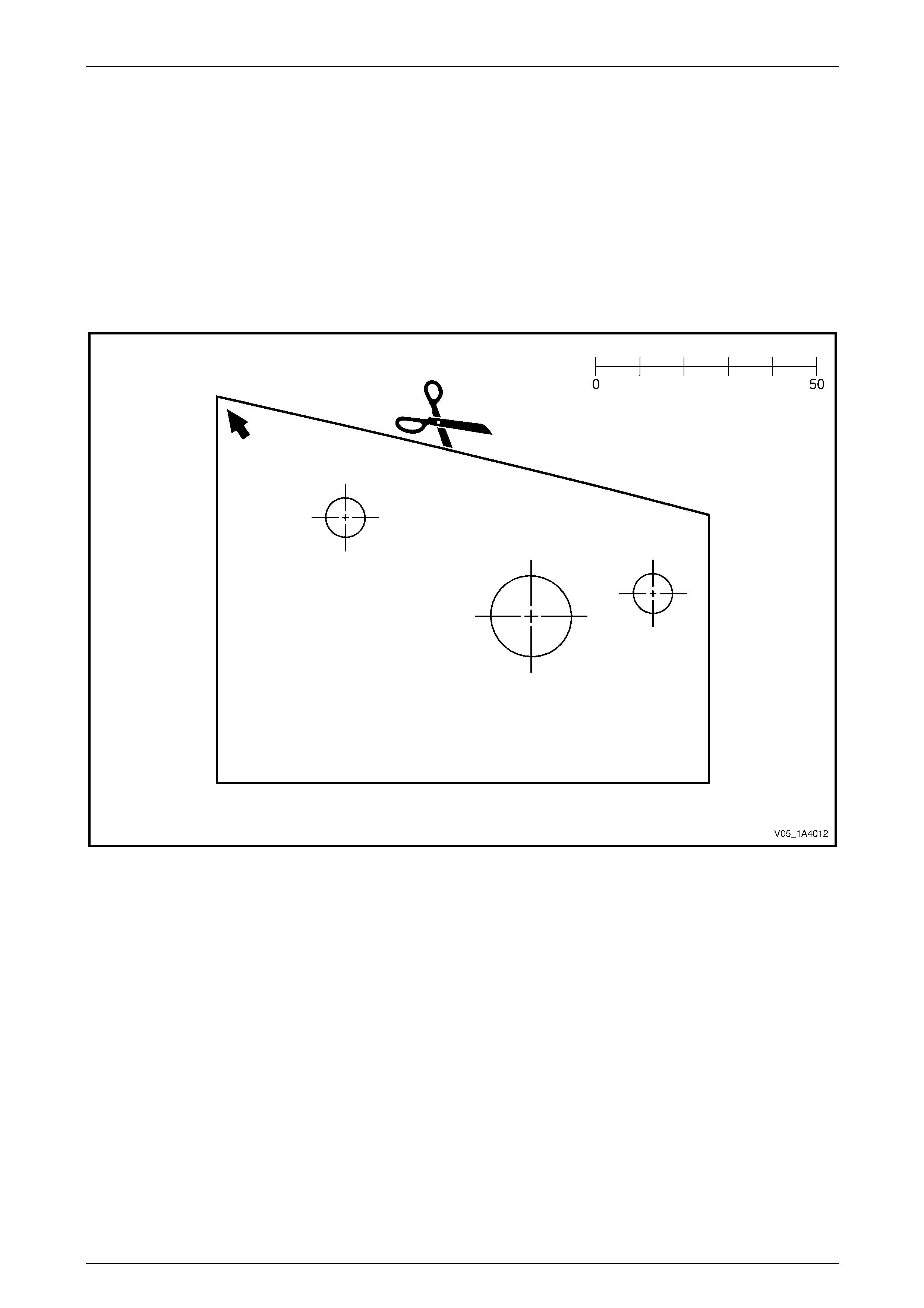
Hood, Rear Compartment Lid, Liftgate and Endgate Page 1A4–42
Page 1A4–42
Reinstall
NOTE
If the rear compartment lid is not being replaced,
proceed to step 11.
1 Construct a drilling template by printing and cutting out the profile, refer to Figure 1A4 – 4 5.
NOTE
Ensure the drilling template prints the correct size
by comparing the scale with a ruler.
Figure 1A4 – 45
2 Place a mark (1) on the right-hand outer edge of the rear co mpartment lid (measuring 470 mm from the front right-
hand side corner) in a straight line, refer to Figure 1A 4 – 46.
NOTE
If the rear compartment lid is painted, protect the
paintwork in the area near the mounting and
wiring holes with masking tape.
3 Place the template (2) on the rear compartme nt lid, ali gning the corner with the arro w to the mark (1) and the edg e
of the template with the edge of the rear compartment lid.
4 Mark the centre of both mounting holes (3) and, for the right-hand side only, the centre of the hole (4) for the rear
spoiler wiring harness.
5 Turn the template over and repeat step 2 to step 4 inclusive for the left-hand side.
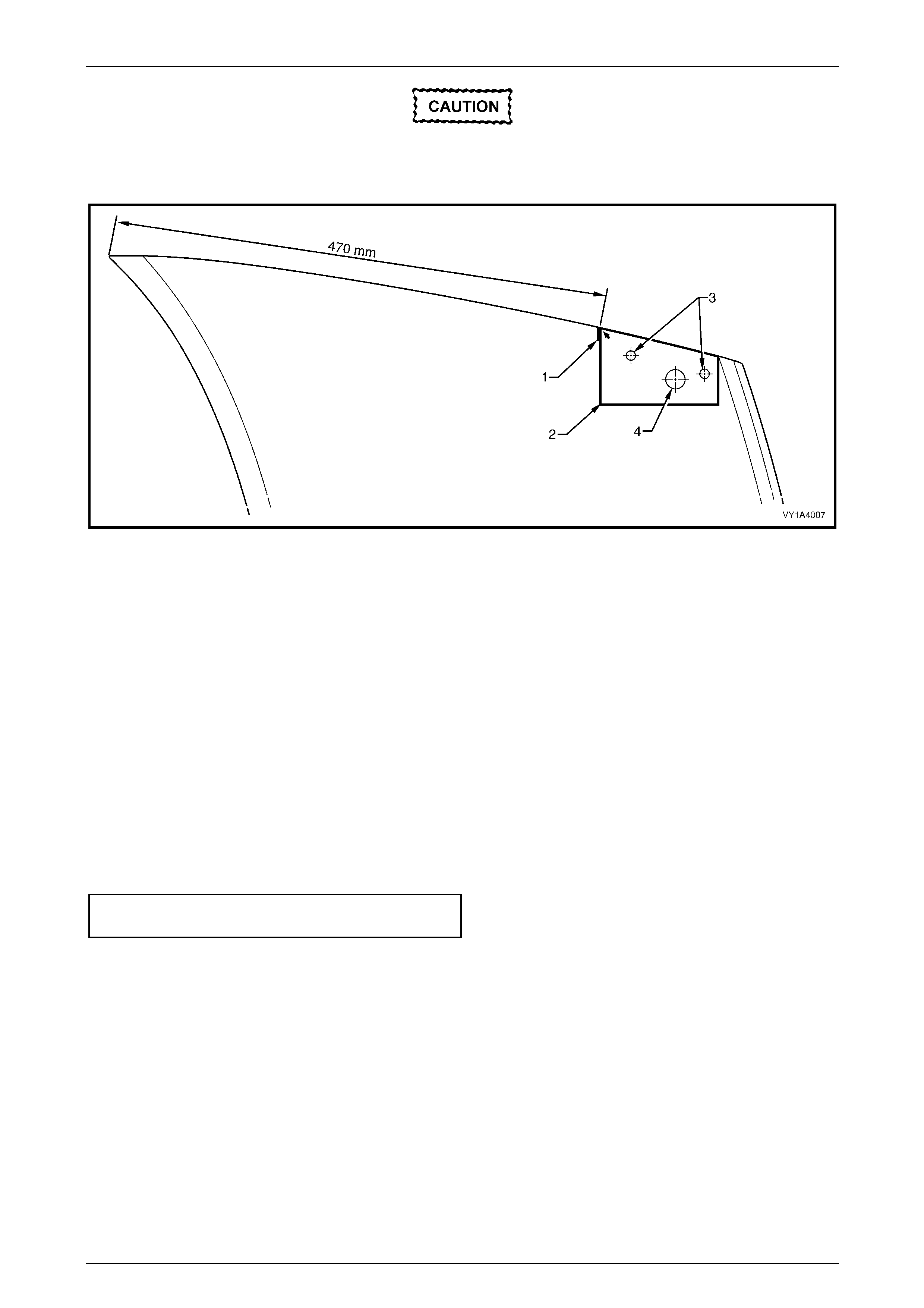
Hood, Rear Compartment Lid, Liftgate and Endgate Page 1A4–43
Page 1A4–43
Mark the centre of both mounting holes only;
the hole for the rear spoiler wiring harness is
for the right-hand side only.
Figure 1A4 – 46
6 Place the rear spoiler in position on the rear compartment lid and check the mounting studs align with the mounting
hole marks. Adjust as required.
7 Open the rear compartment lid slightly and place a block of wood under the drilling locations.
8 Carefully drill the mounting holes through the inner and out er rear compartment lid pane ls. Initially, drill 3.0 mm pilot
holes, then drill out to 9.0 mm.
9 Carefully drill the rear spoil er wirin g harness hole on the rig ht-hand side of the outer rear compartment lid panel
only. Initially, drill a 3.0 mm hole, then drill out to 18.0 mm.
10 Remove any burrs from the drill holes and re move all swarf. Refinish the panel as required.
11 Fit the rear spoiler to the rear compartment lid, feeding the hig h-mount stop lamp wiring harness through the
18 mm hole.
12 Install the seals and nuts onto the studs and hand-tighten.
13 Check the alignment of the rear spoiler on the rear compartment lid.
14 Tighten the nuts to the correct torque specification.
Rear spoiler assembly attaching
nut torque specification...............................2.0 – 5.0 Nm
15 Connect the rear spoiler wiring harness connector within the rear compartment lid cavity and clip it onto the inner
rear compartment lid panel, refer to Figure 1A4 – 41.
16 Check the operation of the high-mount stop lamp.
17 Refit the rear compartment lid carpet, refer to 4.1 Rear Compartment Lid Carpet.

Hood, Rear Compartment Lid, Liftgate and Endgate Page 1A4–44
Page 1A4–44
4.4 Rear Compartment Lid Latch Assembly
LT Section No. — 12–680
Remove
1 If required, remove the rear compartment lid carpet, refer to 4.1 Rear Compartment Lid Carpet.
2 Remove the two screws (1) attaching the rea r
compartment lid latch assembly (2) to the rear
compartment lid.
3 Withdraw the latch assembly from the inner rear
compartment lid panel far enough to e nable
disconnection of the actuator rod (3) and rear
compartment lid release cable (4).
4 Remove the latch assembl y.
Figure 1A4 – 47
Reinstall
Reinstallation of the rear com partment lid latch assembly is the reverse of the remova l procedure, noting the following:
1 Lubricate the rear compartment lid latch assembly with NLGI No. 1 lithium grease or equivalent.
2 Before closing the rear compartment lid, close the rear compartment lid latch and check the operation of the rear
compartment lid latch assembly using the rear compartment lid release switch and rear compartment lid release
cable assembly. If the operation is satisfactory, close the rear compartmen t lid and recheck the operation. If
required, adjust the rear compartment lid striker assemb ly, refer to 4.10 Rear Compartment Lid Striker Assembly.
3 Tighten the screws to the correct torque specification.
Rear compartment lid latch
assembly attaching screw
torque specification.....................................2.0 – 5.0 Nm

Hood, Rear Compartment Lid, Liftgate and Endgate Page 1A4–45
Page 1A4–45
4.5 Rear Compartment Lid Actuator
Assembly
LT Section No. — 12–680
NOTE
The rear compartment lid actuator
assembly is controlled by the body control
module (BCM). For diagnosis, refer to
Section 12J Body Control Module.
Remove
1 If required, remove the rear compartment lid carpet, refer to 4.1 Rear Compartment Lid Carpet.
2 Loosen the two screws (1) attaching the rear
compartment lid actuator assembly (2) to the rear
compartment lid.
3 If required, disconnect the connecting ro d from the
rear compartment lid latch assembly.
4 Withdraw the actuator assembly from the keyhole slots
in the inner rear compartment lid p anel.
5 Remove the actuator assembly from the inne r rear
compartment lid panel cavity far enough to enable the
wiring harness connector to be disco nnected.
6 Remove the actuator assembly.
Figure 1A4 – 48
Reinstall
Reinstallation of the rear com partment lid actuator assembly is the reverse of the removal procedure, noting the
following:
1 Before closing the rear compartment lid, close the rear compartment lid latch and check the operation of the rear
compartment lid latch assembl y using the rear compartment lid release switch. If the operation is satisfactory, close
the rear compartment lid and recheck the operation. If required, adjust the rear compartment lid striker assembly,
refer to 4.10 Rear Compartment Lid Striker Assembly.
2 Tighten the screws to the correct torque specification.
Rear compartment lid actuator
assembly attaching screw
torque specification.....................................2.0 – 5.0 Nm
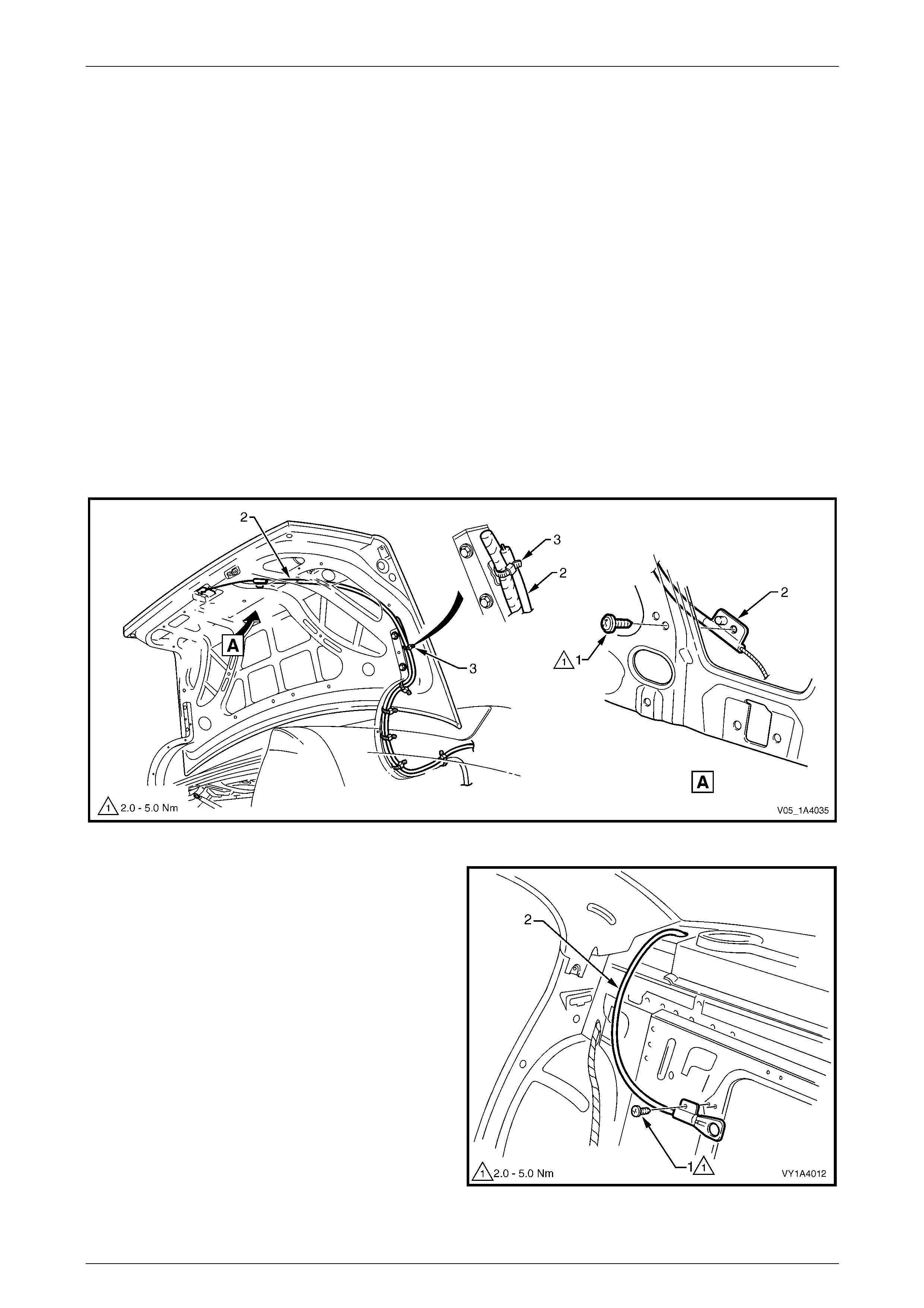
Hood, Rear Compartment Lid, Liftgate and Endgate Page 1A4–46
Page 1A4–46
4.6 Rear Compartment Lid Release Cable
Assembly
LT Section No. — 12–680
Remove
1 If required:
a Remove the rear compartment lid carpet, refer to 4.1 Rear Compartment Lid Carpet.
b Remove the rear compartment lid latch assembly, refer to 4.4 Rear Compartment Lid Latch Assembly.
c Remove the right-hand rear seat-back assembl y, refer to Section 1A7 Seat Assembli es.
d Partially remove the rear window trim panel assembly, refer to Section 1A8 Headlining and Interior Trim.
2 Remove the screw (1) attaching the rear compartment lid rele ase cable assembly (2) to the rear compartment lid,
refer to Figure 1A4 – 49.
3 Remove the straps (3) attaching the cable assembl y to the rear comp artme nt lid actuator assembly wiring harness.
4 Withdraw the cable assembly from the rear compartment lid cavity and lay it on the rear compartment floor.
Figure 1A4 – 49
5 From within the right-hand rear passenger
compartment, remove screw (1) attaching the rear
compartment lid release cable assembl y (2).
6 Carefully feed the cab le assembly into the passenger
compartment and remove.
Figure 1A4 – 50

Hood, Rear Compartment Lid, Liftgate and Endgate Page 1A4–47
Page 1A4–47
Reinstall
Reinstallation of the rear com partment lid release cable assembly is the reverse of the removal procedure, noting the
following:
1 Before closing the rear compartment lid, close the rear compartment lid latch and check the operation of the rear
compartment lid latch assembly using the rear compartment lid release switch and rear compartment lid release
cable assembly. If the operation is satisfactory, close the rear compartmen t lid and recheck the operation. If
required, adjust the rear compartment lid latch striker assembly,
refer to 4.10 Rear Compartment Lid Striker Assembly.
2 Tighten the screws to the correct torque specification.
Rear compartment lid release
cable assembly attaching screw
torque specification.....................................2.0 – 5.0 Nm
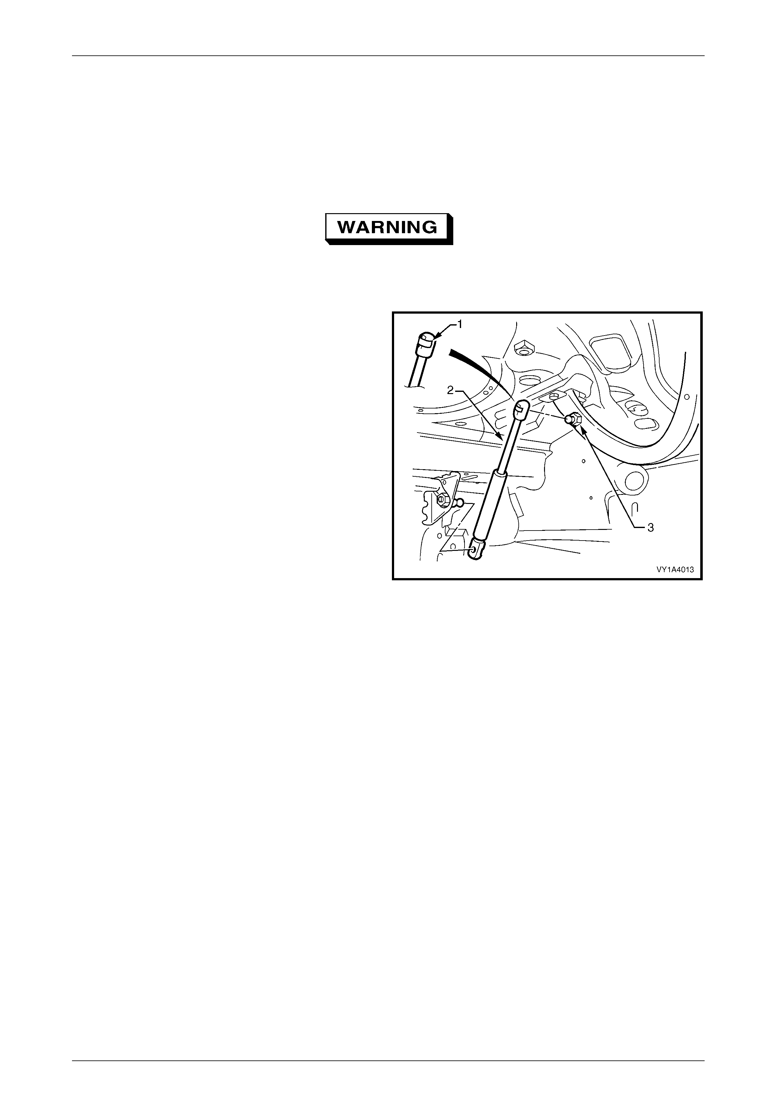
Hood, Rear Compartment Lid, Liftgate and Endgate Page 1A4–48
Page 1A4–48
4.7 Rear Compartment Lid Strut Assembly
LT Section No. — 12–680
Remove
The hood struts contain pressurised gas. Do
not subject them to extreme heat, p ressure or
physical damage.
1 Support the rear compartment lid securel y.
2 Using a fine flat-bladed screwdriver, prise the
retainer (1) from the rear compartment lid strut end (2).
NOTE
The retainer can spring off the hood strut
assembly and be easily lost.
3 Pull the strut assembly from the strut ball stud (3).
4 Repeat for the opposite end, if required.
Figure 1A4 – 51
Reinstall
NOTE
If a rear compartment lid strut assembly is
replaced, ensure the correct type is specified as
vehicles with a rear spoiler require stronger
struts.
Reinstallation of the rear com partment lid strut assembly is the reverse of the removal procedure, noting the following:
1 Apply a small amount of NLGI No. 1 lithium grease or equivalent to the inside of the strut ball cup.
2 Install the retainer onto the rear compartment lid strut end, if removed.
3 Align the rear compartment lid strut with the strut ball stud and push into place.
4 If required, repeat for the opposite end.
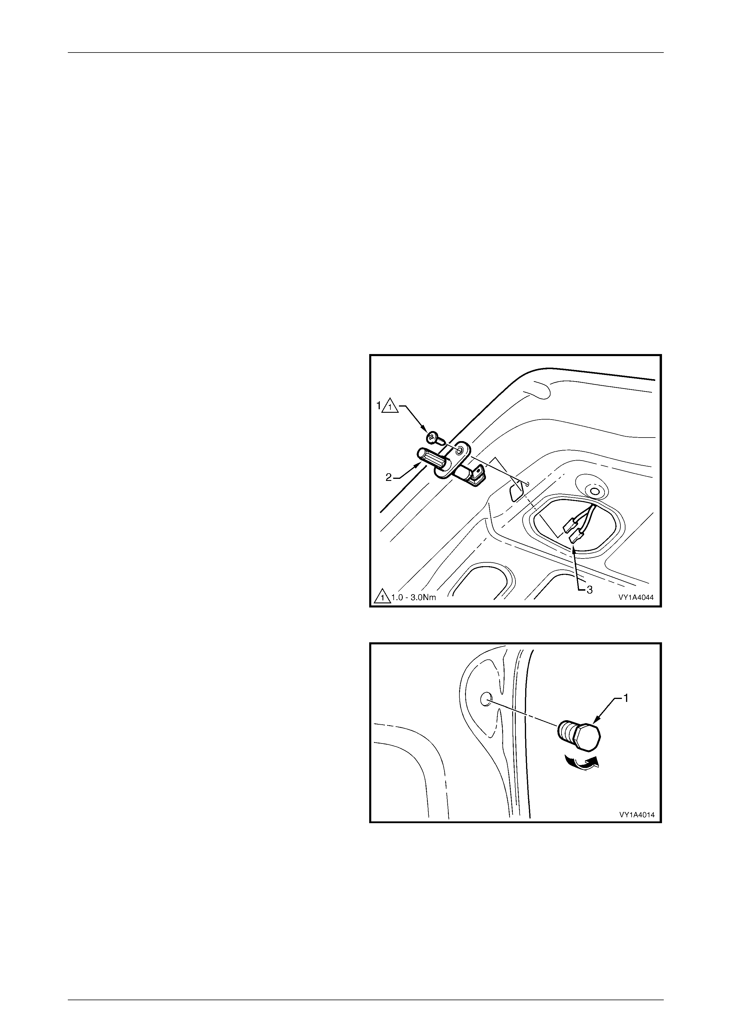
Hood, Rear Compartment Lid, Liftgate and Endgate Page 1A4–49
Page 1A4–49
4.8 Rear Compartment Lid Assembly
LT Section No. — 12–680
Remove
1 If required, remove the following components:
a Rear compartment lid carpet, refer to 4.1 Rear Compartment Lid Carpet.
b Rear spoiler assembly if fitted, refer to 4.3 Rear Spoiler Assembly.
c Rear compartment lid latch assembly, refer to 4.4 Rear Compartment Lid Latch Assembly.
d Rear compartment lid actuator assembly, refer to 4.5 Rear Compartment Lid Actuator Assembly.
e Rear compartment lid release cable assembly from the rear compartmen t lid only,
refer to 4.6 Rear Compartment Lid Release Cable Assembly.
f Badges and emblems, refer to Section 1A9 Exteri or Ornamentation.
2 Remove the screw (1) attaching the rear compartment
courtesy lamp switch assembly (2) to the rear
compartment lid.
3 Withdraw the switch assembly and disc onnect the
wiring connectors (3).
4 Remove the body wiring harness assembly from the
rear compartment lid only, refer to
Section 12O Fuses, Relays and Wiring Harnesses.
Figure 1A4 – 52
5 Unscrew the rear compartment lid bumper (1) from
each side of the rear compartment lid.
Figure 1A4 – 53
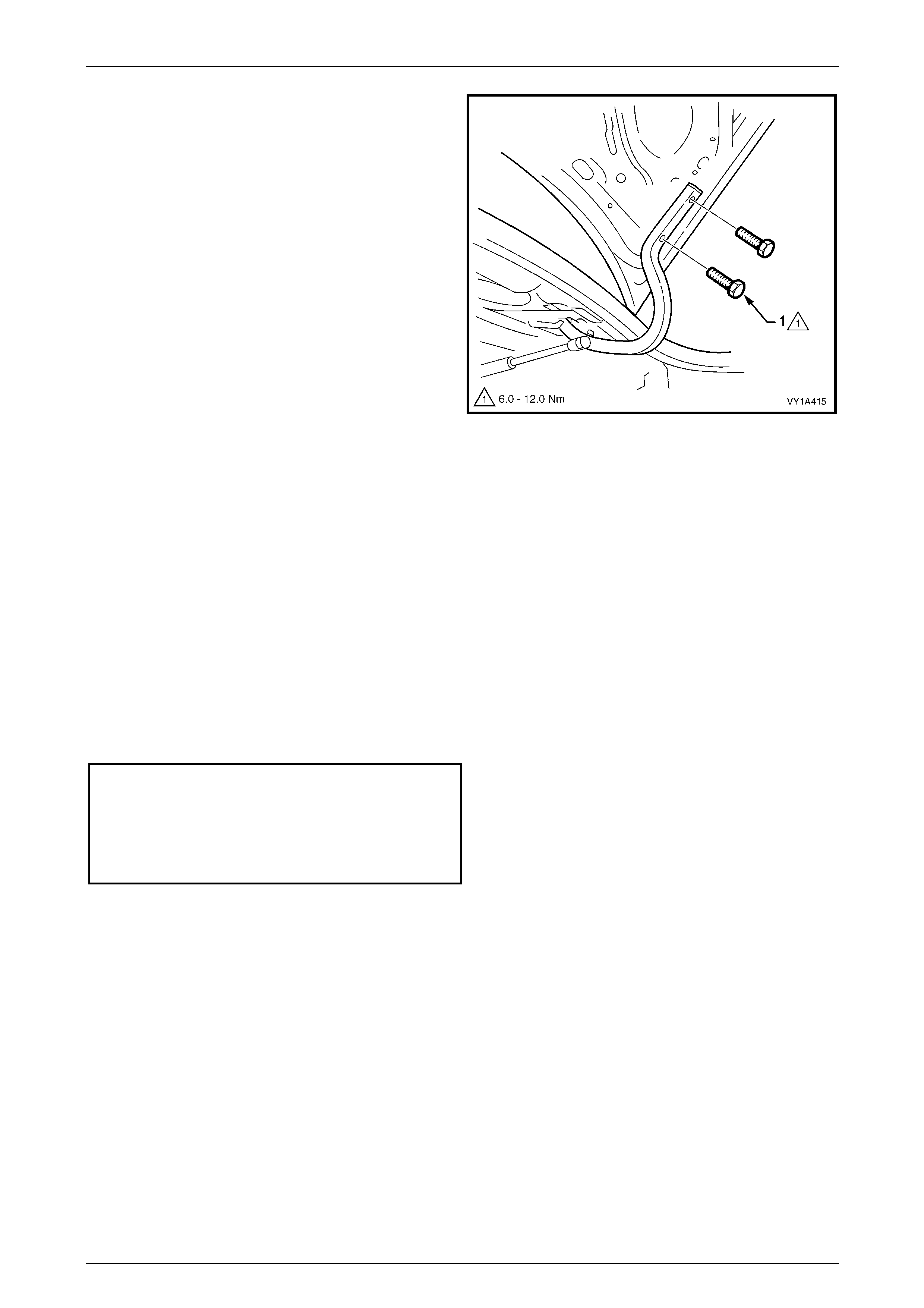
Hood, Rear Compartment Lid, Liftgate and Endgate Page 1A4–50
Page 1A4–50
6 Mark the position of the two rear compartment lid
screws (1) on each hinge to aid reinstallation.
7 Remove the two screws from each hinge attaching the
rear compartment lid to the hinges.
8 With the aid of an assistant, carefully lift the rear
compartment lid from the vehicle.
Figure 1A4 – 54
Reinstall
Reinstallation of the rear com partment lid is the reverse of the removal procedure, noting the following:
1 With the aid of an assistant, lift the rear compartment lid into position.
2 Align the rear compartment lid with the screw holes in the hinges and i nstall the four attaching screws; do not
tighten.
3 Align the screw heads with the marks previously made and temporarily tighten the screws. If no marks exist, align
the screws centrally in their holes.
4 Install the rear compartment lid bumper each side, ensuring they are set fully in.
5 Carefully close the rear comp artment lid, ensuring it does not contact the surrounding panels.
6 If required, adjust the position of the rear compartment lid, refer to Adjust in this Section.
7 Tighten the screws to the correct torque specification.
Rear compartment lid
assembly attaching screw
torque specification...................................6.0 – 12.0 Nm
Rear compartment courtesy lamp
switch assembly attaching
screw torque specification............................1.0 –3.0 Nm
NOTE
Ensure the body wiring harness assembly
is correctly routed and attached within
the rear compartment lid, refer to
Section 12O Fuses, Relays and Wiring
Harnesses.
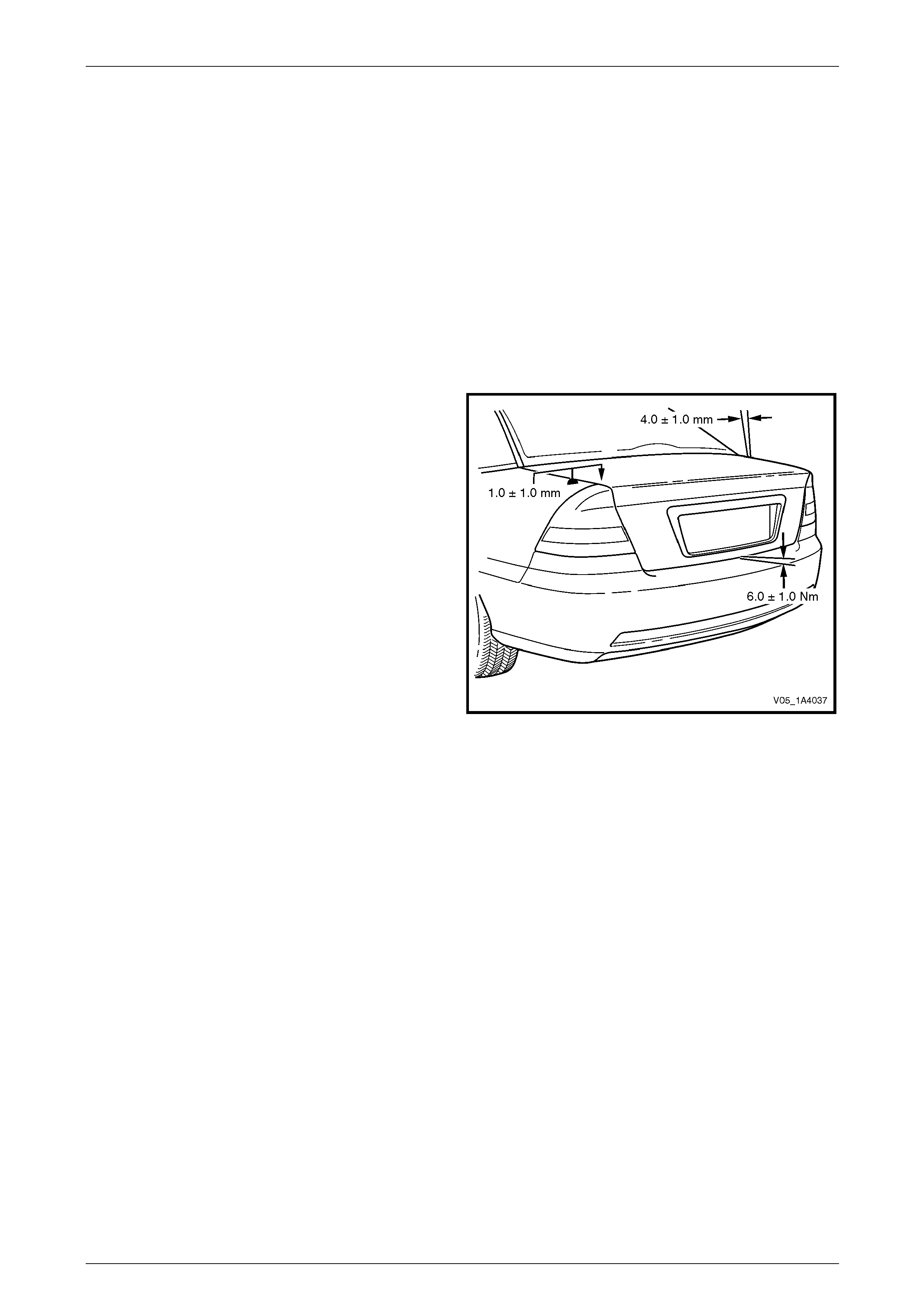
Hood, Rear Compartment Lid, Liftgate and Endgate Page 1A4–51
Page 1A4–51
Adjust
Correct alignment of the rear compartment lid is critical to it s operation and to the aesthetics of the vehicle. The following
components allow adjustment of the rear compartment lid:
• the rear compartment lid bumper provides vertical adjustment at the rear of the rear compartment lid,
• the rear compartment lid to hinge screws and rear comp artment lid hinge to body screws provide forward, rearward
and skew adjustment of the rear compartment lid, and
• rear compartment lid striker assembly provides vertical and sideways adjustment of the rear compartment lid.
If alignment is required, adjust the rear compartment lid assembly in the following order:
1 If fitted, remove the rear compartment lid striker assembly, refer to 4.10 Rear Compartment Lid Striker Assembly.
2 Ensure the rear compartment lid weatherstrip assembly is installed and the rear compartment lid bumpers are fitted
and set fully in.
3 Carefully close the rear comp artment lid, ensuring each side does not contact the vehicle.
4 Check the alignment of the rear compartment lid for:
• length; compare to the tail lamps: they should be
equal.
• width of gap; compare the gap between the rear
compartment lid and the quarter panel on each
side: the gap must be 4.0 mm ±1.0 mm.
• consistency of gap; compare the width of gap
between the rear compartment lid and the
quarter panel at the front, middle and rear on
each side: the gap should be even.
Figure 1A4 – 55
5 Open the rear compartment lid and, if required, loos en the screws attaching the rear compartment lid to the hinge
assembly for fore, aft and skew adjustment, refer to Figure 1A4 – 54.
NOTE
Do not make all adjustments at once. Perform
one adjustment, then carefully close the hood;
check its position and make further adjustments
until the correct alignment is a c hieved.
NOTE
If further adjustment is required, loosen the
screws attaching the rear compartment lid hinge
to the body and adjust the position of the hinge,
refer to 4.9 Rear Compartment Lid Hinge
Assembly.
6 Install the rear compartment lid striker assembly, refer to 4.10 Rear Com partment Lid Striker Assembly.
7 Close the rear compartment lid, ensuring the rear compartment lid striker assembly does not pull the rear
compartment lid to one side, changing the panel gaps. If the panel gaps change, reposition the rear compartment
lid striker assembly.
8 Check the height difference between the rear compartment lid and the quarter panel on each side, refer to
Figure 1A4 – 55. The height difference is 1.0 mm ±1.0 mm. The rear compartment lid to rear bumper fascia
assembly gap specification is 6.0 mm ±1.0 mm.
9 If required, open the rear compartment lid and adjust the rear compartment lid striker assembly and/or bumper, and
recheck.
10 Tighten the screws to the correct torque specification, refer to Reinstall in this Section.
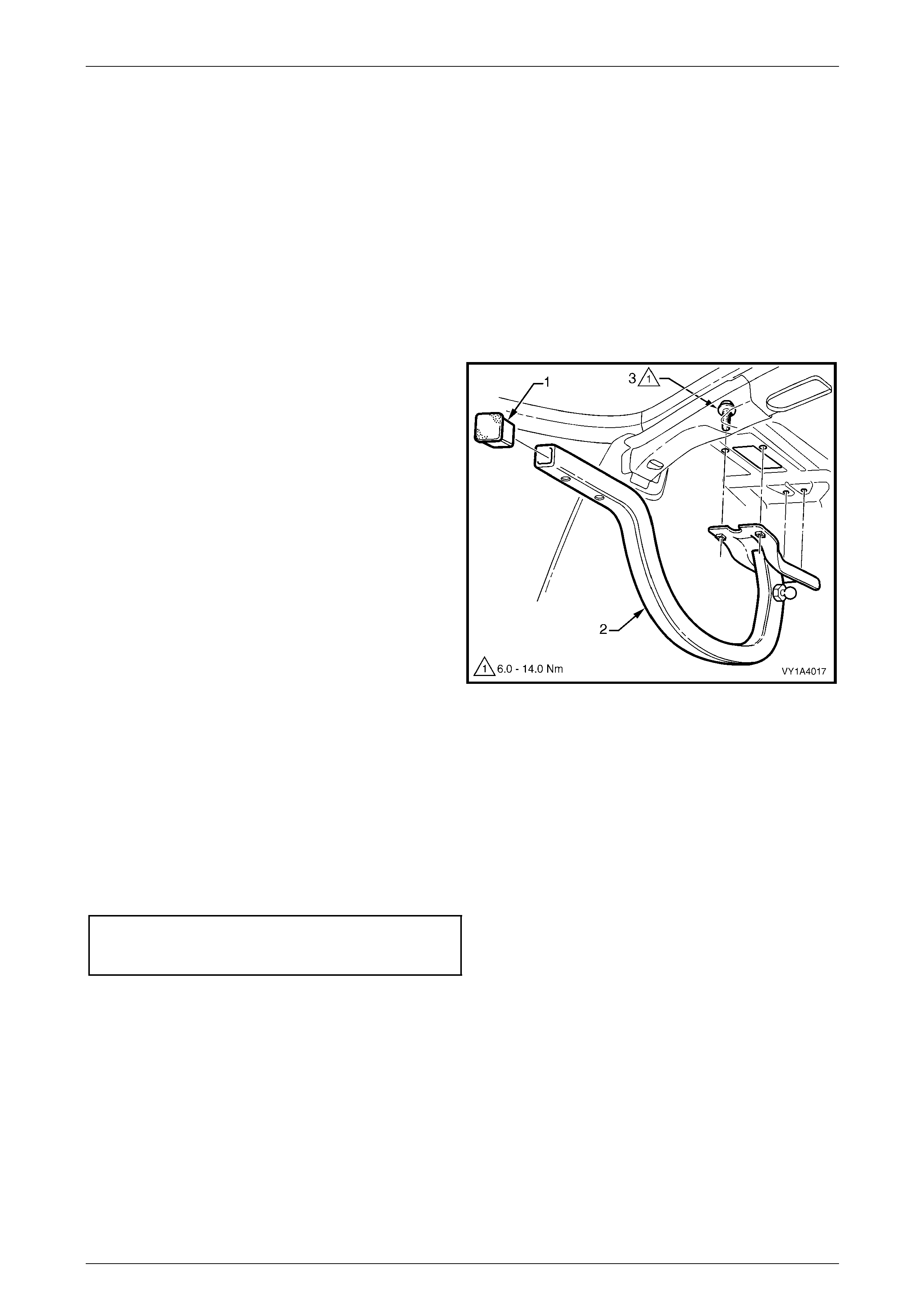
Hood, Rear Compartment Lid, Liftgate and Endgate Page 1A4–52
Page 1A4–52
4.9 Rear Compartment Lid Hinge Assembly
LT Section No. — 12–660
Remove
1 If required:
a Partially remove the rear window panel trim assembly, refer to Section 1A8 Headlining and Interior Trim.
b Remove the rear compartment lid, refer to 4.8 Rear Compartment Lid Assembly.
c Remove the rear compartment lid strut assembly from the hinge assembly,
refer to 4.7 Rear Compartment Lid Strut Assembly.
2 If required, prise the rear compartment lid hinge
cap (1) from the end of the rear compartment lid hinge
assembly (2).
3 If fitted, remove the sound deadener sheet from abov e
the hinge screws.
4 With the aid of an assistant, hold the rear
compartment lid hinge assembly.
5 From within the passenger compartment, remove
screw (3), four places, attaching the rear compartment
lid hinge assembly to the vehicle.
6 Remove the rear compartment lid hin ge assembly.
Figure 1A4 – 56
Reinstall
Reinstallation of the rear com partment lid hinge assembly is the reverse of the removal p rocedure, noting the follo wing:
1 With the aid of an assistant, lift the rear compartment lid hinge assembly into position.
2 Install the screws, aligning them with the old marks or centrall y in their holes.
3 Install and align the rear compartment lid, refer to 4.8 Rear Compartment Lid Assembly.
4 Tighten the screws to the correct torque specification.
Rear compartment lid hing e
assembly attaching screw
torque specification...................................6.0 – 14.0 Nm
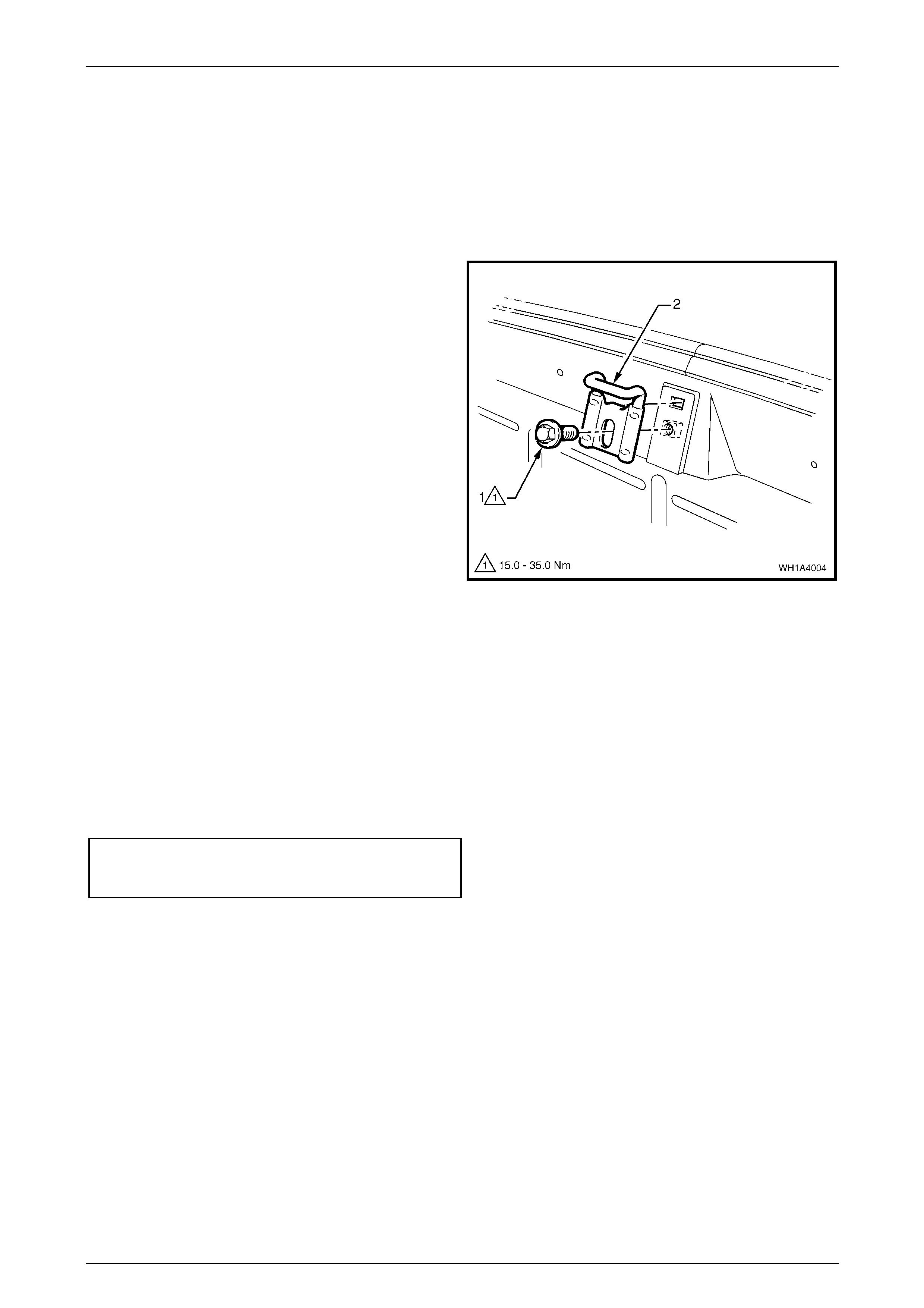
Hood, Rear Compartment Lid, Liftgate and Endgate Page 1A4–53
Page 1A4–53
4.10 Rear Compartment Lid Striker Assembly
LT Section No. — 12–680
Remove
1 If required, remove the rear end trim panel, refer to Section 1A8 Headlining and Interior Trim.
2 Mark the position of the rear compartment lid striker
assembly with a pencil.
3 Remove the screw (1) attaching the rear compartment
lid striker assembly (2) to the vehicle and remove the
striker assembly.
Figure 1A4 – 57
Reinstall
Reinstallation of the rear com partment lid striker assembly is the reverse of the removal proced ure. Tighten the screw to
the correct torque specification.
NOTE
If required, adjust the position of the striker to
obtain the correct rear compartment lid
alignment, refer to 4.8 Rear Compartment Lid
Assembly.
Rear compartment lid striker
assembly attaching screw
torque specification.................................15.0 – 35.0 Nm
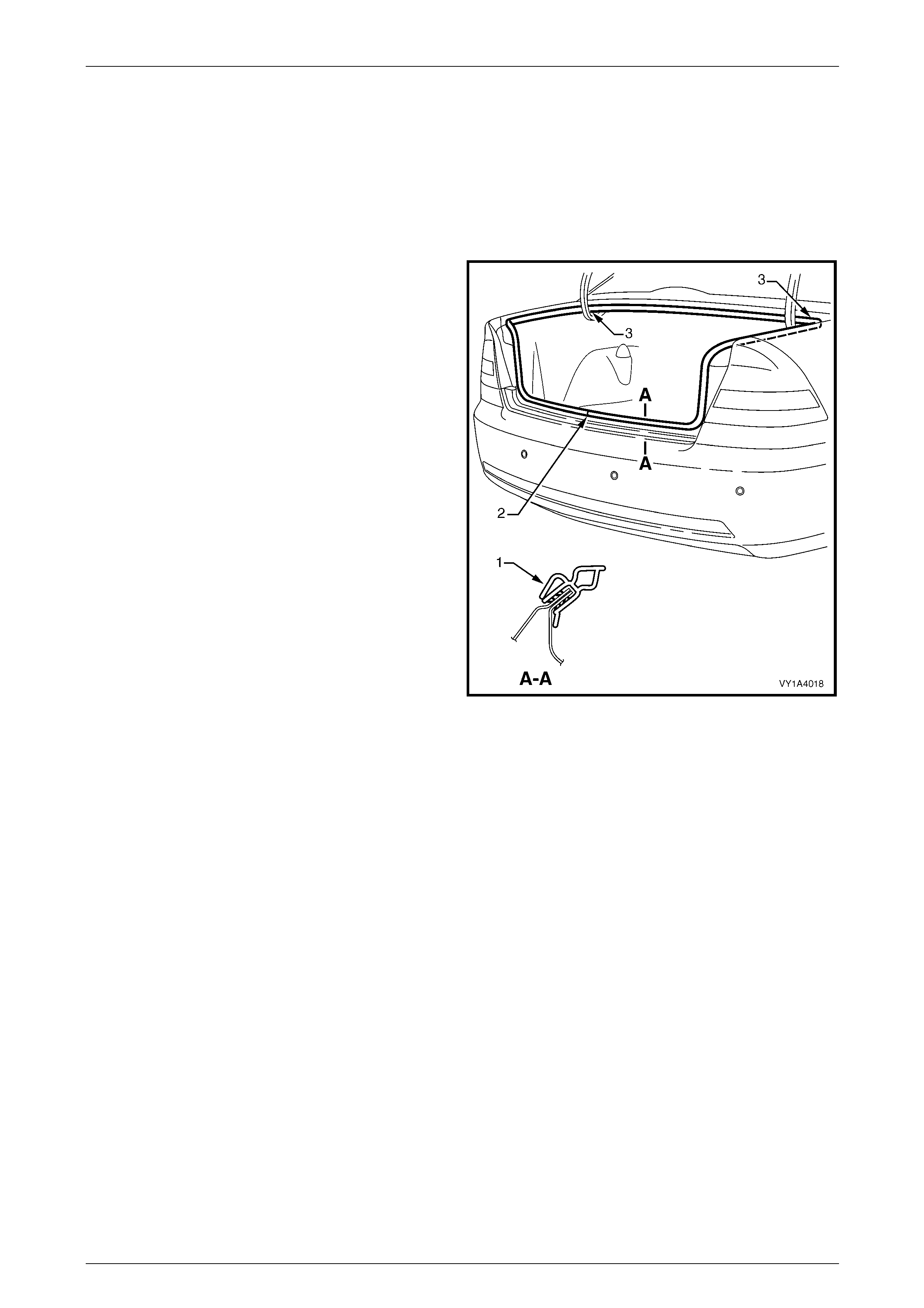
Hood, Rear Compartment Lid, Liftgate and Endgate Page 1A4–54
Page 1A4–54
4.11 Rear Compartment Lid Weatherstrip
LT Section No. — 11–600
Remove
1 If required, remove the rear end trim panel, refer to Section 1A8 Headlining and Interior Trim.
2 Grasp the rear compartment lid weatherstrip and
carefully pull it from the body flange. Start at one poi nt
and continue along its length.
3 Remove the rear compartment lid weatherstrip from
the vehicle, over the rear compartment lid.
Figure 1A4 – 58
Reinstall
Reinstallation of the rear com partment lid weatherstrip is the reverse of the removal procedure, noting the following:
1 Lay the rear compartment lid weatherstrip on the floor, ensuring the L-shaped lip (1) faces the inside, refer to
Figure 1A4 – 58.
2 Locate the rear compartment lid weatherstrip join (2) and align it with the rear compartment lid striker assembly.
3 Fit the rear compartment lid weatherstrip over the rear compartment lid and push onto the body flange, beginn ing
at the join.
NOTE
Allow the rear compartment lid weatherstrip to
crowd in each corner (3) to avoid short-cutting the
corners.

Hood, Rear Compartment Lid, Liftgate and Endgate Page 1A4–55
Page 1A4–55
5 Service Operations — Rear
Compartment Lid, Coupe
5.1 Rear Compartment Lid Carpet
LT Section No. — 14–480
Remove
1 Remove the screw (1) attaching the spare wheel
stowage cover hook (2).
2 Using a suitable trim clip removal tool, remove the
retainer (3), 17 places, attaching the rear compartment
lid carpet (4).
3 Remove the carpet from the rear compartment lid.
4 If required, prise the nut (5) and washer (6) from the
rear compartment lid with a fine flat-bladed
screwdriver.
Figure 1A4 – 59
Reinstall
Reinstallation of the rear com partment lid carpet is the reverse of the removal procedure. Tighten the screw to the correct
torque specification.
Spare wheel stowage cover
hook attaching screw
torque specification.....................................1.0 – 3.0 Nm
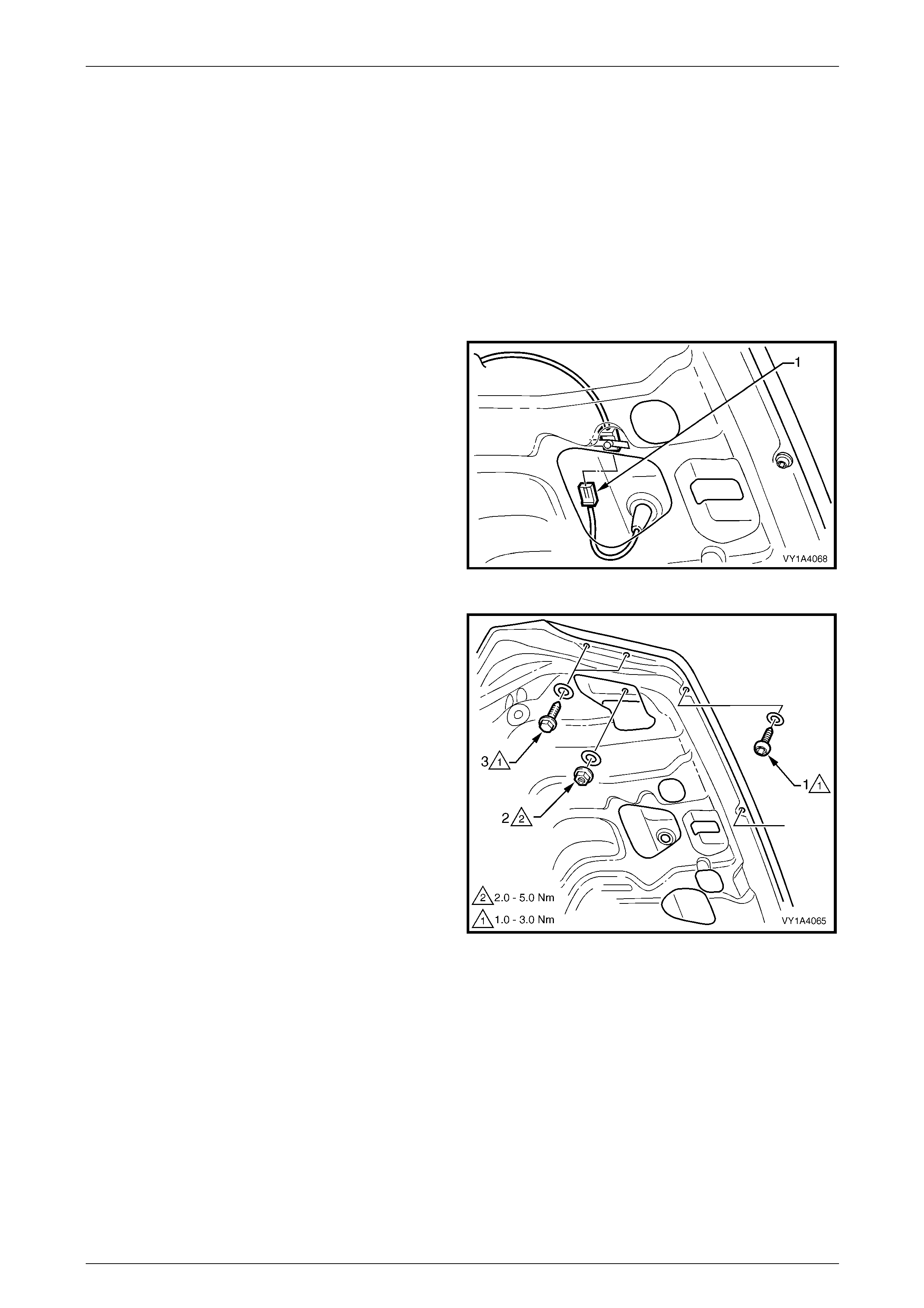
Hood, Rear Compartment Lid, Liftgate and Endgate Page 1A4–56
Page 1A4–56
5.2 Rear Compartment Lid Appliqué
Assembly
LT Section No. — 02–375
Remove
1 If required, remove the:
a Rear compartment lid carpet, refer to 5.1 Rear Compartment Lid Carpet.
b Licence plate.
2 From within the rear compartment lid cavity,
disconnect the rear licence plate lamp wiring
connector (1).
Figure 1A4 – 60
3 Remove the Torx-head screw and seal (1), three
places, from the lower edge of the rear compartment
lid.
4 Remove the nut and seal (2), two places, from within
each side of the rear compartment lid cavity.
5 Remove the screw and seal (3), two places, from each
side of the rear compartment lid.
Figure 1A4 – 61
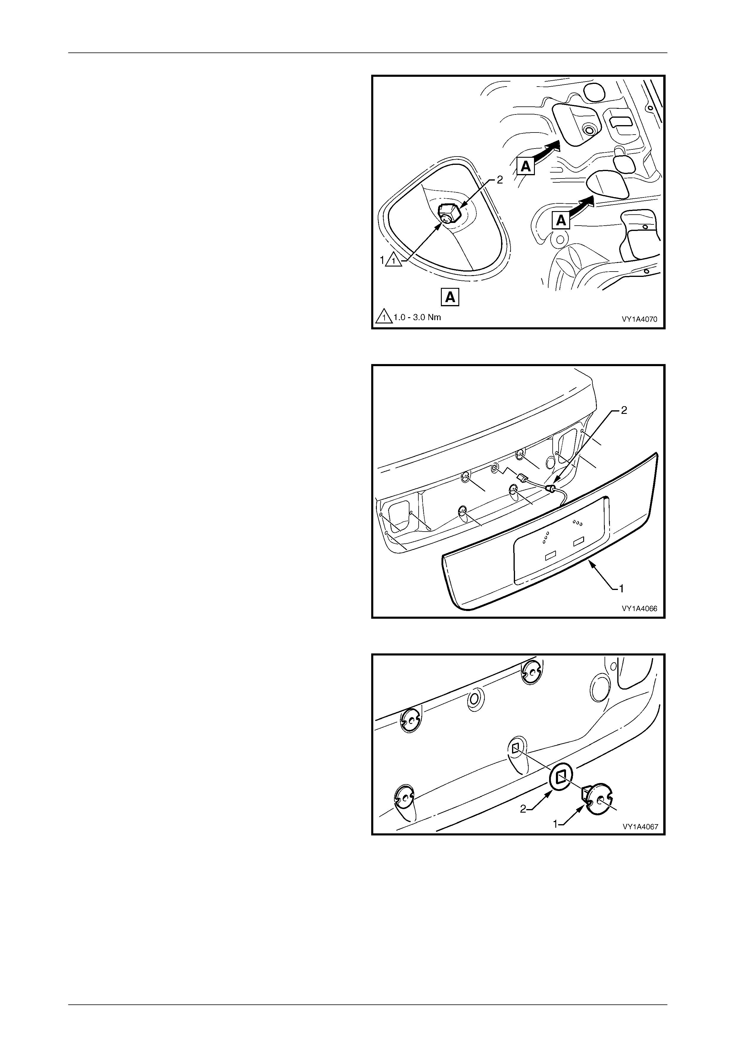
Hood, Rear Compartment Lid, Liftgate and Endgate Page 1A4–57
Page 1A4–57
6 Either:
• Remove screw (1), four places, from the retainer
within the rear compartment lid cavity.
or
• Press the four tabs (2) on each side to
disengage the retainer from the rear
compartment lid panel.
Figure 1A4 – 62
7 Partially remove the appliqué assembly (1) from the
rear compartment lid.
8 Remove the rear licence plate lamp wiring harness
grommet (2) and disconnect the rear licence plate
lamp wiring harness.
9 Remove the appliqué assemb ly.
Figure 1A4 – 63
10 If not removed with the appliqué, carefully pri se the
four retainers (1) and seals (2) from the rear
compartment lid using a fine flat-bladed screwdriver.
Figure 1A4 – 64
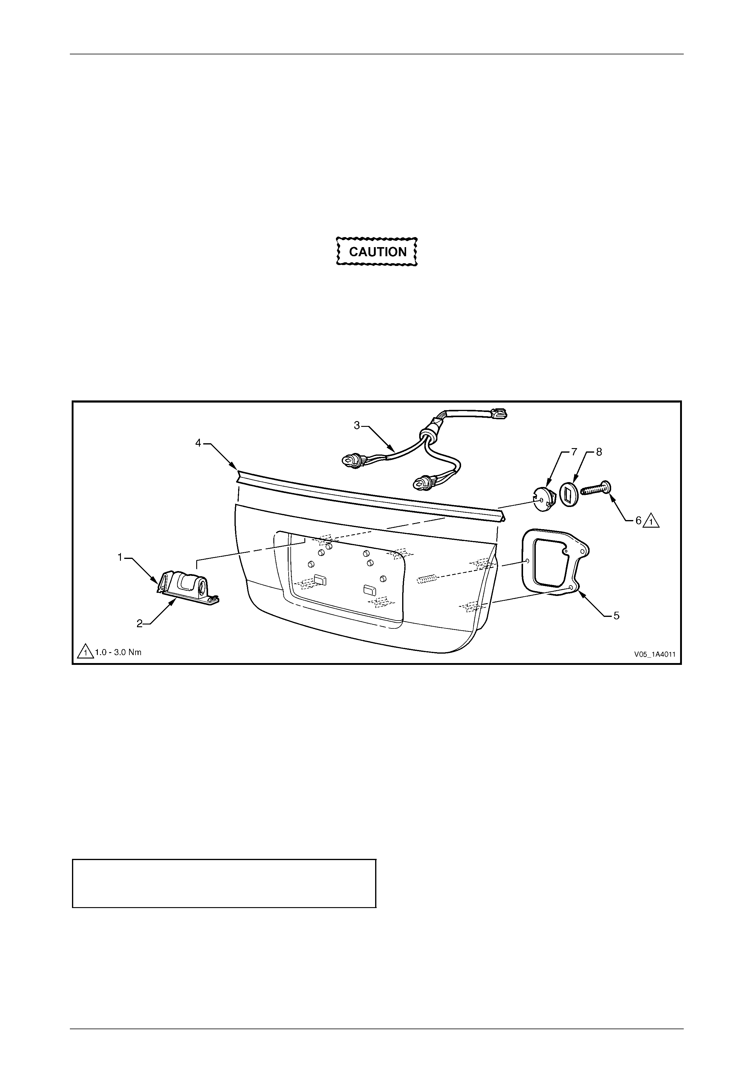
Hood, Rear Compartment Lid, Liftgate and Endgate Page 1A4–58
Page 1A4–58
Disassemble
1 Press the tab (1) and remove the rear licence lamp housing (2) from the rear compartmen t lid appliqué assembly,
refer to Figure 1A4 – 65.
2 Rotate the bulb socket and remove it from the rear licence lamp ho using.
3 Repeat for the remaining rear licence lamp housing.
4 Remove the rear licence plate lamp wiring harness assembly (3) from behind the appl iqué assembly.
The rear compartment lid appliqué assembly
upper seal is attached with adhesive.
5 Carefully remove the rear compartment lid appliqué assembl y upper seal (4).
6 Remove the rear compartment lid app liqué assembly gasket (5) from each side of the appliqu é assemb ly.
7 If not previously removed, remove screw (6), four places, attaching the retainers (7) and seals (8) to the appliqu é
assembly.
Figure 1A4 – 65
Reassemble
Reassembly of the rear compartment lid app liqué assembly is the reverse of the disassembly procedur e, noting the
following:
1 Remove any adhesive and clean the rear compartment lid app liqué assembly upper seal and the top edge of the
rear compartment lid appliqué assembl y us ing Prepsol or equivalent. Attach the rear compartment lid ap pliqué
assembly upper seal using a dhesive.
2 If required, fit the retainer (7) and seal (8), four places, to the appliqué assembly and tighten the screw (6), four
places, to the correct torque specification, refer to Figure 1A4 – 65.
Rear compartment lid appliqué
assembly retainer attaching screw
torque specification.....................................1.0 – 3.0 Nm

Hood, Rear Compartment Lid, Liftgate and Endgate Page 1A4–59
Page 1A4–59
Reinstall
Reinstallation of the rear compartment lid appliqué assembly is the reverse of the removal procedure, noting the
following:
1 Ensure the seals are correctly fitted.
2 Ensure the four retainers snap into position when the appliqué assembly is installed on the rear compartment lid.
3 Tighten the screws and nuts to the correct torque specification.
Rear compartment lid appliqué
assembly lower attaching screw
torque specification.....................................1.0 – 3.0 Nm
Rear compartment lid appliqué
assembly attaching nut
torque specification.....................................2.0 – 5.0 Nm
Rear compartment lid appliqué
assembly outer attaching screw
torque specification.....................................1.0 – 3.0 Nm
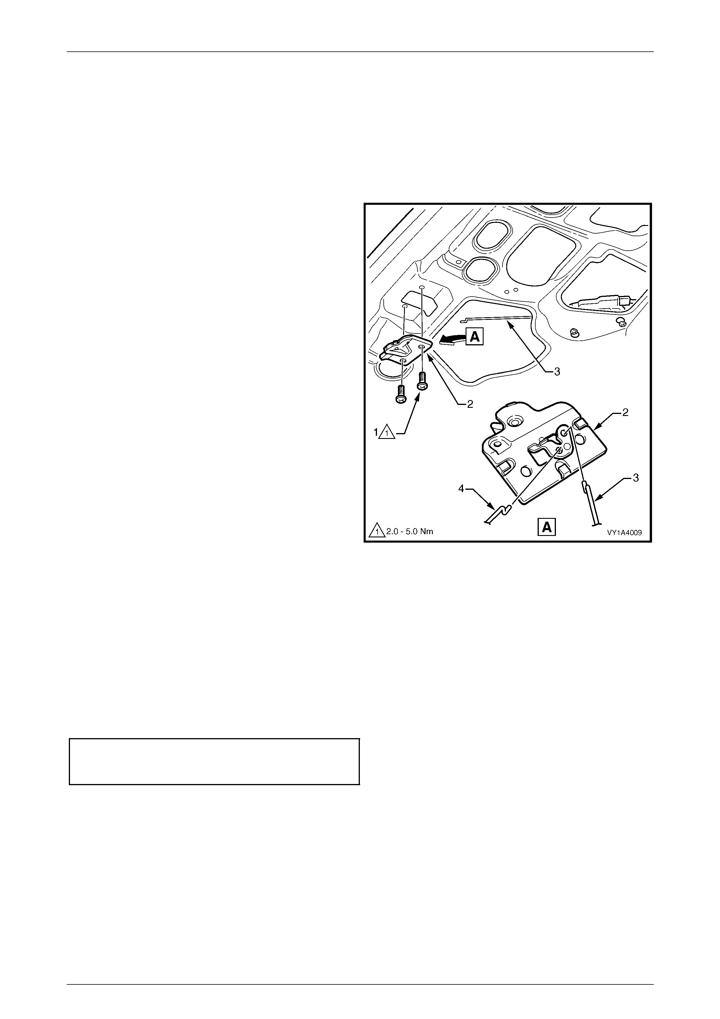
Hood, Rear Compartment Lid, Liftgate and Endgate Page 1A4–60
Page 1A4–60
5.3 Rear Compartment Lid Latch Assembly
LT Section No. — 12–680
Remove
1 If required, remove the rear compartment lid carpet, refer to 5.1 Rear Compartment Lid Carpet.
2 Remove the two screws (1) attaching the rea r
compartment lid latch assembly (2) to the rear
compartment lid.
3 Withdraw the latch assembly from the inner rear
compartment lid panel far enough to e nable
disconnection of the actuator rod (3) and rear
compartment lid release cable (4).
4 Remove the latch assembl y.
Figure 1A4 – 66
Reinstall
Reinstallation of the rear com partment lid latch assembly is the reverse of the remova l procedure, noting the following:
1 Lubricate the rear compartment lid latch assembly with NLGI No. 1 lithium grease or equivalent.
2 Before closing the rear compartment lid, close the rear compartment lid latch and check the operation of the rear
compartment lid latch assembly using the rear compartment lid release switch and rear compartment lid release
cable assembly. If the operation is satisfactory, close the rear compartmen t lid and recheck the operation. If
required, adjust the rear compartment lid striker assemb ly, refer to 5.9 Rear Compartment Lid Striker Assembly.
3 Tighten the screws to the correct torque specification.
Rear compartment lid latch
assembly attaching screw
torque specification.....................................2.0 – 5.0 Nm
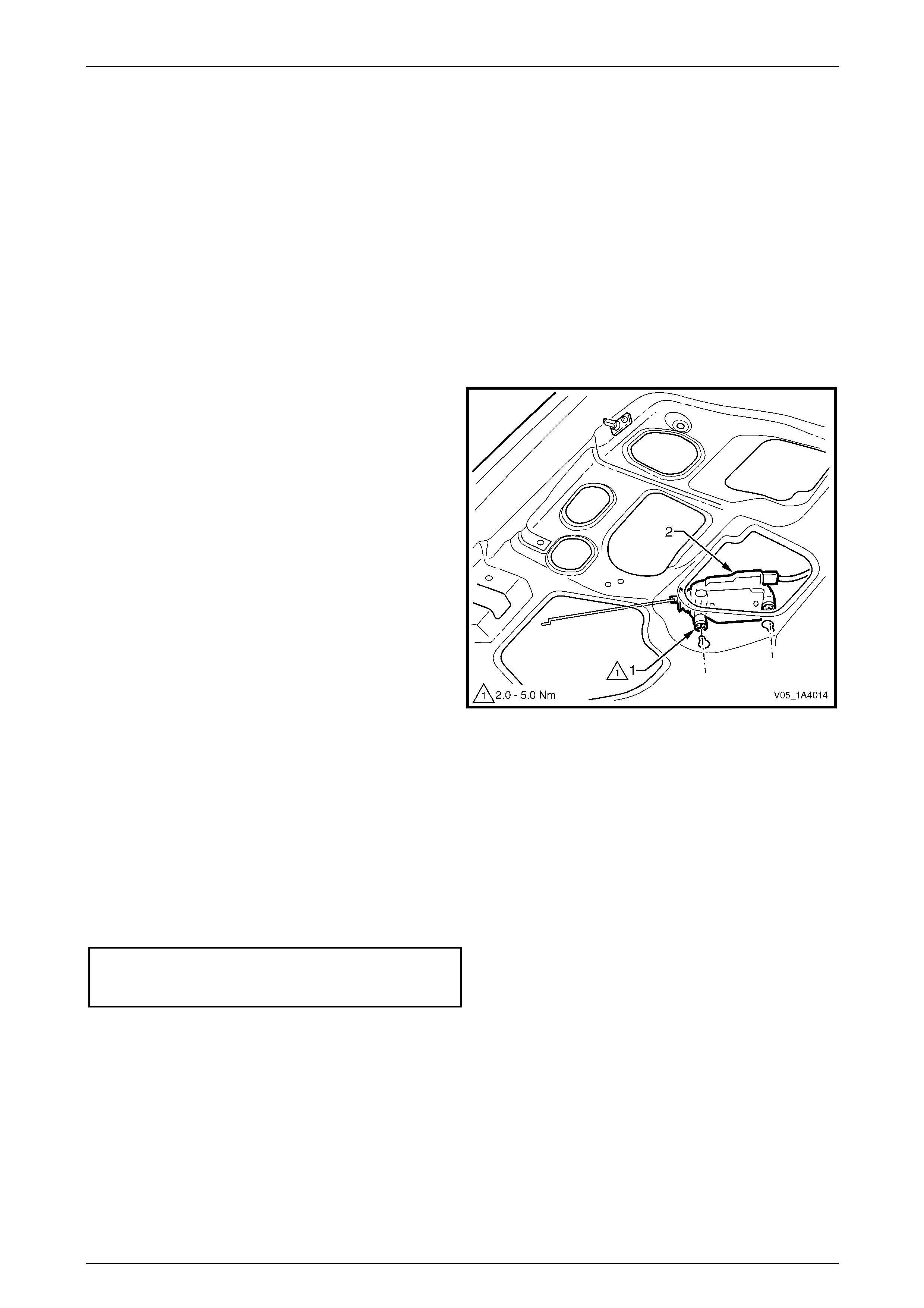
Hood, Rear Compartment Lid, Liftgate and Endgate Page 1A4–61
Page 1A4–61
5.4 Rear Compartment Lid Actuator
Assembly
LT Section No. — 12–680
NOTE
The rear compartment lid actuator assembly is
controlled by the bod y control module (BCM ). For
diagnosis, refer to Section 12J Body Control
Module.
Remove
1 If required, remove the rear compartment lid carpet, refer to 5.1 Rear Compartment Lid Carpet.
2 Loosen the two screws (1) attaching the rear
compartment lid actuator assembly (2) to the rear
compartment lid.
3 If required, disconnect the connecting ro d from the
rear compartment lid latch assembly.
4 Withdraw the actuator assembly from the keyhole slots
in the inner rear compartment lid p anel.
5 Remove the actuator assembly from the inne r rear
compartment lid panel cavity far enough to enable the
wiring harness connector to be disco nnected.
6 Remove the actuator assembly.
Figure 1A4 – 67
Reinstall
Reinstallation of the rear com partment lid actuator assembly is the reverse of the removal procedure, noting the
following:
1 Before closing the rear compartment lid, close the rear compartment lid latch and check the operation of the rear
compartment lid latch assembl y using the rear compartment lid release switch. If the operation is satisfactory, close
the rear compartment lid and recheck the operation. If required, adjust the rear compartment lid striker assembly,
refer to 5.9 Rear Compartment Lid Striker Assembly.
2 Tighten the screws to the correct torque specification.
Rear compartment lid actuator
assembly attaching screw
torque specification.....................................2.0 – 5.0 Nm
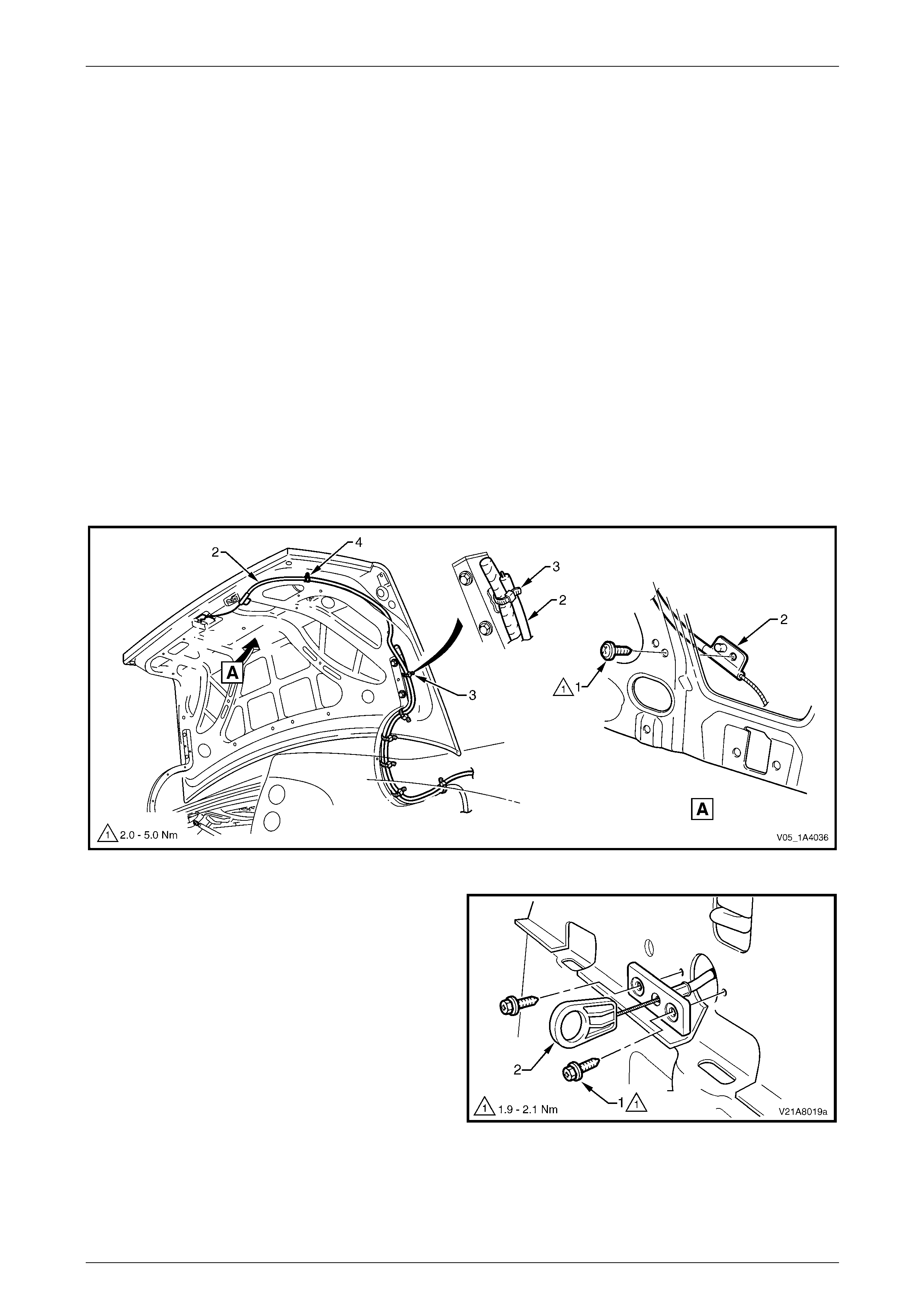
Hood, Rear Compartment Lid, Liftgate and Endgate Page 1A4–62
Page 1A4–62
5.5 Rear Compartment Lid Release Cable
Assembly
LT Section No. — 12–680
Remove
1 If required:
a Remove the rear compartment lid carpet, refer to 5.1 Rear Compartment Lid Carpet.
b Remove the rear compartment lid latch assembly, refer to 5.3 Rear Compartment Lid Latch Assembly.
c Remove the right-hand rear seat-back assembl y, refer to Section 1A7 Seat Assembli es.
d Partially remove the rear window trim panel assembly, refer to Section 1A8 Headlining and Interior Trim.
2 Remove the screw (1) attaching the rear compartment lid rele ase cable assembly (2) to the rear compartment lid,
refer to Figure 1A4 – 68.
3 Remove the straps (3) attaching the cable assembl y to the rear comp artme nt lid actuator assembly wiring harness.
4 Remove the retainer (4) attaching the cable to the rear compartment lid.
5 Withdraw the cable assembly from the rear compartment lid cavity and lay it on the rear compartment floor.
Figure 1A4 – 68
5 Remove the two screws (1) attaching the rea r
compartment lid release cable assembl y (2), located
under the right rear seat-back head restraint.
6 Carefully feed the cab le assembly into the passenger
compartment and remove.
Figure 1A4 – 69

Hood, Rear Compartment Lid, Liftgate and Endgate Page 1A4–63
Page 1A4–63
Reinstall
Reinstallation of the rear com partment lid release cable assembly is the reverse of the removal procedure, noting the
following:
1 Before closing the rear compartment lid, close the rear compartment lid latch and check the operation of the rear
compartment lid latch assembly using the rear compartment lid release switch and rear compartment lid release
cable assembly. If the operation is satisfactory, close the rear compartmen t lid and recheck the operation. If
required, adjust the rear compartment lid latch striker assembly,
refer to 5.9 Rear Compartment Lid Striker Assembly.
2 Tighten the screws to the correct torque specification.
Rear compartment lid release
cable assembly attaching screw
(rear seat-back) torque specification...........1.9 – 2.1 Nm
Rear compartment lid release
cable assembly attaching
screw (rear compartment lid)
torque specification.....................................2.0 – 5.0 Nm

Hood, Rear Compartment Lid, Liftgate and Endgate Page 1A4–64
Page 1A4–64
5.6 Rear Compartment Lid Strut Assembly
LT Section No. — 12–680
Remove
The hood struts contain pressurised gas. Do
not subject them to extreme heat, p ressure or
physical damage.
1 Support the rear compartment lid securel y.
2 Using a fine flat-bladed screwdriver, prise the
retainer (1) from the rear compartment lid strut end (2).
NOTE
The retainer can spring off the hood strut
assembly and be easily lost.
3 Pull the strut assembly from the strut ball stud (3).
4 Repeat for the opposite end, if required.
Figure 1A4 – 70
Reinstall
NOTE
If a rear compartment lid strut assembly is
replaced, ensure the correct type is specified as
vehicles with a rear spoiler require stronger
struts.
Reinstallation of the rear com partment lid strut assembly is the reverse of the removal procedure, noting the following:
1 Apply a small amount of NLGI No. 1 lithium grease or equivalent to the inside of the strut ball cup.
2 Install the retainer onto the rear compartment lid strut end, if removed.
3 Align the rear compartment lid strut with the strut ball stud and push into place.
4 If required, repeat for the opposite end.
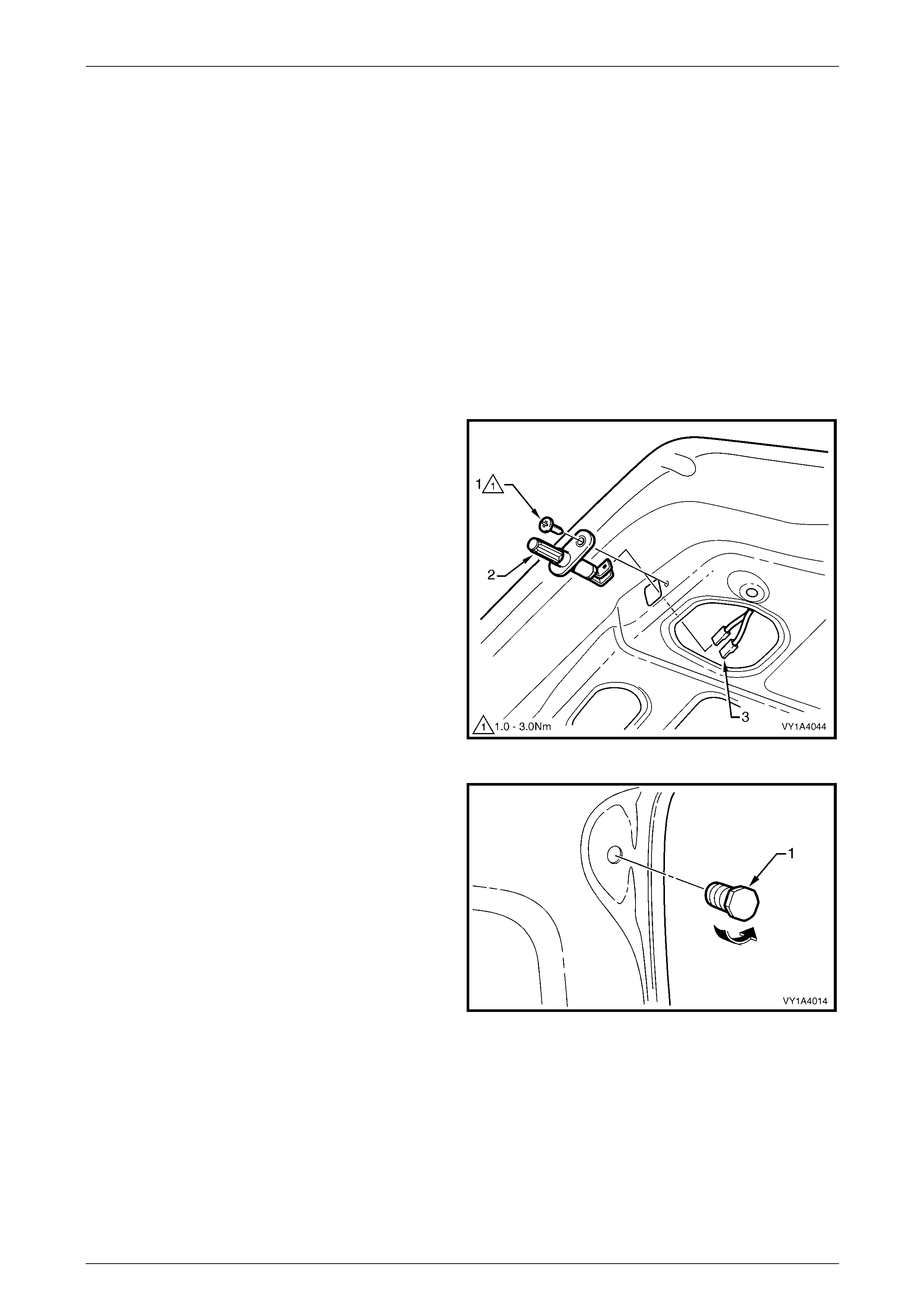
Hood, Rear Compartment Lid, Liftgate and Endgate Page 1A4–65
Page 1A4–65
5.7 Rear Compartment Lid Assembly
LT Section No. — 12–680
Remove
1 If required, remove the following components:
a Rear compartment lid carpet, refer to 5.1 Rear Compartment Lid Carpet.
b Rear compartment lid latch assembly, refer to 5.3 Rear Compartment Lid Latch Assembly.
c Rear compartment lid actuator assembly, refer to 5.4 Rear Compartment Lid Actuator Assembly.
d Rear compartment lid release cable assembly from the rear compartmen t lid only,
refer to 5.5 Rear Compartment Lid Release Cable Assembly.
e Badges and emblems, refer to Section 1A9 Exterior Ornamentation.
2 Remove the screw (1) attaching the rear compartment
courtesy lamp switch assembly (2) to the rear
compartment lid.
3 Withdraw the switch assembly and disc onnect the
wiring connectors (3).
4 Remove the body wiring harness assembly from the
rear compartment lid only, refer to
Section 12O Fuses, Relays and Wiring Harnesses.
Figure 1A4 – 71
5 Unscrew the rear compartment lid bumper (1) from
each side of the rear compartment lid.
Figure 1A4 – 72
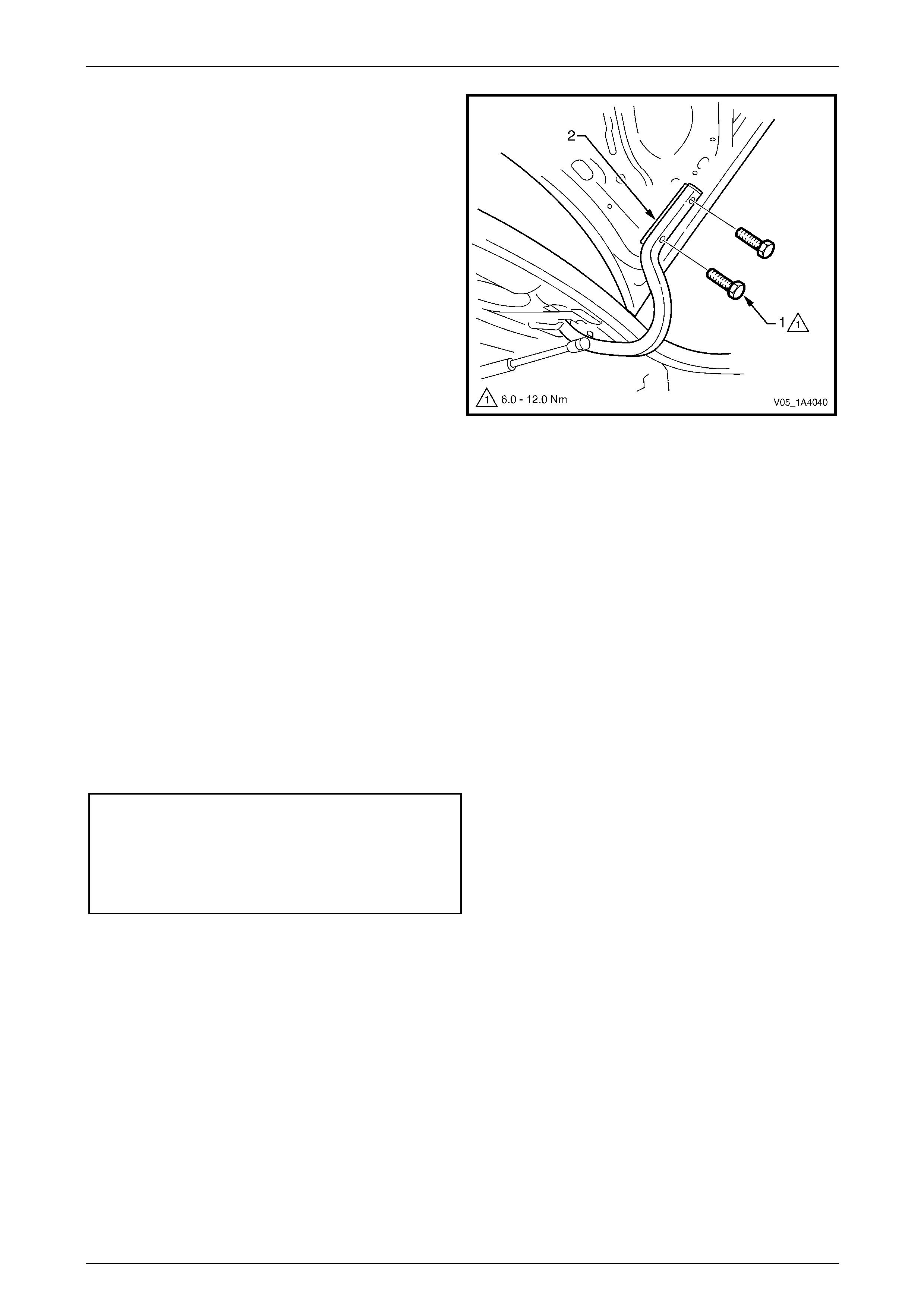
Hood, Rear Compartment Lid, Liftgate and Endgate Page 1A4–66
Page 1A4–66
6 Mark the position of the two rear compartment lid
screws (1) on each hinge to aid reinstallation.
7 Remove the two screws from each hinge attaching the
rear compartment lid to the hinges.
8 With the aid of an assistant, carefully lift the rear
compartment lid from the vehicle.
NOTE
Take care to ensure the 2 mm spacer (2) does
not fall when the rear compartment lid is
removed.
Figure 1A4 – 73
Reinstall
Reinstallation of the rear com partment lid is the reverse of the removal procedure, noting the following:
1 With the aid of an assistant, lift the rear compartment lid into position.
2 Ensure the spacers are correctl y located between the rear compartment lid and the hin ges.
3 Align the rear compartment lid with the screw holes in the spacer and the hinges and install the four attaching
screws; do not tighten.
4 Align the screw heads with the marks previously made and temporarily tighten the screws. If no marks exist, align
the screws centrally in their holes.
5 Install the rear compartment lid bumper each side, ensuring they are set fully in.
6 Carefully close the rear comp artment lid, ensuring it does not contact the surrounding panels.
7 If required, adjust the position of the rear compartment lid, refer to Adjust in this Section.
8 Tighten the screws to the correct torque specification.
Rear compartment lid
assembly attaching screw
torque specification...................................6.0 – 12.0 Nm
Rear compartment courtesy lamp
switch assembly attaching
screw torque specification............................1.0 –3.0 Nm
NOTE
Ensure the body wiring harness assembly
is correctly routed and attached within
the rear compartment lid, refer to
Section 12O Fuses, Relays and Wiring
Harnesses.
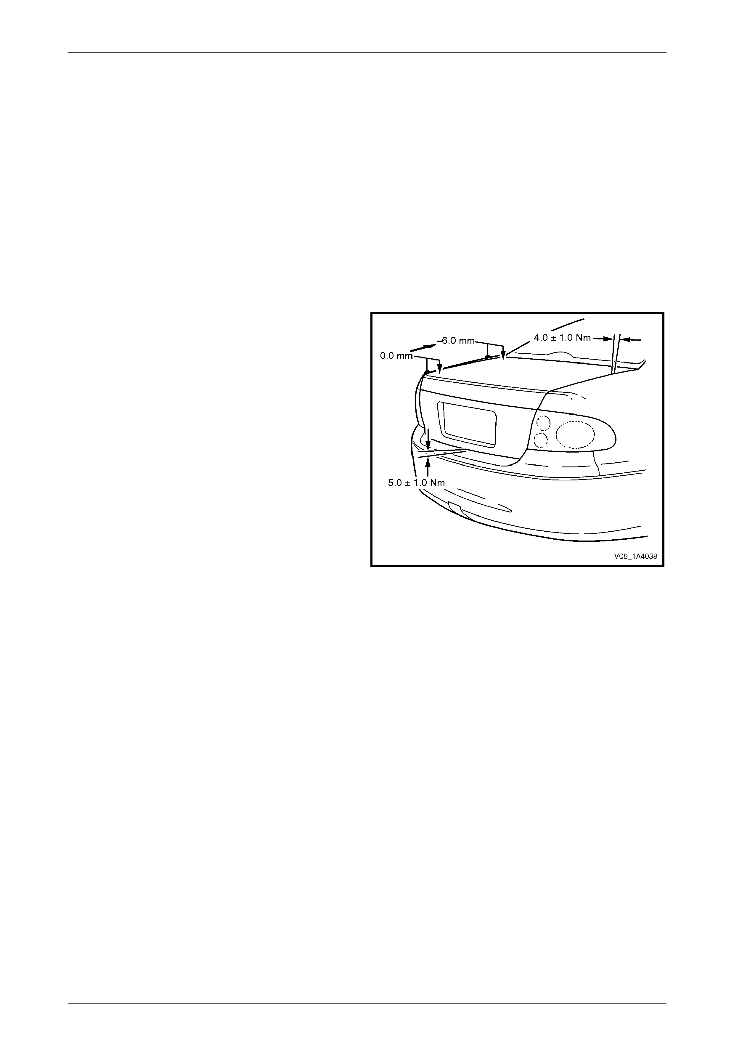
Hood, Rear Compartment Lid, Liftgate and Endgate Page 1A4–67
Page 1A4–67
Adjust
Correct alignment of the rear compartment lid is critical to it s operation and to the aesthetics of the vehicle. The following
components allow adjustment of the rear compartment lid:
• the rear compartment lid bumper provides vertical adjustment at the rear of the rear compartment lid,
• the rear compartment lid to hinge screws and rear comp artment lid hinge to body screws provide forward, rearward
and skew adjustment of the rear compartment lid, and
• rear compartment lid striker assembly provides vertical and sideways adjustment of the rear compartment lid.
If alignment is required, adjust the rear compartment lid assembly in the following order:
1 If fitted, remove the rear compartment lid striker assembly, refer to 5.9 Rear Compartment Lid Striker Assembly.
2 Ensure the rear compartment lid weatherstrip assembly is installed and the rear compartment lid bumpers are fitted
and set fully in.
3 Carefully close the rear comp artment lid, ensuring each side does not contact the vehicle.
4 Check the alignment of the rear compartment lid for:
• length; compare to the tail lamps: they should be
equal.
• width of gap; compare the gap between the rear
compartment lid and the quarter panel on each
side: the gap must be 4.0 mm ±1.0 mm.
• consistency of gap; compare the width of gap
between the rear compartment lid and the
quarter panel at the front, middle and rear on
each side: the gap should be even.
5 Open the rear compartment lid and, if required, loosen
the screws attaching the rear compartment lid to the
hinge assembly for fore, aft and skew adjustment,
refer to Figure 1A4 – 73.
Figure 1A4 – 74
NOTE
Do not make all adjustments at once. Perform
one adjustment, then carefully close the rear
compartment lid; check its position and make
further adjustments until the correct alignment is
achieved.
NOTE
If further adjustment is required, loosen the
screws attaching the rear compartment lid hinge
to the body and adjust the position of the hinge,
refer to 5.8 Rear Compartment Lid Hinge
Assembly.
6 Install the rear compartment lid striker assembly, refer to 5.9 Rear Compartment Lid Striker Assembly.
7 Close the rear compartment lid, ensuring the rear compartment lid striker assembly does not pull the rear
compartment lid to one side, changing the panel gaps. If the panel gaps change, reposition the rear compartment
lid striker assembly.
8 Check the height difference between the rear compartment lid and the quarter panel on e ach sid e,
refer to Figure 1A4 – 74. The height difference is 0.0 mm at the rear of the rear compartment lid, tapering to
6.0 mm below the quarter panel at the front. T he rear compartment lid to rear bumper fascia assembl y gap
specification 5.0 mm ±1.0 mm.
9 If required, open the rear compartment lid and adjust the rear compartment lid striker assembly and/or bumper, and
recheck.
10 Tighten the screws to the correct torque specification, refer to Reinstall in this Section.
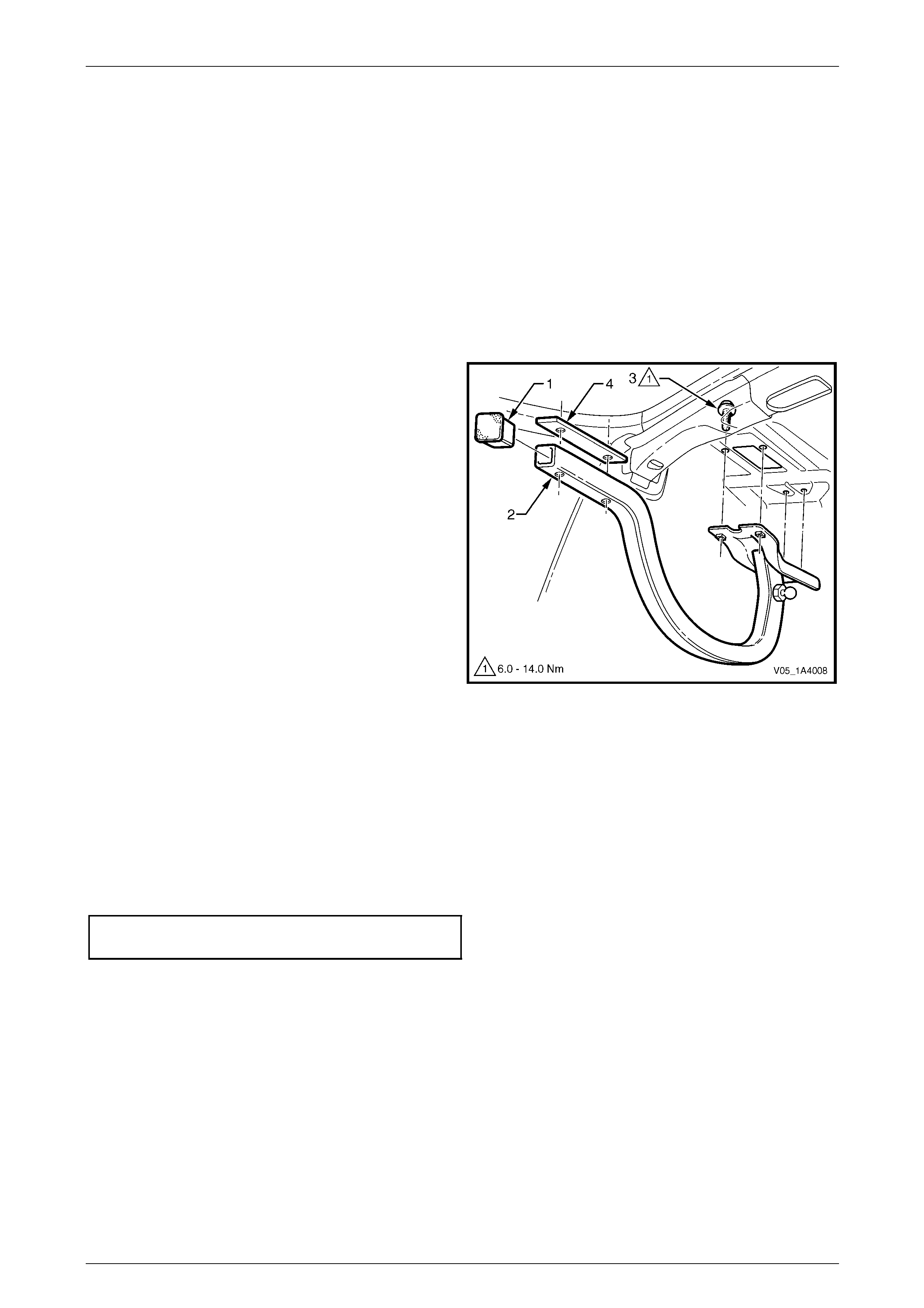
Hood, Rear Compartment Lid, Liftgate and Endgate Page 1A4–68
Page 1A4–68
5.8 Rear Compartment Lid Hinge Assembly
LT Section No. — 12–660
Remove
1 If required:
a Partially remove the rear window panel trim assembly, refer to Section 1A8 Headlining and Interior Trim.
b Remove the rear compartment lid, refer to 5.7 Rear Compartment Lid Assembly.
c Remove the rear compartment lid strut assembly from the hinge assembly,
refer to 5.6 Rear Compartment Lid Strut Assembly.
2 If required, prise the rear compartment lid hinge
cap (1) from the end of the rear compartment lid hinge
assembly (2).
3 If fitted, remove the sound deadener sheet from abov e
the hinge screws.
4 With the aid of an assistant, hold the rear
compartment lid hinge assembly.
5 From within the passenger compartment, remove the
four screws (3) attaching the rear compartment lid
hinge assembly to the vehicle.
6 Remove the rear compartment lid hin ge assembly.
7 Remove and discard the 2 mm spacer (4).
Figure 1A4 – 75
Reinstall
Reinstallation of the rear com partment lid hinge assembly is the reverse of the removal p rocedure, noting the follo wing:
1 With the aid of an assistant, lift the rear compartment lid hinge assembly into position.
2 Install the screws, aligning them with the old marks or centrall y in their holes.
3 Install and align the rear compartment lid, refer to 5.7 Rear Compartment Lid Assembly.
4 Tighten the screws to the correct torque specification.
Rear compartment lid hing e assembly
attaching screw torque specification........6.0 – 14.0 Nm

Hood, Rear Compartment Lid, Liftgate and Endgate Page 1A4–69
Page 1A4–69
5.9 Rear Compartment Lid Striker Assembly
LT Section No. — 12–680
Remove
1 If required, remove the rear end trim panel, refer to Section 1A8 Headlining and Interior Trim.
2 Mark the position of the rear compartment lid striker
assembly with a pencil.
3 Remove the screw (1) attaching the rear compartment
lid striker assembly (2) to the vehicle and remove the
striker assembly.
Figure 1A4 – 76
Reinstall
Reinstallation of the rear com partment lid striker assembly is the reverse of the removal proced ure. Tighten the screw to
the correct torque specification.
NOTE
If required, adjust the position of the striker to
obtain the correct rear compartment lid
alignment, refer to 5.7 Rear Compartment Lid
Assembly.
Rear compartment lid striker assembly
attaching screw torque specification.......15.0 – 35.0 Nm
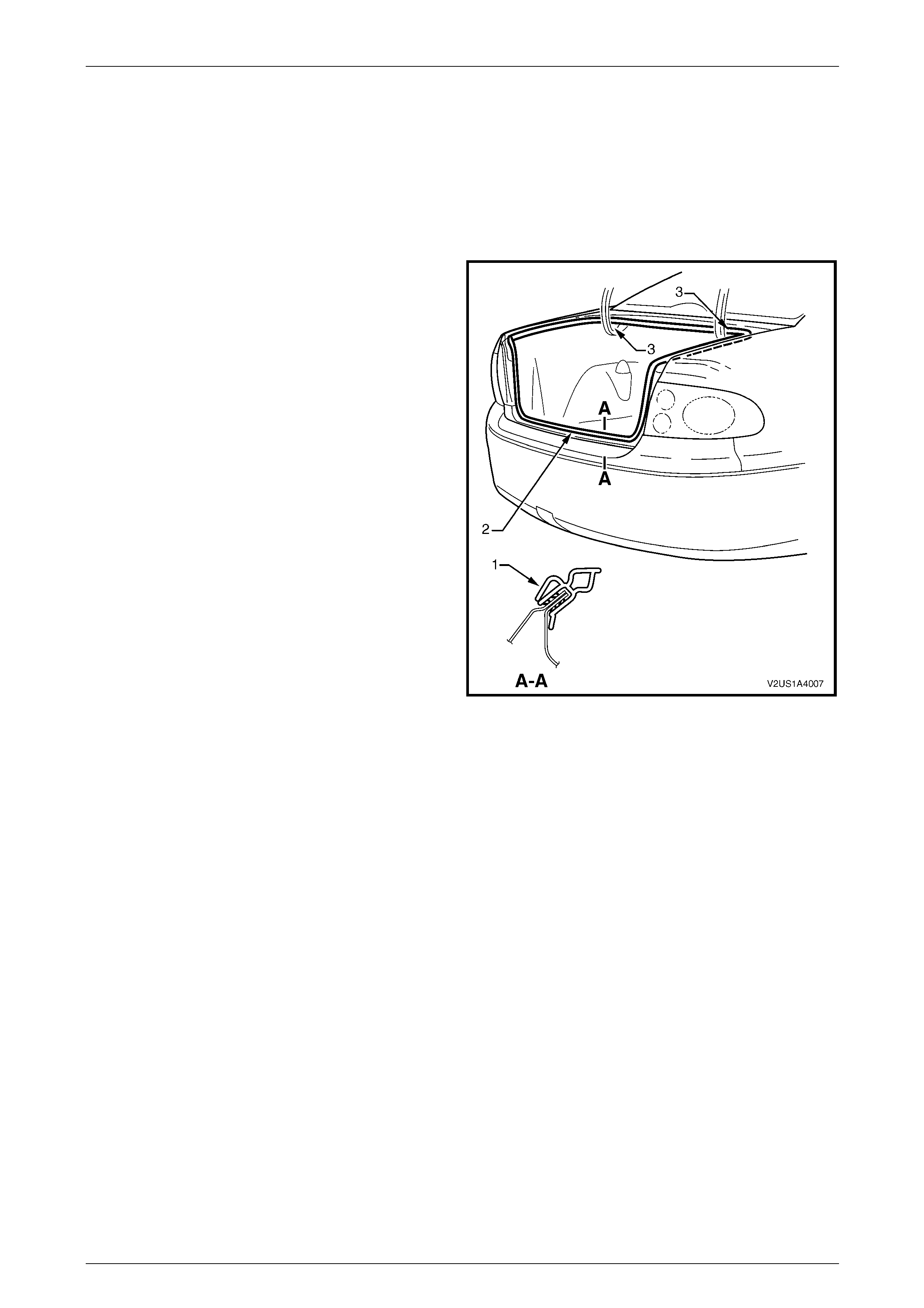
Hood, Rear Compartment Lid, Liftgate and Endgate Page 1A4–70
Page 1A4–70
5.10 Rear Compartment Lid Weatherstrip
LT Section No. — 11–600
Remove
1 If required, remove the rear end trim panel, refer to Section 1A8 Headlining and Interior Trim.
2 Grasp the rear compartment lid weatherstrip and
carefully pull it from the body flange. Start at one poi nt
and continue along its length.
3 Remove the rear compartment lid weatherstrip from
the vehicle, over the rear compartment lid.
Figure 1A4 – 77
Reinstall
Reinstallation of the rear com partment lid weatherstrip is the reverse of the removal procedure, noting the following:
1 Lay the rear compartment lid weatherstrip on the floor, ensuring the L-shaped lip (1) faces the inside, refer to
Figure 1A4 – 77.
2 Locate the rear compartment lid weatherstrip join (2) and align it with the rear compartment lid striker assembly.
3 Fit the rear compartment lid weatherstrip over the rear compartment lid and push onto the body flange, beginn ing
at the join.
NOTE
Allow the rear compartment lid weatherstrip to
crowd in each corner (3) to avoid short-cutting the
corners.
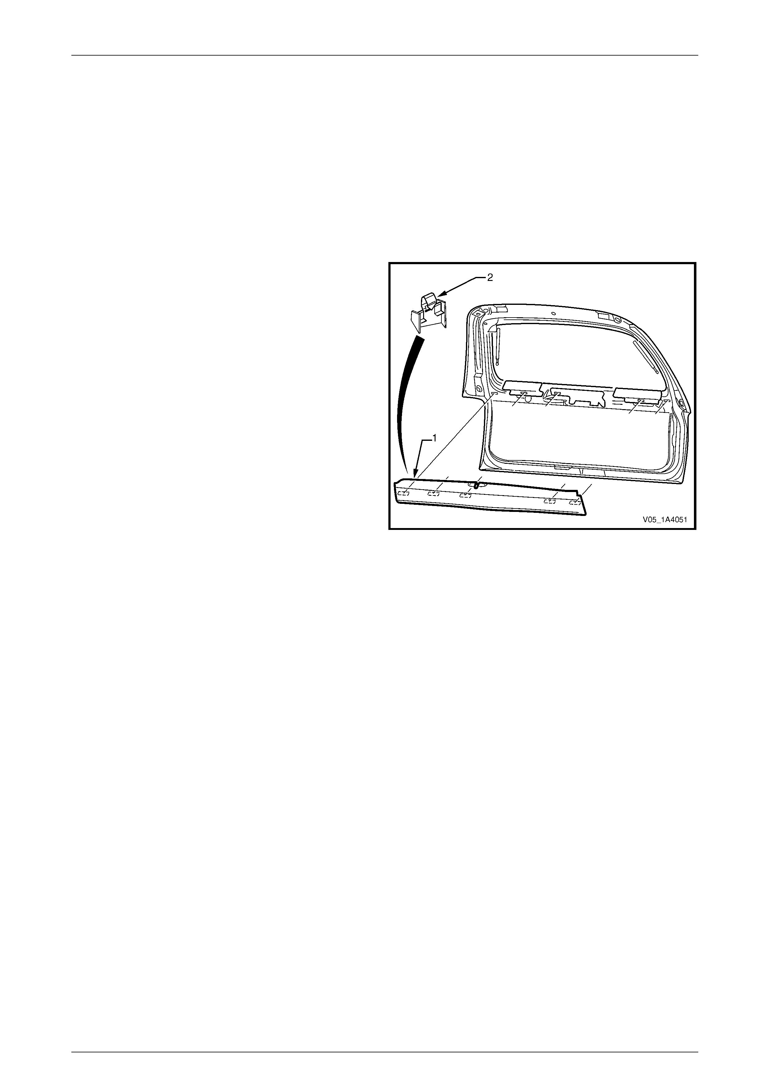
Hood, Rear Compartment Lid, Liftgate and Endgate Page 1A4–71
Page 1A4–71
6 Service Operations — Liftgate,
Wagon
6.1 Liftgate Window Lower Garnish
LT Section No. — 14–500
Remove
1 Beginning at one end, insert a fine flat-bladed
screwdriver behind the liftgate window lower
garnish (1) at the retaining clip (2) and begin to prise
the lower garnish from the liftgate.
2 Continue prising the lower garnish from the liftgate at
the remaining retaining clip locations.
3 If required, prise the retaining clips from the li ftgate
window lower garnish with a flat-bladed scre wdriver.
Figure 1A4 – 78
Reinstall
Reinstallation of the liftgate window lower garnish is the reverse of the removal procedure, noting the following:
1 Refit the retaining clips, ensuring they are c orrectly oriented.
2 Align the retaining clips with their corresponding holes in the liftgate assemb ly, then clip the lower garnish onto the
liftgate assembly.
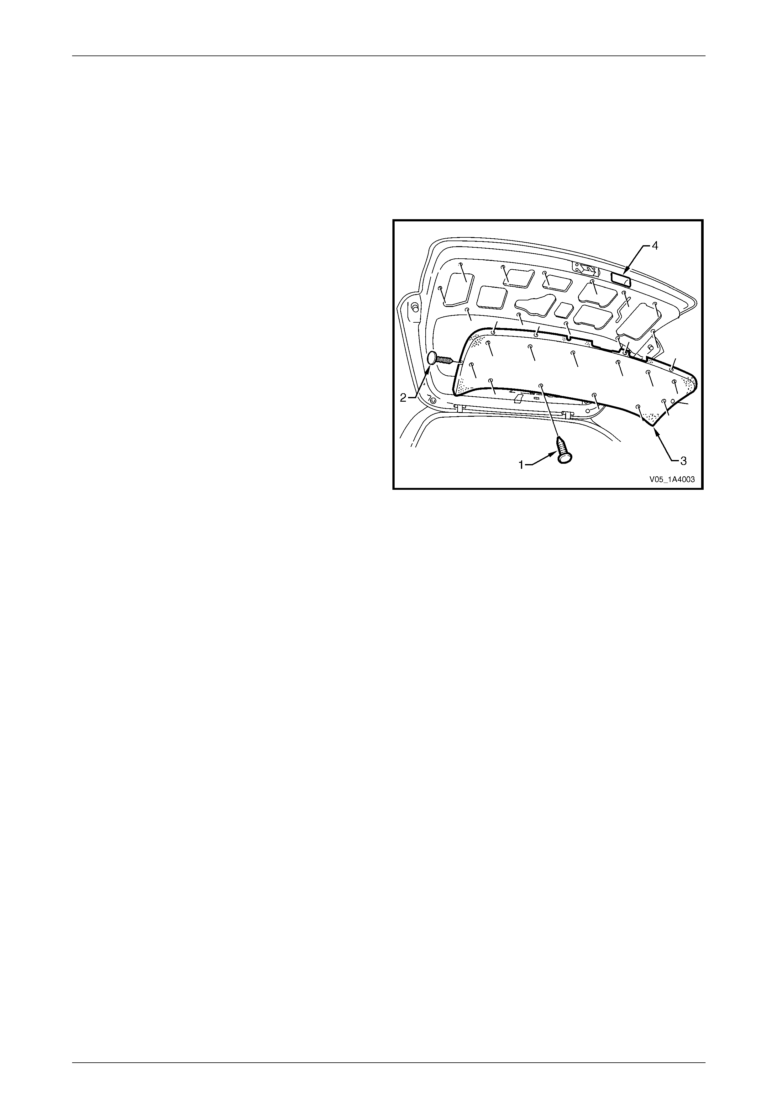
Hood, Rear Compartment Lid, Liftgate and Endgate Page 1A4–72
Page 1A4–72
6.2 Liftgate Lower Trim Panel
LT Section No. — 14–500
Remove
1 If required, remove the liftgate window lower garnish, refer to 6.1 Liftgate Window Lower Garnish.
2 Using a suitable trim clip removal too l, carefully prise
the retainer (1), 12 places, and retain er (2), six places,
attaching the liftgate lower trim panel (3) to the liftgate
assembly.
3 Remove the lower trim panel from the liftgate
assembly by sliding it from under the liftgate insid e
handle (4).
Figure 1A4 – 79
Reinstall
Reinstallation of the liftgate lower trim pan el is the reverse of the removal procedure, notin g the following:
1 Install the lower trim panel, sliding it under the liftgate inside handle.
2 Fit the retainers, 18 places, pushing them in firmly.
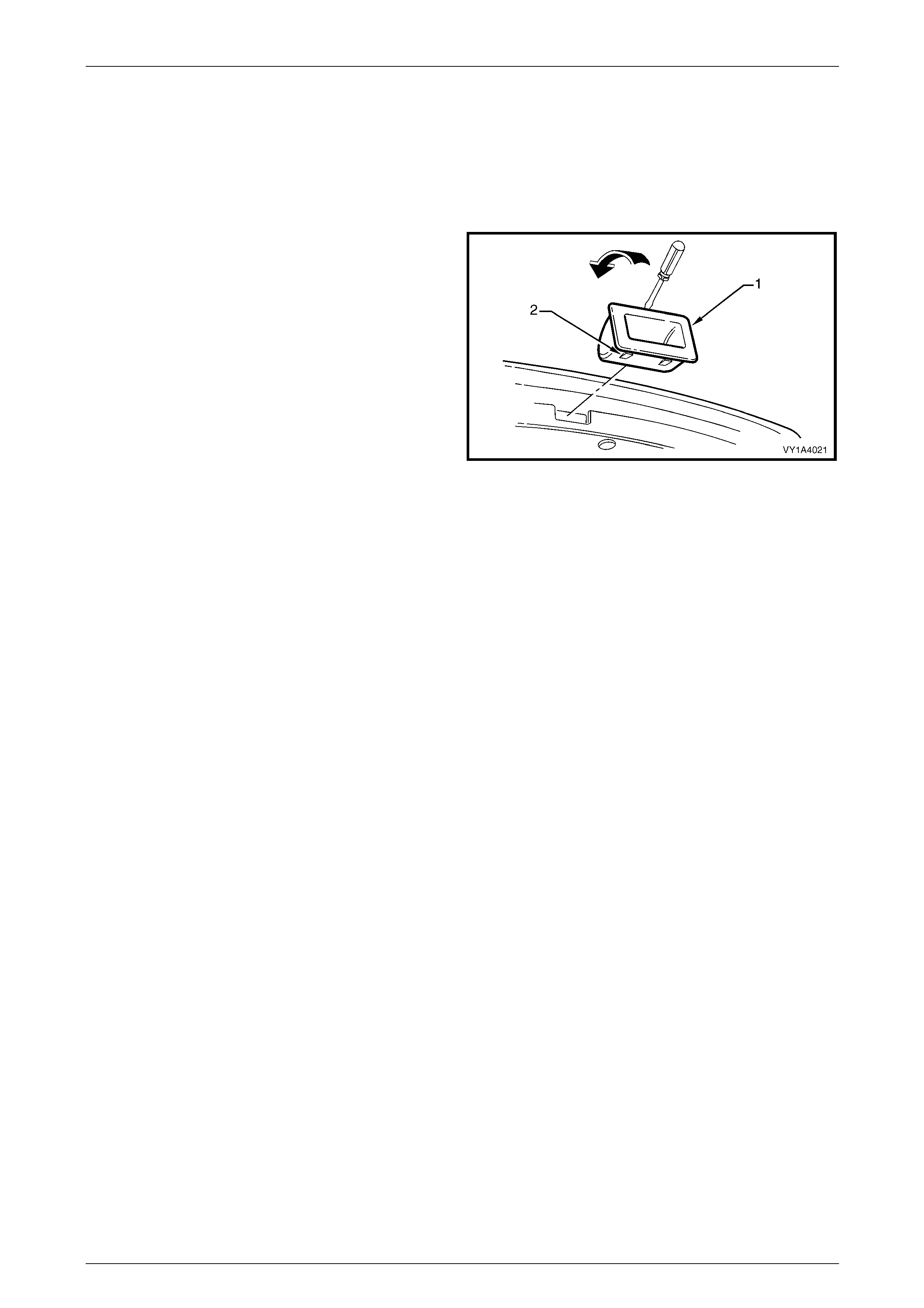
Hood, Rear Compartment Lid, Liftgate and Endgate Page 1A4–73
Page 1A4–73
6.3 Liftgate Inside Handle
LT Section No. — XX–XXX
Remove
1 Insert a flat-bladed screwdriver between the liftgate
assembly and the rear edge of the liftgate inside
handle (1).
NOTE
Place a rag bet ween th e screwdriver and liftgate
lower trim panel to protect the paintwork.
2 Carefully lever the screwdriver in the direction shown
to release the retaining tabs (2) from the liftgate
assembly.
3 Remove the inside handle.
Figure 1A4 – 80
Reinstall
Reinstallation of the liftgate inside handle is the reverse of the remov al procedure, ensuring the retaini ng tabs are
correctly seated.
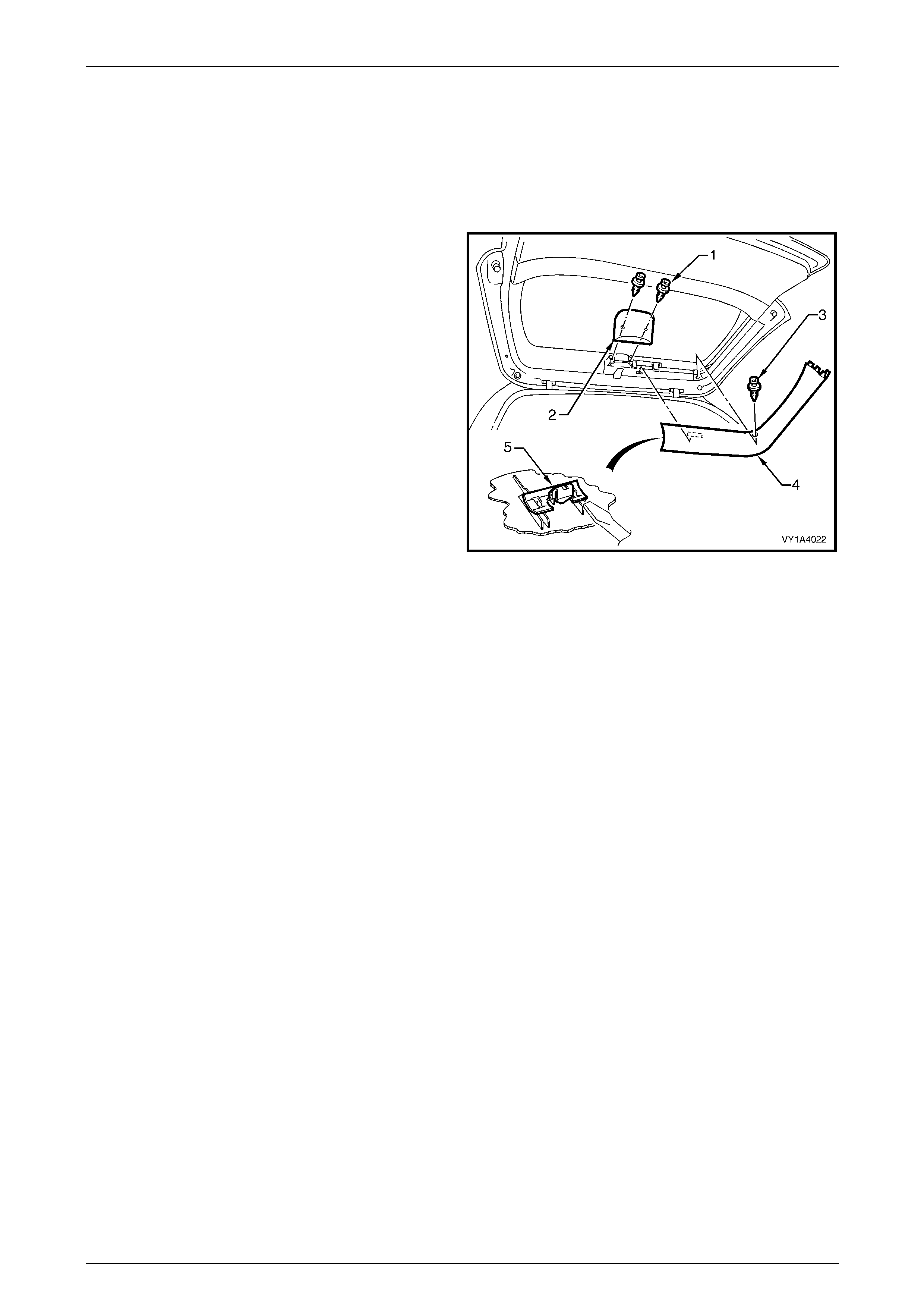
Hood, Rear Compartment Lid, Liftgate and Endgate Page 1A4–74
Page 1A4–74
6.4 Liftgate Window Upper Garnish
LT Section No. — 14–500
Remove
1 Remove the two retainers (1) and remove the hig h-
mount stop lamp cover (2).
2 Remove the retainer (3) from either the left-hand or
right-hand liftgate window upper gar nish (4).
3 Insert a flat-bladed screwdriver behind the upper
garnish at the retaining clip (5) . Push on the clip tab
and carefully p r ise the upper garnish from the liftgate
assembly.
4 Remove the upper garnish from the liftgate. Detach it
from the liftgate window lower garnish, if not previously
removed.
5 If required, prise the retaining clip from the lift gate
window upper garnish.
Figure 1A4 – 81
Reinstall
Reinstallation of the liftgate window upper garnish is the reverse of the removal procedure. If refitting the retaining clips,
ensure the correct orientation.
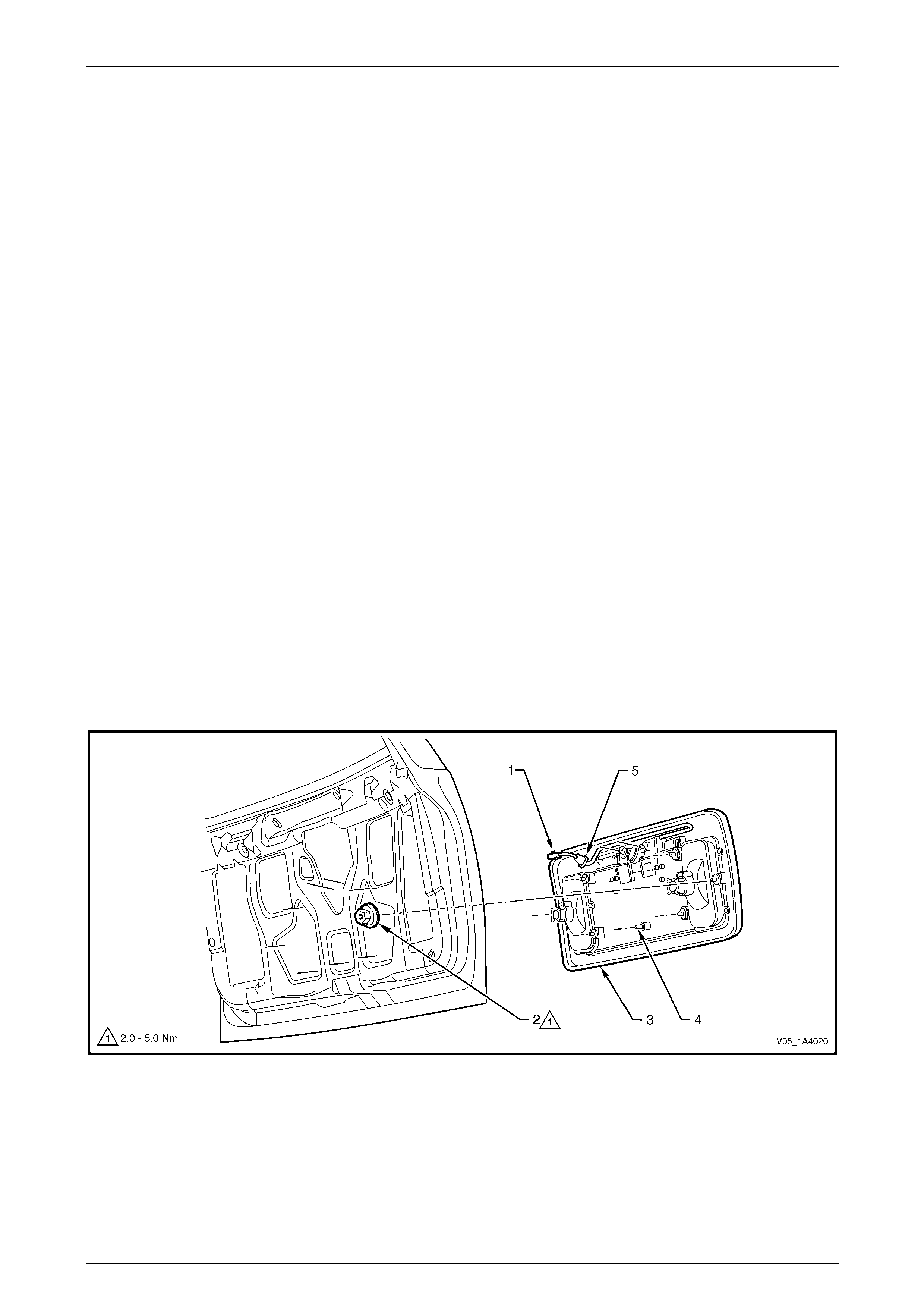
Hood, Rear Compartment Lid, Liftgate and Endgate Page 1A4–75
Page 1A4–75
6.5 Liftgate Appliqué Assembly
LT Section No. — 02–385
Remove
1 If required, remove the following components:
a Licence plate.
b Liftgate window lower garnish, refer to 6.1 Liftgate Window Lower Garnish.
c Liftgate lower trim panel, refer to 6.2 Liftgate Lower Trim Panel.
2 Remove fusible link F102 from the engine compartment fuse and relay panel assembly,
refer to Section 12O Fuses, Relays and Wiring Harnesses.
3 Remove the rear wiper control module, refer to Section 12N W ipers, Washers and Horn.
4 Remove both backup lamp bulbs from their socket assemblies.
5 Disconnect the licence plat e lamp wiring connector (1) from within the liftgate assembly cavity, refer to
Figure 1A4 – 82.
6 From within the liftgate assembly cavity, remove the nut (2), eight places, attaching the liftgate appliqué
assembly (3) to the liftgate assembly.
NOTE
The two upper top inner nuts also attach the
liftgate appliqué push-button assembly.
7 Prise the pin (4) from the retainer at the bottom of the appliqué assembly.
8 Partially remove the appliqué assembly, remove the licence plate lamp wiring harness grommet (5) and withdr aw
the licence plate lamp wiring harness.
9 Remove the appliqué assemb ly.
Figure 1A4 – 82
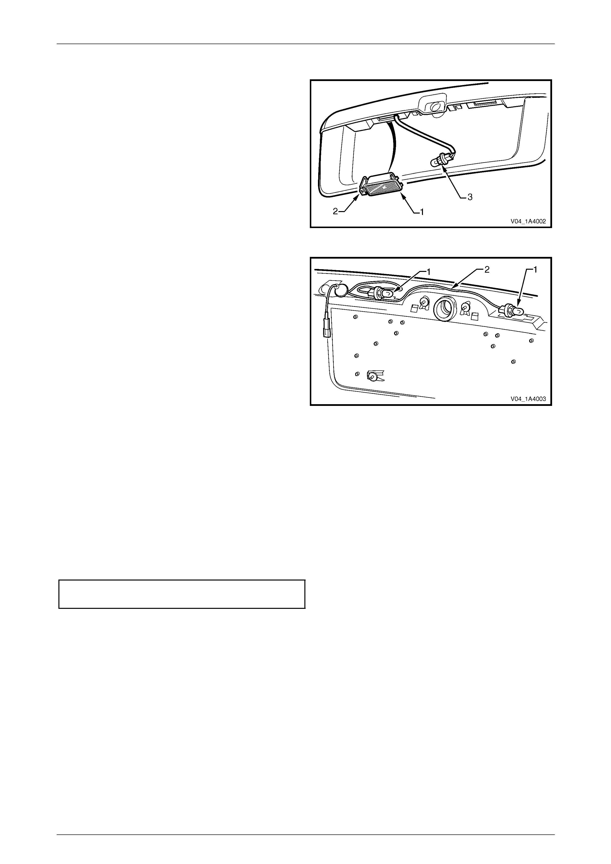
Hood, Rear Compartment Lid, Liftgate and Endgate Page 1A4–76
Page 1A4–76
Disassemble
1 Press the tab (1) and remove the rear licence lamp
housing (2) from the appliqué assembly.
2 Rotate the bulb socket (3) and remove it from the rear
licence lamp housi ng.
3 Repeat for the remaining lamp housing.
Figure 1A4 – 83
4 If required, pass both bulb sockets (1) through the
aperture in the liftgate appliqu é assemb ly, then
remove the licence plate lamp wiring harness (2).
Figure 1A4 – 84
Reassembly
Reassembly of the liftgate appliqué assembly is the reverse of the disassembl y proc edure, ensuring the licence plate
lamp wiring harness is routed correctly.
Reinstall
Reinstallation of the liftgate appliqué assembly is the reverse of the removal procedure, noting the following:
1 Ensure the rear compartment lid appl iqué assembly does not pinch the licence plate l amp wiring harness.
2 Tighten the nuts to the correct torque specification.
Liftgate appliqué assembly
attaching nut torque specification................2.0 – 5.0 Nm
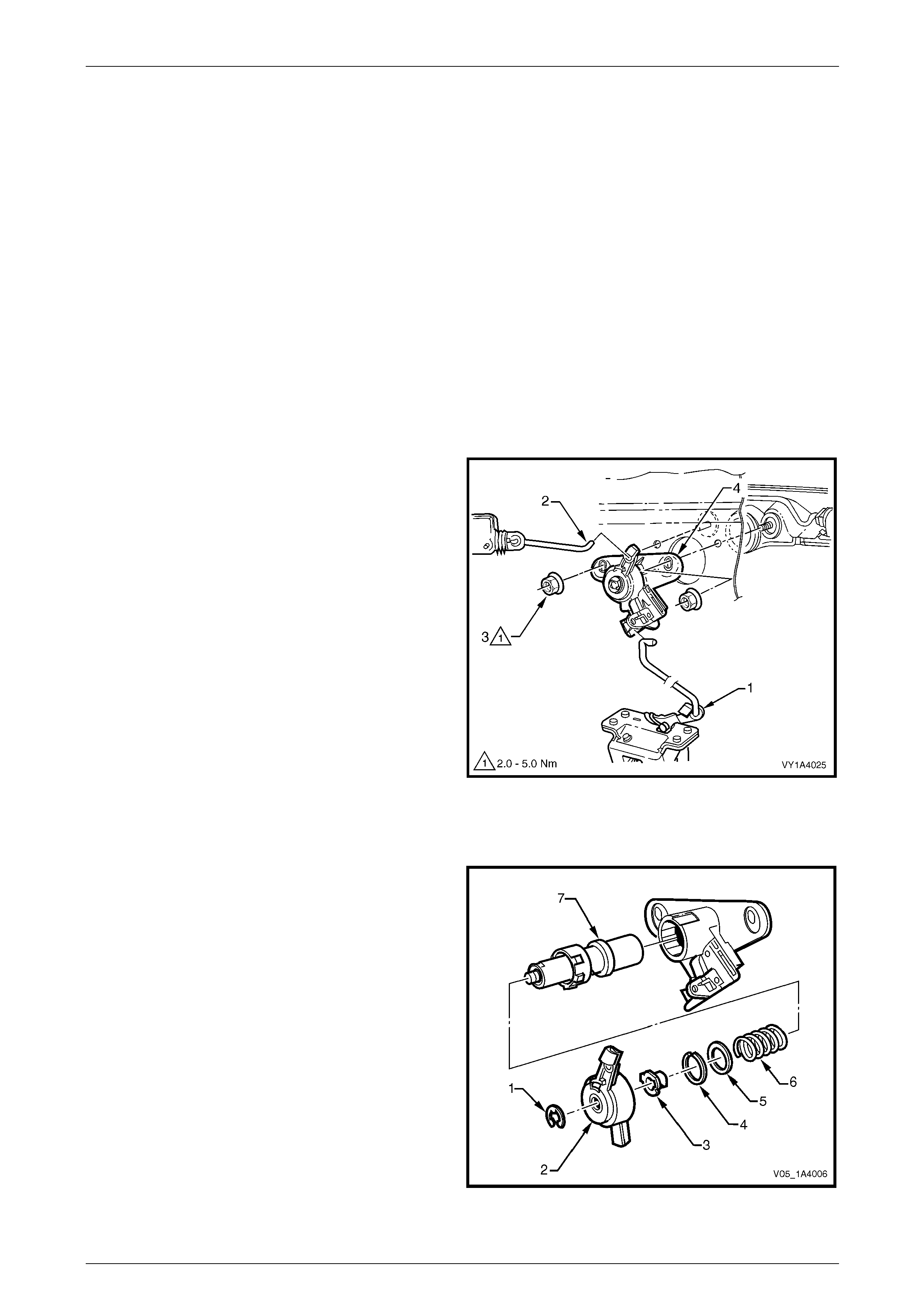
Hood, Rear Compartment Lid, Liftgate and Endgate Page 1A4–77
Page 1A4–77
6.6 Liftgate Handle Push-button Assembly
LT Section No. — 12–680
Remove
NOTE
Replacement liftgate handle push-button
assemblies are supplied un-coded and will
required to be disassembled and sent to an
authorised locksmith for coding to the vehicle's
keys.
1 If required, remove the following components:
a Liftgate window lower garnish, refer to 6.1 Liftgate Window Lower Garnish.
b Liftgate lower trim panel, refer to 6.2 Liftgate Lower Trim Panel.
2 Disconnect the liftgate lock connecting rod (1) from the
latch assembly.
3 Disconnect the actuator connecting rod (2) from the
liftgate handle push-button assembly (4).
4 From within the liftgate cavity, remove the two nuts (3)
attaching the push-button assembly to the liftgate.
NOTE
The two inner nuts also attach the liftgate handle
assembly.
5 Remove the push-button assembly.
Figure 1A4 – 85
Disassemble
1 Remove the liftgate handle pus h-button assembly
components in the following order:
a E-clip (1),
b latch actuator cover (2),
c drive cam (3),
d spring clip (4),
e washer (5),
f spring (6), then
g lock cylinder assembly (7).
Figure 1A4 – 86
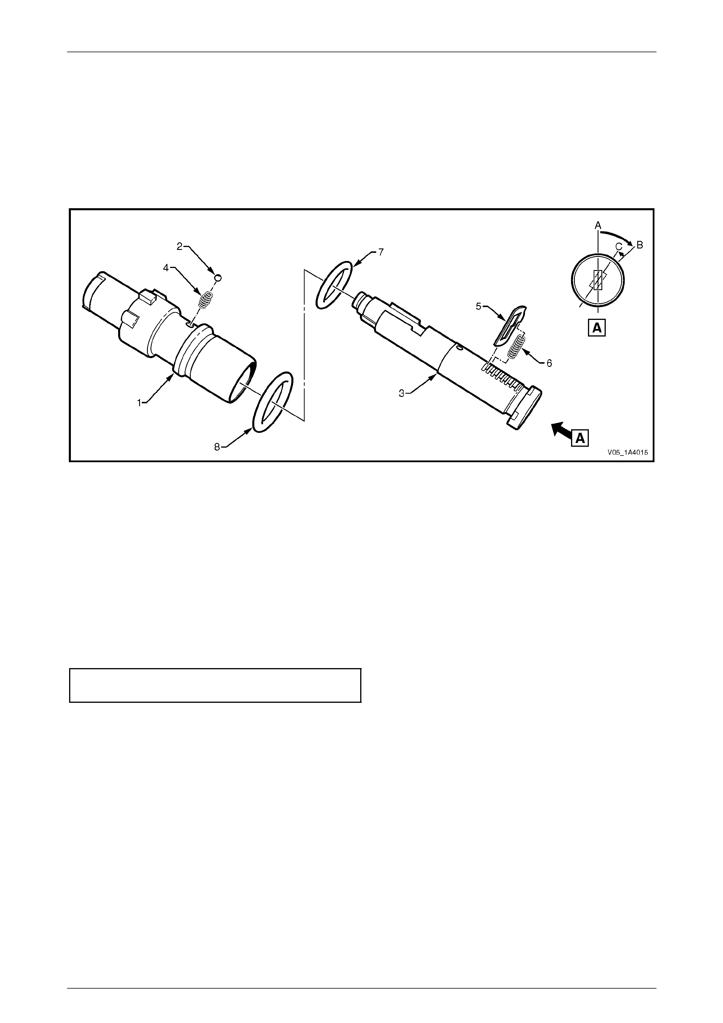
Hood, Rear Compartment Lid, Liftgate and Endgate Page 1A4–78
Page 1A4–78
2 The lock cylinder assembl y can be further disassembled to enable coding a s follows, refer to Figure 1A4 – 87:
• Insert the key, then turn it from position A to position B.
• Cover the ball hole in the housing (1) with a finger to stop the ball (2) being forced out and turn the key back
slightly to position C.
• Withdraw the lock barrel (3) from the housing until the bal l is released. Remove the ball and spring (4) and
remove the lock barrel from the housing.
• If required, remove the tumblers (5), springs (6) and O-rings (7) and (8).
Figure 1A4 – 87
Reassemble
Reassembly of the liftgate handl e push-button assembly is the reverse of the disassembly procedure. Before fitting a
new liftgate handle push-button assembly, an authorised locksmith must code it to the vehicle's keys.
Reinstall
Reinstallation of the liftgate handle push-button assembly is the reverse of the removal procedure, noting the following:
1 The slotted holes in the liftgate handle push-button assembly provide adjustment of the actuator connecting rod.
2 Tighten the nuts to the correct torque specification.
Liftgate handle push-button assembl y
attaching nut torque specification................2.0 – 5.0 Nm
3 Test for correct operation of the liftgate hand le push-button assembly before installing the trim components.
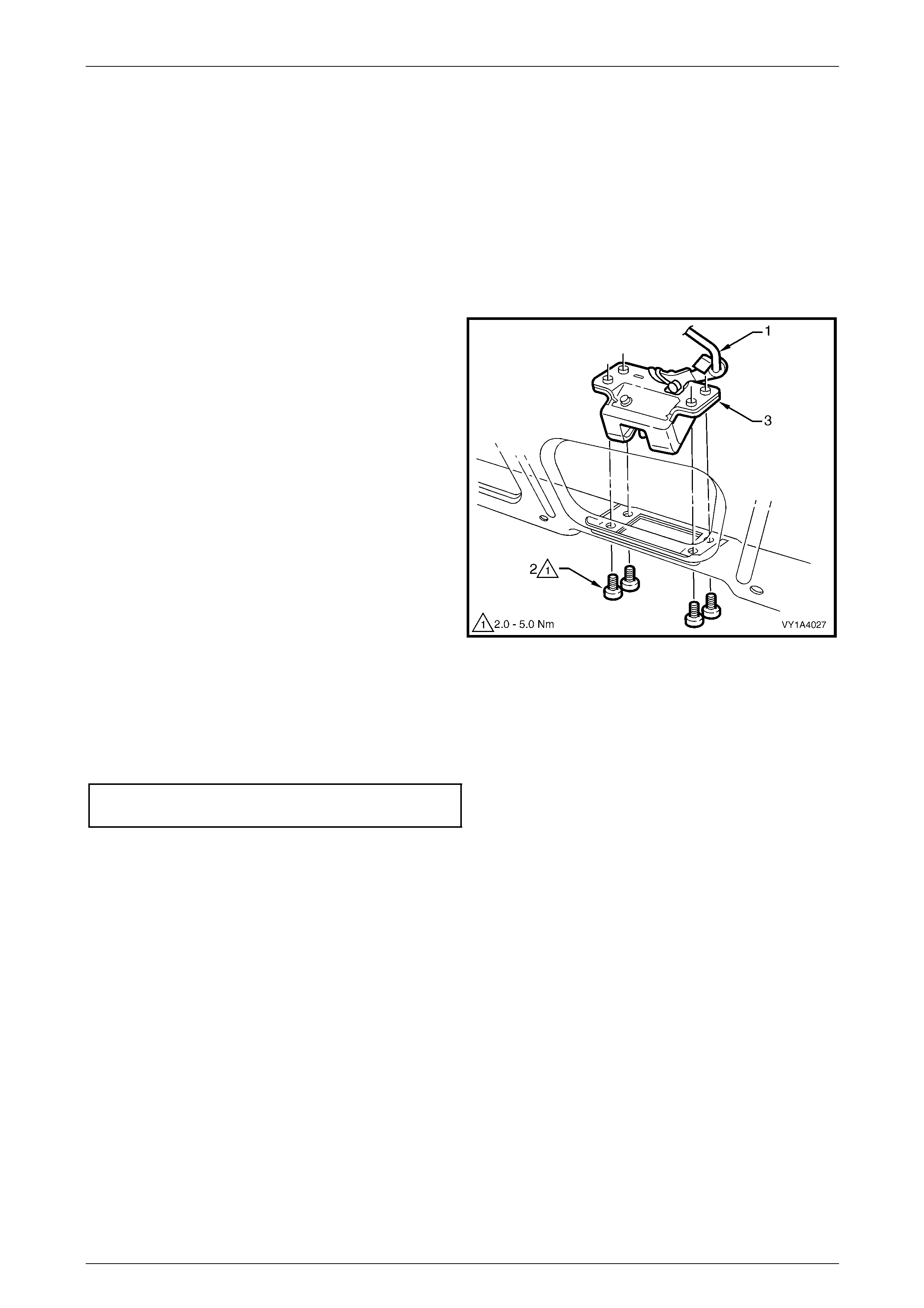
Hood, Rear Compartment Lid, Liftgate and Endgate Page 1A4–79
Page 1A4–79
6.7 Liftgate Latch Assembly
LT Section No. — 12–680
Remove
1 If required, remove the following components:
a Liftgate window lower garnish, refer to 6.1 Liftgate Window Lower Garnish.
b Liftgate lower trim panel, refer to 6.2 Liftgate Lower Trim Panel.
2 From within the liftgate cavity, disconnect the liftgate
lock connecting rod (1).
3 Remove the four screws (2) attaching the liftgate latch
assembly (3) to the liftgate.
4 Remove the latch assembly from the liftgate cavity.
Figure 1A4 – 88
Reinstall
Reinstallation of the liftgate latch assembly is the reverse of the removal procedure, notin g the following:
1 Tighten the screws to the correct torque specification.
Liftgate latch assembly attaching
screw torque specification...........................2.0 – 5.0 Nm
2 Test for correct operation of the lock assembly before installi ng the trim components.
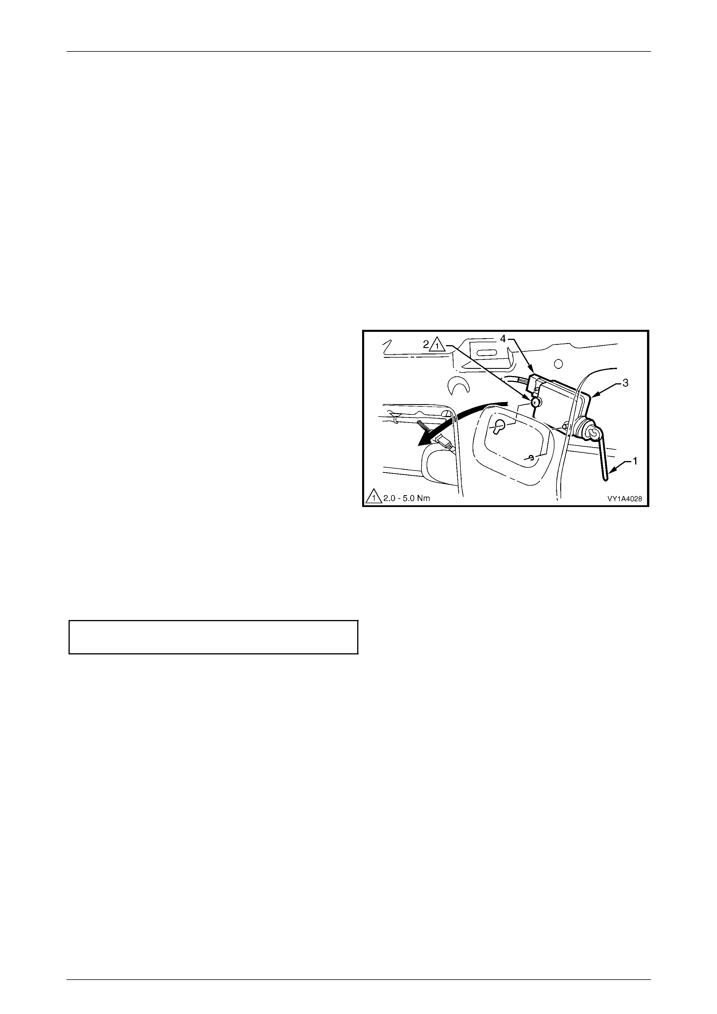
Hood, Rear Compartment Lid, Liftgate and Endgate Page 1A4–80
Page 1A4–80
6.8 Liftgate Actuator Assembly
LT Section No. — 12–680
Remove
NOTE
The liftgate actuator assembly is part of the
central locking system. For diagnosis, refer to
Section 12J Body Control Module.
1 If required, remove the following components:
a Liftgate window lower garnish, refer to 6.1 Liftgate Window Lower Garnish.
b Liftgate lower trim panel, refer to 6.2 Liftgate Lower Trim Panel.
2 Disconnect the connecting rod (1) from the push-
button assembly.
3 Loosen the scre w (2) and slide the liftgate actuator
assembly (3) from its keyhole slot.
4 Remove the actuator assembly from the liftgate cavity
as shown and disconnect the wiring con nector (4).
Figure 1A4 – 89
Reinstall
Reinstallation of the liftgate actuator assembly is the reverse of the removal procedure, noting the following:
1 Tighten the screw to the correct torque specification.
Liftgate actuator assembly attaching
screw torque specification...........................2.0 – 5.0 Nm
2 Test for correct operation of the lock assembly before installi ng the trim components.
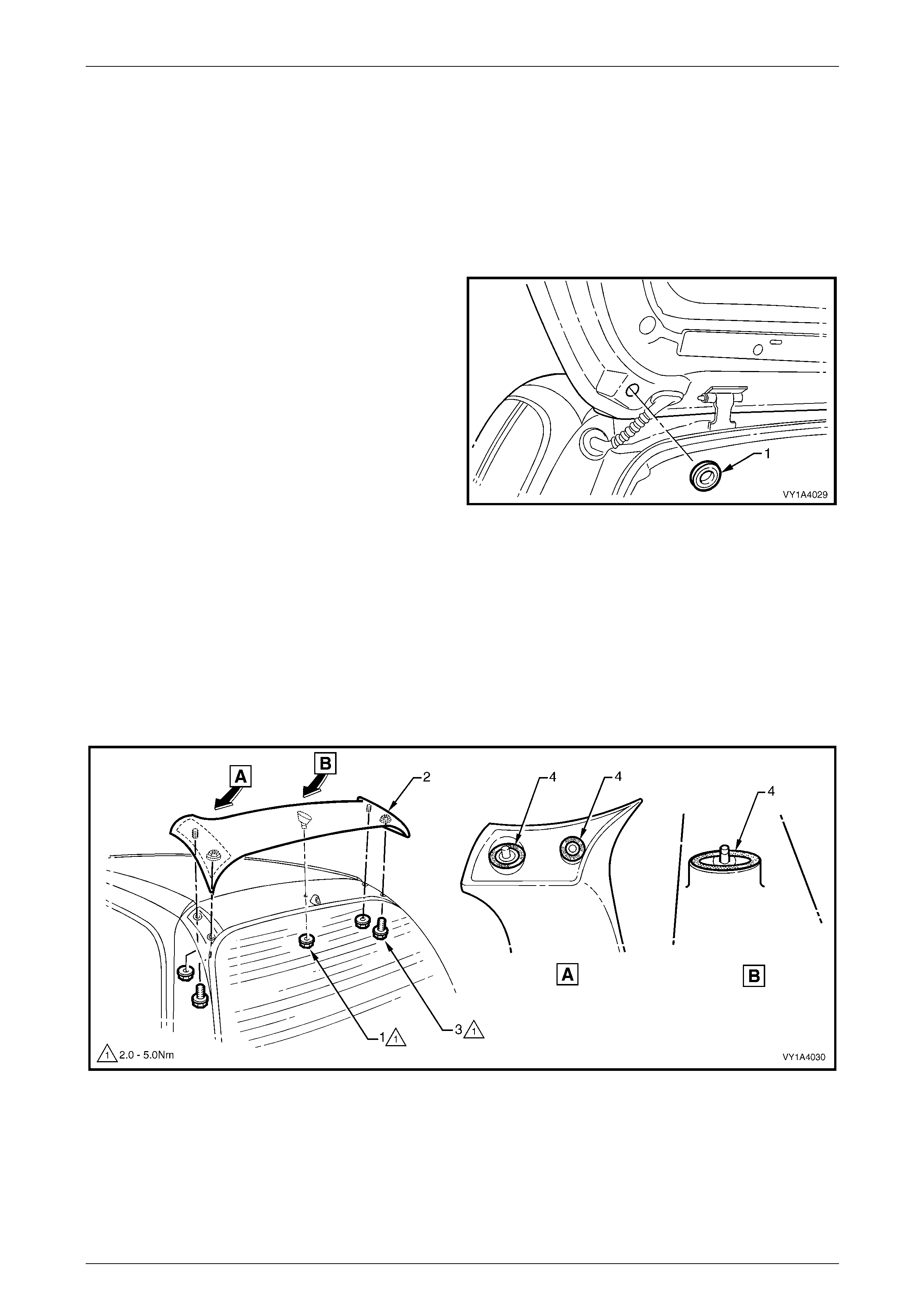
Hood, Rear Compartment Lid, Liftgate and Endgate Page 1A4–81
Page 1A4–81
6.9 Liftgate Air Deflector Assembly
LT Section No. — 10–350
Remove
1 If required, remove the high-mount stop lamp cover and l iftgate window upper garnish,
refer to 6.4 Liftgate Window Upper Garnish.
2 Remove the plug (1) from each side of the l iftgate
assembly.
Figure 1A4 – 90
3 Remove the three nuts (1) attaching the liftgate air deflector assembly (2) to the liftgate assembly, refer to
Figure 1A4 – 91.
4 Remove the two screws (3) attaching the deflector assemb ly to the liftgate assembly and remove the deflector
assembly.
NOTE
Take care when removing the deflector asse mbly
not to damage the seals (4) as they are not
serviceable.
Figure 1A4 – 91

Hood, Rear Compartment Lid, Liftgate and Endgate Page 1A4–82
Page 1A4–82
Reinstall
Reinstallation of the liftgate air deflector assembly is the reverse of the removal procedur e, noting the following:
1 Before installation, ensure the seals are not damaged. If in doubt, apply a small amount of non-hardening sealer.
2 Tighten the screws and nuts to the correct torque specification.
Liftgate air deflector assembly attaching
nut torque specification...............................2.0 – 5.0 Nm
Liftgate air deflector assembly attaching
screw torque specification...........................2.0 – 5.0 Nm


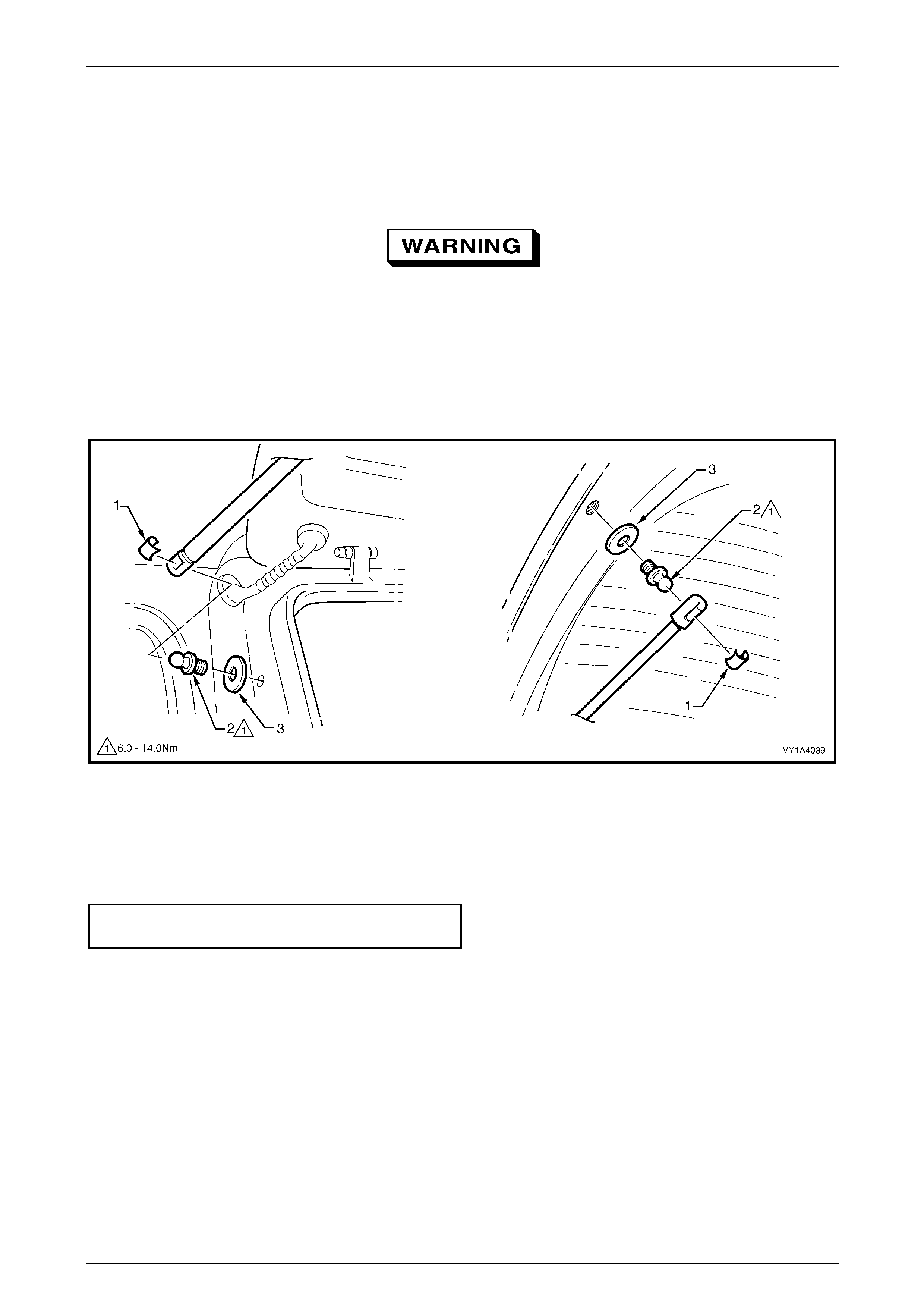
Hood, Rear Compartment Lid, Liftgate and Endgate Page 1A4–86
Page 1A4–86
6.13 Liftgate Strut Assembly
LT Section No. — 12–500
Remove
The liftgate struts contain pressurised gas.
Do not subject them to extreme heat,
pressure or physical damage.
1 Support the liftgate assembly securely.
2 Using a fine flat-bladed screwdriver, prise the retainer (1) from the strut end.
3 Pull the liftgate strut assembly from the liftgate ball stud (2).
4 Repeat for the opposite end as requir ed.
5 If required, remove the liftgate ball stud and washer (3) from the liftgate assembly or vehicle.
Figure 1A4 – 92
Reinstall
Reinstallation of the liftgate strut assembly is the reverse of the removal procedure, noting the following:
1 If removed, install the liftgate ball stud an d washer.
2 Tighten the liftgate ball stud to the correct torque sp ecification.
Liftgate ball stud
torque specification...................................6.0 – 14.0 Nm
3 Apply a small amount of NLGI No. 1 lithium grease or equivalent to the inside of the liftgate strut ball cup.
4 Install the retainer onto the liftgate strut end.
5 Align the strut with the liftgate ball stud and push into place.
NOTE
The liftgate strut assembly must be installed with
the cylinder end attached to the vehicle.
6 Repeat for the opposite end, if required.
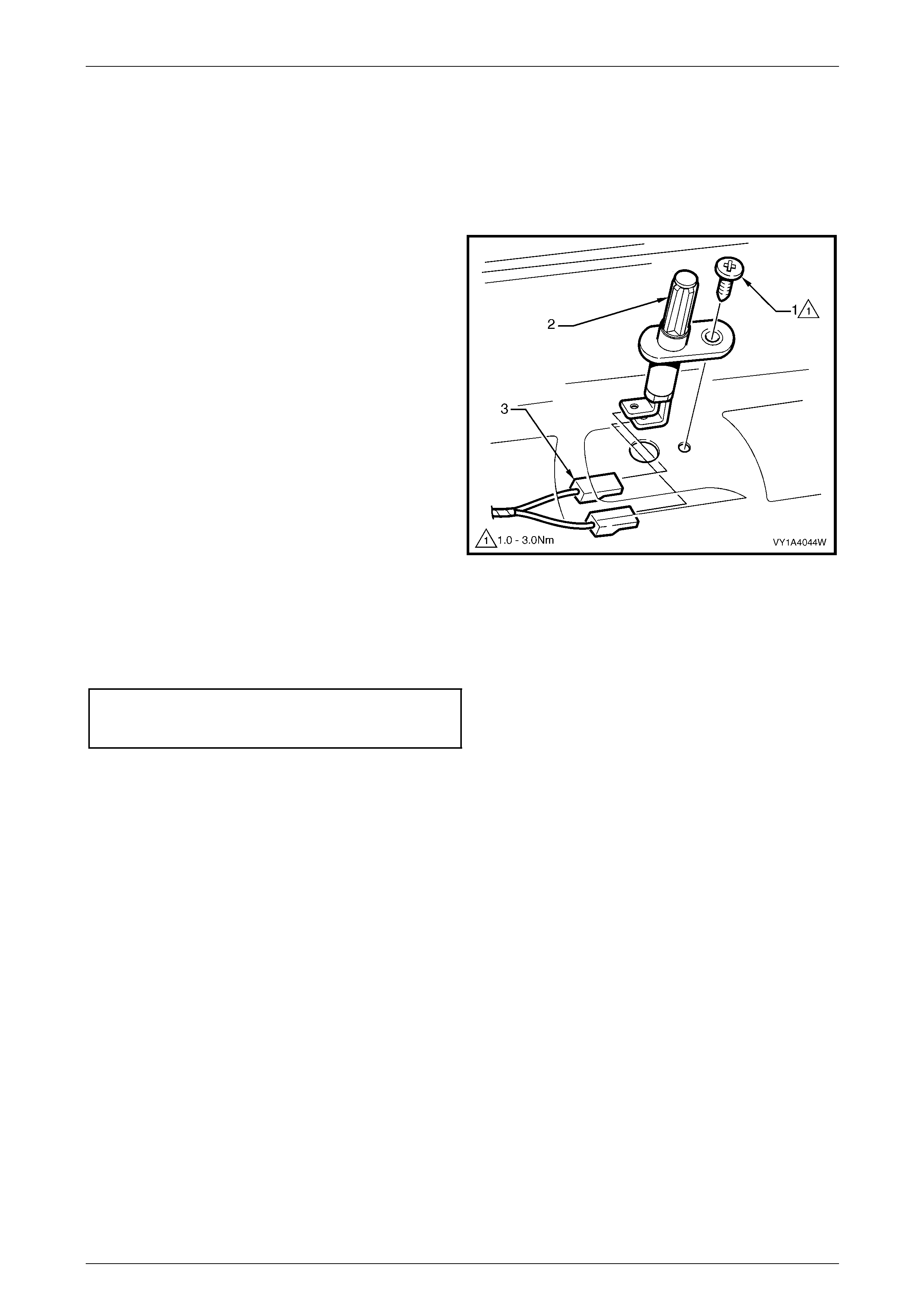
Hood, Rear Compartment Lid, Liftgate and Endgate Page 1A4–87
Page 1A4–87
6.14 Rear Compartment Courtesy Lamp
Switch Assembly
LT Section No. — XX–XXX
Remove
1 Remove the screw (1) attaching the rear compartment
courtesy lamp switch assembly (2) to the liftgate
assembly.
2 Withdraw the rear compartment courtesy lamp switch
assembly and disconnect the liftgate assembly wiring
harness connectors (3).
Figure 1A4 – 93
Reinstall
Reinstallation of the rear com partment courtesy lamp switch assembly is the reverse of the removal procedure. Tighten
the screw to the correct torque specification.
Rear compartment courtesy
lamp switch assembly attaching
screw torque specification...........................1.0 – 3.0 Nm
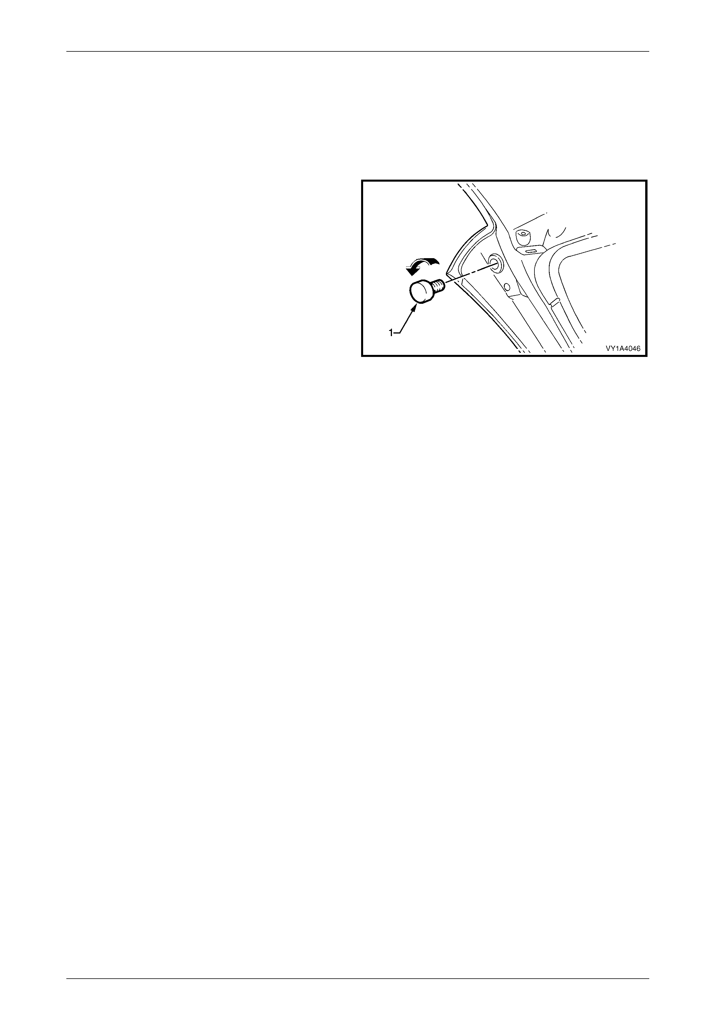
Hood, Rear Compartment Lid, Liftgate and Endgate Page 1A4–88
Page 1A4–88
6.15 Liftgate Bumper
LT Section No. — XX–XXX
Remove
Remove the liftgate bumper (1) from each side of the liftgate
by unscrewing in the direction shown.
Figure 1A4 – 94
Reinstall
Reinstallation of the liftgate bumper is the reverse of the removal procedure, ensuring the liftgate bumper is screwed all
the way in. To set the liftgate bumper to its correct position, refer to 6.16 Liftgate Assembly.
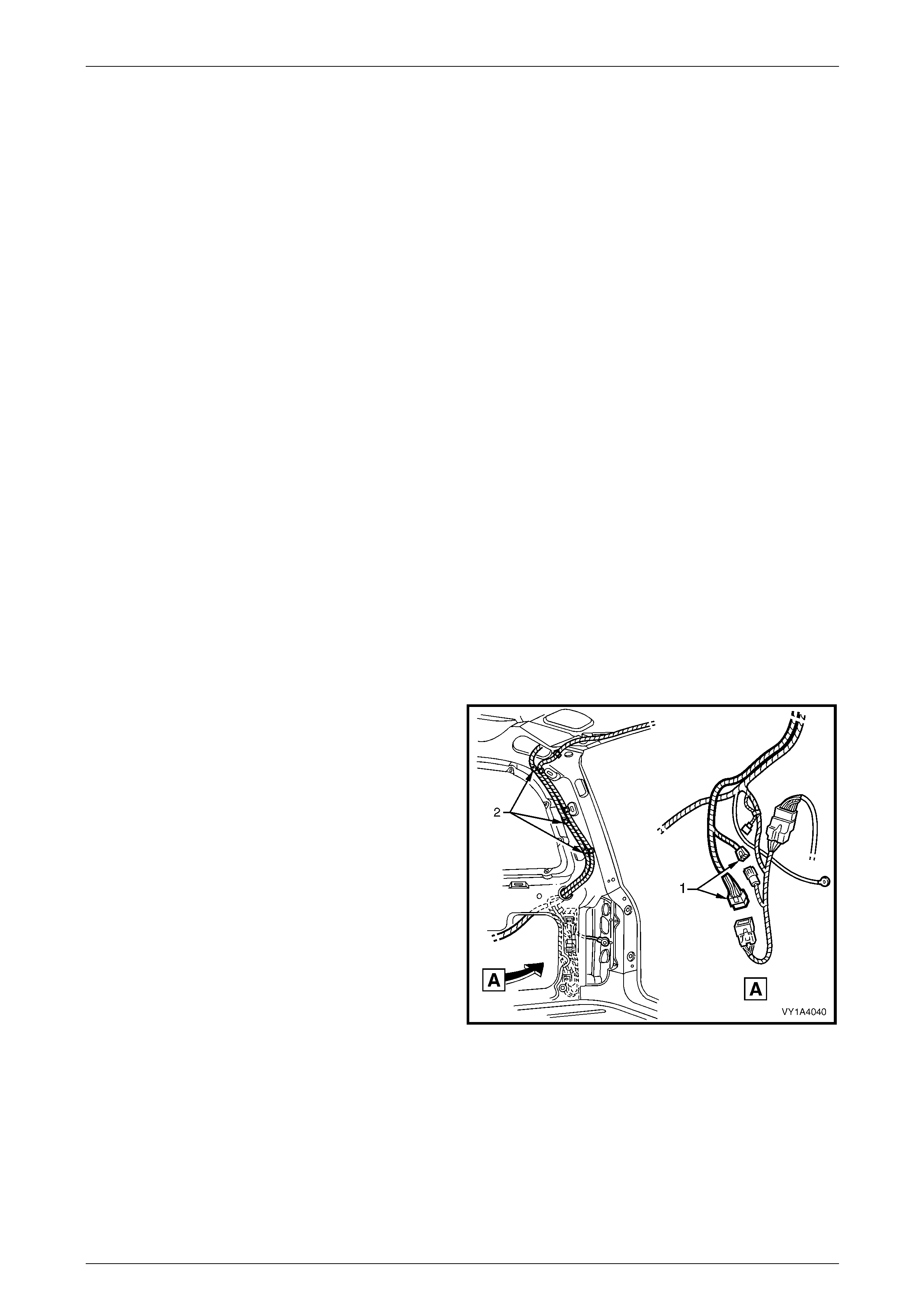
Hood, Rear Compartment Lid, Liftgate and Endgate Page 1A4–89
Page 1A4–89
6.16 Liftgate Assembly
LT Section No. — 12–500
Remove
1 If required, remove the following components:
a Liftgate window lower garnish. refer to 6.1 Liftgate Window Lower Garnish.
b Liftgate lower trim panel. refer to 6.2 Liftgate Lower Trim Panel.
c Liftgate inside handle. refer to 6.3 Liftgate Inside Handle.
d Liftgate window upper garnish, refer to 6.4 Liftgate Window Upper Garnish.
e Liftgate handle push-button assembl y, refer to 6.6 Liftgate Handle Push-button Assembly.
f Liftgate latch assembly, refer to 6.7 Liftgate Latch Assembly.
g Liftgate actuator assembly, refer to 6.8 Liftgate Actuator Assembly.
h Liftgate air deflector assembly, refer to 6.9 Liftgate Air Deflector Assembly.
i Rear window wiper assembly, refer to Section 12N Wipers, Washers and Horn.
j Rear window washer nozzle and hose assem blies, refer to Section 12N Wipers, Washers and Horn.
k High-mount stop lamp assembly, refer to Section 12B Lighting System.
l Liftgate strut assembly from the liftgate, refer to 6.13 Liftgate Strut Assembly.
m Liftgate window assembly, refer to Section 1A6 Stationary Windows.
n Badges and emblems, refer to Section 1A9 Exterior Ornamentation.
2 Partially remove the right-hand quarter inner trim upper and right-h and body rear corner garnis h, refer to
Section 1A8 Headlining and Interior Trim.
3 Disconnect the two liftgate assembly wiring harness
connectors (1).
4 Unclip the three liftgate assembl y wiring h arness
clips (2).
Figure 1A4 – 95
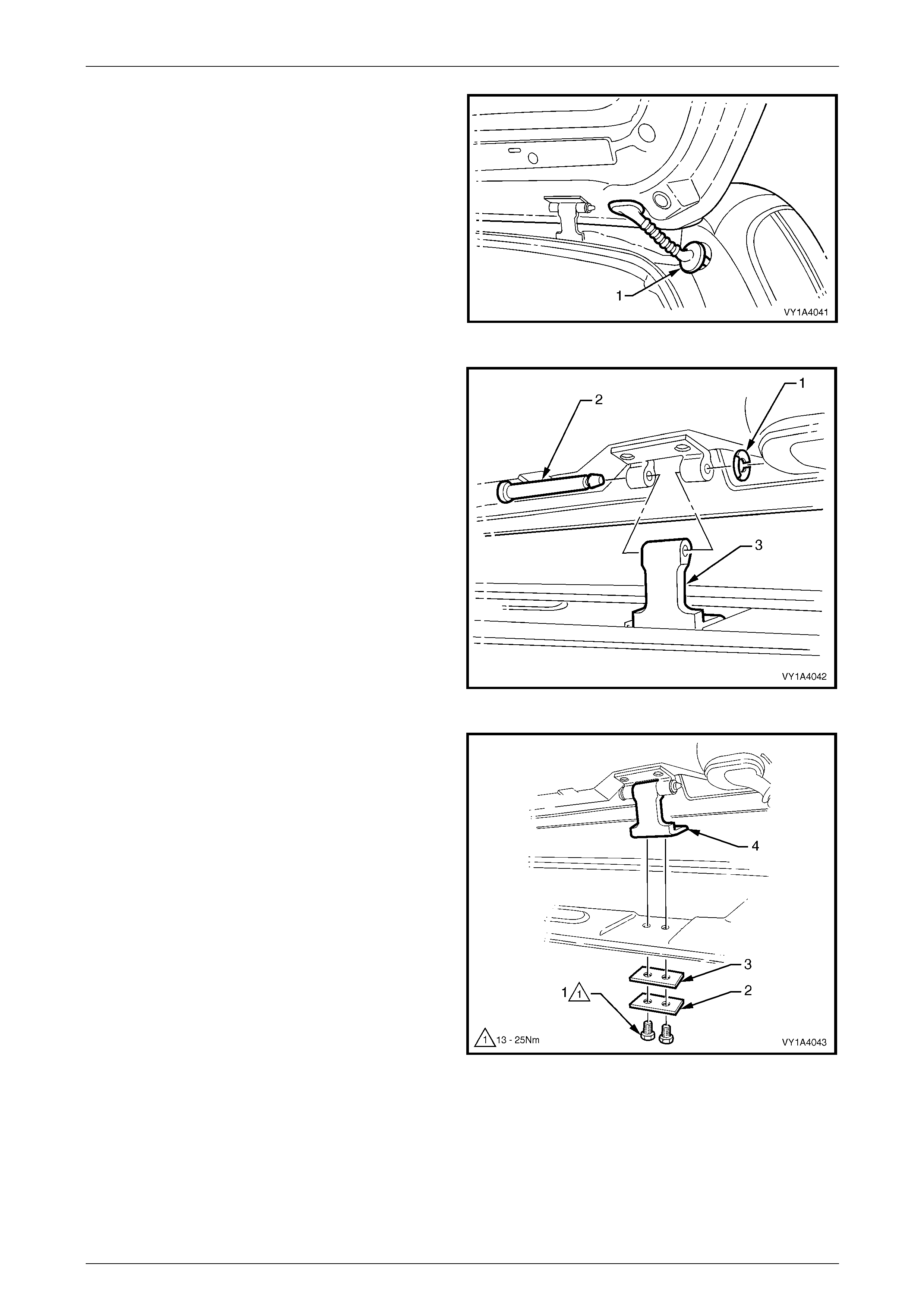
Hood, Rear Compartment Lid, Liftgate and Endgate Page 1A4–90
Page 1A4–90
5 Remove the right-hand grommet (1) from the vehicle
and withdraw the liftgate asse mbly wiring harness
from the pillar cavity.
Figure 1A4 – 96
6 Either:
• To remove the liftgate assembly only:
(1) Remove the liftgate hinge pin retain er (1)
from each side of the vehicle.
(2) With the aid of an assistant to support the
liftgate, withdraw each liftgate hinge
pin (2).
(3) Remove the liftgate assembly, leaving the
body side of the liftgate hinge (3) in
position.
Figure 1A4 – 97
or:
• To remove the liftgate assembly and the
complete liftgate hinge:
(1) Remove the liftgate windo w upper garnis h,
refer to Section 1A8 Headlining and Interior
Trim.
(2) Remove the two screws (1), plate (2) and
seal (3).
(3) Remove the liftgate assembly, with the
complete liftgate hinge (4) attached.
Figure 1A4 – 98
Disassemble
1 Remove the rear compartment courtesy lamp s witch assembly,
refer to 6.14 Rear Compartment Courtesy Lamp Switch Assembly.
2 Remove the liftgate wiring harness assembly, refer to Section 12O Fuses, Relays and Wiring Harnesses.
3 Remove the liftgate bumpers, refer to 6.15 Liftgate Bumper.
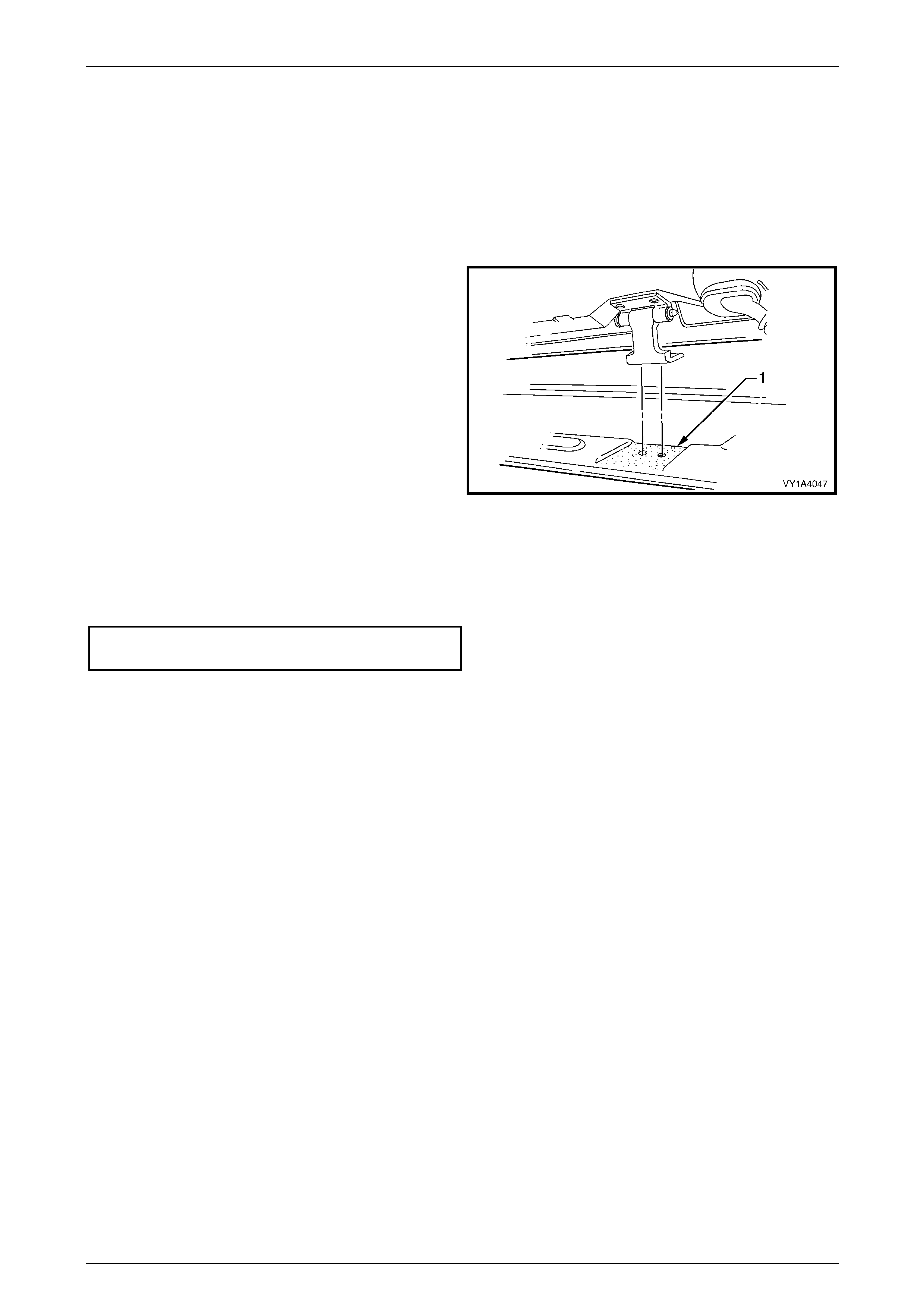
Hood, Rear Compartment Lid, Liftgate and Endgate Page 1A4–91
Page 1A4–91
Reassemble
Reassembly of the liftgate assembly is the reverse of the dis assembly procedure.
Reinstall
Reinstallation of the liftgate assembly is the reverse of the removal procedure, noting the following:
1 If the liftgate assembly was removed from the liftgate hinge pin, lubricate the pin with NLGI No. 1 lithium grease or
equivalent before installatio n.
2 If the liftgate assembly was removed with the body
side of the liftgate hinge attached, appl y sealer (Lord
Fusor #800 or #801 or equivalent) to the sha ded
area (1).
3 Set both bumpers to the fully set-in position, then
adjust to achieve the required alignment of the liftgate,
refer to Adjust in this Section.
4 Before installing the trim panels, test the operation of
the following items:
• rear wiper,
• rear window washer,
• high-mount stop lamp, Figure 1A4 – 99
• rear compartment courtesy lamp switch, and
• liftgate handle push-button assembly.
5 Tighten all screws to the correct torque specification.
Liftgate hinge (body side) attaching
screw torque specification.......................13.0 – 25.0 Nm
Adjust
Correct alignment of the liftgate assembly is critical to its operation and to the aesthetics of the vehicle. The following
components allow adjustment of the liftgate assembly:
• the liftgate bumper provides adjustment at the outer area of the liftgate assembl y,
• the liftgate hinge screws provide forward, rearward and skew adjustment of the liftgate assembly, and
• the liftgate striker assembly provides vertical and sideways adjustment of the liftgate assembly.
If alignment is required, adjust the liftgate assembly in the following order.
1 If fitted, remove the liftgate striker assembly, refer to 6.17 Liftgate Striker Assembly.
2 Ensure the liftgate weatherstrip assembly, refer to 6.18 Liftgate Weatherstrip is installed and the liftgate bumpers
are fitted and set fully in.
3 Carefully close the liftgate, en suring the top and each side does not contact the vehicle.
4 Check the alignment of the liftgate for width and co nsistency of gap to the roof panel, the quarter pan el on each
side, tail lamps and rear bumper fascia, refer to Figure 1A4 – 100.
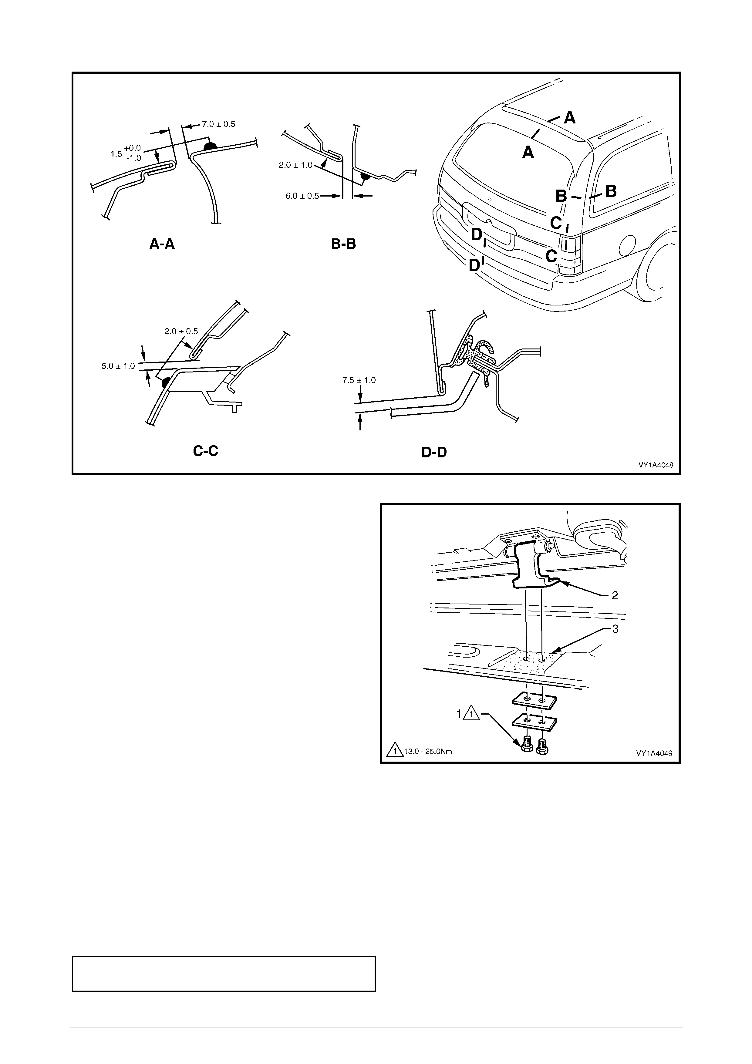
Hood, Rear Compartment Lid, Liftgate and Endgate Page 1A4–92
Page 1A4–92
Figure 1A4 – 100
5 If the gap between the liftgate assembly and roof
panel is not within specification and/or is not parallel to
the quarter panel on each side, open the liftgate
assembly and adjust the posit ion of the liftgate hinges.
a Remove the liftgate windo w upper garnis h, refer
to Section 1A8 Headlining an d Interior Trim.
b Loosen the two screws (1), attaching the liftgate
hinge (2).
c Lift the hinge away from the body and apply
sealer (Lord Fusor #800 or #801 or equivalent)
to the shaded area sho wn (3).
d Adjust the position of the liftgate hinge, tighten
the screws and recheck the liftgate assembly
alignment.
NOTE
Do not make all adjustments at once. Perform
one adjustment, then carefully close the liftgate
assembly; check its position and make further
adjustments until the correct alignment is
achieved.
Figure 1A4 – 101
6 If the gap between the liftgate assembly and roof panel is within specification and the liftg ate assembly is parallel to
the quarter panel on each side, open the liftgate assembly and adjust the liftgate bumpers to provide a slightly
greater gap at the lower edge of the liftgate assembly above each tail lamp. This allows the liftgate striker assembly
to pull the liftgate assembly in slightly when closed.
7 Install the liftgate striker assembly, refer to 6.17 Liftgate Striker Assembly.
8 Close the liftgate assembly. Ensure the liftgate striker assembly does not pull the liftgate assembly to one side,
changing the panel gaps. If the gap changes, move the liftgate striker assembly as required.
9 Tighten the screws to the correct torque specification.
Liftgate hinge (body side) attaching
screw torque specification.......................13.0 – 25.0 Nm
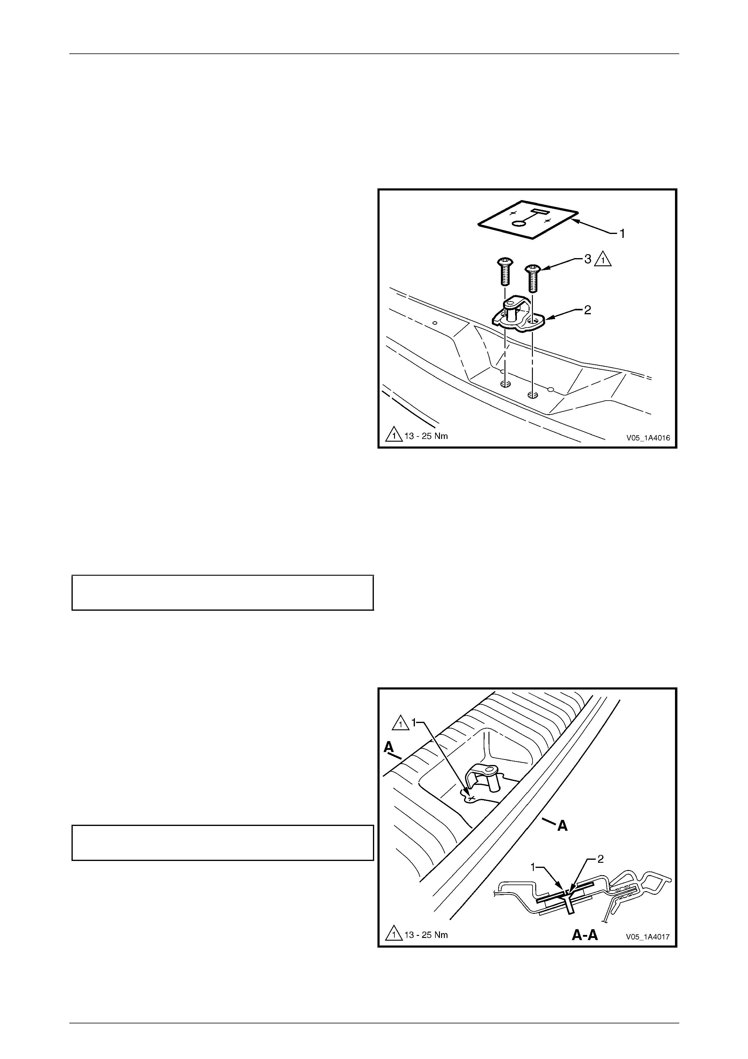
Hood, Rear Compartment Lid, Liftgate and Endgate Page 1A4–93
Page 1A4–93
6.17 Liftgate Striker Assembly
Remove
LT Section No. — 12–680
1 If required, remove the rear end trim panel, refer to Section 1A8 Headlining and Interior Trim.
2 Remove the rear end trim panel seal (1) from the
liftgate striker assembly (2).
3 Mark the position of the striker assembly on the
surrounding panel with a marker pen.
4 Remove the two Torx-head screws (3), attaching the
liftgate striker assembly.
5 Remove the liftgate striker assembly.
Figure 1A4 – 102
Reinstall
Reinstallation of the liftgate striker assembly is the reverse of the removal procedure, n oting the following:
1 Align the striker assembly to the pen mark and, if required, adjust the position of the striker assembly before
installing the trim components, refer to Adjust in this Section.
2 Tighten the screws to the correct torque specification.
Liftgate striker assembly attaching
screw torque specification.......................13.0 – 25.0 Nm
Adjust
LT Section No. — 12–500
1 Insert a Torx-head driver through the opening in the
rear end trim panel seal into the liftgate striker
assembly screw.
2 If required, loosen the screw (1), two places, and
reposition the liftgate striker assembly (2).
3 Tighten the screws and check alignment of the liftgate
assembly, refer to 6.16 Liftgate Assembly.
4 When positioned correctly, tighten the liftgate striker
assembly screws to the specified torque.
Liftgate striker assembly attaching
screw torque specification.......................13.0 – 25.0 Nm
Figure 1A4 – 103
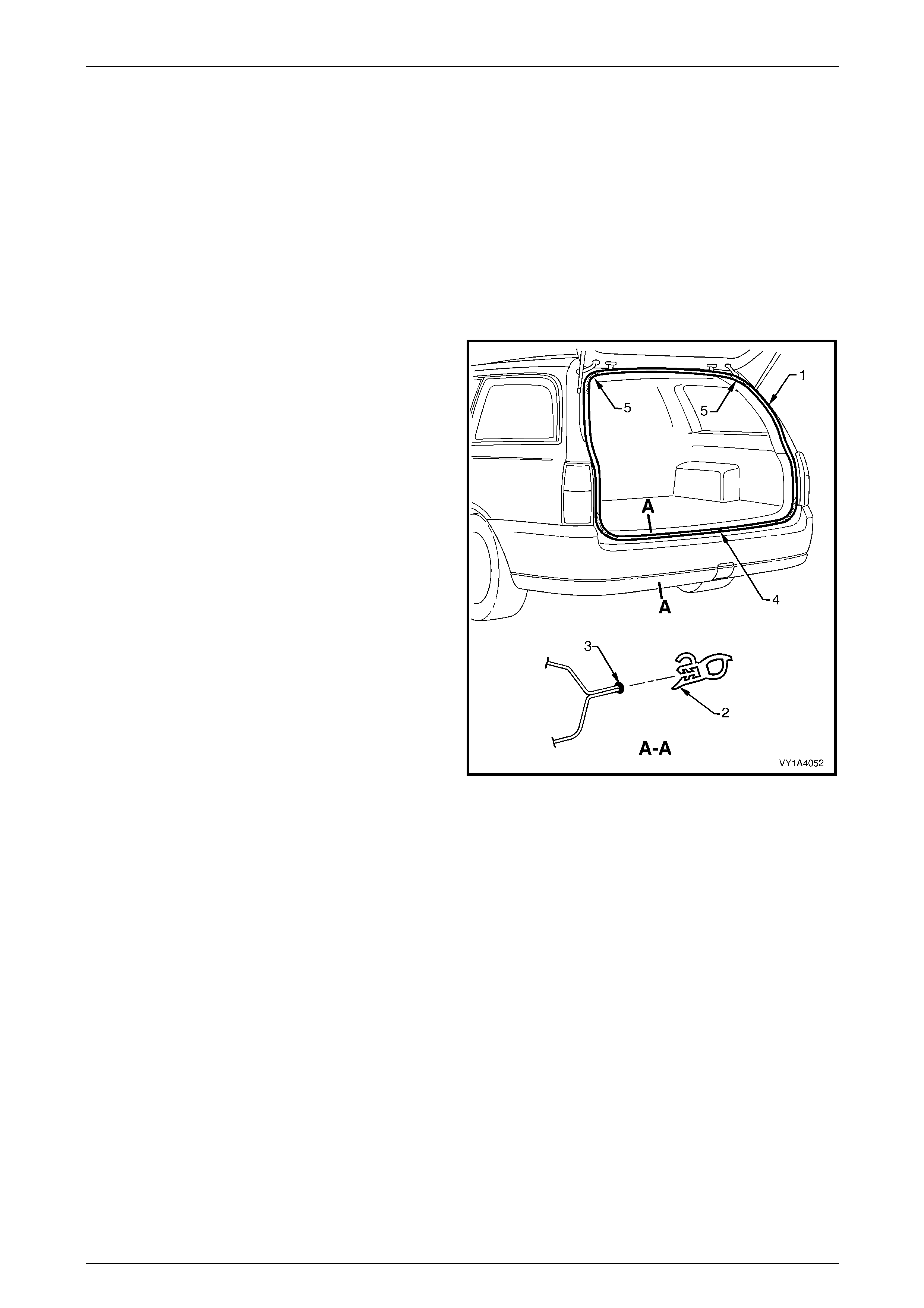
Hood, Rear Compartment Lid, Liftgate and Endgate Page 1A4–94
Page 1A4–94
6.18 Liftgate Weatherstrip Assembly
LT Section No. — 11–600
Remove
NOTE
While not necessary, removing the trim panels
eases installation of the liftgate weatherstrip
assembly.
1 Grasping the liftgate weatherstrip assembly (1),
carefully pull it from the body flange. Start at one poi nt
and continue along its length.
2 Remove the weatherstrip assembly from the vehicle.
Figure 1A4 – 104
Reinstall
Reinstallation of the liftgate weatherstrip assembly is the reverse of the removal procedure, noting the following:
1 Lay the weatherstrip assembly on the floor and ensure the longer side of the weatherstrip (2) faces the outside,
refer to Figure 1A4 – 104.
2 Apply a small bead of non-hardening windscreen sealer such as butyl-mastic or equivalent (3) to the body flange.
3 Locate the weatherstrip assembly join (4) and al ign it with the liftgate striker assembly.
4 Fit the weatherstrip assembly onto the body flange and, beginning at the join, push it into positio n.
NOTE
Allow the weatherstrip assembly to crowd in each
corner (5) to avoid short cutting the corners. If
required, crimp the weatherstrip assembly to
ensure a tight fit onto the body flange.

Hood, Rear Compartment Lid, Liftgate and Endgate Page 1A4–95
Page 1A4–95
7 Service Operations — Liftgate,
AWD Wagon
7.1 Liftgate Window Lower Garnish
LT Section No. — 14–500
Remove
1 Beginning at one end, insert a fine flat-bladed
screwdriver behind the liftgate window lower
garnish (1) at the retaining clip (2) and begin to prise
the garnish from the liftgate.
2 Continue prising the lower garnish from the liftgate at
the remaining retaining clip locations.
3 If required, prise the retaining clips from the li ftgate
window lower garnish with a flat-bladed scre wdriver.
Figure 1A4 – 105
Reinstall
Reinstallation of the liftgate window lower garnish is the reverse of the removal procedure, noting the following:
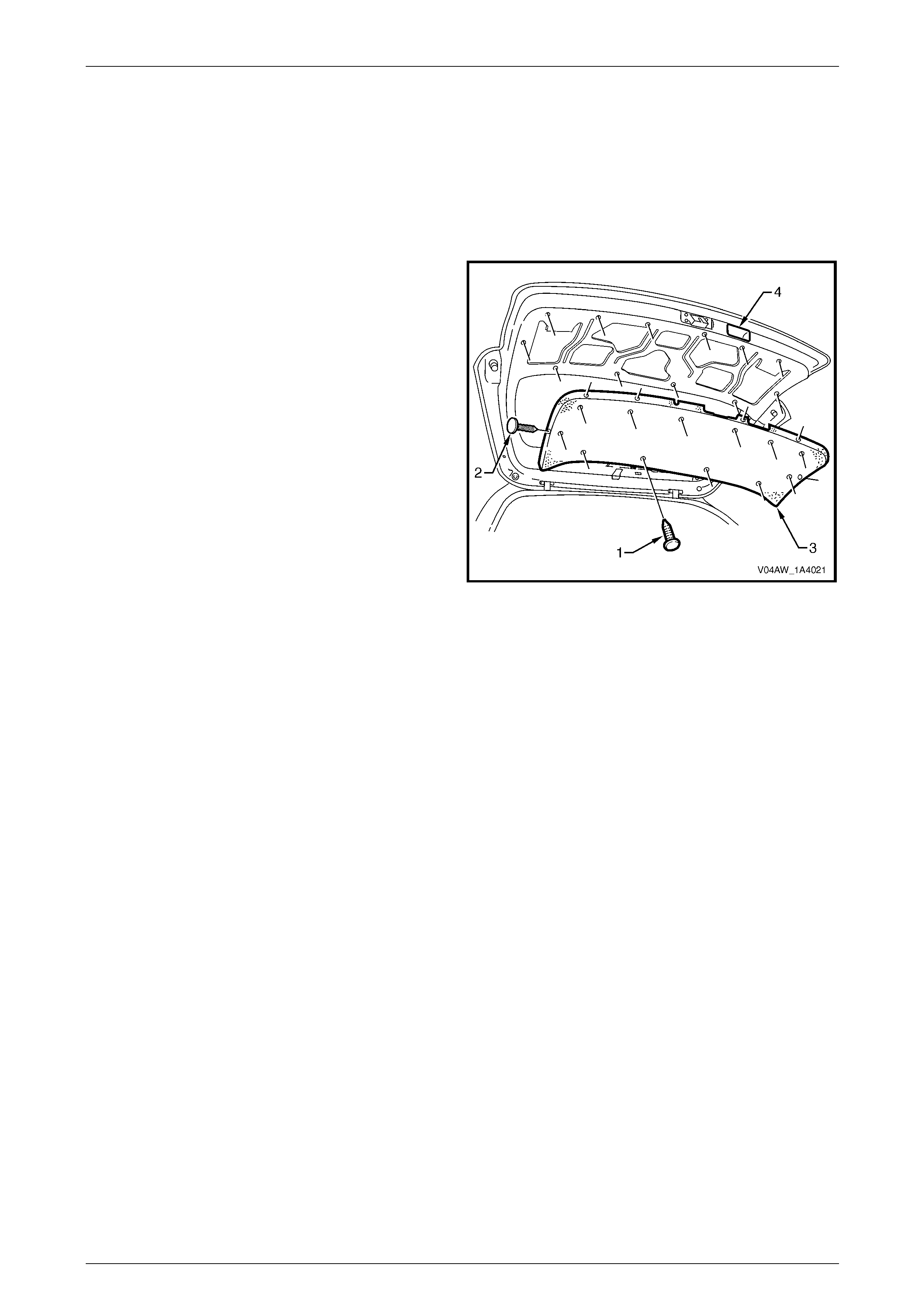
Hood, Rear Compartment Lid, Liftgate and Endgate Page 1A4–96
Page 1A4–96
7.2 Liftgate Lower Trim Panel
LT Section No. — 14–500
Remove
1 If required, remove the liftgate window lower garnish, refer to 7.1 Liftgate Window Lower Garnish.
2 Using a suitable trim clip removal too l, carefully prise
the retainer (1), 12 places, and retain er (2), six places,
attaching the liftgate lower trim panel (3) to the liftgate
assembly.
3 Remove the lower trim panel from the liftgate
assembly by sliding it from under the liftgate insid e
handle (4).
Figure 1A4 – 106
Reinstall
Reinstallation of the liftgate lower trim pan el is the reverse of the removal procedure, notin g the following:
1 Install the lower trim panel, sliding it under the liftgate inside handle.
2 Fit the retainers, 18 places, pushing them in firmly.
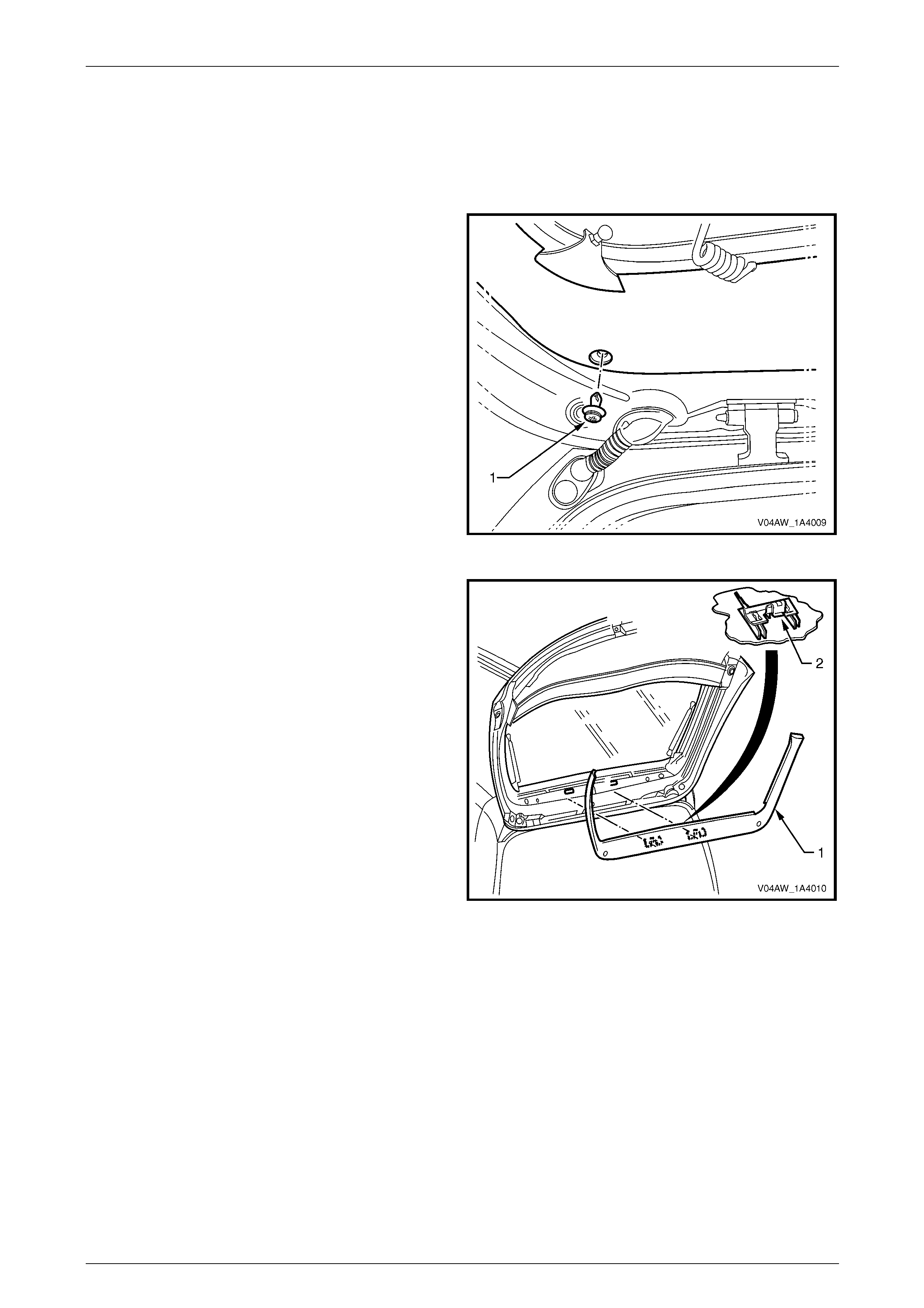
Hood, Rear Compartment Lid, Liftgate and Endgate Page 1A4–97
Page 1A4–97
7.3 Liftgate Window Upper Garnish
LT Section No. — 14–500
Remove
1 Remove the retainer (1), from each side of the liftgate
window upper garnish.
Figure 1A4 – 107
2 Insert a flat-bladed screwdriver behind the liftgate
window upper garnish (1) at the retaining clip (2).
3 Push on the two clip tabs and carefully prise the
liftgate window upper garnish from the liftgate
assembly.
4 Remove the upper garnish from the liftgate. Detach it
from the liftgate window lower garnish, if not previously
removed..
5 If required, prise the retaining clips from the liftgate
window upper garnish using a flat-bladed screwdriver.
Figure 1A4 – 108
Reinstall
Reinstallation of the liftgate window upper garnish is the reverse of the removal procedure, ensuring the retaining clips
are correctly oriented.
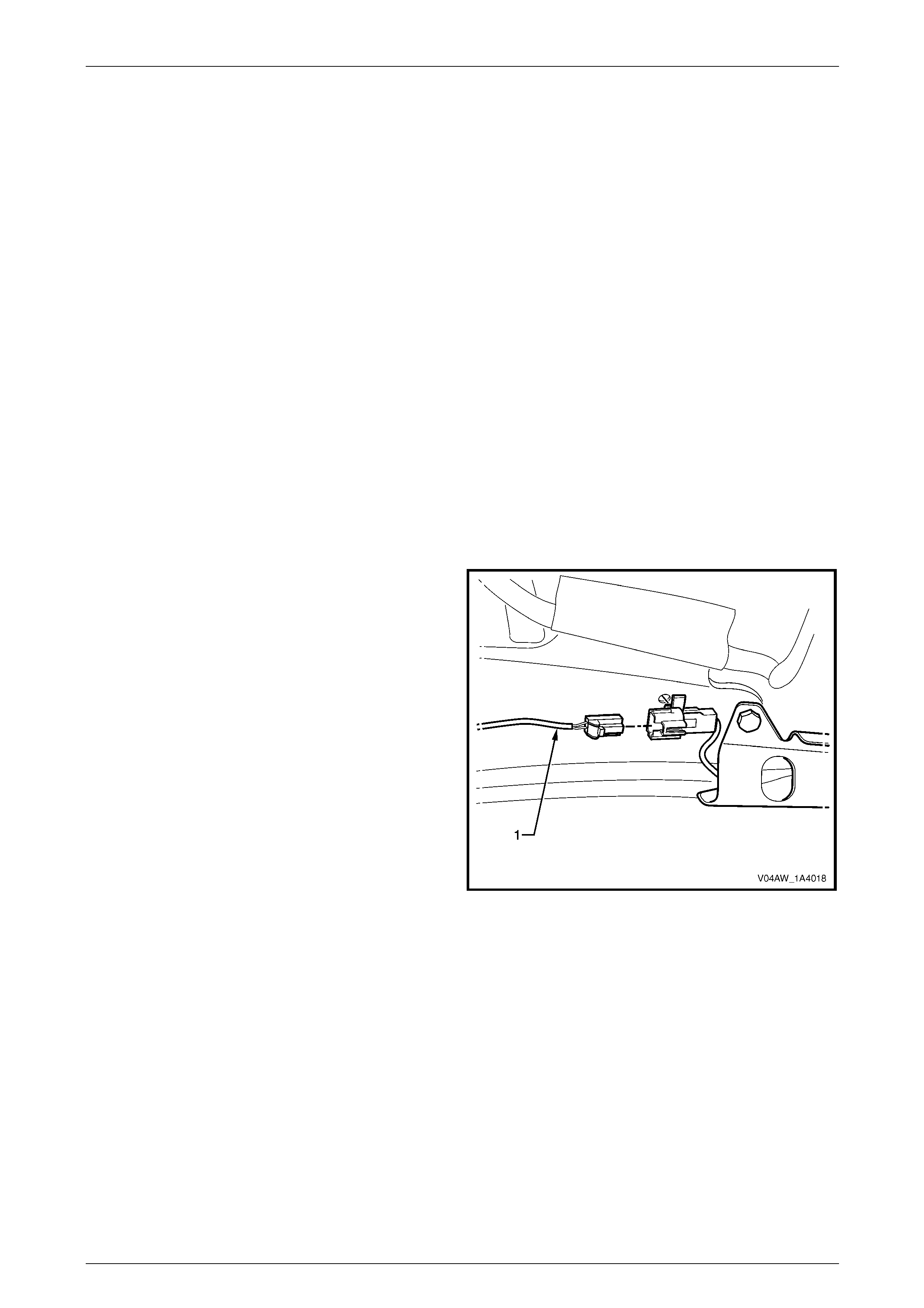
Hood, Rear Compartment Lid, Liftgate and Endgate Page 1A4–98
Page 1A4–98
7.4 Liftgate Window Release Assembly
LT Section No. — XX–XXX
NOTE
The function of the liftgate window microswitch
and liftgate window release actuator can be
tested without removal from the vehicle by
removing the liftgate lower trim panel, refer to
Disassemble in this Section.
NOTE
For additional information and diagnosis
of the rear wiper control module and the
liftgate window release assembly, refer to
Section 12N Wipers, Washers and Horn.
Remove
1 Remove fuse F20 from the passenger compartment fuse a nd relay panel assembly,
refer to Section 12O Fuses, Relays and Wiring Harnesses.
2 Remove the liftgate window lower garnish, refer to 7.1 Liftgate W indow Lower Garnish.
3 Disconnect the liftgate window micros witch wiring
connector (1).
Figure 1A4 – 109

Hood, Rear Compartment Lid, Liftgate and Endgate Page 1A4–99
Page 1A4–99
4 Disconnect liftgate window release actuator wirin g
connector (1).
Figure 1A4 – 110
5 Remove the five screws (1) attaching the liftgate
window release assembly (2) to the liftgate assemb ly.
6 Remove the liftgate windo w release assemb ly.
Figure 1A4 – 111
Disassemble
Liftgate Window Release Actuator
Remove
1 Rotate the clip (1) and remove the connecting rod (2)
from the liftgate window release actuator (3).
Figure 1A4 – 112
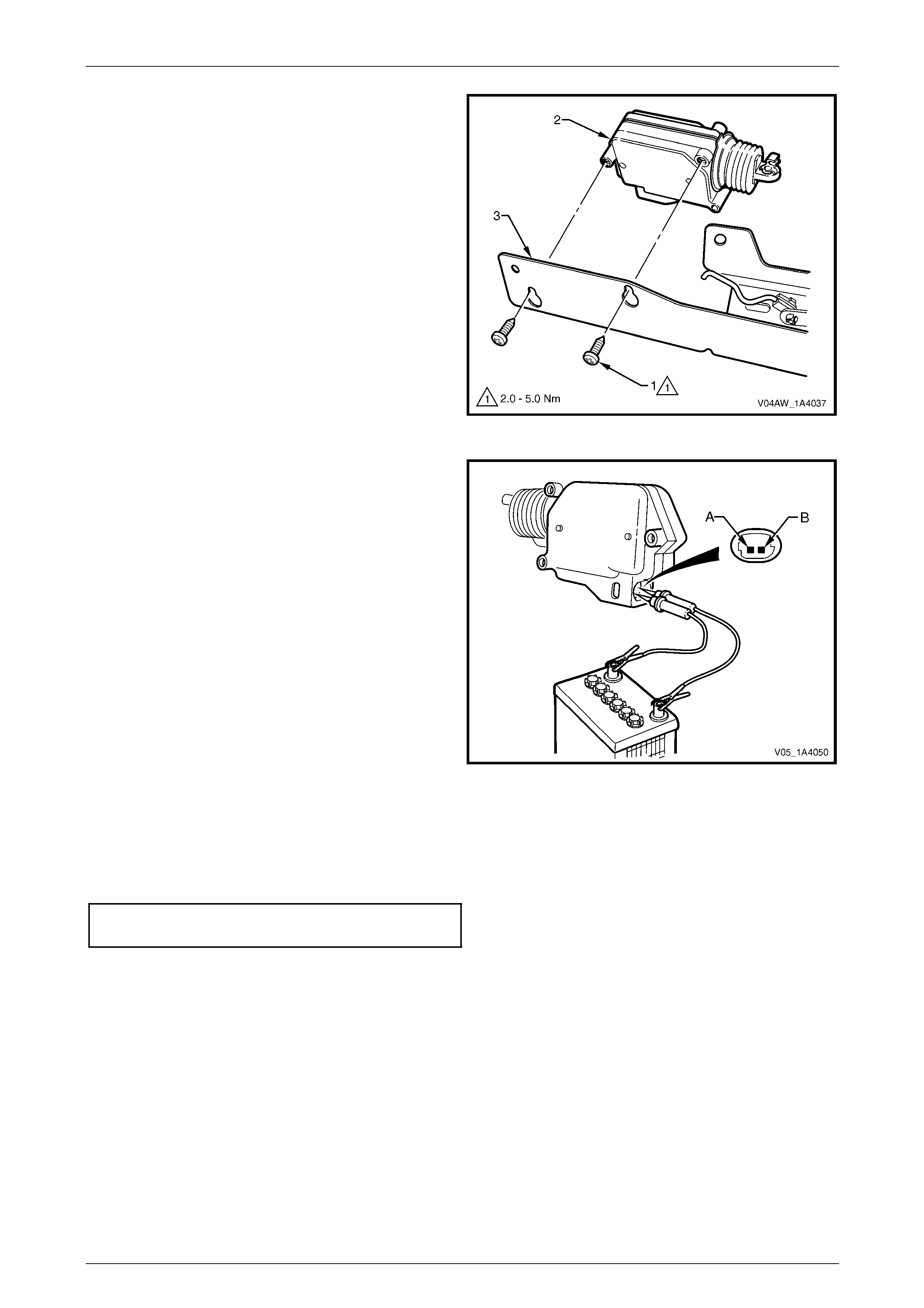
Hood, Rear Compartment Lid, Liftgate and Endgate Page 1A4–100
Page 1A4–100
2 Loosen the two screws (1) attaching the l iftgate
window release actuator (2) to the liftgate window
release assembly (3).
3 Slide the liftgate window release actuator from the
keyhole slots and remove.
Figure 1A4 – 113
Test
1 Ensure the plunger of the liftgate window release
actuator moves freely.
2 Check the plunger extends when ground is connected
to pin B and battery voltage is applie d to pin A.
3 If unsatisfactory, replace the actuator.
Reinstall
Reinstallation of the liftgate window release actuator is the reverse of the removal procedure, noting the following:
1 Ensure the screws are seated in the narrow end of the keyhole slots befor e tightening.
2 Tighten the screws to the correct torque specification.
Liftgate window release actuator
attaching screw torque specification...........2.0 – 5.0 Nm
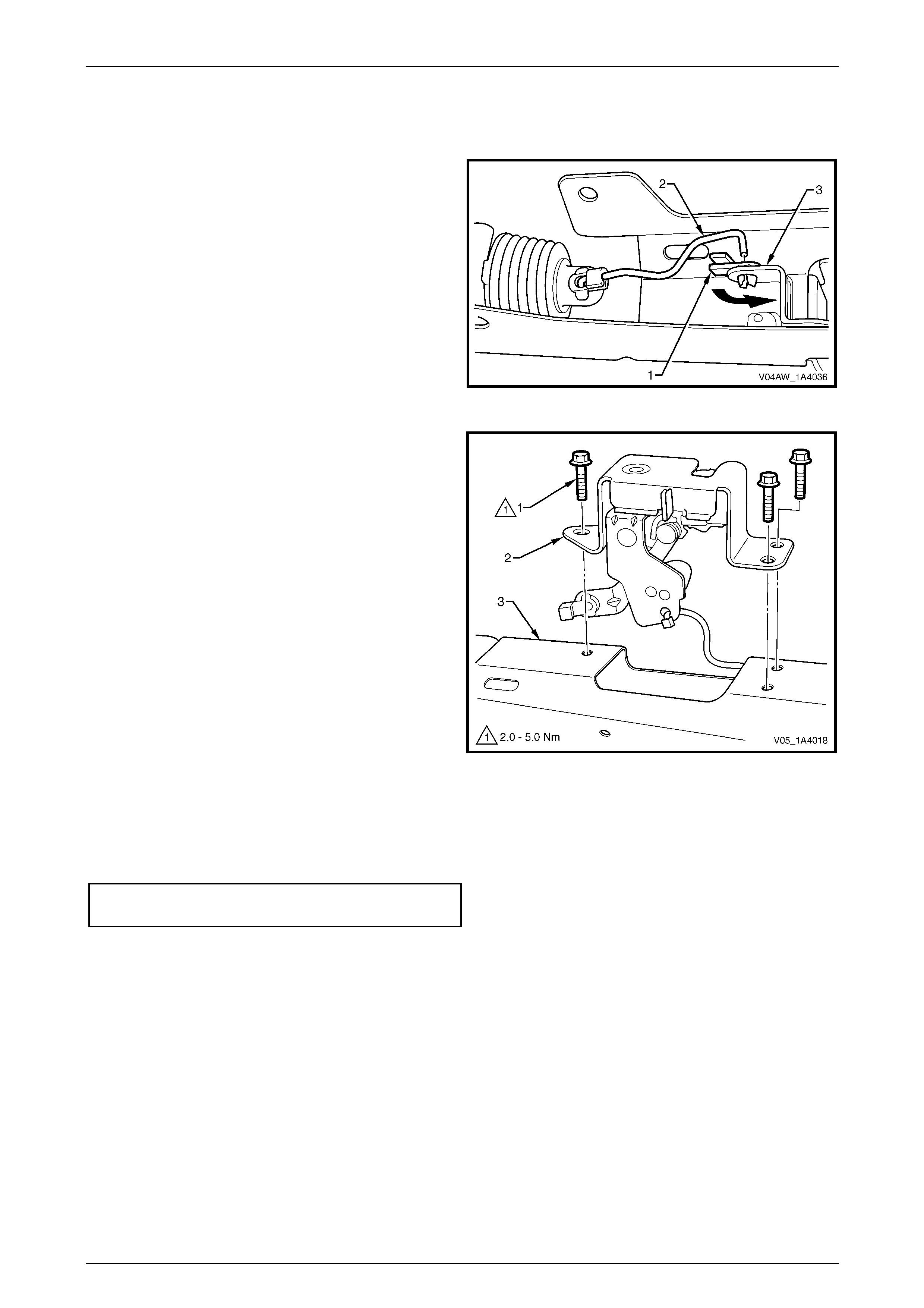
Hood, Rear Compartment Lid, Liftgate and Endgate Page 1A4–101
Page 1A4–101
Liftgate Window Latch Assembly
Remove
1 Rotate the clip (1) and remove the connecting rod (2)
from the liftgate window latch assembly (3).
Figure 1A4 – 114
2 Remove the three screws (1) attaching the liftgate
window latch assembly (2) to the liftgate windo w
release assembly (3).
Figure 1A4 – 115
Reinstall
Reinstallation of the liftgate window latch assembly is the reverse of the removal proced ure. Tighten the screws to the
correct torque specification.
Liftgate window latch assembly attaching
screw torque specification...........................2.0 – 5.0 Nm
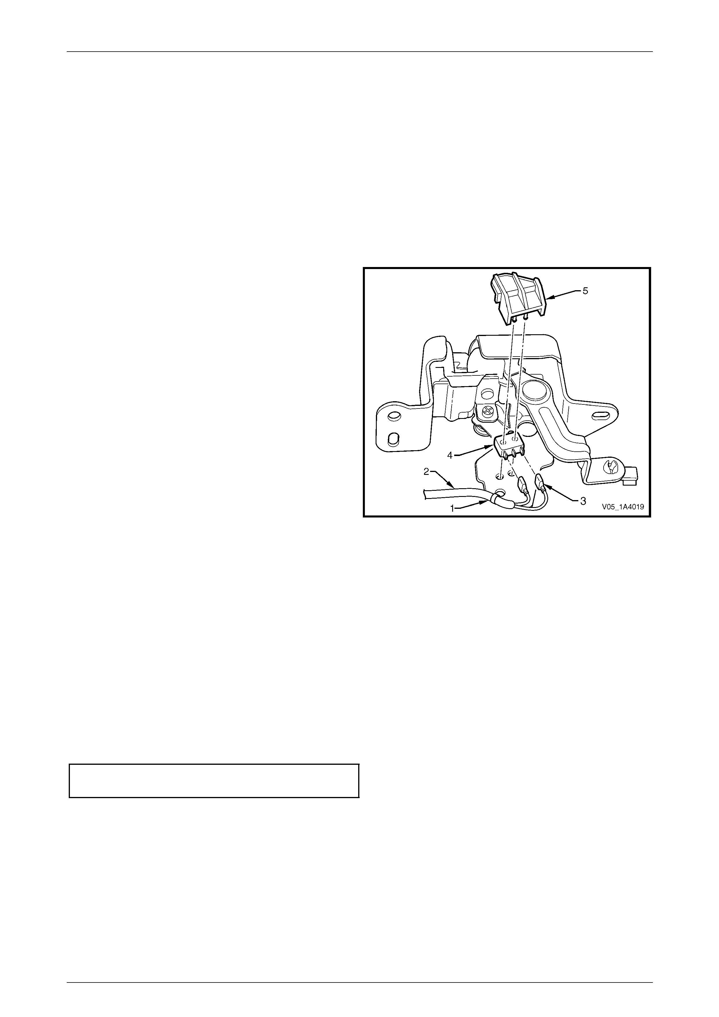
Hood, Rear Compartment Lid, Liftgate and Endgate Page 1A4–102
Page 1A4–102
Liftgate Window Microswitch
NOTE
The liftgate window micros witch provides position
status of the liftgate window assembly to the
rear wiper control module and switches the
rear compartment lamp. For further information
on the liftgate window microswitch, refer to
Section 12B Lighting System.
Remove
1 If required, remove the liftgate window latch assembly.
2 If required, cut the cable tie (1) to enable removal of
the liftgate window microswitch wiring harness (2).
3 Disconnect the liftgate window micros witch wiring
connector (3) from the outer terminals of the liftgate
window microswitch (4).
4 Unclip the liftgate window microswitch retainer (5) and
remove the microswitch.
Figure 1A4 – 116
Reinstall
Reinstallation of the liftgate window microswitch is the reverse of the remo val procedure.
Test
Using a digital multimeter, check the resista nce of the microswitch indicates an open circuit when the liftgate window
latch assembly is in the closed position and continuity when the liftgate window latch assembly is in the open position. If
unsatisfactory replace the microswitch.
Reinstall
Reinstallation of the liftgate window release assembly is the reverse of the removal pr ocedure, noting the following:
1 Tighten the screws to the correct torque specification.
Liftgate window release assembly
attaching screw torque specification.........6.0 – 14.0 Nm
2 Check the operation of the liftgate window release actuator and the liftgate window latch assembly before installing
the trim components.
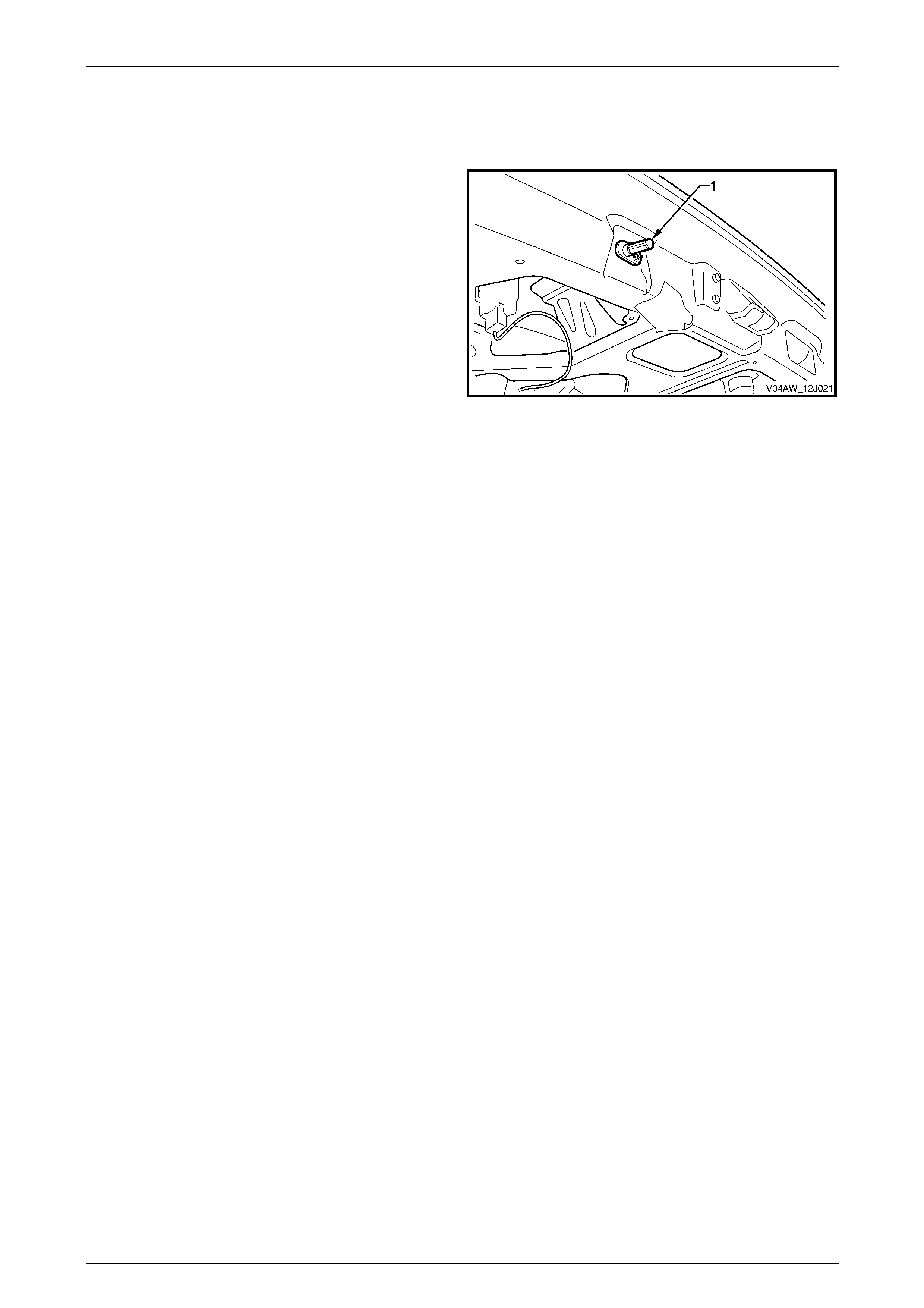
Hood, Rear Compartment Lid, Liftgate and Endgate Page 1A4–103
Page 1A4–103
7.5 Liftgate Switch
LT Section No. — XX–XXX
The liftgate switch (1) switches the rear compartment lamp
on and provides position statu s of the liftgate assembly to
the rear wiper control module .
For liftgate switch service operations, refer to
6.14 Rear Compartment Courtesy Lamp Switch Assembly.
For information on the rear wiper control modul e, refer to
Section 12N Wipers, Washers and Horn.
For further information on the liftgate switch, refer to
Section 12B Lighting System.
Figure 1A4 – 117

Hood, Rear Compartment Lid, Liftgate and Endgate Page 1A4–104
Page 1A4–104
7.6 Liftgate Appliqué Assembly
LT Section No. — 02–385
Remove
1 If required, remove the following components:
a Licence plate.
b Liftgate window lower garnish, refer to 7.1 Liftgate Window Lower Garnish.
c Liftgate lower trim panel, refer to 7.2 Liftgate Lower Trim Panel.
2 Remove fusible link F102 from the engine compartment fuse and relay panel assembly,
refer to Section 12O Fuses, Relays and Wiring Harnesses.
3 Remove the rear wiper control module, refer to Section 12N W ipers, Washers and Horn.
4 Remove both backup lamp bulbs from their socket assemblies.
5 Disconnect the licence plat e lamp wiring connector (1) from within the liftgate assembly cavity, refer to
Figure 1A4 – 118.
6 From within the liftgate assembly cavity, remove the nut (2), eight places, attaching the liftgate appliqué
assembly (3) to the liftgate assembly.
NOTE
The two upper top inner nuts also attach the
liftgate appliqué push-button assembly.
7 Prise the pin (4) from the retainer at the bottom of the appliqué assembly.
8 Partially remove the appliqué assembly, remove the licence plate lamp wiring harness grommet (5) and withdr aw
the licence plate lamp wiring harness.
9 Remove the appliqué assemb ly.
Figure 1A4 – 118
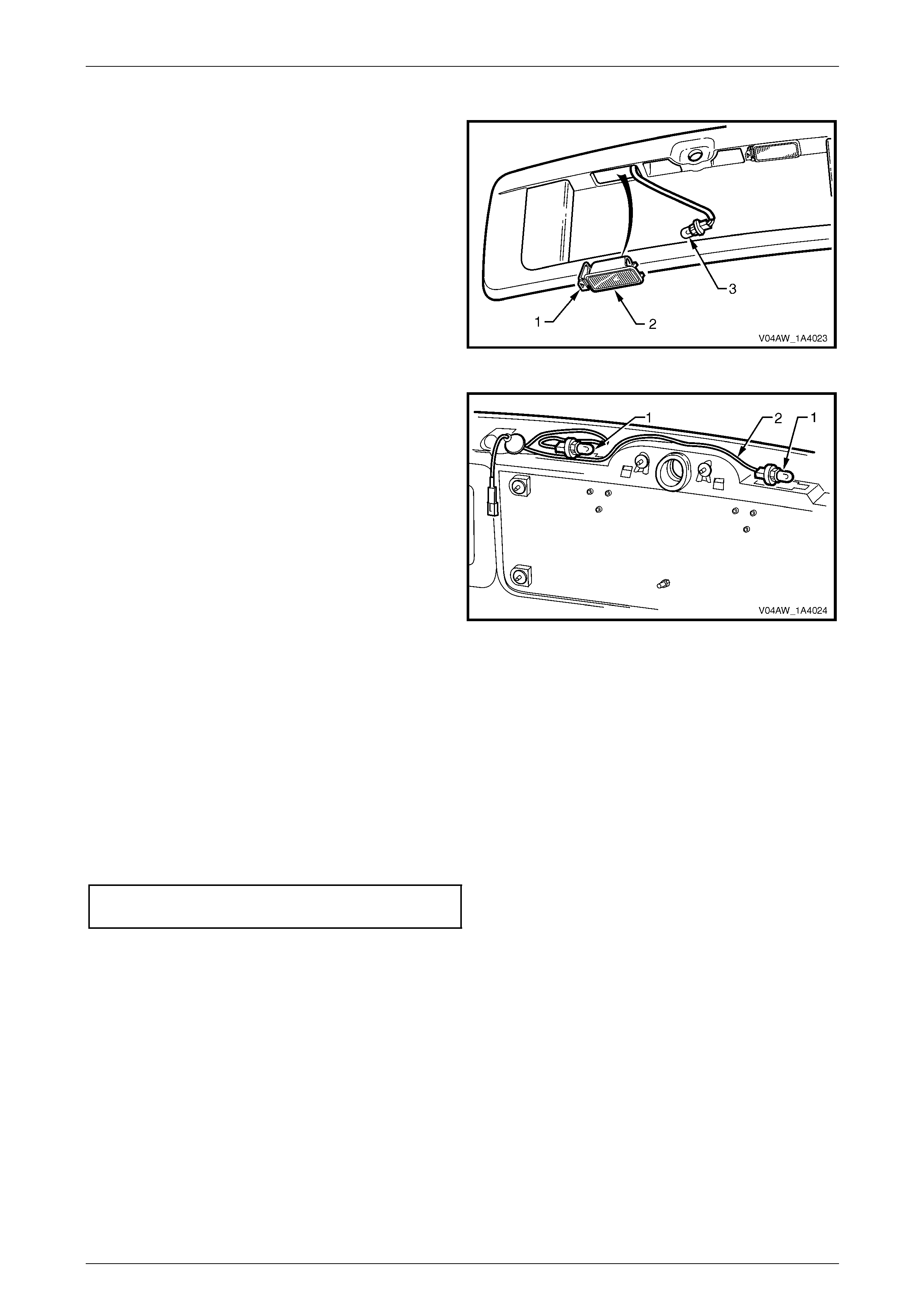
Hood, Rear Compartment Lid, Liftgate and Endgate Page 1A4–105
Page 1A4–105
Disassemble
1 Press the tab (1) and remove the rear licence plate
lamp housing (2) from the appliqué assembly.
2 Rotate the bulb socket (3) and remove it from the rear
licence plate lamp housing.
3 Repeat for the remaining rear licence plate lamp
housing.
Figure 1A4 – 119
4 Pass both bulb sockets (1) through the aperture in the
liftgate appliqué assembly. Remove the licence plate
lamp wiring harness (2).
5 If required, remove both the backup lamp assembli es,
refer to Section 12B Lighting System.
Figure 1A4 – 120
Reassemble
Reassembly of the liftgate appliqué assembly is the reverse of the disassembl y proc edure, ensuring the licence plate
lamp wiring harness (1) is routed correctly.
Reinstall
Reinstallation of the appliqué assembly is the reverse of the removal procedur e, noting the following:
1 Ensure the liftgate appliqué as sembly does not pinch the licence plate l amp wiring harness.
2 Tighten the nuts to the correct torque spec ification.
Liftgate appliqué assembly attaching
nut torque specification...............................2.0 – 5.0 Nm

Hood, Rear Compartment Lid, Liftgate and Endgate Page 1A4–106
Page 1A4–106
7.7 Liftgate Handle Push-button Assembly
LT Section No. — 12–680
Remove
NOTE
Replacement liftgate handle push-button
assemblies are supplied un-coded and will
required to be disassembled and sent to an
authorised locksmith for coding to the vehicle's
keys.
1 If required, remove the following components:
a Liftgate window lower garnish, refer to 6.1 Liftgate Window Lower Garnish.
b Liftgate lower trim panel, refer to 6.2 Liftgate Lower Trim Panel.
2 Disconnect the liftgate lock connecting rod (1) from the
latch assembly.
3 Disconnect the actuator connecting rod (2) from the
liftgate handle push-button assembly (4).
4 From within the liftgate cavity, remove the two nuts (3)
attaching the push-button assembly to the liftgate.
NOTE
The two inner nuts also attach the liftgate handle
assembly.
5 Remove the push-button assembly.
Figure 1A4 – 121
Disassemble
1 Remove the liftgate handle pus h-button assembly
components in the following order:
a E-clip (1),
b latch actuator cover (2),
c drive cam (3),
d spring clip (4),
e washer (5),
f spring (6), then
g lock cylinder assembly (7).
Figure 1A4 – 122

Hood, Rear Compartment Lid, Liftgate and Endgate Page 1A4–107
Page 1A4–107
2 The lock cylinder assembl y can be further disassembled to enable coding a s follows, refer to Figure 1A4 – 123:
• Insert the key, then turn it from position A to position B.
• Cover the ball hole in the housing (1) with a finger to stop the ball (2) being forced out and turn the key back
slightly to position C.
• Withdraw the lock barrel (3) from the housing until the bal l is released. Remove the ball and spring (4) and
remove the lock barrel from the housing.
• If required, remove the tumblers (5), springs (6) and O-rings (7) and (8).
Figure 1A4 – 123
Reassemble
Reassembly of the liftgate handl e push-button assembly is the reverse of the disassembly procedure. Before fitting a
new liftgate handle push-button assembly, an authorised locksmith must code it to the vehicle's keys.
Reinstall
Reinstallation of the liftgate handle push-button assembly is the reverse of the removal procedure, noting the following:
1 The slotted holes in the liftgate handle push-button assembly provide adjustment of the actuator connecting rod.
2 Tighten the nuts to the correct torque specification.
Liftgate handle push-button assembl y
attaching nut torque specification................2.0 – 5.0 Nm
3 Test for correct operation of the liftgate hand le push-button assembly before installing the trim components.
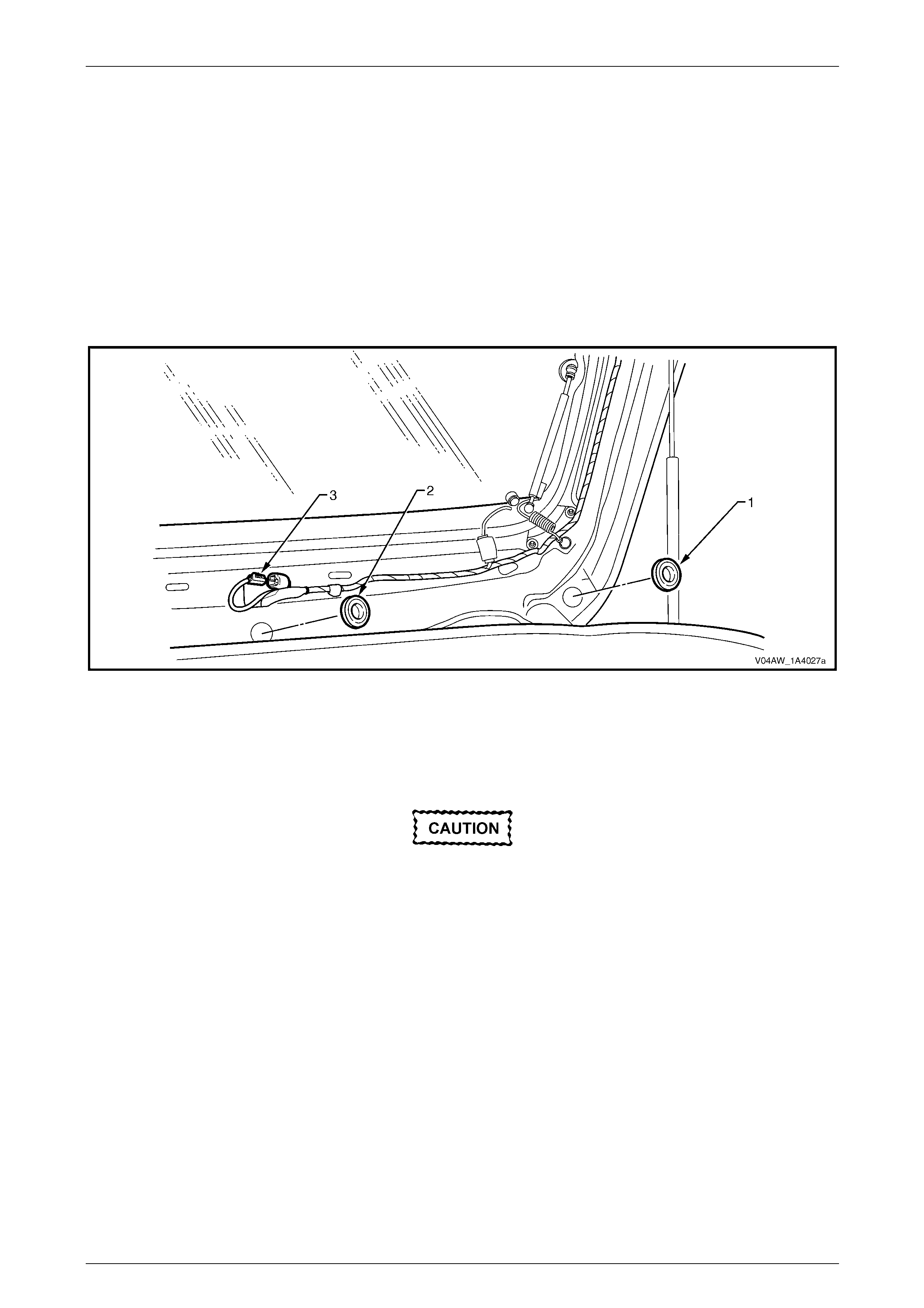
Hood, Rear Compartment Lid, Liftgate and Endgate Page 1A4–108
Page 1A4–108
7.8 Liftgate Air Deflector Assembly
LT Section No. — 10–350
Remove
1 Remove the liftgate window upper garnish, refer to 7.3 Liftgate Window Upper Garnish.
2 Remove the plug (1) from both sides of the liftgate, refer to Figure 1A4 – 124.
3 Remove the plug (2) from the centre of the liftgate.
4 Disconnect the high-mount stop lamp wiring connector (3).
Figure 1A4 – 124
5 Using a tube socket, remove the three nuts (1) attachin g the liftgate air deflector assembly (2) to the liftgate,
refer to Figure 1A4 – 125.
6 Remove the two screws (3) attaching the air deflector assembly to the liftgate.
Take care not to damage the seals (4) when
removing the liftgate air deflector assembly,
as they are not ser viceable.
7 Remove the air deflector assembly.
8 Remove the grommet and withdraw the wiring harness (5).
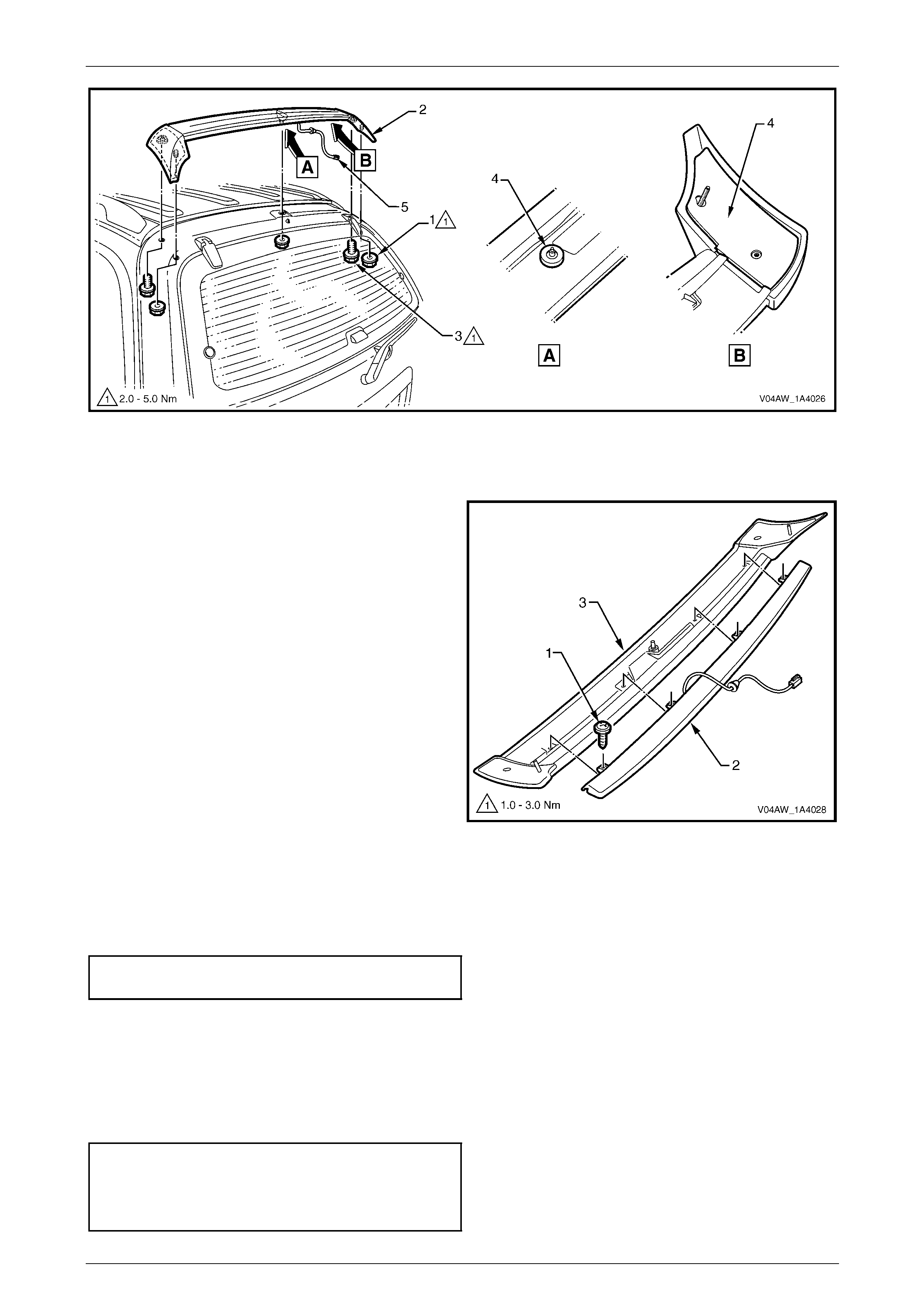
Hood, Rear Compartment Lid, Liftgate and Endgate Page 1A4–109
Page 1A4–109
Figure 1A4 – 125
Disassemble
Remove the screw (1), four places, attaching the high-
mount stop lamp assembly (2) to the air deflector
assembly (3).
Figure 1A4 – 126
Reassemble
Reassembly of the liftgate air deflector assembly is the reverse of the disassembly procedure. Tighten the screws to the
correct torque specification.
High-mount stop lamp assembly
attaching screw torque specification...........1.0 – 3.0 Nm
Reinstall
Reinstallation of the liftgate air deflector assembly is the reverse of the removal procedur e, noting the following:
1 Before installation, ensure the seals are not damaged. If in doubt, apply a small amount of non-hardening sealer.
2 Tighten the fasteners to the correct torque specification.
Liftgate air deflector assembly
attaching nut torque specification................2.0 – 5.0 Nm
Liftgate air deflector assembly
attaching screw torque specification...........2.0 – 5.0 Nm
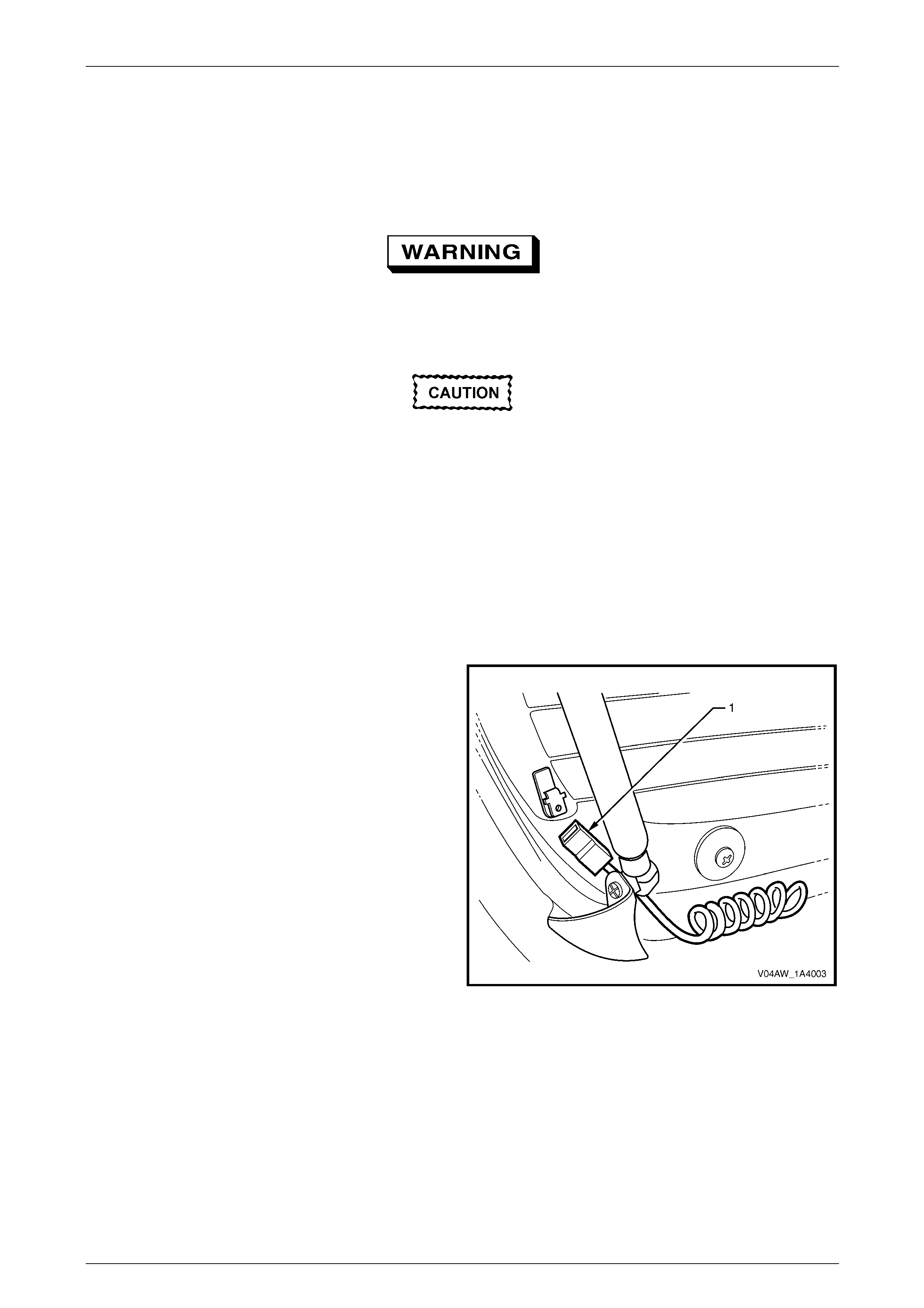
Hood, Rear Compartment Lid, Liftgate and Endgate Page 1A4–110
Page 1A4–110
7.9 Liftgate Window Assembly
LT Section No. — 11–030
Remove
The liftgate window struts contain
pressurised gas. Do not subject them to
extreme heat, pressure or ph ysi cal d ama ge.
Take care to ensure the liftgate window glass
does not strike any object when being
removed or repl aced. Chipped edges can lead
to subsequent breakage o f the liftg ate w indow
glass.
1 Ensure the rear wiper arm is in the parked position on the rear wiper arm ramp. To park the rear wiper arm:
a Ensure the liftgate assembly and the liftgate wind ow assembly are closed.
b Turn the ignition on and operate the rear wiper switch on, then off.
c When the rear wiper arm moves to the park position on the rear wiper arm ramp, turn the ignition off.
2 Open the liftgate window assembly.
3 Disconnect the demister connector (1) from each side.
Figure 1A4 – 127
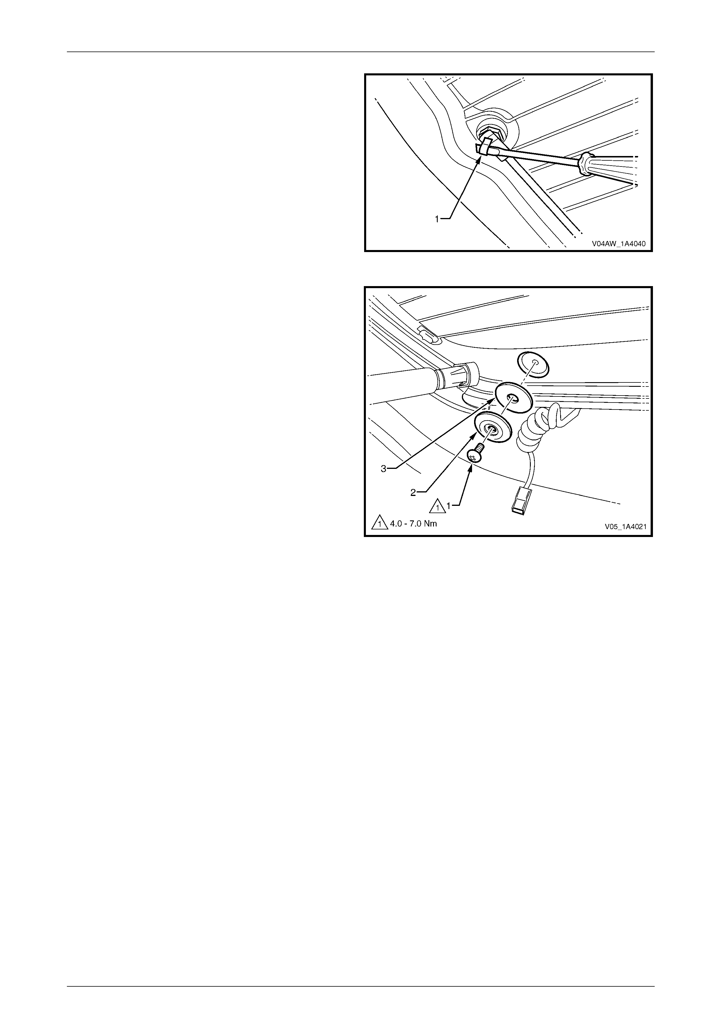
Hood, Rear Compartment Lid, Liftgate and Endgate Page 1A4–111
Page 1A4–111
4 With the aid of an assistant, use a fine flat-bladed
screwdriver to remove the retainer (1) from the windo w
end of the liftgate window strut. Disconnect the
window end of the liftgate window strut from the
liftgate window strut ball stud. Repeat for the opposite
side.
Figure 1A4 – 128
5 Either:
• To remove the liftgate window assembly from the
liftgate hinge:
(1) Remove the screw (1), washer (2) and
seal (3) attaching the liftgate windo w
assembly to the liftgate window hinge from
both sides of the vehicle.
(2) Remove the liftgate window assembly.
or:
• To remove the liftgate window assembly from the
liftgate, refer to 7.10 Liftgate Window Hinge and
remove the window hinges.
Figure 1A4 – 129
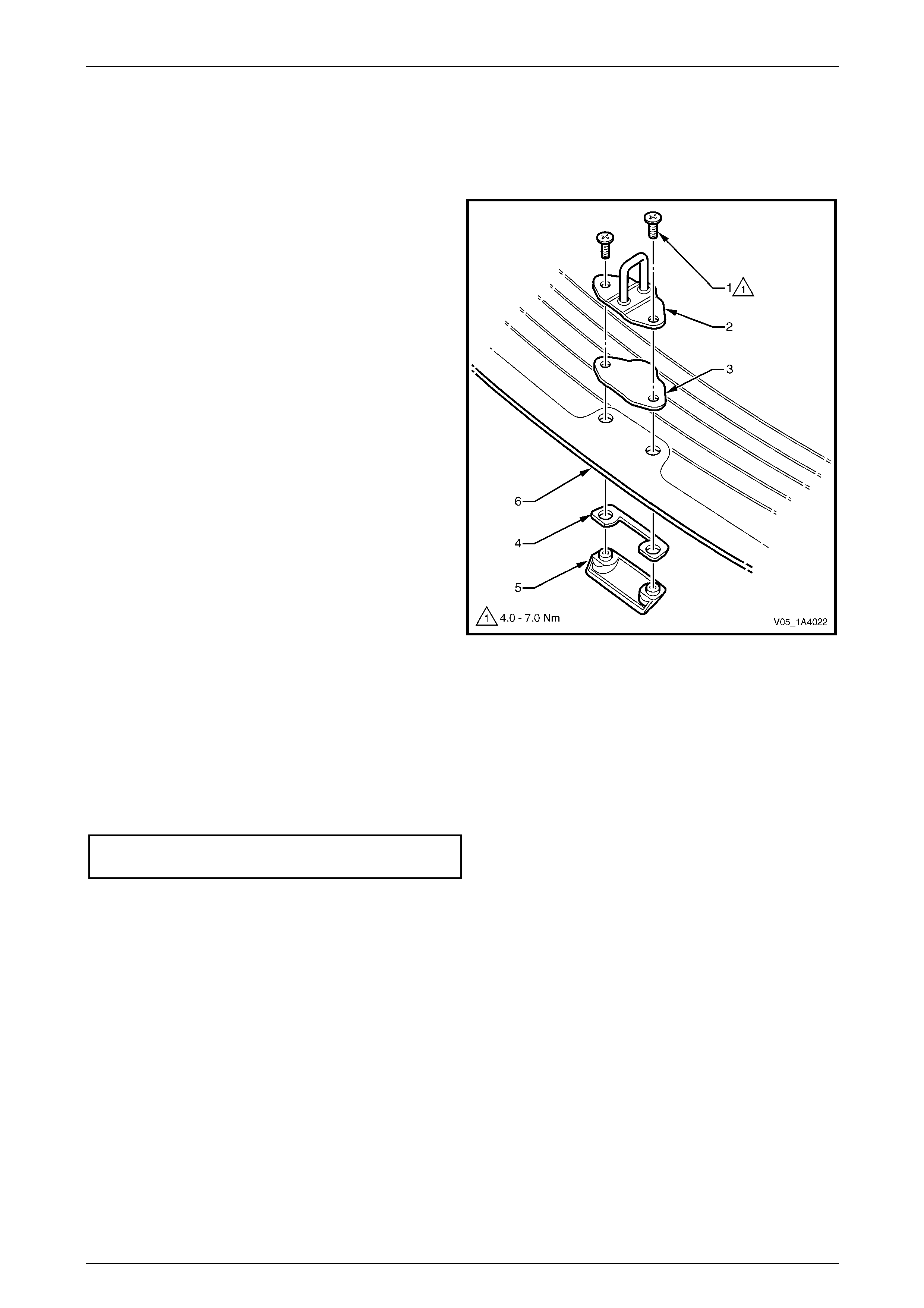
Hood, Rear Compartment Lid, Liftgate and Endgate Page 1A4–112
Page 1A4–112
Disassemble
Liftgate Window Striker and Handle
Remove
1 Remove the two screws (1) from the liftgate window
striker (2).
2 Remove the liftgate windo w striker, liftgate windo w
striker seal (3), liftgate handle seal (4) and liftgate
window handle (5) from the liftgate windo w
assembly (6).
Figure 1A4 – 130
Reinstall
Reinstallation of the liftgate window striker and handle is the reverse of the removal procedure, noting the following:
1 Inspect the seals for damage and replace if necessary.
2 Apply thread adhesive L octite 242 or Loctite 243 to the screw threads.
3 Tighten the screws to the correct torque specification.
Liftgate window striker and handle
screw torque specification...........................4.0 – 7.0 Nm
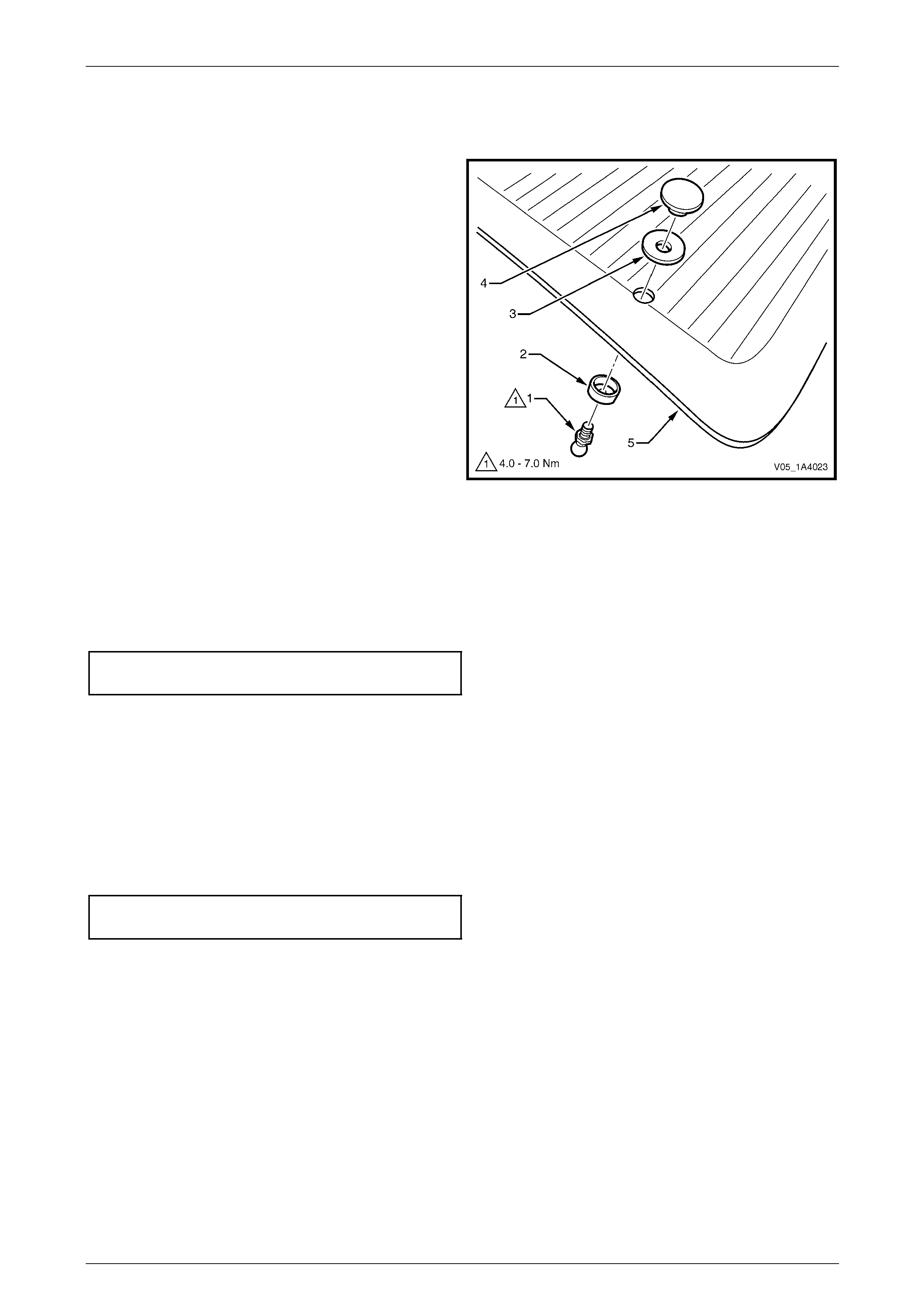
Hood, Rear Compartment Lid, Liftgate and Endgate Page 1A4–113
Page 1A4–113
Liftgate Windo w Strut Ball Stud
Remove
1 Unscrew the liftgate window strut ball stud (1), seals
(2) and (3) and the outer retainer (4) from the liftgate
window assembly (5).
NOTE
If required, hold the outer retainer to prevent it
rotating.
2 If required, repeat for the opposite side.
Figure 1A4 – 131
Reinstall
Reinstallation of the liftgate window strut ball stud is the reverse of the removal procedure, noting the following:
1 Apply thread adhesive L octite 242 or Loctite 243 to the screw threads.
2 Tighten the ball stud to the correct torque specification.
Liftgate window strut ba ll
stud torque specification .............................4.0 – 7.0 Nm
Reinstall
Reinstallation of the liftgate window assembly is the reverse of the removal procedure, noting the following:
1 Inspect the seals for damage and replace if necessary.
2 Ensure the seals on the liftgate windo w hinges are insta lled.
3 Apply thread adhesive L octite 242 or Loctite 243 to the screw threads.
4 Tighten the screws to the correct torque specification.
Liftgate window hinge screw
torque specification.....................................4.0 – 7.0 Nm

Hood, Rear Compartment Lid, Liftgate and Endgate Page 1A4–114
Page 1A4–114
7.10 Liftgate Window Hinge
LT Section No. — XX–XXX
Remove
1 Remove the liftgate window upper garnish, refer to 7.3 Liftgate Window Upper Garnish.
2 If required, remove the liftgate window assembly, refer to 7.9 Liftgate Window Assembly.
3 Using a tube socket, remove the nut (1) attaching the
liftgate window hinge to the liftgate assembly.
Figure 1A4 – 132
4 Remove the liftgate windo w hinge and se al (1).
5 Repeat for the opposite hinge as requ ired.
Figure 1A4 – 133
Reinstall
Reinstallation of the liftgate window hinge is the reverse of the removal procedure, noting the following:
1 Inspect the seal for damage and replace if necessar y.
2 Tighten the nut to the correct torque specification.
Liftgate window hinge nut
torque specification.....................................3.0 – 6.0 Nm
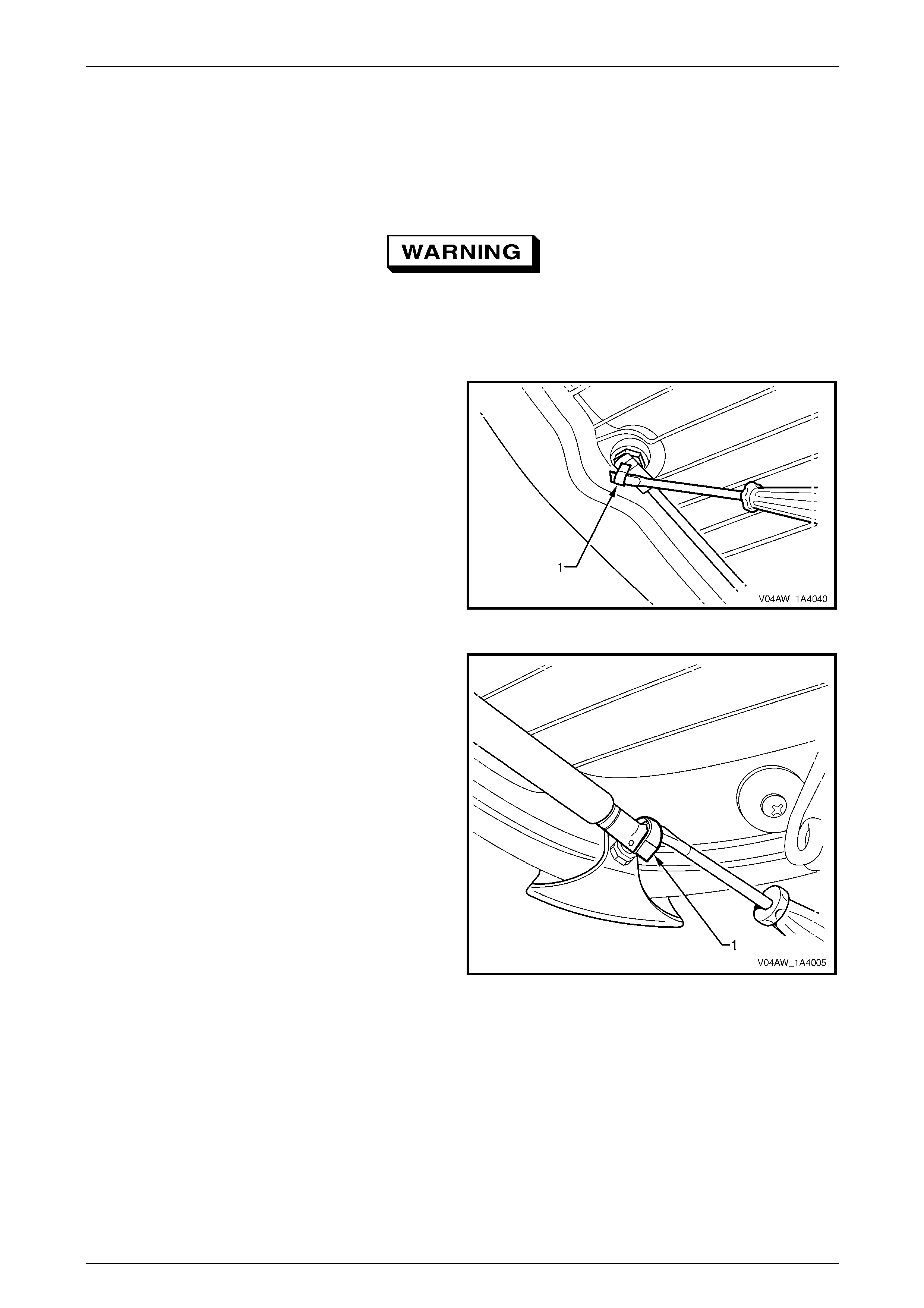
Hood, Rear Compartment Lid, Liftgate and Endgate Page 1A4–115
Page 1A4–115
7.11 Liftgate Window Strut
LT Section No. — XX–XXX
Remove
The liftgate window struts contain
pressurised gas. Do not subject them to
extreme heat, pressure or ph ysi cal d ama ge.
1 Open the liftgate window assembly to relieve the tension in the liftgate window strut.
2 Using a fine flat-bladed screwdriver, unclip the
retainer (1) from the lower end of the liftgate window
strut.
3 Disconnect the lower end of the window strut from the
liftgate window assembly.
Figure 1A4 – 134
4 Using a fine flat-bladed screwdriver, unclip the
retainer (1) from the upper end of the strut.
5 Remove the strut from the liftgate.
Figure 1A4 – 135
Reinstall
Reinstallation of the liftgate window strut is the reverse of the removal procedure, noting the following:
1 If required, apply a small amount of NLGI No. 1 lithium grease or equivalent to the inside of the liftgate window strut
ball cap.
2 Install the strut with the cylinder end attached to the liftgate assembly.
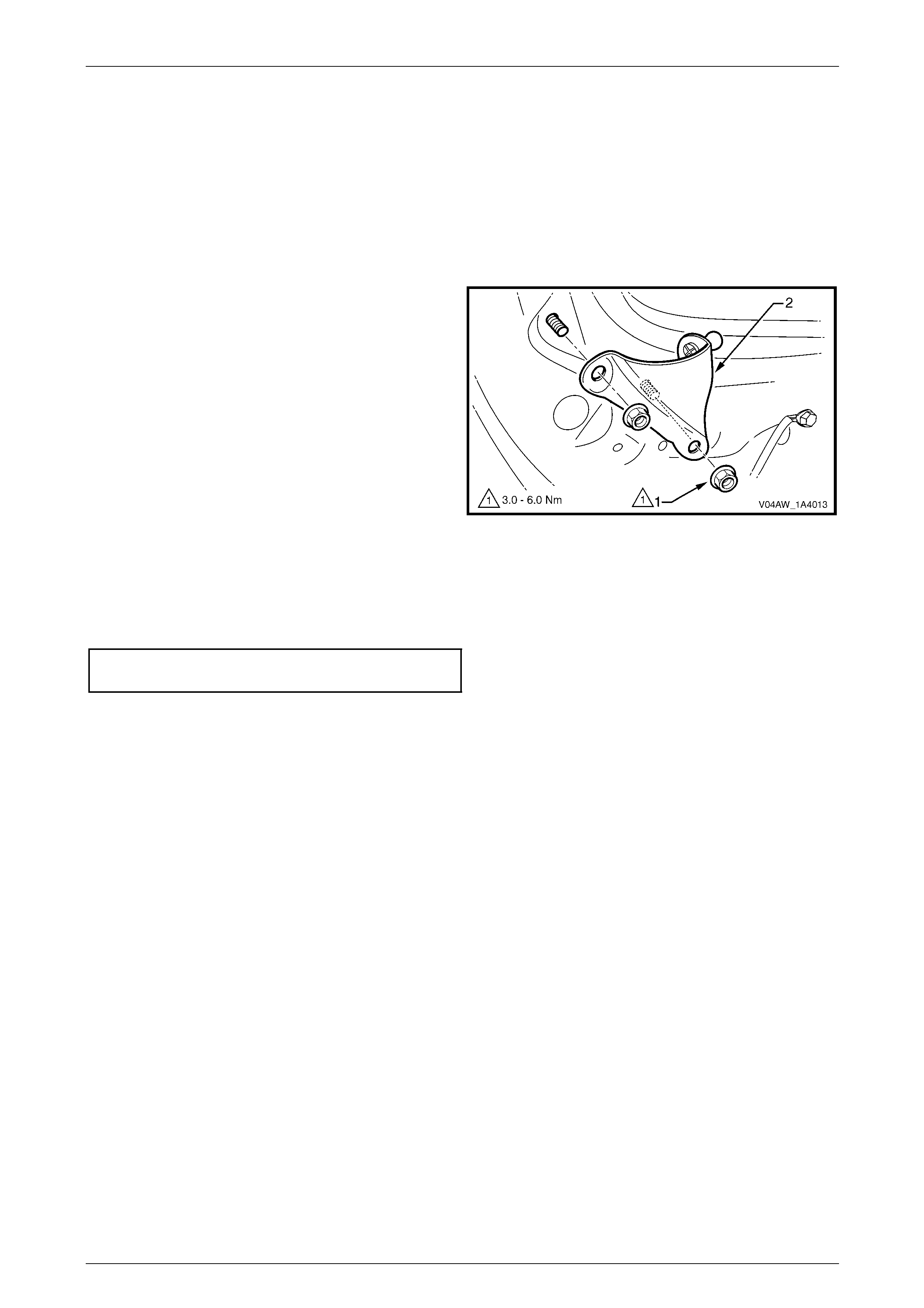
Hood, Rear Compartment Lid, Liftgate and Endgate Page 1A4–116
Page 1A4–116
7.12 Liftgate Window Upper Strut Bracket
LT Section No. — XX–XXX
Remove
1 If required, remove the liftgate window upper garnish, refer to 7.3 Liftgate Window Upper Garnish .
2 Disconnect the liftgate window strut from the liftgate window upper strut bracket,
refer to 7.11 Liftgate Window Strut.
3 Remove the two nuts (1) attaching the liftgate window
upper strut bracket (2).
4 Remove the strut bracket.
Figure 1A4 – 136
Reinstall
Reinstallation of the liftgate window upper strut bracket is the reverse of the removal procedure. Tighten the nuts to the
correct torque specification.
Liftgate window upper strut bracket
nut torque specification...............................3.0 – 6.0 Nm
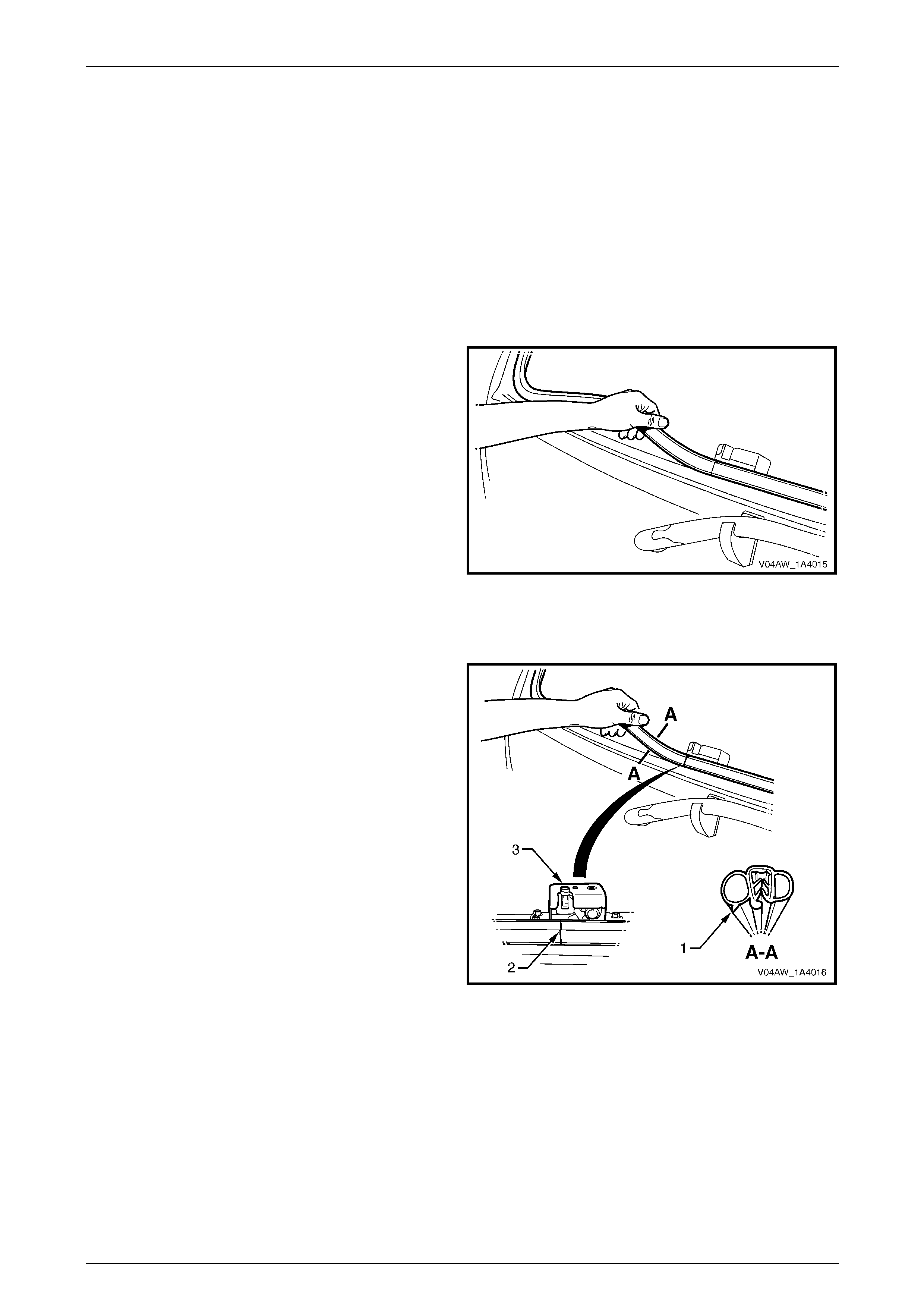
Hood, Rear Compartment Lid, Liftgate and Endgate Page 1A4–117
Page 1A4–117
7.13 Liftgate Window Weatherstrip
LT Section No. — 11–600
Remove
1 If required, remove the following components:
a Liftgate window lower garnish, refer to 7.1 Liftgate Window Lower Garnish.
b Liftgate window upper garnish, refer to 7.3 Liftgate Window Upper Garnish.
2 Disconnect the liftgate window strut from the liftgate window assembly, refer to 7.11 Liftgate Window Strut.
3 Remove the liftgate windo w weatherstrip from the
liftgate assembly opening.
Figure 1A4 – 137
Reinstall
1 Ensure the lip (1) of the liftgate window weatherstrip
faces the outside.
2 Locate the liftgate window weatherstrip join (2) and
ensure it aligns with the latch ope ning on the liftgate
window latch assembly (3).
3 If required, crimp the liftgate window weatherstrip to
ensure a tight fit onto the weatherstrip flange.
4 Install the liftgate window weatherstrip into the liftgate
assembly opening.
5 Ensure the liftgate window weatherstrip is correctly
seated into all parts of the liftgate assembly,
particularly in the corners.
Figure 1A4 – 138
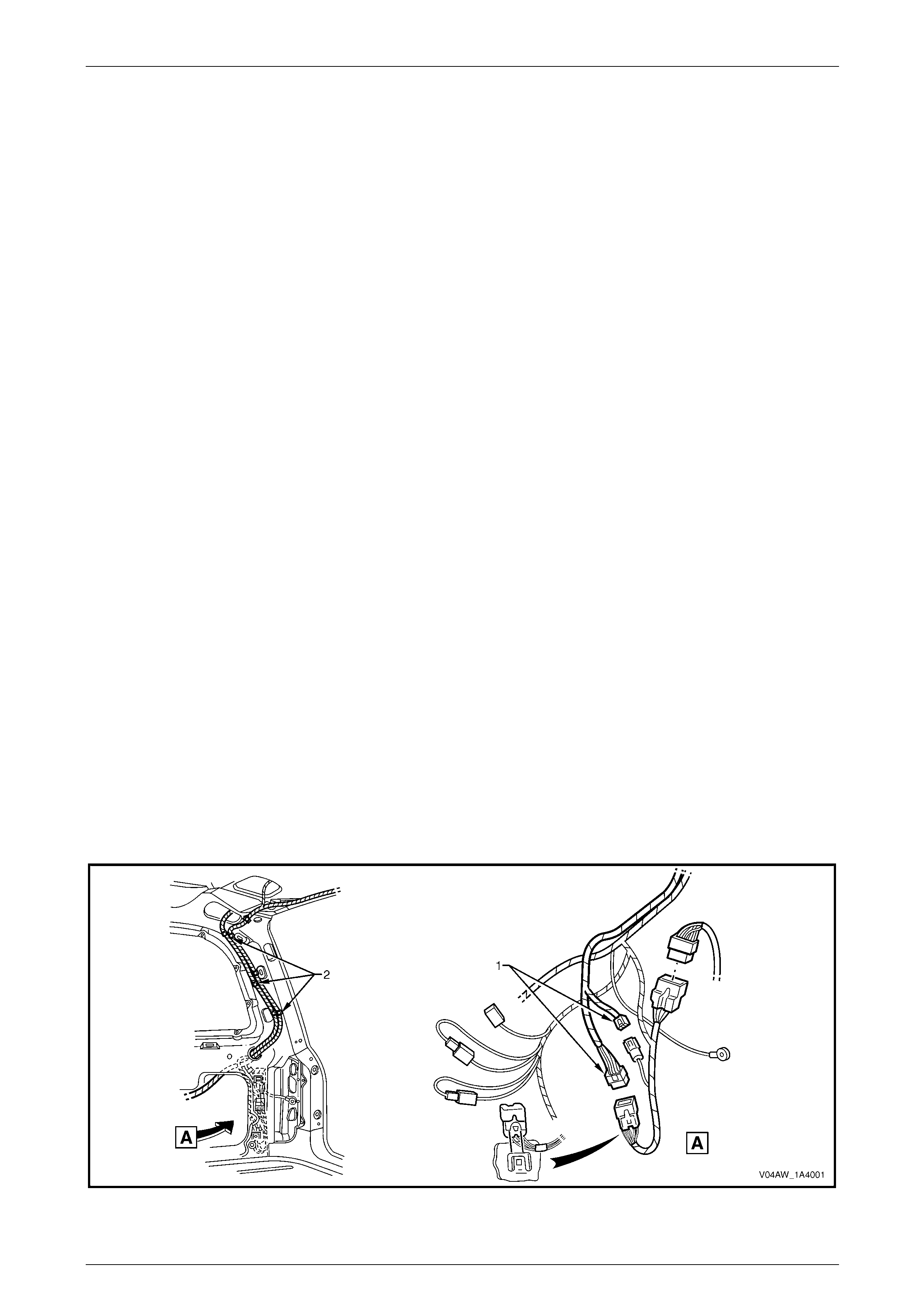
Hood, Rear Compartment Lid, Liftgate and Endgate Page 1A4–118
Page 1A4–118
7.14 Liftgate Assembly
LT Section No. — 12–500
Remove
1 If required, remove the following components:
a Liftgate window lower garnish, refer to 7.1 Liftgate Window Lower Garnish.
b Liftgate lower trim panel, refer to 7.2 Liftgate Lower Trim Panel.
c Liftgate window upper garnish, refer to 7.3 Liftgate Window Upp er Garnish.
d Liftgate inside handle, refer to 6.3 Liftgate Inside Handle.
e Liftgate window release assembly, refer to 7.4 Liftgate W indow Release Assembly.
f Rear wiper arm assembly, rear wiper motor assembly, rear wiper ramp and rear wiper control module,
refer to Section 12N Wipers, Washers and Horn.
g Liftgate appliqué assembly, refer to 7.6 Liftgate Appliqué Assembly.
h Liftgate appliqué push-button assembly, refer to 7.7 Liftgate Handle Push-button Assembly.
i Liftgate air deflector assembl y, refer to 7.8 Liftgate Air Deflec tor Assembly.
j Liftgate window assembly, refer to 7.9 Liftgate Window Assembly.
k Liftgate window hinge, refer to 7.10 Liftgate Window Hinge.
l Liftgate window strut, refer to 7.11 Liftgate Windo w Strut.
m Liftgate window upper strut bracket, refer to 7.12 Liftgate Window Upper Strut Bracket.
n Liftgate window weatherstrip, refer to 7.13 Liftgate Window Weatherstrip.
o Liftgate latch assembly, refer to 6.7 Liftgate Latch Assembly.
p Liftgate actuator assembly, refer to 6.8 Liftgate Actuator Assembly.
q Badges and emblems, refer to Section 1A9 Exterior Ornamentation.
2 Partially remove the right-hand quarter inner trim upper and right-hand body rear corner garnish,
refer to Section 1A8 Headlining and Interior Trim.
3 Disconnect the two liftgate assembly wiring harness connectors (1), refer to Figure 1A4 – 139.
4 Unclip the three liftgate wiring harness clips (2).
Figure 1A4 – 139
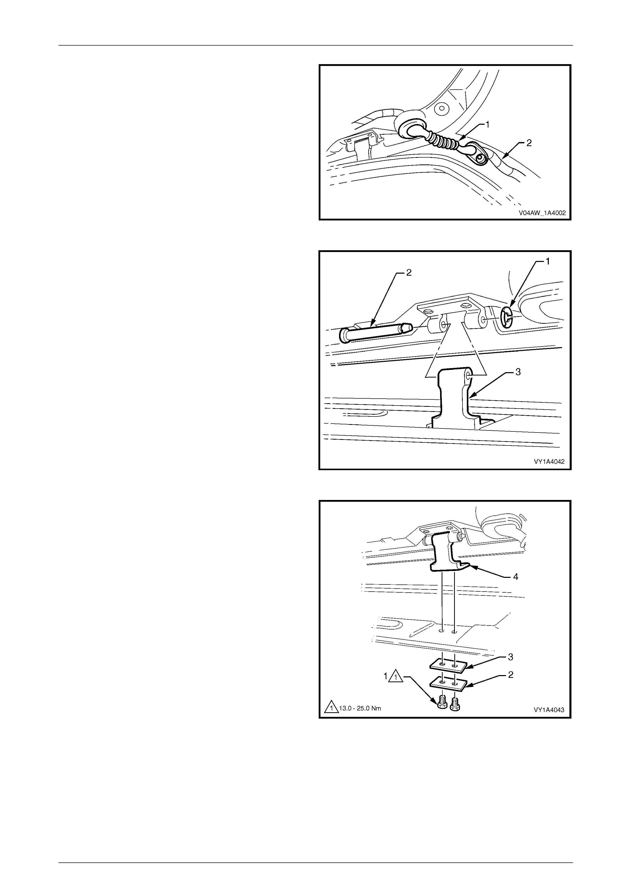
Hood, Rear Compartment Lid, Liftgate and Endgate Page 1A4–119
Page 1A4–119
5 Remove the right-hand grommet (1) and withdraw the
liftgate assembly wiring harne ss (2) from the pillar
cavity.
6 If a sunroof is fitted, disconnect the sunroof drain tube,
refer to Section 1F2 Sunroof — On-line.
7 Remove the rear window washer nozzle and hose
assemblies, refer to 6.11 Rear Window Washer
Nozzle and Hose Assemblies.
8 Remove the liftgate strut assembly from the liftgate
assembly, refer to 6.13 Liftgate Strut Assembly.
Figure 1A4 – 140
9 Either:
• To remove the liftgate assembly only:
(1) Remove the liftgate hinge pin retain er (1)
from each side of the vehicle.
(2) With the aid of an assistant to support the
liftgate, withdraw each liftgate hinge
pin (2).
(3) Remove the liftgate assembly, leaving the
body side of the liftgate hinge (3) in
position.
Figure 1A4 – 141
or:
• To remove the liftgate assembly and the
complete liftgate hinge:
(1) Remove the liftgate windo w upper garnis h,
refer to Section 1A8 Headlining and Interior
Trim.
(2) Remove the two screws (1), plate (2) and
seal (3).
(3) Remove the liftgate assembly, with the
complete liftgate hinge (4) attached.
Figure 1A4 – 142
Disassemble
1 Remove the rear compartment courtesy lamp s witch assembly,
refer to 6.14 Rear Compartment Courtesy Lamp Switch Assembly.
2 Remove the liftgate wiring harness assembly, refer to Section 12O Fuses, Relays and Wiring Harnesses.
3 Remove the liftgate bumper, refer to 6.15 Lift gate Bumper.
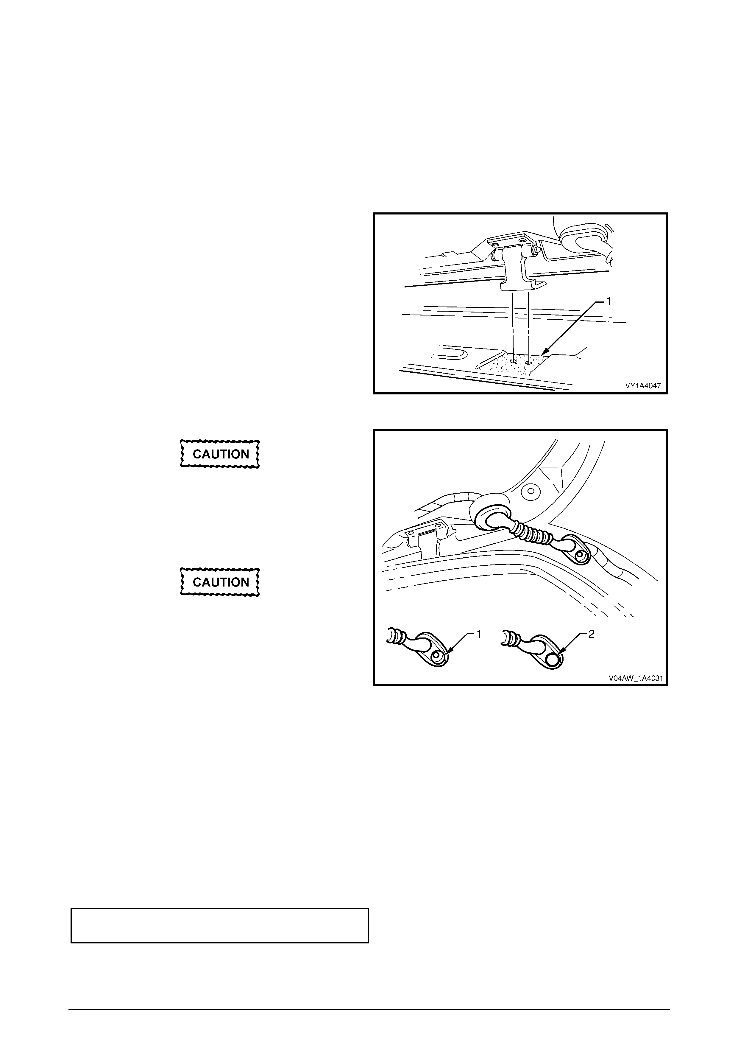
Hood, Rear Compartment Lid, Liftgate and Endgate Page 1A4–120
Page 1A4–120
Reassemble
Reassembly of the liftgate assembly is the reverse of the dis assembly procedure.
Reinstall
Reinstallation of the liftgate assembly is the reverse of the removal procedure, noting the following:
1 If the liftgate assembly was removed from the liftgate hinge pin, lubricate the pin with NLGI No. 1 lithium grease or
equivalent before installatio n.
2 If the liftgate assembly was removed with the body
side of the liftgate hinge attached, appl y sealer (Lord
Fusor #800 or #801 or equivalent) to the sha ded
area (1).
3 Set both bumpers to the fully set-in position, then
adjust to achieve the required alignment of the liftgate,
refer to Adjust in this Section.
Figure 1A4 – 143
For a vehicle equipped with a sunroof,
remove the rear drain tube plug from the
grommet (1) for drainage of the sunroof.
Ensure the rear drain tube is fitted, refer to
Section 1F2 Sunroof — On-line.
Ensure the rear drain tube plug (2) is
installed if a sunroof is not fitted to the
vehicle.
4 If a sunroof is fitted, connect the drain tube.
Figure 1A4 – 144
5 Before installing the trim panels, test the operation of the following items:
• rear wiper,
• rear window washer,
• high-mount stop lamp,
• rear compartment courtesy lamp switch,
• liftgate window release actuator, and
• liftgate lock mechanism.
6 Tighten the screws to the correct torque specification.
Liftgate hinge (body side) attaching
screw torque specification.......................13.0 – 25.0 Nm
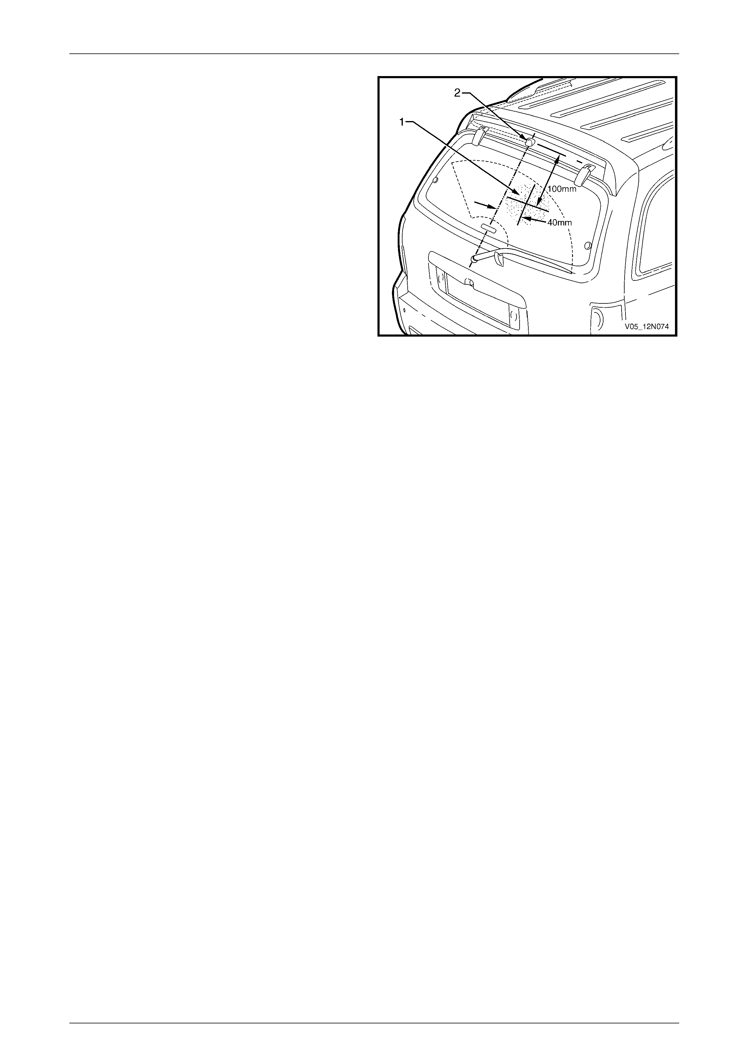
Hood, Rear Compartment Lid, Liftgate and Endgate Page 1A4–121
Page 1A4–121
7 Test the operation and alignment of the rear window
washer assembly. Spray from the nozzle jet shou ld
strike the window within the 100 mm diameter area
shown shaded.
8 If adjustment is required, insert a pin or piece of fine
wire into the nozzle jet and adjust the direction of flow.
Figure 1A4 – 145
Adjust
Correct alignment of the liftgate assembly is critical to its operation and to the aesthetics of the vehicle. The following
components allow adjustment of the liftgate assembly:
• the liftgate bumper provides adjustment at the outer area of the liftgate assembl y,
• the liftgate hinge screws provide forward, rearward and skew adjustment of the liftgate assembly, and
• the liftgate striker assembly provides vertical and sideways adjustment of the liftgate assembly.
If alignment is required, adjust the liftgate assembly in the following order:
1 If fitted, remove the liftgate striker assembly, refer to 6.17 Liftgate Striker Assembly.
2 Ensure the liftgate weatherstrip assembly is installed, refer to 6.18 Liftgate Weatherstrip.
3 Ensure the liftgate bumpers are fitted and set fully in, refer to 6.15 Liftgate Bumper.
4 Carefully close the liftgate assembly while ensuri ng the top and each side do not contact the vehicle.
5 Check the alignment of the liftgate assembl y for width and consistency of gap to the roof panel, quarter panel each
side, tail lamps and rear bumper fascia, refer to Figure 1A4 – 146.
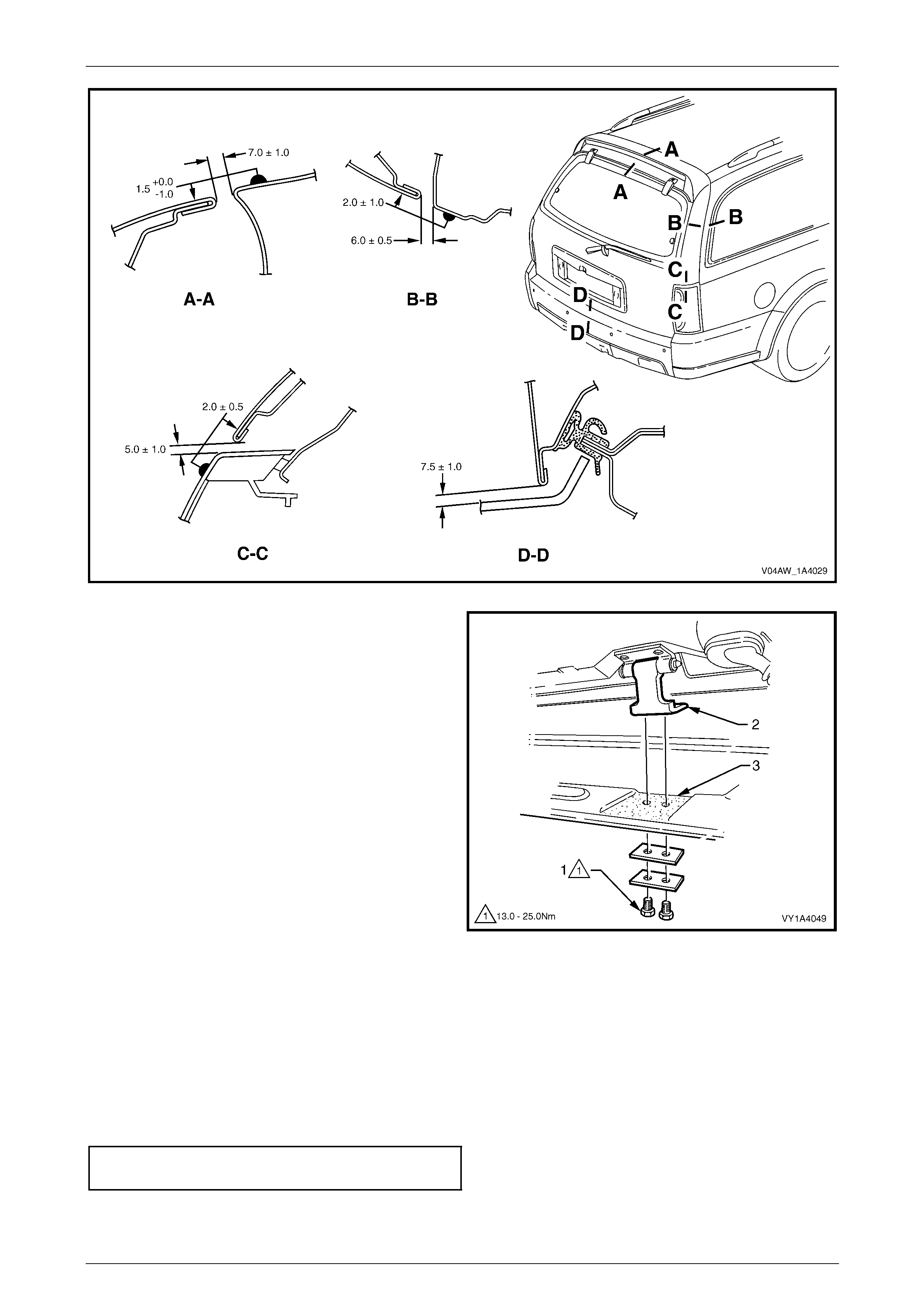
Hood, Rear Compartment Lid, Liftgate and Endgate Page 1A4–122
Page 1A4–122
Figure 1A4 – 146
6 If the gap between the liftgate assembly and roof
panel is not within specification and/or is not parallel to
the quarter panel on each side, open the liftgate
assembly and adjust the posit ion of the liftgate hinges.
a If required, remove the liftgate window upper
garnish, refer to Section 1A8 Headlining and
Interior Trim.
b Loosen the two screws (1), attaching the liftgate
hinge (2).
c Lift the hinge away from the body and apply
sealer (Lord Fusor #800 or #801 or equivalent)
to the area shown (3).
d Adjust the position of the liftgate hinge, tighten
the screws and recheck the liftgate assembly
alignment. NOTE
Do not make all adjustments at once. Perform
one adjustment, then carefully close the liftgate
assembly, check its position and make further
adjustments until the correct alignment is
achieved.
Figure 1A4 – 147
7 If the gap between the liftgate assembly and roof panel is within specification and the liftg ate assembly is parallel to
the quarter panel on each side, open the liftgate assembly and adjust the liftgate bumpers to provide a slightly
greater gap at the lower edge of the liftgate assembly above each tail lamp. This allows the liftgate striker assembly
to pull the liftgate assembly in slightly when closed.
8 Install the liftgate striker assembly, refer to 6.17 Liftgate Striker Assembly.
9 Close the liftgate assembly. Ensure the liftgate striker assembly does not pull the liftgate assemb ly to one side,
changing the panel gaps; if the gap ch anges, move the liftgate striker assembly as required.
10 Tighten the screws to the correct torque specification.
Liftgate hinge attaching screw
torque specification.................................13.0 – 25.0 Nm
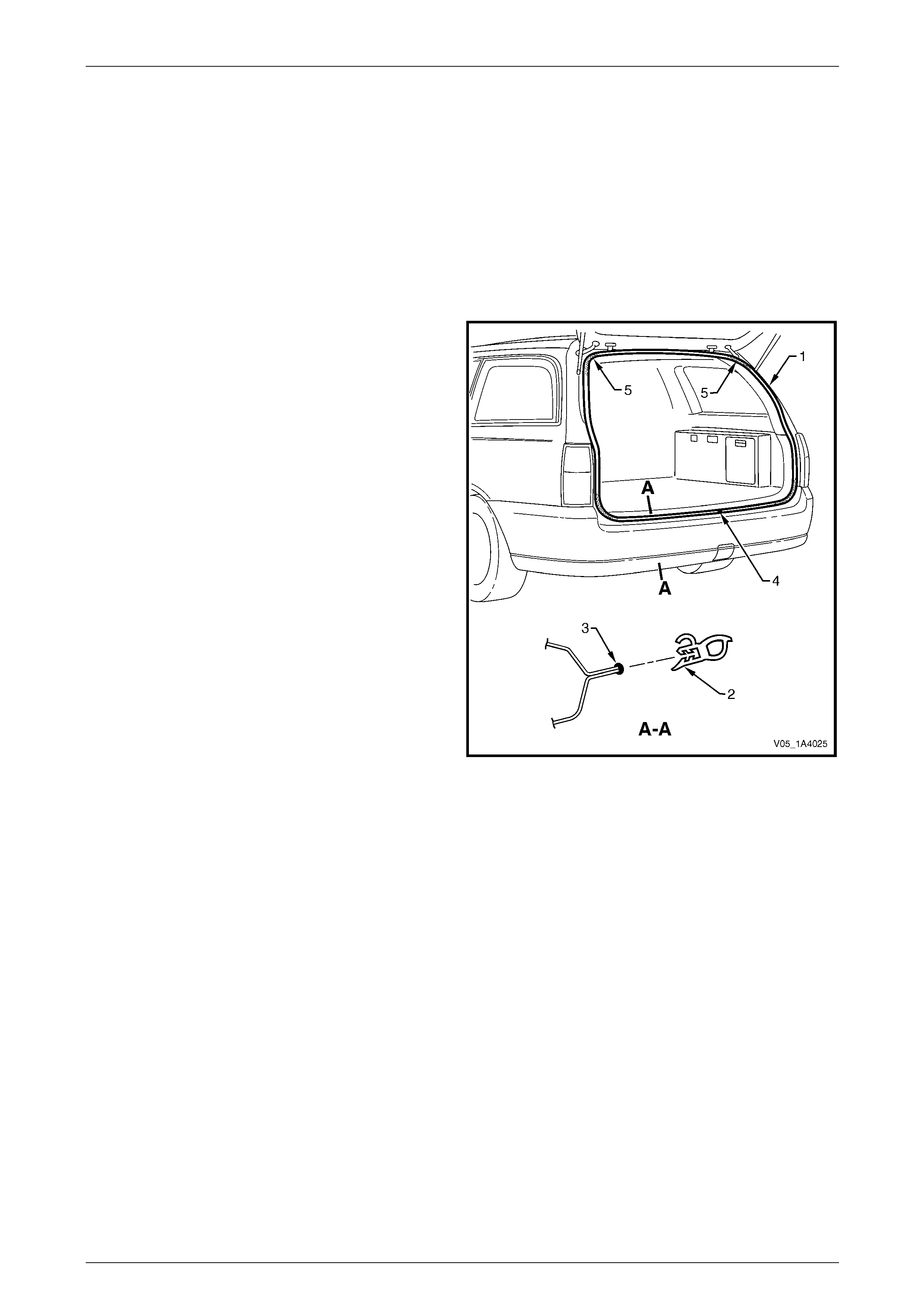
Hood, Rear Compartment Lid, Liftgate and Endgate Page 1A4–123
Page 1A4–123
7.15 Liftgate Weatherstrip Assembly
LT Section No. — 11–600
Remove
NOTE
While not necessary, removal of the trim panels
eases installation of the liftgate weatherstrip
assembly.
1 Grasping the liftgate weatherstrip assembly (1),
carefully pull it from the body flange. Start at one poi nt
and continue along its length.
2 Remove the weatherstrip assembly from the vehicle.
Figure 1A4 – 148
Reinstall
Reinstallation of the liftgate weatherstrip assembly is the reverse of the removal procedure, noting the following:
1 Lay the weatherstrip assembly on the floor and ensure the longer side of the weatherstrip (2) faces the outside,
refer to Figure 1A4 – 148.
2 Apply a small bead of non-hardening windscreen sealer such as butyl-mastic or equivalent (3) to the body flange.
3 Locate the weatherstrip assembly join (4) and al ign it with the liftgate striker assembly.
4 Fit the weatherstrip assembly onto the body flange and, beginning at the join, push it into positio n.
NOTE
Allow the liftgate weatherstrip assembly to crowd
in each corner (5) to avoid short cutting the
corners. If required, crimp the liftgate weatherstrip
assembly to ensure a tight fit onto the body
flange.
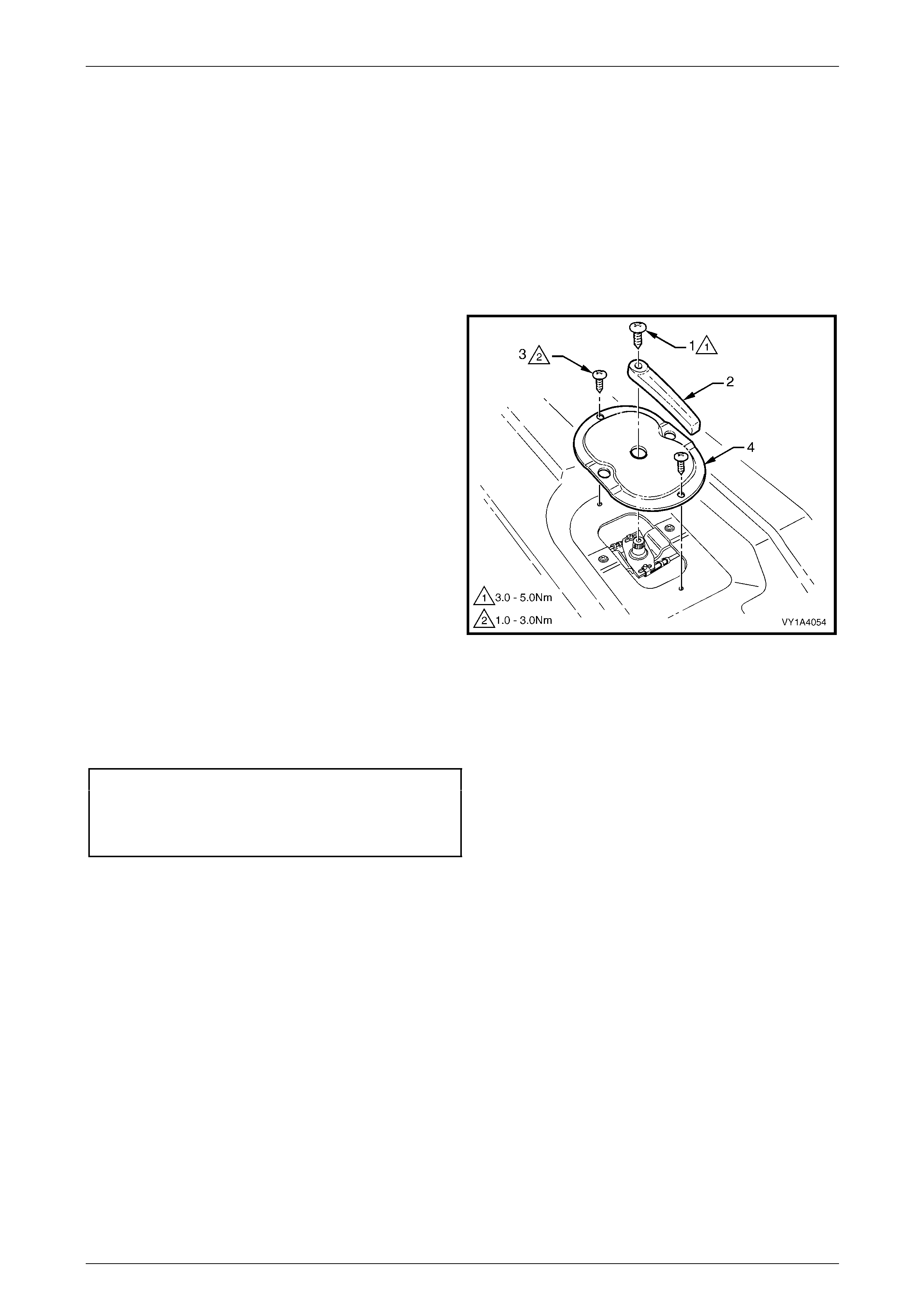
Hood, Rear Compartment Lid, Liftgate and Endgate Page 1A4–124
Page 1A4–124
8 Service Operations — Endgate,
Utility
8.1 Endgate Inner Panel Access Hole Cover
LT Section No. — 12–685
Remove
1 Remove the screw (1) attaching the endgate
handle (2).
2 Remove the two screws (3) attaching the en dgate
inner panel access hole cover (4).
Figure 1A4 – 149
Reinstall
Reinstallation of the endgate inner panel access hole cover is the reverse of the removal procedure. Tighten the screws
to the correct torque specification.
Endgate handle attaching
screw torque specification...........................3.0 – 5.0 Nm
Endgate inner panel access hole cover
attaching screw torque specification...........1.0 – 3.0 Nm
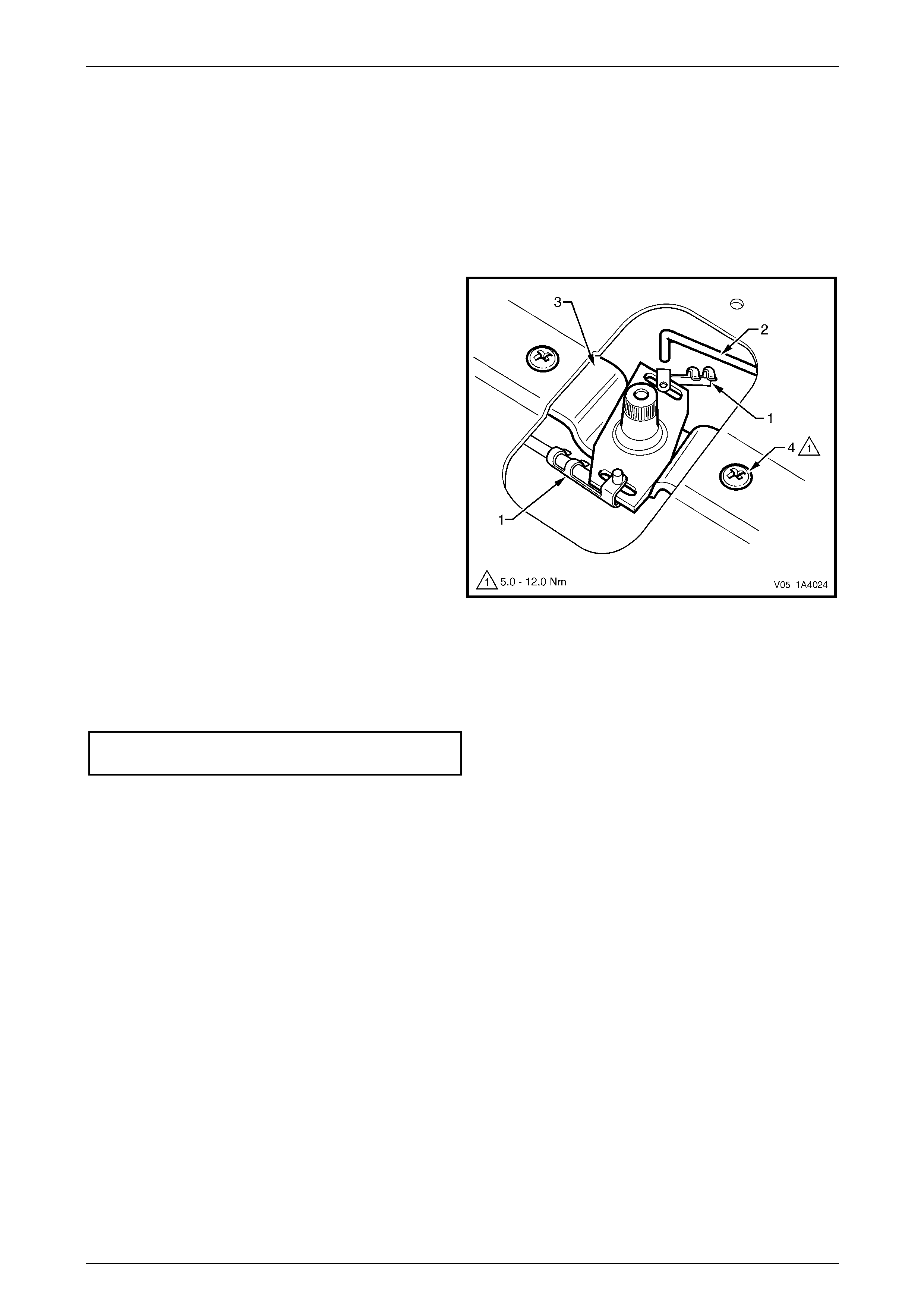
Hood, Rear Compartment Lid, Liftgate and Endgate Page 1A4–125
Page 1A4–125
8.2 Endgate Lock Anchor Plate Assembly
LT Section No. — 12–685
Remove
1 If required, remove the endgate handl e and endgate inner panel access hole cover,
refer to 8.1 Endgate Inner Panel Access Hole Cover.
2 Unclip the two retainers (1), from the endgate latch
assembly (2).
3 Disconnect the latch assemblies from the endgate lock
anchor plate assembly (3).
4 Remove the screw (4), two places, attaching the
anchor plate assembly to the endgate assembly.
5 Remove the anchor plate assembl y from the endgate
assembly cavity.
Figure 1A4 – 150
Reinstall
Reinstallation of the endgate lock anchor plate assembly is the reverse of the removal procedure. Tighten the screws to
the correct torque specification.
Endgate lock anchor plate assembly
attaching screw torque specification.........5.0 – 12.0 Nm
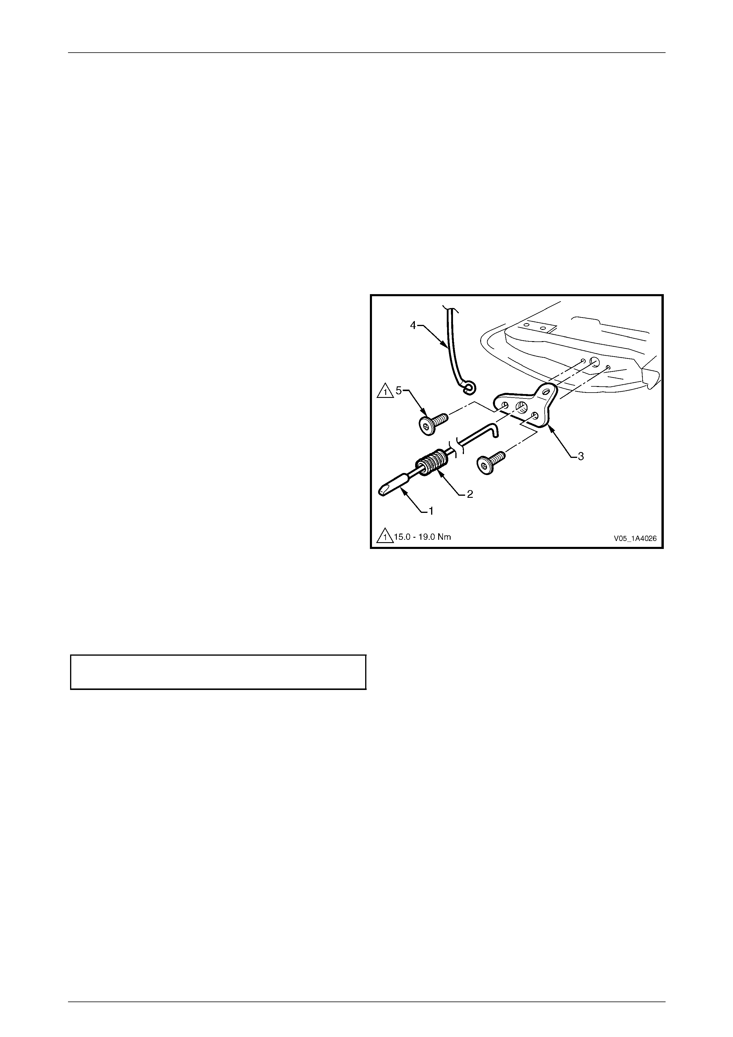
Hood, Rear Compartment Lid, Liftgate and Endgate Page 1A4–126
Page 1A4–126
8.3 Endgate Latch Assembly and Endgate
Latch Bracket Assembly
LT Section No. — 12–685
Remove
1 If required:
a Remove the endgate handle and endgate inner panel access hole cover,
refer to 8.1 Endgate Inner Panel Access Hole Cover.
b Unclip the retainer and discon nect the endgate latch assembly from the endgate lock anchor plate assembly,
refer to 8.2 Endgate Lock Anchor Plate Assembly.
2 Withdraw the endgate latch assembly (1) and
spring (2) from the endgate latch bracket
assembly (3).
3 With the aid of an assistant, unhook the endgate cable
assembly (4) from the latch bracket assembly.
4 Remove the two Torx-head screws (5), attaching the
latch bracket assembly to the endgate assembly, then
remove the latch bracket assembly.
Figure 1A4 – 151
Reinstall
Reinstallation of the endgate latch assembly and endg ate latch bracket assembly is the reverse of the r emova l
procedure. Tighten the screws to the correct torque specific ation.
Endgate latch bracket assembly
attaching screw torque specification.......15.0 – 19.0 Nm
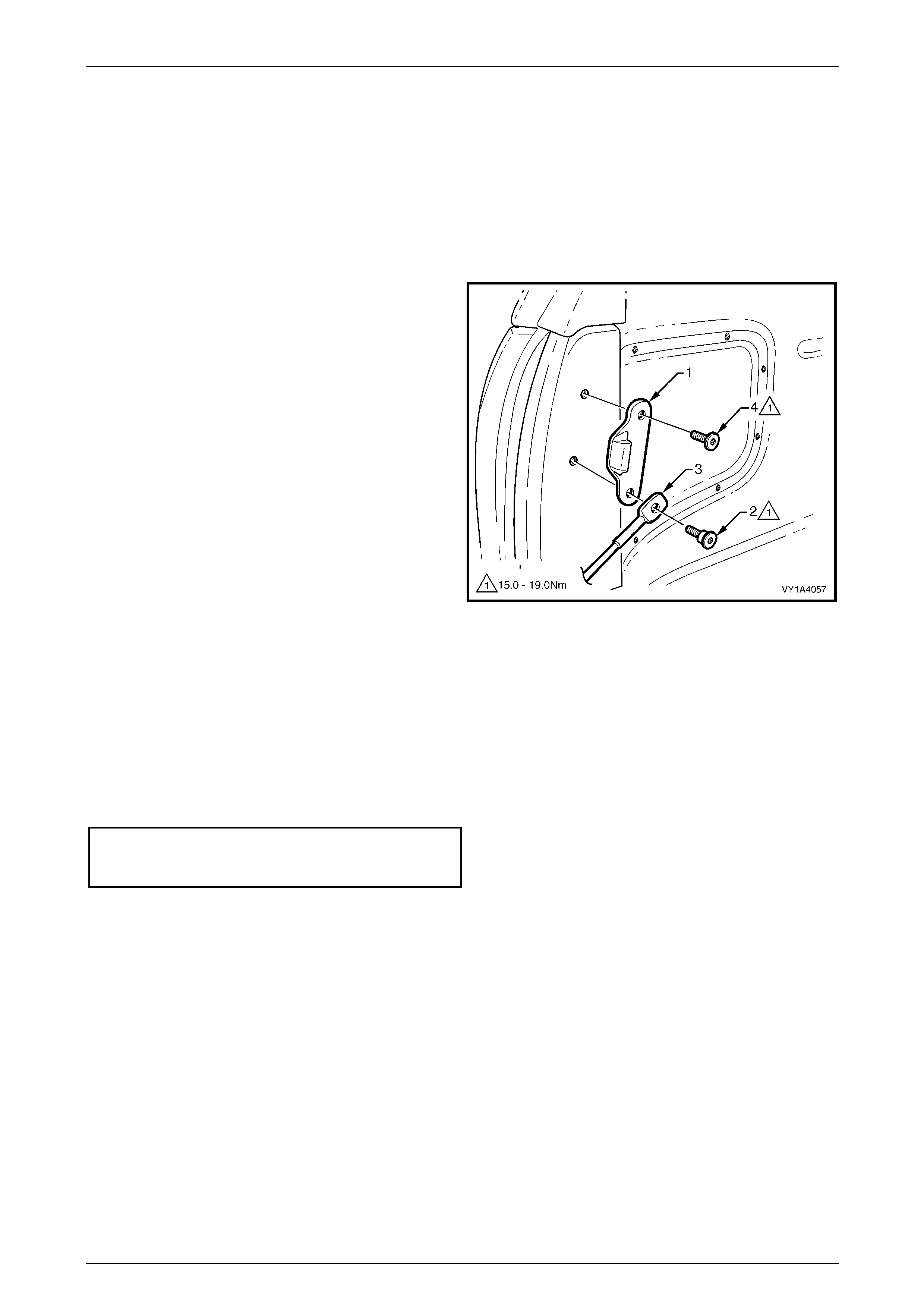
Hood, Rear Compartment Lid, Liftgate and Endgate Page 1A4–127
Page 1A4–127
8.4 Endgate Striker and Endgate Cable
Assembly
LT Section No. — 12–685
Remove
1 Open the endgate and disconnect the endgate cable assembly from the endgate latch bracket assembly.
2 Mark the position of the endgate striker (1) with a
marker pen.
3 Remove the lower screw (2) attaching the endg ate
cable assembly (3) and endgate striker to the vehicle.
Remove the endgate cable assembly.
4 Remove the upper screw (4) attaching the striker to
the vehicle, then remove the striker.
Figure 1A4 – 152
Reinstall
Reinstallation of the endgate striker and endgate cable assembly is the reverse of the removal procedure. T ighten the
screws the correct torque specification.
NOTE
The longer, shanked screw is for the lower cable
assembly and striker hole.
Endgate striker and endgate
cable assembly attaching
screw torque specification.......................15.0 – 19.0 Nm
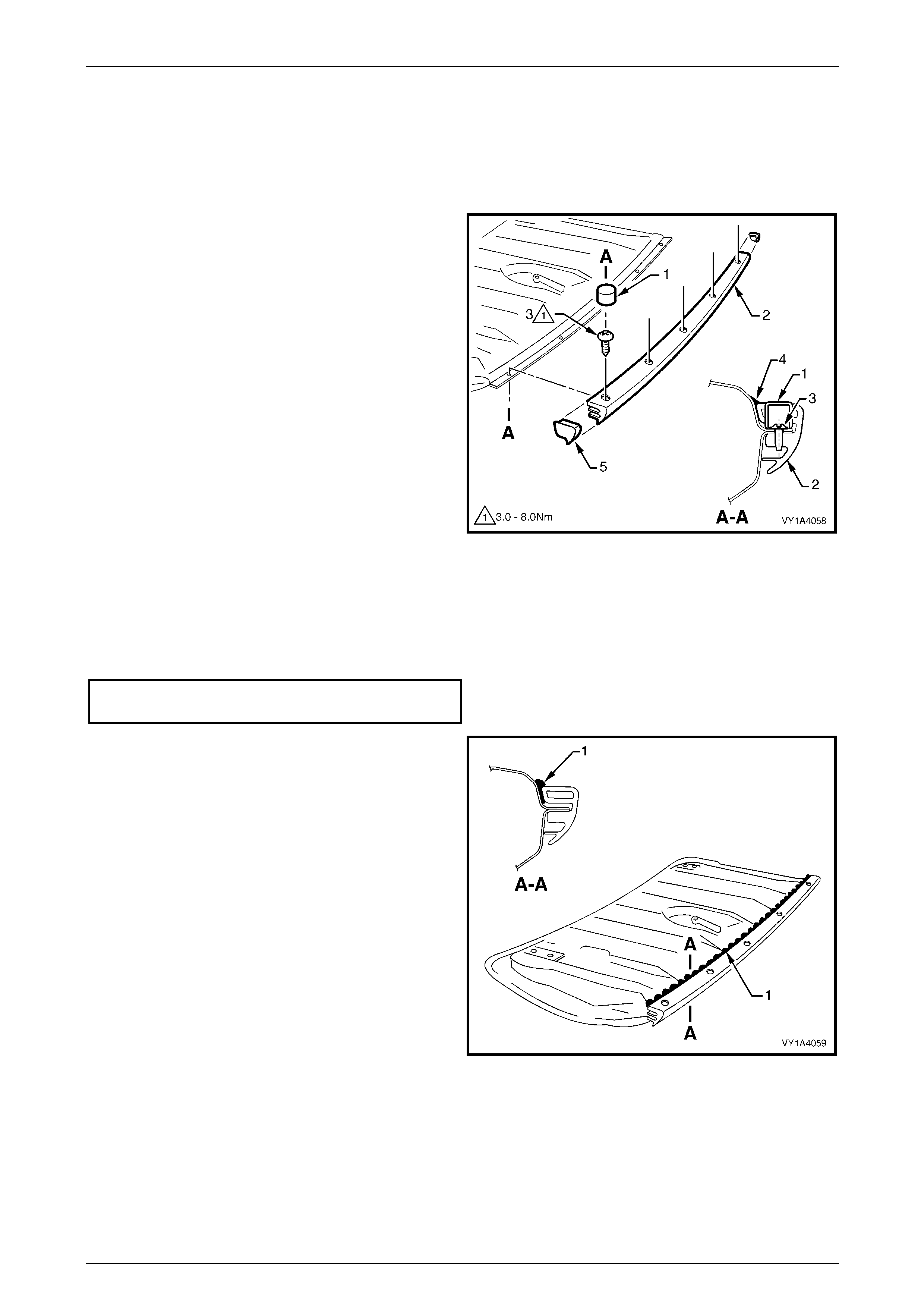
Hood, Rear Compartment Lid, Liftgate and Endgate Page 1A4–128
Page 1A4–128
8.5 Endgate Upper Moulding Assembly
LT Section No. — 12–480
Remove
1 If fitted, prise plug (1), five places, from the endgate
upper moulding assembly (2).
2 Remove the screw (3), five places, attaching the
endgate upper moulding assembly to the endgate
assembly and remove the moulding assembly,
carefully cutting the sealer (4) alon g the lower inside
edge of the moulding.
3 If required, prise the cap (5) from each end the
moulding assembly.
Figure 1A4 – 153
Reinstall
Reinstallation of the endgate upper moulding assemb ly is the reverse of the removal procedure, noting the following:
1 Tighten the screws to the correct torque specification.
Endgate upper moulding assembly
attaching screw torque specification...........3.0 – 8.0 Nm
2 Apply a bead of sealer (1) (Lo r d F usor #122, #123,
#125 or #126, or 3M Automix 830 7 or 8308 or
equivalent) to the lower inside edge of the endgate
upper moulding assembl y.
3 Smooth over the sealer to provide a neat, clean finish.
Figure 1A4 – 154
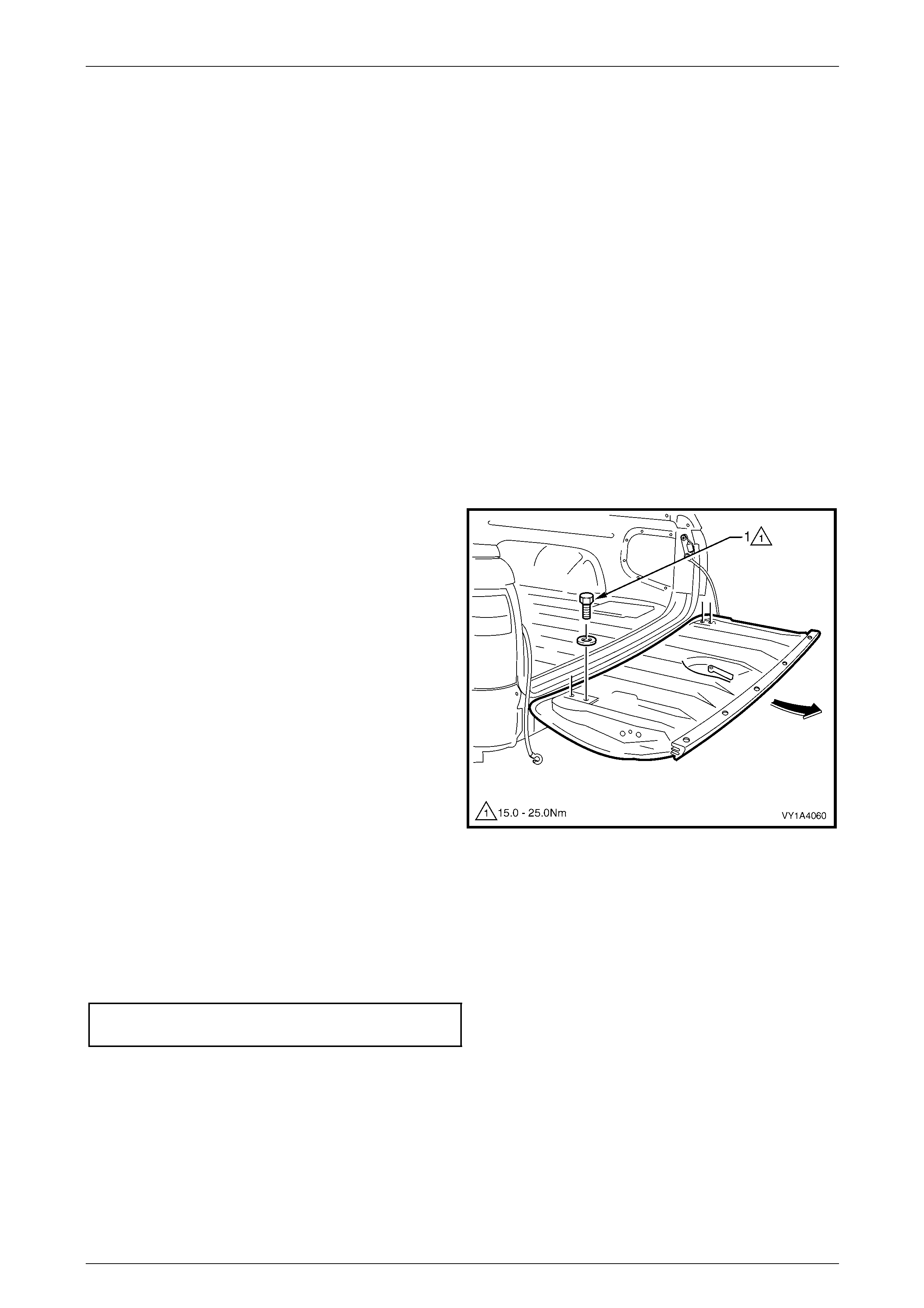
Hood, Rear Compartment Lid, Liftgate and Endgate Page 1A4–129
Page 1A4–129
8.6 Endgate Assembly
LT Section No. — 12–500
NOTE
If the endgate assembly is replaced, a new
endgate hook label is required.
Remove
1 If required, remove the following components:
a Endgate handle and end gate inner panel access hole cover,
refer to 8.1 Endgate Inner Panel Access Hole Cover.
b Endgate lock anchor plate assembly, refer to 8.2 Endgate Lock Anchor Pl ate Assembly.
c Endgate latch assembly and endgate latch bracket assembly,
refer to 8.3 Endgate Latch Assembly and Endgate Latch Bracket Assembly.
d Endgate upper moulding assembly, refer to 8.5 Endgate Upper Moulding Assembly.
e Badges and emblems, refer to Section 1A9 Exterior Ornamentation.
2 Mark the position of the endgate hinge screws with a
marker pen as required.
3 With the aid of an assistant, remove the endgate hinge
screw (1) and washer, four places, attaching the
endgate assembly to the hinge assemblies.
4 Remove the endgate assembl y by sliding it rearwards
from the hinge assemblies.
Figure 1A4 – 155
Reinstall
Reinstallation of the endgate assembly is the reverse of the removal procedure, noting the following:
1 Align the endgate hinge screws with the pen marks or adjust the endgate, refer to Adjust in this Section.
2 Tighten the screws to the correct torque specification.
Endgate assembly attaching screw
torque specification.................................15.0 – 25.0 Nm
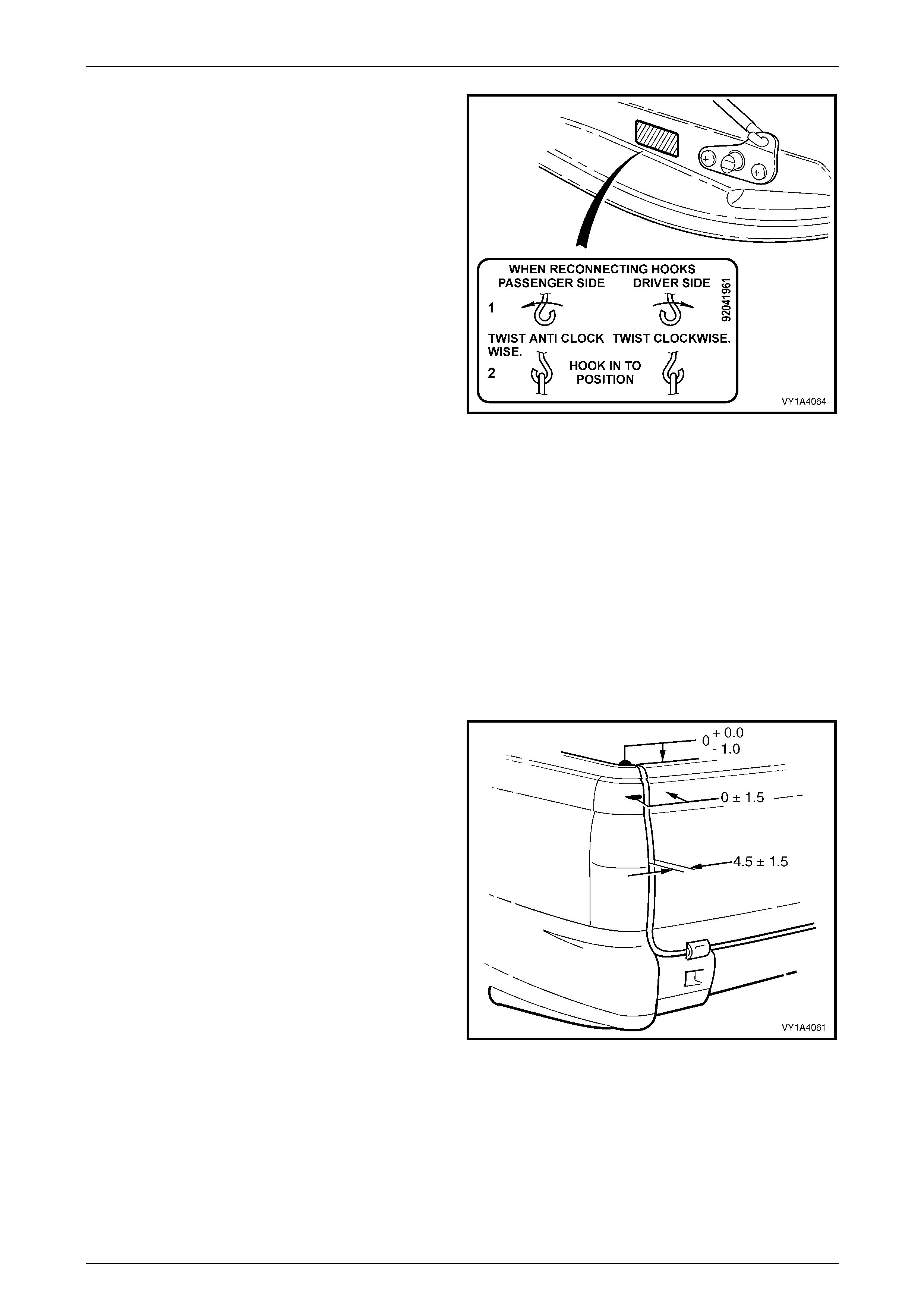
Hood, Rear Compartment Lid, Liftgate and Endgate Page 1A4–130
Page 1A4–130
3 Install the endgate hook label to the left-hand side of
the endgate assembly inner panel as shown.
Figure 1A4 – 156
Adjust
Correct alignment of the endgate assembl y is critical to its operation and to the aesthetics of the vehicle. The following
components allow adjustment of the liftgate:
• endgate assembly hinge screws provide vertical, horizontal and skew adjustment; and
• endgate striker provides adjustment flushness of the endgate assembl y to the veh icle.
If alignment is required, adjust the endgate assembly in the following order:
1 Remove the endgate striker, refer to 8.4 Endgate Striker and Endgate Cable Assembly.
2 Ensure the endgate upper mouldi ng assembly and endgate weatherstrip assembly are installed.
3 Carefully close the endgate assembly, ensuring each side does not contact the vehicle.
4 Check the alignment of the endgate for height,
flushness, width and consistency of gap to the side
panel outer and tail lamps.
5 If required, loosen the endgate hinge screws and
reposition the endgate assembly. If enough
adjustment can not be obtained, loosen the lower
hinge assembly screws, refer to
8.7 Endgate Hinge Assembly. Reposition the hing e.
6 Install the endgate striker, refer to
8.4 Endgate Striker and Endgate Cable Assembly.
7 Close the endgate, then adjust the position of the
endgate striker to provide flushness between the
endgate assembly, and the side p anel outer and tail
lamps.
Figure 1A4 – 157
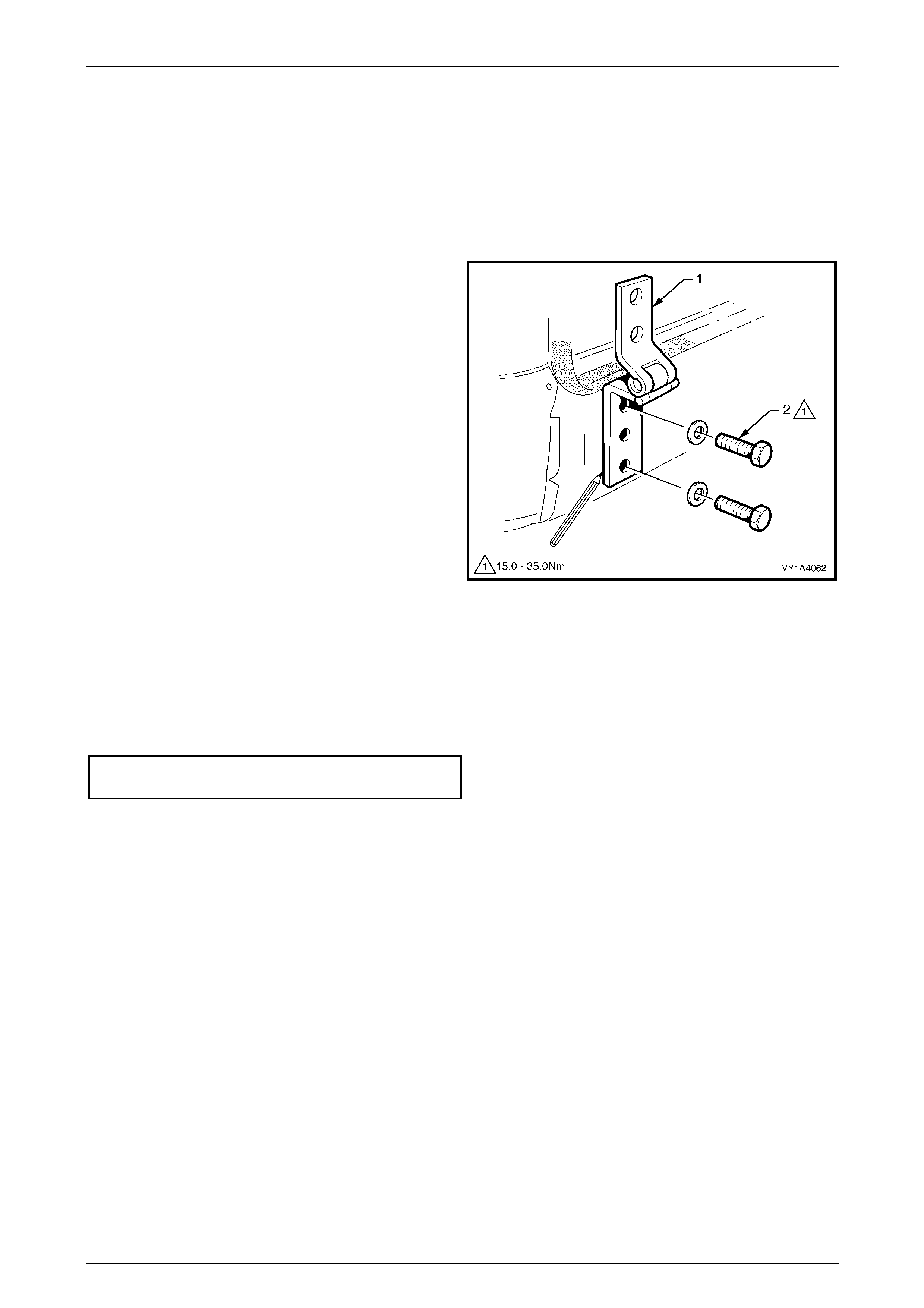
Hood, Rear Compartment Lid, Liftgate and Endgate Page 1A4–131
Page 1A4–131
8.7 Endgate Hinge Assembly
LT Section No. — 12–685
Remove
1 If required, remove the rear bumper fascia, either one or both sides as required, refer to Section 1D Bumper Bars.
2 If installed, close the endgate.
3 Mark the position of the endgate hinge ass embly (1)
with a marker pen.
4 Remove the two screws (2) and washers attaching the
endgate hinge assembly to the vehicle.
5 Remove the endgate hinge as sembly from the vehicle.
Figure 1A4 – 158
Reinstall
Reinstallation of the endgate hinge assembly is the reverse of the removal procedure, noting the following:
1 Align the endgate hinge assembly with the pen marks or adjust the endgate, refer to 8.6 Endgate Assembly.
2 Tighten the screws to the correct torque specification.
Endgate hinge assembly attaching
screw torque specification.......................15.0 – 35.0 Nm
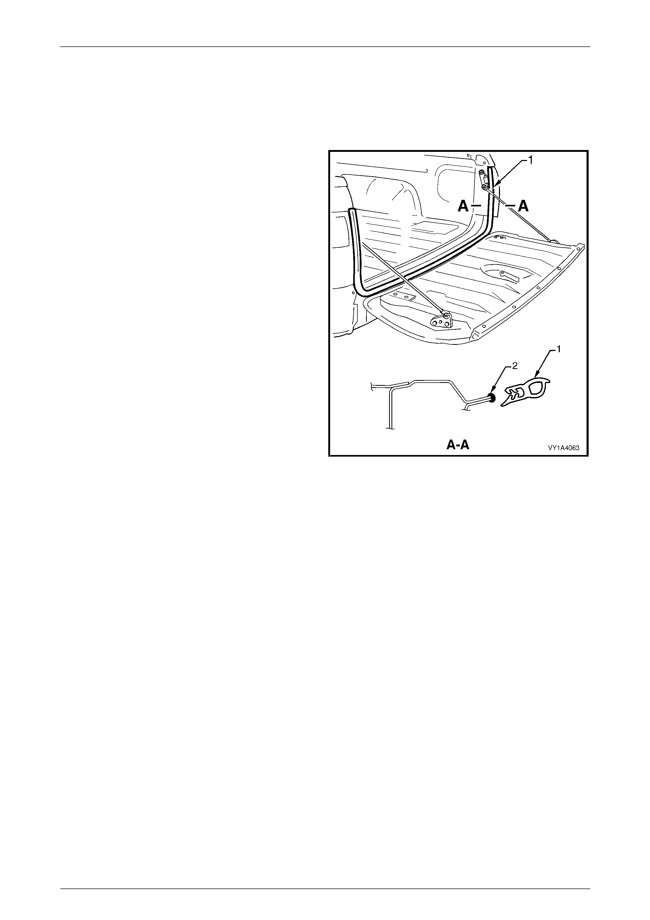
Hood, Rear Compartment Lid, Liftgate and Endgate Page 1A4–132
Page 1A4–132
8.8 Endgate Weatherstrip Assembly
LT Section No. — 11–600
Remove
1 Grasping the endgate weatherstrip assembly (1),
carefully pull it away from the body flange. Start at one
end and continue along its length.
2 Remove the weatherstrip assembly from the vehicle.
Figure 1A4 – 159
Reinstall
Reinstallation of the endgate weatherstrip assembly is the reverse of the removal proce dure, noting the following:
1 Lay the weatherstrip assembly on the endgate assembly and ensure the longer side of the weatherstrip (2) faces
the outside, refer to Figure 1A4 – 159.
2 Apply a small bead of non-hardening windscreen sealer such as butyl-mastic or equivalent (2) to the body flange.
3 Fit the weatherstrip assembly onto the body flange and, sea t ing it against the quarter panel rear mouldin g, push it
into position.
NOTE
Allow the endgate weatherstrip assembly to
crowd in each corner to avoid short-cutting the
corners. If required, crimp the endgate
weatherstrip assembly to ensure a tight fit onto
the body flange.
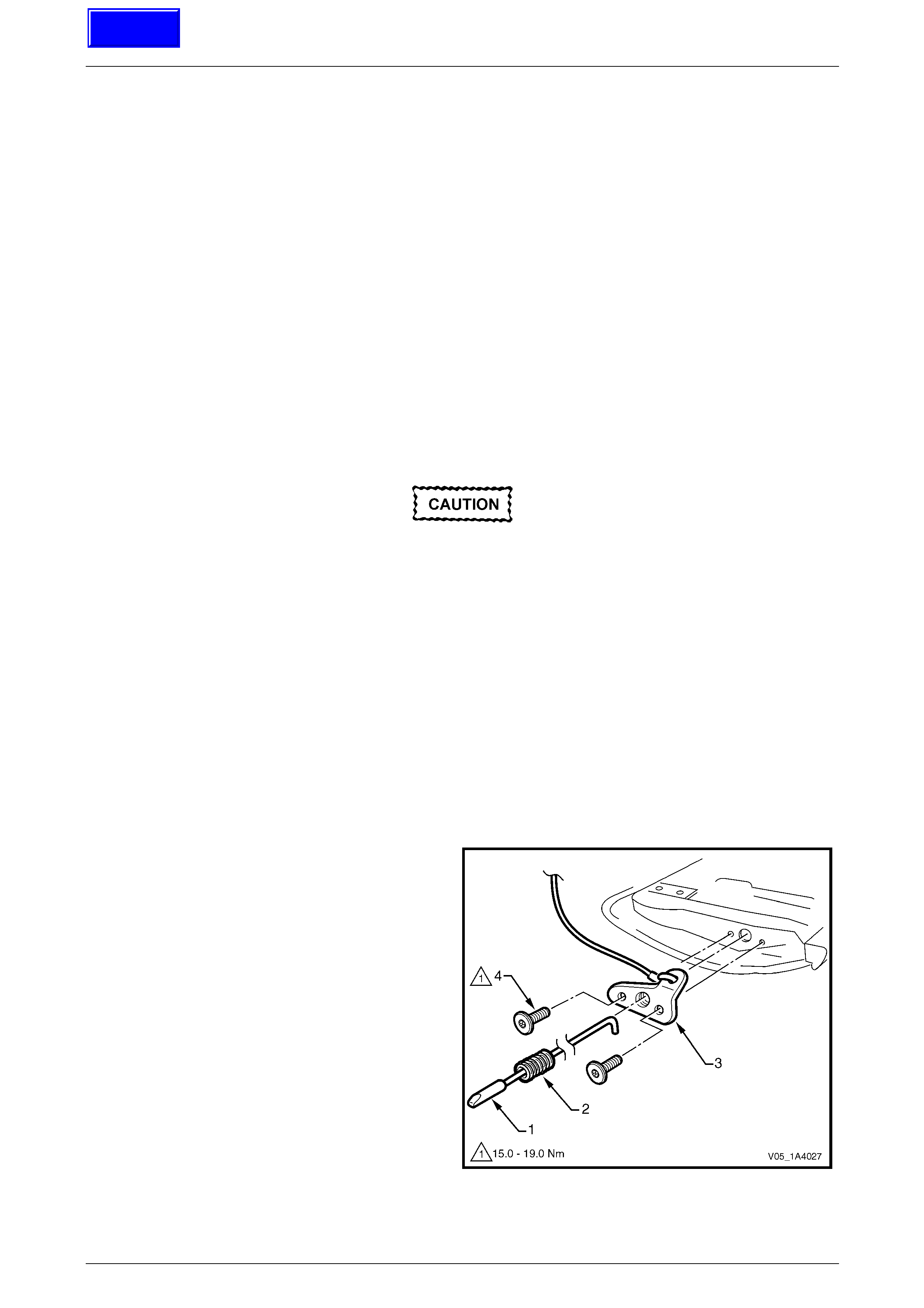
Hood, Rear Compartment Lid, Liftgate and Endgate Page 1A4–133
Page 1A4–133
9 Service Operations — Endgate,
Crew Cab and AWD Crew Cab
NOTE
This Section contains the service procedures for
components of the Crew Cab endgate that differ
from the Utility. For information not contained in
this Section, refer to 8 Service Operations —
Endgate, Utility.
9.1 Endgate Latch Bracket and Cable
Assembly, and Endgate Striker
LT Section No. — 12–685
Remove
Disconnecting either end of the cable
assembly causes the endgate to interfere w ith
the bumper fascia. This could result in
damage to either the bumper fascia or the
endgate. Ensure the liftgate is supported at all
times during removal.
NOTE
Crew Cab vehicles are fitted with a full- width rear
bumper fascia. The endgate can not be
unhooked and lowered to the vertical position.
The endgate cable assembly is permanently
attached to the endgate latch bracket.
1 Remove the endgate handle and endgate inner panel access hole cover,
refer to 8.1 Endgate Inner Panel Access Hole Cover.
2 Unclip both retainers from the endgate latch assembly retainer and disconnect the endgate latch assembly from the
endgate lock anchor plate assembly, refer to 8.2 Endgate L ock Anchor Pl ate Assembly.
3 Withdraw the endgate latch assembly (1) and
spring (2) from the endgate latch bracket and cable
assembly (3).
4 With the aid of an assistant, remove the latch bracket
and cable assembly.
5 Remove the two Torx-head screws (4) attaching the
latch bracket and cable assembl y to the endgate
assembly, then remove the latch bracket assembly.
Figure 1A4 – 160
Techline
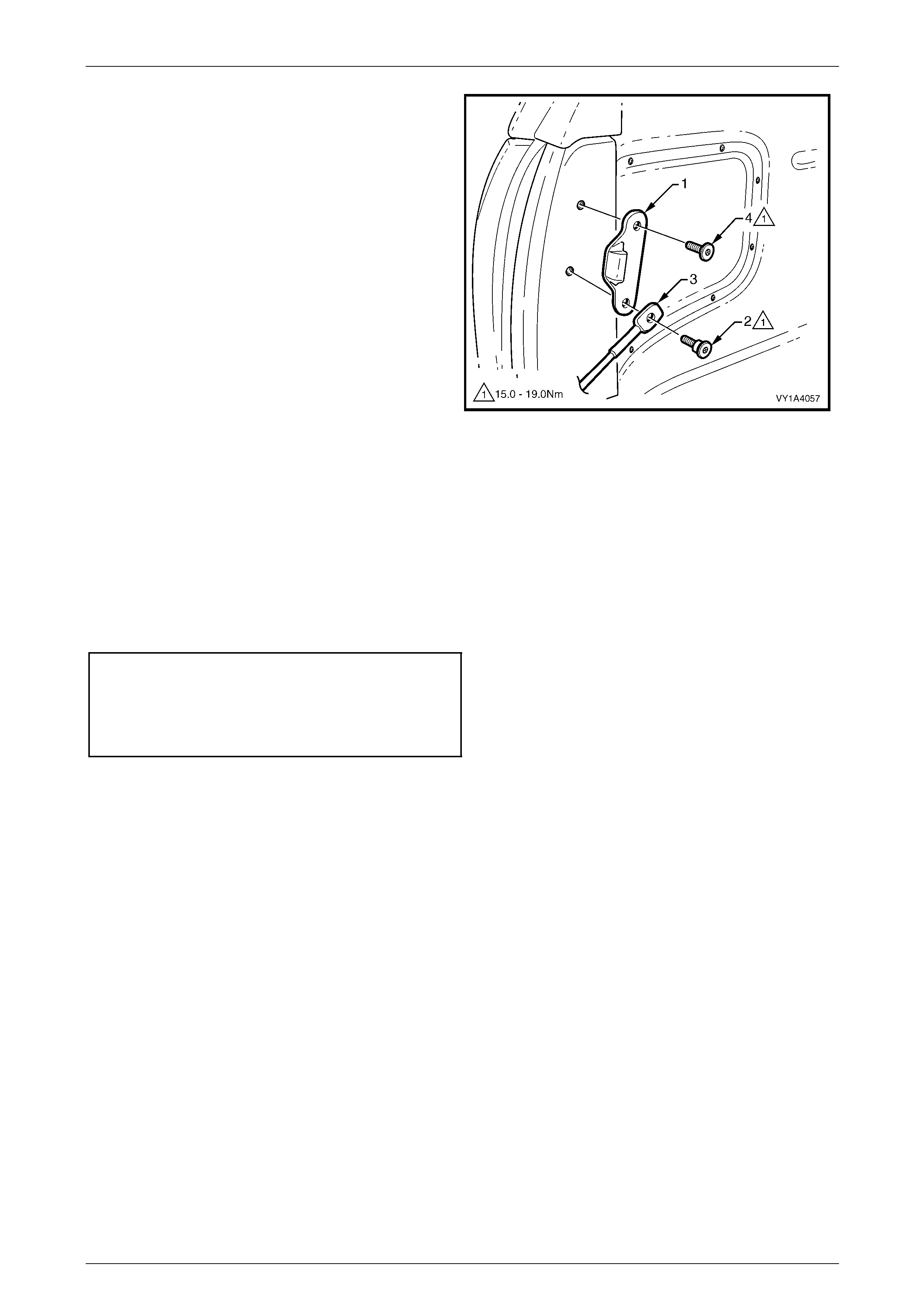
Hood, Rear Compartment Lid, Liftgate and Endgate Page 1A4–134
Page 1A4–134
6 Mark the position of the endgate striker (1) with a
marker pen.
7 Remove the lower screw (2) attaching the latch
bracket and cable assembly (3), and the striker to the
vehicle. Remove the latch bracket and cable
assembly.
8 If required, remove the upper scre w (4) attaching the
striker to the vehicle, then remove the striker.
Figure 1A4 – 161
Reinstall
Reinstallation of the endgate latch bracket and cable asse mbly, and endgate striker is the reverse of the removal
procedure. Tighten the screws to the correct torque specific ation.
NOTE
The longer shanked screw is for the lower
endgate latch bracket and cable assembly and
endgate striker hole.
Endgate striker attaching screw
torque specification.................................15.0 – 19.0 Nm
Endgate latch bracket and
cable assembly attaching
screw torque specification.......................15.0 – 19.0 Nm

Hood, Rear Compartment Lid, Liftgate and Endgate Page 1A4–135
Page 1A4–135
10 Torque Wrench Specifications
10.1 Hood – Except Coupe
Hood Primary Latch Striker Nut.................................................22.0 – 28.0 Nm
Hood Primary Latch Release Cable
Retainer Screw..............................................................................1.0 – 3.0 Nm
Hood Strut Ball Stud..................................................................13.0 – 22.0 Nm
Hood Strut Assembly To Fender
Attaching Screw ........................................................................10.0 – 14.0 Nm
Hood Front Moulding Attaching Screw..........................................1.0 – 2.0 Nm
Hood Front Moulding Assembly Screw..........................................3.0 – 5.0 Nm
Upper Hinge Section Attaching Screw ......................................10.0 – 25.0 Nm
Lower Hinge Section Attaching Screw ......................................10.0 – 25.0 Nm
Hood Hinge Screw ....................................................................10.0 – 25.0 Nm

Hood, Rear Compartment Lid, Liftgate and Endgate Page 1A4–136
Page 1A4–136
10.2 Hood – Coupe
Hood Primary Latch Striker Nut.................................................22.0 – 28.0 Nm
Hood Primary Latch Release Cable
Retainer Screw .............................................................................1.0 – 3.0 Nm
Hood Strut Ball Stud..................................................................13.0 – 22.0 Nm
Hood Strut Assembly To Fender
Attaching Screw ........................................................................10.0 – 14.0 Nm
Upper Hinge Section Attaching Screw ......................................10.0 – 25.0 Nm
Lower Hinge Section Attaching Screw ......................................10.0 – 25.0 Nm
Hood Hinge Screw ....................................................................10.0 – 25.0 Nm

Hood, Rear Compartment Lid, Liftgate and Endgate Page 1A4–137
Page 1A4–137
10.3 Rear Compartment Lid – Sedan
Spare Wheel Stowage Cover
Hook Attaching Screw...................................................................1.0 – 3.0 Nm
Rear Compartment Lid Appli qué
Assembly Attaching Screw............................................................0.8 – 1.5 Nm
Rear Compartment Lid Appli qué
Assembly Attaching Nut ................................................................2.0 – 5.0 Nm
High-Mount Stop Lamp Assembl y
Attaching Screw ....................................................................................5.0 Nm
Rear Spoiler Assembly Attaching Nut ...........................................2.0 – 5.0 Nm
Rear Compartment Lid Latch
Assembly Attaching Screw............................................................2.0 – 5.0 Nm
Rear Compartment Lid Actuator
Assembly Attaching Screw............................................................2.0 – 5.0 Nm
Rear Compartment Lid Release
Cable Assembly Attaching Screw..................................................2.0 – 5.0 Nm
Rear Compartment Lid Assembly
Attaching Screw ..........................................................................6.0 – 12.0 Nm
Rear Compartment Courtesy Lamp
Switch Assembly Attaching Screw ................................................1.0 –3.0 Nm
Rear Compartment Lid Hinge
Assembly Attaching Screw..........................................................6.0 – 14.0 Nm
Rear Compartment Lid Striker
Assembly Attaching Screw........................................................15.0 – 35.0 Nm

Hood, Rear Compartment Lid, Liftgate and Endgate Page 1A4–138
Page 1A4–138
10.4 Rear Compartment Lid – Coupe
Spare Wheel Stowage Cover Hook
Attaching Screw ............................................................................1.0 – 3.0 Nm
Rear Compartment Lid Appli qué
Assembly Retainer Attaching Screw .............................................1.0 – 3.0 Nm
Rear Compartment Lid Appli qué
Assembly Lower Attaching Screw.................................................1.0 – 3.0 Nm
Rear Compartment Lid Appli qué
Assembly Attaching Nut ................................................................2.0 – 5.0 Nm
Rear Compartment Lid Appli qué
Assembly Outer Attaching Screw..................................................1.0 – 3.0 Nm
Rear Compartment Lid Latch Assembly
Attaching Screw ............................................................................2.0 – 5.0 Nm
Rear Compartment Lid Actuator Assembly
Attaching Screw ............................................................................2.0 – 5.0 Nm
Rear Compartment Lid Release Cable
Assembly Attaching Screw (Rear Seat-Back) ..............................1.9 – 2.1 Nm
Rear Compartment Lid Release Cable
Assembly Attaching Screw (Rear Compartment Lid) ....................2.0 – 5.0 Nm
Rear Compartment Lid Assembly Attaching Screw.....................6.0 – 12.0 Nm
Rear Compartment Courtesy Lamp
Switch Assembly Attaching Screw ................................................1.0 –3.0 Nm
Rear Compartment Lid Hinge Assembly
Attaching Screw .........................................................................6.0 – 14.0 Nm
Rear Compartment Lid Striker Assembly
Attaching Screw .......................................................................15.0 – 35.0 Nm

Hood, Rear Compartment Lid, Liftgate and Endgate Page 1A4–139
Page 1A4–139
10.5 Liftgate – Wagon
Liftgate Appliqué Assembly Attaching Nut ....................................2.0 – 5.0 Nm
Liftgate Handle Push-Button Assembl y
Attaching Nut ................................................................................2.0 – 5.0 Nm
Liftgate Latch Assembly Attaching Screw .....................................2.0 – 5.0 Nm
Liftgate Actuator Assembly Attaching Screw ................................ 2.0 – 5.0 Nm
Liftgate Air Deflector Assembly Attaching Nut ..............................2.0 – 5.0 Nm
Liftgate Air Deflector Assembly Attaching Screw ..........................2.0 – 5.0 Nm
Liftgate Ball Stud .........................................................................6.0 – 14.0 Nm
Rear Compartment Courtesy
Lamp Switch Assembly Attaching Screw ......................................1.0 – 3.0 Nm
Liftgate Hinge (Body Side) Attaching Screw .............................13.0 – 25.0 Nm
Liftgate Striker Assembly Attaching Screw ............................... 13.0 – 25.0 Nm

Hood, Rear Compartment Lid, Liftgate and Endgate Page 1A4–140
Page 1A4–140
10.6 Liftgate – AWD Wagon
Liftgate Window Release Actuator Attaching Screw .....................2.0 – 5.0 Nm
Liftgate Window Latch Assembly Attaching Screw .......................2.0 – 5.0 Nm
Liftgate Window Release Assembly Attaching Screw ................6.0 – 14.0 Nm
Liftgate Appliqué Assembly Attaching Nut ....................................2.0 – 5.0 Nm
Liftgate Handle Push-Button Assembly Attaching Nut ..................2.0 – 5.0 Nm
High-Mount Stop Lamp Assembly Attaching Screw .....................1.0 – 3.0 Nm
Liftgate Air Deflector Assembly Attaching Nut ..............................2.0 – 5.0 Nm
Liftgate Air Deflector Assembly Attaching Screw ..........................2.0 – 5.0 Nm
Liftgate Window Striker And Handle Screw ..................................4.0 – 7.0 Nm
Liftgate Window Strut Ball Stud ....................................................4.0 – 7.0 Nm
Liftgate Window Hinge Screw........................................................4.0 – 7.0 Nm
Liftgate Window Hinge Nut............................................................3.0 – 6.0 Nm
Liftgate Window Upper Strut Bracket Nut ..................................... 3.0 – 6.0 Nm
Liftgate Hinge (Body Side) Attaching Screw .............................13.0 – 25.0 Nm
Liftgate Hinge Attaching Screw .................................................13.0 – 25.0 Nm

Hood, Rear Compartment Lid, Liftgate and Endgate Page 1A4–141
Page 1A4–141
10.7 Endgate – Utility
Endgate Handle Attaching Screw .................................................3.0 – 5.0 Nm
Endgate Inner Panel Access Hole Cover
Attaching Screw ...........................................................................1.0 – 3.0 Nm
Endgate Lock Anchor Plate Assembly
Attaching Screw .........................................................................5.0 – 12.0 Nm
Endgate Latch Bracket Assembly
Attaching Screw .......................................................................15.0 – 19.0 Nm
Endgate Striker And Endgate
Cable Assembly Attaching Screw .............................................15.0 – 19.0 Nm
Endgate Upper Moulding Assembly
Attaching Screw ...........................................................................3.0 – 8.0 Nm
Endgate Assembly Attaching Screw..........................................15.0 – 25.0 Nm
Endgate Hinge Assembly Attaching Screw ..............................15.0 – 35.0 Nm

Hood, Rear Compartment Lid, Liftgate and Endgate Page 1A4–142
Page 1A4–142
10.8 Endgate – Crew Cab and AWD Crew Cab
Endgate Striker Attaching Screw...............................................15.0 – 19.0 Nm
Endgate Latch Bracket and Cable
Assembly Attaching Screw........................................................15.0 – 19.0 Nm