
Front and Rear Door Assemblies Page 1A5–1
Page 1A5–1
Section 1A5
Front and Rear Door Assemblies
ATTENTION
Before performing any service operation or other procedure described in this Section, refer to Section 00
Warnings, Cautions and Notes for correct workshop practices with regard to safety and/or property damage.
1 General Information ...............................................................................................................................7
1.1 Door Assemblies.................................................................................................................................................... 7
Door Frames........................................................................................................................................................... 7
Door Windows........................................................................................................................................................ 7
Door Mechanisms.................................................................................................................................................. 7
Door Trims.............................................................................................................................................................. 7
Door Seals.............................................................................................................................................................. 7
2 Service Operations – Front Door External Components ...................................................................8
2.1 Front Door Hinge Lubrication............................................................................................................................... 8
2.2 Front Door Lock Striker Plate Assembly ............................................................................................................. 9
Remove................................................................................................................................................................... 9
Reinstall.................................................................................................................................................................. 9
2.3 Front Door Remote Inner Handle Assembly...................................................................................................... 10
Remove................................................................................................................................................................. 10
Reinstall................................................................................................................................................................ 10
2.4 External Rear-view Mirror ................................................................................................................................... 11
Remove and Reinstall.......................................................................................................................................... 11
3 Service Operations – Front Door Trim Panel Assembly ..................................................................12
3.1 Front Door Trim Panel......................................................................................................................................... 12
Remove................................................................................................................................................................. 12
Disassemble......................................................................................................................................................... 13
Trim Panel – Configuration One....................................................................................................................... 14
Trim Panel – Configuration Two....................................................................................................................... 15
Trim Panel – Coupe ......................................................................................................................................... 16
Exterior Rear-view Mirror Switch...................................................................................................................... 17
Front Door Radio Speaker Grille...................................................................................................................... 17
Front Door Insulator Assembly......................................................................................................................... 18
Lower Side Impact Insert (where fitted)............................................................................................................ 18
Front Door Map Pocket Assembly.................................................................................................................... 19
Front Door Armrest Insert Assembly................................................................................................................ 20
Front Door Inner Pull Handle Assembly........................................................................................................... 21
Front Door Window Defogger Air Duct............................................................................................................. 22
Front Door Air Outlet Assembly........................................................................................................................ 23
Front Door Air Duct Assembly.......................................................................................................................... 23
Front Door Inner Sealing Strip Assembly......................................................................................................... 24
Front Door Courtesy Lamp (where fitted)......................................................................................................... 24
Reinstall................................................................................................................................................................ 24
Techline
Techline

Front and Rear Door Assemblies Page 1A5–2
Page 1A5–2
4 Service Operations – Front Door Internal Components...................................................................25
4.1 Front Door Lock and Actuator Assembly.......................................................................................................... 25
Remove................................................................................................................................................................. 25
Disassemble......................................................................................................................................................... 26
Reassemble.......................................................................................................................................................... 26
Adjust.................................................................................................................................................................... 27
Reinstall................................................................................................................................................................ 27
4.2 Front Door Outer Handle Assembly................................................................................................................... 28
Remove................................................................................................................................................................. 28
Disassemble – Driver's Side............................................................................................................................... 29
Reassemble – Driver's Side................................................................................................................................ 31
Reinstall................................................................................................................................................................ 31
Lock Cylinder Reset (Free Turn)......................................................................................................................... 32
4.3 Front Door Window Guide Assembly................................................................................................................. 33
Remove................................................................................................................................................................. 33
Reinstall................................................................................................................................................................ 33
4.4 Front Door Window Guide Channel Assembly.................................................................................................. 34
Remove................................................................................................................................................................. 34
Reinstall................................................................................................................................................................ 36
4.5 Front Door Window Regulator Assembly.......................................................................................................... 37
Remove................................................................................................................................................................. 37
Reinstall................................................................................................................................................................ 38
4.6 Front Door Window Assembly............................................................................................................................ 39
Remove................................................................................................................................................................. 39
Reinstall................................................................................................................................................................ 39
Adjust.................................................................................................................................................................... 40
4.7 Front Door Speaker ............................................................................................................................................. 42
Remove and Reinstall.......................................................................................................................................... 42
4.8 Front Door Wiring Harness Assembly............................................................................................................... 43
Remove and Reinstall.......................................................................................................................................... 43
4.9 Exterior Rear-view Mirror Memory Module........................................................................................................ 44
Remove................................................................................................................................................................. 44
Reinstall................................................................................................................................................................ 44
5 Service Operations – Front Door Sealing Components, Except Coupe.........................................45
5.1 Front Door Window Inner Filler Assembly ........................................................................................................ 45
Remove................................................................................................................................................................. 45
Reinstall................................................................................................................................................................ 45
5.2 Front Door Inner Panel Beltline Seals................................................................................................................ 46
Remove................................................................................................................................................................. 46
Reinstall................................................................................................................................................................ 46
5.3 Front Door Window Belt Outer Reveal Moulding Assembly............................................................................ 47
Remove................................................................................................................................................................. 47
Reinstall................................................................................................................................................................ 47
5.4 Front Door Weatherstrip Assemblies ................................................................................................................. 48
Assemblies Lay-out............................................................................................................................................. 48
Remove................................................................................................................................................................. 49
Reinstall................................................................................................................................................................ 49
5.5 Front Door Window Upper Garnish Moulding................................................................................................... 50
Remove................................................................................................................................................................. 50
Reinstall................................................................................................................................................................ 51
5.6 Front Door Water Shield...................................................................................................................................... 52
Remove................................................................................................................................................................. 52
Reinstall................................................................................................................................................................ 52
5.7 Front Door Opening Weatherstrip Assembly.................................................................................................... 53
Remove................................................................................................................................................................. 53
Reinstall................................................................................................................................................................ 53

Front and Rear Door Assemblies Page 1A5–3
Page 1A5–3
6 Service Operations – Front Door Sealing Components, Coupe......................................................54
6.1 Front Door Window Inner Filler Assembly ........................................................................................................ 54
Remove................................................................................................................................................................. 54
Reinstall................................................................................................................................................................ 54
6.2 Front Door Inner Panel Beltline Seals................................................................................................................ 55
Remove................................................................................................................................................................. 55
Reinstall................................................................................................................................................................ 55
6.3 Front Door Window Belt Outer Reveal Moulding Assembly............................................................................ 56
Remove................................................................................................................................................................. 56
Reinstall................................................................................................................................................................ 56
6.4 Front Door Weatherstrip Assemblies ................................................................................................................. 57
Assemblies Lay-out............................................................................................................................................. 57
Remove................................................................................................................................................................. 58
Reinstall................................................................................................................................................................ 58
6.5 Front Door Window Upper Garnish Moulding................................................................................................... 59
Remove................................................................................................................................................................. 59
Reinstall................................................................................................................................................................ 60
6.6 Front Door Water Shield...................................................................................................................................... 61
Remove................................................................................................................................................................. 61
Reinstall................................................................................................................................................................ 61
6.7 Front Door Opening Weatherstrip Assembly.................................................................................................... 62
Remove................................................................................................................................................................. 62
Reinstall................................................................................................................................................................ 62
7 Service Operations – Front Door Assembly......................................................................................63
7.1 Front Door Assembly .......................................................................................................................................... 63
Remove................................................................................................................................................................. 63
Disassemble......................................................................................................................................................... 64
Reassemble.......................................................................................................................................................... 65
Reinstall................................................................................................................................................................ 66
7.2 Adjust Front Door Assembly .............................................................................................................................. 67
Adjustment Procedure ........................................................................................................................................ 67
8 Service Operations – Rear Door External Components...................................................................68
8.1 Rear Door Hinge Lubrication.............................................................................................................................. 68
8.2 Rear Door Lock Striker Plate Assembly ............................................................................................................ 69
Remove................................................................................................................................................................. 69
Reinstall................................................................................................................................................................ 69
8.3 Rear Door Window Regulator Handle Assembly .............................................................................................. 70
Remove................................................................................................................................................................. 70
Reinstall................................................................................................................................................................ 70
8.4 Rear Door Remote Inner Handle Assembly....................................................................................................... 71
Remove................................................................................................................................................................. 71
Reinstall................................................................................................................................................................ 71
9 Service Operations – Rear Door Trim Panel Assembly, Sedan and Wagon..................................72
9.1 Rear Door Trim Panel.......................................................................................................................................... 72
Remove................................................................................................................................................................. 72
Disassemble......................................................................................................................................................... 73
Trim Panel........................................................................................................................................................ 73
Rear Door Radio Speaker Grille....................................................................................................................... 74
Rear Door Insulator Assembly ......................................................................................................................... 74
Rear Door Armrest Insert Assembly................................................................................................................. 75
Rear Door Inner Pull Handle Assembly............................................................................................................ 76
Rear Door Inner Sealing Strip Assemblies....................................................................................................... 76
Rear Door Courtesy Lamp (where fitted).......................................................................................................... 77
Rear Door Power Window Switch (where fitted)............................................................................................... 77
Reinstall................................................................................................................................................................ 77

Front and Rear Door Assemblies Page 1A5–4
Page 1A5–4
10 Service Operations – Rear Door Trim Panel Assembly, Crew Cab.................................................78
10.1 Rear Door Trim Panel .......................................................................................................................................... 78
Remove................................................................................................................................................................. 78
Disassemble......................................................................................................................................................... 79
Trim Panel........................................................................................................................................................ 79
Rear Door Radio Speaker Grille....................................................................................................................... 80
Rear Door Insulator Assembly ......................................................................................................................... 80
Rear Door Armrest Insert Assembly................................................................................................................. 81
Rear Door Pull Cup.......................................................................................................................................... 82
Rear Door Inner Sealing Strip Assembly.......................................................................................................... 82
Rear Door Power Window Switch (where fitted)............................................................................................... 83
Reinstall................................................................................................................................................................ 83
11 Service Operations – Rear Door Internal Components, Sedan and Wagon ..................................84
11.1 Rear Door Lock and Actuator Assembly ........................................................................................................... 84
Remove................................................................................................................................................................. 84
Disassemble......................................................................................................................................................... 85
Reassemble.......................................................................................................................................................... 86
Adjust.................................................................................................................................................................... 86
Reinstall................................................................................................................................................................ 86
11.2 Rear Door Outer Handle Assembly.................................................................................................................... 87
Remove................................................................................................................................................................. 87
Reinstall................................................................................................................................................................ 87
11.3 Rear Door Window Guide Channel Assembly................................................................................................... 88
Remove................................................................................................................................................................. 88
Reinstall................................................................................................................................................................ 89
11.4 Rear Door Window Assembly............................................................................................................................. 90
Remove................................................................................................................................................................. 90
Reinstall................................................................................................................................................................ 90
Adjust.................................................................................................................................................................... 91
11.5 Rear Door Window Regulator Assembly ........................................................................................................... 93
Remove................................................................................................................................................................. 93
Reinstall................................................................................................................................................................ 93
11.6 Rear Door Stationary Window Assembly .......................................................................................................... 95
Remove................................................................................................................................................................. 95
Reinstall................................................................................................................................................................ 95
11.7 Rear Door Speaker............................................................................................................................................... 96
Remove and Reinstall.......................................................................................................................................... 96
11.8 Rear Door Wiring Harness Assembly ................................................................................................................ 97
Remove and Reinstall.......................................................................................................................................... 97
12 Service Operations – Rear Door Internal Components, Crew Cab.................................................98
12.1 Rear Door Lock and Actuator Assembly ........................................................................................................... 98
Remove................................................................................................................................................................. 98
Disassemble......................................................................................................................................................... 99
Reassemble........................................................................................................................................................ 100
Adjust.................................................................................................................................................................. 100
Reinstall.............................................................................................................................................................. 100
12.2 Rear Door Outer Handle Assembly.................................................................................................................. 101
Remove............................................................................................................................................................... 101
Reinstall.............................................................................................................................................................. 102
12.3 Rear Door Window Guide Channel Assembly................................................................................................. 103
Remove............................................................................................................................................................... 103
Reinstall.............................................................................................................................................................. 104

Front and Rear Door Assemblies Page 1A5–5
Page 1A5–5
12.4 Rear Door Window Assembly........................................................................................................................... 105
Remove............................................................................................................................................................... 105
Reinstall.............................................................................................................................................................. 105
Adjust.................................................................................................................................................................. 106
12.5 Rear Door Window Regulator Assembly ......................................................................................................... 108
Remove............................................................................................................................................................... 108
Reinstall.............................................................................................................................................................. 108
12.6 Rear Door Stationary Window Assembly ........................................................................................................ 110
Remove............................................................................................................................................................... 110
Reinstall.............................................................................................................................................................. 110
12.7 Rear Door Speaker............................................................................................................................................. 111
Remove and Reinstall........................................................................................................................................ 111
12.8 Rear Door Wiring Harness Assembly .............................................................................................................. 112
Remove and Reinstall........................................................................................................................................ 112
13 Service Operations – Rear Door Sealing, Sedan and Wagon........................................................113
13.1 Rear Door Window Inner Filler Assembly........................................................................................................ 113
Remove............................................................................................................................................................... 113
Reinstall.............................................................................................................................................................. 113
13.2 Rear Door Inner Panel Beltline Seals............................................................................................................... 114
Remove............................................................................................................................................................... 114
Reinstall.............................................................................................................................................................. 114
13.3 Rear Door Window Belt Outer Reveal Moulding Assembly ........................................................................... 115
Remove............................................................................................................................................................... 115
Reinstall.............................................................................................................................................................. 115
13.4 Rear Door Weatherstrip Assemblies................................................................................................................ 116
Assemblies Lay-out........................................................................................................................................... 116
Remove............................................................................................................................................................... 116
Reinstall.............................................................................................................................................................. 116
13.5 Rear Door Window Upper Garnish Moulding.................................................................................................. 117
Remove............................................................................................................................................................... 117
Reinstall.............................................................................................................................................................. 118
13.6 Rear Door Water Shield..................................................................................................................................... 119
Remove............................................................................................................................................................... 119
Reinstall.............................................................................................................................................................. 119
13.7 Rear Door Opening Weatherstrip Assembly ................................................................................................... 120
Remove............................................................................................................................................................... 120
Reinstall.............................................................................................................................................................. 120
14 Service Operations – Rear Door Sealing, Crew Cab.......................................................................121
14.1 Rear Door Window Inner Filler Assembly........................................................................................................ 121
Remove............................................................................................................................................................... 121
Reinstall.............................................................................................................................................................. 121
14.2 Rear Door Inner Panel Beltline Seal................................................................................................................. 122
Remove............................................................................................................................................................... 122
Reinstall.............................................................................................................................................................. 122
14.3 Rear Door Window Belt Outer Reveal Moulding Assembly ........................................................................... 123
Remove............................................................................................................................................................... 123
Reinstall.............................................................................................................................................................. 123
14.4 Rear Door Weatherstrip Assemblies................................................................................................................ 124
Assemblies Lay-out........................................................................................................................................... 124
Remove............................................................................................................................................................... 124
Reinstall.............................................................................................................................................................. 124

Front and Rear Door Assemblies Page 1A5–6
Page 1A5–6
14.5 Rear Door Window Upper Garnish Moulding.................................................................................................. 125
Remove............................................................................................................................................................... 125
Reinstall.............................................................................................................................................................. 126
14.6 Rear Door Water Shield..................................................................................................................................... 127
Remove............................................................................................................................................................... 127
Reinstall.............................................................................................................................................................. 127
14.7 Rear Door Opening Weatherstrip Assembly ................................................................................................... 128
Remove............................................................................................................................................................... 128
Reinstall.............................................................................................................................................................. 128
15 Service Operations – Rear Door Assembly, Except Crew Cab .....................................................129
15.1 Rear Door Assembly.......................................................................................................................................... 129
Remove............................................................................................................................................................... 129
Disassemble....................................................................................................................................................... 130
Reassemble........................................................................................................................................................ 131
Reinstall.............................................................................................................................................................. 132
15.2 Adjust Rear Door Assembly.............................................................................................................................. 133
Adjustment Procedure ...................................................................................................................................... 133
16 Service Operations – Rear Door Assembly, Crew Cab ..................................................................134
16.1 Rear Door Assembly.......................................................................................................................................... 134
Remove............................................................................................................................................................... 134
Disassemble....................................................................................................................................................... 135
Reassemble........................................................................................................................................................ 136
Reinstall.............................................................................................................................................................. 136
16.2 Adjust Rear Door Assembly.............................................................................................................................. 137
Adjustment Procedure ...................................................................................................................................... 137
17 Torque Wrench Specifications..........................................................................................................138
17.1 Sedan and Wagon.............................................................................................................................................. 138
Front Door .......................................................................................................................................................... 138
Rear Door ........................................................................................................................................................... 139
17.2 Coupe.................................................................................................................................................................. 140
17.3 Crew Cab ............................................................................................................................................................ 141
Front Door .......................................................................................................................................................... 141
Rear Door ........................................................................................................................................................... 142
17.4 Ute and Regular Cab.......................................................................................................................................... 143
18 Special Tools ......................................................................................................................................144

Front and Rear Door Assemblies Page 1A5–7
Page 1A5–7
1 General Information
1.1 Door Assemblies
This Section describes the front and rear doors with their components, mechanism and trim panel.
A complete overview of all trim components is covered by this Section, with the components illustrated and identified for
each vehicle type.
Door Frames
The front and rear door assemblies c onsist each of an outer panel which is hemmed over an inner panel at the door
outer edges. Structural adhesive is applied within the hemmed joint and joint sealer, hand putty and cavity wax are used
for the prevention of corrosion. A rolled upper door frame retains a sliding g lass run channel.
Each door is connected to the body of the v ehicle by an upper and a lower hinge. The male section of the door hinges is
welded to the door inner panel facing and the female section to the correspond ing body pillar. A door check and a h old
open link are located between each door assembly and the corresponding body pillar.
NOTE
The rear door assemblies fitted to Crew Cab
vehicles, although uni que, are similar in des ign to
the rear door assemblies fitted to Sedan and
Wagon vehicles.
Door Windows
Each front door sliding window is operated by a double arm scissor type window regulator which is attached to the g lass
lifter channels and to the front door inner panel.
Each rear door sliding window is operated by a cable type mechanism which is attached to the glass lifter channels and
to the rear door inner panel.
Electrically operated front sliding windows are avai lable on all models. For Sedan, Wagon and Cre w Cab vehicles,
electrically operated rear sliding windows are also available. Electrically operated windows are standard features on
Coupe vehicles.
Door Mechanisms
Lift-bar exterior door handles operate the fork type door locks in conjunction with door lock striker bolts.
A two key locking system uses a master key (with inbuilt remote security features) to operate all locks on the vehicle. A
secondary key operates the glove compartment only. A front door locking rod knob operates the door locks internally.
The front door lock cylinder is fitted onl y to the driver’s door, it is of the ‘free turning’ design which pr events unlocking o f
the door by objects other than the correct key. If any object, except the correct key, is inserted into the lock, the cylinder
will rotate without unlocking the door.
Electric door lock actuators and electric external rear-view mirrors are standard features.
Door Trims
Each front door trim features a map pocket, an air vent with front door window defog, a radio spe aker g rille, a courtesy
lamp (where fitted) and a cloth or leather insert. An insulator is glued at the back of the front door trim panel assemb ly.
On Sedan, Wagon and Crew Cab vehicles, each rear door trim features a radio speaker grille, a courtesy lamp (where
fitted) and a cloth or leather insert. An insulator is glued at the back of the rear door trim pane l assembly.
Door Seals
All doors are fitted with a weatherstrip which incorporate plastic clips to secure it to the door. The plastic clips are
attached to holes located around the outer lower edge of the door inner panel. The upper section of the weatherstrip is
retained in a channel which is an integral part of the rolled upper door frame.
All doors feature a windo w upper weatherstrip which is retai ned in a channel which is an integral part of the rol led upper
door frame. At the lower section of the door window opening, an inner sealing strip is attached to the upper edge of the
trim panel assembly and a window belt outer reveal moul ding is attached to the door panel.
Door opening weatherstrips are fitted to the vehicle body, one weatherstrip is located at each door o pe nin g frame. A
water seal is located between the door frame and trim panel assembly and is glued to the door inner panel.
Front and Rear Door Assemblies Page 1A5–8
Page 1A5–8
2 Service Operations – Front Door
External Components
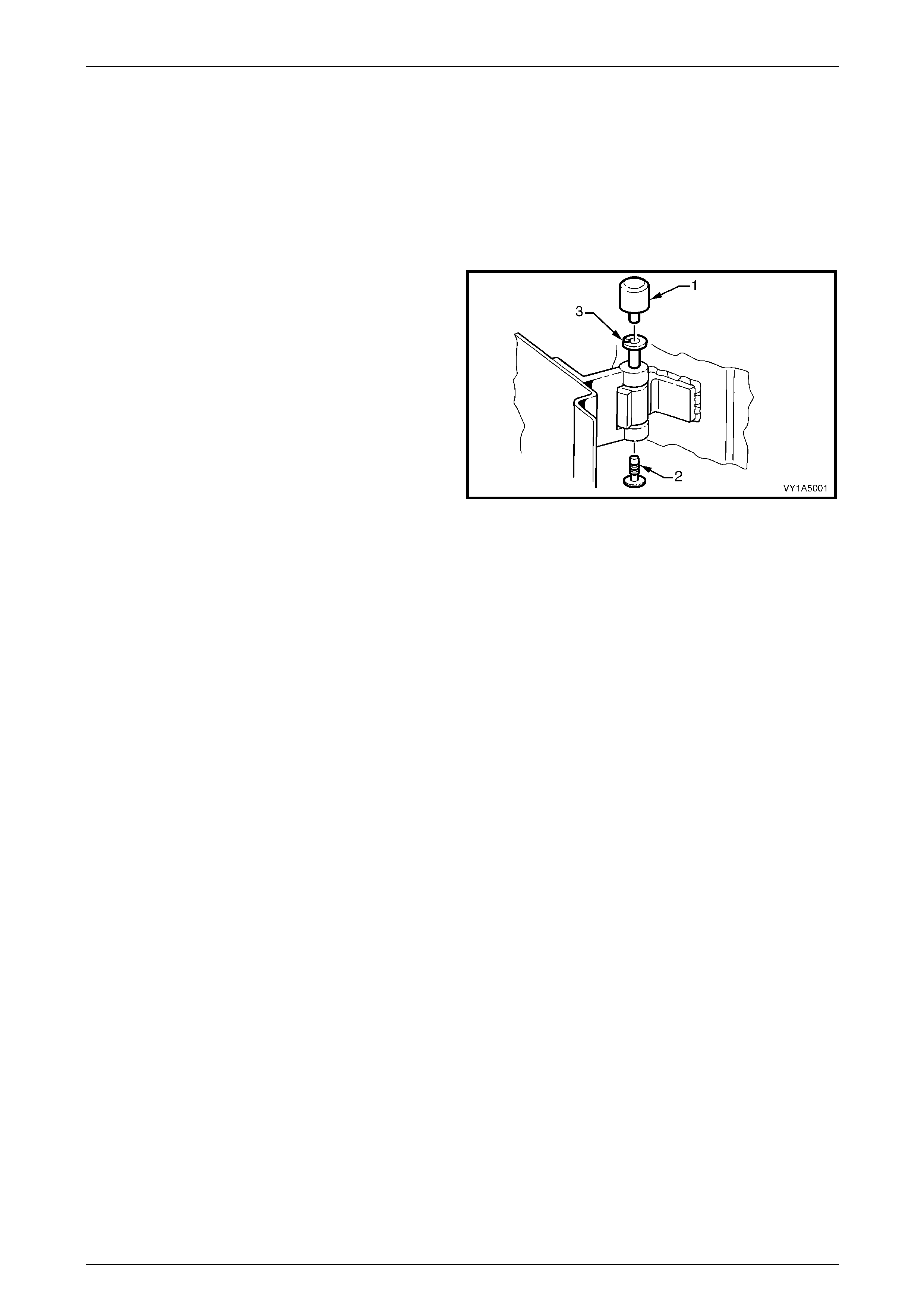
2.1 Front Door Hinge Lubrication
LT Section — 11–370
1 Remove the cap (1) and plug (2) from the hinge pi n (3)
on the upper and lower hinge s .
2 Using a grease gun, inject into the hinge pin, Lithium
base grease NLGI No. 1 ( with 9 % zinc oxide) or
equivalent.
3 Reinstall the cap and plug.
4 Wipe off any excess grease.
Figure 1A5 – 1
Front and Rear Door Assemblies Page 1A5–9
Page 1A5–9
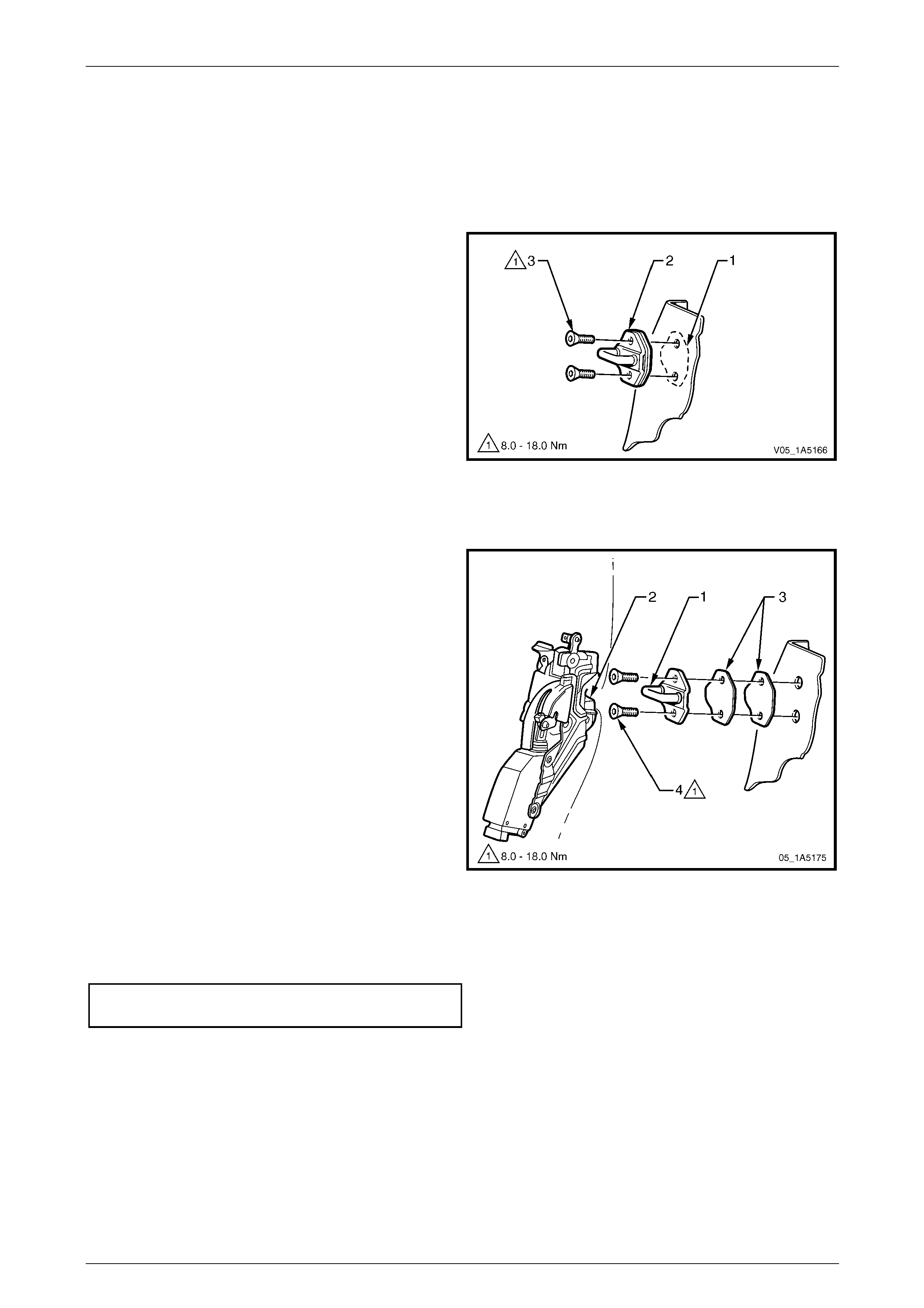
2.2 Front Door Lock Striker Plate Assembly
LT Section — 11–360
Remove
1 Pencil scribe (1) the location of the lock striker plate
assembly (2) on to the body pillar before rem oval, to
facilitate reinstallation.
2 Using a Torx bit (30 T) , remove the two attaching
screws (3).
3 Remove the striker plate assembly and spacer plates,
if fitted.
Figure 1A5 – 2
Reinstall
1 Align the lock striker plate assembl y (1), so the bridge
of the striker locates centrally in the lock assembly
fork (2) as the front door is being closed.
2 Firmly tighten the two screws (4) attaching the striker
plate assembly, do not torque at this stage.
3 Check for correct engagement of the front door lock o n
the striker plate assembly; the front door must not
‘Ride’ on the striker plate assembl y.
4 If required, correct the engagement by vertical or
horizontal adjustment of the lock striker plate
assembly. Add or delete spacer plates (3) between the
striker plate assembly and body pillar, as needed. Also
refer to 7.2 Adjust Front Door Assembly.
NOTE
It is sound practice to remove the striker plate
assembly and allo w the door to hang free on the
hinges. Set the hinges as necessary to achieve
correct alignment and uniform margins, then
reinstall the striker plate assembly and adjust.
5 Tighten the striker plate assembl y attaching screws to
the correct torque specification.
Front door lock striker plate assembly
attaching screws torque specification .......8.0 – 18.0 Nm
Figure 1A5 – 3
Front and Rear Door Assemblies Page 1A5–10
Page 1A5–10
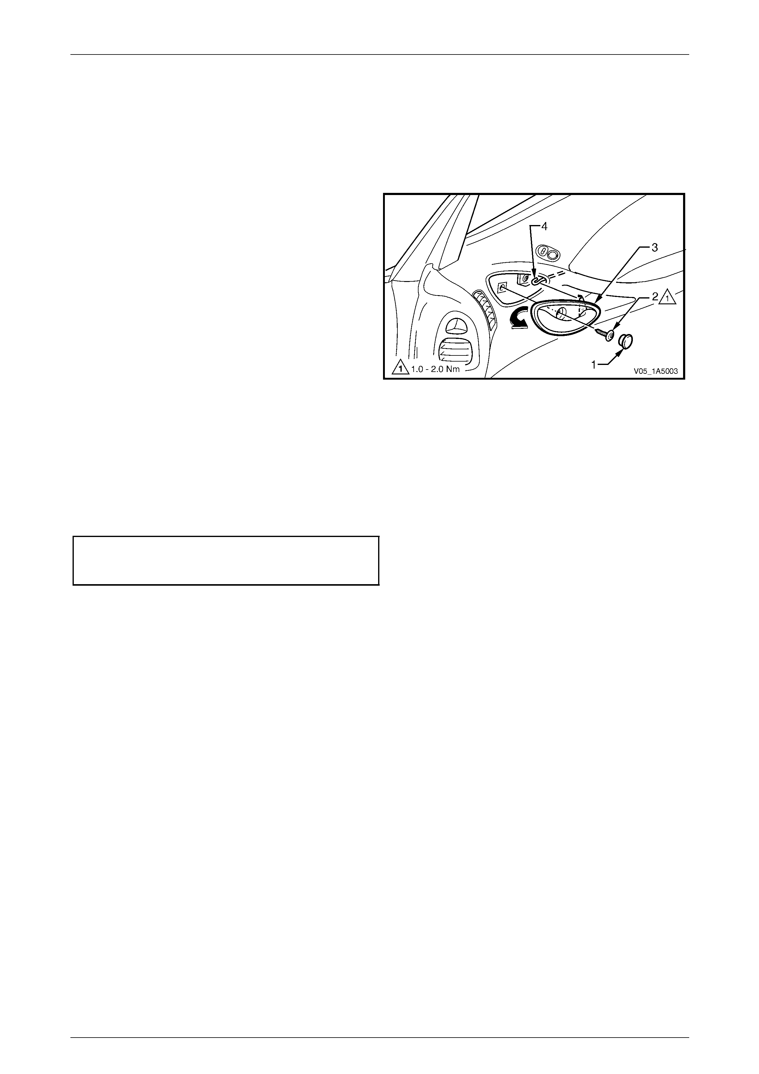
2.3 Front Door Remote Inner Handle
Assembly
LT Section — 11–360
Remove
1 Prise off the remote inner handle bolt finisher cap (1).
2 Remove the screw (2) attaching the remote inner
handle assembly (3) to the trim panel.
3 Remove the remote inner handle assembly in a
forward direction and unhook the remote control
rod (4) from the handle assembly.
Figure 1A5 – 4
Reinstall
Reinstallation of the front door remote inner handle assembly is the reverse of the removal procedure, noting the
following:
1 Ensure the remote inner handle assembly and the remote control rod are engaged before final fitment.
2 Tighten the remote inner handle assembly attaching screw to the correct torque specification.
Front door remote inner handle
assembly attaching screw
torque specification.....................................1.0 – 2.0 Nm

Front and Rear Door Assemblies Page 1A5–12
Page 1A5–12
3 Service Operations – Front Door
Trim Panel Assembly
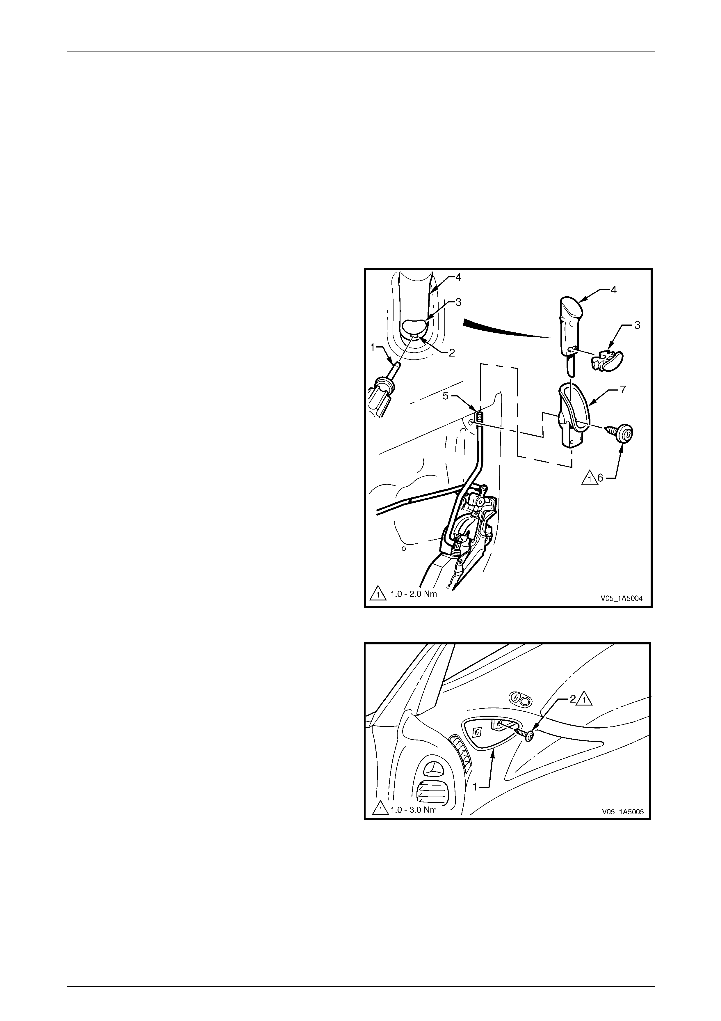
3.1 Front Door Trim Panel
LT Section — 14–220
Remove
1 As required, remove the remote inner handle assembly, refer to 2.3 Front Door Remote Inner Handle Assembly.
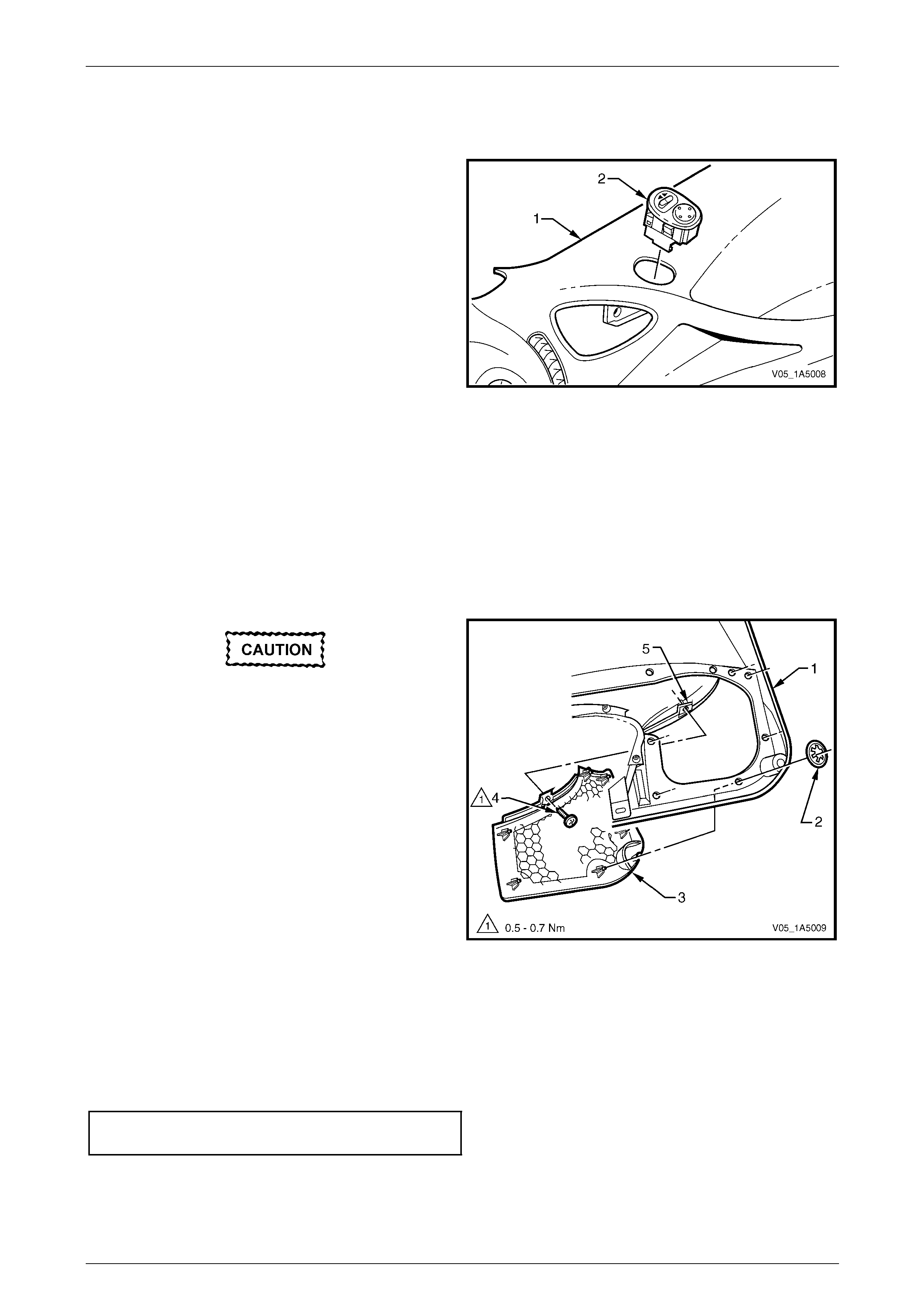
2 Insert a small flat bladed screwdriver or scribe (1) in
the slot (2) below the red locking insert (3).
3 Gently prise the red locking insert from the locking ro d
knob (4), taking care not to damage the knob.
4 Lift-up the locking rod knob to separate it from the
locking rod (5) and remove.
5 Remove the screw (6) attaching the locking rod knob
escutcheon (7) to the inner panel assembly and
remove the escutcheon.
Figure 1A5 – 5
6 Through the remote inner handle assembly
aperture (1), remove the screw (2) attaching the trim
panel assembly to the inner panel assembly.
Figure 1A5 – 6
Front and Rear Door Assemblies Page 1A5–13
Page 1A5–13
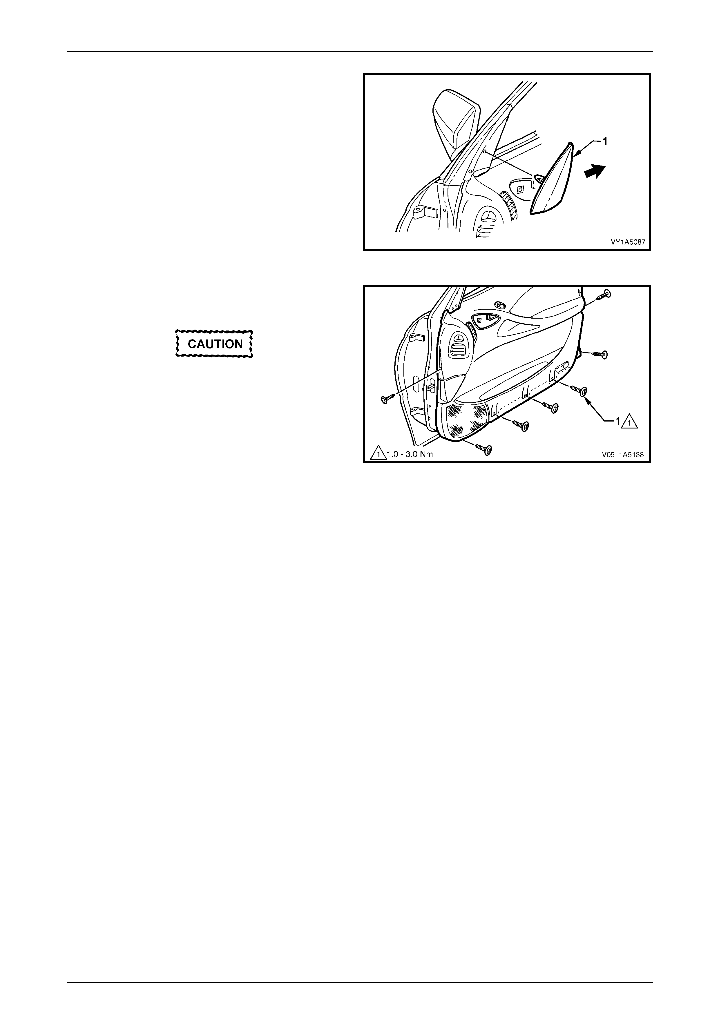
7 Gently prise the front edge of the window defogger
outlet (1) and remove to the rear.
Figure 1A5 – 7
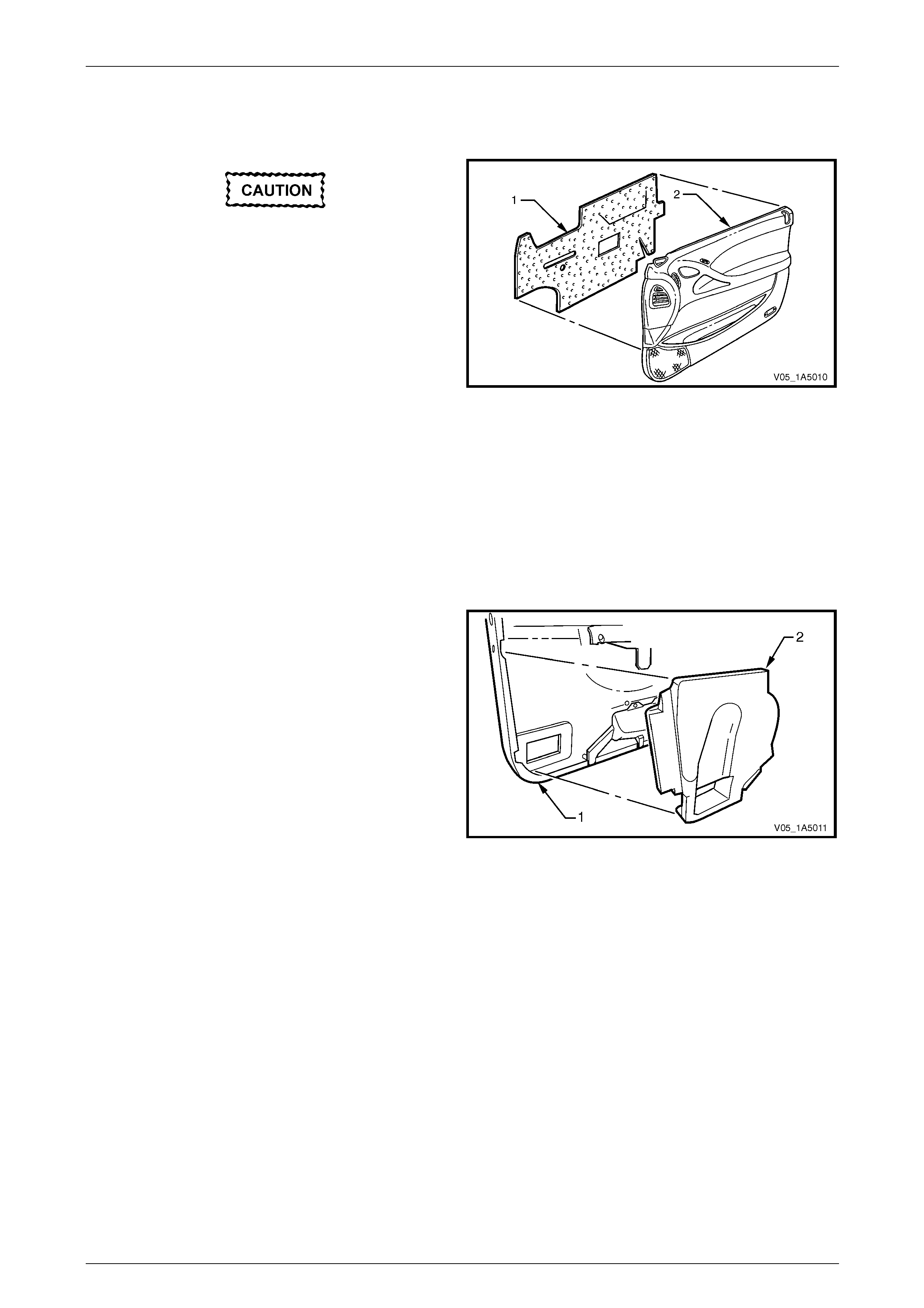
8 Remove the seven screws (1) attaching the trim panel
assembly to the inner panel assembly.
Take care while removing the trim panel
assembly as the wiring harness connectors
are still connected.
9 Lift the top of the trim panel assembly, up and out of
the door inner channel.
10 While supporting the trim panel assem bl y, disconnect
all the wiring harness connectors.
11 Remove the trim panel assembly. Figure 1A5 – 8
Disassemble
To disassemble the front door trim panel assembl y, remov e all the components attached to the trim panel foundation as
described in this Section:
• configuration one, refer to Figure 1A5 – 9
• configuration two, refer to Figure 1A5 – 10
• Coupe, refer to Figure 1A5 – 11.
Front and Rear Door Assemblies Page 1A5–14
Page 1A5–14
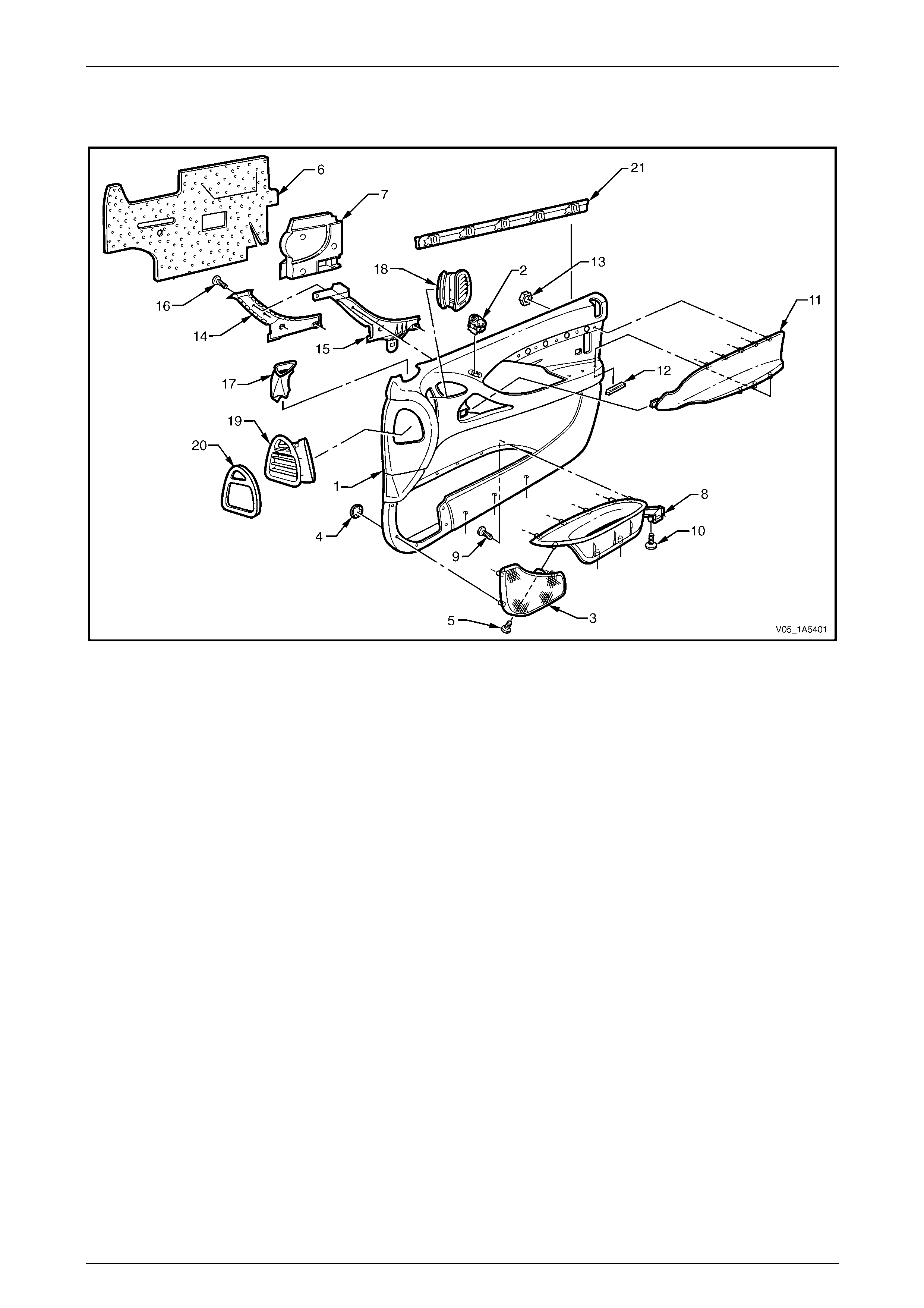
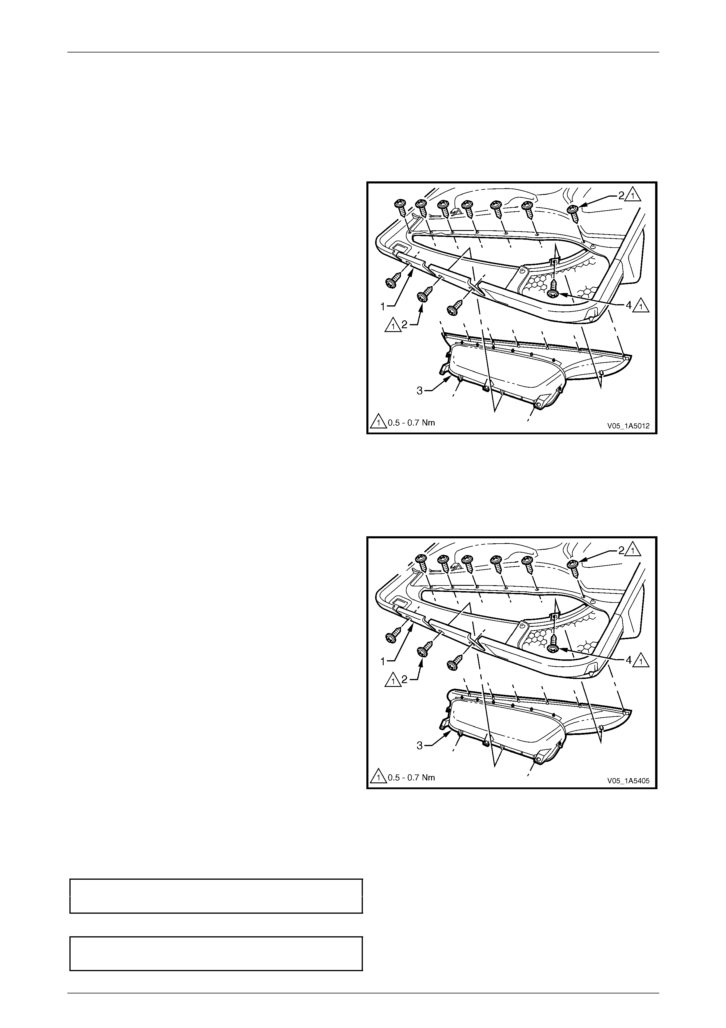
Trim Panel – Configuration One
The front door trim panel configuration o ne is fitted to vehicles without side impact airbags, refer to Figure 1A5 – 9.
Figure 1A5 – 9
Legend
1 Front Door Trim Panel Foundation
2 Exterior Rear-view Mirror Switch (driver’s side only)
3 Front Door Radio Speaker Grille
4 Front Door Radio Speaker Grille Retainer (6 places)
5 Front Door Radio Speaker Grille Screw
6 Front Door Insulator Assembly
7 Lower Side Impact Insert
8 Front Door Map Pocket Assembly
9 Front Door Map Pocket Assembly Screw (5 places)
10 Front Door Map Pocket Assembly Screw (3 places)
11 Front Door Armrest Insert Assembly
12 Front Door Armrest Insert Assembly Clip (3 places)
13 Front Door Armrest Insert Assembly Nut (5 places)
14 Front Door Inner Handle Cover
15 Front Door Inner Handle Bracket
16 Front Door Inner Handle Screw (4 places)
17 Front Door Window Defogger Air Duct
18 Front Door Air Outlet Assembly
19 Front Door Air Duct Assembly
20 Front Door Air Duct Seal
21 Front Door Window Inner Sealing Strip Assembly
Front and Rear Door Assemblies Page 1A5–15
Page 1A5–15
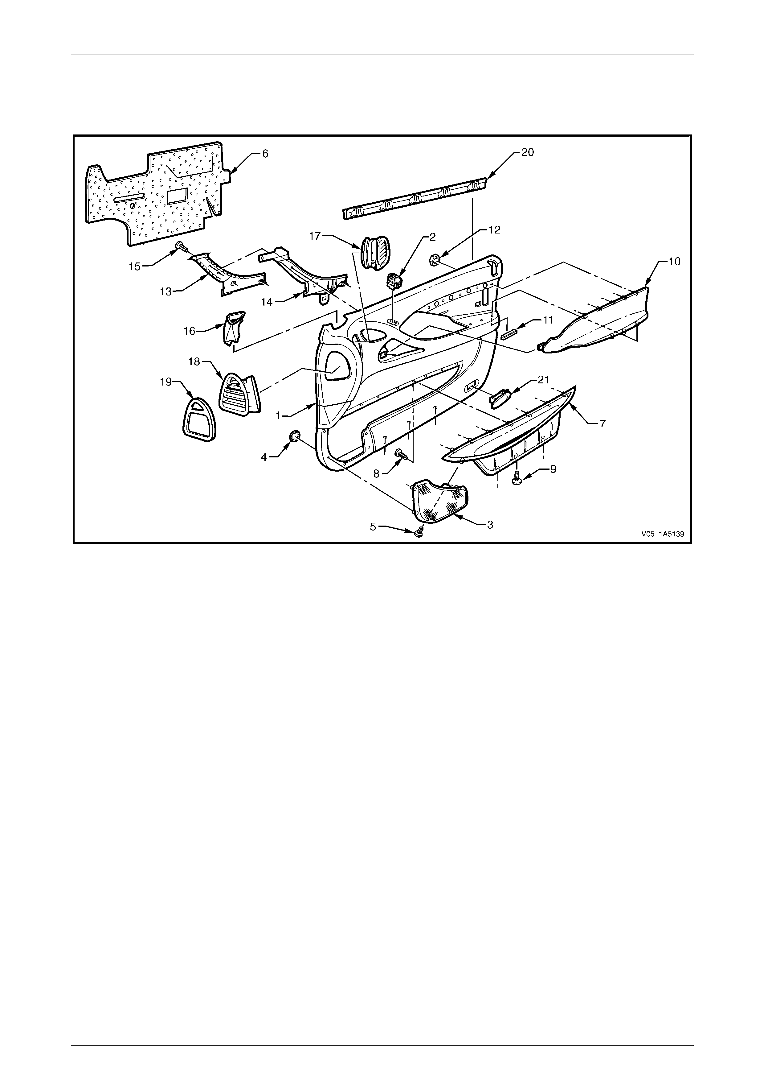
Trim Panel – Configuration Two
The front door trim panel configuration two is fitted to vehicles equipp ed with side impact airbags, except Coupe, refer to
Figure 1A5 – 10.
Figure 1A5 – 10
Legend
1 Front Door Trim Panel Foundation
2 Exterior Rear-View Mirror Switch (driver’s side only)
3 Front Door Radio Speaker Grille
4 Front Door Radio Speaker Grille Retainer (6 places)
5 Front Door Radio Speaker Grille Screw
6 Front Door Insulator Assembly
7 Front Door Map Pocket Assembly
8 Front Door Map Pocket Assembly Screw (7 places)
9 Front Door Map Pocket Assembly Screw (3 places)
10 Front Door Armrest Insert Assembly
11 Front Door Armrest Insert Assembly Clip (3 places)
12 Front Door Armrest Insert Assembly Nut (5 places)
13 Front Door Inner Handle Cover
14 Front Door Inner Handle Bracket
15 Front Door Inner Handle Screw (4 places)
16 Front Door Window Defogger Air Duct
17 Front Door Air Outlet Assembly
18 Front Door Air Duct Assembly
19 Front Door Air Duct Seal
20 Front Door Window Inner Sealing Strip Assembly
21 Front Door Courtesy Lamp (where fitted)
Front and Rear Door Assemblies Page 1A5–16
Page 1A5–16
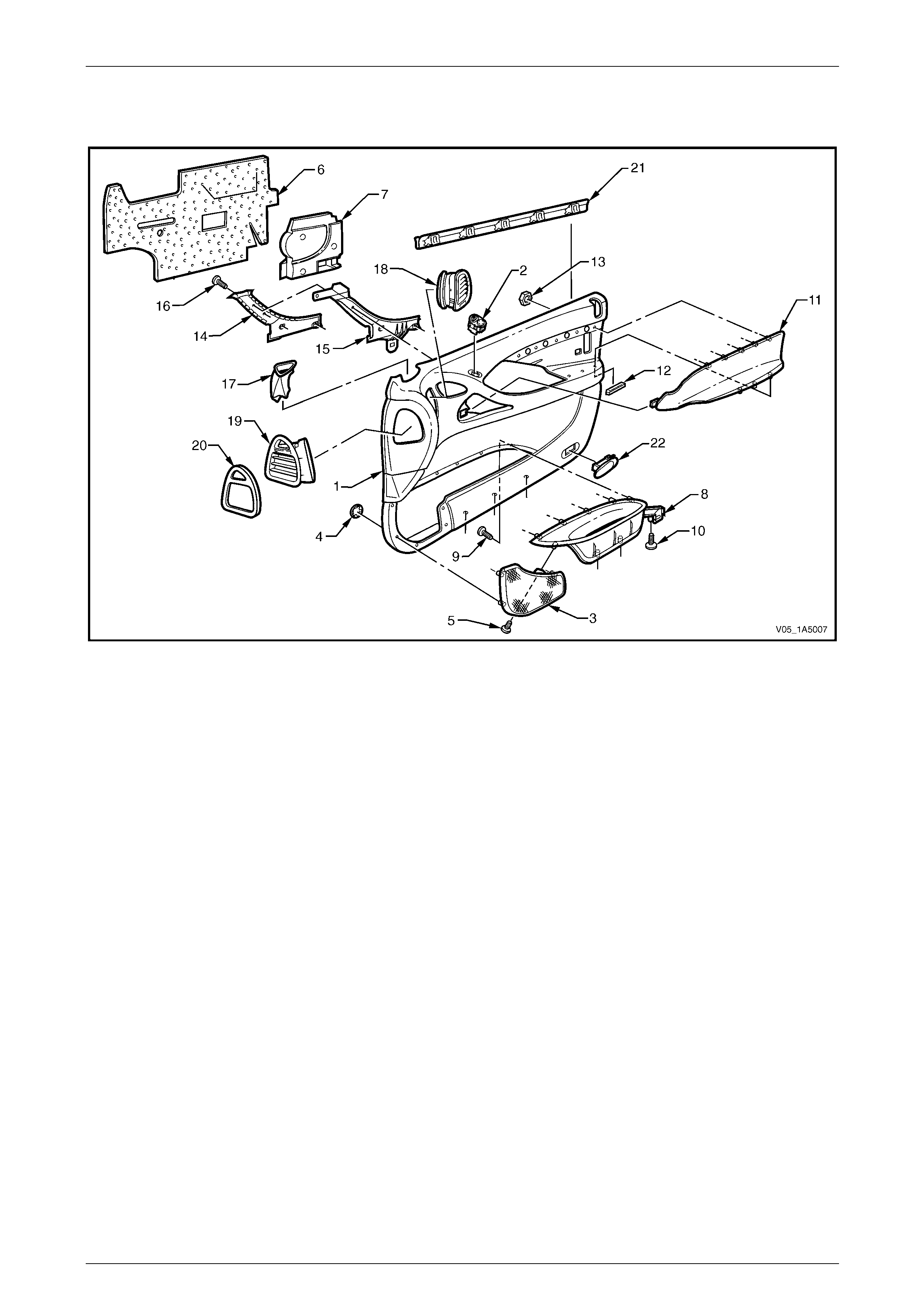
Trim Panel – Coupe
This front door trim panel configuration is fitted to Coupe vehicles, refer to Figure 1A5 – 11.
Figure 1A5 – 11
Legend
1 Front Door Trim Panel Foundation
2 Exterior Rear-view Mirror Switch (driver’s side only)
3 Front Door Radio Speaker Grille
4 Front Door Radio Speaker Grille Retainer (6 places)
5 Front Door Radio Speaker Grille Screw
6 Front Door Insulator Assembly
7 Lower Side Impact Insert
8 Front Door Map Pocket Assembly
9 Front Door Map Pocket Assembly Screw (6 places)
10 Front Door Map Pocket Assembly Screw (3 places)
11 Front Door Armrest Insert Assembly
12 Front Door Armrest Insert Assembly Clip (5 places)
13 Front Door Armrest Insert Assembly Nut (7 places)
14 Front Door Inner Handle Cover
15 Front Door Inner Handle Bracket
16 Front Door Inner Handle Screw (4 places)
17 Front Door Window Defogger Air Duct
18 Front Door Air Outlet Assembly
19 Front Door Air Duct Assembly
20 Front Door Air Duct Seal
21 Front Door Window Inner Sealing Strip Assembly
22 Front Door Courtesy Lamp
Front and Rear Door Assemblies Page 1A5–17
Page 1A5–17
Exterior Rear-view Mirror Switch
Remove
NOTE
The exterior rear-view mirror switch is only fitted
to the front door on the driver's side.
1 From behind the trim assembly (1), depress the tangs
of the switch (2).
2 Push free the switch and remove.
NOTE
For further information regarding Service and
Diagnosis of the external rear-view mirror and
switch, refer to Section 12H Rear-view Mirrors.
Figure 1A5 – 12
Reinstall
Reinstallation of the exter ior rear-view mirror switch is the reverse of the removal procedure, noting the following:
Ensure the tangs secure the switch assembly to the trim panel foundati on.
Front Door Radio Speaker Grille
Remove
Take care when remo ving the clips (2), as the
radio speaker grille lugs on which the clips
are attached may break, requiring the
replacement of the radio speaker grille.
1 From behind the trim panel assembly (1), using side-
cutters cut the speed clip (2), six places, securin g the
radio speaker grille (3) to the trim panel foundation,
then remove from the lugs and discard.
2 Remove the screw (4) attaching the radio speaker
grille to the map pocket assembl y (5).
3 Push free the radio speaker grille and remove.
Figure 1A5 – 13
Reinstall
Reinstallation of the front door radio speaker grille is the reverse of the removal proced ure, noting the follo wing:
1 Push new round speed clips onto the lu gs to secure the radio speaker grille .
2 Tighten the screw attaching the front door radio sp eaker grille to the correct torque specification.
Front door radio speaker grille
attaching screw torque specification...........0.5 – 0.7 Nm
Front and Rear Door Assemblies Page 1A5–18
Page 1A5–18
Front Door Insulator Assembly
Remove
Take care not to tear the insulator (1) and
retain on it as much adh esive as possible. Do
not fold the insulator and store in a flat
location with the adhesive facing away from
other surfaces.
Remove the insulator assembly (1) from the back of the trim
panel assembly (2), by peeling the insulator slowly across
the trim panel foundation.
Figure 1A5 – 14
Reinstall
Reinstallation of the front door insulator assembly is the reverse of the removal procedure, noting the following:
If required, apply additional hot melt adhesive with a high softenin g point (eg. 90°C) to the insulator assembly.
Lower Side Impact Insert (where fitted)
Remove
1 If required, peel back the insulator assembly from the
lower rear portion of the trim panel assembly, allo wing
access to the lower side impact insert. Refer to
Front Door Insulator Assembly in this Section.
2 From behind the trim panel assembly (1), slowly pull
the lower side impact insert (2) away from the trim
panel foundation, allowing the adhesive to stay on the
lower side impact insert.
3 Remove the lower side impact insert from the trim
panel assembly.
Figure 1A5 – 15
Reinstall
Reinstallation of the lower side impact insert is the reverse of the removal procedure, noting the following:
If required, apply additional hot melt adhesive with a high softenin g point (eg. 90°C) to the lower side impact insert.
Front and Rear Door Assemblies Page 1A5–19
Page 1A5–19
Front Door Map Pocket Assembly
Remove – Except Coupe
1 If required, peel back the insulator assembly from the lower rear portion of the trim panel a ssembly, allowing
access to the map pocket assembly attaching screws. Refer to Front Door Insulator Assembly in this Section.
2 If required, remove the lower side impact insert, refer to Lower Side Impact Insert in this Section.
3 From behind the trim panel as sembly (1), remove the
screws (2) attaching the map pocket assembly (3) to
the trim panel foundation, as follows:
• remove the ten screws for vehicles with side
impact airbags, or
• remove the eight screws for vehicles without side
impact airbags.
4 Remove the screw (4) attaching the radio speaker
grille to the map pocket assembl y.
5 Remove the map pocket assembly from the trim panel
assembly.
Figure 1A5 – 16
Remove – Coupe
1 If required, peel back the insulator assembly from the lower rear portion of the trim panel a ssembly, allowing
access to the map pocket assembly attaching screws. Refer to Front Door Insulator Assembly in this Section.
2 If required, remove the lower side impact insert, refer to Lower Side Impact Insert in this Section.
3 From behind the trim panel as sembly (1), remove the
nine screws (2) attaching the map pocket assembly (3)
to the trim panel foundation.
4 Remove the screw (4) attaching the radio speaker
grille to the map pocket assembl y.
5 Remove the map pocket assembly from the trim panel
assembly.
Figure 1A5 – 17
Reinstall
Reinstallation of the front door map pocket assembly is the reverse of the removal procedure, noting the following:
1 Tighten the screws attaching the map p ocket assembly to the correct torque specification.
Front door map pocket assembly
attaching screws torque specification .........0.5 – 0.7 Nm
2 Tighten the screw attaching the radio spe ake r grille to the correct torque specification.
Front door radio speaker grille
attaching screw torque specification...........0.5 – 0.7 Nm

Front and Rear Door Assemblies Page 1A5–20
Page 1A5–20
Front Door Armrest Insert Assembly
Remove – Except Coupe
1 If required, peel back the insulator assembly from the lower rear portion of the trim panel a ssembly, allowing
access to the armrest insert assembly attaching parts. Refer to Front Door Insulator Assembly in this Section.
2 If required, remove the lower side impact insert, refer to Lower Side Impact Insert in this Section.
3 From behind the trim panel as sembly (1), remove the
retainer (2), three places, from the armrest insert
assembly shaft (3) by sliding, then pulling it away from
the trim panel assembly.
Take care when remo ving the speed nuts (4),
as the rotating action may cut-off the armrest
insert assembly shafts (5) to which they are
attached, requiring the replacement of the
armrest insert assembly.
4 Using side-cutters cut the speed nut (4), five places,
then remove it from the armrest insert assembly
shaft (5) and discard.
5 Prise the armrest insert assembly (6) from the trim
panel assembly.
6 Slide rearward the armrest insert assembly to
disengage the tab (7) and remove from the trim panel
assembly.
Figure 1A5 – 18
Remove – Coupe
1 If required, peel back the insulator assembly from the lower rear portion of the trim panel a ssembly, allowing
access to the armrest insert assembly attaching parts. Refer to Front Door Insulator Assembly in this Section.
2 If required, remove the lower side impact insert, refer to Lower Side Impact Insert in this Section.
3 From behind the trim panel as sembly (1), remove the
retainer (2), five places, from the armrest insert
assembly shafts (3) by sliding, then pulling it away
from the trim panel assembly.
Take care when remo ving the speed nuts (4),
as the rotating action may cut-off the armrest
insert assembly shafts (5) to which they are
attached, requiring the replacement of the
armrest insert assembly.
4 Using side-cutters cut the speed nut (4), seven pl aces,
then remove it from the armrest insert assembly
shafts (5) and discard.
5 Prise the armrest insert assembly (6) from the trim
panel assembly.
6 Slide rearward the armrest insert assembly to
disengage the tab (7) and remove from the trim panel
assembly.
Figure 1A5 – 19
Front and Rear Door Assemblies Page 1A5–21
Page 1A5–21
Reinstall
Reinstallation of the front door armrest insert assembly is the reverse of th e removal procedure, noting the following:
NOTE
Ensure the shafts are not damaged before fitting
the front door armrest insert assembly, replace if
necessary.
1 The armrest insert assembly (6) must be sitting flush against the trim panel assembly (1) along the entire top
contacting surface with the tab (7) engaged, refer to Figure 1A5 – 18 or Figure 1A5 – 19.
2 Install new nuts attaching the armrest insert assembl y and t ighte n to the correct torque specification.
Front door armrest insert assembly
attaching nuts torque specification..............0.7 – 0.9 Nm
Front Door Inner Pull Handle Assembly
Remove
1 If required, remove the armrest insert assembly, refer to Front Door Armrest Insert Assembly in this Section.
2 From behind the trim panel as sembly (1), remove the
four screws (2) attaching the inner pull handl e
bracket (3) to the trim panel assembly.
3 Remove the inner pull handle bracket assembly from
the trim panel assembly.
4 Peel off the cover (4) from the inner pull handle
bracket.
Figure 1A5 – 20
Reinstall
Reinstallation of the front door inner pull handle assembly is the reverse of the removal procedure, noting the following:
Tighten the four screws attaching the inn er p ull handle assembly to the correct torque specification.
Front door inner pull handle assembly
attaching screws torque specification .........1.3 – 1.7 Nm
Front and Rear Door Assemblies Page 1A5–22
Page 1A5–22
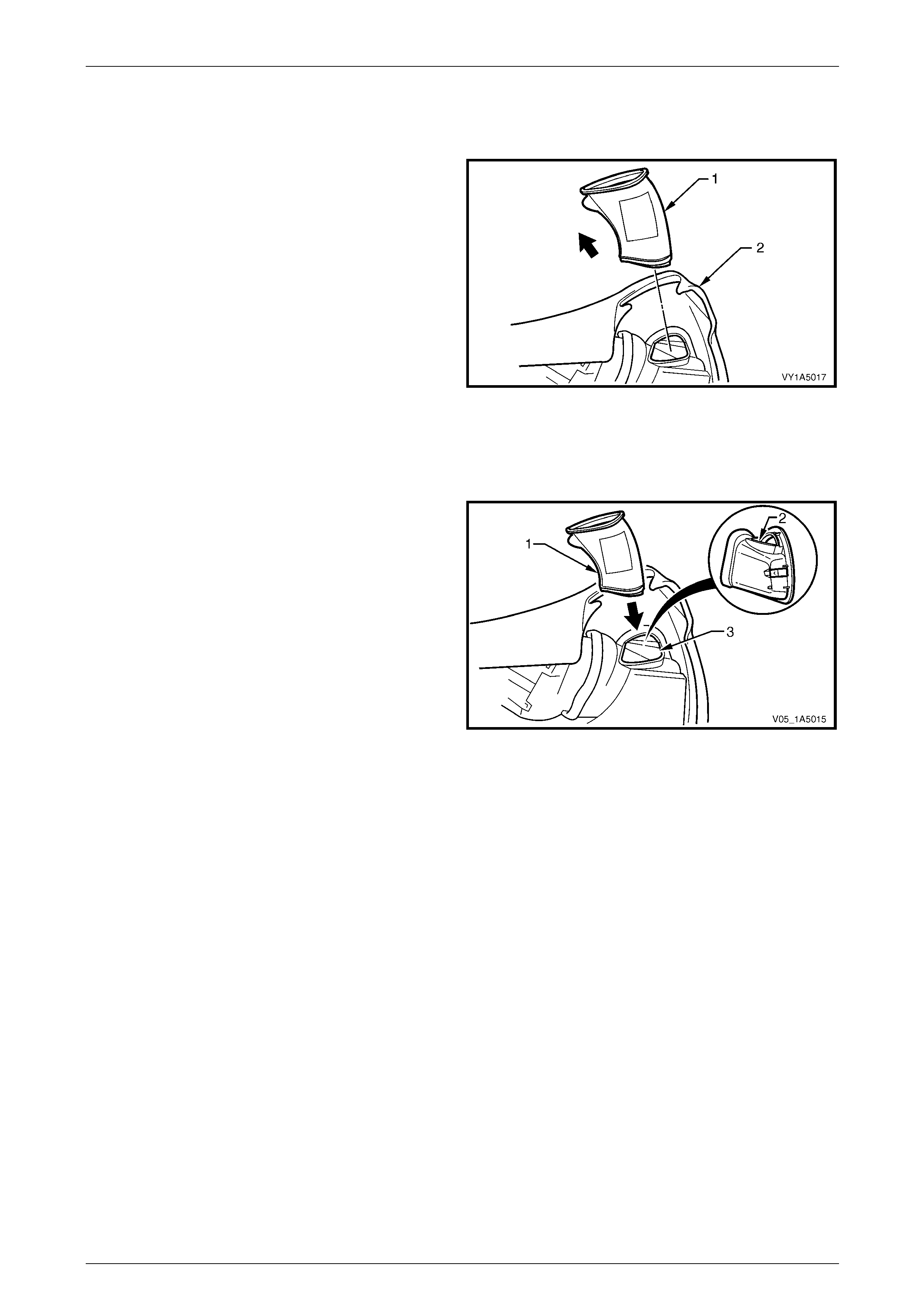
Front Door Window Defogger Air Duct
Remove
Pull the window defogger air duct (1) up wards and lift it out
of the trim panel assembly (2) to remove.
Figure 1A5 – 21
Reinstall
Reinstallation of the front door window defogger air duct is the reverse of the removal procedure, noting the following:
1 Align the window defogger air duct (1) with the
aperture (2) in the front door air duct assembly.
2 Feed the window defogger air duct through the trim
panel opening (3) and insert in the aperture of the front
door air duct assembly, ensuring the y form a tight
seal.
Figure 1A5 – 22
Front and Rear Door Assemblies Page 1A5–23
Page 1A5–23
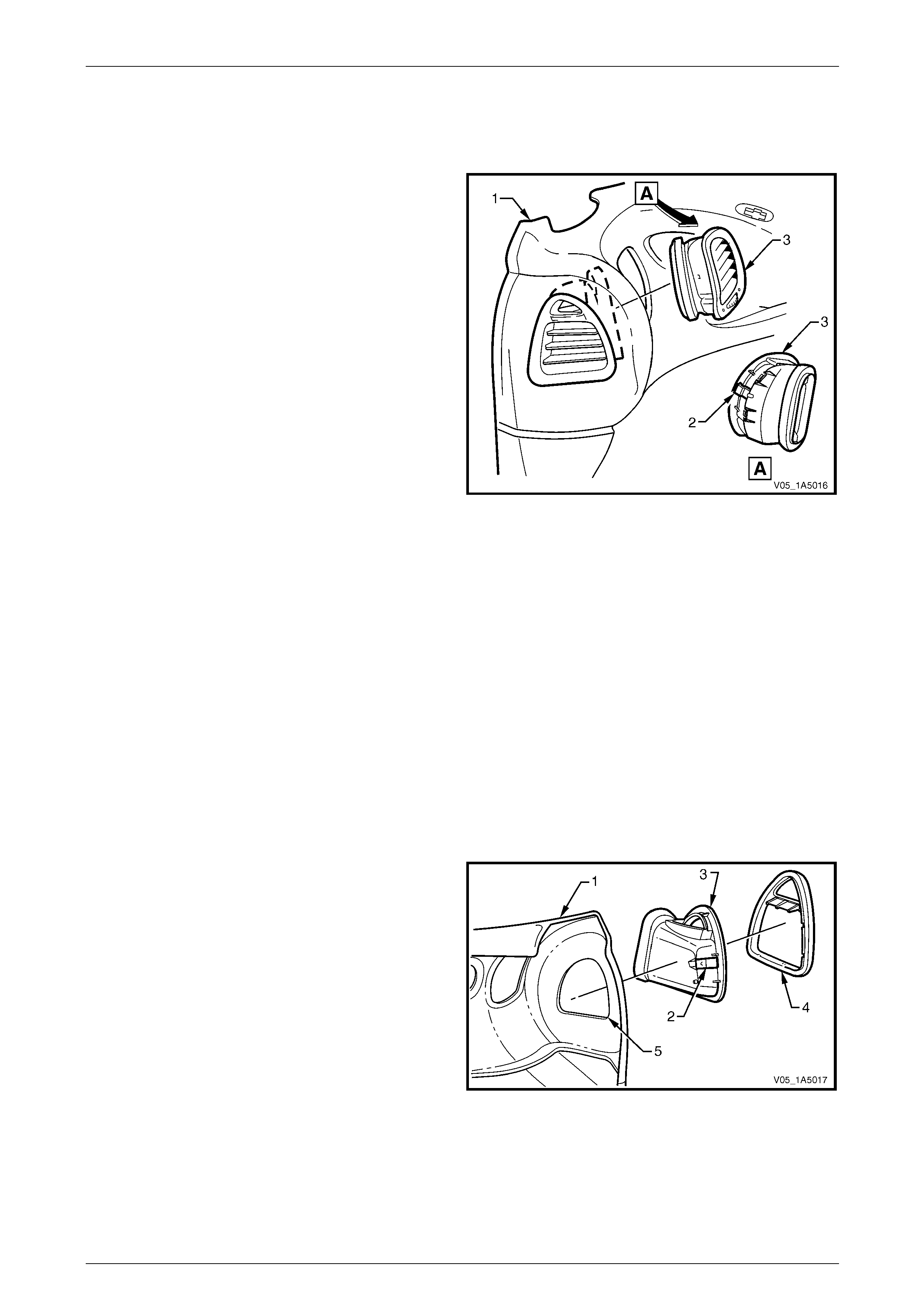
Front Door Air Outlet Assembly
Remove
1 From behind the trim panel as sembly (1), depress the
spring clip retainer (2) to release the air outle t
assembly (3) from the trim panel assembly.
2 Push the air outlet assembly out from the trim panel
assembly to remove.
Figure 1A5 – 23
Reinstall
Reinstallation of the front door air outlet assembly is the reverse of the removal procedure, noting the following:
Ensure the air outlet assembly is correctly fitted to the front door air duct assembly and the spring clip retainer secures
the air outlet assembly to the trim panel assembly.
Front Door Air Duct Assembly
Remove
1 Remove the following components as required:
a Window defogger air duct, refer to Front Door Window Defogger Air Duct in this Section.
b Air outlet assembly, refer to Front Door Air Outlet Assembly in this Section.
2 If required, peel back the insulator assembly from the upper front portion of the trim panel assembly, allowing
access to the air duct assembly, refer to Front Door Insulator Assembly in this Section.
3 From behind the trim panel as sembly (1), depress the
spring clip retainer (2) to release the air duct
assembly (3) from the trim panel assembly.
4 Push the air duct assembly out from the trim panel
assembly to remove.
5 Remove the air duct seal (4) from the air duct
assembly.
Figure 1A5 – 24
Reinstall
Reinstallation of the front door air duct assembly is the reverse of the removal procedure, noting the following:
Ensure the spring clip retainer secures the air duct assembly to the trim panel assembly.
Front and Rear Door Assemblies Page 1A5–24
Page 1A5–24
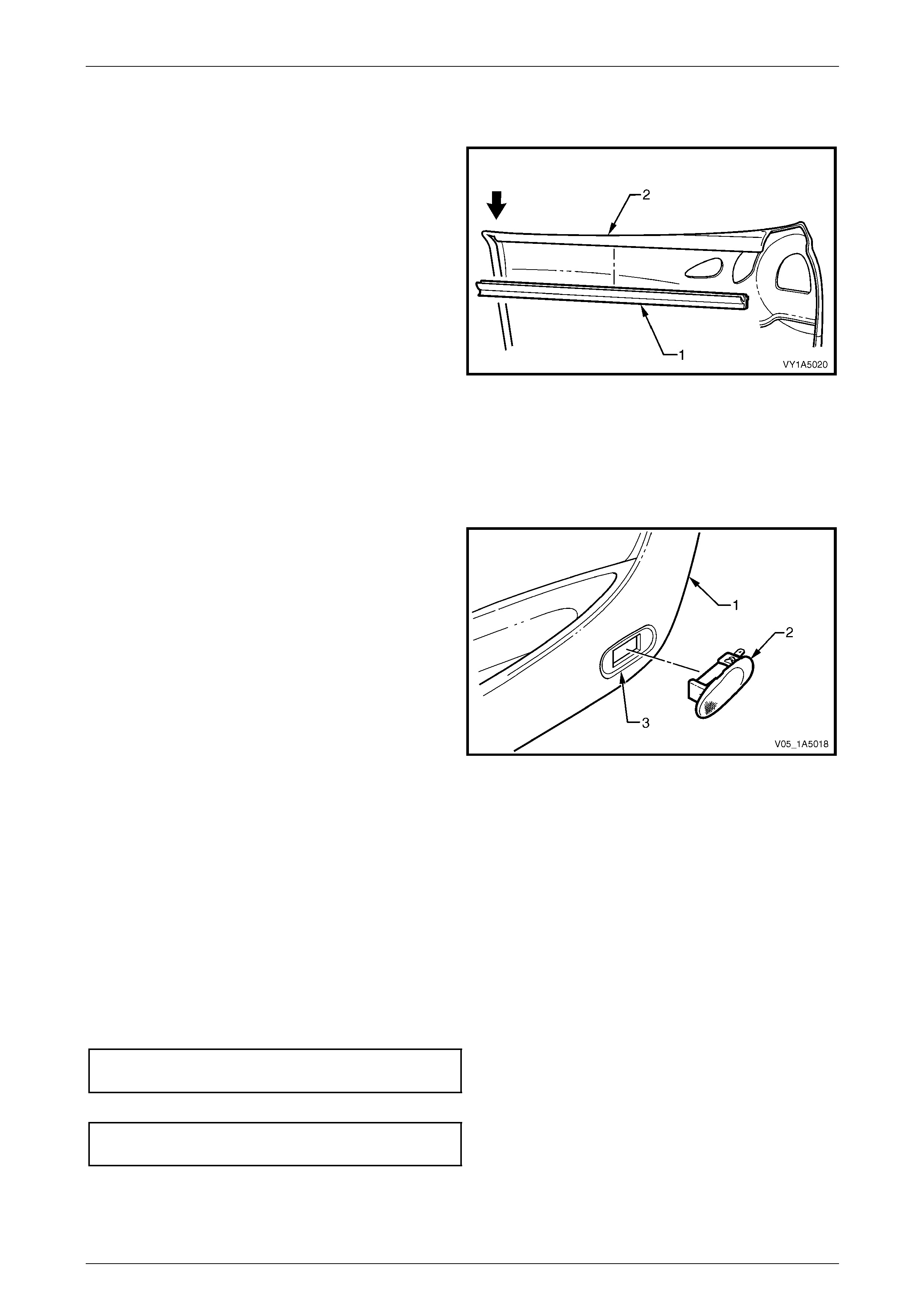
Front Door Inner Sealing Strip Assembly
Remove
1 Push down on one end of the inner seal ing strip
assembly (1) to start the removal process from the trim
panel assembly (2).
2 Push down and progressivel y move along the inner
sealing strip assembly until it separates from the trim
panel assembly and remove.
Figure 1A5 – 25
Reinstall
Reinstallation of the front door inner sealing strip assembly is the reverse of the removal procedure.
Front Door Courtesy Lamp (where fitted)
Remove
1 From behind the trim panel as sembly (1), depress the
retaining tangs securing the courtesy lamp (2) to the
trim panel assembly.
2 Push the lamp out of the aperture (3) in the trim panel
assembly and remove.
NOTE
For service and diagnosis of the
front door courtesy lamp refer to
Section 12B Lighting System.
Figure 1A5 – 26
Reinstall
Reinstallation of the front door courtesy lamp is the reverse of the removal procedure, noting the fo llowing:
Ensure the retaining tangs are securing the courtesy lamp to the front door trim panel ass embly.
Reinstall
Reinstallation of the front door trim panel assembly is the reverse of the removal procedure, noting the following:
1 Ensure the remote inner handle assembl y and the remote control rod, are engaged befor e final fitment of the trim
panel assembly, refer to 2.3 Front Door Remote Inner Handle Assembly.
2 Tighten all the trim panel assembly attaching screws to the correct torque specification.
NOTE
The screws along the bottom of the trim panel
assembly are wax-tip sealing screws.
Front door trim panel assembly
attaching screws torque specification .........1.0 – 3.0 Nm
3 Tighten the screw attaching the locking rod knob escutcheo n to the correct torque specification.
Front door locking rod knob escutcheon
attaching screw torque specification...........1.0 – 2.0 Nm
4 Ensure the red locking insert is secured to the locking rod knob assembly.
5 Fit the rear edge of the window defogger outlet before pushing the reta ining clip into the front door upper frame.
Front and Rear Door Assemblies Page 1A5–25
Page 1A5–25
4 Service Operations – Front Door
Internal Components
4.1 Front Door Lock and Actuator Assembly
LT Section — 11–360
Remove
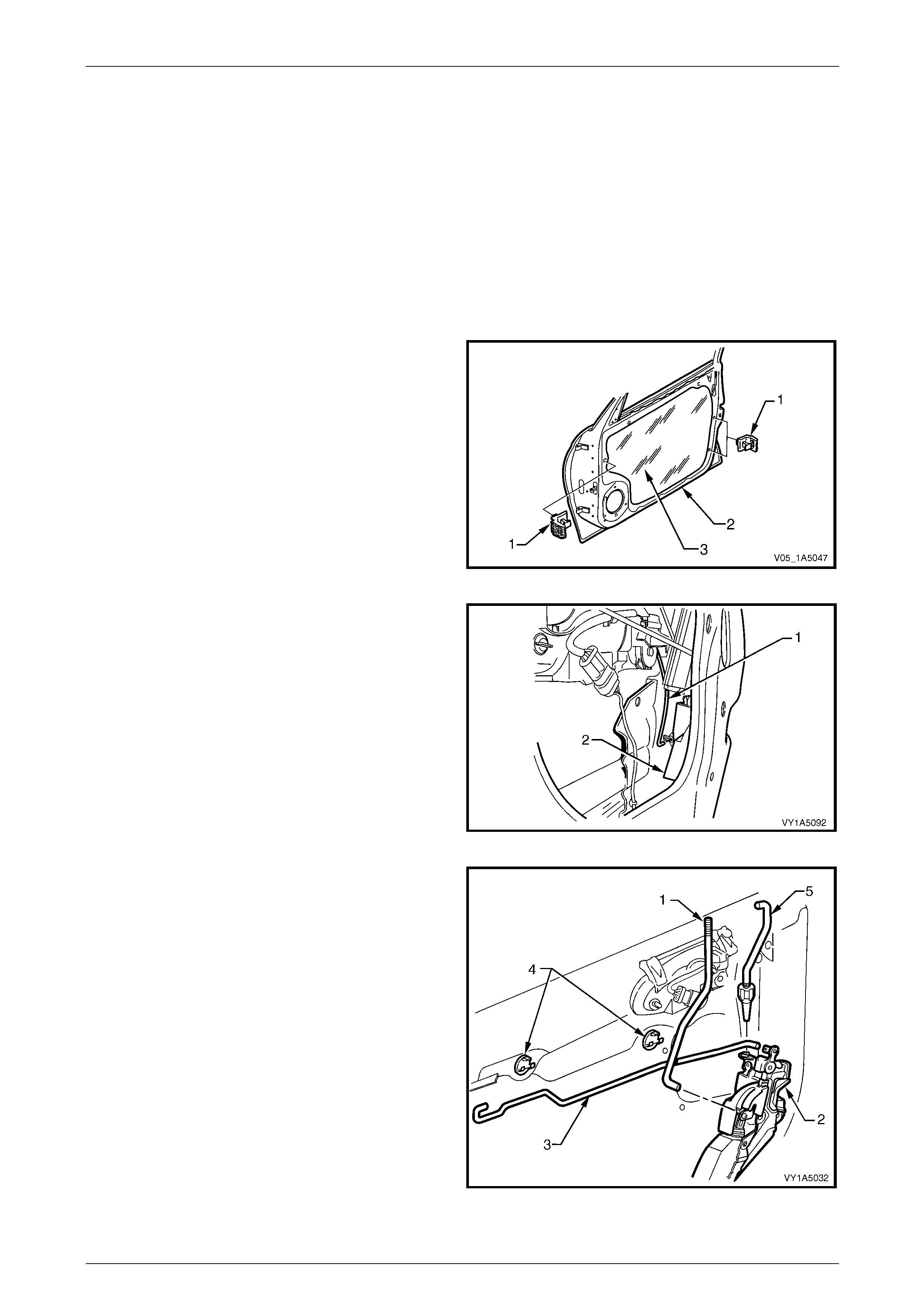
1 Remove the trim panel assembly, refer to 3.1 Front Door Trim Panel.
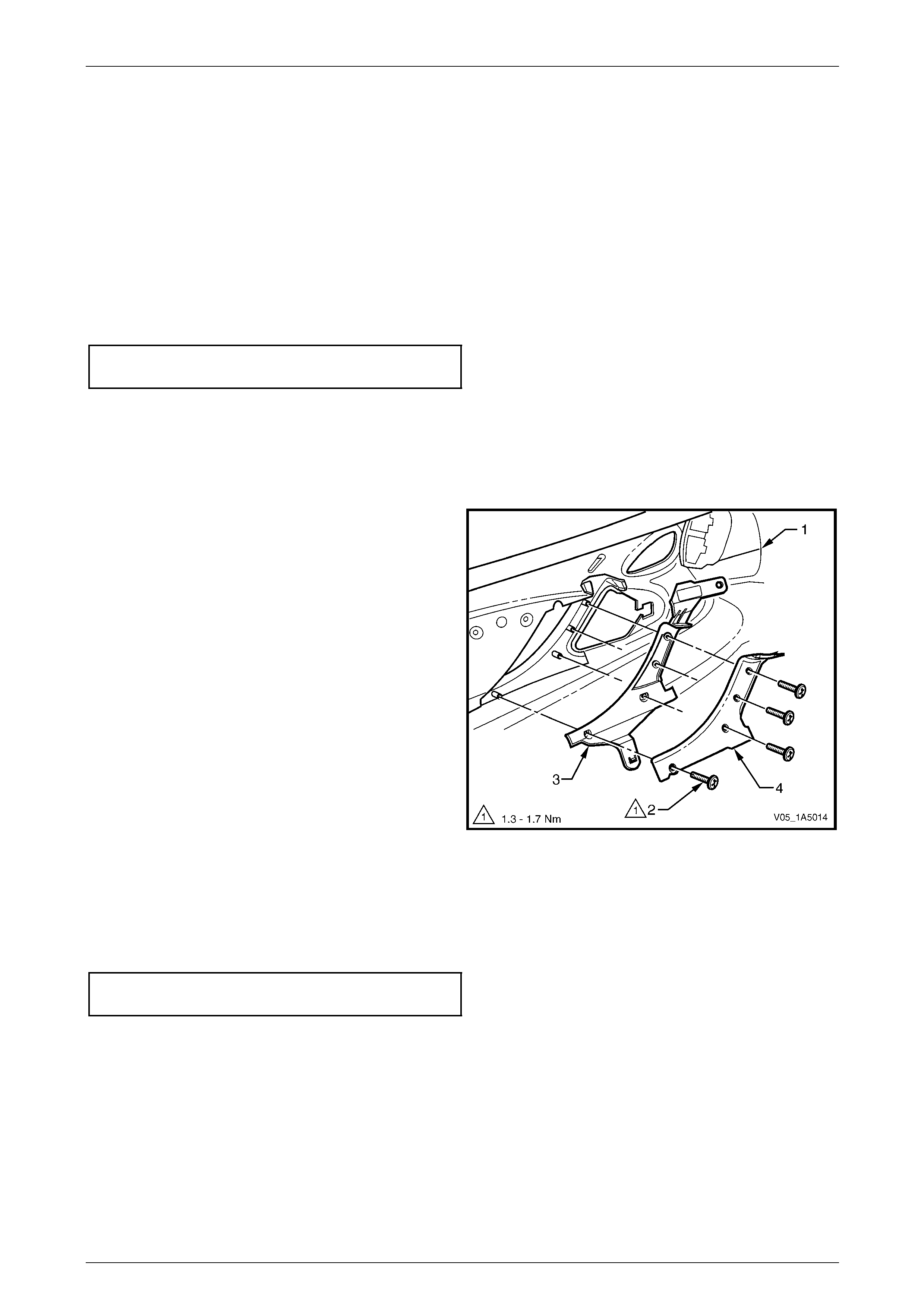
2 Remove the trim panel bracket (1), three places, from
the inner panel (2) by levering out the centre pin of
each bracket.
3 Carefully peel off the water shield (3) from the inner
panel.
NOTE
The water shield only need t o be partly removed
to allow access to complete this procedure.
Figure 1A5 – 27
NOTE
The following step is only applicable to the front
door on the driver side.
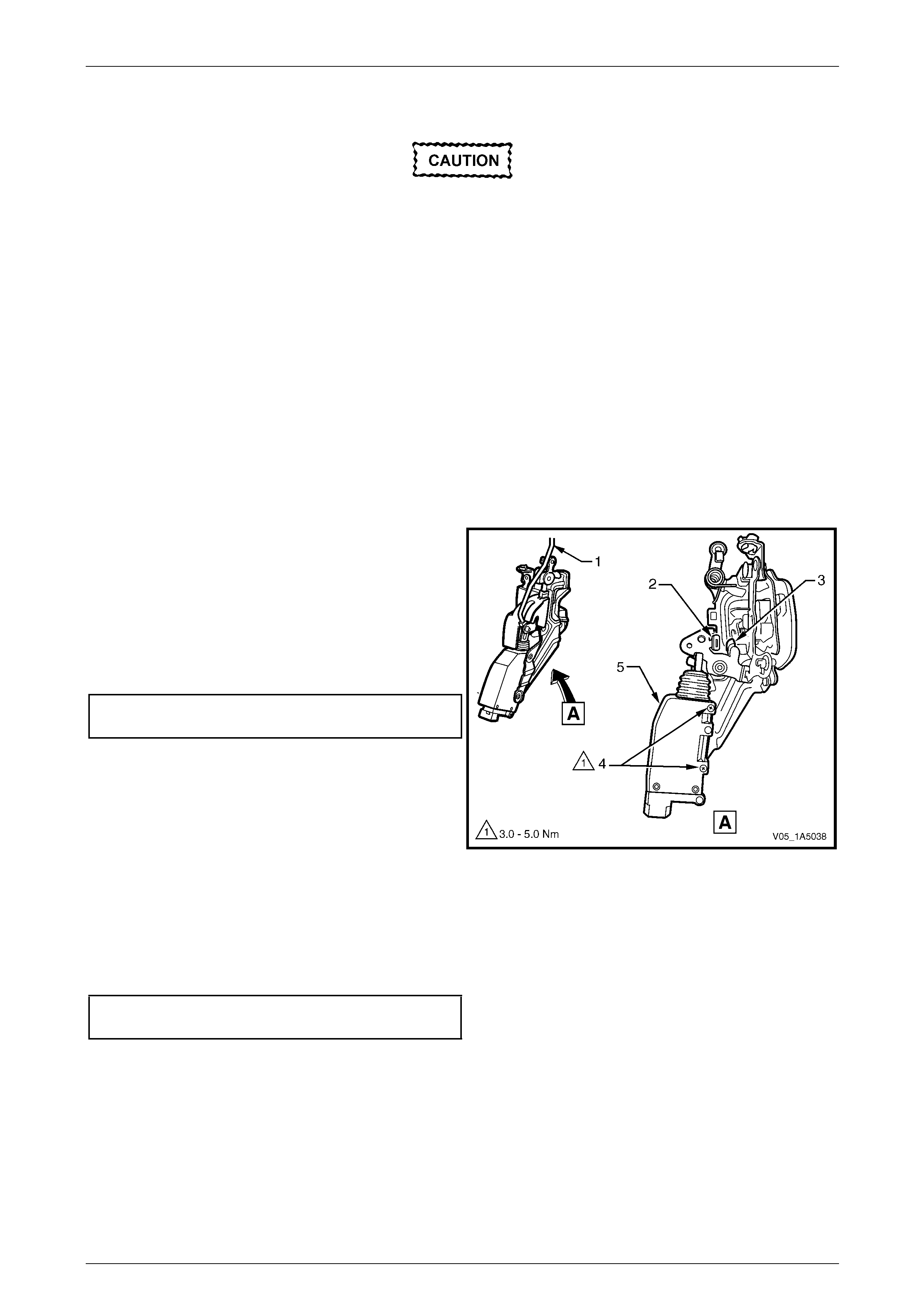
4 Disconnect the lock cylinder rod (1) from the lock
assembly (2) by releasing the lock cylinder rod
retainer.
Figure 1A5 – 28
5 Disconnect the locking rod (1) from the lock
assembly (2) by releasing the locking rod retainer,
then remove the locking rod.
6 Disconnect the remote control rod (3) from the lock
assembly by releasing the remote control rod retainer.
If required, remove the remote control rod by
disengaging it from the two remote control rod
clips (4).
NOTE
The front door outer handle rod (5) disengages
from the lock assembly when the lock and
actuator assembly is being removed.
Figure 1A5 – 29
Front and Rear Door Assemblies Page 1A5–26
Page 1A5–26
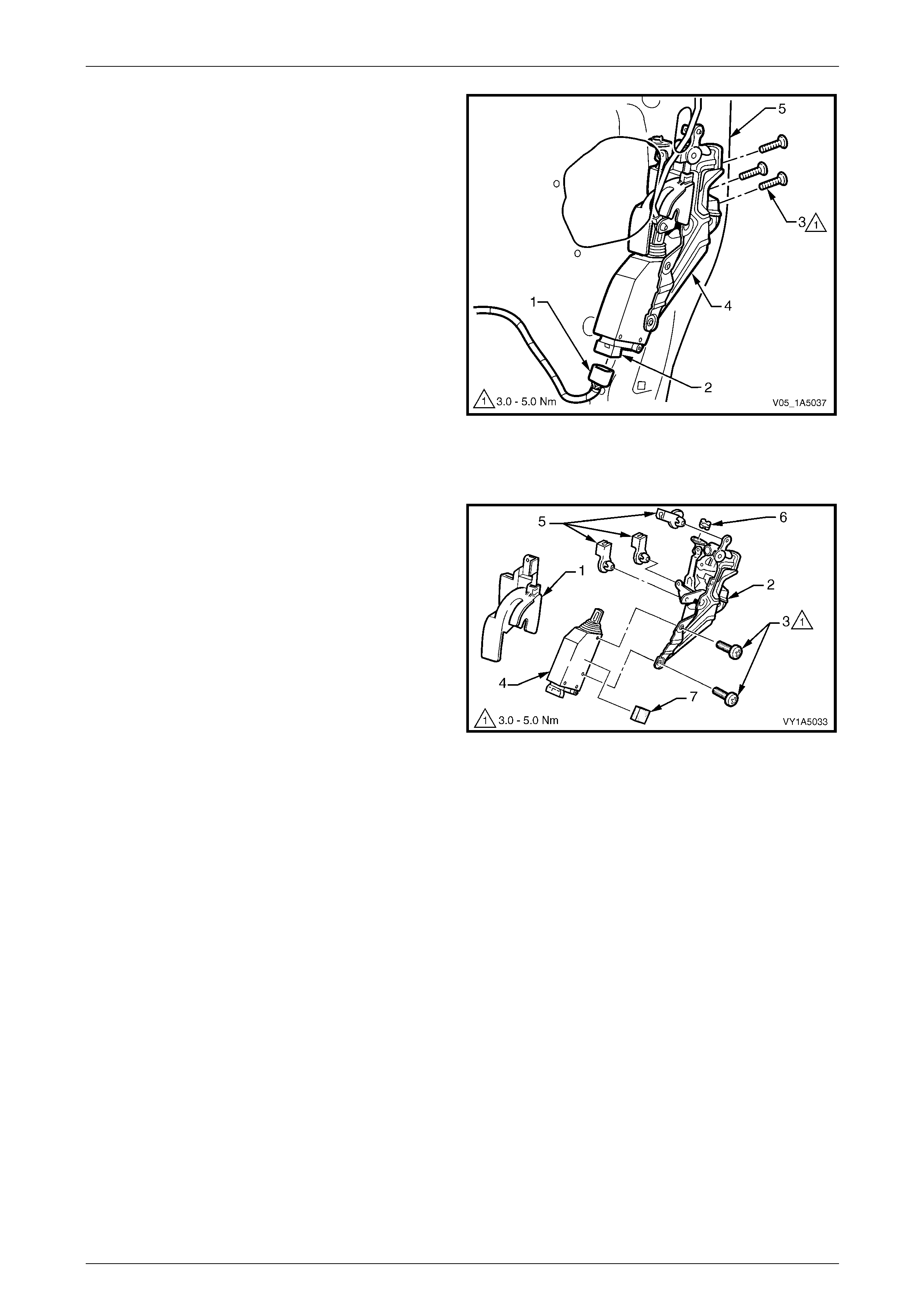
7 Disconnect the harness electrical connector (1) from
the lock actuator assembly (2).
8 Remove the three screws (3) attaching the lock
assembly (4) to the inner panel (5).
9 Remove the lock and actuator assembl y thr ough the
aperture in the inner panel.
Figure 1A5 – 30
Disassemble
1 Remove the anti-theft cover (1) from the lock
assembly (2).
2 Remove the two screws (3) attaching the loc k actuator
assembly (4) to the lock assembly, then remove the
actuator assembly.
3 Remove the three retaining clips (5) and the bush (6)
from the lock assembly.
4 If required, remove the lock actuator insulator (7) from
the lock actuator assembly.
Figure 1A5 – 31
Reassemble
Reassembly of the front door lock and actuator assembly is the reverse of the disassembly proced ure, noting the
following:
1 Attach the lock actuator assembly to the lock assembly, do not torque the two screws at this stage.
2 Adjust the position of the lock actuator assembly as descri bed in this Section, refer to Adjust in this Section.
Front and Rear Door Assemblies Page 1A5–27
Page 1A5–27
Adjust
Adjustment of the front door lock and
actuator assembly is critical to ensure correct
operation of the electric door lock system.
NOTE
The following adjustment procedure is
to be performed if a diagnostic test in
Section 12J Body Control Module suggests the
front door lock and actuator assembly may be
incorrectly adjusted, or if any of the following
symptoms occur:
• ineffective deadlock operation,
• failure to lock and unlock,
• door lock actuator motors oscillate (rattling
noise).
1 If required, remove the lock and actuator assembl y from the inner panel, refer to Remove in this Section.
2 Using the locking rod (1), lock and unlock the lock
actuator mechanism, checking the lock actuator
lever (2) rests on the rubber pad (3).
3 If required, loosen the t wo screws (4) and reposition
the lock actuator assembly (5) until the required
position is achieved.
4 Tighten the two screws (4) attaching the lock actuator
assembly to the correct torque specification.
Front door lock actuator assembly
attaching screws torque specification .........3.0 – 5.0 Nm
NOTE
Ensure the lock actuator assembly has not
moved during the tightening procedure.
Figure 1A5 – 32
Reinstall
Reinstallation of the front door lock and actuator assembly is the reverse of the removal procedure, noting the following:
Tighten the three screws attaching the lock and actu ator assembly to the correct torque specification.
Front door lock and actuator assembly
attaching screws torque specification .........3.0 – 5.0 Nm
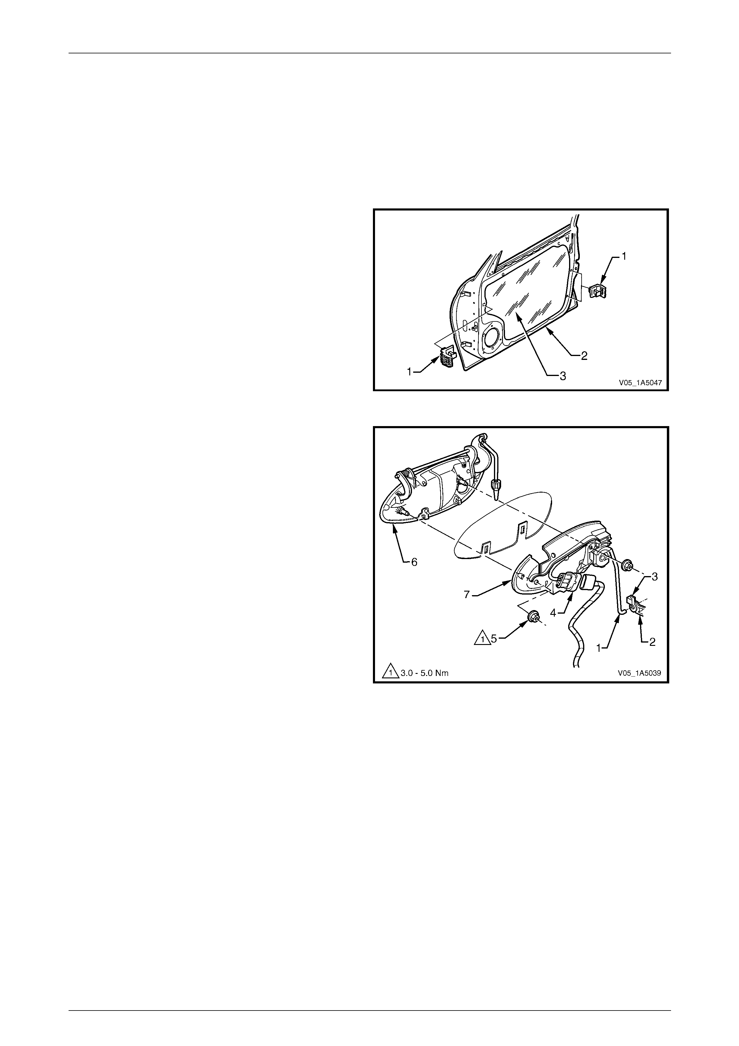
Front and Rear Door Assemblies Page 1A5–28
Page 1A5–28
4.2 Front Door Outer Handle Assembly
LT Section — 11–360
Remove
1 Remove the trim panel assembly, refer to 3.1 Front Door Trim Panel.
2 Remove the trim panel bracket (1), three places, from
the inner panel (2) by levering out the centre pin of
each bracket.
3 Carefully peel off the water shield (3) from the inner
panel.
NOTE
The water shield only need t o be partly removed
to allow access to complete this procedure.
Figure 1A5 – 33
4 For the outer handle assembly on the driver' s side,
proceed as follows:
a Disconnect the lock cylinder rod (1) from the lock
assembly (2) by releasing the lock cylinder rod
retainer (3).
b Disconnect the wiring harness from the lock
micro-switch wiring harness connector (4).
NOTE
The outer handle bracket assembly (7) on the
driver's side consists of a micro-switch, a door
lock cylinder and a bracket.
5 Remove the two nuts (5) attaching the outer handle
assembly.
6 Remove the front door outer handle (6) and
bracket (7) assemblies.
Figure 1A5 – 34
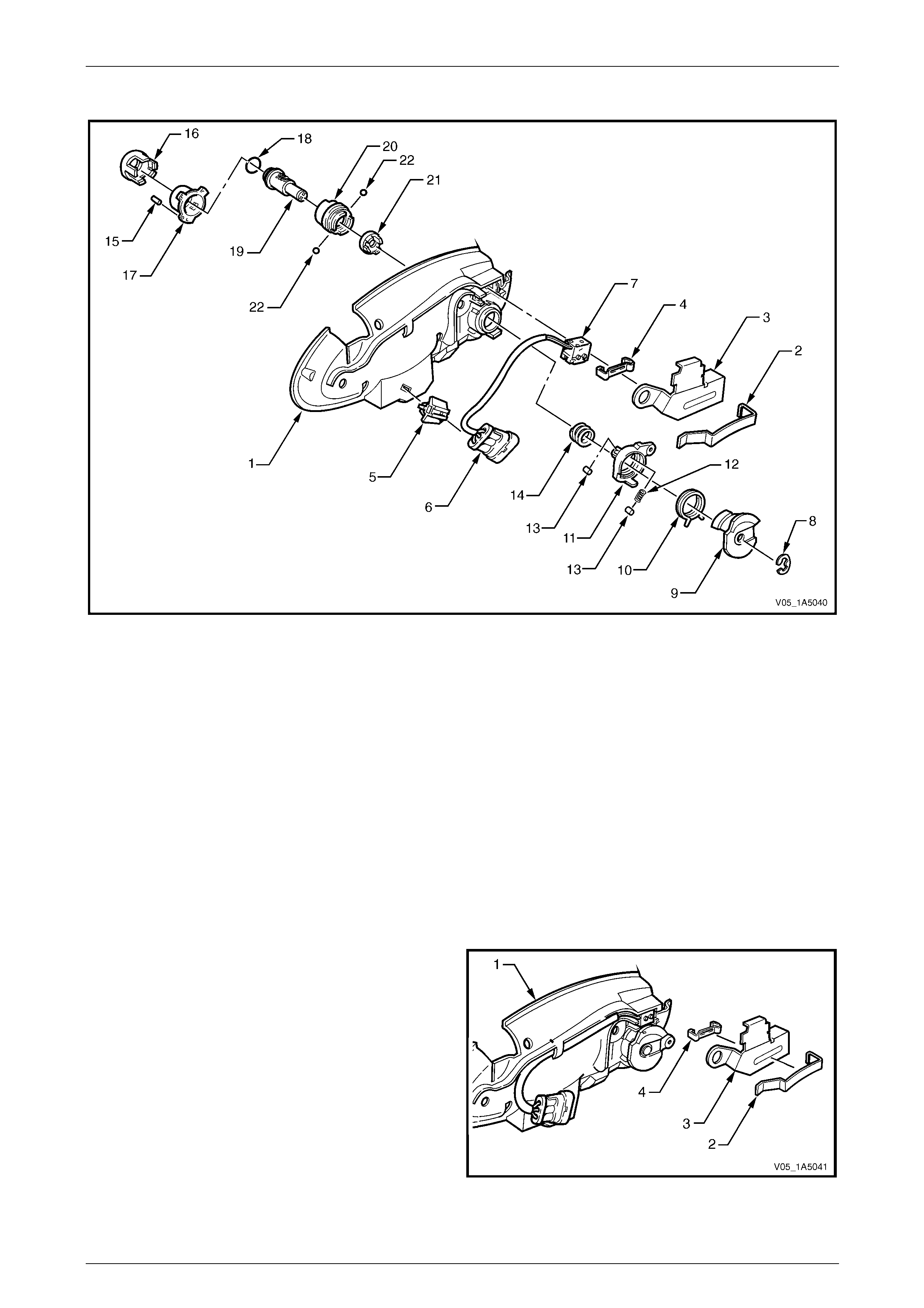
Front and Rear Door Assemblies Page 1A5–29
Page 1A5–29
Disassemble – Driver's Side
Figure 1A5 – 35
Legend
1 Front Door Outer Handle Bracket
2 Lock Barrel Shield Clip
3 Lock Barrel Shield
4 Lock Micro Switch Clip
5 Micro Switch Wiring Harness Connector Retaining Clip
6 Micro Switch Wiring Harness Connector
7 Lock Electric Micro Switch
8 Lock Barrel Clip
9 Lock Micro Switch Control Cam
10 Lock Torsion Spring
11 Lock Lever
12 Lock Lever Roller Spring
13 Lock Lever Roller
14 Lock Clutch Thrust Spring
15 Lock Barrel Housing Pin
16 Lock Barrel Housing Cover
17 Lock Barrel Housing
18 Lock Cylinder O-ring
19 Lock Cylinder Assembly
20 Lock Barrel Sleeve
21 Lock Clutch Coupling
22 Lock Clutch Balls
1 From the back of the outer handle bracket (1), using a
small screwdriver gently remove the lock ba rrel shield
clip (2).
2 Remove the lock barrel shield (3).
3 Using a small screwdriver, gently remove the lock
micro switch clip (4) away from the outer handle
bracket.
Figure 1A5 – 36
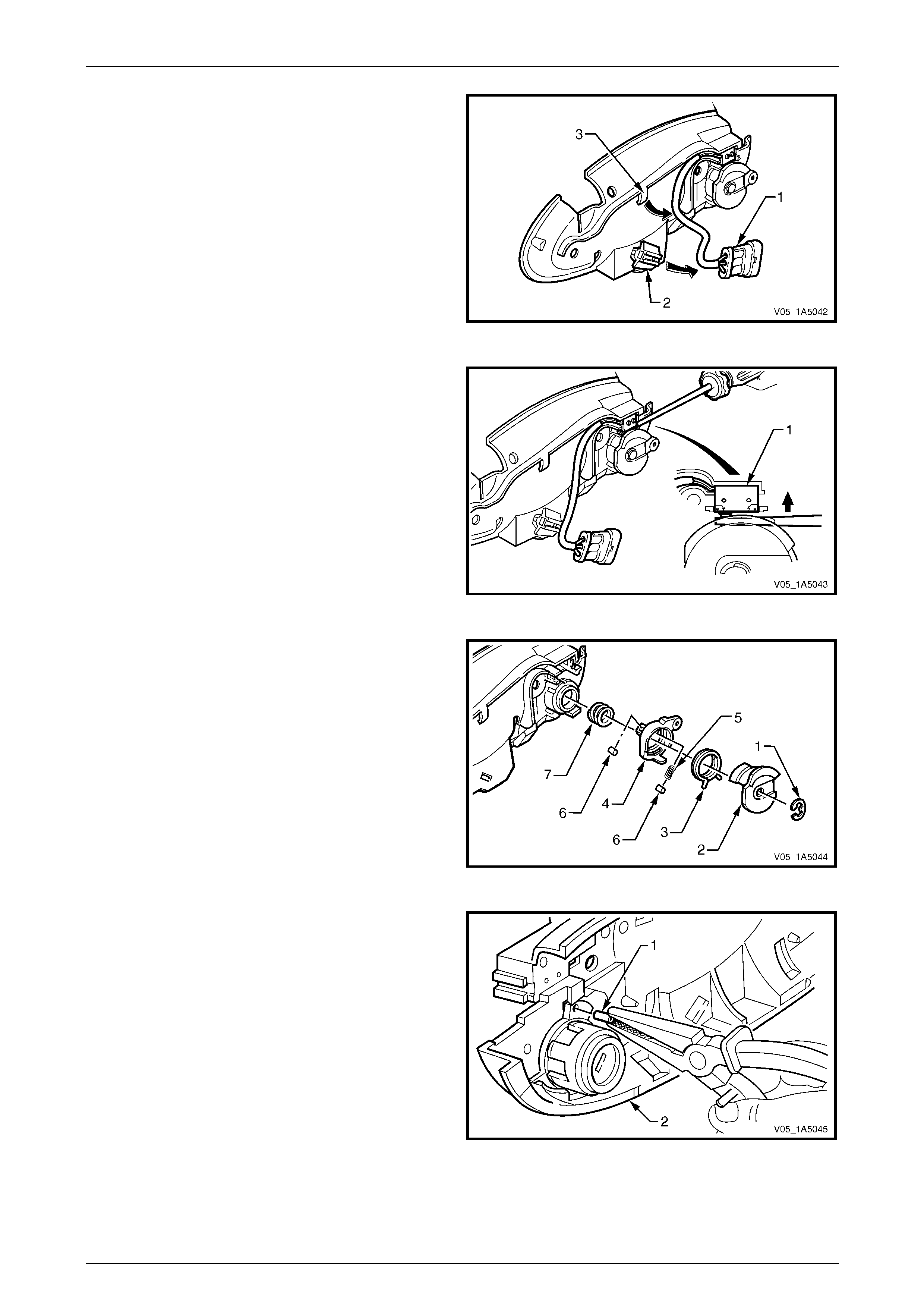
Front and Rear Door Assemblies Page 1A5–30
Page 1A5–30
4 Slide the micro switch wiring harness connector (1) off
the retaining clip (2) and free the wiring harness out
from under the outer handle bracket retainer (3).
Figure 1A5 – 37
5 Using a small flat bladed screwdriver, push in the two
contacts of the lock electric micro switch (1) and
remove the lock electric micro switch and connector
assembly.
NOTE
To test the micro-switch, refer to
Section 12J Body Control Module.
Figure 1A5 – 38
6 Remove the lock barrel shield clip (1) and slide the
lock micro switch control cam (2), lock torsion
spring (3) and lock lever (4) away from the lock
assembly.
NOTE
Take care not to lose the lock lever roller
spring (5) and the two lock lever rollers (6) during
this procedure.
7 Remove the lock clutch thrust spring (7) from the lock
assembly.
Figure 1A5 – 39
8 Using a suitable pair of pliers, pull the lock barrel
housing pin (1) out of the oute r handle bracket (2).
Figure 1A5 – 40
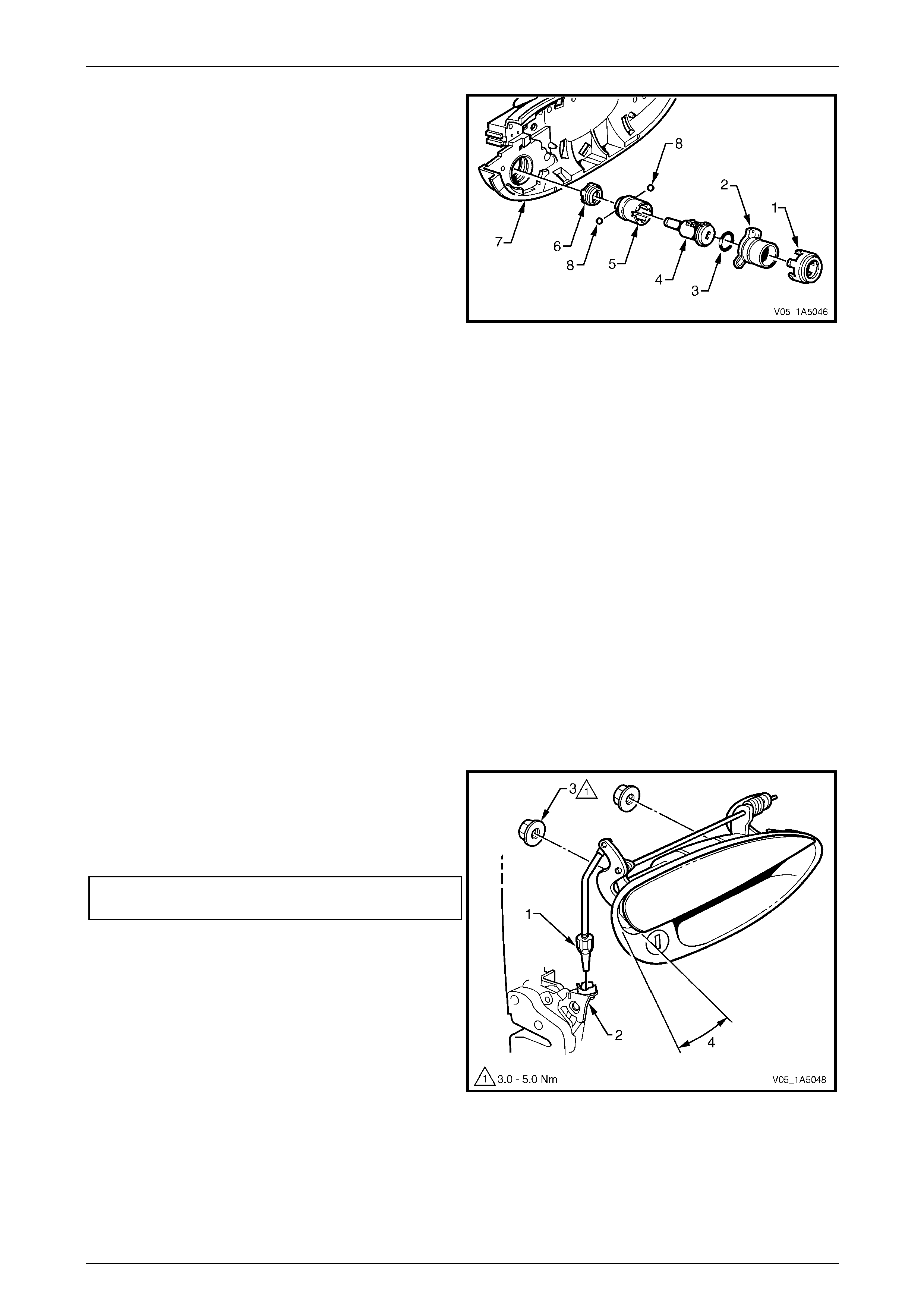
Front and Rear Door Assemblies Page 1A5–31
Page 1A5–31
9 Rotate in an anti-clockwise direction and remove the
housing cover (1), housing (2), O-ring (3), cylinder
assembly (4), sleeve (5) and clutch coupling (6) from
the outer handle bracket (7).
NOTE
Take care not to lose the two lock clutch balls (8)
during this procedure.
Figure 1A5 – 41
Reassemble – Driver's Side
Reassembly of the front door outer handle assembly is the reverse of the removal proced ure, noting the following:
NOTE
Lock cylinder service replacement kits are
supplied un-coded, which facilitates re-coding of
the lock cylinder to match the original key. It is
recommended the overhaul and re-coding of the
lock cylinder is performed by an authorised
locksmith.
1 Ensure the two lock clutch balls are fitted when installing the lock barrel sleeve and the O-ring is not damaged.
2 Rotate the parts in a clockwise direction when installing the lock barrel housing cover, housing, cylinder assembly,
sleeve and clutch coupling.
3 Ensure the two lock lever rollers and roller spring are fitted when installing the lock lever.
Reinstall
Reinstallation of the front door outer handle assembly is the reverse of the removal procedure, noting the following:
1 Ensure the adjusting nut (1) is seated in the lock and
actuator assembly (2) before installing the two
attaching nuts (3).
2 Tighten the two nuts attaching the outer h andle
assembly to the correct torque specification.
Front door outer handle assembly
attaching nuts torque specification..............3.0 – 5.0 Nm
3 Check and if necessary rotate the adjustin g nut to
allow the latch disengagement with the striker when
the outer handle opening (4) is 18° ± 5° from the rest
position.
Figure 1A5 – 42

Front and Rear Door Assemblies Page 1A5–32
Page 1A5–32
Lock Cylinder Reset (Free Turn)
NOTE
If the ‘free turn’ lock cylinder b ecomes misaligned
due to the insertion of an incorrect key, a foreign
object or if the correct key is not inserted fully
when turned, the following proced ure needs to be
carried out.
1 Insert the correct key fully into the lock assembly, preferably in the vertical position and turn the key slowly
anti-clockwise until a click is felt.
2 Then slowly turn the key clockwise until a clic k is felt.
3 Return the key to the vertical position (if not already there) and withdraw the key.
4 Reinsert the key in the vertical positio n and check if the key will lock and unlock the vehicle.
5 If the key does not work properly, keep the key in the lock assembly and tur n it 180° anti-clockwise, then repeat the
procedure.
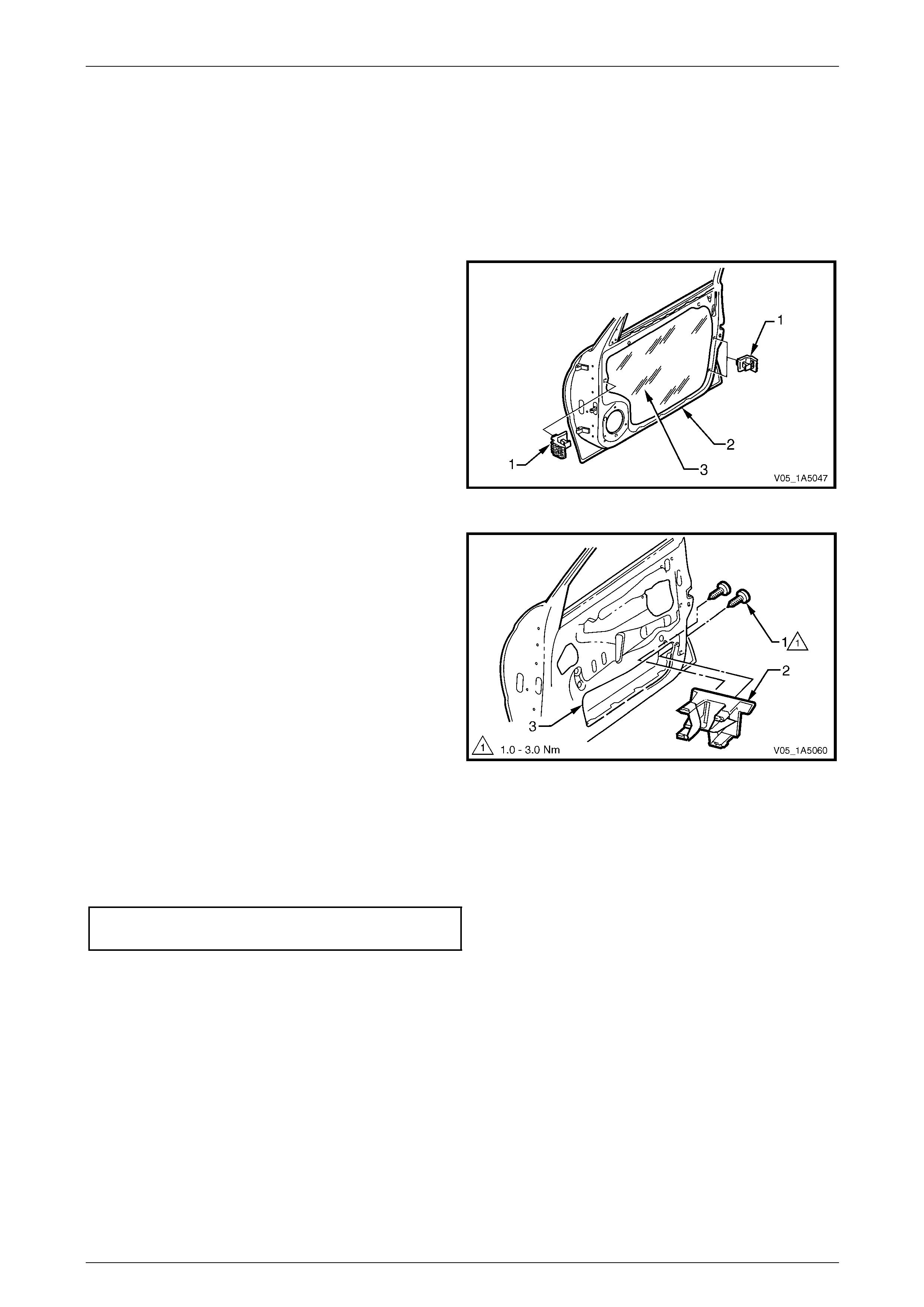
Front and Rear Door Assemblies Page 1A5–33
Page 1A5–33
4.3 Front Door Window Guide Assembly
LT Section — 11–625
Remove
1 Remove the trim panel assembly, refer to 3.1 Front Door Trim Panel.
2 Remove the three trim panel brackets (1) from the
inner panel (2) by levering out the centre pi n of each
bracket.
3 Carefully peel off the water shield (3) from the inner
panel.
NOTE
The water shield only need t o be partly removed
to allow access to complete this procedure.
Figure 1A5 – 43
4 Remove the two screws (1) attaching the window
guide assembly (2).
5 Remove the window guide assembly through the
opening (3) in the inner p anel.
Figure 1A5 – 44
Reinstall
Reinstallation of the front door window guide assembly is the reverse of the removal procedure, noting the follo wing:
Tighten the two screws attaching the window guide ass embl y to the correct torque specification.
Front door window guide ass embl y
attaching screws torque specification .........1.0 – 3.0 Nm
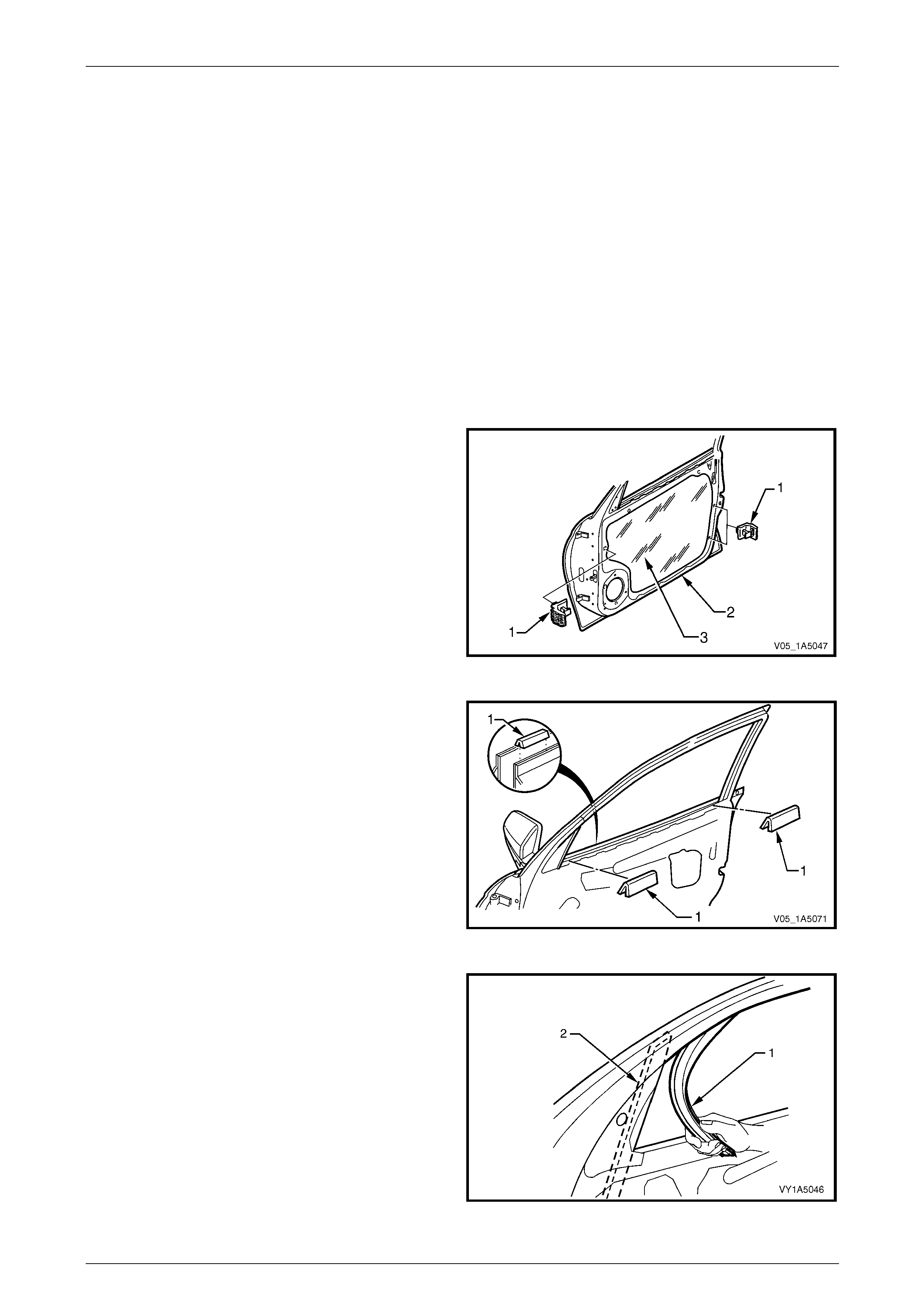
Front and Rear Door Assemblies Page 1A5–34
Page 1A5–34
4.4 Front Door Window Guide Channel
Assembly
LT Section — 11–625
Remove
1 Lower the front door window to the down position.
2 Remove the following components as required:
a Trim panel assembly, refer to 3.1 Front Door Trim Panel.
b Speaker, refer to Section 12D Entertainment System.
c Window belt outer reveal moulding assembly,
refer to 5.3 Front Door Window Belt Outer Reveal Moulding Assembl y or
6.3 Front Door Window Belt Outer Reveal Moulding Assembly.
3 Remove the trim panel bracket (1), three places, from
the inner panel (2) by levering out the centre pin of
each bracket.
4 Carefully peel off the water shield (3) from the inner
panel.
NOTE
The water shield only need t o be partly removed
to allow access to complete this procedure.
Figure 1A5 – 45
5 Remove the two inner panel beltline sea ls (1) from the
front door assembly.
Figure 1A5 – 46
6 Carefully remove the windo w upper weatherstrip
assembly (1) from the window guide channel
assembly (2).
NOTE
It is not necessary to remove the upper
weatherstrip assembly completely; remove it
only from the windo w guide channel assembly.
Figure 1A5 – 47
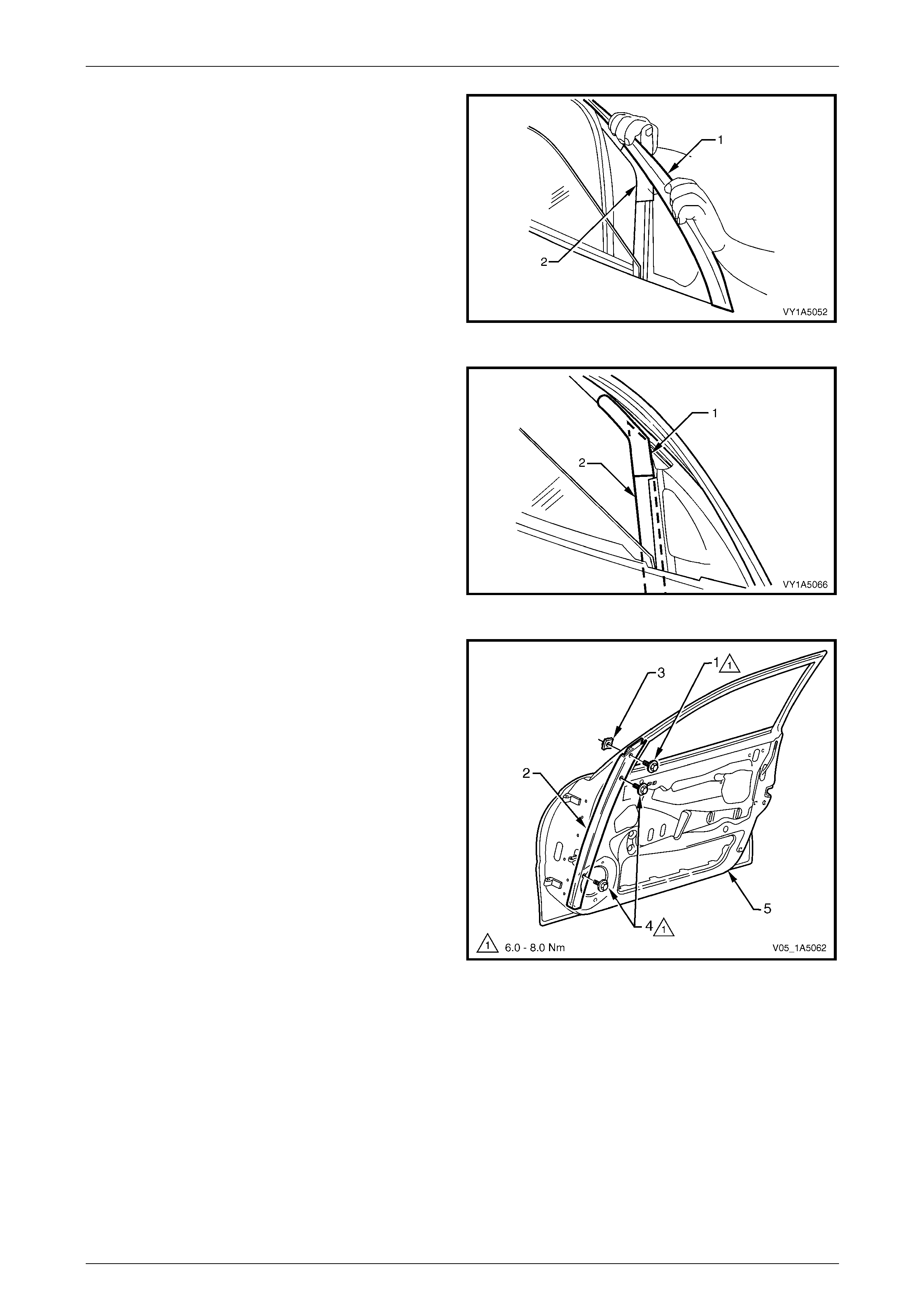
Front and Rear Door Assemblies Page 1A5–35
Page 1A5–35
7 Remove the exterior rear-view mirror, refer to
Section 12H Rear-view Mirrors.
8 Partially remove the upper weatherstrip assembly (1)
from the lip on the door upper frame, to access the
window guide channel cap (2).
Figure 1A5 – 48
9 Carefully peel back the window guide chann el
self-adhesive cap (1) away from the window guide
channel (2).
Figure 1A5 – 49
10 Remove the window down stop screw (1) from the
window guide channel assembly (2).
NOTE
Do not remove the window down stop nut (3) as
it is encapsulated in the guide channel.
11 Remove the upper and lo wer scre ws (4) attaching the
window guide channel assembly to the inner panel (5).
Figure 1A5 – 50
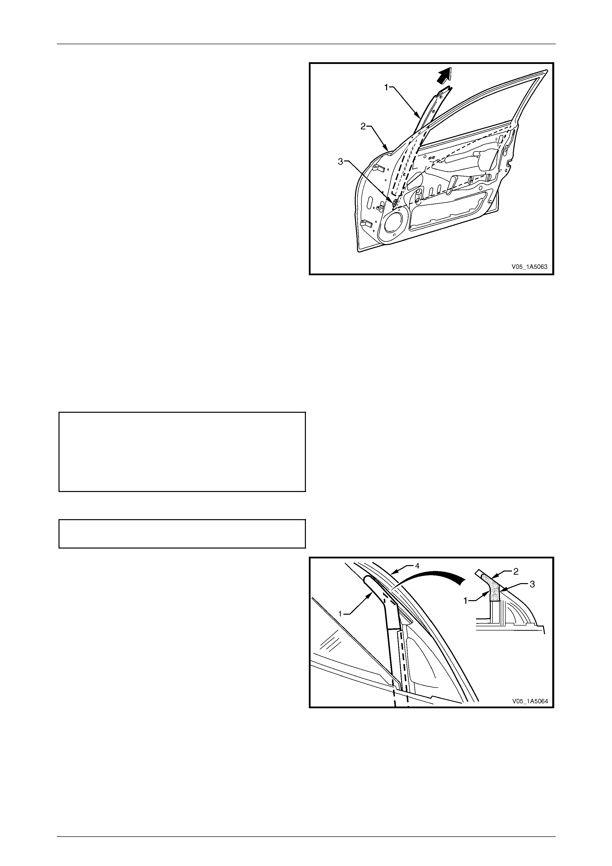
Front and Rear Door Assemblies Page 1A5–36
Page 1A5–36
12 Remove the window guide ch annel assembly (1) from
the door assembly (2) in an upward direction,
disengaging the window assembly slides (3) from the
window guide channel assembly.
Figure 1A5 – 51
Reinstall
Reinstallation of the front door window guide channel assembly is the reverse of the removal procedure, noting the
following:
1 Ensure the window assembly slides are engaged in the window guide channel assembly.
2 Tighten the upper and lower screws (4) attaching the window guide channel assembly (3) to the correct torque
specification, refer to Figure 1A5 – 50.
Front door window guide channel
assembly upper attaching screw
torque specification.....................................6.0 – 8.0 Nm
Front door window guide channel
assembly lower attaching screw
torque specification.....................................6.0 – 8.0 Nm
3 Tighten the window down stop screw (1) to the correct torque specification.
Front door window down
stop screw torque specification...................6.0 – 8.0 Nm
4 Align the self-adhesive cap (1 ) flush with the upper
edge of the door frame (2) and the front edge of the
window guide channel (3).
5 Wrap the overhang of the sel f-adhesive cap into the
door frame and the window guide chan nel.
6 Ensure the upper weatherstrip assembly (4) is
correctly fitted onto the lip of the door upper frame.
Figure 1A5 – 52
7 Ensure the window upper weatherstrip assembl y (1) is pus hed back fully into the window guid e cha nnel
assembly (2), refer to Figure 1A5 – 47.
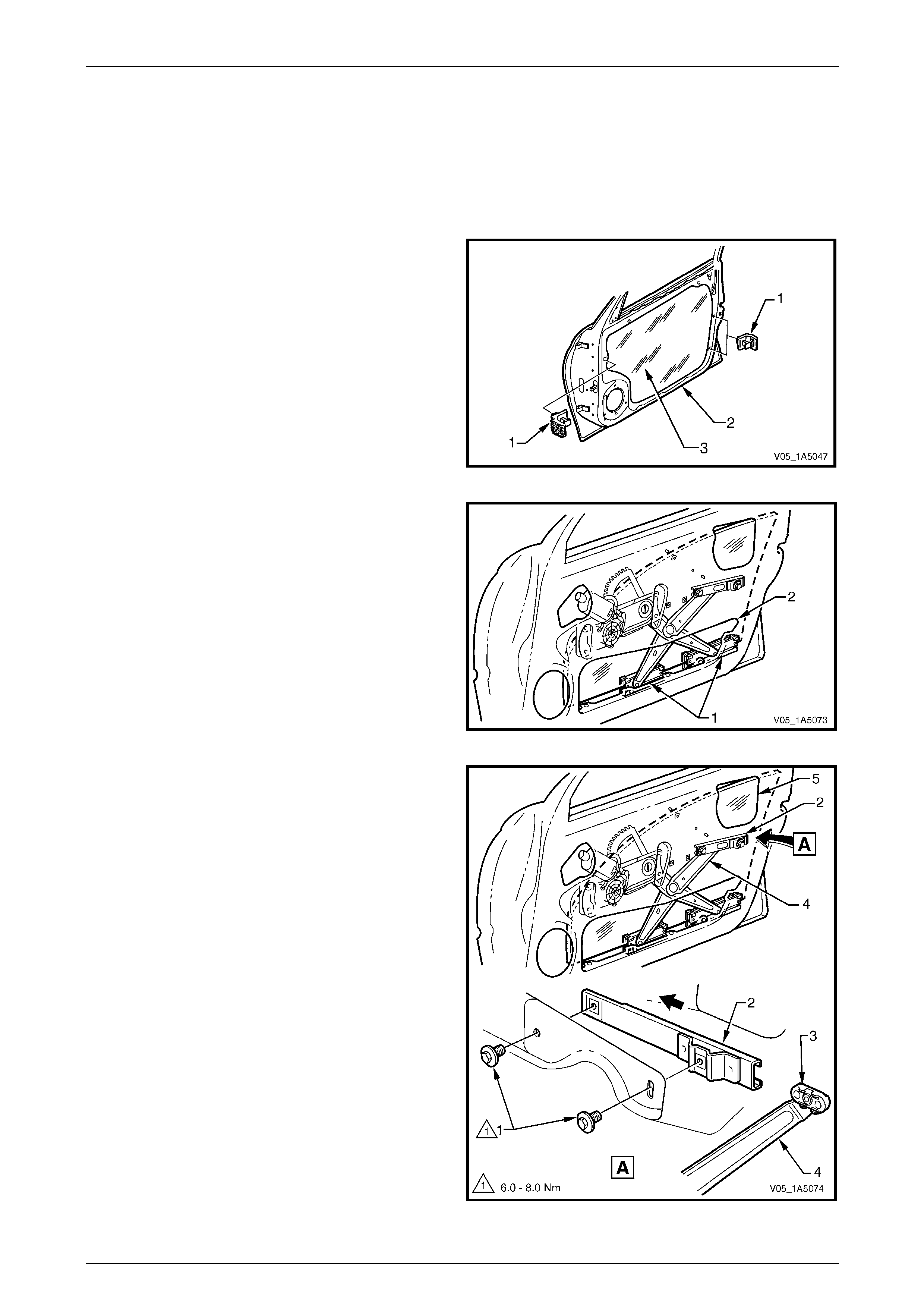
Front and Rear Door Assemblies Page 1A5–37
Page 1A5–37
4.5 Front Door Window Regulator Assembly
LT Section — 11–675
Remove
1 Remove the Trim panel assembly, refer to 3.1 Front Door Tr im Panel.
2 Remove the trim panel bracket (1), three places, from
the inner panel (2) by levering out the centre pin of
each bracket.
3 Carefully peel off the water shield (3) from the inner
panel.
Figure 1A5 – 53
4 Lower the window assembly to a position where the
window regulator slid ers and the two window guide
rails (1) are visible through the aperture (2) in the inner
panel.
Figure 1A5 – 54
5 Remove the two screws (1) attaching the window
regulator channel assembly ( 2) to the inn er pan el.
6 Push the window regulator channel assembly out of
the slider (3) on the window regulator counter balance
arm (4).
7 Remove the window regulator channel assembly
through the upper opening (5) in the inner panel.
Figure 1A5 – 55
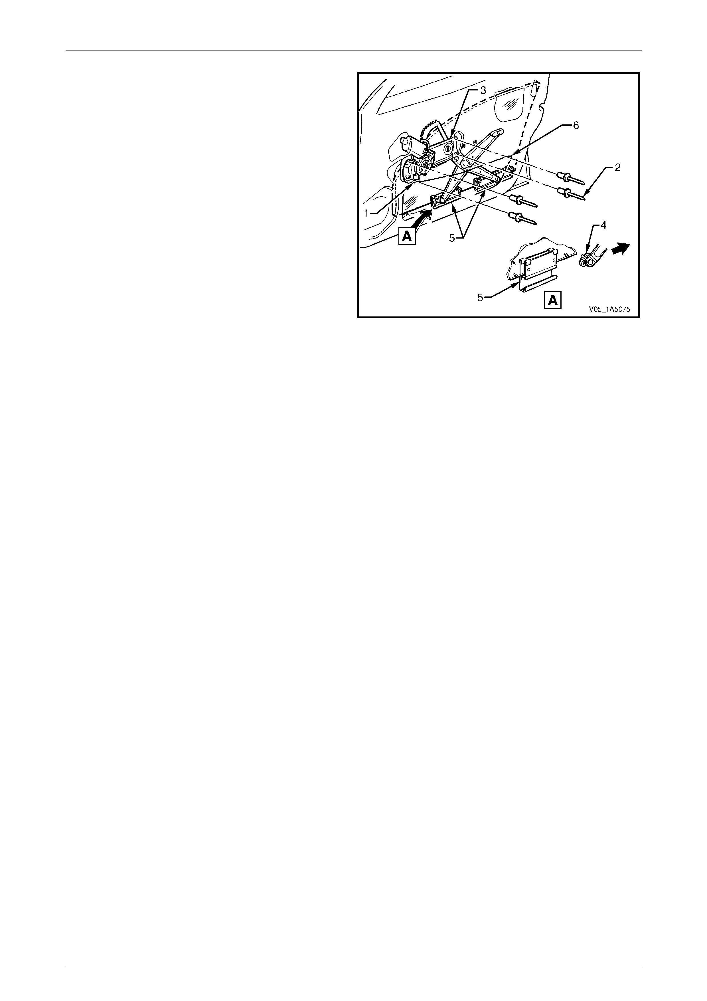
Front and Rear Door Assemblies Page 1A5–38
Page 1A5–38
8 Disconnect the window regulator assembly wiring
harness connector (1).
9 Have an assistant to support the window glass and
drill out the four rivets (2) securing the window
regulator assembly (3) to the inner panel.
NOTE
Use a 5 mm drill bit to drill out the four rivets
securing the window regulator assembly.
10 Move the two window regulator sliders (4) out of the
two window guide channels (5).
11 Raise the window glass by hand.
12 Remove the window regulator assembly through the
inner panel aperture (6).
13 Place a wooden chock inside the door assembly to
hold the window glass pannel up, while replacing the
window regulator assembl y. Figure 1A5 – 56
Reinstall
Reinstallation of the front door window regulator assembly is the reverse of the removal procedure, noting the following:
1 Ensure that all frictional surfaces of the window regulator assembly and associated parts are adequately lubricated
with Lithium base grease NLGI No. 1 (with 9 % zinc oxide) or equivalent.
2 Align the attaching holes in the window regulator assembly with the corresponding holes in the inner panel an d
secure the window regulator assembly with 5 mm rivets.
NOTE
Washers may be inserted when installing the
rivets as the attaching holes in the inner panel
may have been enlarged when the rivets were
drilled out.
3 Fit the slider of the counter balance arm in the channel assembly and secur e loosely with the two attaching screws,
do not torque at this stage.
4 Adjust the window and regulator assemblies, then torque the attaching scre ws as per the adjustment procedure,
refer to 4.6 Front Door Window Assembly.
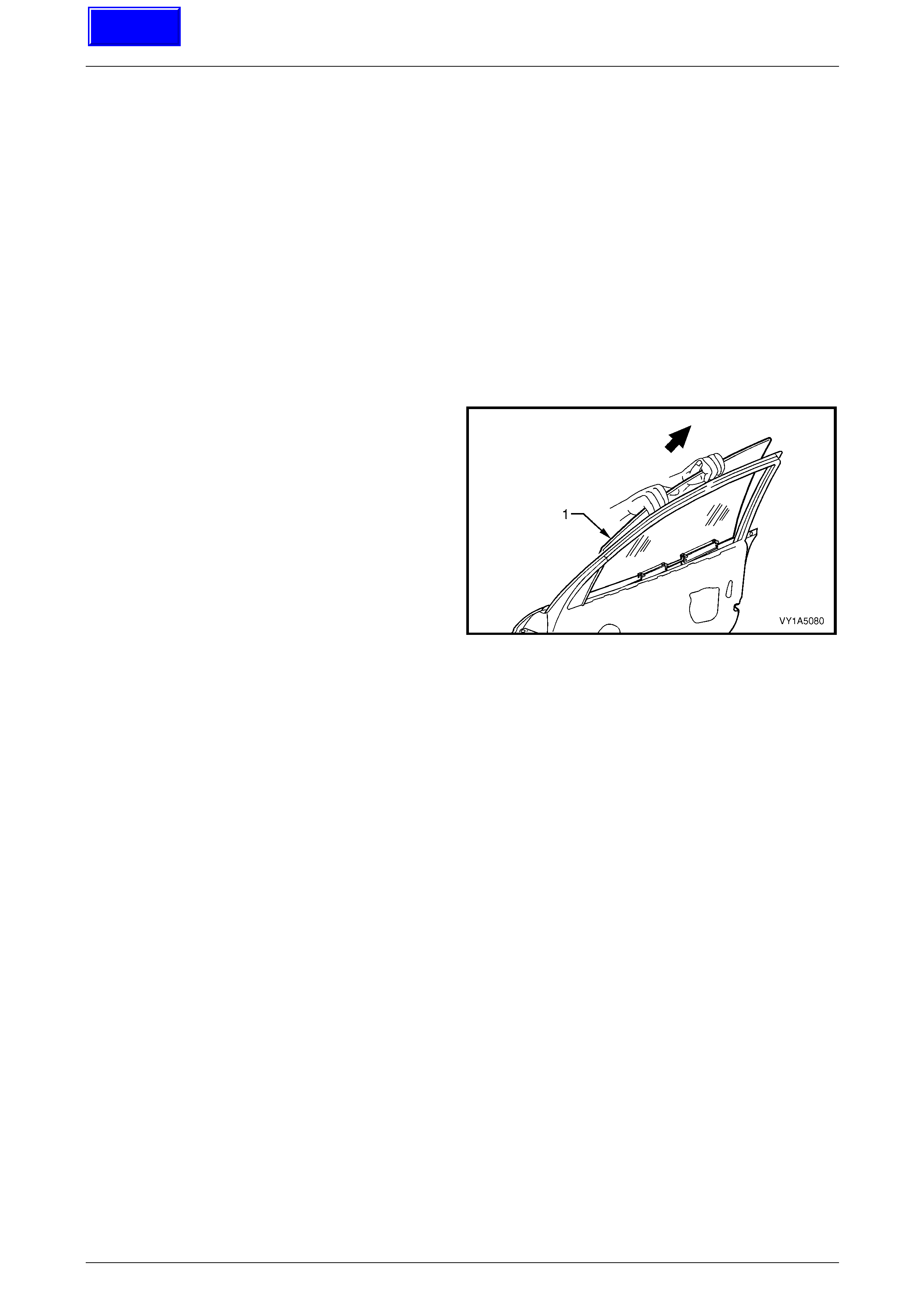
Front and Rear Door Assemblies Page 1A5–39
Page 1A5–39
4.6 Front Door Window Assembly
LT Section — 11–020
Remove
1 Remove the following components as required:
a Trim panel assembly, refer to 3.1 Front Door Trim Panel.
b Window regulator assembly, refer to 4.5 Fr ont Door Window Regulator Assembly.
c Window belt outer reveal moulding assembly,
refer to 5.3 Front Door Window Belt Outer Reveal Moulding Assembl y or
6.3 Front Door Window Belt Outer Reveal Moulding Assembly.
d Window guide channel assembly, refer to 4.4 Front Door Window Guide Channel Ass embly.
2 Lift the window assembly (1) up through the door belt
opening and slide to the rear.
Figure 1A5 – 57
Reinstall
Reinstallation of the front door window assembly is the reverse of the removal procedure, noting the following:
1 Insert the window assembly down through the door belt ope nin g taking care not to damage the glass panel.
NOTE
Do not torque any component attaching screw
prior to adjusting the window and regulator
assemblies.
2 When installing the window regulator assembly, make sure to adjust the windo w and regu lator assemblies as per
the adjusting procedure as described in this section, refer to Adjust.
Techline
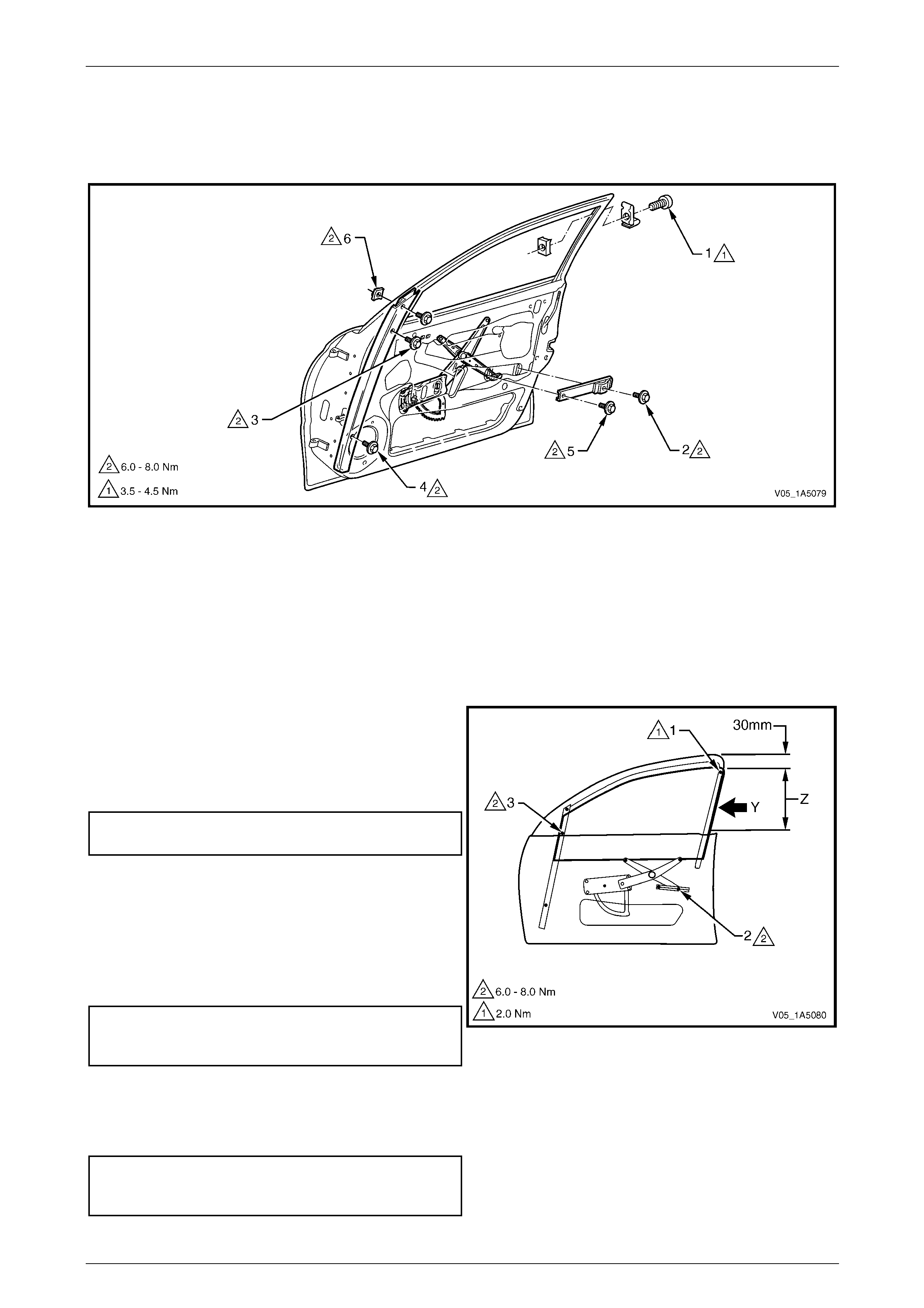
Front and Rear Door Assemblies Page 1A5–40
Page 1A5–40
Adjust
Figure 1A5 – 58 shows the screw / nut locations and torque values for the front door window assembly adjustment
procedure.
Figure 1A5 – 58
Legend
1 Front Door Window Up Stop Screw and Nut
2 Front Door Window Regulator Channel Rear Attaching
Screw
3 Front Door Window Guide Channel Assembly Upper
Attaching Screw
4 Front Door Window Guide Channel Assembly Lower
Attaching Screw
5 Front Door Window Regulator Channel Front Attaching
Screw
6 Front Door Window Down Stop Screw and Nut
1 Adjust the window assembly up stop, point (1) at the
rear of the front door so there is a 1 mm gap below the
highest possible end stop posi t ion.
2 Tighten the window up stop screw, point (1), to the
specified preliminar y torque value.
Front door window up stop screw
preliminary torque specification............................2.0 Nm
3 Wind the window assembly up through area (Z), until it
is approximately 30 mm before the closed position. At
the same time press the rail, which is bonded to the
rear edge of the window assembly, forward (Y).
4 Secure the window regulator channel assembly in
position without imposing any stress, by tightening the
rear attaching screw, point (2), to the specified torque.
Front door window regulator channel
rear attaching screw
torque specification.....................................6.0 – 8.0 Nm
5 Tighten the window guide cha nnel assembly upper
attaching screw, point (3), to the specified torque.
Ensure the window assembly is hel d approximately
30 mm before the closed position.
Front door window guide channel
assembly upper attaching screw
torque specification.....................................6.0 – 8.0 Nm
Figure 1A5 – 59

Front and Rear Door Assemblies Page 1A5–41
Page 1A5–41
6 Wind the window assembly down to approximately
30 mm above the belt outer reveal mould in g
assembly. At the same time press the rail at the rear
edge of the window assembly, for ward (Y). Tighten th e
window guide channel assembly lower attaching
screw, point (4), to the specified torque.
Front door window guide channel
assembly lower attaching screw
torque specification.....................................6.0 – 8.0 Nm
7 Secure the window regulator channel assembly in
position without imposing any stress, by tightening the
front attaching screw, point (5), to the specified torque.
Front door window regulator
channel front attaching screw
torque specification.....................................6.0 – 8.0 Nm
Figure 1A5 – 60
8 Wind the window assembly up to a positi on where its
upper edge is flush with the upper edg e of the e xterior
rear-view mirror housing, as seen from the outside. In
this position, the upper edge of the window assembly
must be parallel with point (X) on the window upper
weatherstrip assembly, over area (W).
9 Check the cranking load of the window assembly in
area (V). If the window assembly binds or the motor
load sounds excessive, re-adjust the window
assembly by correcting the guide channe l attachment
points (3 and 4).
10 Adjust the window down stop screw, point (6), so the
down stop nut contacts with the window. Tighten the
window down stop screw to the specified torque.
Front door window down stop screw
torque specification.....................................6.0 – 8.0 Nm
11 Check the window for the following:
a The upper edge of the window must be par allel
to the lip of the door upper frame run channe l at
point (X) and over the area (W ).
b The upper edge of the window must be inserted
by 4 mm ±1 mm above the lip of the door upper
frame run channel at point (X) and over the
area (W).
NOTE
If either the deviation in parallelism or the
insertion depth e xceeds 1 mm from specificat ion,
the stop assemblies at points (1 and 6) must be
readjusted.
12 Tighten the window up stop scre w (1), to the specified
final torque value.
Front door window up stop screw
torque specification.....................................3.5 – 4.5 Nm
Figure 1A5 – 61


Front and Rear Door Assemblies Page 1A5–43
Page 1A5–43
4.8 Front Door Wiring Harness Assembly
LT Section —
Remove and Reinstall
Ensure the wiring harness assembly is routed and clipped correctly. For the wiring harness assembly attachment and
routing, refer to Section 12O Fuses, Relays and Wirin g Harn esses.
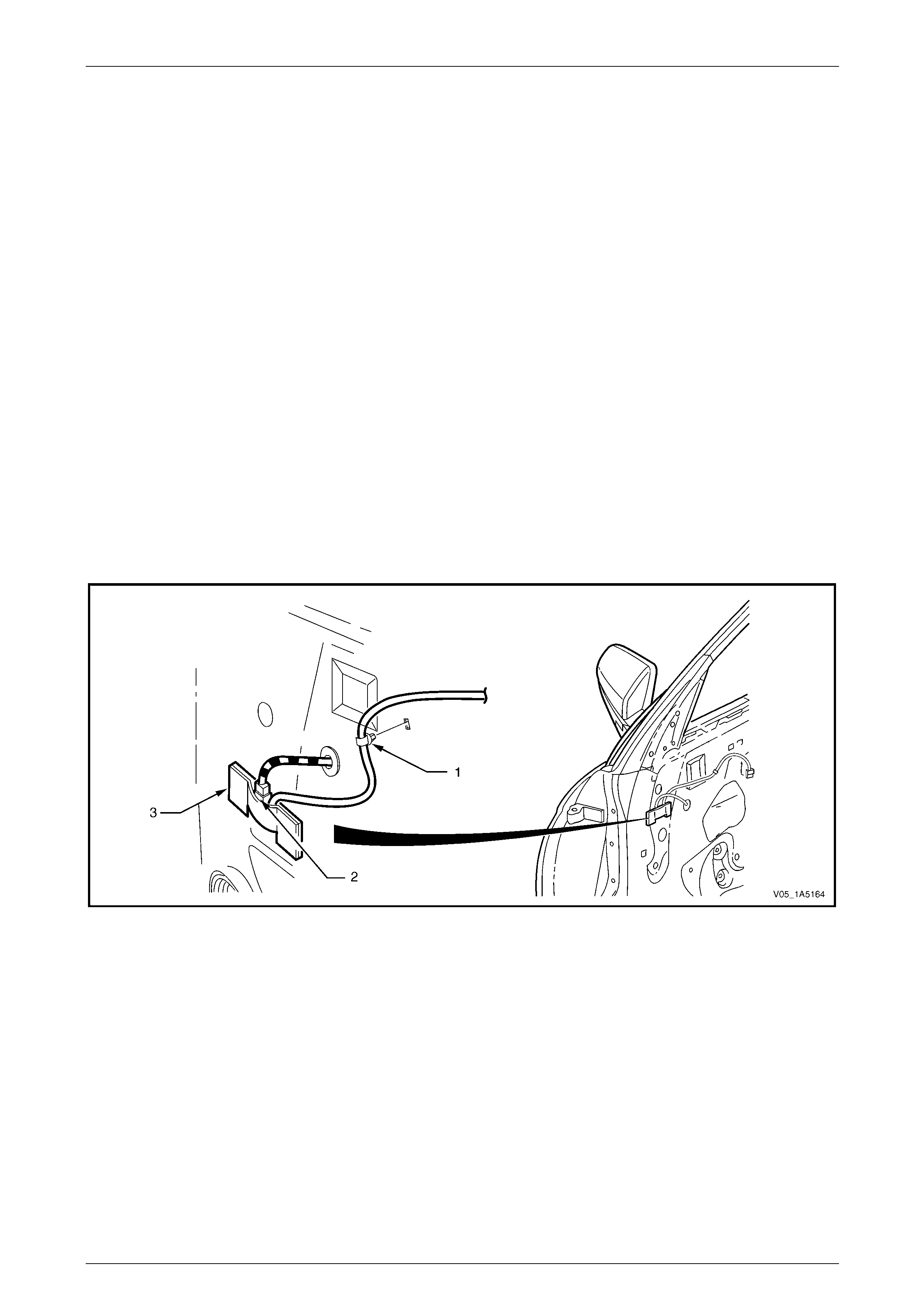
Front and Rear Door Assemblies Page 1A5–44
Page 1A5–44
4.9 Exterior Rear-view Mirror Memory
Module
LT Section — 14–275
Remove
NOTE
The exterior rear-view mirror memory module is
only fitted to Level 3 vehicles.
1 Remove the trim panel assembly, refer to 3.1 Front Door Trim Panel.
2 Remove the exterior rear-view mirror memory module harness retainer (1) from the inner panel, refer to
Figure 1A5 – 62.
3 Disconnect the harness connector (2) from the exterior rear-view mirror memory module (3).
4 Carefully peel the exterior rear -view mirror memory module from the inner panel.
NOTE
For diagnosis of the exterior rear-view
mirror memory module, refer to
Section 1A7 Seat Assemblies.
Figure 1A5 – 62
Reinstall
Reinstallation of the exter ior rear-view mirror memory module is the reverse of the removal procedure, noting the
following:
If required, use a commercially available contact adhesive to attach the exterior rear-view mirror memory module to the
inner panel.
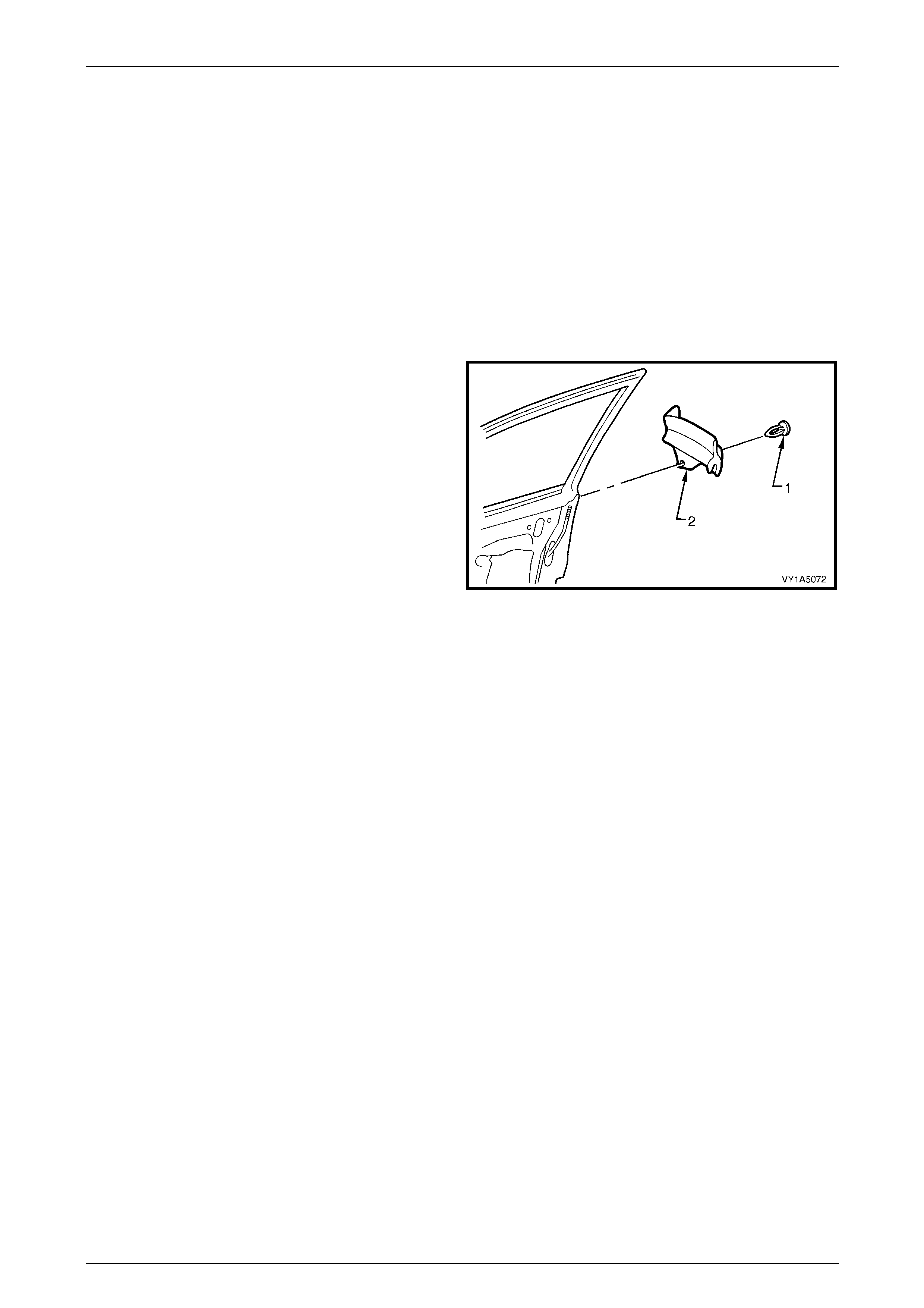
Front and Rear Door Assemblies Page 1A5–45
Page 1A5–45
5 Service Operations – Front Door
Sealing Components, Except
Coupe
5.1 Front Door Window Inner Filler
Assembly
LT Section — 11–650
Remove
1 Gently prise the retainer (1) out from the sealing strip
of the window inner filler assembly (2).
2 Remove the window inner filler assembly from the rear
of the door assembly.
Figure 1A5 – 63
Reinstall
Reinstallation of the front door window inner filler assembly is the reverse of the removal procedure.
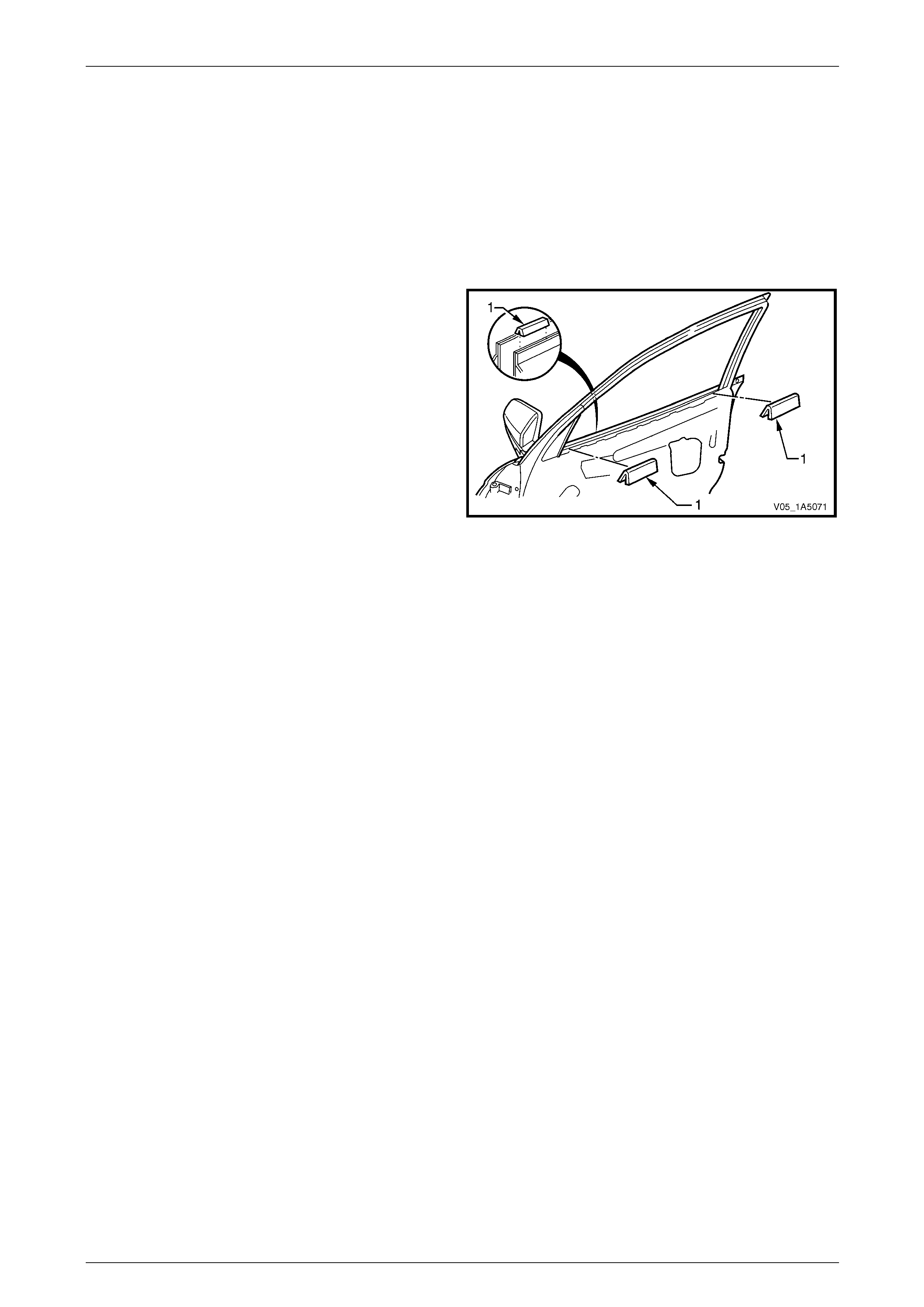
Front and Rear Door Assemblies Page 1A5–46
Page 1A5–46
5.2 Front Door Inner Panel Beltline Seals
LT Section — 11–650
Remove
1 Lower the window to the down position.
2 Remove the trim panel assembly, refer to 3.1 Front Door Trim Panel.
3 Remove the inner panel two beltline seals (1) from the
door assembly.
Figure 1A5 – 64
Reinstall
Reinstallation of the front door inner panel beltline seals is the reverse of the remov al pro c edure.

Front and Rear Door Assemblies Page 1A5–47
Page 1A5–47
5.3 Front Door Window Belt Outer Reveal
Moulding Assembly
LT Section — 11–650
Remove
1 Lower the window assembly.
2 If required, remove the window inner filler assembl y, refer to 5.1 Front Door Window Inner Filler Assembly.
3 Remove the screw (1) attaching the window belt outer
reveal moulding assembly.
Take care not to damage the moulding or the
plastic retaining clips during this procedure.
4 Starting from the rear of the door, prise upward the
window belt outer reveal moulding assembl y (2) until
the retaining clips (3) are freed.
5 Slide the window belt outer reveal moulding assembly
out from underneath the exterior rear-view mirror and
remove. Figure 1A5 – 65
Reinstall
Reinstallation of the front door window belt outer reveal moulding assembly is the reverse of the removal procedure,
noting the following:
1 Slide the window belt outer reveal moulding
assembly (1) under the exterior rear-view mirror (2).
2 Align the rear of the window belt outer reveal moulding
assembly at 1.4 mm over the rear of the front door.
Using the palm of the hand, firmly tap the assembl y
down onto the door outer panel upper flange.
3 Tighten the screw (3) attaching the window belt outer
reveal moulding assembly to the correct torque
specification.
Front door window belt outer reveal
moulding attaching screw
torque specification.....................................1.0 – 3.0 Nm Figure 1A5 – 66
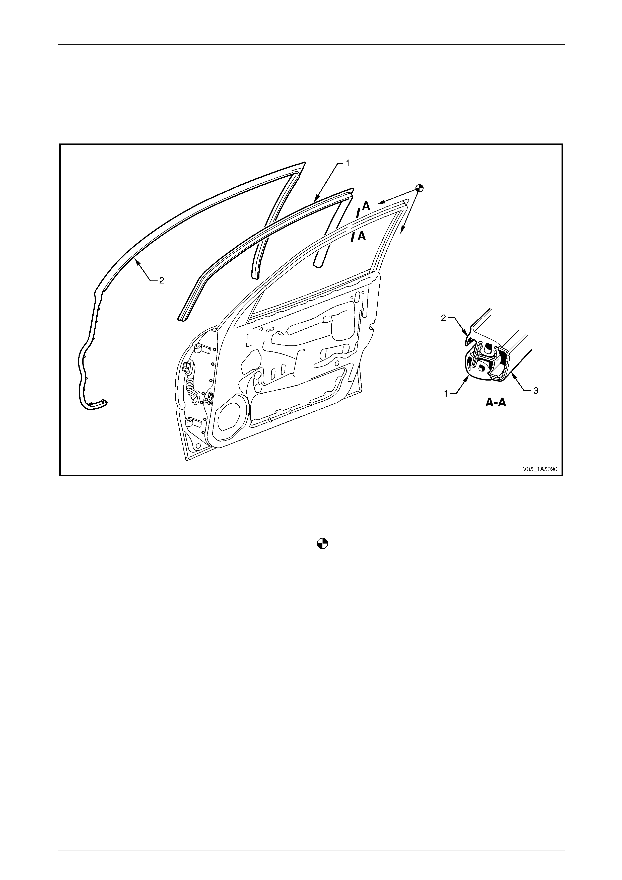
Front and Rear Door Assemblies Page 1A5–48
Page 1A5–48
5.4 Front Door Weatherstrip Assemblies
LT Section — 11–650
Assemblies Lay-out
Figure 1A5 – 67
Legend
1 Front Door Window Upper Weatherstrip Assembly
2 Front Door Upper Weatherstrip Assembly
3 Front Door Upper Frame
Front Door Upper Weatherstrip Assembly Reinstallation
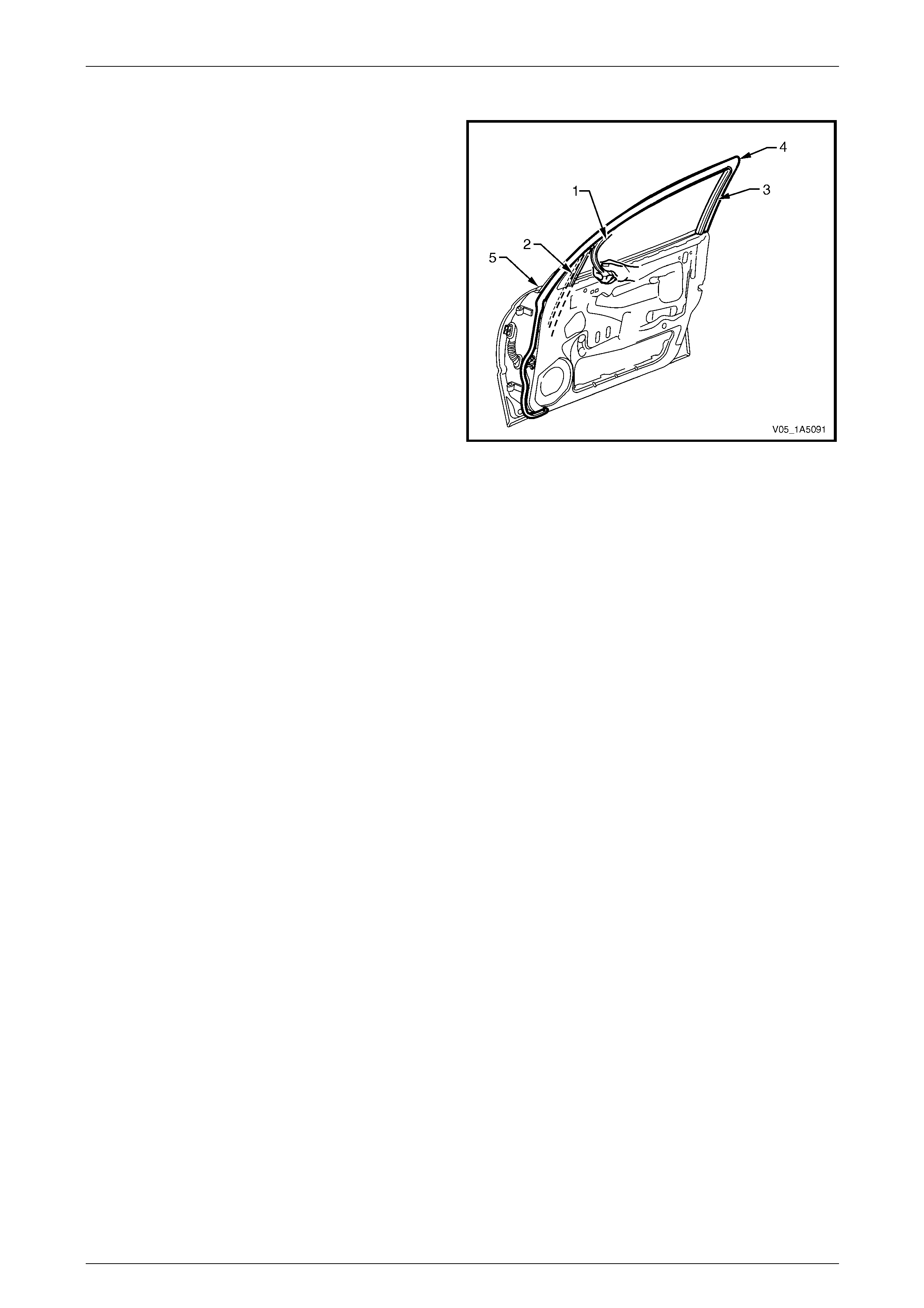
Front and Rear Door Assemblies Page 1A5–49
Page 1A5–49
Remove
1 Lower the window to the down position.
2 Carefully remove the windo w upper weatherstrip
assembly (1) starting from the window guide channel
assembly (2), then pull out of the door upper frame
channel.
3 Pull the upper weatherstrip assembly (3) up and out of
the door upper frame, from the top rear corner (4) of
the door.
4 Progressively remove the upper weatherstrip
assembly from the lip on the door upper frame.
5 Carefully remove the upper weatherstrip assembly
from below the belt line (5), allowing the retainer clips
to pull out of the upper weatherstrip assembly and
remain in the door panel.
6 Remove the retainer clips from the door panel with a
clip removal tool and refit them back into the upper
weatherstrip assembly, ready for reinstallation. Figure 1A5 – 68
Reinstall
Reinstallation of the front door weatherstrip assemblies is the reverse of the removal proc edure, noting the following:
1 Install the upper weatherstrip assembly (2) starting at the top rear corner and aligning the locating marks on the
door frame, then proceed in direction of arrows, refer to Figure 1A5 – 67.
2 Ensure the retainer clips secure the upper weatherstrip assembly to the door panel below the belt line.
3 Ensure the window upper weatherstrip assembly is pushed back fully into the door upper frame channel and
window guide channel assembly.

Front and Rear Door Assemblies Page 1A5–50
Page 1A5–50
5.5 Front Door Window Upper Garnish
Moulding
LT Section — 11–650
Remove
NOTE
The front door window upper garnish moulding
may be damaged during this operation and
require replacement.
1 Lower the front door window to the down position.
2 Remove the following components as required:
a Trim panel assembly, refer to 3.1 Front Door Trim Panel.
b Window inner filler assembly, refer to 5.1 Front Door Window Inner Filler Assembly.
c Upper weatherstrip assembly, from the lip on the door upper frame,
refer to 5.4 Front Door Weatherstrip Assemblies.
3 Carefully remove the windo w upper weatherstrip
assembly (1) from the window guide channel
assembly (2).
NOTE
It is not necessary to remove the window upper
weatherstrip assembly completely, remove it
only from the windo w guide channel assembly.
Figure 1A5 – 69
4 Remove the exterior rear-view mirror, refer to
Section 12H Rear-view Mirrors.
5 With the aid of a knife, progressively peel the window
upper garnish moulding (1) from around the door
upper frame, separating the adhes ive from the frame.
6 If required, peel off the two self-adhesive seal s (2)
from the door inner panel.
7 As required, clean the surface of the door upper frame
with Prepsol or equivalent.
Figure 1A5 – 70
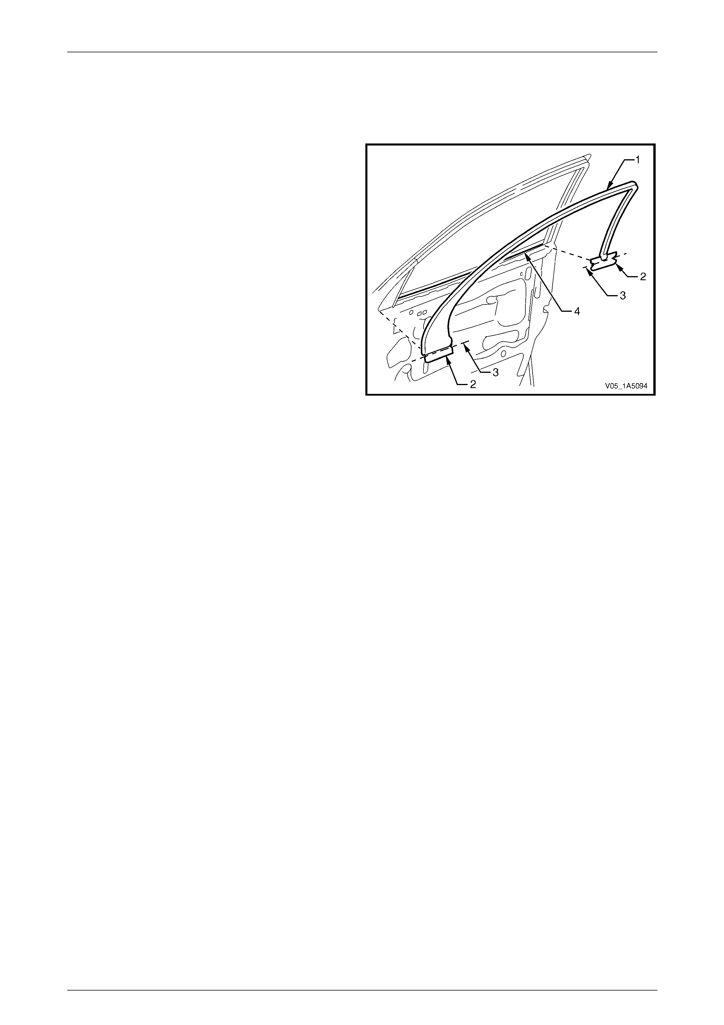
Front and Rear Door Assemblies Page 1A5–51
Page 1A5–51
Reinstall
Reinstallation of the front door window upper garnish moulding is the reverse of the removal procedure, noting the
following:
1 Ensure the door upper frame is clean prior to
positioning the window upper garnish moulding (1).
2 If required, install the self-adhesive se als (2), align the
centre line of notches (3) with the top of the door
skin (4).
3 As required, install a new self -adhesive window upper
garnish moulding to the door upper frame.
Figure 1A5 – 71
4 Ensure the window upper weatherstrip assembl y (1) is pus hed back fully into the window guid e cha nnel
assembly (2), refer to Figure 1A5 – 69.
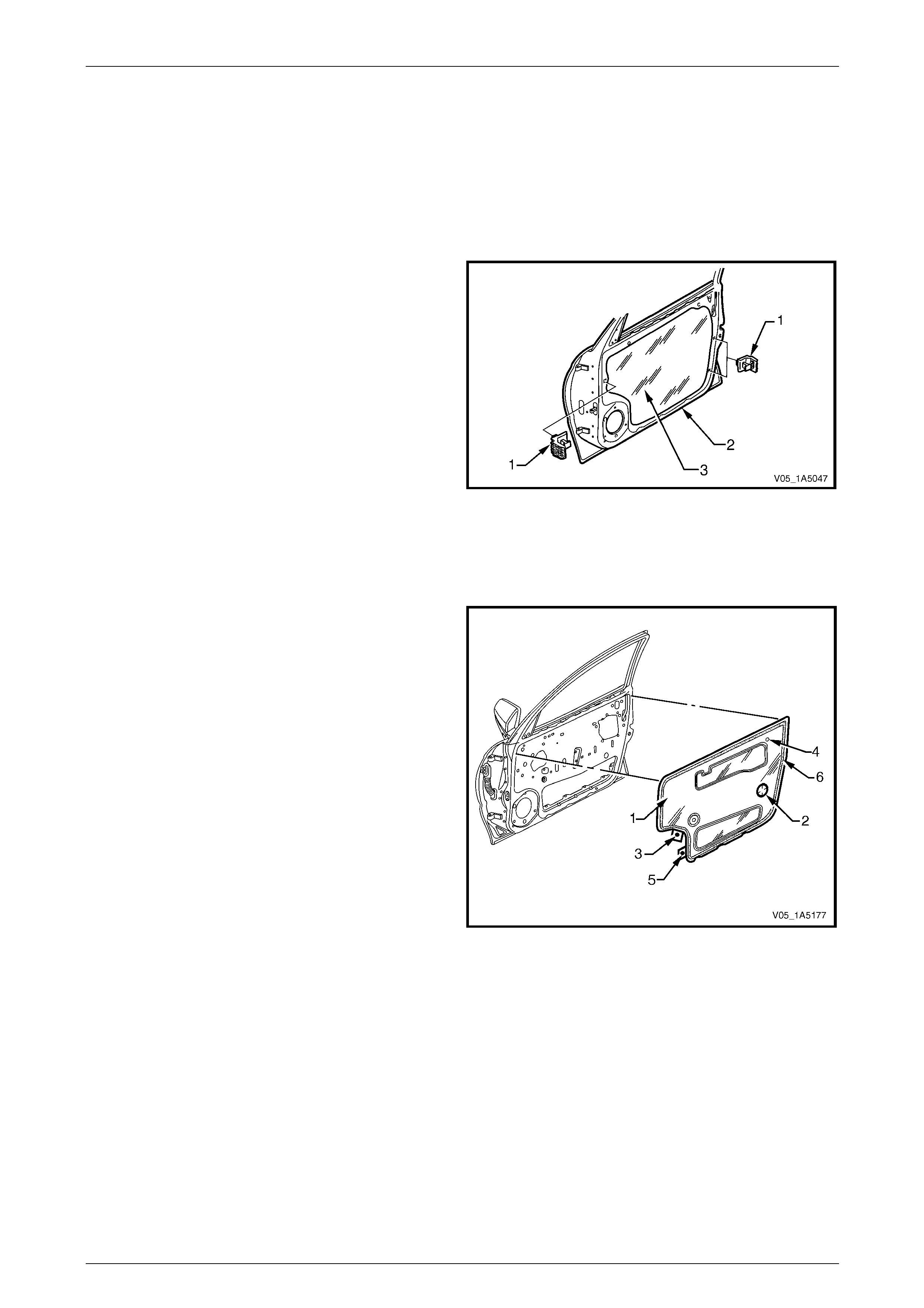
Front and Rear Door Assemblies Page 1A5–52
Page 1A5–52
5.6 Front Door Water Shield
LT Section — 14–220
Remove
1 Remove the trim panel assembly, refer to 3.1 Front Door Trim Panel.
2 Remove the trim panel bracket (1), three places, from
the inner panel (2) by levering out the centre pin of
each bracket.
3 Carefully peel off the water shield (3) from the door
inner panel.
Figure 1A5 – 72
Reinstall
Reinstallation of the front door water shield is the reverse of the removal procedure, noting the following:
1 If installing a new water shield (1), proceed as follows:
a Apply foamed hot melt adh esive around entire
periphery of the shield co urtesy lamp
perforation (2), then remove the tab (3) and
adhere over the perforation.
b Apply foamed hot melt adh esive around entire
periphery of the jig hole (4), then remove the
tab (5) and adhere over the jig hole.
c Apply foamed hot melt adhesive around the
entire periphery (6) of the water shield, then fit to
the door inner panel.
2 If reusing the same water shield, apply hot melt
adhesive as required and fit to the door inner panel.
Figure 1A5 – 73
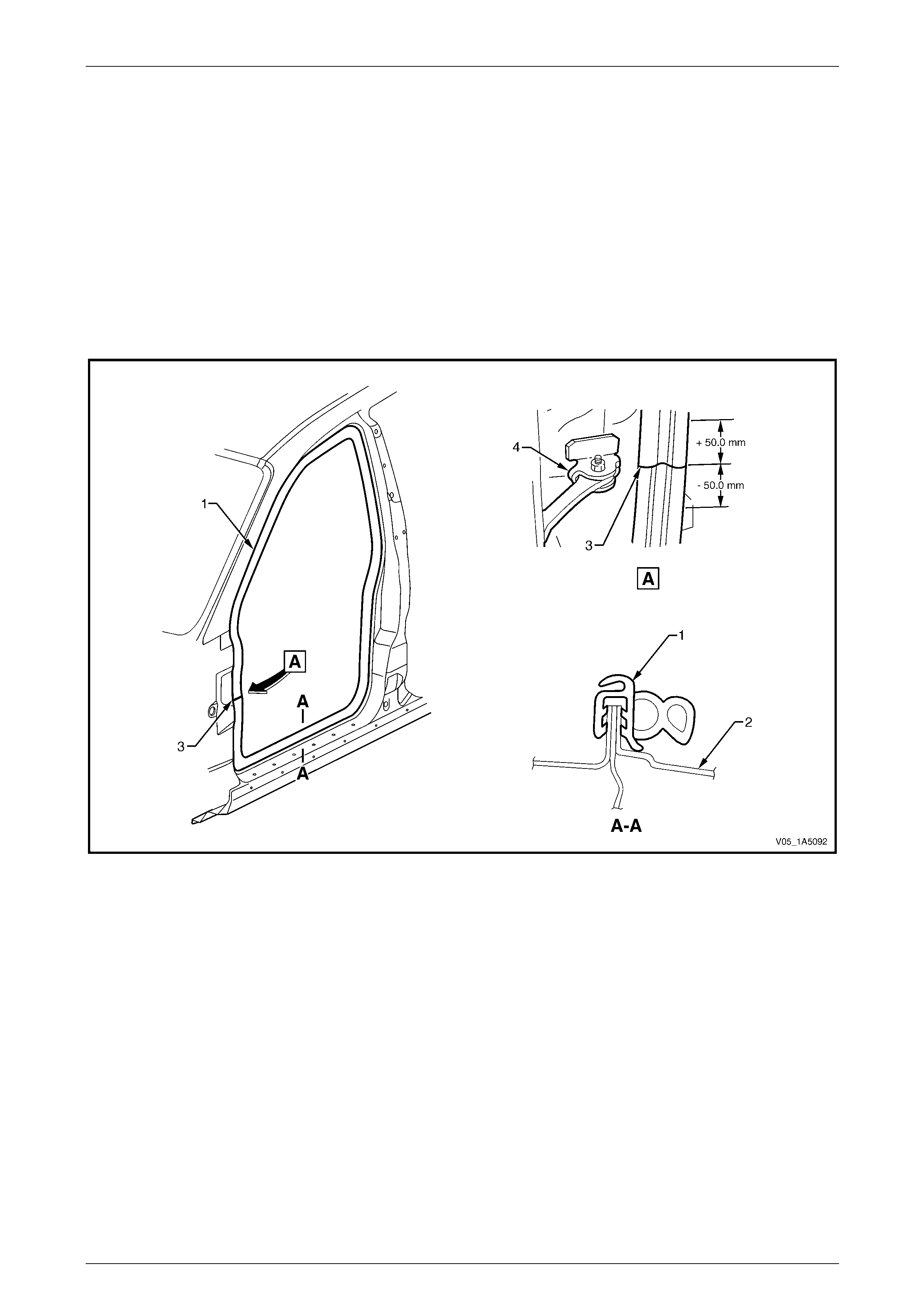
Front and Rear Door Assemblies Page 1A5–53
Page 1A5–53
5.7 Front Door Opening Weatherstrip
Assembly
LT Section — 11–600
Remove
1 Remove the following components as required:
a Side sill trim and plate, centre pillar lower and upper trim, windshield side garnis h, hinge pillar trim and front
floor carpet retaining clips, refer to Section 1A8 Headlining and Interi or Trim.
b Instrument panel outer cover, refer to Section 1A3 Instrument Panel and Console.
2 Gently prise the weatherstrip assembly (1) from the front door opening frame (2), refer to Figure 1A5 – 74.
Figure 1A5 – 74
Legend
1 Front Door Opening Weatherstrip Assembly
2 Front Door Opening Frame Assembly 3 Front Door Opening Weatherstrip Identification Mark
4 Front Door Check Assembly
Reinstall
Reinstallation of the front door opening weatherstrip assembly is the reverse of the removal procedure, noting the
following:
1 Align the identification mark ( 3) on t he weatherstrip assembly (1), with the door check assembly (4) in the door
opening frame (2) within ±50 mm, refer to Figure 1A5 – 74.
2 Ensure the weatherstrip assembly does not short cut corners and foul the door trim.
NOTE
Allow crowding of the weatherstrip assembly in all
corners of the door frame opening.
3 Ensure the lip of the weatherstrip assembly sits over the trim panels.

Front and Rear Door Assemblies Page 1A5–54
Page 1A5–54
6 Service Operations – Front Door
Sealing Components, Coupe
6.1 Front Door Window Inner Filler
Assembly
LT Section — 11–650
Remove
1 Gently prise the retainer (1) out from the sealing strip
of the window inner filler assembly (2).
2 Remove the window inner filler assembly from the rear
of the door assembly.
Figure 1A5 – 75
Reinstall
Reinstallation of the front door window inner filler assembly is the reverse of the removal procedure.
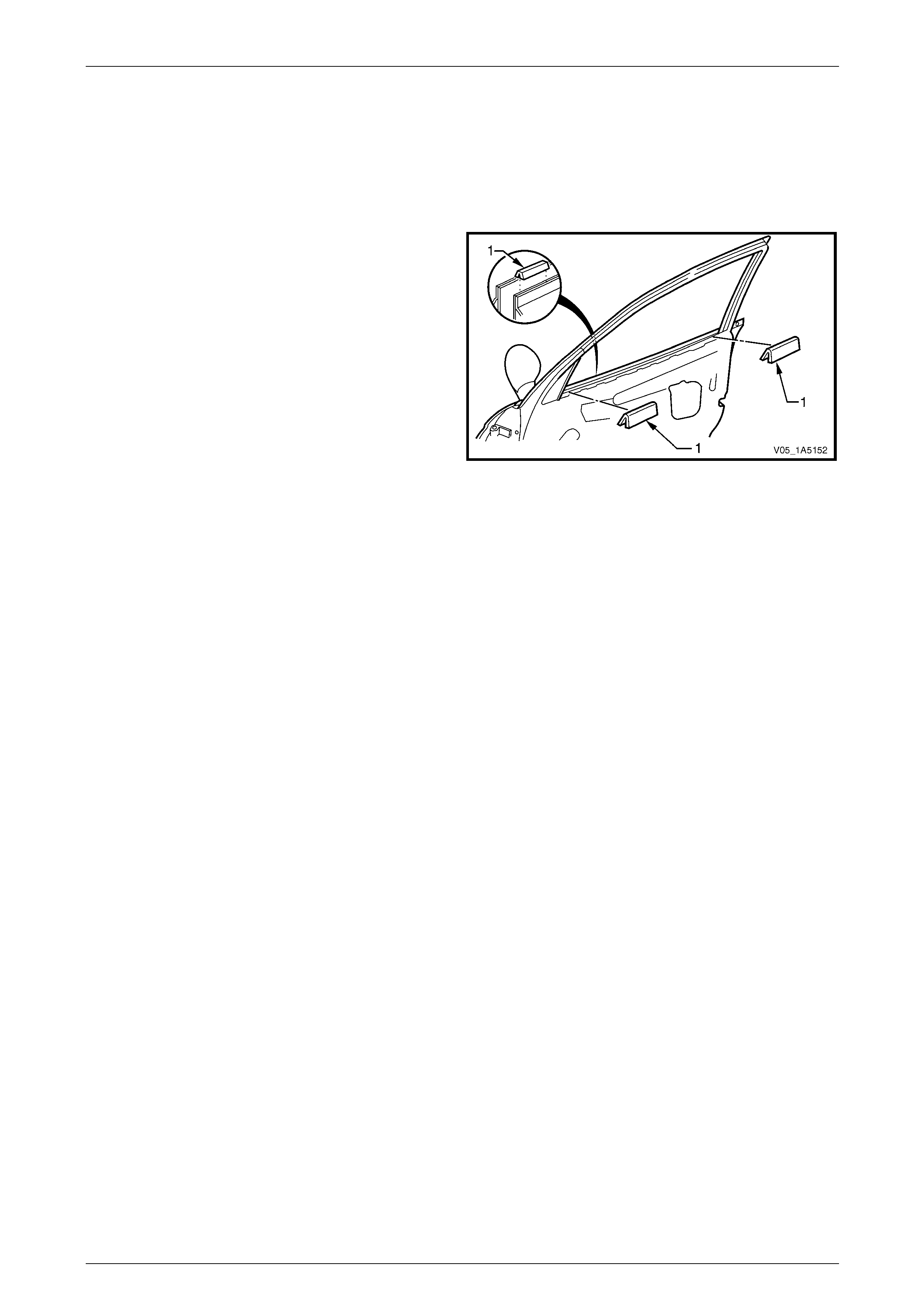
Front and Rear Door Assemblies Page 1A5–55
Page 1A5–55
6.2 Front Door Inner Panel Beltline Seals
LT Section — 11–650
Remove
1 Lower the window to the down position.
2 Remove the trim panel assembly,
refer to 3.1 Front Door Trim Panel.
3 Remove the inner panel two beltline seals (1) from the
door assembly.
Figure 1A5 – 76
Reinstall
Reinstallation of the front door inner panel beltline seals is the reverse of the remov al pro c edure.
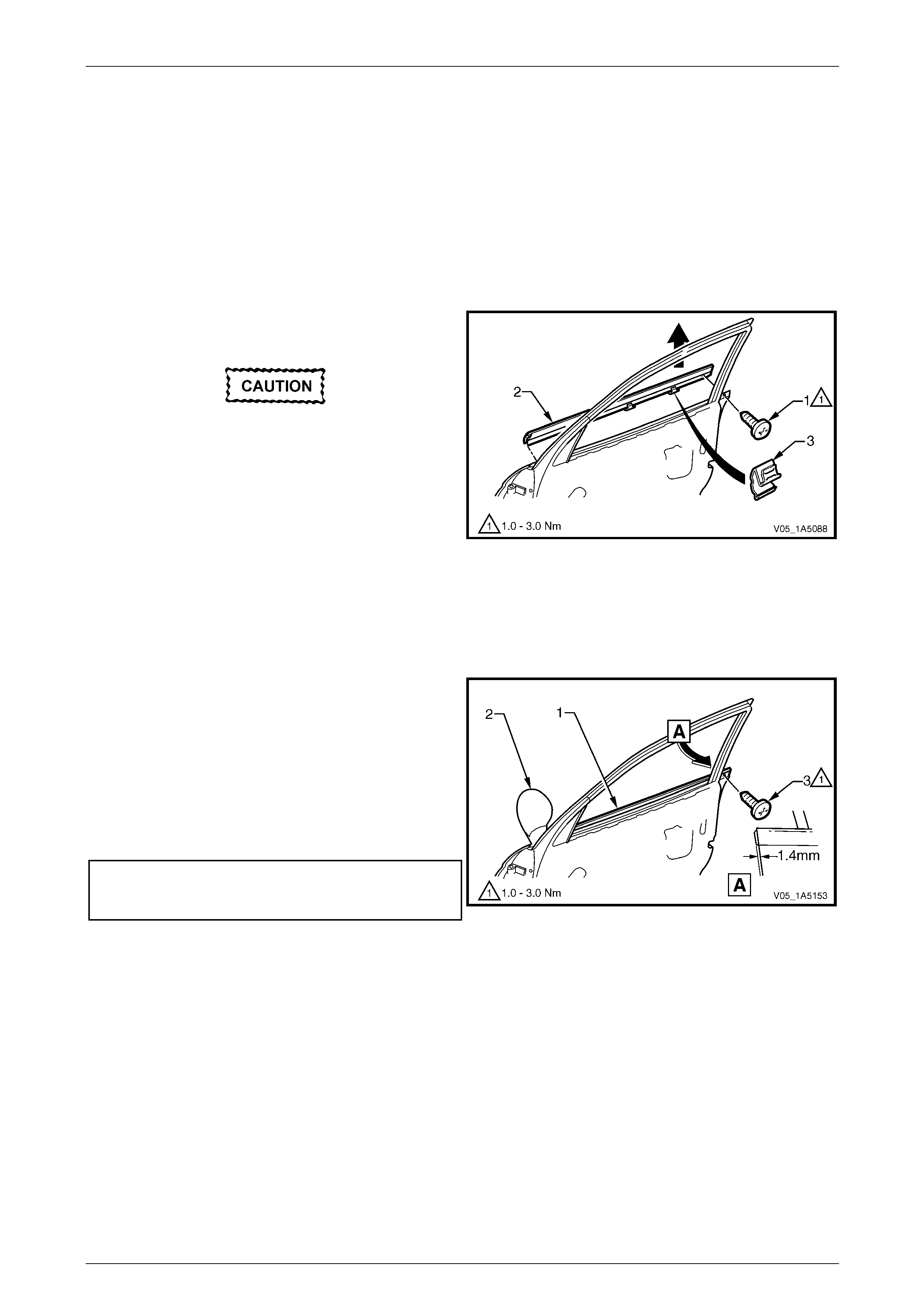
Front and Rear Door Assemblies Page 1A5–56
Page 1A5–56
6.3 Front Door Window Belt Outer Reveal
Moulding Assembly
LT Section — 11–650
Remove
1 Lower the window assembly.
2 If required, remove the window inner filler assembl y, refer to 6.1 Front Door Window Inner Filler Assembly.
3 Remove the screw (1) attaching the window belt outer
reveal moulding assembly.
Take care not to damage the moulding or the
plastic retaining clips during this procedure.
4 Starting from the rear of the door, prise upward the
window belt outer reveal moulding assembl y (2) until
the retaining clips (3) are freed.
5 Slide the window belt outer reveal moulding assembly
out from underneath the exterior rear-view mirror and
remove. Figure 1A5 – 77
Reinstall
Reinstallation of the front door window belt outer reveal moulding assembly is the reverse of the removal procedure,
noting the following:
1 Slide the window belt outer reveal moulding
assembly (1) under the exterior rear-view mirror (2).
2 Align the rear of the window belt outer reveal moulding
assembly at 1.4 mm over the rear of the door. Using
the palm of the hand, firmly tap the assembly down
onto the door outer panel upper flange.
3 Tighten the screw (3) attaching the window belt outer
reveal moulding assembly to the correct torque
specification.
Front door window belt outer reveal
moulding attaching screw
torque specification.....................................1.0 – 3.0 Nm Figure 1A5 – 78

Front and Rear Door Assemblies Page 1A5–57
Page 1A5–57
6.4 Front Door Weatherstrip Assemblies
LT Section — 11–650
Assemblies Lay-out
Figure 1A5 – 79
Legend
1 Front Door Window Upper Weatherstrip Assembly
2 Front Door Upper Weatherstrip Assembly
3 Front Door Upper Frame
Front Door Upper Weatherstrip Assembly Reinstallation

Front and Rear Door Assemblies Page 1A5–58
Page 1A5–58
Remove
1 Lower the window to the down position.
2 Carefully remove the windo w upper weatherstrip
assembly (1) starting from the window guide channel
assembly (2), then pull out of the door upper frame
channel.
3 Pull the upper weatherstrip assembly (3) up and out of
the door upper frame, from the top rear corner (4) of
the door.
4 Progressively remove the upper weatherstrip
assembly from the lip on the door upper frame.
5 Carefully remove the upper weatherstrip assembly
from below the belt line (5), allowing the retainer clips
to pull out of the upper weatherstrip assembly and
remain in the door panel.
6 Remove the retainer clips from the door panel with a
clip removal tool and refit them back into the upper
weatherstrip assembly, ready for reinstallation. Figure 1A5 – 80
Reinstall
Reinstallation of the front door weatherstrip assemblies is the reverse of the removal proc edure, noting the following:
1 Install the upper weatherstrip assembly (2) starting at the top rear corner and aligning the locating marks on the
door frame, then proceed in direction of arrows, refer to Figure 1A5 – 79.
2 Ensure the retainer clips secure the upper weatherstrip assembly to the door panel below the belt line.
3 Ensure the window upper weatherstrip assembly is pushed back fully into the door upper frame channel and
window guide channel assembly.
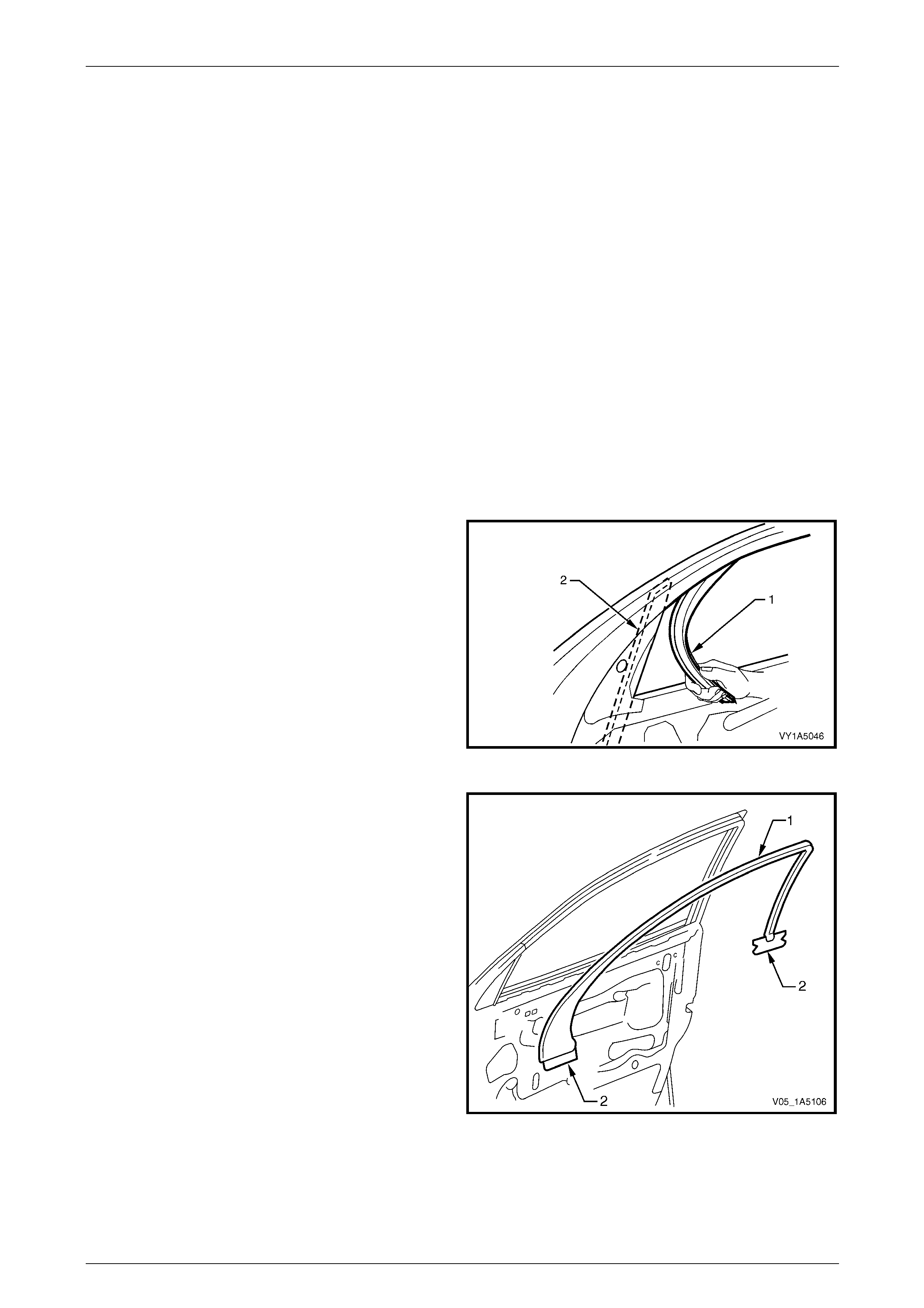
Front and Rear Door Assemblies Page 1A5–59
Page 1A5–59
6.5 Front Door Window Upper Garnish
Moulding
LT Section — 11–650
Remove
NOTE
The front door window upper garnish moulding
may be damaged during this operation and
require replacement.
1 Lower the front door window to the down position.
2 Remove the following components as required:
a Trim panel assembly, refer to 3.1 Front Door Trim Panel.
b Window inner filler assembly, refer to 6.1 Front Door Window Inner Filler Assembly.
c Upper weatherstrip assembly from the lip on the door upper frame,
refer to 6.4 Front Door Weatherstrip Assemblies.
3 Carefully remove the windo w upper weatherstrip
assembly (1) from the window guide channel
assembly (2).
NOTE
It is not necessary to remove the window upper
weatherstrip assembly completely, remove it
only from the windo w guide channel assembly.
Figure 1A5 – 81
4 Remove the exterior rear-view mirror, refer to
Section 12H Rear-view Mirrors.
5 With the aid of a knife, progressively peel the window
upper garnish moulding (1) from around the door
upper frame, separating the adhes ive from the frame.
6 If required, peel off the two self-adhesive seal s (2)
from the door inner panel.
7 As required, clean the surface of the door upper frame
with Prepsol or equivalent.
Figure 1A5 – 82

Front and Rear Door Assemblies Page 1A5–60
Page 1A5–60
Reinstall
Reinstallation of the front door window upper garnish moulding is the reverse of the removal procedure, noting the
following:
1 Ensure the door upper frame is clean prior to
positioning the window upper garnish moulding (1).
2 If required, install the self-adhesive se als (2 and 3).
Align the front seal centre line (4) and the centre lin e
of notches (5) on the rear seal with the top of the door
skin (6).
3 As required, install a new self -adhesive window upper
garnish moulding (1) to the door upper frame .
Figure 1A5 – 83
4 Ensure the window upper weatherstrip assembl y (1) is pus hed back fully into the window guid e cha nnel
assembly (2), refer to Figure 1A5 – 81.
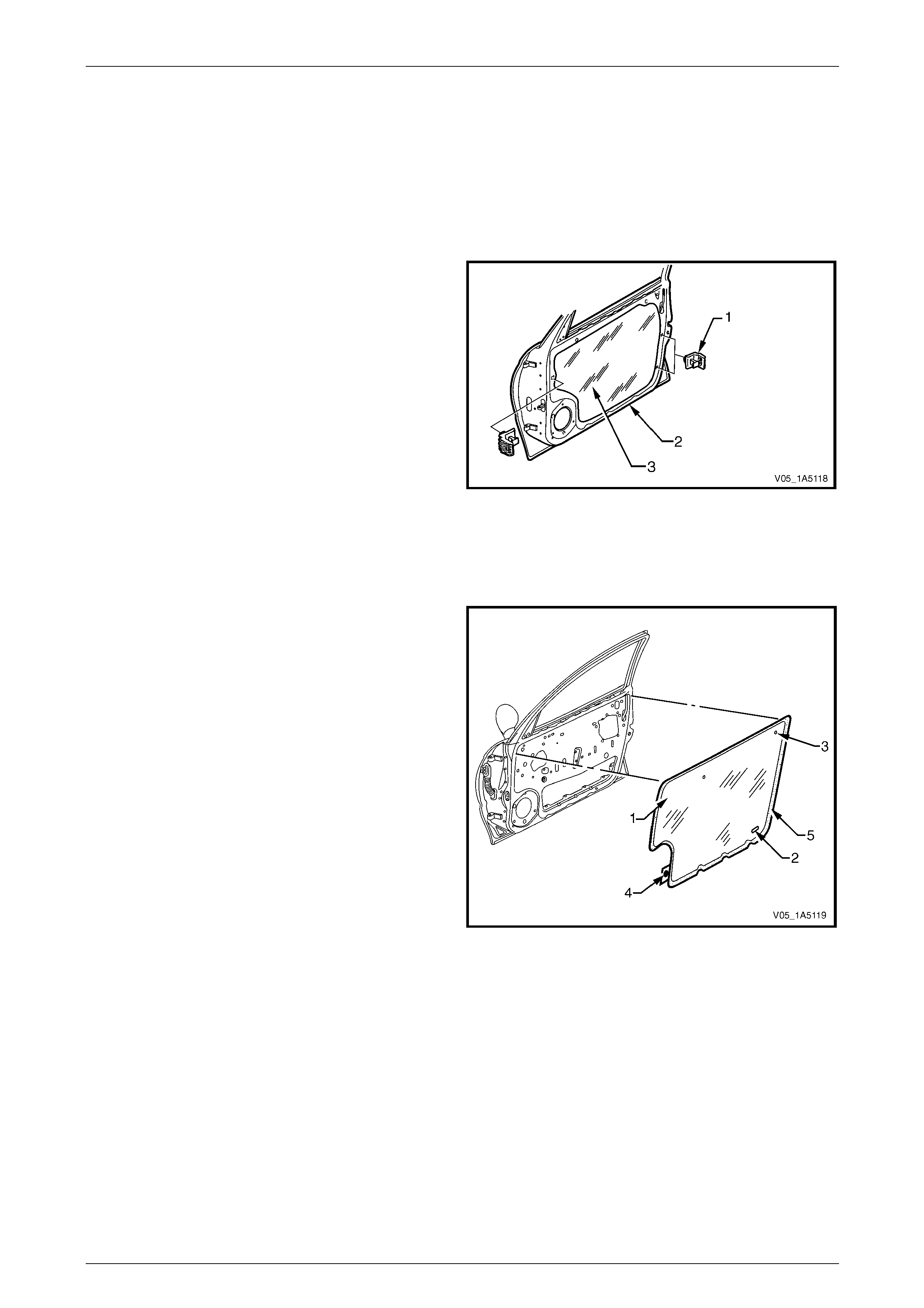
Front and Rear Door Assemblies Page 1A5–61
Page 1A5–61
6.6 Front Door Water Shield
LT Section — 14–220
Remove
1 Remove the trim panel assembly, refer to 3.1 Front Door Trim Panel.
2 Remove the trim panel bracket (1), three places, from
the inner panel (2) by levering out the centre pin of
each bracket.
3 Carefully peel off the water shield (3) from the door
inner panel.
Figure 1A5 – 84
Reinstall
Reinstallation of the front door water shield is the reverse of the removal procedure, noting the following:
1 If installing a new water shield (1), proceed as follows:
a Apply foamed hot melt adhesive around the
entire periphery of the courtesy lamp
perforation (2).
b Apply foamed hot melt adh esive around entire
periphery of the jig hole (3), remove the tab (4)
and adhere over the jig hole.
c Apply foamed hot melt adhesive around the
entire periphery (5) of the water shield, then fit to
the door inner panel.
2 If reusing the same water shield, apply hot melt
adhesive as required and fit to the door inner panel.
Figure 1A5 – 85
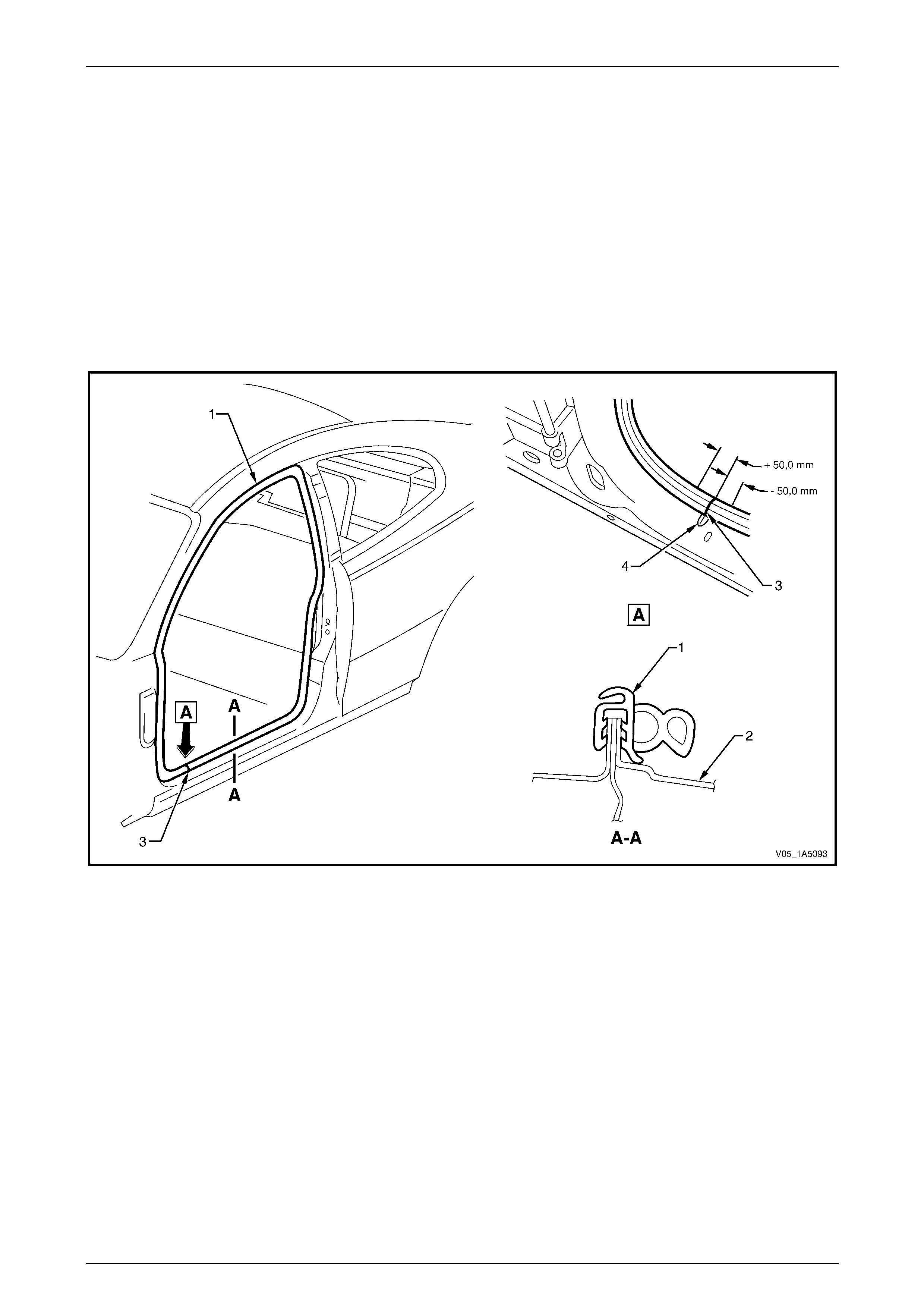
Front and Rear Door Assemblies Page 1A5–62
Page 1A5–62
6.7 Front Door Opening Weatherstrip
Assembly
LT Section — 11–600
Remove
1 Remove the following components as required:
a Side sill trim and plate, quarter trim panel, ce ntre pillar upper trim, windshield side garnish, hinge pillar trim
and front floor carpet retaining clips, refer to Section 1A8 Headlining and Interior Trim.
b Instrument panel outer cover, refer to Section 1A3 Instrument Panel and Console.
2 Gently prise the weatherstrip assembly (1) from the door opening frame (2), refer to Figure 1A5 – 86.
Figure 1A5 – 86
Legend
1 Door Opening Weatherstrip Assembly
2 Door Opening Frame Assembly 3 Door Opening Weatherstrip Identification Mark
4 Door Frame Dart
Reinstall
Reinstallation of the front door opening weatherstrip assembly is the reverse of the removal procedure, noting the
following:
1 Align the identification mark ( 3) on t he weatherstrip assembly (1), with the dart (4) in the door o pe nin g frame (2)
within ±50 mm, refer to Figure 1A5 – 86.
2 Ensure the weatherstrip assembly does not short cut corners and foul the door trim.
NOTE
Allow crowding of the weatherstrip assembly in all
corners of the door frame opening.
3 Ensure the lip of the weatherstrip assembly sits over the trim panels.
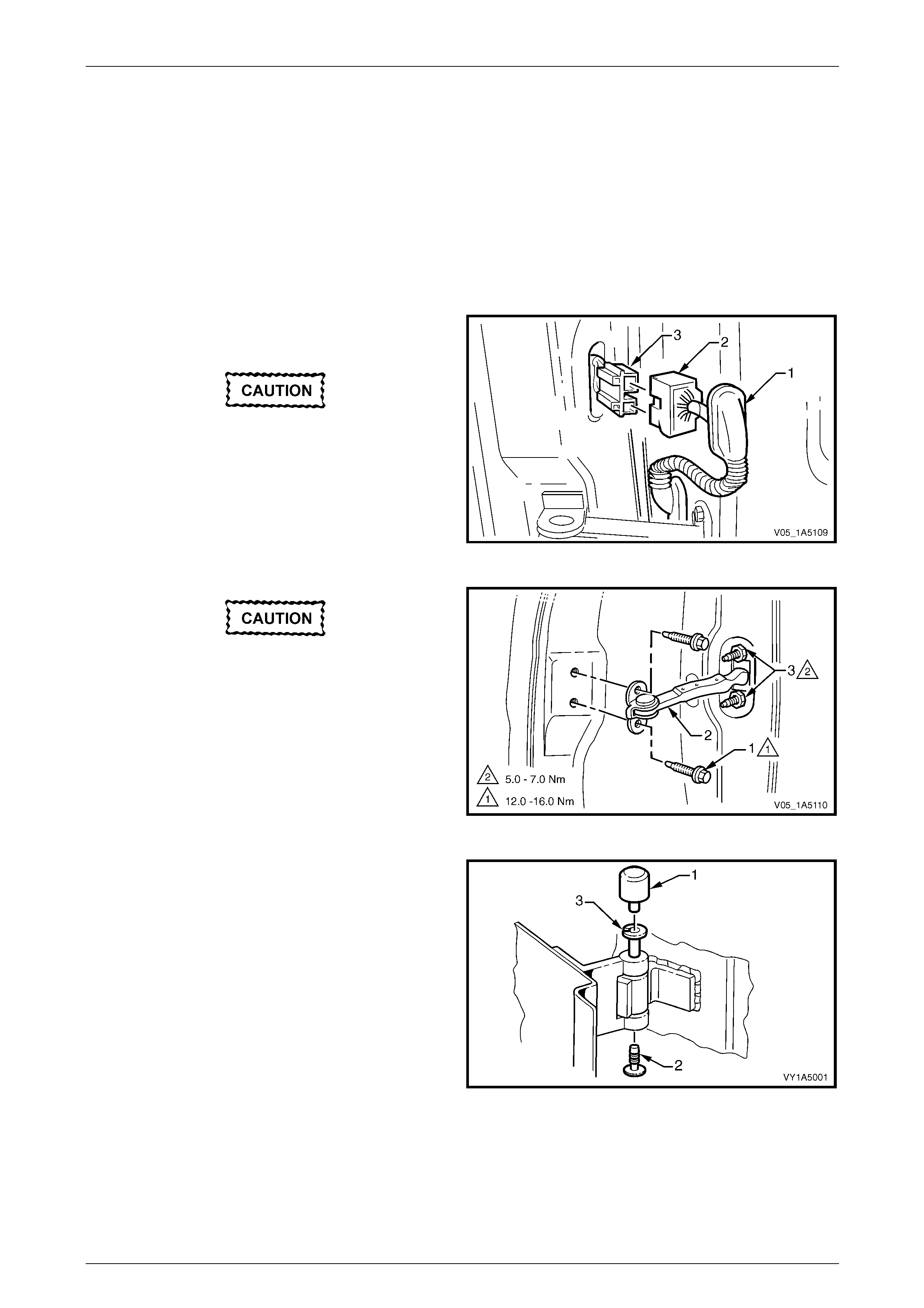
Front and Rear Door Assemblies Page 1A5–63
Page 1A5–63
7 Service Operations – Front Door
Assembly
7.1 Front Door Assembly
LT Section — 11–370
Remove
1 Remove the grommet (1) from the front door wiring
harness connector (2).
Take care not to pull the wiring out of the
connectors during the following operation.
2 Depress the tabs and disconnect the front door wiring
harness connector from the body wiring harness
connector (3).
Figure 1A5 – 87
Ensure the door cannot swing freely as it
may cause damage during the following
operation.
3 Remove the two screws (1) attaching the check
assembly (2) to the vehicle.
4 If required, remove the two nuts (3) attaching the
check assembly to the door and remove the check
assembly.
Figure 1A5 – 88
5 Remove the hinge pin cap (1) and plug (2) from the
hinge pin (3) on the upper and lower door hinges.
6 Have an assistant support the door or alternatively,
support the base of the door on a wooden block and a
trolley jack.
Figure 1A5 – 89
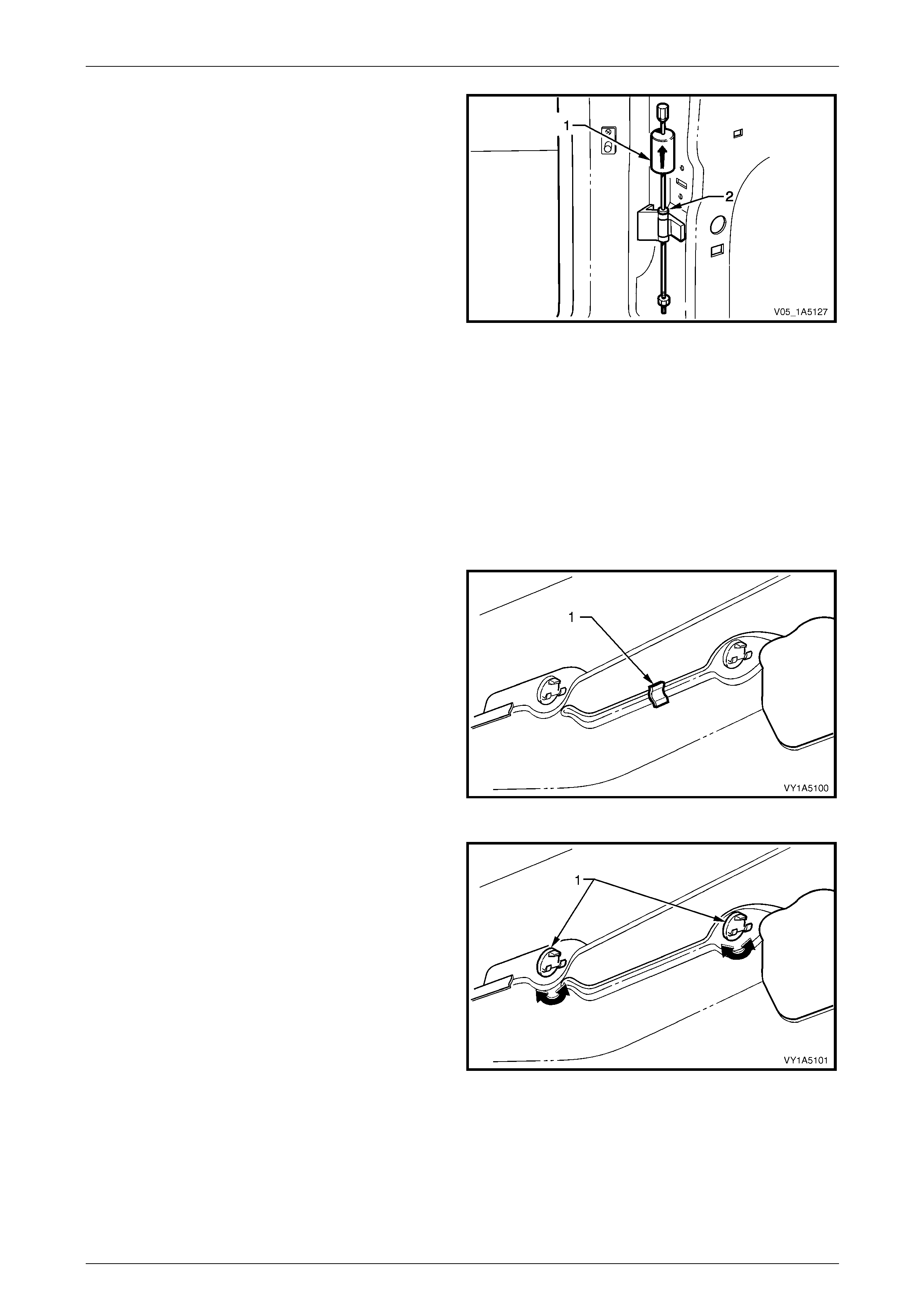
Front and Rear Door Assemblies Page 1A5–64
Page 1A5–64
7 Using the Tool No. AU170 (1), drive the hinge pin (2)
out of the lower and then upper hinges.
8 Remove the door assembly.
Figure 1A5 – 90
Disassemble
1 Remove the following components as required:
a Trim panel assembly, refer to 3.1 Front Door Trim Panel.
b Internal components, refer to 4 Service Operations – Front Door Internal Components.
c Sealing components, refer to 5 Service Operations – Fr ont Door Sealing Components, E xcept Coupe or
6 Service Operations – Front Door Sealing Components, Coupe.
d Body side moulding, as applicable, refer to Section 1A9 Exterior Ornamentation.
2 Prise the deadener (1) from the door inner p anel.
Figure 1A5 – 91
3 Rotate the two remote control rod clips (1) by 90° then
remove from the door inner panel.
Figure 1A5 – 92
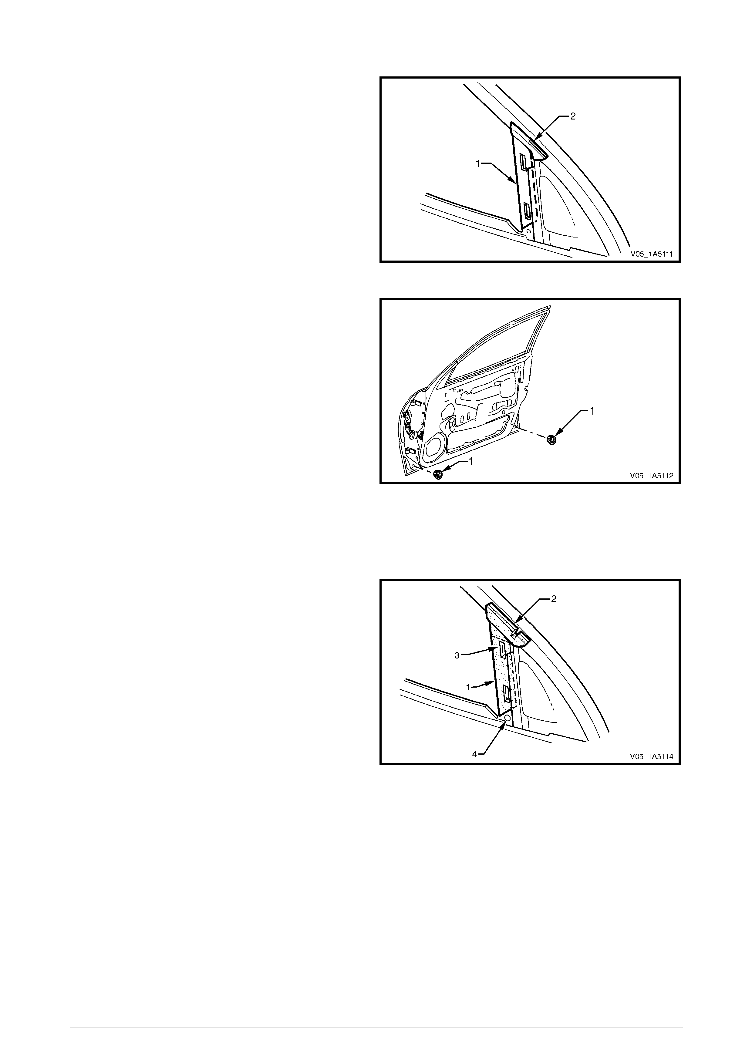
Front and Rear Door Assemblies Page 1A5–65
Page 1A5–65
4 Carefully remove the windo w guide ch annel seal (1),
then the upper frame seal (2) from the door a ssembly.
Figure 1A5 – 93
5 Remove the two plugs (1) from the door inner panel
drain holes.
Figure 1A5 – 94
Reassemble
Reassembly of the front door is the reverse of the disassembly procedure, notin g the following:
1 Install the window guide channel seal (1) over the
upper frame seal (2), ensuring the slot (3) an d hole (4)
are not obstructed.
NOTE
Install the upper frame seal and window guide
channel seal before any other door hardware.
Figure 1A5 – 95
2 If reusing the same deadener (1), apply a small amount of contact ad hesive before fitting to the door inner panel,
refer to Figure 1A5 – 91.
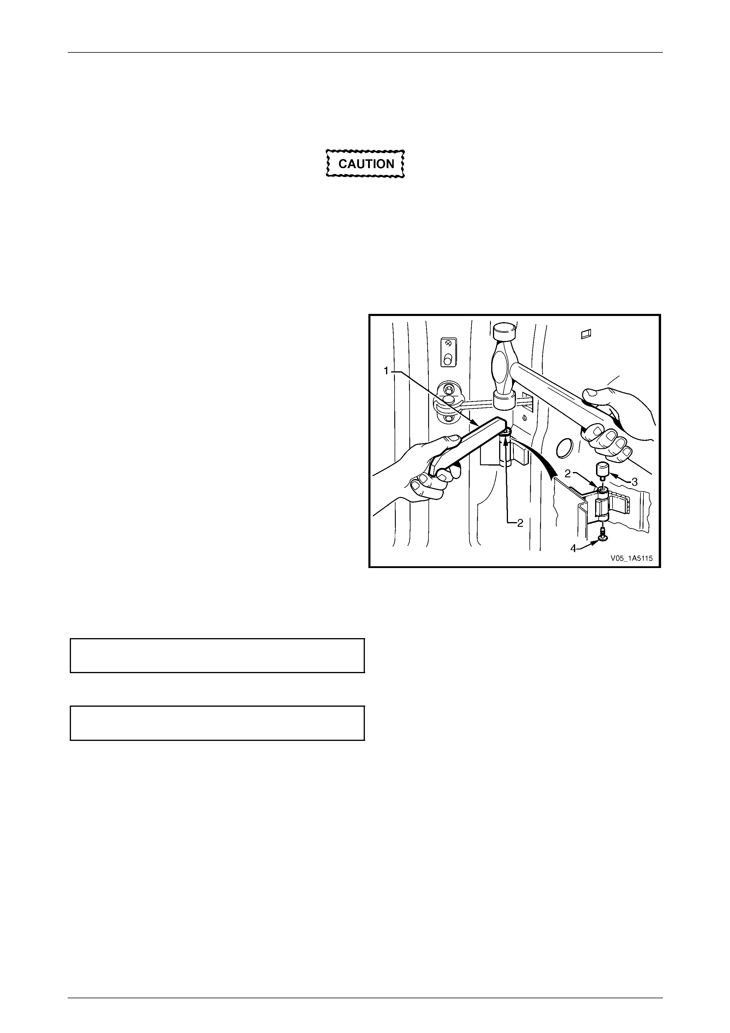
Front and Rear Door Assemblies Page 1A5–66
Page 1A5–66
Reinstall
Reinstallation of the front door assembly is the reverse of the removal procedure, noting the following:
If using a new front door panel assembly it
must be prepared to maintain original
manufacturers specifications. This includes
the application of joint sealer, hand putty and
cavity wax. Refer to the Service Manual
Supplement, Body Structure Repair Manual
for specifications.
1 Apply Lithium base grease NLGI No. 1 (with 9 % zinc oxide) or equivalent, to the hinge pin prior to reinstallation.
2 Using Tool No AU303 (1) an d a hammer, install the
hinge pin (2) with the slot facing for ward and the head
of the pin facing up for the lower hinge and down for
the upper hinge.
NOTE
A 15° deviation is permissable for the positioning
of the hinge pin slot on reinstallation.
3 Check the fit of the door assembly and adjust as
required, refer to 7.2 Adjust Front Door Assembly.
NOTE
Make allowances in the adjustment of the door
assembly if the trim and hardware are not
installed.
Figure 1A5 – 96
4 Tighten the two screws (1) attaching the che ck assembly (2) to the correct torque specification, refer to
Figure 1A5 – 88.
Front door check assembly
attaching screws torque specification .....12.0 – 16.0 Nm
5 Tighten the two nuts (3) attaching the check assembly to the specified torque.
Front door check assembly
attaching nuts torque specification..............5.0 – 7.0 Nm
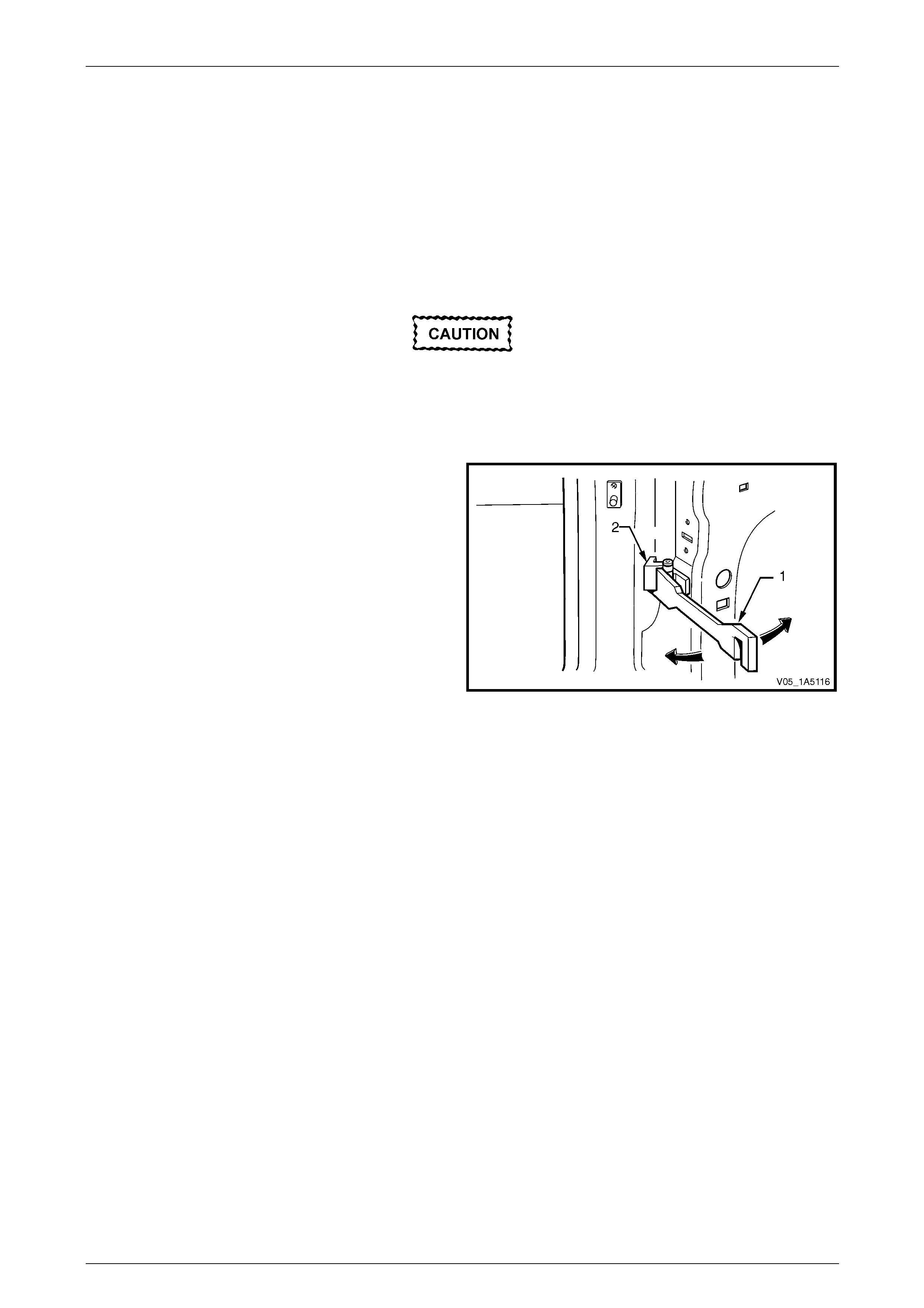
Front and Rear Door Assemblies Page 1A5–67
Page 1A5–67
7.2 Adjust Front Door Assembly
Adjustment Procedure
Uniform margins and alignment of the front doors in relation to the door opening frame assembly can be achi eved by
setting the appropriate door hi nge. Refer to the Servic e Manual Supplement, Bod y Structure Re pair Manual for
specifications.
Adjust the door hinges in conj unction with the adjustment of the lock striker plate assembly to achieve an acceptable
door closing effort with correct door lock to striker engagement, refer to 2.2 Front Door Lock Striker Plate Assembly.
Adjust the front door with the striker plate
assembly removed. The striker plate
assembly must not pull the door into the
correct position and must be fitted once
satisfactory alignment is achie ved.
Use Tool No. AU184 (1) to set the front door hinges by
slightly bending the hinge (2) noting the following:
1 Give attention to uniform margins and ali gnment
between the door and surrounding parts when the
adjustments are being carried out.
2 Take care when adjusting the door not to misalign the
hinge pin. Any significant misalignment will cause the
pin to shear when the door is opened or closed.
3 Excessive bending or levering of the door upper frame
will cause damage.
4 Final adjustment must take place when all the door
components and seals are installed. Figure 1A5 – 97

Front and Rear Door Assemblies Page 1A5–68
Page 1A5–68
8 Service Operations – Rear Door
External Components
8.1 Rear Door Hinge Lubrication
LT Section — 11–730
1 Remove the cap (1) and plug (2) from the hinge pi n (3)
on the upper and lower hinge s .
2 Using a grease gun, inject into the hinge pin, Lithium
base grease NLGI No. 1 ( with 9 % zinc oxide) or
equivalent.
3 Reinstall the cap and plug.
4 Wipe off any excess grease.
Figure 1A5 – 98
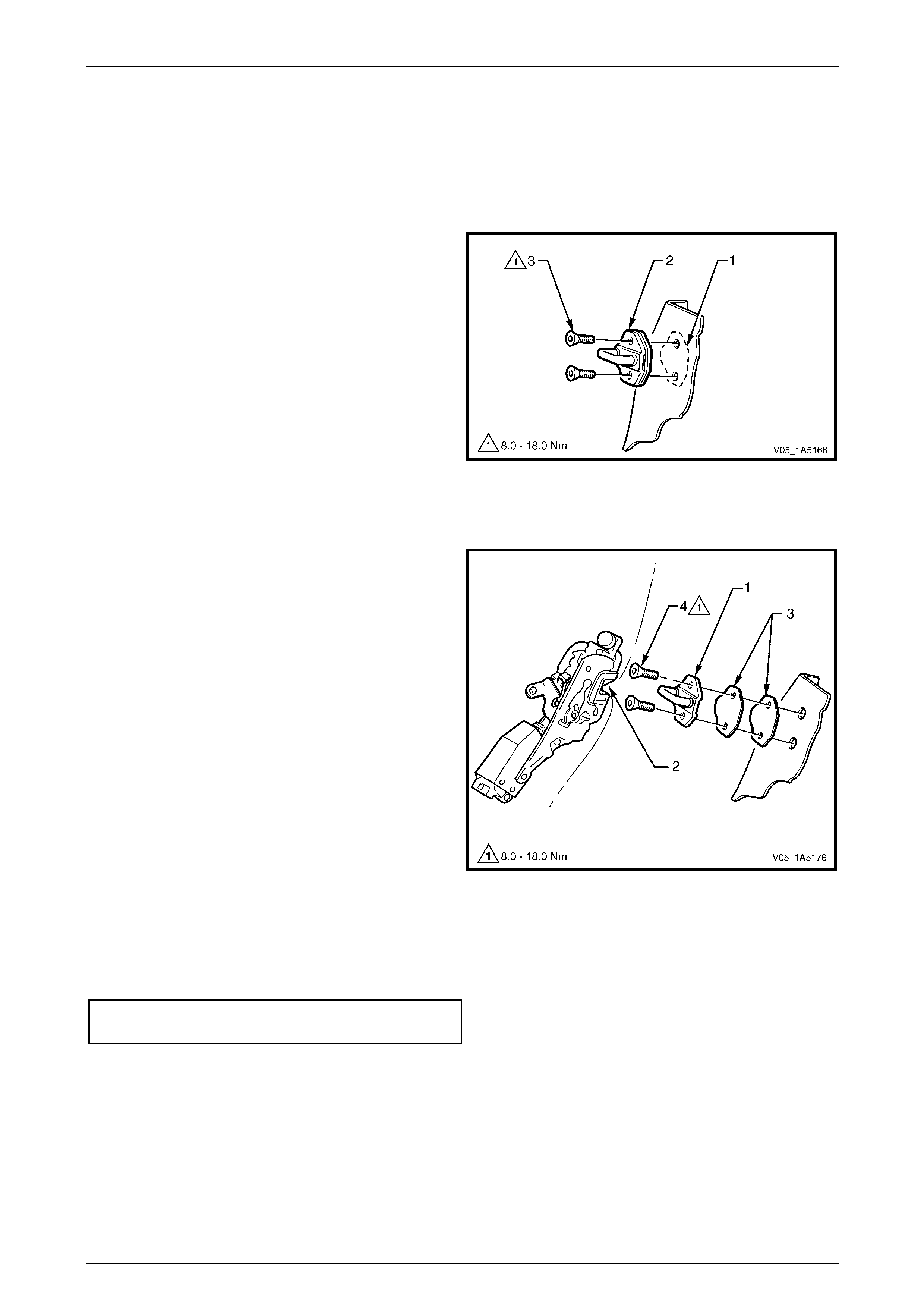
Front and Rear Door Assemblies Page 1A5–69
Page 1A5–69
8.2 Rear Door Lock Striker Plate Assembly
LT Section — 11–725
Remove
1 Pencil scribe (1) the location of the lock striker plate
assembly (2) on to the body pillar before rem oval, to
facilitate reinstallation.
2 Using a Torx bit (30 T) , remove the two attaching
screws (3).
3 Remove the striker plate assembly and spacer plates,
if fitted.
Figure 1A5 – 99
Reinstall
1 Align the lock striker plate assembl y (1), so the bridge
of the striker locates centrally in the lock assembly
fork (2) as the rear door is being closed.
2 Firmly tighten the two screws attaching the striker
plate assembly, do not torque at this stage.
3 Check for correct engagement of the rear d oor lock on
the striker plate assembly; the rear door must not
‘Ride’ on the striker plate assembl y.
4 If required, correct the engagement by vertical or
horizontal adjustment of the lock striker plate
assembly. Add or delete spacer plates (3) between the
striker plate assembly and body pillar, as needed. Also
refer to 15.2 Adjust Rear Door Assembly or
16.2 Adjust Rear Door Assembly.
NOTE
It is sound practice to remove the striker plate
assembly and allo w the door to hang free on the
hinges. Set the hinges as necessary to achieve
correct alignment and uniform margins, then
reinstall the striker plate assembly and adjust.
5 Tighten the striker plate assembl y attaching screws to
the correct torque specification.
Rear door lock striker plate assembly
attaching screws torque specification .......8.0 – 18.0 Nm
Figure 1A5 – 100
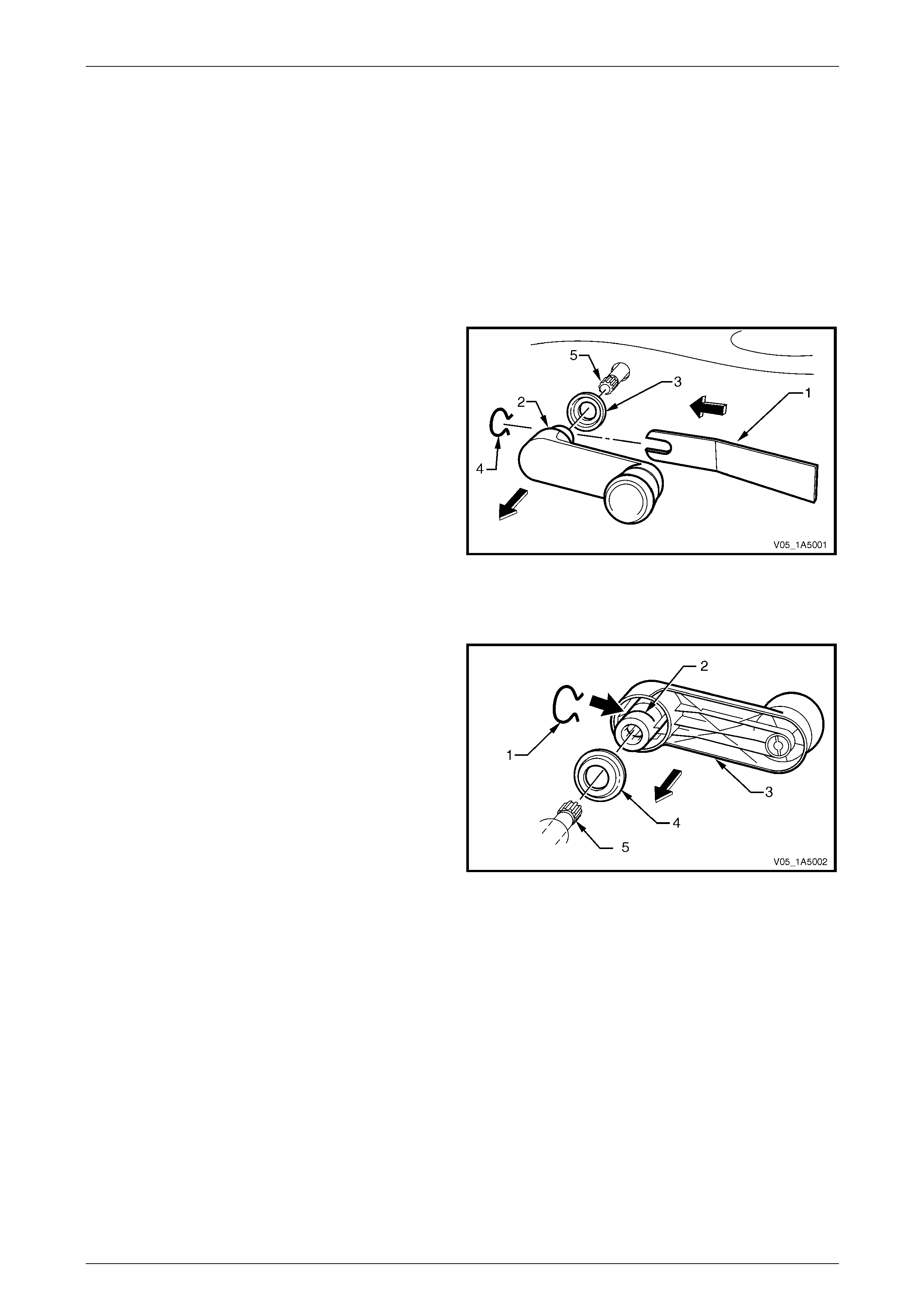
Front and Rear Door Assemblies Page 1A5–70
Page 1A5–70
8.3 Rear Door Window Regulator Handle
Assembly
LT Section — 11–810
Remove
NOTE
The rear door windo w regulator handle assembly
is only fitted to Level 1 vehicles.
1 Insert a commercially available window regulator
handle removal tool (1) between the base of the
handle (2) and the washer (3), in line with the arm of
the handle.
2 Push to disengage the clip (4).
NOTE
Take care when disengagi ng the clip that it does
not spring off.
3 Pull the handle to remove it from the splines (5) of the
regulator spindle.
Figure 1A5 – 101
Reinstall
1 Locate the rear windo w regulator handle clip (1) in the
groove (2) of the handle (3), with the open en ds of the
clip facing the handle arm.
2 Fit the washer (4) on the handle.
NOTE
Make sure both the rear door windows ar e at the
same height before fitting the handle .
3 Position the handle onto the regu lator spindle splines,
symmetrically with the handle on the opposite rear
door.
4 Push the handle onto the regulator spindle splines
until the clip engages the groove (5) at the base of the
splines.
Figure 1A5 – 102
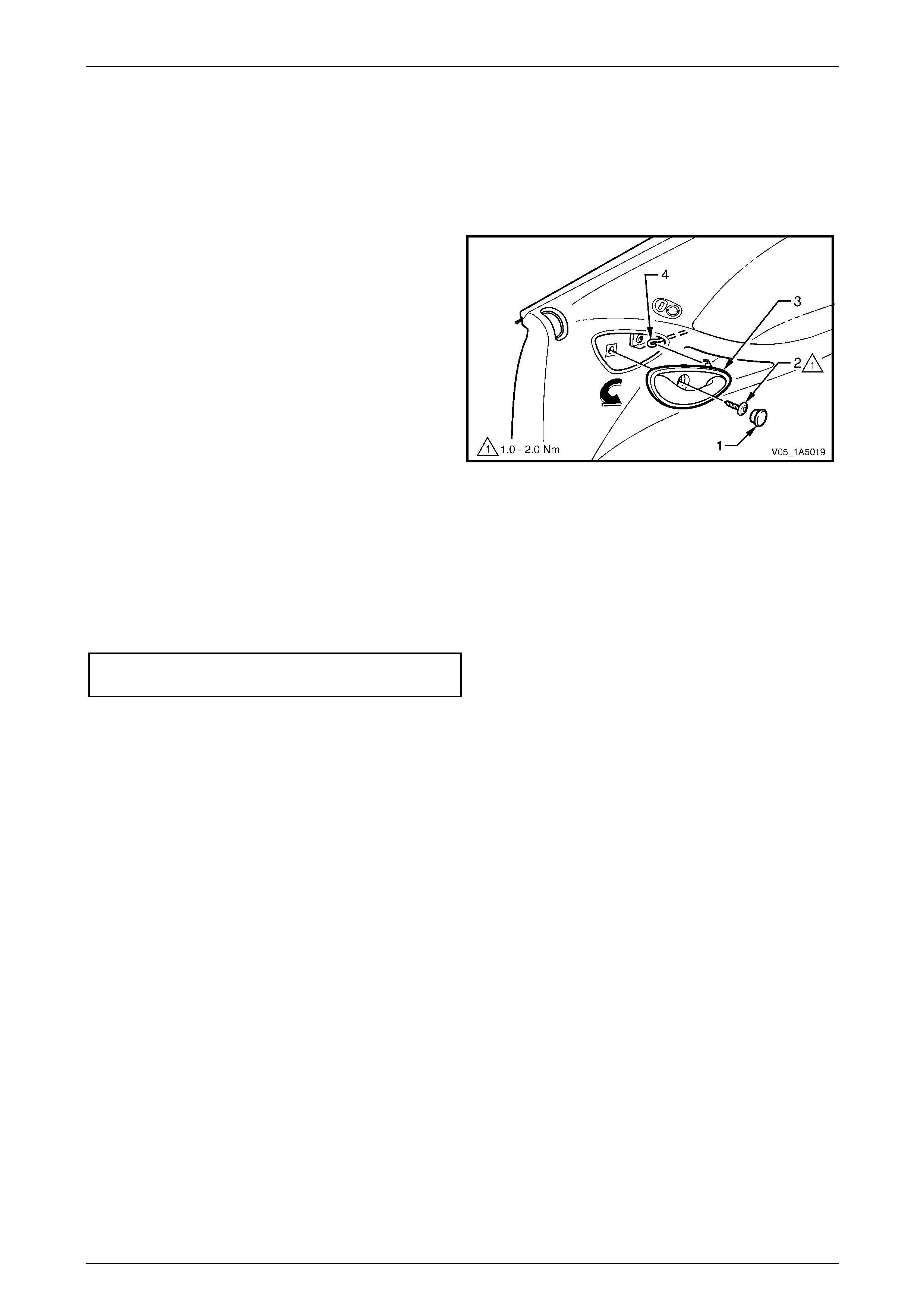
Front and Rear Door Assemblies Page 1A5–71
Page 1A5–71
8.4 Rear Door Remote Inner Handle
Assembly
LT Section — 11–725
Remove
1 Prise off the remote inner handle bolt finisher cap (1).
2 Remove the screw (2) attaching the remote inner
handle assembly (3) to the trim panel.
3 Remove the remote inner handle assembly in a
forward direction and unhook the remote control
rod (4) from the handle assembly.
Figure 1A5 – 103
Reinstall
Reinstallation of the rear door remote inner handle assembly is the reverse of the removal procedure, noting the
following:
1 Ensure the remote inner handle assembly and the remote control rod are engaged before final fitment.
2 Tighten the remote inner handle assembly attaching screw to the correct torque specification.
Rear door remote inner handle assembly
attaching screw torque specification...........1.0 – 2.0 Nm
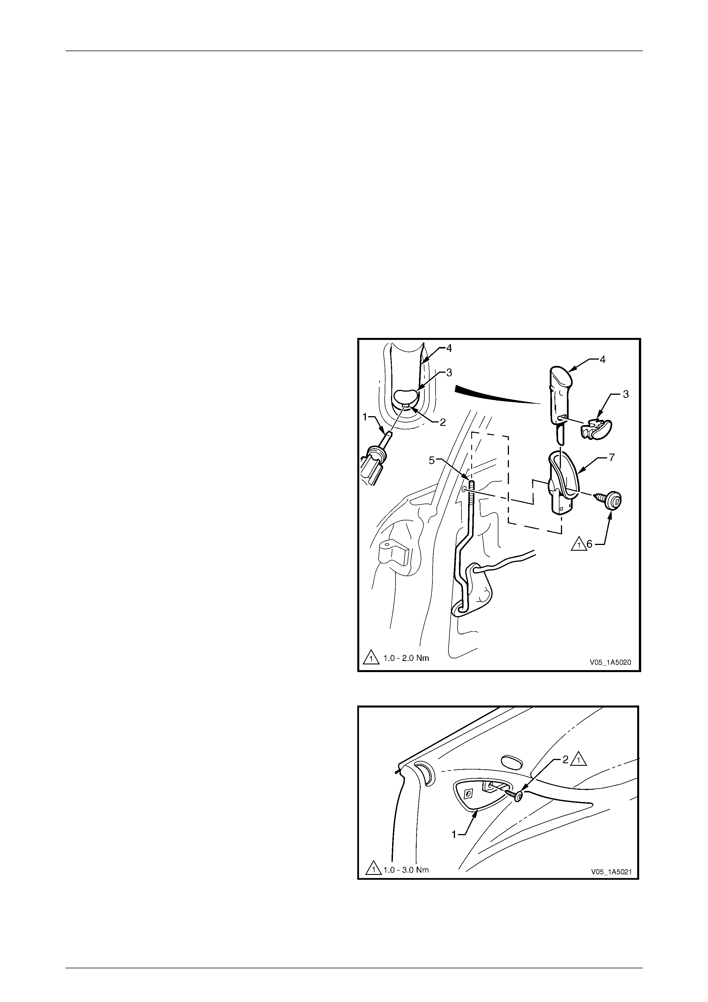
Front and Rear Door Assemblies Page 1A5–72
Page 1A5–72
9 Service Operations – Rear Door
Trim Panel Assembly, Se dan and
Wagon
9.1 Rear Door Trim Panel
LT Section — 14–270
Remove
1 Remove the following components as required:
a Window regulator handle assembly (where fitted),
refer to 8.3 Rear Door Window Regulator Handle Assembl y.
b Remote inner handle assembly, refer to 8.4 Rear Door Remote Inner Handle Assembly.
2 Insert a small flat bladed screwdriver or scribe (1) in
the slot (2) below the red locking insert (3).
3 Gently prise the red locking insert from the locking ro d
knob (4), taking care not to damage the knob.
4 Lift-up the locking rod knob to separate it from the
locking rod (5) and remove.
5 Remove the screw (6) attaching the locking rod knob
escutcheon (7) to the inner panel assembly and
remove the escutcheon.
Figure 1A5 – 104
6 Through the remote inner handle assembly
aperture (1), remove the screw (2) attaching the trim
panel assembly to the inner panel assembly.
Figure 1A5 – 105
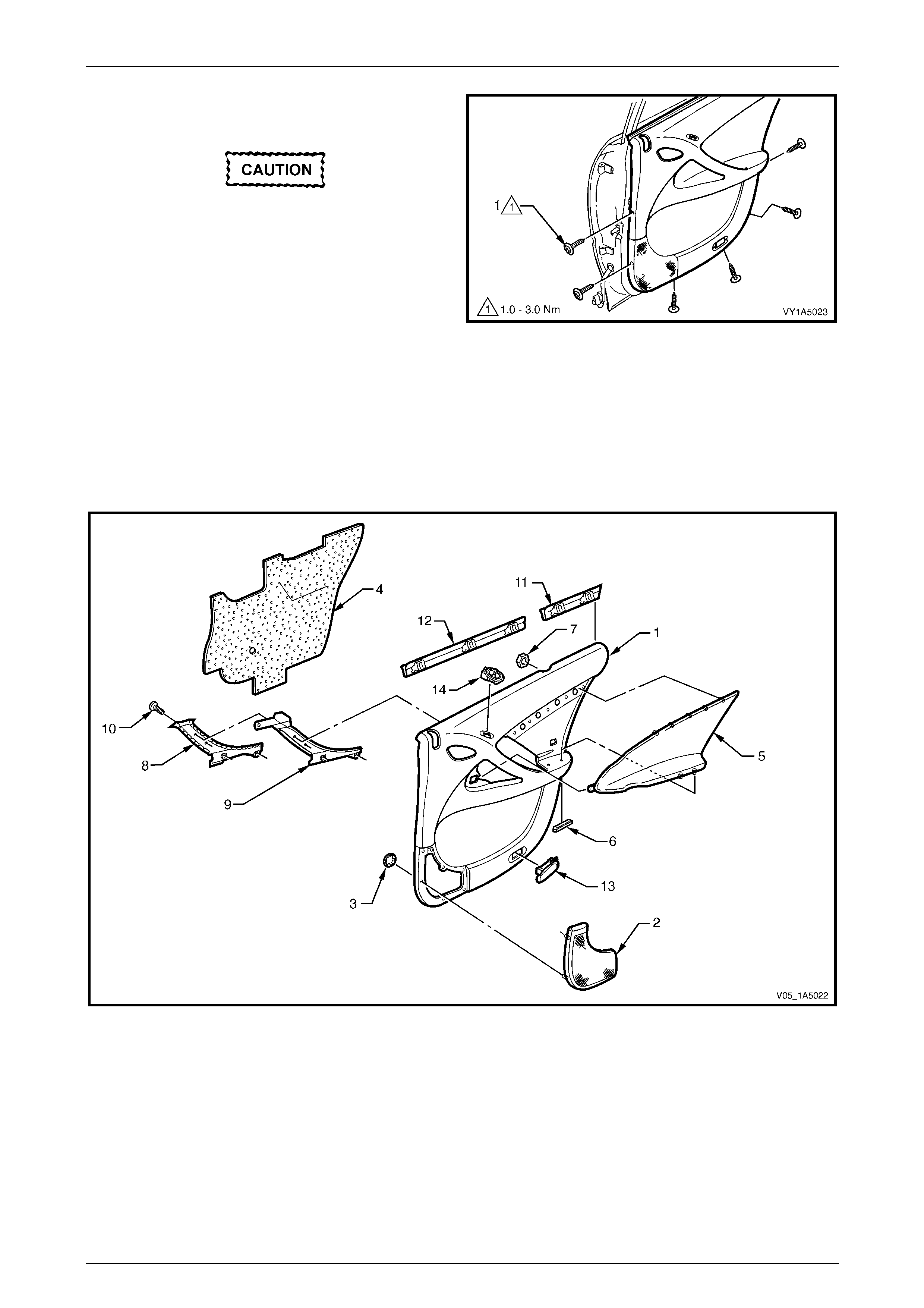
Front and Rear Door Assemblies Page 1A5–73
Page 1A5–73
7 Remove the six screws (1) attaching the trim panel
assembly to the inner panel assembly.
Take care while removing the trim panel
assembly as the wiring harness connectors
are still connected.
8 Lift the top of the trim panel assembly upwards to
release it from the rear door inner channel.
9 While supporting the trim panel assem bl y, disconnect
all the wiring harness connectors.
10 Remove the trim panel assembly. Figure 1A5 – 106
Disassemble
To disassemble the rear door trim panel assembly, remove all the components attached to the trim panel foundation as
described in this Section, refer to F igure 1A5 – 107.
Trim Panel
Figure 1A5 – 107
Legend
1 Rear Door Trim Panel Foundation
2 Rear Door Radio Speaker Grille
3 Rear Door Radio Speaker Grille Retainer (7 places)
4 Rear Door Insulator Assembly
5 Rear Door Armrest Insert Assembly
6 Rear Door Armrest Insert Assembly Clip (2 places)
7 Rear Door Armrest Insert Assembly Nut (5 places)
8 Rear Door Inner Handle Cover
9 Rear Door Inner Handle Bracket
10 Rear Door Inner Handle Screw (4 places)
11 Rear Door Window Inner Rear Sealing Strip Assembly
12 Rear Door Window Inner Front Sealing Strip Assembly
13 Rear Door Courtesy Lamp (where fitted)
14 Rear Door Power Window Switch (where fitted)
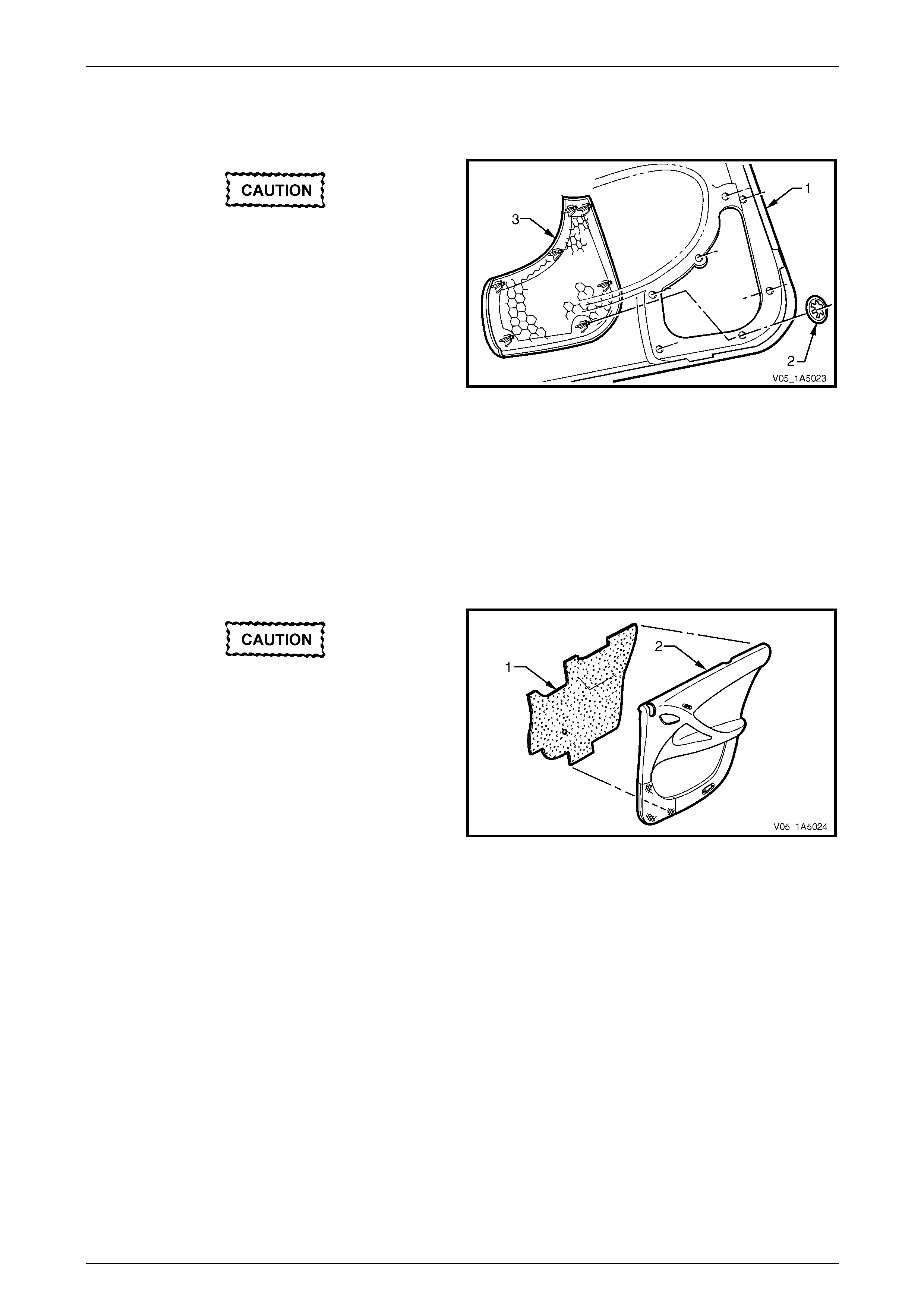
Front and Rear Door Assemblies Page 1A5–74
Page 1A5–74
Rear Door Radio Speaker Grille
Remove
Take care when remo ving the clips (2), as the
radio speaker grille lugs on which the clips
are attached may break, requiring the
replacement of the radio speaker grille.
1 From behind the trim panel assembly (1), using side-
cutters cut the speed clip (2), seven places, securi ng
the radio speaker grille (3) to the trim pane l
foundation, then remove from the lugs and discard.
2 Push free the radio speaker grille and remove. Figure 1A5 – 108
Reinstall
Reinstallation of the rear door radio speaker grille is the reverse of the removal proced ure, noting the following:
Push new round speed clips onto the lu gs to secure the radio speaker grille .
Rear Door Insulator Assembly
Remove
Take care not to tear the insulator (1) and
retain on it as much adh esive as possible. Do
not fold the insulator and store in a flat
location with the adhesive facing away from
other surfaces.
Remove the insulator assembly (1) from the back of the trim
panel assembly (2), by peeling the insulator slowly across
the trim panel foundation.
Figure 1A5 – 109
Reinstall
Reinstallation of the rear door insulator assembly is the reverse of the removal procedure , noting the following:
If required, apply additional hot melt adhesive with a high softenin g point (eg. 90°C) to the insulator assembly.
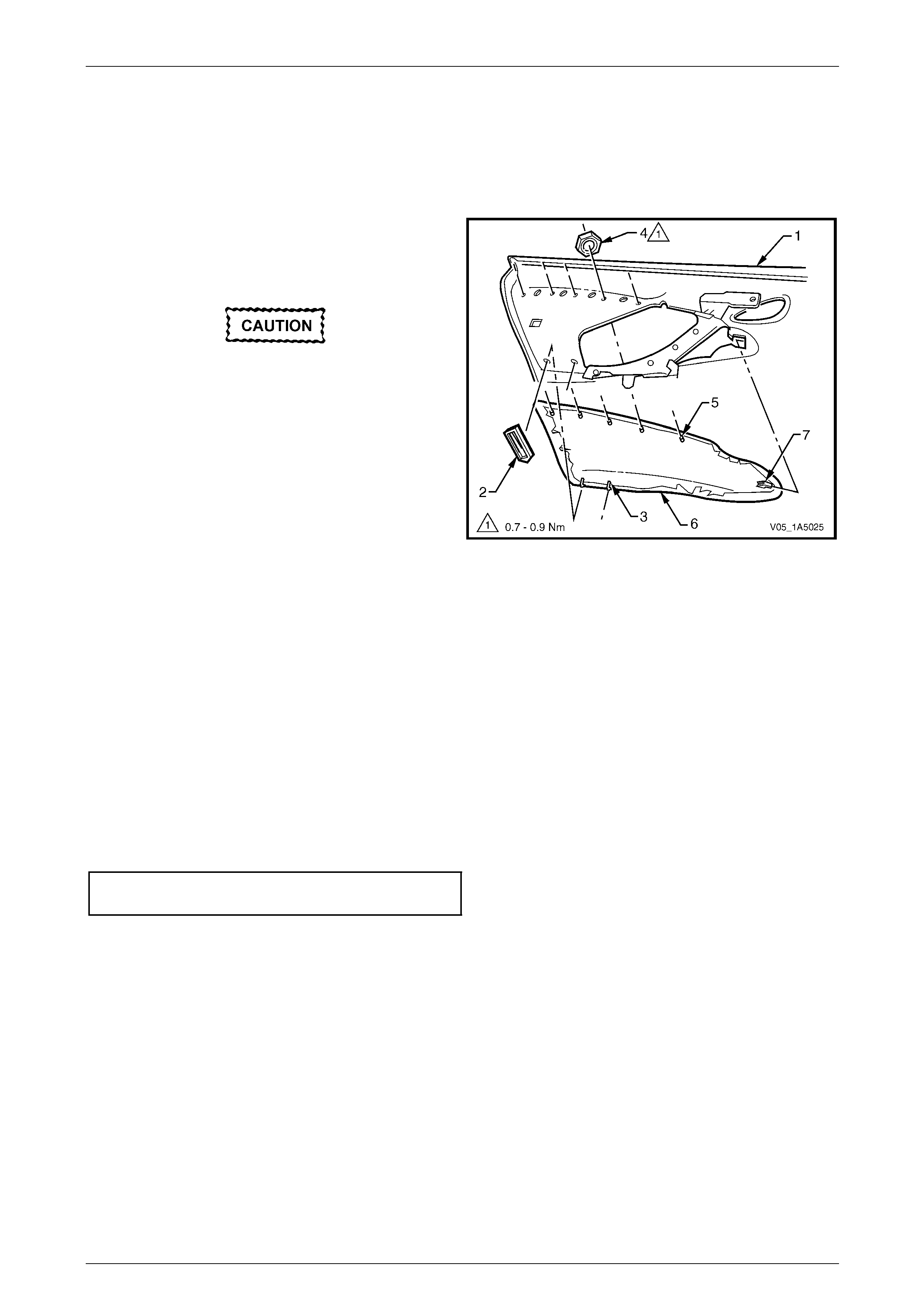
Front and Rear Door Assemblies Page 1A5–75
Page 1A5–75
Rear Door Armrest Insert Assembly
Remove
1 If required, peel back the insulator assembly from the upper rear portion of the trim panel assembly, allowing
access to the armrest insert assembly attaching parts. Refer to Rear Door Insulator Assembly in this Section.
2 From behind the trim panel as sembly (1), remove the
retainer (2), two places, from the armrest insert
assembly shaft (3) by sliding, then pulling it away from
the trim panel assembly.
Take care when remo ving the speed nuts (4),
as the rotating action may cut-off the armrest
insert assembly shafts (5) to which they are
attached, requiring the replacement of the
armrest insert assembly.
3 Using side-cutters cut the speed nut (4), five places,
then remove it from the armrest insert assembly
shaft (5) and discard.
4 Prise the armrest insert assembly (6) from the trim
panel assembly.
5 Slide rearward the armrest insert assembly to
disengage the tab (7) and remove from the trim panel
assembly.
Figure 1A5 – 110
Reinstall
Reinstallation of the rear door armrest insert assembly is the reverse of the removal procedure, noting the following:
NOTE
Ensure the shafts are not damaged before fitting
the rear door armrest insert assembly, replace if
necessary.
1 The armrest insert assembly (6) must be sitting flush against the trim panel assembly (1) along the entire top
contacting surface with the tab (7) engaged, refer to Figure 1A5 – 110.
2 Install new nuts attaching the armrest insert assembl y and t ighte n to the correct torque specification.
Rear door armrest insert assembly
attaching nuts torque specification..............0.7 – 0.9 Nm
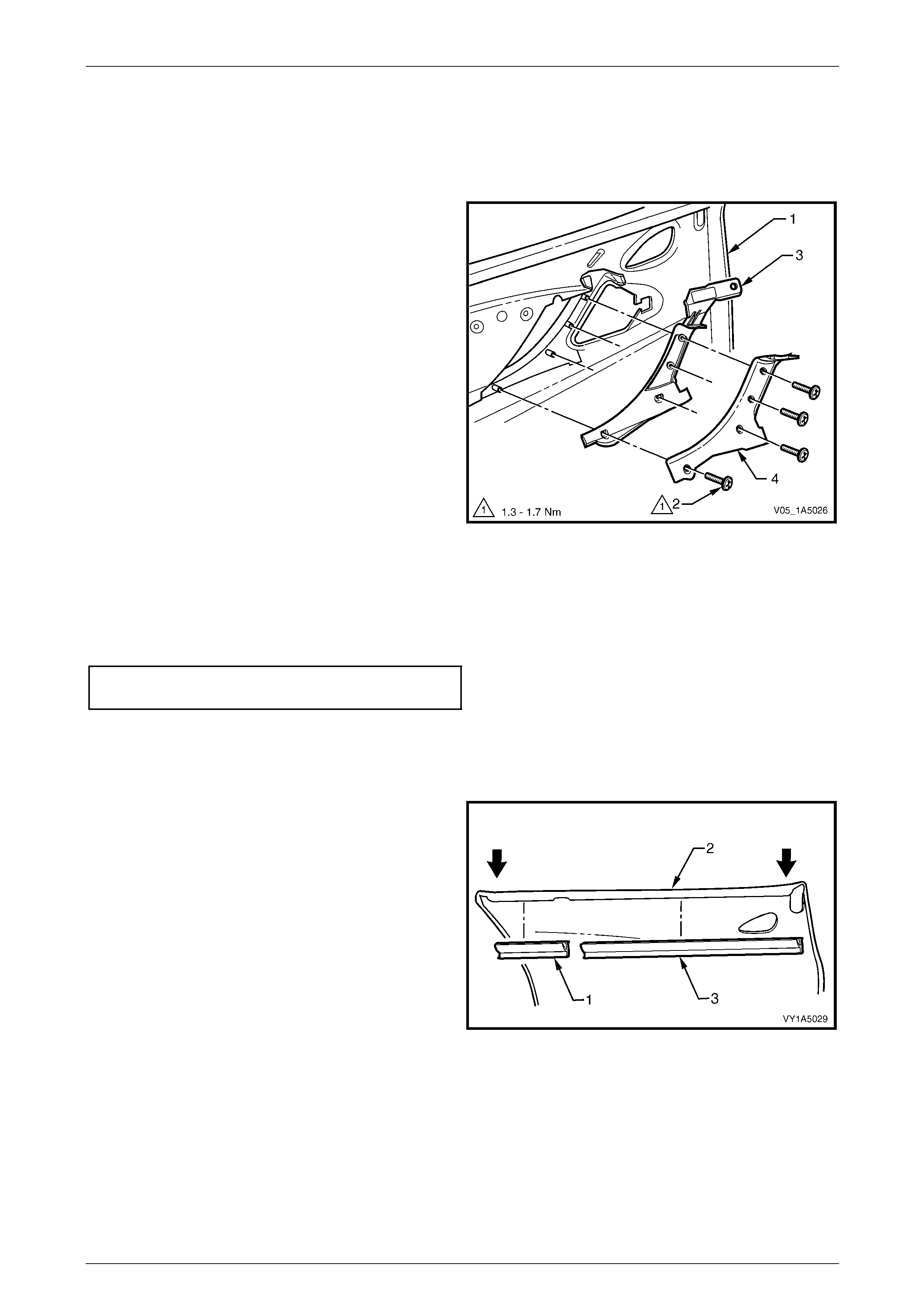
Front and Rear Door Assemblies Page 1A5–76
Page 1A5–76
Rear Door Inner Pull Handle Assembly
Remove
1 If required, remove the armrest insert assembly, refer to Rear Door Armrest Insert Assembly in this Section.
2 From behind the trim panel as sembly (1), remove the
four screws (2) attaching the inner pull handl e
bracket (3) to the trim panel assembly.
3 Remove the inner pull handle bracket assembly from
the trim panel assembly.
4 Peel off the cover (4) from the inner pull handle
bracket.
Figure 1A5 – 111
Reinstall
Reinstallation of the rear door inner pull handle assembly is the reverse of the removal p rocedure, noting the following:
Tighten the four screws attaching the inn er p ull handle assembly to the correct torque specification.
Rear door inner pull handle assembly
attaching screws torque specification .........1.3 – 1.7 Nm
Rear Door Inner Sealing Strip Assemblies
Remove
1 Push down on one end of the inner rear sealing strip
assembly (1) to start the removal process from the trim
panel assembly (2).
2 Push down and progressivel y move along the inner
rear sealing strip assembly until it separates from the
trim panel assembly and remove.
3 Repeat the procedure to remove the inn er front
sealing strip assembly (3).
Figure 1A5 – 112
Reinstall
Reinstallation of the rear door inner sealing strip assemblies is the reverse of the removal procedure.
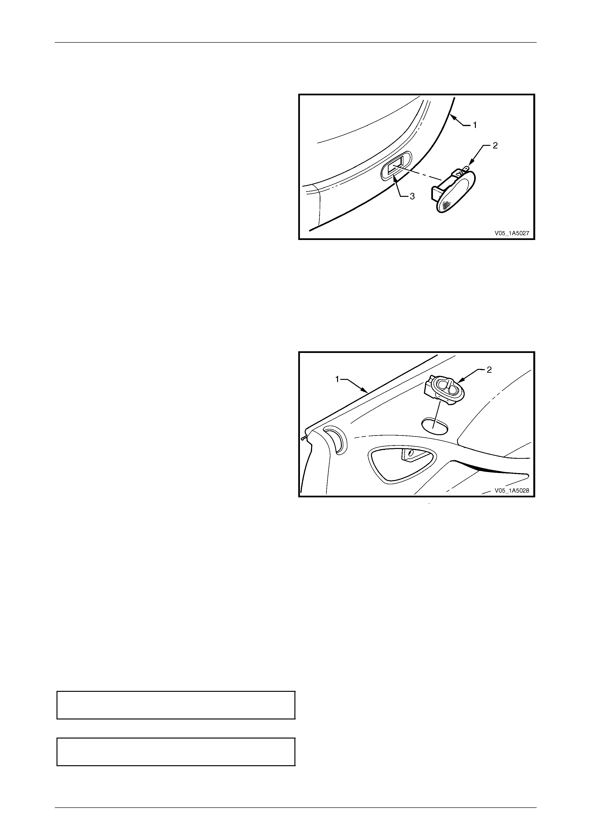
Front and Rear Door Assemblies Page 1A5–77
Page 1A5–77
Rear Door Courtesy Lamp (where fitted)
Remove
1 From behind the trim panel as sembly (1), depress the
retaining tangs securing the courtesy lamp (2) to the
trim panel assembly.
2 Push the lamp out of the aperture (3) in the trim panel
assembly and remove.
NOTE
For service and diagnosis of the
front door courtesy lamp, refer to
Section 12B Lighting System.
Figure 1A5 – 113
Reinstall
Reinstallation of the rear door courtesy lamp is the reverse of the removal procedure, n oting the fo llowing:
Ensure the retaining tangs ar e securing the courtesy lamp to the trim panel assembly.
Rear Door Power Window Switch (where fitted)
Remove
1 From behind the trim panel as sembly (1), depress the
tangs of the power window switch (2).
2 Push free the power window switch and remove.
NOTE
For further information regarding service and
diagnosis of the rear door power windo w switch,
refer to Section 12J Body Control Module.
Figure 1A5 – 114
Reinstall
Reinstallation of the rear door power window switch is the reverse of the removal proce dure, noting the following:
Ensure the tangs secure the switch assembly to the trim panel foundati on.
Reinstall
Reinstallation of the rear door trim panel assembly is the reverse of the removal proced ure, notin g the following:
1 Ensure the remote inner handle assembl y and the remote control rod, are engaged befor e final fitment of the trim
panel assembly, refer to 8.4 Rear Door Remote Inner Handle Assembly.
2 Tighten all the trim panel assembly attaching screws to the correct torque specification.
NOTE
The screws along the b ottom of the rear door trim
panel assembly are wax-tip sealing screws.
Rear door trim panel assembly
attaching screw torque specification...........1.0 – 3.0 Nm
3 Tighten the screw attaching the locking rod knob escutcheo n to the correct torque specification.
Rear door locking rod knob escutcheon
attaching screw torque specification...........1.0 – 2.0 Nm
4 Ensure the red locking insert is secured to the locking rod knob assembly.
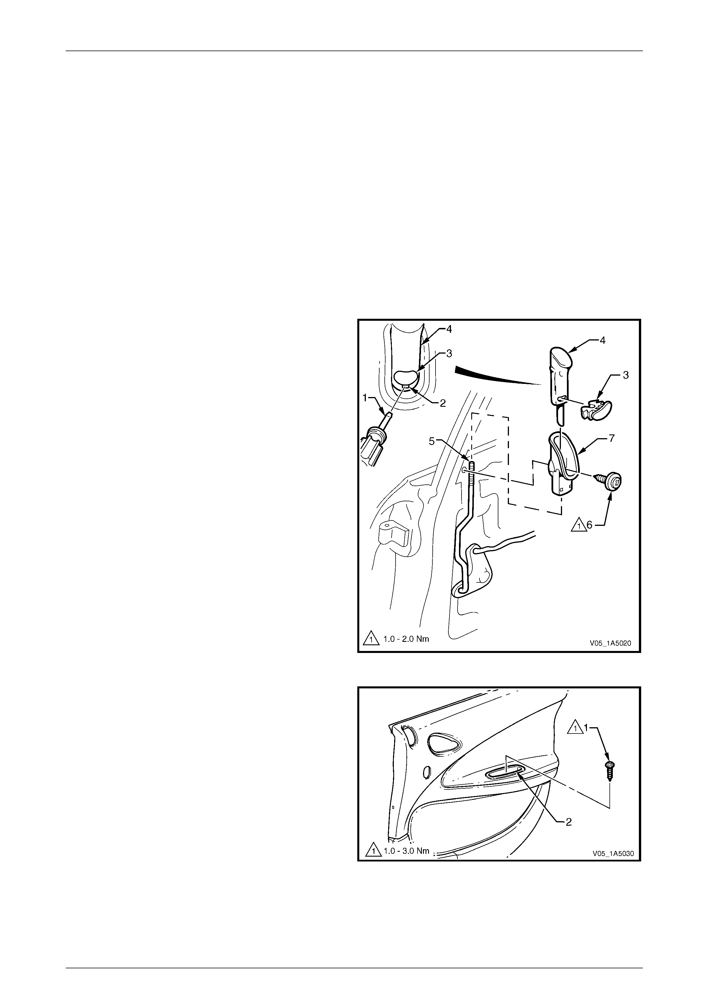
Front and Rear Door Assemblies Page 1A5–78
Page 1A5–78
10 Service Operations – Rear Door
Trim Panel Assembly, Crew Cab
10.1 Rear Door Trim Panel
LT Section — 14–270
Remove
1 Remove the following components as required:
a Window regulator handle assembly (where fitted),
refer to 8.3 Rear Door Window Regulator Handle Assembl y.
b Remote inner handle assembly, refer to 8.4 Rear Door Remote Inner Handle Assembly.
2 Insert a small flat bladed screwdriver or scribe (1) in
the slot (2) below the red locking insert (3).
3 Gently prise the red locking insert from the locking ro d
knob (4), taking care not to damage the knob.
4 Lift-up the locking rod knob to separate it from the
locking rod (5) and remove.
5 Remove the screw (6) attaching the locking rod knob
escutcheon (7) to the inner panel assembly and
remove the escutcheon.
Figure 1A5 – 115
6 Remove the screw (1) attaching the pull cup (2) to the
pull cup bracket.
Figure 1A5 – 116
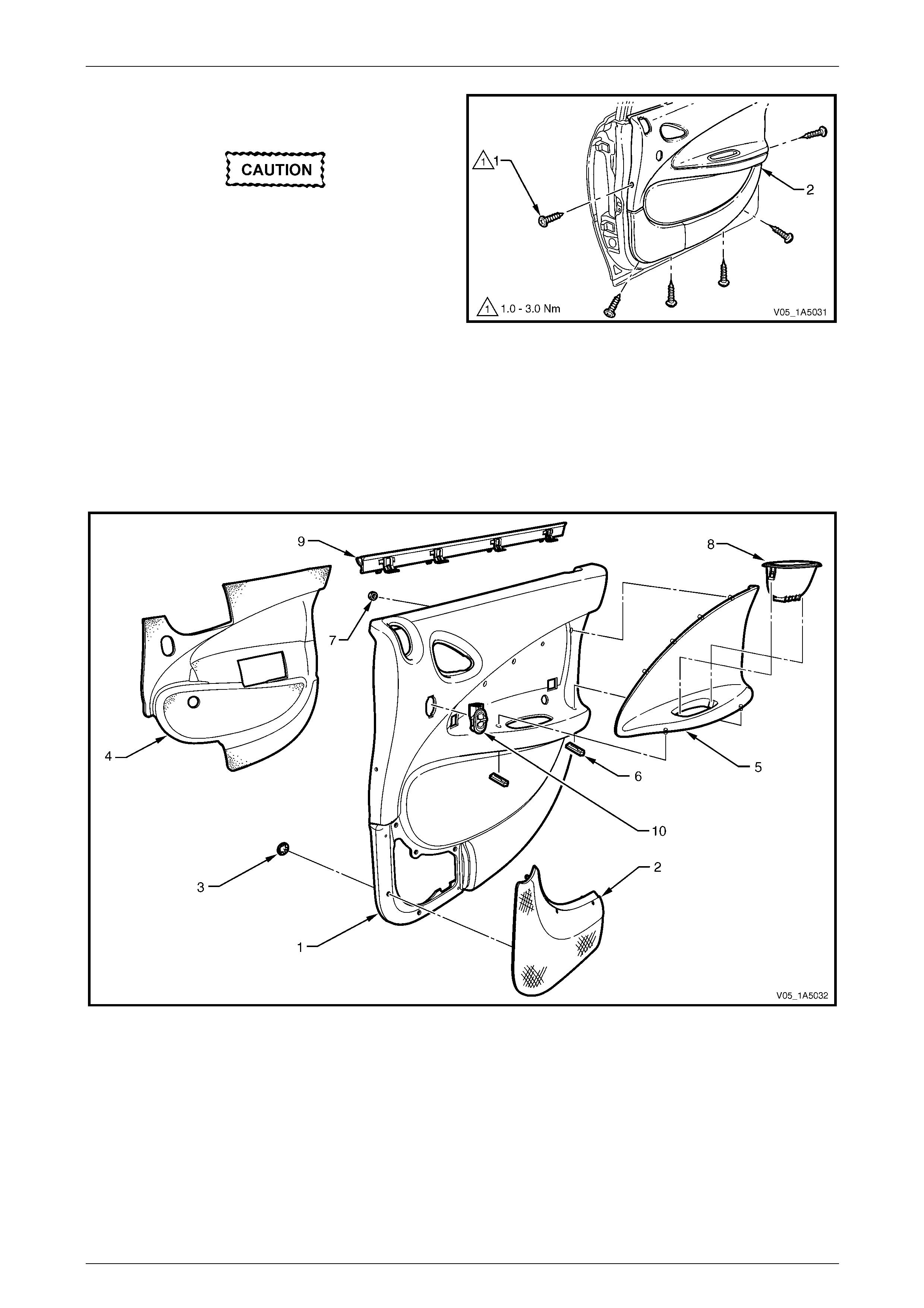
Front and Rear Door Assemblies Page 1A5–79
Page 1A5–79
7 Remove the six screws (1) attaching the trim panel
assembly to the inner panel assembly.
Take care while removing the rear door trim
panel assembly as the wiring harness
connectors are still connected.
8 Lift the top of the trim panel assembly upwards to
release it from the rear door inner channel.
9 While supporting the trim panel assem bl y, disconnect
all the wiring harness connectors.
10 Remove the trim panel assembly. Figure 1A5 – 117
Disassemble
To disassemble the rear door trim panel assembly, remove all the components attached to the trim panel foundation as
described in this Section, refer to F igure 1A5 – 118.
Trim Panel
Figure 1A5 – 118
Legend
1 Rear Door Trim Panel Foundation
2 Rear Door Radio Speaker Grille
3 Rear Door Radio Speaker Grille Retainer (7 places)
4 Rear Door Insulator Assembly
5 Rear Door Armrest Insert Assembly
6 Rear Door Armrest Insert Assembly Clip (2 places)
7 Rear Door Armrest Insert Assembly Nut (4 places)
8 Rear Door Pull Cup
9 Rear Door Window Inner Sealing Strip Assembly
10 Rear Door Power Window Switch (where fitted)
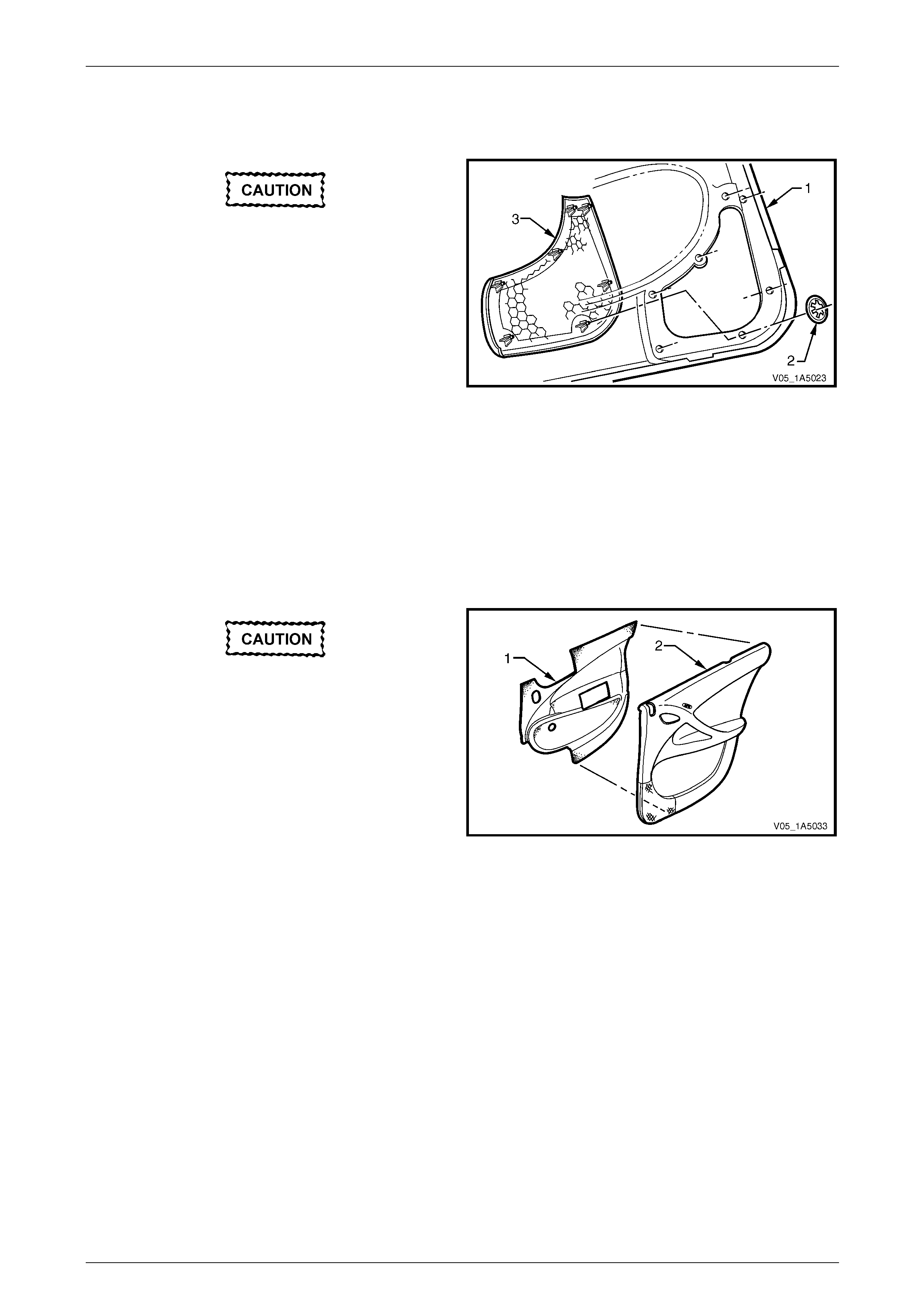
Front and Rear Door Assemblies Page 1A5–80
Page 1A5–80
Rear Door Radio Speaker Grille
Remove
Take care when remo ving the clips (2), as the
radio speaker grille lugs on which the clips
are attached may break, requiring the
replacement of the radio speaker grille.
1 From behind the trim panel assembly (1), using side-
cutters cut the speed clip (2), seven places, securi ng
the radio speaker grille (3) to the trim pane l
foundation, then remove from the lugs and discard.
2 Push free the radio speaker grille and remove. Figure 1A5 – 119
Reinstall
Reinstallation of the rear door radio speaker grille is the reverse of the removal proced ure, noting the following:
Push new round speed clips onto the lu gs to secure the radio speaker grille .
Rear Door Insulator Assembly
Remove
Take care not to tear the insulator (1) and
retain on it as much adh esive as possible. Do
not fold the insulator and store in a flat
location with the adhesive facing away from
other surfaces.
Remove the insulator assembly (1) from the back of the trim
panel assembly (2), by peeling the insulator slowly across
the trim panel foundation.
Figure 1A5 – 120
Reinstall
Reinstallation of the rear door insulator assembly is the reverse of the removal procedure , noting the following:
If required, apply additional hot melt adhesive with a high softenin g point (eg. 90°C) to the insulator assembly.
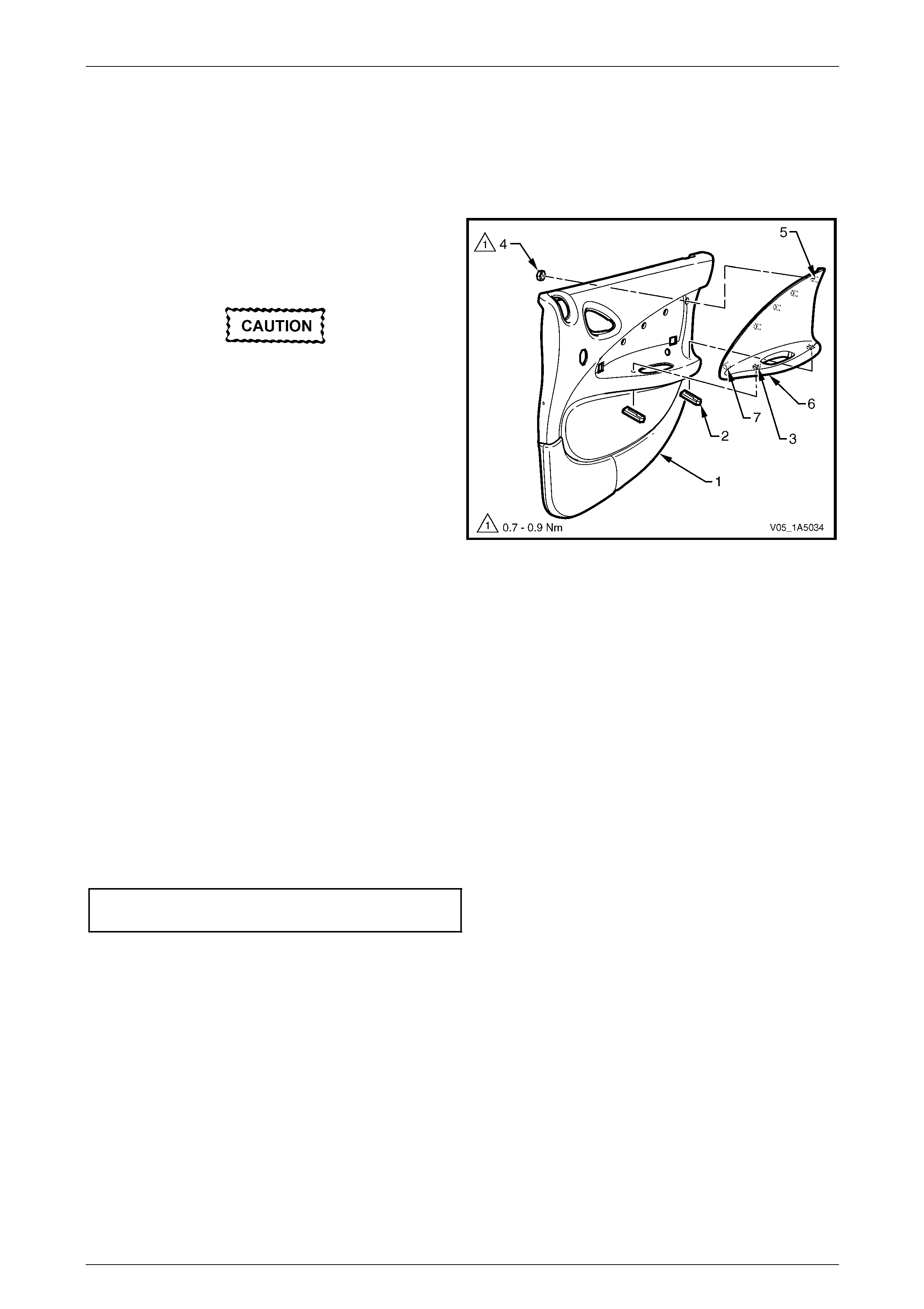
Front and Rear Door Assemblies Page 1A5–81
Page 1A5–81
Rear Door Armrest Insert Assembly
Remove
1 If required, peel back the insulator assembly from the upper rear portion of the trim panel assembly, allowing
access to the armrest insert assembly attaching parts. Refer to Rear Door Insulator Assembly in this Section.
2 From behind the trim panel as sembly (1), remove the
two retainers (2), from the armrest insert assembly
shafts (3) by sliding, then pulling them away from the
trim panel assembly.
Take care when remo ving the nuts (4), as the
rotating action may cut-off the rear door
armrest insert assembly shafts (5) to which
the nuts are attached, requiring the
replacement of the rear door armrest insert
assembly.
3 Using side-cutters cut the speed nut (4), four places,
then remove it from the armrest insert assembly
shaft (5) and discard.
4 Prise the armrest insert assembly (6) from the trim
panel assembly.
5 Slide rearward the armrest insert assembly to
disengage the tab (7) and remove from the trim panel
assembly.
Figure 1A5 – 121
Reinstall
Reinstallation of the rear door armrest insert assembly is the reverse of the removal procedure, noting the following:
NOTE
Ensure the shafts are not damaged before fitting
the rear door armrest insert assembly, replace if
necessary.
1 The armrest insert assembly (6) must be sitting flush against the trim panel assembly (1) along the entire top
contacting surface with the tab (7) engaged, refer to Figure 1A5 – 121.
2 Install new nuts attaching the armrest insert assembl y and t ighte n to the correct torque specification.
Rear door armrest insert assembly
attaching nuts torque specification..............0.7 – 0.9 Nm
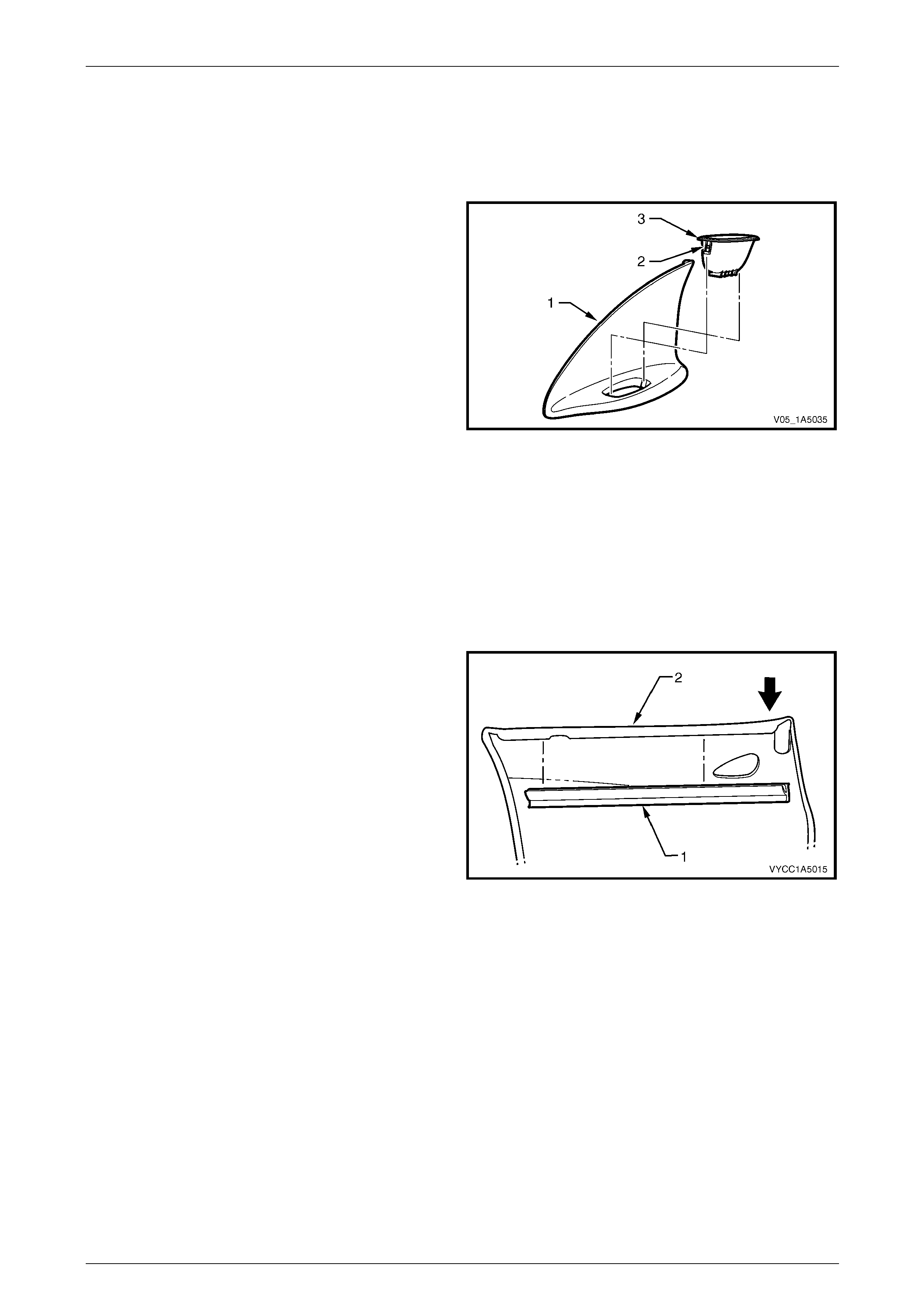
Front and Rear Door Assemblies Page 1A5–82
Page 1A5–82
Rear Door Pull Cup
Remove
1 If required, remove the armrest insert assembly, refer to Rear Door Armrest Insert Assembly in this Section.
2 From behind the armrest insert assembly (1), depress
the retaining tab (2), two places, on the pull cup (3).
3 Push free the pull cup and remove.
Figure 1A5 – 122
Reinstall
Reinstallation of the rear door pull cup is the reverse of the removal procedure, noting the following:
Ensure the two retaining tabs secure the p ul l cup to the armrest insert assembly.
Rear Door Inner Sealing Strip Assembly
Remove
1 Push down on one end of the inner seal ing strip
assembly (1) to start the removal process from the trim
panel assembly (2).
2 Push down and progressivel y move along the inner
sealing strip assembly until it separates from the trim
panel assembly and remove.
Figure 1A5 – 123
Reinstall
Reinstallation of the rear door inner sealing strip assembly is the reverse of the removal procedure.
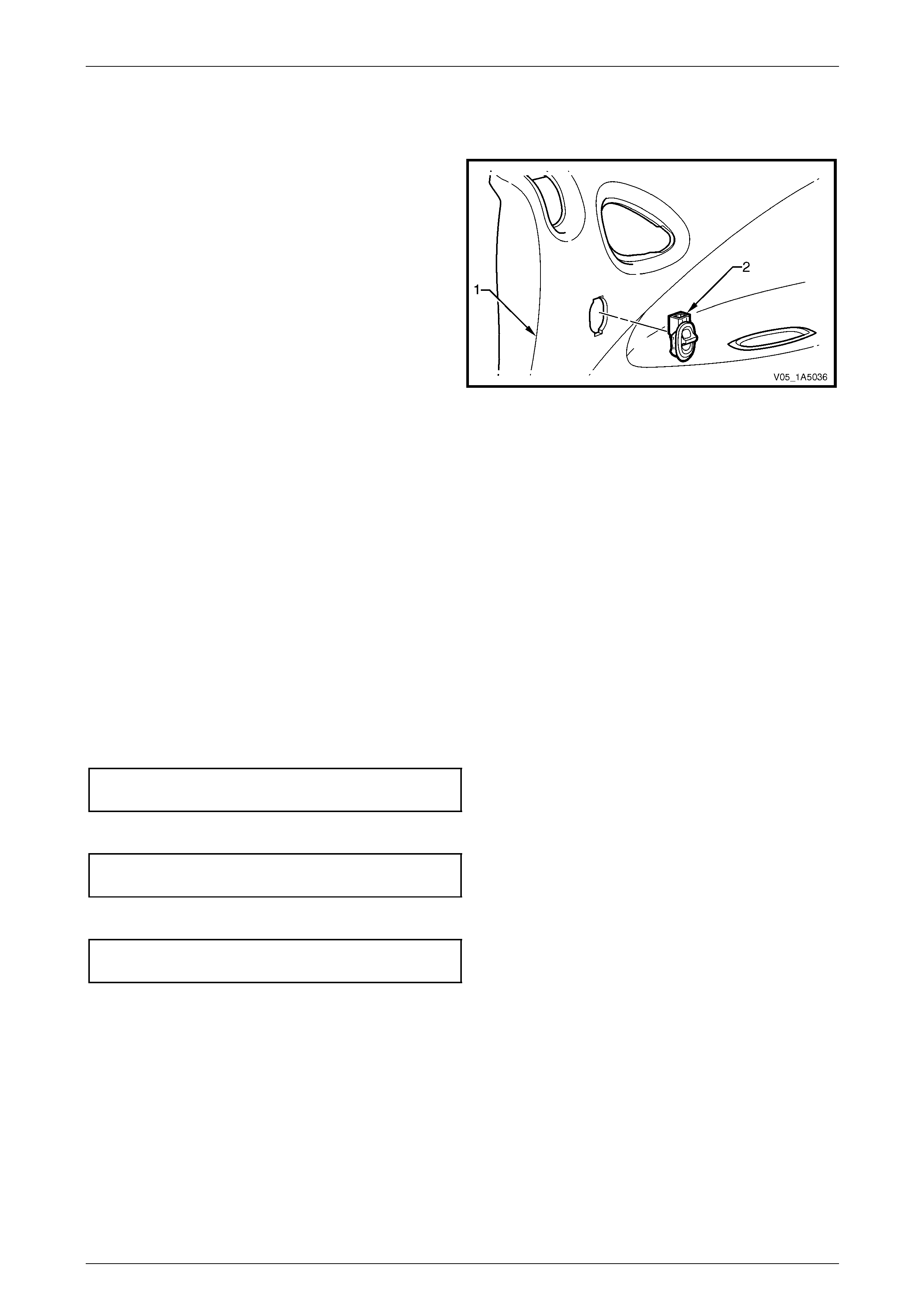
Front and Rear Door Assemblies Page 1A5–83
Page 1A5–83
Rear Door Power Window Switch (where fitted)
Remove
1 From behind the trim panel as sembly (1), depress the
tangs of the power window switch (2).
2 Push free the power window switch and remove.
NOTE
For further information regarding service and
diagnosis of the rear door power windo w switch,
refer to Section 12J Body Control Module.
Figure 1A5 – 124
Reinstall
Reinstallation of the rear door power window switch is the reverse of the removal proce dure, noting the following:
Ensure the tangs secure the switch assembly to the trim panel foundati on.
Reinstall
Reinstallation of the rear door trim panel assembly is the reverse of the removal proced ure, notin g the following:
1 Ensure the remote inner handle assembl y and the remote control rod, are engaged befor e final fitment of the trim
panel assembly, refer to 8.4 Rear Door Remote Inner Handle Assembly.
2 Tighten all the trim panel assembly attaching screws to the correct torque specification.
NOTE
The screws along the b ottom of the rear door trim
panel assembly are wax-tip sealing screws.
Rear door trim panel assembly
attaching screws torque specification .........1.0 – 3.0 Nm
3 Tighten the pull cup attaching screw to the correct torque specification.
Rear door pull cup attaching s c rew
torque specification.....................................1.0 – 3.0 Nm
4 Tighten the screw attaching the locking rod knob escutcheo n to the correct torque specification.
Rear door locking rod knob escutcheon
attaching screw torque specification...........1.0 – 2.0 Nm
5 Ensure the red locking insert is secured to the locking rod knob assembly.
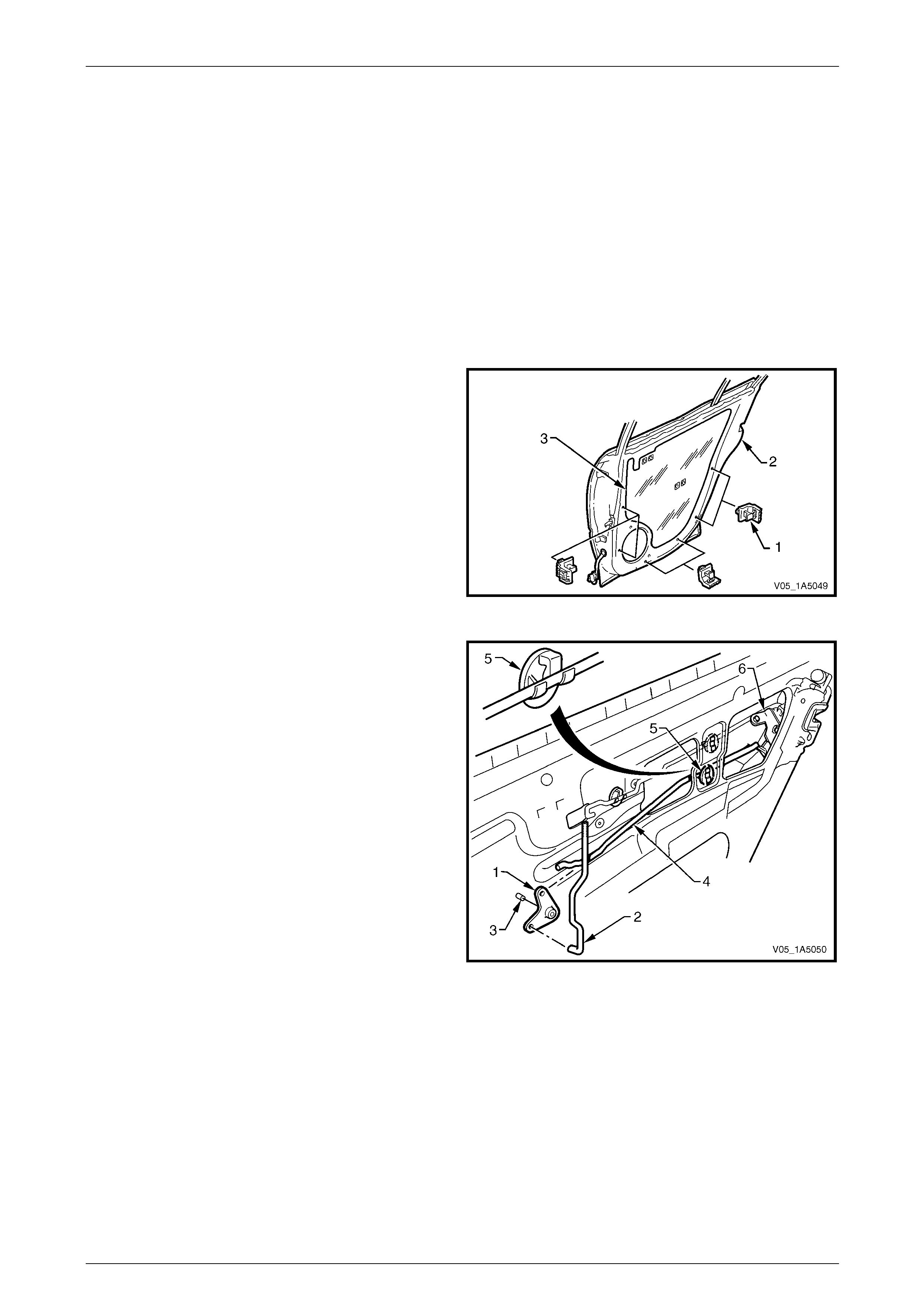
Front and Rear Door Assemblies Page 1A5–84
Page 1A5–84
11 Service Operations – Rear Door
Internal Components, Sedan and
Wagon
11.1 Rear Door Lock and Actuator Assembly
LT Section — 11–725
Remove
1 Remove the trim panel assembly, refer to 9.1 Rear Door Trim Panel.
2 Remove the trim panel bracket (1), six places , from
the inner panel (2) by levering out the centre pin of
each bracket.
3 Carefully peel off the water shield (3) from the inner
panel.
NOTE
The water shield only need t o be partly removed
to allow access to complete this procedure.
Figure 1A5 – 125
4 Lever the bell crank assembly (1) with the lock ing
rod (2) from the pivot shaft (3).
5 Remove the locking bell crank rod (4) from the clip (5)
and the rear door lock assembl y (6).
Figure 1A5 – 126
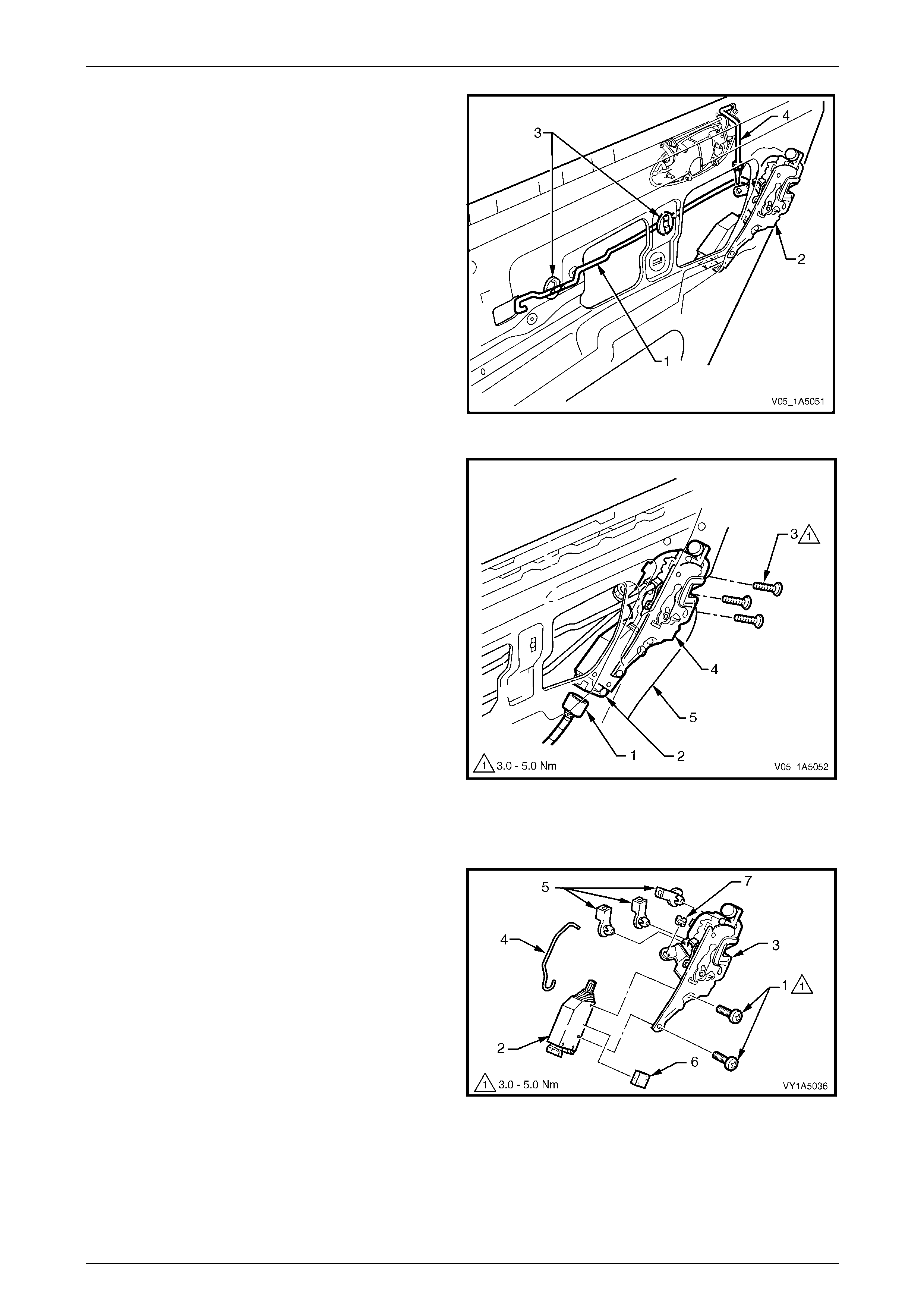
Front and Rear Door Assemblies Page 1A5–85
Page 1A5–85
6 Disconnect the remote control rod (1) from the lock
assembly (2) by releasing the remote control rod
retainer. Remove the remote control rod by
disengaging it from the two remote control rod
clips (3).
NOTE
The outer handle rod (4) disengages from the
lock assembly when the lock and actuator
assembly is being removed.
Figure 1A5 – 127
7 Disconnect the harness electrical connector (1) from
the lock actuator assembly (2).
8 If required, remove the window guide ch annel
assembly, refer to 11.3 Rear Door Window Guide
Channel Assembly.
9 Remove the three screws (3) attaching the lock
assembly (4) to the inner panel (5).
10 Remove the lock and actuator assembl y thr ough the
aperture in the inner panel.
Figure 1A5 – 128
Disassemble
1 Remove the two screws (1) attaching the loc k actuator
assembly (2) to the lock assembly (3).
2 Remove the actuating rod (4) from the actuator
assembly and the lock assem bly, then remove the
actuator assembly.
3 Remove the three retaining clips (5) and the bush (6)
from the lock assembly.
4 If required, remove the lock actuator insulator (7) from
the lock actuator assembly.
Figure 1A5 – 129
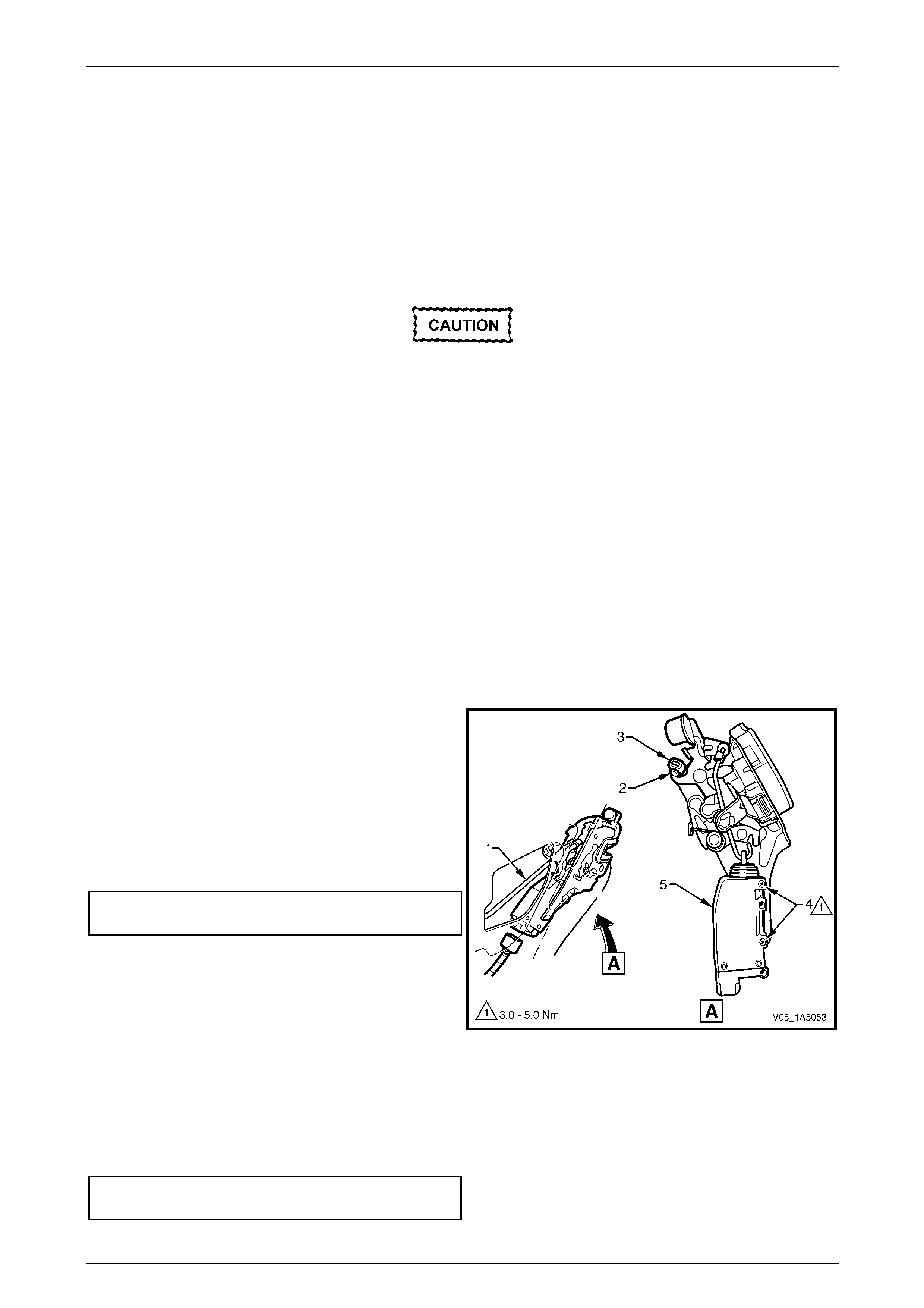
Front and Rear Door Assemblies Page 1A5–86
Page 1A5–86
Reassemble
Reassembly of the rear door lock and actuator assembly is the reverse of the disassembly procedure, noting the
following:
1 Attach the lock actuator assembly to the lock assembly, do not torque the two screws at this stage.
2 Adjust the position of the lock actuator assembly as descr ibed in this Section, refer to Adjust.
Adjust
Adjustment of the rear door lock and actuator
assembly is critical to ensure correct
operation of the electric door lock system.
NOTE
The following adjustment procedure is
to be performed if a diagnostic test in
Section 12J Body Control Module suggests the
rear door lock and actuator assembly may be
incorrectly adjusted, or if any of the following
symptoms occur:
• ineffective deadlock operation,
• failure to lock and unlock,
• door lock actuator motors oscillate (rattling
noise).
1 If required, remove the lock and actuator assembl y from the inner panel as described in this Section,
refer to Remove.
2 Using the locking bell crank rod (1), lock an d unlock
the lock actuator mechanism, checking the lock
actuator bump stop (2) rests on the lock actuator
lever (3).
3 If required, loosen the t wo screws (4) and reposition
the lock actuator assembly (5) until the required
position is achieved.
4 Tighten the two screws attaching the lock actuator
assembly to the correct torque specification.
Rear door lock actuator assembly
attaching screws torque specification .........3.0 – 5.0 Nm
NOTE
Ensure the lock actuator assembly has not
moved during the tightening procedure.
Figure 1A5 – 130
Reinstall
Reinstallation of the lock and actuator assembly is the reverse of the removal procedure, noting the follo wing:
Tighten the three screws attaching the lock and actu ator assembly to the correct torque specific ation.
Rear door lock and actuator assembly
attaching screws torque specification .........3.0 – 5.0 Nm
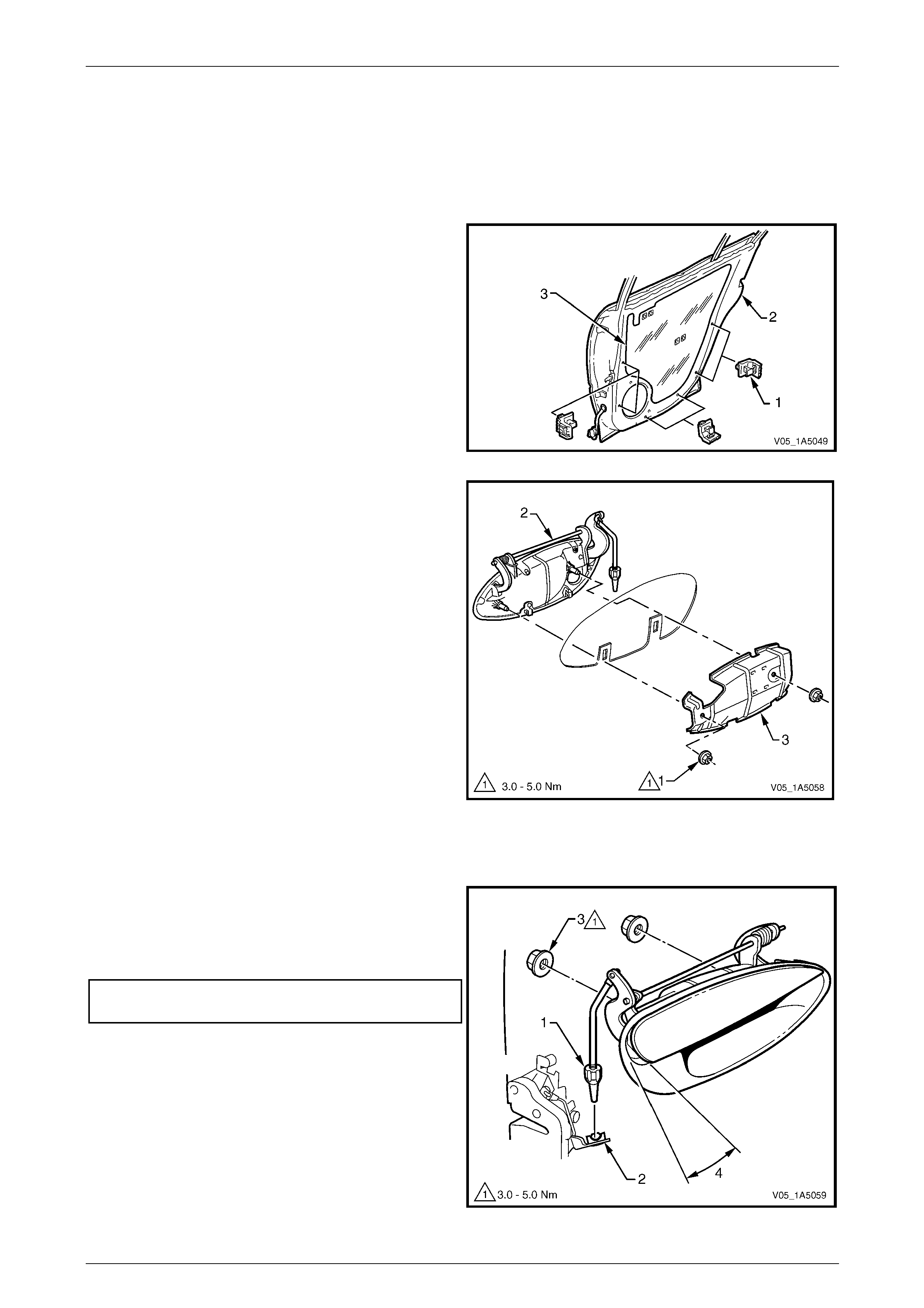
Front and Rear Door Assemblies Page 1A5–87
Page 1A5–87
11.2 Rear Door Outer Handle Assembly
LT Section — 11–725
Remove
1 Remove the trim panel assembly, refer to 9.1 Rear Door Trim Panel.
2 Remove the trim panel bracket (1), six places , from
the inner panel (2) by levering out the centre pin of
each bracket.
3 Carefully peel off the water shield (3) from the inner
panel. NOTE
The water shield only need t o be partly removed
to allow access to complete this procedure.
Figure 1A5 – 131
4 Remove the two nuts (1) attaching the outer handle
assembly.
5 Remove the front door outer handle (2) and
bracket (3) assemblies.
Figure 1A5 – 132
Reinstall
Reinstallation of the rear door outer handle assembly is the reverse of the removal procedure, noting the following:
1 Ensure the adjusting nut (1) is seated in the lock and
actuator assembly (2) before installing the two
attaching nuts (3).
2 Tighten the two nuts attaching the outer h andle
assembly to the correct torque specification.
Rear door outer handle assembly
attaching nuts torque specification..............3.0 – 5.0 Nm
3 Check and if necessary rotate the adjustin g nut to
allow the latch disengagement with the striker when
the outer handle opening (4) is 18° ±5° from the rest
position.
Figure 1A5 – 133
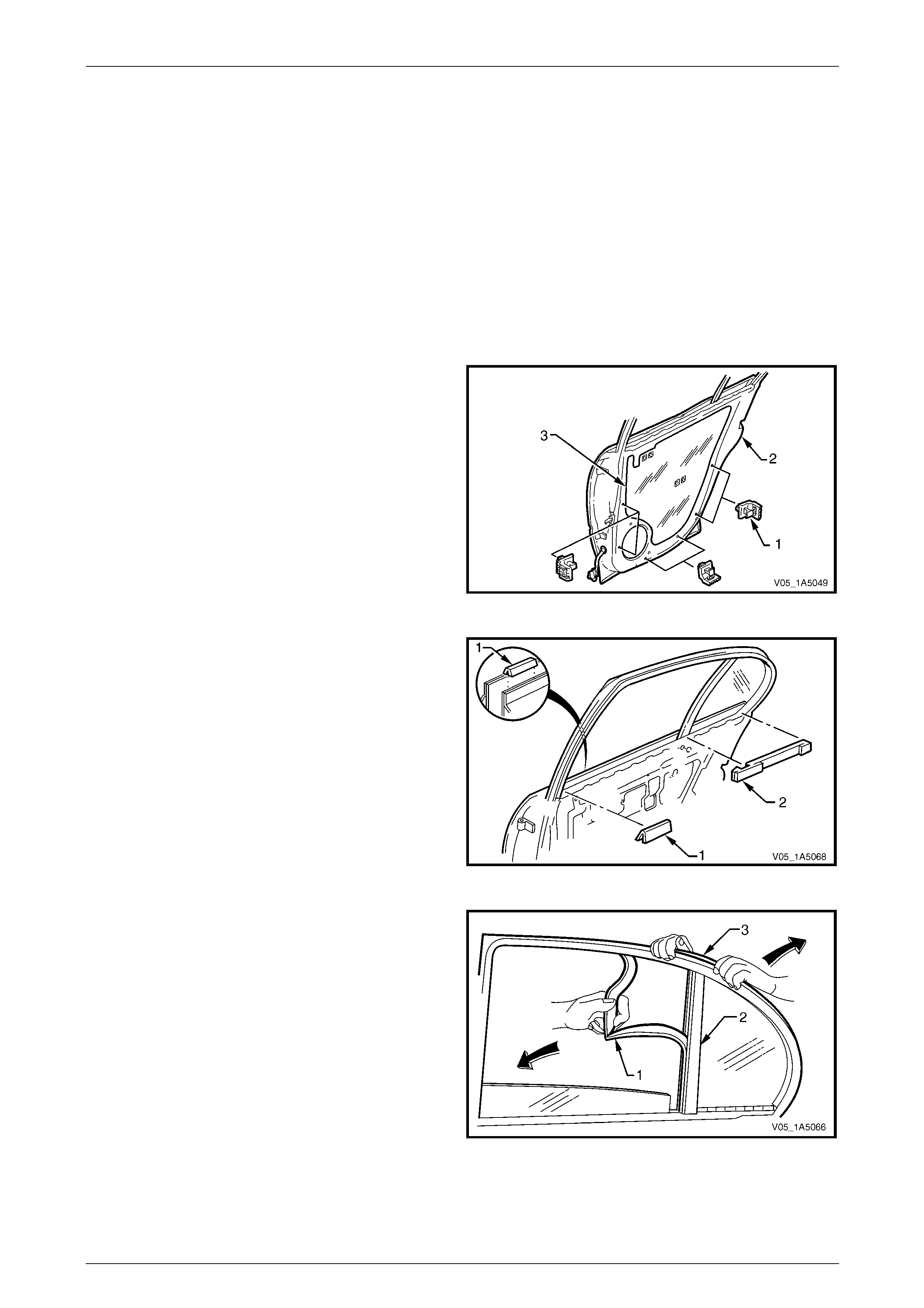
Front and Rear Door Assemblies Page 1A5–88
Page 1A5–88
11.3 Rear Door Window Guide Channel
Assembly
LT Section — 11–750
Remove
1 Lower the rear door window to the down position.
2 Remove the following components as required:
a Trim panel assembly, refer to 9.1 Rear Door Trim Panel.
b Window belt outer reveal moulding assembly,
refer to 13.3 Rear Door Window Belt Outer Reveal Moulding Assembly.
3 Remove the trim panel bracket (1), six places , from
the inner panel (2) by levering out the centre pin of
each bracket.
4 Carefully peel off the water shield (3) from the inner
panel.
NOTE
The water shield only need t o be partly removed
to allow access to complete this procedure.
Figure 1A5 – 134
5 Remove the inner panel beltline front seal (1) and rear
seal (2) from the rear door assembly.
Figure 1A5 – 135
6 Carefully remove the windo w upper weatherstrip
assembly (1) from the window guide channel
assembly (2).
NOTE
It is not necessary to remove the upper
weatherstrip assembly completely, remove it
only from the windo w guide channel assembly.
7 Partially remove the upper weatherstrip assembly (3)
from the lip on the door upper frame, to access the
window guide channel assembly.
Figure 1A5 – 136
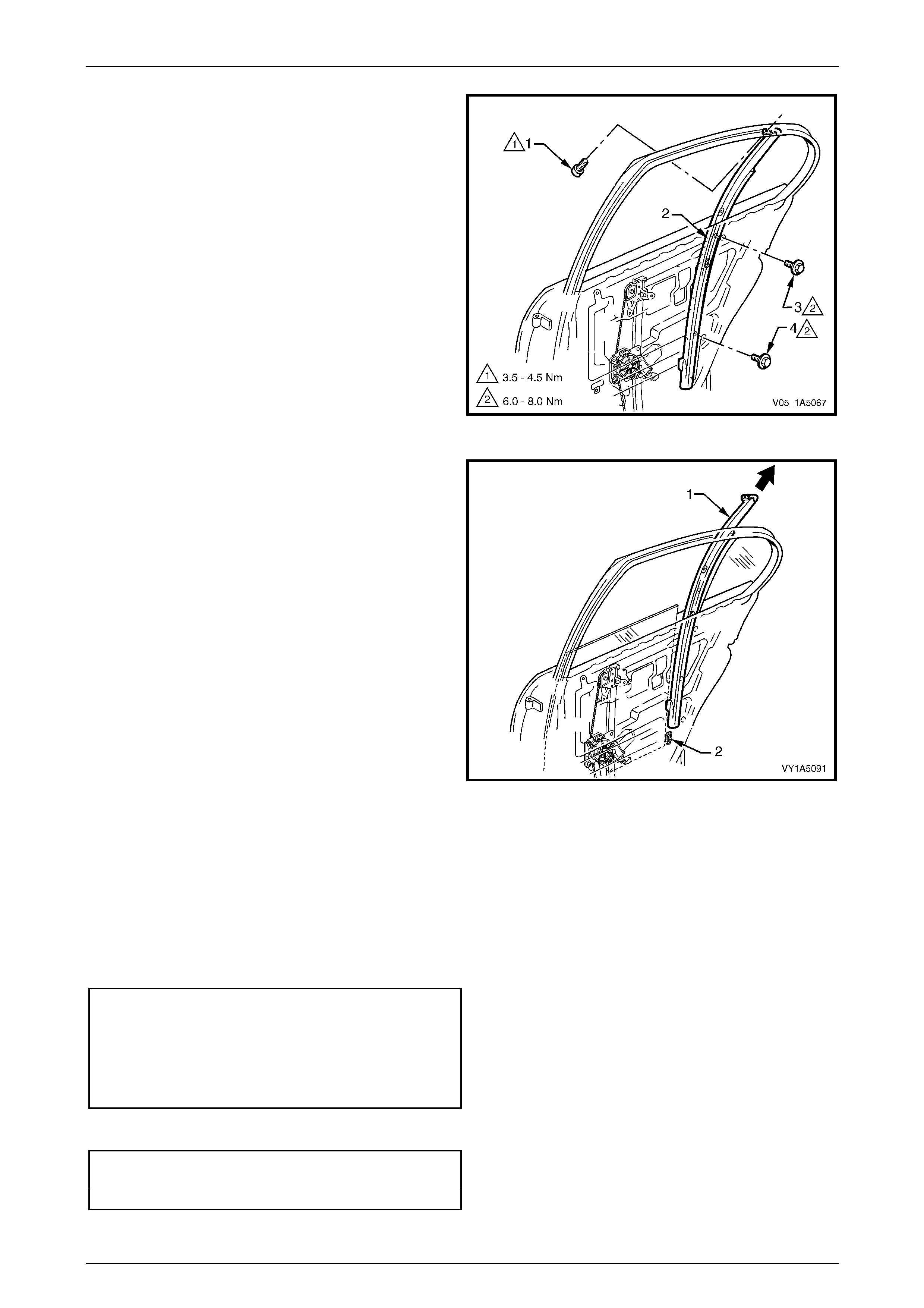
Front and Rear Door Assemblies Page 1A5–89
Page 1A5–89
8 Remove the upper screw (1) attaching the window
guide channel assemb ly (2) to the door upper frame.
9 Remove the centre screw (3) and lower screw (4)
attaching the window guide ch annel assembly to the
inner panel.
Figure 1A5 – 137
10 Remove the window guide ch annel assembly (1) from
the door assembly in an up ward direction, d isen gaging
the window assembly slides (2) from the window guide
channel assembly.
Figure 1A5 – 138
Reinstall
Reinstallation of the rear door window guide channel assembly is the reverse of the removal procedure, noting the
following:
1 Ensure the window assembly slides are engaged in the window guide channel assembly.
2 Tighten the centre screw (3) and lower screw (4) attaching the window guide channel assembly (2) to the correct
torque specification, refer to Figure 1A5 – 1 37.
Rear door windo w guide c hannel
assembly centre attaching screw
torque specification.....................................6.0 – 8.0 Nm
Rear door windo w guide c hannel
assembly lower attaching screw
torque specification.....................................6.0 – 8.0 Nm
3 Tighten the upper screw (1) attaching the window guide channel ass embly to the correct torque specification.
Rear door windo w guide c hannel
assembly upper attaching screw
torque specification.....................................3.5 – 4.5 Nm
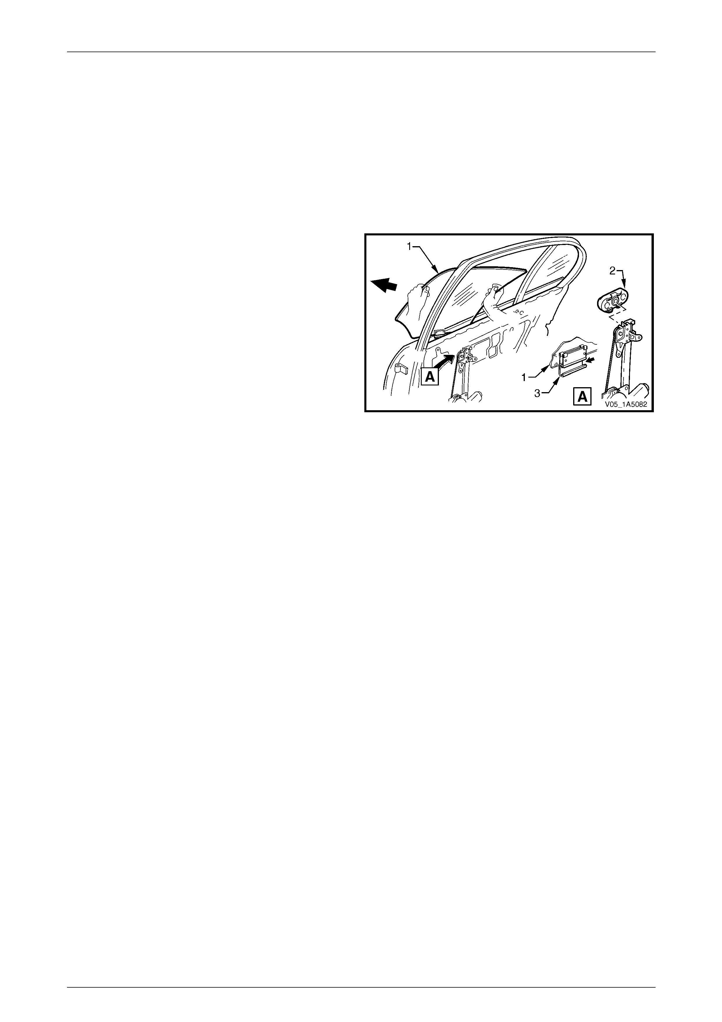
Front and Rear Door Assemblies Page 1A5–90
Page 1A5–90
11.4 Rear Door Window Assembly
LT Section — 11–020
Remove
1 Remove the following components as required:
a Trim panel assembly, refer to 9.1 Rear Door Trim Panel.
b Window guide channel assembly, refer to 11.3 Rear Door Window Guide Channe l Assembly.
2 Raise the window assembly (1).
3 Slide the window assembly forward at an angle of 45°
while disengaging the window regulator slider (2) out
of the window guide channel (3) and remove.
Figure 1A5 – 139
Reinstall
Reinstallation of the rear door window assembly is the reverse of the removal procedure , noting the following:
1 Insert the rear door window assembly down through the rear door belt opening taking care not to damage the glass
panel.
NOTE
Do not torque any component attaching screw
prior to adjusting the window and regulator
assemblies.
2 When installing the window assembly, make sure to adjust the window and regulator assemblies as per the
adjusting procedure as described in this Section, refer to Adjust.
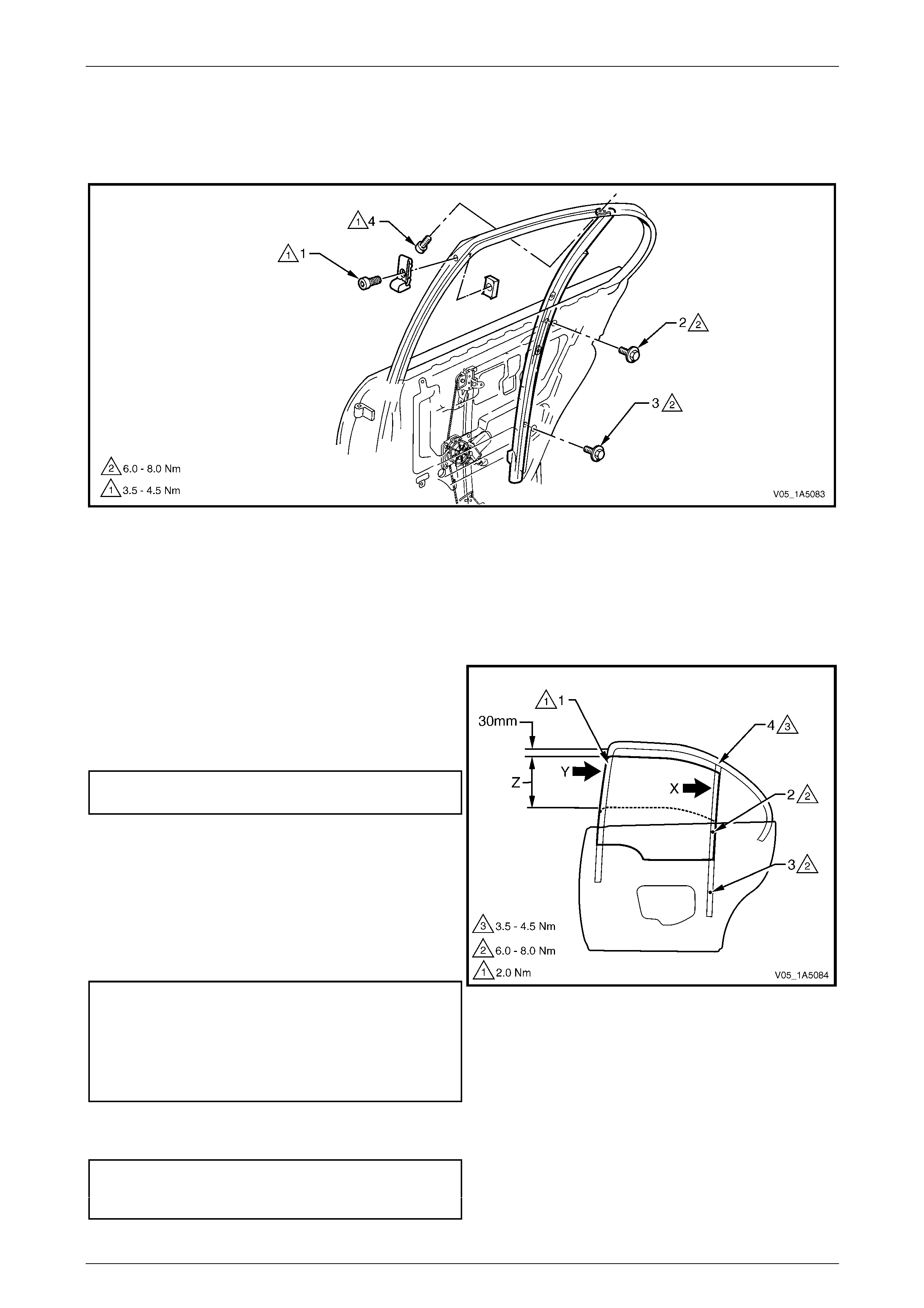
Front and Rear Door Assemblies Page 1A5–91
Page 1A5–91
Adjust
Figure 1A5 – 140 shows the screw / nut locations and torque values for the rear door window assembly adjustment
procedure.
Figure 1A5 – 140
Legend
1 Rear Door Window Up Stop Screw and Nut
2 Rear Door Window Guide Channel Assembly Lower
Attaching Screw
3 Rear Door Window Guide Channel Assembly Lower
Attaching Screw
4 Rear Door Window Guide Channel Assembly Upper
Attaching Screw
1 Adjust the window assembly up stop, point (1) at the
front of the rear door so there is a 1 mm gap below the
highest possible end stop posi t ion.
2 Tighten the window up stop screw, point (1), to the
specified preliminar y torque value.
Rear door window up stop screw
preliminary torque specification............................2.0 Nm
3 Wind the window assembly up through area (Z), until it
is approximately 30 mm before the closed position. At
the same time press the rail, which is bonded to the
front edge of the window assembly, rearward (Y).
4 Push the window guide channel assembly
rearward (X) and tighten the wind ow guide channel
assembly attaching centre scre w, point (2) and lo wer
screw, point (3), to the specified torque.
Rear door windo w guide c hannel
assembly centre attaching screw
torque specification.....................................6.0 – 8.0 Nm
Rear door windo w guide c hannel
assembly lower attaching screw
torque specification.....................................6.0 – 8.0 Nm
5 Tighten the window guide cha nnel assembly upper
attaching screw, point (4), to the specified torque.
Rear door windo w guide c hannel
assembly upper attaching screw
torque specification.....................................3.5 – 4.5 Nm
Figure 1A5 – 141

Front and Rear Door Assemblies Page 1A5–92
Page 1A5–92
6 Check the cranking load of the window assembly in
area (W). If the window assembly binds or the motor
load sounds excessive, re-adjust the window
assembly by correcting the windo w guide ch annel
assembly attachment points (2, 3 and 4).
7 Check the window for the following:
a The upper edge of the window must be par allel
to the lip of the door upper frame run channe l at
point (V) and over the area (U).
b The upper edge of the window must be inserted
by 4 mm ±1 mm above the lip of the door upper
frame run channel at point (V) and over the
area (U).
NOTE
If either the deviation in parallelism or the
insertion depth e xceeds 1 mm from specificat ion,
the up stop assembly, point (1), must be
readjusted.
8 Tighten the window up stop screw, point (1), to the
specified final torque value.
Rear door window up stop screw
torque specification.....................................3.5 – 4.5 Nm
Figure 1A5 – 142
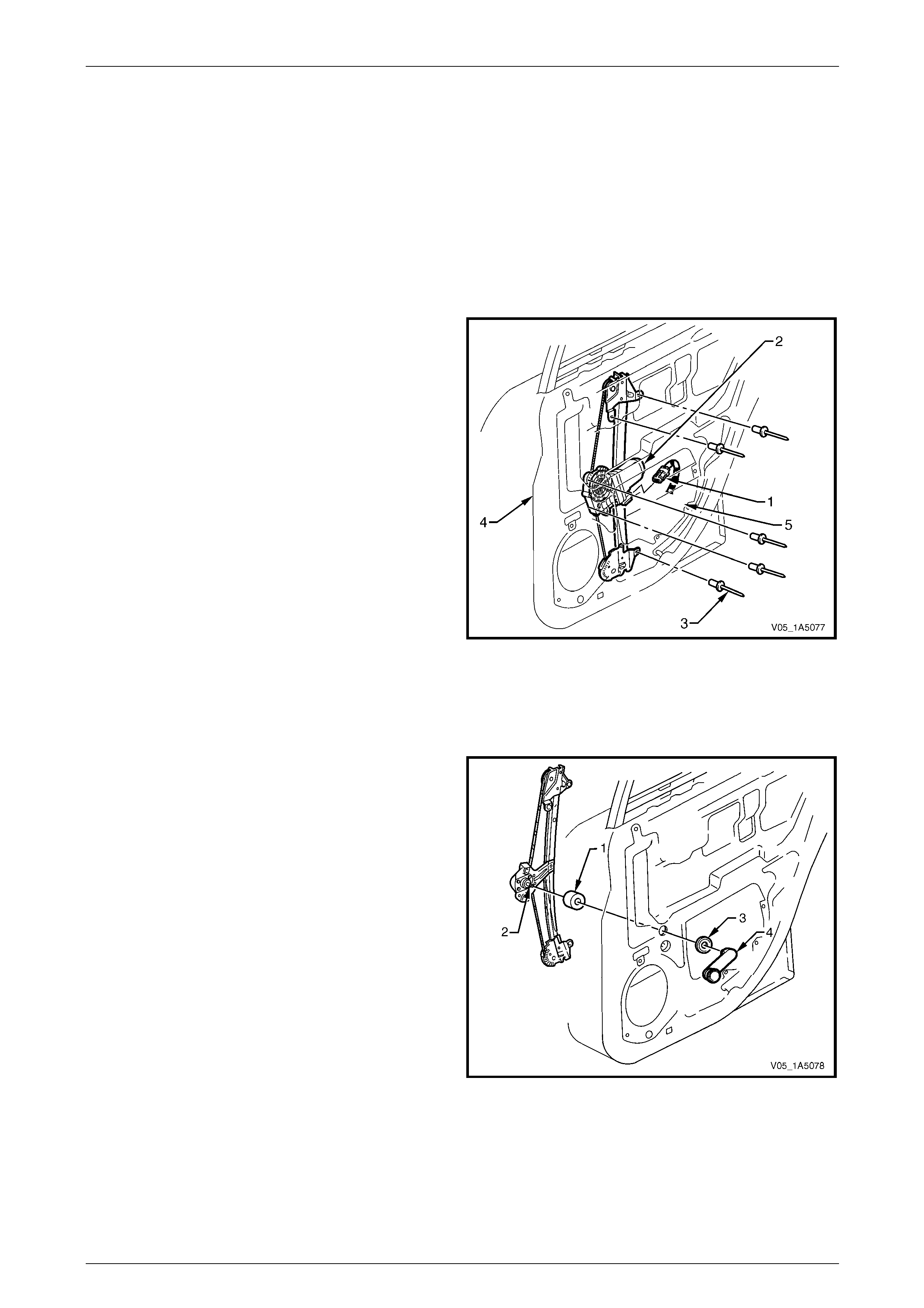
Front and Rear Door Assemblies Page 1A5–93
Page 1A5–93
11.5 Rear Door Window Regulator Assembly
LT Section — 11–810
Remove
1 Remove the following components as required:
a Trim panel assembly, refer to 9.1 Rear Door Trim Panel.
b Window assembly, refer to 11.4 Rear Door Window Assembly.
2 If fitted, disconnect the wiring harness connector (1)
from the window regulator assembly (2).
3 Drill out the five rivets (3) securing the window
regulator assembly to the inner panel (4).
NOTE
Use a 5 mm drill bit to drill out the five rivets
securing the window regulator assembly.
4 Remove the window regulator through the aperture (5)
in the inner panel.
Figure 1A5 – 143
Reinstall
Reinstallation of the rear door window regulator assembly is the reverse of the removal procedure, noting the following:
1 If applicable, fit the handle shaft seal (1) to the windo w
regulator spindle (2), before installin g into the rear
door assembly.
NOTE
The window regulator washer (3) and handle (4)
are to be installed after the trim panel assem bly.
Figure 1A5 – 144

Front and Rear Door Assemblies Page 1A5–94
Page 1A5–94
2 Ensure that all frictional surfaces of the window regulator assembly and associated parts are adequately lubricated
with Lithium base grease NLGI No. 1 (with 9 % zinc oxide) or equivalent.
3 Align the attaching holes in the window regulator assembly with the corresponding holes in the inner panel an d
secure the window regulator assembly with 5 mm rivets.
NOTE
Washers may be inserted when installing the
rivets as the attaching holes in the inner panel
may have been enlarged when the rivets were
drilled out.
4 Adjust the rear door window and regulator assemblies as per the adjustment procedure,
refer to 11.4 Rear Door Window Assembly.
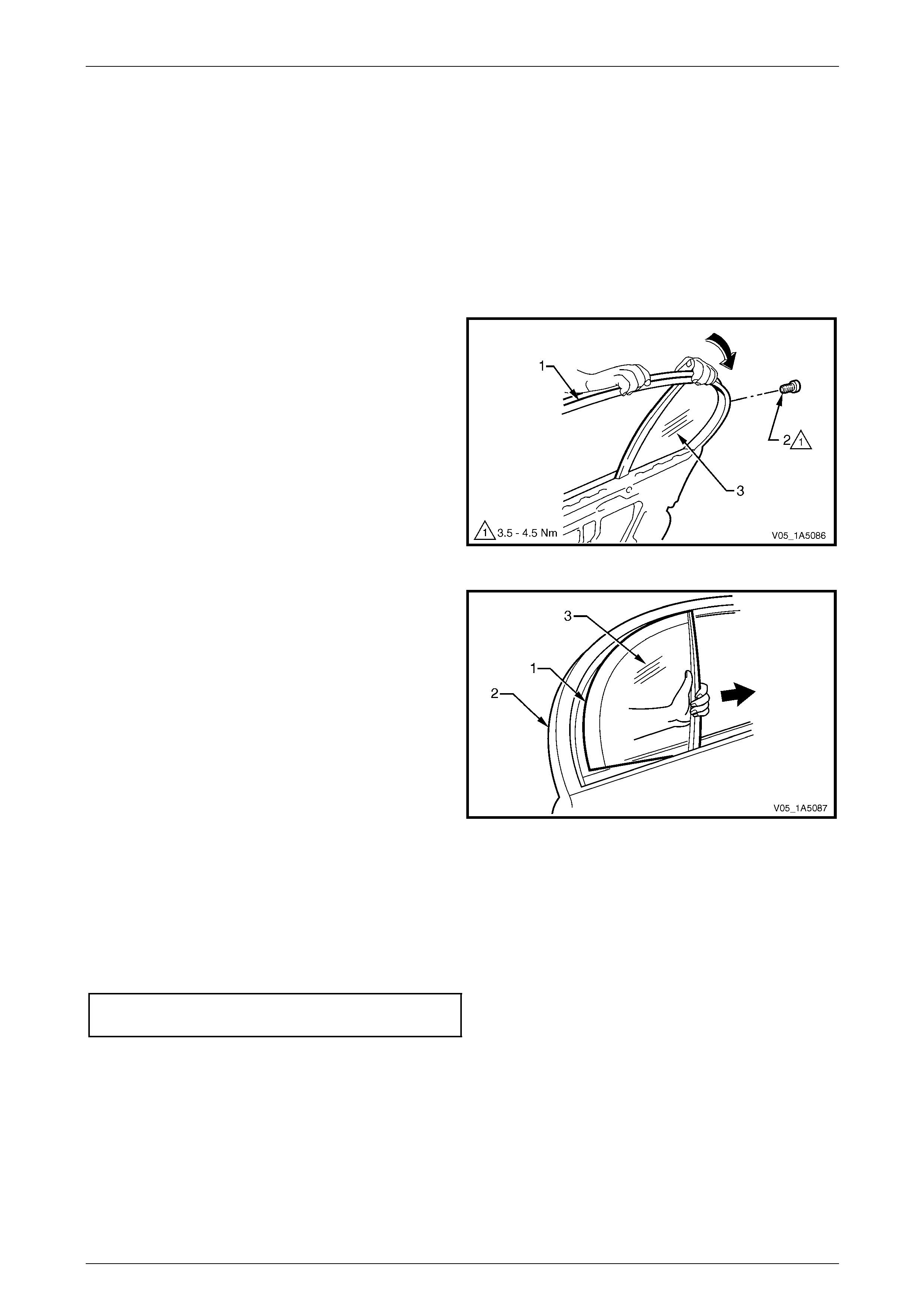
Front and Rear Door Assemblies Page 1A5–95
Page 1A5–95
11.6 Rear Door Stationary Window Assembly
LT Section — 11–020
Remove
1 Remove the following components as required:
a Trim panel assembly, refer to 9.1 Rear Door Trim Panel.
b Window assembly, refer to 11.4 Rear Door Window Assembly.
2 Roll back a section of the upper weatherstrip
assembly (1) from the lip on the door upper frame, to
access the screw (2) attaching the stationary window
assembly (3).
3 Remove the screw attaching the stationary window
assembly.
Figure 1A5 – 145
4 Pry the inner section of the stationar y window rubb er
seal (1) from its position in the door upper frame (2).
5 Slide the stationary window assembly (3) forward and
remove.
Figure 1A5 – 146
Reinstall
Reinstallation of the rear door stationary window assembly is the reverse of the removal procedure, n oti ng the following:
1 Ensure the rear door stationary window rubber seal is correctly inserted.
2 Tighten the screw attaching the stationar y window to the specified torqu e.
Rear door stationary window
attaching screw torque specification...........3.5 – 4.5 Nm


Front and Rear Door Assemblies Page 1A5–97
Page 1A5–97
11.8 Rear Door Wiring Harness Assembly
LT Section —
Remove and Reinstall
Ensure the wiring harness assembly is routed and clipped correctly. For the rear door wiring harness assembly
attachment and routing, refer to Section 12O Fuses, Relays and Wiring Harnesses.
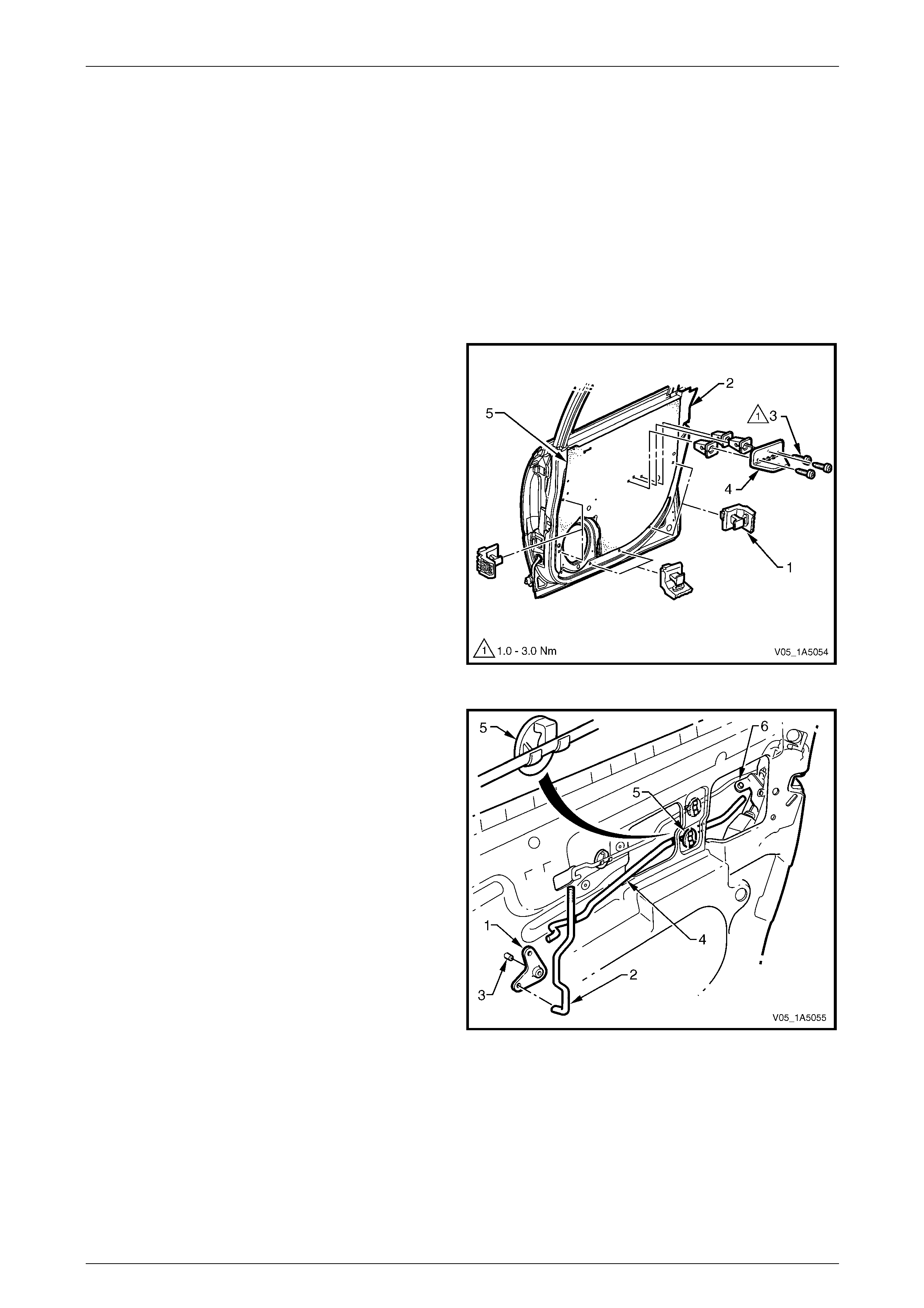
Front and Rear Door Assemblies Page 1A5–98
Page 1A5–98
12 Service Operations – Rear Door
Internal Components, Crew Cab
12.1 Rear Door Lock and Actuator Assembly
LT Section — 11–725
Remove
1 Remove the trim panel assembly, refer to 10.1 Rear Door Trim Pane l.
2 Remove the trim panel bracket (1), six places , from
the inner panel (2) by levering out the centre pin of
each bracket.
3 Remove the three screws (3) attaching the pull cup
bracket (4) to the inner panel and remove the pull cup
bracket.
4 Carefully peel off the water shield (3) from the inner
panel.
NOTE
The water shield only need t o be partly removed
to allow access to complete this procedure.
Figure 1A5 – 147
5 Lever the bell crank assembly (1) with the lock ing
rod (2) from the pivot shaft (3).
6 Remove the locking bell crank rod (4) from the clip (5)
and the rear door lock assembl y (6).
Figure 1A5 – 148
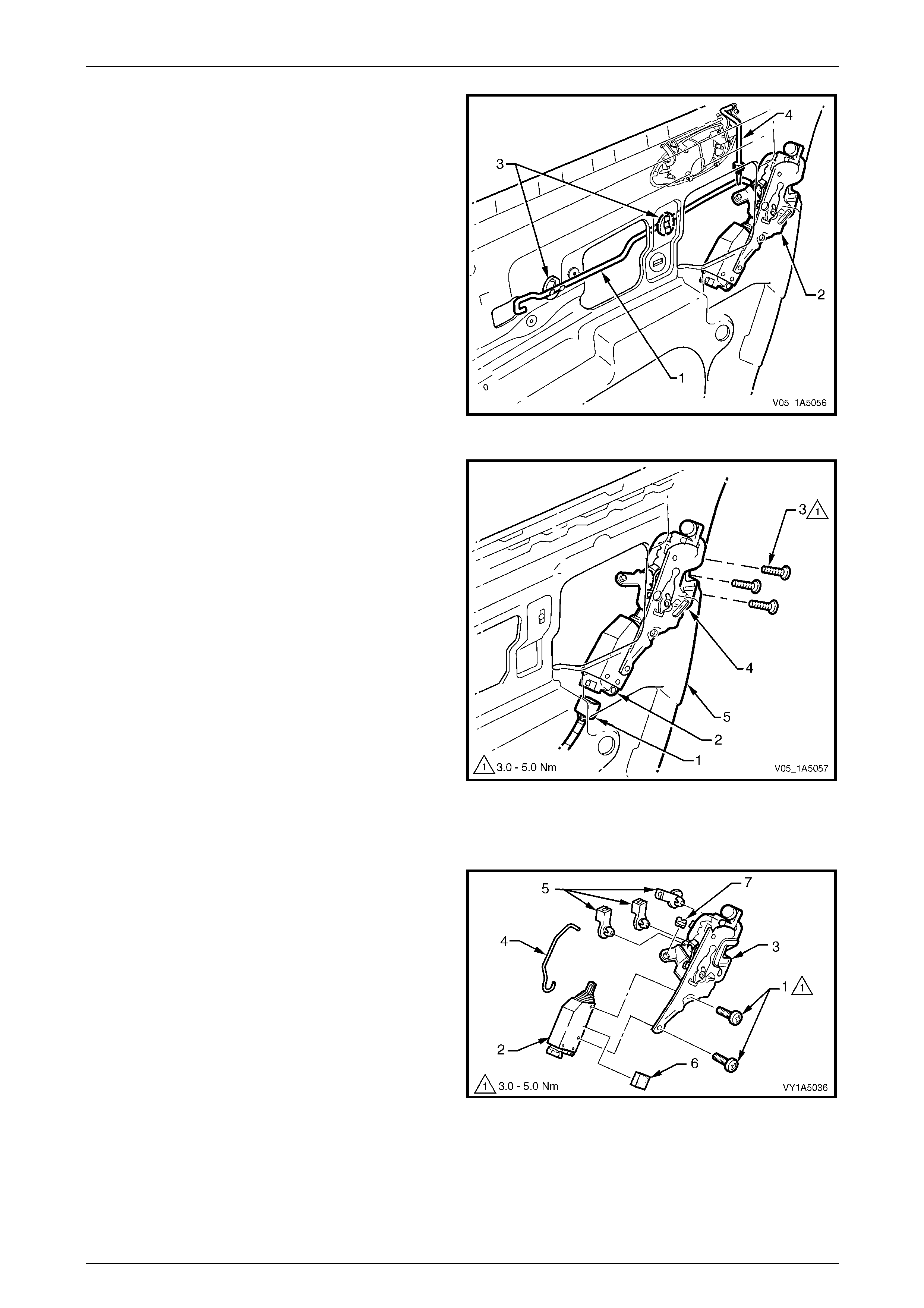
Front and Rear Door Assemblies Page 1A5–99
Page 1A5–99
7 Disconnect the remote control rod (1) from the lock
assembly (2) by releasing the remote control rod
retainer. Remove the remote control rod by
disengaging it from the two remote control rod
clips (3).
NOTE
The outer handle rod (4) disengages from the
lock assembly when the lock and actuator
assembly is being removed.
Figure 1A5 – 149
8 Disconnect the harness electrical connector (1) from
the lock actuator assembly (2).
9 If required, remove the window guide ch annel
assembly, refer to 12.3 Rear Door Window Guide
Channel Assembly.
10 Remove the three screws (3) attaching the lock
assembly (4) to the inner panel (5).
11 Remove the lock and actuator assembl y thr ough the
aperture in the inner panel.
Figure 1A5 – 150
Disassemble
1 Remove the two screws (1) attaching the loc k actuator
assembly (2) to the lock assembly (3).
2 Remove the actuating rod (4) from the actuator
assembly and the lock assem bly, then remove the
actuator assembly.
3 Remove the three retaining clips (5) and the bush (6)
from the lock assembly.
4 If required, remove the lock actuator insulator (7) from
the lock actuator assembly.
Figure 1A5 – 151
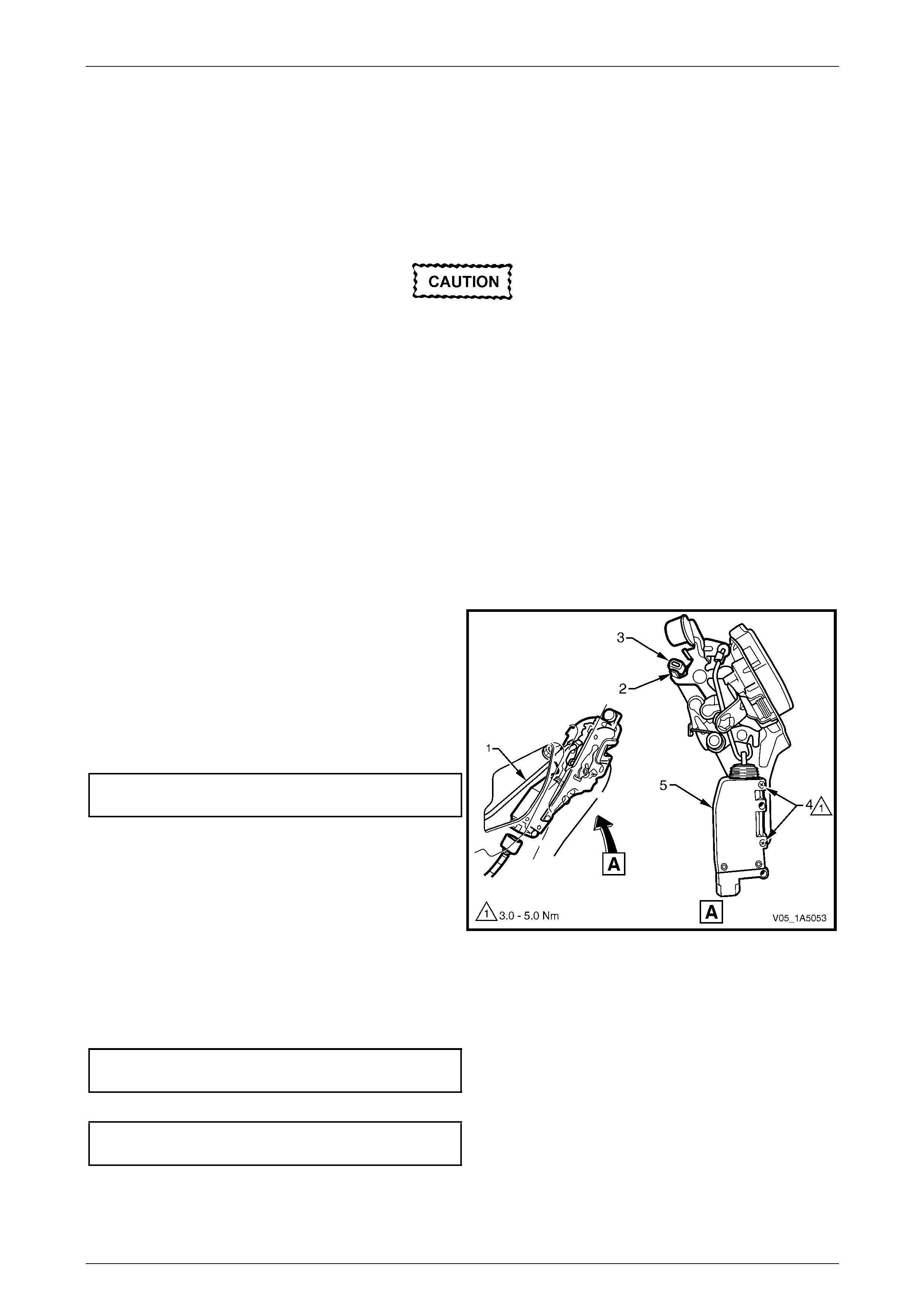
Front and Rear Door Assemblies Page 1A5–100
Page 1A5–100
Reassemble
Reassembly of the rear door lock and actuator assembly is the reverse of the disassembly procedure, noting the
following:
1 Attach the lock actuator assembly to the lock assembly, do not torque the two screws at this stage.
2 Adjust the position of the lock actuator assembly as descr ibed in this Section, refer to Adjust.
Adjust
Adjustment of the rear door lock and actuator
assembly is critical to ensure correct
operation of the electric door lock system.
NOTE
The following adjustment procedure is
to be performed if a diagnostic test in
Section 12J Body Control Module suggests the
rear door lock and actuator assembly may be
incorrectly adjusted, or if any of the following
symptoms occur:
• ineffective deadlock operation,
• failure to lock and unlock,
• door lock actuator motors oscillate (rattling
noise).
1 If required, remove the lock and actuator assembl y from the inner panel as describ ed in this Section, refer to
Remove.
2 Using the locking bell crank rod (1), lock an d unlock
the lock actuator mechanism, checking the lock
actuator bump stop (2) rests on the lock actuator
lever (3).
3 If required, loosen the t wo screws (4) and reposition
the lock actuator assembly (5) until the required
position is achieved.
4 Tighten the two screws attaching the lock actuator
assembly to the correct torque specification.
Rear door lock actuator assembly
attaching screws torque specification .........3.0 – 5.0 Nm
NOTE
Ensure the lock actuator assembly has not
moved during the tightening procedure.
Figure 1A5 – 152
Reinstall
Reinstallation of the rear door lock and actuator assembly is the reverse of the removal procedure, noting the following:
1 Tighten the three screws attaching the rear door lock and actuator assembly to the correct torque spe cification.
Rear door lock and actuator assembly
attaching screws torque specification .........3.0 – 5.0 Nm
2 Tighten the three screws attaching the rear door p ull cup bracket to the correct torque specification.
Rear door pull cup bracket
attaching screws torque specification .........1.0 – 3.0 Nm
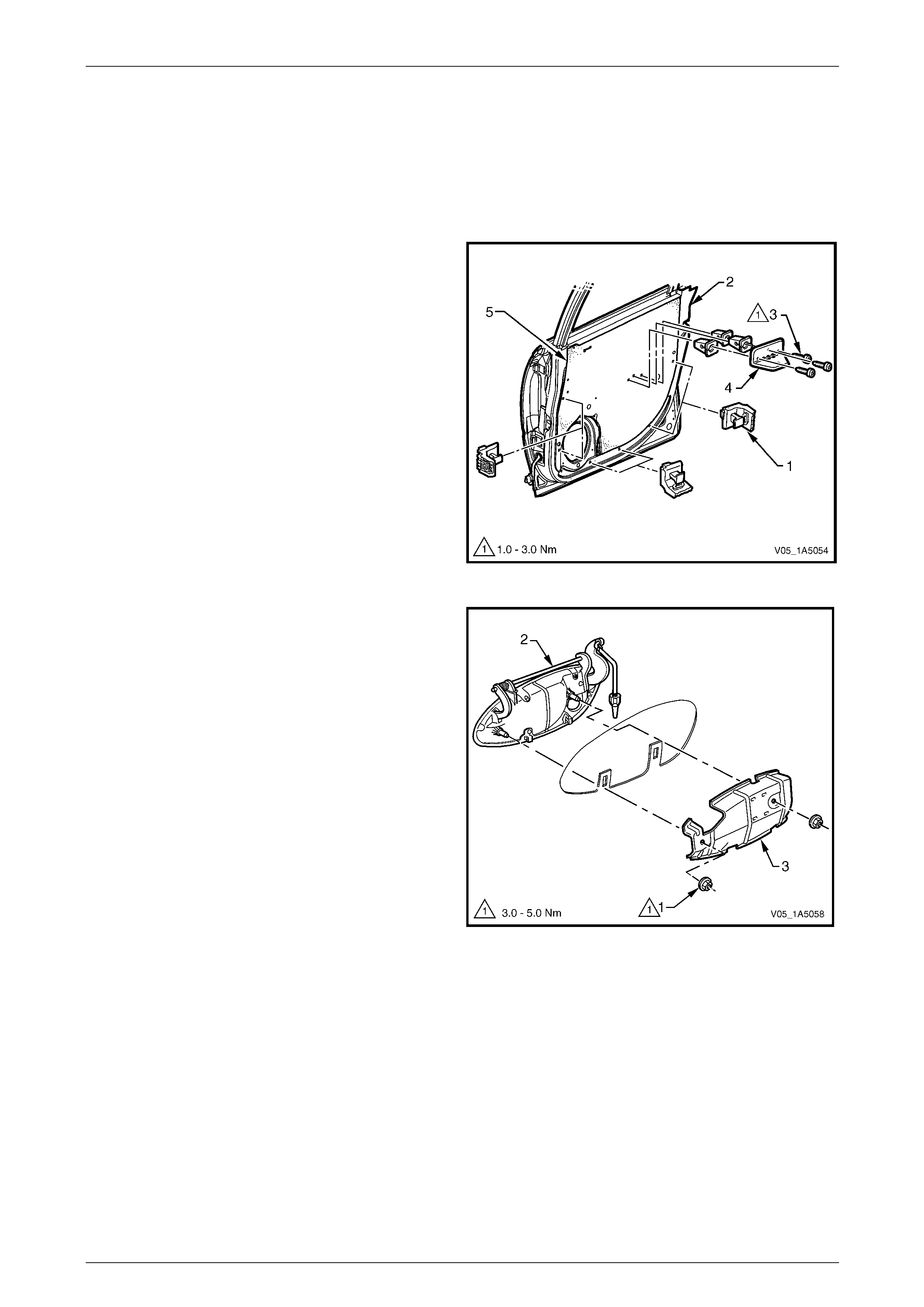
Front and Rear Door Assemblies Page 1A5–101
Page 1A5–101
12.2 Rear Door Outer Handle Assembly
LT Section — 11–725
Remove
1 Remove the trim panel assembly, refer to 10.1 Rear Door Trim Pane l.
2 Remove the trim panel bracket (1), six places , from
the inner panel (2) by levering out the centre pin of
each bracket.
3 Remove the three screws (3) attaching the pull cup
bracket (4) to the inner panel and remove the pull cup
bracket.
4 Carefully peel off the water shield (3) from the inner
panel.
NOTE
The water shield only need t o be partly removed
to allow access to complete this procedure.
Figure 1A5 – 153
5 Remove the two nuts (1) attaching the outer handle
assembly.
6 Remove the front door outer handle (2) and
bracket (3) assemblies.
Figure 1A5 – 154
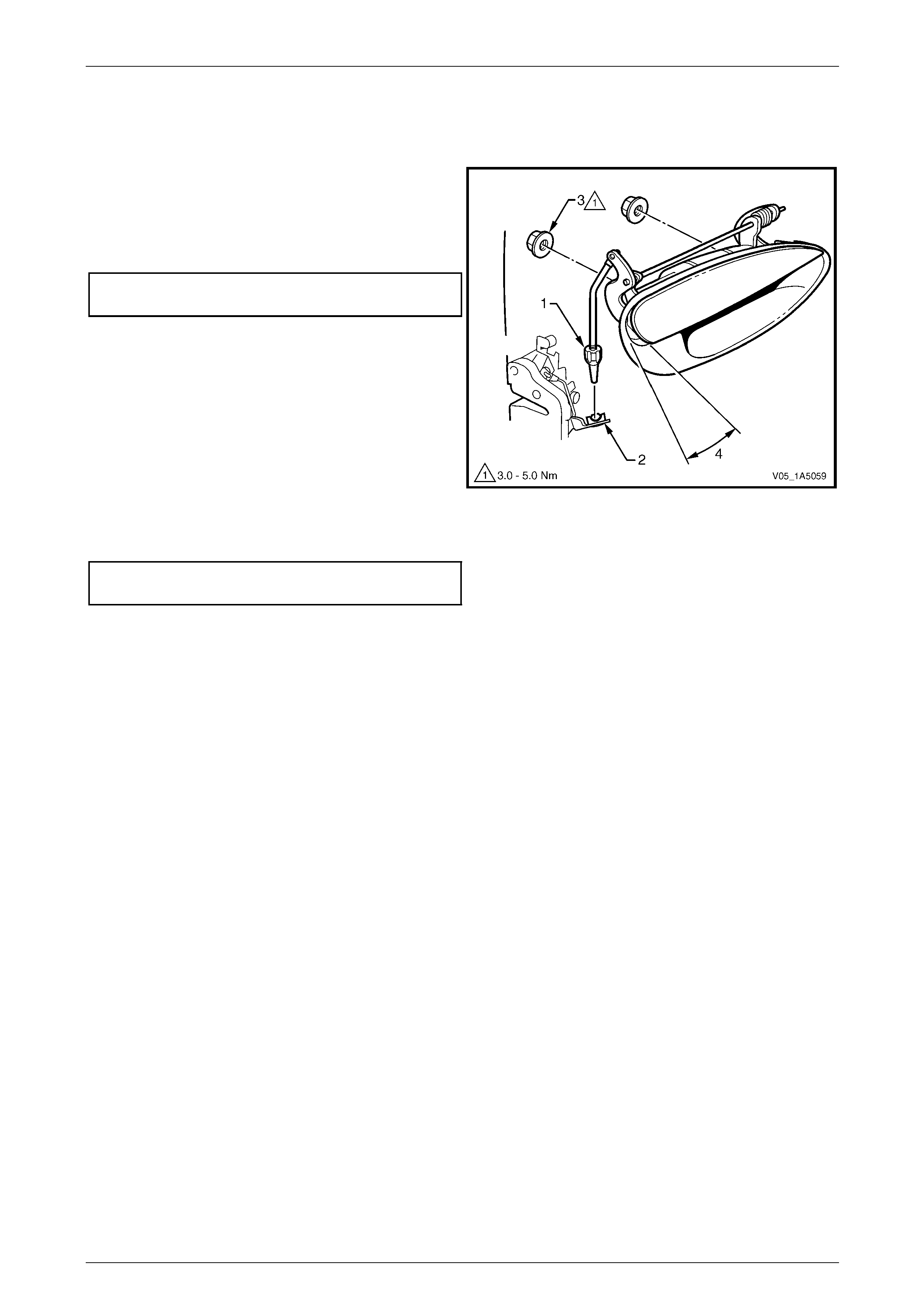
Front and Rear Door Assemblies Page 1A5–102
Page 1A5–102
Reinstall
Reinstallation of the rear door outer handle assembly is the reverse of the removal procedure, noting the following:
1 Ensure the adjusting nut (1) is seated in the lock and
actuator assembly (2) before installing the two
attaching nuts (3).
2 Tighten the two nuts attaching the outer h andle
assembly to the correct torque specification.
Rear door outer handle assembly
attaching nuts torque specification..............3.0 – 5.0 Nm
3 Check and if necessary rotate the adjustin g nut to
allow the latch disengagement with the striker when
the outer handle opening (4) is 18° ±5° from the rest
position.
Figure 1A5 – 155
4 Tighten the three screws attaching the rear door p ull cup bracket to the correct torque specification.
Rear door pull cup bracket
attaching screws torque specification .........1.0 – 3.0 Nm
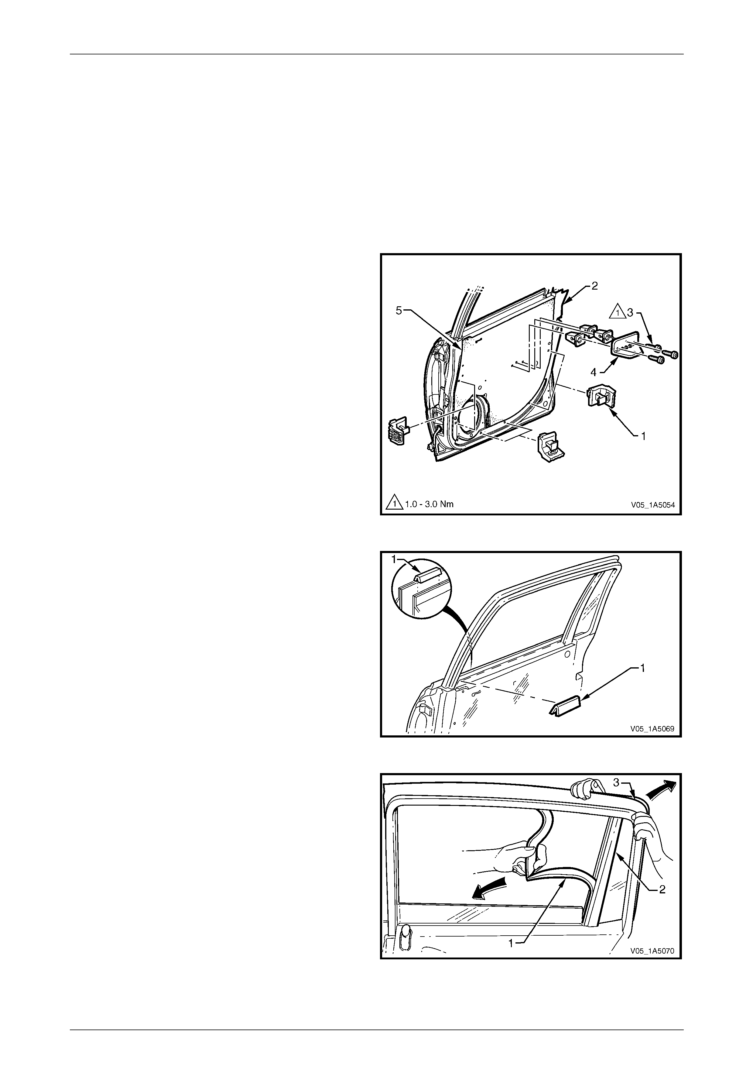
Front and Rear Door Assemblies Page 1A5–103
Page 1A5–103
12.3 Rear Door Window Guide Channel
Assembly
LT Section — 11–750
Remove
1 Lower the rear door window to the down position.
2 Remove the trim panel assembly, refer to 10.1 Rear Door Trim Pane l.
3 Remove the trim panel bracket (1), six places , from
the inner panel (2) by levering out the centre pin of
each bracket.
4 Remove the three screws (3) attaching the pull cup
bracket (4) to the inner panel and remove the pull cup
bracket.
5 Carefully peel off the water shield (3) from the inner
panel.
NOTE
The water shield only need t o be partly removed
to allow access to complete this procedure.
Figure 1A5 – 156
6 Remove the inner panel beltl ine seal (1) from the rear
door assembly.
Figure 1A5 – 157
7 Carefully remove the windo w upper weatherstrip
assembly (1) from the window guide channel
assembly (2).
NOTE
It is not necessary to remove the upper
weatherstrip assembly completely, remove it
only from the windo w guide channel assembly.
8 Partially remove the upper weatherstrip assembly (3)
from the lip on the door upper frame, to access the
window guide channel assembly.
Figure 1A5 – 158
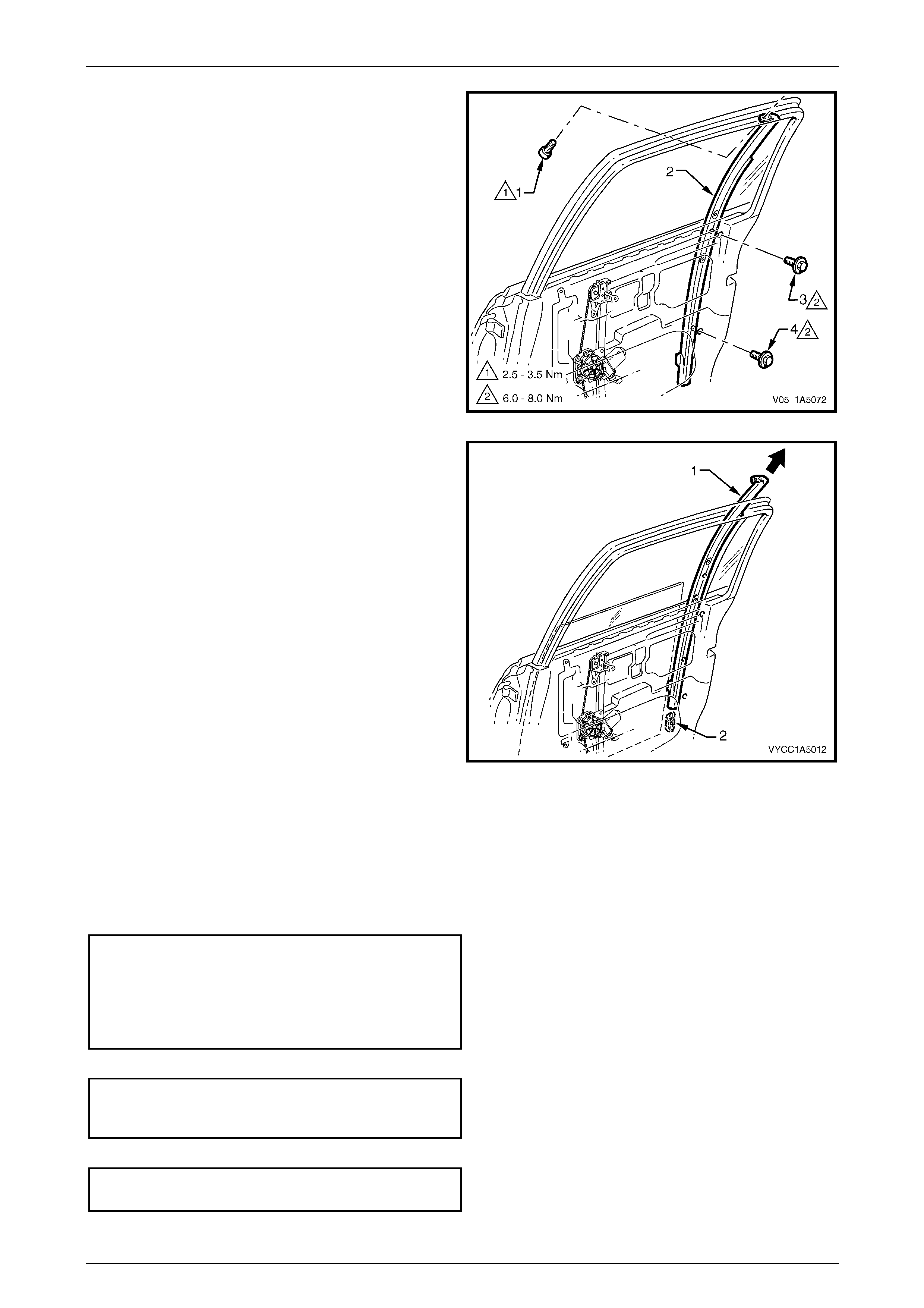
Front and Rear Door Assemblies Page 1A5–104
Page 1A5–104
9 Remove the upper screw (1) attaching the window
guide channel assemb ly (2) to the door upper frame.
10 Remove the centre screw (3) and lower screw (4)
attaching the window guide ch annel assembly to the
inner panel.
Figure 1A5 – 159
11 Remove the window guide ch annel assembly (1) from
the door assembly in an up ward direction, d isen gaging
the window assembly slides (2) from the window guide
channel assembly.
Figure 1A5 – 160
Reinstall
Reinstallation of the rear door window guide channel assembly is the reverse of the removal procedure, noting the
following:
1 Ensure the window assembly slides are engaged in the window guide channel assembly.
2 Tighten the centre screw (3) and lower screws (4) attaching the window guide channel assembl y (2) to the correct
torque specification, refer to Figure 1A5 – 1 59.
Rear door windo w guide c hannel
assembly centre attaching screw
torque specification.....................................6.0 – 8.0 Nm
Rear door windo w guide c hannel
assembly lower attaching screw
torque specification.....................................6.0 – 8.0 Nm
3 Tighten the upper screw (1) attaching the window guide channel ass embly to the correct torque specification.
Rear door windo w guide c hannel
assembly upper attaching screw
torque specification.....................................3.5 – 4.5 Nm
4 Tighten the three screws attaching the pull cup bracket to the correct torque spec ification.
Rear door pull cup bracket
attaching screws torque specification .........1.0 – 3.0 Nm
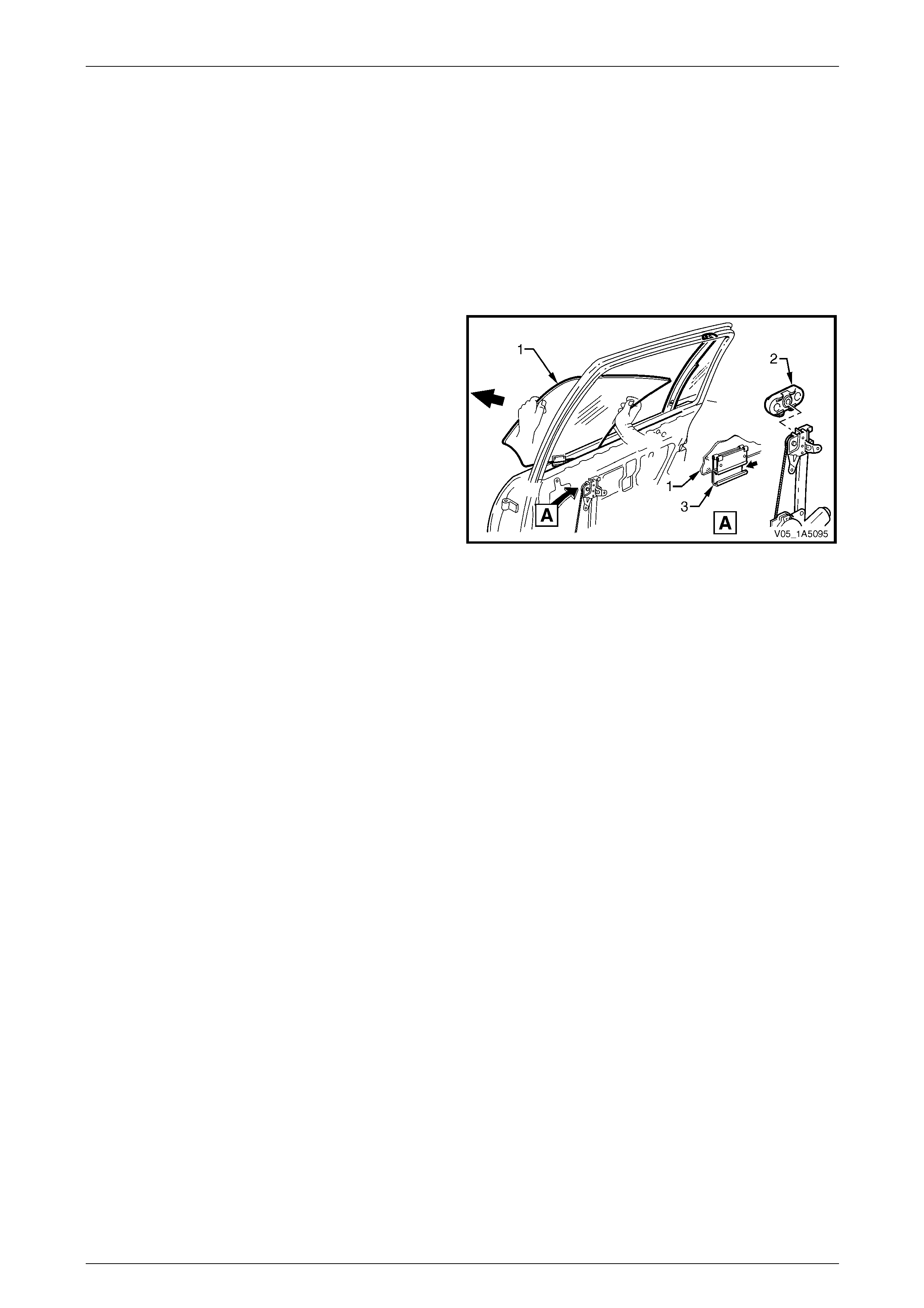
Front and Rear Door Assemblies Page 1A5–105
Page 1A5–105
12.4 Rear Door Window Assembly
LT Section — 11–020
Remove
1 Remove the following components as required:
a Remove the rear door trim panel assembly, refer to 10.1 Rear Door Tr im Panel.
b Remove the rear door window guide channel assembly,
refer to 12.3 Rear Door Window Guide Channel Assembly.
2 Raise the rear door window assembly (1).
3 Slide the rear door window as sembly forward at an
angle of 45° while disengaging the rear door window
regulator slider (2) out of the rear door window guide
channel (3) and remove.
Figure 1A5 – 161
Reinstall
Reinstallation of the rear door window assembly is the reverse of the removal procedure , noting the following:
1 Insert the rear door window assembly down through the rear door belt opening taking care not to damage the glass
panel.
NOTE
Do not torque any component attaching screw
prior to adjusting the rear door window and
regulator assemblies.
2 When installing the rear door wind ow assembly, make sure to adjust the rear door window and regulator
assemblies as per the adjusting procedure as described in this section, refer to Adjust.
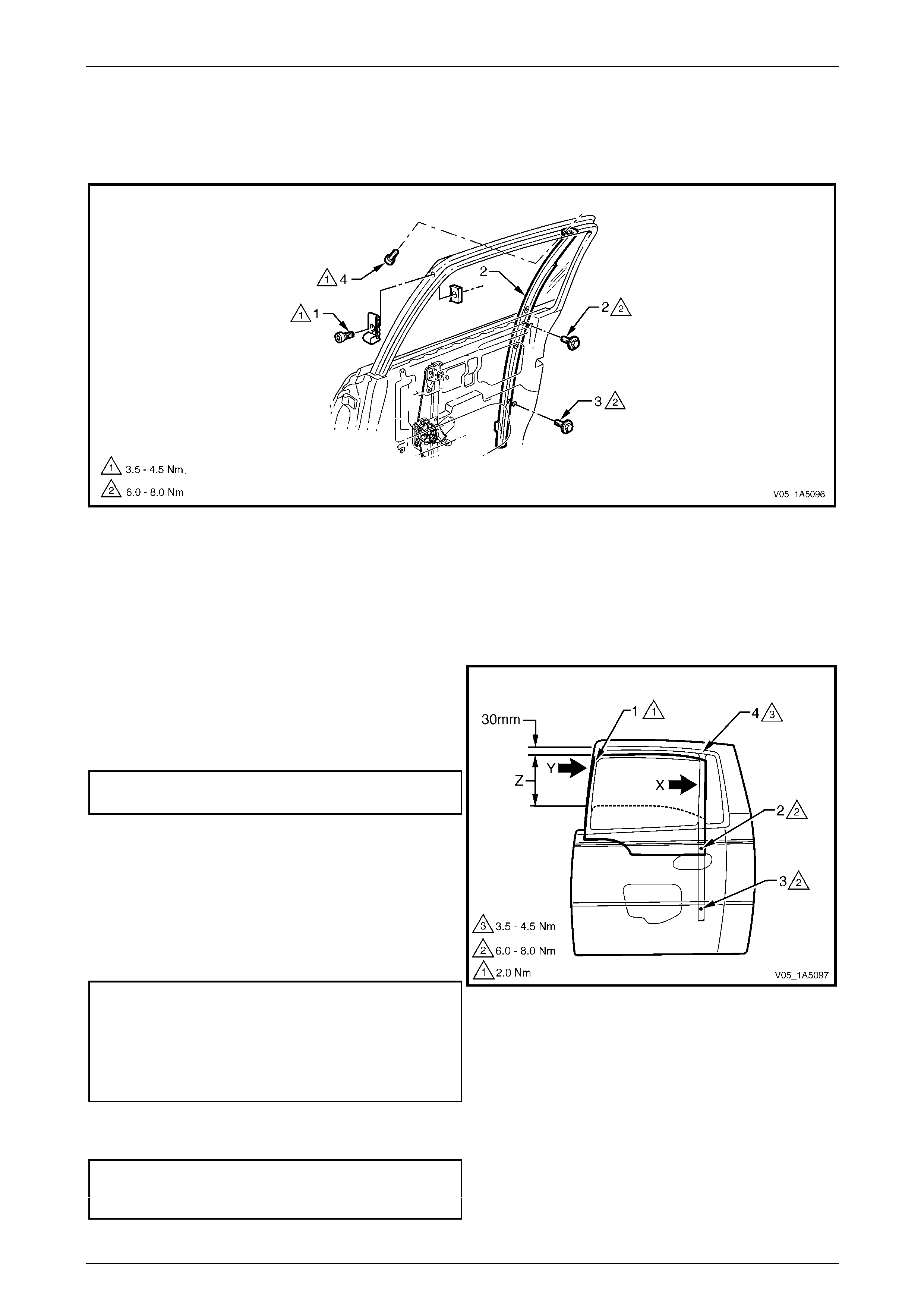
Front and Rear Door Assemblies Page 1A5–106
Page 1A5–106
Adjust
Figure 1A5 – 162 shows the screw / nut locations and torque values for the rear door window assembly adjustment
procedure.
Figure 1A5 – 162
Legend
1 Rear Door Window Up Stop Screw and Nut
2 Rear Door Window Guide Channel Assembly Lower
Attaching Screw
3 Rear Door Window Guide Channel Assembly Lower
Attaching Screw
4 Rear Door Window Guide Channel Assembly Upper
Attaching Screw
1 Adjust the window assembly up stop, point (1) at the
front of the rear door so there is a 1 mm gap below the
highest possible end stop posi t ion.
2 Tighten the window up stop screw, point (1), to the
specified preliminar y torque value.
Rear door window up stop screw
preliminary torque specification............................2.0 Nm
3 Wind the window assembly up through area (Z), until it
is approximately 30 mm before the closed position. At
the same time press the rail, which is bonded to the
front edge of the window assembly, rearward (Y).
4 Push the window guide channel assembly
rearward (X) and tighten the wind ow guide channel
assembly centre attaching screw, point (2) and lo wer
attaching screw, point (3), to the specified torque.
Rear door windo w guide c hannel
assembly centre attaching screw
torque specification.....................................6.0 – 8.0 Nm
Rear door windo w guide c hannel
assembly lower attaching screw
torque specification.....................................6.0 – 8.0 Nm
5 Tighten the window guide channel assembly attaching
screw, point (4), to the specified torque.
Rear door windo w guide c hannel
assembly upper attaching screw
torque specification.....................................3.5 – 4.5 Nm
Figure 1A5 – 163
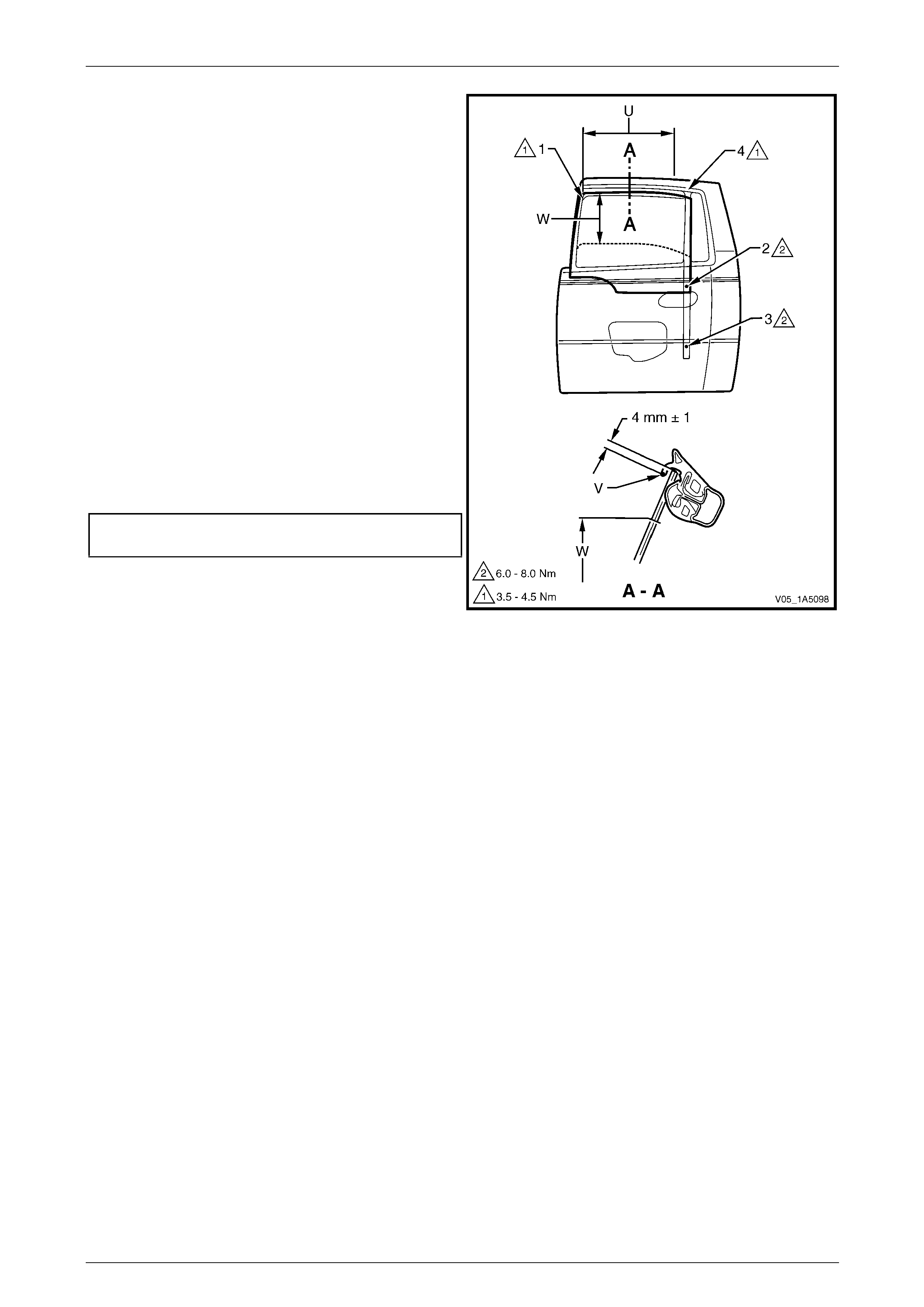
Front and Rear Door Assemblies Page 1A5–107
Page 1A5–107
6 Check the cranking load of the window assembly in
area (W). If the window assembly binds or the motor
load sounds excessive, re-adjust the window
assembly by correcting the windo w guide ch annel
assembly attachment points (2, 3 and 4).
7 Check the window for the following:
a The upper edge of the window must be par allel
to the lip of the door upper frame run channe l at
point (V) and over the area (U).
b The upper edge of the window must be inserted
by 4 mm ±1 mm above the lip of the door upper
frame run channel at point (V) and over the
area (U).
NOTE
If either the deviation in parallelism or the
insertion depth e xceeds 1 mm from specificat ion,
the up stop assembly, point (1), must be
readjusted.
8 Tighten the window up stop screw, point (1), to the
specified final torque value.
Rear door window up stop screw
torque specification.....................................3.5 – 4.5 Nm
Figure 1A5 – 164

Front and Rear Door Assemblies Page 1A5–108
Page 1A5–108
12.5 Rear Door Window Regulator Assembly
LT Section — 11–810
Remove
1 Remove the following components as required:
a Trim panel assembly, refer to 10.1 Rear Door Trim Panel.
b Window assembly, refer to 12.4 Rear Door Window Assembly.
2 If fitted, disconnect the wiring harness connector (1)
from the window regulator assembly (2).
3 Drill out the five rivets (3) securing the window
regulator assembly to the inner panel (4).
NOTE
Use a 5 mm drill bit to drill out the five rivets
securing the window regulator assembly.
4 Remove the window regulator through the aperture (5)
in the inner panel.
Figure 1A5 – 165
Reinstall
Reinstallation of the rear door window regulator assembly is the reverse of the removal procedure, noting the following:
1 If applicable, fit the handle shaft seal (1) to the windo w
regulator spindle (2), before installin g into the rear
door assembly.
NOTE
The window regulator washer (3) and ha ndle (4) are to be
installed after the trim panel assembly.
Figure 1A5 – 166

Front and Rear Door Assemblies Page 1A5–109
Page 1A5–109
2 Ensure that all frictional surfaces of the window regulator assembly and associated parts are adequately lubricated
with Lithium base grease NLGI No. 1 (with 9 % zinc oxide) or equivalent.
3 Align the attaching holes in the window regulator assembly with the corresponding holes in the inner panel an d
secure the window regulator assembly with 5 mm rivets.
NOTE
Washers may be inserted when installing the
rivets as the attaching holes in the inner panel
may have been enlarged when the rivets were
drilled out.
4 Adjust the window and regulator assemblies as per the adjustment procedure,
refer to 12.4 Rear Door Window Assembly.
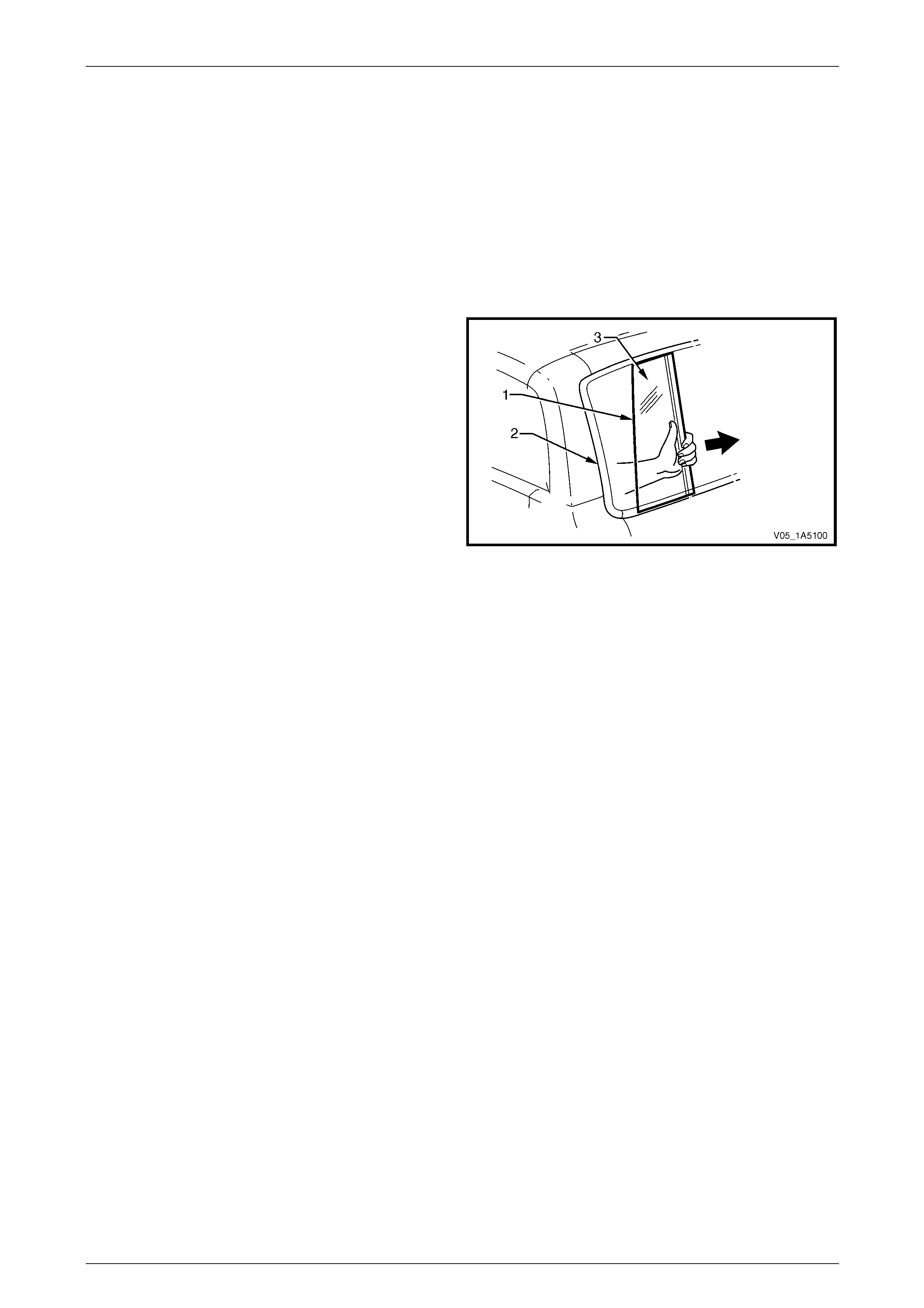
Front and Rear Door Assemblies Page 1A5–110
Page 1A5–110
12.6 Rear Door Stationary Window Assembly
LT Section — 11–020
Remove
1 Remove the following components as required:
a Trim panel assembly, refer to 10.1 Rear Door Trim Panel.
b Window assembly, refer to 12.4 Rear Door Window Assembly.
2 Pry the inner section of the stationar y window rubb er
seal (1) from its position in the door upper frame (2).
3 Slide the stationary window assembly (3) forward and
remove.
Figure 1A5 – 167
Reinstall
Reinstallation of the rear door stationary window assembly is the reverse of the removal procedure, n oti ng the following:
Ensure the rear door stationary window rubber seal is correctly inserted.


Front and Rear Door Assemblies Page 1A5–112
Page 1A5–112
12.8 Rear Door Wiring Harness Assembly
LT Section —
Remove and Reinstall
Ensure the wiring harness assembly is routed and clipped correctly. For the rear door wiring harness assembly
attachment and routing, refer to Section 12O Fuses, Relays and Wiring Harnesses.

Front and Rear Door Assemblies Page 1A5–113
Page 1A5–113
13 Service Operations – Rear Door
Sealing, Se dan and Wagon
13.1 Rear Door Window Inner Filler Assembly
LT Section — 11–775
Remove
1 Gently prise the retainer (1) from the sealing strip of
the window inner filler assembly (2).
2 Remove the window inner filler assembly from the
front of the door assembly.
Figure 1A5 – 168
Reinstall
Reinstallation of the rear door window inner filler assembly is the reverse of the removal procedure.
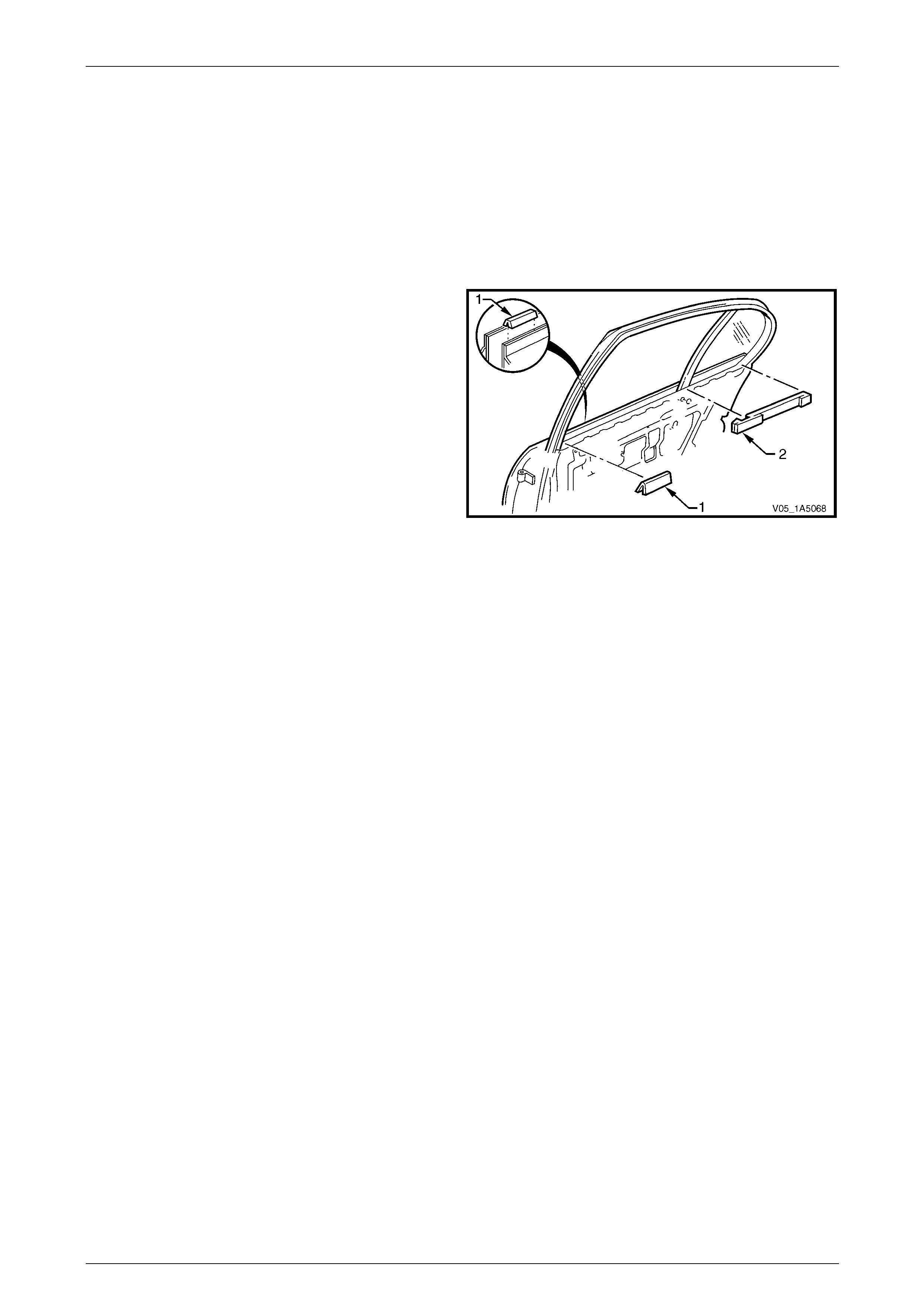
Front and Rear Door Assemblies Page 1A5–114
Page 1A5–114
13.2 Rear Door Inner Panel Beltline Seals
LT Section — 11–775
Remove
1 Lower the window to the down position.
2 Remove the trim panel assembly, refer to 9.1 Rear Door Trim Panel.
3 Remove the inner panel beltline front seal (1) and rear
seal (2) from the door assembly.
Figure 1A5 – 169
Reinstall
Reinstallation of the rear door inner panel beltline seals is the reverse of the removal procedure.
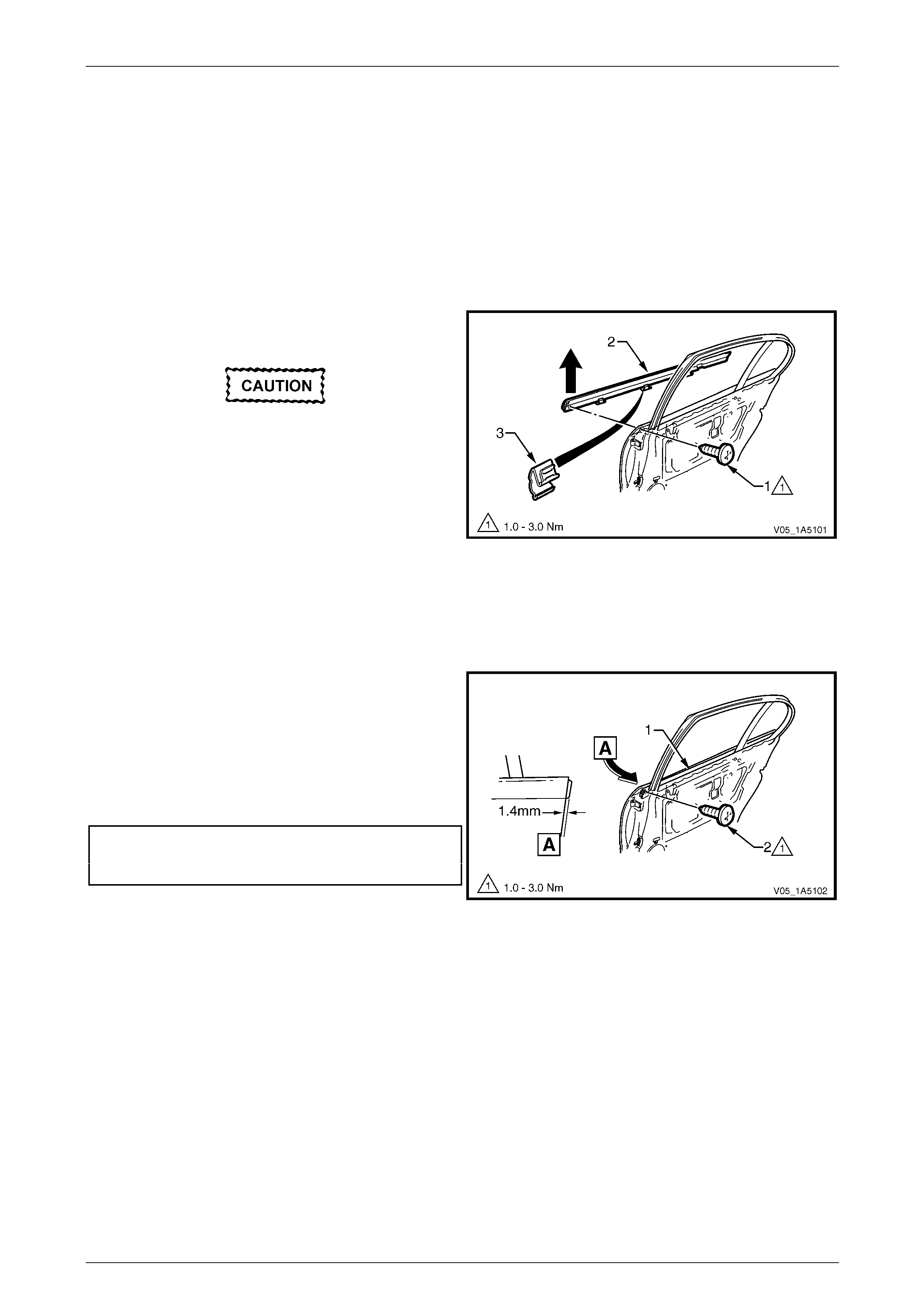
Front and Rear Door Assemblies Page 1A5–115
Page 1A5–115
13.3 Rear Door Window Belt Outer Reveal
Moulding Assembly
LT Section — 11–775
Remove
1 Lower the window assembly.
2 If required, remove the window inner filler assembl y, refer to 13.1 Rear Door Window Inner Filler Assembly.
3 Remove the screw (1) attaching the window belt outer
reveal moulding assembly.
Take care not to damage the moulding or the
plastic retaining clips during this procedure.
4 Starting from the front of the door, prise upward the
window belt outer reveal moulding assembl y (2) until
the retaining clips (3) are freed and rem ove.
Figure 1A5 – 170
Reinstall
Reinstallation of the rear door window belt outer reveal moulding assembly is the rev erse of the removal procedure,
noting the following:
1 Align the front of the window belt outer reveal
moulding assembly (1) at 1.4 mm over the front of the
rear door. Using the palm of the hand, firmly tap the
assembly down onto the door outer pan el upper
flange.
2 Tighten the screw (2) attaching the window belt outer
reveal moulding assembly to the correct torque
specification.
Rear door window belt outer reveal
moulding attaching screw
torque specification.....................................1.0 – 3.0 Nm
Figure 1A5 – 171
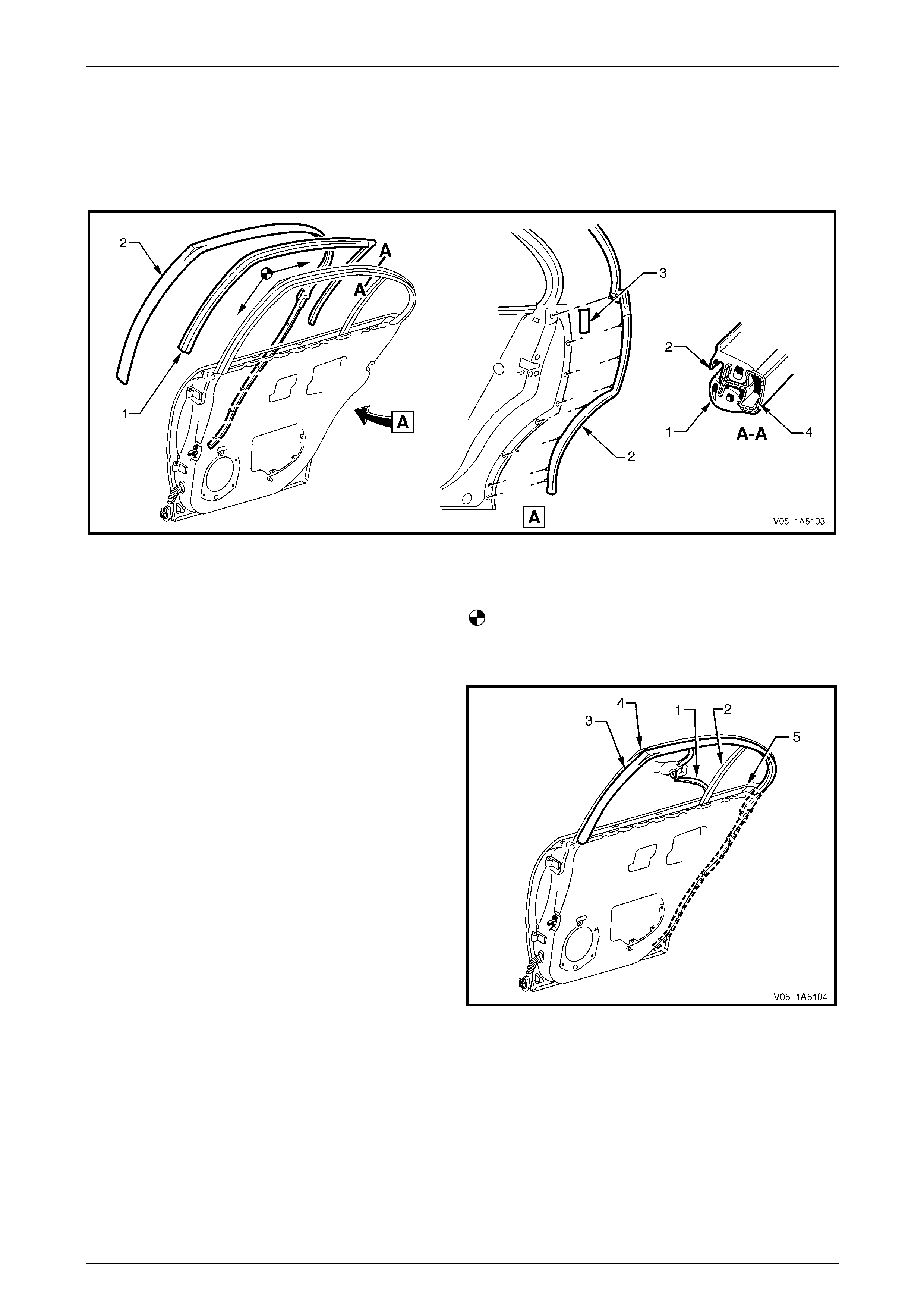
Front and Rear Door Assemblies Page 1A5–116
Page 1A5–116
13.4 Rear Door Weatherstrip Assemblies
LT Section — 11–775
Assemblies Lay-out
Figure 1A5 – 172
Legend
1 Rear Door Window Upper Weatherstrip Assembly
2 Rear Door Upper Weatherstrip Assembly
3 Double-sided Tape
4 Rear Door Upper Frame
Rear Door Upper Weatherstrip Assembly Reinstallation
Remove
1 Lower the window to the down position.
2 Carefully remove the windo w upper weatherstrip
assembly (1) starting from the window guide channel
assembly (2), then pull out of the door upper frame
channel.
3 Pull the upper weatherstrip assembly (3) up and out of
the door upper frame, from the top front corner (4) of
the door.
4 Progressively remove the upper weatherstrip
assembly from the lip on the door upper frame.
5 Carefully remove the upper weatherstrip assembly
from below the belt line (5), allowing the retainer clips
to pull out of the upper weatherstrip assembly and
remain in the door panel.
6 Remove the retainer clips from the door panel with a
clip removal tool and refit them back into the upper
weatherstrip assembly, ready for reinstallation.
Figure 1A5 – 173
Reinstall
Reinstallation of the rear door weatherstrip assemblies is the reverse of the removal procedure, noting the following:
1 If required, reapply double-sided tape (3) to the door panel assembly, refer to Figure 1A5 – 172.
2 Install the upper weatherstrip assembly (2) starting at the top front corner and aligning the locating marks on the
door frame, then proceed in direction of arrows.
3 Ensure the retainer clips secure the upper weatherstrip assembly to the door panel below the belt line.
4 Ensure the window upper weatherstrip assembly is pushed back fully into the door upper frame channel and
window guide channel assembly.
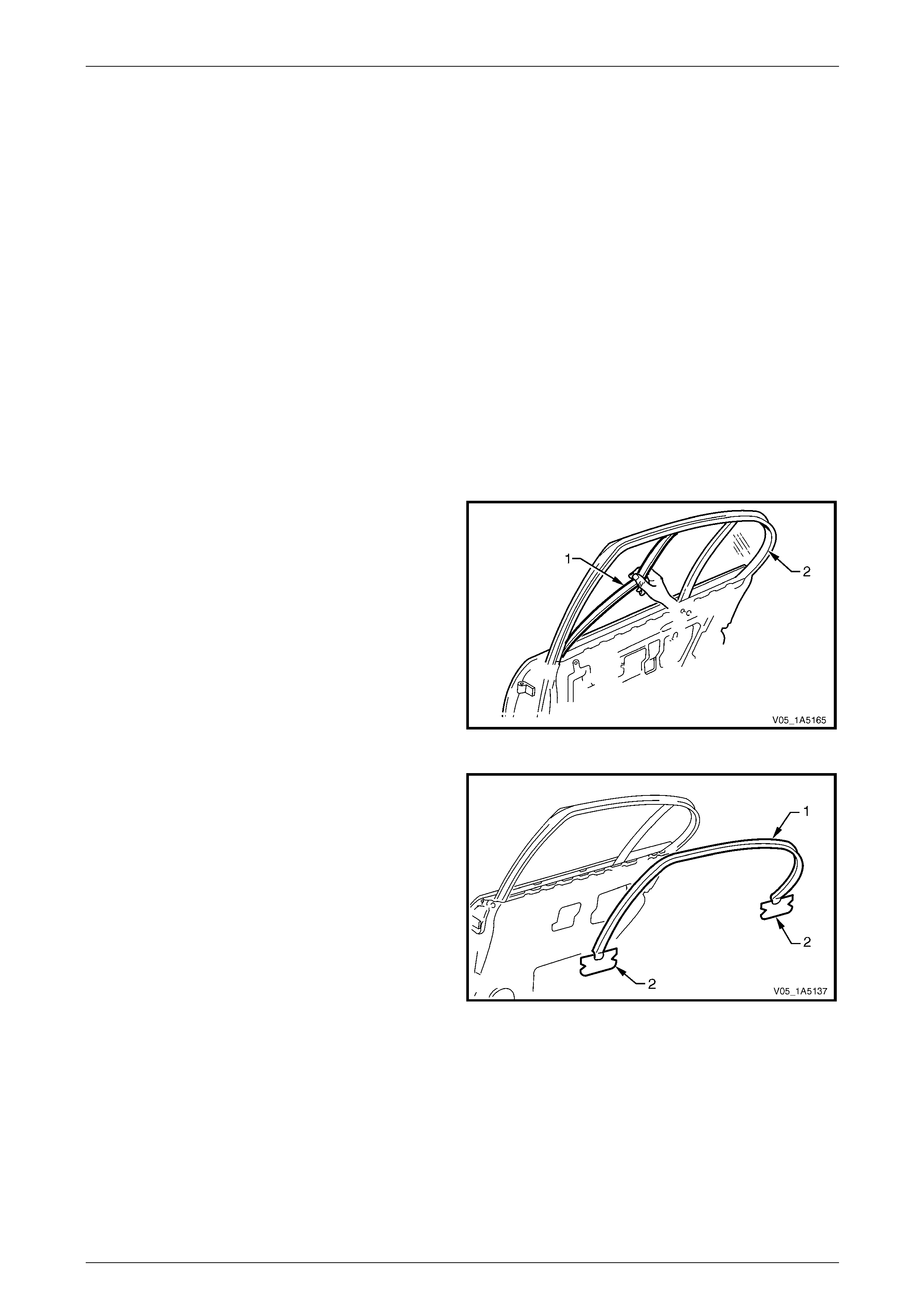
Front and Rear Door Assemblies Page 1A5–117
Page 1A5–117
13.5 Rear Door Window Upper Garnish
Moulding
LT Section — 11–775
Remove
NOTE
The rear door window upper garnish moulding
may be damaged during this operation and
require replacement.
1 Lower the window to the down position.
2 Remove the following components as required:
a Trim panel assembly, refer to 9.1 Rear Door Trim Panel.
b Window inner filler assembly, refer to 13.1 Rear Door Window Inner Filler Assembly.
c Upper weatherstrip assembly from the lip on the door upper frame,
refer to 13.4 Rear Door Weatherstrip Assemblies.
3 Partially remove the window upper weatherstrip
assembly (1) from the door upper frame channel (2)
only.
Figure 1A5 – 174
4 With the aid of a knife, progressively peel the window
upper garnish moulding (1) from around the door
upper frame, separating the adhes ive from the frame.
5 If required, peel off the two self-adhesive seal s (2)
from the door inner panel.
6 As required, clean the surface of the door upper frame
with Prepsol or equivalent.
Figure 1A5 – 175
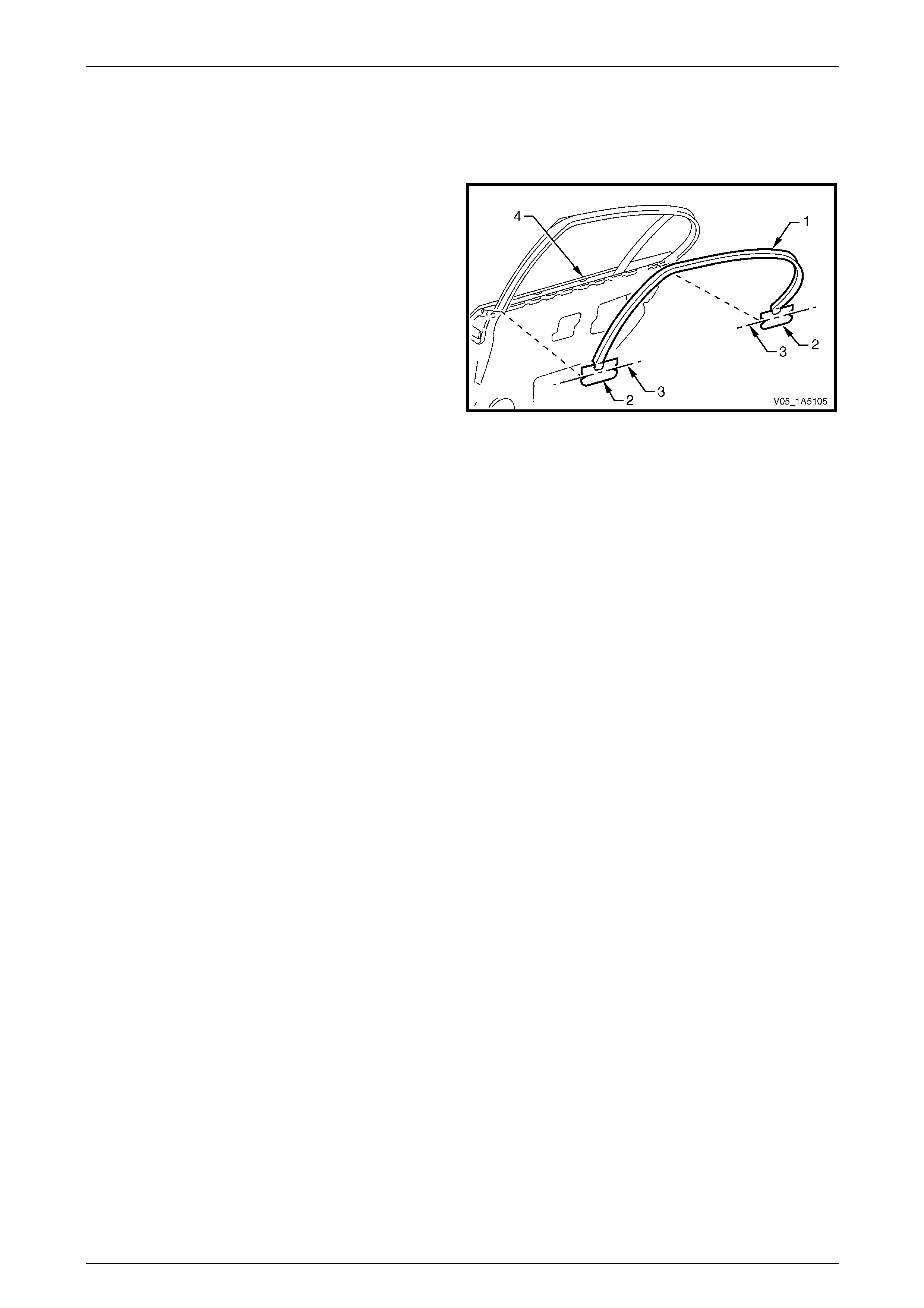
Front and Rear Door Assemblies Page 1A5–118
Page 1A5–118
Reinstall
Reinstallation of the rear door window upper garnish moulding is the reverse of the removal procedure, noting the
following:
1 Ensure the door upper frame is clean prior to
positioning the window upper garnish moulding (1).
2 If required, install the two self-adhesive seals (2) and
align the centre line of notches (3) with the top of the
door skin (4).
3 Install the self-adhesive wind ow upper garnish
moulding to the door upper frame.
Figure 1A5 – 176
4 Ensure the window upper garnish moulding is correctly inserted in the stationary window rubber seal.
5 Ensure the window upper weatherstrip assembl y is pus hed back fully into the door upper frame chan nel.
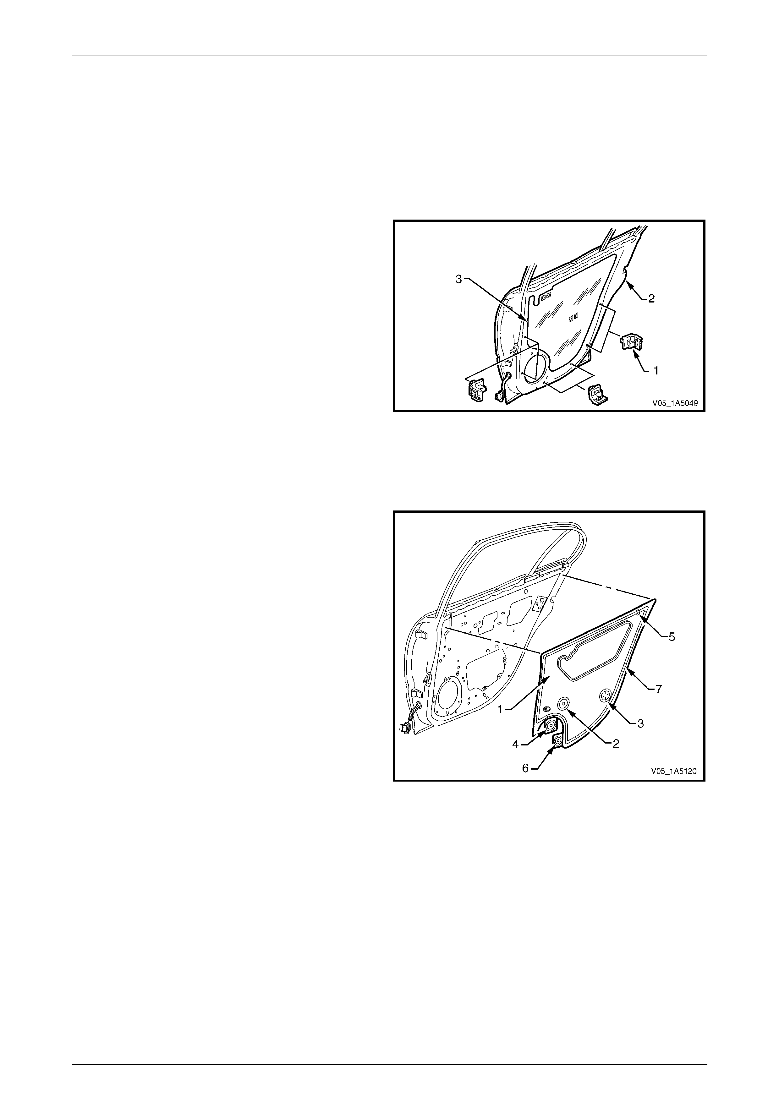
Front and Rear Door Assemblies Page 1A5–119
Page 1A5–119
13.6 Rear Door Water Shield
LT Section — 14–270
Remove
1 Remove the trim panel assembly, refer to 9.1 Rear Door Trim Panel.
2 Remove the trim panel bracket (1), six places , from
the inner panel (2) by levering out the centre pin of
each bracket.
3 Carefully peel off the water shield (3) from the door
inner panel.
Figure 1A5 – 177
Reinstall
Reinstallation of the rear door water shield is the reverse of the removal procedure, noti ng the following:
1 If installing a new water shield (1), proceed as follows
a Apply foamed hot melt adh esive around entire
periphery of either the shield hole (2) for the
window regulator handle or courtesy lamp
perforation (3) as applicable, then remove the
tab (4) and adhere over the hole or perforation.
b Apply foamed hot melt adh esive around entire
periphery of the jig hole (5), then remove the
tab (6) and adhere over the jig hole.
c Apply foamed hot melt adhesive around the
entire periphery (7) of the water shield, then fit to
the door inner panel.
2 If reusing the same water shield, apply hot melt
adhesive as required and fit to the door inner panel.
Figure 1A5 – 178
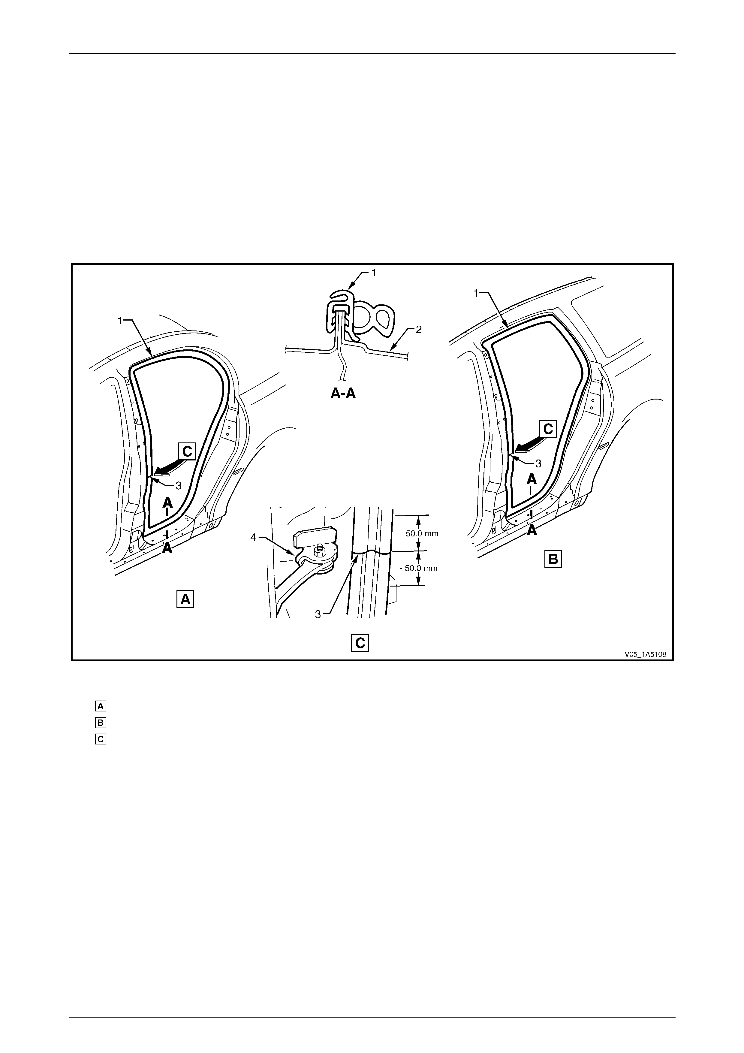
Front and Rear Door Assemblies Page 1A5–120
Page 1A5–120
13.7 Rear Door Opening Weatherstrip
Assembly
LT Section — 11–600
Remove
1 As required, remove the side sill trim and pla t e, centre pillar lower and upper trim, body lock pillar garnish, body
lock pillar lower trim (wagon only) and front floor carpet retainin g clips,
refer to Section 1A8 Headlining and Interior Trim.
2 Gently prise the weatherstrip assembly (1) from the rear door opening frame (2), refer to Figure 1A5 – 179.
Figure 1A5 – 179
Legend
View Rear Door Opening, Sedan
View Rear Door Opening, Wagon
View Weatherstrip Alignment
1 Rear Door Opening Weatherstrip
Assembly
2 Rear Door Opening Frame Assembly
3 Rear Door Opening Weatherstrip
Identification Mark
4 Rear Door Check Assembly
Reinstall
Reinstallation of the rear door opening weatherstrip assembly is the reverse of the removal procedure, noting the
following:
1 Align the identification mark ( 3) on t he weatherstrip assembl y, with the do or check asse mbly (4) in the door opening
frame (2) within ±50 mm, refer to Figure 1A5 – 179.
2 Ensure the weatherstrip assembly (1) does not short cut corners and foul the door trim.
NOTE
Allow crowding of the weatherstrip assembly in all
corners of the door frame opening (2).
3 Ensure the lip of the weatherstrip assembly sits over the trim panels.
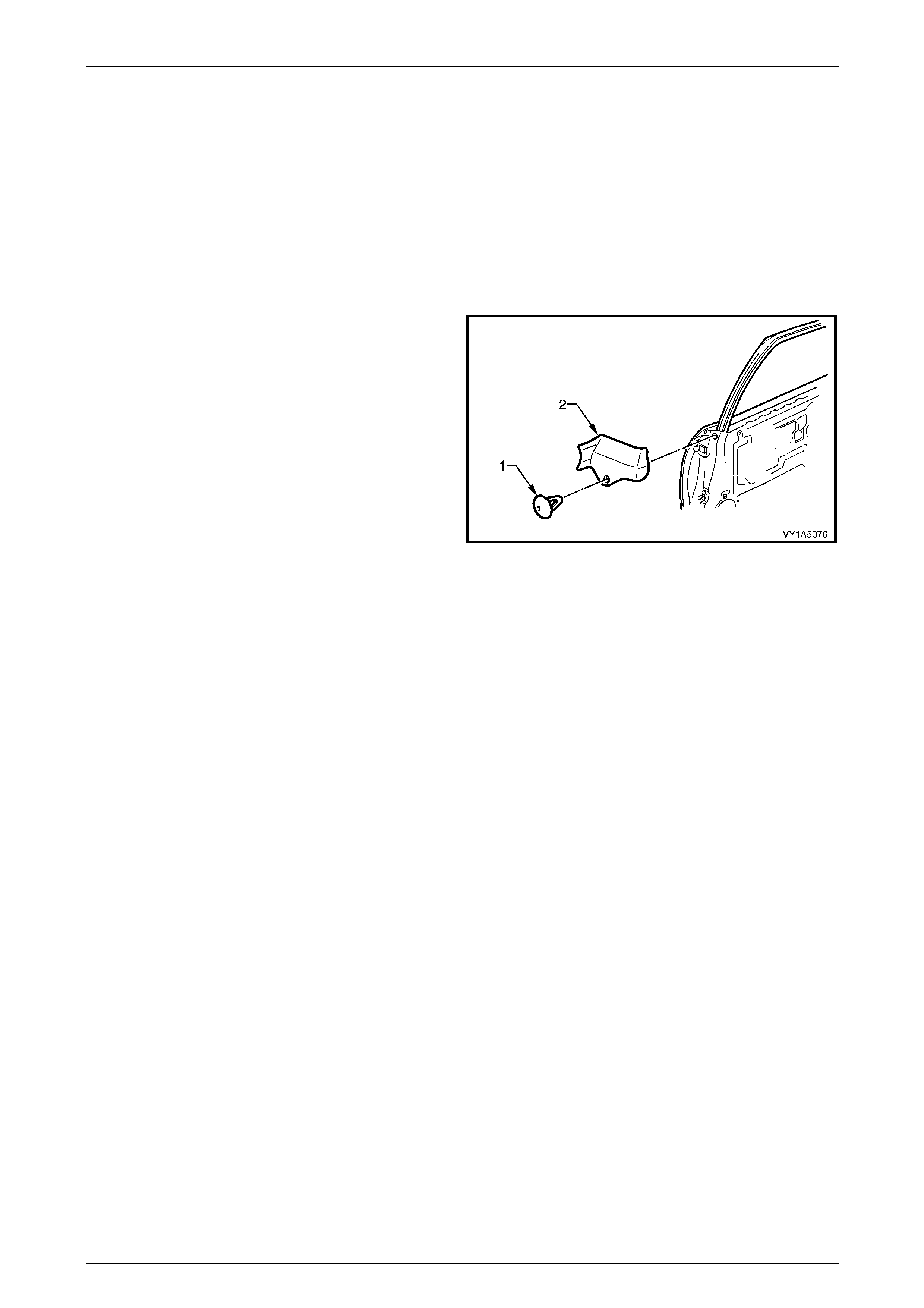
Front and Rear Door Assemblies Page 1A5–121
Page 1A5–121
14 Service Operations – Rear Door
Sealing, Crew Cab
14.1 Rear Door Window Inner Filler Assembly
LT Section — 11–775
Remove
1 Gently prise the retainer (1) from the sealing strip of
the window inner filler assembly (2).
2 Remove the window inner filler assembly from the
front of the door assembly.
Figure 1A5 – 180
Reinstall
Reinstallation of the rear door window inner filler assembly is the reverse of the removal procedure.
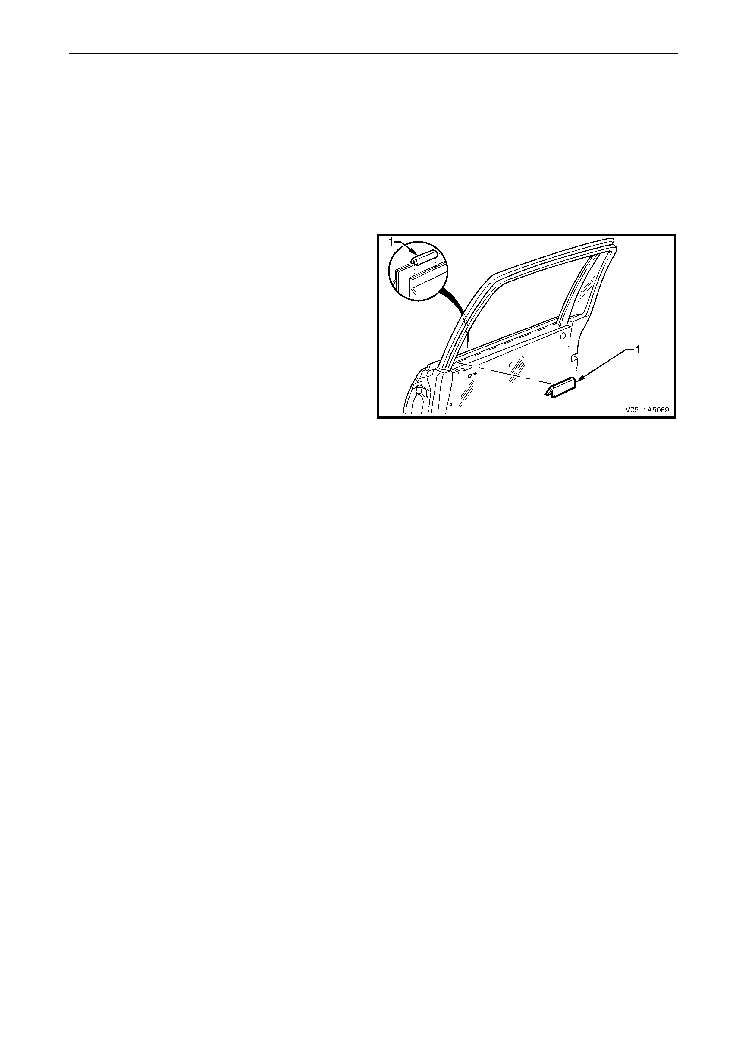
Front and Rear Door Assemblies Page 1A5–122
Page 1A5–122
14.2 Rear Door Inner Panel Beltline Seal
LT Section — 11–775
Remove
1 Lower the window to the down position.
2 Remove the trim panel assembly, refer to 10.1 Rear Door Trim Pane l.
3 Remove the inner panel beltline seal (1) from the door
assembly.
Figure 1A5 – 181
Reinstall
Reinstallation of the rear door inner panel beltline seal is the reverse of the removal procedure.
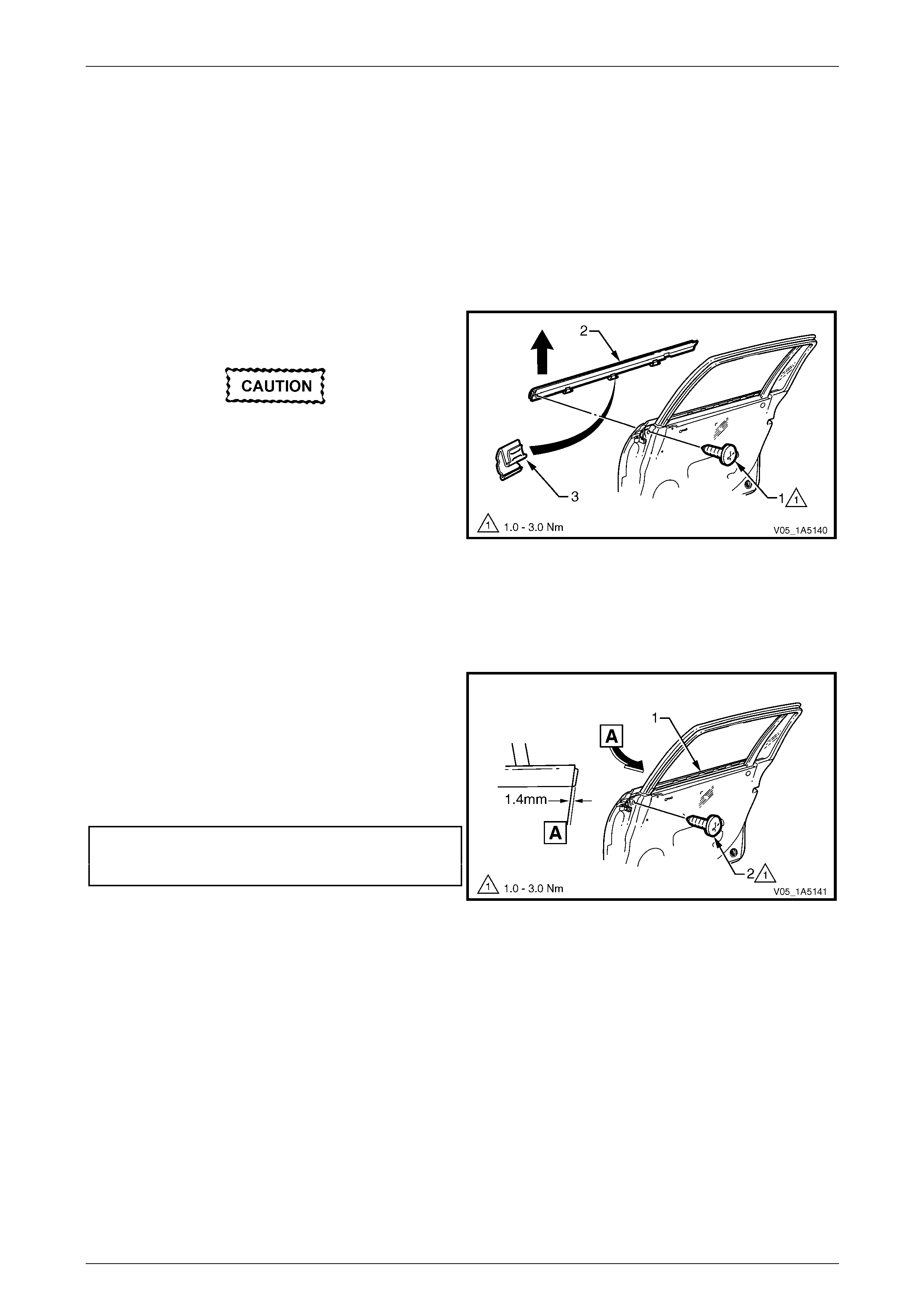
Front and Rear Door Assemblies Page 1A5–123
Page 1A5–123
14.3 Rear Door Window Belt Outer Reveal
Moulding Assembly
LT Section — 11–775
Remove
1 Lower the window assembly.
2 If required, remove the window inner filler assembl y, refer to 14.1 Rear Door Window Inner Filler Assembly.
3 Remove the screw (1) attaching the window belt outer
reveal moulding assembly.
Take care not to damage the moulding or the
plastic retaining clips during this procedure.
4 Starting from the front of the door, prise upward the
window belt outer reveal moulding assembl y (2) until
the retaining clips (3) are freed and rem ove.
Figure 1A5 – 182
Reinstall
Reinstallation of the rear door window belt outer reveal moulding assembly is the rev erse of the removal procedure,
noting the following:
1 Align the front of the window belt outer reveal
moulding assembly (1) at 1.4 mm over the front of the
rear door. Using the palm of the hand, firmly tap the
assembly down onto the door outer pan el upper
flange.
2 Tighten the screw (2) attaching the window belt outer
reveal moulding assembly to the correct torque
specification.
Rear door window belt outer reveal
moulding attaching screw
torque specification.....................................1.0 – 3.0 Nm
Figure 1A5 – 183
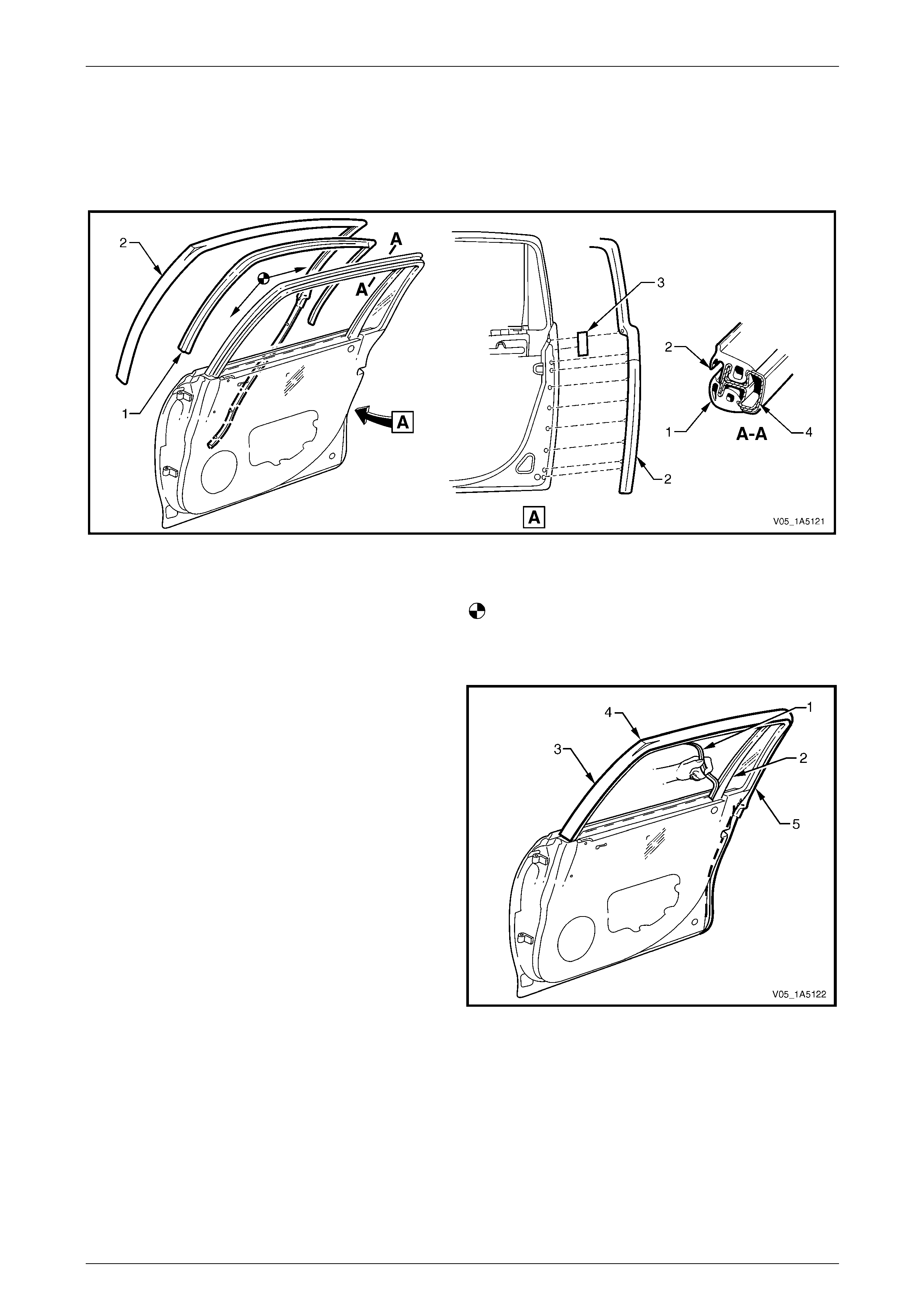
Front and Rear Door Assemblies Page 1A5–124
Page 1A5–124
14.4 Rear Door Weatherstrip Assemblies
LT Section — 11–775
Assemblies Lay-out
Figure 1A5 – 184
Legend
1 Rear Door Window Upper Weatherstrip Assembly
2 Rear Door Upper Weatherstrip Assembly
3 Double-sided Tape
4 Rear Door Upper Frame
Rear Door Upper Weatherstrip Assembly Reinstallation
Remove
1 Lower the window to the down position.
2 Carefully remove the windo w upper weatherstrip
assembly (1) starting from the window guide channel
assembly (2), then pull out of the door upper frame
channel.
3 Pull the upper weatherstrip assembly (3) up and out of
the door upper frame, from the top front corner (4) of
the door.
4 Progressively remove the upper weatherstrip
assembly from the lip on the door upper frame.
5 Carefully remove the upper weatherstrip assembly
from below the belt line (5), allowing the retainer clips
to pull out of the upper weatherstrip assembly and
remain in the door panel.
6 Remove the retainer clips from the door panel with a
clip removal tool and refit them back into the upper
weatherstrip assembly, ready for reinstallation.
Figure 1A5 – 185
Reinstall
Reinstallation of the rear door weatherstrip assemblies is the reverse of the removal procedure, noting the following:
1 If required, reapply double-sided tape (3) to the door panel assembly, refer to Figure 1A5 – 184.
2 Install the upper weatherstrip assembly (2) starting at the top front corner and aligning the locating marks on the
door frame, then proceed in direction of arrows.
3 Ensure the retainer clips secure the upper weatherstrip assembly to the door panel below the belt line.
4 Ensure the window upper weatherstrip assembly is pushed back fully into the door upper frame channel and
window guide channel assembly.
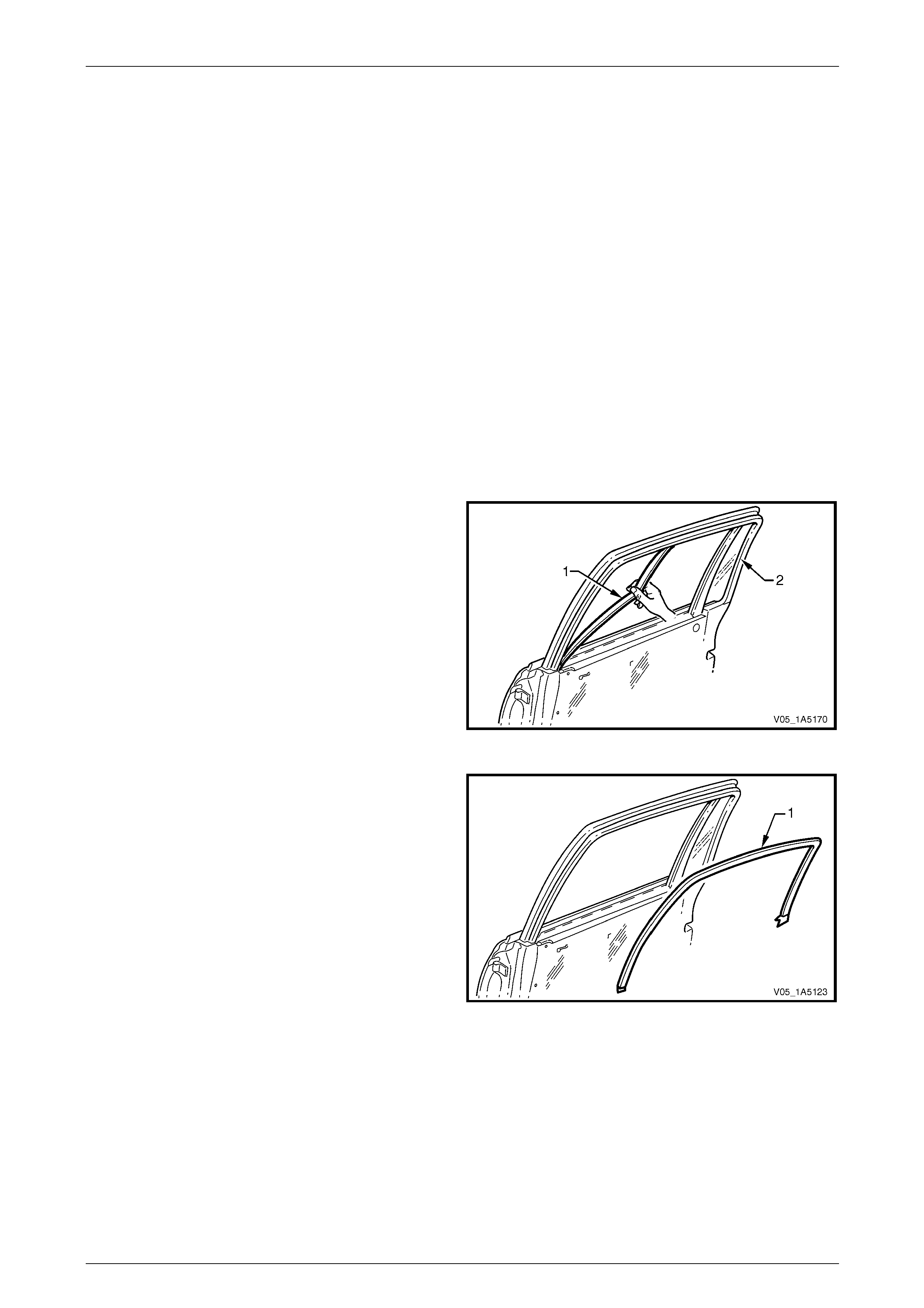
Front and Rear Door Assemblies Page 1A5–125
Page 1A5–125
14.5 Rear Door Window Upper Garnish
Moulding
LT Section — 11–775
Remove
NOTE
The rear door window upper garnish moulding
may be damaged during this operation and
require replacement.
1 Lower the window to the down position.
2 Remove the following components as required:
a Trim panel assembly, refer to 10.1 Rear Door Trim Panel.
b Window inner filler assembly, refer to 14.1 Rear Door Window Inner Filler Assembly.
c Upper weatherstrip assembly from the lip on the rear door upper frame,
refer to 14.4 Rear Door Weatherstrip Assemblies.
3 Partially remove the window upper weatherstrip
assembly (1) from the door upper frame channel (2)
only.
Figure 1A5 – 186
4 With the aid of a knife, progressively peel the window
upper garnish moulding (1) from around the door
upper frame, separating the adhes ive from the frame.
5 As required, clean the surface of the door upper frame
with Prepsol or equivalent.
Figure 1A5 – 187
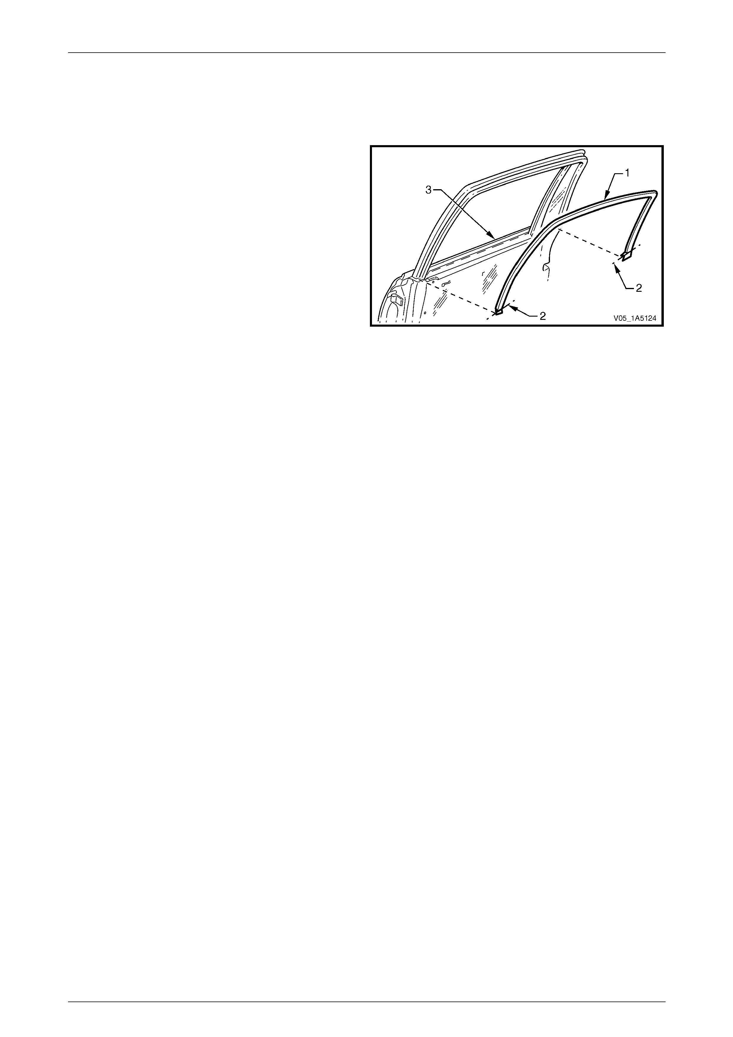
Front and Rear Door Assemblies Page 1A5–126
Page 1A5–126
Reinstall
Reinstallation of the rear door window upper garnish moulding is the reverse of the removal procedure, noting the
following:
1 Ensure the door upper frame is clean prior to
positioning the window upper garnish moulding (1).
2 Install the self-adhesive wind ow upper garnish
moulding to the door upper frame. Align the centre
lines (2) with the top of the door skin (3).
Figure 1A5 – 188
3 Ensure the window upper garnish moulding is correctly inserted in the stationary window rubber seal.
4 Ensure the window upper weatherstrip assembl y is pus hed back fully into the door upper frame chan nel.
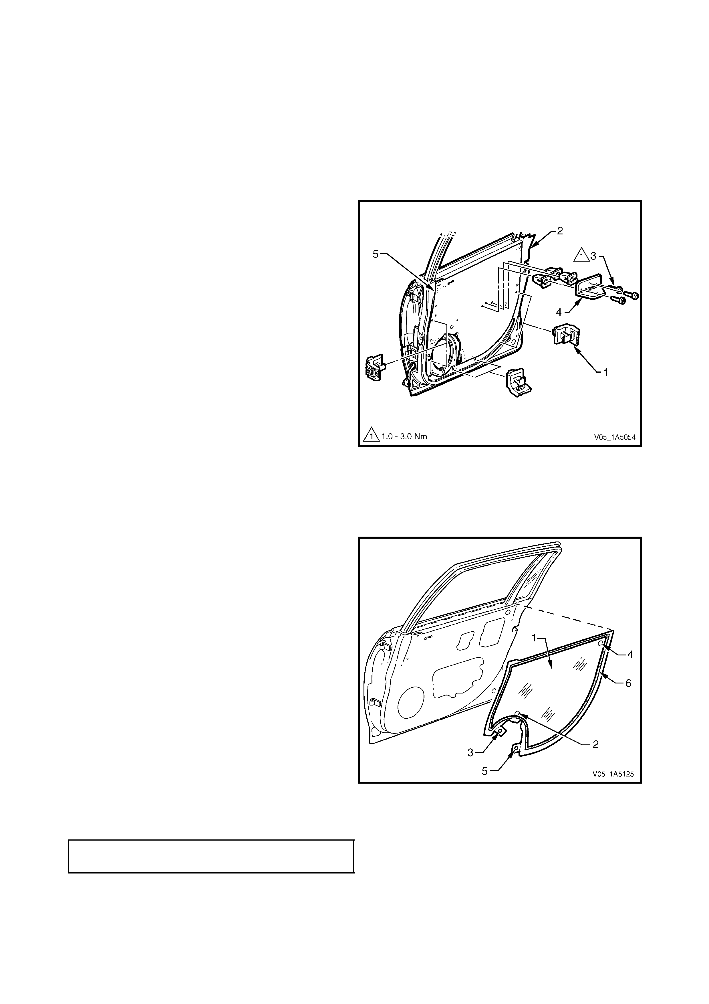
Front and Rear Door Assemblies Page 1A5–127
Page 1A5–127
14.6 Rear Door Water Shield
LT Section — 14–270
Remove
1 Remove the Trim panel assembly, refer to 10.1 Rear Door Trim Panel.
2 Remove the trim panel bracket (1), six places , from
the inner panel (2) by levering out the centre pin of
each bracket.
3 Remove the three screws (3) attaching the pull cup
bracket (4) to the door inner panel and remove the pull
cup bracket.
4 Carefully peel off the water shield (3) from the door
inner panel.
Figure 1A5 – 189
Reinstall
Reinstallation of the rear door water shield is the reverse of the removal procedure, noti ng the following:
1 If installing a new water shield (1), proceed as follows:
a As applicable, apply foamed hot melt adh esive
around entire periphery of the shield hole (2) for
the window regulator handle perforation, then
remove the tab (3) and adhere over the h ole .
b Apply foamed hot melt adh esive around entire
periphery of the jig hole (4), then remove the
tab (5) and adhere over the jig hole.
c Apply foamed hot melt adhesive around the
entire periphery (6) of the water shield, then fit to
the door inner panel.
2 If reusing the same water shield, apply hot melt
adhesive as required and fit to the door inner panel.
Figure 1A5 – 190
3 Tighten the three screws attaching the pull cup bracket to the correct torque spec ification.
Rear door pull cup bracket
attaching screws torque specification .........1.0 – 3.0 Nm
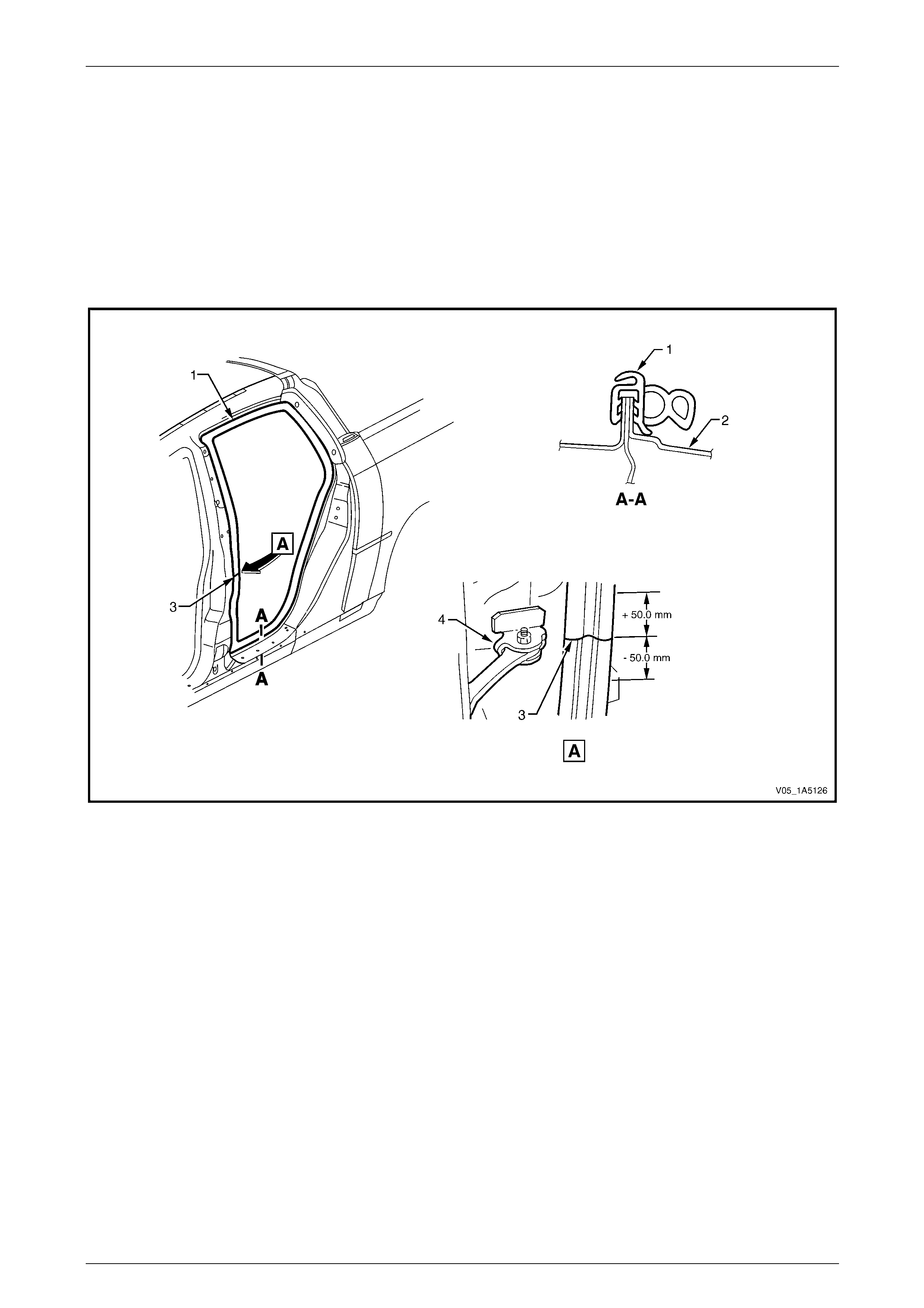
Front and Rear Door Assemblies Page 1A5–128
Page 1A5–128
14.7 Rear Door Opening Weatherstrip
Assembly
LT Section — 11–600
Remove
1 As required, remove the side sill trim and pla t e, centre pillar lower and upper trim, body lock pillar garnish, body
lock pillar upper trim and front floor carpet retaining clips, refer to Section 1A8 Headlining and Interior T r im.
2 Gently prise the weatherstrip assembly (1) from the rear door opening frame (2), refer to Figure 1A5 – 191.
Figure 1A5 – 191
Legend
1 Rear Door Opening Weatherstrip Assembly
2 Rear Door Opening Frame Assembly 3 Rear Door Opening Weatherstrip Identification Mark
4 Rear Door Check Assembly
Reinstall
Reinstallation of the rear door opening weatherstrip assembly is the reverse of the removal procedure, noting the
following:
1 Align the identification mark ( 3) on t he weatherstrip assembl y, with the do or check asse mbly (4) in the door opening
frame (2) within ±50 mm, refer to Figure 1A5 – 191.
2 Ensure the weatherstrip assembly (1) does not short cut corners and foul the door trim.
NOTE
Allow crowding of the weatherstrip assembly in all
corners of the door frame opening (2).
3 Ensure the lip of the weatherstrip assembly sits over the trim panels.
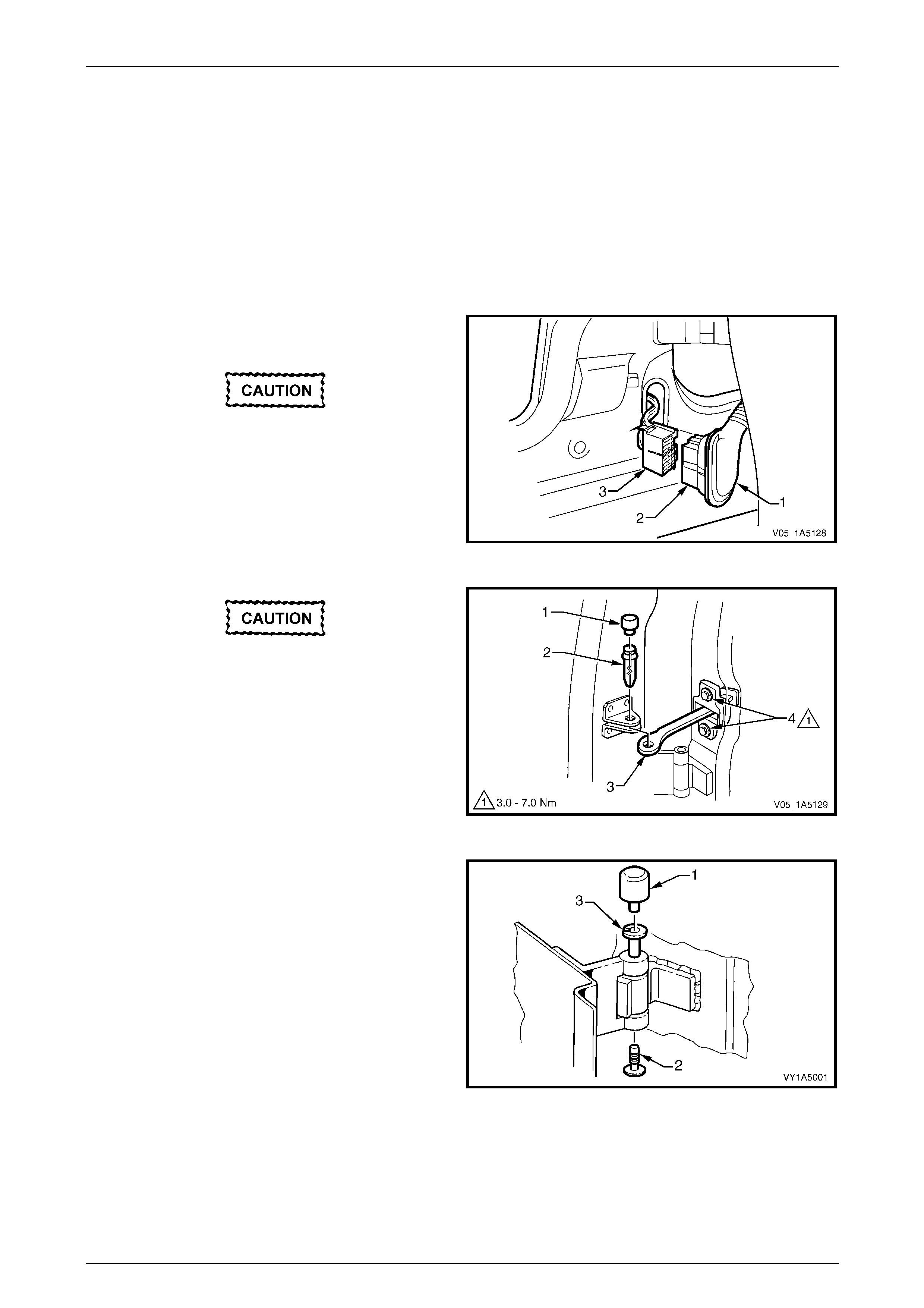
Front and Rear Door Assemblies Page 1A5–129
Page 1A5–129
15 Service Operations – Rear Door
Assembly, Except Crew Cab
15.1 Rear Door Assembly
LT Section — 11–730
Remove
1 Remove the grommet (1) from the rear door wiring
harness connector (2).
Take care not to pull the wiring out of the
connectors during the following operation.
2 Depress the tabs and disconnect the rear door wiring
harness connector from the body wiring harness
connector (3).
Figure 1A5 – 192
Ensure the door cannot swing freely as it
may cause damage during the following
operation.
3 Remove the check link cover (1) and pin (2), then
disconnect the check assembly (3).
4 If required, remove the two screws (4) attaching the
check assembly to the door and remove the check
assembly.
Figure 1A5 – 193
5 Remove the hinge pin cap (1) and plug (2) from the
hinge pin (3) on the upper and lower door hinges.
6 Have an assistant support the door or alternatively,
support the base of the door on a wooden block and a
trolley jack.
Figure 1A5 – 194
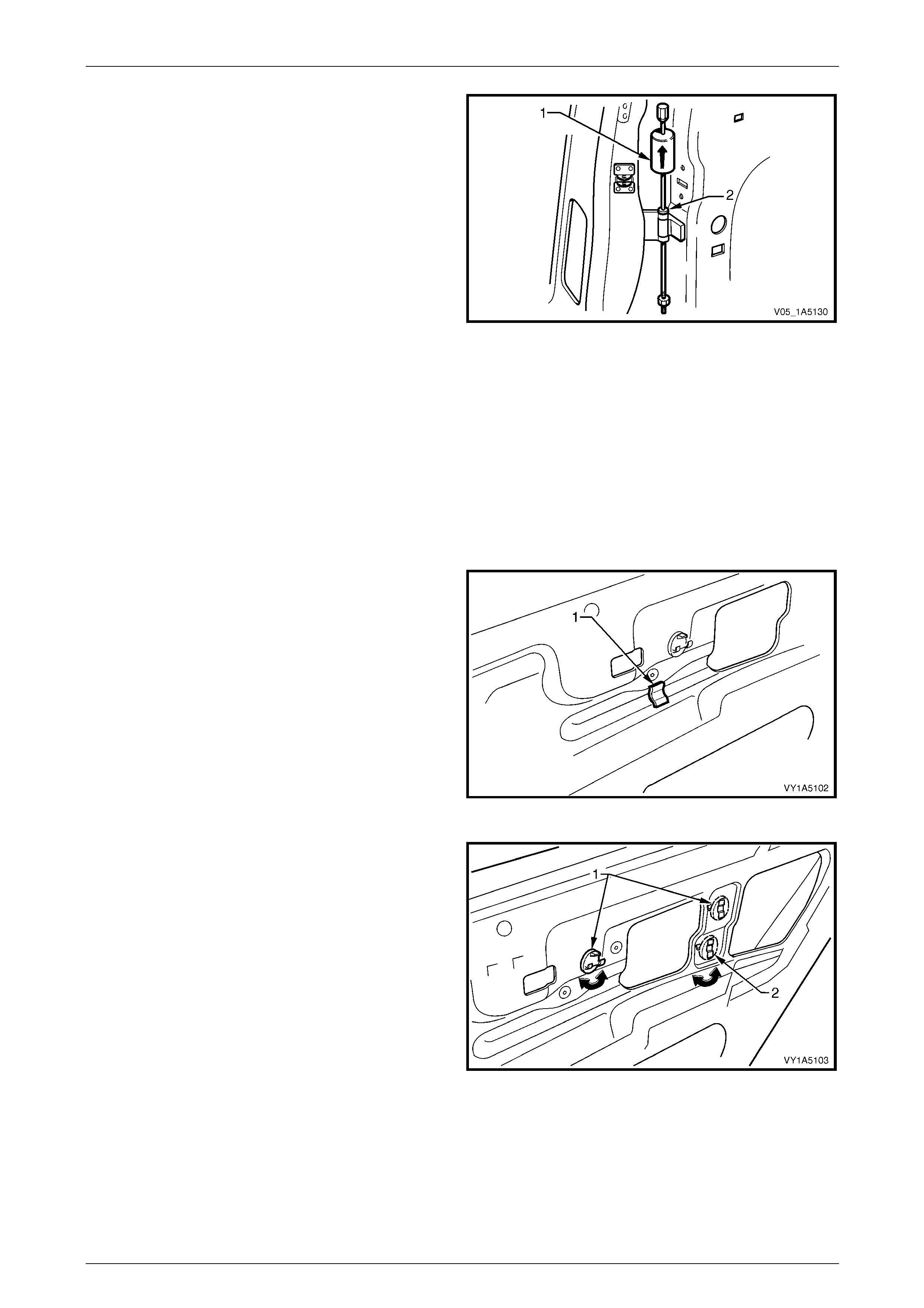
Front and Rear Door Assemblies Page 1A5–130
Page 1A5–130
7 Using the Tool No. AU170 (1), drive the hinge pin (2)
out of the lower and then upper hinges.
8 Remove the door assembly.
Figure 1A5 – 195
Disassemble
1 Remove the following components as required:
a Trim panel assembly, refer to 9.1 Rear Door Trim Panel.
b Internal components, as required,
refer to 11 Service Operations – Rear Door Internal Components, Sedan and Wagon.
c Sealing components, as required, refer to 13 Service Operations – Rear Door Seali ng, Sedan and Wagon.
d Body side moulding, as applicable, refer to Section 1A9 Exterior Ornamentation.
2 Prise the deadener (1) from the door inner p anel.
Figure 1A5 – 196
3 Rotate the two remote control rod clips (1) by 90° then
remove from the door inner panel.
4 Rotate the locking bell crank rod clip (2) by 90° then
remove from the door inner panel.
Figure 1A5 – 197
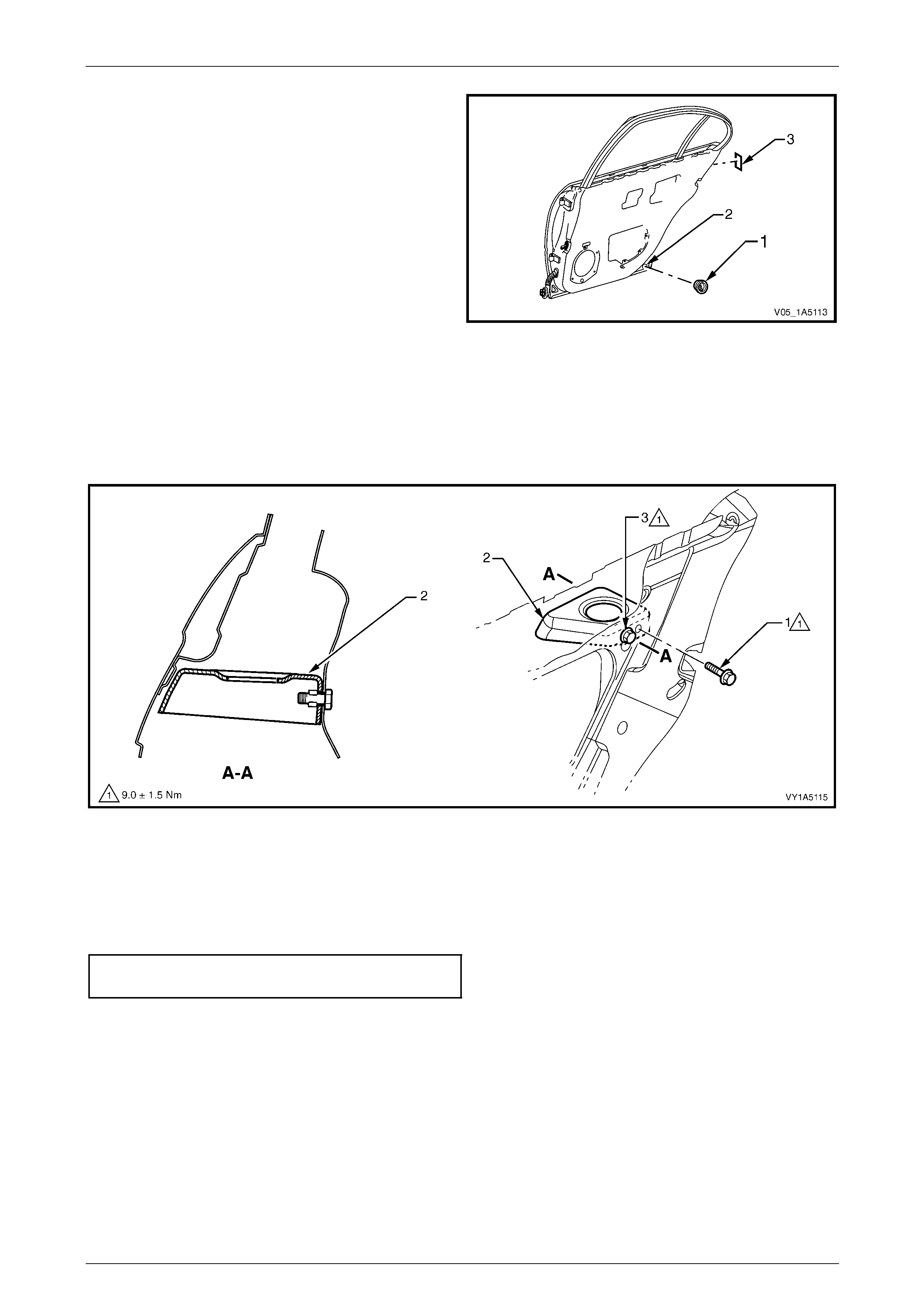
Front and Rear Door Assemblies Page 1A5–131
Page 1A5–131
5 Remove the plug (1) from the door inner panel drain
hole (2).
6 If required, remove the double sided tape (3) from the
door inner panel.
Figure 1A5 – 198
7 Remove the screw (1) attaching the door inner panel reinfor cement (2) to the door assembly, refer to
Figure 1A5 – 199.
8 Loosen the scre w (3) and slide the reinforc ement down withdrawing the screw from the key-hole slot into the door
cavity.
9 Remove the door inner panel reinforcement from the door cavity.
Figure 1A5 – 199
Reassemble
Reassembly of the rear door is the reverse of the disassembly procedure, notin g the following:
1 Tighten the screws attaching the do or inner panel reinforcement to the correct torque specification.
Rear door inner panel reinforcement
attaching screws torque specification .......7.5 – 10.5 Nm
2 If reusing the same deadener (1), apply a small amount of contact ad hesive before fitting to the door inner panel,
refer to Figure 1A5 – 196.
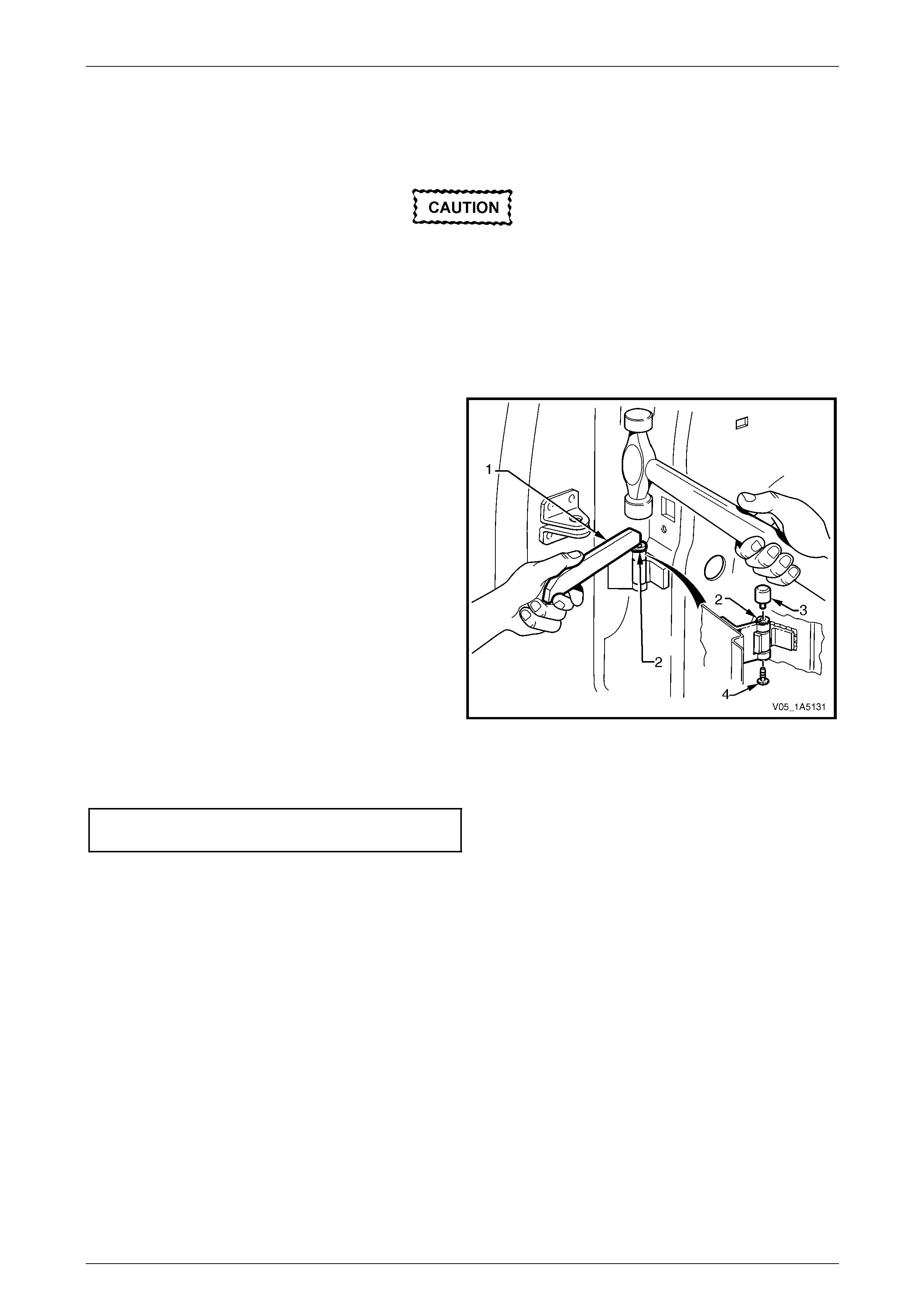
Front and Rear Door Assemblies Page 1A5–132
Page 1A5–132
Reinstall
Reinstallation of the rear door assembly is the reverse of the removal procedure, noting the following:
If using a new rear door panel assembly it
must be prepared to maintain original
manufacturers specifications. This includes
the application of joint sealer, hand putty and
cavity wax. Refer to the Service Manual
Supplement, Body Structure Repair Manual
for specifications.
1 Apply Lithium base grease NLGI No. 1 (with 9 % zinc oxide) or equivalent, to the hinge pin prior to reinstallation.
2 Using Tool No AU303 (1) an d a hammer, install the
hinge pin (2) with the slot facing for ward and the head
of the pin facing up for the lower hinge and down for
the upper hinge.
NOTE
A 15° deviation is permissable for the positioning
of the hinge pin slot on reinstallation.
3 Check the fit of the door assembly and adjust as
required, refer to 15.2 Adjust Rear Door Ass embly.
NOTE
Make allowances in the adjustment of the door
assembly if the trim and hardware are not
installed.
Figure 1A5 – 200
4 Tighten the two screws (4) attaching the che ck assembly (3) to the correct torque specification, refer to
Figure 1A5 – 193.
Rear door check assembly
attaching screws torque specification .........3.0 – 7.0 Nm
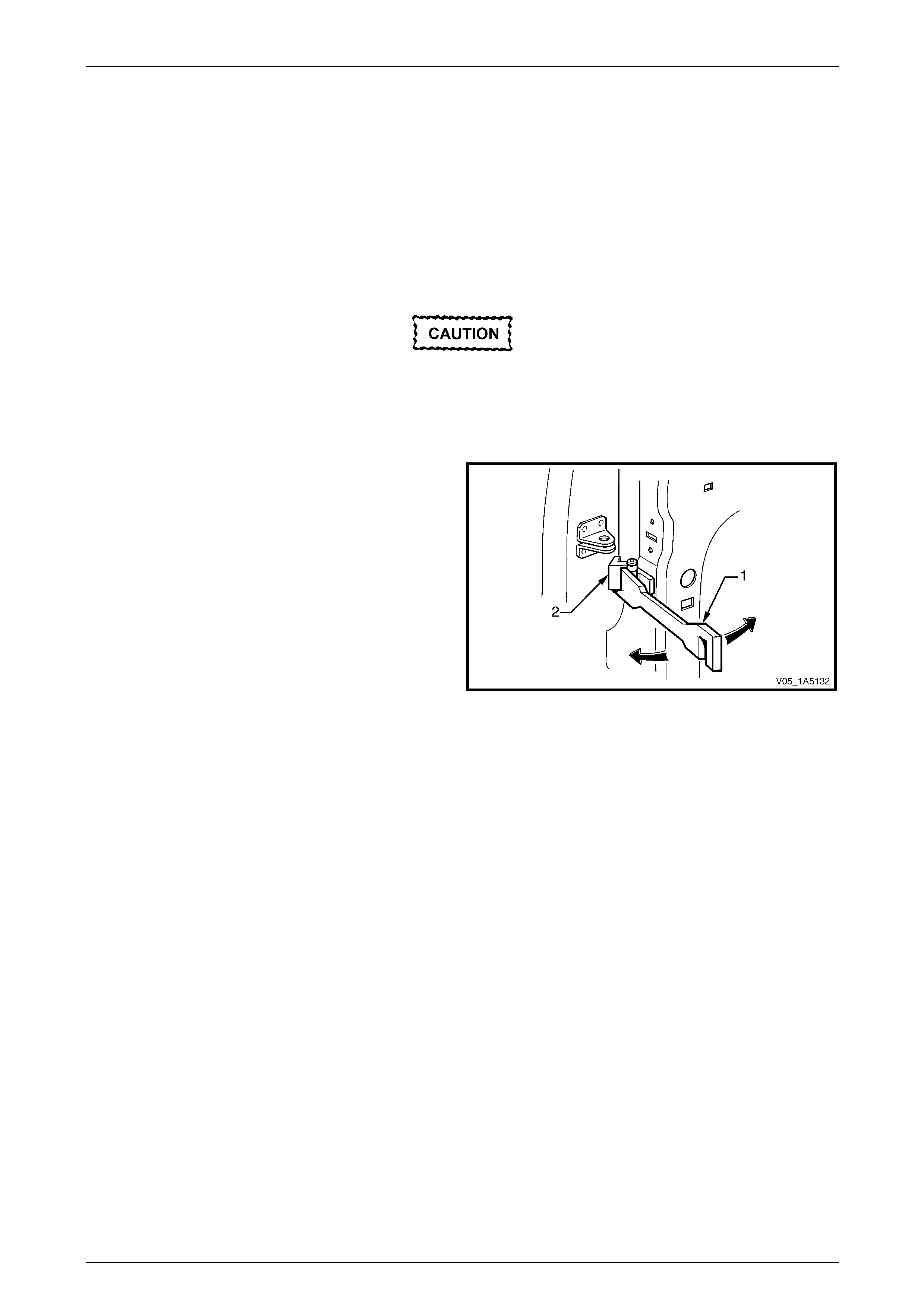
Front and Rear Door Assemblies Page 1A5–133
Page 1A5–133
15.2 Adjust Rear Door Assembly
Adjustment Procedure
Uniform margins and alignment of the rear doors in relation to the door opening frame assembly can be achieved by
setting the appropriate door hi nge. Refer to the Servic e Manual Supplement, Bod y Structure Re pair Manual for
specifications.
Adjust the door hinges in conj unction with the adjustment of the lock striker plate assembly to achieve an acceptable
door closing effort with correct door lock to striker engagement, refer to 8.2 Rear Door Lock Striker Plate Assembly.
Adjust the rear door with the striker plate
assembly removed. The striker plate
assembly must not pull the door into the
correct position and must be fitted once
satisfactory alignment is achie ved.
Use Tool No. AU184 (1) to set the rear door hinges by
slightly bending the hinge (2) noting the following:
1 Give attention to uniform margins and ali gnment
between the door and surrounding parts when the
adjustments are being carried out.
2 Take care when adjusting the door not to misalign the
hinge pin. Any significant misalignment will cause the
pin to shear when the door is opened or closed.
3 Excessive bending or levering of the door upper frame
will cause damage.
4 Final adjustment must take place when all the door
components and seals are installed. Figure 1A5 – 201

Front and Rear Door Assemblies Page 1A5–134
Page 1A5–134
16 Service Operations – Rear Door
Assembly, Crew Cab
16.1 Rear Door Assembly
LT Section — 11–730
Remove
1 Remove the grommet (1) from the rear door wiring
harness connector (2).
Take care not to pull the wiring out of the
connectors during the following operation.
2 Depress the tabs and disconnect the rear door wiring
harness connector from the body wiring harness
connector (3).
Figure 1A5 – 202
Ensure the door cannot swing freely as it
may cause damage during the following
operation.
3 Remove the check link cover (1) and pin (2), then
disconnect the check assembly (3).
4 If required, remove the two screws (4) attaching the
check assembly to the door and remove the check
assembly.
Figure 1A5 – 203
5 Remove the hinge pin cap (1) and plug (2) from the
hinge pin (3) on the upper and lower door hinges.
6 Have an assistant support the door or alternatively,
support the base of the door on a wooden block and a
trolley jack.
Figure 1A5 – 204

Front and Rear Door Assemblies Page 1A5–135
Page 1A5–135
7 Using the Tool No. AU170 (1), drive the hinge pin (2)
out of the lower and then upper hinges.
8 Remove the door assembly.
Figure 1A5 – 205
Disassemble
1 Remove the following components as required:
a Trim panel assembly, refer to 10.1 Rear Door Trim Panel.
b Internal components, as required,
refer to 12 Service Operations – Rear Door Internal Components, Crew Cab.
c Sealing components, as required, refer to 14 Service Operations – Rear Door Seali ng, Crew Cab.
d Body side moulding, as applicable, refer to Section 1A9 Exterior Ornamentation.
2 Prise the deadener (1) from the door inner p anel.
Figure 1A5 – 206
3 Rotate the two remote control rod clips (1) by 90° then
remove from the door inner panel.
4 Rotate the locking bell crank rod clip (2) by 90° then
remove from the door inner panel.
Figure 1A5 – 207
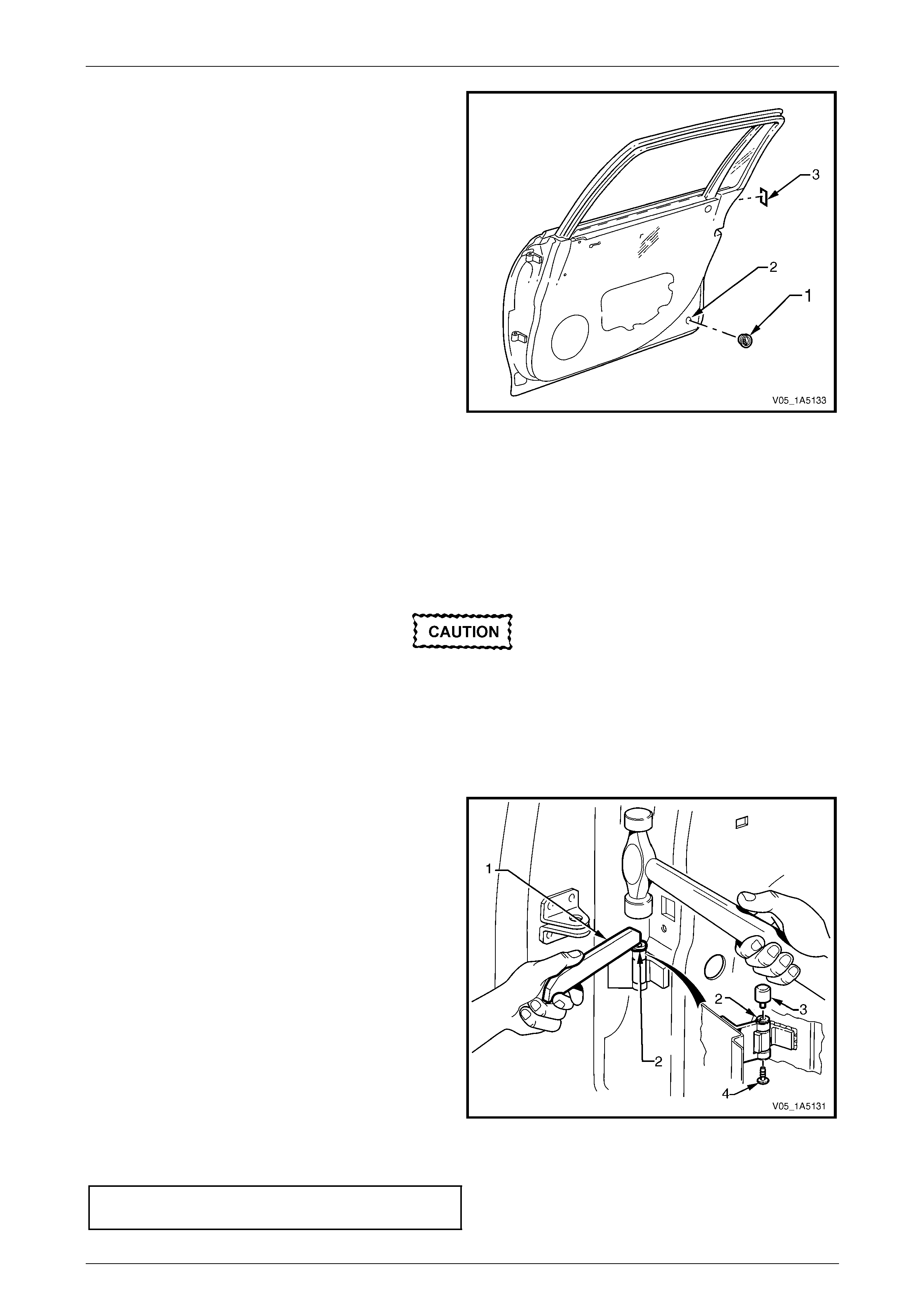
Front and Rear Door Assemblies Page 1A5–136
Page 1A5–136
5 Remove the plug (1) from the door inner panel drain
hole (2).
6 If required, remove the double sided tape (3) from the
door inner panel.
Figure 1A5 – 208
Reassemble
Reassembly of the rear door is the reverse of the disassembly procedure.
If reusing the same rear door deade ner (1), apply a small amount of contact adhesive bef ore fitting to the rear door in ner
panel, refer to Figure 1A5 – 206.
Reinstall
Reinstallation of the rear door assembly is the reverse of the removal procedure, noting the following:
If using a new rear door panel assembly it
must be prepared to maintain original
manufacturers specifications. This includes
the application of joint sealer, hand putty and
cavity wax. Refer to the Service Manual
Supplement, Body Structure Repair Manual
for specifications.
1 Apply Lithium base grease NLGI No. 1 (with 9 % zinc oxide) or equivalent, to the hinge pin prior to reinstallation.
2 Using Tool No AU303 (1) an d a hammer, install the
hinge pin (2) with the slot facing for ward and the head
of the pin facing up for the lower hinge and down for
the upper hinge. NOTE
A 15° deviation is permissable for the positioning
of the hinge pin slot on reinstallation.
3 Check the fit of the door assembly and adjust as
required, refer to 16.2 Adjust Rear Door Ass embly.
NOTE
Make allowances in the adjustment of the door
assembly if the trim and hardware are not
installed.
Figure 1A5 – 209
4 Tighten the two screws (4) attaching the che ck assembly (3) to the correct torque specification, refer to
Figure 1A5 – 203.
Rear door check assembly
attaching screws torque specification .........3.0 – 7.0 Nm
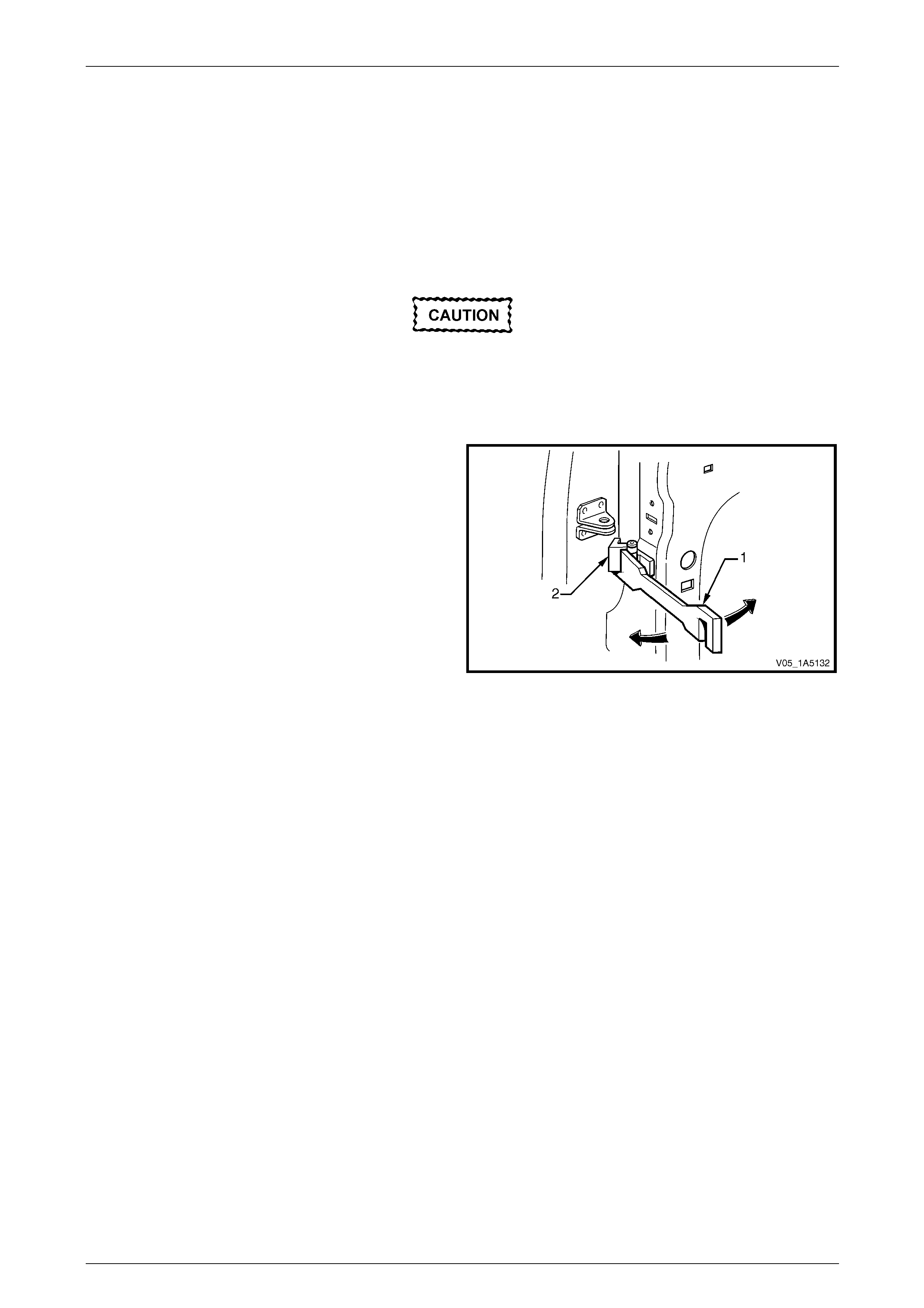
Front and Rear Door Assemblies Page 1A5–137
Page 1A5–137
16.2 Adjust Rear Door Assembly
Adjustment Procedure
Uniform margins and alignment of the rear doors in relation to the door opening frame assembly can be achieved by
setting the appropriate door hi nge. Refer to the Servic e Manual Supplement, Bod y Structure Re pair Manual for
specifications.
Adjust the door hinges in conj unction with the adjustment of the lock striker plate assembly to achieve an acceptable
door closing effort with correct door lock to striker engagement, refer to 8.2 Rear Door Lock Striker Plate Assembly.
Adjust the rear door with the striker plate
assembly removed. The striker plate
assembly must not pull the door into the
correct position and must be fitted once
satisfactory alignment is achie ved.
Use Tool No. AU184 (1) to set the rear door hinges by
slightly bending the hinge (2) noting the following:
1 Give attention to uniform margins and ali gnment
between the door and surrounding parts when the
adjustments are being carried out.
2 Take care when adjusting the door not to misalign the
hinge pin. Any significant misalignment will cause the
pin to shear when the door is opened or closed.
3 Excessive bending or levering of the door upper frame
will cause damage.
4 Final adjustment must take place when all the door
components and seals are installed. Figure 1A5 – 210

Front and Rear Door Assemblies Page 1A5–138
Page 1A5–138
17 Torque Wrench Specifications
17.1 Sedan and Wagon
Front Door
Front Door Lock Striker Plate Assembly Attaching Screw...........8.0 – 18.0 Nm
Front Door Remote Inner Handle Assembly Attaching Screw.......1.0 – 2.0 Nm
Front Door Trim Panel Assembly Attaching Screw........................1.0 – 3.0 Nm
Front Door Locking Rod Knob Escutcheon Attaching Screw .........1.0 – 2.0 Nm
Front Door Radio Speaker Grille Attaching Screw ........................0.5 – 0.7 Nm
Front Door Map Pocket Assembly Attaching Screw......................0.5 – 0.7 Nm
Front Door Armrest Insert Assembly Attaching Nut.......................0.7 – 0.9 Nm
Front Door Inner Pull Handle Assembly Attaching Screw..............1.3 – 1.7 Nm
Front Door Lock Actuator Assembly Attaching Screw...................3.0 – 5.0 Nm
Front Door Lock And Actuator Assembly Attaching Screw............3.0 – 5.0 Nm
Front Door Outer Handle Assembly Attaching Nut........................3.0 – 5.0 Nm
Front Door Window Guide Assembly Attaching Screw..................1.0 – 3.0 Nm
Front Door Window Guide Channel Assembly
Upper Attaching Screw..................................................................6.0 – 8.0 Nm
Front Door Window Guide Channel Assembly
Lower Attaching Screw..................................................................6.0 – 8.0 Nm
Front Door Window Down Stop Screw..........................................6.0 – 8.0 Nm
Front Door Exterior Rear-View Mirror
Assembly Attaching Screw............................................................2.5 – 3.5 Nm
Front Door Window Up Stop Screw
Preliminary Torque Specification............................................................2.0 Nm
Front Door Window Up Stop Screw...............................................3.5 – 4.5 Nm
Front Door Window Regulator
Channel Rear Attaching Screw .....................................................6.0 – 8.0 Nm
Front Door Window Regulator
Channel Front Attaching Screw.....................................................6.0 – 8.0 Nm
Front Door Window Belt Outer Reveal
Moulding Attaching Screw.............................................................1.0 – 3.0 Nm
Front Door Check Assembly Attaching Screw...........................12.0 – 16.0 Nm
Front Door Check Assembly Attaching Nut...................................5.0 – 7.0 Nm

Front and Rear Door Assemblies Page 1A5–139
Page 1A5–139
Rear Door
Rear Door Lock Striker Plate Assembly Attaching Screw............8.0 – 18.0 Nm
Rear Door Remote Inner Handle Assembly Attaching Screw........1.0 – 2.0 Nm
Rear Door Trim Panel Assembly Attaching Screw........................1.0 – 3.0 Nm
Rear Door Locking Rod Knob Escutcheon Attaching Screw..........1.0 – 2.0 nm
Rear Door Armrest Insert Assembly Attaching Nut .......................0.7 – 0.9 Nm
Rear Door Inner Pull Handle Assembly Attaching Screw..............1.3 – 1.7 Nm
Rear Door Lock Actuator Assembly Attaching Screw....................3.0 – 5.0 Nm
Rear Door Lock And Actuator Assembly Attaching Screw ............3.0 – 5.0 Nm
Rear Door Outer Handle Assembly Attaching Nut.........................3.0 – 5.0 Nm
Rear Door Window Guide Channel Assembly
Centre Attaching Screw.................................................................6.0 – 8.0 Nm
Rear Door Window Guide Channel Assembly
Lower Attaching Screw..................................................................6.0 – 8.0 Nm
Rear Door Window Guide Channel Assembly
Upper Attaching Screw..................................................................3.5 – 4.5 Nm
Rear Door Window Up Stop Screw
Preliminary Torque Specification............................................................2.0 Nm
Rear Door Window Up Stop Screw...............................................3.5 – 4.5 Nm
Rear Door Stationary Window Attaching Screw............................3.5 – 4.5 Nm
Rear Door Window Belt Outer Reveal
Moulding Attaching Screw.............................................................1.0 – 3.0 Nm
Rear Door Inner Panel Reinforcement Attaching Screw..............7.5 – 10.5 Nm
Rear Door Check Assembly Attaching Screw ...............................3.0 – 7.0 Nm

Front and Rear Door Assemblies Page 1A5–140
Page 1A5–140
17.2 Coupe
Front Door Lock Striker Plate Assembly Attaching Screw...........8.0 – 18.0 Nm
Front Door Remote Inner Handle Assembly Attaching Screw.......1.0 – 2.0 Nm
Front Door Trim Panel Assembly Attaching Screw........................1.0 – 3.0 Nm
Front Door Locking Rod Knob Escutcheon Attaching Screw .........1.0 – 2.0 Nm
Front Door Radio Speaker Grille Attaching Screw ........................0.5 – 0.7 Nm
Front Door Map Pocket Assembly Attaching Screw......................0.5 – 0.7 Nm
Front Door Armrest Insert Assembly Attaching Nut.......................0.7 – 0.9 Nm
Front Door Inner Pull Handle Assembly Attaching Screw..............1.3 – 1.7 Nm
Front Door Lock Actuator Assembly Attaching Screw...................3.0 – 5.0 Nm
Front Door Lock And Actuator Assembly Attaching Screw............3.0 – 5.0 Nm
Front Door Outer Handle Assembly Attaching Nut........................3.0 – 5.0 Nm
Front Door Window Guide Assembly Attaching Screw..................1.0 – 3.0 Nm
Front Door Window Guide Channel Assembly
Upper Attaching Screw..................................................................6.0 – 8.0 Nm
Front Door Window Guide Channel Assembly
Lower Attaching Screw..................................................................6.0 – 8.0 Nm
Front Door Window Down Stop Screw..........................................6.0 – 8.0 Nm
Front Door Exterior Rear-View Mirror
Assembly Attaching Screw............................................................2.5 – 3.5 Nm
Front Door Window Up Stop Screw
Preliminary Torque Specification............................................................2.0 Nm
Front Door Window Up Stop Screw...............................................3.5 – 4.5 Nm
Front Door Window Regulator Channel
Rear Attaching Screw....................................................................6.0 – 8.0 Nm
Front Door Window Regulator Channel
Front Attaching Screw...................................................................6.0 – 8.0 Nm
Front Door Window Belt Outer Reveal
Moulding Attaching Screw.............................................................1.0 – 3.0 Nm
Front Door Check Assembly Attaching Screw...........................12.0 – 16.0 Nm
Front Door Check Assembly Attaching Nut...................................5.0 – 7.0 Nm

Front and Rear Door Assemblies Page 1A5–141
Page 1A5–141
17.3 Crew Cab
Front Door
Front Door Lock Striker Plate Assembly Attaching Screw...........8.0 – 18.0 Nm
Front Door Remote Inner Handle Assembly Attaching Screw.......1.0 – 2.0 Nm
Front Door Trim Panel Assembly Attaching Screw........................1.0 – 3.0 Nm
Front Door Locking Rod Knob Escutcheon Attaching Screw .........1.0 – 2.0 Nm
Front Door Radio Speaker Grille Attaching Screw ........................0.5 – 0.7 Nm
Front Door Map Pocket Assembly Attaching Screw......................0.5 – 0.7 Nm
Front Door Armrest Insert Assembly Attaching Nut.......................0.7 – 0.9 Nm
Front Door Inner Pull Handle Assembly Attaching Screw..............1.3 – 1.7 Nm
Front Door Lock Actuator Assembly Attaching Screw...................3.0 – 5.0 Nm
Front Door Lock And Actuator Assembly Attaching Screw............3.0 – 5.0 Nm
Front Door Outer Handle Assembly Attaching Nut........................3.0 – 5.0 Nm
Front Door Window Guide Assembly Attaching Screw..................1.0 – 3.0 Nm
Front Door Window Guide Channel Assembly
Upper Attaching Screw..................................................................6.0 – 8.0 Nm
Front Door Window Guide Channel Assembly
Lower Attaching Screw..................................................................6.0 – 8.0 Nm
Front Door Window Down Stop Screw..........................................6.0 – 8.0 Nm
Front Door Exterior Rear-View Mirror
Assembly Attaching Screw............................................................2.5 – 3.5 Nm
Front Door Window Up Stop Screw
Preliminary Torque Specification............................................................2.0 Nm
Front Door Window Up Stop Screw...............................................3.5 – 4.5 Nm
Front Door Window Regulator Channel
Rear Attaching Screw....................................................................6.0 – 8.0 Nm
Front Door Window Regulator Channel
Front Attaching Screw...................................................................6.0 – 8.0 Nm
Front Door Window Belt Outer Reveal
Moulding Attaching Screw.............................................................1.0 – 3.0 Nm
Front Door Check Assembly Attaching Screw...........................12.0 – 16.0 Nm
Front Door Check Assembly Attaching Nut...................................5.0 – 7.0 Nm

Front and Rear Door Assemblies Page 1A5–142
Page 1A5–142
Rear Door
Rear Door Lock Striker Plate Assembly Attaching Screw............8.0 – 18.0 Nm
Rear Door Remote Inner Handle Assembly Attaching Screw........1.0 – 2.0 Nm
Rear Door Trim Panel Assembly Attaching Screw........................1.0 – 3.0 Nm
Rear Door Pull Cup Attaching Screw ............................................1.0 – 3.0 Nm
Rear Door Locking Rod Knob Escutcheon Attaching Screw.........1.0 – 2.0 Nm
Rear Door Armrest Insert Assembly Attaching Nut .......................0.7 – 0.9 Nm
Rear Door Lock Actuator Assembly Attaching Screw....................3.0 – 5.0 Nm
Rear Door Lock And Actuator Assembly Attaching Screw ............3.0 – 5.0 Nm
Rear Door Pull Cup Bracket Attaching Screw ...............................1.0 – 3.0 Nm
Rear Door Outer Handle Assembly Attaching Nut.........................3.0 – 5.0 Nm
Rear Door Window Guide Channel Assembly
Centre Attaching Screw.................................................................6.0 – 8.0 Nm
Rear Door Window Guide Channel Assembly
Lower Attaching Screw..................................................................6.0 – 8.0 Nm
Rear Door Window Guide Channel Assembly
Upper Attaching Screw..................................................................3.5 – 4.5 Nm
Rear Door Window Up Stop Screw
Preliminary Torque Specification............................................................2.0 Nm
Rear Door Window Up Stop Screw...............................................3.5 – 4.5 Nm
Rear Door Window Belt Outer Reveal
Moulding Attaching Screw.............................................................1.0 – 3.0 Nm
Rear Door Check Assembly Attaching Screw ...............................3.0 – 7.0 Nm

Front and Rear Door Assemblies Page 1A5–143
Page 1A5–143
17.4 Ute and Regular Cab
Front Door Lock Striker Plate Assembly Attaching Screw...........8.0 – 18.0 Nm
Front Door Remote Inner Handle Assembly Attaching Screw.......1.0 – 2.0 Nm
Front Door Trim Panel Assembly Attaching Screw........................1.0 – 3.0 Nm
Front Door Locking Rod Knob Escutcheon Attaching Screw .........1.0 – 2.0 Nm
Front Door Radio Speaker Grille Attaching Screw ........................0.5 – 0.7 Nm
Front Door Map Pocket Assembly Attaching Screw......................0.5 – 0.7 Nm
Front Door Armrest Insert Assembly Attaching Nut.......................0.7 – 0.9 Nm
Front Door Inner Pull Handle Assembly Attaching Screw..............1.3 – 1.7 Nm
Front Door Lock Actuator Assembly Attaching Screw...................3.0 – 5.0 Nm
Front Door Lock And Actuator Assembly Attaching Screw............3.0 – 5.0 Nm
Front Door Outer Handle Assembly Attaching Nut........................3.0 – 5.0 Nm
Front Door Window Guide Assembly Attaching Screw..................1.0 – 3.0 Nm
Front Door Window Guide Channel Assembly
Upper Attaching Screw..................................................................6.0 – 8.0 Nm
Front Door Window Guide Channel Assembly
Lower Attaching Screw..................................................................6.0 – 8.0 Nm
Front Door Window Down Stop Screw..........................................6.0 – 8.0 Nm
Front Door Exterior Rear-View Mirror
Assembly Attaching Screw............................................................2.5 – 3.5 Nm
Front Door Window Up Stop Screw
Preliminary Torque Specification............................................................2.0 Nm
Front Door Window Up Stop Screw...............................................3.5 – 4.5 Nm
Front Door Window Regulator Channel
Rear Attaching Screw....................................................................6.0 – 8.0 Nm
Front Door Window Regulator Channel
Front Attaching Screw...................................................................6.0 – 8.0 Nm
Front Door Window Belt Outer Reveal
Moulding Attaching Screw.............................................................1.0 – 3.0 Nm
Front Door Check Assembly Attaching Screw...........................12.0 – 16.0 Nm
Front Door Check Assembly Attaching Nut...................................5.0 – 7.0 Nm
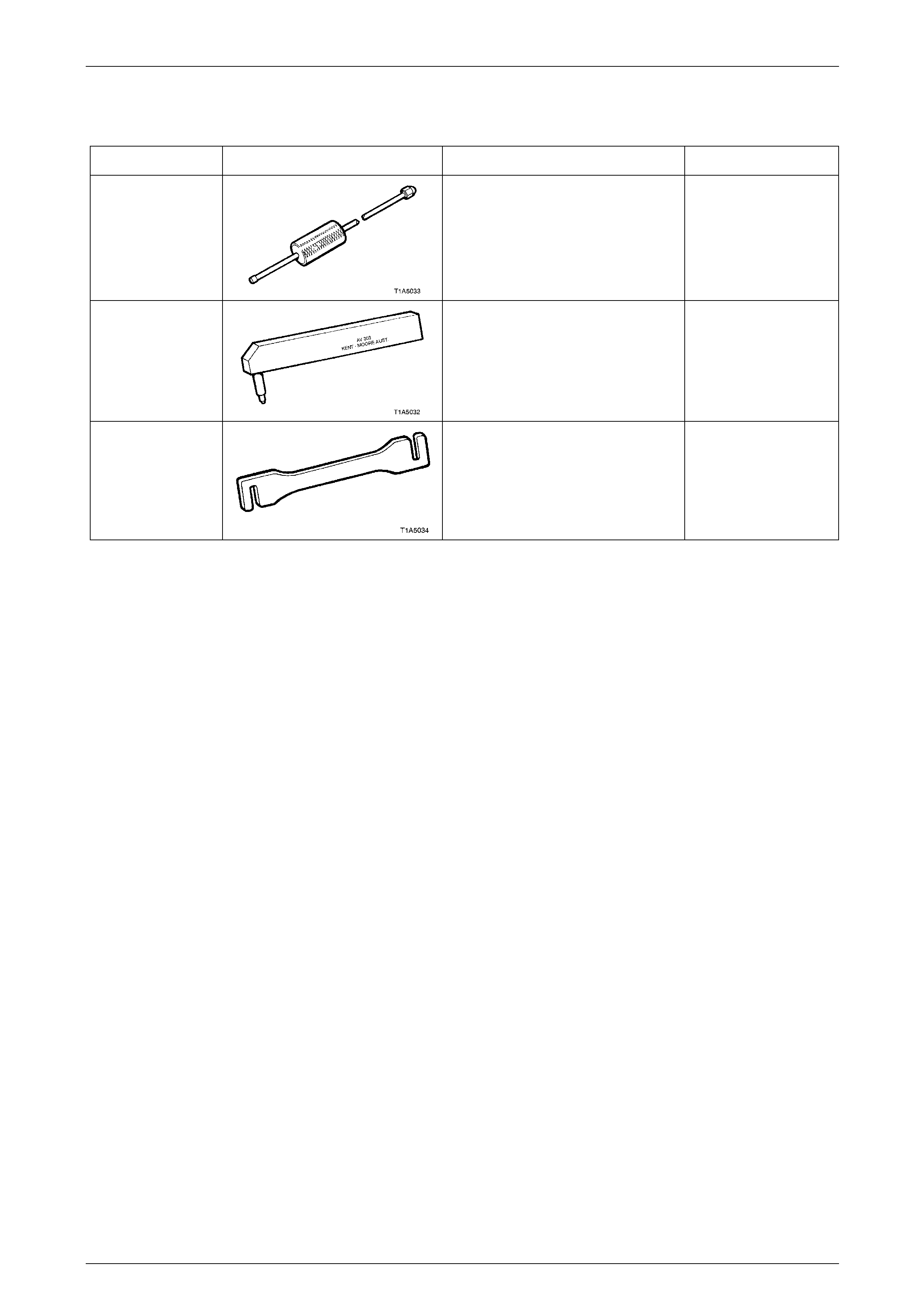
Front and Rear Door Assemblies Page 1A5–144
Page 1A5–144
18 Special Tools
Tool Number Illustration Description Tool Classification
AU170
Door Hinge Pin Removal Tool Available
AU303
Door Hinge Pin Installer Tool Available
AU184
Door Hinge Setting Tool
Used to adjust door alignment.
Desirable