
Stationary Windows Page 1A6–1
Page 1A6–1
Section 1A6
Stationary Windows
ATTENTION
Before performing any service operation or other procedure described in this Section, refer to Section 00
Warnings, Cautions and Notes for correct workshop practices with regard to safety and/or property damage.
1 General Information ...............................................................................................................................3
2 Leak Correction, Bonded Windows......................................................................................................4
2.1 Minor Water Leak Correction................................................................................................................................ 4
3 Service Operations – Front ...................................................................................................................6
3.1 Windshield Assembly............................................................................................................................................ 6
Description............................................................................................................................................................. 6
Preparation............................................................................................................................................................. 7
Remove................................................................................................................................................................... 7
Reinstall – Short Method....................................................................................................................................... 9
Description ......................................................................................................................................................... 9
Preparation......................................................................................................................................................... 9
Reinstall ........................................................................................................................................................... 10
Reinstall – Long Method ..................................................................................................................................... 13
Description ....................................................................................................................................................... 13
Preparation....................................................................................................................................................... 14
Reinstall ........................................................................................................................................................... 15
4 Service Operations – Side...................................................................................................................19
4.1 Quarter Window Assembly, Wagon (except AWD Wagon).............................................................................. 19
Preparation........................................................................................................................................................... 19
Remove................................................................................................................................................................. 19
Reinstall................................................................................................................................................................ 20
4.2 Quarter Window Assembly, AWD Wagon.......................................................................................................... 21
Preparation........................................................................................................................................................... 21
Remove................................................................................................................................................................. 21
Reinstall................................................................................................................................................................ 22
4.3 Quarter Window Assembly, Utility and Regular Cab........................................................................................ 23
Preparation........................................................................................................................................................... 23
Remove................................................................................................................................................................. 23
Reinstall................................................................................................................................................................ 24
4.4 Quarter Window Assembly, Coupe.................................................................................................................... 25
Preparation........................................................................................................................................................... 25
Remove................................................................................................................................................................. 25
Reinstall................................................................................................................................................................ 26
Techline

Stationary Windows Page 1A6–2
Page 1A6–2
5 Service Operations, Rear.....................................................................................................................27
5.1 Rear Window Assembly, Sedan.......................................................................................................................... 27
Description........................................................................................................................................................... 27
Preparation........................................................................................................................................................... 27
Remove................................................................................................................................................................. 28
Reinstall – Short Method..................................................................................................................................... 30
Description ....................................................................................................................................................... 30
Preparation....................................................................................................................................................... 30
Reinstall ........................................................................................................................................................... 31
Reinstall – Long Method ..................................................................................................................................... 34
Description ....................................................................................................................................................... 34
Preparation....................................................................................................................................................... 34
Reinstall ........................................................................................................................................................... 35
5.2 Liftgate Window Assembly, Wagon (except AWD Wagon) ..............................................................................38
Description........................................................................................................................................................... 38
Preparation........................................................................................................................................................... 39
Remove................................................................................................................................................................. 39
Reinstall – Short Method..................................................................................................................................... 41
Description ....................................................................................................................................................... 41
Preparation....................................................................................................................................................... 41
Reinstall ........................................................................................................................................................... 42
Reinstall – Long Method ..................................................................................................................................... 45
Description ....................................................................................................................................................... 45
Preparation....................................................................................................................................................... 45
Reinstall ........................................................................................................................................................... 46
5.3 Rear Window Assembly, Utility, Regular Cab and Crew Cab........................................................................... 49
Description........................................................................................................................................................... 49
Preparation........................................................................................................................................................... 50
Remove................................................................................................................................................................. 50
Reinstall – Short Method..................................................................................................................................... 52
Description ....................................................................................................................................................... 52
Preparation....................................................................................................................................................... 52
Reinstall ........................................................................................................................................................... 53
Reinstall – Long Method ..................................................................................................................................... 56
Description ....................................................................................................................................................... 56
Preparation....................................................................................................................................................... 56
Reinstall ........................................................................................................................................................... 57
5.4 Rear Window Assembly, Coupe......................................................................................................................... 60
Description........................................................................................................................................................... 60
Preparation........................................................................................................................................................... 60
Remove................................................................................................................................................................. 61
Reinstall – Short Method..................................................................................................................................... 63
Description ....................................................................................................................................................... 63
Preparation....................................................................................................................................................... 63
Reinstall ........................................................................................................................................................... 64
Reinstall – Long Method ..................................................................................................................................... 67
Description ....................................................................................................................................................... 67
Preparation....................................................................................................................................................... 67
Reinstall ........................................................................................................................................................... 68
6 Special Tools ........................................................................................................................................71
7 Torque Wrench Specifications............................................................................................................72

Stationary Windows Page 1A6–3
Page 1A6–3
1 General Information
The windshield plays an important role in
occupant protection by supporting the
passenger airbag during deployment.
Therefore, it is imperative the procedures in
this Section are correctly followed, as
incorrect installation may lead to injury or
death.
This Section describes the procedures to remove and reinstall the windshield assembly, rear window assembly (Sedan,
Coupe, Utility, Regular Cab and Crew Cab), liftgate window assembly (Wagon – except AWD) and quarter window (all
vehicles – except Sedan and Crew Cab). Also described is a procedur e to repair minor leaks to urethane bonded
windows.
The winds h ield as se mb ly is ma nufac t ur e d f rom l a mi n a ted gla s s and h a s a tin te d up p e r ba nd . Toughened safety glass is
used for all other windows.
The windshield assembly, rear wi n d ow assembly and liftga te windo w assem b ly are bonded to the vehicle body window
opening with ure th ane adhesive.
The quarter window assembly is attached to the vehicle using plastic nuts. A self adhesive foam weatherstrip is affixed to
the glass to seal the window opening. The nuts should be replaced after removal to maintain an effective weather seal.
For replacement of urethane bon de d windows, urethane service k its have been dev eloped and must be us ed to maintain
original installation requirements. Two different installation methods can be used when replacing the windshield
assembly, rear window assembly or liftgate window assembl y:
• Short Method: involves partial removal of the urethane. It is to be used when the original urethane remaining on the
window opening flanges after the window removal can be used as a base for the new window. This method would
be used where replacement of cracked windshields or removal of intact windo ws is required. T he amount of
urethane left in the window openi ng can be controlled during window removal. It is recommend to leave the
maximum amount of original urethane intact on the body opening flange.
• Long Method: involves complete removal of the uretha ne. It is to be used when the ori gin al urethane remaining on
the window opening flanges after the window rem ov al can not ser ve as a base for the r eplacement window. This
method would be used in cas es requ iring metal work and / or paint refinishing in the window opening or in cases
where the window has been previously replaced using the short method. In such instances, the build up of
urethane could position the window too high in the body opening. In these cases, the original urethane must be
completely removed and replaced with new urethane.
The windshield and Sed an and Coupe rear window are structural members of the vehicle. Once the urethane adhesive
cures, they aid vehicle rigidity.
For service procedures related to the rear door fixed window, refer to Section 1A5 Front and Rear Door Assembli es.
Stationary Windows Page 1A6–4
Page 1A6–4
2 Leak Correction, Bonded
Windows
LT Section No. — 11–020
Safety glasses an d work glo ves must be w orn
at all times when operating with glass.
NOTE
Only use urethane adhesive Betaseal 15685 or
equivalent for water leak correction on bonded
windows.
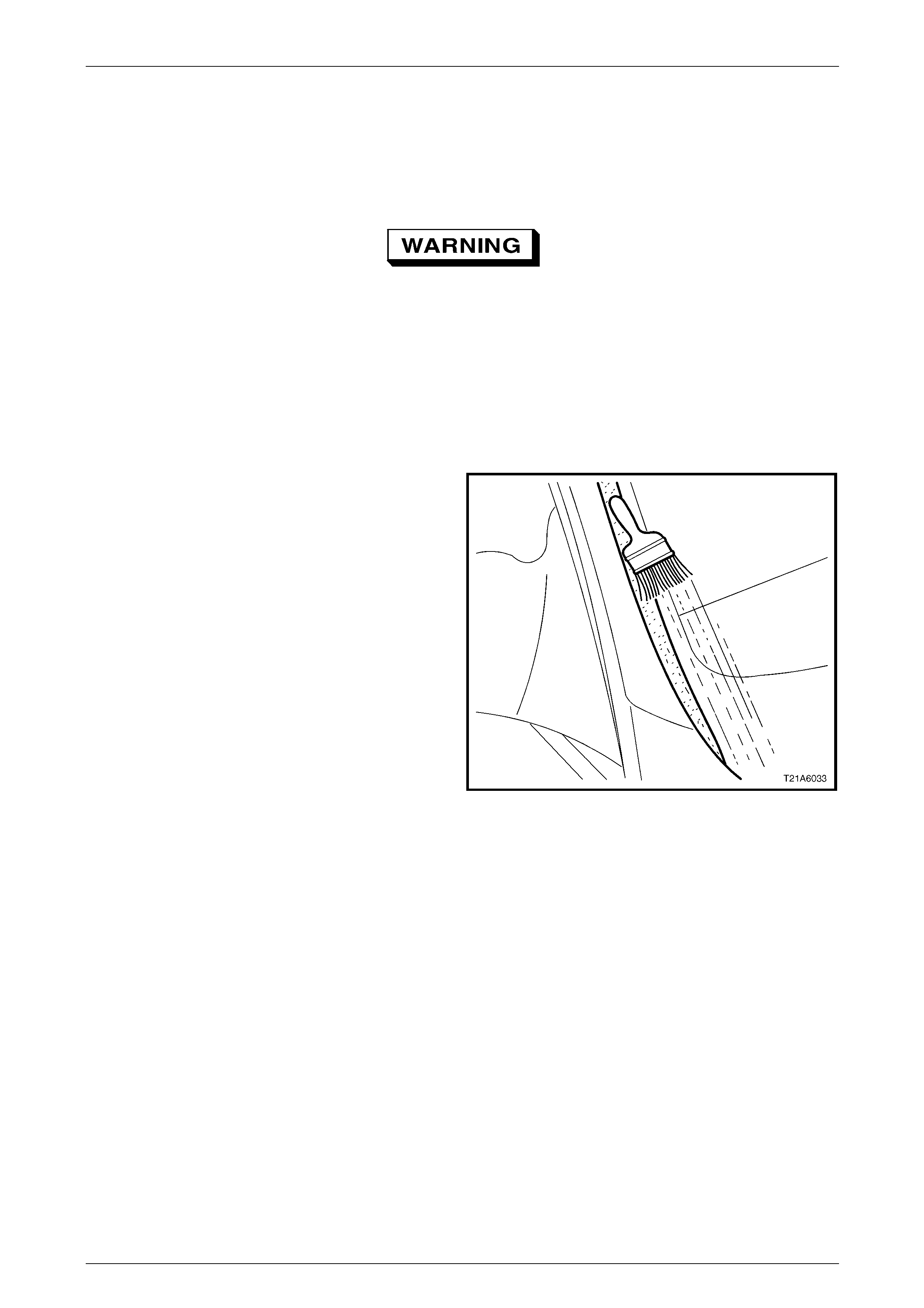
2.1 Minor Water Leak Correction
1 Secure protective covering with masking tape adjacent
to the suspect leak area.
2 To determine the precise location of the leak, use the
air and soap bubble leak test. The soap and water
solution can be applied with either a spray applicat or
or brush.
Figure 1A6 – 1
Stationary Windows Page 1A6–5
Page 1A6–5
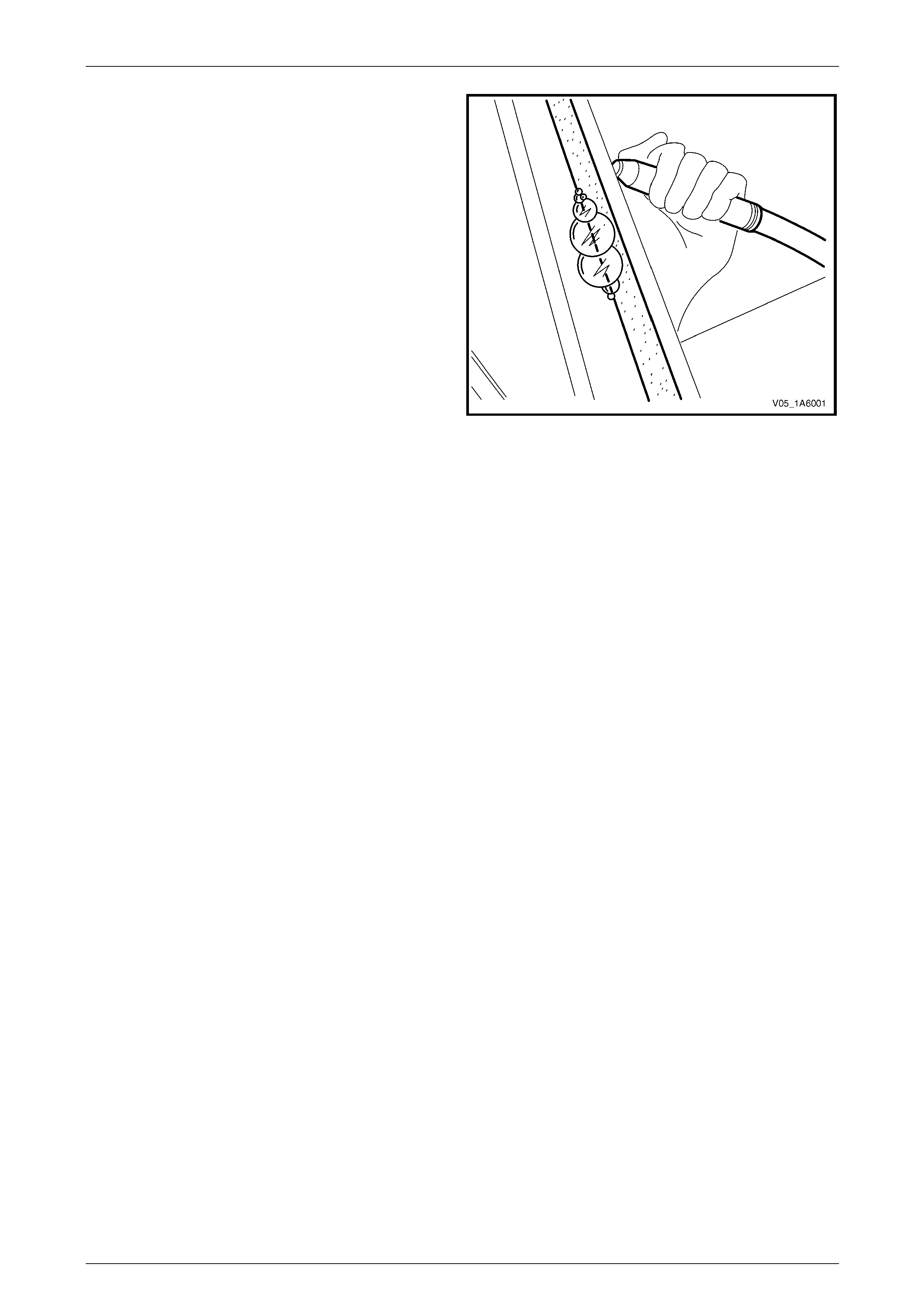
3 Place an air-hose nozzle on the inside of the
windshield or rear window assembly. Have an
assistant outside the vehicle appl y a soapy water
solution opposit e the air source. As a low air pressure
(60 kPa) is applied, soap bubbles will form on the
outside of the window, indicating the location of the
leak.
4 If the suspect leak area is not obvious, commence the
testing across the top and down the sides until the
leak location has been determine d.
5 Using a spatula, work fresh urethane such as Betaseal
15685 or equivalent, in and around the leak area.
NOTE
It is only necessary to remove dust and foreign
matter, as water activates the curing process of
urethane.
6 Leak test the repair, using the air and soap bubble
leak test or apply a moderate spray of water.
7 Remove the masking tape and protective covers, then
clean the windo w assembl y and adjacent paint and
trim surfaces.
Figure 1A6 – 2
Stationary Windows Page 1A6–6
Page 1A6–6
3 Service Operations – Front
3.1 Windshield Assembly
LT Section No. — 11–020
Safety glasses an d work glo ves must be w orn
at all times when operating with glass.
The windshield plays an important role in
occupant protection by supporting the
passenger airbag during deployment. It is
imperative the procedures in this Section for
replacing bonded windows are followed.
Incorrect installation may lead to injury or
death.
Care should be taken to ensure the
windshield does not strike the windshield
opening or any other object. Chipped edges
can lead to subsequent breakage of the
windshield.
NOTE
• Only use urethane adh esive such as Betase al
15685 or equivalent.
• Skinning (partial curing) of the urethane
commences after exposure to the
atmosphere. At 23 degrees Celsius and 50
percent relative humidity, skinning
commences after 30 minutes. Complete
curing of the urethane at this temperature an d
humidity takes 72 hours.
• Urethane service kits are available from most
windshield agents. Manufacturer’s instruction s
should always be foll owed.
• Window assemblies should be installed in the
window opening within five minutes of the
application of urethane.
Description
The windshield assembly rem oval procedure is the same for both the short and long installation methods, with one
exception. If the short method installation is to be used, care must be taken during the windshield removal to ensure that
an even surface of the original remaining urethane exists in the body opening. This is required to serve as a base for the
new urethane bea d and the replacement windshield.
Stationary Windows Page 1A6–7
Page 1A6–7
Preparation
Prevent damage to the paint finish and
minimise clean up by using protective covers
and masking tape over the regions adjacent
to the windshield.
As required, remove the following components:
1 Windshield wiper arm assembly and plenum cover assembly, refer to Section 12N Wipers, Washers and Horn.
2 Instrument panel end cap covers, and the windshield defroster grille assembly,
refer to Section 1A3 Instrument Panel and Consol e.
3 Windshield side garnish, refer to Section 1A8 Headlining and Interior Trim.
4 Internal rear-view mirror, refer to Section 12H Rear-view Mirrors.
Remove
NOTE
• All vehicles have a keyless entry control
module installed between the left and right-
hand windshield defroster grille assembly on
the instrument panel. It is not necessary to
remove the module, however take care to
avoid damage to it during windshield removal.
• To remove the windshield or rear window
special tool J36020 is required. Alternately
manufacture an equivalent tool. Refer to
6 Special Tools.
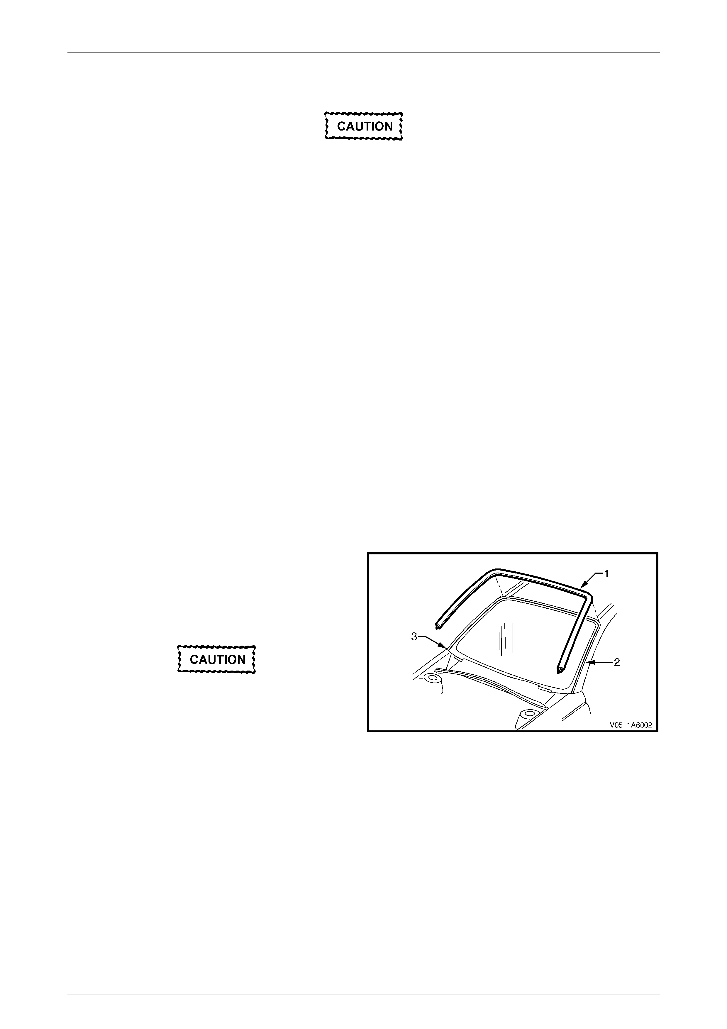
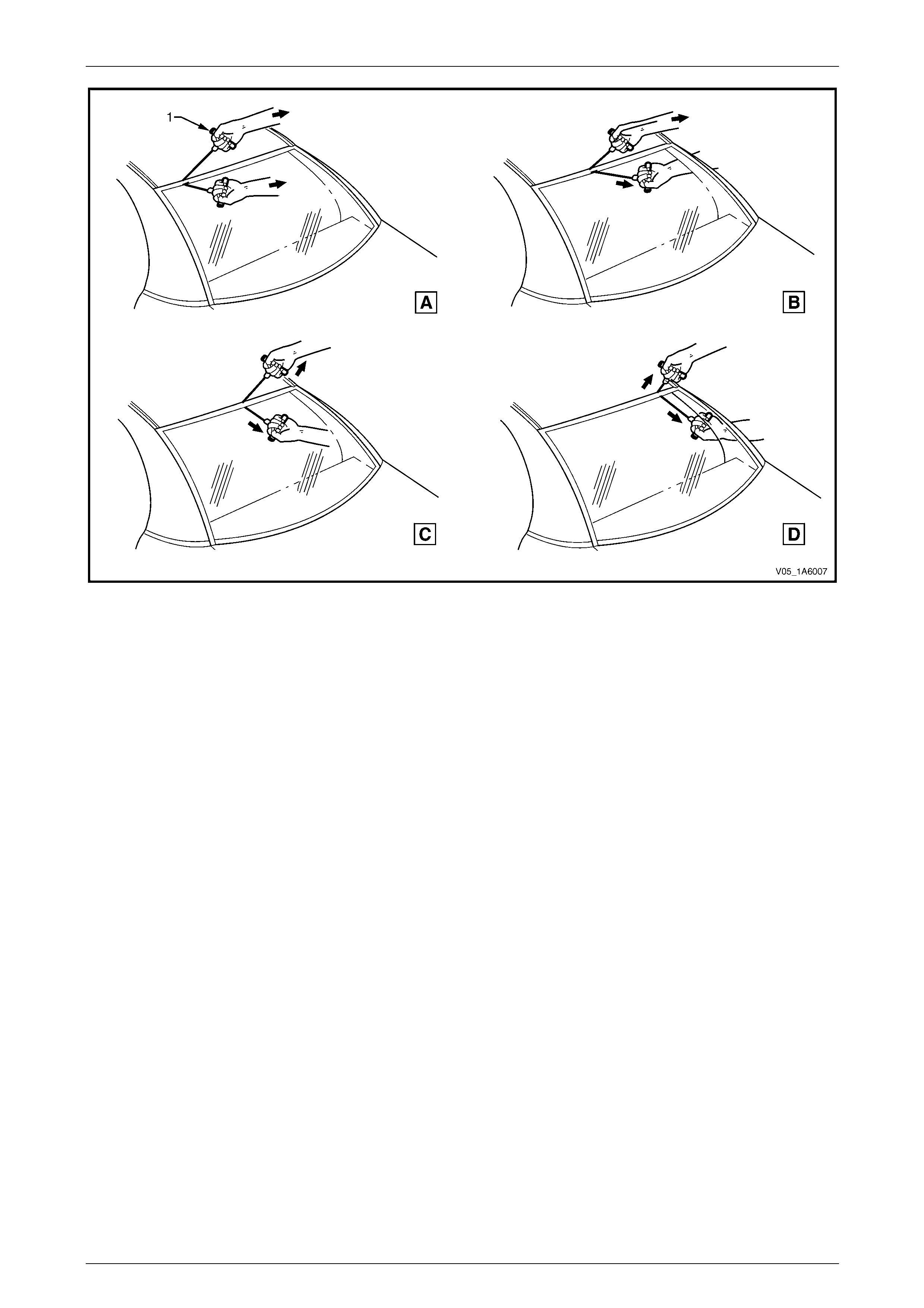
1 Remove the windshield reveal moulding (1) by pulling
the moulding from the windshield opening (2). Start at
the lower corner (3) and work around the windshield.
2 If the windshield is broken, take care to remove all
fragments of glass from the windshield opening.
Ensure the headlining and other trim items
are not damaged while cutting the urethane.
3 Use special tool J36020, or equiv alent, thread one end
of the piano wire through the urethane, starting at the
windshield upper corner. Pull the end of the piano wire
through with pliers.
Figure 1A6 – 3
4 Connect the end of the piano wire to the other han dle of the special tool or equivale nt.
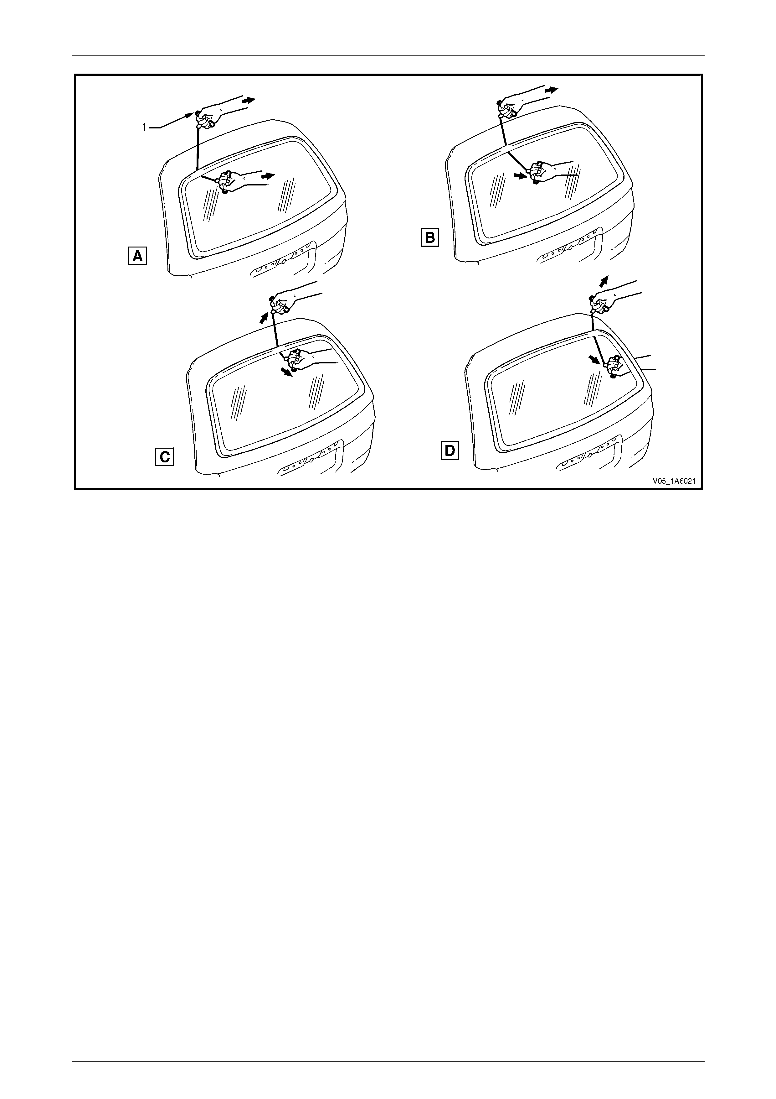
5 With the aid of an assistant, commence cutting the urethane bead. Keep the outside handle (1) parallel to the edge
of the windshield. Use the full len gth of the wire to prevent heat build up in the wire, refer to Figure 1A6 – 4.

Stationary Windows Page 1A6–8
Page 1A6–8
NOTE
To minimise the damage to the interior of the
vehicle, the operator inside th e vehicle should act
as an anchor point and hold the T-handle as
close as possible to the windshield at all times
(especially along the lower edge of the
windshield). The outside operator should pull the
wire up to the interior T-handle in a walking
motion.
Figure 1A6 – 4
6 Carefully lift the windshield o ut of the bod y opening. If there is evidence of the windshield adhering to the urethane,
cut the area again with the piano wire.
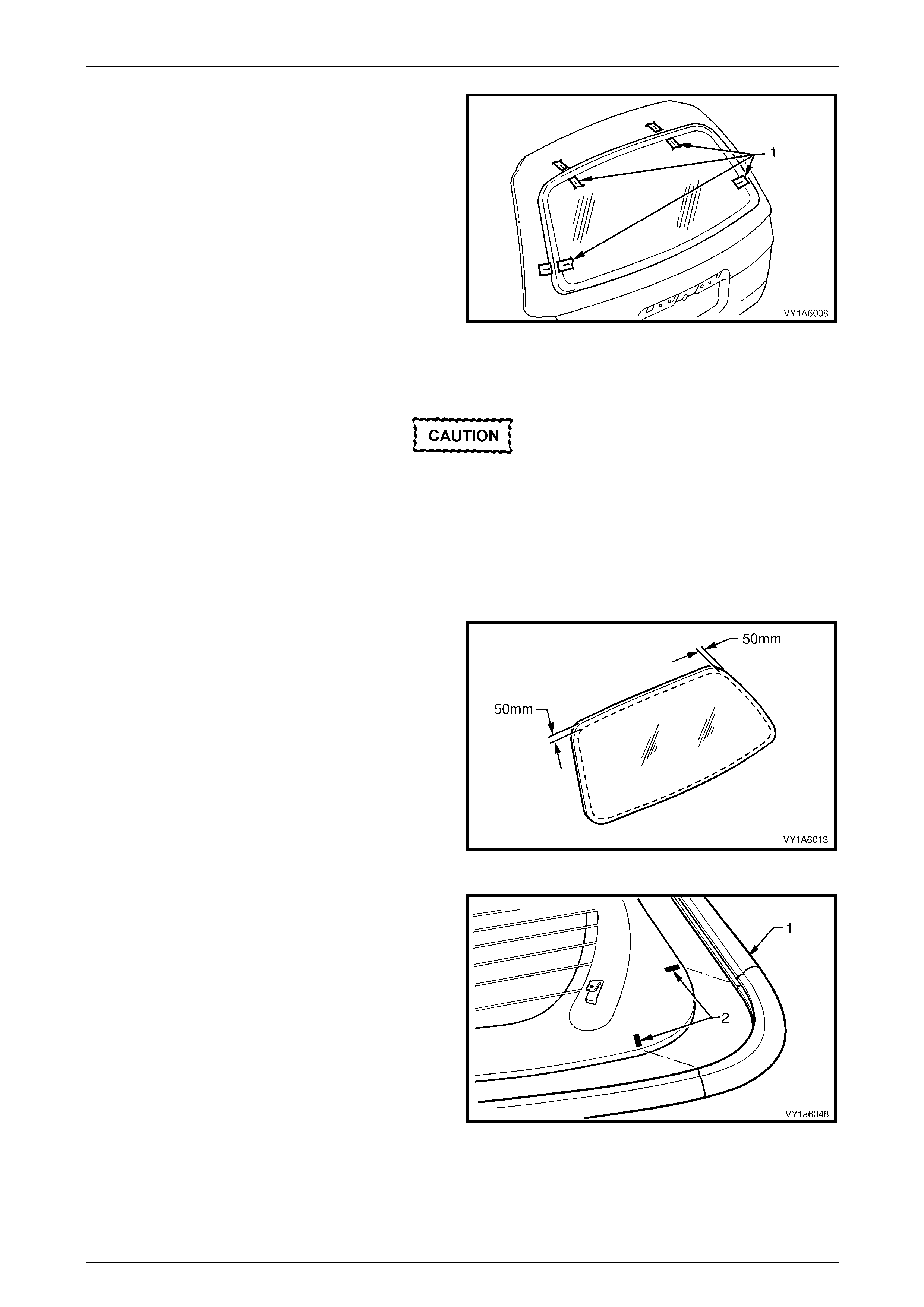
7 All vehicles except Coupe: Remove the two windshield locators from the windshield reinfo rcing fla nge, refer to
Figure 1A6 – 5. Retain for reinstall ation of the windshield.
8 If the original windshield is to be installed again, place the windshield on a clean protected surface or a holding
fixture.
NOTE
• The use of suction cu ps will greatly assist an y
handling of the windshie ld.
• All traces of urethane must be removed from
the windshield. It is not necessary to remove
all traces of the original urethane from the
body opening, unless the long method of
reinstallation is being used. However, any
original urethane remaining must be smooth
and firm.
Stationary Windows Page 1A6–9
Page 1A6–9
Reinstall – Short Method
Description
Throughout the curing period, ensure the
door windows are partially lowered to
eliminate pressure build-up, which can be
caused by slamming doors. A curing time of
24 hours is recommended, although the
vehicle may be driven after five hours
providing it is driven only on a smooth road at
speeds not exceeding 80 km/h with the door
windows partially lowered.
• The short method is recommended when replacing a cracked or broken windshield, or a leak condition that can n ot
be overcome by using the minor water leak repa ir procedure.
• The short method installation i nvolves leaving the maximum amount of the original urethane intact on the body
opening to form a sound base for the replacement urethane and windshield. Any original urethane remaining must
be smooth and firm.
• If material other than urethane has been used for previo us servicing of the windshie ld, the long method installation
procedure (complete removal of the urethane adhesive) is mand atory to achieve an effective window to body bond.
Preparation
Care should be taken to ensure the
windshield does not strike the windshield
opening or any other object. Chipped edges
can lead to subsequent breakage of the
windshield.
Do not use petrol eum based sol vents to clean
any part of the window assembly or body
opening as the presence of oil in the solvent
will pre vent th e adhesion of the n ew urethane.
1 Using a sharp scraper remove any original urethane from around the windshield. Cle an the windshield to be
installed with a suitable oil fre e clea ning agent.
Stationary Windows Page 1A6–10
Page 1A6–10
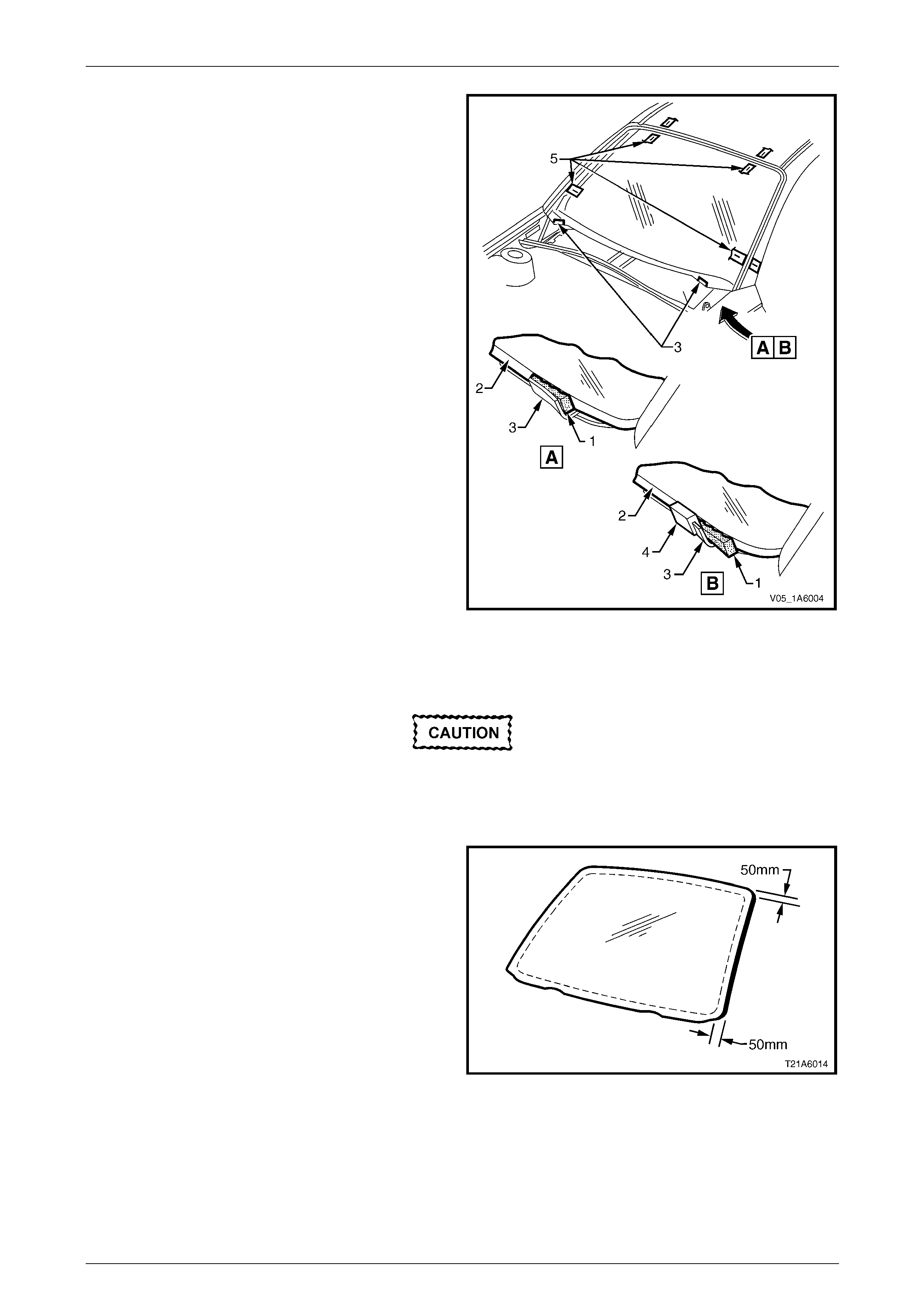
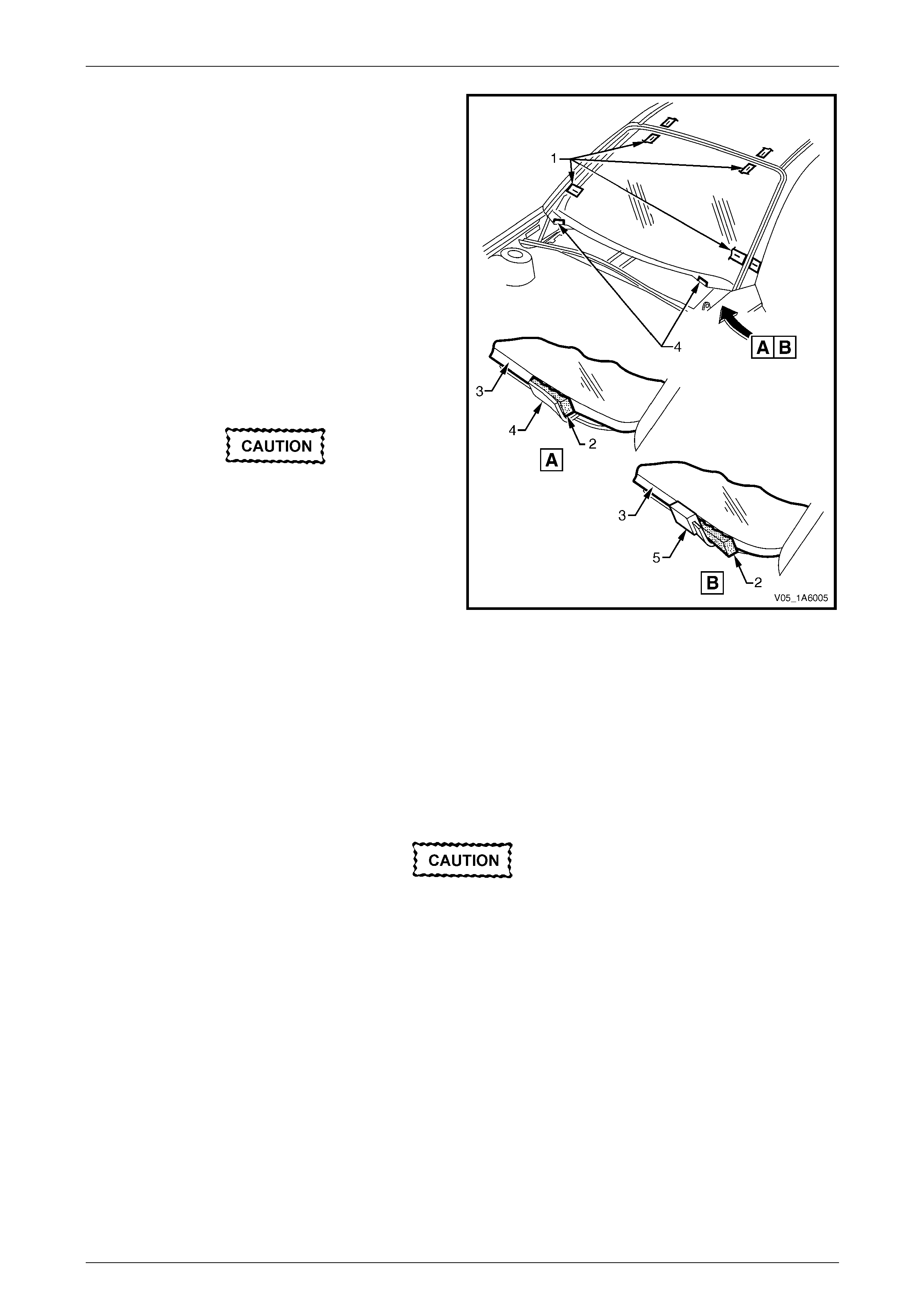
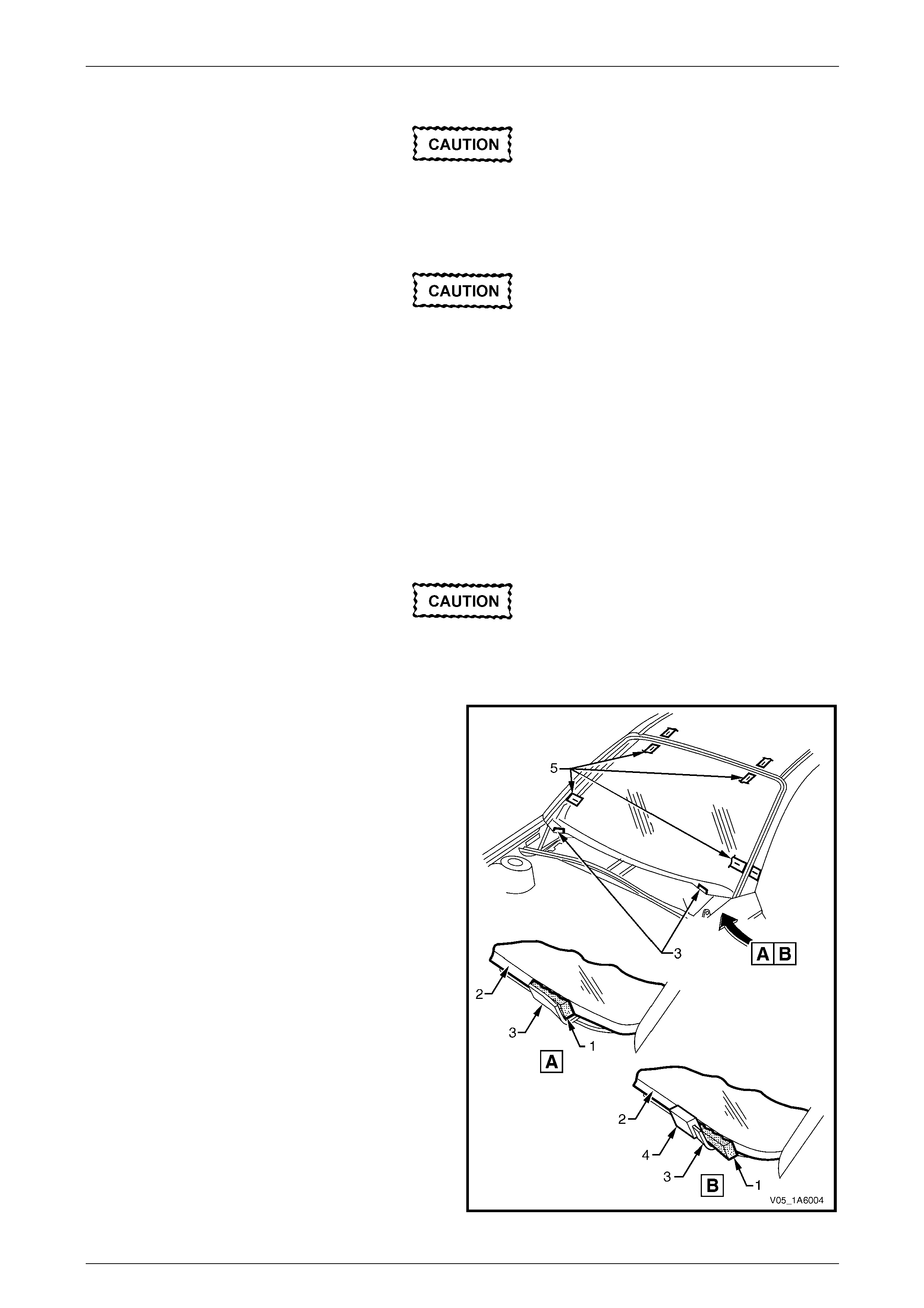
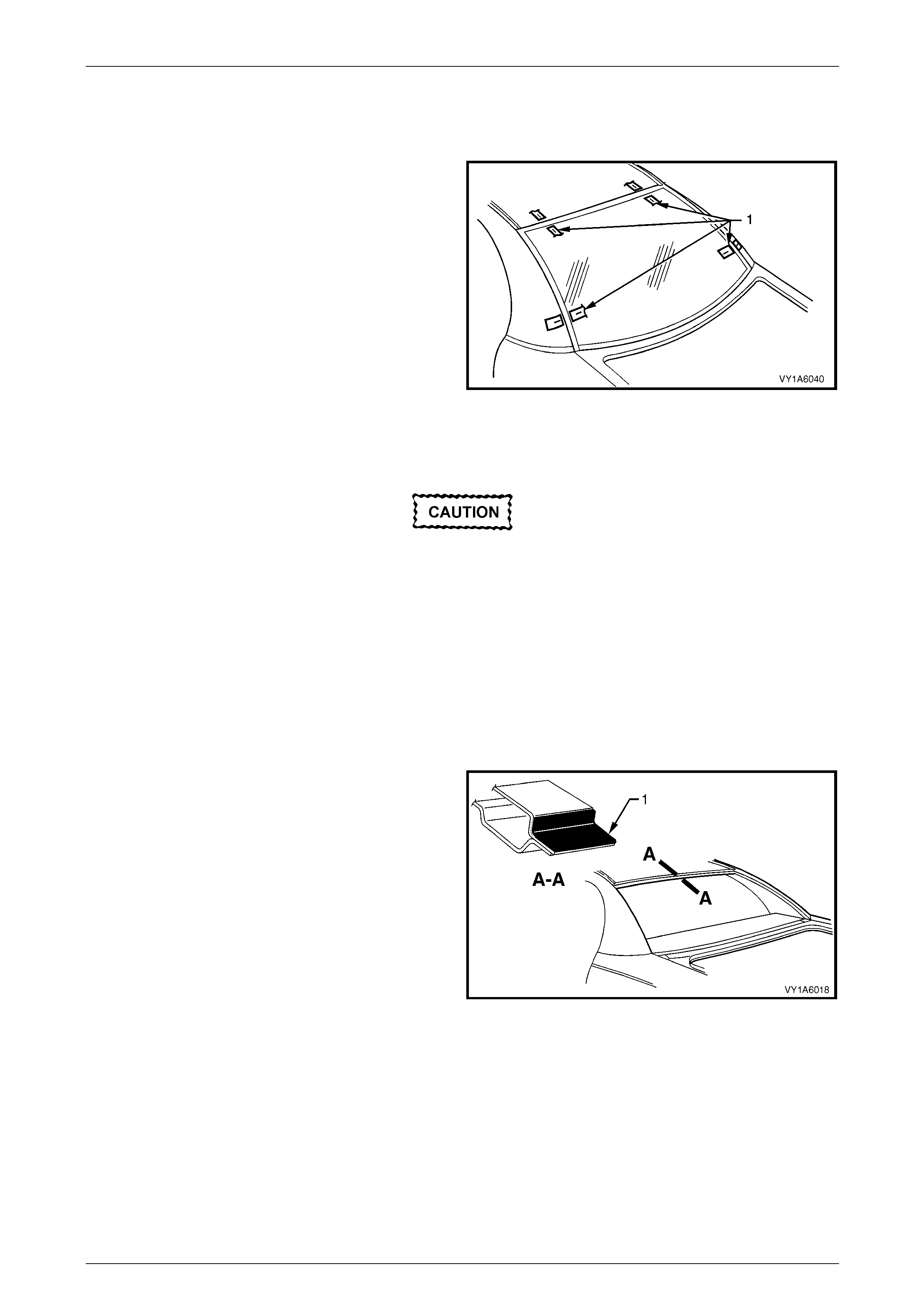
2 Check for correct alignment of the windshield b y:
• All vehicles except Coupe [A]: temporarily
placing the windshield in the bod y open ing. Fit
the windshield locator (1) between the lower
windshield edge (2) and the reinforcing flange
(3).
• Coupe [B]: Place the windshield onto the
extrusion (4) fitted to the reinforcing flange (3). If
required, place a windshie ld locator (1) between
the lower windshield ed ge (2) and the extrusion.
3 Ensure the windshield is centralised in the body
opening left to right by checking the gaps between the
windshield and body opening are eve n on both sides
of the vehicle.
4 With masking tape (5), mark the outer top and side of
the windshield pillar and the roof.
NOTE
This procedure will assist in the alignment of the
windshield in the correct horizontal and vertical
plane during final windshield installation.
5 Remove and place the windshield face down on a
clean protected surface or fixture.
Figure 1A6 – 5
Reinstall
Do not use petrol eum based sol vents to clean
any part of the window assembly, or body
opening as the presence of oil in the solvent
will pre vent th e adhesion of the n ew urethane.
1 Thoroughly clean the inner surface and edges of the
windshield to which the urethane is to be applied. Use
a clean lint-free cloth and a suitable oil free cleaning
solvent.
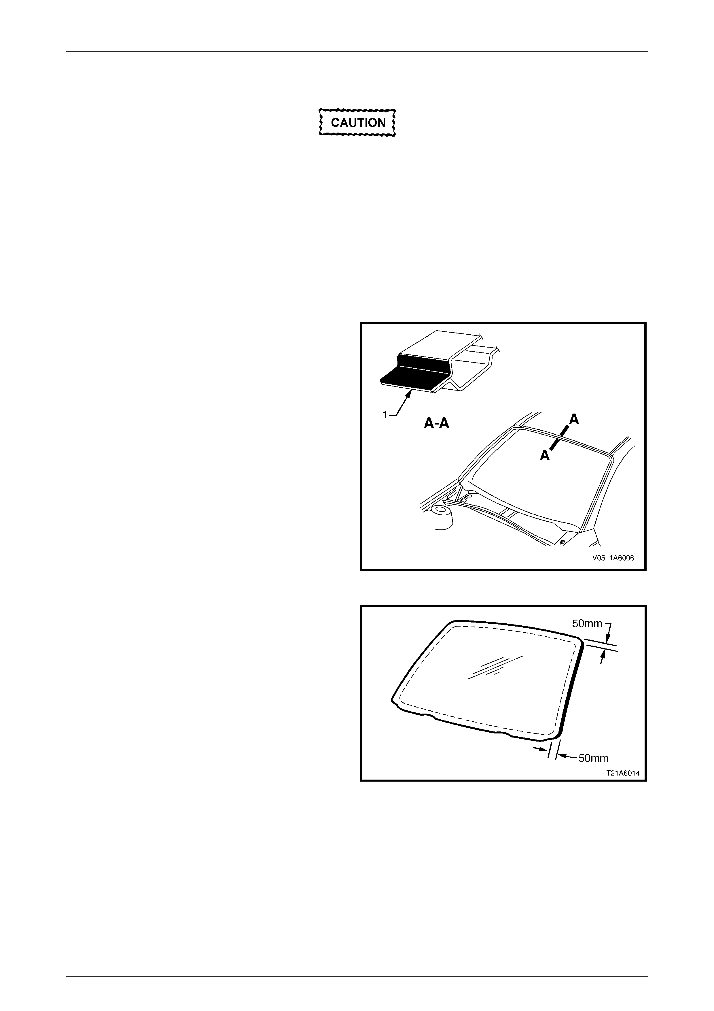
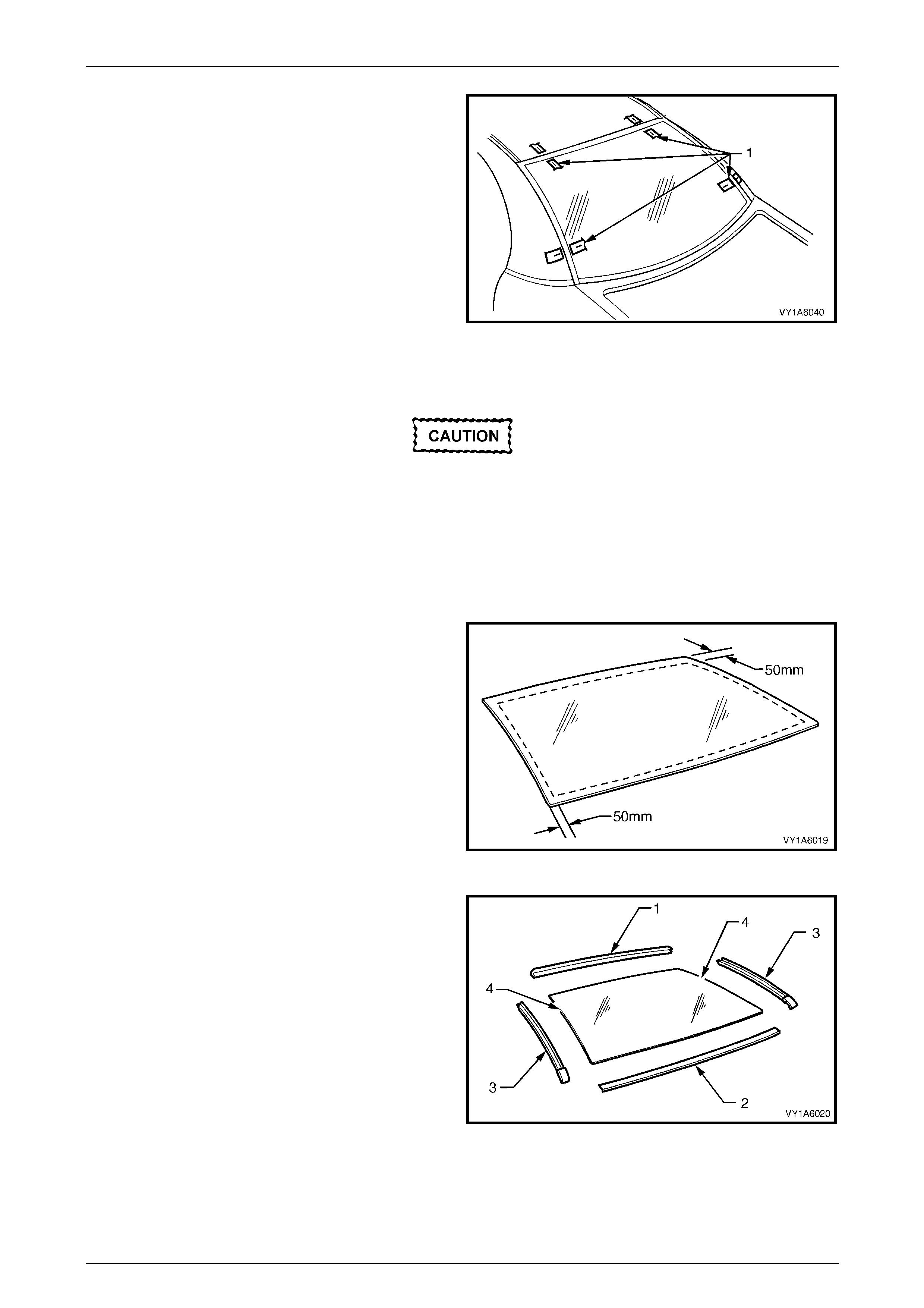
2 Apply a 50 mm wide layer of clear glass primer to the
inner surface of the windshield's perimeter.
Immediately wipe off with a lint-free cloth.
Figure 1A6 – 6

Stationary Windows Page 1A6–11
Page 1A6–11
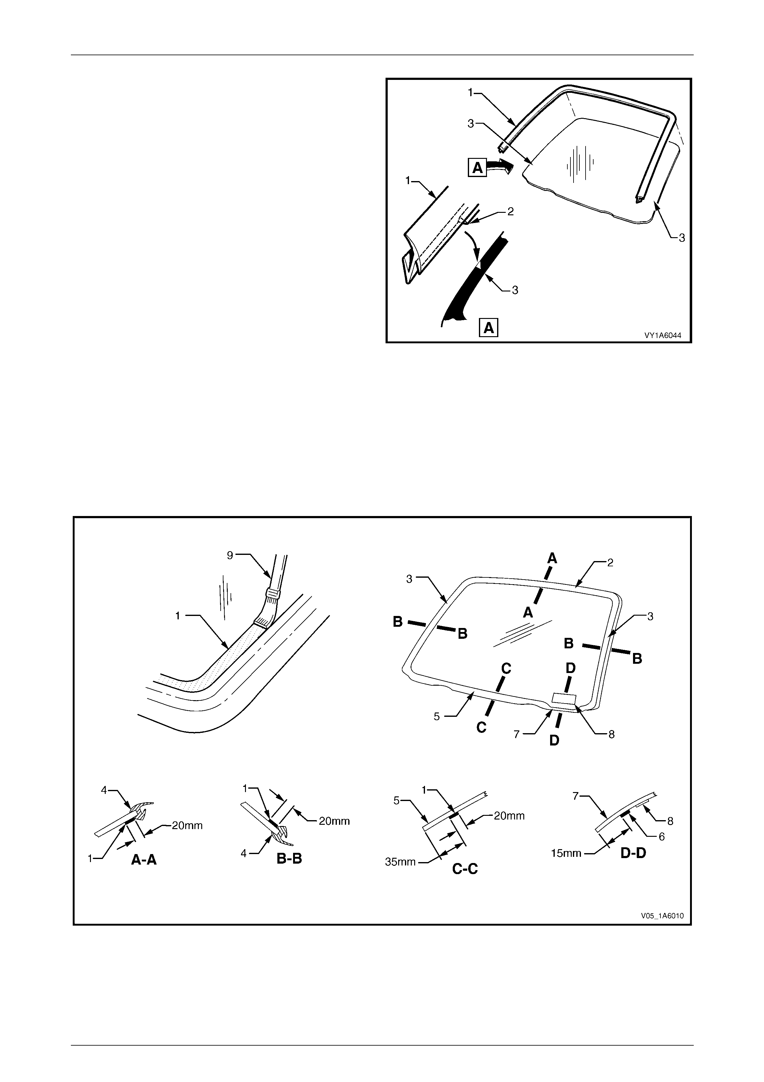
3 Check the condition of the windshiel d reveal
moulding (1). Discard and replace with a new
moulding if damaged.
4 Fit the moulding to the sides and upper section of the
windshield. Ensure the notch of the moulding (2) is
aligned with the V locating mark (3) on the lower
portion of the right-hand and the left-hand side of the
windshield.
5 Check the condition of the original ureth ane around
the windshield opening flange for voids or looseness.
6 Cut away any loose pieces of urethane.
7 Using a suitable spatula, spre ad fresh urethane
smoothly into any voids or uneven sectio ns.
Figure 1A6 – 7
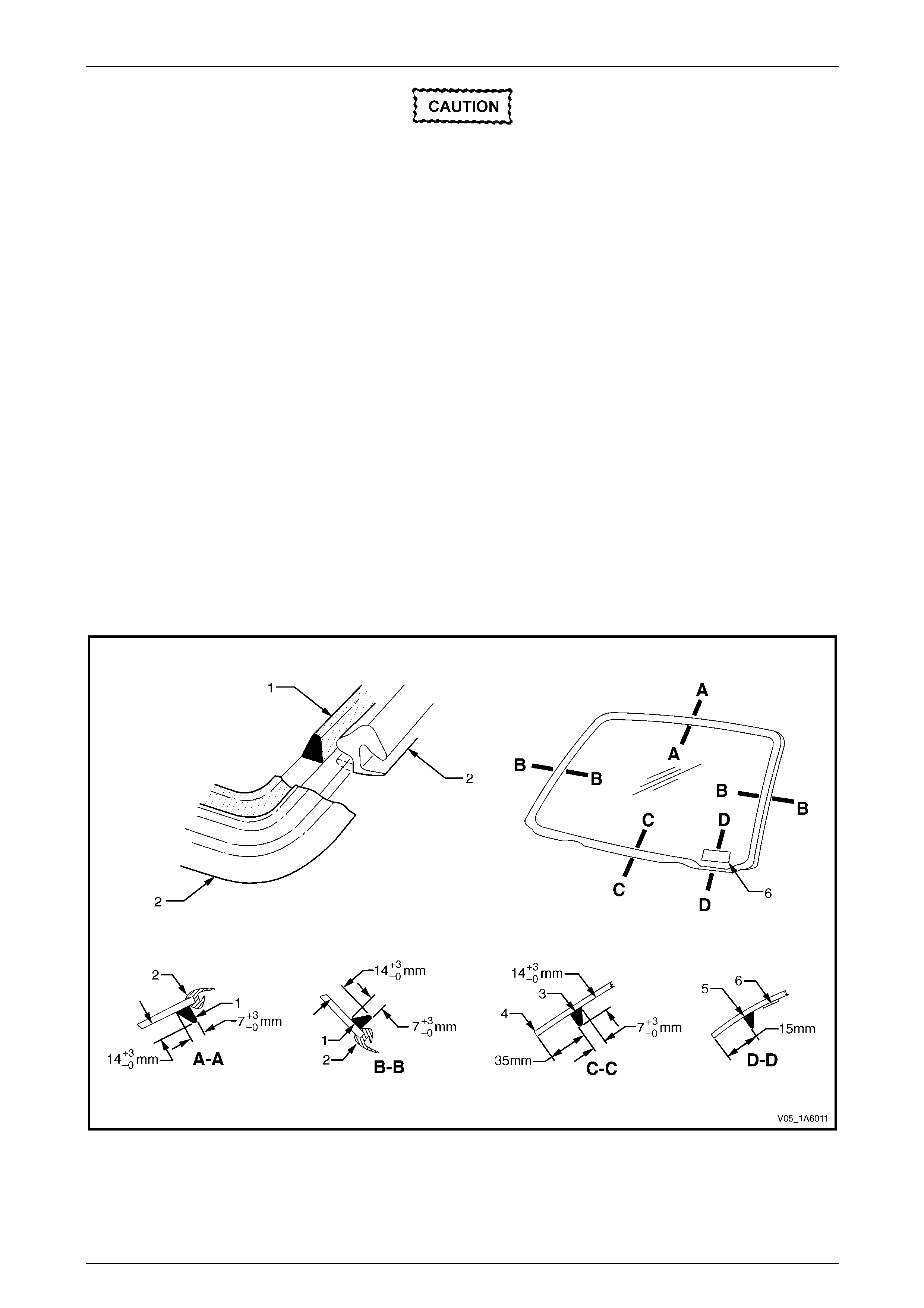
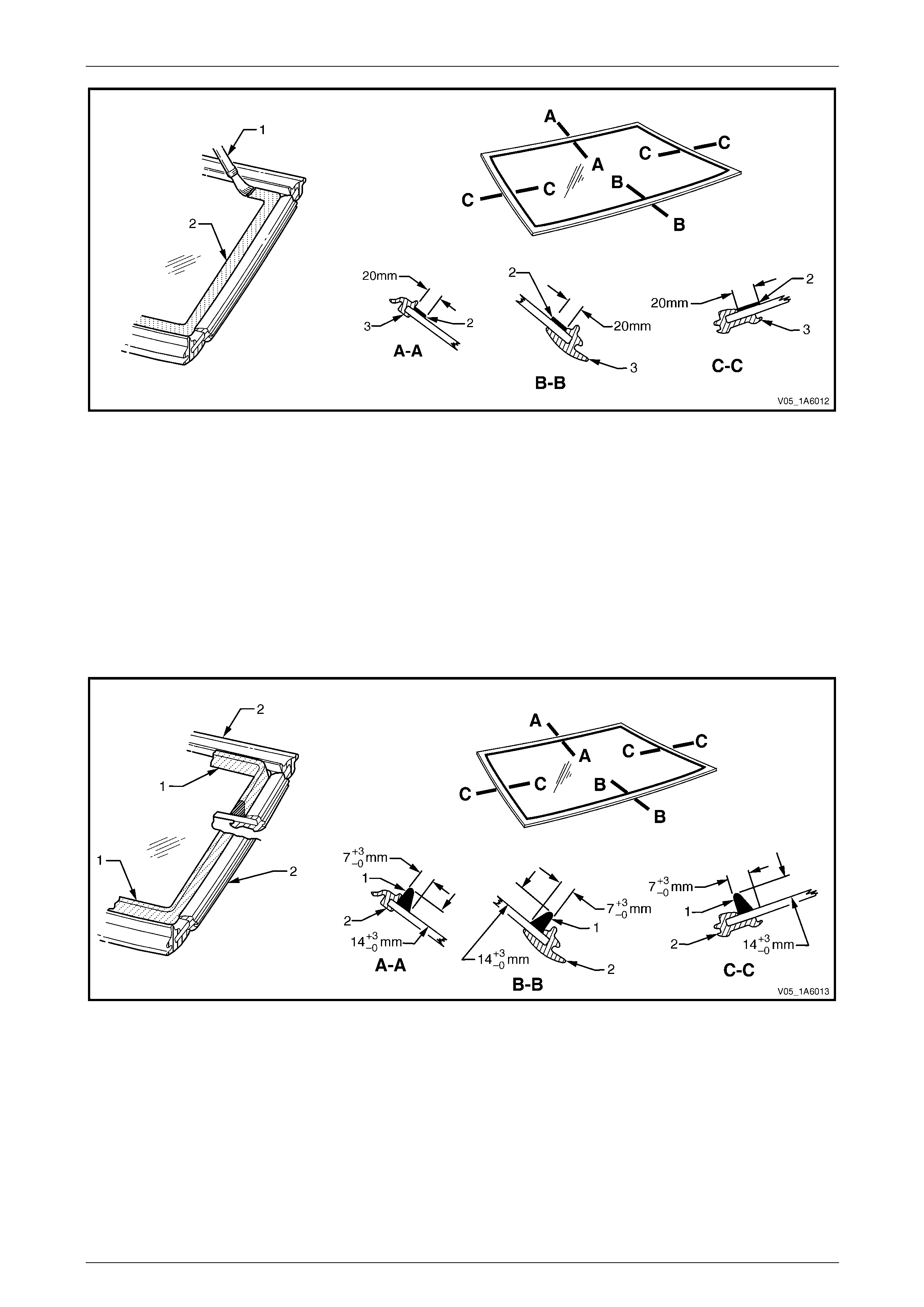
8 Referring to Figure 1A6 – 8, apply a 20 mm wide strip of black glass primer (1) with the applicator (9) included in
the service kit to the inside of the windshield along:
• The upper edge (2), adjacent to the moulding (4).
• The side edges (3), adjacent to the mould ing.
• The lower edge 35 mm from the bottom edge (5) of the windshield. Do not apply primer ac ross the gap for
displaying the Vehicle Identification Number (VIN) (8). Here apply the primer (6) 15 mm from the lower edge
of the windshield (7).
Figure 1A6 – 8
9 For ease of installation and to avoid unnecessary stress on the freshly appli ed urethane, it is recommended the
interior mirror assembly be fitted to the windshield prior to installation of the windshield to the vehicle, refer to
Section 12H Rear-view Mirrors.
Stationary Windows Page 1A6–12
Page 1A6–12
On the lower section of the body opening,
care must be taken to ensure the urethane
bead diameter is such that when compressed
by the windshield installation, the Vehicle
Identification Number (VIN) plate is not
obscured.
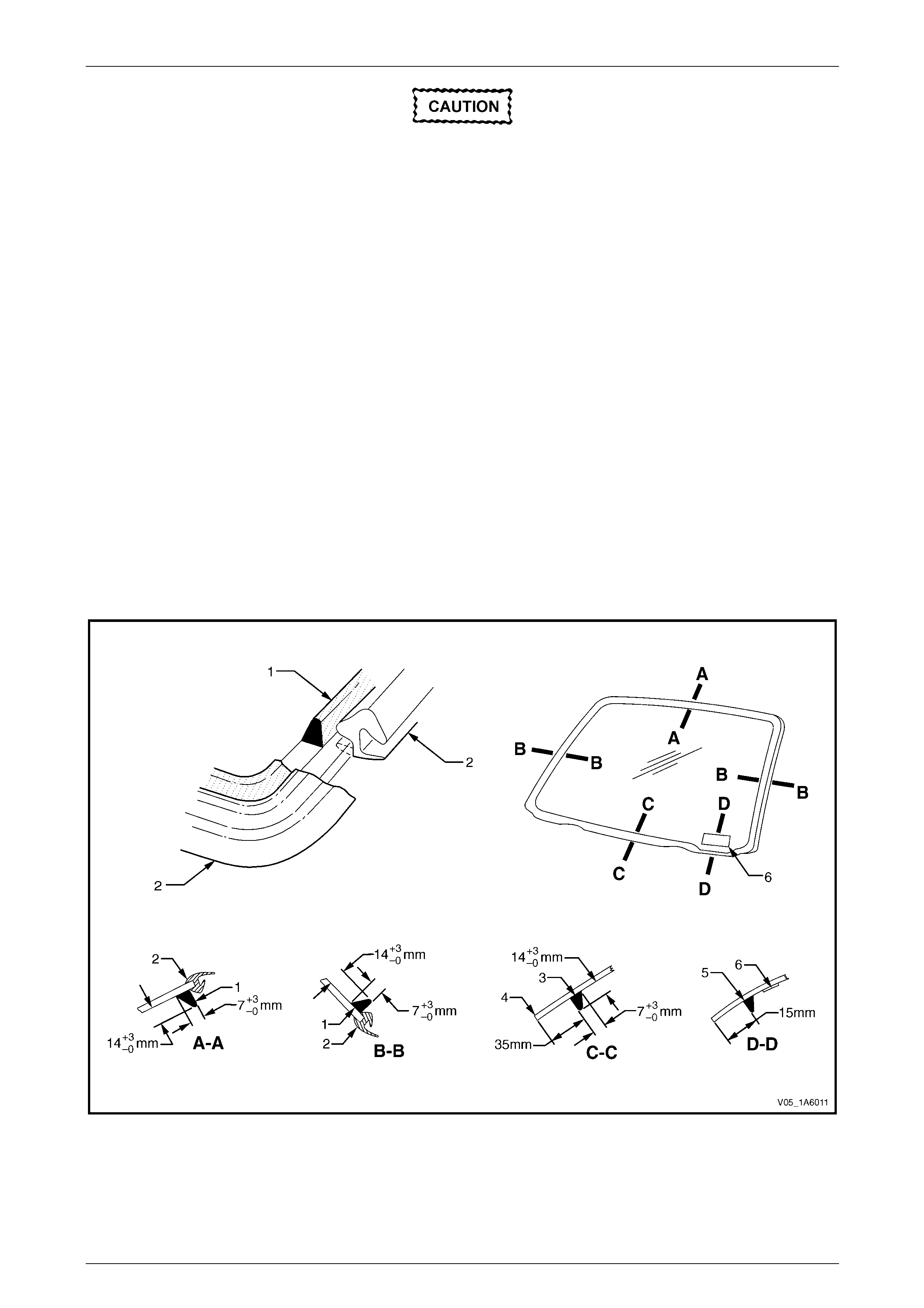
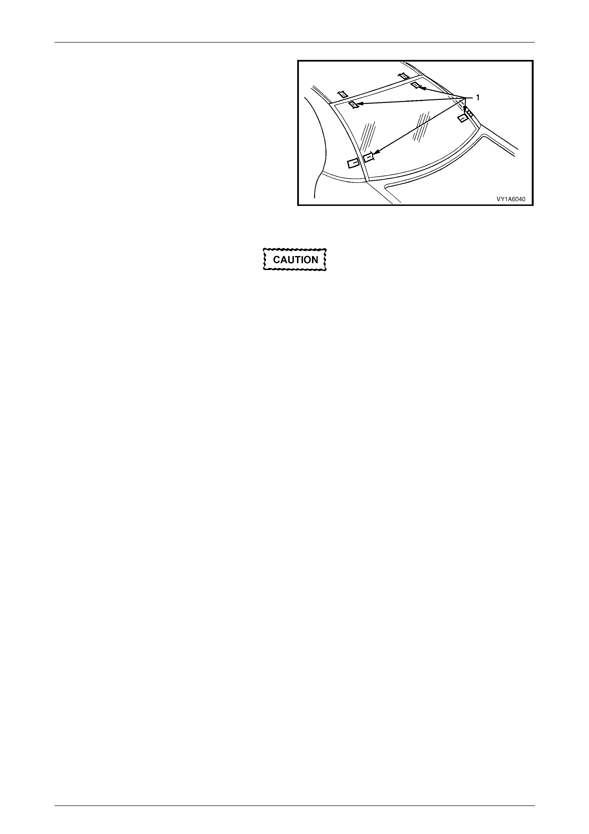
10 Use a hand or automatic applicator to apply a smooth and continuous bead of urethane (1) to the inside of the
windshield (4).
Apply the urethane bead along:
• The upper edge, adjacent to the moulding (2).
• The side edges, adjacent to the mou lding.
• The bottom edge 35 mm inboard from the edge. Adjacent to the gap to display the VIN plate (6) apply a
suitably reduced amount of urethane (5) to ensure the VIN is not obscured when the windshield is installed.
Here apply the urethane (5) 15 mm from the lower edge of the windshield
The amount of new urethane applied should ensure the total amount of uret hane is within the recommended
dimensions. Refer to Figure 1A6 – 9.
NOTE
• Only use urethane adh esive such as Betase al
15685 or equivalent.
• In cold weather, placing the urethane
cartridges adjacent to a source of warmth will
assist in the flow of urethane when using a
hand applicator.
Figure 1A6 – 9
Stationary Windows Page 1A6–13
Page 1A6–13
11 With the aid of an assistant, install the windshield
using the previously attached masking tape (1) on the
roof and windshield pillar as a guide.
• All vehicles except Coupe [A]: Use a windshield
locator (2), between the lower windshield edge
(3) and the reinforcing flange (4), two places, to
locate the windshield vertically in the windshield
opening.
• Coupe [B]: If required, use a windshield locator
(2) between the lower windshield edge (3) and
the extrusion (5) to correctly locate the
windshield in the bo dy opening.
12 Press the windshield firmly into position.
13 Check the effectiveness of sealing from inside the
vehicle. Should any gaps in the sealing exist, apply
additional urethane to fill these gaps.
Do not direct a heavy stream of water onto
freshly applied urethane. If a water leak is
evident, apply addition al urethane to the leak
area, using a spatula to work the urethane
into the source of th e leak.
14 Wait two hours and then water test the windshield
using a moderate spray of water.
15 Clean off any excess urethane using Prepsol or white
spirit.
16 Clean the windshield and then remove the masking
tape previously installed.
17 Reinstall the trim and hardware as required.
Figure 1A6 – 10
Reinstall – Long Method
Description
Throughout the curing period, ensure the
door windows are partially lowered to
eliminate pressure build-up, which can be
caused by slamming doors. A curing time of
24 hours is recommended, although the
vehicle may be driven after five hours
providing it is driven only on a smooth road at
speeds not exceeding 80 km/h with the door
windows partially lowered.
• The long method should be used on vehicles requiring metal or paint repair to the windshield opening or when the
original adhesive is compl etely removed and replaced with new urethane for the windshield installati on.
• This method for the windshield replacement is used when the original ur ethane adhesive material can n ot serve as
a base for the replacement windsh ield.
• This method should also be used when the windshi eld has been previously replaced using the short method. In
such instances, the build-up of urethane could position the windshield too high in the opening.
Stationary Windows Page 1A6–14
Page 1A6–14
Preparation
Care should be taken to ensure the
windshield does not strike the windshield
opening or any other object. Chipped edges
can lead to subsequent breakage of the
windshield.
Do not use petrol eum based sol vents to clean
any part of the window assembly or body
opening as the presence of oil in the solvent
will pre vent th e adhesion of the n ew urethane.
NOTE
Thoroughly check the windshield opening flange
for any irregularities before installing the
windshield.
1 Using a sharp scraper remov e all of the original urethane from around the windshield. Clean the windshield to be
installed with a suitable oil fre e clea ning agent.
2 Using a knife or sharp scraper , carefully remove all the original urethane from around the entire perimeter of the
windshield opening flange. Take care to avoid the removal of paint when removing ur ethane from opening flange.
If any paint work around the windshield
opening flange has been damaged, refinish
the paint before proceeding. Damaged paint
can lead to subsequent rusting.
3 Check for correct alignment of the windshield by:
• All vehicles except Coupe [A]: temporarily
placing the windshield in the bod y open ing. Fit
the windshield locator (1) between the lower
windshield edge (2) and the reinforcing flange
(3).
• Coupe [B]: Place the windshield onto the
extrusion (4) fitted to the reinforcing flange (3). If
required, place a windshie ld locator (1) between
the lower windshield ed ge (2) and the extrusion.
4 Ensure the windshield is centralised in the body
opening left to right by checking the gaps between the
windshield and body opening are eve n on both sides
of the vehicle.
5 With masking tape (5), mark the outer top and side of
the windshield pillar and the roof.
NOTE
This procedure will assist in the alignment of the
windshield in the correct horizontal and vertical
plane during final windshield installation.
6 Remove and place the windshield face down on a
clean protected surface or fixture.
Figure 1A6 – 11
Stationary Windows Page 1A6–15
Page 1A6–15
Reinstall
Do not use petrol eum based sol vents to clean
any part of the window assembly, or body
opening as the presence of oil in the solvent
will pre vent th e adhesion of the n ew urethane.
NOTE
• Flange primer is not required if using the
recommended urethane adhesive Betaseal
15685.
• If using an equivalent to Beta seal 15685 refer
to technical data supplied by the supplier.
1 If required by the supplier of the urethane, apply flange
primer (1) to the region indicated.
2 Thoroughly clean the inner surface and edges of the
windshield to which the urethane is to be applied. Use
a clean lint-free cloth and a suitable oil free cleaning
solvent.
Figure 1A6 – 12
3 Apply a 50 mm wide layer of clear glass primer to the
inner surface of the windshield's perimeter.
Immediately wipe off with a lint-free cloth.
Figure 1A6 – 13
Stationary Windows Page 1A6–16
Page 1A6–16
4 Check the condition of the windshiel d reveal moulding
(1). Discard and replace with a ne w moulding if
damaged.
5 Fit the moulding to the sides and upper section of the
windshield. Ensure the notch of the moulding (2) is
aligned with the V locating mark (3) on the lower
portion of the right-hand and the left-hand side of the
windshield.
Figure 1A6 – 14
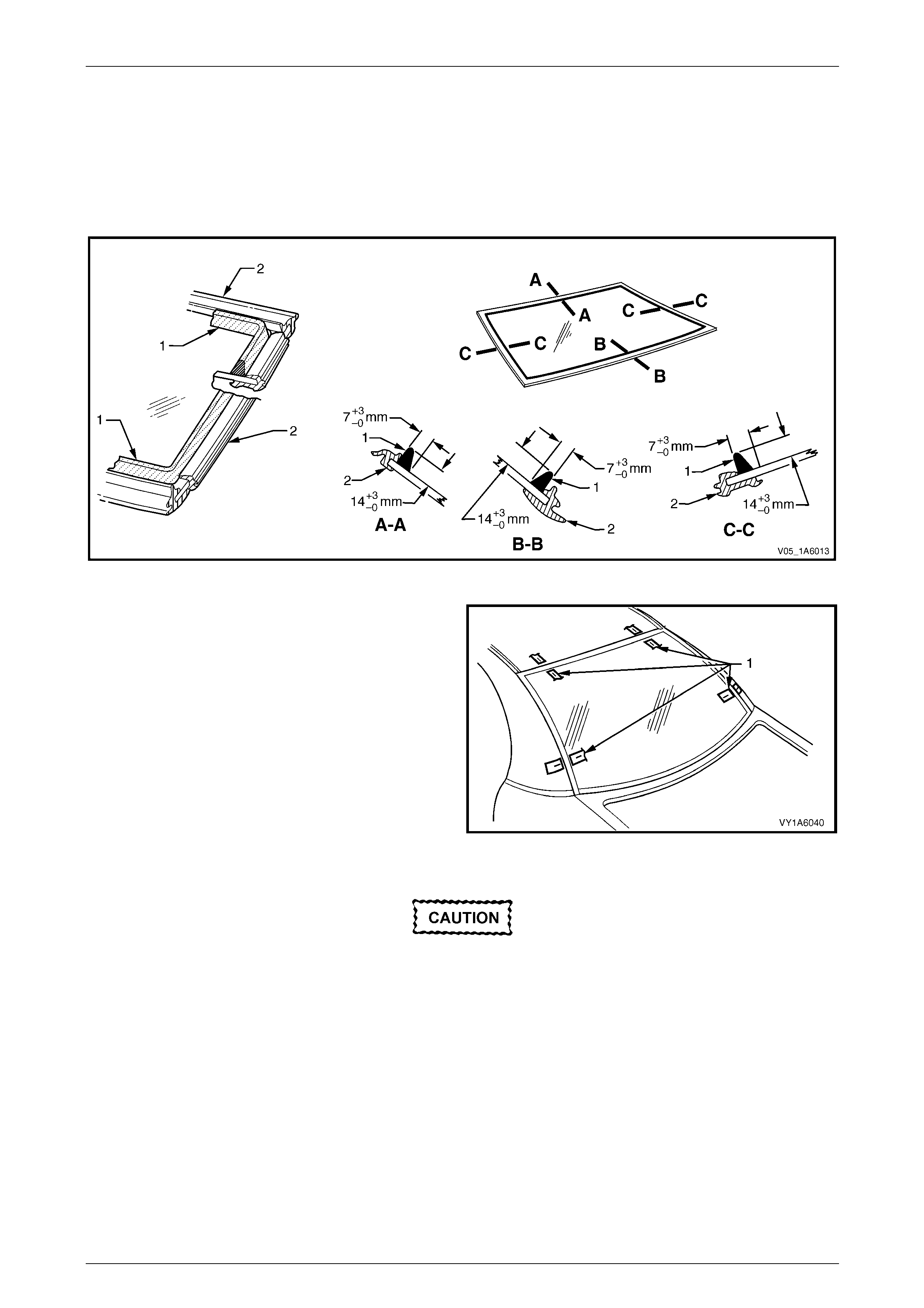
6 Referring to Figure 1A6 – 15, apply a 20 mm wide strip of black glass primer (1) with the applicator (9) included in
the service kit to the inside of the windshield along:
• The upper edge, adjacent to the moulding (4).
• The side edges, adjacent to the mou lding.
• The lower edge 35 mm from the bottom edge of the windshield. Do not ap ply primer across the gap for
displaying the Vehicle Identification Number (VIN) (8). Here apply the primer (6) 15 mm from the lower edge
of the windshield (7).
Figure 1A6 – 15
7 For ease of installation and to avoid unnecessary stress on the freshly appli ed urethane, it is recommended the
interior mirror assembly be fitted to the windshield prior to installation of the windshield to the vehicle, refer to
Section 12H Rear-view Mirrors.
Stationary Windows Page 1A6–17
Page 1A6–17
On the lower section of the body opening,
care must be taken to ensure the urethane
bead diameter is such that when compressed
by the windshield installation, the Vehicle
Identification Number (VIN) plate is not
obscured.
8 Use a hand or automatic applicator to apply a smooth and continuous bead of urethane (1) to the inside of the
windshield.
Apply the urethane bead along:
• The upper edge, adjacent to the moulding.
• The side edges, adjacent to the mou lding.
• The bottom edge 35 mm inboard from the edge. Adjacent to the gap to display the VIN plate (6) apply a
suitably reduced amount of urethane (5) to ensure the VIN is not obscured when the windshield is installed.
Here apply the urethane (5) 15 mm from the lower edge of the windshield
The amount of urethane applied should be within the recomm ended dimensions. Refer to Figure 1A6 – 16.
NOTE
• Only use urethane adh esive such as Betase al
15685 or equivalent.
• In cold weather, placing the urethane
cartridges adjacent to a source of warmth will
assist in the flow of urethane when using a
hand applicator.
Figure 1A6 – 16
Stationary Windows Page 1A6–18
Page 1A6–18
9 With the aid of an assistant, install the windshield
using the previously attached masking tape (1) on the
roof and windshield pillar as a guide.
• All vehicles except Coupe [A]: Use a windshield
locator (2), between the lower windshield edge
(3) and the reinforcing flange (4), two places, to
locate the windshield vertically in the windshield
opening.
• Coupe [B]: If required, use a windshield locator
(2) between the lower windshield edge (3) and
the extrusion (5) to correctly locate the
windshield in the bo dy opening.
10 Press the windshield firmly into position.
11 Check the effectiveness of sealing from inside the
vehicle. Should any gaps in the sealing exist, apply
additional urethane to fill these gaps.
Do not direct a heavy stream of water onto
freshly applied urethane. If a water leak is
evident, apply addition al urethane to the leak
area, using a spatula to work the urethane
into the source of th e leak.
12 Wait two hours and then water test the windshield
using a moderate spray of water.
13 Clean off any excess urethane using Prepsol or white
spirit.
14 Clean the windshield and then remove the masking
tape previously installed.
15 Reinstall the trim and hardware as required.
Figure 1A6 – 17
Stationary Windows Page 1A6–19
Page 1A6–19
4 Service Operations – Side
4.1 Quarter Window Assembly, Wagon
(except AWD Wagon)
LT Section No. — 11–030
Safety glasses an d work glo ves must be w orn
at all times when operating with glass.
Care must be taken during any operation
involving the side glass removal or
installation, to not exert any load on the
window. Failure to observe this may result in
damage to the window.
NOTE
To retain a watertight seal the following
component will require replacement when
performing this operation.
• Quarter window nut (13 required)
Preparation
As required, remove the following components:
1 Rear door opening weatherstrip assembly, refer to Section 1A5 Front and Rear Door Assemblies.
2 Body lock pillar garnish, refer to Section 1A8 Headlining and Interior Trim.
3 Body rear corner garnish, refer to Section 1A8 Headlinin g and Interior Trim.
4 Quarter inner trim panel assembly, refer to Section 1A8 Headlining and Interior Trim.
Remove
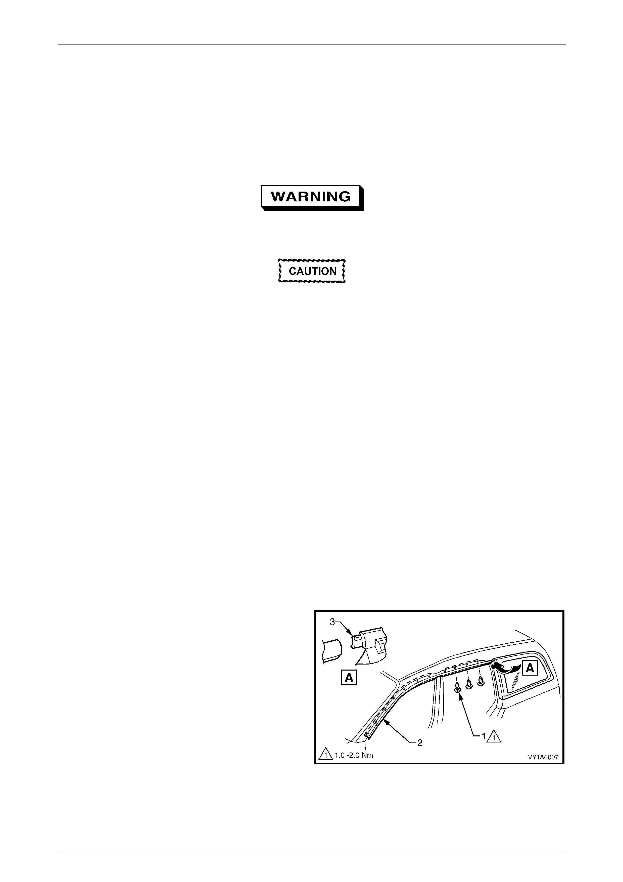
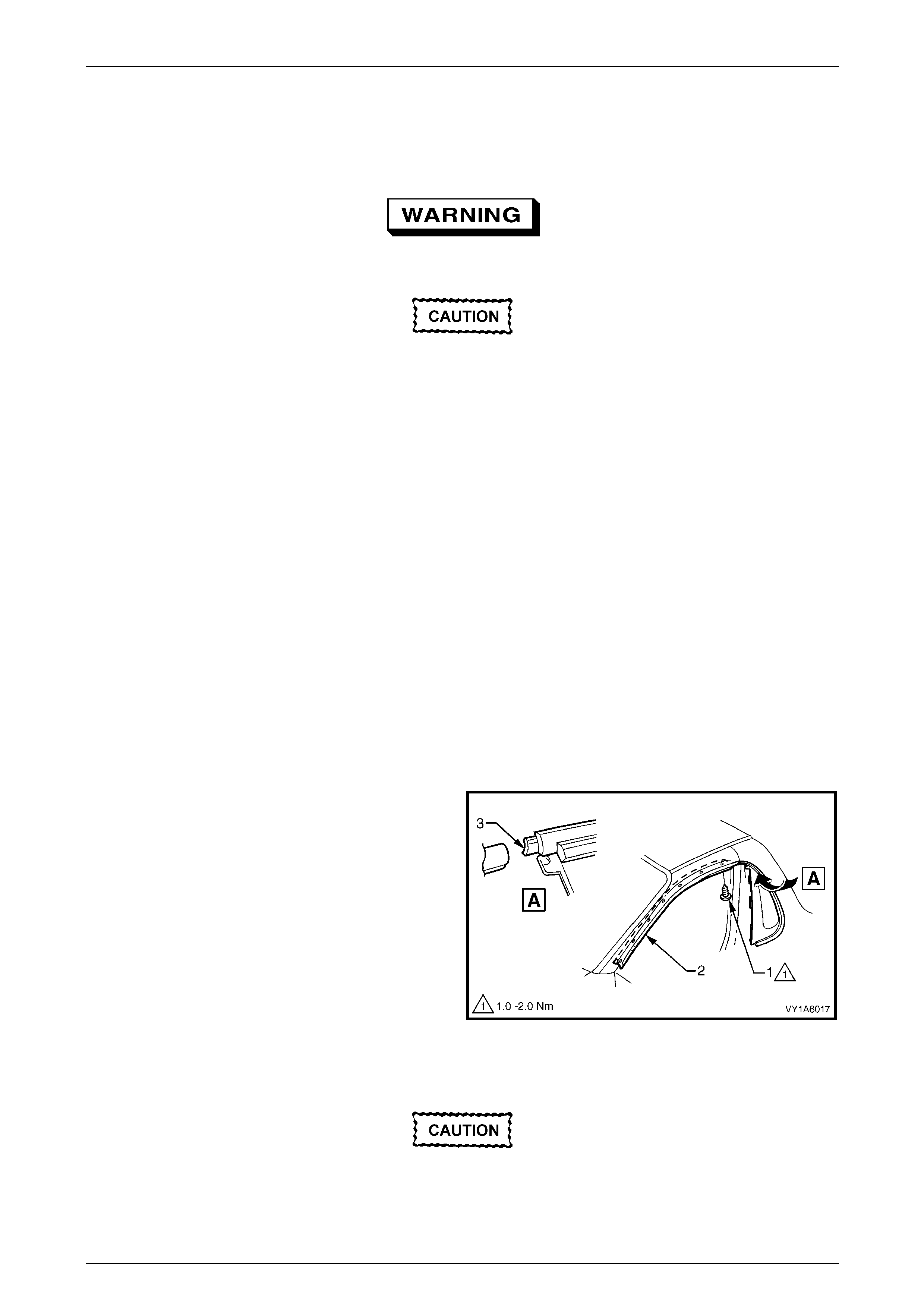
1 Remove the three screws (1) and partially remove the
rear section of the door opening moulding (2) where it
joins the quarter window assembly tab (3).
Figure 1A6 – 18
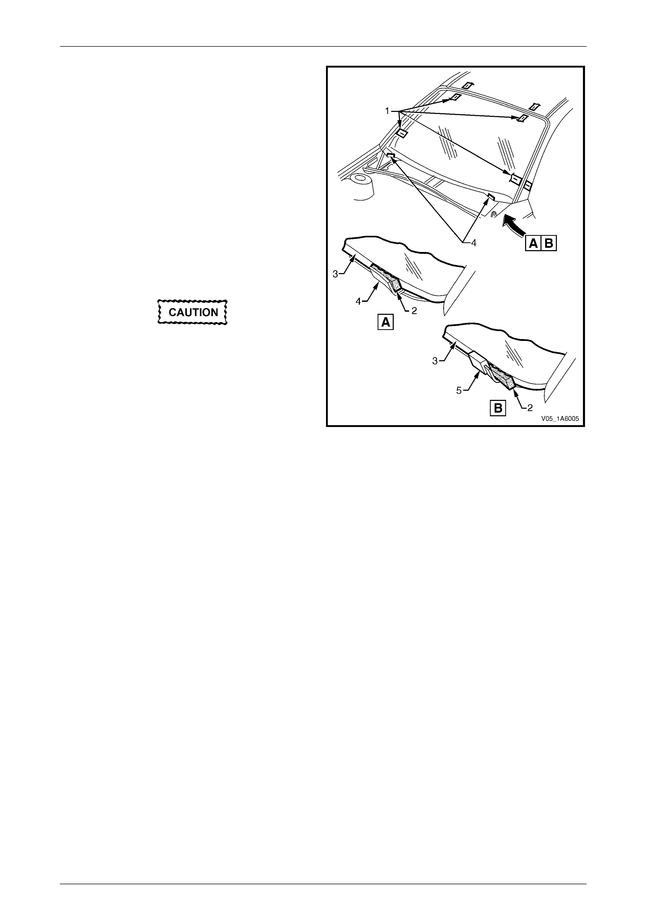
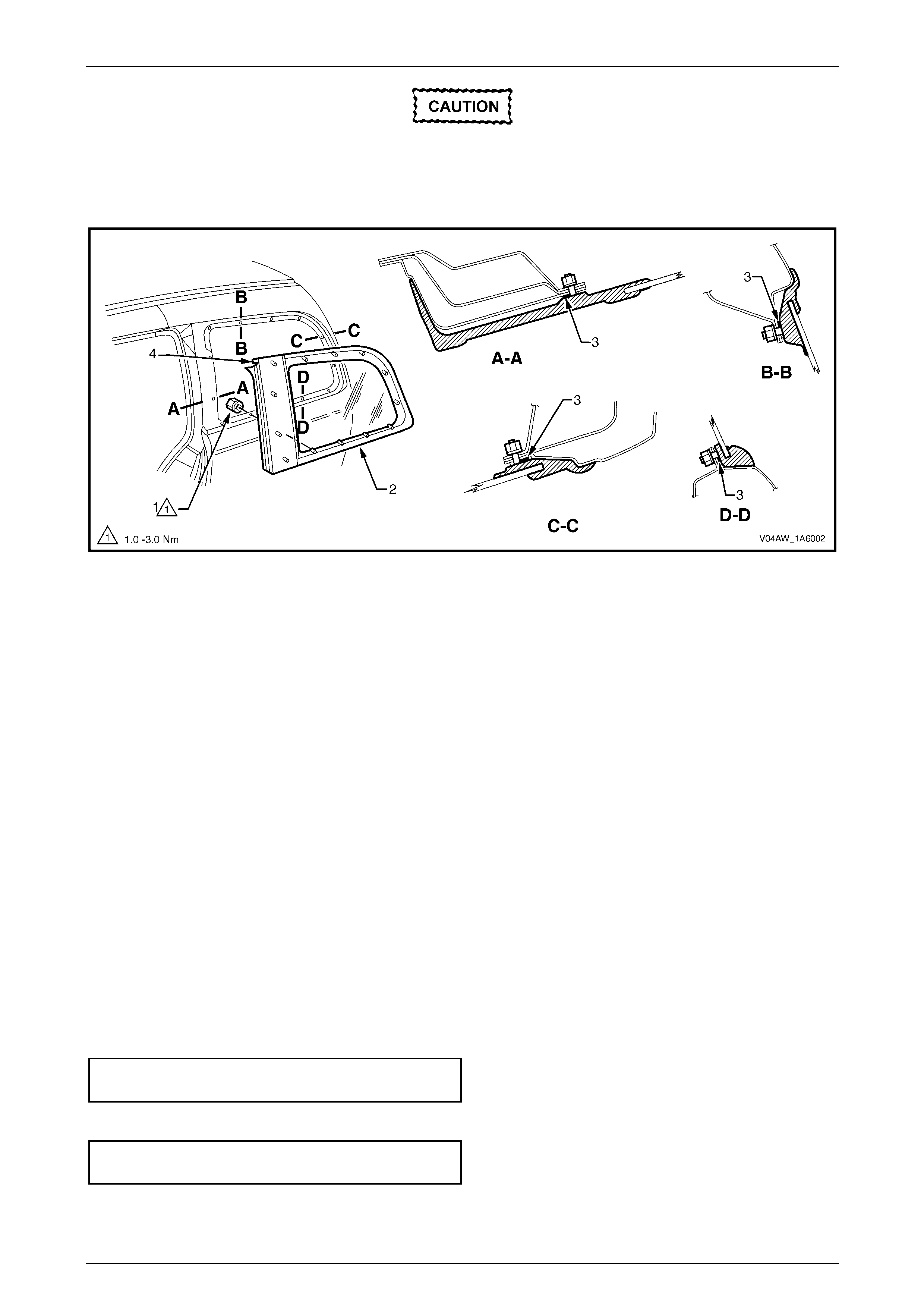
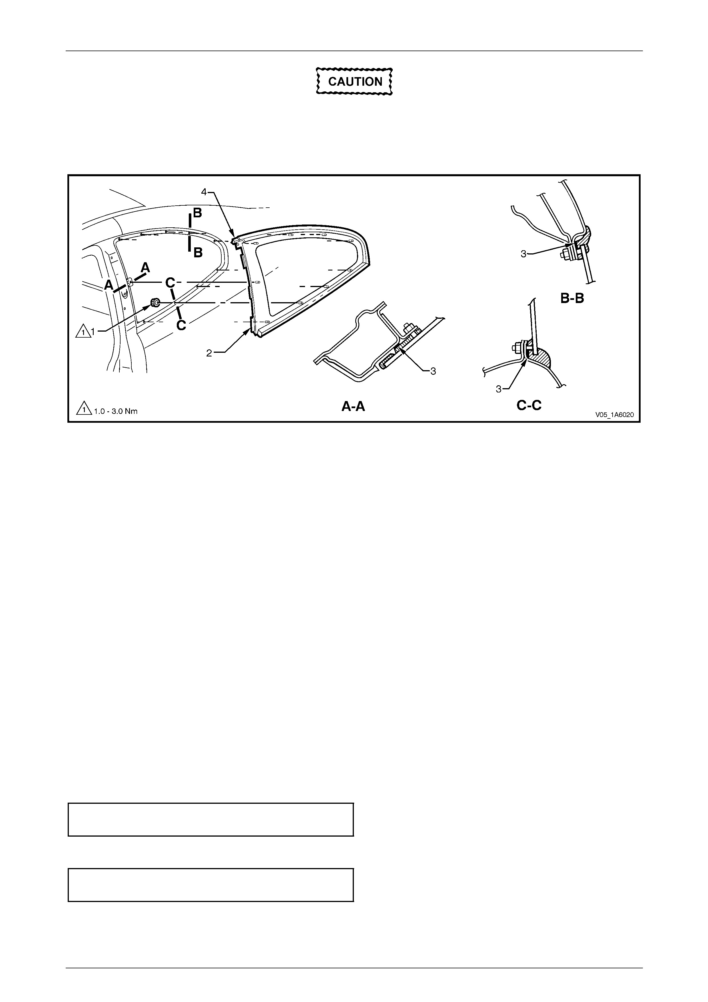
2 Remove the quarter window nut (1), 13 places, securing the quarter window assembly (2) to the bod y opening refer
to Figure 1A6 – 19.
Stationary Windows Page 1A6–20
Page 1A6–20
Take care when removing the quarter window
from the body opening, the attaching pins are
clear of the outer body.
3 Carefully lift the window from the vehicle.
Figure 1A6 – 19
Legend
1 Quarter Window Nut (13 places)
2 Quarter Window Assembly 3 Foam Seal
4 Tab to Door Opening Moulding
NOTE
Sectional views show installed condition.
Reinstall
1 Ensure the seal (3) is in sound condition, refe r to F igure 1A6 – 19.
2 Fit the quarter window into the body openin g, ensuring the tab (4) engages the door opening moulding and the pins
are correctly aligned into the holes in the bo dy opening.
NOTE
The quarter window nuts are encapsulated with a
wax sealer. It is recommended the nuts be
replaced once removed, however if this is not
possible apply a small amount of sealer to the
end of the thread.
3 Install new nuts attaching the quarter window to the body opening. Do not tighten.
4 Position the door opening mouldi ng and tighten the screws to the correct torque specification.
Door opening moulding attaching
screw torque specification...........................1.0 – 2.0 Nm
5 Tighten the quarter window nuts to the correct torque specification.
Quarter window assembly attaching
nut torque specification...............................1.0 – 3.0 Nm
6 Perform a water test of the window's sealing, using a moderate spray of water.
7 Reinstall the trim and hardware as required.
Stationary Windows Page 1A6–21
Page 1A6–21
4.2 Quarter Window Assembly, AWD Wagon
LT Section No. — 11–030
Safety glasses an d work glo ves must be w orn
at all times when operating with glass.
Care must be taken during any operation
involving the side glass removal or
installation, to not exert any load on the
window. Failure to observe this may result in
damage to the window.
NOTE
To retain a watertight seal the following
component will require replacement when
performing this operation.
• Quarter window nut (13 required)
Preparation
As required, remove the following components:
1 Quarter inner trim panel assembly, refer to Section 1A8 Headlining and Interior Trim.
2 Rear quarter window appliqué assembly, refer to Section 1A9 Exterior Ornamentation.
3 Rear door opening weatherstrip assembly, refer to Section 1A5 Front and Rear Door Assemblies.
4 Body lock pillar garnish, refer to Section 1A8 Headlining and Interior Trim.
5 Body rear corner garnish, refer to Section 1A8 Headlinin g and Interior Trim.
Remove
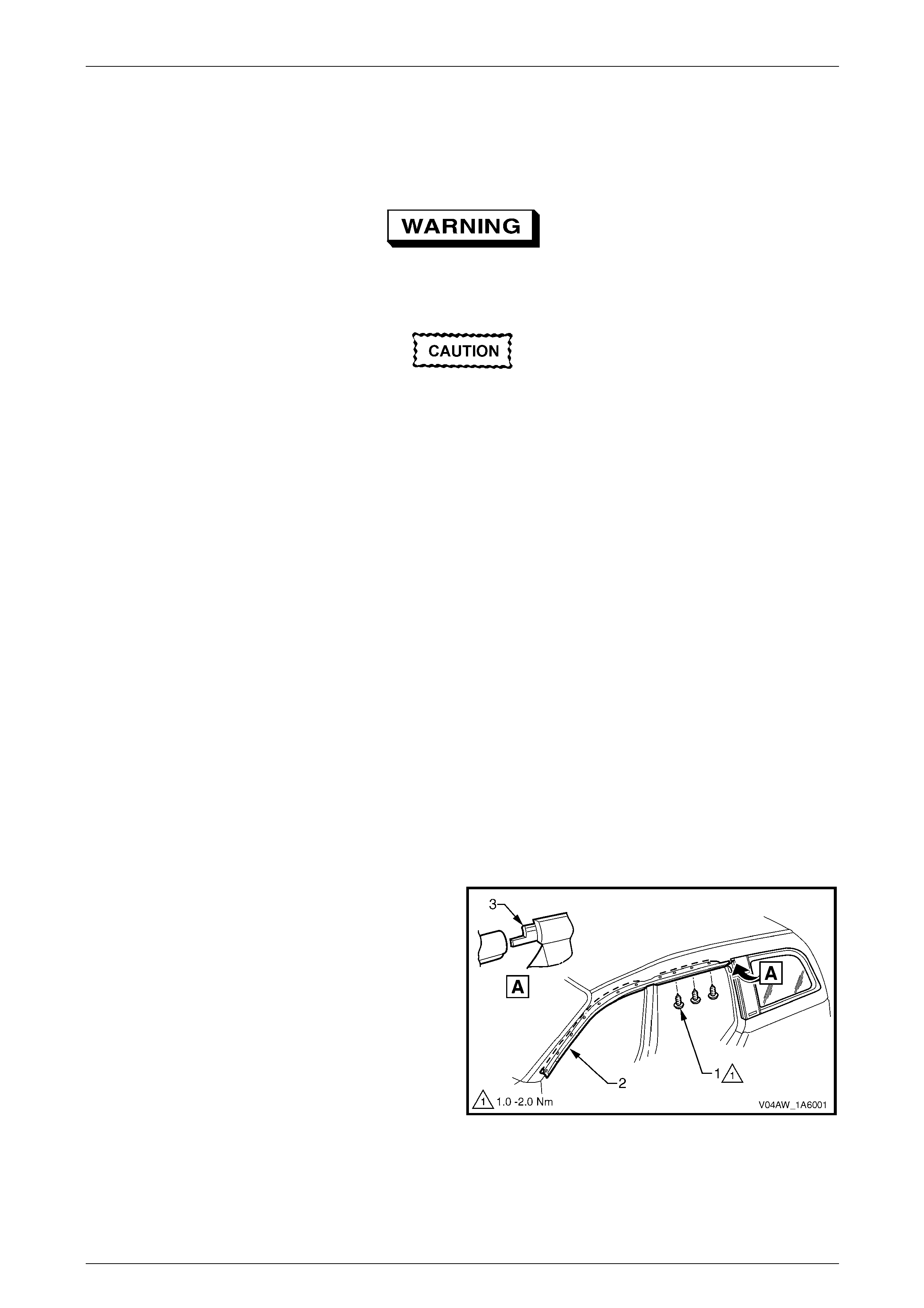
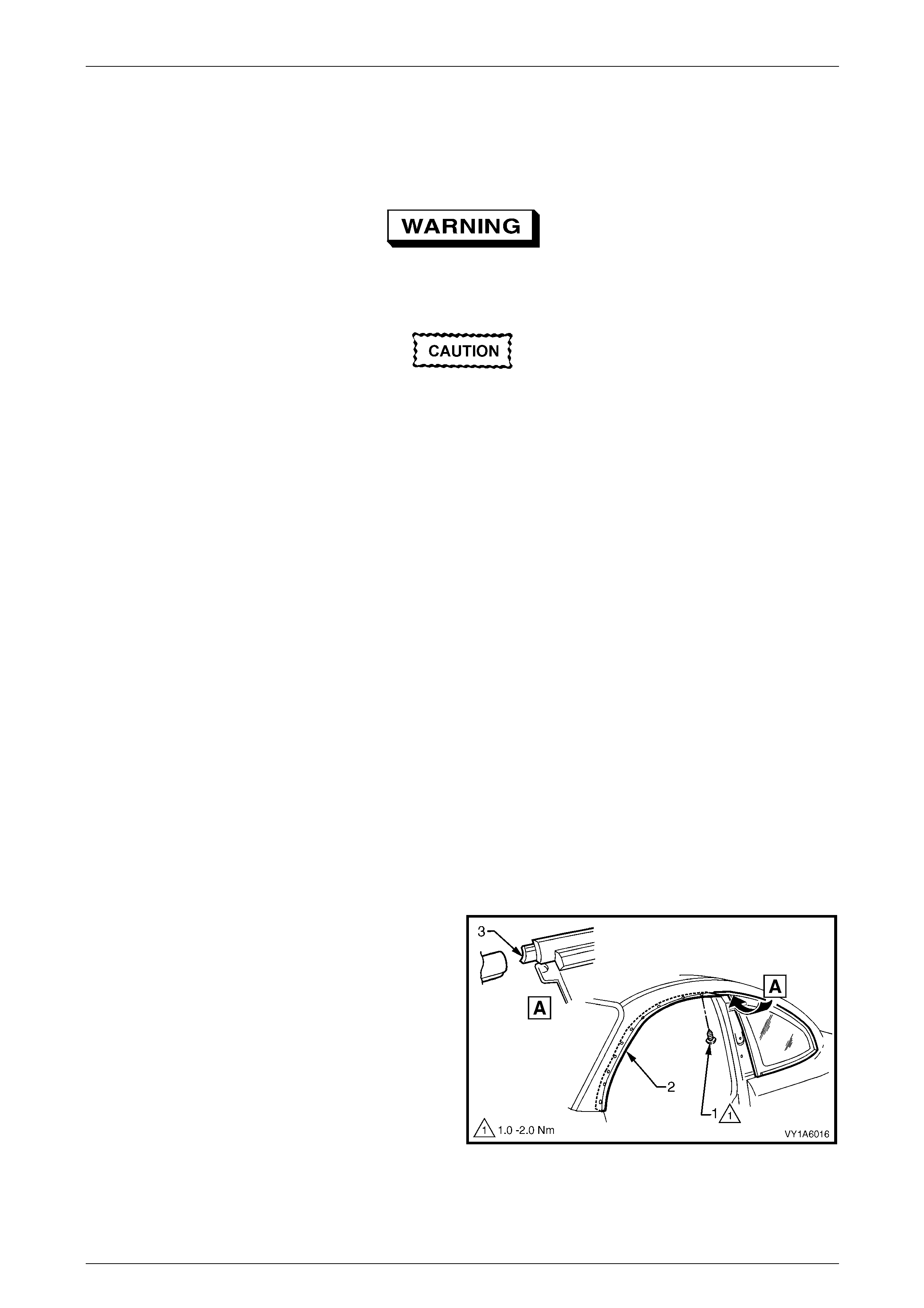
1 Remove the three screws (1) and partially remove the
rear section of the door opening moulding (2) where it
joins the rear quarter window assembly tab (3).
Figure 1A6 – 20
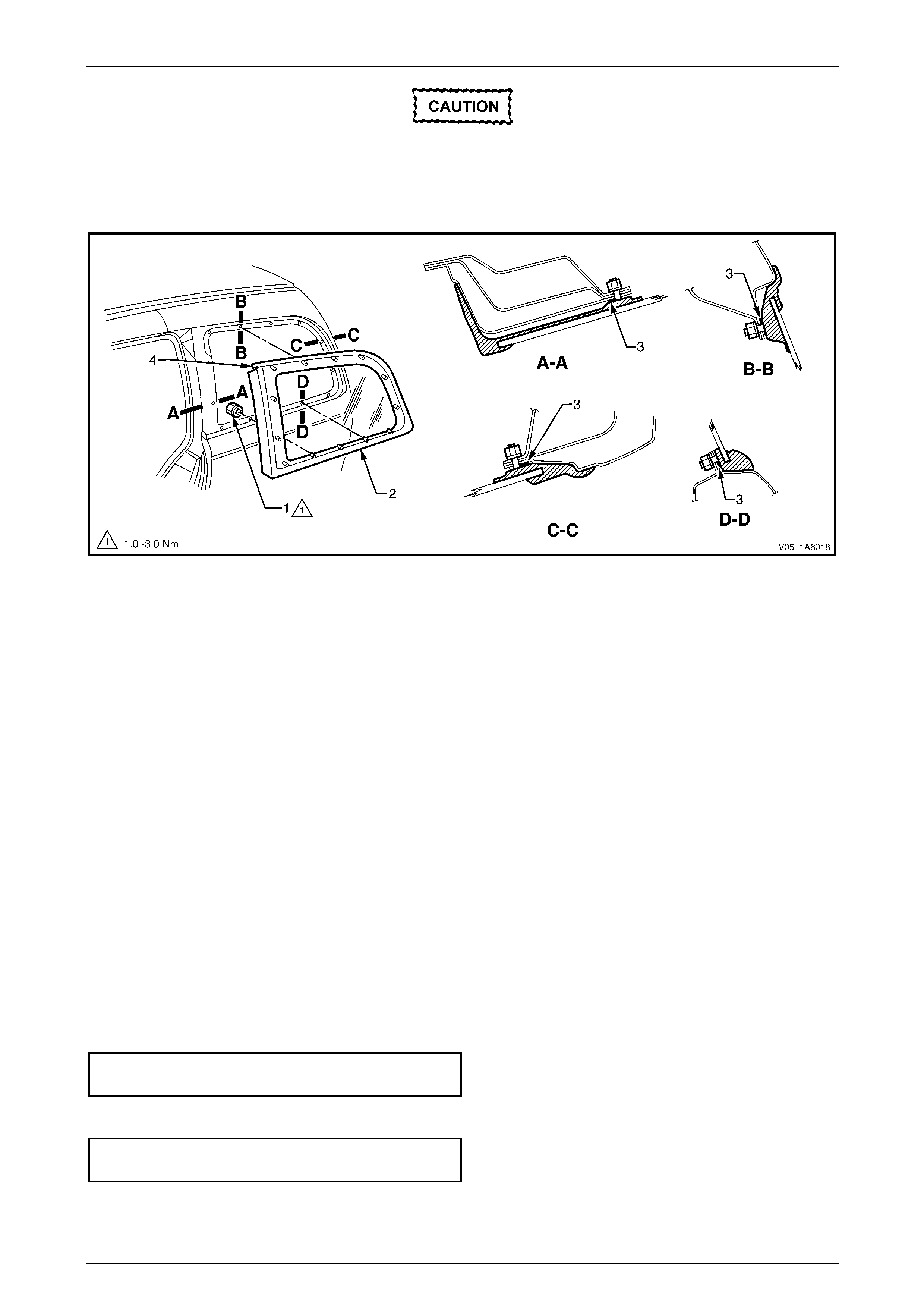
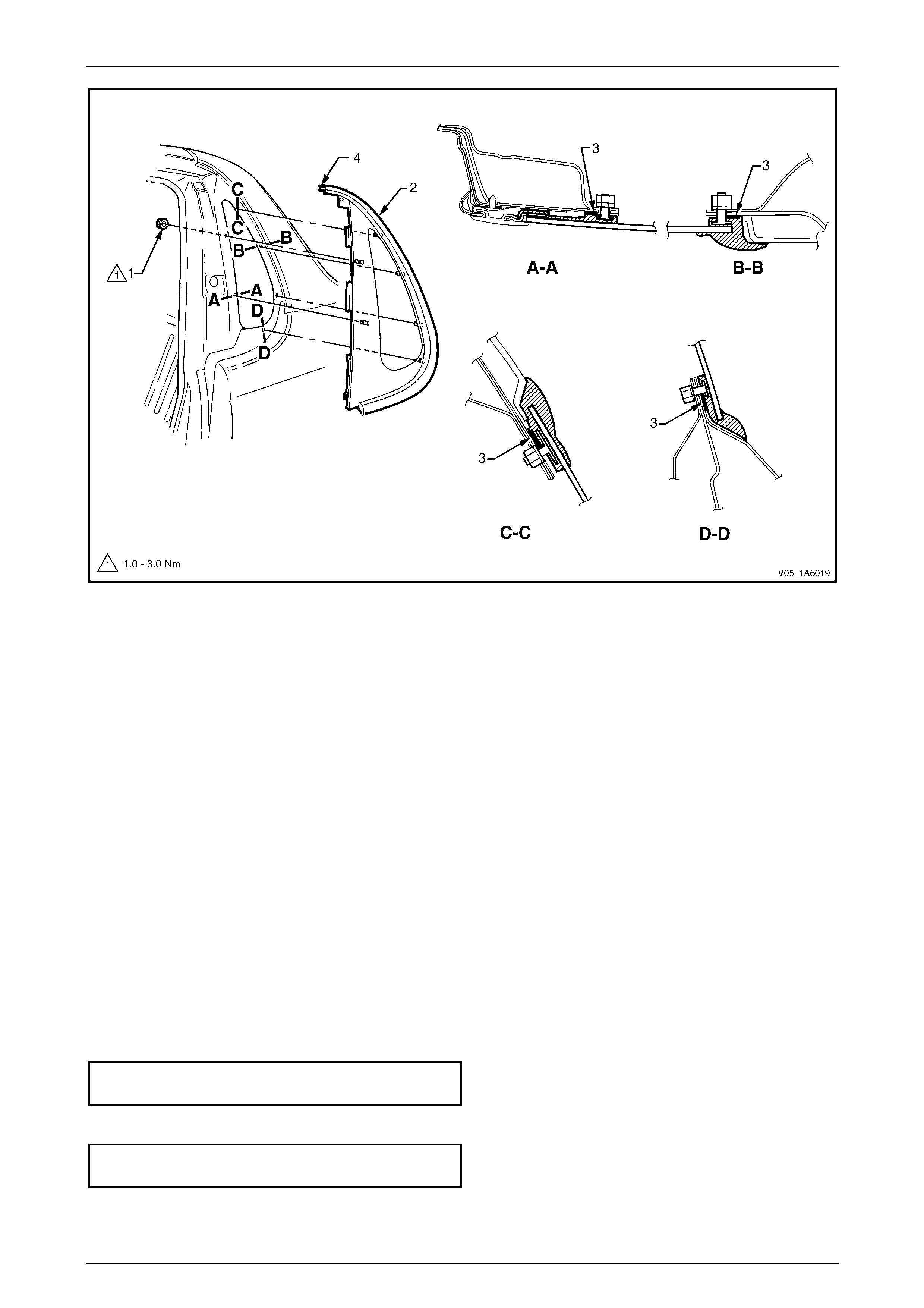
2 Remove the quarter window nut (1), 13 places, securing the quarter window assembly (2) to the body opening,
refer to Figure 1A6 – 21.
Stationary Windows Page 1A6–22
Page 1A6–22
Take care when removing the quarter window
from the body opening, the attaching pins are
clear of the outer body.
3 Carefully lift the window from the vehicle.
Figure 1A6 – 21
Legend
1 Quarter Window Nut (13 places)
2 Quarter Window Assembly 3 Foam Seal
4 Tab to Door Opening Moulding
NOTE
Sectional views show installed condition.
Reinstall
1 Ensure the foam seal (3) is in sound con ditio n, refer to F igure 1A6 – 21.
2 Fit the quarter window into the body openin g, ensuring the tab (4) engages the door opening moulding and the pins
are correctly aligned into the holes in the bo dy opening.
NOTE
The quarter window nuts are encapsulated with a
wax sealer. It is recommended the nuts be
replaced once removed, however if this is not
possible apply a small amount of sealer to the
end of the thread.
3 Install new nuts attaching the quarter window to the body opening. Do not tighten.
4 Position the door opening mouldi ng and tighten the screws to the correct torque specification.
Door opening moulding attaching
screw torque specification...........................1.0 – 2.0 Nm
5 Tighten the quarter window nuts to the correct torque specification.
Quarter window assembly attaching
nut torque specification...............................1.0 – 3.0 Nm
6 Perform a water test of the window's sealing, using a moderate spray of water.
7 Reinstall the trim and hardware as required.
Stationary Windows Page 1A6–23
Page 1A6–23
4.3 Quarter Window Assembly, Utility and
Regular Cab
LT Section No. — 11–025
Safety glasses an d work glo ves must be w orn
at all times when operating with glass.
Care must be taken during any operation
involving the side glass removal or
installation, to not exert any load on the
window. Failure to observe this may result in
damage to the window.
NOTE
To retain a watertight seal the following
component will require replacement when
performing this operation.
• Quarter window nut (six required)
Preparation
As required, remove the following components:
1 Front door opening weatherstrip assembly, refer to Section 1A5 Front an d Rear Door Assemblies.
2 Centre pillar lower trim, refer to Section 1A8 Headlining and Interior Trim.
3 Body lock pillar upper trim refer to Section 1A8 Headlining and Interior Trim.
4 Centre pillar upper finisher, refer to Section 1A9 Exterior Ornamentation.
Remove
1 As required remove the screw (1), several places, to
partially remove the rear section of the door opening
moulding (2) where it joins the quarter window
assembly tab (3).
Figure 1A6 – 22
2 Remove the quarter window nut (1), six places, securing the quarter window assembly (2) to the bod y opening,
refer to Figure 1A6 – 23.
Take care when removing the quarter window
from the body opening, the attaching pins are
clear of the outer body.
3 Carefully lift the window from the vehicle.
Stationary Windows Page 1A6–24
Page 1A6–24
Figure 1A6 – 23
Legend
1 Quarter Window Nut (six places)
2 Quarter Window Assembly 3 Foam Seal
4 Tab to Door Opening Moulding
NOTE
Sectional views show installed condition.
Reinstall
1 Ensure the foam seal (3) is in sound con ditio n, refer to F igure 1A6 – 23.
2 Fit the quarter window into the body openin g, ensuring the tab (4) engages the door opening moulding and the pins
are correctly aligned into the holes in the bo dy opening.
NOTE
The quarter window nuts are encapsulated with a
wax sealer. It is recommended the nuts be
replaced once removed, however if this is not
possible apply a small amount of sealer to the
end of the thread.
3 Install new nuts attaching the quarter window to the body opening. Do not tighten.
4 Position the door opening mouldi ng and tighten the screws to the correct torque specification.
Door opening moulding attaching
screw torque specification...........................1.0 – 2.0 Nm
5 Tighten the quarter window nuts to the correct torque specification.
Quarter window assembly attaching
nut torque specification...............................1.0 – 3.0 Nm
6 Perform a water test of the window's sealing, using a moderate spray of water.
7 Reinstall the trim and hardware as required.
Stationary Windows Page 1A6–25
Page 1A6–25
4.4 Quarter Window Assembl y, Coupe
LT Section No. — 11–020
Safety glasses an d work glo ves must be w orn
at all times when operating with glass.
Care must be taken during any operation
involving the side glass removal or
installation, to not exert any load on the
window. Failure to observe this may result in
damage to the window.
NOTE
To retain a watertight seal the following
component will require replacement when
performing this operation.
• Quarter window nut (nine required)
Preparation
As required, remove the following components:
1 Front door opening weatherstrip assembly, refer to Section 1A5 Front an d Rear Door Assemblies.
2 Partially remove the side sill trim and p late, refer to Section 1A8 Headlining and Interior Trim.
3 Quarter trim panel assembly, refer to Section 1A8 Headlining and Interior Trim.
4 Centre pillar upper trim assembly, refer to Section 1A8 Headlinin g and Interior Trim.
5 Body rear corner garnish, refer to Section 1A8 Headlinin g and Interior Trim.
6 Centre pillar upper finisher, refer to Section 1A9 Exterior Ornamentation.
Remove
1 As required remove the screw (1), several places, to
partially remove the rear section of the door opening
moulding (2) where it joins the quarter window
assembly tab (3).
Figure 1A6 – 24
2 Remove the quarter window nut (1), nine places, securing the quarter window assembly (2) to the body opening,
refer to Figure 1A6 – 25
Stationary Windows Page 1A6–26
Page 1A6–26
Take care when removing the quarter window
from the body opening, the attaching pins are
clear of the outer body.
3 Carefully lift the window from the vehicle.
Figure 1A6 – 25
Legend
1 Quarter Window Nut (nine places)
2 Quarter Window Assembly 3 Foam Seal
4 Tab to Door Opening Moulding
NOTE
Sectional views show installed condition.
Reinstall
1 Ensure the seal foam (3) is in sound condition, refer to Figure 1A6 – 25.
2 Fit the quarter window into the body openin g, ensuring the tab (4) engages the door opening moulding and the pins
are correctly aligned into the holes in the bo dy opening.
NOTE
The quarter window nuts are encapsulated with a
wax sealer. It is recommended the nuts be
replaced once removed, however if this is not
possible apply a small amount of sealer to the
end of the thread.
3 Install new nuts attaching the quarter window to the body opening. Do not tighten.
4 Position the door opening mouldi ng and tighten the screws to the correct torque specification.
Door opening moulding attaching
screw torque specification...........................1.0 – 2.0 Nm
5 Tighten the quarter window nuts to the correct torque specification.
Quarter window assembly attaching
nut torque specification...............................1.0 – 3.0 Nm
6 Perform a water test of the window's sealing, using a moderate spray of water.
7 Reinstall the trim and hardware as required.

Stationary Windows Page 1A6–27
Page 1A6–27
5 Service Operations, Rear
5.1 Rear Window Assembly, Sedan
LT Section No. — 11–020
Safety glasses an d work glo ves must be w orn
at all times when operating with glass.
Care must be taken during any operation
involving the glass removal or installation, to
not exert any load on the window. Failure to
observe this may result in damage to the
window.
NOTE
• Only use urethane adh esive such as Betase al
15685 or equivalent.
• Skinning (partial curing) of the urethane
commences after exposure to the
atmosphere. At 23 degrees Celsius and 50
percent relative humidity, skinning
commences after 30 minutes. Complete
curing of the urethane at this temperature an d
humidity takes 72 hours.
• Urethane service kits are available from most
windshield agents. Manufacturer’s instruction s
should always be foll owed.
• Window assemblies should be installed in the
window opening within five minutes of the
application of urethane.
• The rear window moulding may require
replacement when performing this operation.
Description
The rear window assembly removal procedure is the same for both the sh ort and long installation methods, with one
exception. If the short method installation is to be used, care must be taken during the rear windo w removal to ensure
that an even surface of the original remainin g urethane exists in the body opening, to serve as a base for the new
urethane bead and the repl acement rear window.
Preparation
Prevent damage to the paint finish and
minimise clean up by using protective covers
and masking tape over the regions adjacent
to the rear window.
As required, remove the following components:
1 Roof panel joint finish moulding, refer to Section 1A9 Exterior Ornamentation.
2 Body lock pillar garnish, refer to Section 1A8 Headlining and Interior Trim.
3 Rear window upper garnish, refer to Section 1A8 Headlining and Interior Tr im.
Stationary Windows Page 1A6–28
Page 1A6–28
Remove
A high mount stop lamp assembly is installed
below the rear window trim panel assembly.
Care must be taken to avoid damage to the
lamp assembly during window removal
procedure. It is not necessary to remove the
lamp assembly, b ut to ensure that it is clear of
any debris before window installation.
NOTE
To remove the windshield or rear window special
tool J36020 is required. Alternately manufacture
an equivalent tool. Refer to 6 Special Tools.
1 Disconnect the rear window electrical demister connectors and ce llular telephone antenna if fitted.
2 If the rear window is broken, take care to remove all fragments of glass from the window opening.
Ensure the headlining and other trim items
are not damaged while cutting the urethane.
3 Use special tool J36020, or equivalent, thread one end of the piano wire through the urethane, starting at the rear
window upper corner. Pull the end of the wire through with pliers.
4 Connect the end of the piano wire to the other han dle of the special tool or equivale nt.
5 With the aid of an assistant commence cutting the urethane bead. Keep the outside handle (1) parallel to the edge
of the rear window. Use the full length of the wire to prevent heat build up in the wire refer to Figure 1A6 – 26.
NOTE
To minimise the damage to the interior of the
vehicle, the operator inside th e vehicle should act
as an anchor point. Holdin g the T-handle as close
as possible to the rear window at all times,
(especially along the lower edge of the rear
window), while the outside op erator pulls the wire
up to the interior T-handle in a walking motion.
Stationary Windows Page 1A6–29
Page 1A6–29
Figure 1A6 – 26
6 Carefully lift the rear windo w out of the rear opening. If there is evidence of the window adhering to the urethane,
cut the area again with the piano wire.
7 If the original rear window is to be installed a gain, place the window on a clean protected surface or a holding
fixture.
NOTE
• The use of suction cu ps will greatly assist an y
handling of the rear window.
• All traces of urethane must be removed from
the rear window. It is not necessary to remove
all traces of the original urethane from the
body opening, unless the long method of
reinstallation is being used. However, any
original urethane remaining must be smooth
and firm.

Stationary Windows Page 1A6–30
Page 1A6–30
Reinstall – Short Method
Description
Throughout the curing period ensure that
door windows are partially lowered to
eliminate pressure build-up, which can be
caused by slamming doors. A curing time of
24 hours is recommended, although the
vehicle may be driven after five hours
providing it is driven only on a smooth road at
speeds not exceeding 80 km/h with the door
windows partially lowered.
• The short method is recommended when replacing a cracked or broken rear window, or a leak condition that can
not be overcome by using minor water leak repair procedures.
• The short method installation i nvolves leaving the maximum amount of the original urethane intact on the body
opening to form a sound base for the replacement urethane and rear window. Any original urethane remaining
must be smooth and firm.
• If material other than urethane has been used for previous servicing of the rear window, the long method
installation procedure (complete removal of adhesive) is mandatory to achieve an effective window to metal bond.
Preparation
Care should be taken to ensure the rear
window does not strike the rear window
opening or any other object. Chipped edges
can lead to subsequent breakage of the rear
window.
Do not use petrol eum based sol vents to clean
any part of the window assembly or body
opening as the presence of oil in the solvent
will pre vent th e adhesion of the n ew urethane.
1 Use a sharp scraper to carefully remove all th e original urethane from around the rear window. Clean the rear
window to be installed with a suitable oil free cleaning agent.
2 Check for correct alignment of the rear window by temporarily placing the rear windo w in the body opening.
3 Ensure the rear windo w is centralised in th e body opening left to right by checking the g aps between the rear
window and body opening are even on both sides of the vehicle.
Stationary Windows Page 1A6–31
Page 1A6–31
4 Use masking tape (1) to mark the position on the outer
top of the roof and the rear quarter panel.
NOTE
This procedure will assist in the alignment of the
rear window in the correct horizontal and vertical
plane during final rear window installation.
5 Remove and place the rear window face down on a
clean protected surface or fixture.
Figure 1A6 – 27
Reinstall
Do not use petrol eum based sol vents to clean
the rear w indow assembly o r the rear openi ng
flange as the presenc e of t he oil in the solvent
will pre vent th e adhesion of the n ew urethane.
1 As required, remove the rear window moulding.
2 Thoroughly cle an the inner surface and edge s of the rear window assembly to which the urethane is to be ap plied,
using clean lint-free cloths and a suitable oil free cleaning s olve nt.
3 Apply a 50 mm wide layer of clear glass primer to the
inner surface of the rear window's perimeter.
Immediately wipe off with a lint-free cloth.
4 If using an existing rear windo w moulding, check its
condition. If damaged discard and replace it.
Figure 1A6 – 28
5 Install the rear window upper reveal moulding (1) and
the rear window lower reveal moulding (2) o v er the
edge of the window. Ensure the mouldings are fitted
correctly to the window.
6 Install the rear window side moul ding retainer (3) on
both sides. Ensure all the retainers are posi tioned to
the alignment marks (4), and are fitted correctly to
edge of the window.
7 Check the condition of the original urethane around
the window opening flange for voids or looseness.
8 Cut away any loose pieces of urethane.
9 Use a spatula to spread fresh uretha ne smoothly into
any voids or uneven sections. Figure 1A6 – 29
10 Referring to Figure 1A6 – 30, apply a 20 mm wide strip of black glass primer (2) with the applicator (1) included in
the service kit adjacent to the inside edge of the window moulding (3).
Stationary Windows Page 1A6–32
Page 1A6–32
Figure 1A6 – 30
11 Use a hand or automatic applicator to appl y a smooth and continuo us bead of urethane (1) to the inside of the rear
window adjacent to the inside edge of the window moulding (2). The amount of new urethane applied should
ensure the total amount of urethane is within the recommended dimensions. Refer to Figure 1A6 – 31.
NOTE
• Only use urethane adh esive such as Betase al
15685 or equivalent.
• In cold weather, placing the urethane
cartridges adjacent to a source of warmth will
assist in the flow of urethane when using a
hand applicator.
Figure 1A6 – 31
Stationary Windows Page 1A6–33
Page 1A6–33
12 With the aid of an assistant, install the windshield
using the previously attached masking tape (1) on the
roof and the rear quarter panel as a guide.
NOTE
Ensure the rear window is centralised in the
body opening left to right by checking the gaps
between the windo w mouldin g and b ody op enin g
are even on both sides of the vehicl e.
13 Press the rear window firmly into position.
14 Check the effectiveness of seal from inside the
vehicle. Should any gaps in the sealing exist, apply
additional urethane to fill these gaps. Figure 1A6 – 32
Do not direct a heavy stream of water onto
freshly applied urethane. If a water leak is
evident, apply additional urethane to the leak
area, using a spatula to work the urethane
into the source of th e leak.
15 Wait two hours and then water test the rear window. Use only a moderate spray of water.
16 Clean off any excess urethane using Prepsol or white spirit. Clean the rear window and then remove the masking
tape previously installed.
17 Connect the electrical demist connectors and cell ular telephone antenna if fitted.
18 Reinstall the trim and hardware as required.

Stationary Windows Page 1A6–34
Page 1A6–34
Reinstall – Long Method
Description
Throughout the curing period ensure the door
windows are partially lowered to eliminate
pressure build-up, which can be caused by
slamming doors. A curing time of 24 hours is
recommended, although the vehicle may be
driven after five hours providing it is driven
only on a smooth road at speeds not
exceeding 80 km/h with the door windows
partially lowered.
• The long method should be used on vehicles requiring metal or paint repair to the rear window opening or when the
original adhesive is completely removed and replaced with new urethane for the rear window installation.
• This method for the rear windo w replacemen t is used when the original urethane adhesive material can not serve
as a base for the replacement rear window.
• This method should also be used when the rear window has been previously replaced using the short method. In
such instances, the build-up of urethane could position the rear window too high in the opening.
Preparation
Care should be taken to ensure the rear
window does not strike the rear window
opening or any other object. Chipped edges
can lead to subsequent breakage of the rear
window.
Do not use petrol eum based sol vents to clean
any part of the window assembly or body
opening as the presence of oil in the solvent
will pre vent th e adhesion of the n ew urethane.
NOTE
Thoroughly check the rear window opening
flange for any irregularities before installing the
rear window.
1 Use a sharp scraper to carefully remove an y origi na l urethane from around the rear window. Clean the rear window
to be installed with a suitable oil free cl eaning agent.
2 Use a knife or sharp scraper to carefully remove the original urethane from around the entire perimeter of the rear
window opening flange. Take care to avoid the removal of paint when removing urethane from ope ning flange.
If any paint work around the rear window
opening flange has been damaged, refinish
the paint before proceeding. Damaged paint
can lead to subsequent rusting.
Stationary Windows Page 1A6–35
Page 1A6–35
3 Check for correct alignment of the rear window by temporarily placing the rear windo w in the body opening.
4 Ensure the rear windo w is centralised in th e body opening left to right by checking the g aps between the rear
window and body opening are even on both sides of the vehicle.
5 With masking tape (1), mark the outer top of the roof
and the rear quarter panel.
NOTE
This procedure will assist in the alignment of the
rear window in the correct horizontal and vertical
plane during final rear window installation.
6 Remove and place the rear window assembly face
down on a clean protected s urface or fixture.
Figure 1A6 – 33
Reinstall
Do not use petrol eum based sol vents to clean
any part of the window assembly, or body
opening as the presence of oil in the solvent
will pre vent th e adhesion of the n ew urethane.
NOTE
• Flange primer is not required if using the
recommended urethane adhesive Betaseal
15685.
• If using an equivalent to Beta seal 15685 refer
to technical data supplied by the supplier.
1 If required by the supplier of the urethane, apply flange
primer (1) to the region indicated.
2 As required, remove the rear window moulding.
3 Thoroughly clean the inner surface and edges of the
rear window assembly to which the urethane is to be
applied, using clean lint-free cloths and a suitable oil
free cleaning solvent.
Figure 1A6 – 34

Stationary Windows Page 1A6–36
Page 1A6–36
4 Apply a 50 mm wide layer of clear glass primer to the
inner surface of the rear window's perimeter.
Immediately wipe off with a lint-free cloth.
5 If using an existing rear windo w moulding, check its
condition. If damaged discard and replace it.
Figure 1A6 – 35
6 Install the rear window upper reveal moulding (1) and
the rear window lower reveal moulding (2) o v er the
edge of the window. Ensure the mouldings are fitted
correctly to the window.
7 Install the rear window side moul ding retainer (3) on
both sides. Ensure all the retainers are posi tioned to
the alignment marks (4), and are fitted correctly to
edge of the window.
Figure 1A6 – 36
8 Referring to Figure 1A6 – 37, apply a 20 mm wide strip of black glass primer (2) with the applicator (1) included in
the service kit adjacent to the inside edge of the window moulding (3).
Figure 1A6 – 37
9 Use a hand or automatic applicator to appl y a smooth and continuo us bead of urethane (1) to the inside of the rear
window adjacent to the inside edge of the window moulding (2). The amount of urethane applied sho uld be within
the recommended dimensions. Refer to Figure 1A6 – 38.
Stationary Windows Page 1A6–37
Page 1A6–37
NOTE
• Only use urethane adh esive such as Betase al
15685 or equivalent.
• In cold weather, placing the urethane
cartridges adjacent to a source of warmth will
assist in the flow of urethane when using a
hand applicator.
Figure 1A6 – 38
10 With the aid of an assistant, install the rear window
assembly. Use the previously attached masking tape
(1) on the roof and the rear quarter panel as a guide.
NOTE
Ensure the rear window is centralised in the
body opening left to right by checking the gaps
between the windo w mouldin g and b ody op enin g
are even on both sides of the vehicl e.
11 Press the rear window firmly into position.
12 Check the effectiveness of seal from inside the
vehicle. Should any gaps in the sealing exist, apply
additional urethane to fill these gaps. Figure 1A6 – 39
Do not direct a heavy stream of water onto
freshly applied urethane. If a water leak is
evident, apply additional urethane to the leak
area, using a spatula to work the urethane
into the source of th e leak.
13 Wait two hours and then water test the rear window. Use only a moderate spray of water.
14 Clean off any excess urethane using Prepsol or white spirit. Clean the rear window, then remove the masking tape
previously installed.
15 Connect the electrical demist connectors and cell ular telephone antenna if fitted.
16 Reinstall the trim and hardware as required.
Stationary Windows Page 1A6–38
Page 1A6–38
5.2 Liftgate Window Assembly, Wagon
(except AWD Wagon)
LT Section No. — 11–030
NOTE
The AWD Wagon is fitted with an openin g liftgate
window. For service procedures refer to
Section 1A4 Hood, Rear Compartment Lid,
Liftgate and Endgate.
Safety glasses an d work glo ves must be w orn
at all times when operating with glass.
Care must be taken during any operation
involving the glass removal or installation, to
not exert any load on the window. Failure to
observe this may result in damage to the
window.
NOTE
• Only use urethane adh esive such as Betase al
15685 or equivalent.
• Skinning (partial curing) of the urethane
commences after exposure to the
atmosphere. At 23 degrees Celsius and 50
percent relative humidity, skinning
commences after 30 minutes. Complete
curing of the urethane at this temperature an d
humidity takes 72 hours.
• Urethane service kits are available from most
windshield agents. Manufacturer’s instruction s
should always be foll owed.
• Window assemblies should be installed in the
window opening within five minutes of the
application of urethane.
• The liftgate window moulding may require
replacement when performing this operation.
Description
The liftgate window assembly removal procedure is the same for both the short and the long installation methods, with
one exception. If the short method installation is to be used, more care must be taken during the liftgate window removal
to ensure that an even surface of the original remain ing urethane exists in the liftgate opening. This will serve as a base
for the new urethane bead an d the replacement liftgate window. Any left urethane must be smooth and firm.
Stationary Windows Page 1A6–39
Page 1A6–39
Preparation
Prevent damage to the paint finish and
minimise clean up by using protective covers
and masking tape over the regions adjacent
to the liftgate window.
As required, remove the following components:
• rear window wiper arm assembly,
• high mount stop lamp,
• liftgate window lower garnish,
• liftgate window upper garnish, and
• liftgate Air Deflector Assembly, refer to Section 1A4 Hood, Rear Compartment Lid, Liftgate and E ndgate.
Remove
NOTE
To remove the windshield or rear window special
tool J36020 is required. Alternately manufacture
an equivalent tool. Refer to 6 Special Tools.
1 Disconnect the liftgate window electrical demister connectors and cellular teleph one antenna if fitted.
2 If the liftgate window is broken take care to remove all fragments of glass from the window opening.
Ensure the headlining and other trim items
are not damaged while cutting the urethane.
3 Use special tool J36020, or equiv alent, thread one end of the piano wire through the urethane, starting at the
liftgate window upper corner. Pull the end of the wire through with pliers.
4 Connect the end of the piano wire to the other han dle of the special tool or equivale nt.
5 With the aid of an assistant commence cutting the urethane bead. Keep the outside handle (1) parallel to the edge
of the liftgate window. Use the full length of the wire to prevent heat build up in the wire refer to Figure 1A6 – 40.
NOTE
To minimise the damage to the interior of the
vehicle, the operator inside th e vehicle should act
as an anchor point. Holdin g the T-handle as close
as possible to the liftgate window at all times
while the outside operator pulls the wire up t o the
interior T-handle in a walking motion.
Stationary Windows Page 1A6–40
Page 1A6–40
Figure 1A6 – 40
6 Carefully lift the liftgate window out of the rear openin g. If there is ev idence of the window adhering to the urethane,
cut the area again with the piano wire.
7 If the original rear window is to be installed a gain, place the window on a clean protected surface or a holding
fixture.
NOTE
• The use of suction cu ps will greatly assist an y
handling of the rear window.
• All traces of urethane must be removed from
the liftgate window. It is not necessary to
remove all traces of the ori gin al ur ethane fro m
the body opening, unless the long method of
reinstallation is being used. However, any
original urethane remaining must be smooth
and firm.

Stationary Windows Page 1A6–41
Page 1A6–41
Reinstall – Short Method
Description
Throughout the curing period, ensure the
door windows are partially lowered to
eliminate pressure build-up, which can be
caused by slamming doors. A curing time of
24 hours is recommended, although the
vehicle may be driven after five hours
providing it is driven only on a smooth road at
speeds not exceeding 80 km/h with the door
windows partially lowered.
• The short method is recommende d when replacing a cracked or broken liftgate window, or a leak condition that
cannot be overcome by using the minor water leak repair procedures.
• The short method installation i nvolves leaving the maximum amount of the original urethane intact on the body
opening to form a sound base for the replacement urethane and liftgate window. Any original urethane remaining
must be smooth and firm.
• If material other than urethane has been used for previous servicing of the liftgate window, the long method
installation procedure (complete removal of adhesive) is mandatory to achieve an effective window to metal bond.
Preparation
Care should be taken to ensure the liftgate
window does not strike the lift window
opening or any other object. Chipped edges
can lead to subsequent breakage of the
liftgate window.
Do not use petrol eum based sol vents to clean
any part of the window assembly or body
opening as the presence of oil in the solvent
will pre vent th e adhesion of the n ew urethane.
1 Use a sharp scraper to carefully remove an y origi na l urethane from around the liftgate window. Clean the liftgate
window to be installed with a suitable oil free cleaning agent.
2 Check for correct alignment by temporarily placing the liftgate window in the body opening.
3 Ensure the liftgate window is centralised i n th e body opening left to right by checking the gaps between the liftgate
window and body opening are even on both sides of the vehicle.
Stationary Windows Page 1A6–42
Page 1A6–42
4 Use masking tape (1) to mark the position on the outer
top of the roof and the rear quarter panel.
NOTE
This procedure will assist in the alignment of the
liftgate window in the correct horizontal and
vertical plane during final liftgate window
installation.
5 Remove and place the liftgate window face down on a
clean protected surface or fixture.
Figure 1A6 – 41
Reinstall
Do not use petrol eum based sol vents to clean
the lift window assembly or the rear opening
flange as the presenc e of t he oil in the solvent
will pre vent th e adhesion of the n ew urethane.
1 As required, remove the liftgate window moulding.
2 Thoroughly cle an the inner surface and edges of the liftgate wind ow assembly to which the urethane is to be
applied, using clean lint-free c loths an d a suitable oil free cleaning solvent.
3 Apply a 50 mm wide layer of clear glass primer to the
inner surface of the liftgate window's perimeter.
Immediately wipe off with a lint-free cloth.
4 If using an existing liftgate window moulding, check its
condition. If damaged discard and replace it.
Figure 1A6 – 42
5 Align the window moulding (1) corner with the
alignment marks (2) on the underside of the window in
both the left hand and right hand lo wer corne rs. Install
the moulding.
6 Check the condition of the original ureth ane around
the liftgate opening flange for voids or looseness.
7 Cut away any loose pieces of urethane.
8 Using a suitable spatula, spre ad fresh urethane
smoothly into any voids or uneven sectio ns.
Figure 1A6 – 43
9 Referring to Figure 1A6 – 44, apply a 20 mm wide strip of black glass primer (2) with the applicator (1) included in
the service kit adjacent to the inside edge of the window moulding (3).
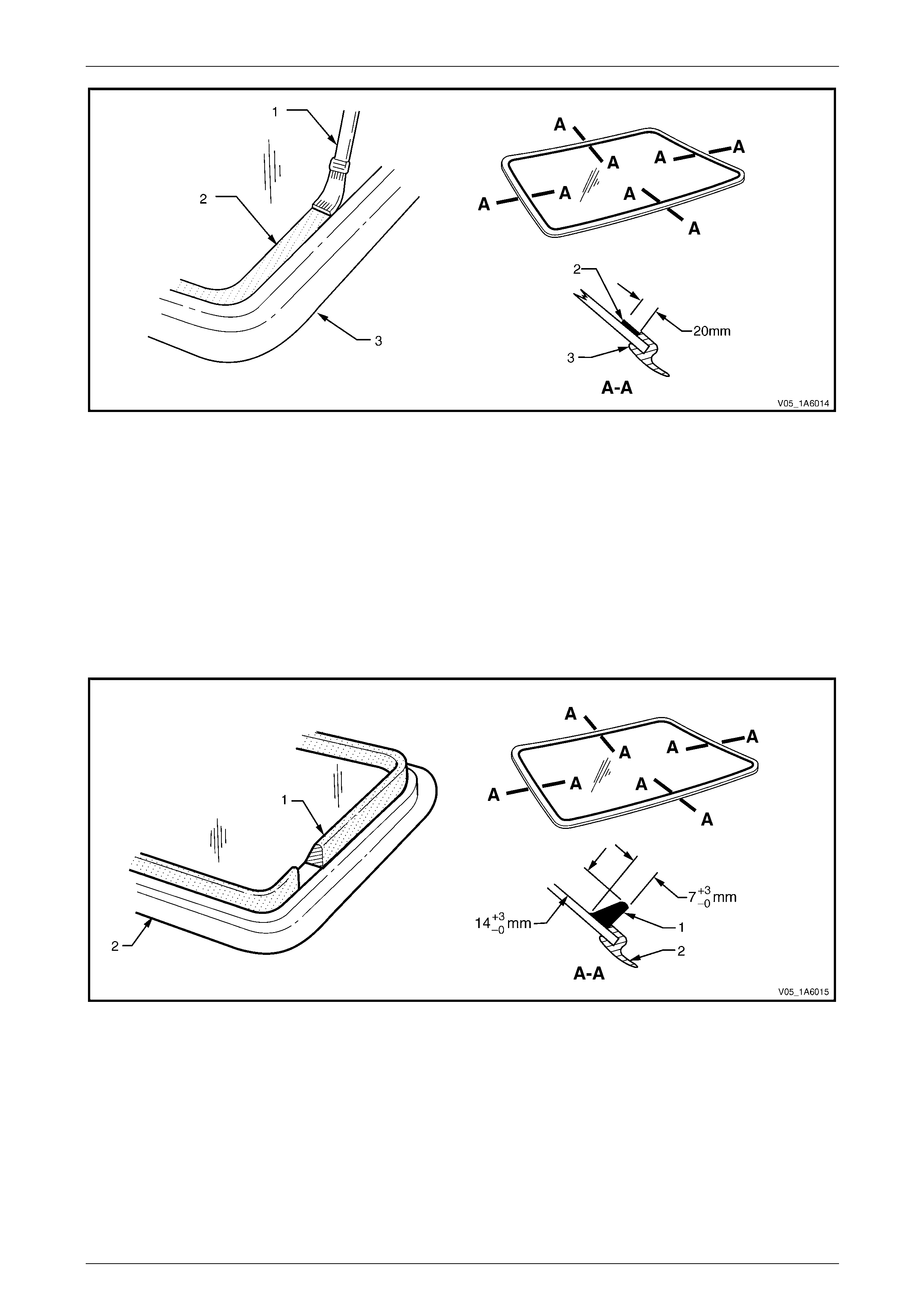
Stationary Windows Page 1A6–43
Page 1A6–43
Figure 1A6 – 44
10 Use a hand or automatic applicator to apply a smooth and continuous bead of urethane (1) to the inside of the
liftgate window adjacent to the insi de edge of the window moulding (2). The amount of new urethane applied
should ensure the total amount of urethan e is within the recommended dimensions. Refer to Figure 1A6 – 45.
NOTE
• Only use urethane adh esive such as Betase al
15685 or equivalent.
• In cold weather, placing the urethane
cartridges adjacent to a source of warmth will
assist in the flow of urethane when using a
hand applicator.
Figure 1A6 – 45
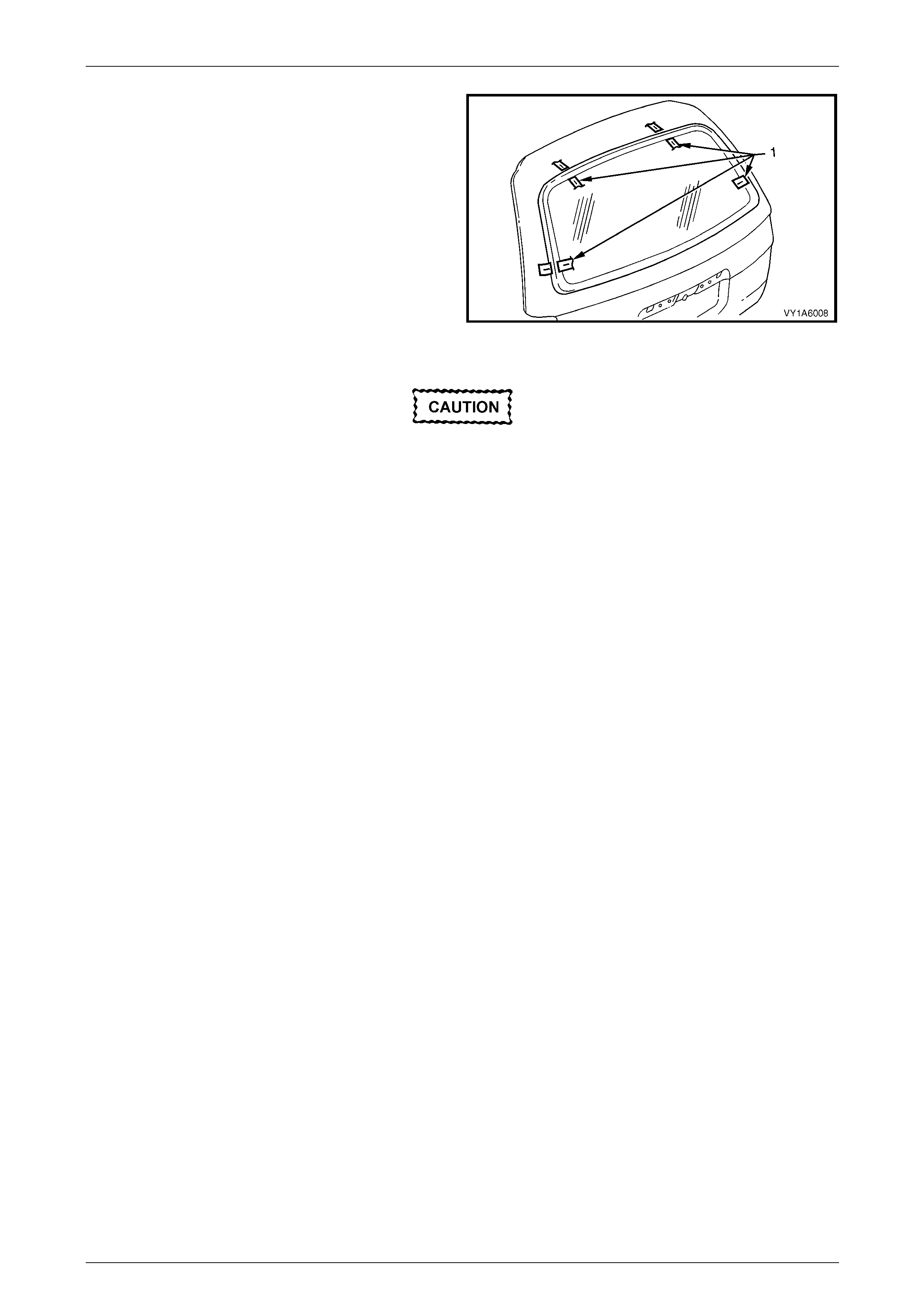
Stationary Windows Page 1A6–44
Page 1A6–44
11 With the aid of an assistant, install the liftgate window
assembly. Use the previously attached masking tape
(1) on the roof and the rear quarter panel as a guide.
NOTE
Ensure the liftgate window is centralised in the
body opening left to right by checking the gaps
between the windo w mouldin g and b ody op enin g
are even on both sides of the vehicl e.
12 Press the liftgate window firmly into position.
13 Check the effectiveness of seal from inside the
vehicle. Should any gaps in the sealing exist, apply
additional urethane to fill these gaps. Figure 1A6 – 46
Do not direct a heavy stream of water onto
freshly applied urethane. If a water leak is
evident, apply additional urethane to the leak
area, using a spatula to work the urethane
into the source of th e leak.
14 Wait two hours and then water test the liftgate window. Use only a mo derate spray of water.
15 Clean off any excess urethane using Prepsol or white spirit. Clean the liftgate window, then remove the masking
tape previously installed.
16 Connect the electrical demist connectors and cell ular telephone antenna if fitted.
17 Reinstall the trim and hardware as required.

Stationary Windows Page 1A6–45
Page 1A6–45
Reinstall – Long Method
Description
Throughout the curing period ensure that
door windows are partially lowered to
eliminate pressure build-up, which can be
caused by slamming doors. A curing time of
24 hours is recommended, although the
vehicle may be driven after five hours
providing it is driven only on a smooth road at
speeds not exceeding 80 km/h with the door
windows partially lowered.
• The long method should be used on vehicles requiring metal or paint repair to the liftgate window opening or when
the original adhesive is completely removed and replaced with new urethane for the liftgate windo w installati on.
• This method for the liftgate window repl acement is used when the original urethane adhesive materi al cannot serve
as a base for the replacement liftgate window.
• This method should also be us ed when the liftgate windo w has been previously replaced using the short method. In
such instances, the build-up of urethane could position the liftgate window too high in the opening.
Preparation
Care should be taken to ensure the liftgate
window does not strike the liftgate window
opening or any other object. Chipped edges
can lead to subsequent breakage of the
liftgate window.
Do not use petrol eum based sol vents to clean
any part of the window assembly, or body
opening as the presence of oil in the solvent
will pre vent th e adhesion of the n ew urethane.
NOTE
Thoroughly check the liftgate window opening
flange for any irregularities before installing the
liftgate window.
1 Use a sharp scraper to carefully remove an y origi na l urethane from around the liftgate window. Clean the liftgate
window to be installed with a suitable oil free cleaning agent.
2 Use a knife or sharp scraper to carefully remove the ori ginal urethane from around the enti re perimeter of the
liftgate window opening flang e. Avoid the removal of paint when removing urethane from ope ning flange.
If any paint work around the liftgate window
opening flange has been damaged, refinish
the paint before proceeding. Damaged paint
can lead to subsequent rusting.
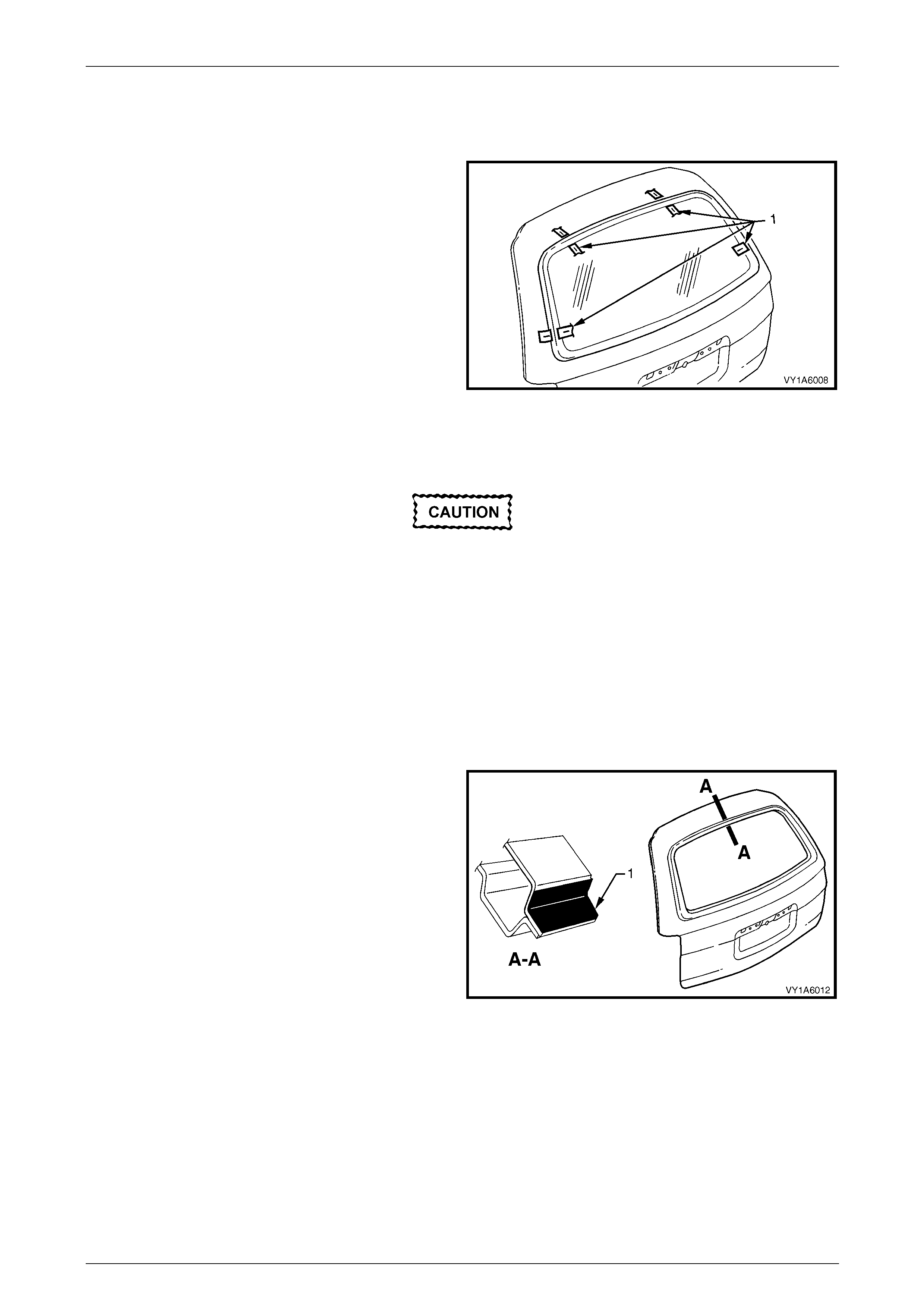
Stationary Windows Page 1A6–46
Page 1A6–46
3 Check for correct alignment by temporarily placing the liftgate window in the body opening.
4 Ensure the liftgate window is centralised i n th e body opening left to right by checking the gaps between the liftgate
window and body opening are even on both sides of the vehicle.
5 Use masking tape (1) to mark the position on the outer
top of the roof and the rear quarter panel.
NOTE
This procedure will assist in the alignment of the
liftgate window in the correct horizontal and
vertical plane during final liftgate window
installation.
6 Remove and place the liftgate window face down on a
clean protected surface or fixture.
Figure 1A6 – 47
Reinstall
Do not use petrol eum based sol vents to clean
any part of the window assembly, or body
opening as the presence of oil in the solvent
will pre vent th e adhesion of the n ew urethane.
NOTE
• Flange primer is not required if using the
recommended urethane adhesive Betaseal
15685.
• If using an equivalent to Beta seal 15685 refer
to technical data supplied by the supplier.
1 If required by supplier of the urethane adhesive, apply
flange primer (1) to the region indicated.
2 As required, remove the liftgate window moulding.
3 Thoroughly clean the inner surface and edges of the
liftgate window assembly to which the urethane is to
be applied, using clean lint-free cloths and a suitable
oil free cleaning solvent.
Figure 1A6 – 48
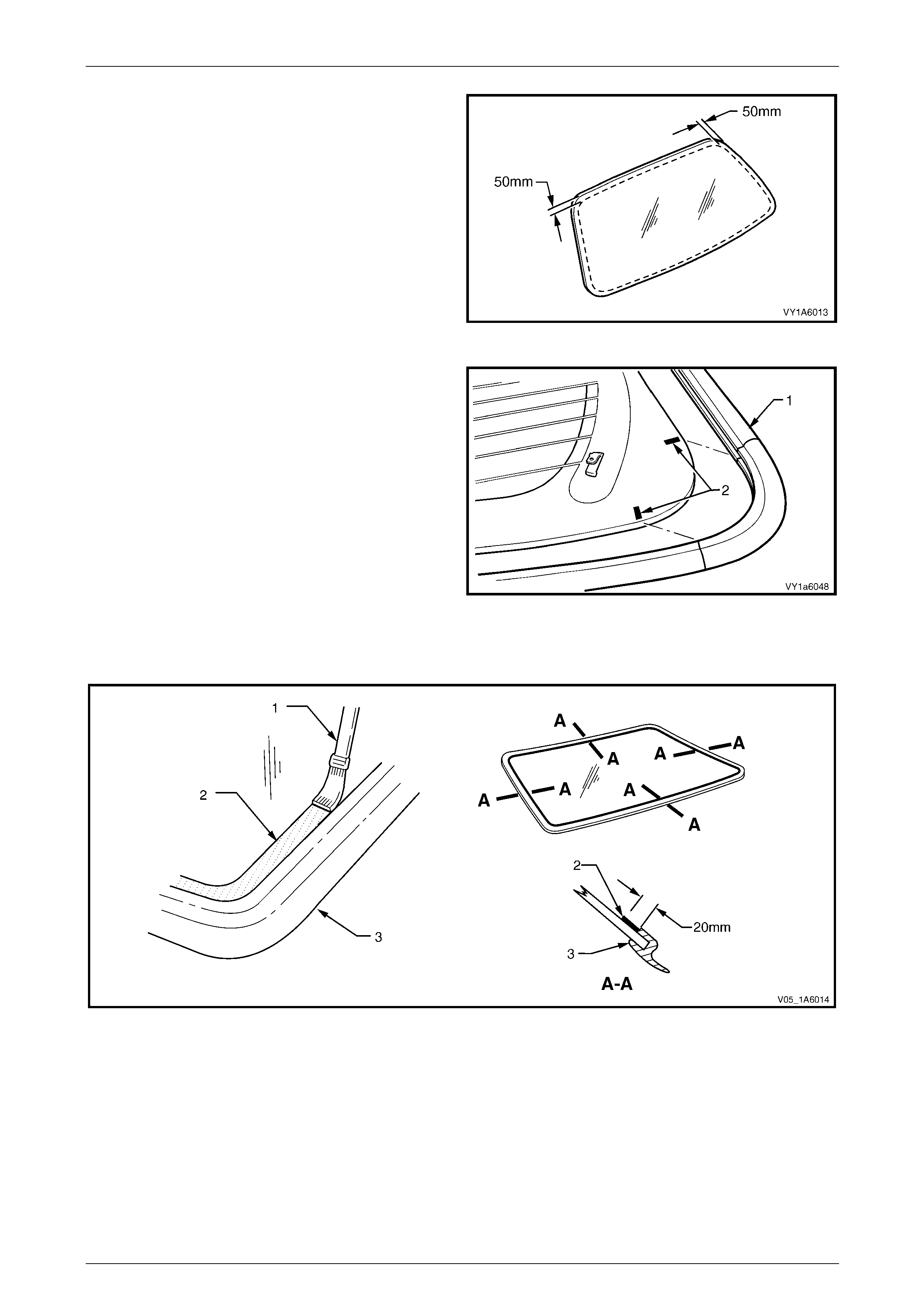
Stationary Windows Page 1A6–47
Page 1A6–47
4 Apply a 50 mm wide layer of clear glass primer to the
inner surface of the liftgate window's perimeter.
Immediately wipe off with a lint-free cloth.
5 If using an existing liftgate window moulding, check its
condition. If damaged discard and replace it.
Figure 1A6 – 49
6 Align the window moulding (1) corner with the
alignment marks (2) on the underside of the window in
both the left hand and right hand lo wer corne rs. Install
the moulding.
Figure 1A6 – 50
7 Referring to Figure 1A6 – 51, apply a 20 mm wide strip of black glass primer (2) with the applicator (1) included in
the service kit adjacent to the inside edge of the window moulding (3).
Figure 1A6 – 51
8 Use a hand or automatic applicator to apply a smooth and continuous bead of urethane (1) to the inside of the
liftgate window adjacent to the insi de edge of the window moulding (2). The amount of urethane applied should be
within the recommended dimensi ons. Refer to Figure 1A6 – 52.
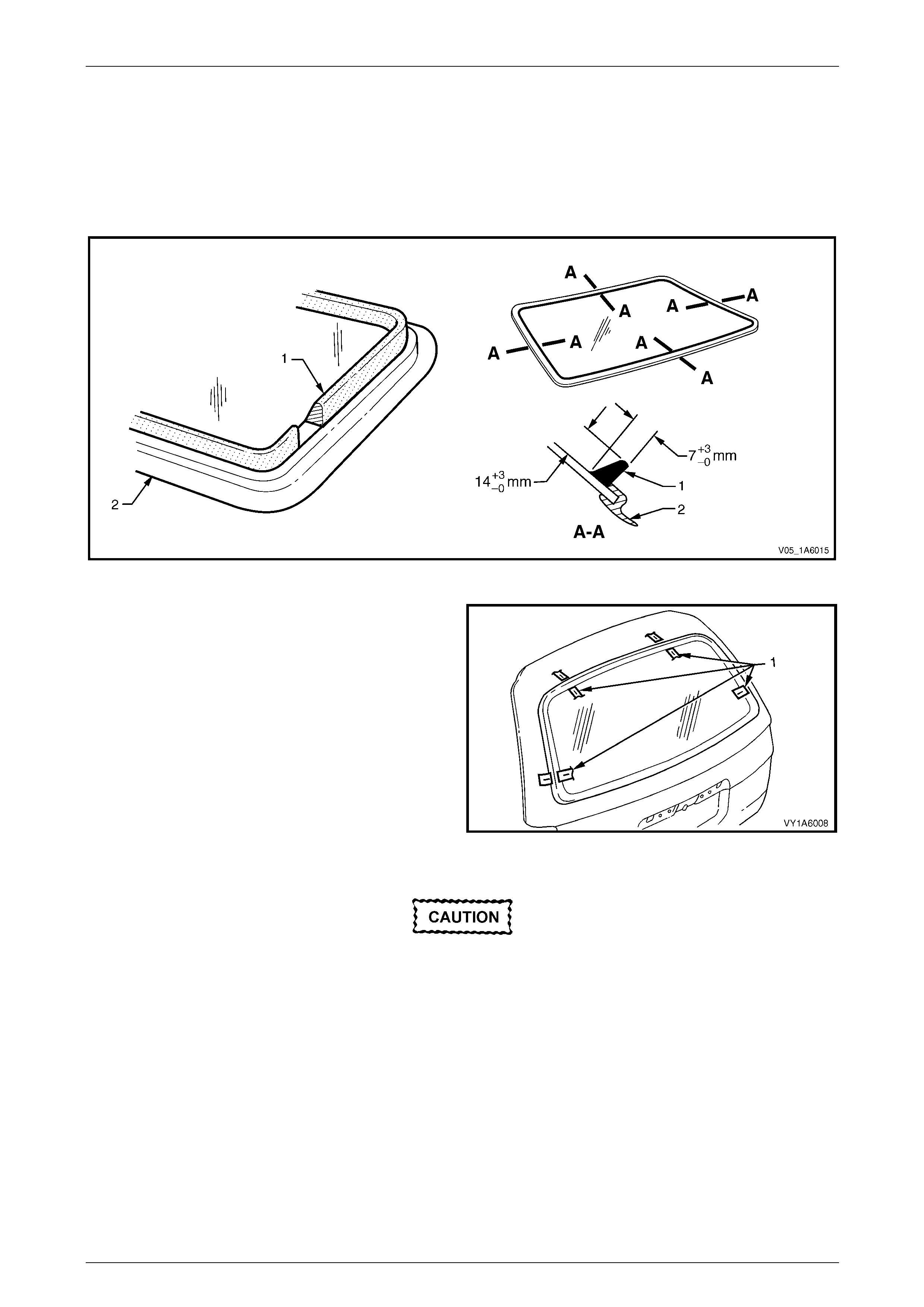
Stationary Windows Page 1A6–48
Page 1A6–48
NOTE
• Only use urethane adh esive such as Betase al
15685 or equivalent.
• In cold weather, placing the urethane
cartridges adjacent to a source of warmth will
assist in the flow of urethane when using a
hand applicator.
Figure 1A6 – 52
9 With the aid of an assistant install the liftgate window
assembly. Use the previously attached masking tape
(1) on the roof and the rear quarter panel as a guide.
NOTE
Ensure the liftgate window is centralised in the
body opening left to right by checking the gaps
between the windo w mouldin g and b ody op enin g
are even on both sides of the vehicl e.
10 Press the liftgate window firmly into position.
11 Check the effectiveness of seal from inside the
vehicle. Should any gaps in the sealing exist, apply
additional urethane to fill these gaps. Figure 1A6 – 53
Do not direct a heavy stream of water onto
freshly applied urethane. If a water leak is
evident, apply additional urethane to the leak
area, using a spatula to work the urethane
into the source of th e leak.
12 Wait two hours and then water test the liftgate window. Use only a mo derate spray of water.
13 Clean off any excess urethane using Prepsol or white spirit. Clean the liftgate window, then remove the masking
tape previously installed.
14 Connect the electrical demist connectors and cell ular telephone antenna if fitted.
15 Reinstall the trim and hardware as required.
Stationary Windows Page 1A6–49
Page 1A6–49
5.3 Rear Window Assembly, Utility, Regular
Cab and Crew Cab
LT Section No. — 11–020
Safety glasses an d work glo ves must be w orn
at all times when operating with glass.
Care must be taken during any operation
involving the glass removal or installation, to
not exert any load on the window. Failure to
observe this may result in damage to the
window.
NOTE
• Only use urethane adh esive such as Betase al
15685 or equivalent.
• Skinning (partial curing) of the urethane
commences after exposure to the
atmosphere. At 23 degrees Celsius and 50
percent relative humidity, skinning
commences after 30 minutes. Complete
curing of the urethane at this temperature an d
humidity takes 72 hours.
• Urethane service kits are available from most
windshield agents. Manufacturer’s instruction s
should always be foll owed.
• Window assemblies should be installed in the
window opening within five minutes of the
application of urethane.
• The rear window moulding may require
replacement when performing this operation.
Description
The rear window removal procedure is the same for both the Utility and Regular Cab vehicles. The procedure for the
Crew Cab is also the same apart from it also requires the removal either the tray or rear body, as well as some the
internal trim and exterior ornamentation components.
The rear window assembly removal procedure is the same for both the short and the long installation methods, with one
exception. If the short method installation is to be used, care must be taken during the rear windo w removal to ensure
that an even surface of the original remainin g urethane exists in the body opening, to serve as a base for the new
urethane bead and the repl acement rear window.
Stationary Windows Page 1A6–50
Page 1A6–50
Preparation
Prevent damage to the paint finish and
minimise clean up by using protective covers
and masking tape over the regions adjacent
to the rear window.
As required, remove the following components:
• Utility, Regular Cab and Crew Cab:
1 Rear window upper moulding, refer to Section 1A9 Exterior Ornamentati on.
2 Body lock pillar upper trim, refer to Section 1A8 Headlining and Interior Trim.
• Crew Cab also:
1 Rear body, refer to Section 1B Sheetmetal.
2 Header trim assembly, refer to Section 1A9 Exterior Ornamentation.
3 Body lock pillar finisher, refer to Section 1A9 Exterior Ornamentation.
4 Rear outer trim panel, refer to Section 1A9 Exterior Ornamentation.
5 Rear upper cross-beam cover, refer to Section 1A8, Headlini ng and Interior Trim.
Remove
NOTE
To remove the windshield or rear window special
tool J36020 is required. Alternately manufacture
an equivalent tool. Refer to 6 Special Tools.
1 Disconnect the rear window electrical demister connectors and ce llular telephone antenna if fitted.
2 If the rear window is broken, carefully remove all fragments of glass from the window opening.
Ensure the headlining and other trim items
are not damaged while cutting the urethane.
3 Use special tool J36020, or equivalent, thread one end of the piano wire through the urethane, starting at the rear
window upper corner. Pull the end of the wire through with pliers.
4 Connect the end of the piano wire to the other han dle of the special tool or equivale nt.
5 With the aid of an assistant commence cutting the urethane bead. Keep the outside handle (1) parallel to the edge
of the rear window. Use the full length of the wire to prevent heat build up in the wire refer to Figure 1A6 – 54. Utility
is shown, Regular Cab and Crew Cab are similar.
NOTE
To minimise the damage to the interior of the
vehicle, the operator inside th e vehicle should act
as an anchor point. Holdin g the T-handle as close
as possible to the rear window at all times, while
the outside operator pulls the wire up to the
interior T-handle in a walking motion.
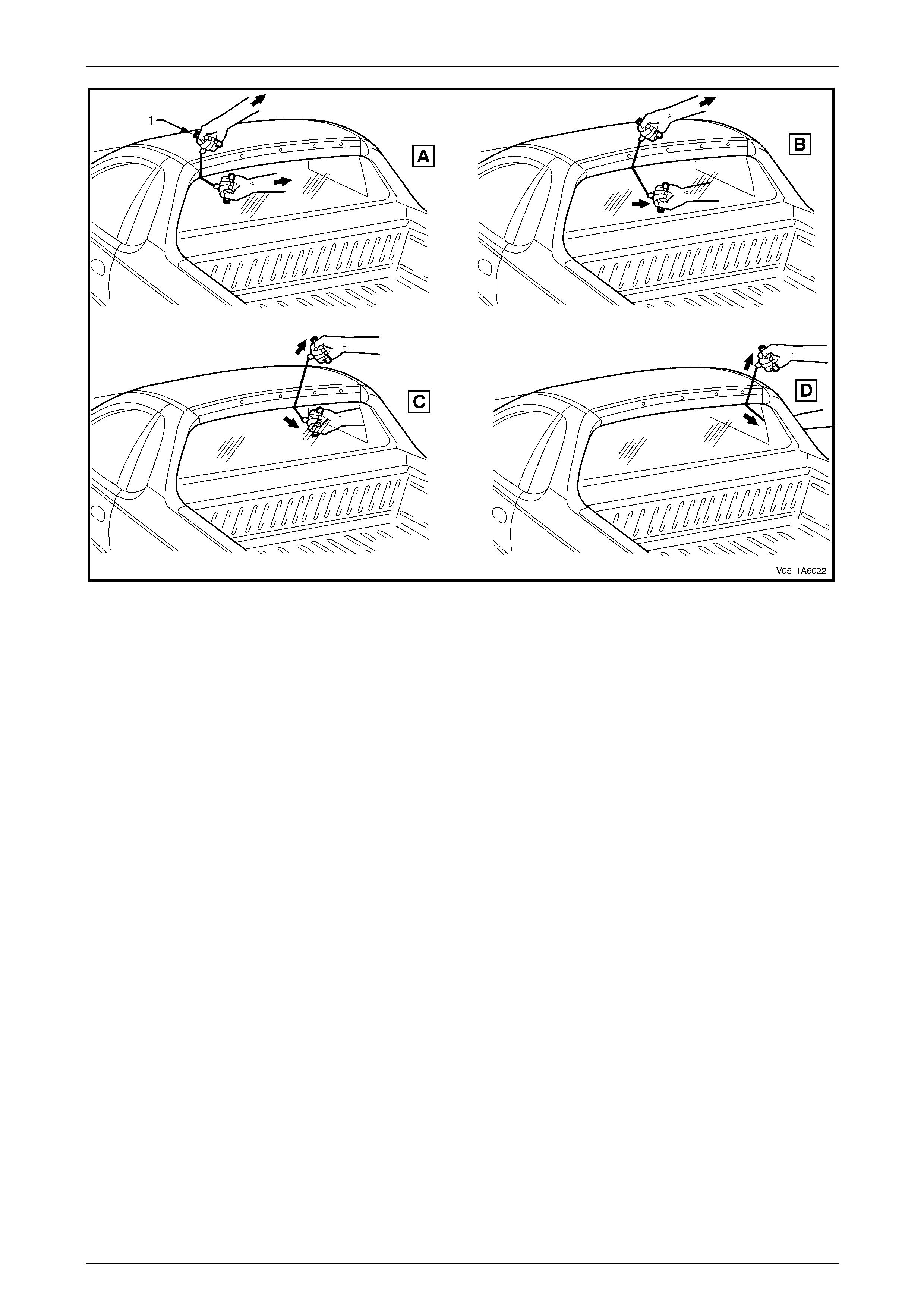
Stationary Windows Page 1A6–51
Page 1A6–51
Figure 1A6 – 54
6 Carefully lift the rear windo w out of the rear opening. If there is evidence of the window adhering to the urethane,
cut the area again with the piano wire.
7 If the original rear window is to be installed a gain, place the window on a clean protected surface or a holding
fixture.
NOTE
• The use of suction cu ps will greatly assist an y
handling of the rear window.
• All traces of urethane must be removed from
the rear window. It is not necessary to remove
all traces of the original urethane from the
body opening, unless the long method of
reinstallation is being used. However, any
original urethane remaining must be smooth
and firm.
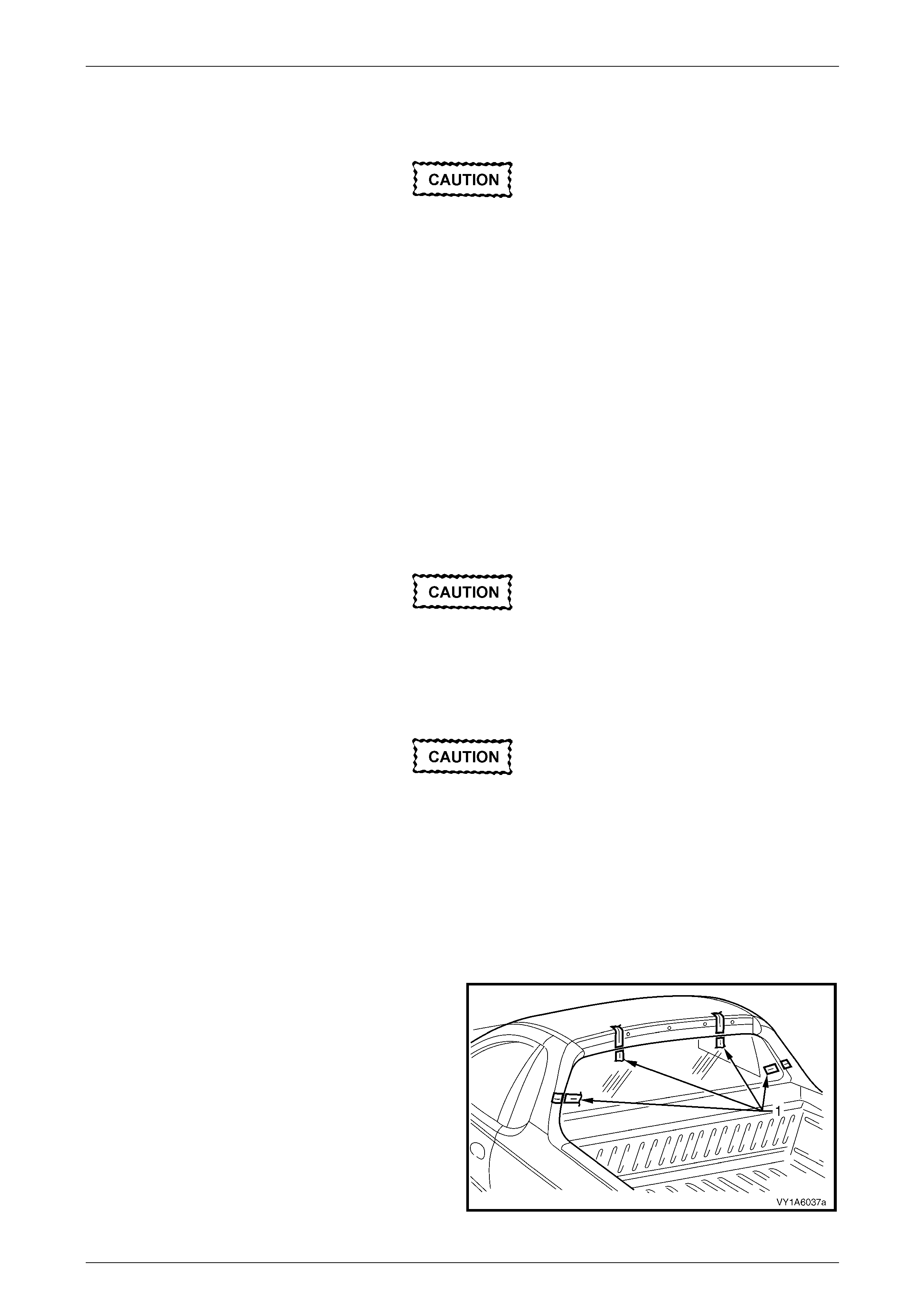
Stationary Windows Page 1A6–52
Page 1A6–52
Reinstall – Short Method
Description
Throughout the curing period ensure the door
windows are partially lowered to eliminate
pressure build-up, which can be caused by
slamming doors. A curing time of 24 hours is
recommended, although the vehicle may be
driven after five hours providing it is driven
only on a smooth road at speeds not
exceeding 80 km/h with the door windows
partially lowered.
• The short method is recommende d when replacing a cracked or broken rea r window, or a leak condition that
cannot be overcome by using the minor water leak repair procedures
• The short method installation i nvolves leaving the maximum amount of the original urethane intact on the body
opening to form a sound base for the replacement urethane and rear window. Any original urethane remaining
must be smooth and firm.
• If material other than urethane has been used for previous servicing of the rear window, the long method
installation procedure (complete removal of the urethane adhesive) is ma ndatory to achieve an effective window to
body bond.
Preparation
Care should be taken to ensure the rear
window does not strike the rear window
opening or any other object. Chipped edges
can lead to subsequent breakage of the rear
window.
Do not use petrol eum based sol vents to clean
any part of the window assembly or body
opening as the presence of oil in the solvent
will pre vent th e adhesion of the n ew urethane.
1 Use a sharp scraper to carefully remove an y origi na l urethane from around the rear window. Clean the rear window
to be installed with a suitable oil free cl eaning agent.
2 Check for correct alignment by temporarily placing the rear window in the body ope ning.
3 Ensure the rear windo w is centralised in th e body opening left to right by checking the g aps between the rear
window and body opening are even on both sides of the vehicle.
4 Use masking tape (1) to mark the position on the outer
top of the roof and the rear quarter panel.
NOTE
This procedure will assist in the alignment of the
rear window in the correct horizontal and vertical
plane during final rear window installation.
5 Remove and place the rear window face down on a
clean protected surface or fixture.
Figure 1A6 – 55
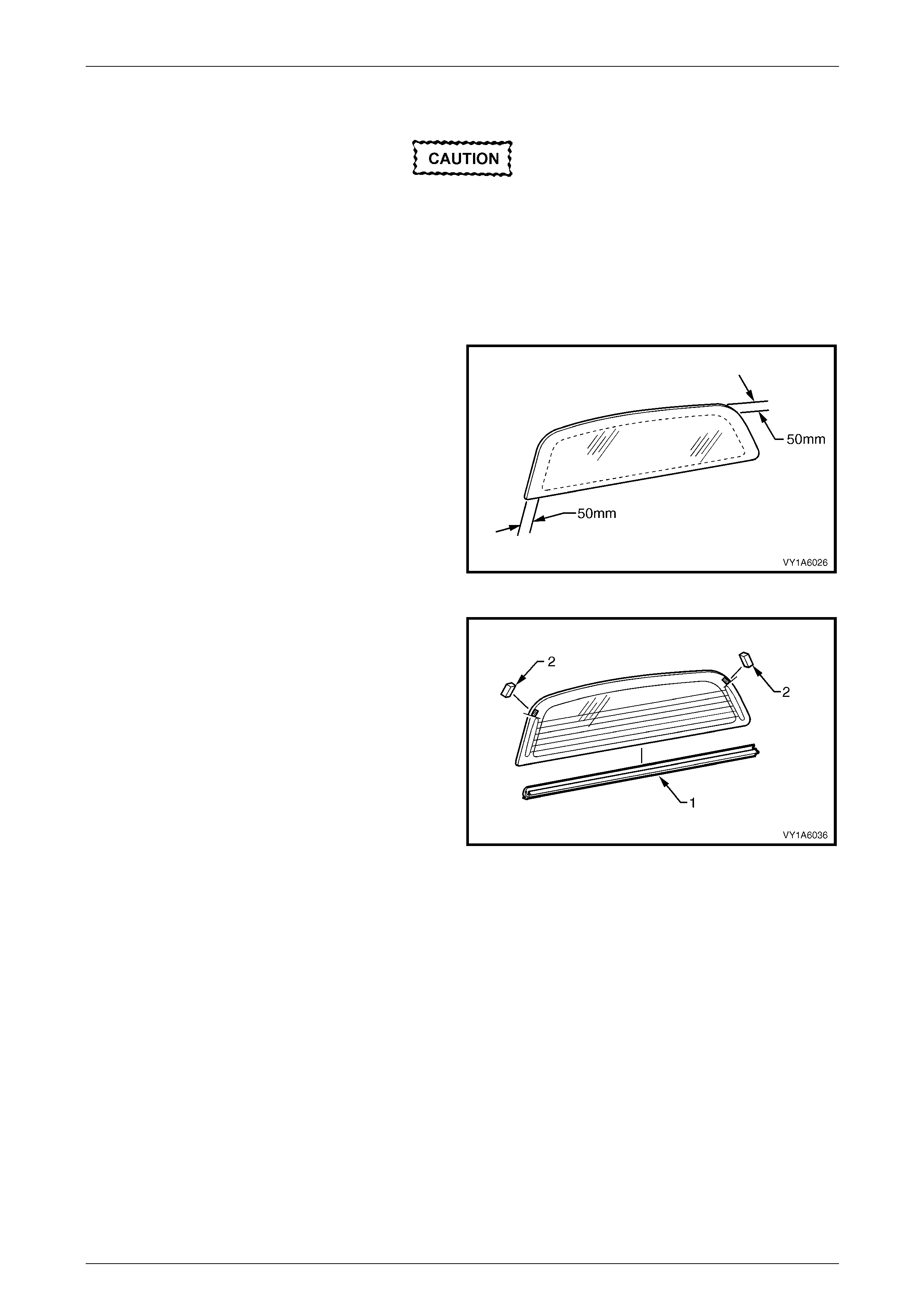
Stationary Windows Page 1A6–53
Page 1A6–53
Reinstall
Do not use petrol eum based sol vents to clean
any part of the window assembly, or body
opening as the presence of oil in the solvent
will pre vent th e adhesion of the n ew urethane.
1 As required, remove the rear window moulding.
2 Thoroughly cle an the inner surface and edge s of the rear window assembly to which the urethane is to be ap plied,
using clean lint-free cloths and a suitable oil free cleaning s olve nt.
3 Apply a 50 mm wide layer of clear glass primer to the
inner surface of the rear window's perimeter.
Immediately wipe off with a lint-free cloth.
4 If using an existing rear windo w moulding, check its
condition. If damaged discard and replace it.
Figure 1A6 – 56
5 Install the moulding (1) over the edge of the window.
Ensure the moulding is fitted correctly to the windo w.
6 Fit the two self adhesive rear window spacers (2),
ensuring they are positioned on edge of the window
adjacent to the end of the bus bar on the right and left-
hand side.
7 Check the condition of the original ureth ane around
the window opening flange for voids or looseness.
8 Cut away any loose pieces of urethane.
9 Use a spatula to spread fresh uretha ne smoothly into
any voids or uneven sections.
Figure 1A6 – 57
10 Referring to Figure 1A6 – 58, apply a 20 mm wide strip of black glass primer (1) with the applicator (2) included in
the service kit adjacent to the inside edge of the window moulding (3).
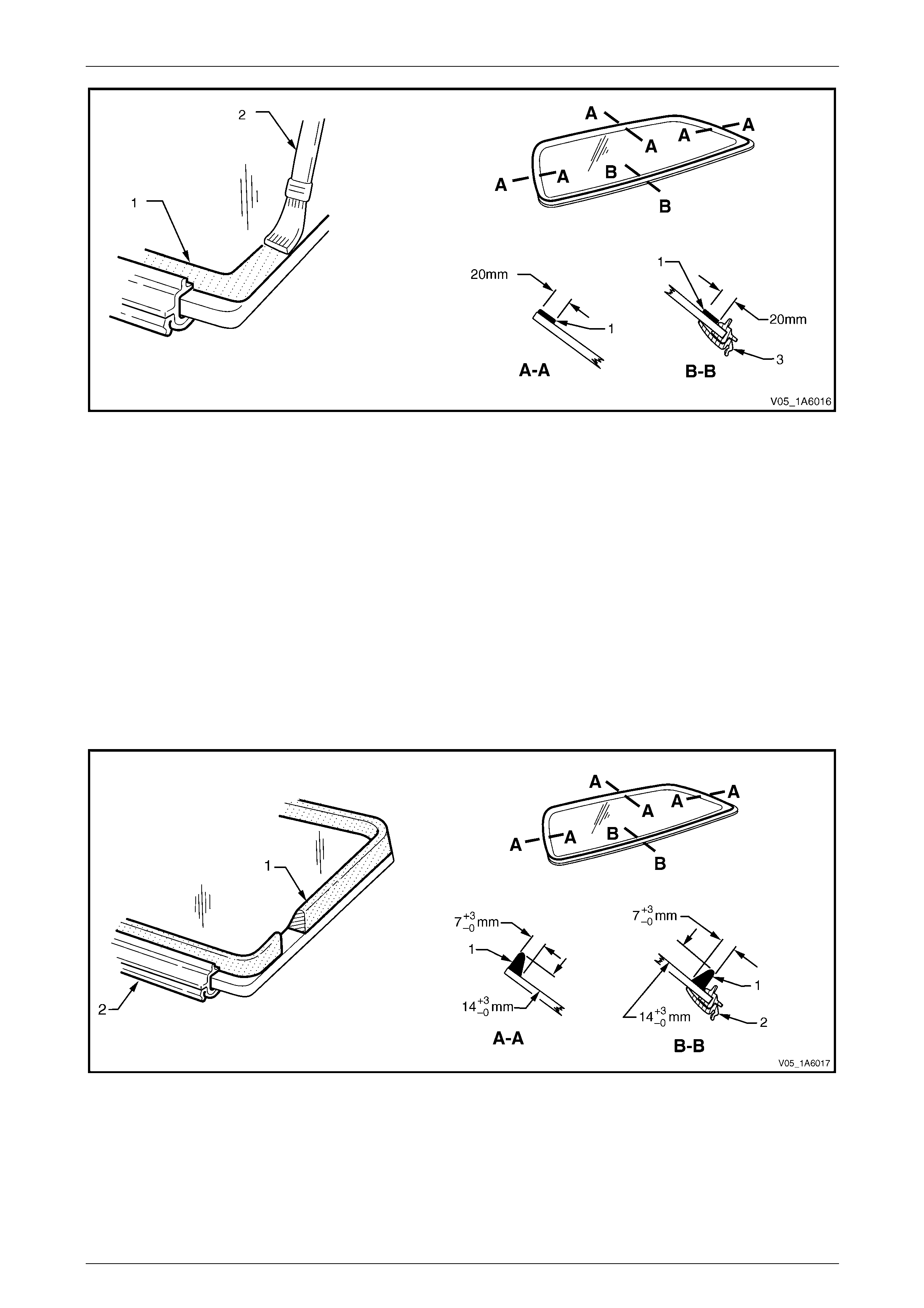
Stationary Windows Page 1A6–54
Page 1A6–54
Figure 1A6 – 58
11 Use a hand or automatic applicator to apply a smooth and contin uous bead of urethane (1) to the inside of the rear
window adjacent to the inside edge of the window moulding (2). The amount of new urethane applied should
ensure the total amount of urethane is within the recommended dimensions. Refer to Figure 1A6 – 59
NOTE
• Only use urethane adh esive such as Betase al
15685 or equivalent.
• The amount of the new urethane applied
should be adjusted to suit the amount of
urethane still remaining in the windshield
opening flange.
• In cold weather, placing the urethane
cartridges adjacent to a source of warmth will
assist in the flow of urethane when using a
hand applicator.
Figure 1A6 – 59
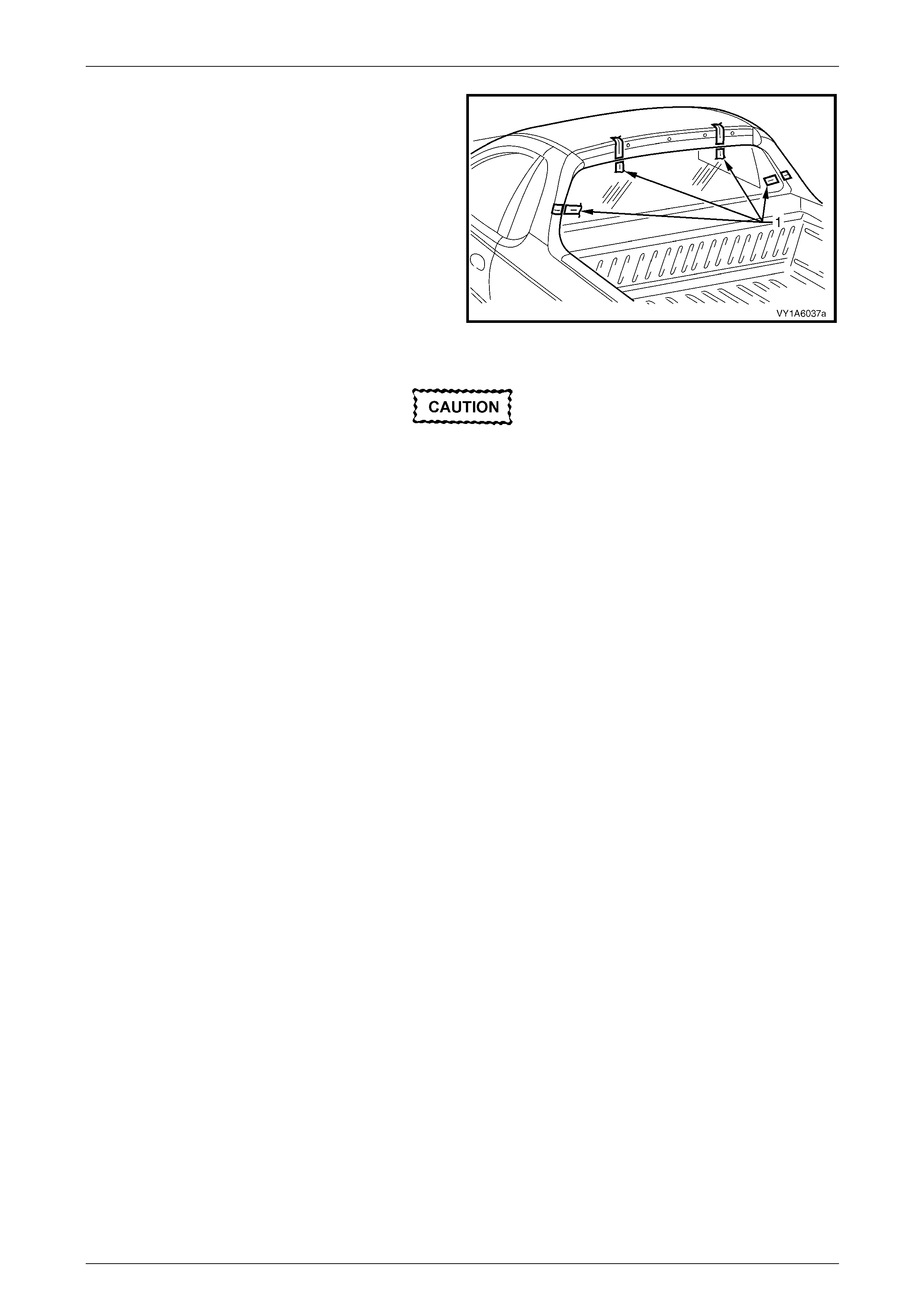
Stationary Windows Page 1A6–55
Page 1A6–55
12 With the aid of an assistant, install the rear window
assembly. Use the previously attached masking tape
(1) on the roof and the rear quarter panel as a guide.
NOTE
Ensure the rear window is centralised in the
body opening left to right by checking the gaps
between the windo w mouldin g and b ody op enin g
are even on both sides of the vehicl e.
13 Press the rear window firmly into position.
14 Check the effectiveness of seal from inside the
vehicle. Should any gaps in the sealing exist, apply
additional urethane to fill these gaps. Figure 1A6 – 60
Do not direct a heavy stream of water onto
freshly applied urethane. If a water leak is
evident, apply additional urethane to the leak
area, using a spatula to work the urethane
into the source of th e leak.
15 Wait two hours and then water test the rear window. Use only a moderate spray of water.
16 Clean off any excess urethane using Prepsol or white spirit. Clean the rear window, then remove the masking tape
previously installed.
17 Connect the electrical demist connectors and cell ular telephone antenna if fitted.
18 Reinstall the trim and hardware as required.
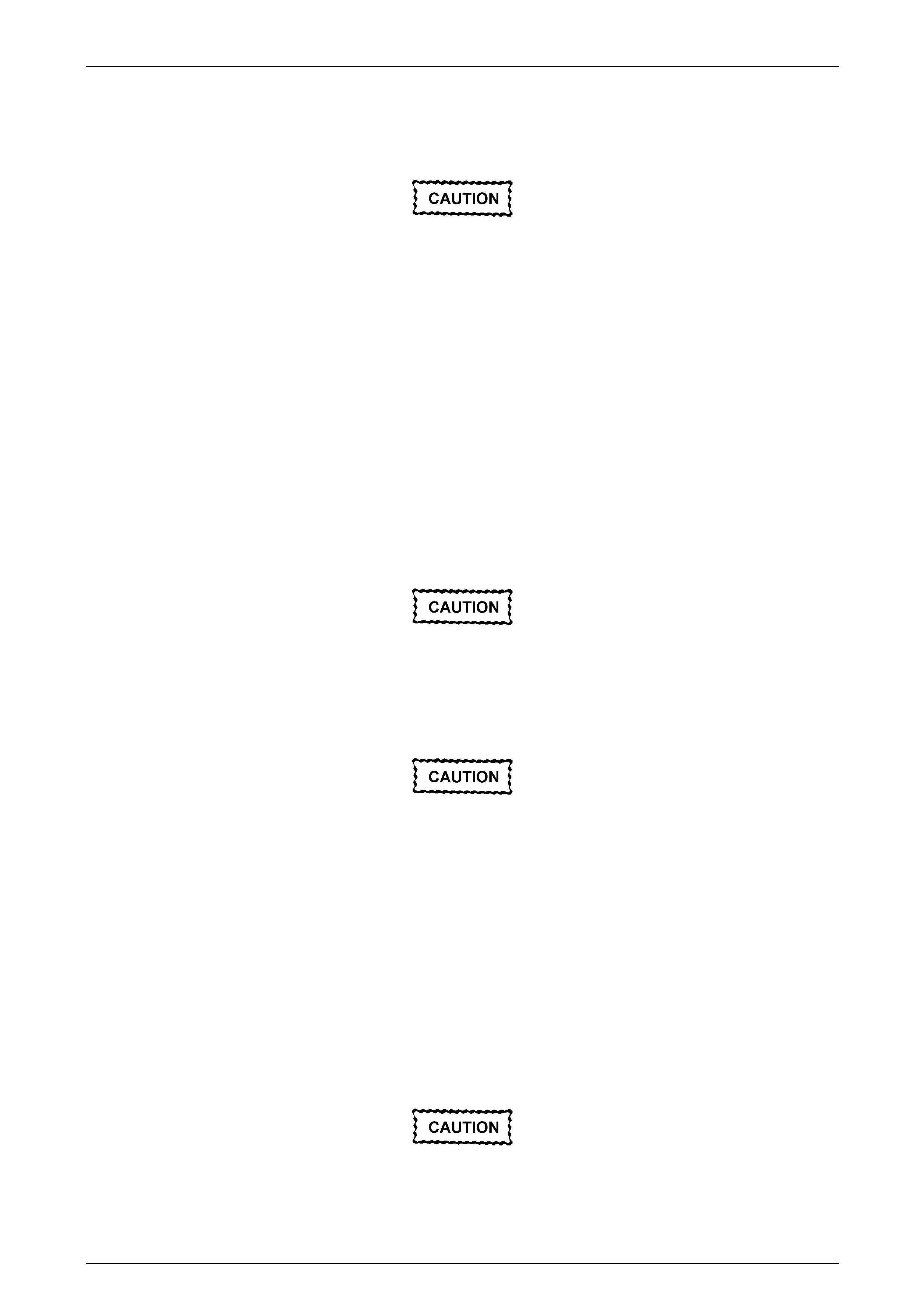
Stationary Windows Page 1A6–56
Page 1A6–56
Reinstall – Long Method
Description
Throughout the curing period ensure that
door windows are partially lowered to
eliminate pressure build-up, which can be
caused by slamming doors. A curing time of
24 hours is recommended, although the
vehicle may be driven after five hours
providing it is driven only on a smooth road at
speeds not exceeding 80 km/h with the door
windows partially lowered.
• The long method should be used on vehicles requiring metal or paint repair to the rear window opening or when the
original adhesive is completely removed and replaced with new urethane for the rear window installation.
• This method for the rear windo w replacemen t is used when the original urethane adhesive material cannot serve
as a base for the replacement rear window.
• This method should also be used when the rear window has been previously replaced using the short method. In
such instances, the build-up of urethane could position the rear window too high in the opening.
Preparation
Care should be taken to ensure the rear
window does not strike the rear window
opening or any other object. Chipped edges
can lead to subsequent breakage of the rear
window.
Do not use petrol eum based sol vents to clean
any part of the window assembly, or body
opening as the presence of oil in the solvent
will pre vent th e adhesion of the n ew urethane.
NOTE
Thoroughly check the rear window opening
flange for any irregularities before installing the
rear window.
1 Use a sharp scraper to carefully remove an y origi na l urethane from around the rear window. Clean the rear window
to be installed with a suitable oil free cl eaning agent.
2 Use a knife or sharp scraper to carefully remove the original urethane from around the entire perimeter of the rear
window opening flange. Avoid the removal of paint when removing urethane from ope ning flange.
If any paint work around the rear window
opening flange has been damaged, refinish
the paint before proceeding. Damaged paint
can lead to subsequent rusting.
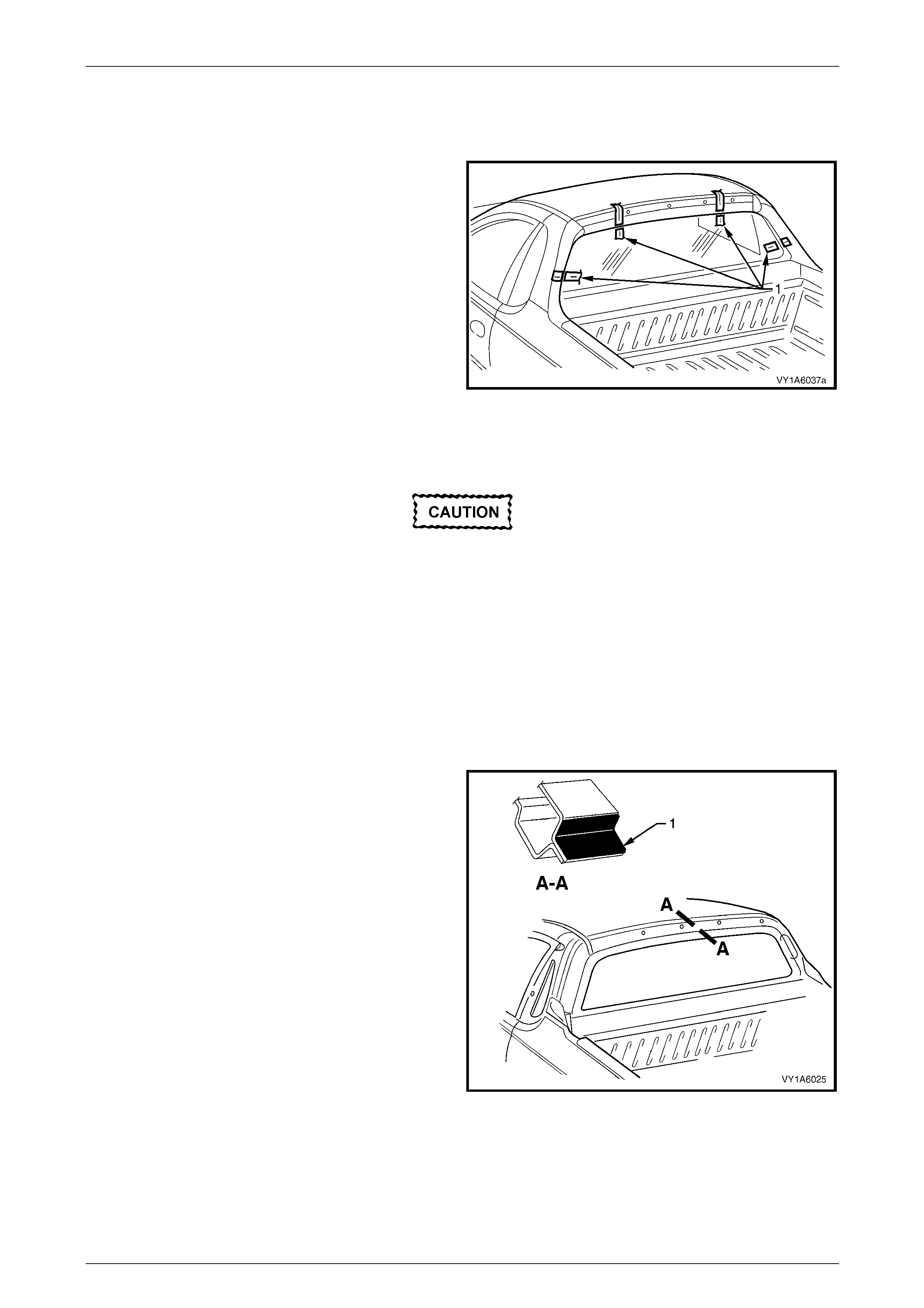
Stationary Windows Page 1A6–57
Page 1A6–57
3 Check for correct alignment by temporarily placing the rear window in the body ope ning.
4 Ensure the rear windo w is centralised in th e body opening left to right by checking the g aps between the rear
window and body opening are even on both sides of the vehicle.
5 Use masking tape (1) to mark the position on the outer
top of the roof and the rear quarter panel.
NOTE
This procedure will assist in the alignment of the
rear window in the correct horizontal and vertical
plane during final rear window installation.
6 Remove and place the rear window face down on a
clean protected surface or fixture.
Figure 1A6 – 61
Reinstall
Do not use petrol eum based sol vents to clean
any part of the window assembly, or body
opening as the presence of oil in the solvent
will pre vent th e adhesion of the n ew urethane.
NOTE
• Flange primer is not required if using the
recommended urethane adhesive Betaseal
15685.
• If using an equivalent to Beta seal 15685 refer
to technical data supplied by the supplier.
1 If required by the supplier of the urethane, apply flange
primer (1) to the region indicated.
2 As required, remove the rear window moulding.
3 Thoroughly clean the inner surface and edges of the
rear window assembly to which the urethane is to be
applied, using clean lint-free cloths and a suitable oil
free cleaning solvent.
Figure 1A6 – 62
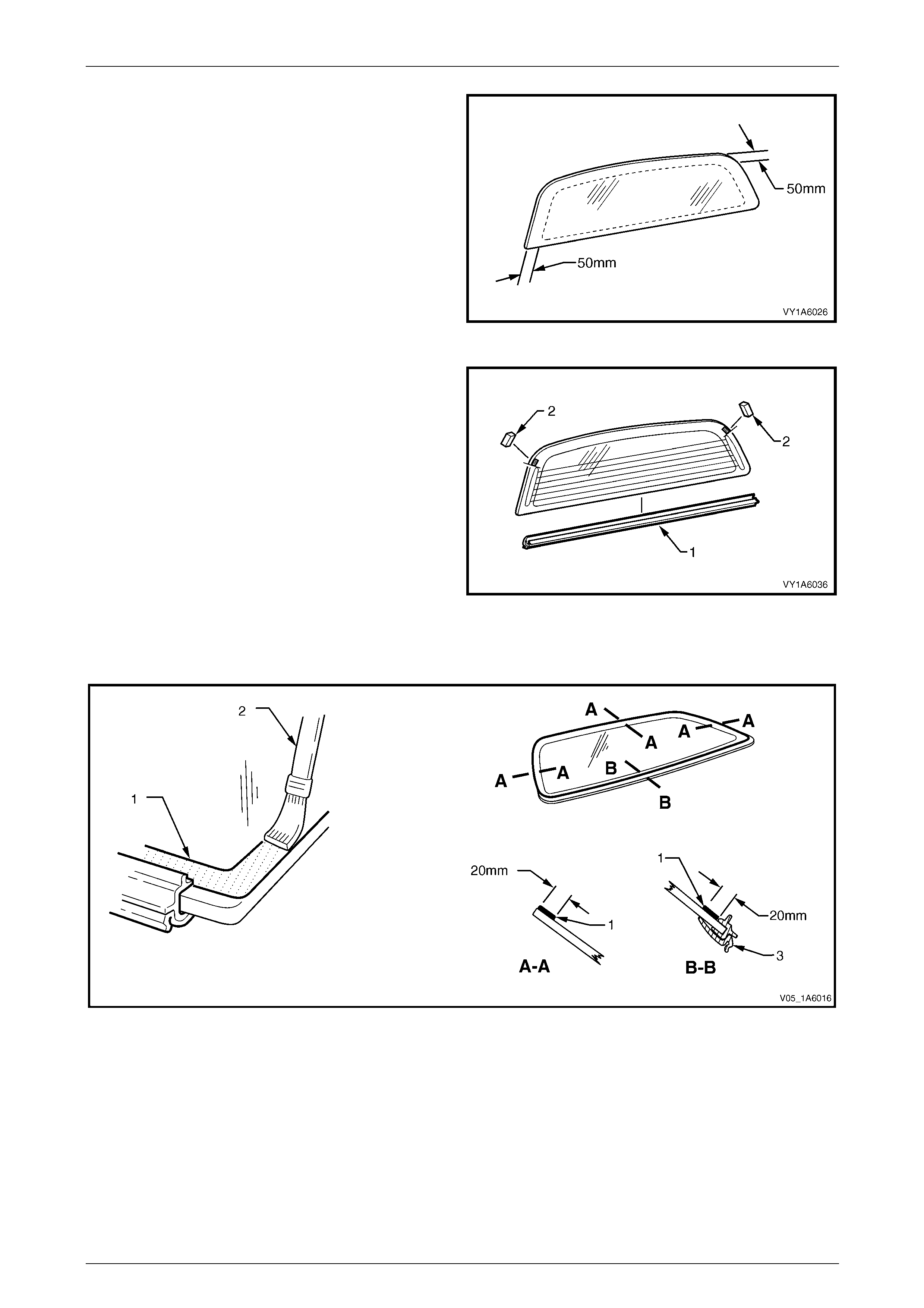
Stationary Windows Page 1A6–58
Page 1A6–58
4 Apply a 50 mm wide layer of clear glass primer to the
inner surface of the rear window's perimeter
immediately wipe off with a lint-free cloth.
5 If using an existing rear windo w moulding, check its
condition. If damaged discard and replace it.
Figure 1A6 – 63
6 Install the moulding (1) over the edge of the window.
Ensure the moulding is fitted correctly to the windo w.
7 Fit the two self adhesive rear window spacers (2),
ensuring they are positioned on edge of the window
adjacent to the end of the bus bar on the right and left-
hand side.
Figure 1A6 – 64
8 Referring to Figure 1A6 – 65, apply a 20 mm wide strip of black glass primer (1) with the applicator (2) included in
the service kit adjacent to the inside edge of the window moulding (3).
Figure 1A6 – 65
9 Use a hand or automatic applicator to appl y a smooth and continuo us bead of urethane (1) to the inside of the rear
window adjacent to the inside edge of the window moulding (2). The amount of urethane applie d should be within
the recommended dimensions. Refer to Figure 1A6 – 66.
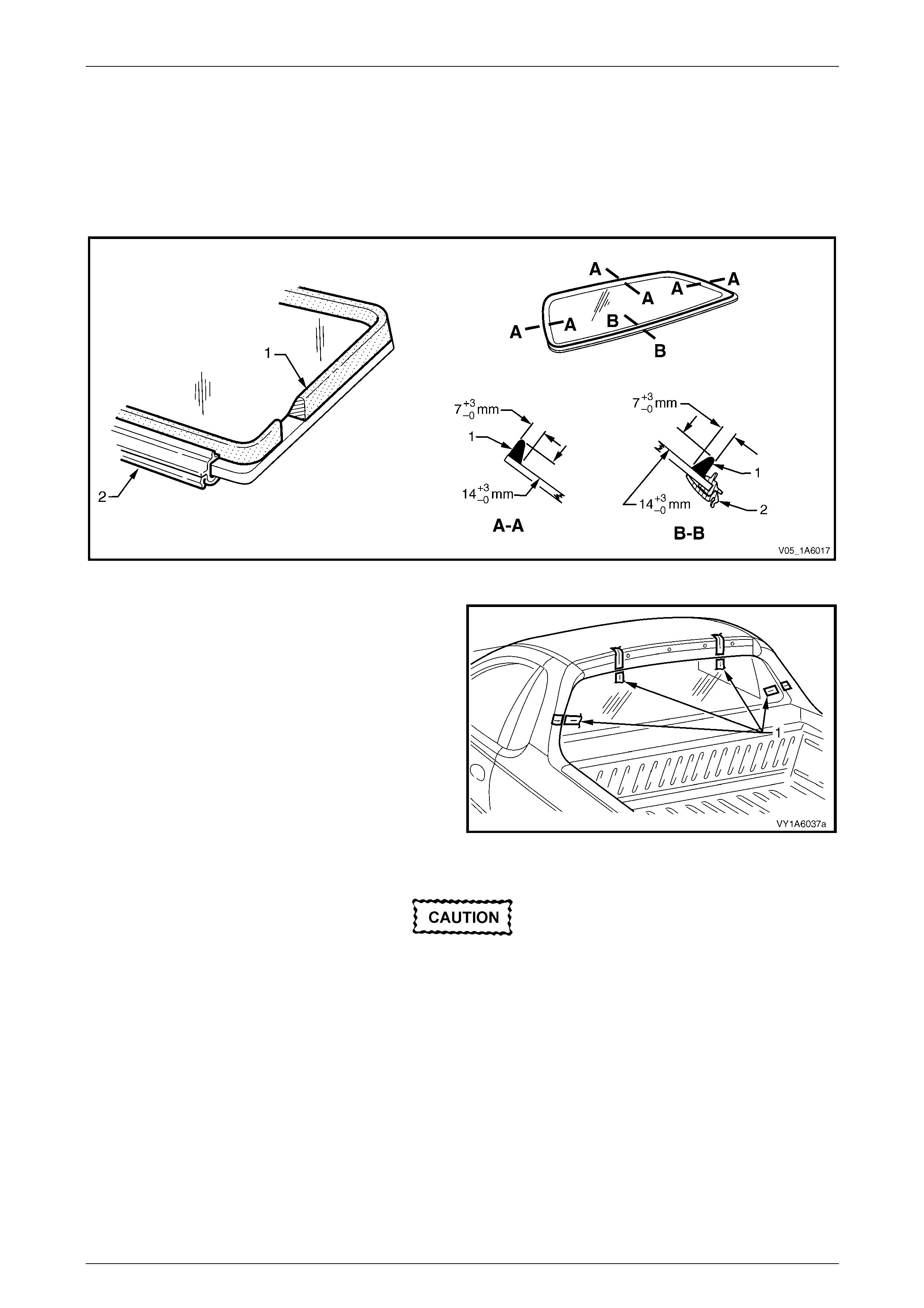
Stationary Windows Page 1A6–59
Page 1A6–59
NOTE
• Only use urethane adh esive such as Betase al
15685 or equivalent.
• In cold weather, placing the urethane
cartridges adjacent to a source of warmth will
assist in the flow of urethane when using a
hand applicator.
Figure 1A6 – 66
10 With the aid of an assistant install the rear window
assembly. Use the previously attached masking tape
(1) on the roof and the rear quarter panel as a guide.
NOTE
Ensure the rear window is centralised in the
body opening left to right by checking the gaps
between the windo w mouldin g and b ody op enin g
are even on both sides of the vehicl e.
11 Press the rear window firmly into position.
12 Check the effectiveness of seal from inside the
vehicle. Should any gaps in the sealing exist, apply
additional urethane to fill these gaps. Figure 1A6 – 67
Do not direct a heavy stream of water onto
freshly applied urethane. If a water leak is
evident, apply additional urethane to the leak
area, using a spatula to work the urethane
into the source of th e leak.
13 Wait two hours and then water test the rear window. Use only a moderate spray of water.
14 Clean off any excess urethane using Prepsol or white spirit. Clean the rear window, then remove the masking tape
previously installed.
15 Connect the electrical demist connectors and cell ular telephone antenna if fitted.
16 Reinstall the trim and hardware as required.
Stationary Windows Page 1A6–60
Page 1A6–60
5.4 Rear Window Assembly, Coupe
LT Section No. — 11–020
Safety glasses an d work glo ves must be w orn
at all times when operating with glass.
Care must be taken during any operation
involving the glass removal or installation, to
not exert any load on the window. Failure to
observe this may result in damage to the
window.
NOTE
• Only use urethane adh esive such as Betase al
15685 or equivalent.
• Skinning (partial curing) of the urethane
commences after exposure to the
atmosphere. At 23 degrees Celsius and 50
percent relative humidity, skinning
commences after 30 minutes. Complete
curing of the urethane at this temperature an d
humidity takes 72 hours.
• Urethane service kits are available from most
windshield agents. Manufacturer’s instruction s
should always be foll owed.
• Window assemblies should be installed in the
window opening within five minutes of the
application of urethane.
• The rear window moulding may require
replacement when performing this operation.
Description
The rear window assembly removal procedure is the same for both the sh ort and long installation methods, with one
exception. If the short method installation is to be used, care must be taken during the rear windo w removal to ensure
that an even surface of the original remainin g urethane exists in the body opening, to serve as a base for the new
urethane bead and the repl acement rear window.
Preparation
Prevent damage to the paint finish and
minimise clean up by using protective covers
and masking tape over the regions adjacent
to the rear window.
As required, remove the following components:
1 Roof joint moulding, refer to Section 1A9 Exterior Ornamentation.
2 Body rear corner garnish, refer to Section 1A8 Headlinin g and Interior Trim.
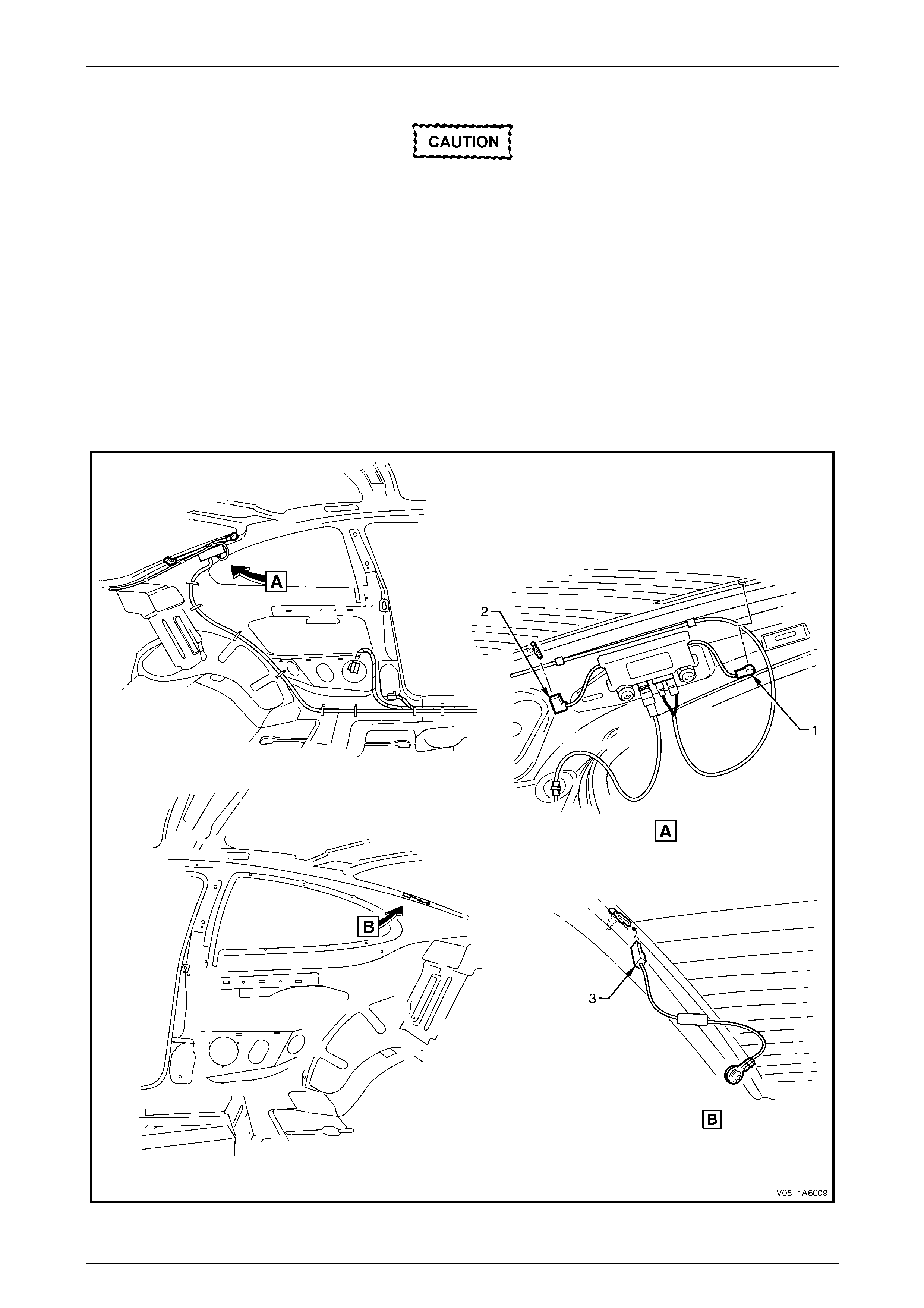
Stationary Windows Page 1A6–61
Page 1A6–61
Remove
A high mount stop lamp assembly is installed
below the rear window trim panel assembly.
Care must be taken to avoid damage to the
lamp assembly during window removal
procedure. It is not necessary to remove the
lamp assembly, b ut to ensure that it is clear of
any debris before window installation.
NOTE
To remove the windshield or rear window special
tool J36020 is required. Alternately manufacture
an equivalent tool. Refer to 6 Special Tools.
1 Disconnect the rear in glass antenna con nectors (1), rear window electrical demister connectors (2) and earth
connector (3) refer to Figure 1A6 – 68. Also remove the cell ular telephone antenna if fitted.
Figure 1A6 – 68
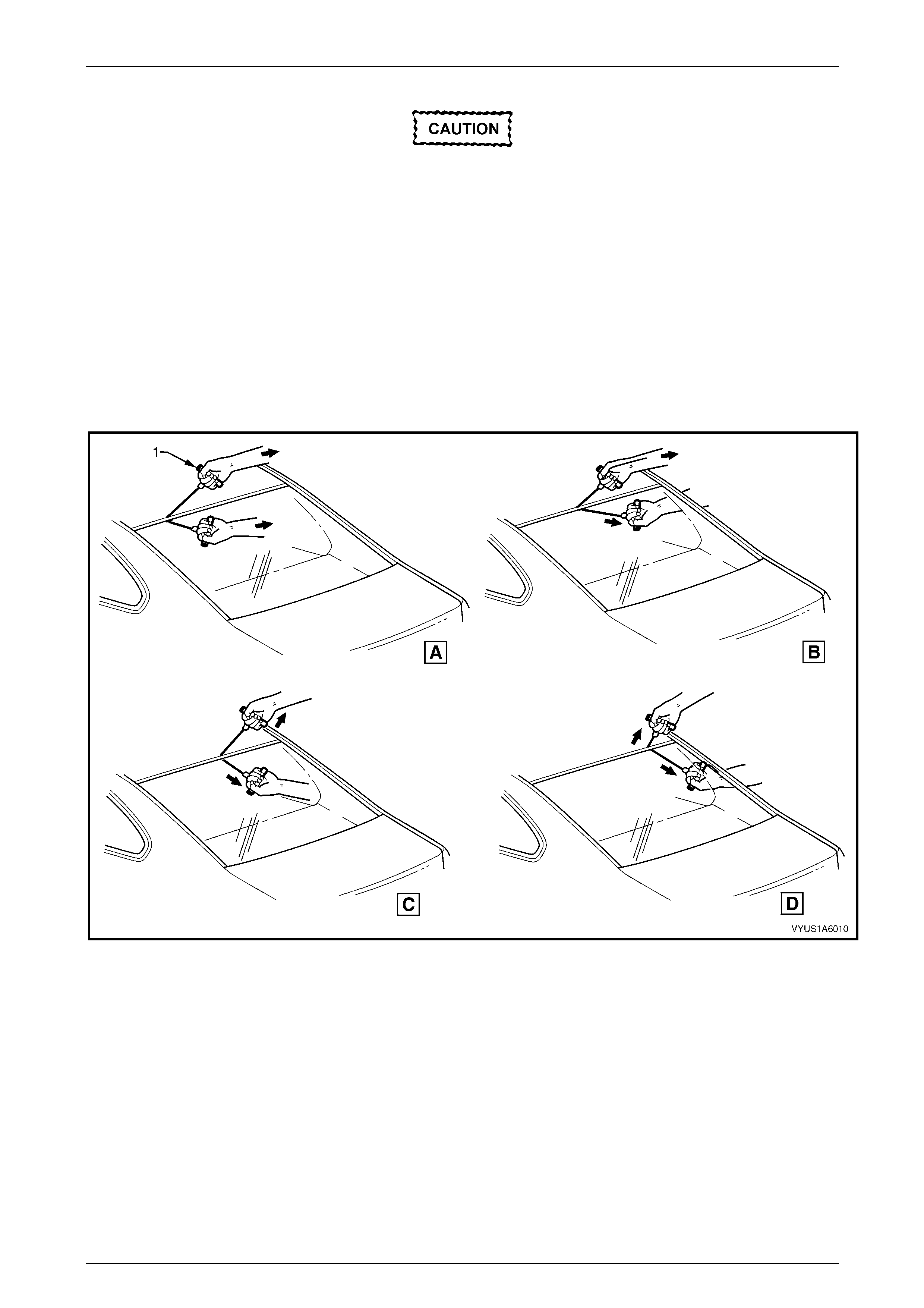
Stationary Windows Page 1A6–62
Page 1A6–62
2 If the rear window is broken, take care to remove all fragments of glass from the window opening.
Ensure the headlining and other trim items
are not damaged while cutting the urethane.
3 Use special tool J36020, or equivalent, thread one end of the piano wire through the urethane, starting at the rear
window upper corner. Pull the end of the wire through with pliers.
4 Connect the end of the piano wire to the other han dle of the special tool or equivale nt.
5 With the aid of an assistant commence cutting the urethane bead. Keep the outside handle (1) parallel to the edge
of the rear window. Use the full length of the wire to prevent heat build up in the wire. Refer to Figure 1A6 – 69.
NOTE
To minimise the damage to the interior of the
vehicle, the operator inside th e vehicle should act
as an anchor point. Holdin g the T-handle as close
as possible to the rear window at all times,
(especially along the lower edge of the rear
window), while the outside op erator pulls the wire
up to the interior T-handle in a walking motion.
Figure 1A6 – 69
6 Carefully lift the rear windo w out of the rear opening. If there is evidence of the window adhering to the urethane,
cut the area again with the piano wire.
7 If the original rear window is to be installed a gain, place the window on a clean protected surface or a holding
fixture. NOTE
• The use of suction cu ps will greatly assist an y
handling of the rear window.
• All traces of urethane must be removed from
the rear window. It is not necessary to remove
all traces of the original urethane from the
body opening, unless the long method of
reinstallation is being used. However, any
original urethane remaining must be smooth
and firm.
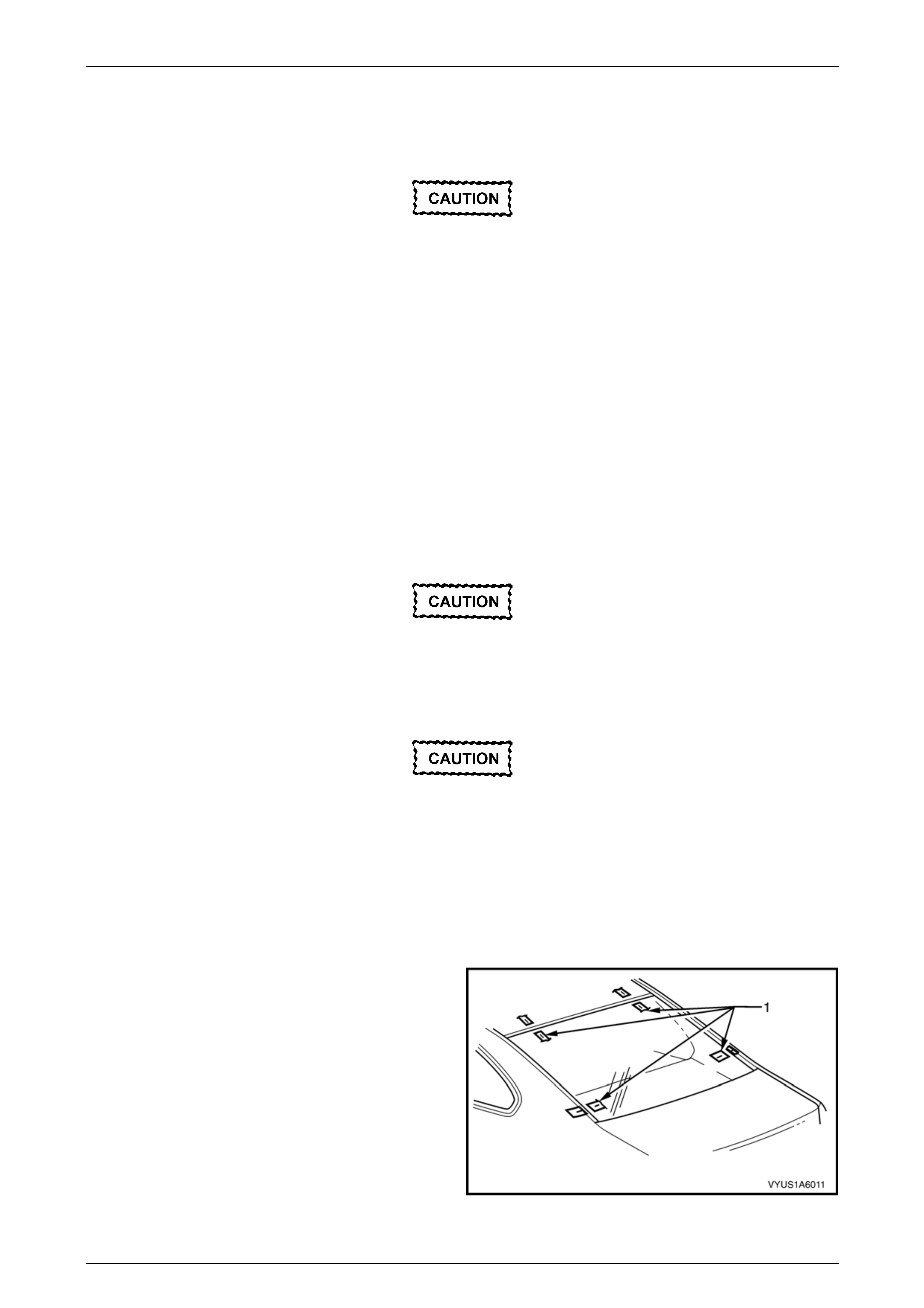
Stationary Windows Page 1A6–63
Page 1A6–63
Reinstall – Short Method
Description
Throughout the curing period ensure that
door windows are partially lowered to
eliminate pressure build-up, which can be
caused by slamming doors. A curing time of
24 hours is recommended, although the
vehicle may be driven after five hours
providing it is driven only on a smooth road at
speeds not exceeding 80 km/h with the door
windows partially lowered.
• The short method is recommende d when replacing a cracked or broken rea r window, or a leak condition that
cannot be overcome by using the minor water leak repair procedures.
• The short method installation i nvolves leaving the maximum amount of the original urethane intact on the body
opening to form a sound base for the replacement urethane and rear window. Any original urethane remaining
must be smooth and firm.
• If material other than urethane has been used for previous servicing of the rear window, the long method
installation procedure (complete removal of adhesive) is mandatory to achieve an effective window to body bond.
Preparation
Care should be taken to ensure the rear
window does not strike the rear window
opening or any other object. Chipped edges
can lead to subsequent breakage of the rear
window.
Do not use petrol eum based sol vents to clean
any part of the window assembly or body
opening as the presence of oil in the solvent
will pre vent th e adhesion of the n ew urethane.
1 Use a sharp scraper to carefully remove an y origi na l urethane from around the rear window. Clean the rear window
to be installed with a suitable oil free cl eaning agent.
2 Check for correct alignment of the rear window by temporarily placing the rear windo w in the body opening.
3 Ensure the rear windo w is centralised in th e body opening left to right by checking the g aps between the rear
window and body opening are even on both sides of the vehicle.
4 Use masking tape (1) to mark the position on the outer
top of the roof and the rear quarter panel.
NOTE
This procedure will assist in the alignment of the
rear window in the correct horizontal and vertical
plane during final rear window installation.
5 Remove and place the rear window face down on a
clean protected surface or fixture.
Figure 1A6 – 70

Stationary Windows Page 1A6–64
Page 1A6–64
Reinstall
Do not use petrol eum based sol vents to clean
the rear w indow assembly o r the rear openi ng
flange as the presenc e of t he oil in the solvent
will pre vent th e adhesion of the n ew urethane.
1 As required, remove the rear window moulding.
2 Thoroughly cle an the inner surface and edge s of the rear window assembly to which the urethane is to be ap plied,
using clean lint-free cloths and a suitable oil free cleaning s olve nt.
3 Apply a 50 mm wide layer of clear glass primer to the
inner surface of the rear window's perimeter.
Immediately wipe off with a lint-free cloth.
4 If using an existing rear windo w moulding, check its
condition. If damaged discard and replace it.
Figure 1A6 – 71
5 Install the rear window upper reveal moulding (1) and
the rear window lower reveal moulding (2) o v er the
edge of the window. Ensure the mouldings are fitted
correctly to the window.
6 Install the rear window side moul ding retainer (3) on
both sides. Ensure all the retainers are posi tioned to
the alignment marks (4), and are fitted correctly to
edge of the window.
7 Check the condition of the original urethane around
the window opening flange for voids or looseness.
8 Cut away any loose pieces of urethane.
9 Use a spatula to spread fresh uretha ne smoothly into
any voids or uneven sections. Figure 1A6 – 72
10 Referring to Figure 1A6 – 73, apply a 20 mm wide strip of black glass primer (2) with the applicator (1) included in
the service kit adjacent to the inside edge of the window moulding (3).
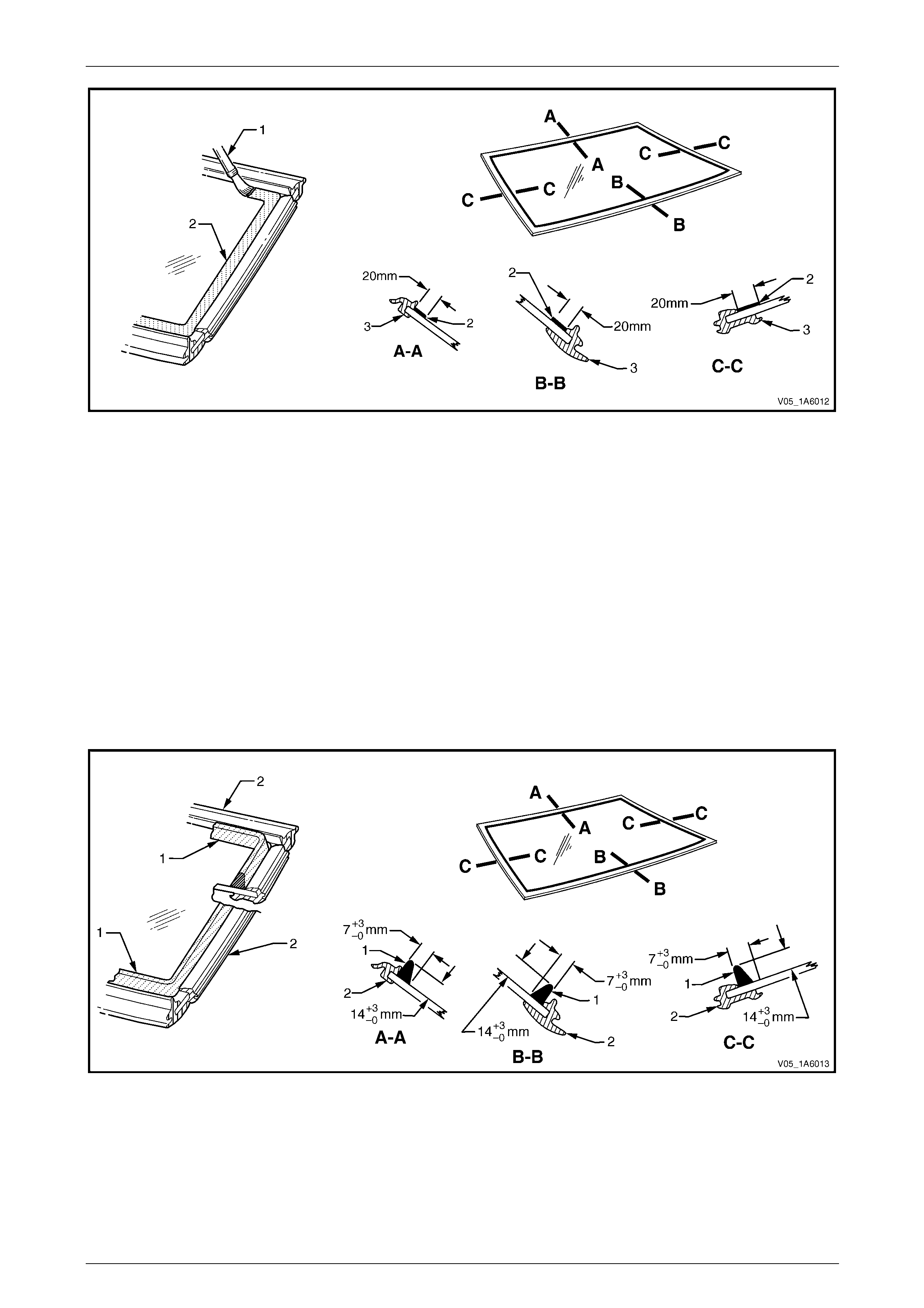
Stationary Windows Page 1A6–65
Page 1A6–65
Figure 1A6 – 73
11 Use a hand or automatic applicator to appl y a smooth and continuo us bead of urethane (1) to the inside of the rear
window adjacent to the inside edge of the window moulding (2). The amount of new urethane applied should
ensure the total amount of urethane is within the recommended dimensions. Refer to Figure 1A6 – 74
NOTE
• Only use urethane adh esive such as Betase al
15685 or equivalent.
• The amount of the new urethane applied
should be adjusted to suit the amount of
urethane still remaining in the windshield
opening flange.
• In cold weather, placing the urethane
cartridges adjacent to a source of warmth will
assist in the flow of urethane when using a
hand applicator.
Figure 1A6 – 74
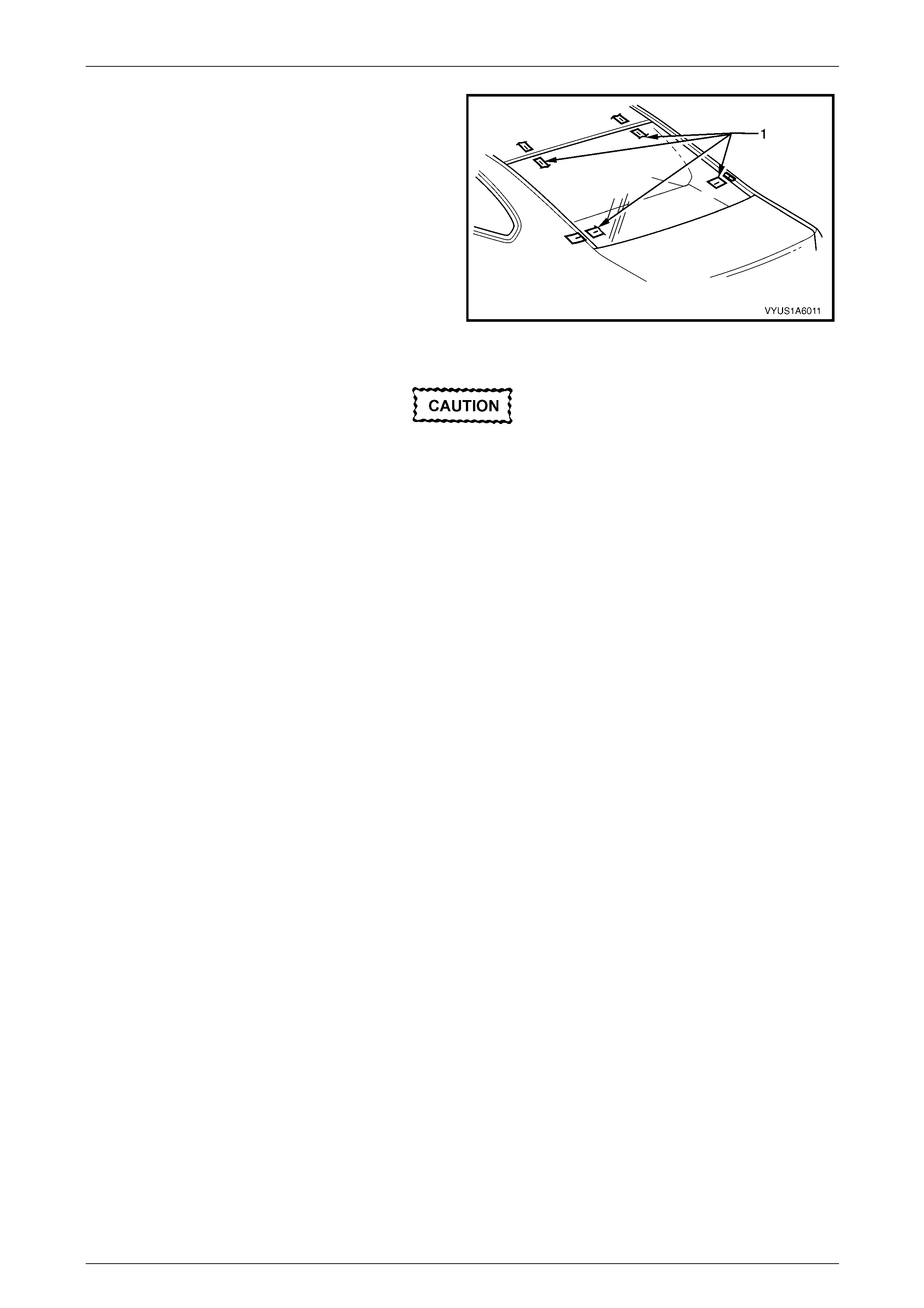
Stationary Windows Page 1A6–66
Page 1A6–66
12 With the aid of an assistant, install the rear window
assembly. Use the previously attached masking tape
(1) on the roof and the rear quarter panel as a guide.
NOTE
Ensure the rear window is centralised in the
body opening left to right by checking the gaps
between the windo w mouldin g and b ody op enin g
are even on both sides of the vehicl e.
13 Press the rear window firmly into position.
14 Check the effectiveness of seal from inside the
vehicle. Should any gaps in the sealing exist, apply
additional urethane to fill these gaps. Figure 1A6 – 75
Do not direct a heavy stream of water onto
freshly applied urethane. If a water leak is
evident, apply additional urethane to the leak
area, using a spatula to work the urethane
into the source of th e leak.
15 Wait two hours and then water test the rear window. Use only a moderate spray of water.
16 Clean off any excess urethane using Prepsol or white spirit. Clean the rear window and then remove the masking
tape previously installed.
17 Connect the electrical demist connectors, rear in glass antenna and earth connectors. Also connect the cellular
telephone antenna if fitted.
18 Reinstall the trim and hardware as required.

Stationary Windows Page 1A6–67
Page 1A6–67
Reinstall – Long Method
Description
Throughout the curing period ensure the door
windows are partially lowered to eliminate
pressure build-up, which can be caused by
slamming doors. A curing time of 24 hours is
recommended, although the vehicle may be
driven after five hours providing it is driven
only on a smooth road at speeds not
exceeding 80 km/h with the door windows
partially lowered.
• The long method should be used on vehicles requiring metal or paint repair to the rear window opening or when the
original adhesive is completely removed and replaced with new urethane for the rear window installation.
• This method for the rear windo w replacemen t is used when the original urethane adhesive material cannot serve
as a base for the replacement rear window.
• This method should also be used when the rear window has been previously replaced using the short method. In
such instances, the build-up of urethane could position the rear window too high in the opening.
Preparation
Care should be taken to ensure the rear
window does not strike the rear window
opening or any other object. Chipped edges
can lead to subsequent breakage of the rear
window.
Do not use petrol eum based sol vents to clean
any part of the window assembly or body
opening as the presence of oil in the solvent
will pre vent th e adhesion of the n ew urethane.
NOTE
Thoroughly check the rear window opening
flange for any irregularities before installing the
rear window.
1 Use a sharp scraper to carefully remove an y origi na l urethane from around the rear window. Clean the rear window
to be installed with a suitable oil free cl eaning agent.
2 Use a knife or sharp scraper to carefully remove the original urethane from around the entire perimeter of the rear
window opening flange. Take care to avoid the removal of paint when removing urethane from ope ning flange.
If any paint work around the rear window
opening flange has been damaged, refinish
the paint before proceeding. Damaged paint
can lead to subsequent rusting.

Stationary Windows Page 1A6–68
Page 1A6–68
3 Check for correct alignment, temporarily place the rear window in the body opening.
4 Ensure the rear windo w is centralised in th e body opening left to right by checking the g aps between the rear
window and body opening are even on both sides of the vehicle.
5 With masking tape (1), mark the outer top of the roof
and the rear quarter panel.
NOTE
This procedure will assist in the alignment of the
rear window in the correct horizontal and vertical
plane during final rear window installation.
6 Remove and place the rear window assembly face
down on a clean protected s urface or fixture.
Figure 1A6 – 76
Reinstall
Do not use petrol eum based sol vents to clean
any part of the window assembly, or body
opening as the presence of oil in the solvent
will pre vent th e adhesion of the n ew urethane.
NOTE
• Flange primer is not required if using the
recommended urethane adhesive Betaseal
15685.
• If using an equivalent to Beta seal 15685 refer
to technical data supplied by the supplier.
1 If required by the supplier of the urethane, apply flange
primer (1) to the region indicated.
2 As required, remove the rear window moulding.
3 Thoroughly clean the inner surface and edges of the
rear window assembly to which the urethane is to be
applied, using clean lint-free cloths and a suitable oil
free cleaning solvent.
Figure 1A6 – 77
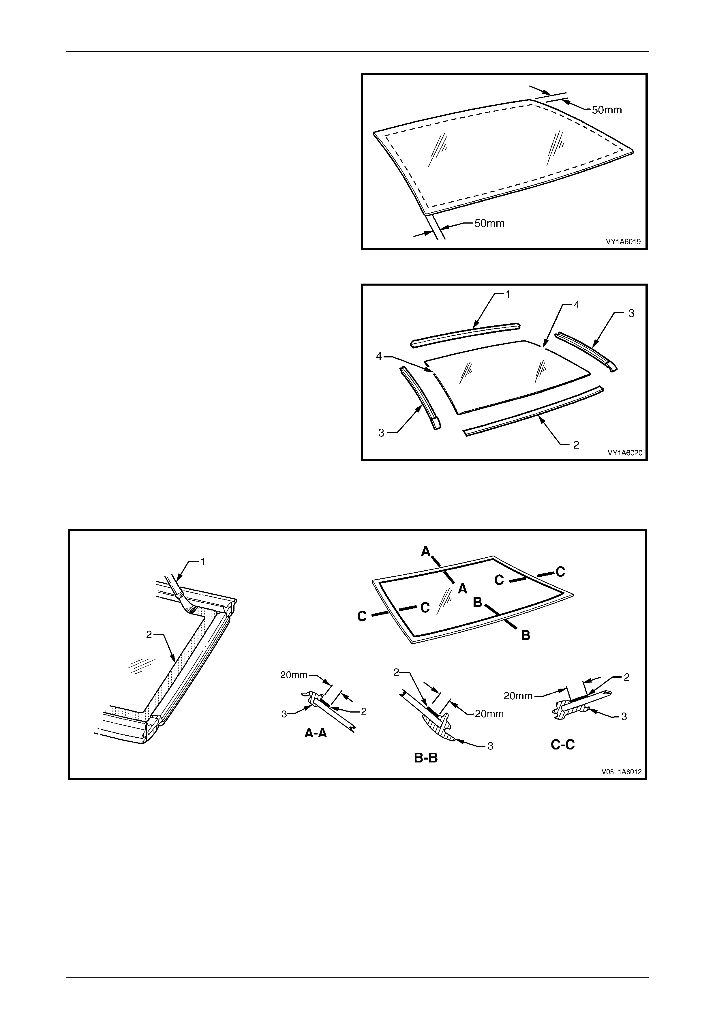
Stationary Windows Page 1A6–69
Page 1A6–69
4 Apply a 50 mm wide layer of clear glass primer to the
inner surface of the rear window's perimeter.
Immediately wipe off with a lint-free cloth.
5 If using an existing rear windo w moulding, check its
condition. If damaged discard and replace it.
Figure 1A6 – 78
6 Install the rear window upper reveal moulding (1) and
the rear window lower reveal moulding (2) o v er the
edge of the window. Ensure the mouldings are fitted
correctly to the window.
7 Install the rear window side moul ding retainer (3) on
both sides. Ensure all the retainers are posi tioned to
the alignment marks (4), and are fitted correctly to
edge of the window.
Figure 1A6 – 79
8 Referring to Figure 1A6 – 80, apply a 20 mm wide strip of black glass primer (2) with the applicator (1) included in
the service kit adjacent to the inside edge of the window moulding (3).
Figure 1A6 – 80
9 Use a hand or automatic applicator to appl y a smooth and continuo us bead of urethane (1) to the inside of the rear
window adjacent to the inside edge of the window moulding (2). The amount of urethane applie d should ensure the
total amount of urethane is within the recomm ended dimensions. Refer to Figure 1A6 – 81.
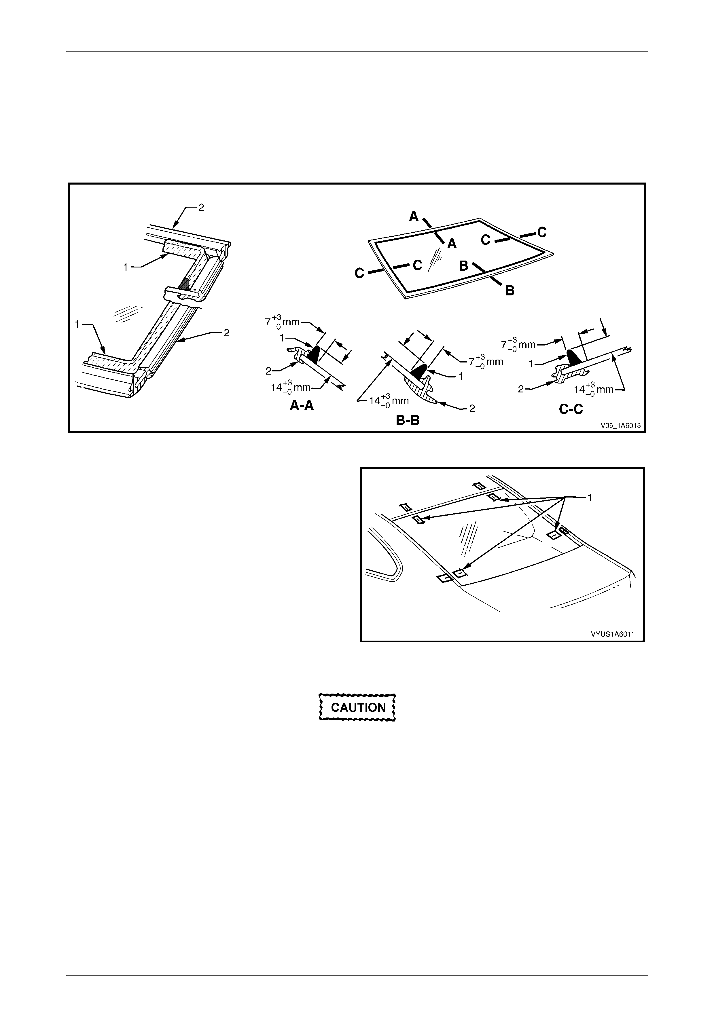
Stationary Windows Page 1A6–70
Page 1A6–70
NOTE
• Only use urethane adh esive such as Betase al
15685 or equivalent.
• In cold weather, placing the urethane
cartridges adjacent to a source of warmth will
assist in the flow of urethane when using a
hand applicator.
Figure 1A6 – 81
10 With the aid of an assistant, install the rear window
assembly. Use the previously attached masking tape
(1) on the roof and the rear quarter panel as a guide.
NOTE
Ensure the rear window is centralised in the
body opening left to right by checking the gaps
between the windo w mouldin g and b ody op enin g
are even on both sides of the vehicl e.
11 Press the rear window firmly into position.
12 Check the effectiveness of seal from inside the
vehicle. Should any gaps in the sealing exist, apply
additional urethane to fill these gaps. Figure 1A6 – 82
Do not direct a heavy stream of water onto
freshly applied urethane. If a water leak is
evident, apply additional urethane to the leak
area, using a spatula to work the urethane
into the source of th e leak.
13 Wait two hours and then water test the rear window. Use only a moderate spray of water.
14 Clean off any excess urethane using Prepsol or white spirit. Clean the rear window, then remove the masking tape
previously installed.
15 Connect the electrical demist connectors, rear in glass antenna and earth connectors. Also connect the cellular
telephone antenna if fitted. If necessar y reverse step 1 of the remove procedure.
16 Reinstall the trim and hardware as required.
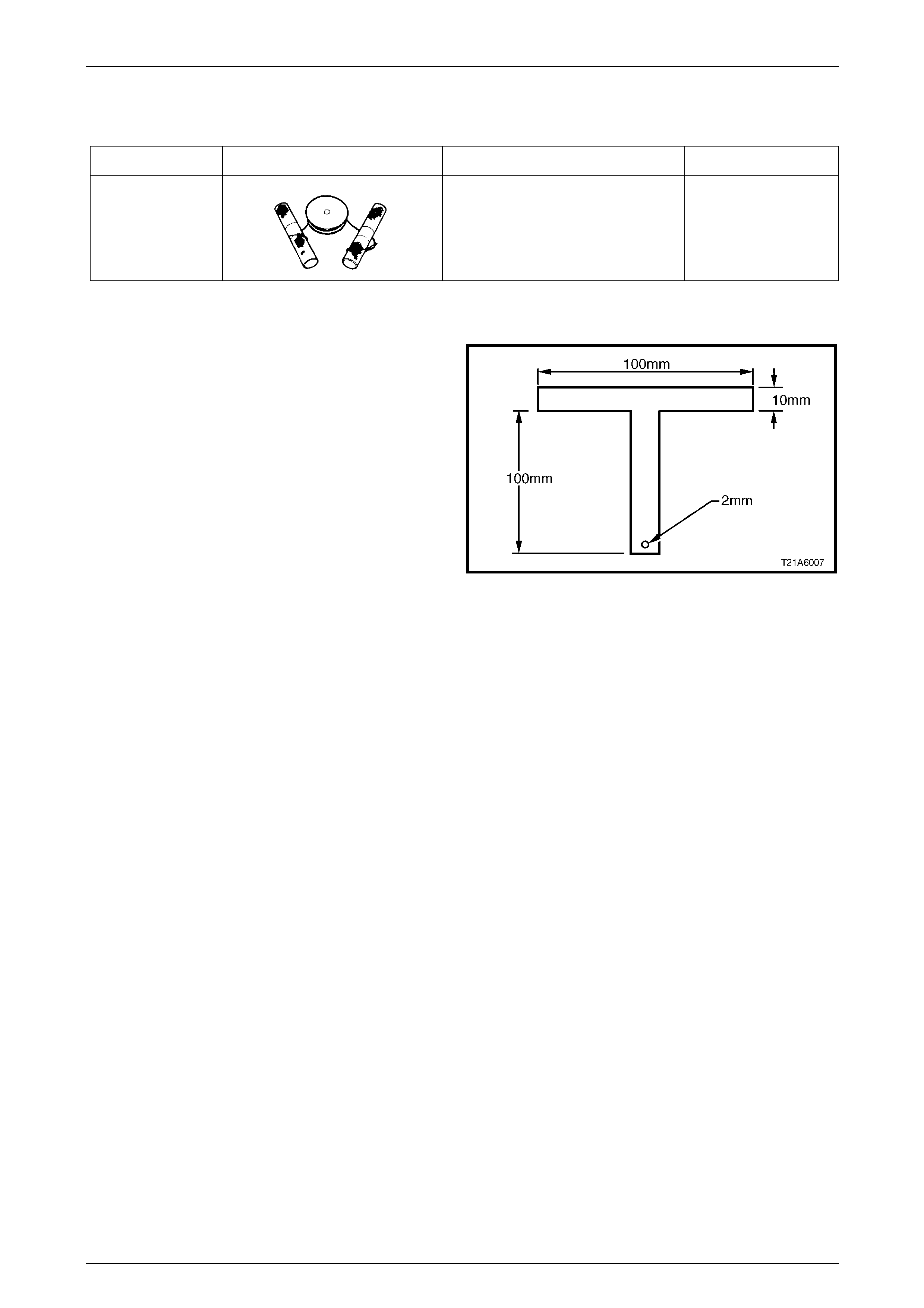
Stationary Windows Page 1A6–71
Page 1A6–71
6 Special Tools
Tool Number Illustration Description Tool Classification
J36020
Windshield Removal Tool and
Piano Wire
Previously Released
Unique
Alternative:
Manufacture an equivalent tool.
1 Manufacture two T-handles to the dimensions shown.
2 Thread 700 mm of piano wire through the hole of one
handle.
Figure 1A6 – 83

Stationary Windows Page 1A6–72
Page 1A6–72
7 Torque Wrench Specifications
Quarter Window Attaching Nut......................................................1.0 – 3.0 Nm
Door Opening Moulding Attaching Screw......................................1.0 – 2.0 Nm