
Seat Assemblies Page 1A7–1
Page 1A7–1
Section 1A7
Seat Assemblies
ATTENTION
Before performing any service operation or other procedure described in this Section, refer to Section 00
Warnings, Cautions and Notes for correct workshop practices with regard to safety and/or property damage.
1 General Information .............................................................................................................................18
1.1 Front Seat General Description.......................................................................................................................... 18
Seat Covers.......................................................................................................................................................... 19
Electric Seat Operation ....................................................................................................................................... 19
Raise/Lower Movement.................................................................................................................................... 19
Fore/Aft Movement........................................................................................................................................... 19
Recline Movement............................................................................................................................................ 20
Four-way Movement Control............................................................................................................................ 20
Eight-way Movement Control ........................................................................................................................... 20
Memory Seat Position System ......................................................................................................................... 21
Priority Keys (Level 3 Vehicles Only) ............................................................................................................... 21
Memory Buttons............................................................................................................................................... 22
Using the Exterior Mirrors................................................................................................................................. 22
EZ-entry System, Coupe.................................................................................................................................. 23
Active Head Restraints........................................................................................................................................ 24
1.2 Rear Seat General Description ........................................................................................................................... 25
Sedan.................................................................................................................................................................... 25
Wagon................................................................................................................................................................... 25
Crew Cab .............................................................................................................................................................. 25
Coupe.................................................................................................................................................................... 25
Seat Covers.......................................................................................................................................................... 25
2 Diagnostics – Front Seat, Non-memo ry, Except Coupe...................................................................26
2.1 Prerequisites........................................................................................................................................................ 26
Safety Requirements ........................................................................................................................................... 26
Equipment ............................................................................................................................................................ 26
Testing Procedures ............................................................................................................................................. 26
2.2 Mechanical Diagnosis – Two-Way/Four-Way Seat............................................................................................ 27
Lumbar Support Inoperative............................................................................................................................... 27
Introduction ...................................................................................................................................................... 27
Test Description ............................................................................................................................................... 27
Diagnostic Table............................................................................................................................................... 27
Seat Recline Forward and/or Back Function is Inoperative............................................................................. 28
Introduction ...................................................................................................................................................... 28
Test Description ............................................................................................................................................... 28
Diagnostic Table............................................................................................................................................... 28
Seat Fore/Aft Movement Function is Inoperative or is Not Smooth................................................................ 28
Introduction ...................................................................................................................................................... 28
Test Description ............................................................................................................................................... 28
Diagnostic Table............................................................................................................................................... 28
Techline
Techline
Techline
Techline
Techline

Seat Assemblies Page 1A7–2
Page 1A7–2
2.3 Electrical Diagnosis – Four-way Driver’s Seat, Except Reg Cab and Utility................................................... 29
Wiring Diagram – Four-way Driver’s Seat, Except Reg Cab and Utility .......................................................... 29
Connector Chart – Four-way Driver’s Seat, Except Reg Cab and Utility ........................................................ 29
None of the Driver’s Seat Adjustment Switch Functions Operate...................................................................30
Introduction ...................................................................................................................................................... 30
Test Description ............................................................................................................................................... 30
Diagnostic Table Notes .................................................................................................................................... 30
Diagnostic Table............................................................................................................................................... 31
Front/Rear of the Driver's Seat Does Not Raise and/or Lower......................................................................... 33
Introduction ...................................................................................................................................................... 33
Test Description ............................................................................................................................................... 33
Diagnostic Table Notes .................................................................................................................................... 33
Diagnostic Table............................................................................................................................................... 34
2.4 Electrical Diagnosis – Four-way Driver’s Seat, Reg Cab and Utility ............................................................... 35
Wiring Diagram – Four-way Driver’s Seat, Reg Cab and Utility....................................................................... 35
Connector Chart – Four-way Driver’s Seat, Reg Cab and Utility..................................................................... 35
None of the Driver’s Seat Adjustment Switch Functions Operate...................................................................36
Introduction ...................................................................................................................................................... 36
Test Description ............................................................................................................................................... 36
Diagnostic Table Notes .................................................................................................................................... 36
Diagnostic Table............................................................................................................................................... 37
Front/Rear of the Driver's Seat Does Not Raise and/or Lower......................................................................... 39
Introduction ...................................................................................................................................................... 39
Test Description ............................................................................................................................................... 39
Diagnostic Table Notes .................................................................................................................................... 39
Diagnostic Table............................................................................................................................................... 40
2.5 Four-way Seat Adjustment Switch Test............................................................................................................. 41
Test ....................................................................................................................................................................... 41
2.6 Electrical Diagnosis – Eight-way Passenger’s Seat ......................................................................................... 42
Wiring Diagram – Eight-way Passenger’s Seat................................................................................................. 42
Connector Chart – Eight-way Passenger’s Seat............................................................................................... 43
Neither Seat Adjustment Switch Functions Operate........................................................................................ 44
Introduction ...................................................................................................................................................... 44
Test Description ............................................................................................................................................... 44
Diagnostic Table Notes .................................................................................................................................... 44
Diagnostic Table............................................................................................................................................... 45
None of the Passenger’s Seat Adjustment Switch Functions Operate........................................................... 46
Introduction ...................................................................................................................................................... 46
Test Description ............................................................................................................................................... 46
Diagnostic Table Notes .................................................................................................................................... 46
Diagnostic Table............................................................................................................................................... 47
Front/Rear of the Passenger’s Seat Does Not Raise and/or Lower................................................................. 48
Introduction ...................................................................................................................................................... 48
Test Description ............................................................................................................................................... 48
Diagnostic Table Notes .................................................................................................................................... 48
Diagnostic Table............................................................................................................................................... 49
Passenger’s Seat Fore/Aft Movement Function is Inoperative or Not Smooth.............................................. 50
Introduction ...................................................................................................................................................... 50
Test Description ............................................................................................................................................... 50
Diagnostic Table Notes .................................................................................................................................... 50
Diagnostic Table............................................................................................................................................... 51
Passenger’s Seat Recline Forward and/or Aft Function is Inoperative .......................................................... 52
Introduction ...................................................................................................................................................... 52
Test Description ............................................................................................................................................... 52
Diagnostic Table Notes .................................................................................................................................... 52
Diagnostic Table............................................................................................................................................... 53
2.7 Eight-way Seat Adjustment Switch Test............................................................................................................ 54
Test ....................................................................................................................................................................... 54

Seat Assemblies Page 1A7–3
Page 1A7–3
3 Diagnostics – Front Seat, Memory and Rear-v ie w Mirror, Except Coupe......................................55
3.1 Prerequisites........................................................................................................................................................ 55
Safety Requirements ........................................................................................................................................... 55
Equipment ............................................................................................................................................................ 55
Testing Procedures ............................................................................................................................................. 55
3.2 System Self Diagnosis ........................................................................................................................................ 56
Current DTCs........................................................................................................................................................ 56
History DTCs........................................................................................................................................................ 56
Clearing DTCs...................................................................................................................................................... 56
3.3 Tech 2 Diagnostics.............................................................................................................................................. 57
Test Modes........................................................................................................................................................... 57
Mode F0: Diagnostic Trouble Codes................................................................................................................ 57
Mode F1: Diagnostic Data Display................................................................................................................... 57
Mode F2: Snapshot.......................................................................................................................................... 57
Mode F3: Miscellaneous Tests......................................................................................................................... 57
Mode F4: Additional Functions......................................................................................................................... 57
3.4 Tech 2 Test Modes and Displays for Diagnosis................................................................................................ 58
System Select Menu............................................................................................................................................ 58
Body Application Menu....................................................................................................................................... 58
System Identification........................................................................................................................................... 58
Application Menu................................................................................................................................................. 58
F0: Diagnostic Trouble Codes............................................................................................................................ 59
F0: Read DTC Information ............................................................................................................................... 59
F1: Clear DTC Information ............................................................................................................................... 59
Diagnostic Trouble Codes................................................................................................................................... 59
F1: Diagnostic Data Display................................................................................................................................ 60
F0: Inputs and Outputs..................................................................................................................................... 60
F1: Memory...................................................................................................................................................... 63
F2: System Identification.................................................................................................................................. 64
F2: Snapshot........................................................................................................................................................ 65
F3: Miscellaneous Tests...................................................................................................................................... 65
F0: Chime......................................................................................................................................................... 65
F1: LED............................................................................................................................................................ 65
F2: Right Exterior Mirror................................................................................................................................... 65
F3: Left Exterior Mirror ..................................................................................................................................... 65
F4: Front Vertical Motor.................................................................................................................................... 65
F5: Rear Vertical Mirror.................................................................................................................................... 65
F6: Horizontal Motor......................................................................................................................................... 65
F7: Recline Motor............................................................................................................................................. 65
F4: Additional Functions..................................................................................................................................... 65
F0: Module Reset............................................................................................................................................. 65
3.5 Preliminary System Diagnosis............................................................................................................................ 66
3.6 Diagnostic Tables................................................................................................................................................ 67
Introduction.......................................................................................................................................................... 67
3.7 Mechanical Diagnosis ......................................................................................................................................... 68
Lumbar Support Inoperative............................................................................................................................... 68
Introduction ...................................................................................................................................................... 68
Test Description ............................................................................................................................................... 68
Diagnostic Table............................................................................................................................................... 68

Seat Assemblies Page 1A7–4
Page 1A7–4
3.8 Electrical Diagnosis – Memory Seat................................................................................................................... 69
Wiring Diagram – Memory Seat.......................................................................................................................... 69
Connector Chart – Memory Seat ........................................................................................................................ 71
Initial Check.......................................................................................................................................................... 72
Introduction ...................................................................................................................................................... 72
Test Description ............................................................................................................................................... 72
Diagnostic Table............................................................................................................................................... 73
No Serial Data Communications to the Seat Memory Module.........................................................................78
Introduction ...................................................................................................................................................... 78
Test Description ............................................................................................................................................... 78
Diagnostic Table Notes .................................................................................................................................... 78
Diagnostic Table............................................................................................................................................... 79
Seat Adjustment Switch Inoperative.................................................................................................................. 80
Introduction ...................................................................................................................................................... 80
Test Description ............................................................................................................................................... 80
Diagnostic Table Notes .................................................................................................................................... 80
Diagnostic Table............................................................................................................................................... 81
Seat Front Lift Motor Inoperative ........................................................................................................................ 82
Introduction ...................................................................................................................................................... 82
Test Description ............................................................................................................................................... 82
Diagnostic Table Notes .................................................................................................................................... 82
Diagnostic Table............................................................................................................................................... 82
Seat Rear Lift Motor Inoperative......................................................................................................................... 83
Introduction ...................................................................................................................................................... 83
Test Description ............................................................................................................................................... 83
Diagnostic Table Notes .................................................................................................................................... 83
Diagnostic Table............................................................................................................................................... 83
Seat Fore/Aft Movement Motor Inoperative....................................................................................................... 84
Introduction ...................................................................................................................................................... 84
Test Description ............................................................................................................................................... 84
Diagnostic Table Notes .................................................................................................................................... 84
Diagnostic Table............................................................................................................................................... 84
Seat-back Recline Motor Inoperative ................................................................................................................. 85
Introduction ...................................................................................................................................................... 85
Test Description ............................................................................................................................................... 85
Diagnostic Table Notes .................................................................................................................................... 85
Diagnostic Table............................................................................................................................................... 86
Memory Position Switch Inoperative ................................................................................................................. 87
Introduction ...................................................................................................................................................... 87
Test Description ............................................................................................................................................... 87
Diagnostic Table Notes .................................................................................................................................... 87
Diagnostic Table............................................................................................................................................... 87
Seat Front Lift Motor Hall-effect Sensor Check................................................................................................. 88
Introduction ...................................................................................................................................................... 88
Test Description ............................................................................................................................................... 88
Diagnostic Table Notes .................................................................................................................................... 88
Diagnostic Table............................................................................................................................................... 88
Seat Rear Lift Motor Hall-effect Sensor Check.................................................................................................. 89
Introduction ...................................................................................................................................................... 89
Test Description ............................................................................................................................................... 89
Diagnostic Table Notes .................................................................................................................................... 89
Diagnostic Table............................................................................................................................................... 89
Seat Fore/Aft Movement Motor Hall-effect Sensor Check................................................................................ 90
Introduction ...................................................................................................................................................... 90
Test Description ............................................................................................................................................... 90
Diagnostic Table Notes .................................................................................................................................... 90
Diagnostic Table............................................................................................................................................... 90

Seat Assemblies Page 1A7–5
Page 1A7–5
Seat-back Recline Motor Hall-effect Sensor Check.......................................................................................... 91
Introduction ...................................................................................................................................................... 91
Test Description ............................................................................................................................................... 91
Diagnostic Table Notes .................................................................................................................................... 91
Diagnostic Table............................................................................................................................................... 91
Priority Key Feature Inoperative......................................................................................................................... 92
Introduction ...................................................................................................................................................... 92
Test Description ............................................................................................................................................... 92
Diagnostic Table Notes .................................................................................................................................... 92
Diagnostic Table............................................................................................................................................... 92
DTC 1 – Front Vertical Up Switch Stuck ............................................................................................................ 93
Introduction ...................................................................................................................................................... 93
Test Description ............................................................................................................................................... 93
Diagnostic Table Notes .................................................................................................................................... 93
Diagnostic Table............................................................................................................................................... 93
DTC 2 – Front Vertical Down Switch Stuck........................................................................................................ 94
Introduction ...................................................................................................................................................... 94
Test Description ............................................................................................................................................... 94
Diagnostic Table Notes .................................................................................................................................... 94
Diagnostic Table............................................................................................................................................... 94
DTC 3 – Rear Vertical Up Switch Stuck.............................................................................................................. 95
Introduction ...................................................................................................................................................... 95
Test Description ............................................................................................................................................... 95
Diagnostic Table Notes .................................................................................................................................... 95
Diagnostic Table............................................................................................................................................... 95
DTC 4 – Rear Vertical Down Switch Stuck......................................................................................................... 96
Introduction ...................................................................................................................................................... 96
Test Description ............................................................................................................................................... 96
Diagnostic Table Notes .................................................................................................................................... 96
Diagnostic Table............................................................................................................................................... 96
DTC 5 – Horizontal Forward Switch Stuck......................................................................................................... 97
Introduction ...................................................................................................................................................... 97
Test Description ............................................................................................................................................... 97
Diagnostic Table Notes .................................................................................................................................... 97
Diagnostic Table............................................................................................................................................... 97
DTC 6 – Horizontal Back Switch Stuck .............................................................................................................. 98
Introduction ...................................................................................................................................................... 98
Test Description ............................................................................................................................................... 98
Diagnostic Table Notes .................................................................................................................................... 98
Diagnostic Table............................................................................................................................................... 98
DTC 7 – Recline Up Switch Stuck....................................................................................................................... 99
Introduction ...................................................................................................................................................... 99
Test Description ............................................................................................................................................... 99
Diagnostic Table Notes .................................................................................................................................... 99
Diagnostic Table............................................................................................................................................... 99
DTC 8 – Recline Down Switch Stuck................................................................................................................ 100
Introduction .................................................................................................................................................... 100
Test Description ............................................................................................................................................. 100
Diagnostic Table Notes .................................................................................................................................. 100
Diagnostic Table............................................................................................................................................. 100
DTC 9 – Memory Button 1 Stuck....................................................................................................................... 101
Introduction .................................................................................................................................................... 101
Test Description ............................................................................................................................................. 101
Diagnostic Table Notes .................................................................................................................................. 101
Diagnostic Table............................................................................................................................................. 101
DTC 10 – Memory Button 2 Stuck..................................................................................................................... 102
Introduction .................................................................................................................................................... 102
Test Description ............................................................................................................................................. 102
Diagnostic Table Notes .................................................................................................................................. 102
Diagnostic Table............................................................................................................................................. 102

Seat Assemblies Page 1A7–6
Page 1A7–6
DTC 11 – Memory Button 3 Stuck..................................................................................................................... 103
Introduction .................................................................................................................................................... 103
Test Description ............................................................................................................................................. 103
Diagnostic Table Notes .................................................................................................................................. 103
Diagnostic Table............................................................................................................................................. 103
DTC 12 – Mirror DIP Button Stuck.................................................................................................................... 104
Introduction .................................................................................................................................................... 104
Test Description ............................................................................................................................................. 104
Diagnostic Table Notes .................................................................................................................................. 104
Diagnostic Table............................................................................................................................................. 104
DTC 13 – No Serial Data .................................................................................................................................... 105
DTC 14 – No Exterior Mirror Communications................................................................................................ 105
DTC 20 – Front Vertical Position Sensor Fault................................................................................................ 105
DTC 21 – Rear Vertical Position Sensor Fault................................................................................................. 105
DTC 22 – Horizontal Position Sensor Fault ..................................................................................................... 105
DTC 23 – Recline Position Sensor Fault.......................................................................................................... 105
DTC 24 – System Voltage Out of Range .......................................................................................................... 105
3.9 Memory Position Switch Test........................................................................................................................... 106
Remove............................................................................................................................................................... 106
Reinstall.............................................................................................................................................................. 106
Test ..................................................................................................................................................................... 106
3.10 Electrical Diagnosis – Rear-view Mirrors......................................................................................................... 107
Wiring Diagram – Rear-view Mirrors................................................................................................................ 107
Connector Chart – Rear-view Mirrors .............................................................................................................. 108
Initial Check........................................................................................................................................................ 109
Introduction .................................................................................................................................................... 109
Test Description ............................................................................................................................................. 109
Diagnostic Table............................................................................................................................................. 110
Mirror Dip Function Check................................................................................................................................ 112
Introduction .................................................................................................................................................... 112
Test Description ............................................................................................................................................. 112
Diagnostic Table............................................................................................................................................. 112
Mirror Heating Function Check......................................................................................................................... 113
Introduction .................................................................................................................................................... 113
Test Description ............................................................................................................................................. 113
Diagnostic Table............................................................................................................................................. 113
No Serial Data from Exterior Rear-view Mirrors.............................................................................................. 114
Introduction .................................................................................................................................................... 114
Test Description ............................................................................................................................................. 114
Diagnostic Table Notes .................................................................................................................................. 114
Diagnostic Table............................................................................................................................................. 115
No Serial Data – Right-hand Exterior Rear-view Mirror.................................................................................. 116
Introduction .................................................................................................................................................... 116
Test Description ............................................................................................................................................. 116
Diagnostic Table Notes .................................................................................................................................. 116
Diagnostic Table............................................................................................................................................. 116
No Serial Data – Left-hand Exterior Rear-view Mirror..................................................................................... 117
Introduction .................................................................................................................................................... 117
Test Description ............................................................................................................................................. 117
Diagnostic Table Notes .................................................................................................................................. 117
Diagnostic Table............................................................................................................................................. 117
Mirror Control Switch Inoperative.................................................................................................................... 118
Introduction .................................................................................................................................................... 118
Test Description ............................................................................................................................................. 118
Diagnostic Table Notes .................................................................................................................................. 118
Diagnostic Table............................................................................................................................................. 119

Seat Assemblies Page 1A7–7
Page 1A7–7
4 Diagnostics – Front Seat, Coupe......................................................................................................120
4.1 Prerequisites...................................................................................................................................................... 120
Safety Requirements ......................................................................................................................................... 120
Equipment .......................................................................................................................................................... 120
Testing Procedures ........................................................................................................................................... 120
4.2 Mechanical Diagnosis ....................................................................................................................................... 121
Lumbar Support Inoperative............................................................................................................................. 121
Introduction .................................................................................................................................................... 121
Test Description ............................................................................................................................................. 121
Diagnostic Table............................................................................................................................................. 121
EZ-entry Lever Function Inoperative................................................................................................................ 122
Introduction .................................................................................................................................................... 122
Test Description ............................................................................................................................................. 122
Diagnostic Table............................................................................................................................................. 122
4.3 Electrical Diagnosis – Eight-way Seat, Non-memory ..................................................................................... 123
Neither Seat Adjustment Switch Functions Operate...................................................................................... 123
Introduction .................................................................................................................................................... 123
Circuit Description.......................................................................................................................................... 123
Test Description ............................................................................................................................................. 123
Diagnostic Table Notes .................................................................................................................................. 123
Diagnostic Table............................................................................................................................................. 124
EZ-entry Electrical Self Test Diagnosis – Eight-way Seat, Non-Memory ...................................................... 125
Introduction .................................................................................................................................................... 125
4.4 Electrical Diagnosis – Passenger's Seat ......................................................................................................... 126
Wiring Diagram – Passenger's Seat, Coupe.................................................................................................... 127
Connector Chart – Passenger's Seat, Coupe.................................................................................................. 128
None of the Passenger’s Seat Adjustment Switch Functions Operate......................................................... 129
Introduction .................................................................................................................................................... 129
Circuit Description.......................................................................................................................................... 129
Test Description ............................................................................................................................................. 129
Diagnostic Table Notes .................................................................................................................................. 129
Diagnostic Table............................................................................................................................................. 130
Front/Rear of the Passenger’s Seat Does Not Raise and/or Lower............................................................... 132
Introduction .................................................................................................................................................... 132
Circuit Description.......................................................................................................................................... 132
Test Description ............................................................................................................................................. 132
Diagnostic Table Notes .................................................................................................................................. 132
Diagnostic Table............................................................................................................................................. 133
Passenger’s Seat Fore/Aft Movement Function is Inoperative or Not Smooth............................................ 134
Introduction .................................................................................................................................................... 134
Circuit Description.......................................................................................................................................... 134
Test Description ............................................................................................................................................. 134
Diagnostic Table Notes .................................................................................................................................. 134
Diagnostic Table............................................................................................................................................. 135
Passenger's Seat Recline Forward and/or Aft Function is Inoperative......................................................... 137
Introduction .................................................................................................................................................... 137
Circuit Description.......................................................................................................................................... 137
Test Description ............................................................................................................................................. 137
Diagnostic Table Notes .................................................................................................................................. 137
Diagnostic Table............................................................................................................................................. 138
Passenger's Seat EZ-entry Switch Function is Inoperative........................................................................... 139
Introduction .................................................................................................................................................... 139
Circuit Description.......................................................................................................................................... 139
Test Description ............................................................................................................................................. 139
Diagnostic Table Notes .................................................................................................................................. 139
Diagnostic Table............................................................................................................................................. 139

Seat Assemblies Page 1A7–8
Page 1A7–8
Passenger's Seat Return Switch Function is Inoperative .............................................................................. 140
Introduction .................................................................................................................................................... 140
Circuit Description.......................................................................................................................................... 140
Test Description ............................................................................................................................................. 140
Diagnostic Table Notes .................................................................................................................................. 140
Diagnostic Table............................................................................................................................................. 141
Passenger's Seat Fore/Aft Movement Motor Hall-effect Sensor Test ........................................................... 142
Introduction .................................................................................................................................................... 142
Circuit Description.......................................................................................................................................... 142
Test Description ............................................................................................................................................. 142
Diagnostic Table Notes .................................................................................................................................. 142
Diagnostic Table............................................................................................................................................. 142
Passenger's Seat Passenger Presence Detection Switch Test ..................................................................... 143
Introduction .................................................................................................................................................... 143
Circuit Description.......................................................................................................................................... 143
Test Description ............................................................................................................................................. 143
Diagnostic Table Notes .................................................................................................................................. 143
Diagnostic Table............................................................................................................................................. 143
4.5 Electrical Diagnosis – Eight-way Seat, Memory.............................................................................................. 144
Neither Seat Adjustment Switch Functions Operate...................................................................................... 144
Introduction .................................................................................................................................................... 144
Circuit Description.......................................................................................................................................... 144
Test Description ............................................................................................................................................. 144
Diagnostic Table Notes .................................................................................................................................. 144
Diagnostic Table............................................................................................................................................. 145
EZ-entry and Memory Self Test Diagnosis ...................................................................................................... 146
Introduction .................................................................................................................................................... 146
4.6 Electrical Diagnosis – Driver's Seat................................................................................................................. 147
Wiring Diagram – Driver's Seat......................................................................................................................... 148
Connector Chart – Driver's Seat....................................................................................................................... 150
None of the Driver’s Seat Adjustment Switch Functions Operate................................................................. 151
Introduction .................................................................................................................................................... 151
Circuit Description.......................................................................................................................................... 151
Test Description ............................................................................................................................................. 151
Diagnostic Table Notes .................................................................................................................................. 151
Diagnostic Table............................................................................................................................................. 152
Front/Rear of the Driver’s Seat Does Not Raise and/or Lower....................................................................... 154
Introduction .................................................................................................................................................... 154
Circuit Description.......................................................................................................................................... 154
Test Description ............................................................................................................................................. 154
Diagnostic Table Notes .................................................................................................................................. 154
Diagnostic Table............................................................................................................................................. 155
Driver’s Seat Fore/Aft Movement Function is Inoperative or Not Smooth.................................................... 157
Introduction .................................................................................................................................................... 157
Circuit Description.......................................................................................................................................... 157
Test Description ............................................................................................................................................. 157
Diagnostic Table Notes .................................................................................................................................. 157
Diagnostic Table............................................................................................................................................. 158
Driver’s Seat Recline Forward and/or Aft Function is Inoperative................................................................ 160
Introduction .................................................................................................................................................... 160
Circuit Description.......................................................................................................................................... 160
Test Description ............................................................................................................................................. 160
Diagnostic Table Notes .................................................................................................................................. 160
Diagnostic Table............................................................................................................................................. 161
Driver's Seat EZ-entry Switch Function is Inoperative................................................................................... 163
Introduction .................................................................................................................................................... 163
Circuit Description.......................................................................................................................................... 163
Test Description ............................................................................................................................................. 163
Diagnostic Table Notes .................................................................................................................................. 163
Diagnostic Table............................................................................................................................................. 164

Seat Assemblies Page 1A7–9
Page 1A7–9
Driver's Seat Return Switch Function is Inoperative...................................................................................... 165
Introduction .................................................................................................................................................... 165
Circuit Description.......................................................................................................................................... 165
Test Description ............................................................................................................................................. 165
Diagnostic Table Notes .................................................................................................................................. 165
Diagnostic Table............................................................................................................................................. 166
Driver's Seat Fore/Aft Movement Motor Hall-effect Sensor Test................................................................... 167
Introduction .................................................................................................................................................... 167
Circuit Description.......................................................................................................................................... 167
Test Description ............................................................................................................................................. 167
Diagnostic Table Notes .................................................................................................................................. 167
Diagnostic Table............................................................................................................................................. 167
Driver's Seat-back Recline Motor Hall-effect Sensor Test ............................................................................. 168
Introduction .................................................................................................................................................... 168
Circuit Description.......................................................................................................................................... 168
Test Description ............................................................................................................................................. 168
Diagnostic Table Notes .................................................................................................................................. 168
Diagnostic Table............................................................................................................................................. 168
Driver's Seat Front Lift Motor Hall-effect Sensor Test.................................................................................... 169
Introduction .................................................................................................................................................... 169
Circuit Description.......................................................................................................................................... 169
Test Description ............................................................................................................................................. 169
Diagnostic Table Notes .................................................................................................................................. 169
Diagnostic Table............................................................................................................................................. 169
Driver's Seat Rear Lift Motor Hall-effect Sensor Test..................................................................................... 170
Introduction .................................................................................................................................................... 170
Circuit Description.......................................................................................................................................... 170
Test Description ............................................................................................................................................. 170
Diagnostic Table Notes .................................................................................................................................. 170
Diagnostic Table............................................................................................................................................. 170
Driver's Seat Passenger Presence Detection Switch Test............................................................................. 171
Introduction .................................................................................................................................................... 171
Circuit Description.......................................................................................................................................... 171
Test Description ............................................................................................................................................. 171
Diagnostic Table Notes .................................................................................................................................. 171
Diagnostic Table............................................................................................................................................. 171
Driver's Seat Memory Position Switch Test .................................................................................................... 172
Introduction .................................................................................................................................................... 172
Circuit Description.......................................................................................................................................... 172
Test Description ............................................................................................................................................. 172
Diagnostic Table Notes .................................................................................................................................. 172
Diagnostic Table............................................................................................................................................. 173
5 Service Operations – Front Seat, Except Regular Cab, Utility and Coupe...................................174
5.1 Usage Chart........................................................................................................................................................ 174
How to Use this Chart........................................................................................................................................ 174
Front Seat Type 1............................................................................................................................................... 176
Front Seat Type 2............................................................................................................................................... 178
Front Seat Type 3............................................................................................................................................... 180
Front Seat Type 4............................................................................................................................................... 182
Front Seat Type 5............................................................................................................................................... 184
Front Seat Type 6............................................................................................................................................... 186
Front Seat Type 7............................................................................................................................................... 188
Front Seat Type 8............................................................................................................................................... 190
Front Seat Type 9............................................................................................................................................... 192
Front Seat Type 10............................................................................................................................................. 194
Front Seat Type 11............................................................................................................................................. 196
Front Seat Type 12............................................................................................................................................. 198

Seat Assemblies Page 1A7–10
Page 1A7–10
5.2 Front Seat Assembly......................................................................................................................................... 200
Remove............................................................................................................................................................... 200
Reinstall.............................................................................................................................................................. 202
Seat Memory Calibration, Front Seat Type 11................................................................................................. 203
5.3 Front Seat Outer Side Cover Assembly........................................................................................................... 205
Remove............................................................................................................................................................... 205
Disassemble....................................................................................................................................................... 206
Front Seat Adjustment Switch........................................................................................................................ 206
Memory Position Switch Assembly................................................................................................................. 207
Reinstall.............................................................................................................................................................. 207
5.4 Front Seat Inner Side Cover.............................................................................................................................. 208
Remove............................................................................................................................................................... 208
Reinstall.............................................................................................................................................................. 208
5.5 Front Seat-back Rear Cover Assembly............................................................................................................ 209
Remove............................................................................................................................................................... 209
Disassemble....................................................................................................................................................... 210
Reassemble........................................................................................................................................................ 210
Reinstall.............................................................................................................................................................. 211
5.6 Front Seat Head Restraint Assembly............................................................................................................... 212
Remove............................................................................................................................................................... 212
Disassemble....................................................................................................................................................... 212
Reassemble........................................................................................................................................................ 213
Reinstall.............................................................................................................................................................. 213
5.7 Front Seat Head Restraint Sleeve..................................................................................................................... 214
Remove............................................................................................................................................................... 214
Reinstall.............................................................................................................................................................. 214
5.8 Lumbar Support Knob Assembly..................................................................................................................... 215
Remove............................................................................................................................................................... 215
Reinstall.............................................................................................................................................................. 215
5.9 Front Seat-back Pad and Cover Assembly...................................................................................................... 216
Remove............................................................................................................................................................... 216
Disassemble....................................................................................................................................................... 217
Reassemble........................................................................................................................................................ 218
Reinstall.............................................................................................................................................................. 218
5.10 Front Seat-back Frame Assembly.................................................................................................................... 219
Remove............................................................................................................................................................... 219
Disassemble....................................................................................................................................................... 220
Side Impact Airbag Assembly ........................................................................................................................ 220
Front Seat Dummy Block Insert Assembly..................................................................................................... 221
Lumbar Support Assembly............................................................................................................................. 221
Active Head Restraint Frame Assembly......................................................................................................... 223
Reinstall.............................................................................................................................................................. 224
5.11 Seat Cable Tray and Memory Module .............................................................................................................. 225
Remove............................................................................................................................................................... 225
Reinstall.............................................................................................................................................................. 226
5.12 Track and Height Adjust Assembly.................................................................................................................. 227
Remove............................................................................................................................................................... 227
Reinstall.............................................................................................................................................................. 227
5.13 Front Seat Cushion Pad and Cover Assembly................................................................................................ 228
Remove............................................................................................................................................................... 228
Disassemble....................................................................................................................................................... 229
Reassemble........................................................................................................................................................ 230
Reinstall.............................................................................................................................................................. 230

Seat Assemblies Page 1A7–11
Page 1A7–11
5.14 Front Seat Cushion Frame Assembly.............................................................................................................. 231
Remove............................................................................................................................................................... 231
Disassemble....................................................................................................................................................... 231
Reassemble........................................................................................................................................................ 231
Reinstall.............................................................................................................................................................. 231
5.15 Front Seat Lift Motor Assemblies..................................................................................................................... 232
5.16 Front Seat Fore/Aft Movement Motor Assembly............................................................................................. 233
5.17 Front Seat-back Recline Motor Assembly ....................................................................................................... 234
5.18 Drive Motor Hall-effect Sensors........................................................................................................................ 235
6 Service Operations – Front Seat, Regular Cab and Utility.............................................................236
6.1 Usage Chart........................................................................................................................................................ 236
How to Use this Chart........................................................................................................................................ 236
Front Seat Type 1............................................................................................................................................... 237
Front Seat Type 2............................................................................................................................................... 239
Front Seat Type 3............................................................................................................................................... 241
Front Seat Type 4............................................................................................................................................... 243
Front Seat Type 5............................................................................................................................................... 245
Front Seat Type 6............................................................................................................................................... 247
6.2 Front Seat Assembly......................................................................................................................................... 249
Remove............................................................................................................................................................... 249
Reinstall.............................................................................................................................................................. 251
6.3 Front Seat Outer Side Cover Assembly........................................................................................................... 252
Remove............................................................................................................................................................... 252
Disassemble....................................................................................................................................................... 253
Front Seat Adjustment Switch........................................................................................................................ 253
Reinstall.............................................................................................................................................................. 253
6.4 Front Seat Inner Side Cover.............................................................................................................................. 254
Remove............................................................................................................................................................... 254
Reinstall.............................................................................................................................................................. 254
6.5 Front Seat-back Rear Cover Assembly............................................................................................................ 255
Remove............................................................................................................................................................... 255
Reinstall.............................................................................................................................................................. 256
6.6 Dump-latch Mechanism Assembly................................................................................................................... 257
Remove............................................................................................................................................................... 257
Reinstall.............................................................................................................................................................. 258
6.7 Front Seat Head Restraint Assembly............................................................................................................... 259
Remove............................................................................................................................................................... 259
Disassemble....................................................................................................................................................... 259
Reassemble........................................................................................................................................................ 260
Reinstall.............................................................................................................................................................. 260
6.8 Front Seat Head Restraint Sleeve..................................................................................................................... 261
Remove............................................................................................................................................................... 261
Reinstall.............................................................................................................................................................. 261
6.9 Lumbar Support Knob Assembly..................................................................................................................... 262
Remove............................................................................................................................................................... 262
Reinstall.............................................................................................................................................................. 262
6.10 Front Seat-back Pad and Cover Assembly...................................................................................................... 263
Remove............................................................................................................................................................... 263
Disassemble....................................................................................................................................................... 264
Reassemble........................................................................................................................................................ 265
Reinstall.............................................................................................................................................................. 265

Seat Assemblies Page 1A7–12
Page 1A7–12
6.11 Front Seat-back Frame Assembly.................................................................................................................... 266
Remove............................................................................................................................................................... 266
Disassemble....................................................................................................................................................... 266
Front Seat Dummy Block Insert Assembly..................................................................................................... 266
Lumbar Support Assembly............................................................................................................................. 267
Reinstall.............................................................................................................................................................. 268
6.12 Seat Cable Tray.................................................................................................................................................. 269
Remove............................................................................................................................................................... 269
Reinstall.............................................................................................................................................................. 270
6.13 Track and Height Adjust Assembly.................................................................................................................. 271
Remove............................................................................................................................................................... 271
Reinstall.............................................................................................................................................................. 271
6.14 Front Seat Cushion Pad and Cover Assembly................................................................................................ 272
Remove............................................................................................................................................................... 272
Disassemble....................................................................................................................................................... 273
Reassemble........................................................................................................................................................ 274
Reinstall.............................................................................................................................................................. 274
6.15 Front Seat Cushion Frame Assembly.............................................................................................................. 275
Remove............................................................................................................................................................... 275
Disassemble....................................................................................................................................................... 275
Reassemble........................................................................................................................................................ 275
Reinstall.............................................................................................................................................................. 275
6.16 Front Seat Lift Motor Assemblies..................................................................................................................... 276
7 Service Operations – Front Seat, Coupe .........................................................................................277
7.1 Usage Chart........................................................................................................................................................ 277
How to Use this Chart........................................................................................................................................ 277
Front Seat Type 1............................................................................................................................................... 278
Front Seat Type 2............................................................................................................................................... 280
7.2 Front Seat Assembly......................................................................................................................................... 282
Remove............................................................................................................................................................... 282
Reinstall.............................................................................................................................................................. 284
Seat Memory Calibration, Front Seat Type 1................................................................................................... 285
7.3 Front Seat Outer Side Cover Assembly........................................................................................................... 287
Remove............................................................................................................................................................... 287
Disassemble....................................................................................................................................................... 288
Front Seat Adjustment Switch........................................................................................................................ 288
Memory Position Switch Assembly................................................................................................................. 289
EZ-entry Module............................................................................................................................................. 289
Reinstall.............................................................................................................................................................. 289
7.4 Front Seat Inner Side Cover.............................................................................................................................. 290
Remove............................................................................................................................................................... 290
Reinstall.............................................................................................................................................................. 290
7.5 Front Seat-back Rear Cover Assembly............................................................................................................ 291
Remove............................................................................................................................................................... 291
Disassemble....................................................................................................................................................... 292
Reassemble........................................................................................................................................................ 292
Reinstall.............................................................................................................................................................. 293
7.6 Front Seat Head Restraint Assembly............................................................................................................... 294
Remove............................................................................................................................................................... 294
Disassemble....................................................................................................................................................... 294
Reassemble........................................................................................................................................................ 295
Reinstall.............................................................................................................................................................. 295
7.7 Front Seat Head Restraint Sleeve..................................................................................................................... 296
Remove............................................................................................................................................................... 296
Reinstall.............................................................................................................................................................. 296

Seat Assemblies Page 1A7–13
Page 1A7–13
7.8 EZ-entry Release Lever and Escutcheon......................................................................................................... 297
Remove............................................................................................................................................................... 297
Reinstall.............................................................................................................................................................. 299
7.9 EZ-entry Switch and Release Cable Assembly ............................................................................................... 300
7.10 Lumbar Support Knob Assembly..................................................................................................................... 301
Remove............................................................................................................................................................... 301
Reinstall.............................................................................................................................................................. 301
7.11 Front Seat-back Pad and Cover Assembly...................................................................................................... 302
Remove............................................................................................................................................................... 302
Disassemble....................................................................................................................................................... 303
Reassemble........................................................................................................................................................ 303
Reinstall.............................................................................................................................................................. 304
7.12 Front Seat-back Frame Assembly.................................................................................................................... 305
Remove............................................................................................................................................................... 305
Disassemble....................................................................................................................................................... 306
EZ-entry Release Lever Retaining Clip and Return Spring............................................................................ 306
Side Impact Airbag Assembly ........................................................................................................................ 307
Front Seat Dummy Block Insert Assembly..................................................................................................... 308
Lumbar Support Assembly............................................................................................................................. 309
Active Head Restraint Frame Assembly......................................................................................................... 310
Reinstall.............................................................................................................................................................. 311
7.13 Seat Cable Tray and Memory Module .............................................................................................................. 312
Remove............................................................................................................................................................... 312
Reinstall.............................................................................................................................................................. 313
7.14 Track and Height Adjust Assembly.................................................................................................................. 314
Remove............................................................................................................................................................... 314
Reinstall.............................................................................................................................................................. 314
7.15 Front Seat Cushion Pad and Cover Assembly................................................................................................ 315
Remove............................................................................................................................................................... 315
Disassemble....................................................................................................................................................... 315
Reassemble........................................................................................................................................................ 317
Reinstall.............................................................................................................................................................. 318
7.16 Front Seat Cushion Frame Assembly.............................................................................................................. 319
Remove............................................................................................................................................................... 319
Disassemble....................................................................................................................................................... 319
Reassemble........................................................................................................................................................ 319
Reinstall.............................................................................................................................................................. 319
7.17 Front Seat Lift Motor Assemblies..................................................................................................................... 320
7.18 Front Seat Fore/Aft Movement Motor Assembly............................................................................................. 321
7.19 Front Seat-back Recline Motor Assembly ....................................................................................................... 322
7.20 Drive Motor Hall-effect Sensors........................................................................................................................ 323
8 Service Operations – Rear Seat, Sedan...........................................................................................324
8.1 Usage Chart........................................................................................................................................................ 324
How to Use this Chart........................................................................................................................................ 324
Rear Seat Type 1................................................................................................................................................ 325
Rear Seat Type 2................................................................................................................................................ 326
Rear Seat Type 3................................................................................................................................................ 327
Rear Seat Type 4................................................................................................................................................ 328
Rear Seat-back Centre Tray and Armrest Assembly...................................................................................... 329

Seat Assemblies Page 1A7–14
Page 1A7–14
8.2 Rear Seat Cushion Assembly........................................................................................................................... 330
Remove............................................................................................................................................................... 330
Disassemble....................................................................................................................................................... 330
Remove – Rear Seat Cushion Release Handle ............................................................................................. 330
Reinstall – Rear Seat Cushion Release Handle............................................................................................. 331
Remove – Rear Seat Cushion Frame ............................................................................................................ 331
Remove – Rear Seat Cushion Cover, Hook and Loop................................................................................... 332
Reinstall – Rear Seat Cushion Cover, Hook and Loop................................................................................... 333
Reinstall – Rear Seat Cushion Frame, Surebond........................................................................................... 335
Reinstall – Rear Seat Cushion Frame, Hook and Loop.................................................................................. 337
Reinstall.............................................................................................................................................................. 339
8.3 Rear Seat-back Assembly................................................................................................................................. 340
Remove............................................................................................................................................................... 340
Disassemble....................................................................................................................................................... 341
Remove – Rear Seat-back Head Restraint .................................................................................................... 341
Reinstall – Rear Seat-back Head Restraint.................................................................................................... 341
Remove – Rear Seat-back Head Restraint Guide.......................................................................................... 341
Reinstall – Rear Seat-back Head Restraint Guide ......................................................................................... 342
Remove – Rear Seat-back Cover, Hook and Loop ........................................................................................ 342
Reinstall – Rear Seat-back Cover, Hook and Loop........................................................................................ 344
Reinstall.............................................................................................................................................................. 348
8.4 Rear Seat-back Head Restraint Assembly....................................................................................................... 349
Remove............................................................................................................................................................... 349
Disassemble....................................................................................................................................................... 349
Reassemble........................................................................................................................................................ 349
Reinstall.............................................................................................................................................................. 349
8.5 Rear Seat-back Head Restraint Guide.............................................................................................................. 350
Remove............................................................................................................................................................... 350
Reinstall.............................................................................................................................................................. 350
8.6 Rear Seat-back Centre, Armrest Assembly..................................................................................................... 351
Remove............................................................................................................................................................... 351
Disassemble....................................................................................................................................................... 351
Reassemble........................................................................................................................................................ 352
Reinstall.............................................................................................................................................................. 353
8.7 Rear Seat Centre Back Assembly..................................................................................................................... 354
Remove............................................................................................................................................................... 354
Disassemble....................................................................................................................................................... 354
Remove – Rear Seat Centre Back Cover and Pad Assembly........................................................................ 354
Reinstall – Rear Seat Centre Back Cover and Pad Assembly ....................................................................... 355
Remove – Rear Seat-back Centre Hinge....................................................................................................... 356
Reinstall – Rear Seat-back Centre Hinge....................................................................................................... 356
Remove – Rear Seat-back Centre Release Button........................................................................................ 356
Reinstall – Rear Seat-back Centre Release Button........................................................................................ 356
Remove – Rear Seat-back Centre Lock Actuator........................................................................................... 356
Reinstall – Rear Seat-back Centre, Lock Actuator......................................................................................... 357
Reinstall.............................................................................................................................................................. 357
8.8 Rear Seat Centre Back, Lock Striker................................................................................................................ 358
Remove............................................................................................................................................................... 358
Reinstall.............................................................................................................................................................. 359

Seat Assemblies Page 1A7–15
Page 1A7–15
9 Service Operations – Rear Seat, Wagon..........................................................................................360
9.1 Usage Chart........................................................................................................................................................ 360
How to Use this Chart........................................................................................................................................ 360
Rear Seat Type 1................................................................................................................................................ 361
Rear Seat Type 2................................................................................................................................................ 362
Rear Seat Type 3................................................................................................................................................ 363
Rear Seat Type 4................................................................................................................................................ 365
Rear Seat-back Frame Assembly ..................................................................................................................... 367
9.2 Rear Seat Cushion Assembly........................................................................................................................... 368
Remove............................................................................................................................................................... 368
Disassemble....................................................................................................................................................... 368
Remove – Rear Seat Cushion Release Handle ............................................................................................. 368
Reinstall – Rear Seat Cushion Release Handle............................................................................................. 369
Remove – Rear Seat Cushion Frame ............................................................................................................ 369
Remove – Rear Seat Cushion Cover, Hook and Loop................................................................................... 370
Reinstall – Rear Seat Cushion Cover, Hook and Loop................................................................................... 371
Reinstall – Rear Seat Cushion Frame, Surebond........................................................................................... 373
Reinstall – Rear Seat Cushion Frame, Hook and Loop.................................................................................. 375
Reinstall.............................................................................................................................................................. 377
9.3 Rear Seat Bolster Assembly............................................................................................................................. 378
Remove............................................................................................................................................................... 378
Reinstall.............................................................................................................................................................. 378
9.4 Rear Seat-back Assembly................................................................................................................................. 379
Remove............................................................................................................................................................... 379
Disassemble....................................................................................................................................................... 380
Remove – Rear Seat-back Release Handle................................................................................................... 380
Reinstall – Rear Seat-back Release Handle .................................................................................................. 380
Remove – Rear Seat-back Retainer Locking Plate........................................................................................ 381
Reinstall – Rear Seat-back Retainer Locking Plate........................................................................................ 381
Remove – Rear Seat-back Head Restraint .................................................................................................... 381
Reinstall – Rear Seat-back Head Restraint.................................................................................................... 381
Remove – Rear Seat-back Trim Cover .......................................................................................................... 382
Reinstall – Rear Seat-back Trim Cover.......................................................................................................... 382
Remove – Child Seat Anchor......................................................................................................................... 382
Reinstall – Child Seat Anchor......................................................................................................................... 382
Remove – Rear Seat-back Head Restraint Guide.......................................................................................... 383
Reinstall – Rear Seat-back Head Restraint Guide ......................................................................................... 384
Remove – Rear Seat-back Armrest Assembly............................................................................................... 384
Reinstall – Rear Seat-back Armrest Assembly............................................................................................... 386
Remove – Rear Seat-back Cover and Pad Assembly.................................................................................... 387
Reinstall – Rear Seat-back Cover and Pad Assembly ................................................................................... 389
Remove – Rear Seat-back Cover, Hook and Loop ........................................................................................ 389
Reinstall – Rear Seat-back Cover, Hook and Loop........................................................................................ 391
Remove – Rear Seat-back Frame Release Button ........................................................................................ 392
Reinstall – Rear Seat-back Frame Release Button........................................................................................ 392
Remove – Left-hand Rear Seat-back Frame Actuator Cable Assembly......................................................... 393
Reinstall – Left-hand Rear Seat-back Frame Actuator Cable Assembly........................................................ 394
Remove – Left-hand Rear Seat-back Frame Inner Latch............................................................................... 394
Reinstall – Left-hand Rear Seat-back Frame Inner Latch .............................................................................. 394
Remove – Rear Seat-back Frame Outer Latch.............................................................................................. 395
Reinstall – Rear Seat-back Frame Outer Latch.............................................................................................. 395
Remove – Rear Seat-back Frame Actuator ................................................................................................... 396
Reinstall – Rear Seat-back Frame Actuator................................................................................................... 396
Remove – Rear Seat-back Armrest Hinge..................................................................................................... 396
Reinstall – Rear Seat-back Armrest Hinge..................................................................................................... 397
Remove – Rear Seat-back Seatbelt Retractor ............................................................................................... 397
Reinstall – Rear Seat-back Seatbelt Retractor............................................................................................... 398
Reinstall.............................................................................................................................................................. 398

Seat Assemblies Page 1A7–16
Page 1A7–16
9.5 Rear Seat-back Head Restraint Assembly....................................................................................................... 399
Remove............................................................................................................................................................... 399
Disassemble....................................................................................................................................................... 399
Reassemble........................................................................................................................................................ 400
Reinstall.............................................................................................................................................................. 400
9.6 Rear Seat-back Head Restraint Guide.............................................................................................................. 401
Remove............................................................................................................................................................... 401
Reinstall.............................................................................................................................................................. 403
9.7 Rear Seat-back Armrest Assembly .................................................................................................................. 404
Remove............................................................................................................................................................... 404
Disassemble....................................................................................................................................................... 404
Reassemble........................................................................................................................................................ 405
Reinstall.............................................................................................................................................................. 405
9.8 Rear Seat-back Armrest Hinge Assembly and Centre Cover......................................................................... 406
Remove............................................................................................................................................................... 406
Reinstall.............................................................................................................................................................. 408
9.9 Rear Seat Centre Support................................................................................................................................. 409
Remove............................................................................................................................................................... 409
Reinstall.............................................................................................................................................................. 409
9.10 Rear Seat-back Lock Striker ............................................................................................................................. 410
Remove............................................................................................................................................................... 410
Reinstall.............................................................................................................................................................. 410
10 Service Operations – Rear Seat, Crew Cab.....................................................................................411
Rear Seat ............................................................................................................................................................ 411
10.1 Rear Seat Cushion Assembly........................................................................................................................... 413
Remove............................................................................................................................................................... 413
Disassemble....................................................................................................................................................... 414
Cushion Cover and Pad Assembly................................................................................................................. 414
Rear Seat Hinge............................................................................................................................................. 418
Rear Seat Latch ............................................................................................................................................. 419
Rear Seat Release Button.............................................................................................................................. 419
Reinstall.............................................................................................................................................................. 420
10.2 Rear Seat-back Insert ........................................................................................................................................ 421
Remove............................................................................................................................................................... 421
Disassemble....................................................................................................................................................... 421
Reassemble........................................................................................................................................................ 422
Reinstall.............................................................................................................................................................. 422
10.3 Rear Seat-back Assembly................................................................................................................................. 423
Remove............................................................................................................................................................... 423
Disassemble....................................................................................................................................................... 423
Rear Seat-back Cover.................................................................................................................................... 423
Reinstall.............................................................................................................................................................. 427
10.4 Head Restraint Assembly.................................................................................................................................. 428
Remove............................................................................................................................................................... 428
Disassemble....................................................................................................................................................... 429
Reassemble........................................................................................................................................................ 430
Reinstall.............................................................................................................................................................. 430
10.5 Head Restraint Sleeve ....................................................................................................................................... 431
Remove............................................................................................................................................................... 431
Reinstall.............................................................................................................................................................. 431

Seat Assemblies Page 1A7–17
Page 1A7–17
11 Service Operations – Rear Seat, Coupe...........................................................................................432
Rear Seat ............................................................................................................................................................ 432
11.1 Rear Seat Cushion Assembly........................................................................................................................... 433
Remove............................................................................................................................................................... 433
Disassemble....................................................................................................................................................... 434
Remove – Rear Seat Cushion Release Handle ............................................................................................. 434
Reinstall – Rear Seat Cushion Release Handle............................................................................................. 434
Remove – Rear Seat Cushion Centre Escutcheon ........................................................................................ 435
Reinstall – Rear Seat Cushion Centre Escutcheon........................................................................................ 435
Remove – Rear Seat Cushion Cover and Pad Assembly ..............................................................................436
Reinstall – Rear Seat Cushion Cover and Pad Assembly.............................................................................. 436
Remove – Rear Seat Cushion Cover............................................................................................................. 437
Reinstall – Rear Seat Cushion Cover............................................................................................................. 438
Reinstall.............................................................................................................................................................. 439
11.2 Rear Seat-back Assembly................................................................................................................................. 440
Remove............................................................................................................................................................... 440
Disassemble....................................................................................................................................................... 441
Remove – Rear Seat-back Head Restraint .................................................................................................... 441
Reinstall – Rear Seat-back Head Restraint.................................................................................................... 441
Remove – Rear Seat-back Head Restraint Guide.......................................................................................... 441
Reinstall – Rear Seat-back Head Restraint Guide ......................................................................................... 442
Remove – Rear Seat-back Centre Escutcheon.............................................................................................. 442
Reinstall – Rear Seat-back Centre Escutcheon ............................................................................................. 442
Remove – Rear Seat-back Cover and Pad Assembly.................................................................................... 443
Reinstall – Rear Seat-back Cover and Pad Assembly ................................................................................... 444
Remove – Rear Seat-back Cover................................................................................................................... 445
Reinstall – Rear Seat-back Cover.................................................................................................................. 446
Reinstall.............................................................................................................................................................. 447
11.3 Rear Seat Head Restraint Assembly................................................................................................................ 448
Remove............................................................................................................................................................... 448
Reinstall.............................................................................................................................................................. 448
11.4 Rear Seat Head Restraint Guide....................................................................................................................... 449
Remove............................................................................................................................................................... 449
Reinstall.............................................................................................................................................................. 449
11.5 Child Comforter Guide – Coupe ....................................................................................................................... 450
Remove............................................................................................................................................................... 450
Reinstall.............................................................................................................................................................. 451
12 Torque Wrench Specifications..........................................................................................................452
Front Seat, Except Regular Cab, Utility and Coupe........................................................................................ 452
Front Seat, Regular Cab and Utility.................................................................................................................. 452
Front Seat, Coupe.............................................................................................................................................. 452
Rear Seat, Sedan................................................................................................................................................ 453
Rear Seat, Wagon .............................................................................................................................................. 453
Rear Seat, Crew Cab.......................................................................................................................................... 453
Rear Seat, Coupe............................................................................................................................................... 453

Seat Assemblies Page 1A7–18
Page 1A7–18
1 General Information
This section describes the diagnostic and service procedure s for the seat assemblies.
For Diagnosis the section is di vided as follows:
• front seat assemblies for vehicles, except coupe, fitted with non-memory seats,
• front seat assemblies for vehicles, except coupe, fitted with memory seats, and
• front seat assemblies for coupe.
For Service Operations the section is divided as follows:
• front seat assemblies for all models e xcept coupe, regular cab and utility,
• front seat assemblies for regular cab and utili ty,
• front seat assemblies for coupe,
• rear seat assemblies for sedan,
• rear seat assemblies for wagon,
• rear seat assemblies for crew cab, and
• rear seat assemblies for coupe.
1.1 Front Seat General Description
For reasons of personal safety, the vehicle
must only be driven after the seat has been
adjusted to the correct driving position. Do
not adjust the driver’s seat when the vehicle
is moving as the seat could move away from
the driving position, causing loss of control.
Accessory and after mar ket seat covers MUST
NOT be fitted to any vehicle with side impact
airbags unless app roved by the manu facturer.
Non-approved seat covers may inhibit the
operation of the side airbag, reducing the
protection otherwise provided to the
occupants during a side-impact collision.
Depending on vehicl e Model Level, the front seats fitted may feature:
• Four or eight-way electric movement functions,
• side impact airbag assembl ies,
• cloth or leather trim,
• active head restraints,
• a driver's seat memory positio n system that integrates with other vehicle functions, and
• an EZ-entry system to aid rear seat access on coupe vehicles.
To identify the front seat type fitted to Sedan and W ag on vehicles, refer to 5.1 Usage Chart. For Regular Cab an d Utility
vehicles, refer to 6.1 Usage Chart. For Coupe vehicles, refer to 7.1 Usage Chart.
The front seatbelt buckle and pretens ioner assemblies are attached to the front seats. For service operations refer to
Section 12M Occupant Protection System.
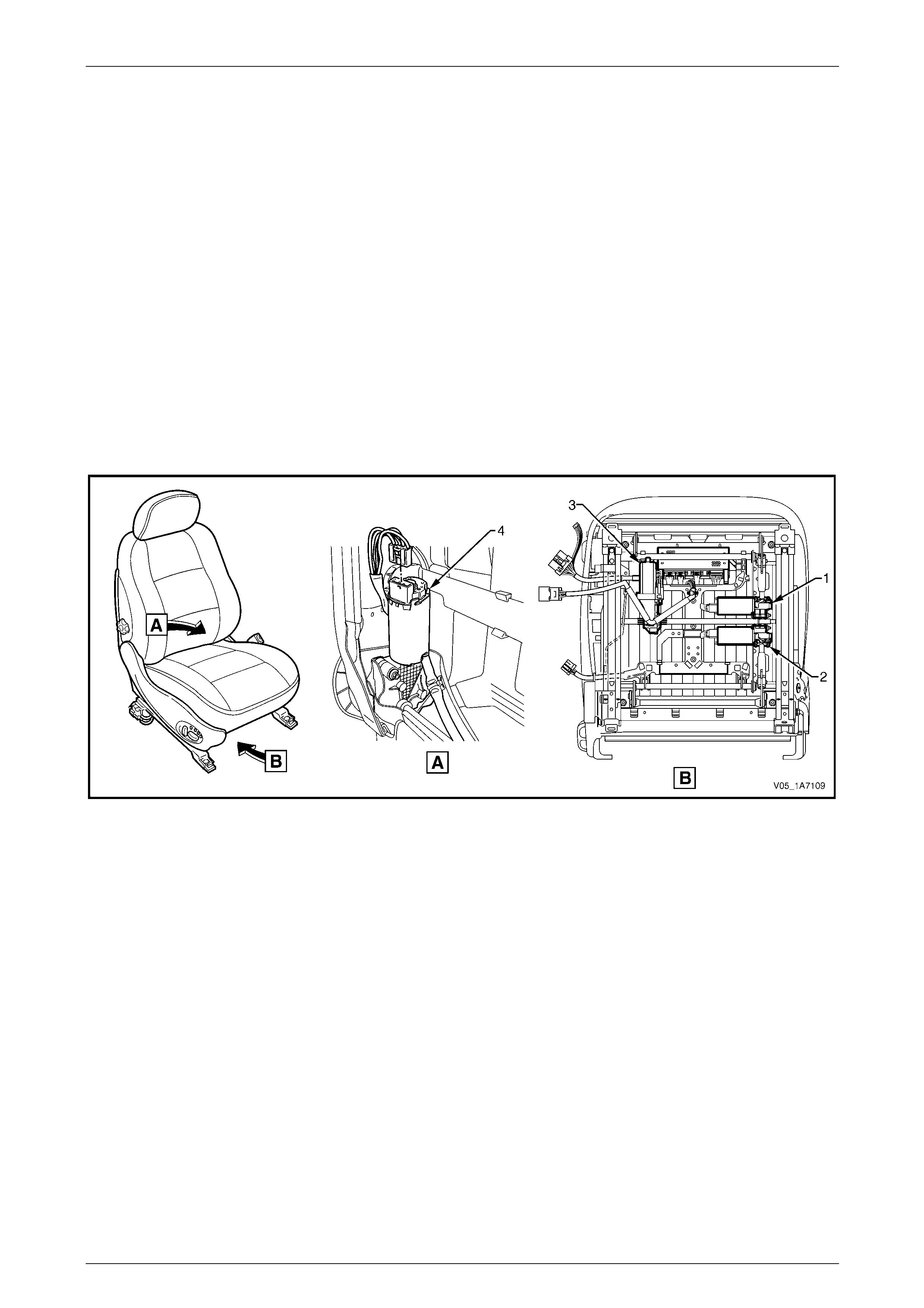
Seat Assemblies Page 1A7–19
Page 1A7–19
Seat Covers
Two seat cover construction methods are use d for the front seat assemb lies. Surebond type covers are not serviced
separately as they are glued to the seat pa d. Hook and Loop type covers are fully serviceable as they are attached within
the grooves of the seat pad with a Velcro type materia l.
Electric Seat Operation
Depending on Model Level of the vehicle, the following front seat electric movement functions are available:
• four-way – seat cushion front raise/lower and rear raise/lower, and
• eight-way – as four- way plus seat fore/aft and seat-back recline.
Referring to Figure 1A7 – 1, four electric motor and gearbox assemblies provide the mov ement of the front seat, one
each, where fitted, for:
• front raise/lower movement (1),
• rear raise/lower movement (2),
• seat fore/aft movement (3), and
• seat-back recline (4).
Figure 1A7 – 1
Each function is independentl y controlled. Alternatively, if desired the front and rear raise/lower movement can be
performed together to raise or lower the complete seat.
Raise/Lower Movement
Two lift motor and gearbox assemblies (1 and 2, refer to Figure 1A7 – 1) are attached to the inboard side of the track and
height adjust assembly; one for front and the other for rear raise/lo wer movement. When a lift motor is operating, it drive s
the gearbox which draws in or extends a mating worm shaft. This in turn operates on an arm and cross-shaft.
The cross-shaft is connected to another arm on the opposite side of the track and height adjust assembly and allows the
raising or lowering of that portion (front or rear) of the seat.
Fore/Aft Movement
To provide seat fore/aft movement, the motor and gearbox assembly (3, refer to Figure 1A7 – 1) is connected to a shaft
geared at each end. Within e ach seat track, the shaft gear is meshed upon a rack, providing fore/aft movement.
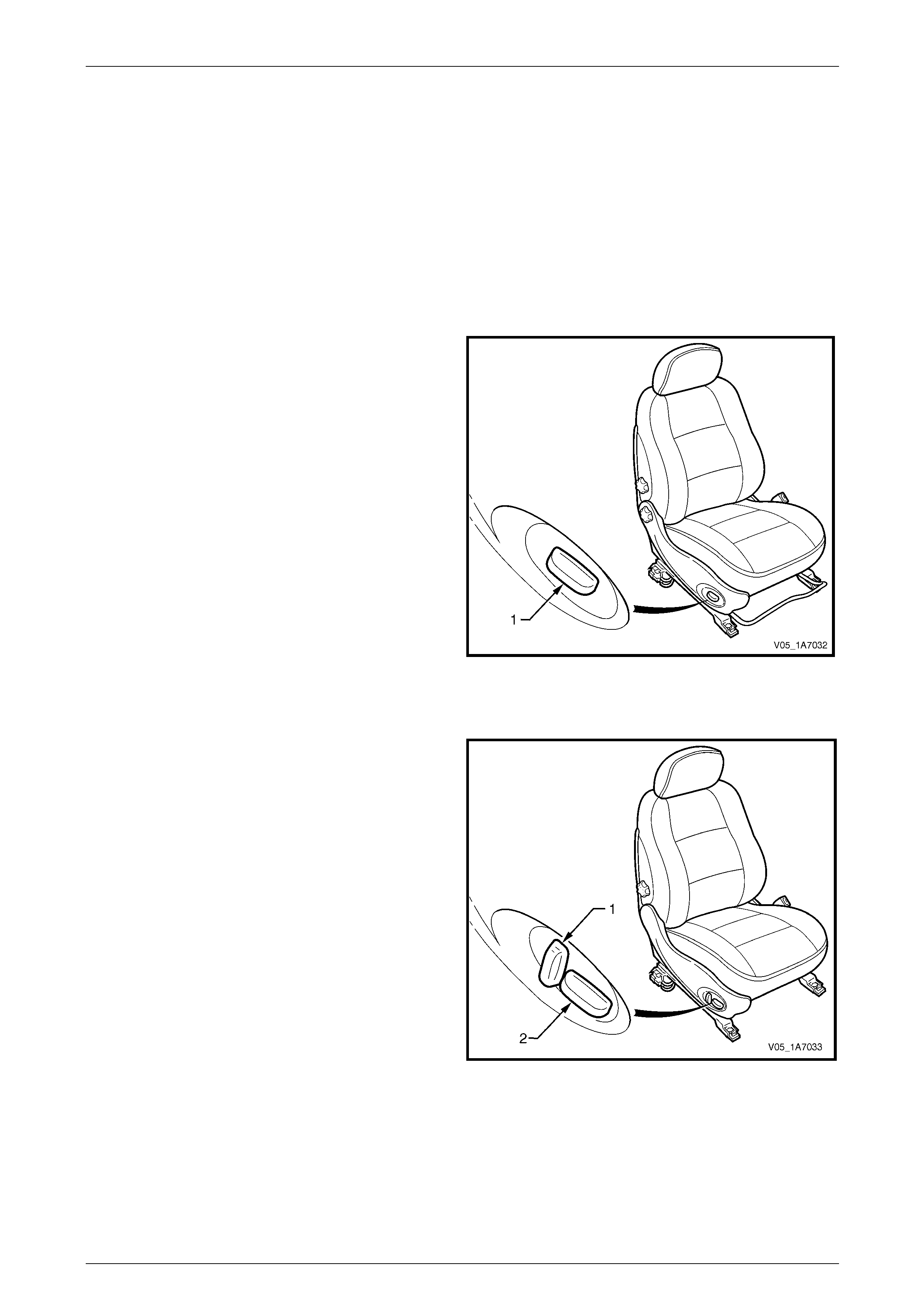
Seat Assemblies Page 1A7–20
Page 1A7–20
Recline Movement
Seat-back recline movement is provided by the recline motor and gearbo x assembly (4, refer to Figure 1A7 – 1), which is
attached to the seat-back frame. A shaft from the gearbox is fitted with a drive gear at each end and is meshed with a
driven gear attached to each seat-back fram e pivot. Motor oper ation causes rotation of the drive ge ar, which turns the
driven gear and seat-back frame, thereby altering the seat-back recline a ngle.
All motors reverse direction when the polarity at the wiring terminals is reversed, resu lting in seat movement in the
opposite direction. During seat position adjustment, the drive motors will cease operation at the end of their travel via an
internal thermal cut-out switch, even if the seat adjustment switch is held on.
Components making up the seat-back recline mechanism and track and height adjust asse mbly are not serviced.
Four-way Movement Control
Four-way seat movement is controlled by a front seat
adjustment switch (1), which is fitted to the outer side of the
front seat.
The switch provides indepe ndent control of the front and
rear raise/lower movements.
To adjust the seat:
• Operate the switch up or down to raise/lower the seat.
• Operate the front of the switch up or down to
raise/lower the front of the seat.
• Operate the rear of the switch up or down to
raise/lower the rear of the seat.
For further information, refer to the Owner's Handbook.
Figure 1A7 – 2
Eight-way Movement Control
The eight-way front seat adjustment switch has an
additional knob (1) which provides control of the seat-back
recline movement. The knob (2) provi des the same
functions as four-way seats plus fore/aft movement.
To adjust the seat:
• Operate the switch forward or backward to move the
seat fore/aft.
• Operate the recline knob to adjust the angl e of the
seat-back. The seat-back moves in the same direction
to which the switch is moved.
For Coupe vehicles, the seat-back recline switch is
disabled during operation of the EZ-entry function (refer to
EZ-entry System, Coupe, in this Section). The switch will be
enabled once the function is completed or cancelled. The
front seat adjustment switch is monitored by the EZ-entr y
module during EZ-entry function and if the switch is
operated, the movement will be cancelled.
For further information, refer to the Owner's Handbook. Figure 1A7 – 3
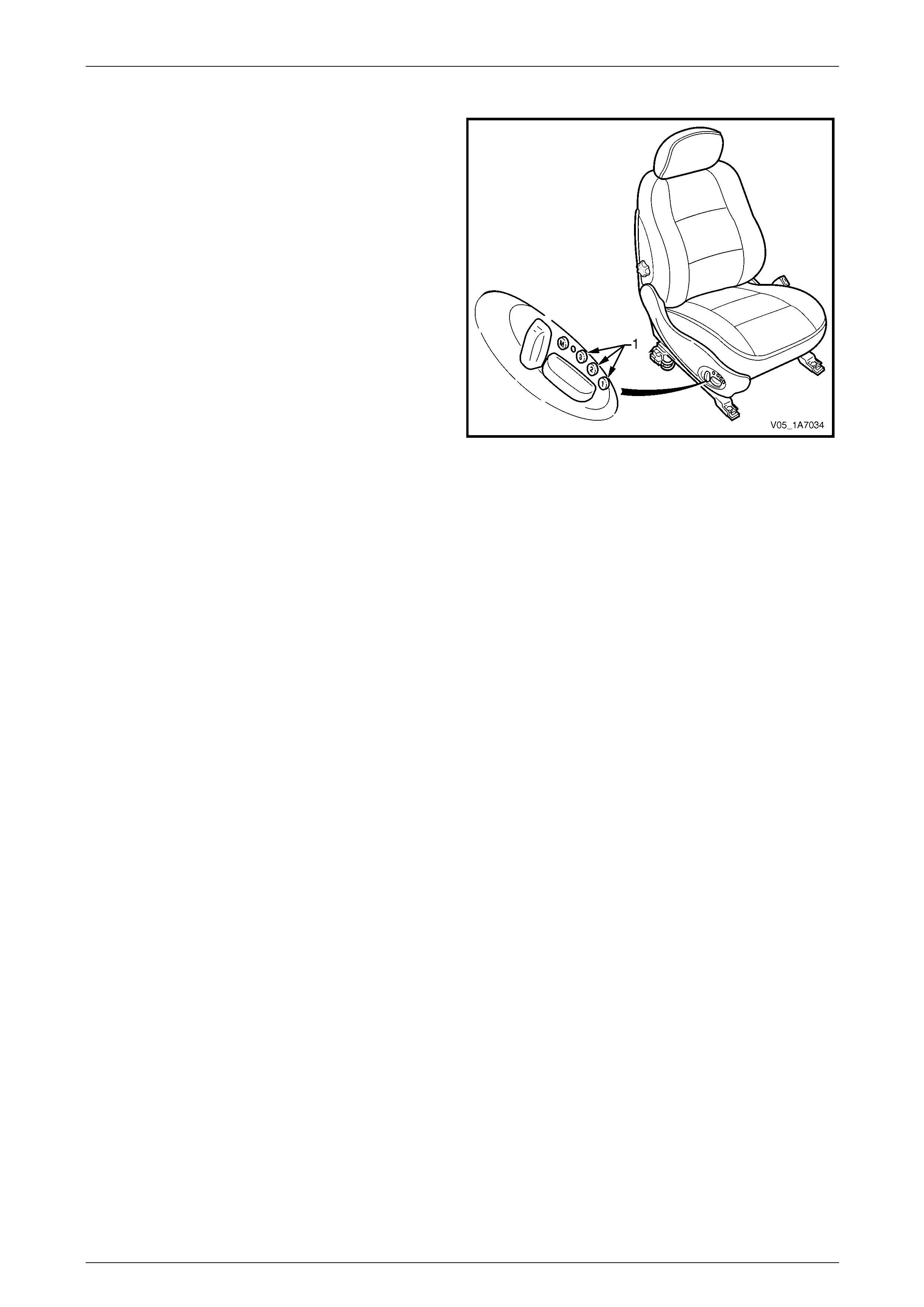
Seat Assemblies Page 1A7–21
Page 1A7–21
Memory Seat Position System
The driver’s seat in Level 3 and Cou pe vehicles is fitted with
a memory seat position system.
The memory seat position system allo ws the driver to adjust
the seat to any of the positions stored in memory by
pressing one of the three memory buttons (1).
In addition, on keyless entr y to Level 3 vehicles, the memory
seat position system through the Body Control Module
(BCM), recognises which igniti on key has been used
(Priority 1 or Priority 2) and adjusts the seat positio n to the
driver’s preferred set position.
Audible and visual feedback for the various fu nctions of the
memory seat position system is provided. The s ystem has a
green LED and a chime, which are used to indicate memory
saves, the recall of priority memory numbers and for seat
diagnostic procedures.
Hall-effect sensors integrated into each of the motor
assemblies are used to monit or the positi on of the seat.
Figure 1A7 – 4
The seat memory module, mounted under the front seat, has a non-volatile memory. While disconnecting the battery will
not erase the seat memory settings, the seat will require recalibrating to reset the potentiometer stop values within the
memory control module.
NOTE
Some of the procedures relating to memory seat
diagnosis detai led in 3 Diagnostics – Front Seat,
Memory and Rear-view Mirror, Except Coupe
require the use of both the Pri ority 1 Key and the
Priority 2 Key.
Priority Keys (Level 3 Vehicles Only )
On Level 3 vehicles, the driver's seat movement is also a function of the priority keys. Priority key 1 and priority key 2
move the driver's seat and exterior mirrors to the positi ons in which they were set when that key was last inserted into the
ignition switch. When the vehi cle is unlocked using the Unlo ck button on a priority key and that priority key is inserted into
the ignition switch, the vehicle identifies the priority key and:
• adjusts the position of the driver's seat,
• adjusts the position of the exterior mirrors to the last position used for that key, and
• if the mirror dip function is activated, adjusts the position of the passenger's exterior mirror when the transmission
selector is placed in reverse.
The driver's seat moves to the last position used for that priority key if:
• that was a memory button position, or
• the seat was adjusted without memorising the position.
The driver's seat moves to the alternate prio rity key position only after pressing the unlock button on the alternate priority
key. If the alternate priority key is not used to unlock the vehicle, that priority key will adjust all personalised settings (for
example, exterior mirror angles, radio and climate control), except the driver's seat.
If activated, the left exterior mirror dip function is linked to the seat and priority key memory (that is, each seat memory
position also stores the left exterior mirror DIP position, if activated).
For further information, refer to the Owner's Handbook.

Seat Assemblies Page 1A7–22
Page 1A7–22
Memory Buttons
The seat can store three different memory settings. To recall a stored memory seat and exterior mirror position, press
and hold one of the memory buttons. After the seat has reached its memorised position, release the memory button. If
the memory button is released before the seat reaches its memorised position, the seat stops moving.
To change a memory position:
1 Adjust the seat with the eight-way front seat adjustment switch.
2 Adjust the exterior mirrors (including the dip position).
3 Place the transmission select or in either park or neutral, then turn on the ignition switch.
4 Press the mirror DIP / memory store button (1, 2 or 3) within five seconds. (Two audible chimes are generated
when a new memory position has been stored.)
5 Place the transmission select or in reverse and wait for the passenger' s mirror to be returned from the DIP angle to
complete saving the mirror position into memory, refer to Using the Exterior Mirrors in this Section.
Using the Exterior Mirrors
The right exterior mirror and left exterior mirror can be adjusted using the rear-view mirror switch on the driver’s door
armrest when the ignition is on.
To operate the right exterior mirror or left exterior mirror:
1 Turn on the ignition switch.
2 Move the rocker switch on the rear-view mirror switch to the position to control the right or left exterior mirror.
3 Press the rear-view mirror switch in one of the directions indicated by one of the moulded dots on the edge of the
rear-view mirror switch to move the mirror up, down, left or right.
Adjusting the DIP View
To change the mirror dip posit ion a nd save it in memory:
1 Turn on the ignition switch.
2 Place the transmission select or in reverse.
3 Ensure the DIP angle is switched on; the left exterior mirror moves to the current DIP position.
4 Adjust the left exterior mirror using the rear-view mirror switch.
5 Place the transmission select or out of reverse.
6 Press the mirror DIP button, then the desired memory store button (1, 2 or 3) to save the mirror dip position into
memory.
For further information, refer to the Owner's Handbook.
Toggle DIP Function On / Off
When the mirror DIP function is activated, the left exterior mirror moves to the position set, typically enabling the driver to
see the kerb more clearly. If activated, the DIP function is operational when the ignition is on and the transmission
selector placed in reverse.
To toggle between the dip view and normal view, press the mirror DIP / memory store button.
• When the DIP function is turned on, two audible chimes are generated.
• When the DIP function is turned off, one audible chime is generated.
For further information, refer to the Owner's Handbook.

Seat Assemblies Page 1A7–23
Page 1A7–23
EZ-entry System, Coupe
The EZ-entry system provides a one touch mechanism to
move the front seat and allow rear seat passengers to enter
or exit the vehicle. The EZ-entry system comprises of:
• an EZ-entry release lever (1),
• a seat return switch (2),
• a passenger presence detection switch (3),
• an EZ-entry switch (4),
• an EZ-entry module (5) – vehicles without memory
function, and
• a memory module incorporating EZ-entry functions (6)
– vehicles with memory function.
When the EZ-entry release lever is un-latched, the
seat-back can be tilted forward.
The EZ-entry module detects if the EZ-entr y feature has
been activated via the EZ-entry switch and providing the
seat is not occupied, the seat will automatically move
forward until end of travel is reached.
Seat fore/ aft position is monitored by a sensor incorporated
with the fore/aft drive motor and recorde d in the EZ-entry
module.
To return the seat, the operator returns the seat-back to the
latched position and presses and holds the seat return
button. The seat will then return to it’s last recorded location.
If the seat return switch remains held, after a period of three
seconds the seat will resume its rearward movement for as
long as the switch is held or until the end of seat travel is
reached.
Figure 1A7 – 5
A passenger presence detection switch (1) is incorporated
into the front seat cushions (2).
Detection of a weight 15 kg or more over the passenger
presence detection switch (seat cushion) will cause the
EZ-entry module to either cancel fore/ aft movement or
prevent fore/ aft movement from commencing should the
EZ-entry function be initiated.
If weight detection causes the EZ-entry function to cease, a
period of one second must pass without weight before re-
start will commence.
The passenger presence detection switch is a pressur e
switch with a nominal high resistance condition with no
weight on the seat. The resistance decreases as the weight
is increased.
An integral diode is provided within the passeng er presence
detection switch and is used by the module to verify
connection of the switch prior to forward movement of the
seat during the operation of the EZ-entry function.
The module will test for the following conditions on the
passenger presence detection switch:
• either line connected to ground or batter y, and
• either line open circuited.
Figure 1A7 – 6
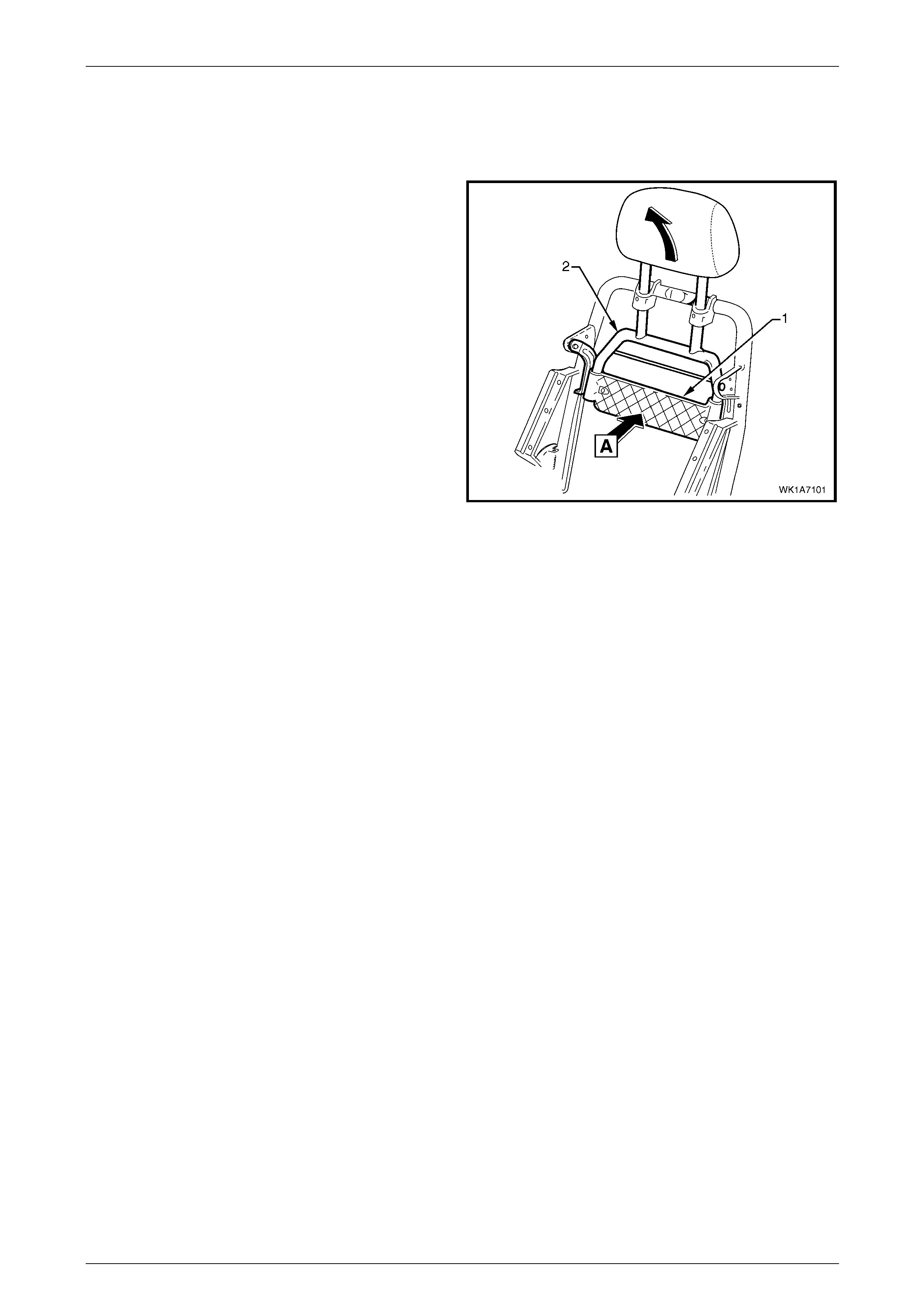
Seat Assemblies Page 1A7–24
Page 1A7–24
Active Head Restraints
The front seats fitted to Acclaim, Calais, LX AWD Wagon a nd Coupe vehicles feature active he ad restraints. During a
rear-end collision, active head restraints are designed to move upward and forward to support the occupant's head an d
reduce neck injuries.
The impact force from the collision push es th e vehicle (and
seat) forward. As the vehicle moves for ward at a speed
greater than the occupant’s body can react to, the body is
moved into the seat (A) pushing on the active hea d restraint
support strap (1).
Due to the pivoting of the active head restrain t frame (2), the
frame along with the head restraint moves upward and
forward, supporting and limiting rearward travel of the
occupant's head.
Figure 1A7 – 7

Seat Assemblies Page 1A7–25
Page 1A7–25
1.2 Rear Seat General Description
Sedan
Depending on vehicl e Model Level, the rear seats fitted may feature:
• cloth or leather trim,
• adjustable head restraints, and
• centre armrest.
To identify the rear seat type fitted to Sedan, refer to 8.1 Usage Chart.
Wagon
Depending on vehicl e Model Level, the rear seats fitted may feature:
• cloth or leather trim,
• adjustable head restraints, and
• centre armrest.
To identify the rear seat type fitted to Wagon, refer to 9.1 Usage Chart.
Crew Cab
The rear seat cushion assembly is hinged at the rear of the base. This allows the rear seat cushion assembly to be
raised for access to a storage area belo w the seat containing the jack and spare wheel repl acement tools. The rear seat
cushion assembly is locked in place by a central latch with the release button located at the front of the seat, above the
transmission tunnel.
The rear seat-back assembly incorporates a wire frame that is moulded within the pad and is serviced only as an
assembly. A one-piece moulded plastic b ase is used instead of a wire frame for the rear seat cushion. This base
supports the cushion pad as well as having provision for the cushion cover to be attached to the base. The base and
cushion pad are serviced as separate components.
Coupe
The rear seats fitted feature:
• leather trim,
• adjustable head restraints,
• centre armrest, and
• child comforter guide (optional).
Where fitted, the child comforter guide is attached to the rear seat-back frame and is used to position the seat-belt in a
more comfortable position for smaller passengers such as childr en. When not in use, the child comforter guide stores
away in a small pouch on the side of the rear seat-back assembly.
Seat Covers
Two seat cover construction methods are use d for the rear seat assemb lies. Surebond type covers are not serviced
separately as they are glued to the seat pa d. Hook and Loop type covers are fully serviceable as they are attached within
the grooves of the seat pad with a Velcro type materia l.

Seat Assemblies Page 1A7–26
Page 1A7–26
2 Diagnostics – Front Seat,
Non-memory, Except Coupe
2.1 Prerequisites
Safety Requirements
When operating the seat as part of any Steps
in the diagnostic tables, ensure that fingers
and limbs are clear of mo ving parts.
Equipment
The following equipment is required to diagnose the seats:
• an unpowered test lamp with a current draw of less than 3 A, and
• a digital multimeter with a minimum impe dance of 10 MΩ.
Testing Procedures
The following points must be adhered to
when performing diagnostic testing on
components:
• Take care when using testing equipment
to diagnose wiring harness connectors. It
is preferred the technician backprobe the
connector to avoid terminal damage.
• When tests are required on connector
terminals, use the adapters in the
connector adapter kit KM–609 to prevent
damage to the terminals.
• Unless the multimeter being used has an
auto-ranging function, ensure the correct
range is selected.
• When backpro bing connectors, ensure the
test lamp ground lead is connected to an
appropriate ground point on the vehicle.
Ensure this ground point is not part of the
circuit being tested.
NOTE
When following the steps in the di agnostic tables,
perform them in the order cited. If the required
nominal value or result is not achi eved, rectif y t he
problem before proceeding any further.

Seat Assemblies Page 1A7–27
Page 1A7–27
2.2 Mechanical Diagnosis – Two-Way/Four-
Way Seat
Lumbar Support Inoperative
Introduction
This test is used to aid in diagnosing the lumbar support as sembly.
Test Description
The following numbers refer to the step numbers in the diagnostic table:
1 Checks if the lumbar support knob is properly engaging the lumbar support adjuster. Check the knob for cracks and
worn splines.
2 Checks if the lumbar support assembly is damaged or worn and if the retaining springs are serviceable and
securely attached to the seat-back frame assembly.
3 Checks if the lumbar support assembly is servicea ble and if the lumber support assembly strap is operating
correctly within the guide rails.
Diagnostic Table
Step Action Yes No
1 Remove the lumbar support knob, refer to 5.8 Lumbar Support Knob
Assembly.
Is the lumbar support adjust knob serviceable? Go to Step 2
Replace the knob,
refer to 5.8 Lumbar
Support Knob
Assembly
2 1 Remove the seat-back cover.
2 Inspect the lumbar support retainers and spri ngs.
Are the lumbar support retaining spri ngs serviceable and securel y
attached to the seat-back frame assembly? Go to Step 3
Replace or reattach
the retaining
springs, refer to
5.10 Front Seat-
back Frame
Assembly
3 1 Visually inspect the lumbar support assembly. Check for broken
or worn parts.
2 Check the strap running across the lumber support assembly is
serviceable and running freely within the guide rails.
NOTE
You may need to attach the lumber support knob to
actuate the strap.
Is the lumbar support assembly serviceabl e? System serviceable
Replace lumbar
support assembly
or resecure lumbar
support assembly
strap ensuring
strap is not binding
with guide rails,
refer to 5.10 Front
Seat-back Frame
Assembly
When all diagno sis an d repairs are completed, ch eck the system for correct op eration.

Seat Assemblies Page 1A7–28
Page 1A7–28
Seat Recline Forward and/or Back Function is Inoperative
Introduction
This test is used to aid in diagnosing the manual recline function of the seat assembly.
Test Description
The following numbers refer to the step numbers in the diagnostic table:
1 Checks if the recliner knob is properly engaging the recliner shaft. Check the knob for cracks and worn splines.
Diagnostic Table
Step Action Yes No
1 Remove the recliner knob, refer to 5.3 F ront Seat Outer Side Cover
Assembly
Is the recliner knob serviceable?
Replace the front
seat-back frame
assembly, refer to
5.10 Front Seat-
back Frame
Assembly
Replace the
recliner knob, refer
to 5.3 Front Seat
Outer Side Cover
Assembly
When all diagno sis an d repairs are completed, ch eck the system for correct op eration.
Seat Fore/Aft Movement Function is Inoperative or is Not Smooth
Introduction
This test is used to aid in diagnosing the fore/aft movement function of the seat being inoperative or the action of the seat
through the range of movement is not smooth.
Test Description
The following numbers refer to the step numbers in the diagnostic table:
1 Checks if there are any items obstructing the guide rails which may stop or hinder the seat movement.
2 Checks if the guide rails have adequate lubricant appli ed to provide a smooth operation for the seat.
3 Checks if the linkage assembly between the adjustment lever and locking tangs is worn or damaged. The lockin g
tangs must disengage from the guide rails be fore the seat will move.
4 Checks if the guide rails have been damaged. Any binding b etween the inner and outer guide rails will result in
poor operation of the fore and aft movement.
Diagnostic Table
Step Action Yes No
1 Are the guide rails free from obstructions? Go to Step 2 Remove the
obstructing item
2 Are the guide rails adequate ly lubricated?
Go to Step 3
Apply a small
amount of grease
type NLGI No. 1
Lithium Grease
(with 9% Zinc
Oxide) to the rails
3 Do the locking tangs disengage the guide rails when the sea t fore and
aft adjustment lever is raised to its full movement?
Go to Step 4
Replace the track
and height adjust
assembly, refer to
5.12 Track and
Height Adjust
Assembly
4 Do the guide rails bind at any point of travel during the fore and aft
movements of the seat? Replace the track
and height adjust
assembly, refer to
5.12 Track and
Height Adjust
Assembly System serviceable
When all diagno sis an d repairs are completed, ch eck the system for correct op eration.
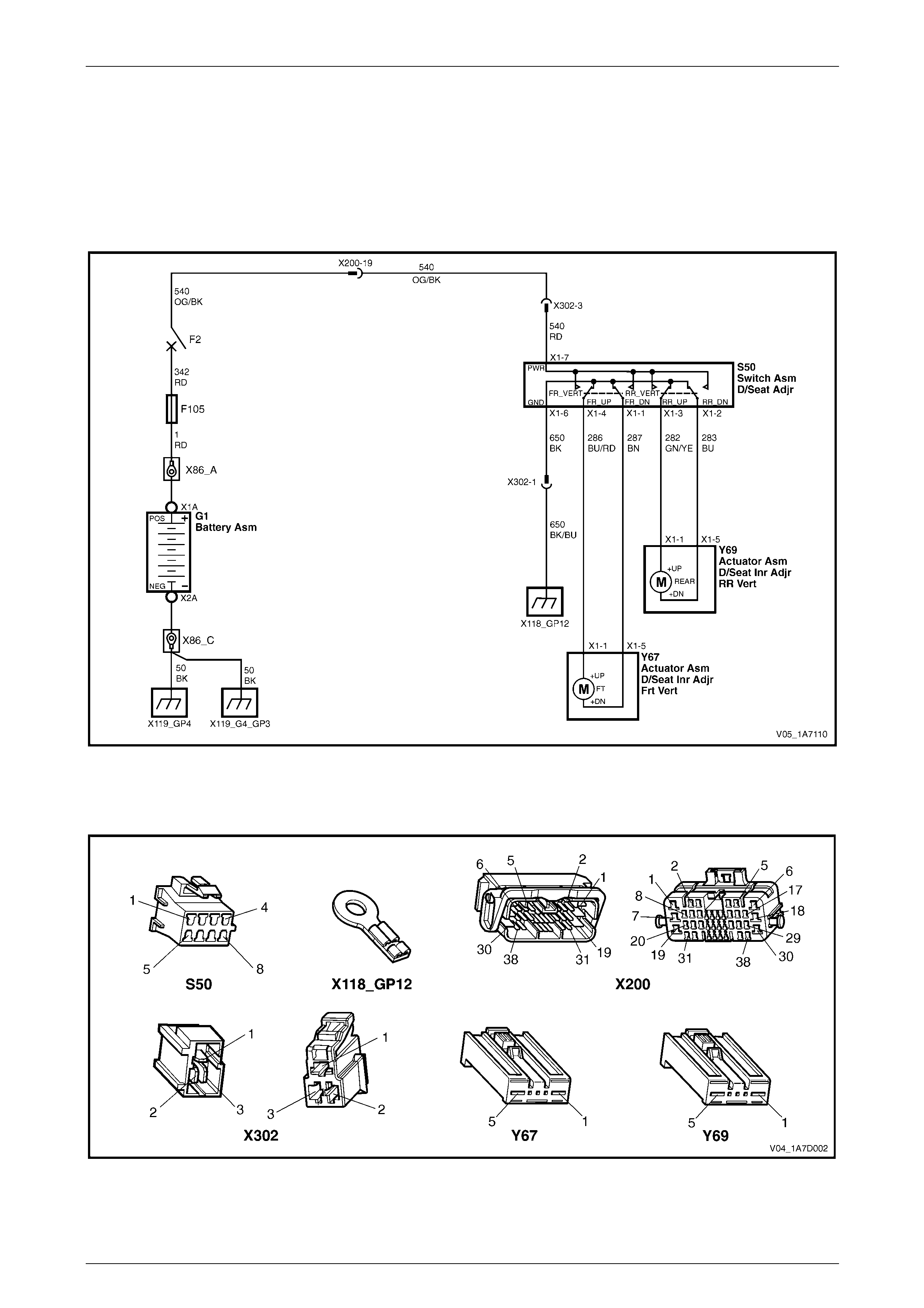
Seat Assemblies Page 1A7–29
Page 1A7–29
2.3 Electrical Diagnosis – Four-way Driver’s
Seat, Except Reg Cab and Utility
The charts in this Section are used to aid in diagnosing faults on four-way driver’s seat assemblies. To aid in the use of
the diagnostic tables, refer to Wiring Diagr am – Four-way Driver’s Seat, Except Reg Ca b and Utility and
Connector Chart – Four- way Driver’s Seat, Exce pt Reg Cab and Utility.
Wiring Diagram – Four-way Driver’s Seat, Except Reg Cab and Utility
Figure 1A7 – 8
Connector Chart – Four-way Driver’s Seat, Except Reg Cab and Utility
Figure 1A7 – 9

Seat Assemblies Page 1A7–30
Page 1A7–30
None of the Driver’s Seat Adjustment Switch Functions Operate
Introduction
This test is used to aid in diagnosing the driver’s seat adjustment switch when none of the switch functions operate. The
test diagnoses the driver’s seat adjustment switch and associated power and ground circuits.
Refer to Wiring Diagram – Four-way Driver’s Seat, Except Reg Cab and Utility and
Connector Chart – Four- way Driver’s Seat, Exce pt Reg Cab and Utility to aid in diagnosis.
Test Description
The following numbers refer to the step numbers in the diagnostic table:
1 Checks if battery voltage is greater than 11.5 V. The seat motors require gr eater than 11.5 V to operate correctly.
2 Checks if circuit breaker F2 located on the passen ger compartment fuse and relay panel assembl y is tripped.
Isolates if circuit breaker F2 is the fault affecting the circuit between the battery and connec tor X200 pin 19.
3 Checks if fusible link F105 located on the engine compartment fuse and relay panel assembly is serviceable.
Isolates if the fusible link is the fault affecting the circuit between the battery and connector X200 pin 19.
4 Checks if all the connectors required for the seat to operate effectively are in place a nd positively connected.
5 Checks if there is battery power at connector S50 – X1 pin 7. Isolates if there is a fault between the battery and
connector S50 – X1 pin 7.
6 Checks if there is battery power at connector X302 pi n 3. Isolates if there is a fault in circuit 540 between
connectors S50 – X1 pin 7 and X302 pin 3.
7 Checks if there is battery voltage at connector X200 pin 19. Isolates if the fault is between the battery and
connector X200 pin 19.
8 Checks if there is battery voltage at circuit breaker F2. Isolates whether the fault is between the b attery and circuit
breaker F2 or bet ween circuit breaker F2 an d connector X200 pin 19.
9 Checks if there is battery voltage at fusible link F105. Isolates whether the fault is between the battery and fusible
link F105 or between fusible li nk F105 and circuit breaker F2.
10 Checks if the driver’s seat adjustment switch is serviceable.
11 Checks if the ground point associated with the system is serviceable.
12 Checks if there is continuity between connectors S50 – X1 pin 6 and X302 pin 1 which supplies the ground circuit
for the driver’s seat adjustment switch. Isolates whether there is a fault in circuit 650 bet ween the switch and
connector X302 pin 1 or between connector X302 pin 1 and the groun d point.
Diagnostic Table Notes
1 For all wiring harness fault diagnoses, refer to Section 12P Wiring Diagrams.
2 For wiring harness repairs, refer to Section 12P Wiring Diagrams.
3 Refer to Section 12O Fuses, Relays and W iring Harnesses for harness routeing.
4 If the fault is deemed to be intermittent, refer to Section 12P Wiring Diagrams.

Seat Assemblies Page 1A7–31
Page 1A7–31
Diagnostic Table
Step Action Yes No
1 Check the battery voltage, refer to Section 12A Battery.
Is the battery voltage greater than 11.5 V? Go to Step 2
Refer to Section
12A Battery for
further diagnosis
2 Inspect circuit breaker F2, refer to Section 12O Fuses, Relays and
Wiring Harnesses.
Is circuit breaker F2 tripped?
Allow the circuit
breaker to reset
(refer to Note 3).
If the circuit breaker
trips again, repair
or replace circuit
540 (refer to
Note 2) Go to Step 3
3 Inspect fusible link F105, refer to Section 12O Fuses, Relays and
Wiring Harnesses.
Is fuse F105 serviceable?
Go to Step 4
Replace the fusible
link.
If the fusible link
becomes
unserviceable
again, repair or
replace circuit 342
(refer to Note 2)
4 Are the following connectors secure (refer to Note 3)?
• S50
• X200
• X302
• Y67
• Y69 Go to Step 5
Ensure the
connectors are
secure
5 Backprobe connector S50 – X1 pin 7 with a test lamp (refer Note 1).
Does the test lamp illuminate? Go to Step 10 Go to Step 6
6 Backprobe connector X302 pin 3 with a test lamp (refer to Note 1).
Does the test lamp illuminate?
Repair or replace
circuit 540 between
connectors
X302 pin 3 and
S50 – X1 pin 7
(refer to Note 2) Go to Step 7
7 Backprobe connector X200 pin 19 with a test lamp (refer to Note 1).
Does the test lamp illuminate?
Repair or replace
circuit 540 between
connectors X200
pin 19 and
X302 pin 3 (refer to
Note 2) Go to Step 8

Seat Assemblies Page 1A7–32
Page 1A7–32
Step Action Yes No
8 1 Remove circuit breaker F2 from the passen ger compartment
fuse and relay panel assembly. Repair or replace
circuit 540 between
circuit breaker F2
and connector
X200 pin 19 (refer
to Note 2) Go to Step 9
9 1 Remove fusible link F105.
2 Using a test lamp, probe connector X18-105 (refer to Note 1).
Does the test lamp illuminate?
Repair or replace
circuit 342 between
fusible link F105
and circuit breaker
F2 (refer to Note 2)
Repair or replace
circuit 1 between
the battery and
fusible link F105
(refer to Note 2)
10 1 Remove the driver’s seat adjustment switch from the seat, refer
to 5.3 Front Seat Outer Side Cover Assembly.
2 Test the driver’s seat adjustment switch, refer to 2.5 Four-way
Seat Adjustment Switch Test.
Is the driver’s seat adjustment switch serviceabl e? Go to Step 11
Replace the
driver’s seat
adjustment switch,
refer to 5.3 Front
Seat Outer Side
Cover Assembly
11 Ensure ground point X118 – GP12 (located in the middle of the
transmission tunnel) is secure and has go od contact with the vehicle
structure.
Is the ground point secure to the vehicle with a good contact? Go to Step 12 Repair ground poi nt
12 1 Backprobe connector X302 pin 1 with a test lamp (refer Note 1).
2 Operate the driver’s seat adjustment switch in any of the
available directions.
Does the test lamp illuminate?
Repair or replace
circuit 650 between
connector X302 pin
1 and ground point
X118 – GP12 (refer
Note 2)
Repair or replace
circuit 650 between
connectors
S50 – X1 pin 6 and
X302 pin 1 (refer
Note 2)
When all diagno sis an d repairs are completed, ch eck the system for correct op eration.

Seat Assemblies Page 1A7–33
Page 1A7–33
Front/Rear of the Driver's Seat Does Not Raise and/or Lower
Introduction
This test is used to aid in diagnosing the front and/or the rear of the driver's seat not raising and/or lowering. The test
diagnoses the driver’s seat adjustment switch and the motor circuits.
Refer to Wiring Diagram – Four-way Driver’s Seat, Except Reg Cab and Utility and
Connector Chart – Four- way Driver’s Seat, Exce pt Reg Cab and Utility to aid in diagnosis.
Test Description
The following numbers refer to the step numbers in the diagnostic table:
1 Checks if the driver's seat adjustment switch operates the seat in any direct ion. Isolates whether there is a battery
or ground fault affecting the seat operation.
2 Checks if all the connectors required for the seat to operate effectively are in place a nd positively connected.
3 Checks if the driver's seat adjustment switch is serviceable.
4 Confirms whether the rear of the seat raises or lowers. Isolates if the seat rear lift motor and circuit of the seat is the
fault.
5 Confirms whether the front of the seat raises or lo wers. Isolates if the seat front lift motor and circuit of the seat is
the fault.
6 Checks if there is battery power to the seat rear lift motor at connector Y69 – X1 pin 1. Isolates if there is a fault in
circuit 282 that supplies battery power to the motor to raise the rear of the seat.
7 Checks if there is battery power to the seat rear lift motor at connector Y69 – X1 pin 5. Isolates whether the fault is
in circuit 283 that supplies battery power to the motor to lower the rear of the seat or the motor is faulty. As
reversing the polarity changes the direction of the motor, this Step also confirms the grou nd circuit from Step 6 is
serviceable.
8 Checks if there is battery power to the seat front lift motor at connector Y67 – X1 pin 1. Isolates if there is a fault in
circuit 286 that supplies battery power to the motor to raise the front of the seat.
9 Checks if there is battery power to the seat front lift motor at connector Y67 – X1 pin 5. Isolates whether the fault is
in circuit 287 that supplies battery power to the motor to lower the front of the seat or the motor is faulty. As
reversing the polarity changes the direction of the motor, this Step also confirms the grou nd circuit from Step 8 is
serviceable.
Diagnostic Table Notes
1 For all wiring harness fault diagnoses, refer to Section 12P Wiring Diagrams.
2 For wiring harness repairs, refer to Section 12P Wiring Diagrams.
3 Refer to Section 12O Fuses, Relays and W iring Harnesses for harness routeing.
4 If the fault is deemed to be intermittent, refer to Section 12P Wiring Diagrams.

Seat Assemblies Page 1A7–34
Page 1A7–34
Diagnostic Table
Step Action Yes No
1 Does the driver's seat adjustm ent switch operate the seat correctly in
any of the four directions?
Go to Step 2
Refer to None of
the Driver’s Seat
Adjustment Switch
Functions Operate
in this Section
2 Are the following connectors secure ?
• S50
• Y69
• Y67 Go to Step 3
Ensure the
connectors are
secure
3 1 Remove the driver's seat adjustment switch from the seat, refer
to 5.3 Front Seat Outer Side Cover Assembly.
2 Test the driver's seat adjustment switch, refer to 2.5 Four-way
Seat Adjustment Switch Test.
Is the driver's seat adjustment switch serviceable? Go to Step 4
Replace the driver's
seat adjustment
switch, refer to 5.3
Front Seat Outer
Side Cover
Assembly
4 Operate the driver's seat adjustment switch to raise or lower the rear
of the seat.
Does the rear of the seat raise and lower? Go to Step 5 Go to Step 6
5 Operate the driver's seat adjustment switch to raise or lower the front
of the seat.
Does the front of the seat raise and lo wer? System serviceable Go to Step 8
6 1 Backprobe connector Y69 – X1 pin 1 with a test lamp (refer to
Note 1).
2 Operate the driver's seat adjustment switch to raise the rear of
the seat.
Does the test lamp illuminate? Go to Step 7
Repair or replace
circuit 282 (refer to
Note 2)
7 1 Backprobe connector Y69 – X1 pin 5 with a test lamp (refer to
Note 1).
2 Operate the driver's seat adjustment switch to lower the rear of
the seat.
Does the test lamp illuminate?
Replace the seat
rear lift motor, refer
to 5.15 Front Seat
Lift Motor
Assemblies
Repair or replace
circuit 283 (refer to
Note 2)
8 1 Backprobe connector Y67 – X1 pin 1 with a test lamp (refer to
Note 1).
2 Operate the driver's seat adjustment switch to raise the front of
the seat.
Does the test lamp illuminate? Go to Step 9
Repair or replace
circuit 286 (refer to
Note 2)
9 1 Backprobe connector Y67 – X1 pin 5 with a test lamp (refer to
Note 1).
2 Operate the driver's seat adjustment switch to lower the front of
the seat.
Does the test lamp illuminate?
Replace the seat
front lift motor, refer
to 5.15 Front Seat
Lift Motor
Assemblies
Repair or replace
circuit 287 (refer to
Note 2)
When all diagno sis an d repairs are completed, ch eck the system for correct op eration.
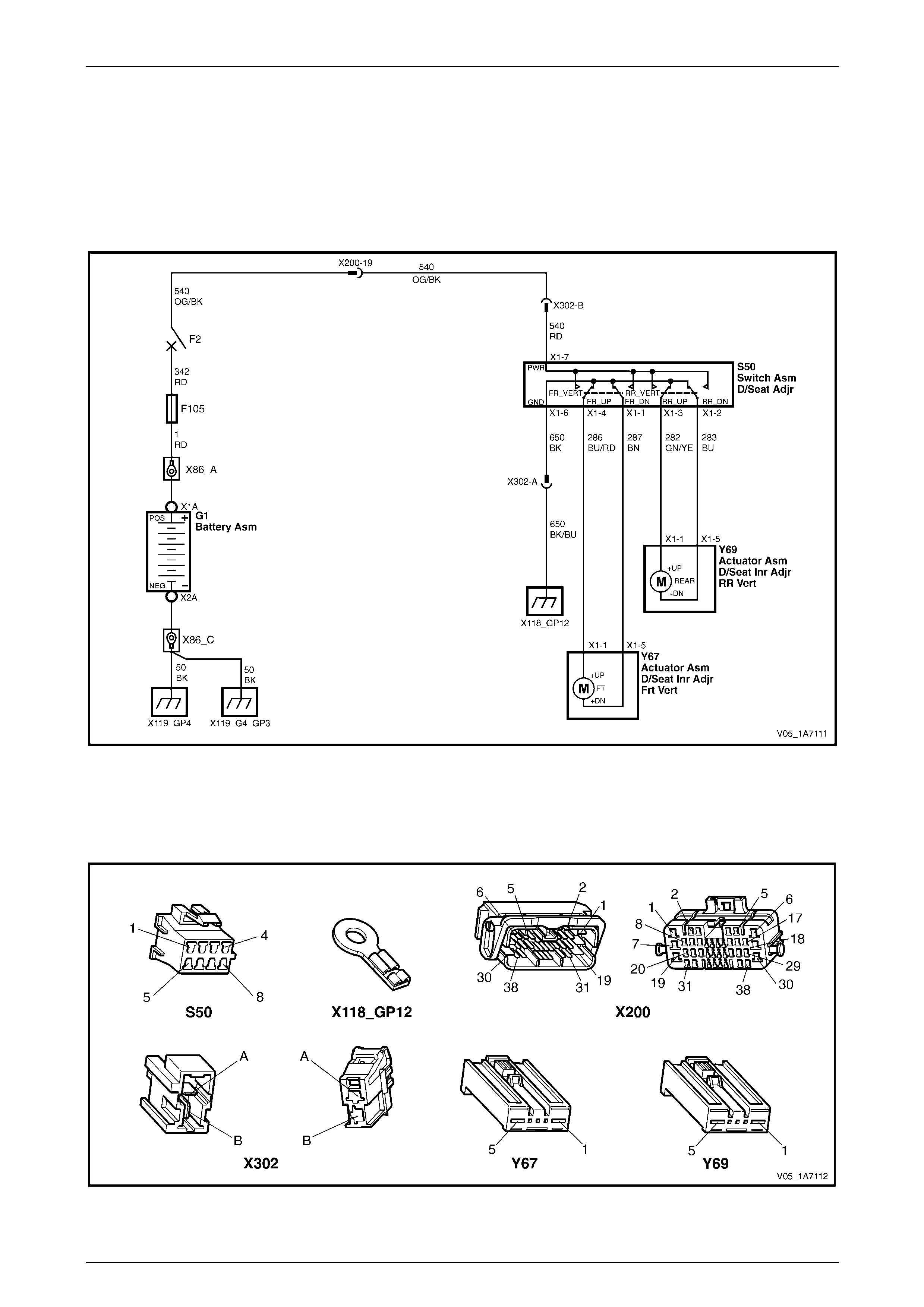
Seat Assemblies Page 1A7–35
Page 1A7–35
2.4 Electrical Diagnosis – Four-way Driver’s
Seat, Reg Cab and Utility
The charts in this Section are used to aid in diagnosing faults on four-way driver’s seat assemblies. To aid in the use of
the diagnostic tables, refer to Wiring Diagra m – Four-way Driver’s Seat, Reg Cab and Utilit y and
Connector Chart – Four-way Driver’s Seat, Reg Cab and Utility.
Wiring Diagram – Four-way Driver’s Seat, Reg Cab and Utility
Figure 1A7 – 10
Connector Chart – Four-way Driver’s Seat, Reg Cab and Utility
Figure 1A7 – 11

Seat Assemblies Page 1A7–36
Page 1A7–36
None of the Driver’s Seat Adjustment Switch Functions Operate
Introduction
This test is used to aid in diagnosing the driver’s seat adjustment switch when none of the switch functions operate. The
test diagnoses the driver’s seat adjustment switch and associated power and ground circuits.
Refer to Wiring Diagram – Four-way Driver’s Seat, Reg Cab and Utilit y and
Connector Chart – Four-way Driver’s Seat, Reg Cab and Utility to aid in diagnos is.
Test Description
The following numbers refer to the step numbers in the diagnostic table:
1 Checks if battery voltage is greater than 11.5 V. The seat motors require gr eater than 11.5 V to operate correctly.
2 Checks if circuit breaker F2 located on the passen ger compartment fuse and relay panel assembl y is tripped.
Isolates if circuit breaker F2 is the fault affecting the circuit between the battery and connec tor X200 pin 19.
3 Checks if fusible link F105 located on the engine compartment fuse and relay panel assembly is serviceable.
Isolates if the fusible link is the fault affecting the circuit between the battery and connector X200 pin 19.
4 Checks if all the connectors required for the seat to operate effectively are in place a nd positively connected.
5 Checks if there is battery power at connector S50 – X1 pin 7. Isolates if there is a fault between the battery and
connector S50 – X1 pin 7.
6 Checks if there is battery power at connector X302 pin B. Isolates if there is a fault in circuit 540 between
connectors S50 – X1 pin 7 and X302 pin B.
7 Checks if there is battery voltage at connector X200 pin 19. Isolates if the fault is between the battery and
connector X200 pin 19.
8 Checks if there is battery voltage at circuit breaker F2. Isolates whether the fault is between the b attery and circuit
breaker F2 or bet ween circuit breaker F2 an d connector X200 pin 19.
9 Checks if there is battery voltage at fusible link F105. Isolates whether the fault is between the battery and fusible
link F105 or between fusible li nk F105 and circuit breaker F2.
10 Checks if the driver’s seat adjustment switch is serviceable.
11 Checks if the ground point associated with the system is serviceable.
12 Checks if there is continuity between connectors S50 – X1 pin 6 and X302 pin A which supplies the ground circuit
for the driver’s seat adjustment switch. Isolates whether there is a fault in circuit 650 bet ween the switch and
connector X302 pin A or between connector X302 pin A and the ground p oint.
Diagnostic Table Notes
1 For all wiring harness fault diagnoses, refer to Section 12P Wiring Diagrams.
2 For wiring harness repairs, refer to Section 12P Wiring Diagrams.
3 Refer to Section 12O Fuses, Relays and Wiri ng Harnesses for harness routeing.
4 If the fault is deemed to be intermittent, refer to Section 12P Wiring Diagrams.

Seat Assemblies Page 1A7–37
Page 1A7–37
Diagnostic Table
Step Action Yes No
1 Check the battery voltage, refer to Section 12A Battery.
Is the battery voltage greater than 11.5 V? Go to Step 2
Refer to Section
12A Battery for
further diagnosis
2 Inspect circuit breaker F2, refer to Section 12O Fuses, Relays and
Wiring Harnesses.
Is circuit breaker F2 tripped?
Allow the circuit
breaker to reset
(refer to Note 3).
If the circuit breaker
trips again, repair
or replace circuit
540 (refer to
Note 2) Go to Step 3
3 Inspect fusible link F105, refer to Section 12O Fuses, Relays and
Wiring Harnesses.
Is fuse F105 serviceable?
Go to Step 4
Replace the fusible
link.
If the fusible link
becomes
unserviceable
again, repair or
replace circuit 342
(refer to Note 2)
4 Are the following connectors secure (refer to Note 3)?
• S50
• X200
• X302
• Y67
• Y69 Go to Step 5
Ensure the
connectors are
secure
5 Backprobe connector S50 – X1 pin 7 with a test lamp (refer Note 1).
Does the test lamp illuminate? Go to Step 10 Go to Step 6
6 Backprobe connector X302 pin B with a test lamp (refer to Note 1).
Does the test lamp illuminate?
Repair or replace
circuit 540 between
connectors
X302 pin B and
S50 – X1 pin 7
(refer to Note 2) Go to Step 7
7 Backprobe connector X200 pin 19 with a test lamp (refer to Note 1).
Does the test lamp illuminate?
Repair or replace
circuit 540 between
connectors X200
pin 19 and
X302 pin B (refer to
Note 2) Go to Step 8

Seat Assemblies Page 1A7–38
Page 1A7–38
Step Action Yes No
8 1 Remove circuit breaker F2 from the passen ger compartment
fuse and relay panel assembly. Repair or replace
circuit 540 between
circuit breaker F2
and connector
X200 pin 19 (refer
to Note 2) Go to Step 9
9 1 Remove fusible link F105.
2 Using a test lamp, probe connector X18-105 (refer to Note 1).
Does the test lamp illuminate?
Repair or replace
circuit 342 between
fusible link F105
and circuit breaker
F2 (refer to Note 2)
Repair or replace
circuit 1 between
the battery and
fusible link F105
(refer to Note 2)
10 1 Remove the driver’s seat adjustment switch from the seat, refer
to 5.3 Front Seat Outer Side Cover Assembly.
2 Test the driver’s seat adjustment switch, refer to 2.5 Four-way
Seat Adjustment Switch Test.
Is the driver’s seat adjustment switch serviceabl e? Go to Step 11
Replace the
driver’s seat
adjustment switch,
refer to 5.3 Front
Seat Outer Side
Cover Assembly
11 Ensure ground point X118 – GP12 (located in the middle of the
transmission tunnel) is secure and has go od contact with the vehicle
structure.
Is the ground point secure to the vehicle with a good contact? Go to Step 12 Repair ground poi nt
12 1 Backprobe connector X302 pin A with a test lamp (refer Note
1).
2 Operate the driver’s seat adjustment switch in any of the
available directions.
Does the test lamp illuminate?
Repair or replace
circuit 650 between
connector X302 pin
A and ground point
X118 – GP12 (refer
Note 2)
Repair or replace
circuit 650 between
connectors
S50 – X1 pin 6 and
X302 pin A (refer
Note 2)
When all diagno sis an d repairs are completed, ch eck the system for correct op eration.

Seat Assemblies Page 1A7–39
Page 1A7–39
Front/Rear of the Driver's Seat Does Not Raise and/or Lower
Introduction
This test is used to aid in diagnosing the front and/or the rear of the driver's seat not raising and/or lowering. The test
diagnoses the driver’s seat adjustment switch and the motor circuits.
Refer to Wiring Diagram – Four-way Driver’s Seat, Reg Cab and Utilit y and
Connector Chart – Four-way Driver’s Seat, Reg Cab and Utility to aid in diagnos is.
Test Description
The following numbers refer to the step numbers in the diagnostic table:
1 Checks if the driver's seat adjustment switch operates the seat in any direct ion. Isolates whether there is a battery
or ground fault affecting the seat operation.
2 Checks if all the connectors required for the seat to operate effectively are in place a nd positively connected.
3 Checks if the driver's seat adjustment switch is serviceable.
4 Confirms whether the rear of the seat raises or lowers. Isolates if the seat rear lift motor and circuit of the seat is the
fault.
5 Confirms whether the front of the seat raises or lo wers. Isolates if the seat front lift motor and circuit of the seat is
the fault.
6 Checks if there is battery power to the seat rear lift motor at connector Y69 – X1 pin 1. Isolates if there is a fault in
circuit 282 that supplies battery power to the motor to raise the rear of the seat.
7 Checks if there is battery power to the seat rear lift motor at connector Y69 – X1 pin 5. Isolates whether the fault is
in circuit 283 that supplies battery power to the motor to lower the rear of the seat or the motor is faulty. As
reversing the polarity changes the direction of the motor, this Step also confirms the grou nd circuit from Step 6 is
serviceable.
8 Checks if there is battery power to the seat front lift motor at connector Y67 – X1 pin 1. Isolates if there is a fault in
circuit 286 that supplies battery power to the motor to raise the front of the seat.
9 Checks if there is battery power to the seat front lift motor at connector Y67 – X1 pin 5. Isolates whether the fault is
in circuit 287 that supplies battery power to the motor to lower the front of the seat or the motor is faulty. As
reversing the polarity changes the direction of the motor, this Step also confirms the grou nd circuit from Step 8 is
serviceable.
Diagnostic Table Notes
1 For all wiring harness fault diagnoses, refer to Section 12P Wiring Diagrams.
2 For wiring harness repairs, refer to Section 12P Wiring Diagrams.
3 Refer to Section 12O Fuses, Relays and Wiri ng Harnesses for harness routeing.
4 If the fault is deemed to be intermittent, refer to Section 12P Wiring Diagrams.

Seat Assemblies Page 1A7–40
Page 1A7–40
Diagnostic Table
Step Action Yes No
1 Does the driver's seat adjustm ent switch operate the seat correctly in
any of the four directions?
Go to Step 2
Refer to None of
the Driver’s Seat
Adjustment Switch
Functions Operate
in this Section
2 Are the following connectors secure ?
• S50
• Y69
• Y67 Go to Step 3
Ensure the
connectors are
secure
3 1 Remove the driver's seat adjustment switch from the seat, refer
to 5.3 Front Seat Outer Side Cover Assembly.
2 Test the driver's seat adjustment switch, refer to 2.5 Four-way
Seat Adjustment Switch Test.
Is the driver's seat adjustment switch serviceable? Go to Step 4
Replace the driver's
seat adjustment
switch, refer to 5.3
Front Seat Outer
Side Cover
Assembly
4 Operate the driver's seat adjustment switch to raise or lower the rear
of the seat.
Does the rear of the seat raise and lower? Go to Step 5 Go to Step 6
5 Operate the driver's seat adjustment switch to raise or lower the front
of the seat.
Does the front of the seat raise and lo wer? System serviceable Go to Step 8
6 1 Backprobe connector Y69 – X1 pin 1 with a test lamp (refer to
Note 1).
2 Operate the driver's seat adjustment switch to raise the rear of
the seat.
Does the test lamp illuminate? Go to Step 7
Repair or replace
circuit 282 (refer to
Note 2)
7 1 Backprobe connector Y69 – X1 pin 5 with a test lamp (refer to
Note 1).
2 Operate the driver's seat adjustment switch to lower the rear of
the seat.
Does the test lamp illuminate?
Replace the seat
rear lift motor, refer
to 5.15 Front Seat
Lift Motor
Assemblies
Repair or replace
circuit 283 (refer to
Note 2)
8 1 Backprobe connector Y67 – X1 pin 1 with a test lamp (refer to
Note 1).
2 Operate the driver's seat adjustment switch to raise the front of
the seat.
Does the test lamp illuminate? Go to Step 9
Repair or replace
circuit 286 (refer to
Note 2)
9 1 Backprobe connector Y67 – X1 pin 5 with a test lamp (refer to
Note 1).
2 Operate the driver's seat adjustment switch to lower the front of
the seat.
Does the test lamp illuminate?
Replace the seat
front lift motor, refer
to 5.15 Front Seat
Lift Motor
Assemblies
Repair or replace
circuit 287 (refer to
Note 2)
When all diagno sis an d repairs are completed, ch eck the system for correct op eration.
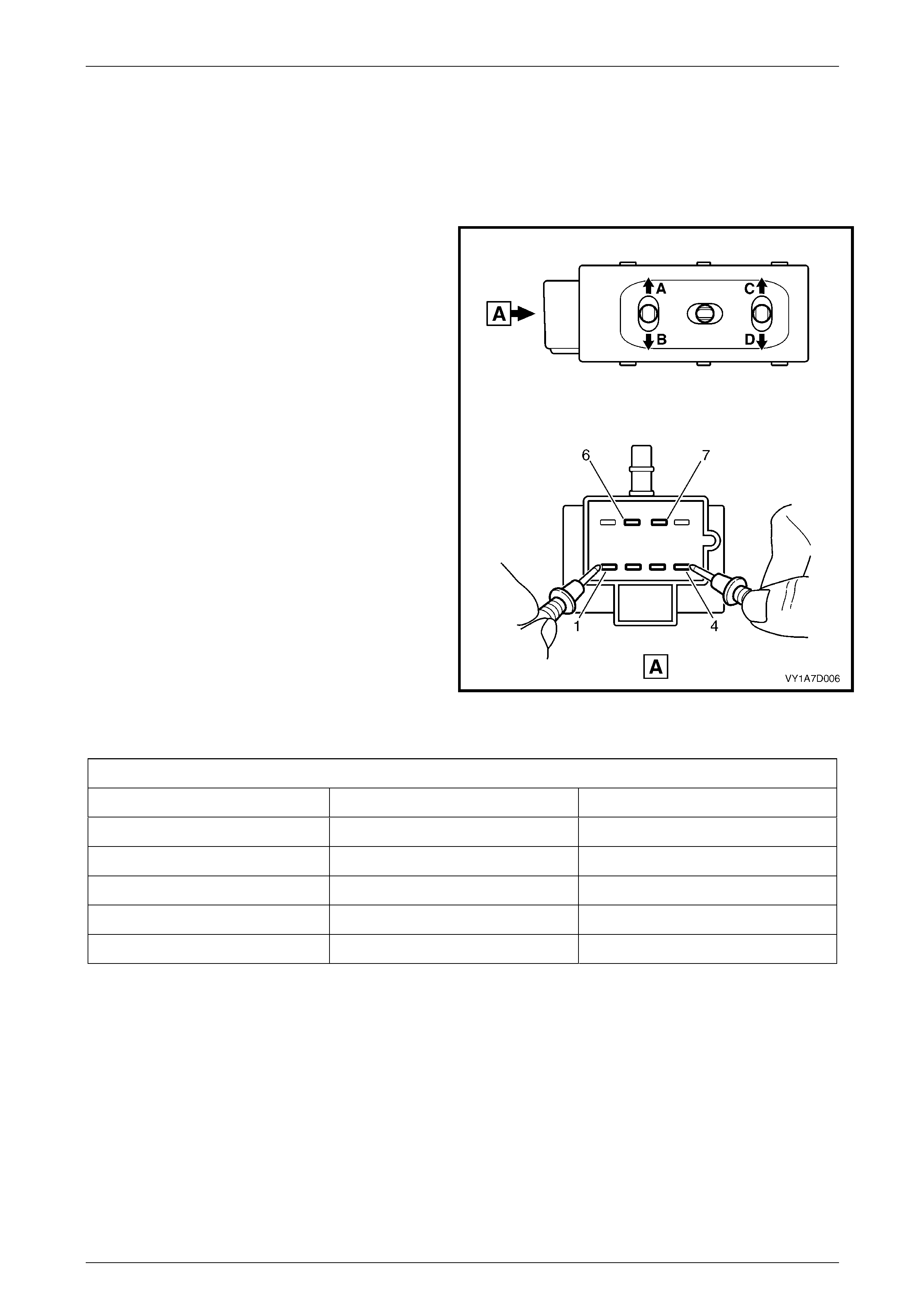
Seat Assemblies Page 1A7–41
Page 1A7–41
2.5 Four-way Seat Adjustment Switch Test
The switch is located on the outer side of the seat, attached to the inner side of the front seat outer side cover.
Test
1 Remove the four-way seat adjustment switch, refer to 5.3 Front Seat Outer Side Cover Assembly.
2 Place the switch in the positions as detailed i n the
chart in this Section. Place the probes of the
multimeter onto the terminals listed and take the
reading. Compare the reading to the chart.
3 If the switch fails any part of the test, replace the
switch assembly with a serviceable item.
4 Install the four-way seat adjustment switch, refer to
5.3 Front Seat Outer Side Cover Assembly.
Figure 1A7 – 12
Four-way Seat Adjustment Switch
Switch Position Switch Terminals Indication If Switch Is Serviceable
Position A 3 and 7 Continuity
Position B 2 and 7 Continuity
Position C 4 and 7 Continuity
Position D 1 and 7 Continuity
Switch in the neutral position 6 and either 1, 2, 3 or 4 Continuity
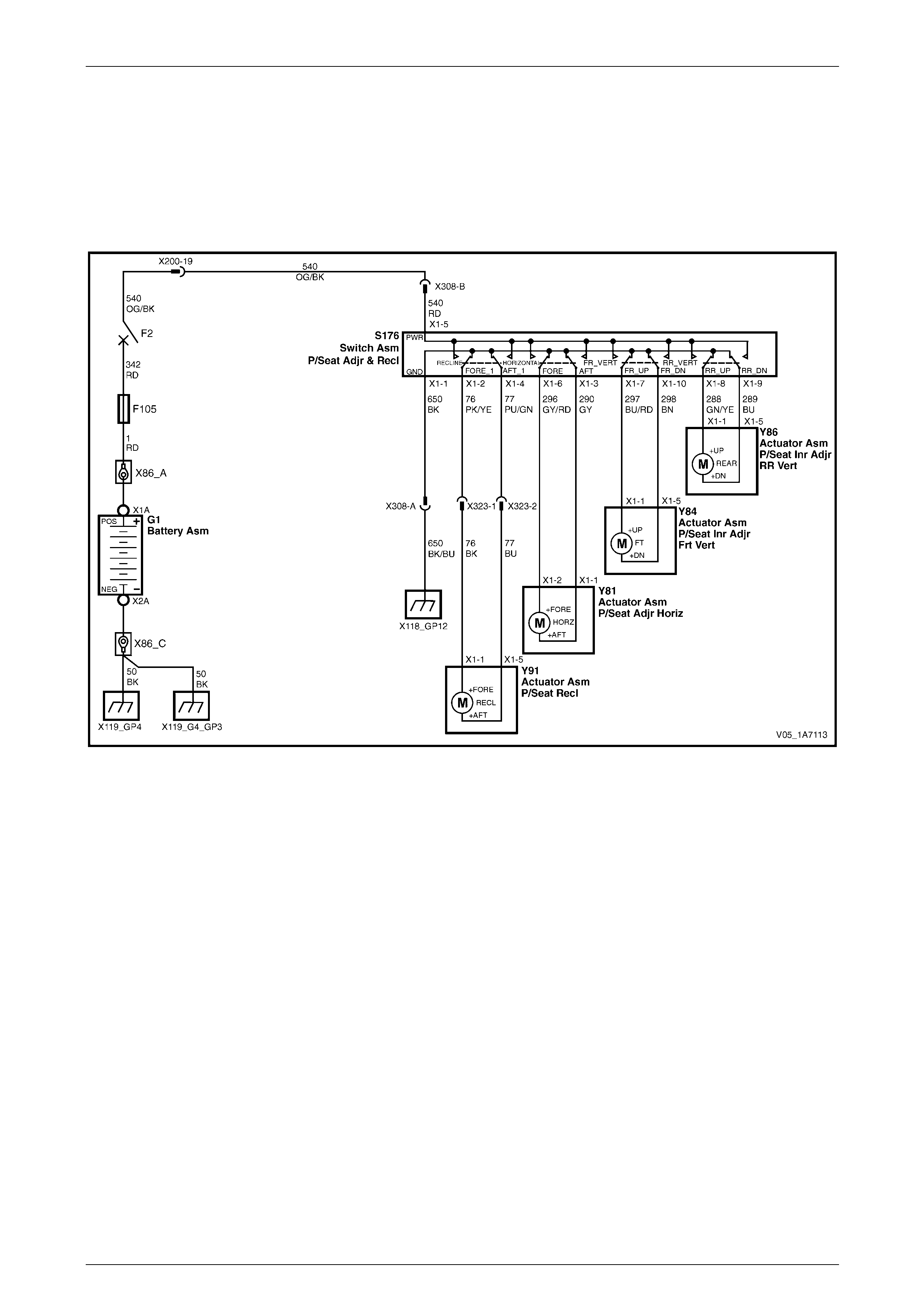
Seat Assemblies Page 1A7–42
Page 1A7–42
2.6 Electrical Diagnosis – Eight-way
Passenger’s Seat
The charts in this Section are used to aid in diagnosing faul ts on eight-way non-memory seat assemb lies. To aid in the
use of the diagnostic tables, refer to Wiring Diagram – Eight-way Passenger’s Seat and
Connector Chart – Eight-way Passenger’s Seat.
Wiring Diagram – Eight-way Passenger’s Seat
Figure 1A7 – 13
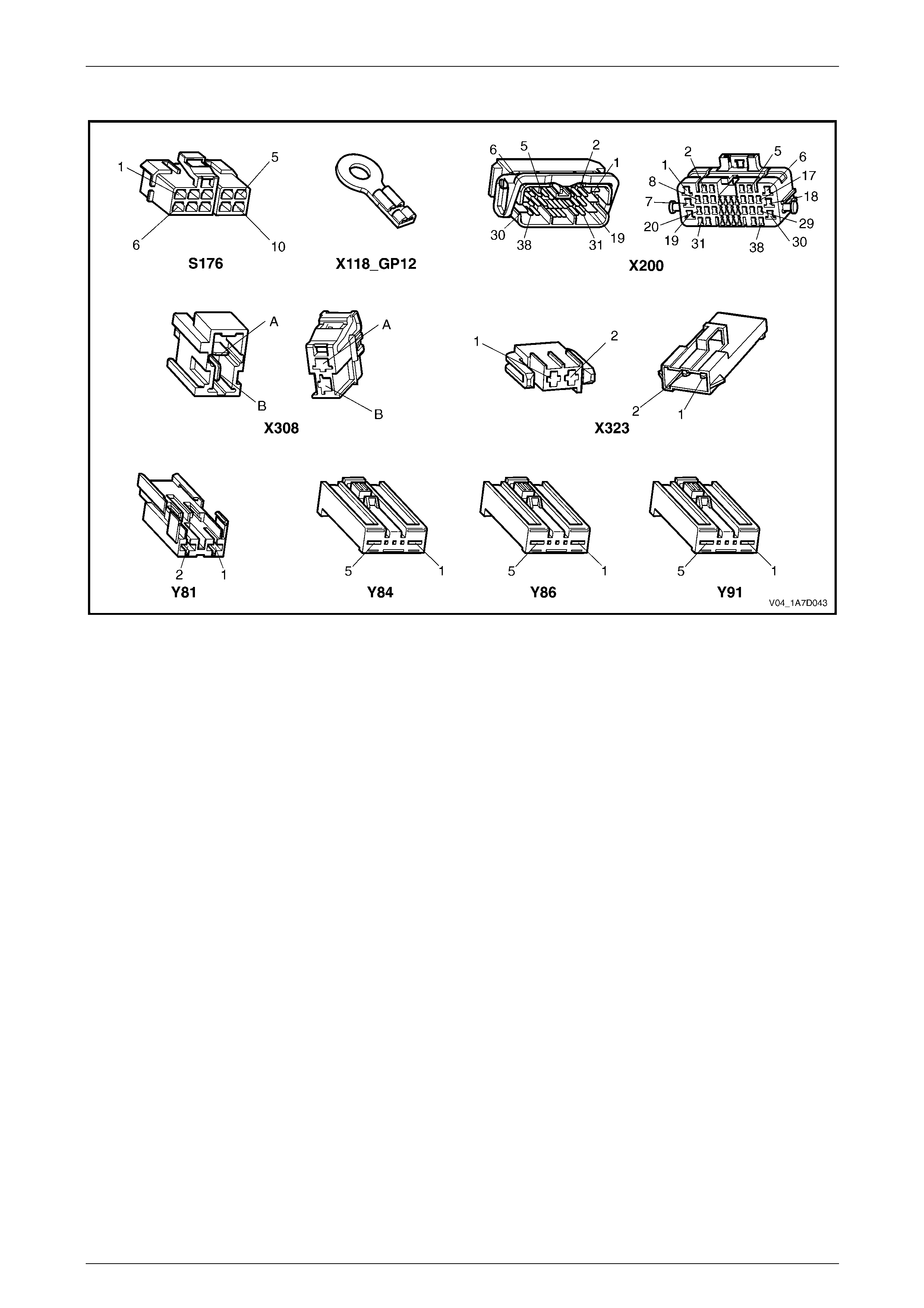
Seat Assemblies Page 1A7–43
Page 1A7–43
Connector Chart – Eight-way Passenger’s Seat
Figure 1A7 – 14

Seat Assemblies Page 1A7–44
Page 1A7–44
Neither Seat Adjustment Switch Functions Operate
Introduction
This test is used to aid in diagnosing the seat power and ground circuits, if neither seat operates when either seat
adjustment switch is operated.
Refer to Wiring Diagram – Eight-way Passenger’s Seat and Connector Chart – Eight-way Passenger’s Seat to aid in
diagnosis.
Test Description
The following numbers refer to the step numbers in the diagnostic table:
1 Checks if battery voltage is greater than 11.5 V. The seat motors require gr eater than 11.5 V to operate correctly.
2 Checks if circuit breaker F2 located on the passen ger compartment fuse and relay panel assembl y is tripped.
Isolates if circuit breaker F2 is the fault affecting the circuit between the battery and connec tor X200 pin 19.
3 Checks if fusible link F105 located on the engine compartment fuse and relay panel assembly is serviceable.
Isolates if the fusible link is the fault affecting the circuit between the battery and connector X200 pin 19.
4 Check if connector X200 is secure.
5 Checks if there is battery voltage at connector X200 pin 19. Isolates if the fault is between the battery and
connector X200 pin 19. If the fault in the circuit is between connectors X200 pin 19 and either X308 pin B or
X302 pin 3, only one seat will operate.
6 Checks if there is battery voltage at circuit breaker F2. Isolates whether the fault is between the b attery and circuit
breaker F2 or bet ween circuit breaker F2 an d connector X200 pin 19.
7 Checks if there is battery voltage at fusible link F105. Isolates whether the fault is between the battery and fusible
link F105 or between fusible li nk F105 and circuit breaker F2.
8 Checks if the ground point associated with the system is serviceable.
Diagnostic Table Notes
1 For all wiring harness fault diagnoses, refer to Section 12P Wiring Diagrams.
2 For wiring harness repairs, refer to Section 12P Wiring Diagrams.
3 Refer to Section 12O Fuses, Relays and W iring Harnesses for harness routeing.
4 If the fault is deemed to be intermittent, refer to Section 12P Wiring Diagrams.

Seat Assemblies Page 1A7–45
Page 1A7–45
Diagnostic Table
Step Action Yes No
1 Check the battery voltage, refer to Section 12A Battery.
Is the battery voltage greater than 11.5 V? Go to Step 2
Refer to Section
12A Battery for
further diagnosis
2 Inspect circuit breaker F2, refer to Section 12O Fuses, Relays and
Wiring Harnesses.
Is circuit breaker F2 tripped?
Allow the circuit
breaker to reset
(refer to Note 3).
If the circuit breaker
trips again, repair
or replace circuit
540 (refer to
Note 2) Go to Step 3
3 Inspect fusible link F105, refer to Section 12O Fuses, Relays and
Wiring Harnesses.
Is fuse F105 serviceable?
Go to Step 4
Replace the fusible
link.
If the fusible link
becomes
unserviceable
again, repair or
replace circuit 342
(refer to Note 2)
4 Is connector X200 secure? Go to Step 5 Ensure the
connector is secure
5 Backprobe connector X200 pin 19 with a test lamp (refer to Note 1).
Does the test lamp illuminate? Go to Step 8 Go to Step 6
6 1 Remove circuit breaker F2 from the passen ger compartment
fuse and relay panel assembly.
2 Using a test lamp, probe connector X12 9 – X45 pin 2 (refer to
Note 1).
Does the test lamp illuminate?
Repair or replace
circuit 540 between
circuit breaker F2
and connector
X200 pin 19 (refer
to Note 2) Go to Step 7
7 1 Remove fusible link F105.
2 Using a test lamp, probe connector X18-105 (refer to Note 1).
Does the test lamp illuminate?
Repair or replace
circuit 342 between
fusible link F105
and circuit breaker
F2 (refer to Note 2)
Repair or replace
circuit 1 between
the battery and
fusible link F105
(refer to Note 2)
8 Ensure ground point X118 – GP12 (located in the middle of the
transmission tunnel) is secure and has go od contact with the vehicle
structure.
Is the ground point secure to the vehicle with a good contact?
Repair or replace
circuit 650 (refer to
Note 2) Repair ground point
When all diagno sis an d repairs are completed, ch eck the system for correct op eration.

Seat Assemblies Page 1A7–46
Page 1A7–46
None of the Passenger’s Seat Adjustment Switch Functions Operate
Introduction
This test is used to aid in diagnosing the passenger’s seat adjustment switch when none of the switch functions operate.
The test diagnoses the passenger’s seat adjustment switch and associate d power and ground circuits.
Refer to Wiring Diagram – Eight-way Passenger’s Seat and Connector Chart – Eight-way Passenger’s Seat to aid in
diagnosis.
Test Description
The following numbers refer to the step numbers in the diagnostic table:
1 Checks if all of the driver’s seat functions work. If none of them work, the fault is not isolated to the passenger’s
seat only.
2 Checks if there is battery power at connector X308 pin B. Isolates if there is a fault in circuit 540 between
connectors X200 pin 19 and X308 pin B.
3 Checks if all the connectors required for the seat to operate effectively are in place a nd positively connected.
4 Checks if there is battery power at connector S176 – X1 pin 5. Isolates if there is a fault in circuit 540 between
connectors S176 – X1 pin 5 and X308 pin B.
5 Checks if the passenger’s seat adjustment switch is serviceable.
6 Checks if there is continuity between connectors S176 – X1 pin 1 and X308 pin A which supp lies the ground circuit
for the passenger’s seat adjustment s witch. Isolates whether there is a fault in circuit 650 between the switch and
connector X308 pin A or between connector X308 pin A and the ground p oint.
Diagnostic Table Notes
1 For all wiring harness fault diagnoses, refer to Section 12P Wiring Diagrams.
2 For wiring harness repairs, refer to Section 12P Wiring Diagrams.
3 Refer to Section 12O Fuses, Relays and W iring Harnesses for harness routeing.
4 If the fault is deemed to be intermittent, refer to Section 12P Wiring Diagrams.

Seat Assemblies Page 1A7–47
Page 1A7–47
Diagnostic Table
Step Action Yes No
1 Are all of the passenger’s seat adjustment switch functio ns
inoperative? Refer to Neither
Seat Adjustment
Switch Functions
Operate in this
Section Go to Step 2
2 Backprobe connector X308 pin B with a test lamp (refer to Note 1).
Does the test lamp illuminate?
Go to Step 3
Repair or replace
circuit 540 between
connectors X200
pin 19 and
X308 pin B (refer to
Note 2)
3 Are the following connectors secure (refer to Note 3)?
• S176
• X308
• Y81
• Y84
• Y86
• Y91 Go to Step 4
Ensure the
connectors are
secure
4 Backprobe connector S176 – X1 pin 5 with a test lamp (refer to Note
1).
Does the test lamp illuminate?
Go to Step 5
Repair or replace
circuit 540 between
connectors
S176 – X1 pin 5
and X308 pin B
(refer to Note 2)
5 1 Remove the passenger’s seat adjustment switch from the seat,
refer to 5.3 Front Seat Outer Side Cover Assembly.
2 Test the passenger’s seat adjustment switch, refer to 2.7 Eight-
way Seat Adjustment Switch Test.
Is the passenger’s seat adjustment switch serviceable? Go to Step 6
Replace the
passenger’s seat
adjustment switch,
refer to 5.3 Front
Seat Outer Side
Cover Assembly
6 1 Backprobe connector X308 pin A with a test lamp (refer to Note
1).
2 Operate the passenger’s seat adjustment switch in any of the
available directions.
Does the test lamp illuminate?
Repair or replace
circuit 650 between
connector X308 pin
A and ground point
X118 – GP12 (refer
to Note 2)
Repair or replace
circuit 650 between
connectors
S176 – X1 pin 1
and X308 pin A
(refer to Note 2)
When all diagno sis an d repairs are completed, ch eck the system for correct op eration.

Seat Assemblies Page 1A7–48
Page 1A7–48
Front/Rear of the Passenger’s Seat Does Not Raise and/or Lower
Introduction
This test is used to aid in diagnosing the front and/or the rear of the passenger’s seat not raising and/or lowering. The
test diagnoses the seat adjustment switch and the motor circuits.
Refer to Wiring Diagram – Eight-way Passenger’s Seat and Connector Chart – Eight-way Passenger’s Seat to aid in
diagnosis.
Test Description
The following numbers refer to the step numbers in the diagnostic table:
1 Checks if the passenger’s seat adjustment switch operates the seat in any direction. Isolates whether the power
and/or ground circuits are at fault.
2 Checks if all the connectors required for the seat to operate effectively are in place a nd positively connected.
3 Checks if the passenger’s seat adjustment switch is serviceable.
4 Confirms whether the rear of the seat raises or lowers. Isolates if the rear lift motor and circuit of the seat is the
fault.
5 Confirms whether the front of the seat raises or lo wers. Isolates whether the front lift motor and circuit of the seat is
the fault.
6 Checks if there is battery power to the seat rear lift motor at connector Y86 – X1 pin 1. Isolates if there is a fault in
circuit 288 that supplies battery power to the motor to raise the rear of the seat.
7 Checks if there is battery power to the seat rear lift motor at connector Y86 – X1 pin 5. Isolates whether the fault is
in circuit 289 that supplies battery power to the motor to lower the rear of the seat or the motor is faulty. As the
direction of the motor is changed by reversing the polarity, this Step also confirms if the ground circuit from Step 6
is serviceable.
8 Checks if there is battery power to the seat front lift motor at connector Y84 – X1 pin 1. Isolates if there is a fault in
circuit 297 that supplies battery power to the motor to raise the front of the seat.
9 Checks if there is battery power to the seat front lift motor at connector Y84 – X1 pin 5. Isolates whether the fault is
in circuit 298 that supplies battery power to the motor to lower the front of the seat or the motor is faulty. As the
direction of the motor is changed by reversing the polarity, this Step also confirms if the ground circuit from Step 8
is serviceable.
Diagnostic Table Notes
1 For all wiring harness fault diagnoses, refer to Section 12P Wiring Diagrams.
2 For wiring harness repairs, refer to Section 12P Wiring Diagrams.
3 Refer to Section 12O Fuses, Relays and W iring Harnesses for harness routeing.
4 If the fault is deemed to be intermittent, refer to Section 12P Wiring Diagrams.

Seat Assemblies Page 1A7–49
Page 1A7–49
Diagnostic Table
Step Action Yes No
1 Does the passenger’s seat adjustment switch oper ate correctly in any
of the eight directions?
Go to Step 2
Refer to None of
the Passenger’s
Seat Adjustment
Switch Functions
Operate in this
Section
2 Are the following connectors secure (refer to Note 3)?
• S176
• Y84
• Y86 Go to Step 3
Ensure the
connectors are
secure
3 1 Remove the passenger’s seat adjustment switch from the seat,
refer to 5.3 Front Seat Outer Side Cover Assembly.
2 Test the passenger’s seat adjustment switch, refer to 2.7 Eight-
way Seat Adjustment Switch Test.
Is the passenger’s seat adjustment switch serviceable? Go to Step 4
Replace the
passenger’s seat
adjustment switch,
refer to 5.3 Front
Seat Outer Side
Cover Assembly
4 Operate the passenger’s seat adj ustment switch to raise or lower the
rear of the seat.
Does the rear of the seat raise and lower? Go to Step 5 Go to Step 6
5 Operate the passenger’s seat adj ustment switch to raise or lower the
front of the seat.
Does the front of the seat raise and lower? System serviceable Go to Step 8
6 1 Backprobe connector Y86 – X1 pin 1 with a test lamp (refer to
Note 1).
2 Operate the passenger’s seat adjustment switch to raise the
rear of the seat.
Does the test lamp illuminate? Go to Step 7
Repair or replace
circuit 288 (refer to
Note 2)
7 1 Backprobe connector Y86 – X1 pin 5 with a test lamp (refer to
Note 1).
2 Operate the passenger’s seat adjustment switch to lower the
rear of the seat.
Does the test lamp illuminate?
Replace the seat
rear lift motor, refer
to 5.15 Front Seat
Lift Motor
Assemblies
Repair or replace
circuit 289 (refer to
Note 2)
8 1 Backprobe connector Y84 – X1 pin 1 with a test lamp (refer to
Note 1).
2 Operate the passenger’s seat adjustment switch to raise the
front of the seat.
Does the test lamp illuminate? Go to Step 9
Repair or replace
circuit 297 (refer to
Note 2)
9 1 Backprobe connector Y84 – X1 pin 5 with a test lamp (refer to
Note 1).
2 Operate the passenger’s seat adjustment switch to lower the
front of the seat.
Does the test lamp illuminate?
Replace the seat
front lift motor, refer
to 5.15 Front Seat
Lift Motor
Assemblies
Repair or replace
circuit 298 (refer to
Note 2)
When all diagno sis an d repairs are completed, ch eck the system for correct op eration.

Seat Assemblies Page 1A7–50
Page 1A7–50
Passenger’s Seat Fore/Aft Movement Function is Inoperative or Not Smooth
Introduction
This test is used to aid in diagnosing the fore/aft movement function of the passenger’s seat being in operative or the
action of the seat through the range of movement is not smooth. The test diagnoses the seat adjustment switch and the
motor circuits.
Refer to Wiring Diagram – Eight-way Passenger’s Seat and Connector Chart – Eight-way Passenger’s Seat to aid in
diagnosis.
Test Description
The following numbers refer to the step numbers in the diagnostic table:
1 Checks if the passenger’s seat adjustment switch operates the seat in any direction. Isolates if there is battery
power to the switch assembly.
2 Checks if there are any items obstructing the guide rails, which may stop or hinder the seat movement.
3 Checks if the guide rails and drive shafts have adequate lubricant applied t o provide a smooth operation of the
seat.
4 Checks if the guide rails or drive shafts have been damaged. An y binding between the moving parts will result in
poor operation of the fore and aft movement.
5 Checks if all the connectors required for the seat to operate effectively are in place a nd positively connected.
6 Checks if the passenger’s seat adjustment switch is serviceable.
7 Checks if there is battery power to the seat fore/aft movement motor at connector Y81 – X1 pin 2. Isolates if there
is a fault in circuit 296 that supplies battery power to the motor to move the seat forward.
8 Checks if there is battery power to the seat fore/aft movement motor at connector Y81 – X1 pin 1. Isolates whether
the fault is in circuit 290 that supplies battery power to the motor to move the seat aft or the motor is faulty. As
reversing the polarity changes the direction of the motor, this Step also confirms if the ground circuit from Step 7 is
serviceable.
Diagnostic Table Notes
1 For all wiring harness fault diagnoses, refer to Section 12P Wiring Diagrams.
2 For wiring harness repairs, refer to Section 12P Wiring Diagrams.
3 Refer to Section 12O Fuses, Relays and W iring Harnesses for harness routeing.
4 If the fault is deemed to be intermittent, refer to Section 12P Wiring Diagrams.

Seat Assemblies Page 1A7–51
Page 1A7–51
Diagnostic Table
Step Action Yes No
1 Does the passenger’s seat adjustment switch oper ate the seat
correctly in any of the eight directions?
Go to Step 2
Refer to None of
the Passenger’s
Seat Adjustment
Switch Functions
Operate in this
Section
2 Are the guide rails free from obstructions? Go to Step 3 Remove the
obstructing item
3 Are the guide rails and driv e shafts adequately lubricated?
Go to Step 4
Apply a small
amount of grease
type NLGI No. 1
Lithium Grease
(with 9% Zinc
Oxide)
4 Do the guide rails or drive shafts bind at any point of travel during the
fore and aft movement of the seat? Replace the track
and height adjust
assembly, refer to
5.12 Track and
Height Adjust
Assembly Go to Step 5
5 Are the following connectors secure (refer to Note 3)?
• S176
• Y81 Go to Step 6
Ensure the
connectors are
secure
6 1 Remove the passenger’s seat adjustment switch from the seat,
refer to 5.3 Front Seat Outer Side Cover Assembly.
2 Test the passenger’s seat adjustment switch, refer to 2.7 Eight-
way Seat Adjustment Switch Test.
Is the passenger’s seat adjustment switch serviceable? Go to Step 7
Replace the
passenger’s seat
adjustment switch,
refer to 5.3 Front
Seat Outer Side
Cover Assembly
7 1 Backprobe connector Y81 – X1 pin 2 with a test lamp (refer to
Note 1).
2 Operate the passenger’s seat adjustment switch to move the
seat forward.
Does the test lamp illuminate? Go to Step 8
Repair or replace
circuit 296 (refer to
Note 2)
8 1 Backprobe connector Y81 – X1 pin 1 with a test lamp (refer to
Note 1).
2 Operate the passenger’s seat adjustment switch to move the
seat aft.
Does the test lamp illuminate?
Replace the seat
fore/aft movement
motor, refer to 5.16
Front Seat Fore/Aft
Movement Motor
Assembly
Repair or replace
circuit 290 (refer to
Note 2)
When all diagno sis an d repairs are completed, ch eck the system for correct op eration.

Seat Assemblies Page 1A7–52
Page 1A7–52
Passenger’s Seat Recline Forward and/or Aft Function is Inoperative
Introduction
This test is used to aid in diagnosing the recline function of the passen ger’s seat being inoperative. T he test diagnoses
the seat adjustment switch and the motor circuits.
Refer to Wiring Diagram – Eight-way Passenger’s Seat and Connector Chart – Eight-way Passenger’s Seat to aid in
diagnosis.
Test Description
The following numbers refer to the step numbers in the diagnostic table:
1 Checks if the passenger’s seat adjustment switch operates the seat in any direction. Isolates if there is battery
power to the switch assembly.
2 Checks if all the connectors required for the seat to operate effectively are in place a nd positively connected.
3 Checks if the passenger’s seat adjustment switch is serviceable.
4 Checks if there is battery power to the front seat-back recline motor at connector Y91 – X1 pin 1. Isolates if there is
a fault in circuit 76 that supplies battery power to the reclining motor to move the seat-back forward.
5 Isolates whether there is a fault in circuit 76 between connectors S176 – X1 pin 2 and X323 pin 1 or between
connectors X323 pin 1 and Y91 – X1 pin 1.
6 Checks if there is battery power to the front seat-back recline motor at connector Y91 – X1 pin 5. Isolates whether
the fault is in circuit 77 that supplies battery po wer to the reclining motor to move the seat-back aft or the reclin ing
motor is faulty. As reversing the polarity chan ges the direction of the motor, this Step also confirms if the groun d
circuit from Step 4 is serviceable.
7 Isolates whether there is a fault in circuit 77 between connectors S176 – X1 pin 4 and X323 pin 2 or between
connectors X323 pin 2 and Y91 – X1 pin 5.
Diagnostic Table Notes
1 For all wiring harness fault diagnoses, refer to Section 12P Wiring Diagrams.
2 For wiring harness repairs, refer to Section 12P Wiring Diagrams.
3 Refer to Section 12O Fuses, Relays and W iring Harnesses for harness routeing.
4 If the fault is deemed to be intermittent, refer to Section 12P Wiring Diagrams.

Seat Assemblies Page 1A7–53
Page 1A7–53
Diagnostic Table
Step Action Yes No
1 Does the passenger’s seat adjustment switch oper ate the seat
correctly in any of the eight directions?
Go to Step 2
Refer to None of
the Passenger’s
Seat Adjustment
Switch Functions
Operate in this
Section
2 Are the following connectors secure (refer to Note 3)?
• S176
• X323
• Y91 Go to Step 3
Ensure the
connectors are
secure
3 1 Remove the passenger’s seat adjustment switch from the seat,
refer to 5.3 Front Seat Outer Side Cover Assembly.
2 Test the passenger’s seat adjustment switch, refer to 2.7 Eight-
way Seat Adjustment Switch Test.
Is the passenger’s seat adjustment switch serviceable? Go to Step 4
Replace the
passenger’s seat
adjustment switch,
refer to 5.3 Front
Seat Outer Side
Cover Assembly
4 1 Backprobe connector Y91 – X1 pin 1 with a test lamp (refer to
Note 1).
2 Operate the passenger’s seat adjustment switch to move the
seat-back forward.
Does the test lamp illuminate? Go to Step 6 Go to Step 5
5 1 Backprobe connector X323 pin 1 with a test lamp (refer to Note
1).
2 Operate the passenger’s seat adjustment switch to move the
seat-back forward.
Does the test lamp illuminate?
Repair or replace
circuit 76 between
connectors
X323 pin 1 and
Y91 – X1 pin 1
(refer to Note 2)
Repair or replace
circuit 76 between
connectors
S176 – X1 pin 2
and X323 pin 1
(refer to Note 2)
6 1 Backprobe connector Y91 – X1 pin 5 with a test lamp (refer to
Note 1).
2 Operate the passenger’s seat adjustment switch to move the
seat-back aft.
Does the test lamp illuminate?
Replace the front
seat-back recline
motor, refer to 5.17
Front Seat-back
Recline Motor
Assembly Go to Step 7
7 1 Backprobe connector X323 pin 2 with a test lamp (refer to Note
1).
2 Operate the passenger’s seat adjustment switch to move the
seat-back aft.
Does the test lamp illuminate?
Repair or replace
circuit 77 between
connectors
X323 pin 2 and
Y91 – X1 pin 5
(refer to Note 2)
Repair or replace
circuit 77 between
connectors
S176 – X1 pin 4
and X323 pin 2
(refer to Note 2)
When all diagno sis an d repairs are completed, ch eck the system for correct op eration.
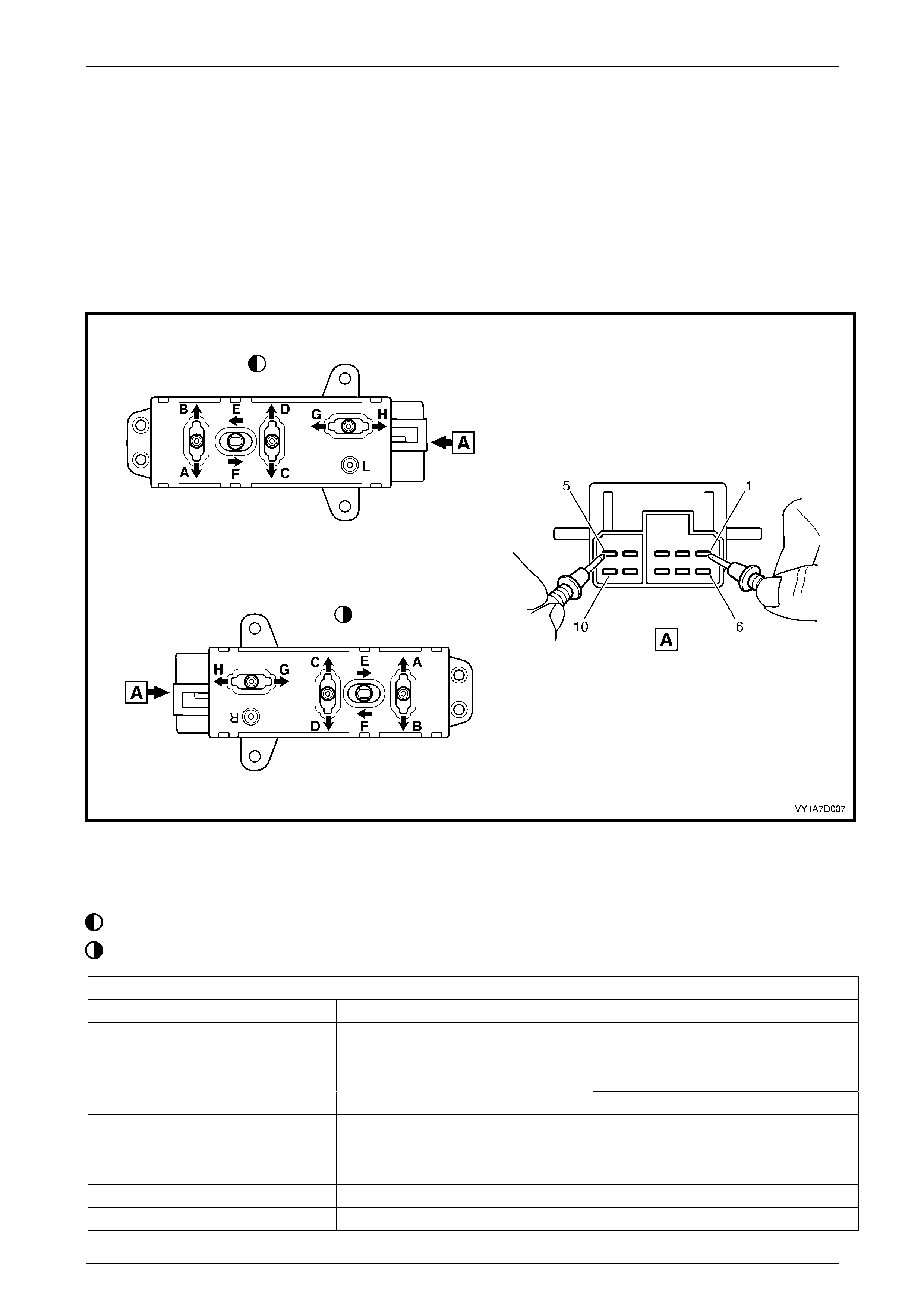
Seat Assemblies Page 1A7–54
Page 1A7–54
2.7 Eight-way Seat Adjustment Switch Test
The switch is located on the outer side of the seat, attached to the inner side of the front seat outer side cover.
Test
1 Remove the eight-way seat adjustment switch, refer to 5.3 Front Seat Outer Side Cover Assembly.
2 Place the switch in the positions as detailed i n the chart in this Section. Place the probes of the multimeter onto the
terminals listed and take the reading. Compare the reading to the chart.
3 If the switch fails any part of the test, replace the switch assembly with a serviceable item.
4 Install the eight-way seat adjustment switch, refer to 5.3 Front Seat Outer Side Cover Assembly.
Figure 1A7 – 15
Legend
Left-hand Switch
Right-hand Switch
Eight-way Seat Adjustment Switch
Switch Position Switch Terminals Indication If Switch Is Serviceable
Position A 10 and 5 Continuity
Position B 7 and 5 Continuity
Position C 9 and 5 Continuity
Position D 8 and 5 Continuity
Position E 6 and 5 Continuity
Position F 3 and 5 Continuity
Position G 2 and 5 Continuity
Position H 4 and 5 Continuity
Switch in the neutral position 1 and either 2, 3, 4, 6, 7, 8, 9 or 10 Continuity

Seat Assemblies Page 1A7–55
Page 1A7–55
3 Diagnostics – Front Seat,
Memory and Rear-view Mirror,
Except Coupe
3.1 Prerequisites
Safety Requirements
When operating the seat as part of any Steps
in the diagnostic tables, ensure that fingers
and limbs are clear of mo ving parts.
Equipment
The following equipment is required to diagnose the seats:
• an unpowered test lamp with a current draw of less than 3 A, and
• a digital multimeter with a minimum impe dance of 10 MΩ.
Testing Procedures
The following points must be adhered to
when performing diagnostic testing on
components:
• Take care when using testing equipment
to diagnose wiring harness connectors. It
is preferred the technician backprobe the
connector to avoid terminal damage.
• When tests are required on connector
terminals, use the adapters in the
connector adapter kit KM–609 to prevent
damage to the terminals.
• Unless the multimeter being used has an
auto-ranging function, ensure the correct
range is selected.
• When backpro bing connectors, ensure the
test lamp ground lead is connected to an
appropriate ground point on the vehicle.
Ensure this ground point is not part of the
circuit being tested.
NOTE
When following the steps in the di agnostic tables,
perform them in the order cited. If the required
nominal value or result is not achi eved, rectif y t he
problem before proceeding any further.

Seat Assemblies Page 1A7–56
Page 1A7–56
3.2 System Self Diagnosis
The seat memory module can self-diagnose the driver's seat and the external rear-vie w mirrors. When a fault or failur e is
detected, the seat memory module sets a diagnostic trouble code (DTC) that represents the fault or failure. A fault or
failure that sets a DTC may leave the seat and/or external rear-view mirrors partially or totally inoperativ e. If the seat
memory module detects a fault, the LED located next to the mirror dip / memory store (M) button on the memory position
switch assembly, illuminates constantly during that igniti on cycle.
Current DTCs are stored by the seat memory modul e. W hen the fault conditions are n o longer met, the DTC becomes a
History DTC.
Current DTCs
When Current DTCs are detected, they are stored by the seat memory module during the current ignition cycle. Current
DTCs are set or cleared based on the condition of the seat memory module during ignition ON or continuous monitori n g
of the current ignition cycle.
NOTE
A Current DTC is identified on the T ech 2 display
by the word Current between the DTC number
and the DTC description. The word History
between the DTC number and the DTC
description indicates the DTC displayed is a
History DTC.
Current DTCs are reset to History DTCs upo n the next diagnostic test sequence when the fault conditions are not met.
Current DTCs can be cleared (changed to history DTC) by removing the fault cond itions.
Tech 2 is unable to clear current DT Cs if the fault conditions still exist; Tech 2 will displ ay Clear DTC Information
Failed.
DTCs stored in the seat memory module can only be displayed and/or cleared using the Tech 2 diagnostic scan tool.
Tech 2 communicates with the seat memory modul e serial data using the Serial Data Link Connector (DLC) which is
attached to the instrument panel lower trim retainer, refer to 3.3 Tech 2 Diagnostics.
History DTCs
History DTCs are set upon the clearing of a current DTC fault condition. History DTCs are maintained by the seat
memory module over multiple ignition cycles. The seat memory module can onl y clear history DTCs from its memor y by
a CLEAR DTCS serial data message from Tech 2.
Clearing DTCs
After any system fault has been rectified, use Tech 2 Clear DTC selection to erase an y fault codes stored in the seat
memory module, refer to 3.4 Tech 2 Test Modes and Displays for Diagnosis.
After DTCs have been cleared, verify proper
system operation and absence of any fault
codes. If Tech 2 displays Clear DTC
Information Failed after attempting to clear
DTCs, the fault condition still exists.
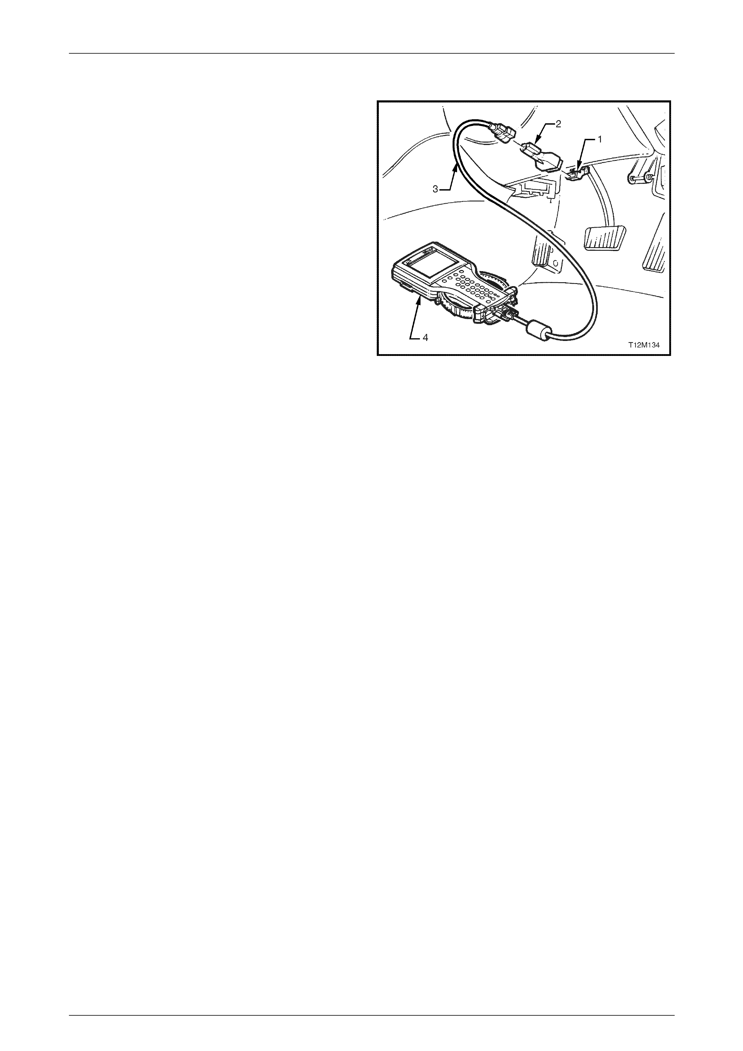
Seat Assemblies Page 1A7–57
Page 1A7–57
3.3 Tech 2 Diagnostics
Tech 2, with the appropriate software, cables and adapters,
when connected to the Serial Data Link Connector (DL C)
can read seat and exterior rear-view mirror serial data. The
DLC is attached to the instrument panel trim retainer
beneath the steering wheel.
1 DLC
2 DLC Adapter
3 DLC Cable
4 Tech 2
For additional general information on connecting and
operating Tech 2, refer to Section 0C Tech 2.
Figure 1A7 – 16
Test Modes
Tech 2 has five test modes for diagnosing the driver's seat and the e xter nal rear-view mirrors.
Mode F0: Diagnostic Tro uble Codes
If F0: Diagnostic Trouble Codes is selected, a selection list is displayed which contains:
• F0: Read DTC Information – Once this mode is selected, both current and history Diagnostic Trouble Codes
(DTCs) stored in the seat memory module's memory may be displayed.
• F1: Clear DTC Information – Once this mode is selected, DTCs stored in the seat memory module's memory may
be cleared.
Mode F1: Diagnostic Data Display
If F1: Diagnostic Data Display is selected, a selection list is displayed which contains:
• F0: Inputs and Outputs – Once this mode is selected, a list of system components and their inputs, outputs and
their status is displayed.
• F1: Memory – Once this mode is selected, a list of each memory position and the position of each of the seat axes
is displayed.
• F2: System Identification – Once this is selected, details including serial number of the seat memory module are
displayed.
Mode F2: Snapshot
In this test mode, Tech 2 captures seat memory module data before and after a forced manual trigger.
Mode F3: Miscellaneous Tests
In this test mode, Tech 2 displays a list of eight tests that can be utilised to diagnose the driver's seat and the external
rear-view mirrors, refer to 3.4 Tech 2 Test Modes and Displays for Diagnosis for further information.
Mode F4: Additional Functions
In this test mode, Tech 2 allows the technician to reset the seat, thus clearing all memory positi ons,
refer to 3.4 Tech 2 Test Modes and Displays for Diagnosis for further information.

Seat Assemblies Page 1A7–58
Page 1A7–58
3.4 Tech 2 Test Modes and Displays for
Diagnosis
A prerequisite to this diagnostic Section is for the user to be familiar with the proper use of Tech 2. The following pages
illustrate only the major Tech 2 screen displays and provide a brief e xplanation of their function for diagnosing the
driver's seat and the external rear-view mirrors. If additional information is required on the operation of Tech 2, reference
should be made to either Section 0C Tech 2 or Tech 2 User's Guide.
System Select Menu
With Tech 2 connected to the DLC, and F0: Diagnostics selected from the Main Menu, the correct Model Year and
Vehicle Type must be select ed for access to the System Select Menu.
Select F3: BODY.
This mode contains all functions to test, diag nose, monitor and program the vehicle's bod y s ystems incl uding the driver's
seat and the external rear-view mirrors.
Body Application Menu
Once F3: Body has been selected from the System Select Menu, Seat and Exterior Mirror Memory Module can be
selected.
Select Seat and Exterior Mirror Memory Module.
When Seat and Exterior Mirror Memory Module is selected, the following two System Identification screens will
appear, which require action.
System Identification
Turn the ignition to the ON position with the engine not running (as requested) and press the Confirm soft key to
continue.
The System Identification Screen will then display information pertaining to the type of seat memory module fitted, serial
number, date of manufacture and other anc illary information. Press the Confirm soft key to continue to the Application
menu. The Identifier code for this seat is 201.
Always refer to the latest General Motors spare parts information for the correct part number.
Application Menu
The following functions will now be available:
• F0: Diagnostic Trouble Codes
• F1: Diagnostic Data Display
• F2: Snapshot
• F3: Miscellaneous Tests
• F4: Additional Functions

Seat Assemblies Page 1A7–59
Page 1A7–59
F0: Diagnostic Trouble Codes
If F0: Diagnostic Trouble Codes is selected from the Application menu, the following selection list is displayed:
F0: Read DTC Informa tion
If this mode is selected, a listing of all (if any) DTCs that have been set by the seat memory module will be displayed.
Information displayed with the DTC number/s that have been set, is a short description of what the DTC is,
and whether it is a current (fault present) or history (stored, but not necessarily on this ignition cycle) DTC.
Refer to Diagnostic Trouble Codes in this Section for the full listing of driver's seat and the external rear-view mirrors
DTCs with the fault identified.
NOTE
If any DTCs are set, referenc e should be m ade t o
the relevant diagnostic tables in this Section.
F1: Clear DTC Informatio n
DTCs can be cleared in this mode by selecting F1: Clear DTC Information, pressing the ENTER button on T ech 2 and
confirming the action as instructed by Tech 2.
If DTC condition is present, Tech 2 will be unable to clear the DTC and will display Clear DTC Informati on Failed.
Diagnostic Trouble Codes
The following table sets out all the possible diagnostic trouble codes as indicated by Tech 2.
DTC Code Location Fault
1 Seat adjustment switch Front vertical up switch stuck
2 Seat adjustment switch Front vertical down switch stuck
3 Seat adjustment switch Rear vertical up switch stuck
4 Seat adjustment switch Rear vertical down switch stuck
5 Seat adjustment switch Horizontal forward switch stuck
6 Seat adjustment switch Horizontal back switch stuck
7 Seat adjustment switch Recline up switch stuck
8 Seat adjustment switch Recline down switch stuck
9 Memory positio n switch assembly Memory button 1 stuck
10 Memory position switch assembly Memory button 2 stuck
11 Memory position switch assembly Memory button 3 stuck
12 Memory position switch assembly Mirror dip button stuck
13 Seat memory module No serial data
14 Exterior rear-view mirror circuit No exterior mirror communication
19 Seat memory module ECU malfunction
20 Seat front lift motor Front vertical position sensor fault
21 Seat rear lift motor Rear vertical position sensor fault
22 Seat fore / aft movement motor Horizontal position sensor fault
23 Seat-back recline motor Recline position sensor fault
24 Seat assembly System voltage out of range

Seat Assemblies Page 1A7–60
Page 1A7–60
F1: Diagnostic Data Display
When F1: Diagnostic Data Display is selected, three sub-headings are displayed by Tech 2.
F0: Inputs and Outputs
F0: Inputs and Outputs displays a list of data streams for various driver's seat and external rear-vie w mirror
components and their current status. T he table in this Section lists all the data streams with a description.
Data Stream /
Screen Display Description
Memory 1 Button Displays the state of button 1 on the memory position switch.
If button 1 on the memory position switch assembly is stuck in the depressed position for
greater than 8 seconds, DTC 9 will be set.
• Not Pressed / Pressed
Memory 2 Button Displays the state of button 2 on the memory position switch.
If button 2 on the memory position switch assembly is stuck in the depressed position for
greater than 8 seconds, DTC 10 will set.
• Not Pressed / Pressed
Memory 3 Button Displays the state of button 3 on the memory position switch.
If button 3 on the memory position switch assembly is stuck in the depressed position for
greater than 8 seconds, DTC 11 will set.
• Not Pressed / Pressed
Mirror DIP Button Displays the state of the mirror dip / memory store (M) button on the memory position
switch.
If the mirror DIP / memory store (M) button on the memory position switch assembly is
stuck in the depressed position for greater than 8 seconds, DTC 12 will set.
• Not Pressed / Pressed
Front Vertical Switch Displays the state of the front lift switch on the seat adjustment switch.
If the front vertical switch is stuck in the up position for greater than 8 seconds, DTC 1 will
set.
If the front vertical switch is stuck in the down position for greater than 8 seconds, DTC 2
will set.
• Inactive / Up / Down
Rear Vertical Switch Displays the state of the rear lift switch on the seat adjustment switch.
If the rear vertical switch is stuck in the up position for greater than 8 seconds, DTC 3 will
set.
If the front vertical switch is stuck in the down position for greater than 8 seconds, DTC 4
will set.
• Inactive / Up / Down
Horizontal Switch Displays the state of the horizontal switch on the seat adjustment switch.
If the horizontal switch is stuck in the forward position for greater than 8 seconds, DTC 5 will
set.
If the horizontal switch is stuck in the aft position for greater than 8 seconds, DTC 6 will set.
• Inactive / Forward / Back

Seat Assemblies Page 1A7–61
Page 1A7–61
Data Stream /
Screen Display Description
Recline Switch Displays the state of the recline switch on the seat adjustment switch.
If the recline switch is stuck in the forward position for greater than 8 seconds, DTC 7 will
set.
If the recline switch is stuck in the aft position for greater than 8 seconds, DTC 8 will set.
• Inactive / Forward / Back
Front Vertical Position
Sensor Displays if the front lift motor position sensor is connected.
• Connected / Not Connected
Front Vertical Position
Sensor Displays the current position of the front lift motor position sensor as a value in Steps. The
Steps will range from 0 to 65535.
• 0 – 65535 Steps (typical 31488 – 33536)
Front Vertical Position
Maximum Limit Displays the maximum limit of travel up in Steps. T his value depends on the calibration of
the seat.
This value should be high but never reach 65535 Steps. If the value d isplayed is 65535, the
seat has not been calibrated. Refer to 5.2 Front Seat Assembly to calibrat e the seat.
• 0 – 65535 Steps (typical 31488 – 33536)
Front Vertical Position
Minimum Limit Displays the minimum limit of travel down in Steps. This value depends on the calibration of
the seat.
This value should be low but never reach 0 Steps. If the value displayed is 0, the seat has
not been calibrated. Refer to 5.2 Front Seat Assembly to calibrate the seat.
• 0 – 65535 Steps (typical 31488 – 33536)
Rear Vertical Position
Sensor Displays if the rear lift motor position sensor is connected.
• Connected / Not Connected
Rear Vertical Position
Sensor Displays the current position of the rear lift motor position sensor as a val ue in Steps. The
Steps will range from 0 to 65535.
• 0 – 65535 Steps (typical 31488 – 33536)
Rear Vertical Position
Maximum Limit Displays the maximum limit of travel up in Steps. T his value depends on the calibration of
the seat.
This value should be high but never reach 65535 Steps. If the value d isplayed is 65535, the
seat has not been calibrated. Refer to 5.2 Front Seat Assembly to calibrat e the seat.
• 0 – 65535 Steps (typical 31488 – 33536)
Rear Vertical Position
Minimum Limit Displays the minimum limit of travel down in Steps. This value depends on the calibration of
the seat.
This value should be low but never reach 0 Steps. If the value displayed is 0, the seat has
not been calibrated. Refer to 5.2 Front Seat Assembly to calibrate the seat.
• 0 – 65535 Steps (typical 31488 – 33536)
Horizontal Position Sensor Displays if the fore/aft movement motor position sensor is c onnected.
• Connected / Not Connected
Horizontal Position Sensor Displays the current position of the fore/aft movement motor position sensor as a value in
Steps. The Steps will range from 0 to 65535.
• 0 – 65535 Steps (typical 20480 – 40960)

Seat Assemblies Page 1A7–62
Page 1A7–62
Data Stream /
Screen Display Description
Horizontal Position
Maximum Limit Displays the maximum limit of travel forward in Steps. T his value de pends on the calibration
of the seat.
This value should be high but never reach 65535 Steps. If the value d isplayed is 65535, the
seat has not been calibrated. Refer to 5.2 Front Seat Assembly to calibrat e the seat.
• 0 – 65535 Steps (typical 20480 – 40960)
Horizontal Position
Minimum Limit Displays the minimum limit of travel aft in Steps. This value depends on the calibration of
the seat.
This value should be low but never reach 0 Steps. If the value displayed is 0, the seat has
not been calibrated. Refer to 5.2 Front Seat Assembly to calibrate the seat.
• 0 – 65535 Steps (typical 20480 – 40960)
Recline Position Sensor Displays if the seat-back recline motor positi on sensor is connected.
• Connected / Not Connected
Recline Position Sensor Displays the current position of the seat-back recline motor position sensor as a value in
Steps. The Steps will range from 0 to 65535.
• 0 – 65535 Steps (typical 16384 – 45056)
Recline Position Maximum
Limit Displays the maximum limit of travel forward in Steps. T his value de pends on the calibration
of the seat.
This value should be high but never reach 65535 Steps. If the value d isplayed is 65535, the
seat has not been calibrated. Refer to 5.2 Front Seat Assembly to calibrat e the seat.
• 0 – 65535 Steps (typical 16384 – 45056)
Recline Position Minimum
Limit Displays the minimum limit of travel aft in Steps. This value depends on the calibration of
the seat.
This value should be low but never reach 0 Steps. If the value displayed is 0, the seat has
not been calibrated. Refer to 5.2 Front Seat Assembly to calibrate the seat.
• 0 – 65535 Steps (typical 16384 – 45056)
Button Pack
Communication Displays whether there is serial data communication with the mirror control switch,
right-hand or left-hand rear-view mirrors. If there is communication with at least one of these
components, Tech 2 will displa y Okay. If there is no communications with all of the
components, Tech 2 will displa y Not Okay.
If there are no serial data communications, a DTC 14 will set.
• Okay / Not Okay
Right Exterior Mirror
Communication Displays if Tech 2 can communicate with the right-hand exterior rear-vie w mirror.
If there is not serial data communications with the right-hand exterior rear-vie w mirror, a
DTC 14 will set.
• Okay / Not Okay
Left Exterior Mirror
Communication Displays if Tech 2 can communicate with the left-hand exterior rear-view mirror.
If there is not serial data communications with the left-hand exterior rear-view mirror, a DTC
14 will set.
• Okay / Not Okay
Right Exterior Mirror Switch Displays the status of the mirror control switch, when the rocker switch is selected to right.
• Up / Down / Left / Right / Inactive
Left Exterior Mirror Switch Displays the status of the mirror control switch, when the rocker switch is selected to left.
• Up / Down / Left / Right / Inactive

Seat Assemblies Page 1A7–63
Page 1A7–63
Data Stream /
Screen Display Description
Memory Recall Position In
Use Displays the status of the current memory recall of the seat assembly.
• Memory 1 / Memory 2 / Memory 3 / Priority 1 / Priority 2 / No Active Memory
Current Priority Displays what is the current priority that has been set when the vehicle is unlocked with
either priority key 1 or 2.
• Priority 1 / Priority 2 / No Active Memory
Able To Recall Displays if the seat assembly has the ability to recal l a memory position.
• Yes / No
Start Wait Active Only when there has been a cold-start reset will Tech 2 display No. A cold-start reset will
occur when module detects too much electromagnetic interference (EMI) in the s ystem. If
the Start Wait Active displays No, the system will still be operational.
• Yes / No
Able To Move When the seat is requested to move, the seat memory module monitors the amount of
Steps that a position sensor has taken during that movement. This inability to move at all or
quickly enough may be due to a physical restriction in that movement, or the battery not
having enough charge to power the particular motor adequately.
• Yes / No
Ignition Switch Displays the status of the ignition switch.
• On / Off / Accessory
Demist Request Displays the status of the rear demist system. This will be Yes when the rear demist button
is pressed.
• Yes / No
Reverse Gear Displays if the vehicle is in reverse gear.
• Inactive / Active
PRNDL Position Displays the position of the transmission selector.
• P / R / N / D / 3 / 2 / 1
F1: Memory
F1: MEMORY displays all the five memory settings availabl e. Within each of the memory settings the position of the seat
is displayed (in Steps) and if the mirror dip function is enabled.
Data Stream /
Screen Display Description
Memory 1 Mirror Dip Status Displ ays if the mirror dip function is enabled for Memory 1.
• Enabled / Disabled
Memory 1 Front Vertical
Position Displays the seat front vertical position (in Steps) that has been store d in Memory 1.
• 0 – 65535 Steps (typical 31488 – 33536)
Memory 1 Rear Vertical
Position Displays the seat rear vertical position (in Steps) that has been stored in Memory 1.
• 0 – 65535 Steps (typical 31488 – 33536)
Memory 1 Horizontal
Position Displays the seat horizontal position (in Steps) that has been stored in Memory 1.
• 0 – 65535 Steps (typical 20480 – 40960)
Memory 1 Recline Position Displays the seat-back recline position (in Steps) that has been stored in Memory 1.
• 0 – 65535 Steps (typical 16384 – 45056)
Memory 2 Mirror Dip Status Displ ays if the mirror dip function is enabled for Memory 2.
• Enabled / Disabled

Seat Assemblies Page 1A7–64
Page 1A7–64
Data Stream /
Screen Display Description
Memory 2 Front Vertical
Position Displays the seat front vertical position (in Steps) that has been store d in Memory 2.
• 0 – 65535 Steps (typical 31488 – 33536)
Memory 2 Rear Vertical
Position Displays the seat rear vertical position (in Steps) that has been stored in Memory 2.
• 0 – 65535 Steps (typical 31488 – 33536)
Memory 2 Horizontal
Position Displays the seat horizontal position (in Steps) that has been stored in Memory 2.
• 0 – 65535 Steps (typical 20480 – 40960)
Memory 2 Recline Position Displays the seat-back recline position (in Steps) that has been stored in Memory 2.
• 0 – 65535 Steps (typical 16384 – 45056)
Memory 3 Mirror Dip Status Displ ays if the mirror dip function is enabled for Memory 3.
• Enabled / Disabled
Memory 3 Front Vertical
Position Displays the seat front vertical position (in Steps) that has been store d in Memory 3.
• 0 – 65535 Steps (typical 31488 – 33536)
Memory 3 Rear Vertical
Position Displays the seat rear vertical position (in Steps) that has been stored in Memory 3.
• 0 – 65535 Steps (typical 31488 – 33536)
Memory 3 Horizontal
Position Displays the seat horizontal position (in Steps) that has been stored in Memory 3.
• 0 – 65535 Steps (typical 20480 – 40960)
Memory 3 Recline Position Displays the seat-back recline position (in Steps) that has been stored in Memory 3.
• 0 – 65535 Steps (typical 16384 – 45056)
Priority 1 Mirror Dip Status Displays if the mirror dip function is enabled for Priority 1.
• Enabled / Disabled
Priority 1 Front Vertical
Position Displays the seat front vertical position (in Steps) that has been stored in P riority 1.
• 0 – 65535 Steps (typical 31488 – 33536)
Priority 1 Rear Vertical
Position Displays the seat rear vertical position (in Steps) that has been stored in Priority 1.
• 0 – 65535 Steps (typical 31488 – 33536)
Priority 1 Horizontal
Position Displays the seat horizontal position (in Steps) that has been stored in Priority 1.
• 0 – 65535 Steps (typical 20480 – 40960)
Priority 1 Recline Position Displays the seat-back recline position (in Steps) that has been stored in Priority 1.
• 0 – 65535 Steps (typical 16384 – 45056)
Priority 2 Mirror Dip Status Displays if the mirror dip function is enabled for Priority 2.
• Enabled / Disabled
Priority 2 Front Vertical
Position Displays the seat front vertical position (in Steps) that has been stored in P riority 2.
• 0 – 65535 Steps (typical 31488 – 33536)
Priority 2 Rear Vertical
Position Displays the seat rear vertical position (in Steps) that has been stored in Priority 2.
• 0 – 65535 Steps (typical 31488 – 33536)
Priority 2 Horizontal
Position Displays the seat horizontal position (in Steps) that has been stored in Priority 2.
• 0 – 65535 Steps (typical 20480 – 40960)
Priority 2 Recline Position Displays the seat-back recline position (in Steps) that has been stored in Priority 2.
• 0 – 65535 Steps (typical 16384 – 45056)
F2: System Identification
F2: System Identification displays the specifications of the seat memory module, refer to System Identification with i n
this Section.

Seat Assemblies Page 1A7–65
Page 1A7–65
F2: Snapshot
In this mode, Tech 2 captures seat memory module data b efore and after a forced manual trigger.
F3: Miscellaneous Tests
In this mode, a list of tests are displayed that can be used to control certain functions of the driver's seat and the exterior
rear-view mirrors.
F0: Chime
When this test is selected, menu keys are available. To activate the chime function of the seat memory module, press
the On key. The chime will then sound continuously. To turn off the chime, press the Off key. To return to
F3: Miscellaneous Tests menu, press the Quit key.
In this test, the input and output data is also displayed, refer to F0: Inputs and Outputs in this Section.
F1: LED
When this test is selected, menu keys are available. To activate the LED function of the seat memory module, press the
Flash key. The LED will flash. To return to F3: Miscellaneous Tests menu, press the Quit key.
In this test, the input and output data is also displayed, refer to F0: Inputs and Outputs in this Section.
F2: Right Exterior Mirror
When this test is selected, the arrow keys on Tech 2 can be used to drive the right-hand exterior mirror in all four
directions. During this test the data stream for the right-hand exterior mirror will be displayed. The data stream will
change from off to the direction pressed.
F3: Left Exterior Mirror
When this test is selected, the arrow keys on Tech 2 can be used to drive the left-hand exterior mirror in all four
directions. During this test the data stream for the left-hand exterior mirror will be displayed. The data stream will change
from off to the direction pressed.
F4: Front Vertical Motor
When this test is selected, menu keys are available. To drive the front lift motor up, press the Up key and alternatively to
move the front lift motor down, press the Down key.
F5: Rear Vertical Mirror
When this test is selected, menu keys are available. To drive the rear lift motor up, press the Up key and alternatively to
move the rear lift motor down, press the Down key.
F6: Horizontal Motor
When this test is selected, menu keys are available. To drive the seat fore/aft movement motor forward, press the
Forward key and alternatively to move the seat fore/aft movement motor aft, press the Back key.
F7: Recline Motor
When this test is selected, menu keys are available. To drive the seat-back recline motor forward, press the Forward key
and alternatively to move the seat-back recline motor aft, press the Back key.
F4: Additional Functions
F0: Module Reset
This function clears all the preset memories inclu din g any priority key the s eat memory module has stored.
When this function is selected, menu keys are available. T ech 2 will prompt with the message Do you Really Want To
Reset. To reset the module, press the Yes key. If the technician does not want to reset the module, pre ss the No key
and to return the F4: Additional Functions menu.

Seat Assemblies Page 1A7–66
Page 1A7–66
3.5 Preliminary System Diagnosis
Prior to starting any diagnosis, the technician should be familiar with the driver's seat and the external rear-view mirror
components and operation. For a descri ptio n of the components and the system operation,
refer to 1 General Information.
When investigating any complaint of a pro bl em or malfunction, always begin diagnosis with a circuit check, refer to
3.8 Electrical Diagnosis – Memor y Seat, Initial Check for a seat fault, or 3.10 Electrical Diag nosis – Rear-view Mirrors,
Initial Check for an exterior rear-view mirror fault. If the complaint is of a mechanical nature,
refer to 3.7 Mechanical Diagnosis.
The diagnostic circuit check ensures the driver's seat and the external rear-view mirrors are communicating on the serial
data line as well as assisting to ide ntify the problem and to ascertain the appro priate diagnostic table in this Section.

Seat Assemblies Page 1A7–67
Page 1A7–67
3.6 Diagnostic Tables
Introduction
The following diagnostic table s are designed to provide fast and efficient fault location and remedy. The diagnostic tables
include a chart, pertinent information, circuit diagrams, and where necessary, the steps are explained by the
corresponding numbered paragraphs.
When performing wiring checks as directed to by the diagnostic tables, rather than probe pins and co nnectors with
incorrect sized multimeter connectio ns, use the ad apters contained in connector test adapter kit Tool No. KM-609 and
test lead set Tool No. KM609-20. This will prevent any possibility of spreading or d amaging wiring harness pins and
causing a system intermittent failure.

Seat Assemblies Page 1A7–68
Page 1A7–68
3.7 Mechanical Diagnosis
Lumbar Support Inoperative
Introduction
This test is used to aid in diagnosing the lumbar support as sembly.
Test Description
The following numbers refer to the step numbers in the diagnostic table:
1 Checks if the lumbar support knob is properly engaging the lumbar support adjuster. Check the knob for cracks and
worn splines.
2 Checks if the lumbar support assembly is damaged or worn and if the retaining springs are serviceable and
securely attached to the seat-back frame assembly.
3 Checks if the lumbar support assembly is servicea ble and if the lumber support assembly strap is operating
correctly within the guide rails.
Diagnostic Table
Step Action Yes No
1 Remove the lumbar support knob, refer to 5.8 Lumbar Support Knob
Assembly.
Is the lumbar support adjust knob serviceable? Go to Step 2
Replace the knob,
refer to 5.8 Lumbar
Support Knob
Assembly
2 1 Remove the seat-back cover.
2 Inspect the lumbar support retainers and spri ngs.
Are the lumbar support retaining spri ngs serviceable and securel y
attached to the seat-back frame assembly? Go to Step 3
Replace or reattach
the retaining
springs, refer to
5.10 Front Seat-
back Frame
Assembly
3 1 Visually inspect the lumbar support assembly. Check for broken
or worn parts.
2 Check the strap running across the lumber support assembly is
serviceable and running freely within the guide rails.
NOTE
You may need to attach the lumber support knob to
actuate the strap.
Is the lumbar support assembly serviceabl e? System serviceable
Replace lumbar
support assembly or
resecure lumbar
support assembly
strap ensuring strap
is not binding with
guide rails, refer to
5.10 Front Seat-
back Frame
Assembly
When all diagno sis an d repairs are completed, ch eck the system for correct op eration.
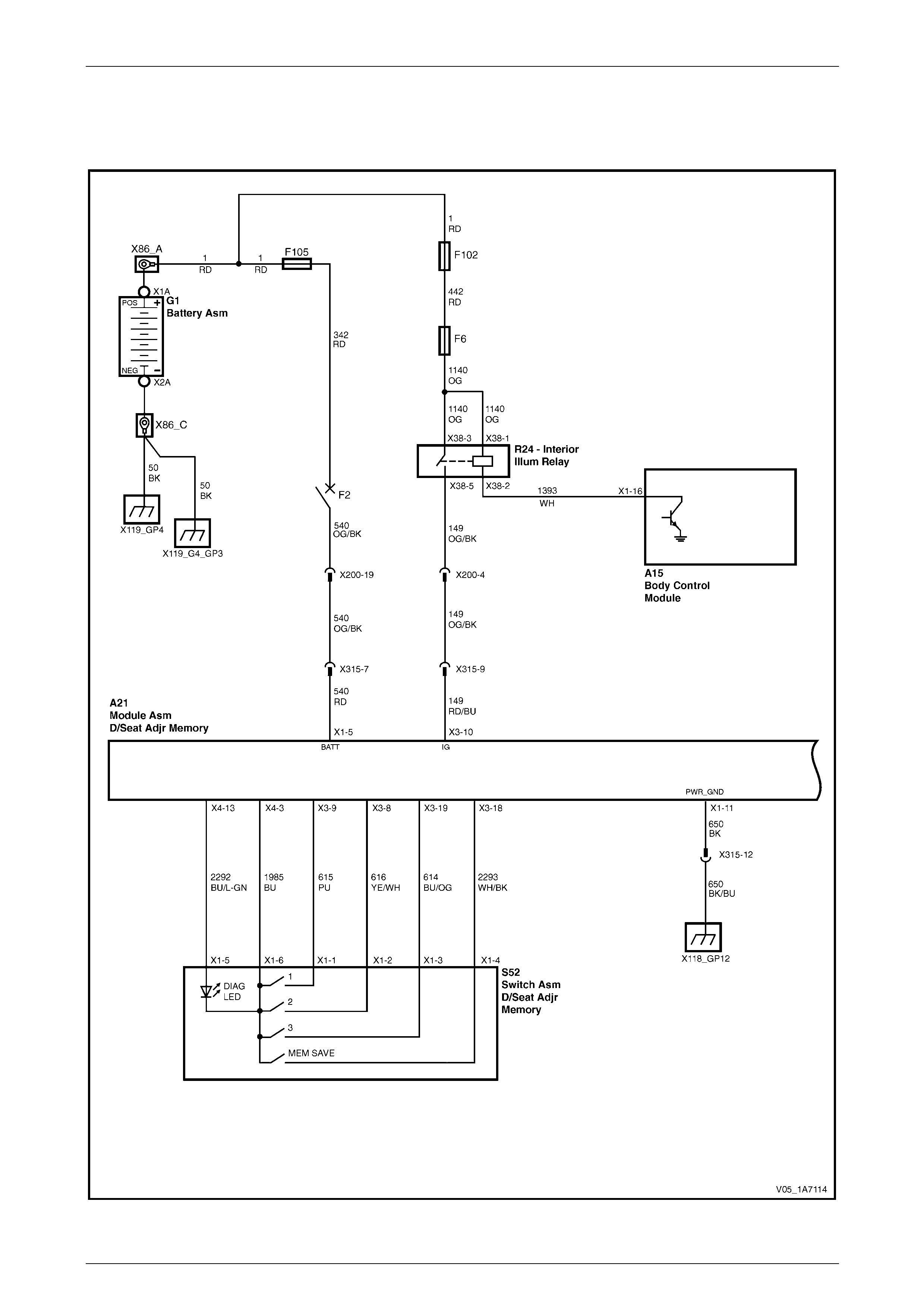
Seat Assemblies Page 1A7–69
Page 1A7–69
3.8 Electrical Diagnosis – Memory Seat
Wiring Diagram – Memory Seat
Figure 1A7 – 17
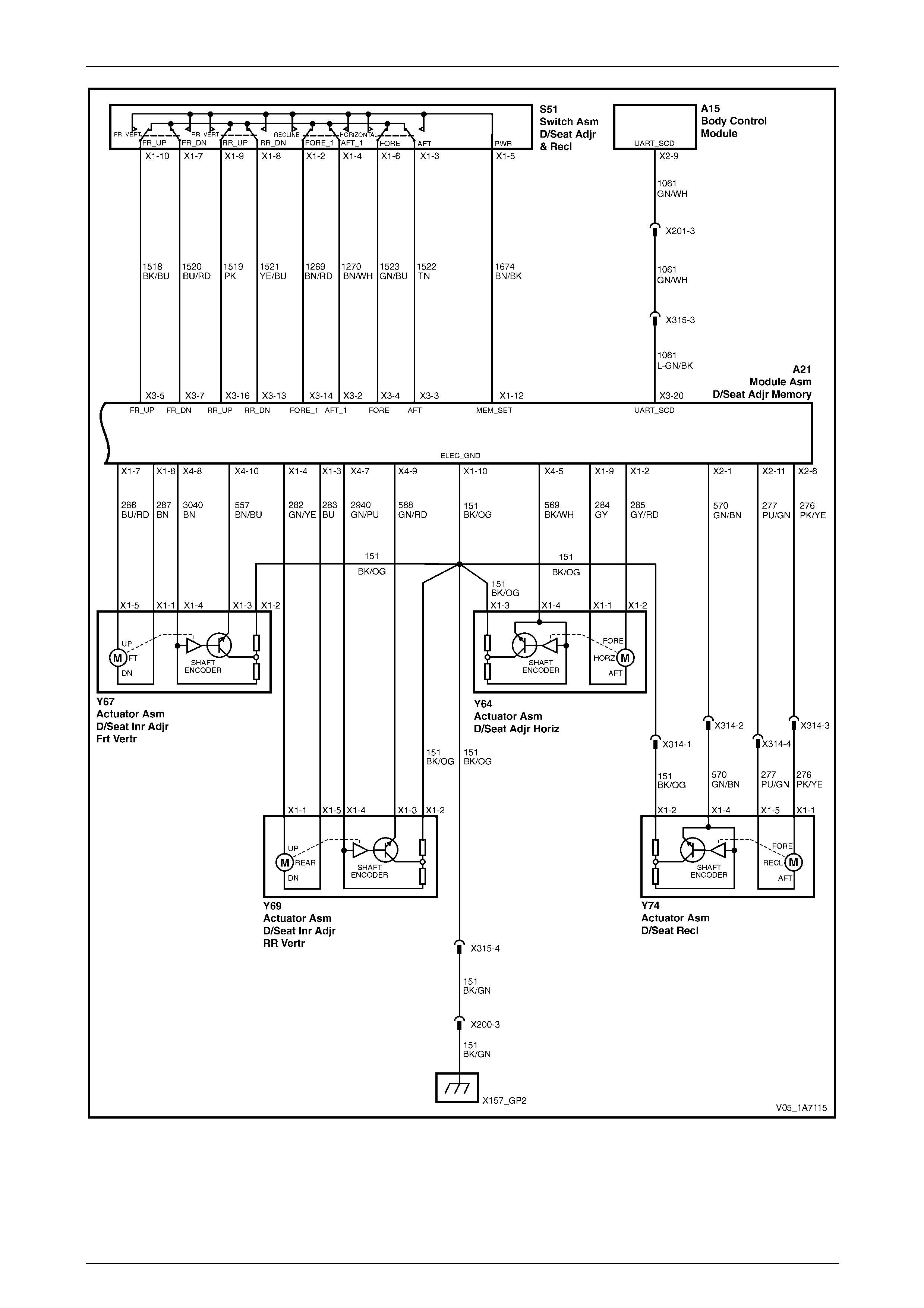
Seat Assemblies Page 1A7–70
Page 1A7–70
Figure 1A7 – 18
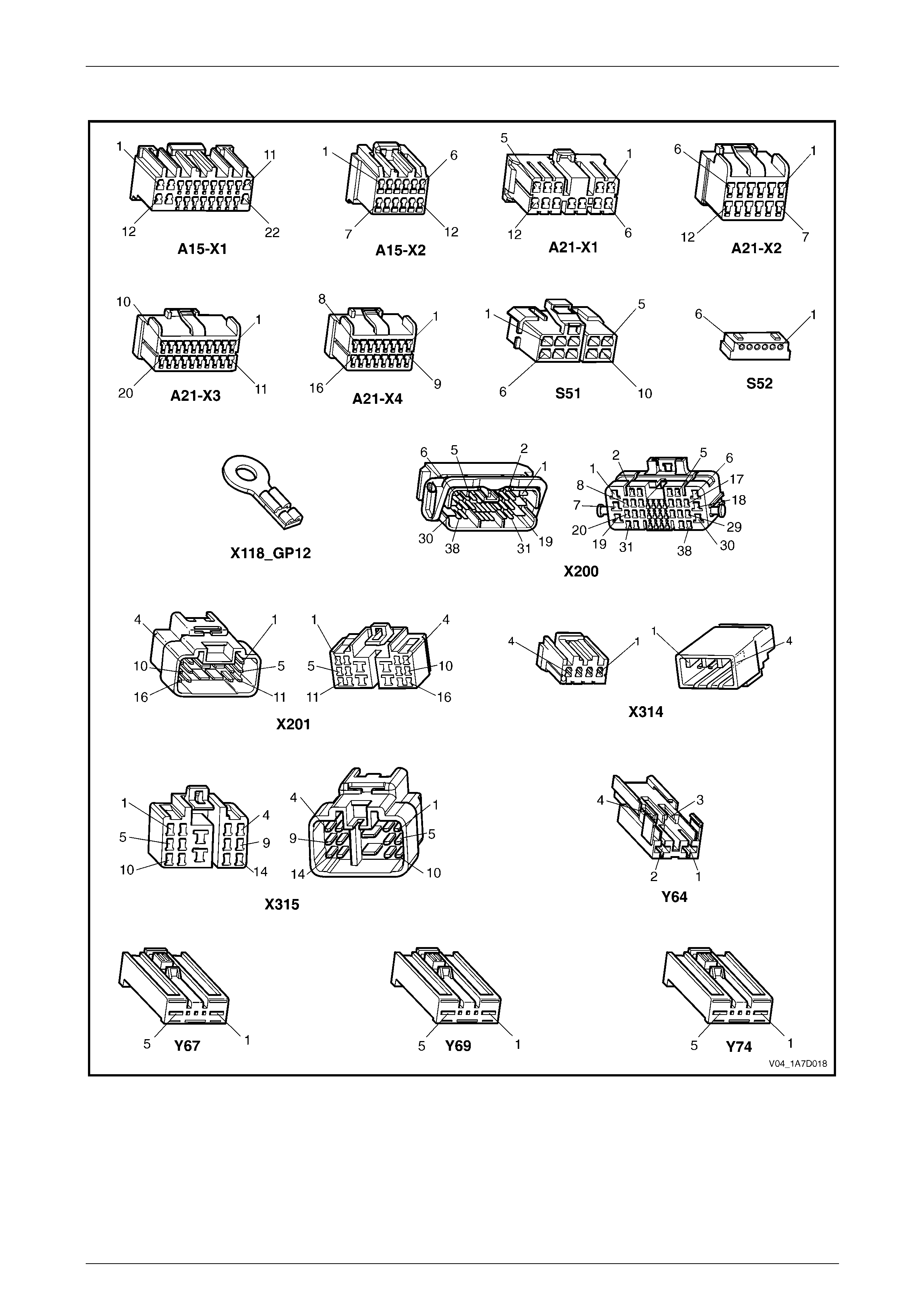
Seat Assemblies Page 1A7–71
Page 1A7–71
Connector Chart – Memory Seat
Figure 1A7 – 19

Seat Assemblies Page 1A7–72
Page 1A7–72
Initial Check
Introduction
The driver's seat and exterior rear-view mirrors can be diagnosed using T ech 2. The diagnostic table tests each function
of the seat for correct operation.
Refer to Wiring Diagram – Memor y Seat and Connector Chart – Memory Seat to aid in diagnosis.
Test Description
The following numbers refer to the step numbers in the diagnostic table:
1 Checks if the fault is isolated to the driver’s seat.
2 If Tech 2 cannot access the System Identification menu there is a problem with the power, serial data
communications or ground circuits to the memory module.
3 Checks if there are any current DTCs.
4-11 Checks if the seat adjustment switch is serviceable. Also checks if the associated motor circuits are serviceable.
12 Using Tech 2, checks if the memory position s witch assembly is operational.
13 Checks if the seat front lift motor hall-effect sensor is connected.
14 Checks if the seat front lift motor hall-effect sensor (in Steps) has an acceptable maximum, minimum value and
current seat position is within that range.
15 Checks if the seat rear lift motor hall-effect sensor is connected.
16 Checks if the seat rear lift motor hall-effect sensor (in Steps) has an acce ptable maximum, minimum val ue and
current seat position is within that range.
17 Checks if the seat horizontal motor hall-effect sensor is connecte d.
18 Checks if the seat horizontal motor hall-effect sensor (in Steps) has an acceptable maximum, minimum value and
current seat position is within that range.
19 Checks if the seat recline motor hall-effect sensor is connected.
20 Checks if the seat recline mot or hall-effect sensor (in Steps) has an accept able maximum, minimum value and
current seat position is within that range.
21 Checks if the seat memory module stores a different seat position for each of the three memory buttons. Checks if
when each of the memory buttons are pressed, the seat moves to the stored position and Tech 2 displays the
correct information.
22 Checks if the seat recalls a priority key memory position.

Seat Assemblies Page 1A7–73
Page 1A7–73
Diagnostic Table
Step Action Yes No
1 Are all of the passenger’s seat adjustment switch functions
inoperative? Refer to Neither
Seat Adjustment
Switch Functions
Operate in 2.6
Electrical Diagnosis
– Eight-way
Passenger’s Seat Go to Step 2
2 1 Connect Tech 2 to the DLC.
2 On Tech 2 select:
Body / Seat and Exterior Mirror Memory Module.
3 Turn the ignition on when prompted.
Is the Seat and Exterior Mirror Module System Identification
specifications displayed? Go to Step 3
Refer to
No Serial Data
Communications to
the Seat Memory
Module in this
Section
3 On Tech 2 select:
Body / Seat and Exterior Mirror Memory Module / Diagnostic
Trouble Codes / Read DTC Information.
Are there any DTCs set?
Refer to the relevant
DTC diagnostic
table in this Section Go to Step 4
4 1 Connect Tech 2 to the DLC.
2 On Tech 2 select:
Body / Seat and Exterior Mirror Memory Module / Diagnostic
Data Display / Inputs and Outputs.
3 Scroll to Front Vertical Switch.
4 While monitoring Tech 2, operate the seat adjustment switch to
raise and lower the front of the seat.
Does Tech 2 display the fol lowing:
• Inactive when the switch is in the neutral position.
• Up when the switch is in the up position.
• Down when the switch is in the down positio n. Go to Step 5
Refer to Seat
Adjustment Switch
Inoperative in this
Section
5 During the test in Step 4, does the front of the seat move in the
following directions?
• When the switch is in the neutral pos ition, the front of the seat
does not move.
• When the switch is in the up position, the front of the seat raises.
• When the switch is in the down position, the front of the seat
lowers.
NOTE
Ensure the seat is not at its maximum limit of travel b efore
performing this test. Go to Step 6
Refer to Seat Front
Lift Motor
Inoperative in this
Section

Seat Assemblies Page 1A7–74
Page 1A7–74
Step Action Yes No
6 1 On Tech 2 select:
Rear Seat Vertical Switch.
2 While monitoring Tech 2, operate the seat adjustment switch to
raise and lower the rear of the seat.
Does Tech 2 display the fol lowing:
• Inactive when the switch is in the neutral position.
• Up when the switch is in the up position.
• Down when the switch is in the down positio n. Go to Step 7
Refer to Seat
Adjustment Switch
Inoperative in this
Section
7 During the test in Step 6, does the rear of the seat move in the
following directions?
• When the switch is in the neutral position, the rear of the seat
does not move.
• When the switch is in the up position, the rear of the seat raises.
• When the switch is in the down position, the rear of the seat
lowers.
NOTE
Ensure the seat is not at its maximum limit of travel b efore
performing this test. Go to Step 8
Refer to Seat Rear
Lift Motor
Inoperative in this
Section
8 1 On Tech 2 select:
Horizontal Switch.
2 While monitoring Tech 2, operate the seat adjustment switch to
move the seat forward and aft.
Does Tech 2 display the fol lowing:
• Inactive when the switch is in the neutral position.
• Forward when the switch is in the forward position.
• Back when the switch is in the aft position. Go to Step 9
Refer to Seat
Adjustment Switch
Inoperative in this
Section
9 During the test in Step 8, does the seat move in the following
directions?
• When the switch is in the neutral position, the seat does not
move.
• When the switch is in the forward position, the seat moves
forward.
• When the switch is in the aft position, the seat moves aft.
NOTE
Ensure the seat is not at its maximum limit of travel b efore
performing this test. Go to Step 10
Refer to Seat
Fore/Aft Movement
Motor Inoperative in
this Section
10 1 On Tech 2 select:
Recline Switch.
2 While monitoring Tech 2, operate the seat adjustment switch to
move the seat-back forward and aft.
Does Tech 2 display the fol lowing:
• Inactive when the switch is in the neutral position.
• Forward when the switch is in the forward position.
• Back when the switch is in the aft position. Go to Step 11
Refer to Seat
Adjustment Switch
Inoperative in this
Section

Seat Assemblies Page 1A7–75
Page 1A7–75
Step Action Yes No
11 During the test in Step 10, does the seat-back move in the following
directions?
• When the switch is in the neutral position, the seat-back does
not move.
• When the switch is in the forward position, th e seat-back moves
forward.
• When the switch is in the aft position, the seat-back moves aft.
NOTE
Ensure the seat is not at its maximum limit of travel b efore
performing this test. Go to Step 12
Refer to Seat
Fore/Aft Movement
Motor Inoperative in
this Section
12 1 On Tech 2 select:
Memory Button 1.
2 While monitoring Tech 2, press the following buttons:
• Memory button 1
• Memory button 2
• Memory button 3
• Mirror dip / memory button
Does Tech 2 display Active next to the corresponding button? Go to Step 13
Refer to Memory
Position Switch
Inoperative in this
Section
13 On Tech 2 select:
Front Vertical Position Sensor.
Does Tech 2 display the hal l-e ffect sensor is Connected? Go to Step 14
Refer to Seat Front
Lift Motor Hall-effect
Sensor Check in
this Section
14 1 On Tech 2 select:
Front Vertical Position Maximum Limit.
2 Check the following values displayed on Tech 2:
• Front Vertical Maximum Position Limit. This should be
less than 65535 Steps.
• Front Vertical Minimum Position Limit. This should be
greater than 0 Steps.
• Front Vertical Position Sensor. This value should be
between the minimum and maximum values. Go to Step 15
Disconnect battery
power from the seat
and perform the
calibration
procedure, refer to
5.2 Front Seat
Assembly
15 On Tech 2 select:
Rear Vertical Position Sensor.
Does Tech 2 display the hal l-e ffect sensor is Connected? Go to Step 16
Refer to Seat Rear
Lift Motor Hall-effect
Sensor Check in
this Section
16 1 On Tech 2 select:
Rear Vertical Position Maximum Limit.
2 Check the following values displayed on Tech 2:
• Rear Vertical Maximum Position Limit. This should be
less than 65535 Steps.
• Rear Vertical Minimum Position Limit. This should be
greater than 0 Steps.
• Rear Vertical Position Sensor. This value should be
between the minimum and maximum values. Go to Step 17
Disconnect battery
power from the seat
and perform the
calibration
procedure, refer to
5.2 Front Seat
Assembly

Seat Assemblies Page 1A7–76
Page 1A7–76
Step Action Yes No
17 On Tech 2 select:
Horizontal Position Sensor.
Does Tech 2 show the hall-effect sensor is Connected? Go to Step 18
Refer to Seat
Fore/Aft Movement
Motor Hall-effect
Sensor Check in
this Section
18 1 On Tech 2 select:
Horizontal Position Maximum Limit.
2 Check the following values displayed on Tech 2:
• Horizontal Maximum Position Limit. This should be less
than 65535 Steps.
• Horizontal Minimum Position Limit. This should be
greater than 0 Steps.
• Horizontal Position Sensor. This value should be
between the minimum and maximum values. Go to Step 19
Disconnect battery
power from the seat
and perform the
calibration
procedure, refer to
5.2 Front Seat
Assembly
19 On Tech 2 select:
Recline Position Sensor.
Does Tech 2 show the hall-effect sensor is Connected? Go to Step 20
Refer to Seat-back
Recline Motor
Inoperative in this
Section
20 1 On Tech 2 select:
Recline Position Maximum Limit.
2 Check the following values displayed on Tech 2:
• Recline Maximum Position Limit. This should be less
than 65535 Steps.
• Recline Minimum Position Limit. This should be greater
than 0 Steps.
• Recline Position Sensor. This value should be between
the minimum and maximum values. Go to Step 21
Disconnect battery
power from the seat
and perform the
calibration
procedure, refer to
5.2 Front Seat
Assembly

Seat Assemblies Page 1A7–77
Page 1A7–77
Step Action Yes No
21 1 Store a new memory position in each of the available positions
(Memory Button 1, 2 and 3), refer to 1 General Information for
instructions (or the Owner Manual).
NOTE
When a seat position is stored into the relevant memory
position, the seat will chime. For each of the memory
positions, confirm the chime.
2 After the last position has been stored in memory, move the seat
out of that position.
3 On Tech 2 select:
Memory Recall Position. Tech 2 should display No Active
Memory.
4 While monitoring Tech 2, press memor y but t on 1. The seat will
move to the stored position and Tech 2 will display Memory
Button 1 while the button is pressed. When the seat comes to a
stop and the button is released, does Tech 2 display Memory
Button 1.
5 While monitoring Tech 2, press memor y but t on 2. The seat will
move to the stored position and Tech 2 will display Memory
Button 2. When the seat comes to a stop and the button is
released, does Tech 2 display Memory Button 2.
6 While monitoring Tech 2, press memor y but t on 3. The seat will
move to the stored position and Tech 2 will display Memory
Button 3. When the seat comes to a stop, does Tech 2 display
Memory Button 3.
Does Tech 2 display the relevant memory positions as described in
this test? Go to Step 22
Replace the seat
memory module,
refer to 5.11 Seat
Cable Tray and
Memory Module
22 NOTE
To perform this test, both keys supplied with the vehicle
are needed.
1 On Tech 2 select:
Current Priority and ensure that No Active Memory is
displayed.
2 Disconnect Tech 2 from the vehicle.
3 Using the seat adjustment switch, move the seat to a new
position and lock the car with the Remote Control from Ke y 1.
4 Unlock the vehicle with the Remote Control from Key 1.
5 Connect Tech 2 to the DLC.
6 On Tech 2 select:
Body / Seat and Exterior Mirror Memory Module / Diagnostic
Data Display / Inputs and Outputs and scroll to Current
Priority.
Does Tech 2 display e ither Priority 1 or Priority 2? System serviceable
Refer to Priority Key
Feature Inoperative
in this Section
When all diagno sis an d repairs are completed, clear all DT Cs and check the system for correct operation.

Seat Assemblies Page 1A7–78
Page 1A7–78
No Serial Data Communications to the Seat Memory Module
Introduction
For Tech 2 to communicate with the seat memory module, the following must be satisfied:
• There must be no faults in the serial data bus. If there is a fault, it can be caused at an y where on the bus and
consist of a short to ground or battery, or an open circuit.
• There must be power and ground circuit to the seat memory module.
If either of these problems exist, Tech 2 will not communicate with either the seat memory module or the entire serial
data bus, depending on where the fault is.
Refer to Wiring Diagram – Memor y Seat and Connector Chart – Memory Seat to aid in diagnosis.
Test Description
The following numbers refer to the step numbers in the diagnostic table:
1 Checks if Tech 2 is able to communicate with other modules in the vehicle. Isolates whether the problem is with the
seat memory module and its circuits or with the serial data bus.
2 Checks if circuit breaker F2 is serviceable.
3 Checks if there is battery supply to the seat memory module at connector A21 – X1.
4 Circuit 650 provides a ground circuit for the seat memory module. Checks if there is an open circuit in circuit 650.
5 Circuit 151 provides a ground circuit for the seat memory module. Checks if there is an open circuit in circuit 151.
6 Checks if there is continuity in the serial data line between the seat memory module and the BCM.
7 Checks if fusible link F105 is serviceable.
8 Checks for battery voltage at connector X200 pin 19. Isolates whether there is a fault in circuit 540 between
connectors X200 and A21–X1 or between X200 and circuit breaker F2.
Diagnostic Table Notes
1 For all wiring harness fault diagnoses, refer to Section 12P Wiring Diagrams.
2 For wiring harness repairs, refer to Section 12P Wiring Diagrams.
3 Refer to Section 12O Fuses, Relays and W iring Harnesses for harness routeing.
4 If the fault is deemed to be intermittent, refer to Section 12P Wiring Diagrams.

Seat Assemblies Page 1A7–79
Page 1A7–79
Diagnostic Table
Step Action Yes No
1 1 Connect Tech 2 to the DLC.
2 Turn the ignition to the ON position with the engine not running.
3 On Tech 2 select:
Body / DTC Check / DTC Check and press the Confirm soft
key when instructed. If No Data is displayed next to a control
module, there is no communication b etween Tech 2 and that
particular control module.
Does Tech 2 communicate with the BCM and the PCM? Go to Step 2
Refer to Section 12J
Body Control
Module
2 1 Disconnect Tech 2 from the DLC.
2 Check the circuit breaker F2, located on the passenger
compartment fuse and relay panel.
Is the circuit breaker F2 serviceable?
Go to Step 3
Allow the circuit
breaker to reset
(refer to Note 3).
If the circuit breaker
trips again, repair or
replace circuit 540
(refer to Note 2)
3 Backprobe connector A21 – X1 pin 5 with a test lamp (refer to Note 1).
Does the test lamp illuminate? Go to Step 4 Go to Step 7
4 1 Disconnect connector A21 – X1 from the seat memory module.
2 Using a multimeter set to measure resistance, probe between
connector A21 – X1 pin 11 and a known ground (refer to
Note 1).
Does the multimeter indicate continuity? Go to Step 5
Repair or replace
circuit 650 (refer to
Note 2)
5 Using a multimeter set to measure resistance , probe between
connector A21 – X1 pin 10 and a known ground (refer to Note 1).
Does the multimeter indicate contin uity? Go to Step 6
Repair or replace
circuit 151 (refer to
Note 2)
6 1 Disconnect connectors A21 – X3 from the seat memory module
and A15 – X2 from the BCM.
2 Using a multimeter set to measure resistance, probe between
connectors A21 – X3 pin 20 and A15 – X2 pin 9 (refer to
Note 1).
Does the multimeter indicate contin uity?
Replace the seat
memory module,
refer to 5.11 Seat
Cable Tray and
Memory Module
Repair or replace
circuit 1061 (refer to
Note 2)
7 Check the fusible link F105, l ocated on the engine compartment fuse
and relay panel assembly.
Is the fusible link F105 serviceable?
Go to Step 8
Replace the fusible
link F105.
If the fusible link
blows again, repair
or replace circuits 1,
342 and 540 (refer
to Note 1)
8 Backprobe connector X200 pin 19 with a test lamp (refer to Note 1).
Does the test lamp illuminate? Repair or replace
circuit 540 between
connectors X200
and A21 – X1 (refer
to Note 2)
Repair or replace
circuit 540 between
the circuit breaker
F2 and connector
X200 (refer to
Note 2)
When all diagno sis an d repairs are completed, clear all DT Cs and check the system for correct operation.

Seat Assemblies Page 1A7–80
Page 1A7–80
Seat Adjustment Switch Inoperative
Introduction
The seat adjustment switch provides manual control for the driver's seat. It is connected by a harness to the seat
memory module.
Refer to Wiring Diagram – Memor y Seat and Connector Chart – Memory Seat to aid in diagnosis.
Test Description
The following numbers refer to the step numbers in the diagnostic table:
2 Checks if there is battery power at connector A21 – X1 pin 12. Isolates if the seat memory module is fau lty.
3 Checks if there is battery power to the seat adjustment switch. Isolates if circuit 1674 is faulty.
4 Checks the seat adjustment switch for serviceability. Isolates if the seat adjustment switch is faulty.
5 Checks the harness connecting the seat adjustment switch to the seat memory module for a short to ground.
6 Checks the harness connecting the seat adjustment switch to the seat memory module for an open circuit. Isolates
whether the harness or the seat memory module is faulty.
Diagnostic Table Notes
1 For all wiring harness fault diagnoses, refer to Section 12P Wiring Diagrams.
2 For wiring harness repairs, refer to Section 12P Wiring Diagrams.
3 Refer to Section 12O Fuses, Relays and W iring Harnesses for harness routeing.
4 If the fault is deemed to be intermittent, refer to Section 12P Wiring Diagrams.

Seat Assemblies Page 1A7–81
Page 1A7–81
Diagnostic Table
Step Action Yes No
1 Has the Initial Check been performed?
Go to Step 2
Perform the Initial
Check in this
Section
2 Backprobe connector A21 – X1 pin 12 with a test lamp (refer to
Note 1).
Does the test lamp illuminate? Go to Step 3
Replace the seat
memory module,
refer to 5.11 Seat
Cable Tray and
Memory Module
3 Backprobe connector S51 – X1 pin 5 with a test lamp (refer to Note 1).
Does the test lamp illuminate? Go to Step 4
Repair or replace
circuit 1674 (refer to
Note 2)
4 Test the seat adjustment switch, refer to 2.7 Eight-way Seat
Adjustment Switch Test.
Is the seat adjustment switch serviceable? Go to Step 5
Replace the seat
adjustment switch,
refer to 5.3 Front
Seat Outer Side
Cover Assembly
5 Using a multimeter set to measure resistance , probe between the
following connectors and a kno wn ground (refer to Note 1):
• S51 – X1 pin 10
• S51 – X1 pin 7
• S51 – X1 pin 9
• S51 – X1 pin 8
• S51 – X1 pin 2
• S51 – X1 pin 4
• S51 – X1 pin 6
• S51 – X1 pin 3
Does the multimeter indicate continuity in any of the above tests?
Repair or replace
the relevant circuit
that displays
continuity on the
multimeter (refer to
Note 2) Go to Step 6
6 1 Disconnect harness connector A21 – X3 from the seat memory
module.
2 Using a multimeter set to measure resistance, probe between
the following connectors (refer to Note 1):
• S51 – X1 pin 10 and A21 – X3 pin 5
• S51 – X1 pin 7 and A21 – X3 pin 7
• S51 – X1 pin 9 and A21 – X3 pin 16
• S51 – X1 pin 8 and A21 – X3 pin 13
• S51 – X1 pin 2 and A21 – X3 pin 14
• S51 – X1 pin 4 and A21 – X3 pin 2
• S51 – X1 pin 6 and A21 – X3 pin 4
• S51 – X1 pin 3 and A21 – X3 pin 3
Does the multimeter indicate continuity in all of the above tests?
Replace the seat
memory module,
refer to 5.11 Seat
Cable Tray and
Memory Module
Repair or replace
the relevant circuit
that does not
display continuity on
the multimeter (refer
to Note 2)
When all diagno sis an d repairs are completed, clear all DT Cs and check the system for correct operation.

Seat Assemblies Page 1A7–82
Page 1A7–82
Seat Front Lift Motor Inoperative
Introduction
The seat front lift motor is controlled by the seat memory module which provides power and ground for the motor. The
polarity of the motor is alternated to change the direction o f the motor.
Refer to Wiring Diagram – Memor y Seat and Connector Chart – Memory Seat to aid in diagnosis.
Test Description
The following numbers refer to the step numbers in the diagnostic table:
2 Checks if there is battery power from the seat memory module to raise the front of the seat. Isolates if the seat
memory module is faulty.
3 Checks if there is battery power to the motor to raise the front of the seat. Isolates if circuit 286 is faulty.
4 Checks if there is battery power from the seat memory module to lower the front of the seat. Isolates if the seat
memory module is faulty.
5 Checks if there is battery power to the motor to lower the front of the seat. Isolates whether circuit 287 or the seat
motor is faulty.
Diagnostic Table Notes
1 For all wiring harness fault diagnoses, refer to Section 12P Wiring Diagrams.
2 For wiring harness repairs, refer to Section 12P Wiring Diagrams.
3 Refer to Section 12O Fuses, Relays and W iring Harnesses for harness routeing.
4 If the fault is deemed to be intermittent, refer to Section 12P Wiring Diagrams.
Diagnostic Table
Step Action Yes No
1 Has the Initial Check been performed?
Go to Step 2
Perform the Initial
Check in this
Section
2 1 Backprobe connector A21 – X1 pin 7 with a test lamp (refer to
Note 1).
2 Operate the seat adjustment switch to raise the front of the seat.
Does the test lamp illuminate? Go to Step 3
Replace the seat
memory module,
refer to 5.11 Seat
Cable Tray and
Memory Module
3 1 Backprobe connector Y67 – X1 pin 5 with a test lamp (refer to
Note 1).
2 Operate the seat adjustment switch to raise the front of the seat.
Does the test lamp illuminate? Go to Step 4
Repair or replace
circuit 286 (refer to
Note 2)
4 1 Backprobe connector A21 – X2 pin 7 with a test lamp (refer to
Note 1).
2 Operate the seat adjustment switch to lower the front of the seat.
Does the test lamp illuminate? Go to Step 5
Replace the seat
memory module,
refer to 5.11 Seat
Cable Tray and
Memory Module
5 1 Backprobe connector Y67 – X1 pin 1 with a test lamp (refer to
Note 1).
2 Operate the seat adjustment switch to lower the front of the seat.
Does the test lamp illuminate?
Replace the seat
front lift motor, refer
to 5.15 Front Seat
Lift Motor
Assemblies
Repair or replace
circuit 287 (refer to
Note 2)
When all diagno sis an d repairs are completed, clear all DT Cs and check the system for correct operation.

Seat Assemblies Page 1A7–83
Page 1A7–83
Seat Rear Lift Motor Inoperative
Introduction
The seat rear lift motor is controlled by the seat memory module which provides power and ground for the motor. The
polarity of the motor is alternated to change the direction o f the motor.
Refer to Wiring Diagram – Memor y Seat and Connector Chart – Memory Seat to aid in diagnosis.
Test Description
The following numbers refer to the step numbers in the diagnostic table:
2 Checks if there is battery power from the seat memory module to raise the rear of the seat. Isolates if the seat
memory module is faulty.
3 Checks if there is battery power to the motor to raise the rear of the seat. Isolates if circuit 282 is faulty.
4 Checks if there is battery power from the seat memory module to lower the rear of the seat. Isolates if the seat
memory module is faulty.
5 Checks if there is battery power to the motor to lower the rear of the seat. Isolates whether circuit 283 or the seat
motor is faulty.
Diagnostic Table Notes
1 For all wiring harness fault diagnoses, refer to Section 12P Wiring Diagrams.
2 For wiring harness repairs, refer to Section 12P Wiring Diagrams.
3 Refer to Section 12O Fuses, Relays and W iring Harnesses for harness routeing.
4 If the fault is deemed to be intermittent, refer to Section 12P Wiring Diagrams.
Diagnostic Table
Step Action Yes No
1 Has the Initial Check been performed?
Go to Step 2
Perform the Initial
Check in this
Section
2 1 Backprobe connector A21 – X1 pin 4 with a test lamp (refer to
Note 1).
2 Operate the seat adjustment switch to raise the rear of the seat.
Does the test lamp illuminate? Go to Step 3
Replace the seat
memory module,
refer to 5.11 Seat
Cable Tray and
Memory Module
3 1 Backprobe connector Y69 – X1 pin 1 with a test lamp (refer to
Note 1).
2 Operate the seat adjustment switch to raise the rear of the seat.
Does the test lamp illuminate? Go to Step 4
Repair or replace
circuit 282 (refer to
Note 2)
4 1 Backprobe connector A21 – X1 pin 3 with a test lamp (refer to
Note 1).
2 Operate the seat adjustment switch to lower the rear of the seat.
Does the test lamp illuminate? Go to Step 5
Replace the seat
memory module,
refer to 5.11 Seat
Cable Tray and
Memory Module
5 1 Backprobe connector Y69 – X1 pin 5 with a test lamp (refer to
Note 1).
2 Operate the seat adjustment switch to lower the rear of the seat.
Does the test lamp illuminate?
Replace the seat
rear lift motor, refer
to 5.15 Front Seat
Lift Motor
Assemblies
Repair or replace
circuit 283 (refer to
Note 2)
When all diagno sis an d repairs are completed, clear all DT Cs and check the system for correct operation.

Seat Assemblies Page 1A7–84
Page 1A7–84
Seat Fore/Aft Movement Motor Inoperative
Introduction
The seat fore/aft movement motor is controlled by the seat memory module which provides power and ground for the
motor. The polarity of the motor is alternated to change the direction of the motor.
Refer to Wiring Diagram – Memor y Seat and Connector Chart – Memory Seat to aid in diagnosis.
Test Description
The following numbers refer to the step numbers in the diagnostic table:
2 Checks if there is battery power from the seat memory module to move the seat forward. Isolates if the seat
memory module is faulty.
3 Checks if there is battery power to the motor to move the seat forward. Isolates if circuit 285 is faulty.
4 Checks if there is battery power from the seat memory module to move the seat aft. Isolates if the seat memory
module is faulty.
5 Checks if there is battery power to the motor to move the seat aft. Isolates whether circuit 284 or the seat motor is
faulty.
Diagnostic Table Notes
1 For all wiring harness fault diagnoses, refer to Section 12P Wiring Diagrams.
2 For wiring harness repairs, refer to Section 12P Wiring Diagrams.
3 Refer to Section 12O Fuses, Relays and W iring Harnesses for harness routeing.
4 If the fault is deemed to be intermittent, refer to Section 12P Wiring Diagrams.
Diagnostic Table
Step Action Yes No
1 Has the Initial Check been performed?
Go to Step 2
Perform the Initial
Check in this
Section
2 1 Backprobe connector A21 – X1 pin 2 with a test lamp (refer to
Note 1).
2 Operate the seat adjustment switch to move the seat forward.
Does the test lamp illuminate? Go to Step 3
Replace the seat
memory module,
refer to 5.11 Seat
Cable Tray and
Memory Module
3 1 Backprobe connector Y64 – X1 pin 2 with a test lamp (refer to
Note 1).
2 Operate the seat adjustment switch to move the seat forward.
Does the test lamp illuminate? Go to Step 4
Repair or replace
circuit 285 (refer to
Note 2)
4 1 Backprobe connector A21 – X1 pin 9 with a test lamp (refer to
Note 1).
2 Operate the seat adjustment switch to move the seat aft.
Does the test lamp illuminate? Go to Step 5
Replace the seat
memory module,
refer to 5.11 Seat
Cable Tray and
Memory Module
5 1 Backprobe connector Y64 – X1 pin 1 with a test lamp (refer to
Note 1).
2 Operate the seat adjustment switch to move the seat aft.
Does the test lamp illuminate?
Replace the seat
fore/aft movement
motor, refer to 5.16
Front Seat Fore/Aft
Movement Motor
Assembly
Repair or replace
circuit 284 (refer to
Note 2)
When all diagno sis an d repairs are completed, clear all DT Cs and check the system for correct operation.

Seat Assemblies Page 1A7–85
Page 1A7–85
Seat-back Recline Motor Inoperative
Introduction
The seat-back recline motor is controll ed by the seat memory module which provides po wer and ground for the motor.
The polarity of the motor is alternate d to change the direction of the motor.
Refer to Wiring Diagram – Memor y Seat and Connector Chart – Memory Seat to aid in diagnosis.
Test Description
The following numbers refer to the step numbers in the diagnostic table:
2 Checks if there is battery power from the seat memory module to move the seat-back forward. Isolates if the seat
memory module is faulty.
3 Checks if there is battery power to the motor to move the seat-back forward. Isolates if circuit 276 is faulty.
4 Isolates whether there is a fault in circuit 276 between connectors A21 – X2 pin 6 a nd X314 pin 3 or between
connectors X314 pin 3 and Y74 – X1 pin 1.
5 Checks if there is battery power from the seat memory module to move the seat-back aft. Isolates if the seat
memory module is faulty.
6 Checks if there is battery power to the motor to move the seat-back aft. Isolates whether circuit 277 or the seat
motor is faulty.
7 Isolates whether there is a fault in circuit 277 between connectors A21 – X2 pin 11 and X314 pin 4 or between
connectors X314 pin 4 and Y74 – X1 pin 5.
Diagnostic Table Notes
1 For all wiring harness fault diagnoses, refer to Section 12P Wiring Diagrams.
2 For wiring harness repairs, refer to Section 12P Wiring Diagrams.
3 Refer to Section 12O Fuses, Relays and W iring Harnesses for harness routeing.
4 If the fault is deemed to be intermittent, refer to Section 12P Wiring Diagrams.

Seat Assemblies Page 1A7–86
Page 1A7–86
Diagnostic Table
Step Action Yes No
1 Has the Initial Check been performed?
Go to Step 2
Perform the Initial
Check in this
Section
2 1 Backprobe connector A21 – X2 pin 6 with a test lamp (refer to
Note 1).
2 Operate the seat adjustment switch to move the seat-back
forward.
Does the test lamp illuminate? Go to Step 3
Replace the seat
memory module,
refer to 5.11 Seat
Cable Tray and
Memory Module
3 1 Backprobe connector Y74 – X1 pin 1 with a test lamp (refer to
Note 1).
2 Operate the seat adjustment switch to move the seat-back
forward.
Does the test lamp illuminate? Go to Step 5 Go to Step 4
4 1 Backprobe connector X314 pin 3 with a test lamp (refer to Note
1).
2 Operate the seat adjustment switch to move the seat-back
forward.
Does the test lamp illuminate?
Repair or replace
circuit 276 between
connectors
X314 pin 3 and
Y74 – X1 pin 1
(refer to Note 2)
Repair or replace
circuit 276 between
connectors
A21 – X2 pin 6 and
X314 pin 3 (refer to
Note 2)
5 1 Backprobe connector A21 – X2 pin 11 with a test lamp (refer to
Note 1).
2 Operate the seat adjustment switch to move the seat-back aft.
Does the test lamp illuminate? Go to Step 6
Replace the seat
memory module,
refer to 5.11 Seat
Cable Tray and
Memory Module
6 1 Backprobe connector Y74 – X1 pin 5 with a test lamp (refer to
Note 1).
2 Operate the seat adjustment switch to move the seat-back aft.
Does the test lamp illuminate?
Replace the
seat-back recline
motor, refer to 5.17
Front Seat-back
Recline Motor
Assembly Go to Step 7
7 1 Backprobe connector X314 pin 4 with a test lamp (refer to Note
1).
2 Operate the seat adjustment switch to move the seat-back aft.
Does the test lamp illuminate?
Repair or replace
circuit 277 between
connectors
X314 pin 4 and
Y74 – X1 pin 5
(refer to Note 2)
Repair or replace
circuit 277 between
connectors
A21 – X2 pin 11 and
X314 pin 4 (refer to
Note 2)
When all diagno sis an d repairs are completed, clear all DT Cs and check the system for correct operation.

Seat Assemblies Page 1A7–87
Page 1A7–87
Memory Position Switch Inoperative
Introduction
The memory position switch is connected to the seat memory module by a harness.
Refer to Wiring Diagram – Memory Seat and Connector Chart – Memory Seat to aid in diagnosis.
Test Description
The following numbers refer to the step numbers in the diagnostic table:
2 Checks the memory position switch for serviceability. Isolates if the switch is faulty.
3 Checks the harness connecting the memory position switch to the seat memory module for a short to ground.
4 Checks the harness connecting the memory position switch to the seat memory module for an open circuit. Isolates
whether the harness or the seat memory module is at fault.
Diagnostic Table Notes
1 For all wiring harness fault diagnoses, refer to Section 12P Wiring Diagrams.
2 For wiring harness repairs, refer to Section 12P Wiring Diagrams.
3 Refer to Section 12O Fuses, Relays and W iring Harnesses for harness routeing.
4 If the fault is deemed to be intermittent, refer to Section 12P Wiring Diagrams.
Diagnostic Table
Step Action Yes No
1 Has the Initial Check been performed?
Go to Step 2
Perform the Initial
Check in this
Section
2 1 Remove the memory position switch, refer to 5.3 Front Seat
Outer Side Cover Assembly.
2 Test the memory position switch, refer to 3.9 Memory Position
Switch Test.
Is the memory position switch serviceabl e? Go to Step 3
Replace the
memory position
switch, refer to 5.3
Front Seat Outer
Side Cover
Assembly
3 Using a multimeter set to measure resistance , probe between the
following connectors and a kno wn ground (refer to Note 1):
• A21 – X3 pin 8
• A21 – X3 pin 9
• A21 – X3 pin 18
• A21 – X3 pin 19
• A21 – X4 pin 3
• A21 – X4 pin 13
Does the multimeter indicate continuity in any of the above tests?
Repair or replace
the relevant circuit
that displays
continuity on the
multimeter (refer to
Note 2) Go to Step 4
4 1 Disconnect connector S52 – X1 from the memory position
switch.
2 Using a multimeter set to measure resistance, probe between
the following connectors (refer to Note 1):
• A21 – X1 pin 3 and S52 – X1 pin 5
• A21 – X1 pin 4 and S52 – X1 pin 1
• A21 – X1 pin 5 and S52 – X1 pin 2
• A21 – X1 pin 6 and S52 – X1 pin 3
• A21 – X1 pin 7 and S52 – X1 pin 4
• A21 – X3 pin 15 and S52 – X1 pin 6
Does the multimeter indicate continuity in all of the above tests?
Replace the seat
memory module,
refer to 5.11 Seat
Cable Tray and
Memory Module
Repair or replace
the relevant circuit
that does not
display continuity on
the multimeter (refer
to Note 2)
When all diagno sis an d repairs are completed, clear all DT Cs and check the system for correct operation.

Seat Assemblies Page 1A7–88
Page 1A7–88
Seat Front Lift Motor Hall-effect Sensor Check
Introduction
The seat front lift motor hall-effect sensor provides a pulse signal to the seat memory module. This signal represents the
vertical position of the front of the seat.
Refer to Wiring Diagram – Memor y Seat and Connector Chart – Memory Seat to aid in diagnosis.
Test Description
The following numbers refer to the step numbers in the diagnostic table:
2 Checks if the hall-effect sensor connector is secure.
3 Checks the AC output from the hall-effect sensor during operation.
4 Checks if the ground circuit is serviceable.
5-6 Checks if there is continuity between connectors Y67 – X1 and A21 – X4. Isolates if the hall-effect senso r is faulty.
Diagnostic Table Notes
1 For all wiring harness fault diagnoses, refer to Section 12P Wiring Diagrams.
2 For wiring harness repairs, refer to Section 12P Wiring Diagrams.
3 Refer to Section 12O Fuses, Relays and W iring Harnesses for harness routeing.
4 If the fault is deemed to be intermittent, refer to Section 12P Wiring Diagrams.
5 The AC voltage displayed will depend on the battery voltage supplied to the seat. At 16 V DC supply, the AC
voltage produced by the hall-effect sensor will be approximately 15 V. At 9 V DC supply, the AC voltage produced
by the hall-effect sensor will be approximatel y 8 V.
Diagnostic Table
Step Action Yes No
1 Has the Initial Check been performed?
Go to Step 2
Perform the Initial
Check in this
Section
2 1 Ensure connector Y67 – X1 is secure.
2 Connect Tech 2 to the DLC.
3 On Tech 2 select:
Body / Seat and Exterior Mirror Module / Diagnostic Data
Display / Inputs and Outputs.
4 Scroll to Front Vertical Position Sensor.
Does Tech 2 show the position sensor as Connected? Go to Step 3 Go to Step 4
3 1 Using a multimeter set to measure AC voltage, probe across
connector Y67 – X1 pins 2 and 4 (refer to No te 1).
2 Operate the seat adjustment switch to raise or lower the front of
the seat.
Does the multimeter indicate 8 – 15 V (refer to Note 5)?
Hall-effect sensor
and associated
wiring serviceable Go to Step 4
4 Using a multimeter set to measure resistance , probe between
connector Y67 – X1 pin 2 and a known ground (refer to Note 1).
Does the multimeter indicate continuity? Go to Step 5
Repair or replace
circuit 151 (refer to
Note 2)
5 1 Disconnect connector A21 – X4 from the seat memory module.
2 Using a multimeter set to measure resistance, probe between
connectors A21 – X4 pin 8 and Y67 – X1 pin 4 (refer to Note 1).
Does the multimeter indicate continuity? Go to Step 6
Repair or replace
circuit 3040 (refer to
Note 2)
6 Using a multimeter set to measure resistance , probe between
connectors A21 – X4 pin 10 and Y67 – X1 pin 3 (refer to Note 1).
Does the multimeter indicate contin uity?
Replace the
hall-effect sensor,
refer to 5.18 Drive
Motor Hall-effect
Sensors
Repair or replace
circuit 557 (refer to
Note 2)
When all diagno sis an d repairs are completed, clear all DT Cs and check the system for correct operation.

Seat Assemblies Page 1A7–89
Page 1A7–89
Seat Rear Lift Motor Hall-effect Sensor Check
Introduction
The seat rear lift motor hall-effect sensor provides a pulse signal to the seat memor y module. This signal represents the
vertical position of the rear of the seat.
Refer to Wiring Diagram – Memor y Seat and Connector Chart – Memory Seat to aid in diagnosis.
Test Description
The following numbers refer to the step numbers in the diagnostic table:
2 Checks if the hall-effect sensor connector is secure.
3 Checks the AC output from the hall-effect sensor during operation.
4 Checks if the ground circuit is serviceable.
5-6 Checks if there is continuity between connectors Y69 – X1 and A21 – X4. Isolates if the hall-effect senso r is faulty.
Diagnostic Table Notes
1 For all wiring harness fault diagnoses, refer to Section 12P Wiring Diagrams.
2 For wiring harness repairs, refer to Section 12P Wiring Diagrams.
3 Refer to Section 12O Fuses, Relays and W iring Harnesses for harness routeing.
4 If the fault is deemed to be intermittent, refer to Section 12P Wiring Diagrams.
5 The AC voltage displayed will depend on the battery voltage supplied to the seat. At 16 V DC supply, the AC
voltage produced by the hall-effect sensor will be approximately 15 V. At 9 V DC supply, the AC voltage produced
by the hall-effect sensor will be approximatel y 8 V.
Diagnostic Table
Step Action Yes No
1 Has the Initial Check been performed?
Go to Step 2
Perform the Initial
Check in this
Section
2 1 Ensure connector Y69 – X1 is secure.
2 Connect Tech 2 to the DLC.
3 On Tech 2 select:
Body / Seat and Exterior Mirror Module / Diagnostic Data
Display / Inputs and Outputs.
4 Scroll to Rear Vertical Position Senso r.
Does Tech 2 show the position sensor as Connected? Go to Step 3 Go to Step 4
3 1 Using a multimeter set to measure AC voltage, probe across
connector Y69 – X1 pins 2 and 4 (refer to No te 1).
2 Operate the seat adjustment switch to raise or lower the rear of
the seat.
Does the multimeter indicate 8 – 15 V (refer to Note 5)?
Hall-effect sensor
and associated
wiring serviceable Go to Step 4
4 Using a multimeter set to measure resistance , probe between
connector Y69 – X1 pin 2 and a known ground (refer to Note 1).
Does the multimeter indicate continuity? Go to Step 5
Repair or replace
circuit 151 (refer to
Note 2)
5 1 Disconnect connector A21 – X4 from the seat memory module.
2 Using a multimeter set to measure resistance, probe between
connectors A21 – X4 pin 7 and Y69 – X1 pin 4 (refer to Note 1).
Does the multimeter indicate continuity? Go to Step 6
Repair or replace
circuit 2940 (refer to
Note 2)
6 Using a multimeter set to measure resistance , probe between
connectors A21 – X4 pin 9 and Y69 – X1 pin 3 (refer to Note 1).
Does the multimeter indicate contin uity?
Replace the
hall-effect sensor,
refer to 5.18 Drive
Motor Hall-effect
Sensors
Repair or replace
circuit 568 (refer to
Note 2)
When all diagno sis an d repairs are completed, clear all DT Cs and check the system for correct operation.

Seat Assemblies Page 1A7–90
Page 1A7–90
Seat Fore/Aft Movement Motor Hall-effect Sensor Check
Introduction
The seat fore/aft movement motor hall-effect sensor provides a pulse sign al to the seat memory module. This signal
represents the horizontal position of the seat.
Refer to Wiring Diagram – Memory Seat and Connector Chart – Memory Seat to aid in diagnosis.
Test Description
The following numbers refer to the step numbers in the diagnostic table:
2 Checks if the hall-effect sensor connector is secure.
3 Checks the AC output from the hall-effect sensor during operation.
4 Checks if the ground circuit is serviceable.
5 Checks if there is continuity between harnes s connectors Y64 – X1 and A21 – X4. Isolates if the hall-effect sensor
is faulty.
Diagnostic Table Notes
1 For all wiring harness fault diagnoses, refer to Section 12P Wiring Diagrams.
2 For wiring harness repairs, refer to Section 12P Wiring Diagrams.
3 Refer to Section 12O Fuses, Relays and W iring Harnesses for harness routeing.
4 If the fault is deemed to be intermittent, refer to Section 12P Wiring Diagrams.
5 The AC voltage displayed will depend on the battery voltage supplied to the seat. At 16 V DC supply, the AC
voltage produced by the hall-effect sensor will be approximately 6 V. At 9 V DC supply, the AC voltage produced by
the hall-effect sensor will be appro x imately 0.6 V.
Diagnostic Table
Step Action Yes No
1 Has the Initial Check been performed?
Go to Step 2
Perform the Initial
Check in this
Section
2 1 Ensure connector Y64 – X1 is secure.
2 Connect Tech 2 to the DLC.
3 On Tech 2 select:
Body / Seat and Exterior Mirror Module / Diagnostic Data
Display / Inputs and Outputs.
4 Scroll to Horizontal Position Sensor.
Does Tech 2 show the position sensor as Connected? Go to Step 3 Go to Step 4
3 1 Using a multimeter set to measure AC voltage, probe across
connector Y64 – X1 pins 3 and 4 (refer to No te 1).
2 Operate the seat adjustment switch to move the seat fore or aft.
Does the multimeter indicate 0.6 – 6 V (refer to Note 5)?
Hall-effect sensor
and associated
wiring serviceable Go to Step 4
4 Using a multimeter set to measure resistance , probe between
connector Y64 – X1 pin 3 and a known ground (refer to Note 1).
Does the multimeter indicate contin uity? Go to Step 5
Repair or replace
circuit 151 (refer to
Note 2)
5 Using a multimeter set to measure resistance , probe between
connectors A21 – X4 pin 5 and Y64 – X1 pin 4 (refer to Note 1).
Does the multimeter indicate contin uity?
Replace the
hall-effect sensor,
refer to 5.18 Drive
Motor Hall-effect
Sensors
Repair or replace
circuit 569 (refer to
Note 2)
When all diagno sis an d repairs are completed, clear all DT Cs and check the system for correct operation.

Seat Assemblies Page 1A7–91
Page 1A7–91
Seat-back Recline Motor Hall-effect Sensor Check
Introduction
The seat-back recline motor hall-effect sensor provides a pulse signal to the seat memory module. This signal represents
the recline position of the seat.
Refer to Wiring Diagram – Memor y Seat and Connector Chart – Memory Seat to aid in diagnosis.
Test Description
The following numbers refer to the step numbers in the diagnostic table:
2 Checks if the hall-effect sensor connector is secure.
3 Checks the AC output from the hall-effect sensor during operation.
4 Checks if the ground circuit is serviceable.
5 Checks if there is continuity between harnes s connectors Y74 – X1 and A21 – X2. Isolates if the hall-effect sensor
is faulty.
Diagnostic Table Notes
1 For all wiring harness fault diagnoses, refer to Section 12P Wiring Diagrams.
2 For wiring harness repairs, refer to Section 12P Wiring Diagrams.
3 Refer to Section 12O Fuses, Relays and W iring Harnesses for harness routeing.
4 If the fault is deemed to be intermittent, refer to Section 12P Wiring Diagrams.
5 The AC voltage displayed will depend on the battery voltage supplied to the seat. At 16 V DC supply, the AC
voltage produced by the hall-effect sensor will be approximately 6 V. At 9 V DC supply, the AC voltage produced by
the hall-effect sensor will be appro x imately 0.6 V.
Diagnostic Table
Step Action Yes No
1 Has the Initial Check been performed?
Go to Step 2
Perform the Initial
Check in this
Section
2 1 Ensure connector Y74 – X1 is secure.
2 Connect Tech 2 to the DLC.
3 On Tech 2 select:
Body / Seat and Exterior Mirror Module / Diagnostic Data
Display / Inputs and Outputs.
4 Scroll to Recline Position Sensor.
Does Tech 2 show the position sensor as Connected? Go to Step 3 Go to Step 4
3 1 Using a multimeter set to measure AC voltage, probe across
connector Y74 – X1 pins 2 and 4 (refer to No te 1).
2 Operate the seat adjustment switch to move the seat-back fore
or aft.
Does the multimeter indicate 0.6 – 6 V (refer to Note 5)?
Hall-effect sensor
and associated
wiring serviceable Go to Step 4
4 Using a multimeter set to measure resistance , probe between
connector Y74 – X1 pin 2 and a known ground (refer to Note 1).
Does the multimeter indicate continuity? Go to Step 5
Repair or replace
circuit 151 (refer to
Note 2)
5 Using a multimeter set to measure resistance , probe between
connectors A21 – X2 pin 1 and Y74 – X1 pin 4 (refer to Note 1).
Does the multimeter indicate contin uity?
Replace the
hall-effect sensor,
refer to 5.18 Drive
Motor Hall-effect
Sensors
Repair or replace
circuit 570 (refer to
Note 2)
When all diagno sis an d repairs are completed, clear all DT Cs and check the system for correct operation.

Seat Assemblies Page 1A7–92
Page 1A7–92
Priority Key Feature Inoperative
Introduction
The priority key function int erfaces with numerous systems on the vehicle. When the ve hicle is unlocked using the
remote control, the seat memory module is activated by the interior illumination relay. Depending upon which key is used
(priority key 1 or priority key 2), the driver's seat moves to the position in which it was set when the vehicle was locked
using the remote control of that priority key.
NOTE
The priority key function also affects the exterior
rear-view mirror position.
Refer to Wiring Diagram – Memor y Seat and Connector Chart – Memory Seat to aid in diagnosis.
Test Description
The following numbers refer to the step numbers in the diagnostic table:
1 Checks if there is battery power supplied to the seat memory module from the interior illumination relay.
2 Checks if the interior illumination circuit operates correctly. Isolates whether circuit 149 is f aulty or there is a fault
with the interior illumination circuit and the BCM.
Diagnostic Table Notes
1 For all wiring harness fault diagnoses, refer to Section 12P Wiring Diagrams.
2 For wiring harness repairs, refer to Section 12P Wiring Diagrams.
3 Refer to Section 12O Fuses, Relays and W iring Harnesses for harness routeing.
4 If the fault is deemed to be intermittent, refer to Section 12P Wiring Diagrams.
Diagnostic Table
Step Action Yes No
1 With any vehicle door o pen, backprobe connector A21 – X3 pin 10
with a test lamp (refer to Note 1).
Does the test lamp illuminate?
Replace the seat
memory module,
refer to 5.11 Seat
Cable Tray and
Memory Module Go to Step 2
2 When the vehicle's door is opened, does the interior light il luminate? Repair or replace
circuit 149 between
connector
A21 – X3 pin 10 and
the interior
illumination rela y
R24 on the
passenger
compartment fuse
and relay panel
assembly (refer to
Note 2)
Check the interior
illumination rela y
R24 for
serviceability, refer
to Section 12J Body
Control Module, for
priority key
diagnosis
When all diagno sis an d repairs are completed, clear all DT Cs and check the system for correct operation.

Seat Assemblies Page 1A7–93
Page 1A7–93
DTC 1 – Front Vertical Up Switch Stuck
Introduction
When a DTC 1 is set, the seat memory module receives an input indicating the seat front up function of the seat
adjustment switch has been activated for 8 secon ds or more.
Refer to Wiring Diagram – Memor y Seat and Connector Chart – Memory Seat to aid in diagnosis.
Test Description
The following numbers refer to the step numbers in the diagnostic table:
1 Checks if the seat adjustment switch is serviceable.
2 Checks if circuit 1518 is shorted to battery. Isolates whether circuit 1518 or the seat memory module is at fault.
Diagnostic Table Notes
1 For all wiring harness fault diagnoses, refer to Section 12P Wiring Diagrams.
2 For wiring harness repairs, refer to Section 12P Wiring Diagrams.
3 Refer to Section 12O Fuses, Relays and W iring Harnesses for harness routeing.
4 If the fault is deemed to be intermittent, refer to Section 12P Wiring Diagrams.
Diagnostic Table
Step Action Yes No
1 Test the seat adjustment switch, refer to 2.7 Eight-way Seat
Adjustment Switch Test.
Is the seat adjustment switch serviceable? Go to Step 2
Replace the seat
adjustment switch,
refer to 5.3 Front
Seat Outer Side
Cover Assembly
2 1 Disconnect connector S51 – X1 from the seat adjustment switch.
2 Backprobe connector S51 – X1 pin 10 with a test lamp (refer to
Note 1).
Does the test lamp illuminate?
Repair or replace
circuit 1518 (refer to
Note 2)
Replace the seat
memory module,
refer to 5.11 Seat
Cable Tray and
Memory Module
When all diagno sis an d repairs are completed, clear all DT Cs and check the system for correct operation.

Seat Assemblies Page 1A7–94
Page 1A7–94
DTC 2 – Front Vertical Down Switch Stuck
Introduction
When a DTC 2 is set, the seat memory module receives an input indicating the seat front down function of the seat
adjustment switch has been activated for 8 secon ds or more.
Refer to Wiring Diagram – Memor y Seat and Connector Chart – Memory Seat to aid in diagnosis.
Test Description
The following numbers refer to the step numbers in the diagnostic table:
1 Checks if the seat adjustment switch is serviceable.
2 Checks if circuit 1520 is shorted to battery. Isolates whether circuit 1520 or the seat memory module is at fault.
Diagnostic Table Notes
1 For all wiring harness fault diagnoses, refer to Section 12P Wiring Diagrams.
2 For wiring harness repairs, refer to Section 12P Wiring Diagrams.
3 Refer to Section 12O Fuses, Relays and W iring Harnesses for harness routeing.
4 If the fault is deemed to be intermittent, refer to Section 12P Wiring Diagrams.
Diagnostic Table
Step Action Yes No
1 Test the seat adjustment switch assembly, refer to 2.7 Eight-way Seat
Adjustment Switch Test.
Is the seat adjustment switch serviceable? Go to Step 2
Replace the seat
adjustment switch,
refer to 5.3 Front
Seat Outer Side
Cover Assembly
2 1 Disconnect connector S51 – X1 from the seat adjustment switch.
2 Backprobe connector S51 – X1 pin 7 with a test lamp (refer to
Note 1).
Does the test lamp illuminate?
Repair or replace
circuit 1520 (refer to
Note 2)
Replace the seat
memory module,
refer to 5.11 Seat
Cable Tray and
Memory Module
When all diagno sis an d repairs are completed, clear all DT Cs and check the system for correct operation.

Seat Assemblies Page 1A7–95
Page 1A7–95
DTC 3 – Rear Vertical Up Switch Stuck
Introduction
When a DTC 3 is set, the seat memory module receives an input indicating the seat rear up function of the seat
adjustment switch has been activated for 8 secon ds or more.
Refer to Wiring Diagram – Memor y Seat and Connector Chart – Memory Seat to aid in diagnosis.
Test Description
The following numbers refer to the step numbers in the diagnostic table:
1 Checks if the seat adjustment switch is serviceable.
2 Checks if circuit 1519 is shorted to battery. Isolates whether circuit 1519 or the seat memory module is at fault.
Diagnostic Table Notes
1 For all wiring harness fault diagnoses, refer to Section 12P Wiring Diagrams.
2 For wiring harness repairs, refer to Section 12P Wiring Diagrams.
3 Refer to Section 12O Fuses, Relays and W iring Harnesses for harness routeing.
4 If the fault is deemed to be intermittent, refer to Section 12P Wiring Diagrams.
Diagnostic Table
Step Action Yes No
1 Test the seat adjustment switch, refer to 2.7 Eight-way Seat
Adjustment Switch Test.
Is the seat adjustment switch serviceable? Go to Step 2
Replace the seat
adjustment switch,
refer to 5.3 Front
Seat Outer Side
Cover Assembly
2 1 Disconnect connector S51 – X1 from the seat adjustment switch.
2 Backprobe connector S51 – X1 pin 9 with a test lamp (refer to
Note 1).
Does the test lamp illuminate?
Repair or replace
circuit 1519 (refer to
Note 2)
Replace the seat
memory module,
refer to 5.11 Seat
Cable Tray and
Memory Module
When all diagno sis an d repairs are completed, clear all DT Cs and check the system for correct operation.

Seat Assemblies Page 1A7–96
Page 1A7–96
DTC 4 – Rear Vertical Down Switch Stuck
Introduction
When a DTC 4 is set, the seat memory module receives an input indicating the seat rear down function of the seat
adjustment switch has been activated for 8 secon ds or more.
Refer to Wiring Diagram – Memor y Seat and Connector Chart – Memory Seat to aid in diagnosis.
Test Description
The following numbers refer to the step numbers in the diagnostic table:
1 Checks if the seat adjustment switch is serviceable.
2 Checks if circuit 1521 is shorted to battery. Isolates whether circuit 1521 or the seat memory module is at fault.
Diagnostic Table Notes
1 For all wiring harness fault diagnoses, refer to Section 12P Wiring Diagrams.
2 For wiring harness repairs, refer to Section 12P Wiring Diagrams.
3 Refer to Section 12O Fuses, Relays and W iring Harnesses for harness routeing.
4 If the fault is deemed to be intermittent, refer to Section 12P Wiring Diagrams.
Diagnostic Table
Step Action Yes No
1 Test the seat adjustment switch, refer to 2.7 Eight-way Seat
Adjustment Switch Test.
Is the seat adjustment switch serviceable? Go to Step 2
Replace the seat
adjustment switch,
refer to 5.3 Front
Seat Outer Side
Cover Assembly
2 1 Disconnect connector S51 – X1 from the seat adjustment switch.
2 Backprobe connector S51 – X1 pin 8 with a test lamp (refer to
Note 1).
Does the test lamp illuminate?
Repair or replace
circuit 1521 (refer to
Note 2)
Replace the seat
memory module,
refer to 5.11 Seat
Cable Tray and
Memory Module
When all diagno sis an d repairs are completed, clear all DT Cs and check the system for correct operation.

Seat Assemblies Page 1A7–97
Page 1A7–97
DTC 5 – Horizontal Forward Switch Stuck
Introduction
When a DTC 5 is set, the seat memory module receives an input indicating the seat forward function of the seat
adjustment switch has been activated for 8 secon ds or more.
Refer to Wiring Diagram – Memor y Seat and Connector Chart – Memory Seat to aid in diagnosis.
Test Description
The following numbers refer to the step numbers in the diagnostic table:
1 Checks if the seat adjustment switch is serviceable.
2 Checks if circuit 1523 is shorted to battery. Isolates whether circuit 1523 or the seat memory module is at fault.
Diagnostic Table Notes
1 For all wiring harness fault diagnoses, refer to Section 12P Wiring Diagrams.
2 For wiring harness repairs, refer to Section 12P Wiring Diagrams.
3 Refer to Section 12O Fuses, Relays and W iring Harnesses for harness routeing.
4 If the fault is deemed to be intermittent, refer to Section 12P Wiring Diagrams.
Diagnostic Table
Step Action Yes No
1 Test the seat adjustment switch, refer to 2.7 Eight-way Seat
Adjustment Switch Test.
Is the seat adjustment switch serviceable? Go to Step 2
Replace the seat
adjustment switch,
refer to 5.3 Front
Seat Outer Side
Cover Assembly
2 1 Disconnect connector S51 – X1 from the seat adjustment switch.
2 Backprobe connector S51 – X1 pin 6 with a test lamp (refer to
Note 1).
Does the test lamp illuminate?
Repair or replace
circuit 1523 (refer to
Note 2)
Replace the seat
memory module,
refer to 5.11 Seat
Cable Tray and
Memory Module
When all diagno sis an d repairs are completed, clear all DT Cs and check the system for correct operation.

Seat Assemblies Page 1A7–98
Page 1A7–98
DTC 6 – Horizontal Back Switch Stuck
Introduction
When a DTC 6 is set, the seat memory module receives an input indicating the seat aft function of the seat adjustment
switch has been activated for 8 seconds or more.
Refer to Wiring Diagram – Memory Seat and Connector Chart – Memory Seat to aid in diagnosis.
Test Description
The following numbers refer to the step numbers in the diagnostic table:
1 Checks if the seat adjustment switch is serviceable.
2 Checks if circuit 1522 is shorted to battery. Isolates whether circuit 1522 or the seat memory module is at fault.
Diagnostic Table Notes
1 For all wiring harness fault diagnoses, refer to Section 12P Wiring Diagrams.
2 For wiring harness repairs, refer to Section 12P Wiring Diagrams.
3 Refer to Section 12O Fuses, Relays and W iring Harnesses for harness routeing.
4 If the fault is deemed to be intermittent, refer to Section 12P Wiring Diagrams.
Diagnostic Table
Step Action Yes No
1 Test the seat adjustment switch, refer to 2.7 Eight-way Seat
Adjustment Switch Test.
Is the seat adjustment switch serviceable? Go to Step 2
Replace the seat
adjustment switch,
refer to 5.3 Front
Seat Outer Side
Cover Assembly
2 1 Disconnect connector S51 – X1 from the seat adjustment switch.
2 Backprobe connector S51 – X1 pin 3 with a test lamp (refer to
Note 1).
Does the test lamp illuminate?
Repair or replace
circuit 1522 (refer to
Note 2)
Replace the seat
memory module,
refer to 5.11 Seat
Cable Tray and
Memory Module
When all diagno sis an d repairs are completed, clear all DT Cs and check the system for correct operation.

Seat Assemblies Page 1A7–99
Page 1A7–99
DTC 7 – Recline Up Switch Stuck
Introduction
When a DTC 7 is set, the seat memory module receives an input indicating the seat-back forward function of the seat
adjustment switch has been activated for 8 secon ds or more.
Refer to Wiring Diagram – Memor y Seat and Connector Chart – Memory Seat to aid in diagnosis.
Test Description
The following numbers refer to the step numbers in the diagnostic table:
1 Checks if the seat adjustment switch is serviceable.
2 Checks if circuit 1269 is shorted to battery. Isolates whether circuit 1269 or the seat memory module is at fault.
Diagnostic Table Notes
1 For all wiring harness fault diagnoses, refer to Section 12P Wiring Diagrams.
2 For wiring harness repairs, refer to Section 12P Wiring Diagrams.
3 Refer to Section 12O Fuses, Relays and W iring Harnesses for harness routeing.
4 If the fault is deemed to be intermittent, refer to Section 12P Wiring Diagrams.
Diagnostic Table
Step Action Yes No
1 Test the seat adjustment switch, refer to 2.7 Eight-way Seat
Adjustment Switch Test.
Is the seat adjustment switch serviceable? Go to Step 2
Replace the seat
adjustment switch,
refer to 5.3 Front
Seat Outer Side
Cover Assembly
2 1 Disconnect connector S51 – X1 from the seat adjustment switch.
2 Backprobe connector S51 – X1 pin 2 with a test lamp (refer to
Note 1).
Does the test lamp illuminate?
Repair or replace
circuit 1269 (refer to
Note 2)
Replace the seat
memory module,
refer to 5.11 Seat
Cable Tray and
Memory Module
When all diagno sis an d repairs are completed, clear all DT Cs and check the system for correct operation.

Seat Assemblies Page 1A7–100
Page 1A7–100
DTC 8 – Recline Down Switch Stuck
Introduction
When a DTC 8 is set, the seat memory module receives an input indicating the seat-back aft function of the seat
adjustment switch has been activated for 8 secon ds or more.
Refer to Wiring Diagram – Memor y Seat and Connector Chart – Memory Seat to aid in diagnosis.
Test Description
The following numbers refer to the step numbers in the diagnostic table:
1 Checks if the seat adjustment switch is serviceable.
2 Checks if circuit 1270 is shorted to battery. Isolates whether circuit 1270 or the seat memory module is at fault.
Diagnostic Table Notes
1 For all wiring harness fault diagnoses, refer to Section 12P Wiring Diagrams.
2 For wiring harness repairs, refer to Section 12P Wiring Diagrams.
3 Refer to Section 12O Fuses, Relays and W iring Harnesses for harness routeing.
4 If the fault is deemed to be intermittent, refer to Section 12P Wiring Diagrams.
Diagnostic Table
Step Action Yes No
1 Test the seat adjustment switch, refer to 2.7 Eight-way Seat
Adjustment Switch Test.
Is the seat adjustment switch serviceable? Go to Step 2
Replace the seat
adjustment switch,
refer to 5.3 Front
Seat Outer Side
Cover Assembly
2 1 Disconnect connector S51 – X1 from the seat adjustment switch.
2 Backprobe connector S51 – X1 pin 4 with a test lamp (refer to
Note 1).
Does the test lamp illuminate?
Repair or replace
circuit 1270 (refer to
Note 2)
Replace the seat
memory module,
refer to 5.11 Seat
Cable Tray and
Memory Module
When all diagno sis an d repairs are completed, clear all DT Cs and check the system for correct operation.

Seat Assemblies Page 1A7–101
Page 1A7–101
DTC 9 – Memory Button 1 Stuck
Introduction
When a DTC 9 is set, the seat memory module receives an input indicating that memory button 1 on the memor y pos ition
switch has been activated for 8 seconds or more.
Refer to Wiring Diagram – Memory Seat and Connector Chart – Memory Seat to aid in diagnosis.
Test Description
The following numbers refer to the step numbers in the diagnostic table:
1 Checks if the memory position switch is serviceable.
2 Checks if circuit 615 is shorted to battery. Isolates whether circuit 615 or the seat memory module is at fault.
Diagnostic Table Notes
1 For all wiring harness fault diagnoses, refer to Section 12P Wiring Diagrams.
2 For wiring harness repairs, refer to Section 12P Wiring Diagrams.
3 Refer to Section 12O Fuses, Relays and W iring Harnesses for harness routeing.
4 If the fault is deemed to be intermittent, refer to Section 12P Wiring Diagrams.
Diagnostic Table
Step Action Yes No
1 1 Remove the memory position switch, refer to 5.3 Front Seat
Outer Side Cover Assembly.
2 Test the memory position switch, refer to 3.9 Memory Position
Switch Test.
Is the memory position switch serviceabl e? Go to Step 2
Replace the
memory position
switch, refer to 5.3
Front Seat Outer
Side Cover
Assembly
2 1 Disconnect connector A21 – X3 from the seat memory module.
2 Backprobe connector A21 – X3 pin 9 with a test lamp (refer to
Note 1).
Does the test lamp illuminate?
Repair or replace
circuit 615 (refer to
Note 2)
Replace the seat
memory module,
refer to 5.11 Seat
Cable Tray and
Memory Module
When all diagno sis an d repairs are completed, clear all DT Cs and check the system for correct operation.

Seat Assemblies Page 1A7–102
Page 1A7–102
DTC 10 – Memory Button 2 Stuck
Introduction
When a DTC 10 is set, the seat memory module receiv es an input indicating that button 2 on the memory position switch
has been activated for 8 seconds or more.
Refer to Wiring Diagram – Memor y Seat and Connector Chart – Memory Seat to aid in diagnos is.
Test Description
The following numbers refer to the step numbers in the diagnostic table:
1 Checks if the memory position switch is serviceable.
2 Checks if circuit 616 is shorted to battery. Isolates whether circuit 616 or the seat memory module is at fault.
Diagnostic Table Notes
1 For all wiring harness fault diagnoses, refer to Section 12P Wiring Diagrams.
2 For wiring harness repairs, refer to Section 12P Wiring Diagrams.
3 Refer to Section 12O Fuses, Relays and W iring Harnesses for harness routeing.
4 If the fault is deemed to be intermittent, refer to Section 12P Wiring Diagrams.
Diagnostic Table
Step Action Yes No
1 1 Remove the memory position switch, refer to 5.3 Front Seat
Outer Side Cover Assembly.
2 Test the memory position switch, refer to 3.9 Memory Position
Switch Test.
Is the memory position switch serviceabl e? Go to Step 2
Replace the
memory position
switch, refer to 5.3
Front Seat Outer
Side Cover
Assembly
2 1 Disconnect connector A21 – X3 from the seat memory module.
2 Backprobe connector A21 – X3 pin 8 with a test lamp (refer to
Note 1).
Does the test lamp illuminate?
Repair or replace
circuit 616 (refer to
Note 2)
Replace the seat
memory module,
refer to 5.11 Seat
Cable Tray and
Memory Module
When all diagno sis an d repairs are completed, clear all DT Cs and check the system for correct operation.

Seat Assemblies Page 1A7–103
Page 1A7–103
DTC 11 – Memory Button 3 Stuck
Introduction
When a DTC 11 is set, the seat memory module receiv es an input indicating that button 3 on the memory position switch
has been activated for 8 seconds or more.
Refer to Wiring Diagram – Memor y Seat and Connector Chart – Memory Seat to aid in diagnosis.
Test Description
The following numbers refer to the step numbers in the diagnostic table:
1 Checks if the memory position switch is serviceable.
2 Checks if circuit 614 is shorted to battery. Isolates whether circuit 614 or the seat memory module is at fault.
Diagnostic Table Notes
1 For all wiring harness fault diagnoses, refer to Section 12P Wiring Diagrams.
2 For wiring harness repairs, refer to Section 12P Wiring Diagrams.
3 Refer to Section 12O Fuses, Relays and W iring Harnesses for harness routeing.
4 If the fault is deemed to be intermittent, refer to Section 12P Wiring Diagrams.
Diagnostic Table
Step Action Yes No
1 1 Remove the memory position switch, refer to 5.3 Front Seat
Outer Side Cover Assembly.
2 Test the memory position switch, refer to 3.9 Memory Position
Switch Test.
Is the memory position switch serviceabl e? Go to Step 2
Replace the
memory position
switch, refer to 5.3
Front Seat Outer
Side Cover
Assembly
2 1 Disconnect connector A21 – X3 from the seat memory module.
2 Backprobe connector A21 – X3 pin 19 with a test lamp (refer to
Note 1).
Does the test lamp illuminate?
Repair or replace
circuit 614 (refer to
Note 2)
Replace the seat
memory module,
refer to 5.11 Seat
Cable Tray and
Memory Module
When all diagno sis an d repairs are completed, clear all DT Cs and check the system for correct operation.

Seat Assemblies Page 1A7–104
Page 1A7–104
DTC 12 – Mirror DIP Button Stuck
Introduction
When a DTC 12 is set, the seat memory module receiv es an input indicating the mirror dip / memory store button M on
the memory position switch has been activate d for 8 seconds or more.
Refer to Wiring Diagram – Memor y Seat and Connector Chart – Memory Seat to aid in diagnos is.
Test Description
The following numbers refer to the step numbers in the diagnostic table:
1 Checks if the memory position switch is serviceable.
2 Checks if circuit 2293 is shorted to battery. Isolates whether circuit 2293 or the seat memory module is at fault.
Diagnostic Table Notes
1 For all wiring harness fault diagnoses, refer to Section 12P Wiring Diagrams.
2 For wiring harness repairs, refer to Section 12P Wiring Diagrams.
3 Refer to Section 12O Fuses, Relays and W iring Harnesses for harness routeing.
4 If the fault is deemed to be intermittent, refer to Section 12P Wiring Diagrams.
Diagnostic Table
Step Action Yes No
1 1 Remove the memory position switch, refer to 5.3 Front Seat
Outer Side Cover Assembly.
2 Test the memory position switch, refer to 3.9 Memory Position
Switch Test.
Is the memory position switch serviceabl e? Go to Step 2
Replace the
memory position
switch, refer to 5.3
Front Seat Outer
Side Cover
Assembly
2 1 Disconnect connector A21 – X3 from the seat memory module.
2 Backprobe connector A21 – X3 pin 18 with a test lamp (refer to
Note 1).
Does the test lamp illuminate?
Repair or replace
circuit 2293 (refer to
Note 2)
Replace the seat
memory module,
refer to 5.11 Seat
Cable Tray and
Memory Module
When all diagno sis an d repairs are completed, clear all DT Cs and check the system for correct operation.

Seat Assemblies Page 1A7–105
Page 1A7–105
DTC 13 – No Serial Data
If DTC 13 is displayed by Tech 2, refer to No Serial Data Communications to the Seat Memory Module.
DTC 14 – No Exterior Mirror Communications
If DTC 14 is displayed by Tech 2, refer to 3.10 Electrical Diagnosis – Rear-view Mirrors, Initial Check.
DTC 20 – Front Vertical Position Sensor Fault
If DTC 20 is displayed by Tech 2, refer to Seat Front Lift Motor Hall-effect Sensor Check noting the following:
The initial check does not hav e to be performed, therefore start the diagnostic procedure at Step 2.
DTC 21 – Rear Vertical Position Sensor Fault
If DTC 21 is displayed by Tech 2, refer to Seat Rear Lift Motor Hall-effect Sensor Check noting the following:
The initial check does not hav e to be performed, therefore start the diagnostic procedure at Step 2.
DTC 22 – Horizontal Position Sensor Fault
If DTC 22 is displayed by Tech 2, refer to Seat Fore/Aft Movement Motor Hall-effect Sensor Check noting the following:
The initial check does not hav e to be performed, therefore start the diagnostic procedure at Step 2.
DTC 23 – Recline Position Sensor Fault
If DTC 23 is displayed by Tech 2, refer to Seat-back Recline Motor Hall-effect Sensor Check noting the following:
The initial check does not hav e to be performed, therefore start the diagnostic procedure at Step 2.
DTC 24 – System Voltage Out of Range
Replace the seat memory module, refer to 5.11 Seat Cable Tray and Memory Module.
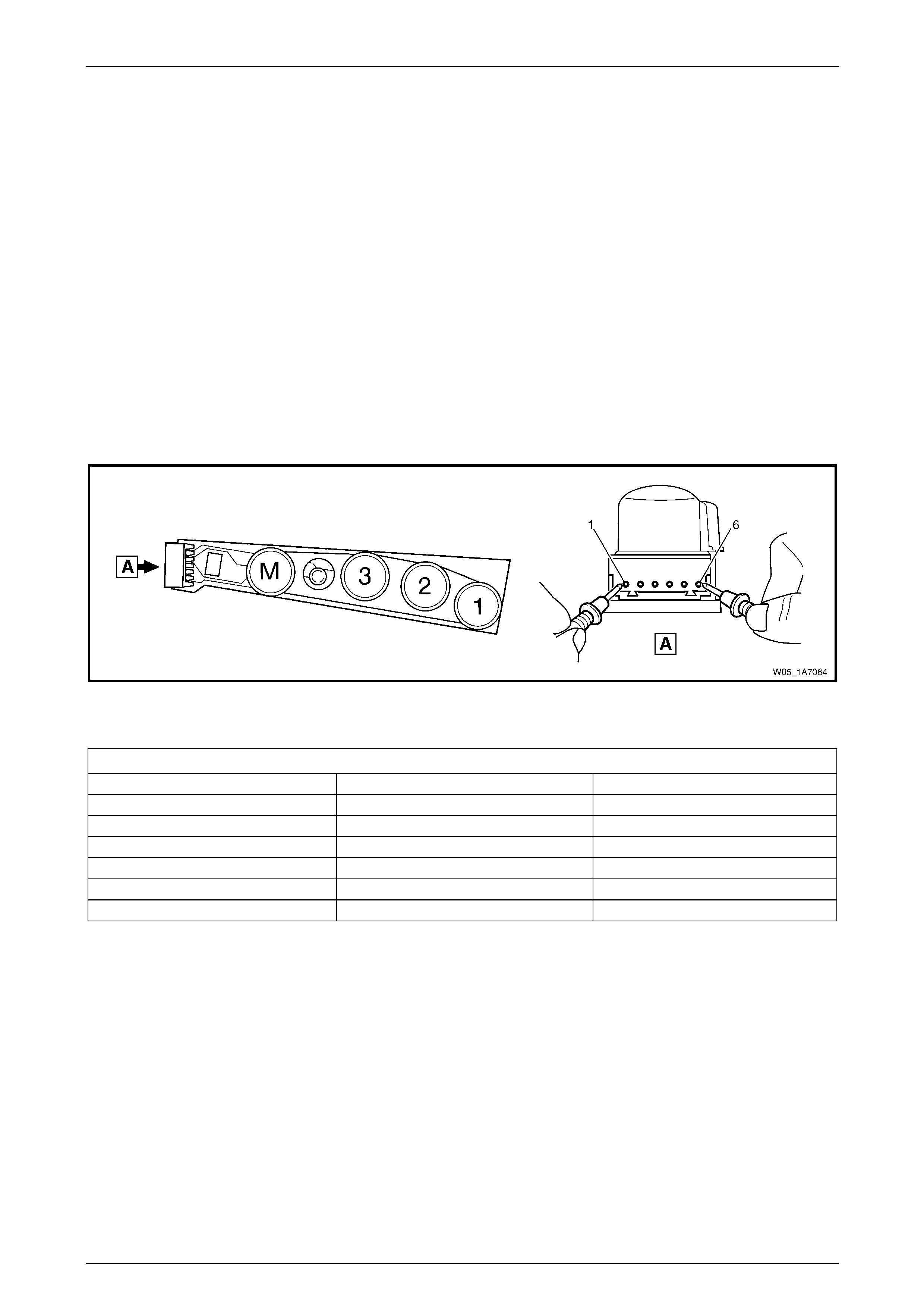
Seat Assemblies Page 1A7–106
Page 1A7–106
3.9 Memory Position Switch Test
The switch is located on the outer side of the seat, attached to the inner side of the front seat outer side cover.
Remove
To remove the memory position switch, refer to 5.3 Front Seat Outer Side Cover Assembly.
Reinstall
To reinstall the memory position switch, refer to 5.3 Front Seat Outer Side Cover Assembly.
Test
1 Place the switch in the positions as detailed i n the chart in this Section. Place the probes of the multimeter onto the
terminals listed and take the reading. Compare the reading to the chart.
2 When testing the LED, ensure multimeter is set to diode range and Note polarity of probes.
3 If the switch fails any part of the test, replace the switch assembly with a serviceable item.
Figure 1A7 – 20
Right-hand Seat Memory Position Switch
Switch Depressed Switch Terminals Indication if Switch is Serviceable
------------ 6 and 1, 2, 3 and 4 Open circuit
Button 1 6 and 1 Continuity
Button 2 6 and 2 Continuity
Button 3 6 and 3 Continuity
Button M 6 and 4 Continuity
------------ 5 (+) probe and 6 (–) probe LED illuminated
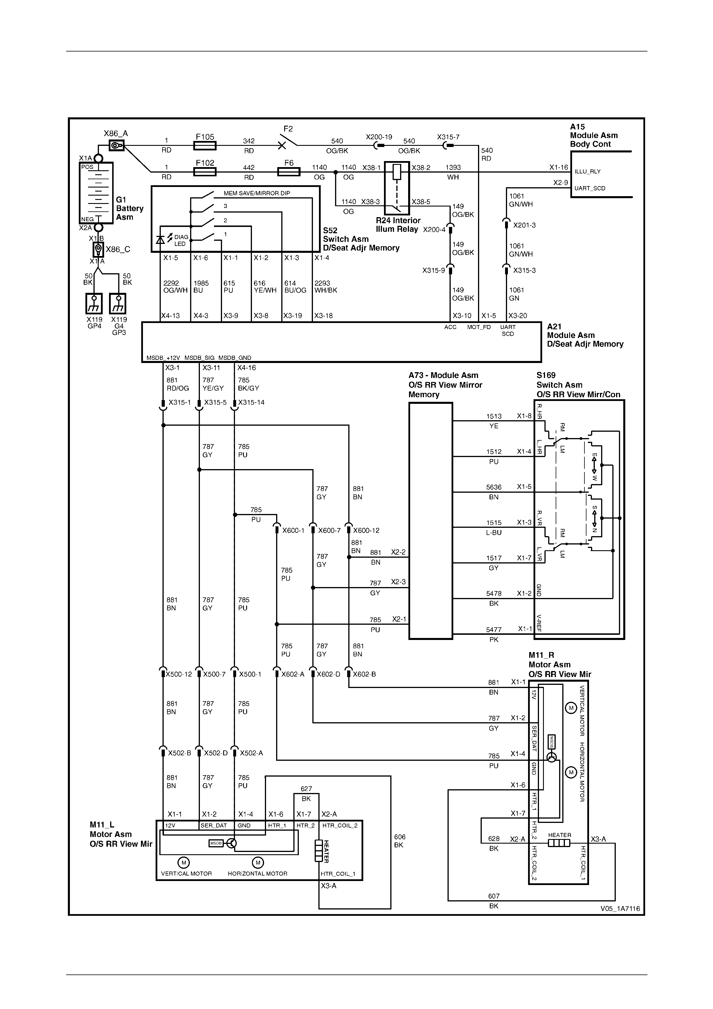
Seat Assemblies Page 1A7–107
Page 1A7–107
3.10 Electrical Diagnosis – Rear-view Mirrors
Wiring Diagram – Rear-view Mirrors
Figure 1A7 – 21
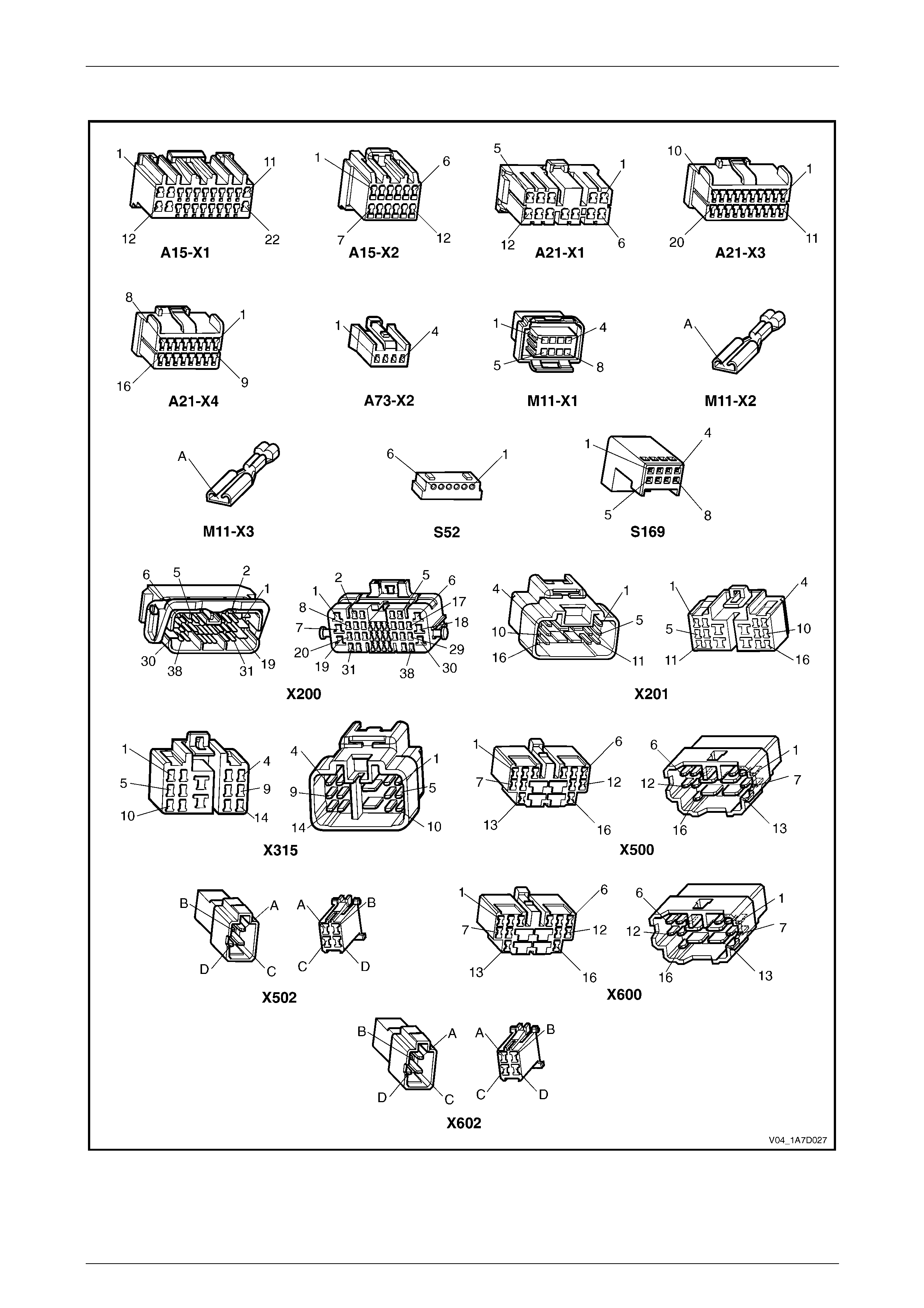
Seat Assemblies Page 1A7–108
Page 1A7–108
Connector Chart – Rear-view Mirrors
Figure 1A7 – 22

Seat Assemblies Page 1A7–109
Page 1A7–109
Initial Check
Introduction
This operational check uses T ech 2 to test the functio nality of the exterior rear-view mirrors and isolates which system is
faulty. The seat memory module provid es electrical power, ground and serial data communicati ons to the mirrors. As
described in 1 General Information, the mirrors can be controlle d:
• manually by the mirror control switch located on the driver's door,
• by pressing any of the memory buttons on the memor y pos ition switch, and
• to dip when reversing (passenger’s mirror only).
Refer to 1 General Information for further details on the operation of the exterior rear-view mirror.
Refer to Wiring Diagram – Rear-view Mirrors and Connector Chart – Rear-view Mirrors to aid in diagnosis.
Test Description
The following numbers refer to the steps in the diagnostic table:
1 Checks if Tech 2 can communicate with the seat memory module.
2 Checks for existence of any diagnostic trouble codes.
3 Checks if Tech 2 is receiving serial data from the exterior rear-view mirrors and the mirror control switch via the
rear-view mirror. All serial data communications need to be interrupted to these assemblies for Tech 2 to indicate
there is a problem.
4 Checks if serial data is being received at right exterior mirror only.
5 Checks if serial data is being received at left exterior mirror only.
6-9 Checks if the mirror control switch is serviceable. Isolates if the exterior rear-view mirrors and circuits are
serviceable.
10 Checks if the mirror dip function is serviceable.
11 Checks if the mirror heating function is serviceable.
12 Checks if the memory recall function of the exterior rear-view mirrors is serviceable. This function is controlled by
the seat memory module which transmits a signal throu gh the serial bus to inform the mirrors what position they
should be in. The exterior rear-view mirror assemblies store the physical position within their o wn modules. If the
seat aspect of this feature is operational, the exterior rear-view mirror assembly is faulty and must be replaced.

Seat Assemblies Page 1A7–110
Page 1A7–110
Diagnostic Table
Step Action Yes No
1 1 Connect Tech 2 to the DLC.
2 On Tech 2 select:
Body / Seat and Exterior Mirror Memory Module.
3 Turn the ignition switch on.
Does the System Identification Screen displa y system information? Go to Step 2 The seat memory
module is at fault
2 On Tech 2 select:
Body / Seat and Exterior Mirror Memory Module / Diagnostic
Trouble Codes / Read DTC Information.
Are there any diagnostic trouble codes displayed? Go to appropriate
DTC table Go to Step 3
3 1 On Tech 2 select:
Body / Seat and Exterior Mirror Memory Module /
Diagnostic Data Display / Inputs And Outputs.
2 Scroll to Button Pack Commu nication.
Does Tech 2 display Okay? Go to Step 4
Refer to No Serial
Data from Exterior
Rear-view Mirrors
4 On Tech 2 select:
Right Exterior Mirror Communication.
Does Tech 2 display Okay? Go to Step 5
Refer to No Serial
Data – Right-hand
Exterior Rear-view
Mirror
5 On Tech 2 select:
Left Exterior Mirror Communication.
Does Tech 2 display Okay? Go to Step 6
Refer to No Serial
Data – Left-hand
Exterior Rear-view
Mirror
6 1 On Tech 2 select:
Body / Seat and Exterior Mirror Memory Module /
Diagnostic Data Display / Input and Output.
2 Scroll to Right Exterior Mirror Switch.
3 Monitor Tech 2.
4 Move the rocker switch on the rear-view mirror switch to the
position to control the right ext erior mirror.
5 Using the rear-view mirror switch:
• Press the mirror up switch.
• Press the mirror down switch.
• Press the mirror left switch.
• Press the mirror right switch.
Does Tech 2 display Up, Down, Left, then Right during op eration? Go to Step 7
Refer to Mirror
Control Switch
Inoperative
7 During the test in Step 6, does the right-hand exterior rear-view mirror
move in the following directions?
• When the switch is in the neutral position, the mirror does not
move.
• When the switch is in the up position, the mirror moves up.
• When the switch is in the down position, the mirror moves
down.
• When the switch is in the right position, the mirror moves right.
• When the switch is in the left position, the mirror moves left.
NOTE
Ensure the mirror is not at its maximum limit of travel in
any direction when performing this test. Go to Step 8
Replace the
right-hand exterior
rear-view mirror
assembly, refer to
Section 12H Rear-
view Mirrors

Seat Assemblies Page 1A7–111
Page 1A7–111
Step Action Yes No
8 1 On Tech 2 select:
Left Exterior Mirror Switch.
2 Monitor Tech 2.
3 Move the rocker switch on the rear-view mirror switch to the
position to control the left exterior mirror.
4 Using the rear-view mirror switch:
• Press the mirror up switch.
• Press the mirror down switch.
• Press the mirror left switch.
• Press the mirror right switch.
Does Tech 2 display Up, Down, Left, then Right during op eration? Go to Step 9
Refer to Mirror
Control Switch
Inoperative
9 During the test in Step 8, does the left-hand exterior rear-view mirror
move in the following directions?
• When the switch is in the neutral position, the mirror does not
move.
• When the switch is in the up position, the mirror moves up.
• When the switch is in the down position, the mirror moves
down.
• When the switch is in the right position, the mirror moves right.
• When the switch is in the left position, the mirror moves left.
NOTE
Ensure the mirror is not at its maximum limit of travel in
any direction when performing this test. Go to Step 10
Replace the
left-hand exterior
rear-view mirror
assembly, refer to
Section 12H Rear-
view Mirrors
10 Does the mirror dip function operate correctly? Refer to Mirror Dip
Function Check Go to Step 11
11 Does the mirror heating function operate correctly? Refer to Mirror
Heating Function
Check Go to Step 12
12 Does the memory recall function of the exterior rear-vie w mirrors
operate correctly? If both exterior
rear-view mirrors
are unable to recall
memory positions,
check the
functionality of the
seat, refer to Initial
Check in 3.8
Electrical Diagnosis
– Memory Seat.
If only one mirror is
unable to recall
memory positions,
replace the mirror
assembly, refer to
Section 12H Rear-
view Mirrors System serviceable
When all diagno sis an d repairs are completed, clear all DT Cs and check the system for correct operation.

Seat Assemblies Page 1A7–112
Page 1A7–112
Mirror Dip Function Check
Introduction
The mirror dip function is operational when:
• the mirror dip function is enabled, refer to 1 General Information for details,
• a position for the passenger's exterior rear-view mirror is stored as the mirror dip, and
• the transmission selector must be placed in REVERSE position.
Test Description
The following numbers refer to the steps in the diagnostic table:
2 Checks if the mirror DIP function is enabled.
3 Checks if the mirror DIP function operates and is positioned correctly.
4 Checks if the mirror DIP function returns an Active messag e on Tech 2 when the transmission s elector is placed in
REVERSE position. Isolates whether there is a fault with the seat memory module or with the serial data from the
transmission selector.
Diagnostic Table
Step Action Yes No
1 Has the Initial Check been performed?
Go to Step 2
Perform the Initial
Check in this
Section
2 1 On Tech 2 select:
Body / Seat and Exterior Mirror Memory Module /
Diagnostic Data Display / Memory.
2 Scroll to Priority 1.
Does Tech 2 display Mirror Dip Button as Enabled? Go to Step 3
Enable mirror DIP
function, refer to 1
General
Information.
Go to Step 3
3 1 Ensure the stored mirror DIP position is noticeably different
from the standard position of the left exterior mirror, refer to 1
General Information.
2 Check the mirror DIP function by placing the transmission
selector in reverse.
Does the mirror DIP function operate? System serviceable Go to Step 4
4 1 On Tech 2 select:
Body / Seat and Exterior Mirror Memory Module /
Diagnostic Data Display / Inputs And Outputs.
2 Scroll to Reverse Gear.
Does Tech 2 display R everse Gear as Active?
Replace the seat
memory module,
refer to 5.11 Seat
Cable Tray and
Memory Module
Refer to Section
6C3 Powertrain
Management for V8
or
Section 6C1
Engine
Management for V6
When all diagno sis an d repairs are completed, clear all DT Cs and check the system for correct operation.
Seat Assemblies Page 1A7–113
Page 1A7–113
Mirror Heating Function Check
Introduction
When the demist button on the instrument panel is pressed to activate the demist function, the request is sent via the
serial data bus to the exterior rear-view mirror assemblies.
Test Description
The following numbers refer to the steps in the diagnostic table:
2 Checks if Tech 2 confirms the demist function has been activated.
3 Checks if the heater element in the right-hand e xterior rear-view mirror operates when the ignition and rear windo w
demister are switched on.
4 Checks if the right-hand mirror heater element is servicea ble. Isolates whether the heater element or the exterior
rear-view mirror assembly is at fault.
5 Checks if the heater element in the left-hand exterior rear-view mirror operates when the ignition and rear window
demister are switched on.
6 Checks if the left-hand mirror heater element is serviceable. Isolates whether the he ater element or the exterior
rear-view mirror assembly is at fault.
Diagnostic Table
Step Action Yes No
1 Has the Initial Check been performed?
Go to Step 2
Perform the Initial
Check in this
Section
2 1 On Tech 2 select:
Body / Seat and Exterior Mirror Memory Module /
Diagnostic Data Display / Input And Output.
2 Scroll to Demist Request.
3 Turn on the rear window demister.
Does Tech 2 display Demist Req uest as Yes? Go to Step 3
Refer to Section
12J Body Control
Module.
Go to Step 3
3 Operate the rear window demister for 2 – 3 minutes.
Does the right-hand exterior mirror feel warm? Go to Step 5 Go to Step 4
4
Turn off the rear window demister before removing
and replacing the righ t-hand exterior mirror glass.
Test the heater element of the right-hand ext erior rear-view mirror,
refer to Section 12H Rear-view Mirrors.
Is the heater element serviceable?
Replace the
right-hand exterior
rear-view mirror
assembly, refer to
Section 12H Rear-
view Mirrors
Replace the
right-hand exterior
rear-view mirror
glass, refer to
Section 12H Rear-
view Mirrors.
Go to Step 5
5 Operate the rear window demister for 2 – 3 minutes.
Does the left-hand exterior mirror feel warm? System serviceable Go to Step 6
6
Turn off the rear window demister before removing
and replacing the left-hand exterior mirror glass.
Test the heater element of the left-hand exterior rear-view mirror,
refer to Section 12H Rear-view Mirrors.
Is the heater element serviceable?
Replace the
left-hand exterior
rear-view mirror
assembly, refer to
Section 12H Rear-
view Mirrors
Replace the
left-hand exterior
rear-view mirror
glass, refer to
Section 12H Rear-
view Mirrors
When all diagno sis an d repairs are completed, clear all DT Cs and check the system for correct operation.

Seat Assemblies Page 1A7–114
Page 1A7–114
No Serial Data from Exterior Rear-view Mirrors
Introduction
The exterior rear-vie w mirrors have a common power, ground and seri al data connector at the seat memory module. If
the circuit is followed, there are two splices in each of the power, grou nd and data communication circuits. In this test, as
there are not serial data communications with any of the exterior rear-view mirrors, it is assumed the fault will be in a
location common to all circuits.
Refer to Wiring Diagram – Rear-view Mirrors and Connector Chart – Rear-view Mirrors to aid in diagnosis.
Test Description
The following numbers refer to the steps in the diagnostic table:
2 Checks if the connectors which are common to the serial data communication for the exterior rear-vie w mirrors are
secure.
3 Checks if battery voltage is present for the exterior rear-view mirror system at the seat memory module.
4 Checks if the seat memory module is supplying a ground circuit for the exterior rear-view mirror system.
5 Checks the battery supply circuit for a short to ground.
6 Checks the ground circuit for a short to battery.
7 Checks if there is continuity in the serial data circuit between connectors A21 – X3 pin 11 and X500 pin 7. Isolates
whether there is an open circuit in circuit 787 that will affect both the exterior rear-view mirrors or the seat memory
module is faulty.
Diagnostic Table Notes
1 For all wiring harness fault diagnoses, refer to Section 12P Wiring Diagrams.
2 For wiring harness repairs, refer to Section 12P Wiring Diagrams.
3 Refer to Section 12O Fuses, Relays and W iring Harnesses for harness routeing.
4 If the fault is deemed to be intermittent, refer to Section 12P Wiring Diagrams.

Seat Assemblies Page 1A7–115
Page 1A7–115
Diagnostic Table
Step Action Yes No
1 Has the Initial Check been performed?
Go to Step 2
Perform the Initial
Check in this
Section
2 Ensure the following connectors are secure (refer to Note 3)?
• A21 – X3
• A21 – X4
• X315 Go to Step 3 Secure the relevant
connectors
3 1 Disconnect connectors A21 – X3 and A21 – X4 from the seat
memory module.
2 Using a multimeter set to measure voltage, probe b etween seat
memory module A21 – X3 pin 1 and a known ground (refer to
Note 1).
Does the multimeter indicate battery voltage? Go to Step 4
Replace the seat
memory module,
refer to 5.11 Seat
Cable Tray and
Memory Module
4 Using a multimeter set to measure resistance, probe between seat
memory module A21 – X4 pin 16 and a known ground (refer to Note
1).
Does the multimeter indicate contin uity? Go to Step 5
Replace the seat
memory module,
refer to 5.11 Seat
Cable Tray and
Memory Module
5 Using a multimeter set to measure resistance, probe between
connector A21 – X3 pin 1 and a known ground (refer to Note 1).
Does the multimeter indicate contin uity?
Repair or replace
circuit 881 (refer to
Note 2) Go to Step 6
6 Using a multimeter set to measure voltage, probe between connector
A21 – X4 pin 16 and a known ground (refer to Note 1).
Does the multimeter indicate battery voltage?
Repair or replace
circuit 785 (refer to
Note 2) Go to Step 7
7 Using a multimeter set to measure resistance, probe between
connectors A21 – X3 pin 11 and X500 pin 7 (refer to Note 1).
Does the multimeter indicate contin uity? Replace the seat
memory module,
refer to 5.11 Seat
Cable Tray and
Memory Module
Repair or replace
circuit 787 between
connector
A21 – X3 pin 11
and the first splice
on circuit 787 (refer
to Note 2)
When all diagno sis an d repairs are completed, clear all DT Cs and check the system for correct operation.

Seat Assemblies Page 1A7–116
Page 1A7–116
No Serial Data – Right-hand Exterior Rear-view Mirror
Introduction
Refer to Wiring Diagram – Rear-view Mirrors and Connector Chart – Rear-view Mirrors to aid in diagnosis.
Test Description
The following numbers refer to the steps in the diagnostic table:
2 Checks if there is battery voltage supplied to the right-hand exterior rear-view mirror. Isolates if there is a fault in
circuit 881 between connectors X602 and A21 – X3.
3 Checks if the ground circuit for the right-hand exterior rear-view mirror is serviceable. Isolates if there is a fault in
circuit 785 between connectors X602 and A21 – X4.
4 Checks the serial data circuit for the right-hand exterior rear-view mirror for integrity. Isolates whether there is a
fault in circuit 787 between connectors A21 – X3 and X602 or the right-hand exterior rear-vie w mirror assembly is
faulty.
Diagnostic Table Notes
1 For all wiring harness fault diagnoses, refer to Section 12P Wiring Diagrams.
2 For wiring harness repairs, refer to Section 12P Wiring Diagrams.
3 Refer to Section 12O Fuses, Relays and W iring Harnesses for harness routeing.
4 If the fault is deemed to be intermittent, refer to Section 12P Wiring Diagrams.
Diagnostic Table
Step Action Yes No
1 Has the Initial Check been performed?
Go to Step 2
Perform the Initial
Check in this
Section
2 Backprobe connector X602 pin B with a test lamp (refer to Note 1).
Does the test lamp illuminate?
Go to Step 3
Repair or replace
circuit 881 between
connectors X602
and A21 – X3 (refer
to Note 2)
3 1 Disconnect harness connector X602.
2 Using a multimeter set to measure resistance, probe between
connector X602 pin A and a known ground (refer to Note 1).
Does the multimeter indicate continuity? Go to Step 4
Repair or replace
circuit 785 between
connectors X602
and A21 – X4 (refer
to Note 2)
4 1 Disconnect connector A21 – X3 from the seat memory module.
2 Using a multimeter set to measure resistance, probe between
connectors A21 – X3 pin 11 and X602 pin D (refer to Note 1).
Does the multimeter indicate contin uity?
Replace the
right-hand exterior
rear-view mirror
assembly, refer to
Section 12H Rear-
view Mirrors
Repair or replace
circuit 787 between
connectors
A21 – X3 and X6 02
(refer to Note 2)
When all diagno sis an d repairs are completed, clear all DT Cs and check the system for correct operation.

Seat Assemblies Page 1A7–117
Page 1A7–117
No Serial Data – Left-hand Exterior Rear-view Mirror
Introduction
Refer to Wiring Diagram – Rear-view Mirrors and Connector Chart – Rear-view Mirrors to aid in diagnosis.
Test Description
The following numbers refer to the steps in the diagnostic table:
2 Checks if there is battery voltage supplied to the left-hand exterior rear-view mirror. Isolates if there is a fault in
circuit 881 between connectors X502 and A21 – X1.
3 Checks if the ground circuit for the left-hand exterior rear-view mirror is serviceable. Isolates if there is a fault in
circuit 785 between connectors X502 and A21 – X3.
4 Checks the serial data circuit for the left-hand exterior rear-view mirror for integrity. Isolates whether there is a fault
in circuit 787 between connectors A21 – X1 and X502 or the left-hand exterior rear-view mirror assembly is faulty.
Diagnostic Table Notes
1 For all wiring harness fault diagnoses, refer to Section 12P Wiring Diagrams.
2 For wiring harness repairs, refer to Section 12P Wiring Diagrams.
3 Refer to Section 12O Fuses, Relays and W iring Harnesses for harness routeing.
4 If the fault is deemed to be intermittent, refer to Section 12P Wiring Diagrams.
Diagnostic Table
Step Action Yes No
1 Has the Initial Check been performed?
Go to Step 2
Perform the Initial
Check in this
Section
2 Backprobe connector X502 pin B with a test lamp (refer to Note 1).
Does the test lamp illuminate?
Go to Step 3
Repair or replace
circuit 881 between
connectors X502
and A21 – X3 (refer
to Note 2)
3 1 Disconnect harness connector X502.
2 Using a multimeter set to measure resistance, probe between
connector X502 pin A and a known ground (refer to Note 1).
Does the multimeter indicate continuity? Go to Step 4
Repair or replace
circuit 785 between
connectors X502
and A21 – X4 (refer
to Note 2)
4 1 Disconnect connector A21 – X3 from the seat memory module.
2 Using a multimeter set to measure resistance, probe between
connectors A21 – X3 pin 11 and X502 pin D (refer to Note 1).
Does the multimeter indicate contin uity?
Replace the
left-hand exterior
rear-view mirror
assembly, refer to
Section 12H Rear-
view Mirrors
Repair or replace
circuit 787 between
connectors
A21 – X3 and X5 02
(refer to Note 2)
When all diagno sis an d repairs are completed, clear all DT Cs and check the system for correct operation.

Seat Assemblies Page 1A7–118
Page 1A7–118
Mirror Control Switch Inoperative
Introduction
When the mirror control switch is used, the signal that it generates is converted by the rear-view mirror module to serial
data. It is then transmitted over the serial data bus. The exterior rear-view mirrors then receive this serial data and move
the appropriate exterior rear-view mirror in the direction that was requested b y the mirror control switch.
Refer to Wiring Diagram – Rear-view Mirrors and Connector Chart – Rear-view Mirrors to aid in diagnosis.
Test Description
The following numbers refer to the steps in the diagnostic table:
2 Checks if the mirror control switch is serviceable.
3 Checks if there is battery power to the rear-view mirror module. Isolates if there is a fault in circuit 881 between
connectors A73 – X2 and A21 – X3.
4 Checks if there is battery power to the mirror control switch. Isolates if the rear-view mirror module is at fault.
5 Checks if the ground circuit for the rear-view mirror module i s serviceable. Isolates if there is a fault in circuit 785
between connectors A73 – X2 and A21 – X4.
6 Checks if the ground circuit for the mirror control switch is serviceable. Isolates if the rear-view mirror module is at
fault.
7 Checks if there is continuity on the serial data bus between connectors A73 – X2 and A21 – X3. Isolates whether
there is an open circuit in circuit 787 between connectors A73 – X2 and A21 – X3 or the rear-view memory module
is faulty.
Diagnostic Table Notes
1 For all wiring harness fault diagnoses, refer to Section 12P Wiring Diagrams.
2 For wiring harness repairs, refer to Section 12P Wiring Diagrams.
3 Refer to Section 12O Fuses, Relays and W iring Harnesses for harness routeing.
4 If the fault is deemed to be intermittent, refer to Section 12P Wiring Diagrams.

Seat Assemblies Page 1A7–119
Page 1A7–119
Diagnostic Table
Step Action Yes No
1 Has the Initial Check been performed?
Go to Step 2
Perform the Initial
Check in this
Section
2 Test the mirror control switch, refer to Section 12H Rear-view Mirrors.
Is the mirror control switch serviceable? Go to Step 3
Replace the mirror
control switch, refer
to Section 12H
Rear-view Mirrors
3 Backprobe connector A73 – X2 pin 2 with a test lamp (refer to
Note 1).
Does the test lamp illuminate?
Go to Step 4
Repair or replace
circuit 881 between
connectors
A73 – X2 and
A21 – X3 (refer to
Note 2)
4 Backprobe connector S169 – X1 pin 1 with a test lamp (refer to
Note 1).
Does the test lamp illuminate?
Go to Step 5
Replace the
rear-view mirror
module, refer to
Section 1A5 Front
and Rear Door
Assemblies
5 Using a multimeter set to measure resistance, probe between
connector A73 – X2 pin 1 and a known ground (refer to Note 1).
Does the multimeter indicate contin uity?
Go to Step 6
Repair or replace
circuit 785 between
connectors
A73 – X2 and
A21 – X4 (refer to
Note 2)
6 Using a multimeter set to measure resistance, probe between
connector S169 – X1 pin 2 and a known ground (refer to Note 1).
Does the multimeter indicate contin uity?
Go to Step 7
Replace the
rear-view mirror
module, refer to
Section 1A5 Front
and Rear Door
Assemblies
7 1 Disconnect connectors A21 – X3 from the seat memory module
and A73 – X2 from the rear-view mirror module.
2 Using a multimeter set to measure resistance, probe between
connectors A73 –X2 pin 3 and a A21 – X3 pin 11 (refer to Note
1).
Does the multimeter indicate contin uity?
Replace the
rear-view mirror
module, refer to
Section 1A5 Front
and Rear Door
Assemblies
Repair or replace
circuit 787 between
connectors
A73 – X2 and
A21 – X3 (refer to
Note 2)
When all diagno sis an d repairs are completed, clear all DT Cs and check the system for correct operation.

Seat Assemblies Page 1A7–120
Page 1A7–120
4 Diagnostics – Front Seat, Coupe
This Section provides charts to assist in the diagnosis and repa ir of front seats. Refer to 7.1 Usage Ch art for a full listing
of the different types of seats fitted to Coupe vehicles. Included in that Sec tion are illustrated parts break downs of the
various seats.
4.1 Prerequisites
Safety Requirements
When operating the seat as part of any Steps
in the diagnostic tables, ensure that fingers
and limbs are clear of mo ving parts.
Equipment
The following equipment is required to diagnose the seats:
• an unpowered test lamp with a current draw of less than 3 A, and
• a digital multimeter with a minimum impe dance of 10 MΩ.
Testing Procedures
The following points must be adhered to
when performing diagnostic testing on
components:
• Take care when using testing equipment
to diagnose wiring harness connectors. It
is preferred the technician backprobe the
connector to avoid terminal damage.
• When tests are required on connector
terminals, use the adapters in the
connector adapter kit KM–609 to prevent
damage to the terminals.
• Unless the multimeter being used has an
auto-ranging function, ensure the correct
range is selected.
• When backpro bing connectors, ensure the
test lamp ground lead is connected to an
appropriate ground point on the vehicle.
Ensure this ground point is not part of the
circuit being tested.
NOTE
When following the steps in the di agnostic tables,
perform them in the order cited. If the required
nominal value or result is not achi eved, rectif y t he
problem before proceeding any further.

Seat Assemblies Page 1A7–121
Page 1A7–121
4.2 Mechanical Diagnosis
Lumbar Support Inoperative
Introduction
This test is used to aid in diagnosing the lumbar support as sembly.
Test Description
The following numbers refer to the step numbers in the diagnostic table:
1 Checks if the lumbar support knob is properly engaging the lumbar support adjuster. Check the knob for cracks and
worn splines.
2 Checks if the lumbar support assembly is damaged or worn and if the retaining springs are serviceable and
securely attached to the seat-back frame assembly.
3 Checks if the lumbar support assembly is servicea ble and if the lumber support assembly strap is operating
correctly within the guide rails.
Diagnostic Table
Step Action Yes No
1 Remove the lumbar support knob, refer to 7.10 Lumbar Support Knob
Assembly.
Is the lumbar support adjust knob serviceable? Go to Step 2
Replace the knob,
refer to 7.10
Lumbar Support
Knob Assembly
2 1 Remove the seat-back cover.
2 Inspect the lumbar support retainers and spri ngs.
Are the lumbar support retaining spri ngs serviceable and securel y
attached to the seat-back frame assembly? Go to Step 3
Replace or reattach
the retaining
springs, refer to
7.11 Front Seat-
back Pad and Cover
Assembly
3 1 Visually inspect the lumbar support assembly. Check for broken
or worn parts.
2 Check the strap running across the lumber support assembly is
serviceable and running freely within the guide rails.
NOTE
You may need to attach the lumber support knob to
actuate the strap.
Is the lumbar support assembly serviceabl e? System serviceable
Replace lumbar
support assembly or
resecure lumbar
support assembly
strap ensuring strap
is not binding with
guide rails, refer to
7.12 Front Seat-
back Frame
Assembly
When all diagno sis an d repairs are completed, ch eck the system for correct op eration.

Seat Assemblies Page 1A7–122
Page 1A7–122
EZ-entry Lever Function Inoperative
Introduction
The EZ-entry lever arm uses a cable to release the se at-back. There is also an electrical component to the operation that
will drive the seat forward using front seat fo re/aft movement motor. This diagnostic table covers the mechanica l aspect
of the lever arm and cable being inoperative.
Test Description
The following numbers refer to the step numbers in the diagnostic table:
1 Checks if the EZ-entry lever arm is serviceable. The lever arm engages a frame assembly which is connected to
the EZ-entry cable assembly.
2 The EZ-entry lever arm and its spring clip are the only serviceable items a s far as the mechanical action of this
system is concerned. Due to safety requirements, if the EZ -entry lever function does not operate after the lever arm
has been checked for serviceabil ity and correct installation, the seat-back frame assembly must be replaced.
Diagnostic Table
Step Action Yes No
1 Remove the EZ-entry lever arm, refer to 7.8 EZ-entr y Release Lever
and Escutcheon.
Is the EZ-entry lever arm serviceable? Go to Step 2
Replace the lever
arm, refer to 7.8
EZ-entry Release
Lever and
Escutcheon
2 Install the EZ-entry lever arm ensuring th e spring clip and lever arm
engage properly, refer to 7.8 EZ-entry Release Lever and
Escutcheon.
Does the EZ-entry lever function operate? System serviceable
Replace the front
seat-back frame
assembly, refer to
7.12 Front Seat-
back Frame
Assembly
When all diagno sis an d repairs are completed, ch eck the system for correct op eration.

Seat Assemblies Page 1A7–123
Page 1A7–123
4.3 Electrical Diagnosis – Eight-way Seat,
Non-memory
Neither Seat Adjustment Switch Functions Operate
Introduction
This test is used to aid in diagnosing the seat power and ground circuits if neither seat operates when either seat
adjustment switch is operated.
Circuit Description
Both front seats have common power and gr ound circuits. If either of these circuits become unserviceable, the electrical
operation of both seats will be affected.
Refer to the following diagrams in this Sectio n to aid in diagnosing the seat adjustme nt switch and associated
components:
• Wiring Diagram – Passenger's Seat and Connector Chart – Passenger's Seat.
Test Description
The following numbers refer to the step numbers in the diagnostic table:
1 Checks if battery voltage is greater than 11.5 V. The seat motors require gr eater than 11.5 V to operate correctly.
2 Checks if circuit breaker F2 located on the passen ger compartment fuse and relay panel assembl y is tripped.
Isolates if circuit breaker F2 is the fault affecting the circuit between the battery and connec tor X200 pin 19.
3 Checks if fusible link F105 located on the engine compartment fuse and relay panel assembly is serviceable.
Isolates if the fusible link is the fault affecting the circuit between the battery and connector X200 pin 19.
4 Checks if connector X200 is secure.
5 Checks if there is battery voltage at connector X200 pin 19. Isolates if the fault is between the battery and
connector X200 pin 19. If the fault in the circuit is between connectors X200 pin 19 and either X308 pin B or
X315 pin 3, only one seat will operate.
6 Checks if there is battery voltage at circuit breaker F2. Isolates whether the fault is between the b attery and circuit
breaker F2 or bet ween circuit breaker F2 an d connector X200 pin 19.
7 Checks if there is battery voltage at fusible link F105. Isolates whether the fault is between the battery and fusible
link F105 or between fusible li nk F105 and circuit breaker F2.
8 Checks if the ground point associated with the system is serviceable.
Diagnostic Table Notes
1 For all wiring harness fault diagnoses, refer to Section 12P Wiring Diagrams.
2 For wiring harness repairs, refer to Section 12P Wiring Diagrams.
3 Refer to Section 12O Fuses, Relays and W iring Harnesses for harness routeing.
4 If the fault is deemed to be intermittent, refer to Section 12P Wiring Diagrams.

Seat Assemblies Page 1A7–124
Page 1A7–124
Diagnostic Table
Step Action Yes No
1 Check the battery voltage, refer to Section 12A Battery.
Is the battery voltage greater than 11.5 V? Go to Step 2
Refer to Section
12A Battery for
further diagnosis
2 Inspect circuit breaker F2 (refer to Note 3).
Is circuit breaker F2 tripped?
Allow the circuit
breaker to reset
(refer to Note 3).
If the circuit breaker
trips again, repair
or replace circuit
540 (refer to
Note 2) Go to Step 3
3 Inspect fusible link F105 (refer to Note 3).
Is fuse F105 serviceable?
Go to Step 4
Replace the fusible
link.
If the fusible link
becomes
unserviceable
again, repair or
replace circuit 342
(refer to Note 2)
4 Is connector X200 secure (ref er to Note 3)? Go to Step 5 Ensure the
connector is secure
5 Backprobe connector X200 pin 19 with a test lamp (refer to Note 1).
Does the test lamp illuminate? Go to Step 8 Go to Step 6
6 1 Remove circuit breaker F2 fro m the passenger compartment
fuse and relay panel assembly.
2 Using a test lamp, probe connector X12 9 – X45 pin 2 (refer to
Note 1).
Does the test lamp illuminate?
Repair or replace
circuit 540 between
circuit breaker F2
and connector
X200 pin 19 (refer
to Note 2) Go to Step 7
7 1 Remove the fusible link F105.
2 Using a test lamp, probe connector X18-105 (refer to Note 1).
Does the test lamp illuminate?
Repair or replace
circuit 342 between
fusible link F105
and circuit breaker
F2 (refer to Note 2)
Repair or replace
circuit 1 between
the battery and
fusible link F105
(refer to Note 2)
8 Ensure the follo wing ground point is secure and has good contact
with the vehicle structure:
• X118 – GP12 located in the middle of the transmission tunnel.
Is the ground point secure to the vehicle with a good contact?
Repair or replace
circuit 650 (refer to
Note 2) Repair ground point
When all diagno sis an d repairs are completed, ch eck the system for correct op eration.

Seat Assemblies Page 1A7–125
Page 1A7–125
EZ-entry Electrical Self Test Diagnosis – Eight-way Seat, Non-Memory
Introduction
The non-memory type seat provides the technician with in-built diagnostics. The diagnostics indicator is a green LED
located on the seat EZ-entry module. The LED can be viewed through the small hole in the outer sid e l ower seat side
cover. To gain access, it is necessary to partially remove the seat outer side cover.
Refer to 7.3 Front Seat Outer Side Cover Assembly.
The chart in this Section displays the error c odes and fault description.
If the error code is above ten, the indication will consist of a single flash, a short delay and then the num ber of flashes
corresponding to the error. A longer delay will occur between error code indications.
EZ-entry Diagnostics
Flashes Description of Error Reference
2 No Passenger Presenc e Detection
(PPD) Switch detected Passenger's Seat Passenger Presenc e Detection Switch Test in
4.4 Electrical Diagnosis – Passenger's Seat.
3 PPD weight detected > 15 kg Passenger's Seat Passenger Presence Detection Switch Test in
4.4 Electrical Diagnosis – Passenger's Seat.
6 Battery voltage low Section 12A Battery.
7 Button stuck detected 4.4 Electrical Diagnosis – Passenger's Seat
8 Dump latch active Passenger's Seat EZ-entry Switch Function is Inoperative in 4.4
Electrical Diagnosis – Passenger's Seat.
9 Return button active Passenger's Seat Return Switch F unction is Inoperative in 4.4
Electrical Diagnosis – Passenger's Seat.
11 Forward track switch active 2.7 Eight-way Seat Adjustment Switch Test.
12 Reverse track switch active 2.7 Eight-way Seat Adjustment Switch Test.
13 Recliner forward switch active 2.7 Eight-way Seat Adjustment Switch Test.
14 Recliner backward switch active 2.7 Eight-way Seat Adjustment Switch Test.
15 At full forward position Passenger’s Seat Fore/Aft Movement Function is Inoperative or
Not Smooth in 4.4 Electrical Diagnosis – Passenger's Seat.
16 At full rearward position Passenger’s Seat Fore/Aft Movement Function is Inoperative or
Not Smooth in 4.4 Electrical Diagnosis – Passenger's Seat.

Seat Assemblies Page 1A7–126
Page 1A7–126
4.4 Electrical Diagnosis – Passenger's Seat
The charts in this Section are used to aid in diagnosing faul ts on the passenger's seat. To aid in the use of the diagnostic
tables, refer to Wiring Diagram – Passenger's Seat, Coupe and Connector Chart – Passenger' s Seat, Coupe.
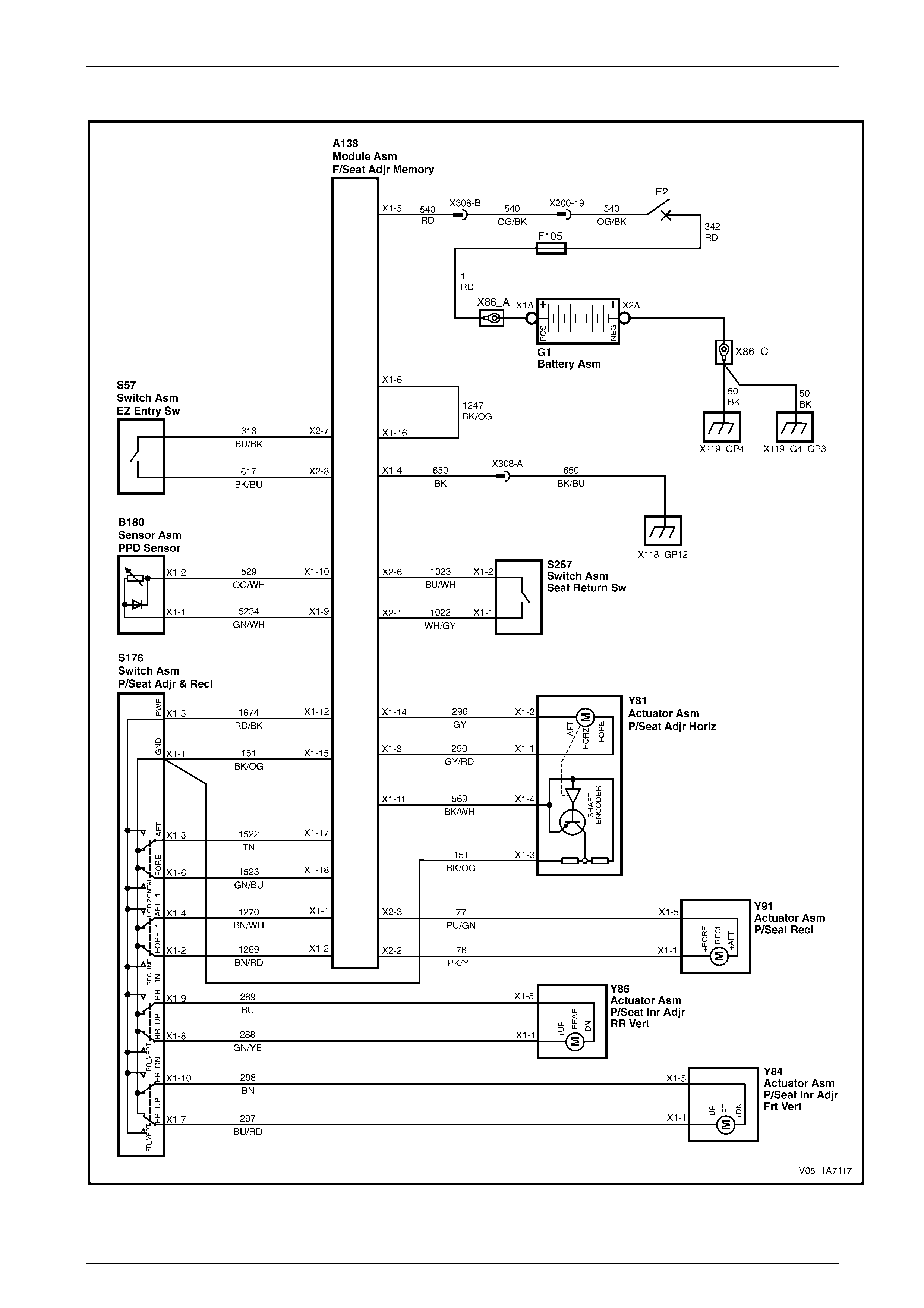
Seat Assemblies Page 1A7–127
Page 1A7–127
Wiring Diagram – Passenger's Seat, Coupe
Figure 1A7 – 23
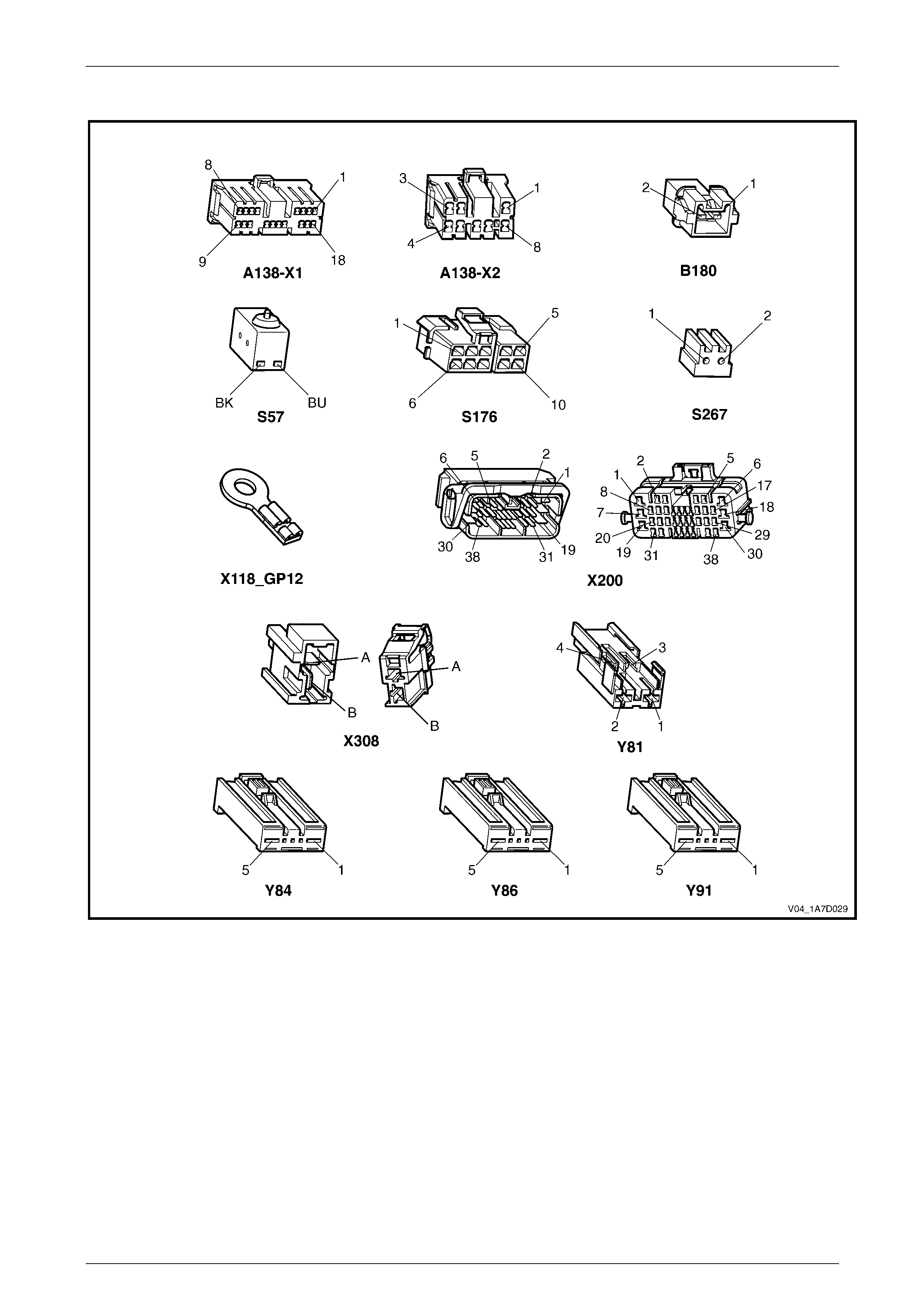
Seat Assemblies Page 1A7–128
Page 1A7–128
Connector Chart – Passenger's Seat, Coupe
Figure 1A7 – 24

Seat Assemblies Page 1A7–129
Page 1A7–129
None of the Passenger’s Seat Adjustment Switch Functions Operate
Introduction
This test is used to aid in diagnosing the passenger’s seat adjustment switch when none of the switch functions operate.
The test diagnoses the passenger’s seat adjustment switch and associate d power and ground circuits.
Circuit Description
The seat adjustment switch provides manual control for the passeng er’s seat. It is connected by a harness to the seat
EZ-entry module and to the seat front and rear lift motors.
Refer to Wiring Diagram – Passenger' s Seat, Coupe and Connector Chart – Passenger's Seat, Coupe to aid in
diagnosis.
Test Description
The following numbers refer to the step numbers in the diagnostic table:
1 Checks if all of the driver’s seat functions work. If none of them work, the fault is not isolated to the driver’s seat
only.
2 Checks if there is battery power at connector X308 pin B. Isolates if there is a fault in circuit 540 between
connectors X200 pin 19 and X308 pin B.
3 Checks if all the connectors required for the seat to operate effectively are in place a nd positively connected.
4 Checks if there is battery power at connector A138 – X1 pin 5. Isolates if there is a fault in circuit 540 between
connectors A138 – X1 pin 5 and X308 pin B.
5 Checks if there is battery power at connector A138 – X1 pin 12. Isolates if there is a fault with the EZ-entry module.
6 Checks if there is battery power at connector S176 – X1 pin 5. Isolates if there is a fault in circuit 1674 between
connectors S176 – X1 pin 5 and A138 – X1 pin 1 2.
7 Checks if the passenger’s seat adjustment switch is serviceable.
8 Checks if there is continuity between connectors S51 – X1 pin 1 and X308 pin A which supplies the ground circuit
for the driver’s seat adjustment switch. Isolates whether the re is a fault between the switch and connector
X308 pin A or between connector X308 pin A and the ground point.
9 Checks if there is continuity between connectors A138 – X1 pin 4 and X308 pin A. Isolates whether there is a fault
between the seat adjustment switch and connector A138 – X1 pin 4 or between connectors A138 – X1 pin 4 and
X308 pin A.
10 Checks if there is continuity between connector A138 – X1 pins 15 and 4. Isolates whether there is a fault between
the seat adjustment switch and connector A138 – X1 pin 15 or the EZ-entry module is at fault.
Diagnostic Table Notes
1 For all wiring harness fault diagnoses, refer to Section 12P Wiring Diagrams.
2 For wiring harness repairs, refer to Section 12P Wiring Diagrams.
3 Refer to Section 12O Fuses, Relays and W iring Harnesses for harness routeing.
4 If the fault is deemed to be intermittent, refer to Section 12P Wiring Diagrams.

Seat Assemblies Page 1A7–130
Page 1A7–130
Diagnostic Table
Step Action Yes No
1 Are all of the driver's seat adjustment s witch functions inoperative? Refer to Neither
Seat Adjustment
Switch Functions
Operate in 4.3
Electrical Diagnosis
– Eight-way Seat,
Non-memory Go to Step 2
2 Backprobe connector X308 pin B with a test lamp (refer to Note 1).
Does the test lamp illuminate?
Go to Step 3
Repair or replace
circuit 540 between
connectors X200
pin 19 and
X308 pin B (refer to
Note 2)
3 Are the following connectors secure (refer to Note 3)?
• A138
• S176
• X308
• Y81
• Y84
• Y86
• Y91 Go to Step 4
Ensure the
connectors are
secure
4 Backprobe connector A138 – X1 pin 5 with a test lamp (refer to
Note 1).
Does the test lamp illuminate?
Go to Step 5
Repair or replace
circuit 540 between
connectors
A138 – X1 pin 5
and X308 pin B
(refer to Note 2)
5 Backprobe connector A138 – X1 pin 12 with a test lamp (refer to
Note 1).
Does the test lamp illuminate?
Go to Step 6
Replace the
passenger’s seat
EZ-entry module,
refer to 7.3 Front
Seat Outer Side
Cover Assembly
6 Backprobe connector S176 – X1 pin 5 with a test lamp (refer to
Note 1).
Does the test lamp illuminate? Go to Step 7
Repair or replace
circuit 1674 (refer
to Note 2)

Seat Assemblies Page 1A7–131
Page 1A7–131
Step Action Yes No
7 1 Remove the passenger’s seat adjustment switch from the seat,
refer to 7.3 Front Seat Outer Side Cover Assembly.
Go to Step 8
Replace the
passenger’s seat
adjustment switch,
refer to 7.3 Front
Seat Outer Side
Cover Assembly
8 1 Backprobe connector X308 pin A with a test lamp (refer to
Note 1).
2 Operate the passenger’s seat adjustment switch in any of the
available directions.
Does the test lamp illuminate?
Repair or replace
circuit 650 between
connector
X308 pin A
and ground poi nt
X118 – GP12 (refer
to Note 2) Go to Step 9
9 1 Backprobe connector A138 – X1 pin 4 with a test lamp (refer to
Note 1).
2 Operate the passenger’s seat adjustment switch in any of the
available directions.
Does the test lamp illuminate?
Repair or replace
circuit 650 between
connectors
A138 – X1 pin 4
and X308 pin A
(refer to Note 2) Go to Step 10
10 1 Backprobe connector A138 – X1 pin 15 with a test lamp (refer
to Note 1).
2 Operate the passenger’s seat adjustment switch in any of the
available directions.
Does the test lamp illuminate?
Replace the
passenger’s seat
EZ-entry module,
refer to 7.3 Front
Seat Outer Side
Cover Assembly
Repair or replace
circuit 151 (refer to
Note 2)
When all diagno sis an d repairs are completed, ch eck the system for correct op eration.

Seat Assemblies Page 1A7–132
Page 1A7–132
Front/Rear of the Passenger’s Seat Does Not Raise and/or Lower
Introduction
This test is used to aid in diagnosing the front and/or the rear of the passenger’s seat not raising and/or lowering. The
test diagnoses the seat adjustment switch and the motor circuits.
Circuit Description
The seat front lift and rear lift motors are controlled by the seat adjustment switch, which provides power and ground for
the motors. The polarity of the motors are alternated to change the direction of the motors.
Refer to Wiring Diagram – Passenger' s Seat, Coupe and Connector Chart – Passenger's Seat, Coupe to aid in
diagnosis.
Test Description
The following numbers refer to the step numbers in the diagnostic table:
1 Checks if the passenger’s seat adjustment switch operates the seat in any direction. Isolates if the power and
ground circuits are at fault.
2 Checks if all the connectors required for the seat to operate effectively are in place a nd positively connected.
3 Checks if the passenger’s seat adjustment switch is serviceable.
4 Confirms whether the rear of the seat raises or lowers. Isolates if the seat rear lift motor and circuit of the seat is the
fault.
5 Confirms whether the front of the seat raises or lo wers. Isolates if the seat front lift motor and circuit of the seat is
the fault.
6 Checks if there is battery power to the seat rear lift motor at connector Y86 – X1 pin 1. Isolates if there is a fault in
circuit 288 that supplies battery power to the motor to raise the rear of the seat.
7 Checks if there is battery power to the seat rear lift motor at connector Y86 – X1 pin 5. Isolates whether the fault is
in circuit 289 that supplies battery power to the motor to lower the rear of the seat or the motor is faulty. As the
direction of the motor is changed by reversing the polarity, this Step also confirms if the ground circuit from Step 6
is serviceable.
8 Checks if there is battery power to the seat front lift motor at connector Y84 – X1 pin 1. Isolates if there is a fault in
circuit 297 that supplies battery power to the motor to raise the front of the seat.
9 Checks if there is battery power to the seat front lift motor at connector Y84 – X1 pin 5. Isolates whether the fault is
in circuit 298 that supplies battery power to the motor to lower the front of the seat or the motor is faulty. As the
direction of the motor is changed by reversing the polarity, this Step also confirms if the ground circuit from Step 8
is serviceable.
Diagnostic Table Notes
1 For all wiring harness fault diagnoses, refer to Section 12P Wiring Diagrams.
2 For wiring harness repairs, refer to Section 12P Wiring Diagrams.
3 Refer to Section 12O Fuses, Relays and W iring Harnesses for harness routeing.
4 If the fault is deemed to be intermittent, refer to Section 12P Wiring Diagrams.

Seat Assemblies Page 1A7–133
Page 1A7–133
Diagnostic Table
Step Action Yes No
1 Does the passenger’s seat adjustment switch operate the seat
correctly in any of the eight directions?
Go to Step 2
Refer to None of
the Passenger’s
Seat Adjustment
Switch Functions
Operate in this
Section
2 Are the following connectors secure (refer to Note 3)?
• A138
• S176
• Y84
• Y86 Go to Step 3
Ensure the
connectors are
secure
3 1 Remove the passenger’s seat adjustment switch from the seat,
refer to 7.3 Front Seat Outer Side Cover Assembly.
2 Test the passenger’s seat adjustment switch, refer to 2.7 Eight-
way Seat Adjustment Switch Test.
Is the passenger’s seat adjustment switch serviceable? Go to Step 4
Replace the
passenger’s seat
adjustment switch,
refer to 7.3 Front
Seat Outer Side
Cover Assembly
4 Operate the passenger’s seat adjustment switch to raise or lower the
rear of the seat.
Does the rear of the seat raise and lower? Go to Step 5 Go to Step 6
5 Operate the passenger’s seat adjustment switch to raise or lower the
front of the seat.
Does the front of the seat raise and lo wer? System serviceable Go to Step 8
6 1 Backprobe connector Y86 – X1 pin 1 with a test lamp (refer to
Note 1).
2 Operate the passenger’s seat adjustment switch to raise the
rear of the seat.
Does the test lamp illuminate? Go to Step 7
Repair or replace
circuit 288 (refer to
Note 2)
7 1 Backprobe connector Y86 – X1 pin 5 with a test lamp (refer to
Note 1).
2 Operate the passenger’s seat adjustment switch to lower the
rear of the seat.
Does the test lamp illuminate?
Replace the seat
rear lift motor, refer
to 7.17 Front Seat
Lift Motor
Assemblies
Repair or replace
circuit 289 (refer to
Note 2)
8 1 Backprobe connector Y84 – X1 pin 1 with a test lamp (refer to
Note 1).
2 Operate the passenger’s seat adjustment switch to raise the
front of the seat.
Does the test lamp illuminate? Go to Step 9
Repair or replace
circuit 297 (refer to
Note 2)
9 1 Backprobe connector Y84 – X1 pin 5 with a test lamp (refer to
Note 1).
2 Operate the passenger’s seat adjustment switch to lower the
front of the seat.
Does the test lamp illuminate?
Replace the seat
front lift motor, refer
to 7.17 Front Seat
Lift Motor
Assemblies
Repair or replace
circuit 298 (refer to
Note 2)
When all diagno sis an d repairs are completed, ch eck the system for correct op eration.

Seat Assemblies Page 1A7–134
Page 1A7–134
Passenger’s Seat Fore/Aft Movement Function is Inoperative or Not Smooth
Introduction
This test is used to aid in diagnosing the fore/aft movement function of the passenger's seat being in operative or the
action of the seat through the range of movement is not smooth. The test diagnoses the seat adjustment switch and the
motor circuits.
Circuit Description
The seat fore/aft movement motor is controlled by the seat EZ-entry module which provides power and ground for the
motor. The polarity of the motor is alternated to change the direction of the motor.
Refer to Wiring Diagram – Passenger' s Seat, Coupe and Connector Chart – Passenger's Seat, Coupe to aid in
diagnosis.
Test Description
The following numbers refer to the step numbers in the diagnostic table:
1 Checks if the passenger's seat adjustment switch operates the seat in any direction. Isolates if there is battery
power to the switch assembly.
2 Checks if there are any items obstructing the guide rails, which may stop or hinder the seat movement.
3 Checks if the guide rails and drive shafts have adequate lubricant applied t o provide a smooth operation of the
seat.
4 Checks if the guide rails or drive shafts have been damaged. An y binding between the moving parts will result in
poor operation of the fore and aft movement.
5 Checks if all the connectors required for the seat to operate effectively are in place a nd positively connected.
6 Checks if the passenger's seat adjustment switch is serviceable.
7 Checks if there is battery power to the seat fore/aft movement motor at connector Y81 – X1 pin 1. Isolates if there
is a fault between the switch and connector Y81 – X1 pin 1.
8 Checks if there is continuity between connectors S176 – X1 pin 6 and A138 – X1 pin 3. Isolates whether there is a
fault between the switch and connector A138 – X1 pin 3 or in circuit 290.
9 Checks if there is continuity between connectors S176 – X1 pin 6 and A138 – X1 pin 18. Isolates whether there is a
fault in circuit 1523 or the passenger's seat EZ-entr y module is at fault.
10 Checks if there is battery power to the seat fore/aft movement motor at connector Y81 – X1 pin 2. Isolates whether
there is a fault between the switch an d con nector Y81 – X1 pin 2 or the motor is faulty. As reversing the polarity
changes the direction of the motor, this Step also confirms if the ground circuit from Step 7 is serviceable.
11 Checks if there is continuity between connectors S176 – X1 pin 3 and A138 – X1 pin 14. Isolates whether there is a
fault between the switch and connector A138 – X1 pin 14 or in circuit 296.
12 Checks if there is continuity between connectors S176 – X1 pin 3 and A138 – X1 pin 17. Isolates whether there is a
fault in circuit 1522 or the passenger's seat EZ-entr y module is at fault.
Diagnostic Table Notes
1 For all wiring harness fault diagnoses, refer to Section 12P Wiring Diagrams.
2 For wiring harness repairs, refer to Section 12P Wiring Diagrams.
3 Refer to Section 12O Fuses, Relays and W iring Harnesses for harness routeing.
4 If the fault is deemed to be intermittent, refer to Section 12P Wiring Diagrams.

Seat Assemblies Page 1A7–135
Page 1A7–135
Diagnostic Table
Step Action Yes No
1 Does the passenger's seat adjustment switch operate the seat
correctly in any of the eight directions?
Go to Step 2
Refer to None of
the Passenger’s
Seat Adjustment
Switch Functions
Operate in this
Section
2 Are the guide rails free from obstructions? Go to Step 3 Remove the
obstructing item
3 Are the guide rails and driv e shafts adequately lubricated?
Go to Step 4
Apply a small
amount of grease
type NLGI No. 1
Lithium Grease
(with 9% Zinc
Oxide)
4 Do the guide rails or drive shafts bind at any point of travel during the
fore and aft movement of the seat? Replace the track
and height adjust
assembly, refer to
7.14 Track and
Height Adjust
Assembly Go to Step 5
5 Are the following connectors secure (refer to Note 3)?
• A138
• S176
• Y81 Go to Step 6
Ensure the
connectors are
secure
6 1 Remove the passenger's seat adjustment switch from the seat,
refer to 7.3 Front Seat Outer Side Cover Assembly.
2 Test the passenger's seat adjustment switch, refer to 2.7 Eight-
way Seat Adjustment Switch Test.
Is the passenger's seat adjustment s witch serviceable? Go to Step 7
Replace the
passenger's seat
adjustment switch,
refer to 7.3 Front
Seat Outer Side
Cover Assembly
7 1 Backprobe connector Y81 – X1 pin 1 with a test lamp (refer to
Note 1).
2 Operate the passenger's seat adjustment switch to move the
seat forward.
Does the test lamp illuminate? Go to Step 10 Go to Step 8
8 1 Backprobe connector A138 – X1 pin 3 with a test lamp (refer to
Note 1).
2 Operate the passenger's seat adjustment switch to move the
seat forward.
Does the test lamp illuminate?
Repair or replace
circuit 290 (refer to
Note 2) Go to Step 9

Seat Assemblies Page 1A7–136
Page 1A7–136
Step Action Yes No
9 1 Backprobe connector A138 – X1 pin 18 with a test lamp (refer
to Note 1). Replace the
passenger's seat
EZ-entry module,
refer to 7.3 Front
Seat Outer Side
Cover Assembly
Repair or replace
circuit 1523 (refer
to Note 2)
10 1 Backprobe connector Y81 – X1 pin 2 with a test lamp (refer to
Note 1).
2 Operate the passenger's seat adjustment switch to move the
seat aft.
Does the test lamp illuminate?
Replace the seat
fore/aft movement
motor, refer to 7.18
Front Seat Fore/Aft
Movement Motor
Assembly Go to Step 11
11 1 Backprobe connector A138 – X1 pin 14 with a test lamp (refer
to Note 1).
2 Operate the passenger's seat adjustment switch to move the
seat aft.
Does the test lamp illuminate?
Repair or replace
circuit 296 (refer to
Note 2) Go to Step 12
12 1 Backprobe connector
A138 – X1 pin 17 with a test lamp (refer to Note 1).
2 Operate the passenger's seat adjustment switch to move the
seat aft.
Does the test lamp illuminate?
Replace the
passenger's seat
EZ-entry module,
refer to 7.3 Front
Seat Outer Side
Cover Assembly
Repair or replace
circuit 1522 (refer
to Note 2)
When all diagno sis an d repairs are completed, ch eck the system for correct op eration.

Seat Assemblies Page 1A7–137
Page 1A7–137
Passenger's Seat Recline Forward and/or Aft Function is Inoperative
Introduction
This test is used to aid in diagnosing the recline function of the passen ger' s seat being inoperative. T he test diagnoses
the seat adjustment switch and the motor circuits.
Circuit Description
The front seat-back recline motor is controlled by the seat EZ-entry module which provide s power and ground for the
motor. The polarity of the motor is alternated to change the direction of the motor.
Refer to Wiring Diagram – Passenger' s Seat, Coupe and Connector Chart – Passenger's Seat, Coupe to aid in
diagnosis.
Test Description
The following numbers refer to the step numbers in the diagnostic table:
1 Checks if the passenger's seat adjustment switch operates the seat in any direction. Isolates if there is battery
power to the switch assembly.
2 Checks if all the connectors required for the seat to operate effectively are in place a nd positively connected.
3 Checks if the passenger's seat adjustment switch is serviceable.
4 Checks if there is battery power to the seat recline motor at connector Y91 – X1 pin 1. Isolates if there is a fault
between the switch and con nector Y91 – X1 pin 1.
5 Checks if there is continuity between connectors S176 – X1 pin 2 and A138 – X2 pin 2. Isolates whether there is a
fault between the switch and connector A138 – X2 pin 2 or in circuit 76.
6 Checks if there is continuity between connectors S176 – X1 pin 2 and A138 – X1 pin 2. Isolates whether there is a
fault in circuit 1269 or the passenger's seat EZ-entr y module is at fault.
7 Checks if there is battery power to the seat recline motor at connector Y91 – X1 pin 5. Isolates whether there is a
fault between the switch and connector Y91 – X1 pin 5 or the motor is faulty. As reversing the polarity changes the
direction of the motor, this Step also confirms if the ground circuit from Step 4 is servicea ble.
8 Checks if there is continuity between connectors S176 – X1 pin 4 and A138 – X2 pin 3. Isolates whether there is a
fault between the switch and connector A138 – X2 pin 3 or in circuit 77.
9 Checks if there is continuity between connectors S176 – X1 pin 4 and A138 – X1 pin 1. Isolates whether there is a
fault in circuit 1270 or the passenger's seat EZ-entr y module is at fault.
Diagnostic Table Notes
1 For all wiring harness fault diagnoses, refer to Section 12P Wiring Diagrams.
2 For wiring harness repairs, refer to Section 12P Wiring Diagrams.
3 Refer to Section 12O Fuses, Relays and W iring Harnesses for harness routeing.
4 If the fault is deemed to be intermittent, refer to Section 12P Wiring Diagrams.

Seat Assemblies Page 1A7–138
Page 1A7–138
Diagnostic Table
Step Action Yes No
1 Does the passenger's seat adjustment switch operate the seat
correctly in any of the eight directions?
Go to Step 2
Refer to None of
the Passenger’s
Seat Adjustment
Switch Functions
Operate in this
Section
2 Are the following connectors secure (refer to Note 3)?
• A138
• S176
• Y91 Go to Step 3
Ensure the
connectors are
secure
3 1 Remove the passenger's seat adjustment switch from the seat,
refer to 7.3 Front Seat Outer Side Cover Assembly.
2 Test the passenger's seat adjustment switch, refer to 2.7 Eight-
way Seat Adjustment Switch Test.
Is the passenger's seat adjustment switch serviceable ? Go to Step 4
Replace the
passenger's seat
adjustment switch,
refer to 7.3 Front
Seat Outer Side
Cover Assembly
4 1 Backprobe connector Y91 – X1 pin 1 with a test lamp (refer to
Note 1).
2 Operate the passenger's seat adjustment switch to move the
seat-back forward.
Does the test lamp illuminate? Go to Step 7 Go to Step 5
5 1 Backprobe connector A138 – X2 pin 2 with a test lamp (refer to
Note 1).
2 Operate the passenger's seat adjustment switch to move the
seat-back forward.
Does the test lamp illuminate?
Repair or replace
circuit 76 (refer to
Note 2) Go to Step 6
6 1 Backprobe connector A138 – X1 pin 2 with a test lamp (refer to
Note 1).
2 Operate the passenger's seat adjustment switch to move the
seat-back forward.
Does the test lamp illuminate?
Replace the
passenger's seat
EZ-entry module,
refer to 7.3 Front
Seat Outer Side
Cover Assembly
Repair or replace
circuit 1269 (refer
to Note 2)
7 1 Backprobe connector Y91 – X1 pin 5 with a test lamp (refer to
Note 1).
2 Operate the passenger's seat adjustment switch to move the
seat-back aft.
Does the test lamp illuminate?
Replace the front
seat-back recline
motor, refer to 7.19
Front Seat-back
Recline Motor
Assembly Go to Step 8
8 1 Backprobe connector A138 – X2 pin 3 with a test lamp (refer to
Note 1).
2 Operate the passenger's seat adjustment switch to move the
seat-back aft.
Does the test lamp illuminate?
Repair or replace
circuit 77 (refer to
Note 2) Go to Step 9
9 1 Backprobe connector A138 – X1 pin 1 with a test lamp (refer to
Note 1).
2 Operate the passenger's seat adjustment switch to move the
seat-back aft.
Does the test lamp illuminate?
Replace the
passenger's seat
EZ-entry module,
refer to 7.3 Front
Seat Outer Side
Cover Assembly
Repair or replace
circuit 1270 (refer
to Note 2)
When all diagno sis an d repairs are completed, ch eck the system for correct op eration.

Seat Assemblies Page 1A7–139
Page 1A7–139
Passenger's Seat EZ-entry Switch Function is Inoperative
Introduction
The EZ-entry function is designed so that when the seat-back is released with the EZ-entry lever, the seat will move to its
fully forward position using th e seat fore/aft movement motor. Once the seat has moved to its fully forward position,
power to the seat fore/aft movement motor will cease. A switch attached to the seat-back activates the seat fore/aft
movement motor when the recline of the seat-back is moved forward after being released using the EZ-entry lever. This
test is used to aid in diagnosing the EZ-entry function of the passenger' s seat being inoperative. T he test diagnoses the
EZ-entry switch and associated circuits.
Circuit Description
The EZ-entry switch is connected to the seat EZ-entry module b y a har ness. The EZ-entry switch is a normally open type
switch.
Refer to Wiring Diagram – Passenger' s Seat, Coupe and Connector Chart – Passenger's Seat, Coupe to aid in
diagnosis.
Test Description
The following numbers refer to the step numbers in the diagnostic table:
2 Checks if the seat fore/aft movement motor is serviceable.
3 Checks if there is battery power to the EZ-entry switch. Isolates if there is a fault with the passenger's seat EZ-entry
module.
4 Checks if there is continuity between connector A138 – X2 pins 7 and 8. Isolates if the passenger's seat EZ-entry
module is at fault.
Diagnostic Table Notes
1 For all wiring harness fault diagnoses, refer to Section 12P Wiring Diagrams.
2 For wiring harness repairs, refer to Section 12P Wiring Diagrams.
3 Refer to Section 12O Fuses, Relays and W iring Harnesses for harness routeing.
4 If the fault is deemed to be intermittent, refer to Section 12P Wiring Diagrams.
Diagnostic Table
Step Action Yes No
1 Is the EZ-entry self diagnosis LED (located on the seat control
module) flashing? Refer to EZ-entry
Electrical Self
Test Diagnosis –
Eight-way Seat,
Non-Memory in
this Section Go to Step 2
2 Does the seat move in the fore/aft direction when operated by
the passenger's seat adjustment switch?
Go to Step 3
Refer to Passenger’s Seat
Fore/Aft Movement
Function is Inoperative or
Not Smooth in this Section
3 Backprobe connector A138 – X2 pin 7 with a test lamp (refer to
Note 1).
Does the test lamp illuminate? Go to Step 4
Replace the passenger's
seat EZ-entry module,
refer to 7.3 Front Seat
Outer Side Cover
Assembly
4 1 Release the seat-back using the EZ-entry lever.
2 Backprobe connector A138 – X2 pin 8 with a test lamp
(refer to Note 1).
Does the test lamp illuminate?
Replace the
passenger's seat
EZ-entry module,
refer to 7.3 Front
Seat Outer Side
Cover Assembly
Replace the passenger's
seat EZ-entry switch, refer
to 7.9 EZ-entry Switch
and Release Cable
Assembly
When all diagno sis an d repairs are completed, ch eck the system for correct op eration.

Seat Assemblies Page 1A7–140
Page 1A7–140
Passenger's Seat Return Switch Function is Inoperative
Introduction
The seat return switch is located on the escu tcheon at the top of the seat-back. The switch function is to move the seat in
an aft direction after the EZ-entry function has been used and the recli ne of the seat has been placed upri ght. With the
seat return switch continuously press ed, the seat will move to its fully aft position, pausing for 2 secon ds at the seat
position where the EZ-entr y lever was operated. The test diagnoses the seat return switch and associated circuits.
Circuit Description
The passenger's seat return switch is connected to the seat EZ-entry module by a harness . The passenger's seat return
switch is a normally open type switch.
Refer to Wiring Diagram – Passenger' s Seat, Coupe and Connector Chart – Passenger's Seat, Coupe to aid in
diagnosis.
Test Description
The following numbers refer to the step numbers in the diagnostic table:
1 Checks if the seat fore/aft movement motor is serviceable.
2 Checks if the seat will move to its fully forward position when the seat-back is released using the EZ-entry lever.
Isolates if the EZ-entry switch function is serviceable.
3 Checks if the seat will move aft when the seat-back is in the upright position and the seat return switch is pressed.
Isolates if the seat return switch is serviceable.
4 Checks if the seat stops for 2 seconds at the position where the EZ-entry lever was released.
5 Checks if circuit 1247 is serviceable.
6 Checks the hall-effect sensor and associated circuits. Isolates whether the hall-effect sensor or the EZ-entry
module is faulty.
7 Checks if there is battery power at connector A138 – X2 pin 6. Isolates if there is a fault with the passenger’s seat
EZ-entry module.
8 Checks if there is continuity between connector A138 – X2 pins 1 and 6. Isolates if there is a fault with the seat
return switch and associated circuits.
9 Checks if there is continuity between connectors A138 – X2 pin 6 and S267 – X1 pin 2. Isolates if there is a fault in
circuit 1023.
10 Checks if there is continuity between connectors S267 – X1 pin 1 and A138 – X2 pin 6. Isolates whether there is a
fault with the passenger’s seat return switch or in circuit 1022.
Diagnostic Table Notes
1 For all wiring harness fault diagnoses, refer to Section 12P Wiring Diagrams.
2 For wiring harness repairs, refer to Section 12P Wiring Diagrams.
3 Refer to Section 12O Fuses, Relays and W iring Harnesses for harness routeing.
4 If the fault is deemed to be intermittent, refer to Section 12P Wiring Diagrams.

Seat Assemblies Page 1A7–141
Page 1A7–141
Diagnostic Table
Step Action Yes No
1 Does the seat move in the fore/aft direction when operated by the
passenger's seat adjustment switch?
Go to Step 2
Refer to
Passenger’s Seat
Fore/Aft Movement
Function is
Inoperative or Not
Smooth in this
Section
2 1 Move the seat forward from the rear most position and note its
position on the track.
2 Release the seat-back using the EZ-entry lever.
Does the seat move forward? Go to Step 3
Refer to
Passenger's Seat
EZ-entry Switch
Function is
Inoperative in this
Section
3 1 Move the seat-back to the upright position.
2 Press and hold the seat return switch.
Does the seat move aft? Go to Step 4 Go to Step 7
4 Does the seat stop for 2 seconds at the position from where it was
unlatched and then continue to the aft most position of the track? System serviceable Go to Step 5
5 1 Disconnect connector A138 – X1 from the passen ger' s seat
EZ-entry module.
2 Using a multimeter set to measure resistance, probe between
connector A138 – X1 pins 6 and 16 (refer to Note 1).
Does the multimeter indicate contin uity? Go to Step 6
Repair or replace
circuit 1247 (refer
to Note 2)
6 Test the seat fore/aft movement motor hall-effect sensor, refer to
Passenger's Seat Fore/Aft Movement Motor Hall-effect Sensor Test
in this Section.
Is the hall-effect sensor and circuit serviceable?
Replace the
passenger's seat
EZ-entry module,
refer to 7.3 Front
Seat Outer Side
Cover Assembly
Repair or replace
the passenger's
seat fore/aft
movement motor
hall-effect sensor or
circuit, refer to 7.20
Drive Motor Hall-
effect Sensors
7 1 Connect connector A138 – X1 to the passenger's seat EZ-entry
module.
2 Backprobe connector A138 – X2 pin 6 with a test lamp (refer to
Note 1).
Does the test lamp illuminate? Go to Step 8
Replace the
passenger's seat
EZ-entry module,
refer to 7.3 Front
Seat Outer Side
Cover Assembly
8 1 Backprobe connector A138 – X2 pin 1 with a test lamp (refer to
Note 1).
2 Press the seat return switch.
Does the test lamp illuminate?
Replace the
passenger's seat
EZ-entry module,
refer to 7.3 Front
Seat Outer Side
Cover Assembly Go to Step 9
9 Backprobe connector S267 – X1 pin 2 with a test lamp (refer to
Note 1).
Does the test lamp illuminate? Go to Step 10
Repair or replace
circuit 1023 (refer
to Note 2)
10 1 Backprobe connector S267 – X1 pin 1 with a test lamp (refer to
Note 1).
2 Press the seat return switch.
Does the test lamp illuminate?
Repair or replace
circuit 1022 (refer
to Note 2)
Replace the
passenger's seat
return switch, refer
to 7.8 EZ-entry
Release Lever and
Escutcheon
When all diagno sis an d repairs are completed, ch eck the system for correct op eration.

Seat Assemblies Page 1A7–142
Page 1A7–142
Passenger's Seat Fore/Aft Movement Motor Hall-effect Sensor Test
Introduction
This test is used to aid in diagnosing the seat fore/aft movement motor hall-effect sensor and associated circuits.
Circuit Description
The seat fore/aft movement motor hall-effect sensor provides a pulse si gnal to the seat EZ-entry module. This signal
represents the horizontal position of the seat.
Refer to Wiring Diagram – Passenger' s Seat, Coupe and Connector Chart – Passenger's Seat, Coupe to aid in
diagnosis.
Test Description
The following numbers refer to the step numbers in the diagnostic table:
1 Checks the AC output from the hall-effect sensor during operation.
2 Checks if the ground circuit is serviceable.
3 Checks if there is continuity between connectors Y81 – X1 and A138 – X1. Isolates if the hall- effect sensor is faulty.
Diagnostic Table Notes
1 For all wiring harness fault diagnoses, refer to Section 12P Wiring Diagrams.
2 For wiring harness repairs, refer to Section 12P Wiring Diagrams.
3 Refer to Section 12O Fuses, Relays and W iring Harnesses for harness routeing.
4 If the fault is deemed to be intermittent, refer to Section 12P Wiring Diagrams.
5 The AC voltage displayed will depend on the battery voltage supplied to the seat. At 16 V DC supply, the AC
voltage produced by the hall-effect sensor will be approximately 6 V. At 9 V DC supply, the AC voltage produced by
the hall-effect sensor will be appro x imately 0.6 V.
Diagnostic Table
Step Action Yes No
1 1 Using a multimeter set to measure AC voltage, probe across
connector Y81 – X1 pins 3 and 4 (refer to No te 1).
2 Operate the seat adjustment switch to move the seat fore or aft.
Does the multimeter indicate 0.6 – 6 V (refer to Note 5)?
Hall-effect sensor
and associated
wiring serviceable Go to Step 2
2 Using a multimeter set to measure resistance, probe between
connector Y81 – X1 pin 3 and a known ground (refer to Note 1).
Does the multimeter indicate contin uity? Go to Step 3
Repair or replace
circuit 151 (refer to
Note 2)
3 1 Disconnect connector A138 – X1 from the passen ger' s seat
EZ-entry module.
2 Using a multimeter set to measure resistance, probe between
connectors A138 – X1 pin 11 and Y81 – X1 pin 4 (refer to
Note 1).
Does the multimeter indicate contin uity?
Replace the
hall-effect sensor,
refer to 7.20 Drive
Motor Hall-effect
Sensors
Repair or replace
circuit 569 (refer to
Note 2)
When all diagno sis an d repairs are completed, ch eck the system for correct op eration.

Seat Assemblies Page 1A7–143
Page 1A7–143
Passenger's Seat Passenger Presence Detection Switch Test
Introduction
This test is used to aid in diagnosing the passenger presence detection (PPD) switch and associated circuits.
Circuit Description
The PPD provides a signal to the seat EZ-ent ry module. This signal represents the presence of a passe nger on the seat.
Refer to Wiring Diagram – Passenger' s Seat, Coupe and Connector Chart – Passenger's Seat, Coupe to aid in
diagnosis.
Test Description
The following numbers refer to the step numbers in the diagnostic table:
1 Checks diode forward resistance of the PPD.
2 Checks diode reverse resistance of the PPD.
3 Checks diode reverse resistance of the PPD with weight on seat.
4 Checks if there is continuity between connectors B180 – X1 pin 1 and A138 – X1 pin 9. Isolates if there is a fault in
circuit 5234.
5 Checks if there is continuity between connectors B180 – X1 pin 2 and A138 – X1 pin 10. Isolates if there is a fault
in circuit 529.
Diagnostic Table Notes
1 For all wiring harness fault diagnoses, refer to Section 12P Wiring Diagrams.
2 For wiring harness repairs, refer to Section 12P Wiring Diagrams.
3 Refer to Section 12O Fuses, Relays and W iring Harnesses for harness routeing.
4 If the fault is deemed to be intermittent, refer to Section 12P Wiring Diagrams.
Diagnostic Table
Step Action Yes No
1 1 Disconnect connector B180 – X1 from the PP D.
2 Using a multimeter set to measure resistance, connect red (+)
probe to pin 1 and black (–) probe to pi n 2 of the PPD (refer to
Note 1).
Does the multimeter indicate contin uity? Go to Step 2
Replace the PPD,
refer to 7.15 Front
Seat Cushion Pad
and Cover
Assembly
2 Using a multimeter set to measure resistance, connect red (+) probe
to pin 2 and black (–) probe to pin 1 of the PPD (refer to No te 1).
Does the multimeter indicate greater than 50 kΩ?
Go to Step 3
Replace the PPD,
refer to 7.15 Front
Seat Cushion Pad
and Cover
Assembly
3 1 Place a weight greater than 15 kg on the seat.
2 Using a multimeter set to measure resistance, connect red (+)
probe to pin 2 and black (–) probe to pi n 1 of the PPD (refer to
Note 1).
Does the multimeter indicate less than 50 kΩ? Go to Step 4
Replace the PPD,
refer to 7.15 Front
Seat Cushion Pad
and Cover
Assembly
4 1 Disconnect connector A138 – X1 from the passen ger' s seat
EZ-entry module (refer to Note 3).
2 Using a multimeter set to measure resistance, probe between
connectors B180 – X1 pin 1 and A138 – X1 pin 9.
Does the multimeter indicate contin uity? Go to Step 5
Repair or replace
circuit 5234 (refer
to Note 2)
5 Using a multimeter set to measure resistance, probe between
connectors B180 – X1 pin 2 and A138 – X1 pin 1 0.
Does the multimeter indicate contin uity?
PPD and
associated wiring
serviceable
Repair or replace
circuit 529 (refer to
Note 2)
When all diagno sis an d repairs are completed, ch eck the system for correct op eration.

Seat Assemblies Page 1A7–144
Page 1A7–144
4.5 Electrical Diagnosis – Eight-way Seat,
Memory
Neither Seat Adjustment Switch Functions Operate
Introduction
This test is used to aid in diagnosing the seat power and ground circuits if neither seat operates when either seat
adjustment switch is operated.
Circuit Description
Both front seats have common power and gr ound circuits. If either of these circuits become unserviceable, the electrical
operation of both seats will be affected.
The charts in this Section are used to aid in diagnosing faults on the driver's eight-way seat, Memory. To aid in the use of
the diagnostic tables, refer to Wiring Diagram – Driver's Seat and Connector Chart – Driv er's Seat.
Test Description
The following numbers refer to the step numbers in the diagnostic table:
1 Checks if battery voltage is greater than 11.5 V. The seat motors require gr eater than 11.5 V to operate correctly.
2 Checks if circuit breaker F2 located on the passen ger compartment fuse and relay panel assembl y is tripped.
Isolates if circuit breaker F2 is the fault affecting the circuit between the battery and connec tor X200 pin 19.
3 Checks if fusible link F105 located on the engine compartment fuse and relay panel assembly is serviceable.
Isolates if the fusible link is the fault affecting the circuit between the battery and connector X200 pin 19.
4 Checks if connector X200 is secure.
5 Checks if there is battery voltage at connector X200 pin 19. Isolates if the fault is between the battery and
connector X200 pin 19. If the fault in the circuit is between connectors X200 pin 19 and either X315 pin 1 or
X308 pin B, only o ne seat will operate.
6 Checks if there is battery voltage at circuit breaker F2. Isolates whether the fault is between the b attery and circuit
breaker F2 or bet ween circuit breaker F2 an d connector X200 pin 19.
7 Checks if there is battery voltage at fusible link F105. Isolates whether the fault is between the battery and fusible
link F105 or between fusible li nk F105 and circuit breaker F2.
8 Checks if the ground point associated with the system is serviceable.
Diagnostic Table Notes
1 For all wiring harness fault diagnoses, refer to Section 12P Wiring Diagrams.
2 For wiring harness repairs, refer to Section 12P Wiring Diagrams.
3 Refer to Section 12O Fuses, Relays and W iring Harnesses for harness routeing.
4 If the fault is deemed to be intermittent, refer to Section 12P Wiring Diagrams.

Seat Assemblies Page 1A7–145
Page 1A7–145
Diagnostic Table
Step Action Yes No
1 Check the batter y voltage, refer to Section 12A Battery.
Is the battery voltage greater than 11.5 V? Go to Step 2
Refer to Section
12A Battery for
further diagnosis
2 Inspect circuit breaker F2 (refer to Note 3).
Is circuit breaker F2 tripped?
Allow the circuit
breaker to reset
(refer to Note 3).
If the circuit breaker
trips again, repair or
replace circuit 540
(refer to Note 2) Go to Step 3
3 Inspect fusible link F105 (refer to Note 3).
Is fusible link F105 serviceabl e?
Go to Step 4
Replace the fusible
link.
If the fusible link
becomes
unserviceable
again, repair or
replace circuit 342
(refer to Note 2)
4 Is connector X200 secure (refer to Note 3)? Go to Step 5 Ensure the
connector is secure
5 Backprobe connector X200 pin 19 with a test lamp (refer to Note 1).
Does the test lamp illuminate? Go to Step 8 Go to Step 6
6 1 Remov e circuit breaker F2 from the passenger compartme nt
fuse and relay panel assembly.
2 Using a test lamp, probe connector X12 9 – X45 pin 2 (refer to
Note 1).
Does the test lamp illuminate?
Repair or replace
circuit 540 between
circuit breaker F2
and connector
X200 pin 19 (refer
to Note 2) Go to Step 7
7 1 Remov e the fusible l ink F105.
2 Using a test lamp, probe connector X18 - 105 (refer to Note 1).
Does the test lamp illuminate?
Repair or replace
circuit 342 between
fusible link F105
and circuit breaker
F2 (refer to Note 2)
Repair or replace
circuit 1 between
the battery and
fusible link F105
(refer to Note 2)
8 Ensure the following ground point is secure and has good contact with
the vehicle structure:
• X118 – GP12 located in the middle of the transmission tunnel.
Is the ground point secure to the vehicle with a good contact?
Repair or replace
circuit 650 (refer to
Note 2) Repair ground point
When all diagno sis an d repairs are completed, ch eck the system for correct op eration.

Seat Assemblies Page 1A7–146
Page 1A7–146
EZ-entry and Memory Self Test Diagnosis
Introduction
The memory type seat provides the techn ician with in-built diagnostics. The diagnostics indicator is a green LED loc ated
on the memory position s witch. To enter the diagnostic mode, cycle the ignition while holding memory buttons 1 and 3 at
the same time.
The chart in this Section displays the error c odes and fault description.
If the error code is above ten, the indication will consist of a single flash, a short delay and then the num ber of flashes
corresponding to the error. A longer delay will occur between error code indications.
EZ-entry and Memory Diagnostics
Flashes Description of Error Reference
2 No Passenger Presence Detection
(PPD) Switch detected Driver's Seat Passenger Presence Detection Switch Test in 4.6
Electrical Diagnosis – Driver's Seat.
3 PPD weight detected > 15 kg Driver's Seat Passenger Presence Detection Switch Test in 4.6
Electrical Diagnosis – Driver's Seat.
4 Seat fore/aft movement motor
hall-effect sensor faulty Driver's Seat Fore/Aft Movement Motor Hall-effect Sensor Test in
4.6 Electrical Diagnosis – Driver' s Seat.
5 Seat rear lift motor hall-effect sensor
faulty Driver's Seat Rear Lift Motor Hall-effect Sensor Test in 4.6
Electrical Diagnosis – Driver's Seat.
6 Seat front lift motor hall-effect sensor
faulty Driver's Seat Front Lift Motor Hall-effect Sensor Test in 4.6
Electrical Diagnosis – Driver's Seat.
7 Seat-back recline motor hall-effect
sensor faulty Driver's Seat-back Recline Motor Hall-effect Sensor Test in 4.6
Electrical Diagnosis – Driver's Seat.
8 Button stuck detected Driver's Seat Memory Position Switch Test in 4.6 Electrical
Diagnosis – Driver's Seat.
9 Dump latch active Driver's Seat EZ-entry Switch Function is Inoperative in 4.6
Electrical Diagnosis – Driver's Seat.
11 Return button active Driver's Seat EZ-entry Switch Function is Inoperative in 4.6
Electrical Diagnosis – Driver's Seat.
12 F orward track switch active 2.7 Eight-way Seat Adjustment Switch Test.
13 Reverse track switch active 2.7 Eight-way Seat Adjustment Switch Test.
14 Recliner forward switch active 2.7 Eight-way Seat Adjustment Switch Test.
15 Recliner backward switch active 2.7 Eight-way Seat Adjustment S witch Test.
16 Memory 1 button active Driver's Seat Memory Position Switch Test in 4.6 Electrical
Diagnosis – Driver's Seat.
17 Memory 2 button active Driver's Seat Memory Position Switch Test in 4.6 Electrical
Diagnosis – Driver's Seat.
18 Memory 3 button active Driver's Seat Memory Position Switch Test in 4.6 Electrical
Diagnosis – Driver's Seat.
19 Memory store M button active Driver's Seat Memory Position Switch Test in 4.6 Electrical
Diagnosis – Driver's Seat.

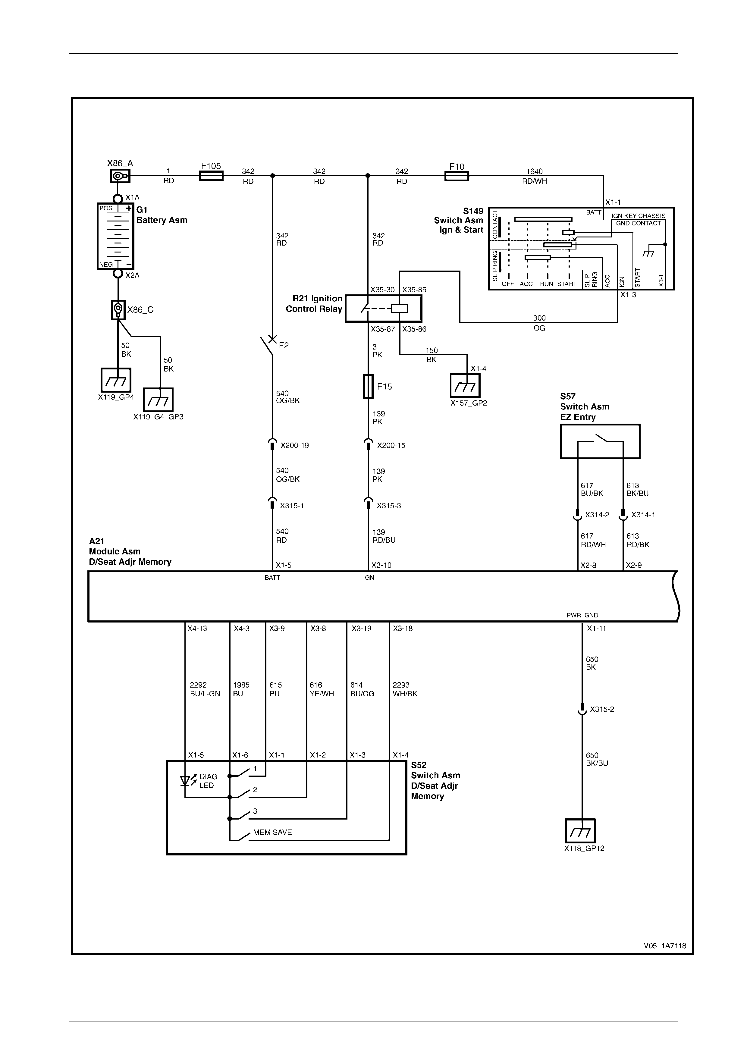
Seat Assemblies Page 1A7–148
Page 1A7–148
Wiring Diagram – Driver's Seat
Figure 1A7 – 25
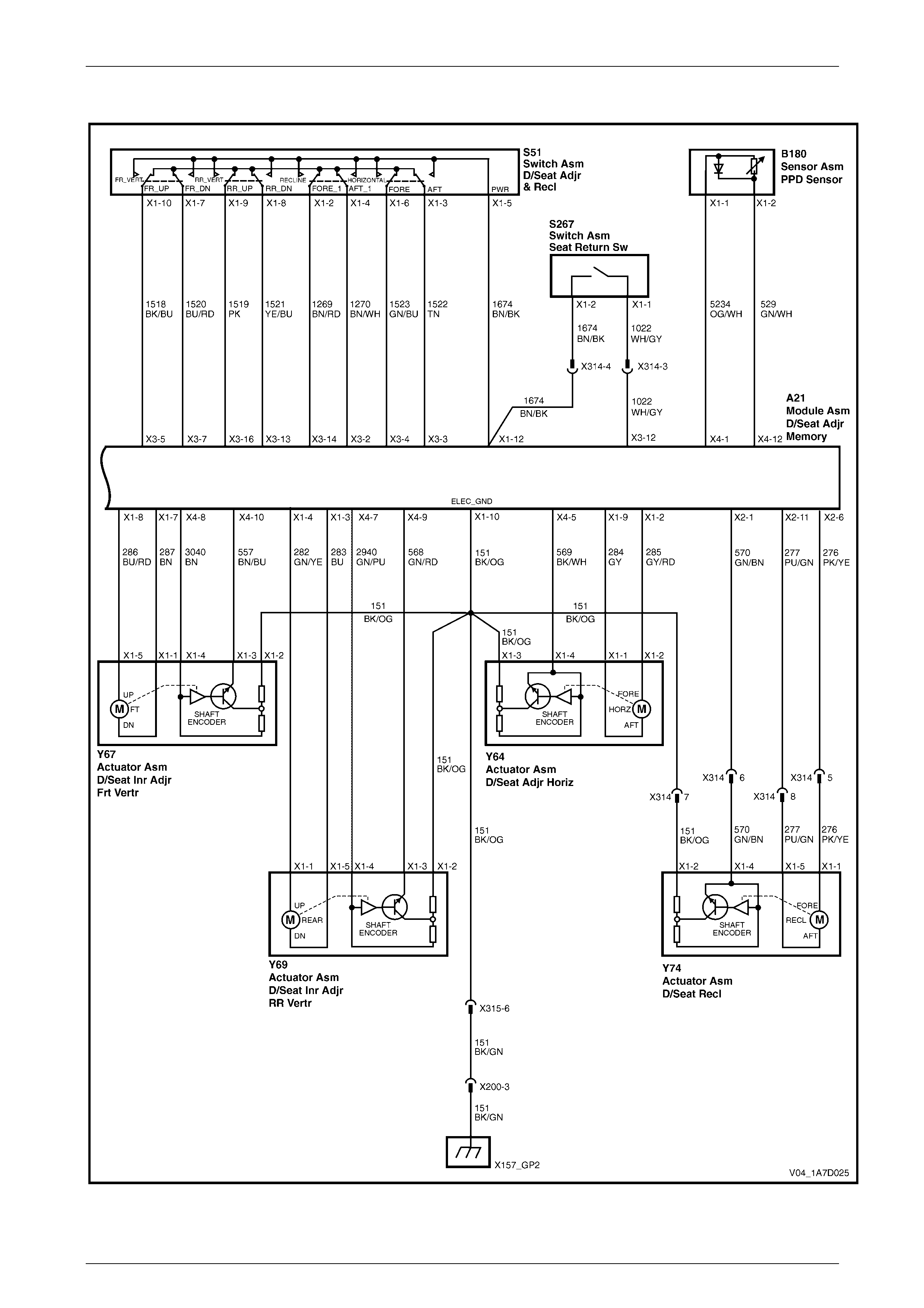
Seat Assemblies Page 1A7–149
Page 1A7–149
Figure 1A7 – 26
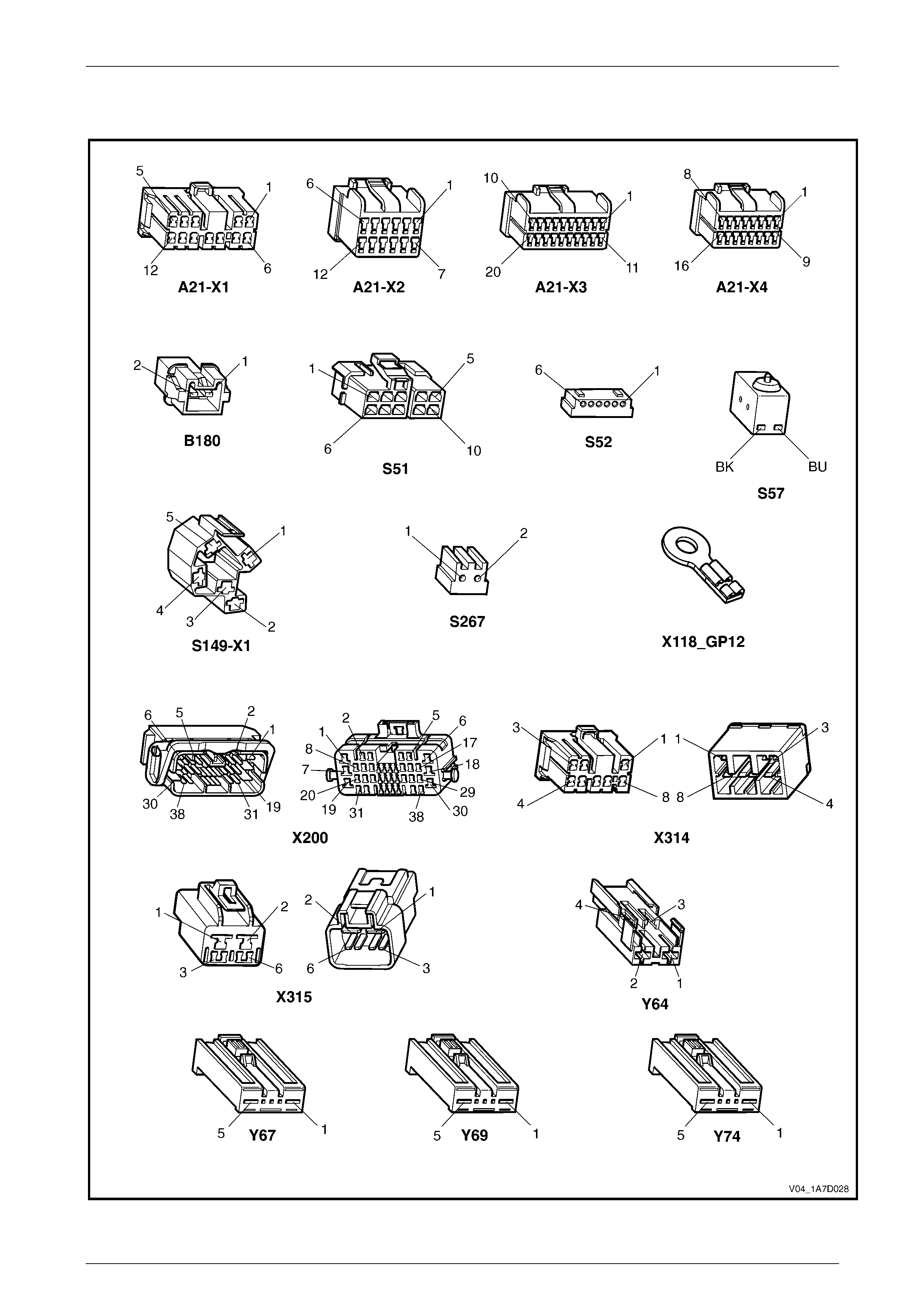
Seat Assemblies Page 1A7–150
Page 1A7–150
Connector Chart – Driver's Seat
Figure 1A7 – 27

Seat Assemblies Page 1A7–151
Page 1A7–151
None of the Driver’s Seat Adjustment Switch Functions Operate
Introduction
This test is used to aid in diagnosing the driver’s seat adjustment switch when none of the switch functions operate. The
test diagnoses the driver’s seat adjustment switch and associated power and ground circuits.
Circuit Description
The seat adjustment switch provides manual control for the driver's seat. It is connected by a harness to the seat
memory module and to the seat front and rear lift motors.
Refer to Wiring Diagram – Driver's Seat and Connector Chart – Driver's Seat to aid in d iagnosis.
Test Description
The following numbers refer to the step numbers in the diagnostic table:
1 Checks if all of the passenger seat functions work. If none of them work, the fault is not isolated to the driver’s seat
only.
2 Checks if there is battery power at connector X315 pin 1. Isolates if there is a fault in circuit 540.
3 Checks if all the connectors required for the seat to operate effectively are in place a nd positively connected.
4 Checks if there is battery power at connector A21 – X1 pi n 5.
5 Checks if there is battery power at connector A21 – X1 pi n 12. Isolates if there is a fault with the seat memory
module.
6 Checks if there is battery power at connector S51 – X1 pin 5. Isolates if there is a fault in circuit 1674.
7 Checks if the driver’s seat adjustment switch is serviceable.
8 Checks if there is continuity between connector X315 pin 2 and ground poi nt X118 – GP1 2. Isolates if there is a
fault in circuit 650.
9 Checks if there is continuity between connectors A21 – X1 pin 11 and X315 pin 2. Isolates if there is a fault in
circuit 650.
10 Checks if there is continuity between connector X200 pin 3 and ground point X157 – GP2. Isolates if there is a fault
in circuit 151.
11 Checks if there is continuity between connectors X315 pin 6 and X200 pin 3. Isolates if there is a fault in circuit 151.
12 Checks if there is continuity between connectors A21 – X1 pin 10 and X315 pin 6. Isolates if there is a fault in
circuit 151.
Diagnostic Table Notes
1 For all wiring harness fault diagnoses, refer to Section 12P Wiring Diagrams.
2 For wiring harness repairs, refer to Section 12P Wiring Diagrams.
3 Refer to Section 12O Fuses, Relays and W iring Harnesses for harness routeing.
4 If the fault is deemed to be intermittent, refer to Section 12P Wiring Diagrams.

Seat Assemblies Page 1A7–152
Page 1A7–152
Diagnostic Table
Step Action Yes No
1 Are all of the passenger’s seat adjustment switch functio ns
inoperative? Refer to Neither
Seat Adjustment
Switch Functions
Operate in 4.5
Electrical Diagnosis
– Eight-way Seat,
Memory Go to Step 2
2 Backprobe connector X315 pin 1 with a test lamp (refer to Note 1).
Does the test lamp illuminate?
Go to Step 3
Repair or replace
circuit 540 between
connectors X200
pin 19 and
X315 pin 1 (refer to
Note 2)
3 Are the following connectors secure (refer to Note 3)?
• A21
• S51
• X314
• X315
• Y64
• Y67
• Y69
• Y74 Go to Step 4
Ensure the
connectors are
secure
4 Backprobe connector A21 – X1 pin 5 with a test lamp (refer to
Note 1).
Does the test lamp illuminate?
Go to Step 5
Repair or replace
circuit 540 between
connectors
A21 – X1 pin 5 and
X315 pin 1 (refer to
Note 2)
5 Backprobe connector A21 – X1 pin 12 with a test lamp (refer to
Note 1).
Does the test lamp illuminate?
Go to Step 6
Replace the
driver’s seat
memory module,
refer to 7.13 Seat
Cable Tray and
Memory Module
6 Backprobe connector S51 – X1 pin 5 with a test lamp (refer to
Note 1).
Does the test lamp illuminate? Go to Step 7
Repair or replace
circuit 1674 (refer
to Note 2)
7 1 Remove the driver’s seat adjustment switch from the seat, refer
to 7.3 Front Seat Outer Side Cover Assembly.
2 Test the driver’s seat adjustment switch, refer to 2.7 Eight-way
Seat Adjustment Switch Test.
Is the driver’s seat adjustment switch serviceable? Go to Step 8
Replace the
driver’s seat
adjustment switch,
refer to 7.3 Front
Seat Outer Side
Cover Assembly

Seat Assemblies Page 1A7–153
Page 1A7–153
Step Action Yes No
8 1 Remove connector A21 – X1 from the seat memory module
(refer to Note 3).
Go to Step 9
Repair or replace
circuit 650 between
connector
X315 pin 2 and
ground point
X118 – GP12 (refer
to Note 2)
9 Using a multimeter set to measure resistance, probe between
connectors A21 – X1 pin 11 and X315 pin 2.
Does the multimeter indicate contin uity?
Go to Step 10
Repair or replace
circuit 650 between
connectors
A21 – X1 pin 11
and X315 pin 2
(refer to Note 2)
10 Using a multimeter set to measure resistance, probe between
connectors X200 pin 3 and X157 – X1 pin 1.
Does the multimeter indicate contin uity?
Go to Step 11
Repair or replace
circuit 151 between
connectors
X200 pin 3 and
X157 – X1 pin 1
(refer to Note 2)
11 Using a multimeter set to measure resistance, probe between
connectors X315 pin 6 and X200 pin 3.
Does the multimeter indicate contin uity?
Go to Step 12
Repair or replace
circuit 151 between
connectors
X315 pin 6 and
X200 pin 3 (refer to
Note 2)
12 Using a multimeter set to measure resistance, probe between
connectors A21 – X1 pin 10 and X315 pin 6.
Does the multimeter indicate contin uity?
Replace the driver's
seat memory
module, refer to
7.13 Seat Cable
Tray and Memory
Module
Repair or replace
circuit 151 between
connectors
A21 – X1 pin 10
and X315 pin 6
(refer to Note 2)
When all diagno sis an d repairs are completed, ch eck the system for correct op eration.

Seat Assemblies Page 1A7–154
Page 1A7–154
Front/Rear of the Driver’s Seat Does Not Raise and/or Lower
Introduction
This test is used to aid in diagnosing the front and/or the rear of the driver’s seat not raising and/or lowering. The test
diagnoses the seat adjustmen t switch and the motor circuits.
Circuit Description
The seat front lift and seat rear lift motors are controlled by the seat memory module, which provides power and ground
for the motors. The polarity of the motors are alternated to change the direction of the motors.
Refer to Wiring Diagram – Driver's Seat and Connector Chart – Driver's Seat to aid in d iagnosis.
Test Description
The following numbers refer to the step numbers in the diagnostic table:
1 Checks if the driver’s seat adjustment switch operates the seat in any direction. Isolates if the power and ground
circuits are at fault.
2 Checks if all the connectors required for the seat to operate effectively are in place a nd positively connected.
3 Checks if the driver’s seat adjustment switch is serviceable.
4 Confirms whether the rear of the seat raises or lowers. Isolates if the seat rear lift motor and circuit of the seat is the
fault.
5 Confirms whether the front of the seat raises or lo wers. Isolates if the seat front lift motor and circuit of the seat is
the fault.
6 Checks if there is battery power to the seat rear lift motor at connector Y69 – X1 pin 1. Isolates if there is a fault
between the switch and connector Y69 – X1 pin 1 .
7 Checks if there is continuity between connectors S51 – X1 pin 9 and A21 – X1 pin 4. Isolates whether there is a
fault between the switch and connector A21 – X1 pin 4 or in circuit 282.
8 Checks if there is continuity between connectors S51 – X1 pin 9 and A21 – X3 pin 16. Isolates whether there is a
fault between the switch and connector A21 – X3 pin 16 or the seat memory module is at fault.
9 Checks if there is battery power to the seat rear lift motor at connector Y69 – X1 pin 5. Isolates whether there is a
fault between the switch and connector Y69 – X1 pin 5 or the motor is at fault.
10 Checks if there is continuity between connectors S51 – X1 pin 8 and A21 – X1 pin 3. Isolates whether there is a
fault between the switch and connector A21 – X1 pin 3 or in circuit 283.
11 Checks if there is continuity between connectors S51 – X1 pin 8 and A21 – X3 pin 13. Isolates whether there is a
fault between the switch and connector A21 – X3 pin 13 or the seat memory module is at fault.
12 Checks if there is battery power to the seat front lift motor at connector Y67 – X1 pin 5. Isolates if there is a fault
between the switch and con nector Y67 – X1 pin 5.
13 Checks if there is continuity between connectors S51 – X1 pin 10 and A21 – X1 pin 8. Isolates whether there is a
fault between the switch and connector A21 – X1 pin 8 or in circuit 286.
14 Checks if there is continuity between connectors S51 – X1 pin 10 and A21 – X3 pin 5. Isolates whether there is a
fault between the switch and connector A21 – X3 pin 5 or the seat memor y module is at fault.
15 Checks if there is battery power to the seat front lift motor at connector Y67 – X1 pin 1. Isolates whether there is a
fault between the switch and connector Y67 – X1 pin 1 or the motor is at fault.
16 Checks if there is continuity between connectors S51 – X1 pin 7 and A21 – X1 pin 7. Isolates whether there is a
fault between the switch and connector A21 – X1 pin 7 or in circuit 287.
17 Checks if there is continuity between connectors S51 – X1 pin 7 and A21 – X3 pin 7. Isolates whether there is a
fault between the switch and connector A21 – X3 pin 7 or the seat memor y module is at fault.
Diagnostic Table Notes
1 For all wiring harness fault diagnoses, refer to Section 12P Wiring Diagrams.
2 For wiring harness repairs, refer to Section 12P Wiring Diagrams.
3 Refer to Section 12O Fuses, Relays and W iring Harnesses for harness routeing.
4 If the fault is deemed to be intermittent, refer to Section 12P Wiring Diagrams.

Seat Assemblies Page 1A7–155
Page 1A7–155
Diagnostic Table
Step Action Yes No
1 Does the driver’s seat adjustment switch operate the seat correctly in
any of the eight directions?
Go to Step 2
Refer to None of
the Driver’s Seat
Adjustment Switch
Functions Operate
in this Section
2 Are the following connectors secure (refer to Note 3)?
• A21
• S51
• Y67
• Y69 Go to Step 3
Ensure the
connectors are
secure
3 1 Remove the driver’s seat adjustment switch from the seat, refer
to 7.3 Front Seat Outer Side Cover Assembly.
2 Test the driver’s seat adjustment switch, refer to 2.7 Eight-way
Seat Adjustment Switch Test.
Is the driver’s seat adjustment switch serviceable? Go to Step 4
Replace the
driver’s seat
adjustment switch,
refer to 7.3 Front
Seat Outer Side
Cover Assembly
4 Operate the driver’s seat adju stment switch to raise or lower the rear
of the seat.
Does the rear of the seat raise and lower? Go to Step 5 Go to Step 6
5 Operate the driver’s seat adju stment switch to raise or lower the front
of the seat.
Does the front of the seat raise and lo wer? System serviceable Go to Step 12
6 1 Backprobe connector Y69 – X1 pin 1 with a test lamp (refer to
Note 1).
2 Operate the driver’s seat adjustment switch to raise the rear of
the seat.
Does the test lamp illuminate? Go to Step 9 Go to Step 7
7 1 Backprobe connector A21 – X1 pin 4 with a test lamp (refer to
Note 1).
2 Operate the driver’s seat adjustment switch to raise the rear of
the seat.
Does the test lamp illuminate?
Repair or replace
circuit 282 (refer to
Note 2) Go to Step 8
8 1 Backprobe connector A21 – X3 pin 16 with a test lamp (refer to
Note 1).
2 Operate the driver’s seat adjustment switch to raise the rear of
the seat.
Does the test lamp illuminate?
Replace the driver's
seat memory
module, refer to
7.13 Seat Cable
Tray and Memory
Module
Repair or replace
circuit 1519 (refer
to Note 2)
9 1 Backprobe connector Y69 – X1 pin 5 with a test lamp (refer to
Note 1).
2 Operate the driver’s seat adjustment switch to lower the rear of
the seat.
Does the test lamp illuminate?
Replace the seat
rear lift motor, refer
to 7.17 Front Seat
Lift Motor
Assemblies Go to Step 10
10 1 Backprobe connector A21 – X1 pin 3 with a test lamp (refer to
Note 1).
2 Operate the driver’s seat adjustment switch to lower the rear of
the seat.
Does the test lamp illuminate?
Repair or replace
circuit 283 (refer to
Note 2) Go to Step 11

Seat Assemblies Page 1A7–156
Page 1A7–156
Step Action Yes No
11 1 Backprobe connector A21 – X3 pin 13 with a test lamp (refer to
Note 1).
2 Operate the driver’s seat adjustment switch to lower the rear of
the seat.
Does the test lamp illuminate?
Replace the driver's
seat memory
module, refer to
7.13 Seat Cable
Tray and Memory
Module
Repair or replace
circuit 1521 (refer
to Note 2)
12 1 Backprobe connector Y67 – X1 pin 5 with a test lamp (refer to
Note 1).
2 Operate the driver’s seat adjustment switch to raise the front of
the seat.
Does the test lamp illuminate? Go to Step 15 Go to Step 13
13 1 Backprobe connector A21 – X1 pin 8 with a test lamp (refer to
Note 1).
2 Operate the driver’s seat adjustment switch to raise the front of
the seat.
Does the test lamp illuminate?
Repair or replace
circuit 286 (refer to
Note 2) Go to Step 14
14 1 Backprobe connector A21 – X3 pin 5 with a test lamp (refer to
Note 1).
2 Operate the driver’s seat adjustment switch to raise the front of
the seat.
Does the test lamp illuminate?
Replace the driver's
seat memory
module, refer to
7.13 Seat Cable
Tray and Memory
Module
Repair or replace
circuit 1518 (refer
to Note 2)
15 1 Backprobe connector Y67 – X1 pin 2 with a test lamp (refer to
Note 1).
2 Operate the driver’s seat adjustment switch to lower the front of
the seat.
Does the test lamp illuminate?
Replace the seat
front lift motor, refer
to 7.17 Front Seat
Lift Motor
Assemblies Go to Step 16
16 1 Backprobe connector A21 – X1 pin 7 with a test lamp (refer to
Note 1).
2 Operate the driver’s seat adjustment switch to lower the front of
the seat.
Does the test lamp illuminate?
Repair or replace
circuit 287 (refer to
Note 2) Go to Step 17
17 1 Backprobe connector A21 – X3 pin 7 with a test lamp (refer to
Note 1).
2 Operate the driver’s seat adjustment switch to lower the front of
the seat.
Does the test lamp illuminate?
Replace the driver's
seat memory
module, refer to
7.13 Seat Cable
Tray and Memory
Module
Repair or replace
circuit 1520 (refer
to Note 2)
When all diagno sis an d repairs are completed, ch eck the system for correct op eration.

Seat Assemblies Page 1A7–157
Page 1A7–157
Driver’s Seat Fore/Aft Movement Function is Inoperative or Not Smooth
Introduction
This test is used to aid in diagnosing the fore/aft movement function of the driver’s seat being inoperative or the action of
the seat through the range of movement is not smooth. The test diagnoses the seat adjustment switch and the motor
circuits.
Circuit Description
The seat fore/aft movement motor is controlled by the seat memory module which provides power and ground for the
motor. The polarity of the motor is alternated to change the direction of the motor.
Refer to Wiring Diagram – Driver's Seat and Connector Chart – Driver's Seat to aid in d iagnosis.
Test Description
The following numbers refer to the step numbers in the diagnostic table:
1 Checks if the driver’s seat adjustment switch operates the seat in any direct ion. Isolates if there is battery power to
the switch assembly.
2 Checks if there are any items obstructing the guide rails, which may stop or hinder the seat movement.
3 Checks if the guide rails and drive shafts have adequate lubricant applied t o provide a smooth operation of the
seat.
4 Checks if the guide rails or drive shafts have been damaged. An y binding between the moving parts will result in
poor operation of the fore and aft movement.
5 Checks if all the connectors required for the seat to operate effectively are in place a nd positively connected.
6 Checks if the driver’s seat adjustment switch is serviceable.
7 Checks if there is battery power to the seat fore/aft movement motor at connector Y64 – X1 pin 3. Isolates if there
is a fault between the switch and connector Y64 – X1 pin 3.
8 Checks if there is continuity between connectors S51 – X1 pin 6 and A21 – X1 pin 2. Isolates whether there is a
fault between the switch and connector A21 – X1 pin 2 or in circuit 285.
9 Checks if there is continuity between connectors S51 – X1 pin 6 and A21 – X3 pin 4. Isolates whether there is a
fault between the switch and connector A21 – X3 pin 4 or the seat memor y module is at fault.
10 Checks if there is battery power to the seat fore/aft movement motor at connector Y64 – X1 pin 1. Isolates whether
there is a fault between the switc h an d connector Y64 – X1 pin 1 or the motor is at fault.
11 Checks if there is continuity between connectors S51 – X1 pin 3 and A21 – X1 pin 9. Isolates whether there is a
fault between the switch and connector A21 – X1 pin 9 or in circuit 284.
12 Checks if there is continuity between connectors S51 – X1 pin 3 and A21 – X3 pin 3. Isolates whether there is a
fault between the switch and connector A21 – X3 pin 3 or the seat memor y module is at fault.
Diagnostic Table Notes
1 For all wiring harness fault diagnoses, refer to Section 12P Wiring Diagrams.
2 For wiring harness repairs, refer to Section 12P Wiring Diagrams.
3 Refer to Section 12O Fuses, Relays and W iring Harnesses for harness routeing.
4 If the fault is deemed to be intermittent, refer to Section 12P Wiring Diagrams.

Seat Assemblies Page 1A7–158
Page 1A7–158
Diagnostic Table
Step Action Yes No
1 Does the driver’s seat adjustment switch operate the seat correctly in
any of the eight directions?
Go to Step 2
Refer to None of
the Driver’s Seat
Adjustment Switch
Functions Operate
in this Section
2 Are the guide rails free from obstructions? Go to Step 3 Remove the
obstructing item
3 Are the guide rails and driv e shafts adequately lubricated?
Go to Step 4
Apply a small
amount of grease
type NLGI No. 1
Lithium Grease
(with 9% Zinc
Oxide)
4 Do the guide rails or drive shafts bind at any point of travel during the
fore and aft movement of the seat? Replace the track
and height adjust
assembly, refer to
7.14 Track and
Height Adjust
Assembly Go to Step 5
5 Are the following connectors secure (refer to Note 3)?
• A21
• S51
• Y64 Go to Step 6
Ensure the
connectors are
secure
6 1 Remove the driver’s seat adjustment switch from the seat, refer
to 7.3 Front Seat Outer Side Cover Assembly.
2 Test the driver’s seat adjustment switch, refer to 2.7 Eight-way
Seat Adjustment Switch Test.
Is the driver’s seat adjustment switch serviceable? Go to Step 7
Replace the
driver’s seat
adjustment switch,
refer to 7.3 Front
Seat Outer Side
Cover Assembly
7 1 Backprobe connector Y64 – X1 pin 2 with a test lamp (refer to
Note 1).
2 Operate the driver’s seat adjustment switch to move the seat
forward.
Does the test lamp illuminate? Go to Step 10 Go to Step 8
8 1 Backprobe connector A21 – X1 pin 2 with a test lamp (refer to
Note 1).
2 Operate the driver’s seat adjustment switch to move the seat
forward.
Does the test lamp illuminate?
Repair or replace
circuit 285 (refer to
Note 2) Go to Step 9

Seat Assemblies Page 1A7–159
Page 1A7–159
Step Action Yes No
9 1 Backprobe connector A21 – X3 pin 4 with a test lamp (refer to
Note 1). Replace the driver's
seat memory
module, refer to
7.13 Seat Cable
Tray and Memory
Module
Repair or replace
circuit 1523 (refer
to Note 2)
10 1 Backprobe connector Y64 – X1 pin 1 with a test lamp (refer to
Note 1).
2 Operate the driver’s seat adjustment switch to move the seat
aft.
Does the test lamp illuminate?
Replace the seat
fore/aft movement
motor, refer to 7.18
Front Seat Fore/Aft
Movement Motor
Assembly Go to Step 11
11. 1 Backprobe co nnector A21 – X1 pin 9 with a test lamp (refer to
Note 1).
2 Operate the driver’s seat adjustment switch to move the seat
aft.
Does the test lamp illuminate?
Repair or replace
circuit 284 (refer to
Note 2) Go to Step 12
12. 1 Backprobe co nnector A21 – X3 pin 3 with a test lamp (refer to
Note 1).
2 Operate the driver’s seat adjustment switch to move the seat
aft.
Does the test lamp illuminate?
Replace the driver's
seat memory
module, refer to
7.13 Seat Cable
Tray and Memory
Module
Repair or replace
circuit 1522 (refer
to Note 2)
When all diagno sis an d repairs are completed, ch eck the system for correct op eration.

Seat Assemblies Page 1A7–160
Page 1A7–160
Driver’s Seat Recline Forward and/or Aft Function is Inoperative
Introduction
This test is used to aid in diagnosing the recline function of the driver’s seat being inoperative. The test diagnoses the
seat adjustment switch and the motor circuits.
Circuit Description
The front seat-back recline motor is controlled by the seat memory module which provides power and ground for the
motor. The polarity of the motor is alternated to change the direction of the motor.
Refer to Wiring Diagram – Driver's Seat and Connector Chart – Driver's Seat to aid in d iagnosis.
Test Description
The following numbers refer to the step numbers in the diagnostic table:
1 Checks if the driver’s seat adjustment switch operates the seat in any direct ion. Isolates if there is battery power to
the switch assembly.
2 Checks if all the connectors required for the seat to operate effectively are in place a nd positively connected.
3 Checks if the driver’s seat adjustment switch is serviceable.
4 Checks if there is battery power to the seat recline motor at connector Y74 – X1 pin 1. Isolates if there is a fault
between the switch and con nector Y74 – X1 pin 1.
5 Checks if there is continuity between connectors S51 – X1 pin 2 and X314 pin 5. Isolates whether there is a fault
between the switch and conn ector X314 pin 5 or in circuit 276.
6 Checks if there is continuity between connectors S51 – X1 pin 2 and A21 – X2 pin 6. Isolates whether there is a
fault between the switch and connector A21 – X2 pin 6 or in circuit 276.
7 Checks if there is continuity between connectors S51 – X1 pin 2 and A21 – X3 pin 14. Isolates whether there is a
fault between the switch and connector A21 – X3 pin 14 or the seat memory module is at fault.
8 Checks if there is battery power to the seat recline motor at connector Y74 – X1 pin 5. Isolates whether there is a
fault between the switch and connector Y74 – X1 pin 5 or the motor is at fault.
9 Checks if there is continuity between connectors S51 – X1 pin 4 and X314 pin 8. Isolates whether there is a fault
between the switch and conn ector X314 pin 8 or in circuit 277.
10 Checks if there is continuity between connectors S51 – X1 pin 4 and A21 – X2 pin 11. Isolates whether there is a
fault between the switch and connector A21 – X2 pin 11 or in circuit 277.
11 Checks if there is continuity between connectors S51 – X1 pin 4 and A21 – X3 pin 2. Isolates whether there is a
fault between the switch and connector A21 – X3 pin 2 or the seat memor y module is at fault.
Diagnostic Table Notes
1 For all wiring harness fault diagnoses, refer to Section 12P Wiring Diagrams.
2 For wiring harness repairs, refer to Section 12P Wiring Diagrams.
3 Refer to Section 12O Fuses, Relays and W iring Harnesses for harness routeing.
4 If the fault is deemed to be intermittent, refer to Section 12P Wiring Diagrams.

Seat Assemblies Page 1A7–161
Page 1A7–161
Diagnostic Table
Step Action Yes No
1 Does the driver’s seat adjustment switch operate the seat correctly in
any of the eight directions?
Go to Step 2
Refer to None of
the Driver’s Seat
Adjustment Switch
Functions Operate
in this Section
2 Are the following connectors secure (refer to Note 3)?
• A21
• S51
• X314
• Y74 Go to Step 3
Ensure the
connectors are
secure
3 1 Remove the driver’s seat adjustment switch from the seat, refer
to 7.3 Front Seat Outer Side Cover Assembly.
2 Test the driver’s seat adjustment switch, refer to 2.7 Eight-way
Seat Adjustment Switch Test.
Is the driver’s seat adjustment switch serviceable? Go to Step 4
Replace the
driver’s seat
adjustment switch,
refer to 7.3 Front
Seat Outer Side
Cover Assembly
4 1 Backprobe connector Y74 – X1 pin 1 with a test lamp (refer to
Note 1).
2 Operate the driver’s seat adjustment switch to move the
seat-back forward.
Does the test lamp illuminate? Go to Step 8 Go to Step 5
5 1 Backprobe connector X314 pin 5 with a test lamp (refer to
Note 1).
2 Operate the driver’s seat adjustment switch to move the
seat-back forward.
Does the test lamp illuminate?
Repair or replace
circuit 276 between
connectors
X314 pin 5 and
Y74 – X1 pin 1
(refer to Note 2) Go to Step 6
6 1 Backprobe connector A21 – X2 pin 6 with a test lamp (refer to
Note 1).
2 Operate the driver’s seat adjustment switch to move the
seat-back forward.
Does the test lamp illuminate?
Repair or replace
circuit 276 between
connectors
A21 – X2 pin 6 and
X314 pin 5 (refer to
Note 2) Go to Step 7
7 1 Backprobe connector A21 – X3 pin 14 with a test lamp (refer to
Note 1).
2 Operate the driver’s seat adjustment switch to move the
seat-back forward.
Does the test lamp illuminate?
Replace the driver's
seat memory
module, refer to
7.13 Seat Cable
Tray and Memory
Module
Repair or replace
circuit 1269 (refer
to Note 2)

Seat Assemblies Page 1A7–162
Page 1A7–162
Step Action Yes No
8 1 Backprobe connector Y74 – X1 pin 5 with a test lamp (refer to
Note 1). Replace the front
seat-back recline
motor, refer to 7.19
Front Seat-back
Recline Motor
Assembly Go to Step 9
9 1 Backprobe connector X314 pin 8 with a test lamp (refer to
Note 1).
2 Operate the driver’s seat adjustment switch to move the
seat-back aft.
Does the test lamp illuminate?
Repair or replace
circuit 277 between
connectors
X314 pin 8 and
Y74 – X1 pin 5
(refer to Note 2) Go to Step 10
10 1 Backprobe connector A21 – X2 pin 11 with a test lamp (refer to
Note 1).
2 Operate the driver’s seat adjustment switch to move the
seat-back aft.
Does the test lamp illuminate?
Repair or replace
circuit 277 between
connectors
A21 – X2 pin 11
and X314 pin 8
(refer to Note 2) Go to Step 11
11 1 Backprobe connector A21 – X3 pin 2 with a test lamp (refer to
Note 1).
2 Operate the driver’s seat adjustment switch to move the
seat-back aft.
Does the test lamp illuminate?
Replace the seat
memory module,
refer to 7.13 Seat
Cable Tray and
Memory Module
Repair or replace
circuit 1270 (refer
to Note 2)
When all diagno sis an d repairs are completed, ch eck the system for correct op eration.

Seat Assemblies Page 1A7–163
Page 1A7–163
Driver's Seat EZ-entry Switch Function is Inoperative
Introduction
The EZ-entry function is designed so that when the seat-back is released with the EZ-entry lever, the seat will move to its
fully forward position using th e seat fore/aft movement motor. Once the seat has moved to its fully forward position,
power to the seat fore/aft movement motor will cease. A switch attached to the seat-back activates the seat fore/aft
movement motor when the recline of the seat-back is moved forward after being released using the EZ-entry lever. This
test is used to aid in diagnosing the EZ-entry function of the driver's seat being inoperative. T he test diagnoses the
EZ-entry switch and associated circuits.
Circuit Description
The EZ-entry switch is connected to the seat memory module by a harness. The EZ-entry switch is a normally open type
switch.
Refer to Wiring Diagram – Driver's Seat and Connector Chart – Driver's Seat to aid in d iagnosis.
Test Description
The following numbers refer to the step numbers in the diagnostic table:
1 Checks if the seat fore/aft movement motor is serviceable.
2 Checks if there is battery power to connector A21 – X2 pi n 9. Isolates if the driver's seat memory module is at fault.
3 Checks if there is continuity between connector A21 – X2 pins 9 and 8. Isolates if there is a fault with the EZ-entry
switch and associated circuits.
4 Checks if there is continuity between connectors A21 – X2 pin 9 and X314 pin 1. Isolates if there is a fault in circuit
613.
5 Checks if there is continuity between connectors A21 – X2 pin 9 and X314 pin 2. Isolates whether the EZ-entry
switch or circuit 617 is at fault.
Diagnostic Table Notes
1 For all wiring harness fault diagnoses, refer to Section 12P Wiring Diagrams.
2 For wiring harness repairs, refer to Section 12P Wiring Diagrams.
3 Refer to Section 12O Fuses, Relays and W iring Harnesses for harness routeing.
4 If the fault is deemed to be intermittent, refer to Section 12P Wiring Diagrams.

Seat Assemblies Page 1A7–164
Page 1A7–164
Diagnostic Table
Step Action Yes No
1 Does the seat move in the fore/aft direction when operated by the
driver's seat adjustment switch?
Go to Step 2
Refer to Driver’s
Seat Fore/Aft
Movement Function
is Inoperative or
Not Smooth in this
Section
2 Backprobe connector A21 – X2 pin 9 with a test lamp (refer to
Note 1).
Does the test lamp illuminate?
Go to Step 3
Replace the driver's
seat memory
module, refer to
7.13 Seat Cable
Tray and Memory
Module
3 1 Release the seat-back using the EZ-entry lever.
2 Backprobe connector A21 – X2 pin 8 with a test lamp (refer to
Note 1).
Does the test lamp illuminate?
Replace the seat
memory module,
refer to 7.13 Seat
Cable Tray and
Memory Module Go to Step 4
4 Backprobe connector X314 pin 1 with a test lamp (refer to Note 1).
Does the test lamp illuminate?
Go to Step 5
Repair or replace
circuit 613 between
connectors
A21 – X2 pin 9 and
X314 pin 1 (refer to
Note 2)
5 Backprobe connector X314 pin 2 with a test lamp (refer to Note 1).
Does the test lamp illuminate?
Repair or replace
circuit 617 between
connectors
A21 – X2 pin 8 and
X314 pin 2 (refer to
Note 2)
Replace the driver's
seat EZ-entry
switch, refer to 7.9
EZ-entry Switch
and Release Cable
Assembly
When all diagno sis an d repairs are completed, ch eck the system for correct op eration.

Seat Assemblies Page 1A7–165
Page 1A7–165
Driver's Seat Return Switch Function is Inoperative
Introduction
The seat return switch is located on the escu tcheon at the top of the seat-back. The switch function is to move the seat in
an aft direction after the EZ-entry function has been used and the recli ne of the seat has been placed upri ght. With the
seat return switch continuously press ed, the seat will move to its fully aft position, pausing for 2 secon ds at the seat
position where the EZ-entr y lever was operated. The test diagnoses the seat return switch and associated circuits.
Circuit Description
The driver’s seat return s witch is connected to the seat memory module by a harness. The driver’s seat return switch is a
normally open type switch.
Refer to Wiring Diagram – Driver's Seat and Connector Chart – Driver's Seat to aid in d iagnosis.
Test Description
The following numbers refer to the step numbers in the diagnostic table:
1 Checks if the seat fore/aft movement motor is serviceable.
2 Checks if the seat will move to its fully forward position when the seat-back is released using the EZ-entry lever.
Isolates if the EZ-entry switch function is serviceable.
3 Checks if the seat will move aft when the seat-back is in the upright position and the seat return switch is pressed.
Isolates if the seat return switch is serviceable.
4 Checks if the seat stops for 2 seconds at the position the EZ-entry lever was released.
5 Tests the hall-effect sensor and associated circuits. Isolates if the hall-effect sensor or the seat memory modul e is
faulty.
6 Checks if the seat return switch and circuit operates correctly. Isolates whether the seat return switch and circuit or
the seat memory module is faulty.
7 Checks if the seat return switch is serviceable.
8 Checks if there is battery power to connector X314 pin 4. Isolates if there is a fault in circuit 1674.
9 Checks if there is battery power to connector S267 – X1 pin 2. Isolates if there is a fault in circuit 1674 between
connector S267 – X1 pin 2 and X314 pin 4.
10 Checks if there is battery power to connector X314 pin 3 when the seat return switch is pressed. Isolates if there is
a fault in circuit 1022.
Diagnostic Table Notes
1 For all wiring harness fault diagnoses, refer to Section 12P Wiring Diagrams.
2 For wiring harness repairs, refer to Section 12P Wiring Diagrams.
3 Refer to Section 12O Fuses, Relays and W iring Harnesses for harness routeing.
4 If the fault is deemed to be intermittent, refer to Section 12P Wiring Diagrams.

Seat Assemblies Page 1A7–166
Page 1A7–166
Diagnostic Table
Step Action Yes No
1 Does the seat move in the fore/aft direction when operated by the
driver's seat adjustment switch?
Go to Step 2
Refer to Driver’s
Seat Fore/Aft
Movement Function
is Inoperative or
Not Smooth in this
Section
2 1 Move the seat forward from the rear most position and note its
position on the track.
2 Release the seat-back using the EZ-entry lever.
Does the seat move forward? Go to Step 3
Refer to Driver's
Seat EZ-entry
Switch Function is
Inoperative in this
Section.
3 1 Move the seat-back to the upright position.
2 Press and hold the seat return switch.
Does the seat move aft? Go to Step 4 Go to Step 6
4 Does the seat stop for 2 seconds at the position from where it was
unlatched and then continue to the most aft position of the track? System serviceable Go to Step 5
5 Test the seat fore/aft movement motor hall-effect sensor, refer to
Driver's Seat Fore/Aft Movement Motor Hall-effect Sensor Test in this
Section.
Is the hall-effect sensor and circuit serviceable? Replace the seat
memory module,
refer to 7.13 Seat
Cable Tray and
Memory Module
Repair or replace
the driver’s seat
fore/aft movement
motor hall-effect
sensor or circuit,
refer to 7.20 Drive
Motor Hall-effect
Sensors
6 1 Backprobe connector A21 – X3 pin 12 with a test lamp (refer to
Note 1).
2 Press the seat return switch.
Does the test lamp illuminate?
Replace the seat
memory module,
refer to 7.13 Seat
Cable Tray and
Memory Module Go to Step 7
7 1 Disconnect connector S267 – X1 from the seat return switch.
2 Using a multimeter set to measure resistance, probe across
seat return switch S267 pins 1 and 2:
3 With the seat return switch in the neutral position (not pressed)
the multimeter should indicate no continuity (open circuit).
4 With the seat return switch active (switch pressed) the
multimeter should indicate continuity (closed circuit).
Does the multimeter indicate as specified? Go to Step 8
Replace the driver's
seat return switch,
refer to 7.8
EZ-entry Release
Lever and
Escutcheon
8 1 Connect connector S267 – X1 to the seat return switch.
2 Backprobe connector X314 pin 4 with a test lamp (refer to
Note 1).
Does the test lamp illuminate?
Go to Step 9
Repair or replace
circuit 1674
between
connectors
X314 pin 4 and
A21 – X1 pin 12
(refer to Note 2)
9 Backprobe connector S267 – X1 pin 2 with a test lamp (refer to
Note 1)
Does the test lamp illuminate?
Go to Step 10
Repair or replace
circuit 1674
between
connectors
X314 pin 4 and
S267 – X1 pin 2
(refer to Note 2)
10 1 Backprobe connector X314 pin 3 with a test lamp (refer to
Note 1).
2 Press the seat return switch.
Does the test lamp illuminate?
Repair or replace
circuit 1022
between
connectors
X314 pin 3 and
A21 – X3 pin 12
(refer to Note 2)
Repair or replace
circuit 1022
between
connectors
X314 pin 3 and
S267 – X1 pin 1
(refer to Note 2)
When all diagno sis an d repairs are completed, ch eck the system for correct op eration.

Seat Assemblies Page 1A7–167
Page 1A7–167
Driver's Seat Fore/Aft Movement Motor Hall-effect Sensor Test
Introduction
This test is used to aid in diagnosing the seat fore/aft movement motor hall-effect sensor and associated circuits.
Circuit Description
The seat fore/aft movement motor hall-effect sensor provides a pulse sign al to the seat memory module. This signal
represents the horizontal position of the seat.
Refer to Wiring Diagram – Driver's Seat and Connector Chart – Driver's Seat to aid in diag nosis.
Test Description
The following numbers refer to the step numbers in the diagnostic table:
1 Checks the AC output from the hall-effect sensor during operation.
2 Checks if the ground circuit is serviceable.
3 Checks if there is continuity between connectors Y64 – X1 and A21 – X4. Isolates if the hall-effect sensor is faulty.
Diagnostic Table Notes
1 For all wiring harness fault diagnoses, refer to Section 12P Wiring Diagrams.
2 For wiring harness repairs, refer to Section 12P Wiring Diagrams.
3 Refer to Section 12O Fuses, Relays and W iring Harnesses for harness routeing.
4 If the fault is deemed to be intermittent, refer to Section 12P Wiring Diagrams.
5 The AC voltage displayed will depend on the battery voltage supplied to the seat. At 16 V DC supply, the AC
voltage produced by the hall-effect sensor will be approximately 6 V. At 9 V DC supply, the AC voltage produced by
the hall-effect sensor will be appro x imately 0.6 V.
Diagnostic Table
Step Action Yes No
1 1 Using a multimeter set to measure AC voltage, probe across
connector Y64 – X1 pins 3 and 4 (refer to No te 1).
2 Operate the seat adjustment switch to move the seat fore or aft.
Does the multimeter indicate 0.6 – 6 V (refer to Note 5)?
Hall-effect sensor
and associated
wiring serviceable Go to Step 2
2 Using a multimeter set to measure resistance, probe between
connector Y64 – X1 pin 3 and a known ground (refer to Note 1).
Does the multimeter indicate contin uity? Go to Step 3
Repair or replace
circuit 151 (refer to
Note 2)
3 1 Disconnect connector A21 – X4 from the driver’s seat memory
module.
2 Using a multimeter set to measure resistance, probe between
connectors A21 – X4 pin 5 and Y64 – X1 pin 4 (refer to Note 1).
Does the multimeter indicate contin uity?
Replace the
hall-effect sensor,
refer to 7.20 Drive
Motor Hall-effect
Sensors
Repair or replace
circuit 569 (refer to
Note 2)
When all diagno sis an d repairs are completed, ch eck the system for correct op eration.

Seat Assemblies Page 1A7–168
Page 1A7–168
Driver's Seat-back Recline Motor Hall-effect Sensor Test
Introduction
This test is used to aid in diagnosing the seat-back recline motor hall-effect sensor and associated circuits.
Circuit Description
The seat-back recline motor hall-effect sensor provides a pulse signal to the seat memory module. This signal represents
the recline position of the seat.
Refer to Wiring Diagram – Driver's Seat and Connector Chart – Driver's Seat to aid in d iagnosis.
Test Description
The following numbers refer to the step numbers in the diagnostic table:
1 Checks the AC output from the hall-effect sensor during operation.
2 Checks if the ground circuit is serviceable.
3-5 Checks if there is continuity between connectors Y74 – X1 and A21 – X2. Isolates if the hall-effect senso r is faulty.
Diagnostic Table Notes
1 For all wiring harness fault diagnoses, refer to Section 12P Wiring Diagrams.
2 For wiring harness repairs, refer to Section 12P Wiring Diagrams.
3 Refer to Section 12O Fuses, Relays and W iring Harnesses for harness routeing.
4 If the fault is deemed to be intermittent, refer to Section 12P Wiring Diagrams.
5 The AC voltage displayed will depend on the battery voltage supplied to the seat. At 16 V DC supply, the AC
voltage produced by the hall-effect sensor will be approximately 6 V. At 9 V DC supply, the AC voltage produced by
the hall-effect sensor will be appro x imately 0.6 V.
Diagnostic Table
Step Action Yes No
1 1 Using a multimeter set to measure AC voltage, probe across
connector Y74 – X1 pins 2 and 4 (refer to No te 1).
2 Operate the seat adjustment switch to move the seat-back fore
or aft.
Does the multimeter indicate 0.6 – 6 V (refer to Note 5)?
Hall-effect sensor
and associated
wiring serviceable Go to Step 2
2 Using a multimeter set to measure resistance, probe between
connector Y74 – X1 pin 2 and a known ground (refer to Note 1).
Does the multimeter indicate contin uity? Go to Step 4 Go to Step 3
3 Using a multimeter set to measure resistance, probe between
connector X314 pin 7 and a known ground (refer to Note 1).
Does the multimeter indicate contin uity?
Repair or replace
circuit 151 between
connectors
X314 pin 7 and
Y74 – X1 pin 2
(refer to Note 2)
Repair or replace
circuit 151 between
connector
X314 pin 7 and
ground point (refer
to Note 2)
4 Using a multimeter set to measure resistance, probe between
connectors A21 – X2 pin 1 and Y74 – X1 pin 4 (refer to Note 1).
Does the multimeter indicate contin uity?
Replace the
hall-effect sensor,
refer to 7.20 Drive
Motor Hall-effect
Sensors Go to Step 5
5 Using a multimeter set to measure resistance, probe between
connectors A21 – X2 pin 1 and X314 pin 6 (refer to Note 1).
Does the multimeter indicate contin uity?
Repair or replace
circuit 151 between
connectors
A21 – X2 pin 1 and
X314 pin 6 (refer to
Note 2)
Repair or replace
circuit 151 between
connectors
Y74 – X1 pin 4 and
X314 pin 6 (refer to
Note 2)
When all diagno sis an d repairs are completed, ch eck the system for correct op eration.

Seat Assemblies Page 1A7–169
Page 1A7–169
Driver's Seat Front Lift Motor Hall-effect Sensor Test
Introduction
This test is used to aid in diagnosing the seat front lift motor hall-effect sensor and associated circuits.
Circuit Description
The seat front lift motor hall-effect sensor provides a pulse signal to the seat memory module. This signal represents the
vertical position of the front of the seat.
Refer to Wiring Diagram – Driver's Seat and Connector Chart – Driver's Seat to aid in d iagnosis.
Test Description
The following numbers refer to the step numbers in the diagnostic table:
1 Checks the AC output from the hall-effect sensor during operation.
2 Checks if the ground circuit is serviceable.
3-4 Checks if there is continuity between connectors Y67 – X1 and A21 – X4. Isolates if the hall-effect senso r is faulty.
Diagnostic Table Notes
1 For all wiring harness fault diagnoses, refer to Section 12P Wiring Diagrams.
2 For wiring harness repairs, refer to Section 12P Wiring Diagrams.
3 Refer to Section 12O Fuses, Relays and W iring Harnesses for harness routeing.
4 If the fault is deemed to be intermittent, refer to Section 12P Wiring Diagrams.
5 The AC voltage displayed will depend on the battery voltage supplied to the seat. At 16 V DC supply, the AC
voltage produced by the hall-effect sensor will be approximately 15 V. At 9 V DC supply, the AC voltage produced
by the hall-effect sensor will be approximatel y 8 V.
Diagnostic Table
Step Action Yes No
1 1 Using a multimeter set to measure AC voltage, probe across
connector Y67 – X1 pins 2 and 4 (refer to No te 1).
2 Operate the seat adjustment switch to raise or lower the front of
the seat.
Does the multimeter indicate 8 – 15 V (refer to Note 5)?
Hall-effect sensor
and associated
wiring serviceable Go to Step 2
2 Using a multimeter set to measure resistance, probe between
connector Y67 – X1 pin 2 and a known ground (refer to Note 1).
Does the multimeter indicate continuity? Go to Step 3
Repair or replace
circuit 151 (refer to
Note 2)
3 1 Disconnect connector A21 – X4 from the seat memory module.
2 Using a multimeter set to measure resistance, probe between
connectors A21 – X4 pin 8 and Y67 – X1 pin 4 (refer to Note 1).
Does the multimeter indicate continuity? Go to Step 4
Repair or replace
circuit 3040 (refer
to Note 2)
4 Using a multimeter set to measure resistance, probe between
connectors A21 – X4 pin 10 and Y67 – X1 pin 3 (refer to Note 1).
Does the multimeter indicate contin uity?
Replace the
hall-effect sensor,
refer to 7.20 Drive
Motor Hall-effect
Sensors
Repair or replace
circuit 557 (refer to
Note 2)
When all diagno sis an d repairs are completed, ch eck the system for correct op eration.

Seat Assemblies Page 1A7–170
Page 1A7–170
Driver's Seat Rear Lift Motor Hall-effect Sensor Test
Introduction
This test is used to aid in diagnosing the seat rear lift motor hall-effect sensor and associated circu its.
Circuit Description
The seat rear lift motor hall-effect sensor provides a pulse signal to the seat memor y module. This signal represents the
vertical position of the rear of the seat.
Refer to Wiring Diagram – Driver's Seat and Connector Chart – Driver's Seat to aid in d iagnosis.
Test Description
The following numbers refer to the step numbers in the diagnostic table:
1 Checks the AC output from the hall-effect sensor during operation.
2 Checks if the ground circuit is serviceable.
3-4 Checks if there is continuity between connectors Y69 – X1 and A21 – X4. Isolates if the hall-effect senso r is faulty.
Diagnostic Table Notes
1 For all wiring harness fault diagnoses, refer to Section 12P Wiring Diagrams.
2 For wiring harness repairs, refer to Section 12P Wiring Diagrams.
3 Refer to Section 12O Fuses, Relays and W iring Harnesses for harness routeing.
4 If the fault is deemed to be intermittent, refer to Section 12P Wiring Diagrams.
5 The AC voltage displayed will depend on the battery voltage supplied to the seat. At 16 V DC supply, the AC
voltage produced by the hall-effect sensor will be approximately 15 V. At 9 V DC supply, the AC voltage produced
by the hall-effect sensor will be approximatel y 8 V.
Diagnostic Table
Step Action Yes No
1 1 Using a multimeter set to measure AC voltage, probe across
connector Y69 – X1 pins 2 and 4 (refer to No te 1).
2 Operate the seat adjustment switch to raise or lower the front of
the seat.
Does the multimeter indicate 8 – 15 V (refer to Note 5)?
Hall-effect sensor
and associated
wiring serviceable Go to Step 2
2 Using a multimeter set to measure resistance, probe between
connector Y69 – X1 pin 2 and a known ground (refer to Note 1).
Does the multimeter indicate continuity? Go to Step 3
Repair or replace
circuit 151 (refer to
Note 2)
3 1 Disconnect connector A21 – X4 from the seat memory module.
2 Using a multimeter set to measure resistance, probe between
connectors A21 – X4 pin 7 and Y69 – X1 pin 4 (refer to Note 1).
Does the multimeter indicate continuity? Go to Step 4
Repair or replace
circuit 2940 (refer
to Note 2)
4 Using a multimeter set to measure resistance, probe between
connectors A21 – X4 pin 9 and Y69 – X1 pin 3 (refer to Note 1).
Does the multimeter indicate contin uity?
Replace the
hall-effect sensor,
refer to 7.20 Drive
Motor Hall-effect
Sensors
Repair or replace
circuit 568 (refer to
Note 2)
When all diagno sis an d repairs are completed, ch eck the system for correct op eration.

Seat Assemblies Page 1A7–171
Page 1A7–171
Driver's Seat Passenger Presence Detection Switch Test
Introduction
This test is used to aid in diagnosing the passenger presence detection (PPD) switch and associated circuits.
Circuit Description
The PPD provides a signal to the seat memory module. T his signal represents the presence of a passenger on the seat.
Refer to Wiring Diagram – Driver's Seat and Connector Chart – Driver's Seat to aid in d iagnosis.
Test Description
The following numbers refer to the step numbers in the diagnostic table:
1 Checks diode forward resistance of the PPD.
2 Checks diode reverse resistance of the PPD.
3 Checks diode reverse resistance of the PPD with weight on seat.
4 Checks if there is continuity between connectors B180 – X1 pin 1 and A21 – X4 pin 1. Isolates if there is a fault in
circuit 5234.
5 Checks if there is continuity between connectors B180 – X1 pin 2 and A21 – X4 pin 12. Isolates if there is a fault in
circuit 529.
Diagnostic Table Notes
1 For all wiring harness fault diagnoses, refer to Section 12P Wiring Diagrams.
2 For wiring harness repairs, refer to Section 12P Wiring Diagrams.
3 Refer to Section 12O Fuses, Relays and W iring Harnesses for harness routeing.
4 If the fault is deemed to be intermittent, refer to Section 12P Wiring Diagrams.
Diagnostic Table
Step Action Yes No
1 1 Disconnect connector B180 – X1 from the PP D
2 Using a multimeter set to measure resistance, connect red (+)
probe to pin 1 and black (–) probe to pi n 2 of the PPD (refer to
Note 1).
Does the multimeter indicate continuity? Go to Step 2
Replace the PPD,
refer to 7.15 Front
Seat Cushion Pad
and Cover
Assembly
2 Using a multimeter set to measure resistance, connect red (+) probe
to pin 2 and black (–) probe to pin 1 of the PPD (refer to No te 1).
Does the multimeter indicate greater than 50 kΩ?
Go to Step 3
Replace the PPD,
refer to 7.15 Front
Seat Cushion Pad
and Cover
Assembly
3 1 Place a weight greater than 15 kg on the seat.
2 Using a multimeter set to measure resistance, connect red (+)
probe to pin 2 and black (–) probe to pi n 1 of the PPD (refer to
Note 1).
Does the multimeter indicate less than 50 kΩ? Go to Step 4
Replace the PPD,
refer to 7.15 Front
Seat Cushion Pad
and Cover
Assembly
4 1 Disconnect connector A21 – X4 from the driver’s seat memory
module.
2 Using a multimeter set to measure resistance, probe between
connectors B180 – X1 pin 1 a nd A21 – X4 pin 1 (refer to
Note 1).
Does the multimeter indicate continuity? Go to Step 5
Repair or replace
circuit 5234 (refer
to Note 2)
5 Using a multimeter set to measure resistance, probe between
connectors B180 – X1 pin 2 a nd A21 – X4 pin 12 (refer to Note 1).
Does the multimeter indicate contin uity?
PPD and
associated wiring
serviceable
Repair or replace
circuit 529 (refer to
Note 2)
When all diagno sis an d repairs are completed, ch eck the system for correct op eration.

Seat Assemblies Page 1A7–172
Page 1A7–172
Driver's Seat Memory Position Switch Test
Introduction
This test is used to aid in diagnosing the seat memory position switch.
Circuit Description
The switch is located on the outer side of the seat, attached to the inner side of the front seat outer side cover. The
memory position switch is connected to the seat memor y module by a harness.
Refer to Wiring Diagram – Driver's Seat and Connector Chart – Driver's Seat to aid in d iagnosis.
Test Description
The following numbers refer to the step numbers in the diagnostic table:
1 Checks if the driver’s seat memory position switch is serviceable.
2 Checks if there is continuity between connectors S52 – X1 pin 5 and A21 – X4 pin 13. Isolates if there is a fault in
circuit 2292.
3 Checks if there is continuity between connectors S52 – X1 pin 6 and A21 – X4 pin 3. Isolates if there is a fault in
circuit 1985.
4 Checks if there is continuity between connectors S52 – X1 pin 1 and A21 – X3 pin 9. Isolates if there is a fault in
circuit 615.
5 Checks if there is continuity between connectors S52 – X1 pin 2 and A21 – X3 pin 8. Isolates if there is a fault in
circuit 616.
6 Checks if there is continuity between connectors S52 – X1 pin 3 and A21 – X3 pin 19. Isolates if there is a fault in
circuit 614.
7 Checks if there is continuity between connectors S52 – X1 pin 4 and A21 – X3 pin 18. Isolates if there is a fault in
circuit 2293.
Diagnostic Table Notes
1 For all wiring harness fault diagnoses, refer to Section 12P Wiring Diagrams.
2 For wiring harness repairs, refer to Section 12P Wiring Diagrams.
3 Refer to Section 12O Fuses, Relays and W iring Harnesses for harness routeing.
4 If the fault is deemed to be intermittent, refer to Section 12P Wiring Diagrams.

Seat Assemblies Page 1A7–173
Page 1A7–173
Diagnostic Table
Step Action Yes No
1 1 Remove the driver’s seat memory position switch from the seat,
refer to 7.3 Front Seat Outer Side Cover Assembly.
2 Test the driver’s seat memory positio n switch, refer to 3.9
Memory Position Switch Test.
Is the driver’s memory position switch serviceable? Go to Step 2
Replace the
driver’s memory
position switch,
refer to 7.3 Front
Seat Outer Side
Cover Assembly
2 Using a multimeter set to measure resistance, probe between
connectors S52 – X1 pin 5 and A21 – X4 pin 13 (refer to Note 1).
Does the multimeter indicate continuity? Go to Step 3
Repair or replace
circuit 2292 (refer
to Note 2)
3 Using a multimeter set to measure resistance, probe between
connectors S52 – X1 pin 6 and A21 – X4 pin 3 (refer to Note 1).
Does the multimeter indicate contin uity? Go to Step 4
Repair or replace
circuit 1985 (refer
to Note 2)
4 Using a multimeter set to measure resistance, probe between
connectors S52 – X1 pin 1 and A21 – X3 pin 9 (refer to Note 1).
Does the multimeter indicate contin uity? Go to Step 5
Repair or replace
circuit 615 (refer to
Note 2)
5 Using a multimeter set to measure resistance, probe between
connectors S52 – X1 pin 2 and A21 – X3 pin 8 (refer to Note 1).
Does the multimeter indicate contin uity? Go to Step 6
Repair or replace
circuit 616 (refer to
Note 2)
6 Using a multimeter set to measure resistance, probe between
connectors S52 – X1 pin 3 and A21 – X3 pin 19 (refer to Note 1).
Does the multimeter indicate contin uity? Go to Step 7
Repair or replace
circuit 614 (refer to
Note 2)
7 Using a multimeter set to measure resistance, probe between
connectors S52 – X1 pin 4 and A21 – X3 pin 18 (refer to Note 1).
Does the multimeter indicate contin uity?
Memory position
switch and
associated wiring
serviceable
Repair or replace
circuit 2293 (refer
to Note 2)
When all diagno sis an d repairs are completed, ch eck the system for correct op eration.

Seat Assemblies Page 1A7–174
Page 1A7–174
5 Service Operations – Front Seat,
Except Regular Cab, Utility and
Coupe
5.1 Usage Chart
How to Use this Chart
The following usage chart is provided to help determine the seat type fitted to the vehicle. T his is important prior to
repairs being performed as the failed/damaged part may no t be serviced.
To determine the seat type fitted to the vehicle, obtain the vehicl e model, which seat requires attention and the seat
cover fabric. Establish other features of the seat such as th e electric movement functions. Using the chart will lead to the
elimination of all other seat combinations, al lowing for the identification of the type and the constructio n of the seat. Refer
to the Figure number shown in Front Seat Type column for a component break down of the front seat assembly.
1 Vehicle – Vehicle model identification.
2 Seating – Driver front seat or passenger front seat.
3 Fabric – Cloth or leather seat covers.
4 Movement – Indicates the number of movement functions of the seat:
• Two-way – Seat cushion mechanical fore/aft movement.
• Four-way – As two-way plus seat cushion electric front and rear raise/lower.
• Eight-way – As four-way plus seat cushion electric fore/aft moveme nt and electric seat-back recline.
5 Memory – Indicates if a seat memory module is fitted.
6 SIAB – Indicates if the seat is fitted with a side impact airbag assembly.
7 Construction – Surebond refers to the seat cover being glued to the seat pad. This type is serviced as a pad and
cover assembly only. Hook and Loop refers to the seat cover being attached to the seat pad with a Velcro type
material and both being serviced as separate parts.
8 Active Head Restraint – Indicates whether standard height adjustable or active head restraints are fitted.
9 Front Seat Type – Identifies the seat type and provides reference to illustrations which show a breakdown of the
serviced component for each front seat assembly.

Seat Assemblies Page 1A7–175
Page 1A7–175
Vehicle Seating Fabric Movement Memory SIAB Construction Active Head
Restraint Front Seat Type
(refer to)
Driver Cloth Four-way No Opt Surebond No 1
(Figure 1A7 – 28)
Executive,
Crew Cab
Passenger Cloth Two-way No Opt Surebond No 2
(Figure 1A7 – 29)
Driver Cloth Four-way No Yes Surebond Yes 3
(Figure 1A7 – 30)
Acclaim
Passenger Cloth Two-way No Yes Surebond Yes 4
(Figure 1A7 – 31)
Driver Cloth/
Leather Four-way No Opt Hook & Loop No 5
(Figure 1A7 – 32)
SV6,
SV8,
S Crew Cab Passenger Cloth/
Leather Two-way No Opt Hook & Loop No 6
(Figure 1A7 – 33)
Driver Cloth/
Leather Four-way No Yes Hook & Loop No 7
(Figure 1A7 – 34)
SS,
SS Crew
Cab,
AWD Crew
Cab Passenger Cloth/
Leather Two-way No Yes Hook & Loop No 8
(Figure 1A7 – 35)
Driver Cloth/
Leather Four-way No Yes Hook & Loop No 9
(Figure 1A7 – 36)
Berlina,
CX6 & SX6
AWD
Wagon Passenger Cloth/
Leather Two-way No Yes Hook & Loop No 10
(Figure 1A7 – 37)
Driver Cloth/
Leather Eight- way Yes Yes Hook & Loop Yes 11
(Figure 1A7 – 38)
Calais,
LX6 & LX8
AWD
Wagon Passenger Cloth/
Leather Eight- way No Yes Hook & Loop Yes 12
(Figure 1A7 – 39)
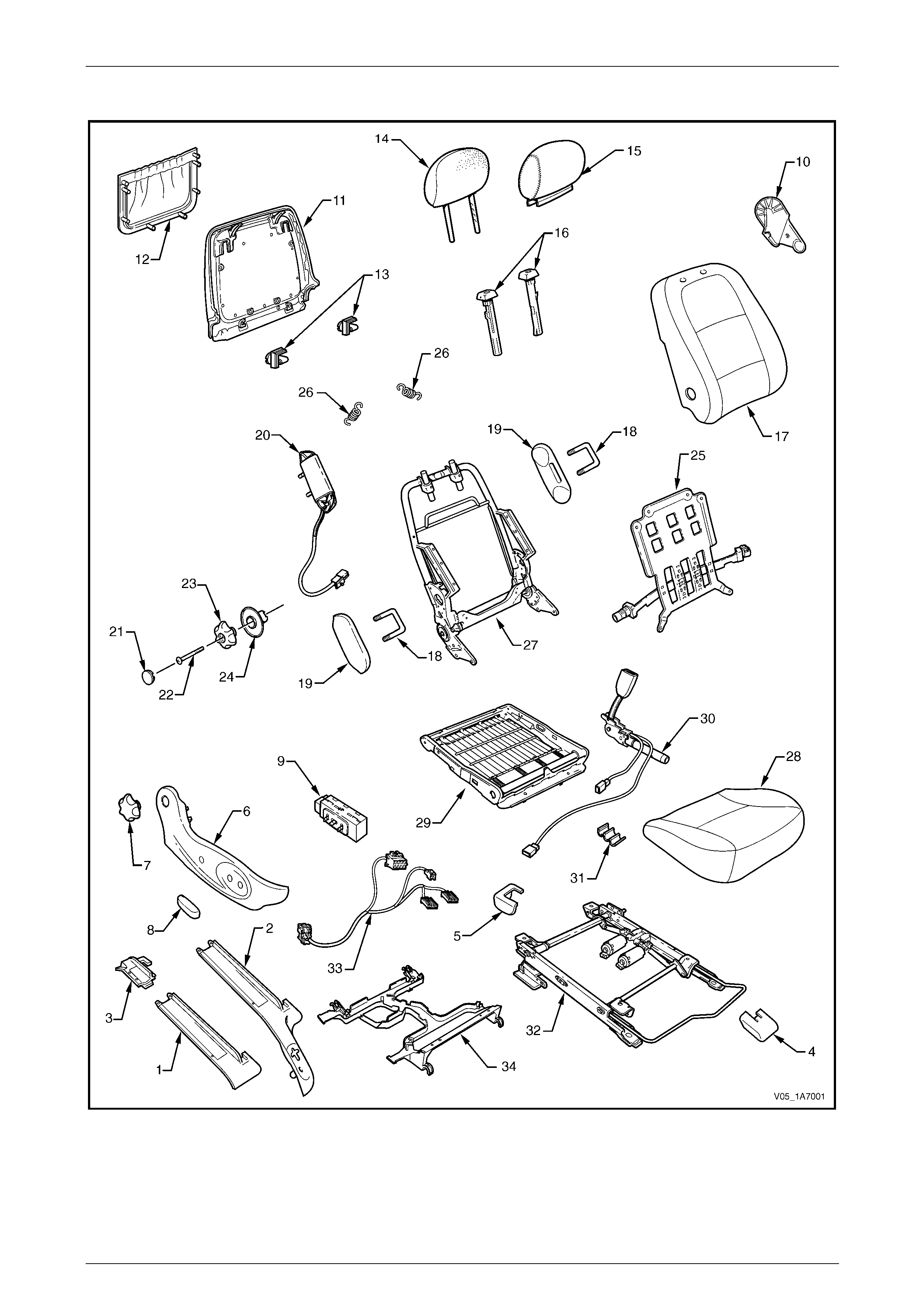
Seat Assemblies Page 1A7–176
Page 1A7–176
Front Seat Type 1
Figure 1A7 – 28

Seat Assemblies Page 1A7–177
Page 1A7–177
Legend
1 Front Seat Outer Front Cover (Crew Cab Only)
2 Front Seat Outer Front Cover
3 Front Seat Outer Rear Cover
4 Front Seat Inner Front Cover
5 Front Seat Inner Rear Cover
6 Front Seat Outer Side Cover
7 Recline Adjuster Knob
8 Front Seat Adjustment Switch Knob
9 Front Seat Adjustment Switch
10 Front Seat Inner Side Cover
11 Front Seat-back Rear Cover
12 Front Seat-back Map Pocket
13 Front Seat-back Cover Retaining Clips
14 Front Seat Head Restraint Pad Assembly
15 Front Seat Head Restraint Cover
16 Front Seat Head Restraint Sleeves
17 Front Seat-back Pad and Cover Assembly
18 Front Seat Dummy Block U-bolt*
19 Front Seat Dummy Block Insert*
20 Side Impact Airbag Assembly*
21 Lumbar Support Knob Cover
22 Lumbar Support Knob Screw
23 Lumbar Support Knob
24 Lumbar Support Deflector Ring
25 Lumbar Support Assembly
26 Lumbar Support Retaining Spring
27 Front Seat-back Frame Assembly
28 Front Seat Cushion Pad and Cover Assembly
29 Front Seat Cushion Frame Assembly
30 Seatbelt Buckle & Pretensioner Assembly
31 Wiring Harness Retaining Clip
32 Track and Height Adjust Assembly
33 Wiring Harness Assembly
34 Front Seat Cable Tray
* Side impact airbag assembly is optional. Front seat dummy block assembly fitted to outer side when side impact airbag
assembly not fitted.
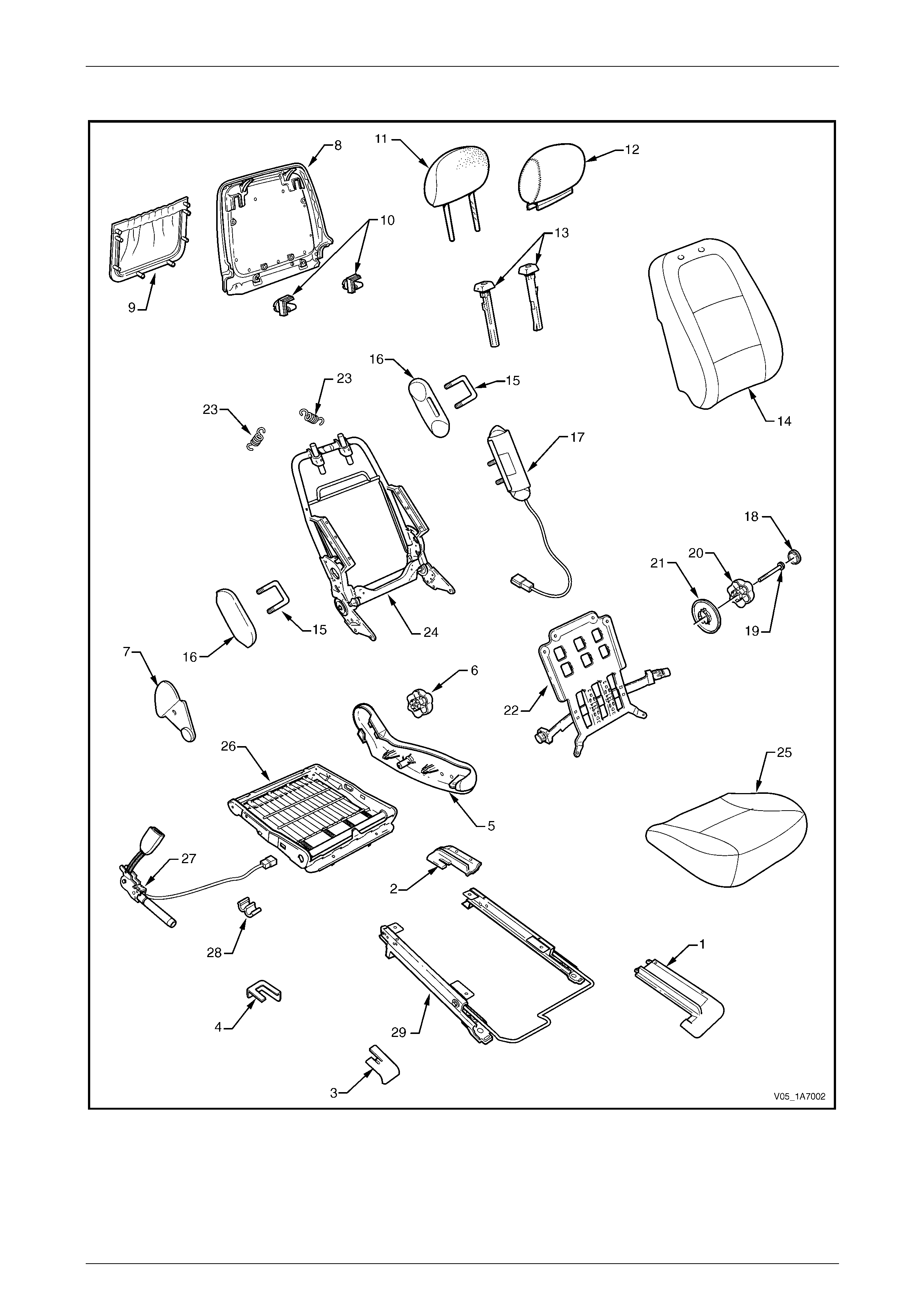
Seat Assemblies Page 1A7–178
Page 1A7–178
Front Seat Type 2
Figure 1A7 – 29

Seat Assemblies Page 1A7–179
Page 1A7–179
Legend
1 Front Seat Outer Front Cover
2 Front Seat Outer Rear Cover
3 Front Seat Inner Front Cover
4 Front Seat Inner Rear Cover
5 Front Seat Outer Side Cover
6 Recline Adjuster Knob
7 Front Seat Inner Side Cover
8 Front Seat-back Rear Cover
9 Front Seat-back Map Pocket
10 Front Seat-back Cover Retaining Clips
11 Front Seat Head Restraint Pad Assembly
12 Front Seat Head Restraint Cover
13 Front Seat Head Restraint Sleeves
14 Front Seat-back Pad and Cover Assembly
15 Front Seat Dummy Block U-bolt*
16 Front Seat Dummy Block Insert*
17 Side Impact Airbag Assembly*
18 Lumbar Support Knob Cover
19 Lumbar Support Knob Screw
20 Lumbar Support Knob
21 Lumbar Support Deflector Ring
22 Lumbar Support Assembly
23 Lumbar Support Retaining Spring
24 Front Seat-back Frame Assembly
25 Front Seat Cushion Pad and Cover Assembly
26 Front Seat Cushion Frame Assembly
27 Seatbelt Buckle & Pretensioner Assembly
28 Wiring Harness Retaining Clip
29 Track and Height Adjust Assembly
* Side impact airbag assembly is optional. Front seat dummy block assembly fitted to outer side when side impact airbag
assembly not fitted.
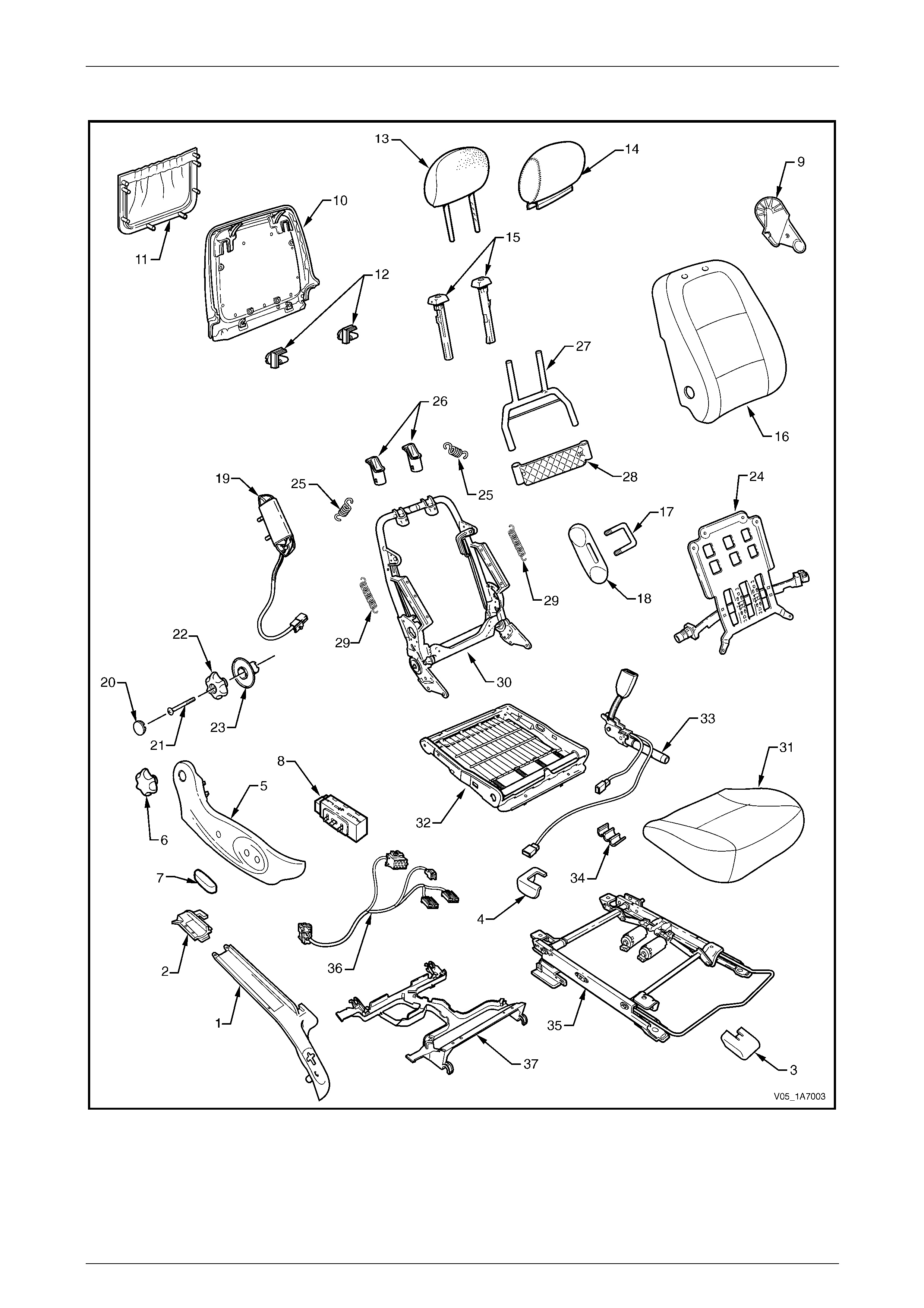
Seat Assemblies Page 1A7–180
Page 1A7–180
Front Seat Type 3
Figure 1A7 – 30

Seat Assemblies Page 1A7–181
Page 1A7–181
Legend
1 Front Seat Outer Front Cover
2 Front Seat Outer Rear Cover
3 Front Seat Inner Front Cover
4 Front Seat Inner Rear Cover
5 Front Seat Outer Side Cover
6 Recline Adjuster Knob
7 Front Seat Adjustment Switch Knob
8 Front Seat Adjustment Switch
9 Front Seat Inner Side Cover
10 Front Seat-back Rear Cover
11 Front Seat-back Map Pocket
12 Front Seat-back Cover Retaining Clips
13 Front Seat Head Restraint Pad Assembly
14 Front Seat Head Restraint Cover
15 Front Seat Head Restraint Sleeves
16 Front Seat-back Pad and Cover Assembly
17 Front Seat Dummy Block U-bolt
18 Front Seat Dummy Block Insert
19 Side Impact Airbag Assembly
20 Lumbar Support Knob Cover
21 Lumbar Support Knob Screw
22 Lumbar Support Knob
23 Lumbar Support Deflector Ring
24 Lumbar Support Assembly
25 Lumbar Support Retaining Spring
26 Active Head Restraint Frame Sleeves
27 Active Head Restraint Frame Assembly
28 Active Head Restraint Frame Support Strap
29 Active Head Restraint Frame Retaining Spring
30 Front Seat-back Frame Assembly
31 Front Seat Cushion Pad and Cover Assembly
32 Front Seat Cushion Frame Assembly
33 Seatbelt Buckle & Pretensioner Assembly
34 Wiring Harness Retaining Clip
35 Track and Height Adjust Assembly
36 Wiring Harness Assembly
37 Front Seat Cable Tray
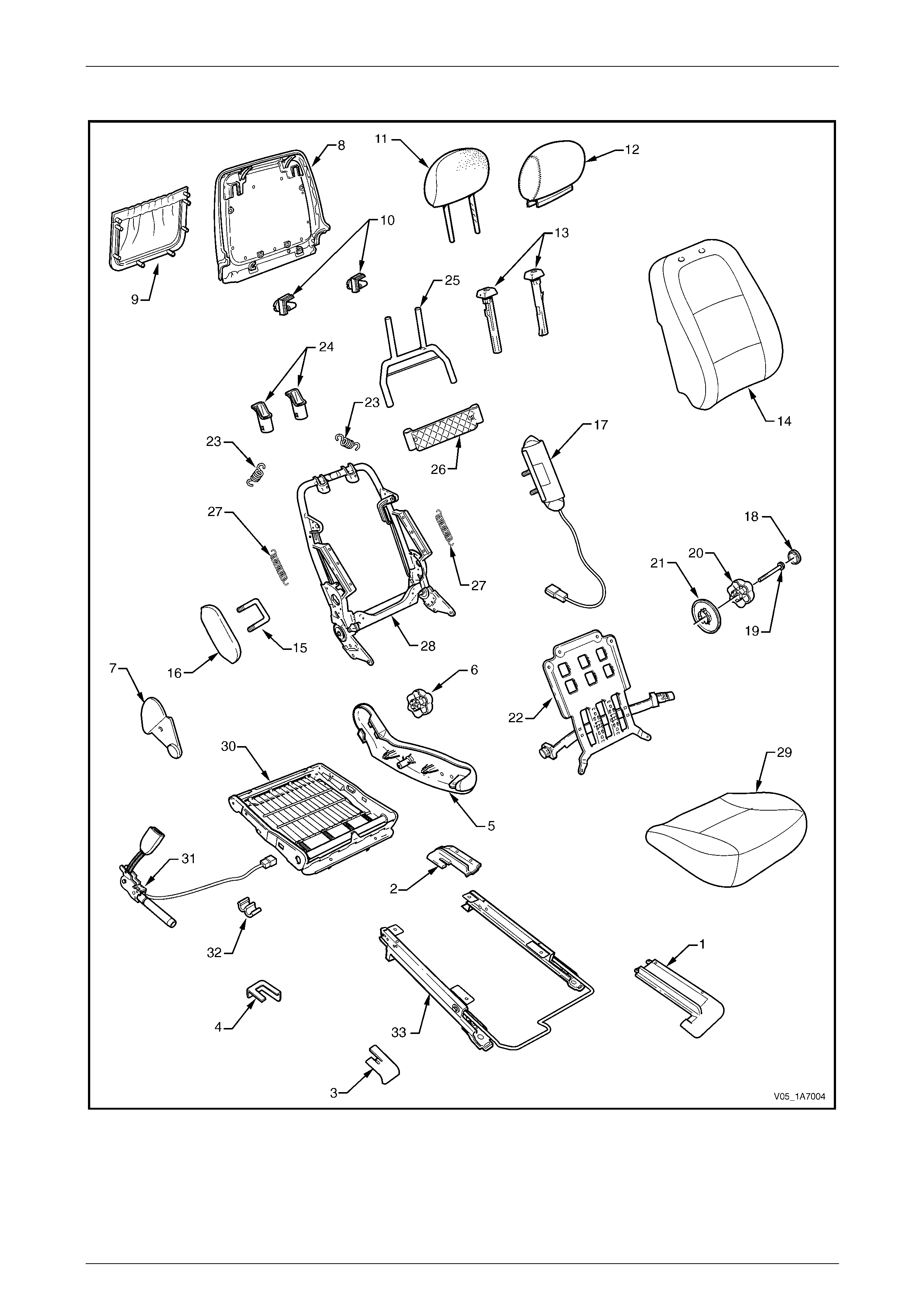
Seat Assemblies Page 1A7–182
Page 1A7–182
Front Seat Type 4
Figure 1A7 – 31

Seat Assemblies Page 1A7–183
Page 1A7–183
Legend
1 Front Seat Outer Front Cover
2 Front Seat Outer Rear Cover
3 Front Seat Inner Front Cover
4 Front Seat Inner Rear Cover
5 Front Seat Outer Side Cover
6 Recline Adjuster Knob
7 Front Seat Inner Side Cover
8 Front Seat-back Rear Cover
9 Front Seat-back Map Pocket
10 Front Seat-back Cover Retaining Clips
11 Front Seat Head Restraint Pad Assembly
12 Front Seat Head Restraint Cover
13 Front Seat Head Restraint Sleeves
14 Front Seat-back Pad and Cover Assembly
15 Front Seat Dummy Block U-bolt
16 Front Seat Dummy Block Insert
17 Side Impact Airbag Assembly
18 Lumbar Support Knob Cover
19 Lumbar Support Knob Screw
20 Lumbar Support Knob
21 Lumbar Support Deflector Ring
22 Lumbar Support Assembly
23 Lumbar Support Retaining Spring
24 Active Head Restraint Frame Sleeves
25 Active Head Restraint Frame Assembly
26 Active Head Restraint Frame Support Strap
27 Active Head Restraint Frame Retaining Spring
28 Front Seat-back Frame Assembly
29 Front Seat Cushion Pad and Cover Assembly
30 Front Seat Cushion Frame Assembly
31 Seatbelt Buckle & Pretensioner Assembly
32 Wiring Harness Retaining Clip
33 Track and Height Adjust Assembly
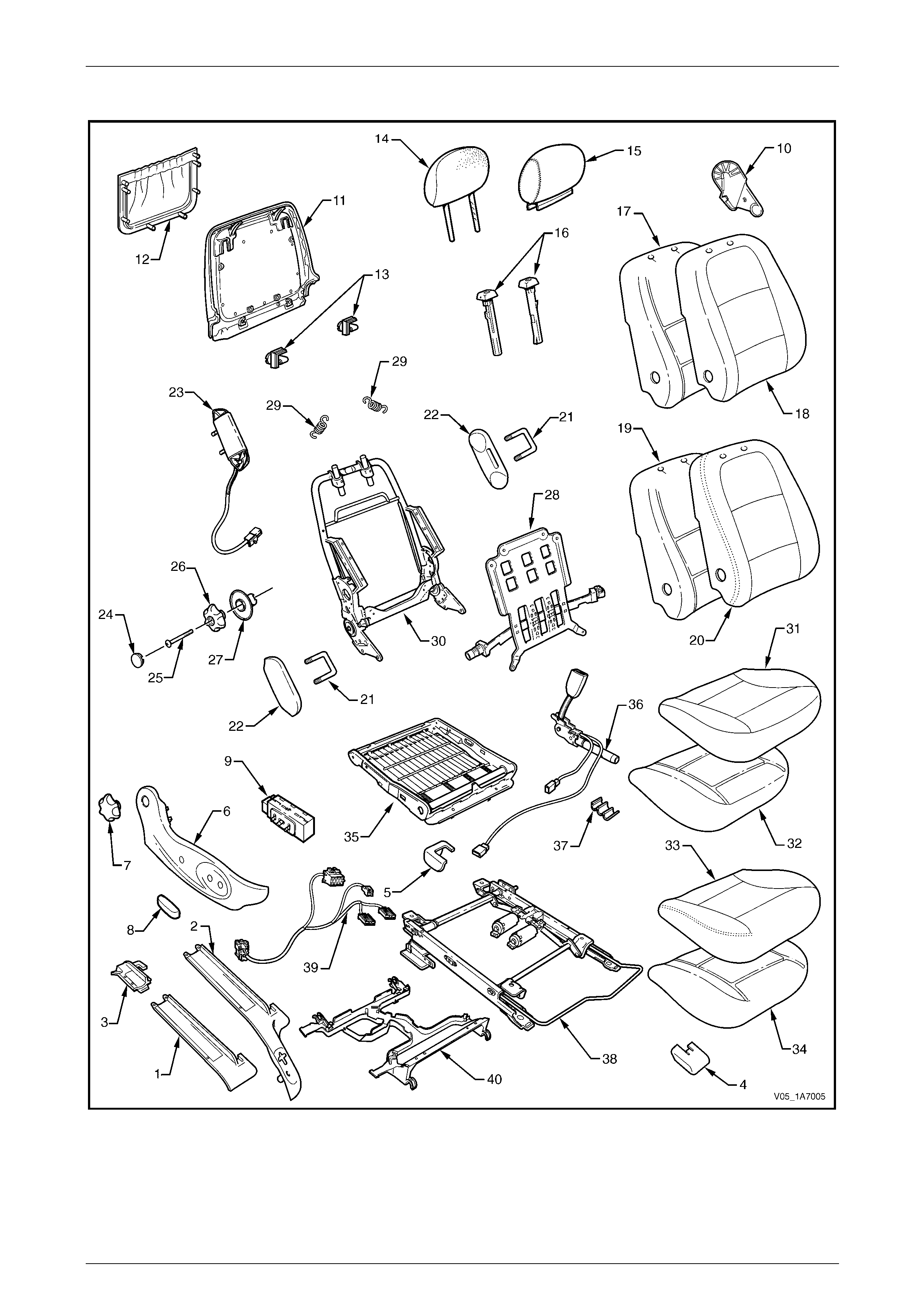
Seat Assemblies Page 1A7–184
Page 1A7–184
Front Seat Type 5
Figure 1A7 – 32

Seat Assemblies Page 1A7–185
Page 1A7–185
Legend
1 Front Seat Outer Front Cover (Crew Cab Only)
2 Front Seat Outer Front Cover
3 Front Seat Outer Rear Cover
4 Front Seat Inner Front Cover
5 Front Seat Inner Rear Cover
6 Front Seat Outer Side Cover
7 Recline Adjuster Knob
8 Front Seat Adjustment Switch Knob
9 Front Seat Adjustment Switch
10 Front Seat Inner Side Cover
11 Front Seat-back Rear Cover
12 Front Seat-back Map Pocket
13 Front Seat-back Cover Retaining Clips
14 Front Seat Head Restraint Pad Assembly
15 Front Seat Head Restraint Cover
16 Front Seat Head Restraint Sleeves
17 Front Seat-back Pad – Cloth Cover
18 Front Seat-back Cloth Cover
19 Front Seat-back Pad – Leather Cover
20 Front Seat-back Leather Cover
21 Front Seat Dummy Block U-bolt*
22 Front Seat Dummy Block Insert*
23 Side Impact Airbag Assembly*
24 Lumbar Support Knob Cover
25 Lumbar Support Knob Screw
26 Lumbar Support Knob
27 Lumbar Support Deflector Ring
28 Lumbar Support Assembly
29 Lumbar Support Retaining Spring
30 Front Seat-back Frame Assembly
31 Front Seat Cushion Cloth Cover
32 Front Seat Cushion Pad – Cloth Cover
33 Front Seat Cushion Leather Cover
34 Front Seat Cushion Pad – Leather Cover
35 Front Seat Cushion Frame Assembly
36 Seatbelt Buckle & Pretensioner Assembly
37 Wiring Harness Retaining Clip
38 Track and Height Adjust Assembly
39 Wiring Harness Assembly
40 Front Seat Cable Tray
* Side impact airbag assembly is optional. Front seat dummy block assembly fitted to outer side when side impact airbag
assembly not fitted.
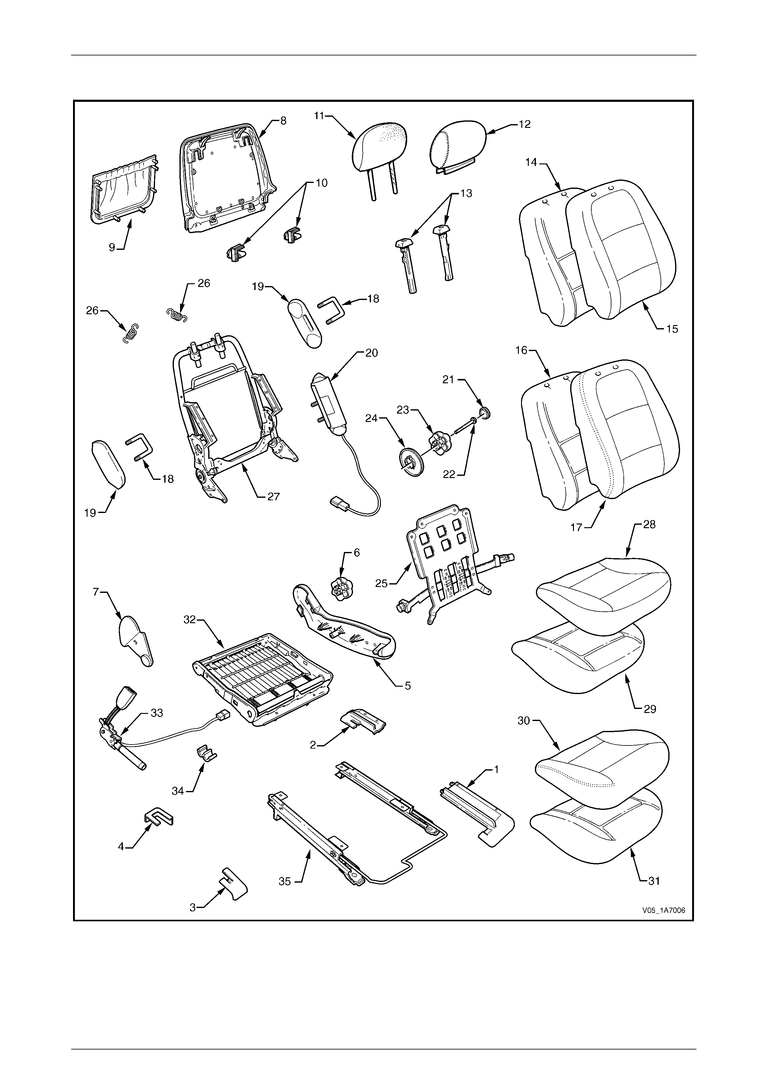
Seat Assemblies Page 1A7–186
Page 1A7–186
Front Seat Type 6
Figure 1A7 – 33

Seat Assemblies Page 1A7–187
Page 1A7–187
Legend
1 Front Seat Outer Front Cover
2 Front Seat Outer Rear Cover
3 Front Seat Inner Front Cover
4 Front Seat Inner Rear Cover
5 Front Seat Outer Side Cover
6 Recline Adjuster Knob
7 Front Seat Inner Side Cover
8 Front Seat-back Rear Cover
9 Front Seat-back Map Pocket
10 Front Seat-back Cover Retaining Clips
11 Front Seat Head Restraint Pad Assembly
12 Front Seat Head Restraint Cover
13 Front Seat Head Restraint Sleeves
14 Front Seat-back Pad – Cloth Cover
15 Front Seat-back Cloth Cover
16 Front Seat-back Pad – Leather Cover
17 Front Seat-back Leather Cover
18 Front Seat Dummy Block U-bolt*
19 Front Seat Dummy Block Insert*
20 Side Impact Airbag Assembly*
21 Lumbar Support Knob Cover
22 Lumbar Support Knob Screw
23 Lumbar Support Knob
24 Lumbar Support Deflector Ring
25 Lumbar Support Assembly
26 Lumbar Support Retaining Spring
27 Front Seat-back Frame Assembly
28 Front Seat Cushion Cloth Cover
29 Front Seat Cushion Pad – Cloth Cover
30 Front Seat Cushion Leather Cover
31 Front Seat Cushion Pad – Leather Cover
32 Front Seat Cushion Frame Assembly
33 Seatbelt Buckle & Pretensioner Assembly
34 Wiring Harness Retaining Clip
35 Track and Height Adjust Assembly
* Side impact airbag assembly is optional. Front seat dummy block assembly fitted to outer side when side impact airbag
assembly not fitted.

Seat Assemblies Page 1A7–188
Page 1A7–188
Front Seat Type 7
Figure 1A7 – 34

Seat Assemblies Page 1A7–189
Page 1A7–189
Legend
1 Front Seat Outer Front Cover (Crew Cab Only)
2 Front Seat Outer Front Cover
3 Front Seat Outer Rear Cover
4 Front Seat Inner Front Cover
5 Front Seat Inner Rear Cover
6 Front Seat Outer Side Cover
7 Recline Adjuster Knob
8 Front Seat Adjustment Switch Knob
9 Front Seat Adjustment Switch
10 Front Seat Inner Side Cover
11 Front Seat-back Rear Cover Assembly
12 Front Seat-back Cover Retaining Clips
13 Front Seat Head Restraint Pad Assembly
14 Front Seat Head Restraint Cover
15 Front Seat Head Restraint Sleeves
16 Front Seat-back Pad – Cloth Cover
17 Front Seat-back Cloth Cover
18 Front Seat-back Pad – Leather Cover
19 Front Seat-back Leather Cover
20 Front Seat Dummy Block U-bolt
21 Front Seat Dummy Block Insert
22 Side Impact Airbag Assembly
23 Lumbar Support Knob Cover
24 Lumbar Support Knob Screw
25 Lumbar Support Knob
26 Lumbar Support Deflector Ring
27 Lumbar Support Assembly
28 Lumbar Support Retaining Spring
29 Front Seat-back Frame Assembly
30 Front Seat Cushion Cloth Cover
31 Front Seat Cushion Pad – Cloth Cover
32 Front Seat Cushion Leather Cover
33 Front Seat Cushion Pad – Leather Cover
34 Front Seat Cushion Frame Assembly
35 Seatbelt Buckle & Pretensioner Assembly
36 Wiring Harness Retaining Clip
37 Track and Height Adjust Assembly
38 Wiring Harness Assembly
39 Front Seat Cable Tray
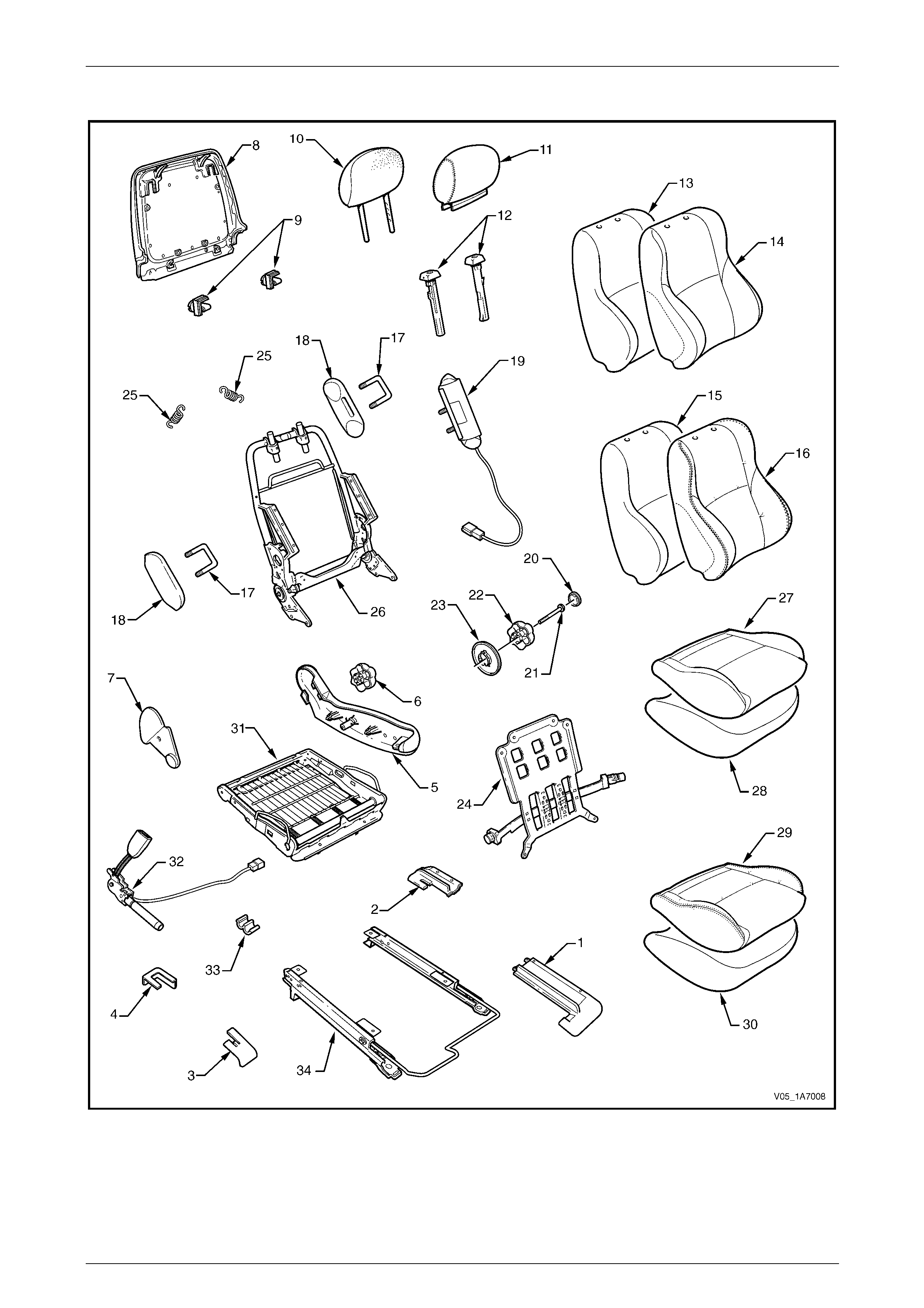
Seat Assemblies Page 1A7–190
Page 1A7–190
Front Seat Type 8
Figure 1A7 – 35

Seat Assemblies Page 1A7–191
Page 1A7–191
Legend
1 Front Seat Outer Front Cover
2 Front Seat Outer Rear Cover
3 Front Seat Inner Front Cover
4 Front Seat Inner Rear Cover
5 Front Seat Outer Side Cover
6 Recline Adjuster Knob
7 Front Seat Inner Side Cover
8 Front Seat-back Rear Cover Assembly
9 Front Seat-back Cover Retaining Clips
10 Front Seat Head Restraint Pad Assembly
11 Front Seat Head Restraint Cover
12 Front Seat Head Restraint Sleeves
13 Front Seat-back Pad – Cloth Cover
14 Front Seat-back Cloth Cover
15 Front Seat-back Pad – Leather Cover
16 Front Seat-back Leather Cover
17 Front Seat Dummy Block U-bolt
18 Front Seat Dummy Block Insert
19 Side Impact Airbag Assembly
20 Lumbar Support Knob Cover
21 Lumbar Support Knob Screw
22 Lumbar Support Knob
23 Lumbar Support Deflector Ring
24 Lumbar Support Assembly
25 Lumbar Support Retaining Spring
26 Front Seat-back Frame Assembly
27 Front Seat Cushion Cloth Cover
28 Front Seat Cushion Pad – Cloth Cover
29 Front Seat Cushion Leather Cover
30 Front Seat Cushion Pad – Leather Cover
31 Front Seat Cushion Frame Assembly
32 Seatbelt Buckle & Pretensioner Assembly
33 Wiring Harness Retaining Clip
34 Track and Height Adjust Assembly
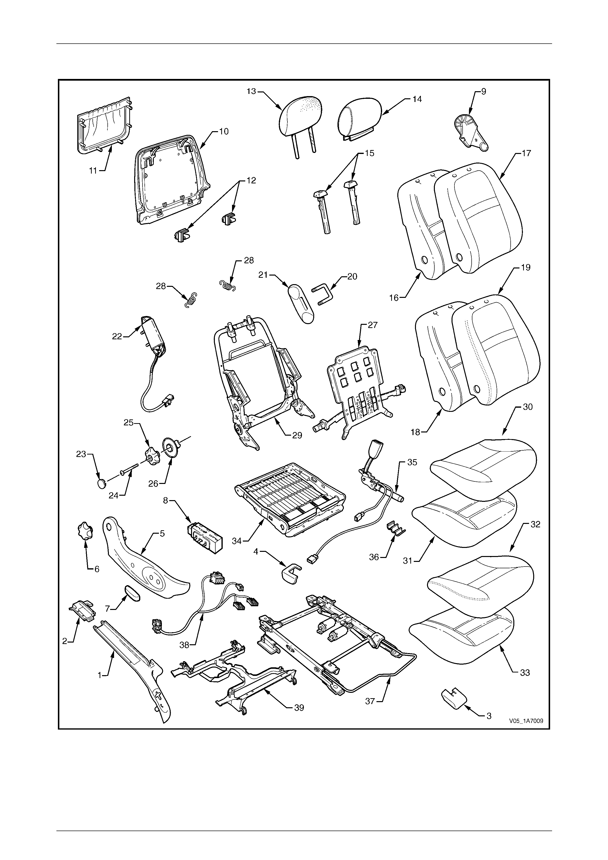
Seat Assemblies Page 1A7–192
Page 1A7–192
Front Seat Type 9
Figure 1A7 – 36

Seat Assemblies Page 1A7–193
Page 1A7–193
Legend
1 Front Seat Outer Front Cover
2 Front Seat Outer Rear Cover
3 Front Seat Inner Front Cover
4 Front Seat Inner Rear Cover
5 Front Seat Outer Side Cover
6 Recline Adjuster Knob
7 Front Seat Adjustment Switch Knob
8 Front Seat Adjustment Switch
9 Front Seat Inner Side Cover
10 Front Seat-back Rear Cover
11 Front Seat-back Map Pocket
12 Front Seat-back Cover Retaining Clips
13 Front Seat Head Restraint Pad Assembly
14 Front Seat Head Restraint Cover
15 Front Seat Head Restraint Sleeves
16 Front Seat-back Pad – Cloth Cover
17 Front Seat-back Cloth Cover
18 Front Seat-back Pad – Leather Cover
19 Front Seat-back Leather Cover
20 Front Seat Dummy Block U-bolt
21 Front Seat Dummy Block Insert
22 Side Impact Airbag Assembly
23 Lumbar Support Knob Cover
24 Lumbar Support Knob Screw
25 Lumbar Support Knob
26 Lumbar Support Deflector Ring
27 Lumbar Support Assembly
28 Lumbar Support Retaining Spring
29 Front Seat-back Frame Assembly
30 Front Seat Cushion Cloth Cover
31 Front Seat Cushion Pad – Cloth Cover
32 Front Seat Cushion Leather Cover
33 Front Seat Cushion Pad – Leather Cover
34 Front Seat Cushion Frame Assembly
35 Seatbelt Buckle & Pretensioner Assembly
36 Wiring Harness Retaining Clip
37 Track and Height Adjust Assembly
38 Wiring Harness Assembly
39 Front Seat Cable Tray
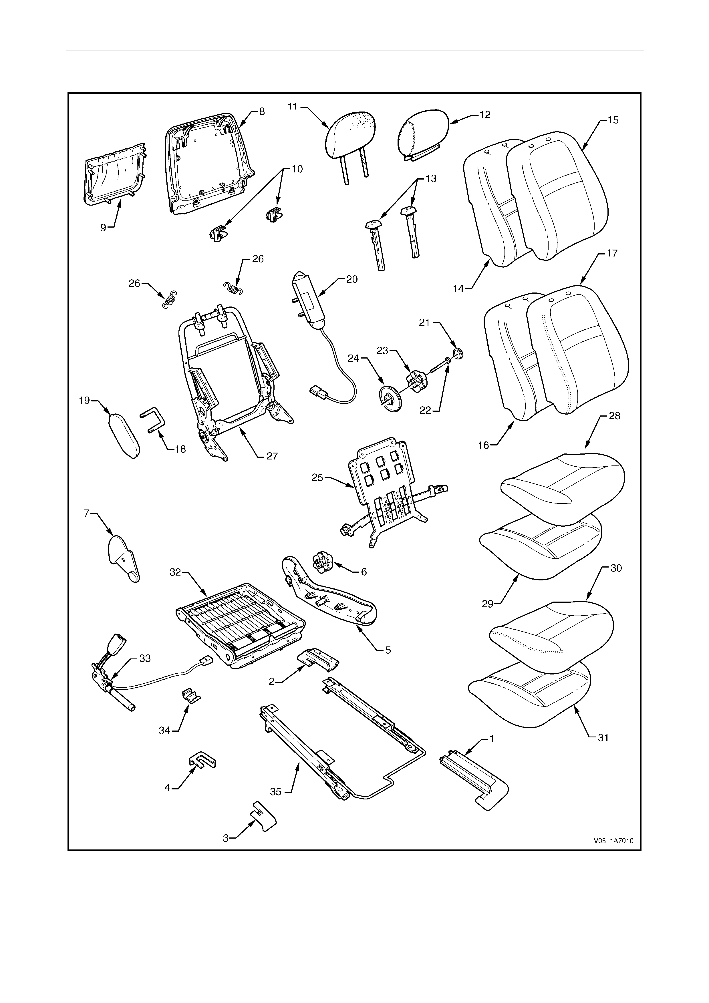
Seat Assemblies Page 1A7–194
Page 1A7–194
Front Seat Type 10
Figure 1A7 – 37

Seat Assemblies Page 1A7–195
Page 1A7–195
Legend
1 Front Seat Outer Front Cover
2 Front Seat Outer Rear Cover
3 Front Seat Inner Front Cover
4 Front Seat Inner Rear Cover
5 Front Seat Outer Side Cover
6 Recline Adjuster Knob
7 Front Seat Inner Side Cover
8 Front Seat-back Rear Cover
9 Front Seat-back Map Pocket
10 Front Seat-back Cover Retaining Clips
11 Front Seat Head Restraint Pad Assembly
12 Front Seat Head Restraint Cover
13 Front Seat Head Restraint Sleeves
14 Front Seat-back Pad – Cloth Cover
15 Front Seat-back Cloth Cover
16 Front Seat-back Pad – Leather Cover
17 Front Seat-back Leather Cover
18 Front Seat Dummy Block U-bolt
19 Front Seat Dummy Block Insert
20 Side Impact Airbag Assembly
21 Lumbar Support Knob Cover
22 Lumbar Support Knob Screw
23 Lumbar Support Knob
24 Lumbar Support Deflector Ring
25 Lumbar Support Assembly
26 Lumbar Support Retaining Spring
27 Front Seat-back Frame Assembly
28 Front Seat Cushion Cloth Cover
29 Front Seat Cushion Pad – Cloth Cover
30 Front Seat Cushion Leather Cover
31 Front Seat Cushion Pad – Leather Cover
32 Front Seat Cushion Frame Assembly
33 Seatbelt Buckle & Pretensioner Assembly
34 Wiring Harness Retaining Clip
35 Track and Height Adjust Assembly

Seat Assemblies Page 1A7–196
Page 1A7–196
Front Seat Type 11
Figure 1A7 – 38

Seat Assemblies Page 1A7–197
Page 1A7–197
Legend
1 Front Seat Outer Front Cover
2 Front Seat Outer Rear Cover
3 Front Seat Inner Front Cover
4 Front Seat Inner Rear Cover
5 Front Seat Outer Side Cover
6 Front Seat Adjustment Switch Knobs
7 Front Seat Adjustment Switch
8 Memory Position Switch Cover
9 Memory Position Switch Assembly
10 Front Seat Inner Side Cover
11 Front Seat-back Rear Cover
12 Front Seat-back Map Pocket
13 Front Seat-back Cover Retaining Clips
14 Front Seat Head Restraint Pad Assembly
15 Front Seat Head Restraint Cover
16 Front Seat Head Restraint Sleeves
17 Front Seat-back Pad – Cloth Cover
18 Front Seat-back Cloth Cover
19 Front Seat-back Pad – Leather Cover
20 Front Seat-back Leather Cover
21 Front Seat Dummy Block U-bolt
22 Front Seat Dummy Block Insert
23 Side Impact Airbag Assembly
24 Lumbar Support Knob Cover
25 Lumbar Support Knob Screw
26 Lumbar Support Knob
27 Lumbar Support Deflector Ring
28 Lumbar Support Assembly
29 Lumbar Support Retaining Spring
30 Active Head Restraint Frame Sleeves
31 Active Head Restraint Frame Assembly
32 Active Head Restraint Frame Support Strap
33 Active Head Restraint Frame Retaining Spring
34 Front Seat-back Frame Assembly
35 Front Seat Cushion Cloth Cover
36 Front Seat Cushion Pad – Cloth Cover
37 Front Seat Cushion Leather Cover
38 Front Seat Cushion Pad – Leather Cover
39 Front Seat Cushion Frame Assembly
40 Seatbelt Buckle & Pretensioner Assembly
41 Wiring Harness Retaining Clip
42 Track and Height Adjust Assembly
43 Seat Memory Module
44 Wiring Harness Assembly
45 Front Seat Cable Tray
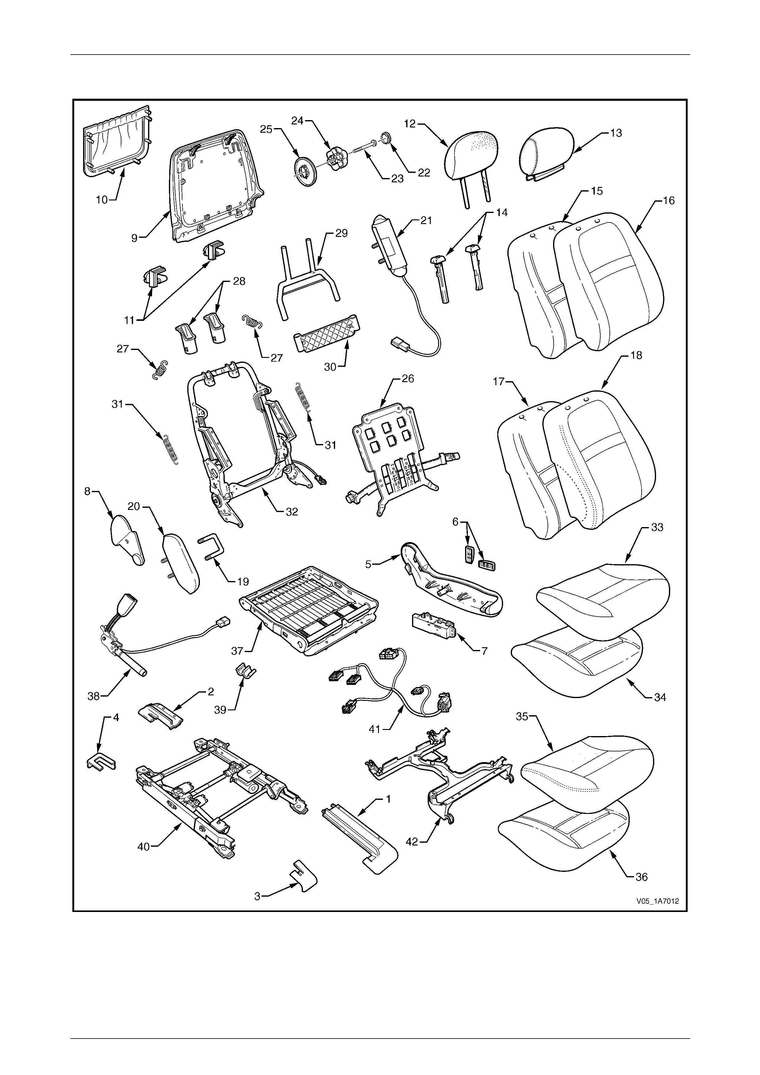
Seat Assemblies Page 1A7–198
Page 1A7–198
Front Seat Type 12
Figure 1A7 – 39

Seat Assemblies Page 1A7–199
Page 1A7–199
Legend
1 Front Seat Outer Front Cover
2 Front Seat Outer Rear Cover
3 Front Seat Inner Front Cover
4 Front Seat Inner Rear Cover
5 Front Seat Outer Side Cover
6 Front Seat Adjustment Switch Knobs
7 Front Seat Adjustment Switch
8 Front Seat Inner Side Cover
9 Front Seat-back Rear Cover
10 Front Seat-back Map Pocket
11 Front Seat-back Cover Retaining Clips
12 Front Seat Head Restraint Pad Assembly
13 Front Seat Head Restraint Cover
14 Front Seat Head Restraint Sleeves
15 Front Seat-back Pad – Cloth Cover
16 Front Seat-back Cloth Cover
17 Front Seat-back Pad – Leather Cover
18 Front Seat-back Leather Cover
19 Front Seat Dummy Block U-bolt
20 Front Seat Dummy Block Insert
21 Side Impact Airbag Assembly
22 Lumbar Support Knob Cover
23 Lumbar Support Knob Screw
24 Lumbar Support Knob
25 Lumbar Support Deflector Ring
26 Lumbar Support Assembly
27 Lumbar Support Retaining Spring
28 Active Head Restraint Frame Sleeves
29 Active Head Restraint Frame Assembly
30 Active Head Restraint Frame Support Strap
31 Active Head Restraint Frame Retaining Spring
32 Front Seat-back Frame Assembly
33 Front Seat Cushion Cloth Cover
34 Front Seat Cushion Pad – Cloth Cover
35 Front Seat Cushion Leather Cover
36 Front Seat Cushion Pad – Leather Cover
37 Front Seat Cushion Frame Assembly
38 Seatbelt Buckle & Pretensioner Assembly
39 Wiring Harness Retaining Clip
40 Track and Height Adjust Assembly
41 Wiring Harness Assembly
42 Front Seat Cable Tray
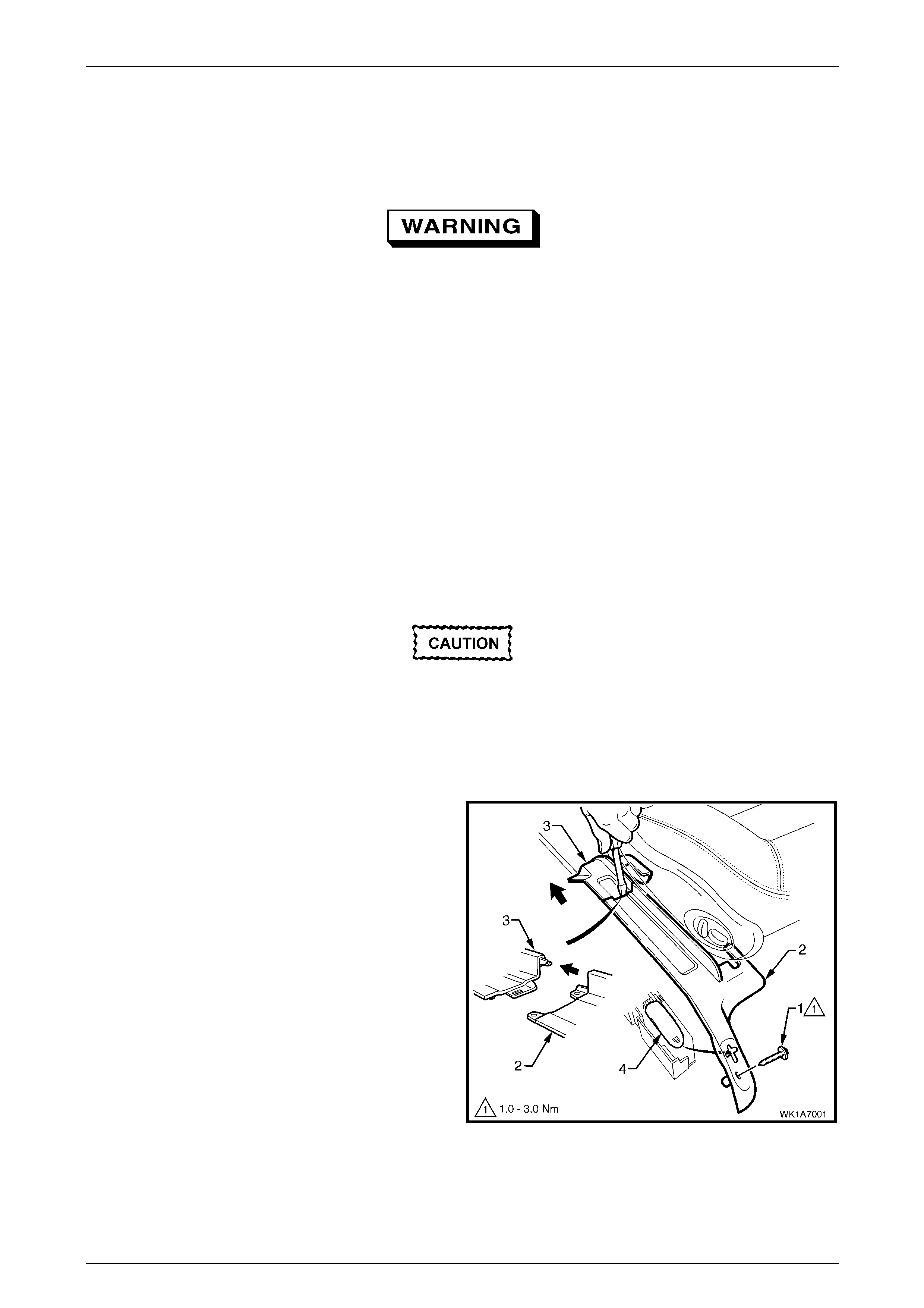
Seat Assemblies Page 1A7–200
Page 1A7–200
5.2 Front Seat Assembly
LT Section No. — 14–295
Before performing any service operation on a
front seat assembly fitted with side
impact airbags, ensure the occupant
protection system is disabled, refer to
Section 12M Occupant Protection System.
NOTE
If the seat assembly is to be disassembled, adjust
the seat assembly to its highest position before
disconnecting the power to the seat.
NOTE
Clean hands are essential when working on the
interior trim.
Remove
Disconnection of the battery affects
certain vehicle electronic systems. Refer to
Section 00 Warnings, Cautions and Notes,
5 Battery Disconnection Procedures before
disconnecting the battery.
1 Disconnect the battery.
2 For the driver’s seat, (except crew cab), remove the
screw (1) attaching the front seat outer front cover (2).
3 Using a small scre wdriver, push in the ce ntre of the
join to separate the front seat outer front cover and the
front seat outer rear cover (3).
4 Unclip the covers from the seat track and disengag e
from the side sill trim.
5 Pull the covers apart and remove the rear c over.
6 For the driver’s seat, (except crew cab), slide the front
cover over the fuel filler door release lever (4) and
remove.
Figure 1A7 – 40
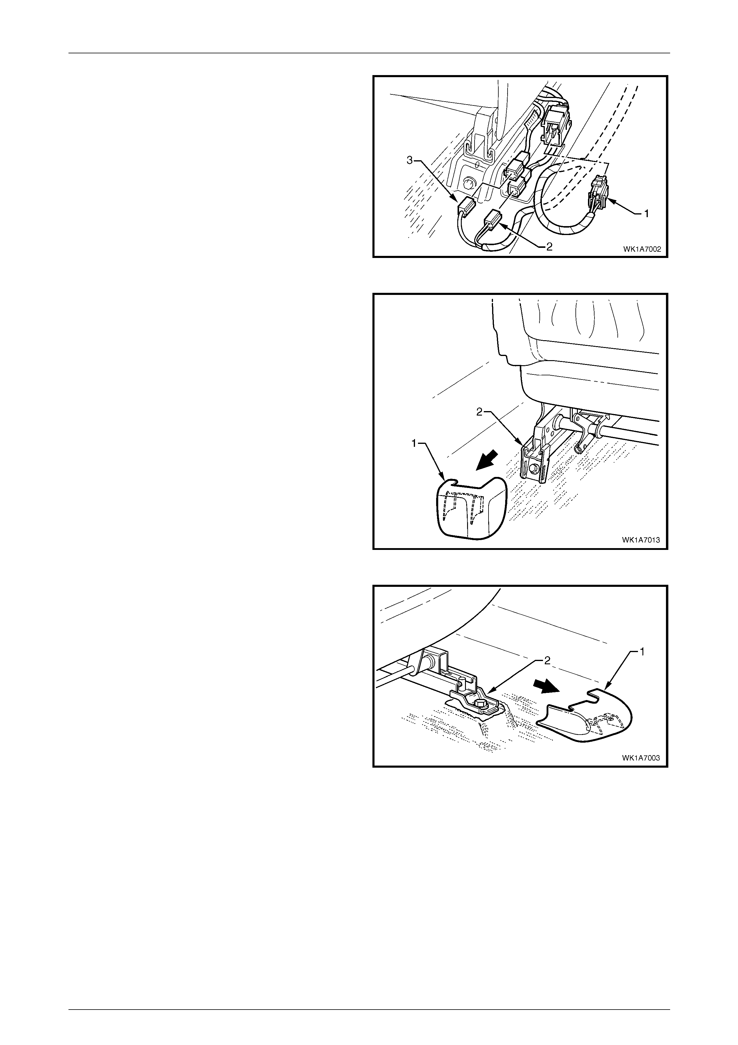
Seat Assemblies Page 1A7–201
Page 1A7–201
7 Disconnect the body wiring ha rness connector (1), the
seatbelt pretensioner wiring connector (2) and the side
impact airbag wiring connector (3), if fitted.
Figure 1A7 – 41
8 Unclip the front seat inner rear cover (1) from the seat
track (2).
Figure 1A7 – 42
9 Unclip the front seat inner front cover (1) from the seat
track (2).
Figure 1A7 – 43
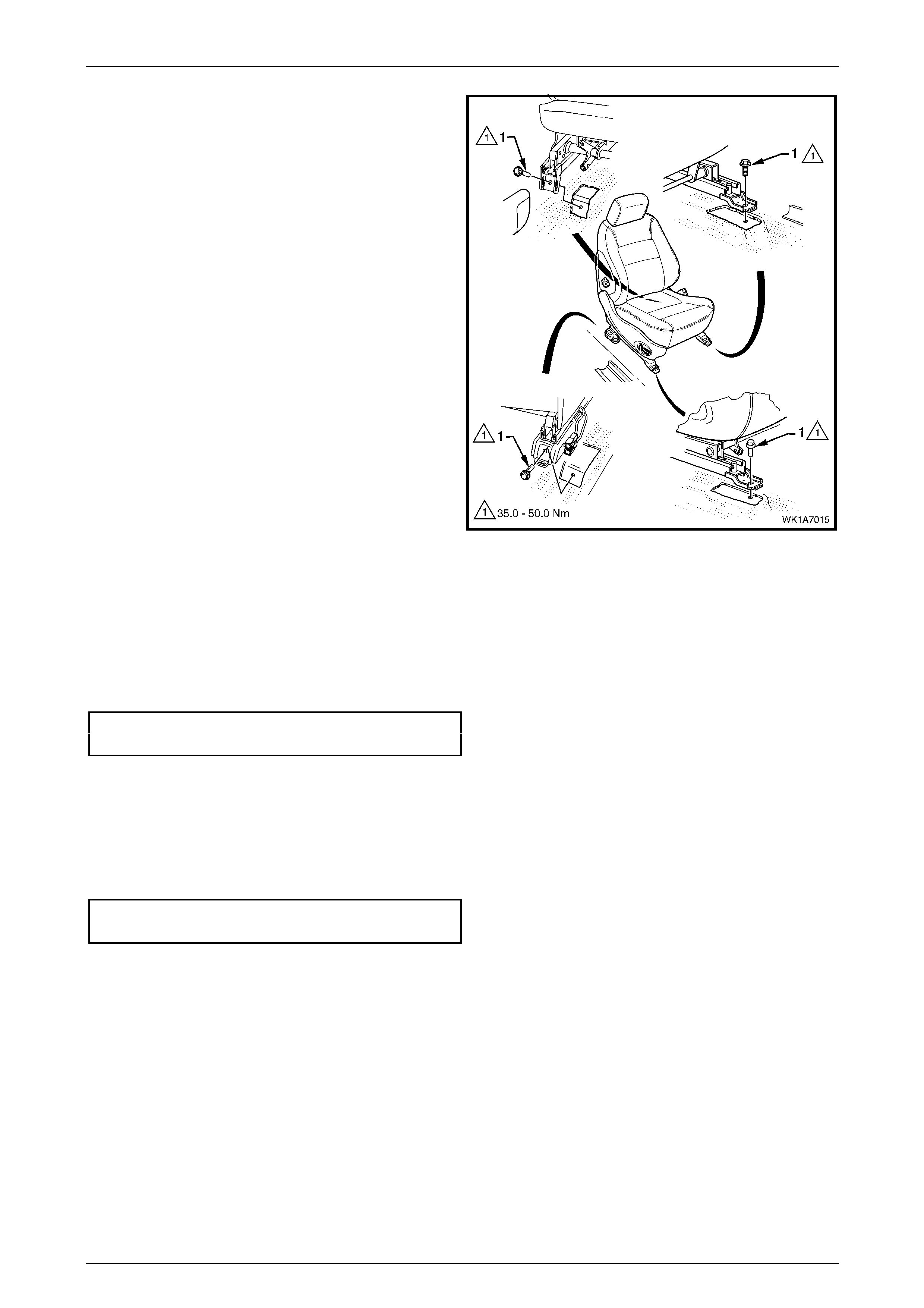
Seat Assemblies Page 1A7–202
Page 1A7–202
10 Remove the four screws (1) attaching the front seat to
the vehicle.
11 Remove the seat from the vehicle.
Figure 1A7 – 44
Reinstall
Reinstallation of the front seat assembly is the reverse of the removal procedure, noting the following:
1 Position the front seat assembly into the vehicle.
2 Install the four screws securing the front seat.
3 Tighten the attaching screws to the correct torque specification.
Front seat assembly attaching screw
torque specification.................................35.0 – 50.0 Nm
4 Connect the seat wiring harness connector, s eatbelt pretensioner harness connector and the side impact airbag
connector.
5 Align the front seat outer cover’s retaining clips and push firmly to engage.
6 Push the front of the front seat outer cover do wn to engage the cover with the front of the seat rail.
7 For the driver’s side, (except crew cab), install the front seat outer front cover attaching screw and tighten to the
specified torque.
Front seat outer front cover attaching
screw torque specification...........................1.0 – 3.0 Nm
8 Check the operation of the front seat functions. While checking the seat adjustment/operation, also check the seat
wiring harnesses do not foul with any of the seat’s moveable components (i.e. seat motor drive shafts, etc.).
NOTE
Type 11 front seats will require seat memory
calibration to reinstate seat memory functions,
refer to Seat Memory Calibration, Front Seat
Type 11.
9 Switch on the ignition and observe the airbag warning indic ator in the instrument cluster.
• If no fault is detected, the airbag warning indicator illuminates for approxim ately five seconds while the
system performs a self-test, and then extinguish.
• If a fault is present, the airbag warning indic ator will remain illuminated and a warning chime may sound after
approximately three seconds. The warning message ‘SRS Airbag F ault’ is displayed in the instrume nt cluster
multi-function display. To diagnose the fault, refer to Section 12M Occupant Protection System.

Seat Assemblies Page 1A7–203
Page 1A7–203
Seat Memory Calibration, Front Seat Type 11
Whenever power is interrupted to the seat memor y module, the following procedure must be performed to reinstate seat
memory functions.
Step Operation Result
1 1 Operate the seat adjustment switch to move the
seat forward.
2 Operate the seat adjustment switch for 1 second to
move the seat aft.
3 Operate the seat adjustment switch to move the
seat forward.
Seat will cease movement when track limit is
reached.
Seat will move aft.
Seat will cease movement when track limit is
reached.
2 1 Operate the seat adjustment switch to move the
seat aft.
2 Operate the seat adjustment switch for 1 second to
move the seat forward.
3 Operate the seat adjustment switch to move the
seat aft.
Seat will cease movement when track limit is
reached.
Seat will move forward.
Seat will cease movement when track limit is
reached.
3 1 Operate the seat adjustment switch to raise the
front of the seat.
2 Operate the adjustment switch for 1 second to
lower the front of the seat.
3 Operate the seat adjustment switch to raise the
front of the seat.
Seat will cease movement when upper limit is
reached.
Se at wi l l lo wer .
Seat will cease movement when upper limit is
reached.
4 1 Operate the seat adjustment switch to lower the
front of the seat.
2 Operate seat adjustment switch for 1 second to
raise the front of the seat.
3 Operate the seat adjustment switch to lower the
front of the seat.
Seat will cease movement when lower limit is
reached.
Seat will raise.
Seat will cease movement when lower limit is
reached.
5 1 Operate the seat adjustment switch to raise the rear
of the seat.
2 Operate the seat adjustment switch for 1 second to
lower the rear of the seat.
3 Operate the seat adjustment switch to raise the rear
of the seat.
Seat will cease movement when upper limit is
reached.
Se at wi l l lo wer .
Seat will cease movement when upper limit is
reached.

Seat Assemblies Page 1A7–204
Page 1A7–204
Step Operation Result
6 1 Operate the seat adjustment switch to lower the
rear of the seat. Seat will cease movement when lower limit is
reached.
7 1 Operate the seat adjustment switch to move the
seat-back aft.
2 Operate the seat adjustment switch for 1 second to
move the seat-back forward.
3 Operate the seat adjustment switch to move the
seat-back aft.
Hold switch until lower limit is reach ed. This
does not have to be mechanical limit.
Seat-back will move forward.
Hold switch until lower limit is reach ed. This
should be same position as in 1.
8 1 Operate the seat adjustment switch to move the
seat-back forward.
2 Operate the seat adjustment switch for 1 second to
move the seat-back aft.
3 Operate the seat adjustment switch to move the
seat-back forward.
Hold switch until upper lim it is reached. This
does not have to be mechanical limit.
Seat-back will move aft.
Hold switch until upper lim it is reached. This
should be same position as in 1.
9 Press the mirror dip/memory store (M) button for 1
second. Stores the calibration into memory. A three-
tone chime sounds to confirm storage.
To test if the seat limits have been correctly calibrated, perform the following:
Step Operation Result
1 Operate the seat adjustment switch in one direction
(fore/aft, raise/lower, etc.). Hold until seat stops.
2 Release the switch briefly. –
3 Operate the switch in the same direction and hold for 3
seconds. The motor will not operate for 2 seconds, then
operates for 0.5 second.
This is a limp-home function that allo ws the
seat to be manually adjusted should a sensor
fail.
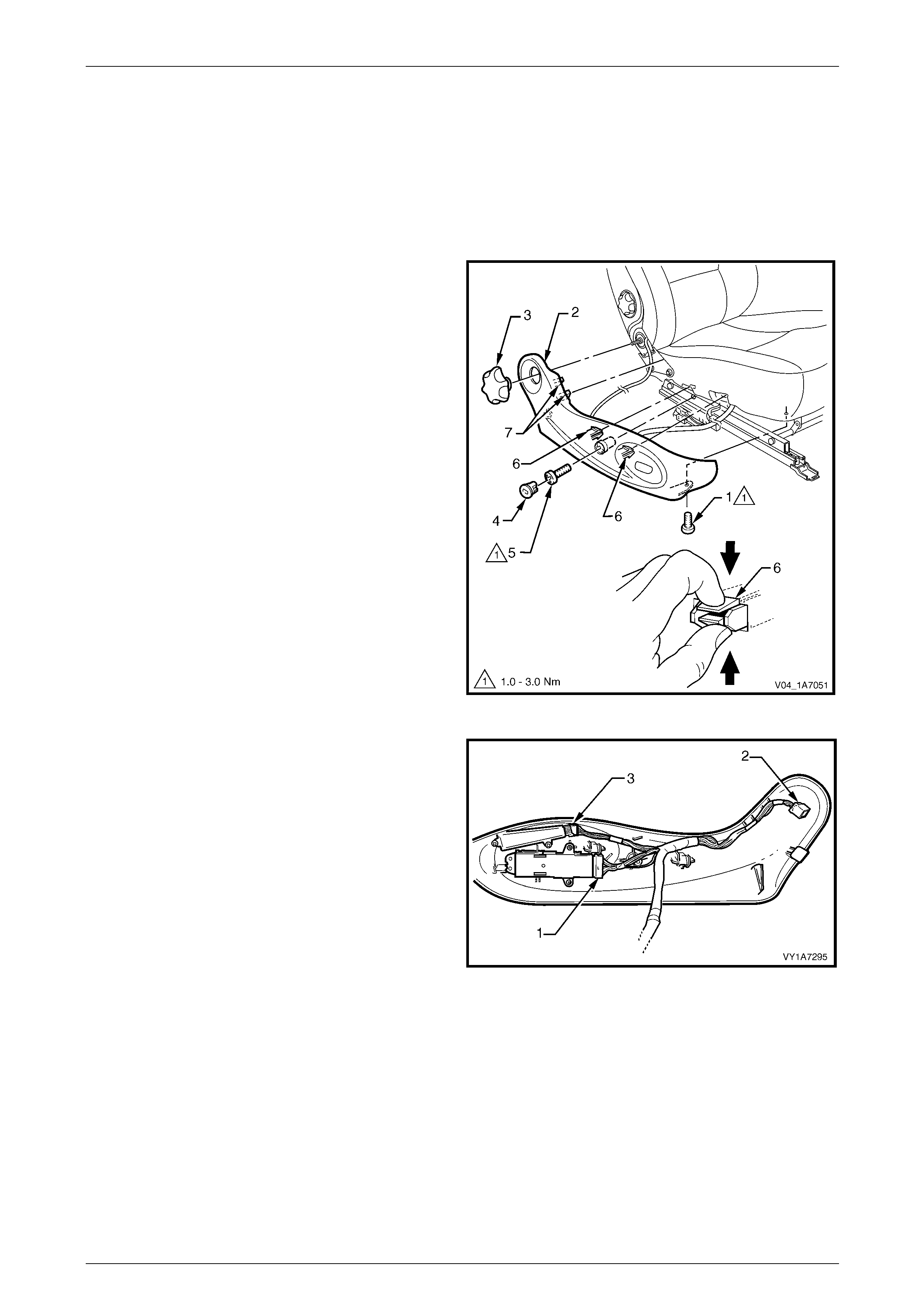
Seat Assemblies Page 1A7–205
Page 1A7–205
5.3 Front Seat Outer Side Cover Assembl y
LT Section No. — 14–322
Remove
1 Raise the seat to the full-up position.
2 Remove the screw (1) from the front of the front seat
outer side cover (2).
3 If required, carefully prise the recliner knob (3) from
the seat assembly.
4 Remove the plug (4) by rotating the plug anti-
clockwise, one quarter of a turn.
5 Remove the screw (5) located behind the plu g.
6 Reach up under the seat assembl y and squeeze
together the two retaining tangs (6), on the i nner side
of the side cover while gently pulling the cover.
7 Gently pull the side cover away from the seat to
disengage the two clips (7) att ache d to the seat-back
frame assembly.
NOTE
Only remove the side cover far enough away
from the seat cushion assembly to gain access
to the seat wiring harness connectors.
Figure 1A7 – 45
8 Where fitted, disconnect the front seat adjustment
switch connector (1), recline motor harness connector
(2) and the memory position switch connector (3) and
unclip the harness from the side cover.
9 Remove the side cover assembly.
Figure 1A7 – 46
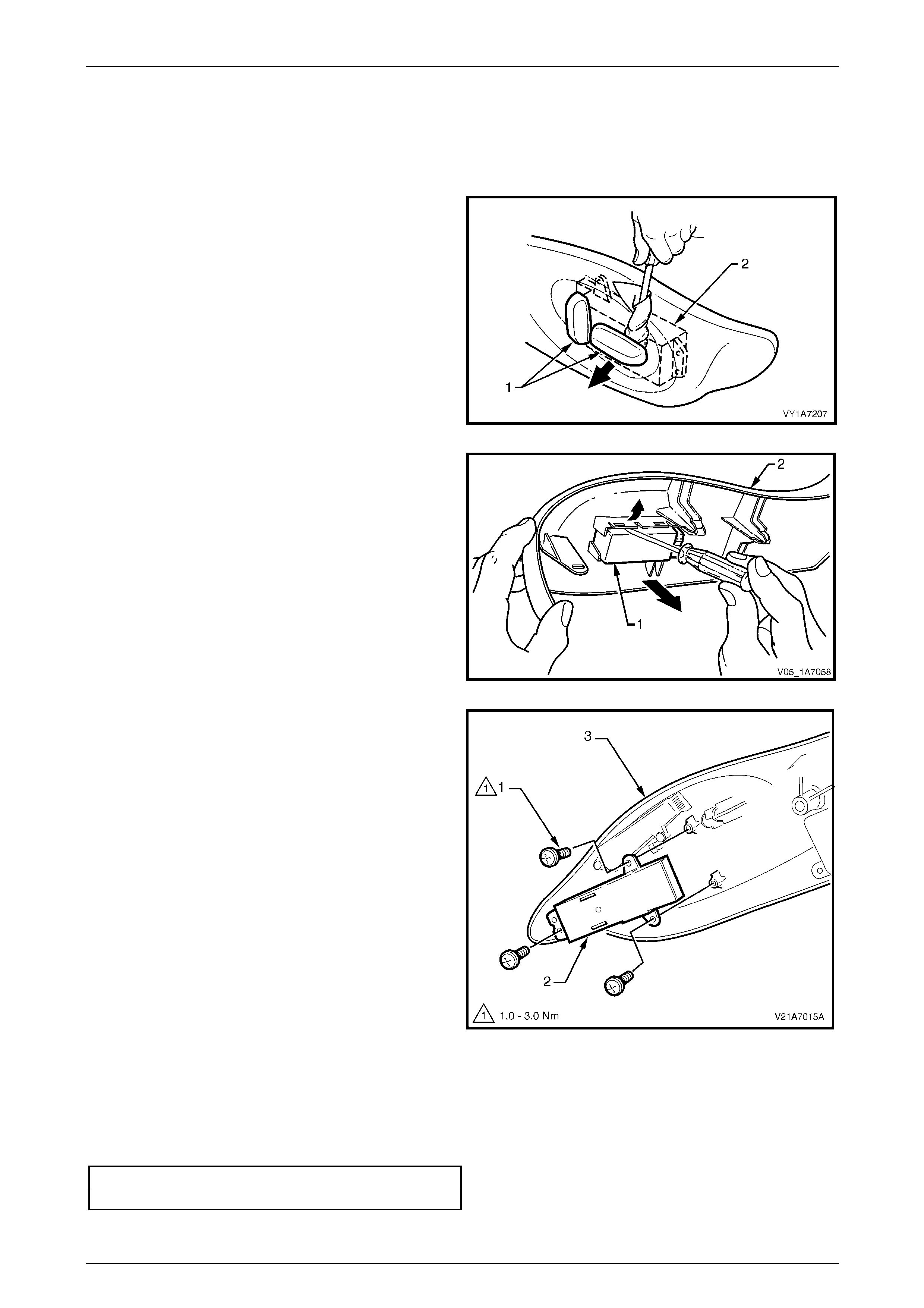
Seat Assemblies Page 1A7–206
Page 1A7–206
Disassemble
Front Seat Adjustment Switch
Remove
1 Depending on movement functions, remove the one or
two adjustment knobs (1) from the front seat
adjustment switch (2), by carefully prising them free
with a small flat tip screwdriver wrapped in a clean
shop rag.
Figure 1A7 – 47
2 On four-way seats, use a flat-blade screwdriver to
gently prise the front seat adjustment switch (1) from
the outer side cover (2).
Figure 1A7 – 48
3 On eight-way seats, remove the three screws (1)
attaching the front seat adjustment switch (2) to the
front seat outer side cover (3).
4 Remove the adjustment switch.
Figure 1A7 – 49
Reinstall
Reinstallation of the front seat adjustment switch is the reverse of the removal procedure, noting the fol lowing:
1 On four-way seats, ensure the seat adjustment switch is clipped securely in place.
2 On eight-way seats, tighten the attaching screws to the correct torque specificatio n.
Front seat adjustment switch
attaching screw torque specification...........1.0 – 3.0 Nm
3 Push the knobs in until they click in place.
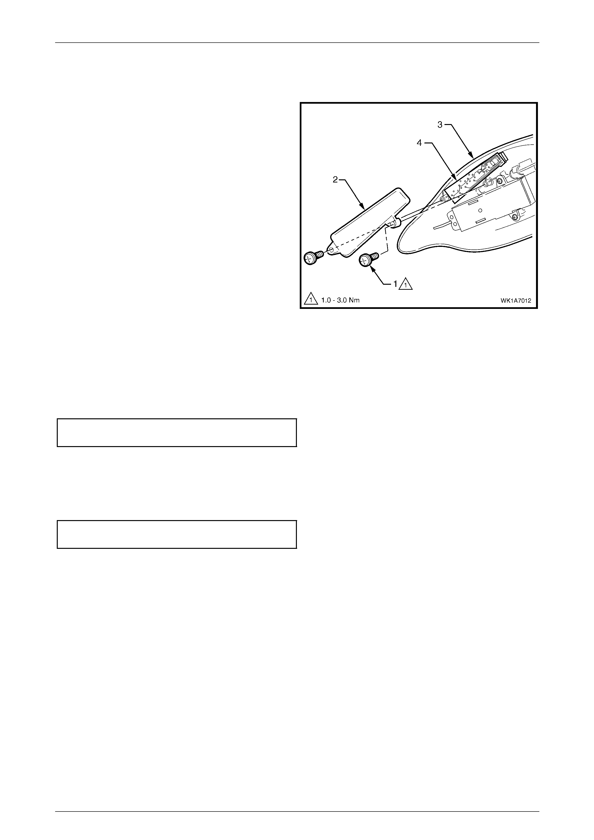
Seat Assemblies Page 1A7–207
Page 1A7–207
Memory Position Switch Assembly
Remove
1 Remove the two screws (1) attaching the memory
position switch cover (2) to the front seat outer side
cover (3).
2 Lift out the memory position switch assembly (4) from
its recess in the side cover.
3 As required, each position button can be removed
from the switch.
Figure 1A7 – 50
Reinstall
Reinstallation of the memory position switch assembly is the reverse of the removal procedure, noting the following:
1 If removed, push the position buttons in until they click in place, ensuring correct orientation.
2 Tighten the attaching screws to the correct torque specification.
Memory position switch cover
attaching screw torque specification...........1.0 – 3.0 Nm
Reinstall
Reinstallation of the front seat outer side cover is the reverse of the removal procedure, n oting the following:
1 Tighten the attaching screws to the correct torque specification.
Front seat outer side cover attaching
screw torque specification...........................1.0 – 3.0 Nm
2 If fitted, ensure the recliner knob is securely clipped in place.
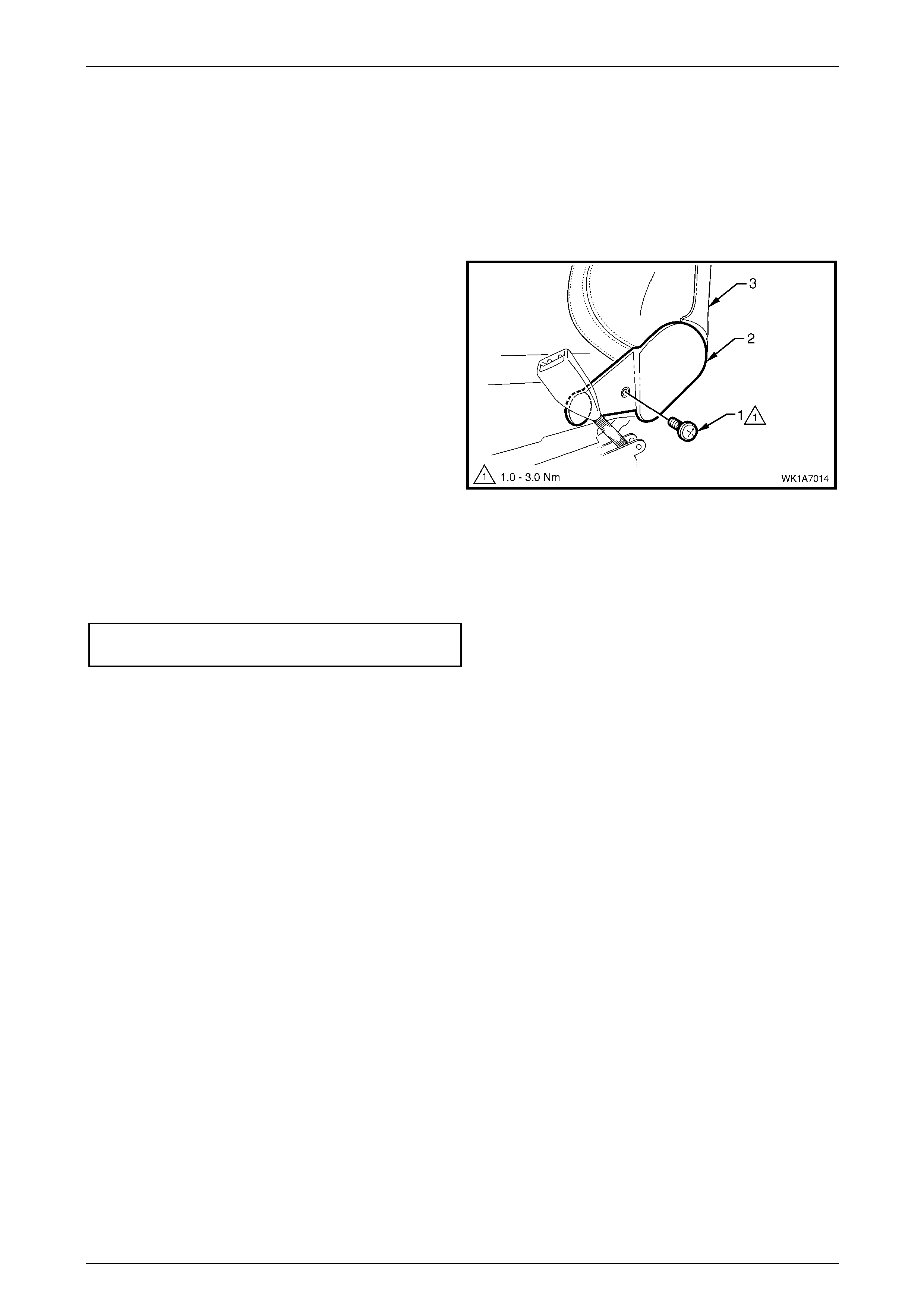
Seat Assemblies Page 1A7–208
Page 1A7–208
5.4 Front Seat Inner Side Cover
LT Section No. — 14–322
As required, remove the front seat assembly, refer to 5.2 Front Seat Assembly.
Remove
Remove the screw (1) attaching the front seat inner side
cover (2) to the seat assembly (3) and remove the cover.
Figure 1A7 – 51
Reinstall
Reinstallation of the front seat inner side cover is the reverse of the removal procedure. Tighte n the atta ching screw to
the correct torque specification.
Front seat inner side cover attachi ng
screw torque specification...........................1.0 – 3.0 Nm

Seat Assemblies Page 1A7–209
Page 1A7–209
5.5 Front Seat-back Rear Cover Assembly
LT Section No. — 14–322
Remove
The following components will require
replacement when performing this operation.
• Two front seat-back rear cover retaining
clips.
1 Pull the lower corners of the front seat-back rear
cover (1) away from the seat (2), breaking the two
retaining clips (3).
Figure 1A7 – 52
2 While holding the lower portion of the front seat-back
rear cover (1) out, pull the cover do wn to release the
two upper retaining lugs (2).
3 Remove the cover.
Figure 1A7 – 53
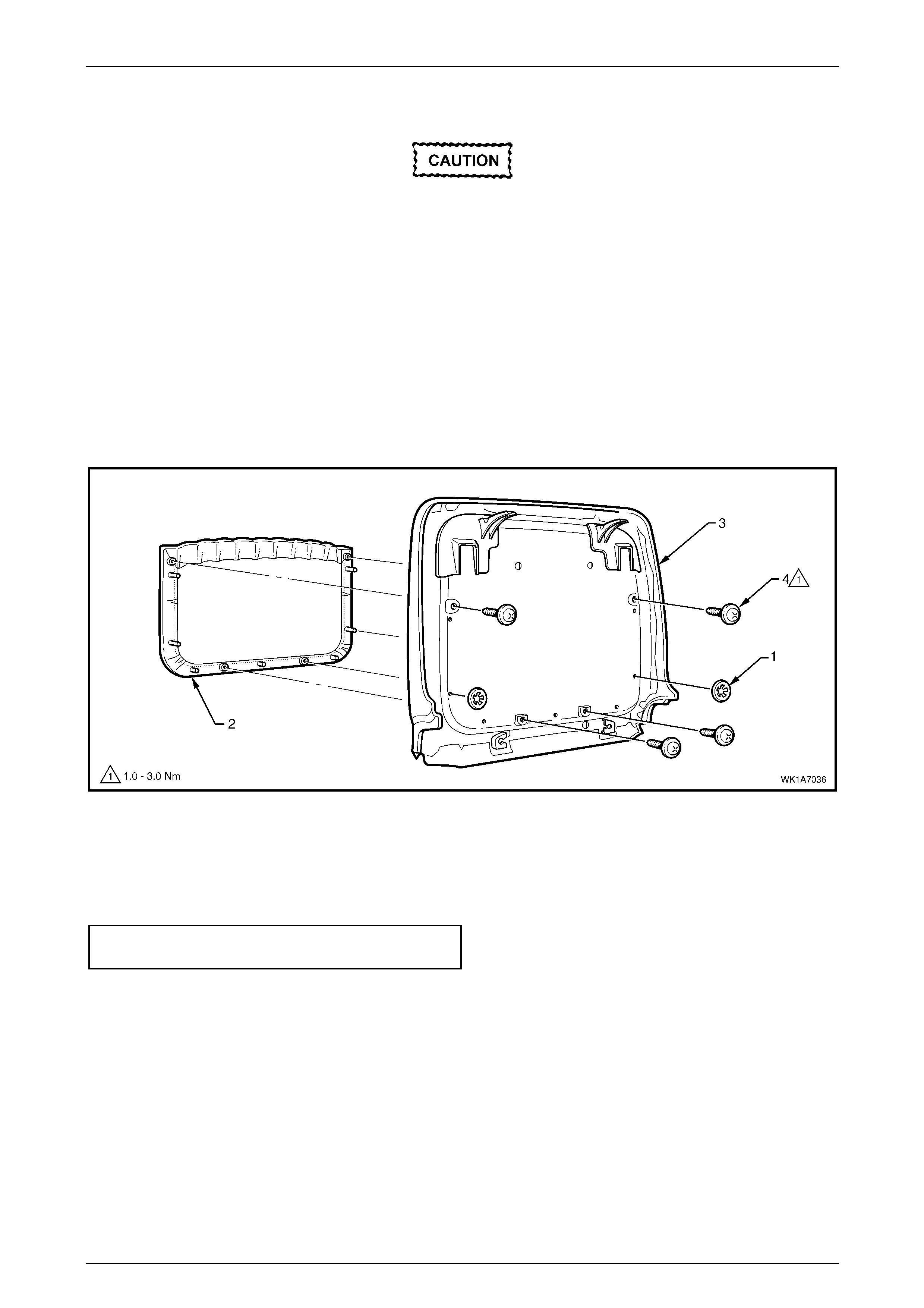
Seat Assemblies Page 1A7–210
Page 1A7–210
Disassemble
When performing Step 1, take care when
removing the retaining clip (1) not to break
the front seat-back map pocket shafts on
which the reta ining clips are attached.
NOTE
This procedure cannot be performed on vehicles
that have the net type seat-back map pocket.
1 Remove the two retaining clips (1) attaching the front seat-back map pocket (2) to the front seat-back rear cover
(3), refer to Figure 1A7 – 54.
2 Remove the four screws (4) attaching the map pocket to the cover.
3 Remove the map pocket.
Figure 1A7 – 54
Reassemble
Reassembly of the front seat-back rear cover is the reverse of the removal procedure. Tighten the attaching screws to
the correct torque specification.
Front seat-back map pocket attaching
screw torque specification...........................1.0 – 3.0 Nm
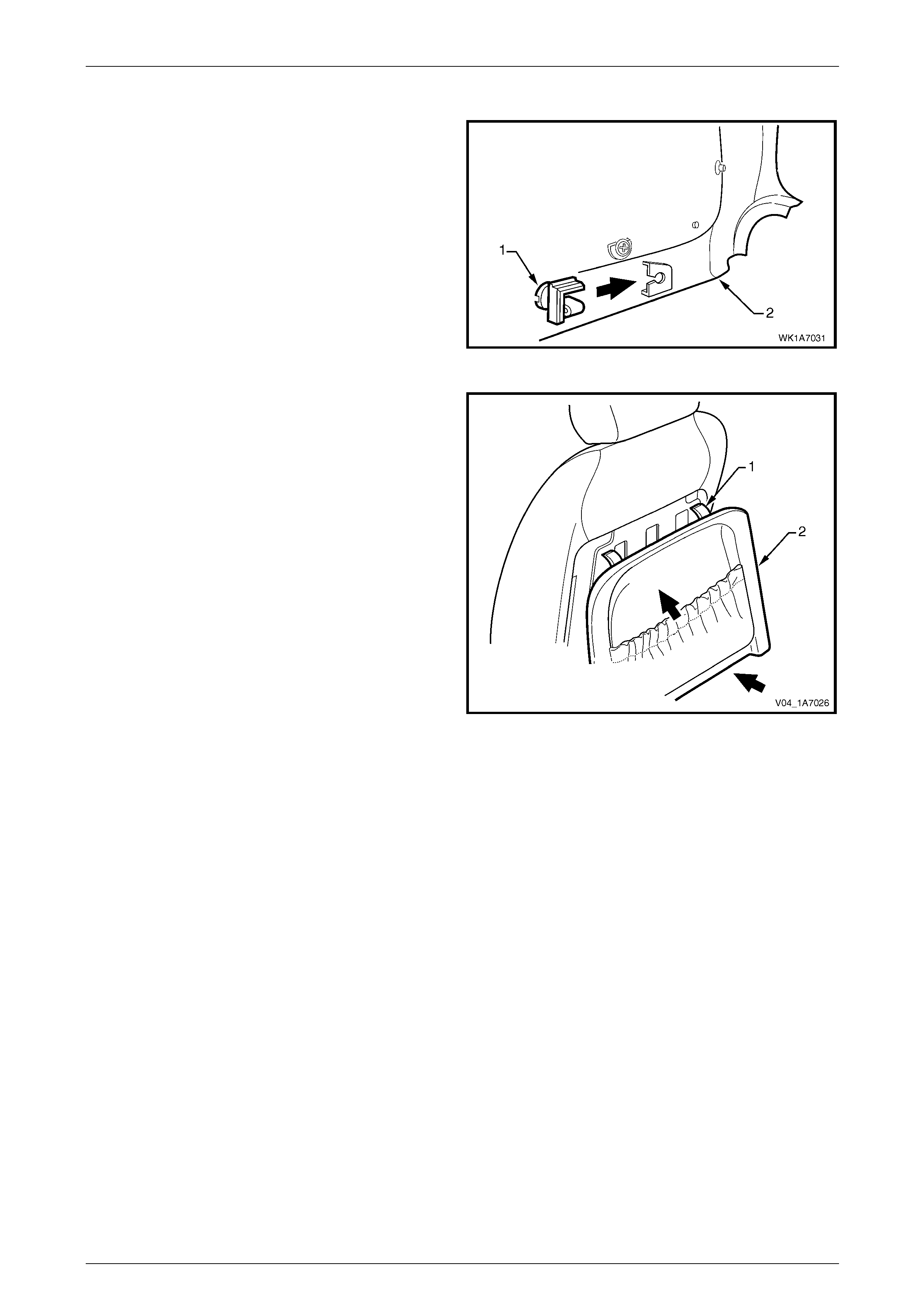
Seat Assemblies Page 1A7–211
Page 1A7–211
Reinstall
1 Replace the damaged retaining clip (1) on the front
seat-back rear cover (2), two places.
Figure 1A7 – 55
2 Align the two upper retaining lugs (1) with the
seat-back.
3 Push the front seat-back rear cover (2) up and in at
the lower edge to engage the two lower retaining clips.
Figure 1A7 – 56

Seat Assemblies Page 1A7–212
Page 1A7–212
5.6 Front Seat Head Restraint Assembly
LT Section No. — 14–295
Remove
1 Raise the head restraint fully.
2 Insert a suitable size probe into the hole (1) in the right-hand head restraint sleeve (2), refer to F igure 1A7 – 57.
3 Push the probe in slightly whil e app lying slight up ward pressure on the head restraint. Hold the up ward pressure.
4 Depress the head restraint sleeve height adjuster lock (3) on the left-hand head restraint sleeve and remove the
head restraint.
Figure 1A7 – 57
Disassemble
1 Disengage the front head restraint cover J-stri p by
pulling the flap (1) back and out of flap (2) in the
direction shown.
Figure 1A7 – 58

Seat Assemblies Page 1A7–213
Page 1A7–213
2 Remove the four staples (1) retaining the cover (2) to
the head restraint pad assembly.
3 Remove the cover from the pad assembly.
Figure 1A7 – 59
Reassemble
Reassembly of the front seat head restraint assembl y is the reverse of the removal procedure. Ensure the head restra int
cover J-clip is fully engaged and sits neatly in the recess in the hea d restraint pad.
Reinstall
Ensuring correct orientation of the head restraint, fit the head restraint shafts into the sleeves and p ush the head restraint
down.

Seat Assemblies Page 1A7–214
Page 1A7–214
5.7 Front Seat Head Restraint Sleeve
LT Section No. — 14–275
As required, remove the front seat head restraint assembl y, refer to 5.6 Front Seat Head Restrai nt Assembl y.
Remove
1 Push down on the surrounding seat cover to reveal the
upper portion of the seat-back frame or active head
restraint frame (1).
2 Using a fine flat-blade screwdriver, depress the head
restraint sleeve retaining lug (2) and withdraw the
head restraint sleeve (3) from the frame.
3 Repeat for the remaining sleeve as required.
Figure 1A7 – 60
Reinstall
Reinstallation of the front seat head restraint sleeve is the reverse of the removal proce dure, noting the following:
NOTE
Ensure the sleeve with the height adjuster lock
(1) is installed on the left-hand side of the seat;
that is the side that corresponds to the lower
square notch (2) in the head restraint shaft.
Figure 1A7 – 61
1 Align the head restraint sleeve locating ribs (1) with
the notch (2) in the seat-back frame.
2 Insert the sleeve and ensure it clicks into place.
Figure 1A7 – 62
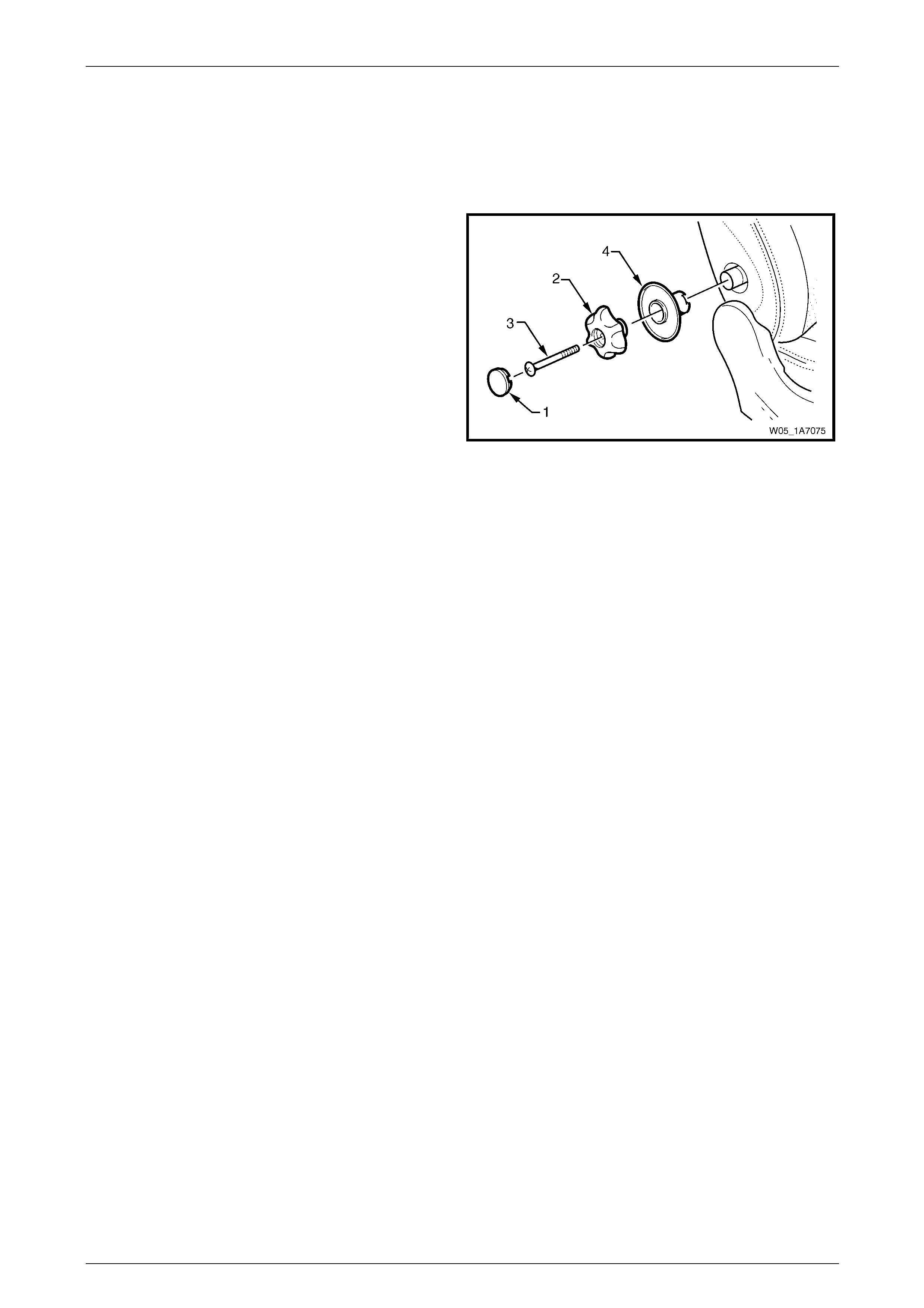
Seat Assemblies Page 1A7–215
Page 1A7–215
5.8 Lumbar Support Knob Assembly
LT Section No. — 14–275
Remove
1 Ensure the lumbar support is in the full off position.
2 Using a fine flat-blade screw-driver, carefully prise the
cap (1) from the lumbar support knob (2).
3 Remove the screw (3) attaching the knob to the
lumbar support shaft.
4 Pull the knob off the lumbar support shaft and remove
the lumbar support deflector ring (4).
NOTE
The knob is lightly clipped to the lumbar support
shaft and will ‘click-off’.
Figure 1A7 – 63
Reinstall
NOTE
Failure to observe the following procedure will
result in damage to the mechanism.
1 Push the lumbar support knob and lumbar support deflector ring onto the adjustment shaft.
2 Rotate the lumbar support knob to fully rela x the lumbar adjustment.
3 Install and tighten the attaching screw until head of screw is just below the surface of the knob.
4 Press cap into place.
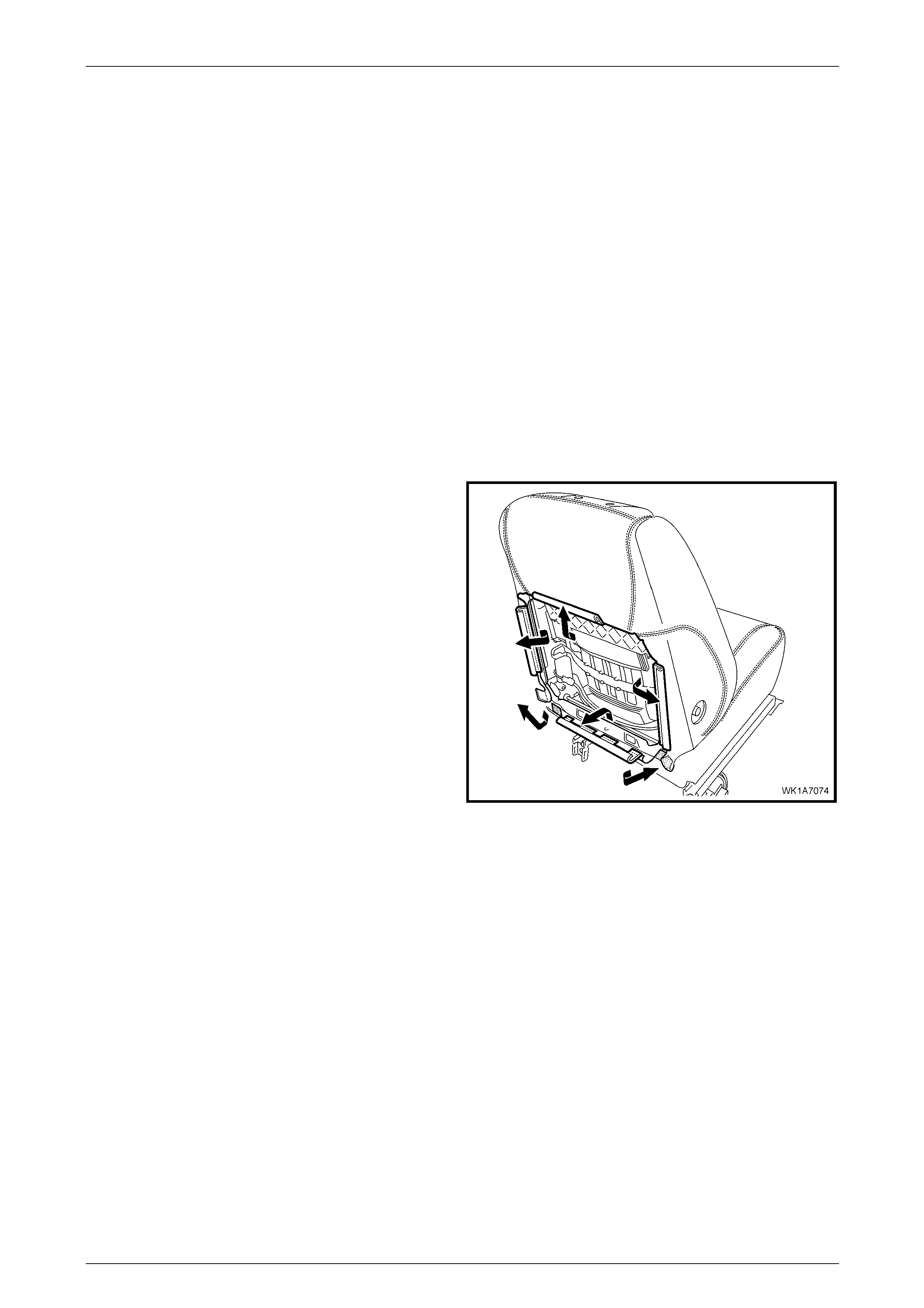
Seat Assemblies Page 1A7–216
Page 1A7–216
5.9 Front Seat-back Pad and Cover
Assembly
LT Section No. — 14–295
As required, remove the following components:
1 Front seat assembly, refer to 5.2 Front Seat Assembly.
2 Front seat outer side cover assembly, refer to 5.3 Front Seat Outer Side Cover Assembly.
3 Front seat inner side cover, refer to 5.4 Front Seat Inner Side Cover.
4 Front seat-back rear cover assembly, refer to 5.5 Front Seat-back Rear Cover Assembly.
5 Front seat head restraint assembly, refer to 5.6 Front Seat Head Restraint Assembly.
6 Front seat head restraint sleeves, refer to 5.7 Front Seat Head Restraint Sleeve.
7 Lumbar support knob assembly, refer to 5.8 Lumbar Support Knob Assembly.
Remove
1 Disengage the J-strips from the seat frame a nd the
Velcro tab at each lower corner.
2 Lift the cover and pad assembly up and away from the
seat-back frame, manoeuvring it over the seat-back
components such as the side impact airbag a nd
dummy block insert assemblies.
Figure 1A7 – 64
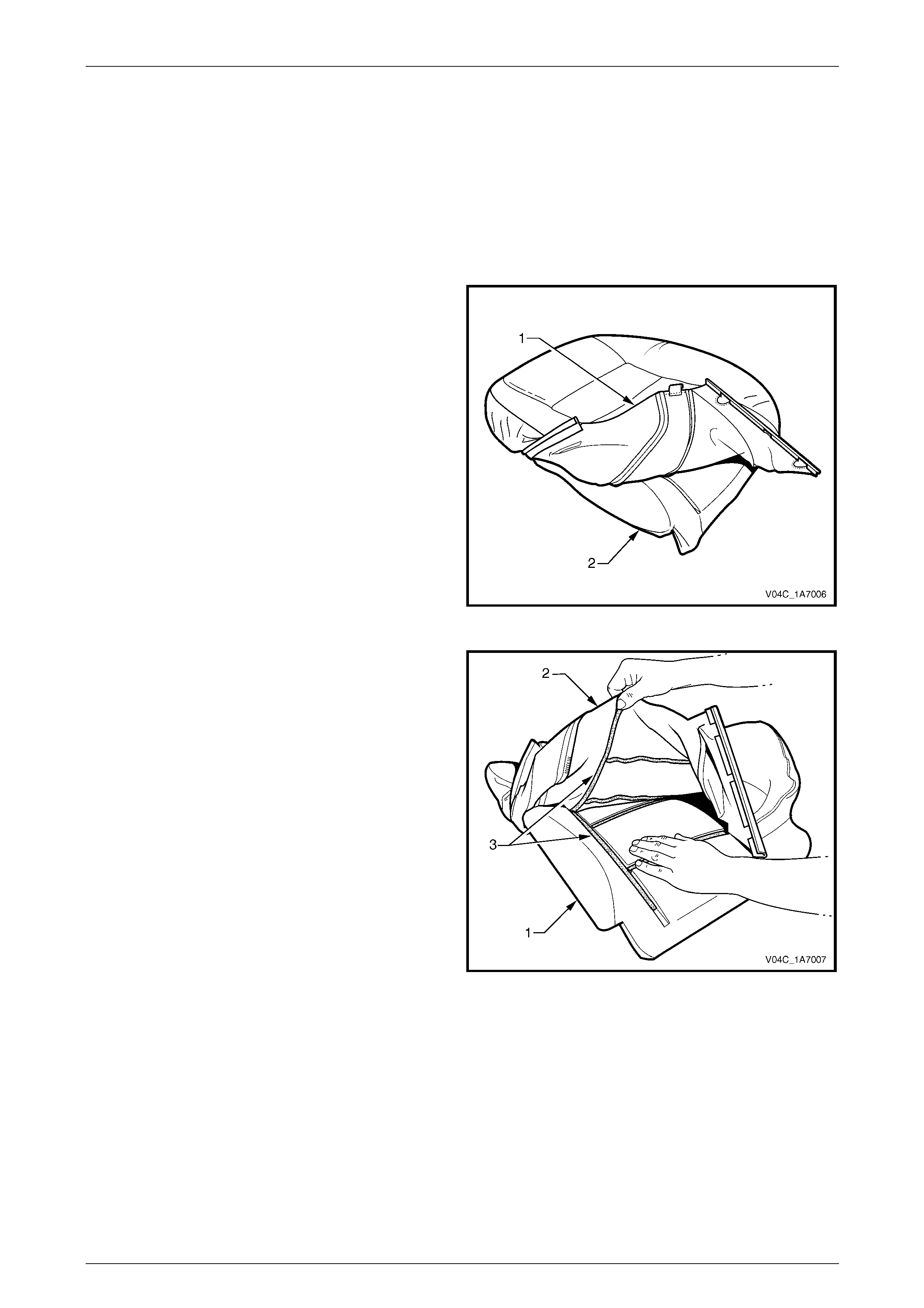
Seat Assemblies Page 1A7–217
Page 1A7–217
Disassemble
NOTE
The following illustrations show typical hook and
loop arrangement, which will vary according to
seat type.
Surebond type seat-back pad and cover
assemblies cannot be disassembled.
1 Fold the lower corners of the seat-back cove r (1) over
the seat-back pad (2).
Figure 1A7 – 65
2 While holding the front seat-back pad (1), pull the
lower corners of the front seat-back cover (2), upwards
and away from the pad to disengage the hook and
loop strips (3).
3 Pull the cover up and over the upper edge of the pad.
Figure 1A7 – 66
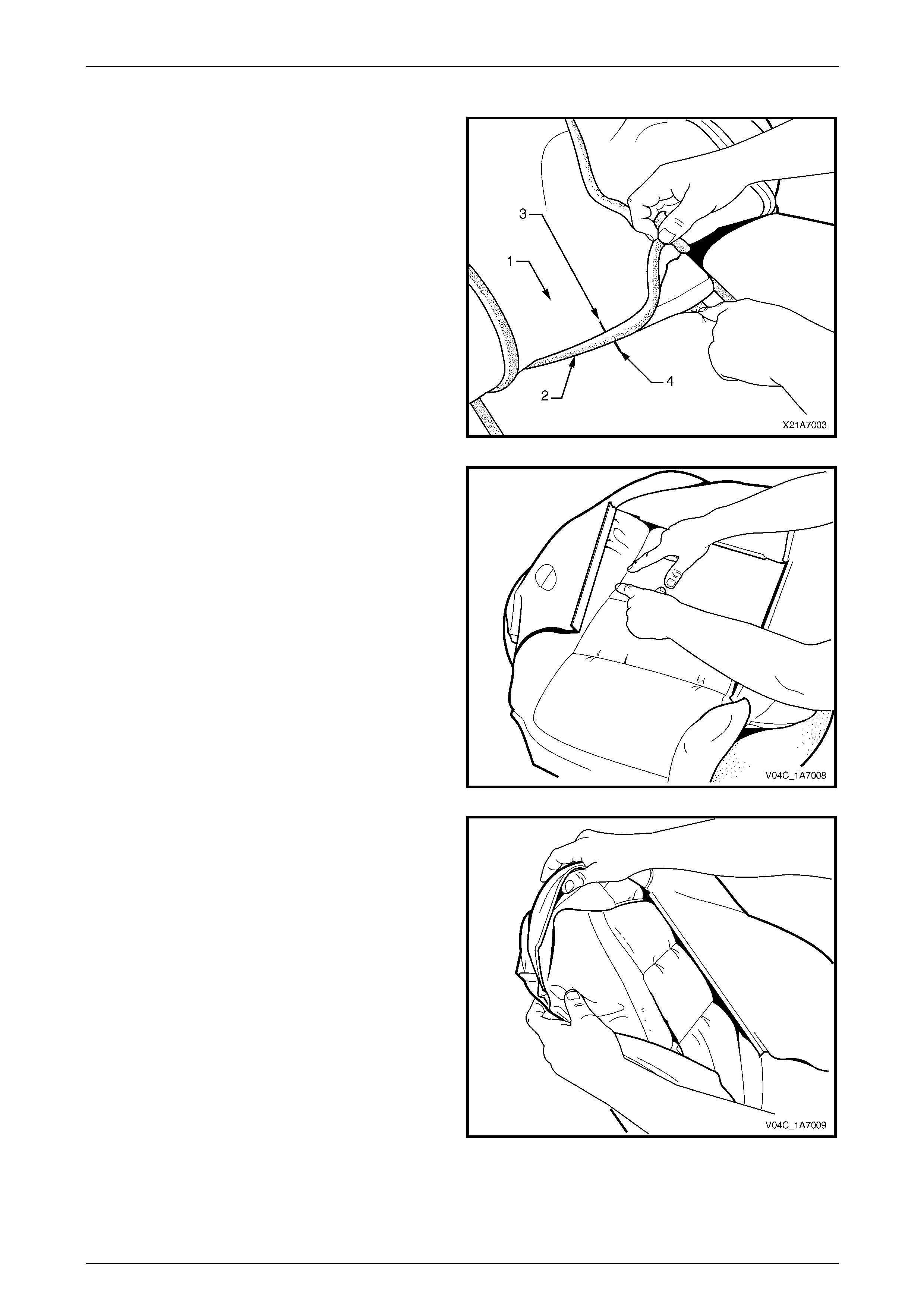
Seat Assemblies Page 1A7–218
Page 1A7–218
Reassemble
1 With the front seat-back cover (1) folded at the central
horizontal strip of hook and loop (2), align the centre
mark (3) on the cover with the centre mark (4) on the
front seat-back pad.
2 Press the cover firmly into the corresponding groove i n
the pad to engage the hook and loop.
Figure 1A7 – 67
3 With the cover folded at the two vertical strips of the
hook and loop, press the cover firml y into the
corresponding grooves in the pad.
Figure 1A7 – 68
4 Roll the upper corners of the cover over the pad.
5 Roll the sides of the cover over the pad.
6 Roll the lower corners of the cover over the pad.
NOTE
Ensure the cover is fitted neatly by hand into all
corners and contours of the pad.
Figure 1A7 – 69
Reinstall
Reinstallation of the front seat -back pad and cover assembly is the reverse of the removal proced ure.

Seat Assemblies Page 1A7–219
Page 1A7–219
5.10 Front Seat-back Frame Assembl y
When carrying a live (undeployed) side
impact airbag assembly or a front seat-back
frame assembly fitted with a (undeployed)
side impact airbag assembly, ensure the
airbag opening is pointed away from you.
Never carry the side impact airbag assembly
or seat-back frame as sembly fitted w ith a side
impact airbag assembly by the airbag wiring
harness or connectors. In case of an
accidental deployment, the airbag will then
deploy with minimal chance of injury.
When placing a live side impact airbag
assembly or a fron t seat-back fr ame as sembly
fitted with a (undeployed) side impact airbag
assembly on a bench or other surface, always
face the airbag opening up, away from the
surface. Never rest the airbag assembly or
seat-back frame with the airbag opening face
down. This is necessary so that a free space
is provided to allow the airbag to expand in
the unlikely event of accidental deployment.
Otherwise, personal injury may result.
LT Section No. — 14–275
As required remove the following c ompo ne nts:
1 Front seat assembly, refer to 5.2 Front Seat Assembly.
2 Front seat outer side cover assembly, refer to 5.3 Front Seat Outer Side Cover Assembly.
3 Front seat inner side cover, refer to 5.4 Front Seat Inner Side Cover.
Remove
1 Remove the two screws (1), each side, attaching the
seat-back assembly (2) to the front seat cushion frame
assembly (3).
2 As required, disconnect and detach the front seat-back
recline motor and side impact airbag wiring harnesses.
3 Remove the seat-back assembly.
Figure 1A7 – 70
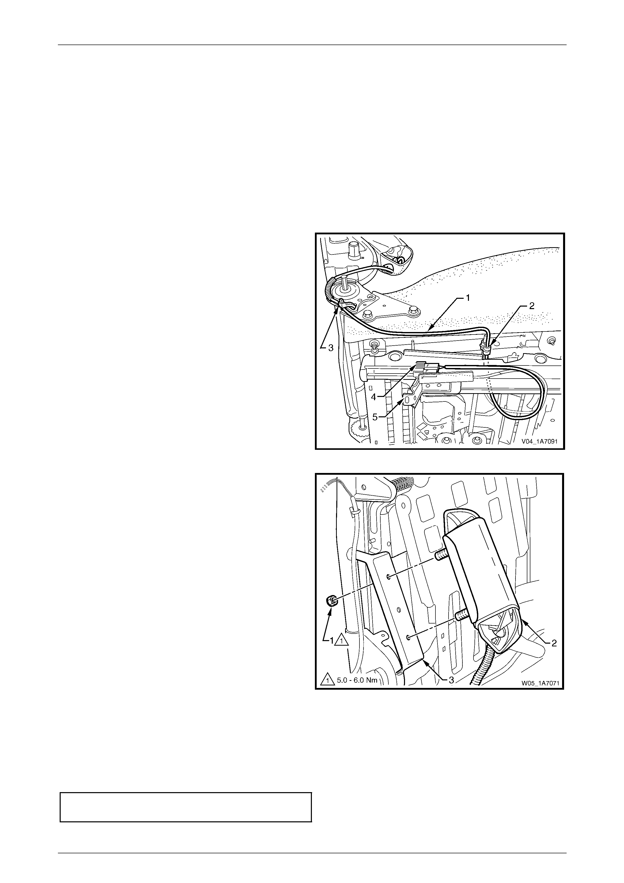
Seat Assemblies Page 1A7–220
Page 1A7–220
Disassemble
As required, remove the following components:
1 Front seat-back rear cover assembly, refer to 5.5 Front Seat-back Rear Cover Assembly.
2 Front seat head restraint assembly, refer to 5.6 Front Seat Head Restraint Assembly.
3 Front seat head restraint sleeves, refer to 5.7 Front Seat Head Restraint Sleeve.
4 Lumbar support knob assembly, refer to 5.8 Lumbar Support Knob Assembly.
Side Impact Airbag Assembly
Remove
1 As required, unclip the side impact airbag wiring
harness (1) from the retaining clip (2) and cut the
cable tie (3) securing the harness to the front seat
cushion frame assembly, taking care not to damage
the wiring harness.
2 Unclip the wiring harness connector (4) from the track
and height adjust assembly (5).
Figure 1A7 – 71
3 Remove the lock-nut (1), two places, attachi ng the
side impact airbag assembl y ( 2) to the seat-b ack
frame (3) and airbag assembly.
Figure 1A7 – 72
Reinstall
Reinstallation of the side impact airba g asse mbly is the reverse of the removal procedure, noting the following:
1 Ensure the conduit covering the wiring harness and the harness are pos itioned correctly, refer to Figure 1A7 – 71.
2 Tighten the attaching nuts to the correct torque specification.
Side impact airbag assembly attaching
nut torque specification...............................5.0 – 6.0 Nm
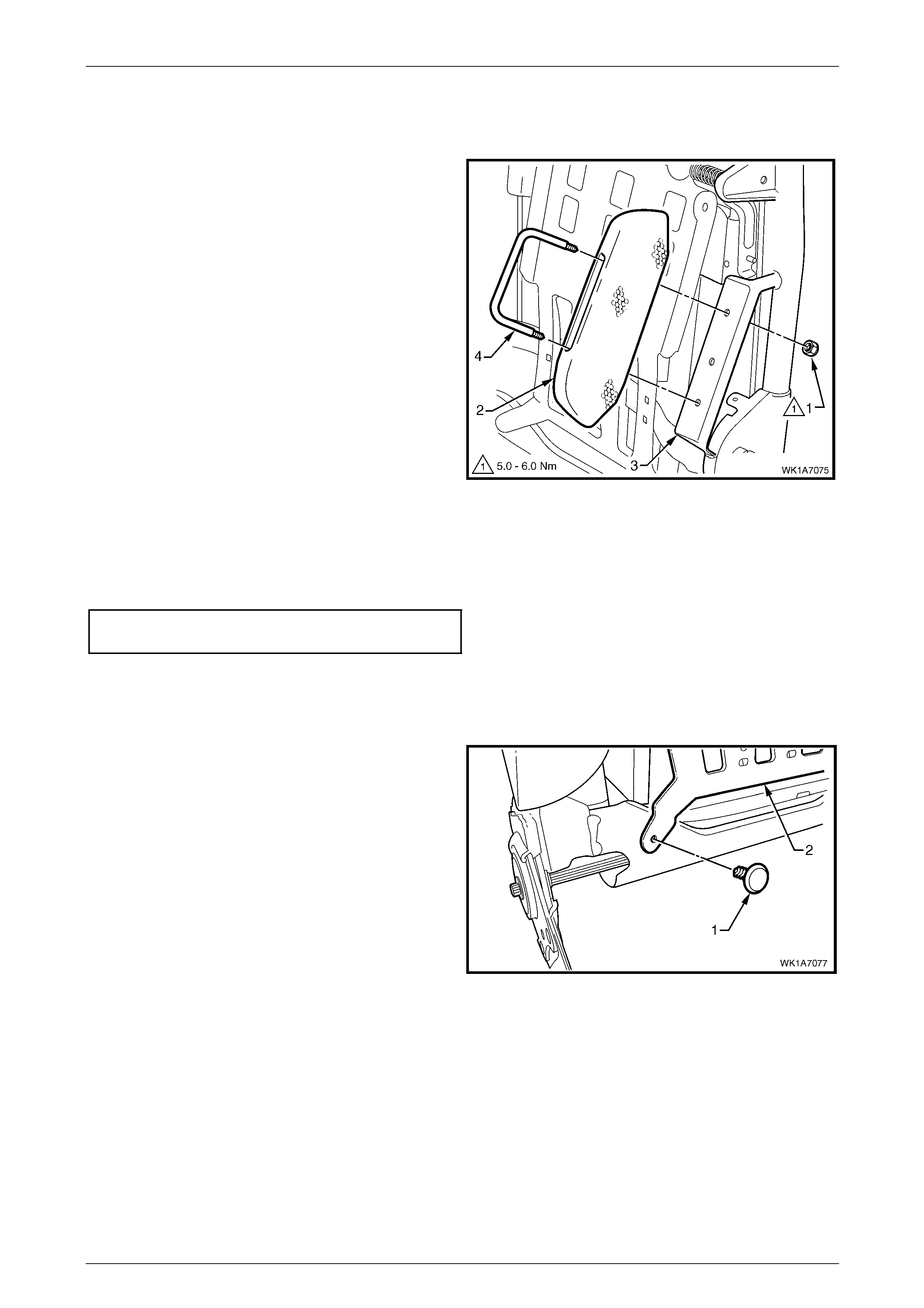
Seat Assemblies Page 1A7–221
Page 1A7–221
Front Seat Dummy Block Insert Assembly
Remove
1 Remove the lock-nut (1), two places, attachi ng the
front seat dummy block insert (2) to the seat-back
frame (3) and remove the dummy block insert
assembly.
2 If required, remove the dummy block U-bolt (4) from
the dummy block insert.
Figure 1A7 – 73
Reinstall
Reinstallation of the front seat dummy block insert assembly is the reverse of the removal procedure. Tighten the
attaching nuts to the correct torque specification.
Front seat dummy block insert assembly
attaching nut torque specification................5.0 – 6.0 Nm
Lumbar Support Assembly
Remove
1 Remove the retainer (1), t wo places, attaching the
lumbar support assembly (2) to the seat-back frame.
Figure 1A7 – 74
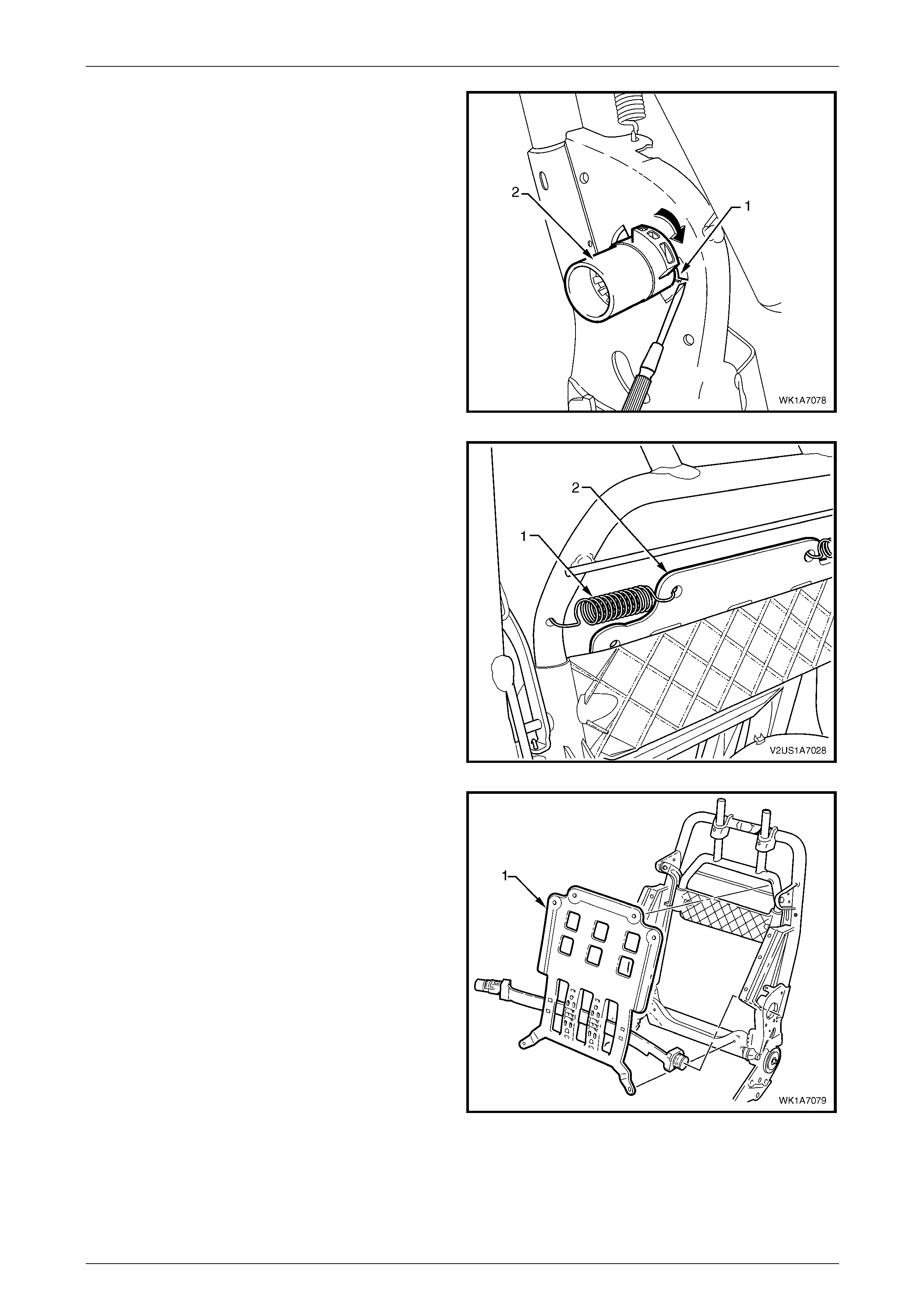
Seat Assemblies Page 1A7–222
Page 1A7–222
2 Depress the retaining tab (1) and from the inner side
of the seat-back frame, rotate the lumbar support
shaft (2) and withdraw from the seat-back frame.
3 Repeat for the opposite side.
Figure 1A7 – 75
4 Disconnect the spring (1), two places, attaching the
lumbar support assembly (2) to the seat-bac k frame or
active head restraint frame.
TIP
To aid spring remova l, pull the support asse mbly
toward the side the spring is being removed to
relieve spring tension.
Figure 1A7 – 76
5 Remove the lumbar support assembly (1).
Figure 1A7 – 77
Reinstall
Reinstallation of the lumbar s upport assembly is the reverse of the removal procedure. Ensure the lumbar support
assembly is correctly seated on the cushion side of the active head restraint frame, where fitted, with the black lumbar
support shaft on the outer side of the seat.
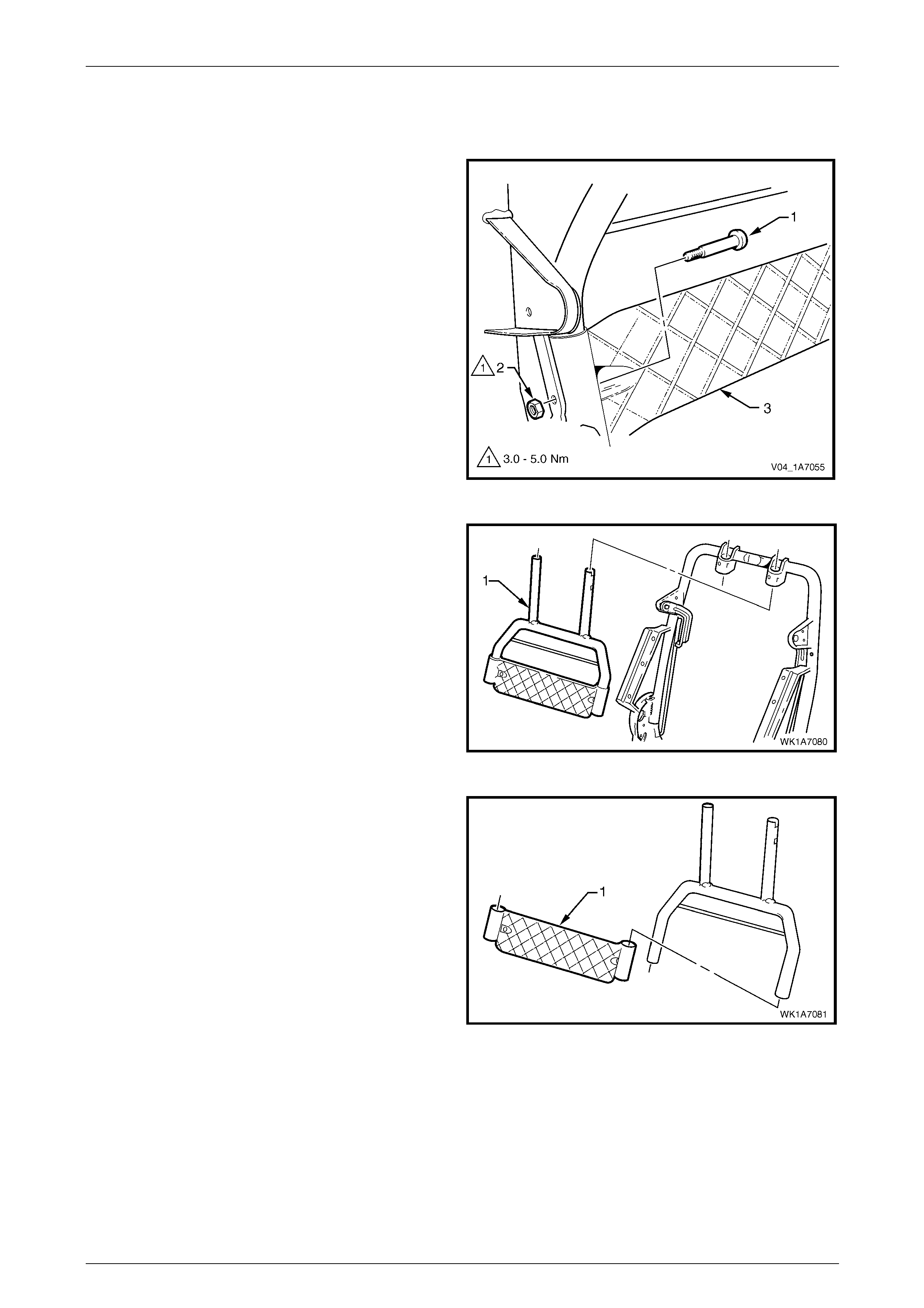
Seat Assemblies Page 1A7–223
Page 1A7–223
Active Head Restraint Frame Assembly
Remove
1 Remove the screw (1) and nut (2), t wo places,
attaching the active head restraint frame assembly (3)
to the seat-back frame hinge.
Figure 1A7 – 78
2 Withdraw the active head restraint frame assembly (1)
downward to remove it from the seat-back frame and
remove.
Figure 1A7 – 79
3 If required, slide the support strap (1) from the active
head restraint frame.
Figure 1A7 – 80

Seat Assemblies Page 1A7–224
Page 1A7–224
4 If required, depress the tab (1), two places, and
withdraw the active head restraint frame sleeve (2)
from the seat-back frame.
5 Repeat for the opposite sleeve as requ ired.
Figure 1A7 – 81
6 If required, remove the spring (1), from the active head
restraint frame hinge and seat-back frame.
7 Repeat for the opposite side as required.
Figure 1A7 – 82
Reinstall
Reinstallation of the active head restraint frame assembly is the reverse of the removal proced ure. Tighten the attaching
nuts to the correct torque specification.
Active head restraint frame assembly
attaching nut torque specification................3.0 – 5.0 Nm
Reinstall
Reinstallation of the front seat -back frame assembly is the reverse of the removal proced ure, notin g the following:
1 Tighten the attaching screws to the correct torque specific ation.
Front seat-back frame assembly
attaching screw torque specification.......30.0 – 45.0 Nm
2 Check the mechanical and elec trical operation of the front seat.
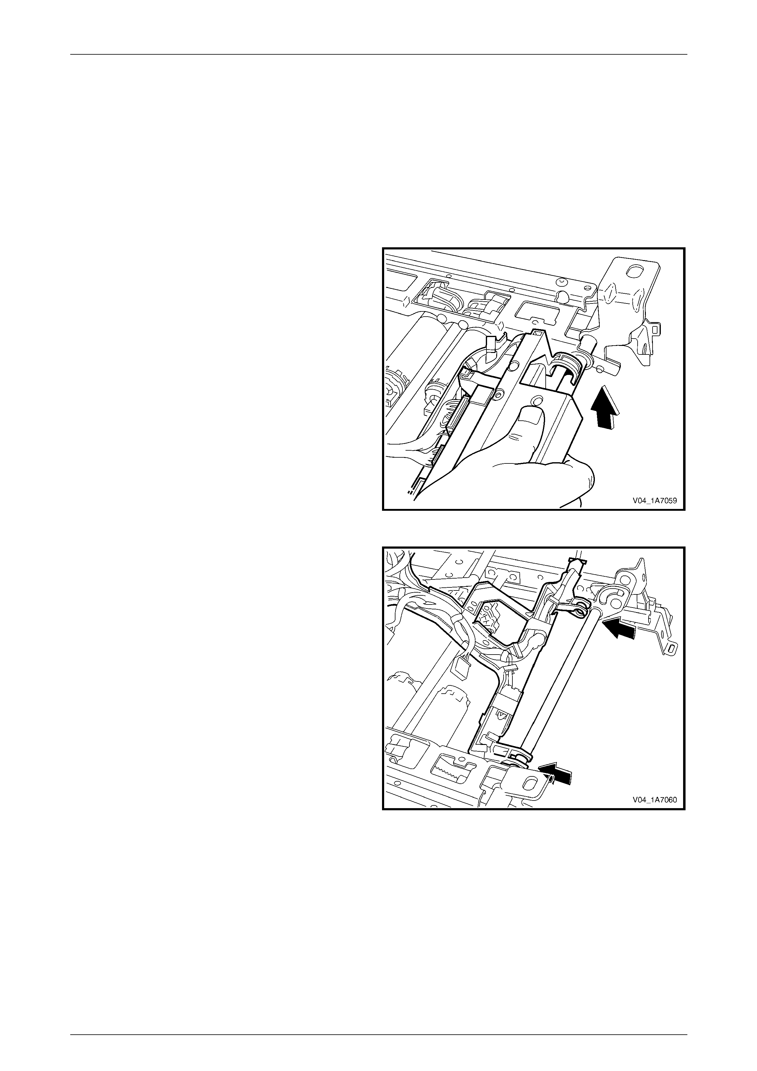
Seat Assemblies Page 1A7–225
Page 1A7–225
5.11 Seat Cable Tray and Memory Module
Remove
1 Remove the front seat assembly, refer to 5.2 Front Seat Assembly.
2 Remove the seat track and height adjust ass embl y, refer to 5.12 Track and Height Adjust Assembly.
3 Disconnect the wiring harness connectors as required.
4 Unclip the cable tray from the front of the seat track
and height adjust assembly.
Figure 1A7 – 83
5 Pull the cable tray forward to release it from the seat
track and height adjust assembl y.
Figure 1A7 – 84
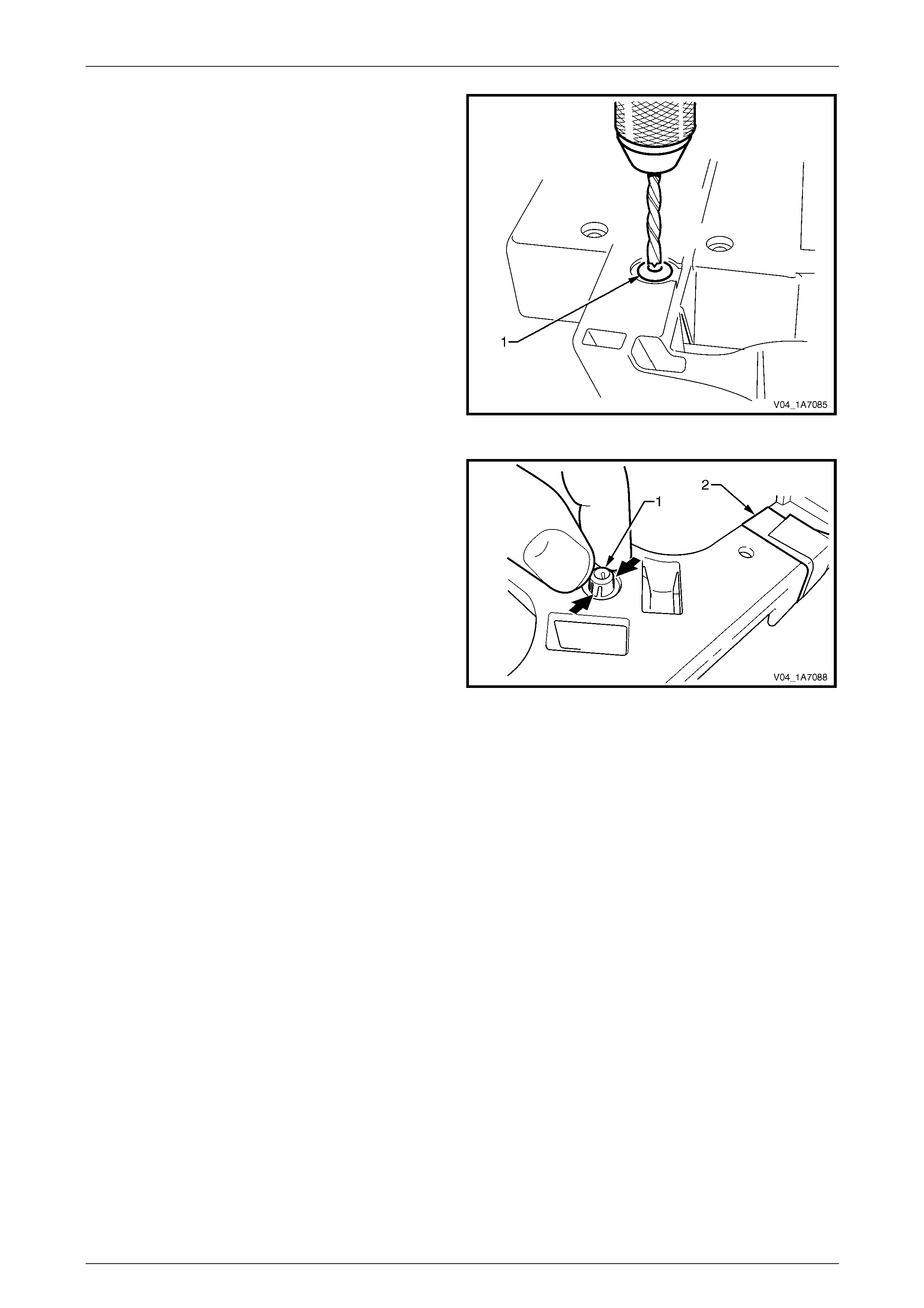
Seat Assemblies Page 1A7–226
Page 1A7–226
6 If required, use a 5 mm drill bit and dri ll out the pop
rivet (1), two places, securing the seat memory
module to the cable tray.
7 Remove the seat memory module.
Figure 1A7 – 85
8 If required, remove the wiring harness from the cable
tray by squeezing the tabs on the harness clips (1)
and by removing the tape (2).
Figure 1A7 – 86
Reinstall
Reinstallation of the seat memor y module is the reverse of the removal procedure, noting the following:
1 Ensure the wiring harness an d connectors are correctly routed and attach ed securely.
2 Use new pop rivets.

Seat Assemblies Page 1A7–227
Page 1A7–227
5.12 Track and Height Adjust Assembly
The track and height adjust assembly
components are non-serviceable. If the track
and height adjust assembly, drive motors or
drive shafts require replacement, the entire
track and height adjust assembly must be
replaced.
LT Section No. — 14–275
As required, remove the following components:
1 Front seat assembly, refer to 5.2 Front Seat Assembly.
2 Front seat outer side cover assembly, refer to 5.3 Front Seat Outer Side Cover Assembly.
Remove
1 As required, detach the wiring harness connectors.
2 As required, detach the seatbelt pretensioner and side airbag wiring harnesses.
3 Remove the four nuts (1) attaching the track and
height adjust assembly (2) to the seat.
4 Remove the track and height adjust assembly.
5 If required, remove the cable tray and wiring harness
assembly, refer to 5.11 Seat Cable Tray and Memory
Module.
6 If required, remove the seatbelt buckle and
pretensioner assembly, refer to Section 12M Occupant
Protection System.
Figure 1A7 – 87
Reinstall
Reinstallation of the track and height adjust assembly is the reverse of the removal procedur e, noting the following:
1 Ensure the connectors are correctly routed and attach ed securely.
2 Tighten the attaching nuts to the correct torque spec ification.
Track and height adjust assembly
attaching nut torque specification............24.0 – 32.0 Nm
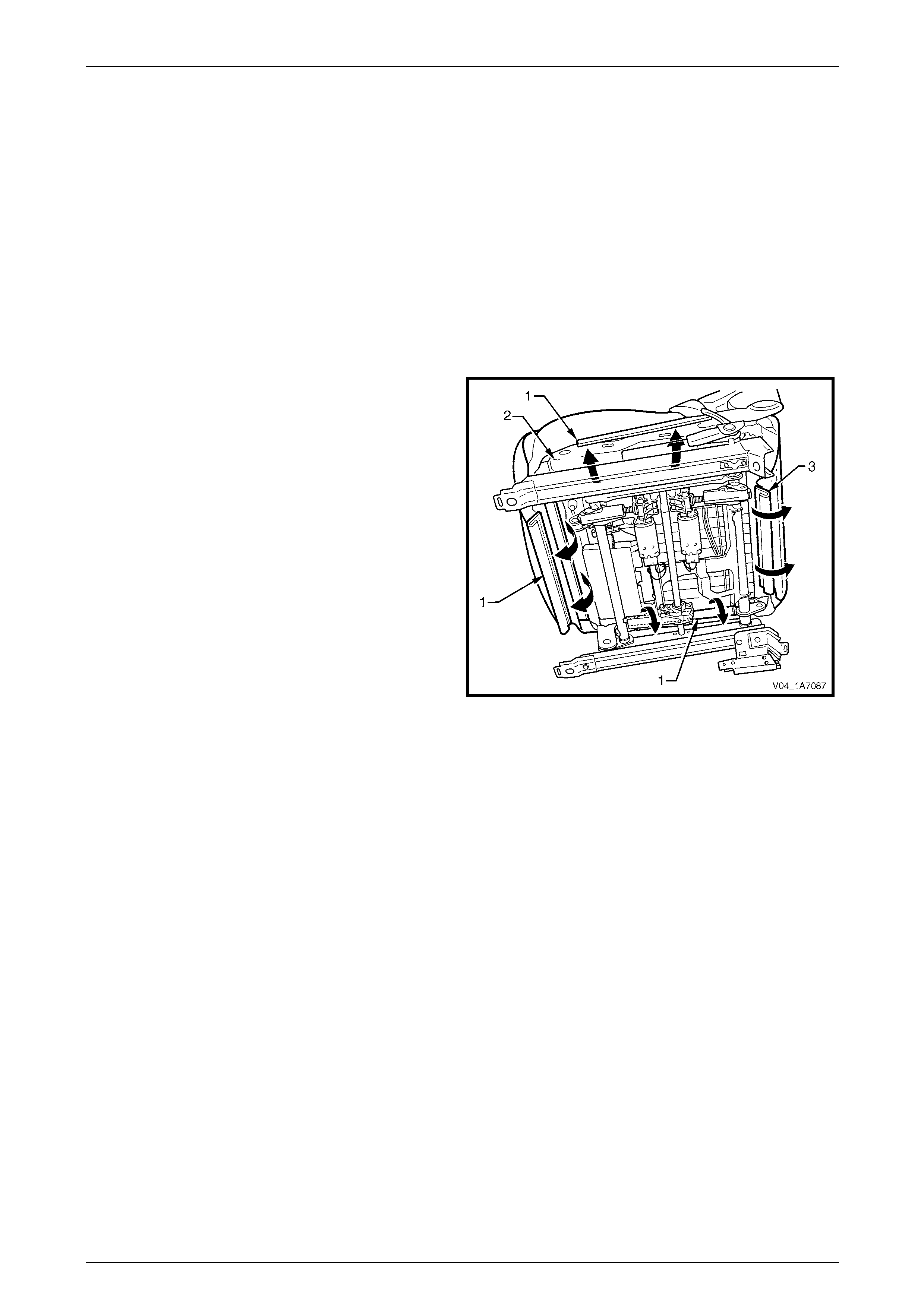
Seat Assemblies Page 1A7–228
Page 1A7–228
5.13 Front Seat Cushion Pad and Cover
Assembly
LT Section No. — 14–295
As required, remove the following components:
1 Front seat assembly, refer to 5.2 Front Seat Assembly.
2 Front seat outer side cover assembly, refer to 5.3 Front Seat Outer Side Cover Assembly.
3 Front seat inner side cover, refer to 5.4 Front Seat Inner Side Cover.
4 Front seat-back frame assembly, refer to 5.10 Front Seat-back Frame Assembly.
Remove
1 From under the front seat cushion, disengage the front
and side J-strips (1) away from the seat frame (2).
2 Lift the cover and pad assembly a way from the seat
frame and then release the rear J-strip (3).
3 Remove the pad and cover assembly.
Figure 1A7 – 88

Seat Assemblies Page 1A7–229
Page 1A7–229
Disassemble
NOTE
The following illustrations show typical hook and
loop arrangement, which will vary according to
seat type.
Surebond type seat-back pad and cover
assemblies cannot be disassembled.
1 Fold the rear corners of the front seat cushion
cover (1) over the front seat cushion pad (2).
Figure 1A7 – 89
2 While holding the front seat cushi on pad (1), pull the
rear corners of the front seat cushion cover (2) forward
and away from the pad to disengage the hook and
loop strips (3).
3 Pull the cover up and over the forward edge of the
pad.
Figure 1A7 – 90
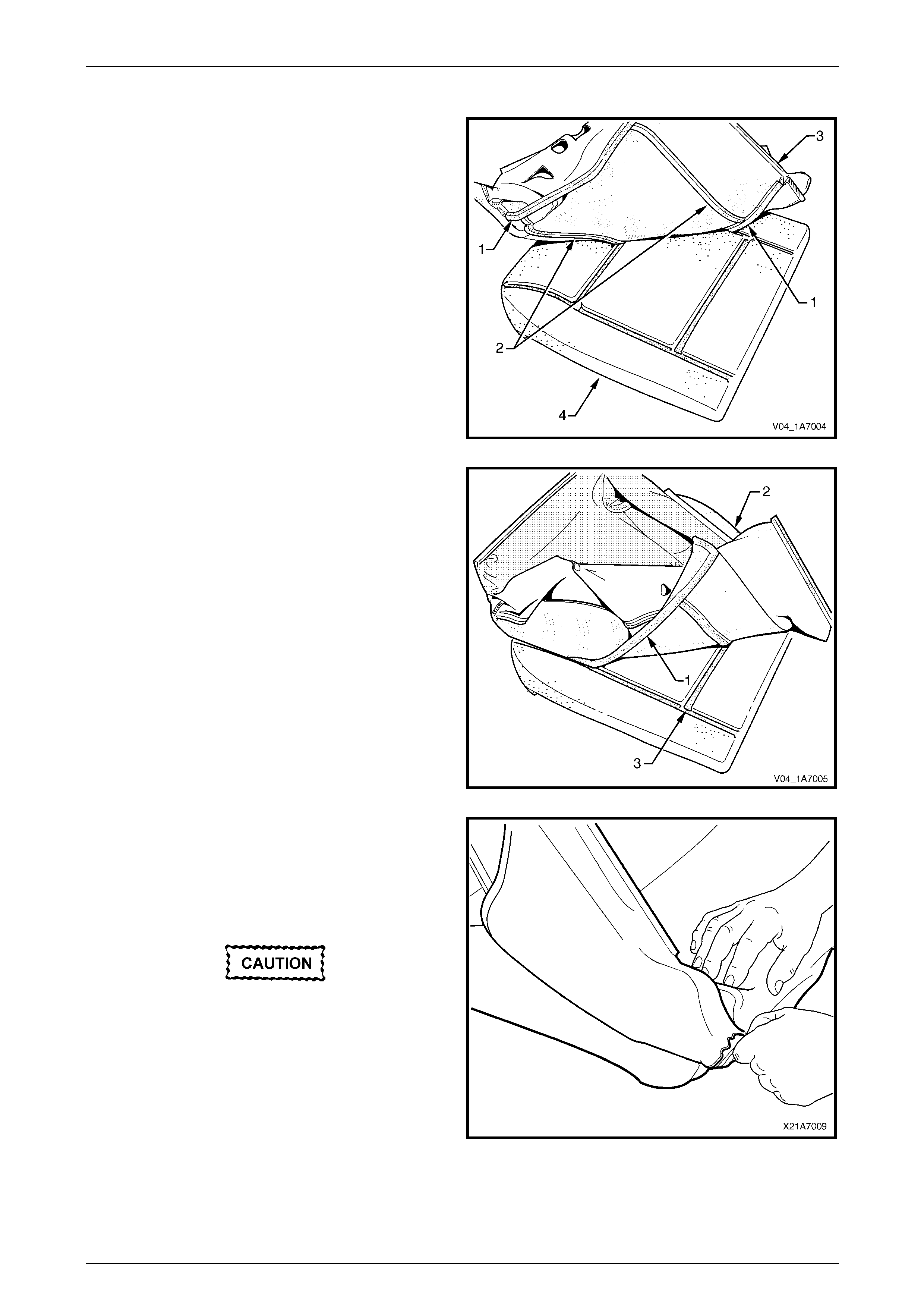
Seat Assemblies Page 1A7–230
Page 1A7–230
Reassemble
1 Align either of the outer hook and l oo p strips (1) and
the one or two cross hook and loop strips (2) on the
front seat cushion cover (3) with the front seat cushion
pad (4).
2 Press the folded edge of the cover firmly into the
corresponding groove in the pad to engage the hook
and loop strip.
Figure 1A7 – 91
3 Align and press the outer hook and loop strip (1), on
the cover (2), with the corresponding groove in the
pad (3).
Figure 1A7 – 92
4 Roll the front corners of the cover over the pad.
5 Roll the sides of the cover over the pad.
6 Roll the rear corners of the cover over the pad.
NOTE
Ensure the pad is fitted neatly by hand into all
corners and contours of the seat cover.
Do not pull the cover onto the pad from
underneath using the J-strip to make it fit
neatly, as the fabric may be damaged.
Figure 1A7 – 93
Reinstall
Reinstallation of the front seat cushion pad and cover assembly is the reverse of the removal procedure.
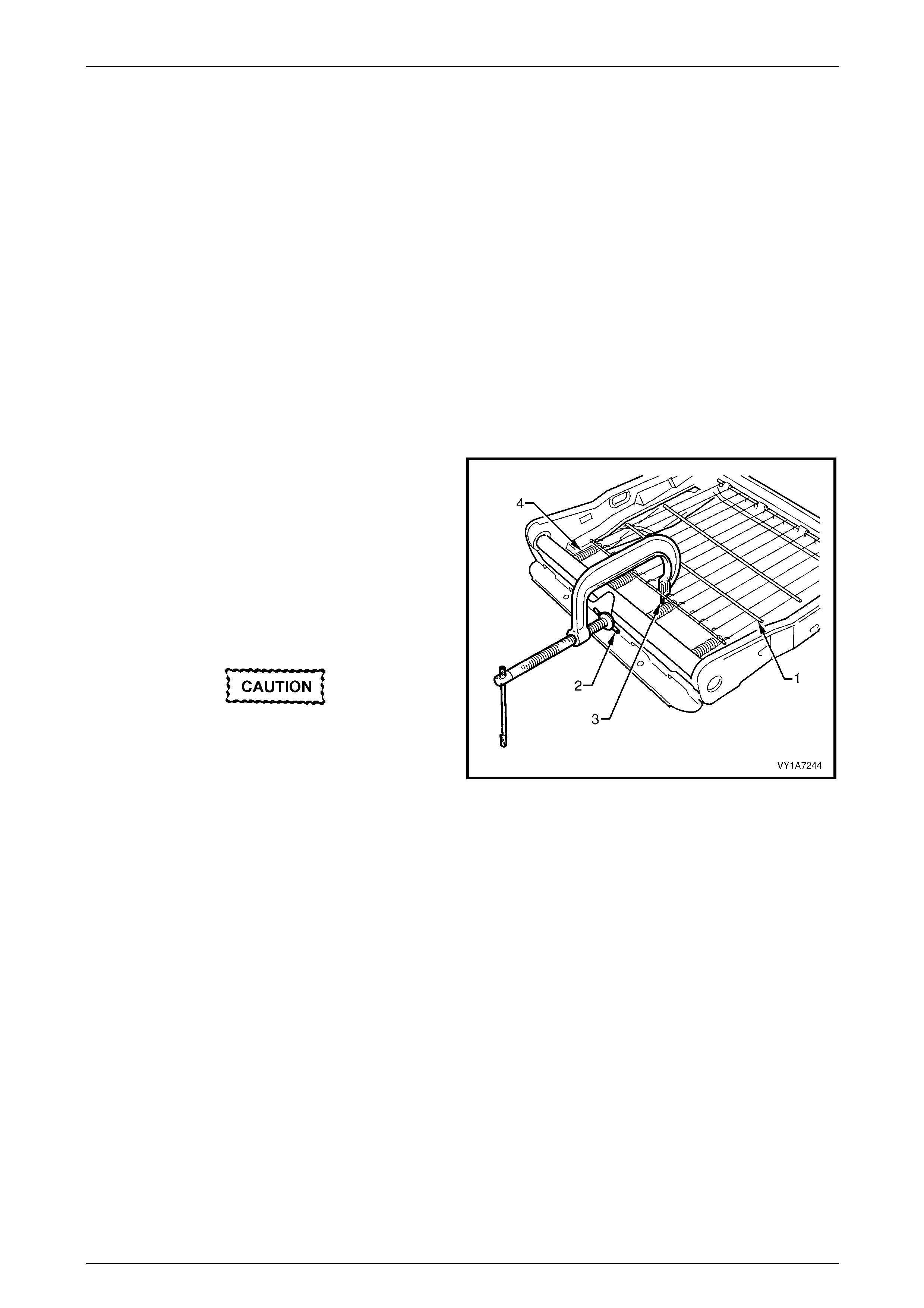
Seat Assemblies Page 1A7–231
Page 1A7–231
5.14 Front Seat Cushion Frame Assembly
LT Section No. — 14–275
Remove
As required remove the following c ompo ne nts:
1 Front seat assembly, refer to 5.2 Front Seat Assembly.
2 Front seat outer side cover assembly, refer to 5.3 Front Seat Outer Side Cover Assembly.
3 Front seat inner side cover, refer to 5.4 Front Seat Inner Side Cover.
4 Front seat-back frame assembly, refer to 5.10 Front Seat-back Frame Assembly.
5 Track and height adjust assembly, refer to 5.12 Track and Height Adjust Assembly.
6 Front seat cushion pad and cover assembly, refer to 5.13 Front Seat Cushion Pad and Cover Assembly.
Disassemble
1 To remove the suspension mat (1), modify a G-clamp
with a 5 mm diameter metal dowel (2) welded to one
end and another approximately 40 mm long and with a
2 mm diameter pin (3) approximately 20 mm l ong
welded to the other end.
2 Using the G-clamp, stretch the suspension mat far
enough to allow the four retaining springs (4) to be
removed from the seat cushion frame.
3 Back the G-clamp load off and remove the suspensio n
mat.
When using the G-clamp, use existing holes
in the suspension mat to ensure mat
deformation does not occur.
Figure 1A7 – 94
Reassemble
Reassembly of the suspension mat is the reverse of the disassembl y proc edure.
Reinstall
Reinstallation of the front seat cushion frame assembly is the reverse of the removal pro cedure, noting the following:
1 Ensure all wiring is correctly connected and routed, refer to Section 12O Fuses, Relays and Wiring Harnesses.
2 Check the mechanical and elec trical operation of the front seat.

Seat Assemblies Page 1A7–232
Page 1A7–232
5.15 Front Seat Lift Motor Assemblies
The front seat lift motor assemblies are non-serviceabl e items.
If a front seat lift motor assembly requires replacement, the track and height adjust assembly must be replaced,
refer to 5.12 Track and Height Adjust Assembly.

Seat Assemblies Page 1A7–233
Page 1A7–233
5.16 Front Seat Fore/Aft Movement Motor
Assembly
The front seat fore/aft movement motor assembl y is a non-serviceable item.
If the front seat fore/aft movement motor or drive shafts require replacement, the track and height adjust assembly must
be replaced, refer to 5.12 Track and Height Adjust Assembly.

Seat Assemblies Page 1A7–234
Page 1A7–234
5.17 Front Seat-back Recline Motor Assembly
The front seat-back recline motor assembly is a non-serviceable item.
If the front seat-back recline motor assembly requires replacement, the fron t seat-back frame assembly must be
replaced, refer to 5.10 Front Seat-back Frame Assembl y.

Seat Assemblies Page 1A7–235
Page 1A7–235
5.18 Drive Motor Hall-effect Sensors
The front seat drive motor hall-effect sensors are non-serviceable items.
If the front seat fore/aft movement and/or front seat lift motor hall-effect sensors require replacement, the track and
height adjust assembly must be replaced, refer to 5.12 Track and Height Adjust Assembly.
If the seat-back recline motor hall-effect sensor requires replacement, the front seat-back frame assem bl y must be
replaced, refer to 5.10 Front Seat-back Frame Assembl y.

Seat Assemblies Page 1A7–236
Page 1A7–236
6 Service Operations – Front Seat,
Regular Cab and Utili ty
6.1 Usage Chart
How to Use this Chart
The following usage chart is provided to help determine the seat type fitted to the vehicle. T his is important prior to
repairs being performed as the failed/damaged part may not be serviceable.
To determine the seat type fitted to the vehicle, obtain the vehicl e model, which seat requires attention and the seat
cover fabric. Establish other features of the seat such as th e electric movement functions. Using the chart will lead to the
elimination of all other seat combinations, al lowing for the identification of the type and the constructio n of the seat. Refer
to the Figure number shown in Front Seat Type column for a component break down of the front seat assembly.
1 Vehicle – Vehicle model identification.
2 Seating – Driver front seat or passenger front seat.
3 Fabric – Cloth or leather seat covers.
4 Movement – Indicates the number of movement functions of the seat:
• Two-way – Seat cushion mechanical fore/aft movement.
• Four-way – As two-way plus seat cushion electric front and rear raise/lower.
5 Memory – Indicates if a seat memory module is fitted.
6 SIAB – Indicates if the seat is fitted with a side impact airbag assembly.
7 Construction – Surebond refers to the seat cover being glued to the seat pad. This type is serviced as a pad and
cover assembly only. Hook and Loop refers to the seat cover being attached to the seat pad with a Velcro type
material and both being serviced as separate parts.
8 Head Restraint – Indicates whether fixed or active head res t raints are fitted.
9 Front Seat Type – Identifies the seat type and provides reference to illustrations which show a breakdown of the
serviced component for each front seat assembly.
Vehicle Seating Fabric Movement Memory SIAB Construction Active Head
Restraint Front Seat Type
(refer to)
Driver Cloth Four-way No No Surebond No 1
(Figure 1A7 – 95)
Reg Cab,
Utility
Passenger Cloth Two-way No No Surebond No 2
(Figure 1A7 – 96)
Driver Cloth Four-way No No Hook & Loop No 3
(Figure 1A7 – 97)
S Reg Cab,
S Utility
Passenger Cloth Two-way No No Hook & Loop No 4
(Figure 1A7 – 98)
Driver Cloth/
Leather Four-way No No Hook & Loop No 5
(Figure 1A7 – 99)
SS Reg
Cab,
SS Utility Passenger Cloth/
Leather Two-way No No Hook & Loop No 6
(Figure 1A7 – 100)
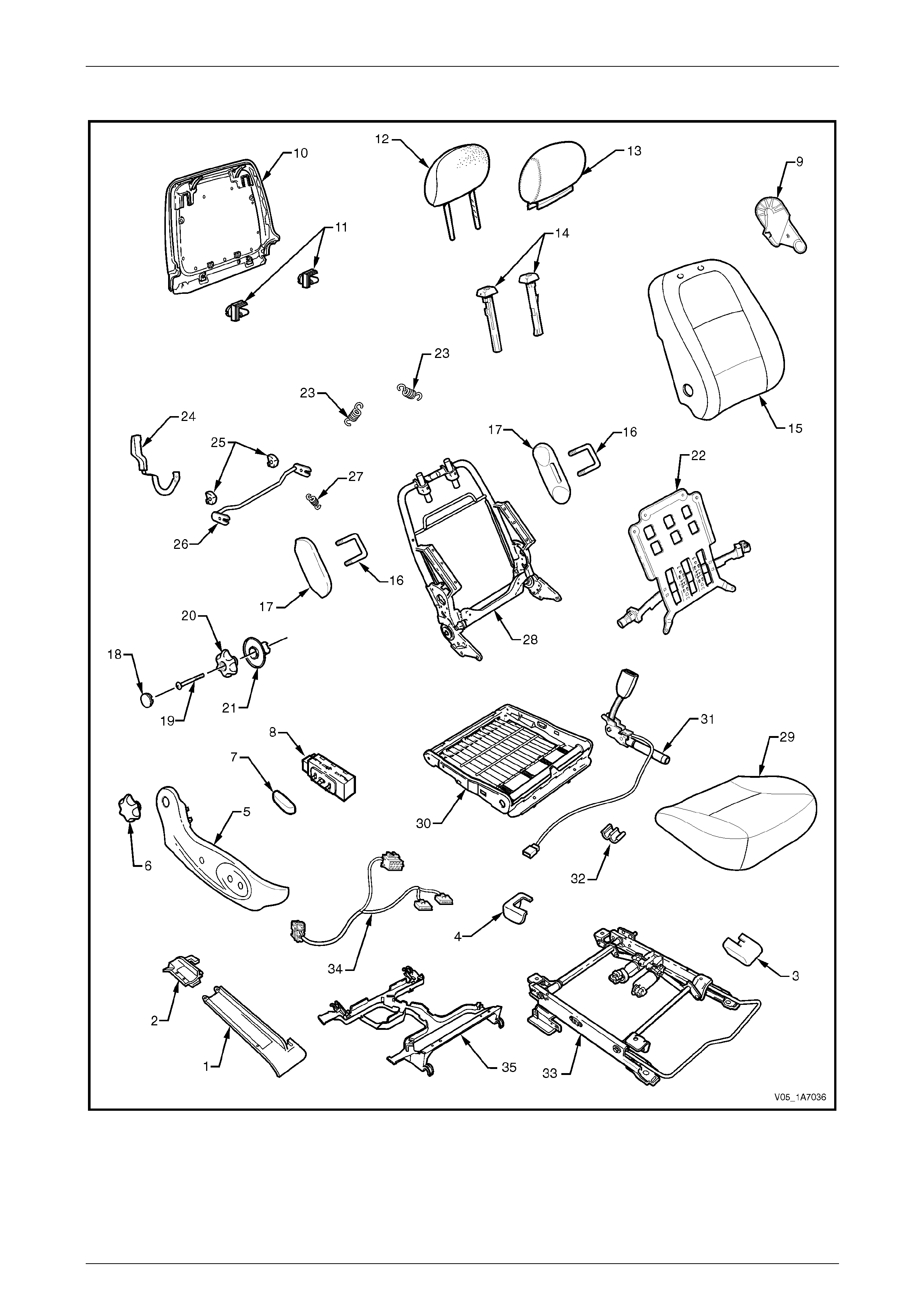
Seat Assemblies Page 1A7–237
Page 1A7–237
Front Seat Type 1
Figure 1A7 – 95

Seat Assemblies Page 1A7–238
Page 1A7–238
Legend
1 Front Seat Outer Front Cover
2 Front Seat Outer Rear Cover
3 Front Seat Inner Front Cover
4 Front Seat Inner Rear Cover
5 Front Seat Outer Side Cover
6 Recline Adjuster Knob
7 Front Seat Adjustment Switch Knob
8 Front Seat Adjustment Switch
9 Front Seat Inner Side Cover
10 Front Seat-back Rear Cover
11 Front Seat-back Rear Cover Retaining Clips
12 Front Seat Head Restraint Pad Assembly
13 Front Seat Head Restraint Cover
14 Front Seat Head Restraint Sleeves
15 Front Seat-back Pad and Cover Assembly
16 Front Seat Dummy Block U-bolt
17 Front Seat Dummy Block Insert
18 Lumbar Support Knob Cover
19 Lumbar Support Knob Screw
20 Lumbar Support Knob
21 Lumbar Support Deflector Ring
22 Lumbar Support Assembly
23 Lumbar Support Retaining Spring
24 Dump-latch Release Lever
25 Dump-latch Release Rod Retainer
26 Dump-latch Release Rod
27 Dump-latch Release Spring
28 Front Seat-back Frame Assembly
29 Front Seat Cushion Pad and Cover Assembly
30 Front Seat Cushion Frame Assembly
31 Seatbelt Buckle and Pretensioner Assembly
32 Wiring Harness Retaining Clip
33 Track and Height Adjust Assembly
34 Wiring Harness Assembly
35 Front Seat Cable Tray
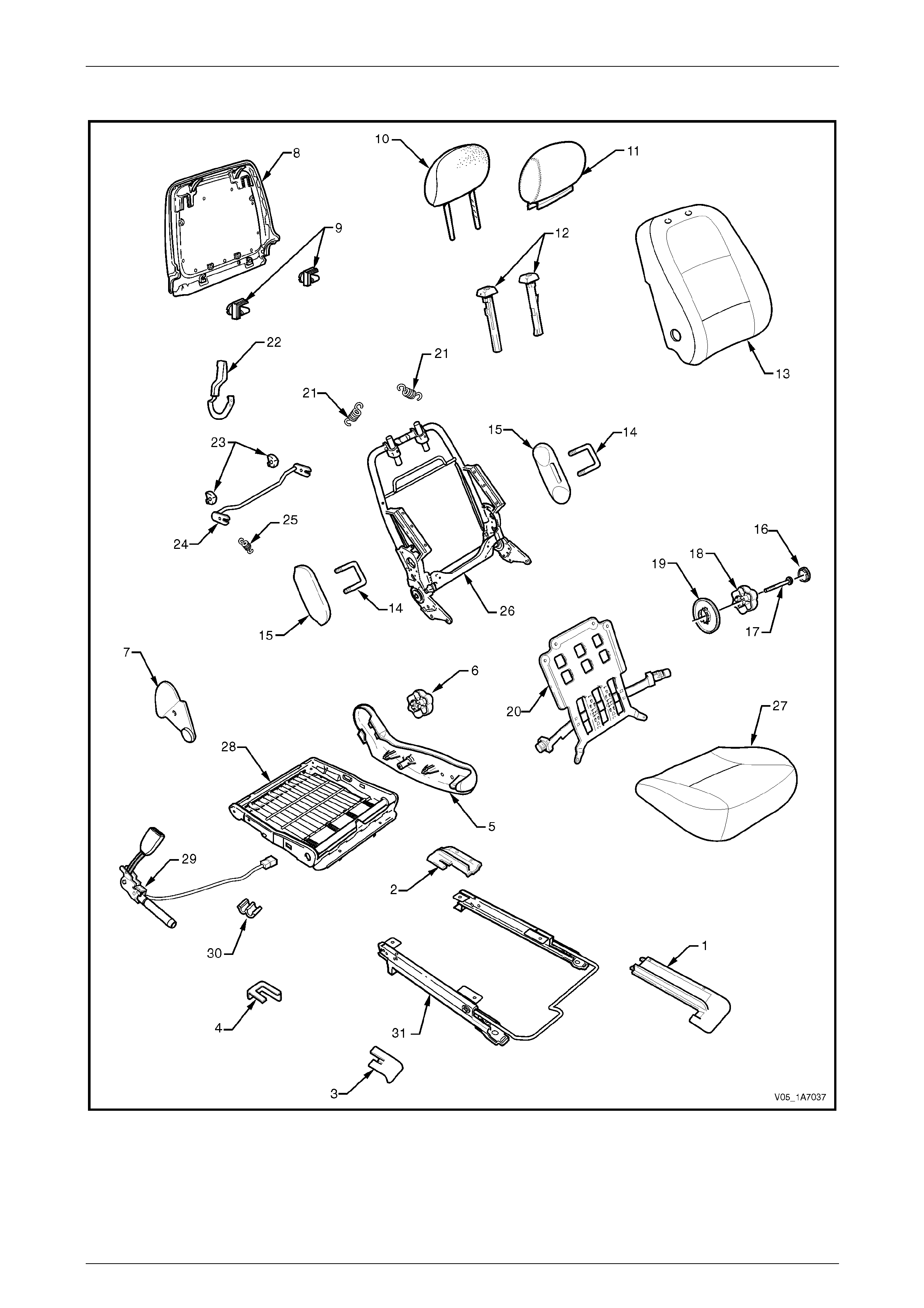
Seat Assemblies Page 1A7–239
Page 1A7–239
Front Seat Type 2
Figure 1A7 – 96

Seat Assemblies Page 1A7–240
Page 1A7–240
Legend
1 Front Seat Outer Front Cover
2 Front Seat Outer Rear Cover
3 Front Seat Inner Front Cover
4 Front Seat Inner Rear Cover
5 Front Seat Outer Side Cover
6 Recline Adjuster Knob
7 Front Seat Inner Side Cover
8 Front Seat-back Rear Cover
9 Front Seat-back Rear Cover Retaining Clips
10 Front Seat Head Restraint Pad Assembly
11 Front Seat Head Restraint Cover
12 Front Seat Head Restraint Sleeves
13 Front Seat-back Pad and Cover Assembly
14 Front Seat Dummy Block U-bolt
15 Front Seat Dummy Block Insert
16 Lumbar Support Knob Cover
17 Lumbar Support Knob Screw
18 Lumbar Support Knob
19 Lumbar Support Deflector Ring
20 Lumbar Support Assembly
21 Lumbar Support Retaining Spring
22 Dump-latch Release Lever
23 Dump-latch Release Rod Retainer
24 Dump-latch Release Rod
25 Dump-latch Release Spring
26 Front Seat-back Frame Assembly
27 Front Seat Cushion Pad and Cover Assembly
28 Front Seat Cushion Frame Assembly
29 Seatbelt Buckle and Pretensioner Assembly
30 Wiring Harness Retaining Clip
31 Track and Height Adjust Assembly
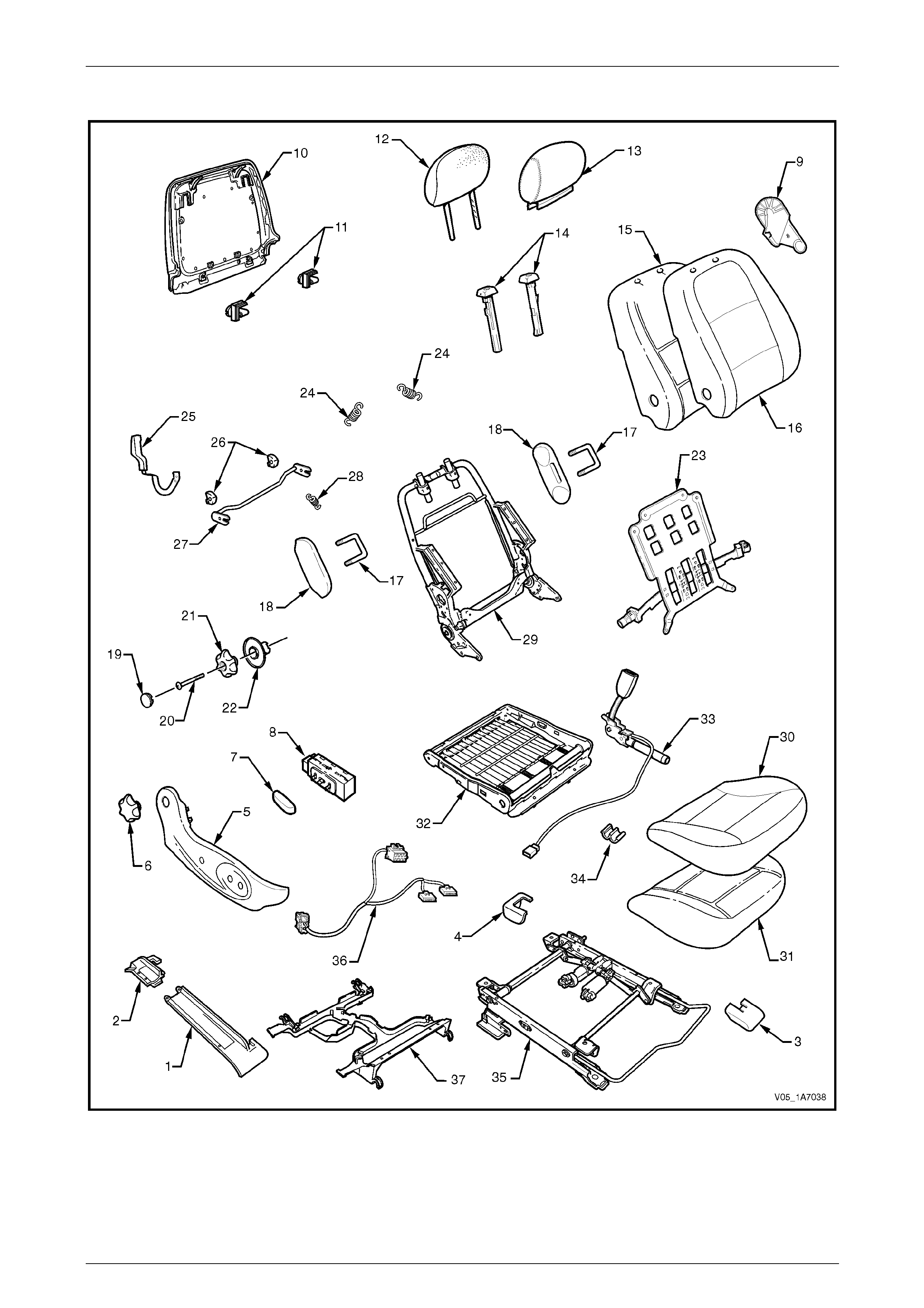
Seat Assemblies Page 1A7–241
Page 1A7–241
Front Seat Type 3
Figure 1A7 – 97

Seat Assemblies Page 1A7–242
Page 1A7–242
Legend
1 Front Seat Outer Front Cover
2 Front Seat Outer Rear Cover
3 Front Seat Inner Front Cover
4 Front Seat Inner Rear Cover
5 Front Seat Outer Side Cover
6 Recline Adjuster Knob
7 Front Seat Adjustment Switch Knob
8 Front Seat Adjustment Switch
9 Front Seat Inner Side Cover
10 Front Seat-back Rear Cover
11 Front Seat-back Rear Cover Retaining Clips
12 Front Seat Head Restraint Pad Assembly
13 Front Seat Head Restraint Cover
14 Front Seat Head Restraint Sleeves
15 Front Seat-back Pad
16 Front Seat-back Cover
17 Front Seat Dummy Block U-bolt
18 Front Seat Dummy Block Insert
19 Lumbar Support Knob Cover
20 Lumbar Support Knob Screw
21 Lumbar Support Knob
22 Lumbar Support Deflector Ring
23 Lumbar Support Assembly
24 Lumbar Support Retaining Spring
25 Dump-latch Release Lever
26 Dump-latch Release Rod Retainer
27 Dump-latch Release Rod
28 Dump-latch Release Spring
29 Front Seat-back Frame Assembly
30 Front Seat Cushion Cover
31 Front Seat Cushion Pad
32 Front Seat Cushion Frame Assembly
33 Seatbelt Buckle and Pretensioner Assembly
34 Wiring Harness Retaining Clip
35 Track and Height Adjust Assembly
36 Wiring Harness Assembly
37 Front Seat Cable Tray
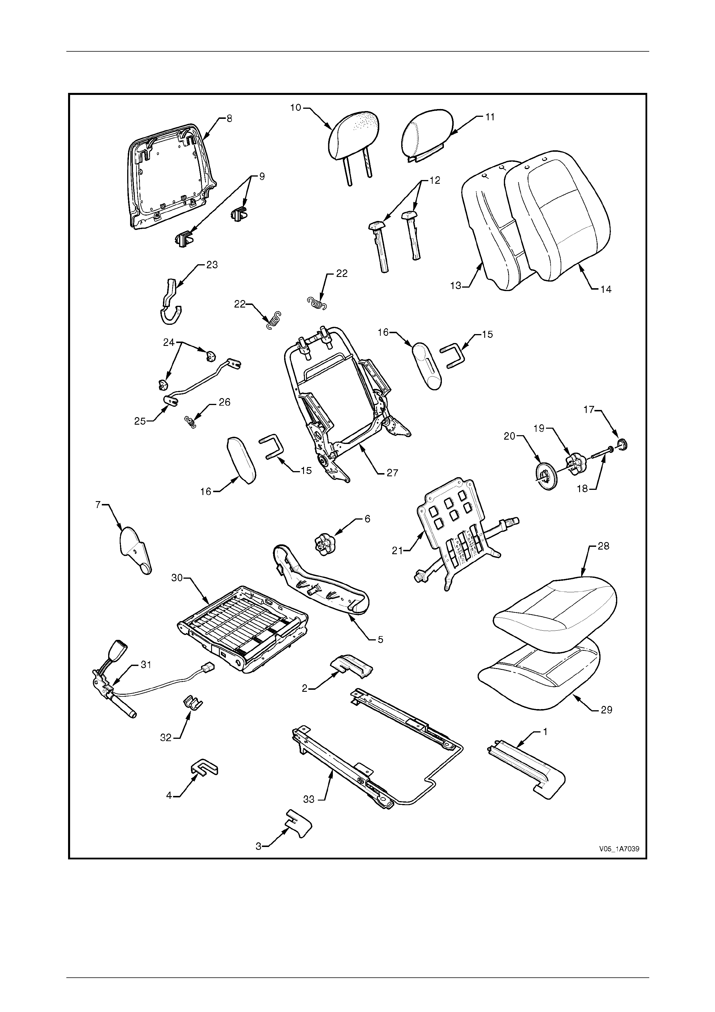
Seat Assemblies Page 1A7–243
Page 1A7–243
Front Seat Type 4
Figure 1A7 – 98

Seat Assemblies Page 1A7–244
Page 1A7–244
Legend
1 Front Seat Outer Front Cover
2 Front Seat Outer Rear Cover
3 Front Seat Inner Front Cover
4 Front Seat Inner Rear Cover
5 Front Seat Outer Side Cover
6 Recline Adjuster Knob
7 Front Seat Inner Side Cover
8 Front Seat-back Rear Cover
9 Front Seat-back Rear Cover Retaining Clips
10 Front Seat Head Restraint Pad Assembly
11 Front Seat Head Restraint Cover
12 Front Seat Head Restraint Sleeves
13 Front Seat-back Pad
14 Front Seat-back Cover
15 Front Seat Dummy Block U-bolt
16 Front Seat Dummy Block Insert
17 Lumbar Support Knob Cover
18 Lumbar Support Knob Screw
19 Lumbar Support Knob
20 Lumbar Support Deflector Ring
21 Lumbar Support Assembly
22 Lumbar Support Retaining Spring
23 Dump-latch Release Lever
24 Dump-latch Release Rod Retainer
25 Dump-latch Release Rod
26 Dump-latch Release Spring
27 Front Seat-back Frame Assembly
28 Front Seat Cushion Cover
29 Front Seat Cushion Pad
30 Front Seat Cushion Frame Assembly
31 Seatbelt Buckle and Pretensioner Assembly
32 Wiring Harness Retaining Clip
33 Track and Height Adjust Assembly
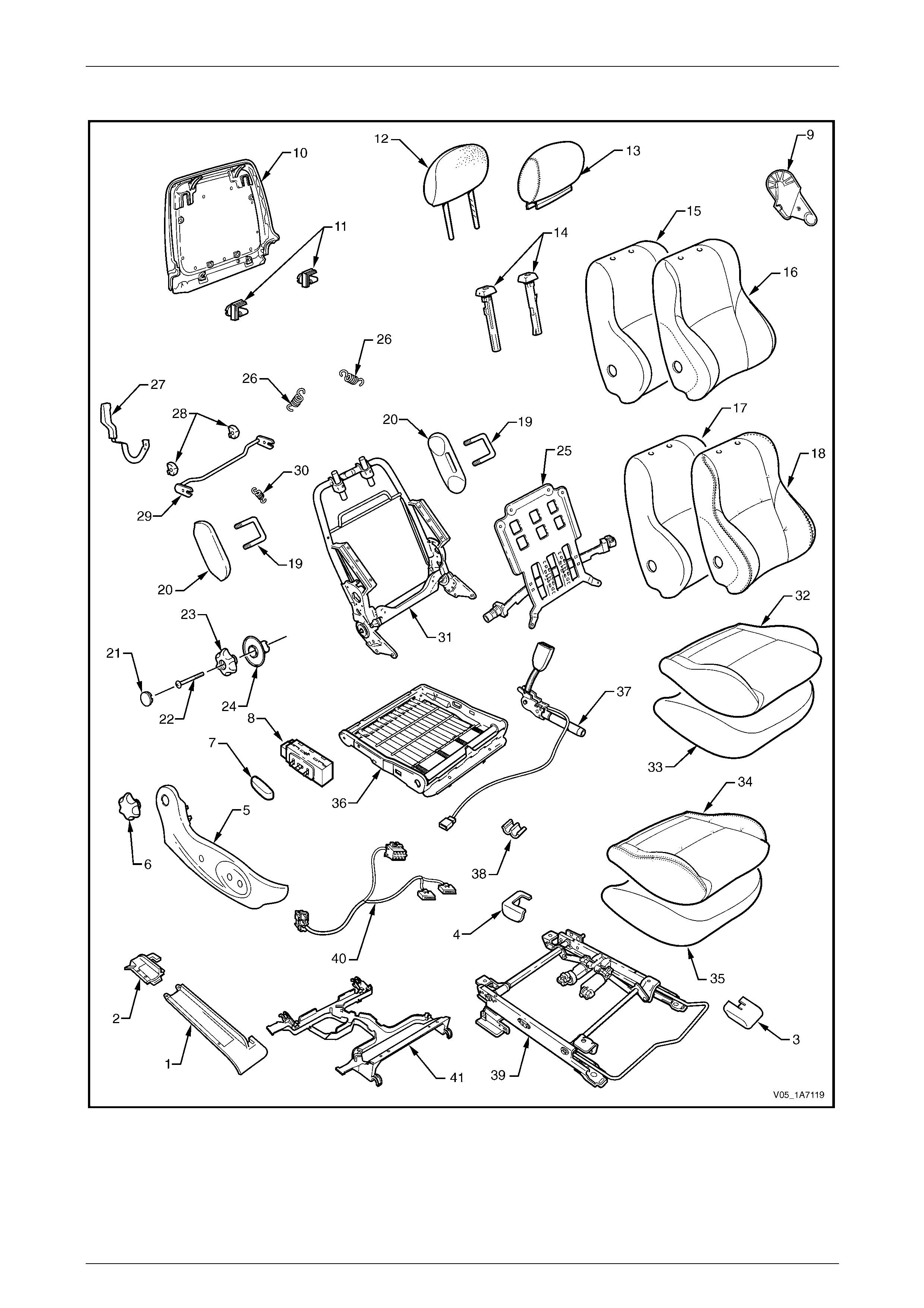
Seat Assemblies Page 1A7–245
Page 1A7–245
Front Seat Type 5
Figure 1A7 – 99

Seat Assemblies Page 1A7–246
Page 1A7–246
Legend
1 Front Seat Outer Front Cover
2 Front Seat Outer Rear Cover
3 Front Seat Inner Front Cover
4 Front Seat Inner Rear Cover
5 Front Seat Outer Side Cover
6 Recline Adjuster Knob
7 Front Seat Adjustment Switch Knob
8 Front Seat Adjustment Switch
9 Front Seat Inner Side Cover
10 Front Seat-back Rear Cover
11 Front Seat-back Rear Cover Retaining Clips
12 Front Seat Head Restraint Pad Assembly
13 Front Seat Head Restraint Cover
14 Front Seat Head Restraint Sleeves
15 Front Seat-back Pad – Cloth Cover
16 Front Seat-back Cloth Cover
17 Front Seat-back Pad – Leather Cover
18 Front Seat-back Leather Cover
19 Front Seat Dummy Block U-bolt
20 Front Seat Dummy Block Insert
21 Lumbar Support Knob Cover
22 Lumbar Support Knob Screw
23 Lumbar Support Knob
24 Lumbar Support Deflector Ring
25 Lumbar Support Assembly
26 Lumbar Support Retaining Spring
27 Dump-latch Release Lever
28 Dump-latch Release Rod Retainer
29 Dump-latch Release Rod
30 Dump-latch Release Spring
31 Front Seat-back Frame Assembly
32 Front Seat Cushion Cloth Cover
33 Front Seat Cushion Pad – Cloth Cover
34 Front Seat Cushion Leather Cover
35 Front Seat Cushion Pad – Leather Cover
36 Front Seat Cushion Frame Assembly
37 Seatbelt Buckle and Pretensioner Assembly
38 Wiring Harness Retaining Clip
39 Track and Height Adjust Assembly
40 Wiring Harness Assembly
41 Front Seat Cable Tray
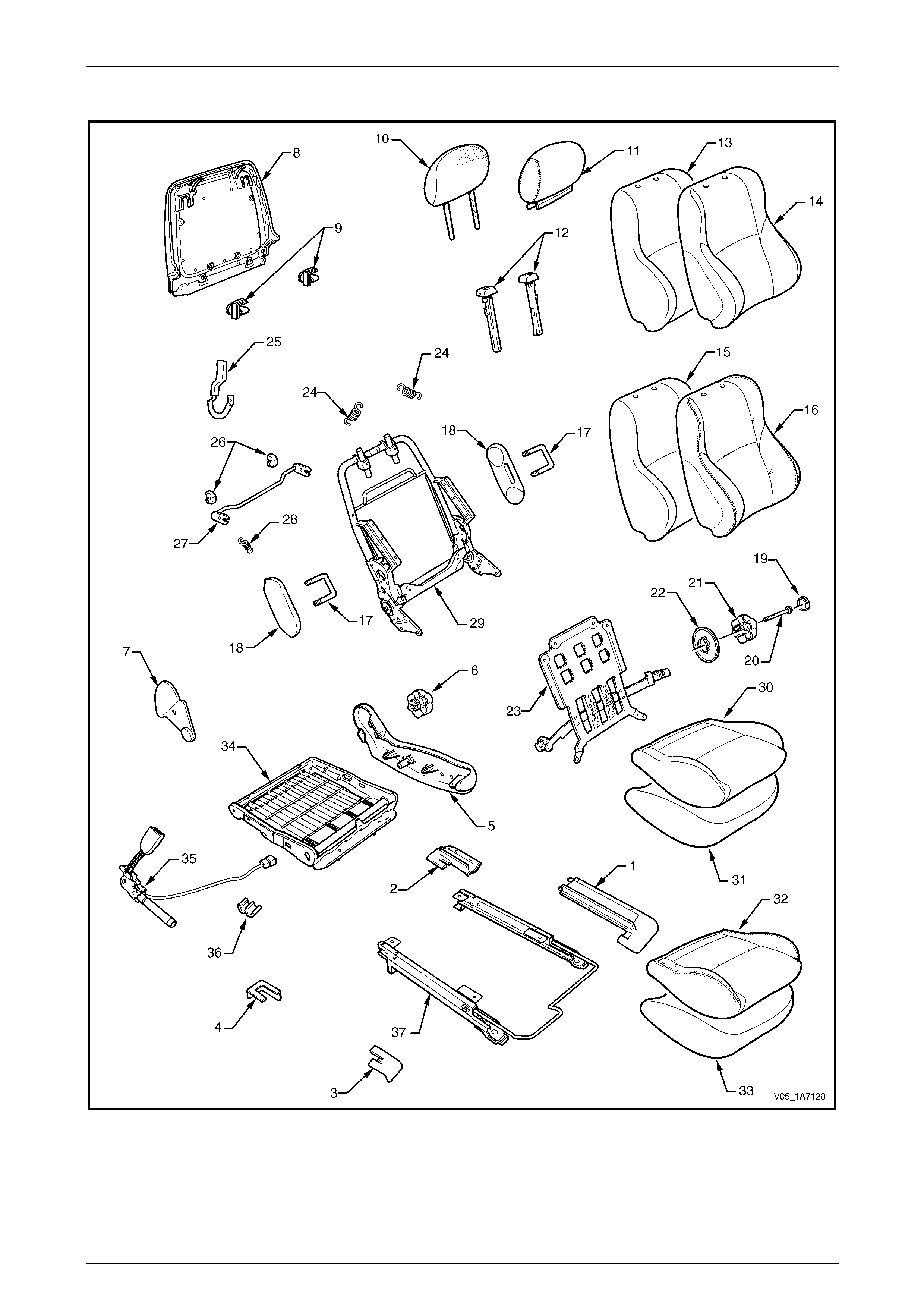
Seat Assemblies Page 1A7–247
Page 1A7–247
Front Seat Type 6
Figure 1A7 – 100

Seat Assemblies Page 1A7–248
Page 1A7–248
Legend
1 Front Seat Outer Front Cover
2 Front Seat Outer Rear Cover
3 Front Seat Inner Front Cover
4 Front Seat Inner Rear Cover
5 Front Seat Outer Side Cover
6 Recline Adjuster Knob
7 Front Seat Inner Side Cover
8 Front Seat-back Rear Cover
9 Front Seat-back Rear Cover Retaining Clips
10 Front Seat Head Restraint Pad Assembly
11 Front Seat Head Restraint Cover
12 Front Seat Head Restraint Sleeves
13 Front Seat-back Pad – Cloth Cover
14 Front Seat-back Cloth Cover
15 Front Seat-back Pad – Leather Cover
16 Front Seat-back Leather Cover
17 Front Seat Dummy Block U-bolt
18 Front Seat Dummy Block Insert
19 Lumbar Support Knob Cover
20 Lumbar Support Knob Screw
21 Lumbar Support Knob
22 Lumbar Support Deflector Ring
23 Lumbar Support Assembly
24 Lumbar Support Retaining Spring
25 Dump-latch Release Lever
26 Dump-latch Release Rod Retainer
27 Dump-latch Release Rod
28 Dump-latch Release Spring
29 Front Seat-back Frame Assembly
30 Front Seat Cushion Cloth Cover
31 Front Seat Cushion Pad – Cloth Cover
32 Front Seat Cushion Leather Cover
33 Front Seat Cushion Pad – Leather Cover
34 Front Seat Cushion Frame Assembly
35 Seatbelt Buckle and Pretensioner Assembly
36 Wiring Harness Retaining Clip
37 Track and Height Adjust Assembly
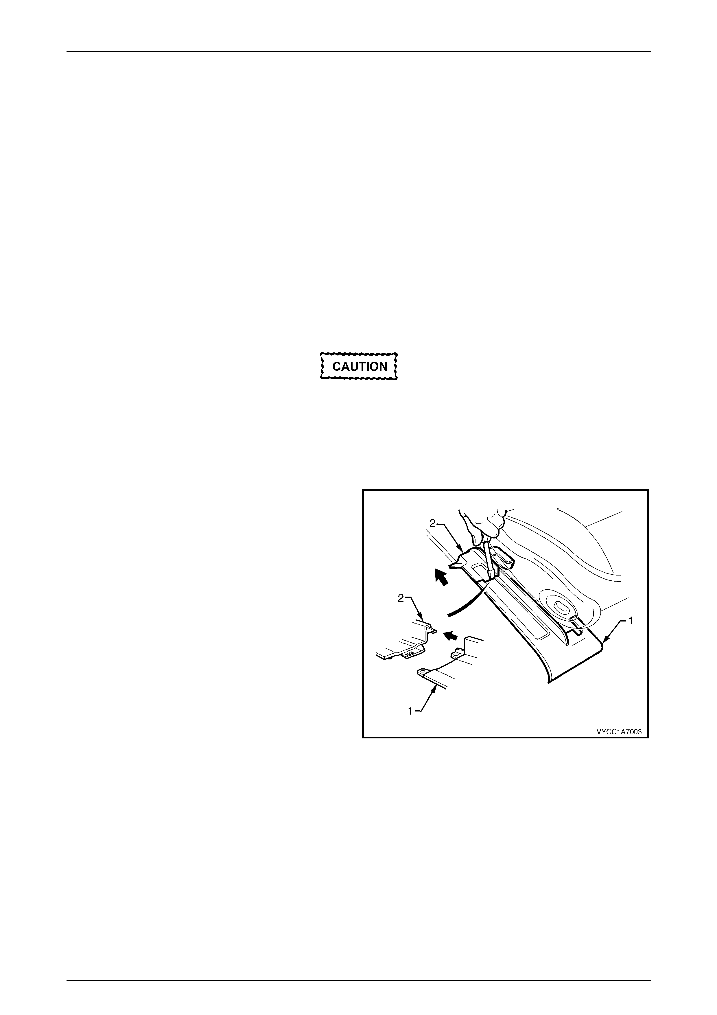
Seat Assemblies Page 1A7–249
Page 1A7–249
6.2 Front Seat Assembly
LT Section No. — 14–295
NOTE
If the seat assembly is to be disassembled, adjust
the seat assembly to its highest position before
disconnecting the power to the seat.
NOTE
Clean hands are essential when working on the
interior trim.
Remove
Disconnection of the battery affects
certain vehicle electronic systems. Refer to
Section 00 Warnings, Cautions and Notes,
5 Battery Disconnection Procedures before
disconnecting the battery.
1 Disconnect the battery.
2 Using a small scre wdriver, push in the ce ntre of the
join to separate the front seat outer front cover (1) and
the front seat outer rear cover (2).
3 Unclip the covers from the seat track and disengag e
from the side sill trim.
4 Pull the covers apart and remove the rear c over.
Figure 1A7 – 101
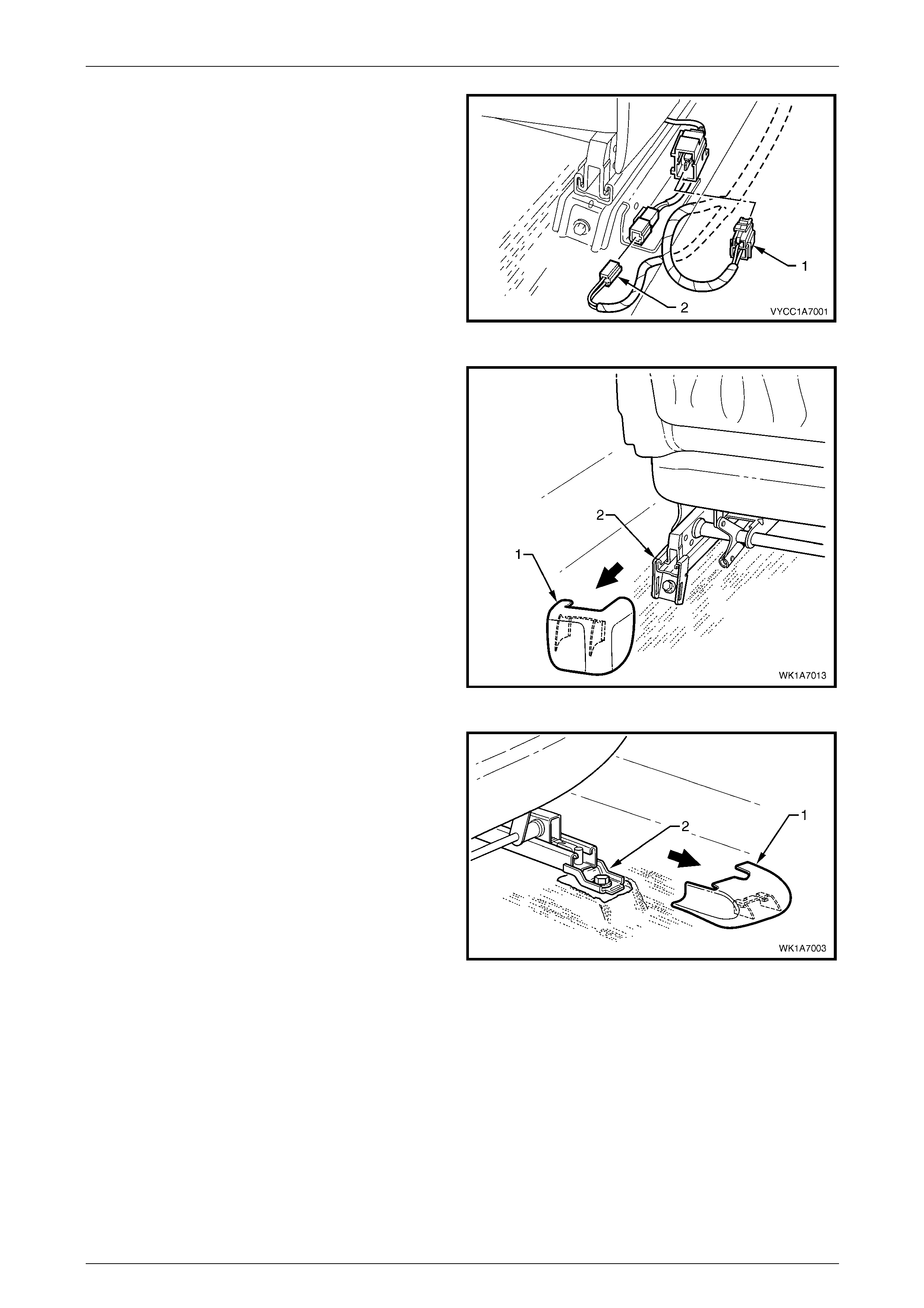
Seat Assemblies Page 1A7–250
Page 1A7–250
5 Disconnect the body wiring ha rness connector (1) if
fitted, and the seatbelt pretensioner wiring
connector (2).
Figure 1A7 – 102
6 Unclip the front seat inner rear cover (1) from the seat
track (2).
Figure 1A7 – 103
7 Unclip the front seat inner front cover (1) from the seat
track (2).
Figure 1A7 – 104
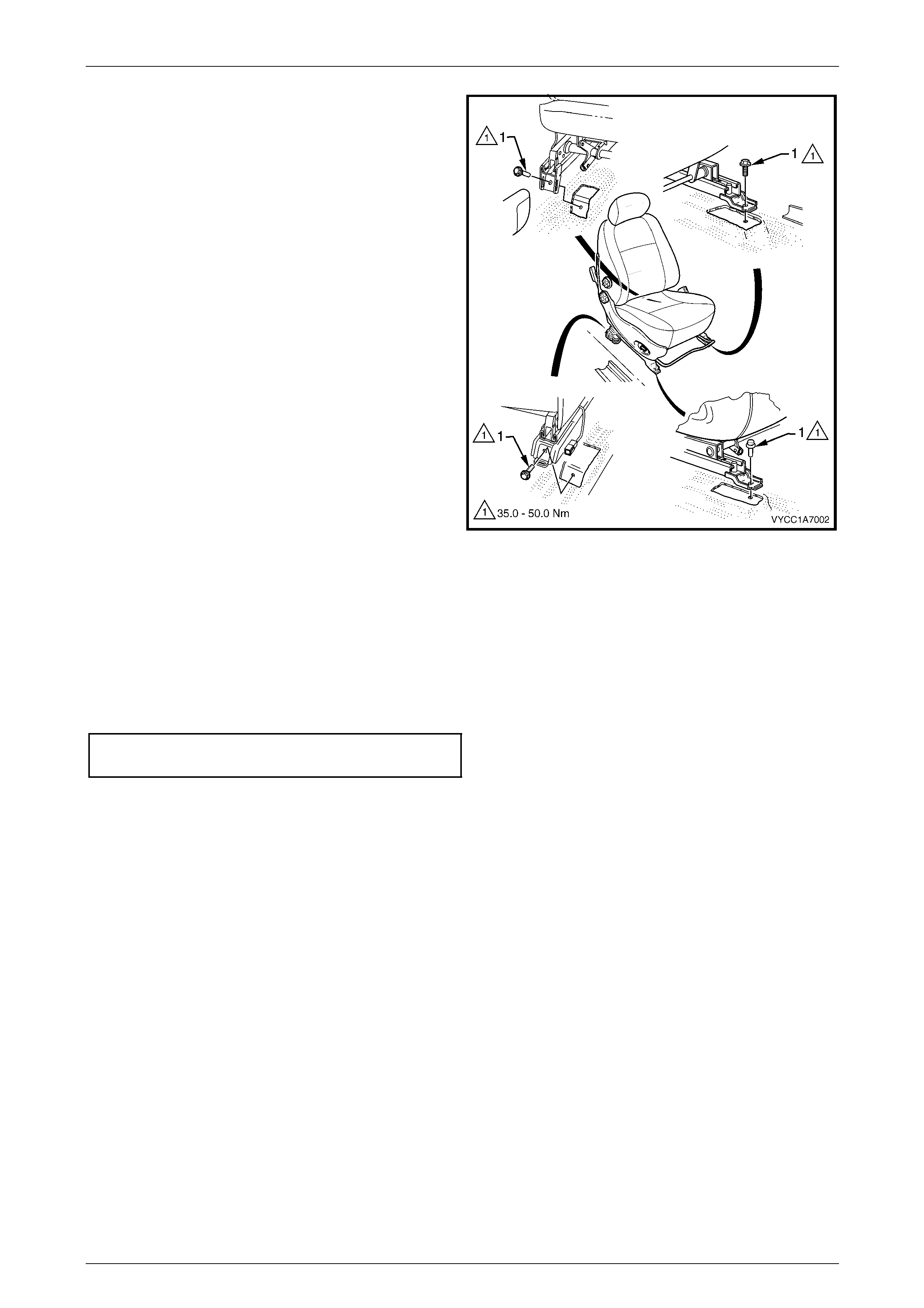
Seat Assemblies Page 1A7–251
Page 1A7–251
8 Remove the four screws (1) attaching the front seat to
the vehicle.
9 Remove the seat from the vehicle.
Figure 1A7 – 105
Reinstall
Reinstallation of the front seat assembly is the reverse of the removal procedure, noting the following:
1 Position the front seat assembly into the vehicle.
2 Install the four screws securing the front seat.
3 Tighten the attaching screws to the correct torque specification.
Front seat assembly attaching screw
torque specification.................................35.0 – 50.0 Nm
4 Connect the seat wiring harness connector, if fitted, and the seatbelt pretensioner harness connector.
5 Align the front seat outer cover’s retaining clips and push firmly to engage.
6 Push the front of the front seat outer cover do wn to engage the cover with the front of the seat rail.
7 Check the operation of the front seat functions. While checking the seat adjustment/operation, also check the seat
wiring harnesses do not foul with any of the seat’s moveable components (i.e. seat motor drive shafts, etc.).
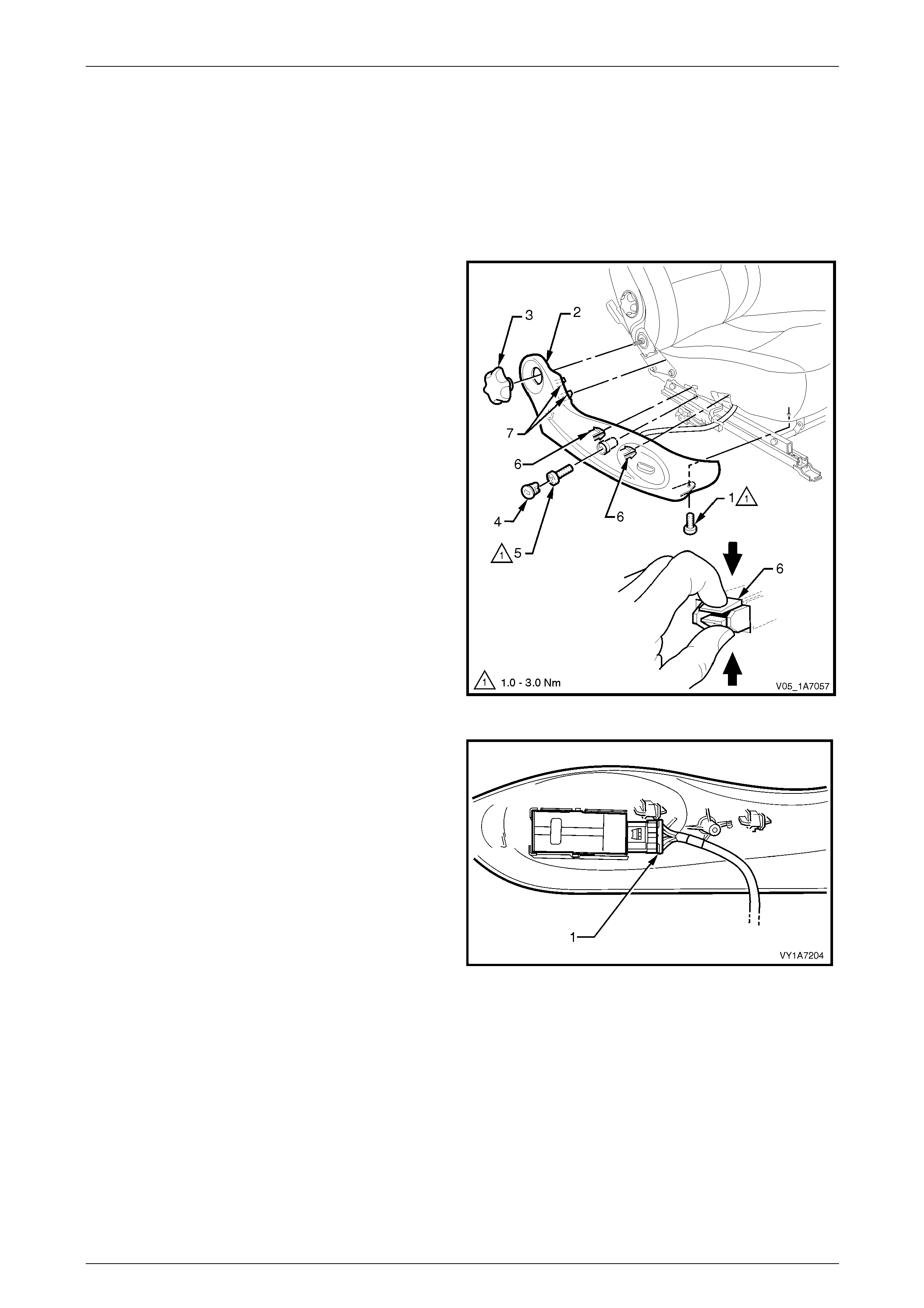
Seat Assemblies Page 1A7–252
Page 1A7–252
6.3 Front Seat Outer Side Cover Assembl y
LT Section No. — 14–322
Remove
1 Raise the seat to the full-up position, if applicable.
2 Remove the screw (1) from the front of the front seat
outer side cover (2).
3 Carefully prise the recliner knob (3) from the seat
assembly.
4 Remove the plug (4) by rotating the plug
anti-clockwise, one quarter of a turn.
5 Remove the screw (5) located behind the plu g.
6 Reach up under the seat assembl y and squeeze
together the two retaining tangs (6), on the i nner side
of the side cover while gently pulling the cover.
7 Gently pull the side cover away from the seat to
disengage the two clips (7) from the seat-back frame
assembly.
NOTE
Only remove the side cover far enough away
from the seat cushion assembly to gain access
to the seat wiring harness connectors, if fitted.
Figure 1A7 – 106
8 Where fitted, disconnect the front seat adjustment
switch connector (1) and unclip the harness from the
side cover.
9 Remove the side cover assembly.
Figure 1A7 – 107
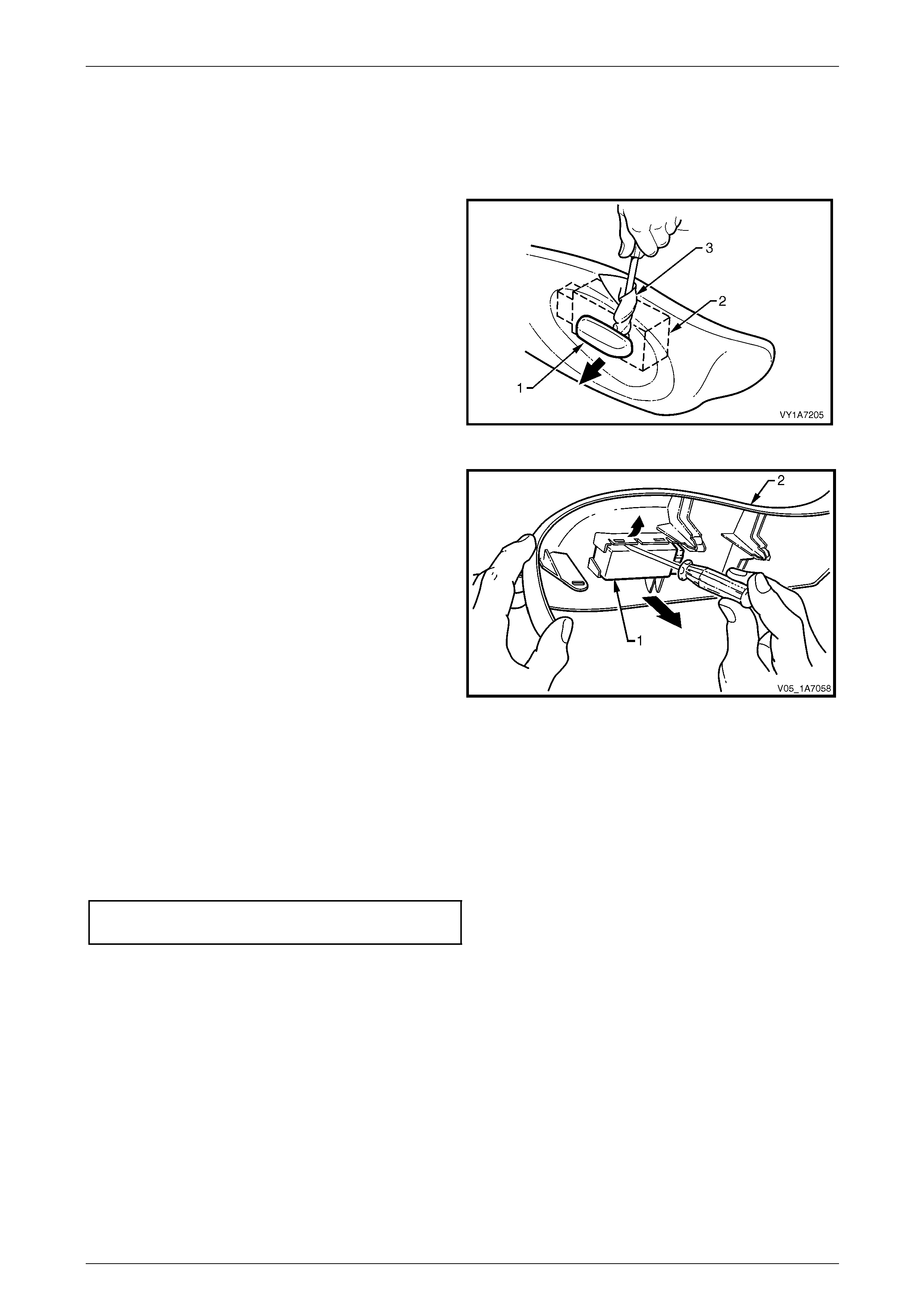
Seat Assemblies Page 1A7–253
Page 1A7–253
Disassemble
Front Seat Adjustment Switch
Remove
1 Remove the knob (1) from the front seat adjustment
switch (2) by carefully prising it free with a small flat tip
screwdriver wrapped in a clea n shop rag (3).
Figure 1A7 – 108
2 Use a flat-blade screwdriver to gently prise the front
seat adjustment switch (1) from the outer side
cover (2).
Figure 1A7 – 109
Reinstall
Reinstall the front seat adjustment switch ensuring it is clipped securely in place. Push the knob in until it clicks in place.
Reinstall
Reinstallation of the front seat outer side cover is the reverse of the removal procedure. Tighten the attaching screws to
the correct torque specification.
Front seat outer side cover attaching
screw torque specification...........................1.0 – 3.0 Nm

Seat Assemblies Page 1A7–254
Page 1A7–254
6.4 Front Seat Inner Side Cover
LT Section No. — 14–322
As required, remove the front seat assembly, refer to 6.2 Front Seat Assembly.
Remove
Remove the screw (1) attaching the front seat inner side
cover (2) to the seat assembly (3) and remove the cover.
Figure 1A7 – 110
Reinstall
Reinstallation of the front seat inner side cover is the reverse of the removal procedure. Tighte n the atta ching screw to
the correct torque specification.
Front seat inner side cover attachi ng
screw torque specification...........................1.0 – 3.0 Nm
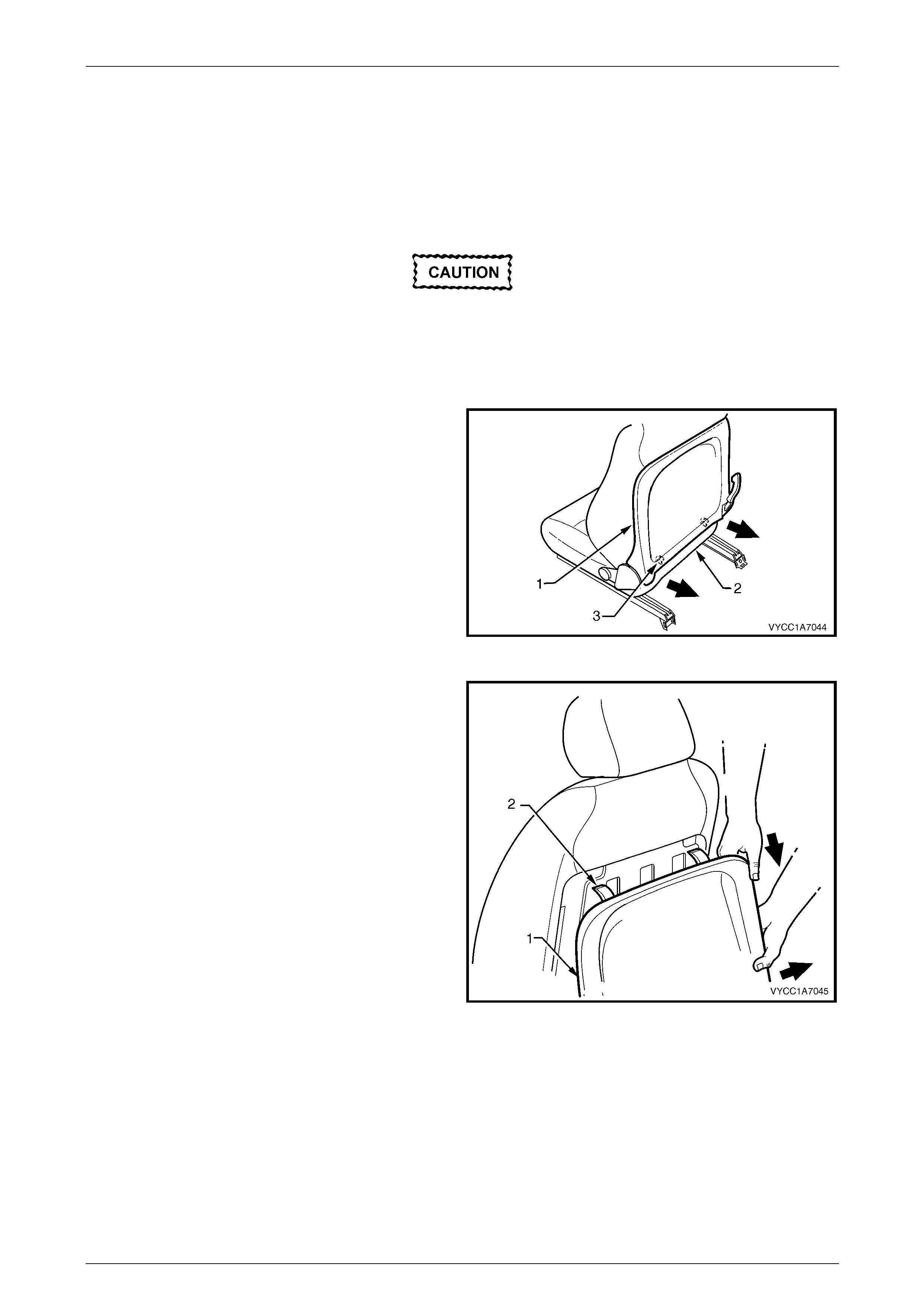
Seat Assemblies Page 1A7–255
Page 1A7–255
6.5 Front Seat-back Rear Cover Assembly
LT Section No. — 14–322
Remove
The following components will require
replacement when performing this operation.
• Two front seat-back rear cover retaining
clips.
1 Pull the lower corners of the front seat-back rear
cover (1) away from the seat (2), breaking the two
retaining clips (3).
Figure 1A7 – 111
2 While holding the lower portion of the front seat-back
rear cover (1) out, pull the cover do wn to release the
two upper retaining lugs (2).
3 Remove the cover.
Figure 1A7 – 112
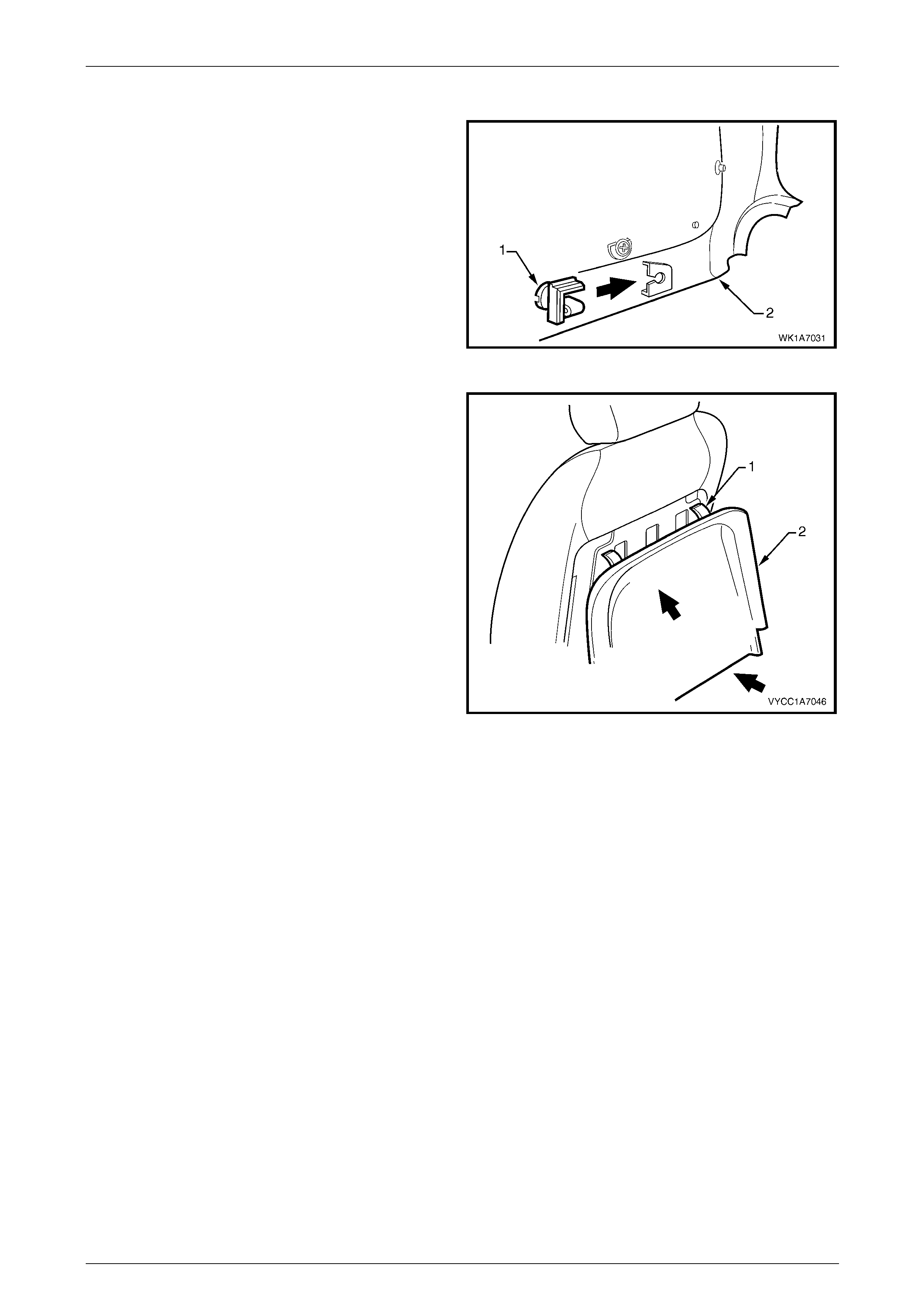
Seat Assemblies Page 1A7–256
Page 1A7–256
Reinstall
1 Replace the damaged retaining clip (1) on the front
seat-back rear cover (2), two places.
Figure 1A7 – 113
2 Align the two upper retaining lugs (1) with the
seat-back.
3 Push the front seat-back rear cover (2) up and in at
the lower edge to engage the two lower retaining clips.
Figure 1A7 – 114
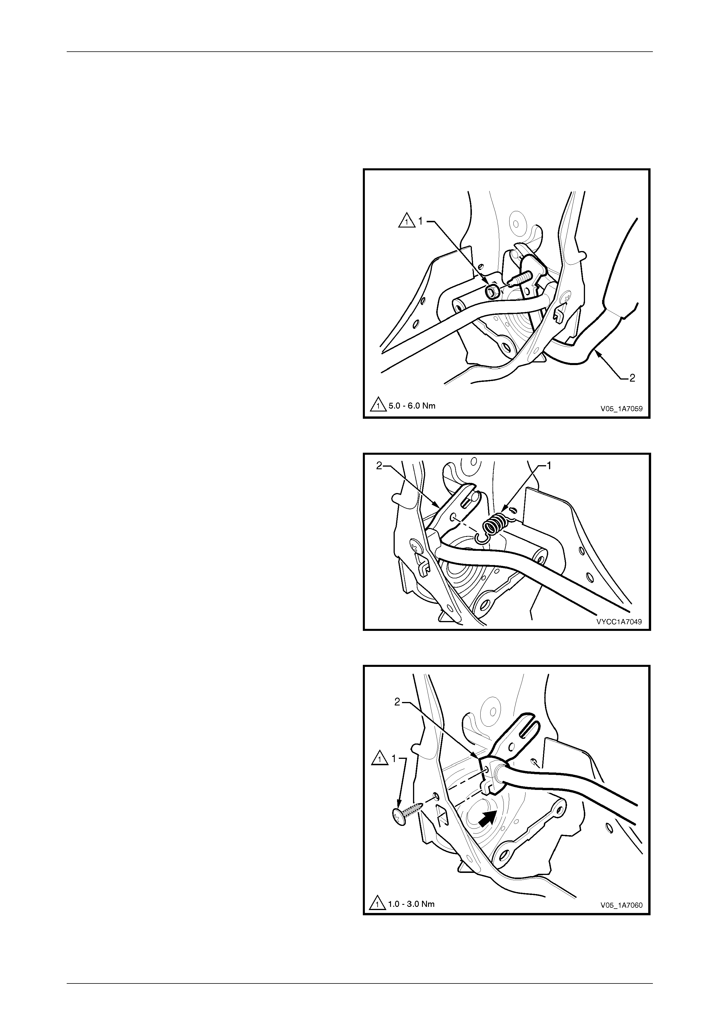
Seat Assemblies Page 1A7–257
Page 1A7–257
6.6 Dump-latch Mechanism Assembly
Remove
As required, remove the front seat-back rear cover, refer to 6.5 Front Seat-back Rear Cover Assembly.
1 Remove the nut (1) attaching the dump-latch release
lever (2) to the seat-back frame and remove the lever.
Figure 1A7 – 115
2 Unhook the spring (1) from the dump-latch release rod
(2) and seat-back frame.
Figure 1A7 – 116
3 Remove the screw (1), attaching the dump-latch
release rod retainer (2) to the seat-back frame.
4 Repeat for the opposite side.
5 From each side of the seat-back frame, detach the
dump-latch release rod retainer and remove the
release rod and retainers.
6 As required, remove the retainers from the release
rod.
Figure 1A7 – 117

Seat Assemblies Page 1A7–258
Page 1A7–258
Reinstall
Reinstallation of the dump-latch assembly is the reverse of the removal procedure. Tighten the attaching fasteners to the
correct torque specification.
Dump-latch release rod retain er attaching
screw torque specification...........................1.0 – 3.0 Nm
Dump-latch release lever attaching
nut torque specification...............................5.0 – 6.0 Nm
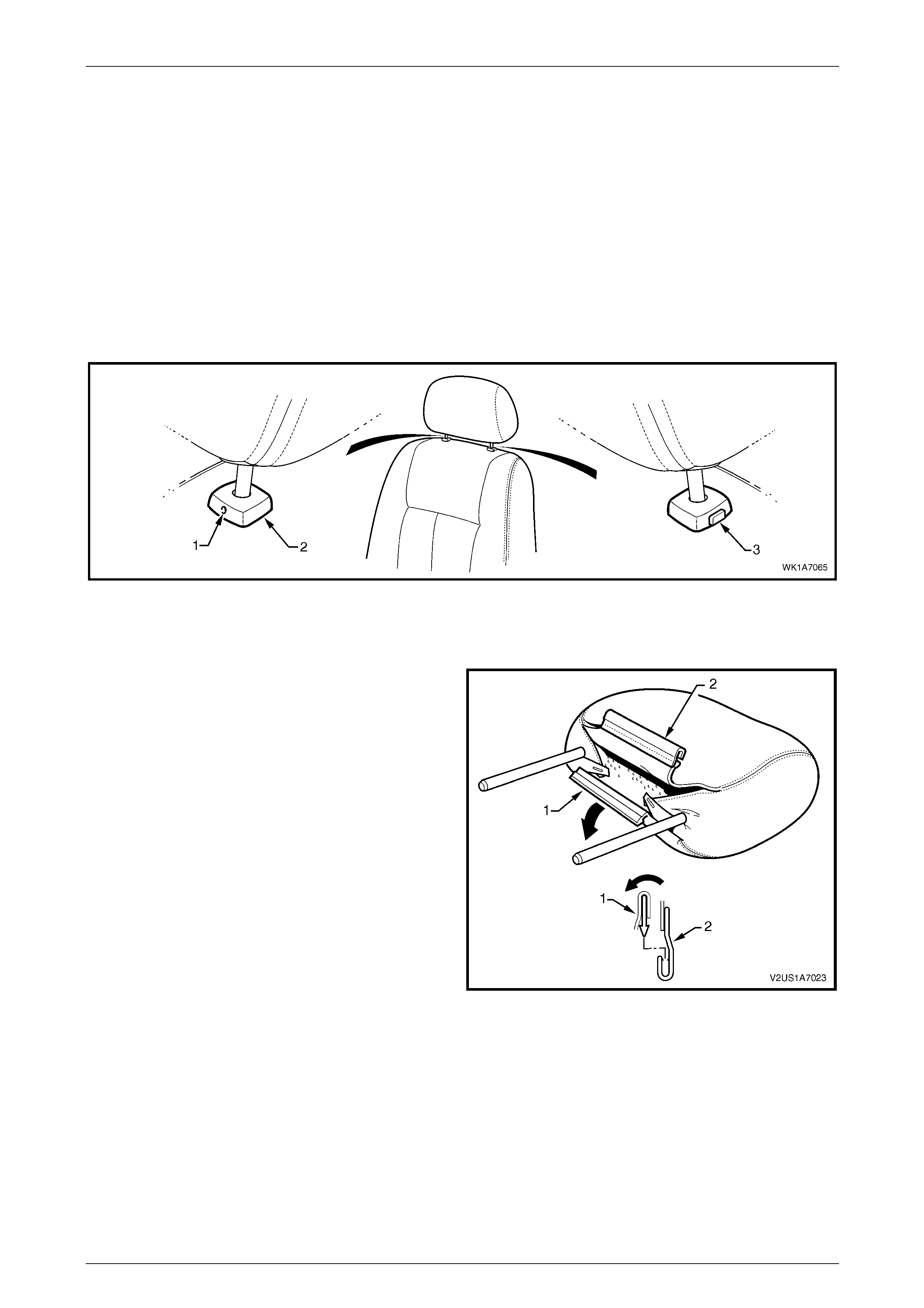
Seat Assemblies Page 1A7–259
Page 1A7–259
6.7 Front Seat Head Restraint Assembly
LT Section No. — 14–295
Remove
1 Raise the head restraint fully.
2 Insert a suitable size probe into the hole (1) in the right-hand head restraint sleeve (2), refer to F igure 1A7 – 118.
3 Push the probe in slightly whil e app lying slight up ward pressure on the head restraint. Hold the up ward pressure.
4 Depress the head restraint sleeve height adjuster lock (3) on the left-hand head restraint sleeve and remove the
head restraint.
Figure 1A7 – 118
Disassemble
1 Disengage the front head restraint cover J-stri p by
pulling the flap (1) back and out of flap (2) in the
direction shown.
Figure 1A7 – 119
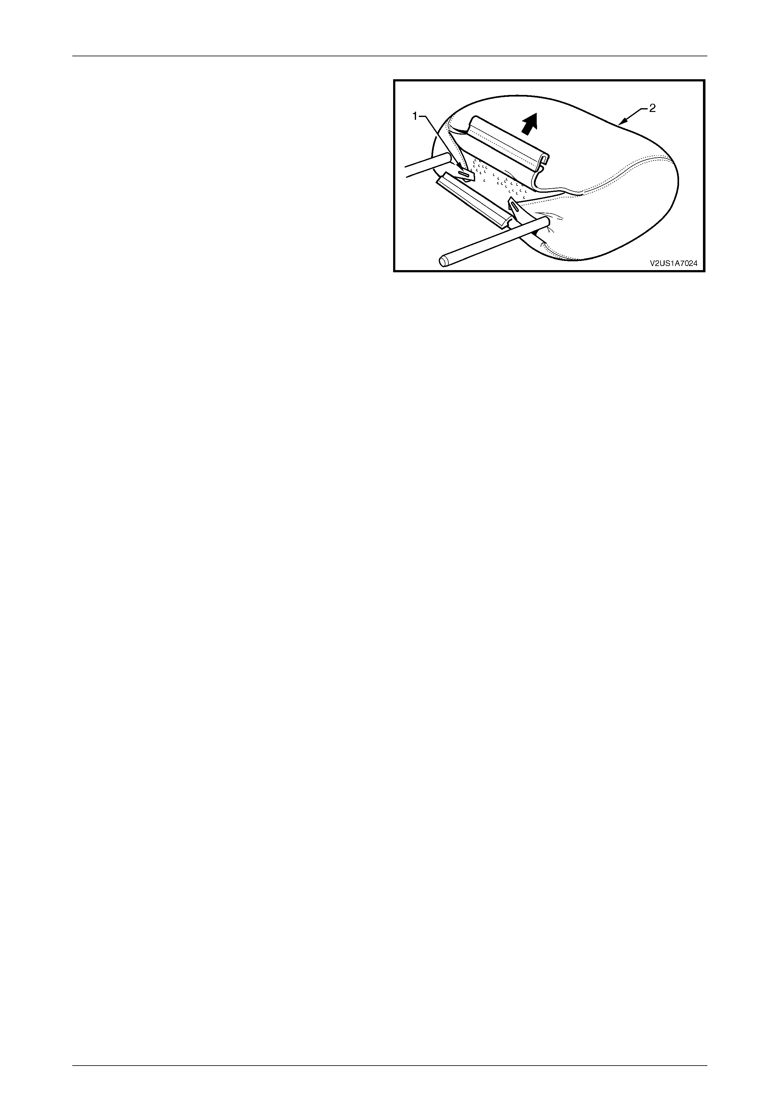
Seat Assemblies Page 1A7–260
Page 1A7–260
2 Remove the two staples (1) retaining the cover (2) to
the head restraint pad assembly.
3 Remove the cover from the pad assembly.
Figure 1A7 – 120
Reassemble
Reassembly of the front seat head restraint assembl y is the reverse of the removal procedure. Ensure the head restra int
cover J-clip is fully engaged and sits neatly in the recess in the hea d restraint pad.
Reinstall
Ensuring correct orientation of the head restraint, fit the head restraint shafts into the sleeves and p ush the head restraint
down.
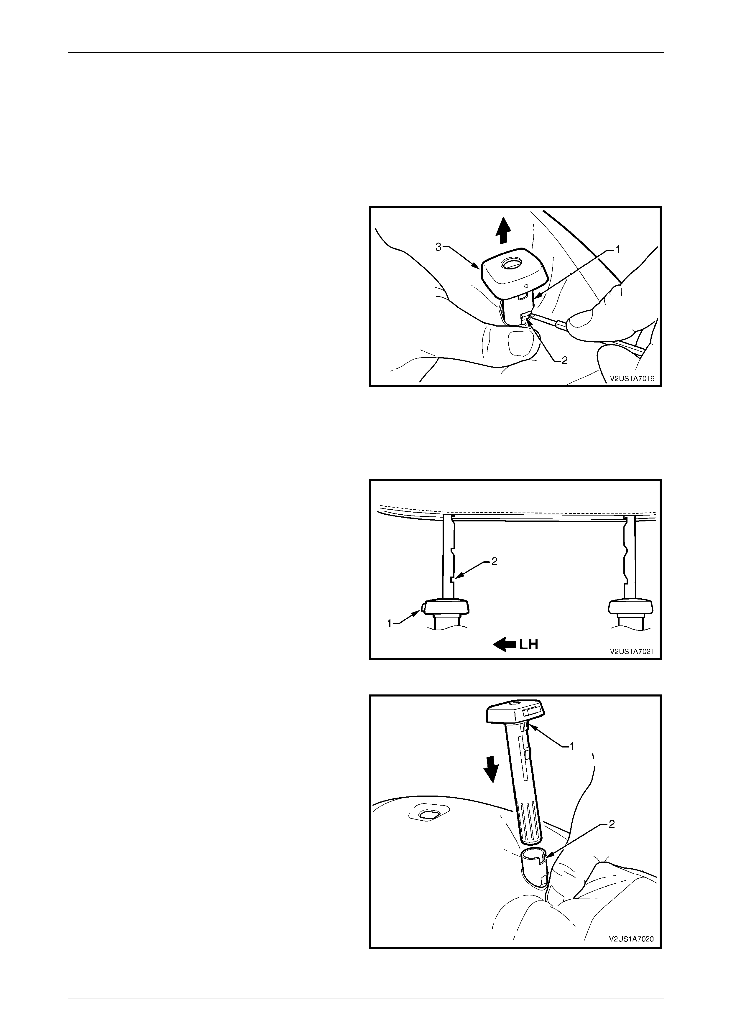
Seat Assemblies Page 1A7–261
Page 1A7–261
6.8 Front Seat Head Restraint Sleeve
LT Section No. — 14–275
As required, remove the front seat head restraint assembl y, refer to 6.7 Front Seat Head Restrai nt Assembl y.
Remove
1 Push down on the surrounding seat cover to reveal the
upper portion of the seat-back frame (1).
2 Using a fine flat-blade screwdriver, depress the head
restraint sleeve retaining lug (2) and withdraw the
head restraint sleeve (3) from the frame.
3 Repeat for the remaining sleeve as required.
Figure 1A7 – 121
Reinstall
Reinstallation of the front seat head restraint sleeve is the reverse of the removal proce dure, noting the following:
NOTE
Ensure the sleeve with the height adjuster lock
(1) is installed on the left-hand side of the seat;
that is the side that corresponds to the lower
square notch (2) in the head restraint shaft.
Figure 1A7 – 122
1 Align the head restraint sleeve locating ribs (1) with
the notch (2) in the seat-back frame.
2 Insert the sleeve and ensure it clicks into place.
Figure 1A7 – 123

Seat Assemblies Page 1A7–262
Page 1A7–262
6.9 Lumbar Support Knob Assembly
LT Section No. — 14–275
Remove
1 Ensure the lumbar support is in the full off position.
2 Using a fine flat-blade screw-driver, carefully prise the
cap (1) from the lumbar support knob (2).
3 Remove the screw (3) attaching the knob to the
lumbar support shaft.
4 Pull the knob off the lumbar support shaft and remove
the lumbar support deflector ring (4).
NOTE
The knob is lightly clipped to the lumbar support
shaft and will ‘click-off’.
Figure 1A7 – 124
Reinstall
NOTE
Failure to observe the following procedure will
result in damage to the mechanism.
1 Push the lumbar support knob and lumbar support deflector ring onto the adjustment shaft.
2 Rotate the lumbar support knob to fully rela x the lumbar adjustment.
3 Install and tighten the attaching screw until head of screw is just below the surface of the knob.
4 Press cap into place.

Seat Assemblies Page 1A7–263
Page 1A7–263
6.10 Front Seat-back Pad and Cover
Assembly
LT Section No. — 14–295
As required, remove the following components:
1 Front seat assembly, refer to 6.2 Front Seat Assembly.
2 Front seat outer side cover assembly, 6.3 Front Seat Outer Side Cover Assembl y.
3 Front seat inner side cover, refer to 6.4 Front Seat Inner Side Cover.
4 Front seat-back rear cover assembly, refer to 6.5 Front Seat-back Rear Cover Assembly.
5 Front seat head restraint assembly, refer to 6.7 Front Seat Head Restraint Assembly.
6 Front seat head restraint sleeves, refer to 6.8 Front Seat Head Restraint Sleeve.
7 Lumbar support knob assembly, refer to 6.9 Lumbar Support Knob Assembly.
Remove
1 Disengage the J-strips from the seat frame a nd the
Velcro tab at each lower corner.
2 Lift the cover and pad assembly up and away from the
seat-back frame, manoeuvring it over the front seat
dummy block insert assemblies.
Figure 1A7 – 125

Seat Assemblies Page 1A7–264
Page 1A7–264
Disassemble
NOTE
The following illustrations show typical hook and
loop arrangement, which will vary according to
seat type.
Surebond type seat-back pad and cover
assemblies cannot be disassembled.
1 Fold the lower corners of the seat-back cove r (1) over
the seat-back pad (2).
Figure 1A7 – 126
2 While holding the front seat-back pad (1), pull the
lower corners of the seat-back cover (2), upwards and
away from the pad to disengage the hook and loop
strips (3).
3 Pull the cover up and over the upper edge of the pad.
Figure 1A7 – 127

Seat Assemblies Page 1A7–265
Page 1A7–265
Reassemble
1 With the front seat-back cover (1) folded at the central
horizontal strip of hook and loop (2), align the centre
mark (3) on the cover with the centre mark (4) on the
front seat-back pad.
2 Press the cover firmly into the corresponding groove i n
the pad to engage the hook and loop.
Figure 1A7 – 128
3 With the cover folded at the two vertical strips of the
hook and loop, press the cover firml y into the
corresponding grooves in the pad.
Figure 1A7 – 129
4 Roll the upper corners of the cover over the pad.
5 Roll the sides of the cover over the pad.
6 Roll the lower corners of the cover over the pad.
NOTE
Ensure the cover is fitted neatly by hand into all
corners and contours of the pad.
Figure 1A7 – 130
Reinstall
Reinstallation of the front seat -back pad and cover assembly is the reverse of the removal proced ure.
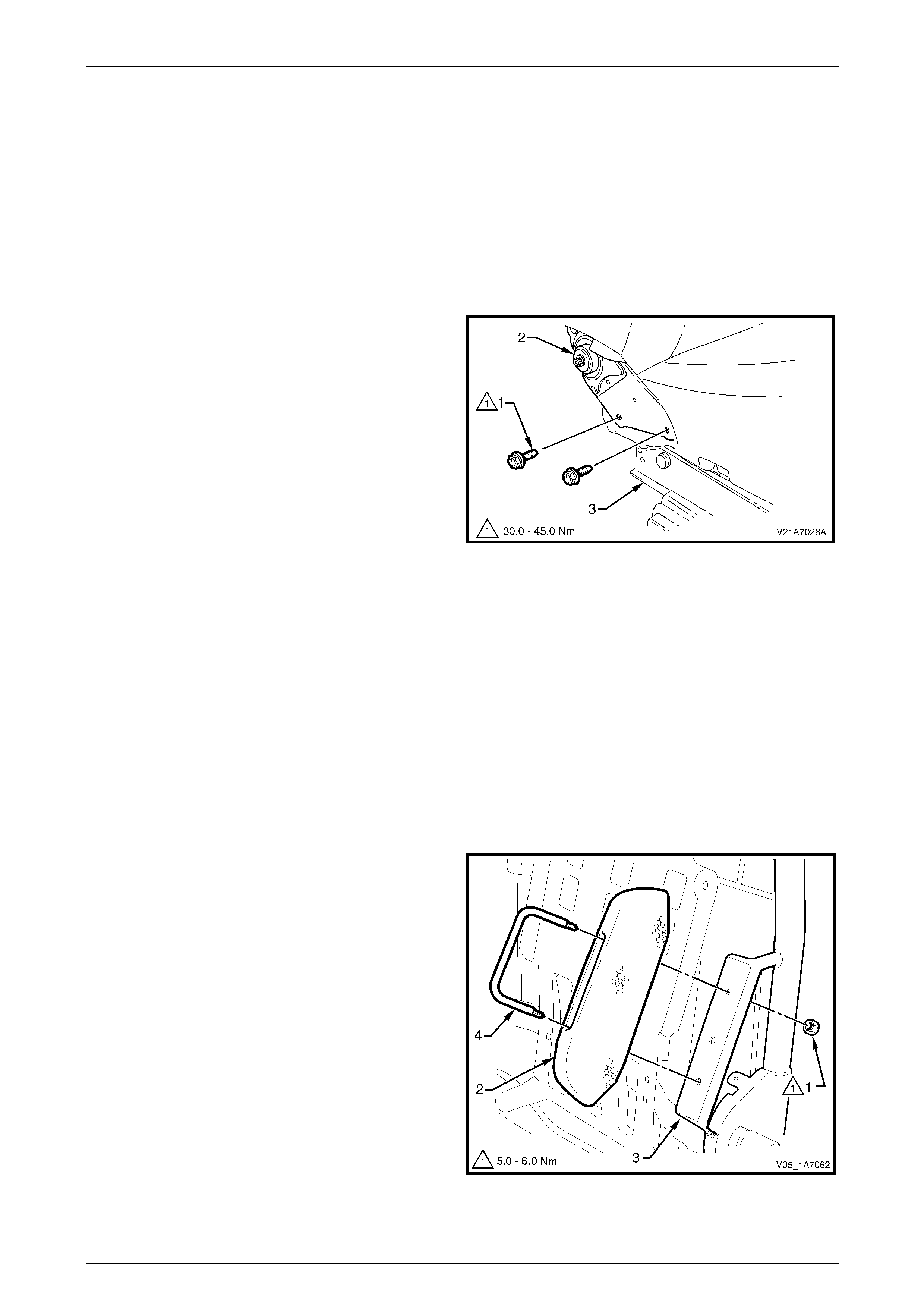
Seat Assemblies Page 1A7–266
Page 1A7–266
6.11 Front Seat-back Frame Assembl y
LT Section No. — 14–275
As required remove the following c ompo ne nts:
1 Front seat assembly, refer to 6.2 Front Seat Assembly.
2 Front seat outer side cover assembly, refer to 6.3 Front Seat Outer Side Cover Assembly.
3 Front seat inner side cover, refer to 6.4 Front Seat Inner Side Cover.
Remove
1 Remove the two screws (1), each side, attaching the
seat-back assembly (2) to the front seat cushion frame
assembly (3).
2 Remove the seat-back assembly.
Figure 1A7 – 131
Disassemble
As required, remove the following components:
1 Front seat-back rear cover assembly, refer to 6.5 Front Seat-back Rear Cover Assembly.
2 Front seat head restraint assembly, refer to 6.7 Front Seat Head Restraint Assembly.
3 Front seat head restraint sleeves, refer to 6.8 Front Seat Head Restraint Sleeve.
4 Lumbar support knob assembly, refer to 6.9 Lumbar Support Knob Assembly.
5 Front seat-back pad and cover assembl y, refer to 6.10 Front Seat-back Pad and Cover Assembl y.
Front Seat Dummy Block Insert Assembly
Remove
1 Remove the lock-nut (1), two places, attachi ng the
front seat dummy block insert (2) to the seat-back
frame (3) and remove the dummy block insert
assembly.
2 If required, remove the dummy block U-bolt (4) from
the dummy block insert.
Figure 1A7 – 132
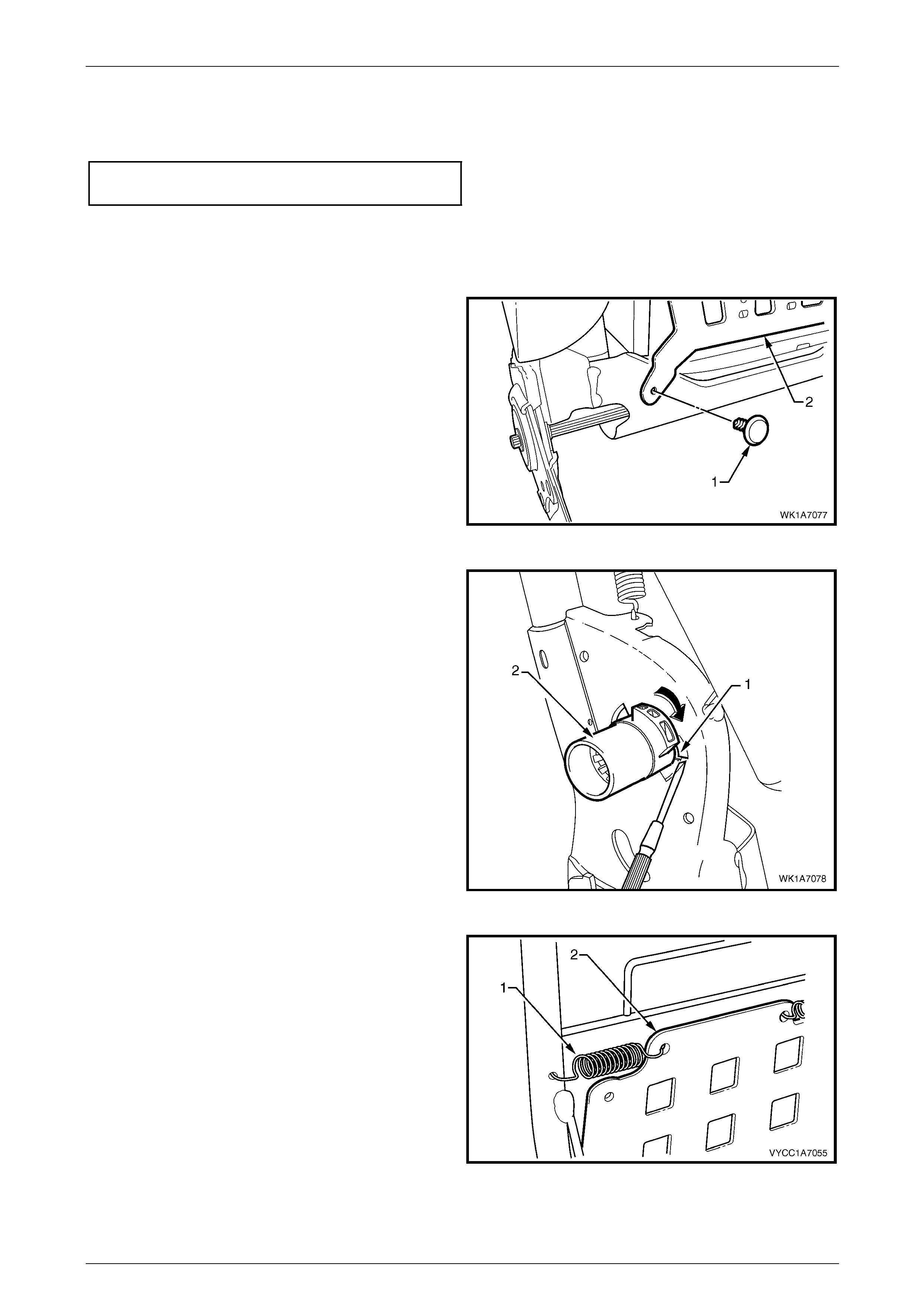
Seat Assemblies Page 1A7–267
Page 1A7–267
Reinstall
Reinstallation of the front seat dummy block insert assembly is the reverse of the removal procedure. Tighten the
attaching nuts to the correct torque specification.
Front seat dummy block insert assembly
attaching nut torque specification................5.0 – 6.0 Nm
Lumbar Support Assembly
Remove
1 Remove the retainer (1), t wo places, attaching the
lumbar support assembly (2) to the seat-back frame.
Figure 1A7 – 133
2 Depress the retaining tab (1) and from the inner side
of the seat-back frame, rotate the lumbar support
shaft (2) and withdraw from the seat-back frame.
3 Repeat for the opposite side.
Figure 1A7 – 134
4 Disconnect the spring (1), two places, attaching the
lumbar support assembly (2) to the seat-back frame.
NOTE
To aid spring remova l, pull the support asse mbly
toward the side the spring is being removed to
relieve spring tension.
Figure 1A7 – 135
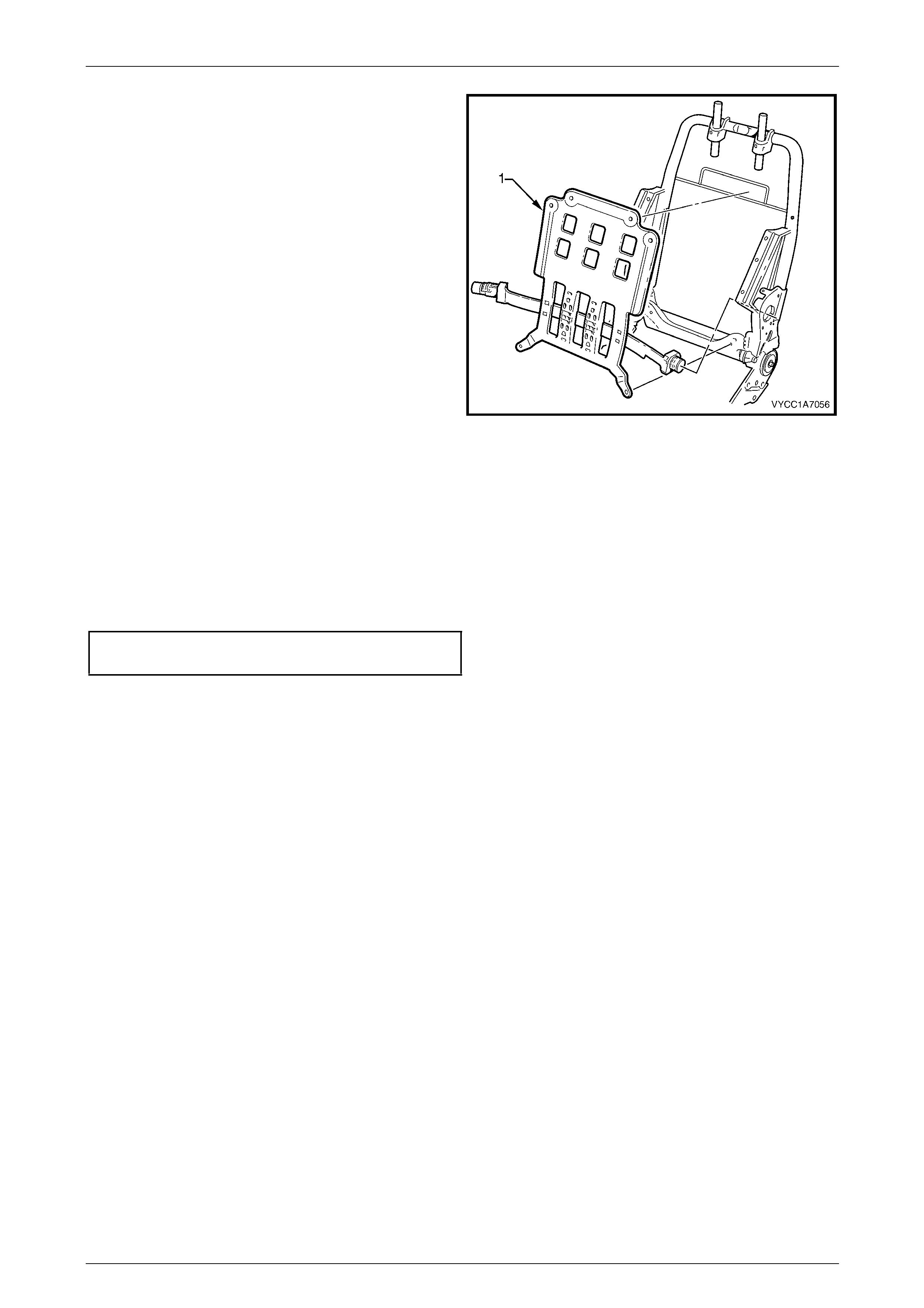
Seat Assemblies Page 1A7–268
Page 1A7–268
5 Remove the lumbar support assembly (1).
Figure 1A7 – 136
Reinstall
Reinstallation of the lumbar s upport assembly is the reverse of the removal procedure.
Reinstall
Reinstallation of the front seat -back frame assembly is the reverse of the removal proced ure, notin g the following:
1 Tighten the attaching screws to the correct torque specific ation.
Front seat-back frame assembly
attaching screw torque specification.......30.0 – 45.0 Nm
2 Check the operation of the front seat-back assembl y.
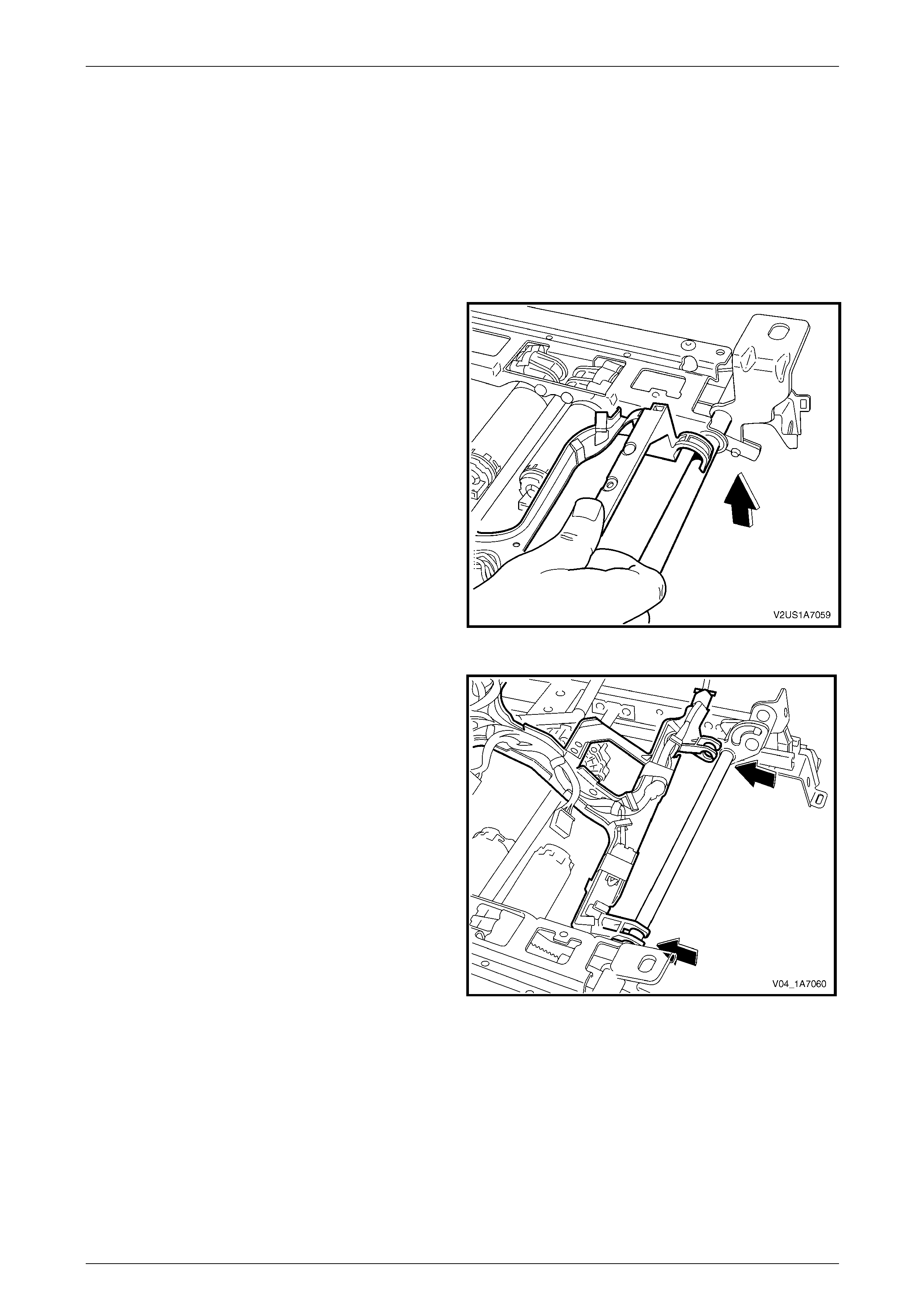
Seat Assemblies Page 1A7–269
Page 1A7–269
6.12 Seat Cable Tray
Remove
As required remove the following c ompo ne nts:
1 Front seat assembly, refer to 6.2 Front Seat Assembly.
2 Remove the seat track and height adjust ass embl y, refer to 6.13 Track and Height Adjust Assembly.
3 Disconnect the wiring harness connectors as required.
4 Unclip the cable tray from the front of the seat track
and height adjust assembly.
Figure 1A7 – 137
5 Pull the cable tray forward to release it from the seat
track and height adjust assembl y.
Figure 1A7 – 138
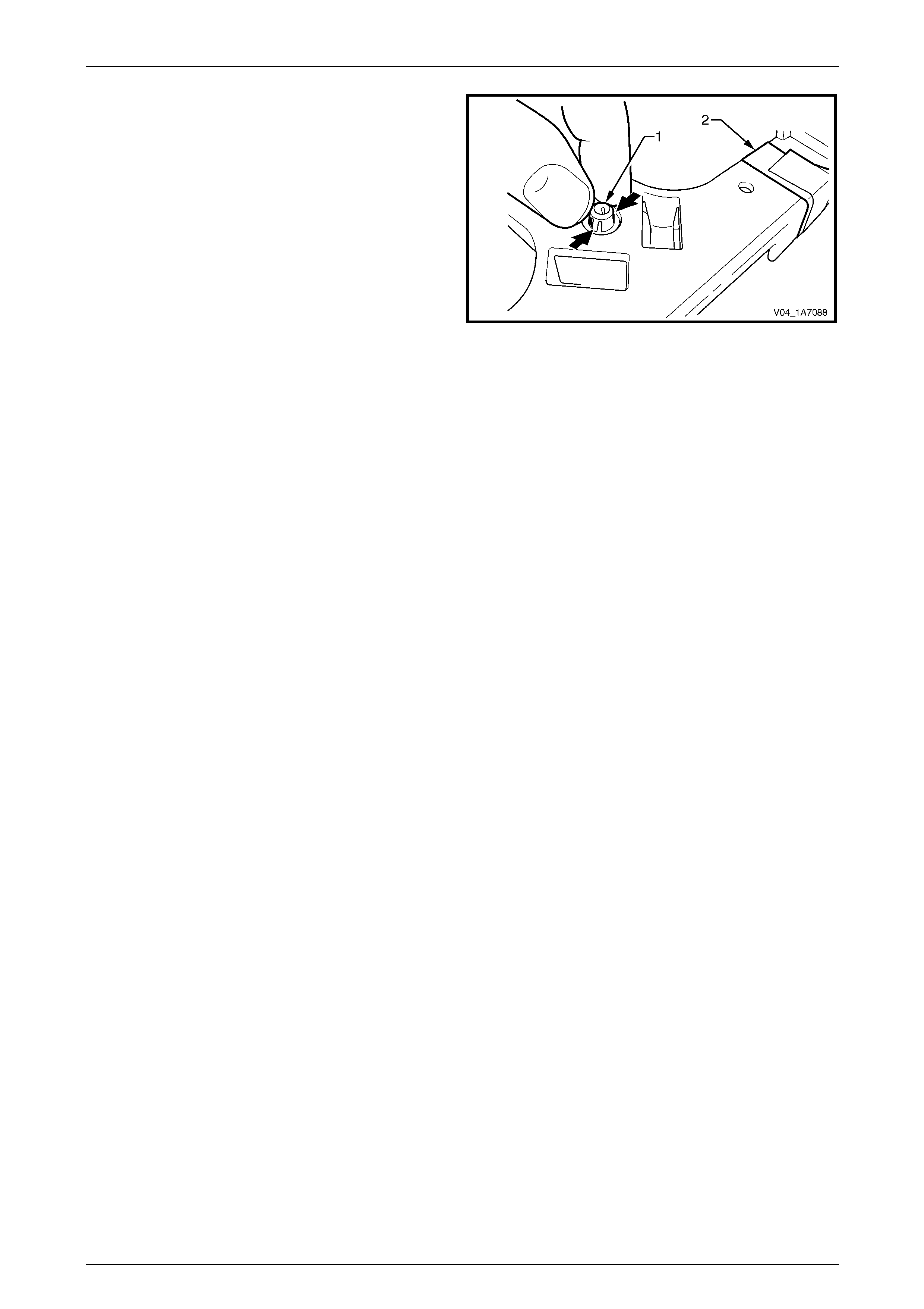
Seat Assemblies Page 1A7–270
Page 1A7–270
6 If required, remove the wiring harness from the cable
tray by squeezing the tabs on the harness clips (1)
and by removing the tape (2).
Figure 1A7 – 139
Reinstall
Reinstallation of the seat cable tray is the reverse of the removal procedure. Ensure the wirin g harness and connectors
are correctly routed and attached securely.
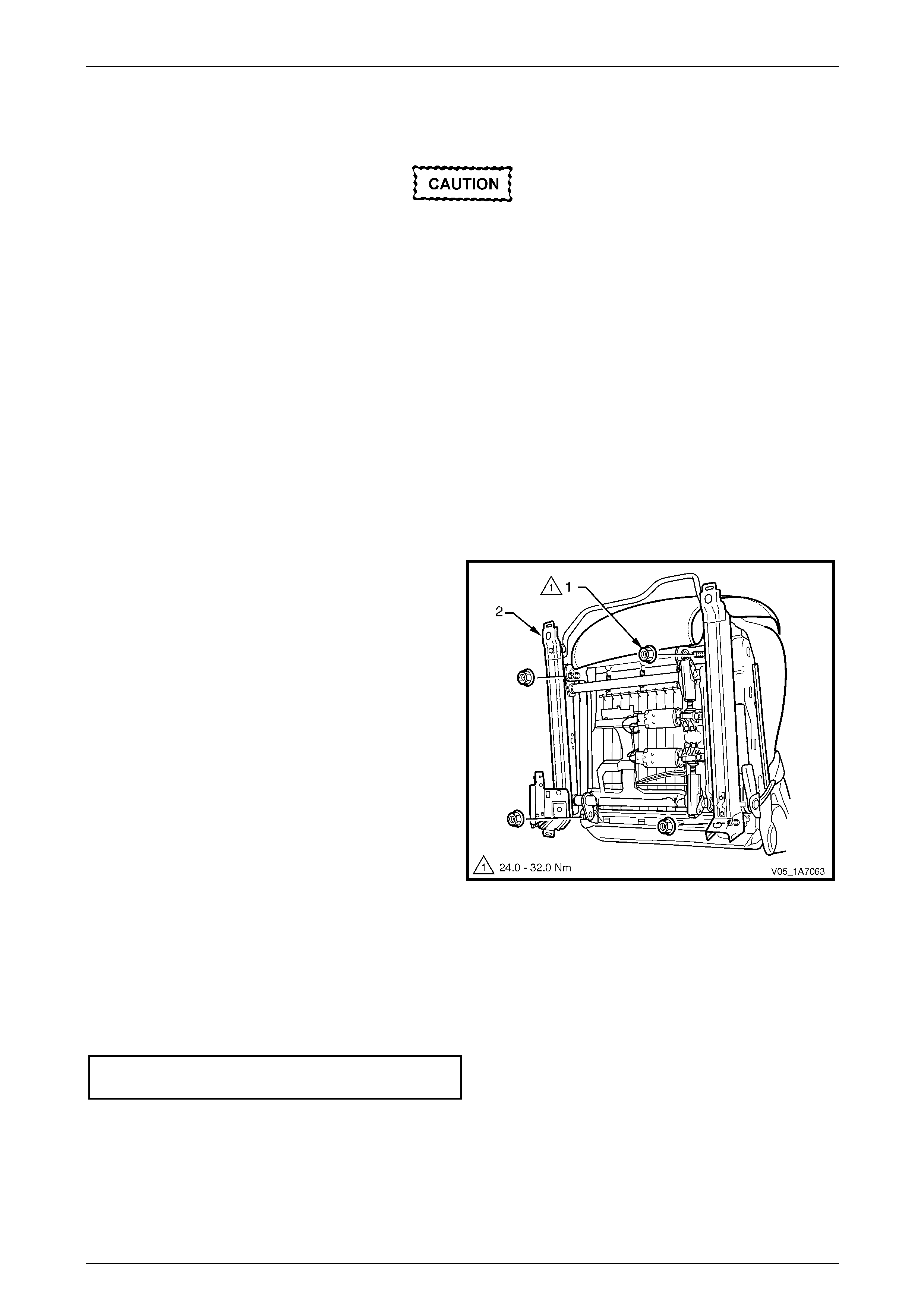
Seat Assemblies Page 1A7–271
Page 1A7–271
6.13 Track and Height Adjust Assembly
The track and height adjust assembly
components are non-serviceable. If the track
and height adjust assembly, drive motors or
drive shafts require replacement, the entire
track and height adjust assembly must be
replaced.
LT Section No. — 14–275
As required, remove the following components:
1 Front seat assembly, refer to 6.2 Front Seat Assembly.
2 Front seat outer side cover assembly, refer to 6.3 Front Seat Outer Side Cover Assembly.
Remove
1 As required, detach the wiring harness connectors.
2 As required, detach the seatbelt pretensioner wiring harness connector.
3 Remove the four nuts (1) attaching the track and
height adjust assembly (2) to the seat.
4 Remove the track and height adjust assembly.
5 If required, remove the cable tray and wiring harness
assembly, refer to 6.12 Seat Cable Tray.
6 If required, remove the seatbelt buckle and
pretensioner assembly, refer to Section 12M Occupant
Protection System.
Figure 1A7 – 140
Reinstall
Reinstallation of the track and height adjust assembly is the reverse of the removal procedur e, noting the following:
1 Ensure the connectors are correctly routed and attach ed securely.
2 Tighten the attaching nuts to the correct torque spec ification.
Track and height adjust assembly
attaching nut torque specification............24.0 – 32.0 Nm
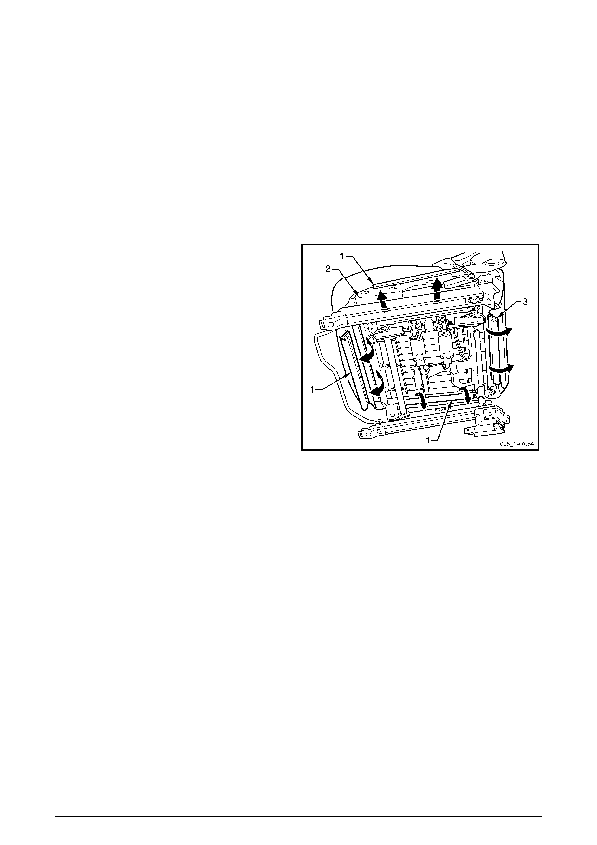
Seat Assemblies Page 1A7–272
Page 1A7–272
6.14 Front Seat Cushion Pad and Cover
Assembly
LT Section No. — 14–295
As required, remove the following components:
1 Front seat assembly, refer to 6.2 Front Seat Assembly.
2 Front seat outer side cover assembly, refer to 6.3 Front Seat Outer Side Cover Assembly.
3 Front seat inner side cover, refer to 6.4 Front Seat Inner Side Cover.
4 Front seat-back frame assembly, refer to 6.11 Front Seat-back Frame Assembly.
Remove
1 From under the front seat cushion, disengage the front
and side J-strips (1) away from the seat frame (2).
2 Lift the cover and pad assembly a way from the seat
frame and then release the rear J-strip (3).
3 Remove the pad and cover assembly.
Figure 1A7 – 141
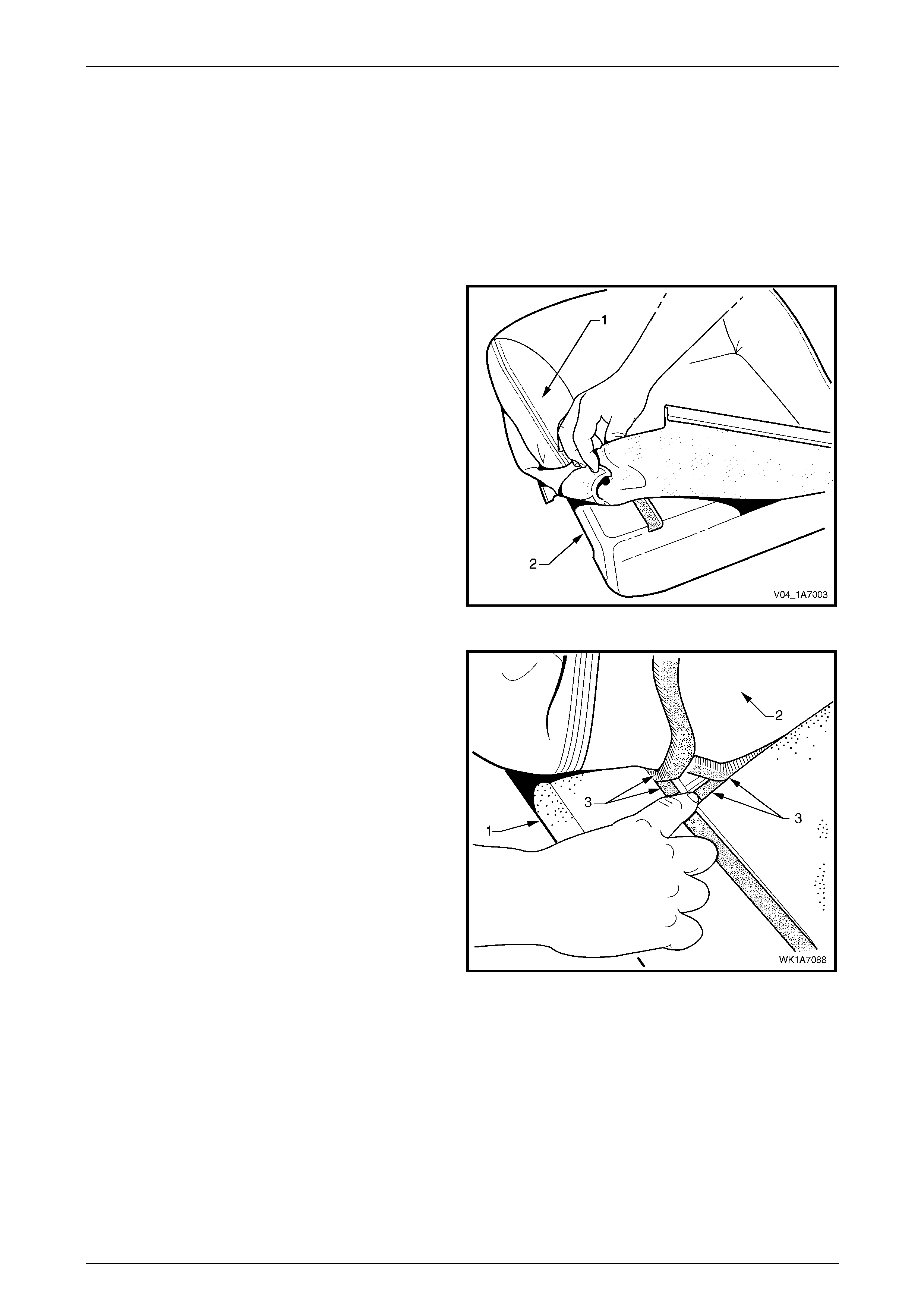
Seat Assemblies Page 1A7–273
Page 1A7–273
Disassemble
NOTE
The following illustrations show typical hook and
loop arrangement, which will vary according to
seat type.
Surebond type seat-back pad and cover
assemblies cannot be disassembled.
1 Fold the rear corners of the front seat cushion
cover (1) over the front seat cushion pad (2).
Figure 1A7 – 142
2 While holding the front seat cushi on pad (1), pull the
rear corners of the front seat cushion cover (2) forward
and away from the pad to disengage the hook and
loop strips (3).
3 Pull the cover up and over the forward edge of the
pad.
Figure 1A7 – 143

Seat Assemblies Page 1A7–274
Page 1A7–274
Reassemble
1 Align either of the outer hook and l oo p strips (1) and
the one or two cross hook and loop strips (2) on the
front seat cushion cover (3) with the front seat cushion
pad (4).
2 Press the folded edge of the cover firmly into the
corresponding groove in the pad to engage the hook
and loop strip.
Figure 1A7 – 144
3 Align and press the outer hook and loop strip (1) on
the cover (2) with the corresponding groove in the
pad (3).
Figure 1A7 – 145
4 Roll the front corners of the cover over the pad.
5 Roll the sides of the cover over the pad.
6 Roll the rear corners of the cover over the seat pad.
NOTE
Ensure the pad is fitted neatly by hand into all
corners and contours of the seat cover.
Do not pull the cover onto the pad from
underneath using the J-strip to make it fit
neatly, as the fabric may be damaged.
Figure 1A7 – 146
Reinstall
Reinstallation of the front seat cushion pad and cover assembly is the reverse of the removal procedure.

Seat Assemblies Page 1A7–275
Page 1A7–275
6.15 Front Seat Cushion Frame Assembly
LT Section No. — 14–275
Remove
As required remove the following c ompo ne nts:
1 Front seat assembly, refer to 6.2 Front Seat Assembly.
2 Front seat outer side cover assembly, refer to 6.3 Front Seat Outer Side Cover Assembly.
3 Front seat inner side cover, refer to 6.4 Front Seat Inner Side Cover.
4 Front seat-back frame assembly, refer to 6.11 Front Seat-back Frame Assembly.
5 Track and height adjust assembly, refer to 6.13 Track and Height Adjust Assembly.
6 Front seat cushion pad and cover assembly, refer to 6.14 Front Seat Cushion Pad and Cover Assembly.
Disassemble
1 To remove the suspension mat (1), modify a G-clamp
with a 5 mm diameter metal dowel (2) welded to one
end and another approximately 40 mm long and with a
2 mm diameter pin (3) approximately 20 mm l ong
welded to the other end.
2 Using the G-clamp, stretch the suspension mat far
enough to allow for the retaining springs (4) to be
removed from the seat cushion frame.
3 Back the G-clamp load off and remove the suspensio n
mat.
When using the G-clamp, use existing holes
in the suspension mat to ensure mat
deformation does not occur.
Figure 1A7 – 147
Reassemble
Reassembly of the suspension mat is the reverse of the disassembl y proc edure.
Reinstall
Reinstallation of the front seat cushion frame assembly is the reverse of the removal pro cedure, noting the following:
1 Ensure all wiring is correctly connected and routed, refer to Section 12O Fuses, Relays and Wiring Harnesses.
2 Check the mechanical and elec trical operation of the front seat.

Seat Assemblies Page 1A7–276
Page 1A7–276
6.16 Front Seat Lift Motor Assemblies
The front seat lift motor assemblies are non-serviceabl e items.
If a front seat lift motor assembly requires replacement, the track and height adjust assembly must be replaced, refer to
6.13 Track and Height Adjust Assembly.

Seat Assemblies Page 1A7–277
Page 1A7–277
7 Service Operations – Front Seat,
Coupe
7.1 Usage Chart
How to Use this Chart
The following usage chart is provided to help determine the seat type fitted to the vehicle. T his is important prior to
repairs being performed as the failed/damaged part may no t be serviced.
To determine the seat type fitted to the vehicle, obtain the vehicle model and which seat requires attenti on. Refer to the
Figure number shown in Front Seat Type column for a component breakdown of the front seat assembly.
1 Vehicle – Vehicle model identification.
2 Seating – Driver front seat or passenger front seat.
3 Fabric – Cloth or leather seat covers.
4 Movement – Indicates the number of movement functions of the seat:
• Eight-way – Seat cushion electric front and rear raise/lower, seat electric fore/aft movement and electric
seat-back recline.
5 Memory – Indicates if a seat memory module is fitted.
6 SIAB – Indicates if the seat is fitted with a side impact airbag assembly.
7 Construction – Hook and Loop refers to the seat cover being attached to the seat pad with a Velcro type materia l
and both being serviced as separate p arts.
8 Active Head Restraint – Indicates if active head restraints are fitted.
9 Front Seat Type – Identifies the seat type and provides reference to illustrations which show a breakdown of the
serviced component for each front seat assembly.
Vehicle Seating Fabric Movement Memory SIAB Construction Active Head
Restraint Front Seat Type
(refer to)
Driver Leather Eight-way Yes Yes Hook & Loop Yes 1
(Figure 1A7 – 148)
CV8
Passenger Leather Eight-way No Yes Hook & Loop Yes 2
(Figure 1A7 – 149)
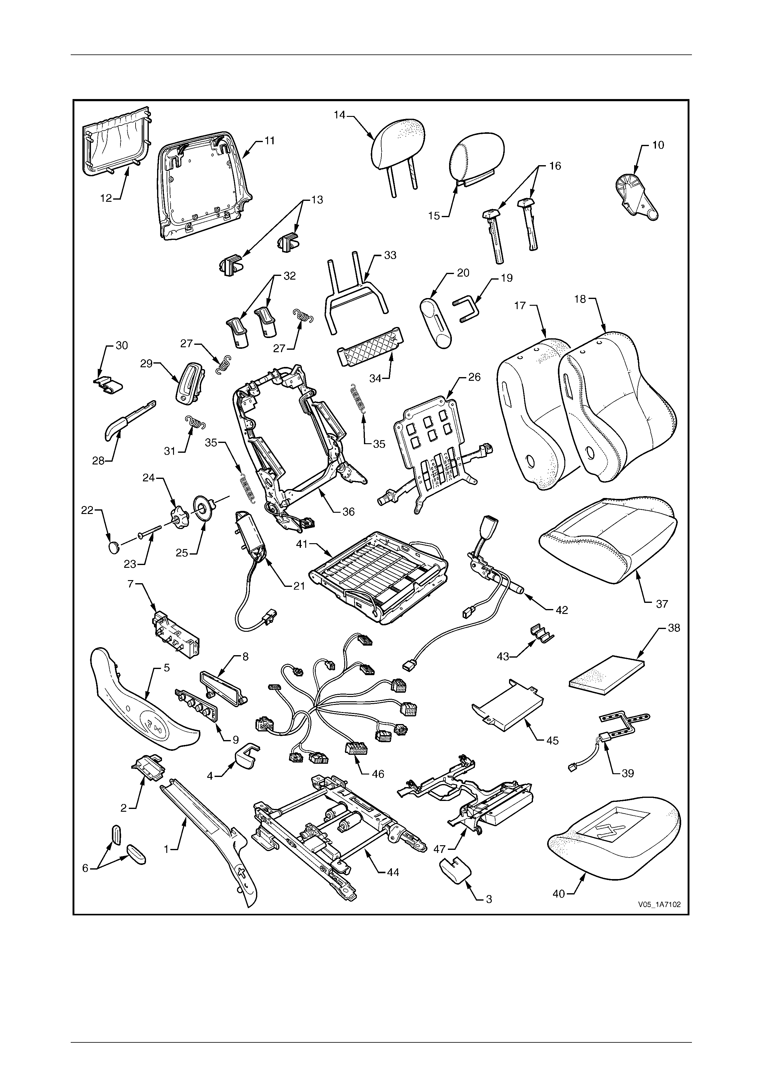
Seat Assemblies Page 1A7–278
Page 1A7–278
Front Seat Type 1
Figure 1A7 – 148

Seat Assemblies Page 1A7–279
Page 1A7–279
Legend
1 Front Seat Outer Front Cover
2 Front Seat Outer Rear Cover
3 Front Seat Inner Front Cover
4 Front Seat Inner Rear Cover
5 Front Seat Outer Side Cover
6 Front Seat Adjustment Switch Knobs
7 Front Seat Adjustment Switch
8 Memory Position Switch Cover
9 Memory Position Switch Assembly
10 Front Seat Inner Side Cover
11 Front Seat-back Rear Cover
12 Front Seat-back Map Pocket
13 Front Seat-back Cover Retaining Clips
14 Front Seat Head Restraint Pad Assembly
15 Front Seat Head Restraint Cover
16 Front Seat Head Restraint Sleeves
17 Front Seat-back Pad
18 Front Seat-back Cover
19 Front Seat Dummy Block U-bolt
20 Front Seat Dummy Block Insert
21 Side Impact Airbag Assembly
22 Lumbar Support Knob Cover
23 Lumbar Support Knob Screw
24 Lumbar Support Knob
25 Lumbar Support Deflector Ring
26 Lumbar Support Assembly
27 Lumbar Support Retaining Spring
28 EZ-entry Release Lever Assembly
29 EZ-entry Release Escutcheon Assembly
30 EZ-entry Release Lever Retaining Clip
31 EZ-entry Release Lever Return Spring
32 Active Head Restraint Frame Sleeves
33 Active Head Restraint Frame Assembly
34 Active Head Restraint Frame Support Strap
35 Active Head Restraint Frame Retaining Spring
36 Front Seat-back Frame Assembly
37 Front Seat Cushion Cover
38 Front Seat Cushion Upper Pad
39 Passenger Presence Detection Switch
40 Front Seat Cushion Pad
41 Front Seat Cushion Frame Assembly
42 Seatbelt Buckle & Pretensioner Assembly
43 Wiring Harness Retaining Clip
44 Track and Height Adjust Assembly
45 Seat Memory Module
46 Wiring Harness Assembly
47 Front Seat Cable Tray
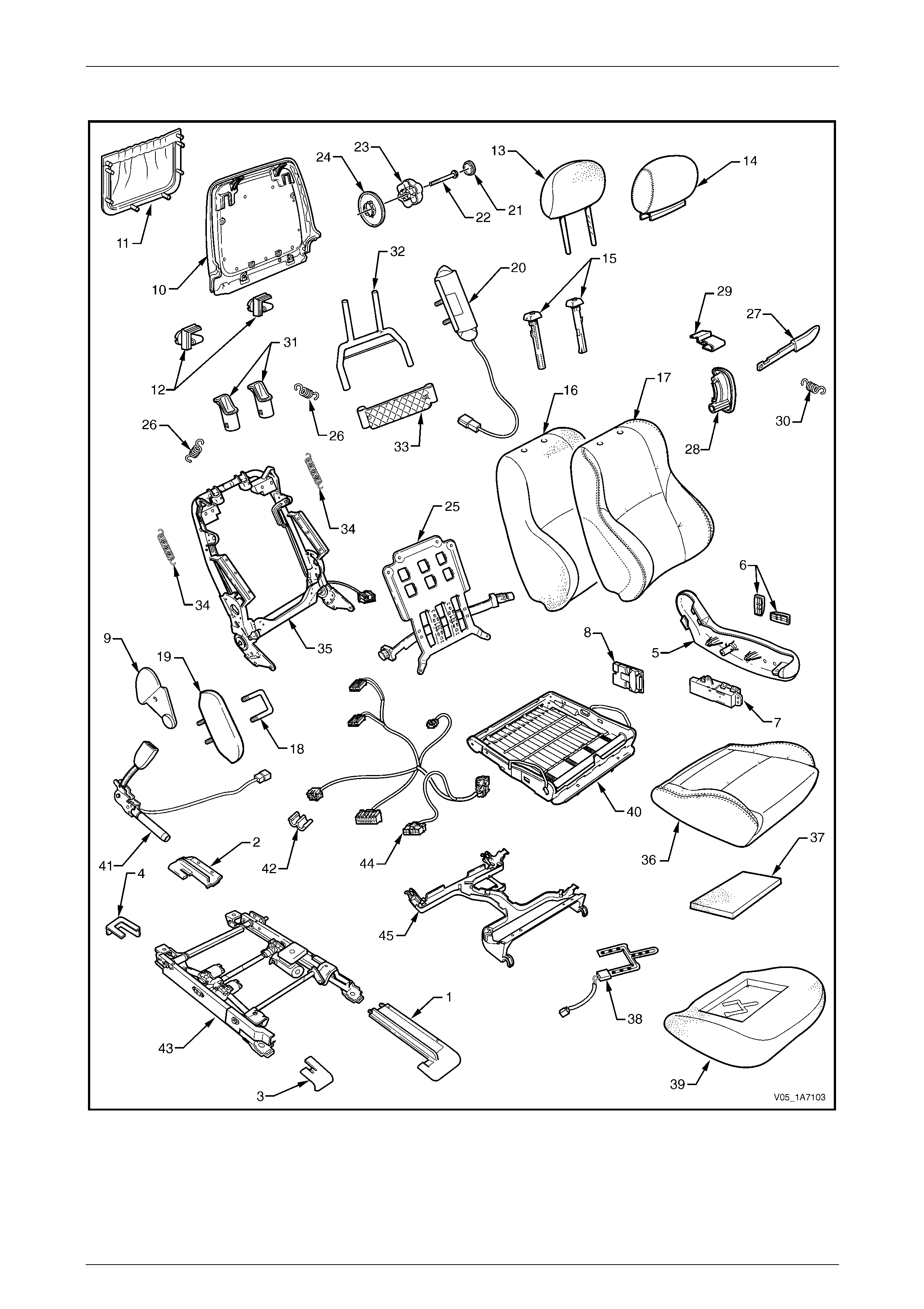
Seat Assemblies Page 1A7–280
Page 1A7–280
Front Seat Type 2
Figure 1A7 – 149

Seat Assemblies Page 1A7–281
Page 1A7–281
Legend
1 Front Seat Outer Front Cover
2 Front Seat Outer Rear Cover
3 Front Seat Inner Front Cover
4 Front Seat Inner Rear Cover
5 Front Seat Outer Side Cover
6 Front Seat Adjustment Switch Knobs
7 Front Seat Adjustment Switch
8 EZ-entry Module
9 Front Seat Inner Side Cover
10 Front Seat-back Rear Cover
11 Front Seat-back Map Pocket
12 Front Seat-back Cover Retaining Clips
13 Front Seat Head Restraint Pad Assembly
14 Front Seat Head Restraint Cover
15 Front Seat Head Restraint Sleeves
16 Front Seat-back Pad
17 Front Seat-back Cover
18 Front Seat Dummy Block U-bolt
19 Front Seat Dummy Block Insert
20 Side Impact Airbag Assembly
21 Lumbar Support Knob Cover
22 Lumbar Support Knob Screw
23 Lumbar Support Knob
24 Lumbar Support Deflector Ring
25 Lumbar Support Assembly
26 Lumbar Support Retaining Spring
27 EZ-entry Release Lever Assembly
28 EZ-entry Release Escutcheon Assembly
29 EZ-entry Release Lever Retaining Clip
30 EZ-entry Release Lever Return Spring
31 Active Head Restraint Frame Sleeves
32 Active Head Restraint Frame Assembly
33 Active Head Restraint Frame Support Strap
34 Active Head Restraint Frame Retaining Spring
35 Front Seat-back Frame Assembly
36 Front Seat Cushion Cover
37 Front Seat Cushion Upper Pad
38 Passenger Presence Detection Switch
39 Front Seat Cushion Pad
40 Front Seat Cushion Frame Assembly
41 Seatbelt Buckle & Pretensioner Assembly
42 Wiring Harness Retaining Clip
43 Track and Height Adjust Assembly
44 Wiring Harness Assembly
45 Front Seat Cable Tray

Seat Assemblies Page 1A7–282
Page 1A7–282
7.2 Front Seat Assembly
LT Section No. — 14–295
Before performing any service operation on a
front seat assembly fitted with side
impact airbags, ensure the occupant
protection system is disabled, refer to
Section 12M Occupant Protection System.
NOTE
If the seat assembly is to be disassembled, adjust
the seat assembly to its highest position before
disconnecting the power to the seat.
NOTE
Clean hands are essential when working on the
interior trim.
Remove
Disconnection of the battery affects
certain vehicle electronic systems. Refer to
Section 00 Warnings, Cautions and Notes,
5 Battery Disconnection Procedures before
disconnecting the battery.
1 Disconnect the battery.
2 For the driver’s seat, remove the screw (1) attaching
the front seat outer front cover (2).
3 Using a small scre wdriver, push in the ce ntre of the
join to separate the front seat outer front cover and the
front seat outer rear cover (3).
4 Unclip the covers from the seat track and disengag e
from the side sill trim.
5 Pull the covers apart and remove the rear c over.
6 For the driver’s seat, slide the front cover over the fuel
filler door release lever (4) and remove.
Figure 1A7 – 150

Seat Assemblies Page 1A7–283
Page 1A7–283
7 Disconnect the body wiring ha rness connector (1), the
seatbelt pretensioner wiring connector (2) and the side
impact airbag wiring connector (3).
Figure 1A7 – 151
8 Unclip the front seat inner rear cover (1) from the seat
track (2).
Figure 1A7 – 152
9 Unclip the front seat inner front cover (1) from the seat
track (2).
Figure 1A7 – 153
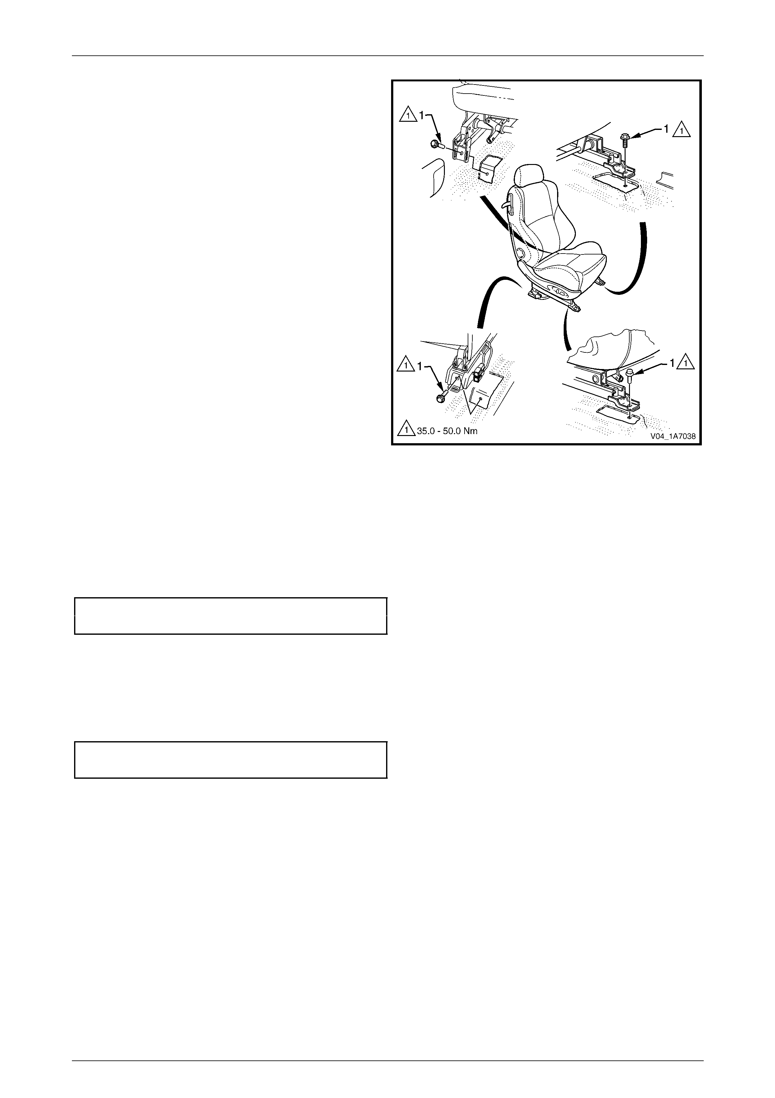
Seat Assemblies Page 1A7–284
Page 1A7–284
10 Remove the four screws (1) attaching the front seat to
the vehicle.
11 Remove the seat from the vehicle.
Figure 1A7 – 154
Reinstall
Reinstallation of the front seat assembly is the reverse of the removal procedure, noting the following:
1 Position the front seat assembly into the vehicle.
2 Install the four screws securing the front seat.
3 Tighten the attaching screws to the correct torque specification.
Front seat assembly attaching screw
torque specification.................................35.0 – 50.0 Nm
4 Connect the seat wiring harness connector, s eatbelt pretensioner harness connector and the side impact airbag
connector.
5 Align the front seat outer cover’s retaining clips and push firmly to engage.
6 Push the front of the front seat outer cover do wn to engage the cover with the front of the seat rail.
7 For the driver’s seat, install the front seat outer front cover attaching screw and tighten to the specified torque.
Front seat outer front cover attaching
screw torque specification...........................1.0 – 3.0 Nm
8 Check the operation of the front seat functions. While checking the seat adjustment/operation, also check the seat
wiring harnesses do not foul with any of the seat’s moveable components (i.e. seat motor drive shafts, etc.).
NOTE
Type 1 front seats will require seat memory
calibration to reinstate seat memory functions,
refer to Seat Memory Calibration, Front Seat
Type 1 in this Section.
9 Switch on the ignition and observe the airbag warning indic ator in the instrument cluster.
• If no fault is detected, the airbag warning indicator illuminates for approxim ately five seconds while the
system performs a self-test, and then extinguish.
• If a fault is present, the airbag warning indic ator will remain illuminated and a warning chime may sound after
approximately three seconds. The warning message ‘SRS Airbag F ault’ is displayed in the instrume nt cluster
multi-function display. To diagnose the fault, refer to Section 12M Occupant Protection System.

Seat Assemblies Page 1A7–285
Page 1A7–285
Seat Memory Calibration, Front Seat Type 1
Whenever power is interrupted to the seat memor y module, the following procedure must be performed to reinstate seat
memory functions.
Step Operation Result
1 1 Operate the seat adjustment switch to move the
seat forward.
2 Operate the seat adjustment switch for 1 second to
move the seat aft.
3 Operate the seat adjustment switch to move the
seat forward.
Seat will cease movement when track limit is
reached.
Seat will move aft.
Seat will cease movement when track limit is
reached.
2 1 Operate the seat adjustment switch to move the
seat aft.
2 Operate the seat adjustment switch for 1 second to
move the seat forward.
3 Operate the seat adjustment switch to move the
seat aft.
Seat will cease movement when track limit is
reached.
Seat will move forward.
Seat will cease movement when track limit is
reached.
3 1 Operate the seat adjustment switch to raise the
front of the seat.
2 Operate the adjustment switch for 1 second to
lower the front of the seat.
3 Operate the seat adjustment switch to raise the
front of the seat.
Seat will cease movement when upper limit is
reached.
Se at wi l l lo wer .
Seat will cease movement when upper limit is
reached.
4 1 Operate the seat adjustment switch to lower the
front of the seat.
2 Operate seat adjustment switch for 1 second to
raise the front of the seat.
3 Operate the seat adjustment switch to lower the
front of the seat.
Seat will cease movement when lower limit is
reached.
Seat will raise.
Seat will cease movement when lower limit is
reached.
5 1 Operate the seat adjustment switch to raise the rear
of the seat.
2 Operate the seat adjustment switch for 1 second to
lower the rear of the seat.
3 Operate the seat adjustment switch to raise the rear
of the seat.
Seat will cease movement when upper limit is
reached.
Se at wi l l lo wer .
Seat will cease movement when upper limit is
reached.

Seat Assemblies Page 1A7–286
Page 1A7–286
Step Operation Result
6 1 Operate the seat adjustment switch to lower the
rear of the seat. Seat will cease movement when lower limit is
reached.
7 1 Operate the seat adjustment switch to move the
seat-back aft.
2 Operate the seat adjustment switch for 1 second to
move the seat-back forward.
3 Operate the seat adjustment switch to move the
seat-back aft.
Hold switch until lower limit is reach ed. This
does not have to be mechanical limit.
Seat-back will move forward.
Hold switch until lower limit is reach ed. This
should be same position as in 1.
8 1 Operate the seat adjustment switch to move the
seat-back forward.
2 Operate the seat adjustment switch for 1 second to
move the seat-back aft.
3 Operate the seat adjustment switch to move the
seat-back forward.
Hold switch until upper lim it is reached. This
does not have to be mechanical limit.
Seat-back will move aft.
Hold switch until upper lim it is reached. This
should be same position as in 1.
9 Press the memory store (M) button for 1 second. Stores the calibration into memory. A three-
tone chime sounds to confirm storage.
To test if the seat limits have been correctly calibrated, perform the following:
Step Operation Result
1 Operate the seat adjustment switch in one direction
(fore/aft, raise/lower, etc.). Hold until seat stops.
2 Release the switch briefly. –
3 Operate the switch in the same direction and hold for 3
seconds. The motor will not operate for 2 seconds, then
operates for 0.5 second.
This is a limp-home function that allo ws the
seat to be manually adjusted should a sensor
fail.
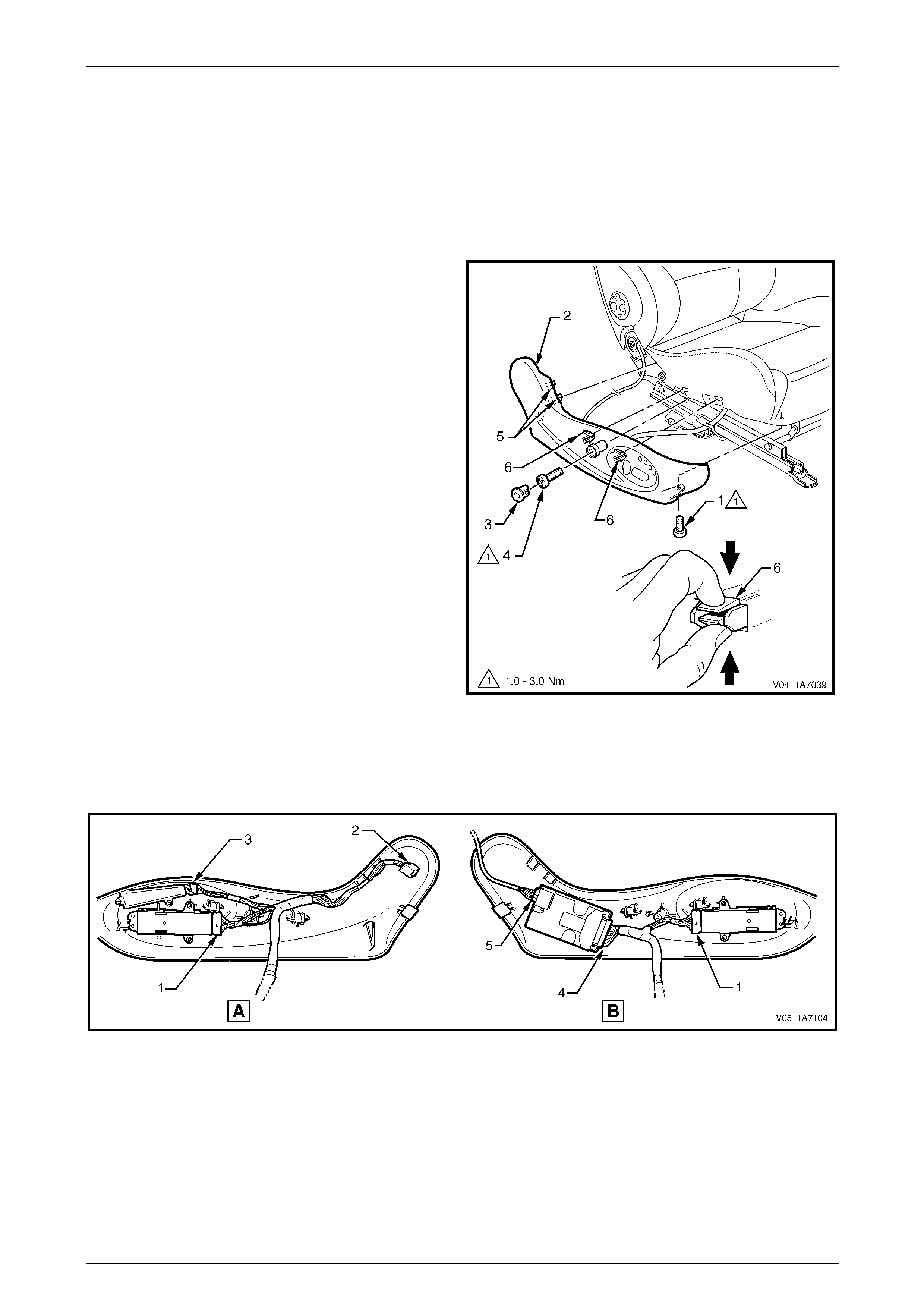
Seat Assemblies Page 1A7–287
Page 1A7–287
7.3 Front Seat Outer Side Cover Assembl y
LT Section No. — 14–322
Remove
1 Raise the seat to the full-up position.
2 Remove the screw (1) from the front of the front seat
outer side cover (2).
3 Remove the plug (3) by rotating the plug anti-
clockwise, one quarter of a turn.
4 Remove the screw (4) located behind the plu g.
5 Reach up under the seat assembl y and squeeze
together the two retaining tangs (6), on the i nner side
of the side cover while gently pulling the cover.
6 Gently pull the side cover away from the seat to
disengage the two clips (5) att ache d to the seat-back
frame assembly.
NOTE
Only remove the side cover far enough away
from the seat cushion assembly to gain access
to the seat wiring harness connectors.
7 Referring to Figure 1A7 – 156, for memory seats (A):
• Disconnect the front seat adjustment switch
connector (1), recline motor harness connector
(2) and memory position s witch connector (3)
and unclip the harness from the side cover.
For non-memory seats (B): Figure 1A7 – 155
• Disconnect the front seat adjustment switch connector (1), EZ-entry module connector (4) and the recline
motor harness connector (5) from the EZ-entry module and unclip the h arn ess from the side cover.
8 Remove the side cover assembly.
Figure 1A7 – 156
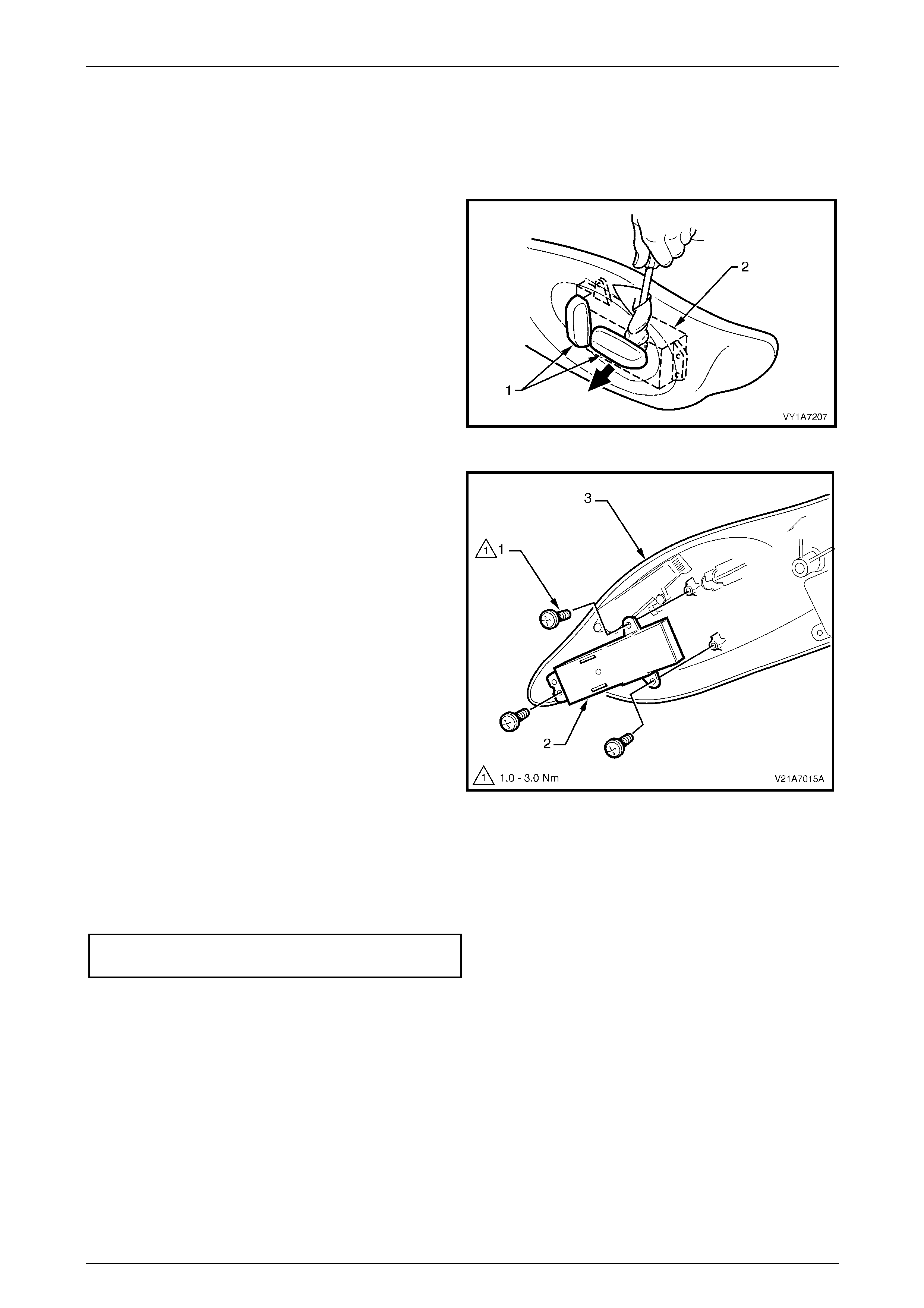
Seat Assemblies Page 1A7–288
Page 1A7–288
Disassemble
Front Seat Adjustment Switch
Remove
1 Remove the two adjustment knobs (1) from the front
seat adjustment switch (2), by carefully prising them
free with a small flat tip screwdriver wrapped in a clean
shop rag.
Figure 1A7 – 157
2 Remove the three screws (1) attaching the front seat
adjustment switch (2) to the front seat outer side
cover (3).
3 Remove the seat adjustment switch.
Figure 1A7 – 158
Reinstall
Reinstallation of the front seat adjustment switch is the reverse of the removal procedure, noting the fol lowing:
1 Tighten the attaching screws to the correct torque specification.
Front seat adjustment switch
attaching screw torque specification...........1.0 – 3.0 Nm
2 Push the knobs in until they click in place.
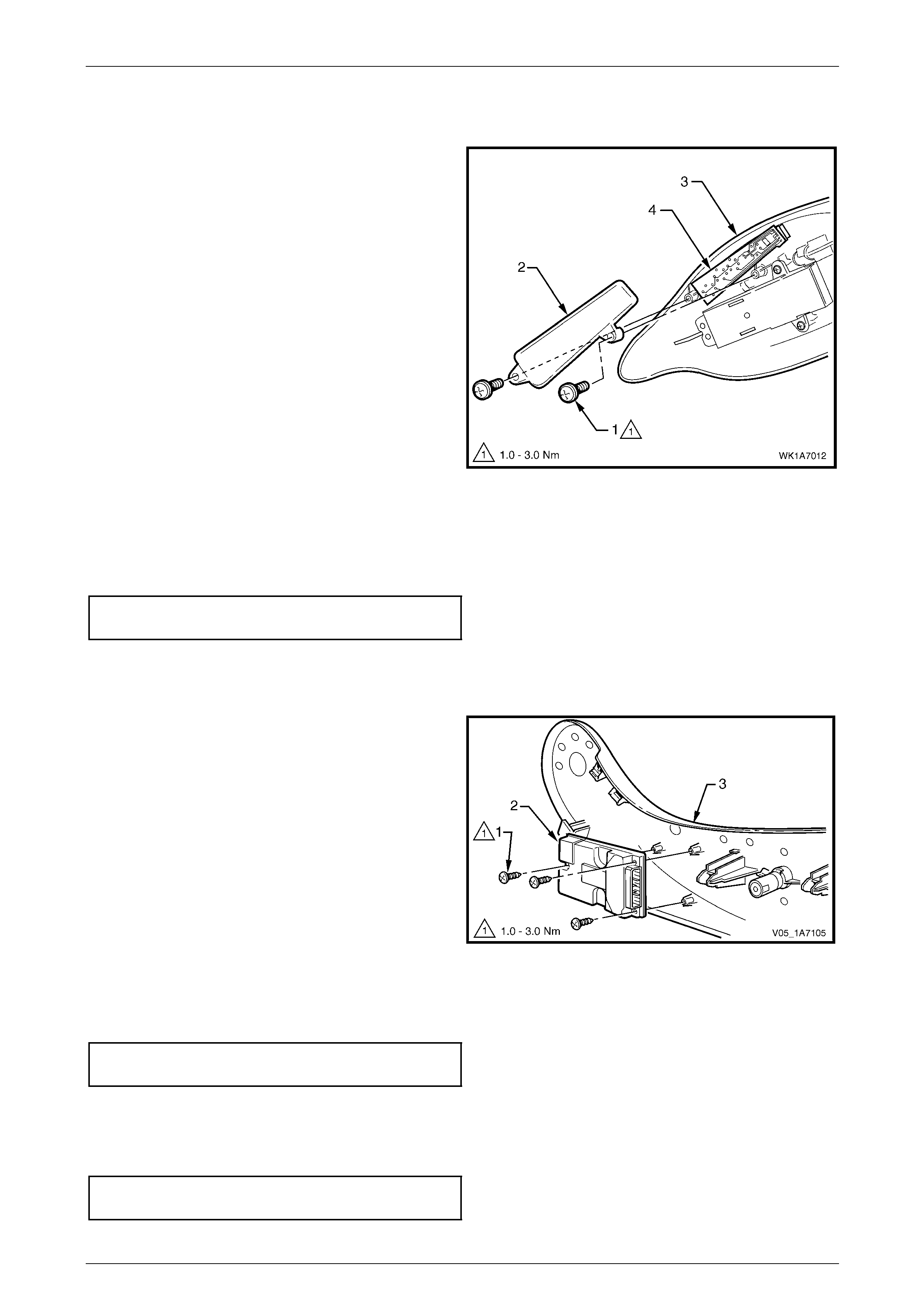
Seat Assemblies Page 1A7–289
Page 1A7–289
Memory Position Switch Assembly
Remove
1 Remove the two screws (1) attaching the memory
position switch cover (2) to the front seat outer side
cover (3).
2 Lift out the memory position switch assembly (4) from
its recess in the side cover.
3 As required, each position button can be removed
from the switch.
Figure 1A7 – 159
Reinstall
Reinstallation of the memory position switch assembly is the reverse of the removal procedure, noting the following:
1 If removed, push the position buttons in until they click in place, ensuring correct orientation.
2 Tighten the attaching screws to the correct torque specification.
Memory position switch cover
attaching screw torque specification...........1.0 – 3.0 Nm
EZ-entry Module
Remove
1 Remove the three screws (1) attaching the EZ-entry
module (2) to the front seat outer side cover (3).
2 Remove the module.
Figure 1A7 – 160
Reinstall
Reinstallation of the EZ-entry module is the reverse of the removal procedure. T ighten the attaching screws to the correct
torque specification.
EZ-entry module attaching screw
torque specification.....................................1.0 – 3.0 Nm
Reinstall
Reinstallation of the front seat outer side cover is the reverse of the removal procedure. Tighten the attaching screws to
the correct torque specification.
Front seat outer side cover attaching
screw torque specification...........................1.0 – 3.0 Nm
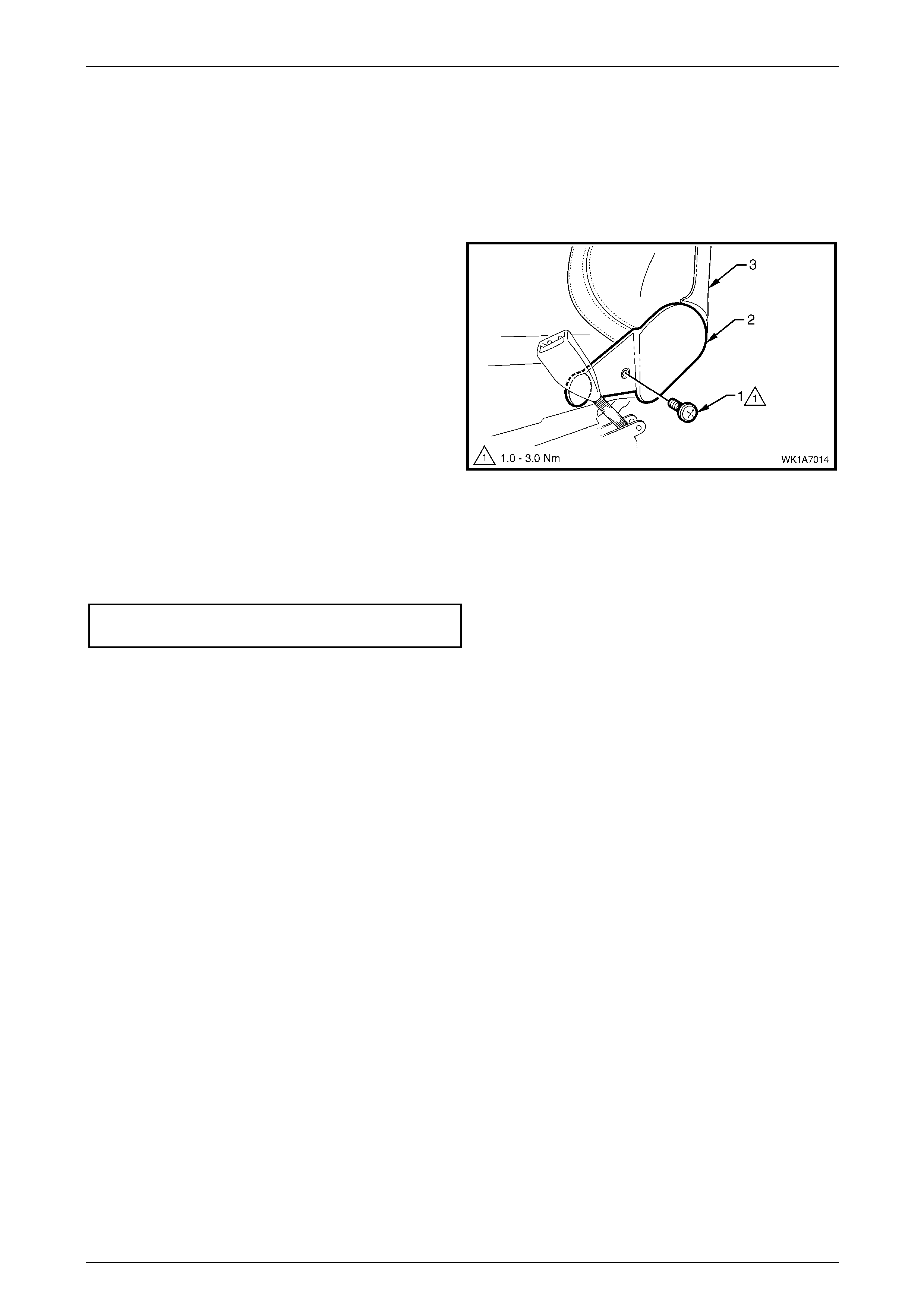
Seat Assemblies Page 1A7–290
Page 1A7–290
7.4 Front Seat Inner Side Cover
LT Section No. — 14–322
As required, remove the front seat assembly, refer to 7.2 Front Seat Assembly.
Remove
Remove the screw (1) attaching the front seat inner side
cover (2) to the seat assembly (3) and remove the cover.
Figure 1A7 – 161
Reinstall
Reinstallation of the front seat inner side cover is the reverse of the removal procedure. Tighte n the atta ching screw to
the correct torque specification.
Front seat inner side cover attachi ng
screw torque specification...........................1.0 – 3.0 Nm
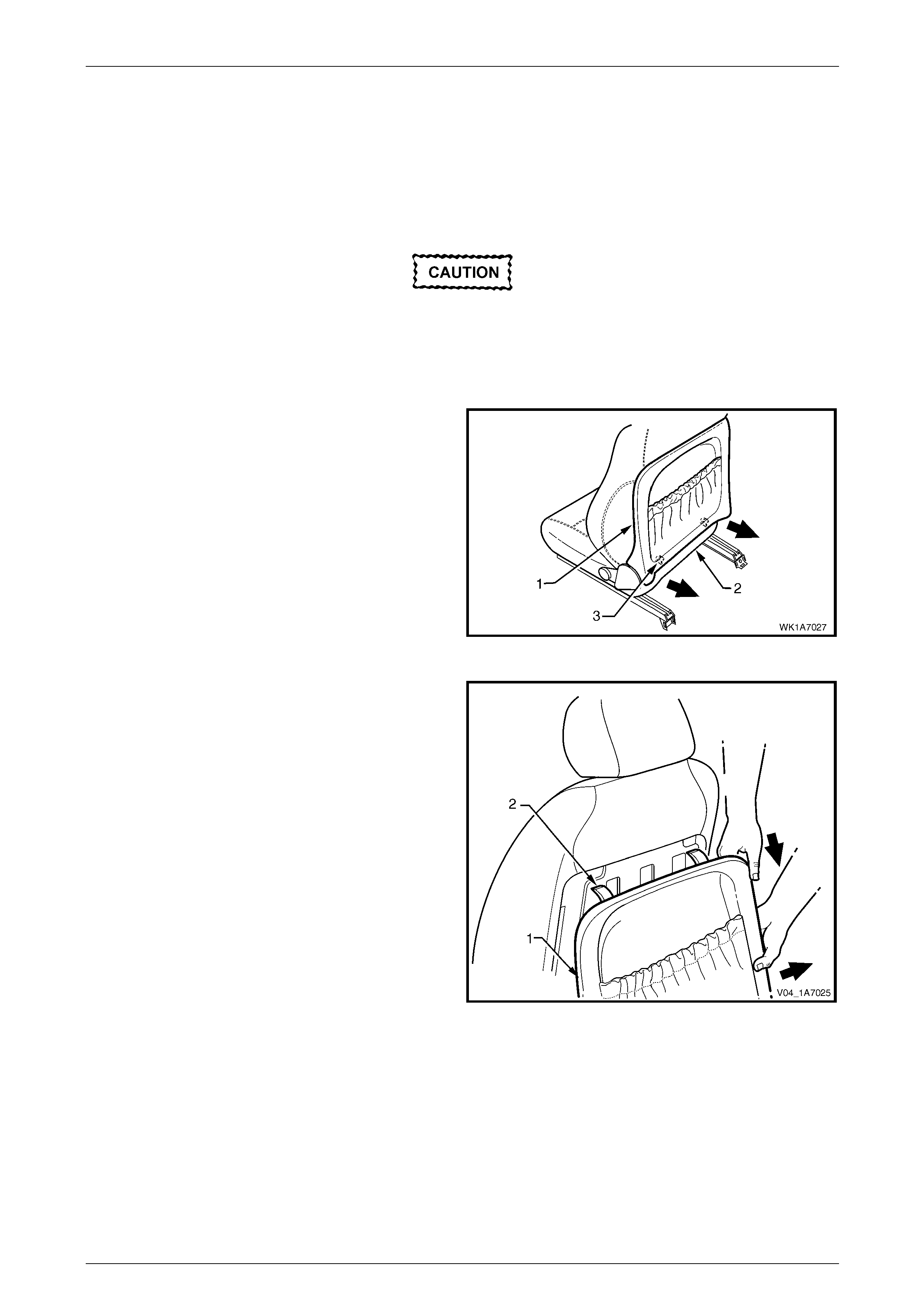
Seat Assemblies Page 1A7–291
Page 1A7–291
7.5 Front Seat-back Rear Cover Assembly
LT Section No. — 14–322
Remove
The following components will require
replacement when performing this operation.
• Two front seat-back rear cover retaining
clips.
1 Pull the lower corners of the front seat-back rear
cover (1) away from the seat (2), breaking the two
retaining clips (3).
Figure 1A7 – 162
2 While holding the lower portion of the front seat-back
rear cover (1) out, pull the cover do wn to release the
two upper retaining lugs (2).
3 Remove the cover.
Figure 1A7 – 163
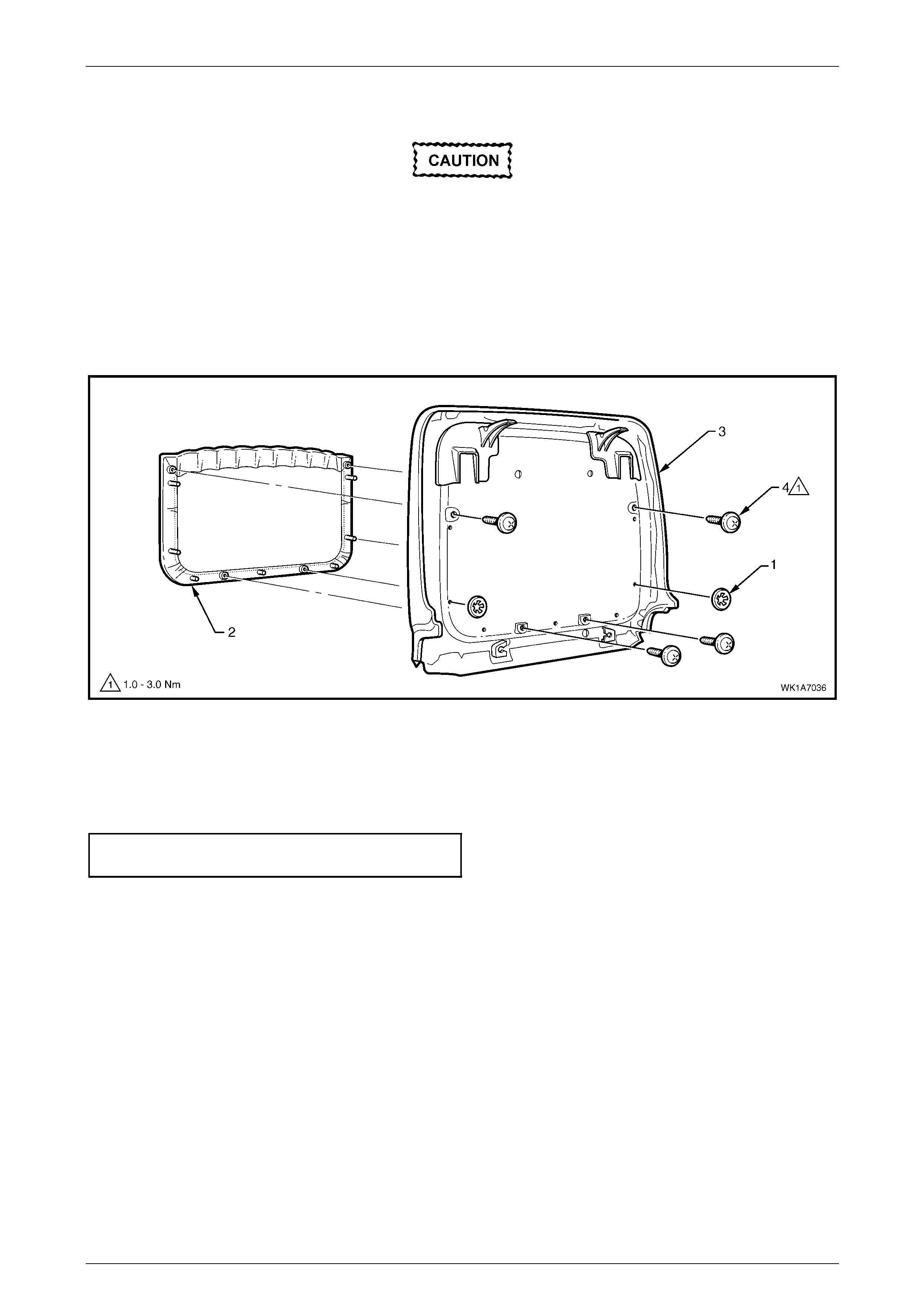
Seat Assemblies Page 1A7–292
Page 1A7–292
Disassemble
When performing Step 1, take care when
removing the retaining clip (1) not to break
the front seat-back map pocket shafts on
which the reta ining clips are attached.
1 Remove the two retaining clips (1) attaching the front seat-back map pocket (2) to the front seat-back rear
cover (3), refer to Figure 1A7 – 164.
2 Remove the four screws (4) attaching the map pocket to the cover.
3 Remove the map pocket.
Figure 1A7 – 164
Reassemble
Reassembly of the front seat-back rear cover is the reverse of the removal procedure. Tighten the attaching screws to
the correct torque specification.
Front seat-back map pocket attaching
screw torque specification...........................1.0 – 3.0 Nm
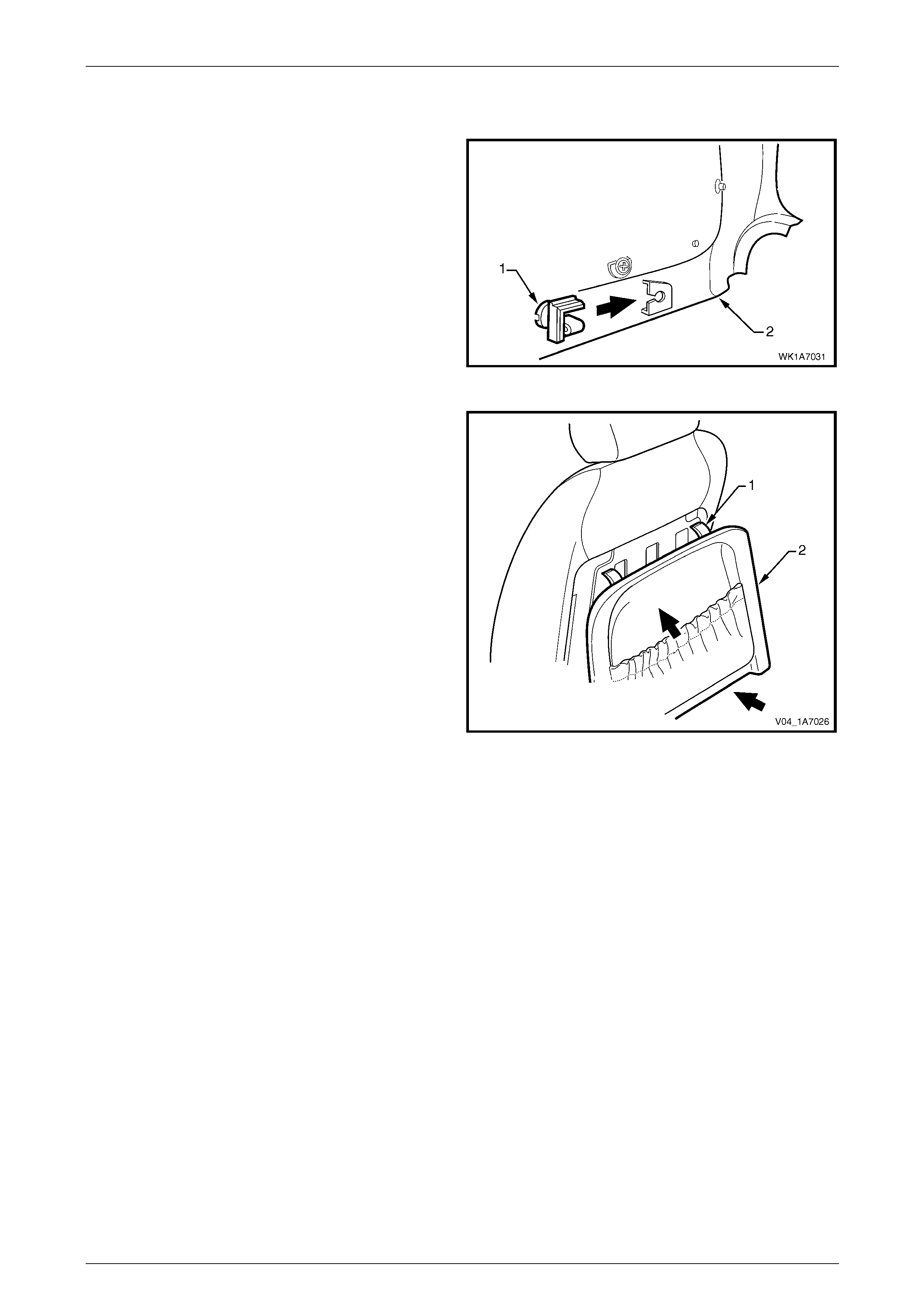
Seat Assemblies Page 1A7–293
Page 1A7–293
Reinstall
1 Replace the damaged retaining clip (1) on the front
seat-back rear cover (2), two places.
Figure 1A7 – 165
2 Align the two upper retaining lugs (1) with the
seat-back.
3 Push the front seat-back rear cover (2) up and in at
the lower edge to engage the two lower retaining clips.
Figure 1A7 – 166
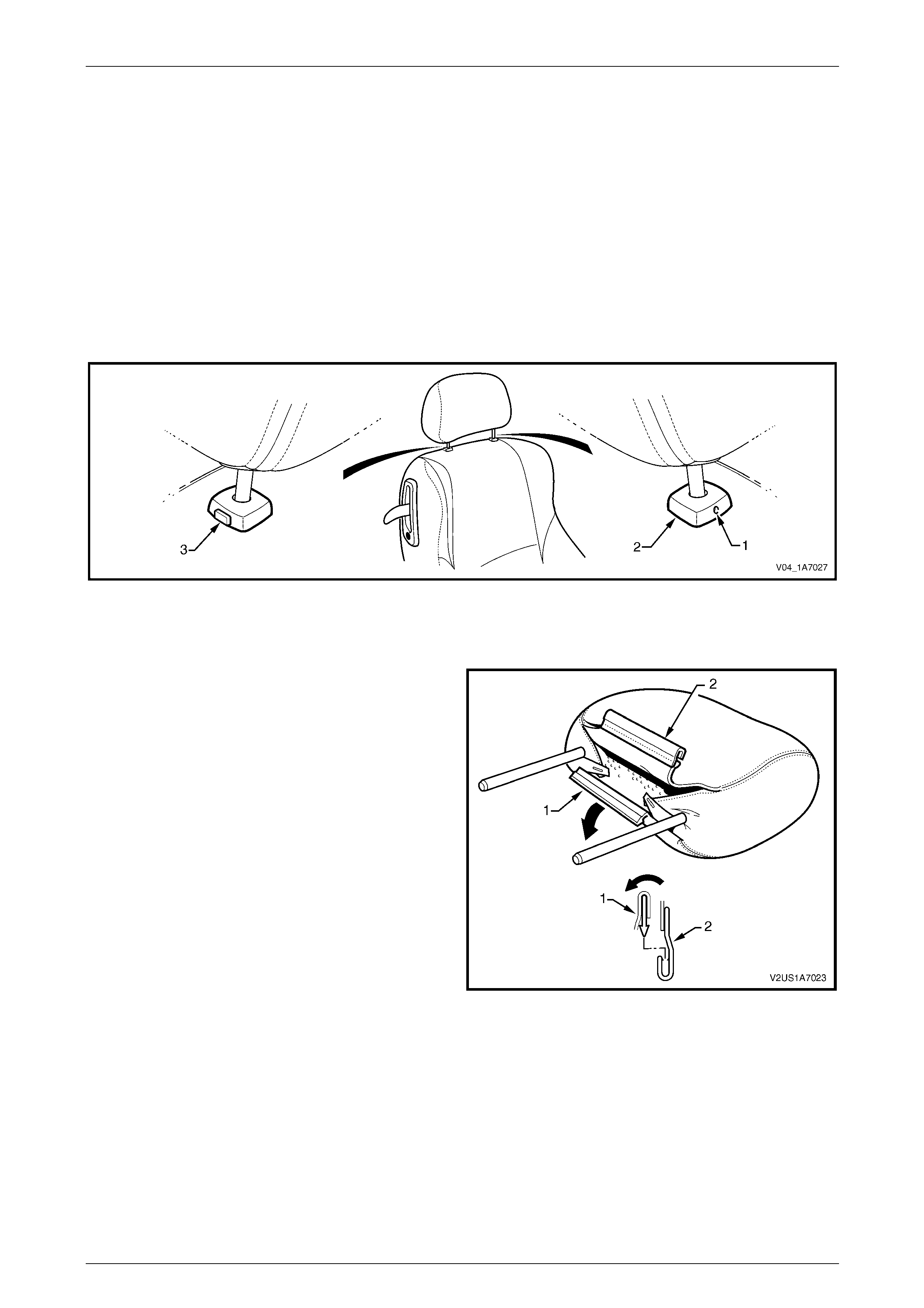
Seat Assemblies Page 1A7–294
Page 1A7–294
7.6 Front Seat Head Restraint Assembly
LT Section No. — 14–295
Remove
1 Raise the head restraint fully.
2 Insert a suitable size probe into the hole (1) in the right-hand head restraint sleeve (2), refer to F igure 1A7 – 167.
3 Push the probe in slightly whil e app lying slight up ward pressure on the head restraint. Hold the up ward pressure.
4 Depress the head restraint sleeve height adjuster lock (3) on the left-hand head restraint sleeve and remove the
head restraint.
Figure 1A7 – 167
Disassemble
1 Disengage the front head restraint cover J-stri p by
pulling the flap (1) back and out of flap (2) in the
direction shown.
Figure 1A7 – 168

Seat Assemblies Page 1A7–295
Page 1A7–295
2 Remove the two staples (1) retaining the cover (2) to
the head restraint pad assembly.
3 Remove the cover from the pad assembly
Figure 1A7 – 169
Reassemble
Reassembly of the front seat head restraint assembl y is the reverse of the removal procedure. Ensure the head restra int
cover J-clip is fully engaged.
Reinstall
Ensuring correct orientation of the head restraint, fit the head restraint shafts into the sleeves and p ush the head restraint
down.

Seat Assemblies Page 1A7–296
Page 1A7–296
7.7 Front Seat Head Restraint Sleeve
As required, remove the front seat head restraint assembl y, refer to 7.6 Front Seat Head Restrai nt Assembl y.
LT Section No. — 14–275
Remove
1 Push down on the surrounding seat cover to reveal the
upper portion of the seat-back frame or active head
restraint frame (1).
2 Using a fine flat-blade screwdriver, depress the head
restraint sleeve retaining lug (2) and withdraw the
head restraint sleeve (3) from the frame.
3 Repeat for the remaining sleeve as required.
Figure 1A7 – 170
Reinstall
Reinstallation of the front seat head restraint sleeve is the reverse of the removal proce dure, noting the following:
NOTE
Ensure the sleeve with the height adjuster lock
(1) is installed on the left-hand side of the seat;
that is the side that corresponds to the lower
square notch (2) in the head restraint shaft.
Figure 1A7 – 171
1 Align the head restraint sleeve locating ribs (1) with
the notch (2) in the seat-back frame.
2 Insert the sleeve and ensure it clicks into place.
Figure 1A7 – 172
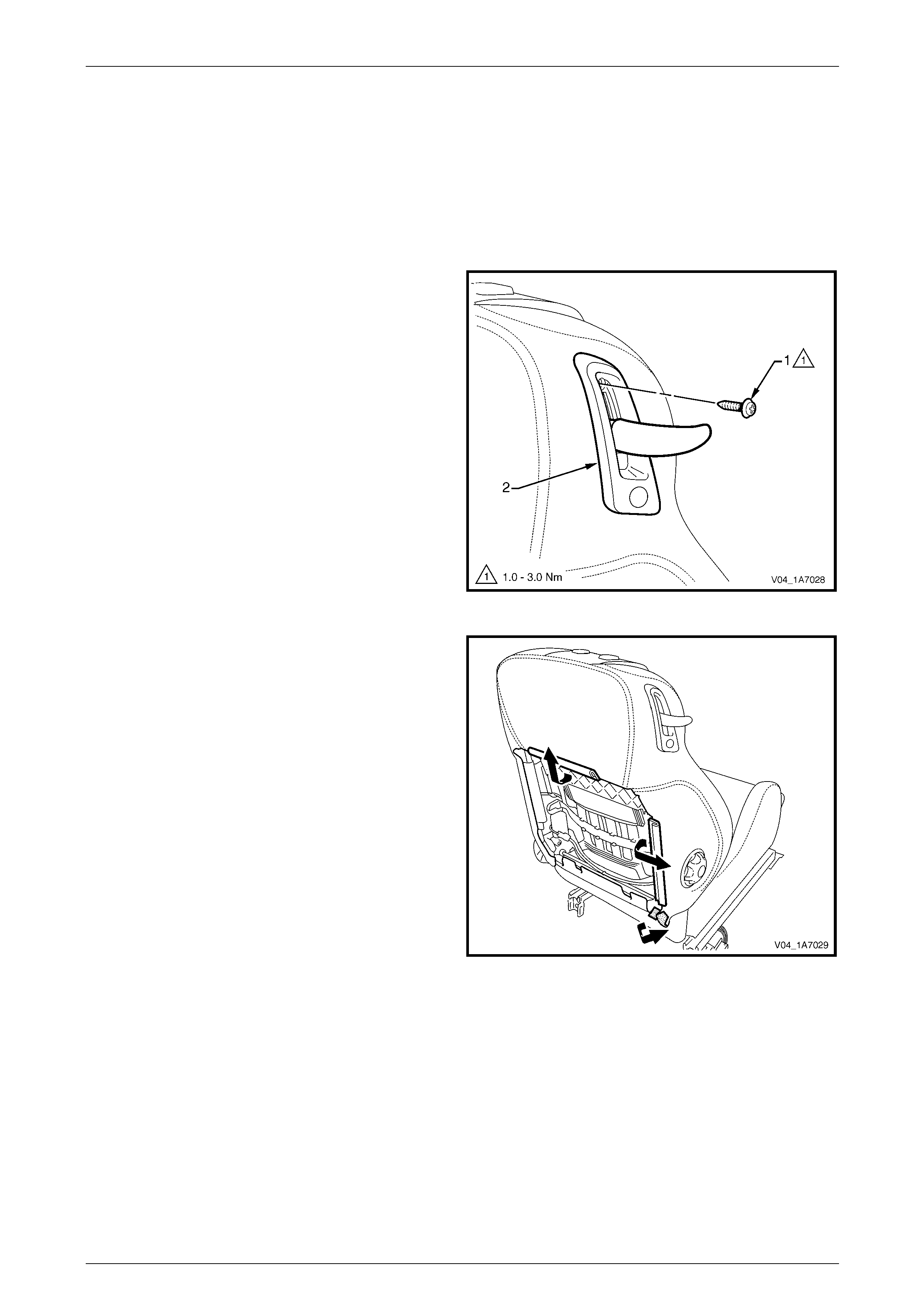
Seat Assemblies Page 1A7–297
Page 1A7–297
7.8 EZ-entry Release Lever and Escutcheon
LT Section No. — 14–275
1 Remove the front seat outer side cover assembly, 7.3 Front Seat Outer Side Cover Assembly.
2 Remove the front seat-back rear cover assembl y, refer to 7.5 Front Seat-back Rear Cov er Assembl y.
Remove
1 Remove the screw (1) retaining the EZ-entry release
escutcheon assembly (2) to the seat-back frame.
Figure 1A7 – 173
2 Partly remove the front seat-back cover by
disengaging the upper and outer J-strips from the
seat-back frame and the Velcro tab at the lower
corner.
Figure 1A7 – 174

Seat Assemblies Page 1A7–298
Page 1A7–298
3 Carefully manoeuvre your hand behind the seat pad
and push up on the retaining clip (1) retaining the
release lever (2).
Take care as there may be sharp edges in
this area.
Figure 1A7 – 175
4 While holding upward pressure on the retaining clip,
grasp the release lever (1) and pul l firmly away from
the seat-back to remove.
NOTE
It may be necessary to wriggle the lever to
loosen it in the escutcheon as sembly (2).
Figure 1A7 – 176
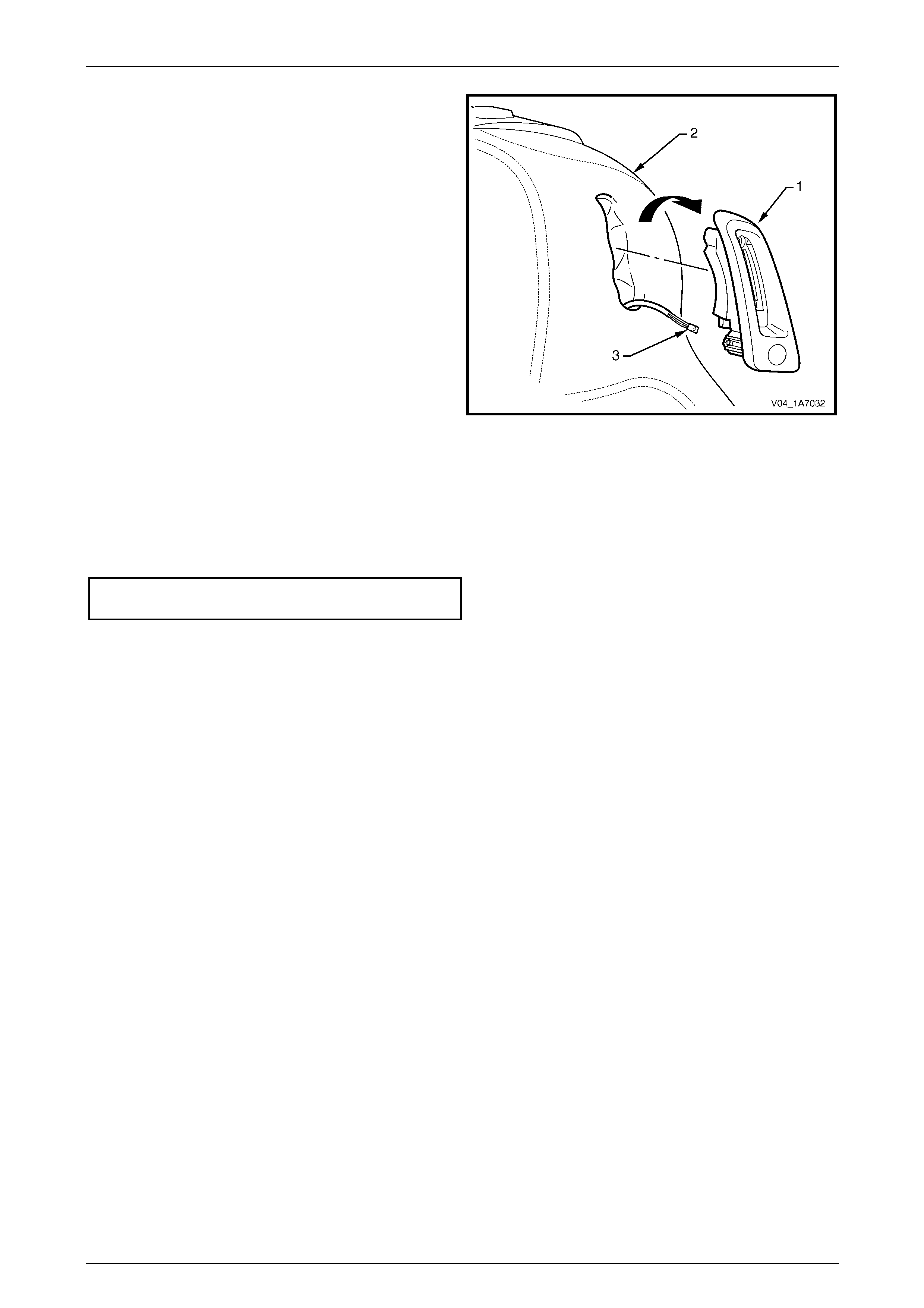
Seat Assemblies Page 1A7–299
Page 1A7–299
5 Partially remove the EZ-entry release escutcheon
assembly (1) from the front seat-back cover (2), by
rotating the top of the escutcheon outward and
disengaging the lower lug.
6 Disconnect the wiring harness connector (3) from the
seat return switch.
7 Remove the escutcheon assembly.
Figure 1A7 – 177
Reinstall
Reinstallation of the EZ-entry release lever and escutche on assembly is the reverse of the removal procedure, noting the
following:
1 Tighten the attaching screw to the correct torque specification.
EZ-entry release escutcheon assembly
attaching screw torque specification...........1.0 – 3.0 Nm
2 Ensure the release lever retaining clip is correctly engaged by pullin g firmly away from the seat and operating the
latch several times.

Seat Assemblies Page 1A7–300
Page 1A7–300
7.9 EZ-entry Switch and Release Cable
Assembly
Due to safety requirement constraints, certain components of the recliner mechanism, including the EZ-entry s witch and
release cable assembly, must not be removed or replaced. If any part of the recliner mechanism requires replacement,
the entire front seat-back frame assembly must be replaced, refer to 7.12 Front Seat-back Frame Assembly.
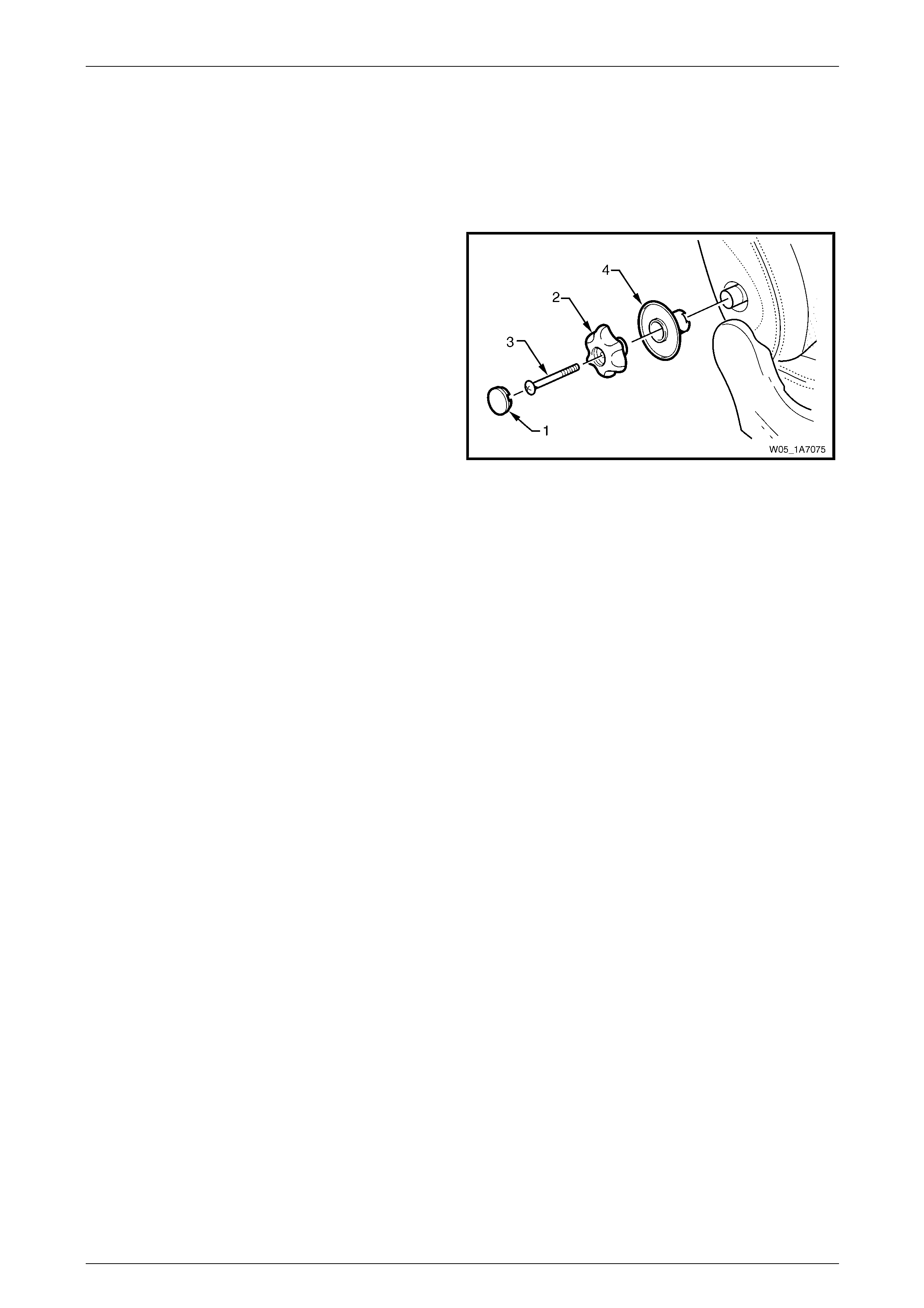
Seat Assemblies Page 1A7–301
Page 1A7–301
7.10 Lumbar Support Knob Assembl y
LT Section No. — 14–275
Remove
1 Ensure the lumbar support is in the full off position.
2 Using a fine flat-blade screw-driver, carefully prise the
cap (1) from the lumbar support knob (2).
3 Remove the screw (3) attaching the knob to the
lumbar support shaft.
4 Pull the knob off the lumbar support shaft and remove
the lumbar support deflector ring (4).
NOTE
The knob is lightly clipped to the lumbar support
shaft and will ‘click-off’.
Figure 1A7 – 178
Reinstall
NOTE
Failure to observe the following procedure will
result in damage to the mechanism.
1 Push the lumbar support knob and lumbar support deflector ring onto the adjustment shaft.
2 Rotate the lumbar support knob to fully rela x the lumbar adjustment.
3 Install and tighten the attaching screw until head of screw is just below the surface of the knob.
4 Press cap into place.

Seat Assemblies Page 1A7–302
Page 1A7–302
7.11 Front Seat-back Pad and Cover
Assembly
LT Section No. — 14–295
As required, remove the following components:
1 Front seat assembly, refer to 7.2 Front Seat Assembly.
2 Front seat outer side cover assembly, refer to 7.3 Front Seat Outer Side Cover Assembly.
3 Front seat inner side cover, refer to 7.4 Front Seat Inner Side Cover.
4 Front seat-back rear cover assembly, refer to 7.5 Front Seat-back Rear Cover Assembly.
5 Front seat head restraint assembly, refer to 7.6 Front Seat Head Restraint Assembly.
6 Front seat head restraint sleeves, refer to 7.7 Front Seat Head Restraint Sleeve.
7 EZ-entry release lever and escutcheo n assembly, refer to 7.8 EZ-entry Release Lever an d Escutcheon.
8 Lumbar support knob assembly, refer to 7.10 Lumbar Support Knob Assembly.
Remove
1 Disengage the J-strips from the seat frame a nd the
Velcro tab at each lower corner.
2 Lift the cover and pad assembly up and away from the
seat-back frame, manoeuvring it over the seat-back
components such as the side impact airbag a ssembly
and dummy block insert assembly.
Figure 1A7 – 179

Seat Assemblies Page 1A7–303
Page 1A7–303
Disassemble
1 Fold the lower corners of the seat-back cove r (1) over
the seat-back pad (2).
Figure 1A7 – 180
2 While holding the front seat-back pad (1), pull the
lower corners of the front seat-back cover (2), upwards
and away from the pad to disengage the hook and
loop strips (3).
3 Pull the cover up and over the upper edge of the pad.
Figure 1A7 – 181
Reassemble
1 With the front seat-back cover (1) folded at the central
horizontal strip of hook and loop (2), align the centre
mark (3) on the cover with the centre mark (4) on the
front seat-back pad.
2 Press the cover firmly into the corresponding groove i n
the pad to engage the hook and loop.
Figure 1A7 – 182
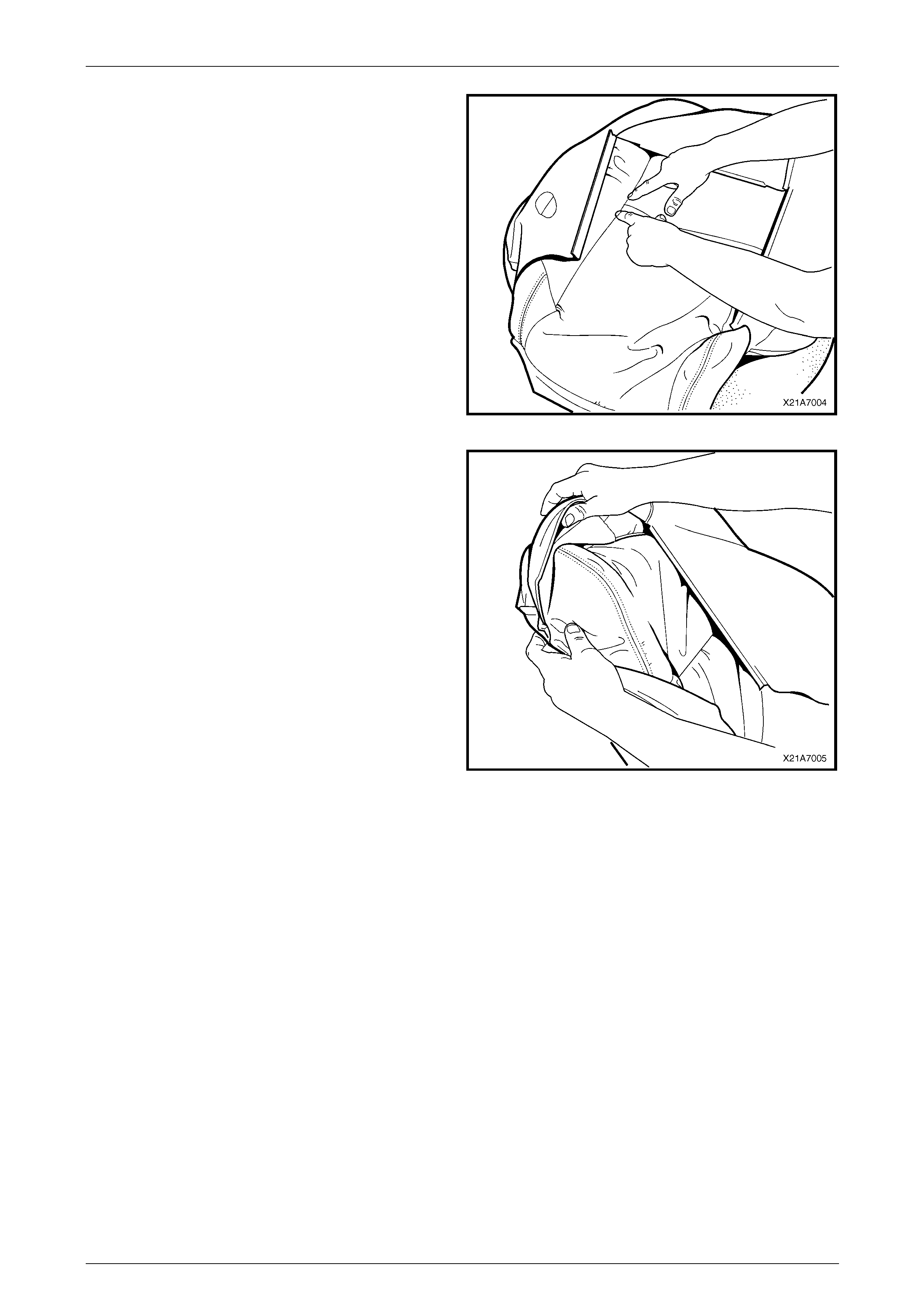
Seat Assemblies Page 1A7–304
Page 1A7–304
3 With the cover folded at the two vertical strips of the
hook and loop, press the cover firml y into the
corresponding grooves in the pad.
Figure 1A7 – 183
4 Roll the upper corners of the cover over the pad.
5 Roll the sides of the cover over the pad.
6 Roll the lower corners of the cover over the pad.
NOTE
Ensure the cover is fitted neatly by hand into all
corners and contours of the pad.
Figure 1A7 – 184
Reinstall
Reinstallation of the front seat -back pad and cover assembly is the reverse of the removal proced ure.
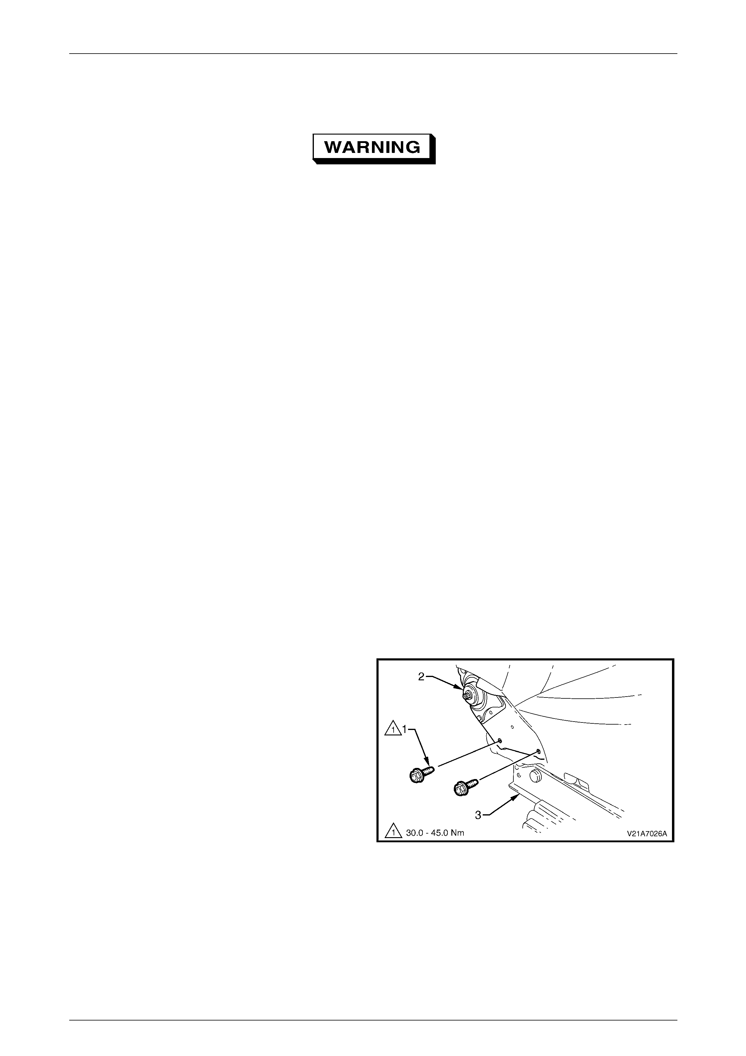
Seat Assemblies Page 1A7–305
Page 1A7–305
7.12 Front Seat-back Frame Assembl y
When carrying a live (undeployed) side
impact airbag assembly or a front seat-back
frame assembly fitted with a (undeployed)
side impact airbag assembly, ensure the
airbag opening is pointed away from you.
Never carry the side impact airbag assembly
or seat-back frame as sembly fitted w ith a side
impact airbag assembly by the airbag wiring
harness or connectors. In case of an
accidental deployment, the airbag will then
deploy with minimal chance of injury.
When placing a live side impact airbag
assembly or a fron t seat-back fr ame as sembly
fitted with a (undeployed) side impact airbag
assembly on a bench or other surface, always
face the airbag opening up, away from the
surface. Never rest the airbag assembly or
seat-back frame with the airbag opening face
down. This is necessary so that a free space
is provided to allow the airbag to expand in
the unlikely event of accidental deployment.
Otherwise, personal injury may result.
LT Section No. — 14–275
As required, remove the following components:
1 Front seat assembly, refer to 7.2 Front Seat Assembly.
2 Front seat outer side cover assembly, refer to 7.3 Front Seat Outer Side Cover Assembly.
3 Front seat inner side cover, refer to 7.4 Front Seat Inner Side Cover.
Remove
1 Remove the two screws (1), each side, attaching the
seat-back assembly (2) to the front seat cushion frame
assembly (3).
2 As required, disconnect and detach the front seat-back
recline motor and side impact airbag wiring harnesses.
3 Remove the seat-back assembly.
Figure 1A7 – 185
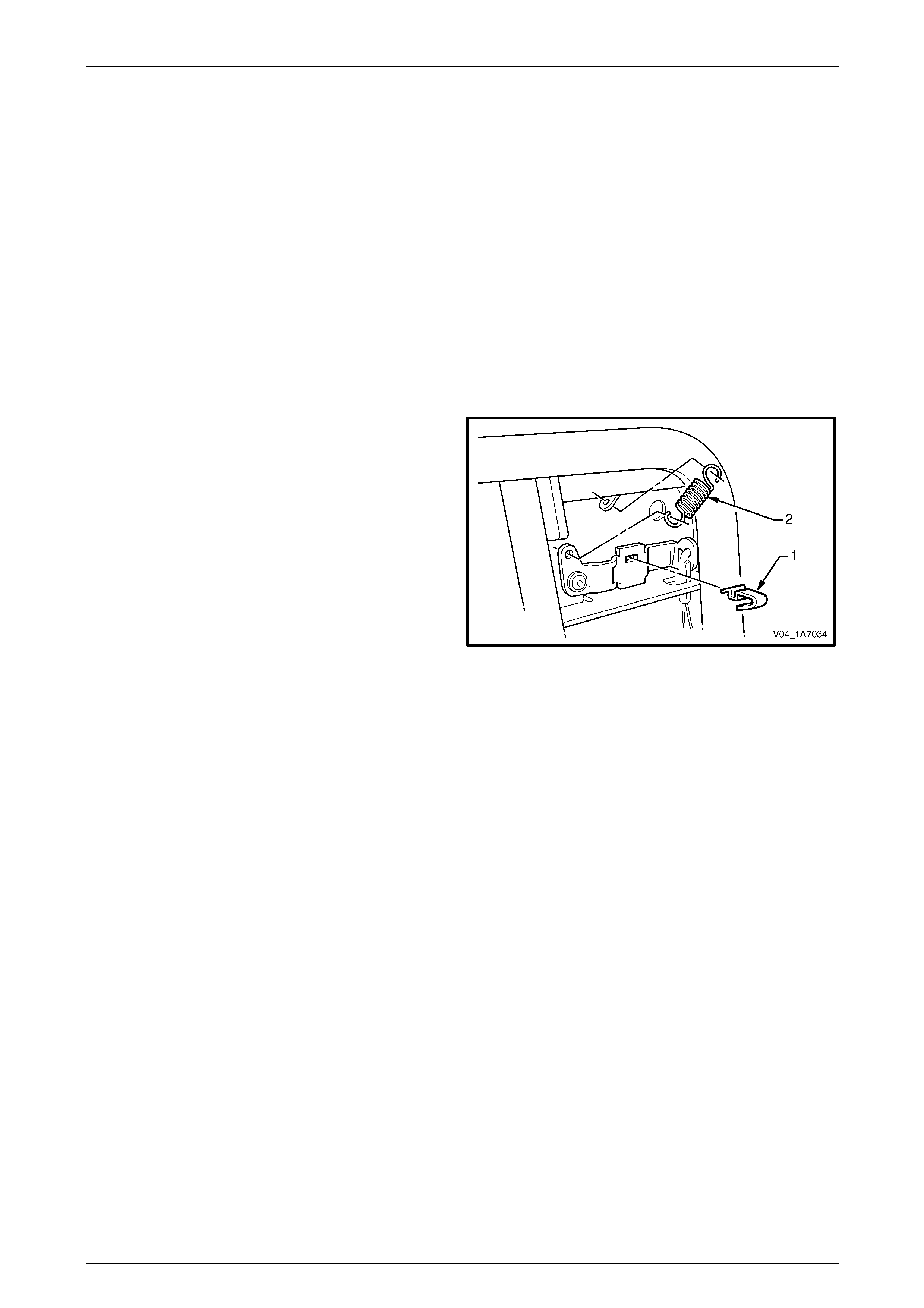
Seat Assemblies Page 1A7–306
Page 1A7–306
Disassemble
As required, remove the following components:
1 Front seat-back rear cover assembly, refer to 7.5 Front Seat-back Rear Cover Assembly.
2 Front seat head restraint assembly, refer to 7.6 Front Seat Head Restraint Assembly.
3 Front seat head restraint sleeves, refer to 7.7 Front Seat Head Restraint Sleeve.
4 EZ-entry release lever and escutcheo n assembly, refer to 7.8 EZ-entry Release Lever an d Escutcheon.
5 Lumbar support knob assembly, refer to 7.10 Lumbar Support Knob Assembly.
6 Front seat-back pad and cover assembl y, refer to 7.11 Front Seat-back Pad and Cover Assembl y.
EZ-entry Release Lever Retaining Clip and Return Spring
Remove
1 Prise the release lever retaining clip (1) from the
release mechanism.
2 Disconnect the return spring (2) from the release
mechanism and seat-back frame
Figure 1A7 – 186
Reinstall
Reinstallation of the EZ-entry release lever retaining clip and return spring is the reverse of the removal procedure.
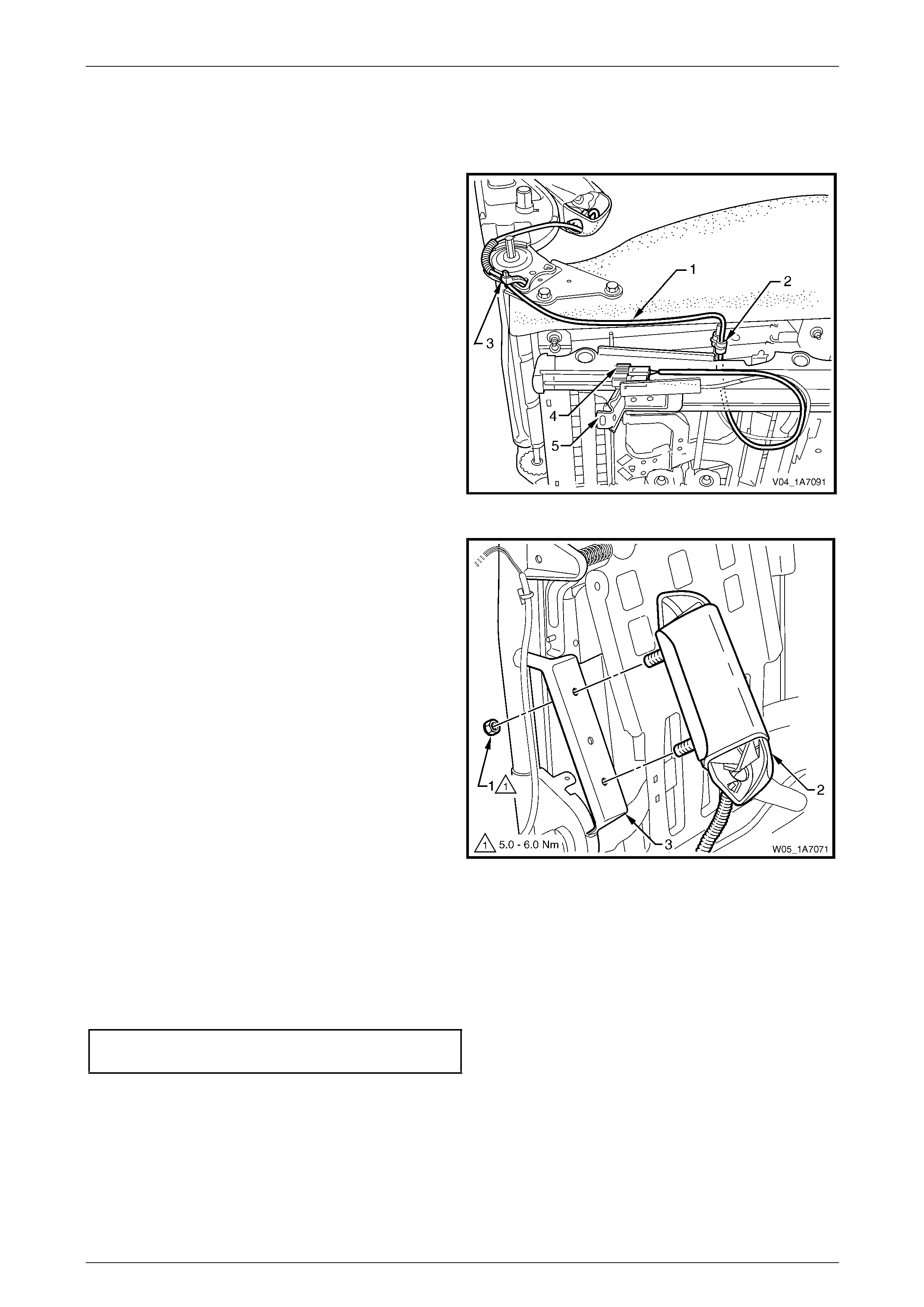
Seat Assemblies Page 1A7–307
Page 1A7–307
Side Impact Airbag Assembly
Remove
1 As required, unclip the side impact airbag wiring
harness (1) from the retaining clip (2) and cut the
cable tie (3) securing the harness to the front seat
cushion frame assembly, taking care not to damage
the wiring harness.
2 Unclip the wiring harness connector (4) from the track
and height adjust assembly (5).
Figure 1A7 – 187
3 Remove the lock-nut (1), two places, attachi ng the
side impact airbag assembl y ( 2) to the seat-b ack
frame (3) and airbag assembly.
Figure 1A7 – 188
Reinstall
Reinstallation of the side impact airba g asse mbly is the reverse of the removal procedure, noting the following:
1 Ensure the conduit covering the wiring harness and the harness are pos itioned correctly, refer to Figure 1A7 – 187.
2 Tighten the attaching nuts to the correct torque specification.
Side impact airbag assembly attaching
nut torque specification...............................5.0 – 6.0 Nm
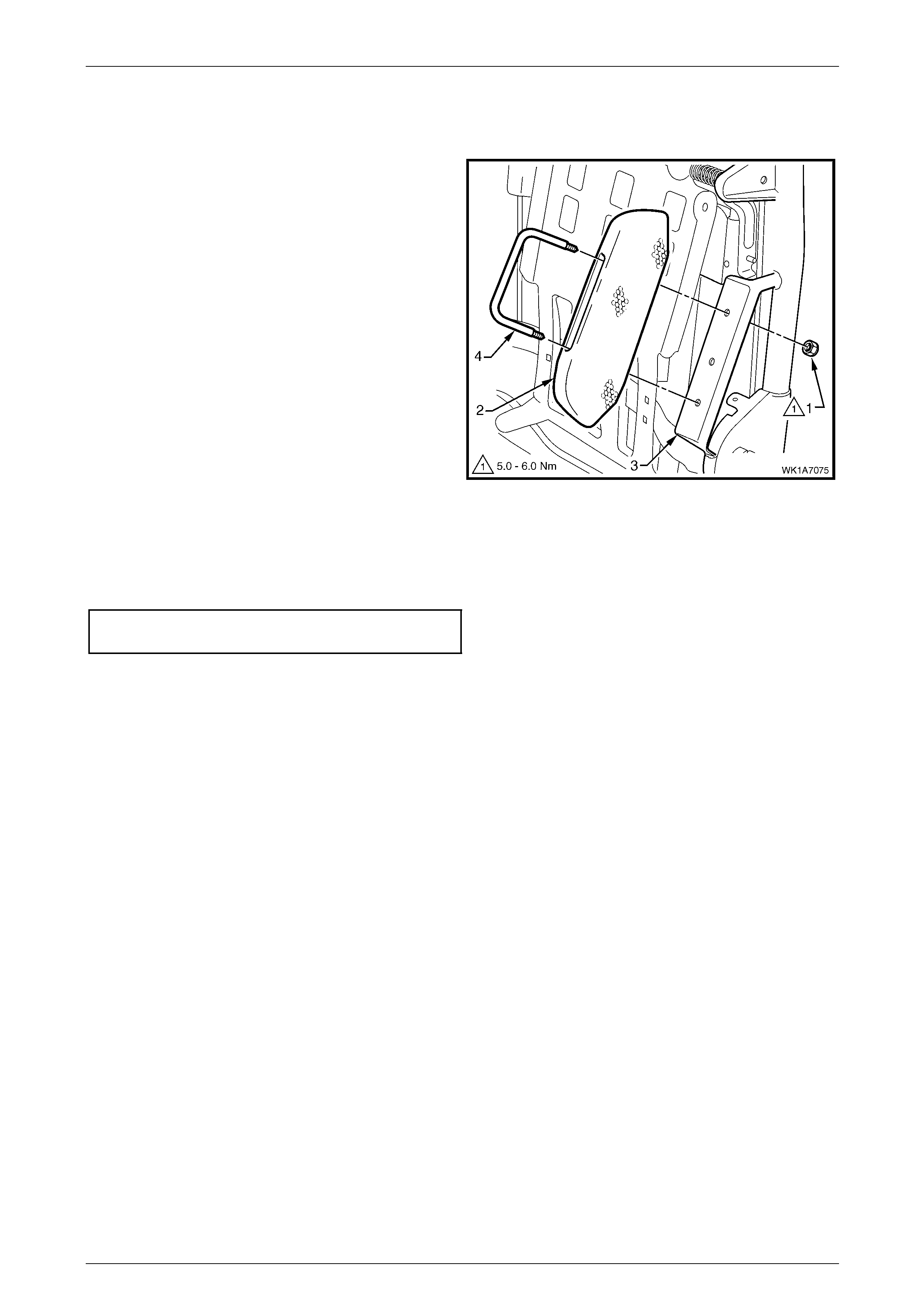
Seat Assemblies Page 1A7–308
Page 1A7–308
Front Seat Dummy Block Insert Assembly
Remove
1 Remove the lock-nut (1), two places, attachi ng the
front seat dummy block insert (2) to the seat-back
frame (3) and remove the dummy block insert
assembly.
2 If required, remove the dummy block U-bolt (4) from
the dummy block insert.
Figure 1A7 – 189
Reinstall
Reinstallation of the front seat dummy block insert assembly is the reverse of the removal procedure. Tighten the
attaching nuts to the correct torque specification.
Front seat dummy block insert assembly
attaching nut torque specification................5.0 – 6.0 Nm

Seat Assemblies Page 1A7–309
Page 1A7–309
Lumbar Support Assembly
Remove
1 Remove the retainer (1), t wo places, attaching the
lumbar support assembly (2) to the seat-back frame.
Figure 1A7 – 190
2 Depress the retaining tab (1) and from the inner side
of the seat-back frame, rotate the lumbar support
shaft (2) and withdraw from the seat-back frame.
3 Repeat for the opposite side.
Figure 1A7 – 191
4 Disconnect the spring (1), two places, attaching the
lumbar support assembly (2) to the active head
restraint frame.
TIP
To aid spring remova l, pull the support asse mbly
toward the side the spring is being removed to
relieve spring tension.
Figure 1A7 – 192
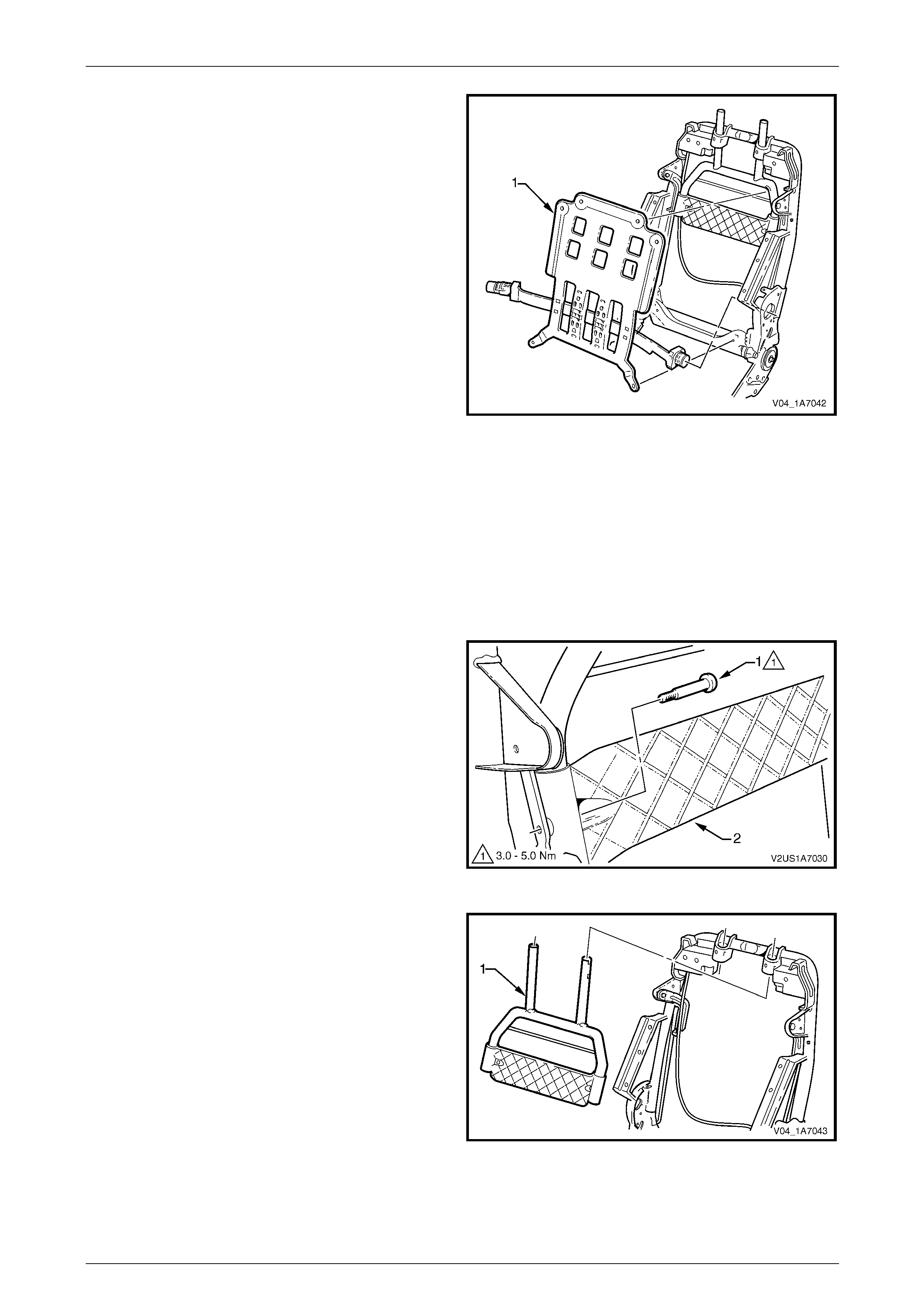
Seat Assemblies Page 1A7–310
Page 1A7–310
5 Remove the lumbar support assembly (1).
Figure 1A7 – 193
Reinstall
Reinstallation of the lumbar s upport assembly is the reverse of the removal procedure. Ensure the lumbar support
assembly is correctly seated on the cushion side of the active head restraint frame, with the black lumbar support shaft
on the outer side of the seat.
Active Head Restraint Frame Assembly
Remove
1 Remove the screw (1), two places, attaching the active
head restraint frame assembly (2) to the seat-back
frame hinge.
Figure 1A7 – 194
2 Withdraw the active head restraint frame assembly (1)
downward to remove it from the seat-back frame and
remove.
Figure 1A7 – 195
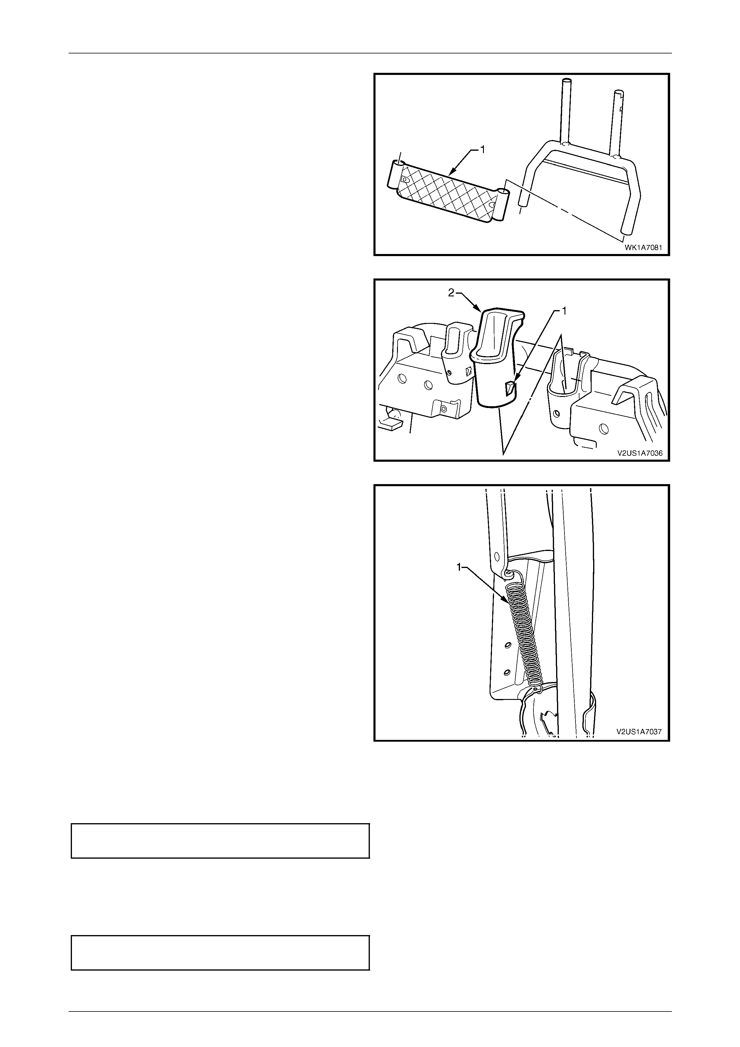
Seat Assemblies Page 1A7–311
Page 1A7–311
3 If required, slide the support strap (1) from the active
head restraint frame.
Figure 1A7 – 196
4 If required, depress the tab (1), two places, and
withdraw the active head restraint frame sleeve (2)
from the seat-back frame.
5 Repeat for the opposite sleeve as requ ired.
Figure 1A7 – 197
6 If required, remove the spring (1), from the active head
restraint frame hinge and seat-back frame.
7 Repeat for the opposite side as required.
Figure 1A7 – 198
Reinstall
Reinstallation of the active head restraint frame assembly is the reverse of the removal proced ure. Tighten the attaching
screws to the correct torque specification.
Active head restraint frame assembly
attaching screw torque specification...........3.0 – 5.0 Nm
Reinstall
Reinstallation of the front seat -back frame assembly is the reverse of the removal proced ure, notin g the following:
1 Tighten the attaching screws to the correct torque specific ation.
Front seat-back frame assembly
attaching screw torque specification.......30.0 – 45.0 Nm
2 Check the mechanical and elec trical operation of the front seat.
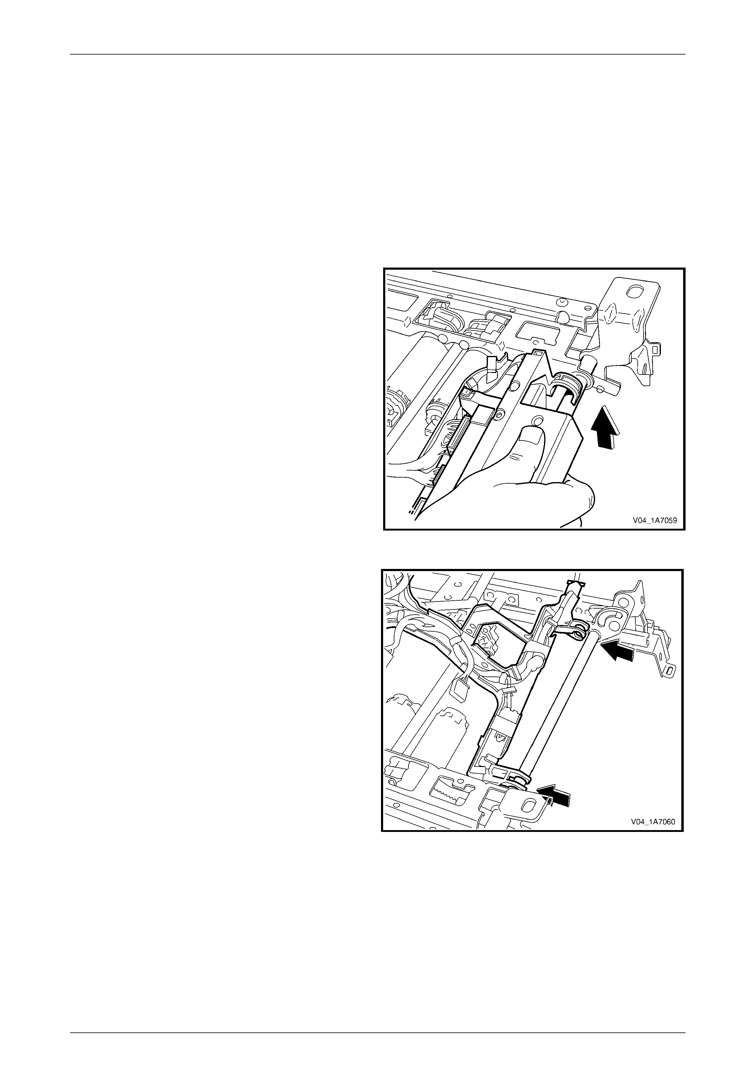
Seat Assemblies Page 1A7–312
Page 1A7–312
7.13 Seat Cable Tray and Memory Module
LT Section No. — 14–275
Remove
As required remove the following c ompo ne nts:
1 Front seat assembly, refer to 7.2 Front Seat Assembly.
2 Remove the seat track and height adjust ass embl y, refer to 7.14 Track and Height Adjust Assembly.
3 Disconnect the wiring harness connectors as required.
4 Unclip the cable tray from the front of the seat track
and height adjust assembly.
Figure 1A7 – 199
5 Pull the cable tray forward to release it from the seat
track and height adjust assembl y.
Figure 1A7 – 200

Seat Assemblies Page 1A7–313
Page 1A7–313
6 If required, use a 5 mm drill bit to drill out the pop rivet,
(1), two places, securing the seat memory module to
the cable tray.
7 Remove the seat memory module.
Figure 1A7 – 201
8 If required, remove the wiring harness from the cable
tray by squeezing the tabs on the harness clips (1)
and by removing the tape (2).
Figure 1A7 – 202
Reinstall
Reinstallation of the seat memor y module is the reverse of the removal procedure, noting the following:
1 Ensure the wiring harness an d connectors are correctly routed and attach ed securely.
2 Use new pop rivets.
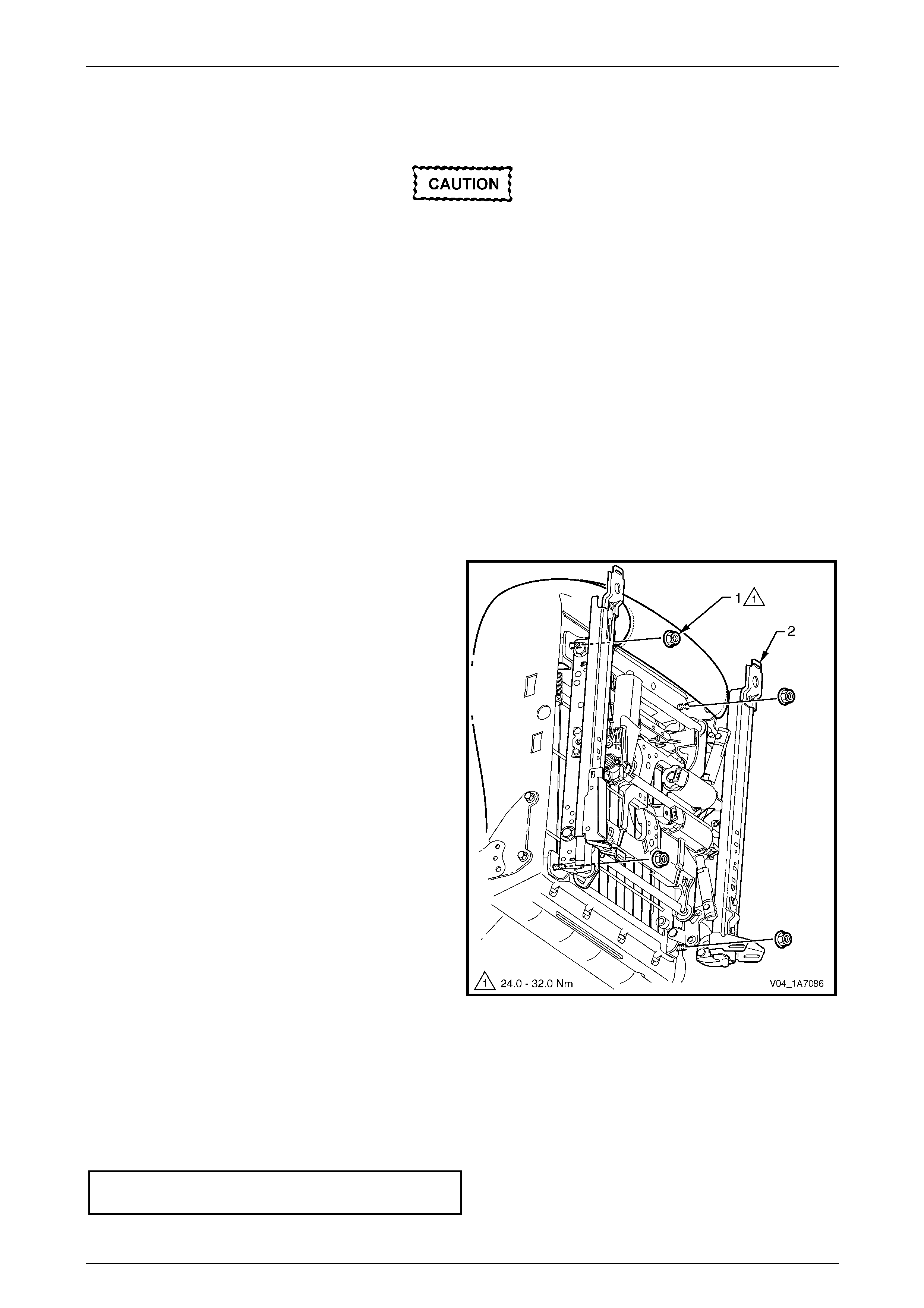
Seat Assemblies Page 1A7–314
Page 1A7–314
7.14 Track and Height Adjust Assembly
The track and height adjust assembly
components are non-serviceable. If the track
and height adjust assembly, drive motors or
drive shafts require replacement, the entire
track and height adjust assembly must be
replaced.
LT Section No. — 14–275
As required, remove the following components:
1 Front seat assembly, refer to 7.2 Front Seat Assembly.
2 Front seat outer side cover assembly, refer to 7.3 Front Seat Outer Side Cover Assembly.
Remove
1 As required, detach the wiring harness connectors.
2 Detach the seatbelt pretensio ner and side airbag wiring harnesses.
3 Remove the four nuts (1) attaching the track and
height adjust assembly (2) to the seat.
4 Remove the track and height adjust assembly.
5 If required, remove the cable tray and wiring harness
assembly, refer to 7.13 Seat Cable Tray and Memory
Module.
6 If required, remove the seatbelt buckle and
pretensioner assembly, refer to Section 12M Occupant
Protection System.
Figure 1A7 – 203
Reinstall
Reinstallation of the track and height adjust assembly is the reverse of the removal procedur e, noting the following:
1 Ensure the connectors are correctly routed and attach ed securely.
2 Tighten the attaching nuts to the correct torque spec ification.
Track and height adjust assembly
attaching nut torque specification............24.0 – 32.0 Nm
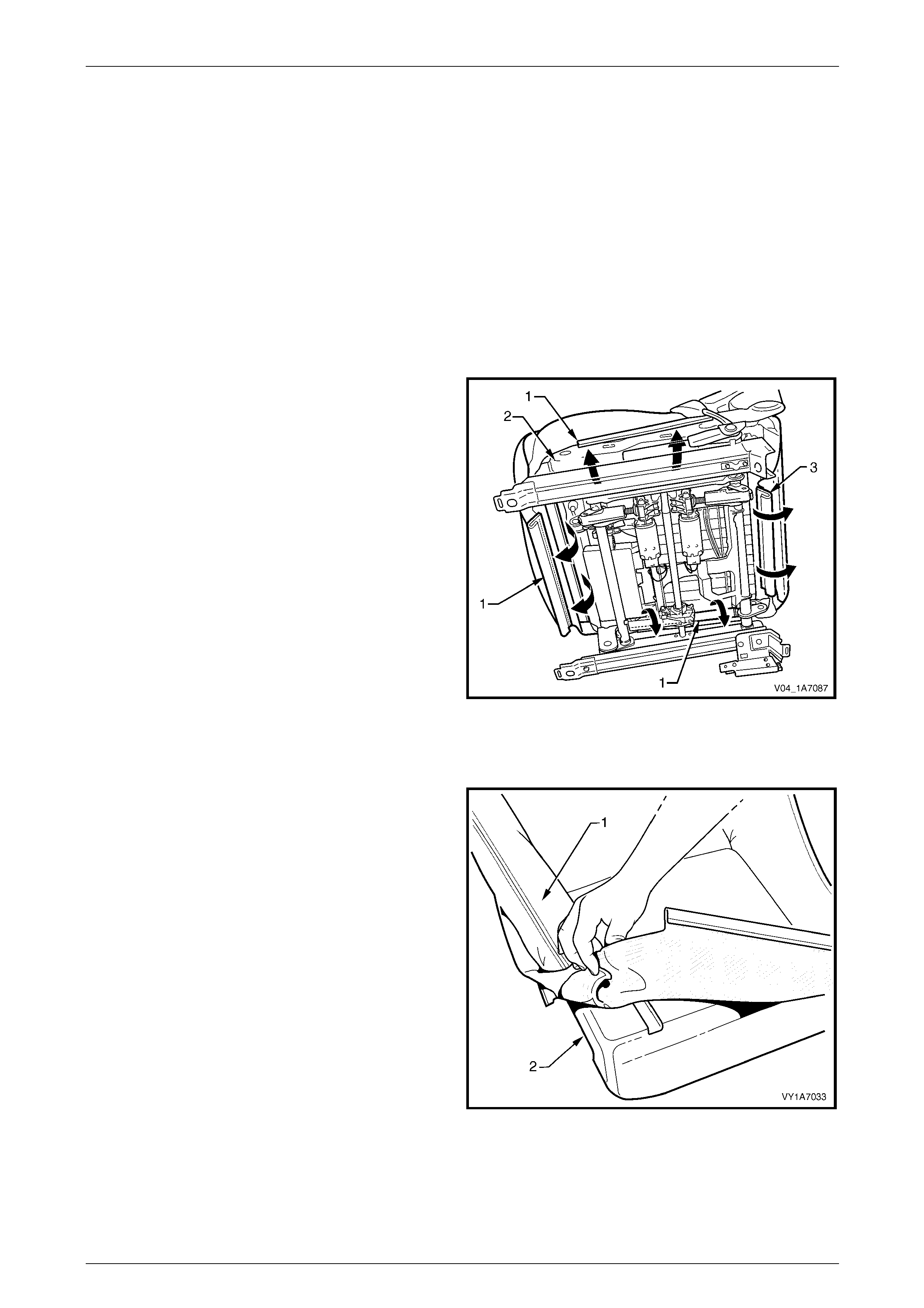
Seat Assemblies Page 1A7–315
Page 1A7–315
7.15 Front Seat Cushion Pad and Cover
Assembly
LT Section No. — 14–295
As required, remove the following components:
1 Front seat assembly, refer to 7.2 Front Seat Assembly.
2 Front seat outer side cover assembly, refer to 7.3 Front Seat Outer Side Cover Assembly.
3 Front seat inner side cover, refer to 7.4 Front Seat Inner Side Cover.
4 Front seat-back frame assembly, refer to 7.12 Front Seat-back Frame Assembly.
Remove
1 From under the front seat cushion, disengage the front
and side J-strips (1) away from the seat frame (2).
2 Lift the cover and pad assembly a way from the seat
frame and then release the rear J-strip (3).
3 Disconnect the passenger pre sence detection harness
connector (4).
4 Remove the pad and cover assembly.
Figure 1A7 – 204
Disassemble
1 Fold the rear corners of the front seat cushion
cover (1) over the front seat cushion pad (2).
Figure 1A7 – 205
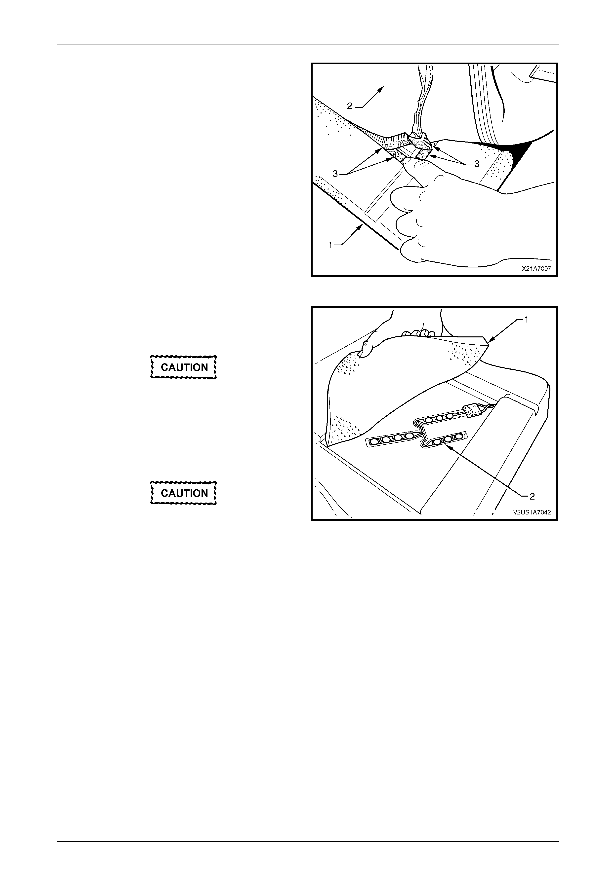
Seat Assemblies Page 1A7–316
Page 1A7–316
2 While holding the front seat cushi on pad (1), pull the
rear corners of the front seat cushion cover (2) forward
and away from the pad to disengage the hook and
loop strips (3).
3 Pull the cover up and over the forward edge of the
pad.
Figure 1A7 – 206
4 If required, carefully peel back the upper cushion
pad (1) to expose the passenger prese nce d etection
switch (2).
The upper cushion pad is glued to the
cushion pad along each edge. Take care not
to damage the pads.
5 Carefully lift-off the passenger presence detection
switch and pull the wiring harness through from the
underside of the cushion pad.
The wiring terminal is glued to the cushion
pad. Take care not to damage the switch or
pad. Figure 1A7 – 207
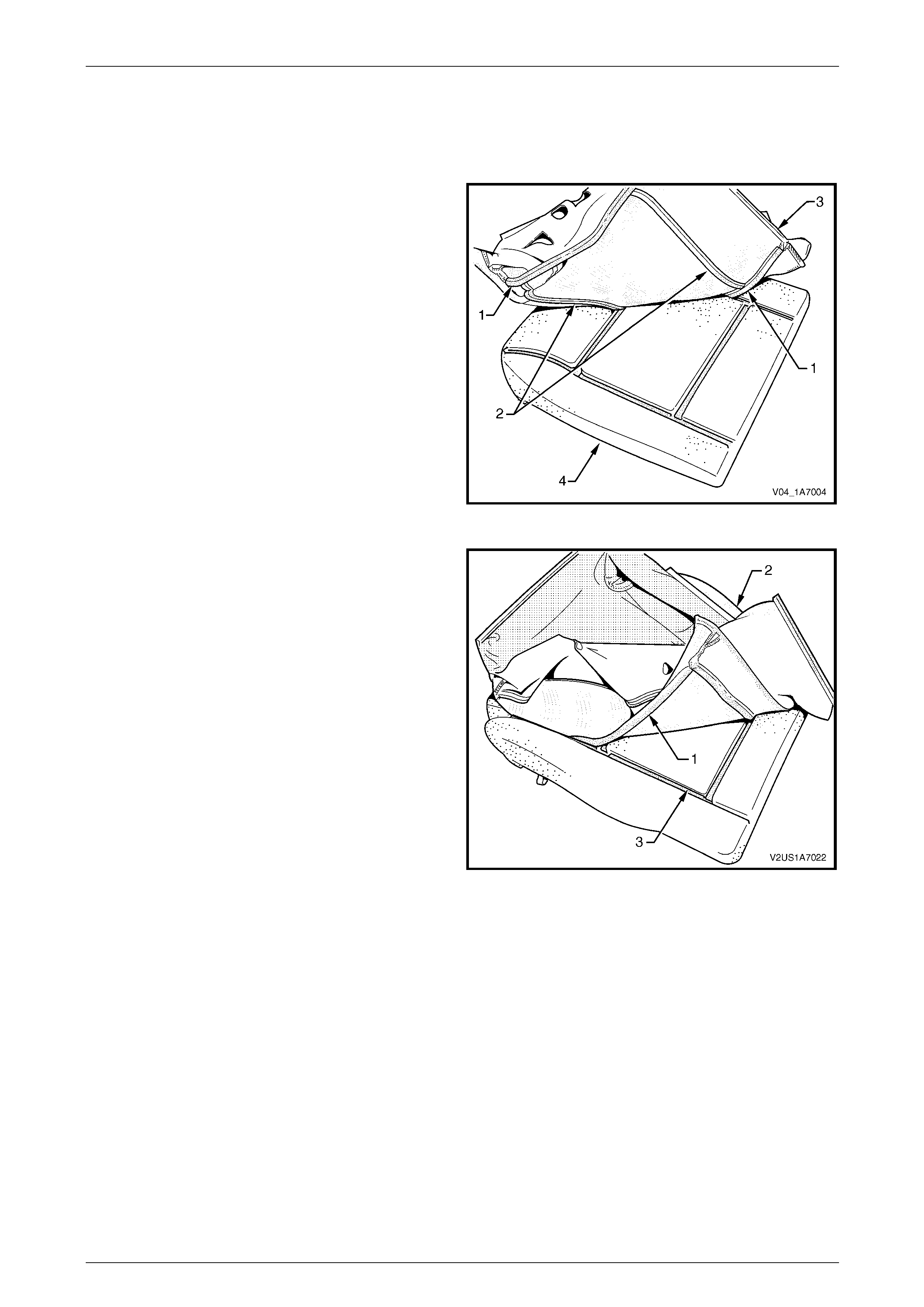
Seat Assemblies Page 1A7–317
Page 1A7–317
Reassemble
1 Ensure the passenger pres ence detection switch is correctly located in the depression in the cushion pad. Apply
new adhesive to the upper cushion.
2 Align either of the outer hook and l oo p strips (1) and
the one or two cross hook and loop strips (2) on the
front seat cushion cover (3) with the front seat cushion
pad (4).
3 Press the folded edge of the cover firmly into the
corresponding groove in the pad to engage the hook
and loop strip.
Figure 1A7 – 208
4 Align and press the outer hook and loop strip (1), on
the cover (2), with the corresponding groove in the
pad (3).
Figure 1A7 – 209
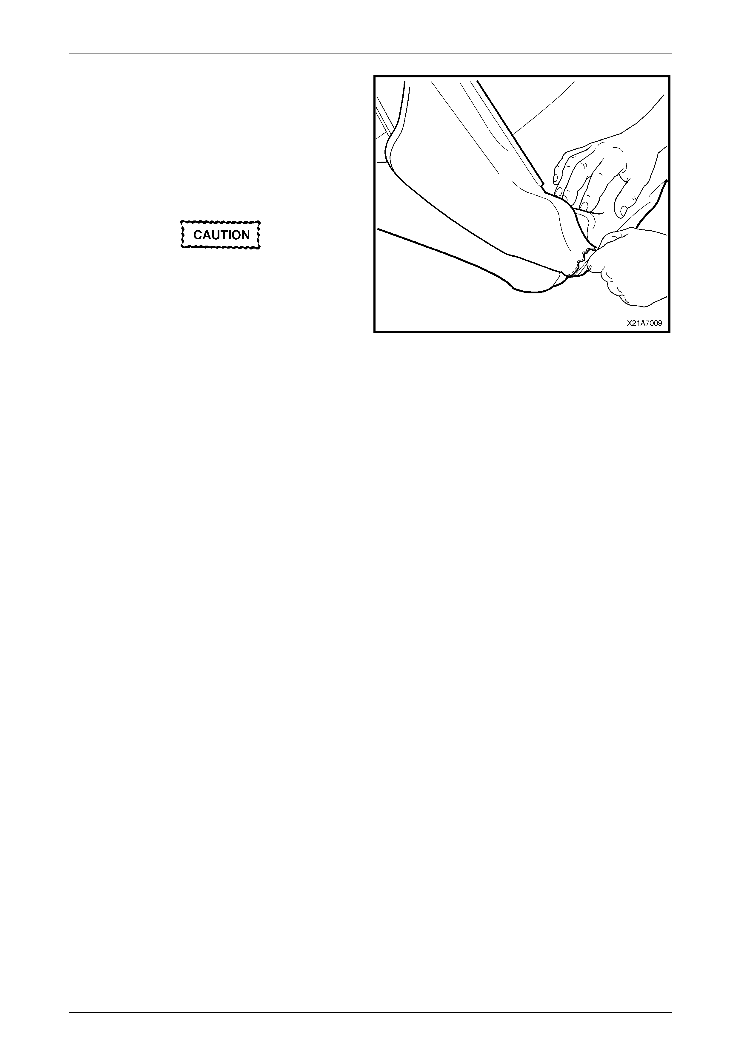
Seat Assemblies Page 1A7–318
Page 1A7–318
5 Roll the front corners of the cover over the pad.
6 Roll the sides of the cover over the pad.
7 Roll the rear corners of the cover over the pad.
NOTE
Ensure the pad is fitted neatly by hand into all
corners and contours of the seat cover.
Do not pull the cover onto the pad from
underneath using the J-strip to make it fit
neatly, as the fabric may be damaged.
Figure 1A7 – 210
Reinstall
Reinstallation of the front seat cushion pad and cover assembly is the reverse of the removal procedure.

Seat Assemblies Page 1A7–319
Page 1A7–319
7.16 Front Seat Cushion Frame Assembly
LT Section No. — 14–275
Remove
As required remove the following c ompo ne nts:
1 Front seat assembly, refer to 7.2 Front Seat Assembly.
2 Front seat outer side cover assembly, refer to 7.3 Front Seat Outer Side Cover Assembly.
3 Front seat inner side cover, refer to 7.4 Front Seat Inner Side Cover.
4 Front seat-back frame assembly, refer to 7.12 Front Seat-back Frame Assembly.
5 Track and height adjust assembly, refer to 7.14 Track and Height Adjust Assembly.
6 Front seat cushion pad and cover assembly, refer to 7.15 Front Seat Cushion Pad and Cover Assembly.
Disassemble
1 To remove the suspension mat (1), modify a G-clamp
with a 5 mm diameter metal dowel (2) welded to one
end and another approximately 40 mm long and with a
2 mm diameter pin (3) approximately 20 mm l ong
welded to the other end.
2 Using the G-clamp, stretch the suspension mat far
enough to allow the four retaining springs (4) to be
removed from the seat cushion frame.
3 Back the G-clamp load off and remove the suspensio n
mat.
When using the G-clamp, use existing holes
in the suspension mat to ensure mat
deformation does not occur.
Figure 1A7 – 211
Reassemble
Reassembly of the suspension mat is the reverse of the disassembl y proc edure.
Reinstall
Reinstallation of the front seat cushion frame assembly is the reverse of the removal pro cedure, noting the following:
1 Ensure all wiring is correctly connected and routed, refer to Section 12O Fuses, Relays and Wiring Harnesses.
2 Check the mechanical and elec trical operation of the front seat.

Seat Assemblies Page 1A7–320
Page 1A7–320
7.17 Front Seat Lift Motor Assemblies
The front seat lift motor assemblies are non-serviceabl e items.
If a front seat lift motor assembly requires replacement, the track and height adjust assembly must be replaced, refer to
7.14 Track and Height Adjust Assembly.

Seat Assemblies Page 1A7–321
Page 1A7–321
7.18 Front Seat Fore/Aft Movement Motor
Assembly
The front seat fore/aft movement motor assembl y is a non-serviceable item.
If the front seat fore/aft movement motor or drive shafts require replacement, the track and height adjust assembly must
be replaced, refer to 7.14 Track and Height Adjust Assembly.

Seat Assemblies Page 1A7–322
Page 1A7–322
7.19 Front Seat-back Recline Motor Assembly
The front seat-back recline motor assembly is a non-serviceable item.
If the front seat-back recline motor assembly requires replacement, the fron t seat-back frame assembly must be
replaced, refer to 7.12 Front Seat-back Frame Assembl y.

Seat Assemblies Page 1A7–323
Page 1A7–323
7.20 Drive Motor Hall-effect Sensors
The front seat drive motor hall-effect sensors are non-serviceable items.
If the front seat fore/aft movement and/or front seat lift motor hall-effect sensors require replacement, the track and
height adjust assembly must be replaced, refer to 7.14 Track and Height Adjust Assembly.
If the seat-back recline motor hall-effect sensor requires replacement, the front seat-back frame assem bl y must be
replaced, refer to 7.12 Front Seat-back Frame Assembl y.

Seat Assemblies Page 1A7–324
Page 1A7–324
8 Service Operations – Rear Seat,
Sedan
8.1 Usage Chart
How to Use this Chart
The following usage chart is provided to help determine the seat type fitted to the vehicle. T his is important prior to
repairs being performed as the failed / dama ged part may not be serviceable.
To determine the seat type fitted to the vehicle, obtain the vehicl e model and the seat cover fabric. Establish if the vehicl e
has an armrest and/or headrest. Using the chart will lead to the elimination of all other seat combinations, allowing for the
identification of the type and t he construction of the seat. Refer to the Figure number shown in Rear Seat T ype column
for a component breakdown of the rear seat assembl y.
1 Vehicle – Vehicle model identification.
2 Fabric – Cloth or leather seat covers.
3 Armrest – If the rear seat-back is fitted with an armrest.
4 Headrest – If the rear seat-ba ck is fitted with a headrest.
5 Construction – Surebond refers to the seat cover being glued to the seat pad. This type is serviced as a pad and
cover assembly only. Hook and Loop refers to the seat cover being attached to the seat pad with a Velcro type
material and both being serviced as separate parts.
6 Rear Seat Type – Identifies the seat type and provides reference to illustrations which sho w a breakdown of the
serviced component for each rear seat assembly.
Vehicle Fabric Armrest Headrest Construction
Rear Seat Type
(refer to)
Executive,
Acclaim Cloth No No Surebond 1
(Figure 1A7 – 212)
SV6,
SV8 Cloth/Leather No No Hook & Loop 2
(Figure 1A7 – 213)
SS,
Berlina Cloth/Leather Yes No Hook & Loop 3
(Figure 1A7 – 214)
Calais Cloth/Leather Yes Yes Hook & Loop 4
(Figure 1A7 – 215)

Seat Assemblies Page 1A7–325
Page 1A7–325
Rear Seat Type 1
Figure 1A7 – 212
Legend
1 Rear Seat-back Assembly - Right-hand
2 Rear Seat-back Assembly - Left-hand
3 Rear Seat Cushion Cover and Pad Assembly
4 Rear Seat Cushion Frame Assembly
5 Rear Seat Cushion Release Handle (2 places)
6 Rear Seat Cushion Cover Wire Retainer
7 Hog Ring
8 Rear Seat-back Centre Cover
9 Rear Seat-back Centre Pad
10 Rear Seat-back Centre Tray Assembly ∗
11 Rear Seat-back Centre Release Button
12 Release Button Rod
13 Rear Seat-back Centre Lock Striker
14 Rear Seat-back Centre Striker Cover
∗ Refer to Figure 1A7 – 216 for a breakdown of the rear seat-back centre tray assembly.
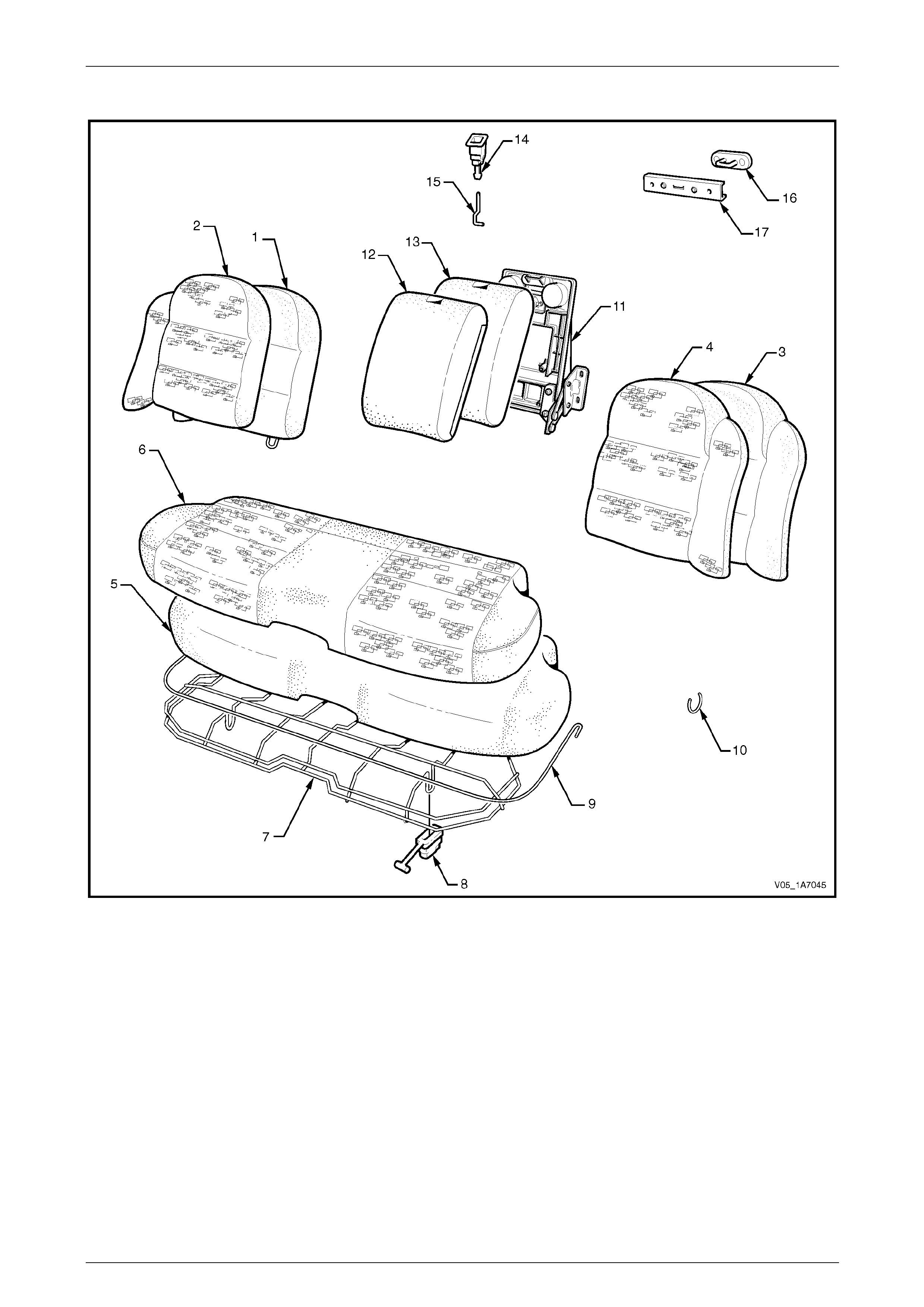
Seat Assemblies Page 1A7–326
Page 1A7–326
Rear Seat Type 2
Figure 1A7 – 213
Legend
1 Rear Seat-back Pad – Right-hand
2 Rear Seat-back Cover – Right-hand
3 Rear Seat-back Pad – Left-hand
4 Rear Seat-back Cover – Left-hand
5 Rear Seat Cushion Pad
6 Rear Seat Cushion Cover Assembly
7 Rear Seat Cushion Frame Assembly
8 Rear Seat Cushion Release Handles (2 places)
9 Rear Seat Cushion Cover Retainer Wire
10 Hog Ring
11 Rear Seat Centre Tray Assembly *
12 Rear Seat-back Centre Cover
13 Rear Seat-back Centre Pad
14 Rear Seat-back Centre Release Button
15 Release Button Rod
16 Rear Seat-back Centre Striker
17 Rear Seat-back Centre Striker Cover
∗ Refer to Figure 1A7 – 216 for a breakdown of the rear seat-back centre tray.
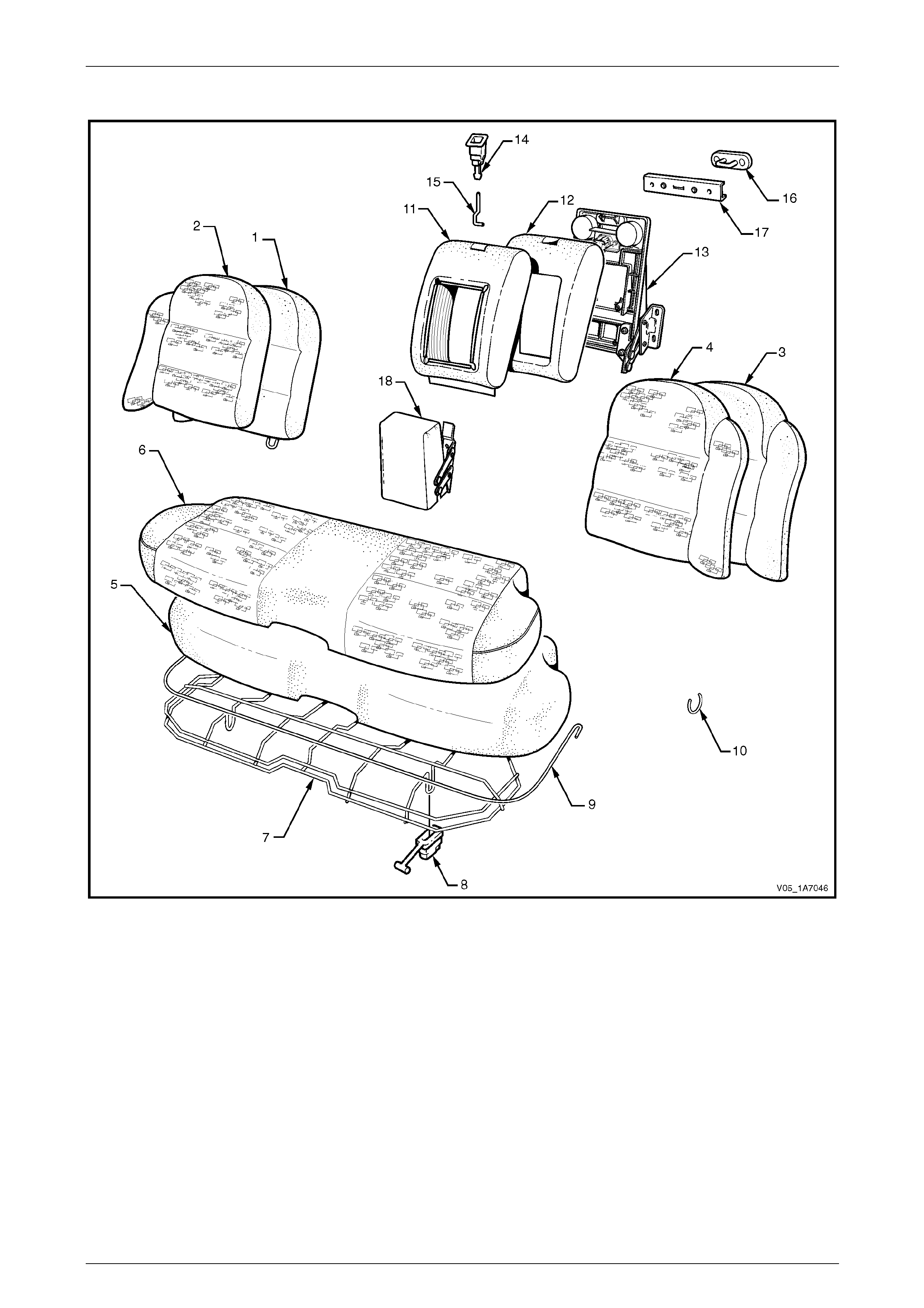
Seat Assemblies Page 1A7–327
Page 1A7–327
Rear Seat Type 3
Figure 1A7 – 214
Legend
1 Rear Seat-back Pad and Frame Assembly - Right-hand
2 Rear Seat-back Cover Assembly - Right-hand
3 Rear Seat-back Pad and Frame Assembly - Left-hand
4 Rear Seat-back Cover Assembly - Left-hand
5 Rear Seat Cushion Pad
6 Rear Seat Cushion Cover Assembly
7 Rear Seat Cushion Frame Assembly
8 Rear Seat Cushion Release Handle (2 places)
9 Rear Seat Cushion Cover Retainer Wire
10 Hog Ring
11 Rear Seat-back Centre Cover
12 Rear Seat-back Centre Pad
13 Rear Seat-back Centre Tray Assembly ∗
14 Rear Seat-back Centre Release Button
15 Release Button Rod
16 Rear Seat-back Centre Lock Striker
17 Rear Seat-back Centre Striker Cover
18 Rear Seat-back Centre Armrest Assembly ∗
∗ Refer to Figure 1A7 – 216 for a breakdown of the rear seat-back centre tray and armrest assemblies.
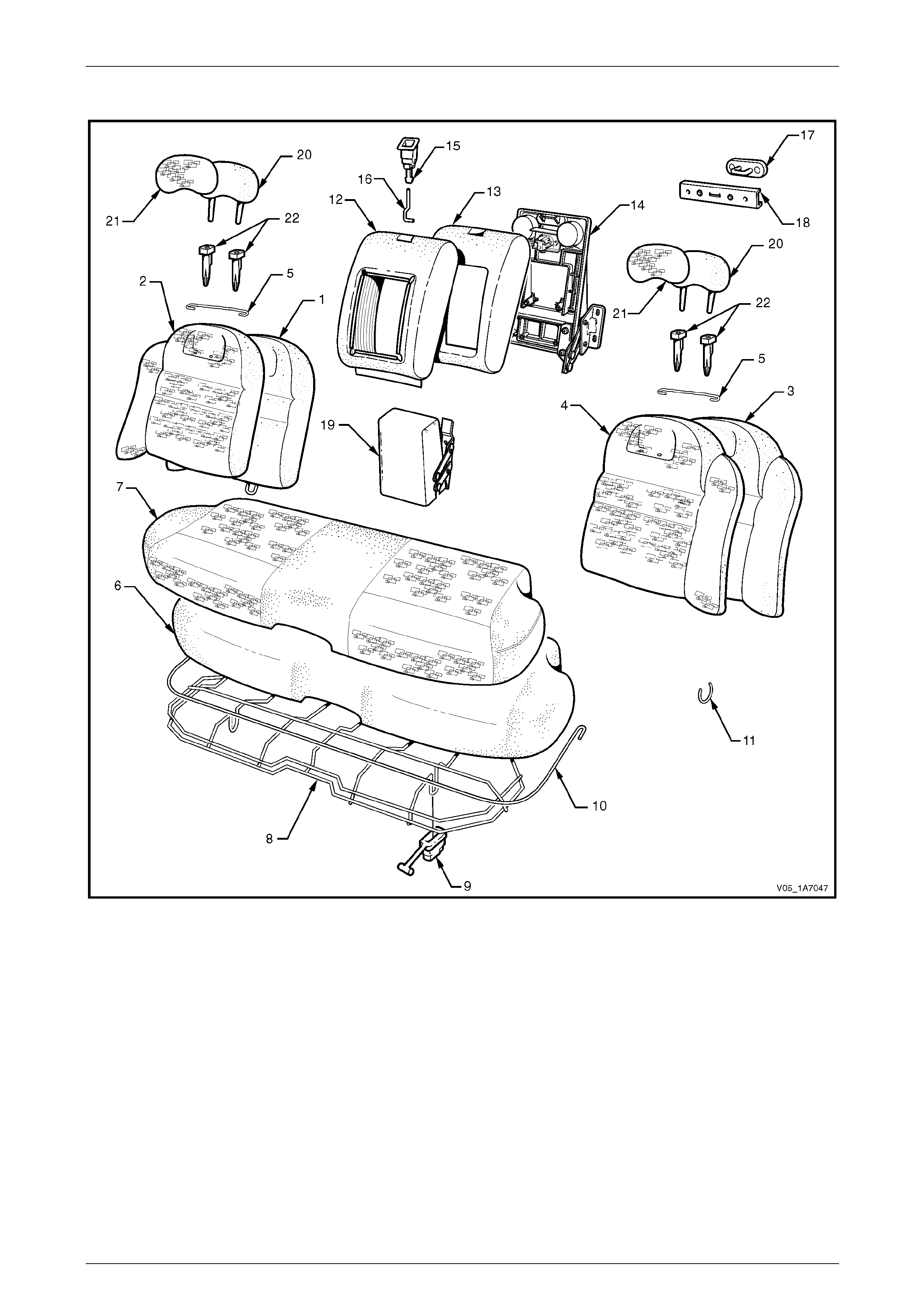
Seat Assemblies Page 1A7–328
Page 1A7–328
Rear Seat Type 4
Figure 1A7 – 215
Legend
1 Rear Seat-back Pad & Frame Assembly - Right-hand Side
2 Rear Seat-back Cover Assembly- Right-hand Side
3 Rear Seat-back Pad & Frame Assembly - Left-ha nd Side
4 Rear Seat-back Cover Assembly- Left-hand Side
5 Rear Seat-back Cover Retaining Wire
6 Rear Seat Cushion Pad
7 Rear Seat Cushion Cover Assembly
8 Rear Seat Cushion Frame Assembly
9 Rear Seat Cushion Release Handle (2 places)
10 Rear Seat Cushion Cover Retainer Wire
11 Hog Ring
12 Rear Seat-back Centre Cover
13 Rear Seat-back Centre Pad
14 Rear Seat-back Centre Tray Assembly ∗
15 Rear Seat-back Centre Release Button
16 Release Button Rod
17 Rear Seat-back Centre Lock Striker
18 Rear Seat-back Centre Striker Cover
19 Rear Seat-back Centre Armrest Assembly ∗
20 Head Restraint Pad
21 Head Restraint Cover
22 Head Restraint Guides
∗ Refer to Figure 1A7 – 216 for a breakdown of the rear seat-back centre tray and armrest assembly.
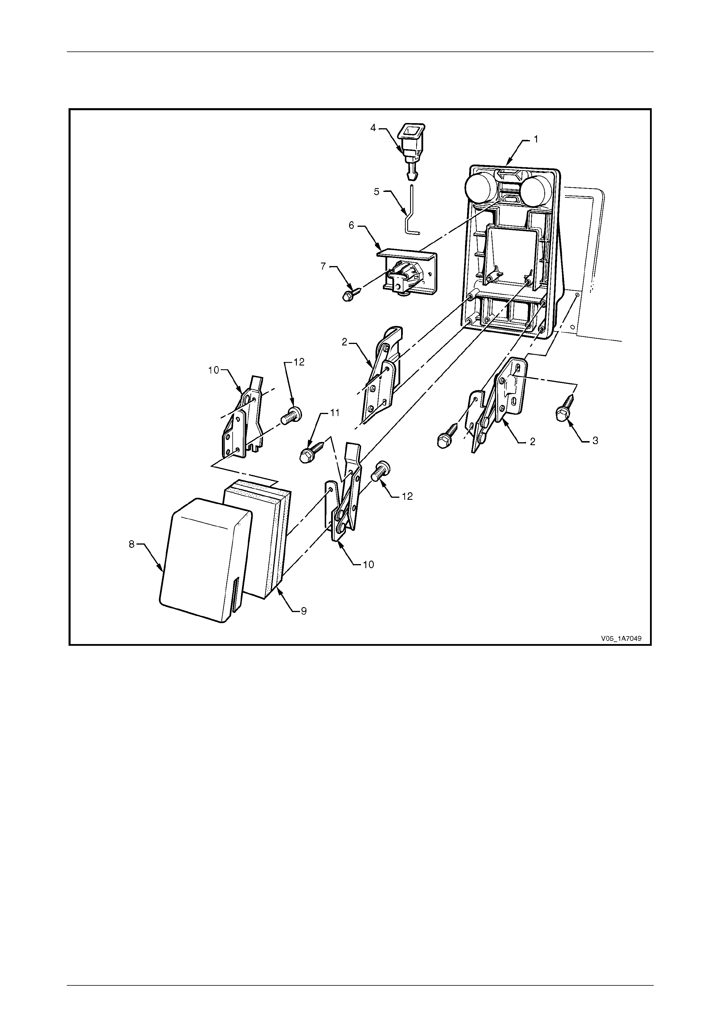
Seat Assemblies Page 1A7–329
Page 1A7–329
Rear Seat-back Centre Tray and Armrest Assembly
Figure 1A7 – 216
Legend
1 Rear Seat-back Centre Tray
2 Rear Seat-back Centre Tray Hinge
3 Hinge Rear Seat-back Centre Bolt (4 places)
4 Rear Seat-back Centre Release Button
5 Release Button Rod
6 Rear Seat-back Centre Lock Actuator
7 Lock Actuator Bolt (2 places)
8 Rear Seat-back Centre Armrest Cover
9 Rear Seat-back Centre Armrest Pad
10 Armrest Assembly Hinge
11 Armrest Hinge Bolt (4 places)
12 Armrest Hinge Screw (4 places)
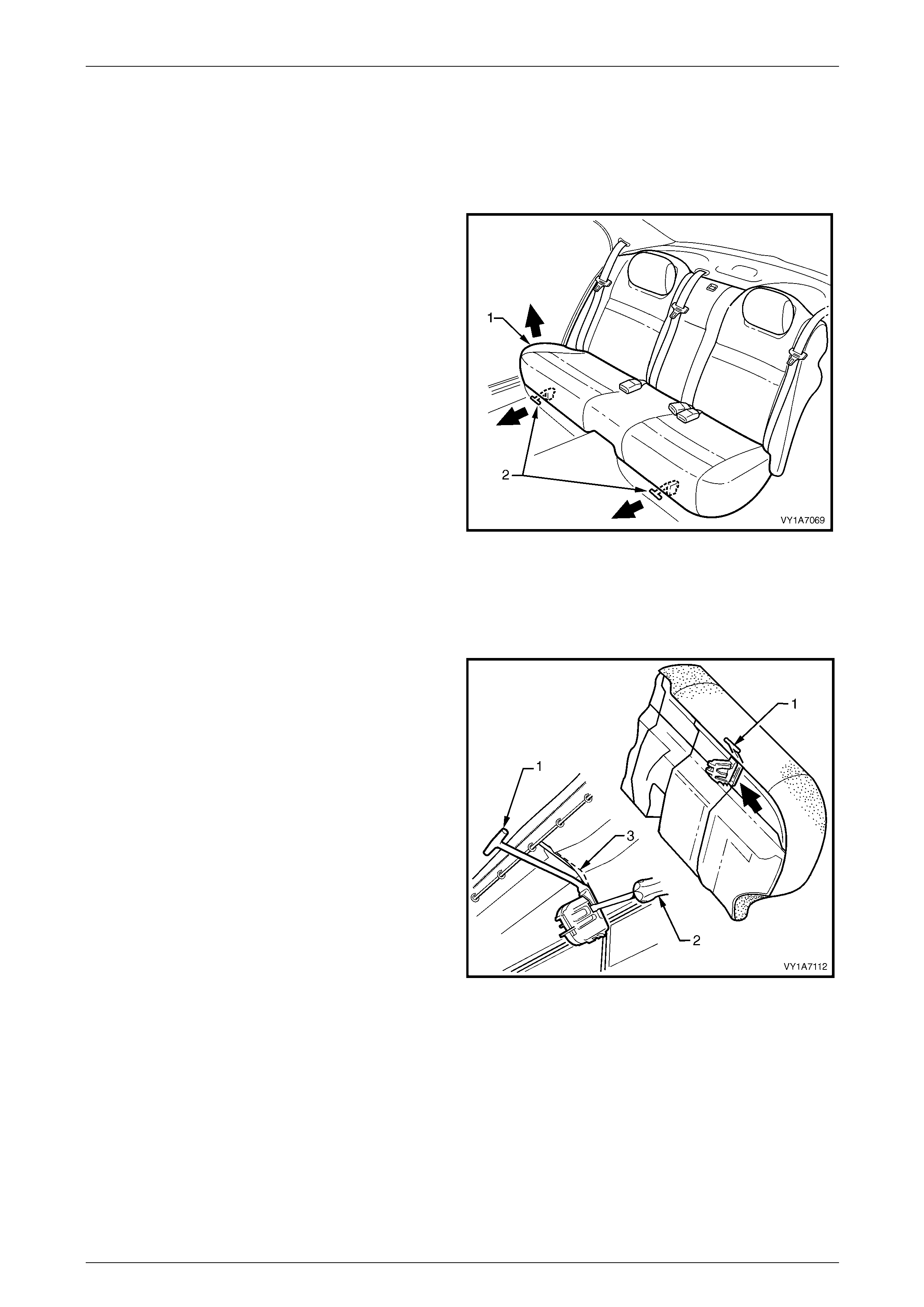
Seat Assemblies Page 1A7–330
Page 1A7–330
8.2 Rear Seat Cushion Assembly
LT Section No. — 14–330
Remove
1 Lift the front of the rear seat cushion assembly (1)
slightly to gain access to the two rear seat cushion
release handles (2).
2 From either the left or the right side of the seat, pull
the release handle T-piece horizontally outwards,
while at the same time lifting the front of the rear seat
cushion until the lock mechanism is released.
3 Repeat step 2 for the opposite side of the seat.
4 Remove the rear seat cushion assembly.
Figure 1A7 – 217
Disassemble
Remove – Rear Seat Cushion Relea se Handle
1 Remove the rear seat cushion release handle (1) by
inserting a screwdriver (2) to disengage the retaining
lugs.
2 Slide the release handle off the rear seat cushion wire
frame (3).
Figure 1A7 – 218

Seat Assemblies Page 1A7–331
Page 1A7–331
Reinstall – Rear Seat Cushion Release Handle
Slide the rear seat cushion rel ease handle (1) onto the rear
seat cushion wire frame (2) and close the cover to lock it
into position.
Figure 1A7 – 219
Remove – Rear Seat Cushion Frame
NOTE
The following component will require replacement
when performing this operation.
• Rear seat cushion hog rings.
Safety glasses an d work glo ves must be w orn
at all times when remo ving the hog ring s.
1 Place the rear seat cushion assembly upside-down.
2 Use bolt cutters (1) to remove the hog rings (2)
attaching the cover and pad assembly (3) to the frame
(4):
• Fifty one places for the Surebond rear seat
cushions.
• Fifty four places for the Hook and Loop rear seat
cushions.
NOTE
Care must be taken when removing the hog
rings not to damage the cushion cover.
NOTE
All hog rings will be destroyed during this
operation and must be replaced.
3 Remove the frame from the rear seat cushion
assembly. Figure 1A7 – 220
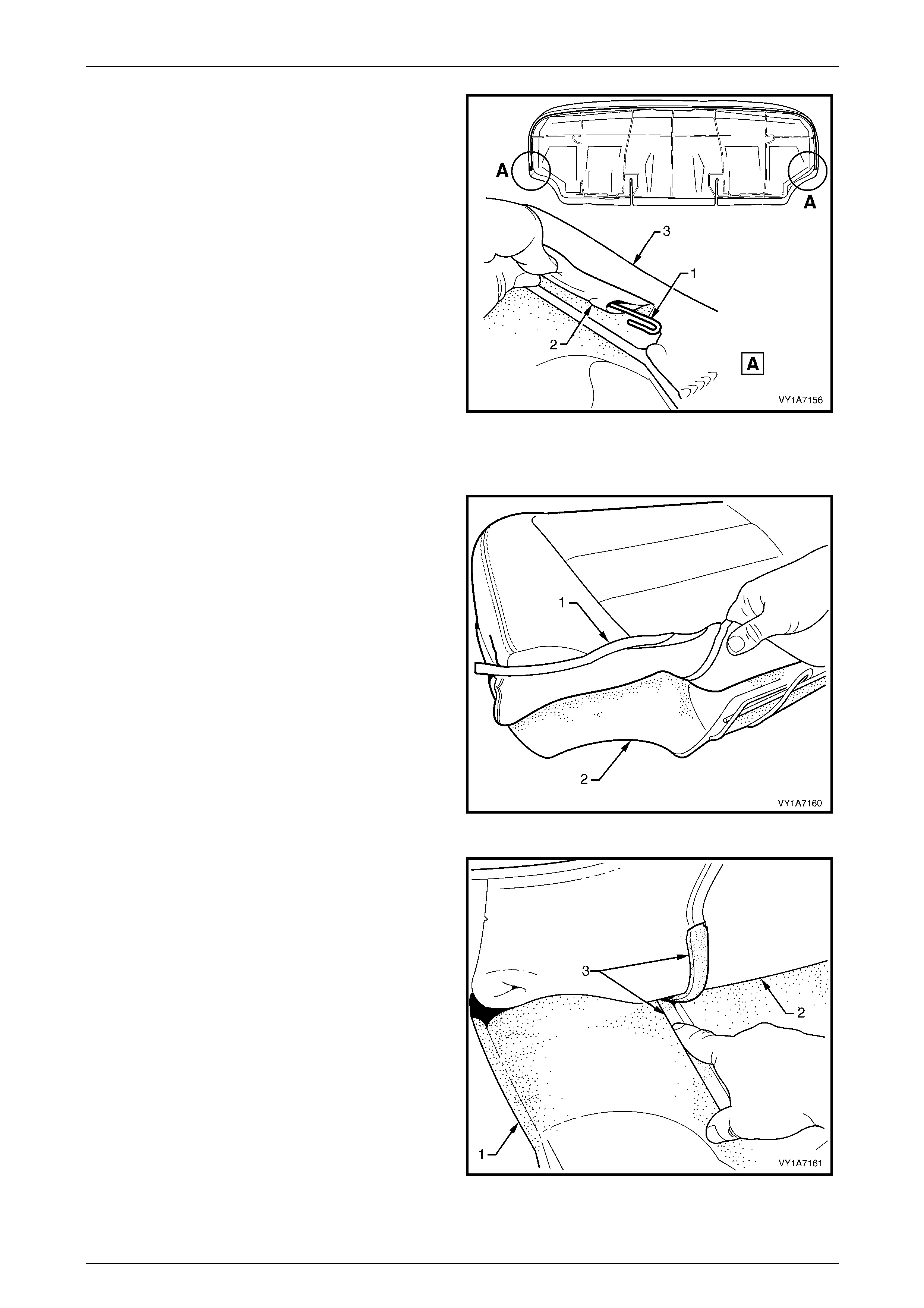
Seat Assemblies Page 1A7–332
Page 1A7–332
4 If required, remove the retaining wire (1) from the
casing (2) on the front of the cushion cover assembly
(3).
Figure 1A7 – 221
Remove – Rear Seat Cushion Cover, Hook and Loop
1 Fold the rear corner of the rear seat cushion cover (1)
over the seat cushion pad (2).
Figure 1A7 – 222
2 While holding the rear seat cushion pad (1), pull the
rear corner of the seat cushion cover (2) away from
the rear seat cushion pad to disenga ge the hook and
loop strip (3).
Figure 1A7 – 223
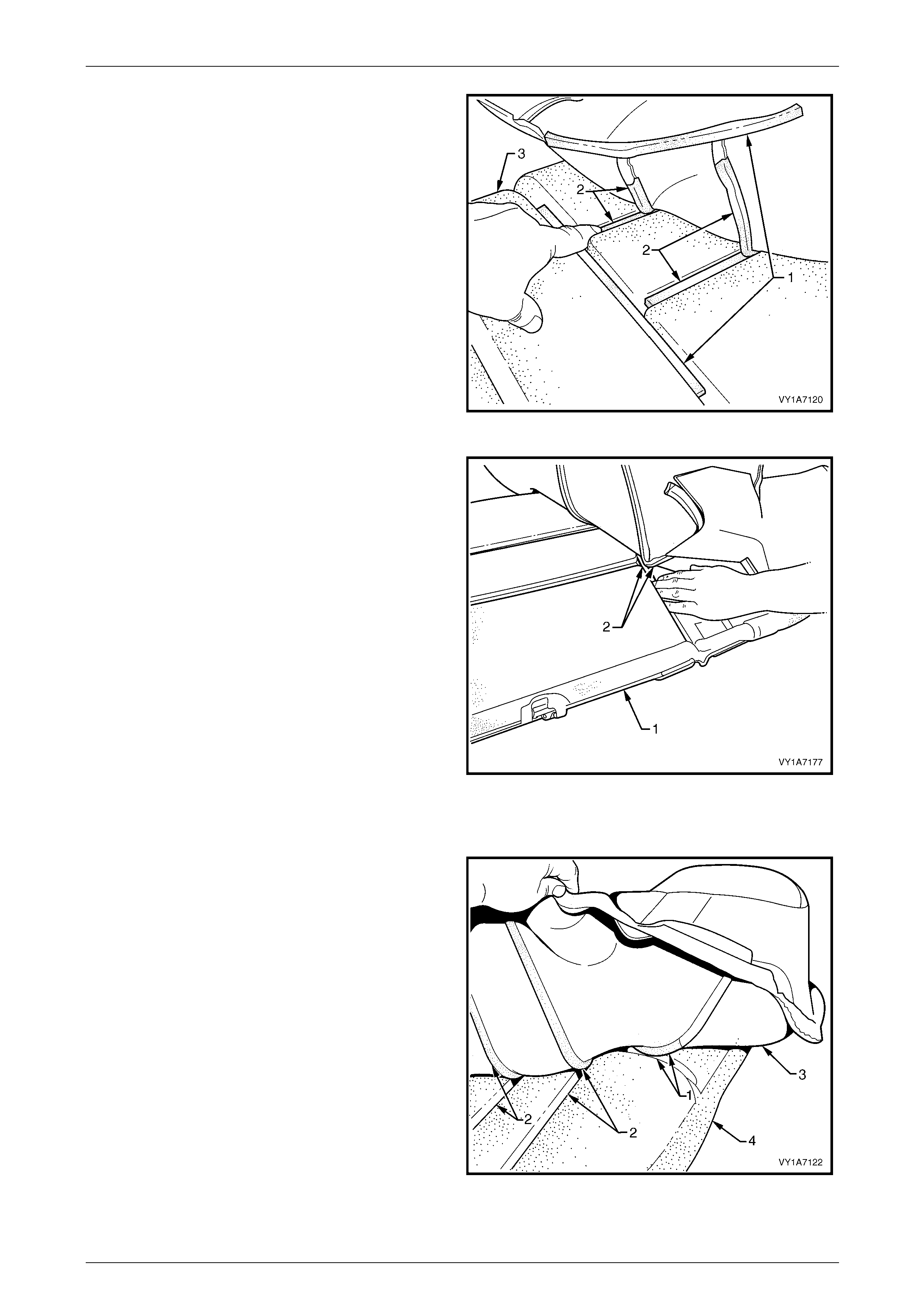
Seat Assemblies Page 1A7–333
Page 1A7–333
3 After disengaging the outer hook and loop strip (1)
remove the one or two cross hook and loop strips (2)
while holding t he seat cushion pad (3).
Figure 1A7 – 224
4 While holding the rear seat cushion pad (1), remove
the inner hook and loop strip (2).
5 Repeat this process for the opposite half of the rear
seat cushion assembly.
6 Remove the rear seat cushion cover.
Figure 1A7 – 225
Reinstall – Rear Seat Cushion Cover, Hook and Lo op
1 Align the inner hook and loop strip (1) and the one or
two cross hook and loop strips (2) on the seat cushion
cover (3) with the seat cushion pad (4).
2 Press the folded edge of the rear seat cushion cover
firmly into the corresponding groove in the seat
cushion pad to engage the hook and loop strip.
Figure 1A7 – 226

Seat Assemblies Page 1A7–334
Page 1A7–334
3 Align and press the outer hook and loop strip (1), on
the seat cushion cover (2), with the corresponding
groove in the seat cushion pad (3).
4 Repeat this process for the opposite half of the rear
seat cover and pad, beginning with the inner strip.
Figure 1A7 – 227
5 With the retaining wire (1) fitted to the rear seat
cushion cover (2), roll the front corner of the cover
over the seat cushion pad (3).
6 Roll the sides of the seat cushion cover over the seat
cushion pad.
7 Roll the rear corners (4) of the seat cushion c over over
the seat cushion pad.
NOTE
Ensure the pad is fitted neatly by hand into all
corners and contours of the seat cover.
Figure 1A7 – 228
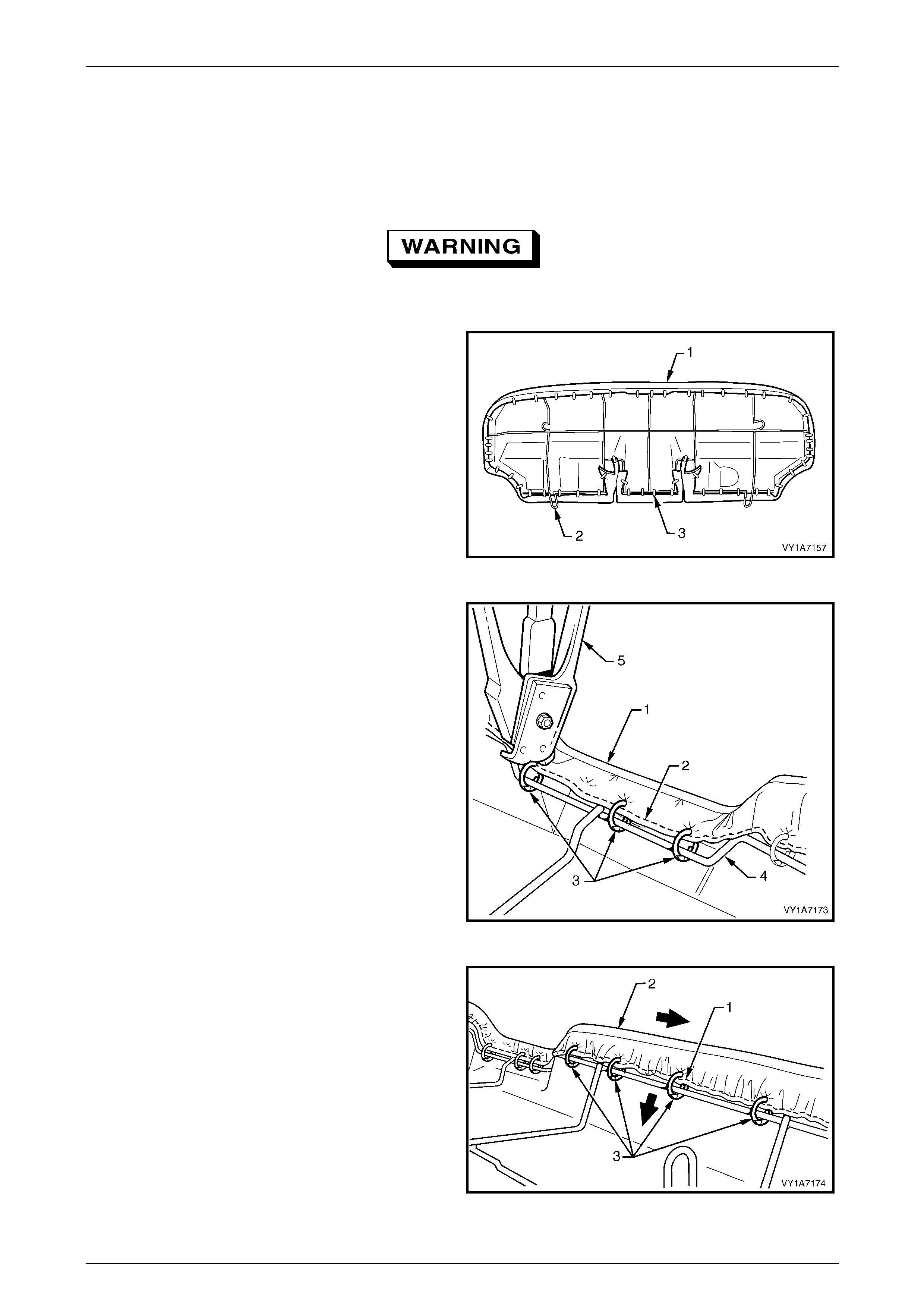
Seat Assemblies Page 1A7–335
Page 1A7–335
Reinstall – Rear Seat Cushion Frame, Surebond
NOTE
All hog rings must be replaced.
Safety glasses an d work glo ves must be w orn
at all times when working with hog rings.
1 Align the rear seat cushion cover and p ad assembly
(1) to the rear seat cushion frame (2) and attach with
approximately fifty one hog rin gs (3) in the p ositions
shown.
Figure 1A7 – 229
2 Beginning at the front, in the centre of the rear seat
cushion cover assembly (1), attach the wire retainer
(2) to the centre of the wire frame (4) with three hog
rings (3) using hog ring pliers (5).
Figure 1A7 – 230
3 Working from the centre outward, attach the wire
retainer (1), pulling the cover assembly (2) tight and
attaching with four hog rings (3).
4 Repeat this process in the opposite direction workin g
from the centre outward.
Figure 1A7 – 231
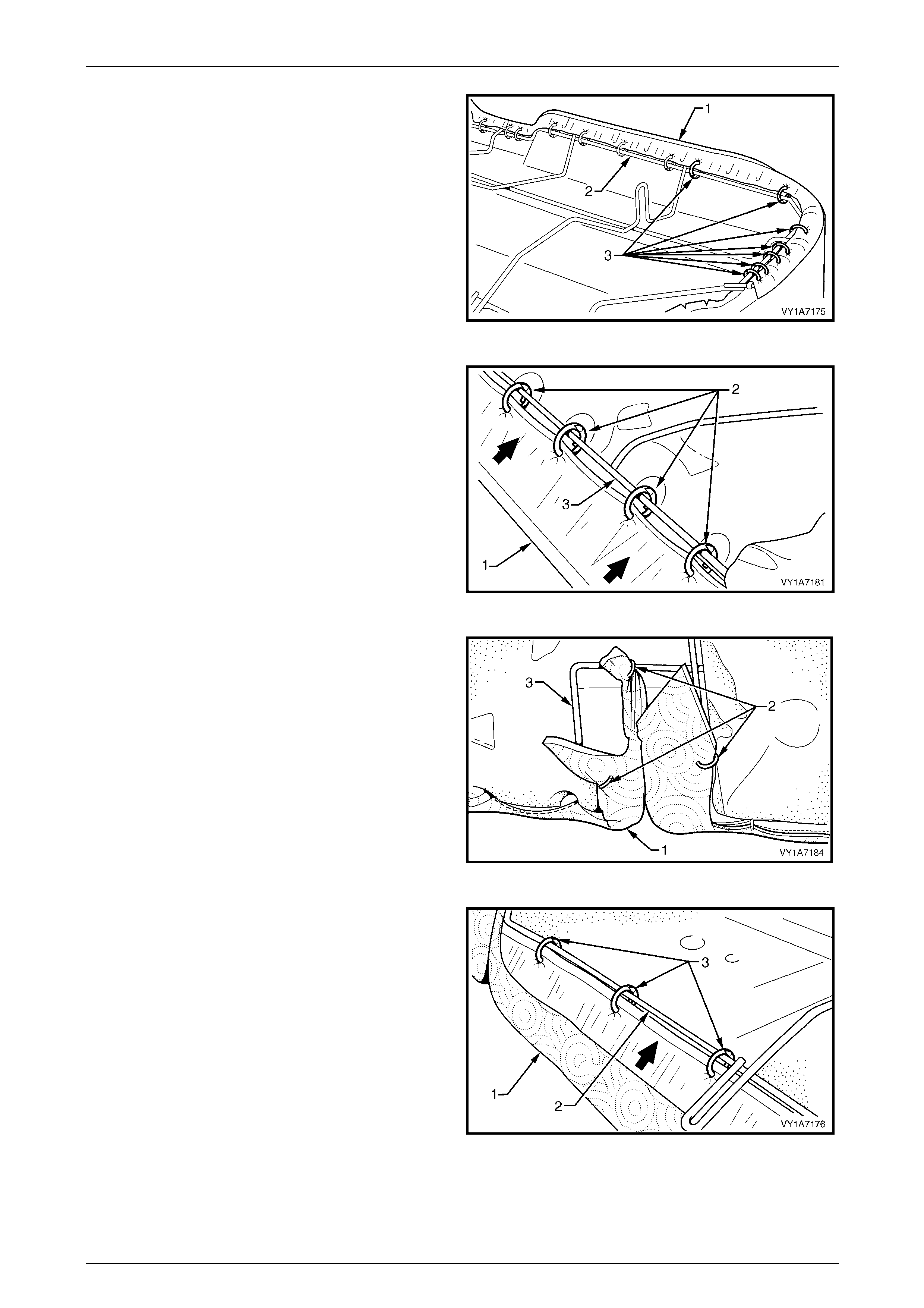
Seat Assemblies Page 1A7–336
Page 1A7–336
5 Continue attaching the cover assembly (1) to the
frame (2), by pulling the cover tight and attaching with
seven hog rings (3).
6 Repeat this process in the opposite direction.
NOTE
The cover should be smooth and without
creases If this is not the case, extra hog rings
are to be used to pull the cover into place.
Figure 1A7 – 232
7 Pull the rear of the cover assembly (1) tight and attach
to the centre of the wire frame (3) with four hog rings
(2).
Figure 1A7 – 233
8 Pull the cover assembly (1) tight into the seatbelt slot
at the rear of the seat pad and attach to the wire frame
(3) with three hog rings (2).
9 Repeat this process for the opposite seatbelt slot.
Figure 1A7 – 234
10 Continue attaching the cover assembly (1) to the
frame (2), by pulling the cover tight and attaching with
three hog rings (3).
11 Repeat this process in the opposite direction.
NOTE
The cover should be smooth and without
creases. If this is not the case, extra hog rings
are to be used to pull the cover into place.
Figure 1A7 – 235
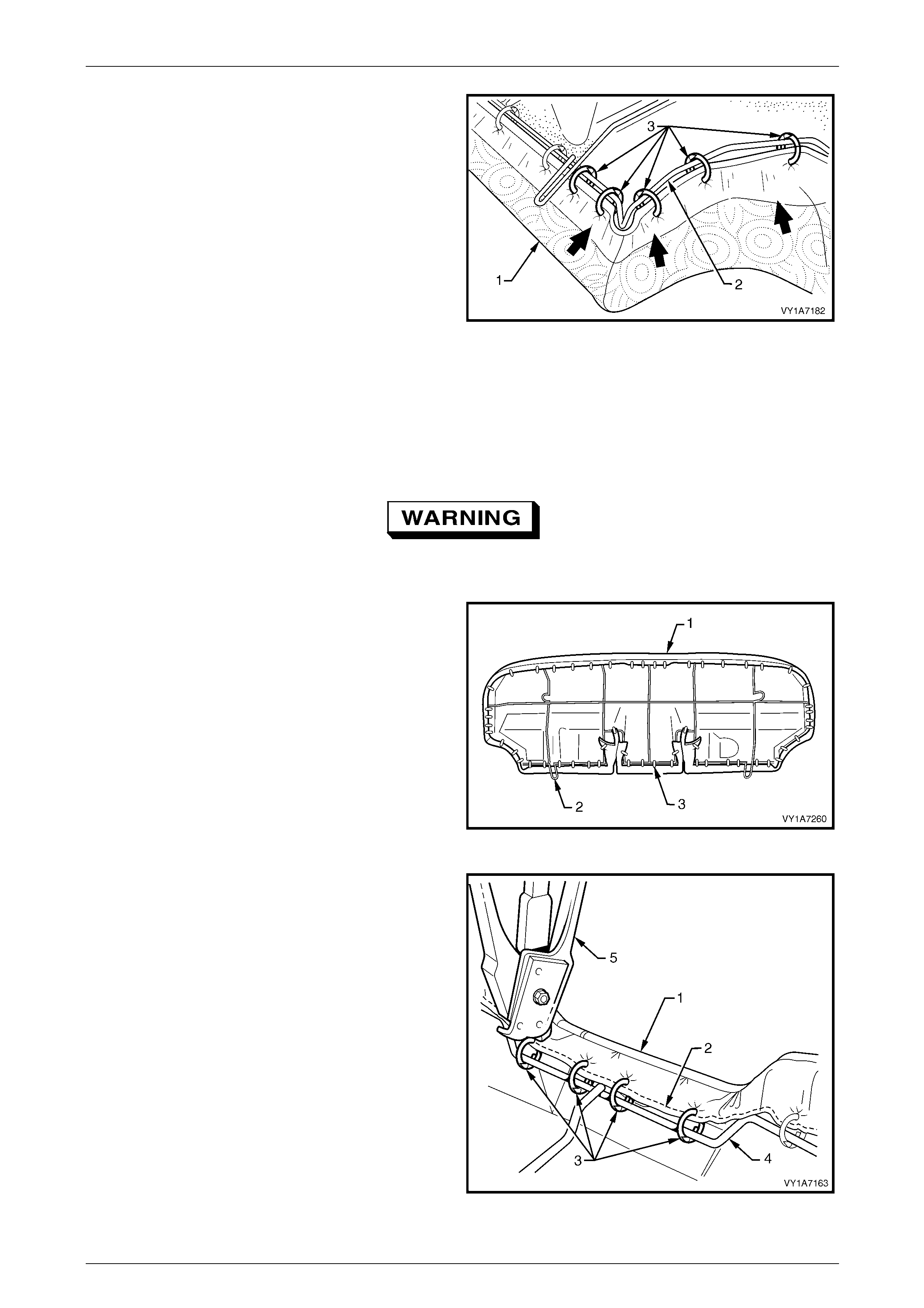
Seat Assemblies Page 1A7–337
Page 1A7–337
12 Continue attaching the cover assembly (1) to the
frame (2), by pulling the cover tight, up and around the
corner and attaching with five hog rings (3).
13 Repeat this process in the opposite direction.
NOTE
The cover should be smooth and without
creases. If this is not the case, extra hog rings
are to be used to pull the cover into place.
Figure 1A7 – 236
Reinstall – Rear Seat Cushion Frame, Hook and Loop
NOTE
All hog rings must be replaced.
Safety glasses an d work glo ves must be w orn
at all times when working with hog rings.
1 Align the rear seat cushion cover and p ad assembly
(1) to the rear seat cushion frame (2) and attach with
approximately fifty four hog rings (3) in the positions
shown.
Figure 1A7 – 237
2 Beginning at the front, in the centre of the rear seat
cushion cover assembly (1), attach the wire retainer
(2) to the centre of the wire frame (4) with four hog
rings (3) using hog ring pliers (5).
Figure 1A7 – 238
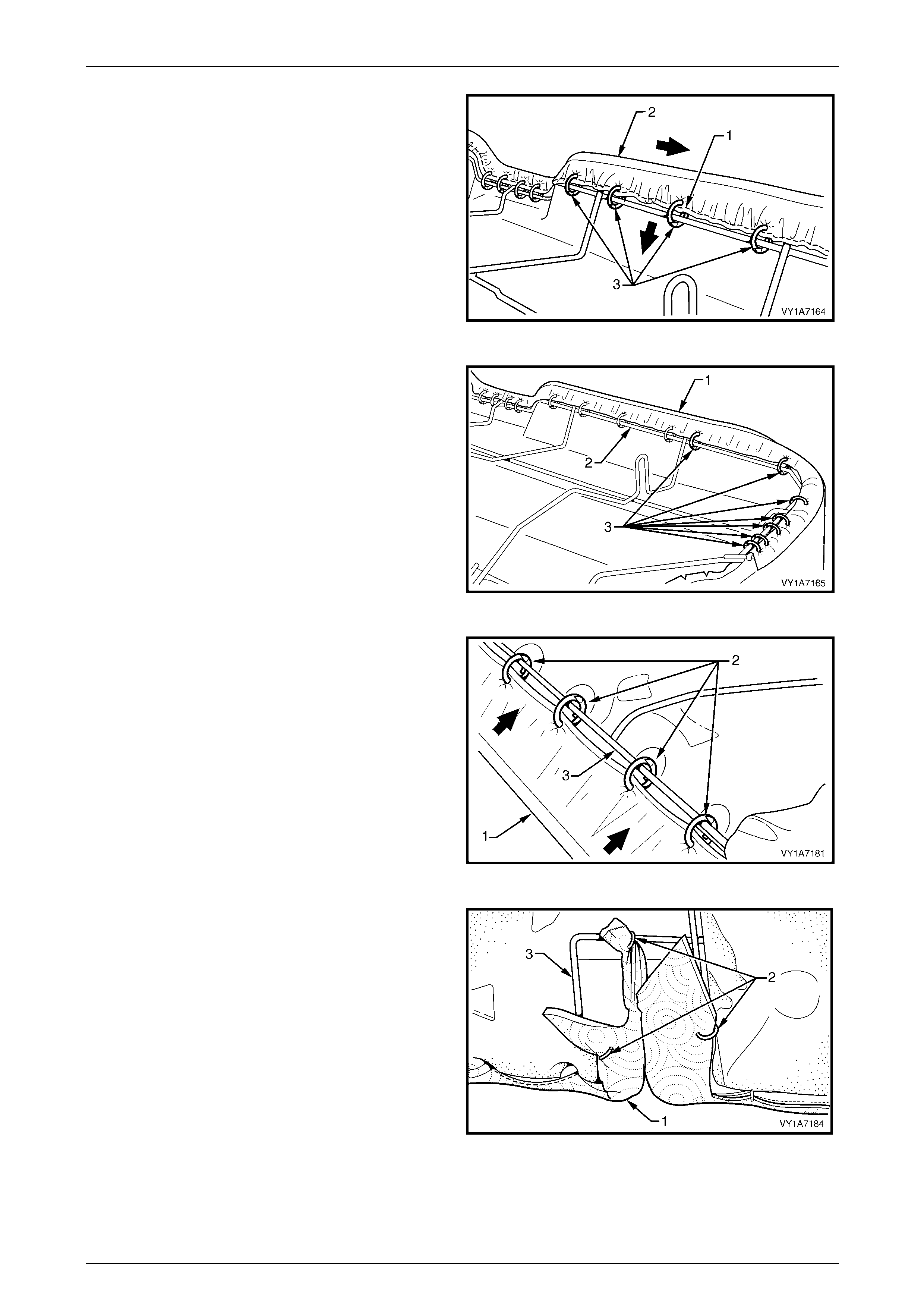
Seat Assemblies Page 1A7–338
Page 1A7–338
3 Working from the centre outward, attach the wire
retainer (1), while pulling the cover assembly (2) tight
and attaching with four hog rings (3).
4 Repeat this process in the opposite direction working
from the centre outward.
Figure 1A7 – 239
5 Continue attaching the cover assembly (1) to the
frame (2), by pulling the cover tight and attaching with
seven hog rings (3).
6 Repeat this process in the opposite direction.
NOTE
The cover should be smooth and without
creases. If this is not the case, extra hog rings
are to be used to pull the cover into place.
Figure 1A7 – 240
7 Pull the rear of the cover assembly (1) tight and attach
the centre with four hog rings (2) to the centre of the
wire frame (3).
Figure 1A7 – 241
8 Pull the cushion cover assembl y (1) tight into the
seatbelt slot at the rear and attach to the wire frame
(3) with three hog rings (2).
9 Repeat this process for the opposite the seatbelt slot.
Figure 1A7 – 242
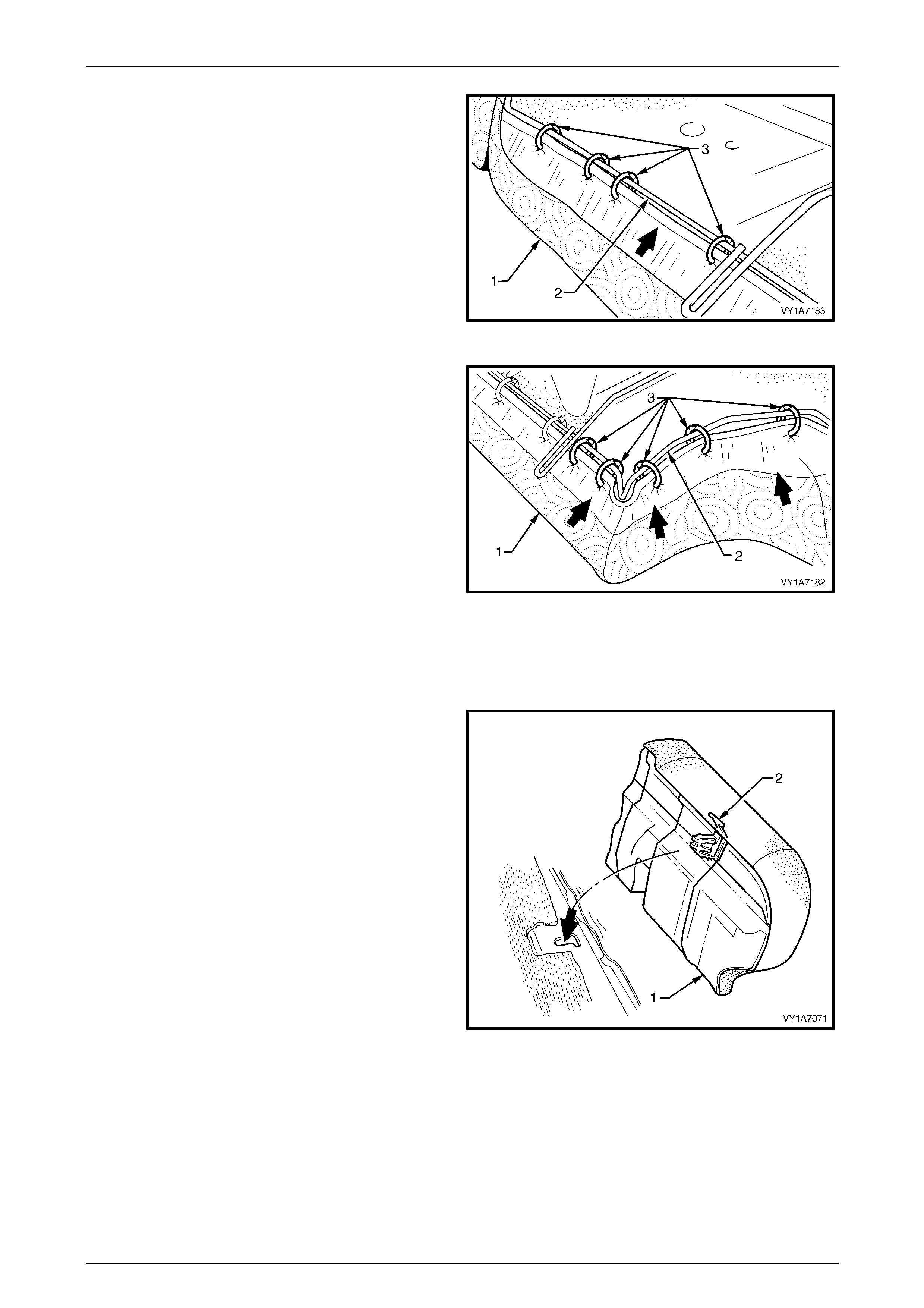
Seat Assemblies Page 1A7–339
Page 1A7–339
10 Continue attaching the cover assembly (1) to the
frame (2), by pulling the cover tight and attaching with
four hog rings (3).
11 Repeat this process in the opposite direction.
Figure 1A7 – 243
12 Continue attaching the cover assembly (1) to the
frame (2), by pulling the cover tight, up and around the
corner and attaching with five hog rings (3).
13 Repeat this process in the opposite direction.
NOTE
The cover should be smooth and without
creases. If this is not the case, extra hog rings
are to be used to pull the cover into place.
Figure 1A7 – 244
Reinstall
1 Position the re ar seat cushion into the vehicle.
2 Push the rear seat cushion (1) into the seat-back and
push down the front of the cushion until the locking
mechanisms (2) lock into position.
Figure 1A7 – 245

Seat Assemblies Page 1A7–340
Page 1A7–340
8.3 Rear Seat-back Assembly
LT Section No. — 14–325
Remove the rear seat cushion assembly, refer to 8.2 Rear Seat Cushion Assembly.
Remove
1 Press the release button and lower the rear seat
centre back assembly (1).
Figure 1A7 – 246
2 Remove the screw (1) attaching the rear seat-back
assembly (2) to the rear floor panel.
3 Lift the rear seat-back assembly up and out of the
retaining brackets (3).
4 Remove the rear seat-back assembly and repeat for
the opposite side if required.
Figure 1A7 – 247
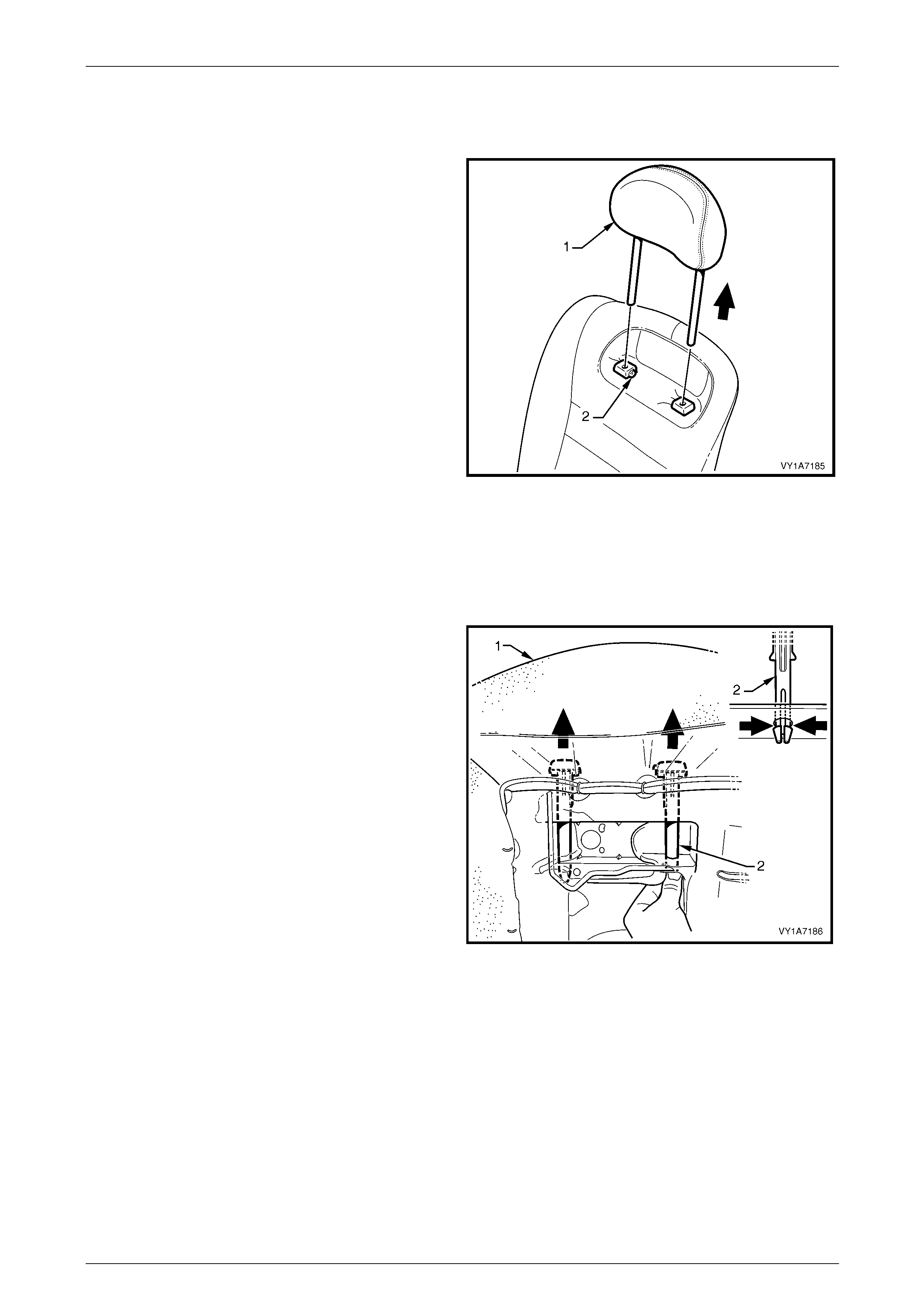
Seat Assemblies Page 1A7–341
Page 1A7–341
Disassemble
Remove – Rear Seat-b ack Head Restraint
1 Remove the head restraint (1) by depressing the head
restraint guide height adjuster lock (2).
2 Pull the head restraint completely out of the guide.
Figure 1A7 – 248
Reinstall – Rear Seat-back Head Restraint
Reinstallation of the head restraint into the rear seat-back assembly is the reverse of the removal procedure.
Remove – Rear Seat-b ack Head Restraint Guide
1 From the back of rear seat-back (1) (foam side)
squeeze the head restraint guide locating prongs (2)
together and remove the guide up and out of the
seat-back assembly.
2 Repeat this process for the remaining head restraint
guide.
Figure 1A7 – 249
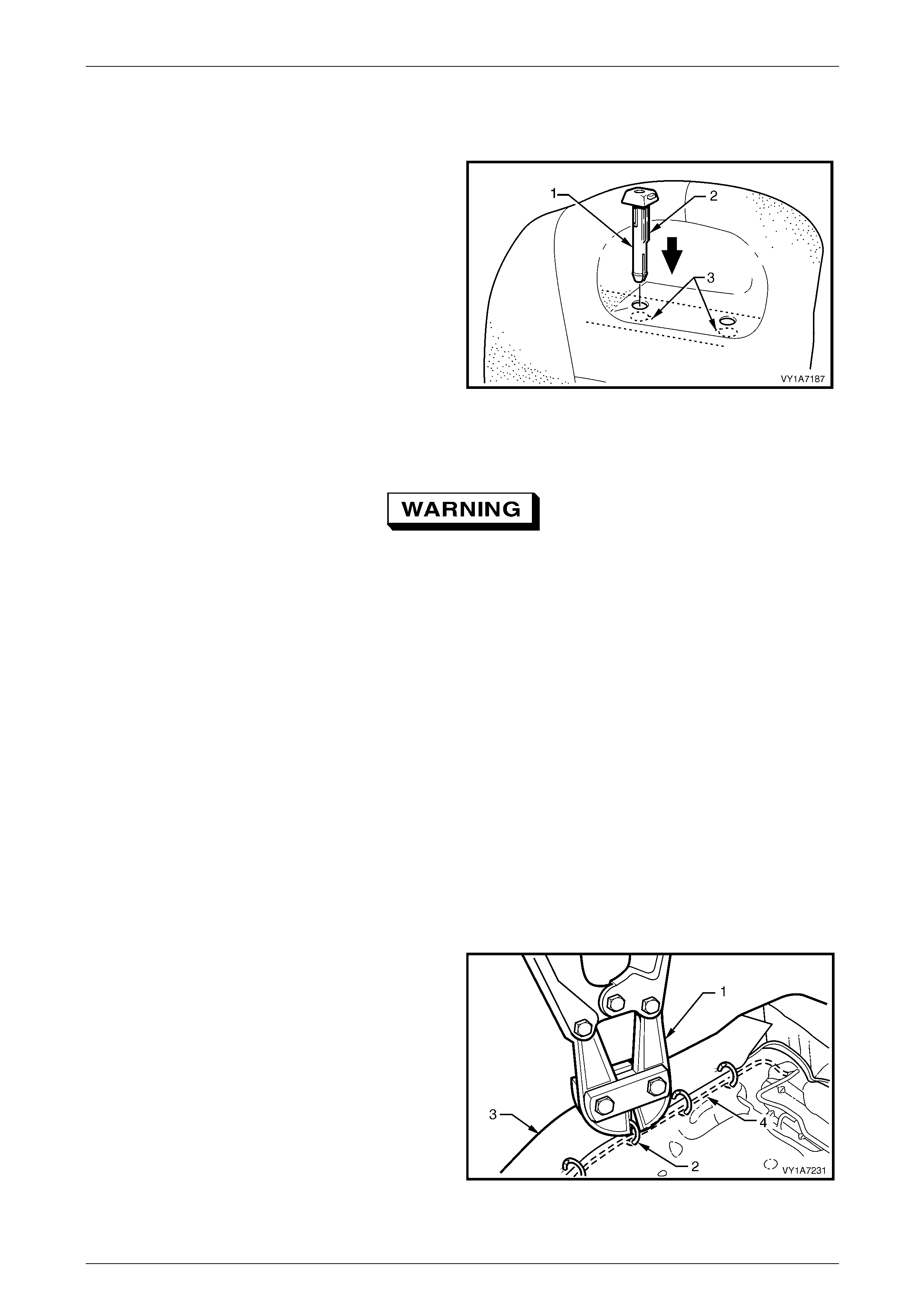
Seat Assemblies Page 1A7–342
Page 1A7–342
Reinstall – Rear Seat-back Head Restraint Guide
Reinstallation of the rear seat head restraint guide is the reverse of the rem oval procedure, noting the foll owing:
When installing the head restraint guide (1), align the
locating ribs (2) with the key-way (3) in the seat-back frame.
NOTE
Ensure the guide with the height adjuster lock is
installed on the side that corresponds to the
notches in the head restraint shaft.
Figure 1A7 – 250
Remove – Rear Seat-back Cover, Hook and Loop
Safety glasses an d work glo ves must be w orn
at all times when remo ving the hog ring s.
NOTE
The following component will require replacement
when performing this operation.
• Rear seat-back hog rings.
NOTE
Surebond cover assemblies are not serviced as
they are glued to the seat-back pad and frame
assembly.
NOTE
The following procedures are applicable to both
left-hand and right-hand rear seat-back
assemblies.
1 Place the rear seat-back assembly face do wn.
2 Use bolt cutters (1) to remove approximately thirty one
hog rings (2) attaching the cov er (3) to the rear
seat-back pad and frame assembly (4).
NOTE
When removing the hog rings, take care not to
damage the rear seat-back cover.
All hog rings will be damaged during this
operation and must be replaced.
Figure 1A7 – 251
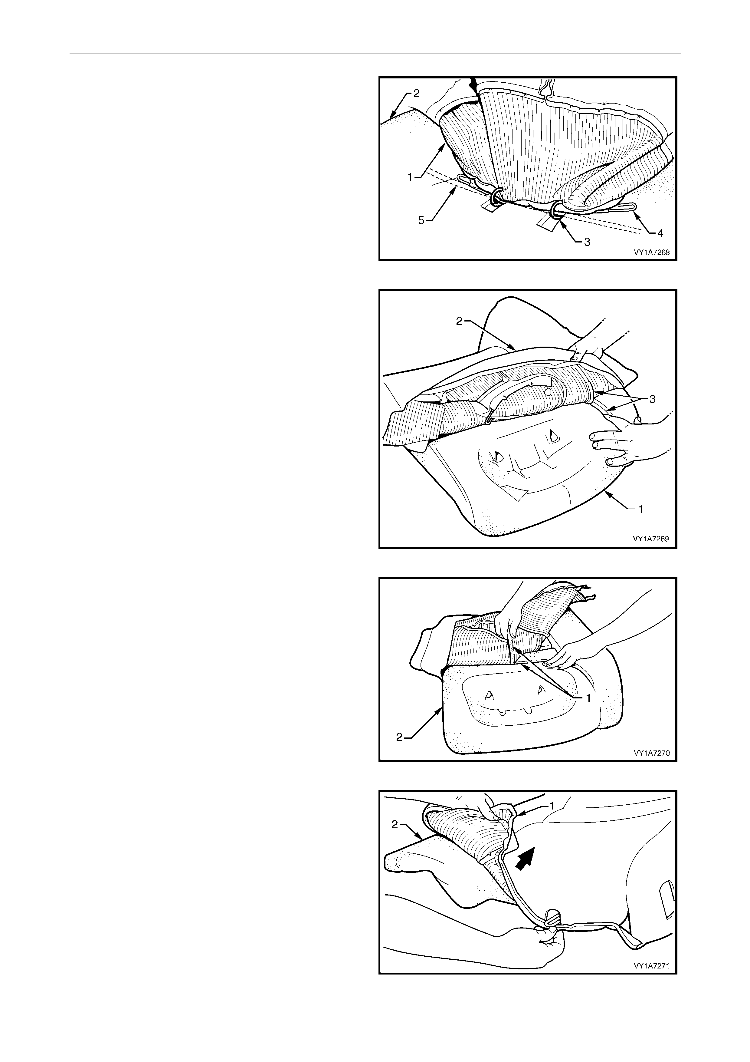
Seat Assemblies Page 1A7–343
Page 1A7–343
3 Fold the upper portion of the rear seat-back cover (1)
over the rear seat-back pad assembly (2).
4 If the rear seat-back has the provision for a head
restraint, cut the two hog rings (3) attaching the
retaining wire (4) to the frame assembly (5).
Figure 1A7 – 252
5 While holding the rear seat-back pad assembly (1),
pull the upper corner of the cover (2) away from the
rear seat-back pad to disengage the hook and loop
strip (3).
Figure 1A7 – 253
6 Remove the one or two cross hook and loop strips (1)
while holding the rear seat-back pad (2).
Figure 1A7 – 254
7 Fold the lower corner of the cover (1) over the
seat-back pad (2).
8 Remove the rear seat-back cover.
Figure 1A7 – 255
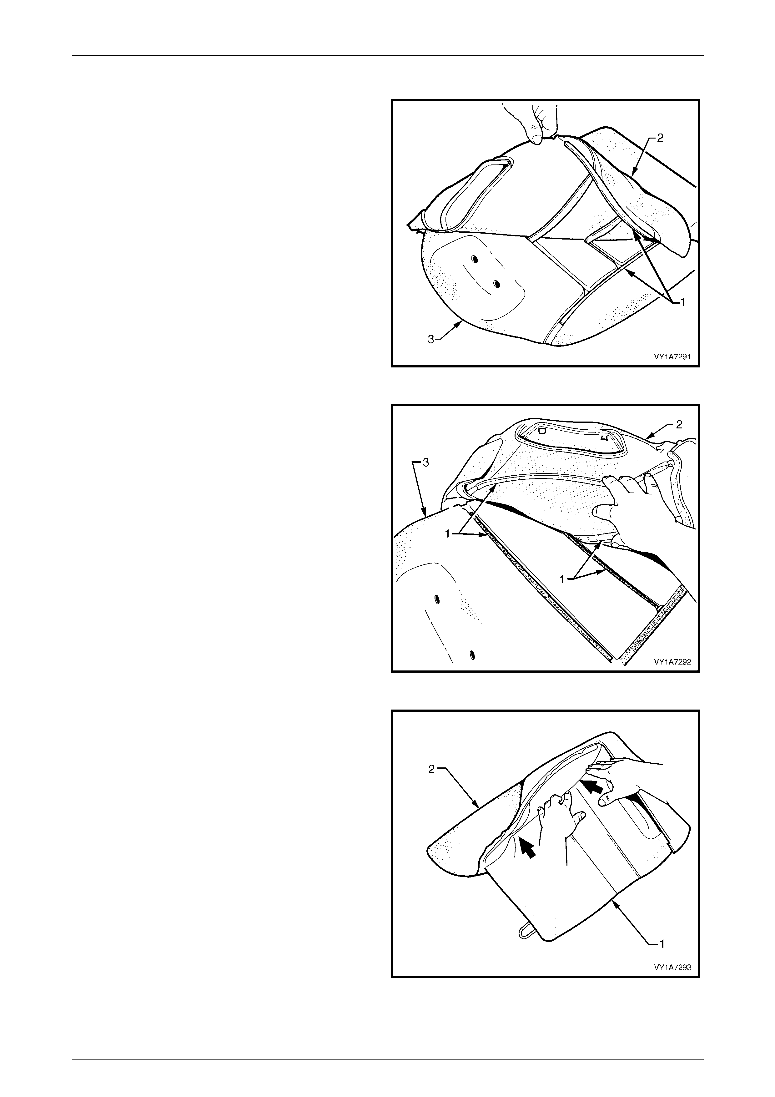
Seat Assemblies Page 1A7–344
Page 1A7–344
Reinstall – Rear Seat-back Cover, Hook and Loop
1 Align the outer hook and loop strip (1) on the
seat-back cover (2) with the seat -back pad (3).
Figure 1A7 – 256
2 Align the one or two cross hook and lo op strips (1) on
the seat-back cover (2) with the seat -back pad (3).
Figure 1A7 – 257
3 Press the folded edge of the rear seat-back cover (1)
firmly into the corresponding groove i n the se at-back
pad (2) to engage the hook and loop strip.
Figure 1A7 – 258
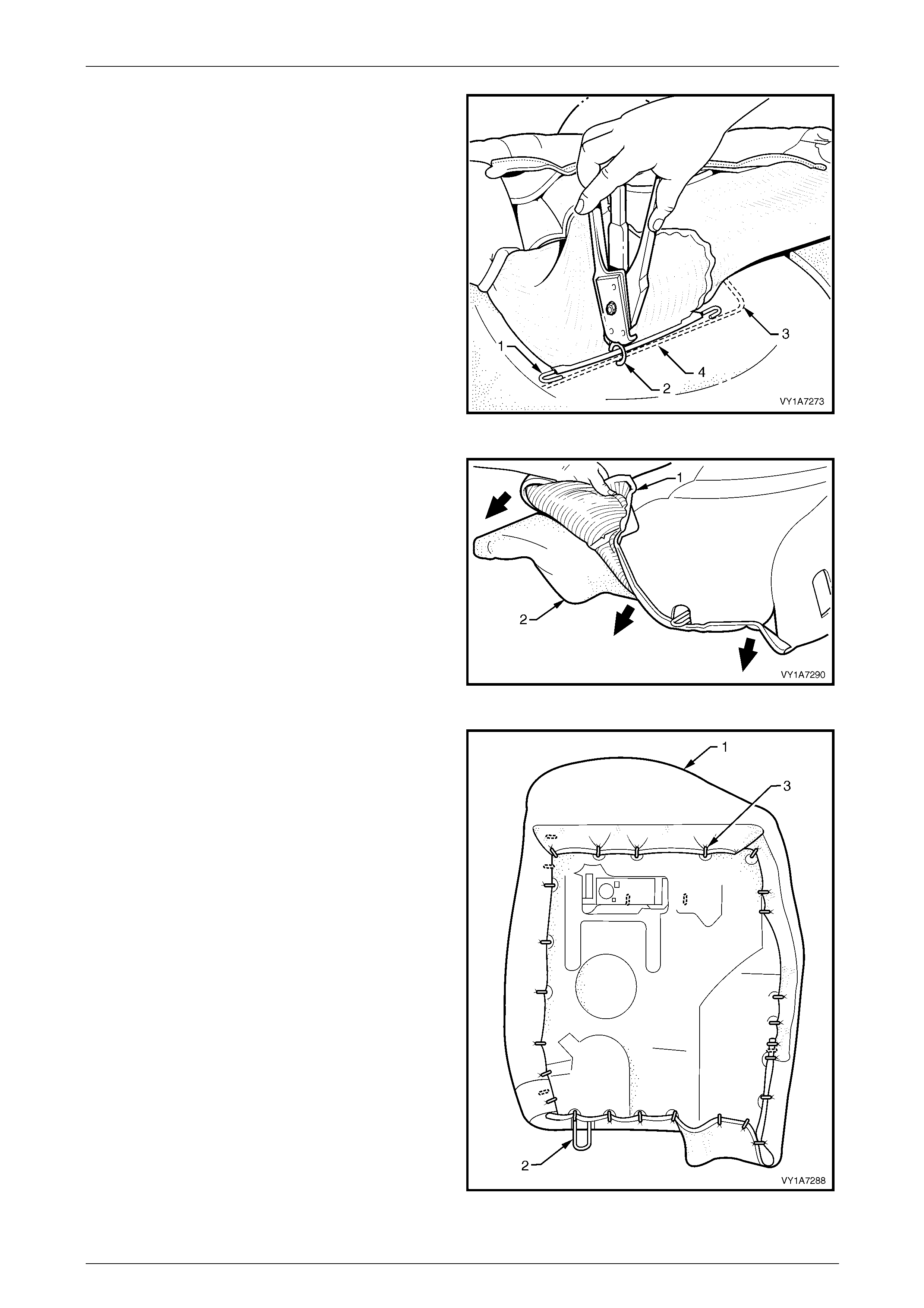
Seat Assemblies Page 1A7–345
Page 1A7–345
4 If the rear seat-back cover has the provision for a head
restraint, the retaining wire (1) must be attached to the
frame (3) with two hog rings (2) using hog ring pliers.
Figure 1A7 – 259
5 Roll the lower corner of the cover (1) over the
seat-back pad (2).
6 Roll the sides of the cover over the seat-bac k pad.
7 Roll the upper corners of the cover over the seat-back
pad.
NOTE
Ensure the cover is fitted neatly by hand into all
corners and contours of the seat-back-pad.
Figure 1A7 – 260
8 Attach the rear seat-back cover (1) to the rear
seat-back pad and frame assembly (2), with
approximately thirty one hog rings (3), in the positions
shown.
Figure 1A7 – 261
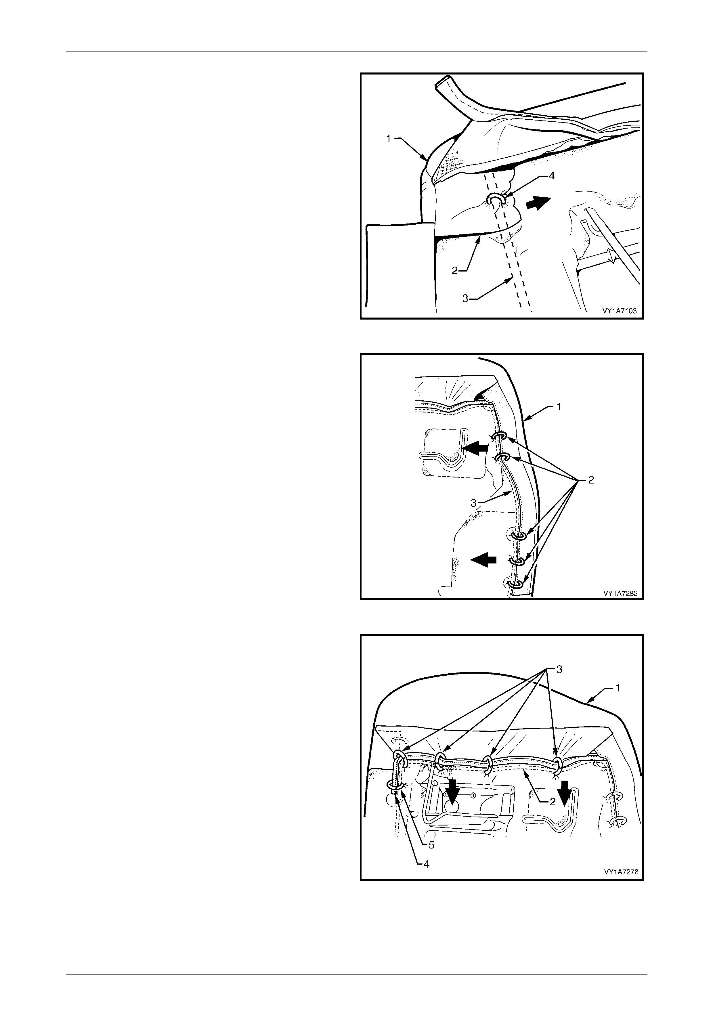
Seat Assemblies Page 1A7–346
Page 1A7–346
9 Beginning at the upper inboard corner of the rear
seat-back cover (1), pull the cover flap (2) towards the
centre and attach to the wire frame (3) with one hog
ring (4).
Figure 1A7 – 262
10 While pulling the cover (1) tight, attach to the wire
frame (3) with five hog rings (2) on the outboard side.
Figure 1A7 – 263
11 Continue attaching the cover (1) to the frame (2) by
pulling the cover tight and attaching with four hog rings
(3).
12 Attach the cover upper piping overhang (4), with one
hog ring (5) to the wire frame, in the top inboard
corner.
Figure 1A7 – 264
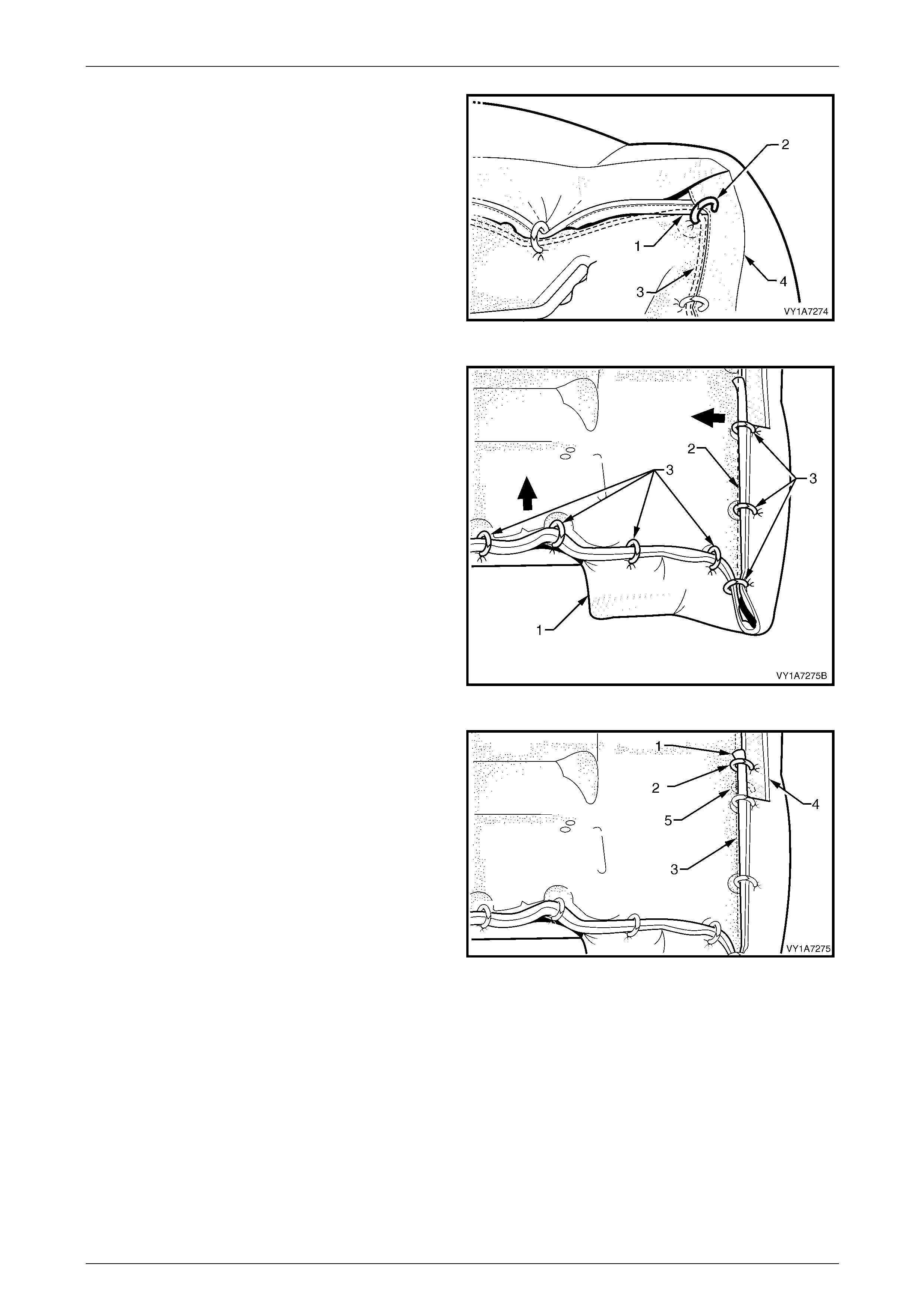
Seat Assemblies Page 1A7–347
Page 1A7–347
13 Attach the cover upper piping overhang (1) with one
hog ring (2) to the wire frame (3) and to the hessian
(4) on the side of the cover, in the top outboar d corner.
Figure 1A7 – 265
14 Continue attaching the cover (1) to the frame (2), by
pulling the cover tight and attaching with seven hog
rings (3).
Figure 1A7 – 266
15 Attach the cover lower piping overhang (1), with one
hog ring (2) to the wire frame (3) and to the hessian
(4) on the side of the cover overlapping a previously
attached hog ring (5).
Figure 1A7 – 267

Seat Assemblies Page 1A7–348
Page 1A7–348
16 Continue attaching the cover (1) to the frame (2), by
pulling the cover tight and attaching with two hog rings
(3).
17 Attach the seat-back cover lower pi ping overhang (4)
to the wire frame with one hog ring (5) in the lower
inboard corner.
Figure 1A7 – 268
18 Continue attaching the cover (1) to the frame (2), by
pulling the cover tight and attaching with five hog rings
(3).
Figure 1A7 – 269
19 On the lower inboard side, pull the cover flap (1)
towards the centre and attach to the wire frame (2)
with one hog ring (3), overlapping a previously attach
hog ring (4).
Figure 1A7 – 270
Reinstall
Reinstallation of the rear seat-back assembly is the reverse of the removal procedure. Tighten the attaching screws to
the correct torque specification.
Rear seat-back assembly attaching
screw torque specification.......................25.0 – 35.0 Nm
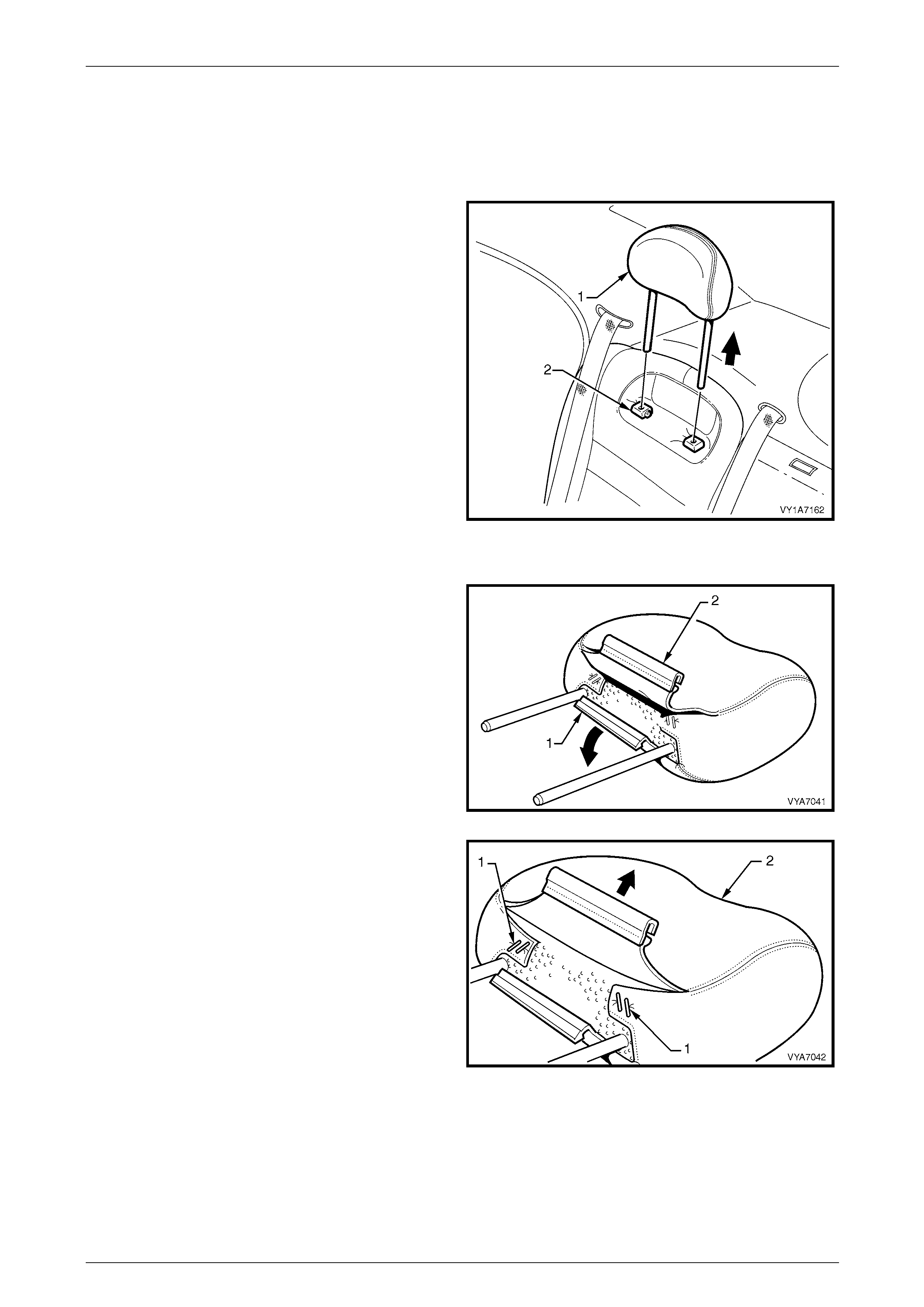
Seat Assemblies Page 1A7–349
Page 1A7–349
8.4 Rear Seat-back Head Restraint Assembly
LT Section No. — 14–350
Remove
1 Remove the head restraint (1) by depressing the head
restraint guide height adjuster lock (2).
2 Pull the head restraint completely out of the guide.
Figure 1A7 – 271
Disassemble
1 Disengaging the rear head restraint cover retaining
J-strip (1) by pulling up the flap (2).
Figure 1A7 – 272
2 Remove the four staples (1) attaching the cover (2) to
the head restraint pad assembly.
3 Remove the cover from the pad assembly.
Figure 1A7 – 273
Reassemble
Reassembly of the rear seat-back head restraint assembly is the reverse of the removal procedure. Ensure the head
restraint cover J-strip is fully engaged.
Reinstall
Reinstallation of the rear seat-back head restraint is the reverse of the removal procedure.
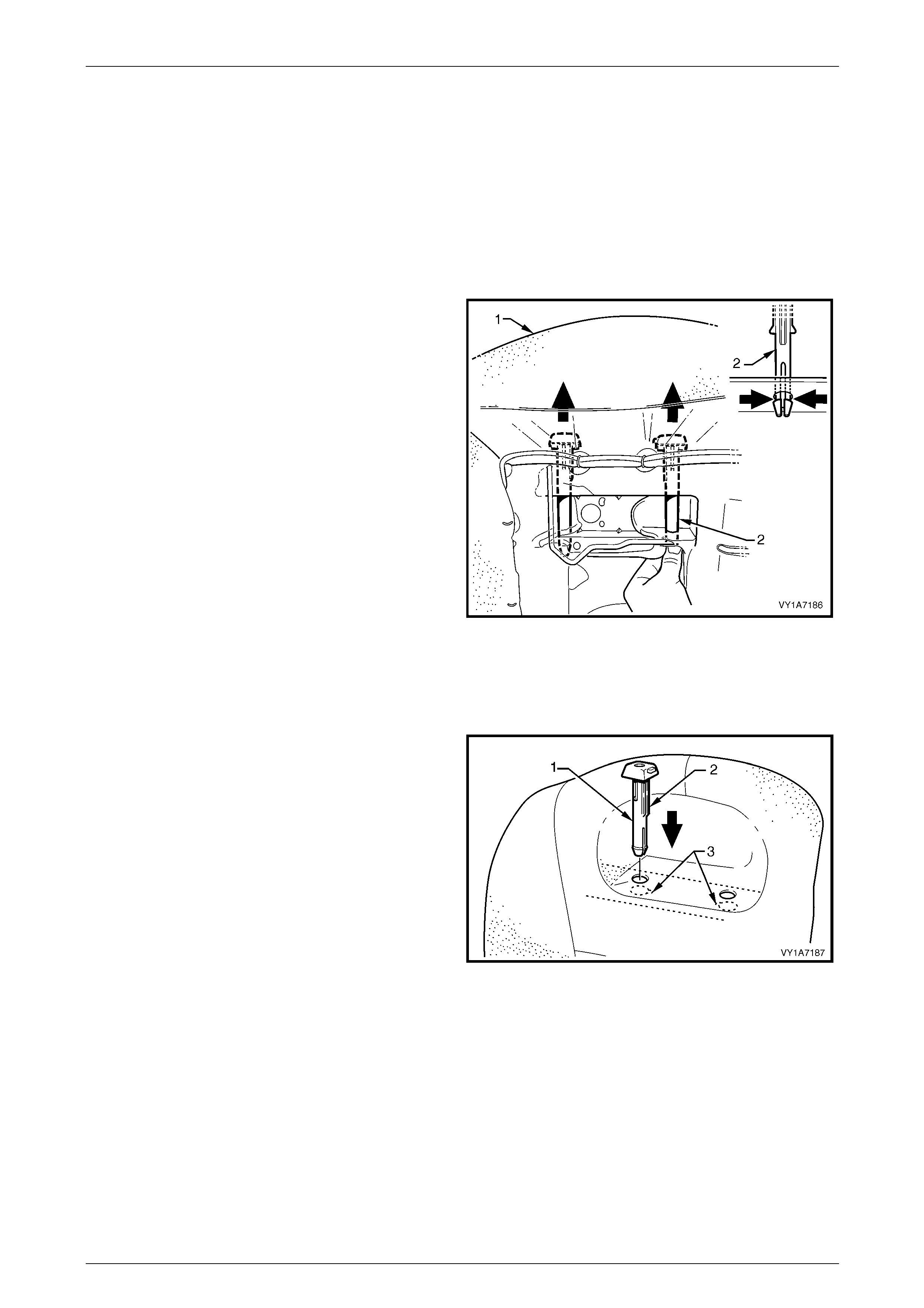
Seat Assemblies Page 1A7–350
Page 1A7–350
8.5 Rear Seat-back Head Restraint Guide
LT Section No. — 14–350
1 Remove the rear seat cushion assembly, refer to 8.2 Rear Seat Cushion Assembly.
2 Remove the rear seat-back assembly, refer to 8.3 Rear Seat-back Assembl y.
3 Remove the rear seat-back head restraint assembly, refer to 8.4 Rear Seat-back Head Restraint Assembly.
Remove
1 From the back of the rear seat-back (1) (foam side)
squeeze the head restraint guide locating prongs (2)
together and remove the guide up and out of the
seat-back assembly.
2 Repeat this process for the remaining head restraint
guide as required.
Figure 1A7 – 274
Reinstall
Reinstallation of the rear seat head restraint guide is the reverse of the rem oval procedure, noting the foll owing:
When installing the head restraint guide (1), align the
locating ribs (2) with the key-way (3) in the seat-back frame.
NOTE
Ensure the guide with the height adjuster lock is
installed on the side that corresponds to the
notches in the head restraint shaft.
Figure 1A7 – 275
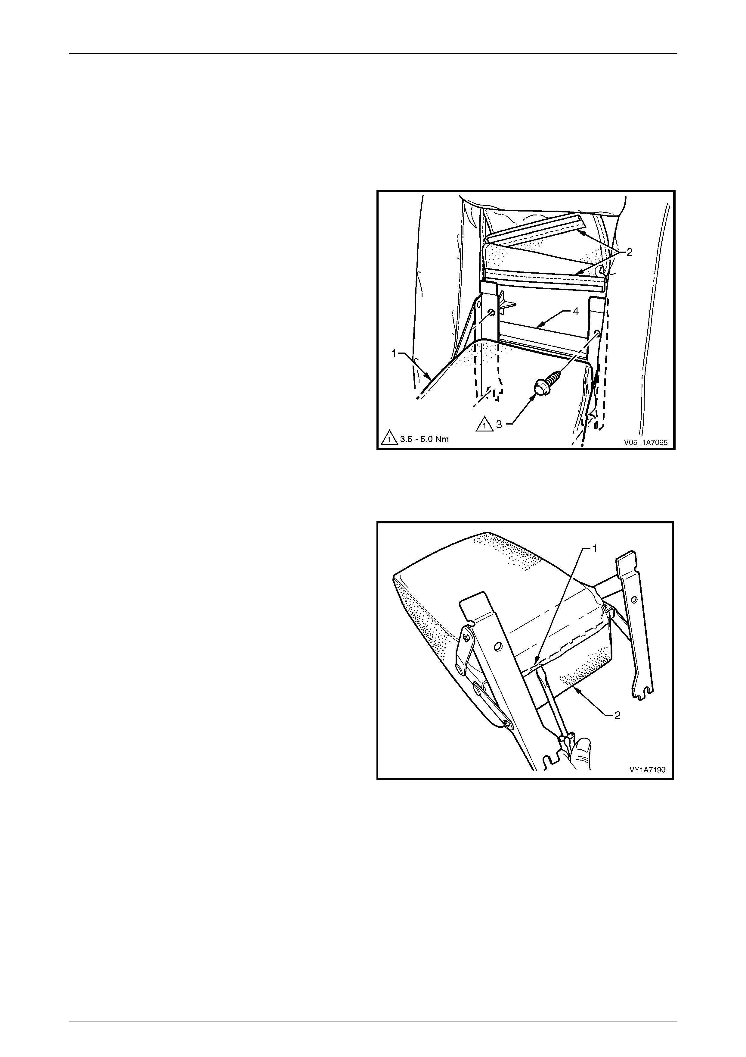
Seat Assemblies Page 1A7–351
Page 1A7–351
8.6 Rear Seat-back Centre, Armrest
Assembly
LT Section No. — 14–350
Remove
1 Lower the armrest assembly (1) and disengage the
trim flap J-strips (2) from the armrest hinge to gain
access to the four attaching screws (3).
2 Remove the four attaching screws from the rear
seat-back centre tray (4), two from above the armrest
and two from below.
3 Remove the armrest assembly.
Figure 1A7 – 276
Disassemble
1 Remove the nine staples (1) securing the upper flap
armrest cover (2) to the armrest pad assembly.
Figure 1A7 – 277
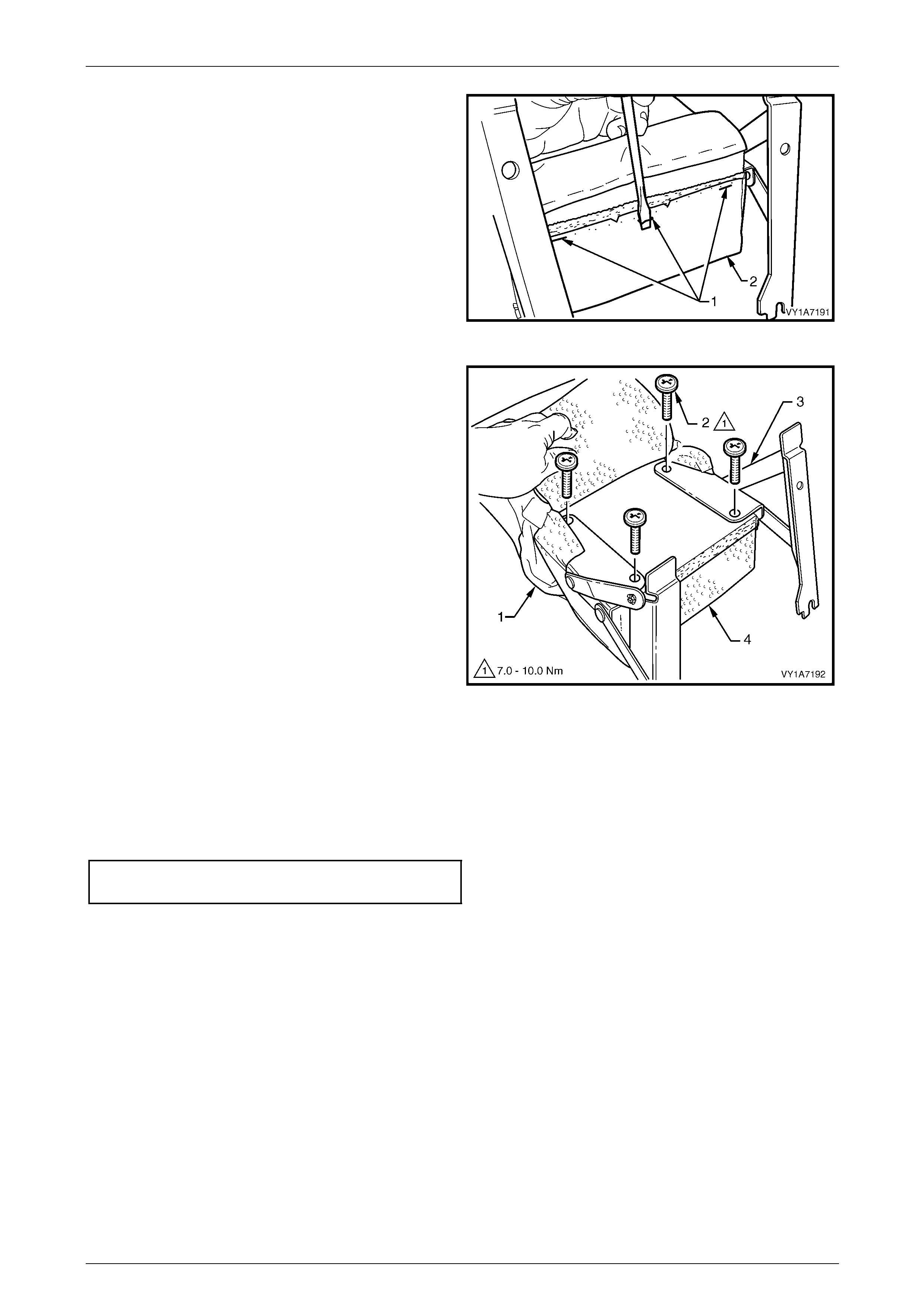
Seat Assemblies Page 1A7–352
Page 1A7–352
2 Remove the three staples (1) securing the lo wer flap
of the armrest cover (2) to the armrest pad assembly.
Figure 1A7 – 278
3 Pull the cover (1) along the armrest to allow access to
the hinge attaching scre ws (2).
4 Remove the four screws attaching the armrest hinge
(3) to the armrest assembly (4) and remove the
hinges.
5 Remove the armrest cover from the armrest pad
assembly.
Figure 1A7 – 279
Reassemble
Reassembly of the rear seat-back centre armrest assembly is the reverse of the removal procedure, noting the following:
1 Ensure the armrest assembly hinge is installed before the cover is fitted.
2 Tighten the attaching screws to the correct torque specification.
Armrest hinge attaching screw
torque specification...................................7.0 – 10.0 Nm
3 The cover is to be smooth and without creases before the staples are installed.
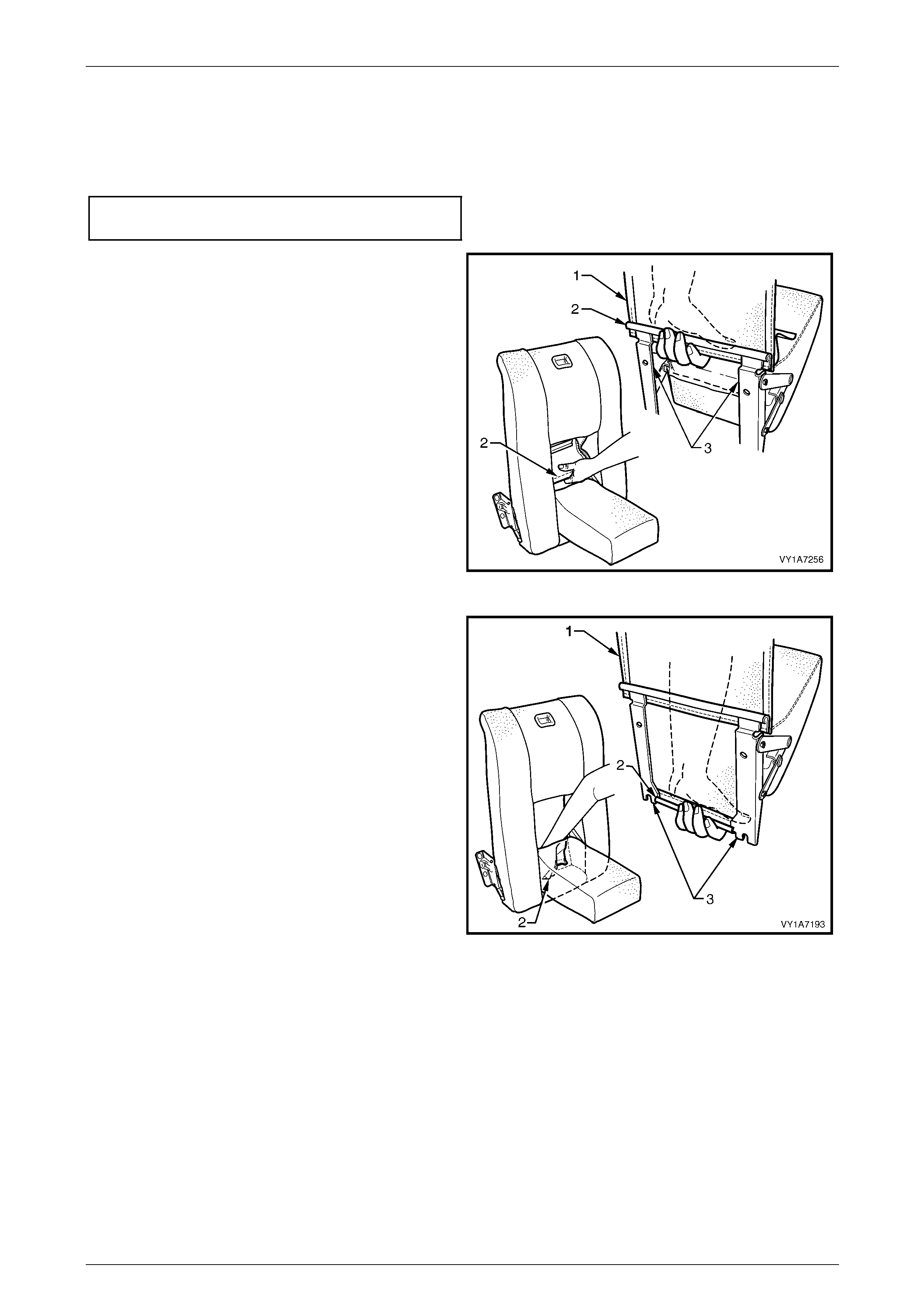
Seat Assemblies Page 1A7–353
Page 1A7–353
Reinstall
Reinstallation of the rear seat-back centre armrest assembly is the reverse of the removal operation, noting the following:
1 Tighten the attaching screws to the correct torque specification.
Armrest hinge assembly attaching
screw torque specification...........................3.5 – 5.0 Nm
2 Refit the armrest trim flap (1) upper J-strip (2) to the
upper part of the hinge bracket (3).
Figure 1A7 – 280
3 Refit the armrest trim flap (1) lower J-strip (2) to the
lower part of the hinge bracket (3).
Figure 1A7 – 281
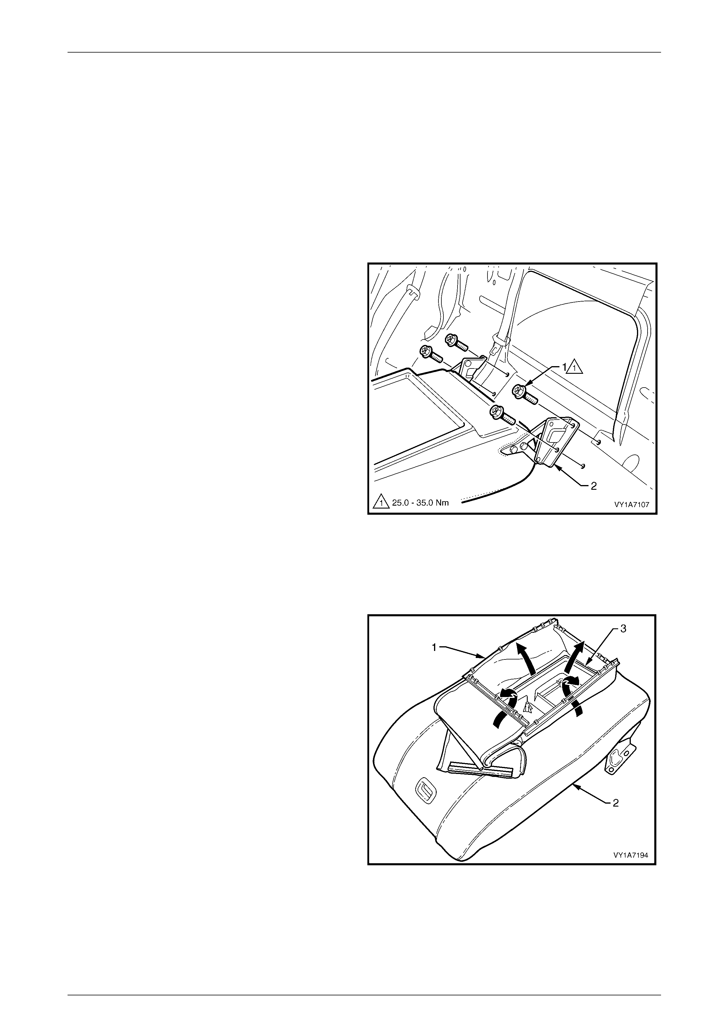
Seat Assemblies Page 1A7–354
Page 1A7–354
8.7 Rear Seat Centre Back Assembly
LT Section No. — 14–350
1 Remove the rear seat cushion assembly, refer to 8.2 Rear Seat Cushion Assembly.
2 Remove the rear seat-back assembly, refer to 8.3 Rear Seat-back Assembl y.
3 Remove the rear seat-back centre, armrest assembly where fitted,
refer to 8.6 Rear Seat-back Centre, Armrest Assembly.
Remove
1 Remove the four screws (1) from the rear seat centre
back hinge assembly (2).
2 Remove rear seat centre back assembly.
Figure 1A7 – 282
Disassemble
Remove – Rear Seat Centre Back Cover and Pad Assembly
1 If fitted with an armrest, pull the four retaining strips (1)
in the centre of the seat centre back assembly (2), up
and away from the inside of the seat-back tray (3).
Figure 1A7 – 283
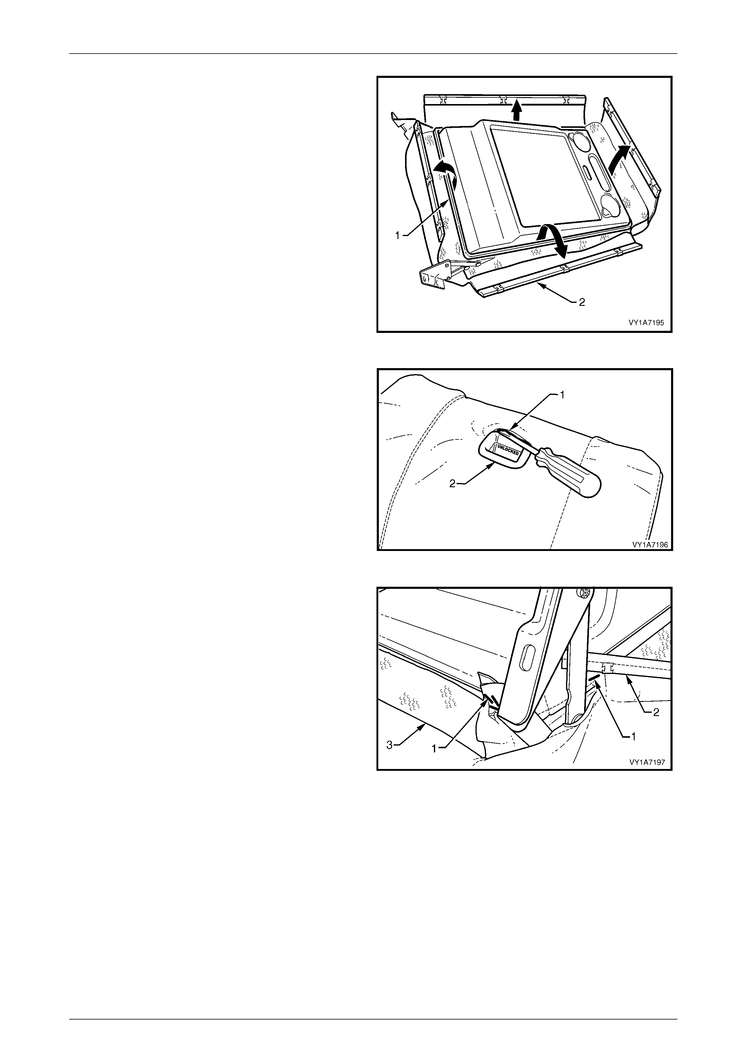
Seat Assemblies Page 1A7–355
Page 1A7–355
2 On the outer edge of the seat-back centre tray (1),
lever up the four retaining strips (2).
Figure 1A7 – 284
3 Lever the seat cover material (1) over the release
button and escutcheon assembl y (2).
Figure 1A7 – 285
4 Remove the four staples (1) each side, attaching the
cover (2) to the seat-back tray (3).
5 Peel the cover away from the seat-back tray and
remove the cover and pad.
Figure 1A7 – 286
Reinstall – Rear Seat Centre Back Cover and Pad Assembly
Reinstallation of the rear seat centre back cover and pad assembly is the reverse of the removal proce dure. The cover is
to be smooth and without creases before the staples are installed.
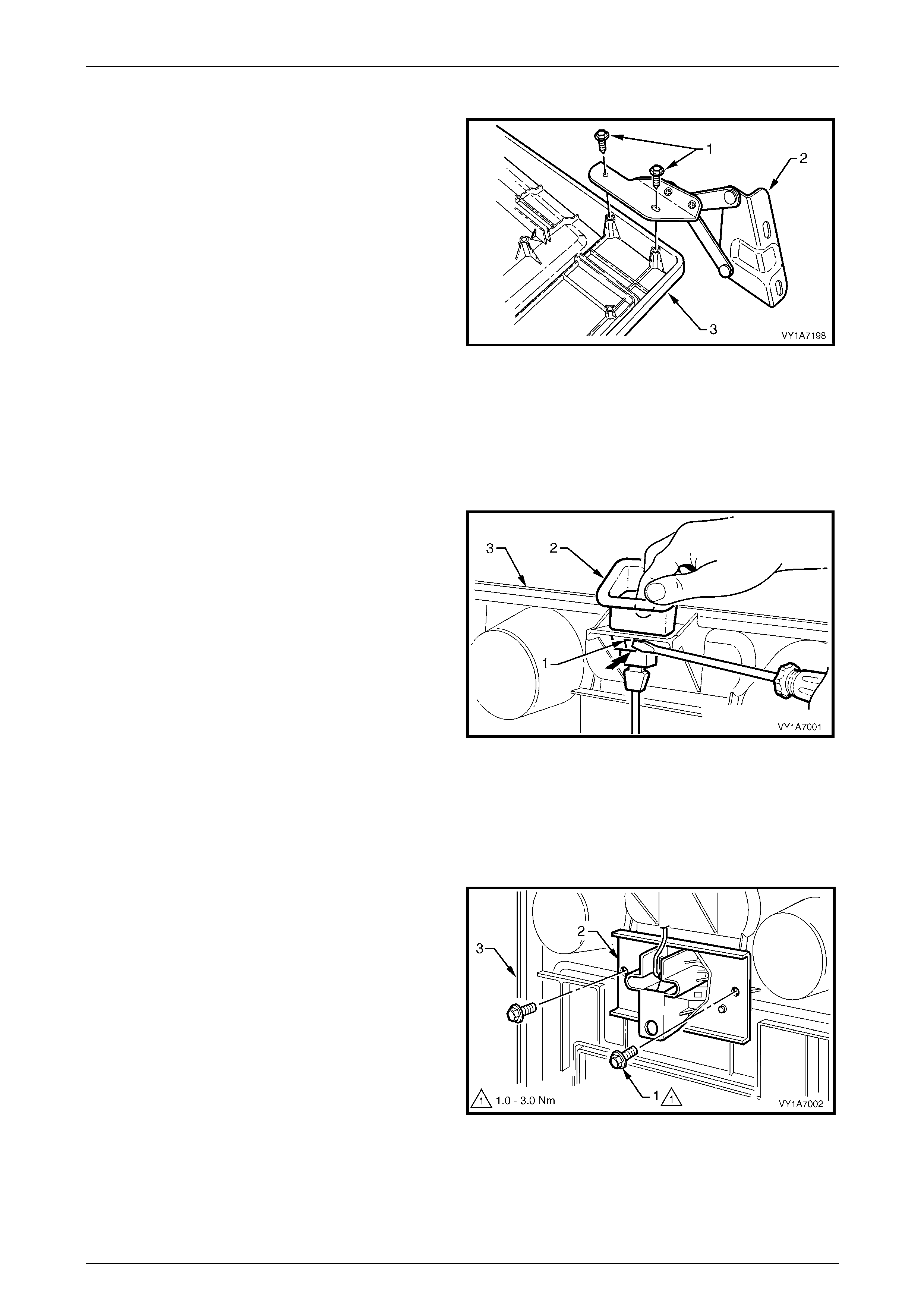
Seat Assemblies Page 1A7–356
Page 1A7–356
Remove – Rear Seat-b ack Centre Hinge
1 Remove the two screws (1) attaching the hi nge (2) to
the rear seat-back centre tray assembly (3) and
remove the hinge.
2 Repeat for the opposite hinge.
Figure 1A7 – 287
Reinstall – Rear Seat-back Cen tre Hinge
Reinstallation of the rear seat-back centre hinge is the reve rse of the removal procedure. Ensure all scre ws ar e tightened
securely.
Remove – Rear Seat-b ack Centre Release Button
1 Using a screwdriver, depress the two tangs (1) on the
front and rear of the release button (2).
2 Remove the release button from the rear seat-back
centre (3).
Figure 1A7 – 288
Reinstall – Rear Seat-back Centre Release Button
Push the release button into the rear seat-back centre assembly, until the button clicks into place.
Remove – Rear Seat-b ack Centre Lock Ac tuator
1 Remove the two screws (1) attaching the loc k actuator
(2) to the back tray (3) and remove the lock actuator.
2 Disengage the release button rod from the lock
actuator.
Figure 1A7 – 289

Seat Assemblies Page 1A7–357
Page 1A7–357
Reinstall – Rear Seat-back Centre, Lock Actuator
Reinstallation of the rear seat-back centre, lock actuator is the reverse of the removal procedure, noting the following:
1 Ensure the button assembly and lock actuator rod are correctly engaged.
2 Tighten the attaching screws to the correct torque specification.
Rear seat-back centre lock actuator
retaining screw torque specification............1.0 – 3.0 Nm
Reinstall
Reinstallation of the rear seat-back centre is the reverse of the removal operation. Tighten the attaching screws to the
correct torque specification.
Rear seat-back centre attaching
screw torque specification.......................25.0 – 35.0 Nm
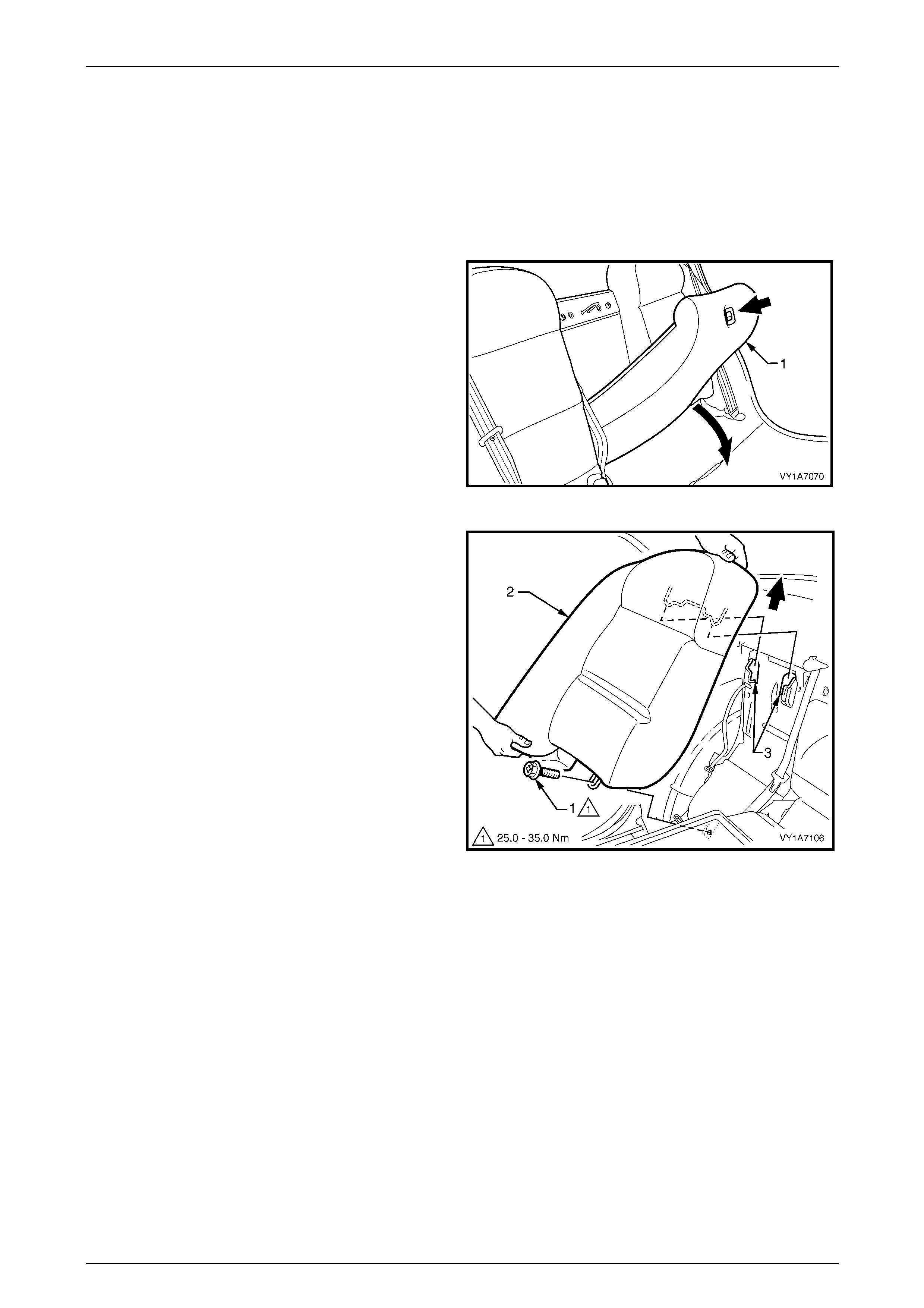
Seat Assemblies Page 1A7–358
Page 1A7–358
8.8 Rear Seat Centre Back, Lock Striker
LT Section No. — 14–350
Remove the rear seat cushion assembly, refer to 8.2 Rear Seat Cushion Assembly.
Remove
1 Press the release button and lower the rear seat
centre back assembly (1).
Figure 1A7 – 290
2 Remove the screw (1) attaching the rear seat-back
assembly (2) to the floor panel.
3 Lift the rear seat-back assembly up and out of the
retaining brackets (3).
4 Remove the rear seat-back assembly and repeat for
the opposite side if required.
Figure 1A7 – 291
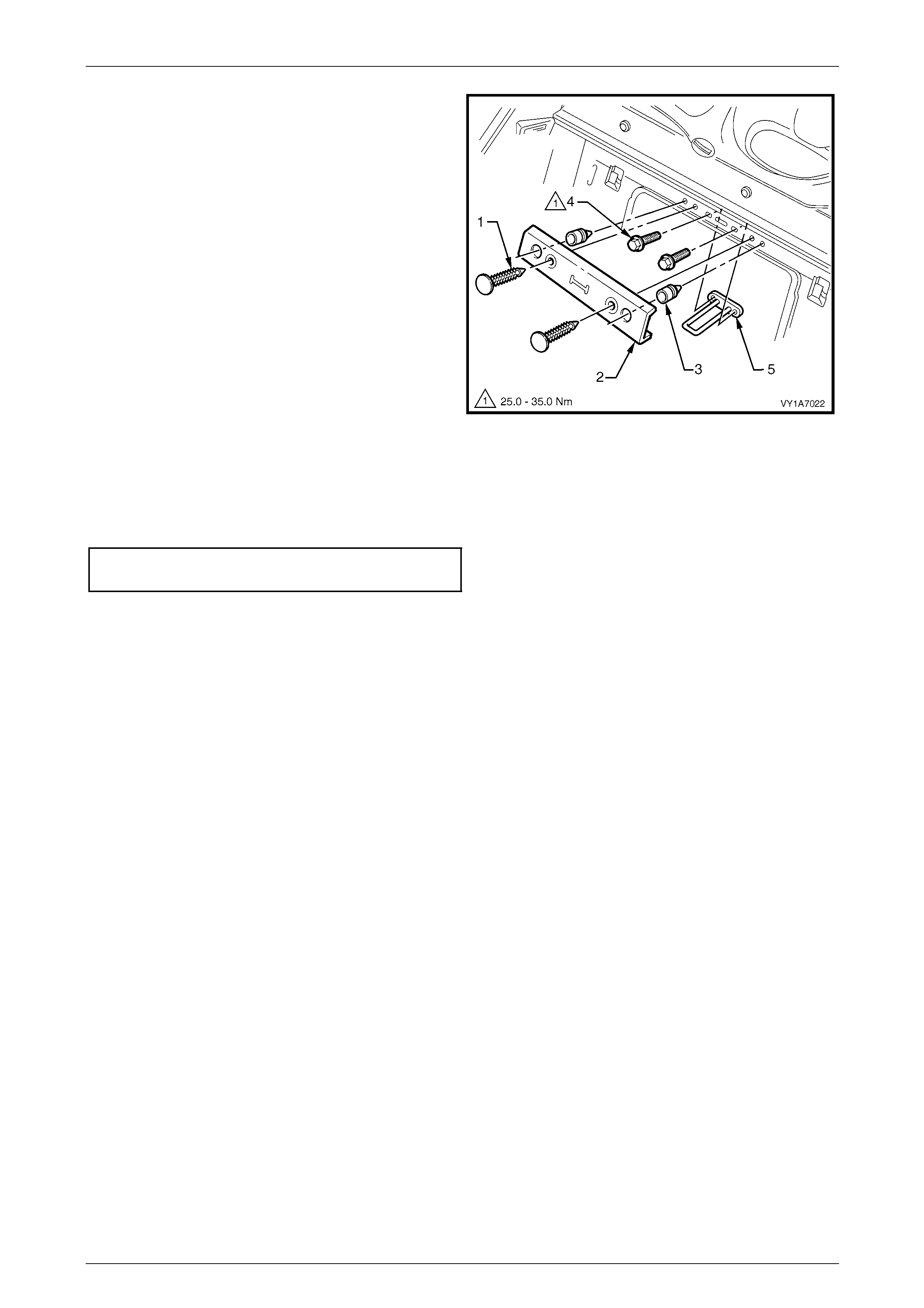
Seat Assemblies Page 1A7–359
Page 1A7–359
5 Prise the two retaining clips ( 1) from the rea r
seat-back cover (2) and remove the cover.
6 If required, remove the two bump stops (3) from the
rear compartment front panel.
7 Remove the two screws (4) attaching the striker (5) to
the rear panel and remove the striker.
Figure 1A7 – 292
Reinstall
Reinstallation of the rear seat lock striker is the reverse of the removal procedure. Tighten the attaching screws to the
correct torque specification.
Rear seat lock striker attaching screw
torque specification.................................25.0 – 35.0 Nm
Seat Assemblies Page 1A7–360
Page 1A7–360
9 Service Operations – Rear Seat,
Wagon
9.1 Usage Chart
How to Use this Chart
The following usage chart is provided to help determine the seat type fitted to the vehicle. T his is important prior to
repairs being performed as the failed / dama ged part may not be serviceable.
To determine the seat type fitted to the vehicle, obtain the vehicl e model and the seat cover fabric. Establish if the vehicl e
has an armrest and/or headrest. Using the chart will lead to the elimination of all other seat combinations, allowing for the
identification of the type and t he construction of the seat. Refer to the Figure number shown in Rear Seat T ype column
for a component breakdown of the rear seat assembl y.
1 Vehicle – Vehicle model identification.
2 Fabric – Cloth or leather seat covers.
3 Armrest – If the rear seat-back is fitted with an armrest.
4 Headrest – If the rear seat-ba ck is fitted with a headrest.
5 Construction – Surebond refers to the seat cover being glued to the seat pad. This type is serviced as a pad and
cover assembly only. Hook and Loop refers to the seat cover being attached to the seat pad with a Velcro type
material and both being serviced as separate parts.
6 Rear Seat Type – Identifies the seat type and provides reference to illustra tions which show a breakdown of the
serviced component for each rear seat assembly.
Vehicle Fabric Armrest Headrest Construction
Rear Seat Type
(refer to)
Executive Cloth No No Surebond 1
(Figure 1A7 – 293)
Acclaim Cloth No Yes Surebond 2
(Figure 1A7 – 294)
Berlina,
CX6 & SX6 AWD Cloth/Leather Yes Yes Hook & Loop 3
(Figure 1A7 – 295)
LX6 & LX8 AWD Leather Yes Yes Hook & Loop 4
(Figure 1A7 – 296)
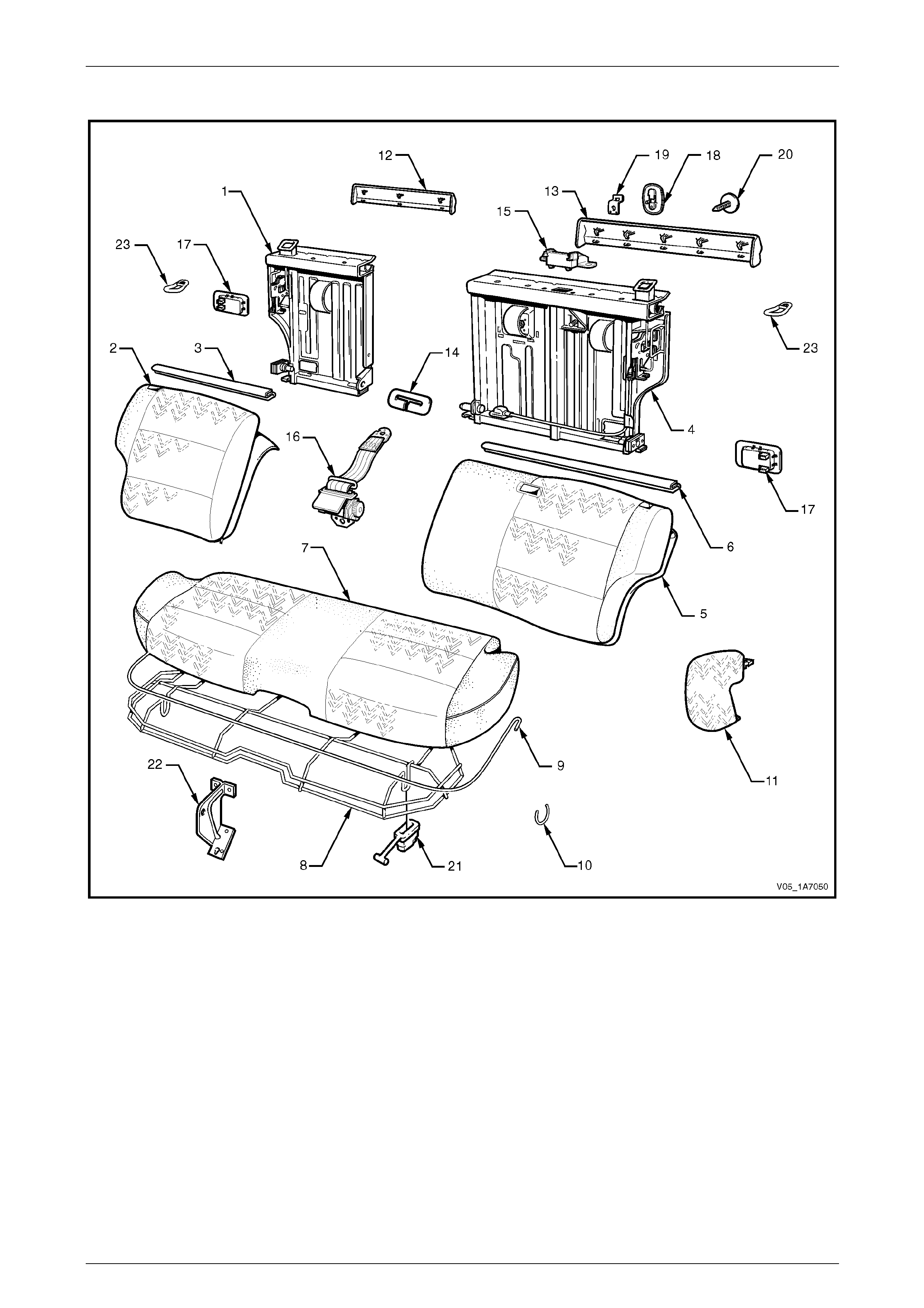
Seat Assemblies Page 1A7–361
Page 1A7–361
Rear Seat Type 1
Figure 1A7 – 293
Legend
1 Rear Seat-back Frame Assembly - Right-hand ∗
2 Rear Seat-back Cover, Carpet & Pad Assembly - Right-hand
3 Top Finisher Strip - Right-hand
4 Rear Seat-back Frame Assembly - Left-hand ∗
5 Rear Seat-back Cover, Carpet & Pad Assembly - Left-hand
6 Top Finisher Strip - Left-hand
7 Rear Seat Cushion Cover & Pad Assembly
8 Rear Seat Cushion Frame Assembly
9 Rear Seat Cushion Cover Retainer Wire
10 Hog Ring
11 Rear Seat Bolster Assembly (2 places)
12 Rear Seat-back Trim Cover Right-hand
13 Rear Seat-back Trim Cover Left-hand
14 Centre Seatbelt Escutcheon
15 Seatbelt Guide Bracket assembly
16 Centre Seatbelt Retractor
17 Rear Seat-back Release Handle (2 places)
18 Child Seat Escutcheon
19 Child Seat Anchor
20 Child Seat Anchor Blanking Plug
21 Rear Seat Cushion Release Handle (2 places)
22 Rear Seat Centre Support
23 Rear Seat-back Lock Striker (2 places)
∗ Refer to Figure 1A7 – 297 for a breakdown of the rear seat-back frame assembly.
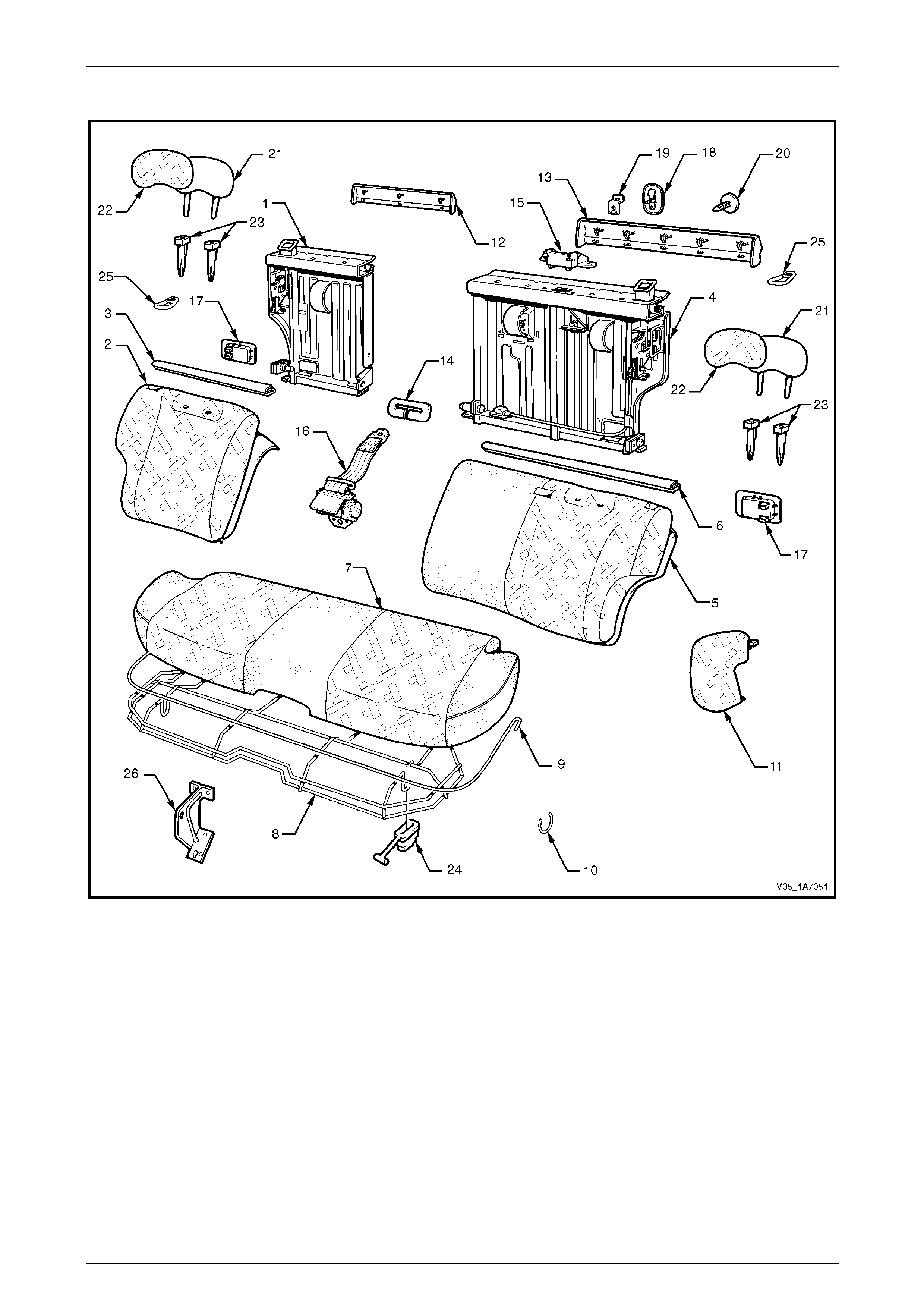
Seat Assemblies Page 1A7–362
Page 1A7–362
Rear Seat Type 2
Figure 1A7 – 294
Legend
1 Rear Seat-back Frame Assembly - Right-hand ∗
2 Rear Seat-back Cover, Carpet & Pad Assembly - Right-hand
3 Top Finisher Strip - Right-hand
4 Rear Seat-back Frame Assembly - Left-hand ∗
5 Rear Seat-back Cover, Carpet & Pad Assembly - Left-hand
6 Top Finisher Strip - Left-hand
7 Rear Seat Cushion Cover & Pad Assembly
8 Rear Seat Cushion Frame
9 Rear Seat Cushion Cover Retainer Wire
10 Hog Ring
11 Rear Seat Bolster Assembly (2 places)
12 Rear Seat-back Trim Cover - Right-hand
13 Rear Seat-back Trim Cover - Left-hand
14 Centre Seatbelt Escutcheon
15 Seatbelt Guide Bracket assembly
16 Centre Seatbelt Retractor
17 Rear Seat-back Release Handle (2 places)
18 Child Seat Escutcheon
19 Child Seat Anchor
20 Child Seat Anchor Blanking Plug
21 Head Restraint Pad (2 places)
22 Head Restraint Cover (2 places)
23 Head Restraint Guide (4 places)
24 Rear Seat Cushion Release Handle (2 places)
25 Rear Seat-back Lock Striker (2 places)
26 Rear Seat Centre Support
∗ Refer to Figure 1A7 – 297 for a breakdown of the rear seat-back frame assembly.
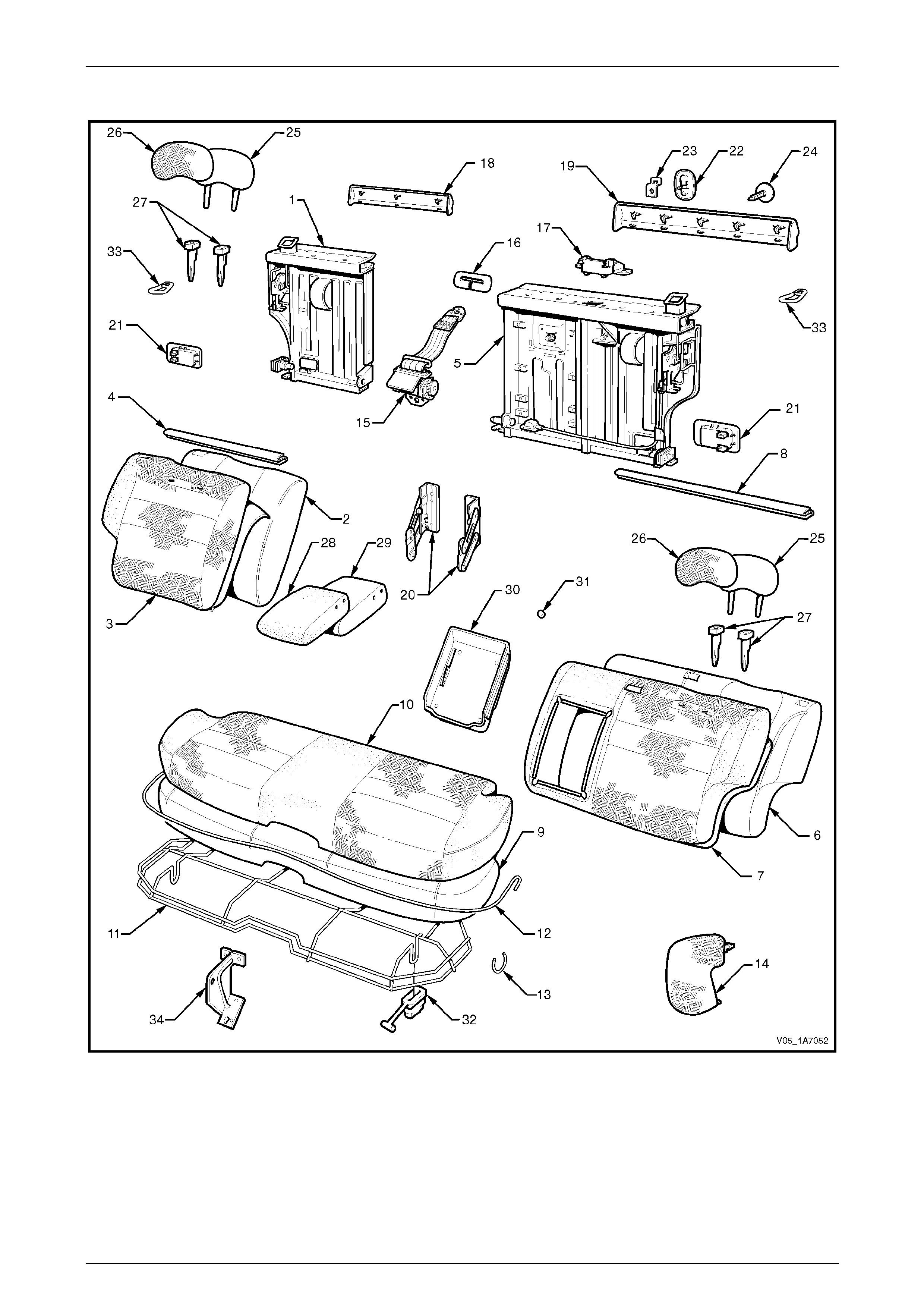
Seat Assemblies Page 1A7–363
Page 1A7–363
Rear Seat Type 3
Figure 1A7 – 295

Seat Assemblies Page 1A7–364
Page 1A7–364
Legend
1 Rear Seat-back Frame Assembly - Right-hand ∗
2 Rear Seat-back Pad - Right-hand
3 Rear Seat-back Cover &Carpet Assembly - Right-hand
4 Top Finisher Strip - Right-hand
5 Rear Seat-back Frame Assembly - Left-hand ∗
6 Rear Seat-back Pad - Left-hand
7 Rear Seat-back Cover &Carpet Assembly - Left-hand
8 Top Finisher Strip - Left-hand
9 Rear Seat Cushion Pad
10 Rear Seat Cushion Cover Assembly
11 Rear Seat Cushion Frame Assembly
12 Retainer - Rear Seat Cushion Cover Wire
13 Hog Ring
14 Bolster Assembly - Rear Seat (2 places)
15 Centre Rear Seatbelt Retractor
16 Centre Seatbelt Escutcheon
17 Seatbelt Guide Bracket Assembly
18 Rear Seat-back Trim Cover - Right-hand
19 Rear Seat-back Trim Cover - Left-hand
20 Armrest Hinge Assembly (2 places)
21 Rear Seat-back Release Handle (2 places)
22 Child Seat Escutcheon
23 Child Seat Anchor
24 Child Seat Anchor Blanking Plug
25 Head Restraint Pad (2 places)
26 Head Restraint Cover (2 places)
27 Head Restraint Guide (4 places)
28 Rear Seat-back Armrest Cover Assembly
29 Rear Seat-back Armrest Pad Assembly
30 Rear Seat-back Armrest Centre Cover
31 Armrest Centre Cover Blanking Plugs
32 Rear Seat Cushion Release Handle (2 places)
33 Rear Seat-back Lock Striker (2 places)
34 Rear Seat Centre Support
∗ Refer to Figure 1A7 – 297 for a breakdown of the rear seat-back frame assembly.
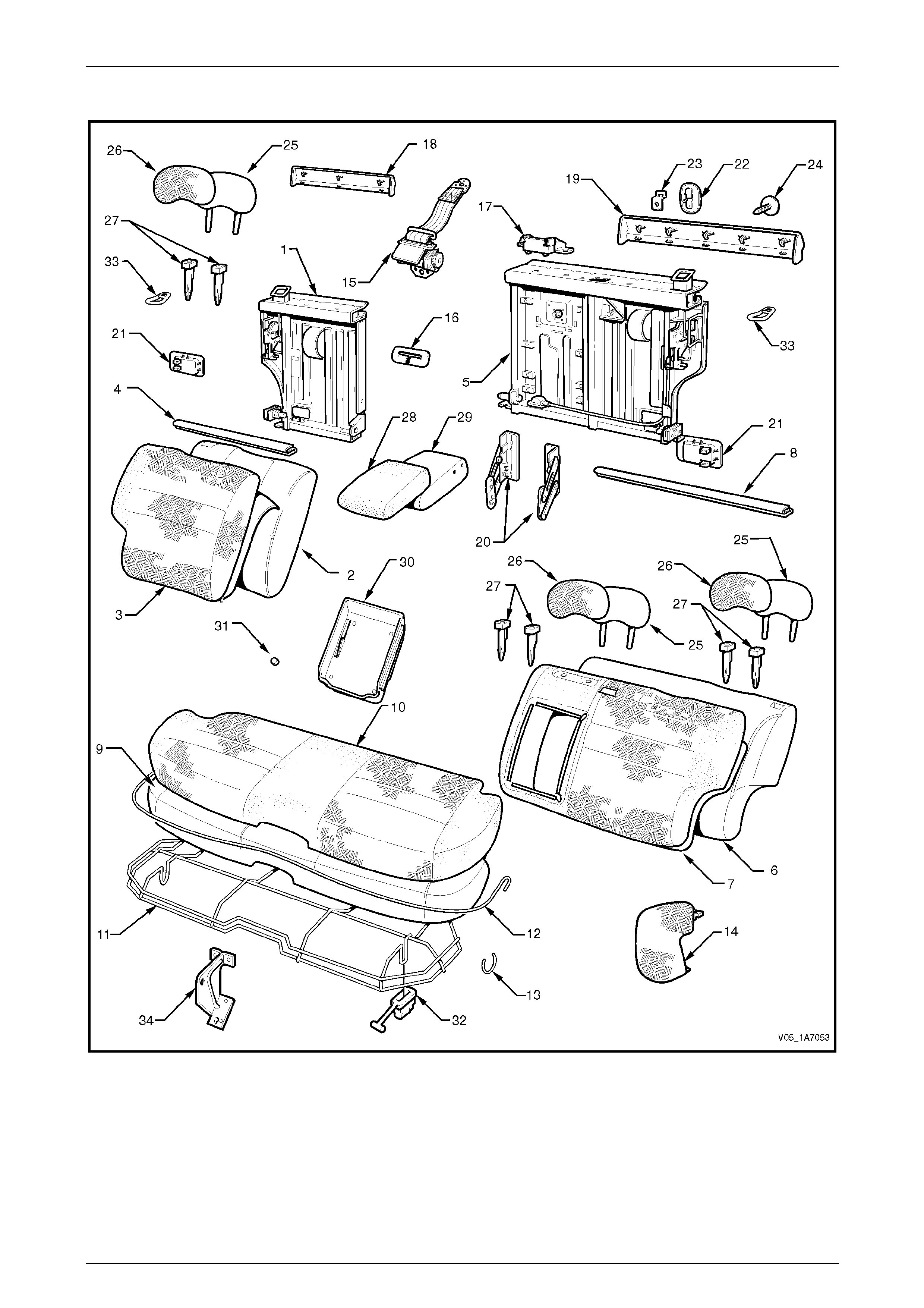
Seat Assemblies Page 1A7–365
Page 1A7–365
Rear Seat Type 4
Figure 1A7 – 296

Seat Assemblies Page 1A7–366
Page 1A7–366
Legend
1 Rear Seat-back Frame Assembly - Right-hand ∗
2 Rear Seat-back Pad - Right-hand
3 Rear Seat-back Cover &Carpet Assembly - Right-hand
4 Top Finisher Strip - Right-hand
5 Rear Seat-back Frame Assembly - Left-hand ∗
6 Rear Seat-back Pad - Left-hand
7 Rear Seat-back Cover &Carpet Assembly - Left-hand
8 Top Finisher Strip - Left-hand
9 Rear Seat Cushion Pad
10 Rear Seat Cushion Cover Assembly
11 Rear Seat Cushion Frame Assembly
12 Retainer - Rear Seat Cushion Cover Wire
13 Hog Ring
14 Bolster Assembly - Rear Seat (2 places)
15 Centre Rear Seatbelt Retractor
16 Centre Seatbelt Escutcheon
17 Seatbelt Guide Bracket Assembly
18 Rear Seat-back Trim Cover - Right-hand
19 Rear Seat-back Trim Cover - Left-hand
20 Armrest Hinge Assembly (2 places)
21 Rear Seat-back Release Handle (2 places)
22 Child Seat Escutcheon
23 Child Seat Anchor
24 Child Seat Anchor Blanking Plug
25 Head Restraint Pad (2 places)
26 Head Restraint Cover (2 places)
27 Head Restraint Guide (4 places)
28 Rear Seat-back Armrest Cover Assembly
29 Rear Seat-back Armrest Pad Assembly
30 Rear Seat-back Armrest Centre Cover
31 Armrest Centre Cover Blanking Plugs
32 Rear Seat Cushion Release Handle (2 places)
33 Rear Seat-back Lock Striker (2 places)
34 Rear Seat Centre Support
∗ Refer to Figure 1A7 – 297 for a breakdown of the rear seat-back frame assembly.
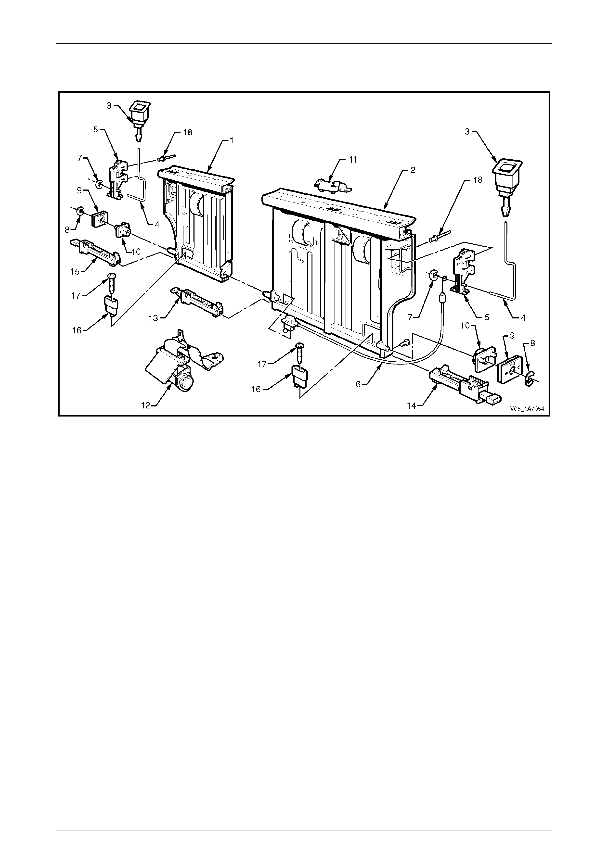
Seat Assemblies Page 1A7–367
Page 1A7–367
Rear Seat-back Frame Assembly
Figure 1A7 – 297
Legend
1 Rear Seat-back Frame Assembly - Right-hand
2 Rear Seat-back Frame Assembly - Left-hand
3 Release Button (2 places)
4 Actuator Rod (2 places)
5 Actuator Lock (2 places)
6 Actuator Cable Assembly
7 Retaining Clip
8 Circlip (2 places)
9 Retainer Plate (2 places)
10 Locking Plate & Pin (2 places)
11 Seatbelt Guide Bracket
12 Seatbelt Retractor Assembly
13 Inner Latch Assembly - Left-hand
14 Outer Latch Assembly - Left-hand
15 Outer Latch Assembly - Right-hand
16 Release Handle Lever (2 places)
17 Release Handle Lever Screw (2 places)
18 Rivets (8 places)
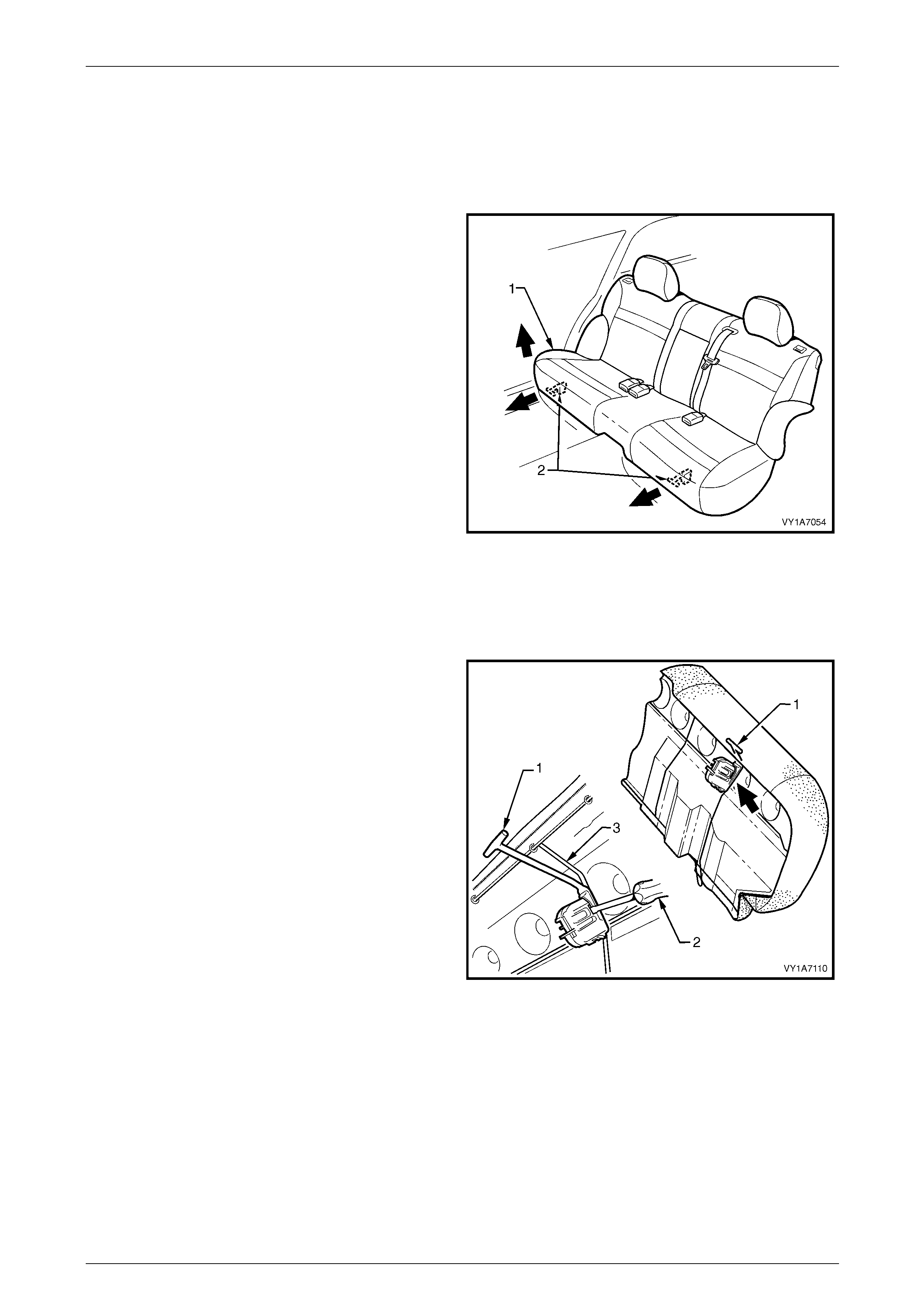
Seat Assemblies Page 1A7–368
Page 1A7–368
9.2 Rear Seat Cushion Assembly
LT Section No. — 14–330
Remove
1 Lift the front of the rear seat cushion assembly (1)
slightly to gain access to the two rear seat cushion
release handles (2).
2 From either the left or the right side of the seat, pull
the release handle T-piece horizontally outwards,
while at the same time lifting the front of the rear seat
cushion until the lock mechanism is released.
3 Repeat step 2 for the opposite side of the seat.
4 Remove the rear seat cushion assembly.
Figure 1A7 – 298
Disassemble
Remove – Rear Seat Cushion Relea se Handle
1 Remove the rear seat cushion release handle (1) by
inserting a screwdriver (2) to disengage the retaining
lugs.
2 Slide the release handle off the rear seat cushion wire
frame (3).
Figure 1A7 – 299
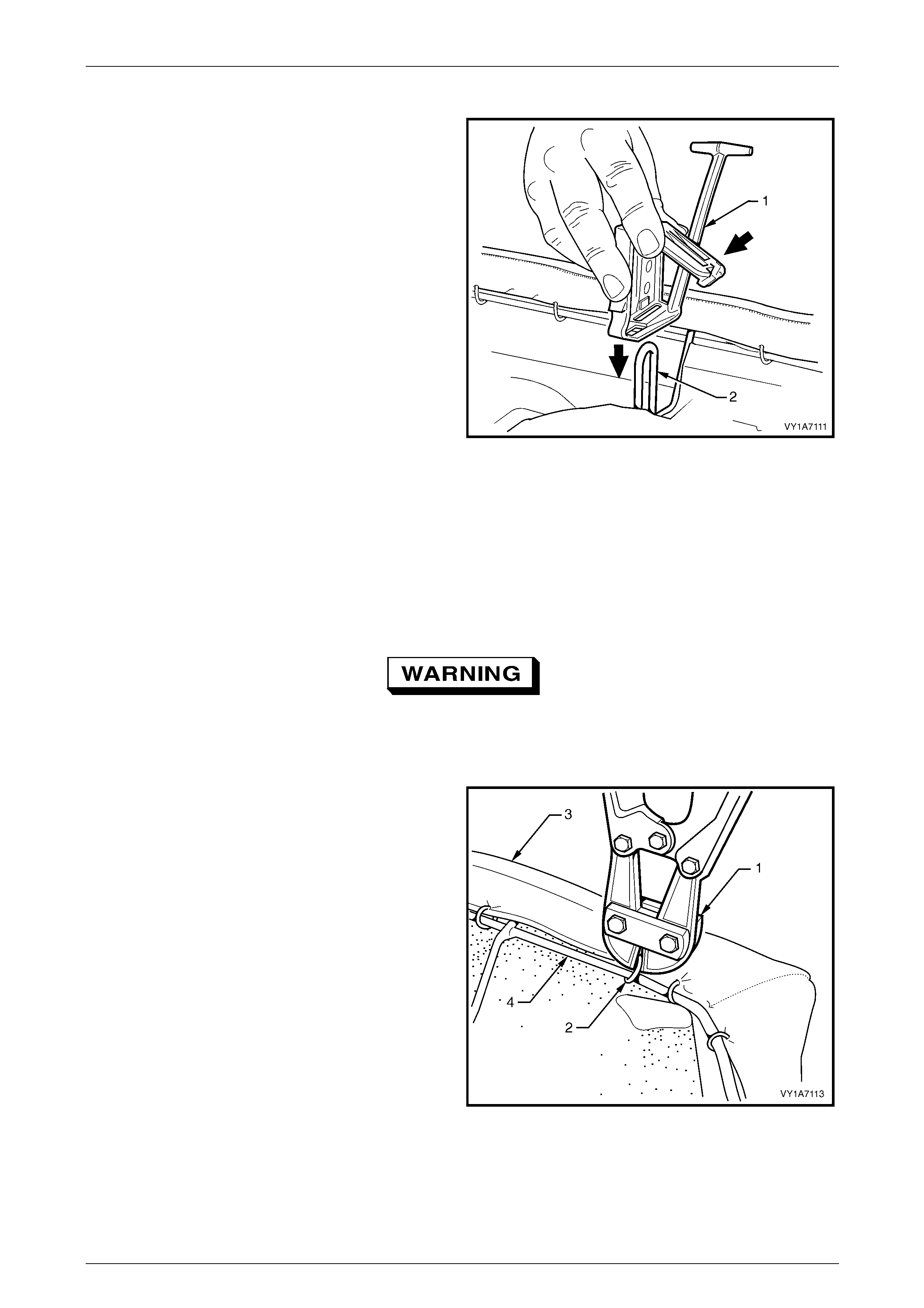
Seat Assemblies Page 1A7–369
Page 1A7–369
Reinstall – Rear Seat Cushion Release Handle
Slide the rear seat cushion rel ease handle (1) onto the rear
seat cushion wire frame (2) and close the cover to lock it
into position.
Figure 1A7 – 300
Remove – Rear Seat Cushion Frame
NOTE
The following component will require replacement
when performing this operation.
• Rear seat cushion hog rings.
Safety glasses an d work glo ves must be w orn
at all times when remo ving the hog ring s.
1 Place the rear seat cushion assembly upside-down.
2 Use bolt cutters (1) to remove the hog rings (2)
attaching the cover and pad assembly (3) to the frame
(4):
• Forty eight places for the Surebond rear seat
cushions.
• Thirty four places for the Hook and Loop rear
seat cushions.
NOTE
Care must be taken when removing the hog
rings not to damage the cushion cover.
NOTE
All hog rings will be destroyed during this
operation and must be replaced.
3 Remove the frame from the rear seat cushion
assembly. Figure 1A7 – 301
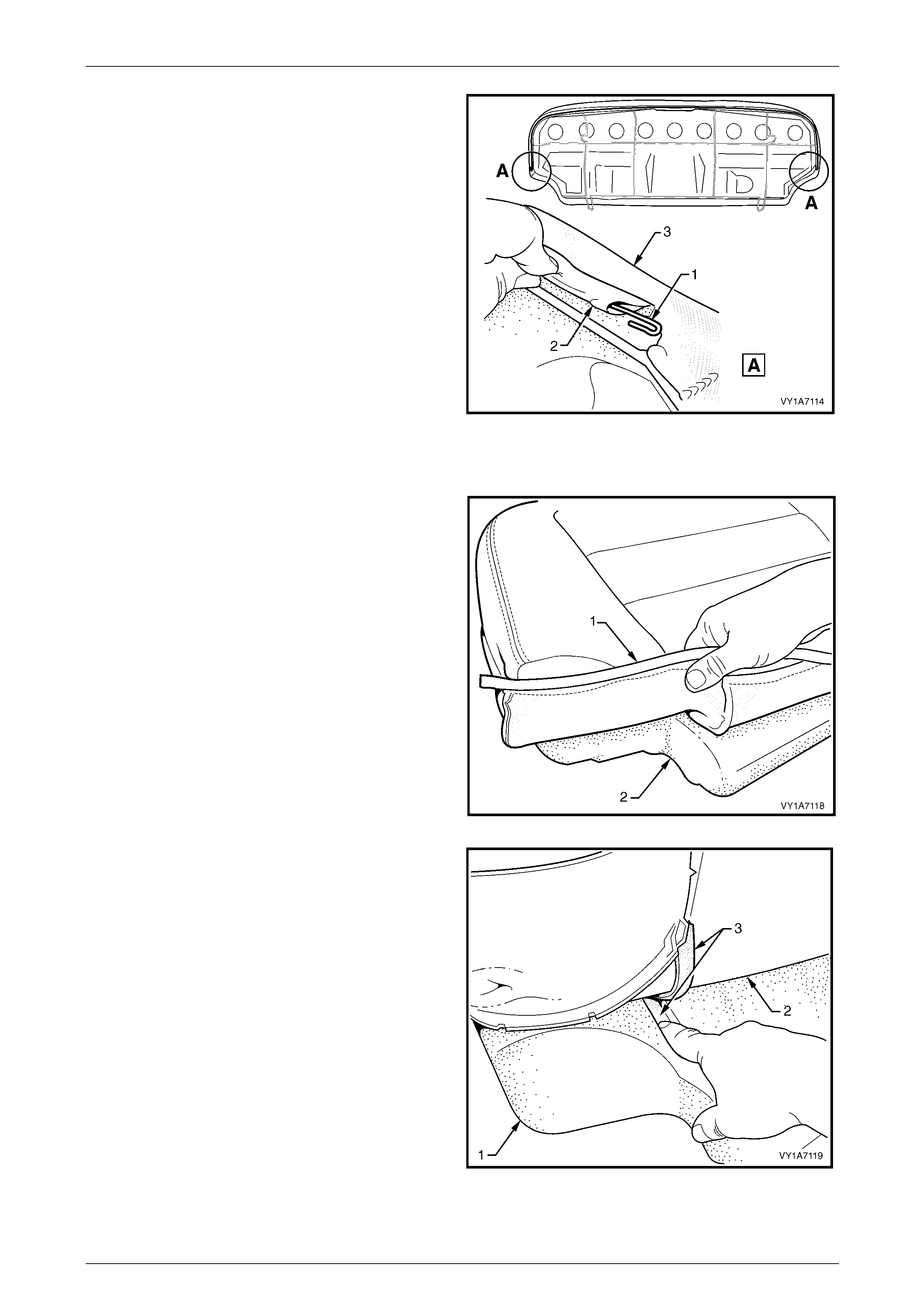
Seat Assemblies Page 1A7–370
Page 1A7–370
4 If required, remove the retaining wire (1) from the
casing (2) on the front of the cushion cover assembly
(3).
Figure 1A7 – 302
Remove – Rear Seat Cushion Cover, Hook and Loop
1 Fold the rear corner of the rear seat cushion cover (1)
over the seat cushion pad (2).
Figure 1A7 – 303
2 While holding the rear seat cushion pad (1), pull the
rear corner of the seat cushion cover (2) away from
the rear seat cushion pad to disenga ge the hook and
loop strip (3).
Figure 1A7 – 304
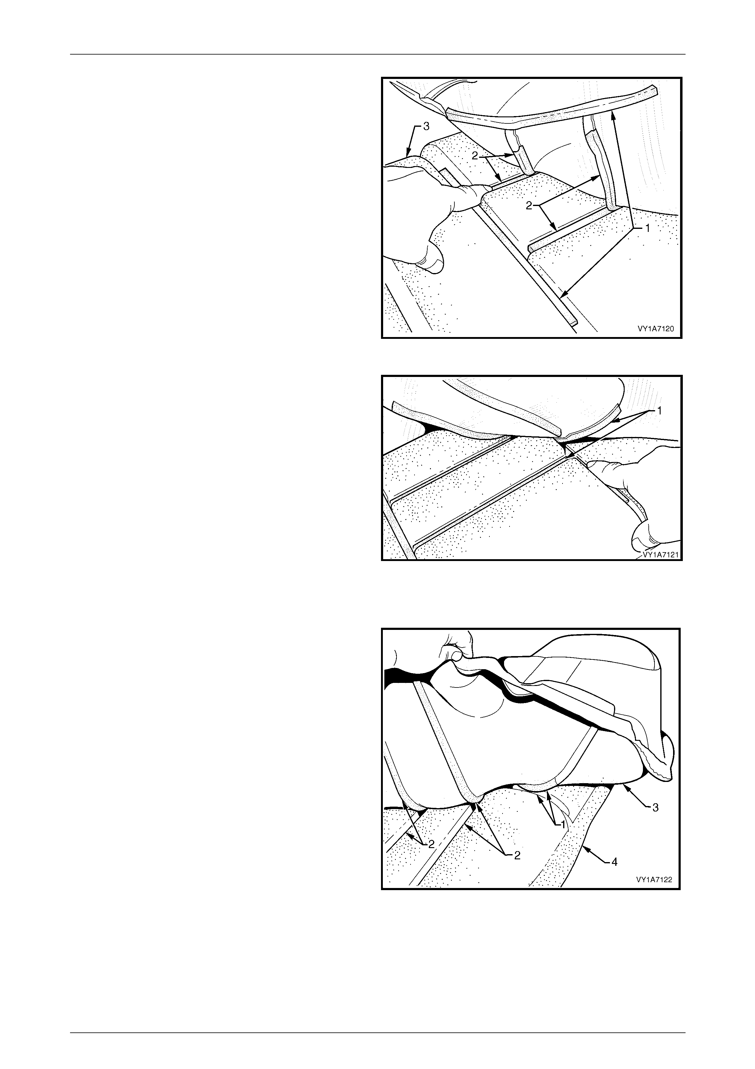
Seat Assemblies Page 1A7–371
Page 1A7–371
3 After disengaging the outer hook and loop strip (1)
remove the one or two cross hook and loop strips (2)
while holding t he seat cushion pad (3).
Figure 1A7 – 305
4 While holding the seat cushion pad, remove the inner
hook and loop strip (1).
5 Repeat this process for the opposite half of the rear
seat cushion assembly.
6 Remove the rear seat cushion cover.
Figure 1A7 – 306
Reinstall – Rear Seat Cushion Cover, Hook and Lo op
1 Align the inner hook and loop strip (1) and the one or
two cross hook and loop strips (2) on the seat cushion
cover (3) with the seat cushion pad (4).
2 Press the folded edge of the rear seat cushion cover
firmly into the corresponding groove in the seat
cushion pad to engage the hook and loop strip.
Figure 1A7 – 307
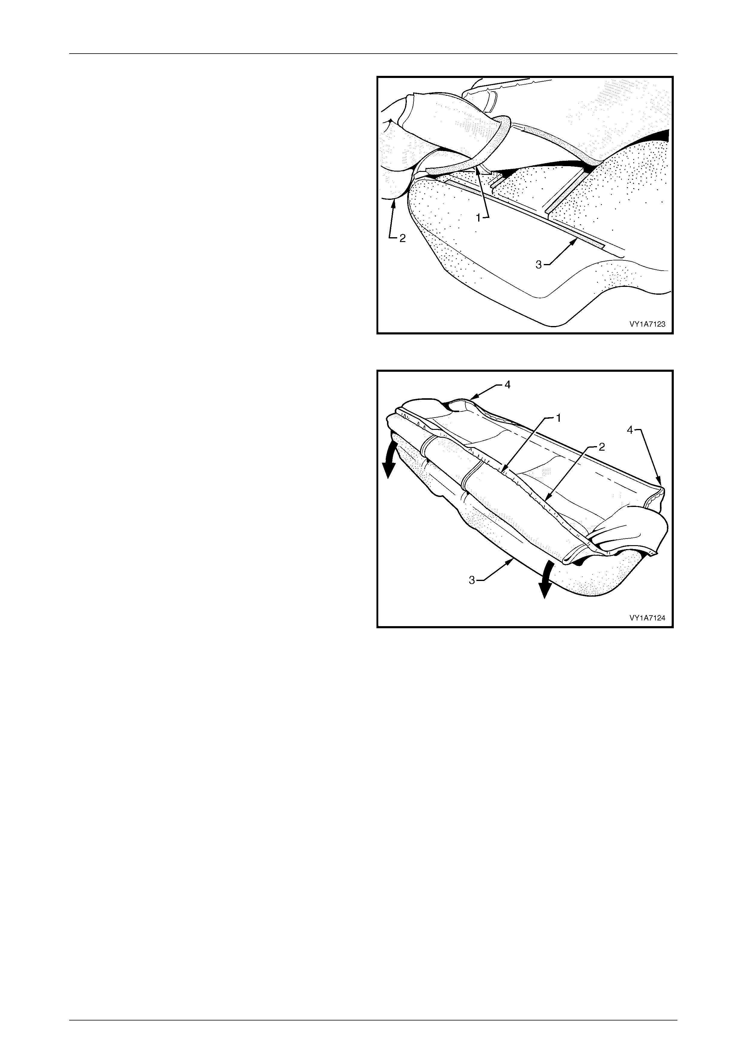
Seat Assemblies Page 1A7–372
Page 1A7–372
3 Align and press the outer hook and loop strip (1), on
the seat cushion cover (2), with the corresponding
groove in the seat cushion pad (3).
4 Repeat this process for the opposite half of the rear
seat cover and pad, beginning with the inner strip.
Figure 1A7 – 308
5 With the retaining wire (1) fitted to the front of the rear
seat cushion cover (2), roll the front corner of the
cover over the seat cushion pad (3).
6 Roll the sides of the seat cushion cover over the seat
cushion pad.
7 Roll the rear corners (4) of the seat cushion c over over
the seat cushion pad.
NOTE
Ensure the pad is fitted neatly by hand into all
corners and contours of the seat cover.
Figure 1A7 – 309
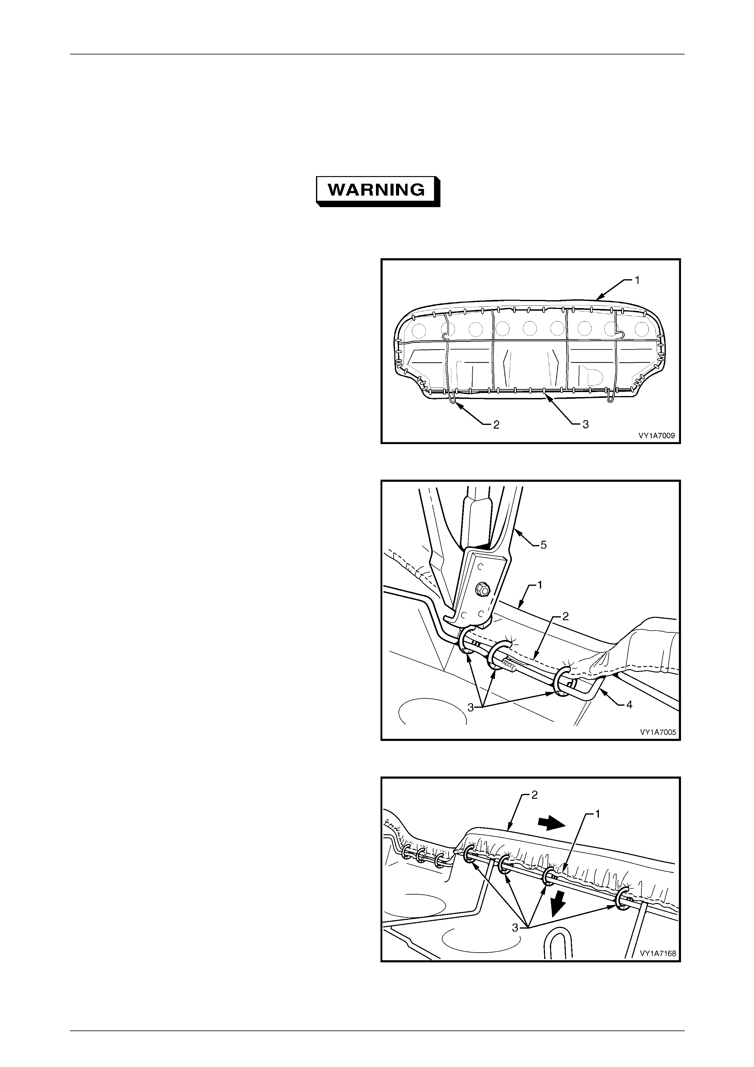
Seat Assemblies Page 1A7–373
Page 1A7–373
Reinstall – Rear Seat Cushion Frame, Surebond
NOTE
All hog rings must be replaced.
Safety glasses an d work glo ves must be w orn
at all times when working with hog rings.
1 Align the rear seat cushion cover and p ad assembly
(1) to the rear seat cushion frame (2) and attach with
approximately forty eight hog rings (3) in the positions
shown.
Figure 1A7 – 310
2 Beginning at the front, in the centre of the rear seat
cushion cover assembly (1), attach the wire retainer
(2) to the centre of the wire frame (4) with three hog
rings (3) using hog ring pliers (5).
Figure 1A7 – 311
3 Working from the centre outward, attach the wire
retainer (1), pulling the cover assembly (2) tight and
attaching with four hog rings (3).
4 Repeat this process in the opposite direction workin g
from the centre outward.
Figure 1A7 – 312
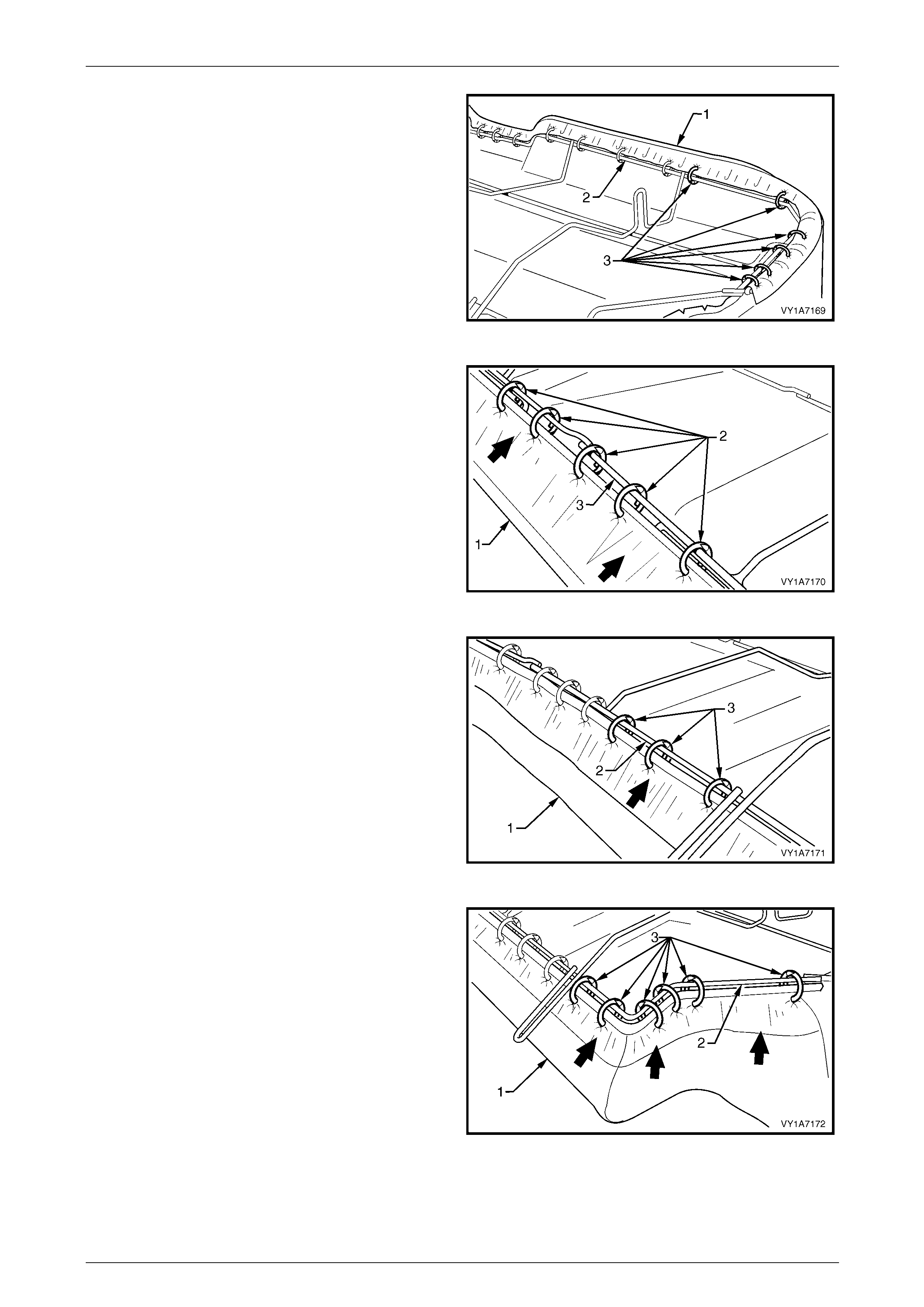
Seat Assemblies Page 1A7–374
Page 1A7–374
5 Continue attaching the cover assembly (1) to the
frame (2), by pulling the cover tight and attaching with
six hog rings (3).
6 Repeat this process in the opposite direction.
NOTE
The cover should be smooth and without
creases. If this is not the case, extra hog rings
are to be used to pull the cover into place.
Figure 1A7 – 313
7 Pull the rear of the cushion cover assembly (1) tight
and attach to the centre of the wire frame (3) with five
hog rings (2).
Figure 1A7 – 314
8 Continue attaching the cover assembly (1) to the
frame (2), by pulling the cover tight and attaching with
three hog rings (3).
9 Repeat this process in the opposite direction.
NOTE
The cover should be smooth and without
creases. If this is not the case, extra hog rings
are to be used to pull the cover into place.
Figure 1A7 – 315
10 Continue attaching the cover assembly (1) to the
frame (2), by pulling the cover tight, up and around the
corner and attaching with six hog rings (3).
11 Repeat this process in the opposite direction.
NOTE
The cover should be smooth and without
creases. If this is not the case, extra hog rings
are to be used to pull the cover into place.
Figure 1A7 – 316
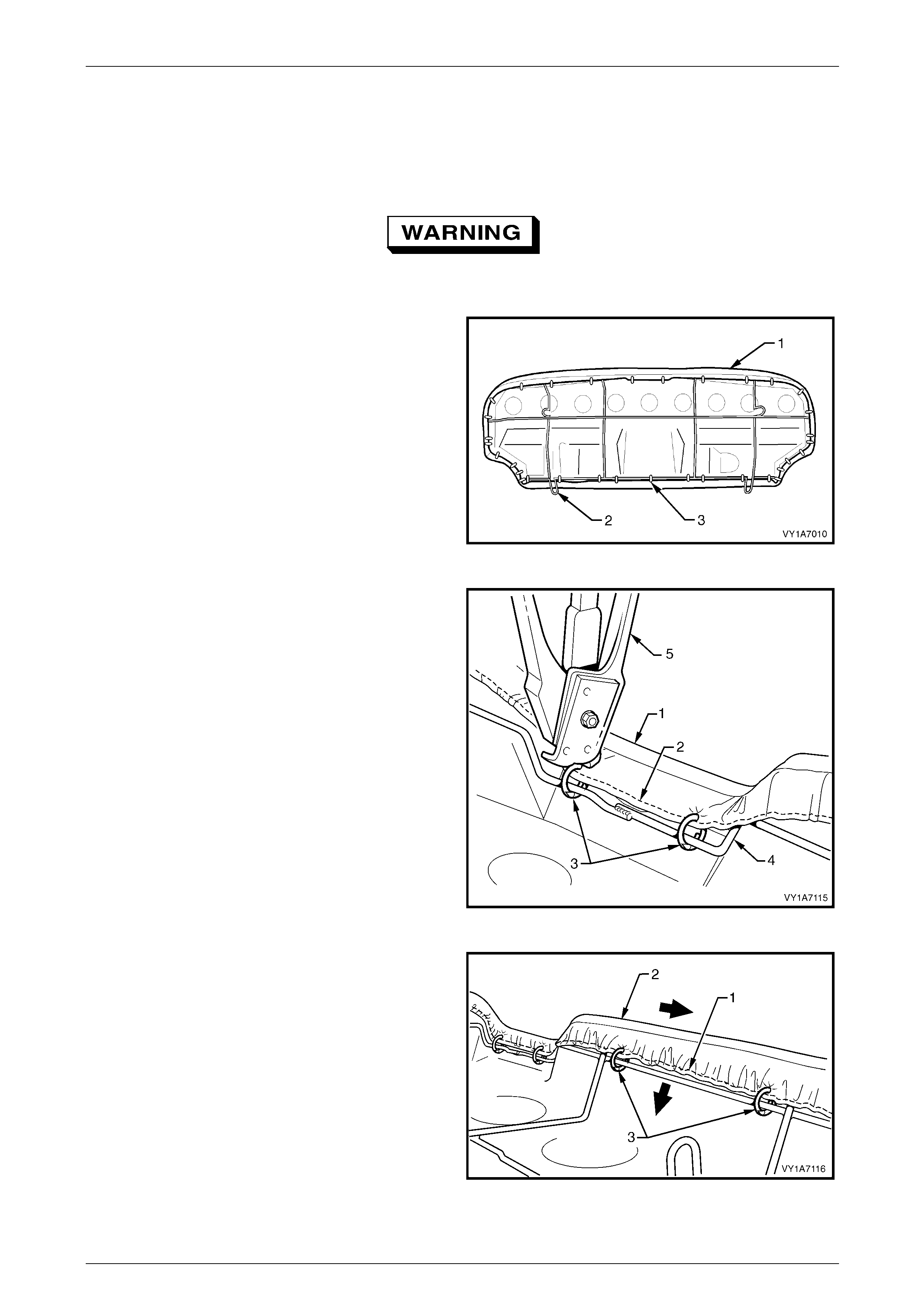
Seat Assemblies Page 1A7–375
Page 1A7–375
Reinstall – Rear Seat Cushion Frame, Hook and Loop
NOTE
All hog rings must be replaced.
Safety glasses an d work glo ves must be w orn
at all times when working with hog rings.
1 Align the rear seat cushion cover and p ad assembly
(1) to the rear seat cushion frame (2) and attach with
approximately thirty four hog rings (3) in the positions
shown.
Figure 1A7 – 317
2 Beginning at the front, in the centre of the rear seat
cushion cover assembly (1), attach the wire retainer
(2) to the centre of the wire frame (4) with two hog
rings (3) using hog ring pliers (5).
Figure 1A7 – 318
3 Working from the centre outward, attach the wire
retainer (1), while pulling the cover assembly (2) tight
and attaching with two hog rings (3).
4 Repeat this process in the opposite direction working
from the centre outward.
Figure 1A7 – 319
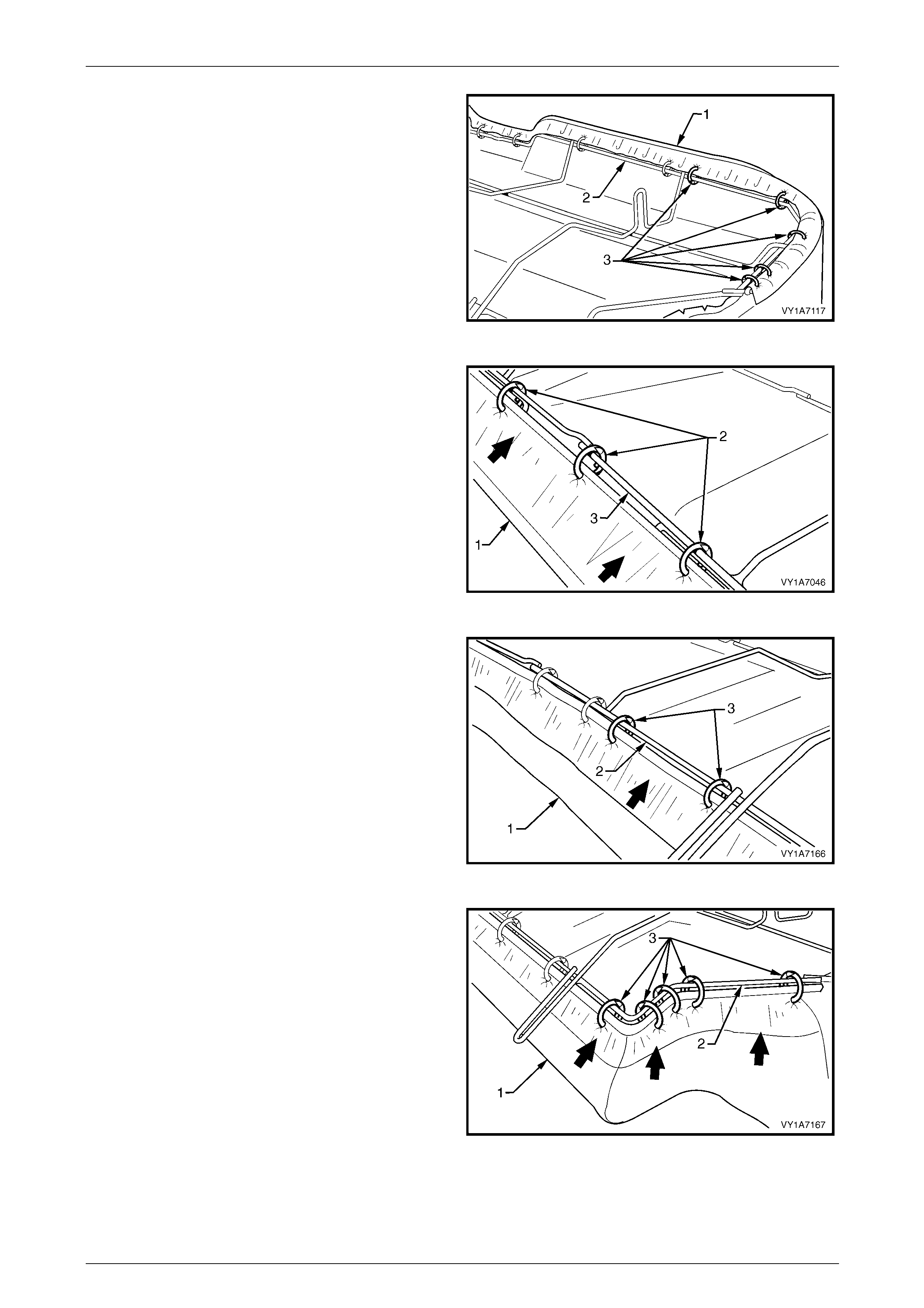
Seat Assemblies Page 1A7–376
Page 1A7–376
5 Continue attaching the cover assembly (1) to the
frame (2), by pulling the cover tight and attaching with
five hog rings (3).
6 Repeat this process in the opposite direction.
NOTE
The cover should be smooth and without
creases. If this is not the case, extra hog rings
are to be used to pull the cover into place.
Figure 1A7 – 320
7 Pull the rear of the cushion cover assembly (1) tight
and attach to the centre of the wire frame (3) with
three hog rings (2).
Figure 1A7 – 321
8 Continue attaching the cover assembly (1) to the
frame (2), by pulling the cover tight and attaching with
two hog rings (3).
9 Repeat this process in the opposite direction.
NOTE
The cover should be smooth and without
creases. If this is not the case, extra hog rings
are to be used to pull the cover into place.
Figure 1A7 – 322
10 Continue attaching the cover assembly (1) to the
frame (2), by pulling the cover tight, up and around the
corner and attaching with five hog rings (3).
11 Repeat this process in the opposite direction.
NOTE
The cover should be smooth and without
creases. If this is not the case, extra hog rings
are to be used to pull the cover into place.
Figure 1A7 – 323
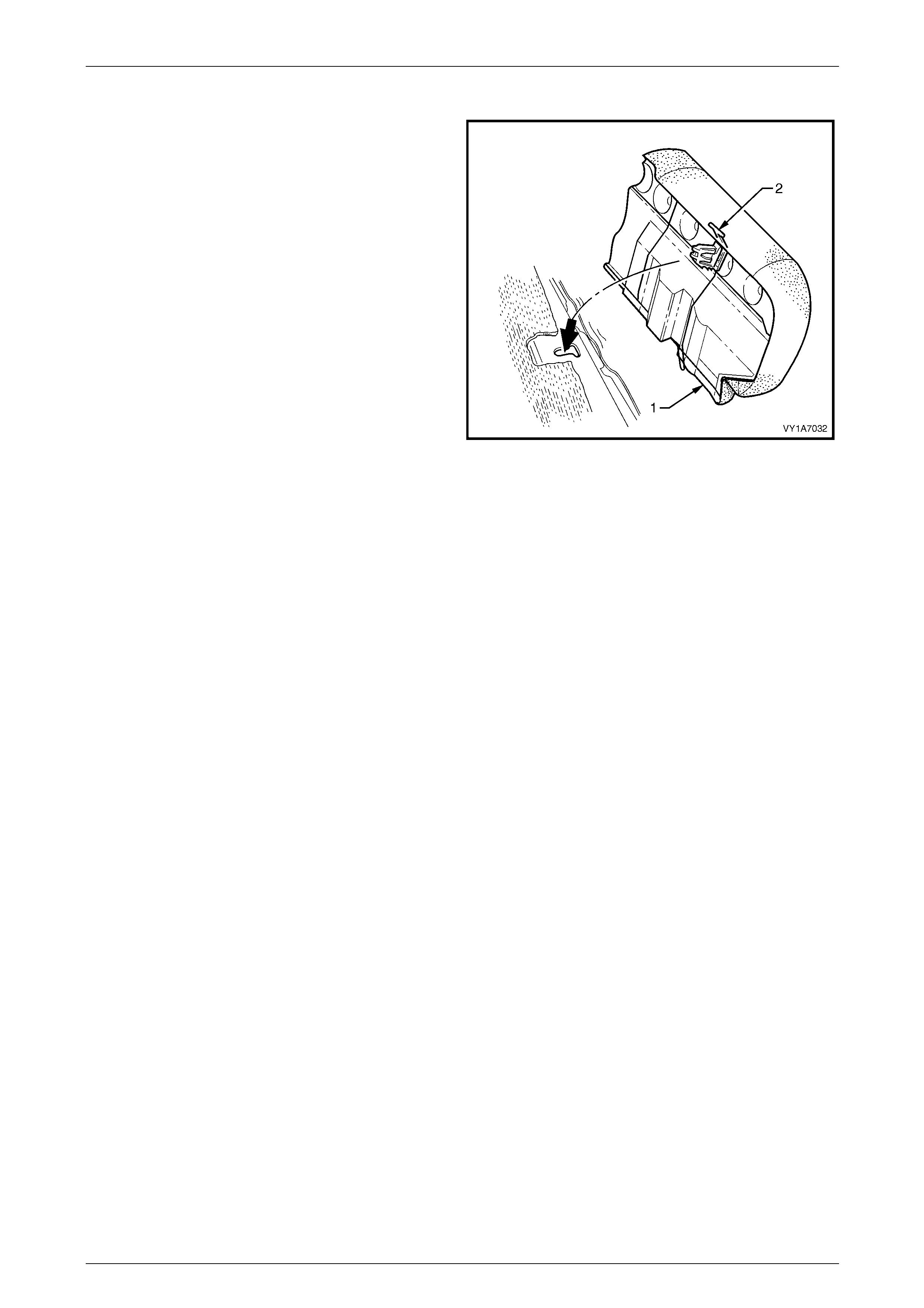
Seat Assemblies Page 1A7–377
Page 1A7–377
Reinstall
1 Position the rear seat cushion into the vehicle.
2 Push the rear seat cushion (1) into the seat-back and
push down the front of seat cushion until the locking
mechanisms (2) lock into position.
Figure 1A7 – 324
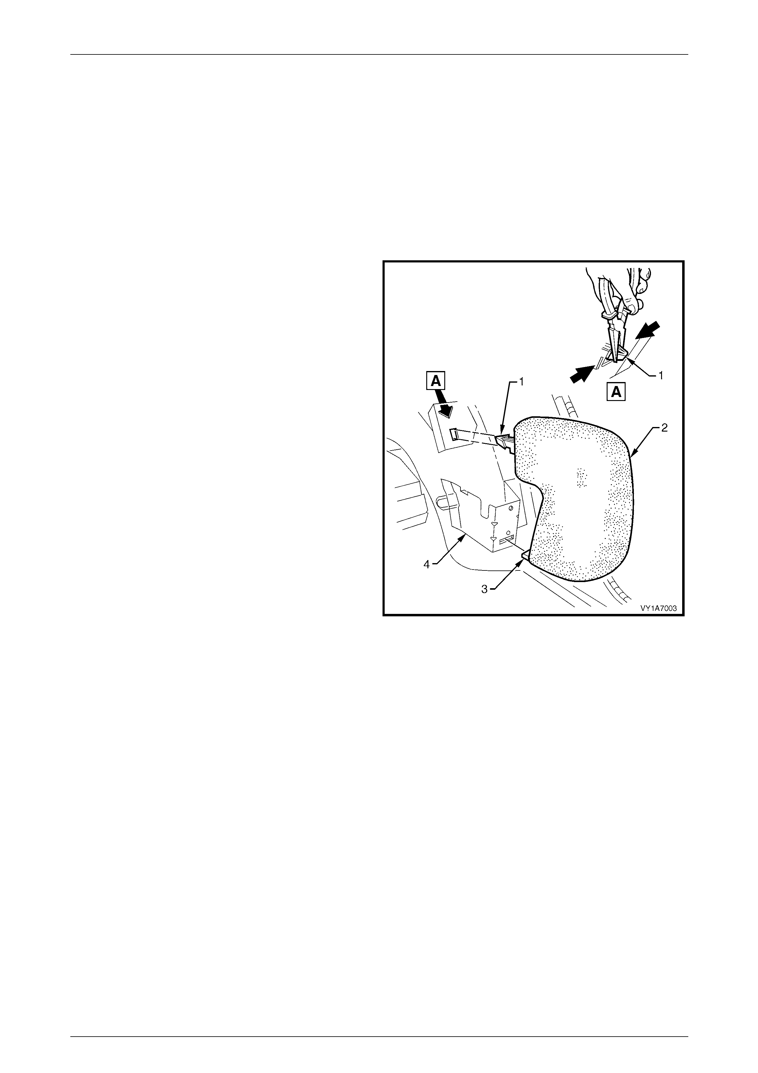
Seat Assemblies Page 1A7–378
Page 1A7–378
9.3 Rear Seat Bolster Assembly
LT Section No. — 14–330
1 Remove the rear seat cushion, 9.2 Rear Seat Cushion Assembly.
2 Unlatch and lower the rear seat-back assem bl y.
3 Remove the quarter inner trim panel assembly, Section 1A8 Headlining and Interior Trim.
Remove
1 Using pliers, squeeze the tangs of the upp er bolster
retaining clip (1) together and pull the rear seat bolster
assembly (2) towards the front of the vehicle.
2 To disengage, lift the lower retaining tang (3) up and
pull the bolster forward, out of the seat-back retaining
bracket (4).
Figure 1A7 – 325
Reinstall
Reinstallation of the rear seat bolster assembly is the reverse of the removal. Insert the lower retaining tang of the bolster
into the seat-back retaining br acket and push the upper retaining clip into the upper retaining bracket.
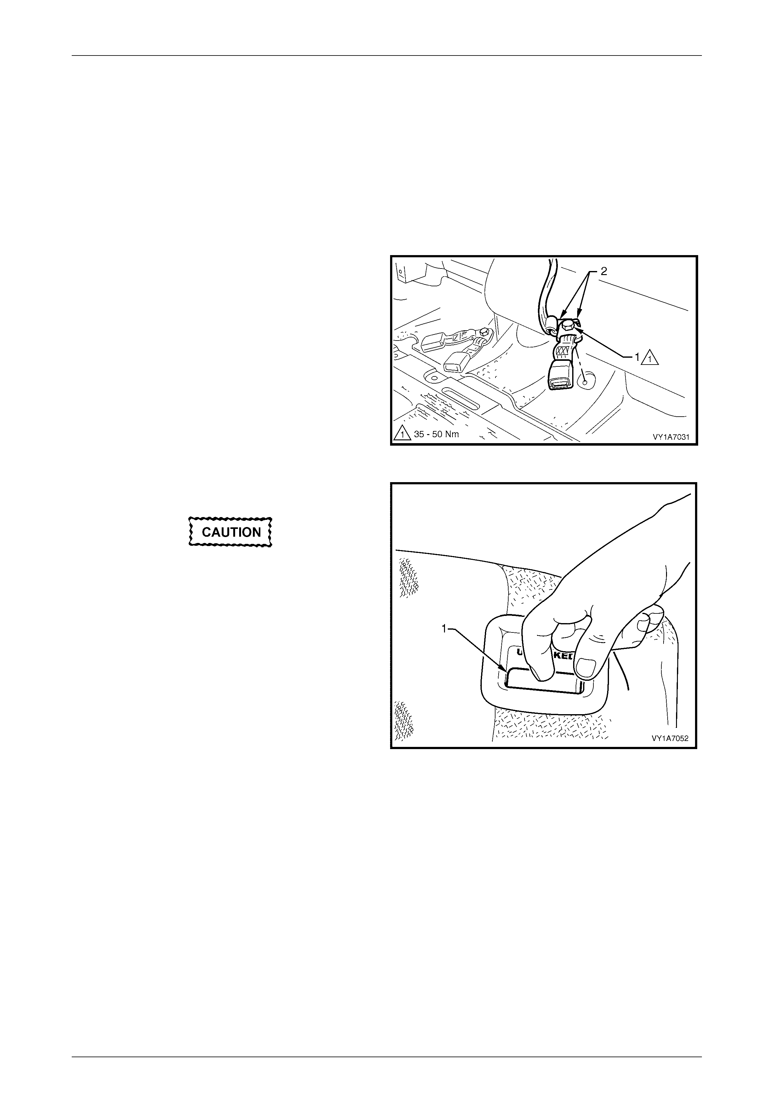
Seat Assemblies Page 1A7–379
Page 1A7–379
9.4 Rear Seat-back Assembly
LT Section No. — 14–325
1 Remove the rear seat cushion assembly, refer to 9.2 Rear Seat Cushion Assembly.
2 Remove the rear seat bolster assembl y on the appropriate side of the vehicle,
refer to 9.3 Rear Seat Bolster Assembly.
Remove
1 For the left-hand side only, remove the bolt (1)
attaching the centre rear seatbelt and the left-hand
buckle anchors (2) to the floor pan.
Figure 1A7 – 326
2 Unlatch and lower the rear seat-back assem bl y (1).
If the seat-back assembly is not lowered, the
seat-back locking p late and pin assembl y will
be damaged if Step 3 is attempted.
Figure 1A7 – 327
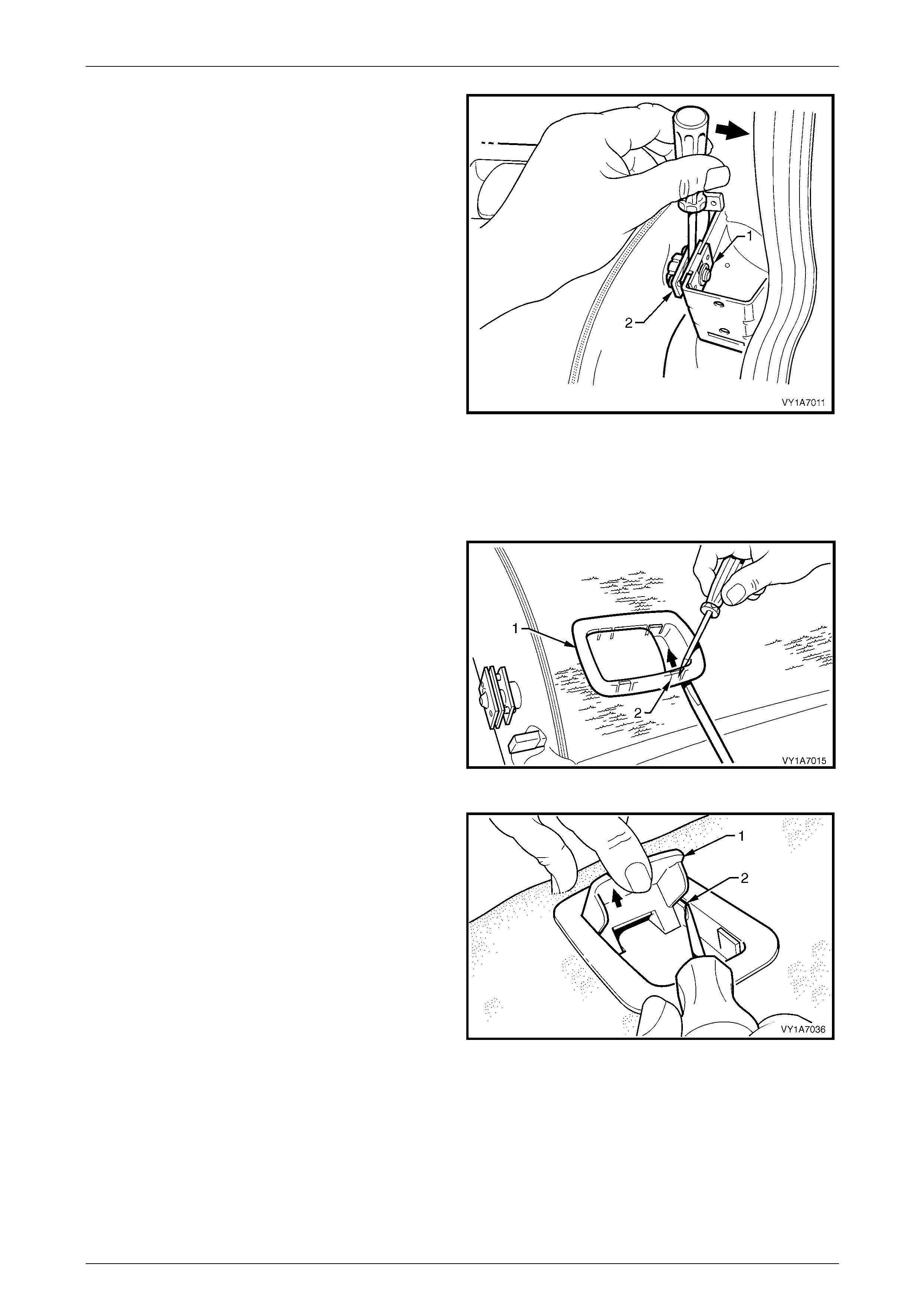
Seat Assemblies Page 1A7–380
Page 1A7–380
3 Insert a screwdriver between the seat (1) and the
locking plate and pin assem bl y (2). Gently pr ise apart
to withdraw the pins from the retaining plate.
4 Lift the outer end of the seat up and out of the
seat-back retainer. Pull the seat-back assembly
towards the door, withdrawing it from the seat-back
centre hinge assembly.
5 Repeat for the opposite side if required.
Figure 1A7 – 328
Disassemble
Remove – Rear Seat-back Release Handle
1 Disengage the release handle assembly (1) by
inserting a screwdriver under one of the corners of the
release handle, while at the same time prising the
retaining tang (2) towards the centre of the release
handle.
Figure 1A7 – 329
2 With one corner of the release handle (1) disengaged,
hold the handle in the release position (up) and
disengage the remaining three tangs (2). Prise them
inwards using a screwdriver towards the centre of the
handle.
3 Remove the release handle as sembly.
Figure 1A7 – 330
Reinstall – Rear Seat-back Release Handle
Reinstallation of the rear seat-back assembly is the reverse of the removal proced ure.
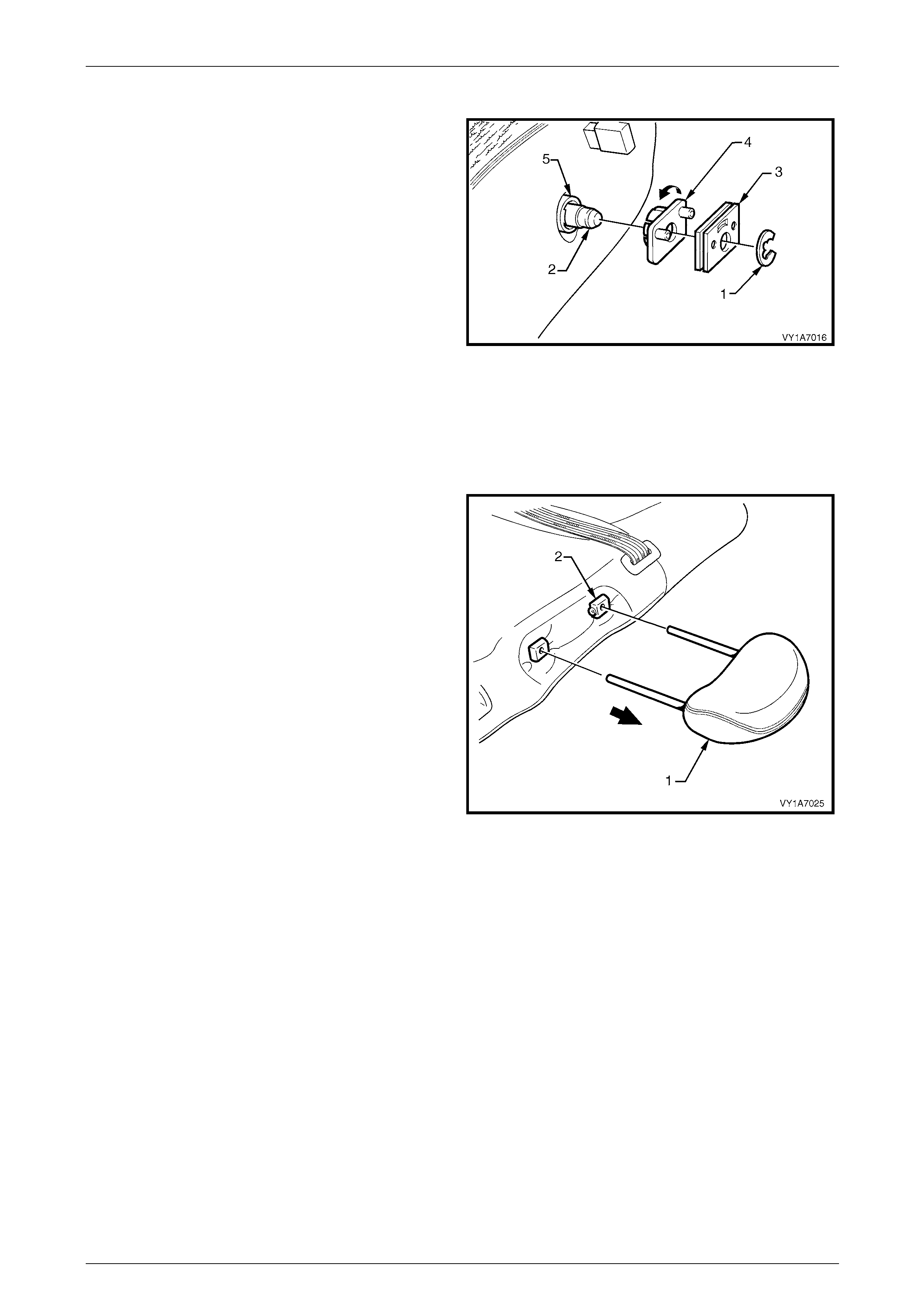
Seat Assemblies Page 1A7–381
Page 1A7–381
Remove – Rear Seat-back Retainer Locking Plate
1 Remove the circlip (1) from the seat-back pivot shaft
(2) and remove the retainer plate (3) from the shaft.
2 Remove the retainer locking plate and pin (4) by
twisting it off the locking bush (5).
NOTE
The locking bush does not have to be removed
unless it is being replaced. T his can be achieve d
by simply levering it off the shaft.
Figure 1A7 – 331
Reinstall – Rear Seat-back Retainer Locking Plate
Reinstallation of the rear seat-back assembly is the reverse of the removal proced ure.
Remove – Rear Seat-b ack Head Restraint
1 Remove the head restraint (1) by depressing the head
restraint guide height adjuster lock (2).
2 Pull the head restraint completely out of the guide.
Figure 1A7 – 332
Reinstall – Rear Seat-back Head Restraint
Reinstallation of the head restraint into the rear seat-back assembly is the reverse of the removal procedure.
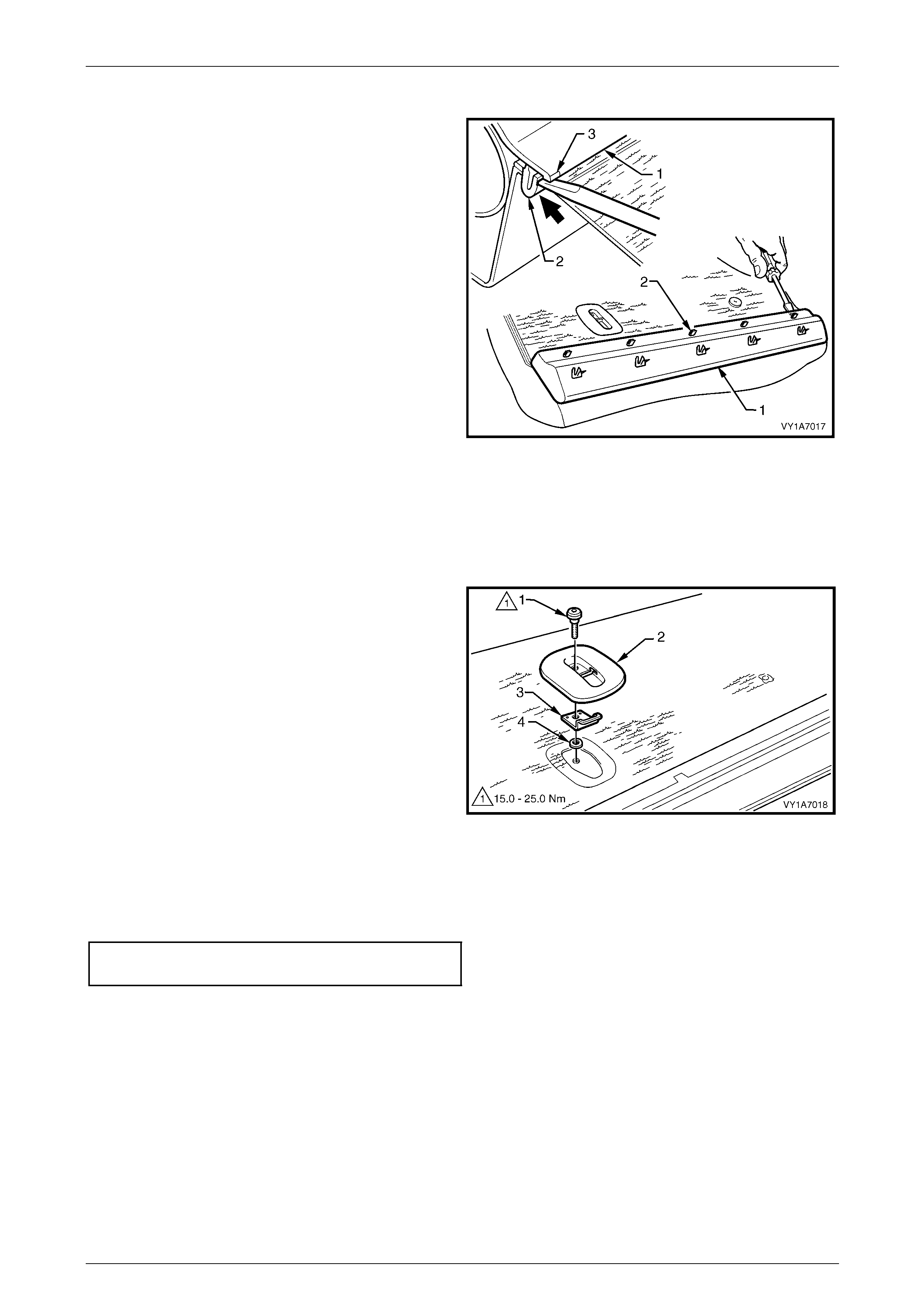
Seat Assemblies Page 1A7–382
Page 1A7–382
Remove – Rear Seat-bac k Trim Cover
1 Carefully remove the rear seat-back trim cover (1), by
inserting a small screwdriver at the tab (2) position,
highlighted by small polished areas (3). Push in to
disengage the retaining tabs (3) five places on the
left-hand seat and three places on the right-hand seat.
2 Start at one end to disengage the cover away from the
seat-back and work along until all reta ining tabs have
been disengaged.
NOTE
Take care not to break the lower retaining tabs
from the rear seat-back trim cover.
Figure 1A7 – 333
Reinstall – Rear Seat-back Trim Cover
Reinstallation of the rear seat-back trim cover is the reverse of the removal procedure.
Remove – Child Seat Anchor
1 Remove the child seat anchor bolt (1) from the
left-hand rear seat-back.
2 Remove the child seat escutcheon (2), anchor (3) and
washer (4).
Figure 1A7 – 334
Reinstall – Child Seat Anchor
Reinstallation of the child s ea t anchor is the reverse of the removal procedure. Tighten the attaching bolt to the correct
torque specification.
Child seat anchor attaching bolt
torque specification.................................15.0 – 25.0 Nm
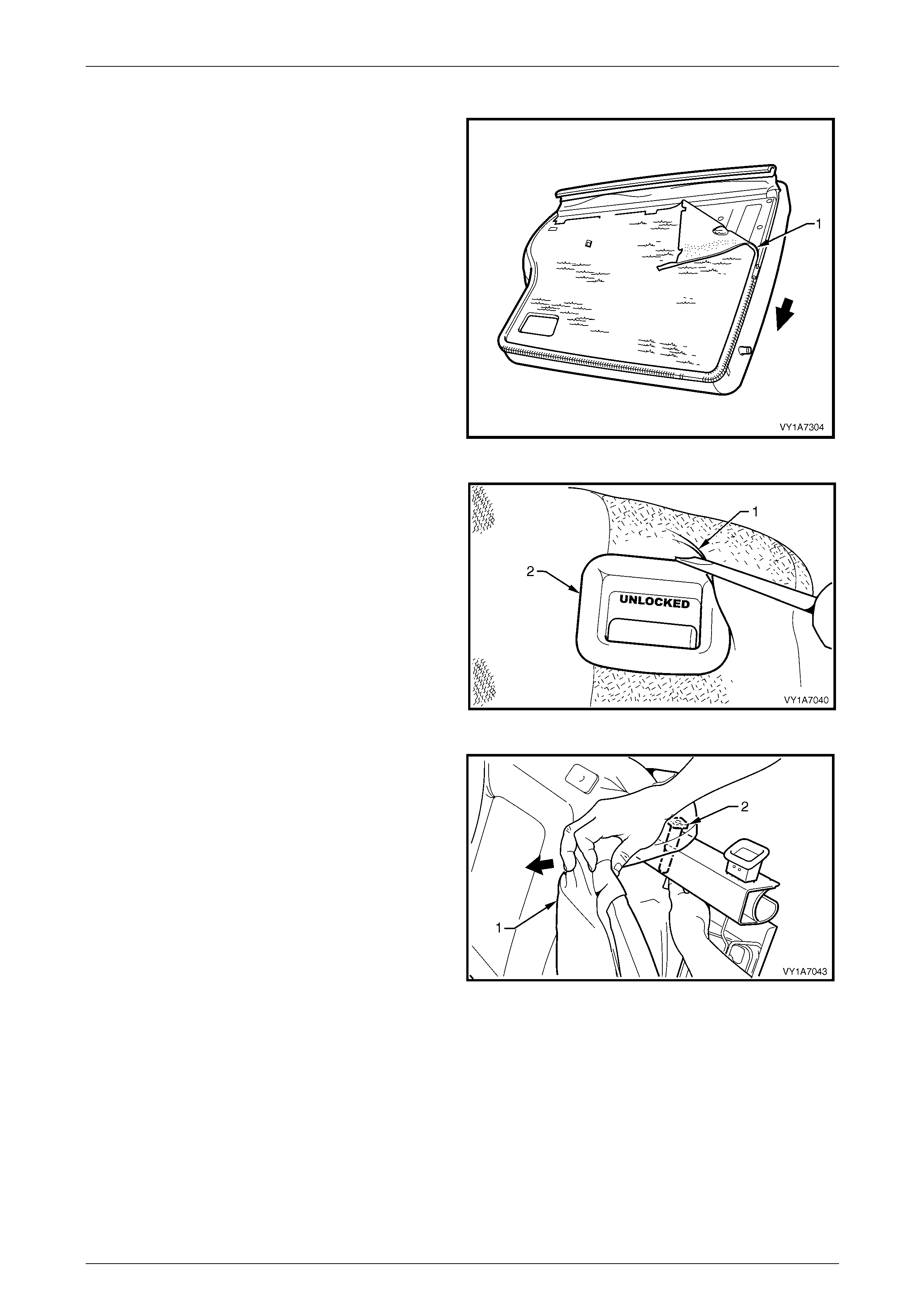
Seat Assemblies Page 1A7–383
Page 1A7–383
Remove – Rear Seat-b ack Head Restraint Guide
1 Unzip the carpet (1) attached to the rear seat-back
cover (2) around the two sides.
2 Fold the cover back revealing the rear seat-back
frame.
Figure 1A7 – 335
3 Lever the cover and pad assembl y (1) over the rel ease
button (2).
Figure 1A7 – 336
4 Pull the top corner of the cover and pad assembly
forward, to allow for the removal of the two head
restraint guides (2).
Figure 1A7 – 337
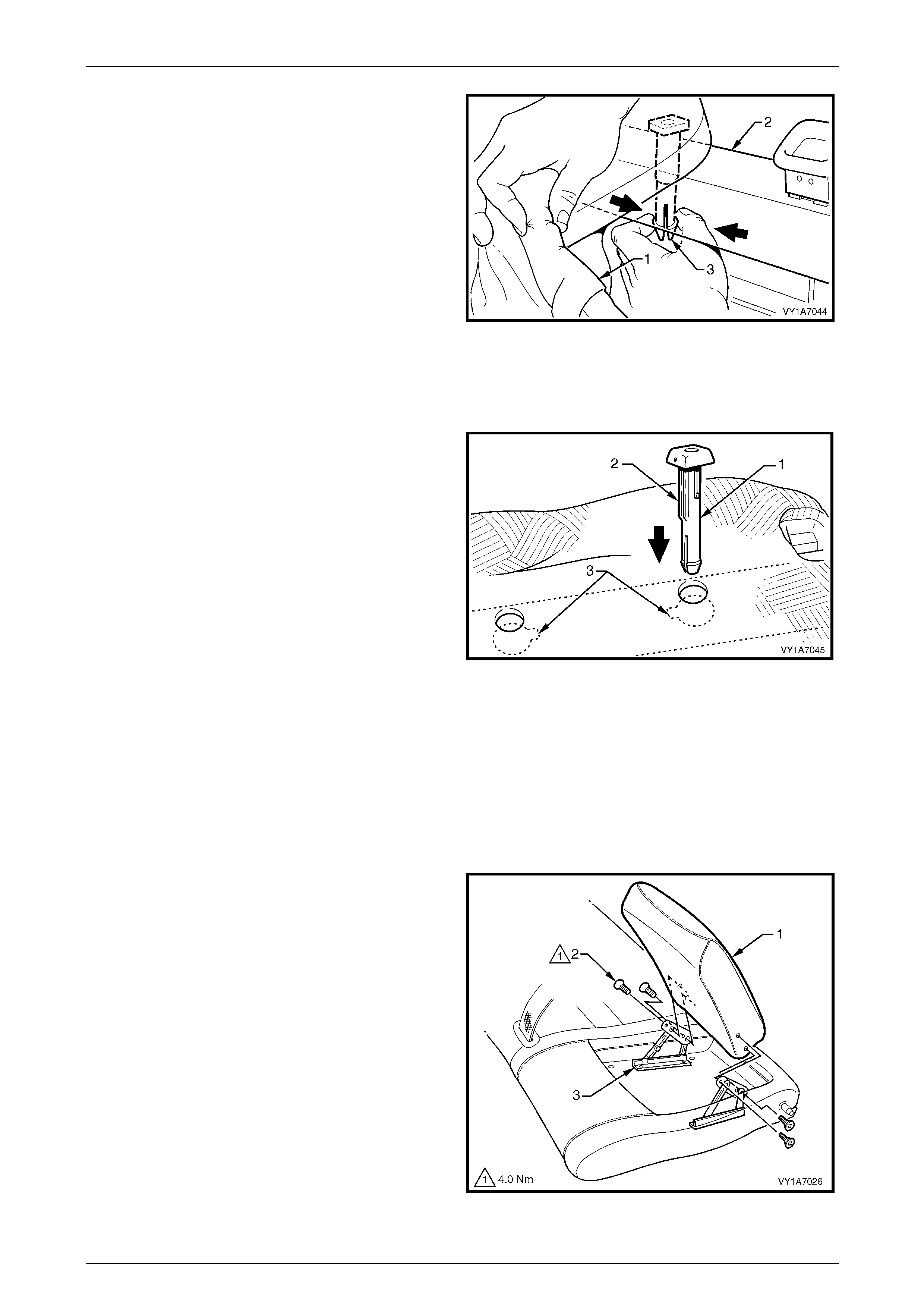
Seat Assemblies Page 1A7–384
Page 1A7–384
5 While holding the cover and pad assembly (1), reach
in between the seat-back frame (2) and the p ad
assembly.
6 Squeeze the head restraint guide locating prongs (3)
together and remove the guide up and out of the
seat-back assembly.
7 Repeat this process for the remaining head restraint
guide.
Figure 1A7 – 338
Reinstall – Rear Seat-back Head Restraint Guide
Reinstallation of the rear seat-back head restraint guide is the revers e of the removal procedure, notin g the following:
When installing the head restraint guide (1), ensure the
locating slots (2) in the seat-back align with key-way (3) on
the head restraint guide.
NOTE
Ensure the guide with the height adjuster lock is
installed on the side that corresponds to the
notches in the head restraint shaft.
Figure 1A7 – 339
Remove – Rear Seat-b ack Armrest Assembly
NOTE
The following component will require replacement
when performing this operation.
• Rear seat-back armrest centre cover blanking
plugs.
1 Partially open the rear seat-back armrest assembly (1)
and remove the four screws (2) attaching the armrest
assembly to the armrest hinge assembly (3).
2 Remove the rear seat-back armrest assembly.
Figure 1A7 – 340
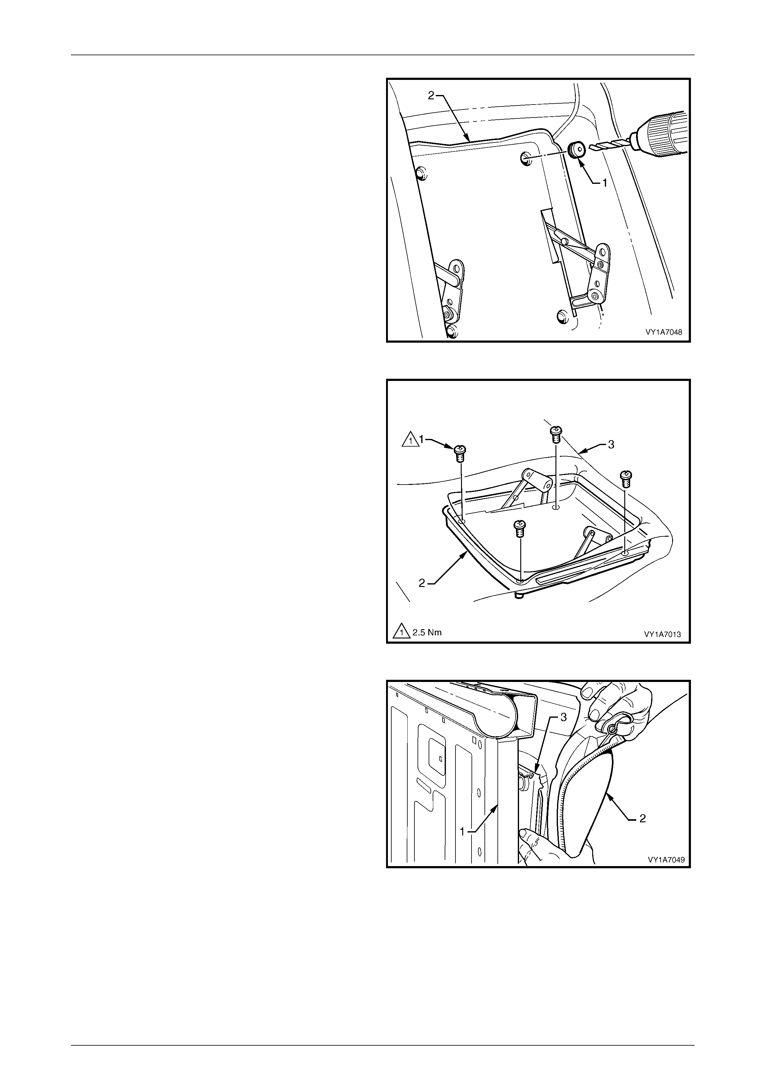
Seat Assemblies Page 1A7–385
Page 1A7–385
3 To remove the four blanking plugs (1) from the rear
seat-back armrest centre cover (2), drill a small hole
into the centre of each plug.
4 Insert a scribe or small screwdriver into the hole in the
plug and pull them free. Take care not to damage the
seat-back cover.
Figure 1A7 – 341
5 Remove the four screws (1) attaching the armrest
centre cover (2) to the seat-back pad and frame
assembly (3).
Figure 1A7 – 342
6 Reach in between the seat-b ack frame (1) and the
seat-back cover and pad assembl y (2).
7 Push the armrest centre cover (3) out through the front
of the seat-back pad.
Figure 1A7 – 343
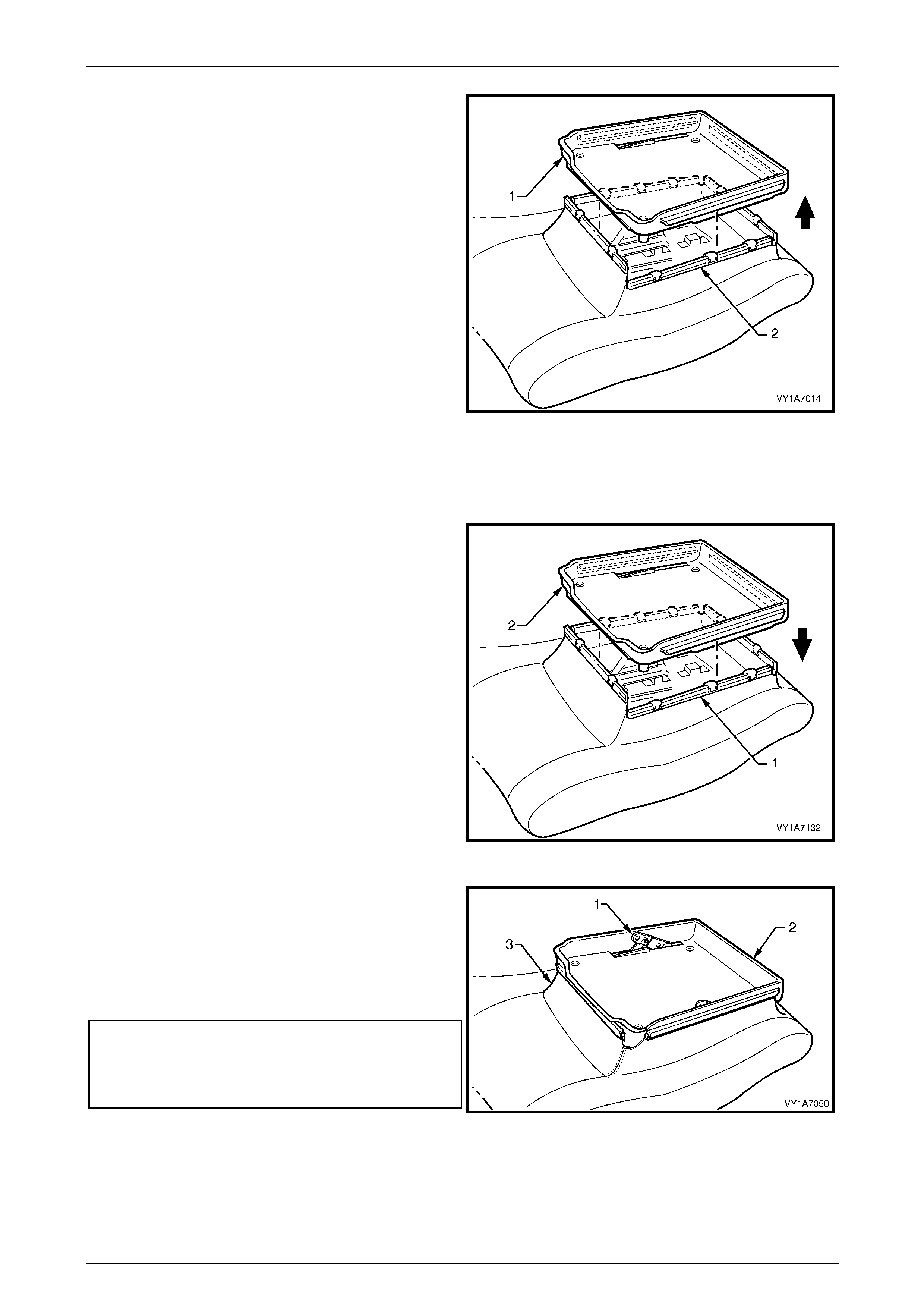
Seat Assemblies Page 1A7–386
Page 1A7–386
8 Lift the armrest centre cover (1) up and pull the four
seat-back cover retainers (2) a way from the sides of
the centre cover.
9 Remove the armrest centre cover.
Figure 1A7 – 344
Reinstall – Rear Seat-back Armrest Assembly
Reinstallation of the rear seat-back armrest assembly is the reverse of the removal procedure, noting the following:
1 Insert the four rear seat-back cover retaining strips (1)
into the armrest centre cover (2).
Figure 1A7 – 345
2 Position the armrest hinges (1) in the partly open
position before installing the armrest centre cover (2).
3 Ensure no puckering occurs around the rear seat-back
cover (3) while installing the armrest centre cover.
4 Tighten the attaching screws to the correct torque
specification.
Armrest centre cover attaching screw
torque specification..............................................2.5 Nm
Rear seat-back armrest assembly attaching
screw torque specification....................................4.0 Nm
5 Install four new centre cover blanking plugs. Figure 1A7 – 346
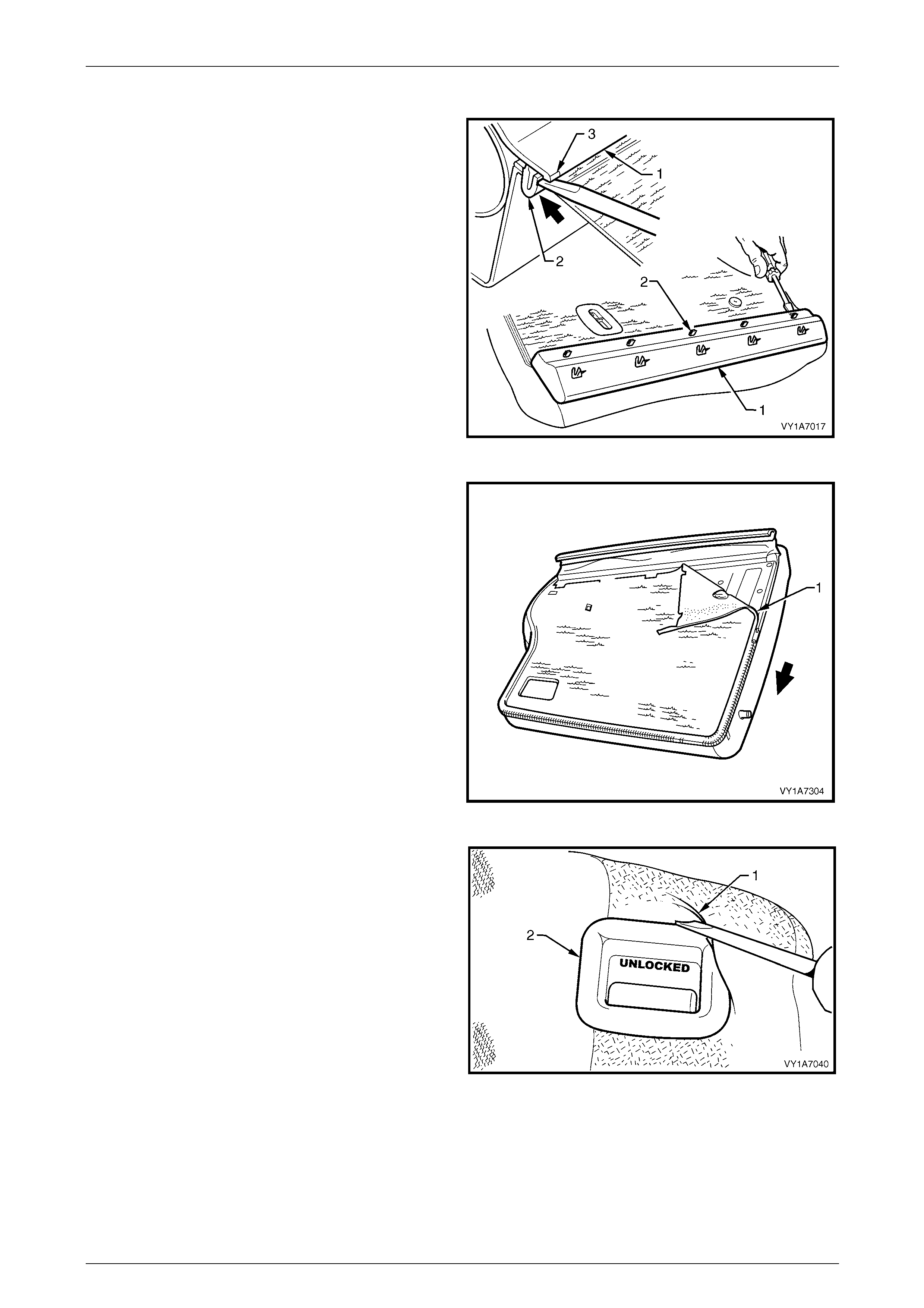
Seat Assemblies Page 1A7–387
Page 1A7–387
Remove – Rear Seat-b ack Cover and Pad Assemb ly
1 Carefully remove the rear seat-back trim cover (1), by
inserting a small screwdriver at the tab (2) position,
highlighted by small polished areas (3). Push in to
disengage the retaining tabs (3) five places on the
left-hand seat and three places on the right-hand seat.
2 Start at one end to disengage the cover away from the
seat-back and work along until all reta ining tabs have
been disengaged.
NOTE
Take care not to break the lower retaining tabs
from the rear seat-back trim cover.
Figure 1A7 – 347
3 Unzip the rear seat-back cover and pad assembly (1)
around two sides and fold back the cover and pad
assembly.
Figure 1A7 – 348
4 Lever the cover and pad assembl y (1) over the rel ease
button (2).
5 For the right-hand side, remove the rear seat -back
cover and pad assembly.
Figure 1A7 – 349
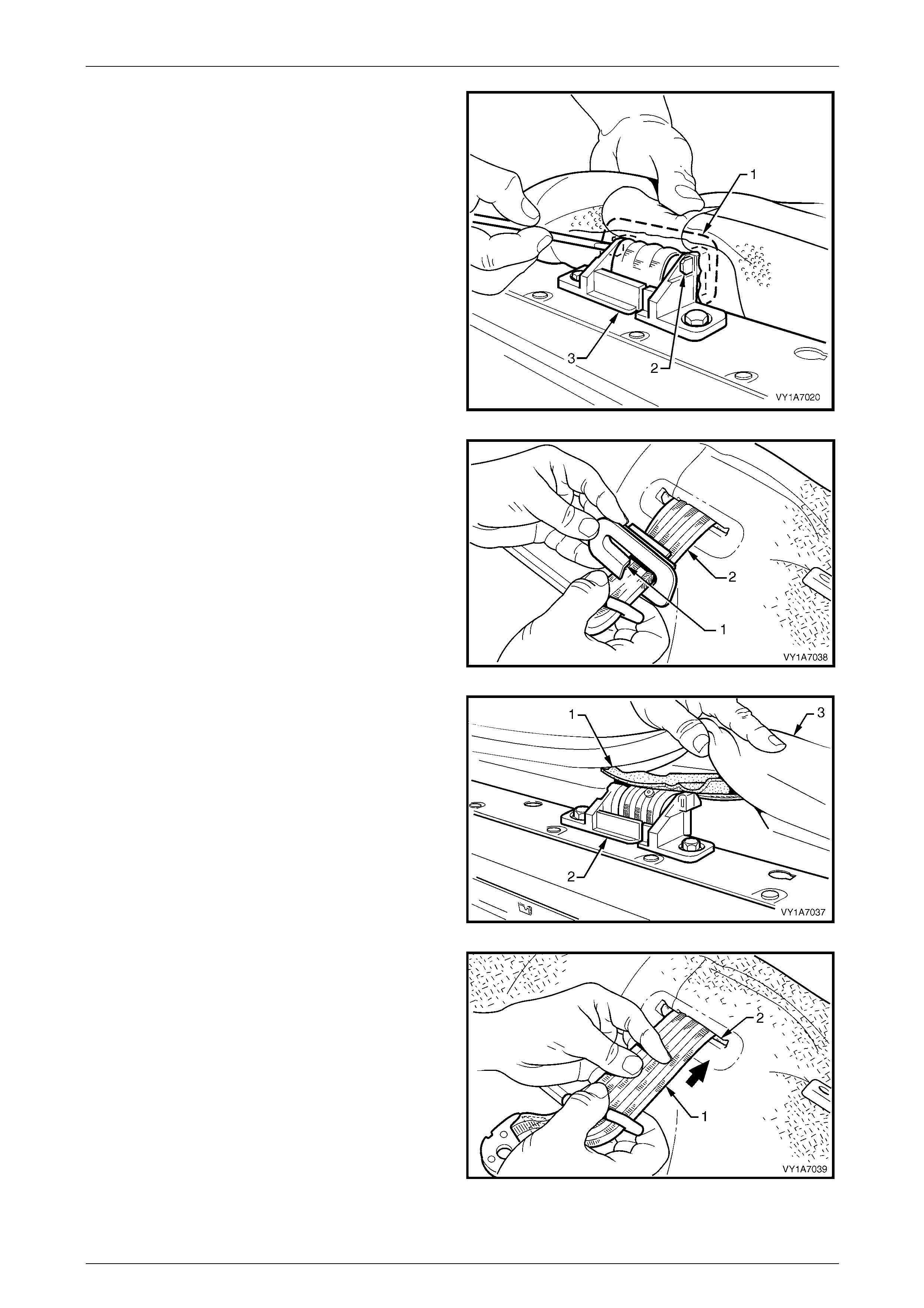
Seat Assemblies Page 1A7–388
Page 1A7–388
6 For the left-hand side, use a screwdriver to release the
centre seatbelt escutcheon (1) from inside th e
left-hand rear seat-back by pushin g the tangs (2) of
the escutcheon through the seatbelt guide bracket
assembly (3). NOTE
Take care not to break the attaching tangs from
the escutcheon.
Figure 1A7 – 350
7 Remove the escutcheon (1) from the seatbelt (2).
Figure 1A7 – 351
8 Feed the seat-back cover flap (1), over the seatbelt
guide bracket assembly (2) and throu gh the pad
assembly (3).
Figure 1A7 – 352
9 Feed the seatbelt (1) through the slot (2) in the cover
and pad assembly.
10 Remove the cover and pad as sembly away from the
seat-back frame.
Figure 1A7 – 353

Seat Assemblies Page 1A7–389
Page 1A7–389
Reinstall – Rear Seat-back Cover and Pad Assembly
Reinstallation of the rear seat-back cover and pad assembly is the reverse of the removal procedure.
Remove – Rear Seat-back Cover, Hook and Loop
NOTE
Surebond cover assemblies are not serviced as
they are glued to the seat-back pad.
NOTE
The following procedures are applicable to both
left-hand and right-hand rear seat-back
assemblies.
1 Fold the outer upper corner of the rear seat-back
cover (1) over the rear seat-back pad (2).
Figure 1A7 – 354
2 While holding the rear seat-back pad (1), pull the
upper corner of the seat cushion cover (2) away from
the rear seat-back pad to disengage the hoo k and loop
strip (3).
Figure 1A7 – 355
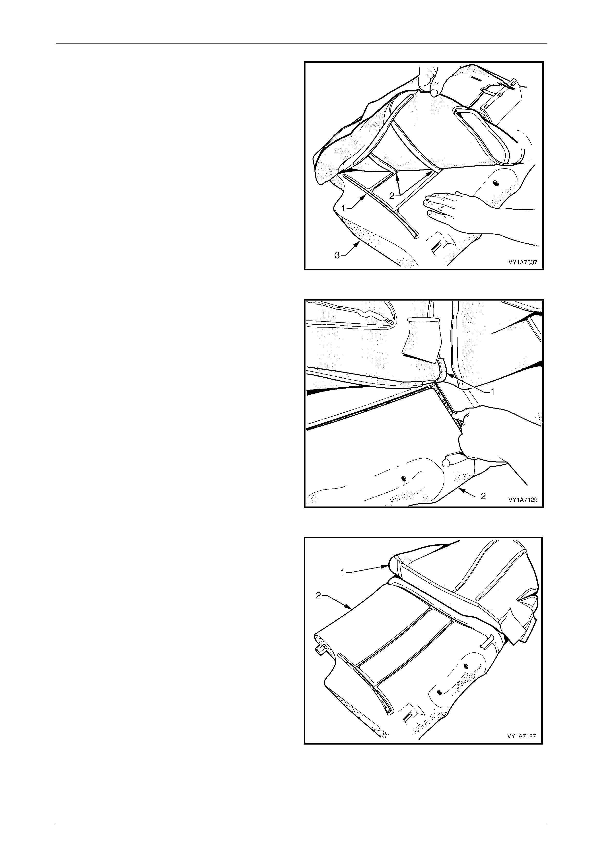
Seat Assemblies Page 1A7–390
Page 1A7–390
3 After disengaging the outer hook and loop strip (1)
remove the one or two cross hook and loop strips (2)
while holding t he seat cushion pad (3).
Figure 1A7 – 356
4 Remove the inner hook and l oop strip (1) while holding
the seat cushion pad (2).
Figure 1A7 – 357
5 Pull the rear seat-back cover (1) up and over the lower
edge of the rear seat-back pad (2).
6 Remove the rear seat-back cover from the rear
seat-back pad.
Figure 1A7 – 358
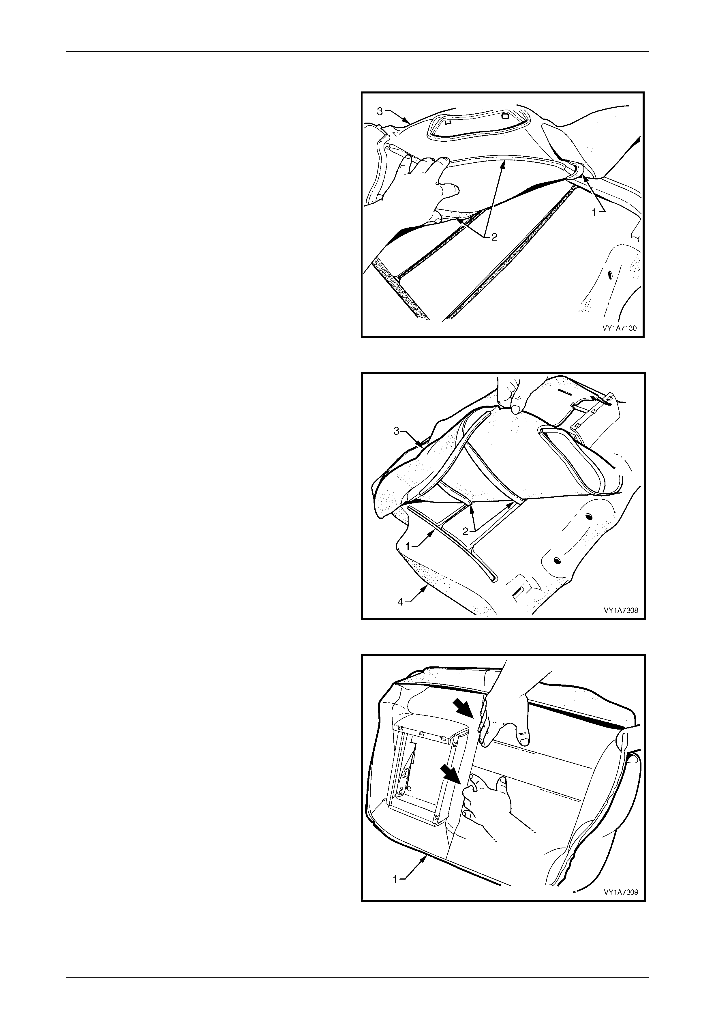
Seat Assemblies Page 1A7–391
Page 1A7–391
Reinstall – Rear Seat-back Cover, Hook and Loop
1 Align the inner hook and loop strip (1) and the one or
two cross hook and loop strips (2) on the seat-back
cover (3), with the seat-back pad.
2 Press the seat-back cover firmly into the
corresponding groove in the seat-back pad to engage
the hook and loop.
Figure 1A7 – 359
3 Align the outer hook and loop strip (1) and the one or
two cross hook and loop strips (2) on the seat cushion
cover (3), with the seat cushion pad (4).
4 Press the seat-back cover firmly into the
corresponding groove in the seat-back pad to engage
the hook and loop.
Figure 1A7 – 360
5 With the seat cover (1) folded at the two vertical strips
of the hook and loop, press the seat-back cover firmly
into the corresponding grooves in the seat-back pad.
Figure 1A7 – 361
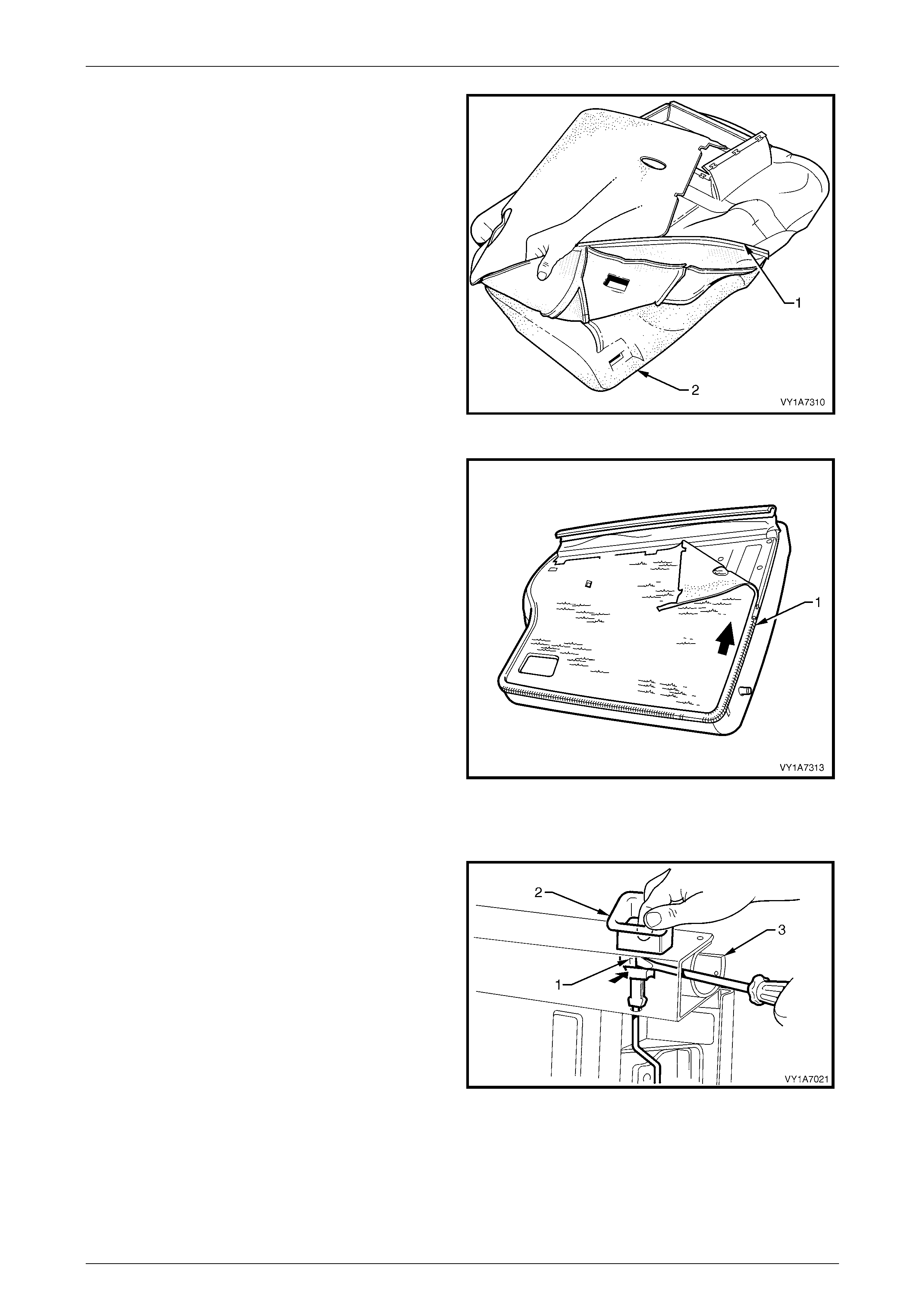
Seat Assemblies Page 1A7–392
Page 1A7–392
6 Roll the lower corners of the rear seat-back cover (1)
over the seat-back pad (2).
7 Roll the sides of the seat-back cover over the
seat-back pad.
8 Roll the upper corners of the seat-back cover over the
seat-back pad.
NOTE
Ensure the pad is fitted neatly by hand into all
corners and contours of the seat cover.
Figure 1A7 – 362
9 Reattach the zip (1) and fasten along two sides.
Figure 1A7 – 363
Remove – Rear Seat-back Frame Release Button
1 Using a screwdriver, depress the two tangs (1) on the
front and rear of the release button (2).
2 Remove the release button from the seat frame (3).
Figure 1A7 – 364
Reinstall – Rear Seat-back Frame Release Button
Push the release button into the rear seat-back frame assembly, until the button clicks into place.
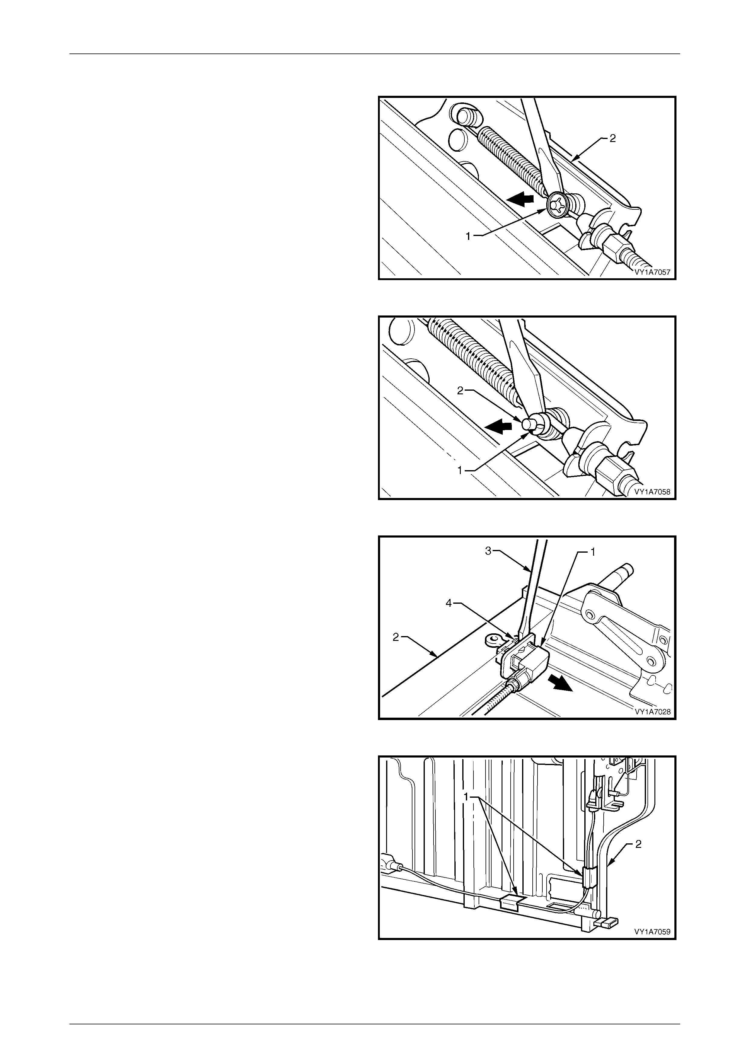
Seat Assemblies Page 1A7–393
Page 1A7–393
Remove – Left-hand Rea r Seat-back Frame Actuator Cable Assembly
NOTE
The following procedure is applicable to the
left-hand rear seat-back assembly only.
1 Use a screwdriver to lever the retaining clip (1) off the
actuator assembly (2).
Figure 1A7 – 365
2 Use a small screwdriver to lever the actuator cable (1)
from the actuator retaining bracket (2).
3 Remove the cable from the actuator.
Figure 1A7 – 366
4 Lever the actuator cable retainer (1) from the
seat-back frame (2) with the aid of a screwdriver (3).
NOTE
Take care when levering the actuator cable
retainer from the seat-back frame. If the retaining
tangs (4) are damaged during removal the
actuator cable assembly has to be replac ed.
Figure 1A7 – 367
5 Remove the tape (1) securing the actuator cable to the
seat-back frame (2) and remove the cable.
NOTE
Take note of the location of the tape for
reinstallation.
Figure 1A7 – 368
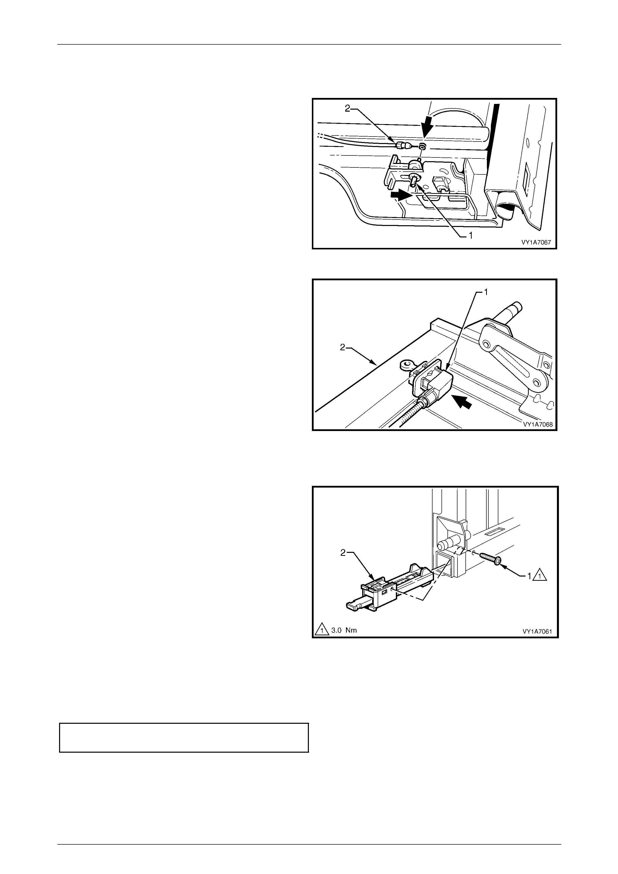
Seat Assemblies Page 1A7–394
Page 1A7–394
Reinstall – Left-hand Rear Seat-back Frame Actuator Cable Assembly
Reinstallation of the rear seat-back frame actuator cable is the reverse of the removal procedure, noting the following:
1 Place the actuator lock (1) in the up position before
connecting the actuator cable (2).
Figure 1A7 – 369
2 Install the actuator cable retainer (1) into the rear
seat-back (2), after the cable is connected to the
actuator assembly.
Figure 1A7 – 370
Remove – Left-hand Rea r Seat-back Frame Inner Latch
1 Remove the screw (1) from the inner latch assembly
(2).
2 Slide the inner latch assem bly out of the seat-back
frame.
Figure 1A7 – 371
Reinstall – Left-hand Rear Seat-back Frame Inner Latch
Reinstallation of the left-hand rear seat-back frame inner latch is the reverse of the removal procedure. Tighten the
attaching screws to the correct torque specification.
Release handle lever attaching screw
torque specification..............................................3.0 Nm
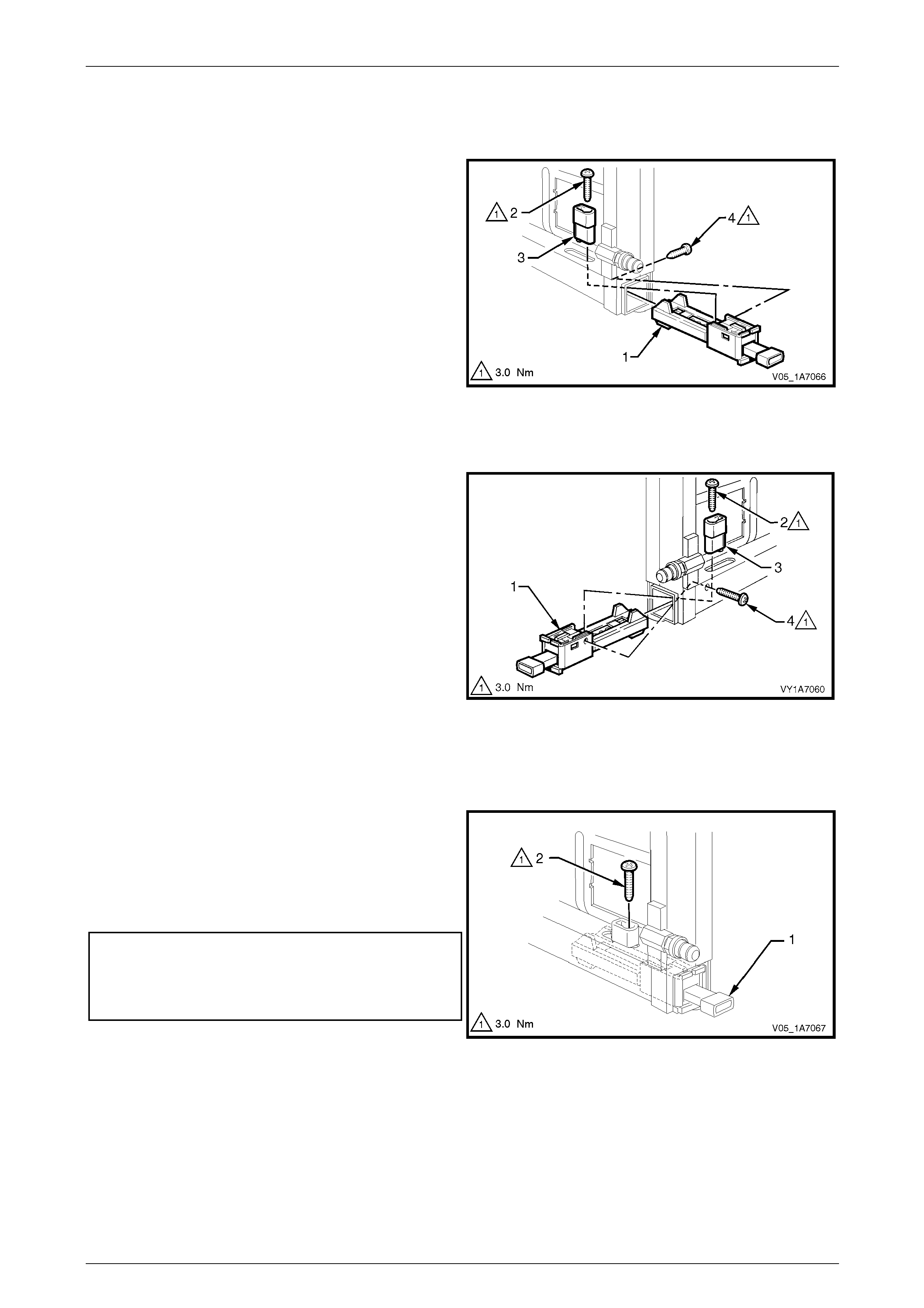
Seat Assemblies Page 1A7–395
Page 1A7–395
Remove – Rear Seat-bac k Frame Outer Latch
Left-hand Seat
1 Remove the outer latch assembly (1) by removing the
screw (2) from the release handle lever (3) and
remove the lever.
2 From the rear of the seat-back remove the attaching
screw (4) from the outer latch assembly.
3 Slide the outer latch assembly out of the seat-back
frame.
Figure 1A7 – 372
Right-hand Seat
1 Remove the outer latch assembly (1) by removing the
screw (2) from the release handle lever (3) and
remove the lever.
2 Remove the attaching screw (4) from the outer latch
assembly.
3 Slide the outer latch assembly out of the seat-back
frame.
Figure 1A7 – 373
Reinstall – Rear Seat-back Frame Ou ter Latch
Reinstallation of the rear seat-back frame outer latch is the reverse of the removal procedure, noting the following:
1 When installing the release handle lever (1) on both
the right and left-hand rear seat frames, apply Loctite
262 or equivalent, to the threads of the retaining screw
(2).
2 Tighten the attaching screws to the correct torque
specification.
Release handle lever attaching screw
torque specification..............................................3.0 Nm
Outer latch assembly attaching screw
torque specification..............................................3.0 Nm
Figure 1A7 – 374
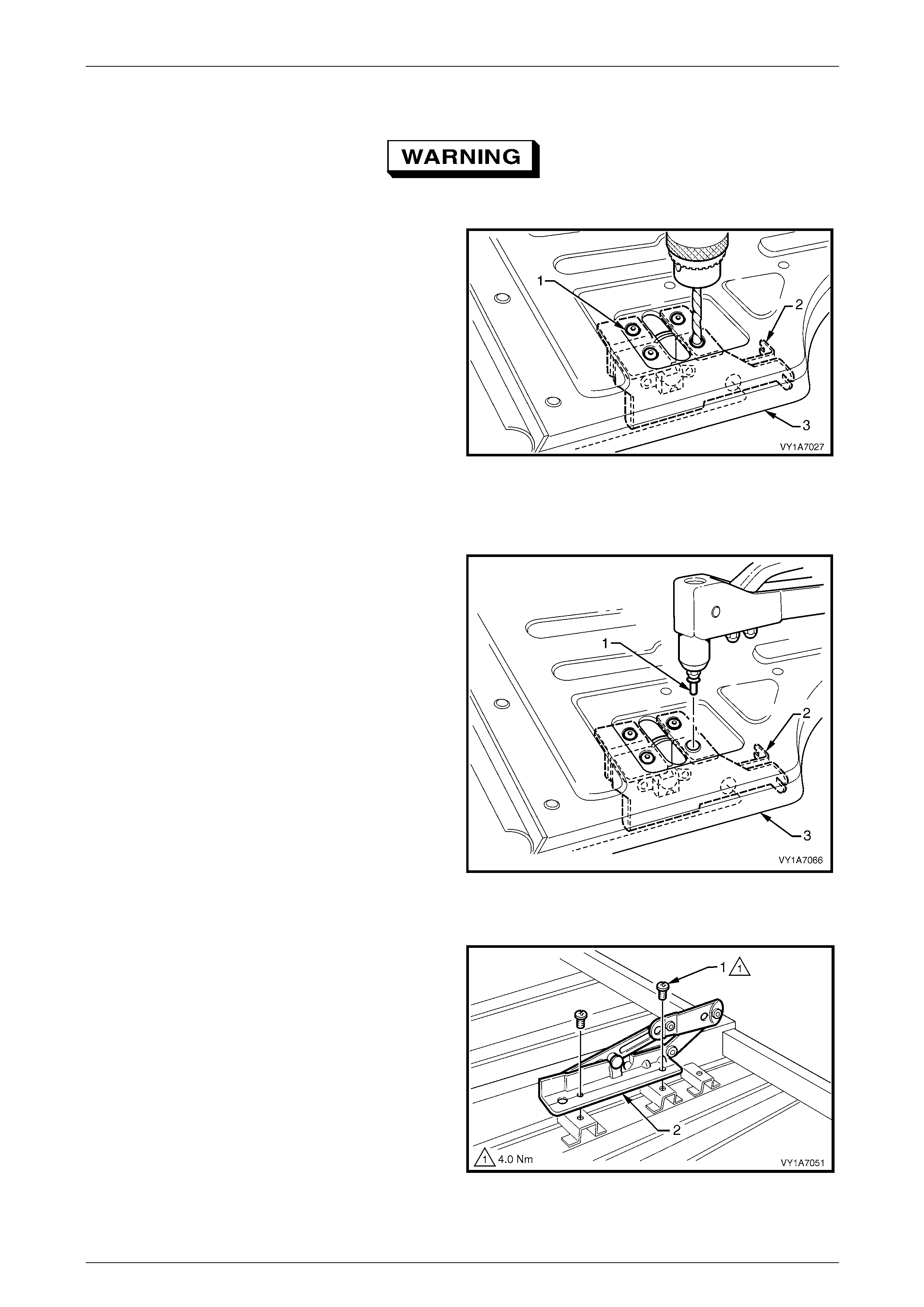
Seat Assemblies Page 1A7–396
Page 1A7–396
Remove – Rear Seat-bac k Frame Actuator
Safety glasses an d work glo ves must be w orn
at all times when drilling.
1 From the rear of the seat-back, use a 5mm drill bit to
drill out the four rivets (1) retaining the actuator
assembly (2) to the seat-back frame (3).
2 Remove the actuator from the seat-back frame.
Figure 1A7 – 375
Reinstall – Rear Seat-back Frame Actuator
Reinstallation of the rear seat-back frame actuator is the reverse of the removal procedure, noting the following:
1 Use four 4.5 mm (3/16) steel rivets (1), (not
aluminium) to rivet the actuator assembly (2) to the
seat-back (3).
2 Ensure the actuator rod is correctly aligned.
Figure 1A7 – 376
Remove – Rear Seat-b ack Armrest Hinge
1 Remove the two screws (1) attaching the hi nge
assembly (2) to the seat-back frame assembl y and
remove the hinge assembly.
2 Repeat for the opposite side.
Figure 1A7 – 377
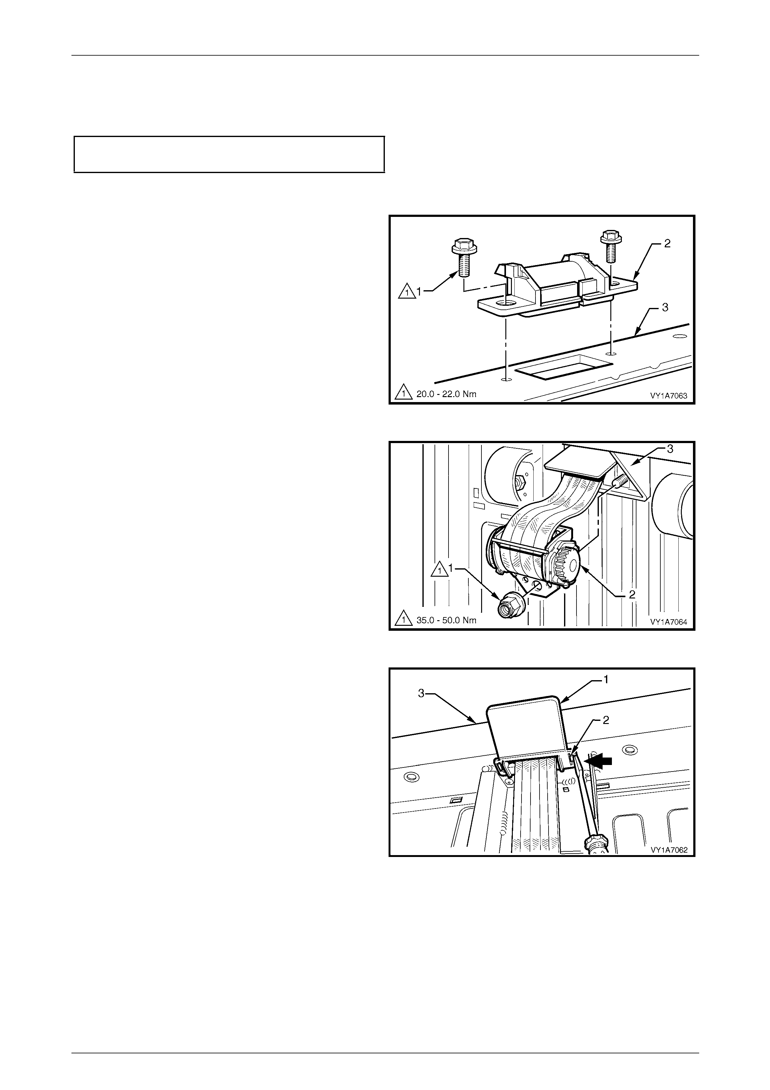
Seat Assemblies Page 1A7–397
Page 1A7–397
Reinstall – Rear Seat-back Armrest Hinge
Reinstallation of the rear seat-back frame actuator is the reverse of the removal procedure. Tighten the attaching screws
to the correct torque specification.
Armrest hinges assembly attaching
screw torque specification....................................4.0 Nm
Remove – Rear Seat-back Seatbelt Retractor
1 Remove the two screws (1) attaching the seat belt
guide bracket (2) to the top of the seat-back frame (3).
2 Remove seatbelt guide bracket by feeding the seatbelt
webbing through the slot in the seatbelt guide bracket.
Figure 1A7 – 378
3 Remove the nut (1) attaching the seat-belt retractor (2)
to the rear seat-back frame (3).
4 Remove the seatbelt retractor from the seat-back
frame stud.
Figure 1A7 – 379
5 Remove the seatbelt retractor escutcheon (1) by
pushing in the tangs (2) and releasing it from the
seat-back frame (3).
6 Feed the seatbelt webbing thr ough seat-back frame
and remove the retractor assembly.
NOTE
The seatbelt retractor will not function unless the
seat-back is in an upright position.
Figure 1A7 – 380

Seat Assemblies Page 1A7–398
Page 1A7–398
Reinstall – Rear Seat-back Seatb elt Retra ctor
Reinstallation of the rear seat-back seatbelt retainer is the reverse of the removal procedure, noting the following:
1 Place the rear seat-back in an upright position before installing the se atbelt retractor.
2 Tighten the attaching fasteners to the correct torque specification.
Seatbelt guide bracket attaching screw
torque specification.................................20.0 – 22.0 Nm
Seatbelt retractor attaching nut torque
specification............................................35.0 – 50.0 Nm
Reinstall
Reinstallation of the rear seat-back assembly is the reverse of the removal procedure, noting the following:
1 Install the rear seat-back in its lo wered position.
2 Fold the rear seat into the upright positio n and the locking plate and pin assembly will automatically lock.
3 Check the function of the seat-back lock b y operating the seat-back lock at least three times while observing the
following:
a Ensure the locking pin on the centre lock ass embl y engages fully with the rear seat-back centre support
assembly when it is in the lock position.
b Ensure the release button, when in the lock positio n, sits flush with the escutcheon.
4 Tighten the attaching screws to the correct torque specification.
Centre rear seatbelt attaching screw
torque specification.................................35.0 – 50.0 Nm
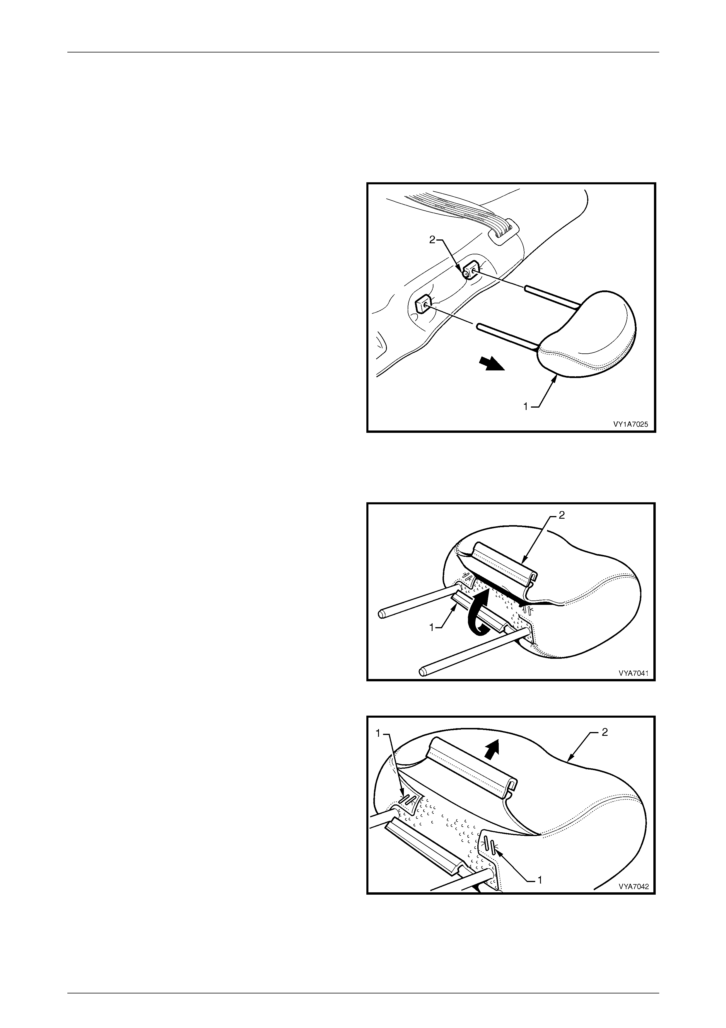
Seat Assemblies Page 1A7–399
Page 1A7–399
9.5 Rear Seat-back Head Restraint Assembly
LT Section No. — 14–350
Remove
1 Remove the head restraint (1) by depressing the head
restraint guide height adjuster lock (2).
2 Pull the head restraint completely out of the guide.
Figure 1A7 – 381
Disassemble
1 Disengage the rear head restraint cover J-strip (1) by
pulling up the flap (2).
Figure 1A7 – 382
2 Remove the four staples (1) attaching the cover (2) to
the head restraint pad assembly.
3 Remove the cover from the pad assembly.
Figure 1A7 – 383

Seat Assemblies Page 1A7–400
Page 1A7–400
Reassemble
Reassembly of the rear seat-back head restraint assembly is the reverse of the removal procedure. Ensure the head
restraint cover J-strip is fully engaged.
Reinstall
Reinstallation of the rear seat-back head restraint is the reverse of the removal procedure.
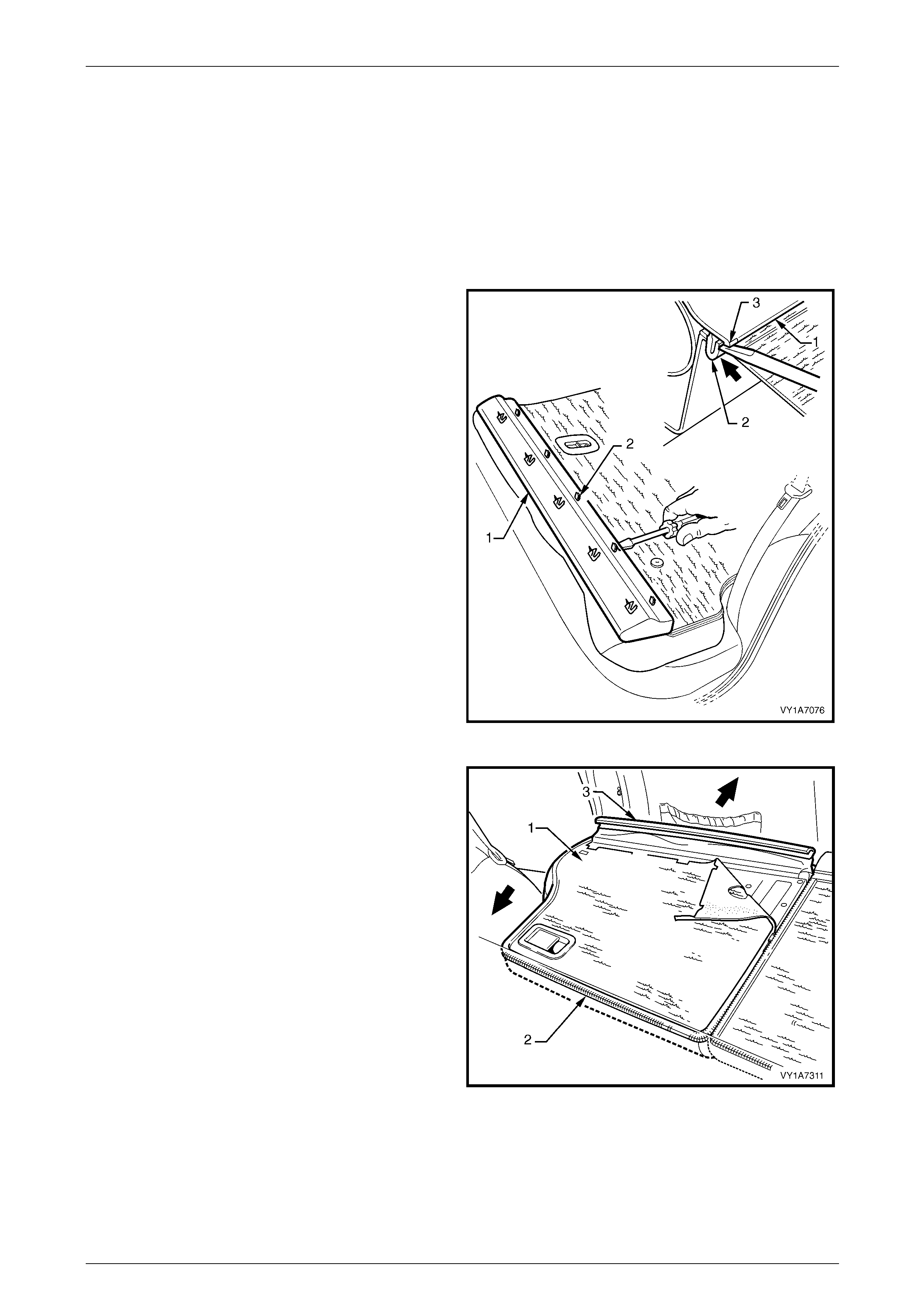
Seat Assemblies Page 1A7–401
Page 1A7–401
9.6 Rear Seat-back Head Restraint Guide
LT Section No. — 14–350
1 Remove the rear seat-back head restraint assembly, refer to 9.5 Rear Seat-back Head Restraint Assembly.
2 Unlatch and lower the rear seat-back assem bl y.
Remove
1 Carefully remove the rear seat-back trim cover (1), by
inserting a small screwdriver at the tab (2) position,
highlighted by small polished areas (3). Push in to
disengage the retaining tabs (3) five places on the
left-hand seat and three places on the right-hand seat.
2 Begin at one end to disengage the cover away from
the seat-back and work along until all retain ing tabs
have been disengaged.
NOTE
Take care not to break the lower retaining tabs
from the rear seat-back trim cover.
Figure 1A7 – 384
3 Partly remove the rear seat-back cover (1) by
unzipping the cover (2) down one side of the rear
seat-back.
4 Pull the outer top finisher strip (3) from the rear
seat-back frame.
NOTE
To ease in the removal of the top finisher strip,
gently lever the strip away from the frame using
a screwdriver.
Figure 1A7 – 385
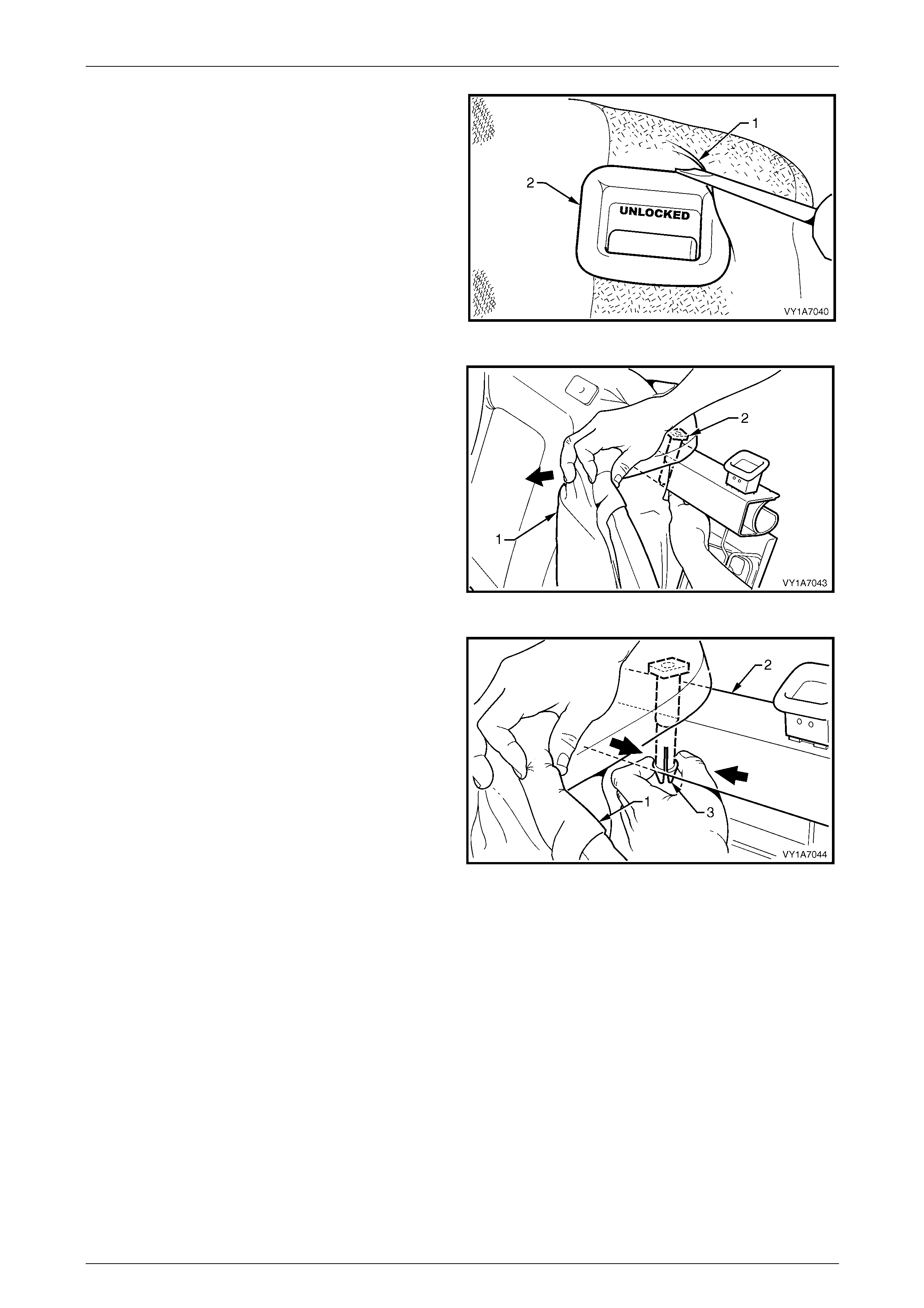
Seat Assemblies Page 1A7–402
Page 1A7–402
5 Lever the cover and pad assembl y (1) over the rel ease
button (2).
Figure 1A7 – 386
6 Pull the top corner of the cover and pad asse mbly (1)
down to allow for the removal of the two head restraint
guides (2).
Figure 1A7 – 387
7 While holding the cover and pad assembly (1), reach
in between the seat-back frame (2) and the p ad
assembly.
8 Squeeze the head restraint guide locating prongs (3)
together and remove the guide up and out of the
seat-back assembly.
9 Repeat this process for the remaining head restraint
guide.
Figure 1A7 – 388
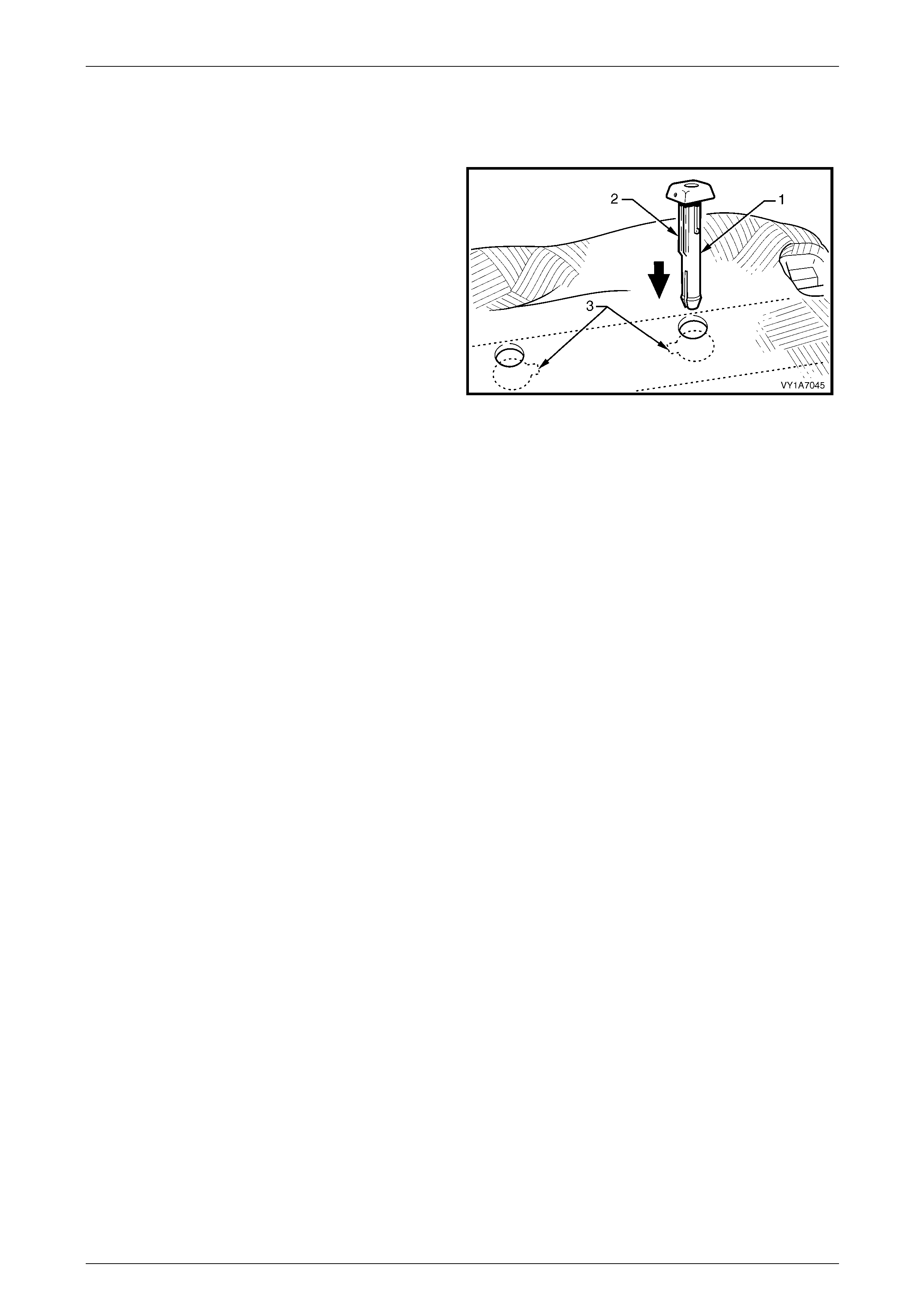
Seat Assemblies Page 1A7–403
Page 1A7–403
Reinstall
Reinstallation of the rear seat head restraint guide is the reverse of the rem oval procedure, noting the foll owing:
When installing the head restraint guide (1), align the
locating ribs (2) with the key-way (3) in the seat-back frame.
NOTE
Ensure the guide with the height adjuster lock is
installed on the side that corresponds to the
notches in the head restraint shaft.
Figure 1A7 – 389
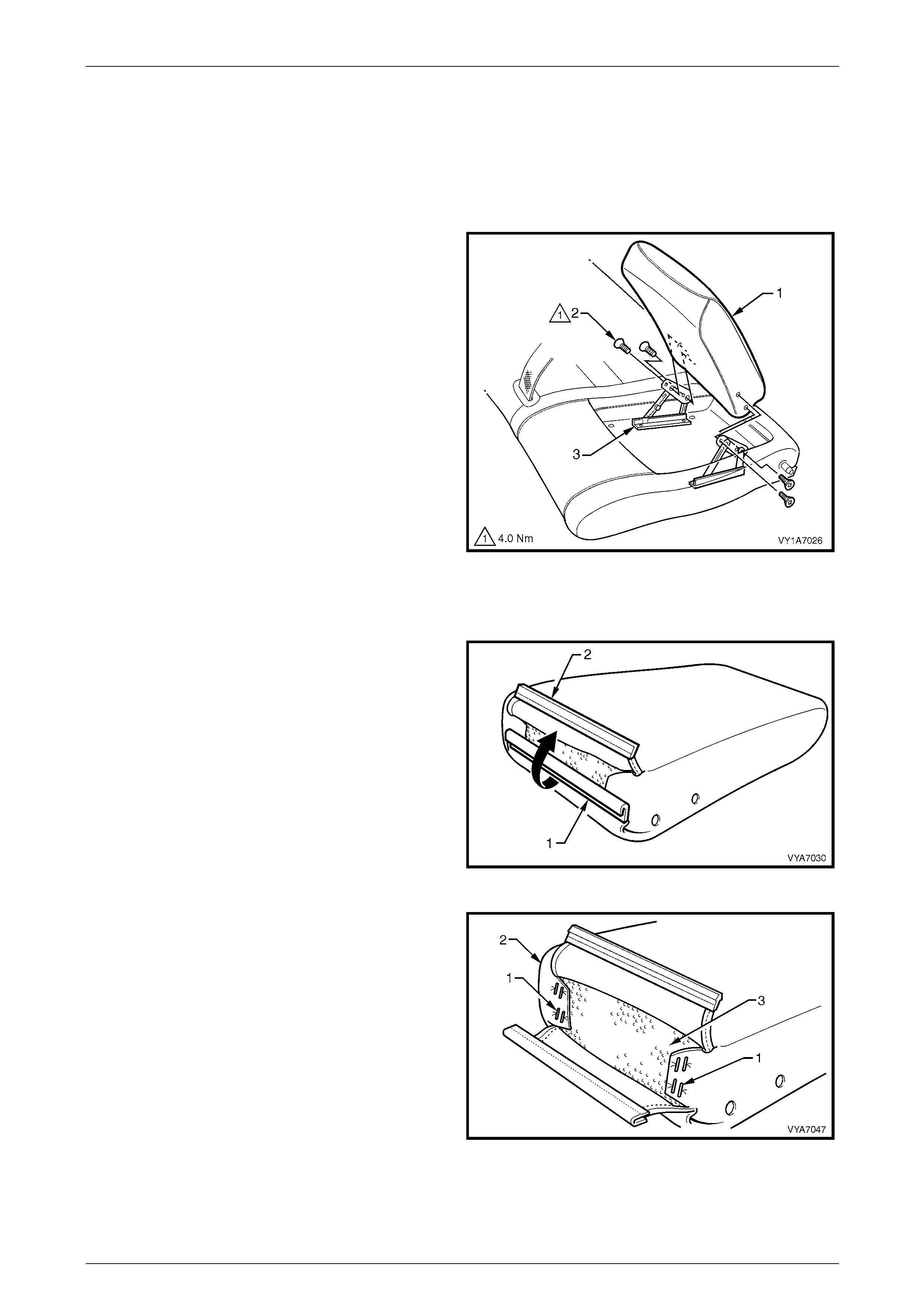
Seat Assemblies Page 1A7–404
Page 1A7–404
9.7 Rear Seat-back Armrest Assembly
LT Section No. — 14–350
Remove
1 Partially open the rear seat-back armrest assembly
(1).
2 Remove the four screws (2) attaching the armrest
assembly to the armrest hinge assembly (3).
3 Remove the rear seat-back armrest assembly.
Figure 1A7 – 390
Disassemble
1 Disengaging the rear seat-back armrest cover
retaining strip (1) by pulling th e flap (2) up.
Figure 1A7 – 391
2 Remove the eight staples (1) attaching the armrest
cover (2) to the armrest pad (3).
3 Slide the armrest cover off the armrest pad.
Figure 1A7 – 392

Seat Assemblies Page 1A7–405
Page 1A7–405
Reassemble
Reassembly of the rear seat-back armrest assembly is the reverse of the removal procedure. Ensure the rear seat-back
armrest retaining clip is fully engaged.
Reinstall
Reinstallation of the rear seat-back armrest assembly is the reverse of the removal procedure. Tighten the attaching
screws to the correct torque specification.
Rear seat-back armrest assembly retaining
screw torque specification....................................4.0 Nm

Seat Assemblies Page 1A7–406
Page 1A7–406
9.8 Rear Seat-back Armrest Hinge Assembly
and Centre Cover
LT Section No. — 14–350
NOTE
The following component will require replacement
when performing this operation.
• Rear seat-back armrest centre cover blanking
plugs.
1 Remove the rear seat cushion assembly, refer to 9.2 Rear Seat Cushion Assembly.
2 Remove the left-hand rear sea t bolster assembly, refer to 9.3 Rear Seat Bolster Assembly.
3 Remove the left-hand rear sea t -back assembly, refer to 9.4 Rear Seat-back Assembly.
4 Remove the left-hand rear sea t -back head restraint assembly,
refer to 9.5 Rear Seat-back Head Restraint Assembly.
5 Remove the rear seat-back armrest assembly, refer to 9.7 Rear Seat-back Armrest Assembly.
Remove
1 To remove the four blanking plugs (1) from the rear
seat-back armrest centre cover (2), drill a small hole
into the centre of each plug.
2 Insert a scribe or small screwdriver into the hole in the
plug and pull them free. Take care not to damage the
seat-back cover.
NOTE
The four blanking plugs will be damaged during
this operation and must be re placed.
Figure 1A7 – 393
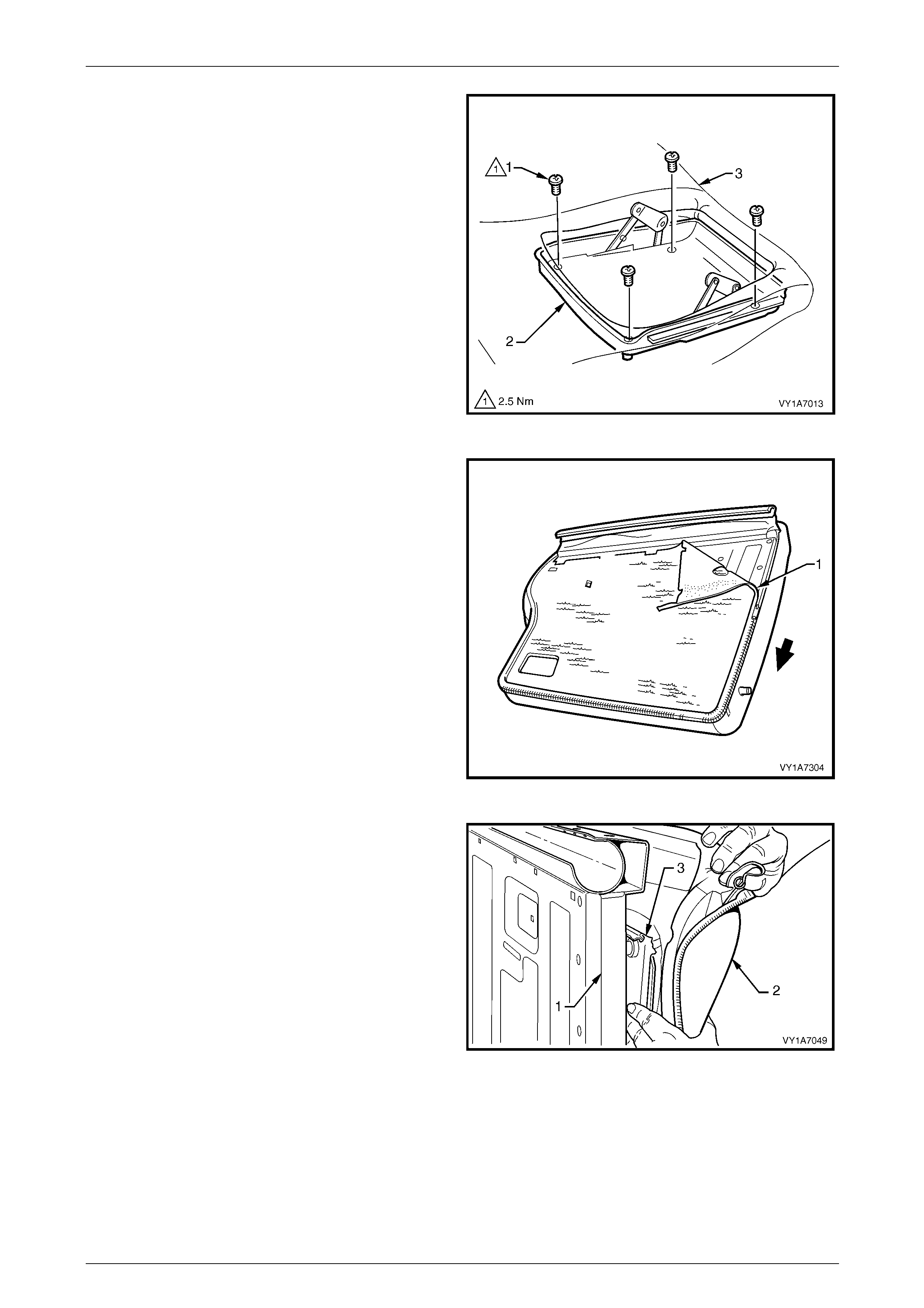
Seat Assemblies Page 1A7–407
Page 1A7–407
3 Remove the four screws (1) attaching the armrest
centre cover (2) to the seat-back pad and frame
assembly (3).
Figure 1A7 – 394
4 Remove the rear seat-back cover (1) by un-zipping the
cover around two sides of the rear seat-back
assembly.
5 Pull the outer top finisher strip from the rear seat-back
frame.
NOTE
To ease in the removal of the top J-strip, gently
lever the strip away from the frame using a
screwdriver.
Figure 1A7 – 395
6 Reach in between the seat-b ack frame (1) and the pad
assembly (2) and push the armrest centre cover (3)
out of the pad.
Figure 1A7 – 396
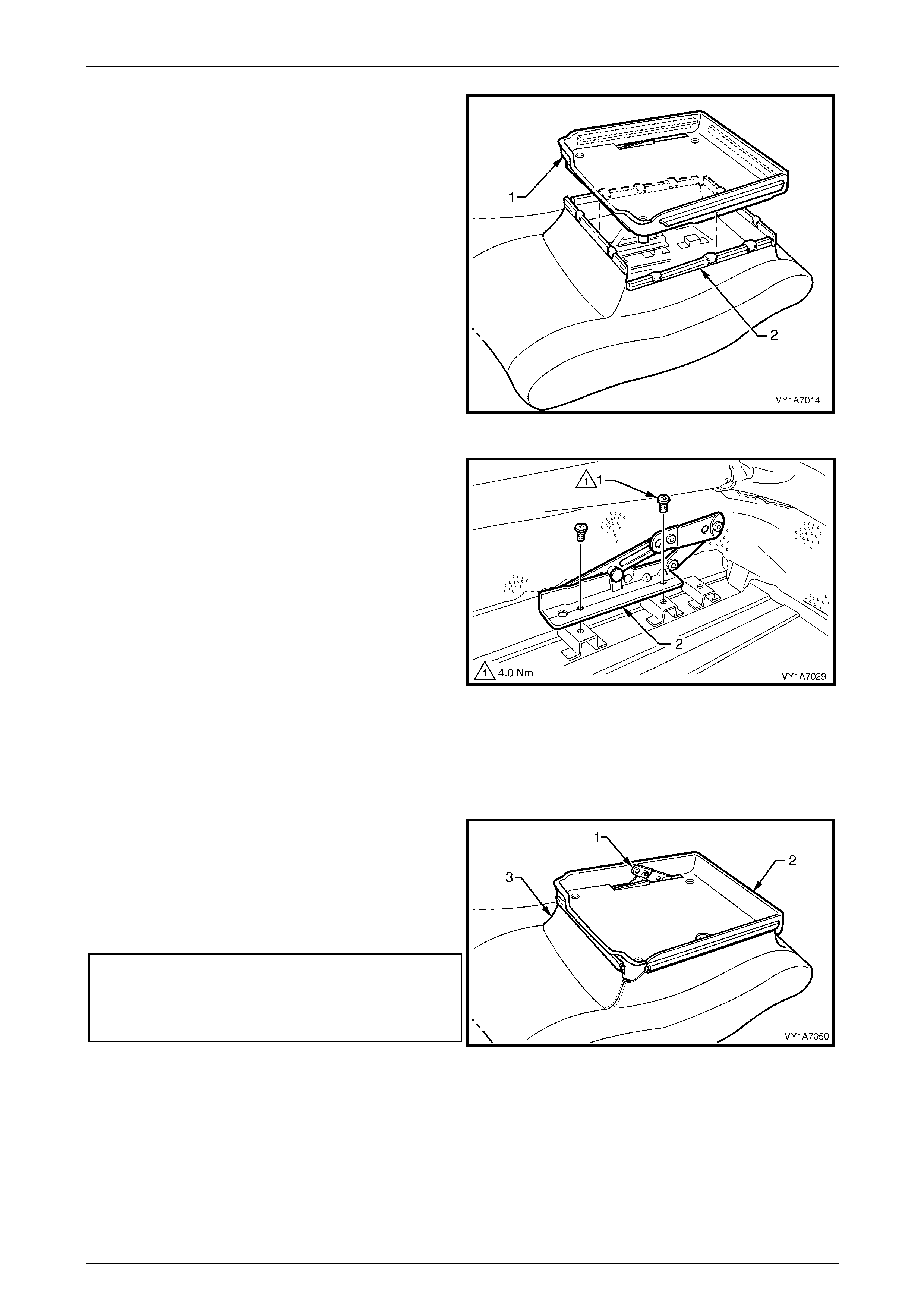
Seat Assemblies Page 1A7–408
Page 1A7–408
7 Lift the armrest centre cover (1) up and pull the four
seat-back cover retainers (2) a way from the four sides
of the centre cover.
8 Remove the armrest centre cover.
Figure 1A7 – 397
9 Remove the two screws (1) attaching the hi nge
assembly (2) to the seat-back frame assembl y and
remove the hinge assembly.
10 Repeat for the opposite side.
Figure 1A7 – 398
Reinstall
Reinstallation of the rear seat-back armrest hinge assembly and centre cover is the reverse of the removal procedure,
noting the following:
1 Position the hinges (1) in the partly open position
before installing the centre cover (2).
2 Ensure no puckering occurs around the rear seat-back
armrest cover (3) while installing the centre cover.
3 Tighten the attaching screws to the correct torque
specification.
Armrest centre cover attaching screw
torque specification..............................................2.5 Nm
Armrest hinges assembly attaching screw
torque specification..............................................4.0 Nm
4 Use four new centre cover blanking plugs. Figure 1A7 – 399
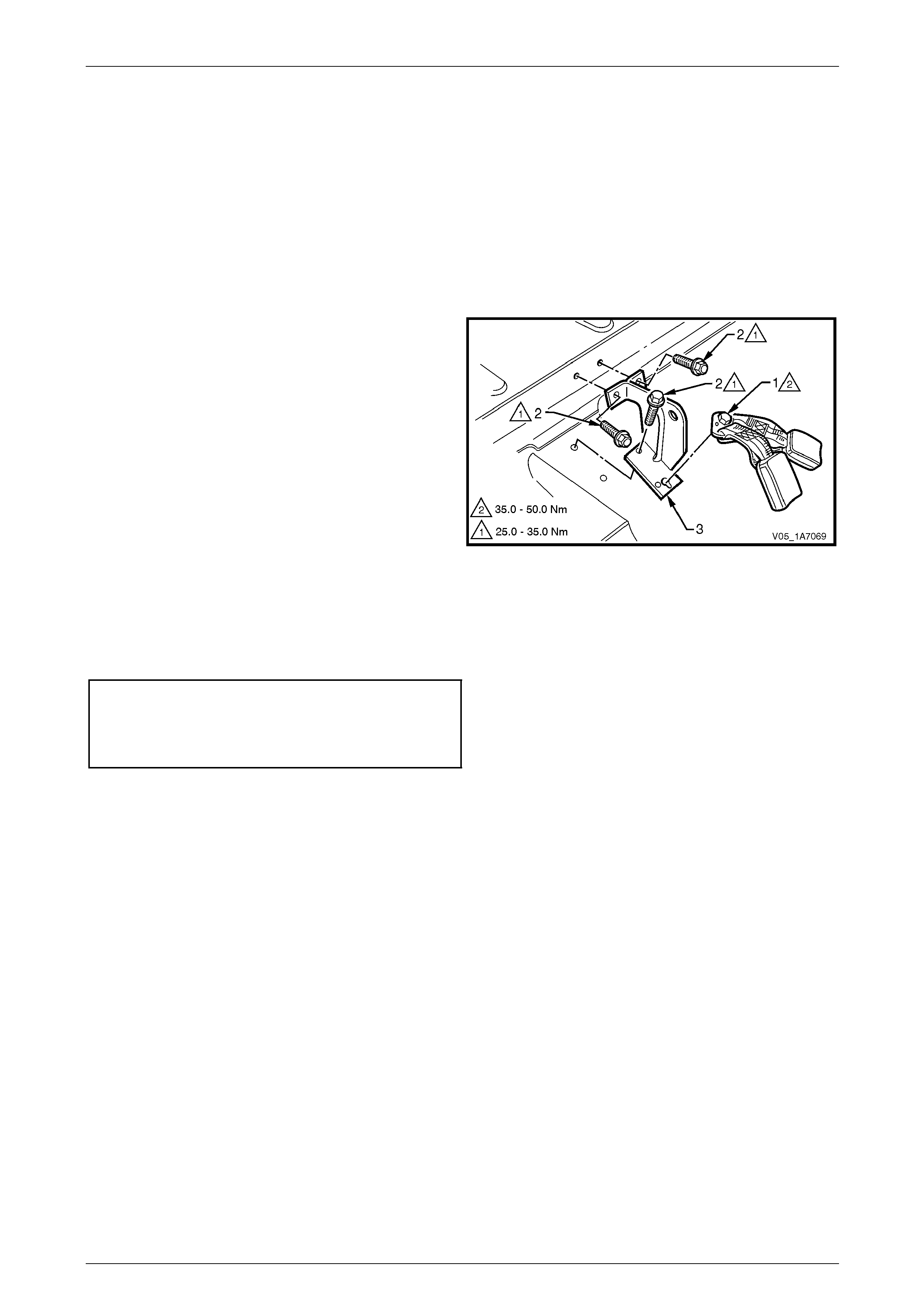
Seat Assemblies Page 1A7–409
Page 1A7–409
9.9 Rear Seat Centre Support
LT Section No. — 14–350
1 Remove the rear seat cushion assembly, refer to 9.2 Rear Seat Cushion Assembly.
2 Remove the rear seat bolster assembly, refer to 9.3 Rear Seat Bolster Assembly.
3 Remove the rear seat-back assembly, refer to 9.4 Rear Seat-back Assembl y.
Remove
1 Remove the right-hand and centre seatbe lt buckle
assembly anchor bolt (1).
2 Remove the three screws (2) attaching the rear seat
centre support (3) to the floor pan.
3 Remove the rear seat centre support.
Figure 1A7 – 400
Reinstall
Reinstallation of the rear seat-back centre support is the reverse of the removal operati on. Tighten the attaching screws
to the correct torque specifications.
Rear seat centre support attaching
screw torque specification.......................25.0 – 35.0 Nm
Seatbelt anchor attaching screw
torque specification.................................35.0 – 50.0 Nm

Seat Assemblies Page 1A7–410
Page 1A7–410
9.10 Rear Seat-back Lock Striker
Remove quarter inner trim panel assembl y, r efer to Section 1A8 Headlining and Interior Trim.
Remove
1 Remove the screw (1) attaching the rear seat-back
lock striker (2) to the rear quarter inner panel.
2 Remove the striker.
Figure 1A7 – 401
Reinstall
Reinstallation of the rear seat-back lock striker is the reverse of the removal procedure. Tighten the attaching scre w to
the correct torque specifications.
Seat-back lock striker attaching screw
torque specification.................................25.0 – 35.0 Nm
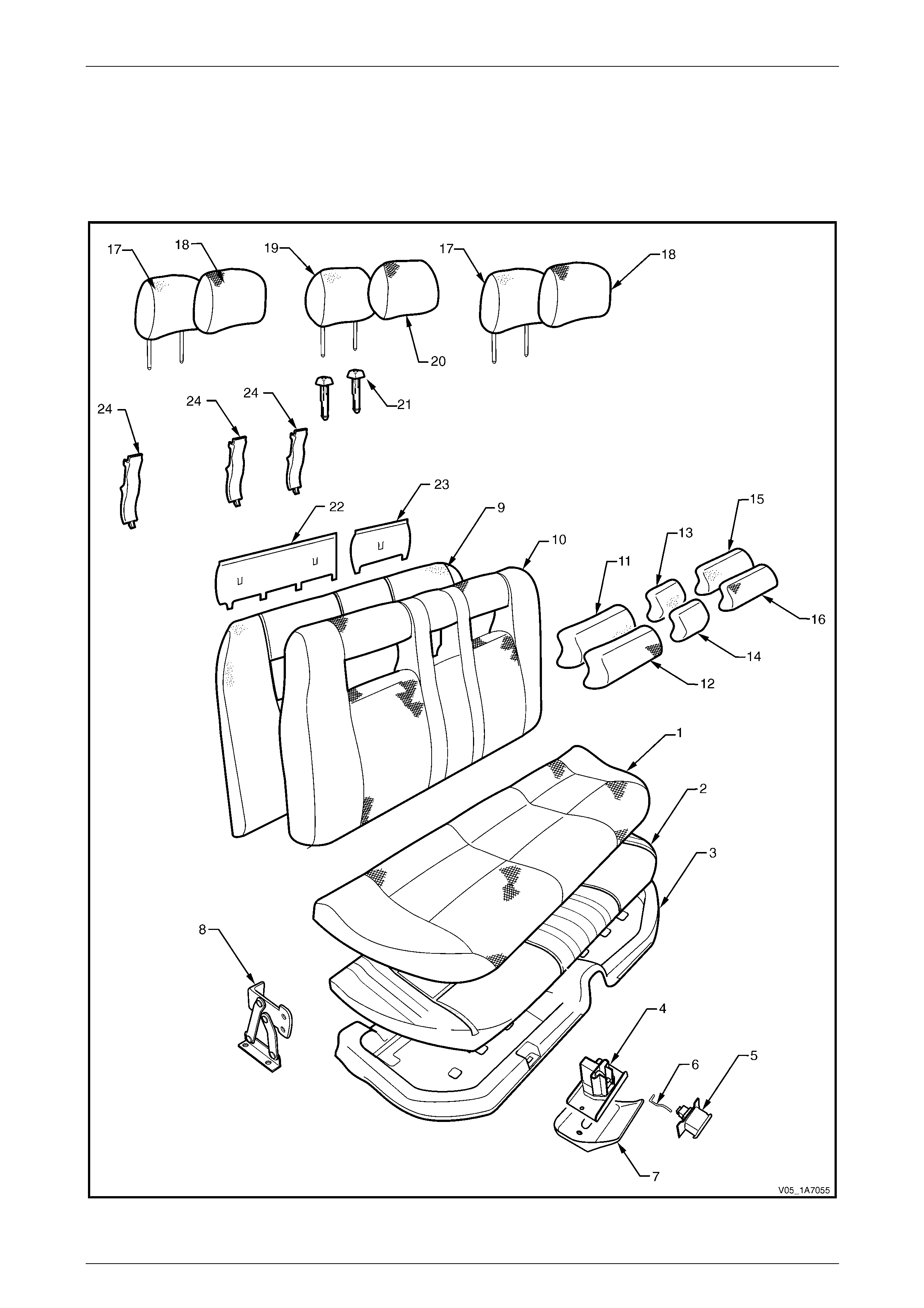
Seat Assemblies Page 1A7–411
Page 1A7–411
10 Service Operations – Rear Seat,
Crew Cab
Rear Seat
Figure 1A7 – 402

Seat Assemblies Page 1A7–412
Page 1A7–412
Legend
1 Rear Seat Cushion Cover
2 Rear Seat Cushion Pad
3 Rear Seat Cushion Base
4 Rear Seat Cushion Latch
5 Rear Seat Cushion Latch Release Button
6 Rear Seat Cushion Latch Release Rod
7 Rear Seat Latch Cover
8 Rear Seat Cushion Hinge (2 places)
9 Rear Seat-back Cushion Pad and Frame
10 Rear Seat-back Cushion, Cover
11 Rear Seat-back Insert Pad, Left-hand
12 Rear Seat-back Insert Cover, Left-hand
13 Rear Seat-back Insert Pad, Centre
14 Rear Seat-back Insert Cover, Centre
15 Rear Seat-back Insert Pad Right-hand
16 Rear Seat-back Insert Cover, Right-hand
17 Rear Head Restraint Pad, Outer
18 Rear Head Restraint Cover, Outer
19 Rear Head Restraint Pad, Centre
20 Rear Head Restraint Cover, Centre
21 Head Restraint Sleeve (6 places)
22 Rear Seat-back Insert Opening Cover, Right-hand
23 Rear Seat-back Insert Opening Cover, Left-hand
24 Seatbelt Guide
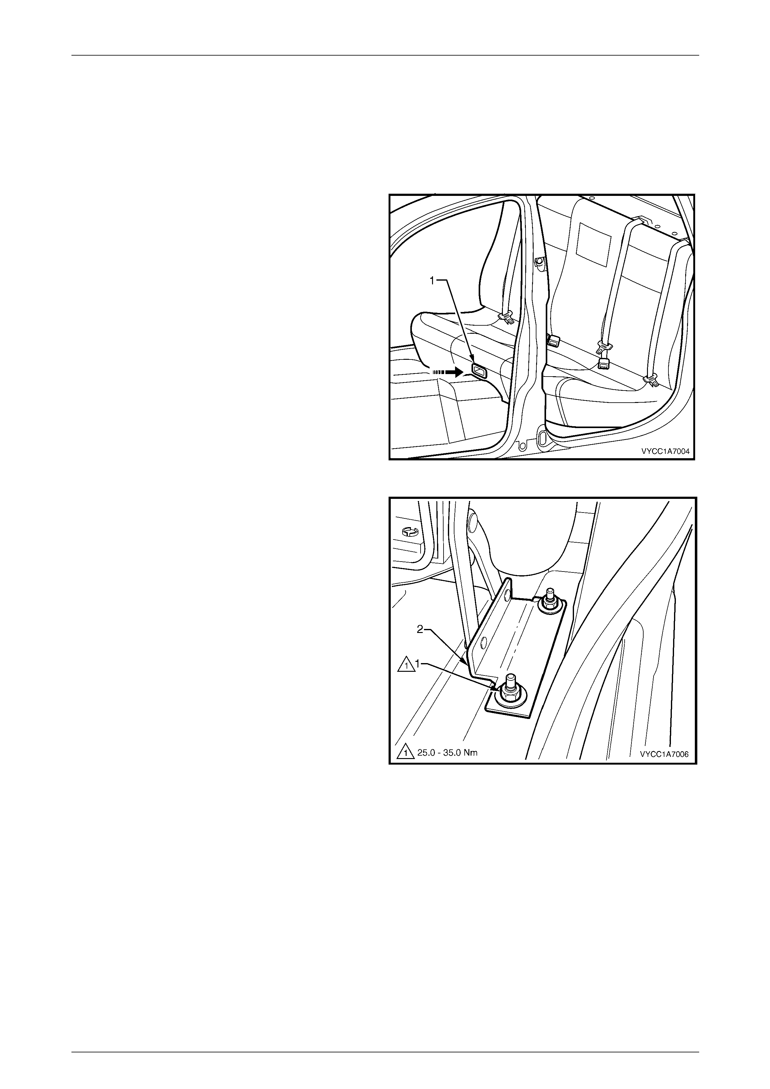
Seat Assemblies Page 1A7–413
Page 1A7–413
10.1 Rear Seat Cushion Assembly
LT Section No. — 14–330
Remove
1 Press the rear seat release button (1) inward and lift
the rear seat cushion to the raised position.
2 Remove the rocker panel cover extension, refer to
Section 1A8 Headlining and Interior Tr im.
Figure 1A7 – 403
3 Remove the two nuts (1), each side, from the rear seat
cushion assembly hinge (2).
4 Remove the rear seat cushion assembly from the
vehicle by manoeuvring it through either rear door
opening.
Figure 1A7 – 404

Seat Assemblies Page 1A7–414
Page 1A7–414
Disassemble
Cushion Cov er and Pad Assembly
Remove
1 Using a suitable scre wdriver, carefully prise the
cushion cover (1) over the seat latch escutch eon (2).
Figure 1A7 – 405
2 Prise up the retaining strips (1), attaching the cushio n
cover (2) to the rear seat cushion base (3).
Figure 1A7 – 406
3 Beginning at a rear corner of the cush ion assembly
(1), carefully peel the cushion cover (2) back,
releasing the hook and loop strips (3).
Figure 1A7 – 407

Seat Assemblies Page 1A7–415
Page 1A7–415
4 Carefully continue foldi ng the cover back releasing the
hook and loop strip (1), 10 places, at the loca tions
shown.
5 Remove the cover and cushio n from the base.
Figure 1A7 – 408
Reinstall
1 Place the rear seat base (1) upside-down and install
the two cushion cover front retaining strips (2) into the
base.
Figure 1A7 – 409
2 Turn the rear seat base (1) over and p ositi on the rear
seat cushion pad (2) on the base.
Figure 1A7 – 410
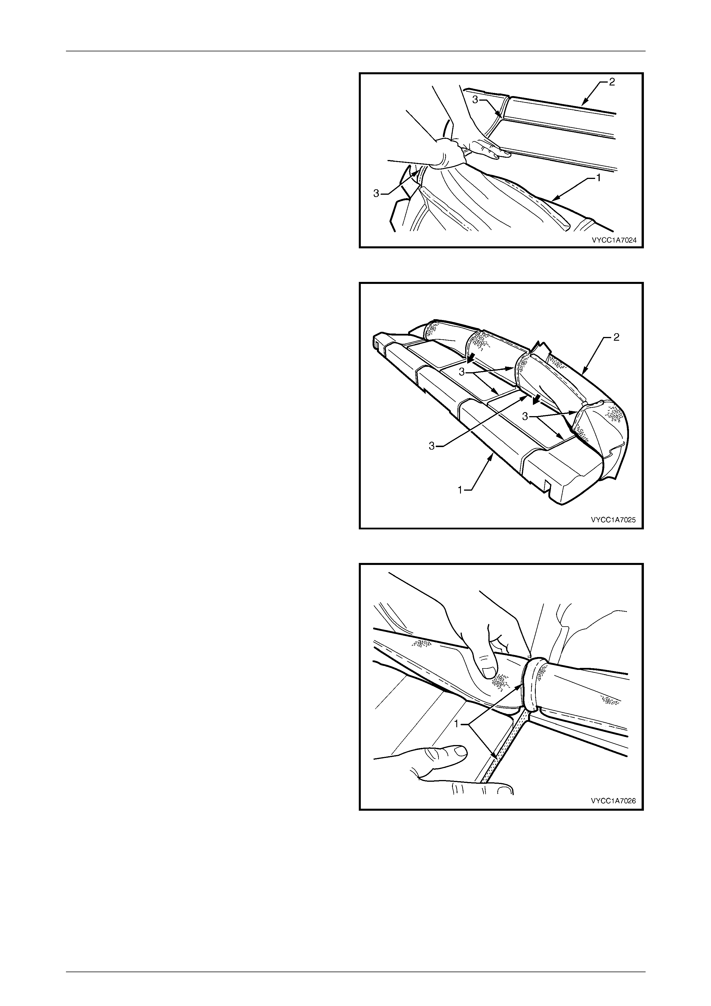
Seat Assemblies Page 1A7–416
Page 1A7–416
3 Beginning at the front corner, pull the cushion cover
(1) over the top of the cushion pad (2), aligning the
hook and loop strips (3).
4 Repeat step 3 for the other side of the cushion
assembly.
Figure 1A7 – 411
5 Working from one corner of the cushion pad (1), pull
the cushion cover (2) over the cushion pad, aligning
the hook and loop strips (3).
Figure 1A7 – 412
6 Align the hook and loop strips (1) and push the cover
into the corresponding groove. Ensure the mating
strips are fully attached and aligned correctly.
Figure 1A7 – 413
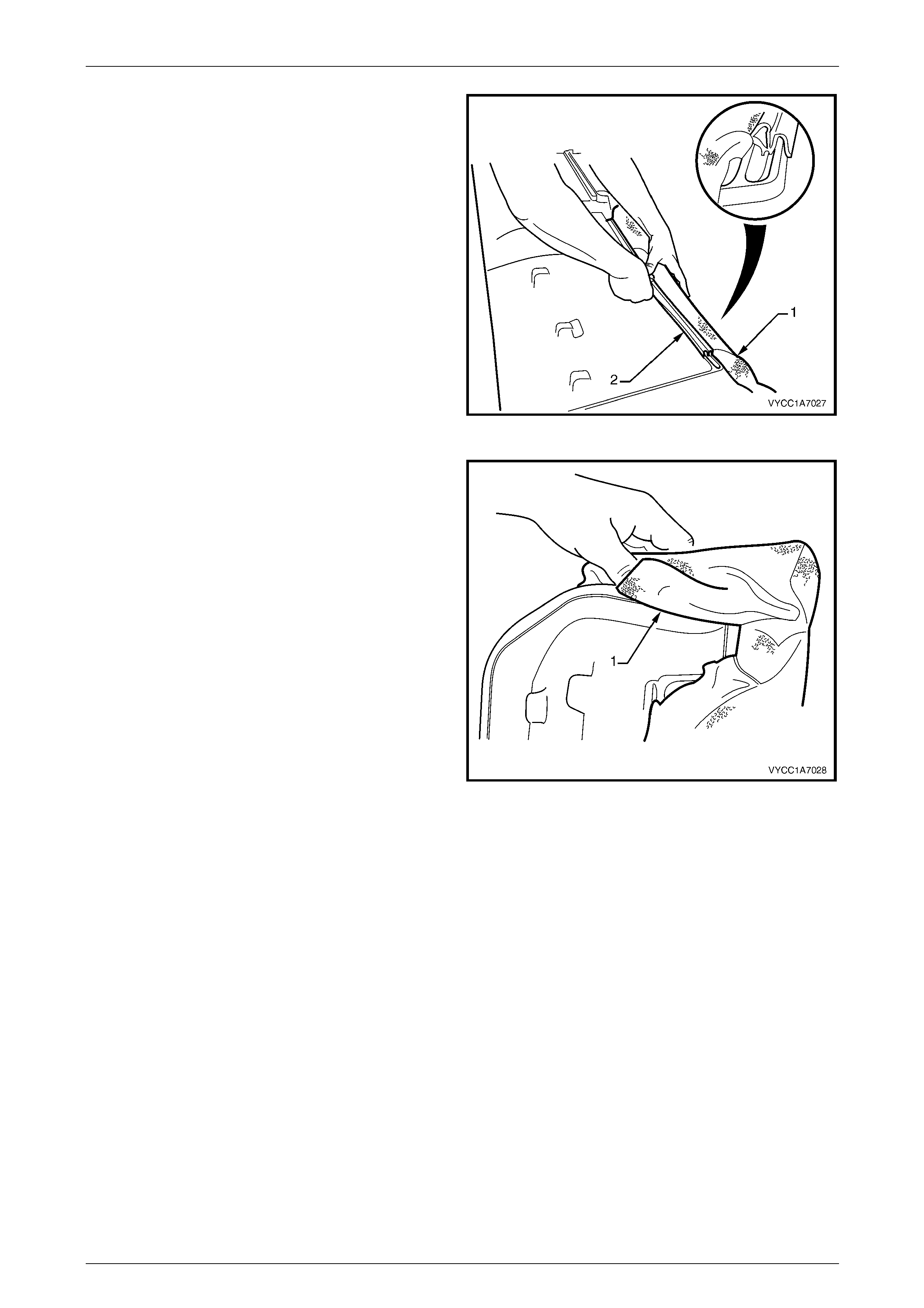
Seat Assemblies Page 1A7–417
Page 1A7–417
7 Pull the cushion cover (1) over the rear of the cushion
pad and fasten the rear retainer strip (2), three places.
NOTE
Ensure the rear retainer strips are fitted to the
second inner groove of the base.
Figure 1A7 – 414
8 Fold the corners of the cushion cover (1) neatly in
behind the cushion pad.
NOTE
Ensure the cushion cover is fitt ed neatly by hand
into all corners and grooves and it is free from
any creases. As part of their designed
appearance, leather cushion covers have
inherent minor creases in the material.
Figure 1A7 – 415
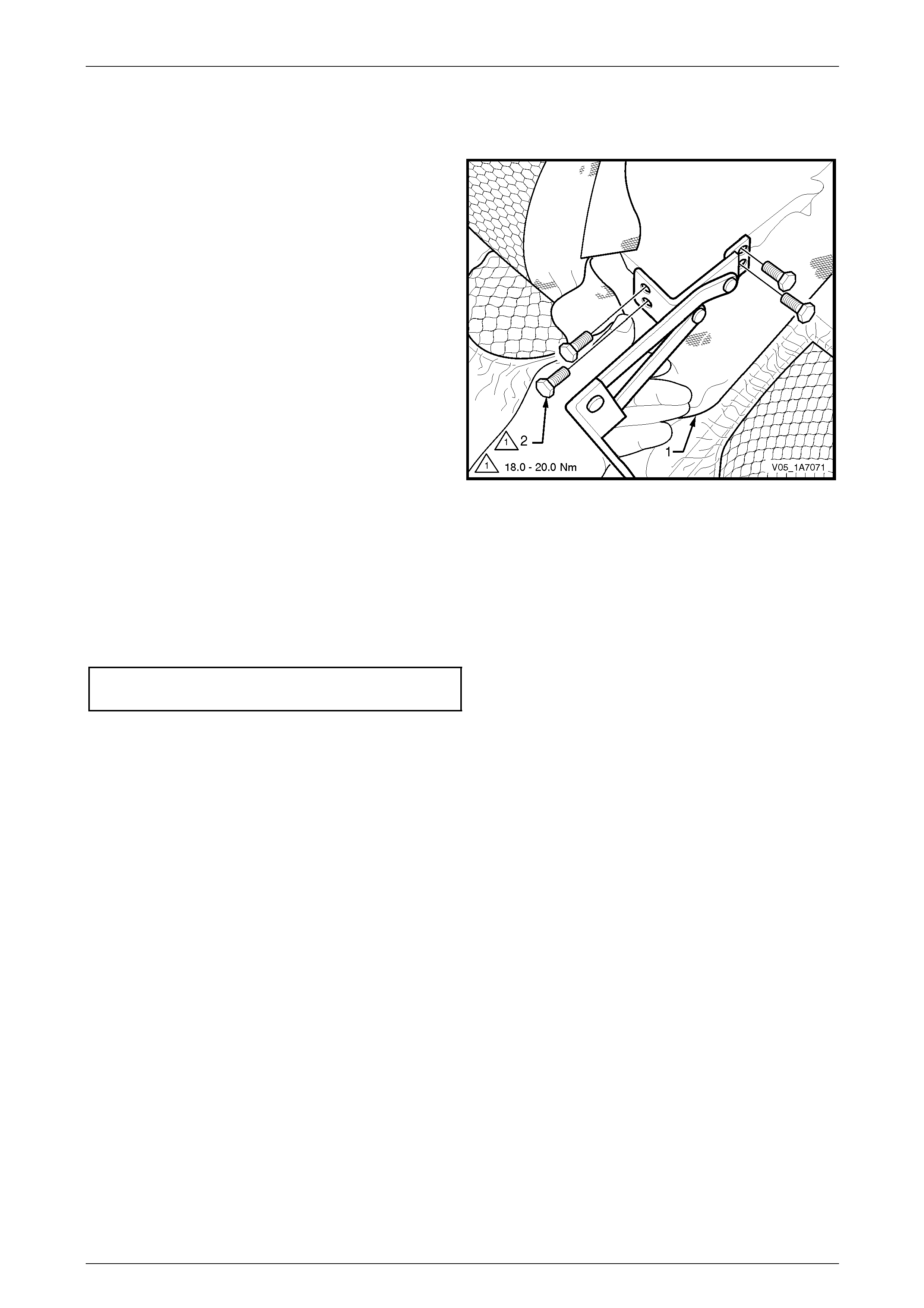
Seat Assemblies Page 1A7–418
Page 1A7–418
Rear Seat Hinge
Remove
1 If the rear seat cushion pad and cover assembl y has
not been removed, fold the rear seat cushion pad an d
cover assembly (1) back sufficiently to gain access to
the hinge and attaching bolts.
2 Remove the four bolts (2) attaching the hinge to the
rear seat cushion base.
3 Remove the hinge past the cushion cover.
Figure 1A7 – 416
Reinstall
1 If the seat cushion pad and cover assembly (1) has not been removed, fold the rear seat cushion pad and cover
assembly back sufficiently to gain access to install the hinge and four attaching bolts (2), refer to F igure 1A7 – 416.
2 Position the hinge on the base and i nstal l the four attaching bolts.
3 Tighten the attaching bolts to the correct torque specification.
Rear seat cushion hinge attaching
bolt torque specification..........................18.0 – 20.0 Nm
4 Ensure the cushion cover is fitted neatly into the corners of the cushion and is free from any creases.
NOTE
As part of their designed appearance, leather
cushion covers have inherent minor creases in
the material.
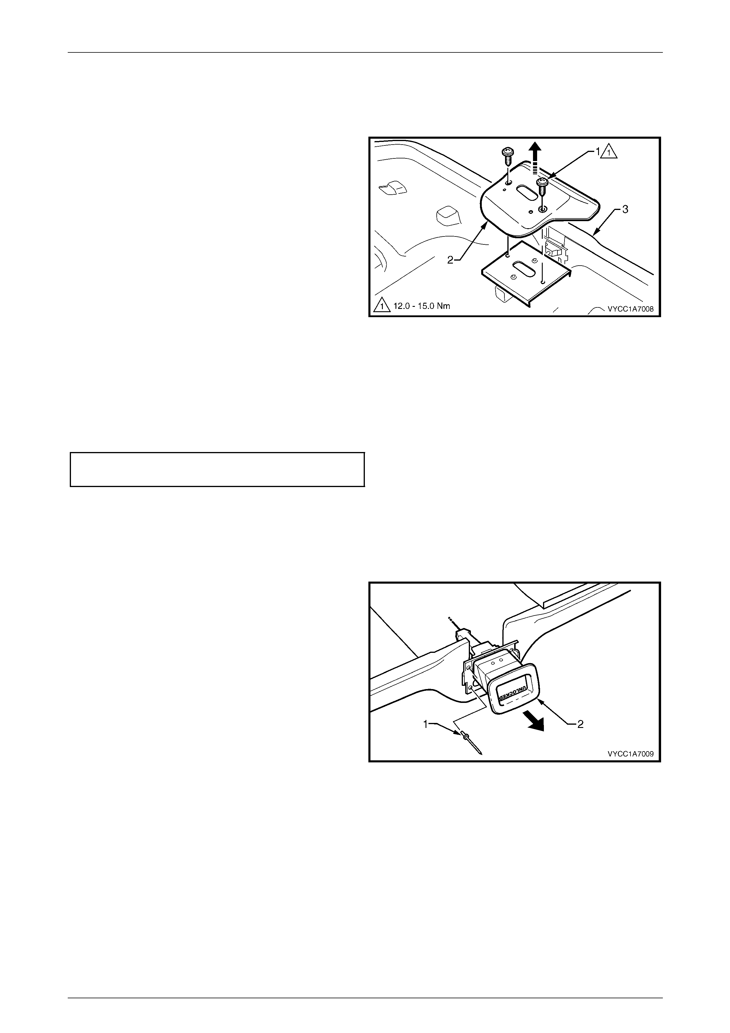
Seat Assemblies Page 1A7–419
Page 1A7–419
Rear Seat Latch
Remove
1 Remove the two screws (1) attaching the rear seat
latch and latch cover (2) to the seat cushion base (3).
2 Unhook the latch release rod from the latch.
3 Lift the latch clear of the release button.
Figure 1A7 – 417
Reinstall
Reinstallation of the rear seat latch is the reverse of the removal procedure , noting the following:
1 Fully locate the release rod in the latch.
2 Tighten the attaching screws to the correct torque specification.
Rear seat cushion latch attaching
screw torque specification.......................12.0 – 15.0 Nm
3 Check the release button and latch oper ate smoothly.
Rear Seat Release Button
Remove
1 Remove the pop rivets (1), four places, attaching the
rear seat cushion release button (2) to the rear seat
cushion base by drilling the heads off the rivets.
2 Remove the release button from the rear seat cushion
base.
Figure 1A7 – 418
Reinstall
Reinstallation of the rear seat release button is the reverse of the removal process. Secure with new pop rivets.
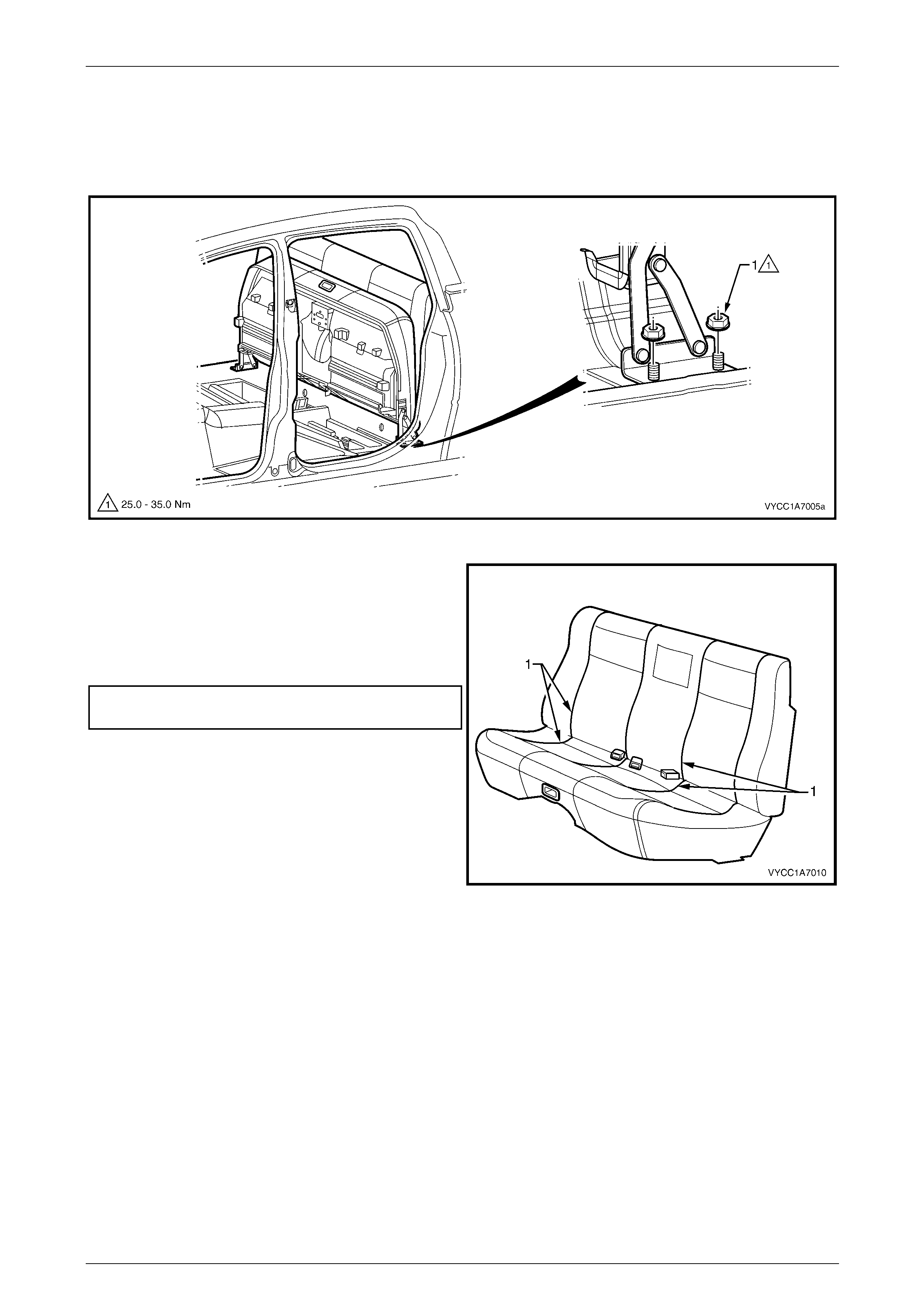
Seat Assemblies Page 1A7–420
Page 1A7–420
Reinstall
Reinstallation of the rear seat cushion assembly is the reverse of the removal pr ocedure, noting the following:
1 Ensure the rear seat assembly is in the upright position and the hinge is h orizontal, refer to Figure 1A7 – 419.
Figure 1A7 – 419
2 Initially tighten the attaching nuts and ensure the
design lines (1) match up to within 10mm when
measured in a lateral direction . Readjust, if required,
by loosening the attaching nuts and repositioning.
3 Install the attaching nut, two places eac h side, and
tighten to the correct torque specification.
Rear seat hinge attaching nut
torque specification.................................25.0 – 35.0 Nm
Figure 1A7 – 420
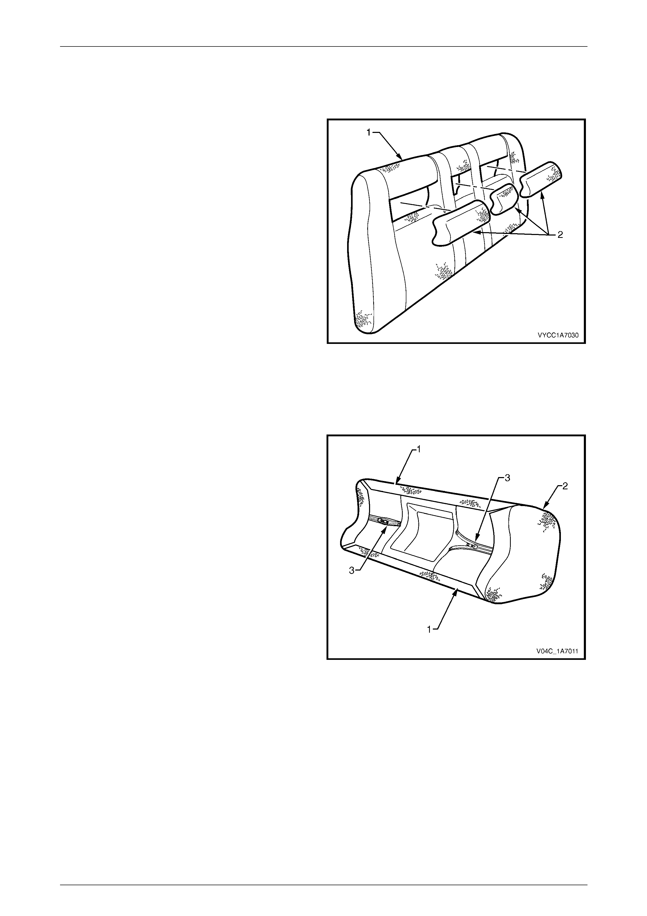
Seat Assemblies Page 1A7–421
Page 1A7–421
10.2 Rear Seat-back Insert
Remove
Holding the rear seat-back assembly (1), place your hand
over the top of the insert (2) and pull the rear seat-back
insert out towards the front of the rear seat-back assembly.
Figure 1A7 – 421
Disassemble
Outer Insert
1 Peel back the two hook and loop strips (1), attaching
the cover (2) to the pad.
2 Remove the two zip fasteners (3).
3 Starting from one corner, carefully remove the cover
from the pad.
Figure 1A7 – 422
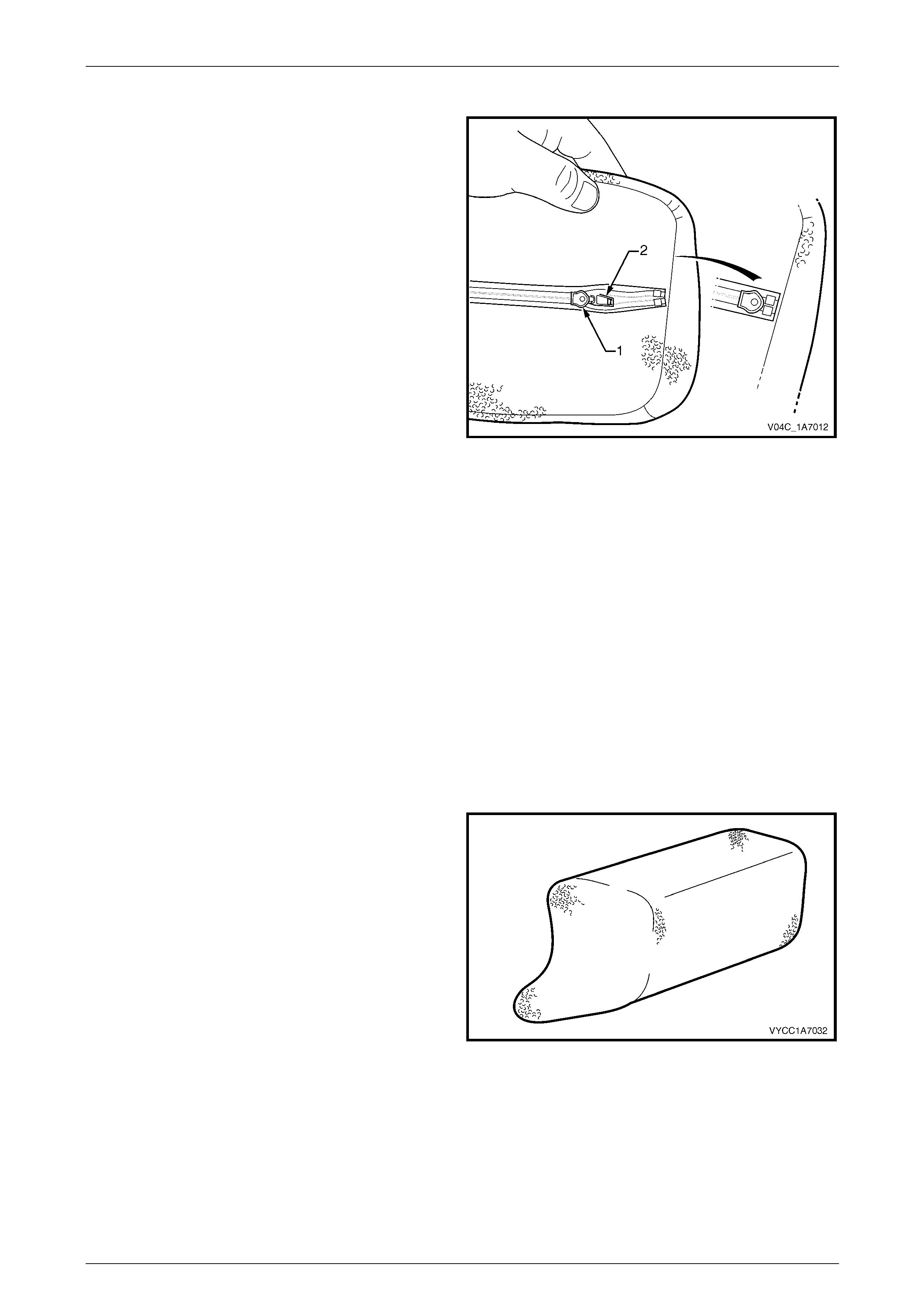
Seat Assemblies Page 1A7–422
Page 1A7–422
Inner Insert
1 Pull the zip fastener (1) back slightly to allow access to
the tag (2) on the fastener.
2 Unzip the cover completely.
3 Starting from one corner, carefully remove the cover
from the pad.
Figure 1A7 – 423
Reassemble
Reassembly of the rear seat-back inner an d outer insert cover is the reverse of the removal procedure, notin g the
following:
1 Ensure the cover is fitted neatly by hand without any creases and the hook and loop strips on the outer insert are
sitting flat against the pad and are fully fastened.
2 Ensure the centre insert zip fastener is fully closed and the tag is tucked in underneath the insert cover, refer to
Figure 1A7 – 423.
NOTE
As part of their designed appearance, leather
cushion covers have inherent minor creases in
the material.
Reinstall
Reinstallation of the rear seat-back insert is the reverse of
the removal procedure, ensuring the wider section faces the
bottom of the seat-back assembly.
Figure 1A7 – 424

Seat Assemblies Page 1A7–423
Page 1A7–423
10.3 Rear Seat-back Assembly
LT Section No. — 14–350
If required, remove the following:
1 Rear seat cushion assembly, refer to 10.1 Rear Seat Cushion Assembly.
2 Rear seatbelts, refer to Section 12M Occupant Protection System.
Remove
1 If required, raise the head restraints to the up per stop, refer to 10.4 Head Restraint Assembly.
2 Remove the bolt (1), two places, attaching the rear seat-back assembly (2) to the body, refer to Figure 1A7 – 425.
Figure 1A7 – 425
3 Holding the rear seat-back assembl y at the lower ed ge, carefully raise the assembly ev enly until the upper
attaching hooks (View A), three places, are released.
4 Remove the rear seat-back assembly.
Disassemble
Rear Seat-back Cover
Remove
1 If required, remove the rear seat-back inserts, refer to 10.2 Rear Seat-back Insert.
2 Remove the two rear seat-back insert opening covers
(1) by carefully pulling the cover away from the
seat-back assembly, releasing the eight hook and loop
strips (2).
Figure 1A7 – 426
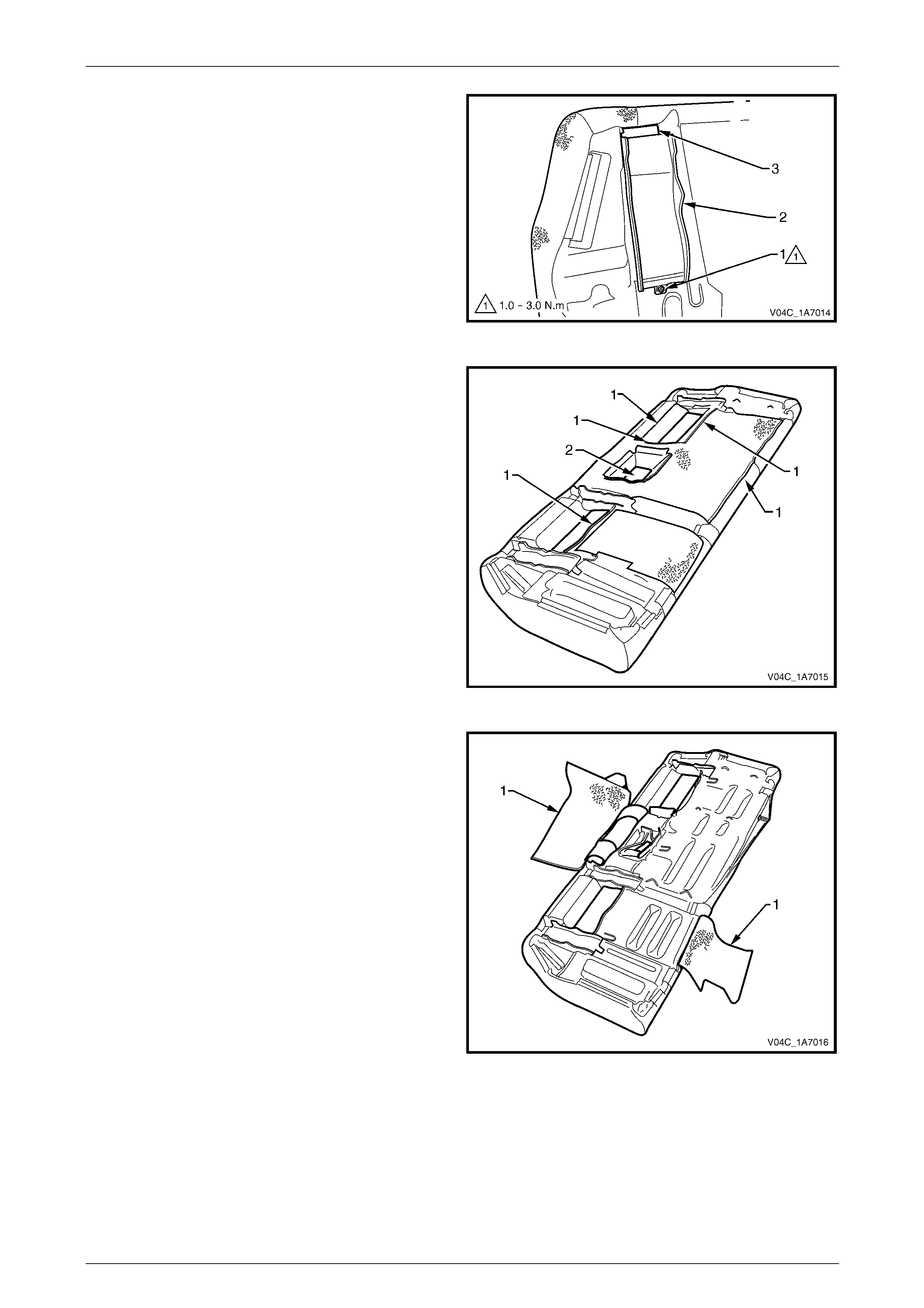
Seat Assemblies Page 1A7–424
Page 1A7–424
3 Remove the screw (1) attaching the seatbelt guid e (2)
to the rear seat-back assembly and remove the guide
by sliding it out from under the J-strip (3).
4 Repeat step 3 for the two remaining seatbe lt guides.
Figure 1A7 – 427
5 Remove the five hook and loop strips (1) and the four
hook and loop strips around the centre i nsert cavity
(2).
Figure 1A7 – 428
6 Fold back the two rear seat-back rear cover s (1).
Figure 1A7 – 429
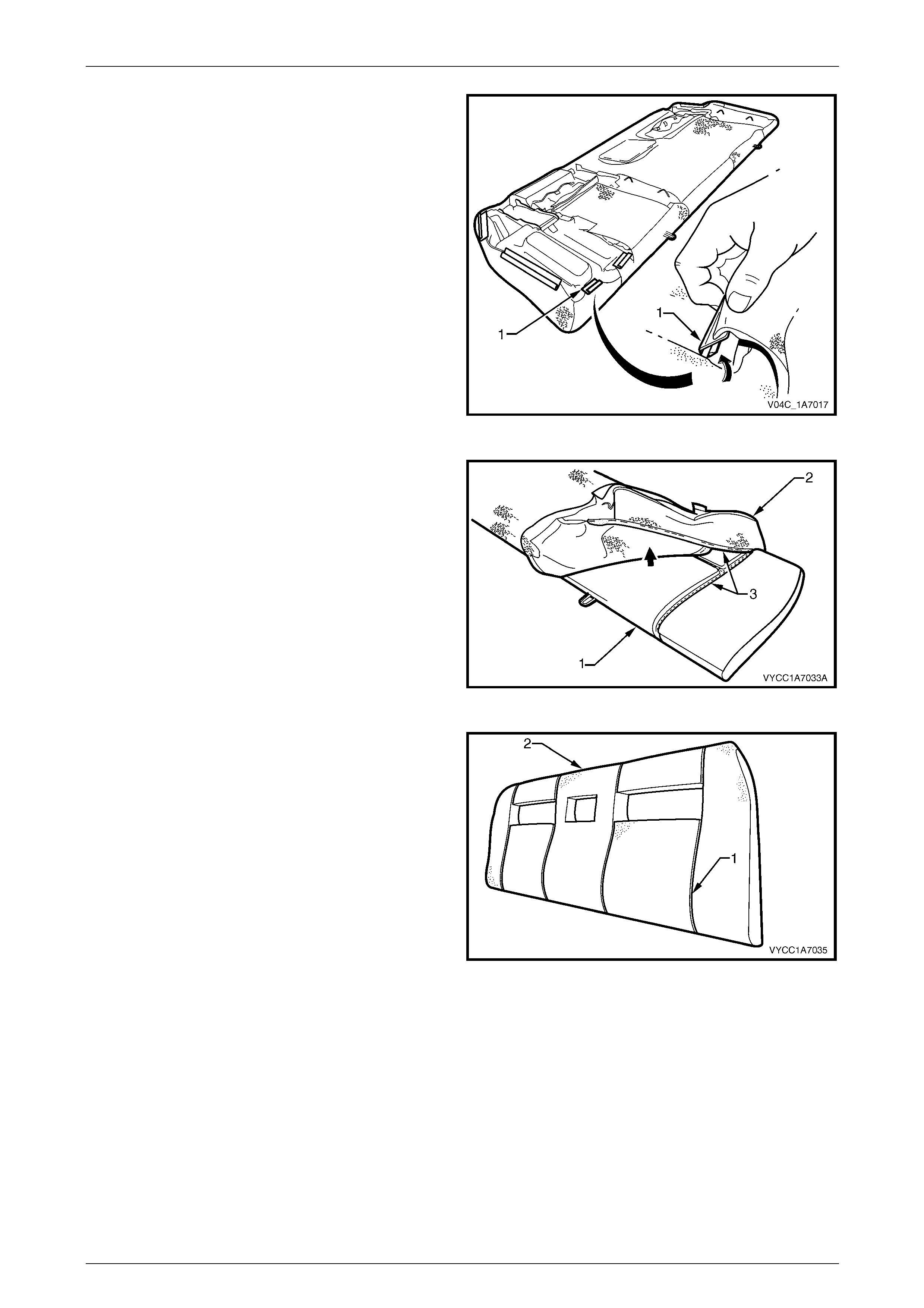
Seat Assemblies Page 1A7–425
Page 1A7–425
7 Remove the J-strips (1), 12 places, attaching the rear
seat-back cover to the seat-back frame, by raising the
J-strip slightly and pushing toward the centre of the
rear seat-back assembly.
8 Carefully fold the cover ov er the corners of the rear
seat-back cushion pad.
Figure 1A7 – 430
9 Starting at the corner of the rear seat-back pad
assembly (1), carefully pull the cushion cover (2),
releasing the hook and loop strips (3).
Figure 1A7 – 431
10 Continue removing the cover, releasing all hook and
loop strips (1) from the pad (2) until the cover is
removed.
Figure 1A7 – 432
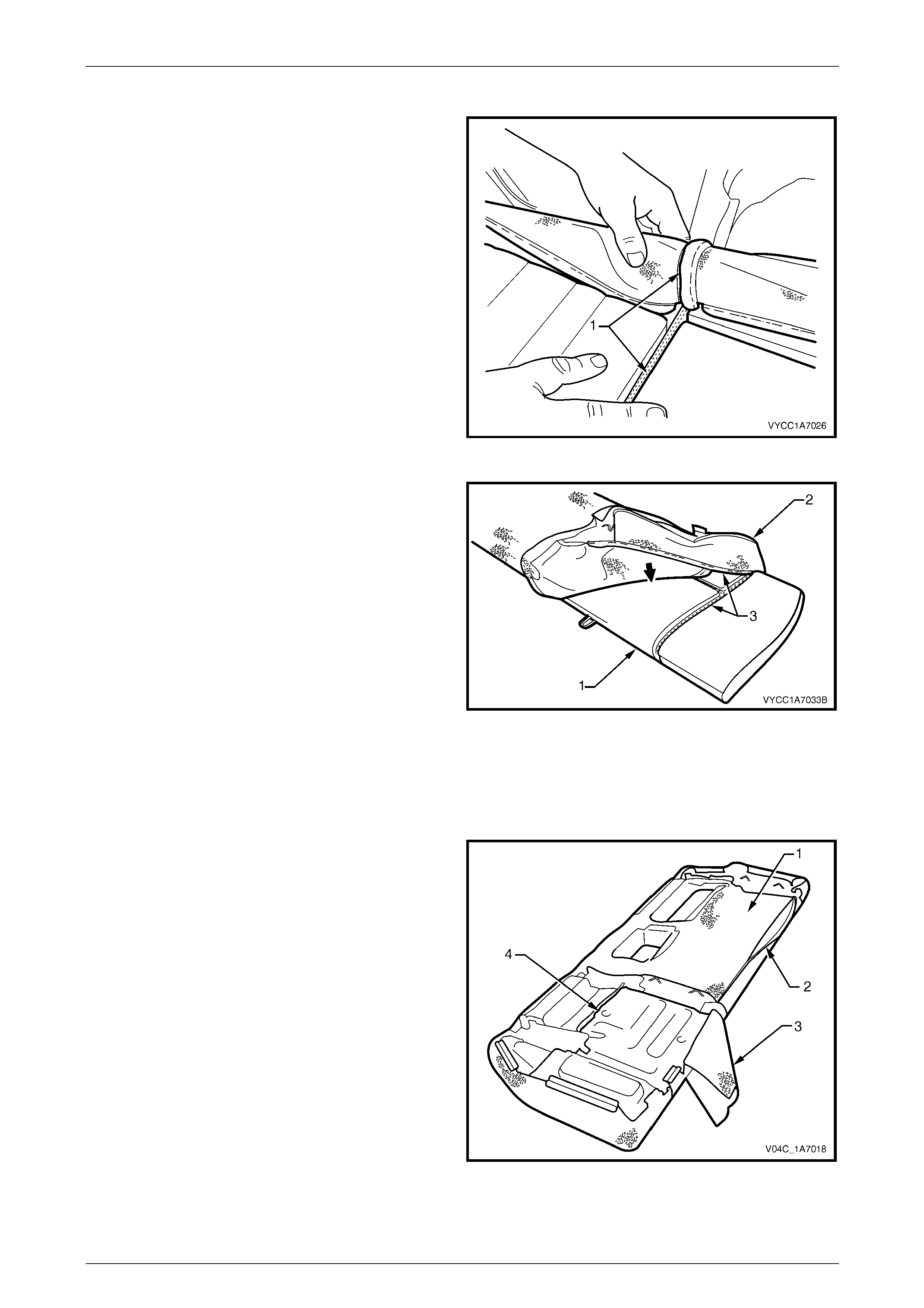
Seat Assemblies Page 1A7–426
Page 1A7–426
Reinstall
1 Align the rear seat-back cushion cover to the pad and
push the cover in to the groove, enga ging the hook
and loop strips (1).
Figure 1A7 – 433
2 Working along the rear seat-back pad (1) continue
inserting the cover (2) into the correspond ing grooves
aligning the hook and loo p strips (3).
Figure 1A7 – 434
3 Place the rear seat-back assembly face down on a clean surface.
4 Fold and position the cover neatly over the corners of the rear seat-back cushi on pad.
5 Reinstall the 12 J-strips by raising the J-strip slightl y then clipping it onto the frame, refer to Figure 1A7 – 430.
6 Fold the right-hand rear seat-back rear cover (1) over
the back of the seat-back assembly and fasten the
lower hook and loop strip (2).
7 Fold the left-hand rear seat-back rear cover (3) over
the seat-back assembly and fasten the hook and loop
strip (4) in the insert cavity.
NOTE
Ensure the rear seat-back rear covers are sitting
flat and free from any creases. Reali gn the hook
and loop strips if necessary.
Figure 1A7 – 435
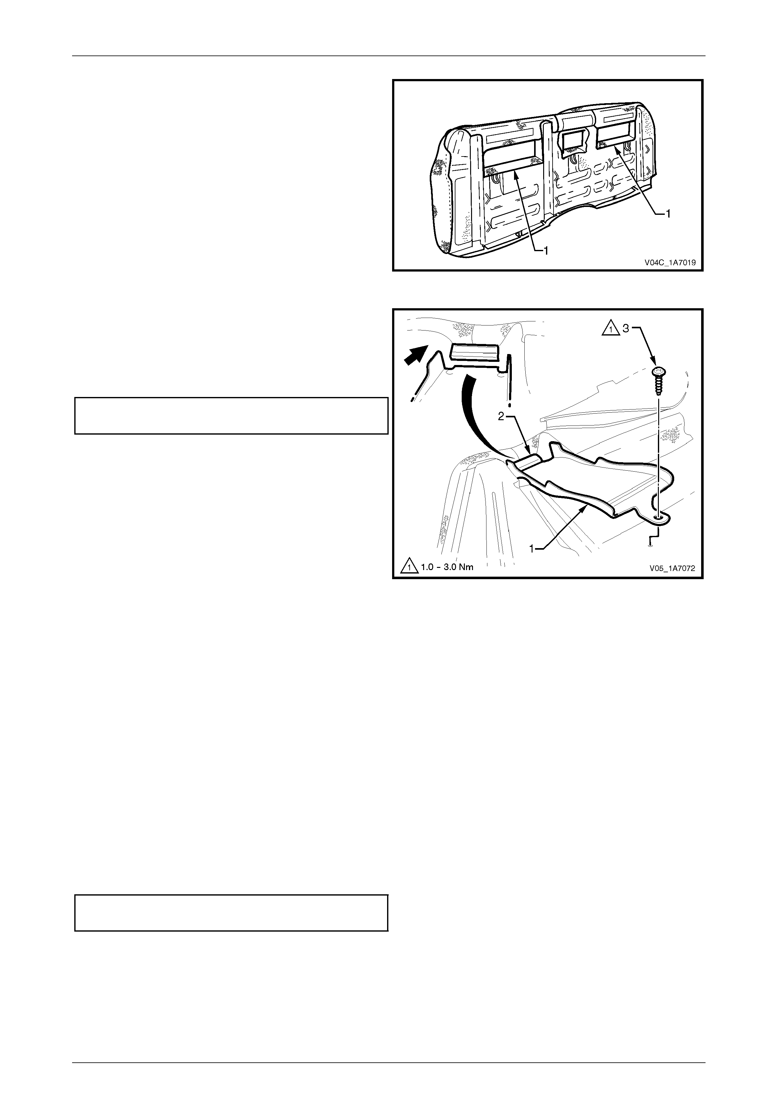
Seat Assemblies Page 1A7–427
Page 1A7–427
8 Reattach the hook and loop strips (1), four places
around the rear seat-back insert cavities.
Figure 1A7 – 436
9 Reinstall the seatbelt gui de (1) by gently pushing the
seatbelt guide into the groove in the rear seat-back
pad under the J-strip (2).
10 Tighten the attaching screw (3) to the correct torque
specification.
Rear seatbelt guide attaching screw
torque specification.....................................1.0 – 3.0 Nm
11 Repeat steps 9 and 10 for the t wo remaining seatbelt
guides.
Figure 1A7 – 437
12 Reinstall the two rear seat-back insert opening covers ensuring the flap in the cover for the child restraint anchor is
in the centre of the rear seat-back insert cavity, refer to Figure 1A7 – 426.
NOTE
Ensure the cushion cover is fitted neatly by hand
into all corners and grooves and is free from any
creases. As part of their designed appearance,
leather cushion covers have inherent minor
creases in the material.
Reinstall
Reinstallation of the rear seat-back assembly is the reverse of the removal procedure, noting the following:
1 Ensure the two, rear seat-back insert opening covers align with the child restraint anchor.
2 Ensure the upper attaching hooks (View A) lock into place and the lower attaching bo lts (1) are tightened to the
correct torque specification, refer to F igure 1A7 – 425.
Rear seat-back assembly attaching
bolt torque specification..........................25.0 – 35.0 Nm
3 If required, reinstall the rear seatbelts, refer to Section 12M Occupant Protection System.
4 Reinstall the rear seat cushion assembl y, refer to 10.1 Rear Seat Cushion Assembly.
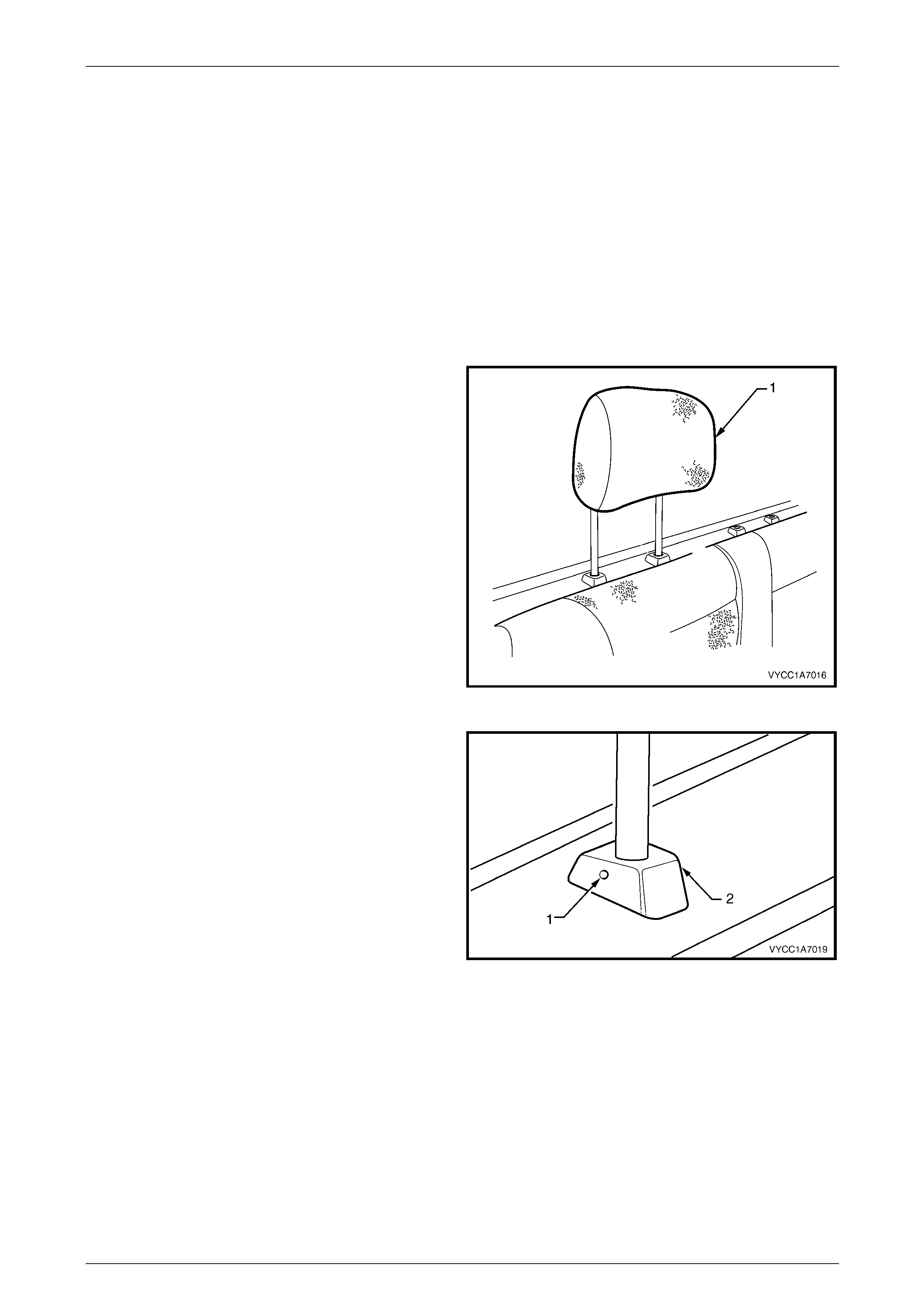
Seat Assemblies Page 1A7–428
Page 1A7–428
10.4 Head Restraint Assembl y
LT Section No. — 14–350
Remove
NOTE
Although the rear seat-back centre head re straint
is different in appearance than the outer head
restraints, the same service procedures apply for
both.
If required, remove the rear seat-back assembl y, refer to 10.3 Rear Seat-back Assembly.
1 Raise the head restraint fully.
Figure 1A7 – 438
2 Insert a suitable size probe into the hole (1) in the
left-hand head restraint guide (2).
3 Push the probe in slightly whil e app lying slight up ward
pressure on the head restraint. Hold the upward
pressure.
Figure 1A7 – 439
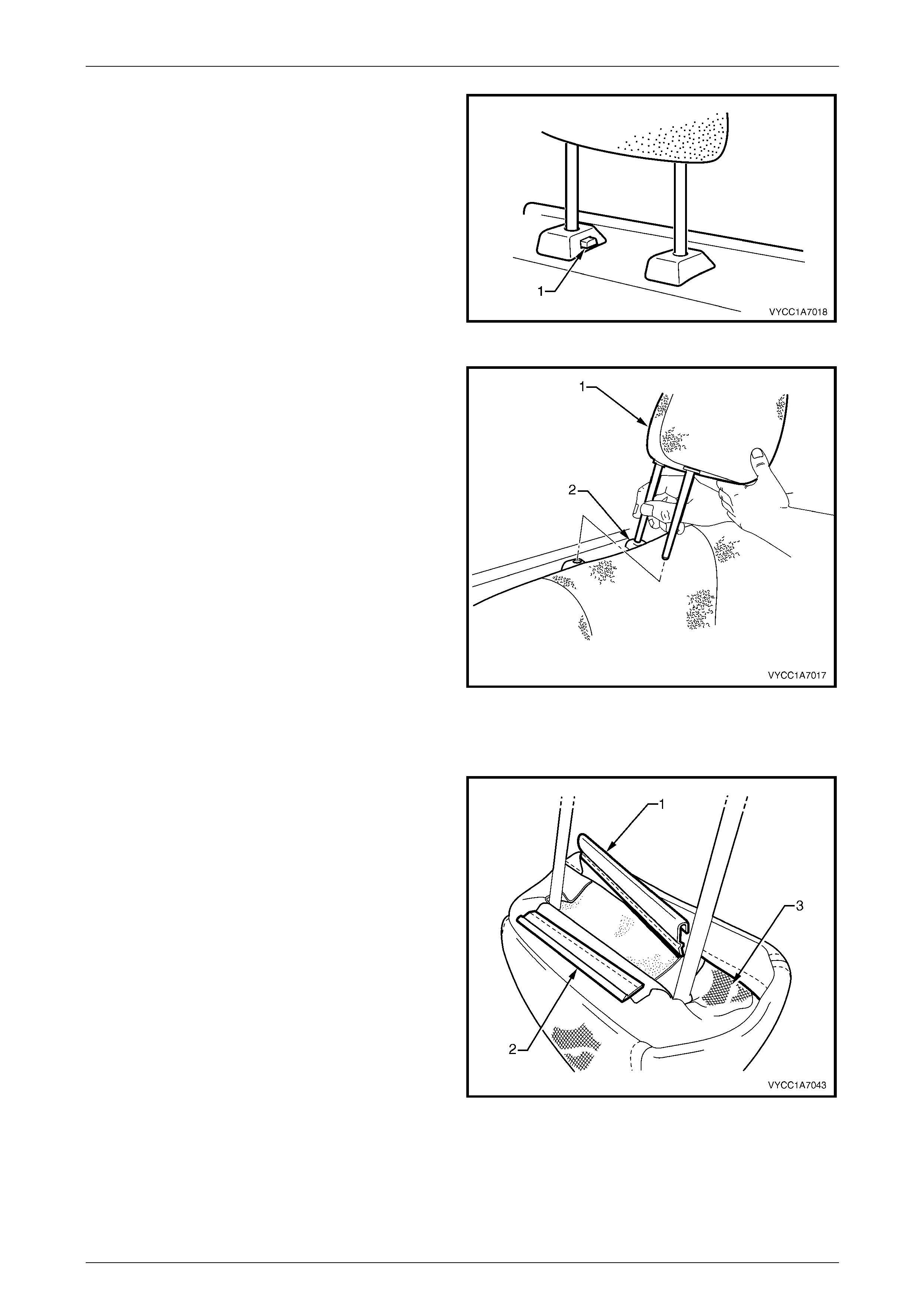
Seat Assemblies Page 1A7–429
Page 1A7–429
4 Depress the right-hand head restraint sleeve height
adjuster lock (1) and raise the head restraint so the
right-hand head restraint post is clear of the sleeve.
Figure 1A7 – 440
5 Remove the head restraint from the right-hand sleeve
and rotate the head restraint (1).
6 Remove the head restraint from the left-hand head
restraint sleeve (2).
NOTE
The right-hand head restraint post has a r ed uced
height to assist in the removal and reinstallation
of the head restraint.
Figure 1A7 – 441
Disassemble
1 Disengage the front head restraint cover J-stri p by
pulling the flap (1) back and out of flap (2) in the
direction shown.
2 Beginning at one corner of the head restraint, gently
remove the cover (3) from the pad assembly.
Figure 1A7 – 442

Seat Assemblies Page 1A7–430
Page 1A7–430
Reassemble
Reassembly of the front seat head restraint assemb ly is the reverse of the removal procedure, ensuring the head
restraint cover J-clips are fully engage d and the cover (3) is neatly tucked into the corners, refer to Figure 1A7 – 442.
NOTE
Ensure the head restraint cover is fitted neatly by
hand and is free from any creases. As part of
their designed appearance, leather cushion
covers have inherent minor creases in the
material.
Reinstall
Reinstallation of the rear head restraint is the reverse of the removal procedure.
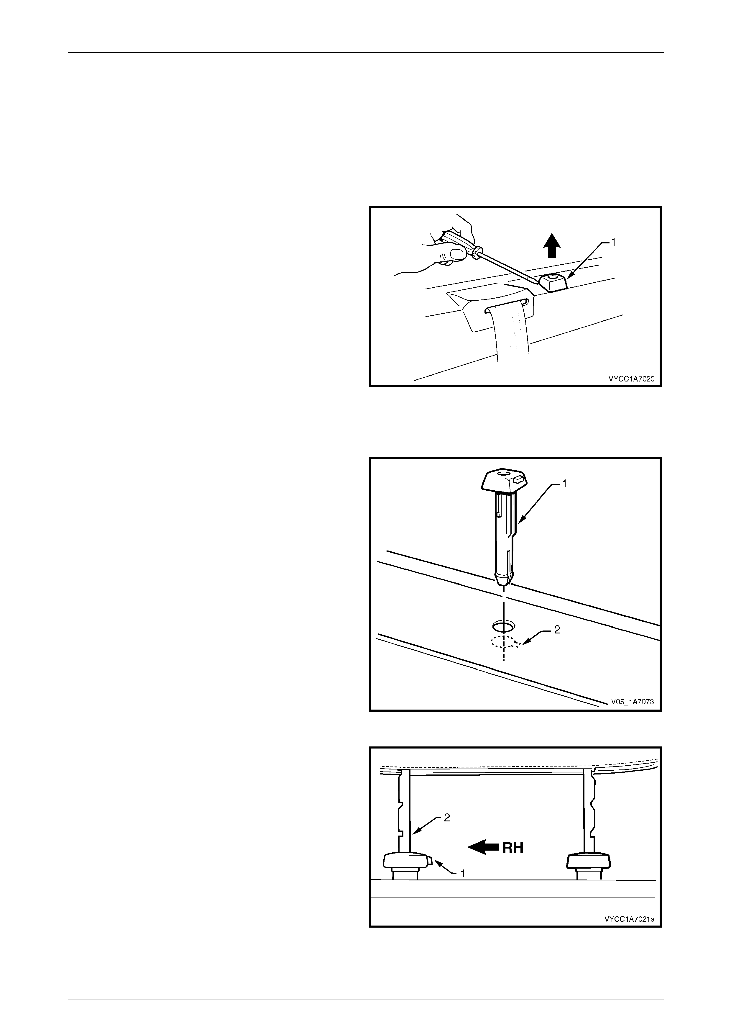
Seat Assemblies Page 1A7–431
Page 1A7–431
10.5 Head Restraint Sleeve
LT Section No. — 14–350
Remove
1 If required, remove the head restraint, refer to 10.4 Head Restraint Assembly.
2 Using a suitable sized scre wdriver, gently lever the
head restraint sleeve up while applying a slight upward
pressure.
3 Remove the head restraint sleeve form the upper
cross beam cover and panel.
Figure 1A7 – 443
Reinstall
1 Align the head restraint sleeve ensuring the locating
ribs (1) of the head restraint sleeve aligns with the key-
way (2) in the upper cross beam cover, then insert the
sleeve into the rear cross beam panel until it clips into
place.
NOTE
The head restraint sleeve shown is the
right-hand side. When viewed from inside of the
vehicle the release button in the right-hand and
the hole in the left-hand side should face each
other when installed correctly.
Figure 1A7 – 444
2 Ensure the sleeve with the height adjuster lock (1) is
installed on the right-hand side of the upper
cross-beam cover when viewed from the front of the
vehicle; that is the side that corresponds to the lo wer
square notch (2) in the head restraint shaft.
3 Reinstall the rear head restraint, refer to
10.4 Head Restraint Assembly.
Figure 1A7 – 445
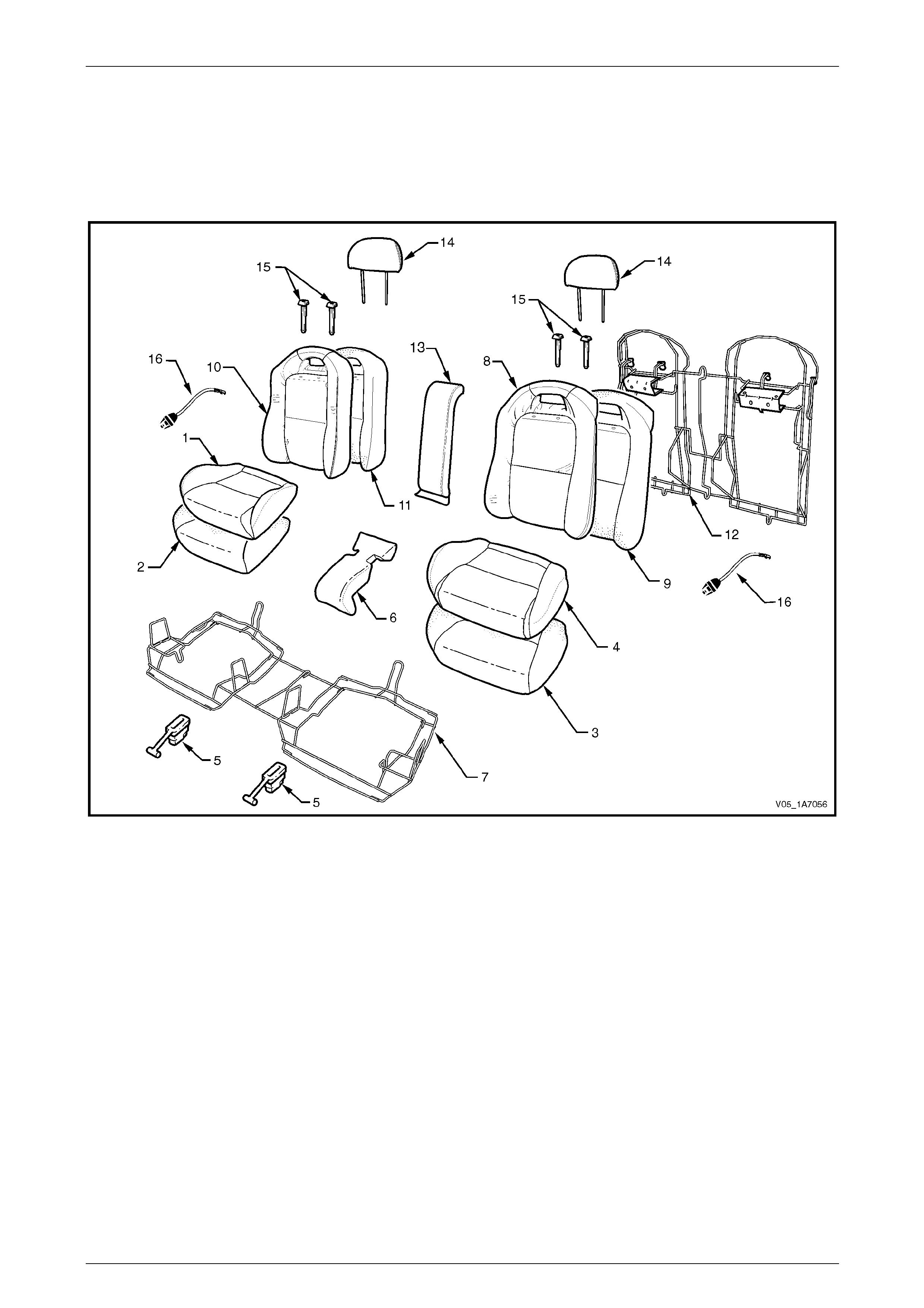
Seat Assemblies Page 1A7–432
Page 1A7–432
11 Service Operations – Rear Seat,
Coupe
Rear Seat
Figure 1A7 – 446
Legend
1 Rear Seat Cushion Cover – Right-hand
2 Rear Seat Cushion Pad – Right-hand
3 Rear Seat Cushion Pad – Left-hand
4 Rear Seat Cushion Cover – Left-hand
5 Rear Seat Cushion Release Handle
6 Rear Seat Cushion Centre Escutcheon
7 Rear Seat Cushion Frame
8 Rear Seat-back Cover – Left-hand
9 Rear Seat-back Pad – Left-hand
10 Rear Seat-back Cover – Right-hand
11 Rear Seat-back Pad – Right-hand
12 Rear Seat-back Frame
13 Rear Seat-back Centre Escutcheon
14 Head Restraint
15 Head Restraint Sleeve
16 Child Comforter Guide
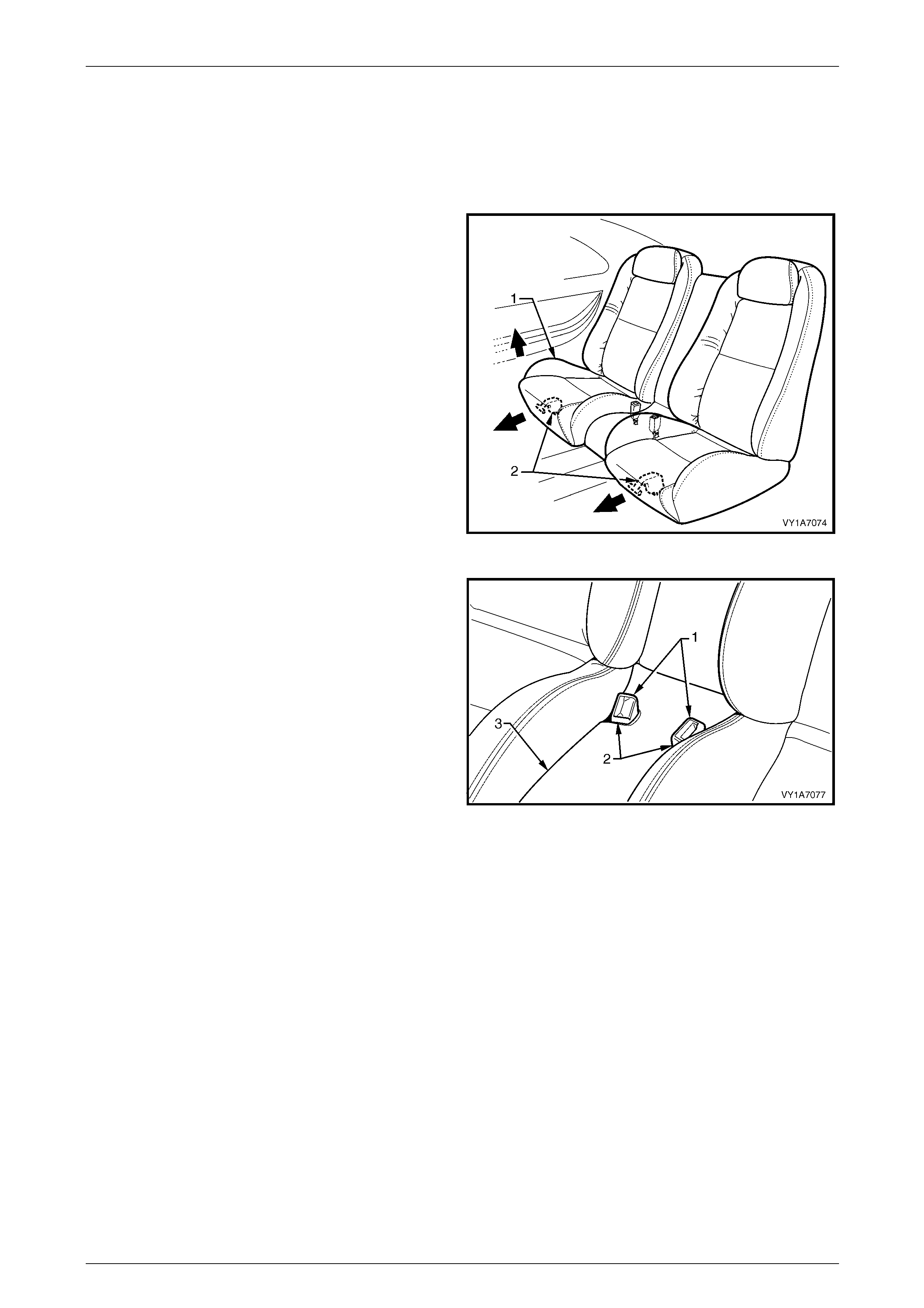
Seat Assemblies Page 1A7–433
Page 1A7–433
11.1 Rear Seat Cushion Assembly
LT Section No. — 14–325
Remove
1 Lift the front of the rear seat cushion assembly (1)
slightly to gain access to the two rear seat cushion
release handles (2).
2 From either the left or the right side of the seat, pull
the release handle T-piece horizontally outwards,
while at the same time lifting the front of the rear seat
cushion until the lock mechanism is released.
3 Repeat step 2 for the opposite side of the seat.
Figure 1A7 – 447
4 Manoeuvre the two seatbelt buckles (1) through the
two slots (2) in the rear seat centre escutcheon (3).
5 Lift the front of the rear seat cushion assembly to
disengage the rear of the frame from the rear
seat-back frame.
6 Remove the rear seat cushion assembly.
Figure 1A7 – 448
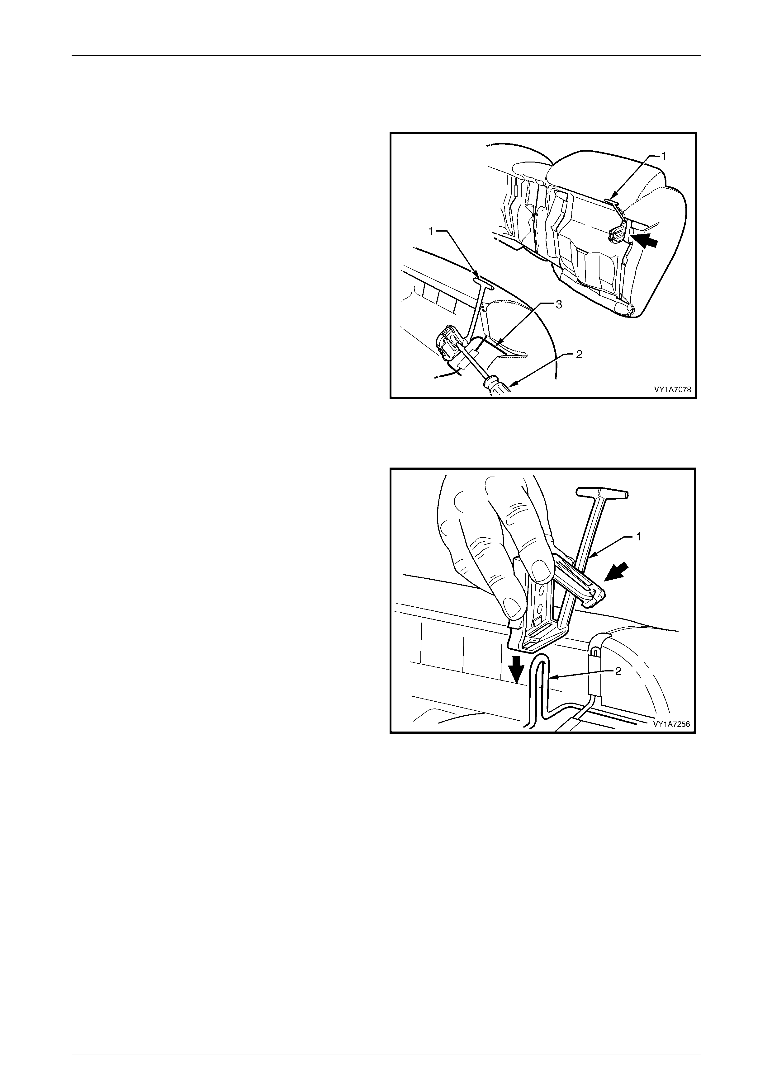
Seat Assemblies Page 1A7–434
Page 1A7–434
Disassemble
Remove – Rear Seat Cushion Relea se Handle
1 Remove the rear seat cushion release handle (1) by
inserting a screwdriver to disengage the reta ining lugs.
2 Slide the release handle off the rear seat cushion wire
frame (2).
Figure 1A7 – 449
Reinstall – Rear Seat Cushion Release Handle
Slide the rear seat cushion rel ease handle (1) onto the rear
seat cushion wire frame (2) and close the cover to lock it
into position.
Figure 1A7 – 450
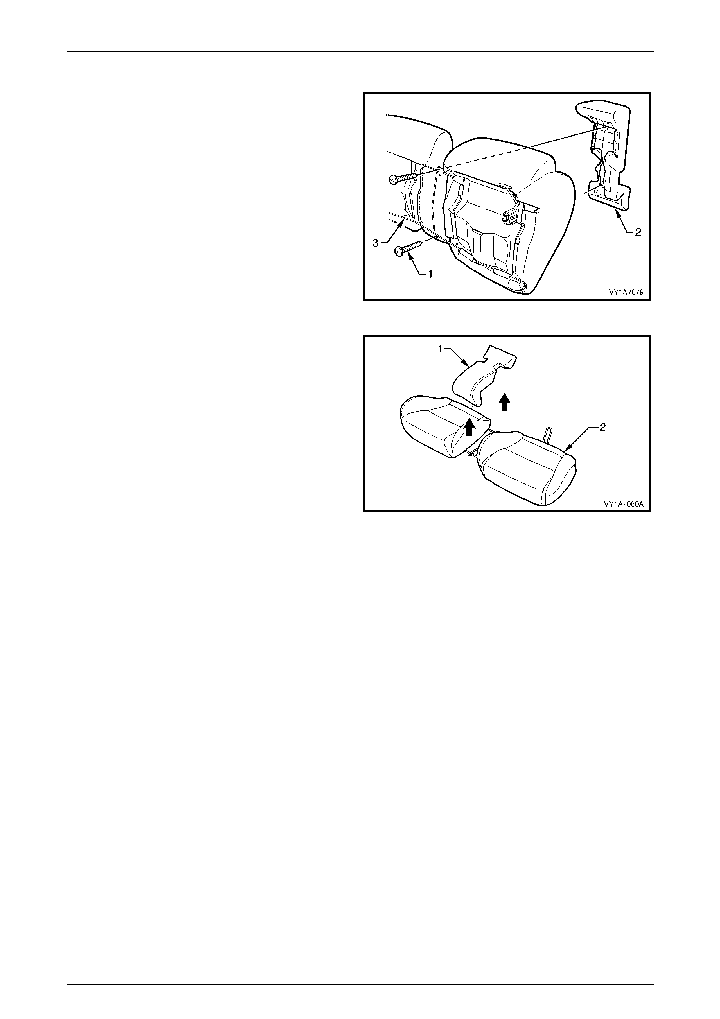
Seat Assemblies Page 1A7–435
Page 1A7–435
Remove – Rear Seat Cushion Centre Escutcheon
1 Remove the two screws (1) attaching the rear seat
cushion centre escutcheon (2) to the rear sea t cushion
frame (3).
Figure 1A7 – 451
2 Remove the rear seat cushion centre escutcheon (1)
from the rear seat cushion assembly (2).
Figure 1A7 – 452
Reinstall – Rear Seat Cushion Centre Escutcheon
Reinstallation of the rear seat cushion centre escutcheon is the reverse of the removal procedure. Ensure all attaching
screws are tightened securel y.
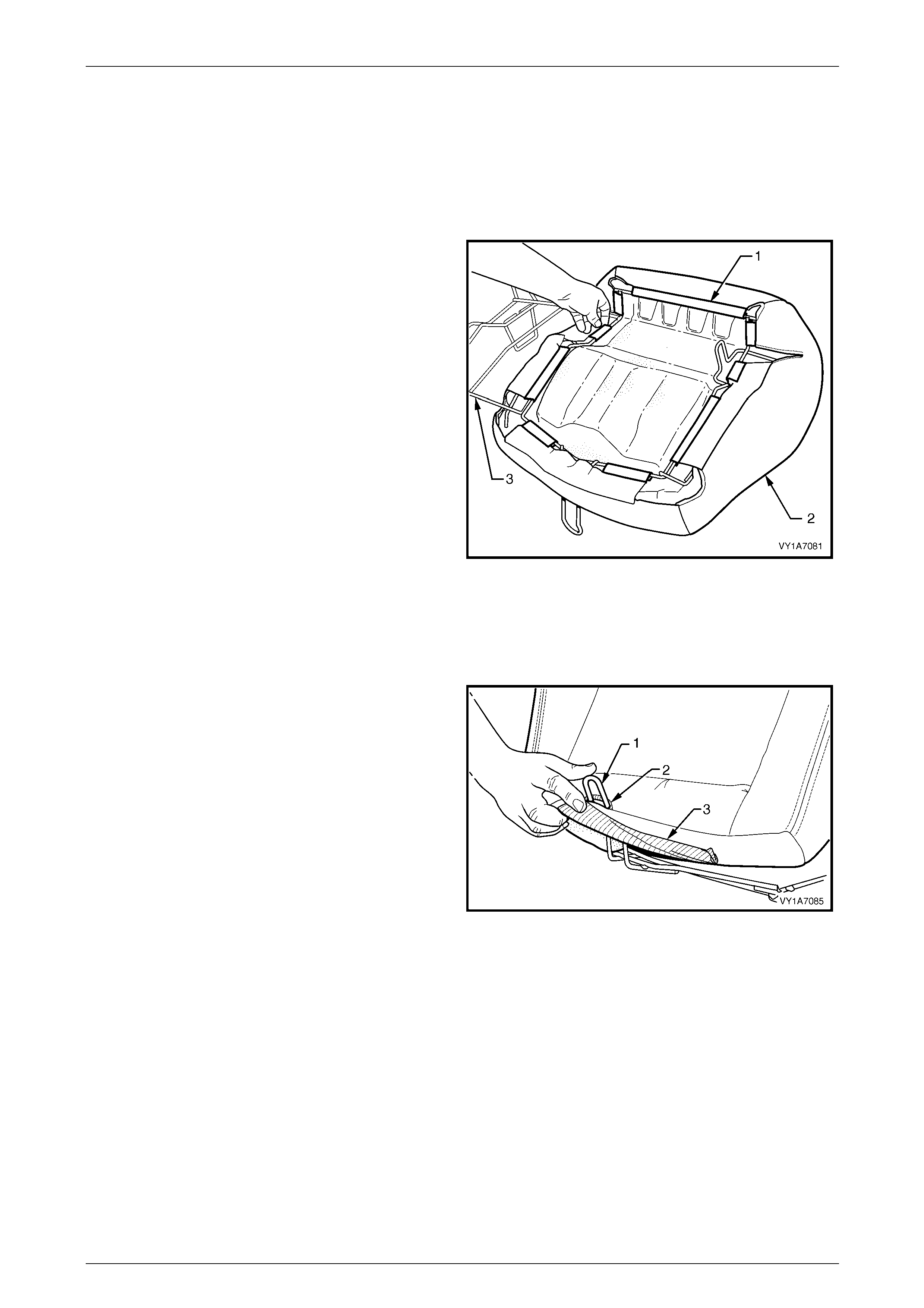
Seat Assemblies Page 1A7–436
Page 1A7–436
Remove – Rear Seat Cushion Cover and Pad Assembly
NOTE
The following procedures are applicable to both
left-hand and right-hand rear seat cushion
assemblies.
1 With the rear seat cushion assembly upside- down,
unclip the nine retainers (1) attachi ng the rear seat
cushion cover (2) to the frame (3).
2 Remove the cover and pad assembl y from the frame.
3 Repeat for the opposite side as required.
Figure 1A7 – 453
Reinstall – Rear Seat Cushion Cover and Pad Ass embly
Reinstallation of the rear seat cushion cover and pad ass embly is the reverse of the removal procedure, noting the
following:
Before attaching the cushion assembly to the frame, fit the
leg of the seat frame (1) through the slot (2) provided in the
rear of the seat cushion cover (3).
Figure 1A7 – 454

Seat Assemblies Page 1A7–437
Page 1A7–437
Remove – Rear Seat Cushion Cover
NOTE
The following procedures are applicable to both
left-hand and right-hand rear seat cushion
assemblies.
1 Fold the rear corners of the rear seat cushion cover (1)
over the seat cushion pad (2).
Figure 1A7 – 455
2 While holding the rear seat cushion pad (1), pull the
rear corners of the seat cushion cover (2) forwards
and away from the rear seat cushion pad to dise ngage
the hook and loop strips (3).
3 Pull the rear seat cover up and over the forward edge
of the rear seat cushion pad and remove.
Figure 1A7 – 456
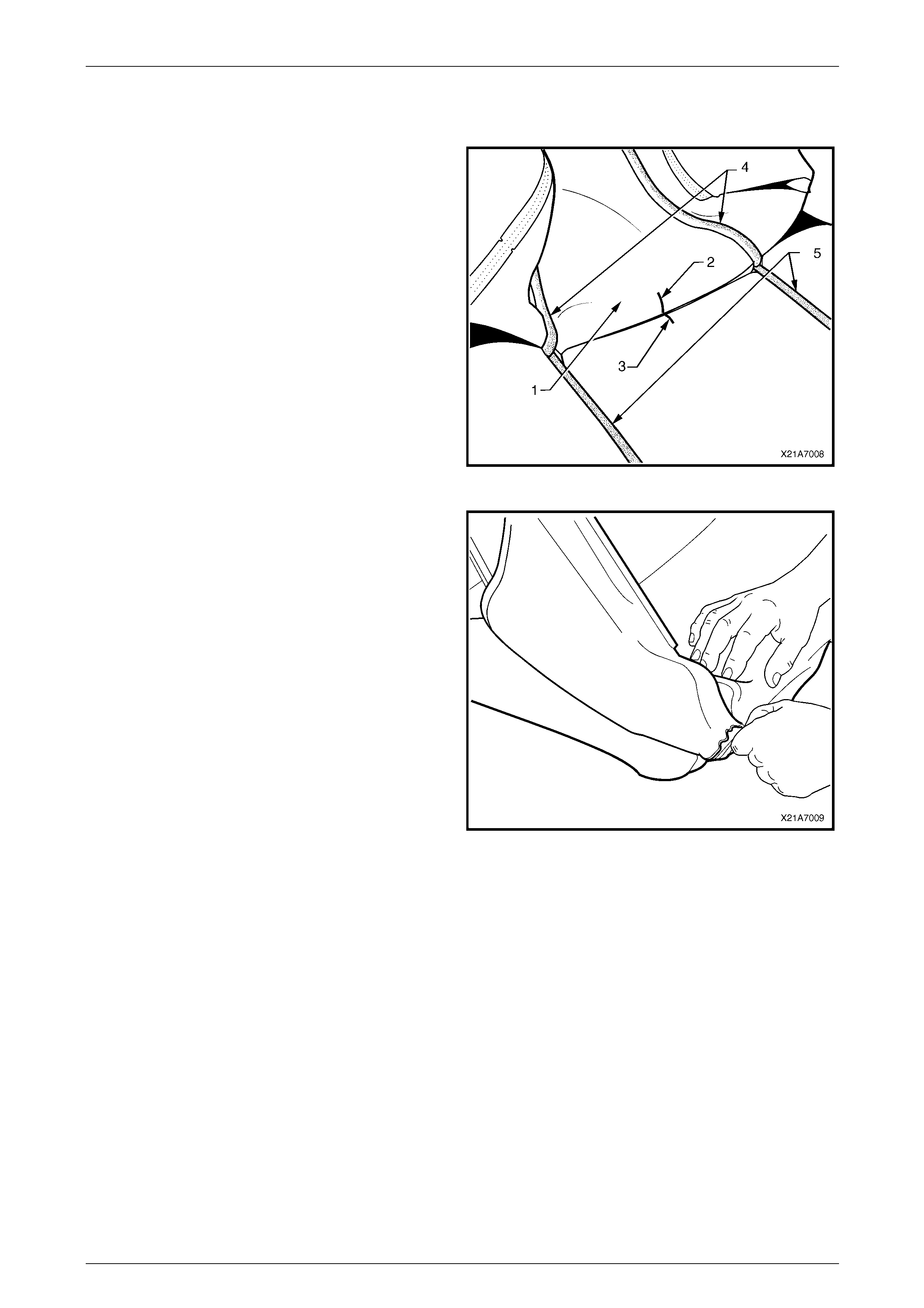
Seat Assemblies Page 1A7–438
Page 1A7–438
Reinstall – Rear Seat Cushion Cover
Reinstallation of the rear seat cushion is the reverse of the removal procedure, notin g the following:
1 With the seat cushion cover (1) folded at the central
horizontal strip of hook and loop, align the centre mark
(2) on the rear seat cushion cover with the centre mark
(3) on the seat cushion pad.
2 Press the folded edge of the rear seat cushion cover
firmly into the corresponding groove in the seat
cushion pad to engage the hook and loop.
3 With the seat cover folded at the two vertical strips of
hook and loop (4), press the seat-back cover firmly
into the corresponding grooves (5) in the se at cushion
pad.
Figure 1A7 – 457
4 Roll the front corners of the rear seat cushion cover
over the seat cushion pad.
5 Roll the sides of the seat cushion cover over the seat
cushion pad.
6 Roll the rear corners of the seat cushion cov er over
the seat cushion pad.
NOTE
Ensure the pad is fitted neatly by hand into all
corners and contours of the seat cover.
Do not pull the cover onto the pad from
underneath using the J-stri p to make it fit neatly,
as the fabric may be damaged.
Figure 1A7 – 458
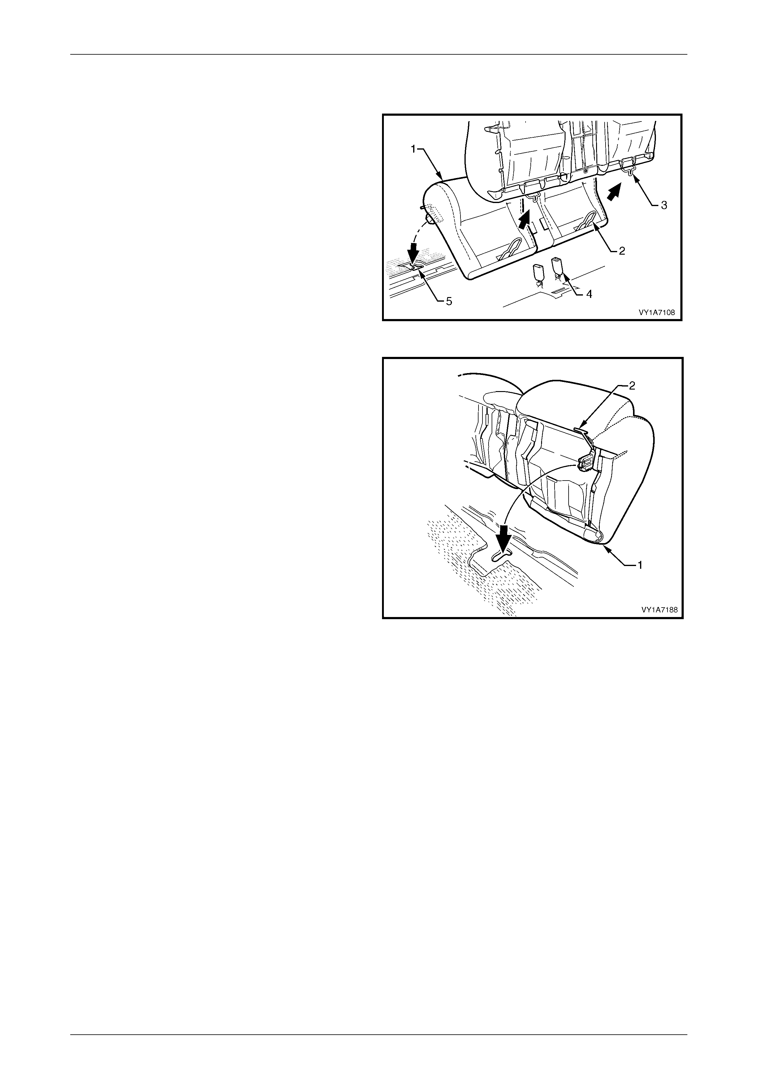
Seat Assemblies Page 1A7–439
Page 1A7–439
Reinstall
1 Sit the rear seat cushion (1) into position allowing the
frame legs (2) to slide up under the rear seat-back (3).
2 Feed the seatbelt buckles (4) through the two slots in
the centre escutcheon.
Figure 1A7 – 459
3 Push the rear seat cushion (1) into the back of the
seat and push down the front of the seat until the
locking mechanisms (2) lock the seat cushion into
position.
Figure 1A7 – 460
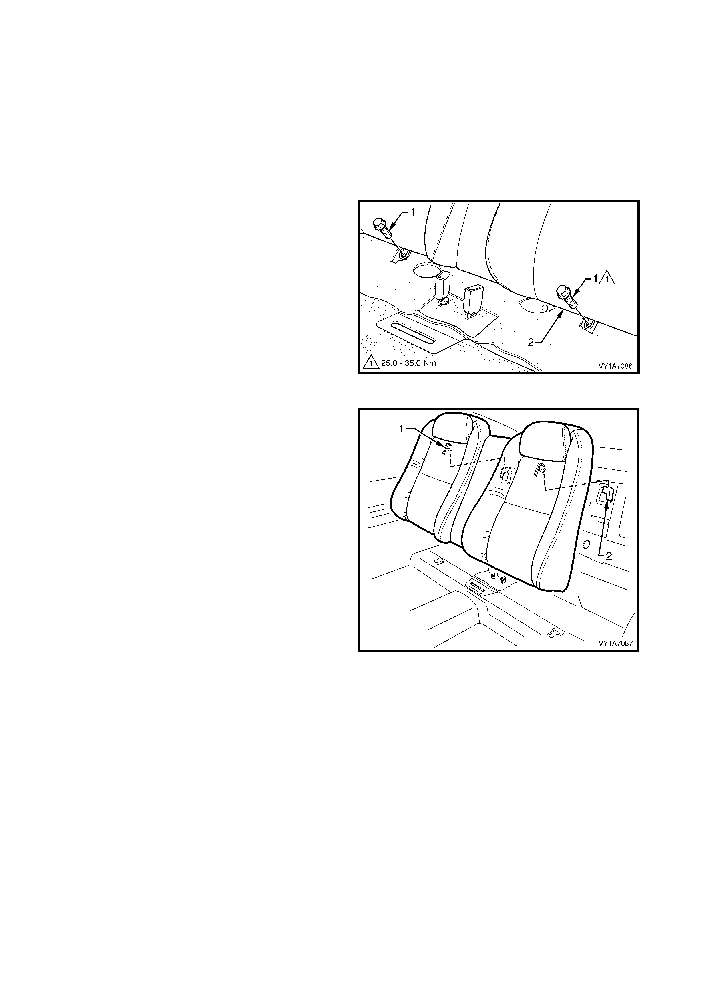
Seat Assemblies Page 1A7–440
Page 1A7–440
11.2 Rear Seat-back Assembly
LT Section No. — 14–350
Remove the rear seat cushion assembly, refer to 11.1 Rear Seat Cushion Assembly.
Remove
1 Remove the two screws (1) securing the rear
seat-back assembly (2) to the rear floor pan.
Figure 1A7 – 461
2 Lift the rear seat-back assembly up until the seat-back
retaining hooks (1) release from the retaining slots (2)
in the rear compartment front panel.
3 Remove the rear seat-back assemblies.
Figure 1A7 – 462
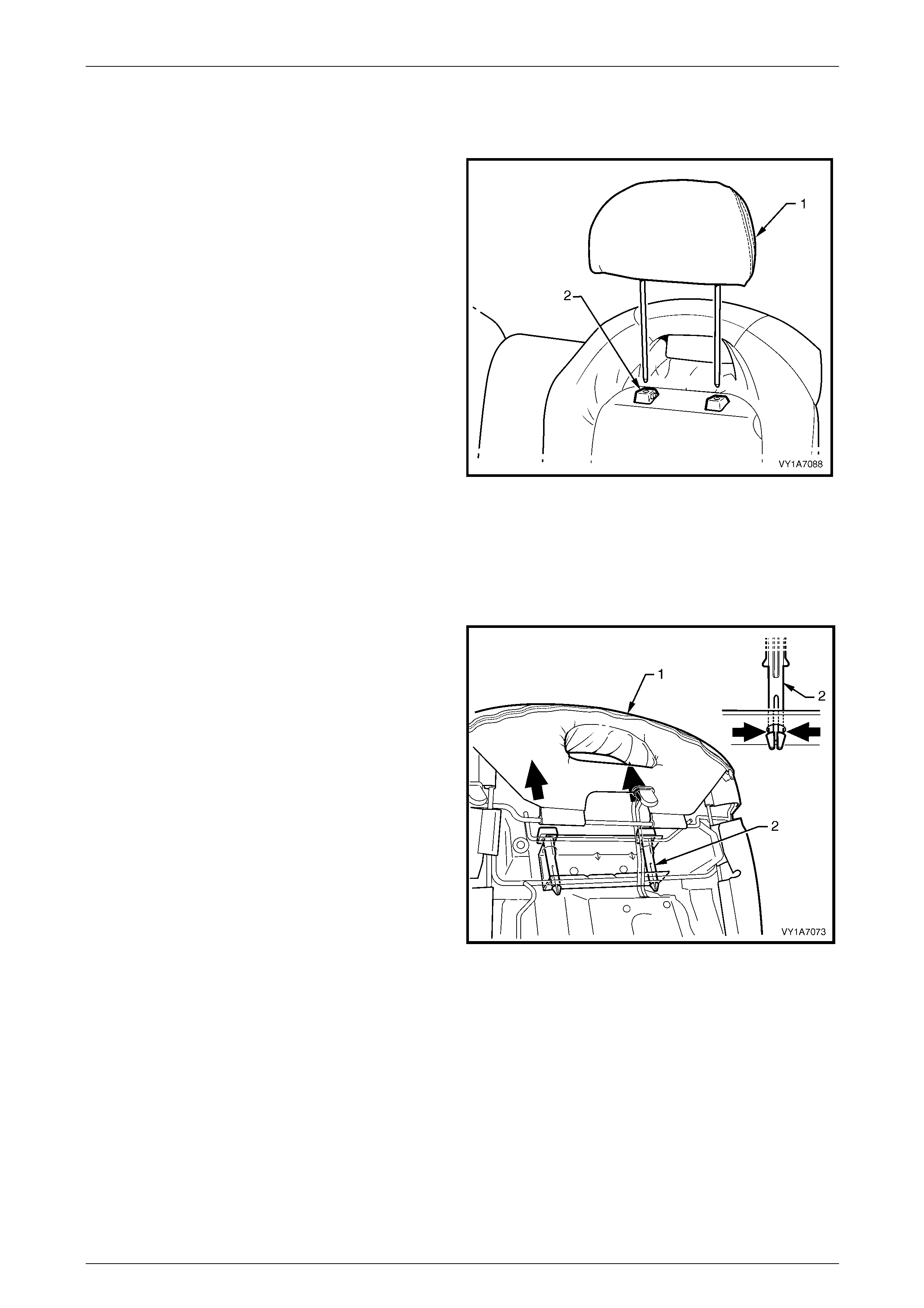
Seat Assemblies Page 1A7–441
Page 1A7–441
Disassemble
Remove – Rear Seat-b ack Head Restraint
Remove the head restraint (1), by depressing the hea d
restraint guide height adjuster lock (2), pull the head
restraint completely out of the guide.
Figure 1A7 – 463
Reinstall – Rear Seat-back Head Restraint
Reinstallation of the head restraints into the rear seat-back assembl y is the reverse of the removal procedure.
Remove – Rear Seat-b ack Head Restraint Guide
From the rear side of the rear seat-back (1), squeeze the
locking prongs of the head res traint guide (2) together while
pulling the top of the guide ou t of the seat-back assembly.
Figure 1A7 – 464
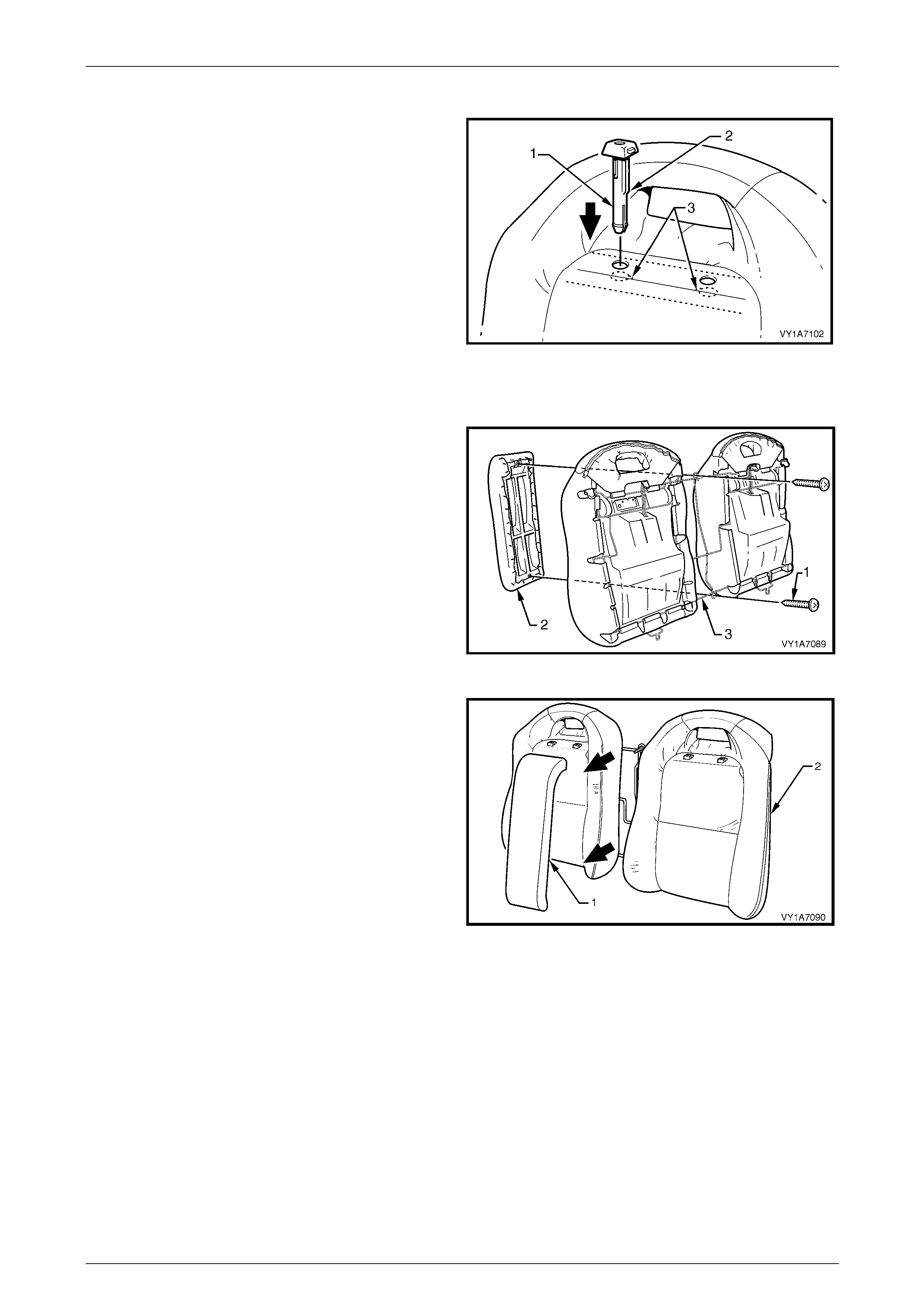
Seat Assemblies Page 1A7–442
Page 1A7–442
Reinstall – Rear Seat-back Head Restraint Guide
When installing the head restraint guide (1), ensure the
locating slots (2) in the seat-back align with key-way (3) on
the head restraint guide.
Figure 1A7 – 465
Remove – Rear Seat-back Centre Escutcheon
1 Remove the two screws (1) attaching the rea r
seat-back centre escutcheon (2) to the rear seat-back
frame (3).
Figure 1A7 – 466
2 Remove the rear seat-back centre escutche on (1)
from the rear seat-back assembly (2).
Figure 1A7 – 467
Reinstall – Rear Seat-back Cen tre Esc utcheon
Reinstallation of the rear seat-back centre escutcheon is the reverse of the removal procedure. Ensure all attaching
screws are tightened securel y.
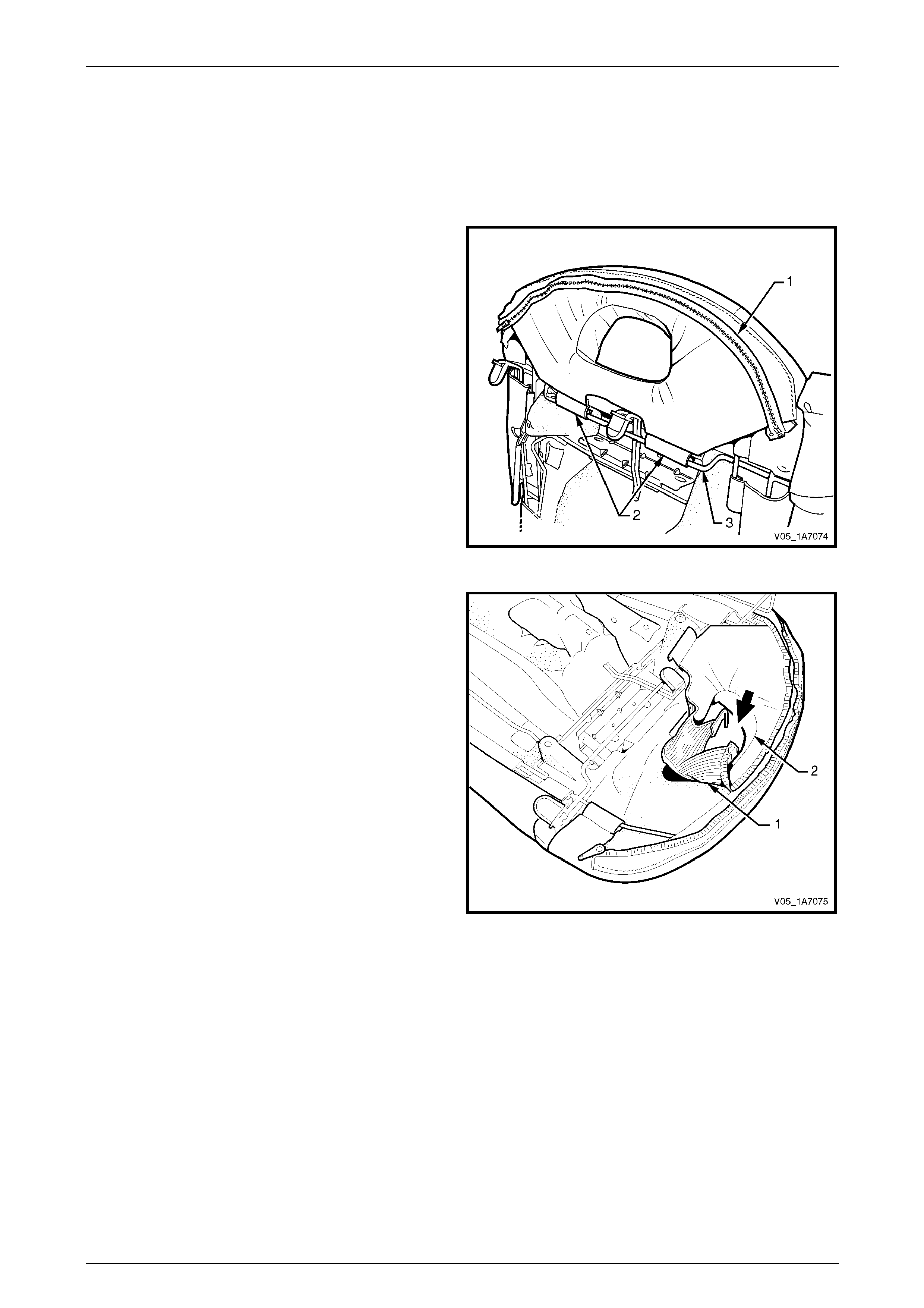
Seat Assemblies Page 1A7–443
Page 1A7–443
Remove – Rear Seat-b ack Cover and Pad Assemb ly
NOTE
The following procedures are applicable to both
left-hand and right-hand rear seat-back
assemblies.
1 Completely unzip the rear seat-back cover flap (1),
located behind the head restraint.
2 Unclip the two retainers (2) attaching the rear
seat-back cover to the frame (3).
Figure 1A7 – 468
3 Tuck the rear seat-back cover flap (1) through the
opening in the rear seat-back pad (2).
Figure 1A7 – 469

Seat Assemblies Page 1A7–444
Page 1A7–444
4 Pull the flap (1) completely through the op ening in the
rear seat-back pad.
Figure 1A7 – 470
5 With the rear seat-back assembly (1) face down,
unclip the remaining fifteen retainers (2) attaching the
rear seat-back cover to the rear seat-back frame (3).
6 Remove the rear seat-back cover and pad assembly.
7 Repeat for the opposite side as required.
Figure 1A7 – 471
Reinstall – Rear Seat-back Cover and Pad Assembly
1 Attach the fifteen retainers (1) securing the rear
seat-back cover and pad assembl y (2) to the rear
seat-back frame (3).
2 Feed the rear seat-back cover flap throug h the
opening in the rear seat-back pad.
Figure 1A7 – 472
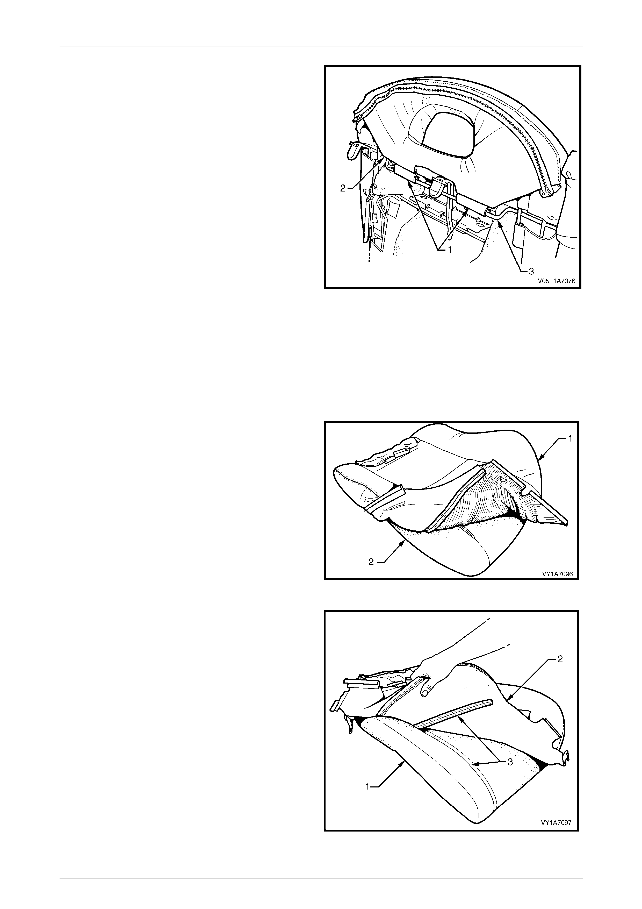
Seat Assemblies Page 1A7–445
Page 1A7–445
3 Attach the two retainers (1) securing the rear
seat-back cover flap (2) to the rear seat-back frame
(3).
4 Zip the rear seat-back cover flap.
Figure 1A7 – 473
Remove – Rear Seat-b ack Cover
NOTE
The following procedures are applicable to both
left-hand and right-hand rear seat-back
assemblies.
1 Fold the lower corners of the seat-back cove r (1) over
the seat-back pad (2).
Figure 1A7 – 474
2 While holding the front seat-back pad (1), pull the
lower corners of the seat-back cover (2), upwards and
away from the front seat pad to disengage the hook
and loop strips (3).
3 Pull the front seat-back cover up and over the upper
edge of the front seat-back pad.
Figure 1A7 – 475
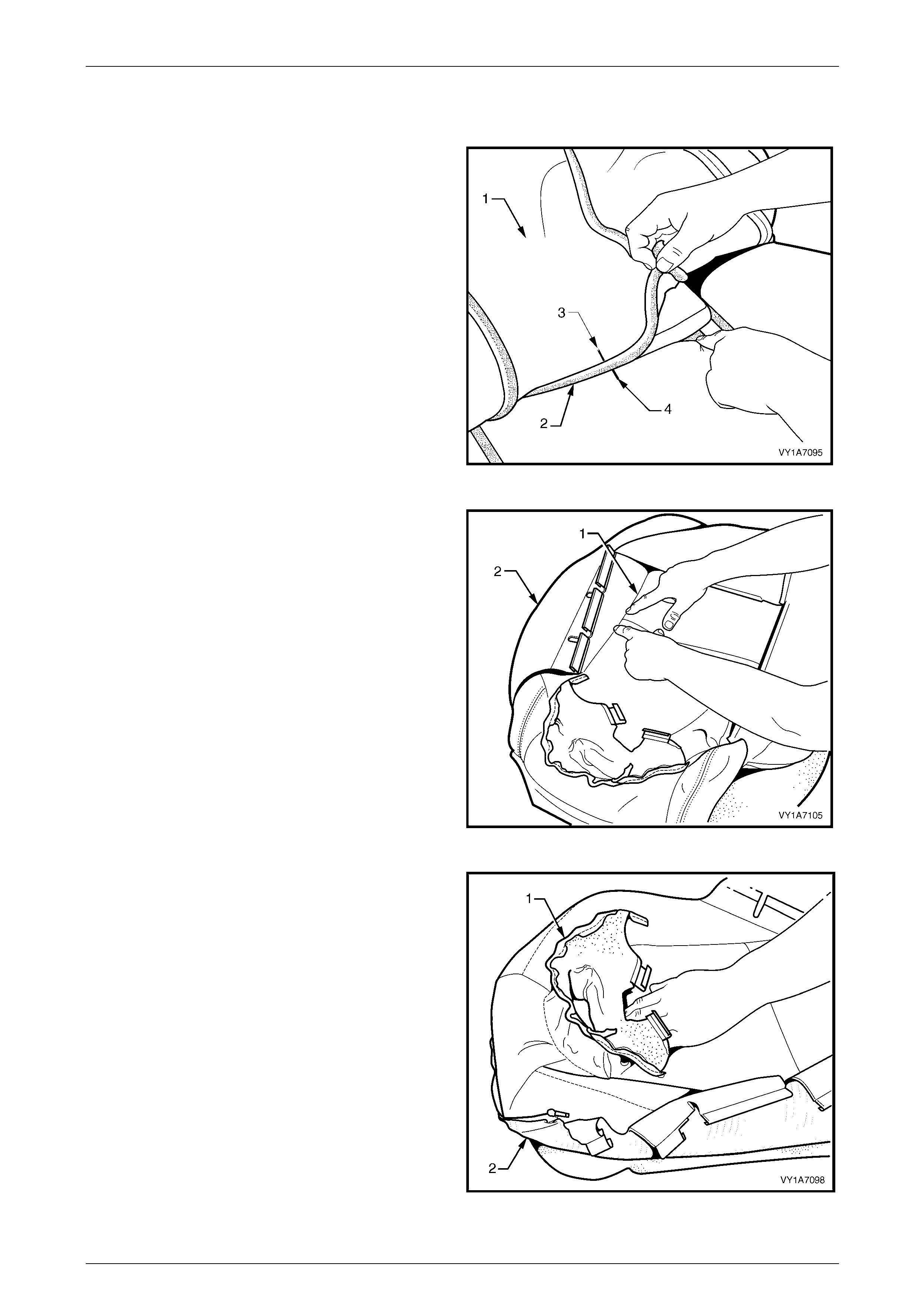
Seat Assemblies Page 1A7–446
Page 1A7–446
Reinstall – Rear Seat-back Cover
Reinstallation of the rear seat-back is the reverse of the removal procedure, noting the following:
1 With the seat-back cover (1) folded at the central
horizontal strip of hook and loop (2), align the centre
mark (3) on the front seat-back cover with the centre
mark (4) on the seat-back pad.
2 Press the seat-back cover firmly into the
corresponding groove in the seat-back pad to engage
the hook and loop.
Figure 1A7 – 476
3 With the seat cover folded at the two vertical strips (1)
of the hook and loop, press the seat-back cover (2)
firmly into the corresponding grooves i n the seat-back
pad.
Figure 1A7 – 477
4 Continue to press firmly behind the head restraint
guide holes, under the flap (1), of the rear seat-back
cover (2), engaging the hook and loop into the
corresponding groove in the seat-back pad.
Figure 1A7 – 478
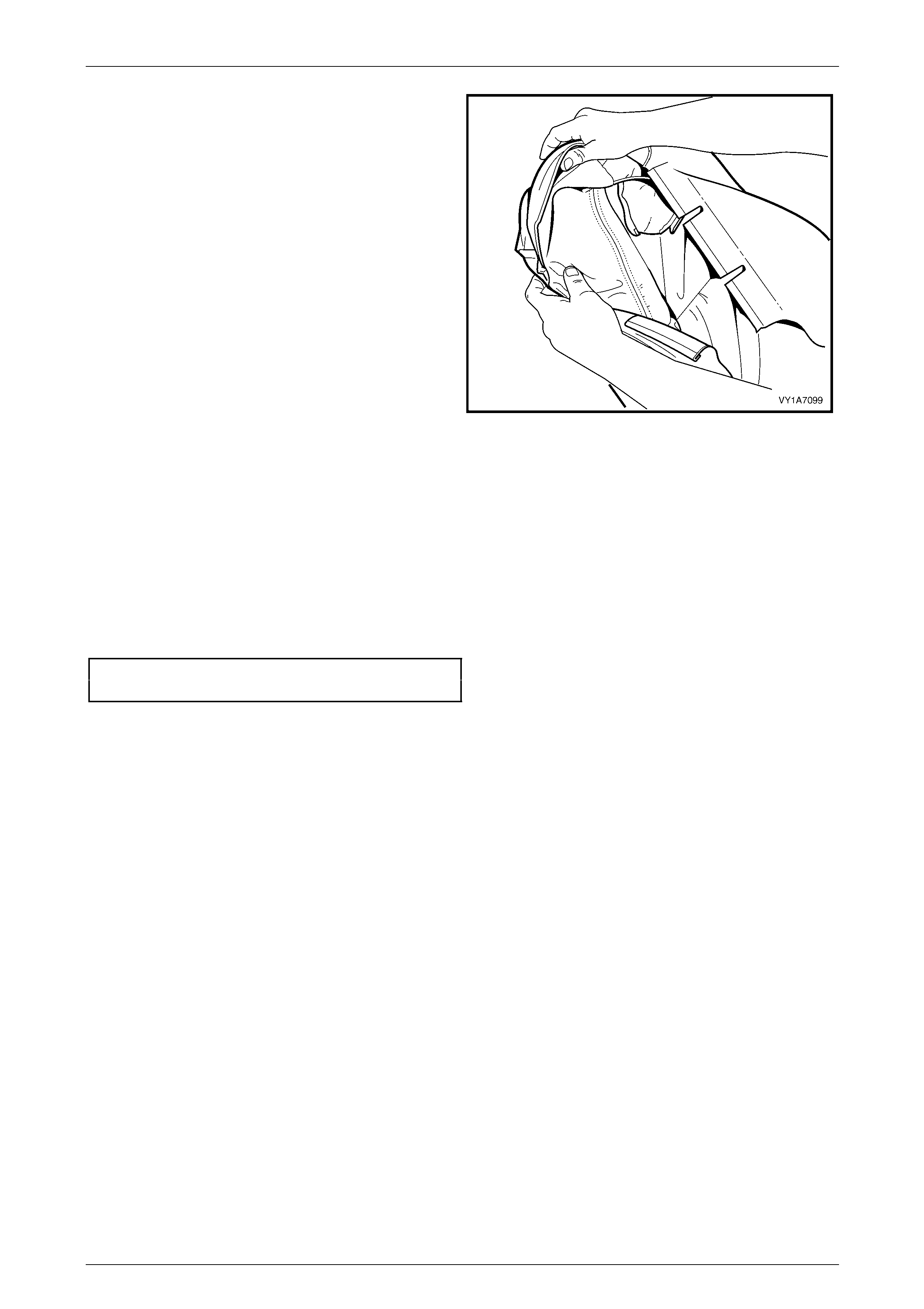
Seat Assemblies Page 1A7–447
Page 1A7–447
5 Roll the lower corners of the seat-back cover over the
seat-back pad.
6 Roll the sides of the seat-back cover over the
seat-back pad.
7 Roll the upper corners of the rear seat-back cover over
the seat-back pad.
NOTE
Ensure the pad is fitted neatly by hand into all
corners and contours of the seat cover.
Do not pull the cover onto the pad from
underneath using the J-stri p to make it fit neatly,
as the fabric may be damaged.
NOTE
Do not feed the flap through the opening in the
rear seat-back pad until the cover is secured to
the frame.
8 Fit the cover and pad assembly to the rear seat-back
frame.
Figure 1A7 – 479
Reinstall
Reinstallation of the rear seat-back assembly is the reverse of the removal procedure, noting the following:
1 The head restraints must be installed into the rear seat-back assembly, before the rear seat-back assembly is
reinstalled.
2 Tighten the attaching screws to the correct torque specification.
Rear seat-back assembly attaching
screw torque specification.......................25.0 – 35.0 Nm
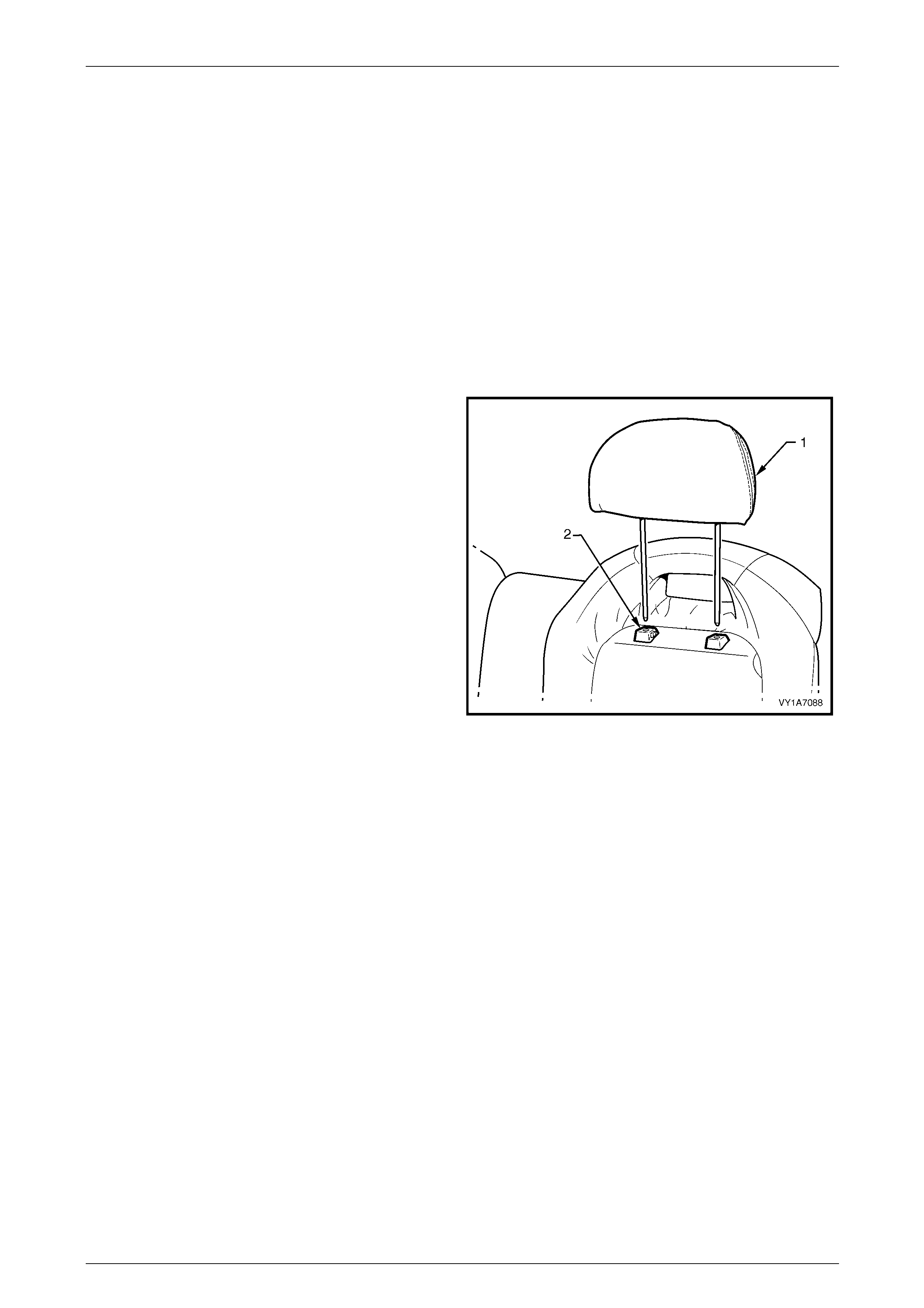
Seat Assemblies Page 1A7–448
Page 1A7–448
11.3 Rear Seat Head Restraint Assembl y
LT Section No. — 14–350
NOTE
As a safety design feature, the rear seat head
restraint can only be removed from the vehicle
with the rear seat-back assembly.
1 Remove the rear seat cushion assembly, refer to 11.1 Rear Seat Cushion Assembl y.
2 Remove the rear seat-back assembly, refer to 11.2 Rear Seat-back Assembl y.
Remove
While holding the head restraint height adjuster lock in, pull
the head restraint (1) completely out of the guide (2).
Figure 1A7 – 480
Reinstall
Reinstallation of the rear seat head restraint is the reverse of the removal procedure.
NOTE
Head restraints must be installed into the rear
seat-back assembly, before the rear seat-back
assembly is reinstalled.
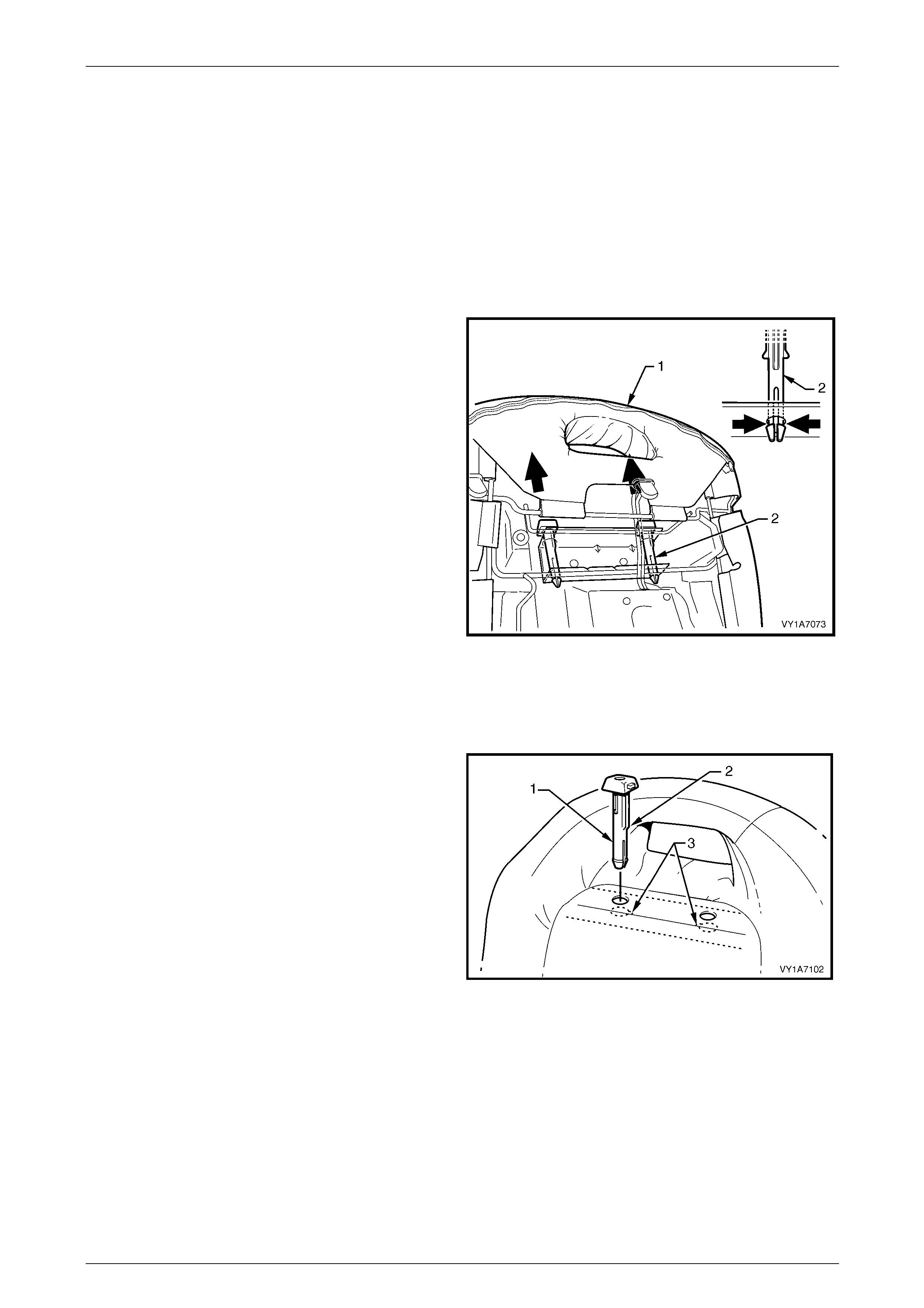
Seat Assemblies Page 1A7–449
Page 1A7–449
11.4 Rear Seat Head Restraint Guide
LT Section No. — 14–350
1 Remove the rear seat cushion assembly, refer to 11.1 Rear Seat Cushion Assembly.
2 Remove the rear seat-back assembly, refer to 11.2 Rear Seat-back Assembl y.
3 Remove the rear seat head restraint assembly, refer to 11.3 Rear Seat Head Restraint Assembly.
Remove
From the rear side of the rear seat-back (1), squeeze the
locking prongs of the head res traint guide (2) together while
pulling the top of the guide ou t of the seat-back assembly.
Figure 1A7 – 481
Reinstall
Reinstallation of the rear seat head restraint guide is the reverse of the rem oval procedure, noting the foll owing:
When installing the head restraint guide (1), ensure the
locating slots (2) in the seat-back align with key-way (3) on
the head restraint guide.
NOTE
Head restraints must be installed into the rear
seat-back assembly, before the rear seat-back
assembly is reinstalled.
Figure 1A7 – 482
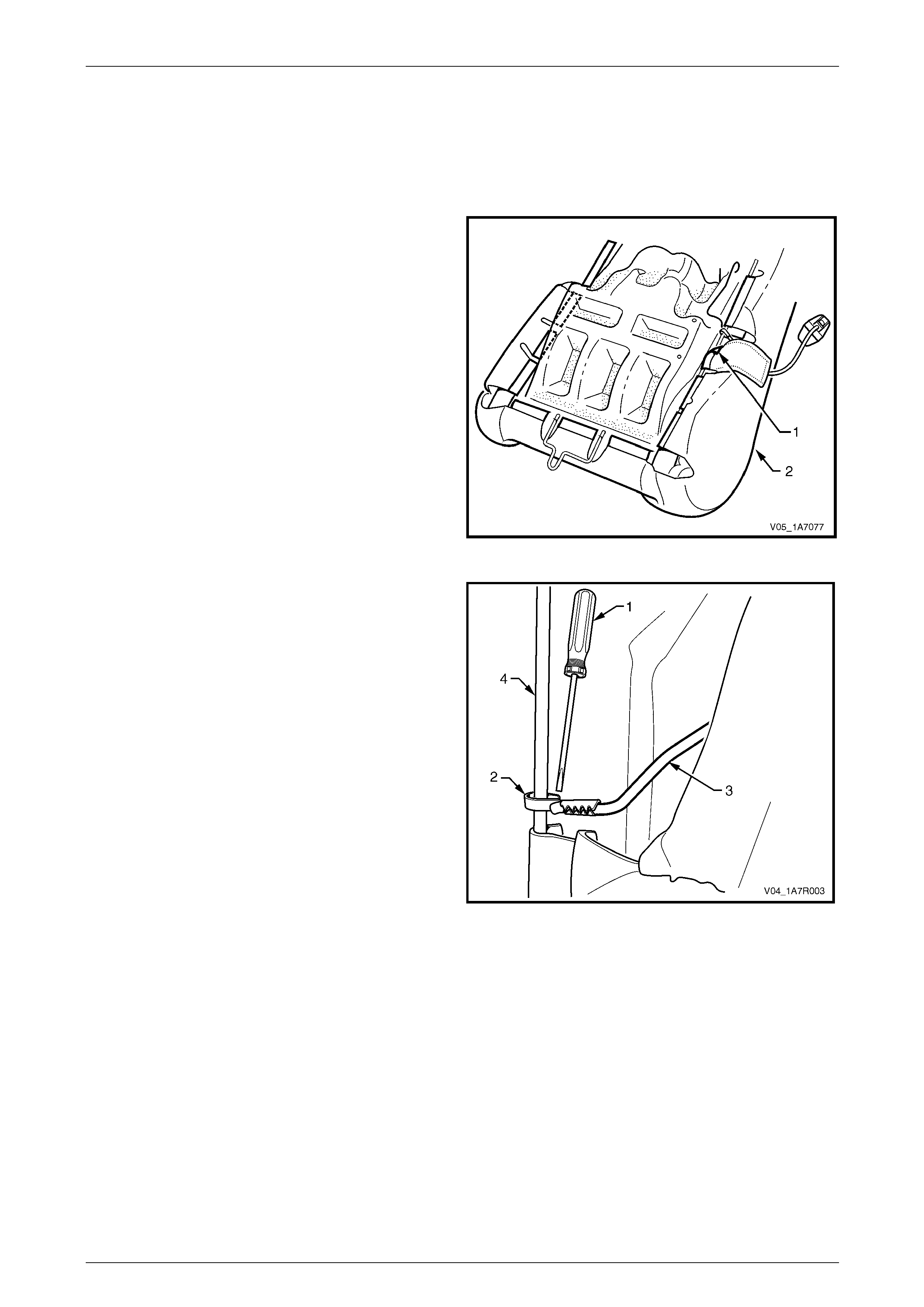
Seat Assemblies Page 1A7–450
Page 1A7–450
11.5 Child Comforter Guide – Coupe
Remove
1 Remove the rear seat-back assembly, refer to 11.2 Rear Seat-back Assembl y.
2 Unclip the J-strip (1) on the outer edge of the rear
seat-back assembly (2).
Figure 1A7 – 483
3 Using a suitable scre wdriver (1), gently pris e open the
clip (2), attaching the child comforter guide strap (3) to
the seat-back frame (4).
4 Unclip the child comforter strap from the seat-back
frame and carefully withdra w the chi ld comforter guide
from the pouch in the rear seat-back cover.
Figure 1A7 – 484
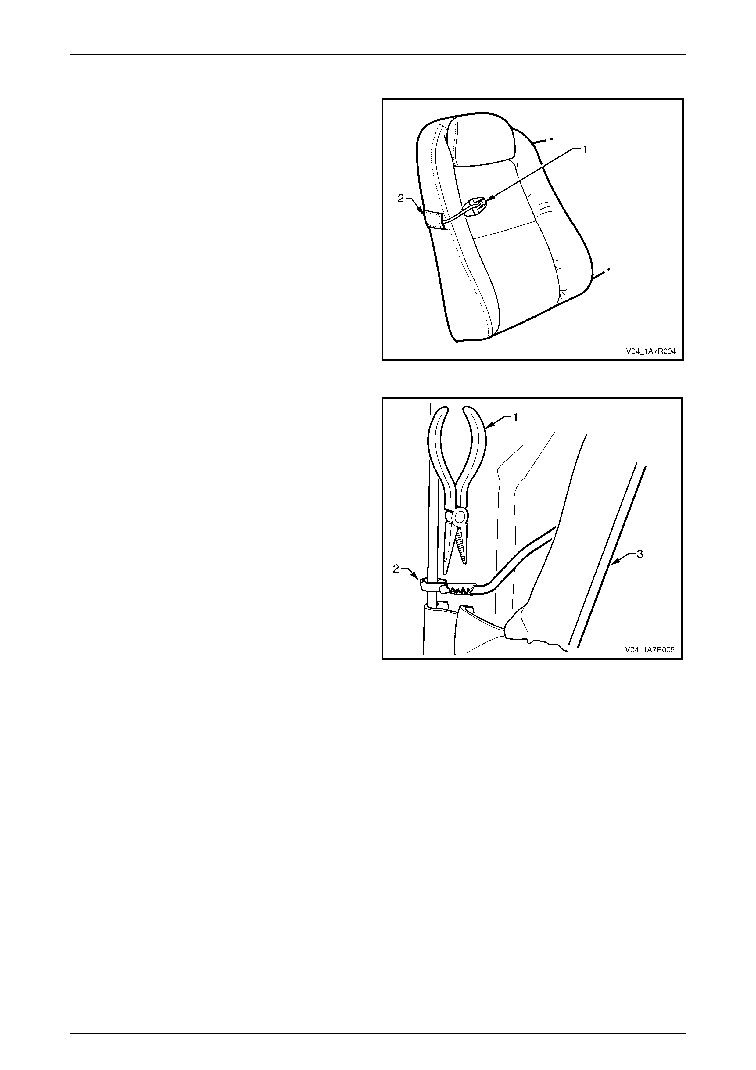
Seat Assemblies Page 1A7–451
Page 1A7–451
Reinstall
1 Insert the child comforter guide strap (1) through the
pouch in the rear seatback cover (2).
2 Clip the child comforter guide attachin g clip onto the
rear seat-back frame, refer to Figure 1A7 – 484.
Figure 1A7 – 485
3 Using a suitable pair of pliers (1), gently squeeze the
end of the child comforter guide attaching clip (2)
closed.
4 Attach the J-strip (3) to the rear seat-back frame.
5 Reinstall the rear seat-back assembly, refer to
11.2 Rear Seat-back Assembly.
Figure 1A7 – 486

Seat Assemblies Page 1A7–452
Page 1A7–452
12 Torque Wrench Specifications
Front Seat, Except Regular Cab, Utility and Coupe
Front Seat Assembly Attaching Screw......................................35.0 – 50.0 Nm
Front Seat Outer Front Cover Attaching Screw.............................1.0 – 3.0 Nm
Front Seat Adjustment Switch Attaching Screw ............................1.0 – 3.0 Nm
Memory Position Switch Cover Attaching Screw...........................1.0 – 3.0 Nm
Front Seat Outer Side Cover Attaching Screw..............................1.0 – 3.0 Nm
Front Seat Inner Side Cover Attaching Screw...............................1.0 – 3.0 Nm
Front Seat-back Map Pocket Attaching Screw..............................1.0 – 3.0 Nm
Side Impact Airbag Assembly Attaching Nut.................................5.0 – 6.0 Nm
Front Seat Dummy Block Insert Assembly Attaching Nut..............5.0 – 6.0 Nm
Active Head Restraint Frame Assembly Attaching Screw.............3.0 – 5.0 Nm
Front Seat-back Frame Assembly Attaching Screw..................30.0 – 45.0 Nm
Track and Height Adjust Assembly Attaching Nut.....................24.0 – 32.0 Nm
Front Seat, Regular Cab and Utility
Front Seat Assembly Attaching Screw......................................35.0 – 50.0 Nm
Front Seat Outer Side Cover Attaching Screw..............................1.0 – 3.0 Nm
Front Seat Inner Side Cover Attaching Screw...............................1.0 – 3.0 Nm
Dump-latch Release Rod Retainer Attaching Screw.....................1.0 – 3.0 Nm
Dump-latch Release Lever Attaching Nut......................................5.0 – 6.0 Nm
Front Seat Dummy Block Insert Assembly Attaching Nut..............5.0 – 6.0 Nm
Front Seat-back Frame Attaching Screw...................................30.0 – 45.0 Nm
Track and Height Adjust Assembly Attaching Nut.....................24.0 – 32.0 Nm
Front Seat, Coupe
Front Seat Assembly Attaching Screw......................................35.0 – 50.0 Nm
Front Seat Outer Front Cover Attaching Screw.............................1.0 – 3.0 Nm
Front Seat Adjustment Switch Attaching Screw ............................1.0 – 3.0 Nm
Memory Position Switch Cover Attaching Screw...........................1.0 – 3.0 Nm
EZ-entry Module Attaching Screw.................................................1.0 – 3.0 Nm
Front Seat Outer Side Cover Attaching Screw..............................1.0 – 3.0 Nm
Front Seat Inner Side Cover Attaching Screw...............................1.0 – 3.0 Nm
Front Seat-back Map Pocket Attaching Screw..............................1.0 – 3.0 Nm
EZ-entry Release Escutcheon Assembly Attaching Screw............1.0 – 3.0 Nm
Side Impact Airbag Assembly Attaching Nut.................................5.0 – 6.0 Nm
Front Seat Dummy Block Insert Assembly Attaching Nut..............5.0 – 6.0 Nm
Active Head Restraint Frame Assembly Attaching Nut .................3.0 – 5.0 Nm
Front Seat-back Frame Assembly Attaching Screw..................30.0 – 45.0 Nm
Track and Height Adjust Assembly Attaching Nut.....................24.0 – 32.0 Nm

Seat Assemblies Page 1A7–453
Page 1A7–453
Rear Seat, Sedan
Rear Seat-back Assembly Attaching Screw..............................25.0 – 35.0 Nm
Armrest Hinge Attaching Screw...................................................7.0 – 10.0 Nm
Armrest Hinge Assembly Attaching Screw....................................3.5 – 5.0 Nm
Rear Seat-back Centre Lock Actuator Attaching Screw................1.0 – 3.0 Nm
Rear Seat-back Centre Attaching Screw...................................25.0 – 35.0 Nm
Rear Seat Lock Striker Attaching Screw....................................25.0 – 35.0 Nm
Rear Seat, Wagon
Child Seat Anchor Attaching Bolt ..............................................15.0 – 25.0 Nm
Armrest Centre Cover Attaching Screw..................................................2.5 Nm
Rear Seat-back Armrest Assembly Attaching Screw..............................4.0 Nm
Release Handle Lever Attaching Screw.................................................3.0 Nm
Outer Latch Assembly Attaching Screw .................................................3.0 Nm
Armrest Hinges Assembly Attaching Screw ...........................................4.0 Nm
Seatbelt Guide Bracket Attaching Screw...................................20.0 – 22.0 Nm
Seatbelt Retractor Attaching Nut...............................................35.0 – 50.0 Nm
Centre Rear Seatbelt Attaching Bolt..........................................35.0 – 50.0 Nm
Rear Seat Centre Support Attaching Screw..............................25.0 – 35.0 Nm
Seatbelt Anchor Attaching Screw..............................................35.0 – 50.0 Nm
Rear Seat, Crew Cab
Rear Seat Cushion Hinge Attaching Bolt...................................18.0 – 20.0 Nm
Rear Seat Cushion Latch Attaching Screw................................12.0 – 15.0 Nm
Rear Seat Cushion Hinge Attaching Nut ...................................25.0 – 35.0 Nm
Rear Seatbelt Guide Attaching Screw...........................................1.0 – 3.0 Nm
Rear Seat-back Assembly Attaching Bolt..................................25.0 – 35.0 Nm
Rear Seat, Coupe
Rear Seat-back Assembly Attaching Screw..............................25.0 – 35.0 Nm