
Exterior Ornamentation Page 1A9-1
Page 1A9-1
Section 1A9
Exterior Ornamentation
ATTENTION
Before performing any service operation or other procedure described in this Section, refer to Section 00
Warnings, Cautions and Notes for correct workshop practices with regard to safety and/or property damage.
1 General Information ...............................................................................................................................8
1.1 Pictorial Index ........................................................................................................................................................ 8
Sedan: Executive and Acclaim............................................................................................................................. 9
Sedan: SV8........................................................................................................................................................... 11
Sedan: SV6........................................................................................................................................................... 13
Sedan: SS............................................................................................................................................................. 15
Sedan: Berlina...................................................................................................................................................... 17
Sedan: Calais ....................................................................................................................................................... 19
Wagon: Executive and Acclaim.......................................................................................................................... 21
Wagon: Berlina..................................................................................................................................................... 23
AWD Wagon: Adventra SX.................................................................................................................................. 25
AWD Wagon: Adventra CX.................................................................................................................................. 27
AWD Wagon: Adventra LX.................................................................................................................................. 29
Coupe: Monaro CV8............................................................................................................................................. 31
Utility: Base.......................................................................................................................................................... 33
Utility: S................................................................................................................................................................ 35
Utility: SS.............................................................................................................................................................. 37
Regular Cab: Base............................................................................................................................................... 39
Regular Cab: S..................................................................................................................................................... 41
Crew Cab: Base.................................................................................................................................................... 43
Crew Cab: S.......................................................................................................................................................... 45
Crew Cab: SS ....................................................................................................................................................... 47
AWD Regular Cab: Base ..................................................................................................................................... 49
AWD Crew Cab: Cross6 ...................................................................................................................................... 51
AWD Crew Cab: Cross8 ...................................................................................................................................... 53
2 Service Operations, Sedan..................................................................................................................55
2.1 Fender Name Plate............................................................................................................................................... 55
Remove................................................................................................................................................................. 55
Reinstall................................................................................................................................................................ 55
2.2 Front Door Name Plate........................................................................................................................................ 57
Remove................................................................................................................................................................. 57
Reinstall................................................................................................................................................................ 57
2.3 Rear Door Name Plate ......................................................................................................................................... 58
SS ......................................................................................................................................................................... 58
Remove............................................................................................................................................................ 58
Reinstall ........................................................................................................................................................... 58
Calais .................................................................................................................................................................... 59
Remove............................................................................................................................................................ 59
Reinstall ........................................................................................................................................................... 59
2.4 Rear Compartment Lid Emblem ......................................................................................................................... 60
Remove................................................................................................................................................................. 60
Reinstall................................................................................................................................................................ 60
2.5 Rear Compartment Lid Name Plate, Left-hand.................................................................................................. 61
Remove................................................................................................................................................................. 61
Reinstall................................................................................................................................................................ 61
Techline
Techline

Exterior Ornamentation Page 1A9-2
Page 1A9-2
2.6 Rear Compartment Lid Name Plate, Right-hand............................................................................................... 62
Remove................................................................................................................................................................. 62
Reinstall................................................................................................................................................................ 62
2.7 Roof Joint Moulding............................................................................................................................................ 64
Remove................................................................................................................................................................. 64
Reinstall................................................................................................................................................................ 64
2.8 Door Opening Moulding...................................................................................................................................... 65
Remove................................................................................................................................................................. 65
Reinstall................................................................................................................................................................ 65
2.9 Centre Pillar Upper Finisher Assembly .............................................................................................................. 66
Remove................................................................................................................................................................. 66
Reinstall................................................................................................................................................................ 66
2.10 Quarter Panel Belt Moulding............................................................................................................................... 67
Remove................................................................................................................................................................. 67
Reinstall................................................................................................................................................................ 67
2.11 Body Side Mouldings .......................................................................................................................................... 68
Remove................................................................................................................................................................. 68
Reinstall................................................................................................................................................................ 68
All Vehicles, Except Berlina and Calais............................................................................................................ 69
Berlina.............................................................................................................................................................. 70
Calais ............................................................................................................................................................... 71
2.12 Rocker Panel Moulding Assembly ..................................................................................................................... 72
Remove................................................................................................................................................................. 72
Reinstall................................................................................................................................................................ 74
2.13 Front Fender Centre Moulding Assembly.......................................................................................................... 75
Remove................................................................................................................................................................. 75
Disassemble......................................................................................................................................................... 76
Reassemble.......................................................................................................................................................... 77
Reinstall................................................................................................................................................................ 78
3 Service Operations, Wagon.................................................................................................................79
3.1 Fender Name Plate............................................................................................................................................... 79
Remove................................................................................................................................................................. 79
Reinstall................................................................................................................................................................ 79
3.2 Liftgate Emblem................................................................................................................................................... 80
Remove................................................................................................................................................................. 80
Reinstall................................................................................................................................................................ 80
3.3 Liftgate Name Plate, Left-hand ........................................................................................................................... 81
Remove................................................................................................................................................................. 81
Reinstall................................................................................................................................................................ 81
3.4 Liftgate Name Plate, Right-hand......................................................................................................................... 82
Remove................................................................................................................................................................. 82
Reinstall................................................................................................................................................................ 83
3.5 Roof Joint Moulding............................................................................................................................................ 84
Remove................................................................................................................................................................. 84
Reinstall................................................................................................................................................................ 84
3.6 Roof Bars.............................................................................................................................................................. 85
Remove................................................................................................................................................................. 85
Reinstall................................................................................................................................................................ 85
3.7 Roof Side Rails..................................................................................................................................................... 86
Remove................................................................................................................................................................. 86
Reinstall................................................................................................................................................................ 86
3.8 Door Opening Moulding...................................................................................................................................... 87
Remove................................................................................................................................................................. 87
Reinstall................................................................................................................................................................ 87
3.9 Centre Pillar Upper Finisher Assembly .............................................................................................................. 88
Remove................................................................................................................................................................. 88
Reinstall................................................................................................................................................................ 88

Exterior Ornamentation Page 1A9-3
Page 1A9-3
3.10 Roof Joint Finisher.............................................................................................................................................. 89
Remove................................................................................................................................................................. 89
Reinstall................................................................................................................................................................ 89
3.11 Body Side Mouldings .......................................................................................................................................... 90
Remove................................................................................................................................................................. 90
Reinstall................................................................................................................................................................ 90
Executive and Acclaim..................................................................................................................................... 91
Berlina.............................................................................................................................................................. 92
3.12 Rocker Panel Moulding Assembly ..................................................................................................................... 93
Remove................................................................................................................................................................. 93
Reinstall................................................................................................................................................................ 94
4 Service Operations, AWD Wagon.......................................................................................................95
4.1 Fender Name Plate............................................................................................................................................... 95
Remove................................................................................................................................................................. 95
Reinstall................................................................................................................................................................ 95
4.2 Liftgate Emblem................................................................................................................................................... 97
Remove................................................................................................................................................................. 97
Reinstall................................................................................................................................................................ 97
4.3 Liftgate Name Plate, Left-hand ........................................................................................................................... 98
Remove................................................................................................................................................................. 98
Reinstall................................................................................................................................................................ 98
4.4 Liftgate Name Plate, Right-hand......................................................................................................................... 99
Remove................................................................................................................................................................. 99
Reinstall................................................................................................................................................................ 99
4.5 Rear Quarter Window Appliqué Assembly Name Plate.................................................................................. 101
Remove............................................................................................................................................................... 101
Reinstall.............................................................................................................................................................. 101
4.6 Roof Rack Carrier Assembly............................................................................................................................. 102
Remove............................................................................................................................................................... 102
Reinstall.............................................................................................................................................................. 102
4.7 Luggage Carrier................................................................................................................................................. 103
Remove............................................................................................................................................................... 103
Reinstall.............................................................................................................................................................. 103
4.8 Door Opening Moulding.................................................................................................................................... 104
Remove............................................................................................................................................................... 104
Reinstall.............................................................................................................................................................. 104
4.9 Rear Quarter Window Appliqué Assembly...................................................................................................... 105
Remove............................................................................................................................................................... 105
Reinstall.............................................................................................................................................................. 105
4.10 Body Side Mouldings ........................................................................................................................................ 106
Remove............................................................................................................................................................... 106
Reinstall.............................................................................................................................................................. 106
4.11 Wheelhouse Opening Flare Assembly............................................................................................................. 108
Front.................................................................................................................................................................... 108
Remove.......................................................................................................................................................... 108
Reinstall ......................................................................................................................................................... 108
Rear..................................................................................................................................................................... 109
Remove.......................................................................................................................................................... 109
Reinstall ......................................................................................................................................................... 109
4.12 Rocker Panel Moulding Assembly ................................................................................................................... 110
Remove............................................................................................................................................................... 110
Disassemble....................................................................................................................................................... 112
Rocker Panel Moulding Front Insert............................................................................................................... 112
Jacking Access Cover.................................................................................................................................... 112
Reinstall.............................................................................................................................................................. 113

Exterior Ornamentation Page 1A9-4
Page 1A9-4
5 Service Operations, Coupe ...............................................................................................................114
5.1 Quarter Panel Name Plate................................................................................................................................. 114
Remove............................................................................................................................................................... 114
Reinstall.............................................................................................................................................................. 114
5.2 Rear Compartment Lid Emblem ....................................................................................................................... 115
Remove............................................................................................................................................................... 115
Reinstall.............................................................................................................................................................. 115
5.3 Rear Compartment Lid Name Plate, Right-hand............................................................................................. 116
Remove............................................................................................................................................................... 116
Reinstall.............................................................................................................................................................. 116
5.4 Roof Joint Moulding.......................................................................................................................................... 117
Remove............................................................................................................................................................... 117
Reinstall.............................................................................................................................................................. 117
5.5 Door Opening Moulding.................................................................................................................................... 118
Remove............................................................................................................................................................... 118
Reinstall.............................................................................................................................................................. 118
5.6 Centre Pillar Upper Finisher Assembly ............................................................................................................ 119
Remove............................................................................................................................................................... 119
Reinstall.............................................................................................................................................................. 119
5.7 Rocker Panel Moulding Assembly ................................................................................................................... 120
Remove............................................................................................................................................................... 120
Reinstall.............................................................................................................................................................. 122
6 Service Operations, Utility.................................................................................................................123
6.1 Fender Name Plate............................................................................................................................................. 123
Remove............................................................................................................................................................... 123
Reinstall.............................................................................................................................................................. 123
6.2 Front Door Name Plate...................................................................................................................................... 124
Remove............................................................................................................................................................... 124
Reinstall.............................................................................................................................................................. 124
6.3 Quarter Panel Name Plate................................................................................................................................. 125
Remove............................................................................................................................................................... 125
Reinstall.............................................................................................................................................................. 125
6.4 Endgate Emblem................................................................................................................................................ 126
Remove............................................................................................................................................................... 126
Reinstall.............................................................................................................................................................. 126
6.5 Endgate Name Plate, Right-hand...................................................................................................................... 127
Remove............................................................................................................................................................... 127
Reinstall.............................................................................................................................................................. 127
6.6 Roof Joint Moulding.......................................................................................................................................... 128
Remove............................................................................................................................................................... 128
Reinstall.............................................................................................................................................................. 128
6.7 Door Opening Moulding.................................................................................................................................... 129
Remove............................................................................................................................................................... 129
Reinstall.............................................................................................................................................................. 129
6.8 Centre Pillar Upper Finisher Assembly ............................................................................................................ 130
Remove............................................................................................................................................................... 130
Reinstall.............................................................................................................................................................. 130
6.9 Rocker Panel Moulding Assembly ................................................................................................................... 131
Remove............................................................................................................................................................... 131
Reinstall.............................................................................................................................................................. 133
6.10 Rear Window Upper Moulding.......................................................................................................................... 134
Remove............................................................................................................................................................... 134
Disassemble....................................................................................................................................................... 135
Reinstall.............................................................................................................................................................. 135
6.11 Rear Window Side Moulding............................................................................................................................. 136
Remove............................................................................................................................................................... 136
Reinstall.............................................................................................................................................................. 136

Exterior Ornamentation Page 1A9-5
Page 1A9-5
6.12 Rear Quarter Window Moulding ....................................................................................................................... 137
Remove............................................................................................................................................................... 137
Reinstall.............................................................................................................................................................. 137
6.13 Quarter Panel Rail.............................................................................................................................................. 138
Remove............................................................................................................................................................... 138
Reinstall.............................................................................................................................................................. 138
6.14 Tonneau Cover Bow Retainer........................................................................................................................... 139
Remove............................................................................................................................................................... 139
Reinstall.............................................................................................................................................................. 139
6.15 Front Fender Centre Moulding Assembly........................................................................................................ 140
Remove............................................................................................................................................................... 140
Disassemble....................................................................................................................................................... 141
Reassemble........................................................................................................................................................ 142
Reinstall.............................................................................................................................................................. 143
7 Service Operations, Regular Cab .....................................................................................................144
7.1 Fender Name Plate............................................................................................................................................. 144
Remove............................................................................................................................................................... 144
Reinstall.............................................................................................................................................................. 144
7.2 Quarter Panel Name Plate................................................................................................................................. 145
Remove............................................................................................................................................................... 145
Reinstall.............................................................................................................................................................. 145
7.3 Roof Joint Moulding.......................................................................................................................................... 146
Remove............................................................................................................................................................... 146
Reinstall.............................................................................................................................................................. 146
7.4 Door Opening Moulding.................................................................................................................................... 147
Remove............................................................................................................................................................... 147
Reinstall.............................................................................................................................................................. 147
7.5 Centre Pillar Upper Finisher Assembly ............................................................................................................ 148
Remove............................................................................................................................................................... 148
Reinstall.............................................................................................................................................................. 148
7.6 Rocker Panel Moulding End Cap...................................................................................................................... 149
Remove............................................................................................................................................................... 149
Reinstall.............................................................................................................................................................. 149
7.7 Rocker Panel Moulding Assembly ................................................................................................................... 150
Remove............................................................................................................................................................... 150
Reinstall.............................................................................................................................................................. 152
7.8 Rear Window Upper Moulding.......................................................................................................................... 153
Remove............................................................................................................................................................... 153
Disassemble....................................................................................................................................................... 154
Reinstall.............................................................................................................................................................. 154
7.9 Rear Window Side Moulding............................................................................................................................. 155
Remove............................................................................................................................................................... 155
Reinstall.............................................................................................................................................................. 155
7.10 Rear Quarter Window Moulding ....................................................................................................................... 156
Remove............................................................................................................................................................... 156
Reinstall.............................................................................................................................................................. 156
7.11 Body Side Rear Trim Panel............................................................................................................................... 157
Remove............................................................................................................................................................... 157
Reinstall.............................................................................................................................................................. 157
7.12 Body Side Rear Trim Bracket............................................................................................................................ 158
Remove............................................................................................................................................................... 158
Reinstall.............................................................................................................................................................. 158
7.13 Rear Outer Trim Panel and NVH Foam............................................................................................................. 159
Remove............................................................................................................................................................... 159
Reinstall.............................................................................................................................................................. 160

Exterior Ornamentation Page 1A9-6
Page 1A9-6
8 Service Operations, Crew Cab..........................................................................................................161
8.1 Fender Name Plate............................................................................................................................................. 161
Remove............................................................................................................................................................... 161
Reinstall.............................................................................................................................................................. 161
8.2 Front Door Name Plate...................................................................................................................................... 162
Remove............................................................................................................................................................... 162
Reinstall.............................................................................................................................................................. 162
8.3 Rear Door Name plate ....................................................................................................................................... 163
Remove............................................................................................................................................................... 163
Reinstall.............................................................................................................................................................. 163
8.4 Endgate Emblem................................................................................................................................................ 164
Remove............................................................................................................................................................... 164
Reinstall.............................................................................................................................................................. 164
8.5 Endgate Name plate, Left-hand ........................................................................................................................ 165
Remove............................................................................................................................................................... 165
Reinstall.............................................................................................................................................................. 165
8.6 Endgate Name Plate, Right-hand...................................................................................................................... 166
Remove............................................................................................................................................................... 166
Reinstall.............................................................................................................................................................. 166
8.7 Roof Joint Moulding.......................................................................................................................................... 167
Remove............................................................................................................................................................... 167
Reinstall.............................................................................................................................................................. 167
8.8 Door Opening Moulding.................................................................................................................................... 168
Remove............................................................................................................................................................... 168
Reinstall.............................................................................................................................................................. 168
8.9 Centre Pillar Upper Finisher Assembly ............................................................................................................ 169
Remove............................................................................................................................................................... 169
Reinstall.............................................................................................................................................................. 169
8.10 Rear Body Front Rocker Moulding................................................................................................................... 170
Remove............................................................................................................................................................... 170
Reinstall.............................................................................................................................................................. 170
8.11 Rear Body Rear Rocker Moulding.................................................................................................................... 171
Remove............................................................................................................................................................... 171
Reinstall.............................................................................................................................................................. 171
8.12 Rocker Panel Moulding Assembly ................................................................................................................... 172
Remove............................................................................................................................................................... 172
Reinstall.............................................................................................................................................................. 173
8.13 Rear Header Trim............................................................................................................................................... 174
Remove............................................................................................................................................................... 174
Reinstall.............................................................................................................................................................. 175
8.14 Rear Header Trim Retainer................................................................................................................................ 176
Remove............................................................................................................................................................... 176
Reinstall.............................................................................................................................................................. 176
8.15 Rear Window Lower Finisher............................................................................................................................ 177
Remove............................................................................................................................................................... 177
Reinstall.............................................................................................................................................................. 177
8.16 Body Lock Pillar Door Moulding....................................................................................................................... 178
Remove............................................................................................................................................................... 178
Reinstall.............................................................................................................................................................. 178
8.17 Body Lock Pillar Trim........................................................................................................................................ 179
Remove............................................................................................................................................................... 179
Reinstall.............................................................................................................................................................. 179
8.18 Body Lock Pillar Finisher.................................................................................................................................. 180
Remove............................................................................................................................................................... 180
Reinstall.............................................................................................................................................................. 180

Exterior Ornamentation Page 1A9-7
Page 1A9-7
8.19 Rear Body Rail Cover and End Cap ................................................................................................................. 181
Remove............................................................................................................................................................... 181
Reinstall.............................................................................................................................................................. 181
8.20 Rear Body Front Rail Cover.............................................................................................................................. 182
Remove............................................................................................................................................................... 182
Reinstall.............................................................................................................................................................. 182
8.21 Rear Outer Trim Panel and NVH Foam............................................................................................................. 183
Remove............................................................................................................................................................... 183
Reinstall.............................................................................................................................................................. 184
8.22 Front Fender Centre Moulding Assembly........................................................................................................ 185
Remove............................................................................................................................................................... 185
Disassemble....................................................................................................................................................... 186
Reassemble........................................................................................................................................................ 187
Reinstall.............................................................................................................................................................. 188
9 Service Operations, AWD Regular Cab and AWD Crew Cab.........................................................189
9.1 Body Lock Pillar Trim Name Plate – CrossXTrac............................................................................................ 189
Remove............................................................................................................................................................... 189
Reinstall.............................................................................................................................................................. 190
9.2 Endgate Name Plate, Right-hand, AWD Crew Cab.......................................................................................... 191
Remove............................................................................................................................................................... 191
Reinstall.............................................................................................................................................................. 191
9.3 Body Side Mouldings, AWD Crew Cab ............................................................................................................ 192
Remove............................................................................................................................................................... 192
Reinstall.............................................................................................................................................................. 192
9.4 Rocker Panel Moulding Assembly, AWD Crew Cab ....................................................................................... 194
Remove............................................................................................................................................................... 194
Disassemble....................................................................................................................................................... 196
Rocker Panel Moulding Front Insert............................................................................................................... 196
Jacking Access Cover.................................................................................................................................... 196
Reinstall.............................................................................................................................................................. 197
9.5 Rear Rocker Panel Moulding, AWD Crew Cab ................................................................................................ 198
Remove............................................................................................................................................................... 198
Reinstall.............................................................................................................................................................. 199
9.6 Rocker Panel Moulding Assembly, AWD Regular Cab................................................................................... 200
Remove............................................................................................................................................................... 200
Reinstall.............................................................................................................................................................. 202
9.7 Rear Wheelhouse Opening Flare Extension.................................................................................................... 203
Remove............................................................................................................................................................... 203
Reinstall.............................................................................................................................................................. 203
9.8 Rear Wheelhouse Opening Flare...................................................................................................................... 204
Remove............................................................................................................................................................... 204
Disassemble....................................................................................................................................................... 204
Reassemble........................................................................................................................................................ 205
Reinstall.............................................................................................................................................................. 205
10 Torque Wrench Specifications..........................................................................................................206
Exterior Ornamentation Page 1A9-8
Page 1A9-8
1 General Information
This Section describes the service procedures for the external ornamentat ion components such as emblems, name
plates, mouldings and finisher s. Also included are the Wagon roof bars, and the Utility quarter pane l rails and tonneau
cover bow retainer.
Many of the components are affixed to the
vehicle with double-sided tape or urethane
adhesive. It is imperative the correct
materials, as specified in this Section, are
used when reassembling these parts. Use of
materials other than those specified may lead
to premature failure.
To aid in identification and serv ice procedure location, refer to the pictorial i ndex diagrams on the following pages.
1.1 Pictorial Index
The following diagrams provide a quick reference to the correct service pr ocedures for exterior ornamentation
components.
Locate the vehicle in the table bel ow and go to the appropria te figure. Identify the component and use the reference chart
below the figure to find the appropriate servi ce procedure.
Body Model Refer to Body Model Refer to
Sedan Executive and Acclaim Figure 1A9 – 1 Utility Base Figure 1A9 – 13
SV8 Figure 1A9 – 2 S Figure 1A9 – 14
SV6 Figure 1A9 – 3 SS Figure 1A9 – 15
SS Figure 1A9 – 4 Regular Cab Base Figure 1A9 – 16
Berlina Figure 1A9 – 5 S Figure 1A9 – 17
Calais Figure 1A9 – 6 Crew Cab Base Figure 1A9 – 18
Wagon Executive and Acclaim Figure 1A9 – 7 S Figure 1A9 – 19
Berlina Figure 1A9 – 8 SS Figure 1A9 – 20
AWD Wagon Adventra SX Figure 1A9 – 9 AWD Regular Cab Base Figure 1A9 – 21
Adventra CX Figure 1A9 – 10 AWD Crew Cab Cross 6 Figure 1A9 – 22
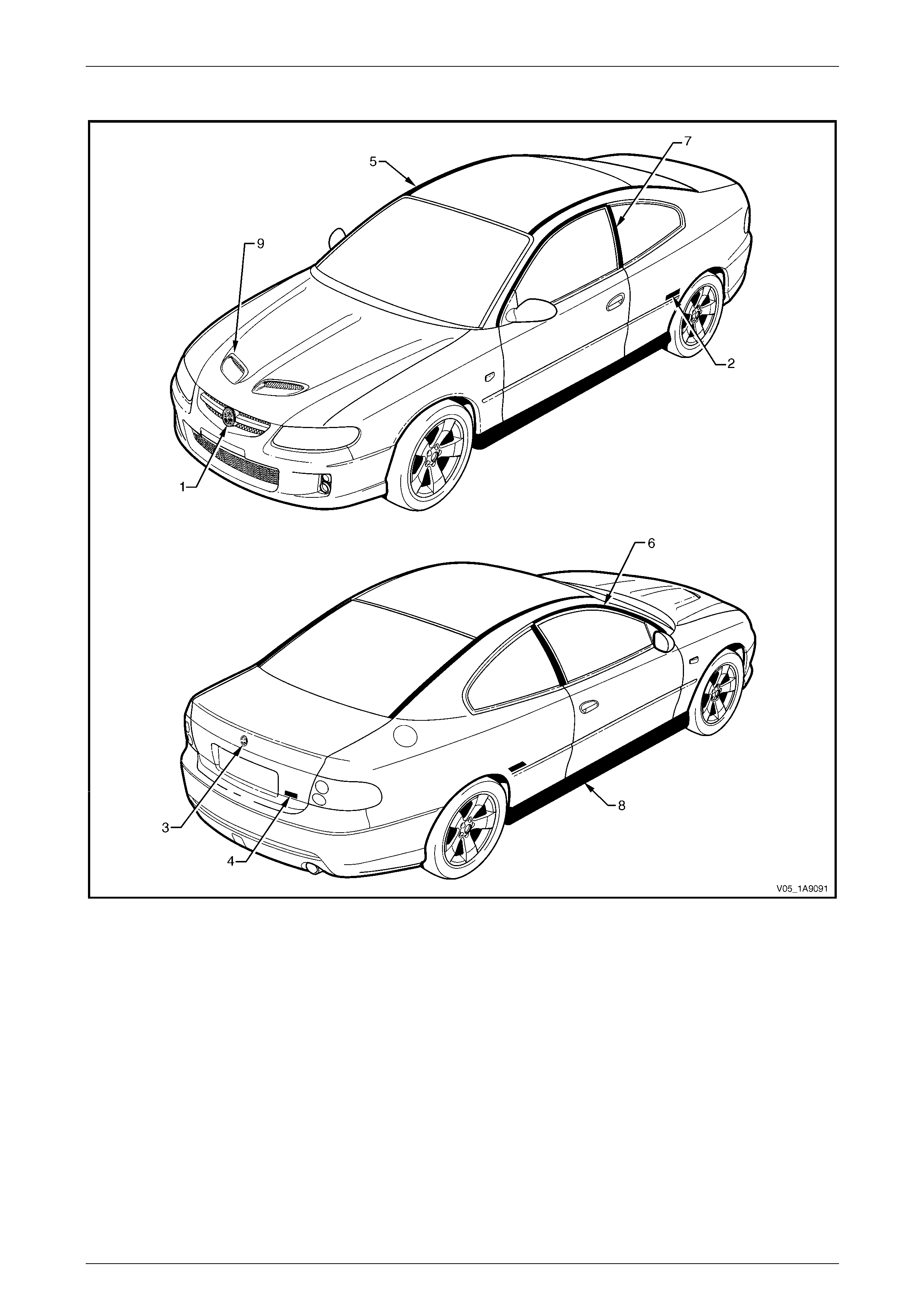
Adventra LX Figure 1A9 – 11 Cross 8 Figure 1A9 – 23
Coupe Monaro CV8 Figure 1A9 – 12
Exterior Ornamentation Page 1A9-9
Page 1A9-9
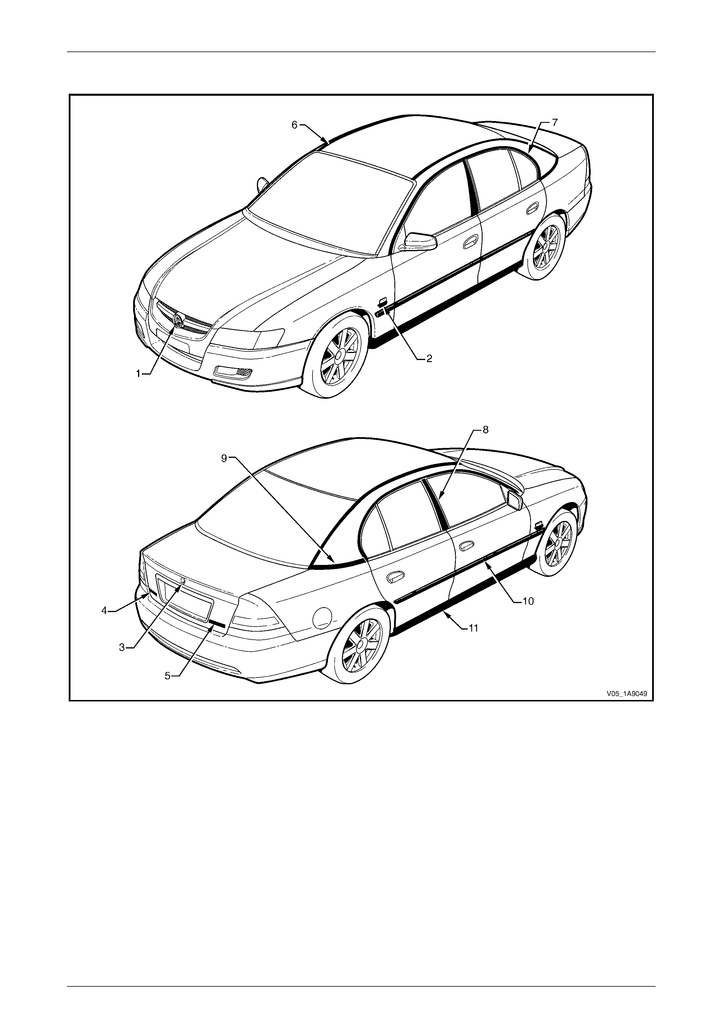
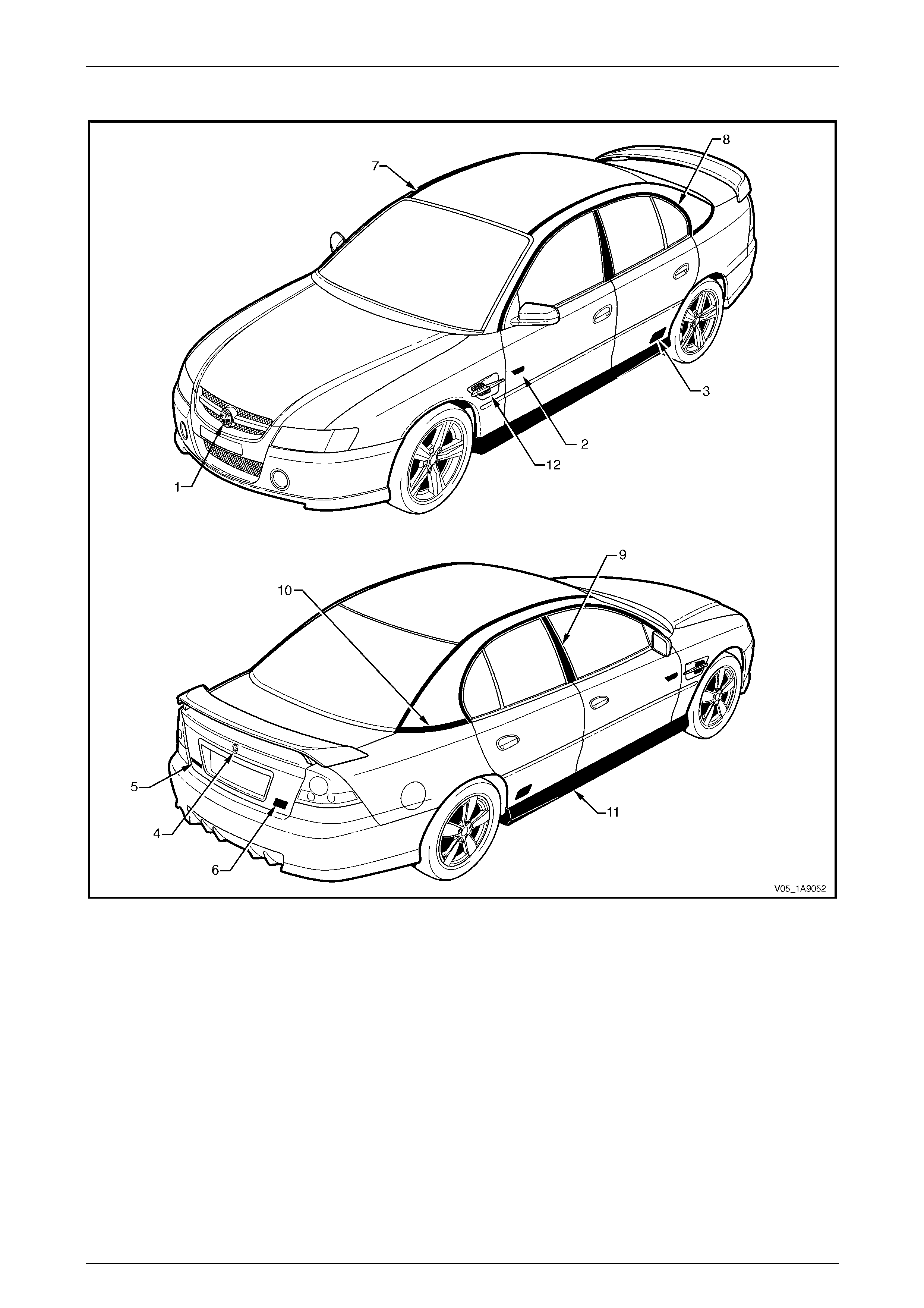
Sedan: Executive and Acclaim
Figure 1A9 – 1

Exterior Ornamentation Page 1A9-10
Page 1A9-10
Reference Chart: Sedan: Executive and Acclaim
Item Description Refer to
1 Radiator Grille Emblem: Holden Section 1C Radiator Grille
2 Fender Name Plate: Alloytec 2.1 Fender Name Plate
3 Rear Compartment Lid Embl em: Holden 2.4 Rear Compartment Lid Emblem
4 Rear Compartment Lid Name Plate: Commo dore 2.5 Rear Compartment Lid Name Plate, Left-hand
5 Rear Compartment Lid Name Plate: Executi ve, Acclaim 2.6 Rear Compartment Lid Name Plate, Rig ht-han d
6 Roof Joint Moulding 2.7 Roof Joint Moulding
7 Door Opening Moulding 2.8 Door Opening Moulding
8 Centre Pillar Upper Finisher Assembly 2.9 Centre Pillar Upper Finisher Assembly
9 Quarter Panel Belt Moulding 2.10 Quarter Panel Belt Moulding
10 Body Side Moulding 2.11 Body Side Mouldings
11 Rocker Panel Moul ding Assembly 2.12 Rocker Panel Moulding Assembly
Exterior Ornamentation Page 1A9-11
Page 1A9-11
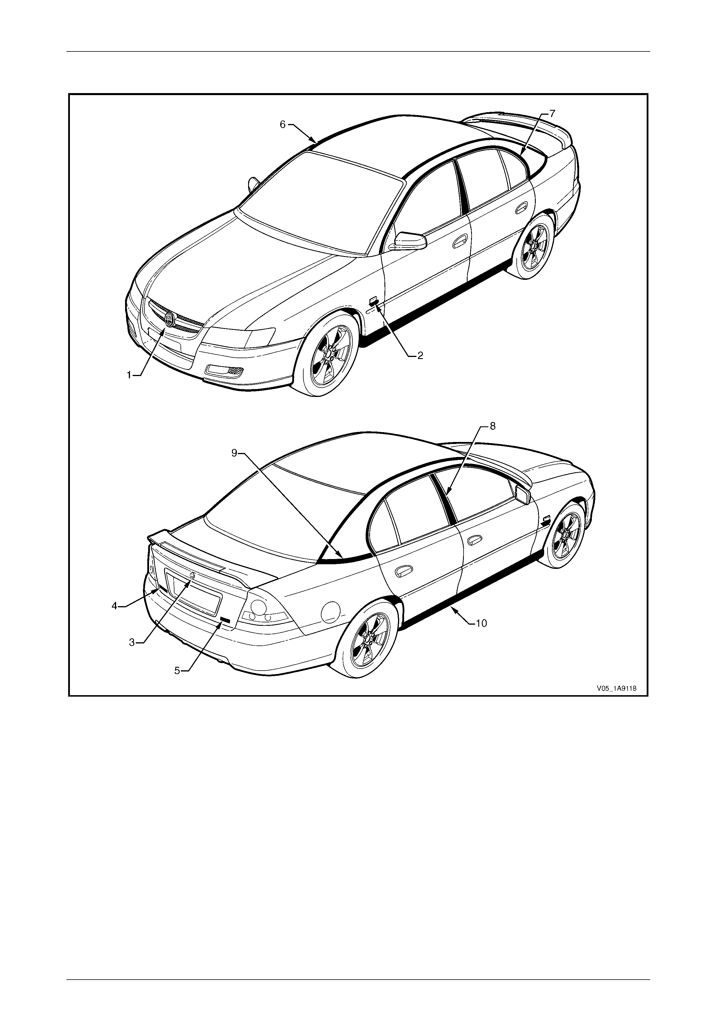
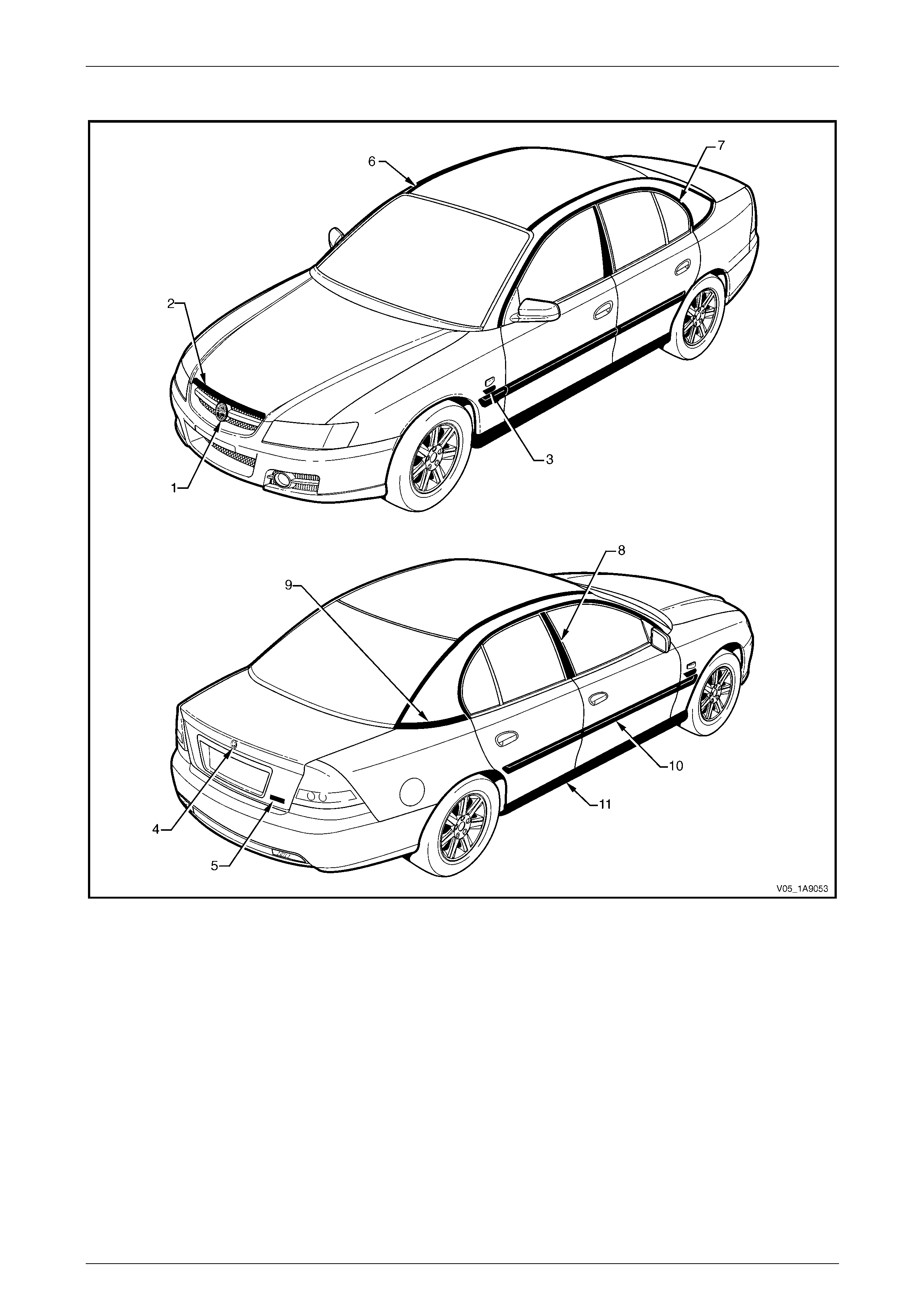
Sedan: SV8
Figure 1A9 – 2

Exterior Ornamentation Page 1A9-12
Page 1A9-12
Reference Chart: Sedan: SV8
Item Description Refer to
1 Radiator Grille Emblem: Holden Section 1C Radiator Grille
2 Fender Name Plate: V8 2.1 Fender Name Plate
3 Rear Compartment Lid Embl em: Holden 2.4 Rear Compartment Lid Emblem
4 Rear Compartment Lid Name Plate: Commo dore 2.5 Rear Compartment Lid Name Plate, Left-hand
5 Rear Compartment Lid Name Plate: SV8 2.6 Rear Compartment Lid Name Plate, Right-hand
6 Roof Joint Moulding 2.7 Roof Joint Moulding
7 Door Opening Moulding 2.8 Door Opening Moulding
8 Centre Pillar Upper Finisher Assembly 2.9 Centre Pillar Upper Finisher Assembly
9 Quarter Panel Belt Moulding 2.10 Quarter Panel Belt Moulding
10 Rocker Panel Moul ding Assembly 2.12 Rocker Panel Moulding Assembly
NOTE
For service procedures of the rear spoiler ref er to
Section 1A4 Hood, Rear Compartment Lid,
Liftgate and Endgate.
Exterior Ornamentation Page 1A9-13
Page 1A9-13
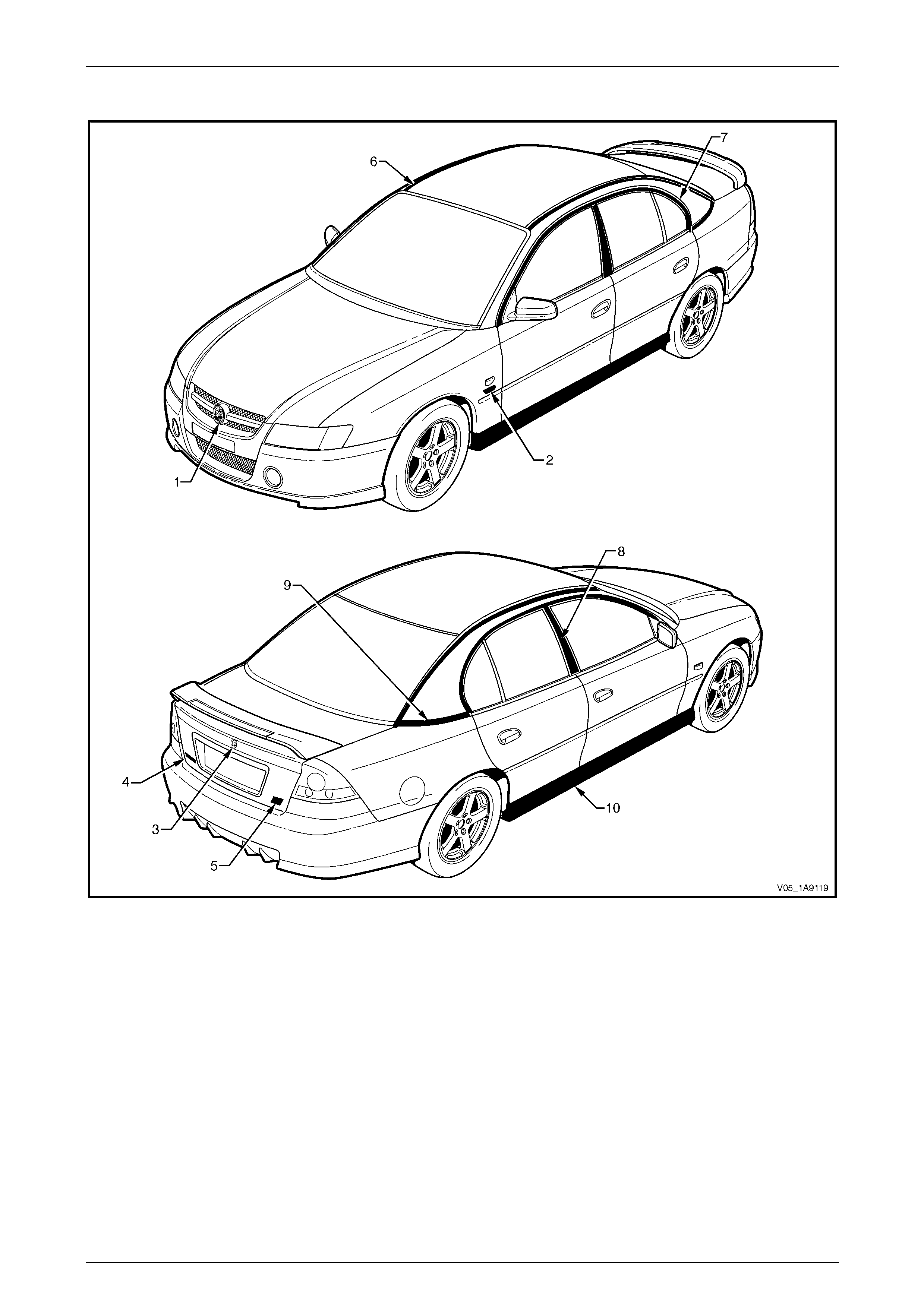
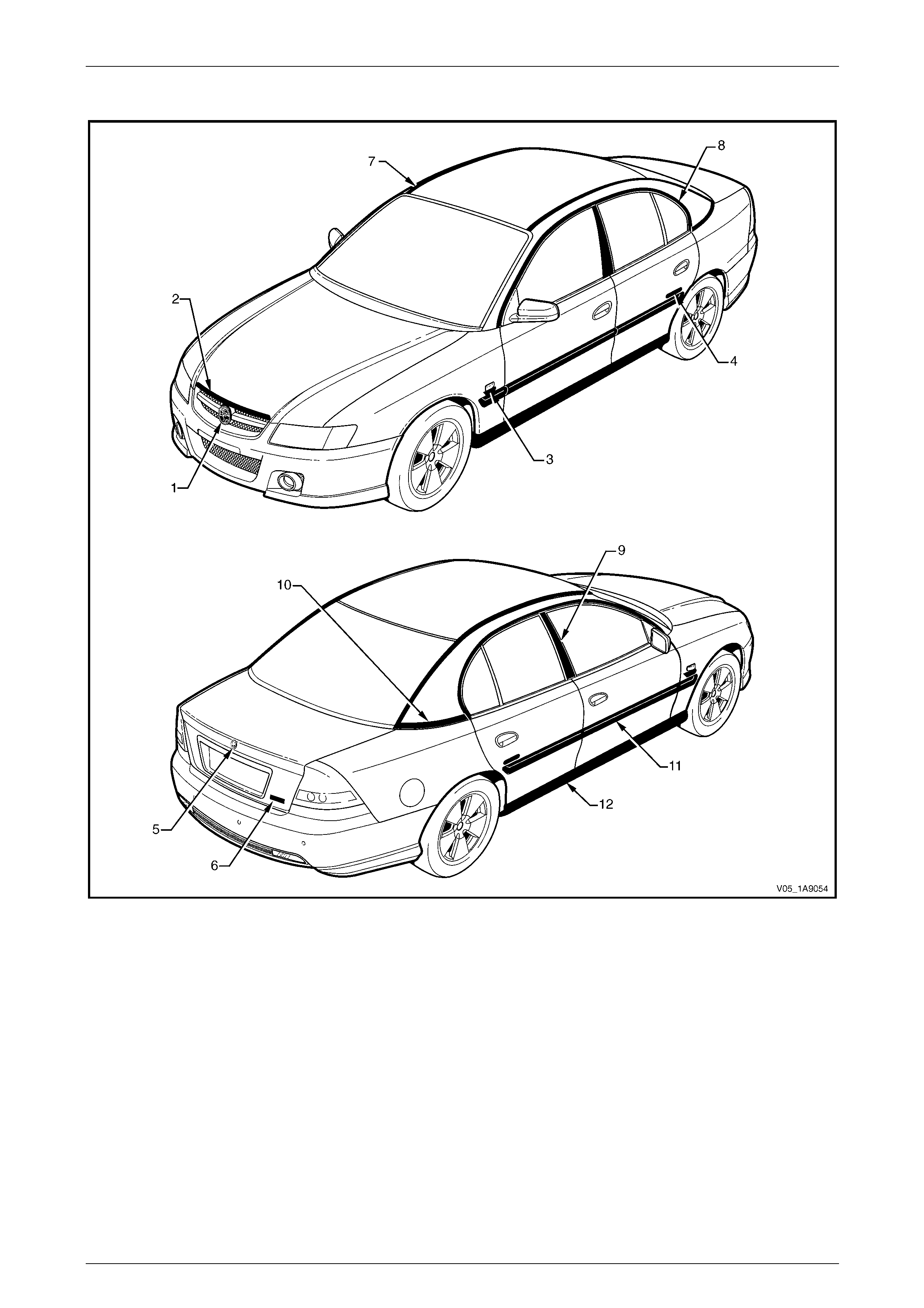
Sedan: SV6
Figure 1A9 – 3

Exterior Ornamentation Page 1A9-14
Page 1A9-14
Reference Chart: Sedan: SV6
Item Description Refer to
1 Radiator Grille Emblem: Holden Section 1C Radiator Grille
2 Fender Name Plate: Alloytec 190. 2.1 Fender Name Plate
3 Rear Compartment Lid Embl em: Holden 2.4 Rear Compartment Lid Emblem
4 Rear Compartment Lid Name Plate: Commo dore 2.5 Rear Compartment Lid Name Plate, Left-hand
5 Rear Compartment Lid Name Plate: SV6 2.6 Rear Compartment Lid Name Plate, Right-hand
6 Roof Joint Moulding 2.7 Roof Joint Moulding
7 Door Opening Moulding 2.8 Door Opening Moulding
8 Centre Pillar Upper Finisher Assembly 2.9 Centre Pillar Upper Finisher Assembly
9 Quarter Panel Belt Moulding 2.10 Quarter Panel Belt Moulding
10 Rocker Panel Moul ding Assembly 2.12 Rocker Panel Moulding Assembly
NOTE
For service procedures of the rear spoiler ref er to
Section 1A4 Hood, Rear Compartment Lid,
Liftgate and Endgate.
Exterior Ornamentation Page 1A9-15
Page 1A9-15
Sedan: SS
Figure 1A9 – 4

Exterior Ornamentation Page 1A9-16
Page 1A9-16
Reference Chart: Sedan: SS
Item Description Refer to
1 Radiator Grille Emblem: Holden Section 1C Radiator Grille
2 Front Door Name Plate: V8 2.2 Front Door Name Plate
3 Rear Door Name Plate: SS 2.3 Rear Door Name Plate
4 Rear Compartment Lid Embl em: Holden 2.4 Rear Compartment Lid Emblem
5 Rear Compartment Lid Name Plate: Commo dore 2.5 Rear Compartment Lid Name Plate, Left-hand
6 Rear Compartment Lid Name Plate: SS 2.6 Rear Compartment Lid Name Plate, Right-hand
7 Roof Joint Moulding 2.7 Roof Joint Moulding
8 Door Opening Moulding 2.8 Door Opening Moulding
9 Centre Pillar Upper Finisher Assembly 2.9 Centre Pillar Upper Finisher Assembly
10 Quarter Panel Belt Moulding 2.10 Quarter Panel Belt Moulding
11 Rocker Panel Moul ding Assembly 2.12 Rocker Panel Moulding Assembly
12 Front Fender Centre Moulding Assembly 2.13 Front Fender Centre Moul ding Assembly
NOTE
For service procedures of the rear spoiler ref er to
Section 1A4 Hood, Rear Compartment Lid,
Liftgate and Endgate.
Exterior Ornamentation Page 1A9-17
Page 1A9-17
Sedan: Berlina
Figure 1A9 – 5

Exterior Ornamentation Page 1A9-18
Page 1A9-18
Reference Chart: Sedan: Berlina
Item Description Refer to
1 Radiator Grille Emblem: Holden Section 1 C Radiator Grille
2 Hood Front Moulding Assembly Section 1A4 Hood, Rear Compartment Lid, Liftgate and Endgate
3 Fender Name Plate: Alloytec, V8 2.1 Fender Name Plate
4 Rear Compartment Lid Embl em: Holden 2.4 Rear Compartment Lid Emblem
5 Rear Compartment Lid Name Plate: Berlin a 2.6 Rear Compartment Lid N ame Plate, Right-hand
6 Roof Joint Moulding 2.7 Roof Joint Moulding
7 Door Opening Moulding 2.8 Door Opening Moulding
8 Centre Pillar Upper Finisher Assembly 2.9 Centre Pillar Upper Finisher Assembly
9 Quarter Panel Belt Moulding 2.10 Quarter Panel Belt Moulding
10 Body Side Moulding 2.11 Body Side Mouldings
11 Rocker Panel Moulding Assembly 2.12 Rocker Panel Moulding Assembly
Exterior Ornamentation Page 1A9-19
Page 1A9-19
Sedan: Calais
Figure 1A9 – 6

Exterior Ornamentation Page 1A9-20
Page 1A9-20
Reference Chart: Sedan: Calais
Item Description Refer to
1 Radiator Grille Emblem: Holden Section 1C Radiator Grill e
2 Hood Front Moulding Assembly Section 1A4 Hood, Rear Compartment Lid, Liftgate and Endgate
3 Fender Name Plate: Alloytec 190, V8 2.1 Fender N ame Plate
4 Rear Door Name Plate: Calais 2.3 Rear Door Name Plate
5 Rear Compartment Lid Embl em: Holden 2.4 Rear Compartment Lid Emblem
6 Rear Compartment Lid Name Plate: Cala is 2.6 Rear Compartment Lid Name Plate, Rig ht-han d
7 Roof Joint Moulding 2.7 Roof Joint Moulding
8 Door Opening Moulding 2.8 Door Opening Moulding
9 Centre Pillar Upper Finisher Assembly 2.9 Centre Pillar Upper Finisher Assembly
10 Quarter Panel Belt Moulding 2.10 Quarter Panel Belt Moulding
11 Body Side Moulding 2.11 Body Side Mouldings
12 Rocker Panel Moulding Assembly 2.12 Rocker Panel Moulding Assembly
Exterior Ornamentation Page 1A9-21
Page 1A9-21
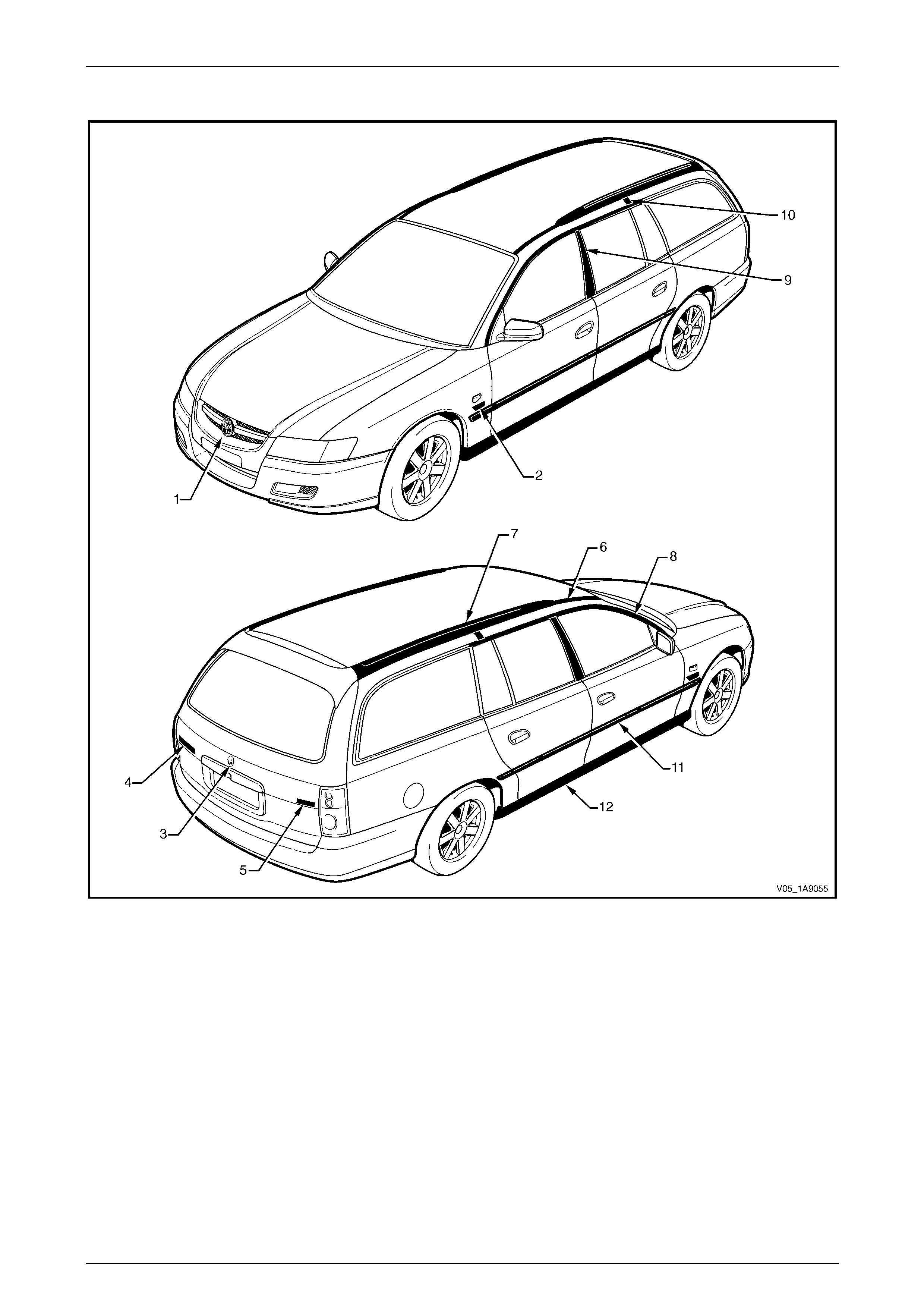
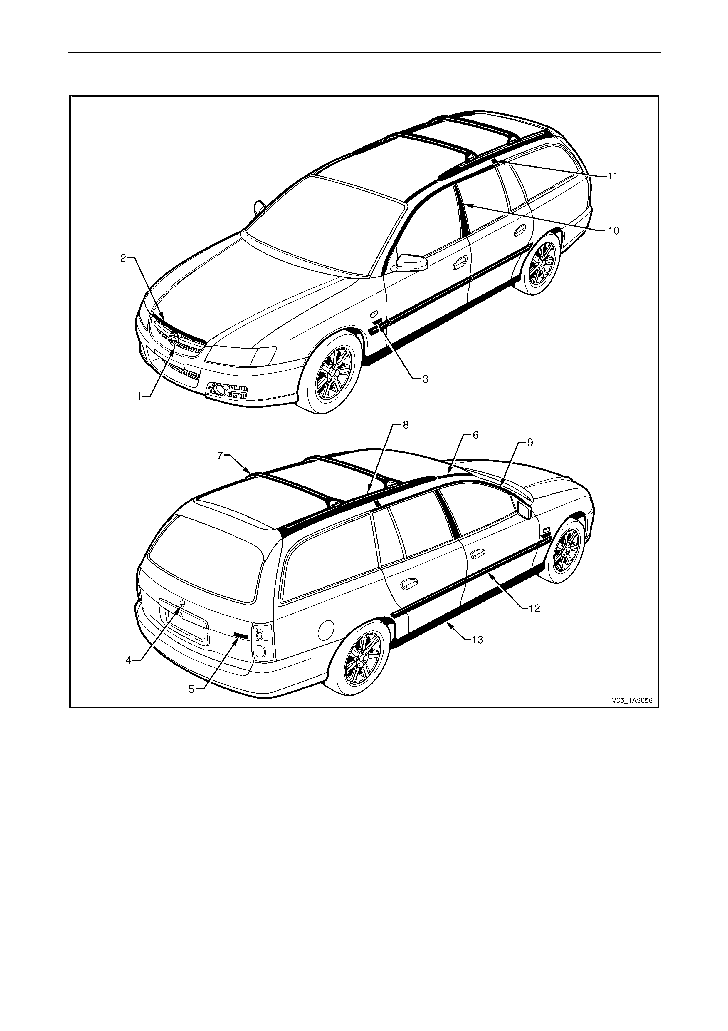
Wagon: Executive and Acclaim
Figure 1A9 – 7

Exterior Ornamentation Page 1A9-22
Page 1A9-22
Reference Chart: Wagon: Executive and Acclaim
Item Description Refer to
1 Radiator Grille Emblem: Holden Section 1C Radiator Grille
2 Fender Name Plate: Alloytec 3.1 Fender Name Plate
3 Liftgate Emblem: Holden 3.2 Liftgate Emblem
4 Liftgate Name Plate: Commodore 3.3 Liftgate Name Plate, Left-hand
5 Liftgate Name Plate: Executive, Acclaim 3.4 Liftgate Name Plate, Right-hand
6 Roof Joint Moulding 3.5 Roof Joint Moulding
7 Roof Side Rails 3.7 Roof Side Rails
8 Door Opening Moulding 3.8 Door Openin g Moulding
9 Centre Pillar Upper Finisher Assembly 3.9 Centre Pillar Upper Finisher Assembl y
10 Roof Joint Finisher 3.10 Roof Joint Finisher
11 Body Side Moulding 3.11 Body Side Mouldings
12 Rocker Panel Moul ding Assembly 3.12 Rocker Panel Moulding Assembly
Exterior Ornamentation Page 1A9-23
Page 1A9-23
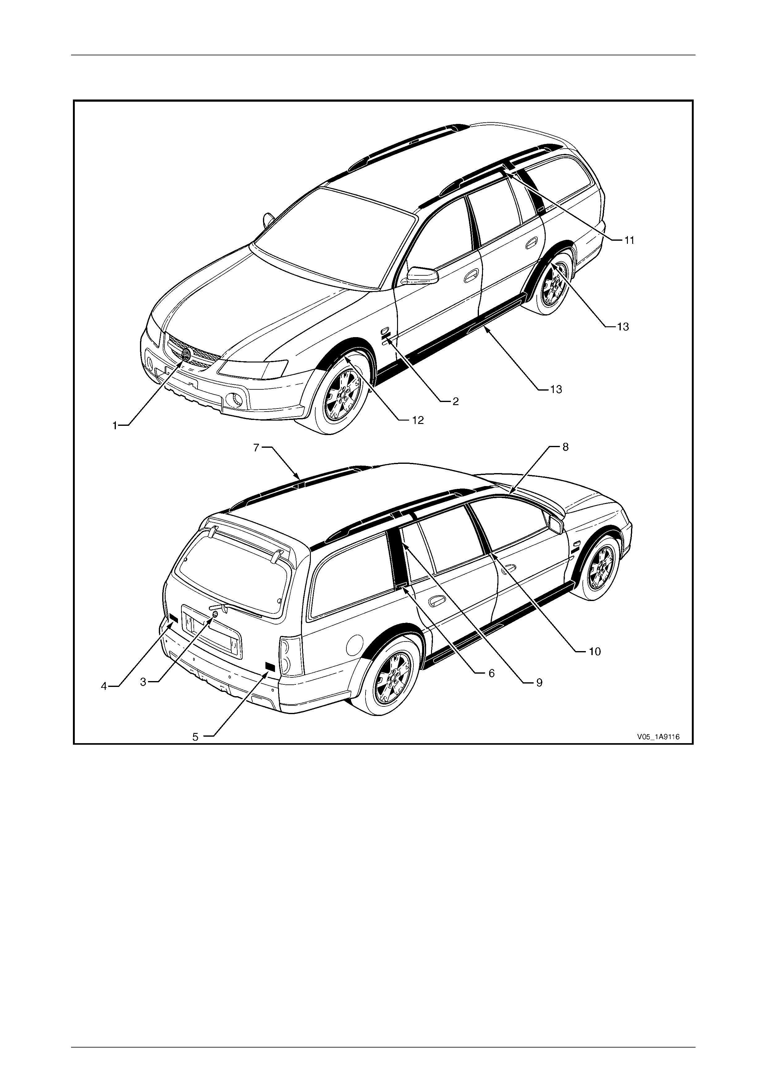
Wagon: Berlina
Figure 1A9 – 8

Exterior Ornamentation Page 1A9-24
Page 1A9-24
Reference Chart: Wagon: Berlina
Item Description Refer to
1 Radiator Grille Emblem: Holden Section 1C Radiator Grille
2 Hood Front Moulding Assembly Section 1A4 Hood, Rear Compartment Lid, Liftgate and Endgate
3 Fender Name Plate: Alloytec, V8 3.1 Fender Name Plate
4 Liftgate Emblem: Holden 3.2 Liftgate Emblem
5 Liftgate Name Plate: Berlina 3.4 Liftgate Name Plate, Right-hand
6 Roof Joint Moulding 3.5 Roof Joint Moulding
7 Roof Bars 3.6 Roof Bars
8 Roof Side Rails 3.7 Roof Side Rails
9 Door Opening Moulding 3.8 Door Opening Moulding
10 Centre Pillar Upper Finisher Assembly 3.9 Centre Pillar Upper Finisher Assembly
11 Roof Joint Finisher 3.10 Roof Joint Finisher
12 Body Side Moulding 3.11 Body Side Mouldings
13 Rocker Panel Moul ding Assembly 3.12 Rocker Panel Moulding Assembly
Exterior Ornamentation Page 1A9-25
Page 1A9-25
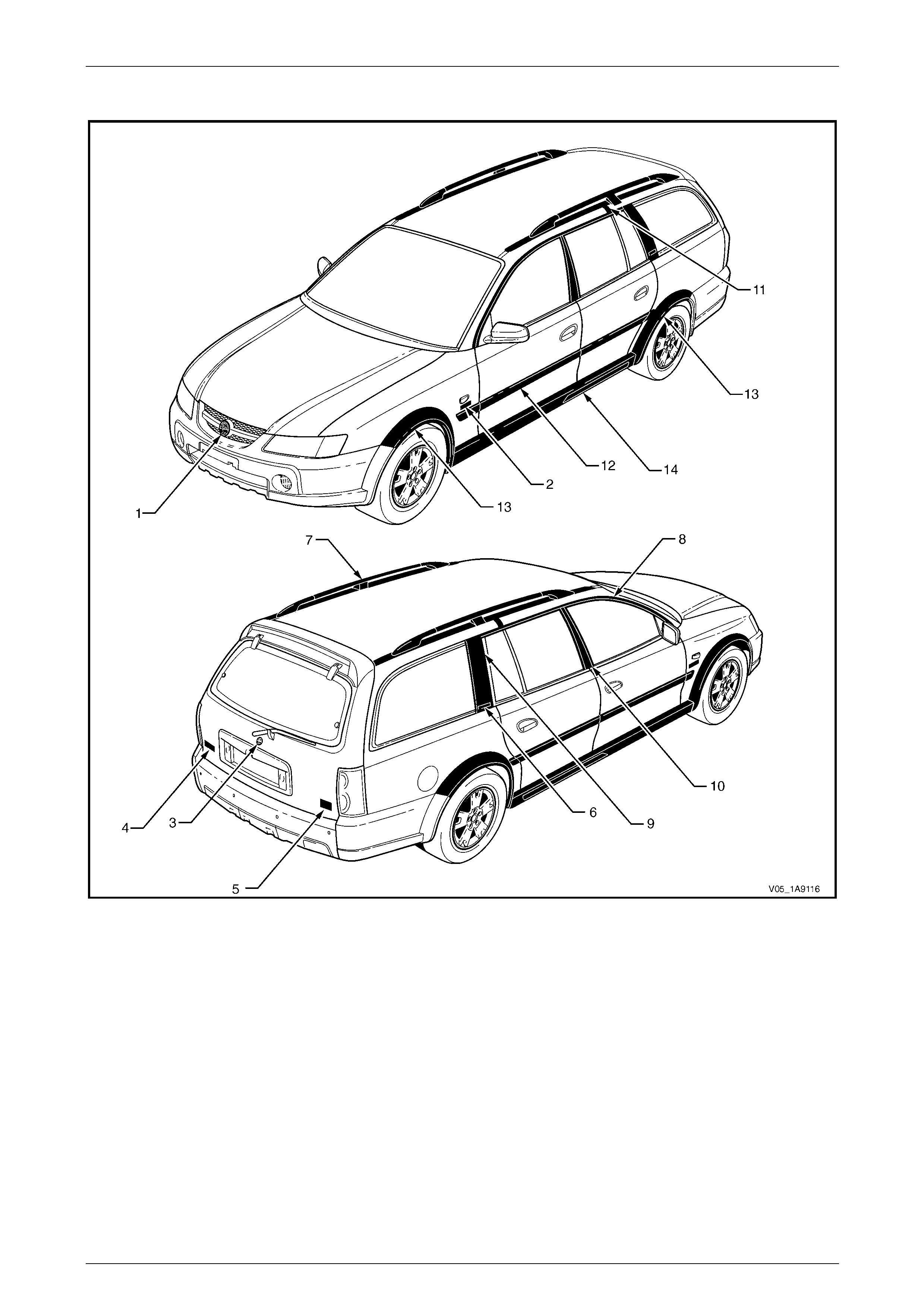
AWD Wagon: Adventra SX
Figure 1A9 – 9

Exterior Ornamentation Page 1A9-26
Page 1A9-26
Reference Chart: AWD Wagon: Adventra SX
Item Description Refer to
1 Radiator Grille Emblem: Holden Section 1C Radiator Grille
2 Fender Name Plate: Alloytec, V8 4.1 Fender Name Plate
3 Liftgate Emblem: Holden 4.2 Liftgate Emblem
4 Liftgate Name Plate: Adventra 4.3 Liftgate Name Plate, Left-hand
5 Liftgate Name Plate: SX6, SX8 4.4 Liftgate Name Plate, Right-hand
6 Rear Quarter Window Appliqué Name Plate:
CrossXTrac 4.5 Rear Quarter Window Appliqué Assembly Name Plate
7 Roof Rack Carrier Assembly 4.6 Roof Rack Carrier Assembly
8 Door Opening Moulding 4.8 Door Opening Moulding
9 Rear Quarter Window Appliqué Assembly 4.9 Rear Quarter Window Appliqué Assembly
10 Centre Pillar Upper Finisher Assembly 3.9 Centre Pillar Upper Finisher Assembly
11 Roof Joint Finisher 3.10 Roof Joint Finisher
12 Wheelhouse Opening Flare 4.11 Wheelhouse Opening F lare Assembly
13 Rocker Panel Moul ding Assembly 4.12 Rocker Panel Moulding Assembly
Exterior Ornamentation Page 1A9-27
Page 1A9-27
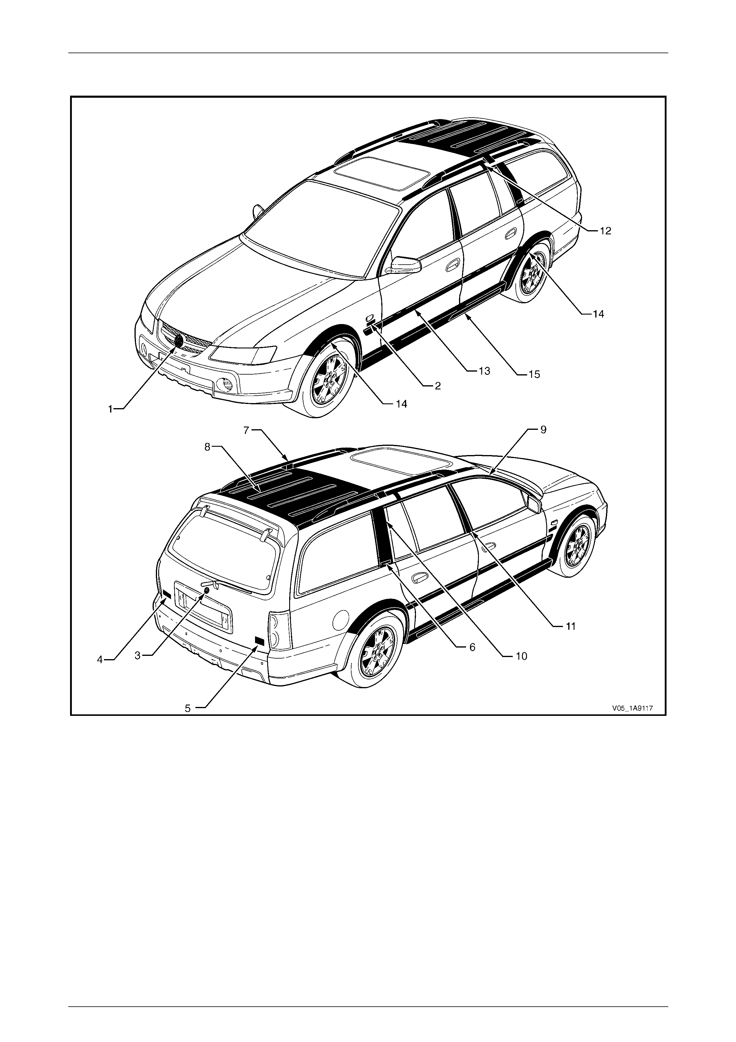
AWD Wagon: Adventra CX
Figure 1A9 – 10

Exterior Ornamentation Page 1A9-28
Page 1A9-28
Reference Chart: AWD Wagon: Adventra CX
Item Description Refer to
1 Radiator Grille Emblem: Holden Section 1C Radiator Grille
2 Fender Name Plate: Alloytec 190 4.1 Fender Name Plate
3 Liftgate Emblem: Holden 4.2 Liftgate Emblem
4 Liftgate Name Plate: Adventra 4.3 Liftgate Name Plate, Left-hand
5 Liftgate Name Plate: CX6 4.4 Liftgate Name Plate, Right-hand
6 Rear Quarter Window Appliqué Name Plate:
CrossXTrac 4.5 Rear Quarter Window Appliqué Assembly Name Plate
7 Roof Rack Carrier Assembly 4.6 Roof Rack Carrier Assembly
8 Door Opening Moulding 4.8 Door Opening Moulding
9 Rear Quarter Window Appliqué Assembly 4.9 Rear Quarter Window Appliqué Assembly
10 Centre Pillar Upper Finisher Assembly 3.9 Centre Pillar Upper Finisher Assembly
11 Roof Joint Finisher 3.10 Roof Joint Finisher
12 Body Side Moulding 4.10 Body Side Mouldings
13 Wheelhouse Opening Flare 4.11 Wheelhouse Opening F lare Assembly
14 Rocker Panel Moul ding Assembly 4.12 Rocker Panel Moulding Assembly
Exterior Ornamentation Page 1A9-29
Page 1A9-29
AWD Wagon: Adventra LX
Figure 1A9 – 11

Exterior Ornamentation Page 1A9-30
Page 1A9-30
Reference Chart: AWD Wagon: Adventra LX
Item Description Refer to
1 Radiator Grille Emblem: Holden Section 1C Radiator Grille
2 Fender Name Plate: Alloytec 190, V8 4.1 Fender Name Plate
3 Liftgate Emblem: Holden 4.2 Liftgate Emblem
4 Liftgate Name Plate: Adventra 4.3 Liftgate Name Plate, Left-hand
5 Liftgate Name Plate: LX6, LX8 4.4 Liftgate Name Plate, Right-hand
6 Rear Quarter Window Appliqué Name Plate:
CrossXTrac 4.5 Rear Quarter Window Appliqué Assembly Name Plate
7 Roof Rack Carrier Assembly 4.6 Roof Rack Carrier Assembly
8 Luggage Carrier 4.7 Luggage Carrier
9 Door Opening Moulding 4.8 Door Opening Moulding
10 Rear Quarter Window Appliqué Assembly 4.9 Rear Quarter Window Appliqué Assembly
11 Centre Pillar Upper Finisher Assembly 3.9 Centre Pillar Upper Finis her Assembly
12 Roof Joint Finisher 3.10 Roof Joint Finisher
13 Body Side Moulding 4.10 Body Side Mouldings
14 Wheelhouse Opening Flare 4.11 Wheelhouse Opening F lare Assembly
15 Rocker Panel Moul ding Assembly 4.12 Rocker Panel Moulding Assembly
Exterior Ornamentation Page 1A9-31
Page 1A9-31
Coupe: Monaro CV8
Figure 1A9 – 12

Exterior Ornamentation Page 1A9-32
Page 1A9-32
Reference Chart: Coupe: Monaro CV8
Item Description Refer to
1 Radiator Grille Emblem: Hold en Section 1C Radiator Grille
2 Quarter Panel Name Plate: Monaro 5.1 Quarter Panel Name Plate
3 Rear Compartment Lid Emb lem: Holden 5.2 Rear Compartment Lid Emblem
4 Rear Compartment Lid Name Plate: CV8 5.3 Rear Compartment Lid Name Plate, Rig ht-han d
5 Roof Joint Moulding 5.4 Roof Joint Moulding
6 Door Opening Moulding 5.5 Door Opening Moulding
7 Centre Pillar Upper Finisher Assembly 5.6 Centre Pillar Upper Finisher Assembly
8 Rocker Panel Mouldin g Asse mbly 5.7 Rocker Panel Moulding Assembly
9 Hood Air Scoop Assembly Section 1A4 Hood, Rear Compartment Lid, Liftgate and End gate
Exterior Ornamentation Page 1A9-33
Page 1A9-33
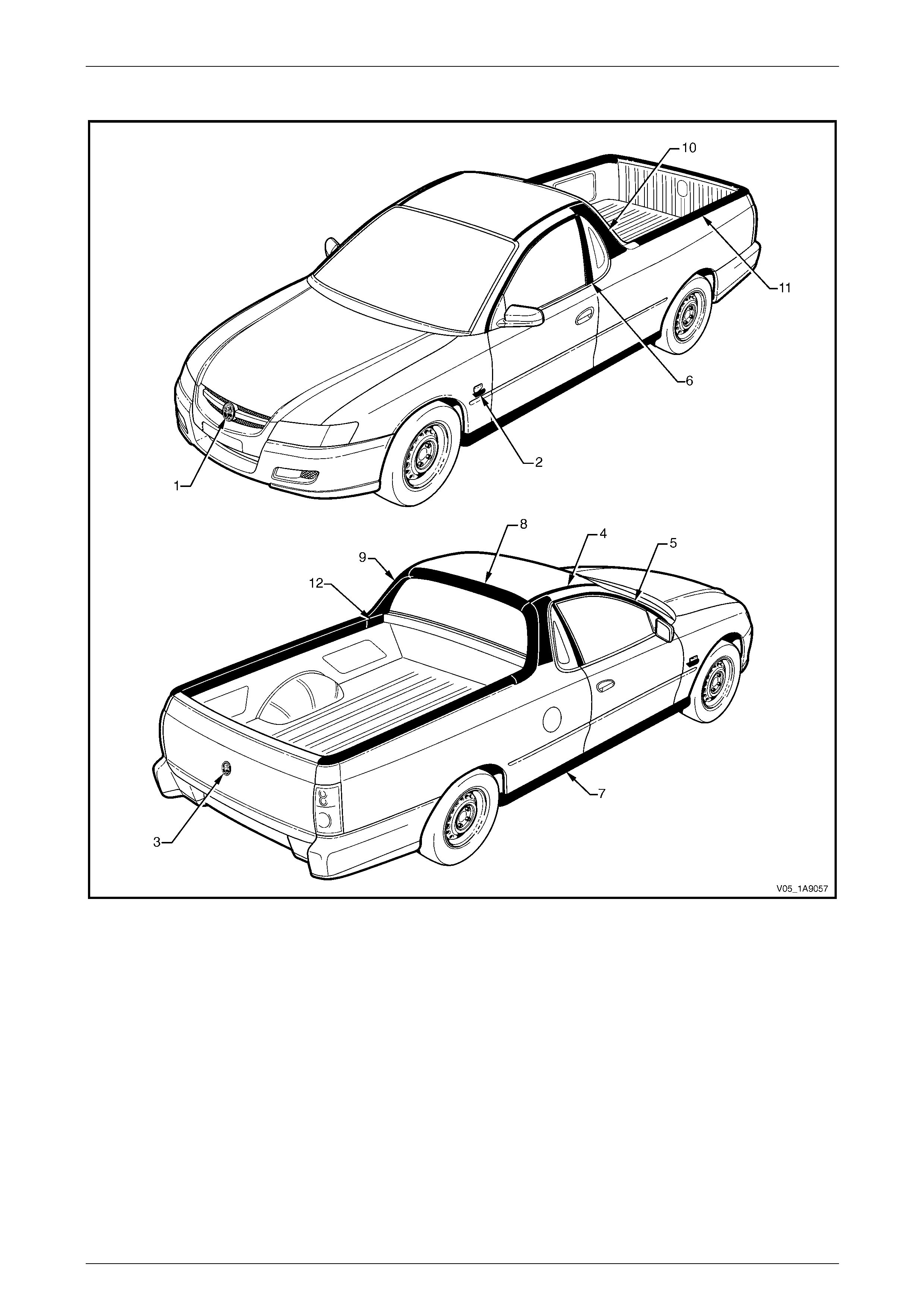
Utility: Base
Figure 1A9 – 13

Exterior Ornamentation Page 1A9-34
Page 1A9-34
Reference Chart: Utility: Base
Item Description Refer to
1 Radiator Grille Emblem: Holden Section 1C Radiator Grille
2 Fender Name Plate: Alloytec, V8 6.1 Fender Name Plate
3 Endgate Emblem: Holden 6.4 Endgate Emblem
4 Roof Joint Moulding 6.6 Roof Joint Moulding
5 Door Opening Moulding 6.7 Door Opening Moulding
6 Centre Pillar Upper Finisher Assembly 6.8 Centre Pillar Upper Finisher Assembly
7 Rocker Panel Moulding Assembly 6.9 Rocker Panel Mo ulding Assembly
8 Rear Window Upper Moulding 6.10 Rear Window Upper Moulding
9 Rear Window Side Moulding 6.11 Rear Window Side Moulding
10 Rear Quarter Window Moulding 6.12 Rear Quarter Window Moulding
11 Quarter Panel Rail 6.13 Quarter Panel Rail
12 Tonneau Cover Bow Retainer 6.14 Tonneau Cover Bow Retainer
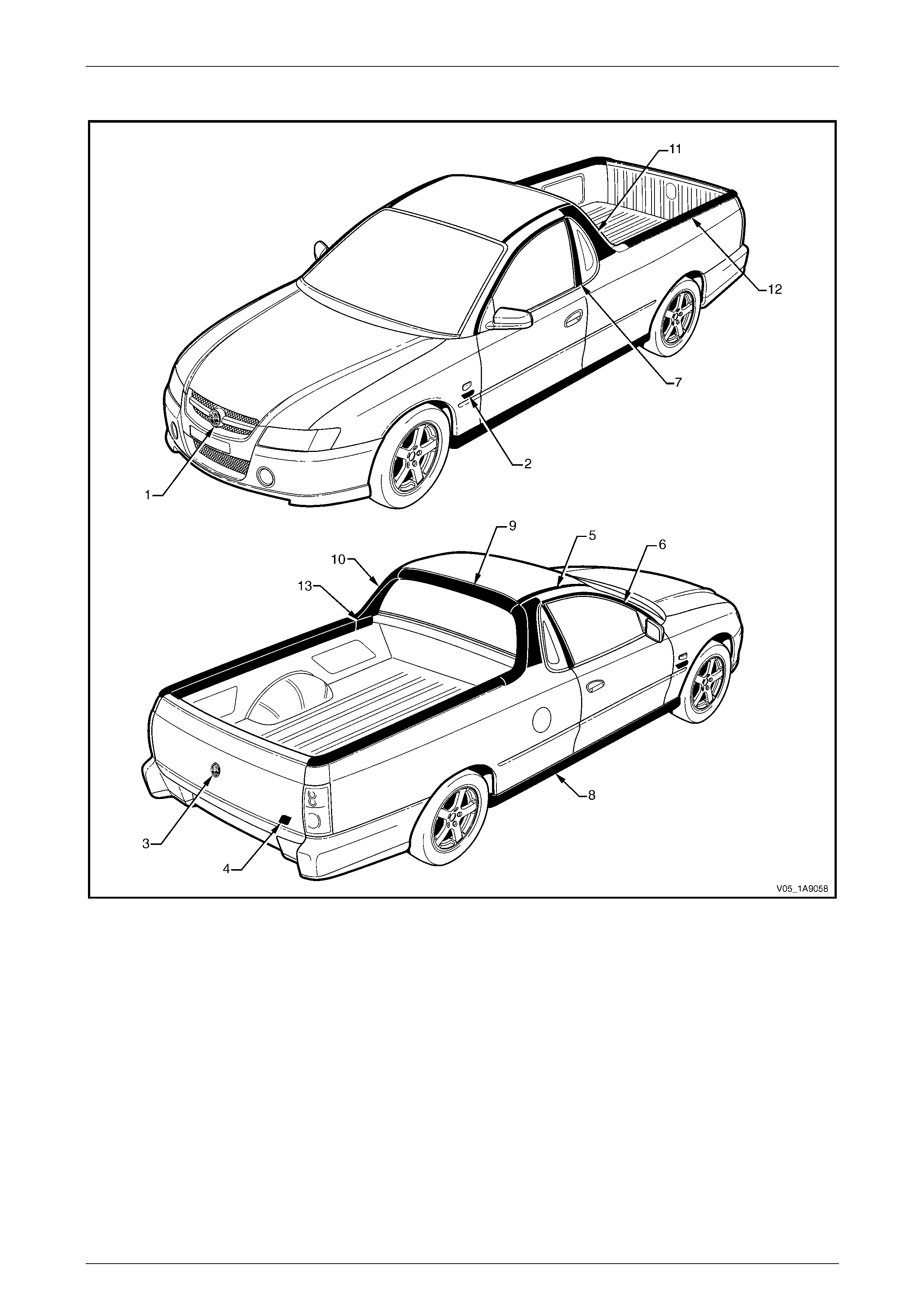
Exterior Ornamentation Page 1A9-35
Page 1A9-35
Utility: S
Figure 1A9 – 14

Exterior Ornamentation Page 1A9-36
Page 1A9-36
Reference Chart: Utility: S
Item Description Refer to
1 Radiator Grille Emblem: Holden Section 1C Radiator Grille
2 Fender Name Plate: Alloytec, V8 6.1 Fender Name Plate
3 Endgate Emblem: Holden 6.4 Endgate Emblem
4 Endgate Name Plate: S 6.5 Endgate Name Plate, Right-hand
5 Roof Joint Moulding 6.6 Roof Joint Moulding
6 Door Opening Moulding 6.7 Door Opening Moulding
7 Centre Pillar upper Finisher Assembly 6.8 Centre Pillar Upper Finisher Assembly
8 Rocker Panel Moulding Assembly 6.9 Rocker Panel Moulding Assembly
9 Rear Window Upper Moulding 6.10 Rear Window Upper Moulding
10 Rear Windo w Side Mould ing 6.11 Rear Window Side Moulding
11 Rear Quarter Window Moulding 6.12 Rear Quarter Window Moulding
12 Quarter Panel Rail 6.13 Quarter Panel Rail
13 Tonneau Cover Bow Retainer 6.14 Tonneau Cover Bow Retainer
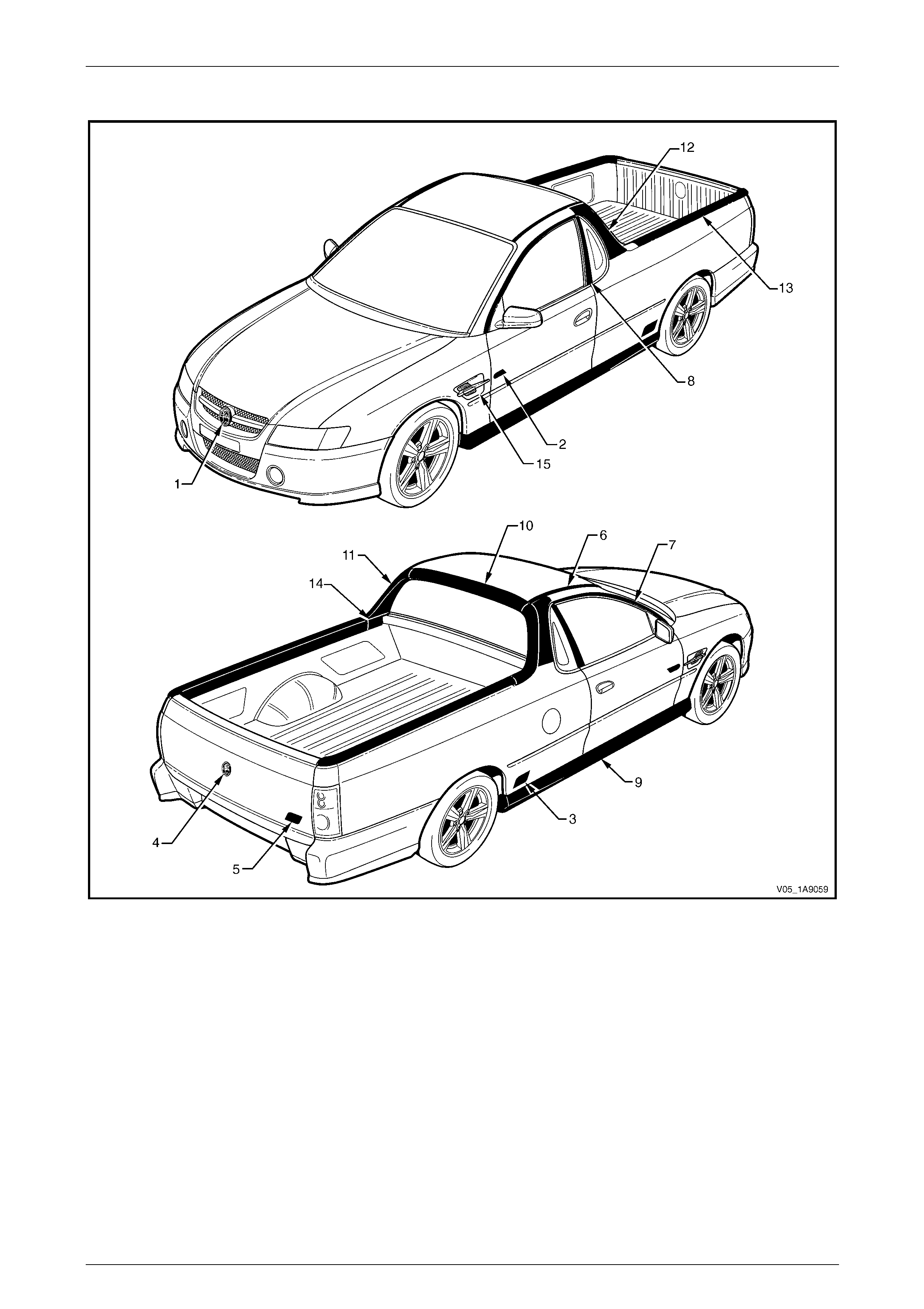
Exterior Ornamentation Page 1A9-37
Page 1A9-37
Utility: SS
Figure 1A9 – 15

Exterior Ornamentation Page 1A9-38
Page 1A9-38
Reference Chart: Utility: SS
Item Description Refer to
1 Radiator Grille Emblem: Holden Section 1C Radiator Grille
2 Front Door Name Plate: V8 6.2 Front Door Name Plate
3 Quarter Panel Name Plate: SS 6.3 Quarter Panel Name Plate
4 Endgate Emblem: Holden 6.4 Endgate Emblem
5 Endgate Name Plate: SS 6.5 Endgate Name Plate, Right-hand
6 Roof Joint Moulding 6.6 Roof Joint Moulding
7 Door Opening Moulding 6.7 Door Opening Moulding
8 Centre Pillar Upper Finisher Assembly 6.8 Centre Pillar Upper Finisher Assembly
9 Rocker Panel Moulding Assembly 6.9 Rocker Pa nel Moulding Assembly
10 Rear Windo w Upper Moul ding 6.10 Rear Window Upper Moulding
11 Rear Windo w Side Mould ing 6.11 Rear Window Side Moulding
12 Rear Quarter Window Moulding 6.12 Rear Quarter Window Moulding
13 Quarter Panel Rail 6.13 Quarter Panel Rail
14 Tonneau Cover Bow Retainer 6.14 Tonneau Cover Bow Retainer
15 Front Fender Centre Moulding Assembly 6.15 Front Fender Centre Moul ding Assembly
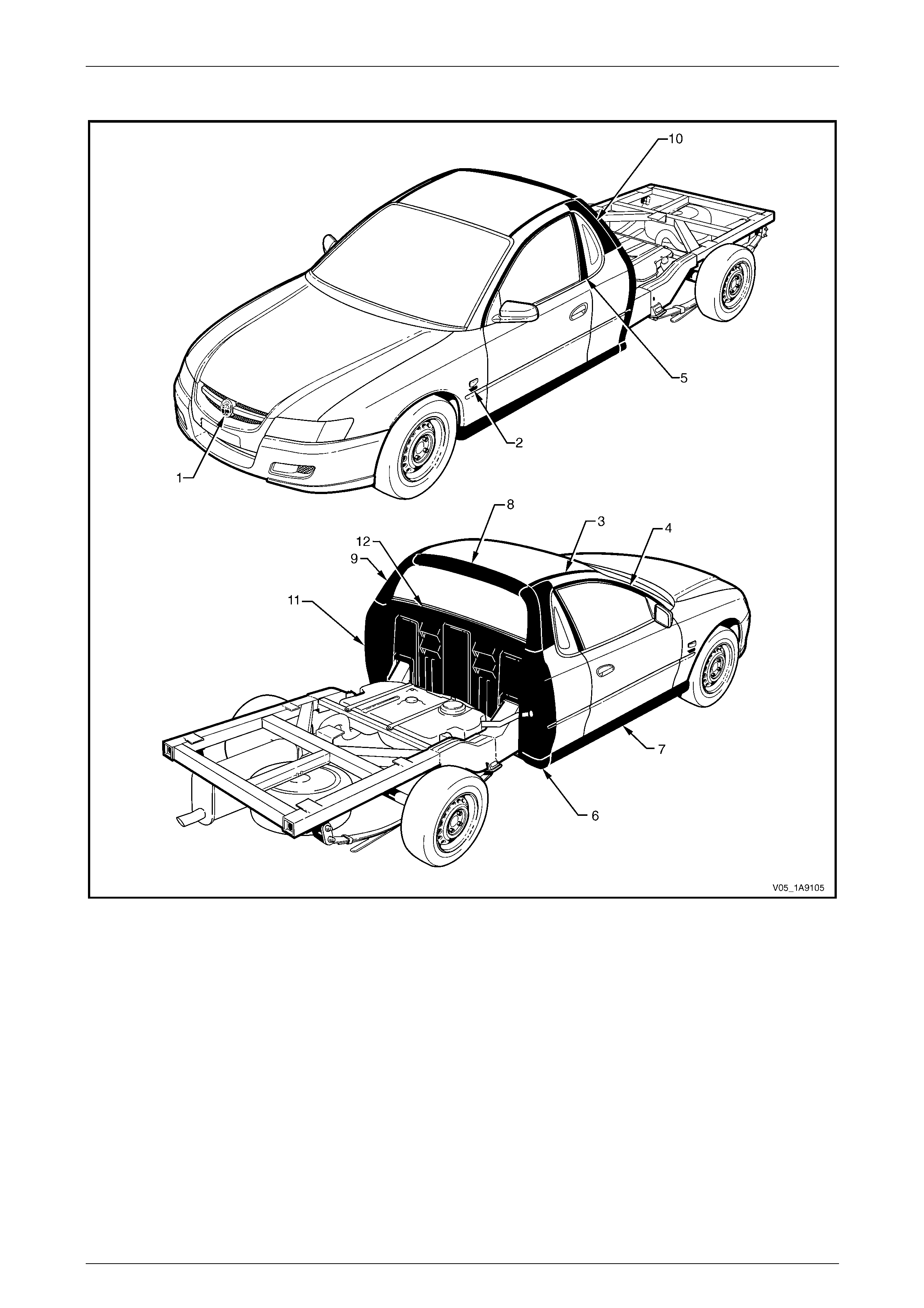
Exterior Ornamentation Page 1A9-39
Page 1A9-39
Regular Cab: Base
Figure 1A9 – 16

Exterior Ornamentation Page 1A9-40
Page 1A9-40
Reference Chart: Regu l ar Cab: Base
Item Description Refer to
1 Radiator Grille Emblem: Holden Section 1C Radiator Grille
2 Fender Name Plate: Alloytec, V8 7.1 Fender Name Plate
3 Roof Joint Moulding 7.3 Roof Joint Moulding
4 Door Opening Moulding 7.4 Door Openin g Moulding
5 Centre Pillar Upper Finisher Assembly 7.5 Centre Pillar Upper Finisher Assembl y
6 Rocker Panel Moulding End Cap 7.6 Rocker Panel Mouldin g End Ca p
7 Rocker Panel Moulding Assembly 7.7 Rocker Panel Moulding Assembly
8 Rear Window Upper Moulding 7.8 Rear Window Upper Moulding
9 Rear Window Side Moulding 7.9 Rear Window Side Moulding
10 Rear Quarter Window Moulding 7.10 Rear Quarter Window Moulding
11 Body Side Rear Trim Panel and Bracket 7.11 Body Side Rear Trim Panel and
7.12 Body Side Rear Trim Bracket
12 Rear Outer Trim Panel and NV H F oam 7.13 Rear Outer Trim Panel and NVH Foam
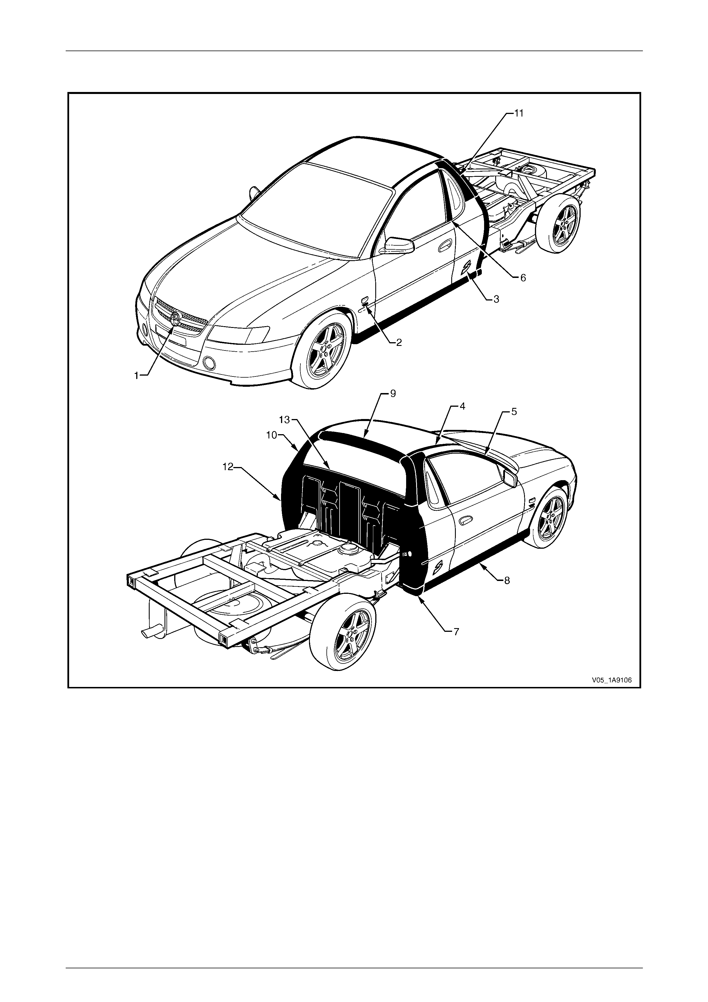
Exterior Ornamentation Page 1A9-41
Page 1A9-41
Regular Cab: S
Figure 1A9 – 17

Exterior Ornamentation Page 1A9-42
Page 1A9-42
Reference Chart: Regu l ar Cab: S
Item Description Refer to
1 Radiator Grille Emblem: Holden Section 1C Radiator Grille
2 Fender Name Plate: Alloytec, V8 7.1 Fender Name Plate
3 Quarter Panel Name Plate: S 7.2 Quarter Panel Name Plate
4 Roof Joint Moulding 7.3 Roof Joint Moulding
5 Door Opening Moulding 7.4 Door Opening Moulding
6 Centre Pillar Upper Finisher Assembly 7.5 Centre Pillar Upper Finisher Assembly
7 Rocker Panel Moulding End Cap 7.6 Rocker Panel Moulding End Cap
8 Rocker Panel Moulding Assembly 7.7 Rocker Panel Moulding Assembly
9 Rear Window Upper Moulding 7.8 Rear Window Upper Moulding
10 Rear Windo w Side Mould ing 7.9 Rear Window Side Moulding
11 Rear Quarter Window Moulding 7.10 Rear Quarter Window Moulding
12 Body Side Rear Trim Panel and Bracket 7.11 Body Side Rear Trim Panel and
7.12 Body Side Rear Trim Bracket
13 Rear Outer Trim Panel and NV H F oam 7.13 Rear Outer Trim Panel and NV H F oam
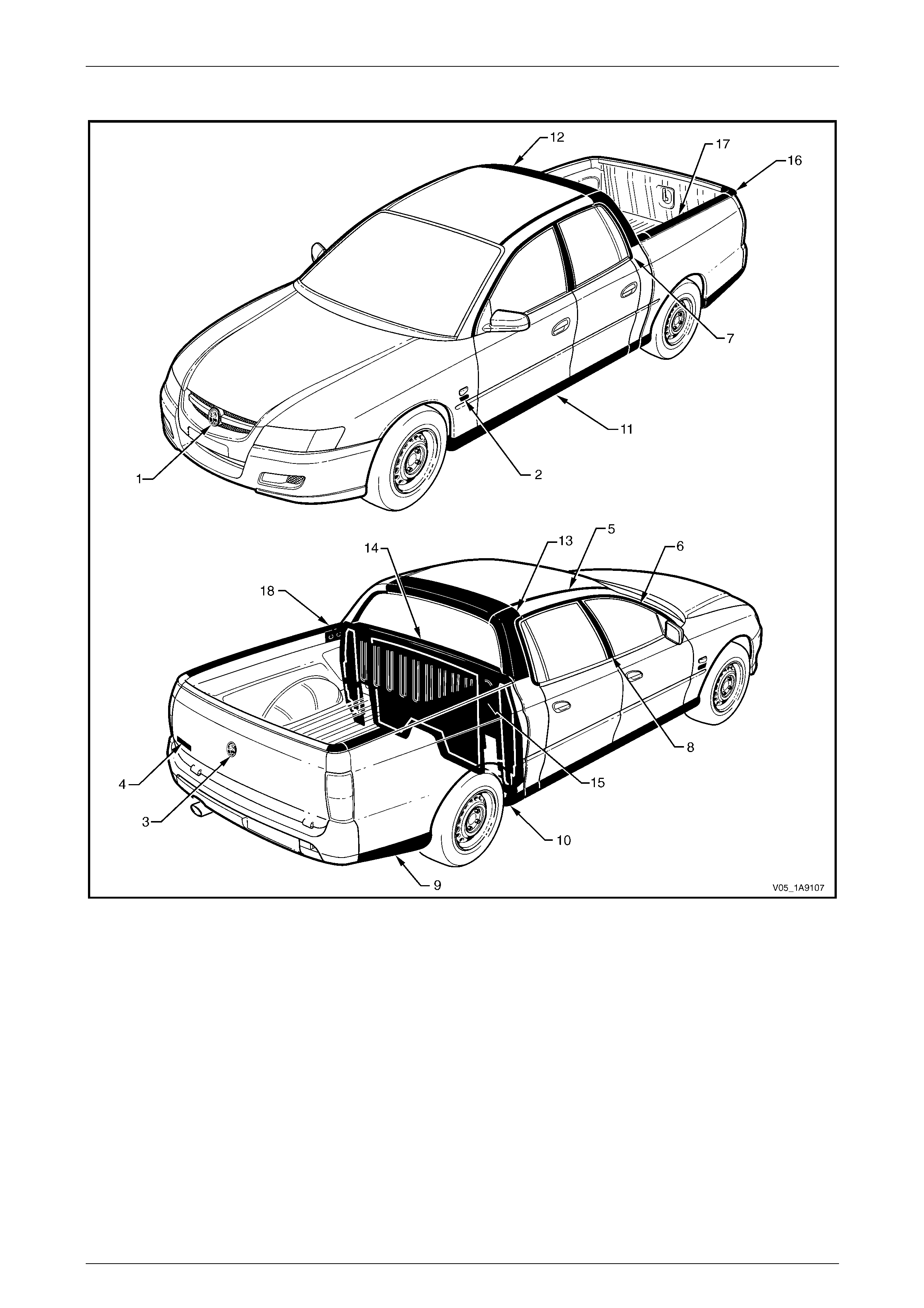
Exterior Ornamentation Page 1A9-43
Page 1A9-43
Crew Cab: Base
Figure 1A9 – 18

Exterior Ornamentation Page 1A9-44
Page 1A9-44
Reference Chart: Crew Cab: Base
Item Description Refer to
1 Radiator Grille Emblem: Holden Section 1C Radiator Grille
2 Fender Name Plate: Alloytec 8.1 Fender Name Plate
3 Endgate Emblem: Holden 8.4 Endgate Emblem
4 Endgate Name Plate: Crewman 8.5 Endgate Name plate, Left-hand
5 Roof Joint Moulding 8.7 Roof Joint Moulding
6 Door Opening Moulding 8.8 Door Opening Moulding
7 Body Lock Pillar Door Moulding 8.16 Body Lock Pillar Do or Moulding
8 Centre Pillar Upper Finisher Assembly 8.9 Centre Pillar Upper Finisher Assembly
9 Rear Body Rear Rocker Moulding 8.11 Rear Body Rear Rocker Mouldin g
10 Rear Body Front Rocker Moulding 8.10 Rear Body Front Rocker Moulding
11 Rocker Panel Moul ding Assembly 8.12 Rocker Panel Moulding Assembly
12 Rear Header Trim 8.13 Rear Header Trim
13 Body Lock Pillar Trim 8.17 Body Lock Pillar Trim
14 Rear Windo w Lower Finisher 8.15 Rear Window Lo wer Finisher
15 Rear Outer Trim Panel and NV H F oam 8.21 Rear Outer Trim Panel and NVH F oa m
16 Rear Body Rail End Cap 8.19 Rear Body Rail Cover and End Cap
17 Rear Body Rail Cover 8.19 Rear Body Rail Cover and End Cap
18 Rear Body Front Rail Cover 8.20 Rear Body Front Rail Cover
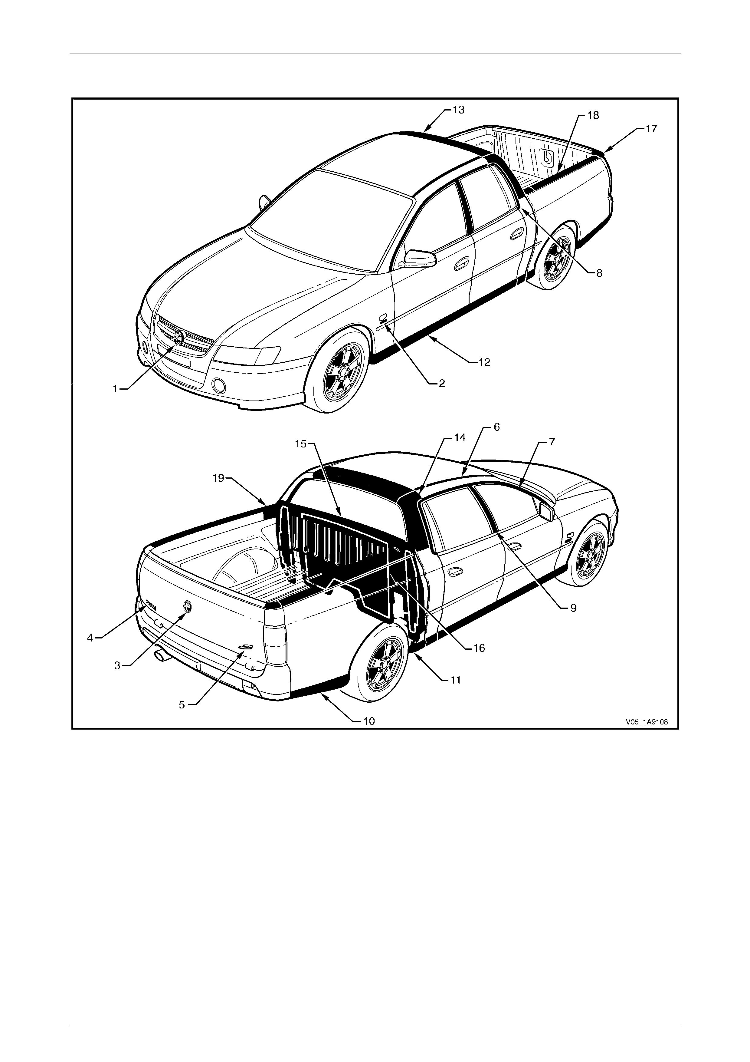
Exterior Ornamentation Page 1A9-45
Page 1A9-45
Crew Cab: S
Figure 1A9 – 19

Exterior Ornamentation Page 1A9-46
Page 1A9-46
Reference Chart: Crew Cab: S
Item Description Refer to
1 Radiator Grille Emblem: Holden Section 1C Radiator Grille
2 Fender Name Plate: Alloytec 8.1 Fender Name Plate
3 Endgate Emblem: Holden 8.4 Endgate Emblem
4 Endgate Name Plate: Crewman 8.5 Endgate Name plate, Left-hand
5 Endgate Name Plate: S 8.6 Endgate Name Plate, Right-hand
6 Roof Joint Moulding 8.7 Roof Joint Moulding
7 Door Opening Moulding 8.8 Door Opening Moulding
8 Body Lock Pillar Door Moulding 8.16 Body Lock Pillar Do or Moulding
9 Centre Pillar Upper Finisher Assembly 8.9 Centre Pillar Upper Finisher Assembly
10 Rear Body Rear Rocker Moulding 8.11 Rear Body Rear Rocker Moulding
11 Rear Body Front Rocker Moulding 8.10 Rear Body Front Rocker Moulding
12 Rocker Panel Moul ding Assembly 8.12 Rocker Panel Moulding Assembly
13 Rear Header Trim 8.13 Rear Header Trim
14 Body Lock Pillar Trim 8.17 Body Lock Pillar Trim
15 Rear Windo w Lower Finisher 8.15 Rear Window Lo wer Finisher
16 Rear Outer Trim Panel and NV H F oam 8.21 Rear Outer Trim Panel and NVH F oa m
17 Rear Body Rail End Cap 8.19 Rear Body Rail Cover and End Cap
18 Rear Body Rail Cover 8.19 Rear Body Rail Cover and End Cap
19 Rear Body Front Rail Cover 8.20 Rear Body Front Rail Cover
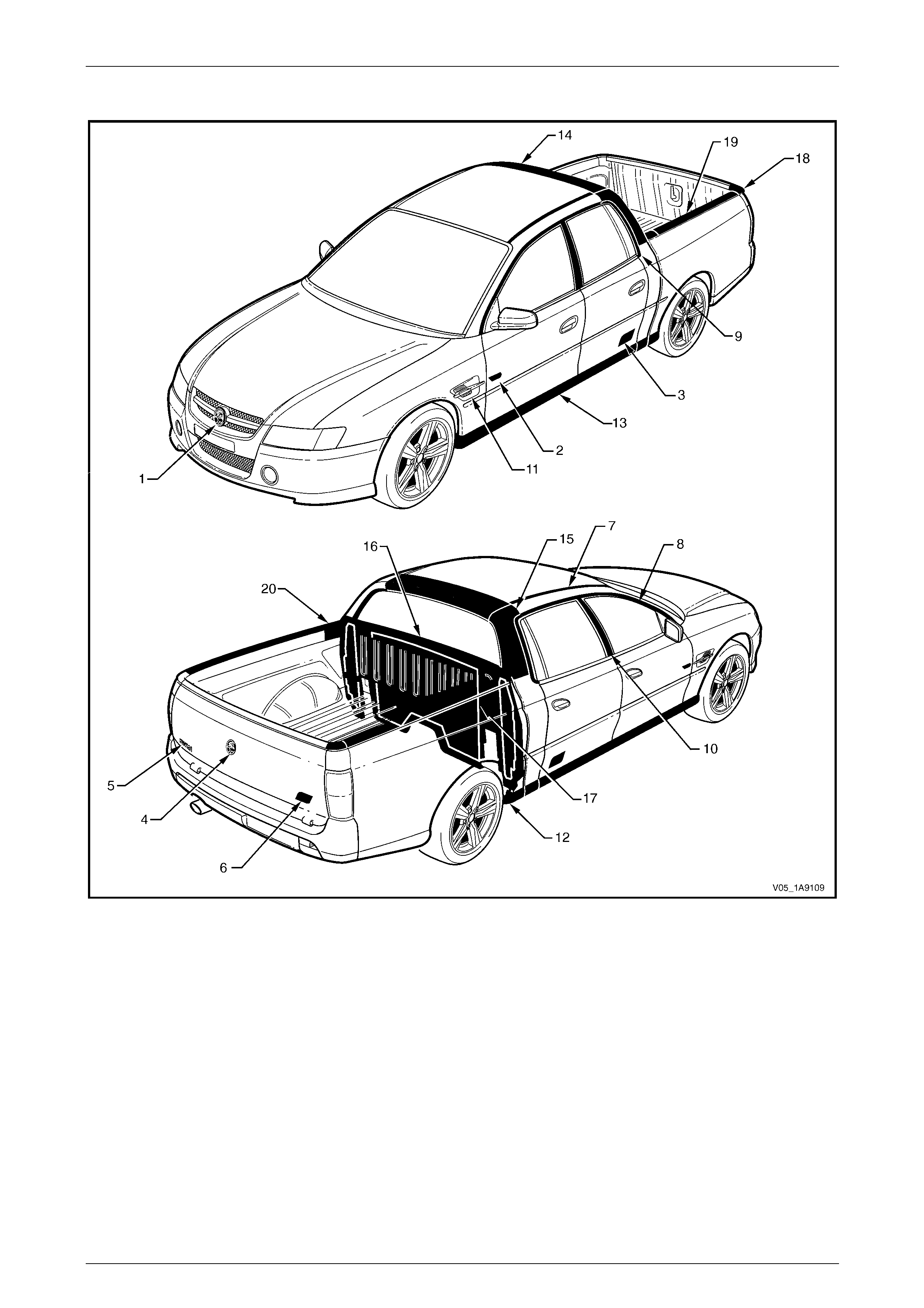
Exterior Ornamentation Page 1A9-47
Page 1A9-47
Crew Cab: SS
Figure 1A9 – 20

Exterior Ornamentation Page 1A9-48
Page 1A9-48
Reference Chart: Crew Cab: SS
Item Description Refer to
1 Radiator Grille Emblem: Holden Section 1C Radiator Grille
2 Front Door Name Plate: V8 8.2 Front Door Name Plate
3 Rear Door Name Plate: SS 8.3 Rear Door Name plate
4 Endgate Emblem: Holden 8.4 Endgate Emblem
5 Endgate Name Plate: Crewman 8.5 Endgate Name plate, Left-hand
6 Endgate Name Plate: SS 8.6 Endgate Name Plate, Right-hand
7 Roof Joint Moulding 8.7 Roof Joint Moulding
8 Door Opening Moulding 8.8 Door Opening Moulding
9 Body Lock Pillar Door Moulding 8.16 Body Lock Pillar Do or Moulding
10 Centre Pillar Upper Finisher Assembly 8.9 Centre Pillar Upper Finis her Assembly
11 Front Fender Centre Moulding Assembly 8.22 Front Fender Centre Moul ding Assembly
12 Rear Body Front Rocker Moulding 8.10 Rear Body Front Rocker Moulding
13 Rocker Panel Moul ding Assembly 8.12 Rocker Panel Moulding Assembly
14 Rear Header Trim 8.13 Rear Header Trim
15 Body Lock Pillar Trim 8.17 Body Lock Pillar Trim
16 Rear Windo w Lower Finisher 8.15 Rear Window Lo wer Finisher
17 Rear Outer Trim Panel and NV H F oam 8.21 Rear Outer Trim Panel and NVH F oa m
18 Rear Body Rail End Cap 8.19 Rear Body Rail Cover and End Cap
19 Rear Body Rail Cover 8.19 Rear Body Rail Cover and End Cap
20 Rear Body Front Rail Cover 8.20 Rear Body Front Rail Cover
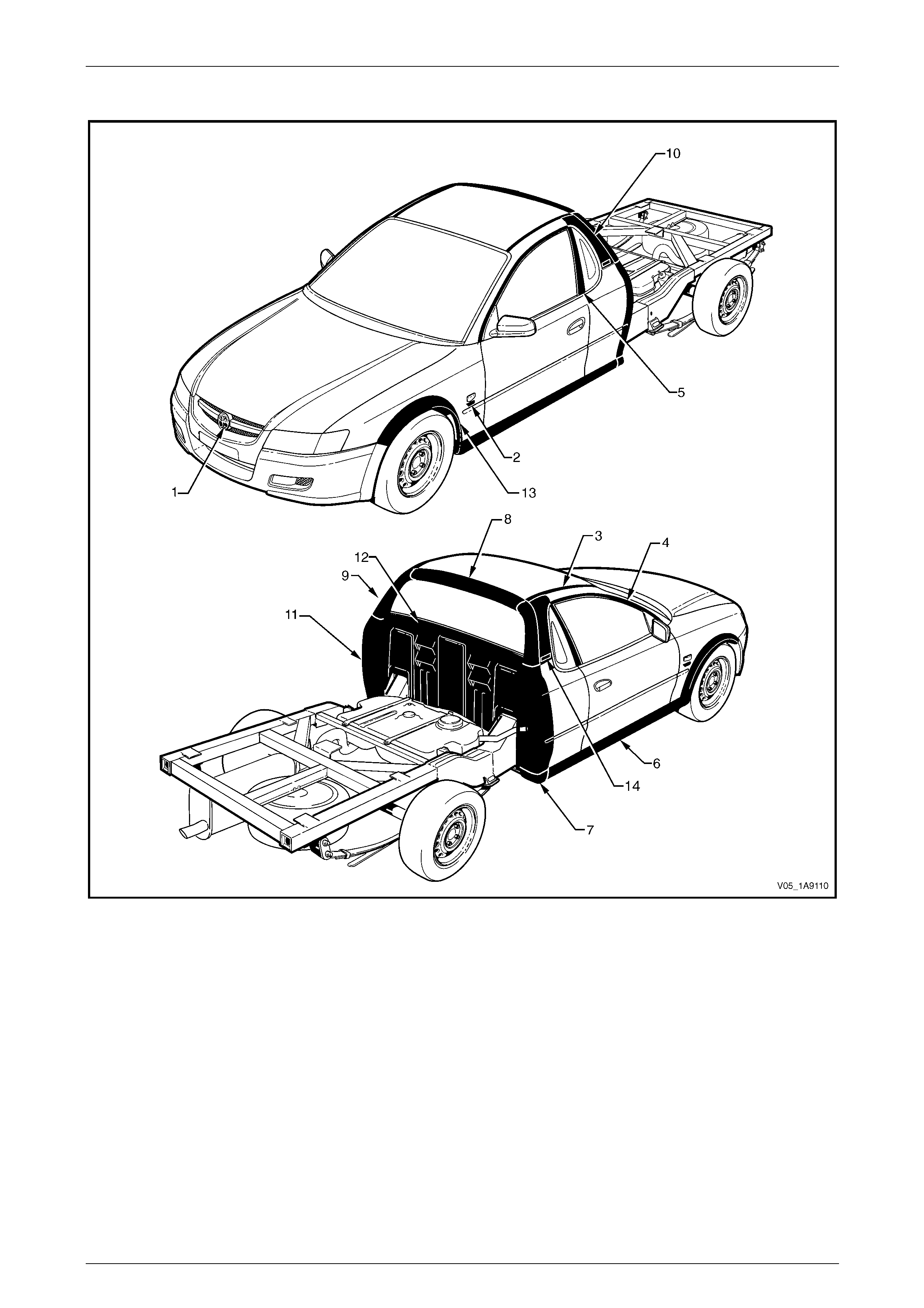
Exterior Ornamentation Page 1A9-49
Page 1A9-49
AWD Regular Cab: Base
Figure 1A9 – 21

Exterior Ornamentation Page 1A9-50
Page 1A9-50
Reference Chart: AWD Reg u lar Cab: Base
Item Description Refer to
1 Radiator Grille Emblem: Holden Section 1C Radiator Grille
2 Fender Name Plate Alloytec, V8 7.1 F ender Name Plate
3 Roof Joint Moulding 7.3 Roof Joint Moulding
4 Door Opening Moulding 7.4 Door Opening Moulding
5 Centre Pillar Upper Finisher Assembly 7.5 Centre Pillar Upper Finisher Assembly
6 Rocker Panel Moulding Assembly 9.4 Rocker Panel Moulding Assembly
7 Rocker Panel Moulding End Cap 7.6 Rocker Panel Moulding End Cap
8 Rear Window Upper Moulding 7.8 Rear Window Upper Moulding
9 Rear Window Side Moulding 7.9 Rear Window Side Moulding
10 Rear Quarter Window Moulding 7.10 Rear Quarter Window Moulding
11 Body Side Rear Trim Panel and Bracket 7.11 Body Side Rear Trim Panel and
7.12 Body Side Rear Trim Bracket
12 Rear Outer Trim Panel and NV H F oam 7.13 Rear Outer T r im Panel and NVH Foam
13 Front Wheelhouse Opening Flare 4.11 Wheelhouse Opening Flare Assembly
14 Body Lock Pillar T r im Name Plate: CrossXTrac 9.1 Body Lock Pillar Trim Name Plate – CrossXTrac
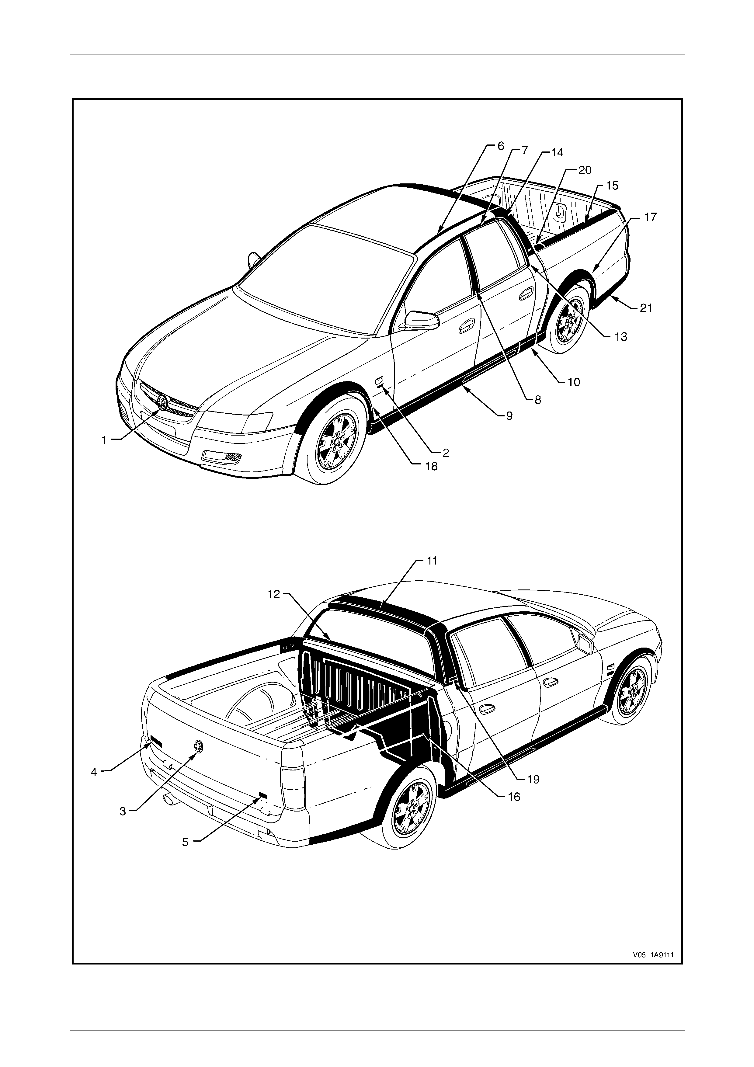
Exterior Ornamentation Page 1A9-51
Page 1A9-51
AWD Crew Cab: Cross6
Figure 1A9 – 22

Exterior Ornamentation Page 1A9-52
Page 1A9-52
Reference Chart: AWD Crew Cab: Cross6
Item Description Refer to
1 Radiator Grille Emblem: Holden Section 1C Radiator Grille
2 Fender Name Plate: Alloytec 8.1 Fender Name Plate
3 Endgate Emblem: Holden 8.4 Endgate Emblem
4 Endgate Name Plate: Crewman 8.5 Endgate Name plate, Left-hand
5 Endgate Name Plate: CrossX6 8.6 Endgate Name Plate, Right-hand
6 Roof Joint Moulding 8.7 Roof Joint Moulding
7 Door Opening Moulding 8.8 Door Opening Moulding
8 Centre Pillar Upper Finisher Assembly 8.9 Centre Pillar Upper Finisher Assembly
9 Rocker Panel Moulding Assembly 9.4 Rocker Panel Mo ulding Assembly
10 Rear Rocker Panel Moulding 9.5 Rear Rocker Panel Moul ding
11 Rear Header Trim 8.13 Rear Header Trim
12 Rear Window Lower Finisher 8.15 Rear Window Lower Finisher
13 Body Lock Pillar Door Mouldi ng 8.16 Body Lock Pillar Door Moulding
14 Body Lock Pillar Trim and Body Lock Pillar Finisher 8.17 Body Lock Pillar Trim and
8.18 Body Lock Pillar Finisher
15 Rear Body Rail Cover and Rear Body Rail End Cap 8.19 Rear Body Rail Cover and End Cap
16 Rear Outer Trim Panel and NVH Foam 8.21 Rear Outer Trim Panel and NVH Foam
Rear Wheelhouse Opening Flare 9.8 Rear Wheelhouse Opening Flare
17 Rear Wheelhouse Opening Flare Extension 9.7 Rear Wheelhouse Opening Flare Extension
18 Front Wheelhouse Openin g Flare 4.11 Wheelhouse Opening F lare Assembly
19 Body Lock Pillar Trim Name Plate: CrossXTrac 9.1 Body Lock Pillar Trim Name Plate – CrossXTrac
20 Rear Body Front Rail Cover 8.20 Rear Body Front Rail Cover
21 Rear Body Rear Rocker Moulding 8.11 Rear Body Rear Rocker Mouldin g
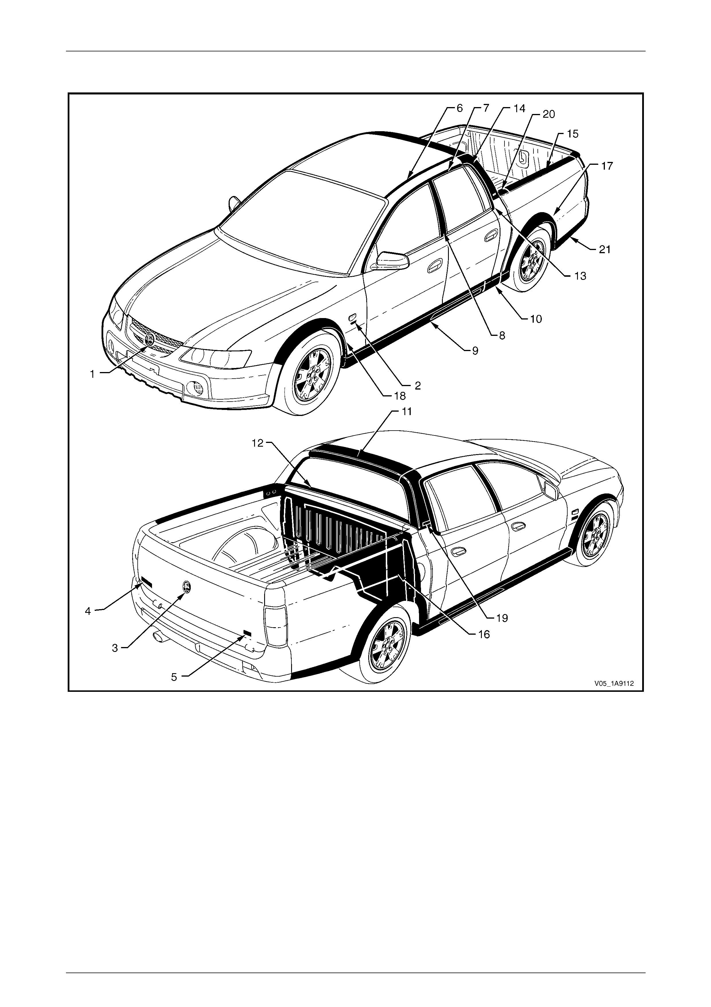
Exterior Ornamentation Page 1A9-53
Page 1A9-53
AWD Crew Cab: Cross8
Figure 1A9 – 23

Exterior Ornamentation Page 1A9-54
Page 1A9-54
Reference Chart: AWD Crew Cab: Cross8
Item Description Refer to
1 Radiator Grille Emblem: Holden Section 1C Radiator Grille
2 Fender Name Plate: Alloytec 8.1 Fender Name Plate
3 Endgate Emblem: Holden 8.4 Endgate Emblem
4 Endgate Name Plate: Crewman 8.5 Endgate Name plate, Left-hand
5 Endgate Name Plate: CrossX8 8.6 Endgate Name Plate, Right-hand
6 Roof Joint Moulding 8.7 Roof Joint Moulding
7 Door Opening Moulding 8.8 Door Opening Moulding
8 Centre Pillar Upper Finisher Assembly 8.9 Centre Pillar Upper Finisher Assembly
9 Rocker Panel Moulding Assembly 9.4 Rocker Panel Mo ulding Assembly
10 Rear Rocker Panel Moulding 9.5 Rear Rocker Panel Moul ding
11 Rear Header Trim 8.13 Rear Header Trim
12 Rear Window Lower Finisher 8.15 Rear Window Lower Finisher
13 Body Lock Pillar Door Mouldi ng 8.16 Body Lock Pillar Door Moulding
14 Body Lock Pillar Trim and Body Lock Pillar Finisher 8.17 Body Lock Pillar Trim and
8.18 Body Lock Pillar Finisher
15 Rear Body Rail Cover and Rear Body Rail End Cap 8.19 Rear Body Rail Cover and End Cap
16 Rear Outer Trim Panel and NVH Foam 8.21 Rear Outer Trim Panel and NVH Foam
Rear Wheelhouse Opening Flare 9.8 Rear Wheelhouse Opening Flare
17 Rear Wheelhouse Opening Flare Extension 9.7 Rear Wheelhouse Opening Flare Extension
18 Front Wheelhouse Openin g Flare 4.11 Wheelhouse Opening F lare Assembly
19 Body Lock Pillar Trim Name Plate: CrossXTrac 9.1 Body Lock Pillar Trim Name Plate – CrossXTrac
20 Rear Body Front Rail Cover 8.20 Rear Body Front Rail Cover
21 Rear Body Rear Rocker Moulding 8.11 Rear Body Rear Rocker Mouldin g

Exterior Ornamentation Page 1A9-55
Page 1A9-55
2 Service Operations, Sedan
2.1 Fender Name Plate
LT Section No. — 10–150
Remove
1 Protect the paint and bodywork with tape or a clean
rag.
2 To assist removal, warm the name plate with a heat-
lamp or heat-gun to soften the adhesiv e.
3 Using a paint scraper or similar, carefully prise the
name plate from the fender.
4 As required remove any remaining double-sided tape
from the name plate and/or fender and clean the
surfaces with Prepsol or equivalent.
Figure 1A9 – 24
Reinstall
1 If reusing the name plate, apply new polyethylene double-sided tape such as 3M 4428 or equivalent to the back of
the name plate. Trim back the tape slightly away from the edge of the name plate.
2 Clean the fender surface with Prepsol or equivalent.
3 Remove the backing paper from the double-sided tape.
4 Apply the name plate in the position shown, measuring fro m the front side turn signal lamp, refer to
Figure 1A9 – 25. Ensure it is positioned parallel to the body side moulding and centred with the side turn signal
lamp.

Exterior Ornamentation Page 1A9-56
Page 1A9-56
Figure 1A9 – 25
5 Press firmly over the entire name plate for at least 10 sec onds to ensure sound adhesion.
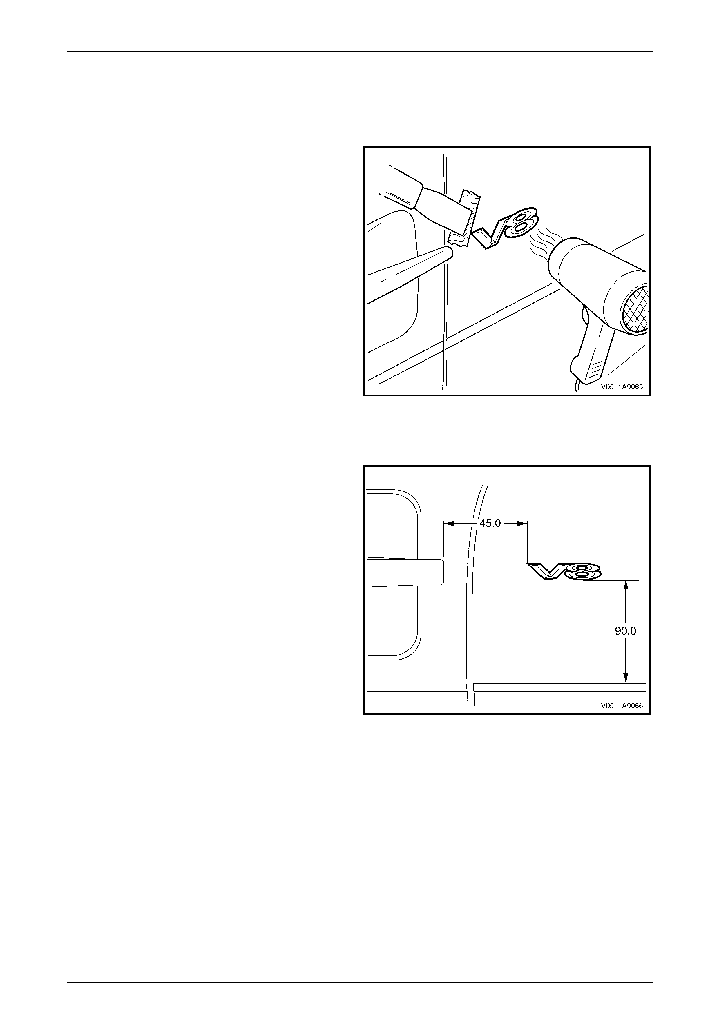
Exterior Ornamentation Page 1A9-57
Page 1A9-57
2.2 Front Door Name Plate
Remove
1 Protect the paint and bodywork with tape or a clean
rag.
2 To assist removal, warm the name plate with a heat-
lamp or heat-gun to soften the adhesiv e.
3 Using a paint scraper or similar, carefully prise the
name plate from the door panel.
4 Remove any remaining double-sided tape from the
name plate and/or door panel and clean the surfaces
with Prepsol or equivalent.
Figure 1A9 – 26
Reinstall
1 If reusing the name plate, apply new polyethylene
double-sided tape such as 3 M 4428 or equivalent to
the back of the name plate. Trim back the tape slightly
away from the edge of the name plate.
2 Clean the door surface with Prepsol or equivalent.
3 Remove the backing paper from the double-sided
tape.
4 Apply the name plate in the position shown. Ensure it
is positioned parallel to the style line.
5 Press firmly over the entire name plate for at least 10
seconds to ensure sound adhesion.
Figure 1A9 – 27
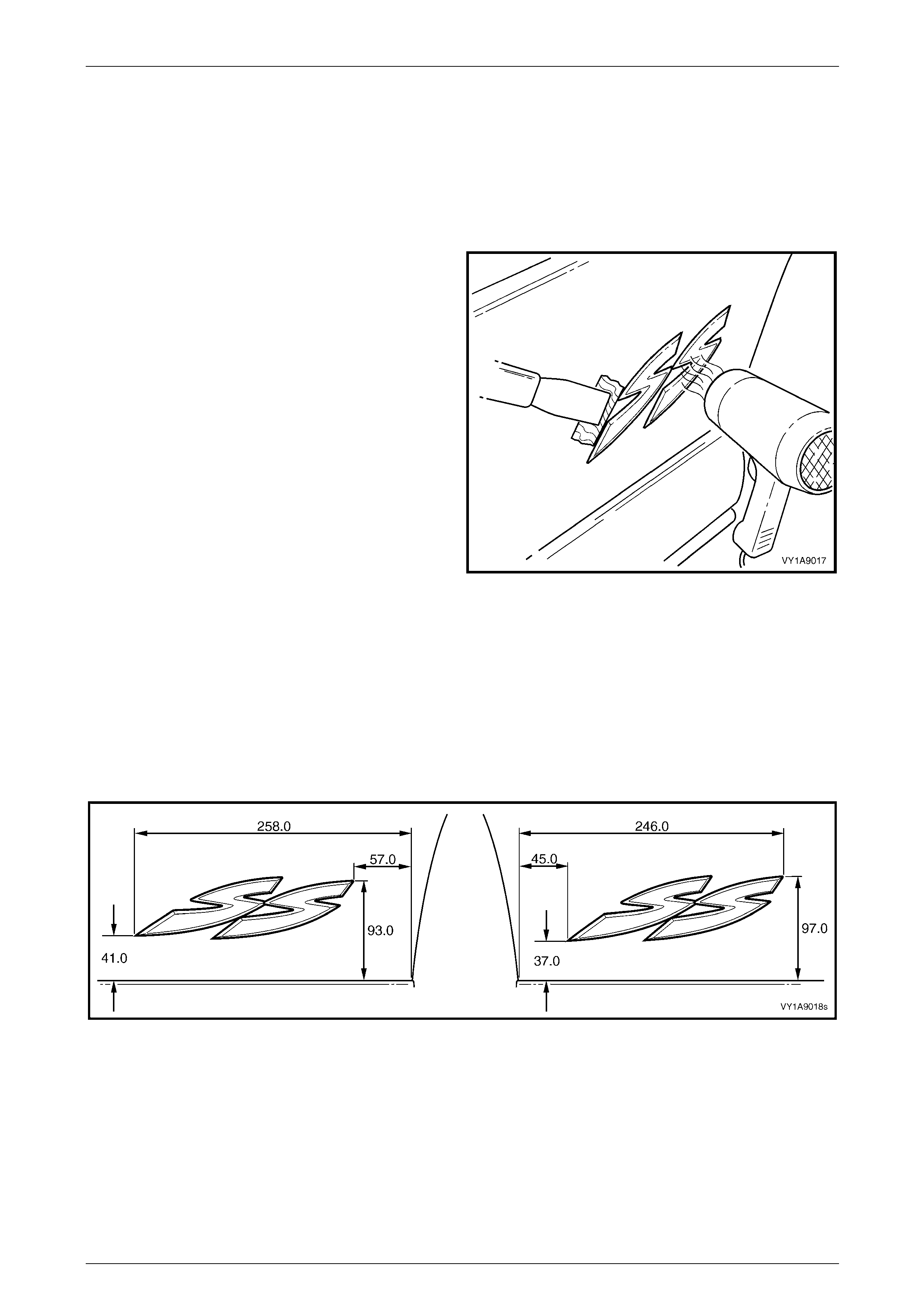
Exterior Ornamentation Page 1A9-58
Page 1A9-58
2.3 Rear Door Name Plate
LT Section No. — 10–150
SS
Remove
1 Protect the paint and bodywork with tape or a clean
rag.
2 To assist removal, warm the name plate with a heat-
lamp or heat-gun to soften the adhesiv e.
3 Using a paint scraper or similar, carefully prise the
name plate from the door panel.
4 As required, remove any remaining double-sided tape
from the name plate and/or door panel and clean the
surfaces with Prepsol or equivalent.
Figure 1A9 – 28
Reinstall
1 If reusing the name plate, apply new polyethylene double-sided tape such as 3M 4428 or equivalent to the back of
the name plate. Trim back the tape slightly away from the edge of the name plate.
2 Clean the door panel surface with Prepsol or equivalent.
3 Remove the backing paper from the double-sided tape.
4 Apply the name plate in the position shown, measuring from the rear lower corner of the rear door panel, refer to
Figure 1A9 – 29. Ensure the name plate is po sitioned parallel to the lower edge of the door.
Figure 1A9 – 29
5 Press firmly over the entire name plate for at least 10 sec onds to ensure sound adhesion.

Exterior Ornamentation Page 1A9-59
Page 1A9-59
Calais
Remove
1 Protect the paint and bodywork with tape or a clean
rag.
2 To assist removal heat the name plate with a heat-
lamp or heat-gun to soften the adhesiv e.
3 Using a paint scraper or similar carefully prise the
name plate from the door panel.
4 As required, remove any remaining double-sided tape
from the name plate and/or door panel and clean the
surfaces with Prepsol or equivalent.
Figure 1A9 – 30
Reinstall
1 If reusing the name plate, apply new polyethylene double-sided tape such as 3M 4428 or equivalent to the back of
the name plate. Trim back the tape slightly away from the edge of the name plate.
2 Clean the door surface with Prepsol or equivalent.
3 Remove the backing paper from the double-sided tape.
4 Apply the name plate on to the rear door in the position shown, measur ing up from the body side moulding and in
from the rear edge of the door. Ensure it is positioned parallel to the body side moulding, refer to Figure 1A9 – 31.
Figure 1A9 – 31
5 Press firmly over the entire name plate for at least 10 sec onds to ensure sound adhesion.
6 Remove the plastic carrier.
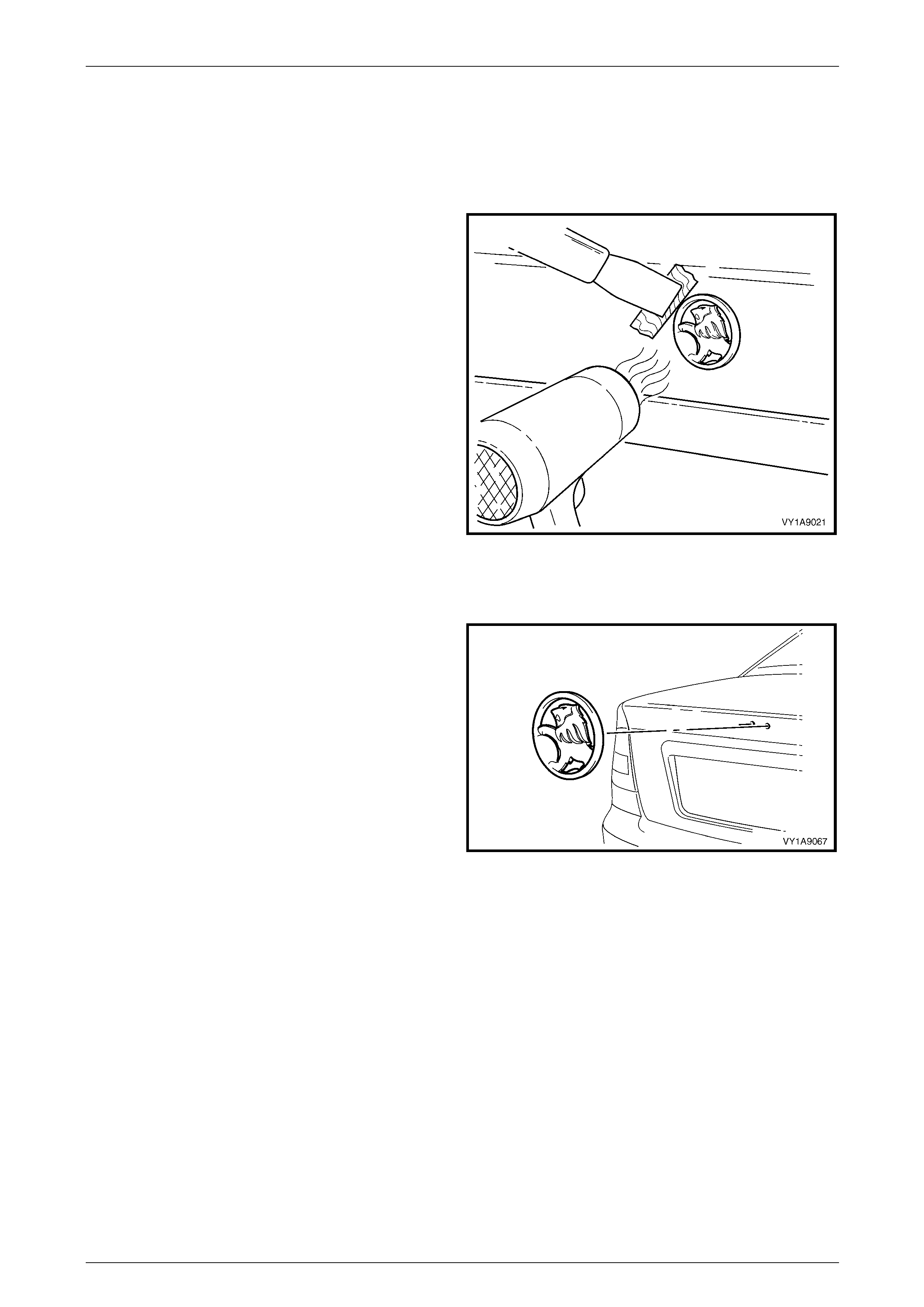
Exterior Ornamentation Page 1A9-60
Page 1A9-60
2.4 Rear Compartment Lid Emblem
LT Section No. — 10–150
Remove
1 Protect the paint and bodywork with tape or a clean
rag.
2 To assist removal, warm the emblem with a heat-lamp
or heat-gun to soften the adhesive.
3 Using a paint scraper or similar, carefully prise the
emblem from the rear compartment lid.
NOTE
The emblem has two locatin g pins, take care not
to break them if the emblem is to be reused.
4 As required, remove any remaining double-sided tape
from the emblem and/or rear compartment lid and
clean the surfaces with Prepsol or equiva lent.
Figure 1A9 – 32
Reinstall
1 If reusing the emblem, apply new polyethylene double-
sided tape such as 3M 4428 or equ ivalent to the back
of the emblem. Trim back the tape slightly away from
the edge of the plate.
2 Clean the panel surface with Prepsol or equivalent.
3 Remove the backing paper from the double-sided
tape.
4 Apply the emblem in the position shown, ensuring the
locating pins are correctly orientated with the locating
holes in the panel surface.
5 Press firmly over the entire emblem for at least 10
seconds to ensure sound adhesion. Figure 1A9 – 33
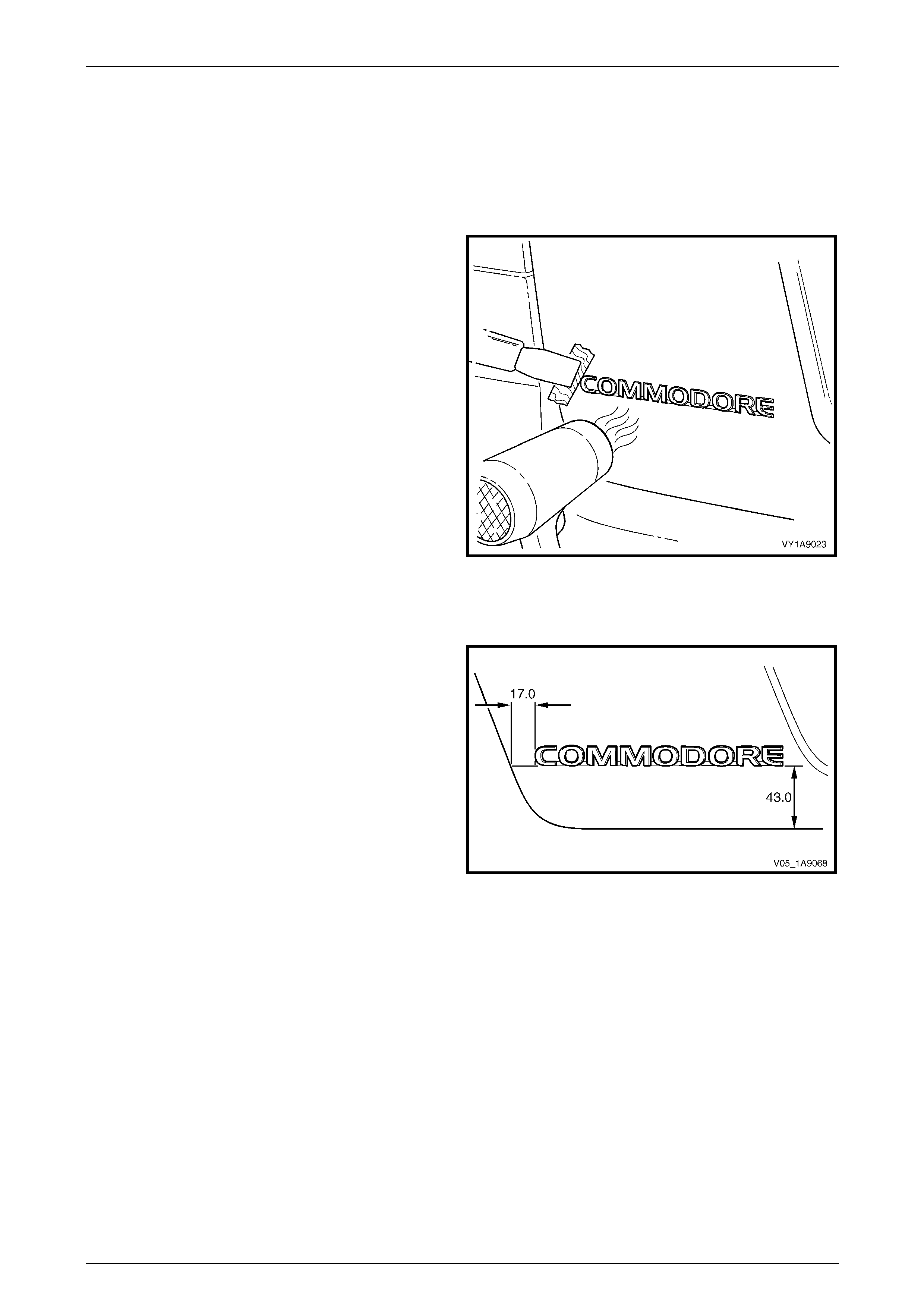
Exterior Ornamentation Page 1A9-61
Page 1A9-61
2.5 Rear Compartment Lid Name Plate, Left-
hand
LT Section No. — 10–150
Remove
1 Protect the paint and bodywork with tape or a clean
rag.
2 To assist removal, warm the name plate with a heat-
lamp or heat-gun to soften the adhesiv e.
3 Using a paint scraper or similar, carefully prise the
name plate from the rear compartment lid.
4 As required, remove any remaining double-sided tape
from the name plate and/or rear compartment lid and
clean the surfaces with Prepsol or equiva lent.
Figure 1A9 – 34
Reinstall
1 If reusing the name plate, apply new polyethylene
double-sided tape such as 3 M 4428 or equivalent to
the back of the name plate. Trim back the tape slightly
away from the edge of the name plate.
2 Clean the panel surface with Prepsol or equivalent.
3 Remove the backing paper from the double-sided
tape.
4 Apply the name plate onto the left-hand side of the
rear compartment lid in the position sho wn, measuring
from the edge of the rear compartment lid. Ensure it is
positioned parallel to the lower edge.
5 Press firmly over the entire name plate for at least 10
seconds to ensure sound adhesion. Figure 1A9 – 35
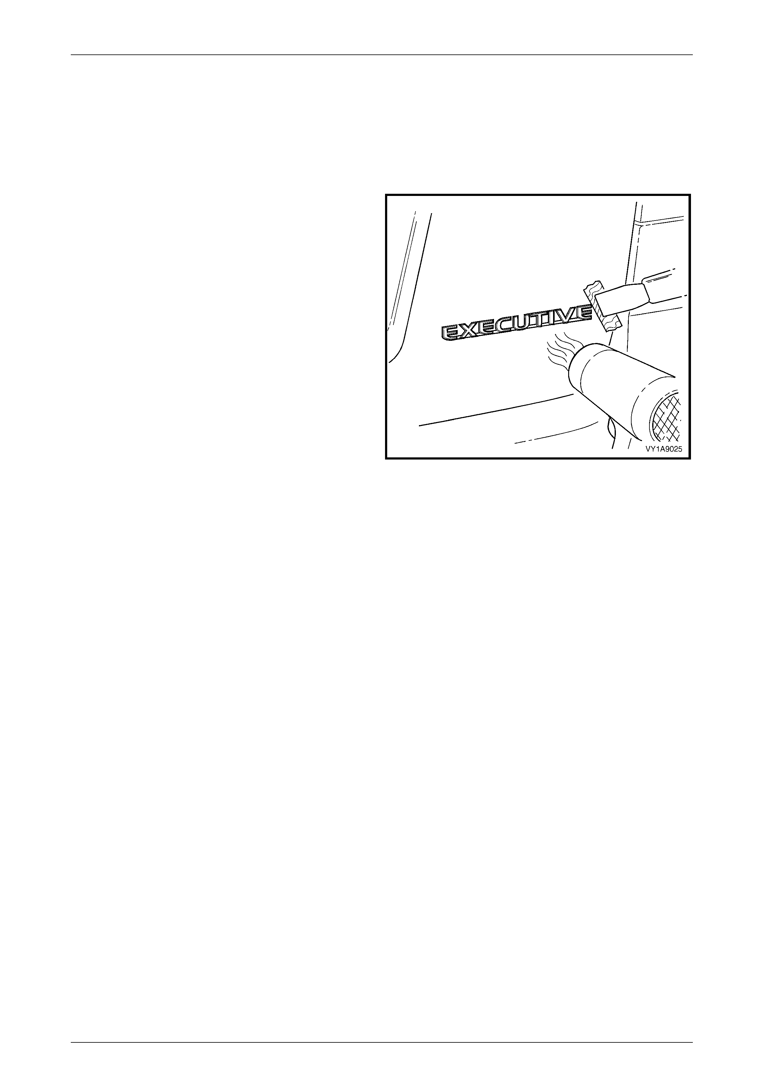
Exterior Ornamentation Page 1A9-62
Page 1A9-62
2.6 Rear Compartment Lid Name Plate,
Right-hand
LT Section No. — 10–150
Remove
1 Protect the paint and bodywork with tape or a clean
rag.
2 To assist removal, warm the name plate with a heat-
lamp or heat-gun to soften the adhesiv e.
3 Using a paint scraper or similar, carefully prise the
name plate from the rear compartment lid.
4 As required, remove any remaining double-sided tape
from the name plate and/or rear compartment lid and
clean the surfaces with Prepsol or equiva lent.
Figure 1A9 – 36
Reinstall
1 If reusing the name plate, apply new polyethylene double-sided tape such as 3M 4428 or equivalent to the back of
the name plate. Trim back the tape slightly away from the edge of the name plate.
2 Clean the panel surface with Prepsol or equivalent.
3 Remove the backing paper from the double-sided tape.
4 Apply the name plate onto the right-hand side of the rear compartment lid in the position shown, measuring from
the edge of the rear compartment lid. Ensure it is positioned parallel to the lower edge, refer to F igure 1A9 – 37.
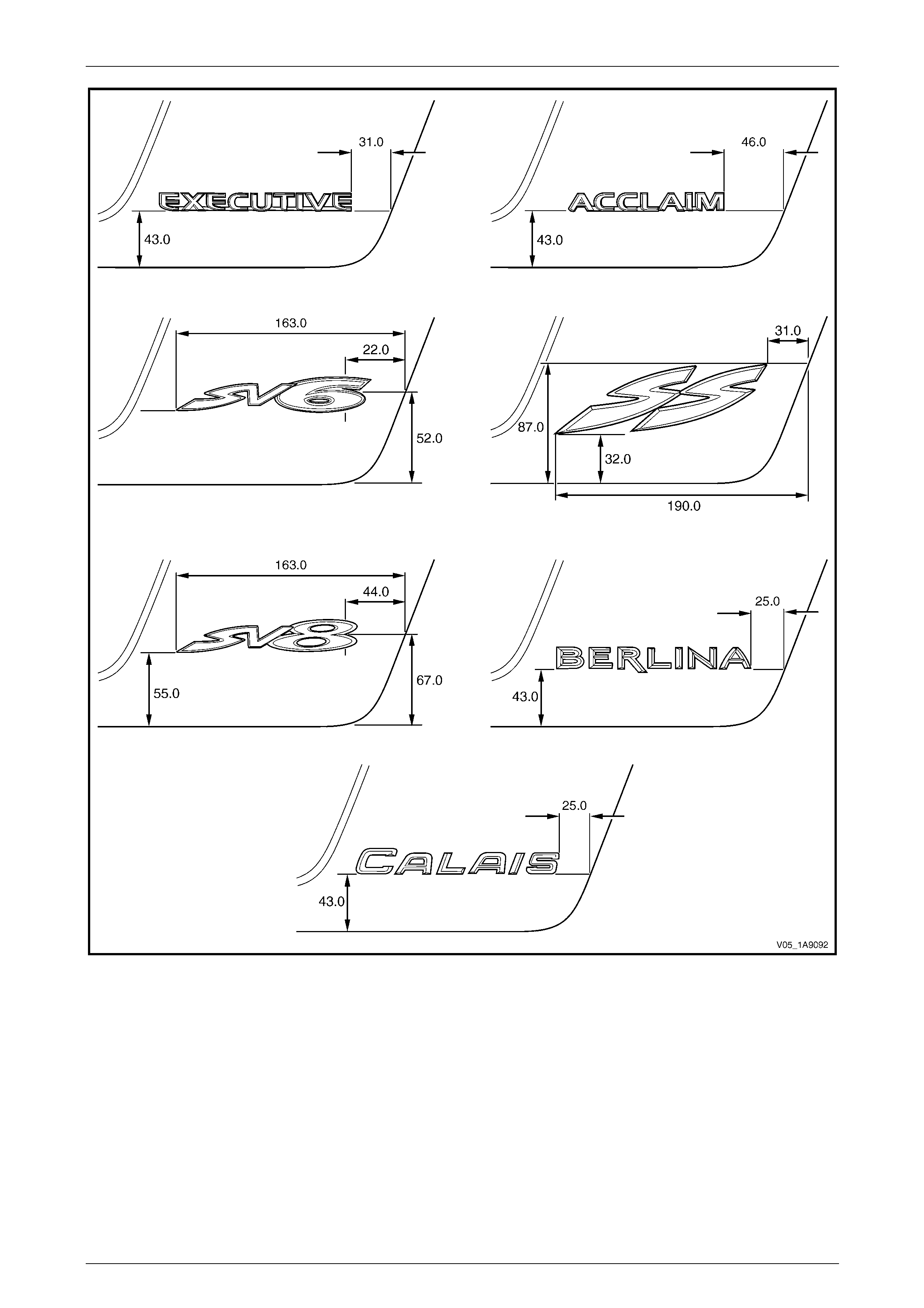
Exterior Ornamentation Page 1A9-63
Page 1A9-63
Figure 1A9 – 37
5 Press firmly over the entire name plate for at least 10 sec onds to ensure sound adhesion.
6 If required remove the plastic carrier.
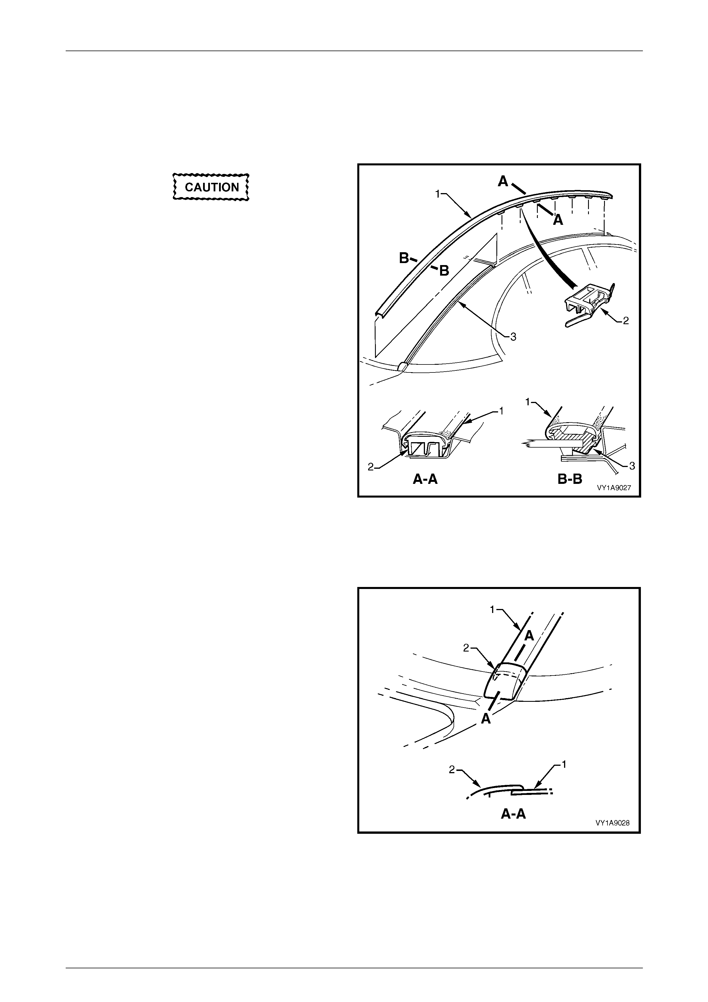
Exterior Ornamentation Page 1A9-64
Page 1A9-64
2.7 Roof Joint Moulding
LT Section No. — 10–250
Remove
Take care as the retaining clips can easily
break. Protect the paintwork with a clean rag.
1 Beginning at the front of the vehicle, use a screwdriver
to carefully prise the roof joi nt moul ding (1) from the
roof channel, disengaging the retain ing clip (2), seven
places.
2 Slide the joint moulding from the rear window side
moulding retainer (3) and remove.
NOTE
For removal of the rear window side
moulding retainer, refer to
Section 1A6 Stationary Windows.
Figure 1A9 – 38
Reinstall
1 As required, seat evenly the seven retainers onto the roof joint moulding.
2 Engage the roof joint moulding (1) onto the rear
window side moulding retainer and slide alon g until the
roof joint moulding sits under the endcap (2).
3 Seat the roof joint moulding in the roof channel and
beginning at the rear, clip it in place.
4 At the front, ensure the moulding is installed under the
windshield moulding cover.
Figure 1A9 – 39
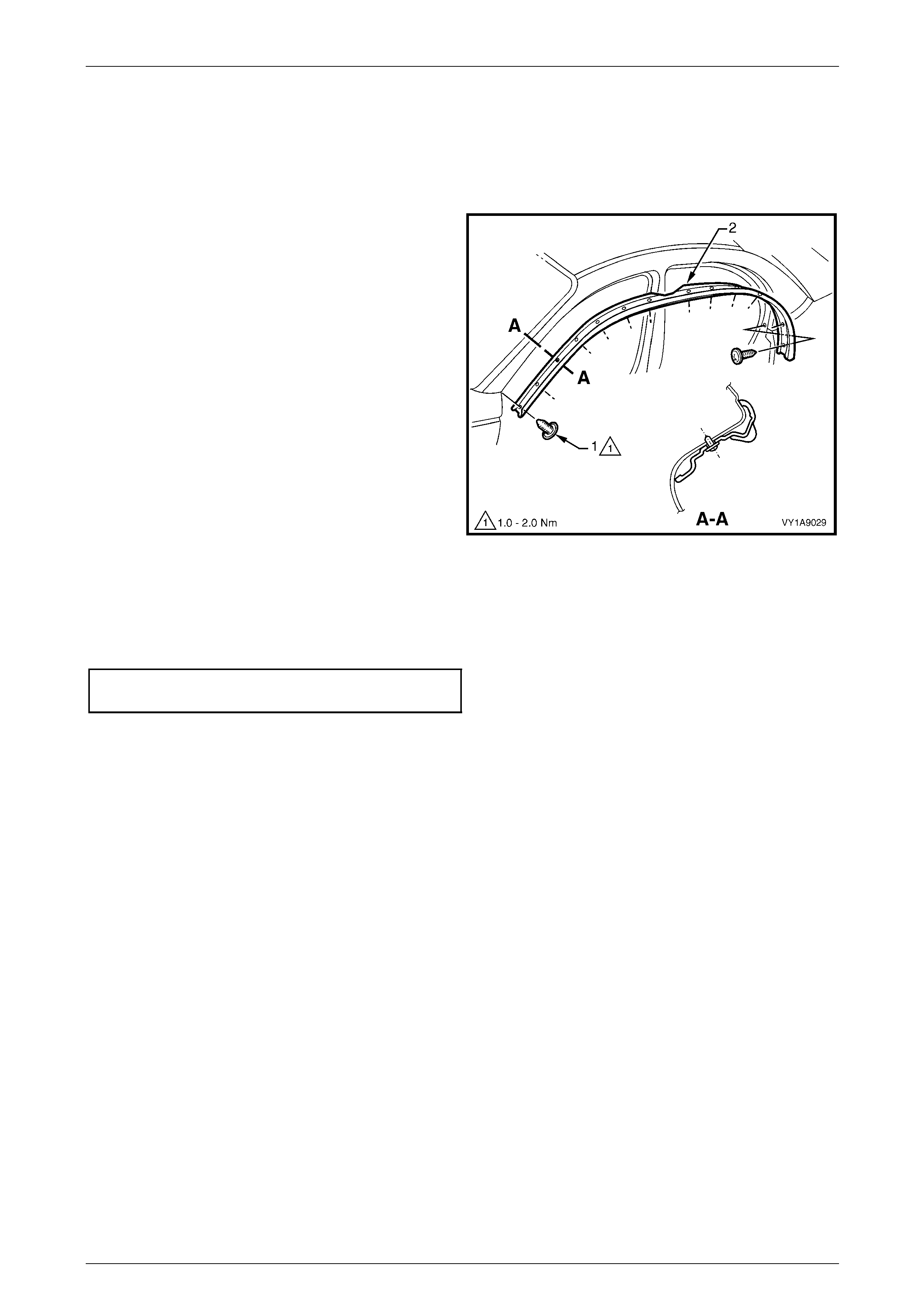
Exterior Ornamentation Page 1A9-65
Page 1A9-65
2.8 Door Opening Moulding
LT Section No. — 10–250
Remove
1 Open the front and rear doors on the relevant side of
the vehicle.
2 Beginning at each end and working towards the
middle, remove the screw (1), 13 places, att achi ng the
door opening moulding (2) to the vehicle.
3 Carefully remove the moulding.
Figure 1A9 – 40
Reinstall
Reinstallation of the door opening moulding is the reverse o f the removal procedure. Tight en the screws to the correct
torque specification.
Door opening moulding attaching
screw torque specification...........................1.0 – 2.0 Nm
NOTE
The screws are encapsulated with a wax sealer.
It is recommended the screws be replaced if
removed, however if this is impractical, apply a
small amount of sealer to the end of the thread.
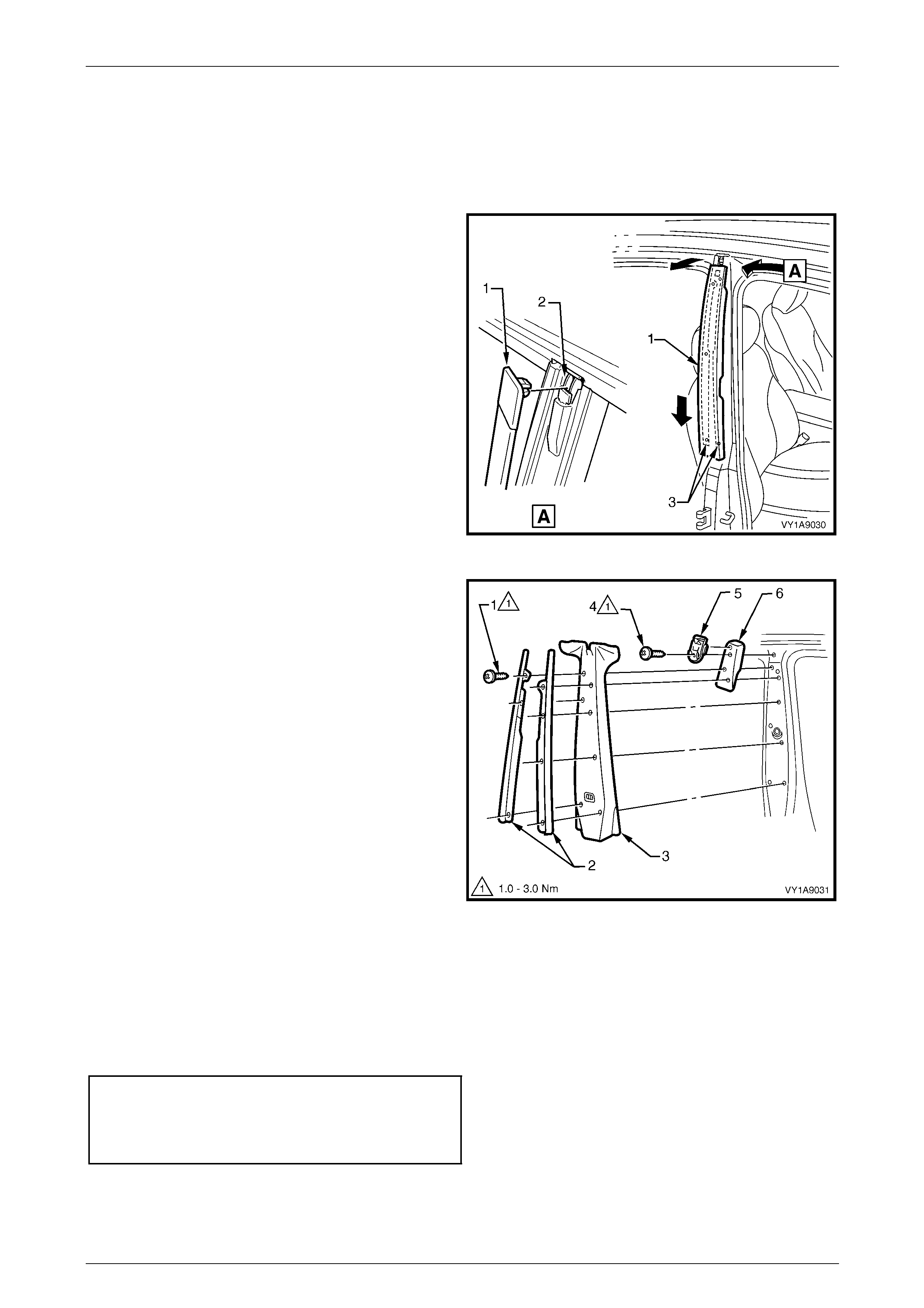
Exterior Ornamentation Page 1A9-66
Page 1A9-66
2.9 Centre Pillar Upper Finisher Assembly
LT Section No. — 10–250
Remove
1 Open the front and rear doors on the relevant side of
the vehicle.
2 Gently prise the top of the centre pillar upper finisher
(1) out to disengage it from the centre pillar upper
finisher retainer (2).
3 Holding the top of finisher out, slide it down the centre
pillar outer sealing strips (3) until it rests on rear door
hinge.
4 Manoeuvre the finisher from the sealing strips and
remove.
Figure 1A9 – 41
5 Remove the screw (1), seven places, attaching the
centre pillar sealing strips (2) to the pill ar and remove
the strips.
6 Partially remove the door opening moulding, refer to
2.8 Door Opening Moulding.
7 Remove centre pillar upper trim panel (3) by pulling
away from the pillar.
8 Remove the screw (4) attaching the centre pillar upper
finisher retainer (5) and centre pillar upper trim mount
plate (6) to the pillar and remove.
Figure 1A9 – 42
Reinstall
Reinstallation of the centre pillar upper finisher assembly is the reverse of the removal procedure, noting the following:
1 Ensure the centre pillar upper trim panel is seated correctly under the do or opening weatherstrips.
2 Tighten the screws to the correct torque specification.
Centre pillar upper finisher retainer
attaching screw torque specification...........1.0 – 3.0 Nm
Centre pillar sealing strip attac hin g
screw torque specification...........................1.0 – 3.0 Nm
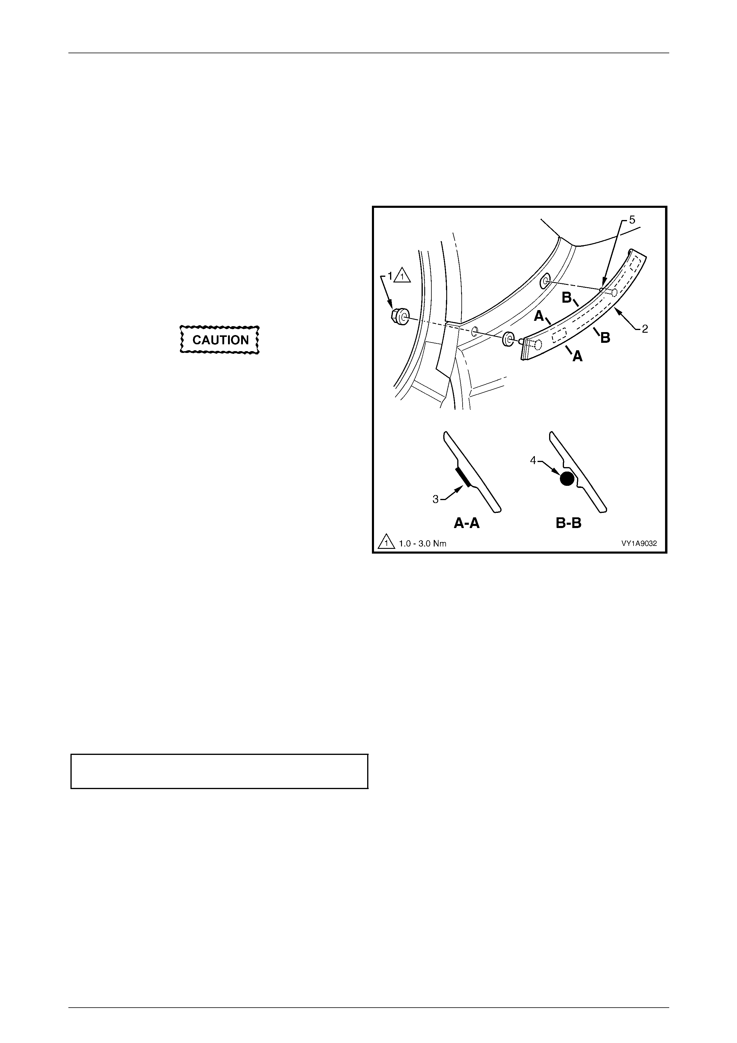
Exterior Ornamentation Page 1A9-67
Page 1A9-67
2.10 Quarter Panel Belt Moulding
LT Section No. — 10–250
Remove
1 Partially remove the body lock pillar garnish far enough to access the quarter panel belt moulding retaining nut,
refer to Section 1A8 Headlining and Interior Trim.
2 Remove the retaining nut (1) attaching the quarter
panel belt moulding (2) to the vehicle.
3 Using a length of piano wire, carefully cut the double-
sided tape (3) and bead of polyurethane adhesive (4)
from the back of the moulding, two places, noting to
remove and reinsert piano wire to get around the
attaching stud (5).
Take care not to damage the adjacent
paintwork.
4 Carefully prise the moulding from the vehicle and
remove.
Figure 1A9 – 43
Reinstall
Reinstallation of the quarter panel belt moulding is the reverse of the removal procedure, noting the following:
1 Apply two lengths of new acrylic double-sided tape such as 3M 5344 or equivalent to the back of the mouldin g,
refer to Section A-A in Figure 1A9 – 43.
2 Apply an 8.0 mm bead of urethane adhesiv e such as Expandite Betaseal 554.02, Sikaflex Drive or eq uivalent to
the back of the moulding, between and for the length of, the ribs in t wo places, refer to Section B-B in
Figure 1A9 – 43.
3 Tighten the retaining nut to the correct torque specification.
Quarter panel belt moulding retaining
nut torque specification...............................1.0 – 3.0 Nm

Exterior Ornamentation Page 1A9-68
Page 1A9-68
2.11 Body Side Mouldings
LT Section No. — 10–250
Remove
1 Protect the paint and bodywork with tape or a clean
rag.
2 Using a paint scraper or similar, begin at one end and
carefully prise the moulding from the panel, cutting
through the double-sided tape and adhesive.
NOTE
As an alternative, carefully use a l ength of piano
wire to cut the adhesive in a similar way to
removing a windshield. If required refer to
Section 1A6 Stationary Windows.
3 As required, remove any remaining double-sided tape
and adhesive from the moulding and/or panel. Clean
the surfaces with Prepsol or equivalent.
Figure 1A9 – 44
Reinstall
For:
• All vehicles except Berlina or Calais refer to Figure 1A9 – 45.
• Berlina refer to Figure 1A9 – 46.
• Calais refer to Figure 1A9 – 47.
1 Place a mark on the rear edge of the fender and/or door panels at the three points shown in the relevant figure as
required. Measure in a straight line from the lower edge of each panel.
2 If a complete moulding set is to be fitted, or as required, apply a length of masking tape along the side of the
vehicle, aligning the top edge of the tape with the marks. Begin by affixing the tape at the rear of the rear door, ho ld
it taut and away from the vehicle, and affix it to each panel. Ensure it is straight and then smooth it down along its
length.
3 If reusing the moulding, apply new acrylic double-sided tape (1) such as 3M 5344 or equivalent along the back of
the moulding.
4 Apply a 3.0 mm diameter bead of urethane adhesive such as Expandite Betaseal 554.02 , Sikaflex Drive or
equivalent over the entire length of moulding (2) and for 50mm in several places (3).
NOTE
Refer to any further directions supplied with the
urethane adhesive.
5 Affix the moulding to the vehicle in the correct positions, aligning the lower edge with the masking tape (if fitted)
and:
• For the fender moulding begin at the rear edge of the fender, aligning to the dimension at Section A-A.
• For the front door moulding begin at the front edge of the front door, aligning to the dimension at
Section A-A.
• For the rear door moulding begin at the front edge of the rear door, aligning to the dimension at Section B-B.
6 Press firmly over the length of the mouldin g(s) at the double-sided tape for 10 seconds to ensure soun d adhesion.
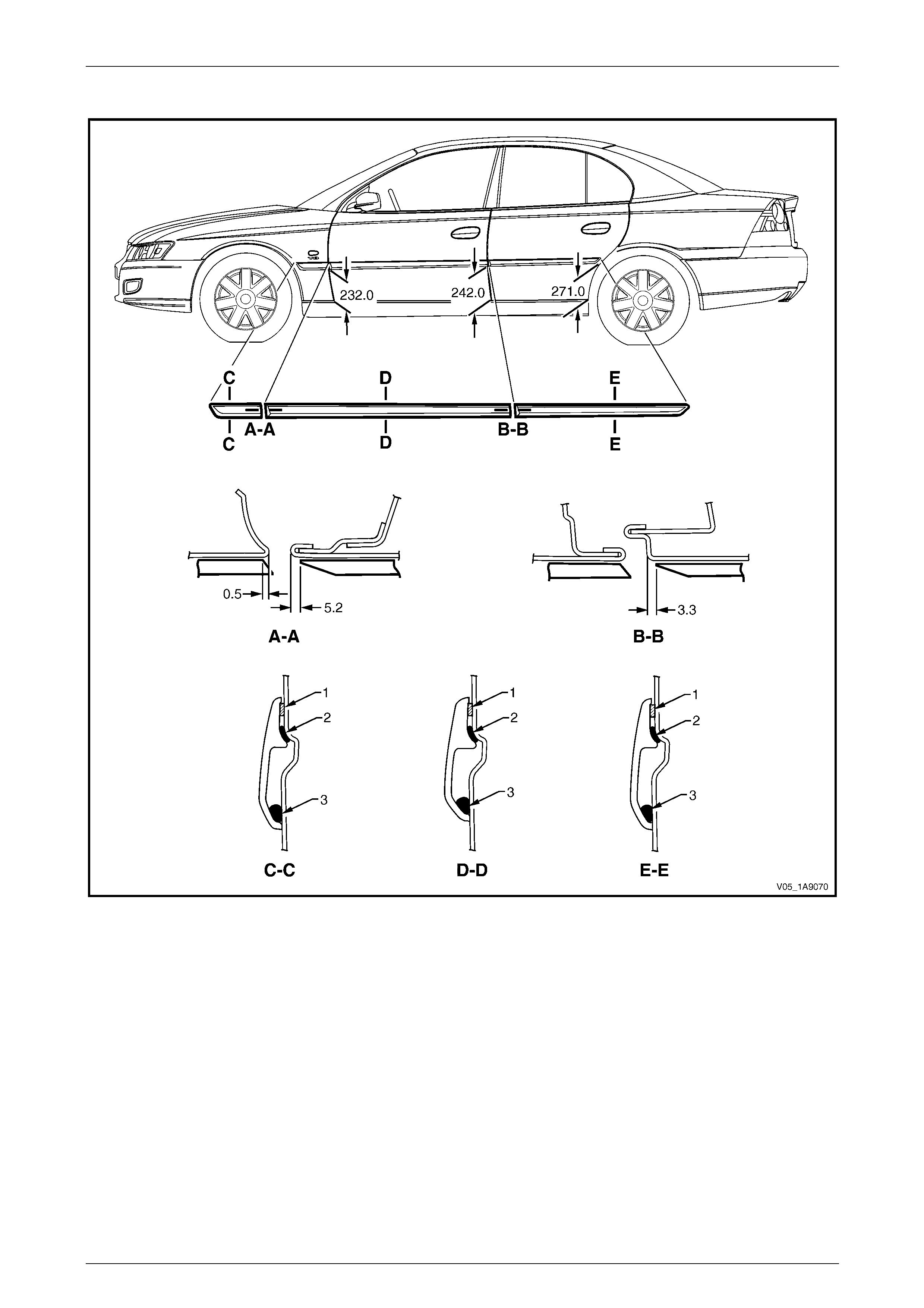
Exterior Ornamentation Page 1A9-69
Page 1A9-69
All Vehicles, Except Berlina and Calais
Figure 1A9 – 45
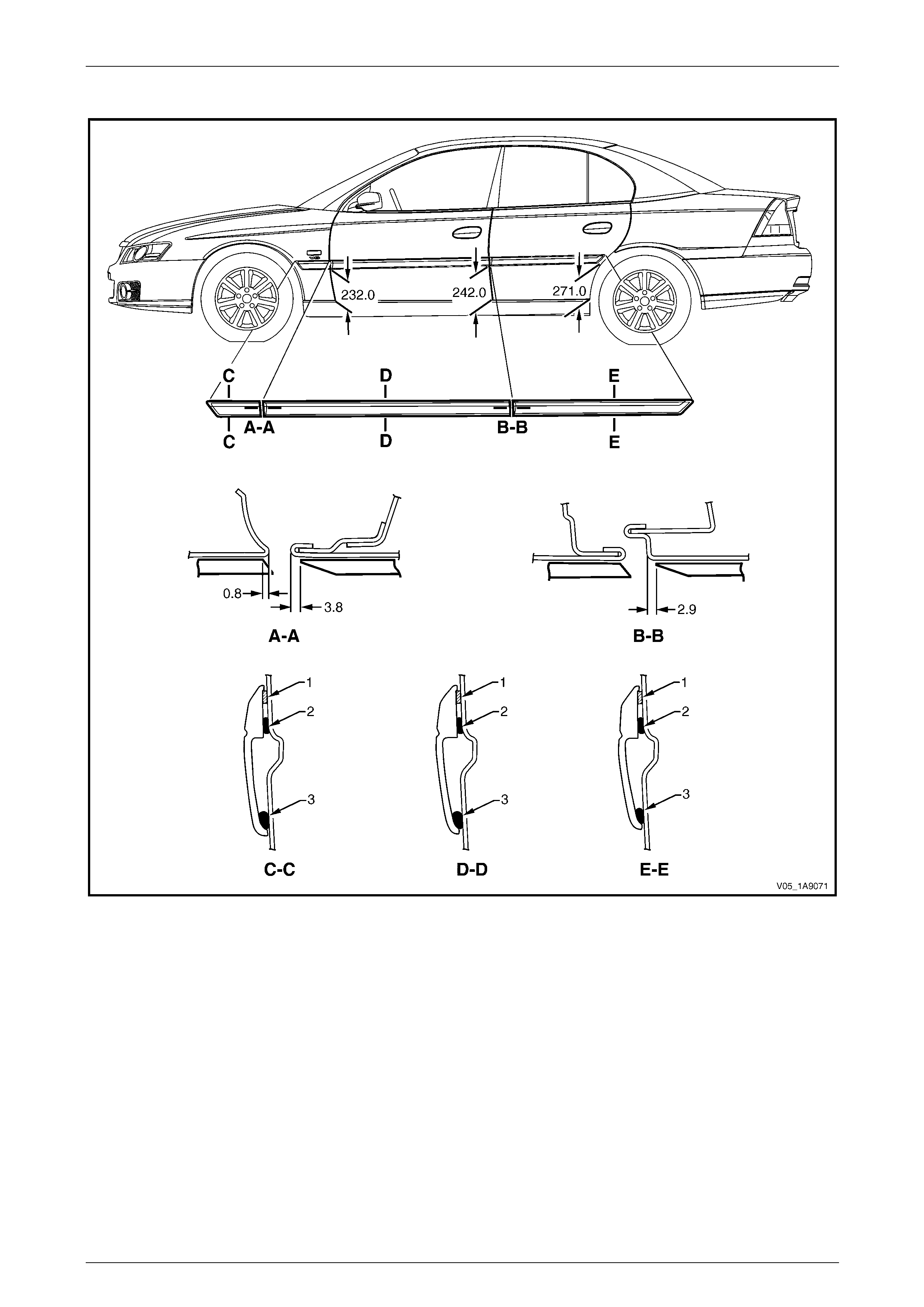
Exterior Ornamentation Page 1A9-70
Page 1A9-70
Berlina
Figure 1A9 – 46
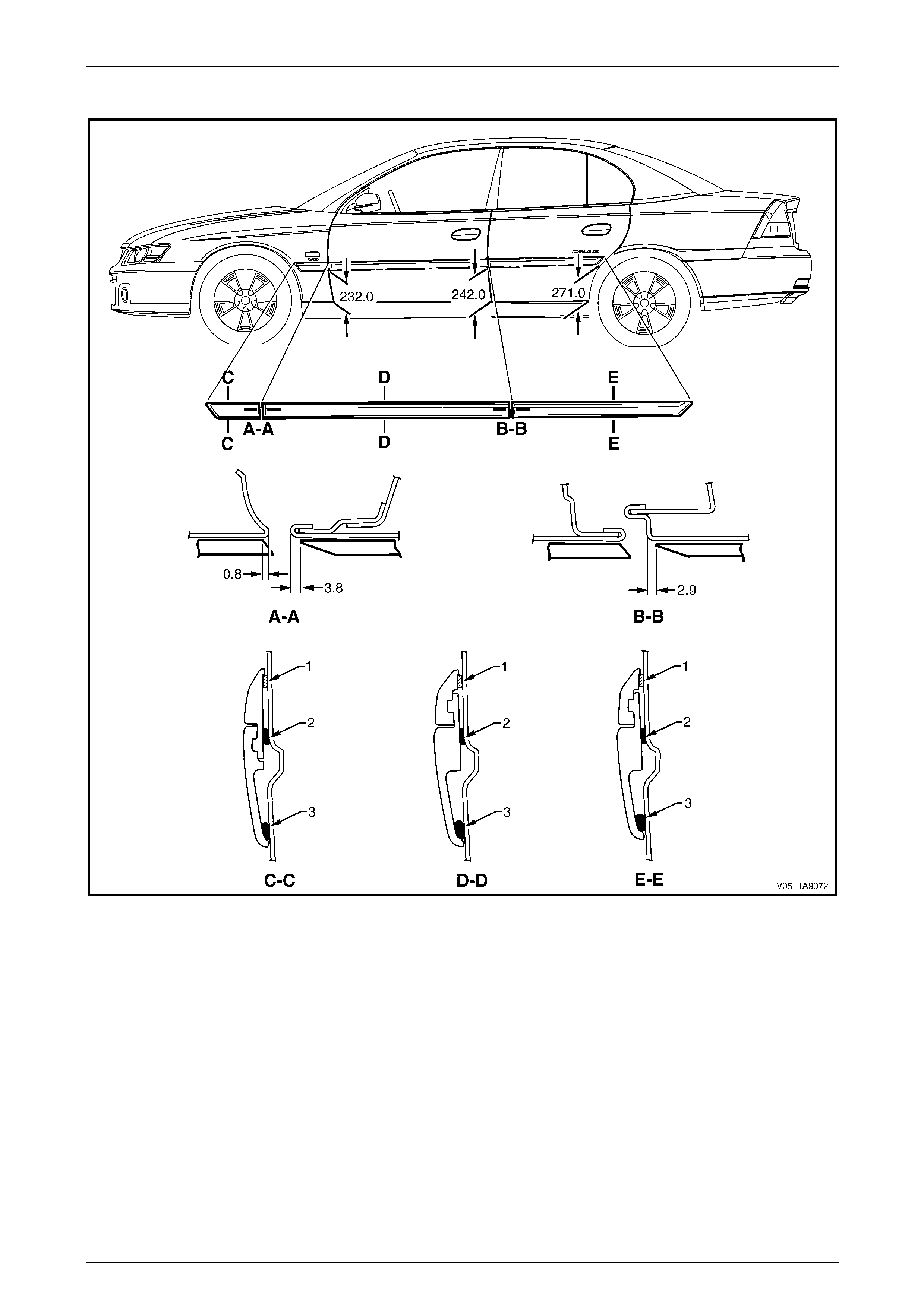
Exterior Ornamentation Page 1A9-71
Page 1A9-71
Calais
Figure 1A9 – 47
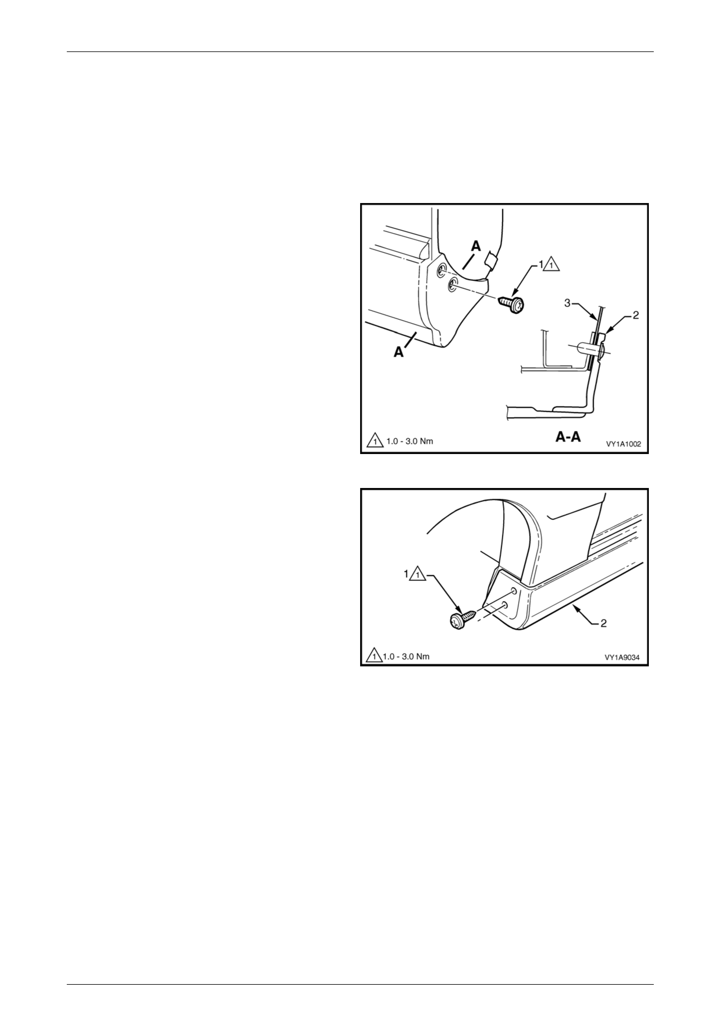
Exterior Ornamentation Page 1A9-72
Page 1A9-72
2.12 Rocker Panel Moulding Assembly
LT Section No. — 10–300
Remove
1 On the relevant side remove the rear road wheel, refer to Section 10 Wheels and T yres.
2 Remove the screw (1), two places, attaching the rear
rocker panel moulding (2) and wheelhouse liner (3).
NOTE
If required, the rear rocker panel moulding can
be removed at this stage by sliding it rearward
from the front rocker panel moulding.
Figure 1A9 – 48
3 Turn the front wheels to full steering lock to ward the
relevant side.
4 Remove the screw (1), two places, attaching the front
rocker panel moulding (2) to the fender and liner.
Figure 1A9 – 49
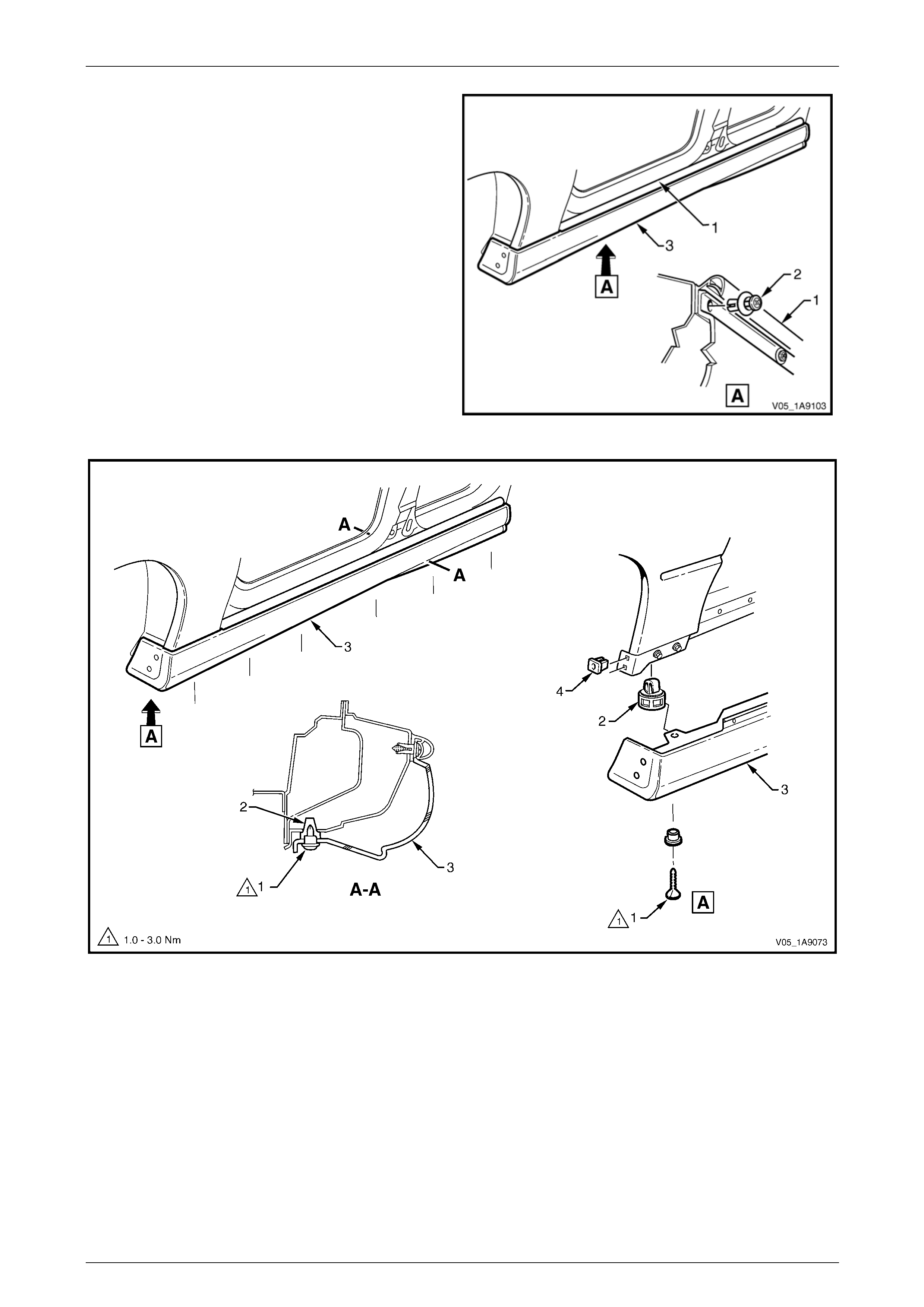
Exterior Ornamentation Page 1A9-73
Page 1A9-73
5 Lift up the rocker panel weatherstrip (1) as shown in
View A to gain access and remove the retainer (2),
nine places, attaching the rocker panel moulding (3) to
the vehicle body.
NOTE
If the retainers are difficult to remove, prise out
the centre section a small amount with a flat
bladed screwdriver, then cont inue to unscrew. It
may also be necessary to retain the outer
section of the retainer with fingers or pliers.
6 Refer to Figure 1A9 – 51. From underneath the
vehicle, remove the screw (1), six places, from the
retainer (2) under the moulding (3).
7 Remove the moulding.
8 If required, prise the nut (4), two places, from the
fender. Figure 1A9 – 50
Figure 1A9 – 51
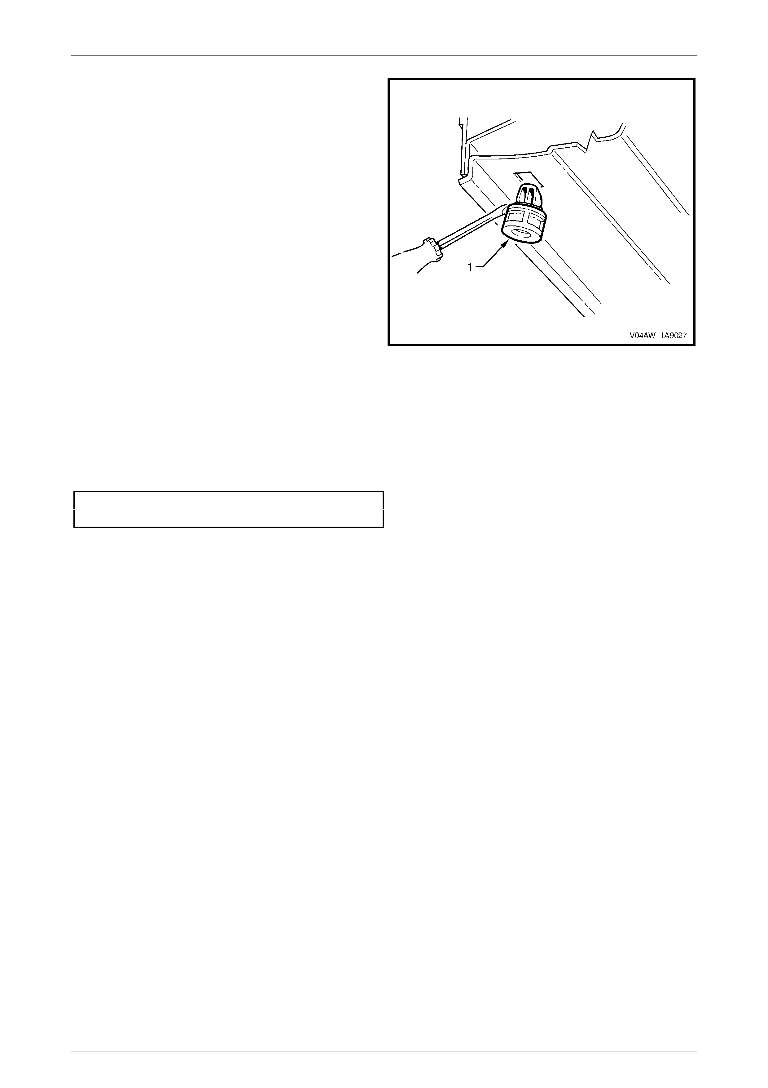
Exterior Ornamentation Page 1A9-74
Page 1A9-74
9 If required, remove the retainer (1), six places, by
gently levering out from the body, taking care not to
damage the paint work.
Figure 1A9 – 52
Reinstall
Reinstallation of the rocker panel front and rear mouldings is the reverse of the removal p r ocedure, noting the following:
1 Ensure the front moulding is correctly seated in the retaining clips.
2 Tighten the screws to the correct torque specification.
Rocker panel moulding attac hin g
screw torque specification...........................1.0 – 3.0 Nm
3 Ensure the weatherstrip is seated correctly.

Exterior Ornamentation Page 1A9-75
Page 1A9-75
2.13 Front Fender Centre Moulding Assembly
Remove
1 Remove the front fender, refer to Section 1B Sheetmetal.
2 Using pliers, squeeze the retaining clip (1), three
places, to release the front fender centre mou lding
assembly from the fender.
Figure 1A9 – 53
3 Protect the paint and bodywork with tape.
4 To assist removal, warm the region around the rear of
the upper moulding with a heat-lamp or heat-gun to
soften the adhesive.
5 Using a paint scraper or similar, carefully prise the rear
edge of the moulding assembly from the fender.
6 Withdraw the lower edge of the moulding assembly
from the fender and gently pull it down to disengage
the three upper lugs.
7 As required remove any remaining double-sided tape
from the moulding and/or fender and clea n the
surfaces with Prepsol or equivalent.
Figure 1A9 – 54

Exterior Ornamentation Page 1A9-76
Page 1A9-76
Disassemble
1 With a flat-blade screwdriver, prise the patch harness
retainer (1) from the moulding assembly.
2 Twist and remove the bulb socket, O-ring and bulb (2)
from the lamp assembly.
Figure 1A9 – 55
3 Carefully using a fine flat-blade screwdriver located at
the lower, rear edge of the lamp assembly, lever the
lamp forward and out to disengage the rear retaining
lug.
4 Withdraw the rear of the lamp from the moulding
assembly.
Figure 1A9 – 56
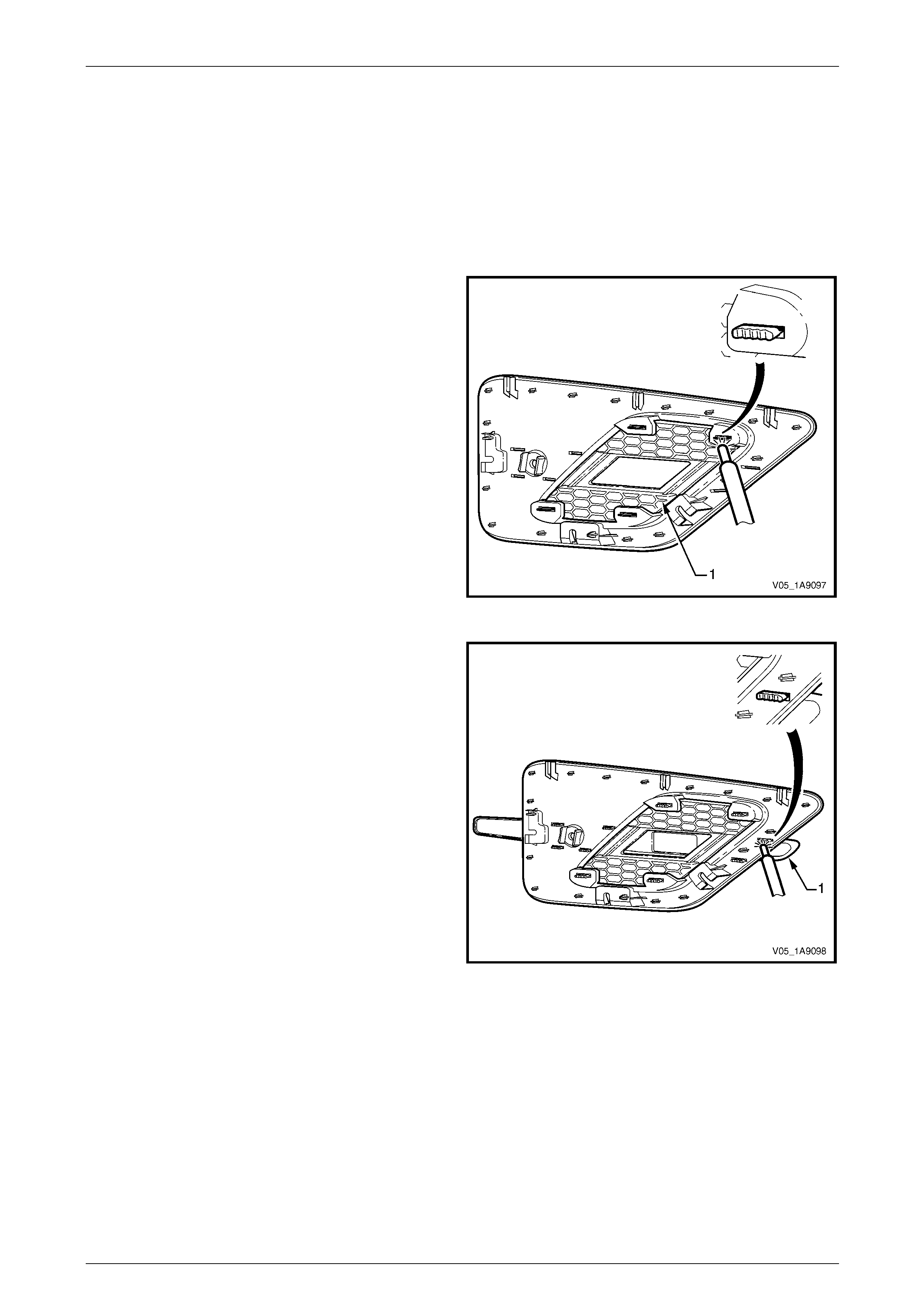
Exterior Ornamentation Page 1A9-77
Page 1A9-77
Reassemble
NOTE
The front fender centre moulding is
supplied unpainted as part of a kit. If a new part is
being used, it will require painting before
it is assembled. The procedure is similar
to painting the bumper fascias, refer to
Section 1D Bumper Bars.
1 Install the front fender centre insert (1):
a Ensure the four heat stake lugs are seated
correctly into the front fender centre moulding.
b Using a soldering iron, melt the ends of the four
heat stakes to secure the insert in place.
c Hold the centre insert in position unti l the pl astic
has cooled.
Figure 1A9 – 57
2 Install the front fender upper moulding (1):
a Ensure the six heat stakes are seated correctly
into the centre moulding.
b Using a soldering iron, melt the ends of the six
heat stakes to secure the moulding in pl ace.
c Hold the upper moulding i n po sition until the
plastic has cooled.
Figure 1A9 – 58
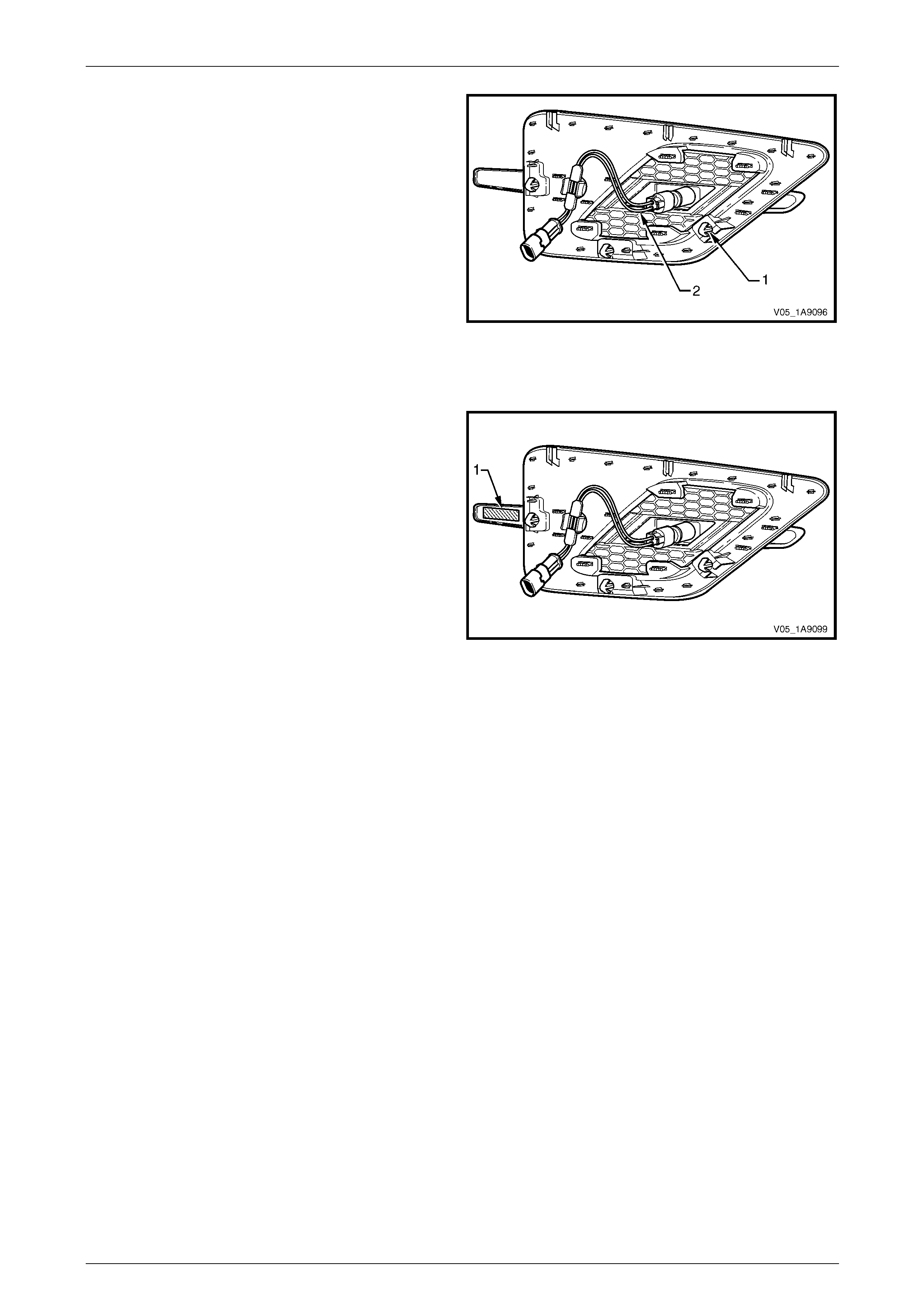
Exterior Ornamentation Page 1A9-78
Page 1A9-78
3 If required, fit the retaining clip (1), three places.
4 Reinstall the lamp assembly, locating the front retainer
first and then clipping the rear lug in place.
5 Reinstall the patch harness (2), connect it to the lamp
assembly and attach its retainer to the mould ing
assembly.
Figure 1A9 – 59
Reinstall
1 If required, apply new polyethylene double-sided tape
such as 3M 4428 or equivalent (1).
2 Clean the fender surface around the moulding
assembly opening with Prepsol or equivalent.
3 Remove the backing paper from the double-sided
tape.
4 Hook the upper lugs behind their mounting tabs on the
front fender.
5 While providing support to the back of the fender, push
the three retainers into place. Ensure all three
retainers snap into place.
6 Apply pressure to the rear of the moulding assembly
for 10 seconds where the double-sided tape was
applied to ensure sound adhesion.
7 Connect the patch harness to the main harness.
8 Reinstall the fender, refer to Section 1B Sheetmetal.
9 Check for correct operation of the front side turn signal
lamp.
Figure 1A9 – 60
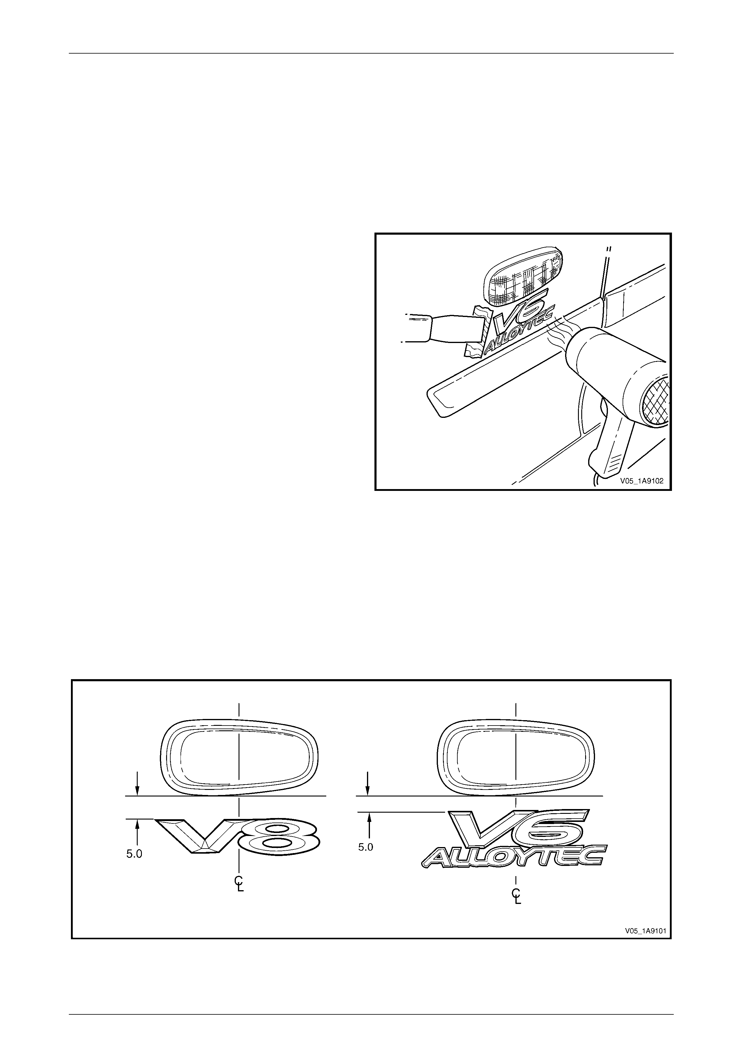
Exterior Ornamentation Page 1A9-79
Page 1A9-79
3 Service Operations, Wagon
3.1 Fender Name Plate
LT Section No. — 10–150
Remove
1 Protect the paint and bodywork with tape or a clean
rag.
2 To assist removal, warm the name plate with a heat-
lamp or heat-gun to soften the adhesiv e.
3 Using a paint scraper or similar, carefully prise the
name plate from the fender.
4 As required remove any remaining double-sided tape
from the name plate and/or fender and clean the
surfaces with Prepsol or equivalent.
Figure 1A9 – 61
Reinstall
1 If reusing the name plate, apply new polyethylene double-sided tape such as 3M 4428 or equivalent to the back of
the name plate. Trim back the tape slightly away from the edge of the name plate.
2 Clean the fender surface with Prepsol or equivalent.
3 Remove the backing paper from the double-sided tape.
4 Apply the name plate in the position shown, measuring fro m the front side turn signal lamp, refer to
Figure 1A9 – 62. Ensure it is positioned parallel to the body side mouldin g.
Figure 1A9 – 62
5 Press firmly over the entire name plate for at least 10 sec onds to ensure sound adhesion.
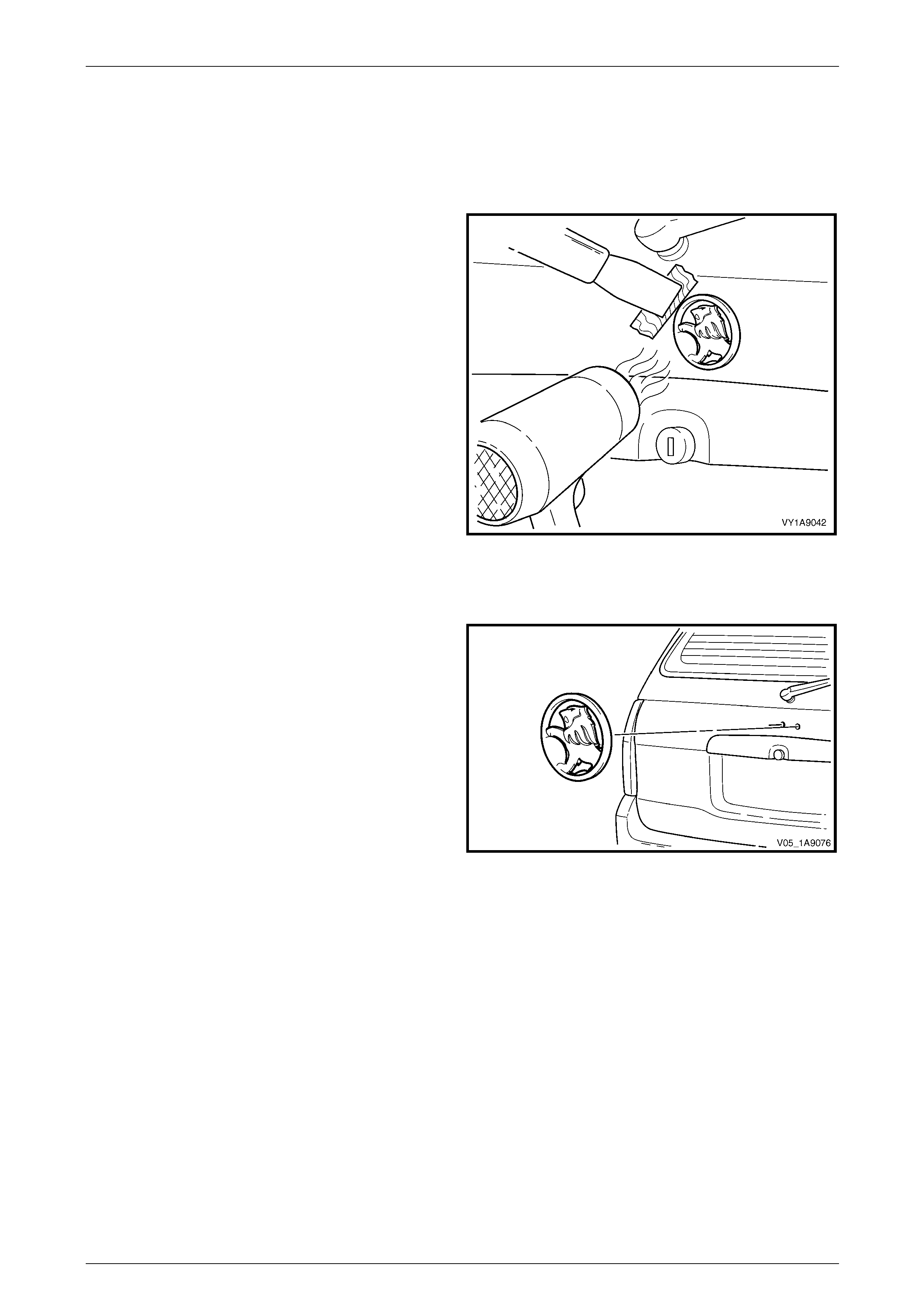
Exterior Ornamentation Page 1A9-80
Page 1A9-80
3.2 Liftgate Emblem
LT Section No. — 10–150
Remove
1 Protect the paint and bodywork with tape or a clean
rag.
2 To assist removal, warm the emblem with a heat-lamp
or heat-gun to soften the adhesive.
3 Using a paint scraper or similar, carefully prise the
emblem from the liftgate.
NOTE
The emblem has two locatin g pins, take care not
to break them if the emblem is to be reused.
4 As required, remove any remaining double-sided tape
from the emblem and/or liftgate and clean the surfaces
with Prepsol or equivalent.
Figure 1A9 – 63
Reinstall
1 If reusing the emblem, apply new polyethylene double-
sided tape such as 3M 4428 or equ ivalent to the back
of the emblem. Trim back the tape slightly away from
the edge of the emblem.
2 Clean the panel surface with Prepsol or equivalent.
3 Remove the backing paper from the double-sided
tape.
4 Apply the emblem in the position shown ensuring the
locating pins are correctly orientated with the locating
holes in the panel surface.
5 Press firmly over the entire emblem for at least 10
seconds to ensure sound adhesion. Figure 1A9 – 64
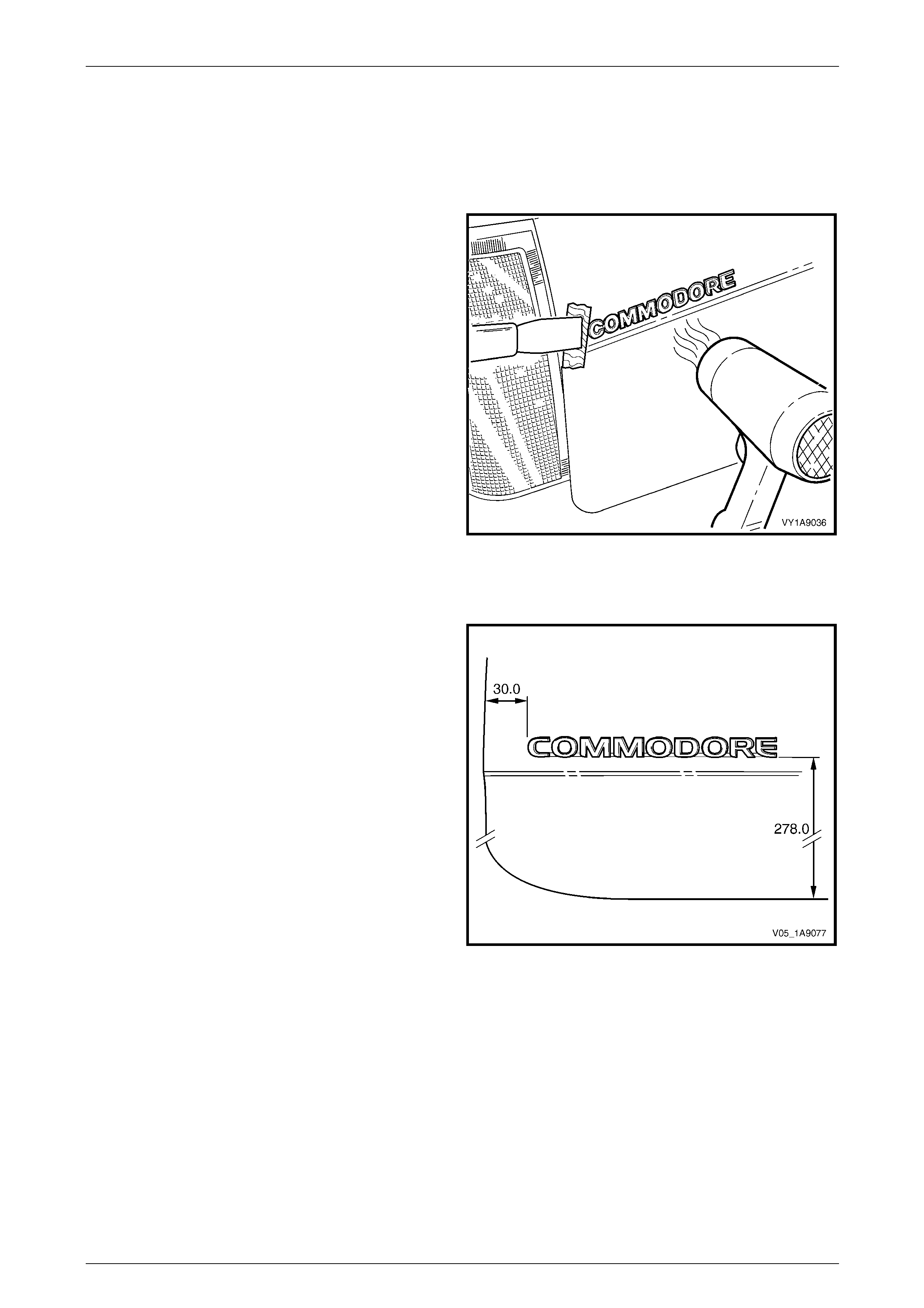
Exterior Ornamentation Page 1A9-81
Page 1A9-81
3.3 Liftgate Name Plate, Left-hand
LT Section No. — 10–150
Remove
1 Protect the paint and bodywork with tape or a clean
rag.
2 To assist removal, warm the name plate with a heat-
lamp or heat-gun to soften the adhesiv e.
3 Using a paint scraper or similar, carefully prise the
emblem from the liftgate.
4 As required, remove any remaining double-sided tape
from the name plate and/or liftgate and clean the
surfaces with Prepsol or equivalent.
Figure 1A9 – 65
Reinstall
1 If reusing the name plate, apply new polyethylene
double-sided tape such as 3 M 4428 or equivalent to
the back of the name plate. Trim back the tape slightly
away from the edge of the name plate.
2 Clean the panel surface with Prepsol or equivalent.
3 Remove the backing paper from the double-sided
tape.
4 Apply the name plate onto the left-hand side of the
liftgate in the position shown, measuring from left-hand
and bottom edge of the liftgate. Ensure it is positioned
parallel to the lo wer edge.
5 Press firmly over the entire name plate for at least 10
seconds to ensure sound adhesion.
Figure 1A9 – 66
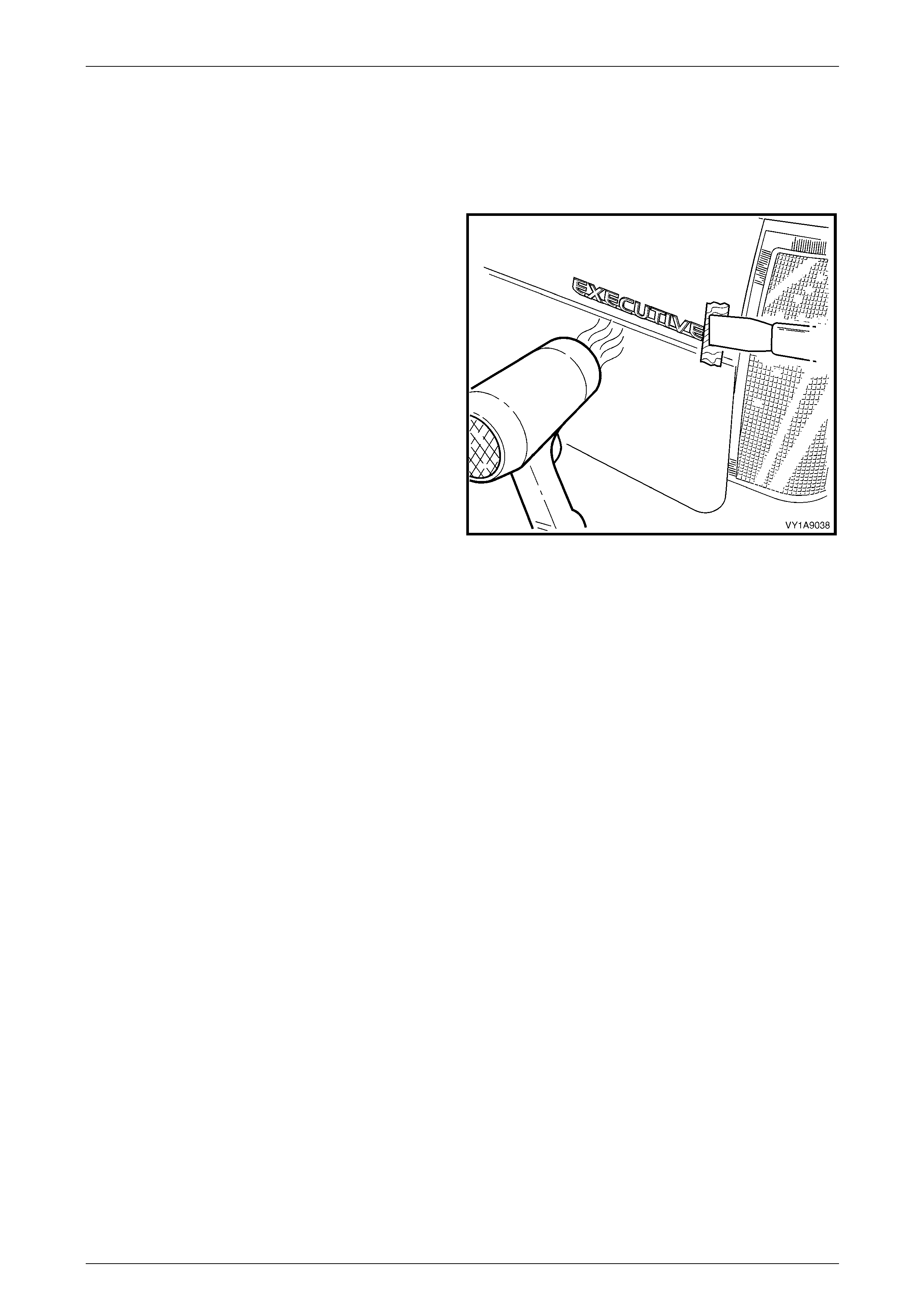
Exterior Ornamentation Page 1A9-82
Page 1A9-82
3.4 Liftgate Name Plate, Right-hand
LT Section No. — 10–150
Remove
1 Protect the paint and bodywork with tape or a clean
rag.
2 To assist removal, warm the name plate with a heat-
lamp or heat-gun to soften the adhesiv e.
3 Using a paint scraper or similar, carefully prise the
name plate from the liftgate.
4 As required, remove any remaining double-sided tape
from the name plate and/or liftgate and clean the
surfaces with Prepsol or equivalent.
Figure 1A9 – 67
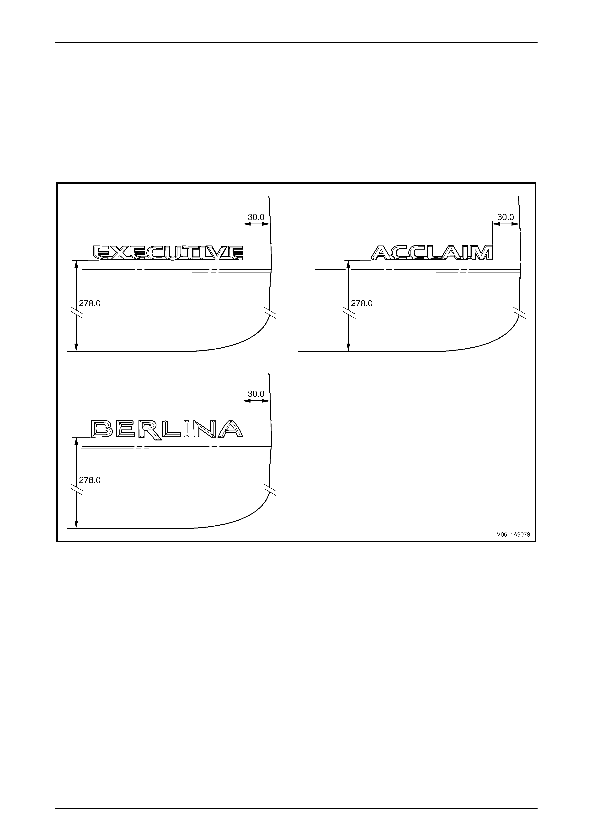
Exterior Ornamentation Page 1A9-83
Page 1A9-83
Reinstall
1 If reusing the name plate, apply new polyethylene double-sided tape such as 3M 4428 or equivalent to the back of
the name plate. Trim back the tape slightly away from the edge of the name plate.
2 Clean the panel surface with Prepsol or equivalent.
3 Remove the backing paper from the double-sided tape.
4 Apply the name plate onto the right-hand side of the liftgate in the position shown, measuring from right-hand and
bottom edge of the liftgate. Ensure it is positioned parallel to the lower edge, refer to Figure 1A9 – 68.
Figure 1A9 – 68
5 Press firmly over the entire name plate for at least 10 sec onds to ensure sound adhesion.
6 If required remove the plastic carrier.
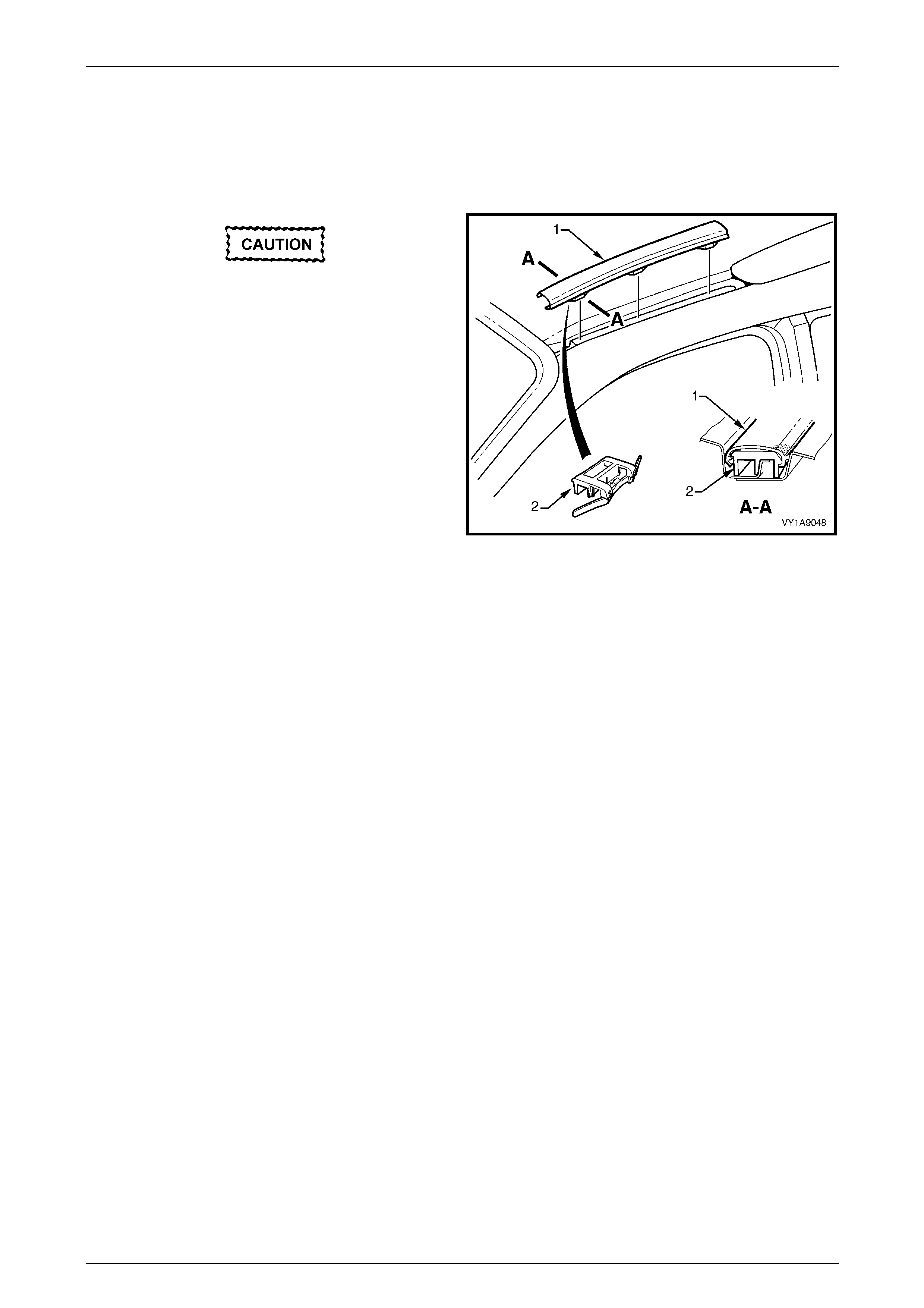
Exterior Ornamentation Page 1A9-84
Page 1A9-84
3.5 Roof Joint Moulding
LT Section No. — 10–250
Remove
Take care as the retaining clips can easily
break. Protect the paintwork with a clean rag.
1 Beginning at the front of the vehicle, use a screwdriver
to carefully prise the roof joi nt moul ding (1) from the
roof channel, disengaging retaining clip (2), three
places.
2 Slide the joint moulding from under the roof side rail
and remove.
Figure 1A9 – 69
Reinstall
1 As required, seat the three retainers evenly onto the roof joint moulding.
2 Slide the moulding under the roof side rail.
3 Seat the moulding in the roof channel and beginning at the rear, clip it in place.
4 At the front, ensure the moulding is installed under the windshield moulding cover.
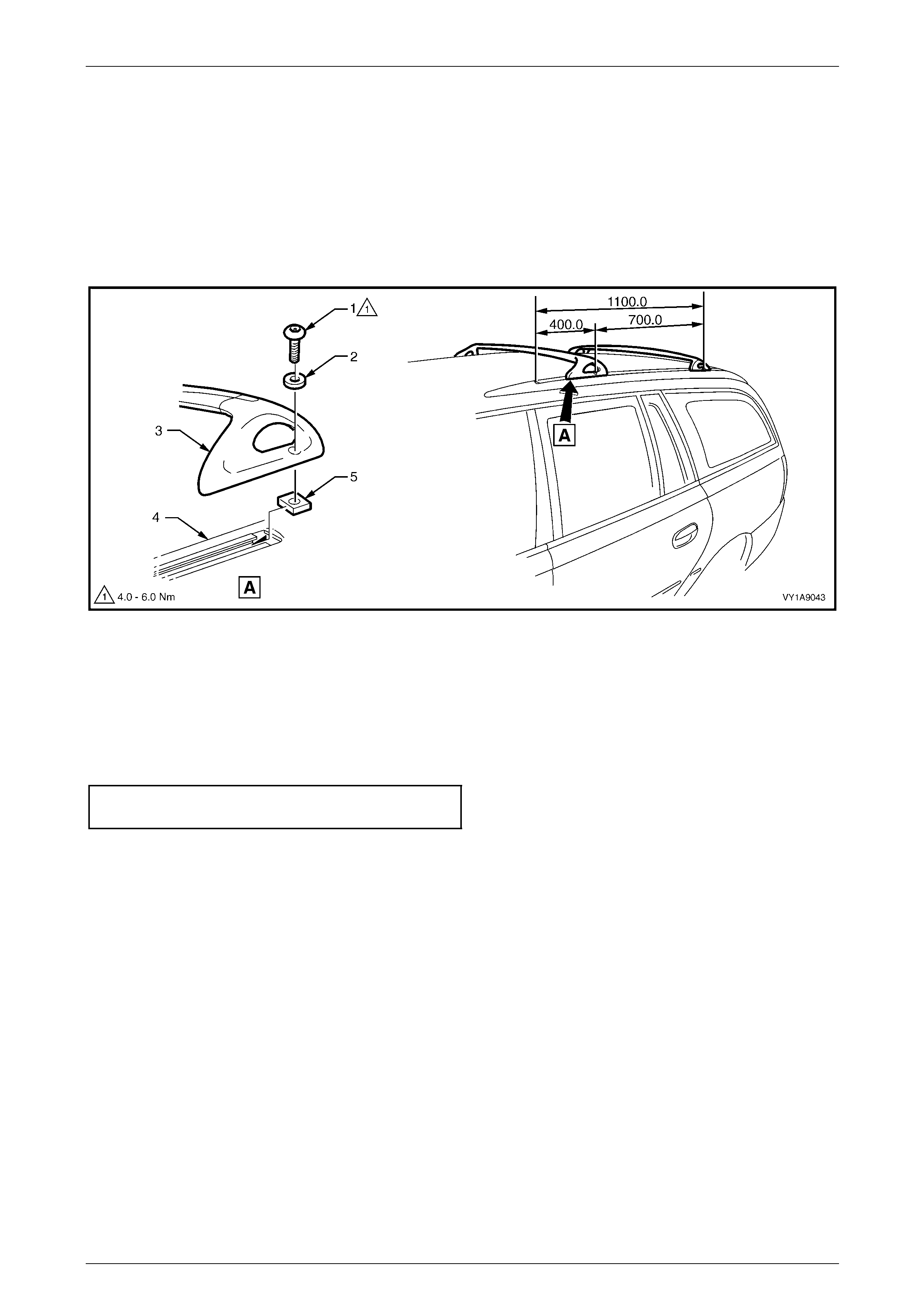
Exterior Ornamentation Page 1A9-85
Page 1A9-85
3.6 Roof Bars
LT Section No. — AA–005
Remove
1 Using the key tool (supplied with vehicle) or an appropri ate Allen Key, loosen and remov e the two locking screws
(1) and washers (2) attaching each roof bar (3) to the roof side rail (4), refer to Figure 1A9 – 70.
2 If required, slide the roof bar attaching nuts (5) out of the rear of the roof side rail.
Figure 1A9 – 70
Reinstall
Reinstallation of the roof bars is the reverse of the removal procedure, noting the following:
1 Position the roof bars in the production standard position as shown. Refer to Figure 1A9 – 70.
2 Tighten the screws to the correct torque specification.
Roof bar attaching screw
torque specification.....................................4.0 – 6.0 Nm
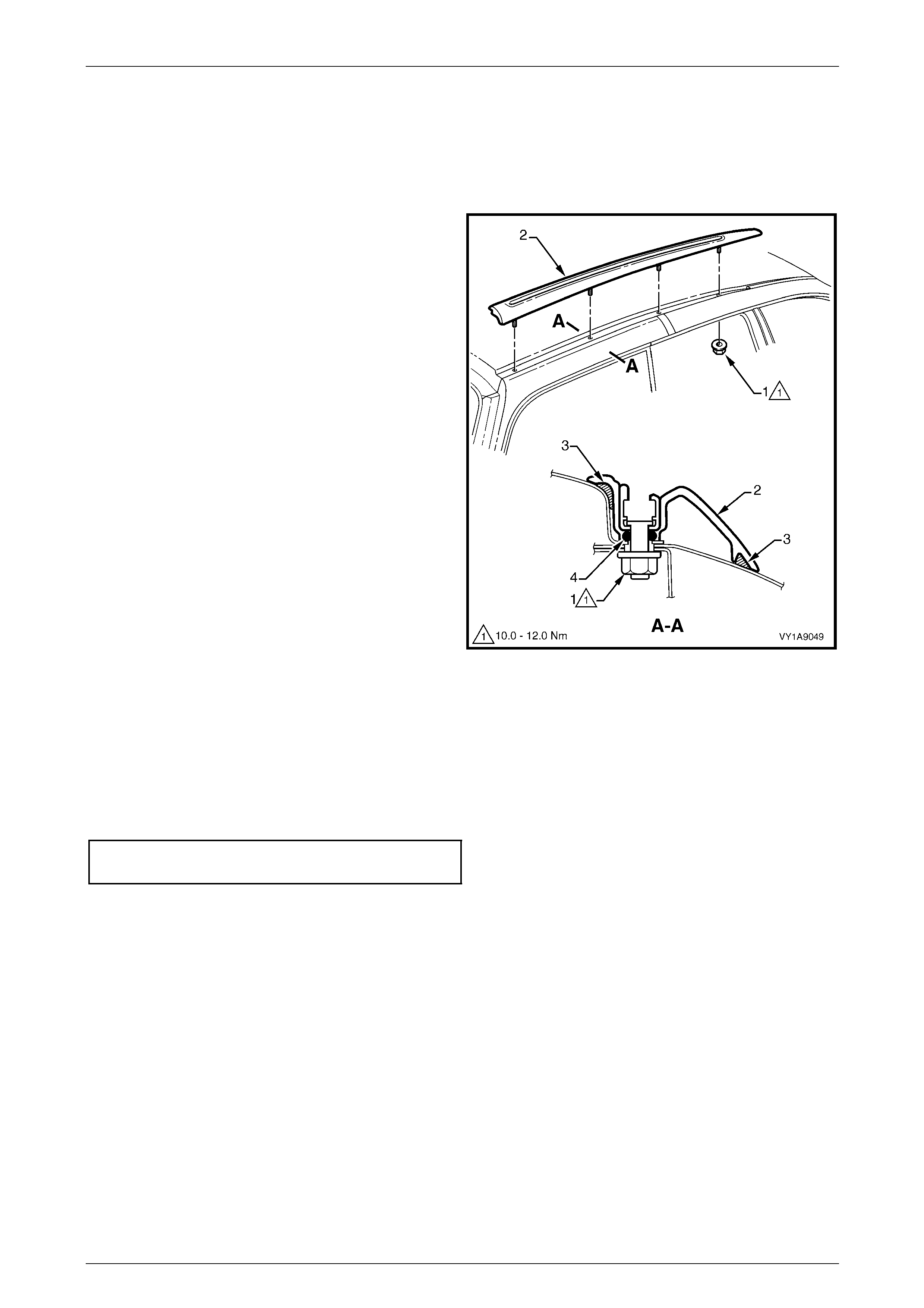
Exterior Ornamentation Page 1A9-86
Page 1A9-86
3.7 Roof Side Rails
LT Section No. — 10–250
Remove
1 Remove the headlining from the vehicle, refer to
Section 1A8 Headlining and Interior Trim.
2 Remove nut (1), four places, attaching the roof side
rail (2) to the roof panel.
3 Remove the roof side rail up until the studs are free
and then slide the rail rear ward.
Figure 1A9 – 71
Reinstall
Reinstallation of the roof side rail is the reverse of the removal procedure, noting the following:
1 Ensure the foam seal (3) is not damaged and is correctly seated and the O-ring seals (4) are fitted to each of the
studs, refer to Figure 1A9 – 71.
2 Tighten the nuts to the correct torque specification.
Roof side rail attaching nut
torque specification.................................10.0 – 12.0 Nm
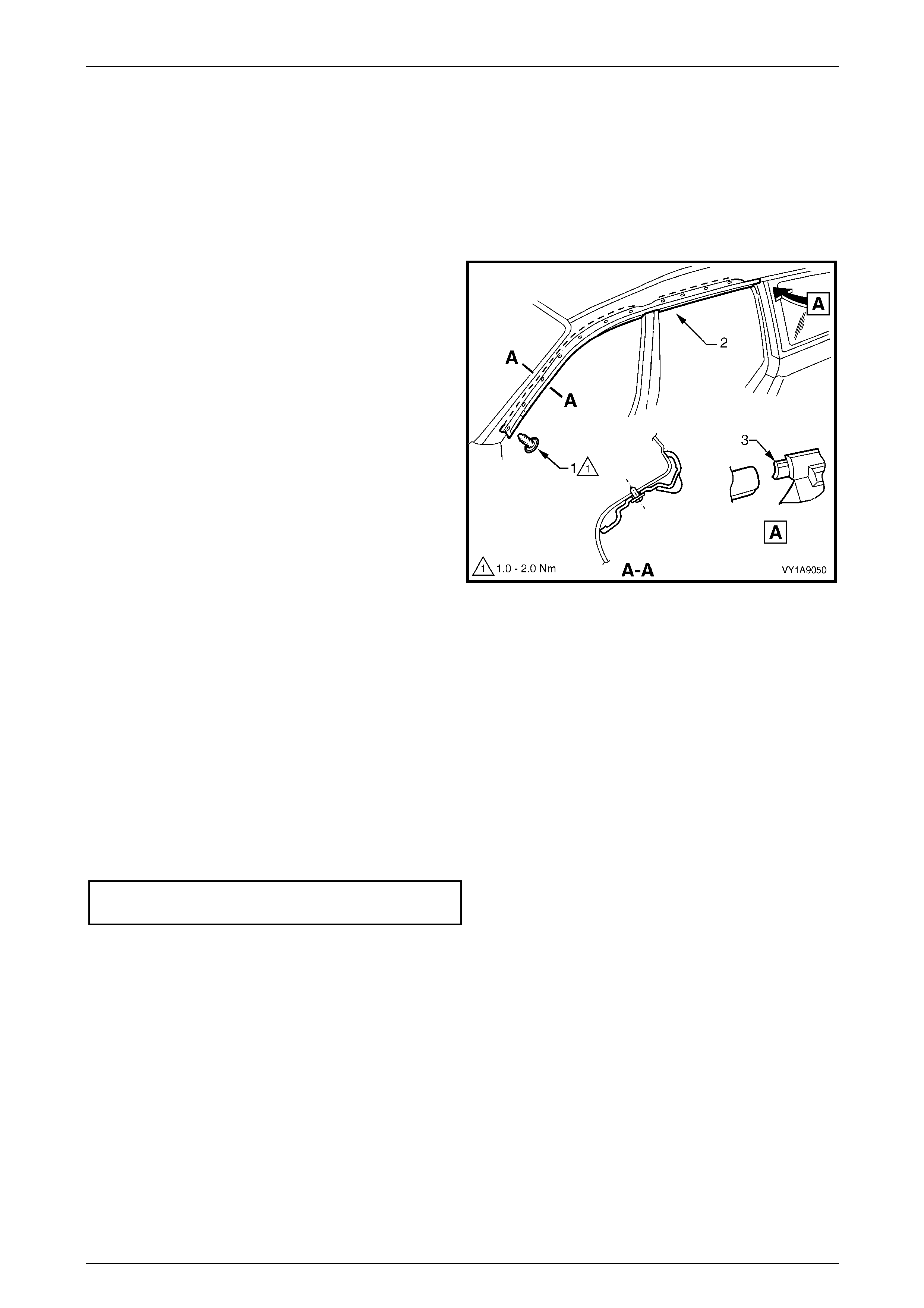
Exterior Ornamentation Page 1A9-87
Page 1A9-87
3.8 Door Opening Moulding
LT Section No. — 10–250
Remove
1 Open the front and rear doors on the relevant side of the vehicle.
2 Beginning at each end and working towards the
middle, remove the screw (1), 11 places, att achi ng the
door opening moulding (2) to the bod y.
3 Carefully remove the moulding, disengaging the
quarter window assembly tab (3).
Figure 1A9 – 72
Reinstall
Reinstallation of the door opening moulding is the reverse of the removal procedure, noting the following:
1 Install the screws by beginnin g at the rear and working forward.
NOTE
The screws are encapsulated with a wax sealer.
It is recommended the screws be replaced once
removed, however if this is impractical, apply a
small amount of sealer to the end of the thread.
2 Tighten the screws to the correct torque specification.
Door opening moulding attaching
screw torque specification...........................1.0 – 2.0 Nm
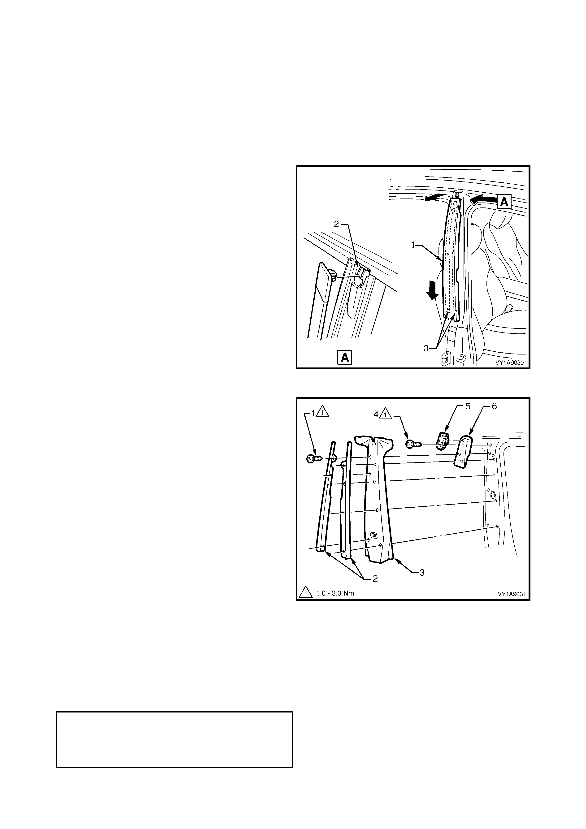
Exterior Ornamentation Page 1A9-88
Page 1A9-88
3.9 Centre Pillar Upper Finisher Assembly
LT Section No. — 10–250
Remove
1 Open the front and rear doors on relevant side of the vehicle.
2 Gently prise top of centre pillar upper finisher (1) out to
disengage it from the centre pillar upper fini sher
retainer (2).
3 Holding the top of finisher out, slide it down the centre
pillar outer sealing strips (3) until it rests on rear door
hinge.
4 Manoeuvre the finisher from the sealing strips and
remove.
Figure 1A9 – 73
5 Remove the screw (1), seven places, attaching the
centre pillar sealing strips (2) to the pill ar and remove
the strips.
6 Partially remove the door opening moulding, refer to
3.8 Door Opening Moulding.
7 Remove the centre pillar upper trim panel (3) by
pulling away from the pillar.
8 Remove the screw (4) attaching the centre pillar upper
finisher retainer (5) and centre pillar upper trim mount
plate (6) to the pillar and remove.
Figure 1A9 – 74
Reinstall
Reinstallation of the centre pillar upper finisher assembly is the reverse of the removal procedure, noting the following:
1 Ensure the centre pillar upper trim panel is seated correctly under door opening weatherstrips.
2 Tighten the screws to the correct torque specification.
Centre pillar upper finisher retainer
attaching screw torque specification...........1.0 – 3.0 Nm
Centre pillar sealing strip attac hin g
screw torque specification...........................1.0 – 3.0 Nm
3 Slide the centre pillar upper finisher up and press it in at the top to engage into the reta ining clip.
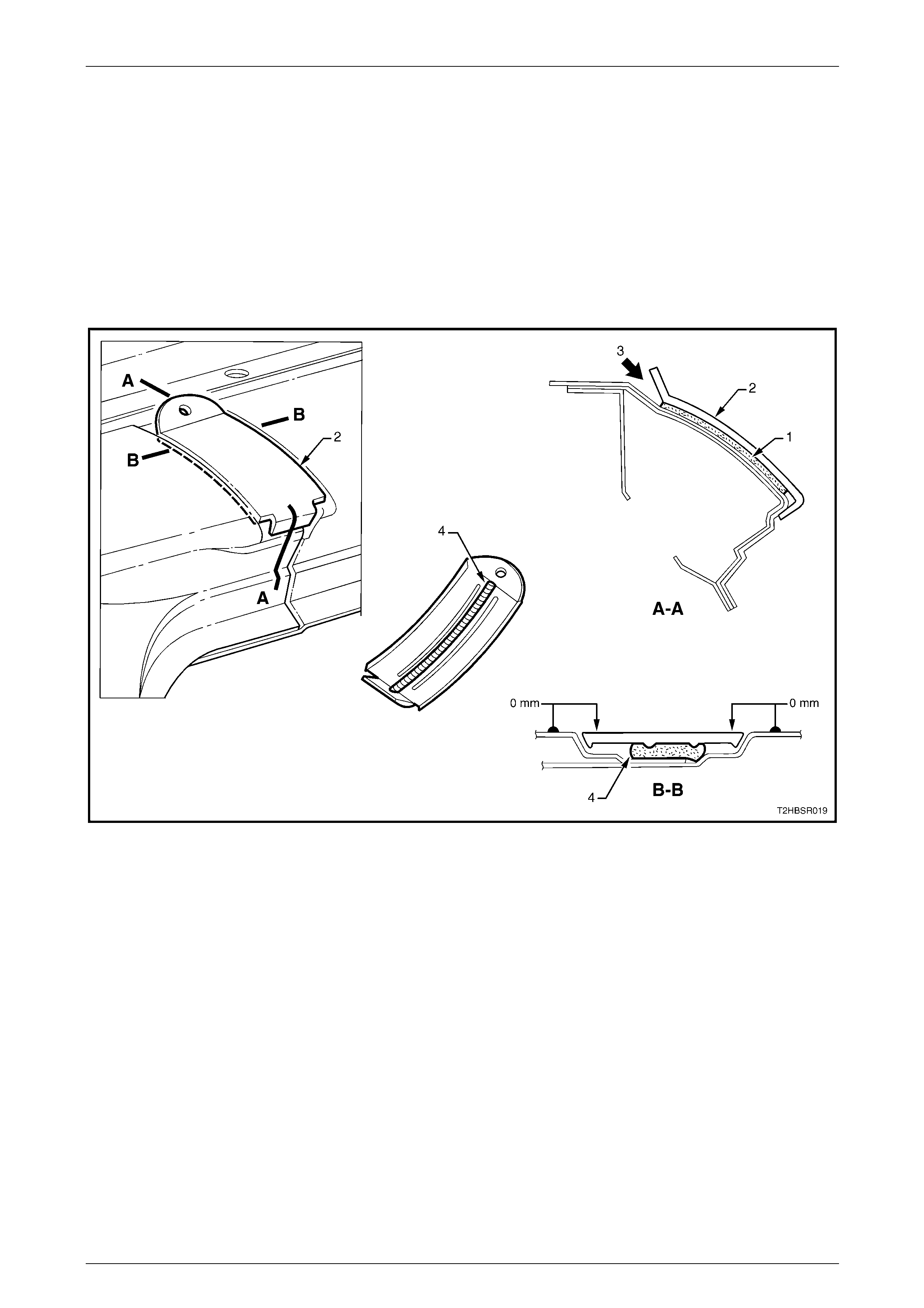
Exterior Ornamentation Page 1A9-89
Page 1A9-89
3.10 Roof Joint Finisher
Remove
1 Remove the following components:
a Roof side rails, refer to 3.7 Roof Side Rails.
b Door opening moulding, refer to 3.8 Door Opening Moulding.
2 Carefully cut the adhesive (1) attaching the roof joint finish er (2), while prising the top of the finisher (3) from the
vehicle, refer to Figure 1A9 – 75.
3 Clean off any residual adhesive as required.
Figure 1A9 – 75
Reinstall
1 Ensure the surface is clean and painted.
2 Apply an 8 mm bead of urethane adhesive such as Expan dite Betaseal 554 02, Sikaflex Drive or eq uivalent (4)
along the back of the moulding, between the ribs.
3 Fit the finisher, ensuring the outer surface is flush with the panel surfaces a nd the side gaps are even.
4 If required, temporarily secure the finisher with tape.
5 Allow the adhesive to cure overnight.
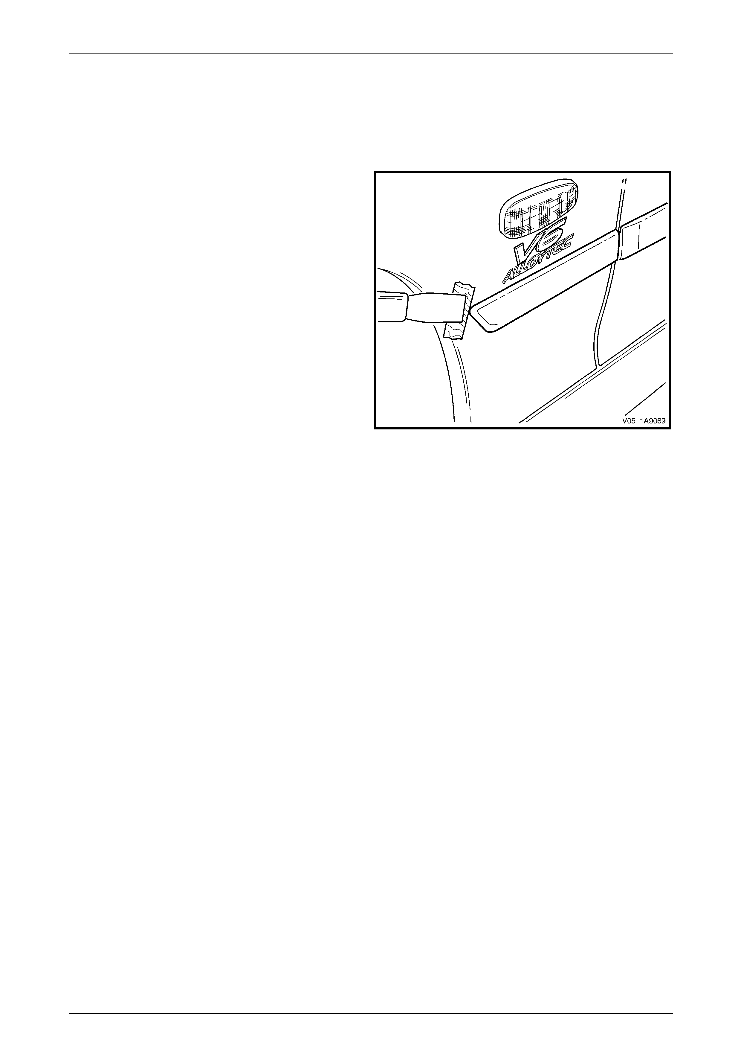
Exterior Ornamentation Page 1A9-90
Page 1A9-90
3.11 Body Side Mouldings
LT Section No. — 10–250
Remove
1 Protect the paint and bodywork with tape or a clean
rag.
2 Using a paint scraper or similar, begin at one end and
carefully prise the moulding from the panel, cutting
through the double-sided tape and adhesive.
NOTE
As an alternative, carefully use a l ength of piano
wire to cut the adhesive in a similar way to
removing a windshield. If required, refer to
Section 1A6 Stationary Windows.
3 As required, remove any remaining double-sided tape
and adhesive from the moulding and/or panel. Clean
the surfaces with Prepsol or equivalent.
Figure 1A9 – 76
Reinstall
For:
• Executive a nd Acclaim vehicles refer to Figure 1A9 – 77.
• Berlina vehicles refer to Figure 1A9 – 78.
1 Place a mark on the rear edge of the fender and/or door panels at the three points shown in the relevant figure as
required. Measure in a straight line from the lower edge of each panel.
2 If a complete moulding set is to be fitted, or as required, apply a length of masking tape along the side of the
vehicle, aligning the top edge of the tape with the marks. Begin by affixing the tape at the rear of the rear door, ho ld
it taut and away from the vehicle, and affix it to each panel. Ensure it is straight and then smooth it down along its
length.
3 If reusing the moulding, apply new acrylic double-sided tape (1) such as 3M 5344 along the back of the moulding.
4 Apply a 3.0 mm diameter bead of urethane adhesive such as Expandite Betaseal 554.02 , Sikaflex Drive or
equivalent over the entire length of moulding (2) and for 50mm in several places (3).
NOTE
Refer to any further directions supplied with the
urethane adhesive.
5 Affix the moulding to the vehicle in the correct positions, aligning the lower edge with the masking tape (if fitted)
and:
• For the fender moulding begin at the rear edge aligning to the dimension at Section A-A.
• For the front door mouldi ng begin at the front edge of the front door, aligning to the dim ension at Section A-A.
• For the rear door moul ding begin at the front edge of the rear door, aligni ng to the dimension at Section B-B.
• For the quarter panel moulding begin at the front edge of the quarter panel, aligning to the dimens ion at
Section C-C.
6 Press firmly over the length of the mouldin g(s) at the double-sided tape for 10 seconds to ensure soun d adhesion.
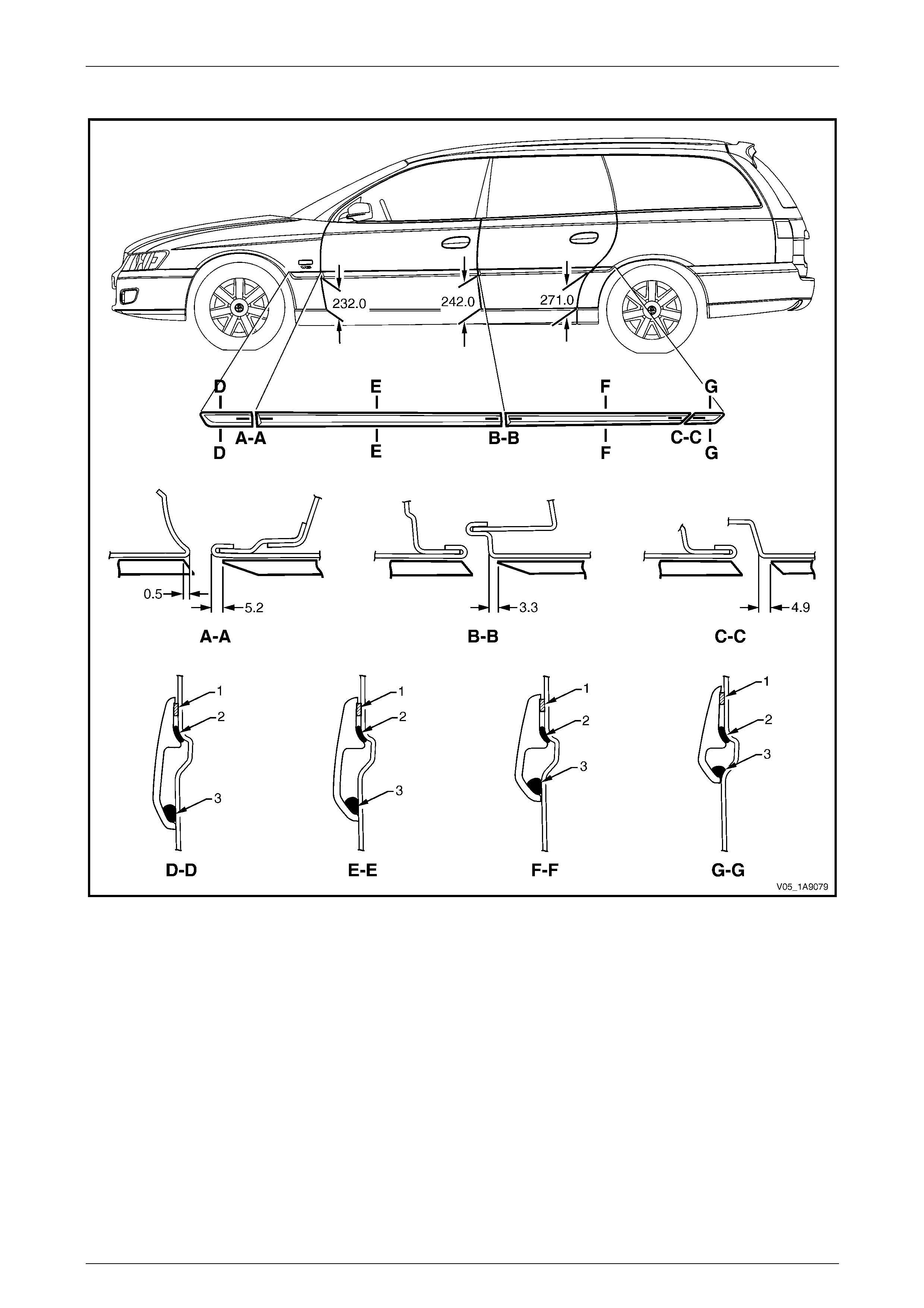
Exterior Ornamentation Page 1A9-91
Page 1A9-91
Executive and Acclaim
Figure 1A9 – 77
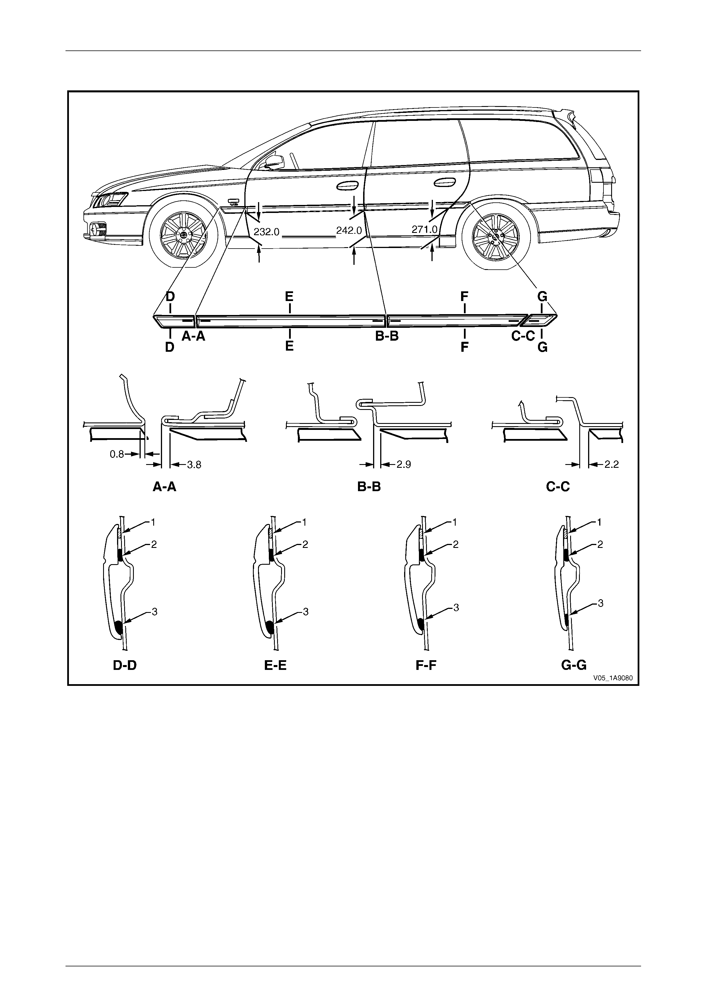
Exterior Ornamentation Page 1A9-92
Page 1A9-92
Berlina
Figure 1A9 – 78
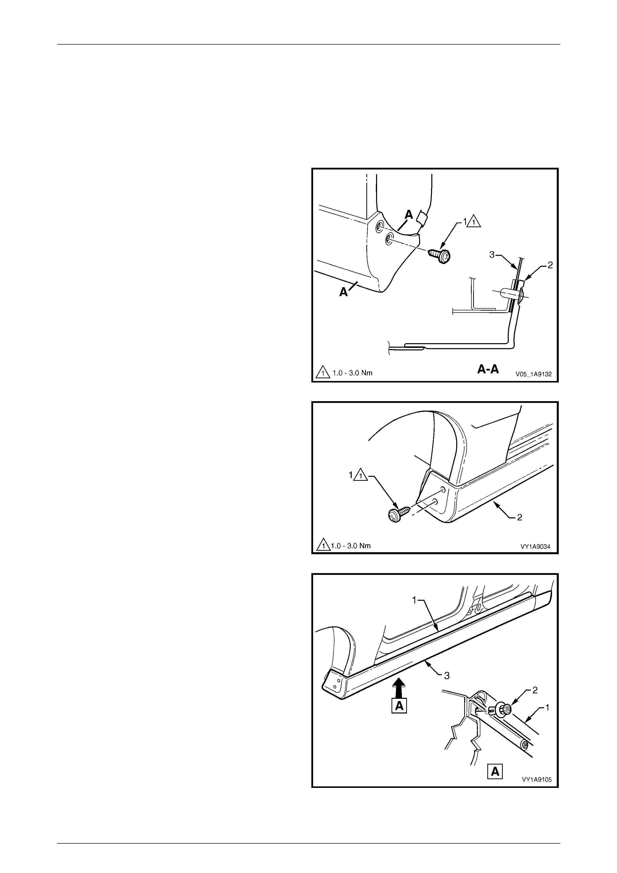
Exterior Ornamentation Page 1A9-93
Page 1A9-93
3.12 Rocker Panel Moulding Assembly
LT Section No. — 10–300
Remove
1 On the relevant side remove the rear road wheel, refer to Section 10 Wheels and T yres.
2 Remove the screw (1), two places, attaching the rear
rocker panel moulding (2) and wheelhouse liner (3).
NOTE
If required, the rear rocker panel moulding can
be removed at this stage by sliding it rearward
from the front rocker panel moulding.
Figure 1A9 – 79
3 Turn the front wheels to full steering lock to ward the
relevant side.
4 Remove the screw (1), two places, attaching the front
rocker panel moulding (2) to the fender and liner.
Figure 1A9 – 80
5 Lift up the rocker panel weatherstrip (1) as shown in
View A to gain access and remove the retainer (2),
nine places, attaching the rocker panel moulding (3) to
the vehicle body. NOTE
If the retainers are difficult to remove, prise out
the centre section a small amount with a flat
bladed screwdriver, then continue to unscrew. It
may also be necessary to retain the outer
section of the retainer with fingers or pliers.
6 Referring to Figure 1A9 – 82, from underneath the
vehicle, remove the screw (1), seven places, from the
retainer (2) under the moulding (3).
7 Remove the moulding.
8 If required, prise nut (4), two places, from the fender.
Figure 1A9 – 81
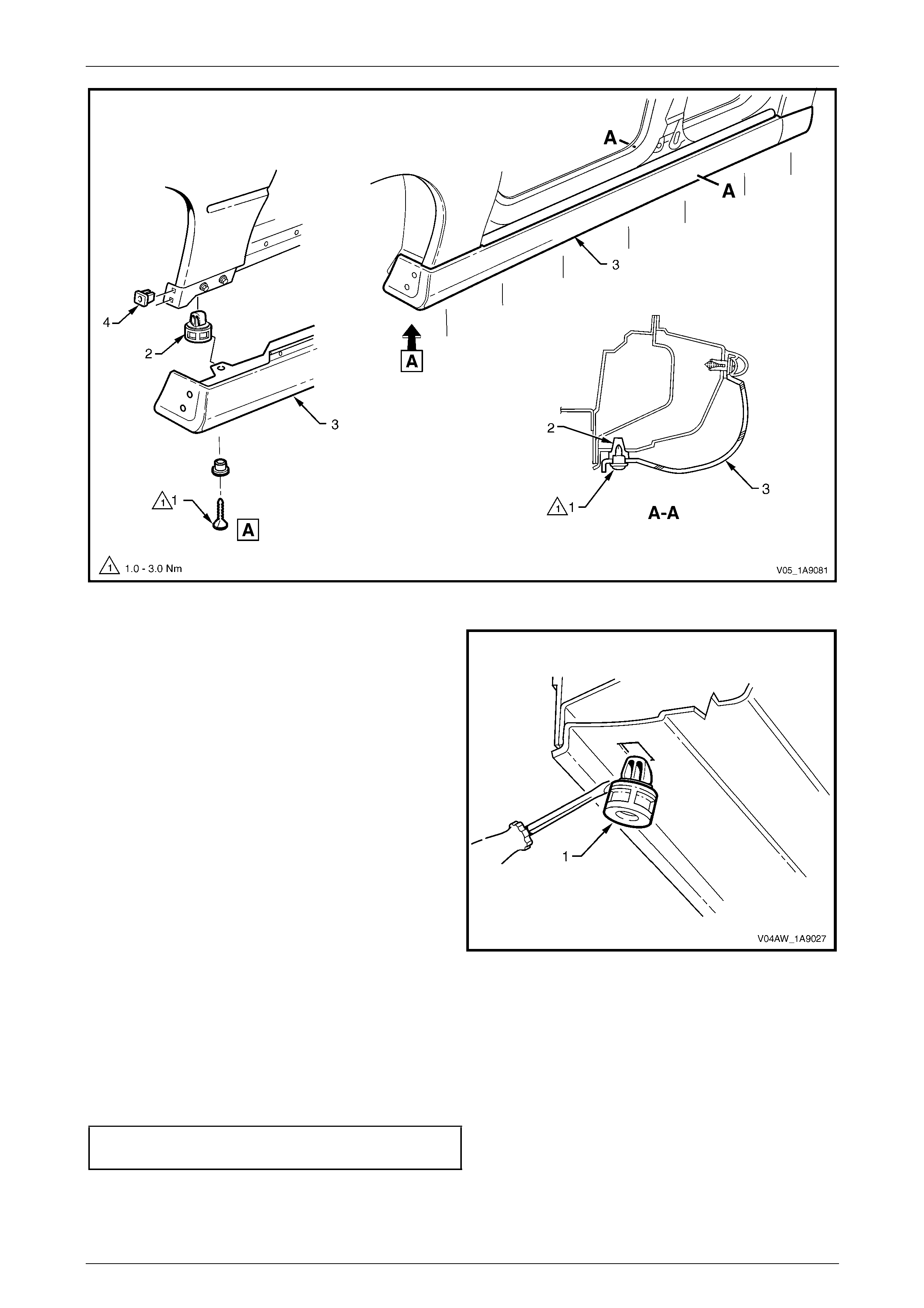
Exterior Ornamentation Page 1A9-94
Page 1A9-94
Figure 1A9 – 82
9 If required, remove the retainer (1), seven places, by
gently levering out from the body, taking care not to
damage the paint work.
Figure 1A9 – 83
Reinstall
Reinstallation of the rocker panel front and rear mouldings is the reverse of the removal p r ocedure, noting the following:
1 Ensure the front moulding is correctly seated in the retaining clips.
2 Tighten the screws to the correct torque specification.
Rocker panel moulding attac hin g
screw torque specification...........................1.0 – 3.0 Nm
3 Ensure the weatherstrip is seated correctly.
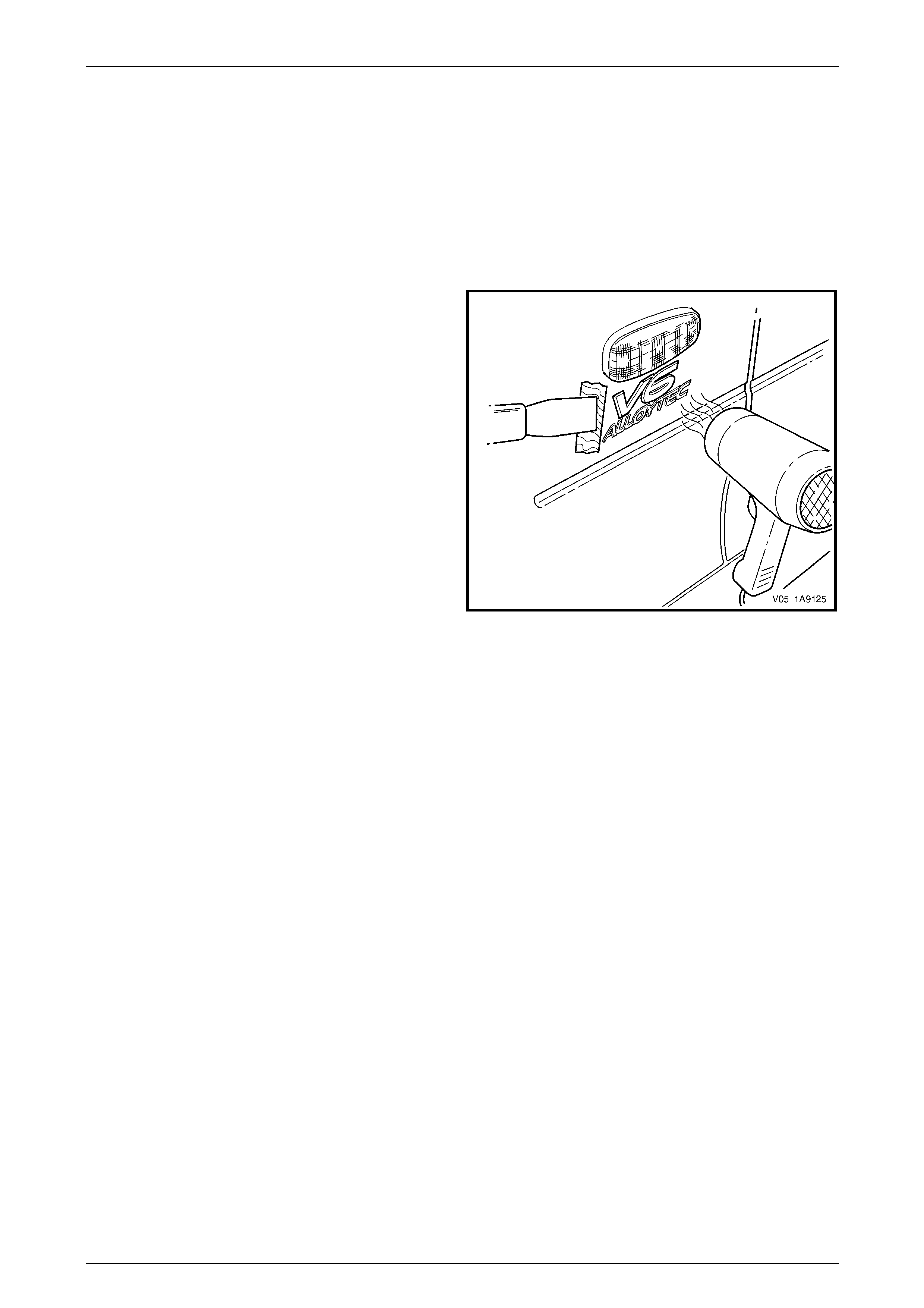
Exterior Ornamentation Page 1A9-95
Page 1A9-95
4 Service Operations, AWD Wagon
4.1 Fender Name Plate
LT Section No. — 10–150
Remove
1 Protect the paint and bodywork with tape or a clean
rag.
2 To assist removal, warm the name plate with a heat-
lamp or heat-gun to soften the adhesiv e.
3 Using a paint scraper or similar, carefully prise the
name plate from the fender.
4 As required, remove any remaining double-sided tape
from the name plate and/or door panel and clean the
surfaces with Prepsol or equivalent.
Figure 1A9 – 84
Reinstall
1 If reusing the name plate, apply new polyethylene double-sided tape such as 3M 4428 or equivalent to the back of
the name plate. Trim back the tape slightly away from the edge of the name plate.
2 Clean the fender surface with Prepsol or equivalent.
3 Remove the backing paper from the double-sided tape.
4 Apply the name plate in the position shown, refer to Figure 1A9 – 85 m easuring from the front side turn signal lam p
(1). Ensure it is positioned parallel to the style line or body side mouldin g (2).
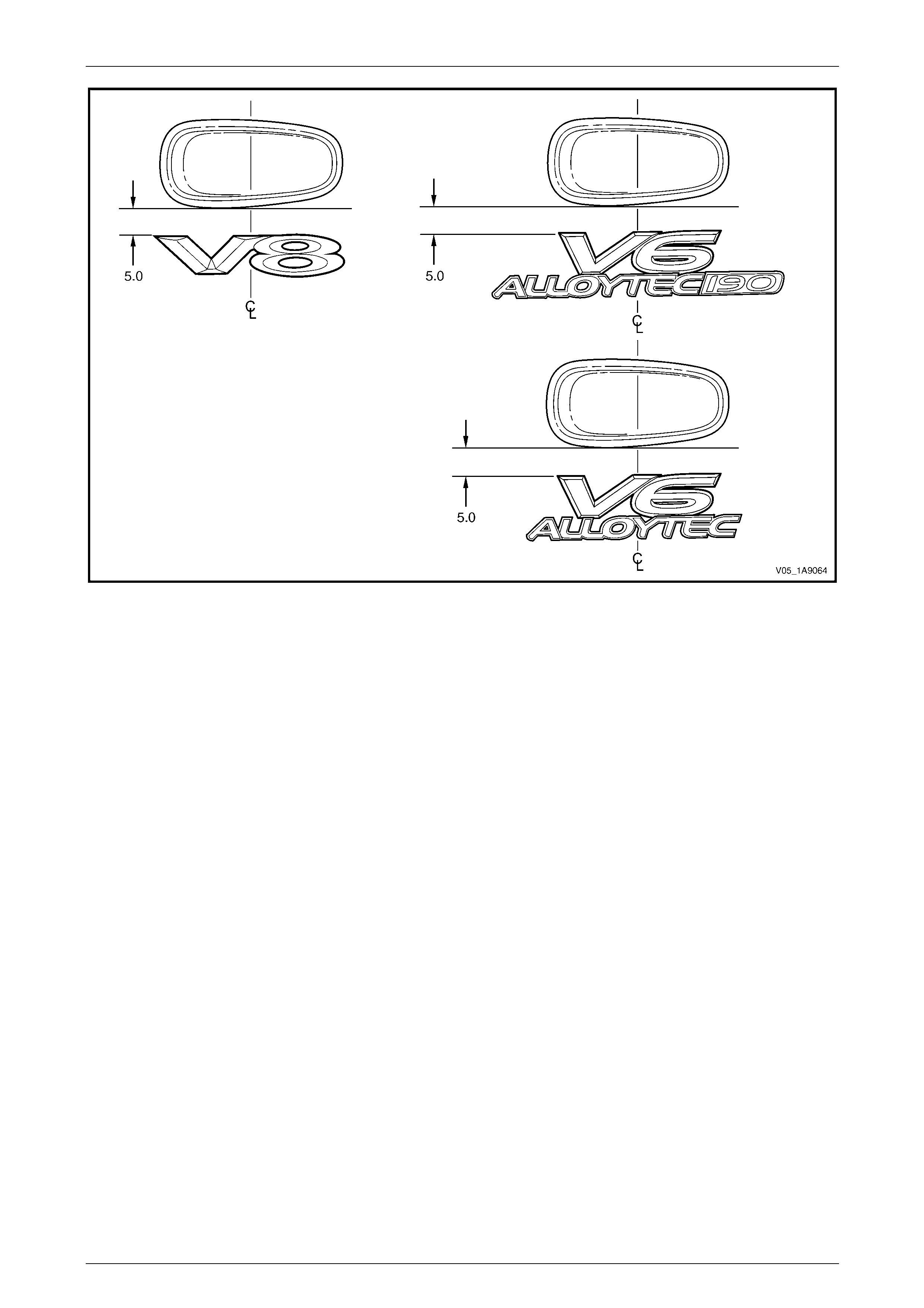
Exterior Ornamentation Page 1A9-96
Page 1A9-96
Figure 1A9 – 85
5 Press firmly over the entire name plate for at least 10 sec onds to ensure sound adhesion.
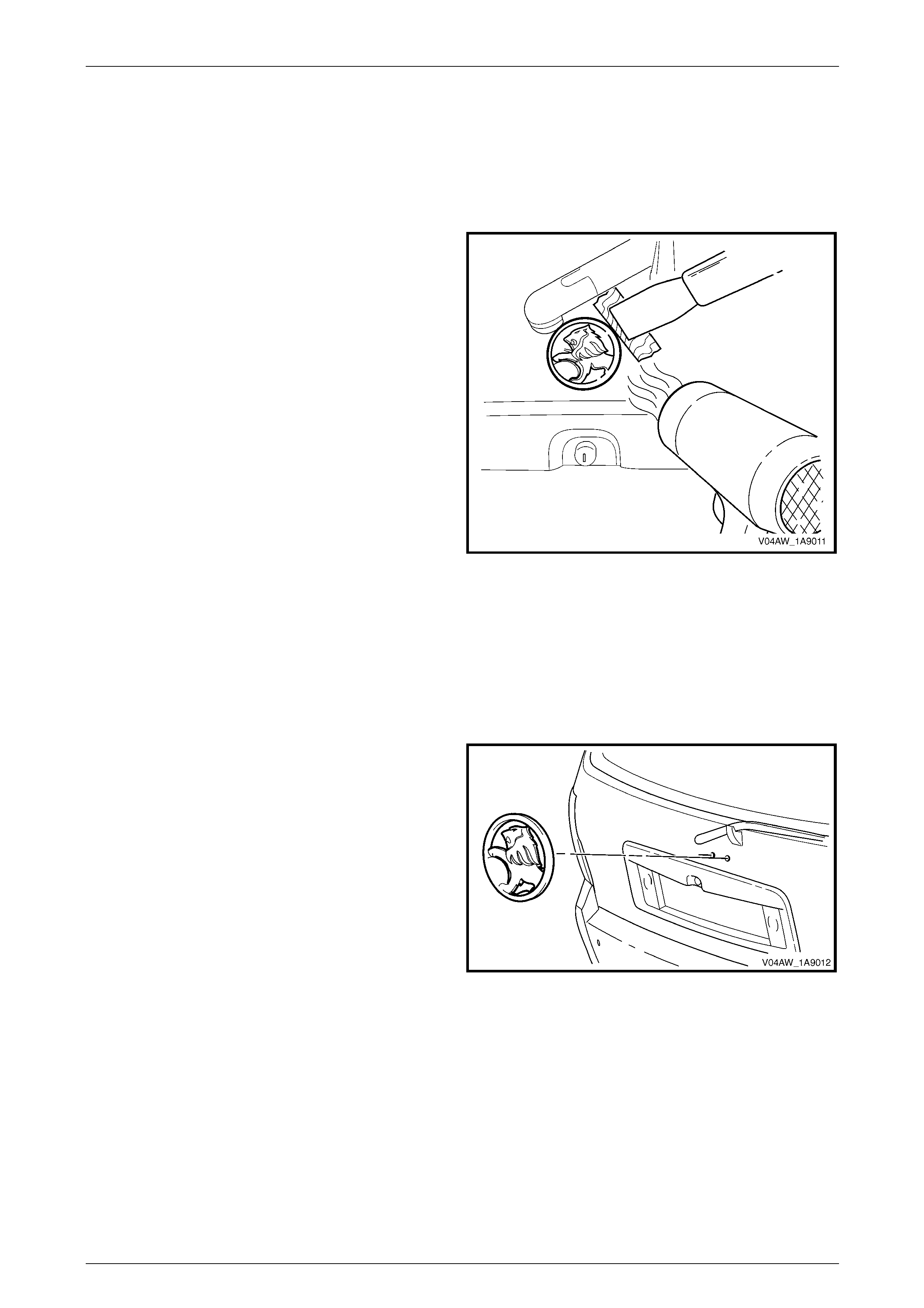
Exterior Ornamentation Page 1A9-97
Page 1A9-97
4.2 Liftgate Emblem
LT Section No. — 10–150
Remove
1 Protect the paint and bodywork with tape or a clean
rag.
2 To assist removal, warm the emblem with a heat-lamp
or heat-gun to soften the adhesive.
3 Using a paint scraper or similar, carefully prise the
emblem from the liftgate.
NOTE
The emblem has two locatin g pins, take care not
to break them if the emblem is to be reused.
4 As required, remove any remaining double-sided tape
from the emblem and/or liftgate and clean the surfaces
with Prepsol or equivalent.
Figure 1A9 – 86
Reinstall
1 If reusing the emblem, apply new polyethylene double-sided tape such as 3M 4428 or equivalent to the back of the
emblem. Trim back the tape slightly away from the edge of the emblem.
2 Clean the panel surface with Prepsol or equivalent.
3 Remove the backing paper from the double-sided tape.
4 Apply the emblem in the position shown ensuring the
locating pins are correctly orientated with the locating
holes in the panel surface.
5 Press firmly over the entire emblem for at least 10
seconds to ensure sound adhesion.
Figure 1A9 – 87
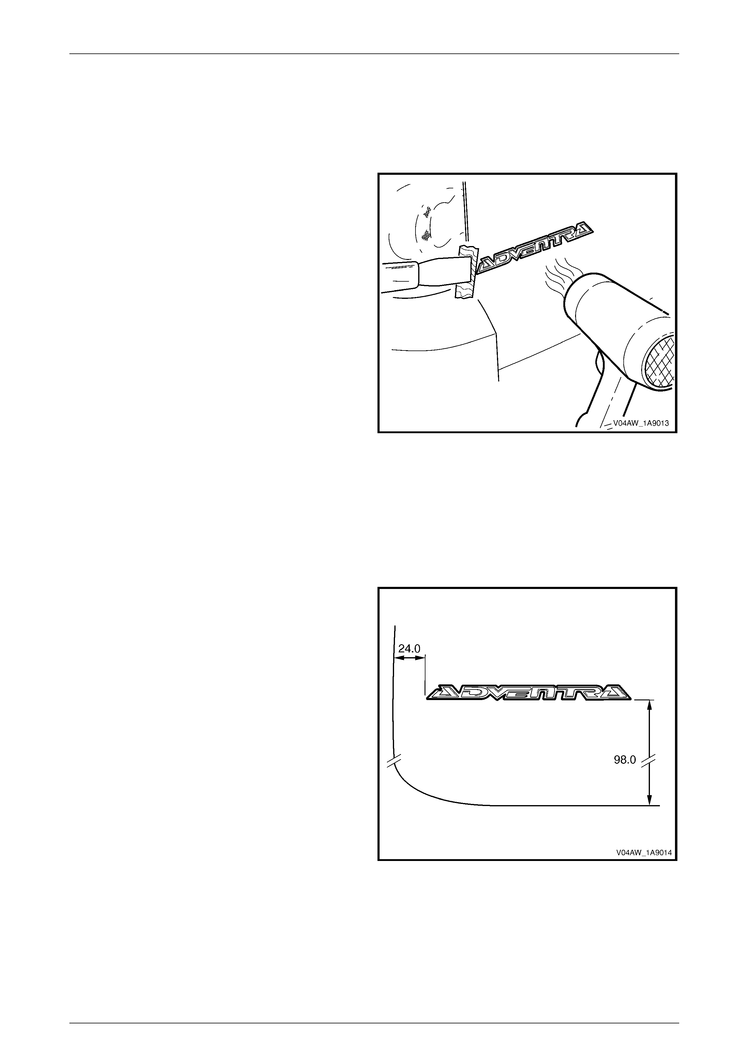
Exterior Ornamentation Page 1A9-98
Page 1A9-98
4.3 Liftgate Name Plate, Left-hand
LT Section No. — 10–150
Remove
1 Protect the paint and bodywork with tape or a clean
rag.
2 To assist removal, warm the emblem with a heat-lamp
or heat-gun to soften the adhesive.
3 Using a paint scraper or similar, carefully prise the
emblem from the liftgate.
4 As required, remove any remaining double-sided tape
from the name plate and/or liftgate and clean the
surfaces with Prepsol or equivalent.
Figure 1A9 – 88
Reinstall
1 If reusing the name plate, apply new polyethylene double-sided tape such as 3M 4428 or equivalent to the back of
the name plate. Trim back the tape slightly away from the edge of the name plate.
2 Clean the panel surface with Prepsol or equivalent.
3 Remove the backing paper from the double-sided tape.
4 Apply the name plate onto the left-hand side of the
liftgate in the position shown, measuring from left-hand
and bottom edge of the liftgate. Ensure it is positioned
parallel to the lo wer edge
5 Press firmly over the entire name plate for at least 10
seconds to ensure sound adhesion.
Figure 1A9 – 89
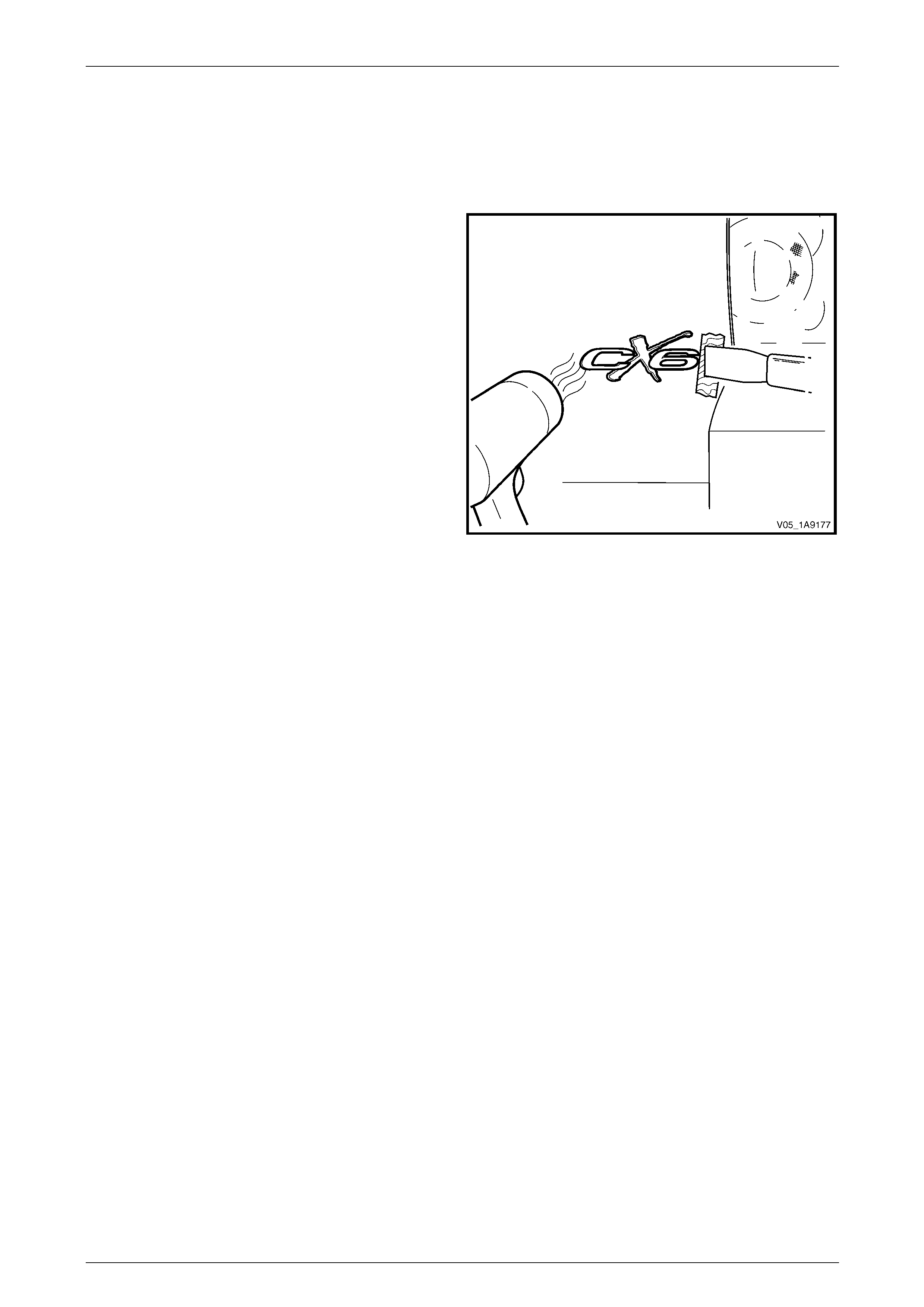
Exterior Ornamentation Page 1A9-99
Page 1A9-99
4.4 Liftgate Name Plate, Right-hand
LT Section No. — 10–150
Remove
1 Protect the paint and bodywork with tape or a clean
rag.
2 To assist removal, warm the emblem with a heat-lamp
or heat-gun to soften the adhesive.
3 Using a paint scraper or similar, carefully prise the
emblem from the liftgate.
4 As required, remove any remaining double-sided tape
from the name plate and/or liftgate and clean the
surfaces with Prepsol or equivalent.
Figure 1A9 – 90
Reinstall
1 If reusing the name plate, apply new polyethylene double-sided tape such as 3M 4428 or equivalent to the back of
the name plate. Trim back the tape slightly away from the edge of the name plate.
2 Clean the panel surface with Prepsol or equivalent.
3 Remove the backing paper from the double-sided tape.
4 Apply the name plate onto the right-hand side of the liftgate in the position shown, measuring from right-hand and
bottom edge of the liftgate. Ensure it is positioned parallel to the lower edge, refer to Figure 1A9 – 91.
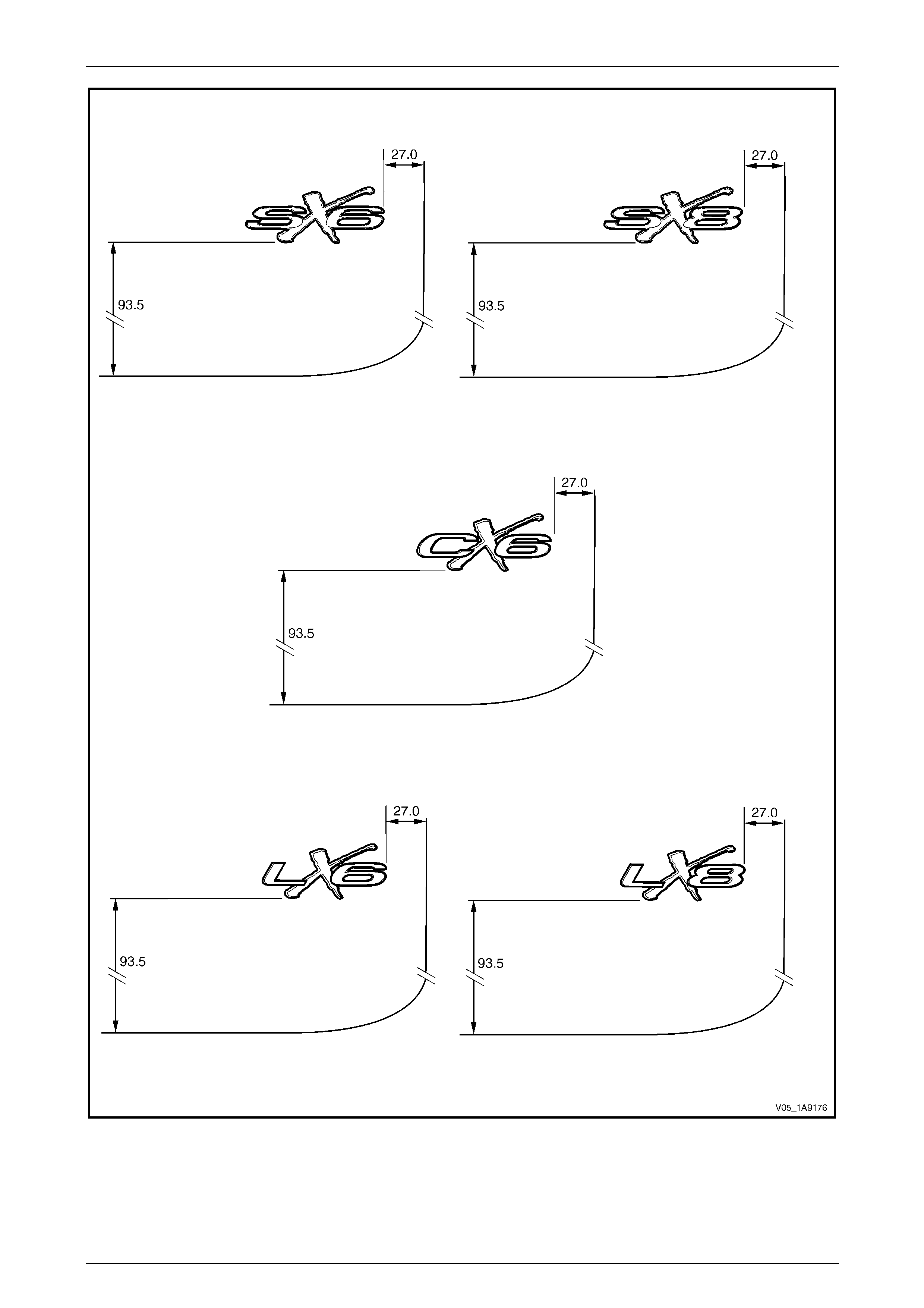
Exterior Ornamentation Page 1A9-100
Page 1A9-100
Figure 1A9 – 91
5 Press firmly over the entire name plate for at least 10 sec onds to ensure sound adhesion.
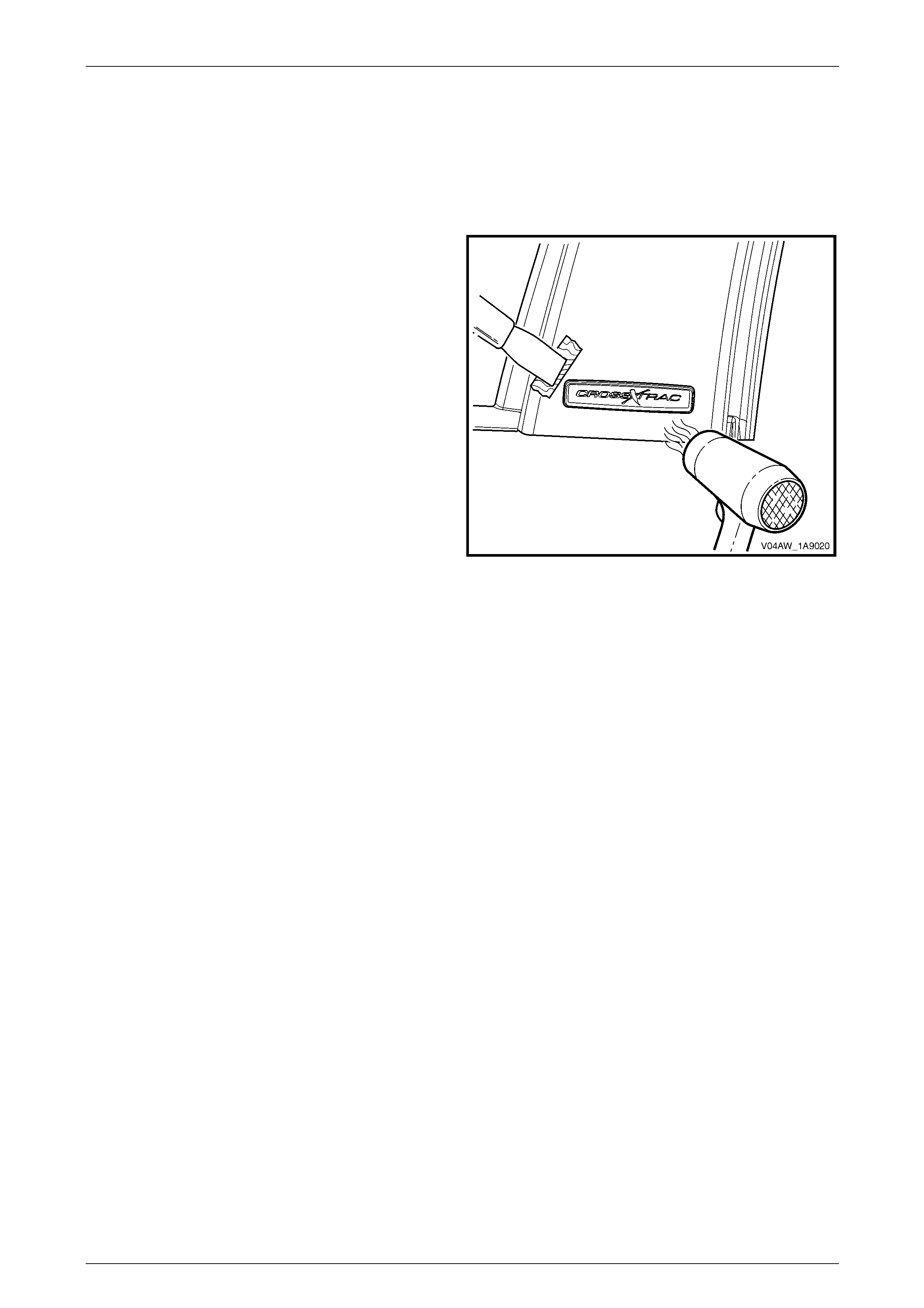
Exterior Ornamentation Page 1A9-101
Page 1A9-101
4.5 Rear Quarter Window Appliqué
Assembly Name Plate
LT Section No. — 10–150
Remove
1 Protect the paint and bodywork with tape or a clean
rag.
2 To assist removal, warm the name plate with a heat-
lamp or heat-gun to soften the adhesiv e.
3 Using a paint scraper or similar, carefully prise the
name plate from the rear quarter window appliqué.
4 Remove any remaining double-sided tape from the
name plate and/or appliqué a nd clean the surfaces
with Prepsol or equivalent.
Figure 1A9 – 92
Reinstall
1 If reusing the name plate, apply new polyethylene double-sided tape such as 3M 4428 or equivalent to the back
and trim the edges of the tape slightly in from the edge of name plate.
2 Clean the appliqué surface with Prepsol or equivalent.
3 Remove the backing paper from the double-sided tape.
4 Apply the name plate into the indent on the appliqué.
5 Press firmly over the entire name plate for at least 10 sec onds to ensure sound adhesion.
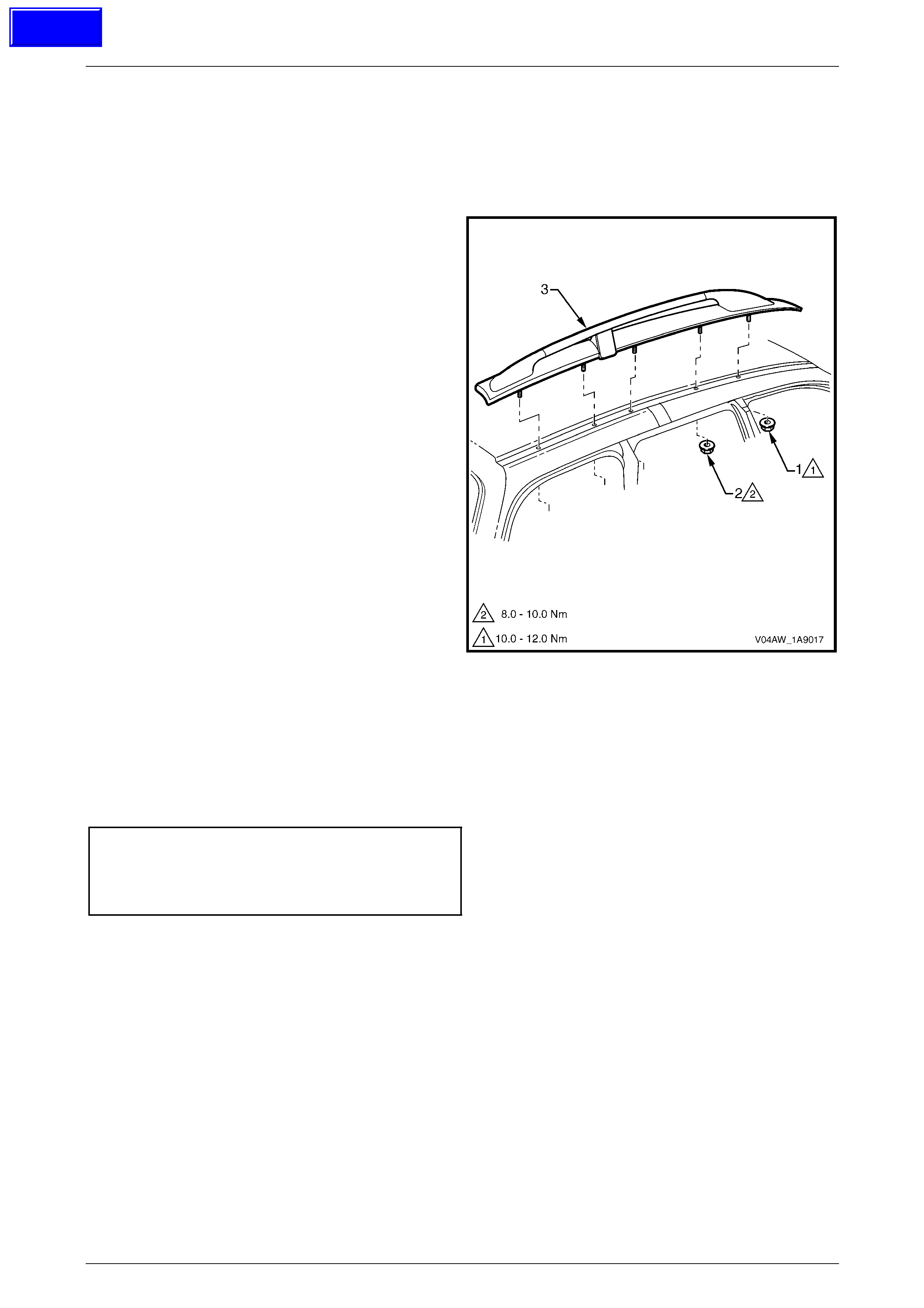
Exterior Ornamentation Page 1A9-102
Page 1A9-102
4.6 Roof Rack Carrier Assembly
Remove
1 Remove the headlining from the vehicle, refer to Section 1A8 Headlining and Interior Trim.
2 From inside the vehicle, remove nut (1), one place and
(2), four places, attaching the roof rack carrier
assembly (2) to the roof panel.
3 Lift the assembly up until the studs are free and then
slide the rail rearward.
Figure 1A9 – 93
Reinstall
Reinstallation of the roof rack carrier assem bl y is the reverse of the remo val procedure, noting the following:
1 Ensure the foam seal is not damaged and is correctly seated and the O-ring seals are fitted to each of the studs.
2 Tighten the nuts to the correct torque specification.
Roof rack carrier assembly front
attaching nut torque specification..............8.0 – 10.0 Nm
Roof rack carrier assembly rear
attaching nut torque specification............10.0 – 12.0 Nm
Techline
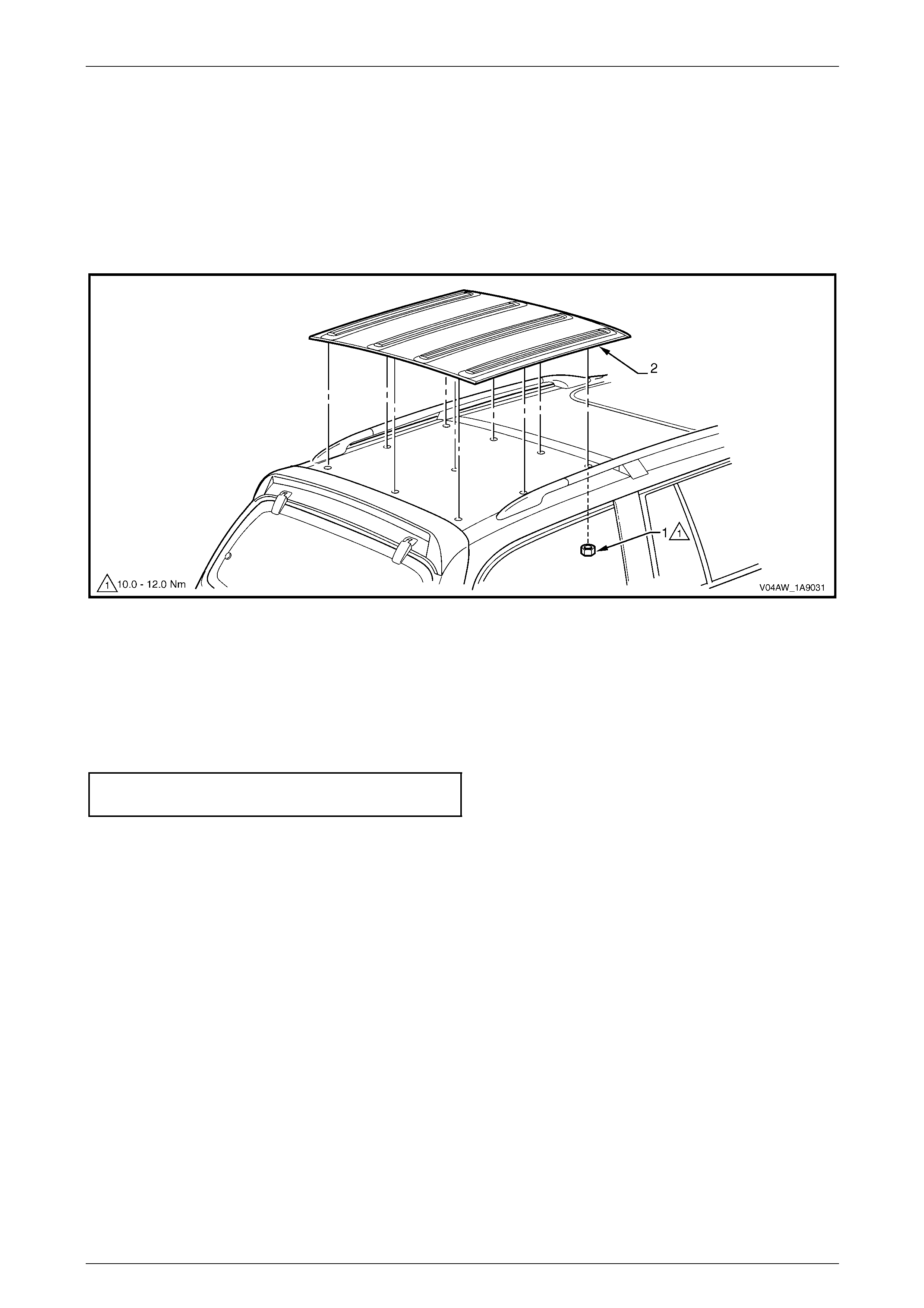
Exterior Ornamentation Page 1A9-103
Page 1A9-103
4.7 Luggage Carrier
Remove
1 Remove the headlining, refer to Section 1A8 Headlining and Interior Trim.
2 Remove nut (1), 10 places, from inside the vehicle, refer to Figure 1A9 – 94.
3 With the aid of an assistant, carefully lift the luggage carrier (2) off the vehicle.
Figure 1A9 – 94
Reinstall
Reinstallation of the luggage carrier is the reverse of the removal procedure, noting the following:
1 Ensure the foam seals are not damaged and is correctly seated and the O-ring seals are fitted to each of the studs.
2 Tighten the nuts to the correct torque specification.
Luggage carrier attaching n ut
torque specification.................................10.0 – 12.0 Nm
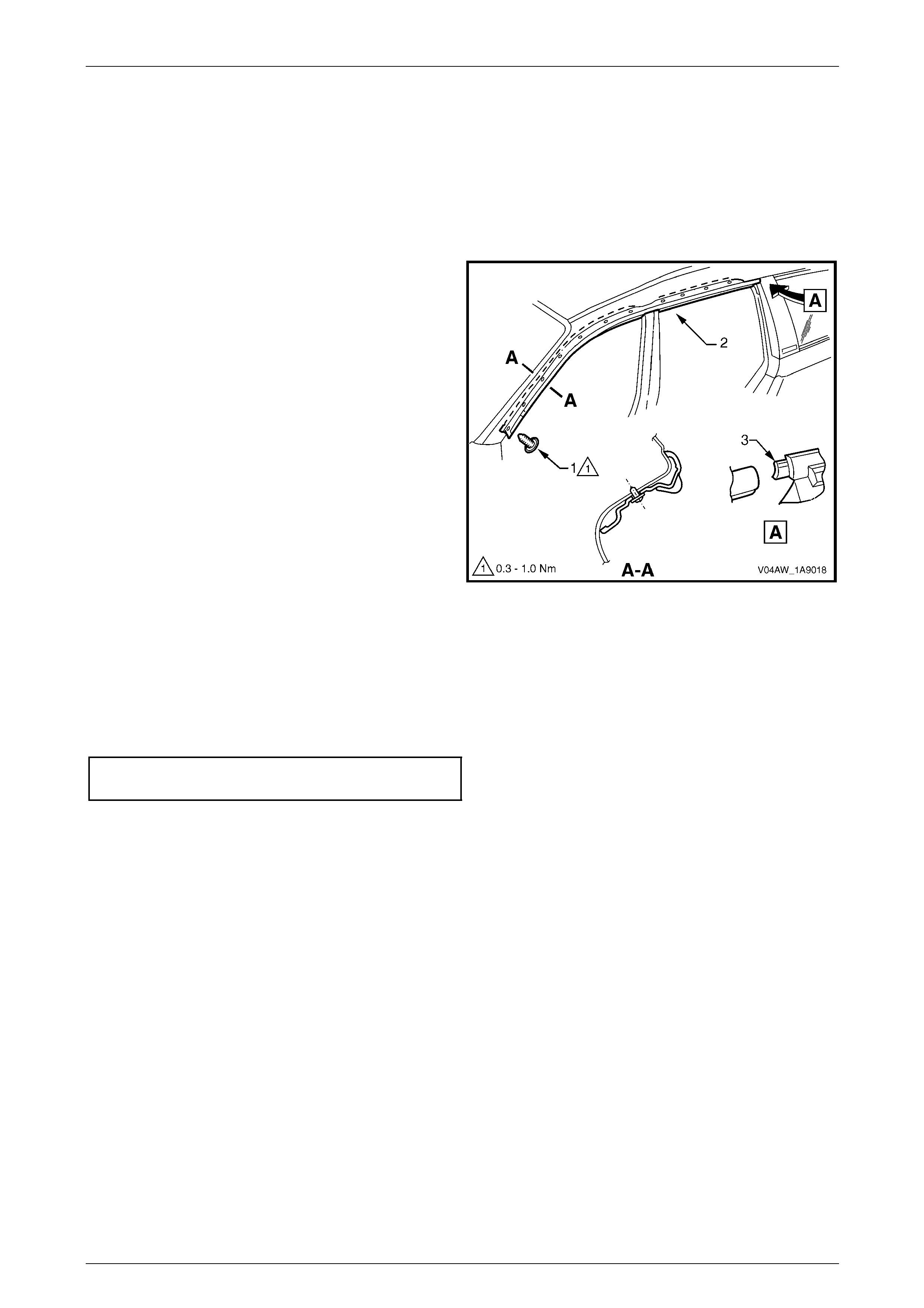
Exterior Ornamentation Page 1A9-104
Page 1A9-104
4.8 Door Opening Moulding
LT Section No. — 10–250
Remove
1 Open the front and rear doors on the relevant side of the vehicle.
2 Beginning at each end and working towards the
middle, remove the screw (1), 11 places, att achi ng the
door opening moulding (2) to the bod y.
3 Carefully remove the moulding, disengaging the
quarter window assembly tab (3).
Figure 1A9 – 95
Reinstall
Reinstallation of the door opening moulding is the reverse of the removal procedure, noting the following:
1 When installing the screws, begin at the rear and work forward.
2 Tighten the screws to the correct torque specification.
Door opening moulding attaching
screw torque specification...........................0.3 – 1.0 Nm
NOTE
The screws are encapsulated with a wax sealer.
It is recommended the screws be replaced once
removed, however if this is impractical, apply a
small amount of sealer to the end of the thread.
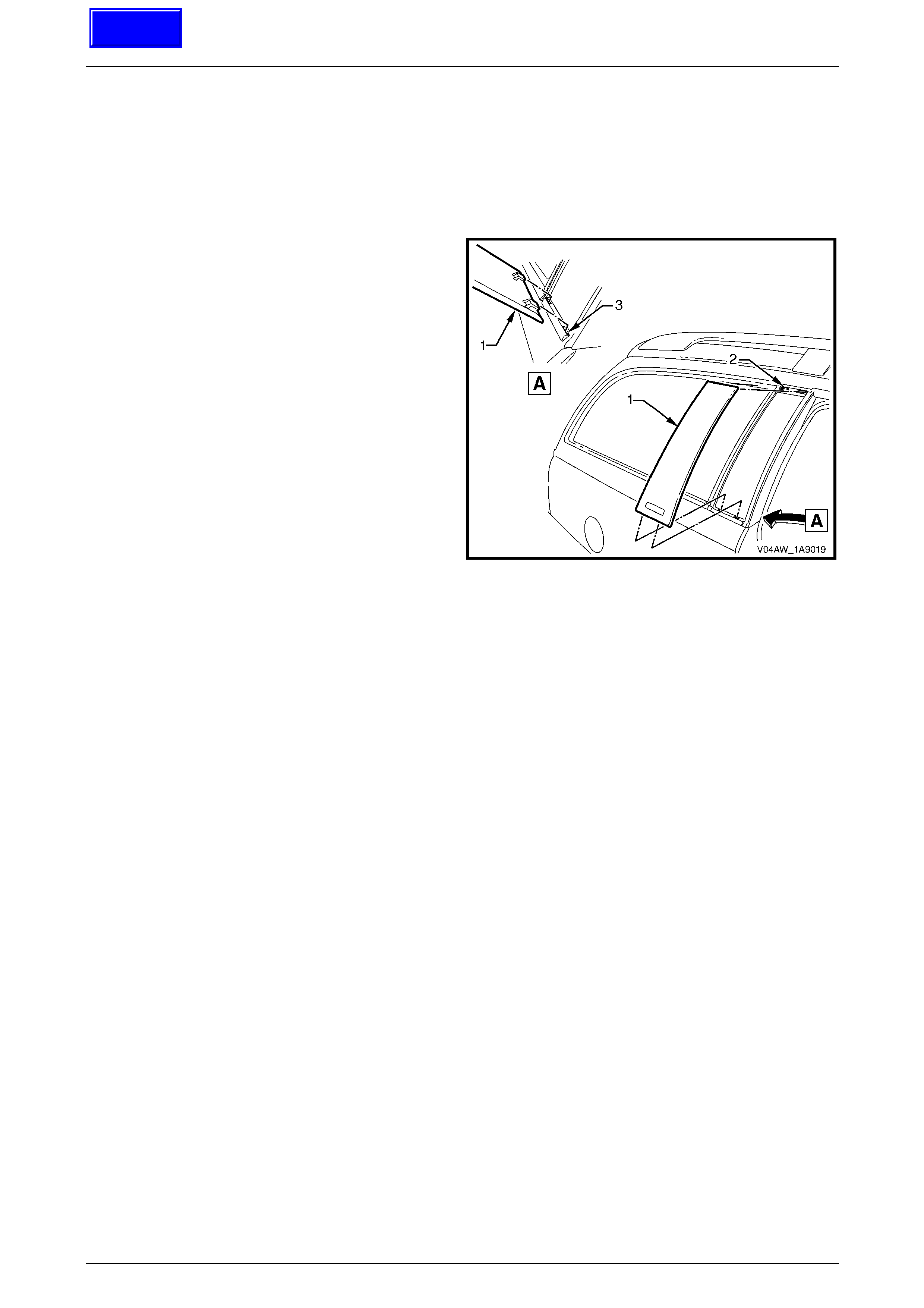
Exterior Ornamentation Page 1A9-105
Page 1A9-105
4.9 Rear Quarter Window Appliqué
Assembly
Remove
1 Open the rear door on relevant side of the vehicle.
2 Gently prise top of rear quarter windo w appliqu é
assembly (1) out to disengage it from the rear quarter
window assembly (2).
3 Holding the top of appliqué out, slide it up the out of
the holes in the moulding (3).
Figure 1A9 – 96
Reinstall
Reinstallation of the rear quarter window appliqué assembly is the reverse of the removal procedure.
Techline
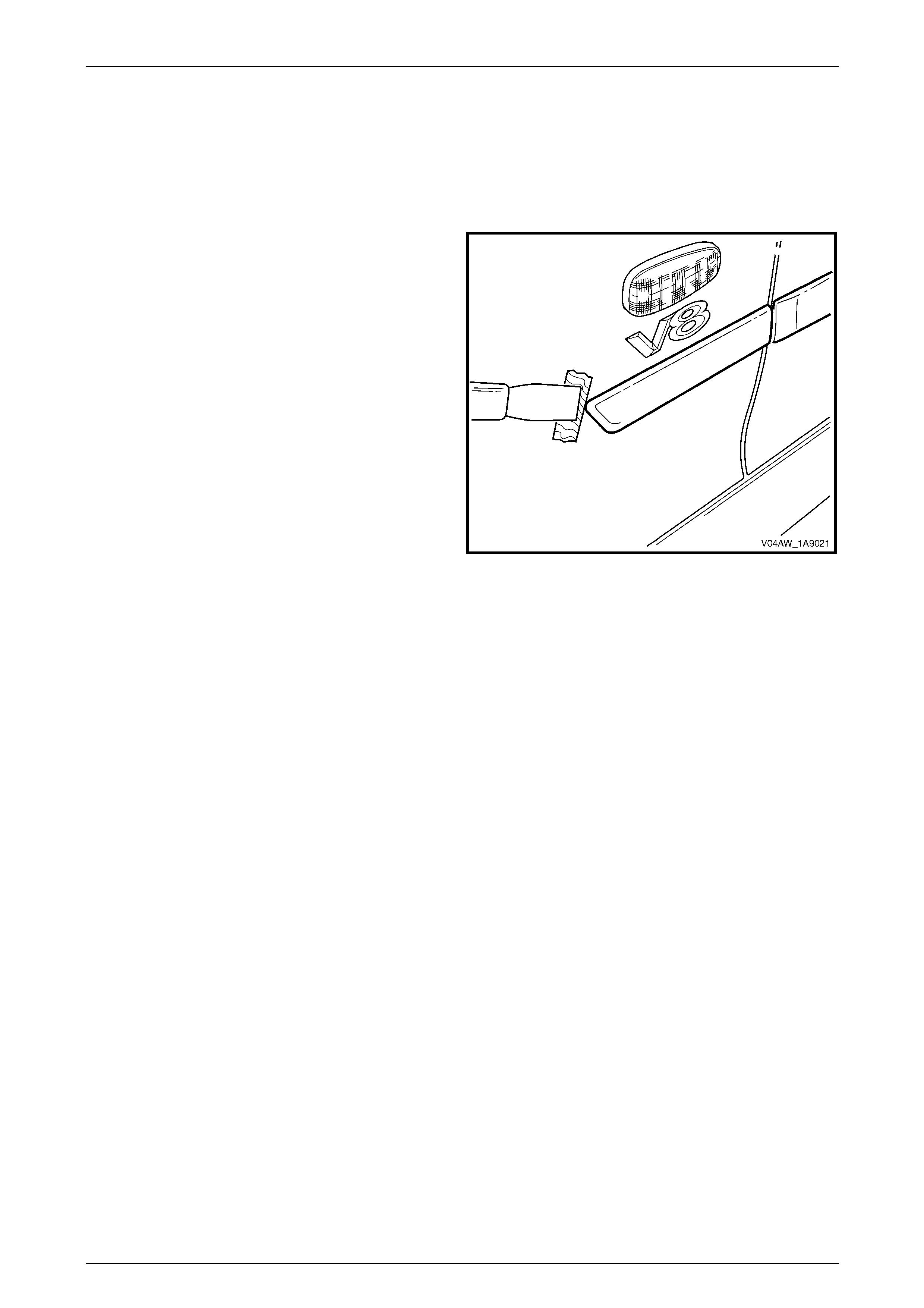
Exterior Ornamentation Page 1A9-106
Page 1A9-106
4.10 Body Side Mouldings
LT Section No. — 10–250
Remove
1 Protect the paint and bodywork with tape or a clean
rag.
2 Using a paint scraper or similar, begin at one end and
carefully prise the moulding from the panel, cutting
through the double-sided tape and adhesive.
NOTE
As an alternative, carefully use a l ength of piano
wire to cut the adhesive in a similar way to
removing a windshield. If required, refer to
Section 1A6 Stationary Windows.
3 As required, remove any remaining double-sided tape
and adhesive from the moulding and/or panel. Clean
the surfaces with Prepsol or equivalent.
Figure 1A9 – 97
Reinstall
1 Place a mark on the rear edge of the fender and/or door panels at the three points, refer to Figure 1A9 – 98.
2 If a complete moulding set is to be fitted, or as required, apply a length of masking tape along the side of the
vehicle, aligning the top edge of the tape with the marks. Begin by affixing the tape at the rear of the rear door, ho ld
it taut and away from the vehicle, and affix it to each panel. Ensure it is straight and then smooth it down along its
length.
3 If reusing the moulding, apply new acrylic double-sided tape (1) such as 3M 5344 along the back of the moulding.
4 Apply two 3.0 mm diameter beads of urethane adhesive su ch as Expandite Betaseal 554.02, Sikaflex Drive or
equivalent over the entire length of moulding (2) and (3), refer to Section A -A.
NOTE
Refer to any further directions supplied with the
urethane adhesive.
5 Affix the moulding to the vehicle in the correct positions, aligning the lower edge with the masking tape (if fitted).
• For the fender moulding begin at the rear edge, aligning to the dimension at Section B-B.
• For the front door mouldi ng begin at the front edge of the front door, aligning to the dim ension at Section B-B.
• For the rear door moul ding begin at the front edge of the rear door, aligni ng to the dimension at Section C-C.
• For the quarter panel moulding begin at the front edge of the quarter p an el, aligning to the dimension at
Section D-D.
6 Press firmly over the length of the mouldin g(s) at the double-sided tape for 10 seconds to ensure soun d adhesion.
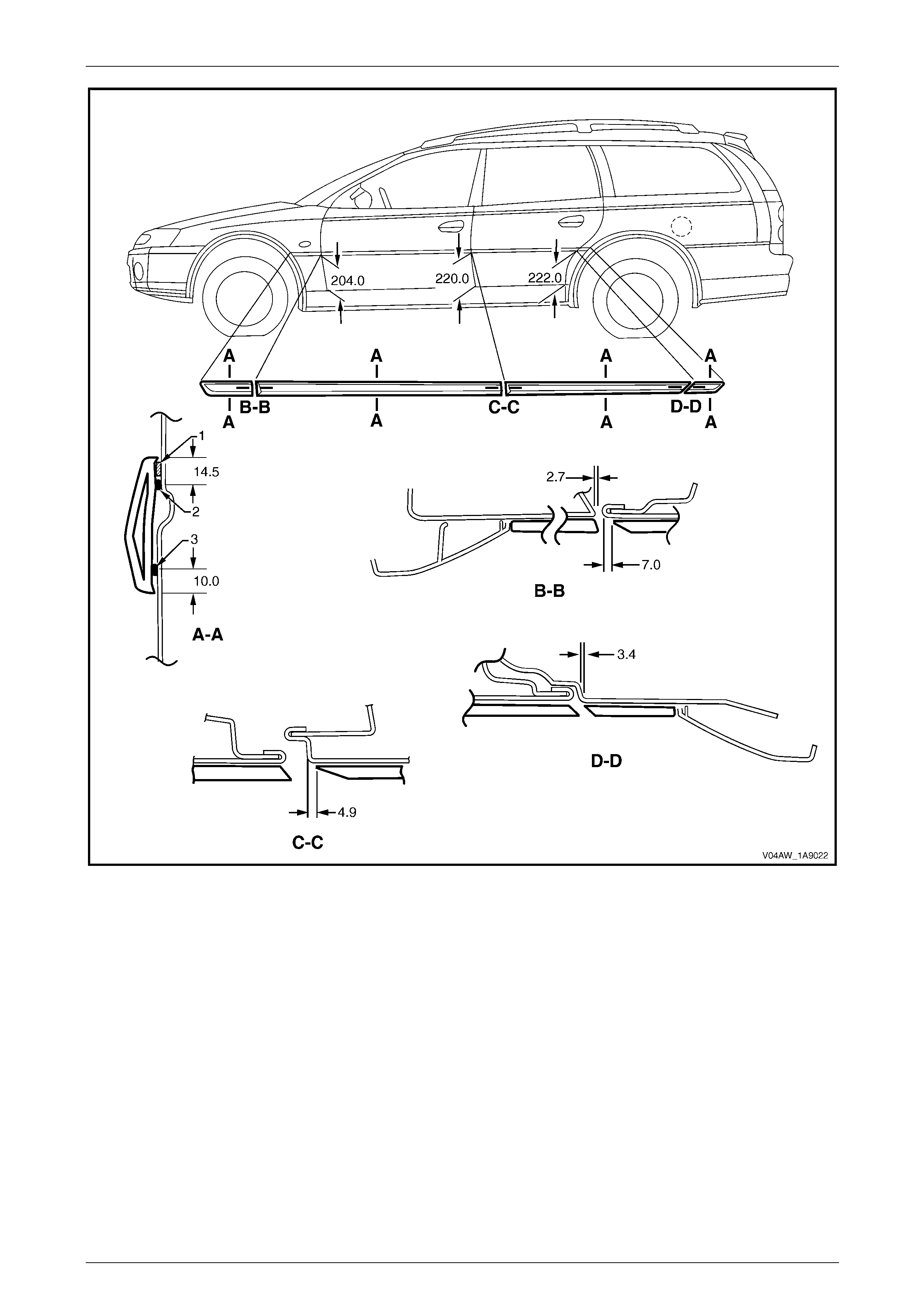
Exterior Ornamentation Page 1A9-107
Page 1A9-107
Figure 1A9 – 98
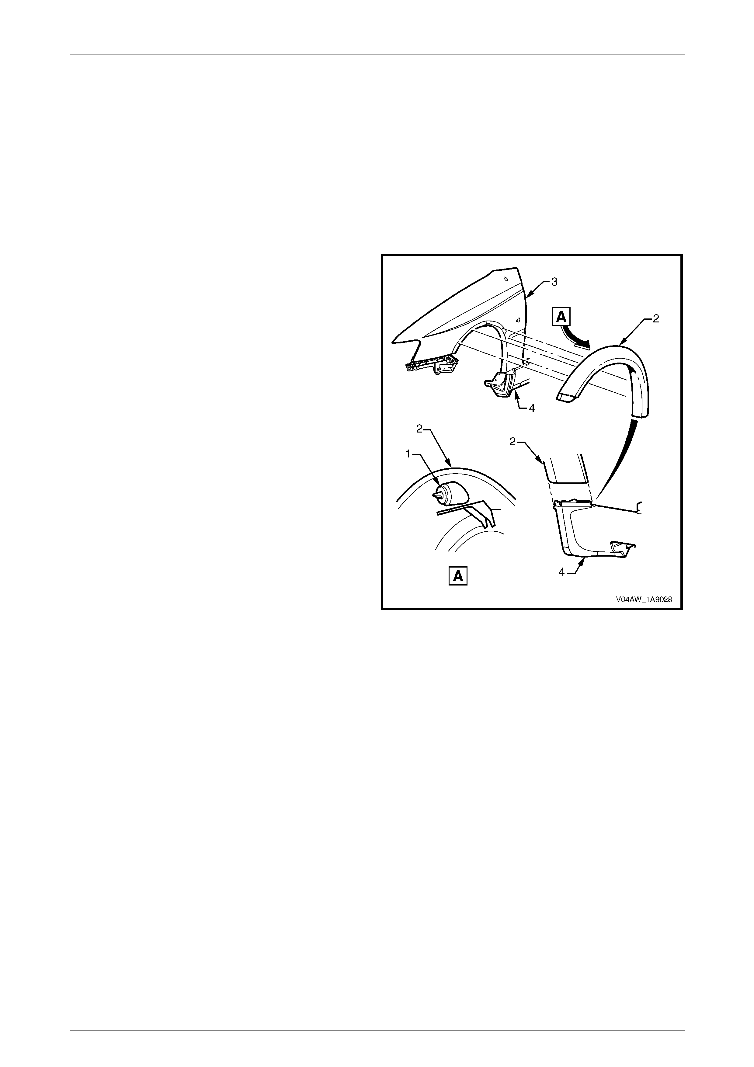
Exterior Ornamentation Page 1A9-108
Page 1A9-108
4.11 Wheelhouse Opening Flare Assembly
Front
Remove
1 Remove the following components:
a Front corner of the front bumper fascia, refer to Section 1D Bumper Bars.
b Front wheelhouse liner, refer to Section 1A1 Body.
2 From behind the fender squeeze the clip (1), six
places, and pull the wheelhouse opening flare (2)
away from the fender (3), working from the front to the
back of the vehicle.
3 Lift the flare away from the rocker panel (4).
Figure 1A9 – 99
Reinstall
1 Ensure the flare assembly is seated correctly in the front bumper fascia guide and the rocker panel skirt.
2 Push the flare assembly towards the quarter panel. Ensure all the retainers are engag ed correctly.
3 Reinstall the wheelhouse liner, refer to Section 1A1 Body.
4 Reinstall the front bumper fascia, refer to Section 1D Bumper Bars.
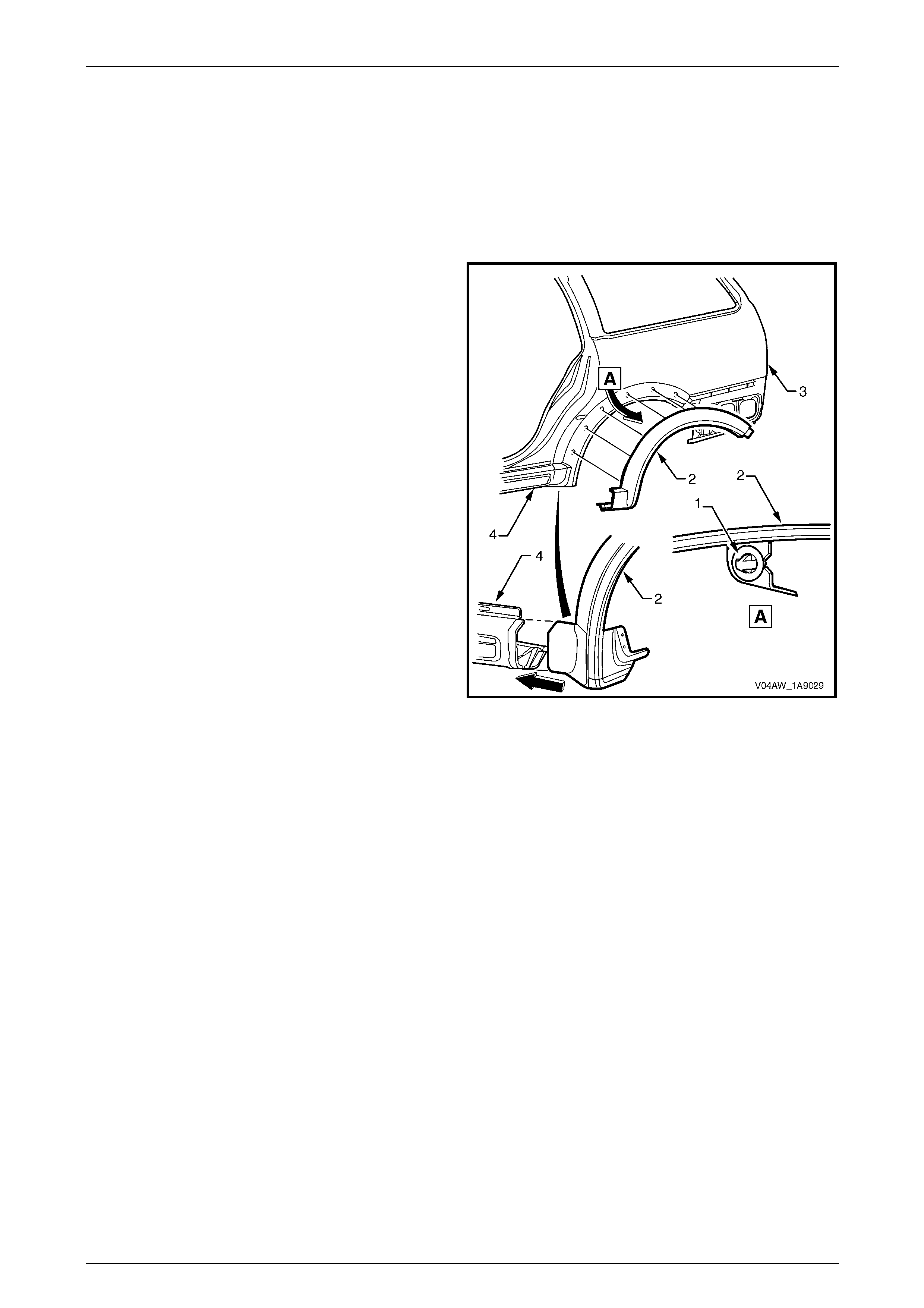
Exterior Ornamentation Page 1A9-109
Page 1A9-109
Rear
Remove
1 Remove the following components:
a Front corner of the rear bumper fascia, refer to Section 1D Bumper Bars.
b Rear wheelhouse liner, refer to Section 1A1 Body.
2 From inside the wheelhouse squeeze the clip (1), six
places, and pull the wheelhouse opening flare (2)
away from the fender (3), working from the back to the
front of the vehicle.
3 Lift the flare away from the rocker panel moulding
assembly (4).
Figure 1A9 – 100
Reinstall
1 Ensure the flare assembly is seated correctly in the rear bumper fascia guide and the rocker panel.
2 Push the flare assembly towards the fender. Ensure all the retainers are engaged correctly.
3 Reinstall the wheelhouse liner, refer to Section 1A1 Body.
4 Reinstall the rear bumper fascia, refer to Section 1D Bumper Bars.
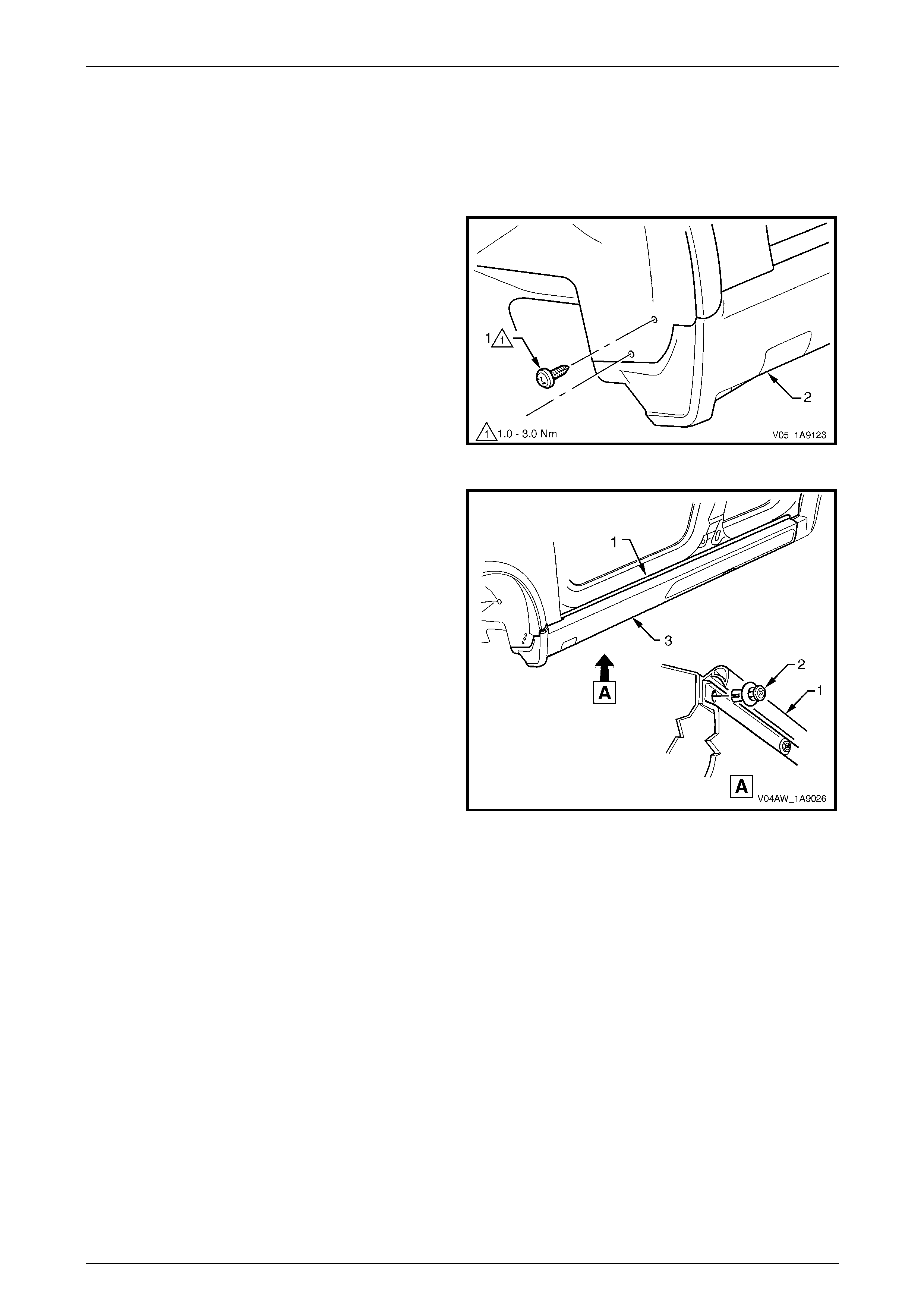
Exterior Ornamentation Page 1A9-110
Page 1A9-110
4.12 Rocker Panel Moulding Assembly
Remove
1 Turn the front wheels to full steering lock to ward the re levant side.
2 Remove the screw (1), two places, attaching the front
rocker panel moulding (2) to the fender and liner.
Figure 1A9 – 101
3 Lift up the rocker panel weatherstrip (1) as shown in
View A to gain access and remove the retainer (2),
nine places, attaching the rocker panel moulding (3) to
the vehicle body.
NOTE
If the retainers are difficult to remove, prise out
the centre section a small amount with a flat
bladed screwdriver, then continue to unscrew. It
may also be necessary to retain the outer
section of the retainer with fingers or pliers.
4 Referring to Figure 1A9 – 103, from underneath the
vehicle, remove the screw (1), seven places, from the
retainer (2) under the moulding (3).
5 Remove the moulding.
6 If required, prise the nut (4), two places, from the
fender. Figure 1A9 – 102
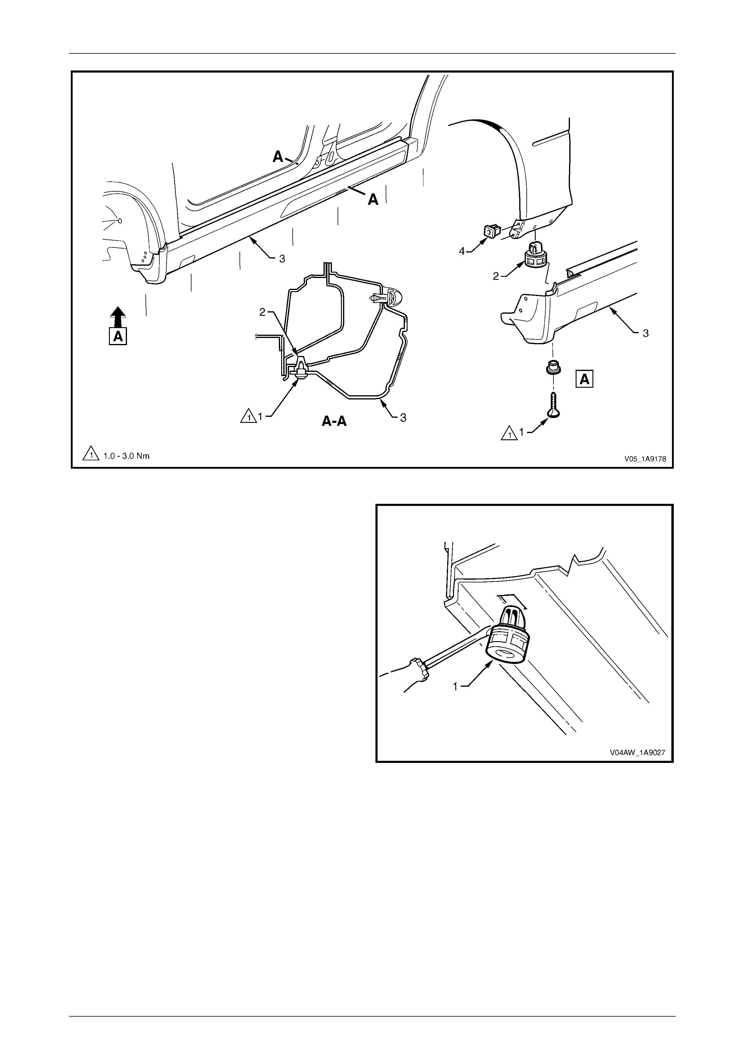
Exterior Ornamentation Page 1A9-111
Page 1A9-111
Figure 1A9 – 103
7 If required, remove the retainer (1), seven places, by
gently levering out from the body, taking care not to
damage the paint work.
Figure 1A9 – 104
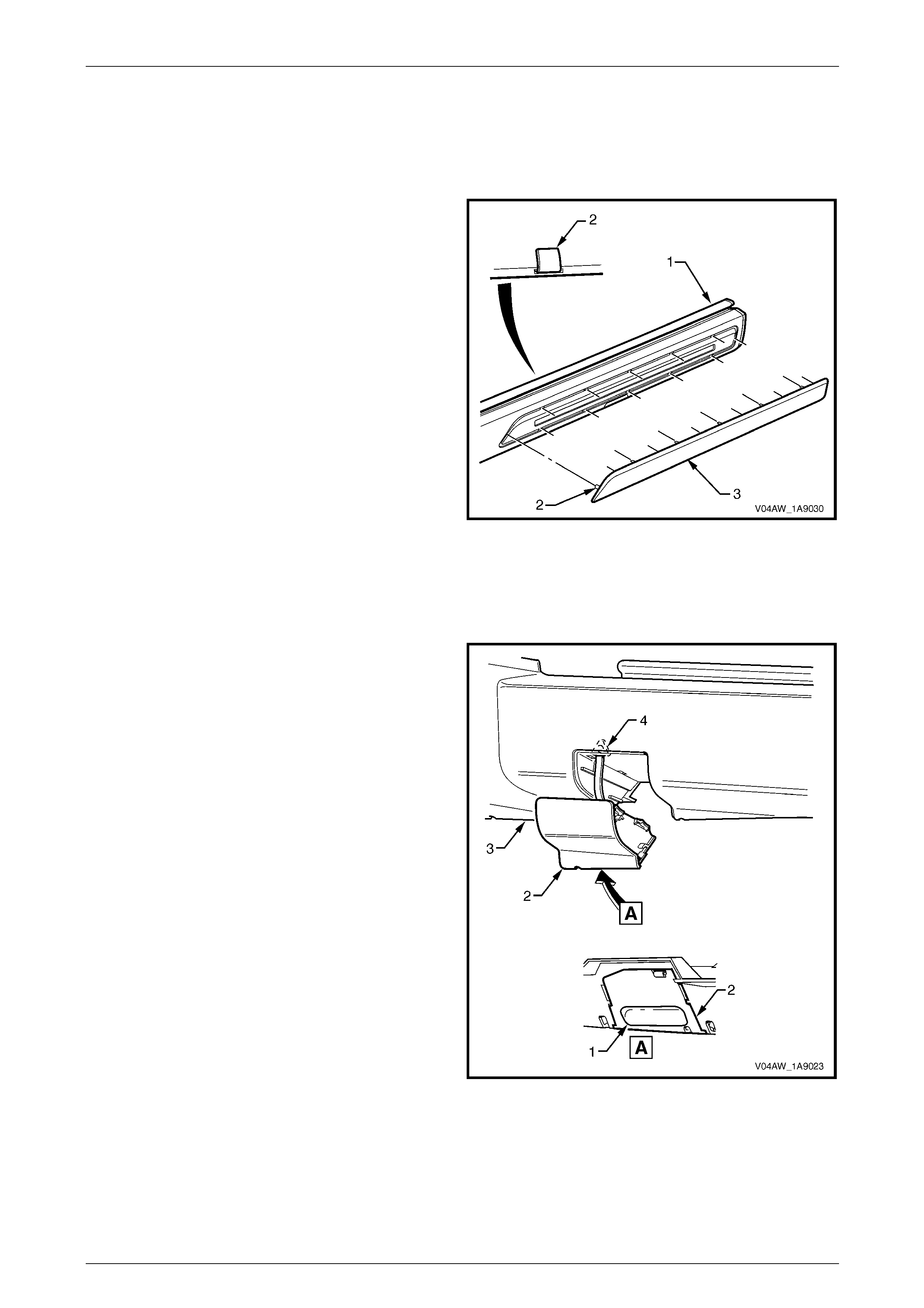
Exterior Ornamentation Page 1A9-112
Page 1A9-112
Disassemble
Rocker Panel Moulding Front Insert
Remove
1 From the inside of the rocker panel moulding (1) lift the
tab (2), 12 places, attaching the front insert (3).
2 Remove the insert from the moulding.
Reinstall
1 Reinstall the insert to the rocker panel moulding
ensuring that all the tabs fit into the correspondi ng
slots.
2 Fold the tabs over to secure the insert to the rocker
panel moulding.
Figure 1A9 – 105
Jacking Access Cover
Remove
1 Holding with fingers in the indent (1) on the back of the
jacking access cover (2) pull out and a way from the
rocker panel moulding (3) to remove.
2 If required, un-attach the tether (4).
Reinstall
Reinstallation of the jacking access cover is the reverse of
the removal procedure.
Figure 1A9 – 106

Exterior Ornamentation Page 1A9-113
Page 1A9-113
Reinstall
Reinstallation of the rocker panel moulding assembly is the reverse of the removal procedure, noting the following:
1 Ensure the moulding is correctly seated in the retaining clips.
2 Tighten the screws to the correct torque specification.
Rocker panel moulding attac hin g
screw torque specification...........................1.0 – 3.0 Nm
3 Ensure the weatherstrip is seated correctly.
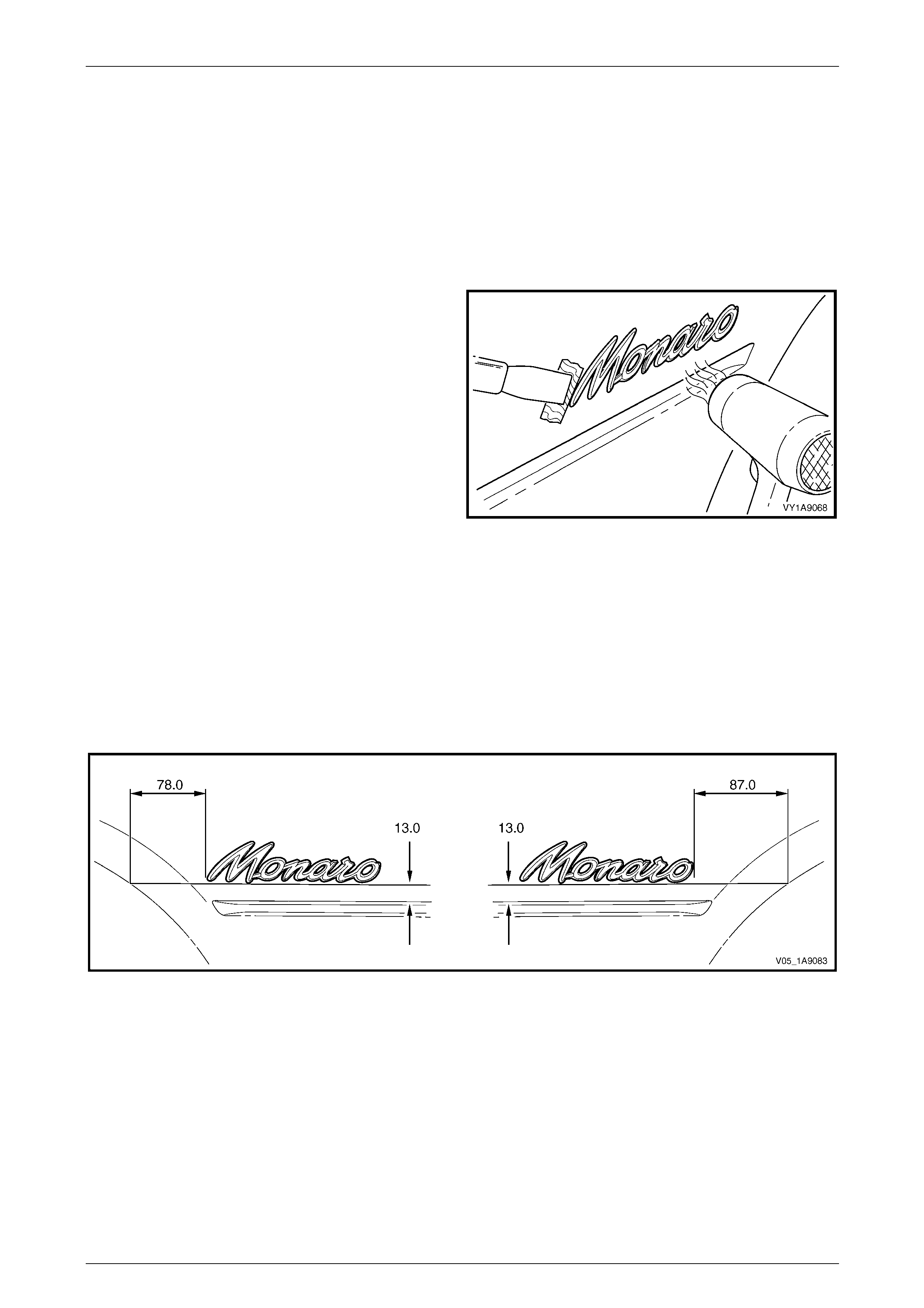
Exterior Ornamentation Page 1A9-114
Page 1A9-114
5 Service Operations, Coupe
5.1 Quarter Panel Name Plate
LT Section No. — 10–150
Remove
1 Protect the paint and bodywork with tape or a clean
rag.
2 To assist removal, warm the name plate with a heat-
lamp or heat-gun to soften the adhesiv e.
3 Using a paint scraper or similar, carefully prise the
name plate from the quarter panel.
4 As required, remove any remaining double-sided tape
from the name plate and/or quarter pan el and clean
the surfaces with Prepsol or equivalent.
Figure 1A9 – 107
Reinstall
1 If reusing the name plate, apply new polyethylene double-sided tape such as 3M 4428 or equivalent to the back of
the name plate. Trim back the tape slightly away from the edge of the name plate.
2 Clean the quarter panel surface with Prepsol or equivale nt.
3 Remove the backing paper from the double-sided tape.
4 Apply the name plate in the position shown ensuring it is straight and is aligned correctly, measuring fro m the body
styling line and wheelarch, refer to Figure 1A9 – 108.
Figure 1A9 – 108
5 Press firmly over the entire name plate for at least 10 sec onds to ensure sound adhesion.
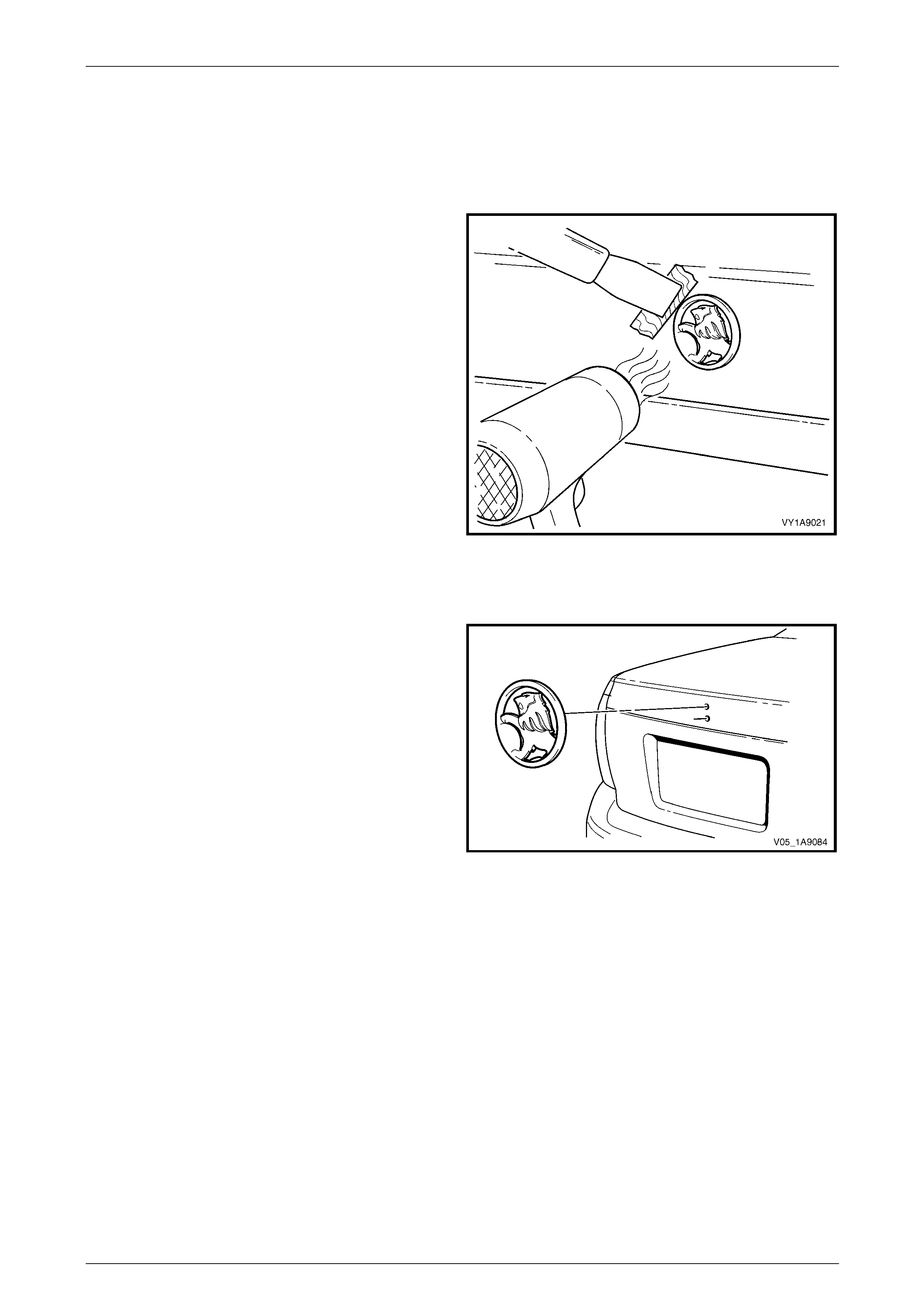
Exterior Ornamentation Page 1A9-115
Page 1A9-115
5.2 Rear Compartment Lid Emblem
LT Section No. — 10–150
Remove
1 Protect the paint and bodywork with tape or a clean
rag.
2 To assist removal, warm the emblem with a heat-lamp
or heat-gun to soften the adhesive.
3 Using a paint scraper or similar, carefully prise the
emblem from the rear compartment lid.
NOTE
The emblem has two locatin g pins, take care not
to break them if the emblem is to be reused.
4 As required, remove any remaining double-sided tape
from the emblem and/or rear compartment lid and
clean the surfaces with Prepsol or equiva lent.
Figure 1A9 – 109
Reinstall
1 If reusing the emblem, apply new polyethylene double-
sided tape such as 3M 4428 or equ ivalent to the back
of the emblem. Trim back the tape slightly away from
the edge of the emblem.
2 Clean the panel surface with Prepsol or equivalent.
3 Remove the backing paper from the double-sided
tape.
4 Apply the emblem in the position shown ensuring the
locating pins are correctly orientated with the locating
holes in the panel surface.
5 Press firmly over the entire emblem for at least 10
seconds to ensure sound adhesion. Figure 1A9 – 110
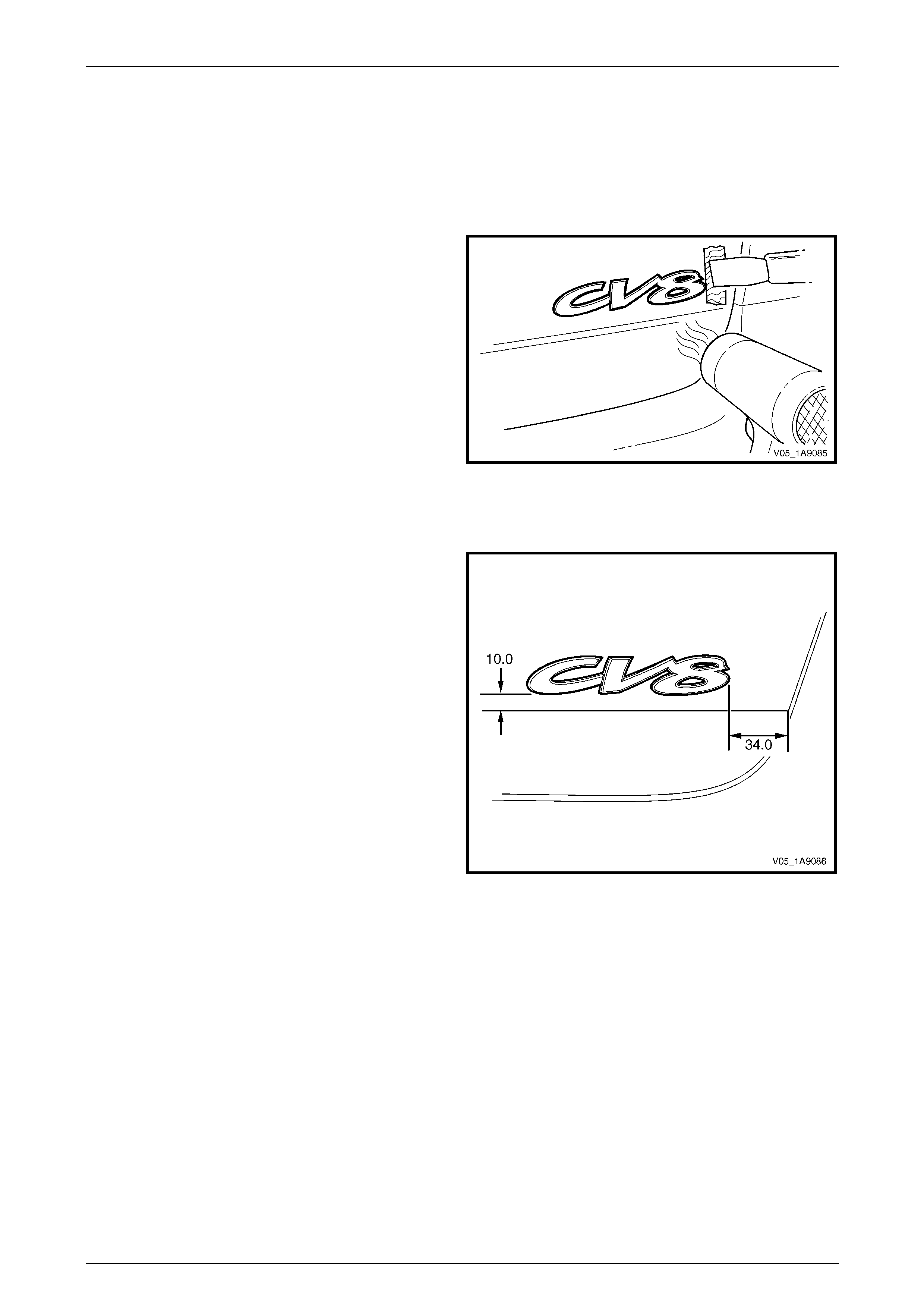
Exterior Ornamentation Page 1A9-116
Page 1A9-116
5.3 Rear Compartment Lid Name Plate,
Right-hand
LT Section No. — 10–150
Remove
1 Protect the paint and bodywork with tape or a clean
rag.
2 To assist removal, warm the emblem with a heat-lamp
or heat-gun to soften the adhesive.
3 Using a paint scraper or similar, carefully prise the
emblem from the rear compartment lid.
4 As required, remove any remaining double-sided tape
from the emblem and/or rear compartment lid and
clean the surfaces with Prepsol or equiva lent.
Figure 1A9 – 111
Reinstall
1 If reusing the name plate, apply new polyethylene
double-sided tape such as 3 M 4428 or equivalent to
the back of the name plate. Trim back the tape slightly
away from the edge of the name plate.
2 Clean the panel surface with Prepsol or equivalent.
3 Remove the backing paper from the double-sided
tape.
4 Apply the name plate onto the right-hand side of the
rear compartment lid in the position sho wn, ensuring it
is straight and is correctly aligned to the
measurements.
5 Press firmly over the entire name plate for at least 10
seconds to ensure sound adhesion.
Figure 1A9 – 112
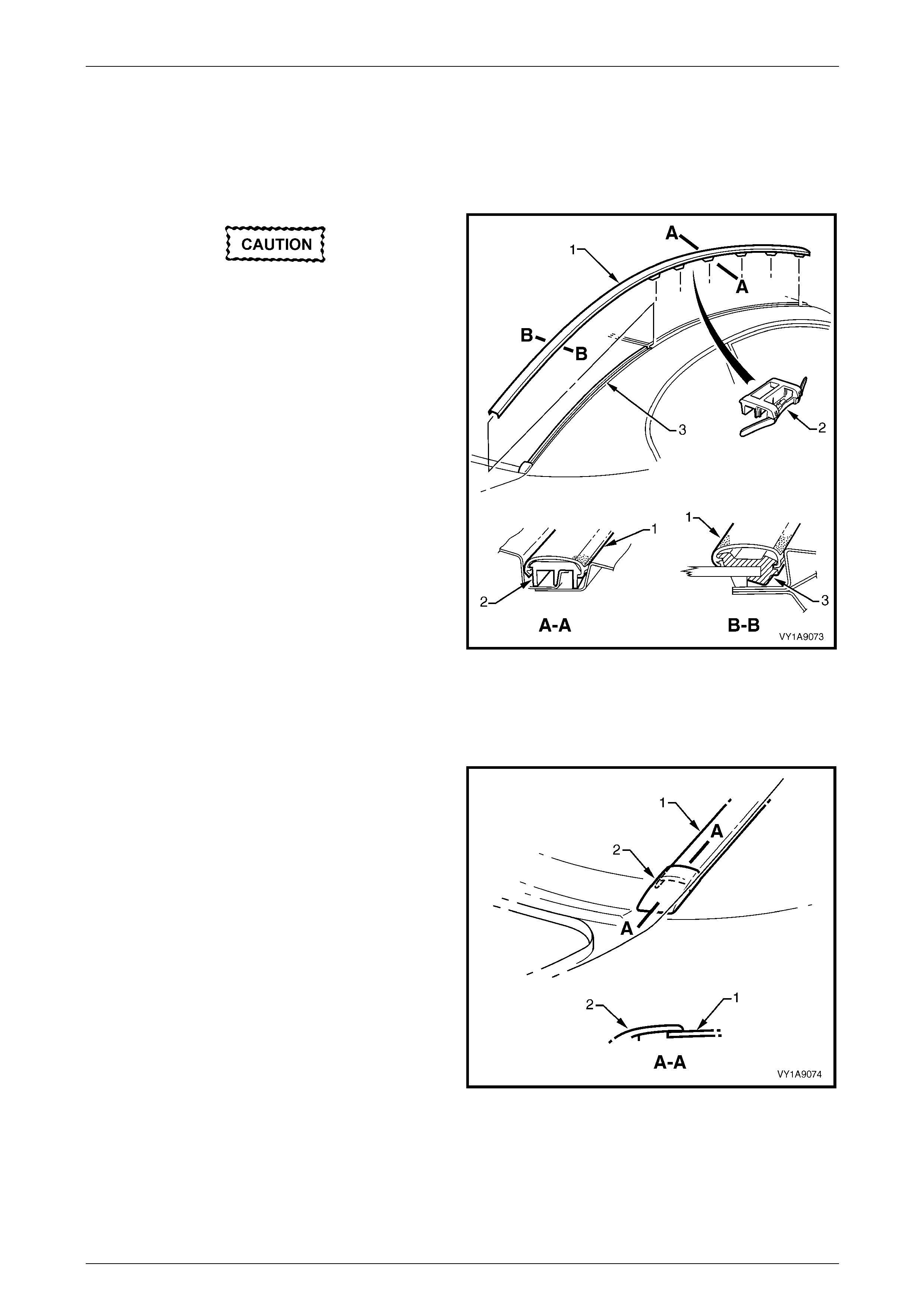
Exterior Ornamentation Page 1A9-117
Page 1A9-117
5.4 Roof Joint Moulding
LT Section No. — 10–250
Remove
Take care as the retaining clips can easily
break. Protect the paintwork with a clean rag.
1 Beginning at the front of the vehicle, use a screwdriver
to carefully prise the roof joi nt moul ding (1) from the
roof channel, disengaging retaining clip (2), six places.
2 Slide the joint moulding from the rear window side
moulding retainer (3) and remove.
Figure 1A9 – 113
Reinstall
1 As required, seat evenly the six retainers onto the roof joint moulding.
2 Engage the roof joint moulding (1) onto the rear
window side mouldin g retainer and slide it along until
the roof joint moulding sits under the endcap (2).
3 Seat the roof joint moulding in the roof channel and
beginning at the rear, clip it in place.
4 At the front, ensure the moulding is installed under the
windshield moulding cover.
Figure 1A9 – 114
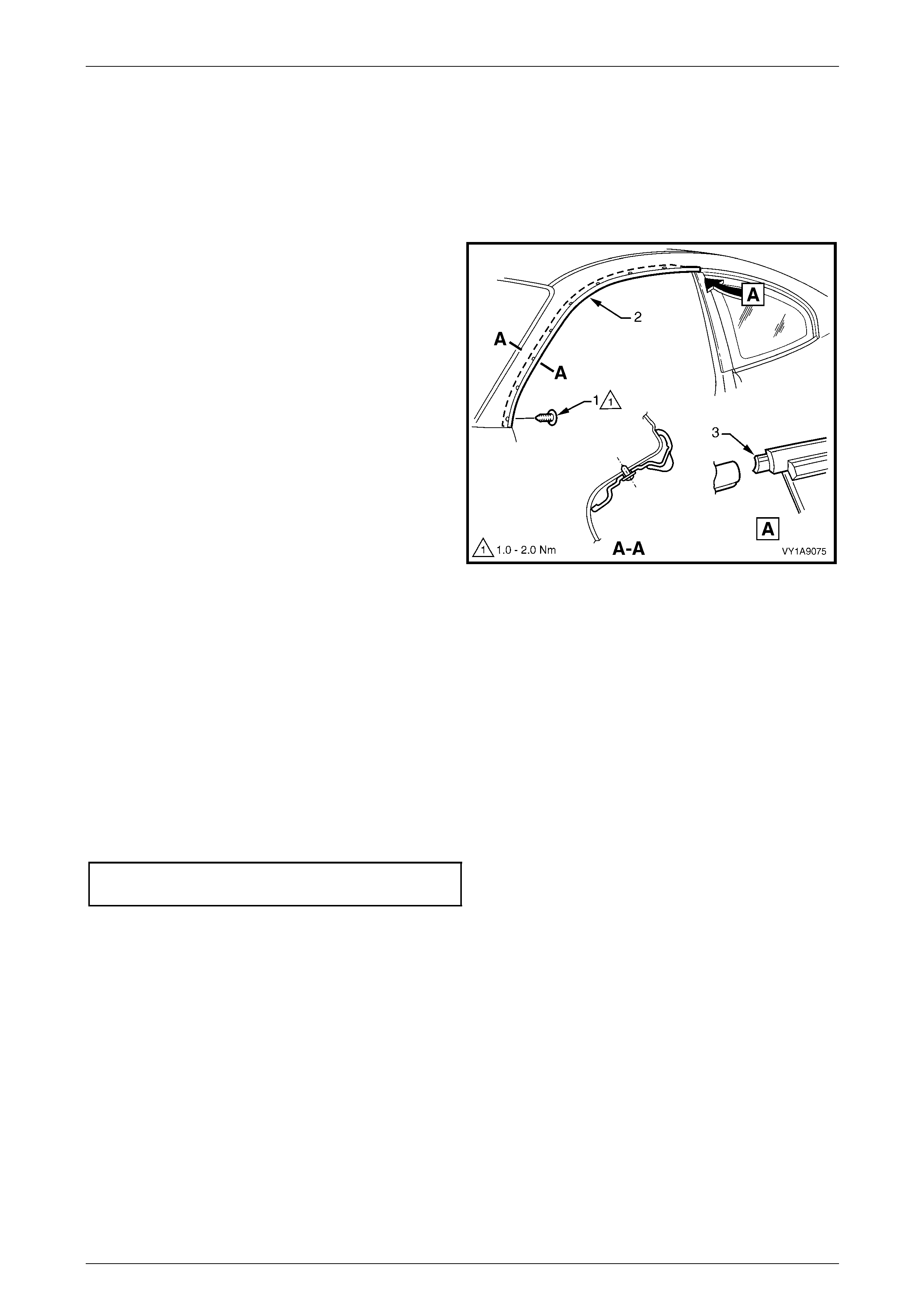
Exterior Ornamentation Page 1A9-118
Page 1A9-118
5.5 Door Opening Moulding
LT Section No. — 10–250
Remove
1 Open the door on the relevant side of the vehicle.
2 Beginning at each end and working towards the
middle, remove the screw (1), eight places, attaching
the door opening moulding (2 ) to the vehicle.
3 Carefully remove the moulding, disengaging the
quarter window assembly tab (3).
Figure 1A9 – 115
Reinstall
Reinstallation of the door opening moulding is the reverse of the removal procedure, noting the following:
1 Install the screws by beginnin g at the rear and working forward.
NOTE
The screws are encapsulated with a wax sealer.
It is recommended the screws be replaced once
removed, however if this is impractical, apply a
small amount of sealer to the end of the thread.
2 Tighten the screws to the correct torque specification.
Door opening moulding attaching
screw torque specification...........................1.0 – 2.0 Nm
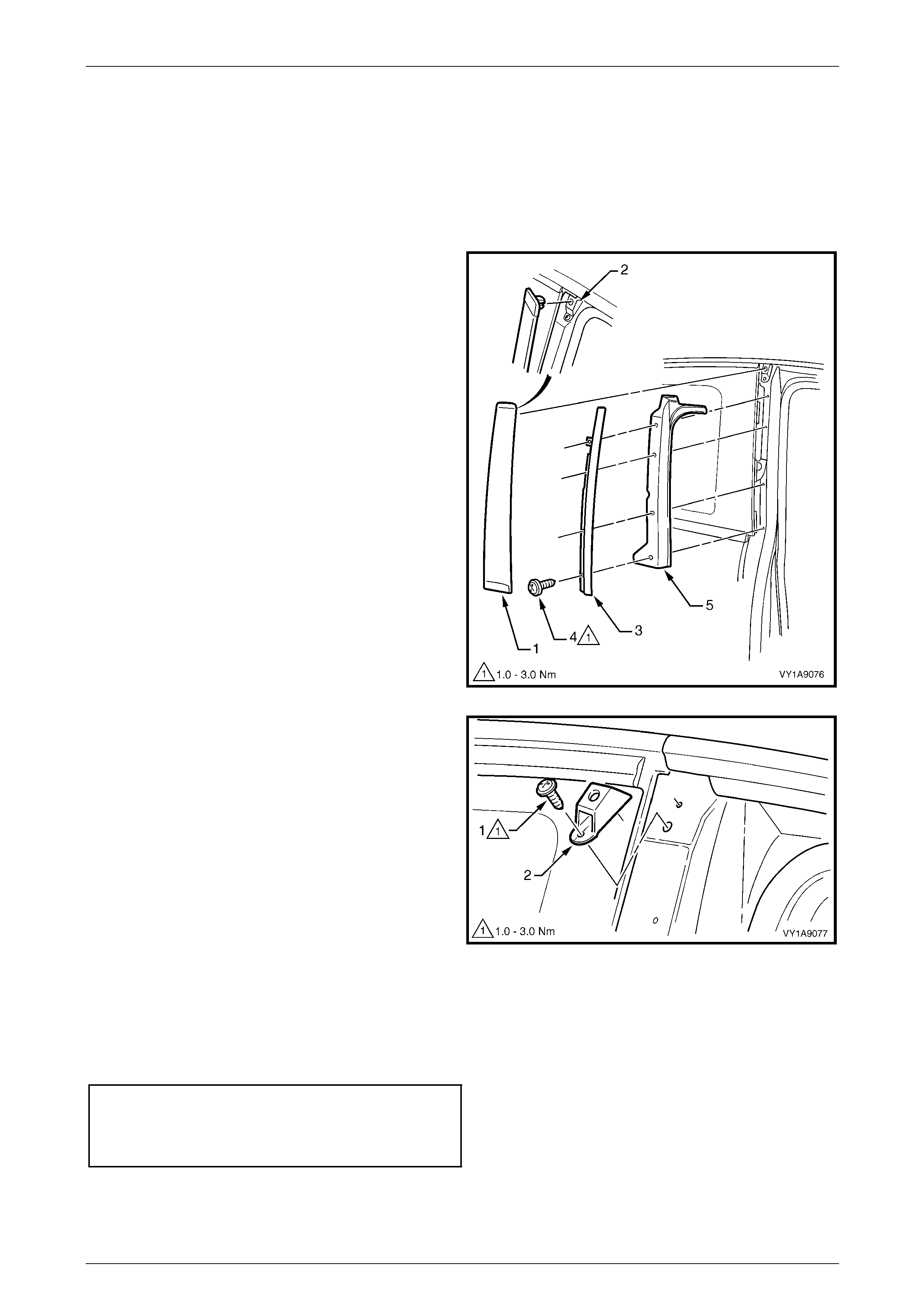
Exterior Ornamentation Page 1A9-119
Page 1A9-119
5.6 Centre Pillar Upper Finisher Assembly
LT Section No. — 10–250
Remove
1 Open the door on the relevant side of the vehicle.
2 Gently prise the top of the centre pillar upper finisher
(1) out to disengage it from the centre pillar upper
finisher retainer (2).
3 Holding the top of finisher out, slide it up the centre
pillar outer sealing strip (3).
4 Manoeuvre the rear edge and then the front edge of
the finisher from the sealing strip and remove.
5 Remove the screw (4), four places, attaching the
centre pillar sealing strip to the pillar and remove the
strip.
6 Remove the centre pillar upper trim panel (5) by
pulling away from the pillar.
Figure 1A9 – 116
7 Remove the screw (1), attaching the centre pillar
upper finisher retainer (2).
8 Carefully prise the retainer from under the quarter
window, noting to disengage the locating lug.
Figure 1A9 – 117
Reinstall
Reinstallation of the centre pillar upper finisher assembly is the reverse of the removal procedure, noting the following:
1 Ensure the centre pillar upper trim panel is seated correctly under the door openin g weatherstrip.
2 Tighten the screws and retainers to the correct torque specification.
Centre pillar upper finisher retainer
attaching screw torque specification...........1.0 – 3.0 Nm
Centre pillar sealing strip attac hin g
screw torque specification...........................1.0 – 3.0 Nm
3 Engage the front edge of the finisher into the sealing strip and then the rear edge into the window assembly.
4 Slide the centre pillar upper finisher down and press it in at the top to engage it into the retaining clip.
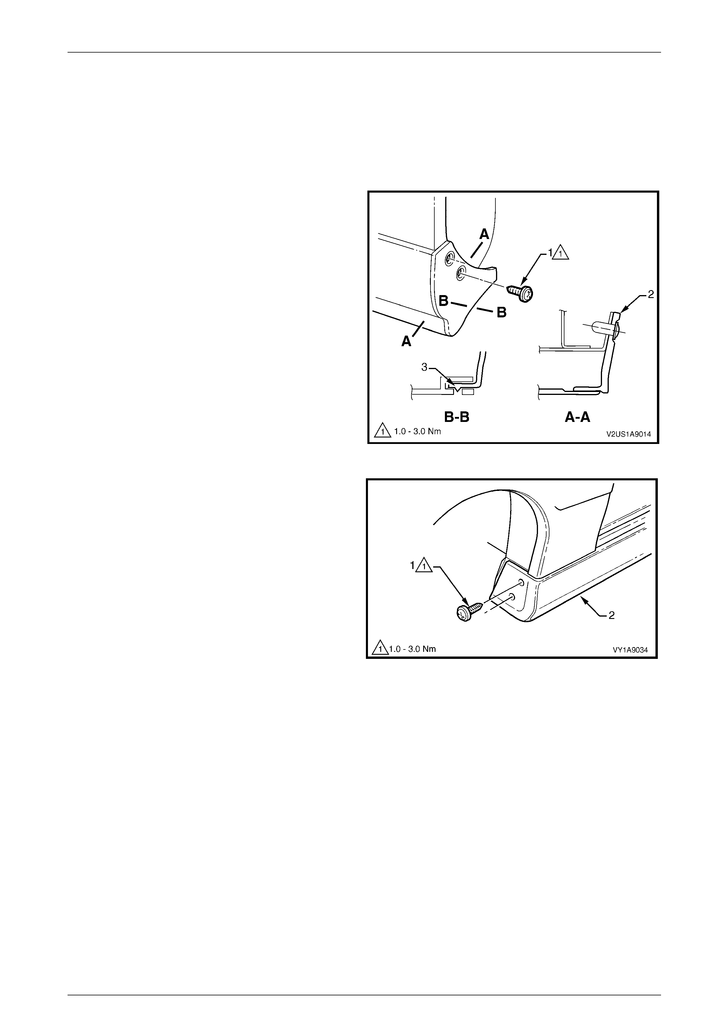
Exterior Ornamentation Page 1A9-120
Page 1A9-120
5.7 Rocker Panel Moulding Assembly
LT Section No. — 10–300
Remove
1 On the relevant side remove the rear road wheel, refer to Section 10 Wheels and T yres.
2 Remove the screw (1), two places, attaching the rear
rocker panel moulding (2) and wheelhouse liner (3).
NOTE
If required, the rear rocker panel moulding can
be removed at this stage by sliding it rearward
from the front rocker panel moulding.
Figure 1A9 – 118
3 Turn the front wheels to full steering lock to ward the
relevant side.
4 Remove the screw (1), two places, attaching the front
rocker panel moulding (2) to the fender and liner.
Figure 1A9 – 119
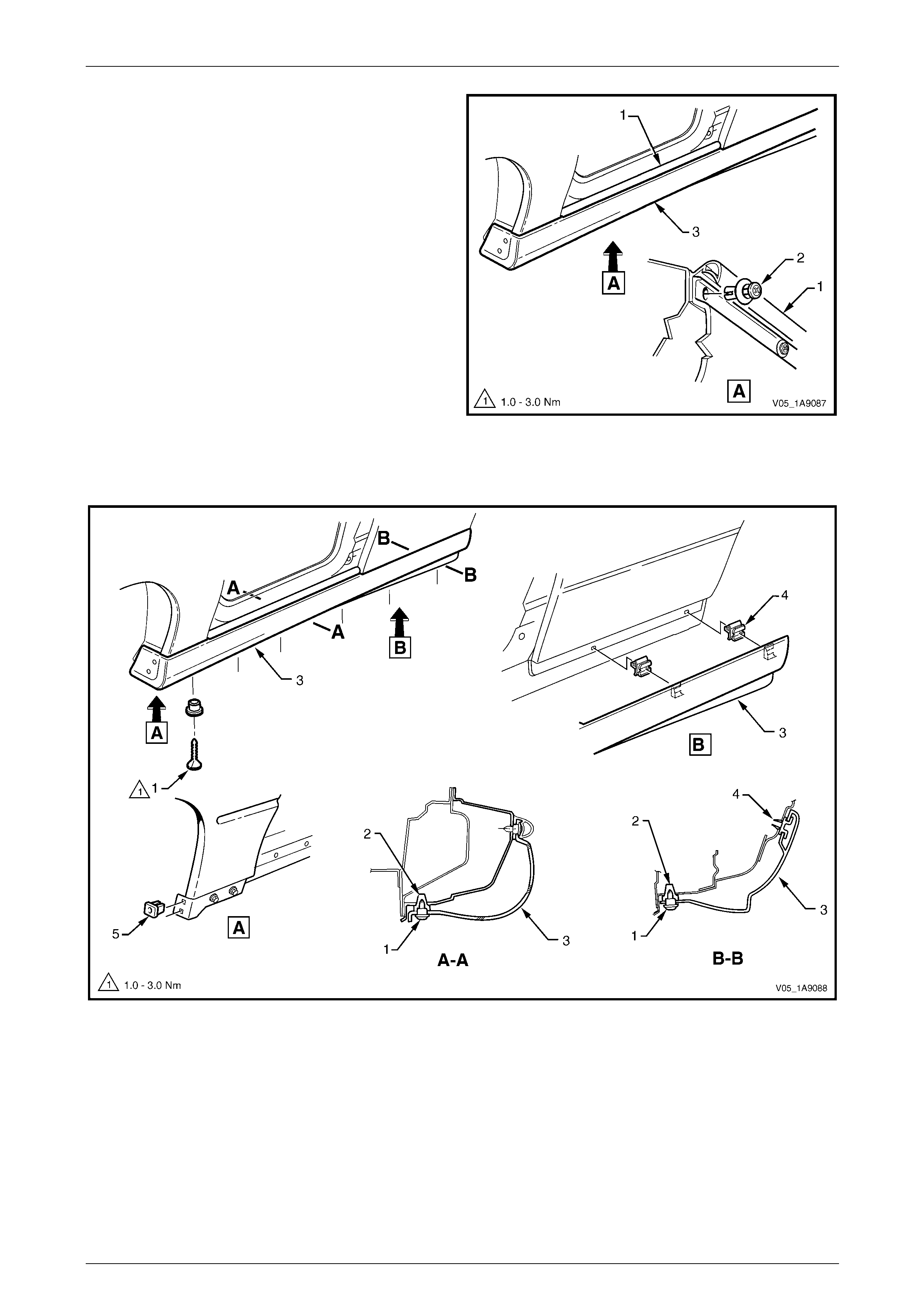
Exterior Ornamentation Page 1A9-121
Page 1A9-121
5 Lift up the rocker panel weatherstrip (1) as shown in
View A to gain access and remove the retainer (2),
five places, attaching the rocker panel moulding (3) to
the vehicle body.
NOTE
If the retainers are difficult to remove, prise out
the centre section a small amount with a flat
bladed screwdriver, then continue to unscrew. It
may also be necessary to retain the outer
section of the retainer with fingers or pliers.
6 Referring to Figure 1A9 – 121. Remove the screw (1),
six places, from the retainer (2) under the moul ding
(3).
7 Carefully remove the moulding from the vehicle,
unclipping retainer (4), two places.
8 If required, prise the nut (5), two places, from the
fender.
9 If required, prise the two retainers from the quater
panel.
Figure 1A9 – 120
Figure 1A9 – 121

Exterior Ornamentation Page 1A9-122
Page 1A9-122
10 If required, remove the retainer (1), six places, by
gently levering out from the body, taking care not to
damage the paint work.
Figure 1A9 – 122
Reinstall
Reinstallation of the rocker panel moulding assembly is the reverse of the removal procedure, noting the following:
1 Ensure the front moulding is correctly seated in the retaining clips.
2 Tighten the screws to the correct torque specification.
Rocker panel moulding attac hin g
screw torque specification...........................1.0 – 3.0 Nm
3 Ensure the weatherstrip is seated correctly.

Exterior Ornamentation Page 1A9-123
Page 1A9-123
6 Service Operations, Utility
6.1 Fender Name Plate
LT Section No. — 10–150
Remove
1 Protect the paint and bodywork with tape or a clean
rag.
2 To assist removal, warm the name plate with a heat-
lamp or heat-gun to soften the adhesiv e.
3 Using a paint scraper or similar, carefully prise the
name plate from the fender.
4 As required remove any remaining double-sided tape
from the name plate and/or fender and clean the
surfaces with Prepsol or equivalent.
Figure 1A9 – 123
Reinstall
1 If reusing the name plate, apply new polyethylene double-sided tape such as 3M 4428 or equivalent to the back of
the name plate. Trim back the tape slightly away from the edge of the name plate.
2 Clean the fender surface with Prepsol or equivalent.
3 Remove the backing paper from the double-sided tape.
4 Apply the name plate in the position shown, measuring from the front side turn signal lamp,
refer to Figure 1A9 – 124. Ensure it is positioned parallel to the style line.
Figure 1A9 – 124
5 Press firmly over the entire name plate for at least 10 sec onds to ensure sound adhesion.

Exterior Ornamentation Page 1A9-124
Page 1A9-124
6.2 Front Door Name Plate
Remove
1 Protect the paint and bodywork with tape or a clean
rag.
2 To assist removal, warm the name plate with a heat-
lamp or heat-gun to soften the adhesiv e.
3 Using a paint scraper or similar, carefully prise the
name plate from the door panel.
4 Remove any remaining double-sided tape from the
name plate and/or door panel and clean the surfaces
with Prepsol or equivalent.
Figure 1A9 – 125
Reinstall
1 If reusing the name plate, apply new polyethylene
double-sided tape such as 3 M 4428 or equivalent to
the back of the name plate. Trim back the tape slightly
away from the edge of the name plate.
2 Clean the door surface with Prepsol or equivalent.
3 Remove the backing paper from the double-sided
tape.
4 Apply the name plate in the position shown. Ensure it
is positioned parallel to the style line.
5 Press firmly over the entire name plate for at least 10
seconds to ensure sound adhesion.
Figure 1A9 – 126
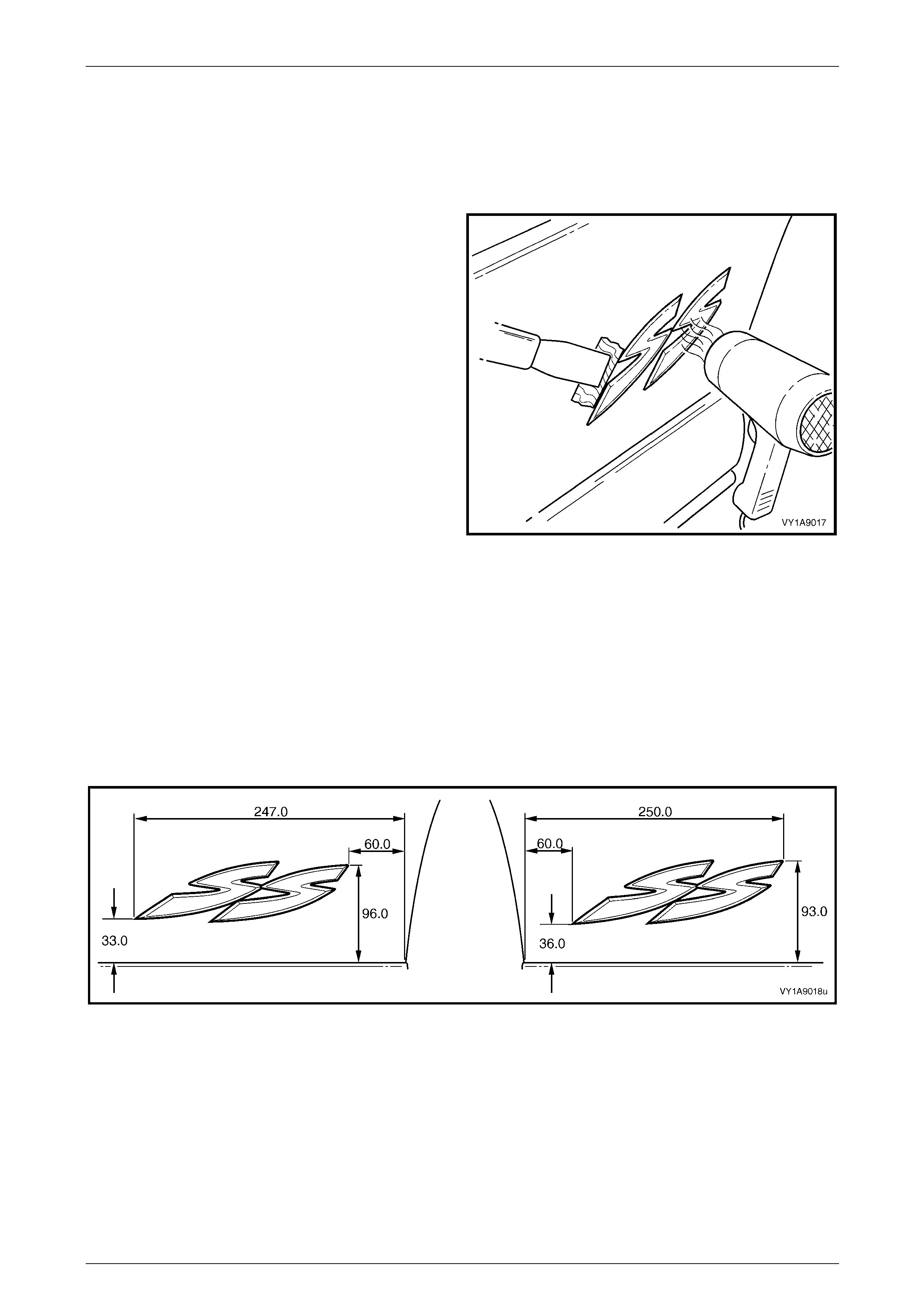
Exterior Ornamentation Page 1A9-125
Page 1A9-125
6.3 Quarter Panel Name Plate
LT Section No. — 10–150
Remove
1 Protect the paint and bodywork with tape or a clean
rag.
2 To assist removal, warm the name plate with a heat-
lamp or heat-gun to soften the adhesiv e.
3 Using a paint scraper or similar, carefully prise the
name plate from the quarter panel.
4 As required, remove any remaining double-sided tape
from the name plate and/or quarter pan el and clean
the surfaces with Prepsol or equivalent.
Figure 1A9 – 127
Reinstall
1 If reusing the name plate, apply new polyethylene double-sided tape such as 3M 4428 or equivalent to the back of
the name plate. Trim back the tape slightly away from the edge of the name plate.
2 Clean the quarter panel surface with Prepsol or equivale nt.
3 Remove the backing paper from the double-sided tape.
4 Apply the name plate on to the lower section of the quarter panel in the position shown, measuring up from the
lower edge of the quarter panel and in from the wheel arch, level with the lower edge of the nam e plate, refer to
Figure 1A9 – 128.
Figure 1A9 – 128
5 Press firmly over the entire name plate for at least 10 sec onds to ensure sound adhesion.

Exterior Ornamentation Page 1A9-126
Page 1A9-126
6.4 Endgate Emblem
LT Section No. — 10–150
Remove
1 Protect the paint and bodywork with tape or a clean
rag.
2 To assist removal, warm the emblem with a heat-lamp
or heat-gun to soften the adhesive.
3 Using a paint scraper or similar, carefully prise the
emblem from the endgate.
NOTE
The emblem has two locatin g pins, take care not
to break them if the emblem is to be reused.
4 As required, remove any remaining double-sided tape
from the emblem and/or endgate and clean the
surfaces with Prepsol or equivalent.
Figure 1A9 – 129
Reinstall
1 If reusing the emblem, apply new polyethylene double-
sided tape such as 3M 4428 or equ ivalent to the back
of the emblem. Trim back the tape slightly away from
the edge of the emblem.
2 Clean the panel surface with Prepsol or equivalent.
3 Remove the backing paper from the double-sided
tape.
4 Apply the emblem in the position shown ensuring the
locating pins are correctly orientated with the locating
holes in the panel surface.
5 Press firmly over the entire emblem for at least 10
seconds to ensure sound adhesion. Figure 1A9 – 130
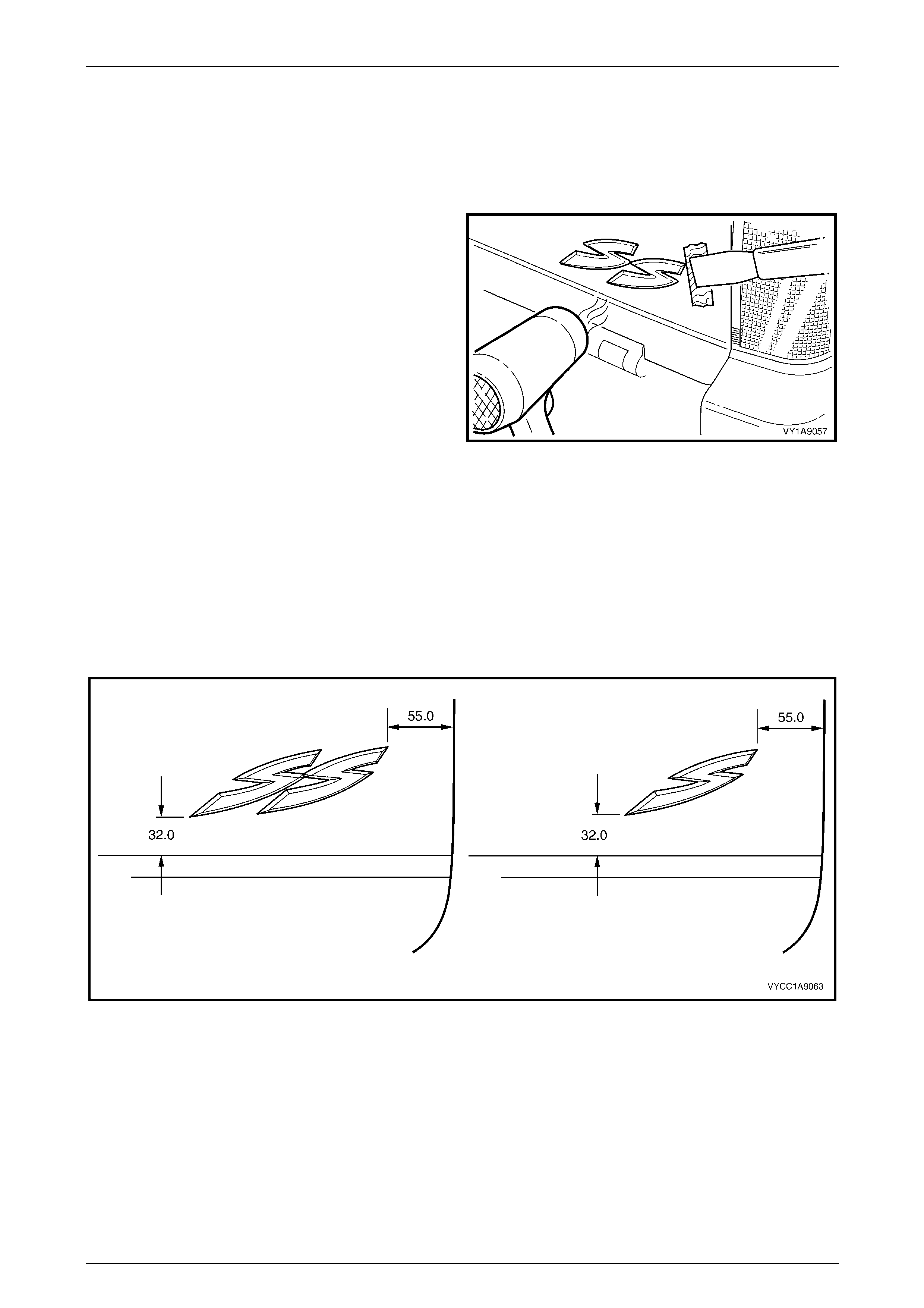
Exterior Ornamentation Page 1A9-127
Page 1A9-127
6.5 Endgate Name Plate, Right-hand
LT Section No. — 10–150
Remove
1 Protect the paint and bodywork with tape or a clean
rag.
2 To assist removal, warm the name plate with a heat-
lamp or heat-gun to soften the adhesiv e.
3 Using a paint scraper or similar, carefully prise the
name plate from the endgate.
4 As required, remove any remaining double-sided tape
from the name plate and/or endgate and clean the
surfaces with Prepsol or equivalent.
Figure 1A9 – 131
Reinstall
1 If reusing the name plate, apply new polyethylene double-sided tape such as 3M 4428 or equivalent to the back of
the name plate. Trim back the tape slightly away from the edge of the name plate.
2 Clean the panel surface with Prepsol or equivalent.
3 Remove the backing paper from the double-sided tape.
4 Apply the name plate onto the right-hand side of the endg ate in the position shown. Ensure the nam e plate is
straight and is correctly aligned to the measurements. Refer to Figure 1A9 – 132.
Figure 1A9 – 132
5 Press firmly over the entire name plate for at least 10 sec onds to ensure sound adhesion.
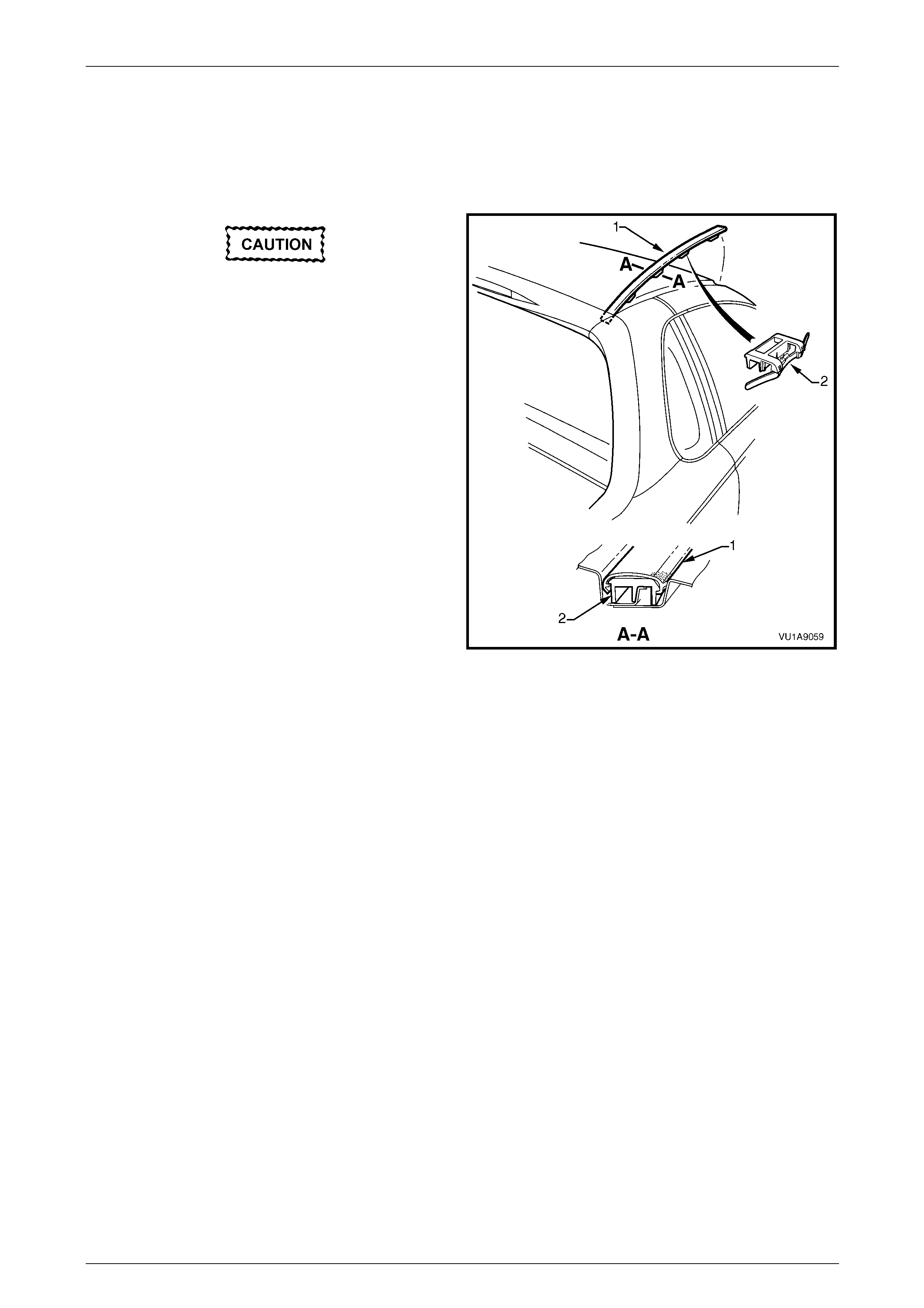
Exterior Ornamentation Page 1A9-128
Page 1A9-128
6.6 Roof Joint Moulding
LT Section No. — 10–265
Remove
Take care as the retaining clips can easily
break. Protect the paintwork with a clean rag.
1 Beginning at the front of the vehicle, use a screwdriver
to carefully prise the roof joi nt moul ding (1) from the
roof channel, disengaging retaining clip (2), four
places.
2 Disengage the roof joint moulding rear locating lug
from the rear window upper mouldin g b y lifting the
moulding at the front until it slides freely from its
location in the rear windo w upper mou lding.
Figure 1A9 – 133
Reinstall
1 As required, seat evenly the four retainers onto the roof joint moulding.
2 Position the roof joint moulding locating lug in position in the rear window upper moulding.
3 Seat the roof joint moulding in the roof channel and beginnin g at the rear, clip it in place.
4 At the front, ensure the moulding is installed under the windshield moulding cover.

Exterior Ornamentation Page 1A9-129
Page 1A9-129
6.7 Door Opening Moulding
LT Section No. — 10–265
Remove
1 Open the door on the relevant side of the vehicle.
2 Beginning at each end and working towards the
middle of the door opening moulding, remove the
screw (1), seven places, attaching the door opening
moulding (2) to the body.
3 Carefully remove the moulding, disengaging the
quarter window assembly tab (3).
Figure 1A9 – 134
Reinstall
Reinstallation of the door opening moulding is the reverse of the removal procedure, noting the following:
1 When installing the screws, begin at the rear and work forward.
NOTE
The screws are encapsulated with a wax sealer.
It is recommended the screws be replaced if
removed, however if this is impractical, apply a
small amount of sealer to the end of the thread.
2 Tighten the screws to the correct torque specification.
Door opening moulding attaching
screw torque specification...........................1.0 – 2.0 Nm
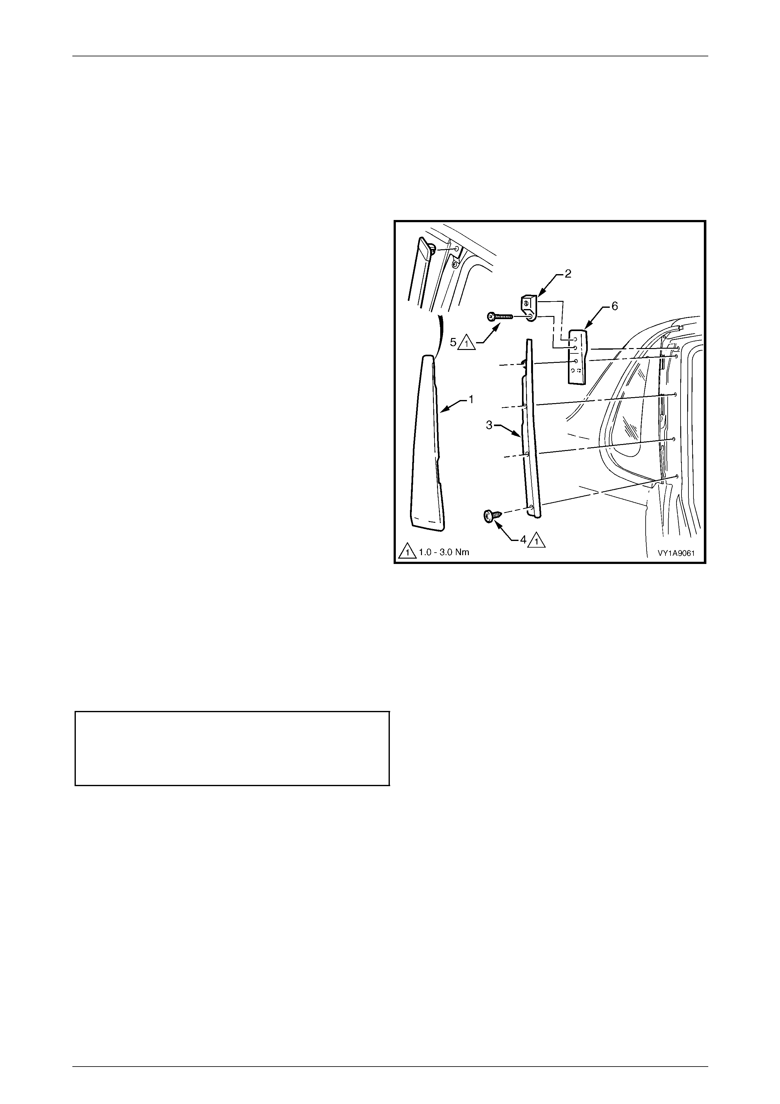
Exterior Ornamentation Page 1A9-130
Page 1A9-130
6.8 Centre Pillar Upper Finisher Assembly
LT Section No. — 10–265
Remove
1 Open the door on the relevant side of the vehicle.
2 Gently prise the top of the centre pillar upper finisher
(1) out to disengage it from the centre pillar upper
finisher retainer (2).
3 Holding the top of the finisher out, slide it up the centre
pillar outer sealing strip (3).
4 Manoeuvre the rear edge and then the front edge of
the finisher from the sealing strip and remove.
5 Remove the screw (4), four places, attaching the
centre pillar sealing strip to the pillar and remove the
strip.
6 Remove the screw (5) attaching the centre pillar upper
finisher retainer and centre pil lar up per trim mount
plate (6) to the pillar and remove.
Figure 1A9 – 135
Reinstall
Reinstallation of the centre pillar upper finisher assembly is the reverse of the removal procedure, noting the following:
1 Ensure the centre pillar upper trim panel is seated correctly under the door openin g weatherstrip.
2 Tighten the screws to the correct torque specification.
Centre pillar upper finisher retainer
attaching screw torque specification...........1.0 – 3.0 Nm
Centre pillar sealing strip attac hin g
screw torque specification...........................1.0 – 3.0 Nm
3 Engage the front edge of the finisher into the sealing strip and then the rear edge into the window assembly.
4 Slide the centre pillar upper finisher down and press it in at the top to engage it into the retaining clip.
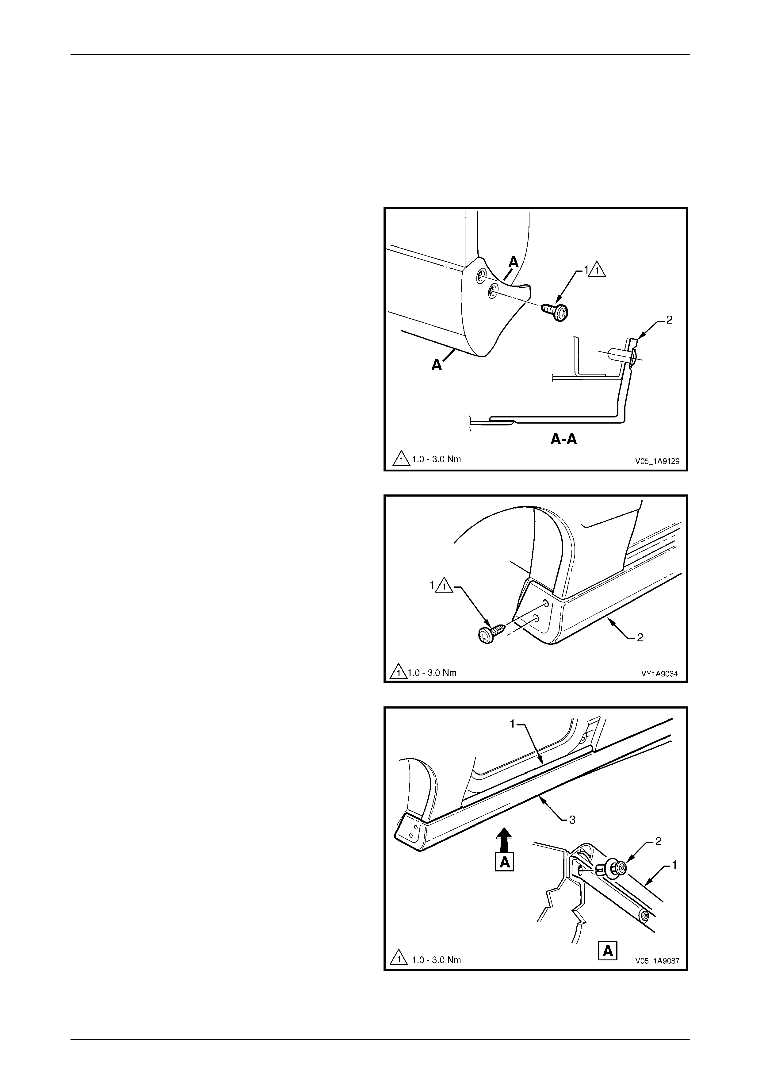
Exterior Ornamentation Page 1A9-131
Page 1A9-131
6.9 Rocker Panel Moulding Assembly
LT Section No. — 10–300
Remove
1 On the relevant side remove the rear road wheel, refer to Section 10 Wheels and T yres.
2 Remove the screw (1), two places, attaching the rear
rocker panel moulding (2).
NOTE
If required, the rear rocker panel moulding can
be removed at this stage by sliding it rearward
from the front rocker panel moulding.
Figure 1A9 – 136
3 Turn the front wheels to full steering lock to ward the
relevant side.
4 Remove the screw (1), two places, attaching the front
rocker panel moulding (2) to the fender and liner.
Figure 1A9 – 137
5 Lift up the rocker panel weatherstrip (1) as shown in
View A to gain access and remove the retainer (2),
five places, attaching the rocker panel moulding (3) to
the vehicle body. NOTE
If the retainers are difficult to remove, prise out
the centre section a small amount with a flat
bladed screwdriver, then continue to unscrew. It
may also be necessary to retain the outer
section of the retainer with fingers or pliers.
6 Referring to Figure 1A9 – 139. From underneath the
vehicle, remove the screw (1), seven places, from the
retainer (2) under the moulding (3).
7 Remove the moulding, unclipping the retainer (4),
three places.
8 If required, prise the nut (5), two places, from the
fender.
9 If required, prise the three retainers (4) from the
quarter panel. Figure 1A9 – 138
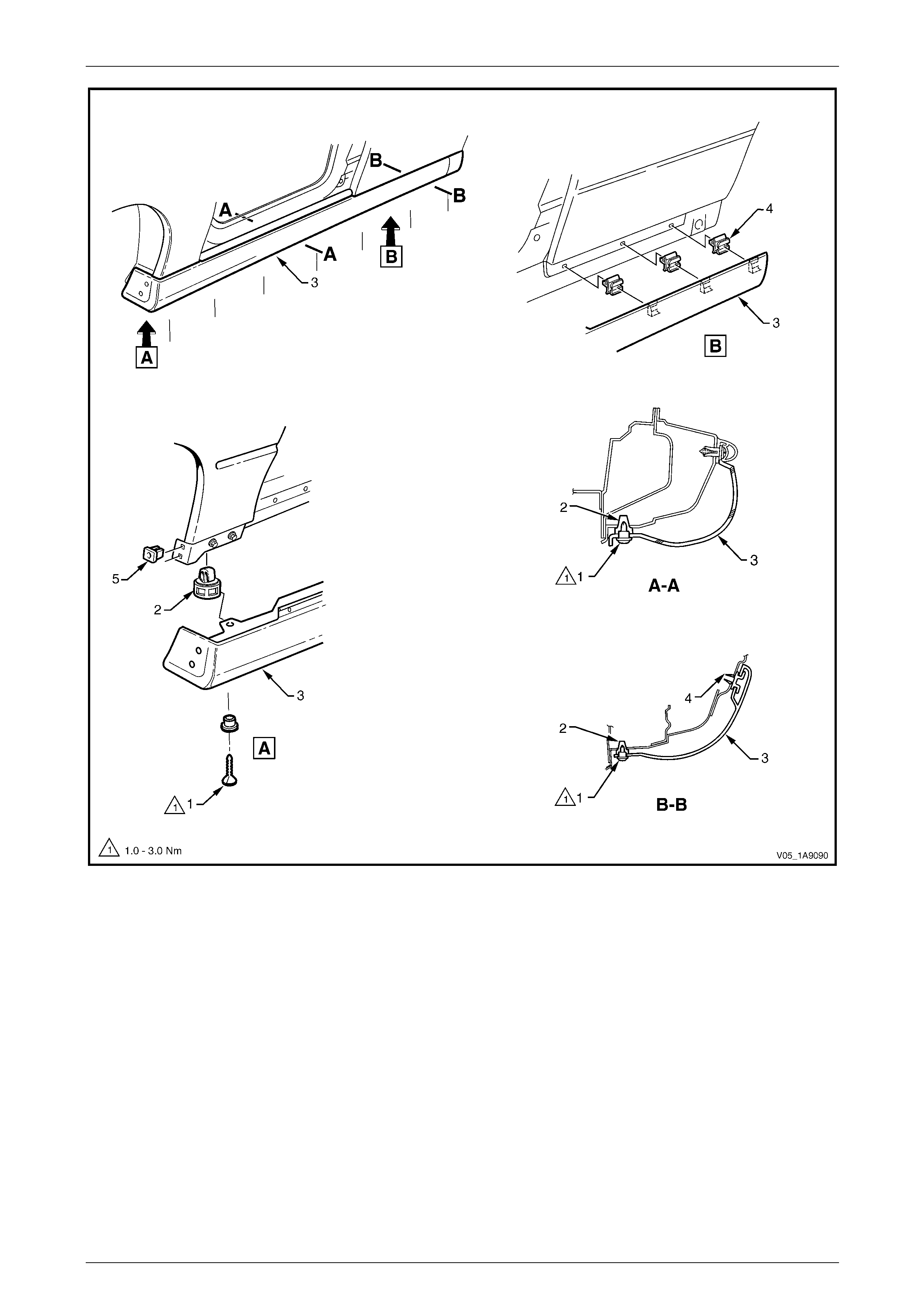
Exterior Ornamentation Page 1A9-132
Page 1A9-132
Figure 1A9 – 139

Exterior Ornamentation Page 1A9-133
Page 1A9-133
10 If required, remove the retainer (2), seven places, by
gently levering out from the body, taking care not to
damage the paint work.
Figure 1A9 – 140
Reinstall
Reinstallation of the rocker panel moulding assembly is the reverse of the removal procedure, noting the following:
1 Ensure the front moulding is correctly seated in the retaining clips.
2 Tighten the screws to the correct torque specification.
Rocker panel moulding attac hin g
screw torque specification...........................1.0 – 3.0 Nm
3 Ensure the weatherstrip is seated correctly.
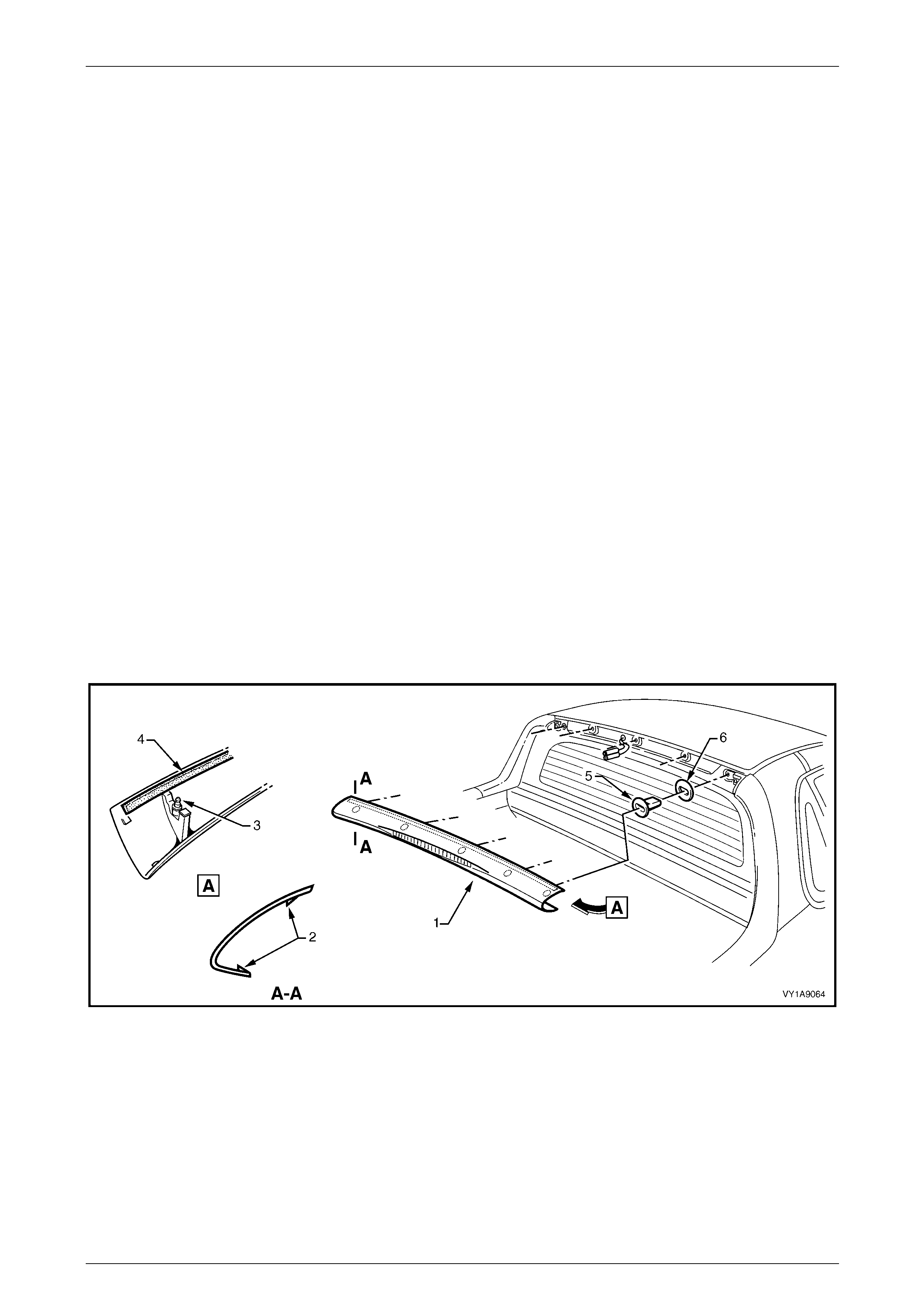
Exterior Ornamentation Page 1A9-134
Page 1A9-134
6.10 Rear Window Upper Moulding
LT Section No. — 10–265
Remove
1 Carefully spread each end of the rear window upper mouldin g (1) to disen gage the locking tabs (2), refer to
Figure 1A9 – 141.
2 Insert a flat-blade screwdriver and clean rag bet ween the lower edge of the moulding and the rear window.
3 Ensuring the locking tabs are disengaged, prise the moulding off in a rearward and slightl y upward direction to
disengage retaining stud (3), five places.
NOTE
The upper edge of the moulding is attached with
double-sided tape (4), remove the moulding
carefully.
4 Where fitted, disconnect the high mount stop lamp connector from the rear of the moulding and remove the
moulding.
5 Remove any remaining double-sided tape from the mould i ng and/or panel as required and clean the surfaces with
Prepsol or equivalent.
6 If required, remove the retainer (5) and seals (6), five places by inserting a flat-blade screwdriver between the
upper edge of the retainer and the panel. While pressing down on the screwdriver, ease the retainer out of its
location.
NOTE
Take care not to damage the paintwork.
Figure 1A9 – 141
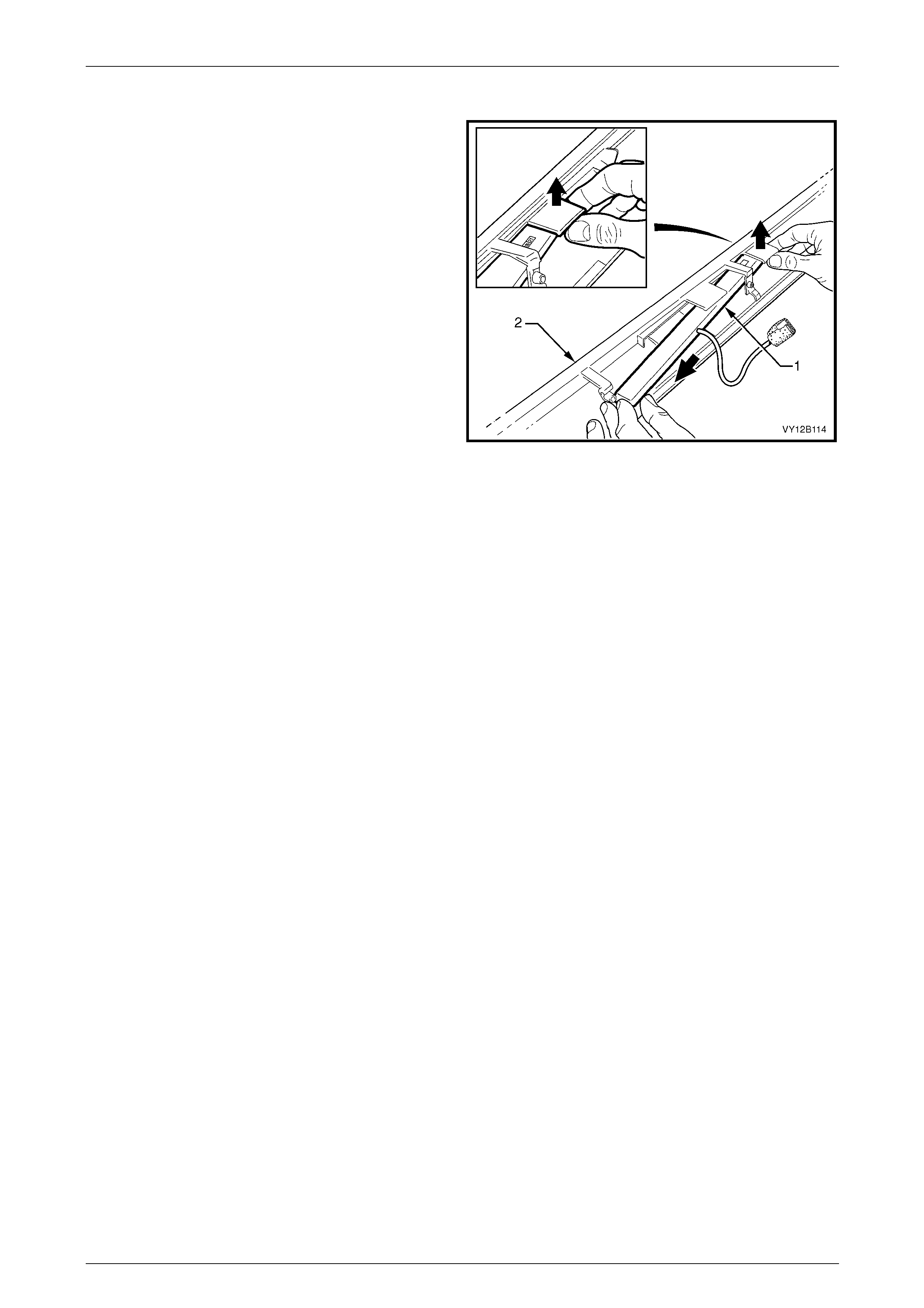
Exterior Ornamentation Page 1A9-135
Page 1A9-135
Disassemble
1 Where fitted, carefully disengage the retaining tangs
from the high mount stop lamp assembly (1) and
manoeuvre the lamp assembly free from the moulding
(2).
Figure 1A9 – 142
Reinstall
1 If fitted, install the high mount stop lamp assembly using the reverse of the disass emble procedure.
2 Check the retainers and seals are in sound condition. Replac e as required.
3 If removed, fit the retainers and seals.
4 If reusing the moulding, apply new polyethylene double-sided tape such as 3M 4428 or equivalent to the upper
surface.
5 Clean the panel surface with Prepsol or equivalent.
6 If fitted connect the high mount stop lamp connector, and check its operation prior to installing the rear window
upper moulding. Fit the connector into its recess in the rea r of the moulding.
7 Remove the backing paper from the double-sided tape.
8 Align the retaining studs with their respective retainers on th e vehicle. Engage the retainers, ensuring the double-
sided tape does not contact until the mouldin g is full y seated.
9 Push-in each end to engage the locking tabs.
10 Press down along the upper surface of the moulding to ensure the tape is correctly adhered to the panel.
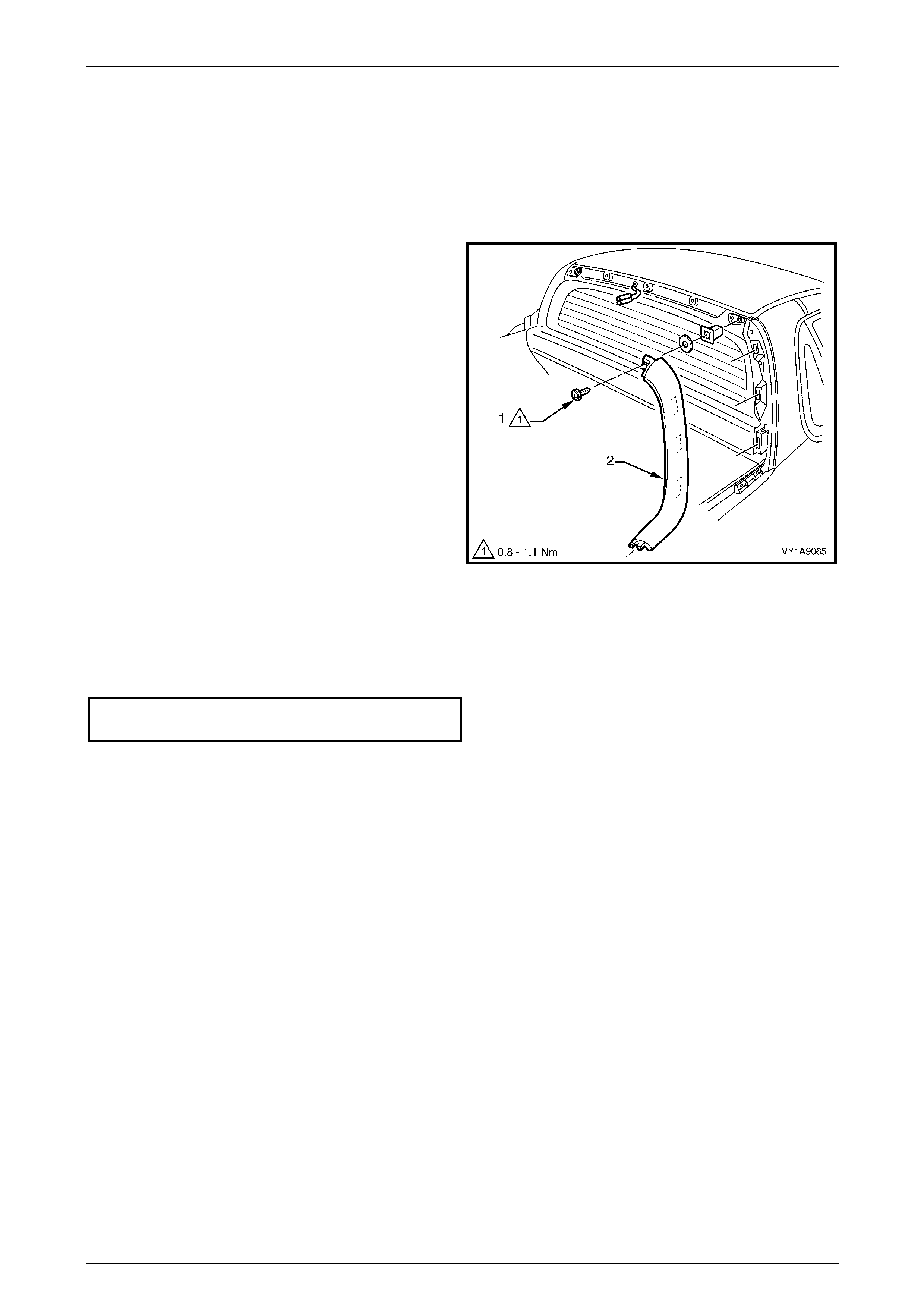
Exterior Ornamentation Page 1A9-136
Page 1A9-136
6.11 Rear Window Side Moulding
LT Section No. — 10–265
Remove
1 Remove the rear window upper moulding, refer to 6.10 Rear Window Upper Moulding.
2 Remove the screw (1) attaching the rear window side
moulding (2).
3 Rotate the upper end of the moulding rearward to
disengage the three retainers.
4 Ease the lower end of the moulding forward to
disengage it from the quarter panel o uter rail .
5 As required, remove the seal and retainer.
Figure 1A9 – 143
Reinstall
Reinstallation of the rear window side moulding is the reverse of the removal procedure. Tighten the screw to the correct
torque specification.
Rear window side moulding attaching
screw torque specification...........................0.8 – 1.1 Nm
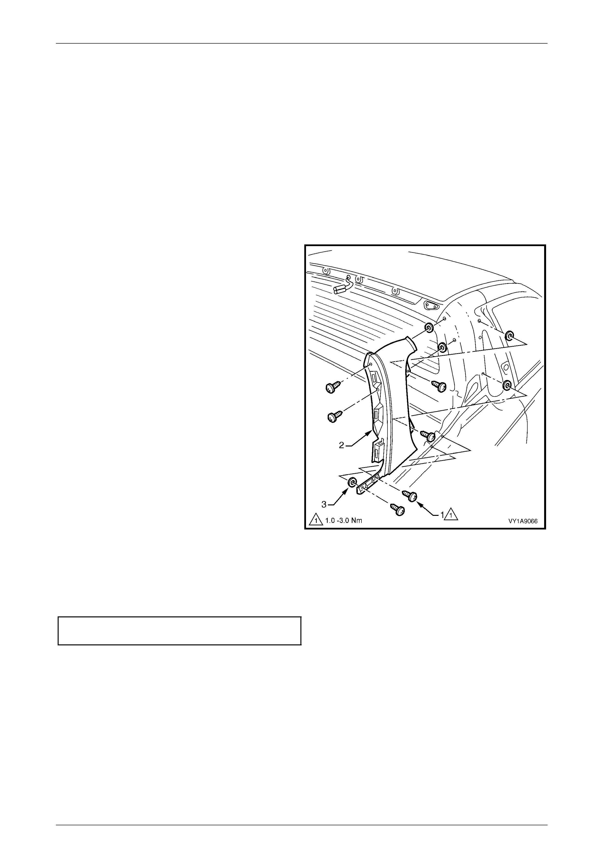
Exterior Ornamentation Page 1A9-137
Page 1A9-137
6.12 Rear Quarter Window Moulding
LT Section No. — 10–265
Remove
1 Remove the following components:
a Body lock pillar upper trim, refer to Section 1A8 Headlining and Interior Trim.
b Quarter window assembly, refer to Section 1A6 Stationary Windows.
c Rear window upper moulding, refer to 6.10 Rear Window Upper Moulding.
d Rear windo w side mouldi ng, refer to 6.11 Rear Window Side Moulding.
2 Remove the six screws (1) attaching the quarter
window moulding (2) to the vehicle.
3 Remove the moulding rearwards, disengaging the
front upper edge.
4 If required, carefully peel th e seals (3) from the
vehicle.
Figure 1A9 – 144
Reinstall
Reinstallation of the rear quarter window moulding is the reverse of the removal procedure. Tighten the screws to the
correct torque specification.
Quarter window moulding attaching
screw torque specification...........................1.0 – 3.0 Nm
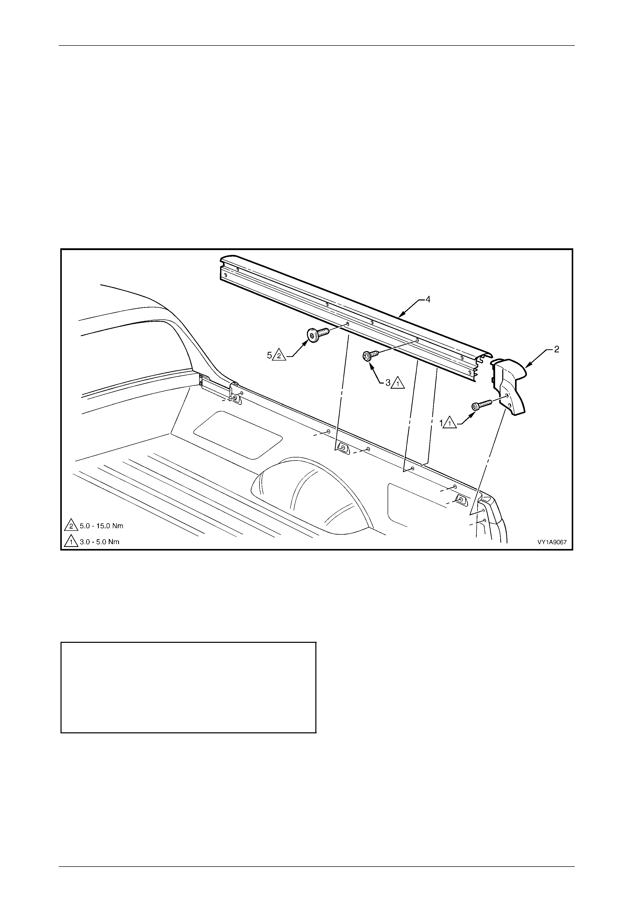
Exterior Ornamentation Page 1A9-138
Page 1A9-138
6.13 Quarter Panel Rail
LT Section No. — 10–480
Remove
1 Remove the screw (1), two places, attaching the quarter panel re ar moulding (2) to the vehicle, refer to
Figure 1A9 – 145.
2 Remove the screw (3), five places, attaching the quarter panel o uter rail (4 ) to the vehicle.
3 Remove the torx-head screw (5), three places, attaching the quarter pane l outer rail.
4 Carefully lift the mouldin g and rail from the vehicle and remove.
Figure 1A9 – 145
Reinstall
Reinstallation of the quarter panel rail is the reverse of the removal procedure. Tighten the screws to the correct torque
specification.
Quarter panel rear moulding a ttaching
screw torque specification...........................3.0 – 8.0 Nm
Quarter panel outer rail attaching
screw torque specification...........................3.0 – 8.0 Nm
Quarter panel outer rail attaching
torx screw torque specification..................5.0 – 15.0 Nm
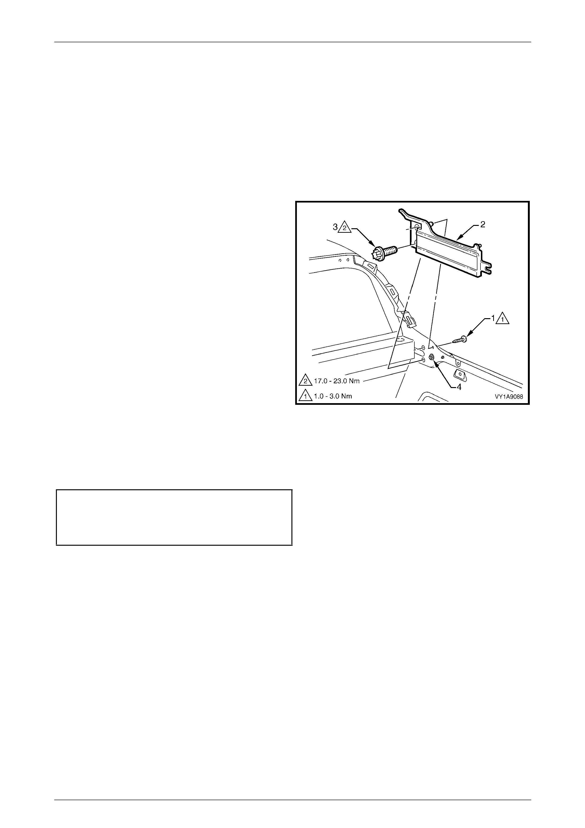
Exterior Ornamentation Page 1A9-139
Page 1A9-139
6.14 Tonneau Cover Bow Retainer
LT Section No. — 10–480
Remove
1 Remove the following components:
a Rear windo w side mouldi ng, refer to 6.11 Rear Window Side Moulding.
b Remove the quarter panel rai ls, refer to 6.13 Quarter Panel Rail.
2 Remove the screw (1) attaching the quarter wind ow
moulding to the tonneau cover bow retainer (2).
3 Remove the torx-head screw (3), two places, attaching
the tonneau cover bow retainer.
4 Remove the retainer from the vehicle.
NOTE
The torx-head screw (4) should not be removed
unless body panel replacement is being
performed. If it is removed, ensure it is installed
before the retainer and tightened to the same
torque as the retainer torx-head screws.
Figure 1A9 – 146
Reinstall
Reinstallation of the tonneau cover bow retainer is the reverse of the removal procedure. Tighten the screws to the
correct torque specification.
Tonneau cover bow retainer attaching
torx screw torque specification................17.0 – 23.0 Nm
Quarter window moulding attaching
screw torque specification...........................1.0 – 3.0 Nm
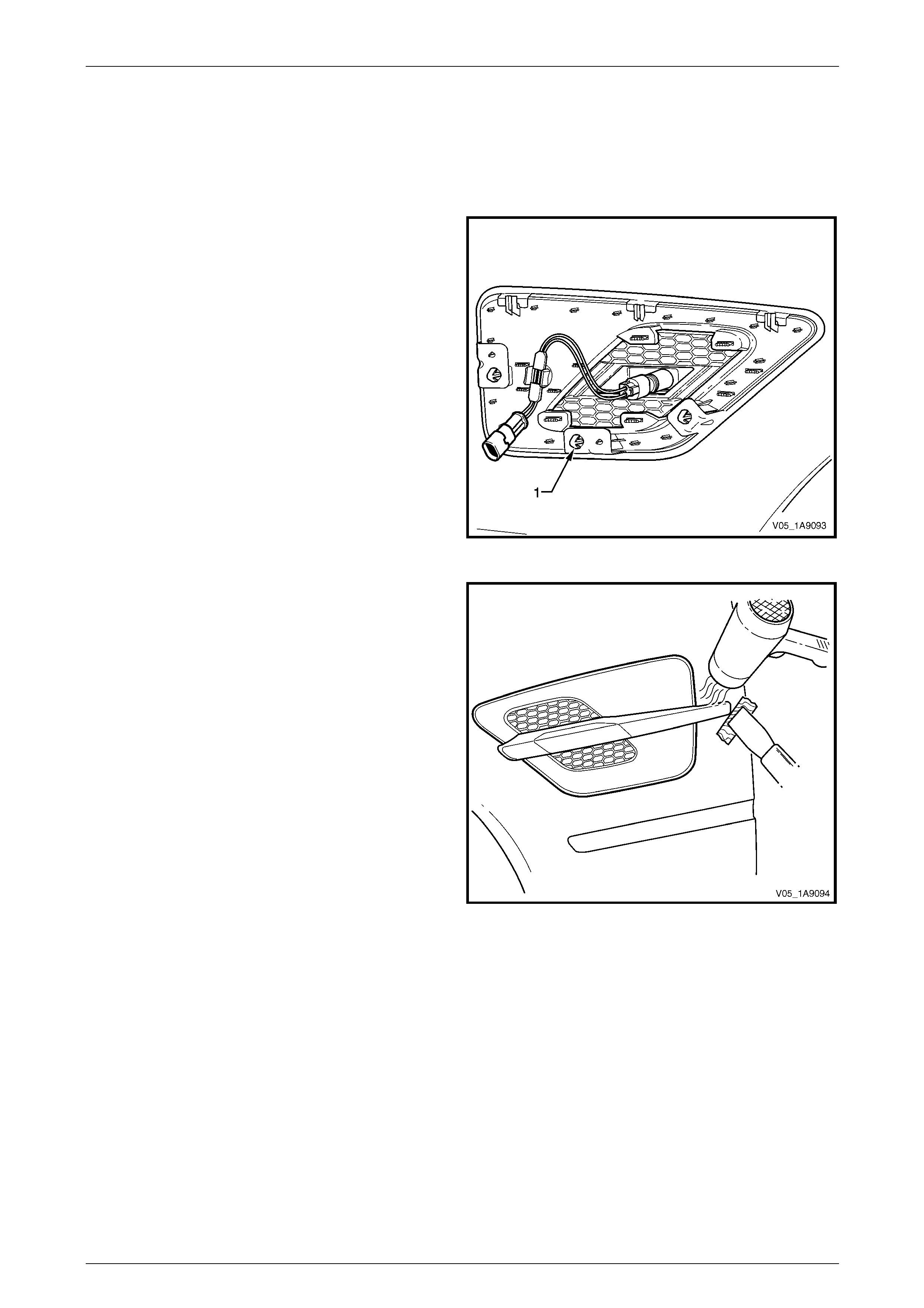
Exterior Ornamentation Page 1A9-140
Page 1A9-140
6.15 Front Fender Centre Moulding Assembly
Remove
1 Remove the front fender, refer to Section 1B Sheetmetal.
2 Using pliers, squeeze the retaining clip (1), three
places, to release the front fender centre mou lding
assembly from the fender.
Figure 1A9 – 147
3 Protect the paint and bodywork with tape.
4 To assist removal, warm the region around the rear of
the upper moulding with a heat-lamp or heat-gun to
soften the adhesive.
5 Using a paint scraper or similar, carefully prise the rear
edge of the moulding assembly from the fender.
6 Withdraw the lower edge of the mou lding assembly
from the fender and gently pull it down to disengage
the three upper lugs.
7 As required remove an y remaining double-sided tape
from the moulding and/or fender and clea n the
surfaces with Prepsol or equivalent.
Figure 1A9 – 148

Exterior Ornamentation Page 1A9-141
Page 1A9-141
Disassemble
1 With a flat-blade screwdriver, prise the patch harness
retainer (1) from the moulding assembly.
2 Twist and remove the bulb socket, O-ring and bulb (2)
from the lamp assembly.
Figure 1A9 – 149
3 Carefully using a fine flat-blade screwdriver located at
the lower, rear edge of the lamp assembly, lever the
lamp forward and out to disengage the rear retaining
lug.
4 Withdraw the rear of the lamp from the moulding
assembly.
Figure 1A9 – 150
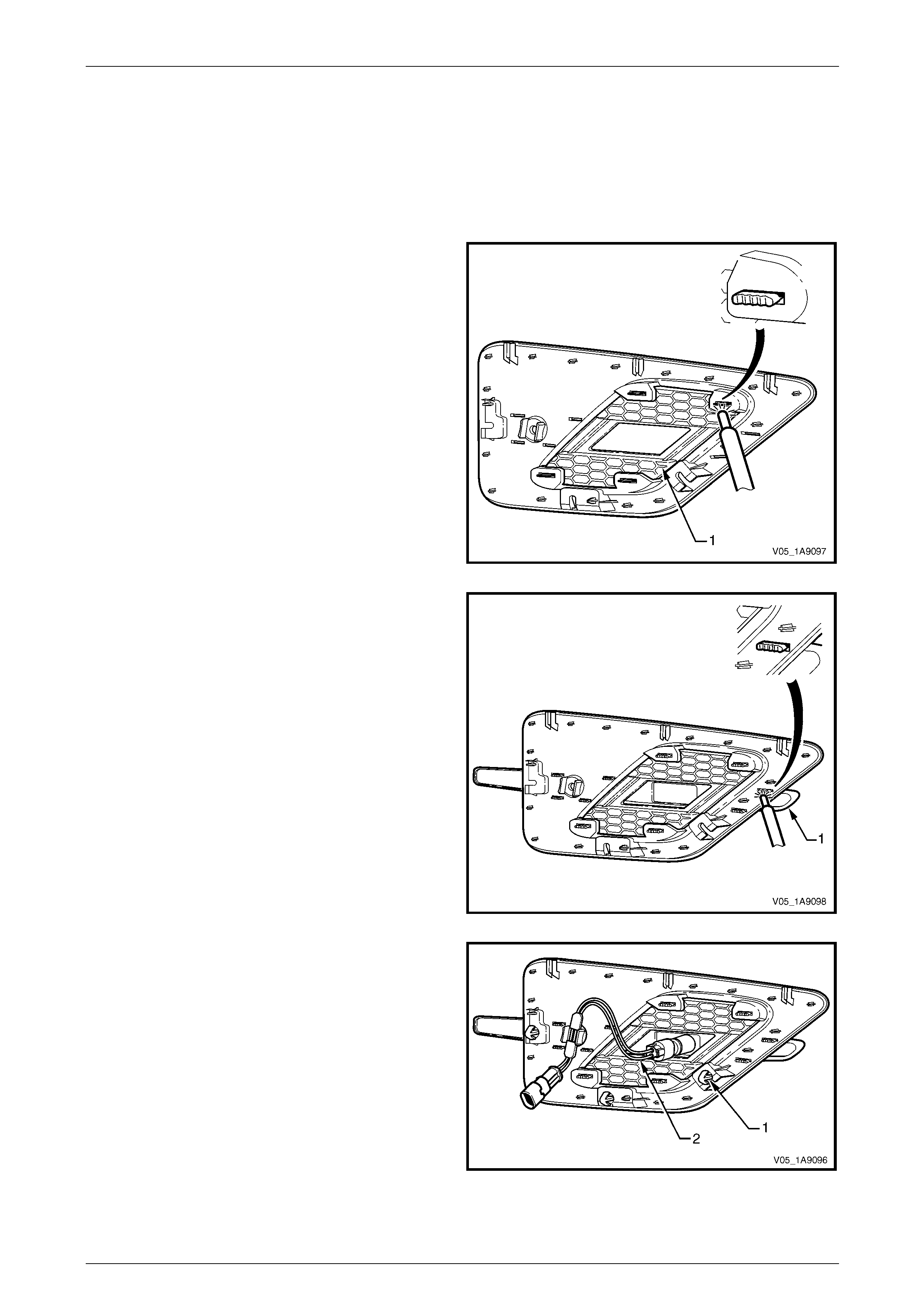
Exterior Ornamentation Page 1A9-142
Page 1A9-142
Reassemble
NOTE
The front fender centre moulding is supplied
unpainted as part of a kit. If a new part
is being used, it will require painting before it is
assembled. The procedure is similar to
painting the bumper fascias, refer to
Section 1D Bumper Bars.
1 Install the front fender centr e i nsert (1):
a Ensure the four heat stake lugs are seated
correctly into the front fender centre moulding.
b Using a soldering iron, melt the ends of the four
heat stakes to secure the insert in place.
c Hold the centre insert in position unti l the pl astic
has cooled.
Figure 1A9 – 151
2 Install the front fender upper moulding (1):
a Ensure the six heat stakes ar e seated correctly
into the centre moulding.
b Using a soldering iron, melt the ends of the six
heat stakes to secure the moulding in pl ace.
c Hold the upper moulding i n po sition until the
plastic has cooled.
Figure 1A9 – 152
3 If required, fit the retaining clip (1), three places.
4 Reinstall the la mp assembly, locating the front retainer
first and then clipping the rear lug in place.
5 Reinstall the patch harness (2), connect it to the lamp
assembly and attach its retainer to the mould ing
assembly.
Figure 1A9 – 153

Exterior Ornamentation Page 1A9-143
Page 1A9-143
Reinstall
1 If required, apply new polyethylene double-sided tape
such as 3M 4428 or equivalent (1).
2 Clean the fender surface around the moulding
assembly opening with Prepsol or equivalent.
3 Remove the backing pap er from the doub le-sided
tape.
4 Hook the upper lugs behind their mounting tabs on the
front fender.
5 While providin g support to the back of the fender, push
the three retainers into place. Ensure all three
retainers snap into place.
6 Apply pressure to the rear of the moulding assembly
for 10 seconds where the double-sided tape was
applied to ensure sound adhesion.
7 Connect the patch harness to the main h arn ess.
8 Reinstall the fender, refer to Section 1B Sheetmetal.
9 Check for correct operation of the front side turn signal
lamp.
Figure 1A9 – 154

Exterior Ornamentation Page 1A9-144
Page 1A9-144
7 Service Operations, Regular Cab
7.1 Fender Name Plate
LT Section No. — 10–150
Remove
1 Protect the paint and bodywork with tape or a clean
rag.
2 To assist removal, warm the name plate with a heat-
lamp or heat-gun to soften the adhesiv e.
3 Using a paint scraper or similar, carefully prise the
name plate from the fender.
4 As required remove an y remaining double-sided tape
from the name plate and/or fender and clean the
surfaces with Prepsol or equivalent.
Figure 1A9 – 155
Reinstall
1 If reusing the name plate, apply ne w polyethylene double-sided tape such as 3M 4428 or equivalent to the back of
the name plate. Trim back the tape slightly away from the edge of the name plate.
2 Clean the fender surface with Prepsol or equivalent.
3 Remove the backing paper from the doub le-sided tape.
4 Apply the name plate in the position shown, measuring from the front side turn sign al lamp,
refer to Figure 1A9 – 156. Ensure it is positioned parallel to the style line.
Figure 1A9 – 156
5 Press firmly over the entire name plate for at least 10 sec onds to ensure sound adhesion.
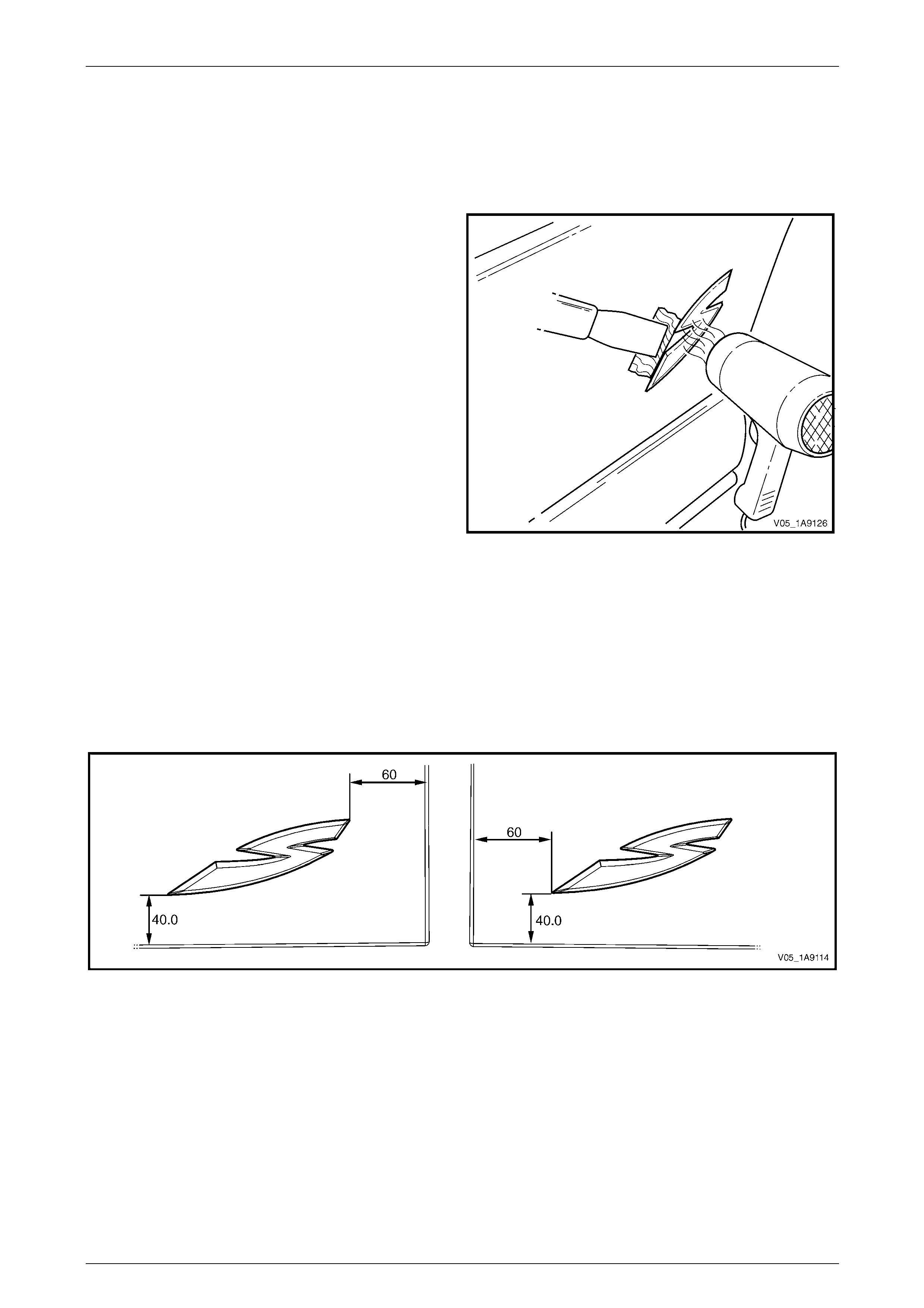
Exterior Ornamentation Page 1A9-145
Page 1A9-145
7.2 Quarter Panel Name Plate
LT Section No. — 10–150
Remove
1 Protect the paint and bodywork with tape or a clean
rag.
2 To assist removal, warm the name plate with a heat-
lamp or heat-gun to soften the adhesiv e.
3 Using a paint scraper or similar, carefully prise the
name plate from the quarter panel.
4 As required, remove any remaining double-sided tape
from the name plate and/or quarter pan el and clean
the surfaces with Prepsol or equivalent.
Figure 1A9 – 157
Reinstall
1 If reusing the name plate, apply ne w polyethylene double-sided tape such as 3M 4428 or equivalent to the back of
the name plate. Trim back the tape slightly away from the edge of the name plate.
2 Clean the quarter pane l surface with Prepsol or equivalent.
3 Remove the backing paper from the doub le-sided tape.
4 Apply the name plate on to the lower section of the quarter panel in the po sition shown, refer to Figure 1A9 – 158.
Figure 1A9 – 158
5 Press firmly over the entire name plate for at least 10 sec onds to ensure sound adhesion.
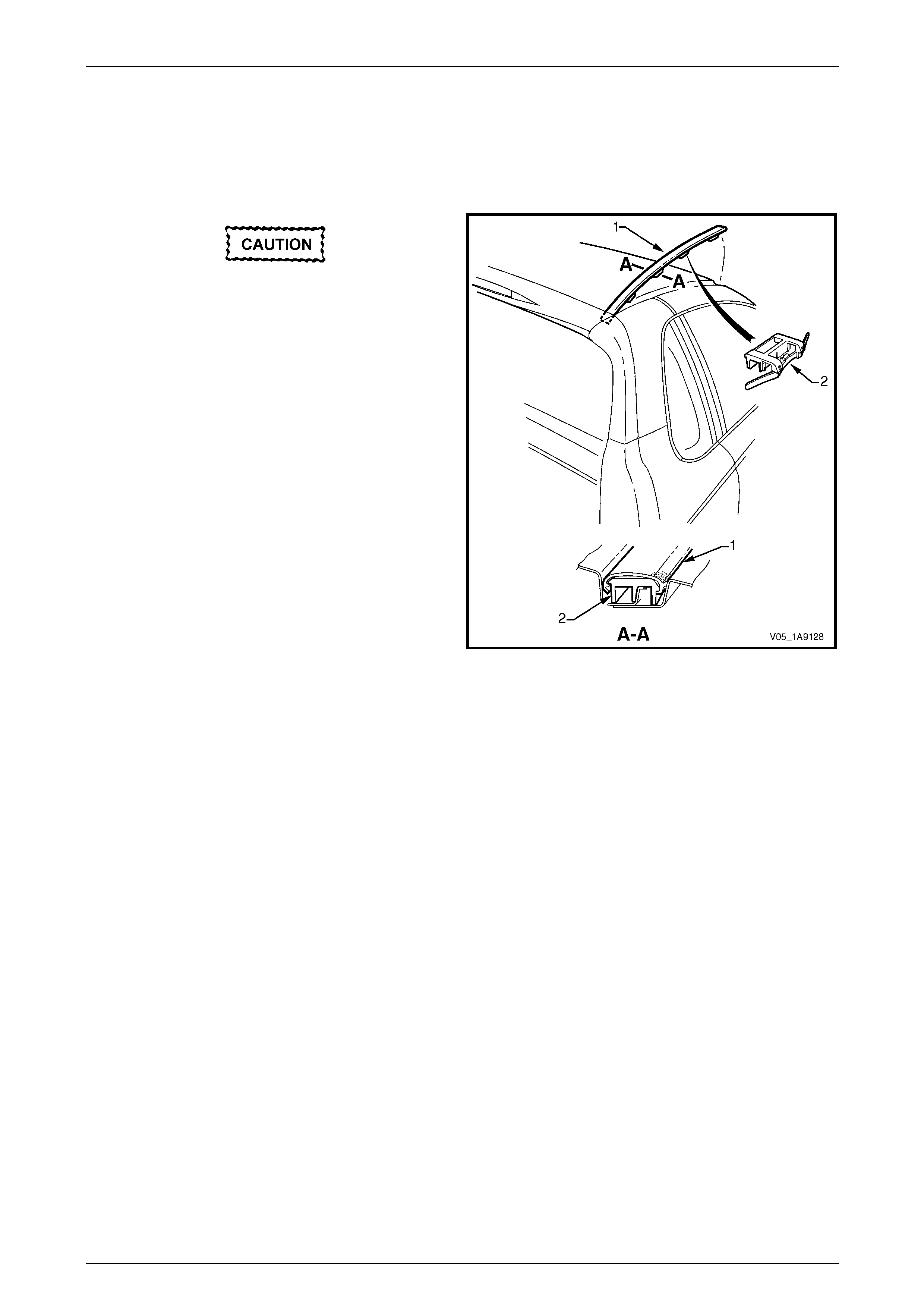
Exterior Ornamentation Page 1A9-146
Page 1A9-146
7.3 Roof Joint Moulding
LT Section No. — 10–265
Remove
Take care as the retaining clips can easily
break. Protect the paintwork with a clean rag.
1 Beginning at the front of the vehicle, use a screwdriver
to carefully prise the roof joi nt moul ding (1) from the
roof channel, disengaging retaining clip (2), four
places.
2 Disengage the roof joint moulding rear locating lug
from the rear window upper mouldin g b y lifting the
moulding at the front until it slides freely from its
location in the rear windo w upper mou lding.
Figure 1A9 – 159
Reinstall
1 As required, seat evenly the four retainers onto the roof joint moulding.
2 Position the roof joint moulding locating lug in position in the rear window upper moulding.
3 Seat the roof joint moulding in the roof channel and beginnin g at the rear, clip it in place.
4 At the front, ensure the moulding is installed under the windshield moulding cover.
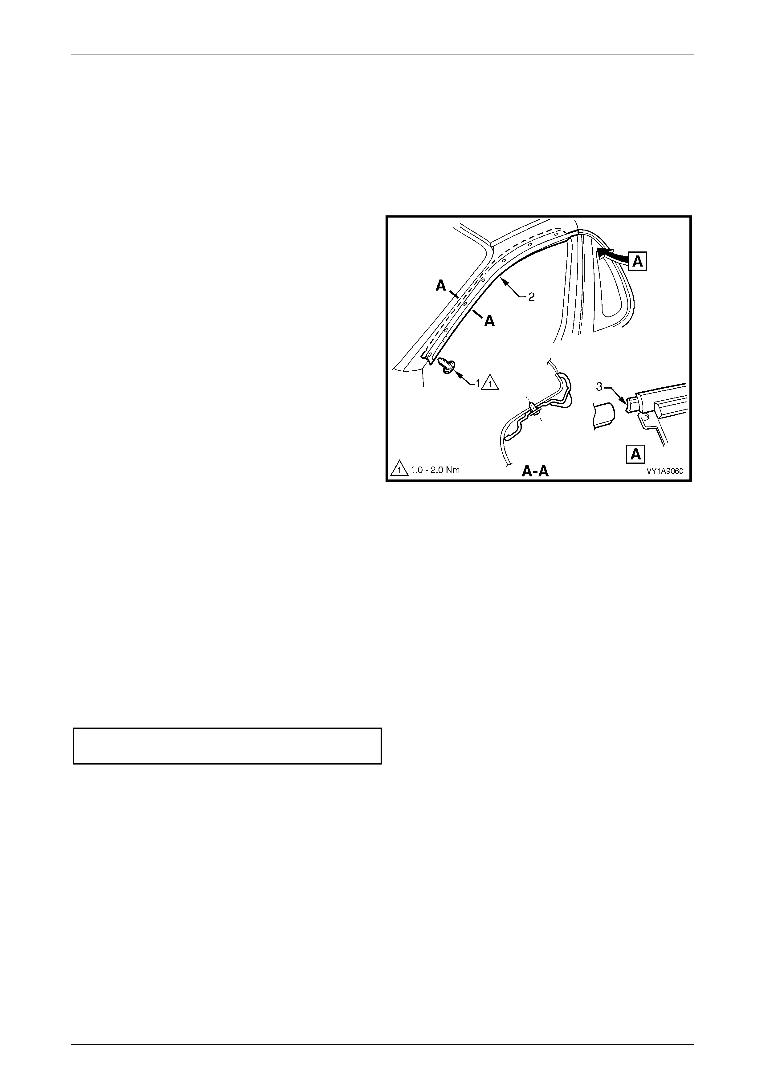
Exterior Ornamentation Page 1A9-147
Page 1A9-147
7.4 Door Opening Moulding
LT Section No. — 10–265
Remove
1 Open the door on the relevant side of the vehicle.
2 Beginning at each en d and working towards the
middle of the door opening moulding, remove the
screw (1), seven places, attaching the door opening
moulding (2) to the body.
3 Carefully remove the moul ding, disengaging the
quarter window assembly tab (3).
Figure 1A9 – 160
Reinstall
Reinstallation of the door opening moulding is the reverse of the removal procedure, noting the following:
1 When installing the screws, begin at the rear and work forward.
NOTE
The screws are encapsulated with a wax sealer.
It is recommended the screws be replaced if
removed, however if this is impractical, apply a
small amount of sealer to the end of the thread.
2 Tighten the scre ws to the correct torque spec ificatio n.
Door opening moulding attaching
screw torque specification...........................1.0 – 2.0 Nm

Exterior Ornamentation Page 1A9-148
Page 1A9-148
7.5 Centre Pillar Upper Finisher Assembly
LT Section No. — 10–265
Remove
1 Open the door on the relevant side of the vehicle.
2 Gently prise the top of the centre pillar upper finisher
(1) out to disengage it from the centre pillar upper
finisher retainer (2).
3 Holding the top of the finisher out, slide it up the centre
pillar outer sealing strip (3).
4 Manoeuvre the rear edge and then the front edge of
the finisher from the sealing strip and remove.
5 Remove the screw (4), four places, attaching the
centre pillar sealing strip to the pillar and remove the
strip.
6 Remove the screw (5) attaching the centre pillar u pp er
finisher retainer and centre pil lar up per trim mount
plate (6) to the pillar and remove.
Figure 1A9 – 161
Reinstall
Reinstallation of the centre pillar upper finisher assembly is the reverse of the removal procedure, noting the following:
1 Ensure the centre pillar upper trim panel is seated correctly under the door openin g weatherstrip.
2 Tighten the scre ws to the correct torque spec ificatio n.
Centre pillar upper finisher retainer
attaching screw torque specification...........1.0 – 3.0 Nm
Centre pillar sealing strip attac hin g
screw torque specification...........................1.0 – 3.0 Nm
3 Engage the front edge of the finisher into the sealing strip and then the rear edge into the window assembly.
4 Slide the centre pillar up per finisher down and press it in at the top to engage it into the retaining clip.
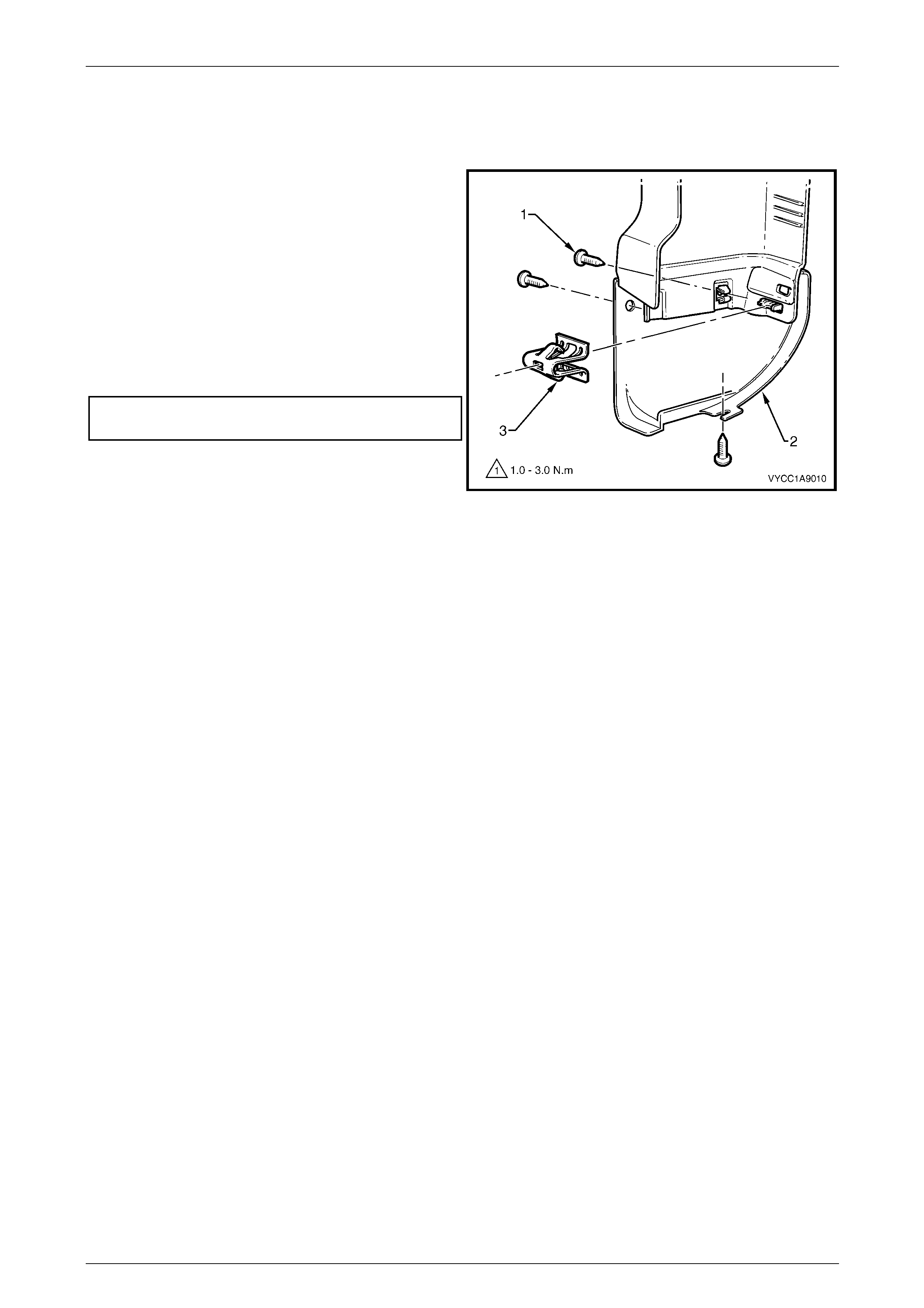
Exterior Ornamentation Page 1A9-149
Page 1A9-149
7.6 Rocker Panel Moulding End Cap
Remove
1 Remove the three screws (1) attaching the rear rocker
panel moulding end cap to the bod y side rear trim
panel and rocker mouldin g end cap (2).
2 Gently prise the rocker panel moulding end cap (2)
outward from the body side rear trim panel to release
the retaining clip (3).
Reinstall
Reinstallation of the rocker panel moulding assembly is the
reverse of the removal procedure. T ighten the screws to the
correct torque specification.
Rocker panel moulding
end cap attaching screw .............................1.0 – 3.0 Nm
NOTE
Ensure the clip holding the rear rocker panel
moulding to the rear side trim panel is fastened
correctly and the screws have been located in
the body side rear trim panel correctly.
Figure 1A9 – 162
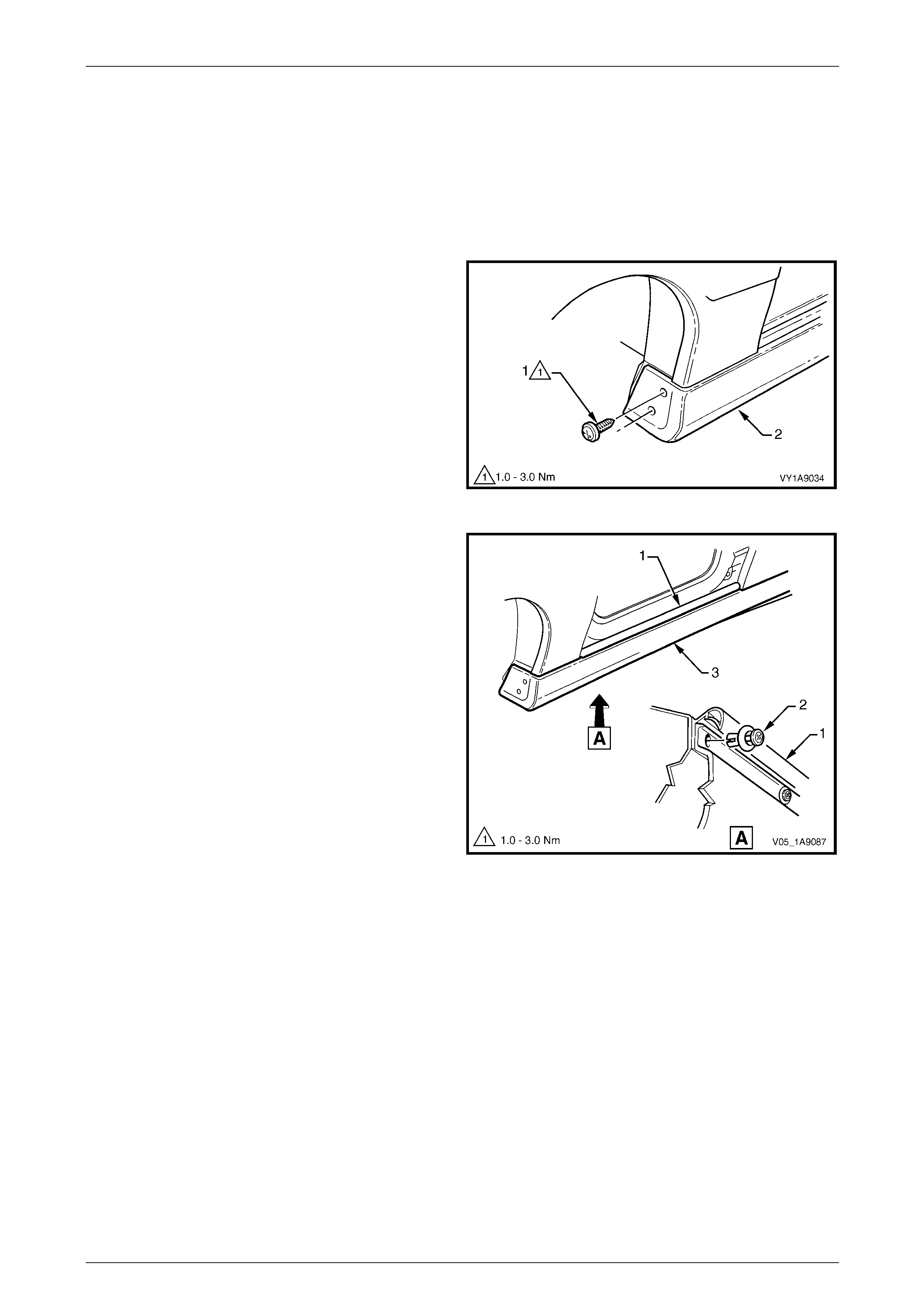
Exterior Ornamentation Page 1A9-150
Page 1A9-150
7.7 Rocker Panel Moulding Assembly
LT Section No. — 10–300
Remove
1 Remove the rocker panel mo ulding end cap, refer to 7.6 Rocker Panel Mouldin g End Cap.
2 Turn the front wheels to full steering lock to ward the
relevant side.
3 Remove the screw (1), two places, attaching the front
rocker panel moulding (2) to the fender and liner.
Figure 1A9 – 163
4 Lift up the rocker panel weatherstrip (1) as shown in
View A to gain access and remove the retainer (2),
five places, attaching the rocker panel moulding (3) to
the vehicle body.
NOTE
If the retainers are difficult to remove, prise out
the centre section a small amount with a flat
bladed screwdriver, then continue to unscrew. It
may also be necessary to retain the outer
section of the retainer with fingers or pliers.
5 Referring to Figure 1A9 – 165, from underneath the
vehicle, remove the screw (3), seven places, from the
retainer under the moulding (4).
6 Remove the moulding.
7 If required, prise nut (5), two places, from the fender.
Figure 1A9 – 164
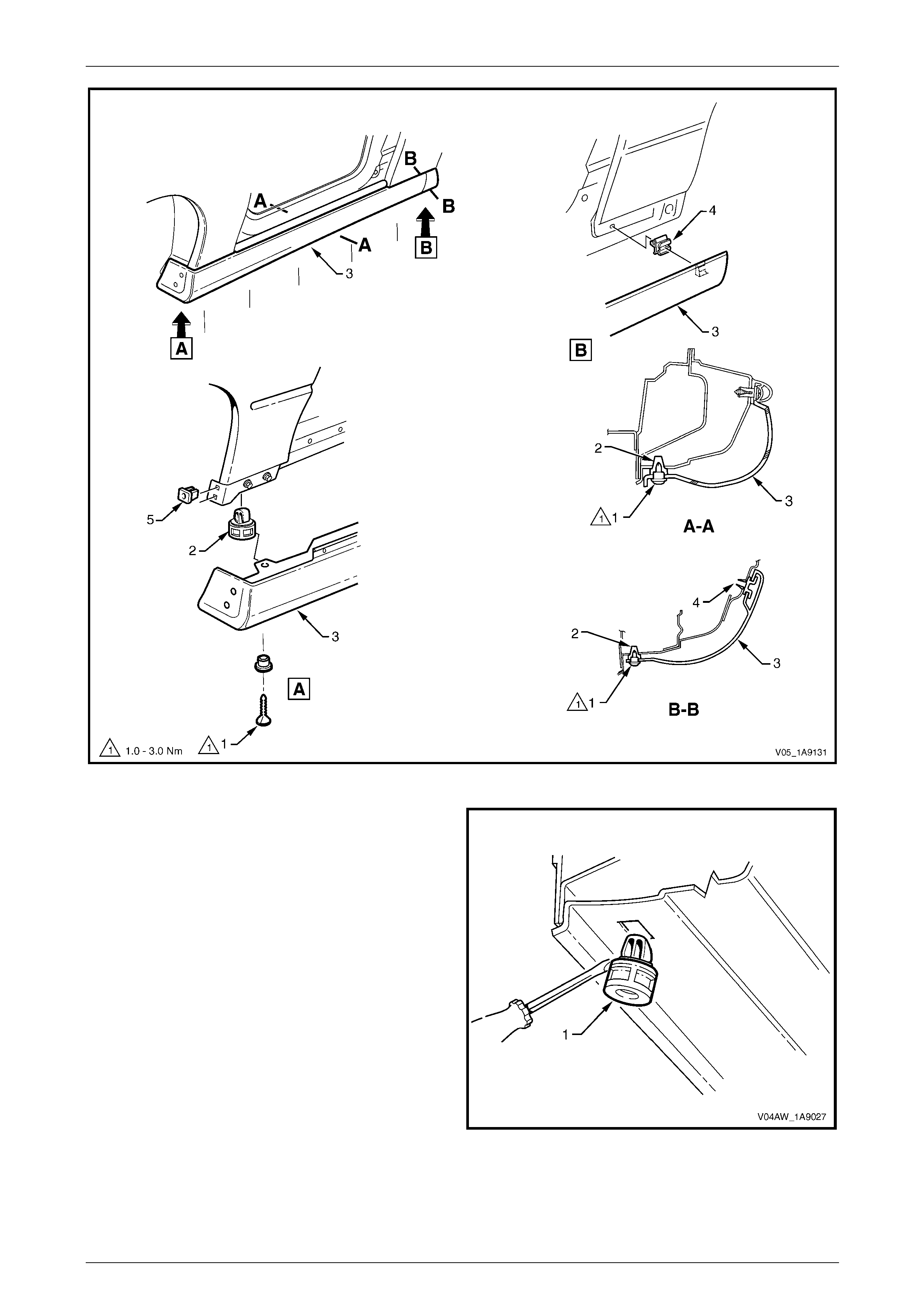
Exterior Ornamentation Page 1A9-151
Page 1A9-151
Figure 1A9 – 165
8 If required, remove the retainer (2), five places, b y
gently levering out from the body, taking care not to
damage the paint work.
Figure 1A9 – 166

Exterior Ornamentation Page 1A9-152
Page 1A9-152
Reinstall
Reinstallation of the rocker panel moulding assembly is the reverse of the removal procedure, noting the following:
1 Ensure the moulding is correctly seated in the retaining clips.
2 Tighten the scre ws to the correct torque spec ificatio n.
Rocker panel moulding attac hin g
screw torque specification...........................1.0 – 3.0 Nm
3 Ensure the weatherstrip is seated correctly.
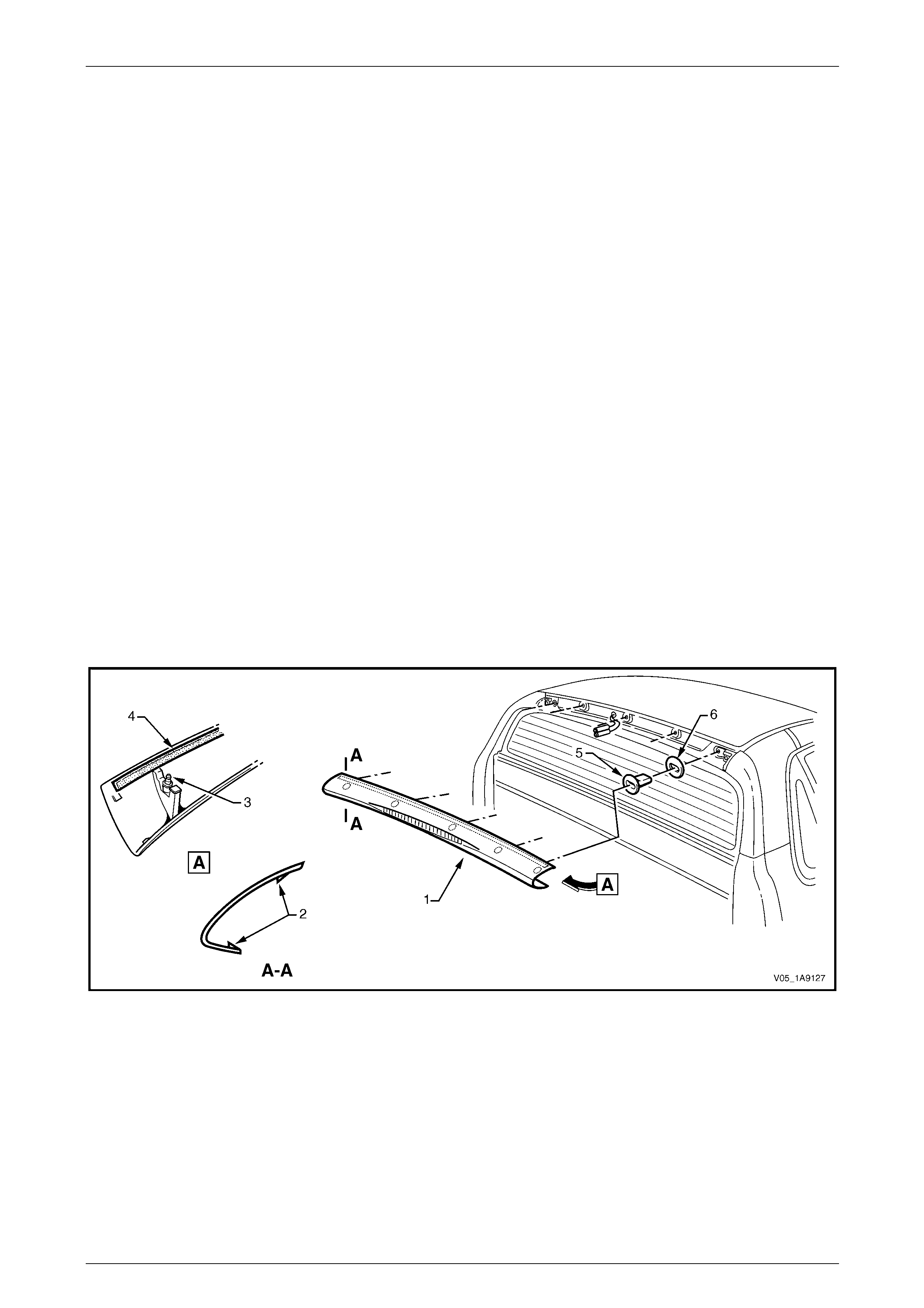
Exterior Ornamentation Page 1A9-153
Page 1A9-153
7.8 Rear Window Upper Moulding
LT Section No. — 10–265
Remove
1 Carefully sprea d each e nd of the rear window upper moulding (1) to diseng age the locking tabs (2), refer to
Figure 1A9 – 167.
2 Insert a flat-blade screwdriver and clean rag bet ween the lower edge of the moulding and the rear window.
3 Ensuring the locking tabs are disengaged, prise the moulding off in a rearward and slightl y upward direction to
disengage retaining stud (3), five places.
NOTE
The upper edge of the moulding is attached with
double-sided tape (4), remove the moulding
carefully.
4 Where fitted, disconnect the hi gh mount stop lamp connector from the rear of the mouldin g and remove the
moulding.
5 Remove any remaining double-sided tape from the mould i ng and/or panel as required and clean the surfaces with
Prepsol or equivalent.
6 If required, remove the retainer (5) and seal (6), five places by inserting a flat-bla de screwdriver between the upper
edge of the retainer and the panel. W hile pressing down on the screwdriver, ease the retainer out of its location.
NOTE
Take care not to damage the paintwork.
Figure 1A9 – 167

Exterior Ornamentation Page 1A9-154
Page 1A9-154
Disassemble
1 Where fitted, carefully diseng age the retaining tangs
from the high mount stop lamp assembly (1) and
manoeuvre the lamp assembly free from the moulding
(2).
Figure 1A9 – 168
Reinstall
1 If fitted, install the high mount stop lamp asse mbly using the reverse of the disassemble procedure.
2 Check the retainers and sea ls are in sound condition. Replace as required.
3 If removed, fit the retainers and seals.
4 If reusing the moulding, app ly new polyethylene double-sided tape such as 3M 4428 or equivalent to the upper
surface.
5 Clean the panel surface with Prepsol or equivalent.
6 Connect the high mount stop lamp connector, if fitted, and check its operation prior to installing the cap. Fit the
connector into its recess in the rear of the moulding.
7 Remove the backing paper from the doub le-sided tape.
8 Align the retaining studs with their respective retainers on the vehicle. Engage the retaine r s, ensuring the double-
sided tape does not contact until the mouldin g is full y seated.
9 Push-in each end to engage the locking tabs.
10 Press down along the upper surface of the moulding to ensure the tape is correctly adhered to the panel.
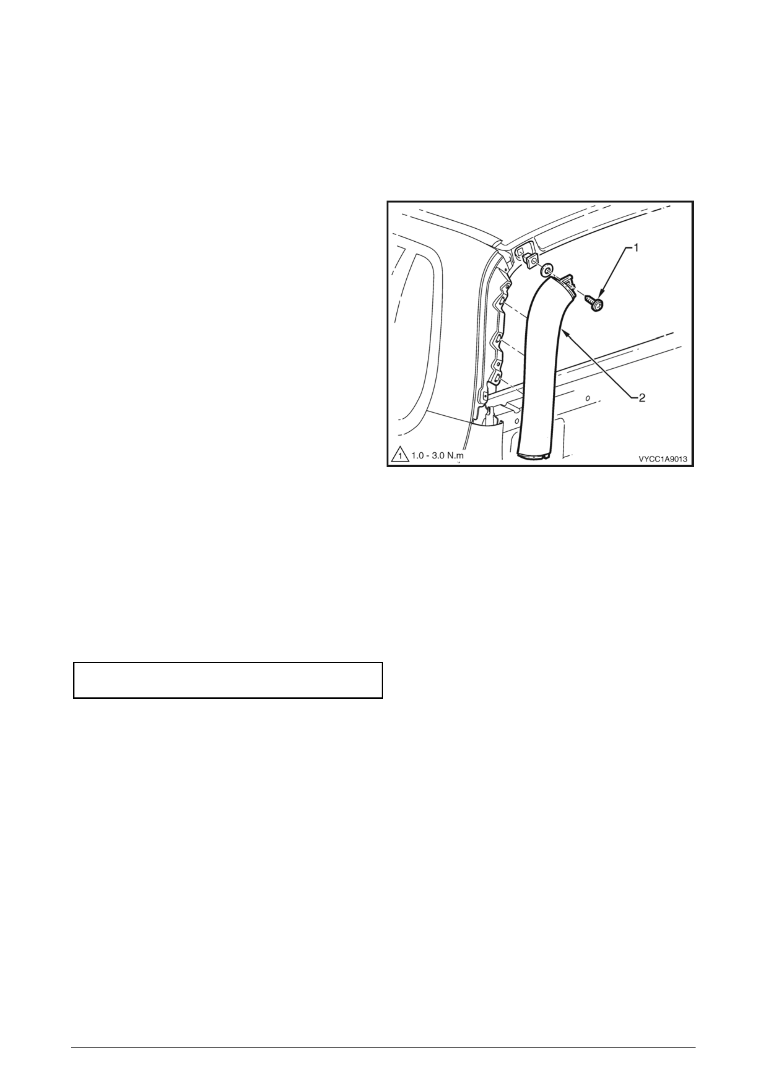
Exterior Ornamentation Page 1A9-155
Page 1A9-155
7.9 Rear Window Side Moulding
LT Section No. — 10–265
Remove
1 Remove the rear windo w upper moulding, refer to 7.8 Rear Window Upper Moulding.
2 Remove the retaining screw (1) attaching the rear
window side moulding (2) to the bod y.
3 Rotate the upper edge of the moulding rearward
disengaging the clip in three places.
4 Remove the rear windo w side moulding taking care to
avoid damage to the paint.
Figure 1A9 – 169
Reinstall
1 Install the lower end of the mouldi ng onto the rear quarter window moulding and behind the body side rear trim
panel, taking care to avoid paint damage.
2 Locate the lower datum pin, then by rolling the moulding forward, position the three clips into the slots engaging the
lower one first.
3 Push the rear window side moul ding firmly on to all three clips.
4 Install the screw retaining the rear window side moulding to the body a nd tighten to the correct torque specification.
Rear window side moulding
retaining screw torque specification............1.0 – 3.0 Nm
5 Install the rear windo w upper mouldin g.
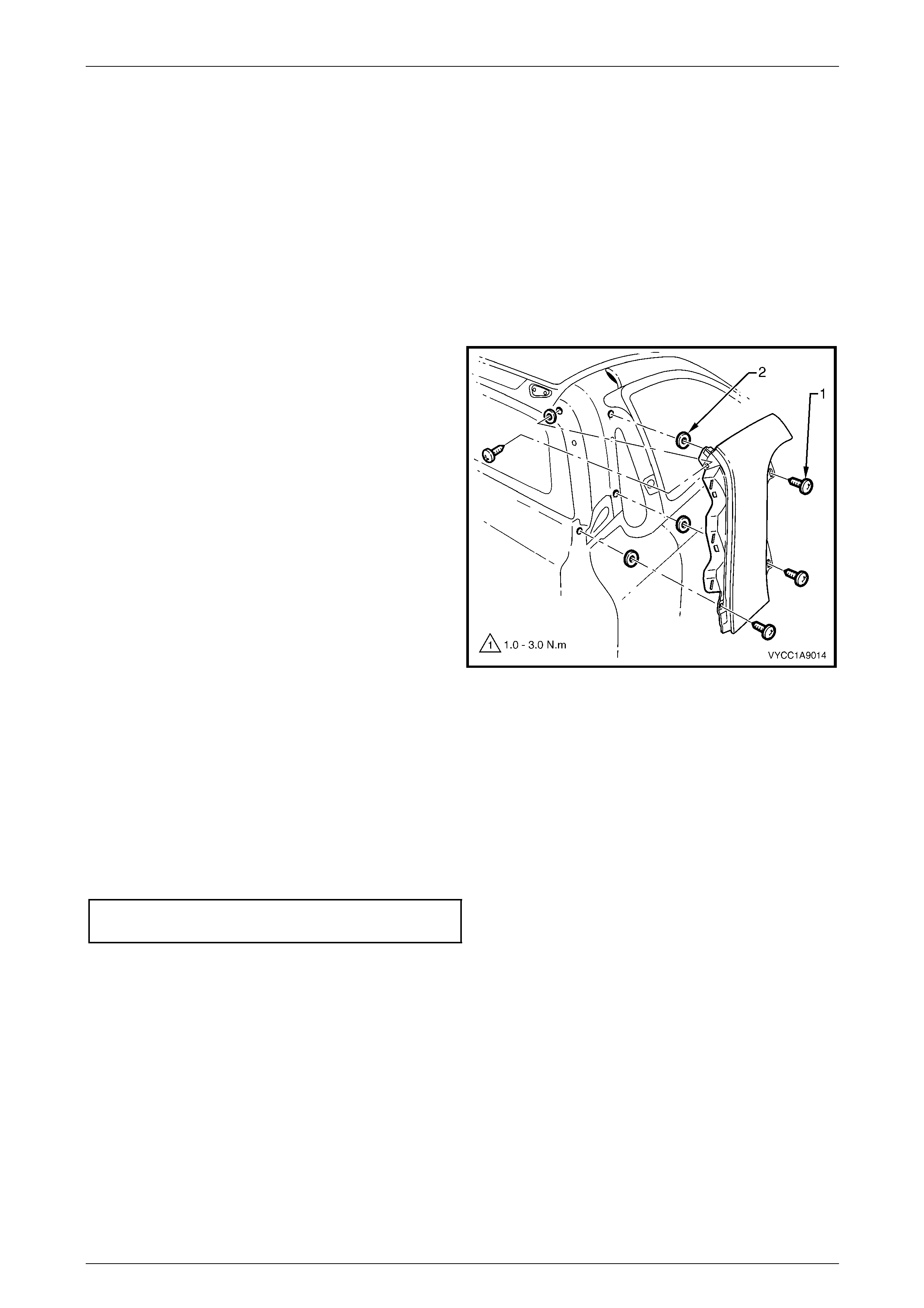
Exterior Ornamentation Page 1A9-156
Page 1A9-156
7.10 Rear Quarter Window Moulding
LT Section No. — 10–265
Remove
1 Remove the following components:
a Quarter window assembly, refer to Section 1A6 Stationary Windows.
b Rear window upper moulding, refer to 7.8 Rear Window Upper Moulding.
c Rear window side moulding, refer to 7.9 Rear Window Side Moulding.
2 Remove the four quarter window moulding attaching
screws (1) attaching the quarter window moulding to
the body.
3 Carefully pull the qu arter window moulding rearward
disengaging the front upper edge and remove the
moulding from the vehicle.
4 If required peel the foam seal (2) from the body, four
places.
Figure 1A9 – 170
Reinstall
Reinstallation of the rear quarter window moulding is the reverse of the removal procedure, noting the following:
1 Reinstall the foam seal, four places over the top of the screw holes.
2 Locate the quarter window moulding to the vehicle.
3 Install the moulding from the rear, inserting the front screws first.
4 Tighten the scre ws to the correct torque spec ificatio n.
Quarter window moulding
attaching screw torque specification...........1.0 – 3.0 Nm
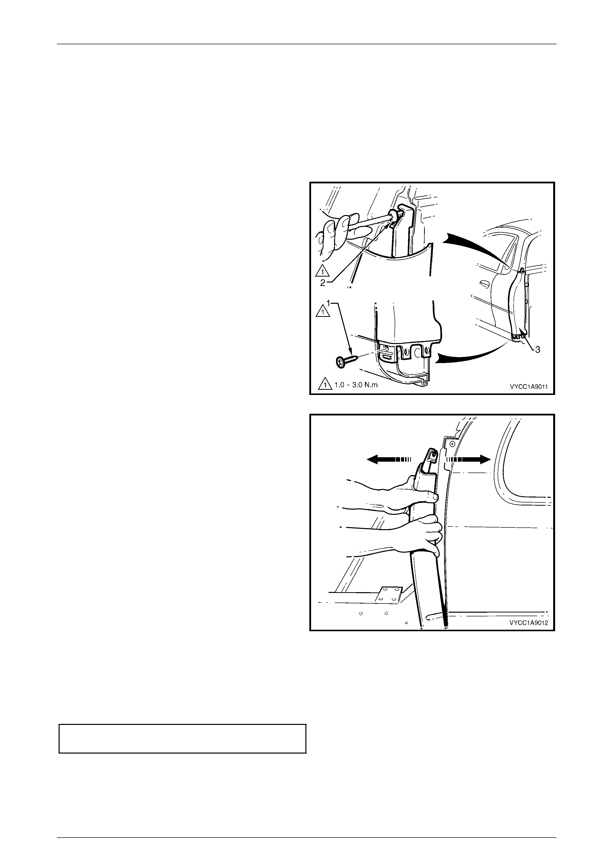
Exterior Ornamentation Page 1A9-157
Page 1A9-157
7.11 Body Side Rear Trim Panel
Remove
1 Remove the following components:
a Tray, if fitted to gain the required access, refe r to Section 1B 1 Tray.
b Rocker panel mouldin g en d cap refer to 7.6 Rocker Panel Moulding End Cap.
c Rear window side moulding re fer to 7.9 Rear W indow Side Moulding.
2 If required, the front rocker panel mould ing
may have to be partially removed to gain access
to the lower screw (1), refer to
7.7 Rocker Panel Moulding Assembly.
3 Remove the two retaining screws (1) and (2) attaching
the body side rear trim panel (3).
Figure 1A9 – 171
4 Starting from the top, carefully pull the body side rear
trim panel rearward slightly to disengage the five
retaining clips from the body side re ar trim panel
mounting bracket.
Figure 1A9 – 172
Reinstall
1 Align the body side rear trim panel on to the five mounting bracket retaining clips.
2 Gently push the body side re ar trim panel evenly and firml y on to the clips until secured.
3 Refit the two retaining screws attaching the trim panel in place and tighten to the correct torque specification.
Body side rear trim panel retaining
screw torque specification...........................1.0 – 3.0 Nm
4 If required refit the rocker panel moulding, refer to 7.7 Rocker Panel Moulding Assembly.
5 Reinstall the rear rocker panel moulding end cap, refer to 7.6 Rocker Panel Moulding End Cap.
6 Reinstall the rear window side moulding, refer to 7.9 Rear Window Side Mouldin g.
7 If required, refit the tray, refer to Section 1B1 Tr ay.
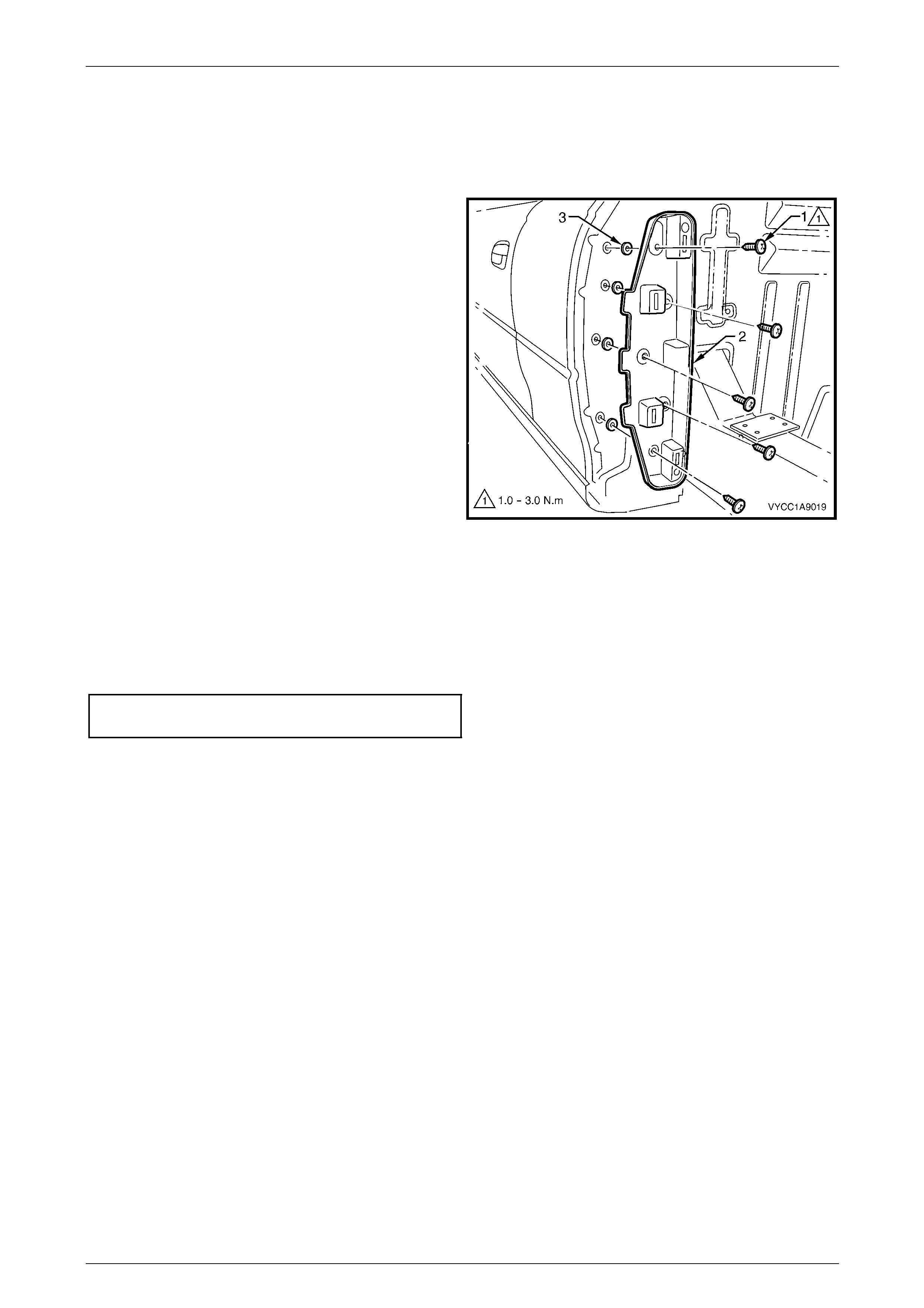
Exterior Ornamentation Page 1A9-158
Page 1A9-158
7.12 Body Side Rear Trim Bracket
Remove
1 Remove the body side rear trim panel, refer to 7.11 Body Side Rear Trim Panel.
2 Remove the five screws (1) attaching the bra cket (2)
to the body.
3 Remove the bracket and if required remove the foam
seal (3), five places.
Figure 1A9 – 173
Reinstall
Reinstallation of the body side rear trim bracket is the reverse of the removal proc edure, noting the following:
1 Position the foam seal, five places over each scre w hole in the body.
2 Tighten the scre ws to the correct torque spec ificatio n.
Body side rear trim bracket mounting
screw torque specification...........................1.0 – 3.0 Nm

Exterior Ornamentation Page 1A9-159
Page 1A9-159
7.13 Rear Outer Trim Panel and NVH Foam
Remove
1 Remove the following components:
a Tray, if fitted refer to Section 1B1 Tray.
b Body side rear trim panel, refer to 7.11 Body Side Rear T r im Panel.
c Retainer (2), 16 places, attaching the rear outer trim panel (1) refer to Figure 1A9 – 174.
2 Carefully tilt the rear outer trim panel rearward and lift it up to clear the body taking care not to dislodge the NVH
foam (3).
3 If required remove the outer section of NVH foam (3), two places.
Figure 1A9 – 174
NOTE
The two centre pieces of NVH foam are glued in
place with hot melt adhesive. Care must be taken
not to tear the foam when removing.
4 Carefully remove the centre p ieces of NVH foam, two places, taking care not to tear the foam at the hot melt
locations, refer to Figure 1A9 – 174.
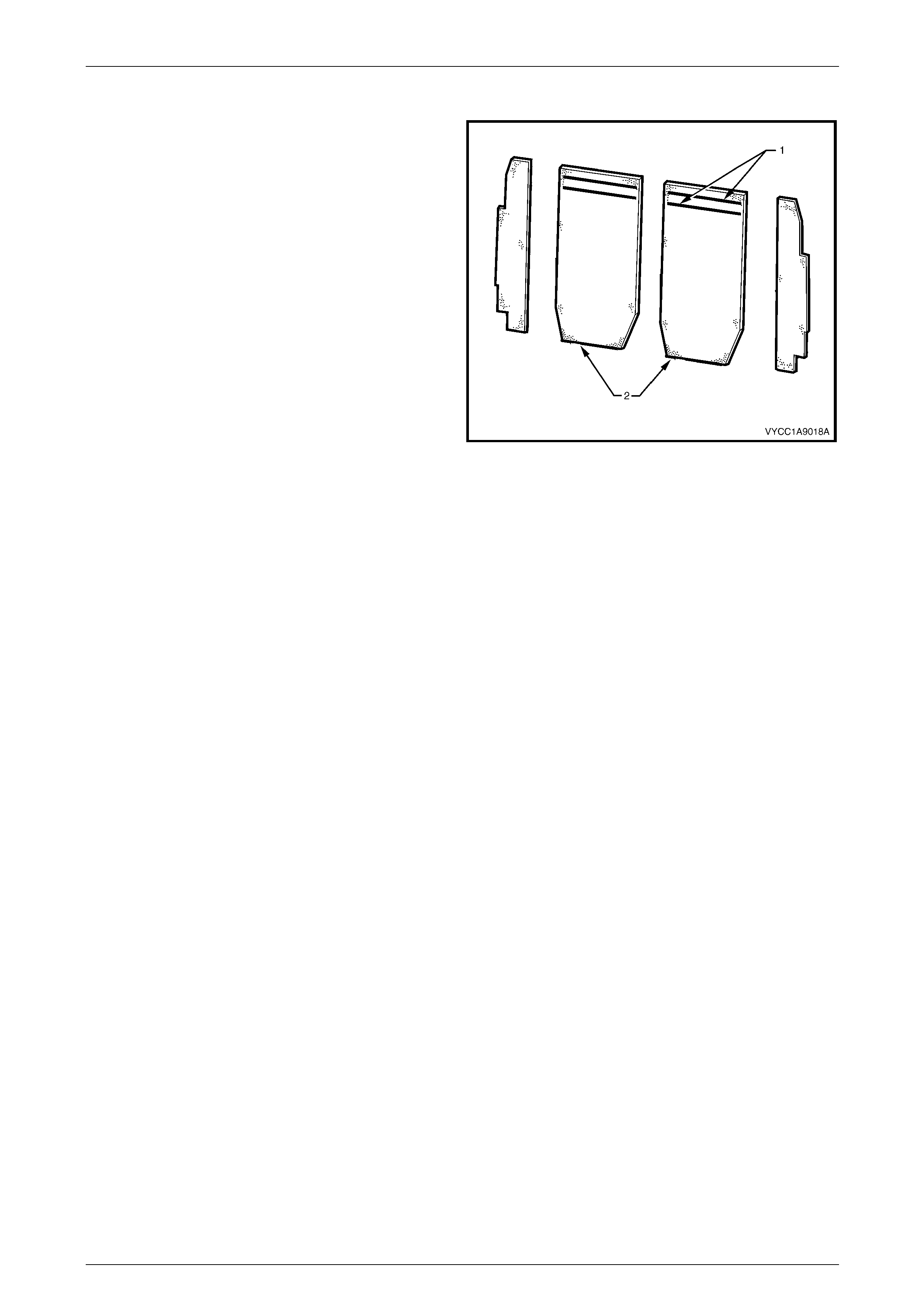
Exterior Ornamentation Page 1A9-160
Page 1A9-160
Reinstall
1 Position the two outer NVH foam pieces into place,
feeding the wiring harness through the slot in the lower
corner of the right-hand piece.
NOTE
The NVH foam used is mirror cut for use on both
sides of the vehicle. The backing on the foam
used during the production process will only be
visible on one half of the vehicle when fitted
correctly.
2 Apply two strips of hot melt glue (1) to the NVH foam
centre pieces. (2).
3 Position the centre piece of NVH foam, two places, to
the rear of the cab.
4 Slide the panel down into position and loc ate the
centre datum pin.
5 Reinstall the retainer, 16 places. Figure 1A9 – 175
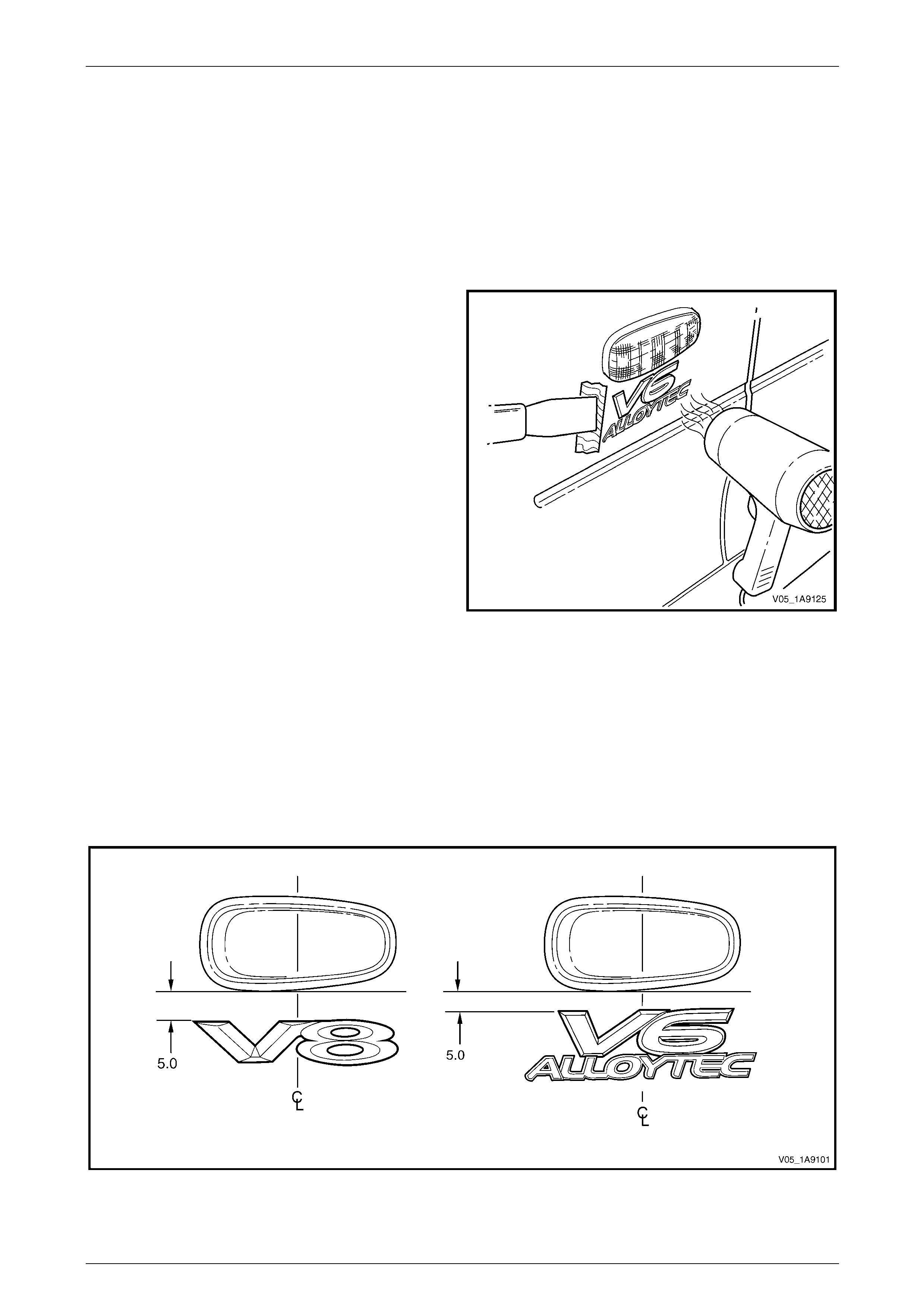
Exterior Ornamentation Page 1A9-161
Page 1A9-161
8 Service Operations, Crew Cab
8.1 Fender Name Plate
LT Section No. — 10–150
Remove
1 Protect the paint and bodywork with tape or a clean
rag.
2 To assist removal, warm the name plate with a heat-
lamp or heat-gun to soften the adhesiv e.
3 Using a paint scraper or similar, carefully prise the
name plate from the fender.
4 As required remove an y remaining double-sided tape
from the name plate and/or fender and clean the
surfaces with Prepsol or equivalent.
Figure 1A9 – 176
Reinstall
1 If reusing the name plate, apply ne w polyethylene double-sided tape such as 3M 4428 or equivalent to the back of
the name plate. Trim back the tape slightly away from the edge of the name plate.
2 Clean the fender surface with Prepsol or equivalent.
3 Remove the backing paper from the doub le-sided tape.
4 Apply the name plate in the position shown, measuring from the front side turn sign al lamp,
refer to Figure 1A9 – 177. Ensure it is positioned parallel to the style line.
Figure 1A9 – 177
5 Press firmly over the entire name plate for at least 10 sec onds to ensure sound adhesion.

Exterior Ornamentation Page 1A9-162
Page 1A9-162
8.2 Front Door Name Plate
Remove
1 Protect the paint and bodywork with tape or a clean
rag.
2 To assist removal, warm the name plate with a heat-
lamp or heat-gun to soften the adhesiv e.
3 Using a paint scraper or similar, carefully prise the
name plate from the door panel.
4 Remove any remaining double-sided tape from the
name plate and/or door panel and clean the surfaces
with Prepsol or equivalent.
Figure 1A9 – 178
Reinstall
1 If reusing the name plate, apply ne w polyethylene
double-sided tape such as 3 M 4428 or equivalent to
the back of the name plate. Trim back the tape slightly
away from the edge of the name plate.
2 Clean the door surface with Prepsol or equivalent.
3 Remove the backing pap er from the doub le-sided
tape.
4 Apply the name plate i n the p ositio n shown. Ensure it
is positioned parallel to the style line.
5 Press firmly over the entire name plate for at least 10
seconds to ensure sound adhesion.
Figure 1A9 – 179
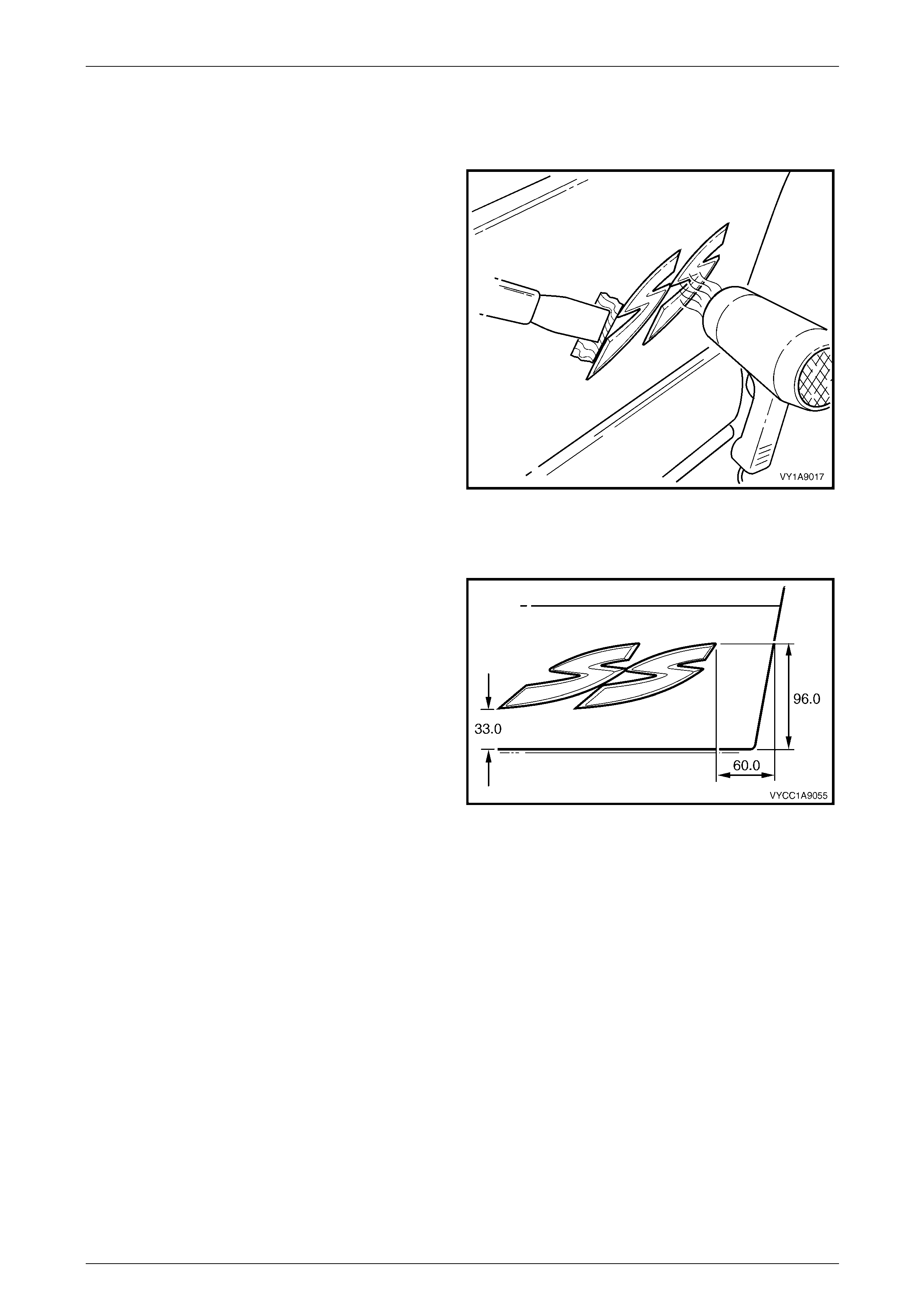
Exterior Ornamentation Page 1A9-163
Page 1A9-163
8.3 Rear Door Name plate
Remove
1 Protect the paint and bodywork with tape or a clean
rag.
2 To assist removal, warm the name plate with a heat-
lamp or heat-gun to soften the adhesiv e.
3 Using a paint scraper or similar, carefully prise the
name plate from the rear door.
4 As required, remove any remaining double-sided tape
from the name plate and/or rear door and clean the
surfaces with Prepsol or equivalent.
Figure 1A9 – 180
Reinstall
1 If reusing the name plate, apply ne w polyethylene
double-sided tape such as 3 M 4428 or equivalent to
the back of the name plate. Trim back the tape slightly
away from the edge of the name plate.
2 Clean the door panel surface with Prepsol or
equivalent.
3 Remove the backing pap er from the doub le-sided
tape.
4 Apply the name plate o nto the lower section of the rear
door panel in the position shown.
5 Press firmly over the entire name plate for at least 10
seconds to ensure sound adhesion. Figure 1A9 – 181
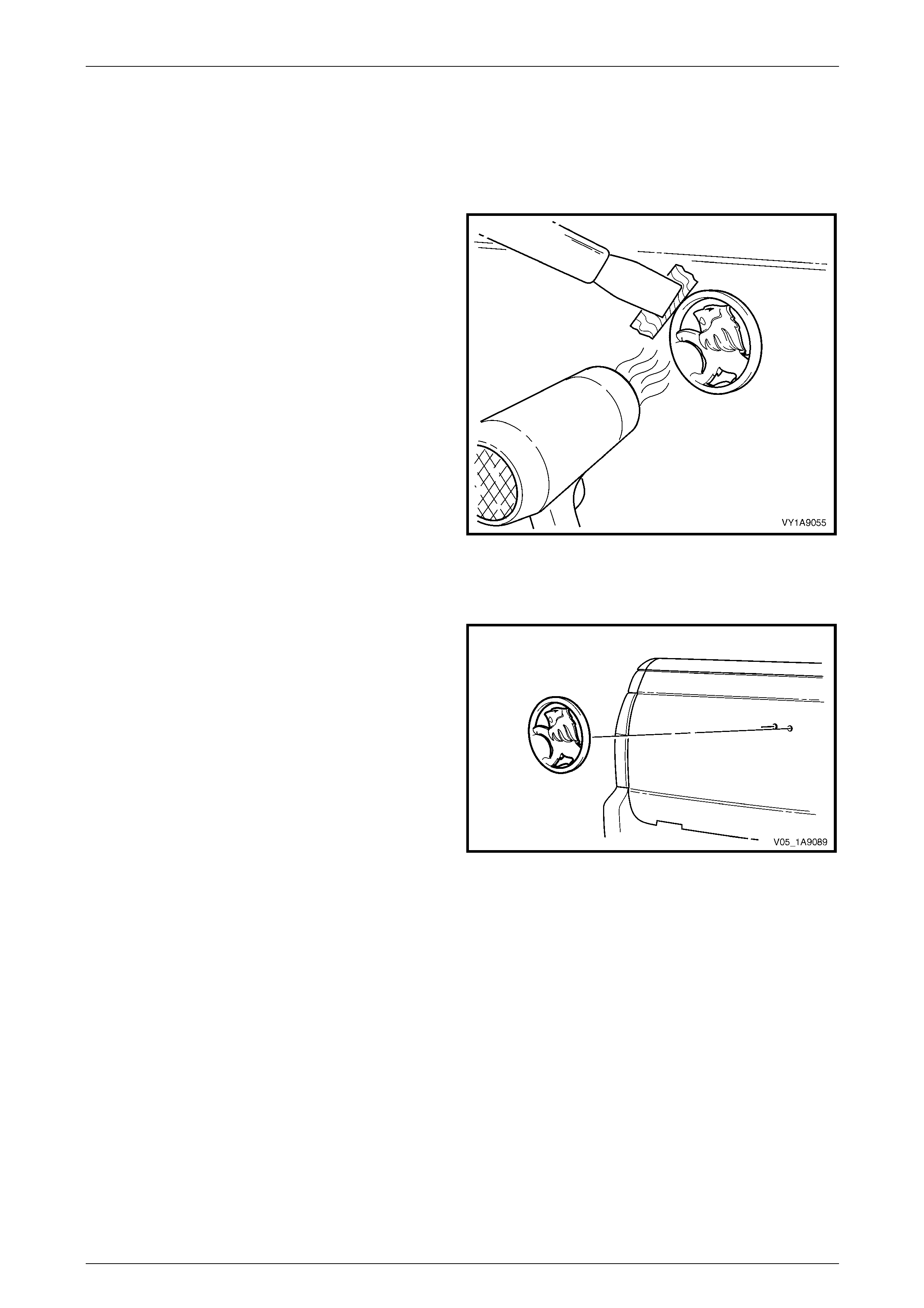
Exterior Ornamentation Page 1A9-164
Page 1A9-164
8.4 Endgate Emblem
LT Section No. — 10–150
Remove
1 Protect the paint and bodywork with tape or a clean
rag.
2 To assist removal, warm the emblem with a heat-lamp
or heat-gun to soften the adhesive.
3 Using a paint scraper or similar, carefully prise the
emblem from the endgate.
NOTE
The emblem has two locatin g pins, take care not
to break them if the emblem is to be reused.
4 As required, remove any remaining double-sided tape
from the emblem and/or endgate and clean the
surfaces with Prepsol or equivalent.
Figure 1A9 – 182
Reinstall
1 If reusing the emblem, apply new polyethylene double-
sided tape such as 3M 4428 or equ ivalent to the back
of the emblem. Trim back the tape slightly away from
the edge of the emblem.
2 Clean the panel surface with Prepsol or equivalent.
3 Remove the backing pap er from the doub le-sided
tape.
4 Apply the emblem in the position shown ensuring the
locating pins are correctly orientated with the locating
holes in the panel surface.
5 Press firmly over the entire emblem for at least 10
seconds to ensure sound adhesion. Figure 1A9 – 183
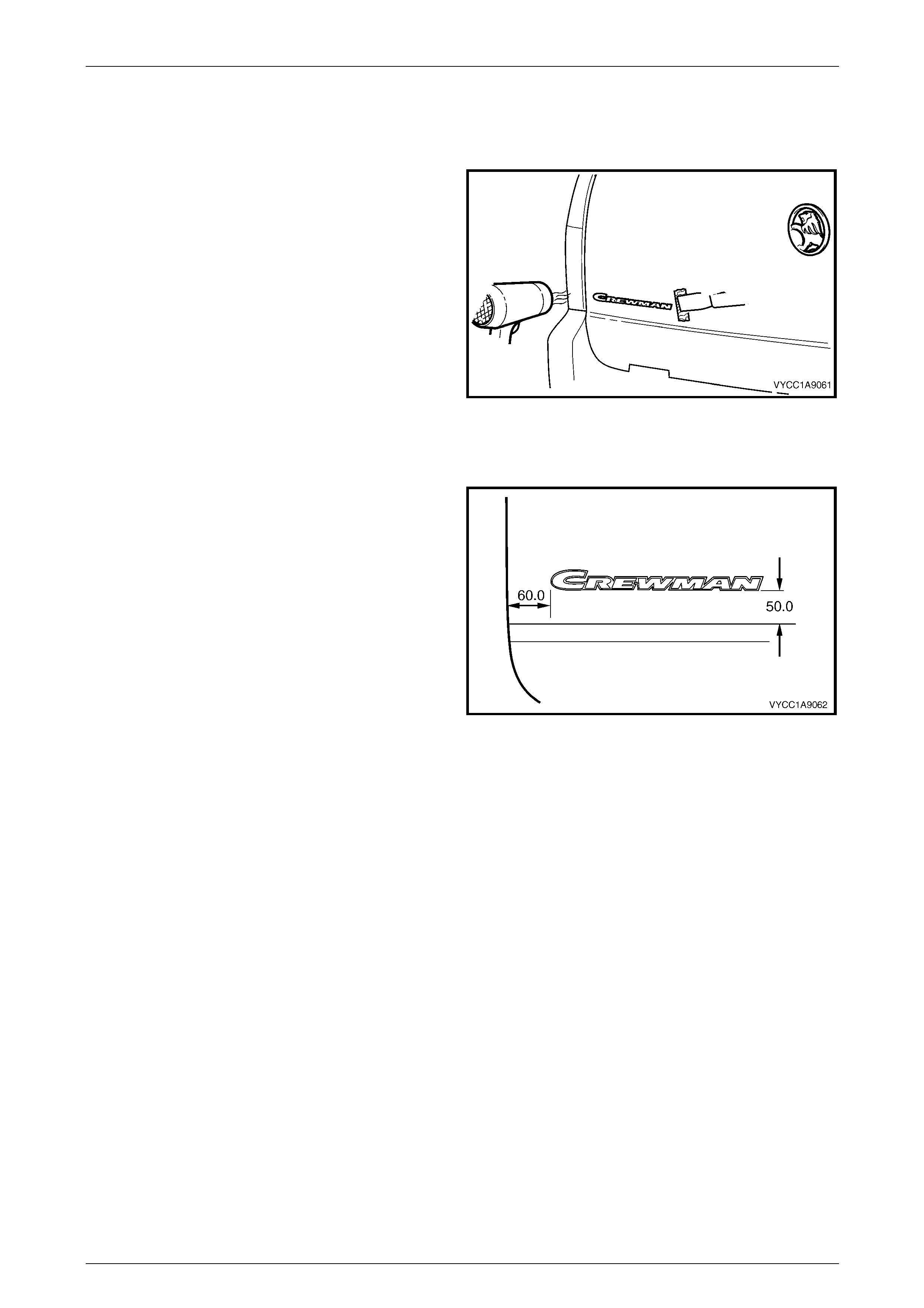
Exterior Ornamentation Page 1A9-165
Page 1A9-165
8.5 Endgate Name plate, Left-hand
Remove
1 Protect the paint and bodywork with tape or a clean
rag.
2 To assist removal, warm the name plate with a heat-
lamp or heat-gun to soften the adhesiv e.
3 Using a paint scraper or similar, carefully prise the
name plate from the endgate.
4 As required, remove any remaining double-sided tape
from the name plate and/or endgate and clean the
surfaces with Prepsol or equivalent.
Figure 1A9 – 184
Reinstall
1 If reusing the name plate, apply ne w polyethylene
double-sided tape such as 3 M 4428 or equivalent to
the back of the name plate. Trim back the tape slightly
away from the edge of the name plate.
2 Clean the endgate panel surface with Prepsol or
equivalent.
3 Remove the backing pap er from the doub le-sided
adhesive tape.
4 Apply the name plate o nto the left-hand side section of
the endgate panel in the pos ition shown.
5 Press firmly over the entire name plate for at least 10
seconds to ensure adhesion o f the double-sided
adhesive tape. Figure 1A9 – 185
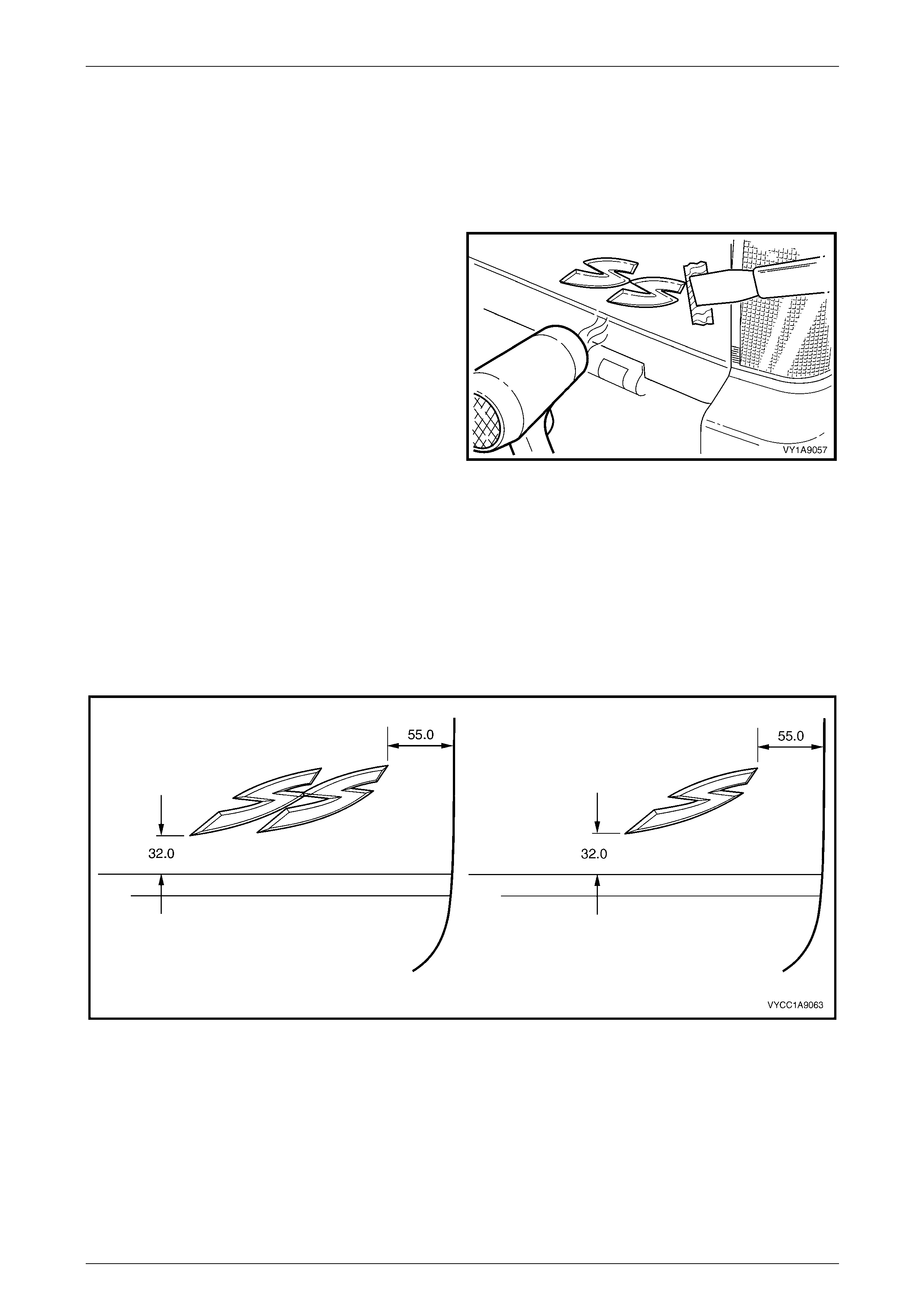
Exterior Ornamentation Page 1A9-166
Page 1A9-166
8.6 Endgate Name Plate, Right-hand
LT Section No. — 10–150
Remove
1 Protect the paint and bodywork with tape or a clean
rag.
2 To assist removal, warm the name plate with a heat-
lamp or heat-gun to soften the adhesiv e.
3 Using a paint scraper or similar, carefully prise the
name plate from the endgate.
4 As required, remove any remaining double-sided tape
from the name plate and/or endgate and clean the
surfaces with Prepsol or equivalent.
Figure 1A9 – 186
Reinstall
1 If reusing the name plate, apply ne w polyethylene double-sided tape such as 3M 4428 or equivalent to the back of
the name plate. Trim back the tape slightly away from the edge of the name plate.
2 Clean the panel surface with Prepsol or equivalent.
3 Remove the backing paper from the doub le-sided tape.
4 Apply the name plate o nto the right-hand side of the endgate in the position shown. Ensure the badge i s straight
and is correctly aligned to the measurements. Refer to Figure 1A9 – 187.
Figure 1A9 – 187
5 Press firmly over the entire name plate for at least 10 sec onds to ensure sound adhesion.
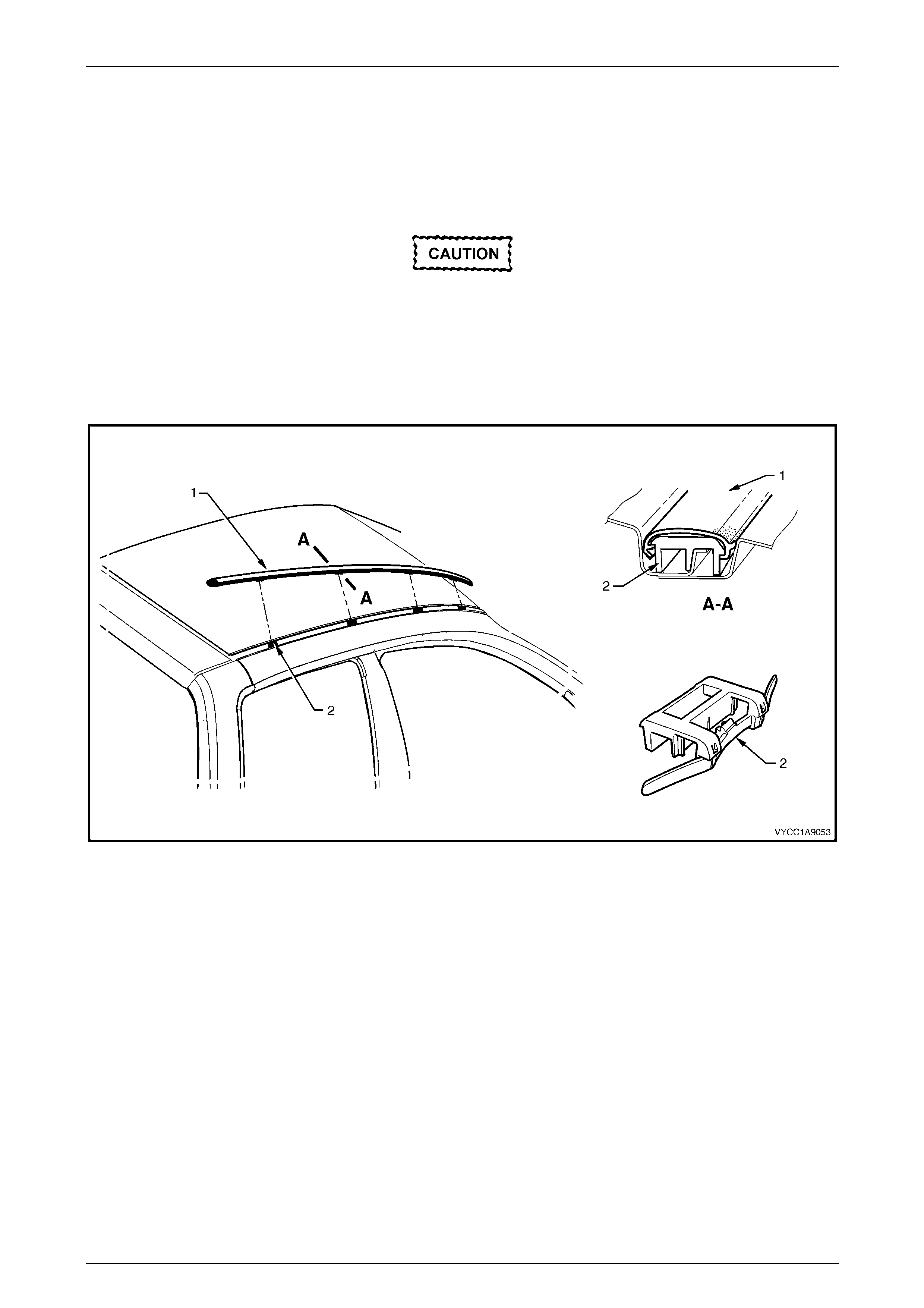
Exterior Ornamentation Page 1A9-167
Page 1A9-167
8.7 Roof Joint Moulding
LT Section No. — 10–265
Remove
Take care as the retaining clips can easily
break. Protect the paintwork with a clean rag.
1 Beginning at the front of the roof panel, use a screwdriver to carefully prise the roof pa nel joint moulding (1) from
the roof channel, disengaging the retaining clip (2), four places.
2 Disengage the rear locating lug on the roof panel joint moulding from the rear header trim by lifting the moulding at
the front.
Figure 1A9 – 188
Reinstall
1 Ensure the roof joint channel is clean and clear of sealant which may obstruct the clips.
2 As required, seat the four clips onto the roof joint mouldi ng, spaced as indicated.
3 Position the roof joint mouldin g locati ng lug i n positi on in the rear header trim.
4 Seat the roof joint moulding ov er the roof channel and beginning at the rear, clip it in place ensuring the mouldin g is
installed under the windshield moulding cover.
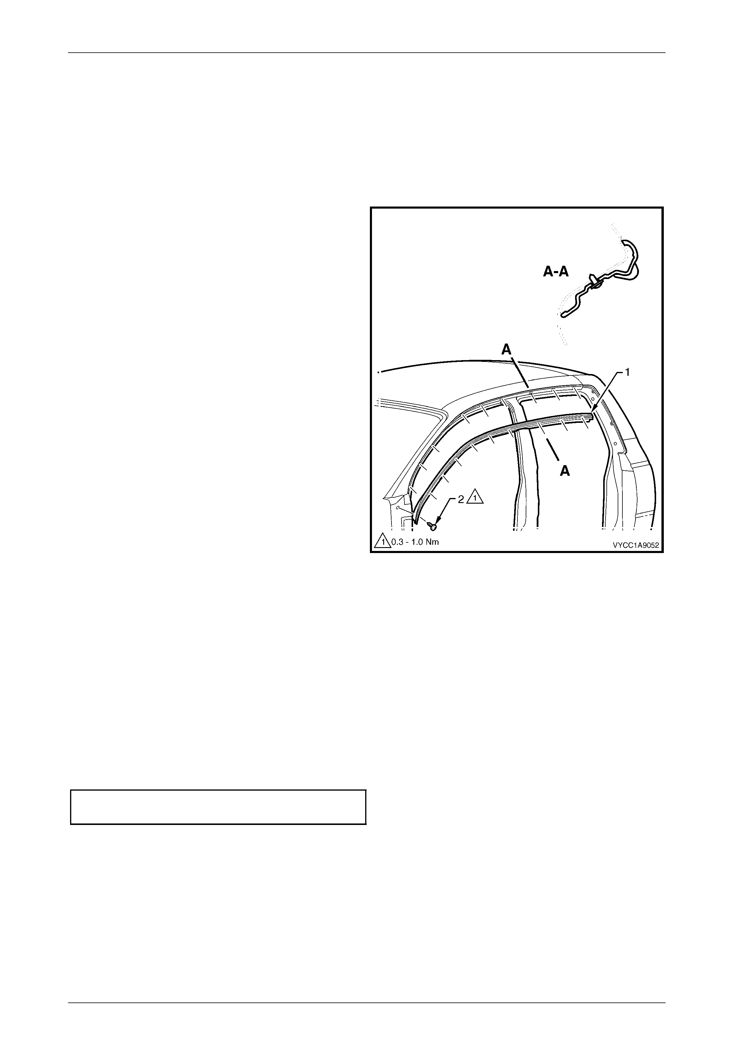
Exterior Ornamentation Page 1A9-168
Page 1A9-168
8.8 Door Opening Moulding
LT Section No. — 10–265
Remove
1 Open the front and rear doors on the relevant side of the vehicle.
2 Beginning at each en d and working towards the
middle of the door opening moulding (1), remove the
screw (2), 10 places, attaching the door opening
moulding to the vehicle.
3 Carefully remove the moul ding.
Figure 1A9 – 189
Reinstall
Reinstallation of the door opening moulding is the reverse of the removal procedure, noting the following:
1 When installing the screws, begin at the rear and work forward.
NOTE
The screws are encapsulated with a wax sealer.
It is recommended the screws be replaced if
removed, however if this is impractical, apply a
small amount of sealer to the end of the thread.
2 Tighten the scre ws to the correct torque spec ificatio n.
Door opening moulding attaching
screw torque specification...........................0.3 – 1.0 Nm
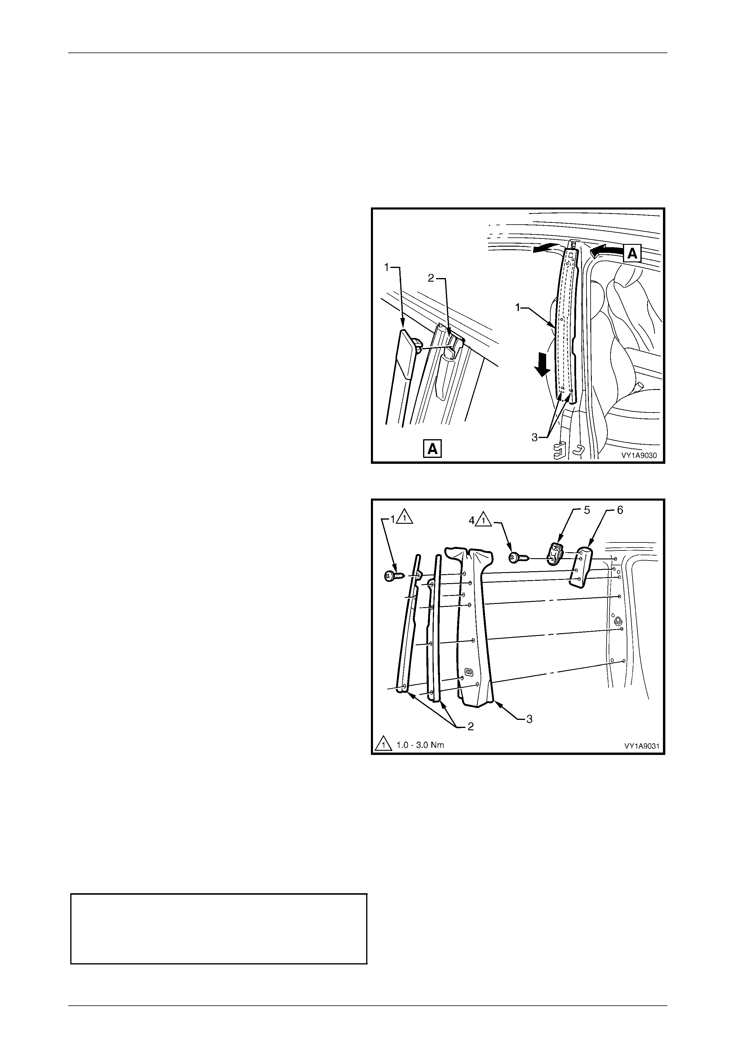
Exterior Ornamentation Page 1A9-169
Page 1A9-169
8.9 Centre Pillar Upper Finisher Assembly
LT Section No. — 10–265
Remove
1 Open the front and rear doors on the relevant side of the vehicle.
2 Gently prise the top of the centre pillar upper finisher
(1) out to disengage it from the centre pillar upper
finisher retainer (2).
3 Holding the top of finisher out, slide it down the centre
pillar outer sealing strips (3) until it rests on rear door
hinge.
4 Manoeuvre the finisher from the sealing strips and
remove.
Figure 1A9 – 190
5 Remove the screw (1), seven places, attaching the
centre pillar sealing strips (2) to the pill ar and remove
the strips.
6 Partially remov e the door frame opening moulding,
refer to 8.8 Door Opening Moulding.
7 Remove the centre pillar upper trim panel (3) by
pulling away from the pillar.
8 Remove the screw (4) attaching the centre pillar u pp er
finisher retainer (5) and centre pillar upper trim mount
plate (6) to the pillar and remove.
Figure 1A9 – 191
Reinstall
Reinstallation of the centre pillar upper finisher assembly is the reverse of the removal procedure, noting the following:
1 Ensure the centre pillar upper trim panel is seated correctly under the do or opening weatherstrips.
2 Tighten the scre ws to the correct torque spec ificatio n.
Centre pillar upper finisher retainer
attaching screw torque specification...........1.0 – 3.0 Nm
Centre pillar sealing strip attac hin g
screw torque specification...........................1.0 – 3.0 Nm
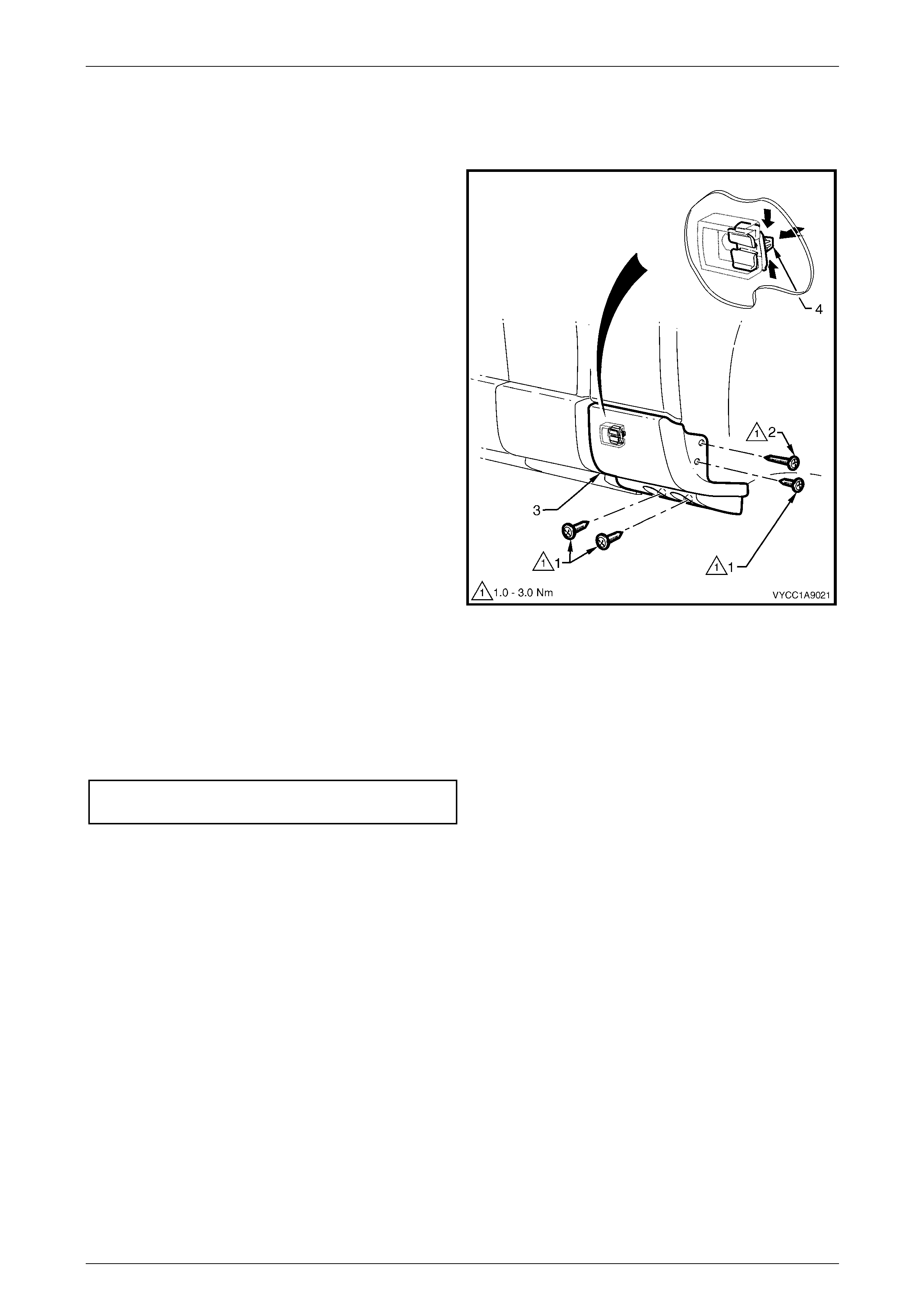
Exterior Ornamentation Page 1A9-170
Page 1A9-170
8.10 Rear Body Front Rocker Moulding
Remove
1 Remove the three screws (1) and the longer screw (2)
attaching the rear body front rocker moulding (3) to the
rear body side panel.
2 From behind the bod y panel, press the retainer clip
tabs (4) together and push the clip out from the panel
to release the rocker moulding .
3 If required, slide the clip out to one side to re move
from the moulding.
Figure 1A9 – 192
Reinstall
1 Slide the clip into place o n the moulding if removed.
2 Locate and pre ss the moul ding onto the panelling.
3 Tighten the scre ws to the correct torque spec ificatio n.
Rear body front rocker moulding attaching
screw torque specification...........................1.0 – 3.0 Nm
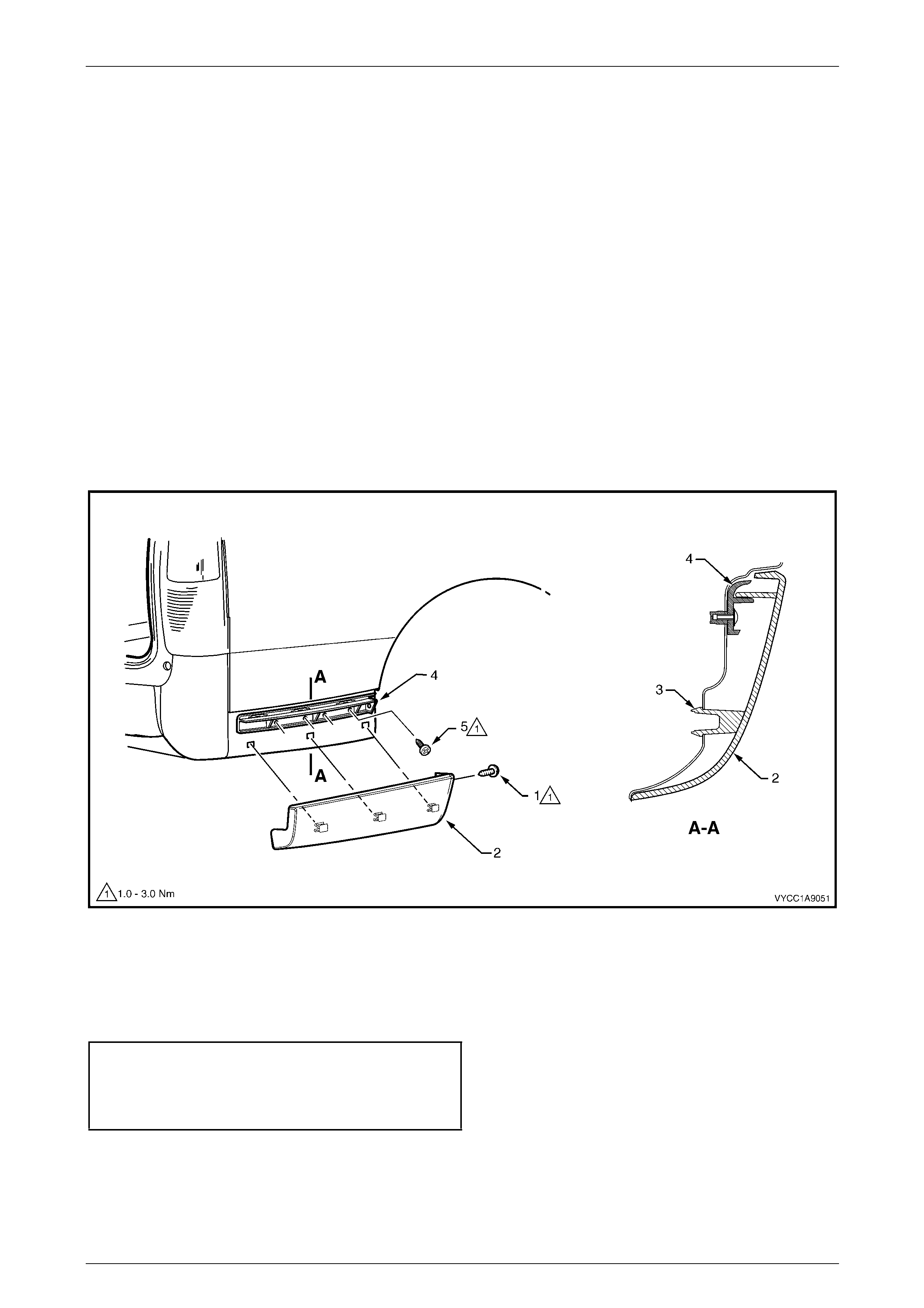
Exterior Ornamentation Page 1A9-171
Page 1A9-171
8.11 Rear Body Rear Rocker Moulding
NOTE
The rear body rear rocker moulding on SS
vehicles is integrated into the rear bumper fascia
assembly. For service procedures on the rear
bumper fascia, refer to Section 1D Bumper Bars.
Remove
1 Remove the screw (1) attaching the rear body rear rocker moulding (2) to the rear wheelhouse l iner,
refer to Figure 1A9 – 193.
2 From behind the rear qu arter panel, press and push out each of the three rocker mouldin g retain ing tangs (3) to
release the rocker moulding from the body panelling.
2 Gently prise the rocker moulding outward from the lower edge to release it from the rear bumper fascia guide
assembly (4).
3 If required, remove the screw (5), four places, attaching the rear bumper fac ia guide assembly to the panel and
remove the guide assembly.
Figure 1A9 – 193
Reinstall
Reinstallation of the rear body assembly rear rocker moulding is the reverse of the removal procedure. Tighten the
screws to the correct torque specification.
Rear bumper fascia guide assembly
attaching screw torque specification...........1.0 – 3.0 Nm
Rear body rear rocker moulding
attaching screw torque specification...........1.0 – 3.0 Nm
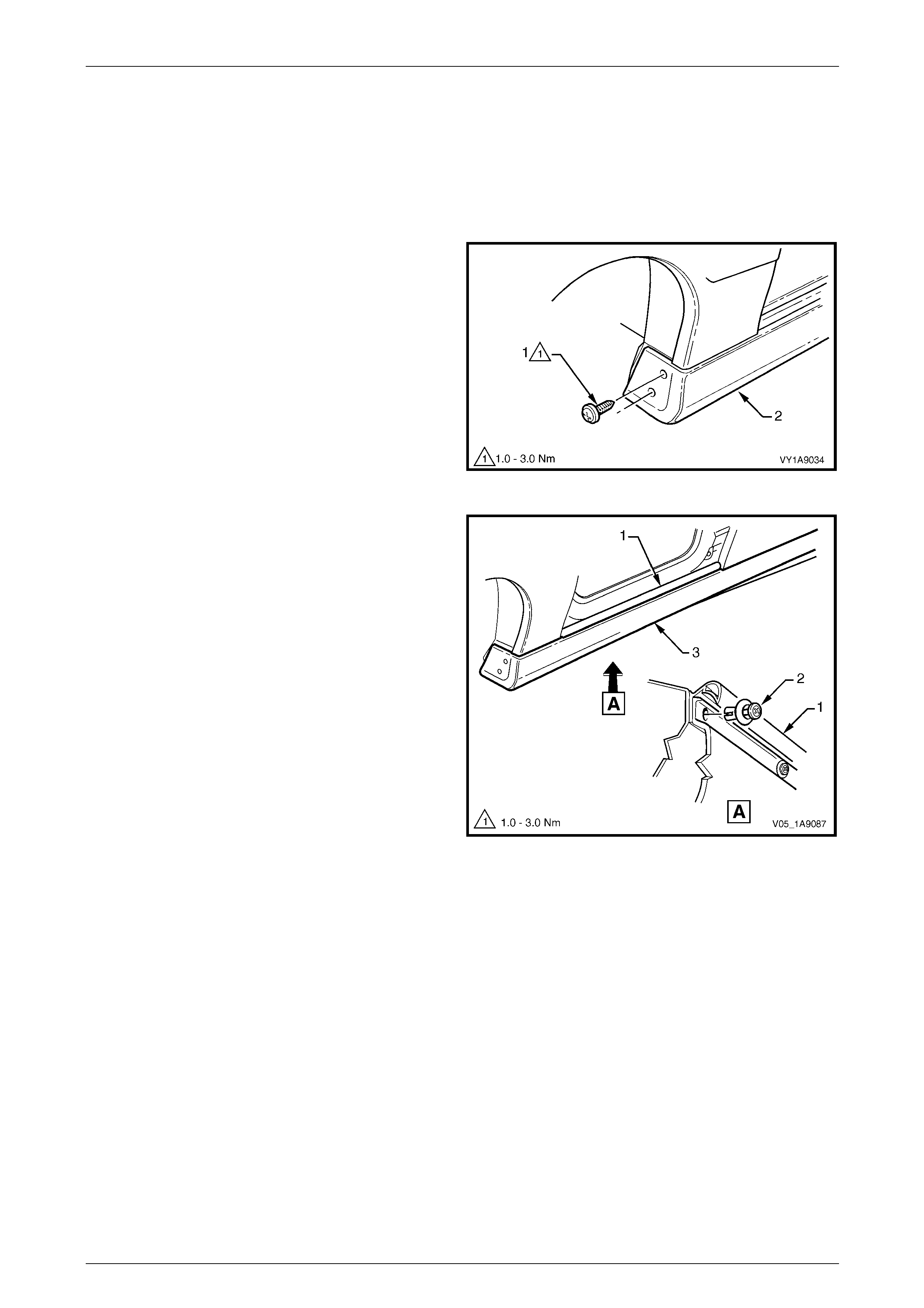
Exterior Ornamentation Page 1A9-172
Page 1A9-172
8.12 Rocker Panel Moulding Assembly
LT Section No. — 10–300
Remove
1 On the relevant side remove the rear road wheel, refer to Section 10 Wheels and T yres.
2 Remove the screw (1), two places, attaching the front
rocker panel moulding (2) to the fender and liner.
Figure 1A9 – 194
3 Lift up the rocker panel weatherstrip (1) as shown in
View A to gain access and remove the retainer (2),
five places, attaching the rocker panel moulding (3) to
the vehicle body.
NOTE
If the retainers are difficult to remove, prise out
the centre section a small amount with a flat
bladed screwdriver, then continue to unscrew. It
may also be necessary to retain the outer
section of the retainer with fingers or pliers.
4 Referring to Figure 1A9 – 196. From underneath the
vehicle, remove the screw (1), 10 places, from the
retainer (2) under the moulding (3).
5 Remove the moulding, uncl ip ping the retainer (4).
6 If required, prise the nut (5), two places, from the
fender.
7 If required, prise retainer from the quater panel. Figure 1A9 – 195
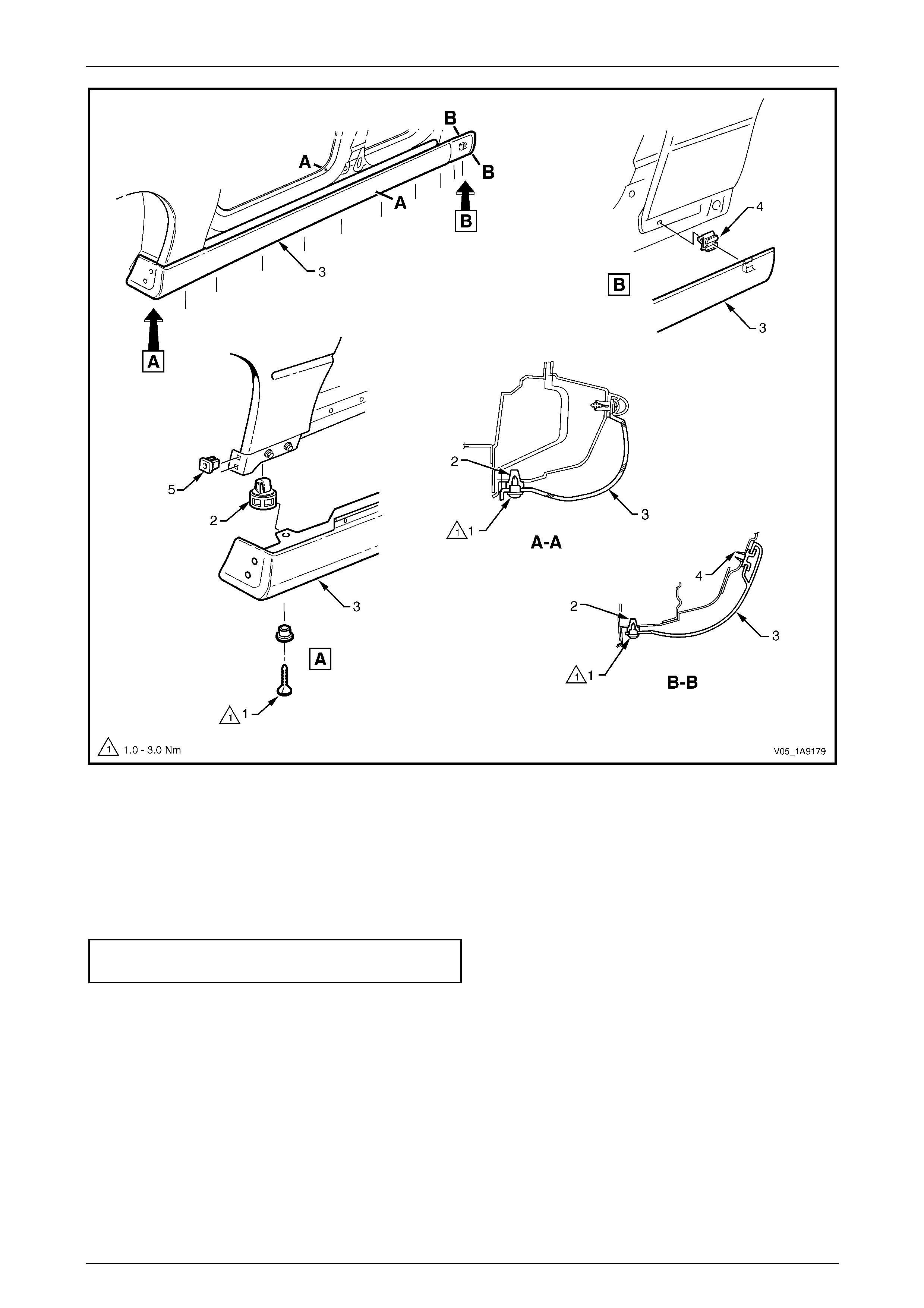
Exterior Ornamentation Page 1A9-173
Page 1A9-173
Figure 1A9 – 196
Reinstall
Reinstallation of the front body rocker moulding is the reverse of the removal procedure, noting the following:
1 Ensure the moulding is correctly seated in the retaining clips.
2 Tighten the scre ws to the correct torque spec ificatio n.
Rocker panel moulding attac hin g
screw torque specification...........................1.0 – 3.0 Nm
3 Ensure the weatherstrip is seated correctly.
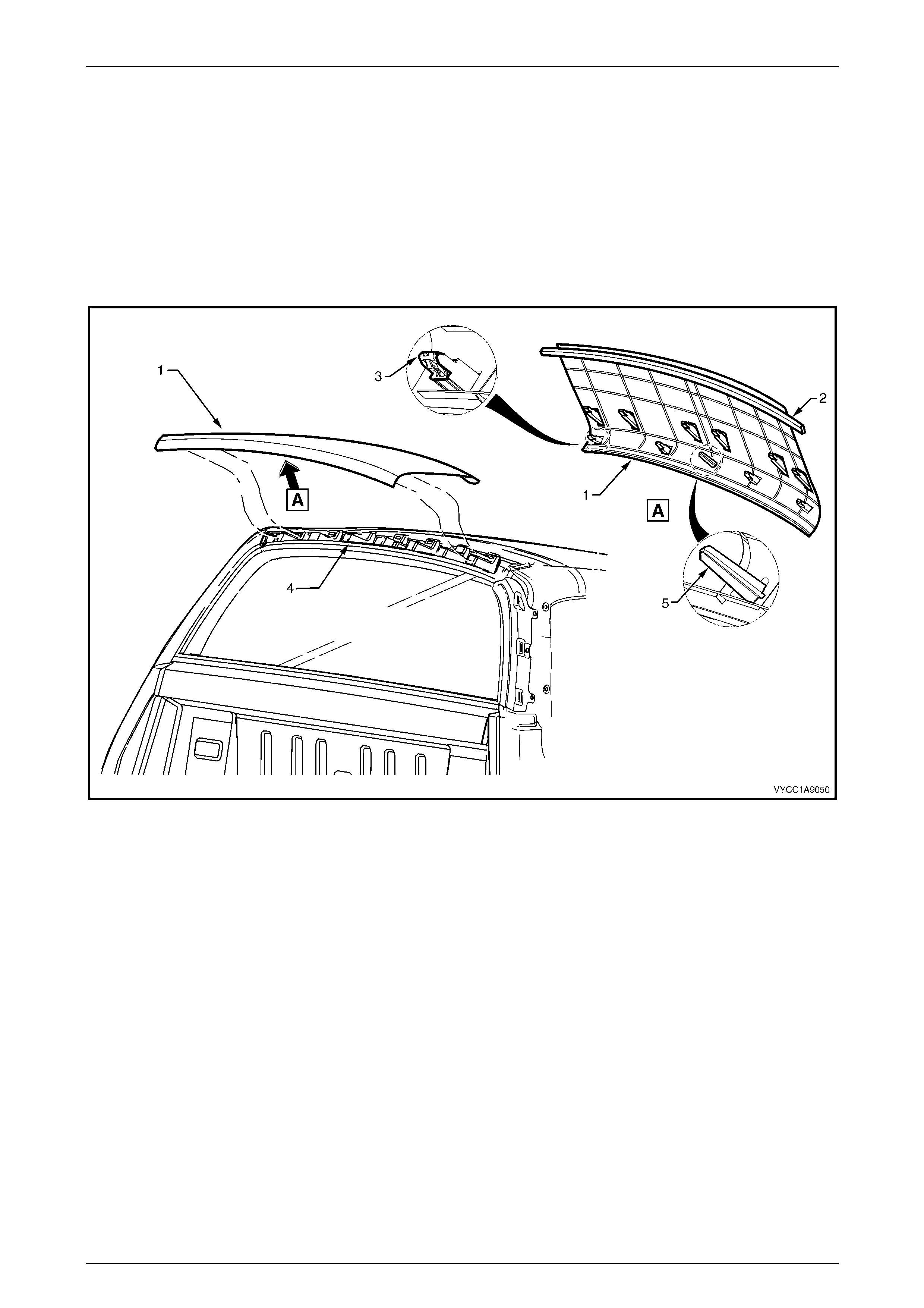
Exterior Ornamentation Page 1A9-174
Page 1A9-174
8.13 Rear Header Trim
Remove
1 Remove the body lock pillar trim, refer to 8.17 Body Lock Pillar Trim.
2 Starting from the front edge, prise the rear head er trim (1) free from the double-sided tape (2),
refer to Figure 1A9 – 197.
3 Gently pull the rear head er trim assembly rearward to release retaining clip (3), 10 places, from the rear header trim
retainer (4).
Figure 1A9 – 197
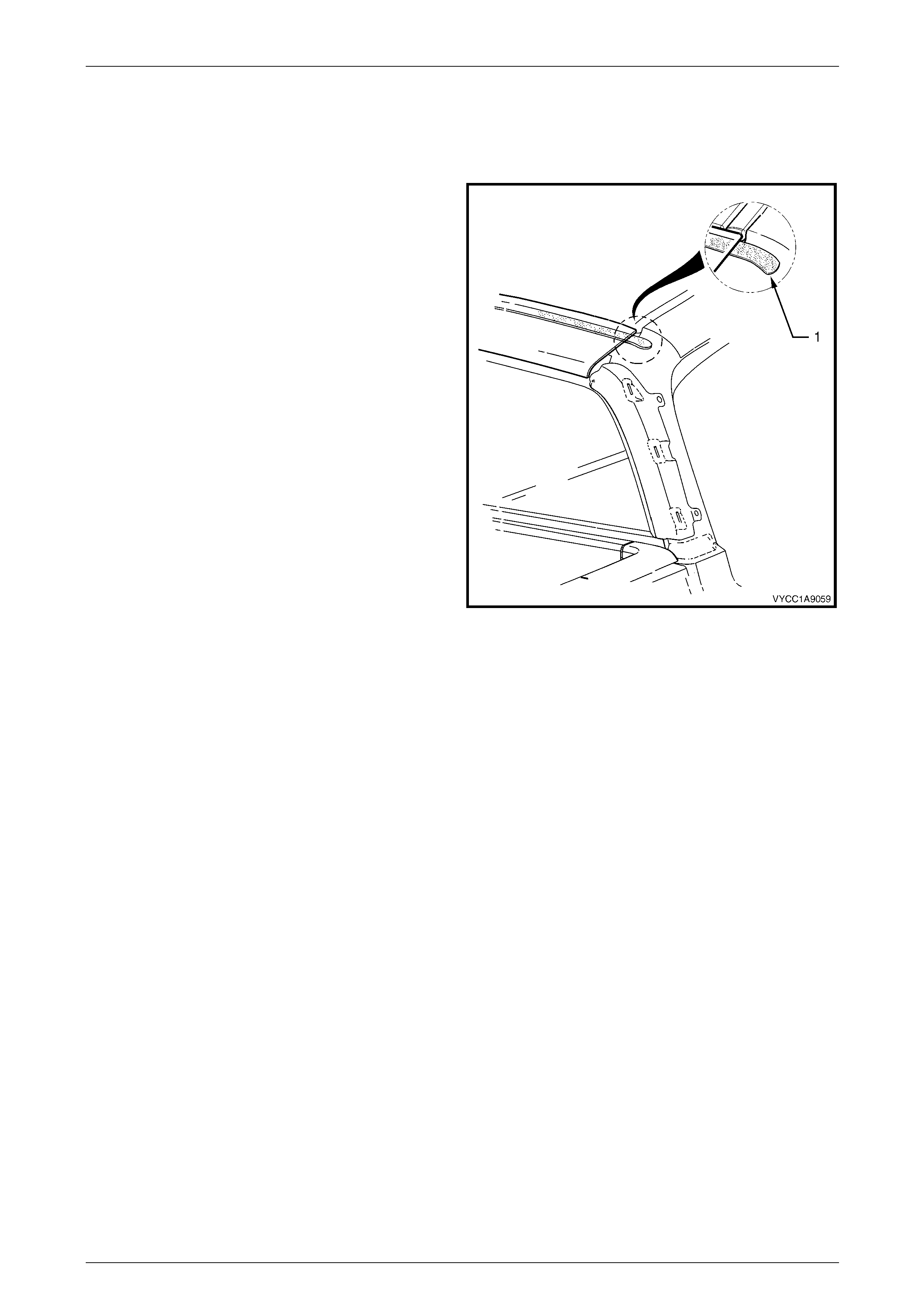
Exterior Ornamentation Page 1A9-175
Page 1A9-175
Reinstall
1 As required, thoroughl y clean and dry the roof panel and trim along the surfaces to be co ntacted with the double-
sided tape using Prepsol or equivalent.
2 If reinstalling the existing header trim, apply a length of
double-sided tape, such as 3 M 4428 or equivalent
along the mating surface of the trim assembly, leaving
at least a 30 mm overhang of tape at either end (1).
NOTE
Do not remove the backing paper from the
double-sided tape at this stage.
3 Referring to Figure 1A9 – 197, position the header trim
so the locating pins (5) are aligned with the slots in the
rear header trim retainer moulding. Starting at a corner
of the rear header trim, hold the front edge up slightl y
and gently tap the header trim evenly until all retaini ng
clips engage into position.
4 Check for correct alignment of the header trim.
5 Peel the backing paper from the underside of one end
of the double-sided tape (1).
6 Position and press the double-sided tape d own onto
the roof panel. Peel back and remove the remaining
length of backing paper and allow the rear header trim
to contact and adhere to the roof panelling.
7 Firmly press do wn along the front edge of the hea der
trim to ensure the double-sided tape is completel y
adhered to the roof panel. Figure 1A9 – 198
8 Reinstall the body lock pill ar trim, refer to Section 1A8 Headlining and Interior Trim.
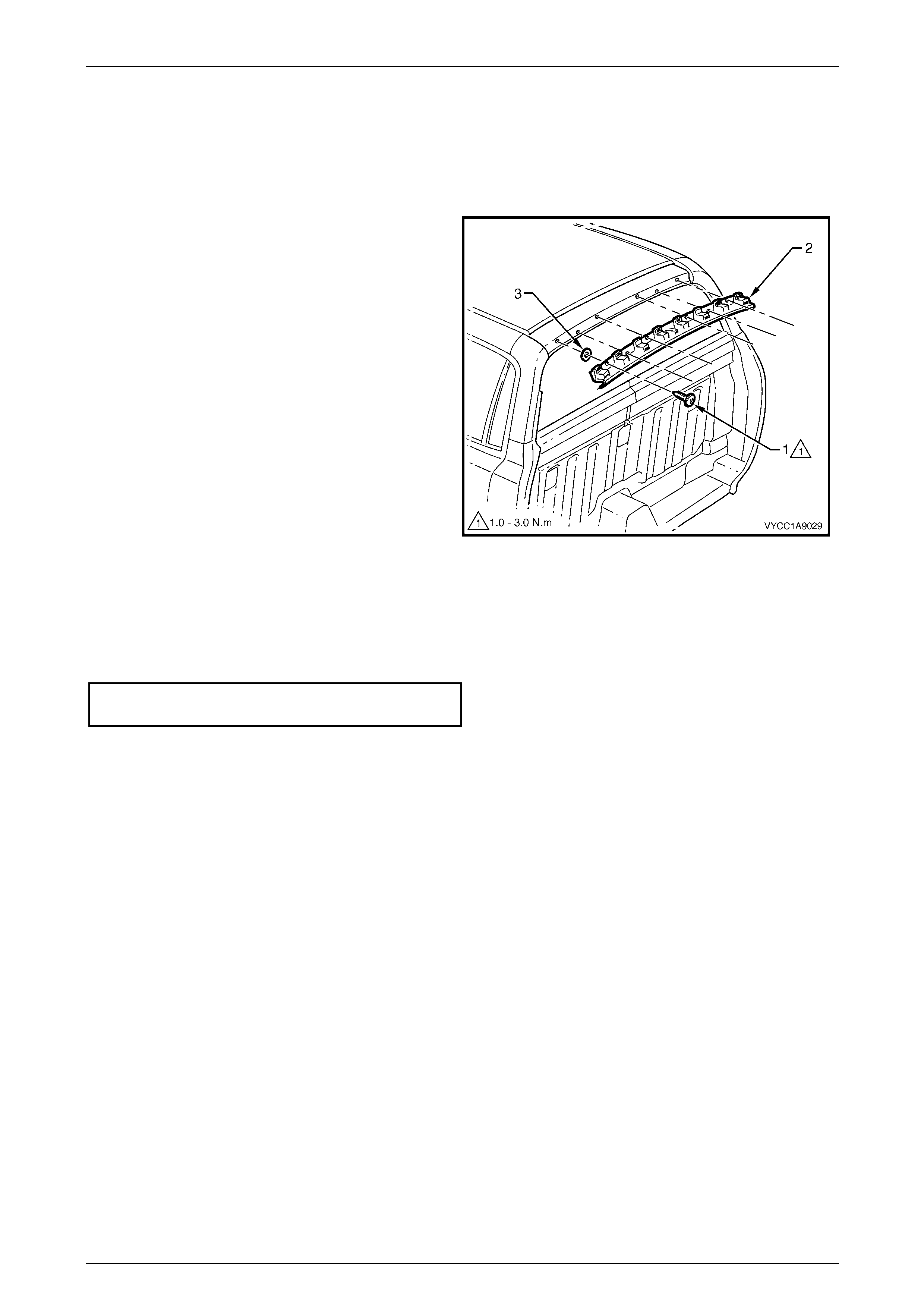
Exterior Ornamentation Page 1A9-176
Page 1A9-176
8.14 Rear Header Trim Retainer
Remove
1 Remove the rear header trim, refer to 8.13 Rear Header T r im.
2 Remove the screw (1), six places, attaching the rear
header trim retainer (2) to the roof panel.
3 If required, remove the foam seal (3), six places, from
the roof panel.
Figure 1A9 – 199
Reinstall
1 Position the foam seals, centrally over the screw holes in the roof panel.
2 Align the retainer with the screw holes, install the screws and tighten to the correct torque specification.
Rear header trim retainer attaching
screw torque specification...........................1.0 – 3.0 Nm
3 Refit the rear header trim.
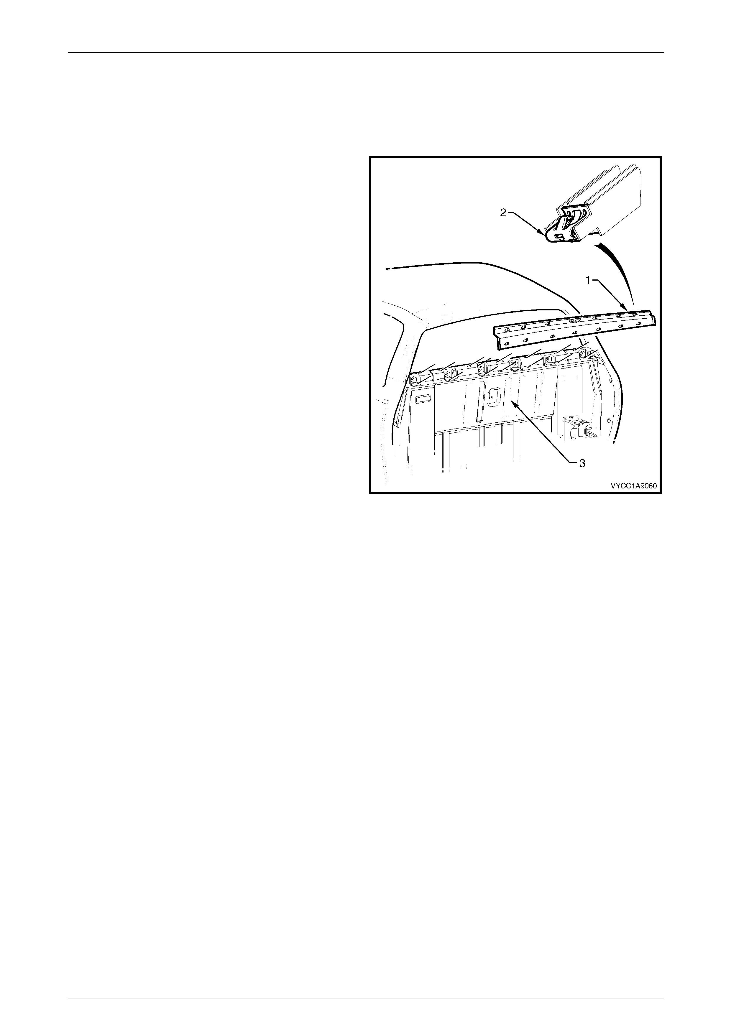
Exterior Ornamentation Page 1A9-177
Page 1A9-177
8.15 Rear Window Lower Finisher
Remove
1 If required, remove the rear bod y assembl y, refer to Section 1B Sheetmetal.
2 Beginning at either edge, use a flat blade screwdriver
to gently prise the rear window lo wer finisher (1) up to
disengage the retainer clips ( 2) from the slots in the
rear outer trim panel (3).
3 Remove the finisher.
Figure 1A9 – 200
Reinstall
1 Align the rear window lower finisher with the slots in the rear outer trim panel and appl y hand pressure evenly to the
outer face of the finisher to engage eac h of the retainer clips.
2 Reinstall the rear body assembly if removed, refer to Section 1B Sheetmetal.
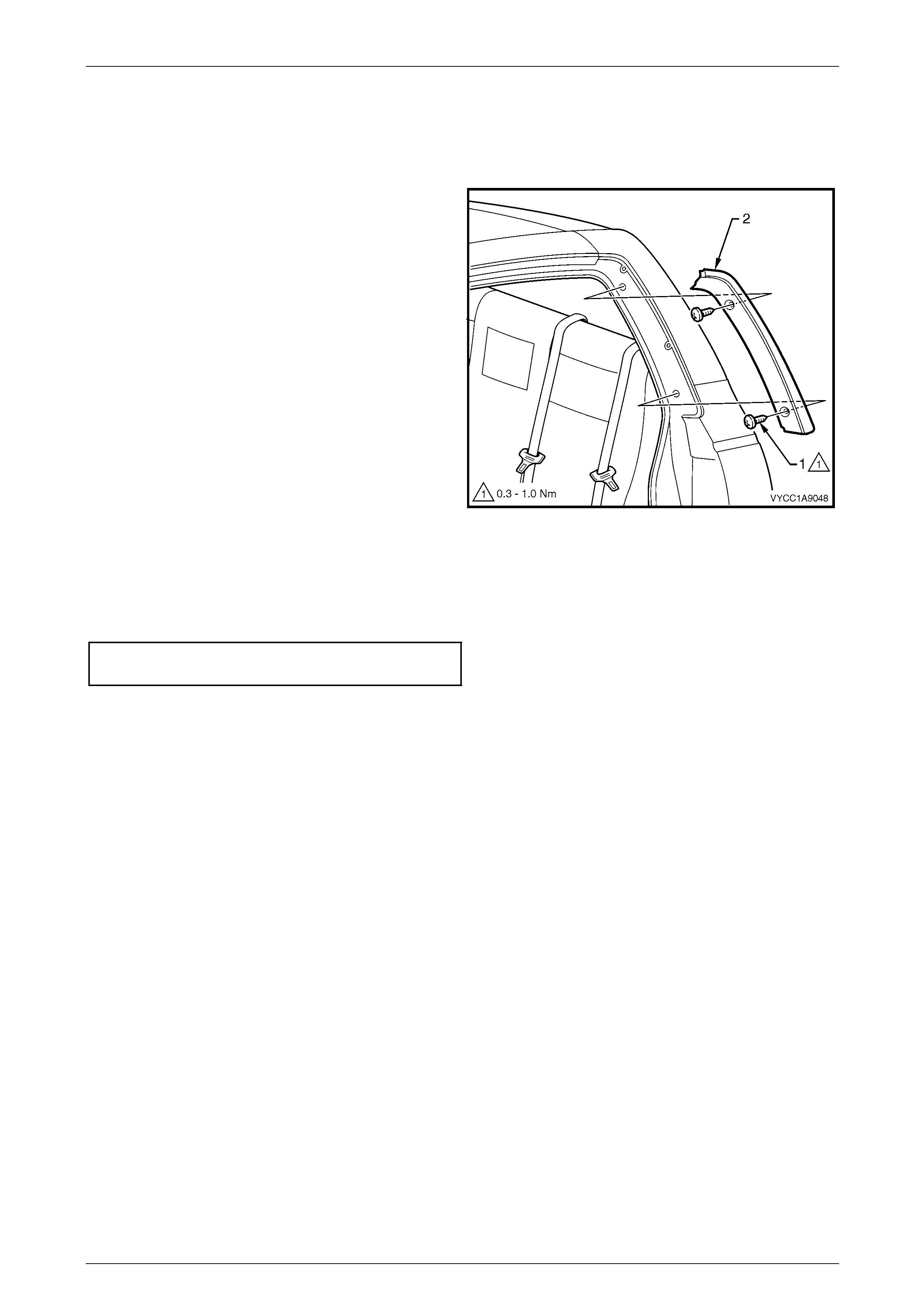
Exterior Ornamentation Page 1A9-178
Page 1A9-178
8.16 Body Lock Pillar Door Moulding
Remove
1 Remove the two screws (1) attachin g the body lock
pillar door moulding (2) and re move the moulding.
Figure 1A9 – 201
Reinstall
Reinstallation of the body lock pillar door moulding is the reverse of the removal procedure. Tighten the screws to the
correct torque specification.
Body lock pillar door mouldi ng
attaching screw torque specification...........0.3 – 1.0 Nm
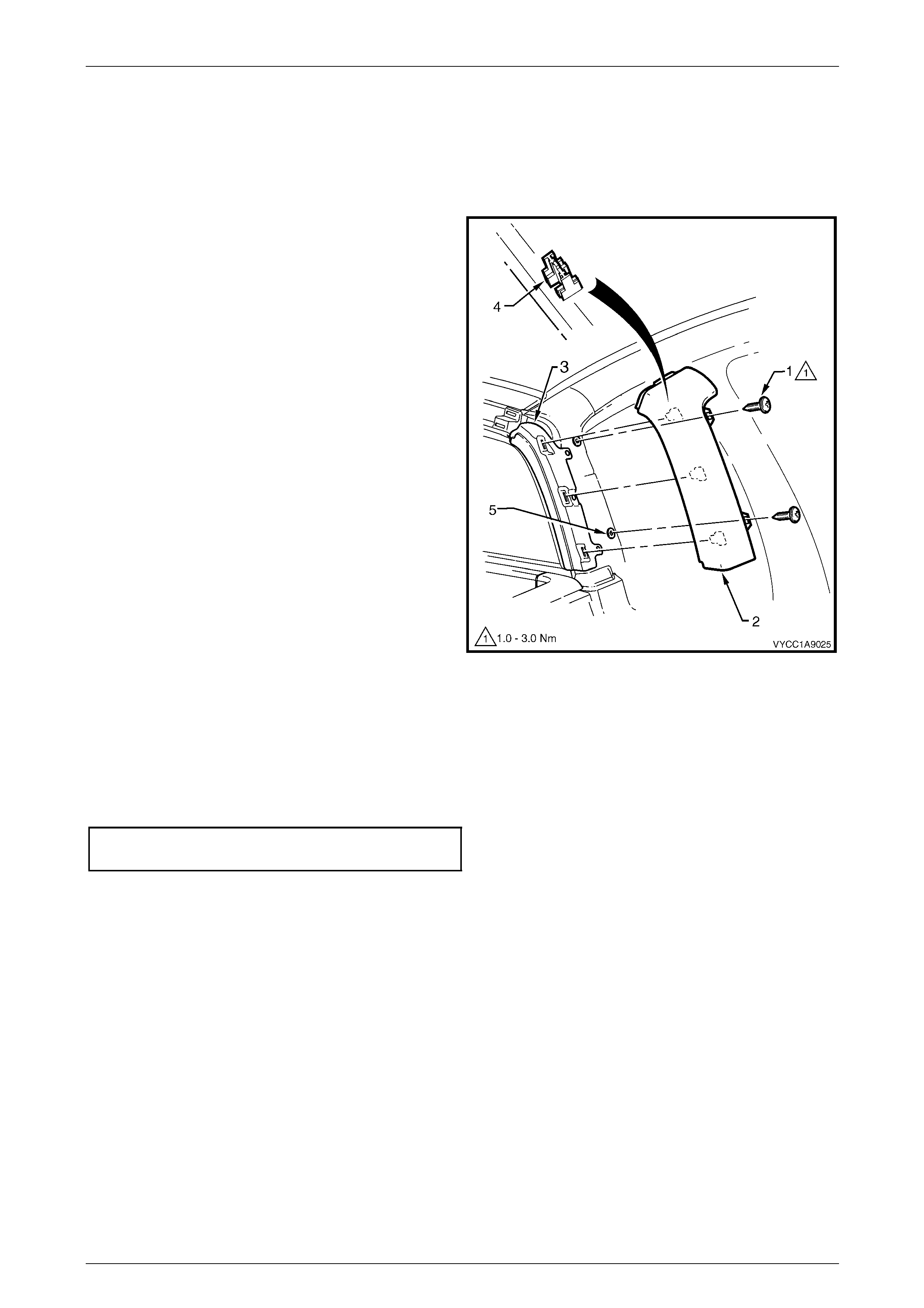
Exterior Ornamentation Page 1A9-179
Page 1A9-179
8.17 Body Lock Pillar Trim
Remove
1 Remove the body lock pillar door moulding, refer to 8.16 Body Lock Pillar Door Moulding.
2 Remove the two screws (1) attachin g the body lock
pillar trim (2), to the body lock pillar.
3 Remove the trim from the body lock pill ar finisher (3),
disengaging the three retaining clips (4).
4 If required remove the t wo foam seals (5).
Figure 1A9 – 202
Reinstall
Reinstallation of the body lock pillar trim is the reverse of the removal procedur e, noting the following:
1 If required, position the foam seals centrally ov er the holes for the attaching screws.
2 Tighten the scre ws to the correct torque spec ificatio n.
Body lock pillar trim attaching
screw torque specification...........................1.0 – 3.0 Nm
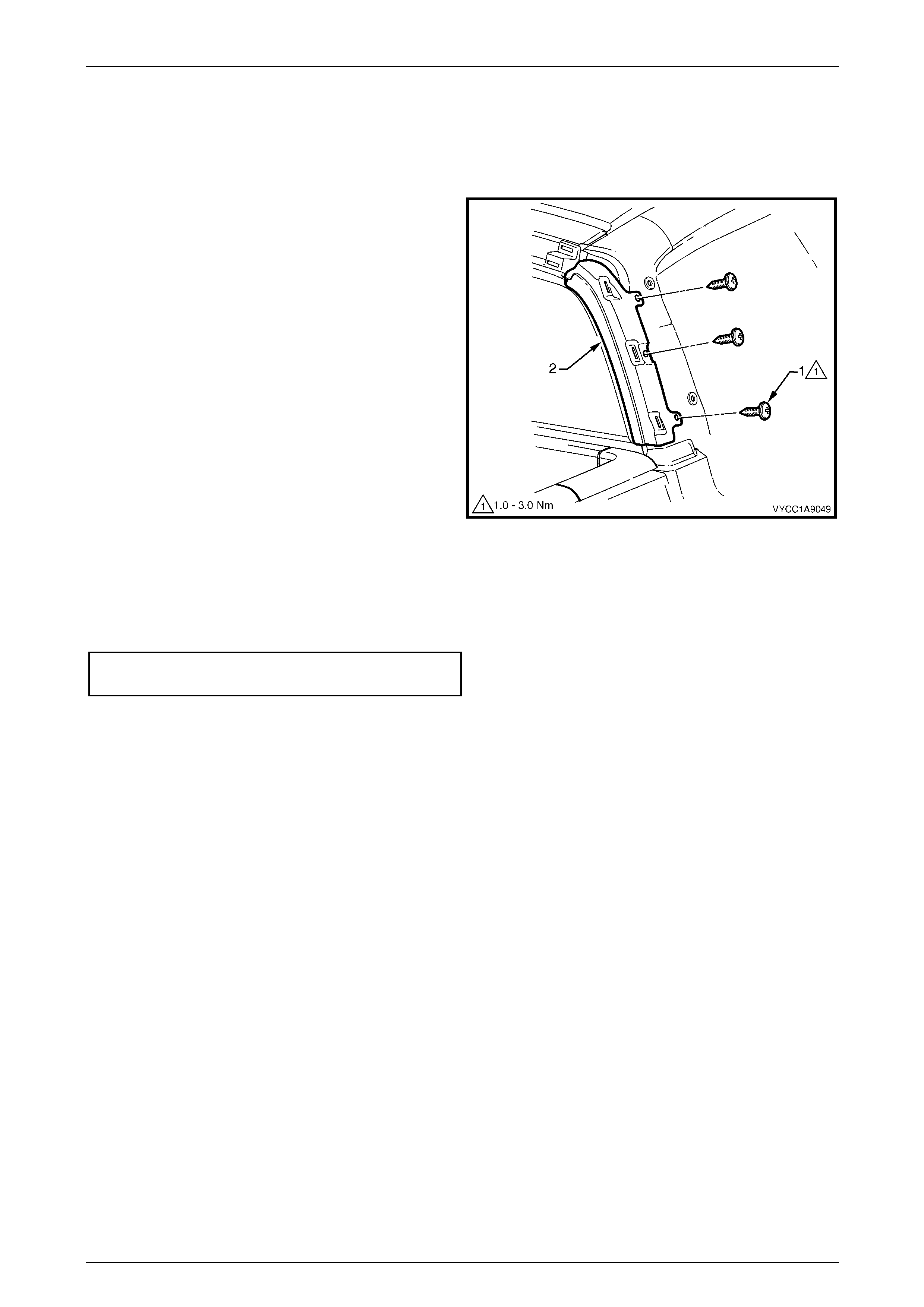
Exterior Ornamentation Page 1A9-180
Page 1A9-180
8.18 Body Lock Pillar Finisher
Remove
1 Remove the body lock pillar trim, refer to 8.17 Body Lock Pillar Trim.
2 Remove the three screws (1) attaching the b od y lock
pillar finisher (2) to the body lo ck pillar and remove.
Figure 1A9 – 203
Reinstall
Reinstallation of the body lock pillar finisher is the reverse of the removal procedure. Tighten the screws to the correct
torque specification.
Body lock pillar finisher attachi ng
screw torque specification...........................1.0 – 3.0 Nm
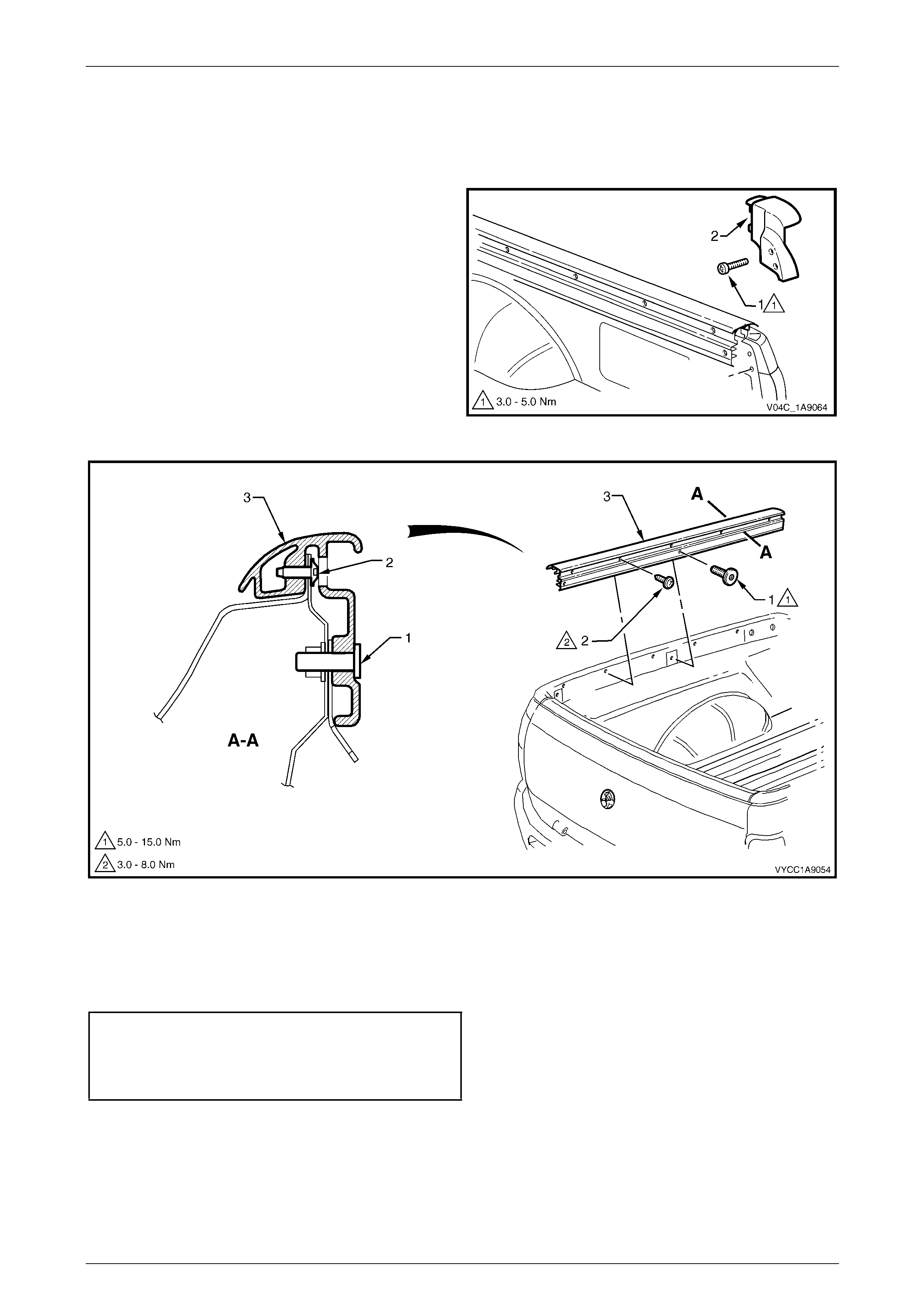
Exterior Ornamentation Page 1A9-181
Page 1A9-181
8.19 Rear Body Rail Cover and End Cap
Remove
1 Remove the screw (1), two places, attaching the rear
body rail end cap to the body and remove.
2 Referring to Figure 1A9 – 205, remove the torx head
screw (1), two places.
3 Remove the screw (2), five places, attaching the rear
body rail cover (3) to the body.
4 Raise the rear body rail cover slightly at the rear and
slide rearwards to release from the front rail cover.
Figure 1A9 – 204
Figure 1A9 – 205
Reinstall
Reinstallation of the rear body rail cover is the reverse of the removal procedure. T ighten the screws to the correct torque
specification.
Rear body rail cover and end cap
attaching screw torque specification...........3.0 – 8.0 Nm
Rear body rail cover torx-head
attaching screw torque specification.........5.0 – 15.0 Nm
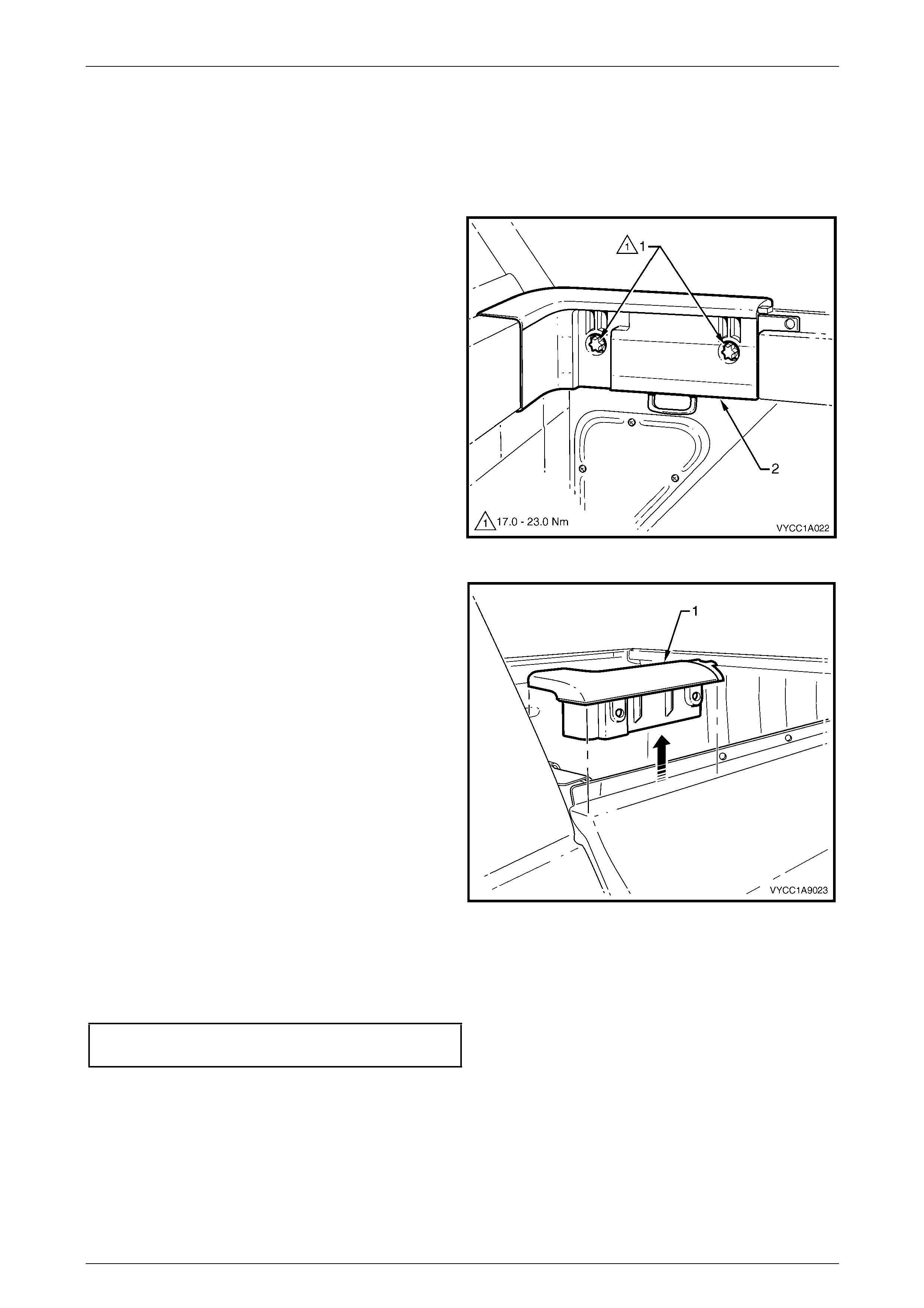
Exterior Ornamentation Page 1A9-182
Page 1A9-182
8.20 Rear Body Front Rail Cover
Remove
1 Remove the relevant rear body rail cover, refer to 8.19 Rear Body Rail Cover and End Cap.
2 Remove the two torx-head bolts (1).
Figure 1A9 – 206
3 Gently lift the rail (1) up from the rear body assembly.
Figure 1A9 – 207
Reinstall
Reinstallation of the rear body front rail cover is the reverse of the removal procedure. Tighten the torx head screw to the
correct torque specification.
Rear body front rail cover torx-head
attaching bolt torque specification...........17.0 – 23.0 Nm
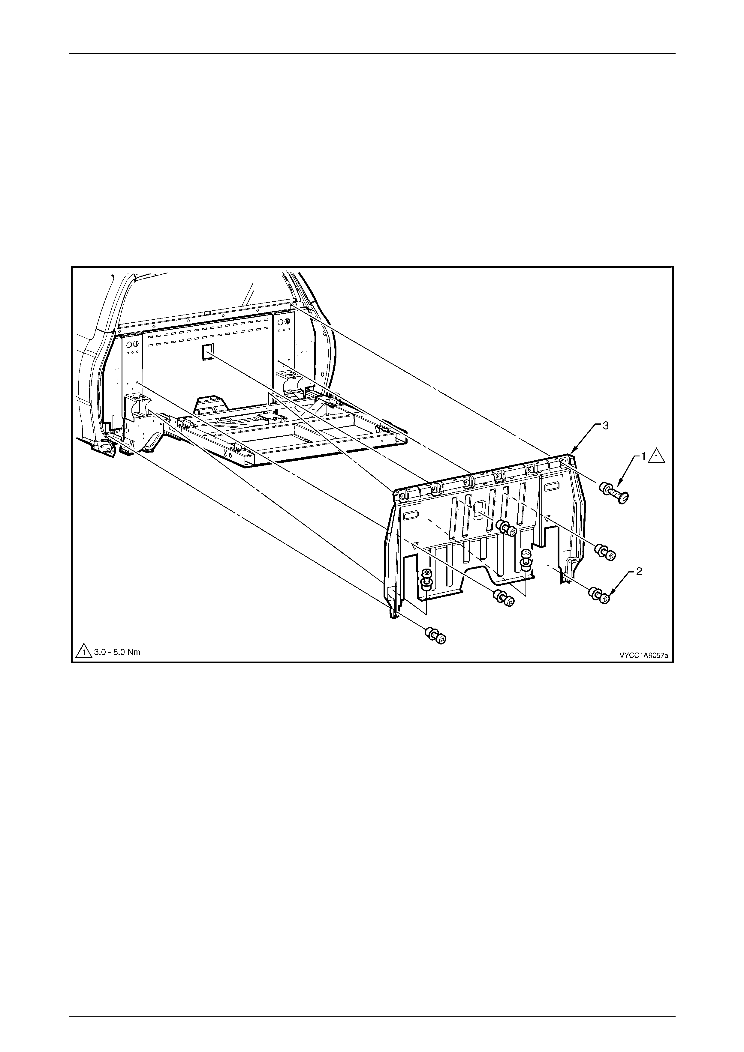
Exterior Ornamentation Page 1A9-183
Page 1A9-183
8.21 Rear Outer Trim Panel and NVH Foam
Remove
1 Remove the following components:
a Rear body assembly, refer to Section 1B Sheetmetal.
b Rear window lower finisher, refer to 8.15 Rear Window Lower Finisher.
2 Remove the rear outer trim panel attach ing screws and cups (1), six places, refer to Figure 1A9 – 208.
3 Remove the rear outer trim panel retainer (2), seven places, and remove the rear outer trim panel (3).
Figure 1A9 – 208
4 As required, remove the NVH Foam, referring to Figure 1A9 – 209:
a Note the routing of the wiring harness at the lower right-hand side of the rear outer trim panel and NVH foam.
b Carefully pull the two outer sections of foam (1) from inside the panell ing cavity and remove.
c Use a flat-blade scraper to dislodge the hot-melt glue (2) attaching the centre section of foam (4) onto the
body panelling and remove the foam.
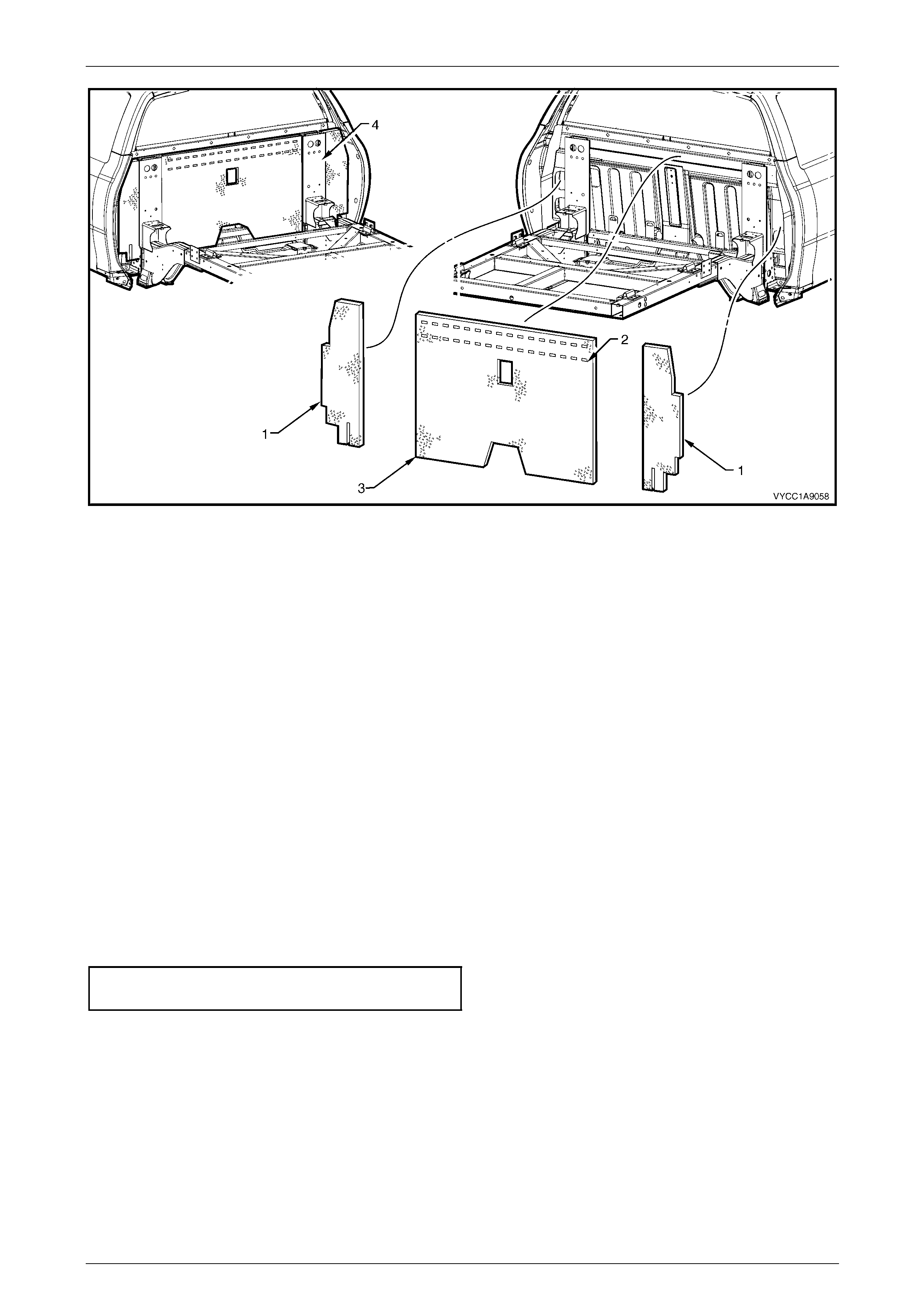
Exterior Ornamentation Page 1A9-184
Page 1A9-184
Figure 1A9 – 209
Reinstall
NOTE
The outer sections of the NVH foam are identical
and can be installed at either side of the vehicle.
When installed correctly, the glossy backing
attached to the foam will be visible on one side of
the vehicle only.
1 Remove any hot-melt glue remaining on the bod y panelling using a scrape r and Prepsol or equivalent to thorou ghly
clean and dry the surface.
2 Position the two outer side foam piec es into the panel cavity, and tuck each inn er edge evenly behi nd the rear sub-
frame.
3 Route the wiring harness as noted during removal procedu r e.
4 Apply t wo solid ro ws of hot-melt glue al ong the top inner face of the centre section of foam as indicated.
5 Fit the foam into position and firmly press the foam onto the panel to ensure correct adhesion is achieved.
6 Fit the rear outer trim panel and install the seven reta iners.
7 Install the rear outer trim panel to bod y attaching screws, six places, and tighten to the corr ect torque specification.
Rear outer trim panel attaching
screw torque specification...........................3.0 – 8.0 Nm
8 Reinstall the rear window lower finisher.
9 Reinstall the rear body assembly, refer to Section 1B Sheet metal.

Exterior Ornamentation Page 1A9-185
Page 1A9-185
8.22 Front Fender Centre Moulding Assembly
Remove
1 Remove the front fender, refer to Section 1B Sheetmetal.
2 Using pliers, squeeze the retaining clip (1), three
places, to release the front fender centre mou lding
assembly from the fender.
Figure 1A9 – 210
3 Protect the paint and bodywork with tape.
4 To assist removal, warm the region around the rear of
the upper moulding with a heat-lamp or heat-gun to
soften the adhesive.
5 Using a paint scraper or similar, carefully prise the rear
edge of the moulding assembly from the fender.
6 Withdraw the lower edge of the mou lding assembly
from the fender and gently pull it down to disengage
the three upper lugs.
7 As required remove an y remaining double-sided tape
from the moulding and/or fender and clea n the
surfaces with Prepsol or equivalent.
Figure 1A9 – 211
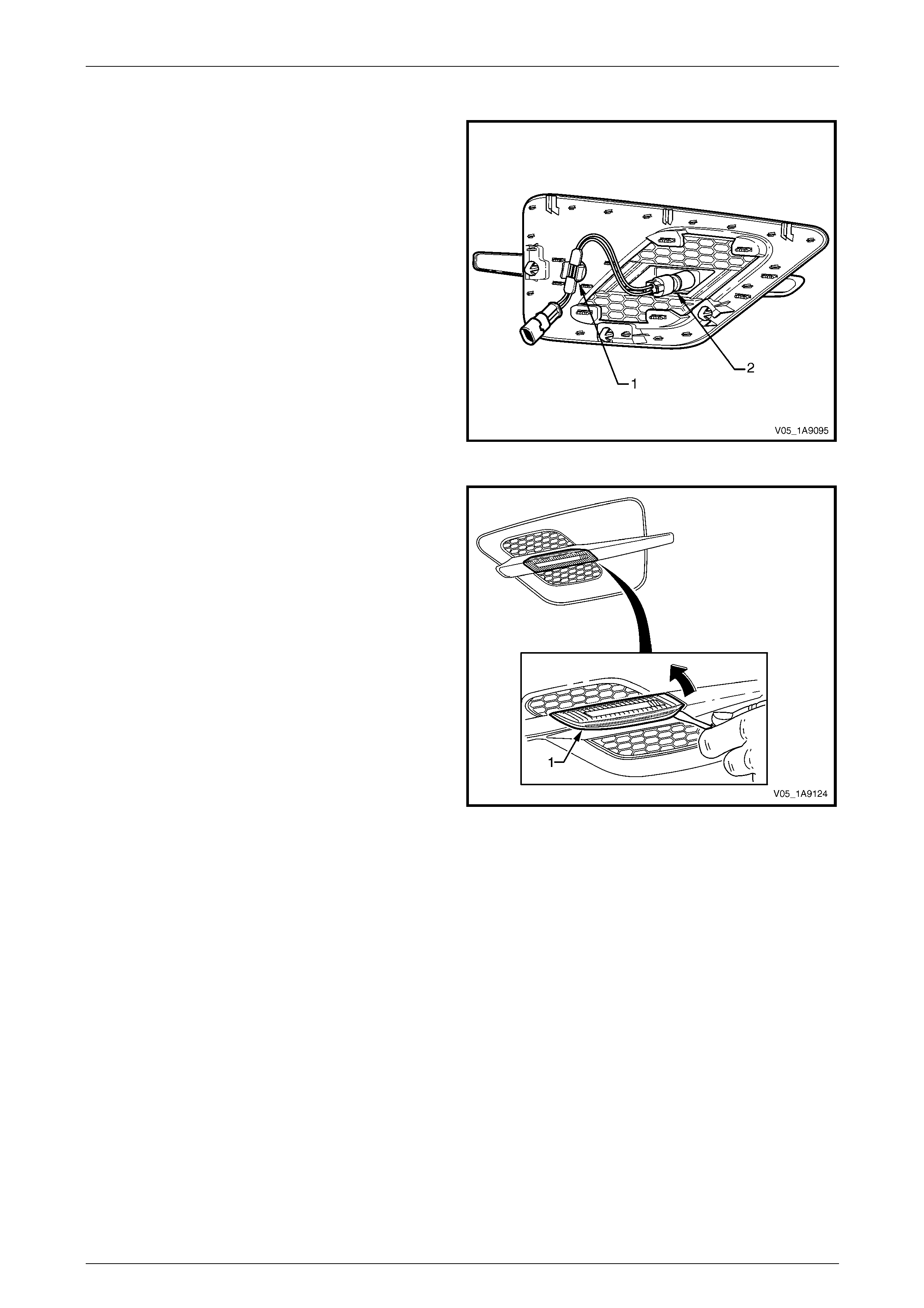
Exterior Ornamentation Page 1A9-186
Page 1A9-186
Disassemble
1 With a flat-blade screwdriver, prise the patch harness
retainer (1) from the moulding assembly.
2 Twist and remove the bulb socket, O-ring and bulb (2)
from the lamp assembly.
Figure 1A9 – 212
3 Carefully using a fine flat-blade screwdriver located at
the lower, rear edge of the lamp assembly, lever the
lamp forward and out to disengage the rear retaining
lug.
4 Withdraw the rear of the lamp from the moulding
assembly.
Figure 1A9 – 213

Exterior Ornamentation Page 1A9-187
Page 1A9-187
Reassemble
NOTE
The front fender centre moulding is supplied
unpainted as part of a kit. If a new part is
being used, it will require painting before it
is assembled. The procedur e is similar to painting
the bumper fascias, refer to
Section 1D Bumper Bars.
1 Install the front fender centr e i nsert (1):
a Ensure the four heat stake lugs are seated
correctly into the front fender centre moulding.
b Using a soldering iron, melt the ends of the four
heat stakes to secure the insert in place.
c Hold the centre insert in position unti l the pl astic
has cooled.
Figure 1A9 – 214
2 Install the front fender upper moulding (1):
a Ensure the six heat stakes ar e seated correctly
into the centre moulding.
b Using a soldering iron, melt the ends of the six
heat stakes to secure the moulding in pl ace.
c Hold the upper moulding i n po sition until the
plastic has cooled.
Figure 1A9 – 215
3 If required, fit the retaining clip (1), three places.
4 Reinstall the la mp assembly, locating the front retainer
first and then clipping the rear lug in place.
5 Reinstall the patch harness (2), connect it to the lamp
assembly and attach its retainer to the mould ing
assembly.
Figure 1A9 – 216
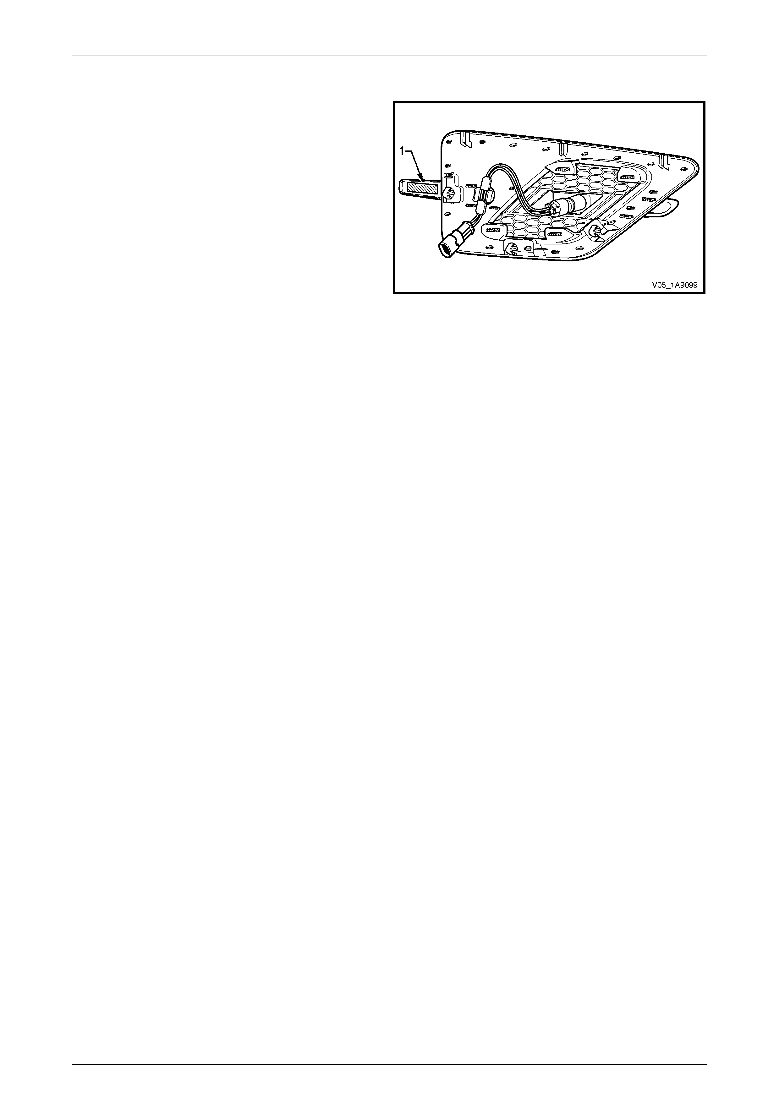
Exterior Ornamentation Page 1A9-188
Page 1A9-188
Reinstall
1 If required, apply new polyethylene double-sided tape
such as 3M 4428 or equivalent (1).
2 Clean the fender surface around the moulding
assembly opening with Prepsol or equivalent.
3 Remove the backing pap er from the doub le-sided
tape.
4 Hook the upper lugs behind their mounting tabs on the
front fender.
5 While providin g support to the back of the fender, push
the three retainers into place. Ensure all three
retainers snap into place.
6 Apply pressure to the rear of the moulding assembly
for 10 seconds where the double-sided tape was
applied to ensure sound adhesion.
7 Connect the patch harness to the main h arn ess.
8 Reinstall the fender, refer to Section 1B Sheetmetal.
9 Check for correct operation of the front side turn signal
lamp.
Figure 1A9 – 217
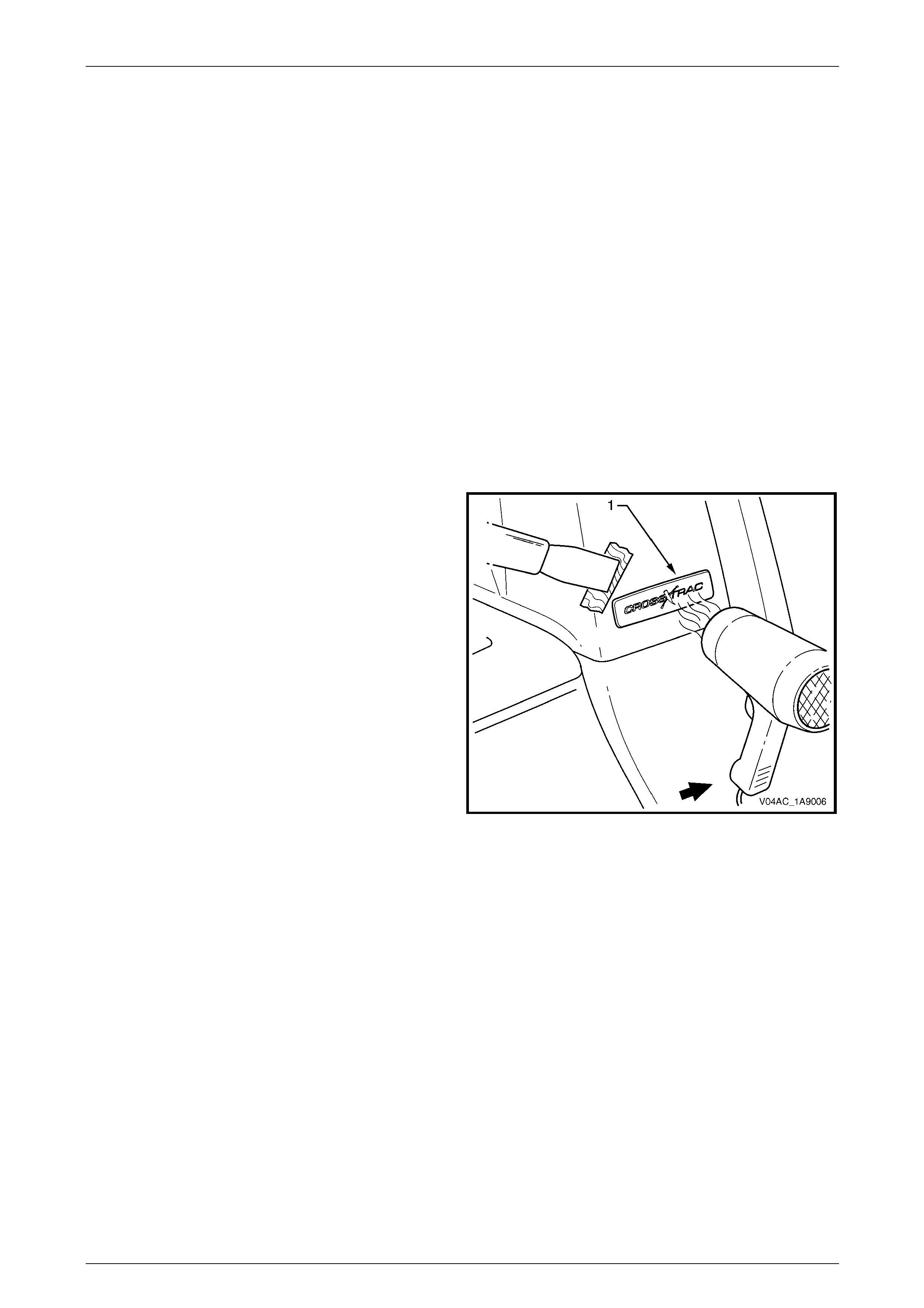
Exterior Ornamentation Page 1A9-189
Page 1A9-189
9 Service Operations, AWD
Regular Cab and AW D Crew Cab
NOTE
This Section contains components for AWD
regular Cab and AWD Crew Cab vehicles that
differ RWD vehicles. For Regular Cab service
information not in this Section, refer to
7 Service Operations, Regular Cab or for Crew
Cab vehicles, 8 Service Operations, Crew Cab.
9.1 Body Lock Pillar Trim Name Plate –
CrossXTrac
LT Section No. — 10–150
Remove
1 Protect the paint and bodywork with tape or a clean
rag.
2 To assist removal, warm the body lock pillar trim name
plate (1) with a heat-lamp or heat-gu n to soften the
adhesive.
3 Using a paint scraper or similar, carefully prise the
body lock pillar trim name plate from the body lock
pillar trim.
4 As required, remove any remaining double-sided tape
from the name plate and/or body lock pillar trim and
clean the surface with Prepsol or equivalent.
Figure 1A9 – 218
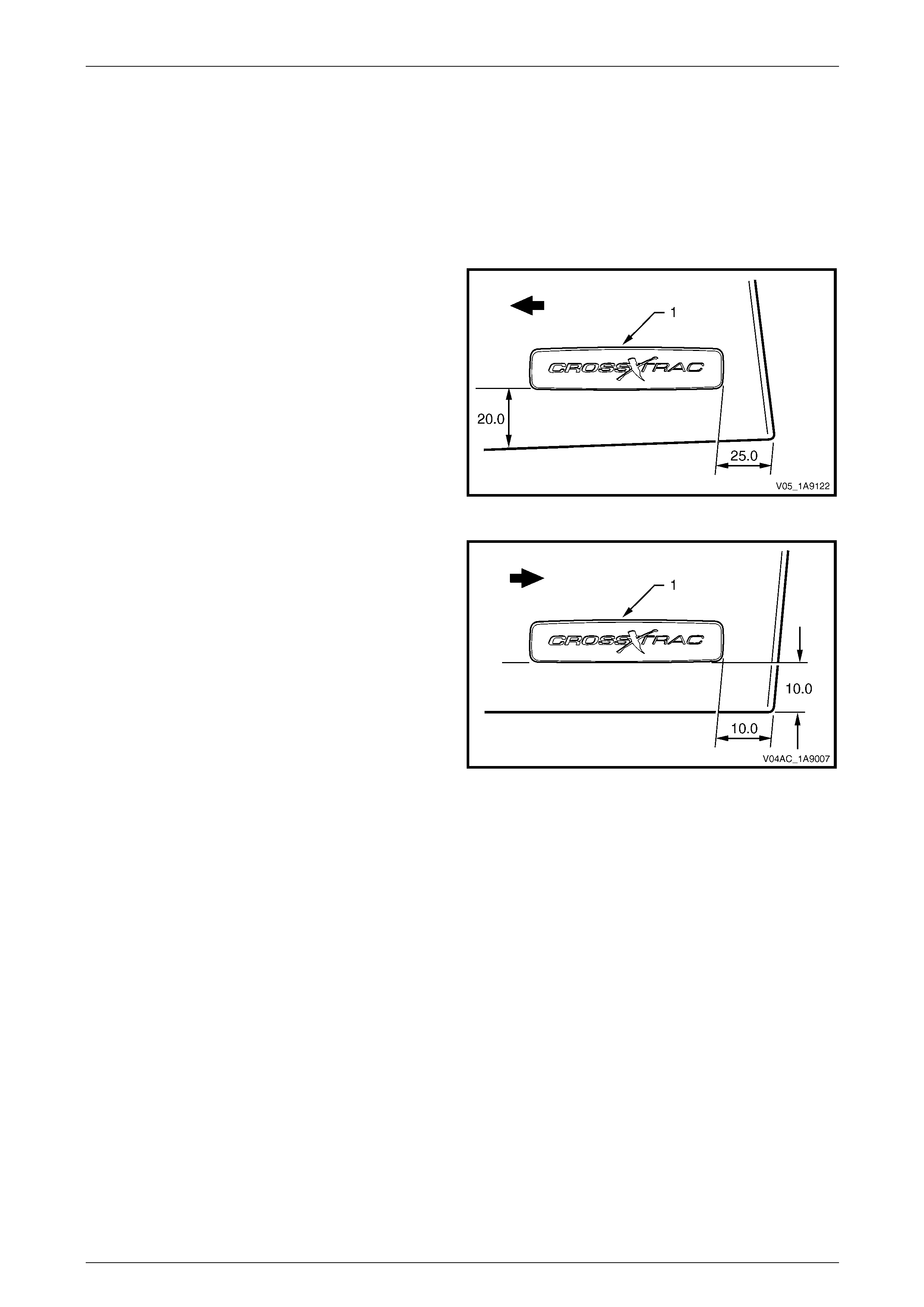
Exterior Ornamentation Page 1A9-190
Page 1A9-190
Reinstall
1 If reusing the name plate, apply ne w polyethylene double-sided tape such as 3M 4428 or equivalent to the back of
the name plate. Trim back the tape slightly away from the edge of the name plate.
2 Clean the body lock pillar trim surface with Prepsol or equivalent.
3 Remove the backing from the double-sided tape.
4 Apply the name plate as fo llows:
• For Regular C ab: Apply the body lock pillar trim
name plate in the position shown, measuring the
distance from the rear edge of the body lock
pillar trim.
Figure 1A9 – 219
• For Crew Cab: Apply the body lock pillar trim
name plate in the position shown, measuring the
distance from the front edge of the body lock
pillar trim.
Figure 1A9 – 220
5 Press firmly over the entire body lock pillar trim name plate for at least 10 seconds to ensure sound adhesion.
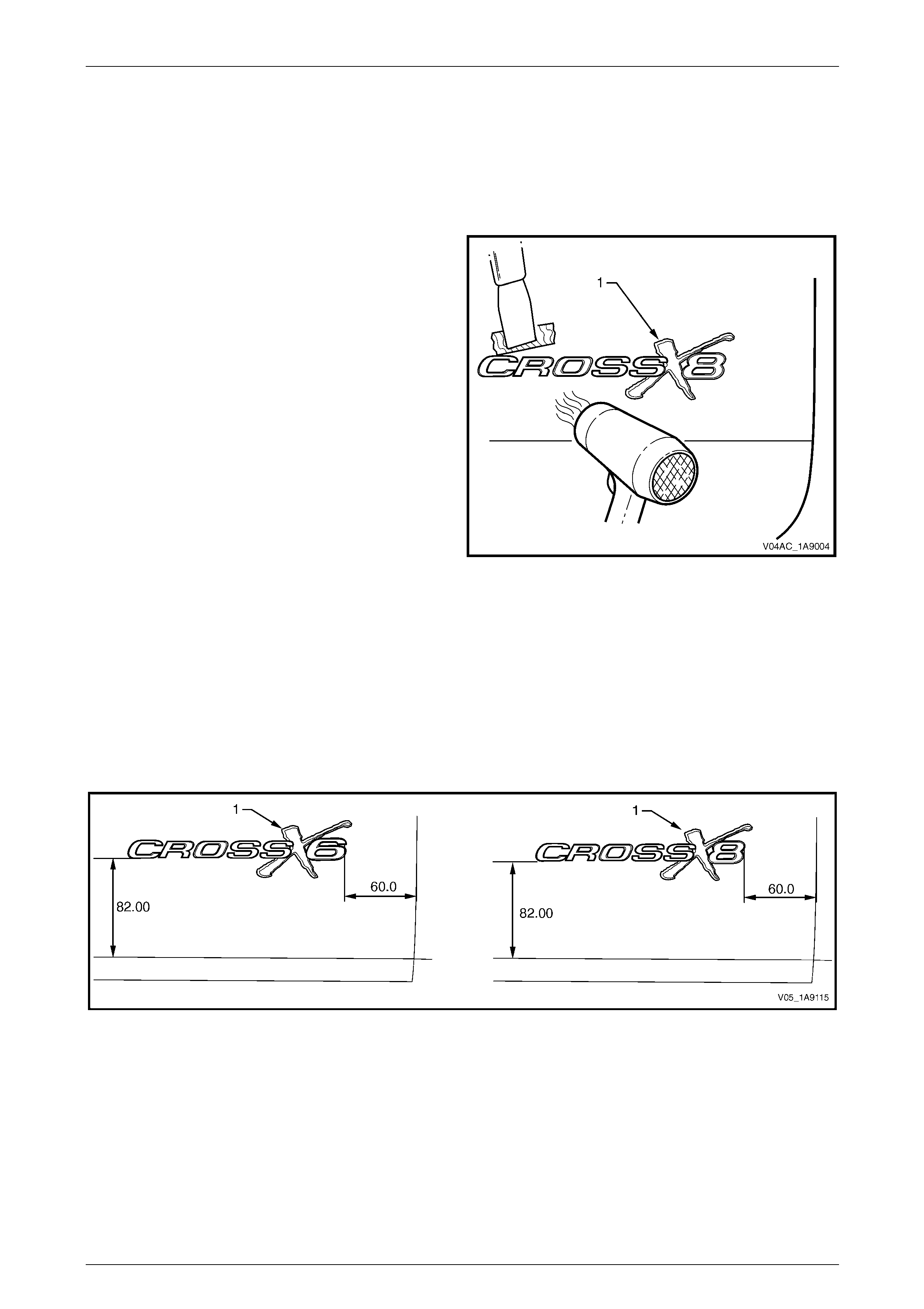
Exterior Ornamentation Page 1A9-191
Page 1A9-191
9.2 Endgate Name Plate, Right-hand, AWD
Crew Cab
LT Section No. — 10–150
Remove
1 Protect the paint and bodywork with tape or a clean
rag.
2 To assist removal, warm the endgate name plate (1)
with a heat-lamp or heat-gun to soften the ad hesive.
3 Using a paint scraper or similar, carefully prise the
endgate name plate from the endgate.
4 As required, remove any remaining double-sided tape
from the name plate and/or en dgate and clean the
surface with Prepsol or equivalent.
Figure 1A9 – 221
Reinstall
1 If reusing the plate, apply new polyethylene double-sided tape such as 3M 442 8 or equivalent to the back of the
plate. Trim back the tape slightly away from the edge of the plate.
2 Clean the endgate surface with Prepsol or equivalent.
3 Remove the backing from the double-sided tape.
4 Apply the endgate name plate onto the lo wer section of the endgate in the position shown, refer to
Figure 1A9 – 222.
Figure 1A9 – 222
5 Press firmly over the entire endgate name p late for at least 10 seconds to ensure sound adhesion.
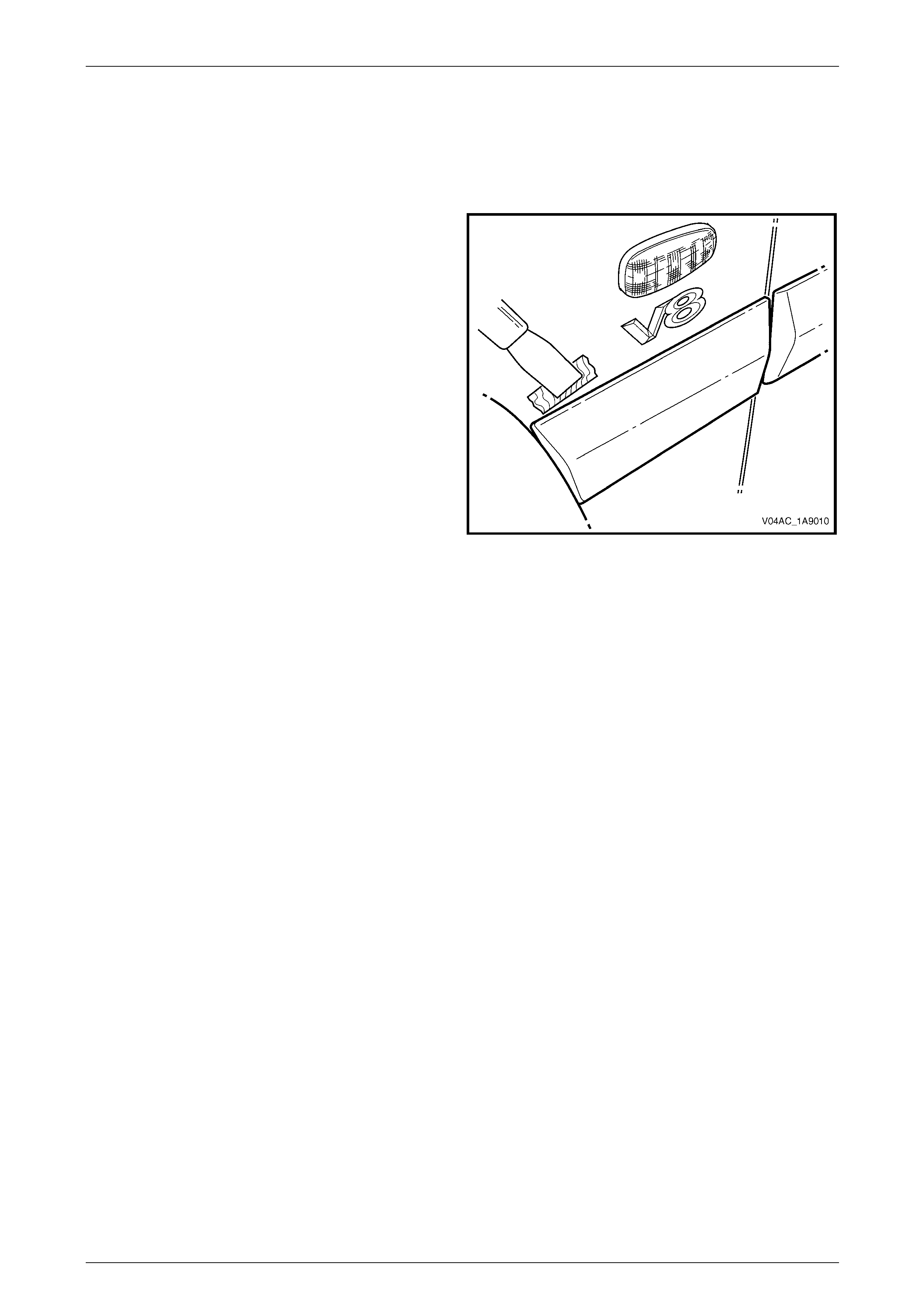
Exterior Ornamentation Page 1A9-192
Page 1A9-192
9.3 Body Side Mouldings, AWD Crew Cab
LT Section No. — 10–250
Remove
1 Protect the paint and bodywork with tape or a clean
rag.
2 Using a paint scraper or similar, begin at one end of
the body side moulding and carefully prise the bod y
side moulding from the panel, cutting throu gh the
double-sided tape and adhesive.
NOTE
To assist removal, use a heat-lamp or heat-gun
and warm the name plate slightly to soften the
adhesive.
NOTE
As an alternative, carefully use a l ength of piano
wire to cut the adhesive in a similar way to
removing a windshield. If required, refer to
Section 1A6 Stationary Windows.
3 As required, remove any remaining double-sided tape
and adhesive from the body side moulding and/or
panel. Clean the surfaces with Prepsol or equivalent.
Figure 1A9 – 223
Reinstall
Reinstallation of the body side mouldings is the reverse of the removal procedure, noting the following:
1 To align the mouldin g, place a mark on the edge of the door panels a nd the front fender at the points shown, refer
to Figure 1A9 – 224.
a For the doors, measure a straight line upwards from the lower rear edge of each door panel at the points
shown.
b For the front fender, measure a straight li ne upwards from the lower rear edge of the fender at the point
shown.
c For the body lock pillar and re ar body, continue the line form ed by the points measured on the doors across
to the body lock pane l and rear body.
2 If a complete set of mouldings is to be fitted, or as required, apply a length of masking tape along the side of the
vehicle level with the marks made in step 1.
3 Begin by affixing the tape to the fender, hold i t taut and away from the vehicle, and affix it to each panel. Ensure the
tape is straight and aligns with the marks on the doors and then, smooth it do wn along its length.
4 If reusing the body side moulding, apply new acrylic doub le-sided tape (1), such as 3M 5344 or equivalent, along
the back of the moulding.
5 Apply two 3.0 mm diameter beads of urethane adhesive (2), such as Expandite Betaseal 554.02, Sikafl ex Drive or
equivalent, over the entire length of mould ing.
NOTE
Refer to any further directions supplied with the
urethane adhesive.
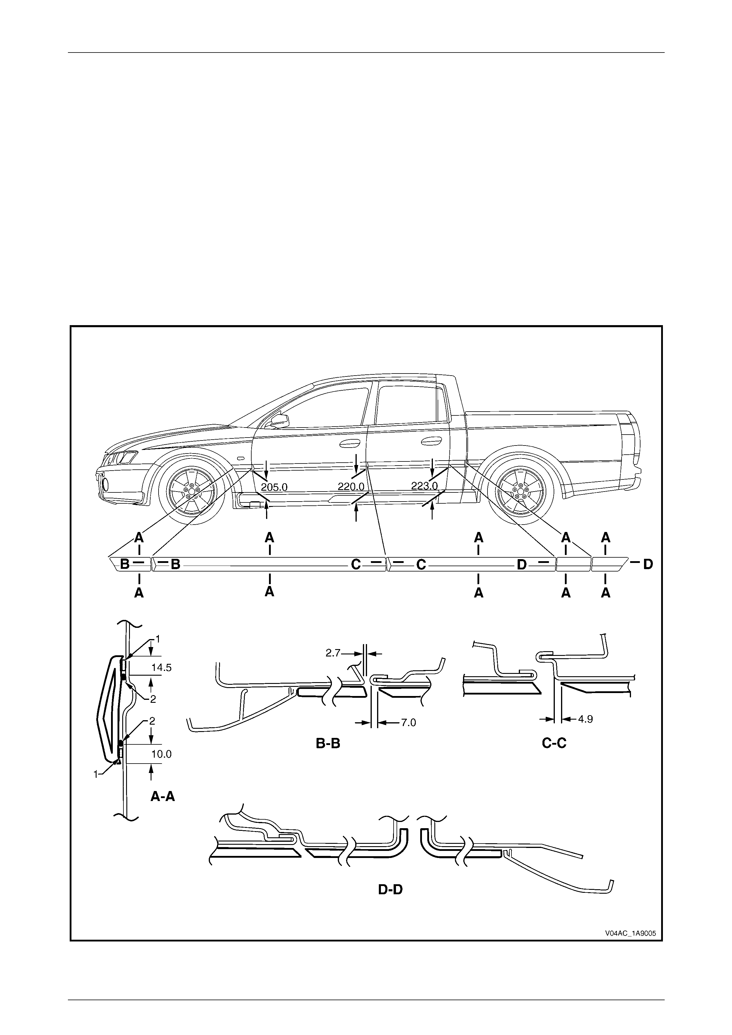
Exterior Ornamentation Page 1A9-193
Page 1A9-193
6 Affix the moulding to the vehic le in the correct position, aligning the lower edge of the mouldin g with the masking
tape (if fitted) and:
• For the fender, align the rear edge of the fender bod y side moulding to the dimension at Section B-B. Ensure
the body side moulding is positioned against the front wheelhouse opening flare assembly.
• For the front door, align the body side moulding with the front edge of the front door to the dimension at
Section B-B.
• For the rear door, alig n the body side moulding with front edge of the rear door to the dimension at Section C-
C.
• For the body lock pillar, align the body side moulding with the rear of the body lock pillar as shown in
Section D-D.
• For the rear bod y, align the bo dy side moulding with the front of the rear body as shown in Section D-D.
Ensure the body side moulding is positioned against the rear wheelhouse opening flare assembly.
7 Press firmly over the length of the bod y side moulding(s) at the double-sided tape for at least 10 seconds to ensure
sound adhesion.
Figure 1A9 – 224
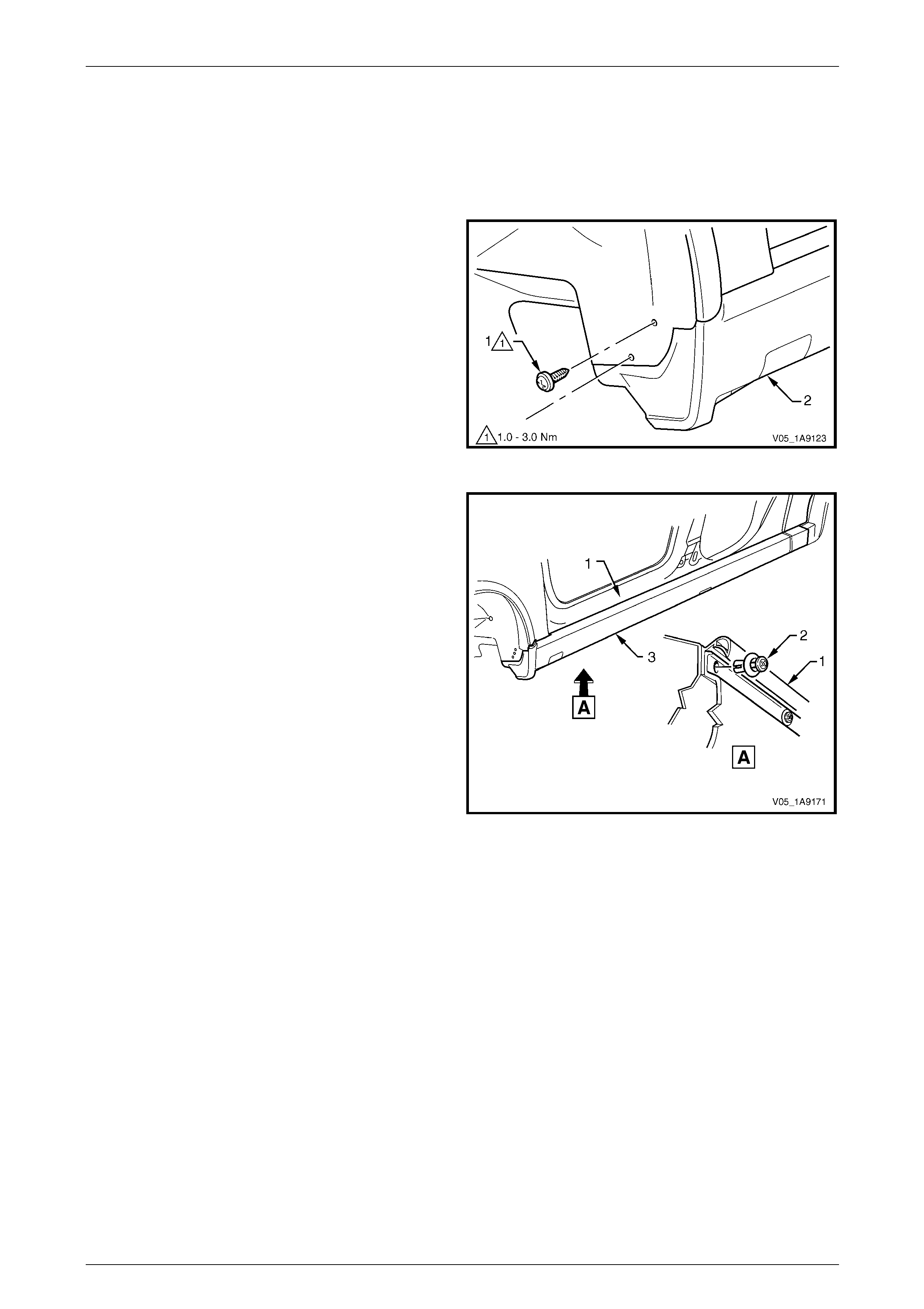
Exterior Ornamentation Page 1A9-194
Page 1A9-194
9.4 Rocker Panel Moulding Assembly, AWD
Crew Cab
Remove
1 Turn the front wheels to full steering lock to ward the re levant side.
2 Remove the screw (1), two places, attaching the front
rocker panel moulding (2) to the fender and liner.
Figure 1A9 – 225
3 Lift up the rocker panel weatherstrip (1) as shown in
View A to gain access and remove the retainer (2),
nine places, attaching the rocker panel moulding (3) to
the vehicle body.
NOTE
If the retainers are difficult to remove, prise out
the centre section a small amount with a flat
bladed screwdriver, then continue to unscrew. It
may also be necessary to retain the outer
section of the retainer with fingers or pliers.
4 Referring to Figure 1A9 – 227, from underneath the
vehicle, remove the screw (1), six places, from the
retainer (2) under the moulding (3).
5 Remove the moulding.
6 If required, prise the nut (4), two places, from the
fender. Figure 1A9 – 226
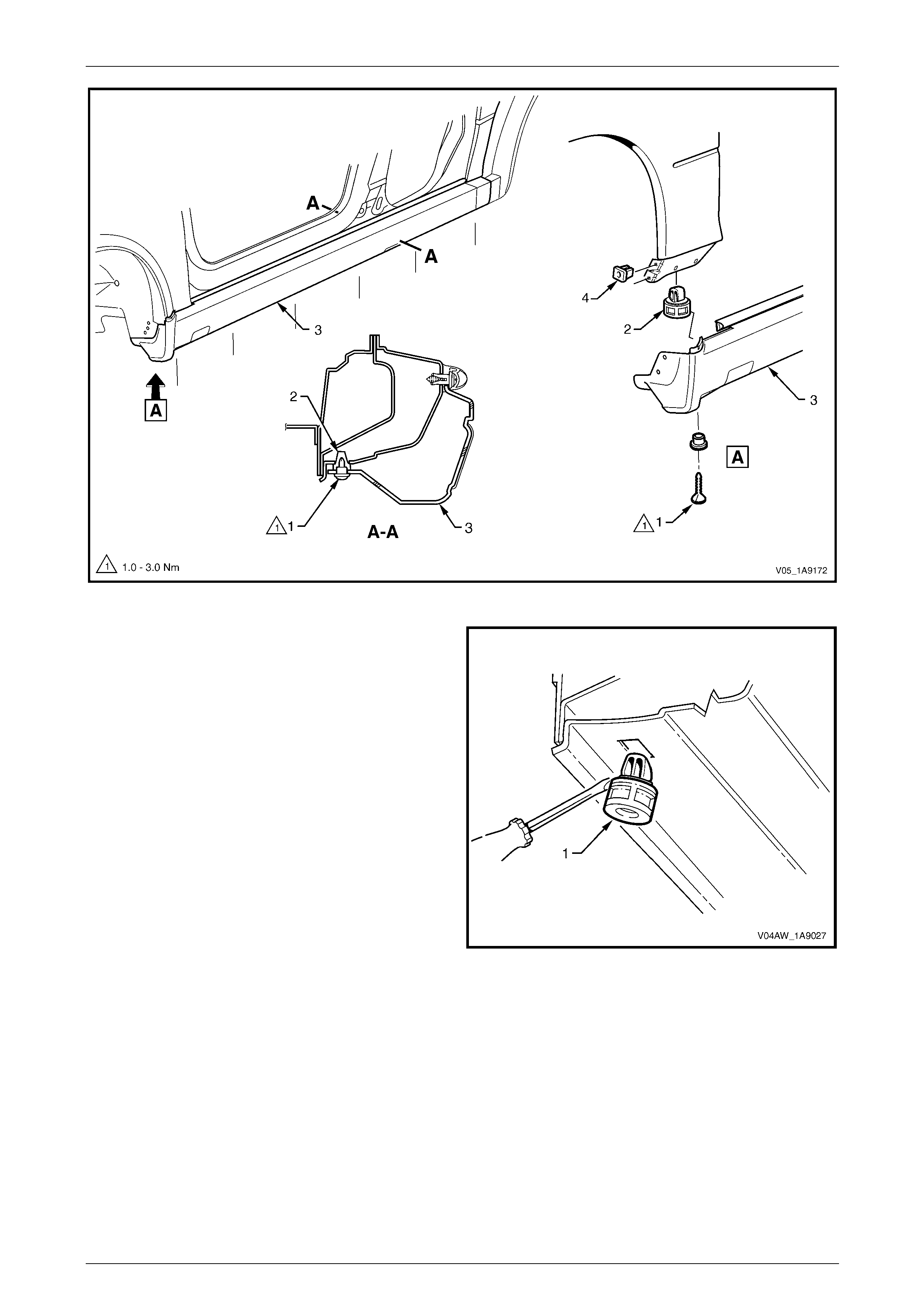
Exterior Ornamentation Page 1A9-195
Page 1A9-195
Figure 1A9 – 227
7 If required, remove the retainer (1), six places, by
gently levering out from the body, taking care not to
damage the paint work.
Figure 1A9 – 228

Exterior Ornamentation Page 1A9-196
Page 1A9-196
Disassemble
Rocker Panel Moulding Front Insert
Remove
1 From the inside of the rocker panel mould ing (1) lift the
tab (2), 12 places, attaching the front insert (3).
2 Remove the insert from the mouldin g.
Reinstall
1 Reinstall the in sert to the rocker panel moulding
ensuring that all the tabs fit into the correspondi ng
slots.
2 Fold the tabs over to secure the insert to the rocker
panel moulding.
Figure 1A9 – 229
Jacking Access Cover
Remove
1 Holding with fingers in the indent (1) on the back of the
jacking access cover (2) pull out and a way from the
rocker panel moulding (3) to remove.
2 If required, un-attach the tether (4).
Reinstall
Reinstallation of the jacking access cover is the reverse of
the removal procedure.
Figure 1A9 – 230

Exterior Ornamentation Page 1A9-197
Page 1A9-197
Reinstall
Reinstallation of the rocker panel moulding assembly is the reverse of the removal procedure, noting the following:
1 Ensure the moulding is correctly seated in the retaining clips.
2 Tighten the scre ws to the correct torque spec ificatio n.
Rocker panel moulding attac hin g
screw torque specification...........................1.0 – 3.0 Nm
3 Ensure the weatherstrip is seated correctly.
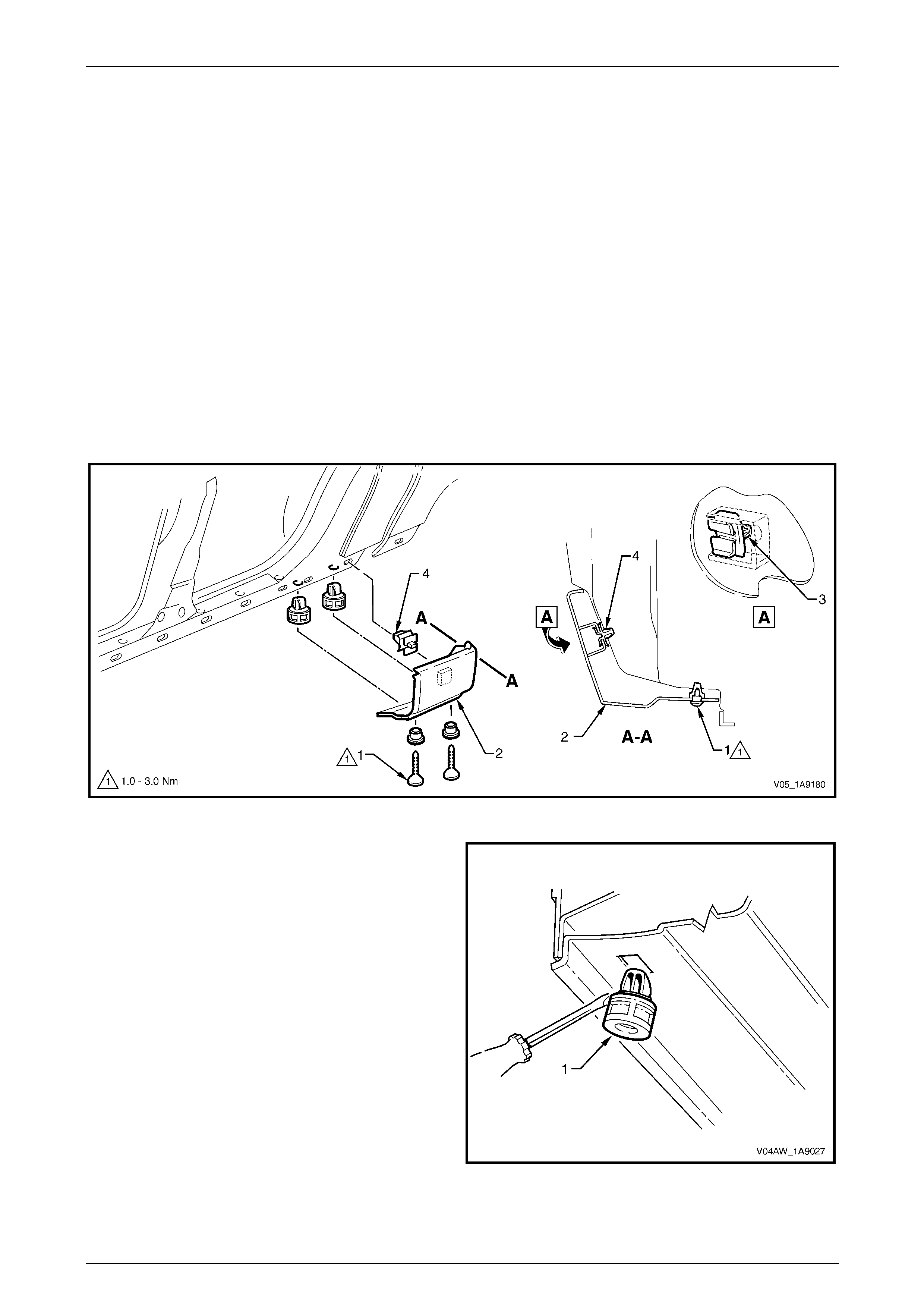
Exterior Ornamentation Page 1A9-198
Page 1A9-198
9.5 Rear Rocker Panel Moulding, AWD Crew
Cab
LT Section No. — 10–300
Remove
1 If required, loosen or remove the rocker panel moulding assembly, refer to 9.4 Rocker Panel Moulding Assembly.
2 Remove the two screw and cups (1) from the und er side of the body lock pillar lower moulding (2),
refer to Figure 1A9 – 231, then slide the rear rocker panel moulding towards the rear of the vehicle.
NOTE
If access cannot be gained to the retainer (4),
then lever the retainer from the body. If this is
done, then the retainer will need to be replaced.
3 If required, slide retainer (4) out to one side to remove it from the body lock pillar lower moulding.
Figure 1A9 – 231
4 If required, remove the retainer (1), two places, by
gently levering out from the body, taking care not to
damage the paint work.
Figure 1A9 – 232

Exterior Ornamentation Page 1A9-199
Page 1A9-199
Reinstall
Reinstallation of the rear rock er panel moulding is the reverse of the removal procedure, noting the following:
1 Locate and press the moulding onto the panelling and clip it in position.
2 Tighten the scre ws to the correct torque spec ificatio n.
Rear rocker panel moulding
screw torque specification...........................1.0 – 3.0 Nm
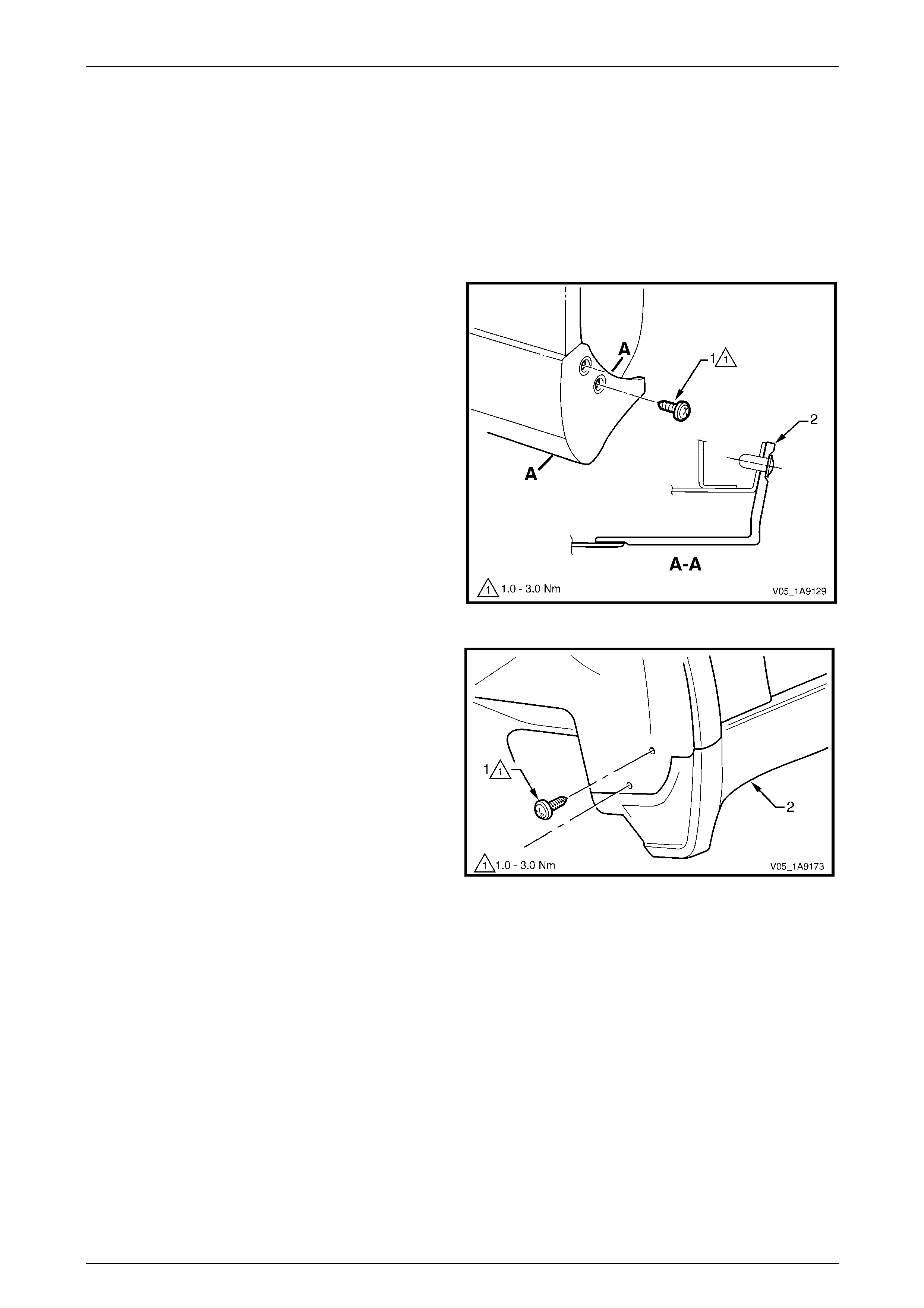
Exterior Ornamentation Page 1A9-200
Page 1A9-200
9.6 Rocker Panel Moulding Assembly, AWD
Regular Cab
LT Section No. — 10–300
Remove
1 On the relevant side remove the rear road wheel, refer to Section 10 Wheels and T yres.
2 Remove the screw (1), two places, attaching the rear
rocker panel moulding (2).
NOTE
If required, the rear rocker panel moulding can
be removed at this stage by sliding it rearward
from the front rocker panel moulding.
Figure 1A9 – 233
3 Turn the front wheels to full steering lock to ward the
relevant side.
4 Remove the screw (1), two places, attaching the front
rocker panel moulding (2) to the fender and liner.
Figure 1A9 – 234
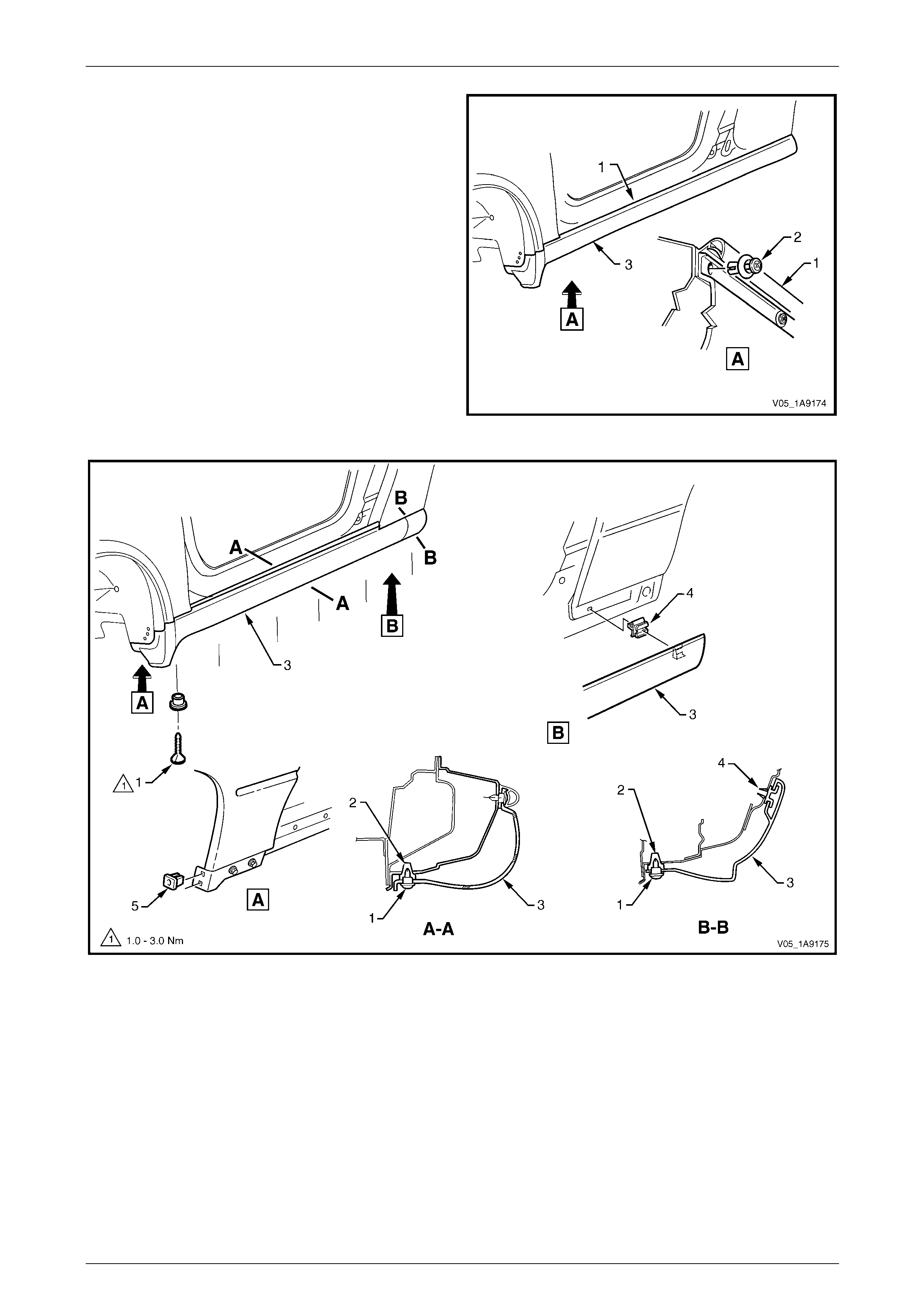
Exterior Ornamentation Page 1A9-201
Page 1A9-201
5 Lift up the rocker panel weatherstrip (1) as shown in
View A to gain access and remove the retainer (2),
five places, attaching the rocker panel moulding (3) to
the vehicle body.
NOTE
If the retainers are difficult to remove, prise out
the centre section a small amount with a flat
bladed screwdriver, then continue to unscrew. It
may also be necessary to retain the outer
section of the retainer with fingers or pliers.
6 Referring to Figure 1A9 – 236. Remove the screw (1),
six places, from the retainer (2) under the moul ding
(3).
7 Carefully remove the moul ding from the vehicle,
unclipping the three retainers (4).
8 If required, prise nut (5), two places, from the fender. Figure 1A9 – 235
Figure 1A9 – 236
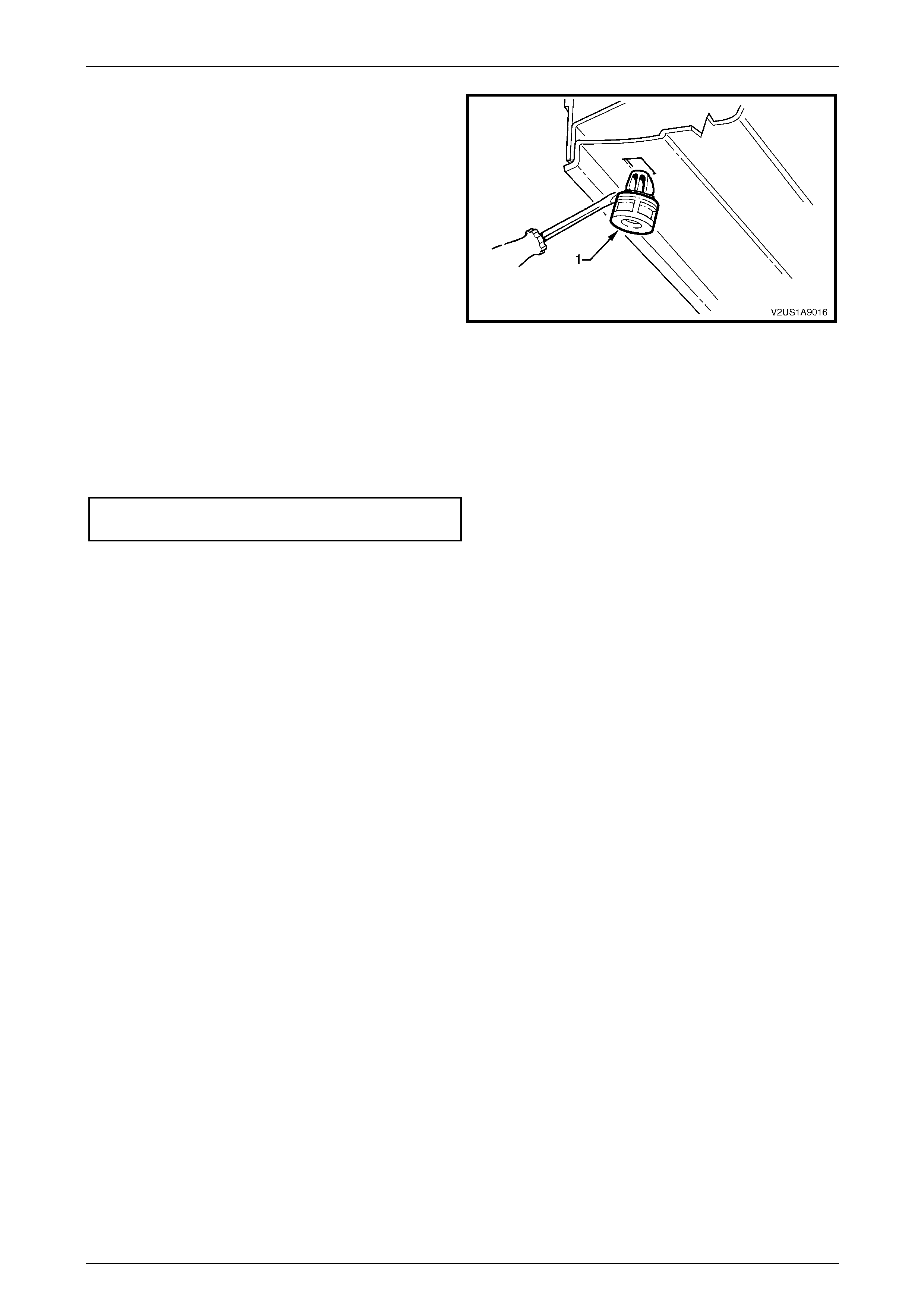
Exterior Ornamentation Page 1A9-202
Page 1A9-202
9 If required, remove the retainer (1), five places, b y
gently levering out from the body, taking care not to
damage the paint work.
Figure 1A9 – 237
Reinstall
Reinstallation of the rocker panel moulding assembly is the reverse of the removal procedure, noting the following:
1 Ensure the moulding is correctly seated in the retaining clips.
2 Tighten the scre ws to the correct torque spec ificatio n.
Rocker panel moulding attac hin g
screw torque specification...........................1.0 – 3.0 Nm
3 Ensure the weatherstrip is seated correctly.
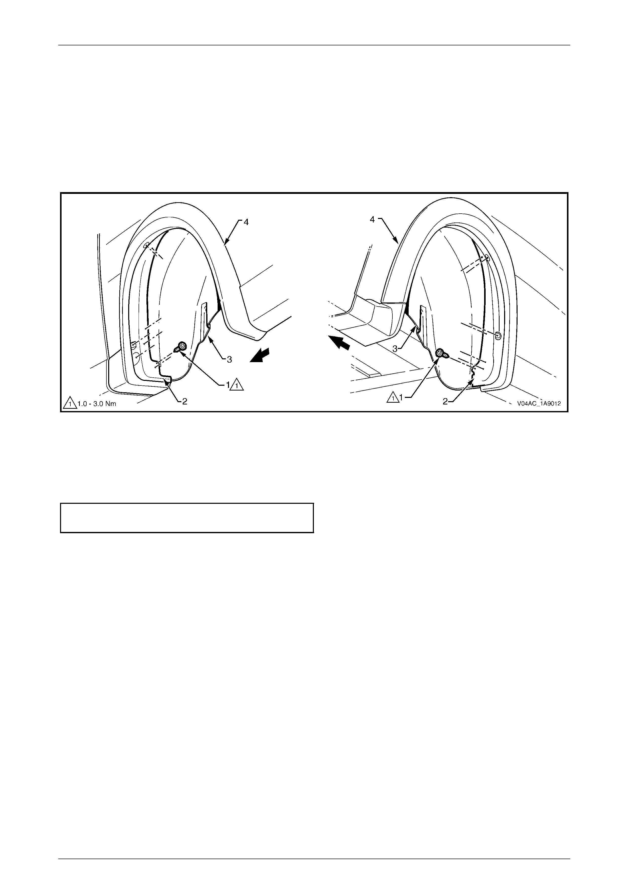
Exterior Ornamentation Page 1A9-203
Page 1A9-203
9.7 Rear Wheelhouse Opening Flare
Extension
Remove
1 Remove the rear mudflap, refer to Section 1A1 Body.
2 Remove the screw (1), 15 places, attaching the wheelhouse opening flare extension (2) to the wheelhouse liner (3)
and wheelhouse flare (4), then remove the fla r e extension, refer to Figure 1A9 – 238.
Figure 1A9 – 238
Reinstall
Reinstallation of the rear wheelhouse opening flare extension is the reverse of the remov al procedure. Tighten the
screws to the correct torque specification.
Rear wheelhouse ope ning flare extension
attaching screw torque specification...........1.0 – 3.0 Nm
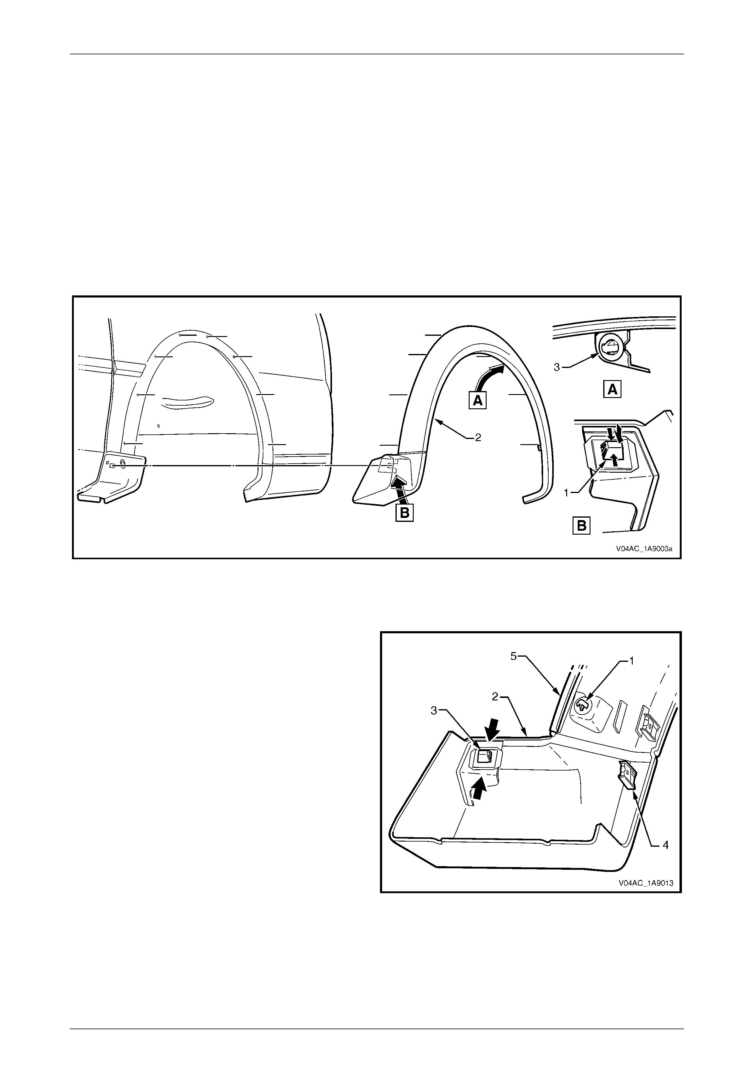
Exterior Ornamentation Page 1A9-204
Page 1A9-204
9.8 Rear Wheelhouse Opening Flare
Remove
1 Remove the following components:
a Rear wheelhouse opening flare extension, refer to 9.6 Rocker Panel Moulding Assembl y, AWD Regular Cab.
b Rear wheelhouse liner, refer to Section 1A1 Body.
2 From inside the wheelhous e, press together the retainer tabs (1) attaching the lower front section of the wheel
opening flare (2) to the rear body and pus h the retai ner clear of the body, refer to Figure 1A9 – 239.
3 From inside the wheelhous e, squeeze the clip (3), eight places, while gently pulling the rear wheelhouse opening
flare away from the rear body and remove the rear wheelhouse opening flare.
Figure 1A9 – 239
Disassemble
1 If required, remove the retaining clip (1), eig ht places,
from the rear wheelhouse opening flare (2) b y sli din g
them from the boss.
2 Remove the retaining clip (3) by pushing the tangs
together and pushing the clip from the flare.
3 Remove the flare extension attaching screw U-nut (4),
eight places.
4 Remove the seal (5), by prising it out of the recess in
the flare.
5 Inspect the seal and U-nuts for damage an d replace if
necessary.
Figure 1A9 – 240
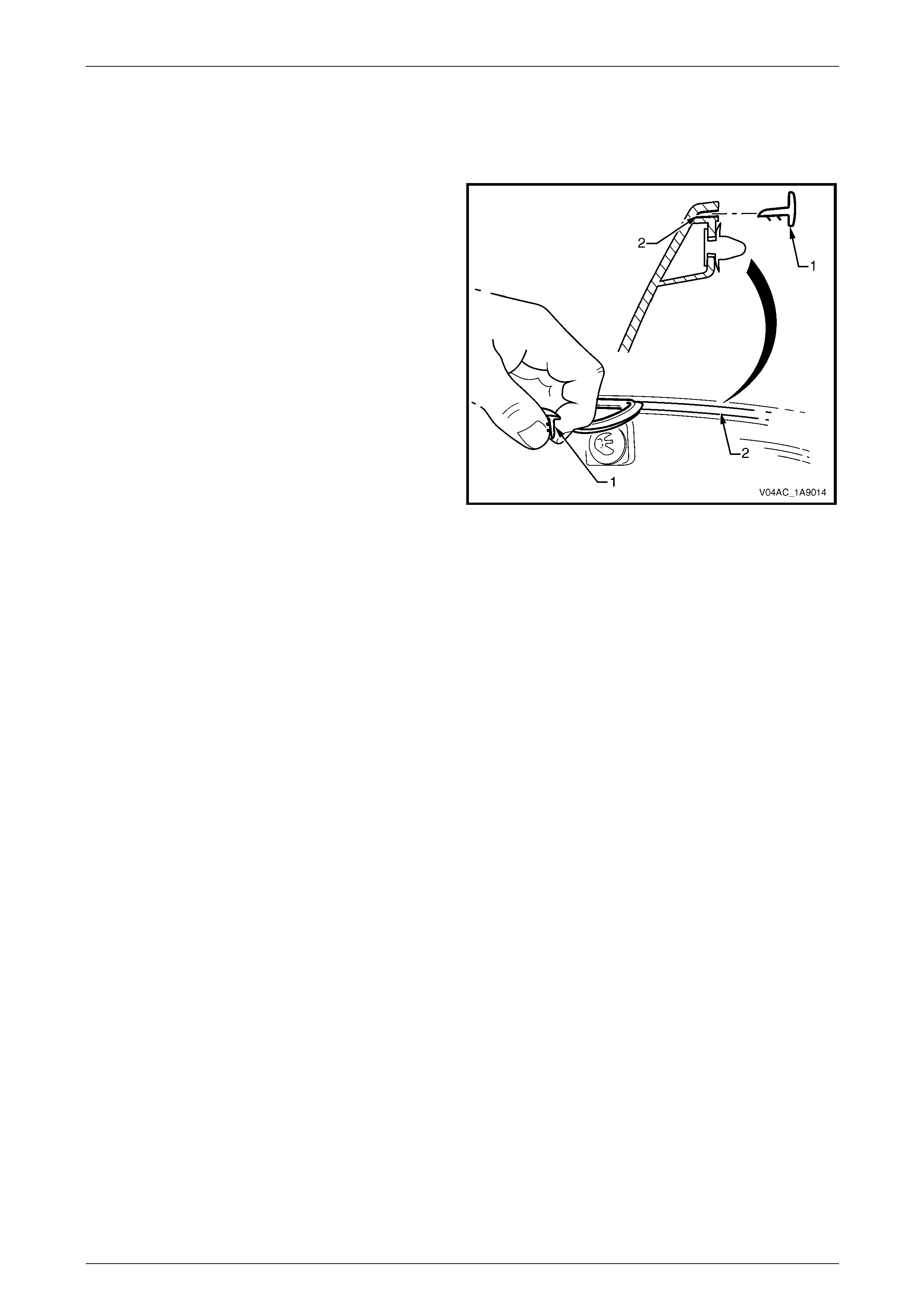
Exterior Ornamentation Page 1A9-205
Page 1A9-205
Reassemble
1 Reassembly of the rear wheelhouse flare is the reverse of the disassemb le procedure ensuring the retai nin g clips
are located in the flare correctly.
2 Position the seal (1) to the recess in the flare (2),
ensuring the retaining lips on the seal are facing
towards the centre of the flare.
Figure 1A9 – 241
Reinstall
Reinstallation of the rear wheelhouse opening flare is the reverse of the removal procedure, noting th e following:
1 Align the rear wheelhouse opening flare to the rear body, then carefully p ush the flare onto the body.
2 Ensure that all the retainers are correctly engaged and the rear wheelhouse ope ning flare is correctly seated on the
rear body.

Exterior Ornamentation Page 1A9-206
Page 1A9-206
10 Torque Wrench Specifications
Door Opening Moulding Attaching Screw......................................1.0 – 2.0 Nm
Centre Pillar Upper Finisher Retainer Attaching Screw.................1.0 – 3.0 Nm
Centre Pillar Sealing Strip Attaching Screw...................................1.0 – 3.0 Nm
Quarter Panel Belt Moulding Retaining Nut...................................1.0 – 3.0 Nm
Rocker Panel Moulding Attaching Screw.......................................1.0 – 3.0 Nm
Roof Bar Attaching Screw .............................................................4.0 – 6.0 Nm
Roof Side Rail Attaching Nut.....................................................10.0 – 12.0 Nm
Roof Rack Carrier Assembly Front Attaching Nut .......................8.0 – 10.0 Nm
Roof Rack Carrier Assembly Rear Attaching Nut......................10.0 – 12.0 Nm
Luggage Carrier Attaching Nut..................................................10.0 – 12.0 Nm
Door Opening Moulding Attaching Screw .....................................0.3 – 1.0 Nm
Rocker Panel Moulding End Cap Attaching Screw........................1.0 – 3.0 Nm
Rear Body Front Rocker Moulding Attaching Screw .....................1.0 – 3.0 Nm
Rear Bumper Fascia Guide Assembly Attaching Screw................1.0 – 3.0 Nm
Rear Header Trim Retainer Attaching Screw ................................1.0 – 3.0 Nm
Rear Window Side Moulding Attaching Screw ..............................0.8 – 1.1 Nm
Rear Window Side Moulding Retaining Screw..............................1.0 – 3.0 Nm
Quarter Window Moulding Attaching Screw..................................1.0 – 3.0 Nm
Quarter Window Moulding Attaching Screw..................................1.0 – 3.0 Nm
Body Lock Pillar Door Moulding Attaching Screw..........................0.3 – 1.0 Nm
Body Lock Pillar Trim Attaching Screw..........................................1.0 – 3.0 Nm
Body Lock Pillar Finisher Attaching Screw....................................1.0 – 3.0 Nm
Body Side Rear Trim Panel Retaining Screw................................1.0 – 3.0 Nm
Body Side Rear Trim Bracket Mounting Screw .............................1.0 – 3.0 Nm
Quarter Panel Rear Moulding Attaching Screw.............................3.0 – 8.0 Nm
Quarter Panel Outer Rail Attaching Screw....................................3.0 – 8.0 Nm
Quarter Panel Outer Rail Attaching Torx Screw..........................5.0 – 15.0 Nm
Tonneau Cover Bow Retainer Attaching Torx Screw ................17.0 – 23.0 Nm
Rear Body Rail Cover and End Cap Attaching Screw...................3.0 – 8.0 Nm
Rear Body Rail Cover Torx-head Attaching Screw......................5.0 – 15.0 Nm
Rear Body Front Rail Cover
Torx-head Attaching Bolt...........................................................17.0 – 23.0 Nm
Rear Outer Trim Panel Attaching Screw........................................3.0 – 8.0 Nm
Rear Wheelhouse Opening Flare
Extension Attaching Screw............................................................1.0 – 3.0 Nm