
Body Builders Guide Page 1B2–1
Page 1B2–1
Section 1B2
Body Builders Guide
ATTENTION
Before performing any Service Operation or other procedure described in this Section, refer to Section 00
Warnings, Cautions and Notes for correct workshop practices with regard to safety and/or property damage.
1 General Information ...............................................................................................................................2
2 Guidelines...............................................................................................................................................3
2.1 Vehicle Selection ................................................................................................................................................... 3
Type of Load........................................................................................................................................................... 3
Body and Payload Weight..................................................................................................................................... 3
Performance........................................................................................................................................................... 3
Fuel System............................................................................................................................................................ 3
Exhaust Systems................................................................................................................................................... 3
Wheels and Tyres .................................................................................................................................................. 3
2.2 Explanation of Terms ............................................................................................................................................ 4
Operating Masses.................................................................................................................................................. 4
GVM................................................................................................................................................................... 4
GCM................................................................................................................................................................... 4
Kerb Mass.......................................................................................................................................................... 4
Load Capacity .................................................................................................................................................... 4
Payload .............................................................................................................................................................. 4
Front and Rear Axle Loads ................................................................................................................................ 4
3 Rear Subframe........................................................................................................................................5
3.1 Modifications.......................................................................................................................................................... 5
3.2 Welding and Heating ............................................................................................................................................. 6
Welding Precautions ............................................................................................................................................. 6
4 Tray and Body.........................................................................................................................................7
4.1 Recommended Clearances................................................................................................................................... 7
Cab Clearance........................................................................................................................................................ 7
Tyre Clearances..................................................................................................................................................... 8
4.2 Mounting Points..................................................................................................................................................... 9
Regular Cab....................................................................................................................................................... 9
Crew Cab......................................................................................................................................................... 10
Mounting Dimensions ......................................................................................................................................... 10
Regular Cab..................................................................................................................................................... 11
Crew Cab......................................................................................................................................................... 12
4.3 Tray and Body Sizes............................................................................................................................................ 13
Regular Cab..................................................................................................................................................... 13
Crew Cab......................................................................................................................................................... 14
5 Torque Specifications..........................................................................................................................15

Body Builders Guide Page 1B2–2
Page 1B2–2
1 General Information
Certain customer requirements may require the fitting of an aftermarket or custom built tray or body to Regular Cab and
Crew Cab vehicles. To meet those requirements, the Body Builders Guide supplies guide lines for the building of a
custom built tray or body.
NOTE
Although the rear body fitted to Crew
Cab vehicles is detachable from the rear
subframe, it is not recommended to fit an
aftermarket or custom built tray or body to a Crew
Cab vehicle unless it has been specified with the
Delete-Tray-Option from the factory. For Crew
Cab rear body service information, refer to
Section 1B Sheetmetal.
The information contained in this guide is of a general nature only. It also provides the body builder with body mounting
point dimensions, as well as general guidelines and recommendations for the construction of a custom built tray or body.
When constructing a custom built tray or body, the bod y builder will need to take into consideration the whole vehicle, its
operating environme nt and how the vehicle will perform as a complete pack age.
It must be emphasised there are certain requirements that must be met in order for the vehicle to meet the design
requirements and perform in a manner for which the vehicle was intended.
When constructing a custom built tray or body, it is the body builders’ responsibility to ensure compliance to the various
Federal or State transport authority regulations that may exist.
It must also be emphasised that any change to the basic vehicle design may severely inhibit its ability to perform the
function for which it was designed. Mechan ical and structural failures, component unreliability, vehicle instability and
general dissatisfaction by the owner or operator can often be traced to inappropriate design and application of a custom
tray, body, equipment and or accessories.
It must be remembered there are certain design and safety requirements that also must b e adhered to in order to comply
to statutory regulations and that certain modifications may invalidate Australian Design Rule (ADR) requ irements. An
application for re-certification of the vehicle may be required after such modifications.
Generally, an Engineers report is require d for modifications to any component or part of a vehicle covered by an ADR.
Any component or part of the vehicle that is covered by an ADR and is modified or will be affected by a modification may
need to be recertified by an approv ed Engineer and an Engineers report issued for that modification.
An aftermarket or custom built tray or body must be fitted with the appropriate lighting as required by any Federal or
State transport authority regul ations. These regulations will also determine the appropriate positioning of any such lights.

Body Builders Guide Page 1B2–3
Page 1B2–3
2 Guidelines
2.1 Vehicle Selection
The following points should be considered when selecting a particular vehicle or model for use with a known body or
equipment.
Type of Load
All calculations which are carried out by the body builder's design engineers assume that, within reasonable limits, the
load to be placed in the tray or body will be evenly distributed along a nd across the tray or body. If the tray, body or
equipment to be carried constitutes an uneve nly distributed load, calculations should then be made with regard to axle
loads in the laden, unladen a nd part laden conditions.
For information regarding axle and vehicle loads, refer to Section 0A General Information.
Body and Payload Weight
The type of tray or body, its weight and the payload capacity required, must be determined.
Performance
Calculations must be carried out to ensure the complete vehicle meets customer expectations and requirements with
respect to performance characteristics. This must be met without interfering with or modifying the base vehicle
specifications.
Fuel System
The fuel tank, fuel lines or filler neck must no t be modified and any relocation of the fuel system components is not
permitted.
Exhaust Systems
Modifications or relocation of the exhaust sys t em is not permitted.
Wheels and Tyres
Adequate clearance must be provided between the rear tyres and the underside of the tra y or bod y and mudguards. The
clearance must allo w the axle to reach its ma ximum travel without the tyres fouling on the tray or body, refer to
4.1 Recommended Clearanc es.
For further information relating to wheels and tyres, refer to Section 10 Wheels and Tyres.

Body Builders Guide Page 1B2–4
Page 1B2–4
2.2 Explanation of Terms
Operating Masses
To ensure the selected vehicle performs satisfactorily and reliably, it is important the manufacturer's specified
Gross Vehicle Mass (GVM) and Gross Combination Mass (GCM) for the specified vehicle is not exceeded.
For further information and specifications relating to operating masses, refer to Section 0A General Information.
GVM
Gross Vehicle Mass (GVM) is the combined weight the vehi cle is allowed to carry when fully loaded. This must include
luggage, passengers and a full tank of fuel.
GCM
Gross Combined Mass is the maximum allo wabl e combined weight of a vehicle with passengers, luggage, a full tank of
fuel plus the weight of a loaded trailer or caravan.
Consideration needs to be ta ken into account when the trailer or caravan has either over-run brakes, electric style brakes
or is an un-braked trailer, as the GCM specification can alter depending on which braking system the towed vehicle is
fitted with.
Kerb Mass
Kerb mass is the weight of the base vehicle including all fluids plus a full tank of fuel.
Load Capacity
Load capacity is the maximum load able to be carried and is usually expressed as the difference between GVM and kerb
mass.
To establish the load capacity, subtract kerb mass from the GVM. Load capacity includes body or tray, accessories, and
full tank of fuel, passengers and luggage payload.
Payload
Payload is the maximum weight that can be l oaded after the tray or body including all accessories and fitt ings is attached
to the vehicle and includes the weight of any passengers and luggage. This varies with the weight of the tray or body and
the number of passengers and accessories fitted to the vehi cle.
To calculate the payload, subtract from the GVM the kerb mass, which requires the following to be added to the kerb
mass, before being subtracted from the GVM to arrive at the final maximum payload.
• The weight of any passengers and luggage
• The weight of any options or accessories
• The weight of the fitted tray or body
Front and Rear Axle Loads
Maximum allowable front and rear axle loads must not be exceeded, and reference should be made to
Section 0A General Information for specifications. The maxi mum combined load for the front and rear axle should never
exceed the maximum GVM.
It should be emphasised the tow ball loa d n eeds to be taken into account when determining the rear axle load.

Body Builders Guide Page 1B2–5
Page 1B2–5
3 Rear Subframe
3.1 Modifications
No modifications to the rear subframe or cabin design are permitted, including heating, drilling, welding or the fitting of
any extra attachments to the rear subframe.
Only the existing body mounting points are to be used to mount a custom tray or body. For dimensions and fixing
locations of the body mounting points, refer to 4.2 Mountin g Points.
Existing holes in the rear subframe must not be bored o ut.
The installation of special equ ipment can result in localisation of stresses on certain areas of the rear subframe. Cracking
and / or bending of the rear subframe members may result if the custom built tray or body to be fitted is not properly
installed.
The flex that has been design ed into the vehicle, including the rear subframe, must be taken into consideration when
designing and building a custom body or tray.
The body builder needs to take into cons ideration that when building a custom tray or body that any add ed height of a
tray or body, including any load being carri ed, will add higher loads to the subframe mounting points. App r opriate
mounting to the subframe is required to take into account these possible increases in loads due to the higher centre of
gravity.
NOTE
The operator of the vehicle also needs to be
notified they have a duty of care when loading a
vehicle that has been fitted with a custom tray or
body and placing a load high on the tray or body
increases the load on the subframe mounting
points and that incorrect positioning of the load
will also have an effect on the steering and
handling of the vehicle.
It must be emphasised that when building a custom tray or body the main support rails are aligned with the upright
sections of the rear subframe and the correct clearances specifie d are strictly adhered to,
refer to 4.1 Recommended Clearances.

Body Builders Guide Page 1B2–6
Page 1B2–6
3.2 Welding and Heating
Welding or heating of the rear subframe or
any of the original attachments is strictly not
permitted and the use o f any oxy acetylene or
similar equipment must not be used to make
holes in the rear subframe.
Although welding of the subfr ame assembly is not permitted, in certain circumstances it may be necessary for the body
builder to weld the tray or body while it is still attached to the vehicle. It is therefore recommend ed that where possible,
the tray or body should be removed from the vehicle prior to performing any welding.
When removing the tray or body is not possible and welding near the subframe is required, the following welding
precautions need to be adher ed to.
Welding Precautions
• The process of welding prod uces fumes which if inhaled, may have short or long term health effects.
• Welding metals containing ce rtain alloys that are galvanised or are specially treated may increase health risk.
• While the risks to the body builder are slight, it is imperative that any welding is performed in a well-ventilated area.
Where it is not possible to ensure good ve ntilation, a suitable respirator should be worn.
• When welding near the fuel ta nk or fuel lines, remove the fuel tank assembly and cover or remove any fuel lines.
• Use a suitable means to protect pipes, wires, rubber components, body panels, leaf springs, etc. against heat and
the effects of weld spatter.
• After welding, do not use water to cool the welds.
Disconnection of the battery affects certain
vehicle electronic systems. For further
information relating to battery disconnection,
refer to Section 00 Warnings, Cautions and
Notes before disconnecting the battery.
• Before any welding is carried out on the ve hicle the battery must be disconnected.
• Disconnecting the battery leads may not always be adequate to overcome voltage surges that can occur during
welding operations. MIG or arc welding pr oduces transient voltages that may damage electronic control devices.
Always disconnect both terminals of the battery and remove the Powertrain Control Module (PCM) before repairing
any part of the vehicle.
• Check behind the sectio n being welded for wiring harnesses, and reposition any harnesses to avoid damage.
• Ensure the earth clamp is located as clos e as possible to the welding site.
• In the vicinity of any welds, disconnect the wiring harn ess b ody earth points.
• Ensure the location of weld earth points, does not result in damage to bearings.
Body Builders Guide Page 1B2–7
Page 1B2–7
4 Tray and Body
4.1 Recommended Clearances
Cab Clearance
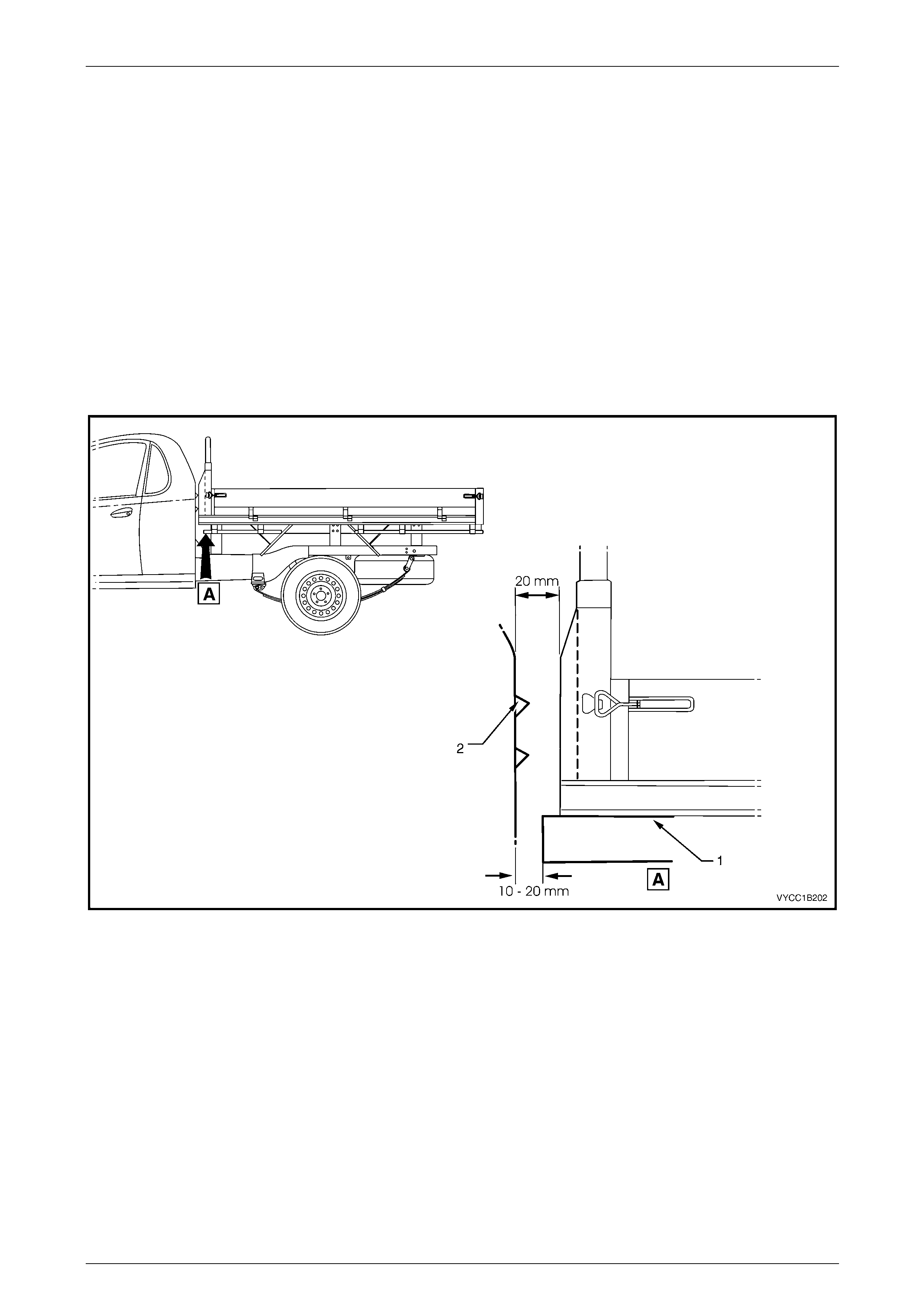
The rear subframe and cab have been designed and engineered with a certain amount of flexing and rigidness. To
prevent contact between the cab and the tray or body due to flexing, it is important the minimum clearance specified of
20 mm between the cab and the tray or body be maintained, refer to Figure 1B2 – 1: Regular Cab shown, Crew Cab
similar.
It should be noted the main longitudin al su pport rails (1) on the underside of the tray or body must align with the rear
subframe uprights. These support rails must protrude slightly further forward than the main portion of the tra y, so the
support rails contact the subframe uprights early in the event of a rear end collision. The specified cleara nce for the main
longitudinal support rails to the rear outer trim panel (2), which covers the subframe upright is to be between 10 to
20 mm.
Figure 1B2 – 1
Body Builders Guide Page 1B2–8
Page 1B2–8
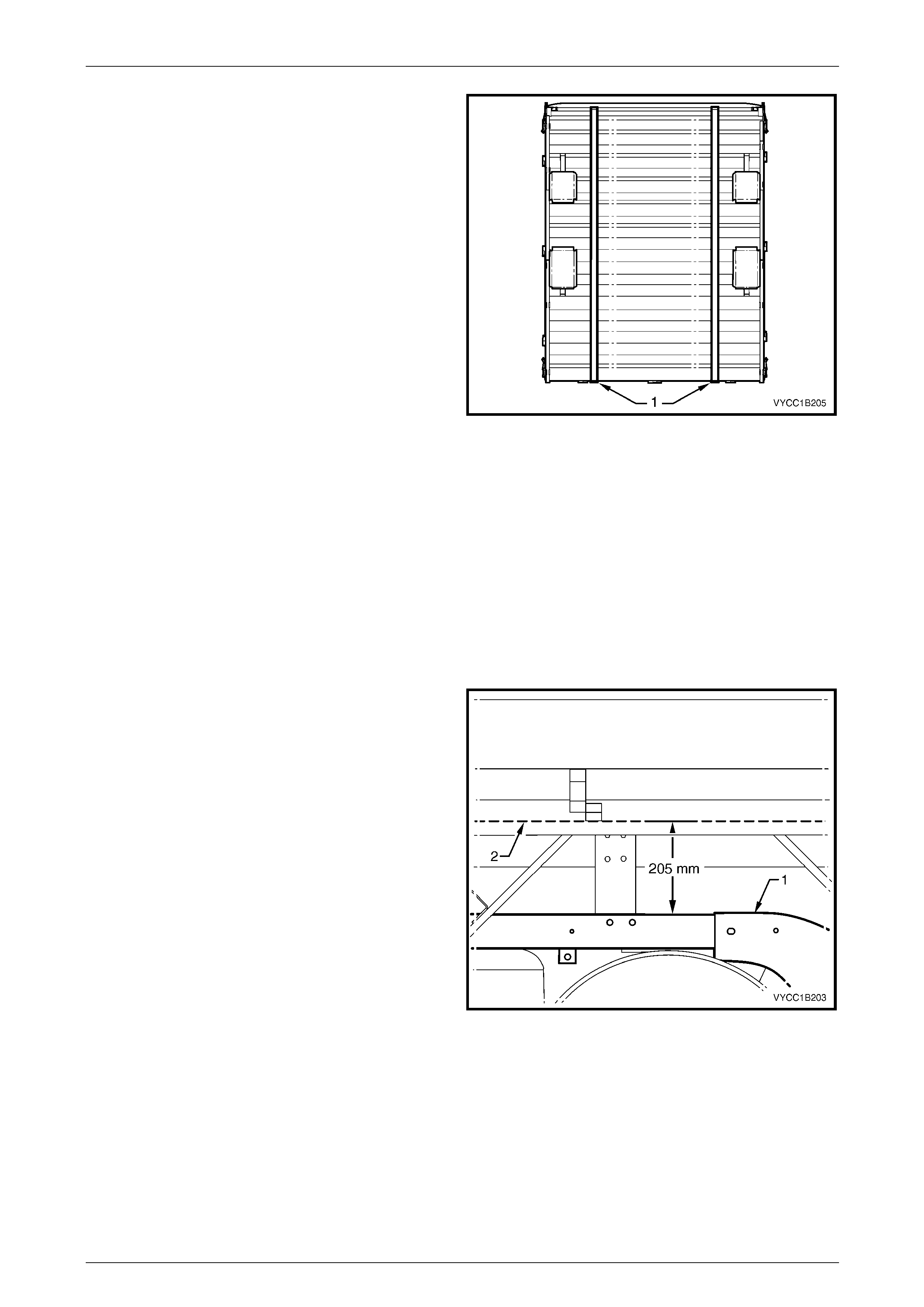
The main longitudinal support rails (1) on the underside of
the tray or body to the outer mating surfaces are to be
between a minimum of 1080mm and a maximum of
1200mm apart and must align with the subframe uprights at
the rear of the cab.
For tray mounting point dimensions, refer to
4.2 Mounting Points. For body and rear su bframe
dimensions, refer to Section 1A2 Body Dimensions.
Figure 1B2 – 2
Tyre Clearances
Adequate clearance must be provided between the rear tyres and the lowest point on the underside of the tray or body
and between the mudguards and tyres. The clearance must allow the axle to reach its maximum travel without the tyres
fouling on the body or the mudguards.
The clearance required between the mudguard and tyre will be determined by its mounting location and pitch of the
mudguard. It is therefore recommended the body builder, when designing and constructing a custom built tray or body,
determines the mudguard to tyre clear ance requirements.
It must be remembered that when determining tyre and mudguard clearance requirements for a custom tray or body, it is
the body builder's responsibility to ensure compliance to the va rious Federal or State transport authority regulations that
may exist for the particular vehicle and its area of op eration.
The minimum clearance requ ired, between the top surface
of the rear subframe longitudinal (1) and the lowest point on
the underside of the tray or body (2) includ ing any
extrusions or crossbeams is 205 mm.
NOTE
It must be emphasised the minimum cl eara nce is
based on the vehicle being fitted with the
standard wheel and t yre options.
For further information and specifications on whe els an d
tyres, refer to Section 10 Wheels and Tyres.
Figure 1B2 – 3

Body Builders Guide Page 1B2–9
Page 1B2–9
4.2 Mounting Points
NOTE
When constructing or mounting a custom tray or
body of a rigid nature, such as a steel tray, the
flexibility of the rear subframe must not be
restricted.
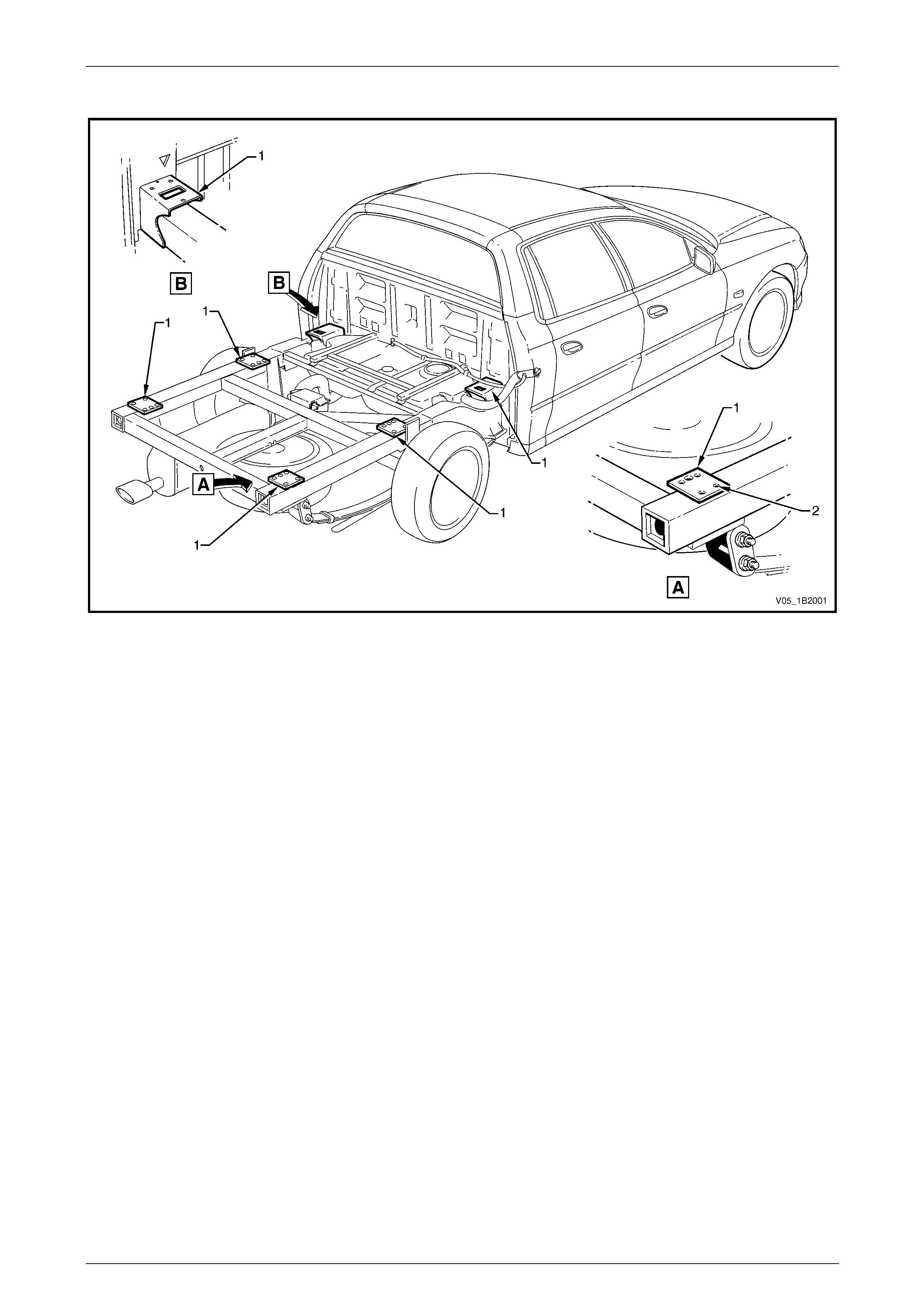
The subframe assembly has six tra y / body mounting points (1), refer to Figure 1B2 – 4 f or Regular Cab or
Figure 1B2 – 5 for Crew Cab vehicles.
Each mounting point, except the Crew Cab front mounting point, incorporates four M10 threaded holes (2): the Crew Cab
front mounting point has three M10 threaded holes. The tray or body must be mounted using all of these six existing
mounting points and al l M10 fixings. Existing holes in the rear subframe frame must not be bored out.
Only high tensile plated bolts with the appropriate n uts and washers are to be used where bolted attachments are fitted
and are to be tightened to the correct torque specification.
Mounting point attaching bolt
torque specification............................................50.0 Nm
Regular Cab
Figure 1B2 – 4
Body Builders Guide Page 1B2–10
Page 1B2–10
Crew Cab
Figure 1B2 – 5
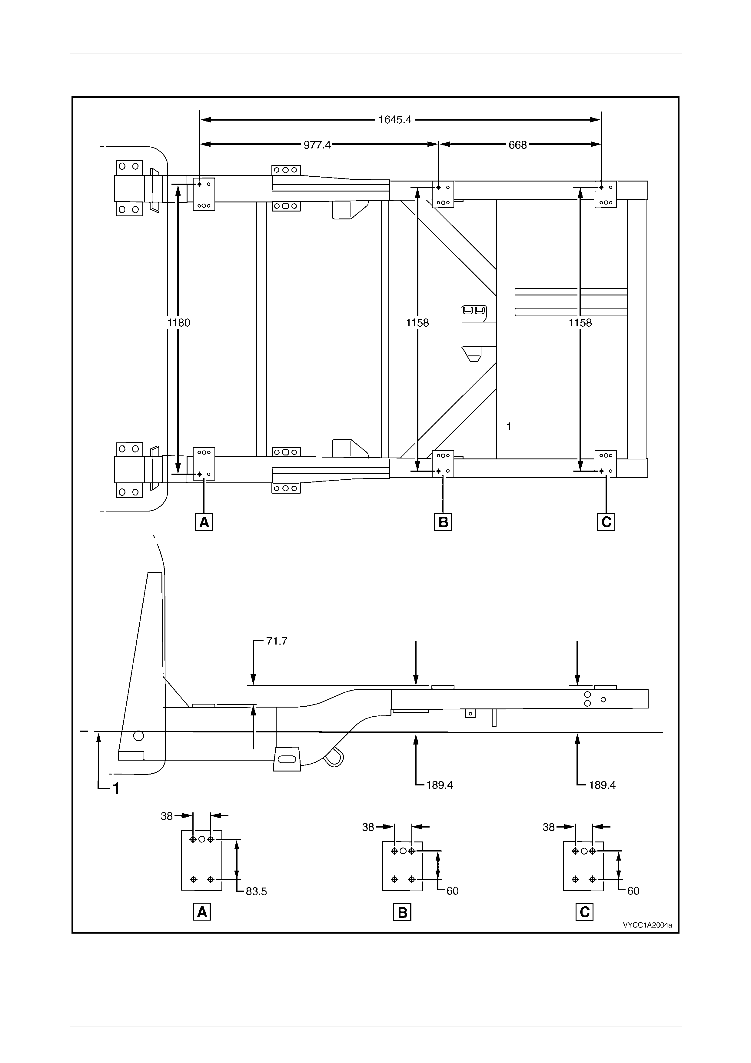
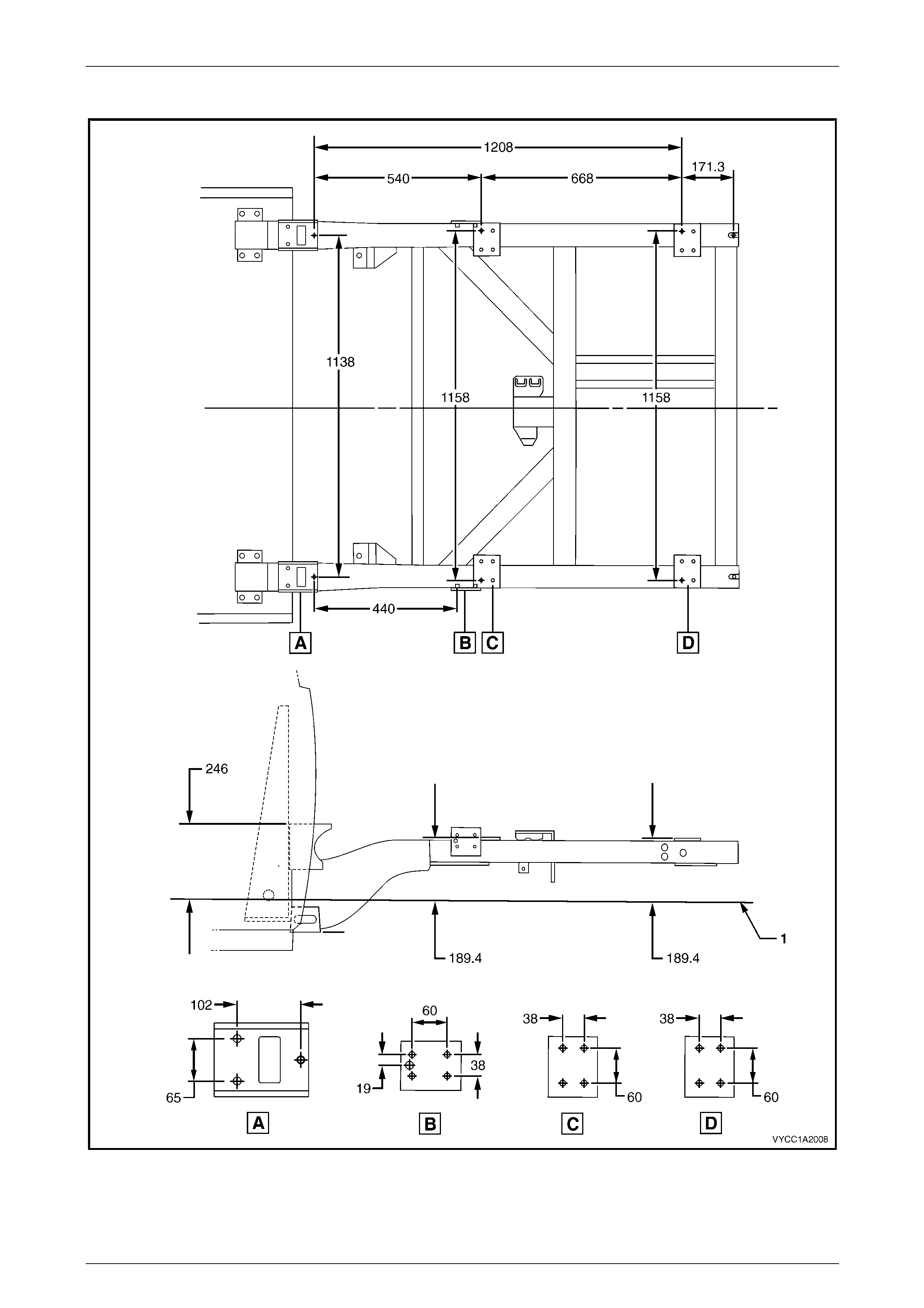
Mounting Dimensions
The following diagr ams show the dimensions between each mounting point and the four M10 threaded ho les at each
point. The main datum surface (1) is the underside of the front side rail assembly.
NOTE
For Crew Cab vehicles, when the Delete-Tub-
Option is specified the mounting point B is not
fitted, refer to Figure 1B2 – 7.
For further information relating to body or subframe dimens ions, refer to Section 1A2 Body Dimensions.
Body Builders Guide Page 1B2–11
Page 1B2–11
Regular Cab
Figure 1B2 – 6
Body Builders Guide Page 1B2–12
Page 1B2–12
Crew Cab
Figure 1B2 – 7
Body Builders Guide Page 1B2–13
Page 1B2–13
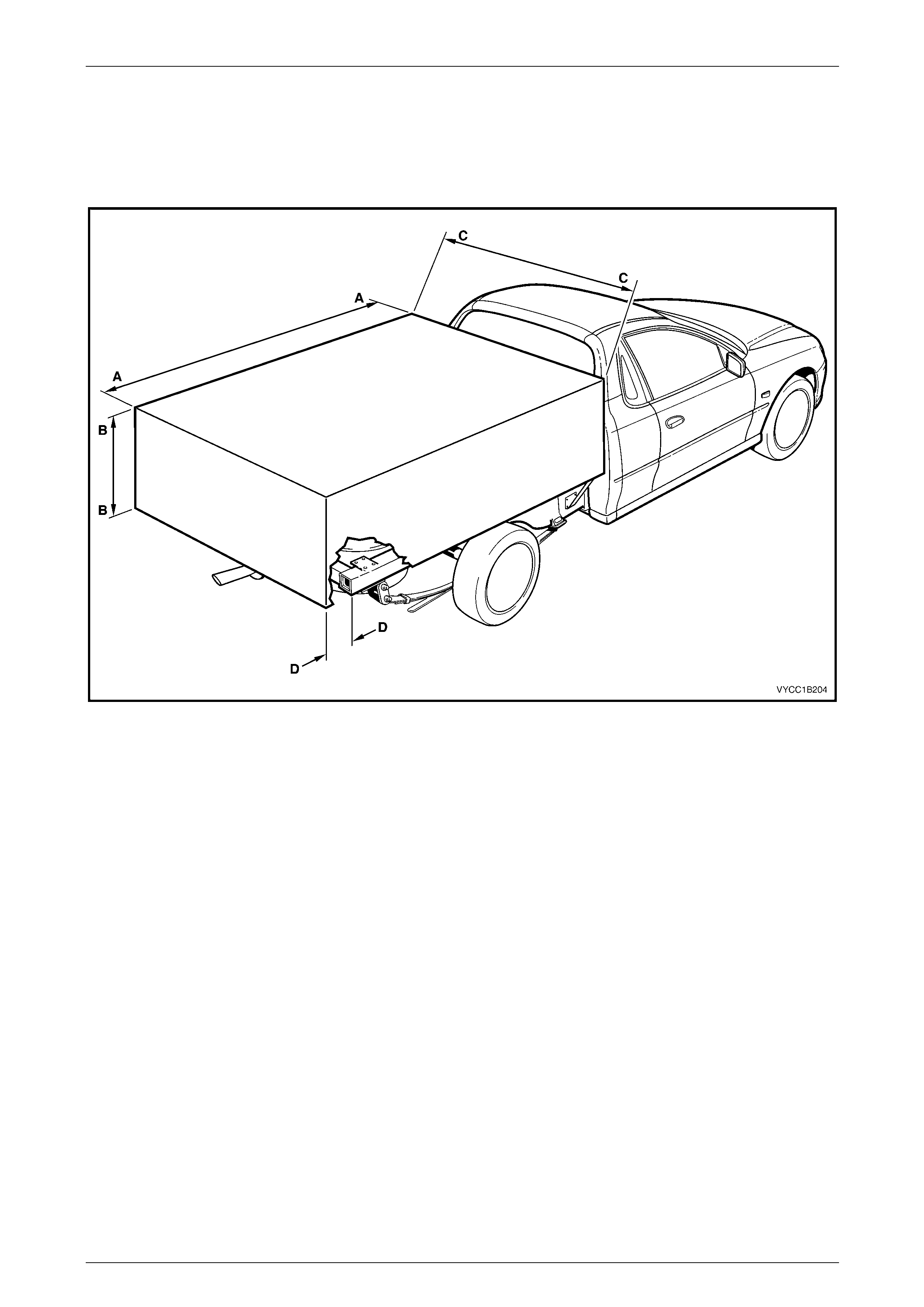
4.3 Tray and Body Sizes
The body builder needs to take into account, and n ot exceed, the recommended maximum overall dime nsions of any
custom built tray or body fitted to a Regular Cab or Crew Cab vehicle, refer to Figure 1B2 – 8 and Figure 1B2 – 9.
Regular Cab
Figure 1B2 – 8
Legend
A – A Maximum overall length – 2340 mm
B – B Maximum height – Refer to 3.1 Modifications C – C Maximum overall width – 1855 mm
D – D Maximum overhang (from rear of subframe) – 370 mm
Body Builders Guide Page 1B2–14
Page 1B2–14
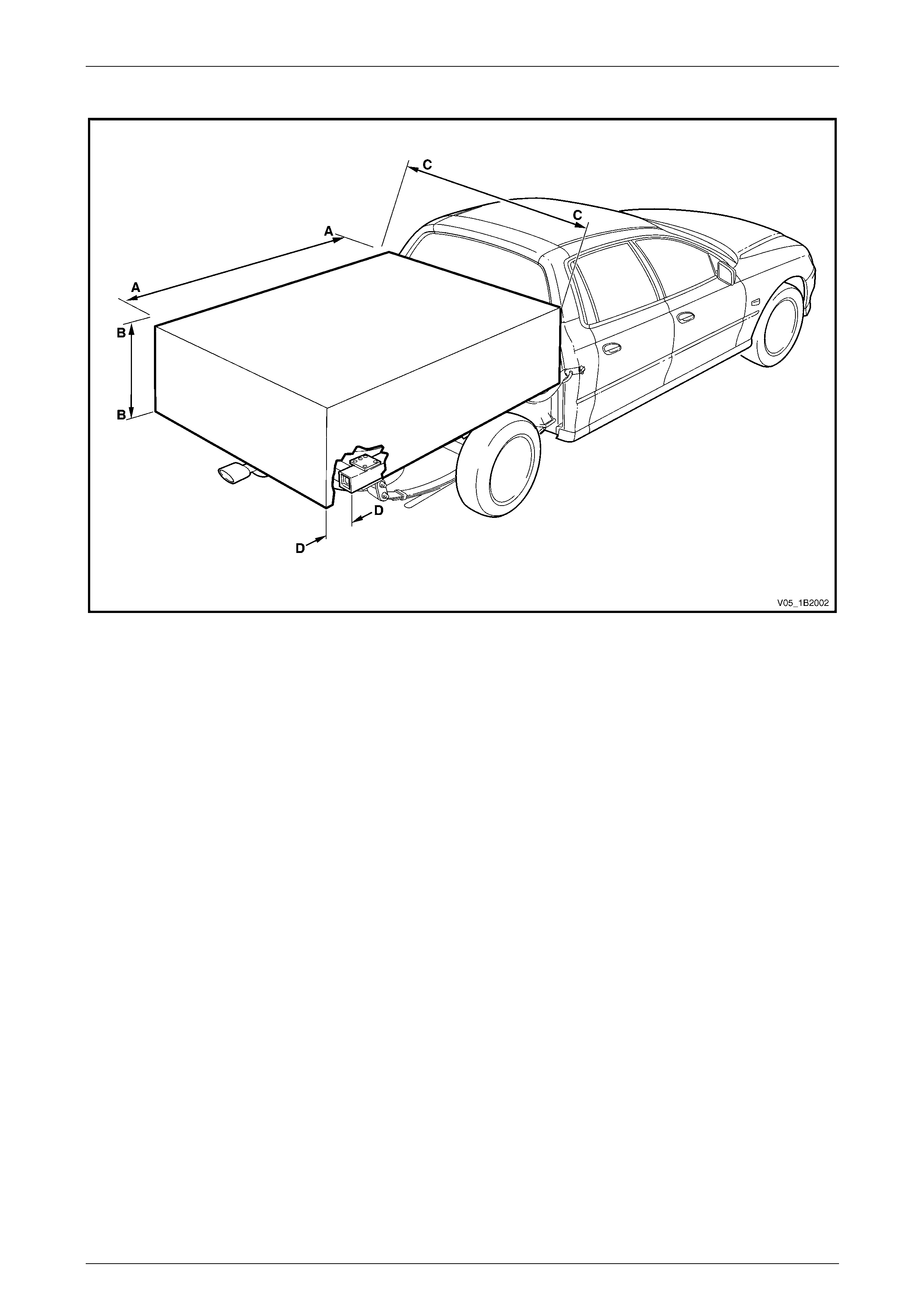
Crew Cab
Figure 1B2 – 9
Legend
A – A Maximum overall length – 1740 mm
B – B Maximum height – Refer to 3.1 Modifications C – C Maximum overall width – 1855 mm
D – D Maximum overhang (from rear of subframe) – 370 mm
It is the body builder's responsibil ity to ensure the vehicle complies to any Federal or State transport a uthority regulations
which may exist regarding the size of a custom tray or body and that any such tray or body complies to all relevant
Federal or State transport authority regulations and a ny Australian Design Rule.
Consideration must also be taken into account for interference or obstruction of rear vision through external rear vision
mirrors. It is the body builder's responsibi lity to ensure that any custom built tray or body does not restrict the vision
through the external mirrors. All Australian Design Rules (ADR) and any relevant Federal or State transport authority
regulations must be complied with.

Body Builders Guide Page 1B2–15
Page 1B2–15
5 Torque Specifications
Mounting Point Attaching Bolts.............................................................50.0 Nm