
Bumper Bars Page 1D–1
Page 1D–1
Section 1D
Bumper Bars
ATTENTION
Before performing any service operation or other procedure described in this Section, refer to Section 00
Warnings, Cautions and Notes for correct workshop practices with regard to safety and/or property damage.
1 General Description ...............................................................................................................................5
2 Paint Systems.........................................................................................................................................6
2.1 General ................................................................................................................................................................... 6
2.2 Rear Park Assist .................................................................................................................................................... 7
2.3 Recommended Materials....................................................................................................................................... 8
2.4 Refinishing of Replacement Parts........................................................................................................................ 9
Priming ................................................................................................................................................................... 9
Paint – 2K Systems................................................................................................................................................ 9
Paint – Cobra Basecoat, Metallic, Pearl or Solid Colour System..................................................................... 10
2.5 Repairing Colour Coat......................................................................................................................................... 11
2.6 Hardener Precautions.......................................................................................................................................... 12
3 Service Operations – Front .................................................................................................................13
3.1 Service Notes....................................................................................................................................................... 13
Razor Blade Retainers......................................................................................................................................... 13
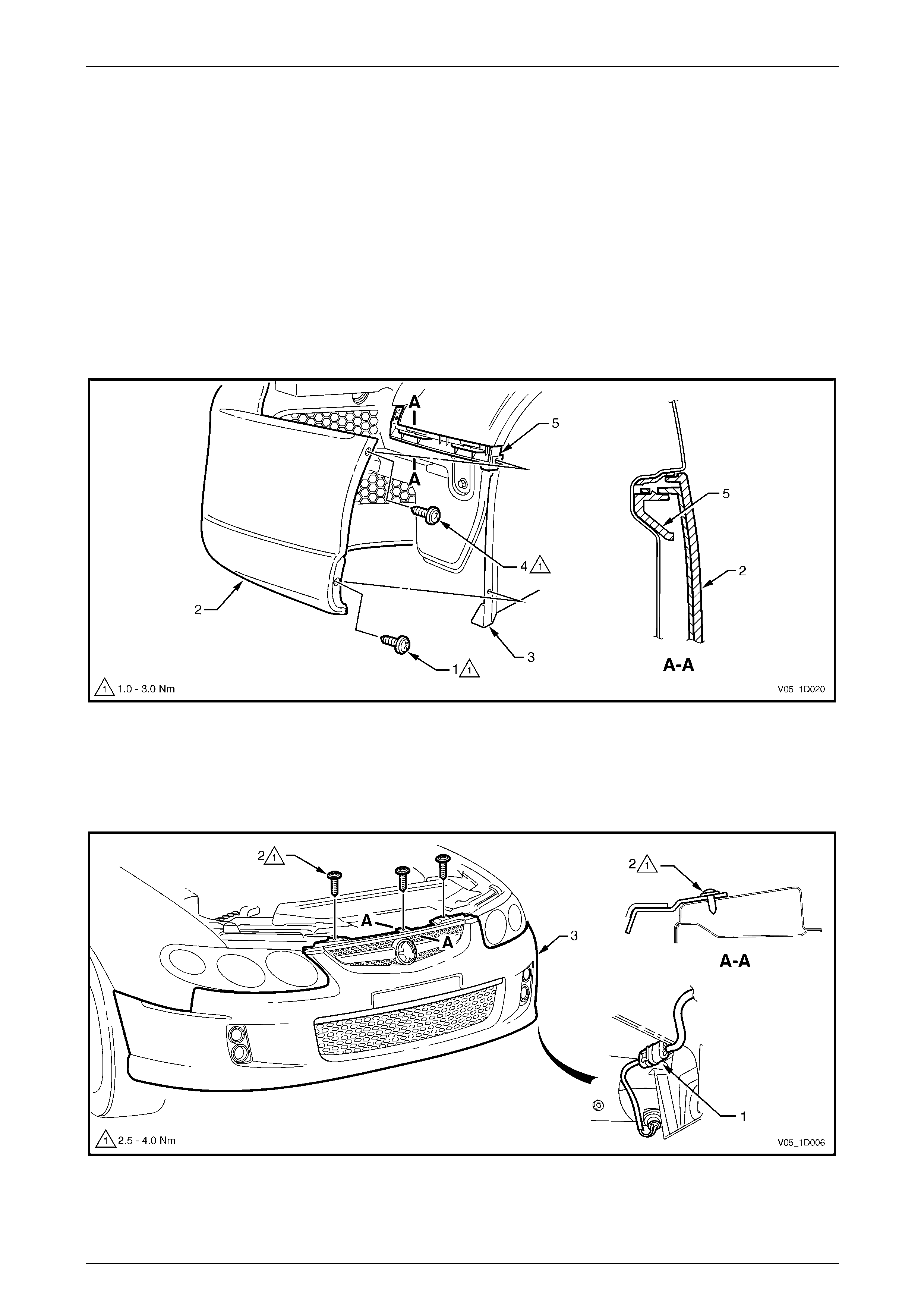
3.2 Front Bumper Fascia Assembly, Except Coupe and AWD ..............................................................................14
Remove................................................................................................................................................................. 14
Disassemble......................................................................................................................................................... 16
Radiator Grille Assembly.................................................................................................................................. 16
Lower Radiator Grille Assembly....................................................................................................................... 16
Front Bumper Access Hole Cover, Level 1 – Except S, SV6 and SS............................................................... 16
Front Fog Lamp Opening Cover, S Utilit y, S Regular Cab and S Crew Cab....................................................16
Front Fog Lamp Surround Cover, Level 2........................................................................................................ 17
Front Fog Lamp Surround Cover, Level 3........................................................................................................ 17
Front Fog Lamp Assembly, Level 2.................................................................................................................. 18
Front Fog Lamp Assembly, Level 3.................................................................................................................. 18
Front Fog Lamp Assembly, SV6 and SS.......................................................................................................... 19
Reinstall................................................................................................................................................................ 19
3.3 Front Bumper Fascia Assembly, Coupe............................................................................................................ 20
Remove................................................................................................................................................................. 20
Disassemble......................................................................................................................................................... 21
Radiator Grille Assembly.................................................................................................................................. 21
Lower Radiator Grille Assembly....................................................................................................................... 21
Front Fog Lamp Opening Cover....................................................................................................................... 21
Front Fog Lamp Assembly............................................................................................................................... 21
Front Bumper Energy Absorber........................................................................................................................ 22
Reinstall ........................................................................................................................................................... 22
Reinstall................................................................................................................................................................ 22

Bumper Bars Page 1D–2
Page 1D–2
3.4 Front Bumper Fascia Undertray......................................................................................................................... 23
AWD Wagon and Crew Cab Cross8 ................................................................................................................... 23
Remove............................................................................................................................................................ 23
Reinstall ........................................................................................................................................................... 24
AWD Regular Cab and Crew Cab Cross6 .......................................................................................................... 24
Remove............................................................................................................................................................ 24
Reinstall ........................................................................................................................................................... 25
3.5 Front Bumper Fascia Assembly, AWD ............................................................................................................... 26
Remove................................................................................................................................................................. 26
Disassemble......................................................................................................................................................... 27
Radiator Grille Assembly.................................................................................................................................. 27
Recovery Point Cover ...................................................................................................................................... 27
Front Bumper Access Hole Cover, AWD Regular Cab and Crew Cab Cross6 ................................................ 28
Front Fog Lamp Opening Cover, Low Level AWD Wagon...............................................................................28
Front Fog Lamp Assembly, High Level AWD Wagon and Crew Cab Cross8................................................... 29
Front Bumper Fascia Insert, AWD Wagon and Crew Cab Cross8................................................................... 29
Reinstall................................................................................................................................................................ 30
3.6 Front Bumper Fascia Guide Assembly, Except Coupe and AWD ................................................................... 31
Remove................................................................................................................................................................. 31
Reinstall................................................................................................................................................................ 31
3.7 Front Bumper Fascia Guide Assembly, Coupe................................................................................................. 32
Remove................................................................................................................................................................. 32
Reinstall................................................................................................................................................................ 32
3.8 Front Bumper Fascia Guide Assembly, AWD.................................................................................................... 33
Remove................................................................................................................................................................. 33
Reinstall................................................................................................................................................................ 33
3.9 Front Bumper Impact Bar Assembly.................................................................................................................. 34
Remove................................................................................................................................................................. 34
Reinstall................................................................................................................................................................ 34
4 Service Operations – Rear...................................................................................................................35
4.1 Service Notes....................................................................................................................................................... 35
Speed Nuts........................................................................................................................................................... 35
Razor Blade Retainers......................................................................................................................................... 35
4.2 Rear Bumper Fascia Assembly, Sedan.............................................................................................................. 36
Remove................................................................................................................................................................. 36
Disassemble......................................................................................................................................................... 38
Towbar Opening Cover.................................................................................................................................... 38
Rear Bumper Fascia Insert, SV6 and SS......................................................................................................... 39
Rear Bumper Fascia Insert, SV8...................................................................................................................... 40
Rear Bumper Fascia Outer Lower Moulding – Level 3..................................................................................... 41
Rear Bumper Fascia Outer Lower Moulding Mounting Bracket – Level 3........................................................ 41
Rear Bumper Fascia Reflective Lens – Level 2 and 3...................................................................................... 42
Rear Bumper Fascia Applique – Level 2 and 3................................................................................................ 42
Rear Park Assist Components ......................................................................................................................... 43
Reinstall................................................................................................................................................................ 48
4.3 Rear Bumper Fascia Assembly, Wagon ............................................................................................................ 49
Remove................................................................................................................................................................. 49
Disassemble......................................................................................................................................................... 50
Towbar Opening Cover.................................................................................................................................... 50
Reinstall................................................................................................................................................................ 50

Bumper Bars Page 1D–3
Page 1D–3
4.4 Rear Bumper Fascia Assembly, AWD Wagon................................................................................................... 51
Remove................................................................................................................................................................. 51
Disassemble......................................................................................................................................................... 53
Rear Bumper Fascia Filler................................................................................................................................ 53
Trailer Wiring Harness...................................................................................................................................... 53
Rear Bumper Fascia Insert .............................................................................................................................. 54
Rear Park Assist Components ......................................................................................................................... 55
Reinstall................................................................................................................................................................ 57
4.5 Rear Bumper Fascia Assembly, Utility .............................................................................................................. 58
Remove................................................................................................................................................................. 58
Reinstall................................................................................................................................................................ 58
4.6 Rear Bumper Fascia Assembly, Coupe............................................................................................................. 59
Remove................................................................................................................................................................. 59
Disassemble......................................................................................................................................................... 60
Towbar Opening Cover.................................................................................................................................... 60
Rear Bumper Fascia Insert .............................................................................................................................. 61
Rear Bumper Fascia Anchor Plate Assembly .................................................................................................. 62
Rear Bumper Fascia Bracket ........................................................................................................................... 62
Rear Park Assist Components ......................................................................................................................... 62
Reassemble ..................................................................................................................................................... 67
Reinstall................................................................................................................................................................ 68
4.7 Rear Bumper Fascia Assembly, Crew Cab........................................................................................................ 69
Remove................................................................................................................................................................. 69
Disassemble......................................................................................................................................................... 71
Reassemble.......................................................................................................................................................... 71
Reinstall................................................................................................................................................................ 71
4.8 Rear Bumper Fascia Guide Assembly, Except AWD Wagon........................................................................... 72
Remove................................................................................................................................................................. 72
Reinstall................................................................................................................................................................ 72
4.9 Rear Bumper Fascia Guide Assembly, AWD Wagon........................................................................................ 73
Remove................................................................................................................................................................. 73
Reinstall................................................................................................................................................................ 73
4.10 Rear Bumper Fascia Centre Support, Sedan..................................................................................................... 74
Remove................................................................................................................................................................. 74
Reinstall................................................................................................................................................................ 74
4.11 Rear Bumper Fascia Upper Support, Wagon .................................................................................................... 75
Remove................................................................................................................................................................. 75
Reinstall................................................................................................................................................................ 75
4.12 Rear Bumper Fascia Upper Support, AWD Wagon........................................................................................... 76
Remove................................................................................................................................................................. 76
Reinstall................................................................................................................................................................ 76
4.13 Rear Bumper Fascia Centre Support, Coupe.................................................................................................... 77
Remove................................................................................................................................................................. 77
Reinstall................................................................................................................................................................ 77
4.14 Rear Bumper Fascia Support, Crew Cab........................................................................................................... 78
Remove................................................................................................................................................................. 78
Reinstall................................................................................................................................................................ 78
4.15 Rear Bumper Impact Bar, Sedan and Wagon.................................................................................................... 79
Remove................................................................................................................................................................. 79
Reinstall................................................................................................................................................................ 79
4.16 Rear Bumper Impact Bar, Coupe........................................................................................................................ 80
Remove................................................................................................................................................................. 80
Reinstall................................................................................................................................................................ 80
4.17 Tow Bar Assembly, AWD Wagon ....................................................................................................................... 81
Remove................................................................................................................................................................. 81
Reinstall................................................................................................................................................................ 81

Bumper Bars Page 1D–4
Page 1D–4
5 Torque Wrench Specifications............................................................................................................82
5.1 Front...................................................................................................................................................................... 82
Except Coupe and AWD...................................................................................................................................... 82
Coupe.................................................................................................................................................................... 82
AWD ...................................................................................................................................................................... 82
All Models............................................................................................................................................................. 82
5.2 Rear....................................................................................................................................................................... 83
Sedan.................................................................................................................................................................... 83
Wagon................................................................................................................................................................... 83
AWD Wagon ......................................................................................................................................................... 83
Utility..................................................................................................................................................................... 83
Coupe.................................................................................................................................................................... 83
Crew Cab .............................................................................................................................................................. 83
All Models............................................................................................................................................................. 83

Bumper Bars Page 1D–5
Page 1D–5
1 General Description
The bumper fascia assemblies fitted to MY 2005 VZ vehic les are constructed from polypropy lene resin. Seven st yles of
front bumper fascias are available depending on Model Le vel and body type. Front fog lamps are also fitted to some
variants, with covers replacing the fog lamps on others. All front bumper fas c ias include an upper radiator grill e and
some have a lower radiator grille which are separate assemblies. For further information of the radiator grill es refer to
Section 1C Radiator Grille.
Eleven rear bumper fascias are avai lable also depending on Model Level and bod y type.
NOTE
For Model Level designations refer to
Section 0A General Information.
Some Sedan and all Coupe and AWD Wagon rear bumper fascia assemblies include four rear sensor assemblies and a
wiring harness for Rear Park Assist (RPA). If the vehicle is fitted with RPA, a new rear bumper fascia service part will
require modification prior to painting and installation. For further information on RPA, refer to
Section 12F1 Rear Park Assist.
A steel front bumper impact bar assembly installed behind the front bumper fascia is attached directly to the front side
rails. The impact bar assembly acts as a mount and support for the bumper fascia assembly and is critical in the
dispersion of crash energy. Hence, it plays an integral role in the operation of the vehicle’s safety systems.
A steel rear bumper impact bar is also installed behind the rear bum per fascia. Repair of the impact bar assemblies
should also be limited to repla cement, as straightening and/or heating can weaken the impact bar assembly resulting in
incorrect occupant protection system operation.

Bumper Bars Page 1D–6
Page 1D–6
2 Paint Systems
2.1 General
The paint system for the bumper fascia assemblies and other painted plastic components is relatively straightfor ward
providing the correct materials are used. Normal refinish lacquers will not adhere to plastic components unless the
correct primers and/or additives are used.
NOTE
Thorough cleanin g and the use of approv ed paint
and additives or their equivalent is required.
Incorrect materials and methods may damage the
plastic or lead to premature paint failure.
The following service recommendatio ns are compiled to guide repairers o n the correct materials and methods to be
employed when refinishing bumper fascias and preparing new parts for service installation. If another paint brand is
chosen, refer to the manufacturer’s latest technic al data for the appropriate materials and procedures required.

Bumper Bars Page 1D–7
Page 1D–7
2.2 Rear Park Assist
Where fitted for Sedan, or on all Coupe and AWD Wagons, the rear bumper fascia assembly contains four sensor
assemblies for Rear Park Assist (RPA). The exposed end of the sensor assembly is painted the vehicle’s body colour.
New service sensor assemblie s are supplied pre-painted in t he vehicle’s body colour and must not have any further paint
applied.
If repainting a fascia assembly, the sensors
and rings MUST be removed. Paint must not
be applied to any part of a sensor, including
the exposed coloured surface. Paint film
applied to the exp osed surface will render the
sensor inoperable as the paint film restricts
the sensor’s ultra-sonic signal. If a sensor is
damaged, it must be replaced.
Replacement housings are supplied unpainted. As they are partially exposed when installed, they will require painting
using the same procedures for painting the bumper fascia, described below.
NOTE
It is preferable to paint the housings and bumper
fascia separately to avoid adhesion problems.
Assemble the housings onto the bumper fascia
once the paint has cured, refer to,
3.2 Front Bumper Fascia Assembly,
Except Coupe and AWD or
4.6 Rear Bumper Fascia Assembly, Coupe.
For further information on rear park assist, refer to Section 12F1 Rear Park Assist.

Bumper Bars Page 1D–8
Page 1D–8
2.3 Recommended Materials
Front and rear bumper fascias are made from high impact strength Polypropylene (PP) resin.
It is essential that only approved materials, paints, etc. or their equivalent are employed when paint repair operations are
performed and when preparing new parts for installation to the vehicles.
The approved materials are:
• PPG Bodykleen 920-30509
• PPG Plastpak Universal Anti Static Cleaner 920-39237
• PPG Plastpak Universal Primer 499-38571
• PPG Plastpak Flexible Additive for Two Component Products 499-35484
• PPG Cobra Basecoat - Colour 534 Line
• PPG 2K Clearcoat 455-30900
• PPG 2K Acrylic Enamel Solid Colour 426 Lin e
• PPG 2K MS Hardener Normal 980-35239
• PPG 2K Thinner 920-49424
NOTE
Always refer to the paint manufacturer’s latest
product information.

Bumper Bars Page 1D–9
Page 1D–9
2.4 Refinishing of Replacement Parts
Replacement parts will requir e priming and coating with approved topcoat colour before installation to the vehicle.
1 Order part and paint materials.
2 Read all safety data material relative to the paint system chosen from the paint manufacturer and
2.6 Hardener Precautions, included further in this Section.
3 Obtain the required respiration and safety equipment recommended by the paint man ufacturer, in this publication
or required by regulations.
4 Wash the unpainted bumper fascia all over with a made-up solution of 9 parts fresh water to 1 part PPG Bodykleen
920-39237. Apply with a clea n, non-metallic pad (recommended Scotchbrite** 448) to scuff the surface.
5 Rinse with fresh cold water.
6 Use a clean cloth saturated with PPG Plastpak Universal Anti-static Cle aner 920-39237. Wash the entire part
allowing contact for a minimum 15 seconds.
7 Dry thoroughly usin g a separate, clean, dry cloth.
8 Repeat steps five and six another three times. Use a separate, clean dry cl oth each time.
NOTE
If a static charge has built up on the bumper
surface (after completing all cleaning operations)
dampen the surface with Plastpak Universal Anti
Static Cleaner and allow to evaporate dry. This
will impart full anti-static properties to the bumper
fascia.
Priming
1 Fit an air-supplied respirator.
2 Apply one light double coat (approximately 3 – 8 m D.F.B. uniformly wet) of PPG Plastpak Universal Primer 499-
38571 to the bumper surface intended for topcoat. Recommended air pressure range is 320 – 420 kPa.
3 Allow to air dry 15 – 20 minutes at 20°C. DO NOT SAND.
** Scotchbrite is a trademark of 3M Co.
Paint – 2K Systems
1 To the matched colour, add Flexible Additive then Hardener and Thinner in the following ratios:
• 246 line colour - 5 parts by volume
• Flexible Additive 499-35484 - 1 part by volume
• 2K MS Hardener 980-35239 - 3 parts by volume
• 2K Thinner 920-49424 - 10 – 20% b y volume
2 Stir thoroughly and strain.
3 Fit an air-supplied respirator.
4 Using a 1.4 – 1.8 mm fluid nozzle on a sta ndard spray gun, apply one medium wet coat.
5 Apply a further one or two coats to achieve coverage (correct film thicknes s is 40 – 50 microns) allowing a 3 – 5
minute flash-off time bet ween coats.
6 If low baking, this can be done immediately after the last coat, but do not allow more than 5 minutes flash-off. Bake
at 60°C for 40 minutes.
7 If air drying, allow 16 hours.

Bumper Bars Page 1D–10
Page 1D–10
Paint – Cobra Basecoat, Metallic, Pearl or Solid Colour System
1 Thin the matched basecoat colour with Cobra Basebuilder, 9 20 line at a 1:1 mix ratio and stir thoroughly.
2 Strain material.
3 Fit an air supplied respirator.
4 Using a 1.4 – 1.6 mm gravit y feed spra y gu n, apply one medium, wet even coat. Allow to flash-off for five minutes
before applying the next coat.
5 Apply one or two further coats to achieve a uniform and even coverage with 5 minutes flash-off bet ween coats.
6 Allow 10 – 20 minutes dryi ng
7 Mix the 2K Clearcoat with Flexible Additive, then Hardener and Thinner in the following ratios:
• 2K Clearcoat 455-30900 - 5 parts b y volume
• Flexible Additive 499-35484 - 1 part by volume
• 2K MS Hardener 980-35239 - 3 parts by volume
• PPG 2K Thinner 920-49424 - 20% by volume
8 Stir thoroughly and strain.
9 Using a 1.4 – 1.8 fluid nozzle spray gun set up, apply one medium wet coat.
10 Apply a further one or two wet coats after a 3 – 5 minutes flash-off between coats.
11 If low baking, this can be done immediately after the last coat, but do not allow more than 5 minutes flash-off. Bake
at 60°C for 40 minutes.
12 If air drying, allow 16 hours.

Bumper Bars Page 1D–11
Page 1D–11
2.5 Repairing Colour Coat
Sanding and repainting may rectify superficial dam age to the paint film and/or plastic surfaces. Parts having deep
gouges in the plastic surface should be replaced as repair methods using filling materials and thinning down of the plastic
section may reduce overall impact strength.
For shallow paint damage, follow the procedure listed under, Colour F inishing of Replacement Parts, in this Section,
using P800 paper to sand down imperfections and using a Scotchbrite 448 pad or P1200 paper, scuff and key existing
paintwork.
Basecoat and Clearcoat can be spot repaired by blending away the bas ecoat colour and spraying the complete bumper
with Clearcoat. Solid colours are best sprayed as complete panels. If the damage extends through the paintwork to the
plastic surface, this must be primed with Plastpak Universal Primer after the correct cleaning procedure.
NOTE
Drying of all products may be accelerated by
heat. But to avoid distortion, unsupported
bumpers should not be heated in an oven or by
lamp above 60°C.

Bumper Bars Page 1D–12
Page 1D–12
2.6 Hardener Precautions
The following instructions relate to the safe handling of all paints containing PPG 2K MS Hardener, which contains not
more than 0.3% isocyanate monomer.
This product is for automotive and industrial
use only. It requires professional equipment
and experience for safe handling. It is not for
use by the general public.
Read and understand the instructions and warnings contained in Material Safet y Data sheets and on the label of the can
containing the base product before opening. Follow all directions and warnings carefully, otherwise do not use this
product. Warnings and precautions o n the la bel also apply to the mixture of hardener and base.
Inhalation of vapour, spray mist and dust from sanding is h armful and may cause lung irritation and allergic respirator y
reaction. The vapour also irritates the skin and eyes.
When mixed with the appropriate base, apply in a spray bo oth fitted with an effective exhaust system. Comply with local
legislation applicable to spray painting of motor vehicles. Wear a positive pressure a ir supplied full face respirator
(complying with any relevant Standards) and gloves while sprayi ng and during all subsequent use. The spray booth area
should be isolated from other peo ple while spraying is in progress and until all spray mist has been effectively evacuated.
If affected by inhalation of vapour or spray mist, move to a location with plenty of fresh air.
If breathing difficulty persists or occurs later, consult a doctor and have the label information availabl e. In the case of eye
contact, flush immediately with plenty of water for 15 minutes and call a doctor.
In case of skin contact, remove contaminated clothing and wash skin thoroughly with soap and water. Immerse
contaminated clothing in water for 24 hours and do not re-use until it has been laundered.
In case of spillage, absorb the liquid o nto dry sand or earth. Remove the spillage from the work area and cover with
water for 24 hours before disposal. Treat the empty hardene r cans in the same manner.
Bumper Bars Page 1D–13
Page 1D–13
3 Service Operations – Front
3.1 Service Notes
Certain components are attached with the following retainers. When removing these, follow the correct procedure to
avoid damaging the component.
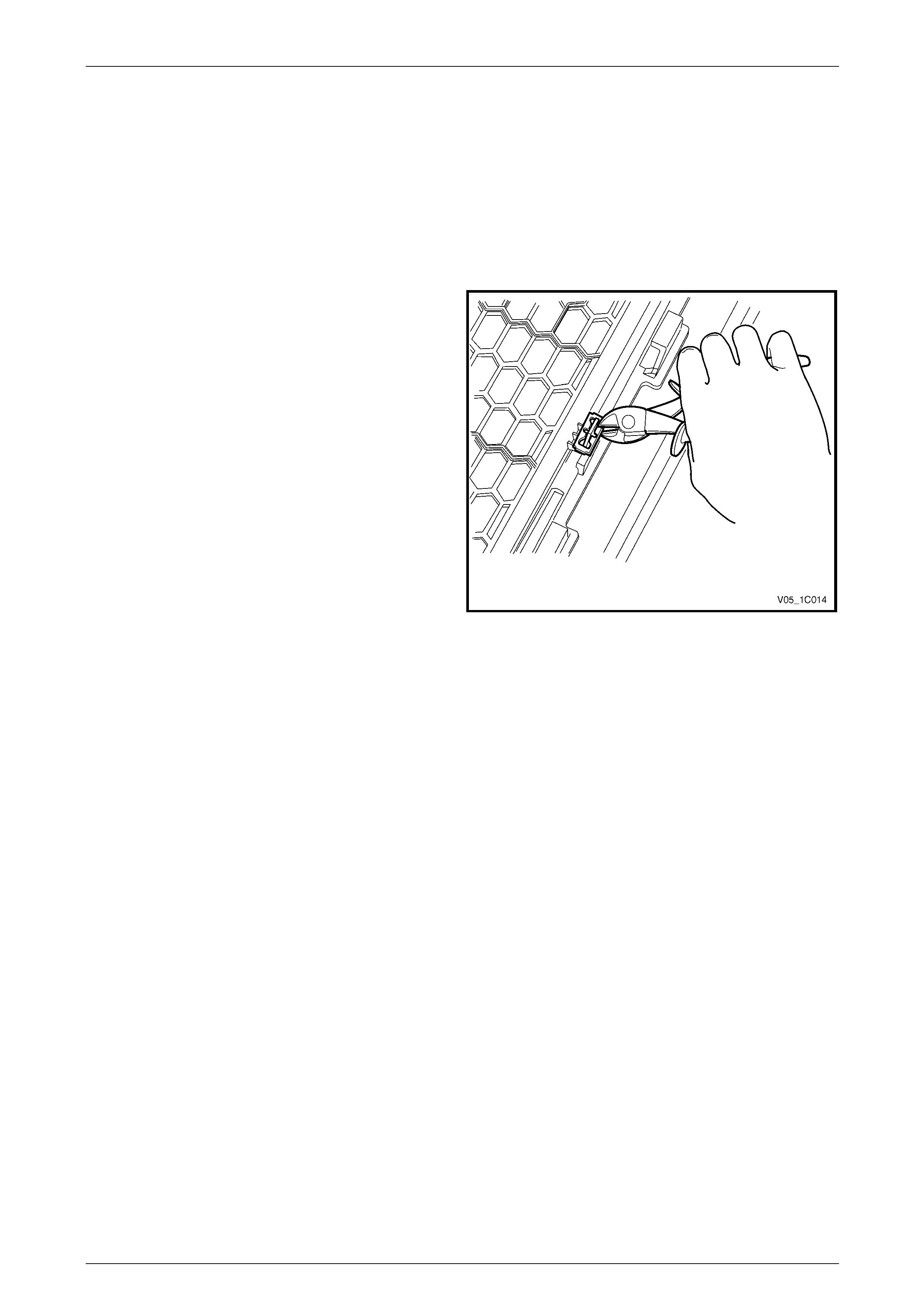
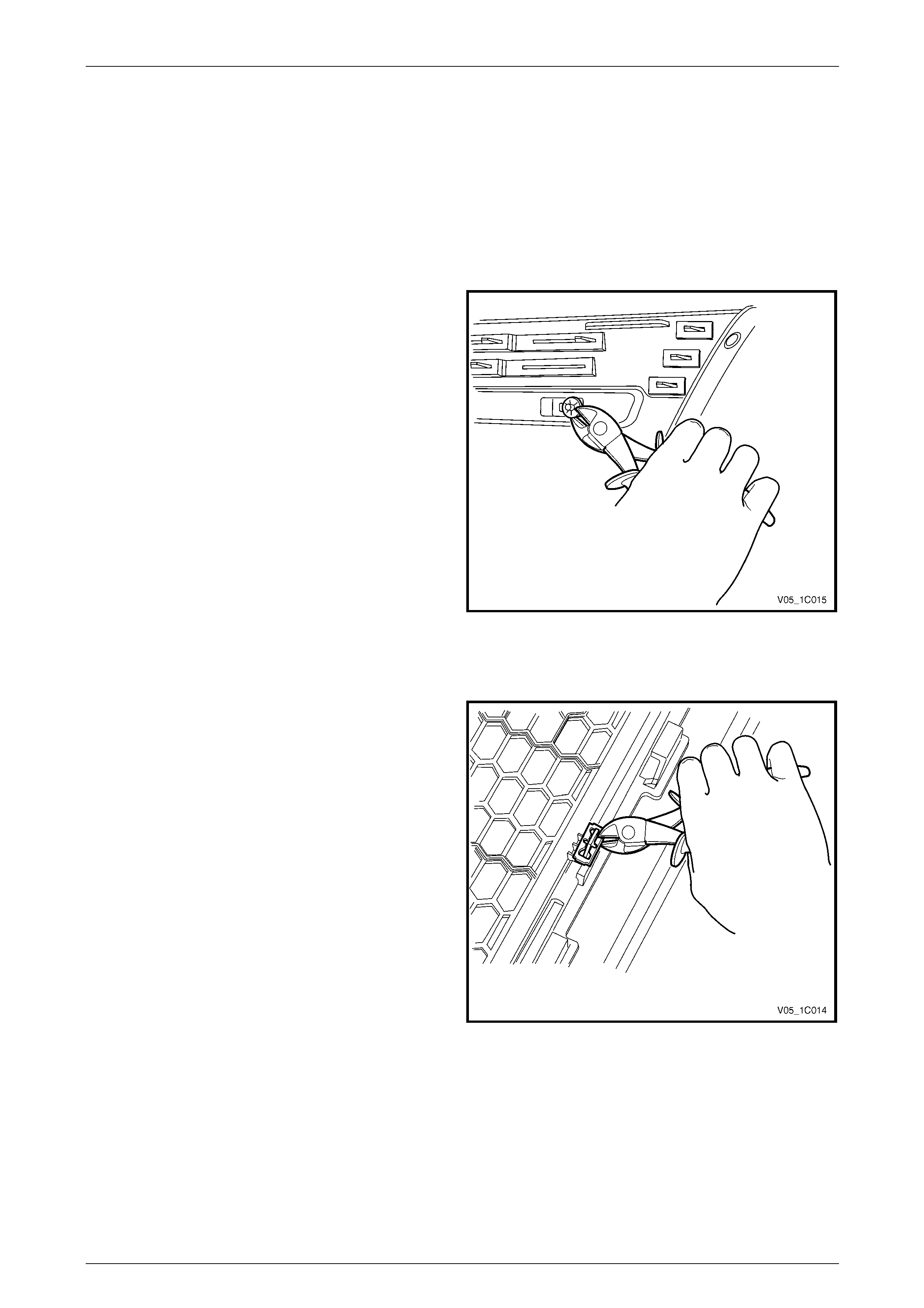
Razor Blade Retainers
1 Prise the edge of the razor blade retai ner away from
the surface, giving enough clearance to allow access
with side cutters.
2 With the side cutters cut the razor blade retainer and
bend the razor blade retainer from the mounting lug
and remove.
3 Replace the razor blade retainer as required.
Figure 1D – 1
Bumper Bars Page 1D–14
Page 1D–14
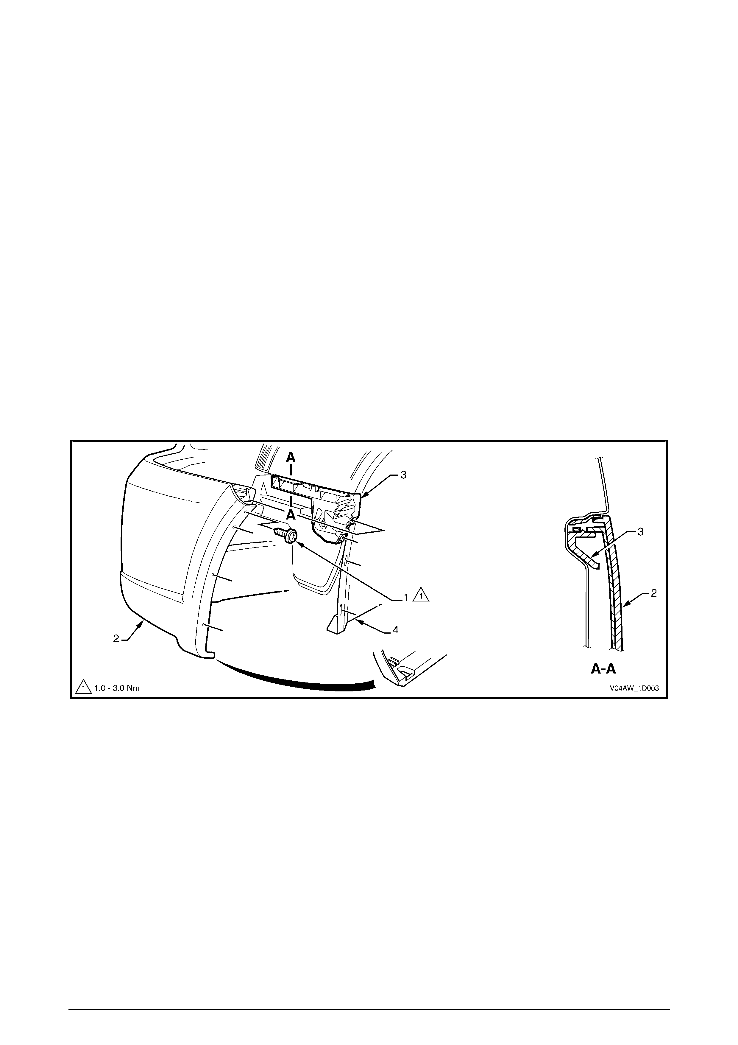
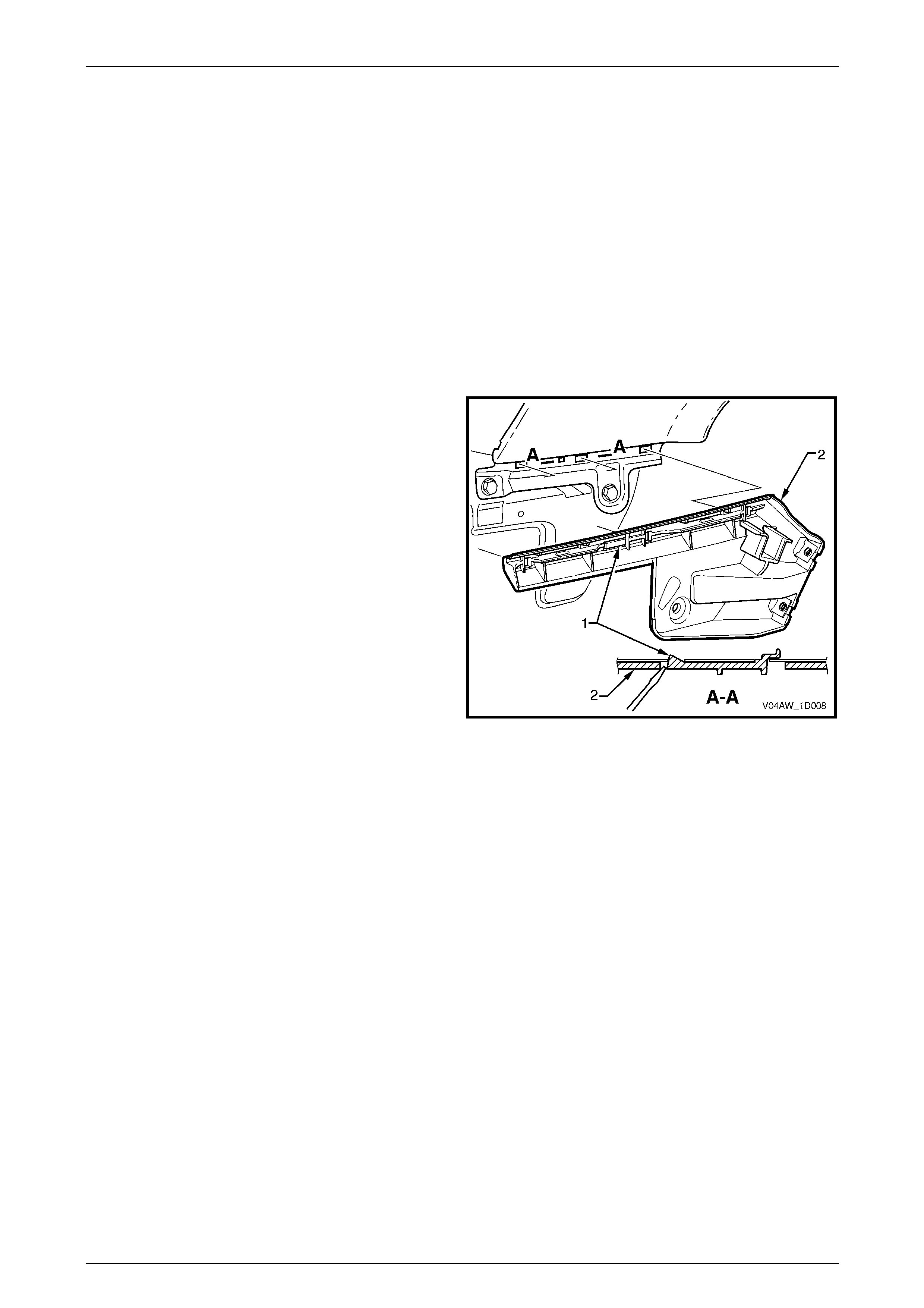
3.2 Front Bumper Fascia Assembly, Except
Coupe and AWD
LT Section No. — 07–500
Remove
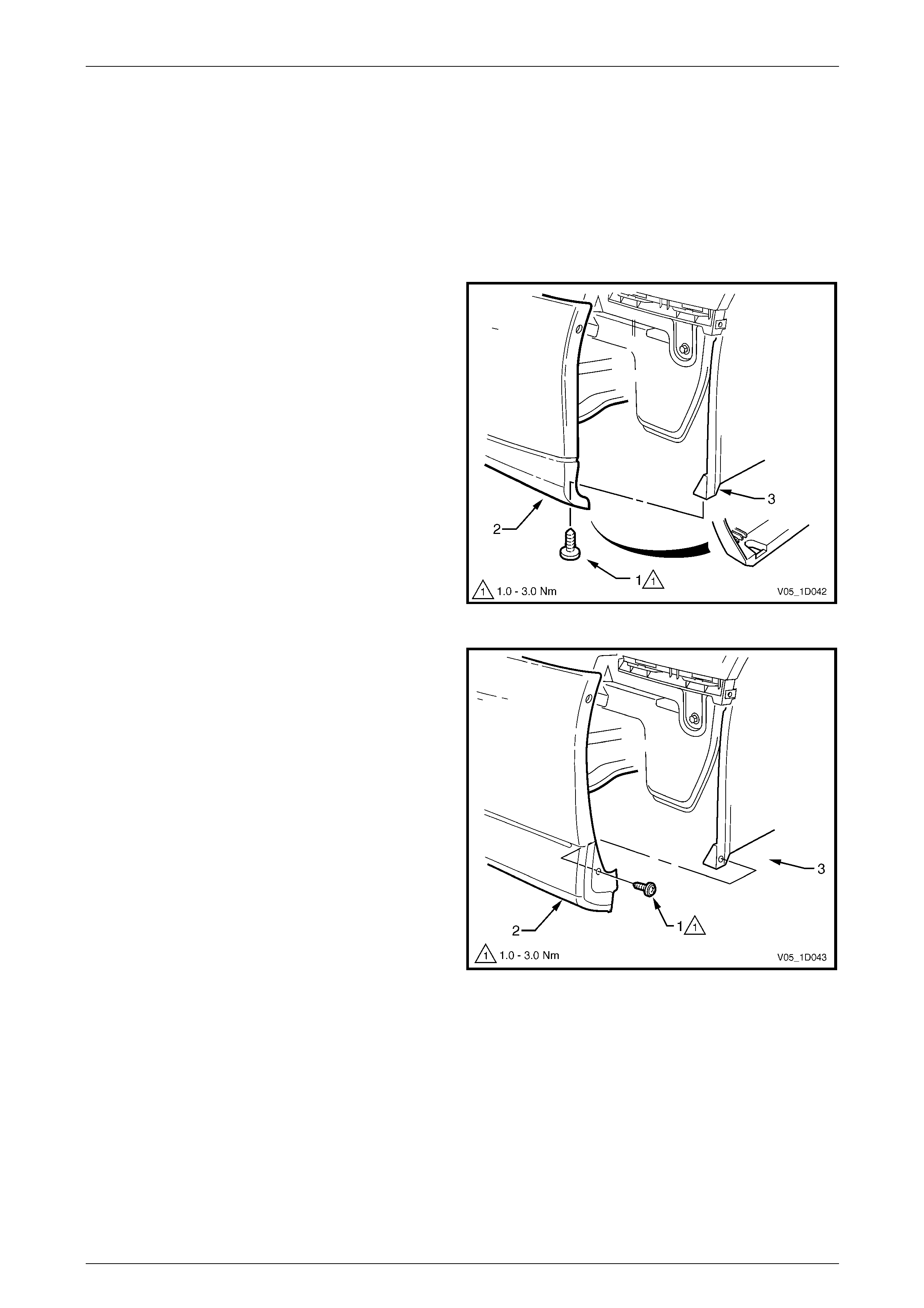
1 Depending on Model, from each side of the vehicle either:
a Remove the screw (1) attaching the undersi de of
the front bumper fascia assembly (2) to the
wheelhouse liner (3), or
Figure 1D – 2
b Remove the screw (1) attaching the front bumper
fascia assembly (2) to the front wheelhouse liner
(3).
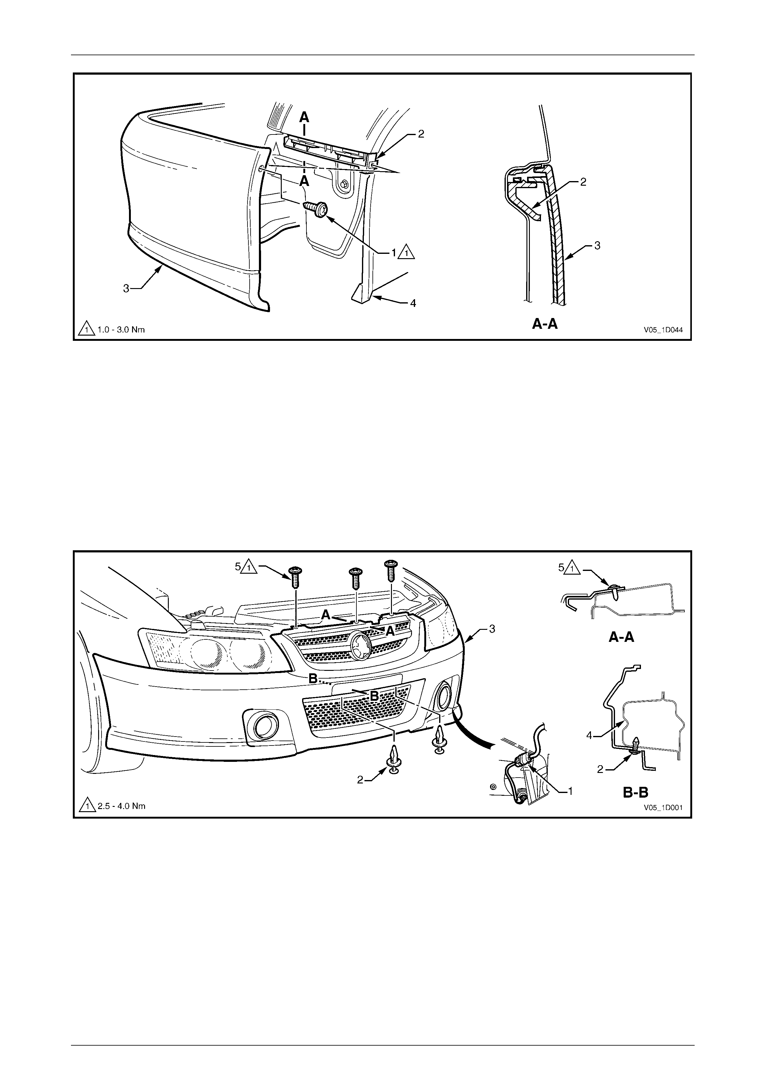
2 Referring to Figure 1D – 4, from each side of the
vehicle:
a Remove the screw (1) attaching the fascia
assembly to the front bumper fascia guide
assembly (2).
b Carefully unclip the fascia assembly from the
guide assembly by graspi ng the upper end of the
fascia and pulling a way from the vehicle.
Figure 1D – 3
Bumper Bars Page 1D–15
Page 1D–15
Figure 1D – 4
3 If fitted, disconnect the front fog lamp wiring connector (1), one place each side of the vehicle, refer to
Figure 1D – 5.
4 Remove the two retainers (2) from the recesses (behind th e licence plate), attaching the fascia assembl y (3) to the
front bumper impact bar assembly (4).
5 Remove the three screws (5) attaching the fascia assembl y to the front upper p an el.
NOTE
The centre screw also attaches the radiator grille
assembly.
Figure 1D – 5
6 With the aid of an assistant remove the fascia assembly and store in a safe plac e.
Bumper Bars Page 1D–16
Page 1D–16
Disassemble
Radiator Grille Assembly
For removal of the radiator grille assembl y, refer to Section 1C Radi ator Grille.
Lower Radiator Grille Assembly
For removal of the lower radiator grille assembly, refer to Section 1C Radiator Grille.
Front Bumper Access Hole Cover, Level 1 – Except S, SV6 and SS
Remove
1 From the rear of the fascia, unclip the retainer (1), six
places, securing the front bumper access hole cover
(2) to the bumper fascia.
2 Remove the cover.
Reinstall
1 Fit the cover into position and clip onto the bumper
fascia.
2 Ensure the retainers are seated correctl y.
Figure 1D – 6
Front Fog Lamp Opening Cover, S Utility, S Regular Cab and S Crew Cab
Remove
1 Depress the retaining tab (1), two places, securing the
front fog lamp opening cover (2) to the bumper fascia.
2 From the front of the bumper fascia, withdraw the
cover from its recess.
Reinstall
1 Fit the cover into position and clip onto the bumper
fascia.
2 Ensure the retainers are seated correctl y.
Figure 1D – 7
Bumper Bars Page 1D–17
Page 1D–17
Front Fog Lamp Surround Cover, Level 2
Remove
1 From the rear of the fascia, unclip the retainer (1),
eight places, securing the fog lamp surround cover (2)
to the bumper fascia.
2 Remove the cover.
Reinstall
1 Fit the cover into position and clip onto the bumper
fascia.
2 Ensure the retainers are seated correctl y.
Figure 1D – 8
Front Fog Lamp Surround Cover, Level 3
Remove
1 From the rear of the fascia, unclip the retainer (1),
three places, securing the front fog lamp surroun d
cover (2) to the bumper fascia.
2 Remove the cover.
Reinstall
1 Fit the cover into position and clip onto the bumper
fascia.
2 Ensure the retainers are seated correctl y.
Figure 1D – 9
Bumper Bars Page 1D–18
Page 1D–18
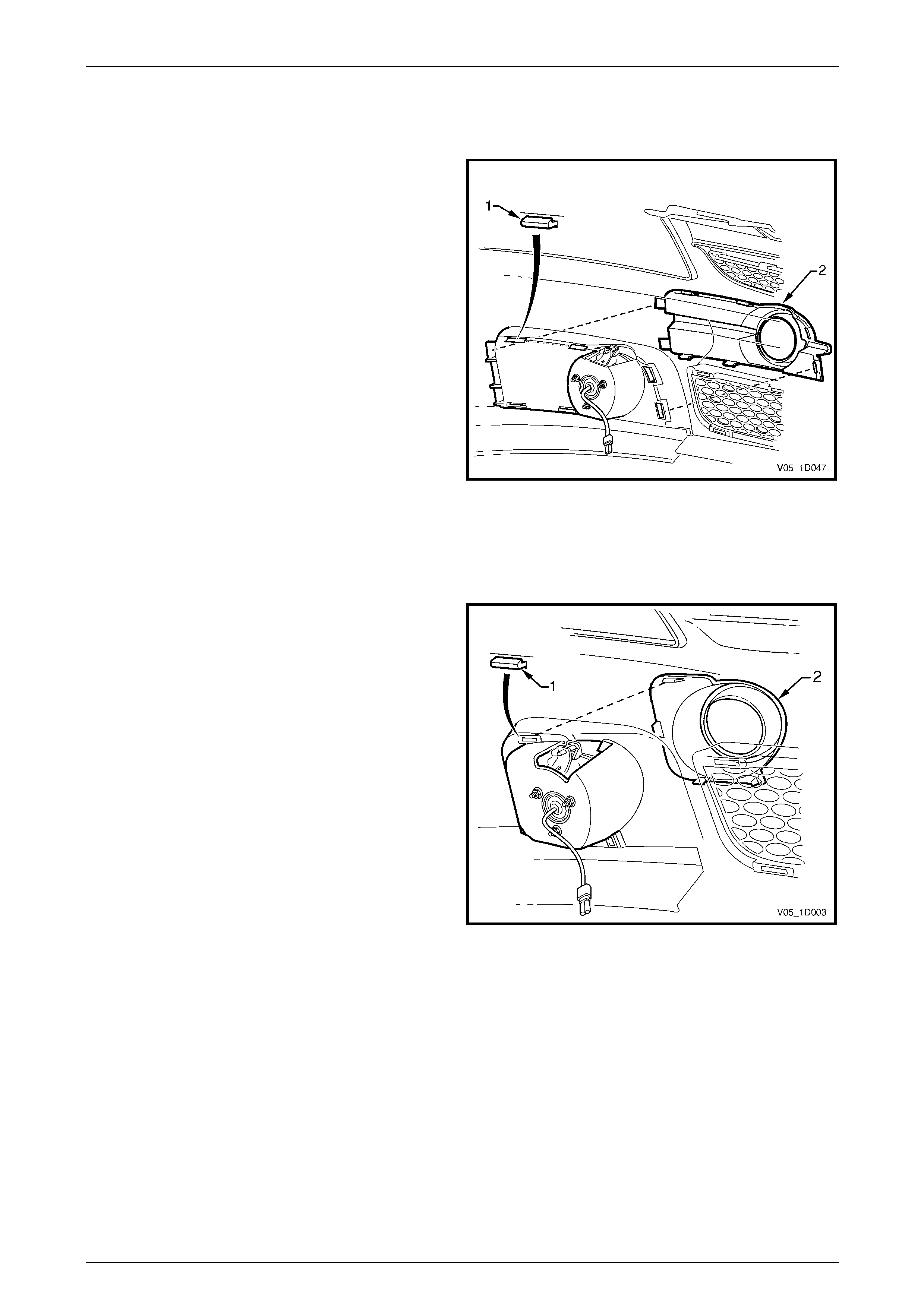
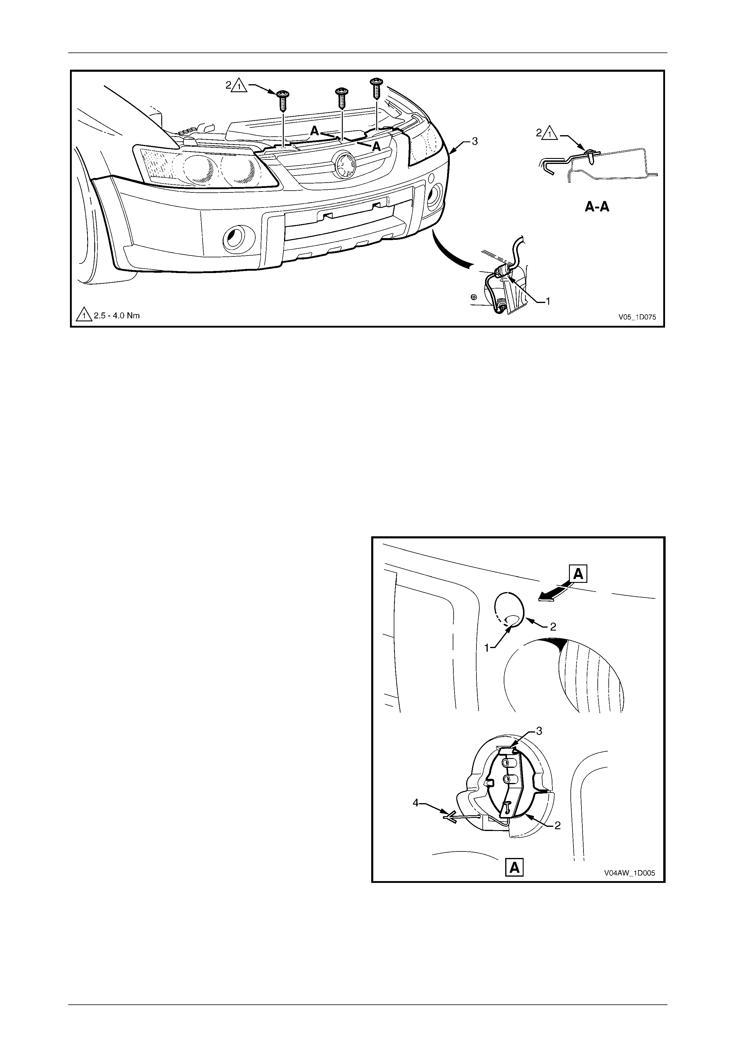
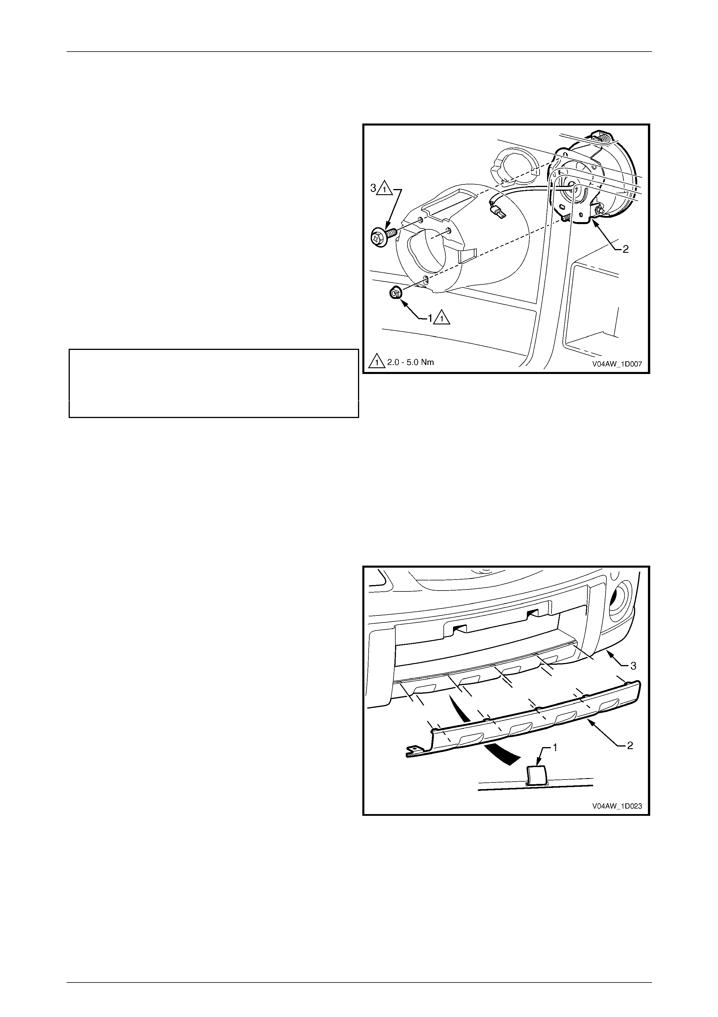
Front Fog Lamp Assembly, Level 2
Remove
1 Remove the fog lamp cover.
2 Remove the nut (1), three places, attaching the front
fog lamp assembly (2) to the bumper fascia.
3 From the front of the bumper fascia, withdraw the lamp
assembly and wiring connector from its recess.
NOTE
For further service of the front fog lamp
assembly refer to Section 12B Lighting System.
Reinstall
Reinstallation of the front fog lamp assembly is the reverse
of the removal procedure. Tighten the nuts to the correct
torque specification.
Front fog lamp assembly attaching
nut torque specification...............................2.0 – 5.0 Nm
NOTE
Following installation of the bumper fascia
assembly, aim the fog lamps, refer to
Section 12B Lighting System.
Figure 1D – 10
Front Fog Lamp Assembly, Level 3
Remove
1 Remove the fog lamp cover.
2 Remove the nut (1), three places, attaching the front
fog lamp assembly (2) to the bumper fascia.
3 From the front of the bumper fascia, withdraw the lamp
assembly and wiring connector from its recess.
NOTE
For further service of the front fog lamp
assembly refer to Section 12B Lighting System.
Reinstall
Reinstallation of the front fog lamp assembly is the reverse
of the removal procedure. Tighten the nuts to the correct
torque specification.
Front fog lamp assembly attaching
nut torque specification...............................2.0 – 5.0 Nm
NOTE
Following installation of the bumper fascia
assembly, aim the fog lamps, refer to
Section 12B Lighting System.
Figure 1D – 11
Bumper Bars Page 1D–19
Page 1D–19
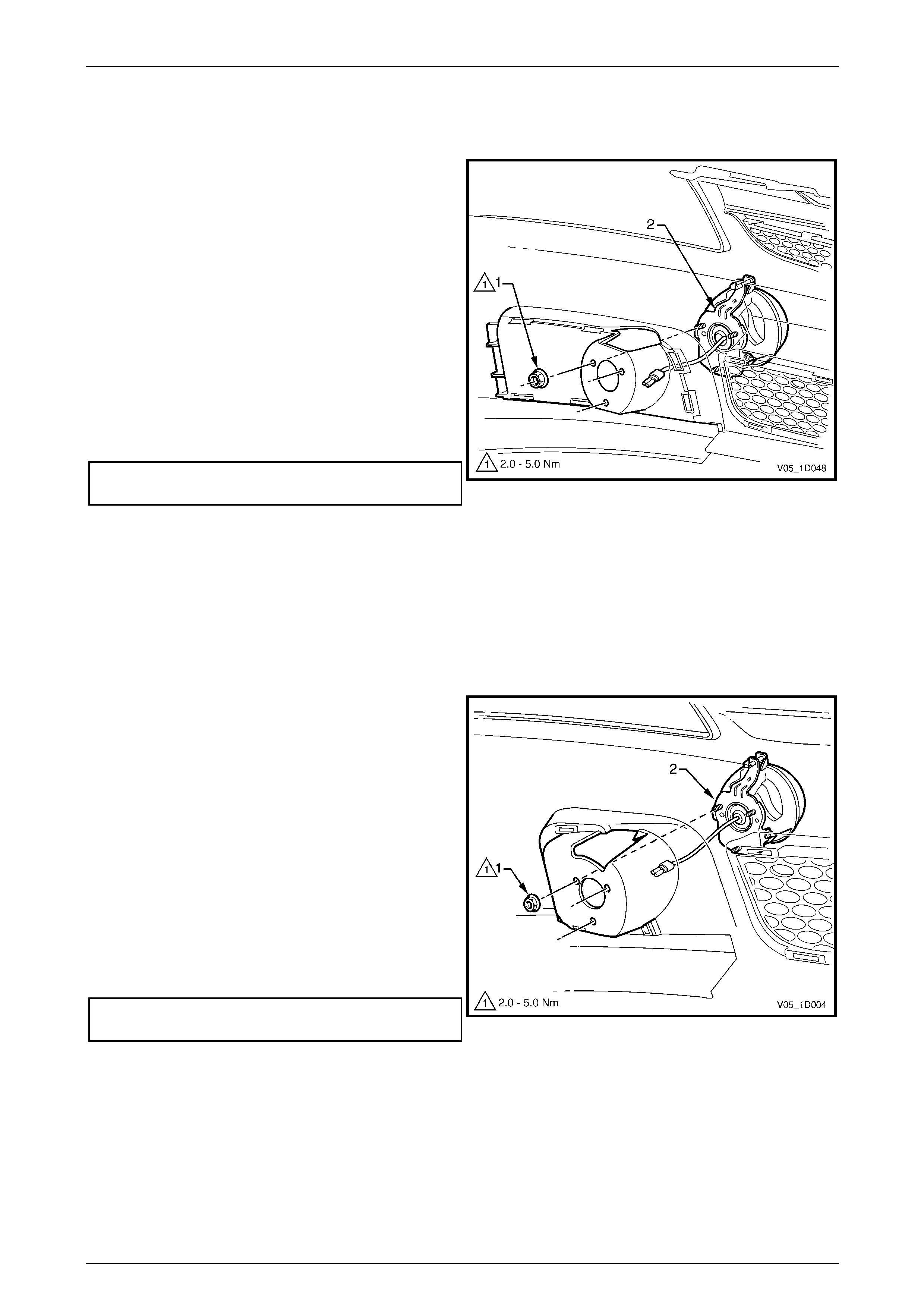
Front Fog Lamp Assembly, SV6 and SS
Remove
1 Remove the nut (1) and screw (2), two places,
attaching the front fog lamp assembly (3) to the
bumper fascia.
2 From the front of the bumper fascia, withdraw the lamp
assembly and wiring connector from its recess.
NOTE
For further service of the front fog lamp
assembly refer to Section 12B Lighting System.
Reinstall
Reinstallation of the front fog lamp assembly is the reverse
of the removal procedure. Tighten the fasteners to the
correct torque specification.
Front fog lamp assembly attaching
nut torque specification...............................2.0 – 5.0 Nm
Front fog lamp assembly attaching screw
torque specification.....................................2.0 – 5.0 Nm
NOTE
Following installation of the bumper fascia
assembly, aim the fog lamps, refer to
Section 12B Lighting System.
Figure 1D – 12
Reinstall
Reinstallation of the front bumper fascia assembly is the reverse of the removal procedure, noting the following:
1 Refinish the front bumper fascia assembly, refer to 2 Paint Systems.
2 To avoid damaging the bump er fascia an d/or vehicle, fit the fascia assembly onto the vehicle with the aid of an
assistant.
3 Tighten the screws to the correct torque specification.
Front bumper fascia assembly to
front wheelhouse liner attaching screw
torque specification.....................................1.0 – 3.0 Nm
Front bumper fascia assembly to front
bumper fascia guide assembly attaching
screw torque specification...........................1.0 – 3.0 Nm
Front bumper fascia assembly to
front upper panel attaching screw
torque specification.....................................2.5 – 4.0 Nm
Bumper Bars Page 1D–20
Page 1D–20
3.3 Front Bumper Fascia Assembly, Coupe
LT Section No. — 07–500
Remove
1 From each side of the vehicle:
a Remove the screw (1), attaching the front bumper fascia assembly (2) to the front wheelhouse liner (3), refer
to Figure 1D – 13.
b Remove the screw (4) attaching the fascia assembly to the front bumper fascia guide assembly (5).
c Carefully unclip the fascia assembly from the guide assembly by grasping the upper end of the fascia and
pulling away from the vehicle.
Figure 1D – 13
2 Disconnect the front fog lamp wiring connector (1), one plac e each side of the vehicle, refer to Figure 1D – 14.
3 Remove the three screws (2) attaching the fascia assembly (3) to the front upper pa nel.
4 With the aid of an assistant remove the fascia assembly and store in a safe plac e.
Figure 1D – 14
Bumper Bars Page 1D–21
Page 1D–21
Disassemble
Radiator Grille Assembly
For removal of the radiator grille assembl y, refer to Section 1C Radi ator Grille.
Lower Radiator Grille Assembly
For removal of the lower radiator grille assembly, refer to Section 1C Radiator Grille.
Front Fog Lamp Opening Cover
Remove
1 From the rear of the bumper fascia, depress the
retaining lug (1), two places, attaching the front fog
lamp cover (2) to the bumper fascia.
2 From the front of the bumper fascia, withdraw the
inner side of the cover while disengaging the two outer
retaining lugs (3) and remove the cover.
Reinstall
1 Fit the cover into position alignin g the outer retaining
lugs.
2 Clip the cover in place ensuring it is seated correctly.
Figure 1D – 15
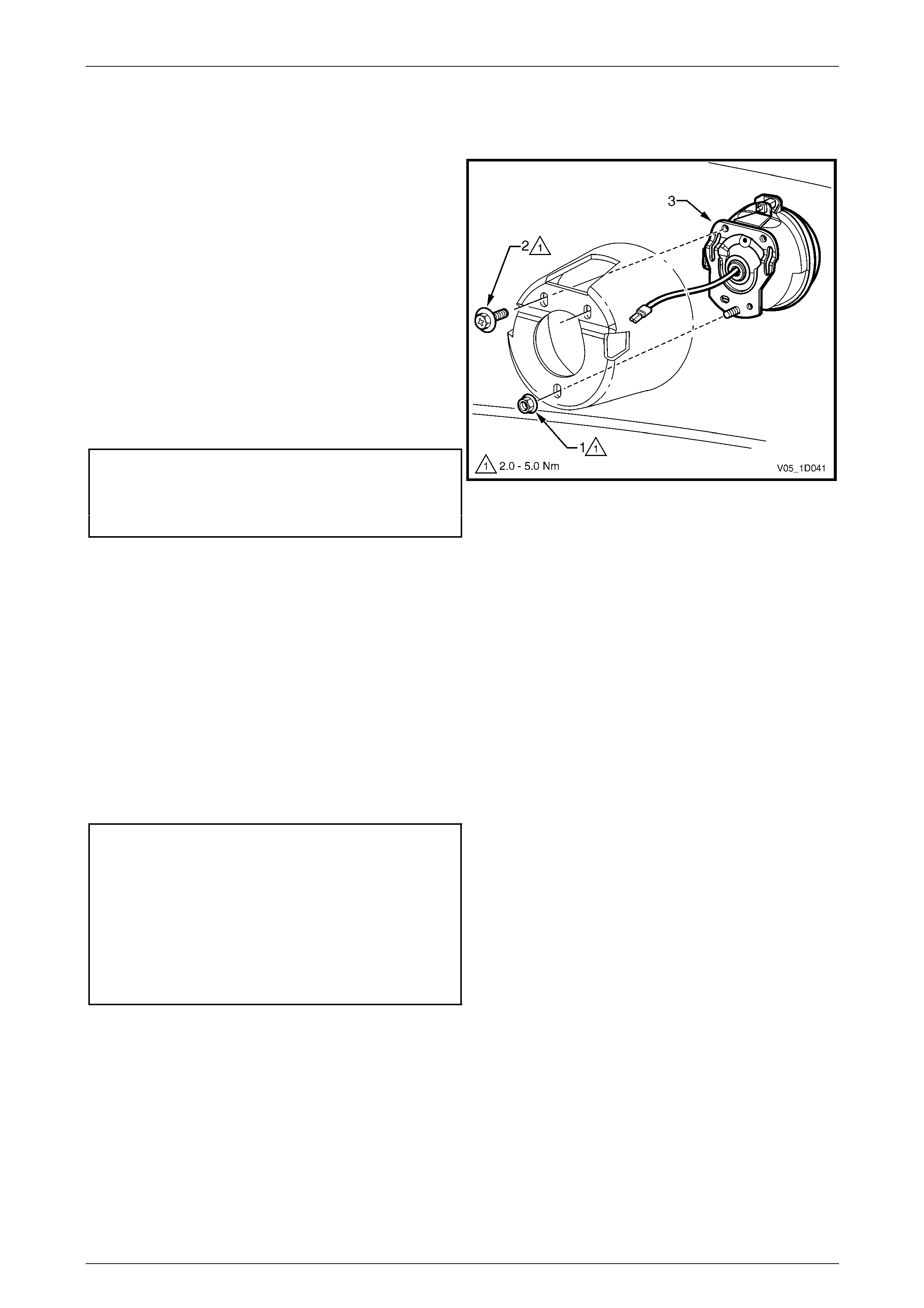
Front Fog Lamp Assembly
Remove
1 Remove the screw (1), three places, attaching the
lamp assembly (2) to the bumper fascia.
2 Withdraw the lamp assembly from the rear of the
bumper fascia and remove.
NOTE
For further servicing of the front fog lamp
assembly, refer to Section 12B Lighting System.
Reinstall
Reinstallation of the front fog lamp assembly is the reverse
of the removal procedure, noting the following:
1 Locate the lamp assembly on the locating lug.
2 Tighten the screws to the correct torque specification.
Front fog lamp assembly attaching
screw torque specification...........................1.0 – 3.0 Nm Figure 1D – 16
NOTE
Following installation of the bumper fascia
assembly, aim the fog lamps, refer to
Section 12B Lighting System.
Bumper Bars Page 1D–22
Page 1D–22
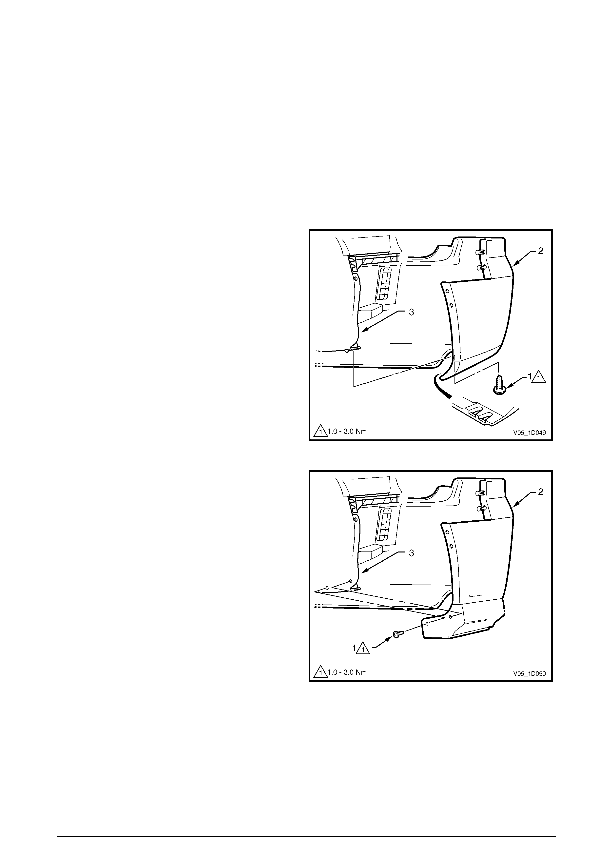
Front Bumper Energy Absorber
1 Remove the razor blade retainer (1) attachi ng the front
bumper fascia energy absorber (2) to the bumper
fascia. For the removal procedure of the razor blade
retainer, refer to 3.1 Service Notes.
2 Remove the energy absorber.
Reinstall
1 Fit the front bumper energy absorber in position and
attach with new razor blade retainers.
Figure 1D – 17
Reinstall
Reinstallation of the front bumper fascia assembly is the reverse of the removal procedure, noting the following:
1 Refinish the bumper fascia, refer to 2 Paint Systems.
2 To avoid damaging the bump er fascia an d/or vehicle, fit the fascia assembly onto the vehicle with the aid of an
assistant.
3 Tighten the screws to the correct torque specification.
Front bumper fascia assembly to
front wheelhouse liner attaching
screw torque specification...........................1.0 – 3.0 Nm
Front bumper fascia assembly to front
bumper fascia guide assembly attaching
screw torque specification...........................1.0 – 3.0 Nm
Front bumper fascia assembly to
front upper panel attaching screw
torque specification.....................................2.5 – 4.0 Nm
Bumper Bars Page 1D–23
Page 1D–23
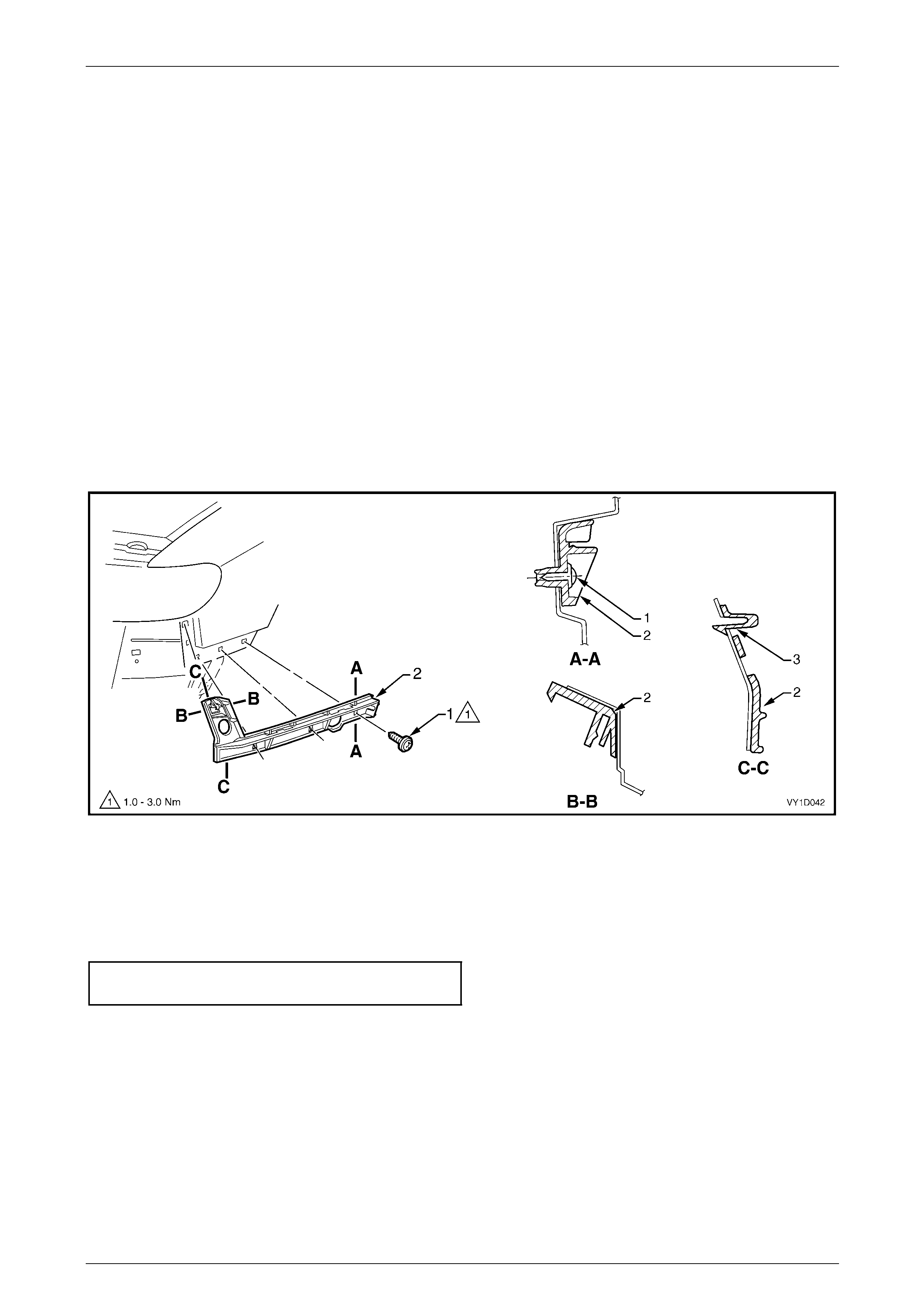
3.4 Front Bumper Fascia Undertray
LT Section No. —
AWD Wagon and Crew Cab Cross8
Remove
1 Remove the retainer (1), three places each side,
attaching the front bumper fascia undertray ( 2) to the
wheelhouse liner (3).
2 Remove the screw (1), four places, attaching the
undertray (2) to the crossmember, refer to
Figure 1D – 19.
3 Remove the screw (3), three places, attaching the
undertray to the centre of the bumper fascia (4).
4 Remove the screw (5), three places each side,
attaching the undertray to the bumper fascia.
5 Remove the undertray by unhooking it from the front
bumper fascia. Figure 1D – 18
Figure 1D – 19
Bumper Bars Page 1D–24
Page 1D–24
Reinstall
Reinstallation of the front bumper fascia undertray is the reverse of the removal procedure, noting the following:
1 Ensure that the undertray is aligned correctly with the tabs (6) on the bumpe r fascia, refer to F igure 1D – 19.
2 Tighten the screws to the correct torque specification.
Front bumper fascia undertray to
crossmember attaching screw
torque specification.....................................5.5 – 8.5 Nm
Front bumper fascia undertray to
bumper fascia attaching screw torque
specification................................................1.0 – 3.0 Nm
AWD Regular Cab and Crew Cab Cross6
Remove
1 Remove the retainer (1), three places each side,
attaching the front bumper fascia undertray ( 2) to the
wheelhouse liner (3).
2 Remove the screw (1), four places, attaching the
undertray (2) to the crossmember, refer to
Figure 1D – 21.
3 Remove the screw (3), four places, attaching the
undertray to the centre of the bumper fascia (4).
4 Remove the screw (5), three places each side,
attaching the undertray to the bumper fascia.
5 Remove the undertray by unhooking it from the front
bumper fascia. Figure 1D – 20
Bumper Bars Page 1D–25
Page 1D–25
Figure 1D – 21
Reinstall
Reinstallation of the front bumper fascia undertray is the reverse of the removal procedure, noting the following:
1 Ensure that the undertray is aligned correctly with the tabs (6) on the bumpe r fascia, refer to F igure 1D – 19.
2 Tighten the screws to the correct torque specification.
Front bumper fascia undertray to
crossmember attaching screw torque
specification................................................5.5 – 8.5 Nm
Front bumper fascia undertray to
bumper fascia attaching screw torque
specification................................................1.0 – 3.0 Nm
Bumper Bars Page 1D–26
Page 1D–26
3.5 Front Bumper Fascia Assembly, AWD
LT Section No. — 07–500
Remove
1 Remove the front bumper fascia undertray, refer to 3.4 Front Bumper Fascia Un dertray.
NOTE
As an alternative the front bumper fascia
assembly can be removed with the front
bumper fascia undertray attached by removing
the retainers attaching the undertray to the
wheelhouse liners and the screws attaching
the undertray to the crossmember, refer to
3.4 Front Bumper Fascia Undertray.
2 From each side of the vehicle:
a Remove the screw (1), four places, attaching the front bumper fascia assembly (2) to the front bumper fascia
guide assembly (3) and wheelhouse liner (4), refer to Figure 1D – 22.
b Carefully unclip the front bumper fascia assembly from the gui de assembly by grasping the upper e nd of the
bumper fascia and pulling away from the vehicle.
Figure 1D – 22
3 If fitted, disconnect the front fog lamp wiring connector (1), one p lace each side, refer to Figure 1D – 23.
4 Remove the three screws (2) attaching the front bumper fascia assem bl y ( 3) to the front upper p an el.
Bumper Bars Page 1D–27
Page 1D–27
Figure 1D – 23
5 With the aid of an assistant remove the front bumper fascia assembly and store in a safe place.
Disassemble
Radiator Grille Assembly
For removal of the radiator grille assembl y, refer to Section 1C Radi ator Grille.
Recovery Point Cover
Remove
1 Press firmly on the indent (1) in the recovery point
cover (2) to release the cover retainer (3).
2 Push the end of the tether (4) together and through the
hole in the bumper fascia.
Reinstall
Reinstallation of the recover y point cover is the reverse of
the removal procedure.
Figure 1D – 24
Bumper Bars Page 1D–28
Page 1D–28
Front Bumper Access Hole Cover, AWD Regular Cab and Crew Cab Cross6
Remove
1 From the rear of the fascia, unclip the retainer (1), six
places, securing the front bumper access hole cover
(2) to the bumper fascia.
2 Remove the cover.
Reinstall
1 Fit the cover into position and clip onto the bumper
fascia.
2 Ensure the retainers are seated correctl y.
Figure 1D – 25
Front Fog Lamp Opening Cover, Low Level AWD Wagon
Remove
1 Depress the retaining tab (1), two places, securing the
front fog lamp opening cover (2) to the bumper fascia.
2 From the front of the bumper fascia, withdraw the
cover from its recess.
Reinstall
1 Fit the cover into position and clip onto the bumper
fascia.
2 Ensure the retainers are seated correctl y.
Figure 1D – 26
Bumper Bars Page 1D–29
Page 1D–29
Front Fog Lamp Assembly, High Level AWD Wagon and Crew Cab Cross8
Remove
1 Remove the nut (1) and screw (2), two places,
attaching the front fog lamp assembly (3) to the
bumper fascia.
2 From the front of the bumper fascia, withdraw the lamp
assembly and wiring connector from its recess.
NOTE
For further service of the front fog lamp
assembly refer to Section 12B Lighting System.
Reinstall
Reinstallation of the front fog lamp assembly is the reverse
of the removal procedure. Tighten the fasteners to the
correct torque specification.
Front fog lamp assembly attaching
nut torque specification...............................2.0 – 5.0 Nm
Front fog lamp assembly attaching
screw torque specification...........................2.0 – 5.0 Nm
NOTE
Following installation of the bumper fascia
assembly, aim the fog lamps, refer to
Section 12B Lighting System.
Figure 1D – 27
Front Bumper Fascia Insert, AWD Wa gon and Crew Cab Cross8
Remove
1 From the rear of the front bumper fascia, lift the
tab (1), nine places, attaching the front bumper fascia
insert (2) to the front bumper fascia (3).
2 Remove the insert from the bumper fascia.
Reinstall
1 Reinstall the insert to the front bumper fascia ensuring
that all the tabs fit in their corresponding slots.
2 Fold the tabs over to secure the insert to the front
bumper fascia.
Figure 1D – 28

Bumper Bars Page 1D–30
Page 1D–30
Reinstall
Reinstallation of the front bumper fascia assembly is the reverse of the removal procedure, noting the following:
1 Refinish the front bumper fascia assembly, refer to 2 Paint Systems.
2 To avoid damaging the bump er fascia an d/or vehicle, fit the fascia assembly onto the vehicle with the aid of an
assistant.
3 Tighten the screws to the correct torque specification.
Front bumper fascia assembly to
front wheelhouse liner attaching
screw torque specification...........................1.0 – 3.0 Nm
Front bumper fascia assembly to front
bumper fascia guide assembly attaching
screw torque specification...........................1.0 – 3.0 Nm
Front bumper fascia assembly to
front upper panel attaching screw
torque specification.....................................2.5 – 4.0 Nm
Bumper Bars Page 1D–31
Page 1D–31
3.6 Front Bumper Fascia Guide Assembly,
Except Coupe and AWD
LT Section No. — 07–500
Remove
1 Remove the front bumper fascia assembly, refer to 3.2 Front Bumper Fascia Assembly.
NOTE
It is possible to remove one side of the bumper
fascia and carefully move it out to gain access to
the guide assembly.
2 Using a fine flat-blade screwdriver, lever and hold the
tab (1) outwards.
3 Slide the guide assembly (2) forward and out to detach
it from the fender.
Figure 1D – 29
Reinstall
1 Align the guide assembly with the slots in the fender and while pushing in slightl y, slide the guide rear wards until it
clicks into place.
2 Reinstall the bumper fascia as required, refer to 3.2 Front Bumper Fascia Assembly, Except Coupe and AWD.
Bumper Bars Page 1D–32
Page 1D–32
3.7 Front Bumper Fascia Guide Assembly,
Coupe
LT Section No. — 07–500
Remove
1 Remove the front bumper fascia assembly, refer to 3.3 Front Bumper Fascia Assembly, Coupe.
NOTE
It is possible to remove one side of the bumper
fascia and carefully move it out to gain access to
the guide assembly.
2 Remove the screw (1), three places, attaching the front bumper fascia guid e assembly (2) to the vehicle, refer to
Figure 1D – 30.
3 Using a fine flat-blade screwdriver, lever and hold the retaining tab (3).
4 Remove the guide outwards to detach it from the fender.
Figure 1D – 30
Reinstall
1 Align the guide assembly with the holes in the fender and push in to locate it in place.
2 Install the screws and tghten to the correct torque specificati on.
Front bumper fascia guide assembly
attaching screw torque specification...........1.0 – 3.0 Nm
3 Reinstall the bumper fascia as required, refer to 3.3 Front Bumper Fascia Assembly, Coupe.
Bumper Bars Page 1D–33
Page 1D–33
3.8 Front Bumper Fascia Guide Assembly,
AWD
LT Section No. — 07–500
Remove
1 Remove the front bumper fascia assembly, refer to 3.5 Front Bumper Fascia Assembly, AWD.
NOTE
It is possible to remove one side of the front
bumper fascia and carefully move it out to gain
access to the front bumper fascia guide
assembly.
2 Using a fine flat-blade screwdriver, lever and hold the
tab (1) outwards.
3 Slide the front bumper fascia guide ass embly (2)
forward and out to detach it from the fender.
Figure 1D – 31
Reinstall
1 Align the guide assembly with the slots in the fender and while pushing in slightl y, slide the guide rear wards until it
clicks into place.
2 Reinstall the bumper fascia as required, refer to 3.5 Front Bumper Fascia Assembly, AWD.
Bumper Bars Page 1D–34
Page 1D–34
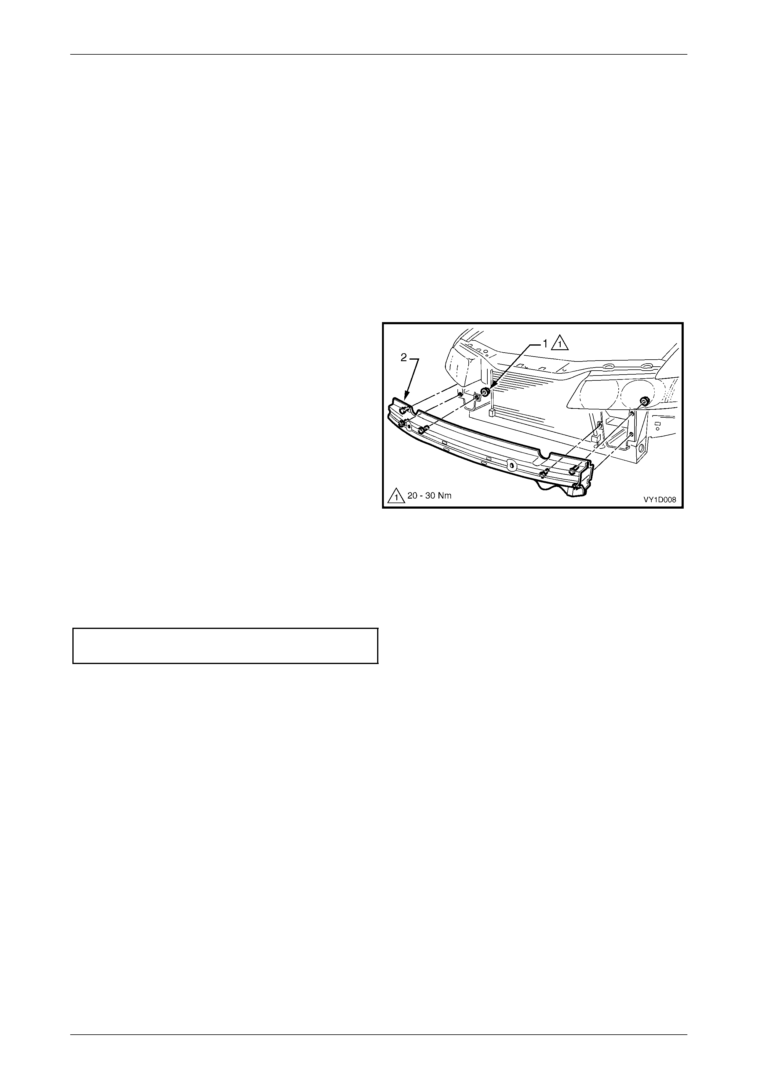
3.9 Front Bumper Impact Bar Assembly
LT Section No. —
Remove
1 Remove the front bumper fascia assembly, refer to:
• 3.2 Front Bumper Fascia Assembly, Except Coupe and AWD, or
• 3.3 Front Bumper Fascia Assembly, Coupe, or
• 3.5 Front Bumper Fascia Assembly, AWD.
2 If fitted, remove the radiator air lower baffle, refer to Section 6B1 Engine Cooling – V6 or
Section 6B3 Engine Cooling – GEN III V8.
3 Remove the nut (1), three places each side, attaching
the bar assembly (2) to the vehicle.
4 Remove the bar assembly.
Figure 1D – 32
Reinstall
1 Fit the bar assembly in position and attach each nut. Do n ot tighten.
2 Ensure the bar assembly is correctl y pos itioned centrally and tighte n the nuts to the correct torque specification.
Front bumper impact bar assembly
attaching nut torque specification............20.0 – 30.0 Nm
3 Reinstall the front bumper fas c ia assembly, refer to 3.2 Front Bumper Fascia Assembly, Except Coupe and AWD.
Bumper Bars Page 1D–35
Page 1D–35
4 Service Operations – Rear
4.1 Service Notes
Certain components are attached with either of the following retainers. When removing these, follo w the correct
procedure to avoid damaging the compone nt.
Speed Nuts
1 Prise the edge of the speed nut away from the
surface, giving enough clearance to allow access with
side cutters.
2 With the side cutters cut the speed nut and bend the
speed nut away from the mounting lug and remove.
3 Replace the speed nut as required.
Figure 1D – 33
Razor Blade Retainers
1 Prise the edge of the razor blade retai ner away from
the surface, giving enough clearance to allow access
with side cutters.
2 With the side cutters cut the razor blade retainer and
bend the razor blade retainer from the mounting lug
and remove.
3 Replace the razor blade retainer as required.
Figure 1D – 34
Bumper Bars Page 1D–36
Page 1D–36
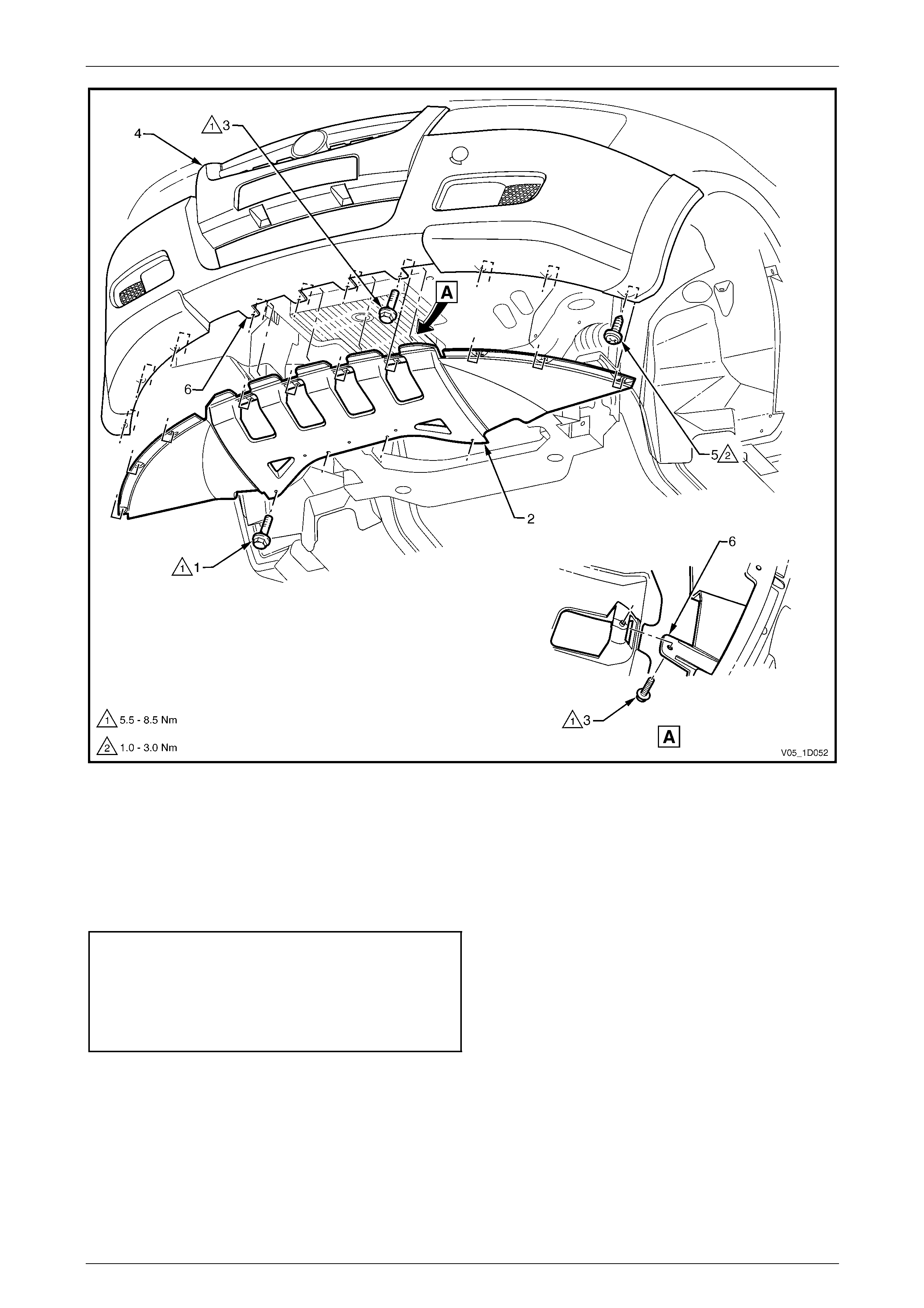
4.2 Rear Bumper Fascia Assembly, Sedan
LT Section No. — 07–525
Remove
1 Remove the following components:
a Rear end trim panel, refer to Section 1A8 Headlining and Interior T r im.
b Quarter inner rear side carpet, refer to Section 1A8 Headlining and Interior Trim.
2 Depending on Model, from each side of the vehicle either:
a Remove the screw (1) attaching the undersi de of
the rear bumper fascia assembly (2) to the rear
wheelhouse liner (3), or
Figure 1D – 35
b Remove the screw (1) two places, attaching the
rear bumper fascia assembly (2) to the rear
wheelhouse liner (3).
3 Referring to Figure 1D – 37, from each side of the
vehicle:
a Remove the two screws (1) attaching the fascia
assembly (3) to the liner and rear bumper fascia
guide assembly (2).
b Carefully unclip the fascia assembly from the
guide assembly by graspi ng the upper end of the
fascia and pulling a way from the vehicle, also
disconnecting the liner lug (4) where applicable.
Figure 1D – 36
Bumper Bars Page 1D–37
Page 1D–37
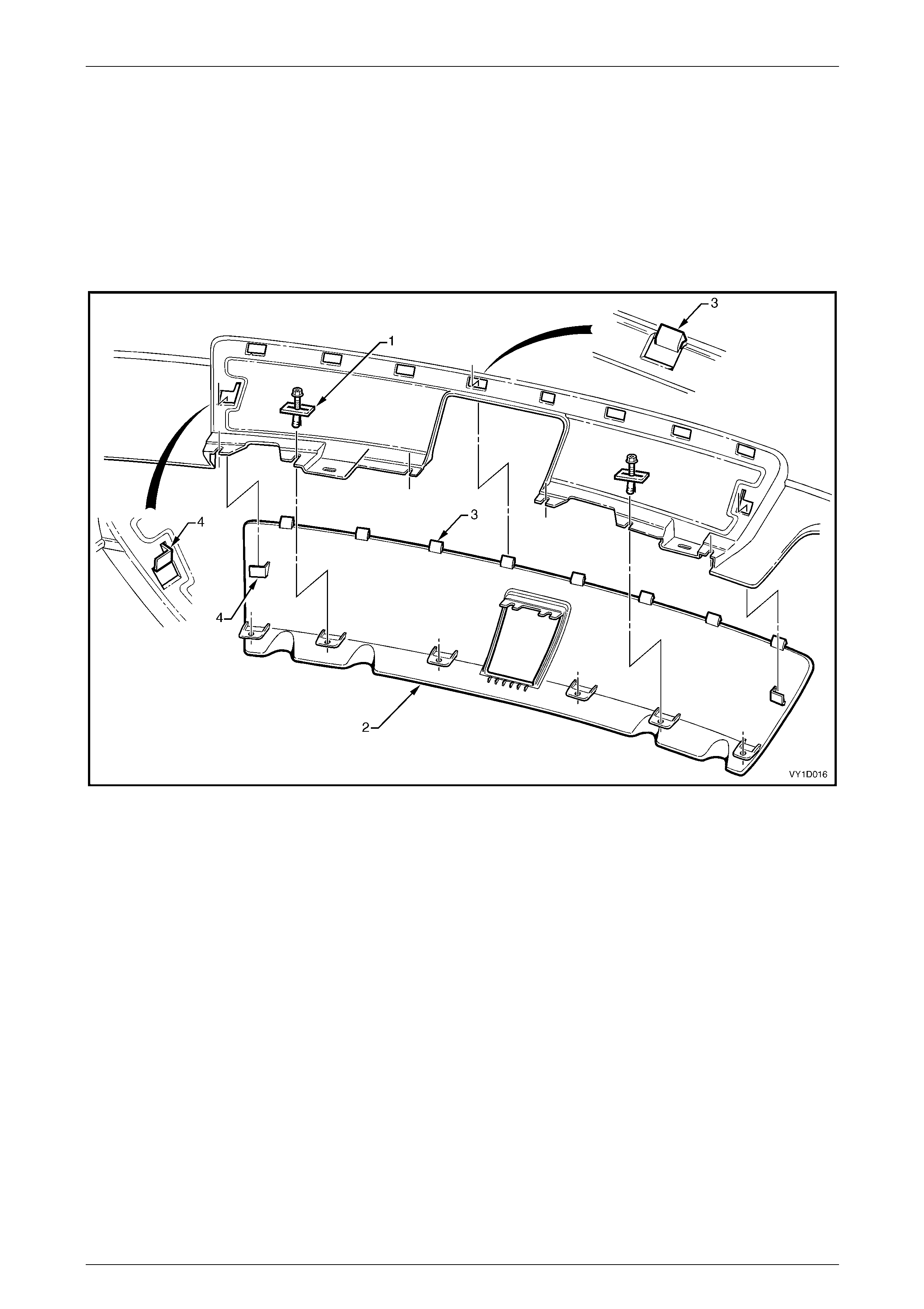
Figure 1D – 37
4 Remove the two nuts (1), each side, attaching the fascia assembly (2) to the vehicle, refer to Figure 1D – 38.
5 Remove the two retainers (3) from belo w the fascia assembly.
6 Remove the centre section of the rear compa r tment lid weatherstrip to allow access to the four upper retainers (4).
7 Remove the four upper retainers attaching the fascia assembly to the rear bumper fascia centre support assembly.
Figure 1D – 38
8 If fitted, disconnect the Rear Park Assist (RPA) wiring
connector from within the rear compartment.
9 With the aid of an assistant, withdraw the fascia
assembly, push the RPA wiring harness gro mmet (1)
through the side panel and withdraw the harness.
10 Remove the fascia assembly ensur ing the seals (5,
Figure 1D – 38) remain with the fascia assembly.
Figure 1D – 39
Bumper Bars Page 1D–38
Page 1D–38
Disassemble
Towbar Opening Cover
Remove
1 Remove the retainer (1), two places, securing the towbar opening cover (2) to the bumper fascia assembly, refer to
Figure 1D – 40. Note the different styles: A – SV8, B – SV6 and SS, C – Levels 1, 2 & 3.
2 Depress the retaining tabs an d remove the cover from the b umper fascia.
Figure 1D – 40
Reinstall
Clip the cover in place ensuring the retaining tabs are seated correctly and install the two retainers.
Bumper Bars Page 1D–39
Page 1D–39
Rear Bumper Fascia Insert, SV6 and SS
Remove
1 Remove the retainers (1), five places, securi ng the rear bumper fascia insert (2) to the bumper fascia, refer to
Figure 1D – 41.
2 Apply downward pressur e on the insert while unclipping the seven tabs (3).
3 Manoeuvre the insert downward and out of the bumper fascia, disengagin g the locating tabs (4) each end of the
insert.
Figure 1D – 41
Reinstall
Reinstallation of the rear bum per fascia insert is the reverse of the removal procedure. Ensure the retain ers and tabs are
seated correctly.
Bumper Bars Page 1D–40
Page 1D–40
Rear Bumper Fascia Insert, SV8
Remove
1 Remove the retainers (1), six places, securing the rear bumper fascia insert (2) to the bumper fascia, refer to
Figure 1D – 42.
2 Apply downward pressur e on the insert while unclipping the eight tabs (3).
3 Manoeuvre the insert downward and out of the bumper fascia, disengagin g the locating tabs (4) each end of the
insert.
Figure 1D – 42
Reinstall
Reinstallation of the rear bum per fascia insert is the reverse of the removal procedure. Ensure the retain ers and tabs are
seated
Bumper Bars Page 1D–41
Page 1D–41
Rear Bumper Fascia Outer Lower Moulding – Level 3
Remove
1 Remove screw (1) attaching the rear bumper fascia
outer lower moulding (2) to the rear bumper fascia (3).
2 Remove the screw (4), two places, attaching the
moulding to the outer lower moulding mounting
bracket.
3 Remove the retainer (5), four places.
Figure 1D – 43
4 Withdraw the moulding (1) from the bumper fascia,
releasing the four lugs from the slots in the bumper
fascia.
Reinstall
Reinstallation of the rear bum per fascia outer lower
moulding is the reverse of the removal procedure. Tighten
the screws to the correct torque specification.
Rear bumper fascia outer lower
moulding attaching screw
torque specification.....................................2.0 – 3.0 Nm
Figure 1D – 44
Rear Bumper Fascia Outer Lower Moulding Mounting Bracket – Lev el 3
Remove
1 Remove screw (1) attaching the rear bumper fascia
outer lower moulding mounting bracket (2) to the rear
bumper fascia, and remove the bracket.
Reinstall
Reinstallation of the rear bum per fascia outer lower
moulding mounting bracket is the reverse of the removal
procedure. Tighten the screw to the correct torque
specification.
Rear bumper fascia outer lower moulding
mounting bracket attaching screw
torque specification.....................................2.0 – 3.0 Nm
Figure 1D – 45
Bumper Bars Page 1D–42
Page 1D–42
Rear Bumper Fascia Reflective Lens – Level 2 and 3
Remove
1 From behind the bumper fascia, remove the two spe ed
nuts (1) attaching the rear bumper fascia ref lective
lens. For the removal procedure of the speed nut, refer
to 4.1 Service Notes.
2 Unattach the two retaining lugs (2) from the rear
bumper fascia applique and remove the lens.
Reinstall
Reinstallation of the rear bum per fascia reflective lens is the
reverse of the removal procedure. Securel y fit ne w speed
nuts.
Figure 1D – 46
Rear Bumper Fascia Applique – Level 2 and 3
Remove
1 Remove the rear bumper fascia reflective lens as previously described.
2 Remove the razor blade retainer (1), 10 pl aces, attaching the rear bumper fascia applique to the bumper fascia,
refer to Figure 1D – 47. For the removal procedure of the razor blade retainer, refer 4.1 Service Notes.
3 Remove the applique.
Figure 1D – 47
Reinstall
Reinstallation of the rear bumper fascia applique is the reverse of the remo val procedure. Securely fit new razor blade
retainers.
Bumper Bars Page 1D–43
Page 1D–43
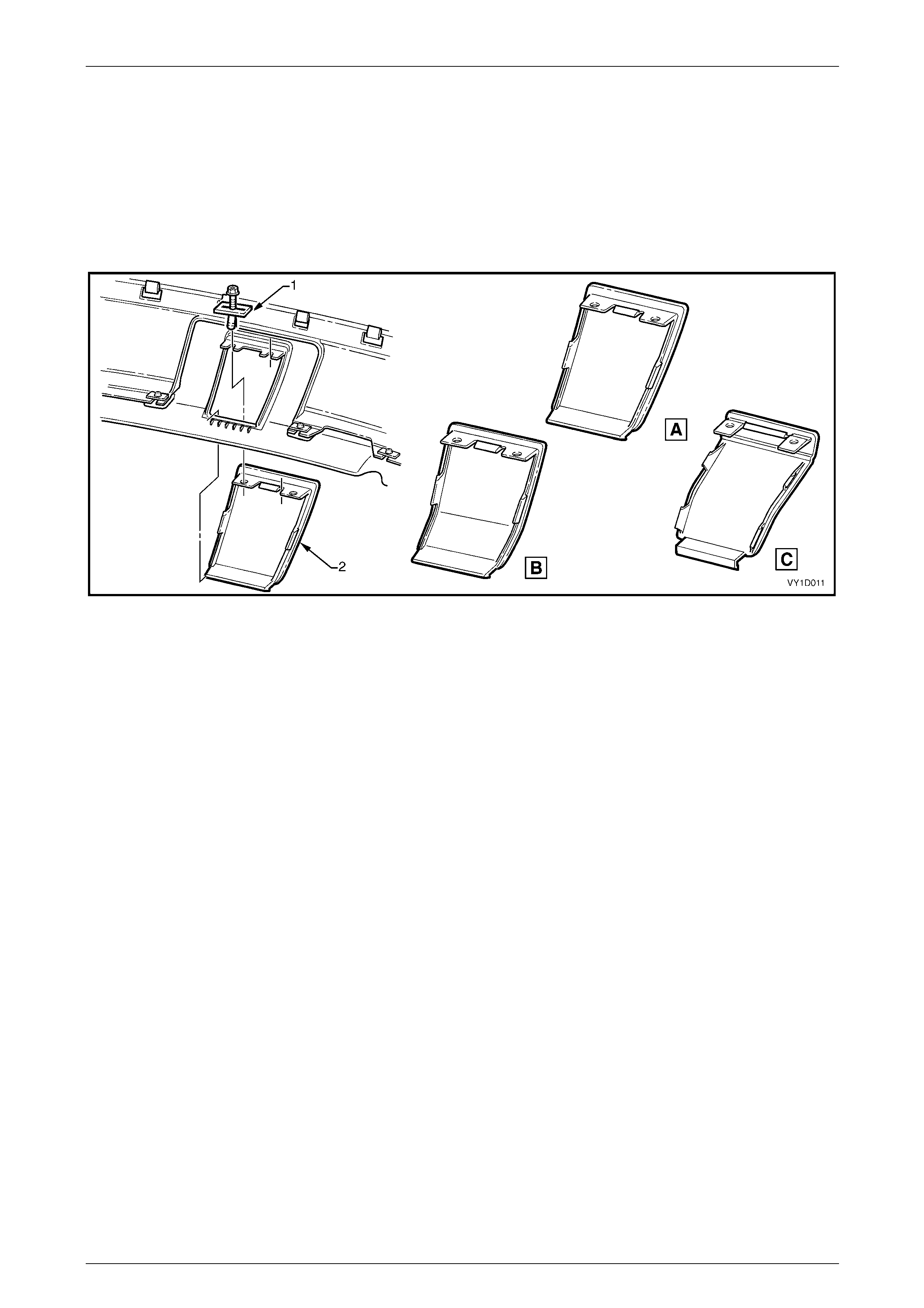
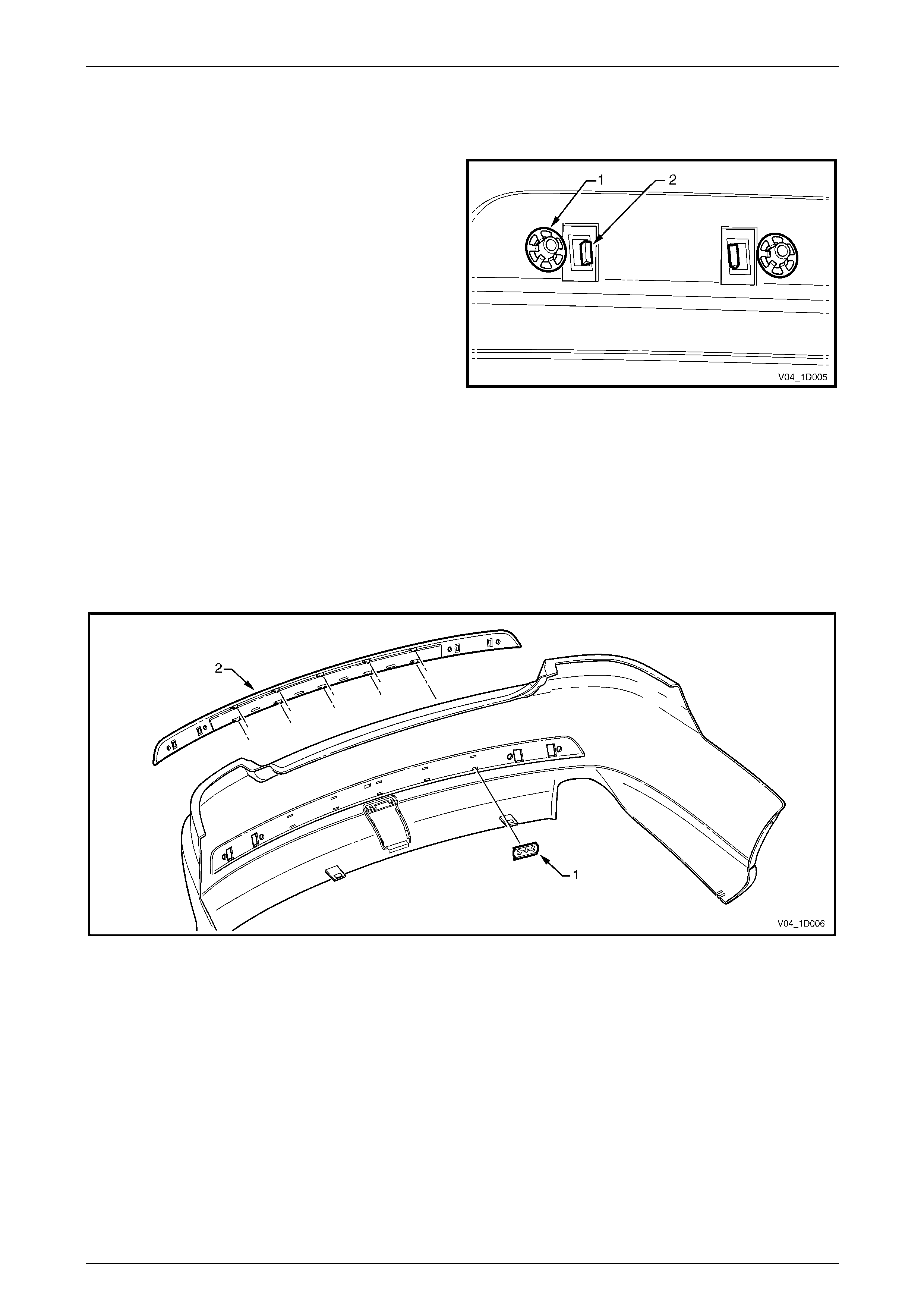
Rear Park Assist Components
Where fitted, four sensor assemblies and th eir associated wiring are fitted to the rear bumper fascia assembl y as part of
the Rear Park Assist (RPA), refer to Figure 1D – 48.
Each rear object sensor assembly (1) is fitted into a rear object sensor housing (2), which is attached to the fascia
assembly with four heat-stakes (3). Holes in the fascia expose the sensor and housing fa ces. Four retaining clips (4)
secure the rear object sensor wiring har ness assembly (5) to the fascia assembly which is routed across to the left-hand
side.
Figure 1D – 48
The fascia assembly and sensors must be
correctly aligned if the system is to operate
correctly. Sensors may be damaged if
dropped or subjected to temperatures above
80° C.
If repainting a fascia assembly, the sensors
and rings must be removed. Paint must not be
applied to any part of a sensor, including the
exposed coloured surface. Paint film applied
to the exposed surface will render the sensor
inoperable as the paint film restricts the
sensor’s ultra-sonic signal. If a sensor is
damaged, it must be replaced.
Replacement housings are supplied
unpainted. As they are partially exposed when
installed, they will require painting using the
same procedures for painting the bumper
fascia, refer to 2 Paint Systems.
NOTE
It is preferable to paint the housings and bumper
fascia separately to avoid adhesion problems.
Assemble the housings onto the bumper fascia
once the paint has cured.
Replacement bumper fascias are sup pli ed without holes and must be modified by follo wing the proce dures in New Facia
Modification.
For further information on rear park assist, refer to Section 12F1 Rear Park Assist.

Bumper Bars Page 1D–44
Page 1D–44
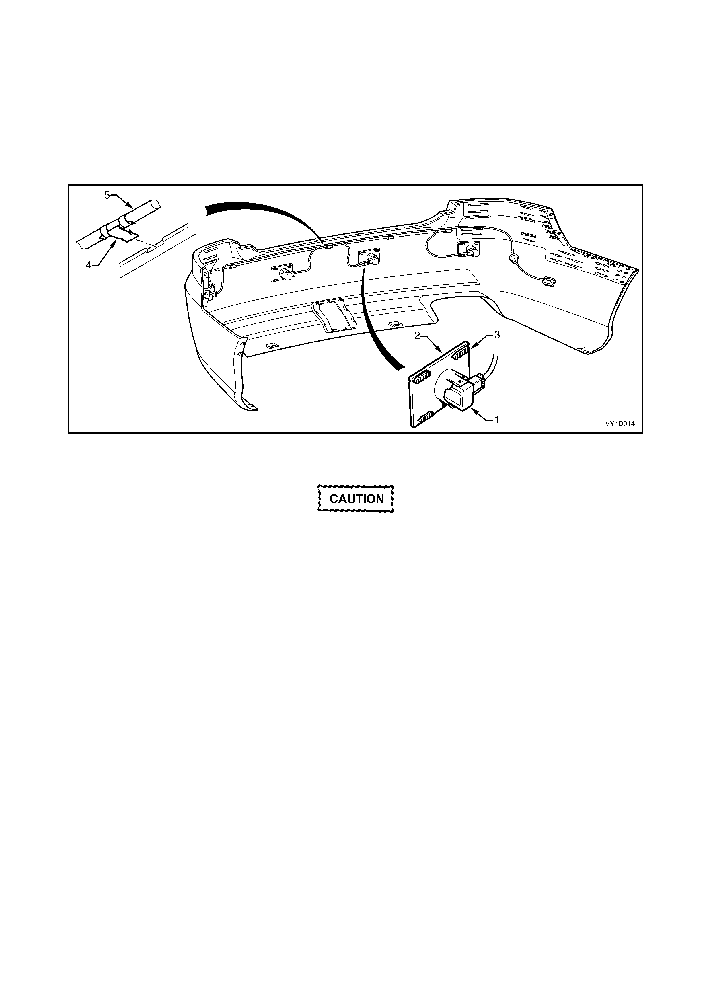
Disassemble
1 Disconnect the wiring connector (1) from the rear
object sensor assembly (2).
2 Using a fine blade screwdriver, lever the upper and
lower tabs (3) of the rear object sensor housing and
slide the sensor from the hous ing.
3 If required, remove the rear object sensor ring (4) from
the sensor.
4 Remove the rear object sensor housi ng from the
bumper fascia by cutting the heat-stakes (5).
NOTE
If the housing is to be reinstalled on the same
bumper fascia, only cut the minimum amount of
material to enable removal, ensuring enough
remains to reattach the housing.
5 Remove the rear object sensor wiring harness from
the bumper fascia by prising the four retaining clips
from the bumper fascia with a fine flat blade
screwdriver.
Figure 1D – 49
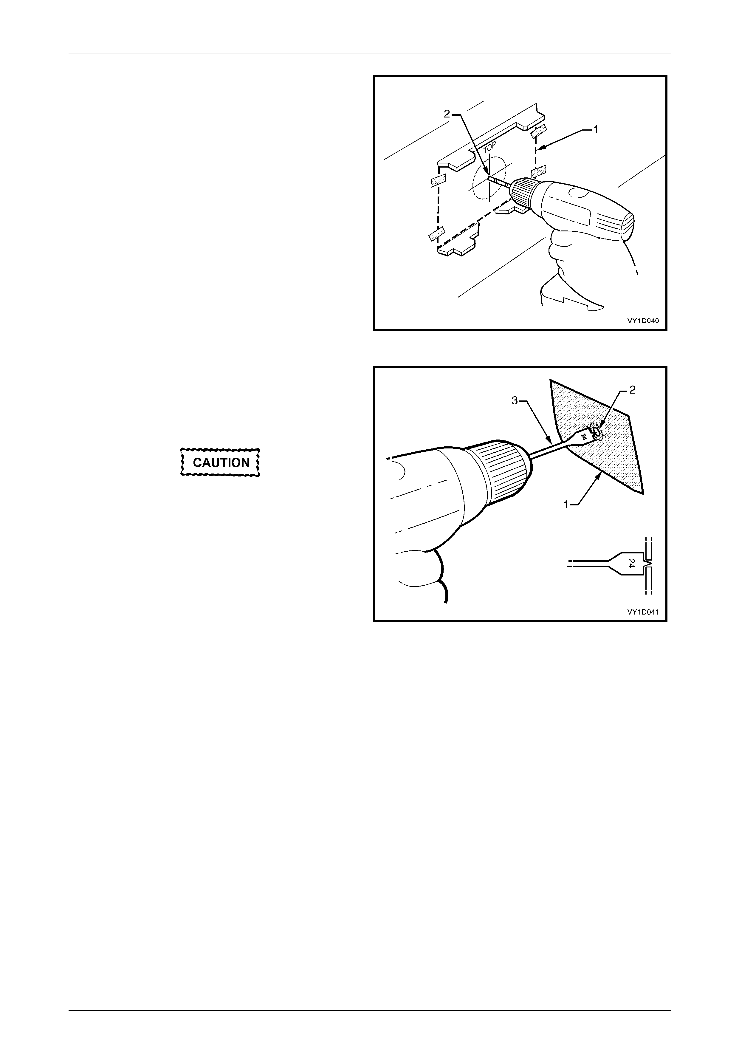
New Fascia Modification
1 Print and cut-out the templates in Figure 1D – 53.
When printing the template, in the Print Dialog
Box ensure the Shrink Oversize Pages To
Paper Size box is not ticked. Always check
the scale on the template to ensure it has
printed the correct size.
2 Perform the following instructions at the four rear object sensor housing mounting locations.
3 Tape the template (1) to the inside of the rear fascia,
aligning the edges between the upper (2) and lower
(3) aid heat stakes.
Figure 1D – 50
Bumper Bars Page 1D–45
Page 1D–45
4 From the inside of the fascia, drill a 2 mm diameter
pilot hole at the template (1) centre point (2).
Figure 1D – 51
5 Place masking tape (1) on the outside surface of the
fascia in the area to be drilled.
6 From the outside of the fascia, enlarge the pi lot hole
(2) to 24 mm using a wood spade drill bit (3).
• Only use a spade drill bit as a normal drill
bit or hole saw may damage the fascia.
• Ensure the spade bit remains square with
the rear fascia.
• Use a slow drill speed to avoid damaging
the rear fascia.
7 Debur the edges of the hole if necessary.
8 As required, paint the bumper fascia an d sensor
housings prior to reassembly, refer to
2 Paint Systems. Figure 1D – 52

Bumper Bars Page 1D–46
Page 1D–46
Figure 1D – 53
Bumper Bars Page 1D–47
Page 1D–47
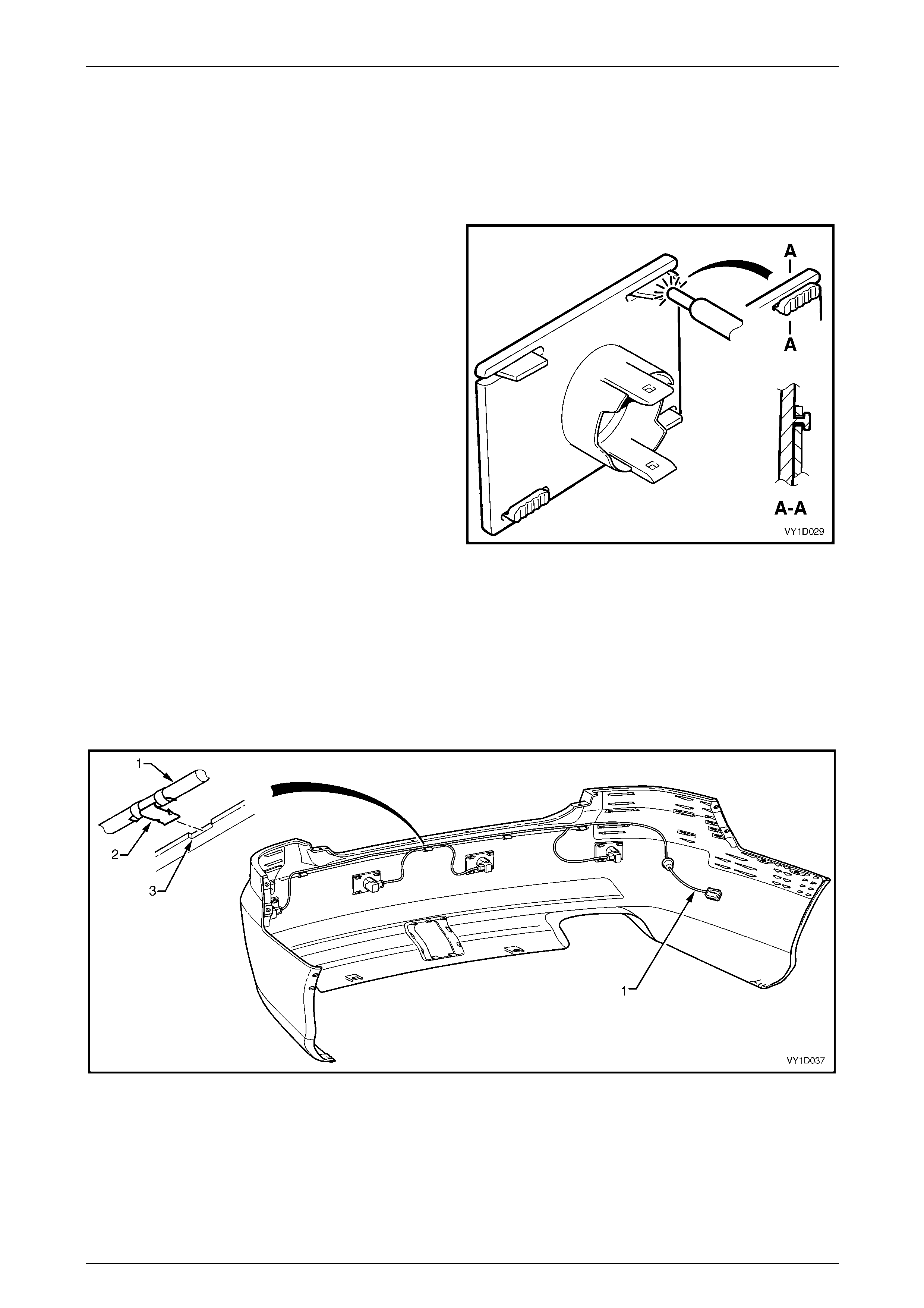
Reassemble
NOTE
It is advisable to paint the bumper fascia and
housings prior to attachment to the bumper
fascia, refer to 2 Paint Systems.
1 Position the housing onto the four stakes, en suring it is
seated against the fascia surface and correctly
protrudes through the hole.
2 Using a soldering iron, melt the end of the heat-stakes.
Hold the housing in position until the plastic has
cooled.
NOTE
Do not over-melt the material and ensure the
housing is fixed securely.
NOTE
If the housing is being reinstalled onto the same
bumper fascia, ensure there is enough material
to provide secure attachment. If required, cut a
thin piece of bumper material from an
inconspicuous place an d use as a filler, melting it
into the heat-stake.
3 Fit the ring onto the end of the sensor, refer to
Figure 1D – 49.
Figure 1D – 54
4 Insert the sensor into the housing firmly, ensuring that the tabs are locked into the sensor.
5 Repeat as required.
6 Route the wiring harness (1) to the left-hand side of the vehicle and connect the wiring harness connectors to each
sensor, refer to Figure 1D – 55.
7 Attach the harness to the upper side of the bumper fascia rib, aligning each clip (2) at the notch (3).
Figure 1D – 55

Bumper Bars Page 1D–48
Page 1D–48
Reinstall
Reinstallation of the rear bum per fascia assembly is the reverse of the removal proced ure, noting the following:
1 Refinish the bumper fascia, refer to 2 Paint Systems.
2 To avoid damaging the bump er fascia an d/or vehicle, fit the fascia assembly onto the vehicle with the aid of an
assistant.
3 Securely fit the RPA wiring harness grommet into the side pane l hole.
4 Tighten the fasteners to the correct torque specification.
Rear bumper fascia assembly to
rear wheelhouse liner attaching
screw torque specification...........................1.0 – 3.0 Nm
Rear bumper fascia assembly to
rear bumper fascia guide assembly
attaching screw torque specification...........1.0 – 3.0 Nm
Rear bumper fascia assembly
attaching nut torque specification................6.0 – 9.0 Nm
5 If fitted, test the rear park assist for correct operation, refer to Section 12F1 Rear Park Assist.
Bumper Bars Page 1D–49
Page 1D–49
4.3 Rear Bumper Fascia Assembly, Wagon
LT Section No. — 07–525
Remove
1 On each side of the vehicle:
a Remove the three screws (1) attaching the rear bumper fascia assembly (2) to the rear wheelho use l iner (3)
and rear bumper fascia guide assembly (4), refer to Figure 1D – 56.
b Disconnect the lug (5) from the liner.
c Carefully unclip the fascia assembly from the guide assembly by grasping the upper end of the fascia
assembly and pulling away from the vehicle.
Figure 1D – 56
2 Remove the retainers (1), 2 places, from below the fascia assembly (2), refer to Figure 1D – 57.
3 Remove the retainers (3), six places, from across the liftgate opening.
4 With the aid of an assistant remove the fascia assembly.
Figure 1D – 57
Bumper Bars Page 1D–50
Page 1D–50
Disassemble
Towbar Opening Cover
Remove
1 Remove the retainer (1), two places, securing the
towbar opening cover (2) to the bumper fascia
assembly.
2 Depress the retaining tabs an d remove the cover from
the bumper fascia.
Reinstall
1 Clip the cover in place ensuring the retaining tabs are
seated correctly and install th e two retainers.
Figure 1D – 58
Reinstall
Reinstallation of the rear bum per fascia assembly is the reverse of the removal proced ure, noting the following:
1 Refinish the bumper fascia, refer to 2 Paint Systems.
2 To avoid damaging the bump er fascia an d/or vehicle, fit the fascia assembly onto the vehicle with the aid of an
assistant.
3 Tighten the screws to the correct torque specification.
Rear bumper fascia assembly to rear
wheelhouse liner attaching screw
torque specification.....................................1.0 – 3.0 Nm
Rear bumper fascia assembly to rear
bumper fascia guide assembly attaching
screw torque specification...........................1.0 – 3.0 Nm
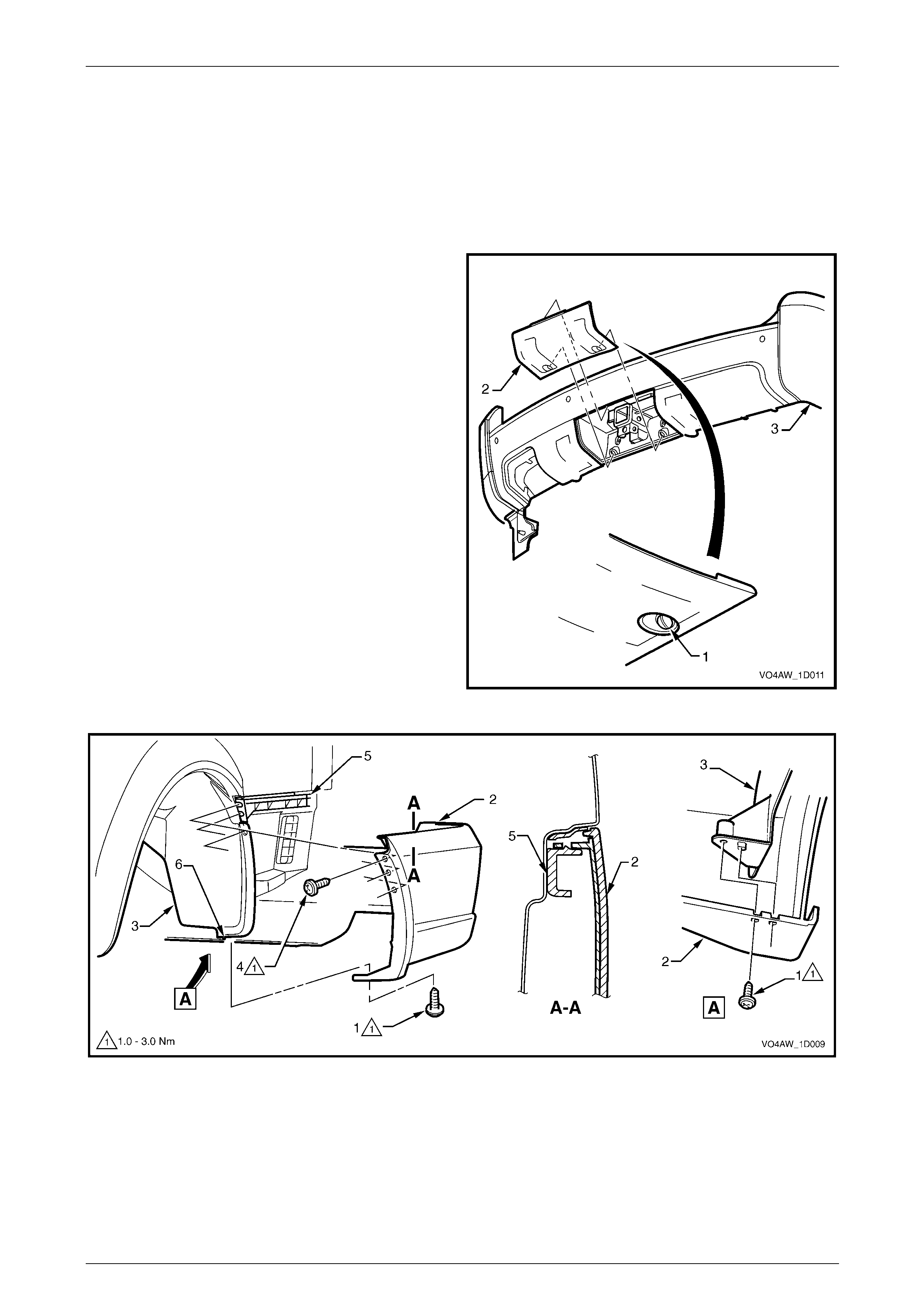
Bumper Bars Page 1D–51
Page 1D–51
4.4 Rear Bumper Fascia Assembly, AWD
Wagon
LT Section No. — 07–525
Remove
1 Rotate the retainer (1), two places, ninety degrees to
release the towbar opening cover (2) from the rear
bumper fascia assembly (3).
2 Remove the cover from the bumper fascia.
3 From each side of the vehicle:
a Remove the screw (1), two places, attaching the
rear bumper fascia assembly (2) to the rear
wheelhouse liner (3), refer to Figure 1D – 60 .
b Remove the screw (4), two places, attaching the
rear bumper fascia assembly to the rear bumper
fascia guide assembly (5).
c Disconnect the lug (6) from the liner.
d Carefully unclip the fascia assembly from the
guide assembly by graspi ng the upper end of the
bumper fascia assembly and pulling away from
the vehicle.
Figure 1D – 59
Figure 1D – 60
4 Remove the retainer (1), two places, from within the towbar opening, refer to Figure 1D – 61.
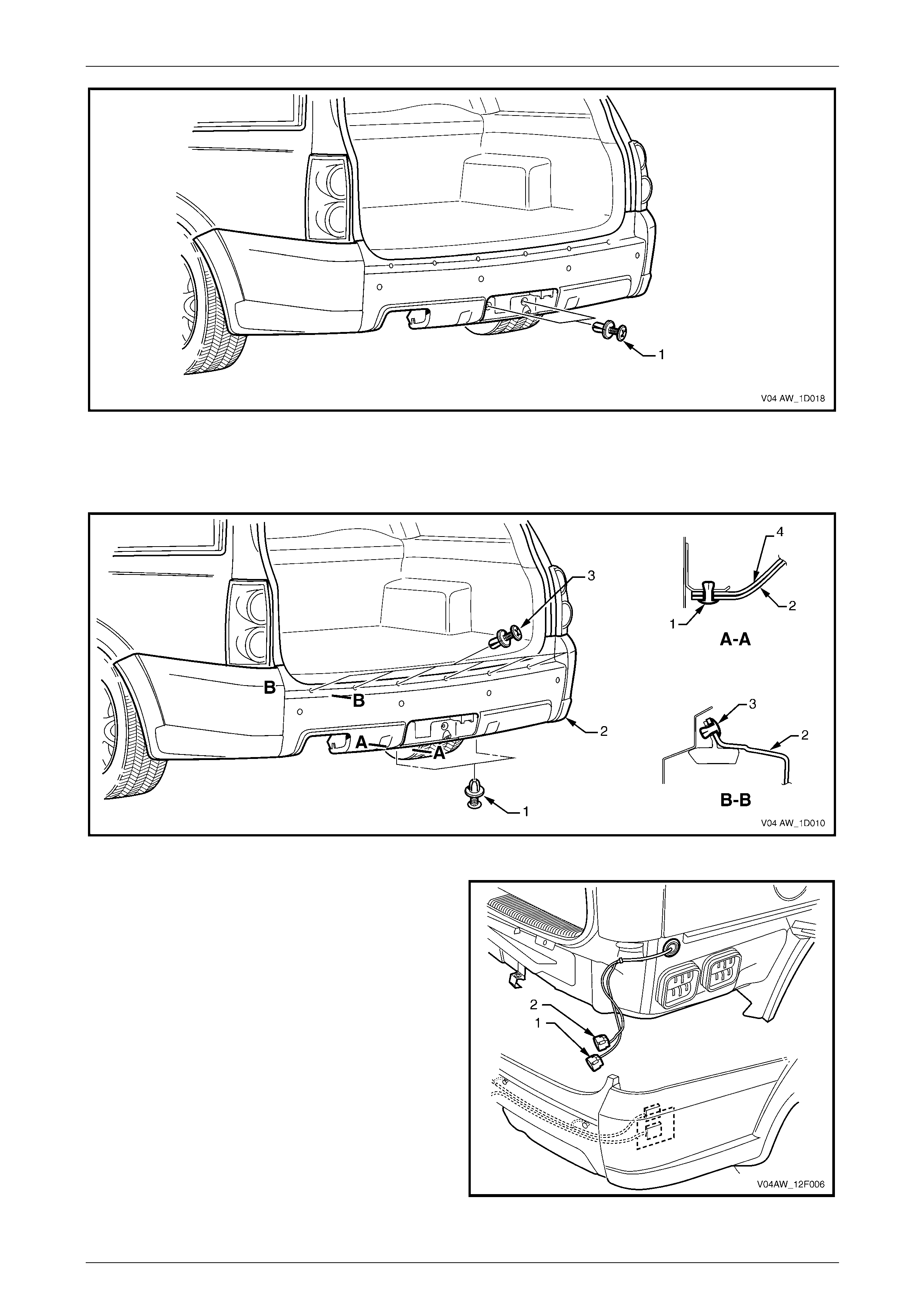
Bumper Bars Page 1D–52
Page 1D–52
Figure 1D – 61
5 Remove the retainer (1), two places, from below the fascia assembly (2), refer to Figure 1D – 62.
6 Remove the retainer (3), six places, from acr oss the liftgate opening.
Figure 1D – 62
7 With the aid of an assistant remove the fascia
assembly from the vehicle far enough to access the
wiring connectors.
8 Disconnect the towbar (1) and rear park assist (2)
wiring connectors.
9 Remove the fascia assembly.
Figure 1D – 63
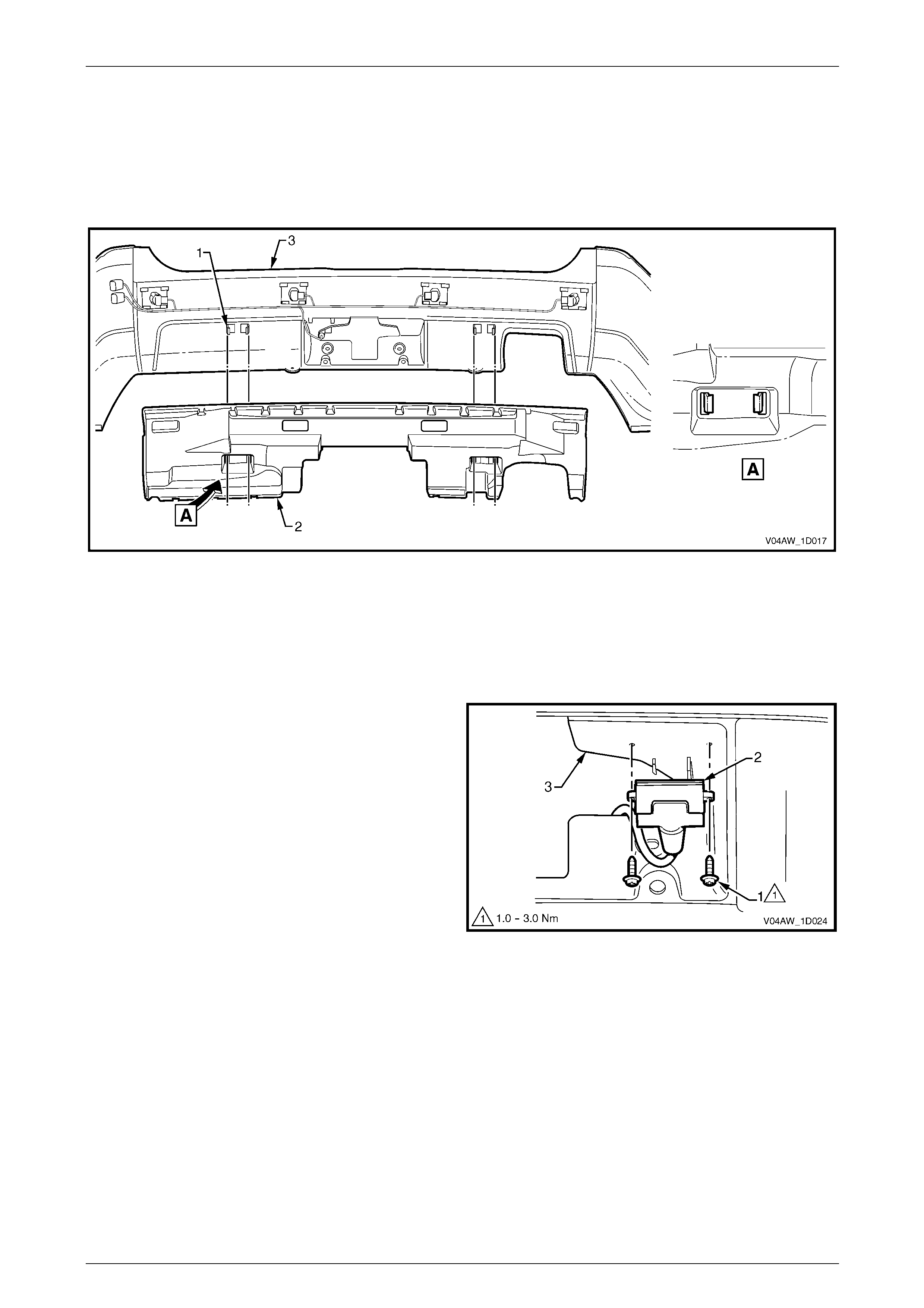
Bumper Bars Page 1D–53
Page 1D–53
Disassemble
Rear Bumper Fascia Filler
Remove
1 Spread the tangs (1) and unclip the rear bumper fascia filler (2) from the bumper fascia (3).
Figure 1D – 64
Reinstall
1 Securely clip the rear bumper fascia filler onto the rear bumper fascia.
Trailer Wiring Harness
1 Remove the two screws (1) attaching the trailer plug to
the rear bumper fascia.
2 From the rear of the bumper fascia, prise the retaining
clip (2), five places, securing the trailer wiring harness
(4) to the bumper fascia (3), refer to Figure 1D – 66.
4 Unclip the trailer wiring harness connector (4) from the
bumper fascia.
5 Pull the trailer plug through the bumper fascia and
remove the harness.
Figure 1D – 65
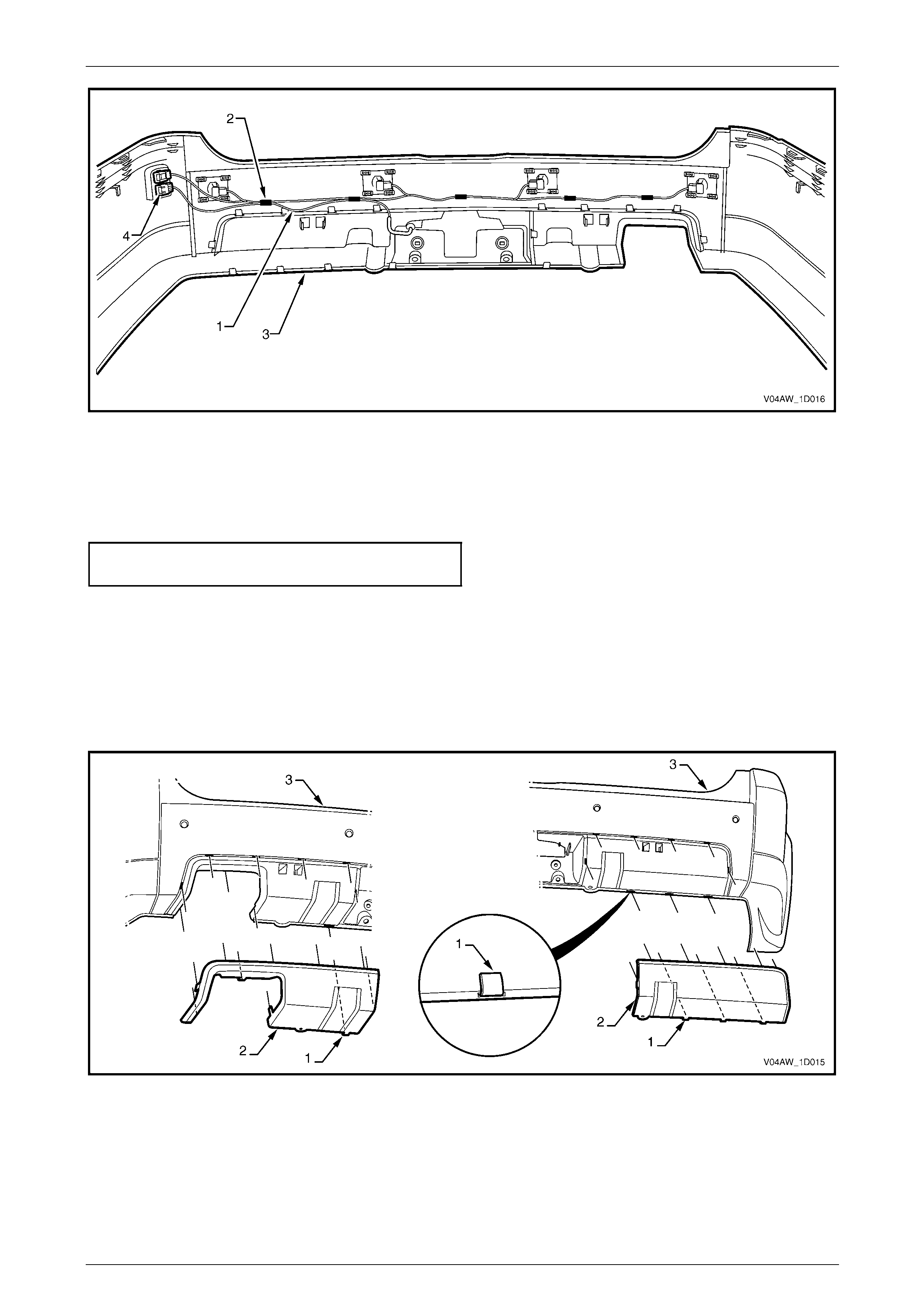
Bumper Bars Page 1D–54
Page 1D–54
Figure 1D – 66
Reinstall
Reinstallation of the trailer wiring harness is the reverse of the removal procedur e. Tighten the screws to the correct
torque specification.
Trailer plug attachi ng screw torque
specification................................................1.0 – 3.0 Nm
Rear Bumper Fascia Insert
Remove
1 From the rear of the bumper fascia, lift the tab (1), ten places on the left-hand side or ni ne places on the right-hand
side, attaching the rear bumper fascia insert ( 2) to the rear b umper fasci a (3).
2 Remove the insert from the rear bumper fascia.
Figure 1D – 67
Reinstall
1 Reinstall the insert to the rear bumper fascia ensuring that all the tabs fit in the corresponding sl ots.
2 Fold the tabs over to secure the insert to the rear bumper fascia.
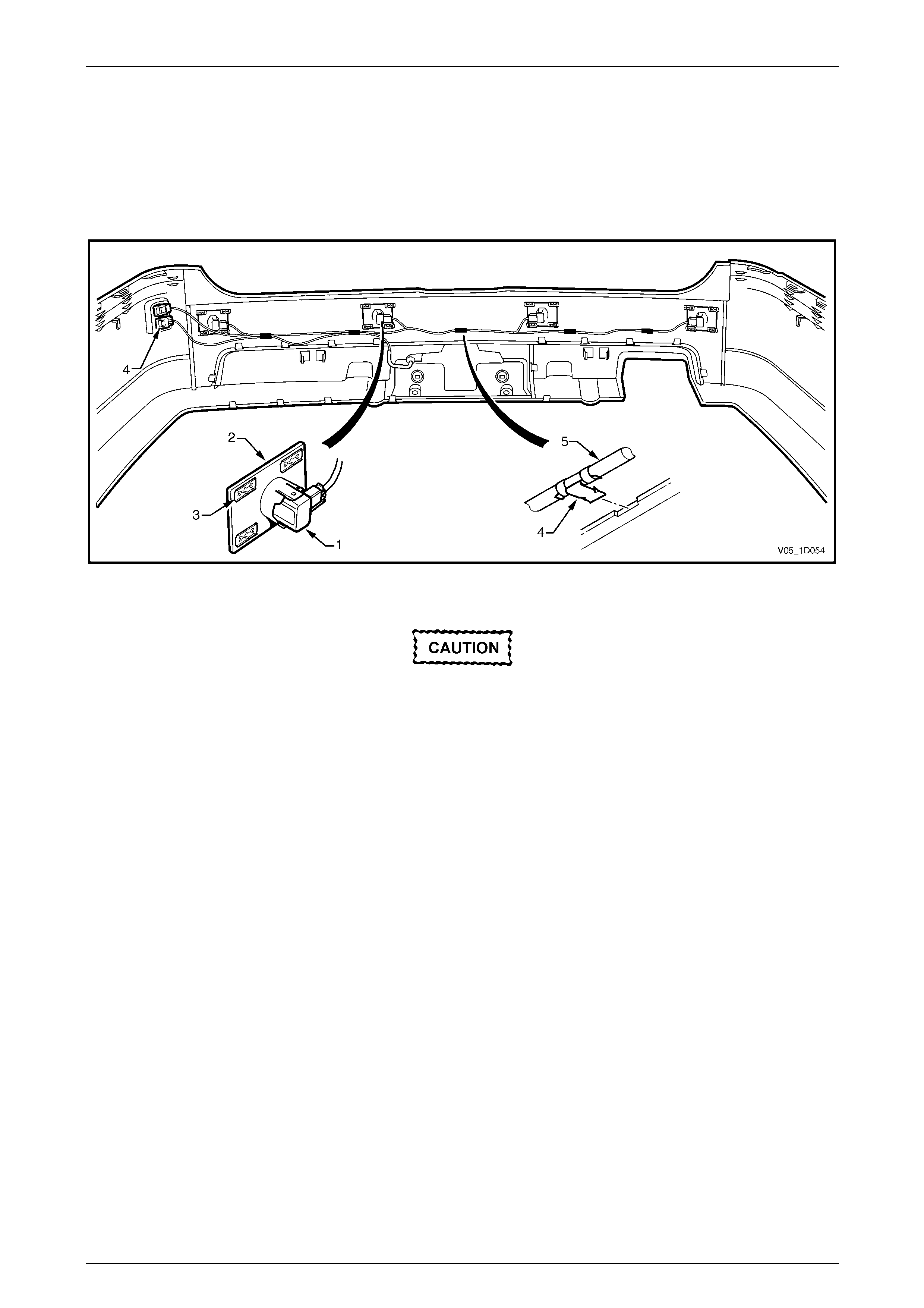
Bumper Bars Page 1D–55
Page 1D–55
Rear Park Assist Components
Four sensor assemblies and their associated wiring are fitted to the rear bumper fascia assembly as part of the Rear
Park Assist (RPA).
Each rear object sensor assembly (1) is fitted into a rear object sensor housing (2), which is attached to the fascia
assembly with four razor blade retainers (3). Holes i n the fascia expose the sensor and housing faces. Five retaining
clips (4) secure the rear object sensor wiring harness assembly (5) to the fascia assembly which is routed across to the
right-hand side.
Figure 1D – 68
The fascia assembly and sensors must be
correctly aligned if the system is to operate
correctly. Sensors may be damaged if
dropped or subjected to temperatures above
80° C.
If repainting a fascia assembly, the sensors
and rings must be removed. Paint must not be
applied to any part of a sensor, including the
exposed coloured surface. Paint film applied
to the exposed surface will render the sensor
inoperable as the paint film restricts the
sensor’s ultra-sonic signal. If a sensor is
damaged, it must be replaced.
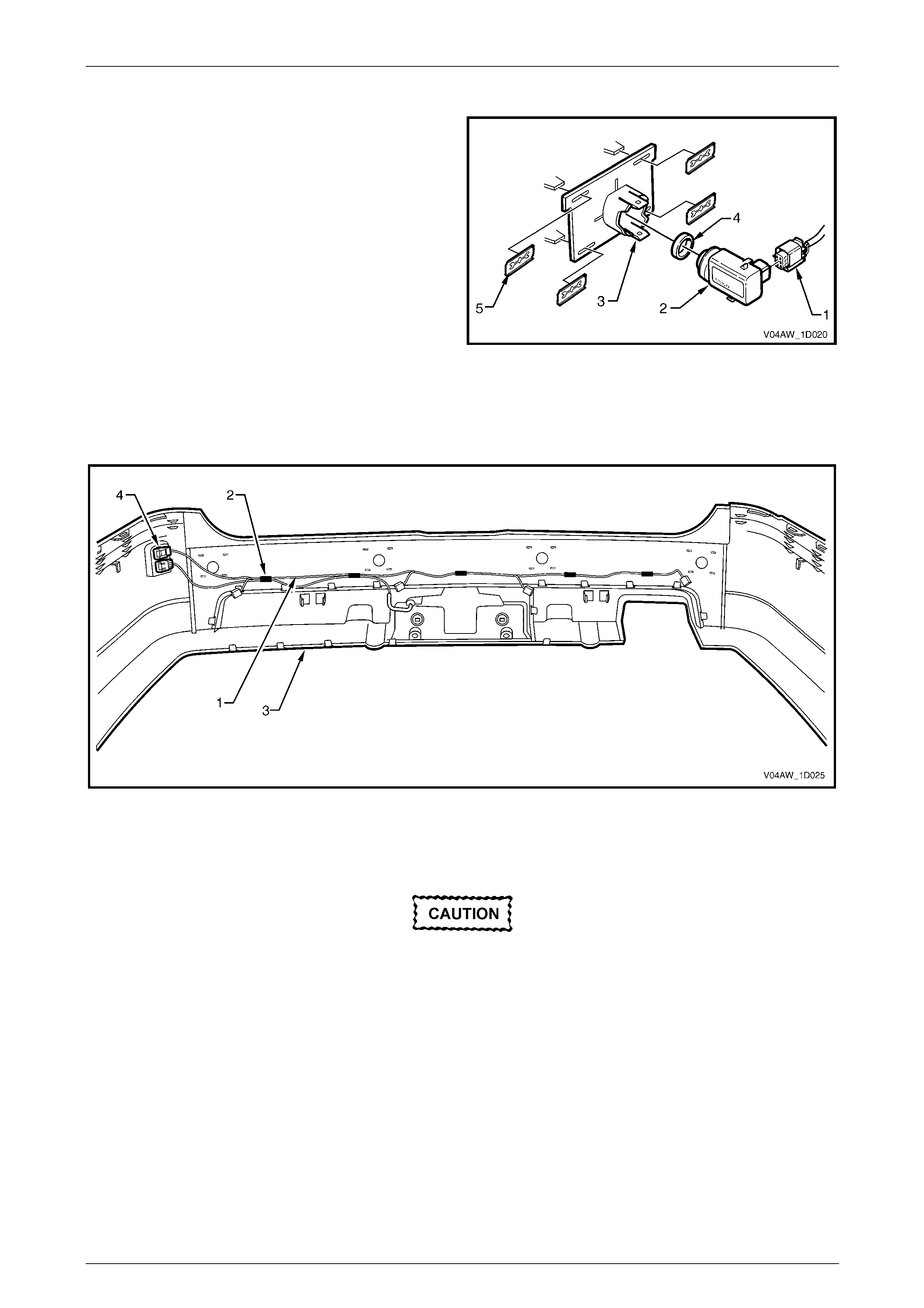
Bumper Bars Page 1D–56
Page 1D–56
Disassemble
1 Disconnect the wiring connector (1) from the rear
object sensor assembly (2).
2 Using a fine blade screwdriver, lever the upper and
lower tabs (3) of the rear object sensor housing and
slide the sensor from the hous ing.
3 If required, remove the rear object sensor ring (4) from
the rear object sensor.
4 Remove the rear object sensor housi ng from the
bumper fascia by removing the razor blade retainers.
For the removal procedure of the razor bla de retainer,
refer to 4.1 Service Notes.
5 Remove the rear object sensor wiring harness (1) by
prising the five retaining clips (2) from the bumper
fascia (3), refer to Figure 1D – 70.
6 Unclip the rear object sensor harness conn ector (4)
from the bumper fascia and remove the wiring
harness.
Figure 1D – 69
Figure 1D – 70
Reassemble
Ensure that the rear object sensor ring is
correctly seated on the sensor and that the
sensor assembly is securely located in the
housing. The sensor ring prevents vibrations
from the sensor being transferred to the
surrounding components. Incorrect fitment
will result in a change to the sensor
characteristics.
Reinstallation of the rear object sensor assembly is the reverse of the removal procedure, noting the following:
1 Attach the rear object sensor housings securely with new razor blade retainers.
2 Ensure that the sensors are correctly installed in the housing with the connector side facing to the centreline of the
vehicle.
3 Attach the wiring harness to the rear bumper fascia by pressing each clip onto the corresponding rib.

Bumper Bars Page 1D–57
Page 1D–57
Reinstall
1 Refinish the rear bumper fascia assembly, refer to 2 Paint Systems.
2 With the aid of an assistant, install the rear bumper fascia assembl y, ensuring that it is seated correctly.
3 Install the six retainers (3) around the liftgate opening, refer to Figure 1D – 62.
4 Insert the two retainers (1) from below the bumper fascia assembly.
5 Align the side of the bumper fascia assembly to the quarter panel and clip the rear bum per fascia assembly into the
guide assembly (4), refer to Figure 1D – 6 0. Rep eat for the opposite side.
6 Install the four screws on each side, attaching the rear bumper fascia assembly to the guide assembl y and rear
wheelhouse liner.
7 Clip the towbar opening cover in place ensuring the retai ning tabs are seated correctly and install the two retainers.
8 Tighten the screws to the correct torque specification.
Rear bumper fascia assembly to rear
wheelhouse liner attaching screw torque
specification................................................1.0 – 3.0 Nm
Rear bumper fascia assembly to rear
bumper fascia guide assembly attaching
screw torque specification...........................1.0 – 3.0 Nm
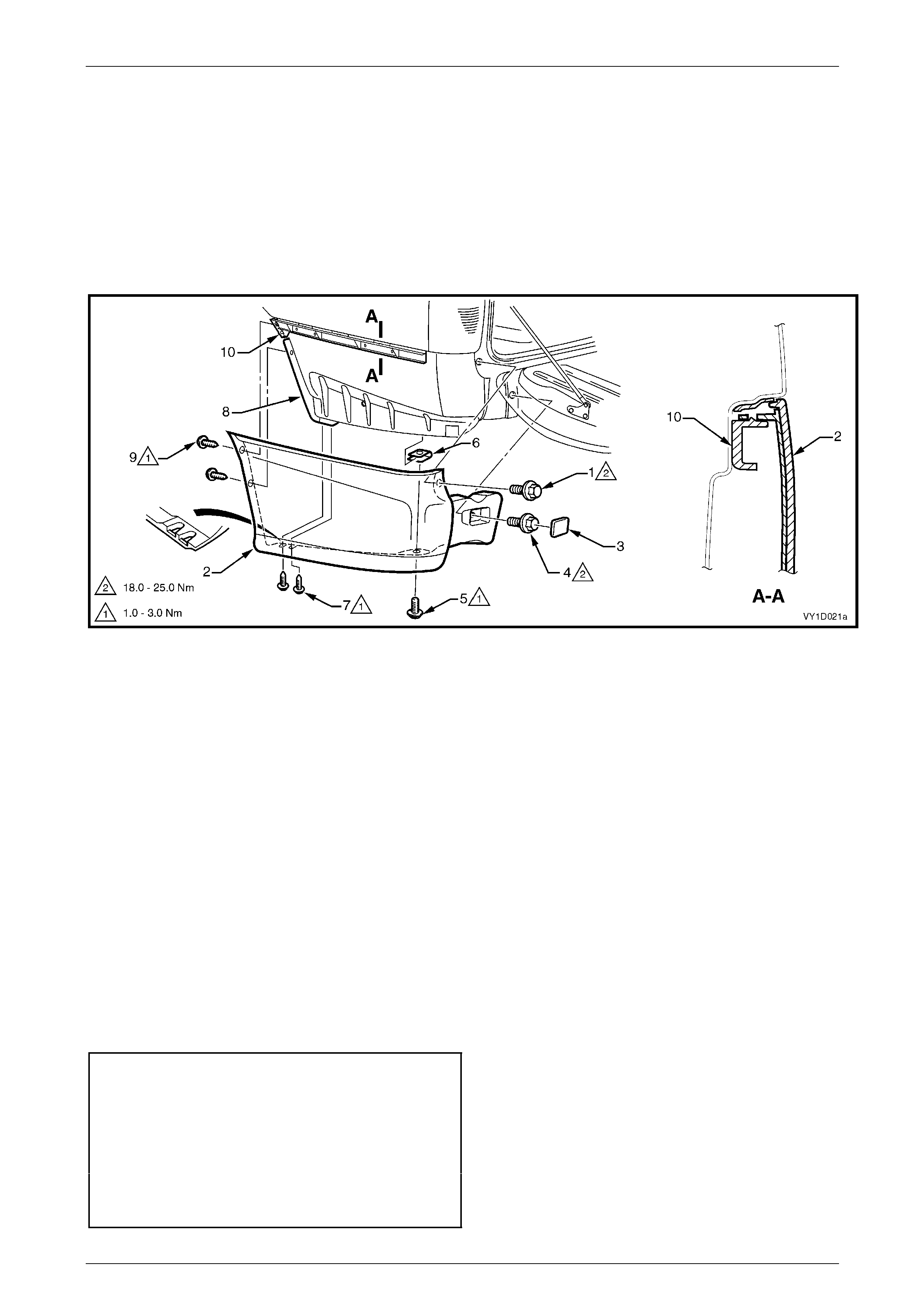
Bumper Bars Page 1D–58
Page 1D–58
4.5 Rear Bumper Fascia Assembly, Utilit y
LT Section No. — 07–525
Remove
Referring to Figure 1D – 71:
1 Open the endgate and remove the screw (1) attaching the bumper fascia (2).
2 Close the endgate.
Figure 1D – 71
3 Insert a fine flat-blade screwdriver and clean shop-rag between the outer edge of the re ar bumper fascia cap (3)
and fascia and prise off the cap.
4 Remove the screw (4) attaching the fascia.
5 Remove the screw (5) attaching the underside of the fascia to the J-nut (6).
6 Remove the screw (7) attaching the lower forward edge of the fascia to the rear wheelhouse liner (8).
7 Remove the two screws (9) attaching the forward edge of the fascia to the rear bumper fascia g uid e assembly (10)
and liner.
8 Carefully unclip the fascia from the guide assembly by grasping the upper end of the fascia and pulling away from
the vehicle.
9 Remove the fascia from the vehicle.
10 If required, remove the J-nut (6) from the outer side panel.
Reinstall
Reinstallation of the rear bum per fascia assembly is the reverse of the removal proced ure, noting the following:
1 Refinish the bumper fascia, refer to 2 Paint Systems.
2 Tighten the screws to the correct torque specification.
Rear bumper fascia to rear end panel
attaching screw torque specification.......18.0 – 25.0 Nm
Rear bumper fascia to J-nut attaching
screw torque specification...........................1.0 – 3.0 Nm
Rear bumper fascia to rear wheelhouse
liner attaching screw torque specification ...1.0 – 3.0 Nm
Rear bumper fascia to rear bumper fascia
guide assembly attaching screw torque
specification................................................1.0 – 3.0 Nm
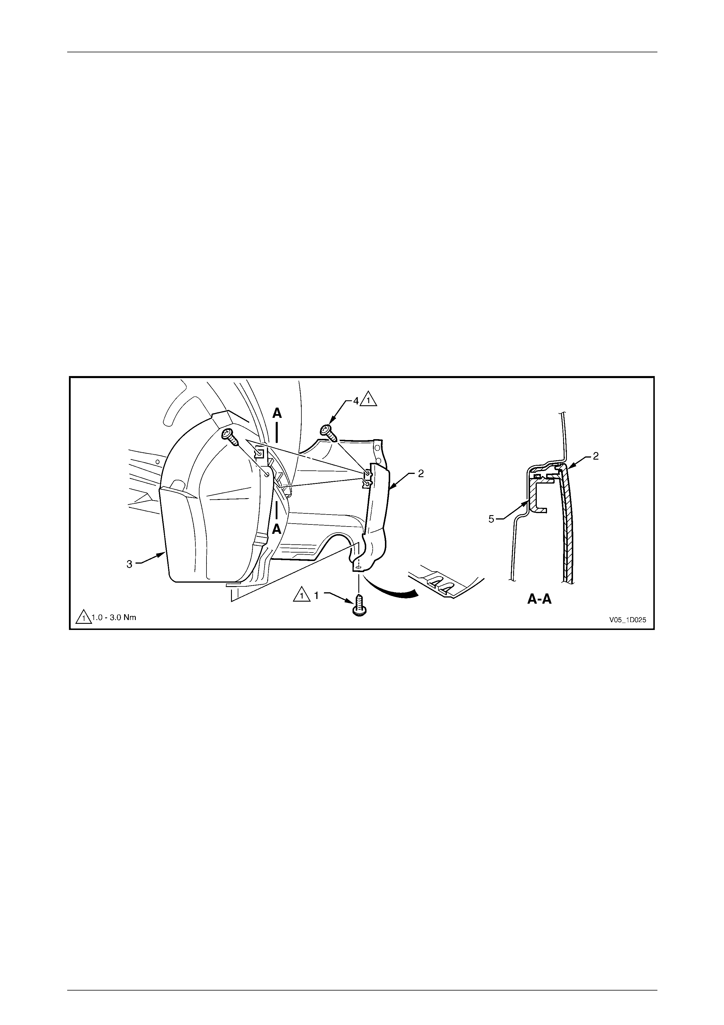
Bumper Bars Page 1D–59
Page 1D–59
4.6 Rear Bumper Fascia Assembly, Coupe
LT Section No. — 07–525
Remove
1 Remove the following components:
a Rear end trim panel, refer to Section 1A8, Headlin ing and Interior Trim.
b Quarter inner rear side carpet, refer to Section 1A8, Headlining an d Interior Trim.
2 From each side of the vehicle:
a Remove the screw (1) attaching the rear bumper fascia as sembly (2) to the rear wheelhouse liner (3), refer to
Figure 1D – 72.
b Remove the screw (4), two places, attaching the fascia assembly to the lin er and rear bumper fascia guide
assembly (5).
c Carefully unclip the fascia assembly from the guide assembly by grasping the upper end of the fascia and
pulling away from the vehicle.
Figure 1D – 72
3 Remove the two nuts (1) each side, attaching the fascia assembly (2) to the vehicle, refer to F igure 1D – 73.
4 Remove the two retainers (3) from belo w the fascia assembl y.
5 Remove the centre section of the rear compa r tment lid weatherstrip to allow access to the four upper retainers (4).
6 Remove the four upper retainers attaching the fascia assembly to the rear bumper fascia centre support assembly.
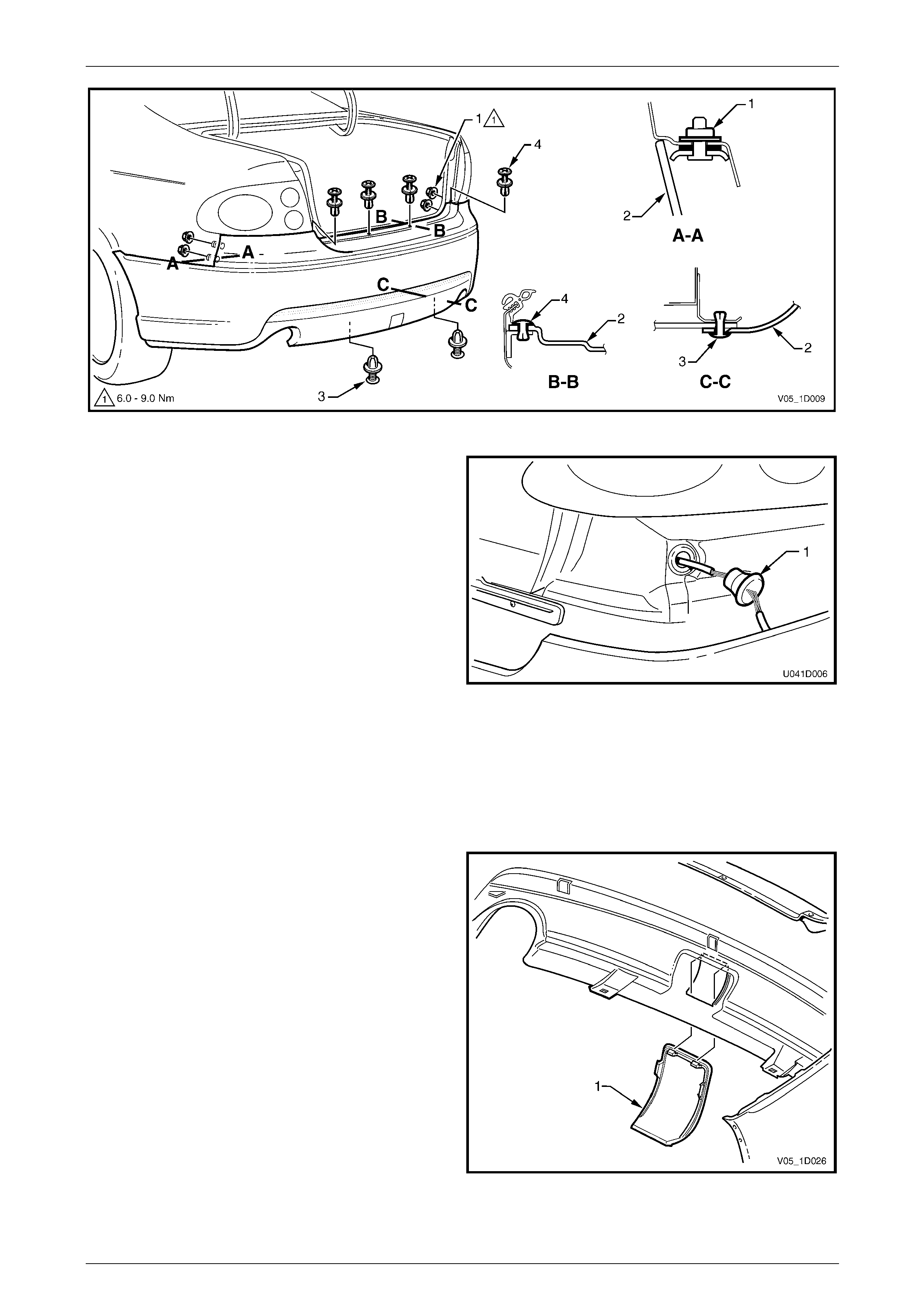
Bumper Bars Page 1D–60
Page 1D–60
Figure 1D – 73
7 Disconnect the Rear Park Assist (RPA) wiring
connector from within the rear compartment.
8 With the aid of an assistant, withdraw the fascia
assembly, push the RPA wiring harness gro mmet (1)
through the rear panel and withdraw the harness.
9 Remove the fascia assembly ensur ing the seals (5,
Figure 1D – 73) remain with the fascia assembly.
Figure 1D – 74
Disassemble
Towbar Opening Cover
Remove
1 Carefully prise the towbar opening cover (1) from the
bumper fascia.
Reinstall
Clip the cover in place ensuring the retaining tabs are
seated correctly.
Figure 1D – 75
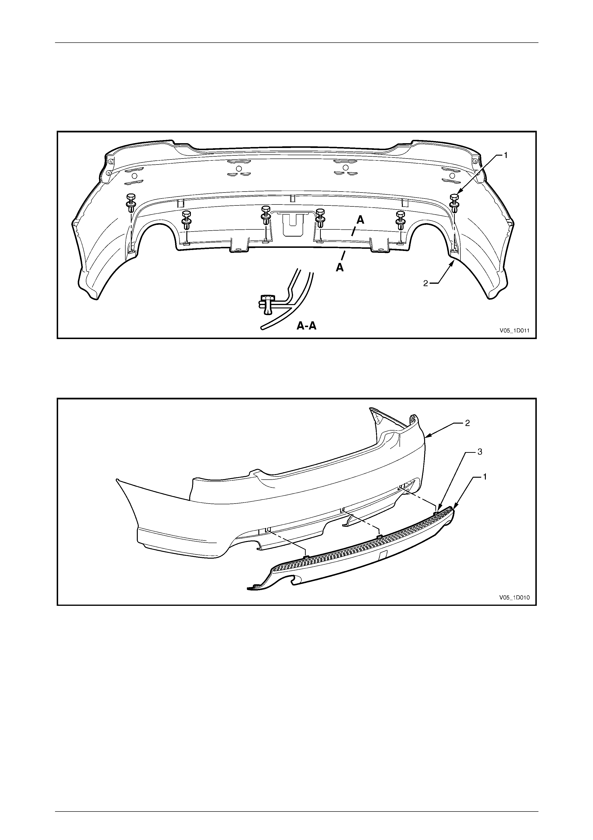
Bumper Bars Page 1D–61
Page 1D–61
Rear Bumper Fascia Insert
Remove
1 From the behind the rear bumper fascia, remove the retainer (1), ten places, attaching the insert (2), refer to
Figure 1D – 76.
Figure 1D – 76
2 Remove the insert (1) from the bumper (2) by pulling out and down to disengage the retai nin g tabs (3), refer to
Figure 1D – 77.
Figure 1D – 77
Reinstall
Reinstallation of the rear bum per fascia insert is the reverse of the removal procedure.
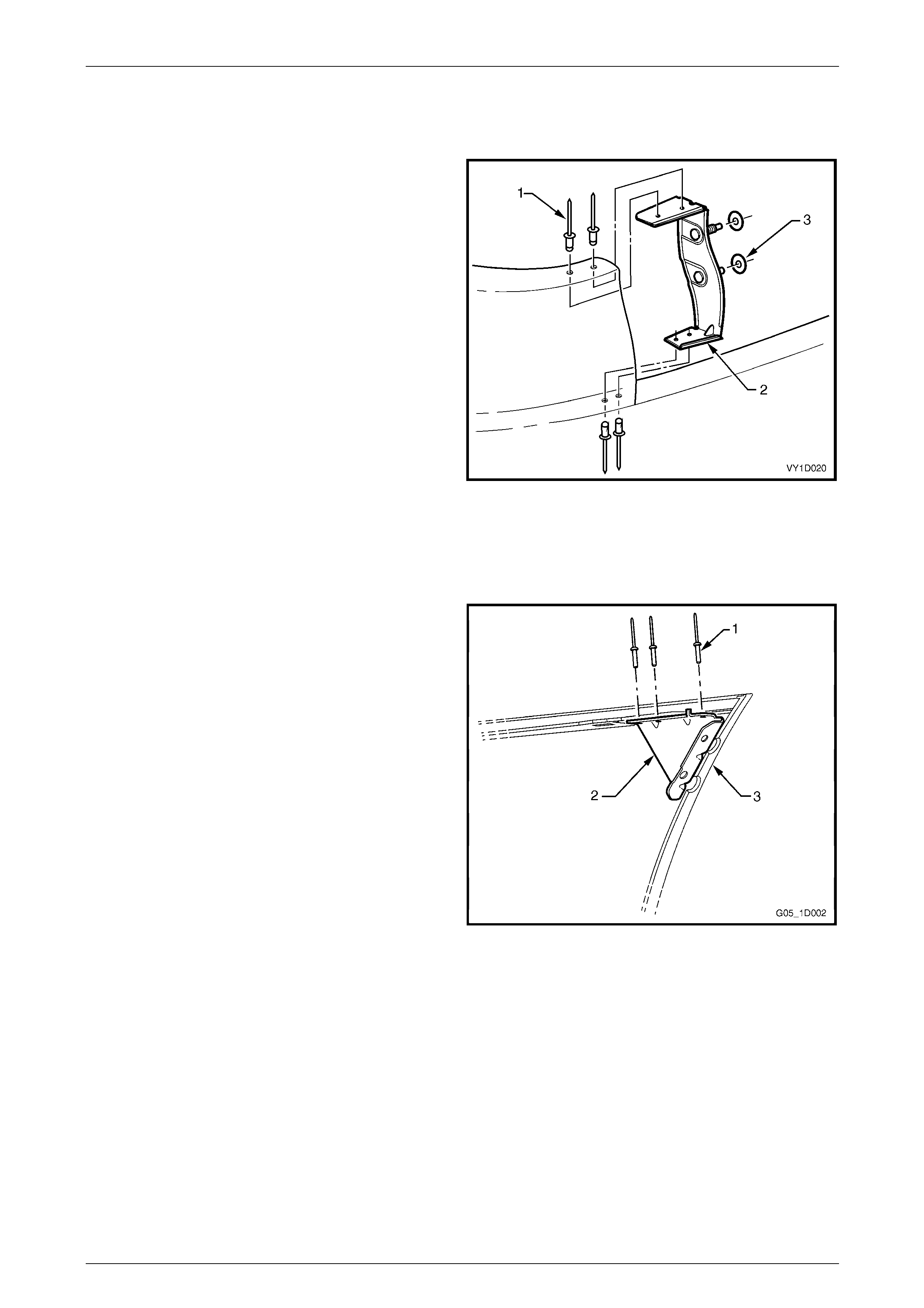
Bumper Bars Page 1D–62
Page 1D–62
Rear Bumper Fascia Anchor Plate Assembly
Remove
1 Using a 3mm drill-bit, remove the four pop rivets (1)
attaching the plate assembly (2) to the bumper fascia.
NOTE
If reusing the bumper fascia assembly, take care
not to enlarge the rivet holes.
2 Remove the plate assembly and if requ ired the two
seals (3).
Reinstall
Reinstall the plate assembly with new 3mm pop rivets.
Figure 1D – 78
Rear Bumper Fascia Bracket
Remove
1 Using a 3mm drill-bit, remove the three pop rivets (1)
attaching the rear bumper fas c ia bracket (2) to the
bumper fascia (3).
NOTE
If reusing the bumper fascia, take care not to
enlarge the rivet holes.
2 Remove the rear bumper fascia bracket.
Reinstall
Reinstall the bracket with new 3mm pop rivets.
Figure 1D – 79
Rear Park Assist Components
Where fitted, four sensor assemblies and th eir associated wiring are fitted to the rear bumper fascia assembl y as part of
the Rear Park Assist (RPA), refer to Figure 1D – 80.
Each rear object sensor assembly (1) is fitted into a rear object sensor housing (2) which is attached to the fascia
assembly with four heat-stakes (3). Holes in the fascia expose the sensor and housing fa ces. Four retaining clips (4)
secure the rear object sensor wiring harness assembly (5) to the fascia assembly which is routed across to the left-hand
side.
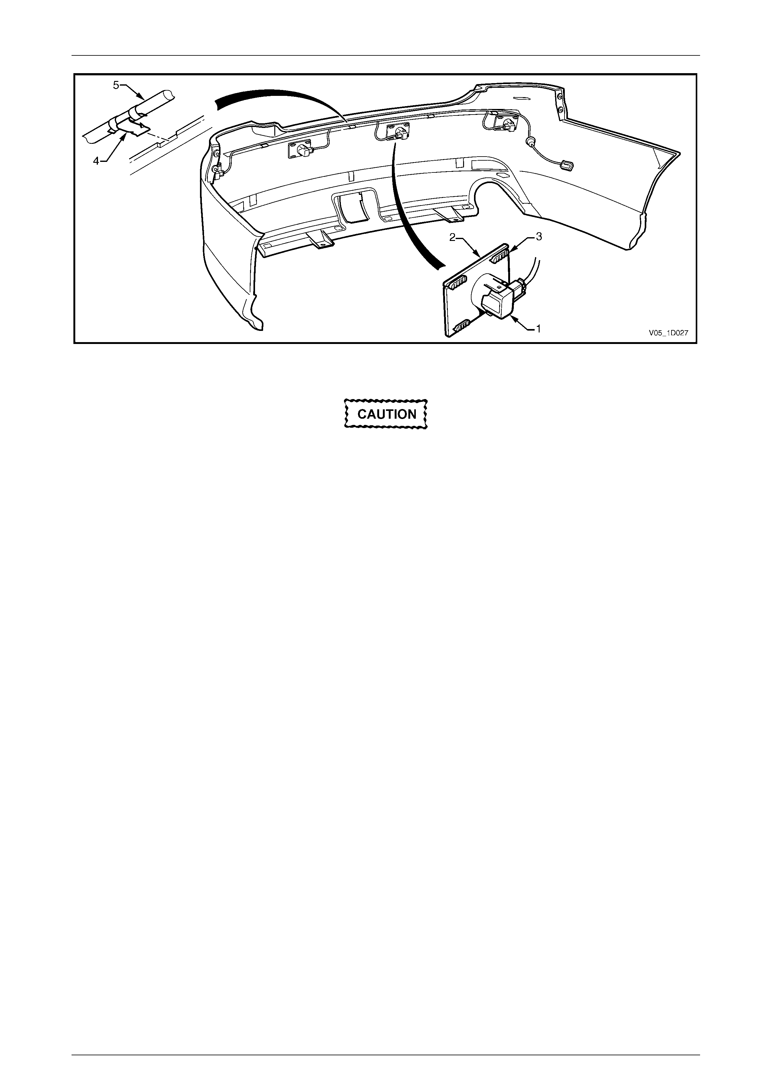
Bumper Bars Page 1D–63
Page 1D–63
Figure 1D – 80
The fascia assembly and sensors must be
correctly aligned if the system is to operate
correctly. Sensors may be damaged if
dropped or subjected to temperatures above
80° C.
If repainting a fascia assembly, the sensors
and rings must be removed. Paint must not be
applied to any part of a sensor, including the
exposed coloured surface. Paint film applied
to the exposed surface will render the sensor
inoperable as the paint film restricts the
sensor’s ultra-sonic signal. If a sensor is
damaged, it must be replaced.
Replacement housings are supplied
unpainted. As they are partially exposed when
installed, they will require painting using the
same procedures for painting the bumper
fascia, refer to 2 Paint Systems.
NOTE
It is preferable to paint the housings and bumper
fascia separately to avoid adhesion problems.
Assemble the housings onto the bumper fascia
once the paint has cured.
Replacement bumper fascias are sup pli ed without holes and must be modified by follo wing the proce dures in New Facia
Modification.
For further information on rear park assist, refer to Section 12F1 Rear Park Assist.
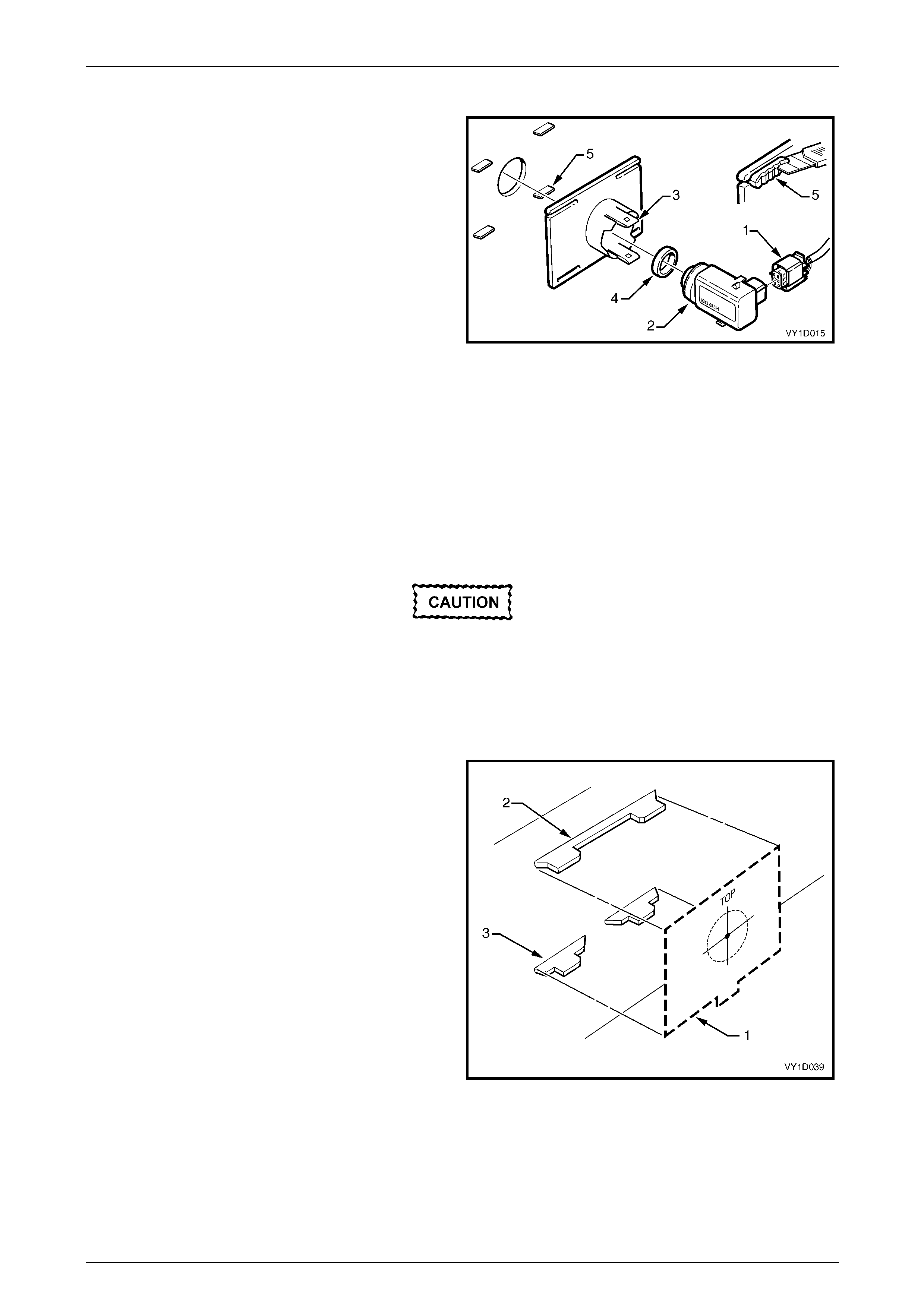
Bumper Bars Page 1D–64
Page 1D–64
Disassemble
1 Disconnect the wiring connector (1) from the rear
object sensor assembly (2).
2 Using a fine blade screwdriver, lever the upper and
lower tabs (3) of the rear object sensor housing and
slide the sensor from the hous ing.
3 If required, remove the rear object sensor ring (4) from
the sensor.
4 Remove the rear object sensor housi ng from the
bumper fascia by cutting the heat-stakes (5).
NOTE
If the housing is to be reinstalled on the same
bumper fascia, only cut the minimum amount of
material to enable removal, ensuring enough
remains to reattach the housing.
5 Remove the rear object sensor wiring harness from
the bumper fascia by prising the four retaining clips
from the bumper fascia with a fine flat blade
screwdriver.
Figure 1D – 81
New Fascia Modification
1 Print and cut-out the templates in Figure 1D – 85.
When printing the template, in the Print Dialog
Box ensure the Shrink Oversize Pages To
Paper Size box is not ticked. Always check
the scale on the template to ensure it has
printed the correct size.
2 Perform the following instructions at the four rear object sensor housing mounting locations.
3 Tape the template (1) to the inside of the rear fascia,
aligning the edges between the upper (2) and lower
(3) aid heat stakes.
Figure 1D – 82
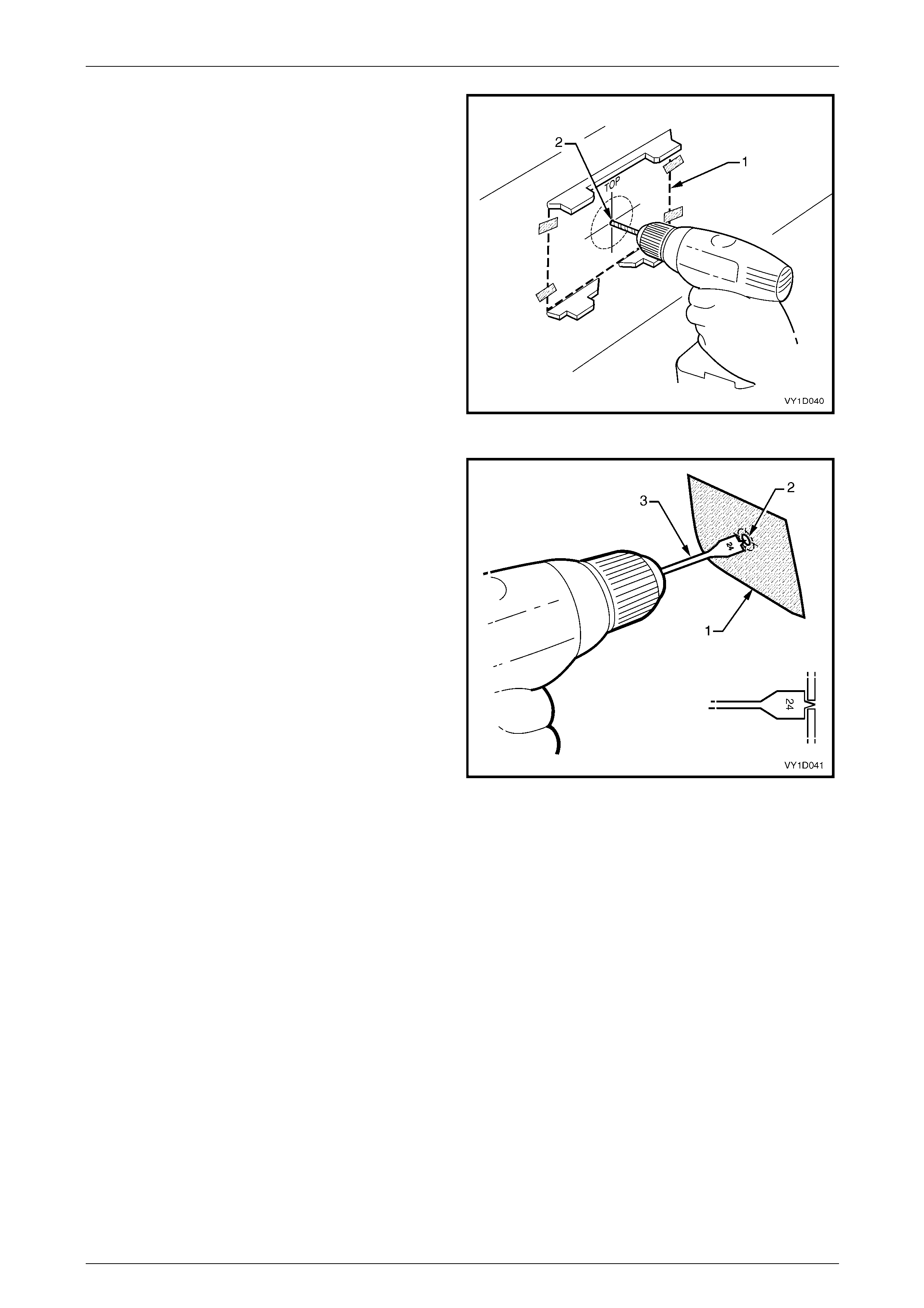
Bumper Bars Page 1D–65
Page 1D–65
4 From the inside of the fascia, drill a 2 mm diameter
pilot hole at the template (1) centre point (2).
Figure 1D – 83
5 Place masking tape (1) on the outside surface of the
fascia in the area to be drilled.
6 From the outside of the fascia, enlarge the pi lot hole
(2) to 24 mm using a wood spade drill bit (3).
CAUTION
• Only use a spade drill bit as a normal drill
bit or hole saw may damage the fascia.
• Ensure the spade drill bit remains square
with the rear fascia.
• Use a slow drill speed to avoid damaging
the rear fascia.
7 Debur the edges of the hole if necessary.
8 As required, paint the bumper fascia an d
sensor housings prior to reassembly, refer to
2 Paint Systems.
Figure 1D – 84
Bumper Bars Page 1D–66
Page 1D–66
Figure 1D – 85
Bumper Bars Page 1D–67
Page 1D–67
Reassemble
NOTE
It is advisable to paint the bumper fascia and
housings prior to attachment to the bumper
fascia, refer to 2 Paint Systems.
1 Position the housing onto the four stakes, en suring it is
seated against the fascia surface and correctly
protrudes through the hole.
2 Using a soldering iron, melt the end of the heat-stakes.
Hold the housing in position until the plastic has
cooled.
NOTE
Do not over-melt the material and ensure the
housing is fixed securely.
NOTE
If the housing is being reinstalled onto the same
bumper fascia, ensure there is enough material
to provide secure attachment. If required, cut a
thin piece of bumper material from an
inconspicuous place an d use as a filler, melting it
into the heat-stake.
3 Fit the ring onto the end of the sensor, refer to
Figure 1D – 81.
Figure 1D – 86
4 Insert the sensor into the housing firmly, ensuring that the tabs are locked into the sensor.
5 Repeat as required.
6 Route the wiring harness (1) to the left-hand side of the vehicle and connect the wiring harness connectors to each
sensor, refer to Figure 1D – 87.
7 Attach the harness to the upper side of the bumper fascia rib, aligning each clip (2) at the notch (3).
Figure 1D – 87

Bumper Bars Page 1D–68
Page 1D–68
Reinstall
Reinstallation of the rear bum per fascia assembly is the reverse of the removal proced ure, noting the following:
1 Refinish the bumper fascia, refer to 2 Paint Systems.
2 To avoid damaging the bump er fascia an d/or vehicle, fit the fascia assembly onto the vehicle with the aid of an
assistant.
3 Securely fit the RPA wiring harness grommet into the side pane l hole.
4 Tighten the fasteners to the correct torque specification.
Rear bumper fascia assembly to rear
wheelhouse liner attaching
screw torque specification...........................1.0 – 3.0 Nm
Rear bumper fascia assembly to rear bumper
fascia guide assembly attaching
screw torque specification...........................1.0 – 3.0 Nm
Rear bumper fascia assembly
attaching nut torque specification................6.0 – 9.0 Nm
5 Test the rear park assist for correct operation, refer to Section 12F1 Rear Park Assist .

Bumper Bars Page 1D–69
Page 1D–69
4.7 Rear Bumper Fascia Assembly, Crew
Cab
LT Section No. — 07–525
Remove
1 Push the locking tang (1) securing the licence plate
lamp housing (2) and pivot the lamp housing down
and remove it from the aperture.
2 Remove the bulb socket (3) from the lamp housing
and place the housing in a safe location.
3 Pass the bulb socket through the aperture in the rear
bumper fascia assembly.
4 Repeat Steps 1 to 3 for the other lamp assembl y.
Figure 1D – 88
5 For SS vehicles, from each side of the vehicle:
a Remove the screw (1), five places, attaching the
rear mudflap (2) to the rear body and remove the
mudflap.
Figure 1D – 89
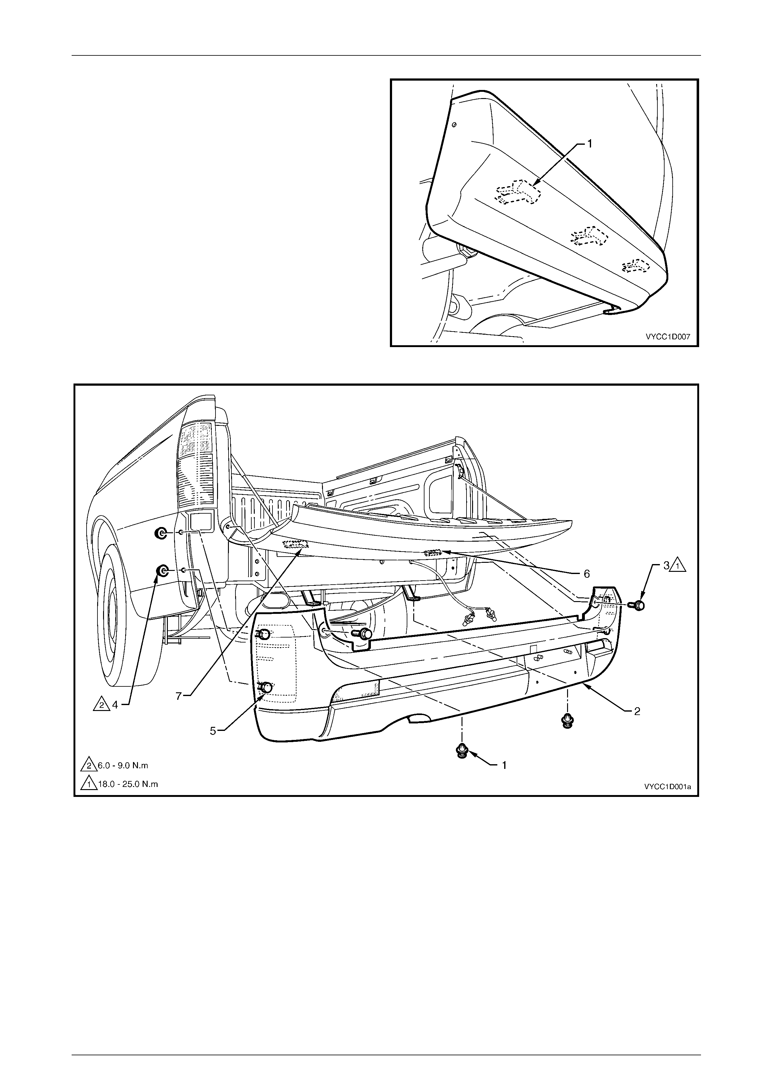
Bumper Bars Page 1D–70
Page 1D–70
b From behind the rear body panel unclip the three
retainers (1) attaching the bumper fascia
extension to the vehic le.
6 Remove the two retainers (1) from below the rear
bumper fascia assembly (2), refer to Figure 1D – 91.
7 Open the endgate, remove the screw (3), one place
each side of the vehicle, and close the e nd gate.
8 Remove the nut (4), from the stud (5), two places each
side each side of the vehicle.
9 Disengage the rear bumper fa scia assembly from the
rear bumper fascia assembly supports (6) and (7).
10 With the aid of an assistant, remove the rear bumper
fascia assembly from the vehicle.
Figure 1D – 90
Figure 1D – 91
Bumper Bars Page 1D–71
Page 1D–71
Disassemble
1 Remove the speed nut (1), two places, attachin g the refle x reflector (2) to the bumper fascia (3), refer to
Figure 1D – 92. For the removal procedure of the speed nut, refer to 4.1 Service Notes.
2 Remove the reflex reflector from the rear bumper fascia.
3 Repeat for the opposite side as required.
Figure 1D – 92
Reassemble
Reassembly of the rear bumper fascia assembly is the reverse of the disassembly procedure.
Reinstall
Reinstallation of the rear bum per fascia assembly is the reverse of the removal proced ure, noting the following:
1 Refinish the bumper fascia, refer to 2 Paint Systems.
2 To avoid damaging the bump er fascia an d/or vehicle, fit the fascia assembly onto the vehicle with the aid of an
assistant.
3 Tighten the fasteners to the correct torque specification.
Rear bumper fascia assembly attaching
screw torque specification.......................18.0 – 25.0 Nm
Rear bumper fascia assembly attaching
nut torque specification...............................6.0 – 9.0 Nm
Rear mudflap attaching screw
torque specification.....................................1.0 – 3.0 Nm

Bumper Bars Page 1D–72
Page 1D–72
4.8 Rear Bumper Fascia Guide Assembly,
Except AWD Wagon
LT Section No. —
Remove
1 Remove the rear bumper fascia assembly, refer to:
• 4.2 Rear Bumper Fascia Assembly, Sedan, or
• 4.3 Rear Bumper Fascia Assembly, Wagon, or
• 4.5 Rear Bumper Fascia Assembly, Utility, or
• 4.6 Rear Bumper Fascia Assembly, Coupe, or
• 4.7 Rear Bumper Fascia Assembly, Crew Cab.
NOTE
It may be possible to remove one side of the
bumper fascia and carefully move it out far
enough to gain access to the guide assembly.
2 Remove the screw (1), four places, attaching the guide
assembly (2).
3 Prise the guide assembly out to detach it from the
vehicle.
NOTE
If required, remove the quarter inner rear side
carpet and using a fine flat-blade screwdriver,
depress the guide rail retaining tabs (4), four
places. Refer to Section 1A8 Headlining and
Interior Trim for the rear side carpet removal
procedure.
Ensure the seal (3), four places, is removed with
the guide assembly.
Figure 1D – 93
Reinstall
Reinstallation of the rear bum per fascia guide assembly is the reverse of the removal pro cedure. Tighten the screws to
the correct torque specification.
Rear bumper fascia guide assembly
attaching screw torque specification...........1.0 – 3.0 Nm

Bumper Bars Page 1D–73
Page 1D–73
4.9 Rear Bumper Fascia Guide Assembly,
AWD Wagon
LT Section No. —
Remove
1 Remove the rear bumper fascia assembly, refer to 4.4 Rear Bumper Fascia Assembly, AW D Wagon.
NOTE
It may be possible to remove one side of the
bumper fascia and carefully move it out far
enough to gain access to the guide assembly.
2 Remove the screw (1), four places, attaching the rear
bumper fascia guide assembl y (2).
3 Prise the guide assembly out to detach it from the
vehicle.
NOTE
Ensure the seal (3), four places, is removed with
the guide assembly.
Figure 1D – 94
Reinstall
Reinstallation of the rear bum per fascia guide assembly is the reverse of the removal pro cedure. Tighten the screws to
the correct torque specification.
Rear bumper fascia guide assembly
attaching screw torque specification...........1.0 – 3.0 Nm
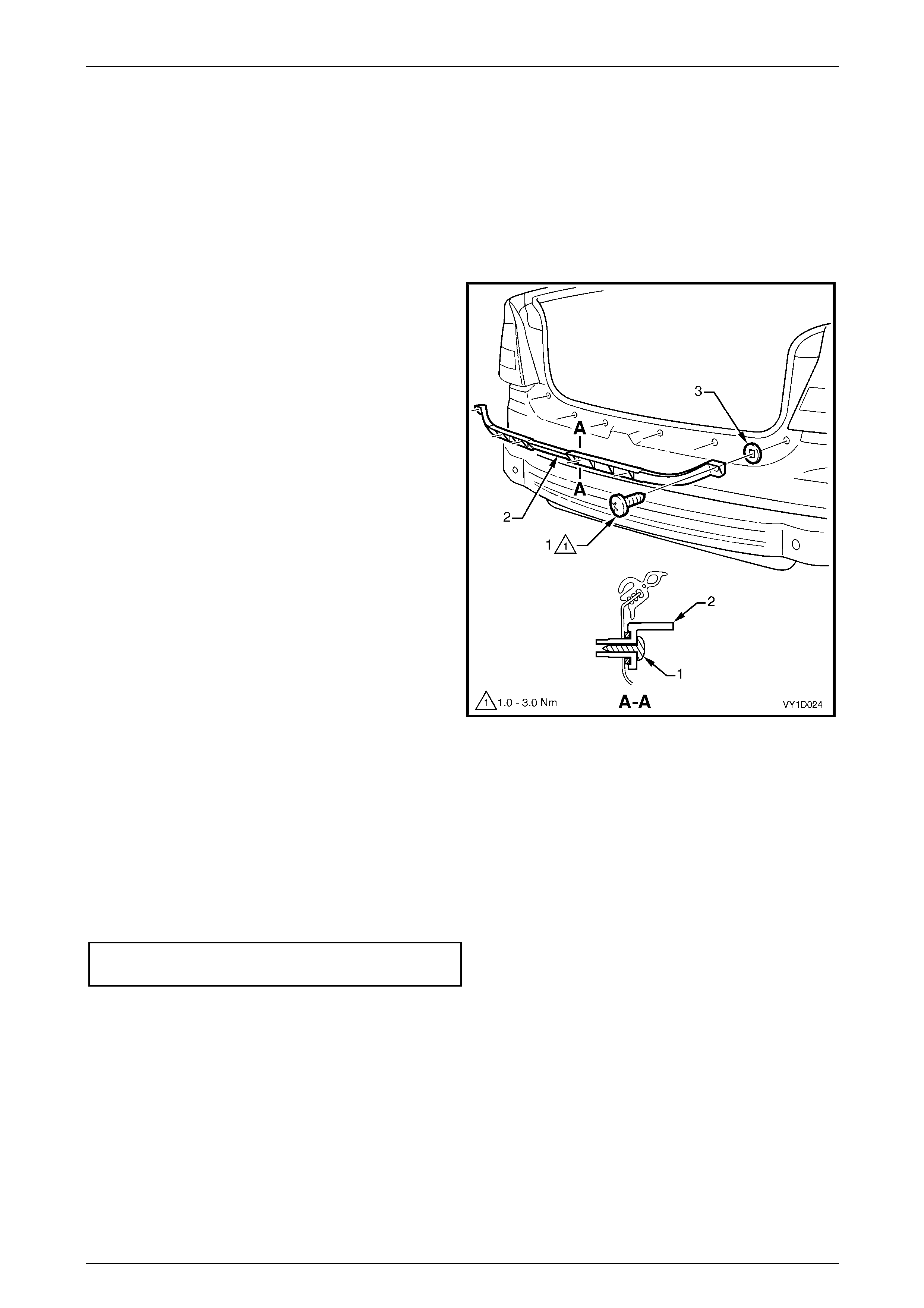
Bumper Bars Page 1D–74
Page 1D–74
4.10 Rear Bumper Fascia Centre Support,
Sedan
LT Section No. —
Remove
1 Remove the rear bumper fascia assembly, refer to 4.2 Rear Bumper Fascia Assembly, Sedan.
2 Remove the screw (1), six places, attaching the rear
bumper fascia centre support (2) to the vehic le.
3 Prise the support from the vehicle, ensuring the seals
(3) remain with the support.
Figure 1D – 95
Reinstall
Reinstallation of the rear bum per fascia centre support is the reverse of the removal procedure. Tighten the screws to the
correct torque specification.
NOTE
Ensure the seals are correctly fitted to the
support prior to installation.
Rear bumper fascia centre support
attaching screw torque specification...........1.0 – 3.0 Nm
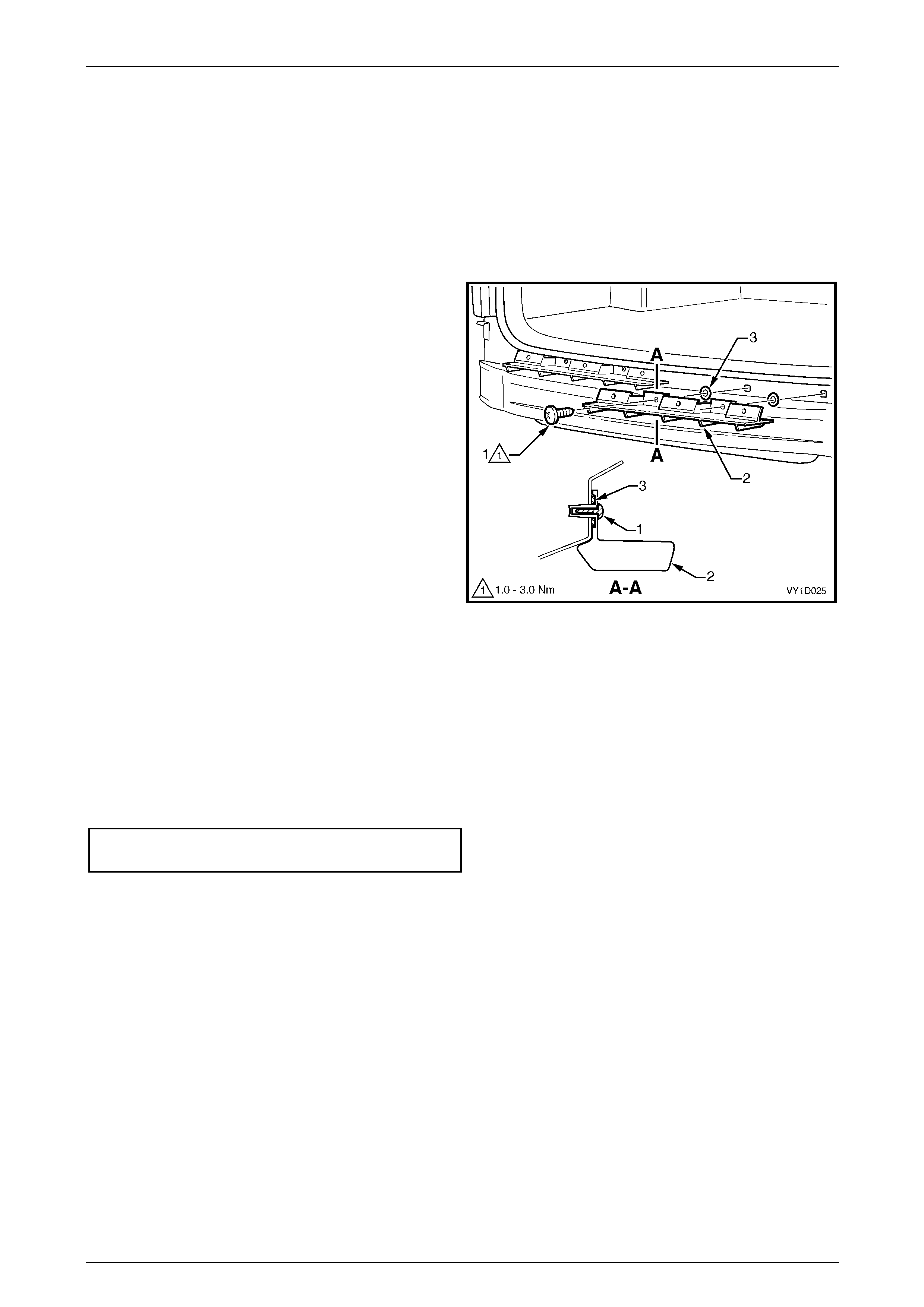
Bumper Bars Page 1D–75
Page 1D–75
4.11 Rear Bumper Fascia Upper Support,
Wagon
LT Section No. —
Remove
1 Remove the rear bumper fascia, refer to 4.3 Rear Bumper Fascia Assem bl y, Wagon.
2 Remove the screw (1), two places, attaching the rear
bumper fascia upper support (2) to the vehicle.
3 Prise the support from the vehicle ensurin g the seals
(3) remain with the support.
4 Repeat for the opposite support as require d.
Figure 1D – 96
Reinstall
Reinstallation of the rear bum per fascia upper support is the reverse of the removal procedure. Tighten the screws to the
correct torque specification.
NOTE
Ensure the seals are correctly fitted to the
support prior to installation.
Rear bumper fascia upper support
attaching screw torque specification...........1.0 – 3.0 Nm
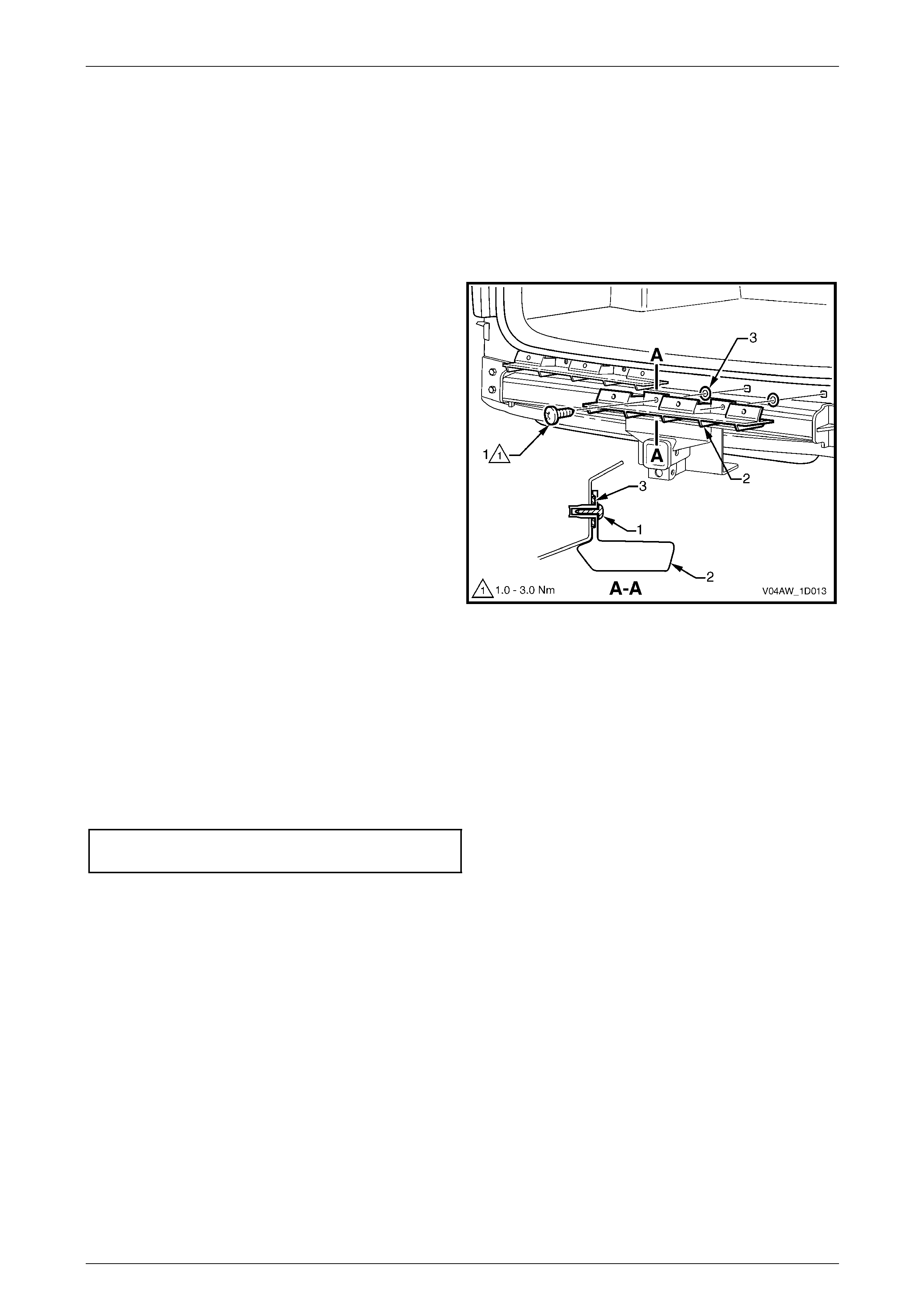
Bumper Bars Page 1D–76
Page 1D–76
4.12 Rear Bumper Fascia Upper Support,
AWD Wagon
LT Section No. —
Remove
1 Remove the rear bumper fascia assembly, refer to 4.4 Rear Bumper Fascia Assembly, AW D Wagon.
2 Remove the screw (1), two places, attaching the rear
bumper fascia upper support (2) to the vehicle.
3 Prise the support from the vehicle ensurin g the
seals (3) remain with the support.
4 Repeat for the opposite support as require d.
Figure 1D – 97
Reinstall
Reinstallation of the rear bum per fascia upper support is the reverse of the removal procedure. Tighten the screws to the
correct torque specification.
NOTE
Ensure the seals are correctly fitted to the
support prior to installation.
Rear bumper fascia upper support
attaching screw torque specification...........1.0 – 3.0 Nm
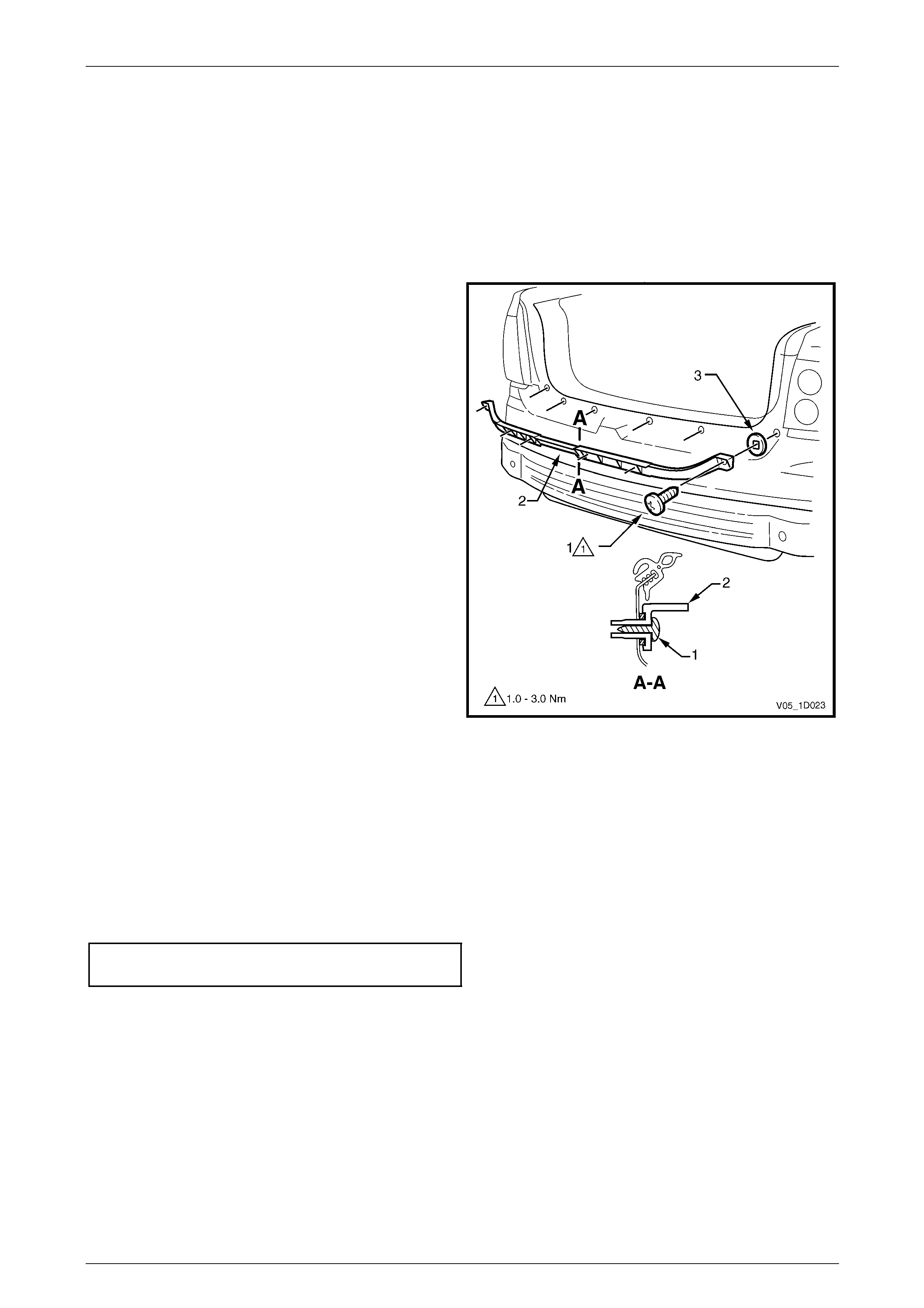
Bumper Bars Page 1D–77
Page 1D–77
4.13 Rear Bumper Fascia Centre Support,
Coupe
LT Section No. —
Remove
1 Remove the rear bumper fascia assembly, refer to 4.6 Rear Bumper Fascia Assembly, Coup e.
2 Remove the screw (1), six places, attaching the rear
bumper fascia centre support (2) to the vehic le.
3 Prise the support from the vehicle, ensuring the seals
(3) remain with the support.
Figure 1D – 98
Reinstall
Reinstallation of the rear bum per fascia centre support is the reverse of the removal procedure. Tighten the screws to the
correct torque specification.
NOTE
Ensure the seals are correctly fitted to the
support prior to installation.
Rear bumper fascia centre support
attaching screw torque specification...........1.0 – 3.0 Nm
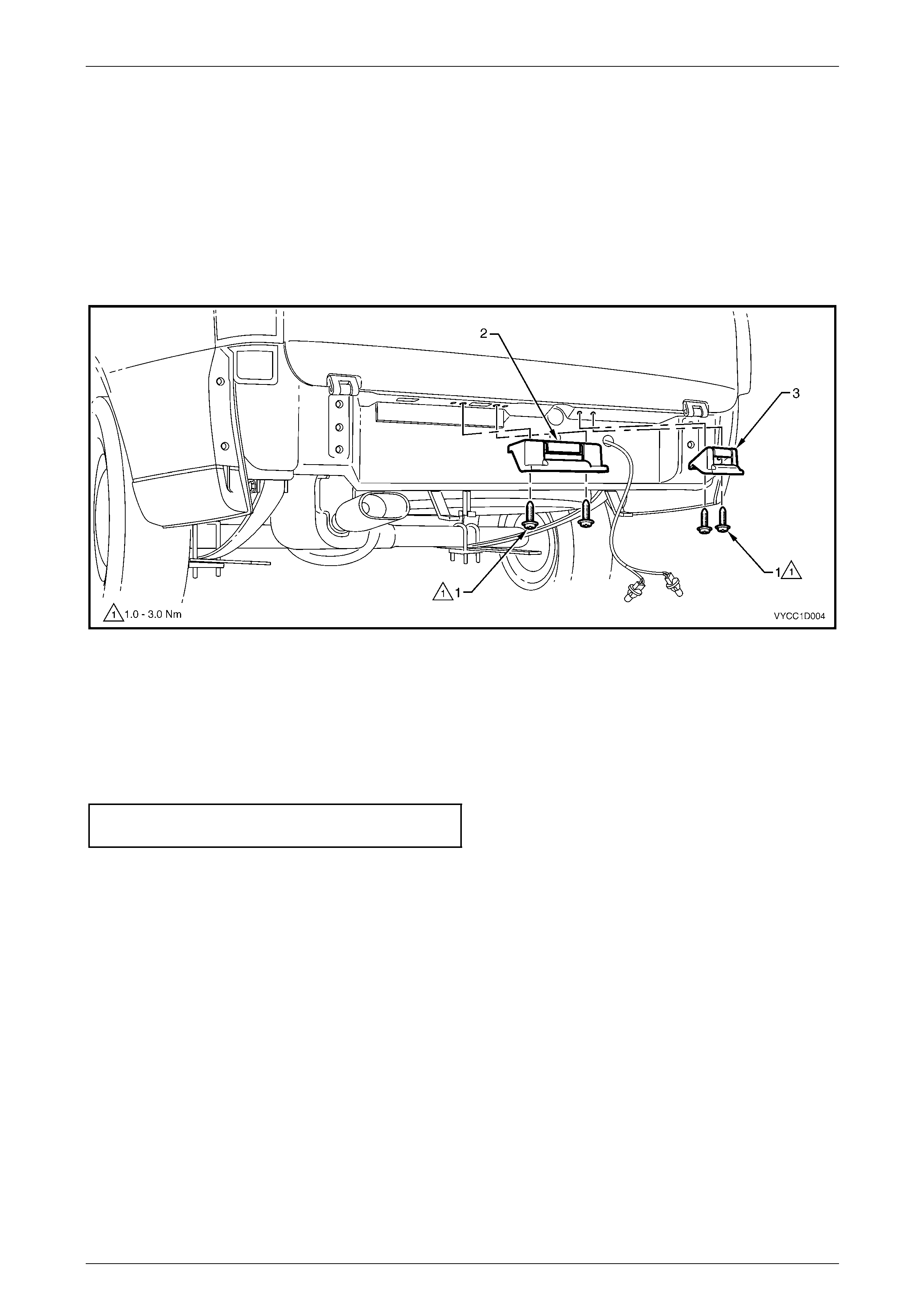
Bumper Bars Page 1D–78
Page 1D–78
4.14 Rear Bumper Fascia Support, Crew Cab
LT Section No. —
Remove
1 Remove the rear bumper fascia assembly, refer to 4.7 Rear Bumper Fascia Assembly, Crew Cab.
2 Remove the two screws (1) attaching the left-hand (2) or right-hand (3) rear bumper fascia support and remove the
support, refer to Figure 1D – 99.
Figure 1D – 99
Reinstall
Reinstallation or the rear bumper fascia support is the reverse of the removal procedure, noting the following:
1 The left-hand and right-hand supports are not interchangeable.
2 Tighten the screws to the correct torque specification.
Rear bumper fascia support assembly
screw torque specification...........................1.0 – 3.0 Nm
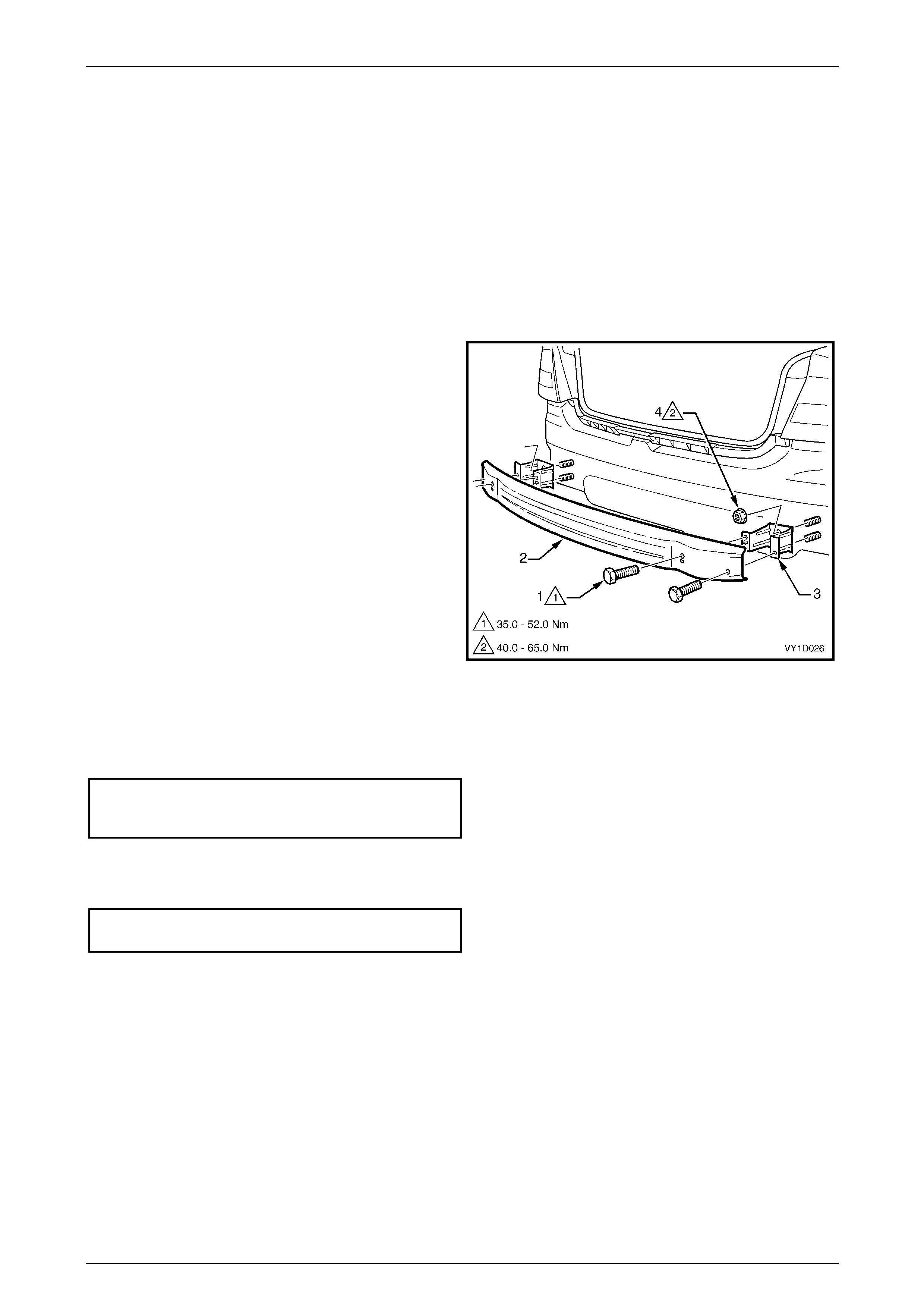
Bumper Bars Page 1D–79
Page 1D–79
4.15 Rear Bumper Impact Bar, Sedan and
Wagon
LT Section No. —
Remove
1 Remove the rear bumper fascia assembly, refer to:
• 4.2 Rear Bumper Fascia Assembly, Sedan, or
• 4.3 Rear Bumper Fascia Assembly, Wagon.
2 Remove the two screws (1), each side, attaching the
rear bumper impact bar (2) to the rear bumper impact
bar bracket assembly (3).
3 Remove the bar.
4 If required, remove the nut (4), two places, attaching
the bracket assembly to the vehicle and remove the
bracket.
Figure 1D – 100
Reinstall
1 Fit the bracket assemblies in position and attach the nuts. Tighten the nuts to the correct torque specifica t ion.
Rear bumper impact bar bracket
assembly attaching nut torque
specification............................................49.0 – 65.0 Nm
2 Fit the bar onto the bracket assemblies and fit each screw. Do not tighten.
3 When all screws are installed, check t he bar is centralised. Tighten the screws to the correct torque specif ication.
Rear bumper impact bar attaching
screw torque specification.......................35.0 – 52.0 Nm
4 Reinstall the rear bumper fascia assembl y, refer to:
• 4.2 Rear Bumper Fascia Assembly, Sedan, or
• 4.3 Rear Bumper Fascia Assembly, Wagon.
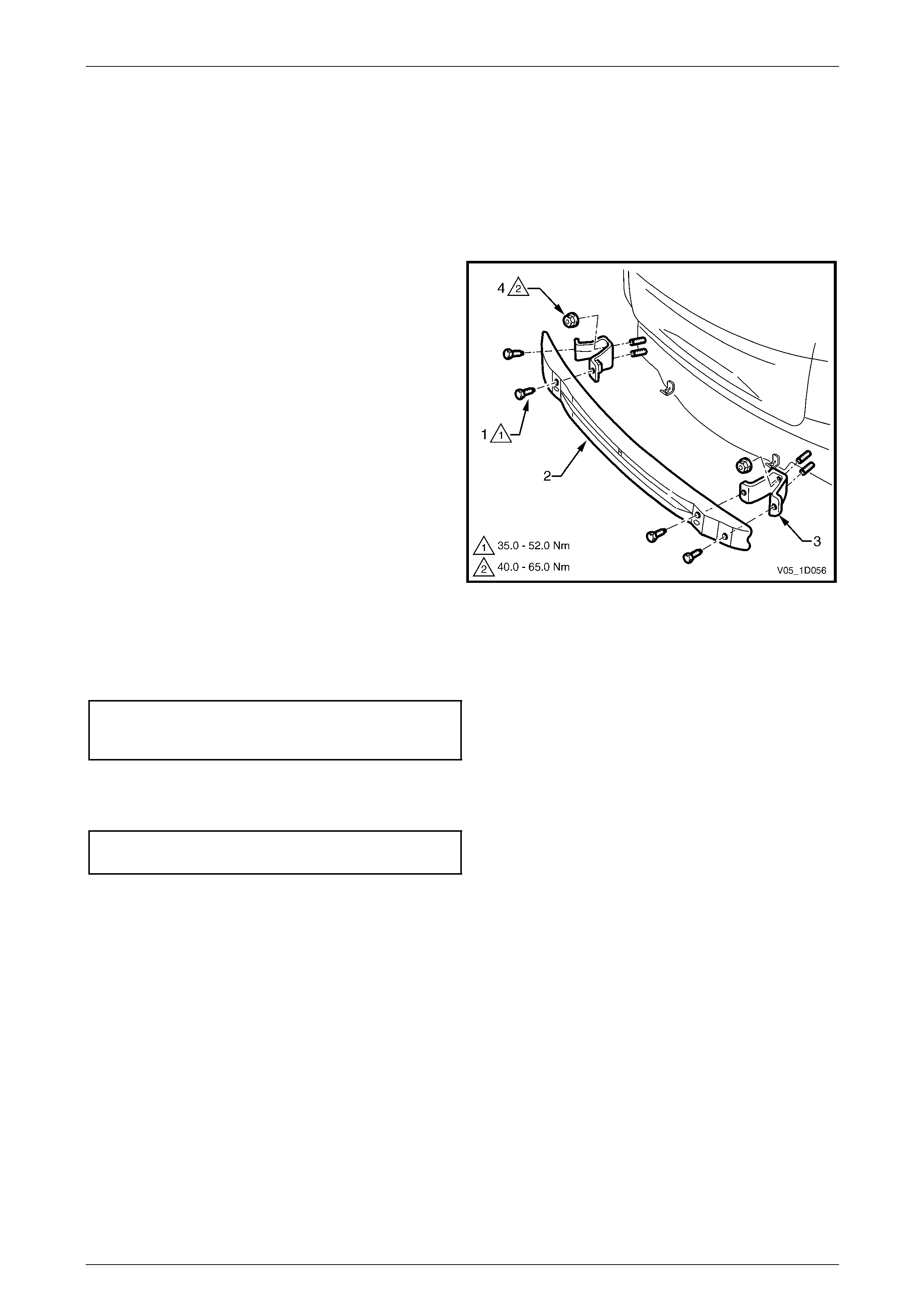
Bumper Bars Page 1D–80
Page 1D–80
4.16 Rear Bumper Impact Bar, Coupe
LT Section No. —
Remove
1 Remove the rear bumper fascia assembly, refer to 4.6 Rear Bumper Fascia Assembly, Coup e.
2 Remove the two screws (1), each side, attaching the
rear bumper impact bar (2) to the rear bumper impact
bar bracket assembly (3).
3 Remove the bar.
4 If required, remove the two nuts (4) attaching the
bracket assembly to the vehicle and remove the
bracket.
Figure 1D – 101
Reinstall
1 Fit the bracket assemblies in position and attach the nuts. Tighten the nuts to the correct torque specifica t ion.
Rear bumper impact bar bracket
assembly attaching nut torque
specification............................................49.0 – 65.0 Nm
2 Fit the bar to the bracket assemblies and fit each screw. Do not tighten.
3 When all screws are installed, check t he bar is centralised. Tighten the screws to the correct torque specif ication.
Rear bumper impact bar attaching
screw torque specification.......................35.0 – 52.0 Nm
4 Refit the rear bumper energy absorber to the impact bar ensurin g that the retain ers engage over the impact bar
flange.
5 Refit the rear bumper fascia assembly, refer to 4.6 Rear Bumper Fascia Assembly, Coupe.
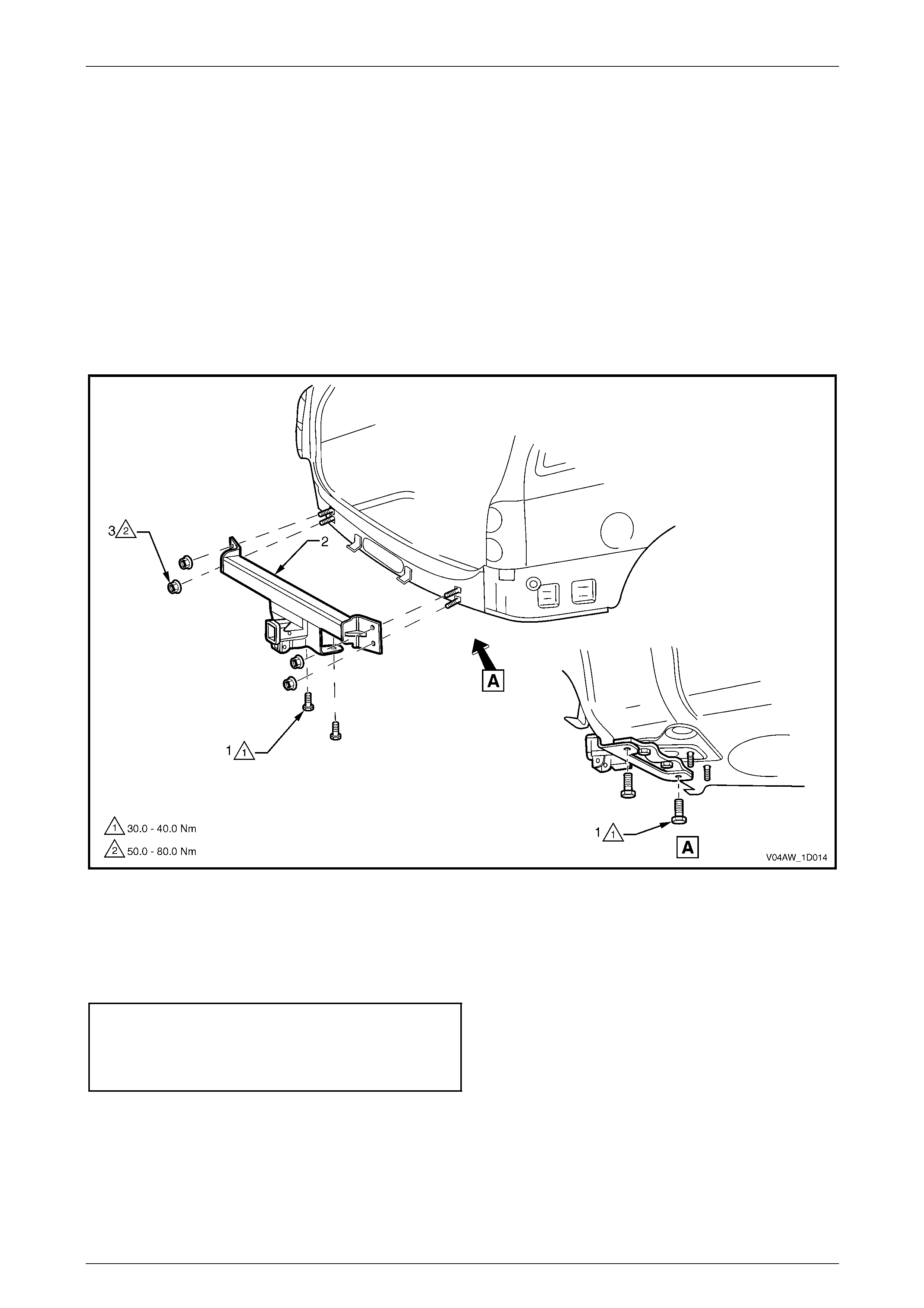
Bumper Bars Page 1D–81
Page 1D–81
4.17 Tow Bar Assembly, AWD Wagon
LT Section No. — AA–025
Remove
1 Remove the rear bumper fascia assembly, refer to 4.4 Rear Bumper Fascia Assembly, AW D Wagon.
2 Remove the rear bumper fascia upper suppo rt, refer to 4.12 Rear Bumper Fascia Up per Support, AWD Wagon.
3 Remove the two screws (1), each side, attaching the towbar assembly (2), refer to Figure 1D – 102.
4 Remove the two nuts (3), each side, attaching the towbar assembly to the vehicle.
5 Remove the towbar assembly.
Figure 1D – 102
Reinstall
Reinstallation of the towbar assembly is the reverse of the removal procedure. Tighten the fasteners to the correct torque
specification.
Towbar assembly attaching screw
torque specification.................................30.0 – 40.0 Nm
Towbar assembly attaching nut
torque specification.................................50.0 – 80.0 Nm

Bumper Bars Page 1D–82
Page 1D–82
5 Torque Wrench Specifications
5.1 Front
Except Coupe and AWD
Front Fog Lamp Assembly Nut .....................................................2.0 – 5.0 Nm
Front Fog Lamp Assembly Screw ................................................2.0 – 5.0 Nm
Front Bumper Fascia Assembly to Fr ont Wheelhouse
Liner Screw ...................................................................................1.0 – 3.0 Nm
Front Bumper Fascia Assembly to Front Bumper Fascia Guide
Assembly Screw.............................................................................1.0 –3.0 Nm
Front Bumper Fascia Assembly to Front Upper Panel Screw .......2.5 – 4.0 Nm
Coupe
Front Fog Lamp Assembly Screw .................................................1.0 – 3.0 Nm
Front Bumper Fascia Assembly to Fr ont Wheelhouse
Liner Screw ...................................................................................1.0 – 3.0 Nm
Front Bumper Fascia Assembly to Front Bumper Fascia Guide
Assembly Screw............................................................................1.0 – 3.0 Nm
Front Bumper Fascia Assembly to Front Upper Panel Screw .......2.5 – 4.0 Nm
Front Bumper Fascia Guide Assembly Screw...............................1.0 – 3.0 Nm
AWD
Front Bumper Fascia Undertray to Crossmember Screw .............5.5 – 8.5 Nm
Front Bumper Fascia Undertray to Bumper Fascia Screw ...........1.0 – 3.0 Nm
Front Fog Lamp Assembly Nut .....................................................2.0 – 5.0 Nm
Front Fog Lamp Assembly Screw ................................................2.0 – 5.0 Nm
Front Bumper Fascia Assembly to Fr ont Wheelhouse
Liner Screw ..................................................................................1.0 – 3.0 Nm
Front Bumper Fascia Assembly to Front Bumper Fascia Guide
Assembly Screw ...........................................................................1.0 – 3.0 Nm
Front Bumper Fascia Assembly to Front Upper Panel Screw .......2.5 – 4.0 Nm
All Models
Front Bumper Impact Bar Assembly Nut ..................................20.0 – 30.0 Nm

Bumper Bars Page 1D–83
Page 1D–83
5.2 Rear
Sedan
Rear Bumper Fascia Outer Lower Moulding Screw ......................2.0 – 3.0 Nm
Rear Bumper Fascia Outer Lower Moulding Mounting
Bracket Screw...............................................................................2.0 – 3.0 Nm
Rear Bumper Fascia Assembly to Rear Wheelhouse
Liner Screw ...................................................................................1.0 – 3.0 Nm
Rear Bumper Fascia Assembl y to Rear Bu mper F ascia Guide
Assembly Screw............................................................................1.0 – 3.0 Nm
Rear Bumper Fascia Assembly Nut ..............................................6.0 – 9.0 Nm
Rear Bumper Fascia Centre Support Screw .................................1.0 – 3.0 Nm
Wagon
Rear Bumper Fascia Assembly to Rear Wheelhouse
Liner Screw ...................................................................................1.0 – 3.0 Nm
Rear Bumper Fascia Assembl y to Rear Bu mper F ascia Guide
Assembly Screw............................................................................1.0 – 3.0 Nm
Rear Bumper Fascia Upper Support Screw ..................................1.0 – 3.0 Nm
AWD Wagon
Trailer Plug Screw ........................................................................1.0 – 3.0 Nm
Rear Bumper Fascia Assembly to Rear Wheelhouse
Liner Screw ...................................................................................1.0 – 3.0 Nm
Rear Bumper Fascia Assembl y to Rear Bu mper F ascia Guide
Assembly Screw............................................................................1.0 – 3.0 Nm
Rear Bumper Fascia Upper Support Screw ..................................1.0 – 3.0 Nm
Utility
Rear Bumper Fascia Assembly to Rear End Panel Screw........18.0 – 25.0 Nm
Rear Bumper Fascia Assembly to J-nut Screw.............................1.0 – 3.0 Nm
Rear Bumper Fascia Assembly to Rear Wheelhouse
Liner Screw ...................................................................................1.0 – 3.0 Nm
Rear Bumper Fascia Assembl y to Rear Bu mper F ascia Guide
Assembly Screw............................................................................1.0 – 3.0 Nm
Coupe
Rear Bumper Fascia Assembly to Rear Wheelhouse
Liner Screw ...................................................................................1.0 – 3.0 Nm
Rear Bumper Fascia Assembl y to Rear Bu mper F ascia Guide
Assembly Screw............................................................................1.0 – 3.0 Nm
Rear Bumper Fascia Assembly Nut ..............................................6.0 – 9.0 Nm
Rear Bumper Fascia Centre Support Screw .................................1.0 – 3.0 Nm
Crew Cab
Rear Bumper Fascia Assembly Screw......................................18.0 – 25.0 Nm
Rear Bumper Fascia Assembly Nut ..............................................6.0 – 9.0 Nm
Rear Mudflap Screw......................................................................1.0 – 3.0 Nm
Rear Bumper Fascia Support Screw.............................................1.0 – 3.0 Nm
All Models
Rear Bumper Fascia Guide Assembly Screw................................1.0 – 3.0 Nm
Rear Bumper Impact Bar Bracket Assembly Nut.......................49.0 – 65.0 Nm
Rear Bumper Impact Bar Screw................................................35.0 – 52.0 Nm