
Sunroof – Online Page 1F2–1
Page 1F2–1
Section 1F2
Sunroof – Online
ATTENTION
Before performing any service operation or other procedure described in this Section, refer to Section 00
Warnings, Cautions and Notes for correct workshop practices with regard to safety and/or property damage.
1 General Information ...............................................................................................................................5
1.1 Sunroof Assembly................................................................................................................................................. 5
Sunroof Operation................................................................................................................................................. 5
Sunroof Switch....................................................................................................................................................... 5
Sunroof Control Unit (SCU)................................................................................................................................... 5
Drive Motor and Drive Gear................................................................................................................................... 6
Glass Panel and Rubber Seal ............................................................................................................................... 6
Glass Panel........................................................................................................................................................ 6
Rubber Seal ....................................................................................................................................................... 6
Sunshade................................................................................................................................................................ 6
Wind Deflector........................................................................................................................................................ 6
Drain Tubes............................................................................................................................................................ 7
Front Drain Tubes .............................................................................................................................................. 7
Rear Drain Tubes – Sedan................................................................................................................................. 7
Rear Drain Tubes – AWD Wagon ...................................................................................................................... 7
Sunroof Harnesses................................................................................................................................................ 7
Sunroof Power harness – Sedan........................................................................................................................ 7
Sunroof Power harness – AWD Wagon............................................................................................................. 7
Sunroof Harness ................................................................................................................................................ 7
Sunroof Control Harness.................................................................................................................................... 7
1.2 Sunroof Functions................................................................................................................................................. 8
Pre-programmed Functions..................................................................................................................................8
Soft Touch.......................................................................................................................................................... 8
Closing the Sunroof............................................................................................................................................ 8
Variable Tilt Position........................................................................................................................................... 8
Auto-close Function............................................................................................................................................ 8
One-way Closing................................................................................................................................................ 9
Jamming Protection (Safety Feature)................................................................................................................. 9
Optional Programmable Function........................................................................................................................ 9
Comfort Position................................................................................................................................................. 9
Programming the Comfort Position .................................................................................................................... 9
1.3 Sunroof Components.......................................................................................................................................... 10
2 Diagnostics – Sunroof.........................................................................................................................12
2.1 Prerequisites........................................................................................................................................................ 12
Safety Requirements ........................................................................................................................................... 12
Equipment ............................................................................................................................................................ 12
Testing Procedures ............................................................................................................................................. 12
2.2 Sunroof Functional Tes t...................................................................................................................................... 13
Introduction.......................................................................................................................................................... 13
Functional Test Description................................................................................................................................ 13
Diagnostic Table Notes ....................................................................................................................................... 13
Diagnostic Table.................................................................................................................................................. 14
2.3 Wiring Diagram – Sunroof................................................................................................................................... 15
2.4 Connector Diagrams – Sunroof.......................................................................................................................... 16

Sunroof – Online Page 1F2–2
Page 1F2–2
2.5 Diagnose Sunroof Malfunction........................................................................................................................... 17
Introduction.......................................................................................................................................................... 17
Electrical Test Description.................................................................................................................................. 17
Diagnostic Table Notes ....................................................................................................................................... 18
Diagnostic Table.................................................................................................................................................. 18
2.6 Sunroof Switch and Sunroof Control Harness Test ......................................................................................... 21
2.7 Malfunction Symptoms ....................................................................................................................................... 22
Repair Advice For Mechanical Failures ............................................................................................................. 22
Repair Advice For Electrical Failures................................................................................................................. 22
Repair Advice For Rattling Noises..................................................................................................................... 23
Repair Advice For Wind Noises.......................................................................................................................... 23
Repair Advice For Water Leaks.......................................................................................................................... 23
3 Service Operations – Sunroof Accessories ......................................................................................24
3.1 Drive Motor........................................................................................................................................................... 24
Remove................................................................................................................................................................. 24
Reinstall................................................................................................................................................................ 24
3.2 Drive Gear............................................................................................................................................................. 25
Remove................................................................................................................................................................. 25
Reinstall................................................................................................................................................................ 25
3.3 Sunroof Control Unit (SCU)................................................................................................................................. 26
Remove................................................................................................................................................................. 26
Reinstall................................................................................................................................................................ 26
3.4 Calibrating the Sunroof Control Unit ................................................................................................................. 27
Introduction.......................................................................................................................................................... 27
Procedure............................................................................................................................................................. 27
3.5 Sunroof Switch..................................................................................................................................................... 28
Remove................................................................................................................................................................. 28
Reinstall................................................................................................................................................................ 28
4 Service Operations – Glass Panel and Mechanism..........................................................................29
4.1 Glass Panel........................................................................................................................................................... 29
Remove................................................................................................................................................................. 29
Reinstall................................................................................................................................................................ 30
Procedure......................................................................................................................................................... 30
Glass Panel – Adjust........................................................................................................................................ 31
4.2 Adjustment Brackets........................................................................................................................................... 32
Remove................................................................................................................................................................. 32
Reinstall................................................................................................................................................................ 32
4.3 Exterior Covers.................................................................................................................................................... 33
Remove................................................................................................................................................................. 33
Reinstall................................................................................................................................................................ 33
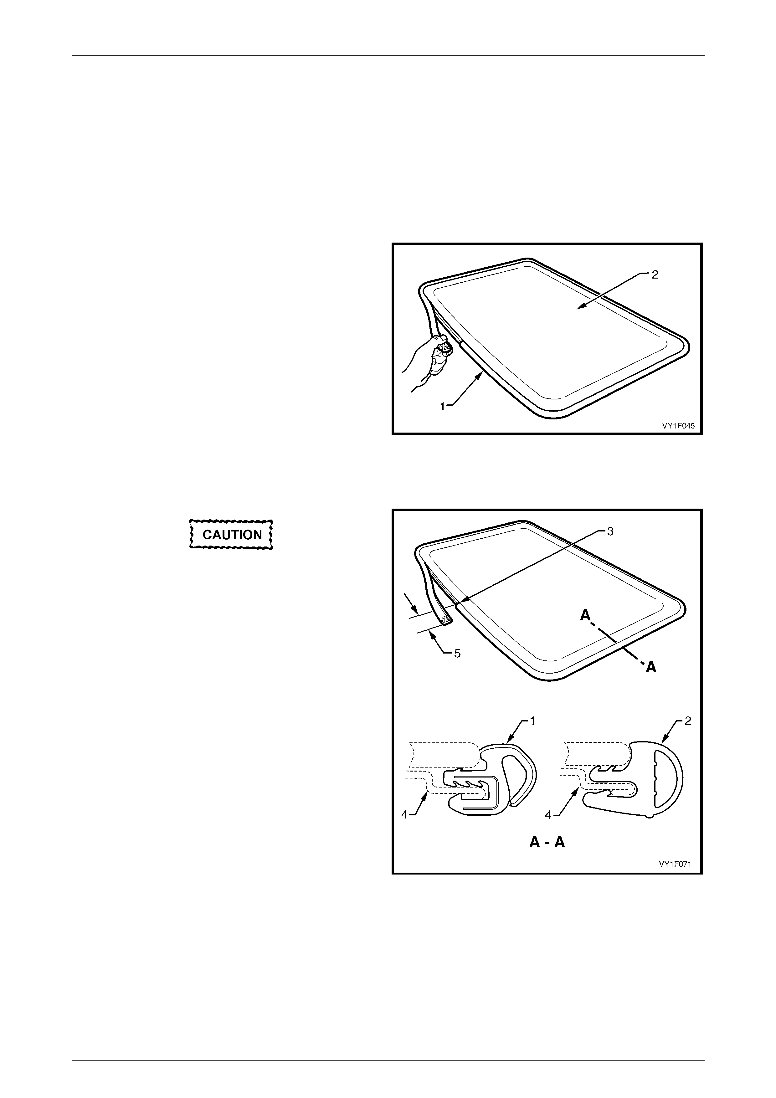
4.4 Rubber Seal.......................................................................................................................................................... 34
Remove................................................................................................................................................................. 34
Reinstall................................................................................................................................................................ 34
Adjustment........................................................................................................................................................... 35
4.5 Wind Deflector...................................................................................................................................................... 36
Remove................................................................................................................................................................. 36
Reinstall................................................................................................................................................................ 36
4.6 Drain Channel....................................................................................................................................................... 37
Remove................................................................................................................................................................. 37
Reinstall................................................................................................................................................................ 37

Sunroof – Online Page 1F2–3
Page 1F2–3
4.7 Sunshade.............................................................................................................................................................. 38
Remove................................................................................................................................................................. 38
Reinstall................................................................................................................................................................ 38
4.8 Drive Cables......................................................................................................................................................... 39
Remove................................................................................................................................................................. 39
Reinstall................................................................................................................................................................ 41
4.9 Timing of Drive Cables........................................................................................................................................ 43
Timing Procedure ................................................................................................................................................ 43
4.10 Blocking Catch..................................................................................................................................................... 44
Remove................................................................................................................................................................. 44
Reinstall................................................................................................................................................................ 44
4.11 Retraction Mechanism......................................................................................................................................... 45
Remove................................................................................................................................................................. 45
Reinstall................................................................................................................................................................ 45
4.12 Guide Rail Mechanism......................................................................................................................................... 47
Remove................................................................................................................................................................. 47
Reinstall................................................................................................................................................................ 49
5 Service Operations – Sunroof Harnesses, Sedan.............................................................................52
5.1 Sunroof Power Harness ...................................................................................................................................... 52
Remove................................................................................................................................................................. 52
Reinstall................................................................................................................................................................ 53
5.2 Sunroof Harness.................................................................................................................................................. 54
Remove................................................................................................................................................................. 54
Reinstall................................................................................................................................................................ 54
5.3 Sunroof Control Harness .................................................................................................................................... 55
Remove................................................................................................................................................................. 55
Reinstall................................................................................................................................................................ 55
6 Service Operations – Sunroof Harnesses, AWD Wagon..................................................................56
6.1 Sunroof Power Harness ...................................................................................................................................... 56
Remove................................................................................................................................................................. 56
Reinstall................................................................................................................................................................ 57
6.2 Sunroof Harness.................................................................................................................................................. 58
Remove................................................................................................................................................................. 58
Reinstall................................................................................................................................................................ 58
6.3 Sunroof Control Harness .................................................................................................................................... 59
Remove................................................................................................................................................................. 59
Reinstall................................................................................................................................................................ 59
7 Service Operations – Sunroof Drain, Sedan......................................................................................60
7.1 Rear Drain Tubes................................................................................................................................................. 60
Remove................................................................................................................................................................. 60
Reinstall................................................................................................................................................................ 62
7.2 Rear Drain Tube Grommet .................................................................................................................................. 63
Remove................................................................................................................................................................. 63
Reinstall................................................................................................................................................................ 63
7.3 Front Drain Tube.................................................................................................................................................. 64
Remove................................................................................................................................................................. 64
Reinstall................................................................................................................................................................ 64

Sunroof – Online Page 1F2–4
Page 1F2–4
8 Service Operations – Sunroof Drain, AWD Wagon...........................................................................65
8.1 Rear Drain Tubes................................................................................................................................................. 65
Remove................................................................................................................................................................. 65
Reinstall................................................................................................................................................................ 67
8.2 Front Drain Tube.................................................................................................................................................. 68
Remove................................................................................................................................................................. 68
Reinstall................................................................................................................................................................ 68
9 Service Operations – Sunroof Assembly...........................................................................................69
9.1 Sunroof Assembly............................................................................................................................................... 69
Remove................................................................................................................................................................. 69
Reinstall................................................................................................................................................................ 71
9.2 Sunroof Assembly Rear Seal.............................................................................................................................. 72
Remove................................................................................................................................................................. 72
Reinstall................................................................................................................................................................ 72
9.3 Sunroof Assembly Front Seal............................................................................................................................. 73
Remove................................................................................................................................................................. 73
Reinstall................................................................................................................................................................ 73
10 Torque Wrench Specifications............................................................................................................74
11 Special Tools ........................................................................................................................................75
Sunroof – Online Page 1F2–5
Page 1F2–5
1 General Information
This Section describes the service procedures required for the factory fitted (Online) sunroof installe d in MY 2005 VZ
Sedan and AWD Wagon Series vehicles.
1.1 Sunroof Assembly
The Online sunroof can be ide ntified b y the presence of a rigid headlining and the abse nce of a rubber trim ring between
the sunroof frame and the roof panel.
The Online sunroof is an electronically operated, two-way design allowing either tilting or sliding action of the glass panel.
It features a tinted glass with a separate internal sunshade and a front edge wind deflector.
All the components for the sunroof assembly are ill ustrated and identified in this Section,
refer to 1.3 Sunroof Components.
Sunroof Operation
The sunroof is operated via the sunro of switch connected to the Sunroof Control Unit (SCU) by two ribbon cables that
each have six wires. The SCU commands a drive motor which is linked to the glass panel via a h elicoil gear, two drive
cables and two guide rail mechanisms.
With the ignition switch in the ACC or ON position, battery voltage is suppli ed to the SCU through the ignition switch. In
conjunction with signals from the sunr oof switch, the SCU supplies the battery voltage to operate the drive motor.
With the ignition switch in the OFF position, battery voltage is supplied to the SCU through the sunroof circuit breaker
located on the passenger compartment fuse and relay panel assembly. The SCU in conjunction with a signal from the
sunroof switch, supplies battery voltage to the drive motor to close the sunroof only.
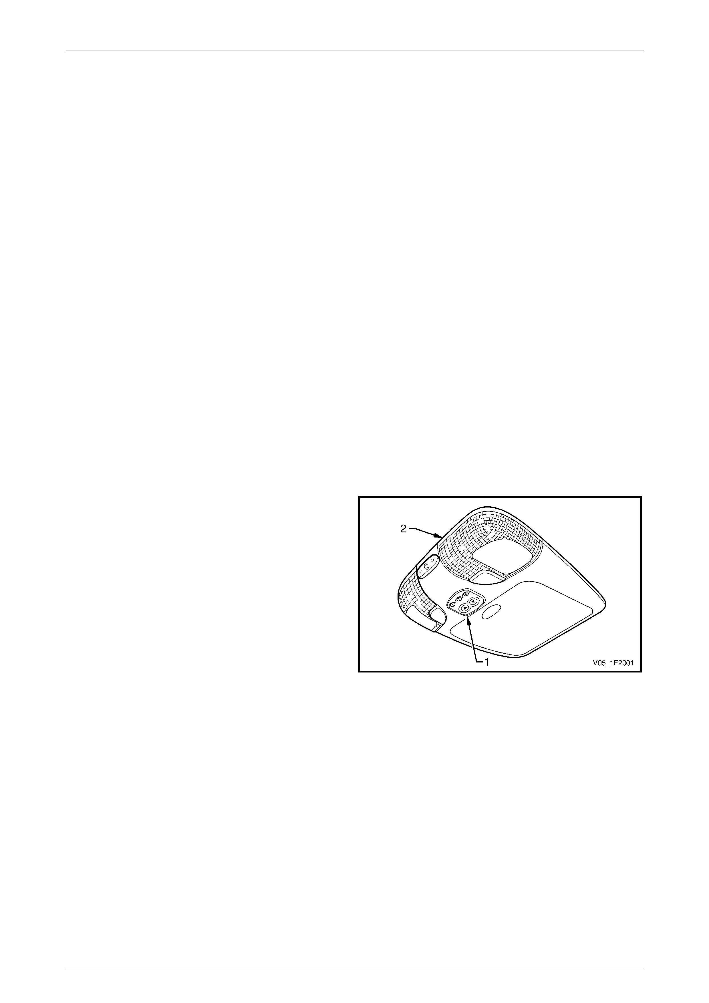
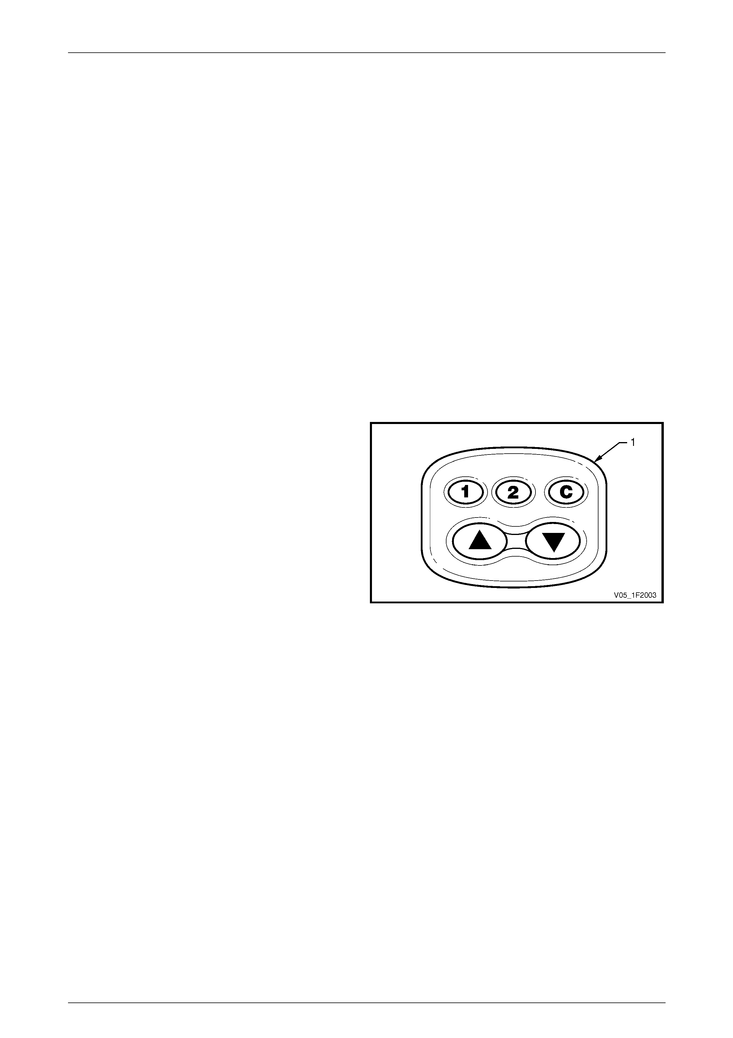
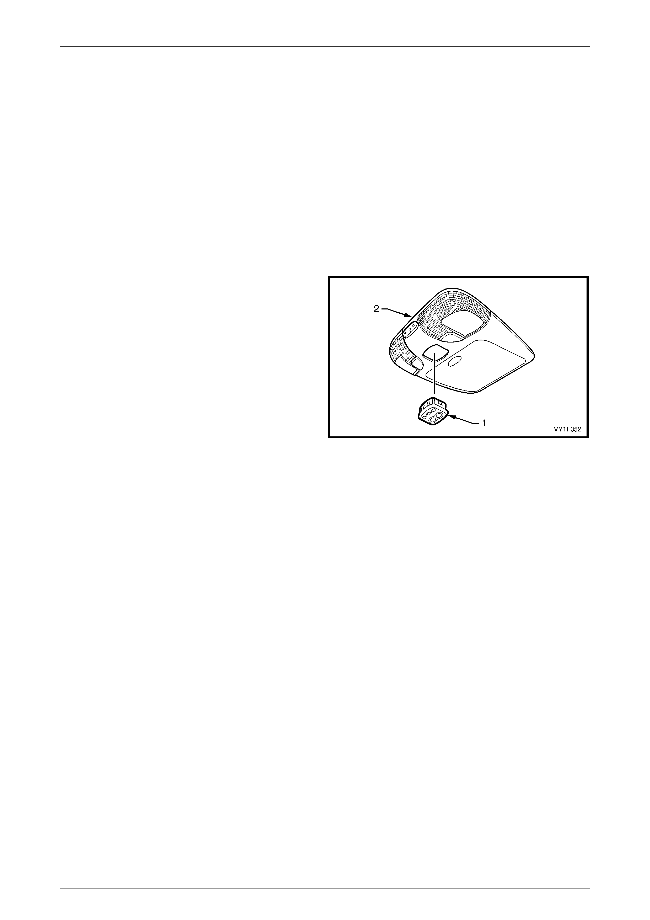
Sunroof Switch
The sunroof switch (1) is located in the roof console (2),
forward of the sunroof opening.
The sunroof switch features five buttons which provide
signals to the Sunroof Control Unit (SCU) for several
pre-programmed functions an d one optional additional
function, refer to 1.2 Sunroof Functions.
Figure 1F2 – 1
Sunroof Control Unit (SCU)
The SCU is located at the rear of the sunroof frame and co ntrols a drive motor to activate the movement of the glass
panel.
The SCU detects the position of the glass pa nel by using an internal position counter. This counter is increase d an d
decreased every time the SCU controls the drive motor.
The counter must first be set (calibrated) to detect the end position of the glass pan el, in full tilt and full slide positions, by
running to a mechanical block.
If the SCU determines that the glass panel is in the incorrect position, as defined by the internal position counter, it
responds by entering the non-calibr ated state. In the non-calibrated state the sunroof operates erratically.
Sunroof – Online Page 1F2–6
Page 1F2–6
Drive Motor and Drive Gear
The drive motor is attached at the rear of the sunroof frame with its output shaft driving a helicoil gear.
The drive motor operates in two directions, forward to open the glass panel and reverse to close it. To drive in the
reverse direction the polarity of the drive motor is reversed by the Sunroof Control Unit (SCU).
Each operation of the drive motor is monitored by the SCU.
Glass Panel and Rubber Seal
Glass Panel
The sunroof glass panel is heat and UV resistant. Clean the glass panel using mild, non-scratching detergent and a
chamois.
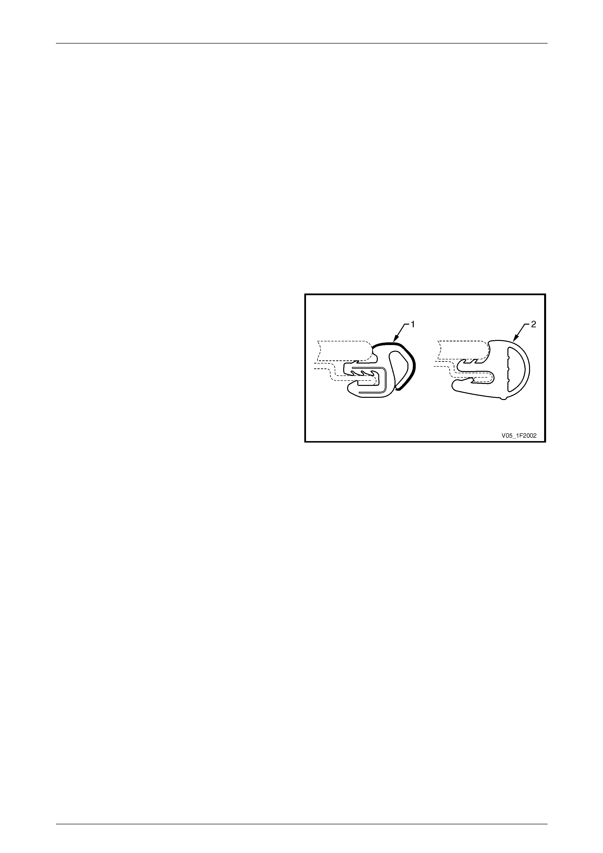
Rubber Seal
Two types of rubber seal can be fitted to the glass pane l assembly. They both have the same function despite the
physical and cross-section differences.
The first rubber seal t ype (1) c an be identified by its outer
surface of velvet-like appearance. The outer edge of the
seal body is open-ended to allow adjustments, with foam
strips, that may be necessary to ensure proper sealing when
the glass panel is in the closed position.
The second rubber seal type (2) is an optional design to the
first type and can be identified by its outer surface of smooth
appearance. The outer section of the seal b od y is hollow
with the external surface covered by an anti-f riction coating.
No adjustment is necessary for this rubber seal t ype.
Figure 1F2 – 2
Sunshade
The sunshade can be ope ned and closed manually when the sunroof is closed but is controlled automatically in the
following conditions:
• Opening the sunroof in a tilt position automatically opens the sunshade to a vent position. The sunshade can then
be fully opened manually.
• Opening the sunroof in the slide mode automatically opens the sunshade along with it. If the glass panel is not fully
opened, the sunshade can be opened further manually.
The sunshade can onl y be cl osed fully when the sunroof is closed, and can only be closed manually.
Wind Deflector
The wind deflector is designed to reduce high frequency noise and buffeting.
The wind deflector automatically rises when the sunroof is opened in slide mode. It retracts when the sunroof is closed. A
stopper on either side of the wind deflector is controlling the height at which the wind deflector is raising.
NOTE
The wind deflector remains in the retracted
position and does not rise when the sunroof is
opened in the tilt mode.

Sunroof – Online Page 1F2–7
Page 1F2–7
Drain Tubes
Front Drain Tubes
The sunroof front drain tubes are routed on either side of the vehicle and include two distinct sections. The lower section
which is located within the A-pillar is made of a metal drain tube welded to the hinge pillar inner panel assembly. The
flexible upper section, made of PVC plastic, is connected at one end to the sunro of front drain outlet and fitted to the
metal drain tube at the other end.
Rear Drain Tubes – Sedan
The sunroof rear drain tubes are fle xible and made of PVC plastic. They are routed on either side of the vehicle from the
sunroof rear drain outlets, along the C-pillar and to a rear drain tube grommet located in the rear compartment floor pa nel
outer extension at the rear of the wheelhouse.
Rear Drain Tubes – AWD Wagon
The sunroof rear drain tubes are fle xible and made of PVC plastic. They are routed on either side of the vehicle along the
roof panel from the sunroof rear drain outlets to grommets at the rear of the rear quarter panels. Each rear drain tube is
secured to the quarter panel inner assembl y by three retaining clips.
Sunroof Harnesses
Sunroof Power Harness – Sedan
The sunroof power harness is routed from the sunroof control unit (SCU), along the C-pillar, through the rear seat back
panel extension assembly and connect to the body harness in the rear compartment. The ground wire is attached to the
right-hand side quarter panel inner assembly.
The sunroof power harness is taped to the right-hand rear drain tube and secured with retaining clips attached to the
C-pillar.
Sunroof Power Harness – AWD Wagon
The sunroof power harness is routed from the sunroof control unit (SCU), along the roof panel and connects to the body
harness at the rear of the vehicle. The sunroof power harness is taped to three retaining clips attached to the right-hand
side quarter panel inner ass embly; the ground wire is also attached to the right-hand side quarter panel inner assembly.
Sunroof Harness
The sunroof harness is a ribbon cable type harness which has six wires. This harness links the sunroof control unit
(SCU) with the sunroof control harness located in the roof console. The sunroof harness is routed around the sunroof
frame and taped to it.
Sunroof Control Harness
The sunroof control harness is a ribbon cable type harness which has si x wires. This harness is located in the roof
console and links the sunroof switch with the sunroof harness.
Sunroof – Online Page 1F2–8
Page 1F2–8
1.2 Sunroof Functions
NOTE
If only the sunroof switch 1 and 2 buttons are
operating, the sunroof switch has to be reset,
refer to 3.5 Sunroof Switch.
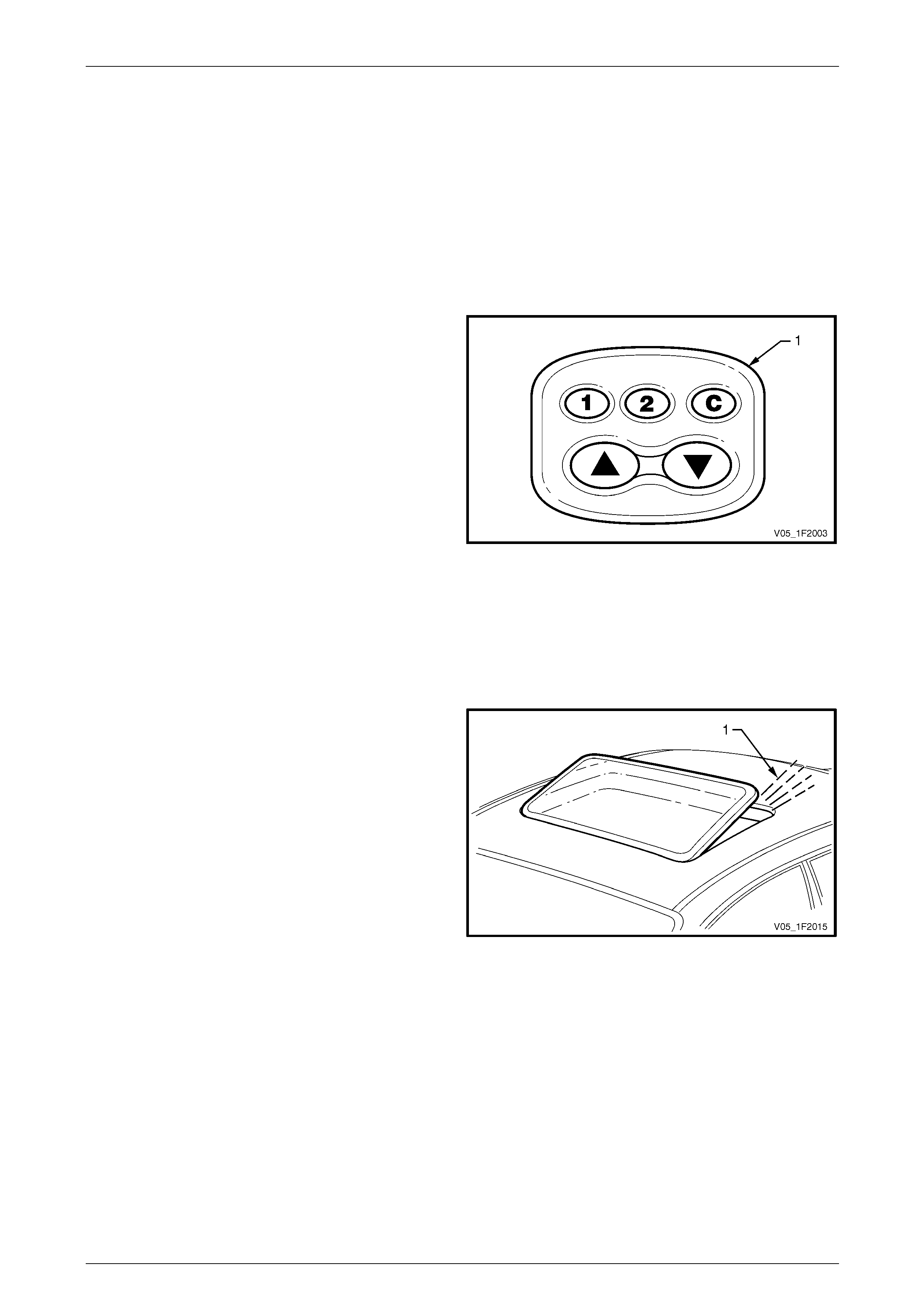
Pre-programmed Functions
Soft Touch
With the ignition switch in the ACC or ON position, the soft
touch operates as follows:
• briefly pressing the sunroof switch (1) S button will
open the sunroof to the maximum slide position,
• briefly pressing the sunroof switch T button will open
the sunroof to the maximum tilt position, and
• movement of the sunroof can be stopped at an y time
by briefly pressing the sunroof switch S or T button
again.
Figure 1F2 – 3
Closing the Sunroof
With the ignition switch in the ACC or ON position, briefly pressing the sunroof switch C button will cause the sunroof to
close from any open position, refer to Figure 1F2 – 3.
Variable Tilt Position
The sunroof can be lowered from maximum ti lt opening
position (1) in three intermediate tilt positions.
To lower the glass panel, proceed as follows, refer to
Figure 1F2 – 3:
• press and hold the sunroof switch S button until the
glass panel reaches the next tilt position, or
• alternatively hold the sunr oof switch S button pressed
and then release it at the desired glass panel tilt
position.
Figure 1F2 – 4
Auto-close Function
Three seconds after the ignition has been turned to the OFF position, the sunroof will close automatically.
To override this action, proceed as follows:
• briefly press the sunroof switch S or T button during the thr ee second interval to maintain the sunroof in the open
position, refer to Figure 1F2 – 3, or
• while the sunroof is closing, briefly press the sunroof switch S or T button when the sunroof has reached the
desired position.
The sunroof can then be closed with the ignition off, but it cannot be opened.

Sunroof – Online Page 1F2–9
Page 1F2–9
One-way Closing
This automatic feature always closes the sunroof from above with a downward motion, lo wering the glass panel to the
close position, even when closed from a slide position, assuring correct positioning of the glass panel.
Jamming Protection (Safety Feature)
When closing the sunroof using the Soft Touch or Auto-close function, the sunroof will automaticall y re-open if it
encounters an obstacle and then try to close aga in. This cycle will continue until the obstacle is removed.
Optional Programmable Function
Comfort Position
This feature allows the sunroof to be opened to two preset positions in the sliding range.
After the comfort position has been programmed, either preset positions can be selected by briefly pressing the sunro of
switch 1 or 2 buttons, refer to Figure 1F2 – 3.
Pressing either sunroof switch 1 or 2 buttons again will open the sunroof fully.
Programming the Comfort Position
To program the two preset positions, proceed as follows:
1 Position the sunroof in the desired locatio n.
2 Press and hold 1 button until a beep is he ard (approx. 3 seconds).
3 Position the sunroof in the second desire d location.
4 Press and hold 2 button until a beep is he ard (approx. 3 seconds).
Sunroof – Online Page 1F2–10
Page 1F2–10
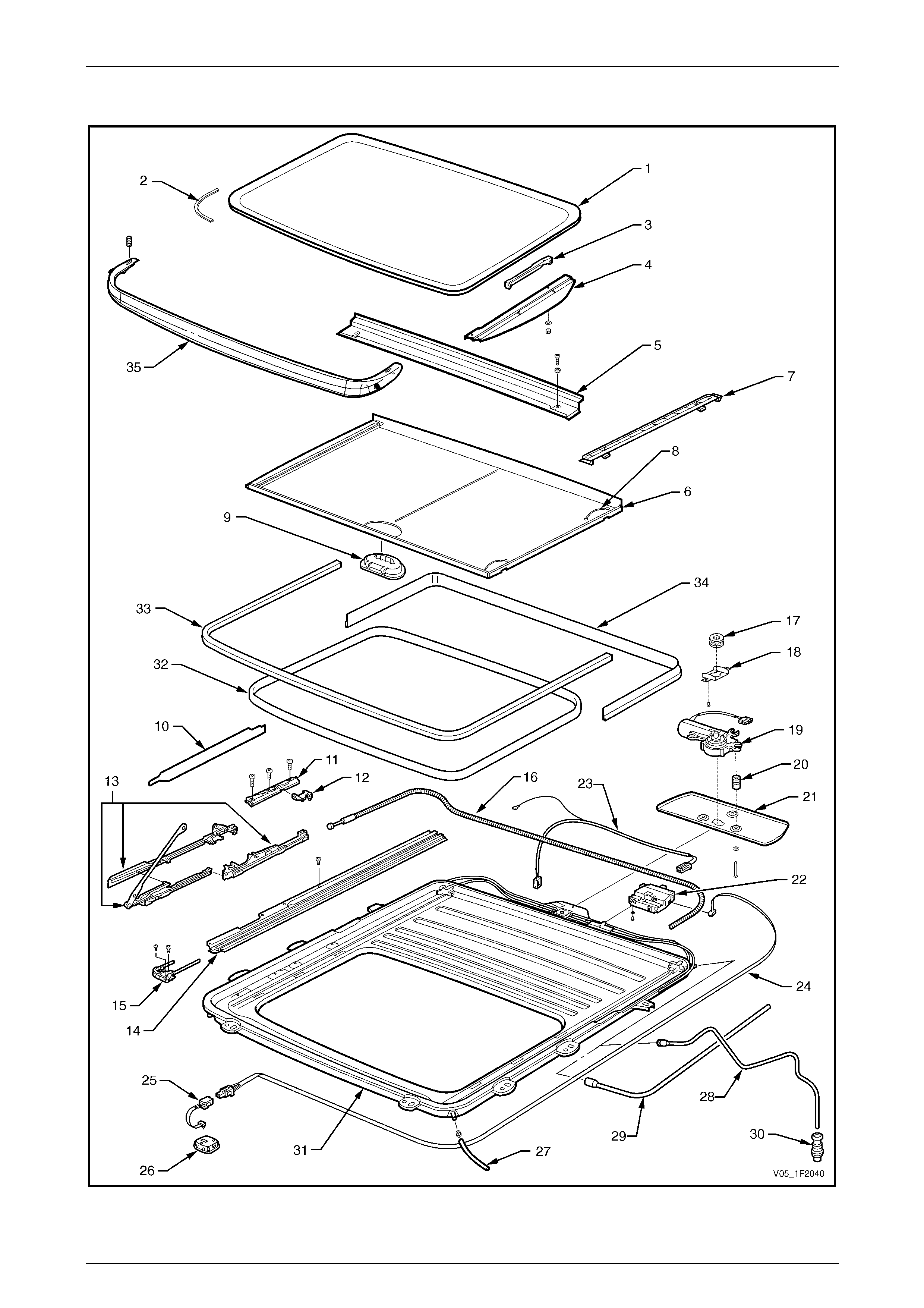
1.3 Sunroof Components
Figure 1F2 – 5

Sunroof – Online Page 1F2–11
Page 1F2–11
Legend
1 Glass Panel
2 Rubber Seal
3 Adjustment Bracket
4 Exterior Cover
5 Drain Channel
6 Sunshade
7 Sunshade Guide
8 Sunshade Spring
9 Sunshade Handle
10 Mechanism Cover
11 Locator
12 Blocking Catch
13 Guide Rail Mechanism
14 Guide Rail
15 Retraction Mechanism
16 Drive Cable
17 Drive Gear
18 Drive Gear Box Retainer
19 Drive Motor
20 Spacer
21 Drive Cover
22 Sunroof Control Unit (SCU)
23 Sunroof Power Harness
24 Sunroof Harness
25 Sunroof Control Harness
26 Sunroof Switch
27 Front Drain Tube
28 Rear Drain Tube (Sedan)
29 Rear Drain Tube (AWD Wagon)
30 Drain Grommet
31 Sunroof Assembly
32 Opening Seal
33 Front Roof Seal
34 Rear Roof Seal
35 Wind Deflector
Sunroof – Online Page 1F2–12
Page 1F2–12
2 Diagnostics – Sunroof
2.1 Prerequisites
Safety Requirements
When operating the sunroof as part of any
steps in the diagnostic tables, ensure that
fingers and limbs are clear of moving parts.
Equipment
The following equipment is required to diagnose the sunroof:
• an unpowered test lamp with a current draw of less than 3 A, and
• a digital multimeter with a minimum impe dance of 10 MΩ.
Testing Procedures
Adhere to the following points when
performing diagnostic testing on
components:
• Take care when using testing equipment
to diagnose wiring harness connectors.
Backprobe the connector to avoid terminal
damage.
• When tests are required on connector
terminals, use the adapters in the
connector adapter kit KM–609 to prevent
damage to the terminals.
• Unless the multimeter being used has an
auto-ranging function, ensure the correct
range is selected.
• When backpro bing connectors, ensure the
test lamp ground lead is connected to an
appropriate ground point on the vehicle.
Ensure this ground point is not part of the
circuit being tested.
NOTE
When following the steps in the di agnostic tables,
perform them in the order cited. If the required
nominal value or result is not achi eved, rectif y t he
problem before proceeding.

Sunroof – Online Page 1F2–13
Page 1F2–13
2.2 Sunroof Functional Test
Introduction
This test confirms the correct operation of the sunroof assembl y through the various functions of the sunroof switch.
For a description of the sunroof various functions, refer to 1.2 Sunroof Functions.
NOTE
If the glass panel stops at an un expected p osition
related to the sunroof switch function, the end
position cannot be reached, or one or
more buttons of the sunroof switch do not operate
the sunroof correctly, then it is necessary to
recalibrate the SCU, refer to
3.4 Calibrating the Sunroof Control Unit .
Functional Test Description
The following numbers refer to the step numbers in the diagnostic table:
1 Checks if the sunroof operates correctly in the slid e open and close mode.
2 Checks if the sunroof operates correctl y in the maximum tilt open and close mode.
3 Checks if the sunroof operates correctly in the variable tilt mode.
4 Checks if the sunroof operates correctly in the soft touch mode.
5 Checks if the sunroof operates correctly in the auto-close m ode.
6 Checks if the sunroof operates correctly in the auto-cl ose override mode.
7 Checks if the sunroof operates correctly in the jamming protection mode.
8 Checks if the sunroof operates correctly in the comfort position mode.
Diagnostic Table Notes
1 For a view of the sunroof switch buttons, refer to Figure 1F2 – 3.
2 To perform the soft touch operation, the auto-close ov erride operation or the comfort position operation , refer to
1.2 Sunroof Functions.
3 If the sunroof does not operate for any function, perform the sunroof electri cal test,
refer to 2.5 Diagnose Sunroof Malfunction.

Sunroof – Online Page 1F2–14
Page 1F2–14
Diagnostic Table
Step Action Yes No
1 1 Turn the ignition switch to the ON position.
2 Briefly press the S button to open the glass panel.
3 Briefly press the C button to close the glass panel.
Does the glass panel slide fully open and then close? Go to Step 2 Refer to Note 3
2 1 Briefly press the T button to open the glass panel to the
maximum tilt position.
2 Briefly press the C button to close the glass panel.
Does the glass panel open to maximum tilt position and then close? Go to Step 3 Refer to Note 3
3 1 Briefly press the T button to open the glass panel to the
maximum tilt position.
2 Press and hold the S button, release it at the next tilt position.
Repeat for all three tilt steps.
Does the variable tilt operation function c orrectly? Go to Step 4 Refer to Note 3
4 Perform the soft touch operation, (refer to Note 2).
Does the soft touch operation function correctly? Go to Step 5 Refer to Note 3
5 1 Briefly press the S button to open the glass panel.
2 Turn the ignition switch to the OFF position.
Does the sunroof close after three seconds? Go to Step 6 Refer to Note 3
6 1 Briefly press the S button to open the glass panel.
2 Turn the ignition switch to the OFF position.
3 Perform the auto-close override operati on, (refer to Note 2).
Does the auto-close override operation function correctly? Go to Step 7 Refer to Note 3
7 1 Turn the ignition switch to the ON position.
2 Briefly press the S button to open the glass panel.
3 Place an obstacle in the glass panel travel path.
4 Briefly press the C button to close the glass panel.
Does the glass panel automatical ly open when encountering the
obstacle and then try to close again? Go to Step 8 Refer to Note 3
8 Perform the comfort position operation, (refer to Note 2).
Does the comfort position operation functio n correctl y? System serviceable Refer to Note 3
Sunroof – Online Page 1F2–15
Page 1F2–15
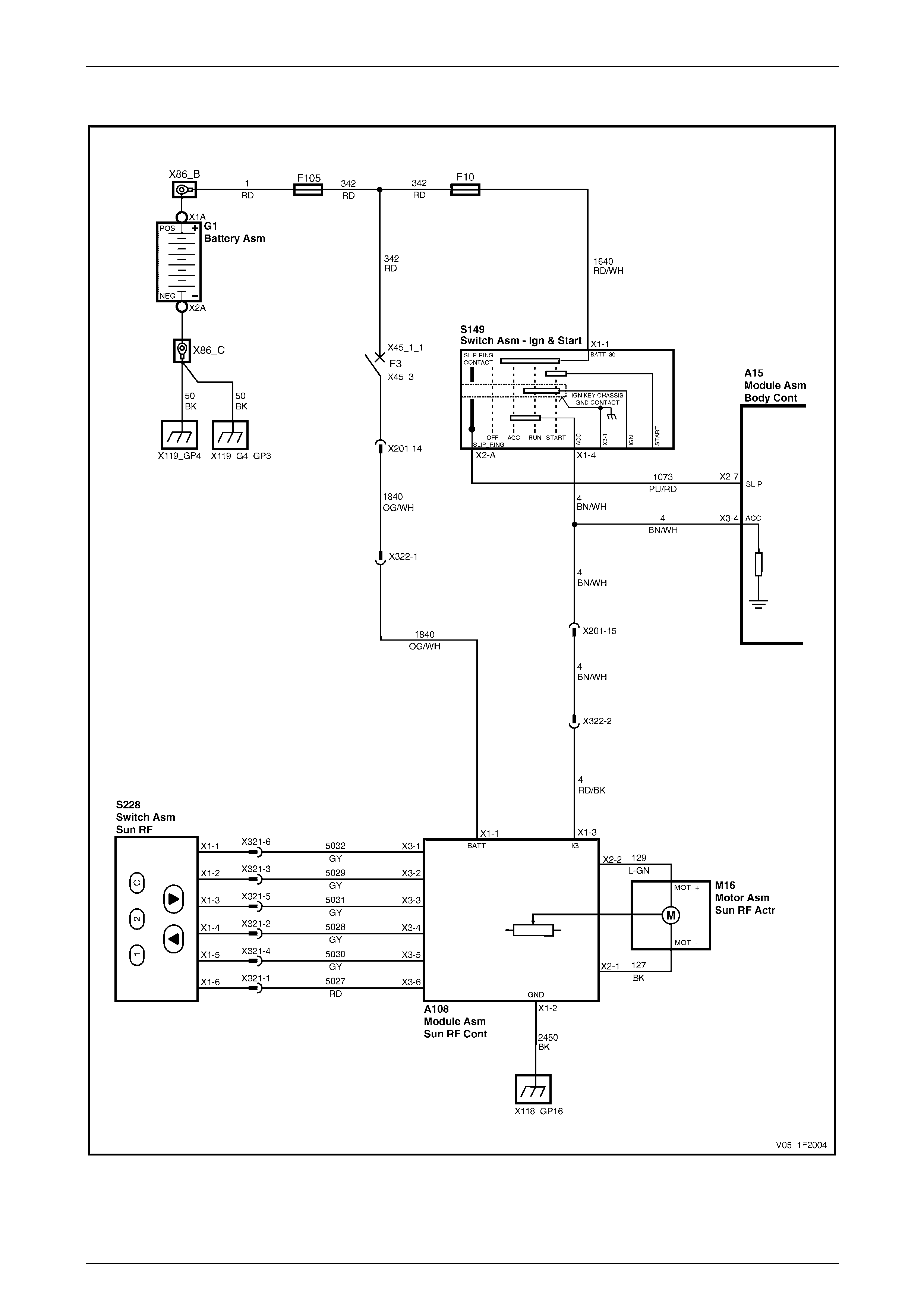
2.3 Wiring Diagram – Sunroof
Figure 1F2 – 6
Sunroof – Online Page 1F2–16
Page 1F2–16
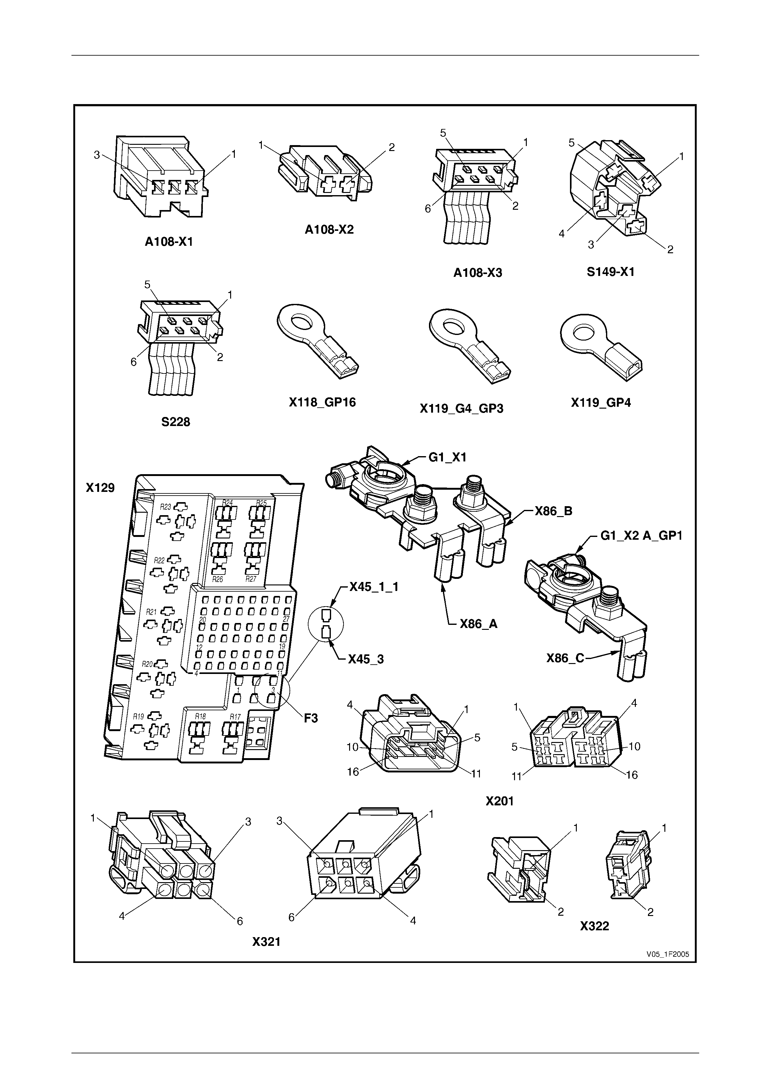
2.4 Connector Diagrams – Sunroof
Figure 1F2 – 7

Sunroof – Online Page 1F2–17
Page 1F2–17
2.5 Diagnose Sunroof Malfunction
Introduction
These tests confirm the serviceability of the sunroof switch, the sunroof control unit (SCU), the drive motor and
associated wiring system.
For a complete wiring diagram of the sunroof circuits, refer to 2.3 Wiring Diagram – Sunroof.
For connector pin locations, refer to 2.4 Connector Diagra ms – Sunroof.
NOTE
The drive motor has an inbuilt thermal cut-out
device that automatically switches the motor off
during an overload condition. After a cool down
period, the motor will function normally.
NOTE
If the SCU fails and is replaced with a new unit,
the first time the new SCU is connected to the
power supply it must be calibrated, refer to
3.4 Calibrating the Sunroof Control Unit .
NOTE
On completion of the electrical test and/or if the
situation arises where only the sunroof switch
1 and 2 buttons are operating, the sunroof switch
has to be reset, refer to 3.5 Sunroof Switch.
Electrical Test Description
The following numbers refer to the step numbers in the diagnostic table:
1 Checks if the sunroof operates correctly in any mode.
2 Checks if battery voltage is more than 11.5 V. The sunroof requires more than 11.5 V to operate correctly.
3 Checks if circuit breaker F3 within the passenger compartment fuse and relay panel assembly is tripped.
4 Checks if there is battery voltage at connector A108 – X1 pin 1. Isolates if the power supply circuits are at fault.
5 Checks if there is battery voltage at connector A108 – X1 pi n 3. Isolates if the power supply circuits are at fault, with
the ignition switch in the ON position.
6 Checks if there is battery voltage at connector A108 – X1 pin 2. Isolates if the earth circuit is at fault.
7 Checks if there is battery voltage at connector X322 pin 1. Isolates if circuit 1840 between connectors X322 pin 1
and A108 – X1 pin 1 is at fault.
8 Checks if there is battery voltage at connector X201 pin 14. Isolates if circuit 1840 between connectors X201 pin 14
and X322 pin 1 is at fault.
9 Checks if there is battery voltage at circuit breaker F3 on the passenger compartment fuse and relay panel
assembly. Isolates if circuit 1840 between circuit break er F 3 and co nnector X201 pin 14 is at fault.
10 Checks if there is battery voltage at connector X322 pin 2. Isolates if circuit 4 between connectors X322 pin 2 and
A108 – X1 pin 3 is at fault.
11 Checks if there is battery voltage at connector X201 pin 15. Isolates if circuit 4 between connectors X201 pin 15
and X322 pin 2 is at fault.
12 Checks if the sunroof switch and sunroof control harness are serviceable.
13 Checks if the sunroof control harness is serviceable. Isolates whether the sunroof control harness or the sunroof
switch is at fault.
14 Checks if there is correct voltage values at connector X321, with the ignition switch in the ON position.
15 Checks if there is correct voltage values at connector X321, with the ignition switch in the OFF position.
16 Checks if the sunroof harness is serviceable. Isolates whether the sunroof harness or the SCU is at fault.
17 Checks if there is battery voltage at connector A108 – X2 pin 2. Isolates if the SCU is at fault.
18 Checks if there is battery voltage at connector A108 – X2 pin 1. Isolates whether the drive motor or the SCU is at
fault.

Sunroof – Online Page 1F2–18
Page 1F2–18
Diagnostic Table Notes
1 For all wiring harness fault diagnosis, refer to Section 12P Wiring Diagrams.
2 For wiring harness repairs, refer to Section 12P Wiring Diagrams.
3 Refer to Section 12O Fuses, Relays and Wiring Harnesses for harness routeing.
4 If at any time the fault is deemed to be intermittent, refer to Section 12P Wiring Diagra m s.
5 For the replacement of the Sunroof Control Unit (SCU), refer to 3.3 Sunroof Control Unit (SCU).
6 For the replacement of the sunroof control harness, refer to 5 Service Operations – Sunroof Harnesses, Sedan or
6 Service Operations – Sunroof Harnesses, AWD W agon.
7 For the replacement of the sunroof harness, refer to 5 Service Operations – Sunroof Harnesses, Sedan or
6 Service Operations – Sunroof Harnesses, AWD W agon.
8 For the replacement of the sunroof switch, refer to 3.5 Sunroof Switch.
9 For the replacement of the sunroof drive motor, refer to 3.1 Drive Motor.
Diagnostic Table
Step Action Yes No
1 1 Turn the ignition switch to the ON position.
2 Perform the sunroof functional test, refer to 2.2 Sunroof
Functional Test.
Does the sunroof operate correctly in any mode? Go to Step 12 Go to Step 2
2 Check the battery voltage, refer to Section 12A Battery and Cables.
Is the battery voltage more than 11.5 V? Go to Step 3
Refer to Section
12A Battery and
Cables for further
diagnosis
3 Check the circuit breaker F3, (refer to Note 3).
Is the circuit breaker F3 tripped?
Allow circuit breaker
to reset
(refer to Note 3)
If the circuit breaker
trips again, check
for a short to ground
in circuit 1840 Go to Step 4
4 1 Remove the headlining, refer to Section 1 A8 Headlining and
Interior Trim.
2 Backprobe SCU connector A108 – X1 pin 1 with a test lamp,
(refer to Note 1).
Does the test lamp illuminate? Go to Step 5 Go to Step 7
5 Backprobe SCU connector A108 – X1 pin 3 with a test lamp, (refer to
Note 1).
Does the test lamp illuminate? Go to Step 6 Go to Step 10
6 Backprobe SCU connector A108 – X1 pin 2 with a test lamp, (refer to
Note 1).
Does the test lamp illuminate?
Repair or replace
circuit 2450
(refer to Note 2) Go to Step 12
7 Backprobe connector X322 pin 1 with a test lamp, (refer to Note 1).
Does the test lamp illuminate?
Repair or replace
circuit 1840,
between connectors
X322 pin 1 and
A108 – X1 pin 1
(refer to Note 2) Go to Step 8

Sunroof – Online Page 1F2–19
Page 1F2–19
Step Action Yes No
8 Backprobe connector X201 pin 14 with a test lamp, (refer to Note 1).
Does the test lamp illuminate?
Repair or replace
circuit 1840,
between connectors
X201 pin 14 an d
X322 pin 1
(refer to Note 2) Go to Step 9
9 Probe the circuit breaker F3 connector X129 – X45 pin 3 with a test
lamp, (refer to Note 1).
Does the test lamp illuminate?
Repair or replace
circuit 1840,
between circuit
breaker F3 pin 3
and connector X201
pin 14
(refer to Note 2)
Repair or replace
circuits 342 or 1
(refer to Note 2)
10 Backprobe connector X322 pin 2 with a test lamp, (refer to Note 1).
Does the test lamp illuminate?
Repair or replace
circuit 4, between
connectors X322
pin 2 and A108 – X1
pin 3
(refer to Note 2) Go to Step 11
11 Backprobe connector X201 pin 15 with a test lamp, (refer to Note 1).
Does the test lamp illuminate?
Repair or replace
circuit 4, between
connectors X201
pin 15 and X322
pin 2
(refer to Note 2)
Repair or replace
circuits 4, 1640,
342,1 or switch
S149
(refer to Note 2)
12 1 If not previously carried out, remove the roof console, refer to
Section 1A8 Headlining and Interior Trim.
2 Check the sunroof switch and sunroof control harness for
continuity, refer to 2.6 Sunroof Switch and Sunroof Control
Harness Test.
Are the sunroof switch and sunroof control harness serviceable? Go to Step 14 Go to Step 13
13 1 Remove the sunroof control harness, (refer to Note 6).
2 Using a multimeter, check for continuity of the sunroof control
harness between connectors X321 and S228, (refer to Note 1).
Is the sunroof control harness serviceable?
Replace the sunroof
switch
(refer to Note 8)
Replace the sunroof
control harness
(refer to Note 6)
14 1 Turn the ignition switch to the ON position.
2 With a multimeter, attach the negative lead to a suitable ground
point.
3 Probe the multimeter positive l ead successively to each pin of
sunroof harness connector X321 and take a reading, (refer to
Note 1).
Do the readings indicate:
• battery voltage on pin 1,
• 6.5 V on pin 2,
• 0 V on pins 3 and 4, and
• 6 V on pins 5 and 6?
Tolerances are ± 0.1 V. Go to Step 15 Go to Step 16

Sunroof – Online Page 1F2–20
Page 1F2–20
Step Action Yes No
15 1 Turn the ignition switch to the OFF position.
2 With a multimeter, attach the negative lead to a suitable ground
point.
3 Ten seconds after the ignition switch has been turned to the
OFF position, probe the multimeter positiv e lead successively to
each pin of sunroof harness connector X321 and take a reading,
(refer to Note 1).
Do the readings indicate:
• 1.7 V on pin 1,
• 0.3 V on pin 2, and
• 0 V on pins 3, 4, 5 and 6?
Tolerances are ± 0.1 V. Go to Step 17 Go to Step 16
16 1 Disconnect sunroof harness connector A108 – X3 from the SCU.
2 With a multimeter, check for continuity of the sunroof harness,
between connectors A108 – X3 and X321, (refer to Note 1).
Is the sunroof harness serviceable? Replace the SCU
(refer to Note 5)
Replace the sunroof
harness
(refer to Note 7)
17 1 With a test lamp, backprobe connector M16 – X2 pin 2, (refer to
Note 1).
2 Briefly press the S button on the sunroof switch.
Does the test lamp illuminate? Go to Step 18 Replace the SCU
(refer to Note 5)
18 1 With a test lamp, backprobe connector M16 – X2 pin 1, (refer to
Note 1).
2 Briefly press the T button on the sunroof switch.
Does the test lamp illuminate?
Replace the drive
motor
(refer to Note 9) Replace the SCU
(refer to Note 5)
When all diagno sis an d repairs are completed, check the system fo r correct operation.
Sunroof – Online Page 1F2–21
Page 1F2–21
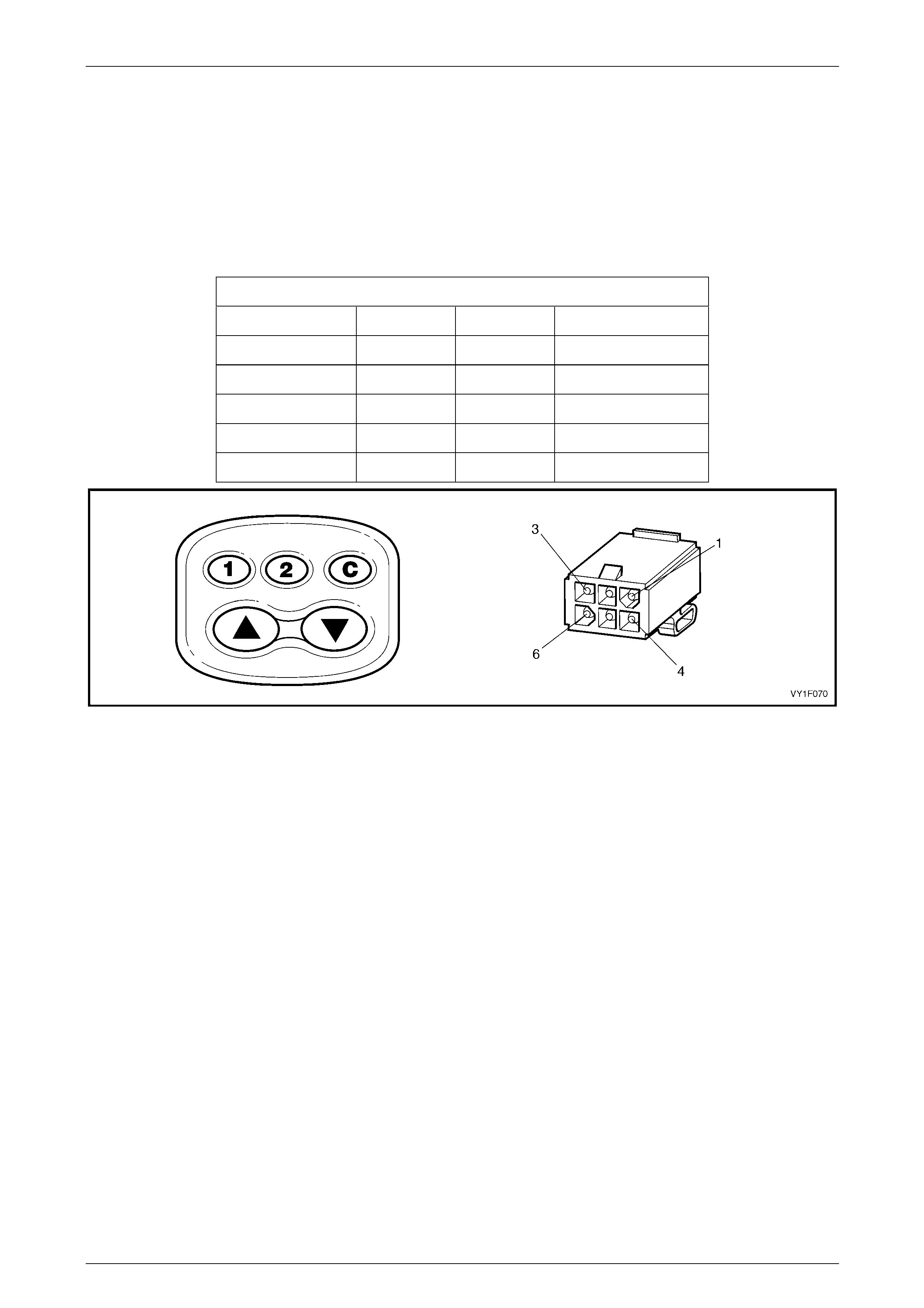
2.6 Sunroof Switch and Sunroof Control
Harness Test
Press the switch buttons and place the multimeter probe tips onto the pins of sunroof control harness co nnector X321.
Ensure reading is as indicated in the chart below. Refer to Figure 1F2 – 8.
If the sunroof switch and sunroof control harness are found to be faulty, replace the sunroof switch or/and the sunroof
control harness as described by the sunroof malfunction diagnostic table, refer to 2.5 Diagnose Sunroof Malfunction.
Sunroof Switch and Sunroof Control Harness
Press Switch + Lead – Lead Indication
S button Pin 3 Pin 5 Continuity
T button Pin 3 Pin 2 Continuity
C button Pin 6 Pin 4 Continuity
1 button Pin 6 Pin 5 Continuity
2 button Pin 6 Pin 2 Continuity
Figure 1F2 – 8
Sunroof – Online Page 1F2–22
Page 1F2–22
2.7 Malfunction Symptoms
Repair Advice For Mechanical Failures
Problem Possible Cause Solution
While closing the panel from the tilt
position, the panel begins to sl ide
rearward.
Blocking catch is broken. Replace the blocking catch, refer to
4.10 Blocking Catch.
While closing the panel from the fully
opened position, the panel begins to
tilt under the roof skin.
Blocking catch is broken. Replace the blocking catch, refer to
4.10 Blocking Catch.
Panel is misaligned side to side. Timing of drive cables is incorrect. Re-time the drive cables, refer to
4.9 Timing of Drive Cables.
Panel is sliding too slowly. With a
13.5 V power supply, the panel should
not take more than 7 seconds to close
from the fully opened position.
1 Misaligned panel creating drag or
friction.
2 Dirty mechanism.
1 Re-time the drive cables, refer
to 4.9 Timing of Drive Cables.
2 Clean and grease the
mechanism or replace if
necessary.
Glass panel stops prematurely. Obstacle in mechanism or guide rail. Remove the obstacle.
Sunshade fails to open when the glass
panel is opened to tilt position. Retraction mechanism is broken. Replace the retraction mechanism,
refer to 4.11 Retraction Mechanism.
Repair Advice For Electrical Failures
Problem Possible Cause Solution
The sunroof operates but the
auto-close and soft touch functions do
not operate.
Insufficient voltage supplied to the
sunroof (bad battery). Check the power supply/battery, refer
to Section 12A Battery and Cables.
Clicking noises from the SCU and the
panel does not slide. Voltage too low. Check the power supply/battery, refer
to Section 12A Battery and Cables.
The SCU is clicking in open position,
but the sunroof does not close with
continuous pressing of the C button.
Voltage drop in power supply. Cut off the power supply briefly
(remove fuse F105), reset the
programmable positions.
The panel is sliding too slowly. With a
13.5 V power supply, the panel should
not take more than 7 seconds to close
from the fully opened position.
1 Weak battery.
2 Weak motor. Test as detailed in
this Section.
1 Charge or replace the battery,
refer to Section 12A Battery and
Cables.
2 Replace the drive motor, refer to
3.1 Drive Motor.
Sunroof – Online Page 1F2–23
Page 1F2–23
Repair Advice For Rattling Noises
Problem Possible Cause Solution
The drain channel rattles. Check if insulator tape is applied
between drain channel and
mechanism.
Add insulator tape.
Rattling in motor area. Drive motor cover screws loose. Tighten drive motor cover screws,
refer to 3.1 Drive Motor.
Repair Advice For Wind Noises
Problem Possible Cause Solution
Excessive wind noise when the glass
panel is in the closed position. 1 Glass panel seal is not fitting
securely against the roof panel.
2 Blocking catch is broken.
1 Adjust the glass panel seal,
refer to 4.4 Rubber Seal.
2 Replace the blocking catch,
refer to 4.10 Blocking Catch.
Repair Advice For Water Leaks
Problem Possible Cause Solution
Water coming through the panel
opening area. 1 Blocked drain tube/s.
2 Misaligned or kinked drai n tubes.
1 Inspect the drain tubes outlet
and the grommets. Blow out
drain tubes.
2 Correct the routeing of the drain
tubes, refer to
7 Service Operations – Sunroof
Drain, Sedan, or
8 Service Operations – Sunroof
Drain, AWD Wagon.
Sunroof – Online Page 1F2–24
Page 1F2–24
3 Service Operations – Sunroof
Accessories
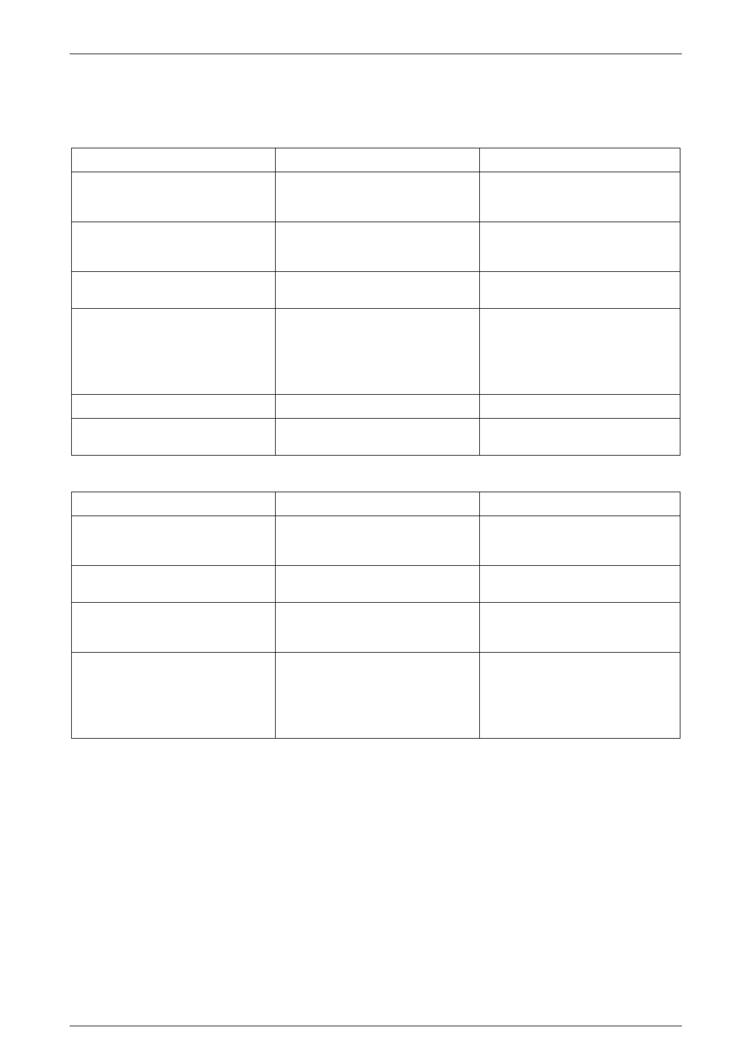
3.1 Drive Motor
LT Section No. — AA–000
Remove
1 Remove the sunroof circuit breaker F3 from the
passenger compartment fuse and relay panel
assembly, refer to Section 12O Fuses, Relays and
Wiring Harnesses.
2 Remove the headlining to ga in access to the drive
motor cover, refer to Section 1A8 Headlining and
Interior Trim.
3 Remove the three Torx screws and washers (1)
securing the drive motor (2) and cover (3).
4 Carefully lower the drive motor cover with the drive
motor and spacers (4).
5 Disconnect the drive motor harness connector (5) from
the sunroof control unit (6).
Figure 1F2 – 9
Reinstall
Reinstallation of the drive motor is the reverse of the removal procedure, noting the foll owing:
1 Check the drive motor for correct operation in both directions, refer to 2.2 Sunroof Functional Test.
2 Ensure the three spacers (4) are fitted to the drive motor (2) before installing it, refer to Figure 1F2 – 9.
3 Tighten the drive motor attaching Torx screws to the specified torque.
Drive motor attaching Torx screw
torque specification..............................................2.0 Nm
Sunroof – Online Page 1F2–25
Page 1F2–25
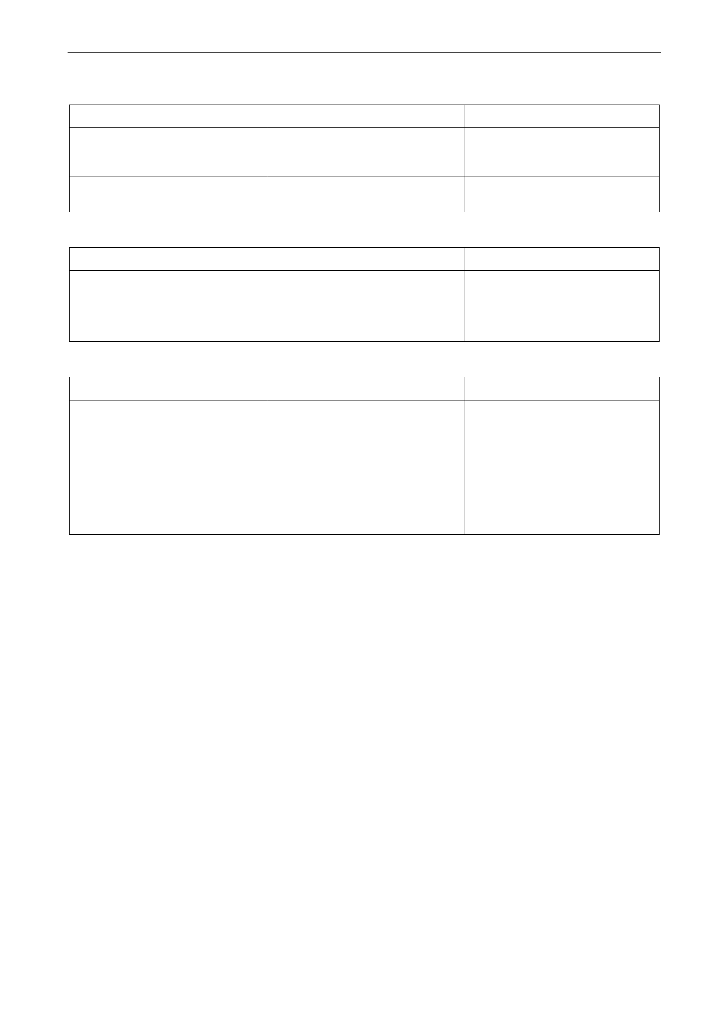
3.2 Drive Gear
LT Section No. — AA–000
Remove
1 Remove the drive motor cover and the drive motor,
refer to 3.1 Drive Motor.
2 Remove the two Torx screws (1) securing the drive
gear retainer (2).
3 Remove the drive gear retainer .
Figure 1F2 – 10
Take care not to damage the splines on the
inside diameter of the drive gear wheel
during the removal procedure.
4 Insert a screwdriver (1) in the drive gear wheel (2),
carefully prise the drive gear and remove.
Figure 1F2 – 11
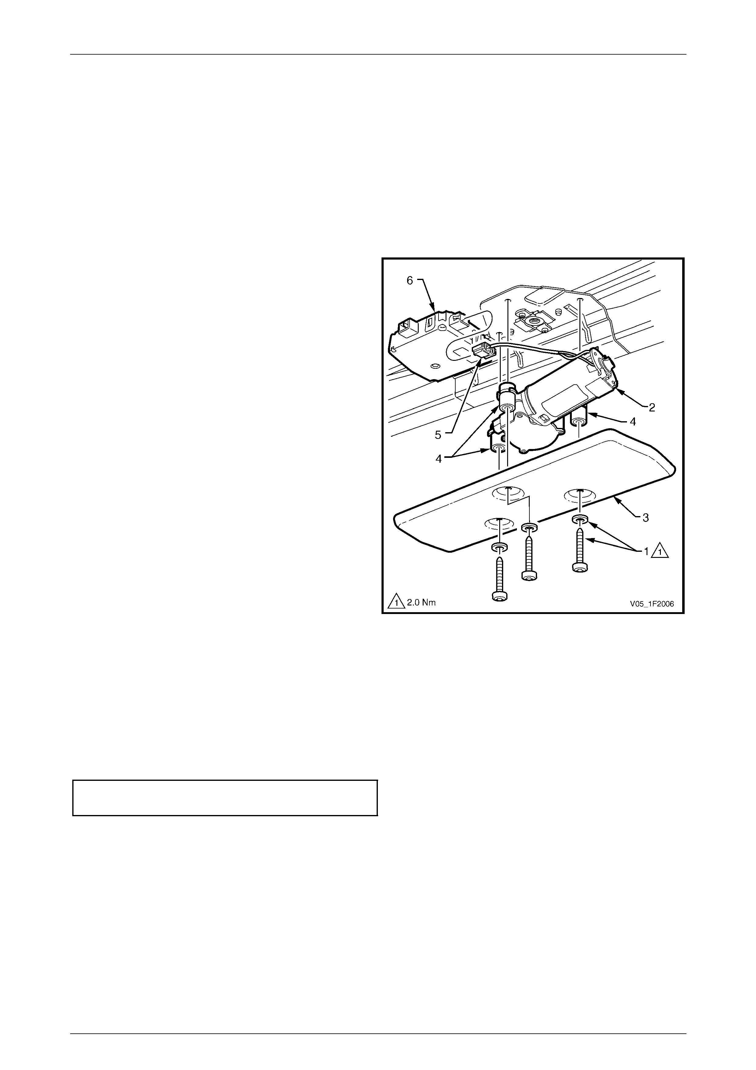
Reinstall
Reinstallation of the drive gear is the reverse of the removal
procedure, noting the follo wing:
1 Install the drive gear (1), ensuring that it is centred (A)
in the opening of the drive motor bracket (2).
NOTE
The splines (3) in the inside diameter of the d rive
gear wheel do not extend to the edge on one
end of the inside diameter. Place this end (4)
without splines, facing down (toward the drive
motor).
2 Tighten the two Torx scre ws attaching the d r ive gear
retainer to the specified torque.
Drive gear retainer attaching Torx screw
torque specification..............................................2.0 Nm
Figure 1F2 – 12
Sunroof – Online Page 1F2–26
Page 1F2–26
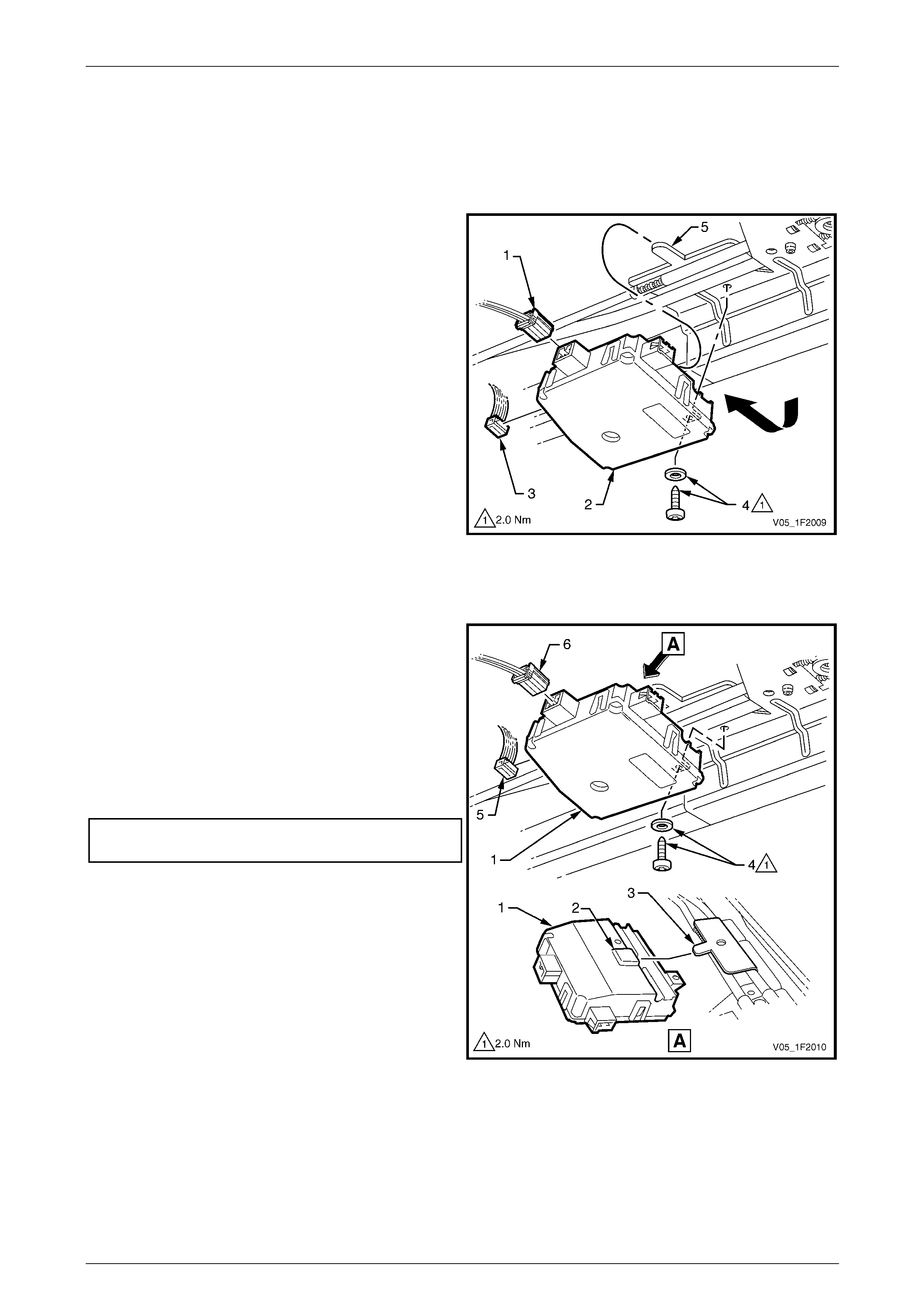
3.3 Sunroof Control Unit (SCU)
LT Section No. — AA–000
Remove
1 Remove the drive motor cover and driv e motor,
refer to 3.1 Drive Motor.
2 Disconnect the sunroof power harness conn ector (1)
from the SCU (2).
3 Disconnect the sunroof harness connector (3) from the
SCU.
4 Remove the SCU retaining Torx screw and
washer (4).
5 Lower the front of the SCU and slide the un it back, out
of the tang (5) to remove.
Figure 1F2 – 13
Reinstall
Reinstallation of the SCU is the revers e of the removal
procedure, noting the follo wing:
1 Install the SCU (1) by lowering it at the front, then
engage the slot (2) on the top side of the u nit over the
tang (3) of the drive cables plate.
2 Slide the SCU fully forward into position and secure
with the Torx screw and washer (4).
3 Tighten the Torx screw attaching the SCU to the
specified torque.
SCU attaching Torx screw
torque specification..............................................2.0 Nm
4 Ensure the sunroof harness connector (5) and the
sunroof power harness connector (6) are securely
connected to the SCU.
NOTE
If the SCU installed is a new unit, it must be
calibrated. Refer to 3.4 Calibrating the Sunroof
Control Unit.
Figure 1F2 – 14
Sunroof – Online Page 1F2–27
Page 1F2–27
3.4 Calibrating the Sunroof Control Unit
LT Section No. — AA–000
Introduction
The sunroof control unit (SCU) is calibrated at production when the sunroof is installed onto the vehicle, however it needs
to be calibrated again if the glass panel stops at an unexpected position in relation to the sunroof switch function, the end
position cannot be reached, or one or more buttons of the sunroof switch do not operate properly any more.
If the SCU fails and is replaced with a new unit, the first time the new SCU is connected to the power supply it must be
calibrated.
Procedure
NOTE
The calibration sequence of the sunroof control
unit (SCU) must be fully completed before the
power is removed from the SCU. Failing to do so
causes the SCU to enter the non-calibrated state,
causing the sunroof to operate erratically.
The SCU must be calibrated using the soft touch function, refer to 1.2 Sunroof Functions, as follows:
1 Turn the ignition to the ACC or ON position.
2 Open the sunroof to the maximum tilt position (until it
reaches the mechanical block) b y continuous ly
pressing the sunroof switch (1) T button.
NOTE
The maximum tilt position is now stored in the
SCU memory and all the electrical functions are
now available.
3 Close the sunroof by briefly pressing the sunroof
switch C button.
4 To complete the calibration the sunro of must be fully
opened in slide mode (until it reach es the me chanical
block) by continuously pressing the sunroof switch
S button.
5 Check that the sunroof operates correctly, refer to
1.2 Sunroof Functions.
Figure 1F2 – 15
Sunroof – Online Page 1F2–28
Page 1F2–28
3.5 Sunroof Switch
LT Section No. — AA–000
Remove
1 Remove the sunroof circuit breaker F3 from the passenger compartment fuse and relay panel assembly, refer to
Section 12O Fuses, Relays and Wiring Harnesses.
2 Remove the roof console. Refer to Section 1A8 Headlining and Interior Trim.
3 Remove the sunroof control harness from the roof console, refer to:
• 5 Service Operations – Sunroof Harnesses, Sedan, or
• 6 Service Operations – Sunroof Harnesses, AWD W agon.
4 Carefully unclip the sunroof switch (1) from the roof
console (2) and remove.
Figure 1F2 – 16
Reinstall
Reinstallation of the sunroof switch is the reverse of the removal procedur e.
NOTE
Should the situation arise where the battery
power is supplied to the sunroof control unit
(SCU) before the sunroof switch is connected to
the SCU, only the sunroof switch 1 and 2 buttons
will operate. With the ignition switch in the OFF
position, the sunroof switch has to be reset by
removing and then reinserting the sunroof circuit
breaker F3 on the passenger compartment fuse
and relay panel assembly, refer to
Section 12O Fuses, Relays and Wiring
Harnesses.
Sunroof – Online Page 1F2–29
Page 1F2–29
4 Service Operations – Glass
Panel and Mec hanism
4.1 Glass Panel
LT Section No. — AA–000
Remove
1 Open the sunroof to the maximum tilt position refer to
1.2 Sunroof Functions.
2 Turn the ignition to the OFF position and override the
auto close function to keep the glass pan el opened,
refer to 1.2 Sunroof Functions.
3 Remove the circuit breaker F3 from the passenger
compartment fuse and relay panel assembly, refer to
Section 12O Fuses, Relays and Wiring Harnesses.
4 Remove the left-hand a nd right-hand guide rail
mechanism covers (1) by grasping them by hand and
sliding towards the rear of the sunroof assembly.
Figure 1F2 – 17
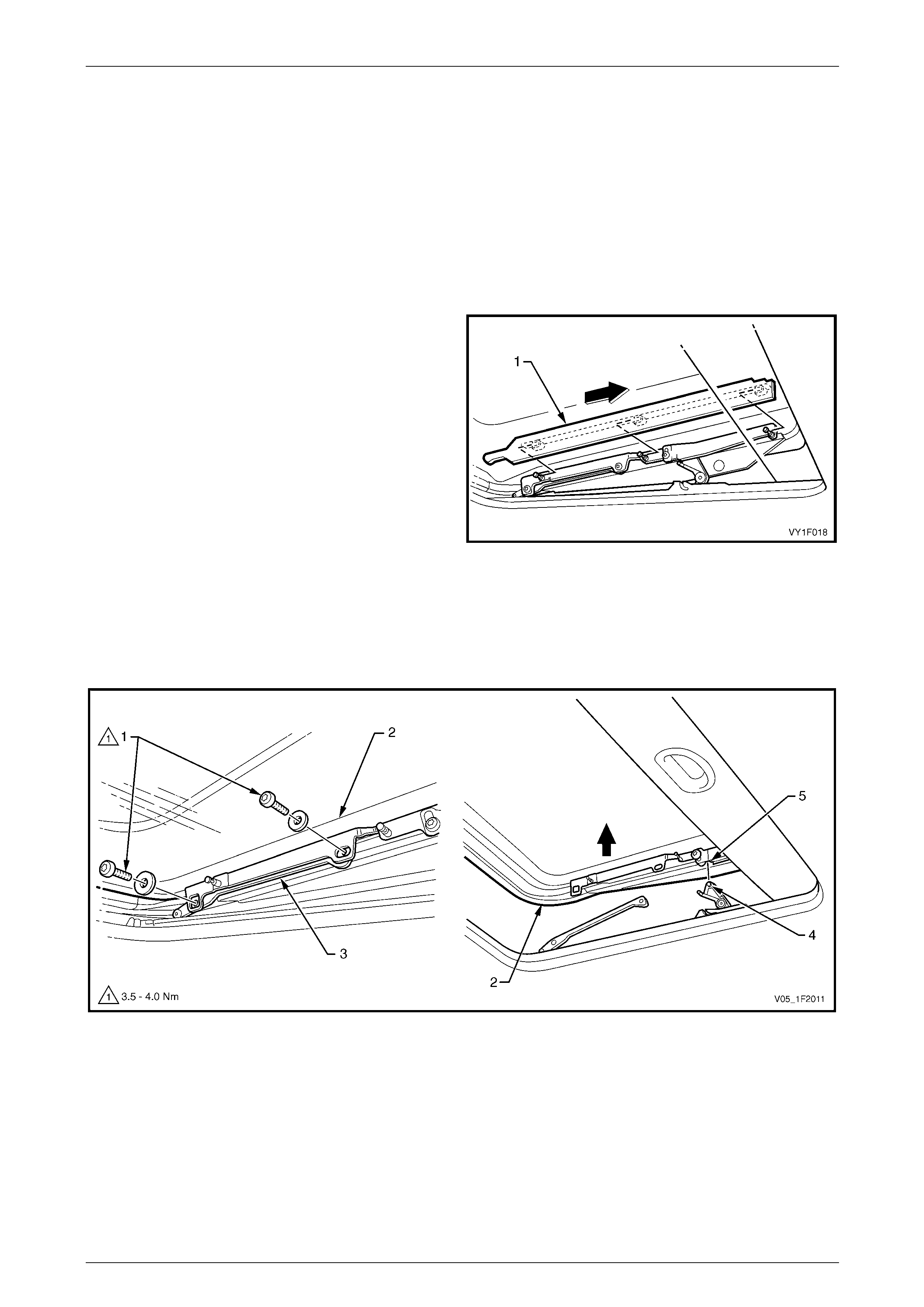
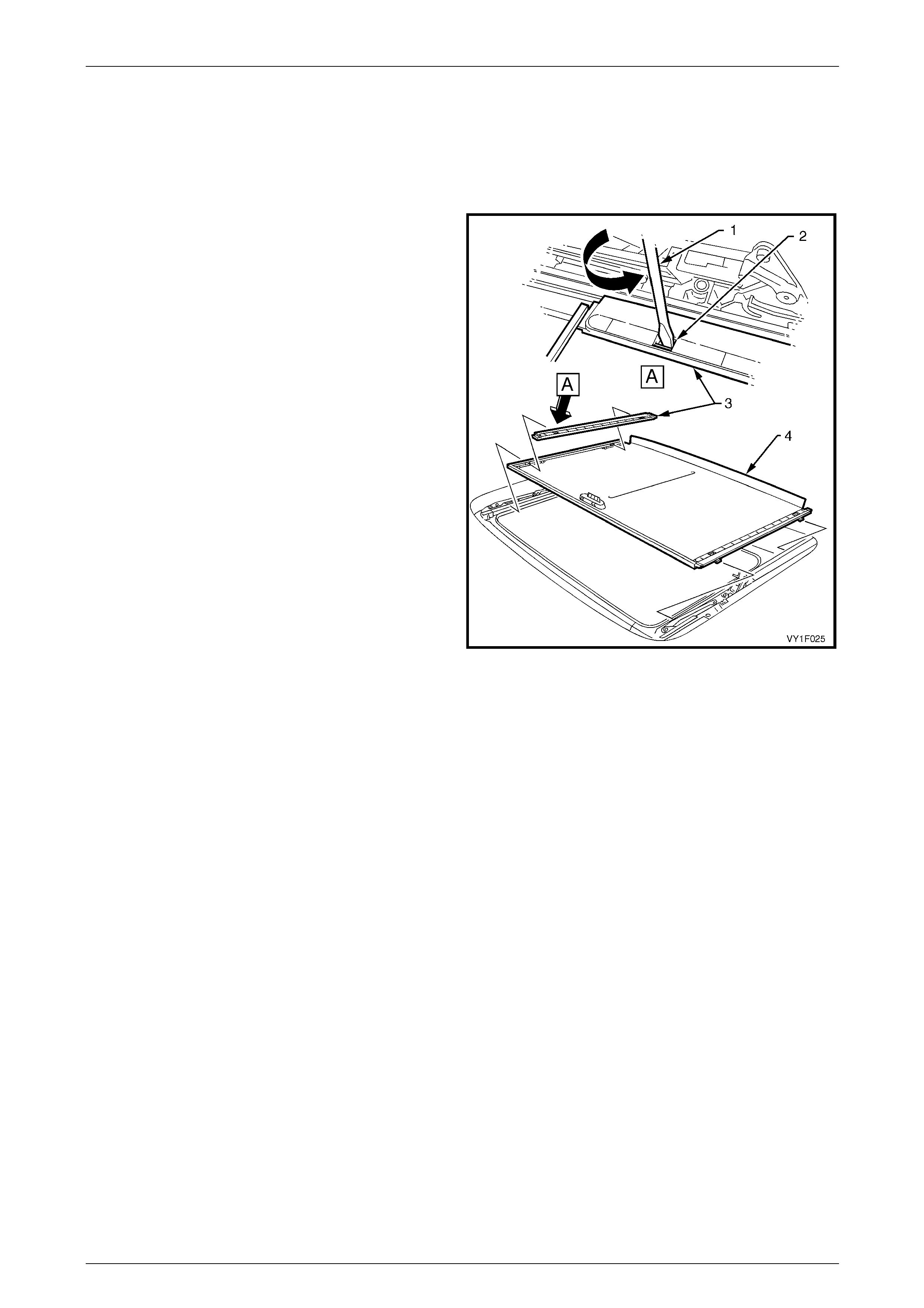
5 Remove the two Torx screws and washers (1) on each side of the glass panel (2) securing it to the guide rail
mechanism (3). Note the size and position of the washers. refer to Figure 1F2 – 18.
6 Carefully lift out the glass panel (2), rele asing the locating tabs (4) from the sliding mechanism (5).
7 Place the glass panel in an appropriate safe area.
Figure 1F2 – 18
Sunroof – Online Page 1F2–30
Page 1F2–30
Reinstall
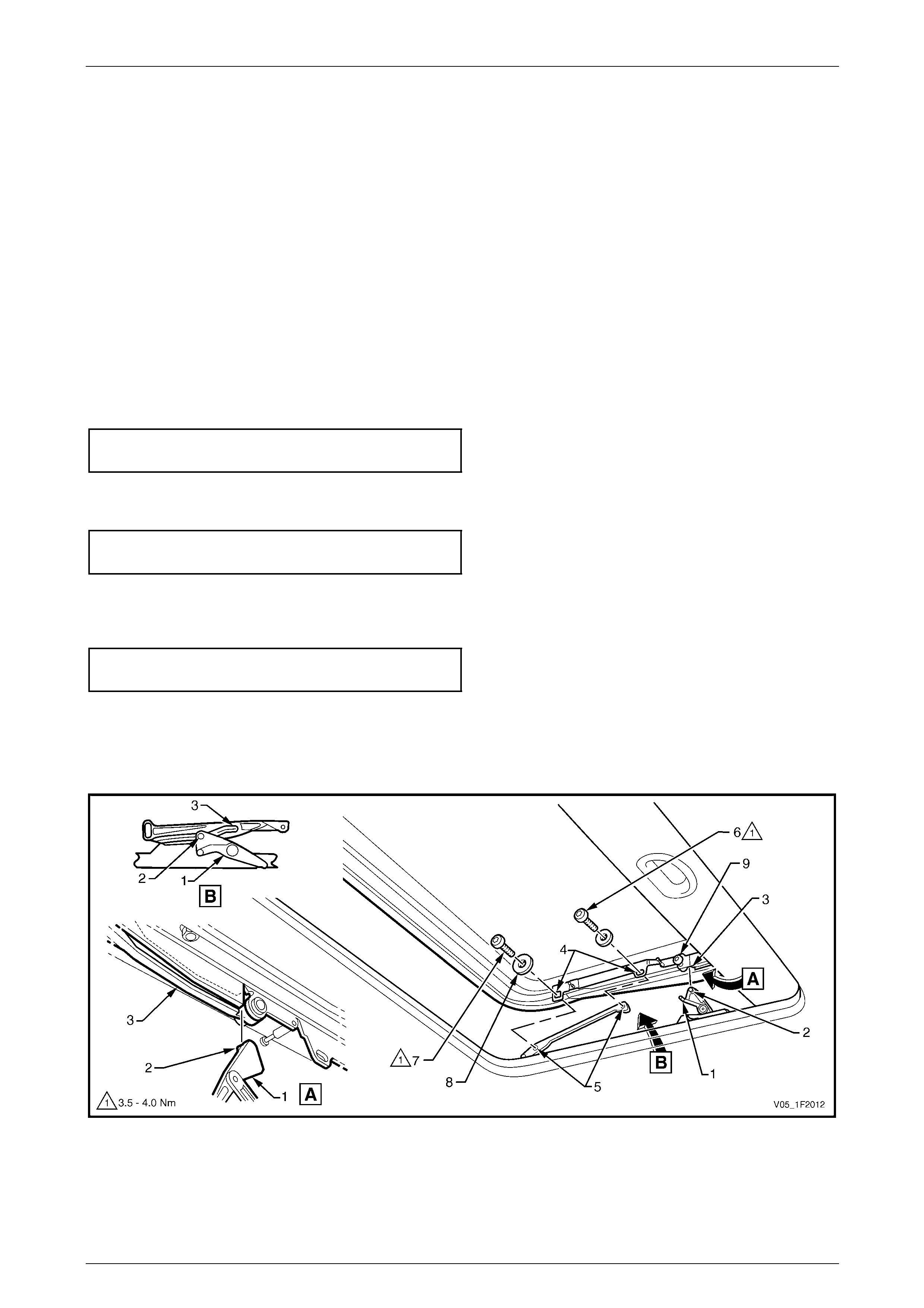
Procedure
1 Position the lever (1) of the guide rail mechani s m in the full tilt position on each side of the sunroof, refer to
Figure 1F2 – 19.
2 Place the lever locating tabs (2) in the sliding mechanism guides (3), then align the glass pane l mounting bracket
holes (4) with the threaded holes (5) of the sliding mechanisms.
3 Secure the glass panel with four Torx screws and washers (6, 7 and 8), with the large washers (8) at the front
locations. Do not tighten the Torx screws at this point.
4 Manually position the sunroof in the closed position.
5 Apply a forward force to move the glass panel against the front of the roof panel openin g. T here must be a tight fit
between the rubber seal of the glass p an el and the front of the roof pa nel opening.
6 While applying the forward force on the glass panel, tight en the centre mounting Torx screws (6) to the specified
torque.
Glass panel mounting T orx screw
torque specification.....................................3.5 – 4.0 Nm
7 Adjust the height of the glass panel at the front with the roof pane l, refer to Glass Pane l – Adjust in this Section,
then tighten the front mounting Torx screws (7) to the specified torque.
Glass panel mounting T orx screw
torque specification.....................................3.5 – 4.0 Nm
8 Loosen the left-hand and right-hand adjustment bracket retaining Torx screws (9). Adjust the height of the glass
panel at the rear with the roof panel, refer to Glass Panel – Adjust in this S ection. Tighten the adjustment bracket
retaining Torx screws to the specified torque.
Adjustment bracket retaining Torx screw
torque specification..............................................2.0 Nm
9 Check the operation of the guide rail mechanism and the adjustment of the glass panel. Repeat Steps 4 to 8 if
further adjustments are required.
10 Install the left-hand and right-hand guide rail mechanism covers, by sliding them towards the front of the sunroof
assembly.
Figure 1F2 – 19
Sunroof – Online Page 1F2–31
Page 1F2–31
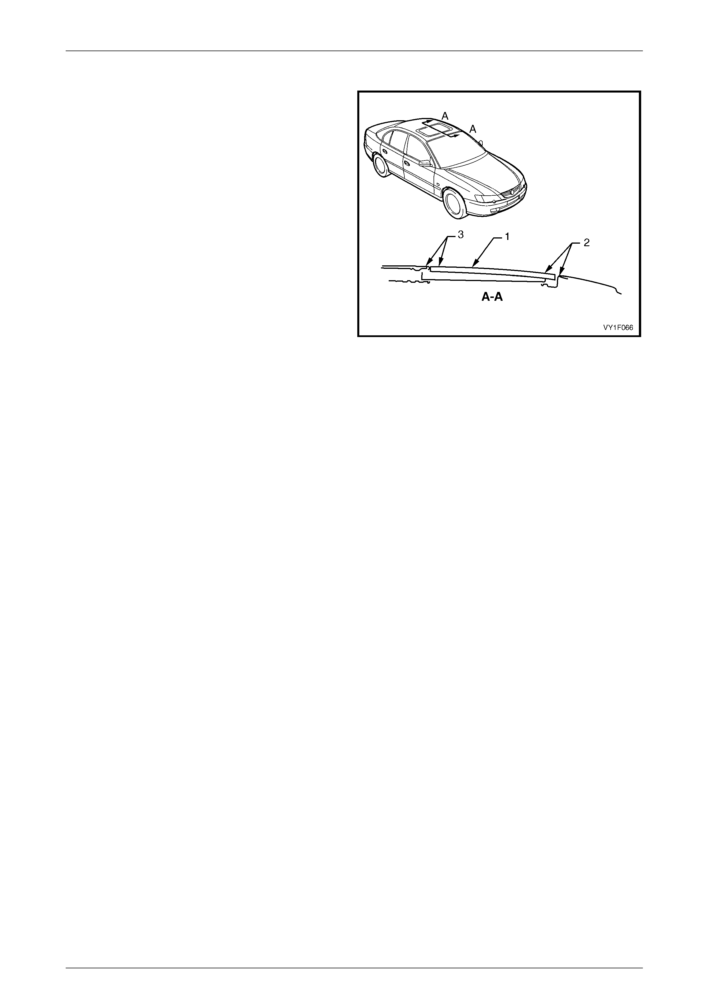
Glass Panel – Adjust
To avoid wind noise (whistling), the glass panel (1) must be
installed level with the roof panel within the following limits:
• Front location (2), flushness 0 to –1 mm,
• Rear location (3), flushness +1 to 0 mm.
Figure 1F2 – 20
Sunroof – Online Page 1F2–32
Page 1F2–32
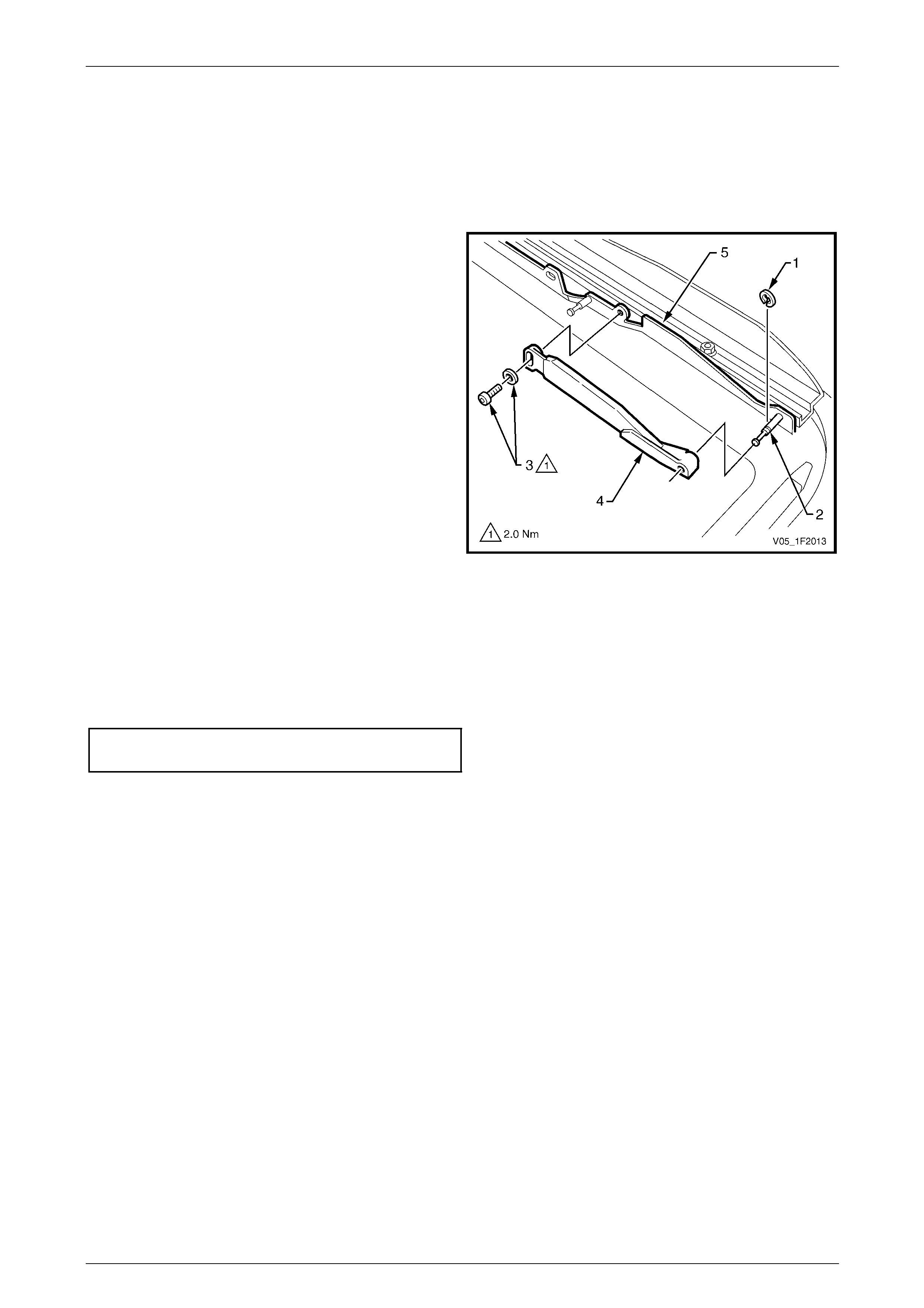
4.2 Adjustment Brackets
LT Section No. — AA–000
Remove
1 Remove the left-hand a nd right-hand guide rail
mechanism covers and the glass panel, refer to
4.1 Glass Panel.
2 Remove the circlip (1) from the mounting pin (2).
3 Remove the Torx screw and washer (3) sec urin g each
adjustment bracket (4) to the glass panel mounting
bracket (5).
4 Slide the bracket off the locating pin an d remove.
Figure 1F2 – 21
Reinstall
Reinstallation of the adjustment brackets is the reverse of the removal procedure, noting the following:
1 Ensure the circlip (1) is secured to the mounting pin (2), refer to Figure 1F2 – 21.
2 Tighten each adjustment bracket retaining Torx screw to the specified torque.
Adjustment bracket retaining Torx screw
torque specification..............................................2.0 Nm
Sunroof – Online Page 1F2–33
Page 1F2–33
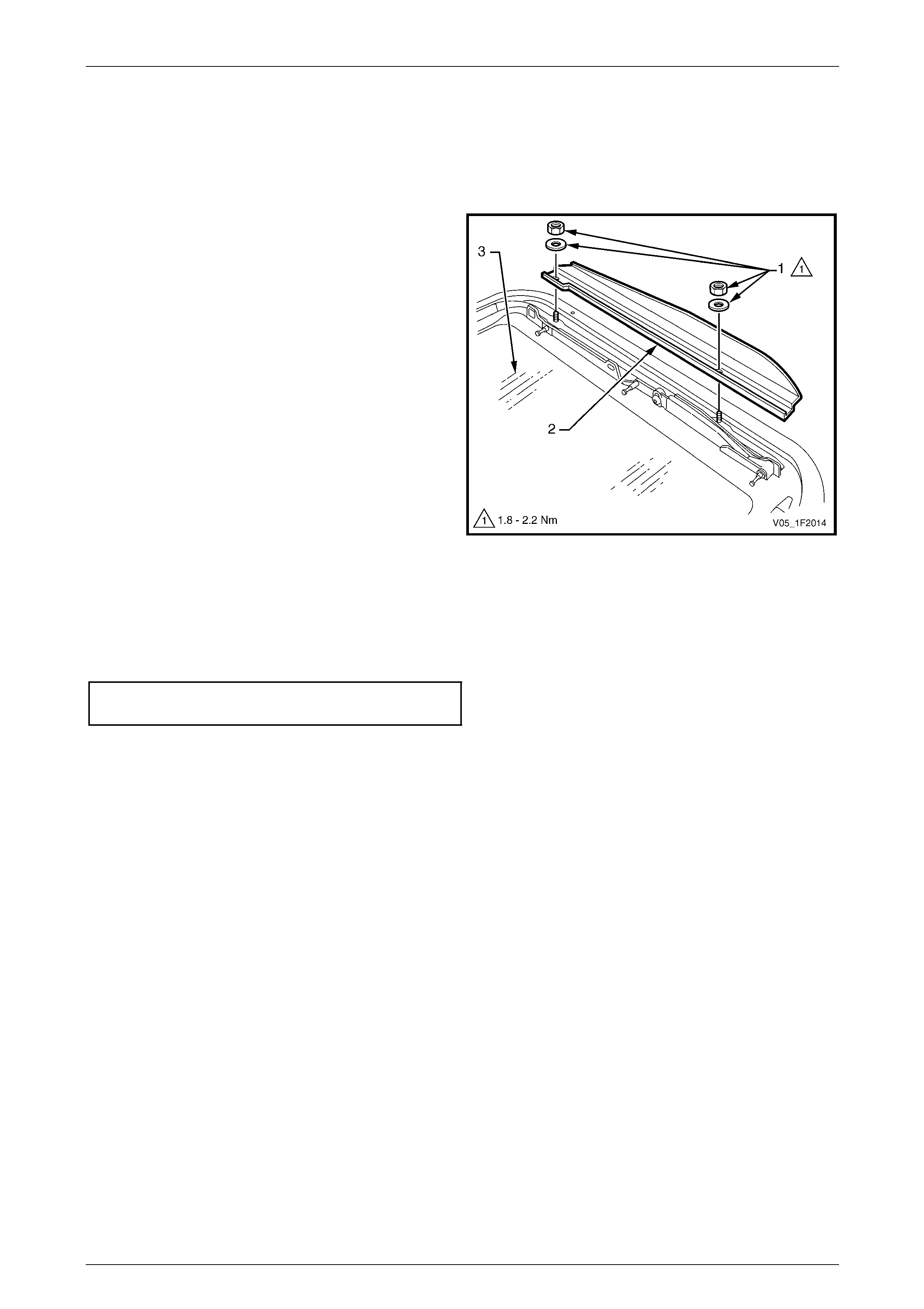
4.3 Exterior Covers
LT Section No. — AA–000
Remove
1 Remove the left-hand a nd right-hand guide rail
mechanism covers and the glass panel, refer to
4.1 Glass Panel.
2 Remove the two nuts and washers (1) attaching each
exterior cover (2) to the glass panel (3).
Figure 1F2 – 22
Reinstall
Reinstallation of the exter ior covers is the reverse of the removal procedure, noting the following:
Tighten the two nuts attaching each e xterior cover to the specified torque.
Exterior cover attaching nut
torque specification.....................................1.8 – 2.2 Nm
Sunroof – Online Page 1F2–34
Page 1F2–34
4.4 Rubber Seal
LT Section No. — AA–000
Remove
1 Remove the left-hand and right-hand guide rail mechanism covers and the glass panel, refer to 4.1 Glass Panel.
2 Remove the exterior covers, refer to 4.3 Exterior Covers.
3 Remove the rubber seal (1) from the glass panel (2).
4 Remove any dirt or debris and clean the glass panel,
refer to 1.1 Sunroof Assembly.
Figure 1F2 – 23
Reinstall
Ensure that the glass and frame is clean and
free of debris before fitting the new rubber
seal.
1 Install the new rubber seal configur ation one (1) or,
alternatively, configuratio n two (2), beginning at the
centre front of the glass frame retaining channel (3).
NOTE
There are two rubber seal configurations that
can be fitted to the glass panel. The installation
procedure is the same for both configurations.
2 Insert the new rubber seal in the glass frame retaining
channel (4) with enough pres sure to have a flush fit
with the glass.
3 Trim the new rubber seal with approximately 6 mm
overlap (5), then work into the retaining channel.
Figure 1F2 – 24
4 Install the glass panel and the guide rail mechanism covers, refer to 4.1 Glass Panel.
5 Check that the new rubber seal firmly contacts the flanged metal sunr oof opening, with the sunroof in the closed
position.
6 If required adjust the rubber seal, refer to Adjustment in this Section.
7 Check the sunroof for correct operation.
Sunroof – Online Page 1F2–35
Page 1F2–35
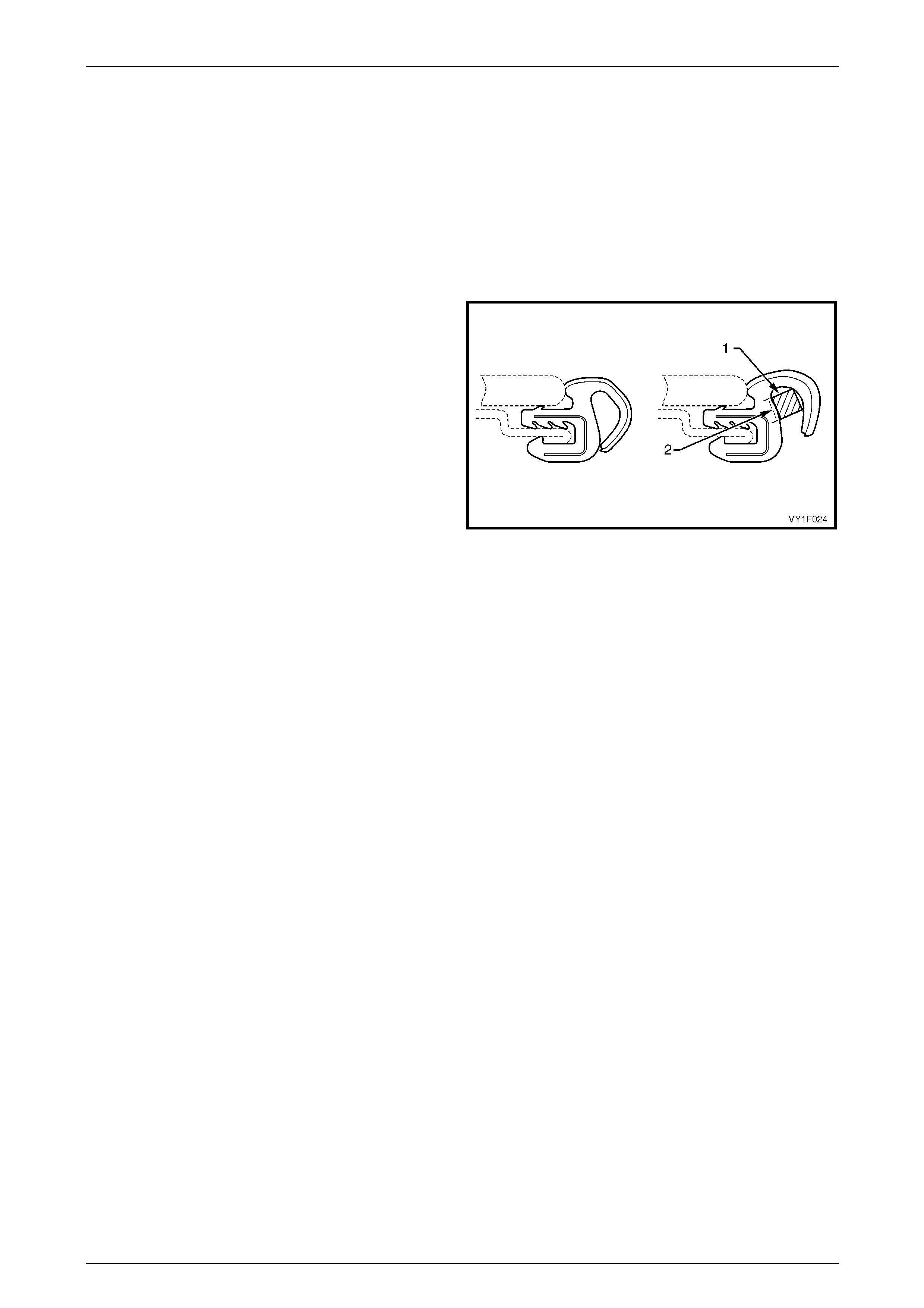
Adjustment
NOTE
The adjustment is applicable to the rubber
seal configuration one (1) only, refer to
Figure 1F2 – 24.
Ensure that the glass panel is correctly adjusted against the roof panel opening, refer to 4.1 Glass Panel.
With the glass panel positioned correctly, the rubber seal should firmly contact the flanged metal sunroof opening. If the
glass panel fits correctly but gaps remain between the seal and the flanged metal sunr oof opening, adjust as follows:
1 With a grease pencil or simila r, mark the areas where
the rubber seal does not make sufficient cont act with
the front of the flanged sunroof opening.
2 Remove the glass panel, refer to 4.1 Glass Panel.
3 In the areas marked, insert a spacer (1) inside the
rubber seal as shown (use a 3mm square section
foam strip with adhesive backing).
4 Peel the backing off the foam spacer and stick to the
inner surface of the seal (2).
5 Install the glass panel and adjust,
refer to 4.1 Glass Panel.
Figure 1F2 – 25
Sunroof – Online Page 1F2–36
Page 1F2–36
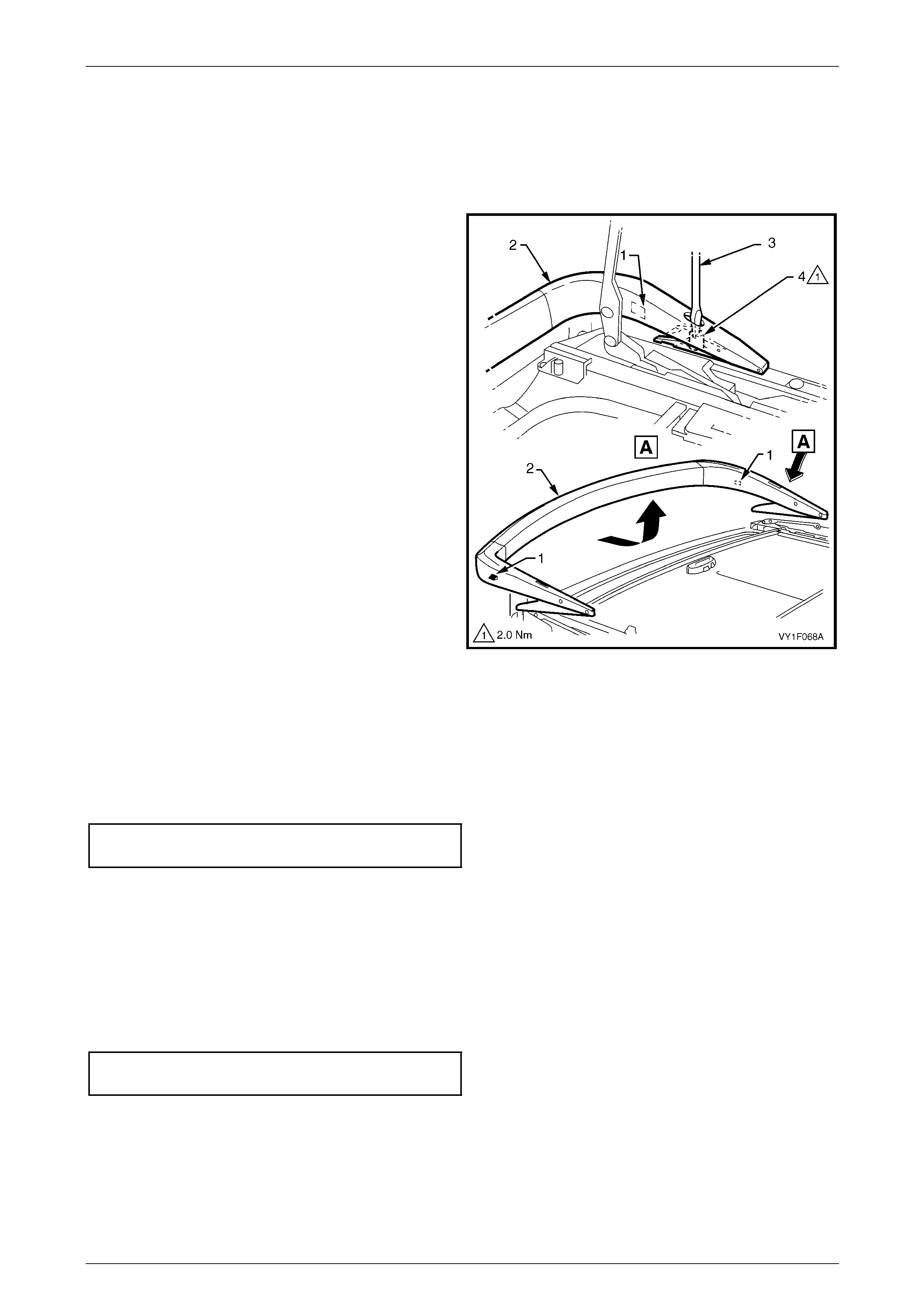
4.5 Wind Deflector
LT Section No. — AA–000
Remove
NOTE
The stoppers (1) on either side of the wind
deflector (2) do not allow the wind deflector
removal with the sunroof installed onto the
vehicle.
1 Open the glass panel to the maximum slide p ositio n
refer to 1.2 Sunroof Functions.
2 Turn the ignition to the OFF position and override the
auto close function to keep the glass pan el opened,
refer to 1.2 Sunroof Functions.
3 Remove the sunroof assembly, refer to
9.1 Sunroof Assembly.
4 Insert a flat blade screwdriver (3) in the wind deflector
mounting hole and loosen the left-hand and right-hand
securing nuts (4).
5 Slide the wind deflector towards the rear and lift it out.
Figure 1F2 – 26
Reinstall
Reinstallation of the wind deflector is the reverse of the removal procedure, noting the following:
1 Always fit the wind deflector to the maximu m forward position.
2 Secure the wind deflector with the two attaching nuts and tighten to the correct torque specification.
Wind deflector attaching nut
torque specification..............................................2.0 Nm
3 Install the sunroof assembly, refer to 9.1 Sunroof Assembly.
4 Close the glass panel and check the sunroof for correct operation, refer to 1.2 Sunroof Functions.
5 If necessary, adjust the wind deflector as follo ws:
a Loosen the two attaching nuts.
b Move the wind deflector forward or rearward as required.
c With the wind deflector in its new position, tighten the two attaching nuts to the correct torque specification.
Wind deflector attaching nut
torque specification..............................................2.0 Nm
Sunroof – Online Page 1F2–37
Page 1F2–37
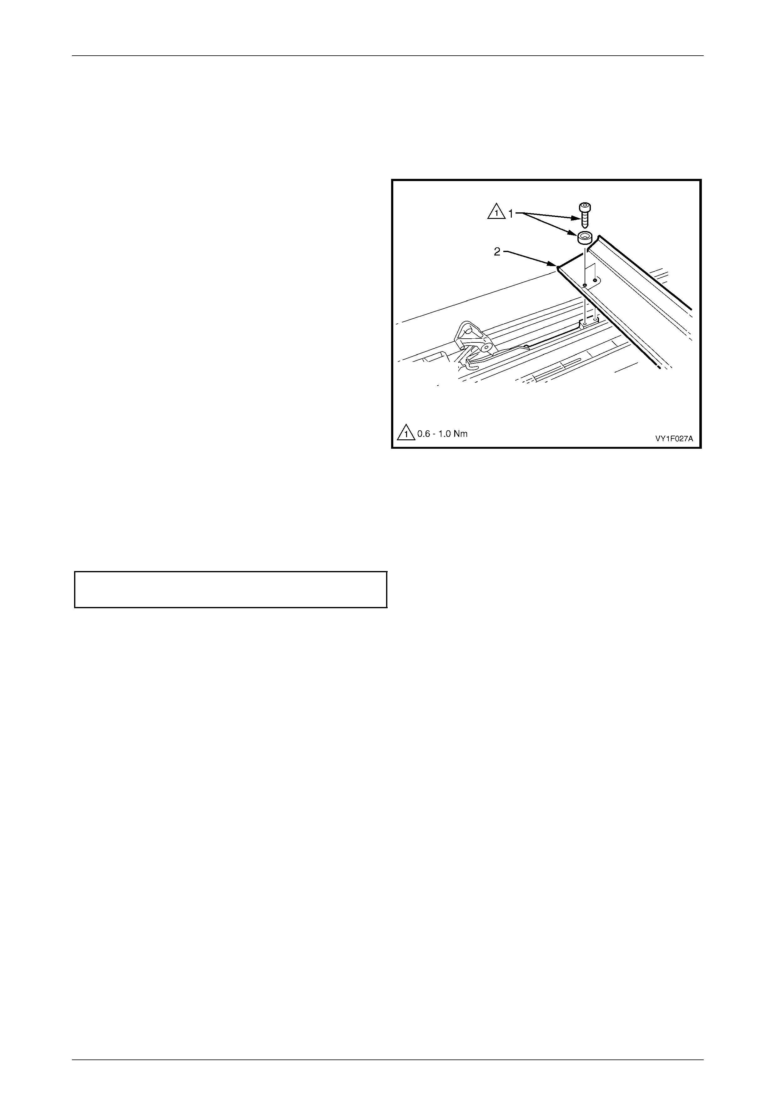
4.6 Drain Channel
LT Section No. — AA–000
Remove
1 Remove the left-hand a nd right-hand guide rail
mechanism covers and the glass panel, refer to
4.1 Glass Panel.
2 Remove the two left-hand and right-hand attaching
Torx screws and washers (1).
3 Lift out the drain channel (2) and remov e.
Figure 1F2 – 27
Reinstall
Reinstallation of the drain channel is the reverse of the removal procedure, noting the following:
Tighten the drain channel attaching Torx screws on the left-hand and right-hand sides to the specified torque.
Drain channel attaching Torx screw
torque specification.....................................0.6 – 1.0 Nm
Sunroof – Online Page 1F2–38
Page 1F2–38
4.7 Sunshade
LT Section No. — AA–000
Remove
1 Remove the left-hand a nd right-hand guide rail
mechanism covers and the glass panel, refer to
4.1 Glass Panel.
2 Remove the drain channel, re fer to
4.6 Drain Channel.
3 Using a flat blade screwdriver (1) or similar, release
the front and rear spring clips (2) from the sunshade
guide (3) by inserting a screwdriver bl ade in the slot
and using a twisting motio n with the blade.
4 Slide the sunshade guide towards the centre of the
vehicle and lift out.
NOTE
It is only necessary to remove the sunshade
guide on one side of the sunshade to allow
sunshade (4) removal.
5 Lift the sunshade clear of the guide rails.
Figure 1F2 – 28
Reinstall
Reinstallation of the sunshad e is the reverse of the removal procedure, noting the follo wing:
1 If the sunshade guide was removed from one side only, ensure the tabs on the sunshade guide still fitted locate
correctly in the guide rail when the sunshade is placed in position.
2 Ensure the tabs on the sunshade g uide(s) being fitted locate correctly in the guide rail.
3 Check for smooth operation of the sunshade before continuing with installation.
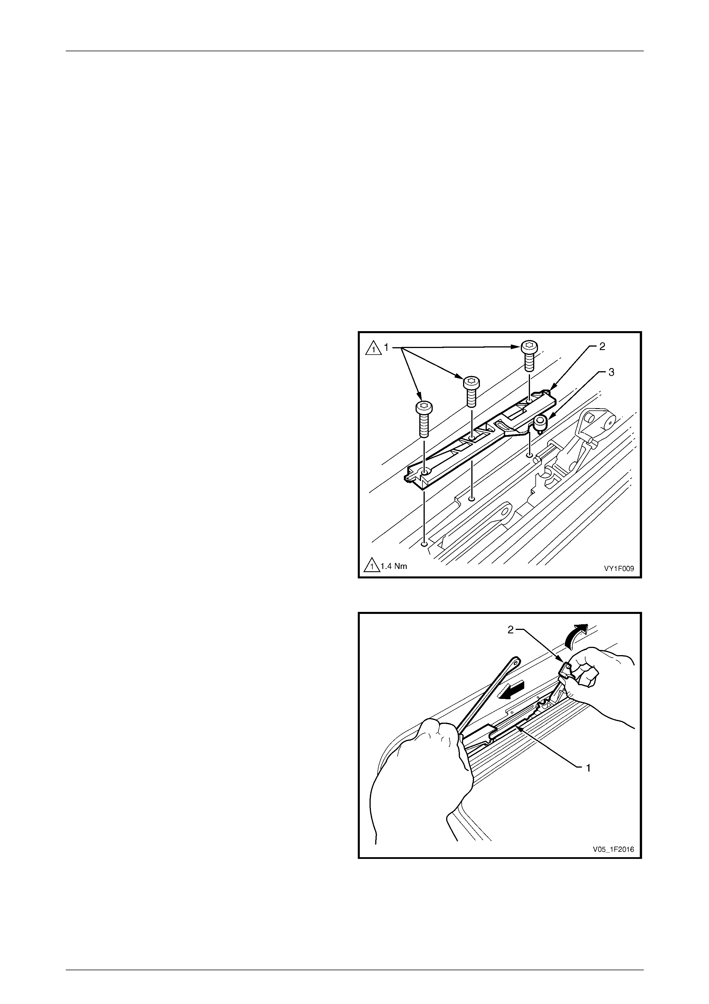
Sunroof – Online Page 1F2–39
Page 1F2–39
4.8 Drive Cables
LT Section No. — AA–000
Remove
1 Remove the left-hand and right-hand guide rail mechanism covers and the glass panel, refer to 4.1 Glass Panel.
2 Remove the drain channel, re fer to 4.6 Drain Cha nnel.
3 Remove the sunshade, refer to 4.7 Sunshade.
4 Close the sunroof guide rail mechanism.
5 Remove the drive motor cover and driv e motor, refer to 3.1 Drive Motor.
6 Remove the SCU, refer to 3.3 Sunroof Control Unit (SCU).
7 Remove the drive gear retaine r and drive gear, refer to 3.2 Drive Gear.
8 Remove the three Torx screws (1) securing the
locator (2). Note the length and position of the screws.
9 Lift off the locator and the blocking catch (3). Note the
orientation of the blocking catch.
Figure 1F2 – 29
10 Pull the guide rail mechanism (1) as far forward as
possible.
11 Push the tilt lever of the guide rail mechanism into the
full tilt position (2).
Figure 1F2 – 30
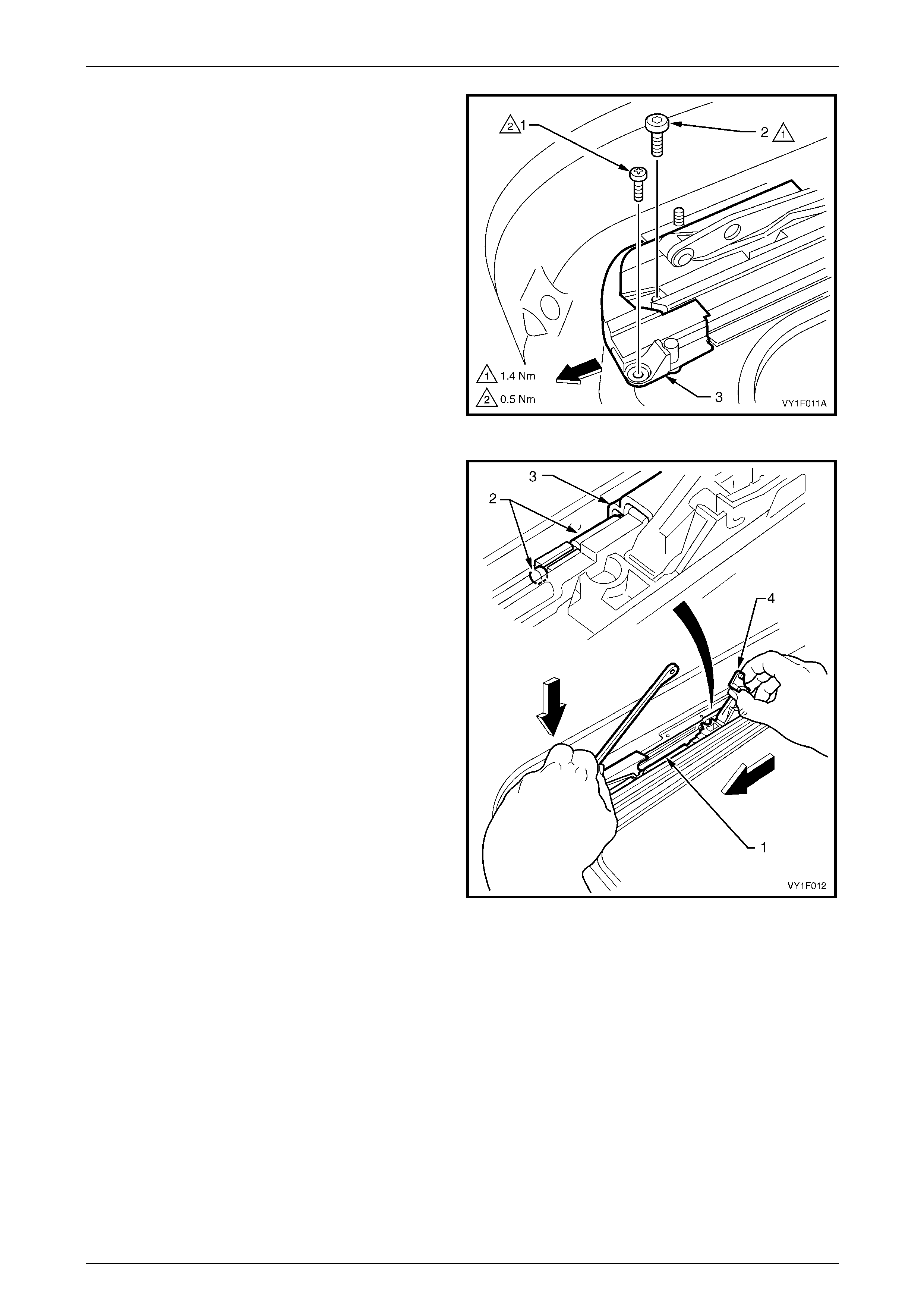
Sunroof – Online Page 1F2–40
Page 1F2–40
12 Remove the locating Phill ips head screw (1) and the
attaching Torx screw (2) from the retraction
mechanism (3).
13 Slide the retraction mechanism forward but do not
remove.
NOTE
This illustration shows the sunroof with the wind
deflector removed. This is for clarity only, the
procedure is performed with the wind deflector
installed.
Figure 1F2 – 31
14 Push the guide rail mechanism (1) further forward until
the drive cable brass end fitting (2) is fully forward of
the drive cable channel (3).
15 While pushing forward, apply downward pressure on
the front of the guide rail mechanism and maintain the
tilt mechanism in the raised position (4).
Figure 1F2 – 32
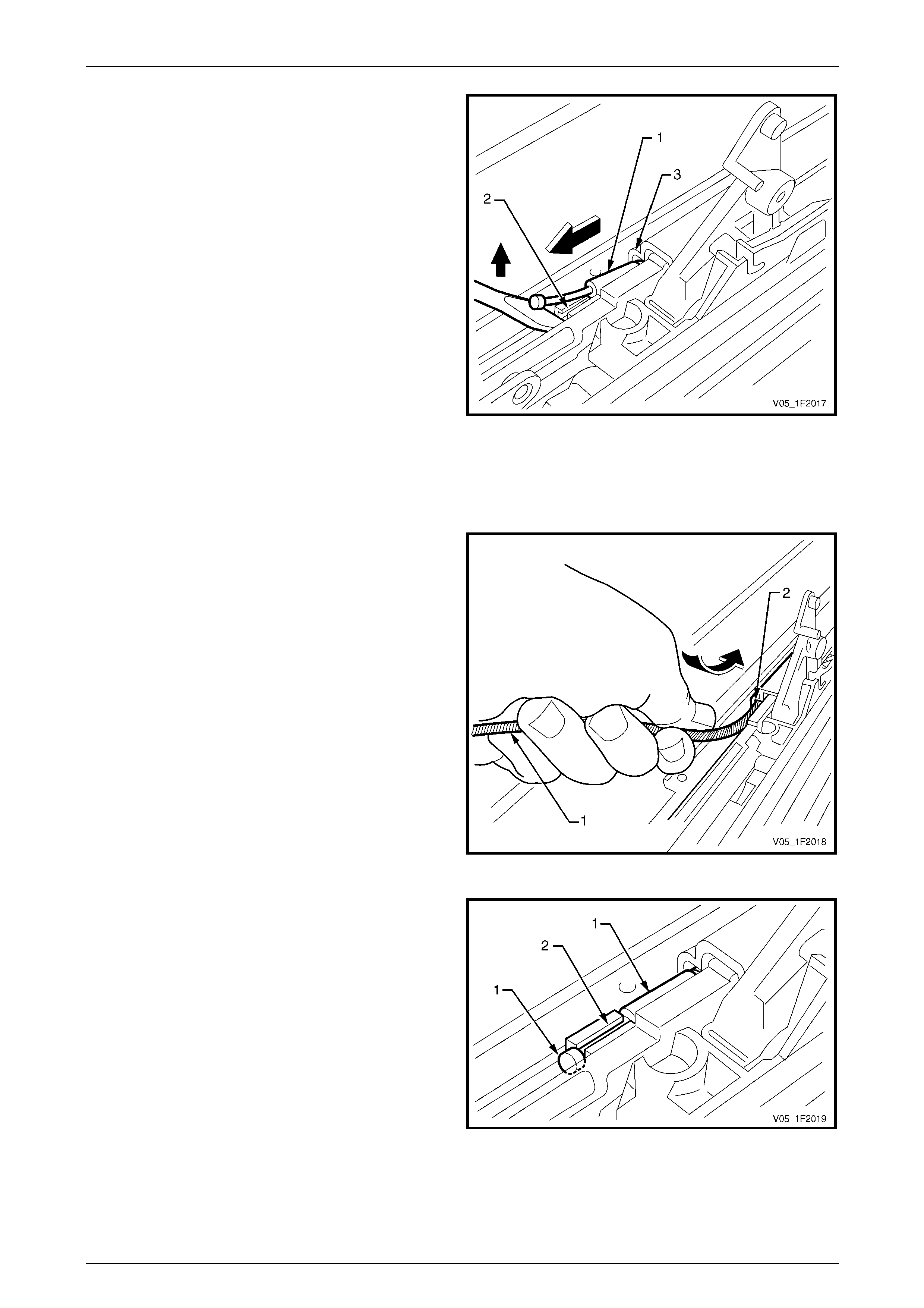
Sunroof – Online Page 1F2–41
Page 1F2–41
16 Lift the brass end fitting of the drive cable (1) out of the
retaining slot (2) in the guide rail mechanism track.
17 Carefully withdraw the drive cable from the drive cable
channel (3).
Figure 1F2 – 33
Reinstall
Reinstallation of the drive cables is the reverse of the removal procedure, noting the following:
1 Check if the new cable is the correct length.
2 Oil the cable using Applied Chemicals Tefoil +PTFE,
Part No. 8-830.
3 Carefully feed the drive cable (1) into the drive cable
channel openin g (2) until the brass end fitting aligns
with the retaining slot in the guide rail mechanism
track.
NOTE
Do not force the cable and avoid kinking or
bending the cable excessivel y .
Figure 1F2 – 34
4 Ensure the brass end fitting (1) of the drive cable seats
securely in the retaining slot (2) in the gu ide rail
mechanism track.
Figure 1F2 – 35
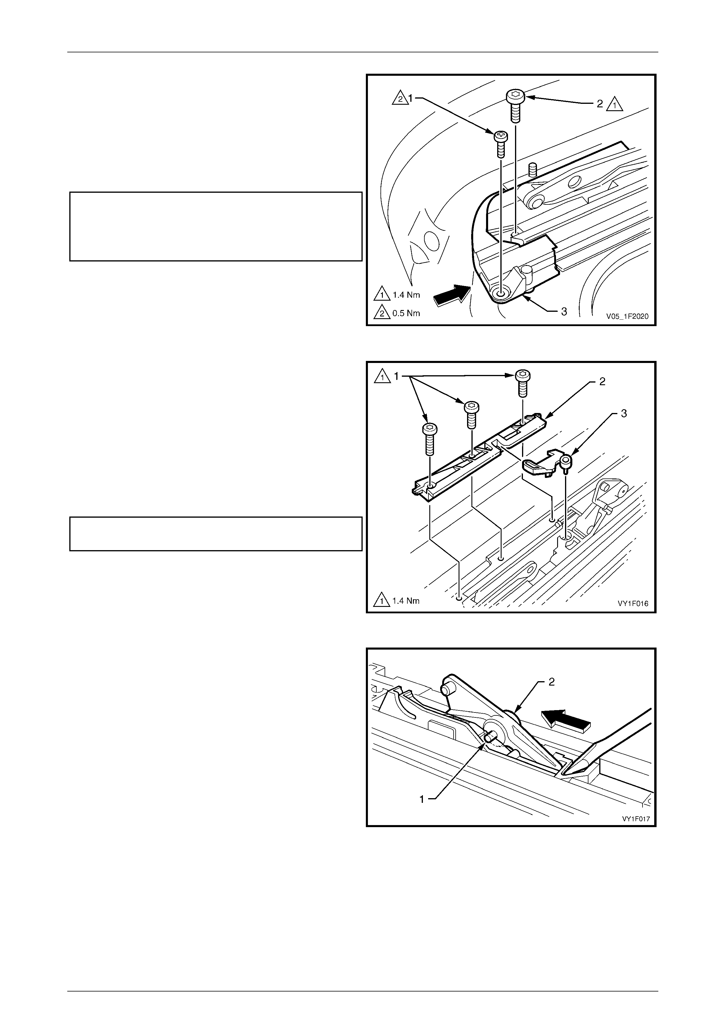
Sunroof – Online Page 1F2–42
Page 1F2–42
5 To install the retraction mechanism, push the guide rail
mechanism towards the rear slightly.
6 Position the retraction mechanism with the locating
Phillips head screw (1).
7 Secure the retraction mechanism with the attaching
Torx screw (2). Tighten the scre ws to the specified
torque.
Retraction mechanism locating screw
torque specification..............................................0.5 Nm
Retraction mechanism attaching
Torx screw torque specification............................1.4 Nm
NOTE
This illustration shows the sunroof with the wind
deflector removed. This is for clarity only, the
procedure is performed with the wind deflector
installed. Figure 1F2 – 36
8 Ensure the blocking catch (3) is correctly fitted to the
locator (2). Position the guide rail mech anism, by
pushing backwards or forwards, so the locator and
blocking catch can be fitted with the blocking catch
mating correctly with the guid e rail mechanism.
9 Install the three attaching Torx scre ws (1) in the
position noted during removal and secure the locator.
10 Push the guide rail mechanism to the fully closed
position, and tighten the three attaching Torx screws
to the specified torque.
Locator attaching Torx screw
torque specification..............................................1.4 Nm
NOTE
If required, repeat the procedure to replace the
drive cable on the opposite side of the sunro of.
Figure 1F2 – 37
11 Push the left-hand and right-hand mechanisms to the
closed position.
12 Insert a pin (1) in the 2.5 mm hole in the left-han d and
right-hand tilt levers (2).
13 Slide the mechanisms forward until the pins stop the
mechanisms movement.
14 Install the drive gear wheel and the drive gear retainer,
refer to 3.2 Drive Gear.
15 Install the SCU,
refer to 3.3 Sunroof Control Unit (SCU).
16 Install the drive motor and drive motor cover,
refer to 3.1 Drive Motor.
17 Remove the pins (1) previously installed,
refer to Step 12.
Figure 1F2 – 38
18 Check the sunroof for correct electrical and mechanical operation before installing th e sunshade and drain channel.
19 Install the glass panel an d the left-hand and right-hand guide rail mechani s m covers, refer to 4.1 Glass Panel.
20 Check the sunroof for correct operation before fitting the headlining, refer to 1.2 Sunroof Functions.
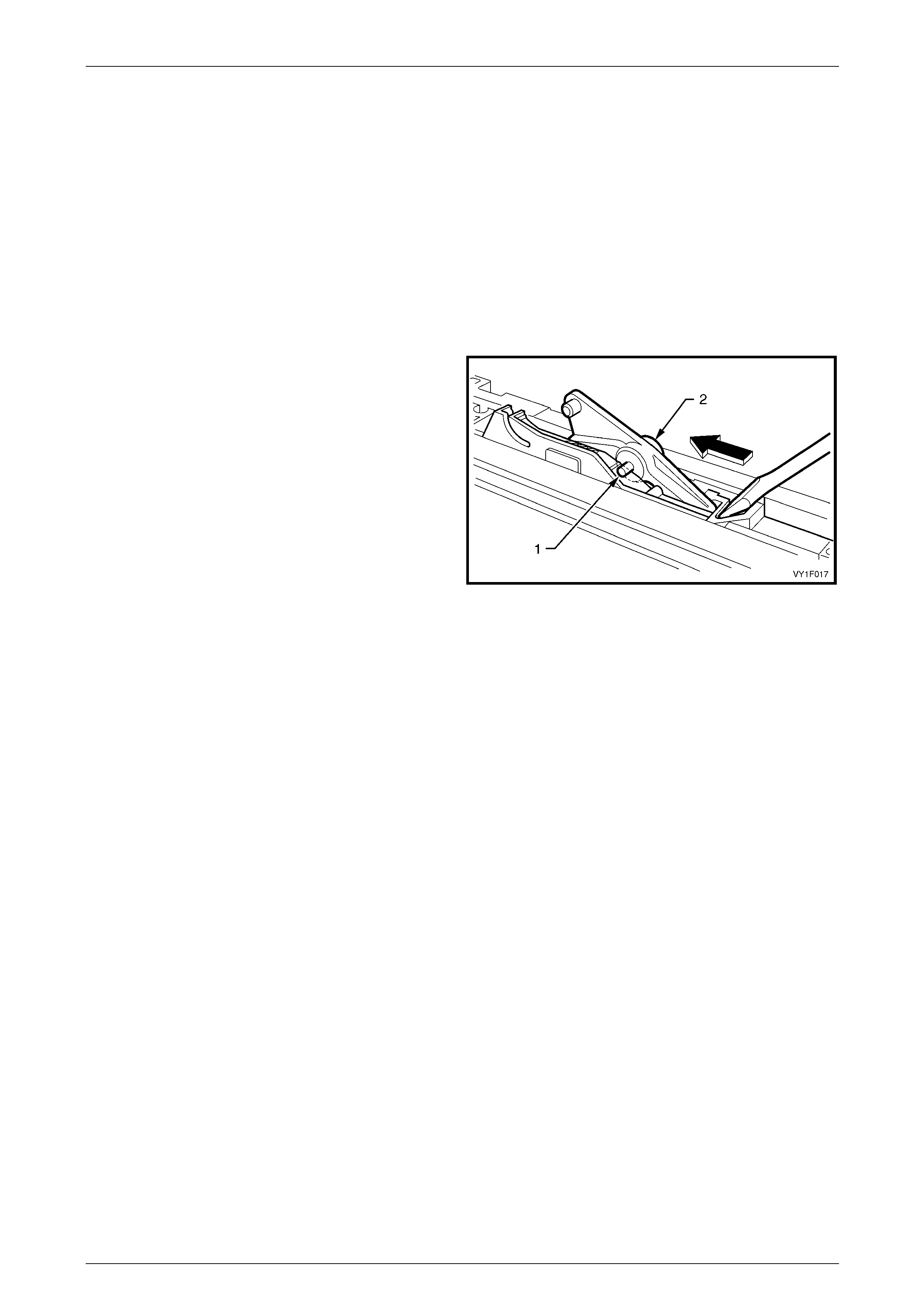
Sunroof – Online Page 1F2–43
Page 1F2–43
4.9 Timing of Drive Cables
LT Section No. — AA–000
Timing Procedure
1 Remove the left-hand and right-hand guide rail mechanism covers and the glass panel, refer to 4.1 Glass Panel.
2 Fully close the sunroof, refer to 1.2 Sunroof Functions.
3 Remove the drive motor cover and driv e motor, refer to 3.1 Drive Motor.
4 Remove the SCU, refer to 3.3 Sunroof Control Unit (SCU).
5 Remove the drive gear retaine r and drive gear, refer to 3.2 Drive Gear.
6 Push the left-hand and right-hand mec ha nisms to the
closed position.
7 Insert a pin (1) in the 2.5 mm hole in the left-hand an d
right-hand tilt levers (2).
8 Slide the mechanisms forward until the pi ns stop the
mechanisms movement.
9 Install the drive gear wheel an d the drive gear retainer,
refer to 3.2 Drive Gear.
10 Install the SCU,
refer to 3.3 Sunroof Control Unit (SCU).
11 Install the drive motor and drive motor cover,
refer to 3.1 Drive Motor.
12 Remove the pins (1) previously installed,
refer to Step 8.
Figure 1F2 – 39
13 Check the sunroof for correct electrical and mechanical function.
14 Install the glass panel an d the left-hand and right-hand guide rail mechani s m covers, refer to 4.1 Glass Panel.
15 Check the sunroof for correct operation before fitting the headlining, refer to 1.2 Sunroof Functions.
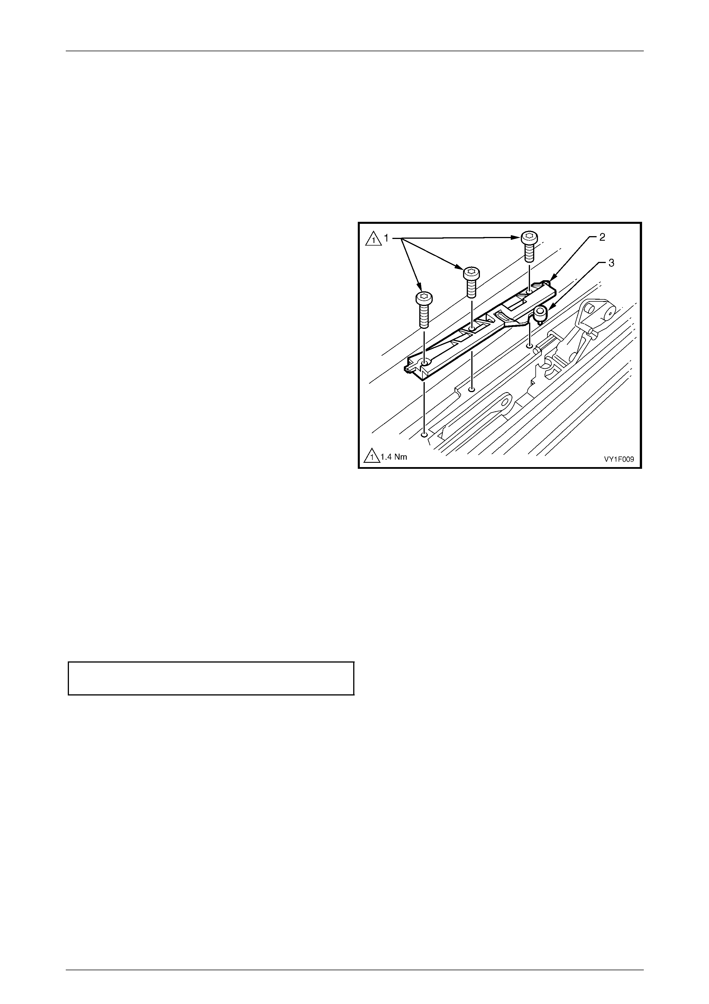
Sunroof – Online Page 1F2–44
Page 1F2–44
4.10 Blocking Catch
LT Section No. — AA–000
Remove
1 Remove the left-hand and right-hand guide rail mechanism covers and the glass panel, refer to 4.1 Glass Panel.
2 Fully retract the guide rail mechanism.
3 Remove the three Torx screws (1) securing the
locator (2). Note the length and position of the screws.
4 Fully tilt the guide rail mechanism.
5 Lift off the locator and the blocking catch (3). Note the
orientation of the blocking catch.
NOTE
If replacing a broken blocking catch, make sure
that any debris is removed.
Figure 1F2 – 40
Reinstall
Reinstallation of the blocking catch is the reverse of the removal procedure, noting the following:
1 Ensure the blocking catch (3) is correctly fitted to the locator (2). Position the guide rail mechanism, by pushing
backwards or forwards, so the locator and blocking catch can be fitted with the blocking catch mating correctly with
the guide rail mechanism, refer to Figure 1F2 – 40.
2 Install the three attaching Torx scre ws (1) in the position noted during removal and secure the locator.
3 Push the guide rail mechanism to the fully closed position, and tighten the three attaching Torx screws to the
specified torque.
Locator attaching Torx screw
torque specification..............................................1.4 Nm
4 Check for correct mechanical operation.
5 Install the glass panel and the left-han d and right-hand guide rail mechanism covers, refer to 4.1 Glass Panel.
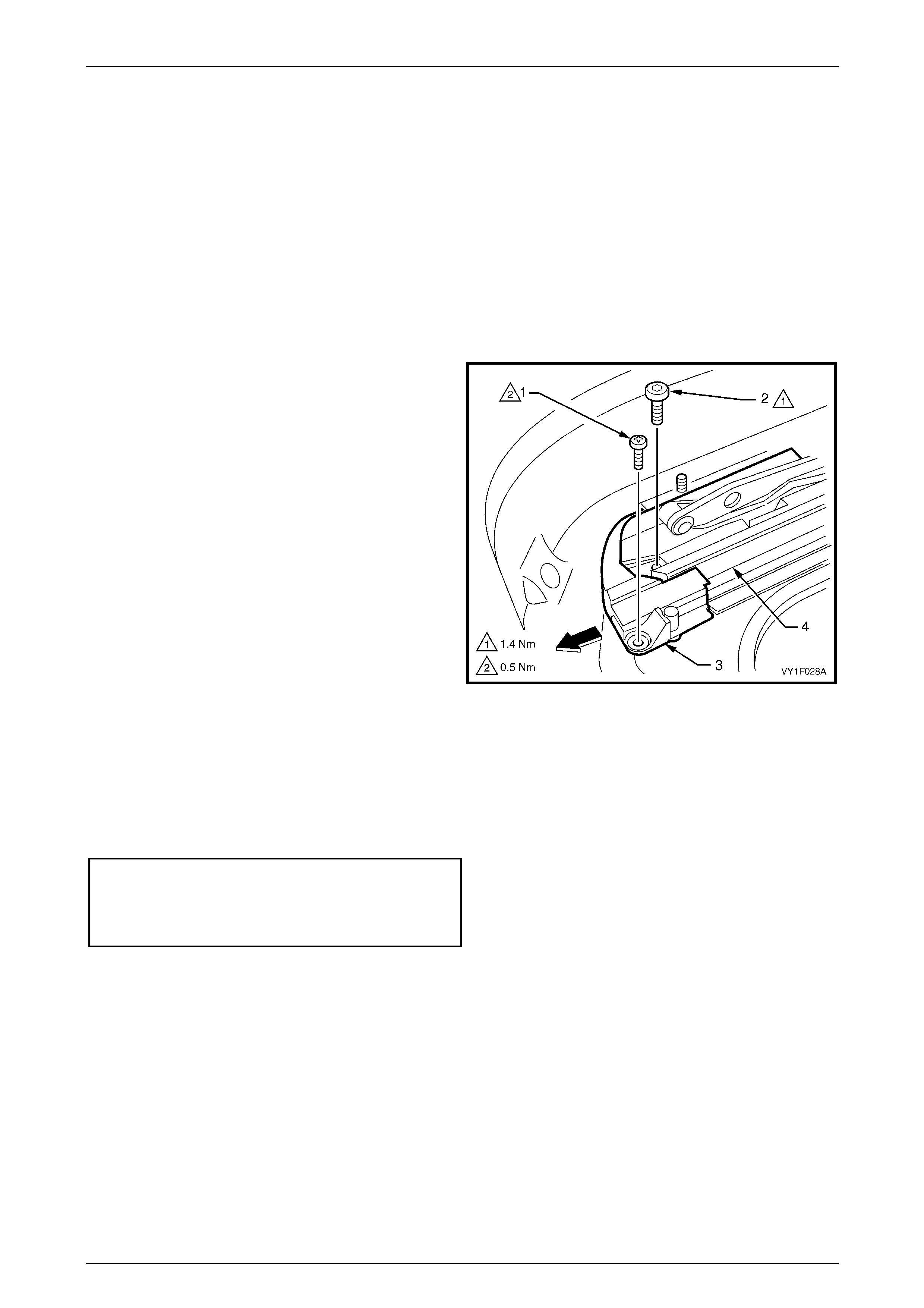
Sunroof – Online Page 1F2–45
Page 1F2–45
4.11 Retraction Mechanism
LT Section No. — AA–000
Remove
1 Open the sunroof to the maximum slide position, refer to 1.2 Sunroof Functions.
2 Turn the igition switch to the OFF position and override the auto close function to keep the glass panel opened,
refer to 1.2 Sunroof Functions.
3 Remove the sunroof assembly from the vehicle, refer to 9.1 Sunroof Assembly.
4 Remove the wind deflector from the t wo attaching studs, refer to 4.5 Wind Deflector.
5 Remove the locating Phillips head screw (1) and the
attaching Torx screw (2) from the retraction
mechanism (3).
6 Withdraw the retraction mechanism forwards out of the
guide rail (4).
Figure 1F2 – 41
Reinstall
1 Install the retraction mechanism (1) in the guide rail (2), refer to Figure 1F2 – 42.
2 Position the retraction mechanism with the locating Phillips head screw (3).
3 Secure the retraction mechanism with the attaching Torx screw (4). Tighten the screws to the specified torque.
Retraction mechanism locating screw
torque specification..............................................0.5 Nm
Retraction mechanism attaching
Torx screw torque specification............................1.4 Nm
4 Install the wind deflector, refer to 4.5 Wind Deflector.
5 Install the sunroof assembly onto the vehicle, refer to 9.1 Sunroof Assembly.
6 Close the glass panel and check the sunroof for correct operation, refer to 1.2 Sunroof Functions.
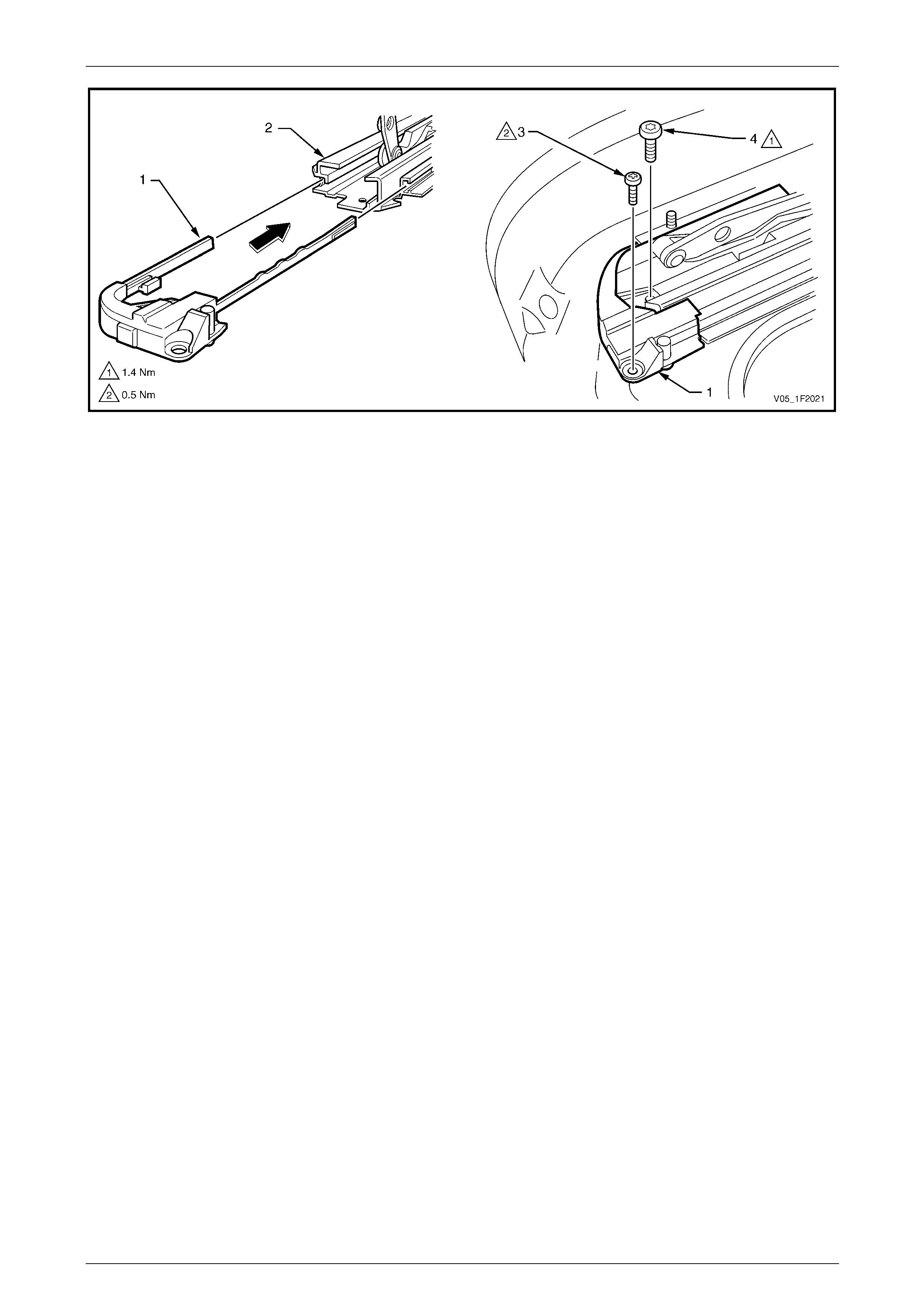
Sunroof – Online Page 1F2–46
Page 1F2–46
Figure 1F2 – 42
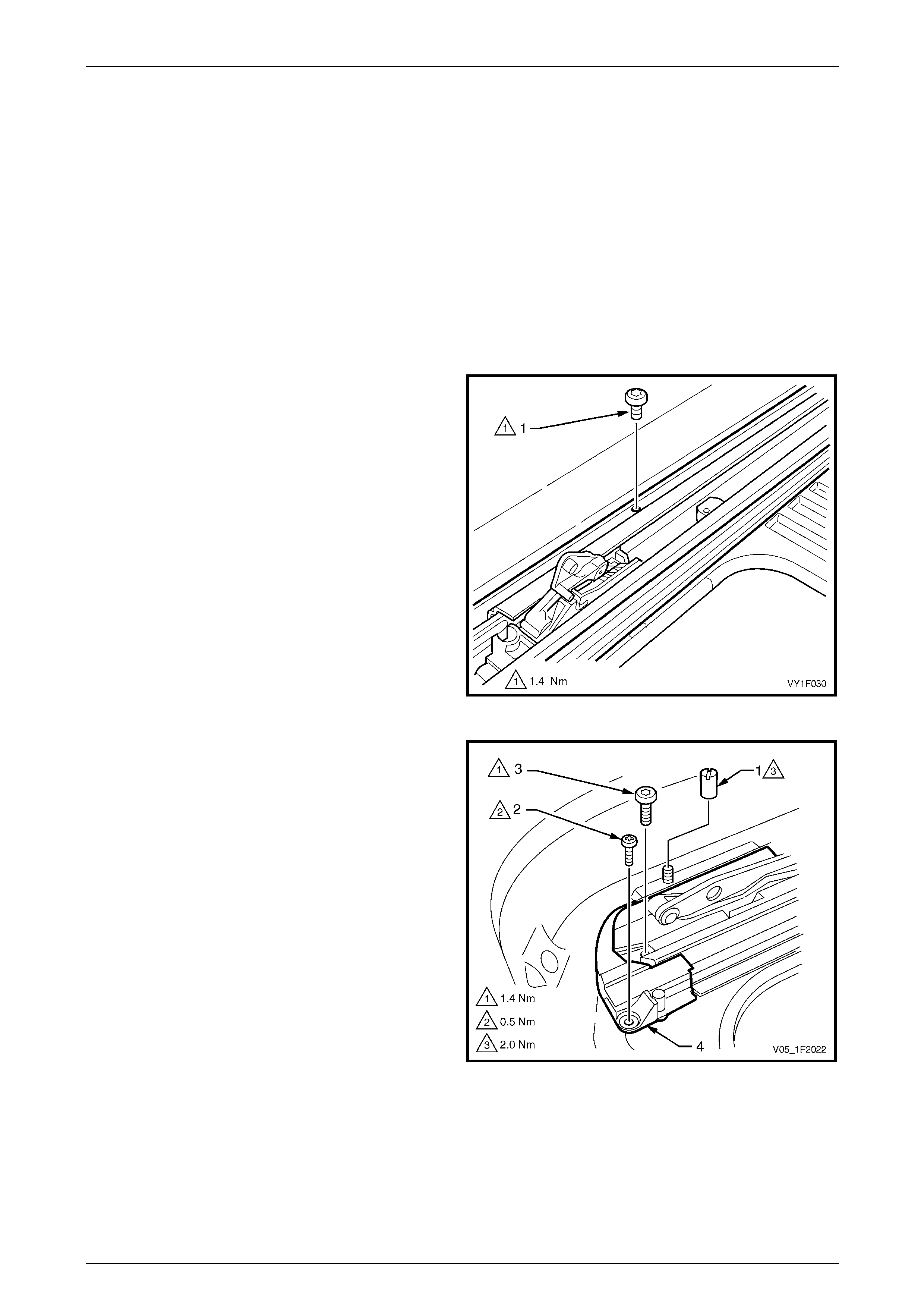
Sunroof – Online Page 1F2–47
Page 1F2–47
4.12 Guide Rail Mechanism
LT Section No. — AA–000
Remove
1 Remove the left-hand and right-hand guide rail mechanism covers and the glass panel, refer to 4.1 Glass Panel.
2 Remove the sunroof assembly from the vehicle, refer to 9.1 Sunroof Assembly.
3 Remove the drain channel, re fer to 4.6 Drain Cha nnel.
4 Remove the sunshade, refer to 4.7 Sunshade.
5 Remove the locator and blocking catch, refer to 4.10 Blocking Catch.
6 Remove the guide rail attachin g Torx screw (1) noting
the length and position of the screw.
Figure 1F2 – 43
7 Remove the wind deflector from the two attaching
studs, refer to 4.5 Wind Deflector.
8 Remove the wind deflector mounting nuts (1).
9 Remove the locating Phillips head screw (2) and the
attaching Torx screw (3) from the retraction
mechanism (4).
Figure 1F2 – 44
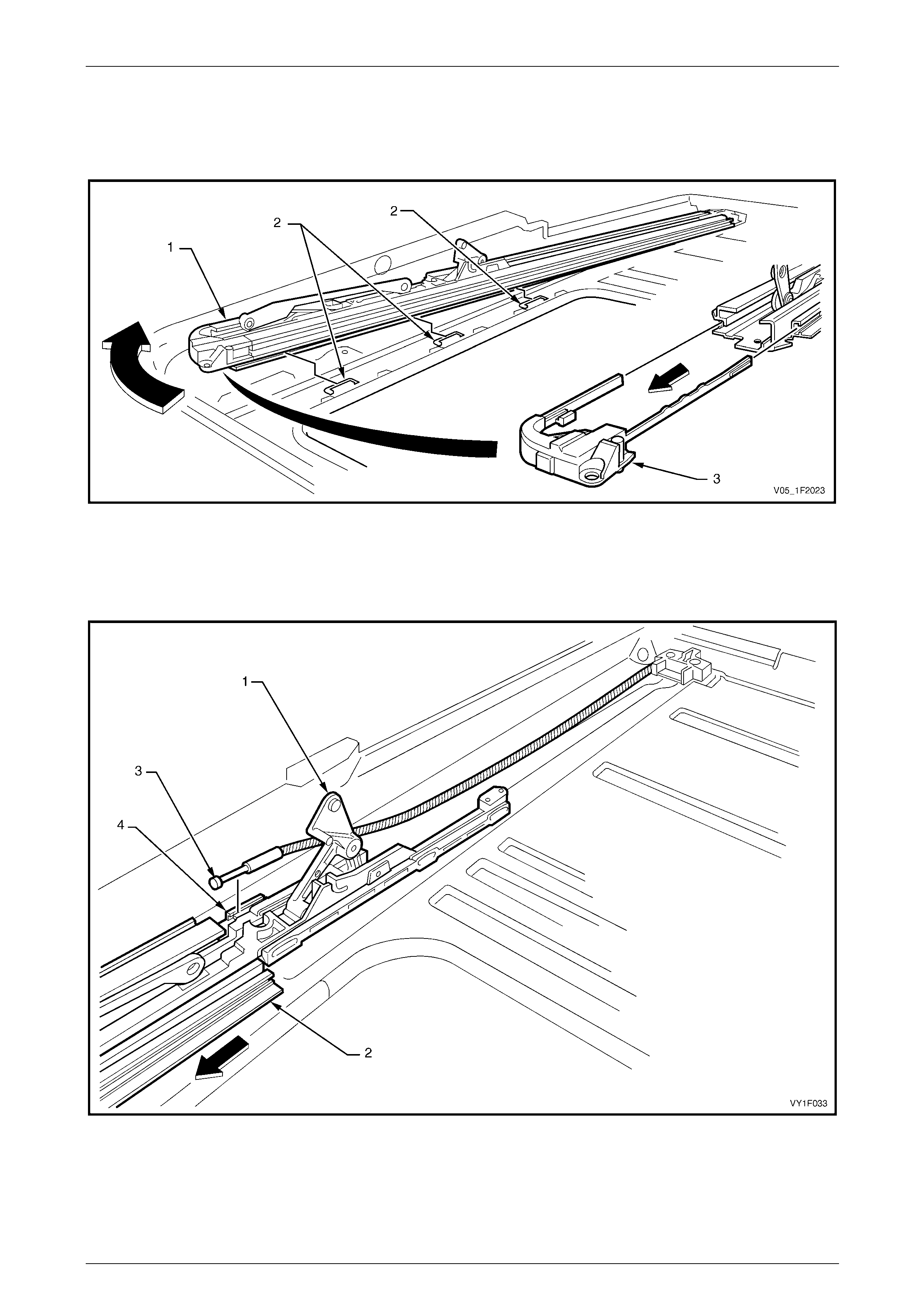
Sunroof – Online Page 1F2–48
Page 1F2–48
10 Slide the mechanism guide rai l (1) sideways to unlock from the locating tabs (2), refer to Figure 1F2 – 45.
11 Lift the front of the mechanism guide rail and withdraw the retraction mechanism (3).
12 Fully close the guide rai l mechanism.
Figure 1F2 – 45
13 While holding the guide rail mechanism (1), gently pull the guide rai l (2) forward over the guide rail mechanism until
the front of the drive cable (3) becomes visible, refer to Figure 1F2 – 46.
14 Lift the drive cable out of the locating slot (4) then carefully lift out the guide rail and guide rail mechanism.
Figure 1F2 – 46
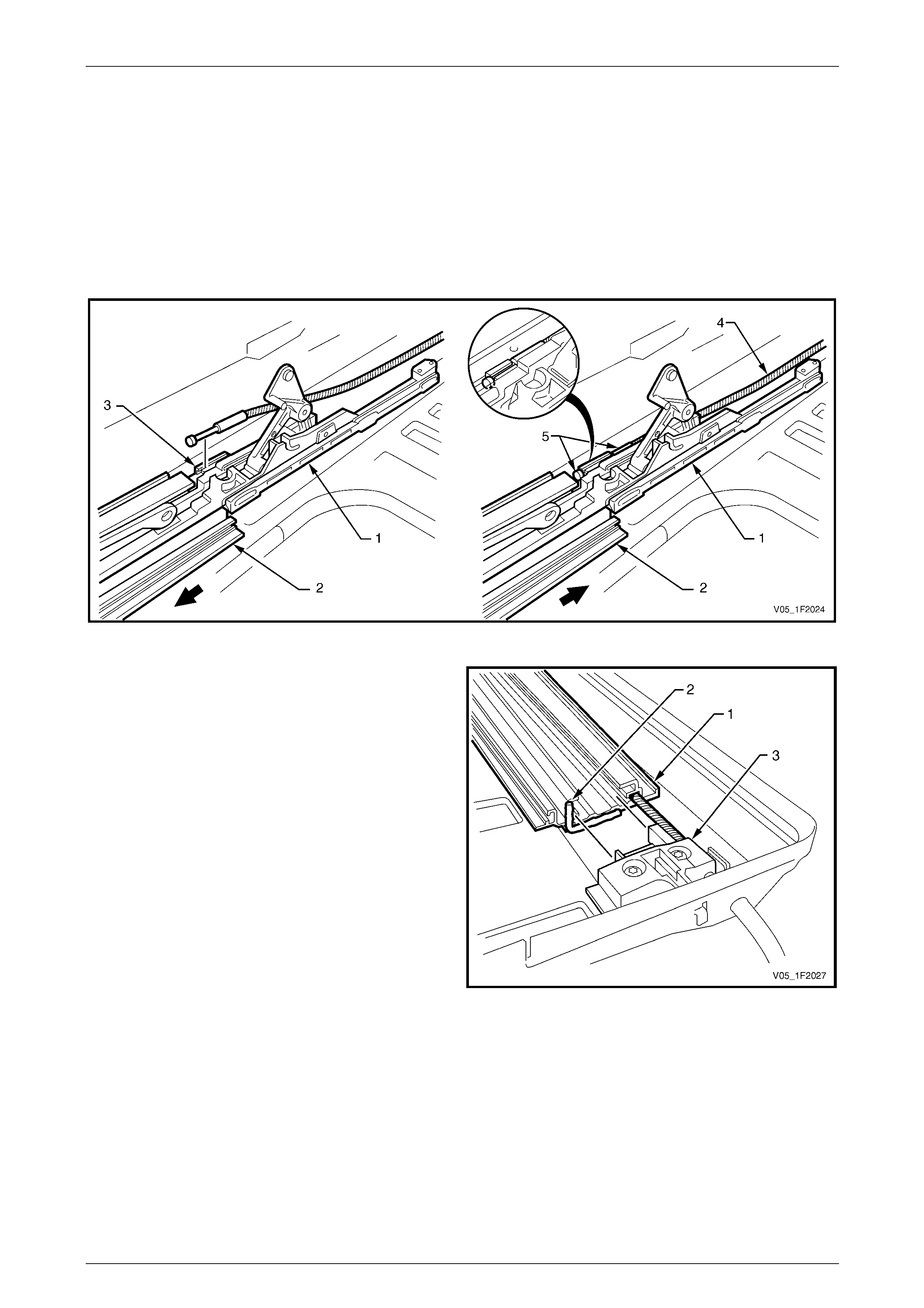
Sunroof – Online Page 1F2–49
Page 1F2–49
Reinstall
1 Ensure that the guide rail mechanism (1) and guide rail (2) are clean and complete, remove any remaining butyl
mastic from the rear of the mechanism guide rail as required. Refer to Figure 1F2 – 47.
2 Slide the guide rail mechanis m out of the guide rail until the drive cable retaining slot (3), in the guide rail
mechanism track, becomes visible.
3 Fit the drive cable (4) into the retaining slot. Ensure that the brass end fitting (5) of the drive cable seats securely in
the retaining slot.
4 While holding the guide rail mechanism (1) in position, push the guide ra il (2) towards the rear locating position
gently to avoid damaging the drive cable.
Figure 1F2 – 47
5 Leave a gap at the rear of the mechanism guide
rail (1) as shown. Apply a bead of butyl mastic
sealer (2) to the end of the guide rail then push into
the rear locating bracket (3).
Figure 1F2 – 48
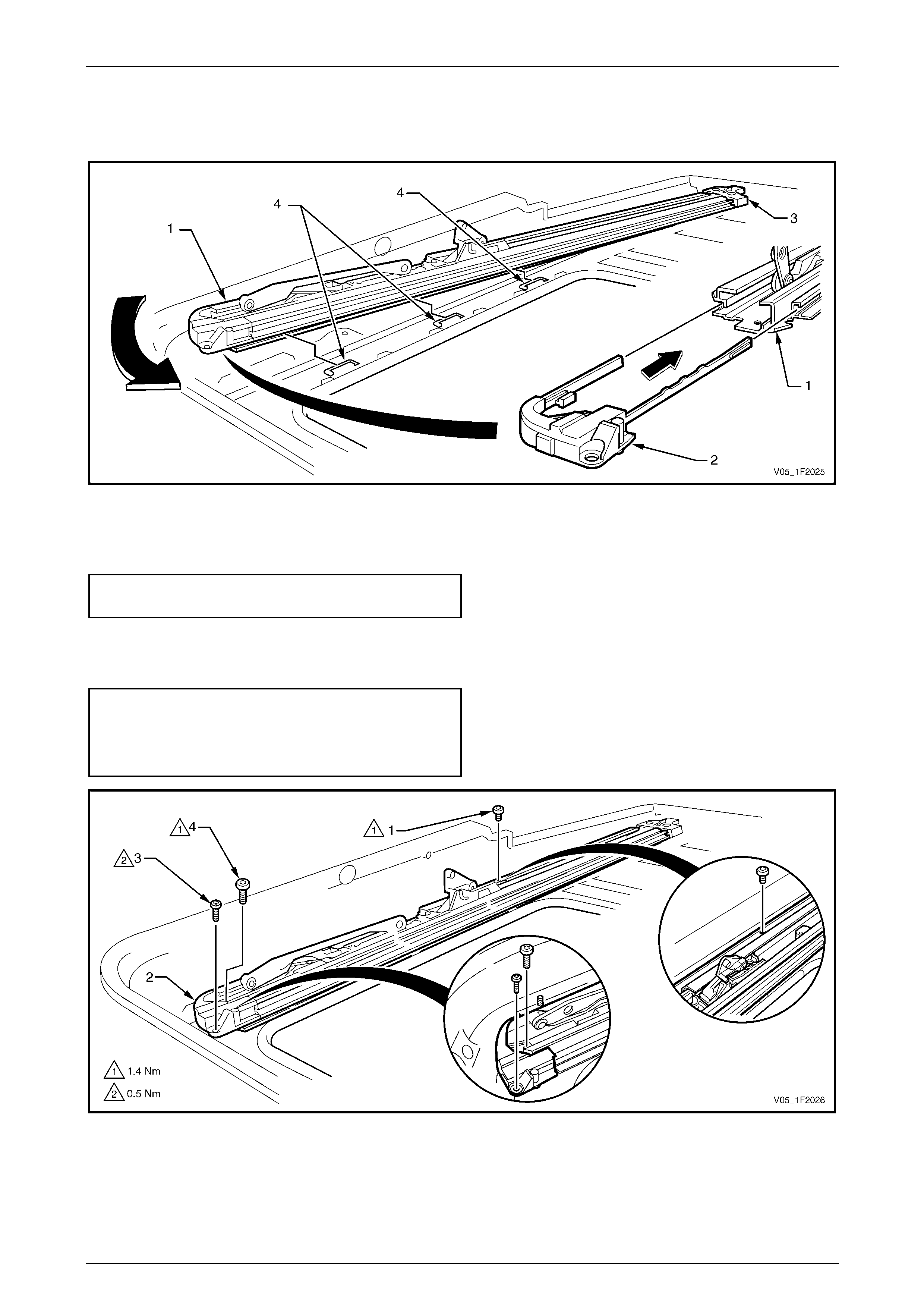
Sunroof – Online Page 1F2–50
Page 1F2–50
6 Lift the front of the guide rail (1) and insert the retraction mechanism (2), refer to Figure 1 F2 – 49.
7 Ensure the guide rail is positione d correctl y against the rear locating bracket (3) then slide sideways to lock in
position onto the tabs (4).
Figure 1F2 – 49
8 Install the guide rail attaching Torx screw (1) ensuring the correct screw noted during removal is used. Tighten the
guide rail attaching Torx screw to the specified torque. Refer to Figure 1F2 – 50.
Guide rail attaching T orx screw
torque specification..............................................1.4 Nm
9 Position the retraction mechanism (2) with the locating Phillips head screw (3).
10 Secure the retraction mechanis m with the attaching Torx screw (4). Tighten the screws to the specified torque.
Retraction mechanism locating screw
torque specification..............................................0.5 Nm
Retraction mechanism attaching
Torx screw torque specification............................1.4 Nm
Figure 1F2 – 50

Sunroof – Online Page 1F2–51
Page 1F2–51
11 Install the locator and blocki ng catch, refer to 4.10 Blocking Catch.
12 Fully tilt the guide rail mechanis m.
13 Ensure the guide rail mechani s m functions correctly.
14 Install the sunshade, refer to 4.7 Sunsha de.
15 Install the drain channel, refer to 4.6 Drain Channel.
16 Install the wind deflector and secure the left-hand and right-hand attaching nuts, refer to 4.5 Wind Deflector.
17 Install the sunroof assembly onto the vehicle, refer to 9.1 Sunroof Assembly.
18 Install the glass panel an d the left-hand and right-hand mechanism covers, refer to 4.1 Glass Panel.
19 Check the sunroof for correct operation.

Sunroof – Online Page 1F2–52
Page 1F2–52
5 Service Operations – Sunroof
Harnesses, Sedan
5.1 Sunroof Power Harness
LT Section No. — AA–000
Remove
1 Remove the sunroof circuit breaker F3 from the passenger compartment fuse and relay panel assembly,
refer to Section 12O Fuses, Relays and Wiring Harnesses.
2 Remove the headlining, refer to Section 1A8 Headlining and Interior Trim.
3 Remove the body lock pillar garnish, refer to Section 1A8 Headlining and Interior T r im.
4 Disconnect the sunroof power harness connector A108 – X1 (1) from the SCU, refer to Figure 1F2 – 51.
5 Unclip the sunroof power harn ess (2) from the sunroof drive cable guides plastic support clip (3).
6 Remove the self-tapping screw (5) securing the ground wire connector (6) to the vehicle.
7 Unclip the sunroof power harness from the C-pill ar metal clip (7) and th e two rear drain tube plastic clips (8).
8 Untape the sunroof power harness from the right-hand rear drain tube (4), noting the position of the tape (9).
9 Disconnect the sunroof power harness connector X322 (10) from the vehicle body harness connector i n the rear
compartment.
10 Feed the sunroof po wer harness through th e hole (11) in the rear seat back panel extension assembly and remove.
11 If required, remove the right-hand rear drai n tube from the sunroof assembly,
refer to 7 Service Operations – Sunroof Drain, Sedan.

Sunroof – Online Page 1F2–53
Page 1F2–53
Figure 1F2 – 51
Legend
1 SCU Connector A108 – X1
2 Sunroof Power Harness
3 Cable Guides Support Clip
4 Rear Drain Tube
5 Ground Connector Self-tapping Screw
6 Power Harness Ground Connector
7 C-pillar Metal Clip
8 Rear Drain Tube Plastic Clips
9 Rear Drain Tube Tape
10 Power Harness Connector X322
11 Hole – Rear Seat Back Panel Extension
Reinstall
Reinstallation of the sunroof power harness is the reverse of the removal procedure, noting the following:
1 Tape the sunroof power harness (2) to the right-hand rear drain tube (4) in the positions (9) noted during removal,
refer to Figure 1F2 – 51.
2 Ensure the sunroof power harness is securely connected to the SCU and body harness.
3 Ensure the ground connector (6) is securely attached to the vehicle. Tighten the ground connector attac hing
screw (5) to the specified torque.
Sunroof power harness ground connector
attaching screw torque specification...........1.5 – 3.0 Nm

Sunroof – Online Page 1F2–54
Page 1F2–54
5.2 Sunroof Harness
LT Section No. — AA–000
Remove
1 Remove the sunroof circuit breaker F3 from the passenger compartment fuse and relay panel assembly,
refer to Section 12O Fuses, Relays and Wiring Harnesses.
2 Remove the headlining, refer to Section 1A8 Headlining and Interior Trim.
3 Disconnect the sunroof harness connector (1) from the
SCU.
4 Unclip the sunroof harness (2) from the sunroof drive
cable guides plastic supp ort clip (3).
5 Untape the sunroof harness from the sunroof frame,
noting the location of the tape (4) and remove the
harness.
Figure 1F2 – 52
Reinstall
Reinstallation of the sunroof harn ess is the reverse of the removal procedure, noting the following:
1 Securely tape the sunroof harness to the sunroof frame in the locations noted during removal.
2 Ensure that the sunroof harness is securely connected to the SCU an d sunroof control harness.

Sunroof – Online Page 1F2–55
Page 1F2–55
5.3 Sunroof Control Harness
LT Section No. — AA–000
Remove
1 Remove the sunroof circuit breaker F3 from the passenger compartment fuse and relay panel assembly,
refer to Section 12O Fuses, Relays and Wiring Harnesses.
2 Remove the roof console. Refer to Section 1A8 Headlining and Interior Trim.
3 Disconnect the sunroof control harn ess con nector (1)
from the sunroof switch (2) and unclip the sunroof
control harness connector (3) from the roof
console (4).
Figure 1F2 – 53
Reinstall
Reinstallation of the sunroof control h arn ess is the reverse of the removal procedure, noting the following:
Ensure the sunroof control harness is securely connected to the sunroof switch, the sunroof harness and clipped to the
roof console.

Sunroof – Online Page 1F2–56
Page 1F2–56
6 Service Operations – Sunroof
Harnesses, AWD Wagon
6.1 Sunroof Power Harness
LT Section No. — AA–000
Remove
1 Remove the sunroof circuit breaker F3 from the passenger compartment fuse and relay panel assembly,
refer to Section 12O Fuses, Relays and Wiring Harnesses.
2 Remove the headlining, refer to Section 1A8 Headlining and Interior Trim.
3 Disconnect the sunroof power harness connector A108 – X1 (1) from the SCU, refer to Figure 1F2 – 54.
4 Unclip the sunroof power harn ess (2) from the sunroof drive cable guides plastic support clip (3).
5 Remove the self-tapping screw (4) securing the ground wire connector (5) to the right-hand side qu arter panel inner
assembly.
6 Disconnect the sunroof power harness connector X322 (6) from the vehicle body harness connector.
7 Remove the right-hand rear drain tube (7) from the three retaining clips (8).
8 Remove the sunroof power harness and the three attached retaining clips from the right-hand side quarter panel
inner assembly.
NOTE
Do not re-use the rear drain tube retaining clips,
as they are damaged when removed from the
quarter panel inner assembly.
9 If required, remove the right-hand rear drain tube from the sunro of assemb ly,
refer to 8 Service Operations – Sunroof Drain, AWD W agon.
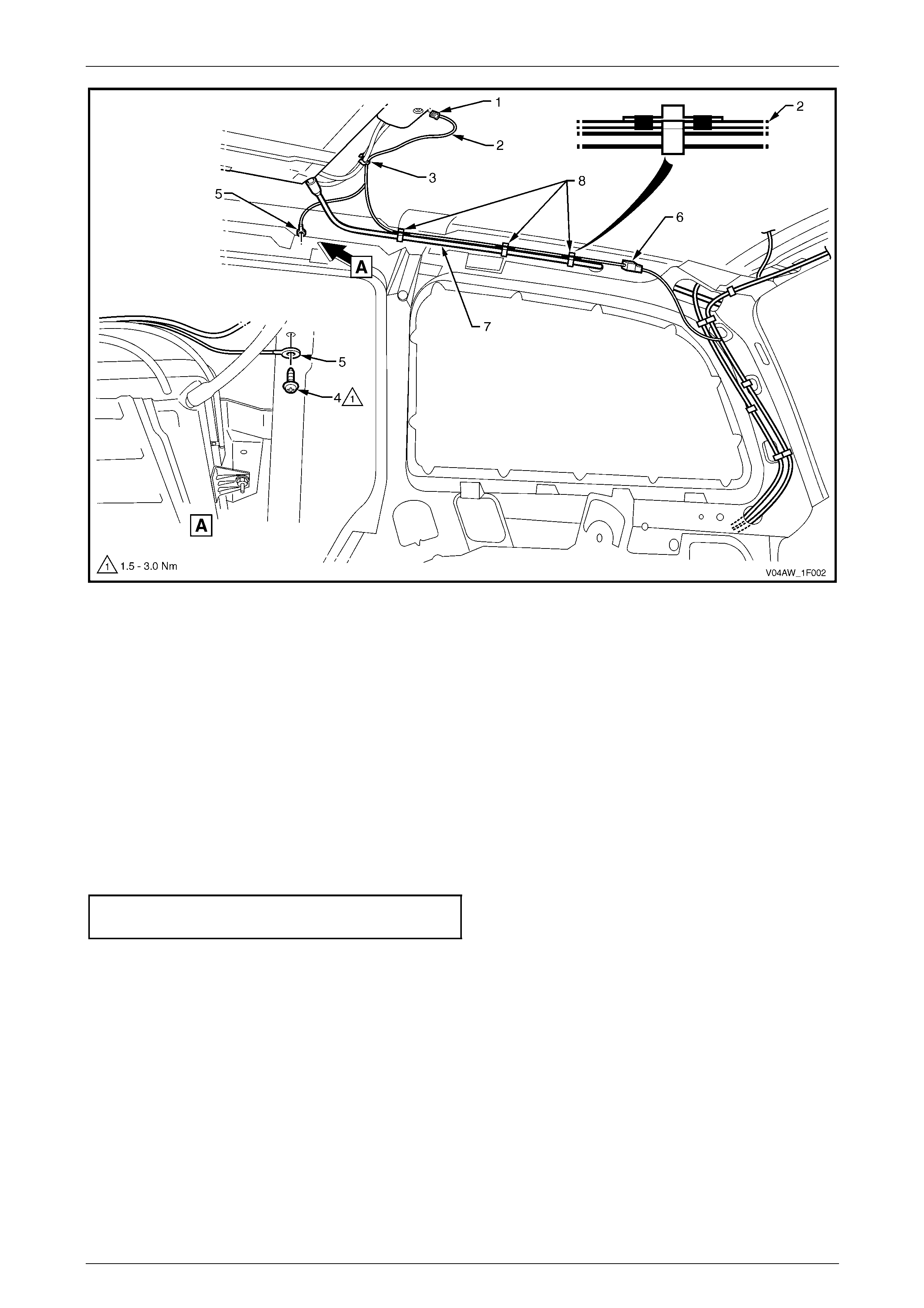
Sunroof – Online Page 1F2–57
Page 1F2–57
Figure 1F2 – 54
Legend
1 SCU Connector A108 – X1
2 Sunroof Power Harness
3 Cable Guides Support Clip
4 Ground Connector Self-tapping Screw
5 Power Harness Ground Connector
6 Power Harness Connector X322
7 Right-hand Rear Drain Tube
8 Retaining Clips
Reinstall
Reinstallation of the sunroof power harness is the reverse of the removal procedure, noting the following:
1 Ensure three new retaining clips are taped to the sunroof power harness at the correct locations before installing to
the right-hand side quarter panel inner assembly.
2 Ensure the ground connector (5) is securely attached to the right-hand side quarter panel inner assembly. Tighten
the attaching screw (4) to the specified torque, refer to Figure 1F 2 – 54.
Sunroof power harness ground connector
attaching screw torque specification...........1.5 – 3.0 Nm
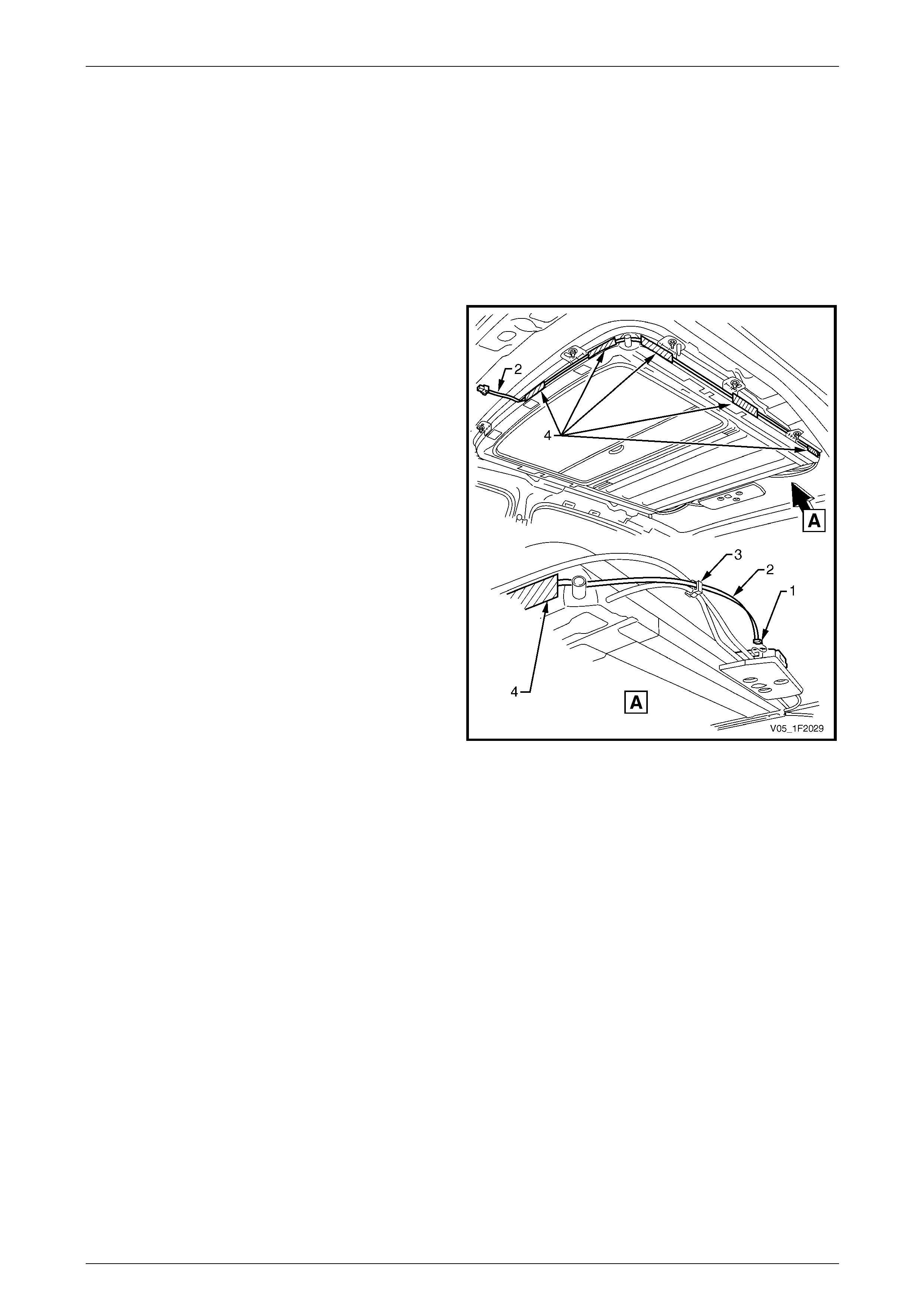
Sunroof – Online Page 1F2–58
Page 1F2–58
6.2 Sunroof Harness
LT Section No. — AA–000
Remove
1 Remove the sunroof circuit breaker F3 from the passenger compartment fuse and relay panel assembly,
refer to Section 12O Fuses, Relays and Wiring Harnesses.
2 Remove the headlining, refer to Section 1A8 Headlining and Interior Trim.
3 Disconnect the sunroof harness connector (1) from the
SCU.
4 Unclip the sunroof harness (2) from the sunroof drive
cable guides plastic supp ort clip (3).
5 Untape the sunroof harness from the sunroof frame,
noting the location of the tape (4) and remove the
harness.
Figure 1F2 – 55
Reinstall
Reinstallation of the sunroof harn ess is the reverse of the removal procedure, noting the following:
1 Securely tape the sunroof harness to the sunroof frame in the locations noted during removal.
2 Ensure the sunroof harness is securel y connected to the SCU and sunroof control harness.
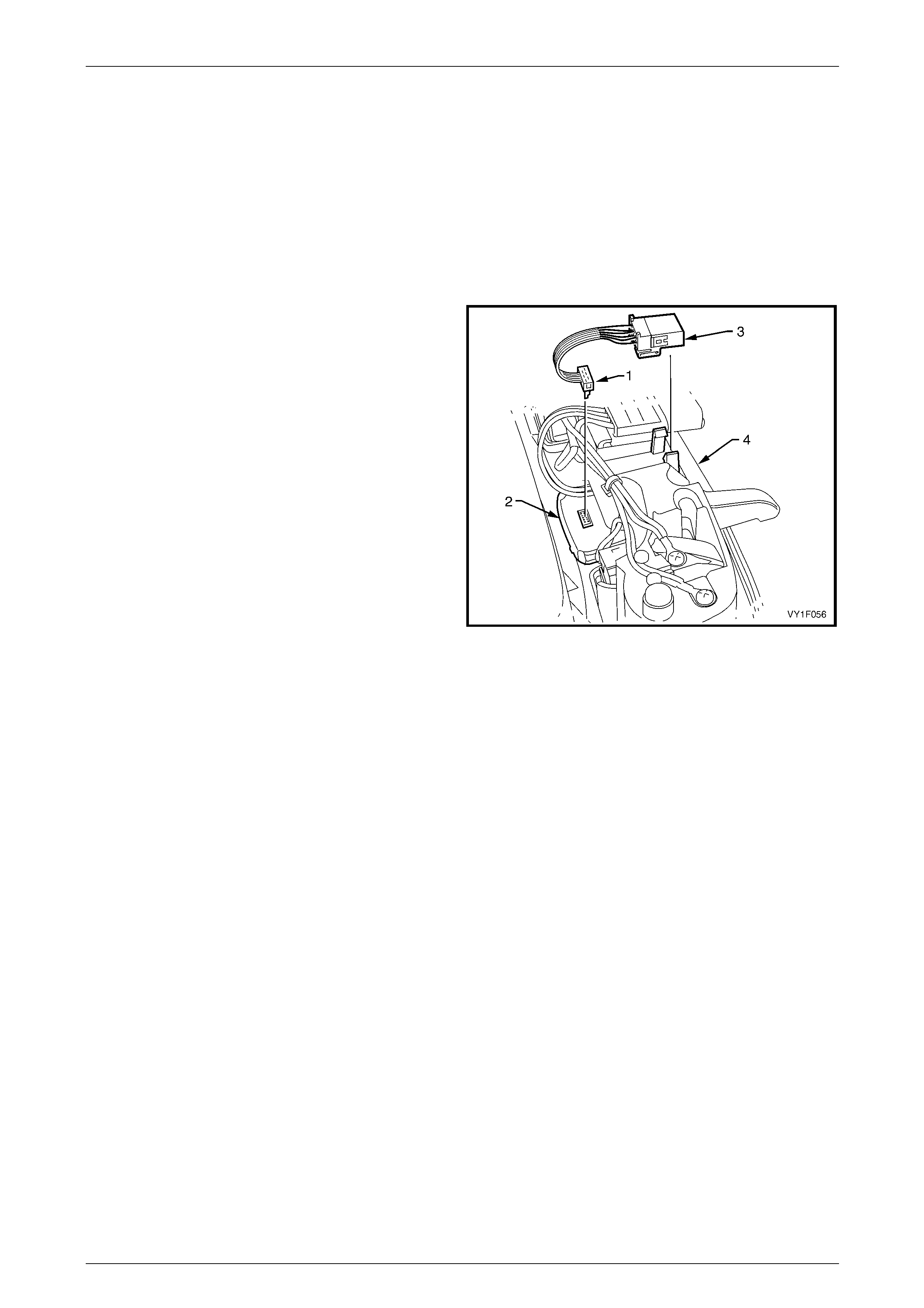
Sunroof – Online Page 1F2–59
Page 1F2–59
6.3 Sunroof Control Harness
LT Section No. — AA–000
Remove
1 Remove the sunroof circuit breaker F3 from the passenger compartment fuse and relay panel assembly,
refer to Section 12O Fuses, Relays and Wiring Harnesses.
2 Remove the roof console. Refer to Section 1A8 Headlining and Interior Trim.
3 Disconnect the sunroof control harn ess con nector (1)
from the sunroof switch (2) and unclip the sunroof
control harness connector (3) from the roof
console (4).
Figure 1F2 – 56
Reinstall
Reinstallation of the sunroof control h arn ess is the reverse of the removal procedure, noting the following:
Ensure the sunroof control harness is securely connected to the sunroof switch, the sunroof harness and clipped to the
roof console.

Sunroof – Online Page 1F2–60
Page 1F2–60
7 Service Operations – Sunroof
Drain, Sedan
7.1 Rear Drain Tubes
LT Section No. — AA–000
Remove
1 Remove the sunroof circuit breaker F3 from the passenger compartment fuse and relay panel assembly,
refer to Section 12O Fuses, Relays and Wiring Harnesses.
2 Remove the headlining, refer to Section 1A8 Headlining and Interior Trim.
3 Remove the body lock pillar garnish, refer to Section 1A8 Headlining and Interior T r im.
4 Remove the rear window trim panel assembl y, refer to Section 1A8 Hea dlining and Interior Trim.
5 Note the entry and exit points, clip locations, taping and general routing of the rear drain tube and sunroof power
harness (right-hand side only), refer to Figure 1F2 – 57.
6 Unclip the rear drain tube (1) and sunroof power harness (2) (right-hand side) from the C-pillar two plastic clips (3).
7 Untape the sunroof power harness from the right-hand rear drain tube, noting the position of the tape (4).
8 Carefully pull the rear drain tube to disconnect from the sunroof rear drain outlet (5).
9 Remove the quarter inner rear side carpet from the rear compartment to expose the rear drain tube,
refer to Section 1A8 Headlining and Interior Trim.
10 Unclip the right-hand side rear drain tube from the plastic clip (6) on the right-hand quarter panel inner assembly.
11 Unclip the left-hand side rear drain tube from the metal clip (7) on the left-hand quarter panel inner assembly,
noting the clip location.
12 Pull the rear drain tube out of the rear drain tube gr ommet (8) located in the rear compartment floor panel outer
extension.
13 From inside the passenger compartment, pull the upper section of the rear drain tube out through the middle
hole (9) in the C-pillar.
14 Withdraw the lower section of the rear drain tube from the rear compartment through the lower hole (10) in the C-
pillar and remove the rear drain tube.
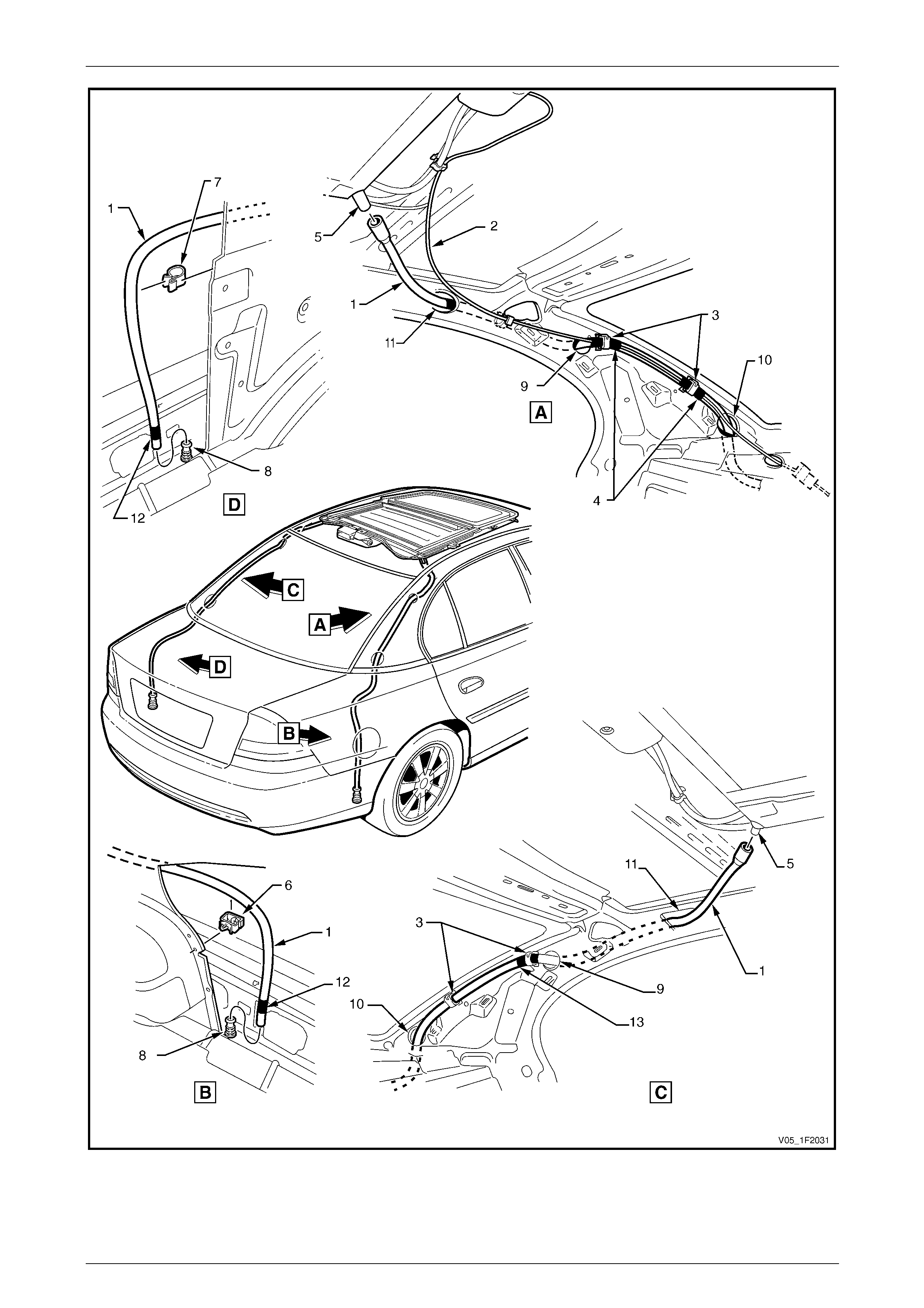
Sunroof – Online Page 1F2–61
Page 1F2–61
Figure 1F2 – 57

Sunroof – Online Page 1F2–62
Page 1F2–62
Reinstall
Reinstallation of the rear drai n tube is the reverse of the removal procedure, noting the following:
1 Ensure the rear drain tubes are clear of dirt and debris and they are free of kinks.
2 Feed the upper section of the rear drain tub e throug h the C-pillar middle opening (9), out through the u pp er
opening (11) and push fit to the sunr oof rear drain tube outlet (5), refer to Figure 1F2 – 57.
NOTE
• If installing a ne w re ar drain tube, remove the
end plug from the rear dra in tube before fitting
it to the sunroof rear drain tube outlet.
• Soapy water may be used to facilitate the
fitting.
3 Feed the lower section of the rear drain tube through the C-pillar lower opening (10), into the rear compartment.
4 Ensure fitment tape (12) is attached 20 mm from the end of the rear drain tube.
5 Push fit the lower end of the rear drain tube into the rear drain tube grommet (8). Ensure the lower edge of the
fitment tape (12) fitted to the end of the rear drain tube is aligned with the outer edge of the grommet to ensure a
secure fit.
6 If the sunroof power harness (2) was removed from the right-hand rear drain tube, tape the sunroof power harness
to the rear drain tube in the positions noted during removal.
7 Secure the rear drain tube and the sunroof power harness (right-hand side only) with the tape and clips in the
positions noted during removal, tape at locati ons (4) for right-hand rear drain tube and location (13) for left-hand
rear drain tube.
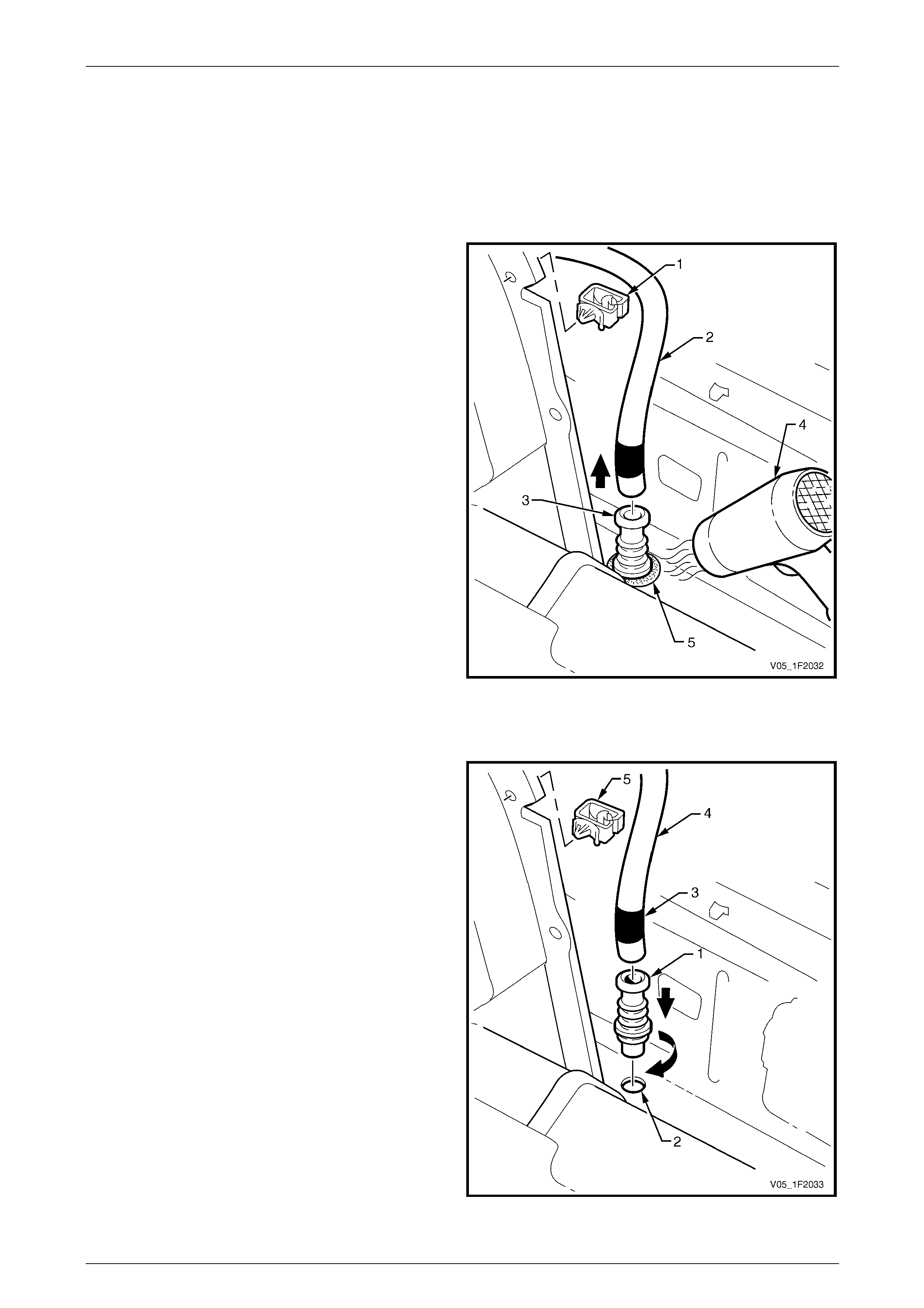
Sunroof – Online Page 1F2–63
Page 1F2–63
7.2 Rear Drain Tube Grommet
LT Section No. — AA–000
Remove
1 Remove the quarter inner rear side carpet from the rear compartment to expose the rear drain tube,
refer to Section 1A8 Headlining and Interior Trim.
2 Unclip the rear drain tube from the clip (1) on the
quarter panel inner assembly, noting the clip location.
3 Pull out the rear drain tube (2) from the rear drain tube
grommet (3) located in the rear compartment floor
panel outer extension.
4 Use a heat gun (4) or similar to soften the sealant (5)
securing the rear drain tube grommet to the locating
hole.
5 Pull the rear drain tube grommet out of the locatin g
hole.
6 Discard the grommet and scrape the seal off the rear
compartment floor panel outer exte nsion.
Figure 1F2 – 58
Reinstall
Reinstallation of the rear drai n tube n ew grommet is the reverse of the removal procedure, noting the following:
1 Push fit the rear drain tube new grommet (1) into the
locating hole (2) using a twisting action to ensure the
lip of the drain tube grommet seals securel y.
NOTE
To reseal the grommet to the locating hole, use
polyurethane adhesive such as Betaseal 15685
or equivalent.
2 Ensure fitment tape (3) is attached 20 mm from the
end of the rear drain tube (4) and firmly push fit the
rear drain tube into the rear drain tube grommet.
3 Ensure the lower edge of the fitment tape is aligned
with the outer edge of the grommet to ensure a secure
fit.
4 Ensure the rear drain tube is secured to the clip (5) on
the quarter panel inner assembl y.
Figure 1F2 – 59
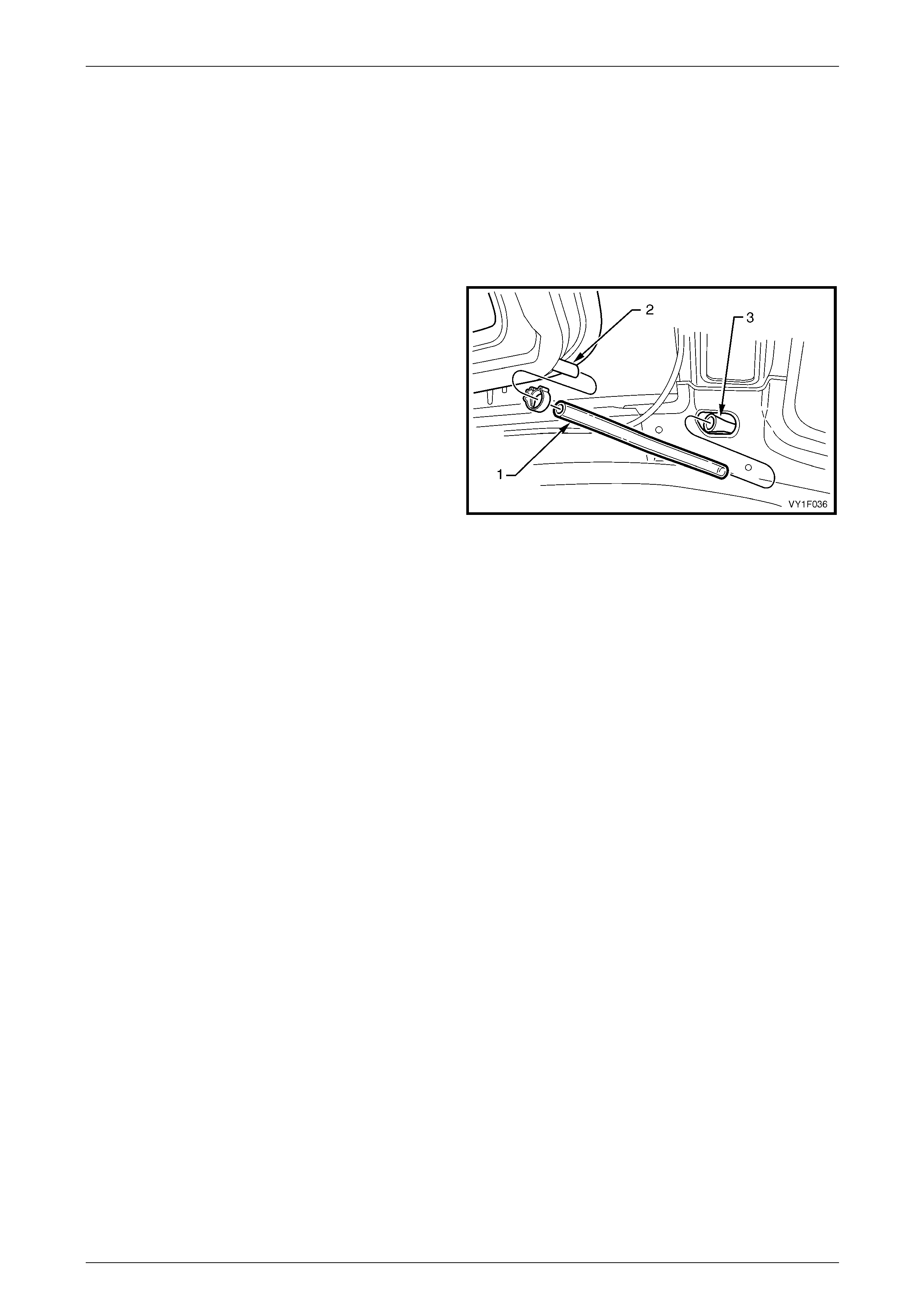
Sunroof – Online Page 1F2–64
Page 1F2–64
7.3 Front Drain Tube
LT Section No. — AA–000
Remove
1 Remove the sunroof circuit breaker F3 from the passenger compartment fuse and relay panel assembly,
refer to Section 12O Fuses, Relays and Wiring Harnesses.
2 Remove the headlining, refer to Section 1A8 Headlining and Interior Trim.
3 Unclip and remove the front drain tube (1) from the
sunroof front drain outlet (2).
4 Withdraw the front drain tube from the A-pil lar metal
drain tube (3) and remove.
Figure 1F2 – 60
Reinstall
Reinstallation of the front drain tube is the reverse of the removal procedure, noting the following:
1 Ensure the front drain tubes are clear of dirt and debris and they are free of kinks.
2 Ensure the front drain tubes are securely at tached to the sunroof front drain outlet (2) and fitted to the A-pillar metal
drain tube (3), refer to Figure 1F2 – 60.

Sunroof – Online Page 1F2–65
Page 1F2–65
8 Service Operations – Sunroof
Drain, AWD Wagon
8.1 Rear Drain Tubes
LT Section No. — AA–000
Remove
1 Remove the sunroof circuit breaker F3 from the passenger compartment fuse and relay panel assembly,
refer to Section 12O Fuses, Relays and Wiring Harnesses.
2 Remove the headlining, refer to Section 1A8 Headlining and Interior Trim.
3 Note the rear drain tube retain ing clip locations (three places), the entry point in the quarter pan el inner assembly,
and general routeing of the rear drain tube (1) and sunroof power harness (2) (right-hand side only), refer to
Figure 1F2 – 61.
4 Unclip the rear drain tube from the retaining clips (3) on the quarter panel inner assembly.
5 Carefully pull the rear drain tube to disconnect from the sunroof rear drain tube outlet (4).
6 Pull the rear drain tube from the grommet (5).
NOTE
Views C and D within Figure 1F2 – 61 show the
grommet with the liftgate in the open position, this
is for clarity only.
7 From inside the rear compartment, pull the rear drain tub e through the hole (6) in the quarter panel inner assembly,
and remove.
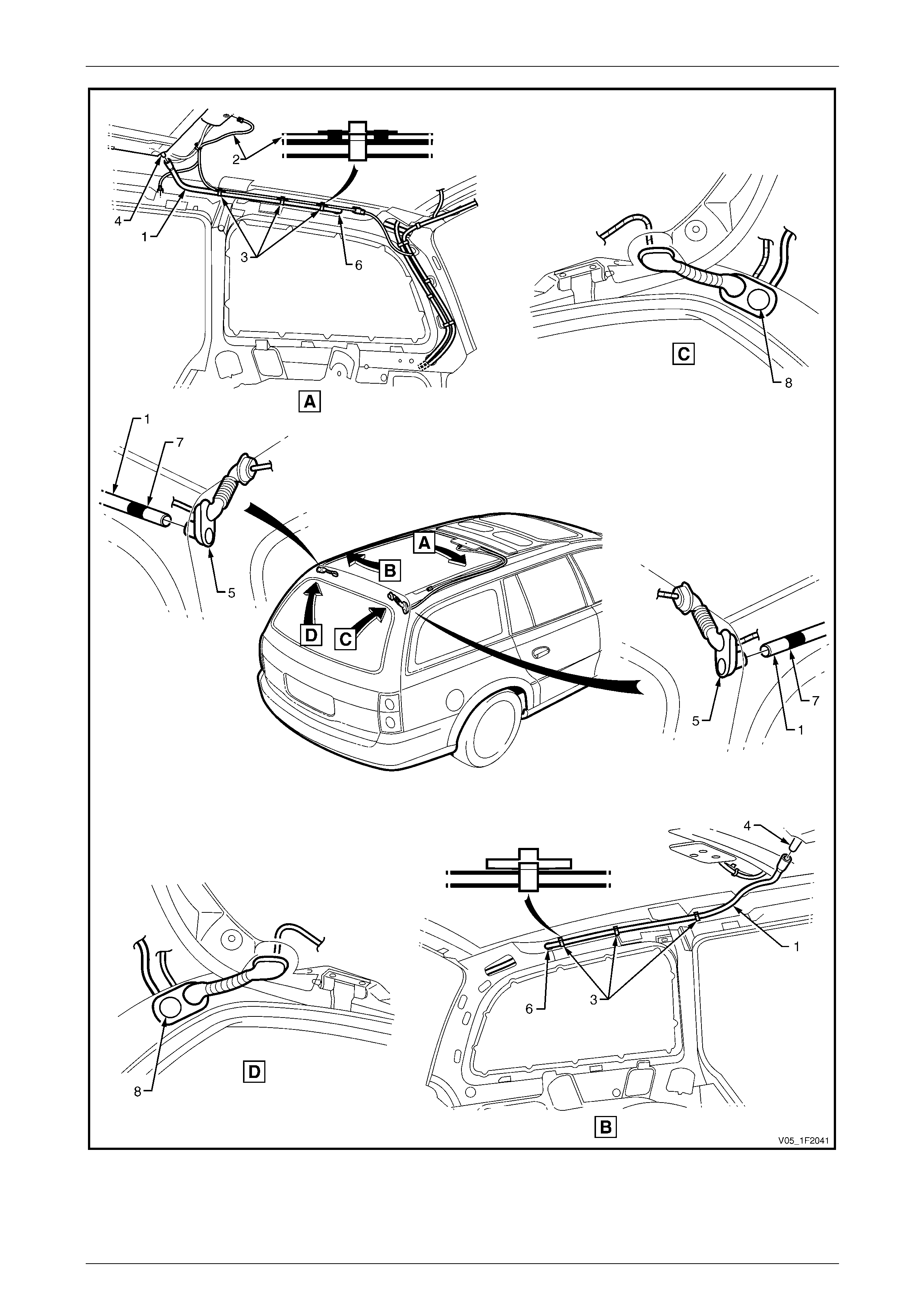
Sunroof – Online Page 1F2–66
Page 1F2–66
Figure 1F2 – 61

Sunroof – Online Page 1F2–67
Page 1F2–67
Reinstall
Reinstallation of the rear drai n tube is the reverse of the removal procedure, noting the following:
1 Ensure the rear drain tube is clear of dirt and debris and is free of kinks.
2 Feed the rear section of the rear drain tube through the hole (6) into the quarter panel inner assembly,
refer to Figure 1F2 – 61.
3 Ensure fitment tape (7) is attached 20 mm from the end of the rear drain tube.
4 Fit the rear drain tube into the grommet (5). Ensure the rear edge of the fitment tape (7) is aligned with the outer
edge of the grommet to ensure a secure fit.
Ensure the rear drain tube plug (8) has been
removed from the grommet (5) for drainag e of
the sunroof.
5 Fit the rear drain tube (1) to the sunroof rear drain tube outlet (4).
NOTE
• If installing a ne w re ar drain tube, remove the
end plug from the rear dra in tube before fitting
it to the sunroof rear drain tube outlet.
• Soapy water may be used to facilitate the
fitting.
6 Secure the rear drain tube with the retainer clips (3) on the quarter panel inner assembly, in the positions noted
during removal.
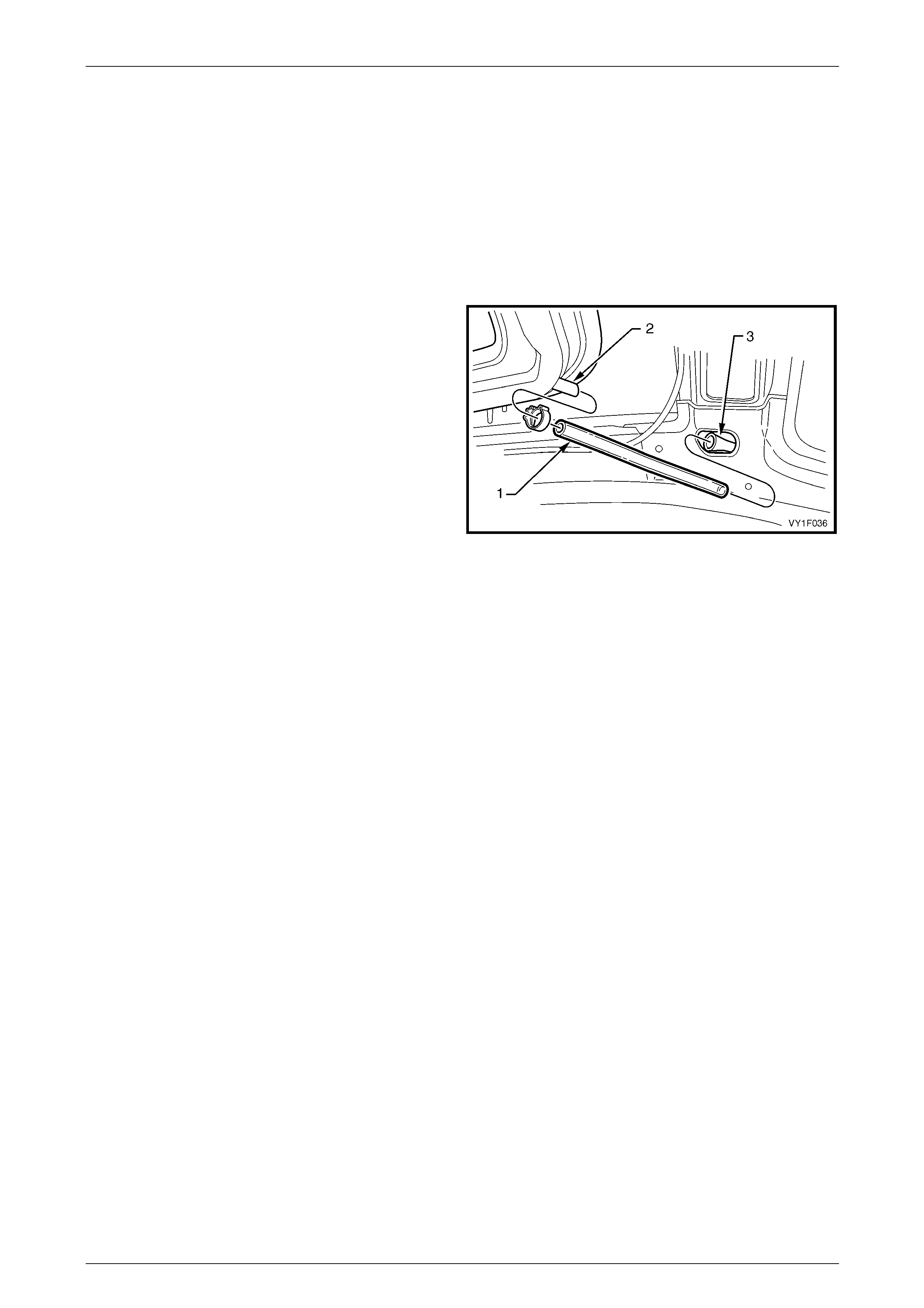
Sunroof – Online Page 1F2–68
Page 1F2–68
8.2 Front Drain Tube
LT Section No. — AA–000
Remove
1 Remove the sunroof circuit breaker F3 from the passenger compartment fuse and relay panel assembly,
refer to Section 12O Fuses, Relays and Wiring Harnesses.
2 Remove the headlining, refer to Section 1A8 Headlining and Interior Trim.
3 Unclip and remove the front drain tube (1) from the
sunroof front drain outlet (2).
4 Withdraw the front drain tube from the A-pil lar metal
drain tube (3) and remove.
Figure 1F2 – 62
Reinstall
Reinstallation of the front drain tube is the reverse of the removal procedure, noting the following:
1 Ensure the front drain tubes are clear of dirt and debris and they are free of kinks.
2 Ensure the front drain tubes are securely at tached to the sunroof front drain outlet (2) and fitted to the A-pillar metal
drain tube (3), refer to Figure 1F2 – 62.
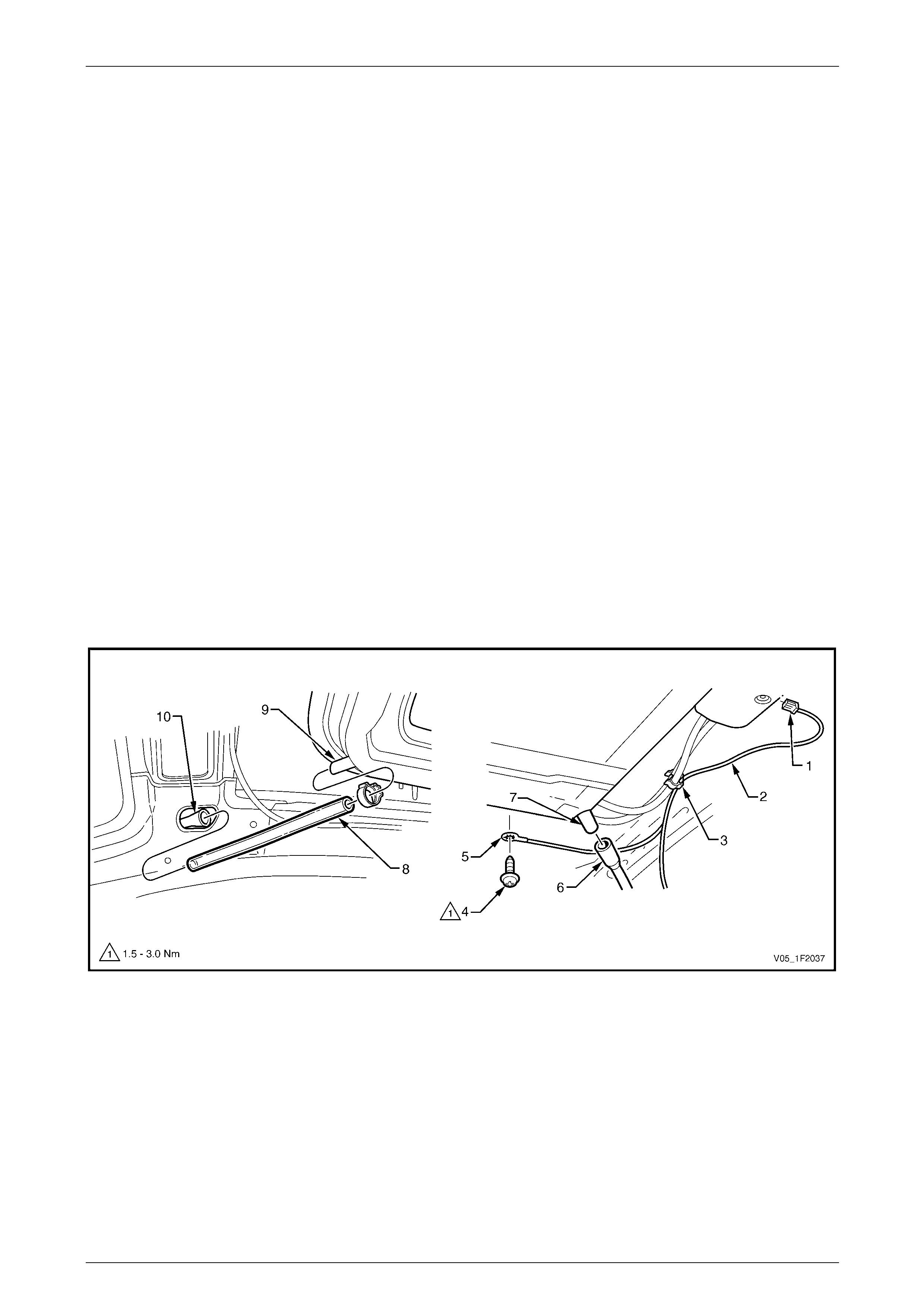
Sunroof – Online Page 1F2–69
Page 1F2–69
9 Service Operations – Sunroof
Assembly
9.1 Sunroof Assembly
LT Section No. — AA–000
Remove
1 Remove the sunroof circuit breaker F3 from the passenger compartment fuse and relay panel assembly,
refer to Section 12O Fuses, Relays and Wiring Harnesses.
2 Remove the headlining, refer to Section 1A8 Headlining and Interior Trim.
3 Lay the front seats back as far as possible to allow for easier removal of the sunroof assembly.
4 Disconnect the sunroof power harness connector (1) from the SCU, refer to Figure 1F2 – 63.
5 Unclip the sunroof power harn ess (2) from the sunroof drive cable guides plastic support clip (3).
6 Remove the self-tapping screw (4) securing the sunroof power harness ground wire connector (5) to the vehicle.
7 Position the sunroof power harness so it will not be damaged when the sunroof assemb ly is lowered.
8 Carefully pull the right-ha nd and left-hand rear drain tubes ( 6) to discon nect them from the sunroof rear drain
outlets (7).
9 Unclip and remove the right-hand and left-hand front drain tubes (8) from the sunroof front drain outlets (9).
10 If required, withdraw the right-hand and left-hand front drain tubes from the A-pillar metal drain tubes (10) and
remove.
Figure 1F2 – 63
11 Loosen the eight attaching nuts (1) securing the sunroof assembly (2) to the mounting studs (3), refer to
Figure 1F2 – 64.
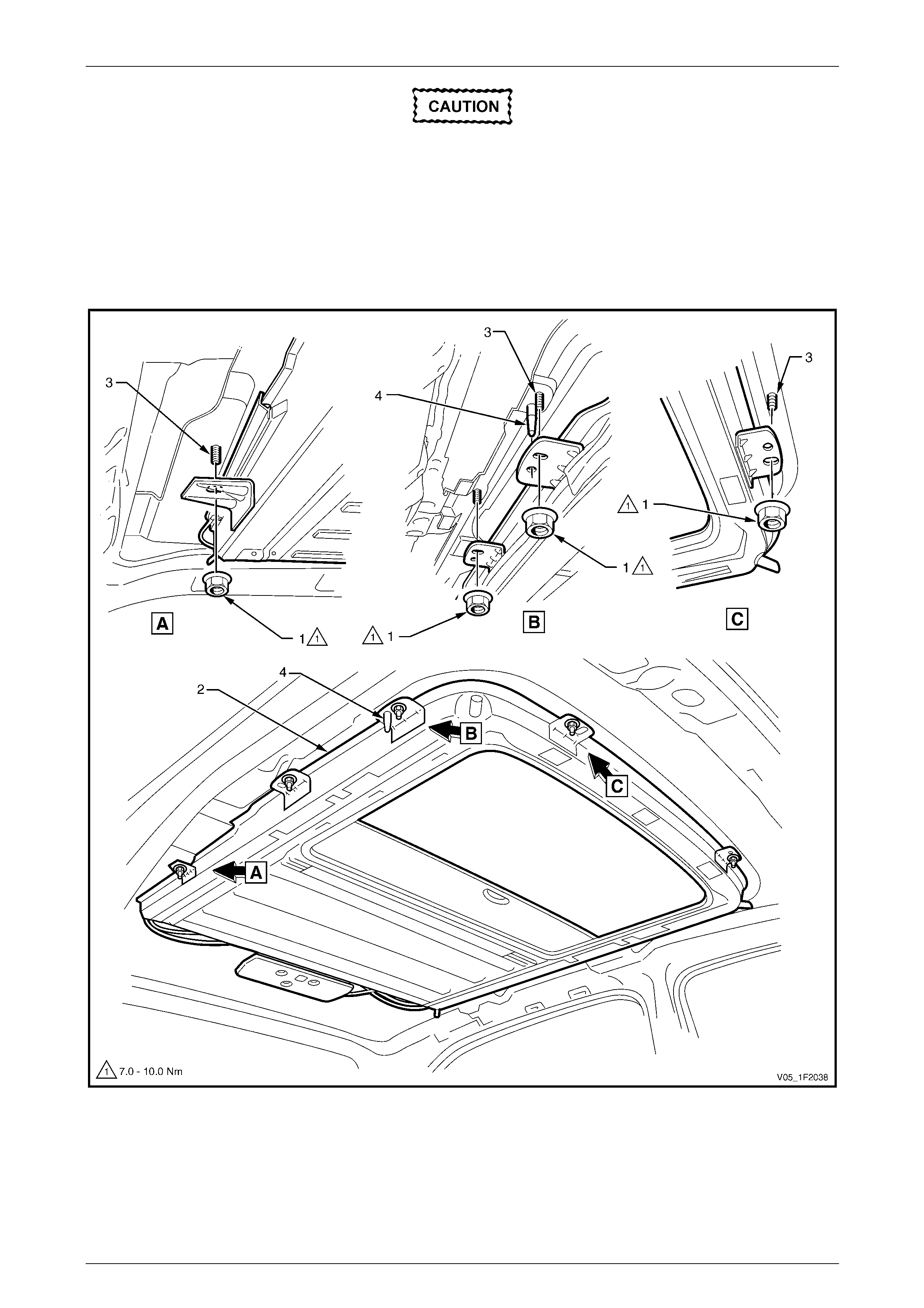
Sunroof – Online Page 1F2–70
Page 1F2–70
To avoid damage to the interior of the vehicle
and/or the sunroof assembly, obtain
assistance to support the sunroof assembly
while removing the attaching nuts and to help
manoeuvre the sunroof assembly out of the
vehicle.
12 While supporting the sunroof assembly, remove the eight attaching nuts from the mounting studs.
13 Carefully lo wer the sunroof assembly and place in an appro priate safe area.
Figure 1F2 – 64
Sunroof – Online Page 1F2–71
Page 1F2–71
Reinstall
Reinstallation of the sunroof assemb ly is the reverse of the removal procedure, noting the following:
1 Check if the front and rear sunroof assembly seals are in go od condition and are correctly fitted.
To avoid damage to the interior of the vehicle
and/or the sunroof assembly, obtain
assistance to support the sunroof assembly
while locating it and securing with the
attaching nuts.
2 Ensure the sunroof assembly (2) is correctly positioned over the mounting studs (3) and the right-hand and
left-hand locating pins (4), refer to Figure 1F2 – 64.
3 Secure the sunroof assembly with the eight attaching nuts (1). Tighten the sunroof assem bl y attaching nuts to the
specified torque.
Sunroof assembly attaching nut
torque specification...................................7.0 – 10.0 Nm
4 Ensure the front drain tubes (8) are securely attached to the sunroof front drain outlet (9) and fitted to the A-pillar
metal drain tube (10), refer to Figure 1F2 – 63.
5 Ensure the rear drain tubes (6) are securel y fitted to the sunroof rear drain tube outlets (7).
6 Ensure the glass panel is flush with the roof, refer to 4.1 Glass Panel.
7 Before installing the headlining, proceed as follows:
a Connect the sunroof control harness to the sunroof harness.
b Connect the sunroof power harness (2) to the SCU and ground wire connector (5) to the vehicle.
c Insert the sunroof circuit breaker F3 in the passenger compartment fuse and relay panel assembly,
refer to Section 12O Fuses, Relays and Wiring Harnesses.
d Check that the sunroof operates correctly, refer to 1.2 Sunroof Functions.
e Remove the sunroof circuit breaker F3 from the passenger compartment fuse and relay panel assembly,
refer to Section 12O Fuses, Relays and Wiring Harnesses.
8 Ensure that the sunroof power harness (2) is securely connected to the SCU and fitted to the sunroof drive cabl e
guides plastic support clip (3).
9 Tighten to the specified torque the self-tap ping screw (4) attaching the sunroof power harness groun d wire
connector (5) to the vehicle.
Sunroof power harness ground connector
attaching screw torque specification...........1.5 – 3.0 Nm
10 Install the headlining, refer to Section 1A 8 Headlining and Interior Trim.
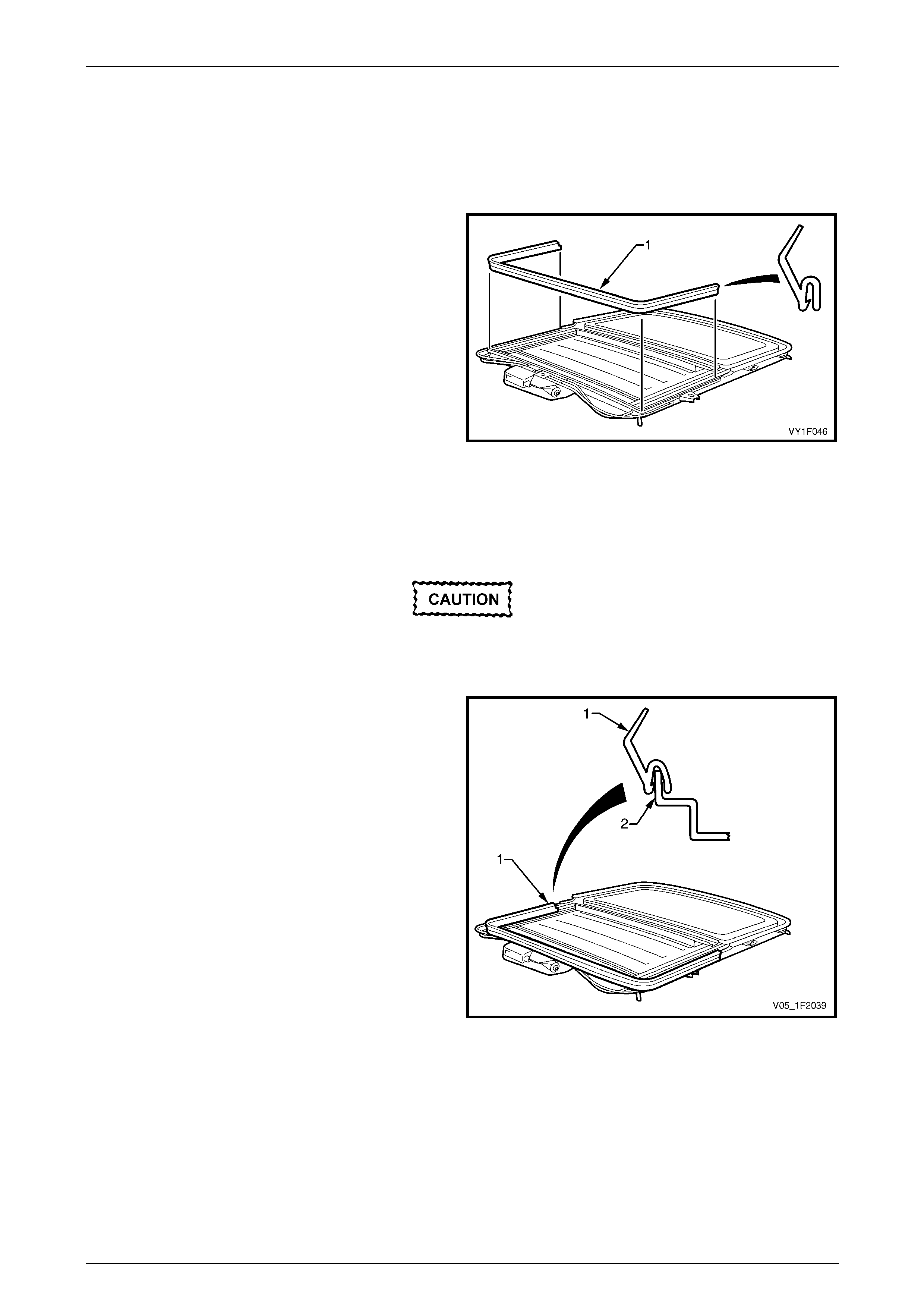
Sunroof – Online Page 1F2–72
Page 1F2–72
9.2 Sunroof Assembly Rear Seal
LT Section No. — AA–000
Remove
1 Remove the sunroof assembly from the vehicle,
refer to 9.1 Sunroof Assembly.
2 Remove the sunroof assembly rear seal (1) from the
lip around the rear sectio n of the sunroof frame.
Figure 1F2 – 65
Reinstall
Reinstallation of the sunroof assemb ly rear seal is the reverse of the removal procedure, noting the following:
Ensure the mounting lip of the sunroof frame
and the rear seal are clean and free of debris
before fitting the rear seal.
1 Install the rubber rear seal (1) on the mounti ng lip (2)
of the sunroof frame rear section.
2 Ensure the rear seal is correctly and fully inserted onto
the sunroof frame mounting lip.
Figure 1F2 – 66
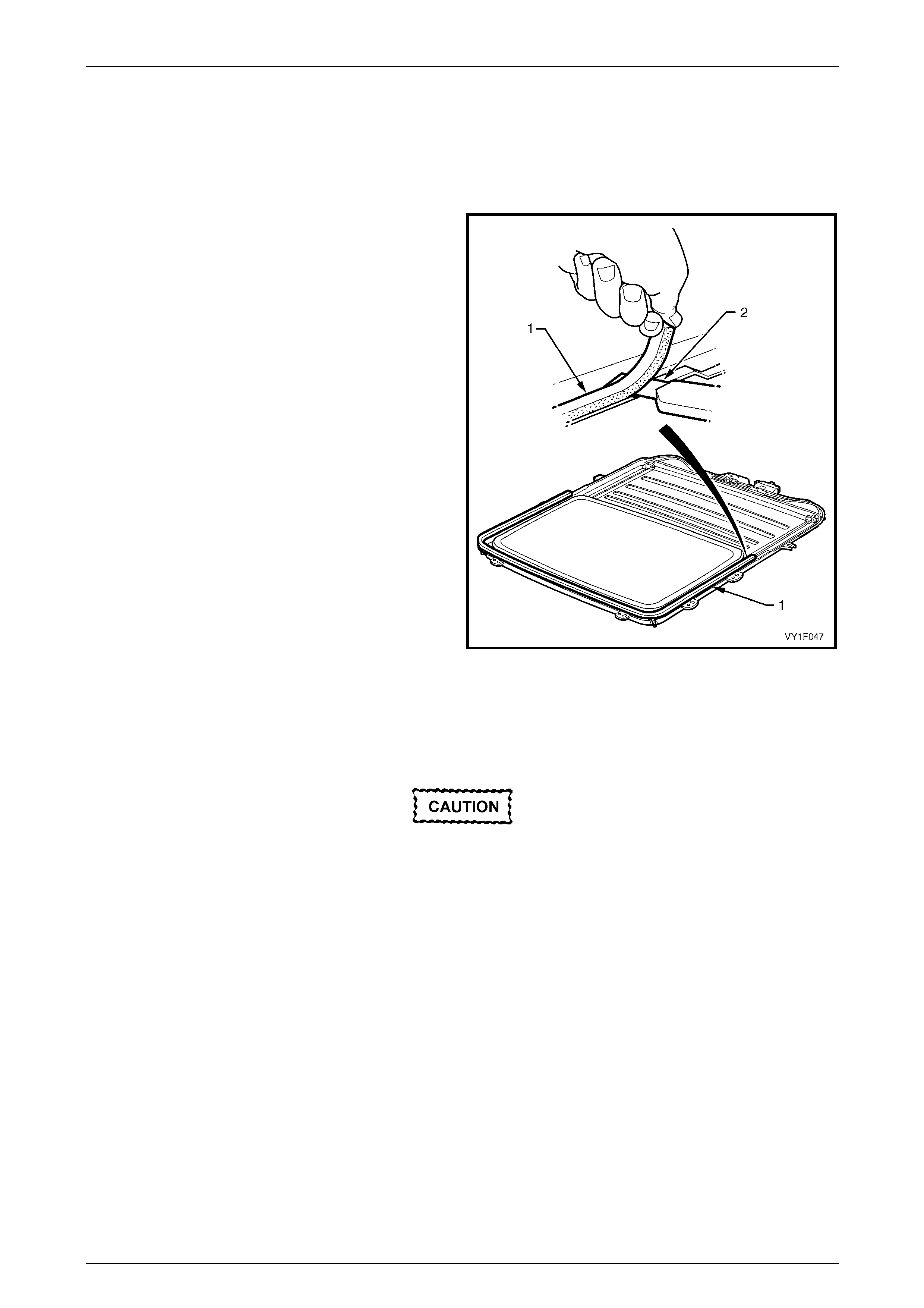
Sunroof – Online Page 1F2–73
Page 1F2–73
9.3 Sunroof Assembly Front Seal
LT Section No. — AA–000
Remove
1 Remove the sunroof assembly from the vehicle,
refer to 9.1 Sunroof Assembly.
2 Peel the sunroof assembly front seal (1) from the front
section of the sunroof frame noting the positi on of the
seal.
NOTE
Use a flat blade knife (2) or similar to facilitate
the sunroof assembly front seal removal if
required.
3 Clean thoroughly the seal mounting surface on the
sunroof frame.
Figure 1F2 – 67
Reinstall
Reinstallation of the sunroof assembly front seal is the reverse of the removal procedure, noting the following:
Ensure the mounting surface of the sunroof
frame is clean and free of debris before fitting
the new sunroof assembly front seal.
1 Peel the backing off a small section of the sunroof assembly front foam seal and position at the starting point, as
noted during removal, on one side of the su nroof frame.
2 Continue to peel the backing from the seal while fixing the seal around the front section of the sunroof frame.
3 Ensure the sunroof assembly front seal has firmly adhered to the sunroof frame.

Sunroof – Online Page 1F2–74
Page 1F2–74
10 Torque Wrench Specifications
Drive Motor Attaching Torx Screw..........................................................2.0 Nm
Drive Gear Retainer Attaching Torx Screw.............................................2.0 Nm
SCU Attaching Torx Screw.....................................................................2.0 Nm
Glass Panel Mounting Torx Screw ................................................3.5 – 4.0 Nm
Adjustment Bracket Retaining Torx Screw.............................................2.0 Nm
Exterior Cover Attaching Nut.........................................................1.8 – 2.2 Nm
Wind Deflector Attaching Nut .................................................................2.0 Nm
Drain Channel Attaching Torx Screw ............................................0.6 – 1.0 Nm
Retraction Mechanism Locating Screw ..................................................0.5 Nm
Retraction Mechanism Attaching Torx Screw.........................................1.4 Nm
Locator Attaching Torx Screw ................................................................1.4 Nm
Guide Rail Attaching Torx Screw............................................................1.4 Nm
Sunroof Power Harness Ground
Connector Attaching Screw............................................................1.5 - 3.0 Nm
Sunroof Assembly Attaching Nut.................................................7.0 – 10.0 Nm
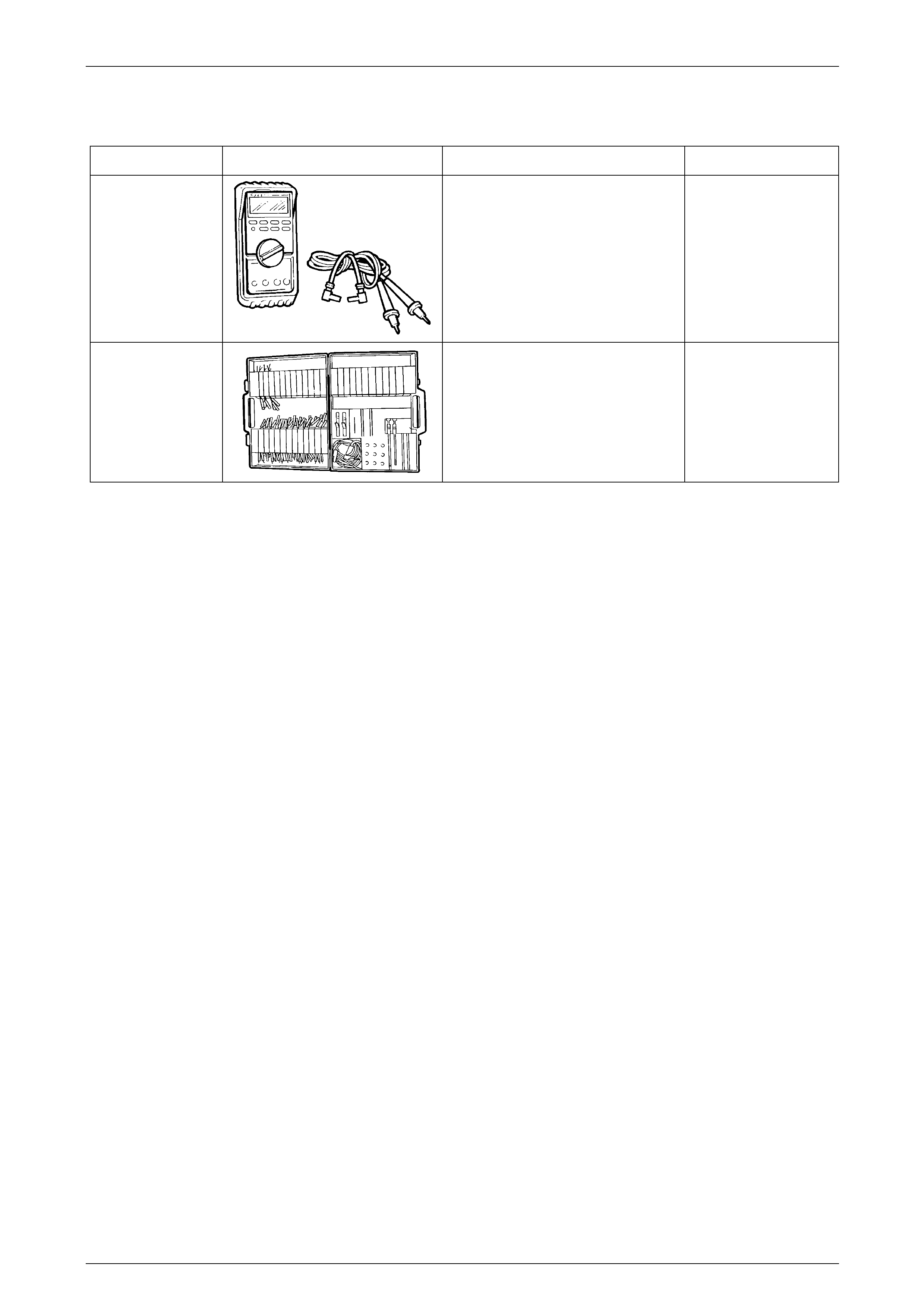
Sunroof – Online Page 1F2–75
Page 1F2–75
11 Special Tools
Tool Number Illustration Description Tool Classification
J39200
(3588)
Digital Multimeter.
Tool no. J39200 previously released,
or use commercially available
equivalent. Must have 10 meg ohm
input impedance.
Previously released.
Available.
KM-609
(J35616-A)
Electronic Kit.
Used in conjunction with a multimeter
for measuring voltages and
resistances without damaging wiring
harness connectors.
Desirable.