
Wheels and Tyres Page 10–1
Section 10
Wheels and Tyres
ATTENTION
Before performing any service operation or other procedure described in this Section, refer to Section 00
Warnings, Cautions and Notes for correct workshop practices with regard to safety and / or property damage.
1 General Information ...............................................................................................................................3
1.1 Tyre Placards ......................................................................................................................................................... 8
1.2 Tyre Markings......................................................................................................................................................... 9
1.3 Spare Wheel Stowage.......................................................................................................................................... 10
Sedan.................................................................................................................................................................... 10
Wagon................................................................................................................................................................... 11
AWD Wagon ......................................................................................................................................................... 12
Coupe.................................................................................................................................................................... 13
Utility – Tool Storage........................................................................................................................................... 14
Utility – Spare Wheel Stowage............................................................................................................................ 15
Regular Cab – Tool Stowage............................................................................................................................... 16
Crew Cab – Tool Stowage................................................................................................................................... 17
Regular Cab and Crew Cab – Spare Wheel Stowage........................................................................................ 18
2 Diagnostics...........................................................................................................................................19
2.1 Wear...................................................................................................................................................................... 19
2.2 Road Testing........................................................................................................................................................ 20
Tyre and Wheel Inspection.................................................................................................................................. 20
Slow Acceleration Test........................................................................................................................................ 20
Neutral Coast-down Test..................................................................................................................................... 20
Downshift Test..................................................................................................................................................... 20
Steering Input Test .............................................................................................................................................. 21
Standing Start Acceleration................................................................................................................................ 21
2.3 Vibration ............................................................................................................................................................... 22
Radial Force Variation......................................................................................................................................... 23
Lateral Force Variation........................................................................................................................................ 23
2.4 Vehicle Lead......................................................................................................................................................... 24
3 Service Operations...............................................................................................................................25
3.1 Tyre Inflation and Inspection.............................................................................................................................. 25
Pressure Adjustments to Suit Operating Conditions....................................................................................... 25
3.2 Wheel Removal and Installation......................................................................................................................... 26
3.3 Tyre Removal and Installation............................................................................................................................ 27
Tyre Repairs......................................................................................................................................................... 28
3.4 Replacement of Wheels and Tyres..................................................................................................................... 29
3.5 Tyre Rotation........................................................................................................................................................ 30
3.6 Checking Wheel and Tyre Assembly Run-out ................................................................................................... 31
Procedure............................................................................................................................................................. 32
Match Mounting ................................................................................................................................................... 33
3.7 Checking Wheel Run-out .................................................................................................................................... 34
Procedure............................................................................................................................................................. 34
3.8 Wheel and Tyre Balancing .................................................................................................................................. 36
Static Balance ...................................................................................................................................................... 36
Dynamic Balance................................................................................................................................................. 36
Off-vehicle Balancing.......................................................................................................................................... 37
On-vehicle Balancing .......................................................................................................................................... 37
Balance Limits...................................................................................................................................................... 38
Page 10–1
Techline

Wheels and Tyres Page 10–2
3.9 Wheel Attaching Nuts and Studs........................................................................................................................ 39
4 Specifications.......................................................................................................................................40
5 Torque Wrench Specifications............................................................................................................42
6 Special Tools ........................................................................................................................................43
Page 10–2
Wheels and Tyres Page 10–3
1 General Information
Executive Sedan and Wagon
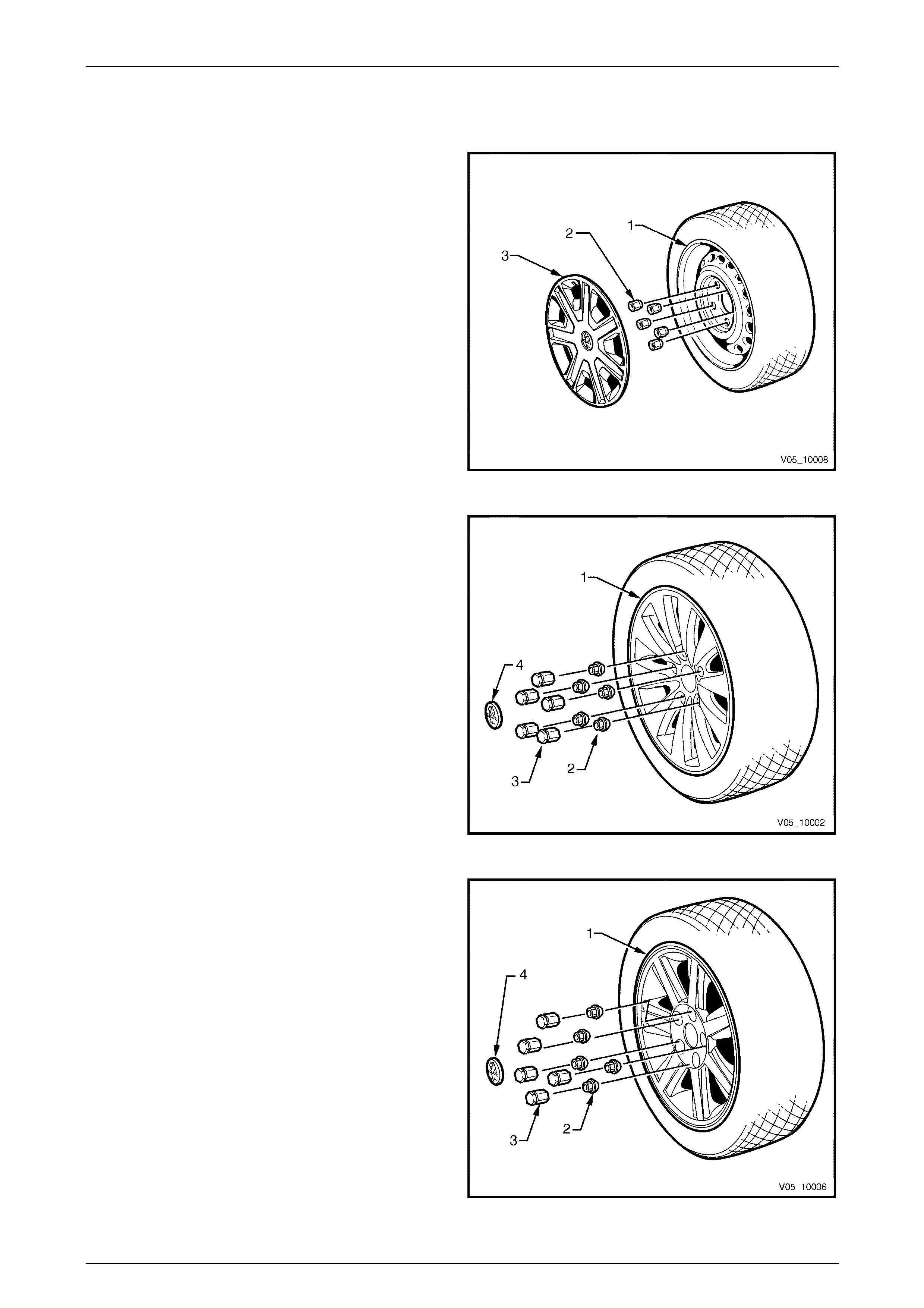
Figure 10 – 1 illustrates the steel wheel (1) wheel nuts (2)
and full wheel trim (3).
Road wheels .............................6J x 15 steel
Tyres.........................................P205/65R15 95H
Option
Road wheels .............................7J x 15 steel
Tyres.........................................205/65R15 99H
Figure 10 – 1
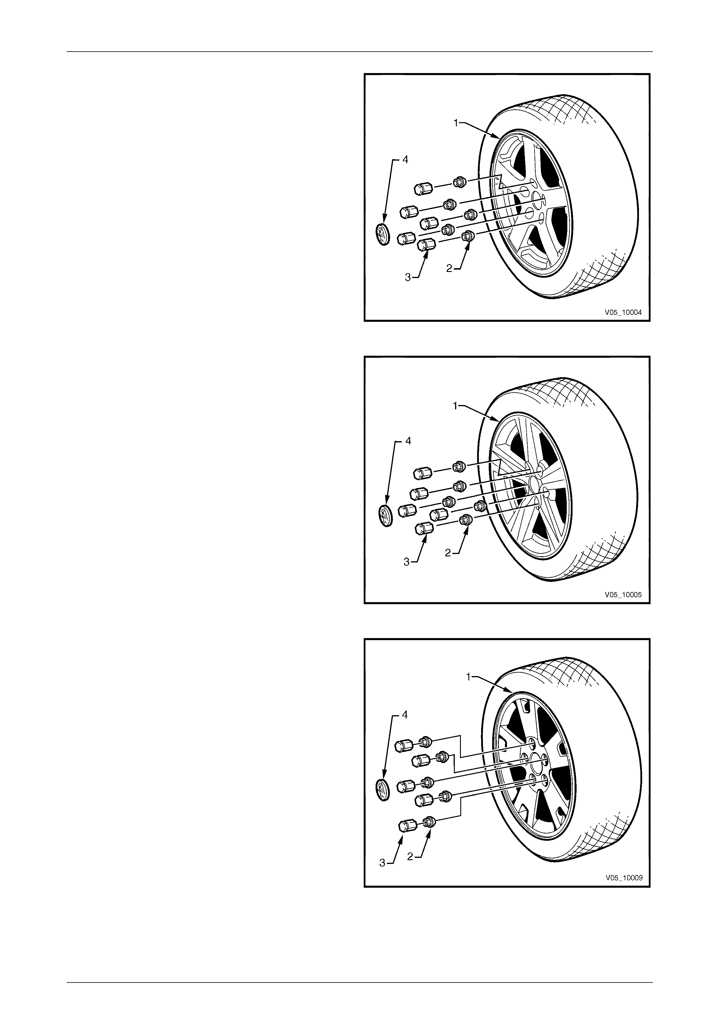
Acclaim Sedan and Wagon
Figure 10 – 2 illustrates the allo y wheel (1), wheel nuts (2)
nut caps (3) and centre cap (4).
Road Wheels............................. 7JJ x 15 alloy
Tyres......................................... P205/65R15 95H
Figure 10 – 2
Berlina Sedan and Wagon
Figure 10 – 3 illustrates the allo y wheel (1), wheel nuts (2),
nut caps (3) and centre cap (4).
Road Wheels............................. 7JJ x 16 alloy
Tyres......................................... 215/60R16 95V
Figure 10 – 3
Page 10–3
Wheels and Tyres Page 10–4
SV6 – SV8 Sedan and S Utility
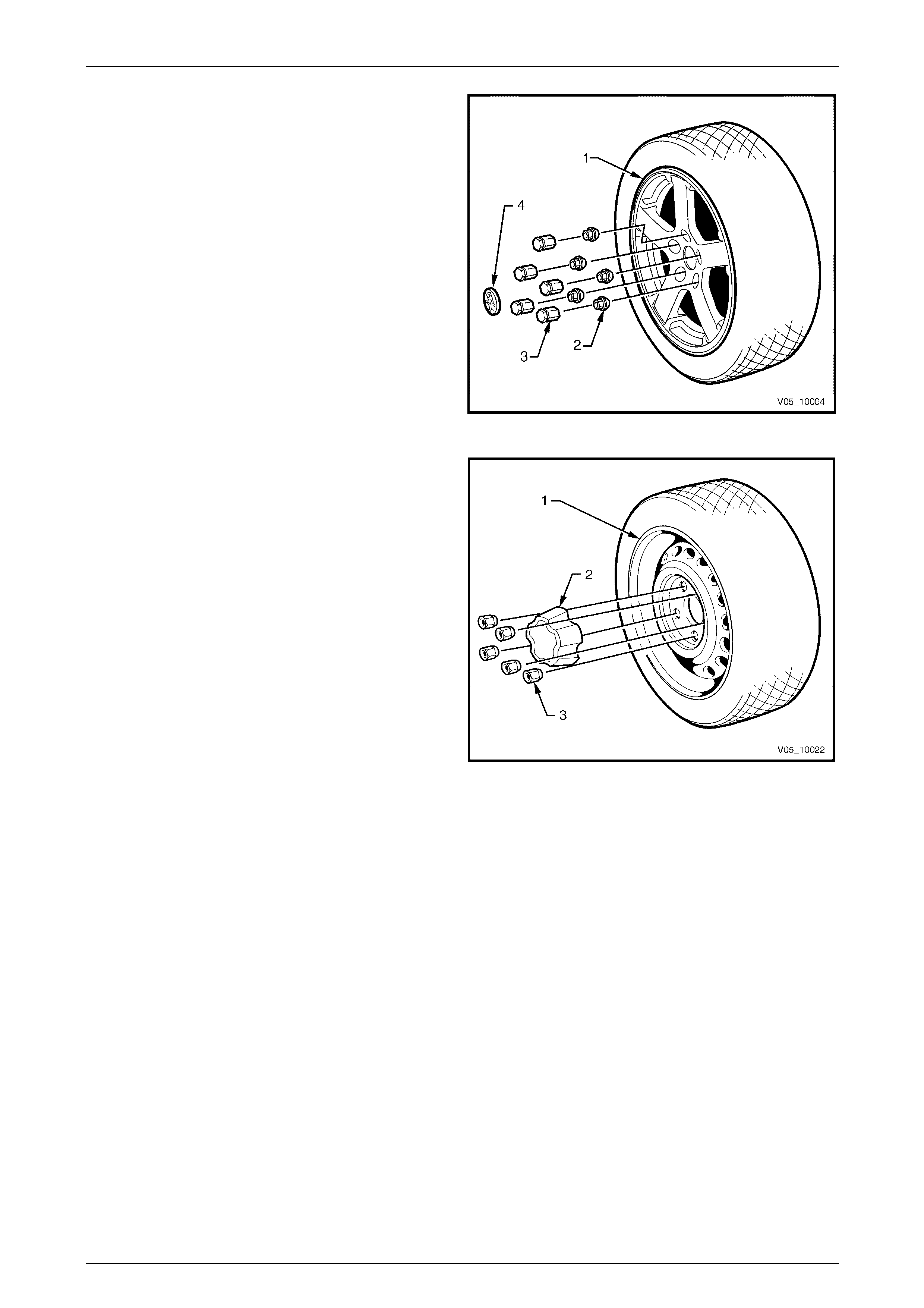
Figure 10 – 4 illustrates the allo y wheel (1), wheel nuts (2),
nut caps (3) and centre cap (4).
Sedan and Utilit y
Road Wheels............................. 8JJ x 17 alloy
Tyres......................................... 235/45R17 93V
Figure 10 – 4
Base Utility
Figure 10 – 5 illustrates the steel wheel (1), centre cap (2)
wheel nuts (3).
Utility Base
Road wheels .............................7J x 15 steel
Tyres.........................................205/65R15 99H
Figure 10 – 5
Page 10–4
Wheels and Tyres Page 10–5
SS Sedan and Utility
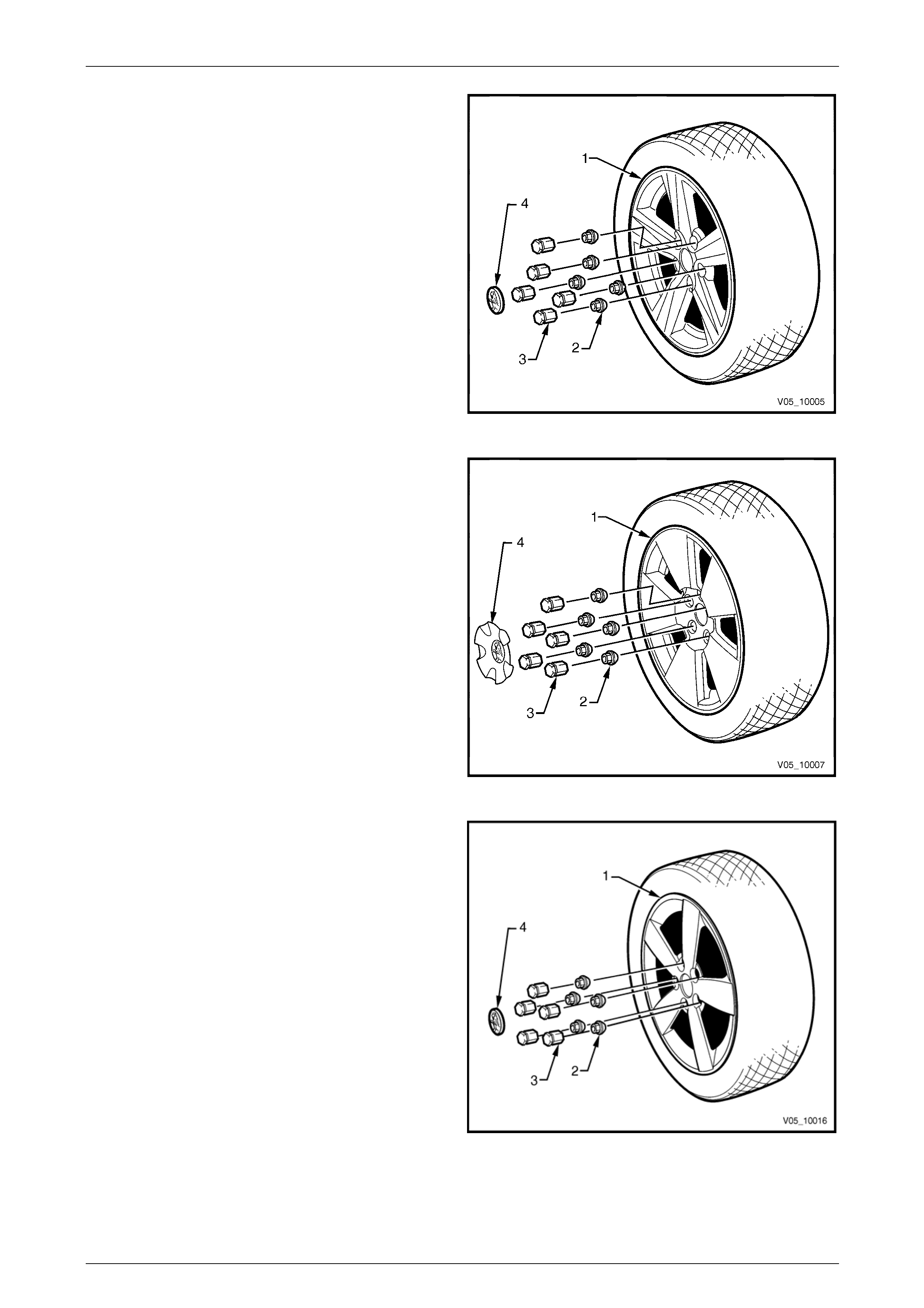
Figure 10 – 6 illustrates the allo y wheel (1), wheel nuts (2),
nut caps (3) and centre cap (4).
Sedan
Road Wheels............................. 8JJ x 18 alloy
Tyres......................................... 235/40R18 91W
Utility
Road Wheels............................. 8JJ x 17 alloy
Tyres......................................... 235/45R17 93V
Figure 10 – 6
Calais Sedan
Figure 10 – 7 illustrates the allo y wheel (1), wheel nuts (2),
nut caps (3) and centre cap (4).
Road Wheels............................. 8JJ x 17 alloy
Tyres......................................... 225/50R17 94V
Figure 10 – 7
Thunder SS Utility
Figure 10 – 8 illustrates the alloy wheel (1), wheel nuts (2)
and chrome nut caps (3) and centre cap (4).
Road Wheels............................. 8JJ x 18 alloy
Tyres......................................... 235/40R18 91W
Figure 10 – 8
Page 10–5
Wheels and Tyres Page 10–6
Adventra SX6 and SX8
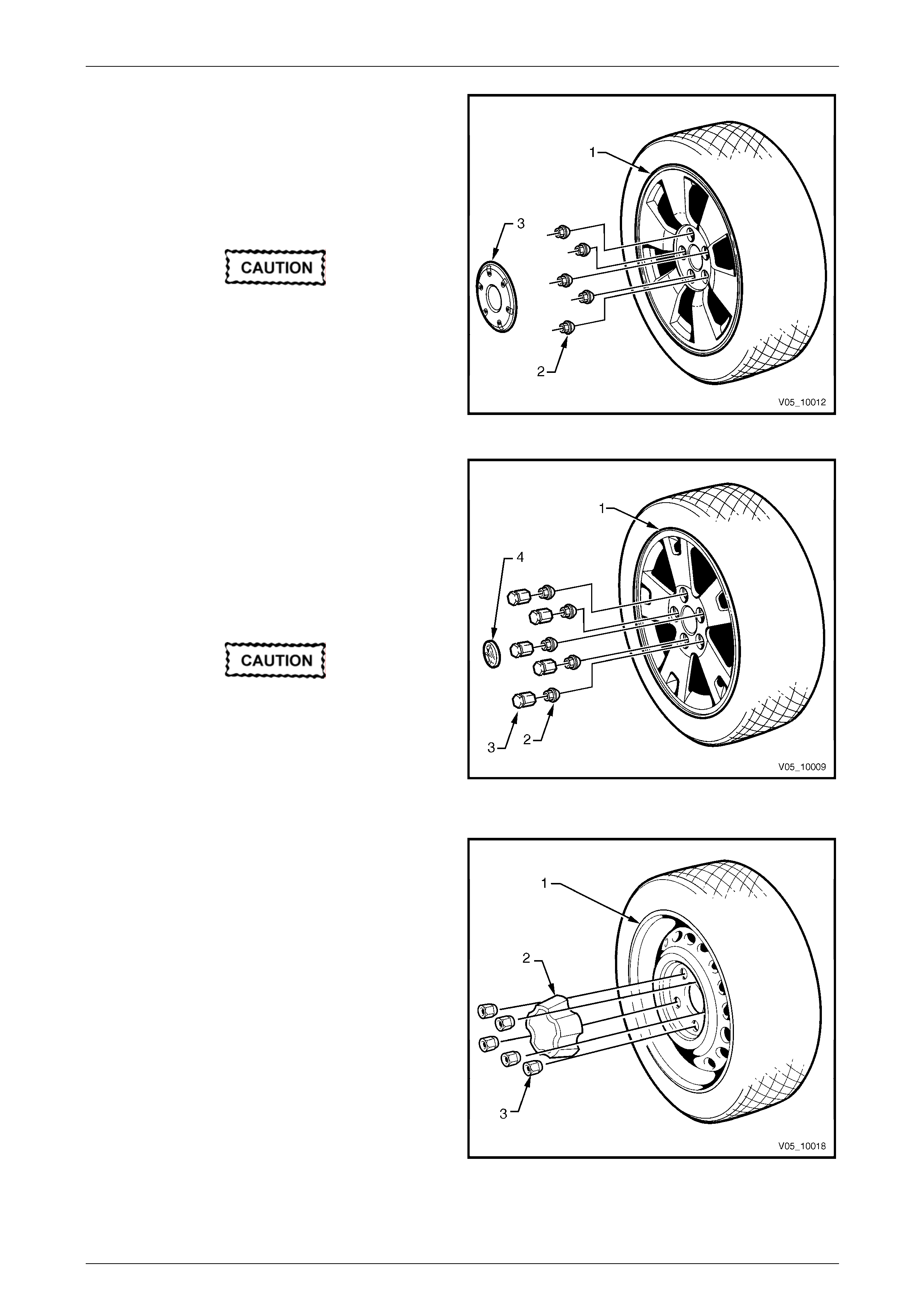
Figure 10 – 9 illustrates the allo y wheel (1), wheel nuts (2)
and centre cap (3).
Road Wheels............................. 7.5JJ x 17 alloy
Tyres......................................... 225/55R17 97H
The original tyre fitted to this vehicle has
reinforced tread and sidewalls and has been
specifically developed for this AWD vehicle.
When tyre replacement is required, it is
strongly recommended the replacement
tyre/s be of the same specification
(Bridgestone Turanza ER30) as originally
fitted to this vehicle.
Figure 10 – 9
Adventra CX6, LX6 and LX8
Figure 10 – 10 illustrates the alloy wheel (1), wheel nuts (2),
nut caps (3) and centre cap (4).
Road Wheels............................. 7.5JJ x 17 alloy
Tyres......................................... 225/55R17 97H
The original tyre fitted to this vehicle has
reinforced tread and sidewalls and has been
specifically developed for this AWD vehicle.
When tyre replacement is required, it is
strongly recommended the replacement
tyre/s be of the same specification
(Bridgestone Turanza ER30) as originally
fitted to this vehicle. Figure 10 – 10
Base Regular Cab an d Crew Cab
Figure 10 – 11 illustrates the steel wheel (1), cap (2) and
wheel nuts (3).
Regular Cab and Crew Cab 2WD
Road Wheels............................. 7J x 15 steel
Tyres......................................... 215/65R15 C 104R
Regular Cab AWD
Road Wheels............................. 7J x 16 steel
Tyres......................................... 215/65R16 C 106R
Figure 10 – 11
Page 10–6
Wheels and Tyres Page 10–7
S Regula Cab and S Crew Cab r
Figure 10 – 12 illustrates the alloy wheel (1), wheel nuts (2),
nut caps (3) and centre cap (4).
Road Wheels............................. 7JJ x 16 alloy
Tyres......................................... 215/65R16 C 106R
Figure 10 – 12
Crew Cab SS and Thunder SS Crewman
Figure 10 – 13 illustrates the a lloy wheel (1), wheel nuts (2)
and nut caps (3) and centre cap (4).
Road Wheels............................. 8JJ x 17 alloy
Tyres......................................... 225/55R17 97H
Figure 10 – 13
Crew Cab X6 and X8
Figure 10 – 14 illustrates the alloy wheel (1), wheel nuts (2),
nut caps (3) and centre cap (4).
Road Wheels............................. 7.5JJ x 17 alloy
Tyres......................................... 225/55R17 97H
NOTE
The alloy wheel for the X8 vehicle has dark paint
in the ports of the wheel.
Figure 10 – 14
Page 10–7
Wheels and Tyres Page 10–8
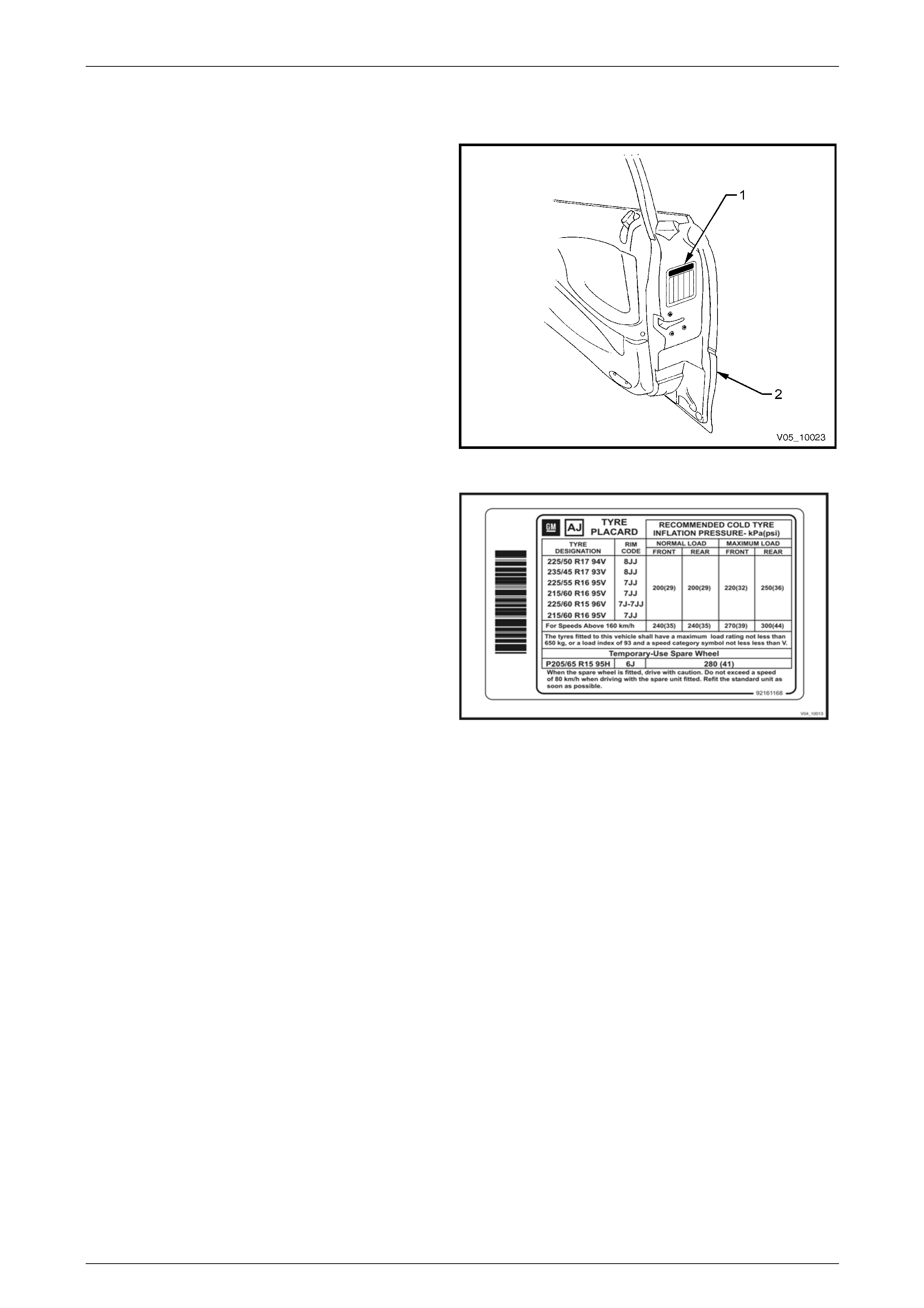
1.1 Tyre Placards
Wheel and tyre sizes, inflation pressures and load
capacity are specifie d on a tyre placard (1) located on
the end surface of the driver’s door (2).
Always check tyre pressures with cold tyres (after
vehicle has stood for three hours or more, or driven less
than 2 kilometres) weekly or before any extended trip.
When checking tyre pressure, also visually inspect
tyres for excessive wear, sharp objects embedded in
the tyre or damage to the sidewalls.
NOTE
• Clean the valve exterior, prior to
applying the air pressure nozzle when
inflating the tyre.
• Always install valve caps to keep out
dust and water.
Figure 10 – 15
The tyre placard shown is typical of those fitted on the
vehicle.
Refer to 4 Specifications or the tyre placard on the
driver’s door for the correct wheel and t yre size and t yre
pressures.
Figure 10 – 16
Page 10–8

Wheels and Tyres Page 10–9
1.2 Tyre Markings
The tyre sidewall has a coded marking system, which provides information about the tyre.
Tyre Marking Example:
P 225 55 R 16 95 V
P Passenger Vehicle Designation
225 Section Width (1) in mm
(225 mm)
55 Aspect Ratio %: Section Width (1) to Section
Height (2)
(55 = 55%)
R Tyre Construction
(R = Radial)
16 Rim Diameter in inches
(16 = 16”)
95 Load Index in kg
91 = 615 kg max. load
93 = 650 kg max loa d
95 = 690 kg max loa d
97 = 730 kg max loa d
99 = 775 kg max loa d
104 = 900 kg max loa d
106 = 950 kg max loa d
V Speed Rating
R = 170 km/h
H = 210 km/h
V = 240 km/h
W = 270 km/h
Figure 10 – 17
Page 10–9
Wheels and Tyres Page 10–10
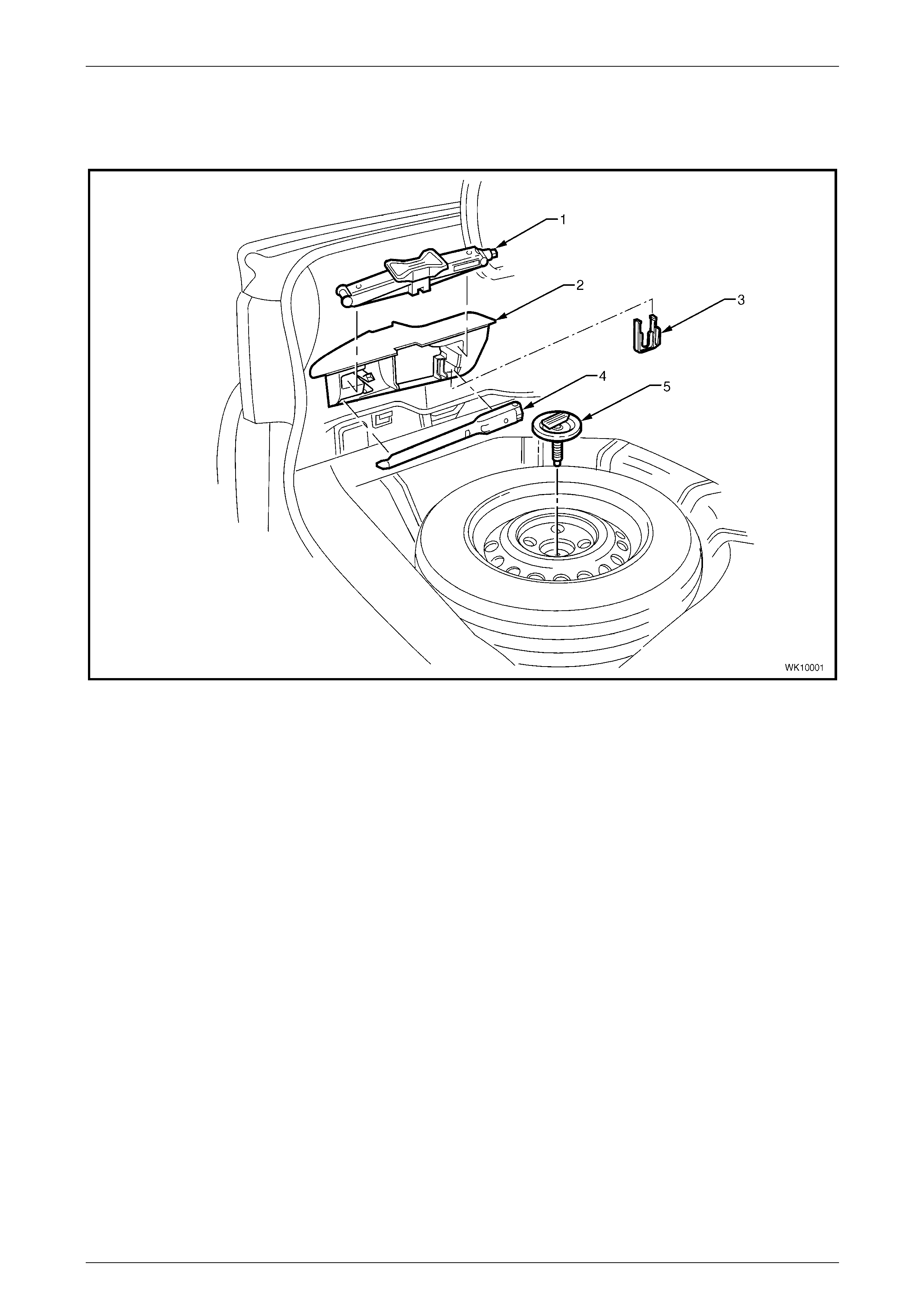
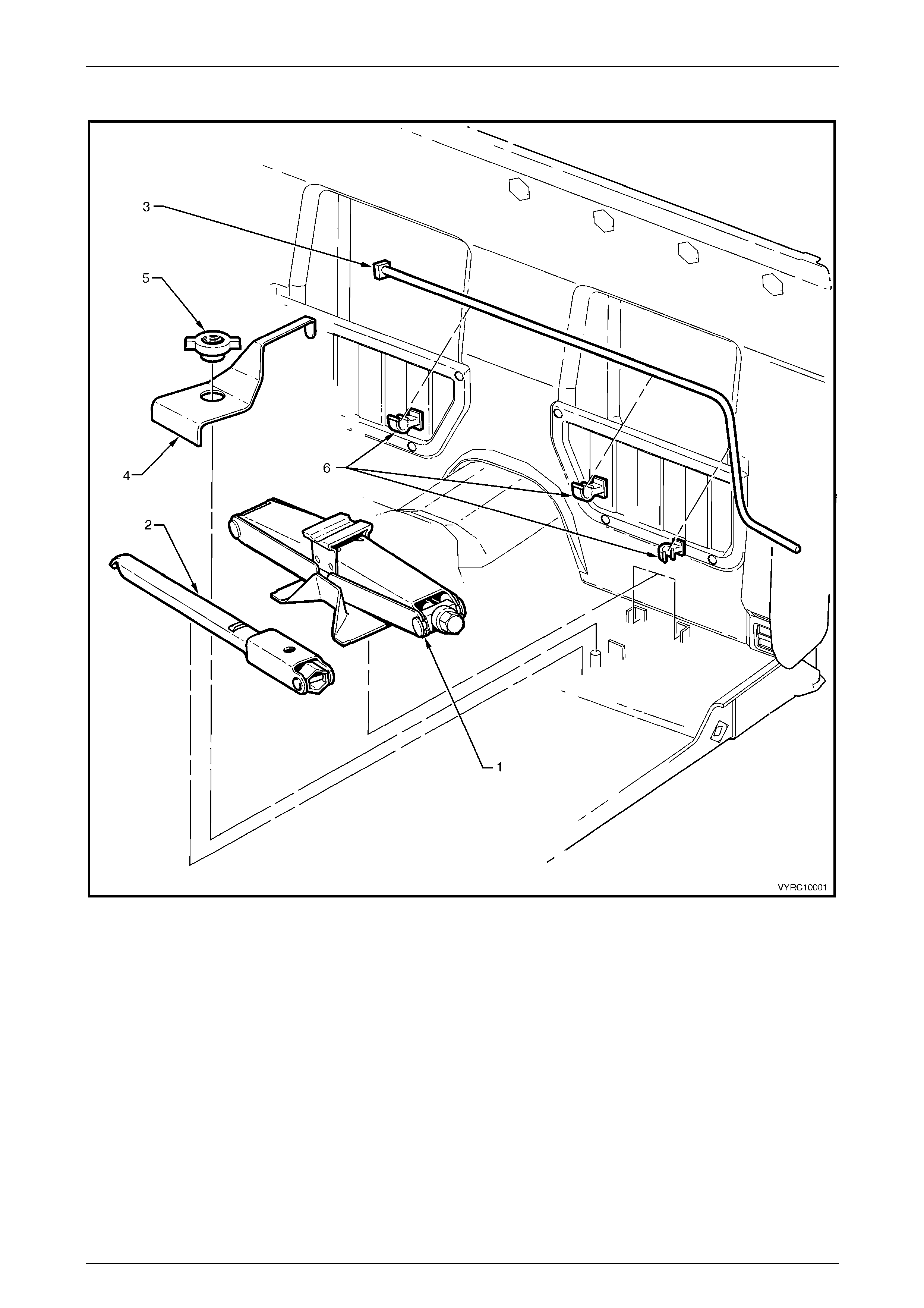
1.3 Spare Wheel Stowage
Sedan
Figure 10 – 18
Legend
1 Jack 4 Jack / Wheel Nut Wrench
2 Stowage Compartment 5 Spare Wheel Retaining Bolt and Plate
3 Nut Cap Removal Tool
Page 10–10
Wheels and Tyres Page 10–11
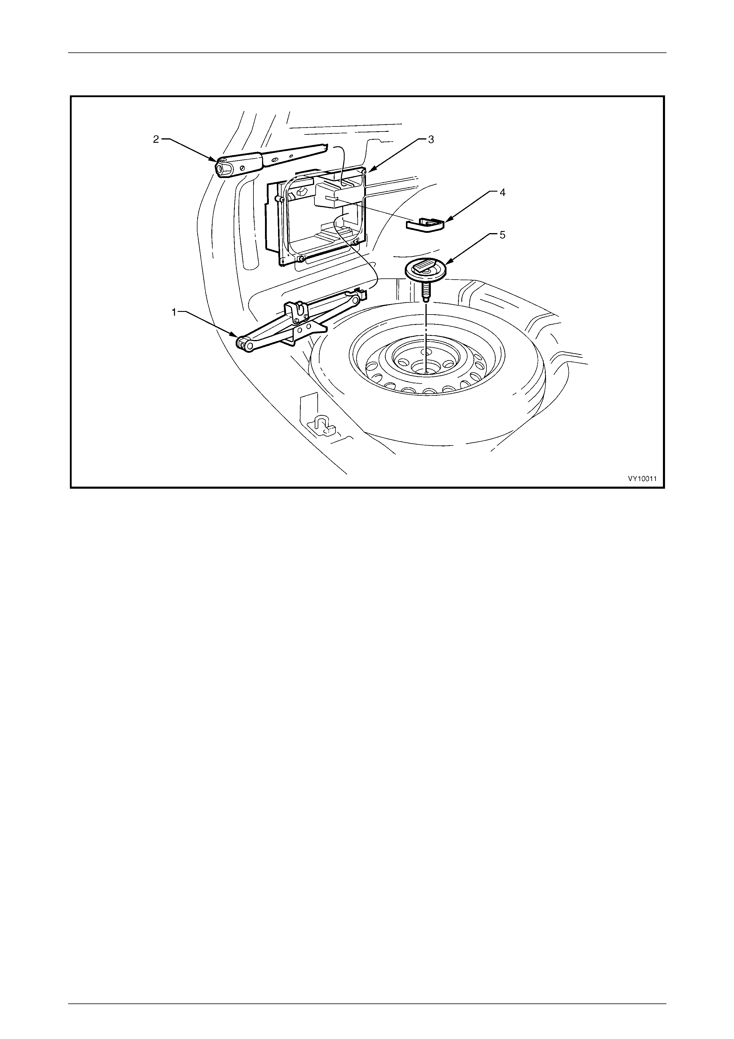
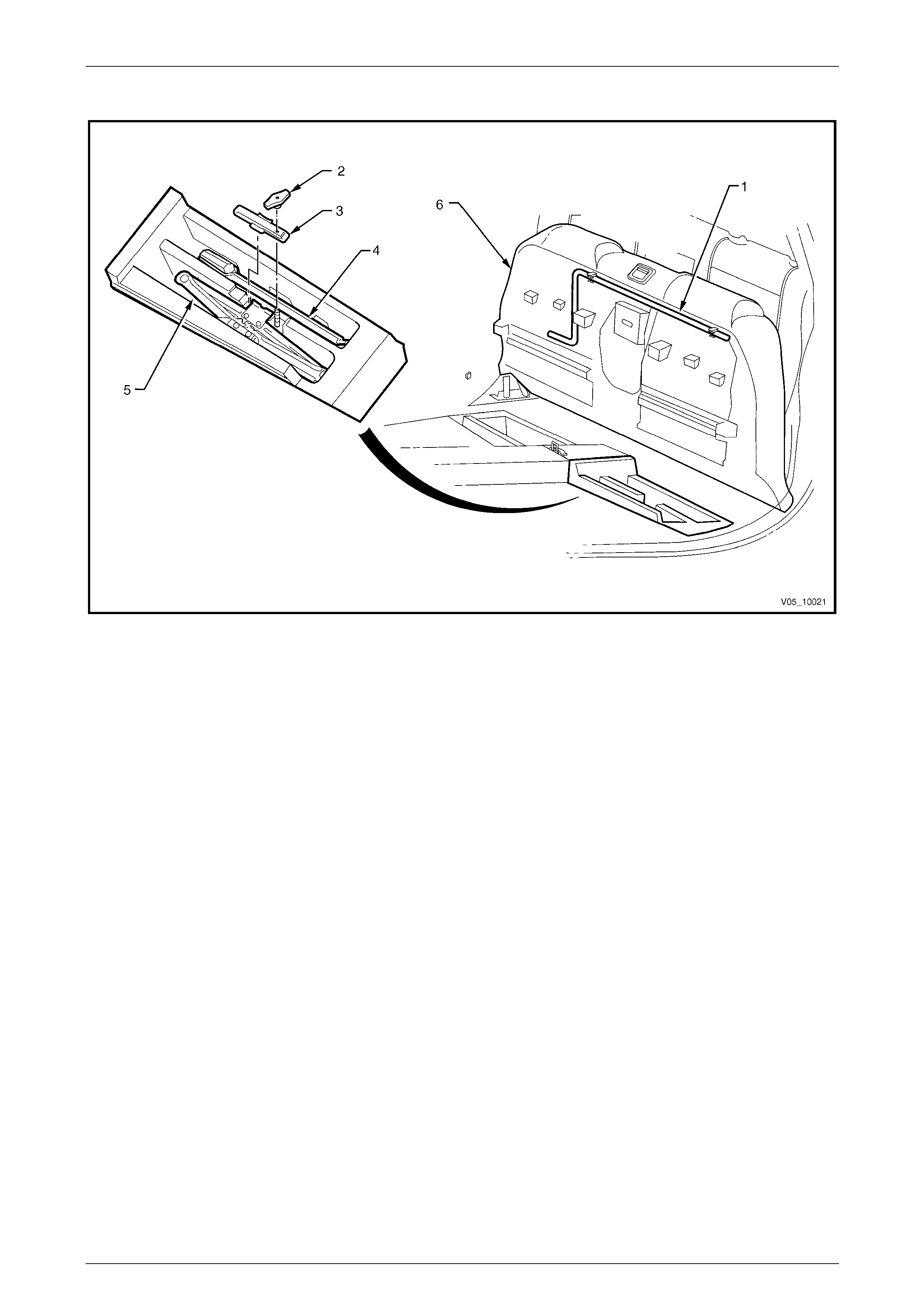
Wagon
Figure 10 – 19
Legend
1 Jack 4 Nut Cap Tool
2 Jack / Wheel Nut Wrench 5 Spare Wheel Retaining Bolt and Plate
3 Stowage Compartment
Page 10–11
Wheels and Tyres Page 10–12
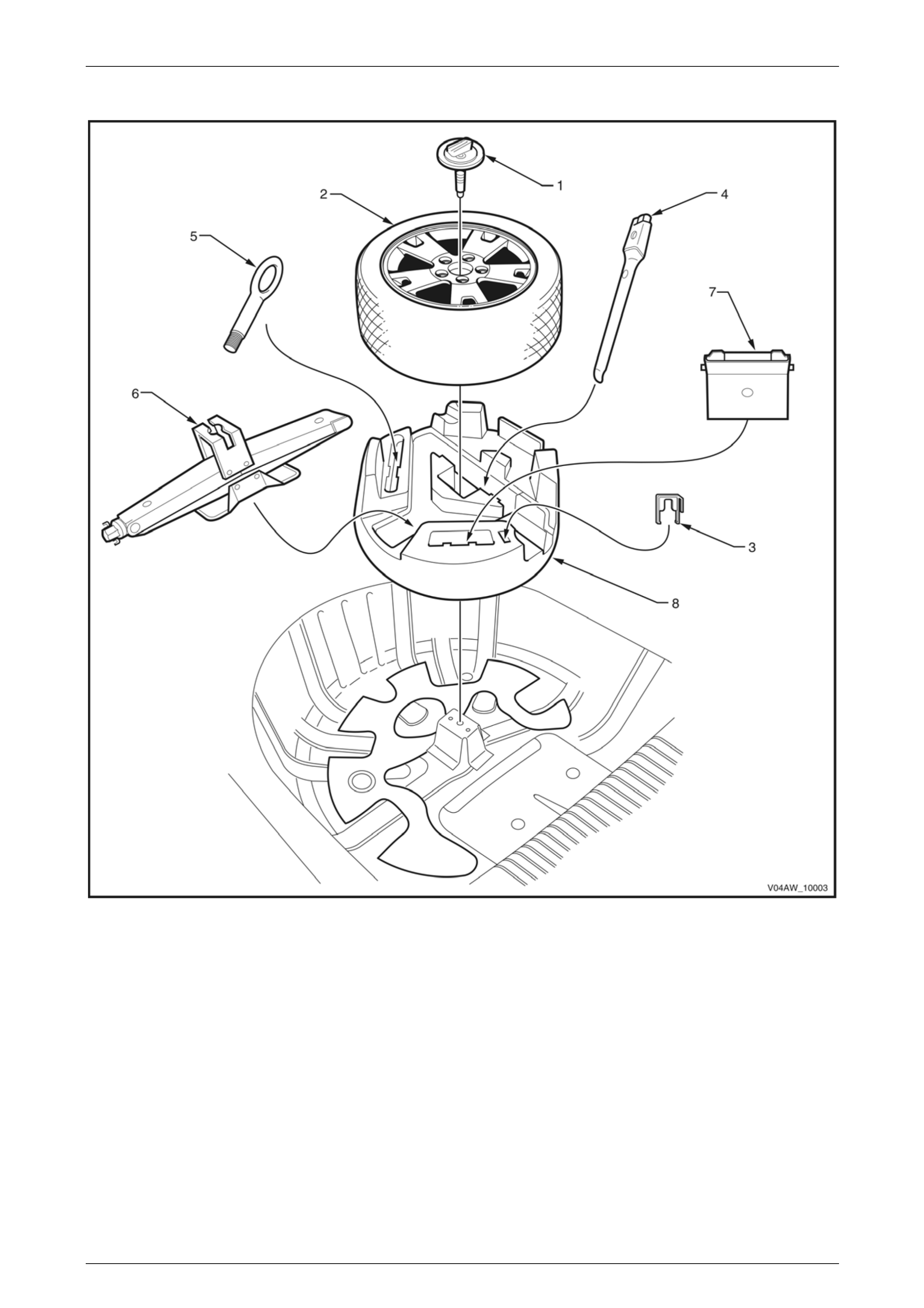
AWD Wagon
Figure 10 – 20
Legend
1 Spare Wheel Retaining Bolt and Plate 5 Tow Hook
2 Spare Wheel 6 Jack Assembly
3 Nut Cap Tool 7 Wheel Chock
4 Jack / Wheel Nut Wrench 8 Jack / Tool Container
Page 10–12
Wheels and Tyres Page 10–13
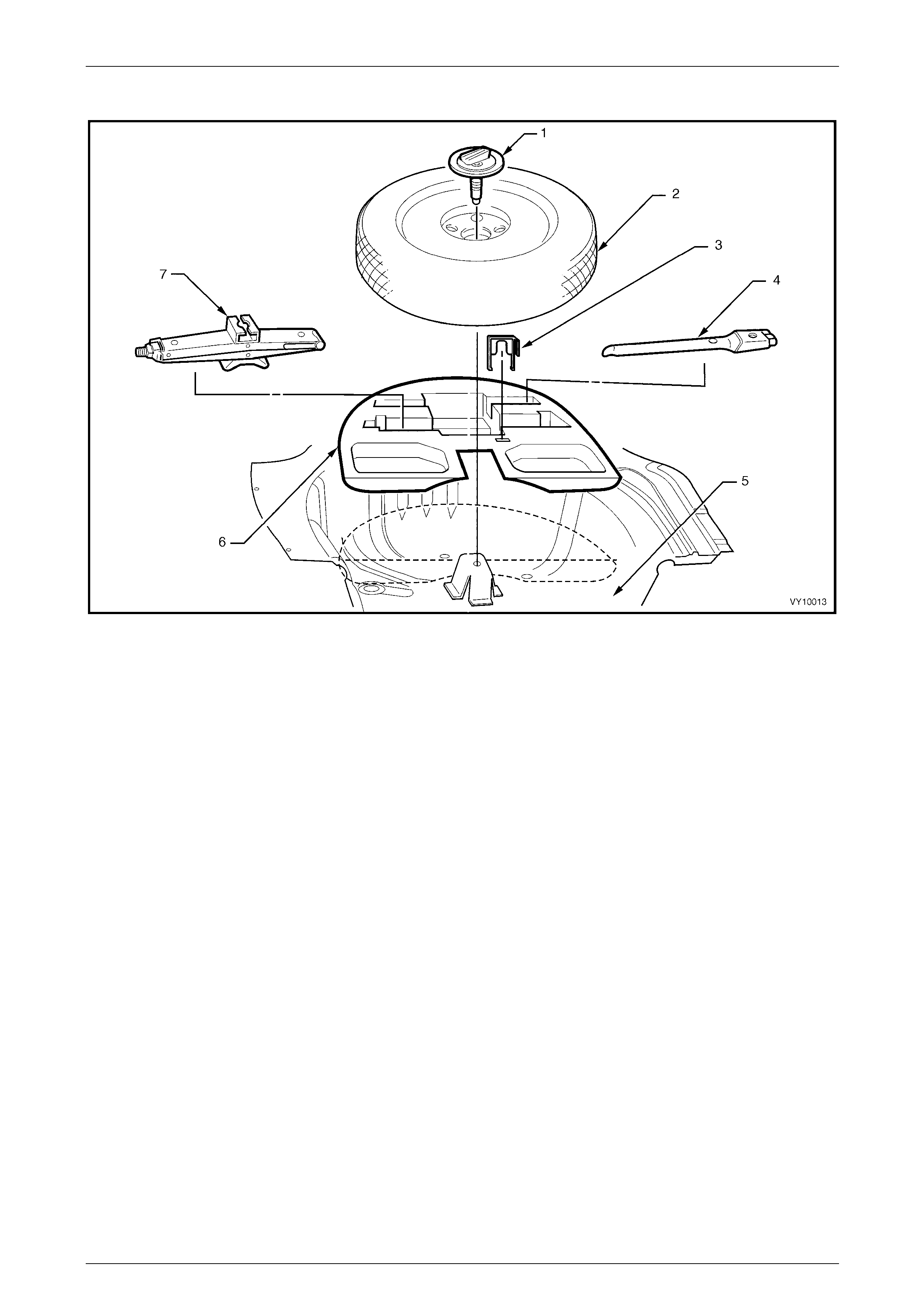
Coupe
Figure 10 – 21
Legend
1 Spare Wheel Retaining Bolt and Plate Assembly
2 Temporary Use Spare Wheel
3 Nut Cap Tool
4 Jack / Wheel Nut Wrench
5 Spare Wheel Well
6 Tool Container
7 Jack Assembly
Page 10–13
Wheels and Tyres Page 10–14
Utility – Tool Storage
Figure 10 – 22
Legend
1 Spare Wheel Hoist Crank Handle
2 Nut Cap Tool 3 Jack Assembly
4 Jack / Wheel Nut Wrench
Page 10–14
Wheels and Tyres Page 10–15
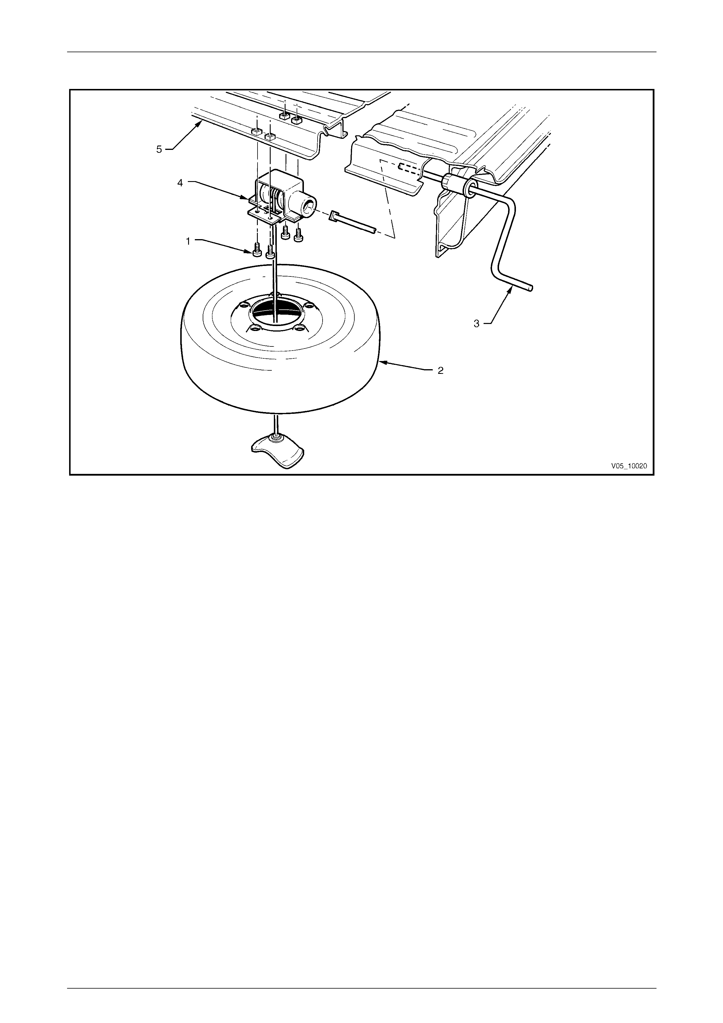
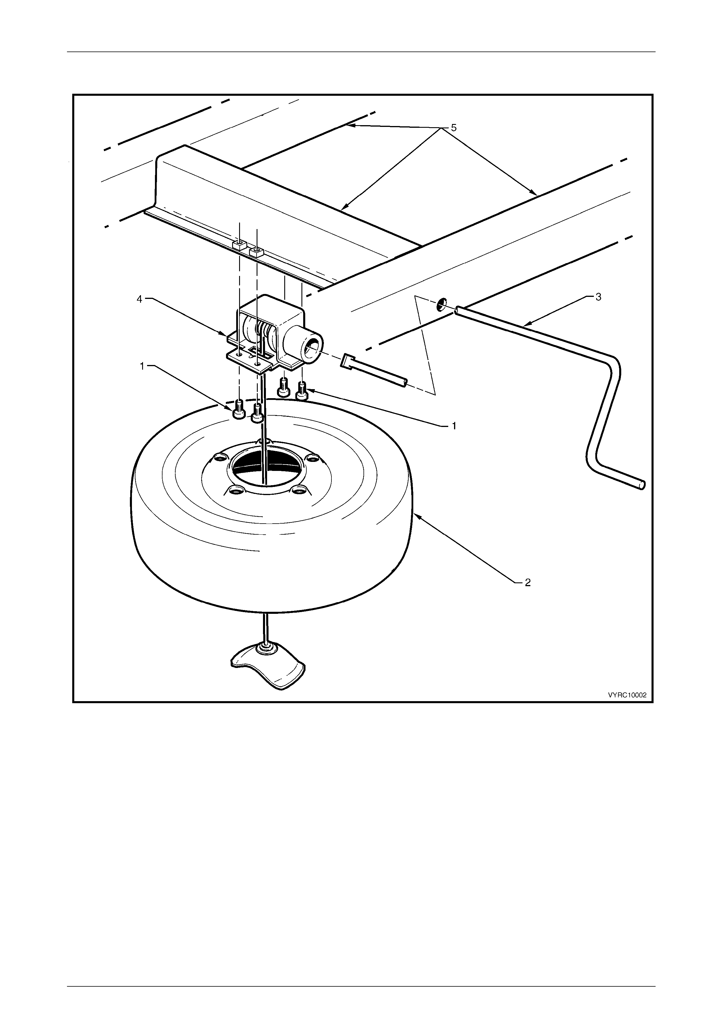
Utility – Spare Wheel Stowage
Figure 10 – 23
Legend
1 Spare Wheel Hoist Attaching Bolts (4 places)
2 Spare Wheel
3 Spare Wheel Hoist Crank Handle
4 Spare Wheel Hoist
5 Rear Frame / Floor Assembly
Page 10–15
Wheels and Tyres Page 10–16
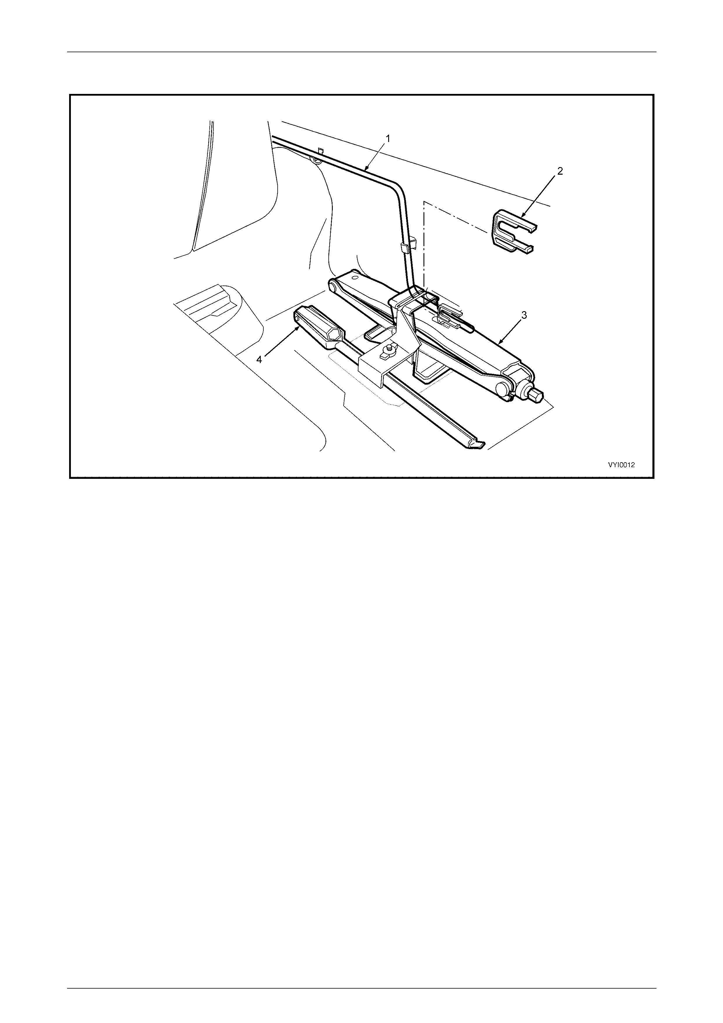
Regular Cab – Tool Stowage
Figure 10 – 24
Legend
1 Jack Assembly
2 Jack and Wheel Nut Wrench
3 Spare Wheel Hoist Crank Handle
4 Jack and Handle Trim Cover
5 Trim Cover Retaining Nut
6 Crank Handle Retainers
Page 10–16
Wheels and Tyres Page 10–17
Crew Cab – Tool Stowage
Figure 10 – 25
Legend
1 Spare Wheel Hoist Crank Handle
2 Jack Assembly Retaining Nut
3 Jack Assembly Retainer
4 Jack and Wheel Nut Wrench
5 Jack Assembly
6 Rear Seat Cushion
Page 10–17
Wheels and Tyres Page 10–18
Regular Cab and Crew Cab – Spare Wheel Stowage
Figure 10 – 26
Legend
1 Spare Wheel Hoist Attaching Bolts (4 places)
2 Spare Wheel
3 Spare Wheel Hoist Crank Handle
4 Spare Wheel Hoist
5 Rear Frame Assembly
Page 10–18

Wheels and Tyres Page 10–19
2 Diagnostics
2.1 Wear
Analysis of tyre wear conditions varies according to the type, size and brand of the tyre fitted to the vehicle. Refer to the
tyre manufacturer's literature relating to t yre wear when evaluating tyre wear conditions.
Page 10–19

Wheels and Tyres Page 10–20
2.2 Road Testing
As there are many reasons for a vibration co ndition to be present in a vehicle, it is vital that a thorough road test be
conducted to eliminate other possible causes for a vibration condition being present.
Tyre and Wheel Inspection
This visual inspection should be conducted for all vibration complaints unl ess the disturbance only occurs with the
vehicle at a standstill.
• The tyres should be inspected for unusua l wear, including cupping, flat spots and heel-and-toe wear. These
conditions can cause t yre growl, howl, slapping noises and vibrati ons throughout the vehicle.
• Establish that all tyres are inflated to the correct pressures prior to any road test.
• Check for bulging in the side walls.
• Check all wheels for bent rim flanges. In many cases, a cracked hubcap or dented trim ring can indicate a bent
wheel underneath.
Slow Acceleration Test
This test is to identify engine or vehicle speed relate d conditions. It will be necessary to perform additional tests in order
to determine in which category the vibration belongs.
1 On a smooth, level road, slowly accelerate up to highway speed.
2 Look for disturbances that match the customer's description.
3 Note the vehicle speed (km/h) and engi ne speed (rpm) where the disturbance occurs.
Follow this test with the neutral coast-down test, and the downshift test.
Neutral Coast-down Test
1 On a smooth, level road, accelerate to a speed slightly hi gher than the speed at which the vibratio n occurs.
2 Shift the vehicle into neutral and coast down through the vibration range. Note if the vibration is present in neutral.
If the vibration still occurs in neutral, it is definitely vehicle-speed sens itive. At this point, the engine and torque converter
have been eliminated as a cause. Depending on the symptoms or frequency, the rep air will concentrate on either the
tyres and wheels, or the propeller shaft and rear a xle.
Downshift Test
1 On a smooth, level road, accelerate to the speed at which the complaint vibration occurs. Note the engine rpm.
2 Decelerate and safely downshift to the next lower gear.
3 Operate the vehicle at the previous engine rpm.
If the vibration returns at the same rpm, the engine or torque converter is the most probable cause. To confirm these
results, repeat this test in still lower gears and in neutral.
Page 10–20

Wheels and Tyres Page 10–21
Steering Input Test
This test is intended to determine if wheel bearings or other suspension compon ents are contributing to a vibration,
especially those relating to noises, howl or growl, grinding and roaring.
• With the vehicle at the vibration speed (km/h), drive throug h slow sweeping turns – first in one direction, then the
other.
If the vibration changes (worsens or diminis hes), the wheel bearings, hubs and tyre tread wear are all po ssible causes.
Standing Start Acceleration
The purpose of this test is to duplicate a vibration called take-off-shudder. In some cases, a powertrain mount or the
exhaust contacting the body may also be suspect, depending on the symptoms.
1 With the vehicle at a complete stop and in gear, remove your foot from the brake.
2 Accelerate to 60 or 70 km/h while checking for vibrations that match the customer's description.
Shudder in the seat or steering wheel under these conditions usually results from incorrec t driveline angles. Worn, tight
or failed universal joints ma y also be a cause, and should be inspected first.
Grunting or groaning noises a long with a buzzing or roughness in the floor usually points to the vibration being conducted
through the engine or transmission mounts, or throug h exhaust mounts and hangers that have grou nded out. Refer to
the respective Sections for rectification procedures.
Page 10–21
Wheels and Tyres Page 10–22
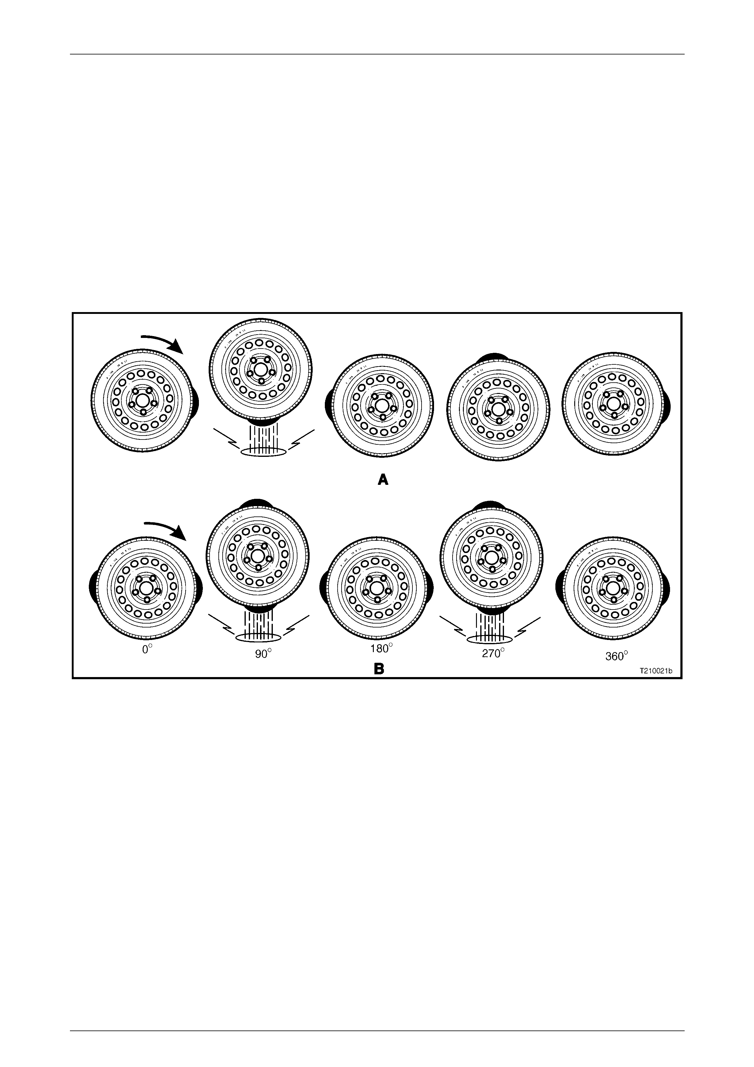
2.3 Vibration
To determine the cause of a vibration con dition that is suspected of being tyre / wheel related, an essential aspect is to
understand the nature of first and second order vibrations (or harmonics).
As shown in Figure 10 – 27, A, a tyre with one high spot would create a d isturbance once every complete revolution. This
is called first-order vibrations.
An oval shaped tyre with t wo high spots (as shown B) would create a disturbance twice per revolution. This is called
second-order vibrations. Three hig h spots would be third order, and so on.
Two first-order vibrations may add to or subtract from the overall amplitude of the disturbance, but that is all. Two
first-order vibrations do not equal a second-order. Due to centrifugal force, an out-of-balance component (for example
tyres, drive shafts or engine) will always create a first-order vibration.
If wheel and tyre assemblies are balanced to the degree required and vibrat ion is still evident, then tyre run-out or force
variation could be responsi ble.
Figure 10 – 27
Page 10–22
Wheels and Tyres Page 10–23
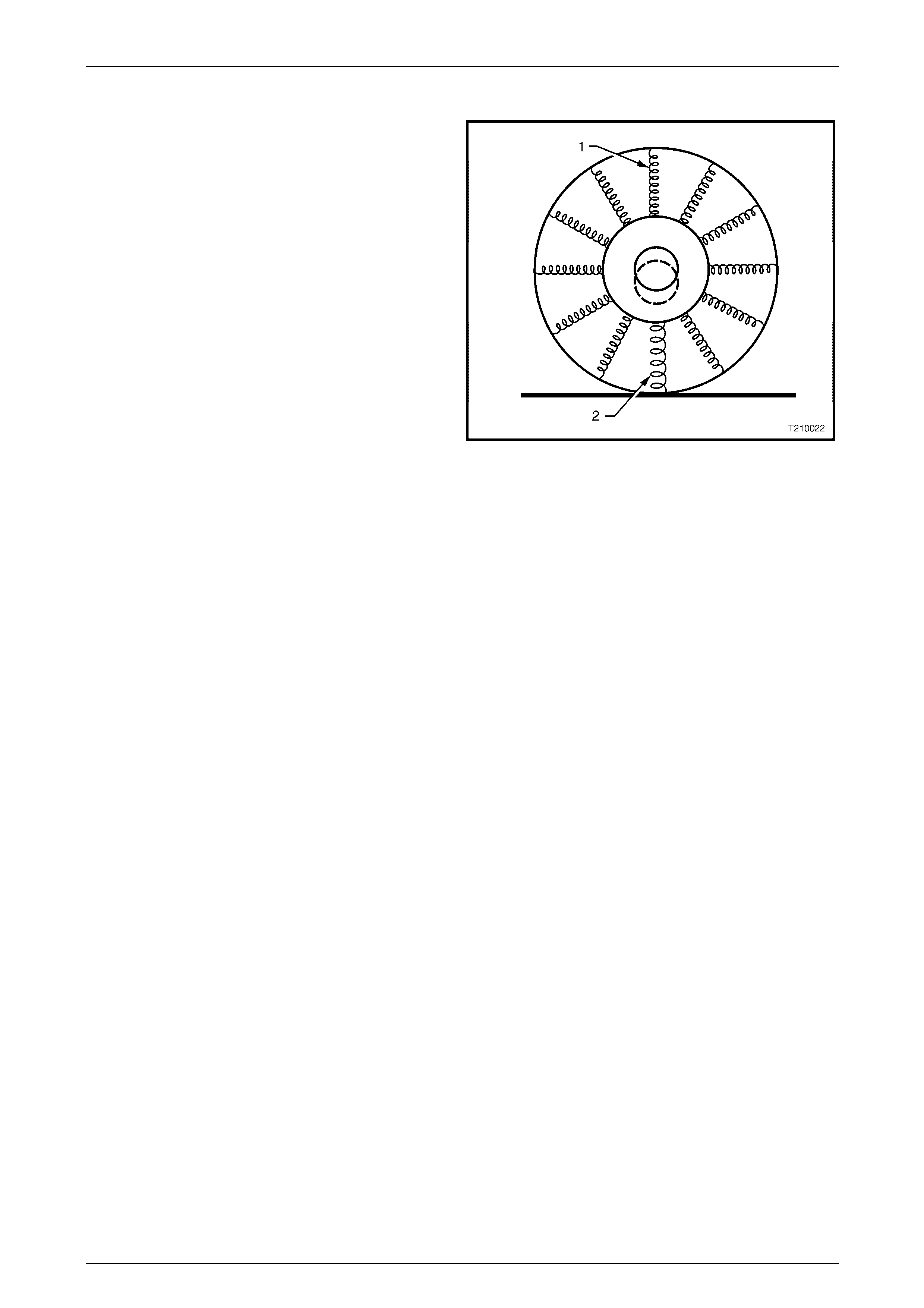
Radial Force Variation
Radial force variation refers to a difference in the stiffness
of a tyre sidewall as it rotates and contacts the road,
Figure 10 – 28 uses springs to illustrate the point. The
lighter springs (1) represent a normal sidewall while the
heavier spring (2) repres ents a stiffer section of the
sidewall.
Tyre and wheel assemblies have some of this due to
splices in the different plies of the tyre, but they do not
cause a problem unless the force variati on is excessive.
These stiff spots in the sidewall can deflect the tyre / wheel
assembly upward as they contact the road.
If there is only one stiff spot in the sidewall, it will deflect the
spindle once per each revolut ion of the tyre / wheel
assembly, causing a first-order tyre / wheel vibration.
If there are two stiff spots, they can cause a second-order
vibration.
First and second order tyre / wheel vibrations are the most
common to occur as a result of radial force variation. Higher
orders (for example third or fourth) are possible, but quite
rare. The most effective way to minimise the possibility of
force variation as a factor in tyre / wheel vibration is to
ensure the tyre / wheel assembly run-out is at an absolute
minimum.
Figure 10 – 28
Some tyre / wheel assemblies may exhibit vibration-causing amounts of force variation even though the y are within run-
out and balance tolerances. Due to tighter tolerances and higher standards in manufacturing, these instances are
becoming rare. If force variation is suspected as bei ng a factor, substitute one or more known good tyre / wheel
assemblies for the suspect assemblies. If this rectifies the problem, replace the offending tyre.
Lateral Force Variation
This is based on the same concept as radial force variati on, except that lateral force variation tends to deflect the vehic le
sideways or laterally, as the n ame implies. A snaky belt inside the tyre can cause lateral force variation. Tyre
replacement using the substitution method may be necessary.
This condition is very rare and again, the best way to eliminate it as a factor is to ensure the lateral run-o ut of the tyre /
wheel assemblies is at an absolute minimum.
In most cases where excessive lateral force variation exists, the vehicle will d isplay a wobble or waddle at low speeds
(8 to 40 km/h) on a smooth road surface. The condition will usually be re lated to a first order vibration of tyre / wheel
rotation.
Some degree of tyre run-out will always be present, due to dimensional tolerances in both the tyre and wheel and can
often be reduced by rotating the tyre on the whe el to cancel out the overall effect. Force Variation (a variation i n stiffness
around the tyre) can also caus e the same problem, resulting in a varying loaded radius as the tyre rotates.
All of these factors have so far been conside r ed to act radially. However, lateral run-out and lateral force variati on can
also be translated into vehicle vibration ranging from low speed waddle to relatively high-speed shake or vibrations
similar to those obtained with tyre imbalance.
Page 10–23

Wheels and Tyres Page 10–24
2.4 Vehicle Lead
Vehicle lead is the deviatio n of the vehicle from a straight path, on a level road (no cambe r) and with no load on the
steering wheel. Lead is usually caused by ali gnment and / or brake drag, but can sometimes be caused b y tyres.
The way in which a tyre is built can produce lead in a veh icle. An example of this is placement of the belt in a radial tyre.
An off-centre belt can cause the tyre to develop a side force while rolling straight down the road.
If one side of the tyre is a little larger in diameter than the other, the tyre will tend to roll up to one side. This will develop a
side force, which can produc e vehicle lead.
The following diagnostic chart can be used to confirm vehicle lead.
Step Action Yes No
1 1 Inflate tyres to the correct pressures.
2 Road test vehicle in opposite directi ons, on a level, uncrowned
road with little or no crosswind.
Does vehicle lead to the same side in both directions? Go to Step 2 Go to Step 8
2 Swap front tyres from one side to the other and road test again in
opposite directions.
Does vehicle lead to the same side as in Step 1?
Put tyres back in
original positions.
Go to Step 8 Go to Step 3
3 Does the vehicle no w lead to the op posite side to that in Step 1? Go to Step 5 Go to Step 4
4 Has the lead condition been corrected? Leave tyres as is. If
roughness
develops, replace
front tyres Go to Step 5
5 Install a known good tyre to replace one front tyre and road test again.
Is the lead condition corrected?
Lead condition has
been isolated.
Replace tyre Go to Step 6
6 Check the test tyre on a known good vehicle.
Has the lead condition been corrected?
Check if tyre is
faulty.
Go to Step 5 Go to Step 7
7 Install a known good tyre to replace remaining front tyre.
Has the lead condition been corrected?
Lead condition has
been isolated.
Replace tyre Go to Step 8
8 1 Check / correct vehicle wheel alignment and maladjusted or
binding steering.
2 Road test again.
Has the lead condition been corrected?
Vehicle is now
operating to
specification Swap tyres, front to
rear and recheck
Page 10–24
Wheels and Tyres Page 10–25
3 Service Operations
3.1 Tyre Inflation and Inspection
The pressure recommended for any vehicle is carefully calculated to give satisfactory ride, stability, steering, tread wear,
tyre life and resistance to wheel / tyre damage. All specified pressures are for cold tyres (after the vehi cle has stood for
three hours or more, or driven less than two kilometres).
Tyre pressures should be checked weekly or before any extended trip, and set to the specifications on the tyre placard
located on the end surface of the driver ’s front door, refer to 1.1 T yre Placards.
When checking tyre pressure, visually inspect tyres for excessive wear, sharp objects embedded i n th e tyre or damage
to the sidewalls.
Clean the exterior of the valve, prior to
applying the air pressure nozzle when
inflating a tyre.
NOTE
Always install valve caps to keep out dust and
water.
Pressure Adjustments to Suit Operating Conditions
Tyre pressure can increase as much as 40 kPa when hot.
Do not reduce pressures to offset this
build-up.
For continuous high-spee d operation, increase pressures as recommended on the tyre placard.
For operation on unsealed rough roa ds, increase cold tyre pressures 28 kPa above that shown on the tyre placard.
Tyre pressures are not to be increased for
unsealed rough road conditions if the tyre
pressures have already been increased for
high-speed operation.
Page 10–25

Wheels and Tyres Page 10–26
3.2 Wheel Removal and Installation
Either corrosion or a tight fit between the
wheel centre and the mo unting or brake disc /
hub flange can cause difficulty in wheel
removal. If tightness is caused by corrosion,
do not use heat or heavy impact.
NOTE
Before removing any wheel, mark the relationship
of the wheel to the mounting flange or brake
disc/hub.
Wheel nuts for alloy wheels have a different
mounting taper to those for steel wheels. DO
NOT interchange or mix wheel nuts from both
types of wheel, as incorrect wheel nuts will
not allow the wheels to be tightened secu rely.
Installing wheels without good metal-to-metal
contact at the mounting surfaces can result in
wheel nuts loosening. Tighten road wheel
attaching nuts to the specified torque and in
the orde r sh own.
Do not use an impact gun to tighten wheel
nuts unless it is fitted with a torque limiter
bar (commercially available). Failure to
correctly tighten wheel nuts to the correct
torque specification may result in a warped
brake disc, which may lead to development
of brake shudder.
Road wheel attaching nut
torque specification .................................. 110 – 140 Nm
Figure 10 – 29
Page 10–26
Wheels and Tyres Page 10–27
3.3 Tyre Removal and Installation
Whenever possible, tyre removal and installation shou ld be carried out on a tyre-changing machine. The use of tyre
levers and mallets is likely to damage tyre carcasses and wheel rims.
Alloy rims must always be repl aced if significantly damaged .
Wheels must not be welded, brazed, peened
or treated in any manner, wh ich could w eaken
them.
The bead set of the rim must be clean and smooth; rust, rubber etc. may be removed with a wire brush or steel wool.
1 Before installing a tyre, or a valve stem, apply an approved tyre lubricant to the tyre bead and rim flange s.
2 Install the valve stem and tyre before the lubrica nt dries.
3 Initially, inflate the tyre to 280 kPa to ensure the tyre beads seat correctly in the rim flanges.
4 If the tyre beads fail to seal at this pressure, deflate the tyre, lubricate the tyre beads and wheel rim agai n and then
inflate.
Exercise care to avoid personal injury when
the tyre bead snaps o ver the wheel rim safety
humps.
NOTE
When fitting a tyre to the rim, ensure the tyre is
correctly indexed to the rim. The first harmonic
high point of the tyre should be matched to the
first harmonic low point of the rim. This matching
minimises force variations inherent with tyre and
rim manufacture. For more information on
harmonics, refer to 2 Diagnostics.
As different origins of tyres have different standards regarding the first harmonic point, re fer to the following as a guide to
the correct tyre fitting position.
• Australian manufactured tyres have a red dot indicating the first harmonic hi gh point.
• European manufactured tyres have a white dot indicating the first harmonic low point.
• Some Japanese manufactured tyres have a red dot indicating the first harmonic high point and a yellow dot (that
should be ignored), which indicates a static balance point.
Page 10–27

Wheels and Tyres Page 10–28
As independent rear suspension is more sensitive to a wheel / tyre imbalance condition than oth er suspension designs,
particular care should be given to correct fitment of t yres to all vehicles with independent rear suspension.
Australian Manufactured T yres
(Red dot on sidewall)
Align the red dot on tyre to mark on outer flange of wheel,
or if there is no mark on the wheel, align the red dot to low
spot of wheel as measured with dial indicator.
European Manufactured Tyres
(White dot on sidewall)
Align the white dot on tyre 180° from the mark on outer
flange of wheel, or if there is no mark on the wheel, align
the white dot 180° from the low spot of the wheel as
measured with the dial indicator.
Japanese Manufactured Tyres If there is a yellow dot but not a red dot use the rule for
Australian tyres. If there is a yellow and a red dot, ignore
the yellow dot and use the red dot as per rule for Australian
tyres.
Tyre Repairs
There are many different materials and techniques avail able to repair tyres. It is suggested that details of materials an d
procedures for the repair of tyres should be obtained from the tyre manufacturer.
As a minimum requirement, all tyre repairs must comply with local standards.
Page 10–28
Wheels and Tyres Page 10–29
3.4 Replacement of Wheels and Tyres
Wheels must be replaced if they are bent, de nted or have excessive lateral or radial run-out. Wheels with run-out greater
than specified may cause objectionable vibration throug h the vehicle.
Replacement wheels must be equival ent to the original equipment wheels in load capacity, diameter, rim width, profile,
offset and mounting configuration. A wheel of incorrect size or type may affect wheel and bearing life, brake coolin g,
speedometer / odometer cali bration, vehicle to ground clearance or tyre to body or chassis clearance.
The selection of replacem ent tyres requires careful consideration if vehicle handling, brak ing, steering response an d ride
comfort are to be preserved.
In the course of vehicle development, all of the factors influencing handling and ride com fort are considered and
particular emphasis is placed on the role of tyres in order to achieve optimum standards in vehicle performance.
When selecting replacement tyres, consult the tyre placard to determine appropriate tyre sizes. It is advisable that
replacement tyres be of the same size, type and sp eed / load rating in order to maintain the intended ride, handling and
braking. This also ensures co mpatibility of ne w tyres with existing tyres and the spare tyre. If such tyres are not available,
choose tyres that meet the requirements specified on the lower section of the tyre placard.
The mixing of different tyre types / profiles
may adversely affect vehicle handling and
control. Do not mix different types of tyres on
the same vehicle except in emergencies.
It is recommended that new tyres be installed in pairs on the same axle. If it is necessary to replace only one tyre, it
should be paired with the tyre having the most tread, to equalise braking traction.
Page 10–29
Wheels and Tyres Page 10–30
3.5 Tyre Rotation
It is recommended that tyre rotation be carried out when brake inspections are performed, as per the service schedul e,
refer to Section 0B Lubrication and Service, or when:
1 Difference in tread depth between front and rear t yres is 1.5 mm.
2 When any unusual tyre wear pattern develops.
If uneven tyre wear is evident, the reason for the wear should be corrected if possible.
If the tyres are rotated, it is recommended the tyre and wheel assembly balance be checked at the same time, refer to
3.8 Wheel and Tyre Balancing.
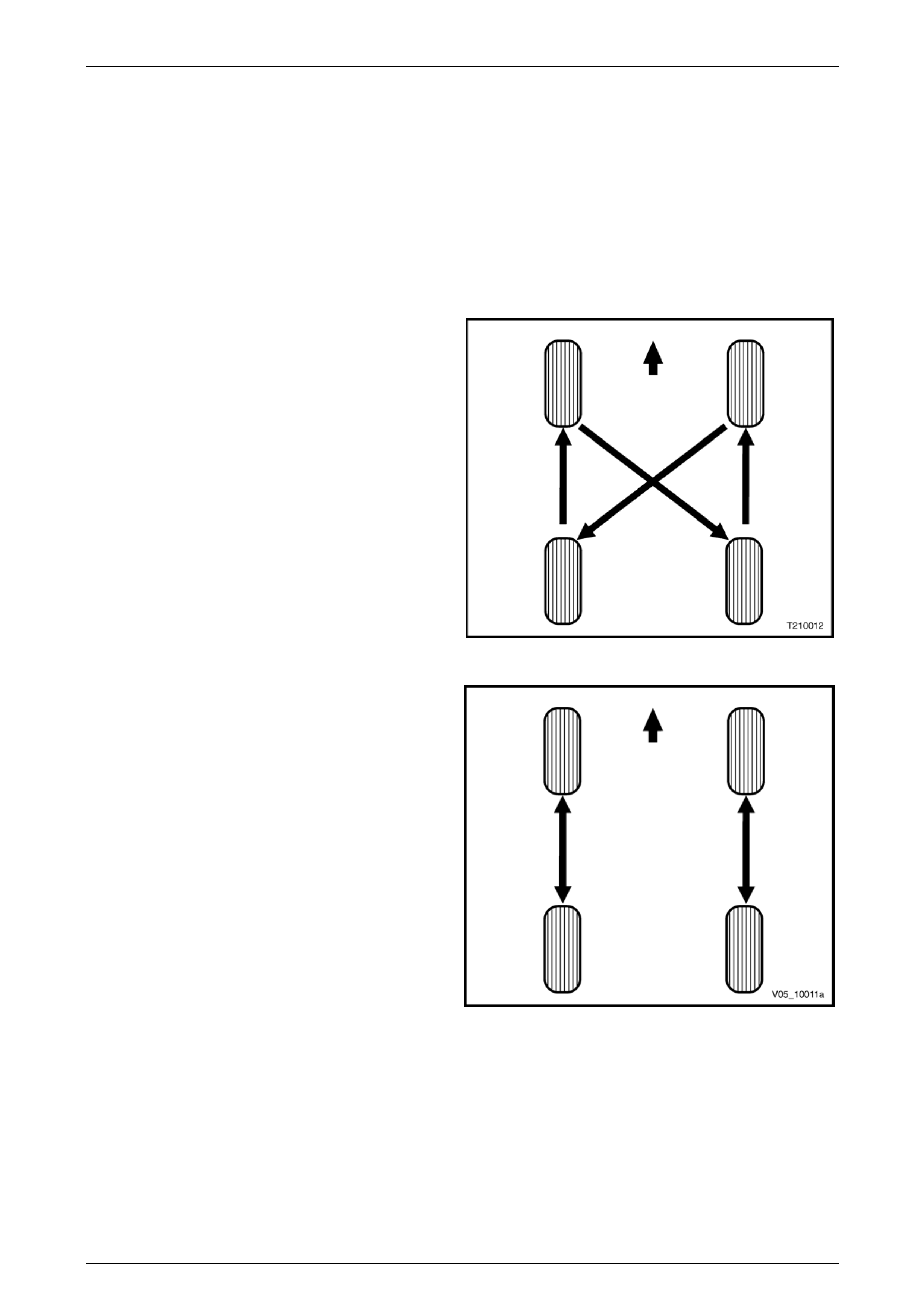
Tyre rotation in accordance with Figure 10 – 30 will assist in
obtaining optimum performanc e, except where a directional
tyre is fitted
Figure 10 – 30
For directional tyre rotation carr y out in accordance with the
procedure in and Figure 10 – 31.
Figure 10 – 31
Page 10–30

Wheels and Tyres Page 10–31
3.6 Checking Wheel and Tyre Assembly
Run-out
Because the run-out of a tyre / wheel assembly will directly affect the amount of imbalance and radial force variation, it
should be corrected first. The smaller the amount of run-out, the less imbalance and force variation. Radial an d lateral
run-out can be corrected at the same time. There are two methods to measure run-out of the tyre / wheel assemblies:
• On the vehicle (mounted to the hub), the wheel bearing must be in good condition.
• Off the vehicle (mounted on a spin-type wheel balancer).
NOTE
Initial on-vehicle inspection should be made prior
to off-vehicle run-out checks.
Measuring the tyre / wheel run-out off the vehicle is easiest. It is usually easier to mount a dial indicator in the correct
location, and the chances of water, dirt, or slush getting on the dial indicator are decreased. Once the run-out has been
measured and corrected off the vehic le, a qu ick visual check of run-out on the vehicle will indicate if any further problems
exist.
If there is a large difference in the run-out measurements from on-vehicl e to off-vehicl e, then the run-out problem is due
to stud pattern run-out, or hub flange run-out, or a mounting problem between the wheel and the vehicle.
Before measuring or attempting to correct excessive run-out, carefull y check the tyre for an uneven bead seat. The
distance from the edge of the ring to the concentric rim locating-ring shoul d be equal around the entire circumference. If
the beads are not seated properly, the t yre should b e remounted. Otherwise, excessive run-out and imbalance will result.
NOTE
If the vehicle has been sitting in one place for a
long time, flat spots may exist at the point where
the tyres are resting on the ground. As the flat
spots affect run-out readings, they should be
removed by driving the vehicle far enough to
warm-up the tyres before conducting any run-out
measurements.
Page 10–31
Wheels and Tyres Page 10–32
Procedure
1 Raise the vehicle on a hoist or jack and supp ort with safety stands, refer to Section 0A General Information.
2 To obtain an initial indication of how much run-out exists, spin each wheel on the vehicle by hand. Visually check
the amount of run-out from the front or rear.
3 Mark the location of each tyre / wheel assembly in relation to the wheel studs and to their position on the vehicle
(for example, the right front, left rear) for future reference.
4 Remove the tyre / wheel assemblies one at a time and mount on a spin-type wheel balancer.
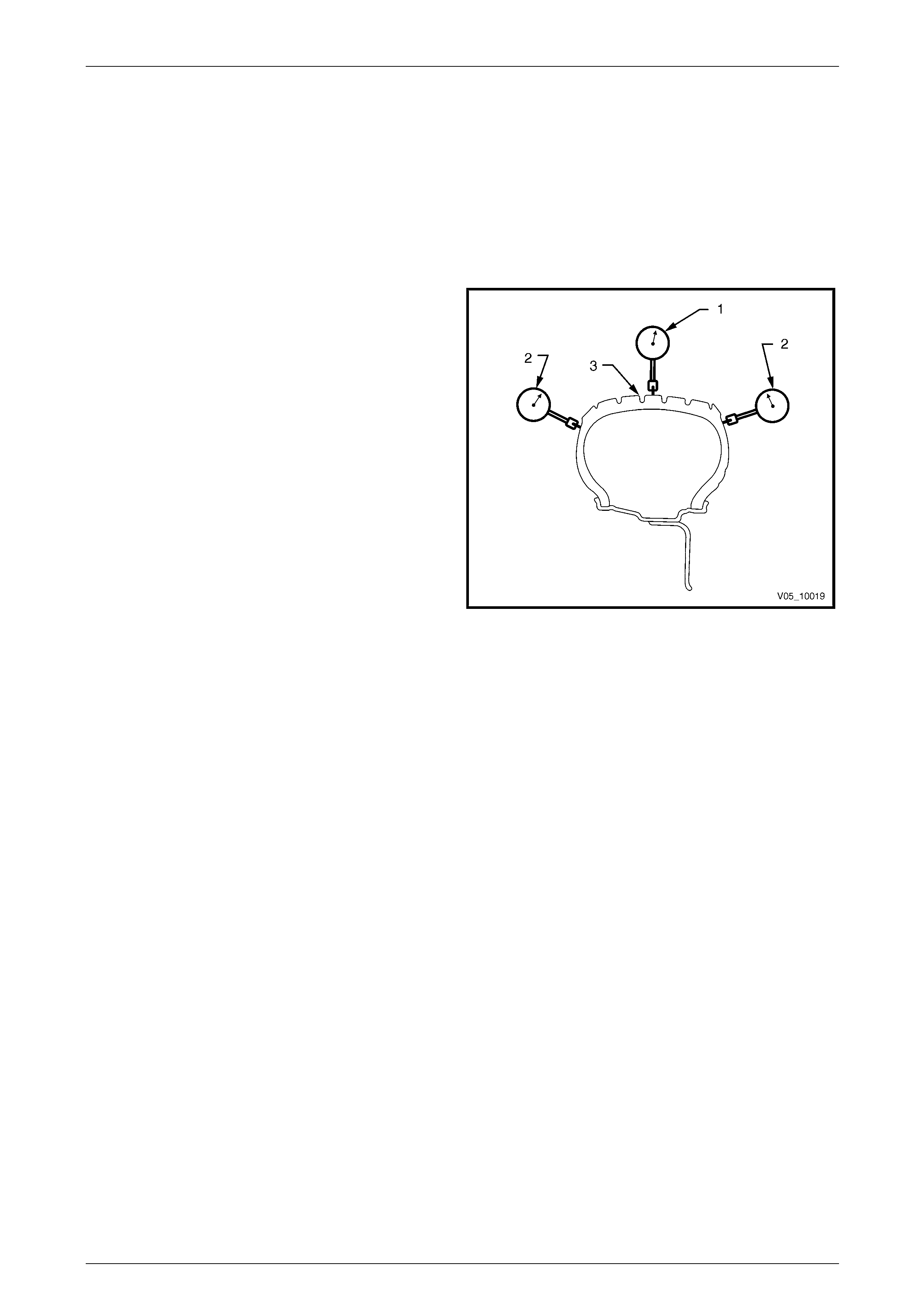
5 Using a dial indicator fitted with a roller, measure the
radial (1) and lateral run-outs (2) of the tyre / wheel
assembly.
NOTE
With tyres that have an aggressive tread pattern,
it will be necessary to wrap the outer
circumference (3) with tape when measuring
radial run-out, to provide a smooth surface for a
more accurate measurement.
NOTE
Lateral run-out should be measured on a
smooth area of the sidewall, as close to the
tread as possible. Any jumps or dips due to
sidewall splices should be ignored and an
average amount of run-out attained.
Figure 10 – 32
6 Slowly rotate the assembly one complete revolution and zero the dial indicator on the low spot.
7 Rotate the assembly one more complete revolution a nd note the total amount of run-out indicated.
As a guide the radial and later al run-out of the tyre / wheel assembly should be no more than 1.5 mm when measured off
the vehicle.
Page 10–32

Wheels and Tyres Page 10–33
Match Mounting
NOTE
Match mounting is recommended to obtain
optimum performance with minimal or no
vibration.
If tyre / wheel assembly run-out is excessive, mark the location of the high and low spots on the t yre and the wheel. The
next step will be to determine if the run-out problem e xists in the tyre, wheel, or a combination of both and then to correct
it. The procedure used to accomplis h this is called match mounting or system matching.
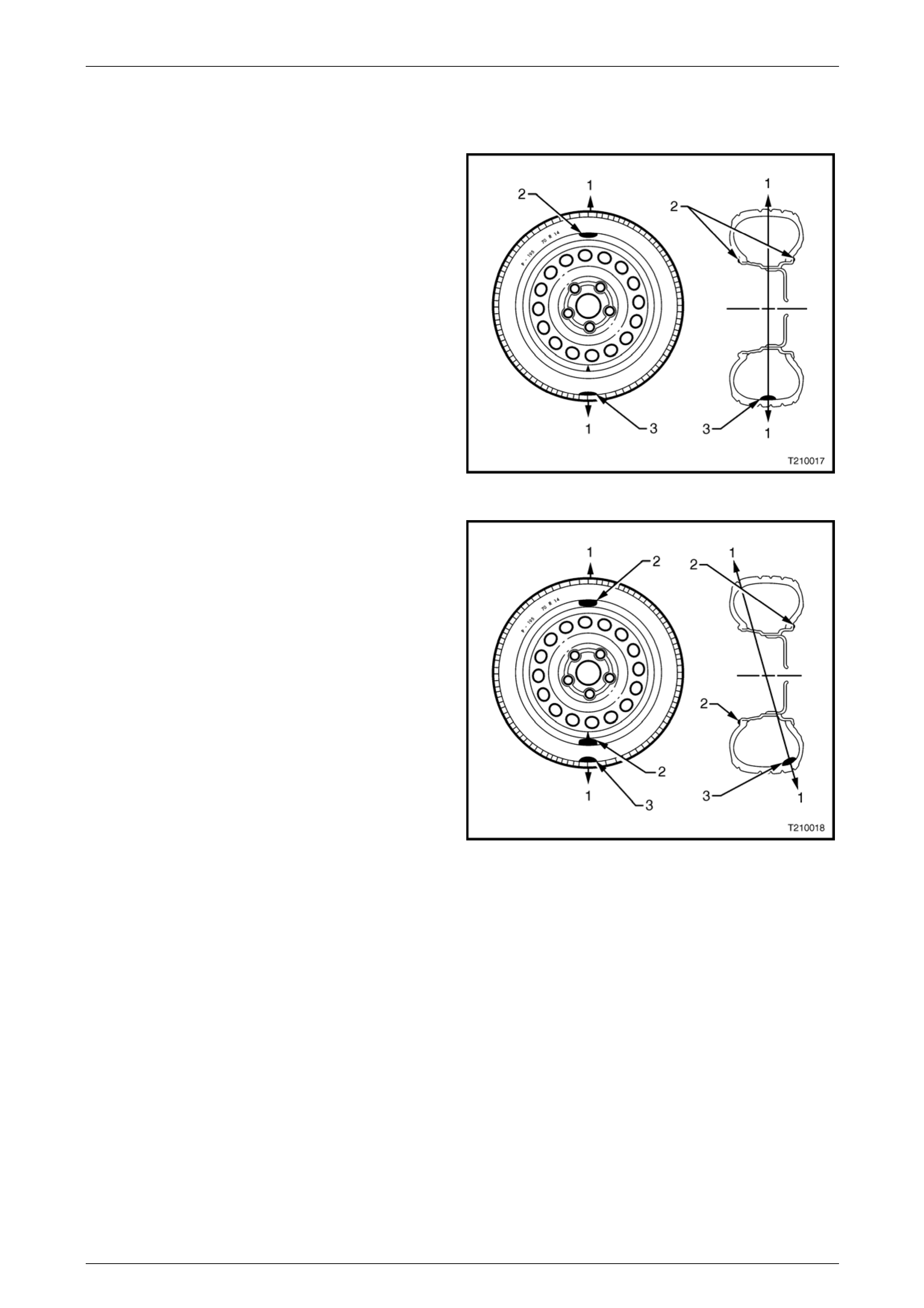
1 Place a mark on the tyre sidewall (1) at the location of
the valve stem (3). This will be referred to as the
12 o’clock position. The location of the high spot A will
always be referred to in relatio n to its clock position on
the wheel.
2 Mount the tyre and wheel assembly on a tyre machine
and break down the bead. Do not dismount the tyre
from the wheel at this time.
3 Rotate the tyre 180° on the rim so the valve stem
reference mark (2) is now at 6 o’clock in relation to the
valve stem itself. Inflate the tyre and make sure the
bead is seated properly. You may have to lube the
bead to enable eas y rotation of the tyre on the wheel.
4 Install the assembly on the tyr e balancer and again
measure the run-out. Mark the ne w location of the
run-out high spot B on the tyre.
Figure 10 – 33
If the run-out is now within tolerance, no further steps are necessary. The tyre may be balanced and installed on the
vehicle.
Alternatively, if the clock location of the hi gh spot B remained at or near the clock location of the original high spot A (as
in Figure 10 – 33), the wheel is the major contributor to the run-out problem. It should be measured for excessive run-out,
as detailed in 3.7 Checking Wheel Run-out and rep laced if found to exceed specification.
If the high spot is now at or near a position 180° (6 o’clock)
from the original high spot, the t yre is the major contributor
(as in Figure 10 – 34) and should be replaced.
Always measure the tyre / wheel assembly run-out after
replacing the tyre and make sure the run-out is within
tolerance before continuing. In the majority of cases, the
first 180° rotation of the tyre will either correct the run-out
problem or indicate which compon ent to replace.
If the high spot is between the t wo extremes, then both the
tyre and wheel are contributing to the run-out. Tr y rotating
the tyre an additional 90° in both the clockwise (9 o’clock)
and anticlockwise (3 o’clock) directions, measuring the run-
out after each rotation. Figure 10 – 34
If run-out cannot be corrected by match mounting, then the tyre must be removed and the wheel run-out measured, refer
to 3.7 Checking Wheel Run-out.
Once run-out has been brought within the tolerance, the tyre / wheel assembly should be balanced.
Page 10–33

Wheels and Tyres Page 10–34
3.7 Checking Wheel Run-out
Wheel run-out should be measured on the inside bead area of the wheel. Measure the run-out in the same fashio n as
tyre run-out. Ignore any jumps or dips due to paint drips, chips, or welds, measure both inboard and outboard.
If the run-out of the wheel is within tolerance, and the tyre / wheel assembly run-out cannot be reduced to an acceptable
level by using the match-mounting techni que, the tyre must be replaced.
NOTE
Always measure the assembly run-out after
replacing the tyre.
If there is a large difference in the run-out measurements from on-vehicl e to off-vehicl e, then the run-out problem is due
to stud pattern run-out, or hub flange run-out, or a mounting problem between the wheel and the vehicle.
The tolerances listed are to serve as gui delines, 4 Specifications. If run-out measurements are within tolerance but are
marginal, some sensitive vehicles may still be affected. It is always advisable to reduce run-out to as little as possible in
order to attain optimum results under all conditions.
Procedure
NOTE
The following measuring procedure can be
performed on either steel or alloy road wheels.
1 Raise the vehicle on a hoist or jack and supp ort with safety stands.
2 Remove the centre cap.
3 Mark the relationship of the wheel to the mounting flange or the brake disc / hub. Remove the wheel attaching nuts
and remove the wheel.
4 Mark the relationship of the tyre to the wheel rim and then remove the tyre from the rim.
5 Check the wheel and mounting flange or brake disc / hub mating surfaces are clean and free from burrs.
6 Install the wheel onto the mounting flan ge or brake disc / hub and install the wheel attaching nuts. Tighten the nuts
to the correct torque specification.
Road wheel attaching nut
torque specification...................................110 – 140 Nm
Page 10–34
Wheels and Tyres Page 10–35
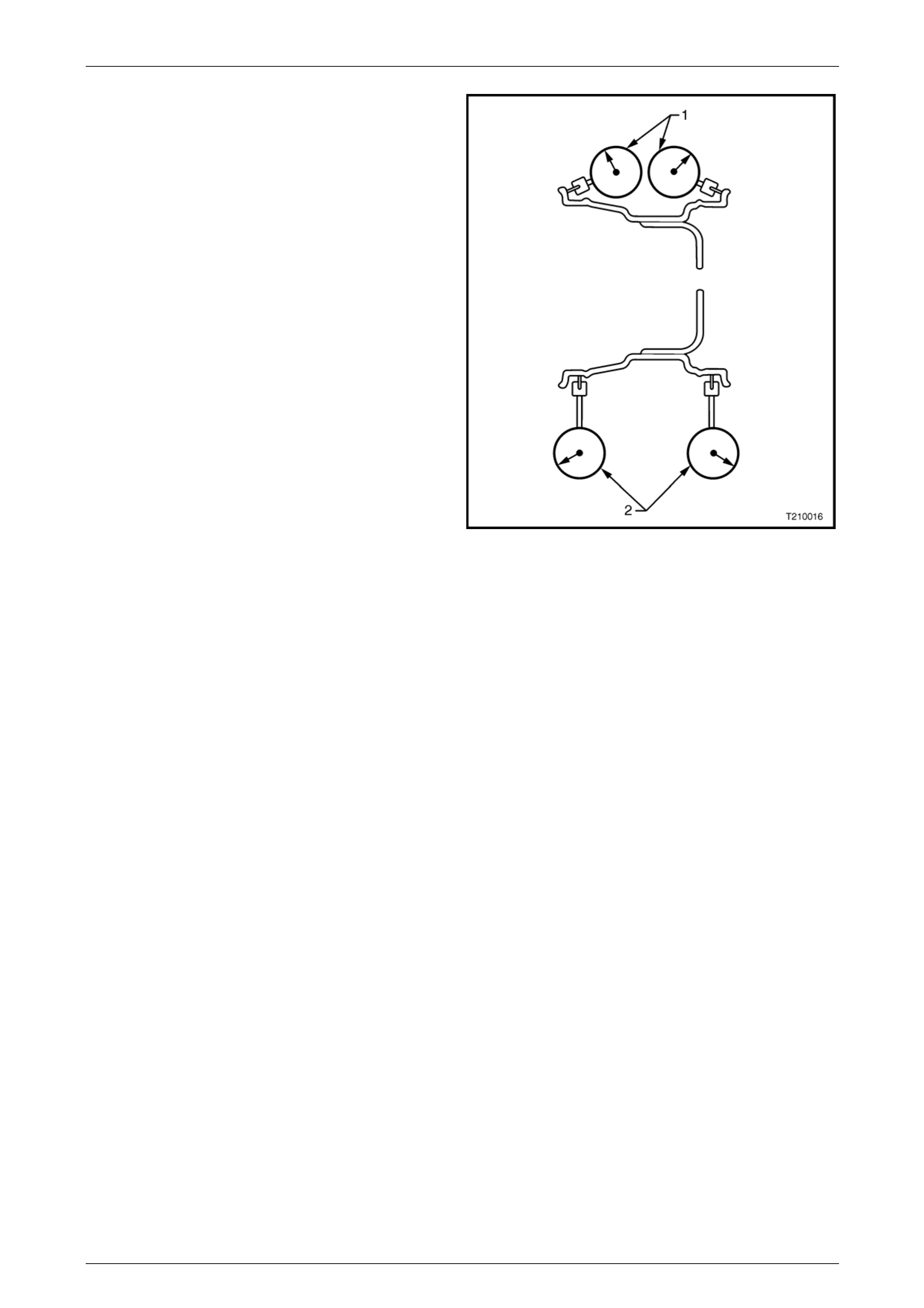
7 Using a dial indicator with a roller fitted to the probe,
secure the body of the indicator to a fixed point, and
butt the roller and probe against the wheel rim at the
points shown. Then, slowly rotate the road wheel and
measure the wheel run-out.
1 = Lateral Run-out.
2 = Radial Run-out.
Wheel run-out should be within the specified values, refer to
4 Specifications.
If not within specification, replace the wheel.
Figure 10 – 35
Page 10–35
Wheels and Tyres Page 10–36
3.8 Wheel and Tyre Balancing
There are two types of wheel and tyre balance, static and dynamic.
Static Balance
Static balance is the equal distribution of weight around the
wheel.
Vibrations caused by static imbalance will cause a vertical
or bouncing motion of the tyre.
Legend
1 Direction of Motion of Wheel.
2 Position for Balance Weight.
3 Heavy Point.
Figure 10 – 36
Dynamic Balance
Dynamic balance affects the distribution of weight on each
side of the tyre / wheel centreline.
Dynamic imbalance res ults in a side-to-side motion of the
tyre sometimes referred to as shimmy.
Legend
1 Direction of Motion of Wheel.
2 Position for Balance Weight.
3 Heavy Point.
Figure 10 – 37
Page 10–36

Wheels and Tyres Page 10–37
Off-vehicle Balancing
When wheel and tyre assem blies require balancing, they should be removed from the vehicle and balanced on a
machine capable of ensuring correct static and dynamic balance. Balancing should be carried out in accordance with the
machine manufacturer's instructions.
Before balancing, remove all accumulated mud from the wheel and any embed ded stones from the tyre treads.
On-vehicle Balancing
When using on-vehicle balancing equipment,
observe the Limited Slip Differential
Precautions, refer to Section 4B1 Rear Final
Drive and Dri ve Shafts.
If checking and / or correcting a tyre / wheel imbalance cond ition off the veh icle and it does not correct the vibration, it
may be necessary to balance the tyre and wheel assembly with the assembly mounted on the vehicle. Use an
on-vehicle, high-speed spin balancer, as this will balance the hubs, rotors, and wheel trims simultaneously. Additionall y,
it can compensate for any amount of residual run-out encountered due to mounting the tyre / wheel assembly on the
vehicle, as opposed to the balance that was achieved on the off-vehicle ba lance.
NOTE
• Although the hub and brake discs do not
normally contribute significantly to an out of
balance condition, if wheels ar e rem oved fro m
the vehicle after balancing it is good practice
to fit the wheels to the same position when
installing on the vehicle. Accordingly, it is
good practice to mark the relationship of the
wheel to the axle flange or hub / brake disc
prior to wheel removal.
• Always follow the on-vehicle balancer
manufacturer’s Operator Manual for specific
instructions.
• Do not remove the off-vehicle balance
weights. The purpos e of on-vehicle balance is
to fine tune the assembly balance already
achieved, not to begin again.
• If the on-vehicle balance calls for more than
10 grams of additional weight, split the weight
between the inboard and outboard flanges of
the wheel. This will avoid disturbing the
dynamic balanc e of t he assembl y, ac hiev ed in
the off-vehicle balance procedure.
• Evaluate the condition following the on-
vehicle balance to determine if the vibration
has been eliminated.
Page 10–37
Wheels and Tyres Page 10–38
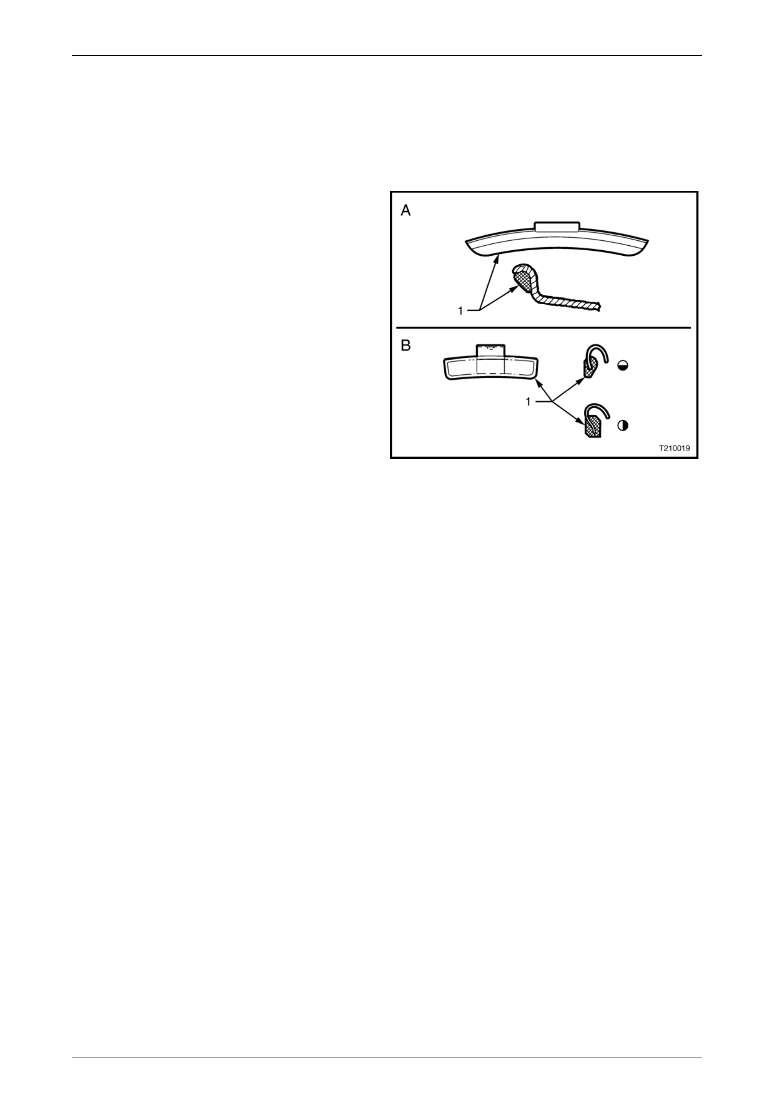
Balance Limits
NOTE
Specific wheel weights for each design of wheel
are used. This is due to the differences in wheel
rim profile.
A wheel weight and profile for steel wheels is shown A.
Weights of this design are available in 10 grams and
15 grams.
A wheel weight and profiles fo r alloy wheels are shown B.
Weights of this design are available in 20, 30, 40 and
50 grams.
A third style of wheel weight is the ribbon weight (not
illustrated) which has a self-a dhesive backing enabling
weights to be adhered to clean flat surfaces on the inside
diameter of the wheel. These ribbon weights are used
primarily on alloy wheels a nd are available marked i n
increments of 5 grams or 10 grams.
Figure 10 – 38
Page 10–38
Wheels and Tyres Page 10–39
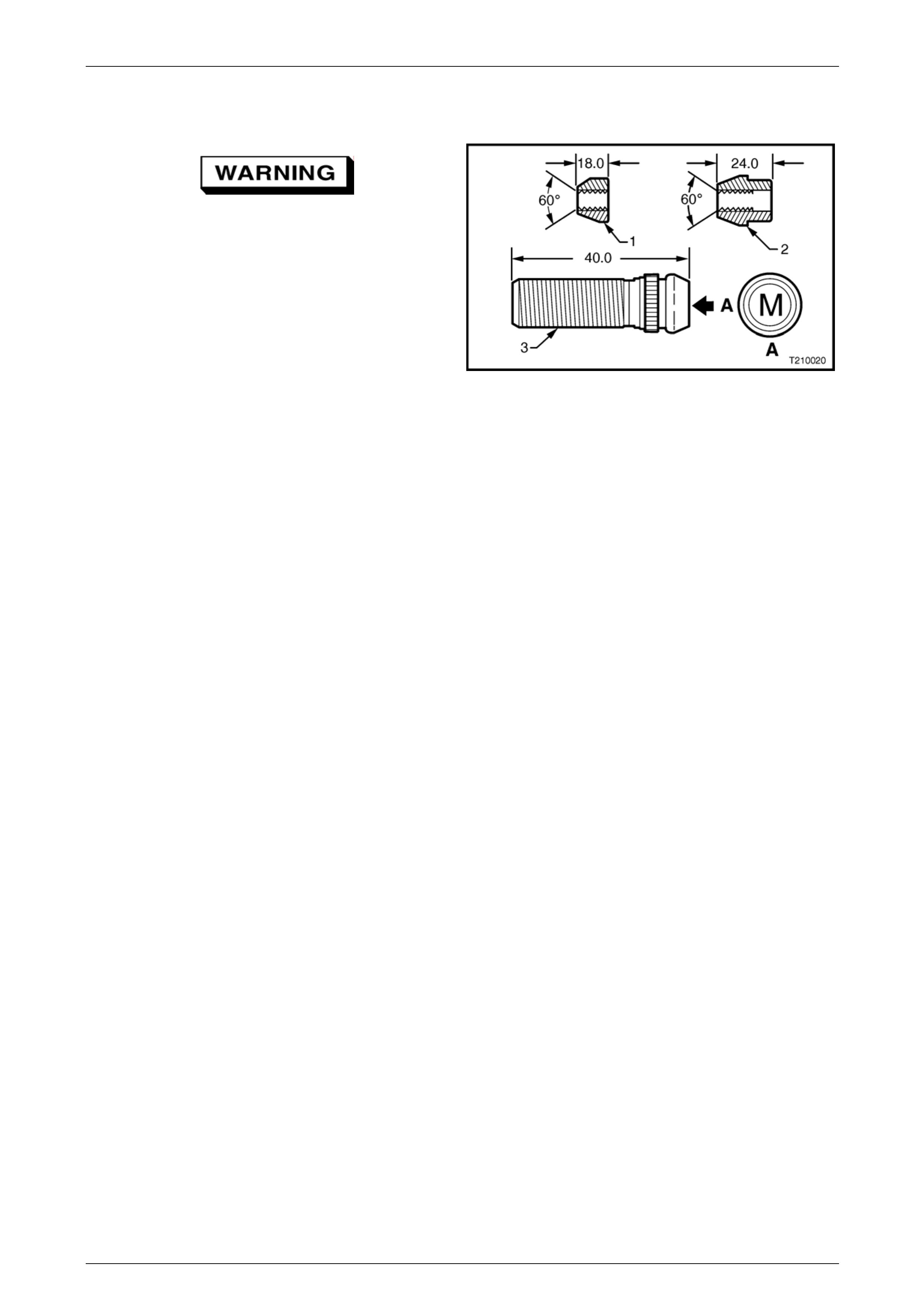
3.9 Wheel Attaching Nuts and Studs
Wheel nuts for alloy wheels have a different
mounting taper to those for steel wheels (1
and 2). Do not interchange or mix wheel nuts
from both types of wheel, as incorrect wheel
nuts will not allow the w heels to b e tightened
securely.
For removal and installation instructions for
the wheel attaching studs (3), either refer to
Section 3A Front Suspension or
Section 4B1 Rear Final Drive and Drive Shafts. All vehicles
use metric (M12 x 1.5) wheel attaching studs and nuts
which are identified as shown A. Figure 10 – 39
Page 10–39

Wheels and Tyres Page 10–40
4 Specifications
Steel Wheels
Rim Width Code....................................................................................................................6J
..............................................................................................................................................7J
Diameter Code .....................................................................................................................15
Maximum Permissible Radial Run-out..........................................................................0.6 mm
Maximum Permissible Lateral Run-out.........................................................................0.8 mm
Offset............................................................................................................. 43 mm (positive)
Alloy Wheels
Rim Width Code..................................................................................................................7JJ
.........................................................................................................................................7.5JJ
............................................................................................................................................8JJ
Diameter Code .....................................................................................................................15
..............................................................................................................................................16
..............................................................................................................................................17
..............................................................................................................................................18
Maximum Permissible Radial Run-out........................................................................0.45 mm
Maximum Permissible Lateral Run-out.......................................................................0.45 mm
Offset (Except Acclaim)................................................................................. 48 mm (positive)
Acclaim........................................................................................................... 41mm (positive)
Page 10–40

Wheels and Tyres Page 10–41
Inflation Pressures
Recommended Cold In flation – kPa
Normal Load Maximum Load
Model Wheel Tyre Designation
Front Rear Front Rear
Executive
Sedan and
Wagon
6J x 15 steel P205/65 R15 95H 220 220 220 250
Executive
Sedan and
Wagon Option
7J x 15 steel 205/65 R15 99H 200 200 220 250
Acclaim Sedan
and Wagon 7JJ x 15 alloy P205/65 R15 95H 220 220 220 250
Berlina Sedan
and Wagon 7JJ x 16 alloy 215/60 R16 95V 200 200 220 250
SV6 Sedan 8JJ x 17 alloy 235/45 R17 93V 200 200 220 250
SV8 Sedan 8JJ x 17 alloy 235/45 R17 93V 200 200 220 250
S Utility 8JJ x 17 alloy 235/45 R17 93V 200 200 220 250
Base Utility 7J x 15 steel 205/65 R15 99H 200 200 220 250
SS Sedan 8JJ x 18 alloy 235/40 R18 91W 230 230 230 270
SS Utility 8JJ x 17 alloy 235/45 R17 93V 200 200 220 250
Thunder SS
Utility 8JJ x 18 alloy 235/40 R18 91W 230 230 230 270
Calais Sedan 8JJ x 17 alloy 225/50 R17 94V 200 200 220 250
CV8 Coupe 8JJ x 18 alloy 235/40 R18 91W 230 230 230 270
Adventra AWD
Wagon 7.5JJ x 17 alloy 225/55 R17 97H 200 200 220 250
2WD Regular
Cab and Crew
Cab 7J x 15 steel 215/65 R15C 104R 200 200 200 370
AWD Regular
Cab 7J x 16 steel 215/65 R16C 106R 200 200 200 370
S Regular Cab
and S Crew Cab 7JJ x 16 alloy 215/65 R16C 106R 200 200 200 370
SS Crew Cab 8JJ x 17 alloy 225/55 R17 97H 210 210 220 280
Thunder SS
Crewman 8JJ x 17 alloy 225/55 R17 97H 210 210 220 280
X6 Crew Cab 7JJ x 16 alloy 215/65 R16C 106R 210 210 220 280
X8 Crew Cab 7.5JJ x 17 all oy 225/55 R17 97H 210 210 220 280
Temporary use
spare 7J 205/65 R15 99H 300
For speeds above 140 km/h (V6 with 15” wheels) 240 240 270 300
For speeds above 160 km/h (Sedan and Wagon) 240 240 270 300
For speeds above 160 km/h (Utility) 220 220 220 300
For speeds above 160 km/h (Coupe) 250 250 270 300
Page 10–41

Wheels and Tyres Page 10–42
5 Torque Wrench Specifications
Road Wheel Attaching Nuts ........................................................110 – 140 Nm
Page 10–42

Wheels and Tyres Page 10–43
6 Special Tools
Tool Number Illustration Description Classification
AU534
Torque Limiting Socket
Released to allow the use of impact
gun to tighten road wheel nuts
Mandatory
Page 10–43