
Entertainment System Page 12D–1
Page 12D–1
Section 12D
Entertainment System
ATTENTION
Before performing any service operation or other procedure described in this Section, refer to Section 00
Warnings, Cautions and Notes for correct workshop practices with regard to safety and/or property damage.
1 General Information ...............................................................................................................................6
1.1 General Description............................................................................................................................................... 6
Entertainment System Component Locations, Except Coupe and AWD Wagon............................................. 7
Entertainment System Component Loc a t i ons , Coupe....................................................................................... 8
Entertainment System Component Loc a t i ons , AWD Wagon.............................................................................9
Type 1 Entertainment System............................................................................................................................. 10
Type 2 Entertainment System............................................................................................................................. 11
Type 3 Entertainment System............................................................................................................................. 12
Type 4 Entertainment System............................................................................................................................. 13
Diversity Antenna ................................................................................................................................................ 14
Priority Key System............................................................................................................................................. 14
1.2 Radio Control Switch Assembly Operation....................................................................................................... 15
Left-hand Switch Assembly (1)......................................................................................................................... 15
Right-hand Switch Assembly (2) ...................................................................................................................... 15
1.3 Power Antenna Operation................................................................................................................................... 16
Full Up / Down Antenna Operation..................................................................................................................... 16
Antenna Adjustable Height System Operation.................................................................................................. 16
1.4 Diversity Antenna Operation, Type 4 Entertainment Systems......................................................................... 17
1.5 Rear Glass Antenna Systems, Coupe................................................................................................................ 18
FM Antennas ........................................................................................................................................................ 18
AM Antenna.......................................................................................................................................................... 18
Mobile Phone Antenna Pad................................................................................................................................. 19
Coupe Antenna Amplifier.................................................................................................................................... 20
2 Operating Instructions.........................................................................................................................22
3 Preliminary Diagnostics ......................................................................................................................23
3.1 General Diagnostic Information.......................................................................................................................... 23
3.2 Principles Of Operation....................................................................................................................................... 24
Radio Reception................................................................................................................................................... 24
FM Reception In Vehicles.................................................................................................................................... 24
AM Reception in Vehicles ................................................................................................................................... 26
Basic Checks........................................................................................................................................................ 27
Common Radio Problems................................................................................................................................... 28
Static................................................................................................................................................................ 28
External Interference........................................................................................................................................ 28
Internal Interference......................................................................................................................................... 29
Diagnosing Internal Interference ...................................................................................................................... 30
Speakers.......................................................................................................................................................... 30
Techline
Techline

Entertainment System Page 12D–2
Page 12D–2
4 Tech 2 Processor Diagnostics............................................................................................................31
Diagnostic Trouble Codes................................................................................................................................... 31
Audio System Input / Output Signals................................................................................................................. 31
4.1 Connecting Tech 2 For System Diagnosis ........................................................................................................ 31
4.2 Tech 2 Test Modes And Displays....................................................................................................................... 32
Main Menu ............................................................................................................................................................ 32
Model Year....................................................................................................................................................... 32
Vehicle Identification Menu .............................................................................................................................. 32
System Selection Menu.................................................................................................................................... 32
Audio System Selection ................................................................................................................................... 32
Body Menu............................................................................................................................................................ 33
4.3 Normal Mode – Audio System ............................................................................................................................ 34
Normal Mode........................................................................................................................................................ 34
Normal Mode Data List..................................................................................................................................... 34
4.4 Diagnostic Trouble Codes – Audio System....................................................................................................... 35
Read Current DTC Information........................................................................................................................... 35
Audio System Diagnostic Trouble Code List .................................................................................................... 35
4.5 Diagnostic Data Display – Audio System .......................................................................................................... 36
Data List................................................................................................................................................................ 36
Data Display Data List...................................................................................................................................... 36
System Identification........................................................................................................................................... 38
4.6 Snapshot – Audio System................................................................................................................................... 39
4.7 Miscellaneous Tests – Audio System................................................................................................................ 40
Speed Dependent Volume................................................................................................................................... 40
Priority Key Selection, Type 4 Entertainment System...................................................................................... 41
Illumination........................................................................................................................................................... 41
Antenna Selection................................................................................................................................................ 42
Antenna (Up / Down)............................................................................................................................................ 42
Security LED......................................................................................................................................................... 43
Display.................................................................................................................................................................. 43
Power (On / Off).................................................................................................................................................... 43
Radio Band........................................................................................................................................................... 44
Preset Memory..................................................................................................................................................... 44
Audio..................................................................................................................................................................... 45
CD Function.......................................................................................................................................................... 45
Eject CD................................................................................................................................................................ 46
Audio Source........................................................................................................................................................ 46
4.8 Program – Audio System .................................................................................................................................... 47
Program Code Index............................................................................................................................................ 47
Program Antenna................................................................................................................................................. 47
4.9 DTC Charts........................................................................................................................................................... 48
DTC 10 – Fascia Button Jammed ....................................................................................................................... 48
Introduction ...................................................................................................................................................... 48
Diagnostic Table............................................................................................................................................... 48
DTC 11 – Steering Wheel Remote Button Jammed........................................................................................... 49
Introduction ...................................................................................................................................................... 49
Diagnostic Table Notes .................................................................................................................................... 49
Diagnostic Table............................................................................................................................................... 49
DTC 21 – CD Mechanism Error (CD Changer Models Only)............................................................................. 50
Introduction ...................................................................................................................................................... 50
Diagnostic Table............................................................................................................................................... 50
DTC 22 – CD Play Error (CD Changer Models Only)......................................................................................... 50
Introduction ...................................................................................................................................................... 50
Diagnostic Table............................................................................................................................................... 50

Entertainment System Page 12D–3
Page 12D–3
DTC 24 – CD Loading Error (Single CD Models Only)...................................................................................... 51
Introduction ...................................................................................................................................................... 51
Diagnostic Table............................................................................................................................................... 51
DTC 25 – CD Defect (Single CD Models Only)................................................................................................... 51
Introduction ...................................................................................................................................................... 51
Diagnostic Table............................................................................................................................................... 51
DTC 26 – CD General Error (Single CD Models Only)....................................................................................... 52
Introduction ...................................................................................................................................................... 52
Diagnostic Table............................................................................................................................................... 52
DTC 30 – Internal Bus Failure............................................................................................................................. 52
DTC 33 – Single Communication Bus Failure (Single Disc CD Units)............................................................. 52
DTC 34 – Multi Communication Bus Failure (Multi Disc CD Units) ................................................................. 52
DTC 35 – Fascia Communication Bus Failure................................................................................................... 52
DTC 40 – No BCM Serial Data............................................................................................................................. 52
5 Audio System Diagnostics..................................................................................................................53
5.1 Prerequisites........................................................................................................................................................ 53
Equipment ............................................................................................................................................................ 53
Testing Procedures ............................................................................................................................................. 53
5.2 Wiring Diagram .................................................................................................................................................... 54
5.3 Connector Charts................................................................................................................................................. 57
5.4 Audio System Diagnostic Circuit Check ............................................................................................................ 59
Introduction.......................................................................................................................................................... 59
Diagnostic Table Notes ....................................................................................................................................... 59
Diagnostic Table.................................................................................................................................................. 59
5.5 Power On / Off...................................................................................................................................................... 60
Introduction.......................................................................................................................................................... 60
Diagnostic Table Notes ....................................................................................................................................... 60
Diagnostic Table.................................................................................................................................................. 60
5.6 No Sound Or Distorted Sound............................................................................................................................ 62
Introduction.......................................................................................................................................................... 62
Diagnostic Table.................................................................................................................................................. 62
5.7 Audio Head Unit Display ..................................................................................................................................... 64
Introduction.......................................................................................................................................................... 64
Diagnostic Table.................................................................................................................................................. 64
5.8 Audio Head Unit Illumination.............................................................................................................................. 65
Introduction.......................................................................................................................................................... 65
Diagnostic Table.................................................................................................................................................. 65
5.9 Hands-free Telephone Input................................................................................................................................ 66
Introduction.......................................................................................................................................................... 66
Diagnostic Table.................................................................................................................................................. 66
5.10 Electric Antenna – Full Up / Down...................................................................................................................... 68
Introduction.......................................................................................................................................................... 68
Diagnostic Table Notes ....................................................................................................................................... 68
Diagnostic Table.................................................................................................................................................. 68
5.11 Electric Antenna – Height Adjustable ................................................................................................................ 70
Introduction.......................................................................................................................................................... 70
Diagnostic Table Notes ....................................................................................................................................... 70
Diagnostic Table.................................................................................................................................................. 70
5.12 Main Rear Glass Antenna System, Coupe......................................................................................................... 73
5.13 Single CD Player.................................................................................................................................................. 75
Introduction.......................................................................................................................................................... 75
Diagnostic Table.................................................................................................................................................. 76

Entertainment System Page 12D–4
Page 12D–4
5.14 CD Changer.......................................................................................................................................................... 77
Introduction.......................................................................................................................................................... 77
Diagnostic Table.................................................................................................................................................. 78
5.15 Radio Reception................................................................................................................................................... 80
Introduction.......................................................................................................................................................... 80
Multipath Detector............................................................................................................................................ 80
Treble Control................................................................................................................................................... 80
Diagnostic Table.................................................................................................................................................. 81
5.16 Subwoofer Amplifier............................................................................................................................................ 84
Introduction.......................................................................................................................................................... 84
Diagnostic Table.................................................................................................................................................. 84
5.17 Subwoofer Amplifier, LX8 AWD Wagon............................................................................................................. 86
Introduction.......................................................................................................................................................... 86
Diagnostic Table.................................................................................................................................................. 86
5.18 Diversity Antenna Fault Diagnosis, Except Coupe........................................................................................... 88
Diversity Antenna System Test Procedure, Except Coupe.............................................................................. 88
5.19 Diversity Antenna Fault Diagnosis, Coupe........................................................................................................ 90
Diversity Antenna System Test Procedure, Coupe........................................................................................... 90
6 Service Operations...............................................................................................................................92
6.1 Audio Head Unit................................................................................................................................................... 92
Remove................................................................................................................................................................. 92
Reinstall................................................................................................................................................................ 93
6.2 Instrument Panel Speakers................................................................................................................................. 94
6.3 Front Door Speakers ........................................................................................................................................... 95
Remove................................................................................................................................................................. 95
Reinstall................................................................................................................................................................ 95
6.4 Rear Door Speakers, Except Utility, Regular Cab and Coupe.......................................................................... 96
Remove................................................................................................................................................................. 96
Reinstall................................................................................................................................................................ 96
6.5 Rear Quarter Speakers, Coupe........................................................................................................................... 97
Remove................................................................................................................................................................. 97
Reinstall................................................................................................................................................................ 97
6.6 Subwoofer Speakers – Type 4 Entertainment System ..................................................................................... 98
Remove................................................................................................................................................................. 98
Reinstall................................................................................................................................................................ 98
6.7 Subwoofer Speaker, LX8 AWD Wagon .............................................................................................................. 99
Remove................................................................................................................................................................. 99
Reinstall................................................................................................................................................................ 99
6.8 Subwoofer Speakers, Coupe ............................................................................................................................ 100
Remove............................................................................................................................................................... 100
Reinstall.............................................................................................................................................................. 100
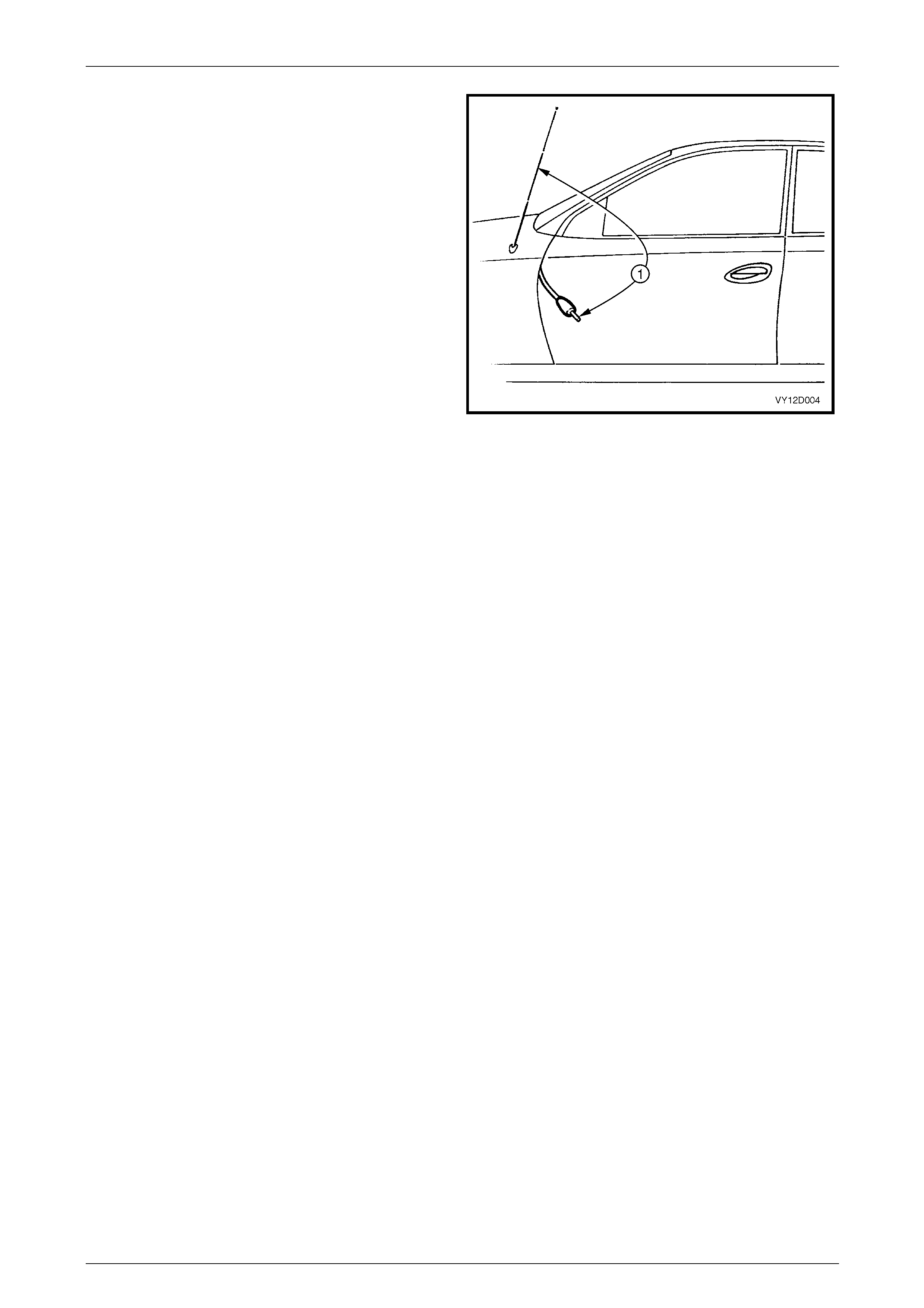
6.9 Manual Antenna................................................................................................................................................. 101
Remove............................................................................................................................................................... 101
Reinstall.............................................................................................................................................................. 102
6.10 Power Antenna................................................................................................................................................... 103
Power Antenna Assembly................................................................................................................................. 103
Remove.......................................................................................................................................................... 103
Reinstall ......................................................................................................................................................... 104
Mast Replacement ............................................................................................................................................. 104
Antenna Motor Operation Check...................................................................................................................... 105

Entertainment System Page 12D–5
Page 12D–5
6.11 Rear Window Antenna System, Coupe............................................................................................................ 106
AM/FM Antenna Coil.......................................................................................................................................... 106
Repair............................................................................................................................................................. 106
Antenna Amplifier Module ................................................................................................................................ 106
Remove.......................................................................................................................................................... 107
Reinstall ......................................................................................................................................................... 107
6.12 Diversity Antenna, Except Coupe..................................................................................................................... 108
Test ..................................................................................................................................................................... 108
Remove.......................................................................................................................................................... 108
Reinstall ......................................................................................................................................................... 109
6.13 Diversity Antenna, Coupe ................................................................................................................................. 110
Test ..................................................................................................................................................................... 110
Remove.......................................................................................................................................................... 110
Reinstall ......................................................................................................................................................... 111
6.14 Radio Control Switch Assembly....................................................................................................................... 112
Remove............................................................................................................................................................... 112
Reinstall.............................................................................................................................................................. 112
6.15 Subwoofer Amplifier.......................................................................................................................................... 113
Remove............................................................................................................................................................... 113
Reinstall.............................................................................................................................................................. 113
6.16 Subwoofer Amplifier, LX8 AWD Wagon........................................................................................................... 114
Remove............................................................................................................................................................... 114
Reinstall.............................................................................................................................................................. 114
6.17 Audio System Security Code............................................................................................................................ 115
Code Entry.......................................................................................................................................................... 115
6.18 Audio System Master Reset.............................................................................................................................. 116
Reset Procedure ................................................................................................................................................ 116
7 Specifications.....................................................................................................................................117
7.1 Program Code Index Numbers ......................................................................................................................... 117
Audio System Code Index Chart.................................................................................................................... 117
8 Torque Wrench Specifications..........................................................................................................118
9 Special Tools ......................................................................................................................................119

Entertainment System Page 12D–6
Page 12D–6
1 General Information
There are four entertainment systems, depending upon the vehicle model and / or options selected.
Component(s) Type 1 Type 2 Type 3 Type 4
Single CD (60 W) X X
6 Disc Changer (60 W) X
6 Disc Changer (200 W) X
Preset Equaliser X X X
Antenna - Height adjustable power X X(4)
Antenna - Power Full Up / Down X(1) X X(8)
Antenna - Manual retractable and l ocka ble X(2)
Antenna - Diversity X
(7)
Antenna - Rear glass X
(5)
Radio Control Switch Assembly X X X X
Instrument Panel speakers X X X X
Front Door speakers X X X X
Rear Door speakers X(3 and 4) X X X
Rear Quarter speakers X
(5)
Sub Woofers (and amplifier) X
(6)
Key
1 Option for Base Utility / Regular Cab
2 Base Utility, Regular Cab and Crew Cab Only
3 Except Utility / Regular Cab
4 Except Coupe
5 Coupe
6 Single Subwoofer Speaker for LX8 AWD Wagon
7 Except AWD Wagon
8 SS and Cross 8 Crew Cab Only
1.1 General Description
Vehicles fitted with a high performance Blaupunkt Audio Entertainment System featuring an AM/FM stereo radio / CD
player combination. T ypes 1 and 2 Enterta inment Systems include a single CD player, whereas Type 3 and 4
Entertainment Systems include a built-in six CD Changer. The entertainment system’s Audio Head Unit (AHU) is
equipped with a unique four-digit security code to protect against theft. A red LED incorporated in the fascia of the AHU
flashes when the security system is armed.
All vehicles are fitted with radio control switch assemblies for the operation of the entertainment system. Control of the
audio system functions can be accomplished without the need for the driver’s hands being removed from the steering
wheel, refer to 1.2 Radio Control Switch Assembly Operation.
The radio in all entertainm ent system types allows 6 AM / 12 FM stations to be preset and enables the connecti on of a
hands-free mobile telephone kit to permit its received calls to be heard through the audio system. A real-time clock,
incorporated in the radio, remains on display permanently, regardless of whether the ignition is turned on or off.
Type 3 and 4 Entertainment Systems feature a height adjustable power antenna. The height adjustable power antenna is
controlled by a switch assembly for both up and down movements on the radio fascia. This s witch works in conjunction
with the Body Control Module (BCM), refer to Section 12J Body Control Module.
The Type 4 Entertainment System features unique 150 mm diameter twin-cone speakers mounted in the front door trim
side pockets. A 150 mm coaxial speaker is mounted in each of the rear door trim side pockets and a pair of subwoofer
speakers and bracket assemblies are mounted on the top of the rear parcel shelf. The subwoofer speakers are powered
by an additional amplifier loc ated on th e left-hand side of the rear compartment. The sub woofer amplifier has a plastic
screw to allow gain adjustment for more or less presenc e if a customer so requests (the centre detent position is the
factory setting).
The Type 4 Entertainment System fitted to the LX8 AWD W agon i ncorp orates the same additional amplifier as that fitted
to the Sedan and Coupe vehicles. The amplifier powers a single subwoofer speaker which is mounted to the left-hand
side quarter inner panel. The amplifier is located behind the left-hand side quarter i nn er pan el, forward of the subwoofer.
All systems are fitted with tweeters mounted in the instrument panel.
Entertainment System Page 12D–7
Page 12D–7
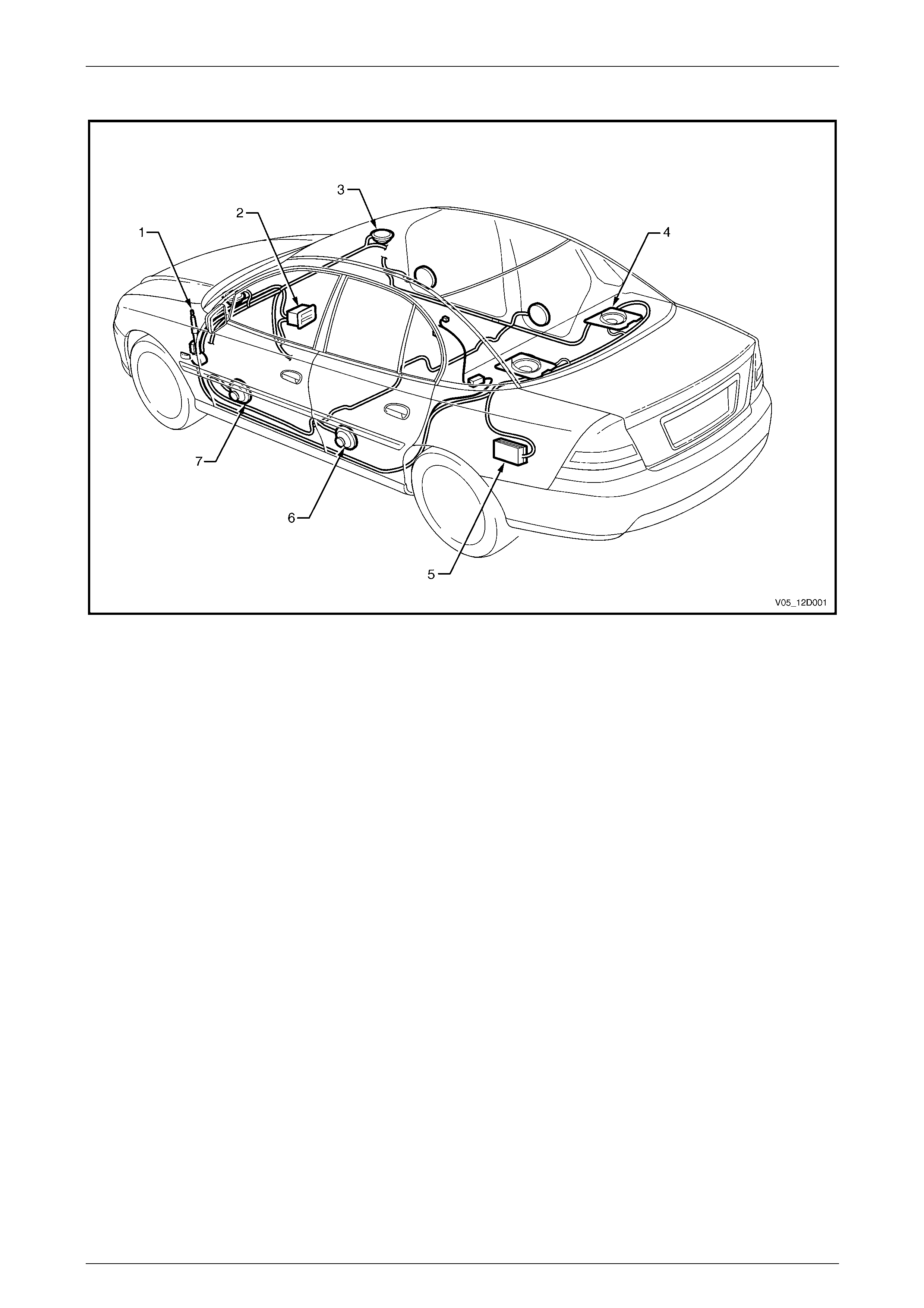
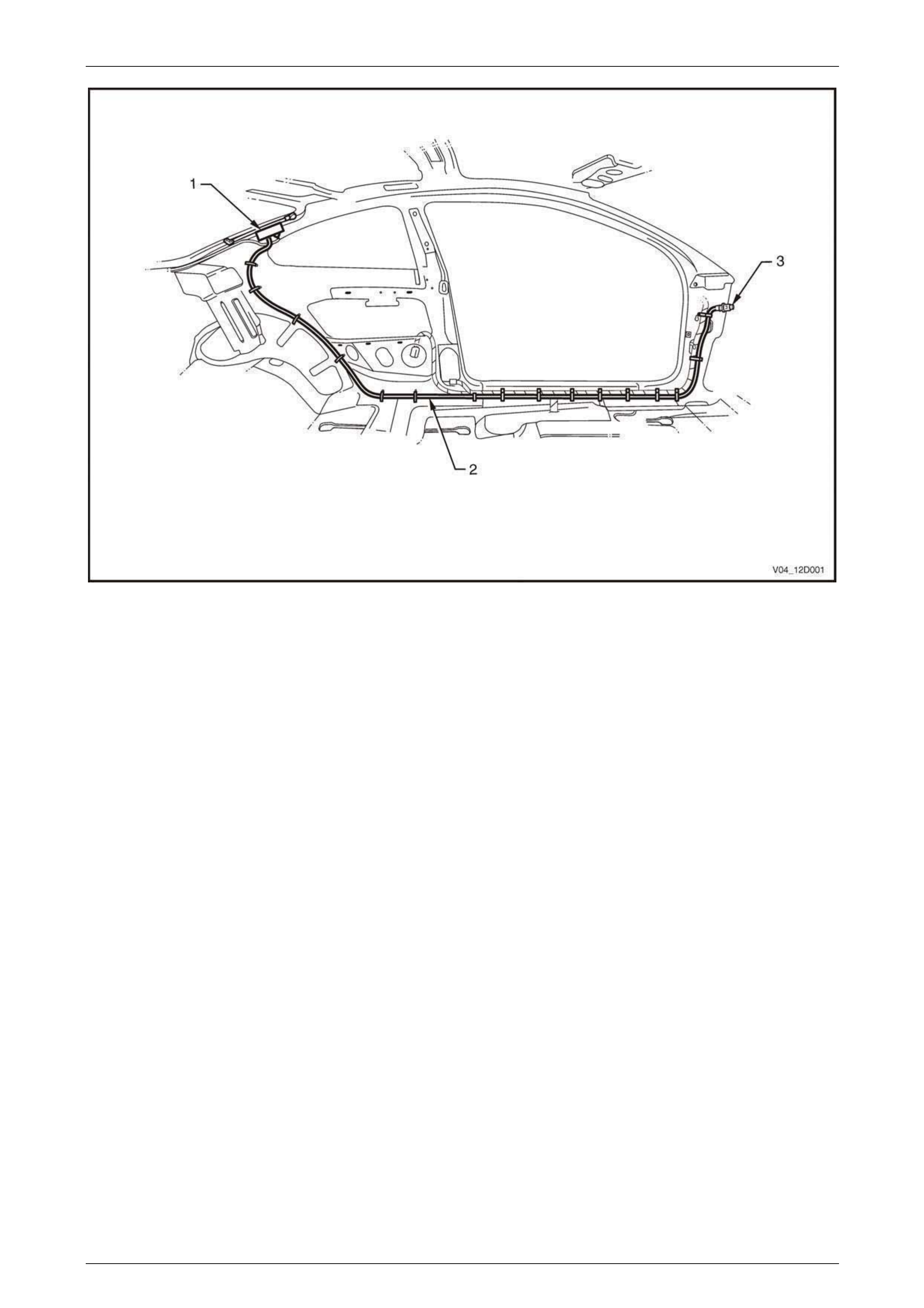
Entertainment System Component Locations, Except Coupe and AWD Wagon
Figure 12D – 1
Legend
1 Power Antenna
2 Audio Head Unit
3 Tweeter
4 Subwoofer (where fitted)
5 Subwoofer Amplifier (where fitted)
6 Rear Door Mounted Speaker (where fitted)
7 Front Door Mounted Speaker
Entertainment System Page 12D–8
Page 12D–8
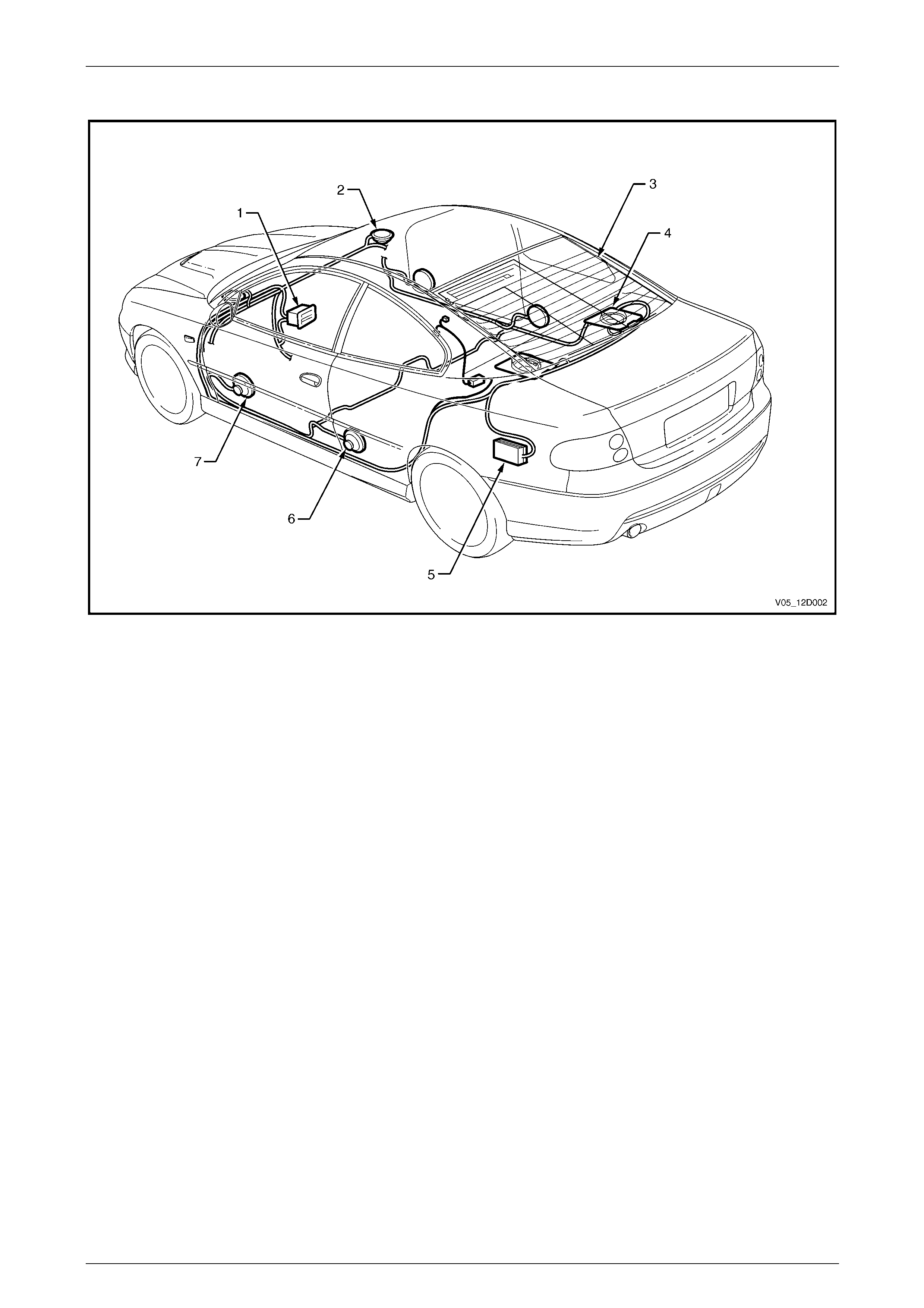
Entertainment System Component Locations, Coupe
Figure 12D – 2
Legend
1 Audio Head Unit
2 Tweeter
3 Rear Glass Antenna
4 Subwoofer (where fitted)
5 Subwoofer Amplifier (where fitted)
6 Rear Quarter Mounted Speaker
7 Front Door Mounted Speaker
Entertainment System Page 12D–9
Page 12D–9
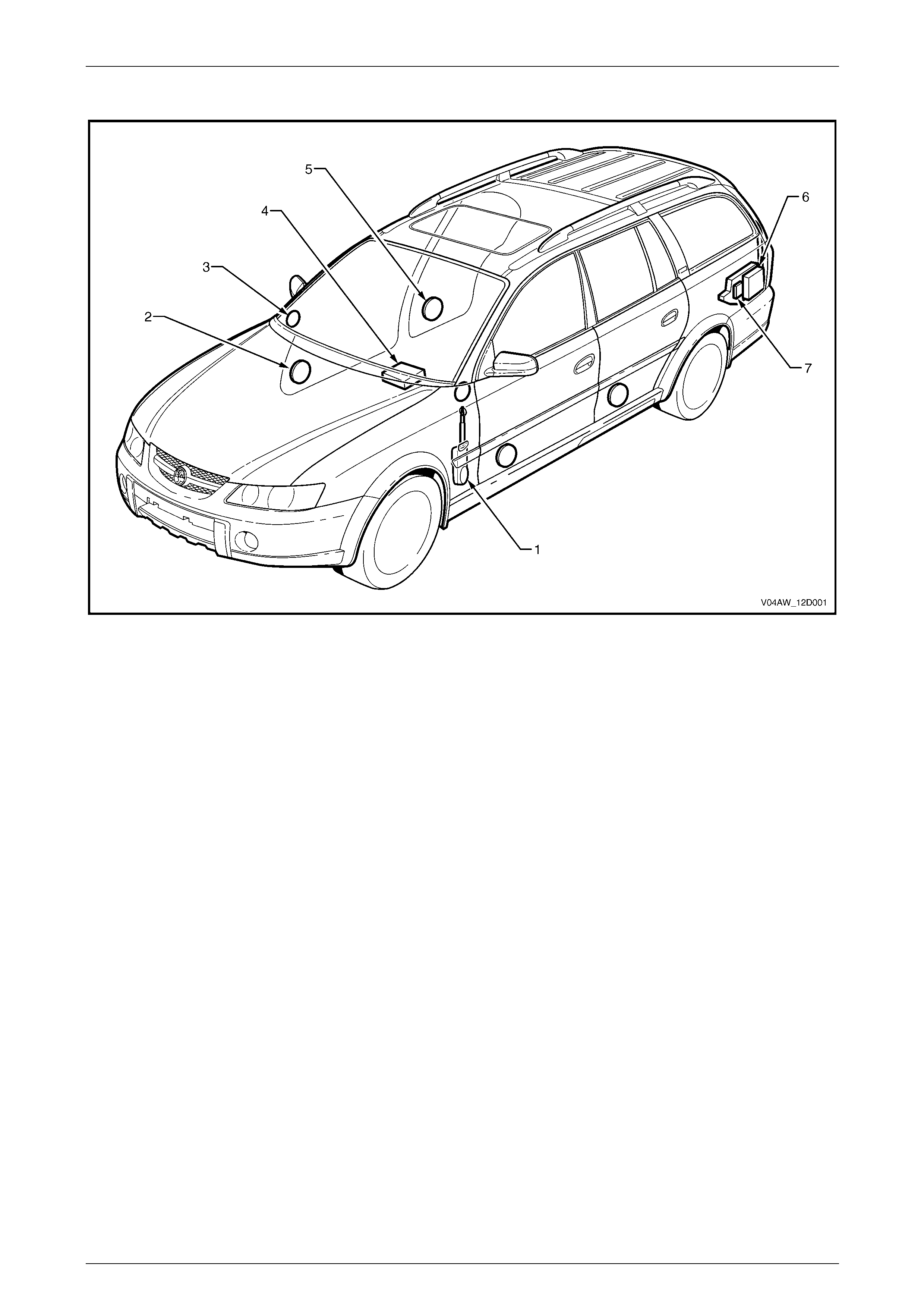
Entertainment System Component Locations, AWD Wagon
Figure 12D – 3
Legend
1 Power Antenna
2 Front Door Speaker
3 Tweeter
4 Audio Head Unit
5 Rear Door Speaker
6 Subwoofer (LX8 Only)
7 Sub Woofer Amplifier (LX8 Only)
Entertainment System Page 12D–10
Page 12D–10
Type 1 Entertainment System
A Type 1 Entertainment System has the following features:
• Single CD unit (60 Watts) with AM / FM Tuner
• Power antenna – Full Up / Down (excludes utility and regular cab vehicles which have a manually retractable and
lockable antenna)
• Steering wheel radio controls
• Two instrument panel mounted tweeters
• Two front door mounted speakers
• Two rear door mounted speakers (except utility and regular cab vehicles)
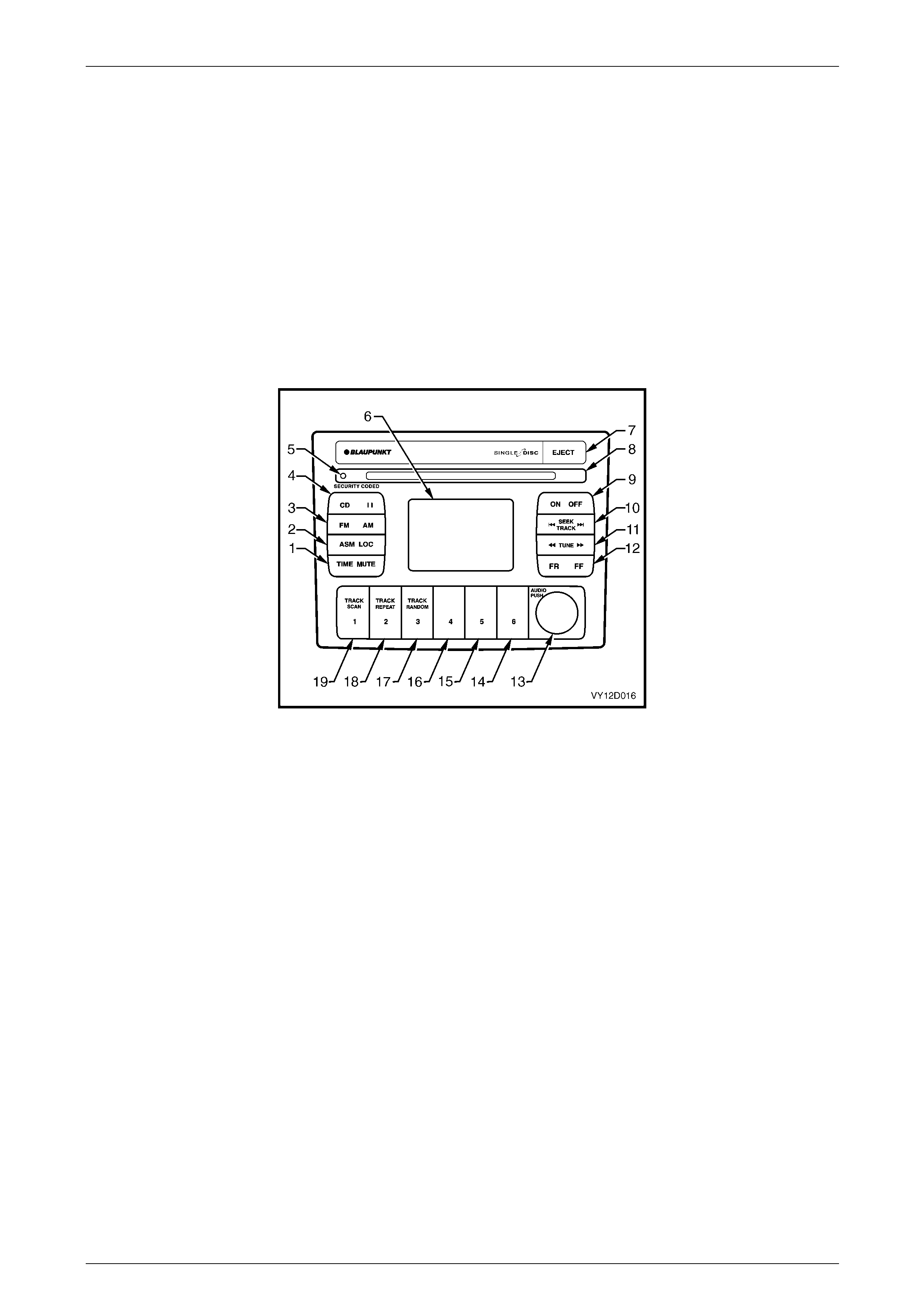
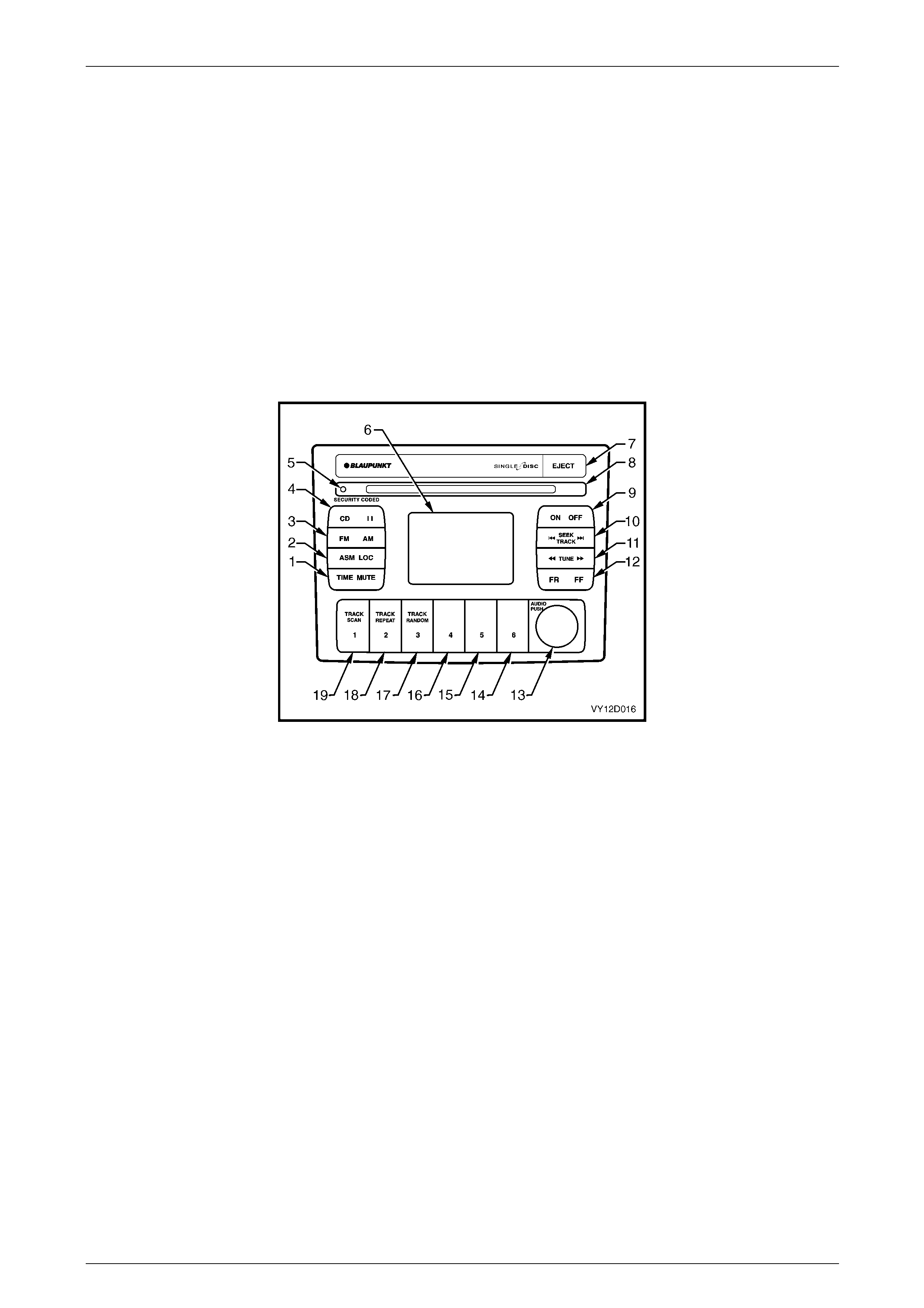
Figure 12D – 4 shows the Type 1 audio head unit front panel.
Figure 12D – 4
Legend
1 Clock Adjustment / Time Display On/Off
MUTE
2 Automatic Station Memory Storage
Local / Distance Search Sensitivity
3 FM1 / FM2 / AM Source Button
4 CD Source Button
CD Pause Button
5 Security Indicator Light
6 Information Display
7 CD Eject Button
8 Disc Load / Remove Slot
9 Radio On / Off
10 Radio Mode: Station Seek
CD Mode: Track Up / Down
11 Radio Mode: Manual Frequency Select
12 CD Mode: Track Cue / Review
13 Volume Control Knob
Push: Bass / Treble / Fader / Balance
14 Radio Mode: Memory Preset Station 6
15 Radio Mode: Memory Preset Station 5
16 Radio Mode: Memory Preset Station 4
17 CD Mode: Track Random
Radio Mode: Memory Preset Station 3
18 CD Mode: Track Repeat
Radio Mode: Memory Preset Station 2
19 CD Mode: Track Scan
Radio Mode: Memory Preset Station 1
Entertainment System Page 12D–11
Page 12D–11
Type 2 Entertainment System
A Type 2 Entertainment System has the following features:
• Single CD unit (60 Watts) with AM / FM Tuner
• Preset equaliser
• Power antenna – Full Up / Down
• Steering wheel radio controls
• Two instrument panel mounted tweeters
• Two front door mounted speakers
• Two rear door mounted speakers
Figure 12D – 5 shows the Type 2 audio head unit front panel.
Figure 12D – 5
Legend
1 Clock Adjustment / Time Display On/Off
Equalizer On / Off Setting
2 Automatic Station Memory Storage
Local / distance Search Sensitivity
3 FM1 / FM2 / AM Source Button
4 CD Source Button
CD Pause Button
5 Security Indicator Light
6 Information Display
7 CD Eject Button
8 Disc Load / Remove Slot
9 Radio On / Off
10 Radio Mode: Station Seek
CD Mode: Track Up / Down
11 Radio Mode: Manual Frequency Select
12 CD Mode: Track Cue / Review
13 Volume Control Knob
Push: Bass / Treble / Fader / Balance
14 Radio Mode: Memory Preset Station 6
15 Radio Mode: Memory Preset Station 5
16 Radio Mode: Memory Preset Station 4
17 CD Mode: Track Random
Radio Mode: Memory Preset Station 3
18 CD Mode: Track Repeat
Radio Mode: Memory Preset Station 2
19 CD Mode: Track Scan
Radio Mode: Memory Preset Station 1

Entertainment System Page 12D–12
Page 12D–12
Type 3 Entertainment System
A Type 3 Entertainment System has the following features:
• 6 Disc In-unit CD changer (60 Watts) with AM / FM Tuner
• Preset equaliser
• Power antenna – Height adjustable (except SS which has a full up / down power antenna)
• Steering wheel radio controls
• Two instrument panel mounted tweeters
• Two front door mounted speakers
• Two rear door mounted speakers
Figure 12D – 6 shows the Type 3 audio head unit front panel.
NOTE
For Type 3 systems with a full up / down power
antenna, electric antenna height adjustment
switch (13) will be replaced with a track cue /
review button for CD mode.
Figure 12D – 6
Legend
1 Clock Adjustment / Time Display On/Off
Equalizer On / Off setting
2 Automatic Station Memory Storage
Local / distance Search Sensitivity
3 FM1 / FM2 / AM Source Button
4 CD Source Button
CD Pause Button
5 Security Indicator Light
CD Mode: Load, Remove, Wait Indicator
6 CD Load Button
7 Information Display
8 CD Eject Button
9 Disc Load / Remove Slot
10 Radio On / Off
11 Radio Mode: Station Seek
CD Mode: Track Up / Down
CD Mode: Push and Hold: Track Cue / Review (Systems
with adjustable height electric antenna)
12 Radio Mode: Manual Frequency Select
CD Mode: Disc select
13 Electric Antenna Height Adjustment (Systems with
adjustable height electric antenna)
CD Mode: Track Cue / Review (Systems without adjustable
height electric antenna)
14 Volume Control Knob
Push: Bass / Treble / Fader / Balance
15 CD Mode: CD Random
CD Mode: Disc 6 select
Radio Mode: Memory Preset Station 6
16 CD Mode: CD Repeat
CD Mode: Disc 5 Select
Radio Mode: Memory Preset Station 5
17 CD Mode: CD Scan
CD Mode: Disc 4 select
Radio Mode: Memory Preset Station 4
18 CD Mode: Track Random
CD Mode: Disc 3 Select
Radio Mode: Memory Preset Station 3
19 CD Mode: Track Repeat
CD Mode: Disc 2 select
Radio Mode: Memory Preset Station 2
20 CD Mode: Track Scan
CD Mode: Disc 1 Select
Radio Mode: Memory Preset Station 1

Entertainment System Page 12D–13
Page 12D–13
Type 4 Entertainment System
A Type 4 Entertainment System has the following features:
• 6 Disc In-unit CD changer (200 Watts) with AM / FM Tuner
• Preset equaliser
• Power antenna – Height adjustable (except Coupe which has a rear glass antenna system)
• Diversity antenna
• Steering wheel radio controls
• Two instrument panel mounted tweeters
• Two front door mounted coaxial speakers
• Two rear door mounted coaxial speakers (or for coupe vehicles, rear quarter trim mounted speakers)
• Two rear shelf mounted subwoofer speakers
• Subwoofer amplifier
Figure 12D – 7 shows the Type 4 audio head unit front panel.
NOTE
For Type 4 systems fitted to coupe vehicles,
electric antenna height adjust ment s witch (13) will
be replaced with a track cue / review button for
CD mode.
Figure 12D – 7
Legend
1 Clock Adjustment / Time Display On/Off
Equalizer On / Off Setting
2 Automatic Station Memory Storage
Local / Distance Search Sensitivity
3 FM1 / FM2 / AM Source Button
4 CD Source Button
CD Pause Button
5 Security Indicator Light
CD Mode: Load, Remove, Wait Indicator
6 CD Load Button
7 Information Display
8 CD Eject Button
9 Disc Load / Remove Slot
10 Radio On / Off
11 Radio Mode: Station Seek
CD Mode: Track Up / Down
CD Mode: Push and Hold: Track cue / review
12 Radio Mode: Manual Frequency Select
CD Mode: Disc Select
13 Electric Antenna Height Adjustment (for coupe refer to Note)
14 Volume Control Knob
Push: Bass / Treble / Fader / Balance / Loudness
Adjustment
15 CD Mode: CD Random
CD Mode: Disc 6 Select
Radio Mode: Memory Preset Station 6
16 CD Mode: CD Repeat
CD Mode: Disc 5 Select
Radio Mode: Memory Preset Station 5
17 CD Mode: CD Scan
CD Mode: Disc 4 Select
Radio Mode: Memory Preset Station 4
18 CD Mode: Track Random
CD Mode: Disc 3 Select
Radio Mode: Memory Preset Station 3
19 CD Mode: Track Repeat
CD Mode: Disc 2 Select
Radio Mode: Memory Preset Station 2
20 CD Mode: Track Scan
CD Mode: Disc 1 Select
Radio Mode: Memory Preset Station 1

Entertainment System Page 12D–14
Page 12D–14
Diversity Antenna
A diversity antenna is part of the T ype 4 ent ertainment system. The diversity antenna system consists of a diversity
antenna, which is an integral p art of the rear window glass, and a diversity antenna module.
Refer to 1.5 Rear Glass Antenna Systems – Diversity Antenna Amplifier Module Overview.
Operating instructions for the audio system accompany the Owner’s Handbook.
Priority Key System
The Priority Key system intera cts with the Type 4 entertainment system. The Priority Key feature utilises two personal
identity memories, which individually memorise the following settings for different ignition keys:
• Last used volume level
• Last used mode
• FM1– radio memory presets
• FM2 – radio memory presets
• AM – radio memory presets
• Bass control settings
• Treble control settings
• Speaker balance setting
• Speaker fader setting
• Time / Frequency priorit y settings
• Local On / Off setting
The radio’s priority settings will follow the priority key number broadcast by the BCM on the veh icle ’s serial
communication data bus.
Entertainment System Page 12D–15
Page 12D–15
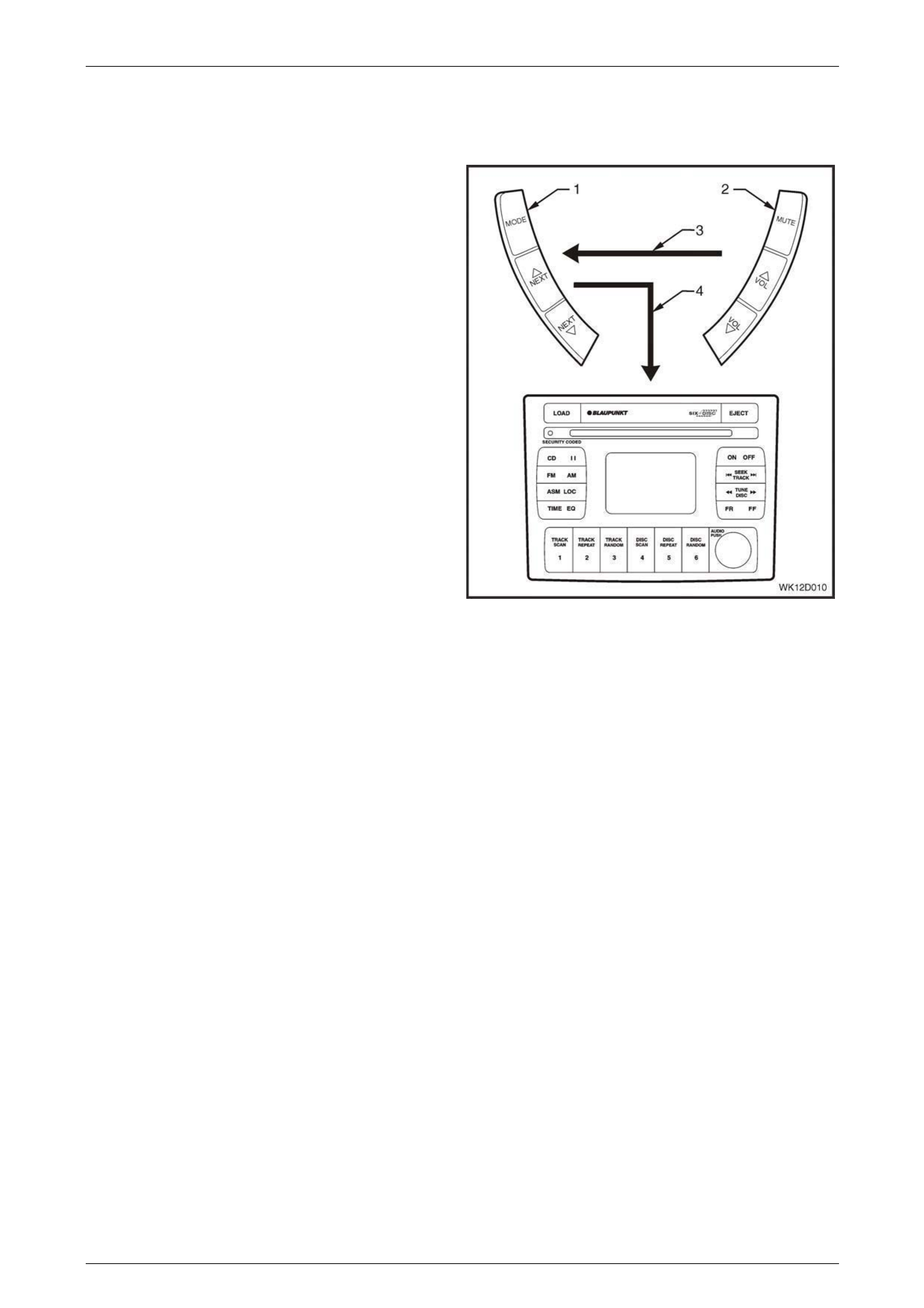
1.2 Radio Control Switch Assembly
Operation
There are two major compon ents of the radio control switch
assembly. These components are as follows:
Left-hand Switch Assembly (1)
Located to the left-hand side of the steering wheel, the left-
hand switch assembly has three momentar y contact
switches used to control the mode of operation and
switching between preset stations.
The MODE button allo ws selection between the Radio Mode
of operation and the CD Mode.
If Radio Mode is selected, the NEXT UP button selects the
next preset station in the frequency band, while the NEXT
DOWN button selects the previous preset radio station.
If CD Mode is selected, the NEXT UP button selects the
next track on the CD, while the NEXT DOWN button selects
the previous track. For CD Changer models, pushing the
NEXT UP and NEXT DOWN buttons simultaneously
changes the disc.
Right-hand Switch Assembly (2)
Located to the right-hand side of the steering wheel, the
right-hand switch assembly has three momentary contact
switches used to control the MUTE function as well as the
VOLUME UP and VOLUME DOWN. Figure 12D – 8
Each control switch has a unique resistanc e value. When a button is pressed on the radio control switch assembly, the
AHU decides the function required by measuring the resistance of the contact pressed.
Wiring (3) from the right-hand s witch is connected to the left-hand switch. The left-hand switch is connected to the audio
head unit by a wiring loom (4), as shown in Figure 12D – 8.
A Multi-function Display (MFD) in the instrument panel can provide the driver with an almost line-of-sight view of the MFD
for ease of operation of the audio system from the horn bar buttons.
Normal display on the MFD during vehicle operation displ ays the normal trip computer functions, for example the
odometer (in the centre of the MFD screen) and the g ear selector position (displayed at the bottom of the MFD screen at
all times).
When the radio or a CD source is selected, the radio band and frequency or the CD symbol replaces the trip computer
display for 2 seconds. The display then reverts to the trip computer display with the radio band and freque ncy or CD and
track indicator changing to a secondary small icon located in the warning icon location on the left-hand side of the MFD.
NOTE
If a warning is activate, the warning will override
the CD and track indicators.
The display of audio system information on the MFD can be turned On or Off from the MFD. The default setting is On.
Refer to Section 12C Instrumentation for further details.

Entertainment System Page 12D–16
Page 12D–16
1.3 Power Antenna Operation
All VZ vehicles variances (with the exception of the Coupe, Base Utility and Regular Cab vehicles) are fitted with a power
antenna. Certain vehicles are fitted with an antenna that extends fully out when the ignition key is turned on, or it returns
to its retracted position when the ignition key is turned off. Other vehicles have memory height adjustable antennas,
whereby the antenna’s e xte nded height is remembered, and every time the ignition key is turned on, the antenna
extends from it retracted position to the previously adjusted height position.
Coupe vehicles are fitted with a Rear Glass Antenna System, which utilises the rear window’s demister element as a
radio antenna. For more information on this, refer to 1.5 Rear Glass Antenna Systems – Rear Glass Antenna Systems,
Coupe.
Base Utility and Regular Cab vehicles are fitted with manually retractable and lockable mast style antenna.
Refer to 1 General Information – Vehicle Options chart to identify what entertainment system type has Full Up / Down,
Height Adjustable Po wer Antenna s ystems fitted or a dual antenna system that utilises a diversity antenna system.
Full Up / Down Antenna Operation
For vehicles with the full up / down power antenna option, the rad io / CD player controls the operation of the antenna.
When the radio is switched on, the antenn a relay is triggered and the antenna rises until fully extended, triggering the
relay to stop further extension. When the radi o is switched off or a CD is played the antenna relay is triggered again and
the antenna commences to lower until fully retracted, tripping the relay and stopping further retraction.
Antenna Adjustable Height System Operation
When the ignition key has been turned on and in the case where the radio was on last time the ignition was turned off,
the antenna mast extends to the same height as it was when last in operation. If a Priority Key feature is used, the
antenna height at Ignition ON or ACC position will be different for each priorit y key used.
If the battery is disconnected, the antenna height memory setting defaults to 5 seconds of mast upward travel after the
battery is reconnected, which raises the antenna approximately 600 mm.
Antenna height memor y can be set and stored for the Priorit y 1 and Priority 2 keys. When the UNLOCK button on the
remote coded key is pressed, the antenna heig ht is recalled by the BCM based upon what priority key (1 or 2) is being
used.
The information for antenna heig ht memory and the pressing of the antenna UP or DOWN buttons is communicated to
the BCM via the Secondary Serial Data Bus.
The antenna mast is moved when either an antenna up or antenna down signal from the radio is received by the BCM
via the serial data bus. The pressing of these switches does not affect the antenna if the BCM does not sense the radio
ON signal or the ignition switch has not been switched in either the ACC or the ON position.
When the radio is turned off, the antenna operates as follows:
1 If the ignition is turned off, there is a delay of approximately 15 seconds before the antenna mast fully retracts.
2 If the ignition is turned on or to the ACC position, the antenna mast will fully retract after 3 seconds.
The antenna mast also retracts when the theft deterrent system is armed or a CD is played.
During engine starting, the radio on signal is momentarily lost. During this time, the BCM assumes the signal is still acti ve
as it senses ignition and accessories inputs, as well as the radio status signal. This ensures unaffected antenna
operation and control during engine cranking.

Entertainment System Page 12D–17
Page 12D–17
1.4 Diversity Antenna Operation, Type 4
Entertainment Systems
When listening to FM signals i n a vehicle, fading of the signal occurs because the radio station’s transmitted signal can
arrive at the antenna from different directions and cause cancelling of the signal even when the vehicle is in a strong
reception area. A diversity antenna system can help ov ercome this problem by using two antenna systems which receive
the same FM signals. The AHU determines which of the two antennas has the strongest signal strength, and switches its
input to be connected to the best antenna until the signal strength situation changes.
The entertainment system uses the power antenna (except coupe, which uses the main rear glass antenna) as the main
antenna and the rear glass antenna as the diversity antenna.
The diversity antenna is an integral part of the rear window glass. The thin conductors that form the diversity antenna are
laid on the inside of the glass in the same manner as the rear window demister elements. A terminal is located on th e
passenger side of the rear window allo wing connectio n of the divers ity antenna to the diversity antenna modu le lead.
The diversity antenna module amplifies the small signals from the diversity antenna to signals of similar strength as the
signals from the main (mast, or rear glass for coupe) antenna. It then transmits the amplified signal to the AHUs diversity
antenna input.
The AHU receives signals fro m both the diversity antenna system and the conventional fender mounted mast type
antenna (or rear glass antenna for coupe). Internal circuitry within the AHU decides which antenna is located in th e
cleaner signal area. It then uses that antenna for its radio reception.
For further information on the diversity antenna amplifier module, refer to 1.5 Rear Glass Antenna Systems – Diversity
Antenna Amplifier Module Overview
For service information on the power antenna, refer to 6.10 Power Antenna.

Entertainment System Page 12D–18
Page 12D–18
1.5 Rear Glass Antenna Systems, Coupe
Vehicles fitted with Type 4 entertainment s ystems are fitted with rear glass antenna systems. The Coupe incorporates
both the main (FM and AM) antennas and an FM diversity antenna in its rear glass antenna system. The rear glass
antenna system utilises the demister element in a du al role of being both an FM antenna and demister element. These
antenna systems eliminate the need for the use of a mast type antenna on the vehicle. With reference to Figure 12D – 5,
the antenna coil assembly comprises three antennas plus provision for an external mobile phone antenna.
FM Antennas
There are two FM antenna s ystems mounted on the rear glass assembly:
• A combined FM Main antenna and demister eleme nt, refer to item 4 in Fig ure 12D – 9.
• An FM Diversity antenna, refer to item 3 in Fig ure 1 2D – 9.
The thin conductors that form each antenna are fixed o n th e inside of the glass, and the antenna / demister electrical
connectors are located on the side of the rear window. The FM Main antenna / demister is connected to body gr ound
which also includes an RF isolatio n coil.
The Antenna Amplifier module amplifies the FM Diversity antenn a signals to help reduce noisy radio reception that may
be generated within the vehicle. This module is mounted in the C-pillar as shown at item 9 in Figure 12D – 10. For further
information on the diversity antenna amplifier modul e,
refer to 1.4 Diversity Antenna Operation, Type 4 Entertainment Systems.
AM Antenna
A single AM antenna system is mounted on the rear glass assembly, refer to item 2 in Figure 12D – 9.
Entertainment System Page 12D–19
Page 12D–19
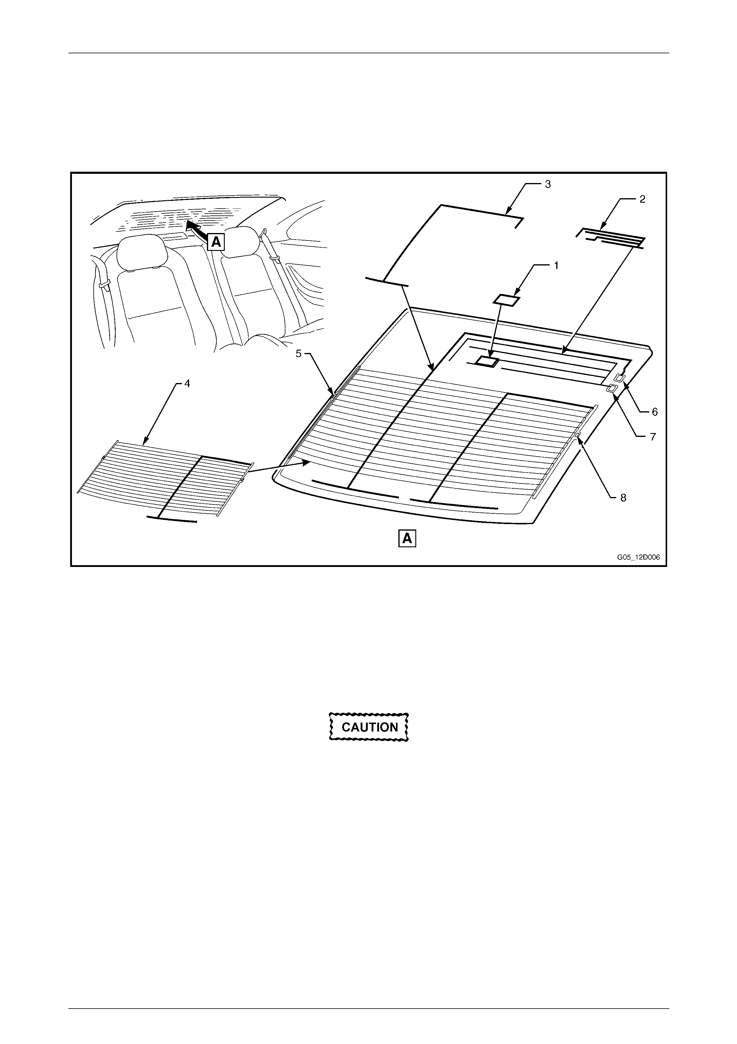
Mobile Phone Antenna Pad
The installation of a fixed external mobile phone antenna to the rear glass may lead to interference between the aud io
system and the mobile phone anten na if it is not mounted in the correct location. To prevent this from happening, the
area (1) in F igure 12D – 9 indicates the recommended loc ation for the mobile phone antenna to be installed in order to
minimise interference between the vehicles radio systems.
Figure 12D – 9
Legend
1 Mobile Phone Antenna Pad Location
2 AM Antenna
3 FM Diversity Antenna
4 FM Main Antenna / Demister Element
5 FM Main Antenna Ground / Demister Element Connection
6 FM Diversity Antenna Connection
7 AM Antenna Connection
8 FM Main Antenna / Demister Element Connection
Window tinting is not recommended on any
glass that has printed antenna coils attached.
Metallic-based tint material significantly
reduces radio reception in both the AM and
FM bands, whereas dye-based tint material
reduces reception in the FM band.
Entertainment System Page 12D–20
Page 12D–20
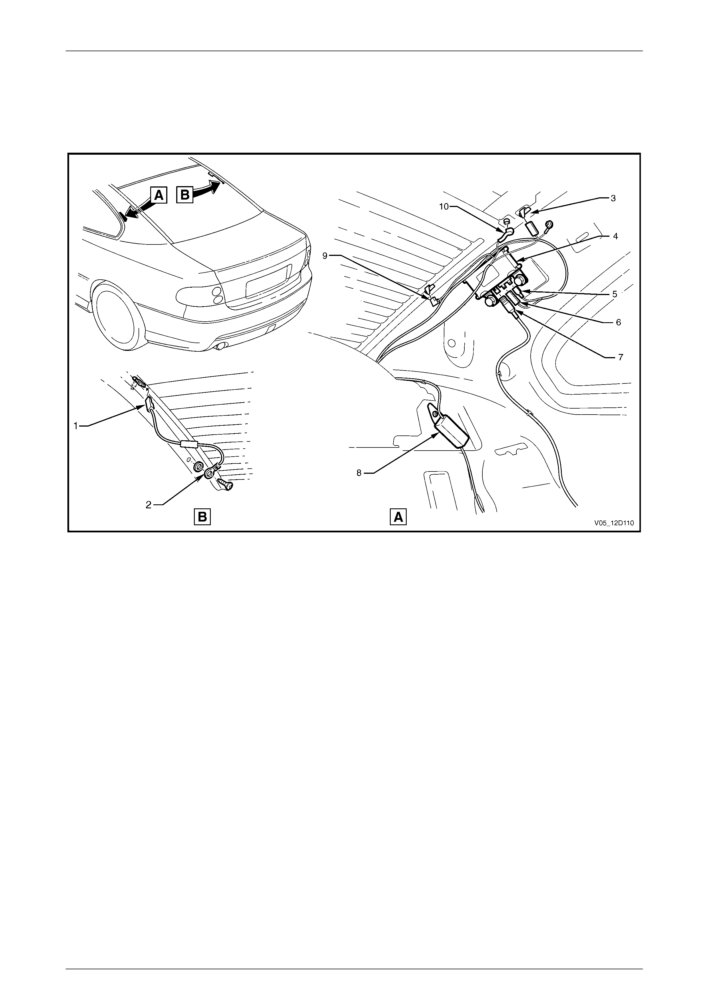
Coupe Antenna Amplifier
The rear glass antenna system consists of an antenna coil assembly that connects to an antenna amplifier module and
connecting leads. Figure 12D – 10 illustrates the location of the antenna am plifier module and the routing of the antenna
cable.
Figure 12D – 10
Legend
1 Antenna Amplifier Connector (L4 – L3)
2 Antenna Ground Lead Terminal (X118 – GP7)
3 Radio Diversity Connector (W4)
4 Antenna and Rear Window Defog Control Module
5 Antenna and Rear Window Defog Control Module Connector
(A93 – X3)
6 Antenna and Rear Window Defog Control Module Connector
(A93 – X1)
7 Antenna and Rear Window Defog Control Module Connector
(A93 – X2)
8 Diversity Antenna Amplifier Assembly
9 Defog Grid Connector (L4 – X2)
10 Antenna Grid Connector (L4 – X1)
Entertainment System Page 12D–21
Page 12D–21
Figure 12D – 11
Legend
1 Antenna Amplifier Module A93
2 Antenna Cable 3 Antenna Cable In-line Connector X208

Entertainment System Page 12D–22
Page 12D–22
2 Operating Instructions
For a detailed description of operation of the entertainment system, refer to the User Handbook Supplement supplied
with the vehicle.

Entertainment System Page 12D–23
Page 12D–23
3 Preliminary Diagnostics
3.1 General Diagnostic Information
This audio system diagnosis is split into several parts.
1 The first part is a short description of the pri ncipl es of radio operation. It is by no means exhaustive, and is to serve
only to give an understan ding of how radios work and how to solve problems if they occur.
2 Many radio problems are caus ed by basic grounding and short-circuitin g problems, which can be found quickly
using the checks included in the Basic C hecks in this Diagnostic Section.
3 The most common fault is that of ‘static’ and so an explanation of what it is, what causes it and how to fix it is also
included.
Entertainment System Page 12D–24
Page 12D–24
3.2 Principles Of Operation
Radio Reception
High quality radio reception is obviously more difficult to achieve in a moving vehicle than from a stationary location.
Audio systems fitted to vehicles incorporate sophisticated electronics to enhance radio reception by extending the
useable listening ran ge whilst eliminatin g extraneous noises, such as static.
Many owners complain of ‘reception pro blems’, which are normal radio operatin g characteristics, particularly with FM.
Such complaints arise as a result of owner misconception as to what constitutes normal radio reception. Naturally, audio
head unit replacement under these circumstances will not affect the radio operating ch aracteristics and has the potential
to create additional owner dissatisfaction. Thus a careful, well informed explanation of radio reception expectatio ns is
more likely to enhance the owner’s understanding and satisf action, as well as avoiding unnecessary repair costs and
inconvenience to the owner of the vehicle.
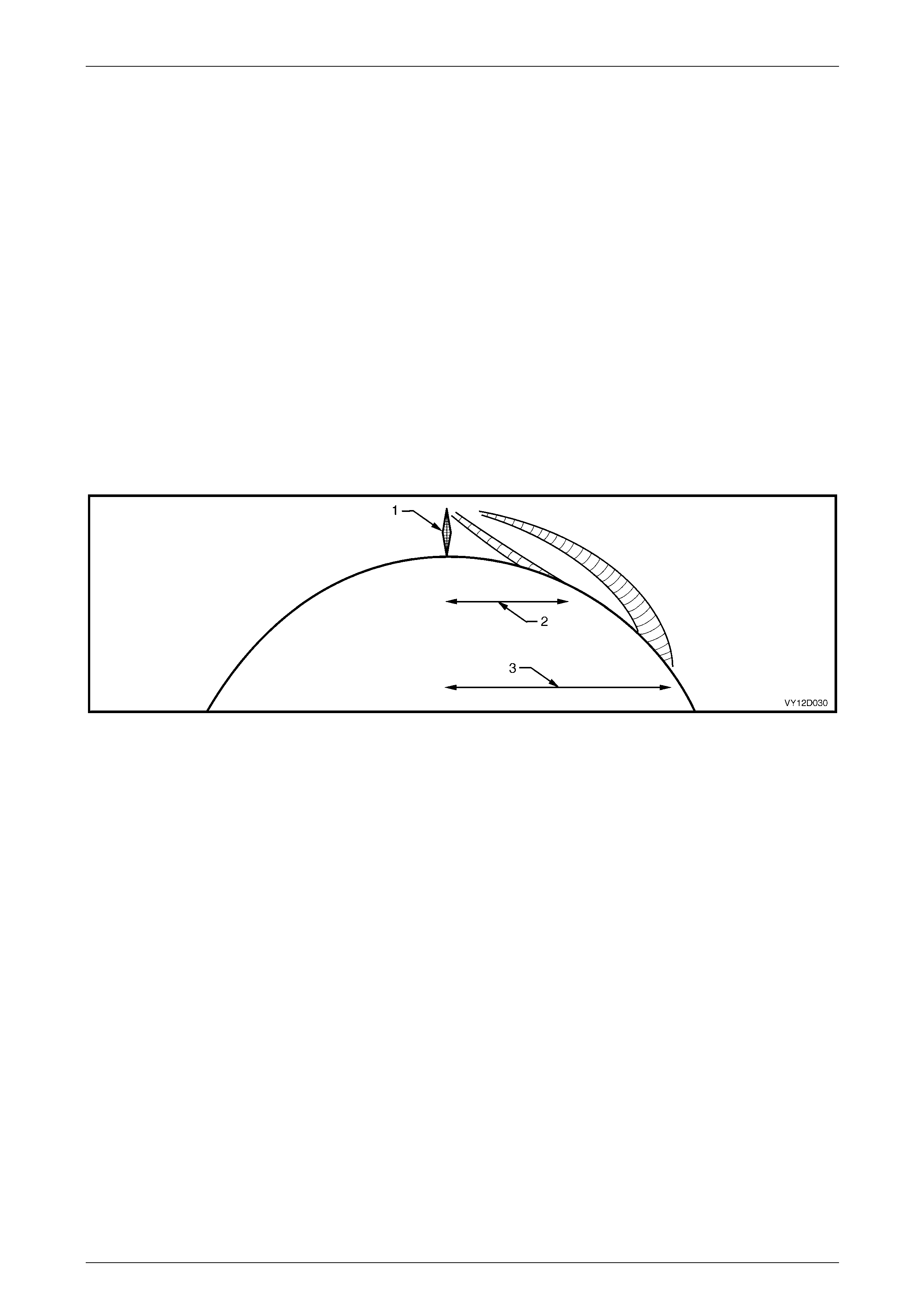
FM Reception In Vehicles
FM stereo’s maximum range is normally limited to 40 – 50 km. The strength of the FM signal is related to the distance
between the receiver and the transmitter. FM signals follow the line of sight, exhibiting many similar char acteristics to
those of light. That is, similarly to sunlight, FM radio waves are cut off by the horizon. Since most FM transmitter towers
are nominally 100 metres from the ground, useable reception cannot extend much beyond the horizon. FM signals will
not bend around corners, but as with light, may be reflected (or blocked) b y lar ge objects. Refer to Figure 12D – 12.
Figure 12D – 12
Legend
1 Radio Transmission Tower 2 FM Transmission (40 – 50 km) 3 AM Transmission (up to several hundred
km)
Although FM signals will not bend around corners, they can be reflected by large o bjects, for examp le hills or buildings.
Because of these characteristics, a reflected sign al and a direct signal can reach the ra dio’s antenna at the same time,
resulting in the signals interferi ng with each other or cancelling each other out. This obvious ly leads to a distortion of the
received signal or a loss of sound, and is known as multi-path interference.
Multi-path interference occurs only with FM reception and can be characterised by changes in distortion (static) levels
occurring as the vehicle is moving. T his is due to the vehicle’s antenna entering and leaving FM signal interference
areas.
FM signal waves have short wavelength, which also means the interferenc e area is small – in the region of several
centimetres across. Because of the small size of interference areas, a ve hicle may pass through many in a short time.
When the vehicle is stationary in an interfer ence area, moving it half a metre can place the ante nna in a region of clear
signal.
A vehicle fitted with a two antenna FM diversity system helps reduce multi-path interfer ence by ensuring at least one
antenna is outside the cancelled sig nal region.
Flutter or fading is caused when a vehicle passes into an area where the direct signal can be overshadowed b y a
building, large structure or hil l. Refer to Figure 12D – 13.

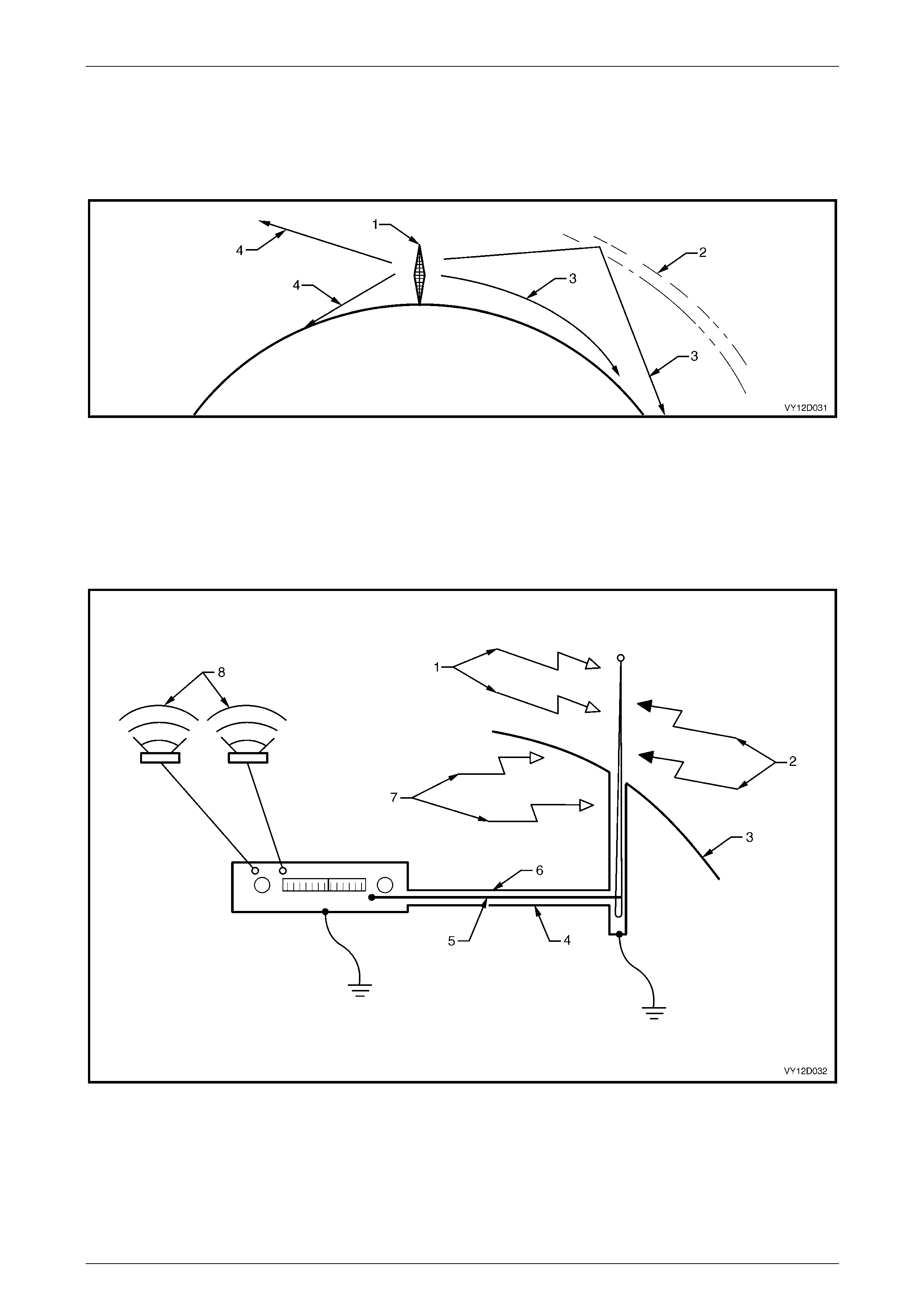
Entertainment System Page 12D–25
Page 12D–25
Figure 12D – 13
Legend
1 Main Signal Path 2 Multi-path Signal 3 Shadowed Signal
Atmospheric conditions can also affect FM reception. Unexplained loss of sensitivity can be caused by high humidity.
Cloudy days are also better for reception tha n clear days. With electronic tuning radios, users can sometimes be
confused by abbreviated radio station call signs. People who tune their radios to abbreviated call sign al frequencies may
be slightly off the correct frequency.
Entertainment System Page 12D–26
Page 12D–26
AM Reception in Vehicles
In contrast to FM signals, AM signals will bend around corners and skip a long the ground. This is due to AM signals
having longer wavelength an d lower frequency. The layer of atmosphere known as the ionosphere can reflect the signal.
This phenomenon gives AM a longer reception range than F M, especially at night. Refer to Figure 12D – 14.
Figure 12D – 14
Legend
1 Radio Transmission Tower 3 AM Transmission
2 Ionosphere 4 FM Transmission
AM reception is affected by static induced by electrica l power lines, traffic lights, electronic signs and thunderstorms.
Fade of AM signals can also be e xpected when driving through tunnels, underpasses, and in cit y centr es.
Figure 12D – 15
Legend
1 Signal from Radio Station 5 Antenna Cable Centre Core
2 External Interference 6 Antenna cable
3 Vehicle Body 7 Internal Interference
4 Antenna Cable Ground Braid 8 Music
Entertainment System Page 12D–27
Page 12D–27
As shown in Figure 12D – 15, signals from radio stations are picked up by the antenna (mast shown, this excludes coupe
which uses a rear glass antenna, same principle applies) and fed to the ra dio while being shielded from interference
sources by the braid. This is a complete electrical circuit, any breaks in the circuit, such as poor connections, will result in
poor reception.
Interference is due to the antenna system picking up signals other than those from the desired station. These
undesirable signals may be produced by electrical equipment in the vehicle itself, such as ignition, which is termed
‘internal interference’. Conver sely, interference from sources outside the vehicle, such as from power lines, is known as
‘external interference’.
Internal interference is minimised b y the shielding around the antenna wire, which prevents internal noise bein g picked
up and fed to the radio. The shielding around the core takes the form of a ‘braid’, which completes the electrical circuit
along which signals travel to the radio. Faults in this shielding system allow interference to reach the radio and hence be
reproduced at the speakers as noise.
It is therefore important the shield of the antenna cable is effectivel y grounded at both the radio (to the radio case) an d at
the antenna end (to the vehicle body), to ensure minimal interference is received by the radio, and the optimum rad io
sensitivity is achiev ed.
Basic Checks
Proper performance of the audio system dep ends greatly on grounding of the antenna and radio case to the vehicle
body, as it eliminates stray curr ents in the antenna circuit. Stray currents may be induced by wires running parallel to the
path of the radio or antenna wiring, or may be due to ‘noisy’ in-vehicle electrical items.
Resistances or connection quality of the major parts of the radio can be checked with a multimeter set to measure
resistance.
When using a multimeter to measure very low resistances, the lead resistance becomes considerable, and must be
subtracted from all subsequent readi ngs. That is, touch the leads together, note the reading, and subtra ct this from all
subsequent readings.
NOTE
A very good contact point is required to measure
ground resistance. This point must not have
current flowing through it during measurement,
therefore ensuring the ignition is turned off. Avoid
measuring using the screw on the door jamb
switch. The best place to measure ground
resistance is to use one of the self-tapping
screws retaining the A-pillar drip rail. Since these
screws are sometimes not correctly grounded,
one of the screws may be removed to take
measurements directly to the body sheet metal.
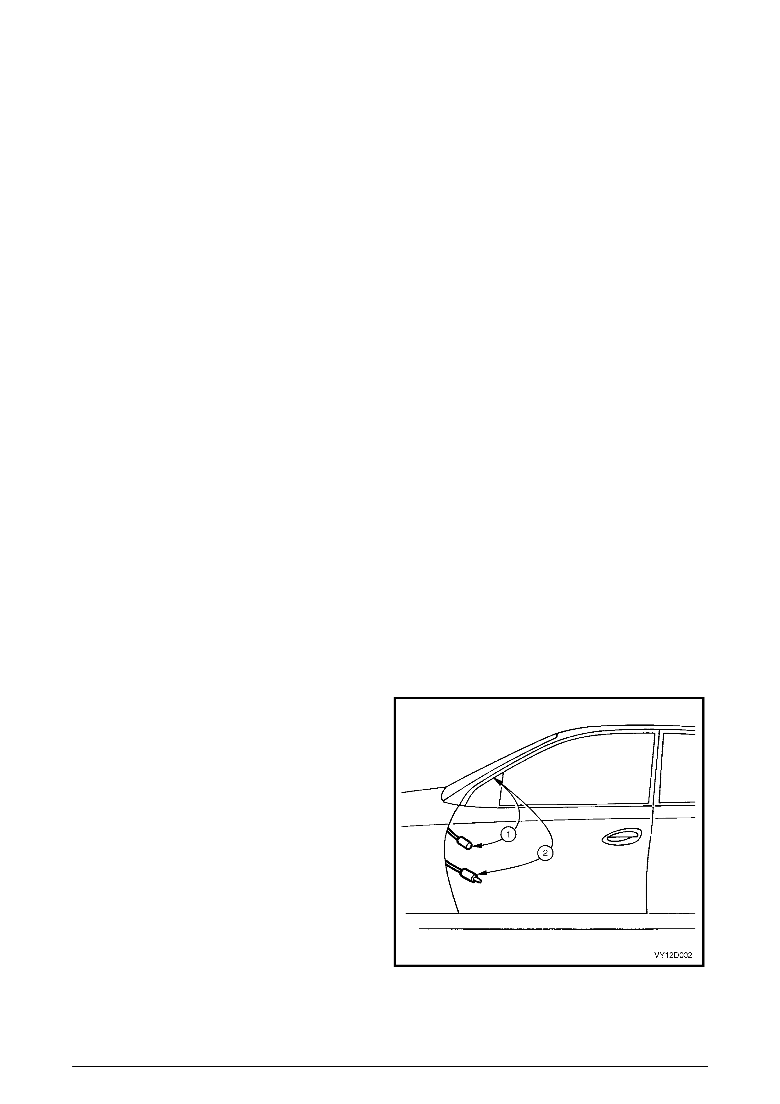
1 Disconnect the battery negative terminal. Refer to
Section 00 Warnings, Cautions and Notes.
NOTE
Failure to disconnect the battery negative
terminal may lead to incorrect resistance
measurements due to stray currents.
2 Disconnect the antenna extension lead from behind
the passenger side hinge pilla r trim assembly.
3 Measure resistance from the outer of the antenna lead
to the vehicle body (1).
Resistance reading 0.3 Ω maximum.
4 Measure resistance from out er of the antenna
extension lead to the vehicle body (2).
Resistance reading 0.6 Ω maximum.
Figure 12D – 16
Entertainment System Page 12D–28
Page 12D–28
5 Check continuity of the path from the antenna cabl e
core to the antenna mast (excludes coupe) by
measuring resistance (1).
Resistance reading 0.4 Ω maximum
NOTE
This test can in fact only be performe d on power
antennas, since manuall y operated antennas ar e
fitted with in-line capacitors with the antenna
body, which misleadingly indicates an open
circuit when resistance is measured.
On vehicles with manually operated antennas,
disconnect the antenna lead from the antenna
lead extension and measure the resistance of
the extension lead cable core from the radio to
the antenna lead connecti on ends.
Resistance values significantly hi gher than those
specified indicate poor c onnections that must be
rectified before proper radio performance ca n be
obtained.
Figure 12D – 17
6 Check for shorts bet ween the antenna core and the braid by disconnecting from the radio and measuring the
resistance between the two. The measured value should indicate an open circuit (very high or infinite resistance).
7 Disconnect the antenna extension l ead at both ends and test the core for continuity.
Common Radio Problems
Static
Static is a buzzing or crackling noise ca used by the radio picking up unwanted radio waves and converting them to noise
output by the speakers.
The unwanted radio waves (interference) co me from several sources, which can be put into two groups; internal a nd
external. As the names suggest, external interference comes from outside the vehicle, and is difficult to control, while the
vehicle generates internal interference.
It must be emphasised that a radio system in good co ndition will protect itself from much static. Before trying to locate
and remove a source of interferenc e it must first be determined the shielding and grounding of the radio is in good
working order. This can easily be done by performing the tests detailed in the ‘Basic Checks’.
It should be noted that static may occur on weak stations, or when driving under bridges because signals from ignition
and the like become relatively stronger than the radio station signal, causing the ignition interference to become quite
strong. This could be due to stronger than normal ignition int erference or a poorly functioning antenna.
If the cause cannot be isolated after performing the tests and trying to isolate a source of interference, using the following
procedures, it may be the radio has an internal fault and requires repair.
External Interference
Static that occurs only while travelling in certain localities, such as near electrical transformers, is undoubtedly external
interference.
If there is any doubt whether the suspected source is causing interference, a simple check is to stop the vehicle and turn
off everything but the radio. If the source is external, the interference will continue and little can be done to eliminate it.
NOTE
The perceived interference level can be
significantly reduced, in noisy environments, by
slightly reducing the treble on the radio tone
controls.
Entertainment System Page 12D–29
Page 12D–29
Internal Interference
Internal interference is that caused by some component of the vehicle’s el ectrical system, and may take many forms.
Many of the electrical items fitted to motor vehicles produce some sort of radio waves, but these radio waves only
become a problem if they are in the range of frequencies at which the radio receiver picks up and reproduces signals as
sound. For the radio, the vehicle’s electrica l system must be designed not to emit radio signals at the frequenc ies of the
AM and FM bands.
Components are sometimes fitted with suppressing devices as part of their design, and failure of these suppressors may
allow the item to start interfering with radio operation.
Interference will be worse on weak stations, since a strong sign al normally overpowers the interfering signal. Interference
can occur when the signal strength drops be low a certain threshold, such as driving under a bridge, inside a workshop,
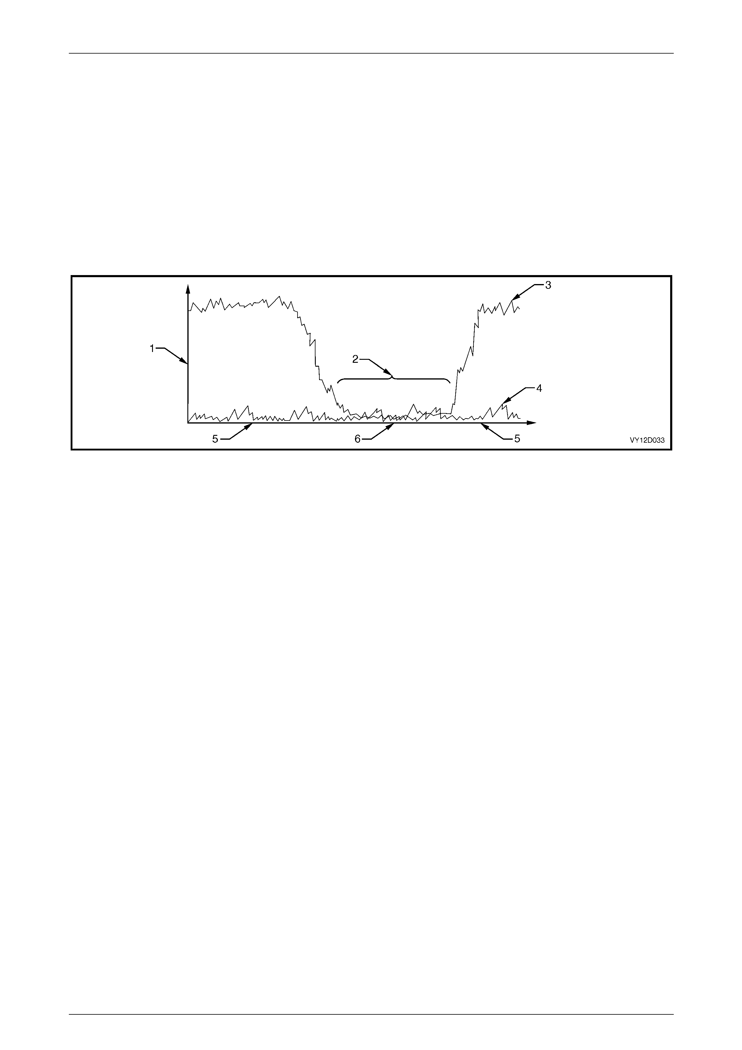
or in the shadow of a building. This situation is shown in Figure 12D – 18.
Figure 12D – 18
Legend
1 Signal Strength 3 Signal at Antenna from Radio Station 5 Normal Reception
2 In-vehicle Noise Interferes with
Tuned Station 4 In-vehicle Noise 6 Reception Blocked
Static may be caused by many internal sources. If static is at ignition frequency, varying with engine speed, the ignition is
the culprit. However, many electrical faults will cause static which otherwise would not be heard. Examples of ignition
interference sources are:
1 Plug leads breaking down.
2 Carbon tracking (arcing) to ground.
3 Faulty spark plugs.
4 Inoperative interference shields.
The actual cause of the interference can b e isolated through carefully noting t he circumstances under which the prob lem
occurs. For example, if it occurs only at speeds above approximatel y 80 km/h in an autom atic transmission equipped
vehicle quite possibly it is the electrical signal being sent to the torque converter clutch.
Other sources of static can be:
1 Electric cooling fan.
2 Electric fuel pump.
3 Normal computer ‘noise’ at certain frequencies.
4 Windshield wipers or washers.

Entertainment System Page 12D–30
Page 12D–30
Diagnosing Internal Interference
If a vehicle has an interference problem that only occurs when the engine is turned on, or some other repeatab le
circumstance, carry out the following procedure:
1 Park the vehicle in an open area, as far away from buildings as possible. Turn the radio onto the band (AM\FM)
and frequency where the complai nt occurs, with the ig nition in the ACC position.
2 Reproduce the interferenc e, eg. turn the ignition on.
3 If interference is due to a fan blower motor, etc. and is judged to be objecti onable, try a similar specification vehicl e
in the same location. If this is not possible, the component should be substituted to determine whether it is faulty.
NOTE
Internal interference is often a symptom of a
defective radio system, such as poor antenna
grounding, etc. If substituting a new component
does not fix the condition, the problem is very
likely to be in the radio system, and the
resistance checks in this Section should be
performed.
4 Whistles / squeals that occur only when the ignition is on, are probably due to electronic modules in the vehicle
creating interference when active (power applied). These modules may be isolated as a cause of interference by
removing power to them and rechecking. This is best done by turning the ignition off, removing the fuse that
supplies that particular item with po wer, turning the ignition back on and rechecking. By process of elimi nation, the
‘noisy’ module should b e able to be found. Once found, substitute the module to find out whether the interference is
normal.
Speakers
Before removing speakers suspected of b eing noisy or faulty, ensure any distortion that may be present is not due to any
of the following:
1 Foreign matter such as sand lying on the speaker cone, especially horizontally mounted speakers such as the
subwoofers.
2 Cable ties or other such material resti ng on the back of the speaker cone.
3 Incorrectly fitted speaker mesh or loose trim around speaker assembly.
4 Distortion of the speaker assembly caus ed by the angled insertion of the speaker retaining screws. Loosening and
tightening the screws while being careful not to distort the speaker cone may rectify the speaker problem.

Entertainment System Page 12D–31
Page 12D–31
4 Tech 2 Processor Diagnostics
Fault diagnosis for the audio system is divided into two areas; faults which can be remedied by checking the operation of
audio system and it's sub components, and those which can be checked by using the Tech 2 Diagnostic Tool.
Diagnostic Trouble Codes
When a fault is detected, the audio system or it's sub component sets a Diagnostic Trouble Code (DTC) that represents
that particular problem or failure. The DT C remains current as long as the fault remains, and is cleared when the fault is
rectified. The DTCs can be read and cleared using Tech 2.
Each DTC is allocated a number. For further details o n each of the DTCs,
refer to 4.4 Diagnostic Trouble Codes – Au dio System.
Audio System Input / Output Signals
Voltages in the following table are typical voltages that will be read at the audio head unit connector while the radio is on,
ignition is on and the radio is in AM or FM mode. Some variation in the values can be expected due to changing battery
voltages and normal tolerances.
4.1 Connecting Tech 2 For System
Diagnosis
Tech 2, with the appropriate software, cables and adaptors,
is capable of reading the audio system serial data when
connected to the Data Link Connector (DLC). T he DLC is
connected to the instrument panel lo wer trim pane l retainer,
below the steering column.
1 Data Link Connector (DLC)
2 DLC Adaptor
3 DLC Cable
4 Tech 2
For additional general information on connecting and
operating Tech 2, refer to Section 0C Tech 2.
Figure 12D – 19

Entertainment System Page 12D–32
Page 12D–32
4.2 Tech 2 Test Modes And Displays
A prerequisite of this diagnostic section is for the user to be familiar with the correct use of Tech 2. The following pages
illustrate only the major Tech 2 screen displays and provide a brief explanation of their function for diagnosing the audio
system. If additional information is required on the operation of Tech 2, reference should be made to either
Section 0C Tech 2 or the Tech 2 User’s Guide.
With the ignition turned off, connect Tech 2 to the Data Link Connector (DLC) using the DLC Adaptor,
refer to 4.1 Connecting Tech 2 For System Diagnosis.
Main Menu
urn the ignition on and press the power button (PWR) on Tech 2.
Tech 2 will perform a series of self-diagnosing power on self-tests (POST). Once this has been completed successfully,
the Tech 2 start-up screen will be disp layed. Press the Enter key to continue.
The Main Menu screen is dis played.
On Tech 2 select:
Diagnostics by using the arrow keys until Diagnostics is highlighted and press the Enter key.
Model Year
Select relevant model year from the model year list and press Enter.
Vehicle Identification Menu
Select the appropriate vehicle type from the list and press Enter.
System Selection Menu
On Tech 2 select:
Body from the System Selection Menu and press Enter.
Audio System Selection
Select Audio System and press Enter.
Turn the ignition on (as requested) and press the Confirm soft key to continue.
The audio system identification details will be displayed. Scroll through the list using the T ech 2 Up and Down arrows.
Press the Confirm soft key to confirm these details.

Entertainment System Page 12D–33
Page 12D–33
Body Menu
This menu provides the Tech 2 user with access to the various functions used to diagnose faults in the audio system.
The following audio s ystem functions are available:
Normal Mode
The normal mode data list is used to view serial data being sent from the audio system.
Refer to 4.3 Normal Mode – Audio System.
Diagnostic Trouble Codes
In this mode, Diagnostic Trouble Codes can be read and cleared.
Refer to 4.4 Diagnostic Trouble Co des – Audio System.
Data Display
In this mode, Tech 2 displays the status of inputs and outputs of the audio system.
Refer to 4.5 Diagnostic Data Displa y – Audio System.
Snapshot
In this test mode, Tech 2 captures data before and after a forced manual error.
Refer to 4.6 Snapshot – Audio System.
Miscellaneous Tests
In this test mode, Tech 2 can test and diagnose faults in the audio s ystem.
Refer to 4.7 Miscellaneous Tests – Audio System.
Program
Audio system information can be programmed when this mode is selected. Refer to 4.8 Program – Audio System.

Entertainment System Page 12D–34
Page 12D–34
4.3 Normal Mode – Audio System
The Normal Mode data list is used to view serial data being sent from the audio system.
On Tech 2 select:
Body / Normal Mode.
Normal Mode
Details of the serial data in the normal mode data list are pr ovided in the following table.
Normal Mode Data List
Tech 2 Display Range Remarks
Radio Status On / Off When the audio head unit is turned off, power is still applied to
the unit to maintain serial data bus communi cations.
Antenna Required Yes / No
(Yes = Antenna Required
No = Antenna Not Required)
Yes when radio is in AM or FM mode. Voltage is within 0.5 V of
battery voltage when active.
Antenna Direction
Switch Off / Down / Up Active when the antenna up or down button is pressed on
models with electric height adjustable a ntenn a.
Radio DTC Status No DTC / DTCs Set Displays DTCs set when a fault has been detected by the
audio system.
Mute Active / Inactive Active when the radio, CD or DVD is muted.
Pause Active / Inactive Active when the CD is paused.
MFD Message
(Multi-function
Display)
Yes / No
(Yes = Module Response With
Message
No = Normal Module Response)
Yes when data is being sent to the instrument cluster
multi-function display (MFD).
Voice In Active / Inactive Active when a Mobile Phone is connected to the Audi o System
and a call is in progress.
Amplifier Requested Yes / No Condition is Yes when the Audio S ystem is on.
Amplifier DDL
Requested Yes / No Condition is Yes when DDL is enabled.

Entertainment System Page 12D–35
Page 12D–35
4.4 Diagnostic Trouble Codes – Audio
System
1 On Tech 2 select:
Body / Diagnostic Trouble Codes.
2 Select the required item from the following:
• Read Current DTC Information. If this mode is selected, a listing of all (if any) DTC that have been set by
the audio system will be disp layed.
• Clear DTC Information. DTC can be cleared in this mode by simply selecting Clear DTC Information,
pressing the Enter key on Tech 2 and c onfirming the action as instructed by Tech 2.
NOTE
Tech 2 will display Clear DTC Information, or
Failed if any DTCs are still current.
Read Current DTC Information
If any DTCs are set, reference should be made to the relevant diagnostic charts in 4.9 DTC Charts.
Audio System Diagnostic Trouble Code List
DTC 10 Fascia Button Jammed DTC 26 CD General Error
DTC 11 Steering Wheel Rem ote Button Jammed DTC 30 Internal Bus Failure
DTC 12 Reserved DTC 33 Single Communicati on Bus Failure
DTC 21 CD Mechanism Error DTC 34 Multi Communication Bus Failure
DTC 22 CD Play Error DTC 35 Fascia Communication Bus Failur e
DTC 24 CD Loading Error DTC 40 No BCM Serial Data
DTC 25 CD Defect DTC 42 Reserved

Entertainment System Page 12D–36
Page 12D–36
4.5 Diagnostic Data Display – Audio System
The Diagnostic Data Display function all ows the status of the audio system inputs and outputs to be monitored, as well
as the system identification details.
1 On Tech 2 select:
Body / Data Display.
2 Select the required item from the following:
• Data List. If this mode is selected, a listing of all serial data being sent by the audio system will be displayed.
• System Information. Provides details of system identification.
Data List
The serial data from the audio system can be checked and tested by selecting the item a nd pressing the Select Items
soft key. The list can be scrolled by using the Up and Down arrow keys.
NOTE
Only the data relevant to the level of audio
system installed will be displayed.
Data Display Data List
Tech 2 Display Range Remarks
Ignition Status On / Off Ignition switch status at terminal X1-A4.
Displays ON when ignition is on.
Security Wait Time Active / Inactive Security lockout timer status. Displays
ACTIVE when an incorrect PIN Code has
been entered.
Audio System Linked to BCM Linked / Unlinked Status of Autocoding system. Shows
LINKED when the radio has been linked
to the vehicle.
Radio Status On / Off Displays audio system status.
Key Priority Signal 1 / 2 Current key setting in us e by the audio
system. Setting is transmitted by BCM.
Antenna Up Required / Not Required Within 0.5 V of battery voltage when in
AM or FM mode, and 0 V in CD mode.
Antenna Main / Diversity Front (or for coupe, rear glass) or rear
antenna selected (if fitted).
Antenna Signal Strength 0 to 100 Signal strength of received station.
100 = very strong signal.
Frequency AM and FM Frequency Range Displays the frequency of the current
station.
Frequency Unit AM = kHz / FM = MHz Displays the frequency of the current
radio mode.
Volume 0 to 63 Volume level set by the volume knob or
remote control.
Speed Dependent Volume Control 0 to 20 Amount of additional volume added du e
to the vehicle speed. Speed is taken from
the serial bus.
Speed Volume Curve 0 to 5 Speed dependent volume compensation
curve selected in the Instrument Cluster
Customisation Mode (Options Menu).
Mute Control Input Active / Inactive Sound is muted by MUTE button on
steering wheel.
Park Lamp Switch On / Off Status of park lamp input. Displays ON
when park lamps are on.

Entertainment System Page 12D–37
Page 12D–37
Tech 2 Display Range Remarks
Preset 1 to 6 Current radio Memory Preset selection.
0 = no preset selected.
Radio Band FM1, FM2, FM ASM, AM, AM ASM Current radio band and mode selection.
Search Sensitivity DX / LO Station searching sensitivity selecti on. DX
= Distant Stations, LO = Local Stations.
Stereo Status Mono / Intermediate / Full Stereo Displays the current FM stereo status.
Setting depends on antenna si gnal
strength, multipath and other factors.
Bass –6 to +6 Current Bass setting, adjusted with the
audio knob. –6 = Minimum, ST D =
Standard Setting, +6 = Maximum
Treble –6 to +6 Current Treble setting, adjusted with the
audio knob. –6 = Minimum, ST D =
Standard Setting, +6 = Maximum
Balance –6 to +6 Current Balance setting, adjusted with the
audio knob. L6 = Maximum Left, STD =
Standard Setting, R6 = Maximum Right
Fader –6 to +6 Current Fader setting, adjusted with the
audio knob. R6 = Maximum Rear, STD =
Standard Setting, F6 = Maximum F r ont
Loudness Bass Boost –6 to +6 Amount of Bass added by the Loudness
function. Reduces to 0 as the volume is
increased. –6 = Minimum, STD =
Standard Setting, +6 = Maximum
Loudness Treble Boost –6 to +6 Amount of Treble added by the Loudness
function. Reduces to 0 as the volume is
increased. –6 = Minimum, STD =
Standard Setting, +6 = Maximum
Equaliser Off, Rock, Pop, Jazz, Classical, Vocal Displays the Equaliser Mode that is
currently active.
Audio Source Tuner, CD, External Source Displa ys the current audio source
selection.
Fascia Button Button Name / Key Released Displays the name of the audio head unit
fascia button when that button is pressed,
or Key Released if no button is pressed.
Steering Wheel Remote Contr ol Button Name / Key Released Displays the name of the steering wheel
remote control button when that button is
pressed, or Key Released if no button is
pressed.
CD In Yes / No Indicates if a CD is currently in the
mechanism or not.
Current CD None, 1 to 6 Displays the number of the CD in the CD
Changer currently being p layed.
Current Track 0 to 99 Displays the current CD track being
played. Number displa yed depends on
the number of tracks on the disc. 0 = no
track selected.
CD Mode Track Random, Track Repeat, Track
Scan, Disc Random, Disc Repeat, Disc
Scan, Play, Pause
Displays the current CD playing mode.

Entertainment System Page 12D–38
Page 12D–38
System Identification
The System Identification screen provid es production information relevant to the Audio System.
The identifier number defines the Audio System installed. The details are:
• 000 – Unidentified.
• 101 – Entertainment System 1; Utility, Executive, Commodore S and CV6 Coupe.
• 201 – Entertainment System 2: Not used.
• 202 – Entertainment System 2; Acclaim.
• 301 – Entertainment System 3; Berlina.
• 302 – Entertainment System 3; Commodore SS, and optional for Utility, Executive, Acclaim, Commodore S.
• 401 – Entertainment System 4; Calais and CV8 Coupe
• 402 – Entertainment System 4; No diversity antenna fitted.

Entertainment System Page 12D–39
Page 12D–39
4.6 Snapshot – Audio System
On Tech 2 select:
Body / Snapshot.
Tech 2 can be used to record s ystem informa tion that is occ urring at a particular moment in time, and this is called a
snapshot. For more details, refer to the Tech 2 User's Guide.

Entertainment System Page 12D–40
Page 12D–40
4.7 Miscellaneous Tests – Audio System
Tech 2 can be used to verify correct operation of the various functions of the audio system to assist in isolating a fault
condition. Tech 2 can be used to force various functions on or off and monitors the response.
Note that if any test takes longer than 40 seconds to perform, the audio system will time-out and the test may have to be
started again.
1 On Tech 2 select:
Body / Miscellaneous Tests.
2 The following functions will now be available:
• Speed Dependent Volume
• Illumination
• Antenna (Up / Down)
• LED
• Display
• Power (On / Off)
• Radio Band
• Preset Memory
• Audio
• CD Function
• Eject
• Audio Source
NOTE
Only the Miscellaneous Tests relevant to the level
of audio system install ed will be displayed.
Speed Dependent Volume
The Speed Dependent Volume test is performed using Tech 2, and allows the input of simulate d road speeds to verify
the correct operation of the speed dependent volume function.
1 Turn the radio off.
2 To enter the audio system Options Menu, press and hold the Preset Station 1 button while turning the radio on.
3 Press the audio button to advance to the speed dependent volume screen, and then rotate the volume knob to
choose a setting of 2 or higher (note that 0 = function off).
4 Turn the radio off then back on again to save the new setting.
5 Select a strong local radio station frequency and set the volume to a comfortable listen ing level.
6 Connect Tech 2 to the DLC.
7 On Tech 2 select:
Body / Audio System / Miscellaneous Tests / Speed Dependent Volume.
8 Press the Increase soft key on Tech 2 to simulate and increase in road speed. Listen for an increase in volume.
9 Press the Decrease soft key on Tech 2 and listen for return to normal volu me.
10 Press the Quit soft key to exit the test. The speed dependent volume will be set to the standard setting (2) on
exiting the test.
11 If the speed dependent volume function does not operate correctly, replace the audio head unit,
refer to 6.1 Audio Head Unit.

Entertainment System Page 12D–41
Page 12D–41
Priority Key Selection, Type 4 Entertainment System
The Priority Key Selection test is performed using Tech 2, and checks for correct switching bet ween the Priority Key 1
audio system settings and the Priority Key 2 settings. Note that when the priority key selection is made using T ech 2, the
audio system responds to the change then r everts back to the selection corresponding to the key in the ignition.
1 Connect Tech 2 to the DLC.
2 On Tech 2 select:
Body / Audio System / Miscellaneous Tests / Priority Key Selection.
3 Switch the audio system on.
4 Tech 2 will display the current serial data at the top of the screen, and the Key Priority Signal and associated key
number at the bottom of the screen.
5 Press the Priority 1 soft key on Tech 2 and check if the audio system switches to the Prior ity Key 1 settings. Verify
the Tech 2 screen displays th e selection of Priority Key 1.
6 Press the Priority 2 soft key on Tech 2 and check if the audio system switches to the Prior ity Key 2 settings. Verify
the Tech 2 screen displays th e selection of Priority Key 2.
7 Press the Quit soft key to exit the test.
8 If the Priority Key Selection function does not operate corr ectly, replace the audio head unit,
refer to 6.1 Audio Head Unit.
Illumination
The audio system buttons and LCD are fully illuminated. The audio head unit receives the illumination control sig nal from
the hardwired illumination in put on the connector. The actual dimming value is received from the BCM by serial data.
The fascia Illumination test is performed usi ng Tech 2, and controls the fascia illumination directl y to ver ify correct
operation.
1 Turn the park lamps on.
2 Connect Tech 2 to the DLC.
3 On Tech 2 select:
Body / Audio System / Miscellaneous Tests / Illumination.
4 Turn the radio on.
5 Using the Increase soft key on Tech 2, increase the illumination level to maximum.
6 Check the display illumination is even with no dark patches and the fascia control buttons are illuminated.
7 Using the Decrease soft key on Tech 2, decrease the i llumination level and check the fascia illumination decreases
accordingly.
8 Press the Quit soft key to exit the test. The standard illumination level will be selected on exiting the test.
9 If the Illumination function does not operate correctly, replace the audio head unit, refer to 6.1 Audio Head Unit.

Entertainment System Page 12D–42
Page 12D–42
Antenna Selection
Some models are fitted with a dual antenna system, called Main and Diversity antennas respectively. When testing the
antenna systems it is useful to command to the audio head unit which antenna to use when making comparisons in
signal quality between the two systems. The Antenna Selection test is performed using Tech 2.
1 Connect Tech 2 to the DLC.
2 On Tech 2 select:
Diagnostics / Model Year / Vehicle Model / Body / Audio System / Miscellaneous Tests / Antenna (Main /
Diversity).
3 Switch the audio system on and select a strong local FM radi o station frequency. Set the volume to a comfortable
listening level.
4 Use the Main soft key on Tech 2 to select the main antenna. Verify the Tech 2 screen displa ys the appropriate
antenna selection.
5 From the Body Menu sel ect Data Display / Data List, then use the Down arrow key on Tech 2 to scroll to Antenna
and verify the Main antenna is selected.
6 Use the Down arrow key on Tech 2 to scroll t o Antenna Signal Strength and note the signal strength i nd ication.
7 On Tech 2 select:
Body / Miscellaneous Tests / Antenna (Main / Diversity).
8 Use the Diversity soft key on Tech 2 to select the diversity antenna. Verify Tech 2 scree n displays the appropriate
antenna selection.
9 On Tech 2 select:
Body / Data Display / Data List, then use the Down arrow key on Tech 2 to scroll to Antenna and verify the
Diversity antenna is selected.
10 Use the Down arrow key on Tech 2 to scroll to Antenna Signal Strength and note the signal strength indication.
11 Compare signal strength figures to provide an obj ective comparison of antenna performance.
12 Press the Quit soft key to exit the test. The Main antenna will be selected on exiting the test.
13 If the Antenna Selection function does not operate correctl y, replace the audio head unit,
refer to 6.1 Audio Head Unit.
Antenna (Up / Down)
The Antenna (Up / Do wn) test is performed using Tech 2, and directly controls the Main antenna by driving it up or down.
1 Connect Tech 2 to the DLC.
2 On Tech 2 select:
Diagnostics / Model Year / Vehicle Model / Body / Audio System / Miscellaneous Tests / Antenna (Up /
Down).
3 Ensure the ignition is on, and turn the radio o n.
4 Tech 2 will display the curr ent antenna status at the bottom of the screen.
5 Using the Up soft key on Tech 2, drive the antenna up. Verify correct antenna operation, and that this status is
displayed on the Tech 2 screen.
6 Using the Down soft key on Tech 2, drive the antenna down. Verify correct antenna operation, and that this status
is displayed on the Tech 2 screen.
7 Press the Quit soft key to exit the test. The Main antenna will be left in the last test position upon exiting the test.
8 If the Antenna (Up / Down) function does not operate correctly, replace the audio head unit,
refer to 6.1 Audio Head Unit.

Entertainment System Page 12D–43
Page 12D–43
Security LED
The LED on the top left of the audio head unit fascia is used as a security indicator and to show the status of the
CD/CDC loading and ejecting . This test is performed using Tech 2, and directly controls the LED to verify correct
operation.
1 Connect Tech 2 to the DLC.
2 On Tech 2 select:
Diagnostics / Model Year / Vehicle Model / Body / Audio System / Miscellaneous Tests / LED.
3 Ensure the ignition is on, and turn the radio off.
4 Press the On soft key on Tech 2, and verify the LED illuminates (orange). If LED illuminates green or red, this
indicates a fault and the audio head unit should be replaced.
5 Press the Off soft key on Tech 2 and verify the LED extinguishes.
6 Press the Quit soft key to exit the test. The LED will extinguish upon exiting the test.
7 If the LED test function does not operate correctly, replace the audio head unit, refer to 6.1 Audio Head Unit.
Display
The audio system incorporates a large dot-matrix type display. This test is performed using Tech 2, and directly controls
all segments on the AHU display to verify correct operation.
1 Connect Tech 2 to the DLC.
2 On Tech 2 select:
Diagnostics / Model Year / Vehicle Model / Body / Audio System / Miscellaneous Tests / Display.
3 Ensure the ignition is on, and switch the audio system on.
4 Press the On soft key on the Tech 2 and verify all display segments are illuminated.
5 Press the Off soft key on Tech 2 and verify all display segments extinguish.
6 Press the Quit soft key to exit the test.
7 Switch the audio system off then on again to reset the display.
8 If the display test function does not operate correctly for the audio system, replace the audio head unit,
refer to 6.1 Audio Head Unit.
Power (On / Off)
This test is performed using Tech 2, an d verifies whether the audio head unit switches on or off correctly.
1 Connect Tech 2 to the DLC.
2 On Tech 2 select:
Diagnostics / Model Year / Vehicle Model / Body / Audio System / Miscellaneous Tests / Power (On / Off).
3 Ensure the ignition is on, and switch the audio system off.
4 Tech 2 will display the curr ent radio status at the bottom of the screen.
5 Press the On soft key on Tech 2 and verify the audio system switches on, and that this status is displayed on the
Tech 2 screen.
6 Press the Off soft key on Tech 2 and verify the audio system switches off, and that this status is displayed on the
Tech 2 screen.
7 Press the Quit soft key to exit the test. The audio system will be left in the last test position upon exiting the test.
8 If the Power (On / Off) function does not operate correctly, replace the audio head un it,
refer to 6.1 Audio Head Unit.

Entertainment System Page 12D–44
Page 12D–44
Radio Band
This test is performed using Tech 2, and verifies the audio head unit switches correctly between the AM and the F M
bands.
1 Connect Tech 2 to the DLC.
2 On Tech 2 select:
Diagnostics / Model Year / Vehicle Model / Body / Audio System / Miscellaneous Tests / Radio Band.
3 Ensure the ignition is on, and switch the audio system on.
4 Tech 2 will display the curr ent radio band status at the bottom of the screen.
5 Using the AM and FM soft keys on Tech 2, switch between the t wo radi o bands and verify the audio system
switches radio bands as follo ws:
• AM selects AM Preset 1.
• FM selects FM1 Preset 1.
Verify the selected band is displayed on the Tech 2 screen.
6 Press the Quit soft key to exit the test. The audio head unit will be left in the last test position upon exiting the test.
7 If the Radio Band function does not operate correctly, replac e the audio head unit, refer to 6.1 Audio Head Unit.
Preset Memory
This test is performed using Tech 2, and verifies the audio head unit selects each of the currently stored preset stations
correctly for both the AM and the FM bands. The AM band has two preset bands (AM and AM ASM), while the FM band
has three (FM1, FM2 and FM ASM), with each band having six preset stations.
1 Connect Tech 2 to the DLC.
2 On Tech 2 select:
Body / Audio System / Miscellaneous Tests / Preset Memory.
3 Ensure the ignition is on, and the audio system is on.
4 The Tech 2 screen displays the current preset band and current station.
5 Use the Tech 2 Up and Down arrows to select from the list and press Enter or Modify.
6 Use the Tech 2 Up and Down arro ws to scroll to the option required.
7 Use the Okay soft key to enable the selection, or the Back soft key to return to the previous screen.
8 Press the Program soft key to program the preset and check the radio changes to the selected preset.
9 Press the Quit soft key to exit the test. The audio system presets will be left in the last test position upon exiting the
test.
10 If the Preset Memory function does not operate correctly, replace the audio hea d unit,
refer to 6.1 Audio Head Unit.

Entertainment System Page 12D–45
Page 12D–45
Audio
This test is performed using Tech 2, and verifies the audio head unit speaker output signals are op erating correctly. The
Audio test checks the Treble and Bass outp uts to each speaker.
NOTE
Only the speaker configuration fitted for the
vehicle will appear in the follo wing test.
1 Connect Tech 2 to the DLC.
2 On Tech 2 select:
Diagnostics / Model Year / Vehicle Model / Body / Audio System / Miscellaneous Tests / Audio.
3 Ensure the ignition is on. S witch the au dio system on and choose a strong local ra dio station frequency.
4 Turn EQ off if this feature is available on the audio head unit.
5 Manually adjust the volume le vel as requested by Tech 2 and press the Confirm soft key.
6 The right rear speaker will be selected for testing. Using the Increase and Decrease soft keys, vary the bass setting
from –6 to +6 and listen for the variation.
7 Use the Tech 2 soft keys to select the other speakers and repeat the test.
8 Repeat Steps 4 and 5 for the T r eble T est.
9 Press the Quit soft key to exit the test.
10 If the Audio test function does not operate correctly, replace the audio head unit, refer to 6.1 Audio Head Unit.
CD Function
This test is performed using Tech 2, an d verifies the CD changes correctly between the various operating modes.
The Next CD Mode soft key on Tech 2 is used to step through this test. If the Previous CD Mode soft key is used Tech 2
will command the modes in the reverse or der.
1 Connect Tech 2 to the DLC.
2 On Tech 2 select:
Diagnostics / Model Year / Vehicle Model / Body / Audio System / Miscellaneous Tests / CD Function.
3 Ensure the ignition is on and s witch the audio system on. Press the LOAD button on the audio system fascia and
insert a disc, or insert a CD on a single CD pla yer.
4 Press the Next CD Mode soft key to command the CD to play the installed disc. The current track and CD number
will be shown on Tech 2.
5 Press the Next CD Mode soft key to command the CD to change the disc. The current track and CD num ber will be
shown on Tech 2.
NOTE
On Type 1 and 2 Entertainment System audio
head units Step 5 will be skipped.
6 Press the Next CD Mode soft key to command the CD to change to the next track. The current track and CD
number will be shown on T ech 2.
7 Press the Next CD Mode soft key to command the CD to fast forward the current track. The current track and CD
number will be shown on T ech 2.
8 Press the Next CD Mode soft key to command the CD to fast rewind the current track. The current track and CD
number will be shown on T ech 2.
9 Press the Next CD Mode soft key to command the CD to pause the current track. The current track and CD number
(for Type 3 and 4 Entertainment System AHUs) will be shown on Tech 2.
10 Press the Quit soft key to exit the test.
11 If the CD function does not operate correctly, replace the audio head unit, refer to 6.1 Audio Head Unit.

Entertainment System Page 12D–46
Page 12D–46
Eject CD
This test is performed using Tech 2, and commands the audio system to eject a single CD or multiple CDs. It is useful
when there is a problem with the audio head unit fascia and the EJECT button is not functi oning correctly.
1 Connect Tech 2 to the DLC.
2 On Tech 2 select:
Diagnostics / Model Year / Vehicle Model / Body / Audio System / Miscellaneous Tests / Eject CD.
3 Ensure the ignition is on, and switch the audio system on.
4 To eject the current CD from a CD Changer, press the Eject Curr. CD soft key on Tech 2.
5 To eject a specific CD, press the Eject Spec. CD soft key on Tech 2. Enter the CD number then press the Enter
key.
6 Press the Quit soft key to exit the test.
7 If the Eject CD function does not operate correctly, replace the audio hea d unit, refer to 6.1 Audio Head Unit.
Audio Source
This test is performed using Tech 2, and verifies the audio head unit will correctly change the audio source as directed by
the fascia control buttons. The audio sourc e can be selected between the radio tuner, the CD or an external so urce.
1 Connect Tech 2 to the DLC.
2 On Tech 2 select:
Body / Audio System / Miscellaneous Tests / Audio Source.
3 Ensure the ignition is on, and switch the audio system on.
4 Press the Tuner soft key on Tech 2.
5 Check if the audio head unit radio tuner can be operated and if Tech 2 displays this selection.
6 Press the CD soft key on Tech 2.
7 Check if the audio head unit CD Changer ca n be operated and if Tech 2 displays this select ion.
8 Press the Ext. Source soft key on Tech 2
9 Check if the audio head unit can be o perated from an external audio source and if Tech 2 screen displays this
selection.
10 Press the Quit soft key to exit the test. The audio system audio source selection will be left in the last test position
upon exiting the test.
11 If the Audio Source function does not operate correctly, replace the audio head unit, refer to 6.1 Audio Head Unit.

Entertainment System Page 12D–47
Page 12D–47
4.8 Program – Audio System
The Program function allo ws various Audio System parameters to be programmed.
1 On Tech 2 select:
Body / Program.
2 The following functions will now be available:
• Program Code Index
• Program Antenna
Program Code Index
The Code Index number i dentifies the audio s ystem and vehicle configuration, an d the Code Version number identifies
the software version. Only the Code Index nu m ber can be changed. The following table details the Code Index number s
for the various vehicle models.
Vehicle Audio System
Code Index
Number
Executive Type 1 Entertainment System 007
Acclaim Type 2 Entertainment S ystem 007
Commodore SV6 and SV8 Type 1 Entertainment System 007
Commodore SS Type 3 Entertainment System 007
Berlina Type 3 Entertainment System 007
Utility Type 1 Entertainment System 009
Calais Type 4 Entertainment System 010
Coupe CV8 Type 4 Entertainment System 010
Regular Cab Type 1 Entertainment System 007
Crew Cab SS and Cross 8 Type 3 Entertainment System 007
CX8 AWD Wagon Type 3 Entertainment System 007
LX8 AWD Wagon Type 4 Entertainment System 007
1 On Tech 2 select:
Program / Program Code Index.
2 The Code Index number a nd the Code Version number are displayed. To change the Code Index number, press
the Program soft key. To exit without making a change, press the Okay soft key.
3 Enter the three-digit Code Index number, including leading z eros, usin g the numeral keys on Tech 2.
4 Press the Enter key to continue, or the Exit key to exit without making a change.
5 Follow any Tech 2 screen prompts when programming is complete d.
Program Antenna
Audio systems are supplied with the antenna drive disabled and are enabled on installatio n. If an antenna drive fails to
operate it may not have been enabled upon installation.
1 On Tech 2 select:
Program / Program Antenna.
2 Press the Okay soft key on Tech 2 to enable the antenna drive.
3 Follow any Tech 2 screen prompts when programming is complete d.

Entertainment System Page 12D–48
Page 12D–48
4.9 DTC Charts
DTC 10 – Fascia Button Jammed
Introduction
With the ignition in either the ACC position or the ON position, DTC 10 will set if an audio head un it fascia panel control
button remains pressed or stuck for more than 40 seconds.
Diagnostic Table
Step Action Yes No
1 Was the Audio System Diagnostic Circuit Che ck performed?
Go to Step 2
Go to 5.4 Audio
System Diagnostic
Circuit Check
2 1 Check the fascia and every button for signs of damage, foreign
objects, poor or sticking operation.
2 Check the escutcheon surrounding the audio head unit is not
distorted and exerting pressure on the fascia.
Is there damage or foreign objects present to cause the problem? Go to Step 3 Go to Step 4
3 Clear any objects and clea n any residue.
Does the button function correctly? System serviceable
Replace the audio
head unit, refer to
6.1 Audio Head
Unit
4 Check the stuck button for signs of poor operation.
Does the button stick for no apparent reason ?
Replace the audio
head unit, refer to
6.1 Audio Head
Unit Go to Step 5
5 1 Connect Tech 2 to the DLC.
2 On Tech 2 select:
Diagnostics / Model Year / Vehicle Model / Body / Audio
System / Diagnostic Trouble Codes / Clear DTC Information.
3 Press all buttons several times.
4 Allow the radio to operate for several minute s. Do not press any
buttons during this time.
Does the DTC set again?
Replace the audio
head unit, refer to
6.1 Audio Head
Unit System serviceable
When all diagno sis an d repairs are completed, clear all DTCs and check the system for correct o peration.

Entertainment System Page 12D–49
Page 12D–49
DTC 11 – Steering Wheel Remote Button Jammed
Introduction
Control buttons located on the steering wheel provide remote operatio n of various audio system functions. The remote
controls constitute a resistive net work. When a button is pressed, the cha nge in resistance is interpreted b y the audio
head unit as a button press, and the appropri ate function is actioned.
With the ignition in either the ACC position or the ON position, DTC 11 will set if a steering wheel control button remains
pressed or stuck for more than 30 seconds.
Diagnostic Table Notes
1 Refer to 5.2 Wiring Diagram and 5.3 Connector Charts to ai d in diagnostics.
Diagnostic Table
Step Action Yes No
1 Was the Audio System Diagnostic Circuit Che ck performed?
Go to Step 2
Go to 5.4 Audio
System Diagnostic
Circuit Check
2 1 Switch the audio head unit on.
2 Press each of the steering wheel remote control buttons and
note if the unit follows the command.
Does the audio system operate as expected? System serviceable Go to Step 3
3 1 Connect Tech 2 to the DLC.
2 On Tech 2 select:
Diagnostics / Model Year / Vehicle Model / Body / Audio
System / Data Display / Data List.
3 Scroll to Steering Wheel Remote Control in the Tech 2 menu.
4 Do not press any button.
Does Tech 2 display K ey Released? Go to Step 4 Go to Step 5
4 Press each of the steering wheel remote cont rol buttons in turn.
Does Tech 2 display the name of each button when pressed? Go to Step 8 Go to Step 6
5 1 Remove the audio head unit, refer to 6.1 Audio Head U nit.
2 Using a multimeter set to measure resistance, probe between
connector A133 – X1 pins C11 and C12 (refer to Note 1).
3 Do not press any button.
Does the multimeter indicate 3.5 – 3.9 kΩ? Go to Step 7 Repair or replace
circuit 1796 or 1750
6 With the multimeter connected as in Step 5, press and hold the MUTE
button.
Does the multimeter indicate 270 – 3 00 Ω?
Go to Step 7
Replace steering
wheel remote
controls, refer to
6.14 Radio Control
Switch Assembly
7 Using a multimeter set to measure resistance, probe between the
following connectors and a known ground (refer to Note 1):
• A133 – X1 pin C11
• A133 – X1 pin C12
Does the multimeter indicate an op en circuit in each test? Go to Step 8 Repair or replace
circuit 1796 or 1750
8 1 Turn the headlamp s witch to the Park position.
2 Using a multimeter set to measure resistance, probe between
connector A133 – X1 pins C11 and C1 (refer to Note 1).
3 Do not press any button.
Does the multimeter indicate 3.5 – 3.9 kΩ?
Replace the audio
head unit, refer to
6.1 Audio Head
Unit
Repair or replace
circuits 1796 or
1750
When all diagno sis an d repairs are completed, clear all DTCs and check the system for correct o peration.

Entertainment System Page 12D–50
Page 12D–50
DTC 21 – CD Mechanism Error (CD Changer Models Only)
Introduction
With the ignition in either the ACC position or the ON position, DTC 21 will set to indicate that an error message has
been received from the CD Changer due to an internal mechanical error.
This error may indicate the following:
• Mechanism has an internal fault.
• Conditions were too severe for the mechanism to operate correctly.
Diagnostic Table
Step Action Yes No
1 1 Switch the audio head unit on.
2 Select CD Mode (it may be necessary to try and load a CD).
Does a Mechanism Error appear on the display of the audio system or
the MFD?
Replace the audio
head unit, refer to
6.1 Audio Head
Unit Refer to 5.14 CD
Changer
When all diagno sis an d repairs are completed, clear all DTCs and check the system for correct o peration.
DTC 22 – CD Play Error (CD Changer Models Only)
Introduction
With the ignition in either the ACC position or the ON position, DTC 22 will set to indicate that an error message has
been received from the CD Changer due to a disc playing error. This error is due to problems in reading the CD, and it
may be set due to the following actions:
• CD was loaded upside do wn. CD mechanis m was unable to play it.
• Computer Data CD was loaded. CD mechanism was unable to play it.
• Disc was badly damaged and could not be read.
• Disc was blank.
• Conditions were too severe for the CD player to read the CD. For examp le, too much vibration.
The DTC will remain set even though a faulty CD might have been removed already or the fault was cleared.
Diagnostic Table
Step Action Yes No
1 1 Eject all CDs from the audio head unit.
2 Load a known good CD.
Does the CD play correctly? Go to Step 2 Refer to 5.14 CD
Changer
2 1 Turn the ignition to the OFF position.
2 Connect Tech 2 to the DLC.
3 On Tech 2 select:
Diagnostics / Model Year / Vehicle Model / Body / Audio
System / Diagnostic Trouble Codes / Clear DTC Information.
4 Play a CD for 30 minutes.
Does the DTC set again? Refer to 5.14 CD
Changer System serviceable
When all diagno sis an d repairs are completed, clear all DTCs and check the system for correct o peration.

Entertainment System Page 12D–51
Page 12D–51
DTC 24 – CD Loading Error (Single CD Models Only)
Introduction
With the ignition in either the ACC position or the ON position, DTC 24 will set to indicate that an error message has
been received from the CD Player due to a jammed disc or the disc being held during the loading or ejecting process.
Diagnostic Table
Step Action Yes No
1 1 Switch the audio head unit on.
2 If a CD is loaded, eject it with the EJECT button.
3 Insert a CD.
4 Eject the CD.
Does the mechanism load and eject a CD normally? System serviceable Refer to 5.13 Single
CD Player
When all diagno sis an d repairs are completed, clear all DTCs and check the system for correct o peration.
DTC 25 – CD Defect (Single CD Models Only)
Introduction
With the ignition in either the ACC position or the ON position, DTC 25 will set to indicate that an error message has
been received from the CD Player as the loaded CD cannot be read. This could be caused by the disc being installed
upside down, the disc being scratched or broken, or a data CD being installed.
This DTC will remain set after the fault has cleared.
Diagnostic Table
Step Action Yes No
1 1 Switch the audio head unit on.
2 Eject the loaded CD if necessary.
3 Check customer’s CDs for:
• Damage, excessive scratching, dirt, labels, pen markings.
• Data CD (not an audio CD).
• Blank CD (not recorded).
• Upside down.
Are the CDs in good condition and loaded with label surface upwards? Go to Step 2
Advise customer of
the problem and
how to avoid it in the
future
2 Load a known good CD.
Does the CD play correctly? System serviceable Refer to 5.13 Single
CD Player
When all diagno sis an d repairs are completed, clear all DTCs and check the system for correct o peration.

Entertainment System Page 12D–52
Page 12D–52
DTC 26 – CD General Error (Single CD Models Only)
Introduction
With the ignition in either the ACC position or the ON position, DTC 26 will set to indicate that an error message has
been received from the CD Player as the installed disc could not be played and th e cause is not evident. This could be
caused by a defective laser pickup or the laser pickup being jammed.
Diagnostic Table
Step Action Yes No
1 1 Connect Tech 2 to the DLC.
2 On Tech 2 select:
Diagnostics / Model Year / Vehicle Model / Body / Audio
System / Diagnostic Trouble Codes / Read Current DTC
Information.
3 Switch the audio head unit on.
4 If necessary, insert a CD.
Is DTC 26 set? Refer to 5.13 Single
CD Player System serviceable
When all diagno sis an d repairs are completed, clear all DTCs and check the system for correct o peration.
DTC 30 – Internal Bus Failure
With the ignition in either the ACC pos ition or the ON position, DTC 30 will set to indicate that an error has occurred with
one of the internal communic ations data busses.
If DTC 30 is set, replace the audio head unit, refer to 6.1 Audi o Head Unit.
DTC 33 – Single Communication Bus Failure (Single Disc CD Units)
With the ignition in either the ACC pos ition or the ON position, DTC 33 will set to indicate that an error has occurred in
communication between the main PCB and the single CD mechanism.
If DTC 33 is set, replace the audio head unit, refer to 6.1 Audi o Head Unit.
DTC 34 – Multi Communication Bus Failure (Multi Disc CD Units)
With the ignition in either the ACC pos ition or the ON position, DTC 34 will set to indicate that an error has occurred in
communication between the main PCB and the CD Changer mechanism.
If DTC 34 is set, replace the audio head unit, refer to 6.1 Audi o Head Unit.
DTC 35 – Fascia Communication Bus Failure
With the ignition in either the ACC pos ition or the ON position, DTC 35 will set to indicate that an error has occurred in
communication between the main PCB and the audio system fascia.
If DTC 35 is set, replace the audio head unit, refer to 6.1 Audio Hea d Unit.
DTC 40 – No BCM Serial Data
With the ignition in either the ACC pos ition or the ON position, DTC 40 will set to indicate the radio has not received any
data from the BCM for more than 10 seconds. This does not necessarily mean the audio head unit has a fault, it usually
indicates the audio head unit has been in operation on a workbench and the bus has not been connected.
If DTC 40 is set, refer to Section 12J Body Control Module for further diagnosis.

Entertainment System Page 12D–53
Page 12D–53
5 Audio System Diagnostics
Some of components associated with the audio system do not set a DTC in the event of a component failure. The
following diagnostic procedures are devised to assist in these cases:
• Power On / Off • Electric Antenna – Height Adjustable
• No Sound or Distorted Sound • Single CD Player
• Audio Unit Display • CD Changer
• Audio Head Unit Illumination • Radio Reception
• Hands-free Telephone Unit • Subwoofer Amplifier
• Electric Antenna – Full Up / Down • Diversity Antenna
Diagnostic tables contained in this Section, list both technical problems and common faults found due to incorrect use of
the audio system. Refer to 5.2 Wiring Diagram and 5.3 Connector Charts to aid in diagn osing the audio system.
It is advantageous to read the Audio System Handbook Supplement supplied with the vehicle before p erforming
diagnosis on the system.
When carrying out wiring checks as directed by the diagnostic charts, rather than probe terminals and connectors with
incorrect sized multimeter connectio ns, use the ad aptors contained in connector test adaptor kit J35616-A (KM609). T his
will prevent any possib ility of spreading or damaging wiring harness terminals, which may later cause a system
intermittent failure. Refer to 5.3 Connector Charts for various connectors associated with the audio s ystem.
Before commencing any diagnostic procedure, the Audio System Diagnostic Circuit Check should be carried out to
ensure a known starting point, refer to 5.4 Audio System Diagnostic Circuit Check.
5.1 Prerequisites
Equipment
The following equipment is required to diagnose the entertainment system:
1 An unpowered test lamp with a current dra w of less than 3 A.
2 A digital multimeter with a minimum impe dance of 10 MΩ.
Testing Procedures
Adhere to the following points when performing diagnostic testing on navigation system components:
1 Take care when using testing equipment to diagnose wiring harness connectors. The technician should backprobe
the connector to avoid terminal damage.
2 When tests are required on connector terminals, use the adapters in the connector adapter kit KM–609 to prevent
damage to the terminals.
3 Unless the multimeter being us ed has an auto-ranging function, ens ure the correct range is selected.
4 When backprobing connectors, ensure the test lamp ground lead is connected to an appr opriate ground point on
the vehicle. Ensure this ground point is not part of the circuit being tested.
NOTE
When following the steps in th e diagnostic tables,
ensure work is performed in the order in which
they are presented. If the required nominal value
or result is not achieved, rectify the problem
before proceeding.
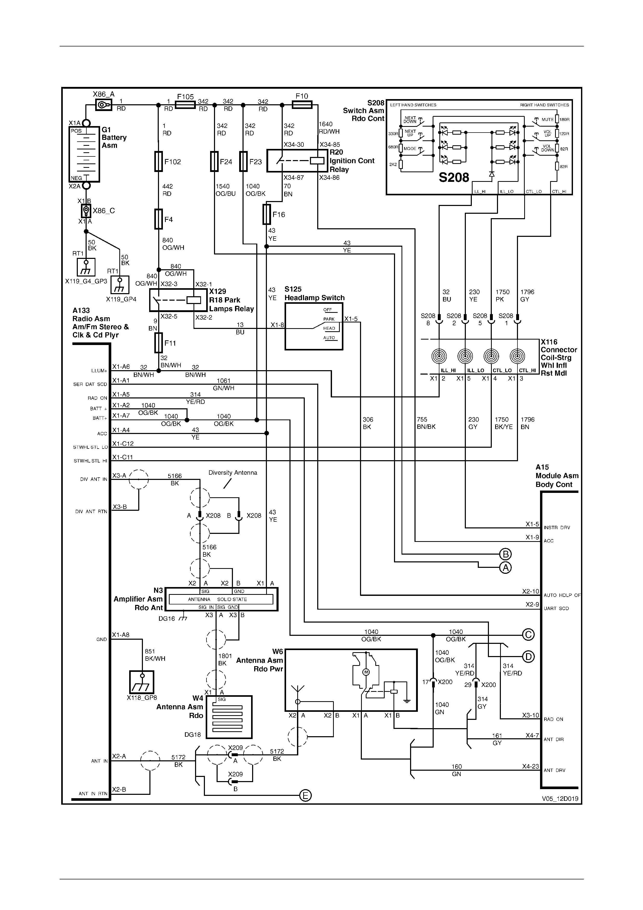
Entertainment System Page 12D–54
Page 12D–54
5.2 Wiring Diagram
Figure 12D – 20
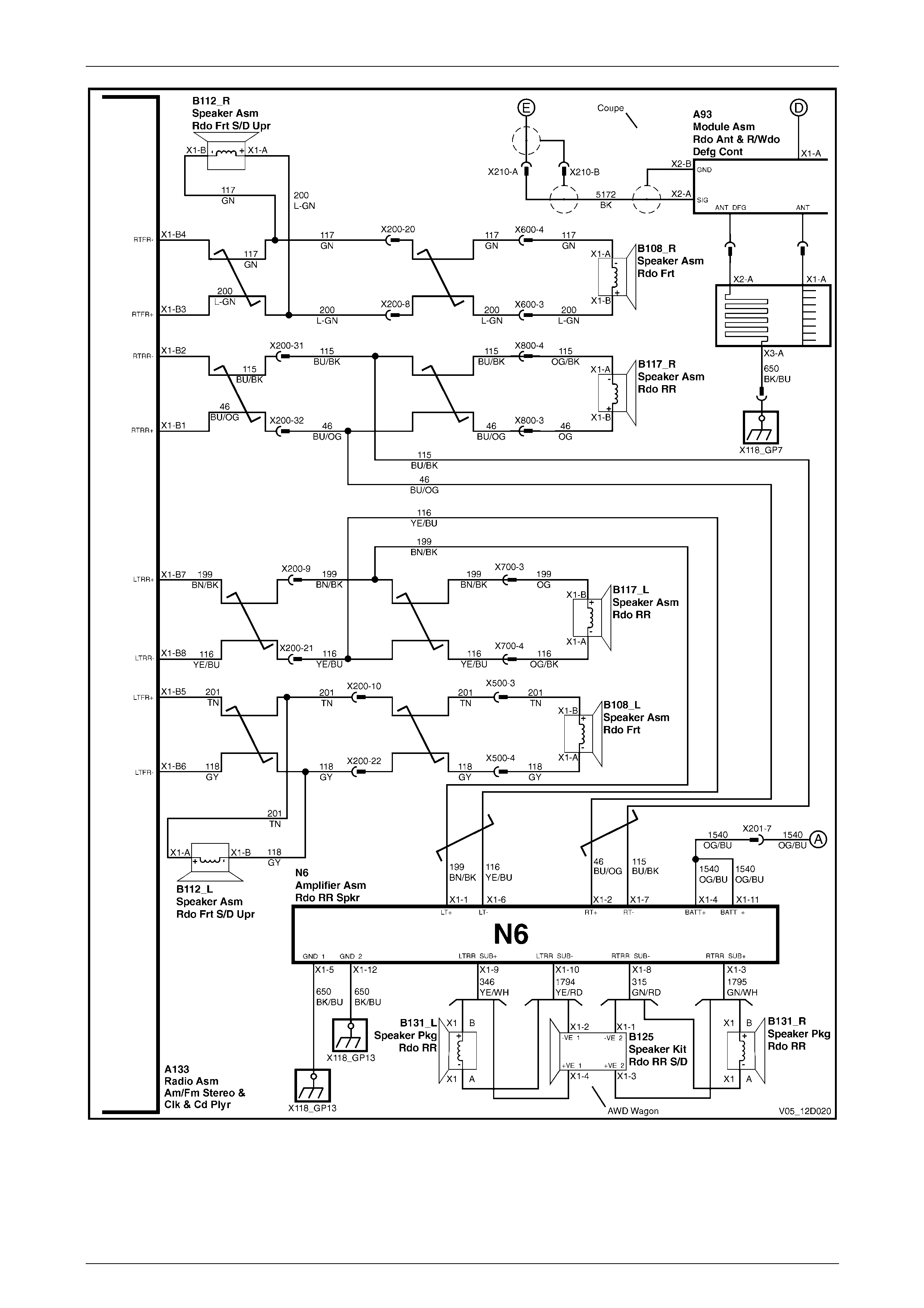
Entertainment System Page 12D–55
Page 12D–55
Figure 12D – 21
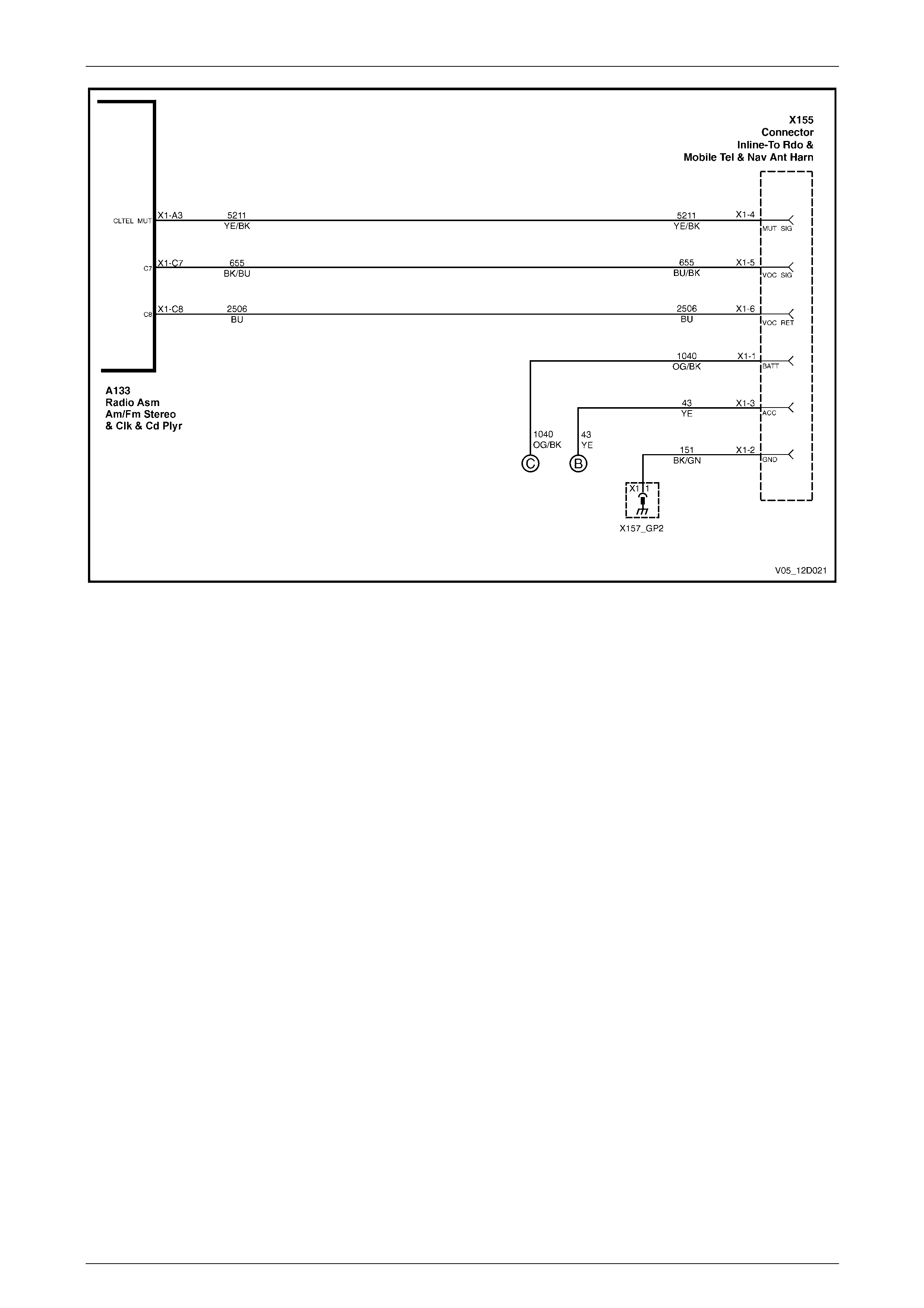
Entertainment System Page 12D–56
Page 12D–56
Figure 12D – 22
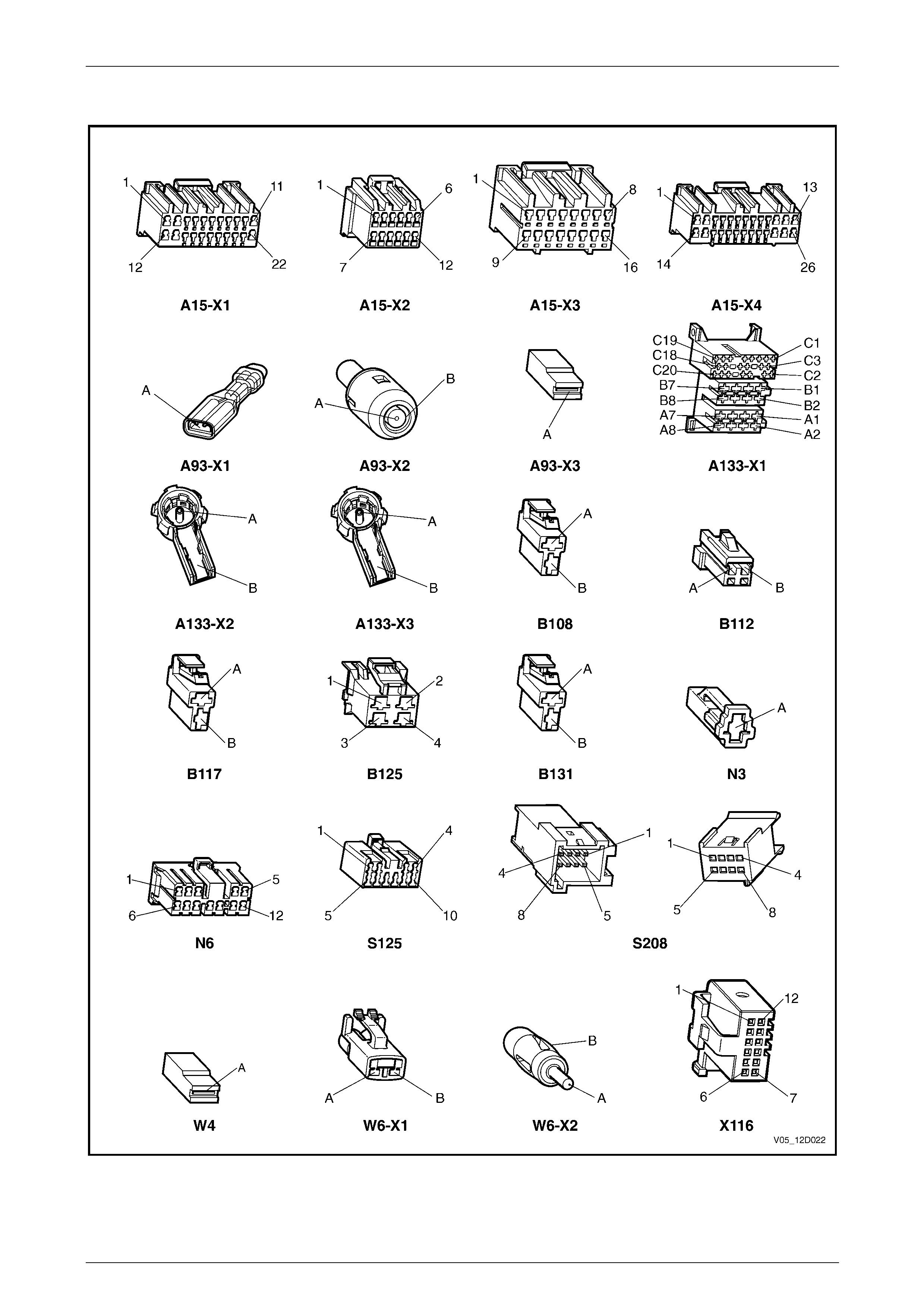
Entertainment System Page 12D–57
Page 12D–57
5.3 Connector Charts
Figure 12D – 23
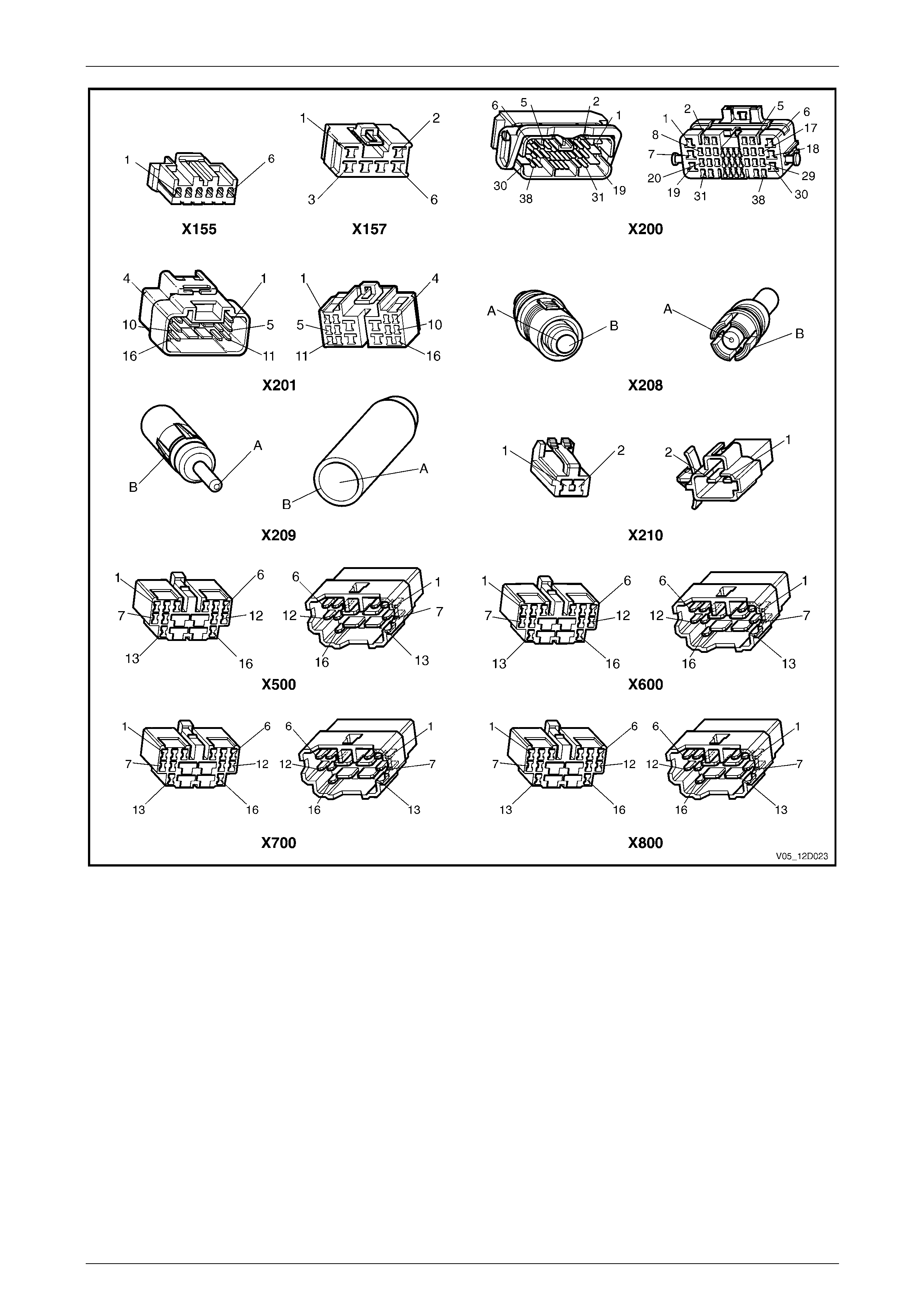
Entertainment System Page 12D–58
Page 12D–58
Figure 12D – 24

Entertainment System Page 12D–59
Page 12D–59
5.4 Audio System Diagnostic Circuit Check
Introduction
When investigating any complaint of an audio system problem or malfunction, al ways be gin diagnosis with the following
diagnostic circuit check. This check is a preliminary procedure that ensures the audi o system is powered up,
communicating on the serial data line, helping to identify a problem or malfunction, and directing the reader to the
appropriate diagnostic chart in this Section.
With Tech 2 connected to the DLC and the ignition switched on, Tech 2 should display serial d ata communication. If
Tech 2 does not display serial data, the serial data circuit may be open or shorted.
The entertainment system and several other control mo dules are connected to the serial data line. The control modules
are the PCM, PIM (GEN III V8 only) BCM, ABS or ABS / TCS, OCC and SRS. The entertainment system or any one of
the control modules could cause a fault on the serial data line. This fault coul d result in Tech 2 not being able to display
serial data.
Diagnostic Table Notes
1 For all wiring harness fault diagnoses, refer to Section 12P Wiring Diagrams.
2 For wiring harness repairs, refer to Section 12P Wiring Diagrams.
3 Refer to Section 12O Fuses, Relays and Wiring Harnesses for harness routeing.
4 If the fault is deemed to be intermittent, refer to Section 12P Wiring Diagrams.
Diagnostic Table
Step Action Yes No
1 1 Turn the ignition to the ACC position.
2 Switch the audio system on and select FM Mode.
Does the antenna raise and / or does the r adio function correctly? Go to Step 2 Go to Step 3
2 Insert a CD, label side upwards.
Does the antenna lower and does the CD function correctly? System serviceable Go to Step 3
3 At Step 1 or 2, did the audio system display illuminate? Go to Step 5 Go to Step 4
4 1 Turn the ignition off.
2 Check the condition of the follo wing fuses (refer to Note 3):
• fuse F4,
• fuse F10,
• fuse F11,
• fuse F16,
• fuse F23,
• fuse F102,
• fuse F105, and
• fuse F24 (vehicles fitted with subwoofer amplifier only)
Are the fuses OK? Go to Step 5
Replace fuse(s) and
retest. If the fuses
blow again test a
short to ground
(refer to Note 1)
5 1 Connect Tech 2 to the DLC.
2 Turn the ignition on.
3 Push the power button on Tech 2.
Does Tech 2 power up? (Screen should illuminate and displa y Tech
2). Go to Step 6
Go to Tech 2
diagnosis, refer to
Section 0C Tech 2
6 1 At the Tech 2 title screen press the Enter key.
2 On Tech 2 select:
Diagnostics / Model Year / Vehicle Model / Body / Audio
System.
Does Tech 2 display Audio System Identification (i.e. Part Number)? Confirm the details
and go to Step 7 Go to DTC 40 – No
BCM Serial Data
7 On Tech 2 select:
Diagnostic Trouble Codes / Read Current DTC Information.
Does Tech 2 display a ny DTC?
Refer to
corresponding
Diagnostic Trouble
Code chart 4.9
DTC Charts Refer to 5 Audio
System Diagnostics
When all diagno sis an d repairs are completed, clear all DTCs and check the system for correct o peration.

Entertainment System Page 12D–60
Page 12D–60
5.5 Power On / Off
Introduction
The audio system uses an ISO standard rad io connector with integral fuse. Connector A133 – X1 pins A7 and A2 are
supplied with permanent batter y power via circuit 1040. Connection to vehicle ground is m ade on connector
A133 – X1 pin A8 via circuit 851. The connector contains a blade fuse of 10 A or 15 A rating depending on the audio
system fitted.
The audio head unit has many sub-circuits that can o nly operate correctly when the battery voltage is above 9 V. When
the voltage drops below 9 V, for example during engine starting, the audio head unit will turn-off to prevent unexpected
operation.
The audio head unit can requ est the accessories line to turn on even after the ignition is t urned off and the key removed.
To do this, press the ON button. The accessories line will operate for approximately 1 hour, then will turn off unless the
audio head unit is turned on o nce more.
Diagnostic Table Notes
1 For all wiring harness fault diagnoses, refer to Section 12P Wiring Diagrams.
2 For wiring harness repairs, refer to Section 12P Wiring Diagrams.
3 Refer to Section 12O Fuses, Relays and Wiring Harnesses for harness routeing.
Diagnostic Table
Step Action Yes No
1 Has the Audio System Diagnostic Circuit Check been performed?
Go to Step 2
Go to 5.4 Audio
System Diagnostic
Circuit Check
2 Turn the ignition switch to the OFF position.
Does the Security LED flash? Go to Step 3 Go to Step 4
3 Check the battery voltage, refer to Section 12A Battery.
Is the battery voltage greater than 12 V? Go to Step 4
Refer to Section
12A Battery for
further diagnosis
4 Switch the audio system on.
Does the radio switch on and operate correctly? Go to Step 11 Go to Step 5
5 Is the audio head unit correctly secure in the console?
Go to Step 6
Push the audio
head unit into the
console using firm
pressure applied
over the removal
tool holes
6 Inspect fuse F23 (refer to Note 3).
Is the fuse serviceable?
Go to Step 7
Replace the fuse. If
the fuse blows again
test a short to
ground (refer to
Note 1)
7 Backprobe fuse F23 with a test lamp (refer to Note 1).
Does the test lamp illuminate?
Go to Step 8
Repair or replace
circuit 342 between
fusible link F23 and
F105 (refer to
Note 2)
8 1 Remove the audio head unit, refer to 6.1 Audio Head U nit.
2 Backprobe audio head unit co nnector A133 – X1 pin A7 with a
test lamp (refer to Note 1).
Does the test lamp illuminate? Go to Step 9
Repair or replace
circuit 1040
between connector
A133 – X1 and
fusible link F23
(refer to Note 2)

Entertainment System Page 12D–61
Page 12D–61
Step Action Yes No
9 Using a multimeter set to measure resistance, probe between
connector A133 – X1 pin A8 and a known ground.
Does the multimeter indicate continuity? Go to Step 10 Repair or replace
circuit 851
10 Using a multimeter set to measure resistance, check for continuity of
the fuse located on the connector at the rear of the aud io head unit.
Does the multimeter indicate continuity?
Replace the audio
head unit, refer to
6.1 Audio Head
Unit
Replace fuse. If the
fuse blows again
test a short to
ground (refer to
Note 1)
11 1 Turn the ignition to the ACC position.
2 Switch the audio system on.
3 Turn the ignition off and open the driver’s door.
Does the audio system also turn off? System serviceable Go to Step 12
12 Inspect fuses F10 and F16 (refer to Note 3).
Are the fuses serviceable?
Go to Step 13
Replace fuses(s)
and retest. If the
fuse(s) blow again
test a short to
ground (refer to
Note 1)
13 1 Remove the audio head unit, refer to 6.1 Audio Head U nit.
2 Using a multimeter probe between connector A133 – X1 pi n A4
and a known ground.
3 Turn the ignition to the ACC position.
Does the multimeter indicate greater than 9 V?
Replace the audio
head unit, refer to
6.1 Audio Head
Unit Repair or replace
circuit 43
When all diagno sis and repairs are completed, check the system for correct operation.

Entertainment System Page 12D–62
Page 12D–62
5.6 No Sound Or Distorted Sound
Introduction
The audio systems feature modern amplifiers that deliver hi gh power and are internally protected against short circuits
and connection to voltage sources.
All audio systems have a Distortion L imitin g circuit. This circuit, when turned on, automatically limits the volume level to
the point where distortion begins. The amount of distortion will depend on the amount of bass in the music. Listen ers who
find the music does not play loud enough with the distortion limiting circuit activated can either:
• reduce the amount of bass, or
• turn the distortion limiting off using the instrument cluster MFD, refer to Section 12C Instrumentation.
Damaged speakers and wiring may not cause a failure when played at low volume levels. At low volume the amplifier
may cope with the additional load ca used by the damage. Problems may onl y become obvious when playi ng at loud
volume levels. Typical symptoms will be
• one speaker dropp ing out,
• two speakers dropping out, or
• all speakers dropping out.
When the amplifier has cooled , the output may resume from the affected speaker or speakers.
Diagnostic Table
Step Action Yes No
1 Has the Audio System Diagnostic Circuit Check been performed?
Go to Step 2
Go to 5.4 Audio
System Diagnostic
Circuit Check
2 1 Turn the ignition switch to the ACC position.
2 Switch the audio system on and set the volume to medium level.
3 Insert and play a CD.
Does the audio system turn on and appear to function normal (apart
from no sound or distorted sound? Go to Step 3 Go to 5.5 Power On
/ Off
3 1 Set EQ to OFF, and Bass, Treble, Fader and Balance to STD.
2 Use the Fader and Balance s ettings to check that each speaker
is operating, including th e instrument panel tweeters and rear
subwoofer(s) (Type 4 Entertainment Systems).
Is there no sound or distortion from one speaker only? Go to Step 4 Go to Step 10
4 1 Set Fader and Balance to STD.
2 Remove the audio head unit, refer to 6.1 Audio Head U nit.
3 Using a multimeter set to measure resistance, probe between
the following points in respect to the defective speaker circuit at
the audio head unit connector A133:
• Left Front – X1 pin B5 and X1 pin B6
• Left Rear – X1 pin B7 and X1 pin B8
• Right Front – X1 pin B3 and X1 pin B4
• Right Rear – X1 pin B1 and X1 pin B2
Does the multimeter indicate 2 – 4 Ω across each connector? Go to Step 5 Go to Step 10
5 1 Remove the defective speaker, refer to relevant speaker section
in 6 Service Operations.
2 Inspect the speaker for damage or foreign material.
Do the speaker terminals appear damaged?
Remove foreign
material. Replace
speaker if damaged,
refer to 6 Service
Operations Go to Step 6
6 Has the speaker or speaker terminals be en making contact with body
metal components? Rectify reason for
contact. Install
speaker Go to Step 7

Entertainment System Page 12D–63
Page 12D–63
Step Action Yes No
7 Using a multimeter set to measure resistance, probe across the
speakers terminals.
Does the multimeter indicate 2 – 4 Ω? Go to Step 8
Replace speaker,
refer to 6 Service
Operations
8 Using a multimeter set to measure resistance, check for continuity
between each of the speaker circuits at the a udio head unit connector
A133, and a known ground:
• Left Front – X1 pin B5, circuit 201
• Left Front – X1 pin B6, circuit 118
• Left Rear – X1 pin B7, circuit 199
• Left Rear – X1 pin B8, circuit 116
• Right Front – X1 pin B3, circuit 200
• Right Front – X1 pin B4, circuit 117
• Right Rear – X1 pin B1, circuit 46
• Right Rear – X1 pin B2, circuit 115
Is any circuit shorted to ground? Repair or replace
defective circuit Go to Step 9
9 Using a multimeter, check for voltage between each of the speaker
circuits at the audio head unit connector A13 3, and a known ground:
• Left Front – X1 pin B5, circuit 201
• Left Front – X1 pin B6, circuit 118
• Left Rear – X1 pin B7, circuit 199
• Left Rear – X1 pin B8, circuit 116
• Right Front – X1 pin B3, circuit 200
• Right Front – X1 pin B4, circuit 117
• Right Rear – X1 pin B1, circuit 46
• Right Rear – X1 pin B2, circuit 115
Is voltage indicated at any circuit? Repair or replace
defective circuit Go to Step 10
10 Using a multimeter set to measure resistance, probe between audio
head unit connector A133 – X1 pin A8 a nd a known ground.
Does the multimeter indicate continuity? Go to Step 11 Repair or replace
circuit 851
11 1 Install the audio head unit and any speakers, refer to 6 Service
Operations.
2 Turn the ignition to the ACC position.
3 Switch the audio system on and play a CD.
4 Increase the volume to a loud level.
5 Allow the audio system to play for 5 minutes.
Has the problem appeared? Go to Step 12 System serviceable
12 1 Allow the audio system to cool.
2 Using the fader and balance settings, repeat Step 11 for the
front and rear / left and right speakers.
Has the test found one speaker to be the cause? Go to Step 13
Replace the audio
head unit, refer to
6.1 Audio Head
Unit
13 Replace the defective speaker, refer to 6 Service Operations.
Is the problem rectified?
System serviceable
Replace the audio
head unit, refer to
6.1 Audio Head
Unit
When all diagno sis and repairs are completed, check the system for correct operation.

Entertainment System Page 12D–64
Page 12D–64
5.7 Audio Head Unit Display
Introduction
The audio head unit has a large dot-matrix display on the fascia. T he display is fully illuminated when the ignition is in the
ACC position or the audio head unit is on. When the park lamps are on, the brightness can be adjusted using the
illumination control slider on the headlamp switch.
Diagnostic Table
Step Action Yes No
1 Was the Audio System Diagnostic Circuit Che ck performed?
Go to Step 2
Go to 5.4 Audio
System Diagnostic
Circuit Check
2 Turn the audio system on and select an FM station.
Is the display easily readable with good contrast between the
displayed characters and the background?
NOTE
During periods of low temperature, the display characters
may take longer to change when changes are made to the
audio system selection. Go to Step 3
Replace the audio
head unit, refer to
6.1 Audio Head
Unit
3 1 Connect Tech 2 to the DLC.
2 On Tech 2 select:
Diagnostics / Model Year / Vehicle Model / Body / Audio
System / Miscellaneous Tests / Display.
3 Press the On soft key on the Tech 2.
Do all segments on the display illuminate? Go to Step 4
Replace the audio
head unit, refer to
6.1 Audio Head
Unit
4 Press the Off soft key on the Tech 2.
Do all segments on the display extinguish? System serviceable
Replace the audio
head unit, refer to
6.1 Audio Head
Unit
When all diagno sis and repairs are completed, check the system for correct operation.

Entertainment System Page 12D–65
Page 12D–65
5.8 Audio Head Unit Illumination
Introduction
The audio head unit has full n ight illumination for easy operation. With the ignition set to the ACC or ON position, the
display is illuminated to make the clock easy to read. When the park lamps are turned on the display and buttons are
fully illuminated. The audio head unit uses two signals to determine the illumination state:
• park lamps switch to determine if illumination should be off or on.
• dimming value from the vehicle serial commu nication bus to determine the illumination brightness.
Testing the operation of illumination functions will be easier if the vehicle is in a darkened area.
Diagnostic Table
Step Action Yes No
1 Was the Audio System Diagnostic Circuit Che ck performed?
Go to Step 2
Go to 5.4 Audio
System Diagnostic
Circuit Check
2 1 Turn the ignition to the ACC position.
2 Switch the audio system on.
3 Turn the headlamp s witch to the Park position.
Does the audio system displa y illuminate evenly? Go to Step 6 Go to Step 3
3 Does every control button illuminate? Go to Step 6 Go to Step 4
4 1 Connect Tech 2 to the DLC.
2 On Tech 2 select:
Diagnostics / Model Year / Vehicle Model / Body / Audio
System / Data Display / Data List.
3 Scroll to Park Lamp Switch in the Tech 2 menu.
4 Using the headlamp s witch, turn the park lamps off and on.
Does Tech 2 display OFF when the park lamps are switched off, and
ON when the park lamps are switched on? Go to Step 6 Go to Step 5
5 1 Remove the audio head unit, refer to 6.1 Audio Head U nit.
2 Using a multimeter measure the voltage at the audio head unit
connector A133 – X1 pin A6 and a known ground.
Is the value within 0.5 V of battery voltage, and greater than 9 V when
the park lamps are on?
Replace the audio
head unit, refer to
6.1 Audio Head
Unit Repair or replace
circuit 32
6 Adjust the headlamp instrument dimming switch between maximum
and minimum brightness.
Does the unit illumination go to maximum and minimum brightness
also? System serviceable Go to Step 7
7 1 On Tech 2 select
Diagnostics / Model Year / Vehicle Model / Body / Body
Control Module / Normal Mode.
2 Scroll to Instrument Lamps in the Tech 2 menu.
Is the dimming percentage message broadcast onto the bus
correctly?
Replace the audio
head unit, refer to
6.1 Audio Head
Unit
Refer to Section 12J
Body Control
Module
When all diagno sis and repairs are completed, check the system for correct operation.

Entertainment System Page 12D–66
Page 12D–66
5.9 Hands-free Telephone Input
Introduction
The Audio System has an elec trical interface for a mobile telephone hands-free kit that may be used to:
• mute the radio when a phone call is in progress.
• play the caller’s voice through the car speakers instead of the hands-free speaker.
Using this circuit has the advantage of automatically silencing the radio or CD so the telephone can be heard without
distraction, and playing the voi ce through a higher powered, higher quality sound s ystem. When the voice is played
through the audio system the volum e, bass and treble can be set to the best listening levels. The Independent Tone
Memory will always recall these settings when a phone call is received.
When the hands-free controller grounds the audio system mute input on terminal A133 – X1 pin A3, the audio system
automatically switches to Phone Mode, which is confirmed by the display showing ‘VOICE IN’. When in Phone Mode the
audio system switches to the telephone input lines on termin al A133 – X1 pi ns C7 and C8. Any signal at those inputs will
be played through the audio amplifier and vehicle speaker s. The inputs are high impedance, differential type that accept
a wide range of inputs from the majority of phone kits on the market. Connect the hands-free kit speaker lines direct to
these terminals; do not connect the hands-fr ee speaker.
NOTE
Mobile phone signal quality can vary greatly
affecting the quality of the sound through the
speaker. When diagnosing phone type problems
it is recommended to move t he vehicle to an area
that has a strong signal.
Diagnostic Table
Step Action Yes No
1 Was the Audio System Diagnostic Circuit Che ck performed?
Go to Step 2
Go to 5.4 Audio
System Diagnostic
Circuit Check
2 1 Turn the ignition on.
2 Switch the audio system on.
3 Place the mobile phone in the vehicle kit and make a call.
Does the audio system switch to VOICE IN mode? Go to Step 10 Go to Step 3
3 1 Switch the audio system off
2 Turn the ignition off.
3 Access the phone kit wiring, refer to Section 12G Cel lular
Phone.
Are connections correctly located and secure ? Go to Step 4 Repair faulty
connection
4 1 Turn the ignition on.
2 Switch the audio system on.
3 Using a multimeter, probe between connector X155 – X1 pin 4
and a known ground.
Does the multimeter indicate 10 V or greater?
Leave the
multimeter
connected.
Go to Step 7 Go to Step 5
5 1 Disconnect the phone kit wiring, refer to Section 12G Cellular
Phone.
2 Switch the audio system on.
3 Using a multimeter, probe between connector X155 – X1 pin 4
and a known ground.
Does the multimeter indicate 10 V or greater? Go to Step 6 Go to Step 9

Entertainment System Page 12D–67
Page 12D–67
Step Action Yes No
6 1 Check the mute line is correctl y connected to the phone kit.
2 Check the voice signal and re turn lines are correctly connected
to the phone kit.
Are connections secure and serviceable? Go to Step 7 Repair faulty circuit
7 1 With the phone installed in the vehicle kit, make a phone call.
2 Using a multimeter, probe between connector X155 – X1 pin 4
and a known ground.
Does the multimeter indicate less than 1 V?
Replace the audio
head unit, refer to
6.1 Audio Head
Unit Go to Step 8
8 1 Disconnect the phone kit wiring connector X155, refer to
Section 12G Cellular Phone.
2 Connect the mute line, connector X1 55 – X1 pin 4 circuit 5211,
to a known ground.
Does the audio system switch to VOICE IN mode? Repair faulty hands-
free kit Go to Step 9
9 1 Remove the audio head unit, refer to 6.1 Audio Head U nit.
2 Using a multimeter set to measure resistance probe between
connector A133 – X1 pin A3 and connector X155 – X1 pin 4.
Does the multimeter indicate continuity?
Replace the audio
head unit, refer to
6.1 Audio Head
Unit Repair or replace
circuit 5211
10 Adjust the phone volume and audio system volume to approximately
50% while the call is in progress.
Does the caller’s voice play through the audio system speakers? Go to Step 13 Go to Step 11
11 At the hands-free kit wiring, check the speaker + wire is connected to
circuit 655 connector X155 – X1 pin 5 and the – wire is connected to
circuit 2506 connector X155 – X1 pin 6.
Are the speaker wires connected correctly? Go to Step 12 Correct wiring
connection
12 1 Remove the audio head unit, refer to 6.1 Audio Head U nit.
2 Disconnect the phone kit wiring, refer to Section 12G Cellular
Phone.
3 Using a multimeter set to measure resistance, probe between
the following connectors:
• A133 – X1 pin C7 and X155 – X1 pin 5.
• A133 – X1 pin C8 and X155 – X1 pin 6.
Does the multimeter indicate continuity? Go to Step 13 Repair or replace
circuit 655 or 2506
13 Ensure the phone volume and the audi o system volume are set at
approximately 50%. If either is set too high or too low, then the sound
quality may be distorted or feedback may be heard.
Is the voice clear, with no distortion? Go to Step 14
Adjust phone and
radio volume, radio
bass and treble until
clear sound is
produced
14 Can digital type noise be hea r d when a phone call is being made? Ensure an antenna
system is connected
to the phone kit and
all connections are
secure System serviceable
When all diagno sis and repairs are completed, check the system for correct operation.

Entertainment System Page 12D–68
Page 12D–68
5.10 Electric Antenna – Full Up / Down
Introduction
Some models are fitted with a non-adjustable, fully up or down electric antenna system. In these vehicles when the aud io
system is in Radio Mode the electric antenna is fully raised. The antenna is retracted when the audio system is in CD
Mode, or turned off.
Battery voltage is applied at al l times to the antenna motor via connector W6 – X1 pin A (circuit 1040), which is protected
by fuse F23. Antenna operation is controlled from the audio system by the Radio On signal, circuit 314, which controls
the internal antenna control relay via connector W6 – X1 pin B (circuit 314).
New Audio Systems are delive r ed with the antenna system disabled. This is to prevent the anten na raising and
potentially becoming damaged in the Vehicle Assembly Plant. As the vehicle p asses through final testing the antenna
drive is enabled and will rem ain enabled thereafter. In the event of an antenna system not functioning, verify the antenna
system has been programmed correctly using T ech 2, refer to 4.8 Program – Audio System.
Diagnostic Table Notes
1 For wiring harness repairs, refer to Section 12P Wiring Diagrams.
2 Refer to Section 12O Fuses, Relays and Wiring Harnesses for harness routeing.
Diagnostic Table
Step Action Yes No
1 Was the Audio System Diagnostic Circuit Che ck performed?
Go to Step 2
Go to Audio System
Diagnostic Circuit
Check
2 1 Turn the audio system on.
2 Switch between Radio Mode and CD Mode (it may be necessary
to insert a CD).
Does the power antenna extend in Radio Mode and retract in CD
Mode? Go to Step 14 Go to Step 3
3 1 Connect Tech 2 to the DLC.
2 On Tech 2 select:
Diagnostics / Model Year / Vehicle Model / Body / Audio
System / Data Display / Data List.
3 Scroll to Antenna Up in the Tech 2 menu.
4 Ensure the audio system is turned on.
5 Switch between Radio Mode and CD Mode (it may be necessary
to insert a CD).
Does Tech 2 display Required in Radio Mode, and Not Required in
CD Mode? Go to Step 4
Enable the antenna
drive using Tech 2,
refer to 4.8
Program – Audio
System
4 1 Remove the passenger’s side fender inn er lin er to gain access
to the antenna motor, refer to Section 1A1 Bod y.
2 Check the antenna is mounted correctly and that all bolts a nd
electrical connections are tight.
3 Check the head of the antenna is visible through the bezel on
the fender and is not snagged on the fender.
4 Check the antenna mast is straight and not jammed within t he
housing.
Are all checks correct? Go to Step 5
Repair or replace
the antenna or
connections, refer to
6.1 Audio Head
Unit
5 Using a multimeter, probe between connector W6 – X1 pin A and a
known ground.
Does the multimeter indicate 10 V or greater? Go to Step 8 Go to Step 6
Techline

Entertainment System Page 12D–69
Page 12D–69
Step Action Yes No
6 1 Disconnect connector X200 ( r efer to Note 2).
2 Using a multimeter set to measure resistance, probe between
connector W6 – X1 pin A and X200 pin 17.
Does the multimeter indicate continuity? Go to Step 7 Repair faulty circuit
7 Inspect fuse F23 (refer to Note 2).
Is the fuse blown? Replace fuse F23 Go to Step 8
8 Backprobe connector X200 pin 17 with a test lamp.
Does the test lamp illuminate? Go to Step 9
Repair or replace
circuits 1040,
342 or 1 (refer to
Note 1)
8 1 Using a multimeter, probe between connector W6 – X1 pin B
and a known ground.
2 Switch the audio system on and select FM Mode. Note the
voltage indication.
3 Switch the audio system off. Note the voltage indication.
Does the multimeter indicate 10 V or great er when the audio head un it
is in radio mode and 0 V when it is switched off? Go to Step 13 Go to Step 9
9 1 Remove the audio head unit, refer to 6.1 Audio Head U nit.
2 Using a multimeter set to measure resistance, probe between
connectors W6 – X1 pin B and A133 – X1 pin A5.
Does the multimeter indicate continuity? Go to Step 10 Go to Step 11
10 Ensure Step 2 was completed.
Is the Antenna Drive enabled?
Replace the audio
head unit, refer to
6.1 Audio Head
Unit Complete Step 2
and test again
11 1 Disconnect connector X200.
2 Using a multimeter set to measure resistance, probe between
connectors X200 pin 29 and A133 – X1 pin A5.
Does the multimeter indicate continuity? Go to Step 12
Repair or replace
circuit 314 between
connectors X200
and A133 – X1
(refer to Note 1)
12 Using a multimeter set to measure resistance, probe between
connectors X200 pin 29 and W6 – X1 pin B.
Does the multimeter indicate continuity? System serviceable
Repair or replace
circuit 314 between
connectors X200
and W6 (refer to
Note 1)
13 Using a multimeter set to measure resistance, probe between the
body of the antenna motor and a known ground.
Does the multimeter indicate continuity? Replace the
antenna, refer to 6.1
Audio Head Unit
Repair faulty
antenna ground
circuit. Check all
attachment bolts for
tightness
14 Does the antenna raise and lo wer smoothly and fully? System serviceable Go to Step 15
15 Clean the antenna mast.
Does the antenna raise and lower smoothly and fully? System serviceable
Replace the
antenna, refer to 6.1
Audio Head Unit
When all diagno sis and repairs are completed, check the system for correct operation.

Entertainment System Page 12D–70
Page 12D–70
5.11 Electric Antenna – Height Adjustable
Introduction
Some vehicles are fitted with a height adjustable e lectric antenna system. In these vehicles the audio s ys tem has up and
down antenna buttons fitted. While in Radio Mode thes e buttons are used to raise or lower the antenna to a height that
suits the user. In CD Mode the buttons have no effect.
The adjustable height anten na is under direct control of the BCM. The audio system Radio On signal on circuit 31 4 is
applied to the BCM on terminal A15 – X3 pin 10 and, together with information on the serial data bus, instructs the BCM
to raise or lower the antenna. Antenna motor power is supplied via the BCM (terminal A15 – X4 pin 23) and is applied to
the antenna connector W6 – X1 pin A (circuit 160). Antenna direction control is also controlled by the BCM (terminal
A15 – X4 pin 7) and is appli ed to the antenna connector W6 – X1 pin B (circuit 161).
New Audio Systems are delive r ed with the antenna system disabled. This is to prevent the anten na raising and
potentially becoming damaged in the Vehicle Assembly Plant. As the vehicle p asses through final testing the antenna
drive is enabled and will rem ain enabled thereafter. In the event of an antenna system not functioning, verify the antenna
system has been programmed correctly using T ech 2, refer to 4.8 Program – Audio System.
Diagnostic Table Notes
1 For all wiring harness fault diagnoses, refer to Section 12P Wiring Diagrams.
2 For wiring harness repairs, refer to Section 12P Wiring Diagrams.
3 Refer to Section 12O Fuses, Relays and Wiring Harnesses for harness routeing.
4 If the fault is deemed to be intermittent, refer to Section 12P Wiring Diagrams.
Diagnostic Table
Step Action Yes No
1 Was the Audio System Diagnostic Circuit Che ck performed?
Go to Step 2
Go to Audio System
Diagnostic Circuit
Check
2 1 Turn the audio system on.
2 Switch between Radio Mode and CD Mode (it may be necessary
to insert a CD).
Does the power antenna extend in Radio Mode and retract in CD
Mode? Go to Step 15 Go to Step 3
3 1 Connect Tech 2 to the DLC.
2 On Tech 2 select:
Diagnostics / Model Year / Vehicle Model / Body / Audio
System / Data Display / Data List.
3 Scroll to Antenna Up in the Tech 2 menu.
4 Ensure the audio head unit is turned on.
5 Switch between Radio Mode and CD Mode (it may be necessary
to insert a CD).
Does Tech 2 display REQUIRED in Radio Mode, and NOT
REQUIRED in CD Mode? Go to Step 4
Enable the antenna
drive using
Tech 2, refer to 4.8
Program – Audio
System
4 1 On Tech 2 select:
Diagnostics / Model Year / Vehicle Model / Body / Body
Control Module / Data Display / Inputs and Outputs.
2 Scroll to Radio Status in the Tech 2 menu.
3 Switch between Radio Mode and CD Mode (it may be necessary
to insert a CD).
Does Tech 2 display ON in Radio Mode, and OFF in CD Mode? Go to Step 7 Go to Step 5
Techline

Entertainment System Page 12D–71
Page 12D–71
Step Action Yes No
5 1 Gain access to the BCM, refer to Section 12J Body Control
Module.
2 Using a multimeter, probe between connector A15 – X3 pin 10
and a known ground.
3 Switch the audio head unit on and select F M Mode. Note the
voltage indication.
4 Switch the audio head unit off. Note the voltage indication.
Does the multimeter indicate 10 V or greater when the audio hea d unit
is in radio mode and 0 V when it is switched off?
Refer to Section 12J
Body Control
Module for further
diagnostics Go to Step 6
6 1 Remove the audio head unit, refer to 6.1 Audio Head U nit.
2 Using a multimeter set to measure resistance, probe between
connectors A133 – X1 pin A5 and A15 – X3 pin 10.
Does the multimeter indicate continuity?
Replace the audio
head unit, refer to
6.1 Audio Head
Unit
Repair or replace
circuit 314 (refer to
Note 2)
7 1 On Tech 2 select
Diagnostics / Model Year / Vehicle Model / Body / Body
Control Module / Data Display / Inputs and Outputs.
2 Scroll to Radio Status in the Tech 2 menu.
3 Turn the audio system on and select FM Mod e.
4 Alternately press the Antenna Up and Down buttons on the
audio system fascia.
Does Tech 2 display Antenna UP and DOWN as required? Go to Step 8
Refer to 4.9 DTC
Charts, DTC 10 –
Fascia Button
Jammed
8 1 On Tech 2 select
Diagnostics / Model Year / Vehicle Model / Body / Body
Control Module / Miscellaneous Tests.
2 Scroll to Antenna in the Tech 2 menu and press the Enter key.
3 Follow the test precondition prompts as detai led on the Tech 2
screen.
4 Raise and lower the antenna using the Tech 2 UP and DOWN
soft keys.
Does the antenna operate correctl y?
Refer to Section 12J
Body Control
Module for further
diagnostics Go to Step 9
9 1 Remove the passenger’s side fender inn er lin er to gain access
to the antenna motor, refer to Section 1A1 Bod y.
2 Check the antenna is mounted correctly and that all bolts a nd
electrical connections are tight.
3 Check the head of the antenna is visible through the bezel on
the fender and is not snagged on the fender.
4 Check the antenna mast is straight and not jammed within t he
housing.
Are all checks correct? Go to Step 10
Repair or replace
the antenna, refer to
6.10 Power
Antenna
10 1 Using a multimeter, probe between connector W6 – X1 pin A
and a known ground.
2 Turn the audio system on.
3 Using the Antenna Up and Down switches on the audio system
front fascia, raise and lower the antenna.
Does the multimeter indicate 10 V or greater while raising or lowering
the antenna and 0 V at all other times? Go to Step 12 Go to Step 11

Entertainment System Page 12D–72
Page 12D–72
Step Action Yes No
11 1 Gain access to the BCM, refer to Section 12J Body Control
Module.
2 Using a multimeter, probe between connector A15 – X4 pin 23
and a known ground.
3 Turn the ignition on.
4 Switch the audio system on and select FM Mode. Note the
voltage indication.
5 Using the Antenna Up and Down switches on the audio system
front fascia, raise and lower the antenna.
Does the multimeter indicate 10 V or greater while raising or lowering
the antenna and 0 V at all other times?
Repair or replace
circuit 160 (refer to
Note 2)
Refer to Section 12J
Body Control
Module for further
diagnostics
12 1 Using a multimeter, probe between connector W6 – X1 pin B
and a known ground.
2 Switch the audio system on and select FM Mode. Note the
voltage indication.
3 Using the Antenna Up and Down switches on the audio system
front fascia, raise and lower the antenna.
Does the multimeter indicate 10 V or greater while raising or lowering
the antenna and 0 V at all other times? Go to Step 14 Go to Step 13
13 1 Using a multimeter, probe between connector A15 – X4 pin 7
and a known ground.
2 Turn the ignition on.
3 Switch the audio system on and select FM Mode. Note the
voltage indication.
4 Switch the audio system off. Note the voltage indication.
Does the multimeter indicate 10 V or greater when switched to radio
mode and display 0 V when the audio head unit is switched off? Repair faulty circuit
Refer to Section 12J
Body Control
Module for further
diagnostics
14 1 Gain access to the antenna motor.
2 Using a multimeter set to measure resistance, probe between
the body of the power antenna motor and a known ground.
Does the multimeter indicate continuity?
Replace the
antenna, refer to
6.10 Power
Antenna Repair the antenn a
ground circuit
15 Does the antenna raise and lo wer smoothly and fully? System serviceable Go to Step 16
16 Clean the antenna mast.
Does the antenna raise and lower smoothly and fully? System serviceable
Replace the
antenna, refer to
6.10 Power
Antenna
When all diagno sis and repairs are completed, check the system for correct operation.

Entertainment System Page 12D–73
Page 12D–73
5.12 Main Rear Glass Antenna System, Coupe
The antenna coil assembly comprises two antennas, one for AM signals and another for FM / FM2 signals, and these
form an integral part of the rear window glass. A diversity antenna is also included for augmented FM reception. The
FM / FM2 antenna coil is also used as the rear window demister element. The thin conductors that form each antenna
are laid on the inside of the glass, and two connectors are located on the side of the rear window allowing connection of
the antenna coils to the antenna amplifier module.
The antenna amplifier module amplifies the small signals from the antenna coil assembly then transmits the amplified
signal to the radio’s antenna i nput. The module is located beneath the trim on the left han d side body rear corner garnish.
The module is connected to the au dio system head unit via a coaxial lead, circuit 5172.
A single wire lead, circuit 314, from the audio system head unit provides the +12 V power supply to the antenna amplifier
module for its operation. The modu le is grounded through its case to the vehicle body. To prevent interference, it is very
important that the module and coaxial lead are grounded securely.
Step Action Yes No
1 Was the Audio System Diagnostic Circuit Che ck performed?
Go to Step 2
Go to 5.4 Audio
System Diagnostic
Circuit Check
2 Does the rear window have an after-market tint material fitted? After-market window
tint material is not
recommended as
they can reduce
radio reception.
Replace the rear
window, refer to
Section 1A6
Stationary Windo ws. Go to Step 3
3 1 Turn the ignition to the ON position.
2 Select a known weak AM station.
Is the AM signal received? Go to Step 4 Go to Step 14
4 Is the AM signal noisier than usual? Go to Step 10 Go to Step 5
5 1 Select a known weak FM station.
2 Check that the rear window demister is off.
Is the FM signal received? Go to Step 9 Go to Step 6
6 Inspect the FM antenna coil for damage.
Is the FM antenna coil damaged? Repair the antenna
coil using an after-
market repair kit Go to Step 7
7 Ensure that the FM antenna coil connectors are securely connected at
each side of the rear windo w.
Are the FM antenna coil connectors secure ly connected? Go to Step 8
Ensure that the
connectors are
securely connected
8 1 Remove the left-hand side body rear corner body garnish, refer
to Section 1A8 Headlining and Interior Trim.
2 Inspect the antenna amplifier module and cable connecting the
FM antenna coil to the module for damage.
Is either the cable or module damaged?
Replace the
damaged antenna
amplifier module,
refer to 6.11 Rear
Window Antenna
System, Coupe
Replace the
defective antenna
amplifier module,
refer to 6.11 Rear
Window Antenna
System, Coupe
9 Turn the rear window demister on?
Did the FM reception weaken or did the background noise increas e? Replace the rear
window, refer to
Section 1A6
Stationary Windows Confirm fault with
customer
10 1 Remove the left-hand side front body rear corner garnish, refer
to Section 1A8 Headlining and Interior Trim.
2 The antenna amplifier modu le ground path is through the
mounting bolts. Check that the mounting bolts are correctly
installed and at the correct torque specification.
Is the torque specification betwee n 6 – 8 Nm?
Go to Step 11
Tighten the
mounting bolts to
the correct
specification. If
reception does not
improve, replace the
antenna amplifier
module. Refer to
6.11 Rear Window
Antenna System,
Coupe

Entertainment System Page 12D–74
Page 12D–74
Step Action Yes No
11 Check that the antenna amplifier module connectors are securely
connected.
Are the antenna amplifier module connectors securely connected? Go to Step 12
Ensure the
connectors are
securely connected
12 Check the antenna coaxial cable between the antenna amplifier
module and the radio cradl e is not damaged and is securely
connected.
Is the cable damaged or not secure ly connected?
Secure cable or
replace if damaged
Replace the
antenna amplifier
module, refer to
6.11 Rear Window
Antenna System,
Coupe.
Go to Step 13
13 Check the audio system for correct operation.
Does the audio system operate correctl y?
End of diagnostics
Install the original
antenna amplifier
module, refer to
6.11 Rear Window
Antenna System,
Coupe.
Replace the audio
head unit, refer to
6.1 Audio Head
Unit.
14 1 Remove the audio head unit, refer to 6.1 Audio Head U nit.
2 Check the antenna connector is plugged into the radio cradle
properly.
3 From inside the vehicle, remove the left-han d side hinge pillar
trim assembly to gain access to the antenna conn ector, refer to
Section 1A8 Headlining and Interior Trim. Check the antenna
extension lead is correctly connected to the front antenna lead.
4 Install the audio head unit, refer to 6.1 Audio Head Unit.
5 Switch the audio head unit on.
Has the signal strength improved?
Ensure that all
connections are
secure. Go to Step 15
15 1 Remove the audio head unit, refer to 6.1 Audio Head U nit.
2 Disconnect the antenna connector from the rear of the radio
cradle.
3 Using a multimeter, check the resistance between the gro und
and the centre core of the antenna coaxial cable.
Does the multimeter indicate 10 kΩ? Go to Step 16
Repair or replace
defective coaxial
cable
16 1 Remove the left-hand side body rear corner garnish, refer to
Section 1A8 Headlining and Interior Trim.
2 Check that the antenna amplifier module connectors are
securely connected to the module.
Are all antenna amplifier module conn ectors securely connected? Go to Step 17
Ensure that all
connections are
secure.
17 1 Disconnect connector A93 – X1 from the m odule.
2 Turn the radio on.
3 Using a multimeter, check the voltage at con nector
A93 – X1 pin A.
Does the multimeter indicate batter y voltage ?
Replace the
antenna amplifier
module, refer to
6.11 Rear Window
Antenna System,
Coupe Repair or replace
circuit 314
When all diagno sis and repairs are completed, check the system for correct operation.

Entertainment System Page 12D–75
Page 12D–75
5.13 Single CD Player
Introduction
Type 1 and 2 entertainment systems feature a single CD pla yer. The CD is inserted into the CD player through the slot
on the fascia above the displa y. Unlike the models with CD Changer, the CD is loa ded by pushing it into the CD slot until
the mechanism senses the CD and automatically loads it into the playing positio n.
The CD player will play all co mmercially recorded 120 mm music CDs, and most CDRs that have bee n recorded using
good quality CD W riters. CD-RWs may not play satisfactorily.
The CD Player will not pla y non-standard sized CDs, eg 80 mm CDs. Using CDs smaller than 120 mm even with an
adaptor may result in damage to the CD, CD pla yer or both.
Foreign objects, eg credit cards, placed in the CD slot will prevent loading and unloading of CDs.
Loading two CDs at once will jam the mechanism.
The CD Player cannot decode files recorded in compressed format, eg MP3.
CDs should not have labels attached to them. The label may peel off or buckle du e to heat and rub or jam the CD
mechanism. Damage caused b y these labels is not covered under warranty.
The CD mechanism is a high quality unit with mechanical shock absorb ers. T here is no electronic anti-skip memory
buffer fitted, therefore the CD player may skip when given a sharp jolt, for example hitting a large pothole while driving.
Under normal circumstances the CD player will resume playback within one second of the shock. No damage to the CD
mechanism or CD should occur during the skip.
NOTE
In cases where fascia button damage or no
operation prevents a customer’s CD from being
ejected, use Tech 2 to remove the CD prior to
returning the unit for repair, refer to
4.7 Miscellaneous T ests – Audio System. Where
this is not possible and the unit is returned for
repair with a customer’s CD trapped inside,
attach a note to the Exchange Request form
detailing:
• Name of CD (for example 'Carmina Burana').
• Owner’s name.
• Owner’s mailing address, or Holden Retailer's
address – if CD is to be returned to the
customer by the Holden Retailer.
• Contact name and telephone number within
the Holden Retailer.
It is recommended the audio head unit does
not contain a CD when being removed or
installed. Under some circumstances, a CD
may become dislodged it the unit is treated
roughly during removal or installation.

Entertainment System Page 12D–76
Page 12D–76
Diagnostic Table
Step Action Yes No
1 Was the Audio System Diagnostic Circuit Che ck performed?
Go to Step 2
Go to 5.4 Audio
System Diagnostic
Circuit Check
2 1 Switch the audio system on
2 Select Radio Mode and tune to a strong stati on.
Does the system work as expected in Radio Mode? Go to Step 3
Diagnose other
system related
problems first
3 1 Switch to CD Mode.
2 Load a CD (if necessary), label facing upwards.
3 Eject the CD.
Does CD load and eject smoothly and quietl y? Go to Step 4
Replace the audio
head unit, refer to
6.1 Audio Head
Unit
4 Load the CD, label facing upwards.
Does the CD play correctly without interrupti on?
NOTE
Verify the CD plays correctly on another unit before
deciding to replace the audi o head unit. Go to Step 5
Replace the audio
head unit, refer to
6.1 Audio Head
Unit
5 With the CD playing, test drive the vehicle and note if the C D skips
over average road surfaces.
Is the performance as expected?
NOTE
This test must be performed with a CD in good condition.
Dirty or badly scratched CDs will skip much easier due to
the poor laser signal received from them. System serviceable Go to Step 6
6 1 Remove the audio head unit, refer to 6.1 Audio Head U nit.
2 Check the audio head un it cradle and surrounding escutcheon
are securely held in place by their retaining screws.
Is the assembly securely mounted?
Replace the audio
head unit, refer to
6.1 Audio Head
Unit Repair as necessary
When all diagno sis and repairs are completed, check the system for correct operation.

Entertainment System Page 12D–77
Page 12D–77
5.14 CD Changer
Introduction
Type 3 and 4 entertainment systems feat ure an integrated six-disc CD Changer built into the audio head unit. CDs are
loaded and ejected one at a time through the single slot on the fascia. Display messages, audible be eps and flashing of
the fascia LED co-ordinate the load ing and removal of CDs. A seven second memor y is fitted to prevent music
interruption due to strong vibration.
The CD Changer will play all commercially recorded 120 mm music CDs, and most CD Rs that have been recorded using
good quality CD W r iters. CD-RW s may not play satisfactorily. The CD Changer will not play non-standard sized CDs, eg
80 mm CDs. Using CDs smaller than 120 mm even with an adaptor may result in damage to the CD, CD Changer or
both.
The CD Changer uses a LOAD button on the fascia to start the loading process. Pushing CDs into the CD slot will not
cause automatic loading and may cause the mechanism to jam.
Foreign objects, eg credit cards, placed in the CD slot will prevent loading and unloading of CDs.
Loading two CDs at once will jam the mechanism.
The CD Changer cannot decode files recorded in compressed format, eg MP3.
CDs should not have labels attached to them. The label may peel off or buckle du e to heat and rub or jam the CD
mechanism. Damage caused b y these labels is not covered under warranty.
NOTE
In cases where fascia button damage or no
operation prevents a customer’s CD from being
ejected, use Tech 2 to remove the CD prior to
returning the unit for repair, refer to
4.7 Miscellaneous T ests – Audio System. Where
this is not possible and the unit is returned for
repair with a customer’s CDs trapped inside,
attach a note to the Exchange Request form
detailing:
• Name of CDs (for example 'Carmina Buran a' ).
• Owner’s name.
• Owner’s mailing address, or Holden Retailer's
address – if CD is to be returned to the
customer by the Holden Retailer.
• Contact name and telephone number within
the Holden Retailer.
It is recommended the audio head unit does
not contain any CDs when being removed or
installed. Under some circumstances, a CD
may become dislodged it the unit is treated
roughly during removal or installation.

Entertainment System Page 12D–78
Page 12D–78
Diagnostic Table
Step Action Yes No
1 Was the Audio System Diagnostic Circuit Che ck performed? Leave Tech 2
connected. Go to
Step 2
Go to 5.4 Audio
System Diagnostic
Circuit Check
2 1 Switch the audio system on.
2 Select Radio Mode and tune to a strong stati on.
Does the system work as expected in Radio Mode? Go to Step 3
Diagnose other
system related
problems first
3 Does the display show that any CDs are loaded? Press CD button.
Go to Step 6 Go to Step 4
4 Press the LOAD button.
Does the CD player make normal lo ading noises and request a CD
after a few seconds?
Go to Step 5
Record any DTCs
and eject the CDs.
Replace the audio
head unit, refer to
6.1 Audio Head
Unit
5 Load the CD.
Does the CD load smoothly and quickly? Go to Step 6
Replace the audio
head unit, refer to
6.1 Audio Head
Unit
6 Does the CD play normally? P ress the CD button if necessary.
NOTE
Verify the CD plays correctly on another unit before
deciding to replace the CD player. Go to Step 7
Record any DTCs
and eject the CDs.
Replace the audio
head unit, refer to
6.1 Audio Head
Unit
7 Is excessive noise coming from the mechan ism? Record any DTCs
and eject the CDs.
Replace the audio
head unit, refer to
6.1 Audio Head
Unit Go to Step 8
8 Using the TRACK>> button step through the tracks on the CD
stopping at each briefly to conf irm correct playback.
Does each track play correctly?
NOTE
Verify the CD plays correctly on another unit before
deciding to replace the CD player. Go to Step 9
Record any DTCs
and eject the CDs.
Replace the audio
head unit, refer to
6.1 Audio Head
Unit

Entertainment System Page 12D–79
Page 12D–79
Step Action Yes No
9 1 Load and play a second CD, or select another if one is already
loaded.
Go to Step 10
Record any DTCs
and eject the CDs.
Replace the audio
head unit, refer to
6.1 Audio Head
Unit
10 Repeat Step 9 until six CDs have been loaded and tested.
Did the operation finish successfully?
Go to Step 11
Record any DTCs
and eject the CDs.
Replace the audio
head unit, refer to
6.1 Audio Head
Unit
11 Eject, load and briefly play each CD again.
Were any errors encountered?
Record any DTCs
and eject the CDs.
Replace the audio
head unit, refer to
6.1 Audio Head
Unit Go to Step 12
12 1 Put the CD player into DISC RANDOM mode.
2 Set the volume to a medium level.
3 Allow to play unattended for one hour or more.
Were any errors encountere d that stopped playback?
Record any DTCs
and eject the CDs.
Replace the audio
head unit, refer to
6.1 Audio Head
Unit Go to Step 13
13 With a CD playing, test drive the vehicle on s m ooth and rough roads
and note if any errors occur. Change the CD several times during the
test.
Were any abnormalities noted?
Record DTCs and
eject the CDs.
Replace the audio
head unit, refer to
6.1 Audio Head
Unit System serviceable
When all diagno sis and repairs are completed, check the system for correct operation.

Entertainment System Page 12D–80
Page 12D–80
5.15 Radio Reception
Introduction
The audio system has a sophisticated radio tuner. Primary emphasis is on consistent sou nd quality without the effects of
external interference. The AM section has good sensitivity for weak stations and strong selectivity to prevent interference
from other stations. FM includes a multipath detection circuit to stop unwanted noise being amplified and a treble cut
circuit to reduce noise when sign als are weak. The circuit is under continuous computer control to ad just its
characteristics as reception conditions var y. Apart from Local (LOC) and Distance (DX) search switching there are no
user adjustable parameters. For further information on radio frequencies, reception, interference and common radio
problems, refer to 3.2 Principles Of Operation.
With Tech 2 it is possible to monitor the signal strength received by the radio. This is a good tool for diagnosing radio and
antenna problems. On models fitted with a diversity antenna, Tech 2 may be used to switch between the front antenna
and the diversity antenna for d iagnostic purposes.
The diversity antenna system is used to minimise the normal disturbances associate d with FM transmissions. Using the
two antennas the radio monitors the signal from both antennas and dynam ically selects the antenna with the better
signal. Compared to a standard single antenna, this achieves a more even sound quality witho ut the frequent
disturbances of a single ante nna design. Refer to the 5.18 Diversity Antenna Fault Diagnosis, or
5.19 Diversity Antenna Fault Diagnosis, Coupe for details and diagnosis of the Diversity Antenna.
Multipath Detector
The audio system has a special circuit to detect the presence of multipath in the FM signal. When multipath is detected,
the tuner switches to mono output mode so the multipath di stortion is not heard. The computer requires several seconds
of multipath free reception before it will allow the output to return to full stereo. Due to this circuitry, the radio will
sometimes be in mono reception mode during city and urban driving where multipath is most common. The delay in
switching from mono to stereo is to reduce the effects of the music suddenly switching modes. Switching between mono
and stereo is often perceived as a volume change. In some cases the customer will notice the volume fluctuation,
particularly if a high value of treble has been selected in the audio settin g.
Treble Control
When signals become weaker the background noise se ems to become stronger. The background noise in fact remains
constant but the radio station is not strong enough to overco me it. In these circumstances the radio automatically
reduces the amount of treble (called High Frequency C ut) to help hide the background n oise. The audio head units High
Frequency Cut is partially selectable with the LOCAL function. When in LOCAL mode, there is no High Frequency Cut. In
non-LOCAL Mode or Distance Mode, the treble is reduced by half to cut down on the background n oise. It is
recommended to leave the LOCAL on to achi eve t he best performance from local radio stations.
NOTE
When performing radio diagnosis it is
recommended the vehicle be moved outside the
workshop. Radio signals are blocked by the metal
structure of most workshops making testing
difficult. AM particularly is affected by being in an
enclosed space. Radio reception varies
significantly with location. When testing for radio
performance it is advisable to have another car
available for a comparison ch eck.
Vehicle interference is often caused b y a bad earth connection within the vehicle. T o isolate the sourc e of interference
turn circuits on and off until the source of the noise is found, eg indicators, wipers, horn. Then study th e circuit diagram
paying attention to the location of earth points, refer to Section 12P Wiring Diagrams. Check each earth point for
tightness and ensure that mating surfaces are free from corrosion.

Entertainment System Page 12D–81
Page 12D–81
Diagnostic Table
Step Action Yes No
1 Was the Audio System Diagnostic Circuit Che ck performed?
Go to Step 2
Go to Audio System
Diagnostic Circuit
Check
2 1 Move the vehicle to an outside location that is known to have
good reception.
2 Ensure the audio head unit is install ed in the instrument panel
correctly. If the audio head unit is not fully installed, connection
to the antenna lead will be affected.
3 Switch the audio system on.
4 Ensure the antenna is full y extended (excludes coupe).
Is the antenna damaged or not exten din g correctly?
Refer to 5.10
Electric Antenna –
Full Up / Down, 5.11
Electric Antenna –
Height Adjustable or
5.12 Main Rear
Glass Antenna
System, Coupe
Diagnosis
If vehicle is fitted
with a Type 1 to 3
Entertainment
System, go to
Step 3
If vehicle is a Type 4
Entertainment
System, go to
Step 4
3 1 If possible, select a local FM station.
2 Connect Tech 2 to the DLC.
3 On Tech 2 select:
Diagnostics / Model Year / Vehicle Model / Body / Audio
System / Data Display / Data List.
4 Scroll to Antenna Signal Strength in the Tech 2 menu.
Can the signal strength be made to read 60 or more? If necessary
move the vehicle to find a better signal. Go to Step 13 Go to Step 6
4 1 If possible, select a local FM station.
2 Connect Tech 2 to the DLC.
3 On Tech 2 select
Diagnostics / Model Year / Vehicle Model / Body / Audio
System / Data Display / Data List.
4 Scroll to Antenna Signal Strength in the Tech 2 menu.
5 Switch between the main and diversity antennas using the
Tech 2 soft keys.
6 Drive the vehicle in a small circ le while monitoring the main and
diversity antenna signal strengths.
Is the displayed signal stren gth within 20 for each antenna and abov e
40? Go to Step 13 Go to Step 5
5 Is the diversity antenna signal strength always about 30 units below
the main antenna signal strength? Refer to 5.18
Diversity Antenna
Fault Diagnosis or
5.19 Diversity
Antenna Fault
Diagnosis, Coupe Go to Step 6

Entertainment System Page 12D–82
Page 12D–82
Step Action Yes No
6 1 Remove the audio head unit, refer to 6.1 Audio Head U nit.
Go to Step 13 Go to Step 7
7 1 Remove the audio head unit, refer to 6.1 Audio Head U nit.
2 Using a multimeter set to measure resistance, probe between
connector A133 – X1 pin A8 and a known ground.
Does the multimeter indicate continuity? Go to Step 8 Repair or replace
circuit 851
8 Using a multimeter set to measure resistance, probe between body
ground and the centre terminal of the main antenna lead.
Does the multimeter indicate an open circuit, or greater than 100 MΩ?
Go to Step 9
Replace damaged
antenna. Refer to
6.10 Power
Antenna or 6.11
Rear Window
Antenna System,
Coupe, or replace
damaged antenna
extension lead.
Refer to Section
12O Fuses, Relays
and Wiring
Harnesses for
further details
9 Using a multimeter set to measure resistance, probe between the
body ground and the outer metal spring connections of the main
antenna lead.
Does the multimeter indicate less than 1 Ω? Go to Step 10 Repair faulty ground
connection
10 1 Disconnect the antenna extension lead from the antenna lead
connector.
2 Using a multimeter set to measure resistance, probe between
connector A133 – X2 pin A to the other end of the extensi on
lead.
Does the multimeter indicate continuity? Reinstall antenna
lead. Go to Step 11
Replace antenna
extension lead. For
extension lead
installation and
routing refer to
Section 12O Fuses,
Relays and Wiring
Harnesses
11 If possible, remove suspect audio head unit and install in another
vehicle, refer to 6.1 Audio Head Unit. If not available go to Step 12.
Has reception improved?
Replace the audio
head unit, refer to
6.1 Audio Head
Unit
Refer to 5.10
Electric Antenna –
Full Up / Down, 5.11
Electric Antenna –
Height Adjustable or
5.12 Main Rear
Glass Antenna
System, Coupe
Diagnosis

Entertainment System Page 12D–83
Page 12D–83
Step Action Yes No
12 Temporarily fit a substitute front antenna. Install new main
antenna, refer to
6.10 Power
Antenna
Replace the audio
head unit, refer to
6.1 Audio Head
Unit
13 1 Choose AM and tune to a weak station.
2 Confirm expected sound q uality on another vehicl e at the same
location.
3 Turn the ignition off (if it was on).
4 From the Body Menu, select Audio System / Data Display /
Data List on Tech 2.
5 Scroll to Antenna Signal Strength in the Tech 2 menu.
6 Note the signal strength and sound quality.
7 Turn the ignition on (do not start engine) and operate electrical
items in the vehicle – wipers, indicators, fan, lights, etc.
Has the sound qualit y reduced significantly by turning the ignition on?
Check for poor
ground connections.
Isolate the cause by
switching circuits on
and off. Repair
faulty circuit Go to Step 14
14 Start the engine.
Has the sound quality reduced significantly by starting the engine? Go to Step 15 Go to Step 16
15 Operate the engine throttle to increase the engine speed.
Does the interference change frequency with changes in en gine
speed? Check charging, fuel
and ignition system
for bad electrical
connections
Check the electronic
modules and motors
for poor
connections, eg,
starter motor and
PCM
16 Move the vehicle.
Does the level of interference also change, i.e. interference is
external?
Compare with
another similar
vehicle. If the
performance is
similar, the
interference is
caused by external
sources and cannot
be overcome
Replace the audio
head unit, refer to
6.1 Audio Head
Unit
When all diagno sis and repairs are completed, check the system for correct operation.

Entertainment System Page 12D–84
Page 12D–84
5.16 Subwoofer Amplifier
Introduction
Type 4 entertainment systems are fitted with an auxiliary amplifier to improve t he low frequency output of the system
using two parcel shelf mounted subwoofer speakers. The unit is a two channel, high powered design that features self-
protection circuitry to stop overload in the event of damage to wiring or speakers, or high temperatures. Sign al inputs to
the amplifier are taken from the correspondin g left and right rear door speakers, as per the system diagram, and the
signals are then combined to produce a mono output.
Output gain can be varied by turnin g the small adjuster mounted on the end of the casing at the opposite end to the
connector. The centre position is the defau lt setting. From the centre position the subwoofer effect can be increased by
6 dB or decreased by 3 dB from the factory setting for customers who prefer more or less subwoofer effect. A 10 Amp
fuse mounted in the end of the unit will protect the wiring in event of an internal amplifier failure.
Diagnostic Table
Step Action Yes No
1 Was the Audio System Diagnostic Circuit Che ck performed?
Go to Step 2
Go to Audio System
Diagnostic Circuit
Check
2 1 Switch the audio system on.
2 Increase bass to maximum, fade speakers to the rear, set
balance to STD, and adjust the volume to a medium level.
Can you hear the sub woof er system operating from inside the vehicle
or in the rear compartment? Go to Step 9 Go to Step 3
3 Are the corresponding rear door speakers operati ng? Go to Step 5 Go to Step 4
4 1 Check the door speaker wiring for an open circuit or short circuit
and repair as necessary, refer to 5.6 No Sou nd Or Distorted
Sound.
2 Test the audio system again as detailed in Step 2.
Is the system working?
Return audio
system settings to
normal. Go to
Step 14 Go to Step 5
5 1 Remove the subwoofer amplifier, refer to 6.15 Sub woofer
Amplifier.
2 Inspect the 10 A fuse located at end of the amplifier unit.
Is the fuse blown? Replace the fuse Go to Step 6
6 1 Ensure the wiring connections on the subwoofer amplifier wiring
harness are secure.
2 Using a multimeter, probe between the following connectors and
a known ground:
• N6 – X1 pin 4
• N6 – X1 pin 11
Does the multimeter indicate 10 V or greater? Go to Step 7
Repair or replace
circuit 1040 (refer to
Section 12P Wiring
Diagrams)
7 Using a multimeter set to measure resistance, probe between the
following connectors and a known ground:
• N6 – X1 pin 5
• N6 – X1 pin 12
Does the multimeter indicate continuity? Go to Step 8
Repair or replace
circuit 650 (refer to
Section 12P Wiring
Diagrams)

Entertainment System Page 12D–85
Page 12D–85
Step Action Yes No
8 1 Install the amplifier, refer to 6.15 Subwoofer Amplifier.
2 Test the audio system again as detailed in Step 2.
Does the system operate correctly? System serviceable Go to Step 9
9 Check the wiring connections on the subwoofer speakers for damage
or incorrect connection.
Are the connections operation al and secure? Go to Step 10
Secure connections
and replace as
necessary
10 1 Using a multimeter set to measure resistance, check for open
circuit probing between each of the speaker circuits and a
known ground at amplifier connector N6. Re pair as necessary.
2 Test the audio system again as detailed in Step 2.
Is the system working? System serviceable Go to Step 11
11 1 Disconnect the subwoofer amplifier conn ector N6.
2 Ensure each subwoofer speaker connector is securely
connected to its speaker.
3 Using a multimeter set to measure resistance, probe between
each of the following connectors:
• N6 – X1 pin 9 and N6 – X1 pin 10
• N6 – X1 pin 3 and N6 – X1 pin 8
Does the multimeter indicate approximately 2 Ω respectively?
Replace the
subwoofer amplifier,
refer to 6.15
Subwoofer Amplifier Go to Step 12
12 1 Disconnect the subwoofer speaker connector on the speaker
that gives the faulty reading.
2 Using a multimeter set to measure resistance, probe between
the speaker terminals.
Does the multimeter indicate approximately 2 Ω? Go to Step 13
Replace the
subwoofer speaker,
refer to 6.6
Subwoofer
Speakers – Type 4
Entertainment
System
13 1 Repair open or short circuit in speaker wiring circuits 346, 1794,
315 or 1795 as appropriate (refer to Section 12P Wiring
Diagrams).
2 Install the amplifier and speakers and test the audio system
again as detailed in Step 2.
Is the system working? System serviceable
Replace the
subwoofer amplifier,
refer to 6.15
Subwoofer Amplifier
14 Are both speakers working equally and free from unusual vibrations,
buzzes or distortion? System serviceable Go to Step 15
15 1 Check the speaker cone for foreign materials, such as screws,
stones or wiring.
2 Verify the sealing foam on the parcel sh elf is seated correctly
and not touching the speaker cone. Repair a s necessary.
3 Verify the parcel shelf is tightly mounted and not free to vibrate.
4 Test the audio system again as detailed in Step 2.
Is the system working as expected? System serviceable
Replace the
subwoofer speaker,
refer to 6.6
Subwoofer
Speakers – Type 4
Entertainment
System
When all diagno sis and repairs are completed, check the system for correct operation.

Entertainment System Page 12D–86
Page 12D–86
5.17 Subwoofer Amplifier, LX8 AWD Wagon
Introduction
LX8 AWD Wagon vehicles are fitted with an auxiliary amplifier to improve the low frequency output of the system,
powering a rear compartment mounted 10" dual voice coil subwoofer. The unit is a t wo channel, hi gh powered design
that features self-protection circuitry to stop overload in the event of damage to wiring or speakers, or high temperatures.
Signal inputs to the amplifier are taken from the corresponding left and right rear door speakers, as per the system
diagram, and the signals are then com bined to produce a mono output.
Output gain can be varied by turnin g the small adjuster mounted on the end of the casing at the opposite end to the
connector. The centre position is the defau lt setting. From the centre position the subwoofer effect can be increased by
6 dB or decreased by 3 dB from the factory setting for customers who prefer more or less subwoofer effect. A 10 Amp
fuse mounted in the end of the unit will protect the wiring in event of an internal amplifier failure.
Diagnostic Table
Step Action Yes No
1 Was the Audio System Diagnostic Circuit Che ck performed?
Go to Step 2
Go to Audio System
Diagnostic Circuit
Check
2 1 Switch the audio system on
2 Increase bass to maximum, fade speakers to the rear, set
balance to STD, and adjust the volume to a medium level.
Can you hear the sub woof er system operating from inside the vehicle
or in the rear compartment? Go to Step 9 Go to Step 3
3 Are the corresponding rear door speakers operati ng? Go to Step 5 Go to Step 4
4 1 Check the door speaker wiring for an open circuit or short circuit
and repair as necessary, refer to 5.6 No Sou nd Or Distorted
Sound.
2 Test the audio system again as detailed in Step 2.
Is the system working?
Return audio
system settings to
normal. Go to
Step 14 Go to Step 5
5 1 Remove the subwoofer amplifier, refer to 6.16 Sub woofer
Amplifier, LX8 AWD Wagon.
2 Inspect the 10 A fuse located at end of the unit.
Is the fuse blown? Replace the fuse Go to Step 6
6 1 Ensure the wiring connections on the subwoofer amplifier wiring
harness are secure.
2 Using a multimeter, probe between the following connectors and
a known ground:
• N6 – X1 pin 5
• N6 – X1 pin 11
Does the multimeter indicate 10 V or greater? Go to Step 7 Repair or replace
circuit 1040
7 Using a multimeter set to measure resistance, probe between the
following connectors and a known ground:
• N6 – X1 pin 5
• N6 – X1 pin 12
Does the multimeter indicate less than 1 Ω? Go to Step 8 Repair or replace
circuit 650

Entertainment System Page 12D–87
Page 12D–87
Step Action Yes No
8 1 Install the amplifier, refer to 6.16 Subwoofer Amplifier, LX8
AWD Wagon.
2 Test the audio system again as detailed in Step 2.
Does the system operate correctly? System serviceable Go to Step 9
9 Check the wiring connections on the subwoofer speakers for damage
or incorrect connection.
Are the connections operation al an d secure? Go to Step 10
Secure connections
and replace as
necessary
10 1 Using a multimeter set to measure resistance, check for open
circuit probing between each of the speaker circuits and a
known ground at amplifier connector N6. Re pair as necessary.
2 Test the audio system again as detailed in Step 2.
Is the system working? System serviceable Go to Step 11
11 1 Disconnect the subwoofer amplifier conn ector N6.
2 Ensure each subwoofer speaker connector is securely
connected to its speaker.
3 Using a multimeter set to measure resistance, probe between
each of the following connectors:
• N6 – X1 pin 9 and N6 – X1 pin 10
• N6 – X1 pin 3 and N6 – X1 pin 8
Does the multimeter indicate approximately 2 Ω respectively?
Replace the
subwoofer amplifier,
refer to 6.16
Subwoofer
Amplifier, LX8 AWD
Wagon Go to Step 12
12 1 Disconnect the subwoofer speaker connector on the speaker
that gives the faulty reading.
2 Using a multimeter set to measure resistance, probe between
the speaker terminals.
Does the multimeter indicate approximately 2 Ω? Go to Step 13
Replace the
subwoofer speaker.
Refer to 6.7
Subwoofer Speaker,
LX8 AWD Wagon
13 1 Repair open or short circuit in speaker wiring circuits 346, 1794,
315 or 1795 as appropriat e.
2 Install the amplifier and speakers and test the audio system
again as detailed in Step 2.
Is the system working? System serviceable
Replace the
subwoofer amplifier,
refer to 6.16
Subwoofer
Amplifier, LX8 AWD
Wagon
When all diagno sis and repairs are completed, check the system for correct operation.
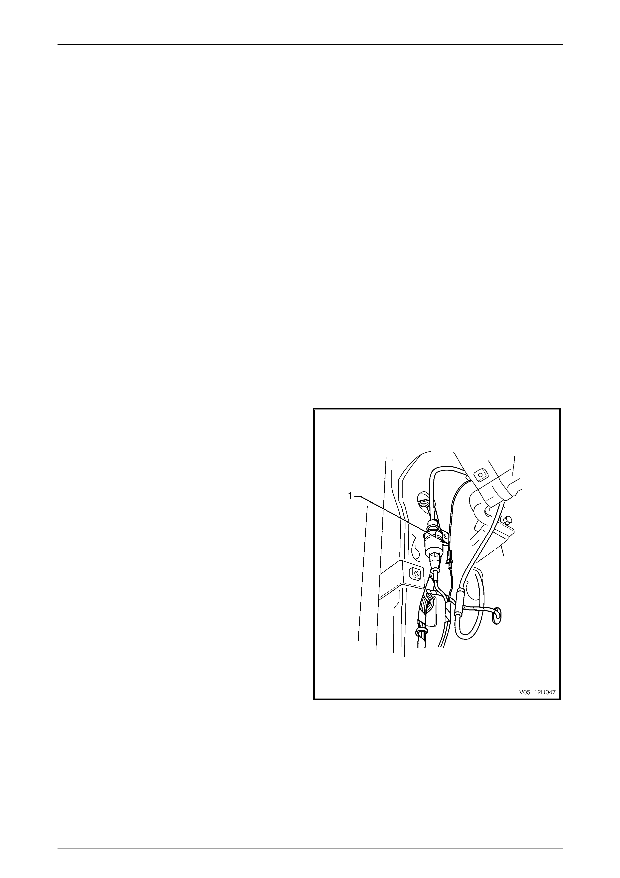
Entertainment System Page 12D–88
Page 12D–88
5.18 Diversity Antenna Fault Diagnosis,
Except Coupe
Before commencing the diagnostic procedure for the diversity antenna system the following should be checke d:
• Determine whether the reception problem is apparent with FM, AM or both. Faults affecting both FM and AM
reception are not caused b y the diversity antenna system due to the fact the diversity antenna system only affects
FM reception. The conventio nal fender mounted mast type antenna system is more likel y to be cause of such
faults.
• Ensure the customer complaint is not due to normal operation or the limitations of FM transmissions. The diversit y
antenna system is designed t o minimise distortion in the sound quality of FM reception and not to give large
increases in FM reception range.
• Compare reception qualit y with that of anoth er vehicle equipped with a diversit y antenna system in the same
location and under the same cond itions.
Diversity Antenna System Test Procedure, Except Coupe
NOTE
When the vehicle’s conventional antenna is
lowered, disconnected or faulty, the radio will not
use the diversity antenna system to receive FM
radio signals. If no FM stations can be received
then the fault is not due to the diversity antenna
system.
Refer to 5.15 Radio Reception befor e commencing to diagnose a diversity antenna related system fault.
1 Remove the left-hand side still trim and plate
assembly,
refer to Section 1A8 Headlining and Interi or Trim.
2 Remove the left-hand side body lock pillar lower trim,
refer to Section 1A8 Headlining and Interi or Trim.
3 Remove the left-hand side hinge pillar trim assembly,
refer to Section 1A8 Headlining and Interi or Trim.
4 Leaving the wiring harnesses connected to the
exposed module, manoeuvre the module from the
plastic mounting bracket.
5 Remove the plastic mounting bracket.
6 Disconnect the diversity antenna amplifier module
power cable (1).
7 Test the voltage at the diversity antenna module-to-
main wiring harness connector with the key in
Accessories position. If 12 V is indicated, continu e with
next step. If 0 V is indicated, trace wire back to fault
and repair.
Figure 12D – 25
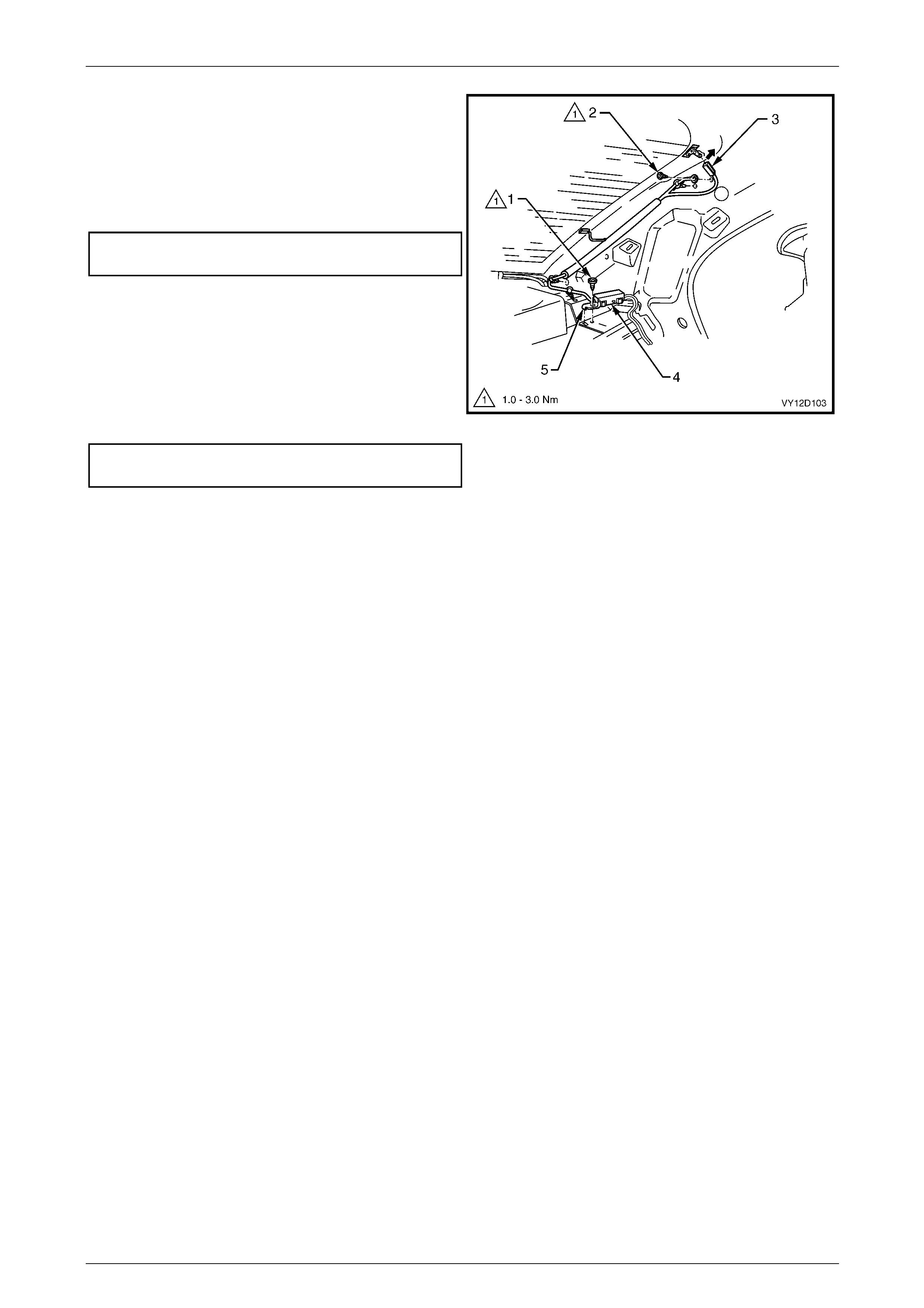
Entertainment System Page 12D–89
Page 12D–89
8 Remove the rear window trim panel assembl y, refer to
Section 1A8 Headlining and Interior Trim.
9 Check the connection from the diversity antenna
module connector (3) to the rear windo w connector.
Check the ground terminal (2) for a good electrical
ground. If necessary, tighten to the correct torque
specification.
Diversity antenna grounding
screw torque specification...........................1.0 – 3.0 Nm
10 Measure the resistance from the mounting tab (5) of
the diversity antenna amplifier module (4) to a good
ground point. If greater than 1 Ω, remove the retaining
screw (1) and module. Check the mating surfaces of
the module and rear parcel s helf are clean and free of
any corrosion.
11 Reinstall the module and tighten screw to the correct
torque specification and check the resistance again.
Diversity antenna module mounting
screw torque specification...........................1.0 – 3.0 Nm
Figure 12D – 26
12 Check the diversity antenna for continuity, refer to 5.18 Diversity Antenna Fault Diagnosis. If the antenna continuity
is acceptable then replace the diversity antenna amplifier module, refer to 6.12 Diversity Antenna, Except Coupe.
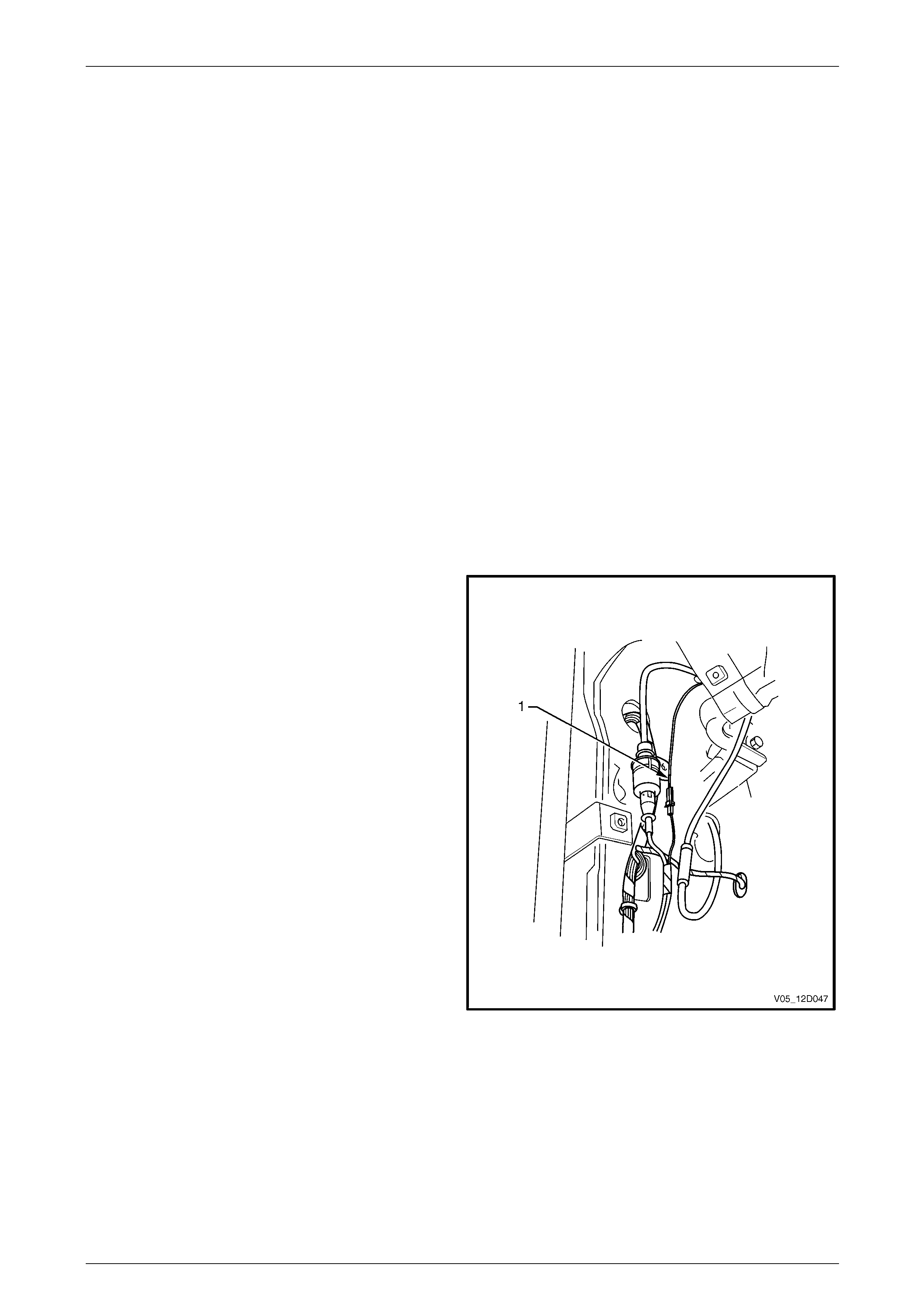
Entertainment System Page 12D–90
Page 12D–90
5.19 Diversity Antenna Fault Diagnosis,
Coupe
Before commencing the diagnostic procedure for the diversity antenna system the following should be checked:
• Determine whether the reception problem is apparent with FM, AM or both. Faults affecting both FM and AM
reception are not caused b y the diversity antenna system due to the fact the diversity antenna system only affects
FM reception. The main rear glass antenna system is more likely to be cause of such faults.
• Ensure the customer complaint is not due to normal operation or the limitations of FM transmissions. The diversit y
antenna system is designed t o minimise distortion in the sound quality of FM reception and not to give large
increases in FM reception range.
• Compare reception qualit y with that of anoth er vehicle equipped with a diversit y antenna system in the same
location and under the same cond itions.
Diversity Antenna System Test Procedure, Coupe
NOTE
When the vehicle’s m ain antenna is disconnected
or faulty, the radio will not use the diversity
antenna system to receive FM radio signa ls. If no
FM stations can be received then the fault is not
due to the diversity antenna system.
Refer to 5.15 Radio Reception befor e commencing to diagnose a diversity antenna related system fault.
1 Remove the left-hand side body hinge pillar trim
assembly, refer to
Section 1A8 Headlining and Interior Trim.
2 Leaving the wiring harnesses connected to the
exposed module, manoeuvre the module from the
plastic mounting bracket.
3 Remove the plastic mounting bracket.
4 Disconnect the diversity antenna amplifier module
power cable (1).
5 Test the voltage at the diversity antenna module-to-
main wiring harness connector with the key in
Accessories position. If 12 V is indicated, continu e with
next step. If 0 V is indicated, trace wire back to fault
and repair.
6 Remove the left-hand side body rear corner garnish,
refer to Section 1A8 Headlining and Interi or Trim.
Figure 12D – 27
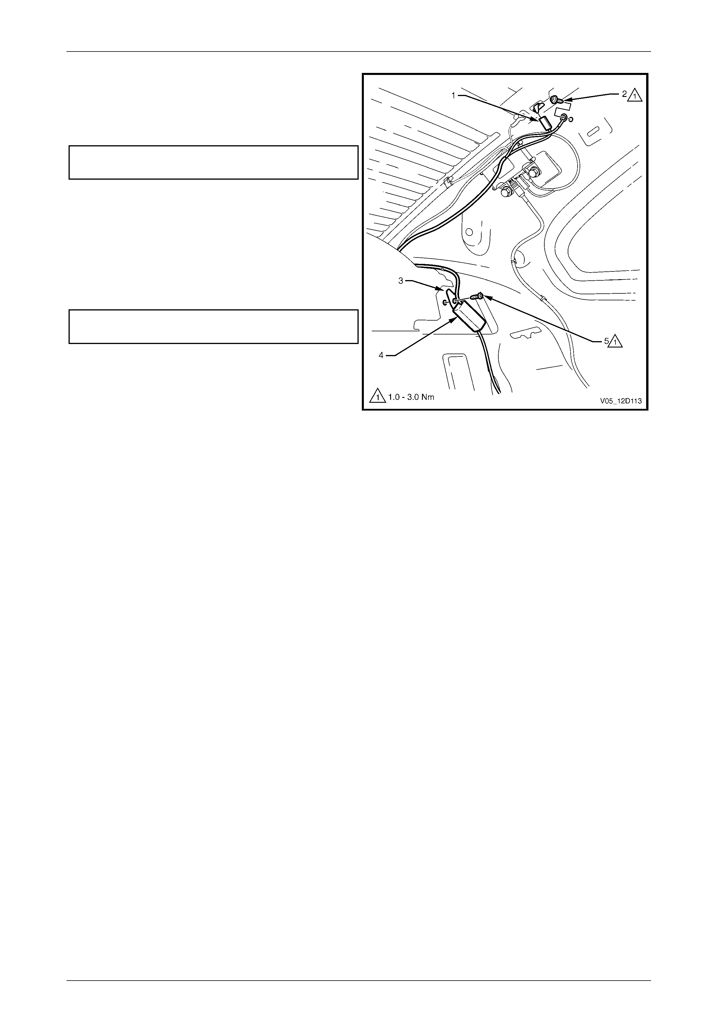
Entertainment System Page 12D–91
Page 12D–91
7 Check the connection from the diversity antenna
module connector (1) to the rear windo w connector.
Check the ground terminal (2) for a good electrical
ground. If necessary, tighten to the correct torque
specification.
Diversity antenna grounding
screw torque specification...........................1.0 – 3.0 Nm
8 Measure the resistance from the mountin g tab (3) of
the diversity antenna amplifier module (4) to a good
ground point. If greater than 1 Ω, remove the retaining
screw (5) and module. Check the mating surfaces of
the module and rear parcel s helf are clean and free of
any corrosion.
9 Reinstall the module a nd tighten screw to the correct
torque specification and check the resistance again.
Diversity antenna module mounting
screw torque specification...........................1.0 – 3.0 Nm
10 Check the diversity antenna for continuity, refer to
5.19 Diversity Antenna Fault Diagnosis, Coupe. If the
antenna continuity is acceptable the n replace the
diversity antenna amplifier module, refer to
6.13 Diversity Antenna, Coupe. Figure 12D – 28
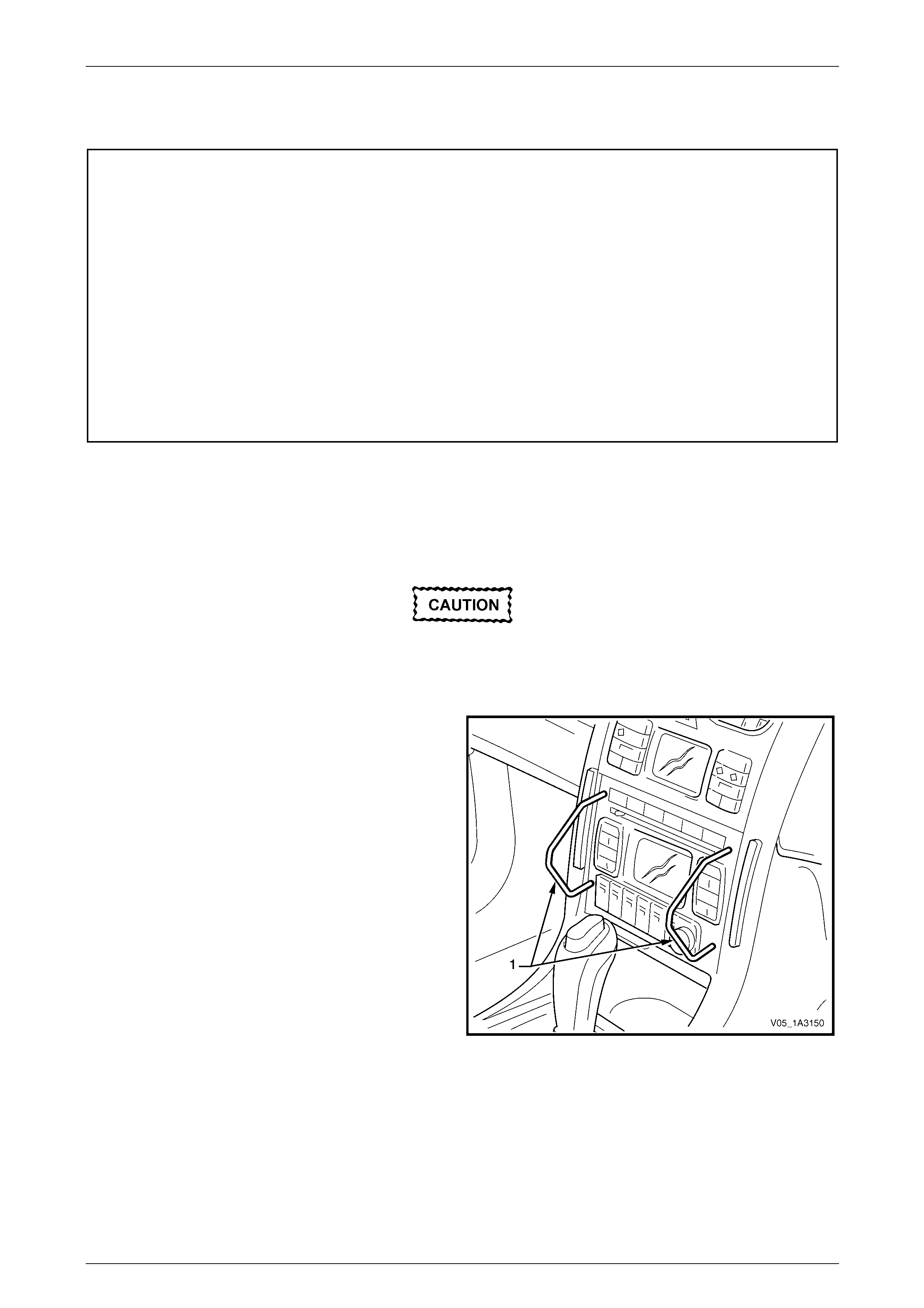
Entertainment System Page 12D–92
Page 12D–92
6 Service Operations
IMPORTANT
All fasteners are important attaching parts as they affect the performance of vital components and / or could
result in major repair expense. W here specified in this section, fasteners MUST be replaced w ith parts of the
same part number or a GM approved equivalent. Do not use fasteners of an inferior quality or substitute
design.
Torque values must be used as specified during reassembly to ensure correct retention of all components.
Throughout this section, fastener torque wrench specifications may be accompanied with the following
identification marks:
Fasteners must be replaced after loosening.
Vehicle must be at kerb height before final tightening.
Fasteners either ha ve micro encapsulated sealant ap plied or inco rporate a mech anical thread lo ck and
should only be re-used once. If in doubt, replacement is recommended.
If one of these identification marks is present alongside a fastener torque wrench specification, the
recommendation regarding that fastener must be adhered to.
6.1 Audio Head Unit
LT Section No. — 09–440
Remove
It is recommended the audio head unit does
not contain a CD when being removed. Under
some circumstances, a CD may become
dislodged if the unit is treated roughly during
removal.
1 Eject any CD’s that may be in the CD unit / changer.
2 Ensure the audio system is turned off.
3 Using the special service tools KM6067 (1), insert the
tools into the access holes and push the service tool in
to engage the barbs of the retaining spring clips.
4 Apply outward pressur e to the service tools to release
the spring clips then pull the audi o head unit out of the
cradle.
5 Remove the service tools.
Figure 12D – 29

Entertainment System Page 12D–93
Page 12D–93
Reinstall
Reinstallation of the audio head unit is the reverse of the removal procedure, noting the following:
1 Service tools are not required to install the audio head unit.
2 Slide the audio head unit into the cradle and using finger pressure ov er the removal tool holes, push the unit in until
the spring clips engage.
Do not apply pressur e to the buttons, knob or
display as damage may result.
3 If a new audio head unit has been insta lled, enter the security code. Refer to 6.17 Audio System Security Code.
4 Store the new security code into BCM memory using Tech 2, refer to Section 12J Body Control Module for further
details. Ensure the vehicle owner is prov ided with a copy of the new security code.
5 Check the audio system for correct operation. Load any customer CDs that were originally in the audi o system.

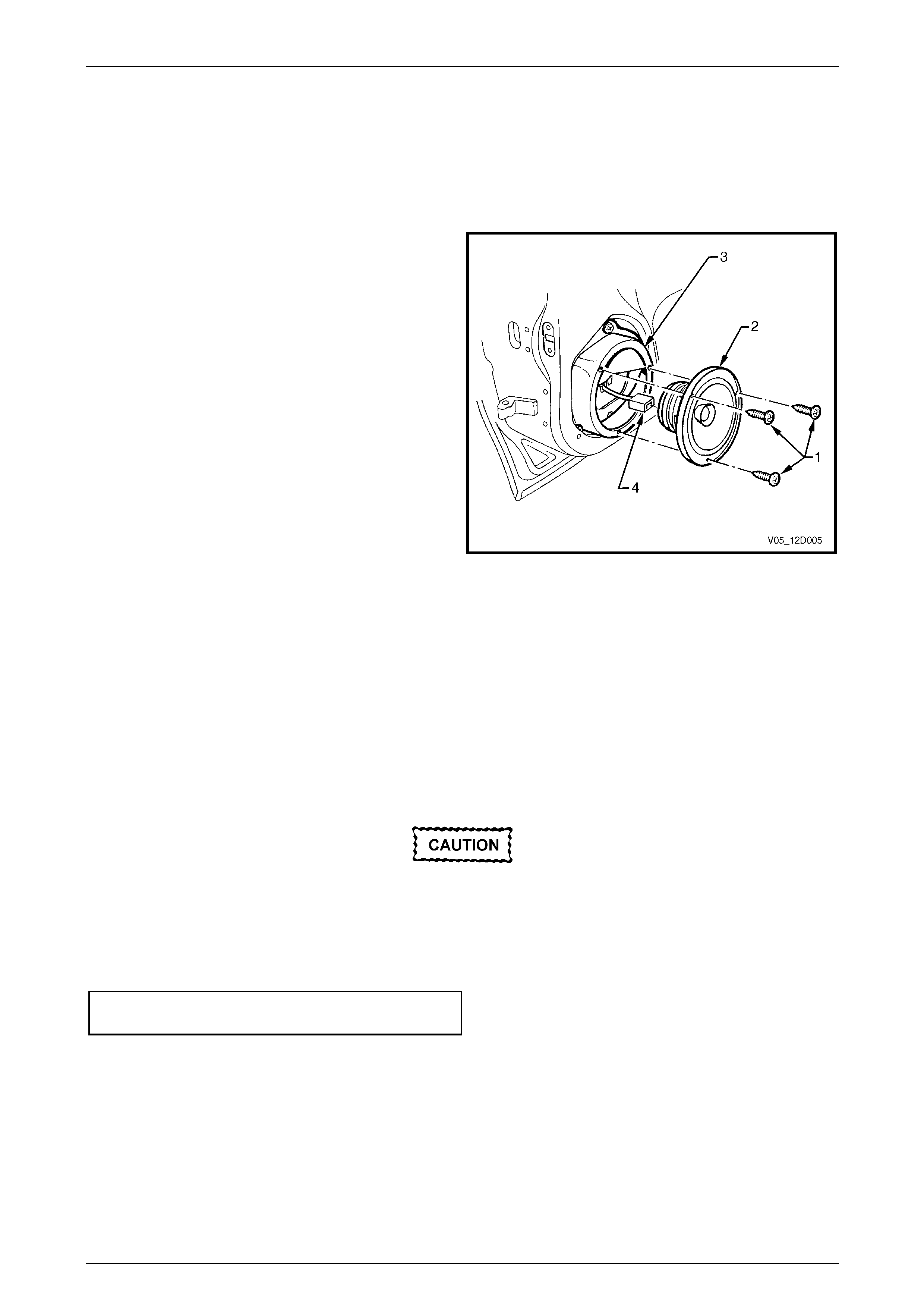
Entertainment System Page 12D–95
Page 12D–95
6.3 Front Door Speakers
LT Section No. — 09–500
Remove
1 Ensure the audio system is turned off.
2 Remove the door trim from the front door. Refer to
Section 1A5 Front and Rear Door Assemblies.
3 Remove the three retaining screws (1).
4 Remove the door speaker (2) from the speaker
box (3).
5 Release the wiring harness (4) from the tab on the
rear of the speaker box.
6 Disconnect the wiring harness from the spea ker
connector and remove the speaker.
Figure 12D – 30
Reinstall
Reinstallation of the front door speakers is th e reverse of the remova l procedure, noting the following:
1 Ensure the electrical connector is correctly attached to the speaker, refer to Figure 12D – 30.
2 Before installing the speaker, visuall y ins pect the cavity of the speaker mounting box for protrusions that will touch
the underside of the speaker cone on installation, i.e. cable ties etc. Secure the wiring harness to the tab on the
rear of the speaker box.
3 Carefully install the speaker retaining screws ensuring the speaker frame is not distorted when the screws are
tightened.
Incorrect torque specification or angled
insertion of the speaker retaining screws can
lead to speaker distortion. Ensure the screws
are installed square to the speaker frame and
are tightened to the correct torque
specification.
Front door speaker retaining
screw torque specification...........................1.0 – 3.0 Nm
4 Check the speaker operation once installation has been completed.

Entertainment System Page 12D–96
Page 12D–96
6.4 Rear Door Speakers, Except Utility,
Regular Cab and Coupe
LT Section No. — 09–500
Remove
1 Ensure the audio system is turned off.
2 Remove the door trim from the rear door, refer to
Section 1A5 Front and Rear Door Assemblies.
3 Remove the three retaining screws (3).
4 Remove the speaker (2) from speaker box (1).
5 Release the wiring harness (4) from the tab on the
rear of the speaker box.
6 Disconnect the wiring harness from the spea ker
connector and remove the speaker.
Figure 12D – 31
Reinstall
Reinstallation of the rear doo r speakers is the reverse of the removal procedure, noting the following:
1 Ensure the electrical connector is correctly attached to the speaker, refer to Figure 12D – 31.
2 Before installing the speaker, visuall y ins pect the cavity of the speaker mounting box for protrusions that will touch
the underside of the speaker cone on installation, i.e. cable ties etc. Secure the wiring harness to the tab on the
rear of the speaker box.
3 Carefully install the speaker retaining screws ensuring the speaker frame is not distorted when the screws are
tightened.
Incorrect torque specification or angled
insertion of the speaker retaining screws can
lead to speaker distortion. Ensure the screws
are installed square to the speaker frame and
are tightened to the correct torque
specification.
Rear door speaker retaining
screw torque specification...........................1.0 – 3.0 Nm
4 Check the speaker operation once installation has been completed.
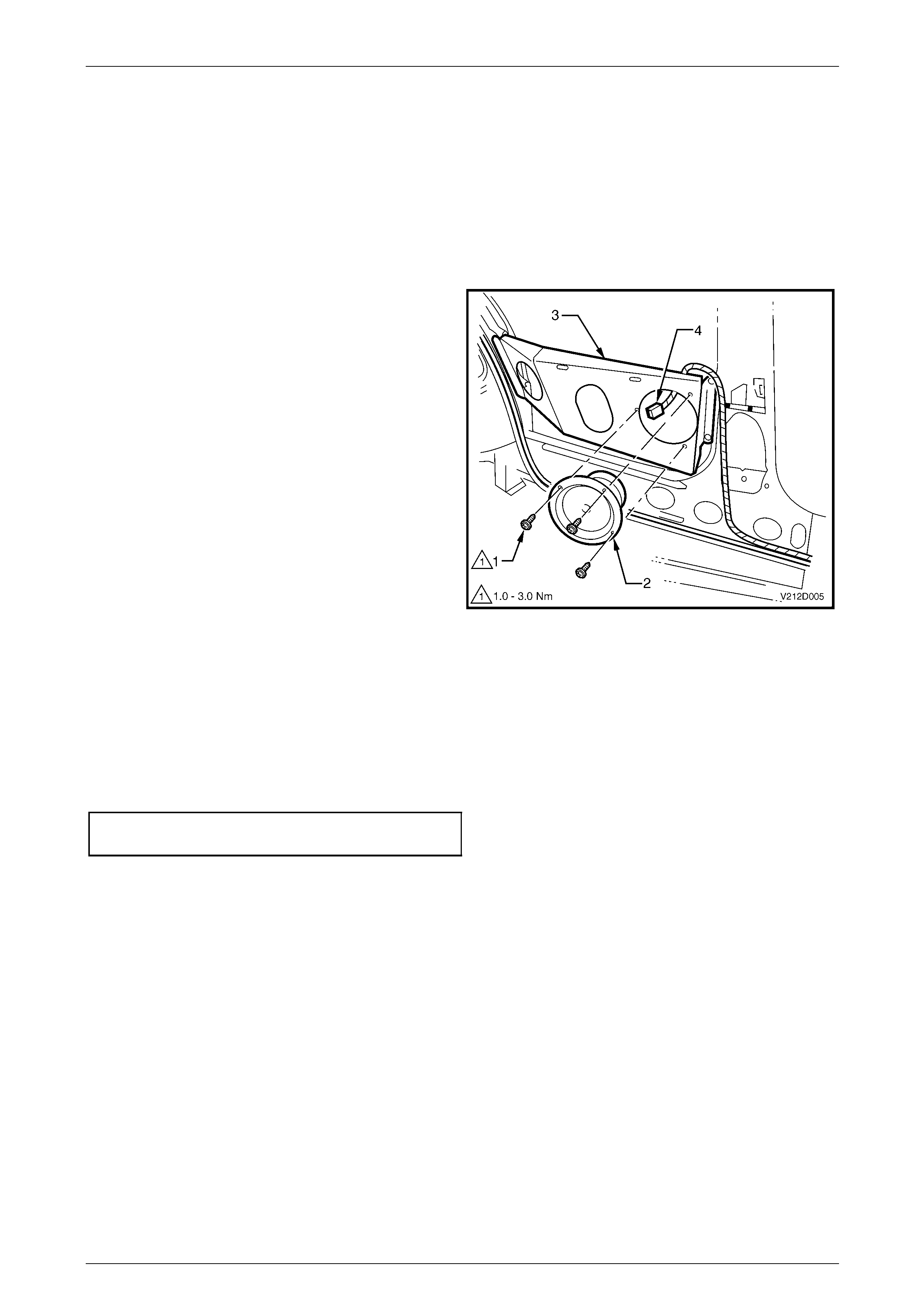
Entertainment System Page 12D–97
Page 12D–97
6.5 Rear Quarter Speakers, Coupe
LT Section No. — 09–500
Remove
1 Ensure the audio system is turned off.
2 Remove the rear quarter trim panel, refer to Section 1A8 H eadlining and Interior Trim.
3 Remove the three screws (1) securing the rear quarter
speaker (2) to the mounting bracket (3).
4 Pull the speaker away from the mounting bracket to
gain access, and disconnect the wiring harness
connector (4).
5 Remove the rear quarter speaker.
Figure 12D – 32
Reinstall
Reinstallation of the rear qua r ter speakers is the reverse of the removal procedure, noting the following:
1 Ensure the electrical connector is correctly attached to the speaker.
2 Tighten the retaining screws to the correct torque sp ecification.
3 Check operation prior to installing the rear quarter trim.
Rear quarter speaker retaining
screw torque specification...........................1.3 – 3.0 Nm
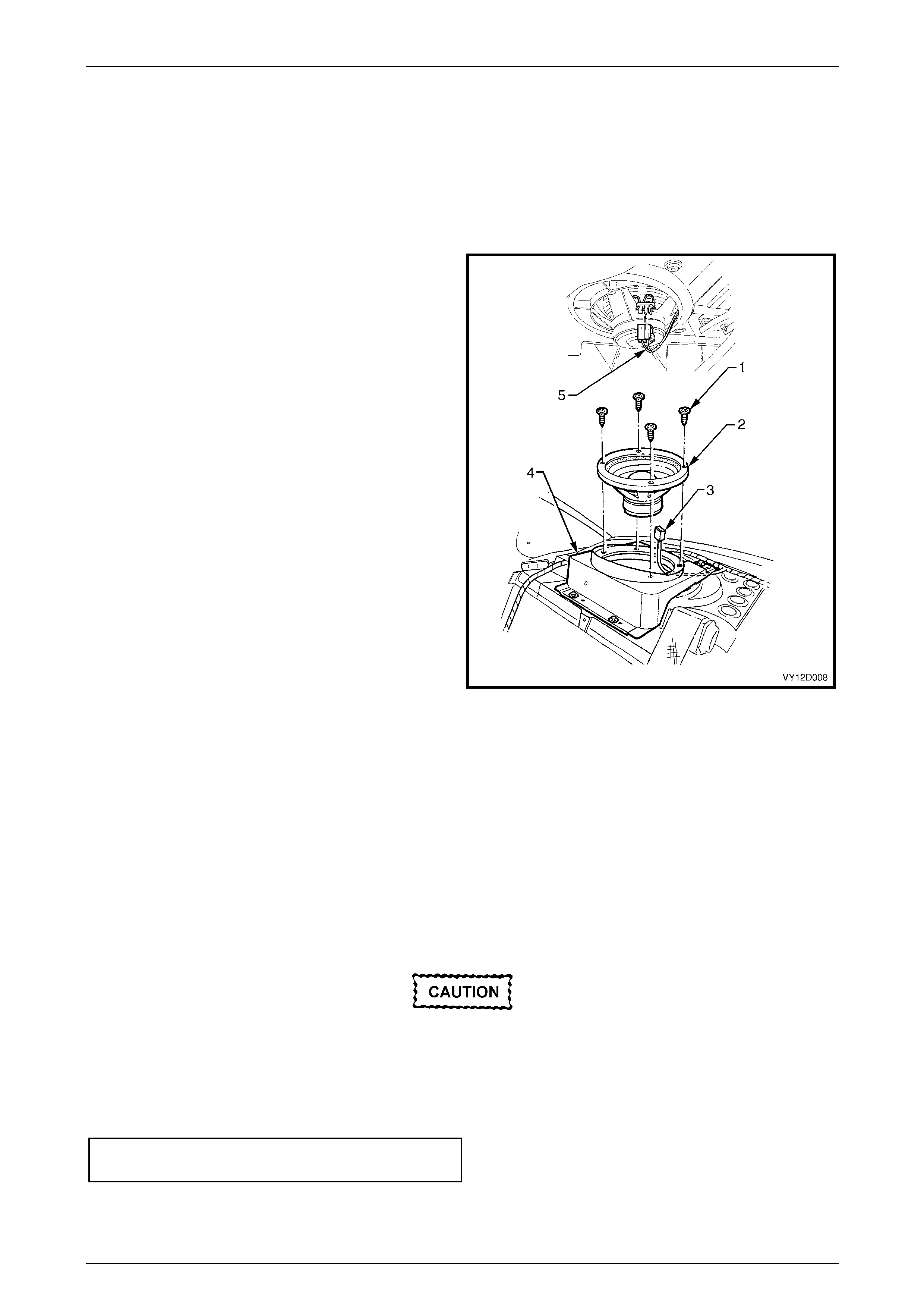
Entertainment System Page 12D–98
Page 12D–98
6.6 Subwoofer Speakers – Type 4
Entertainment System
LT Section No. — 09–500
Remove
1 Ensure the audio system is turned off.
2 Remove rear window trim panel assembly, refer to
Section 1A8 Headlining and Interior Trim.
3 From inside the rear compartment, carefully remove
the connector (3) from the left-hand or right-hand si de
subwoofer (2).
4 From within the passenger compartment, remove the
four screws (1) securing each subwoofer and carefully
lift the subwoofer from the mounting bracket (4).
Figure 12D – 33
Reinstall
Reinstallation is the reverse of the removal procedure, noting the follo wing:
1 Ensure the electrical connect ors are correctly attached to the speaker.
2 Before installing the speaker, visuall y inspect the speaker mounting bo x cavity for protrusions that will touch the
underside of the speaker cone on installation, i.e. cable ties etc.
3 Carefully install the speaker retaining screws, ensuring the speaker frame is not distorted when the screws are
tightened. Ensure the wiring harness is not j ammed.
4 Install rear window trim panel assembly, refer to Section 1A8 Headlining and Interior Trim.
Incorrect torque specification or angled
insertion of the speaker retaining screws can
lead to speaker distortion. Ensure the screws
are installed square to the speaker frame and
are tightened to the correct torque
specification.
Subwoofer speaker retaining
screw torque specification...........................1.0 – 3.0 Nm
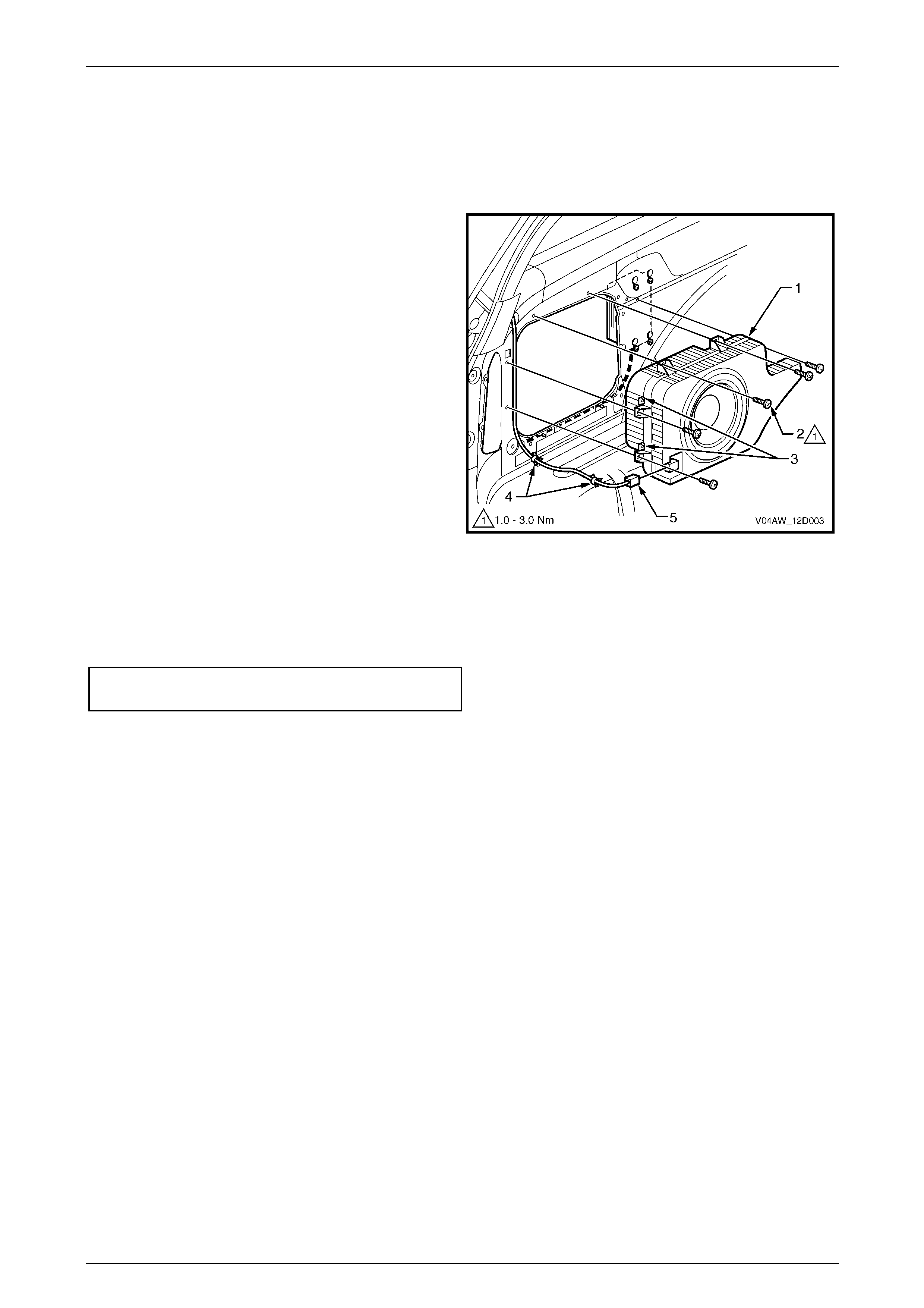
Entertainment System Page 12D–99
Page 12D–99
6.7 Subwoofer Speaker, LX8 AWD Wagon
LT Section No. — 09–500
Remove
1 Remove the left-hand side quarter inner trim panel
assembly, refer to
Section 1A8 Headlining and Interior Trim.
2 Remove the five attaching screws (2) from the
subwoofer speaker (1).
3 Unclip the wiring harness (4) from the mounting
lugs (3).
4 Disconnect the connector (5) from the subwoofer
speaker.
Figure 12D – 34
Reinstall
Reinstallation of the subwoofer speaker is the reverse of the removal procedure. Tighten the subwoofer speaker
attaching screws to the correct torque specification.
LX8 AWD Wagon subwoofer speaker
attaching screw torque specification...........1.5 – 3.0 Nm
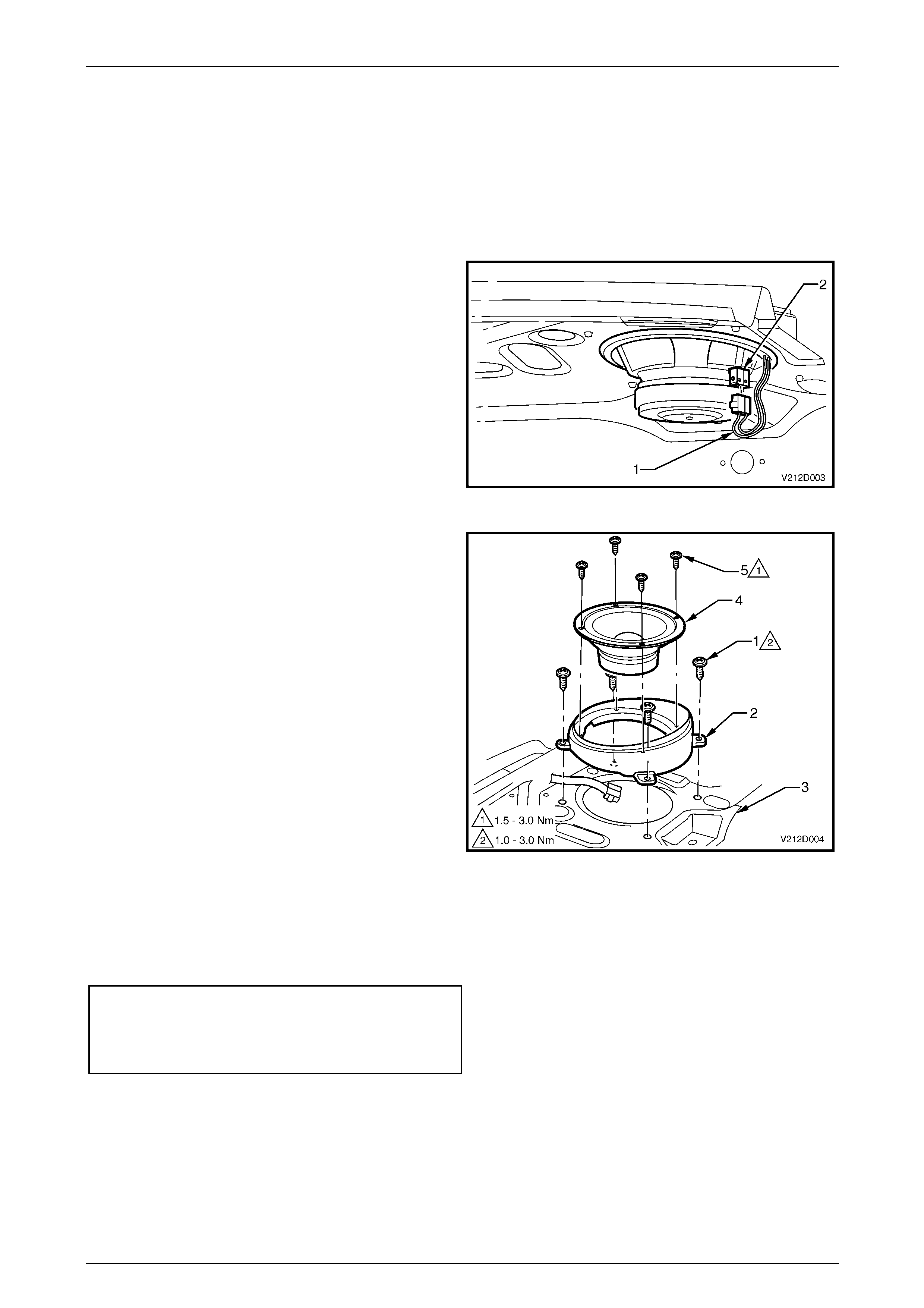
Entertainment System Page 12D–100
Page 12D–100
6.8 Subwoofer Speakers, Coupe
LT Section No. — 09–500
Remove
1 Ensure the radio audio system is turned off.
2 Open the rear compartment lid and disconnect the
wiring harness connector (1) from the subwoofer
speaker (2).
3 Remove the rear parcel shelf assembly, refer to
Section 1A8 Headlining and Interior Trim.
Figure 12D – 35
4 Remove the four screws (1) securing the speaker
mounting box (2) to the rear parcel shelf (3).
5 Remove the mounting box and speaker.
6 Remove the four screws (5) securing the speaker to
the mounting box and carefully separate.
Figure 12D – 36
Reinstall
Reinstallation of the subwoofer speakers is the reverse of the removal procedur e. Tighten all retaining screws to the
correct torque specification.
Speaker mounting box to rear parcel shelf
retaining screw torque specification............1.0 – 3.0 Nm
Rear parcel shelf speaker to mounting bo x
retaining screw torque specification............1.5 – 3.0 Nm
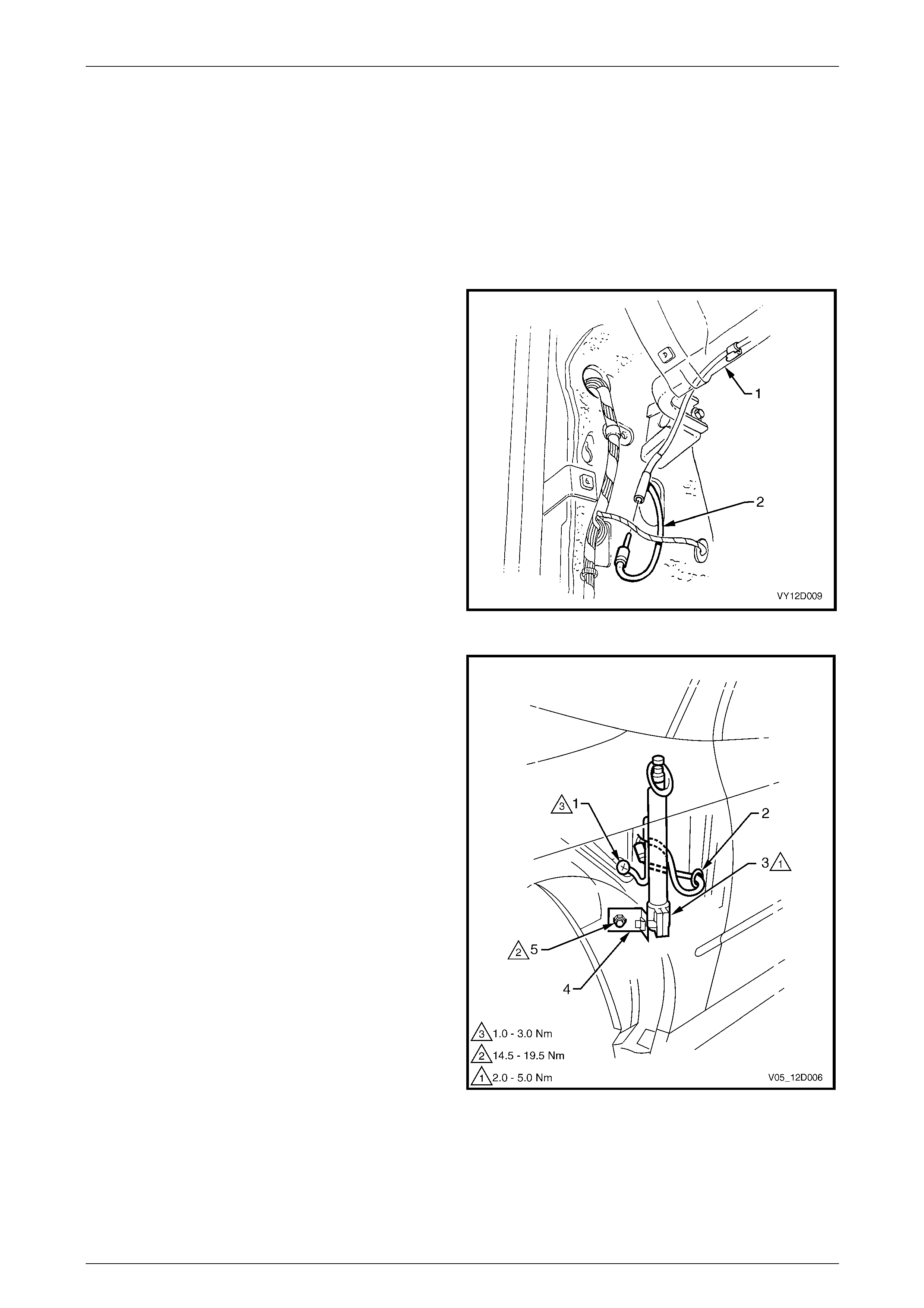
Entertainment System Page 12D–101
Page 12D–101
6.9 Manual Antenna
LT Section No. — 09–400
Remove
1 Ensure the audio system is turned off.
2 Remove the hinge pillar trim assembly, refer to Section 1A8 Headlining and Interior Trim.
3 Leaving the wiring harnesses connected to the
exposed module, manoeuvre the module from the
plastic mounting bracket.
4 Remove the plastic mounting bracket (1).
5 Disconnect the antenna lead ( 2) from the connecting
socket of the antenna extension lead.
6 Remove the left-hand side fender liner, refer to
Section 1A1 Body.
Figure 12D – 37
7 Push the antenna mast down to the fully retracted
position.
8 Remove the screw (1) connecting the ground braid to
the inner fender ground terminal.
9 While supporting the antenna, remove the bolt (5)
attaching the antenna bracket (4) to the inner fender
panel.
10 Remove the antenna lead grommet (2) from the inner
fender panel and pull the lead out from the passenger
compartment.
11 Withdraw the antenna downward through the bezel
and remove, complete with the lead and grommet.
12 If necessary, loosen the antenna bracket bolt (3) and
remove the bracket from the antenna.
Figure 12D – 38

Entertainment System Page 12D–102
Page 12D–102
Reinstall
Reinstallation of the manual antenna is the reverse of the removal proce dure, noting the following:
1 If removed, leave the antenna bracket bolt loose.
2 Ensure the antenna an d the ground leads are routed correctly and are securely connected.
3 With the antenna pushed up against the stop in the bezel, tighten the bolt attaching the antenna bracket to the
inner fender panel to the correct torque specification.
Antenna bracket to inner fender panel
retaining bolt torque specification............14.5 – 19.5 Nm
Antenna ground braid to inner fender panel
retaining screw torque specification............1.0 – 3.0 Nm
4 Tighten the antenna bracket bolt to the correct torque specification.
Antenna bracket attaching bolt torque
specification................................................2.0 – 5.0 Nm
5 Extend the antenna and chec k the radio operation and reception.
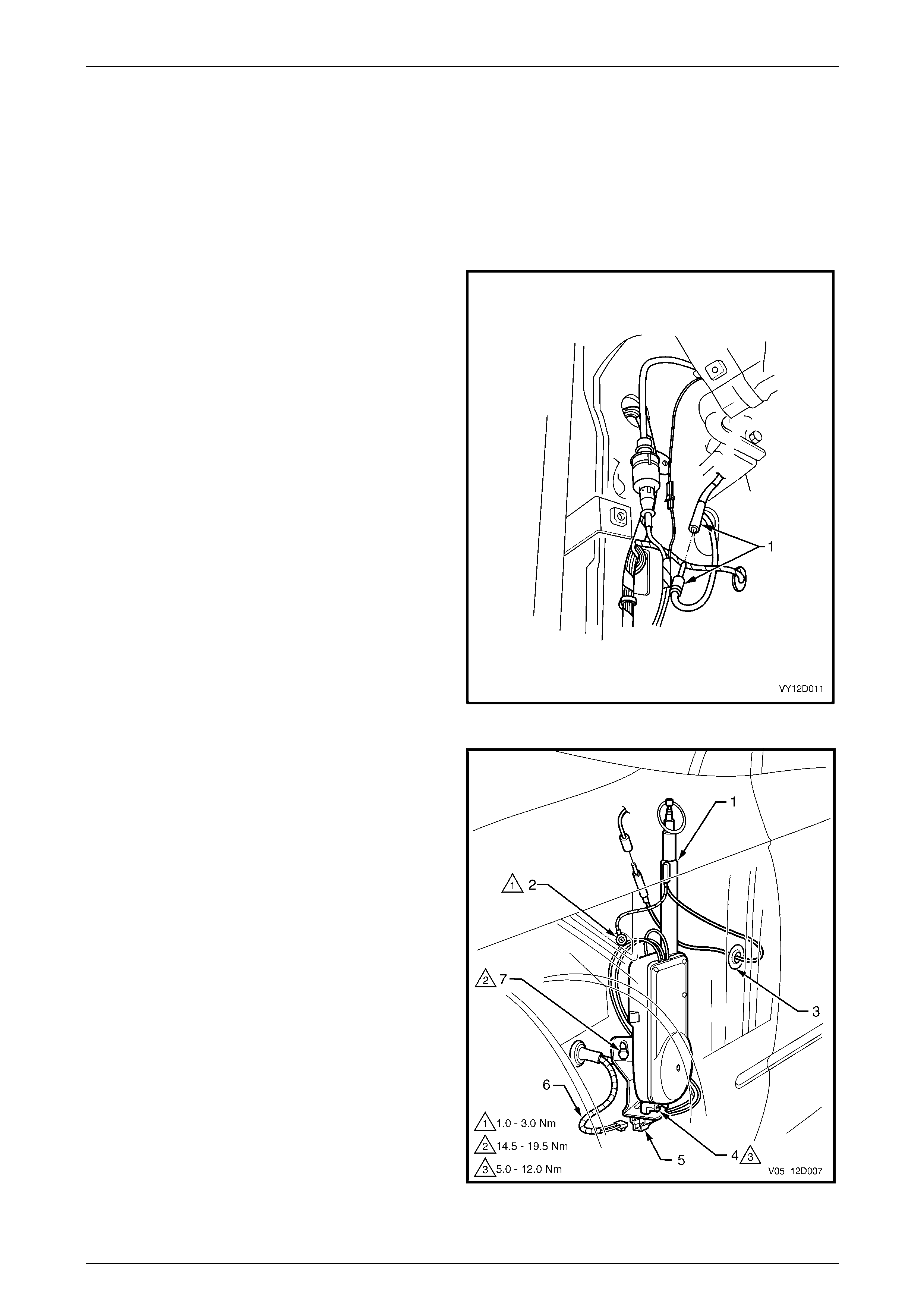
Entertainment System Page 12D–103
Page 12D–103
6.10 Power Antenna
Power Antenna Assembly
LT Section No. — 09–400
Remove
1 Ensure the audio system is turned off and the antenna
mast is in the fully retracted position.
2 From inside the vehicle, remove the left-han d side
hinge pillar trim assembly, refer to
Section 1A8 Headlining and Interior Trim.
3 Leave the wiring harnesses connected to the exposed
Powertrain Control Module (V6 models) or the
Powertrain Interface Module (GEN III models) and
manoeuvre the module from the plastic mounting
bracket.
4 Remove the plastic mounting bracket.
5 Disconnect the antenna lead ( 1) from the connecting
socket of the antenna extension lead.
Figure 12D – 39
6 Remove the left-hand side fender inner liner, refer to
Section 1A1 Body.
7 Remove the screw (2) connecting the ground braid to
the inner fender ground terminal.
8 Disconnect the antenna power connector (6) from the
wiring harness connector in the wheel well.
9 While supporting the antenna assembly (5), remove
the retaining bolt (7) from the antenna support bracket.
10 Remove the antenna lead grommet (3) from the inner
fender panel and pull the lead out from the passenger
compartment.
11 Withdraw the antenna (1) down through the bezel and
remove the antenna, complete with leads, grommet
and bracket.
12 If required, remove the two nuts (4) securing the
antenna to the mounting bracket.
Figure 12D – 40

Entertainment System Page 12D–104
Page 12D–104
Reinstall
Reinstallation of the power antenna is the reverse of the removal procedure, notin g the following:
1 Ensure the cable and harness are routed correctly.
2 Ensure the antenna an d the ground leads are routed correctly and are securely connected.
3 With the antenna pushed up against the stop in the bezel, tighten the bolt attaching the antenna bracket to the
inner fender panel to the correct torque specification.
Antenna bracket to inner fender panel
retaining bolt torque specification............14.5 – 19.5 Nm
Antenna ground braid to inner fender panel
retaining screw torque specification............1.0 – 3.0 Nm
Antenna assembly to bracket attaching
nuts torque specification ...........................5.0 – 12.0 Nm
4 Check the antenna operation and the radio reception.
Mast Replacement
LT Section No. — 09–400
The following procedure is for replacing a damaged or fault y antenn a mast and drive cable assembly.
1 Remove the power antenna assembly, refer to 6.10 Power Antenna.
2 Remove the chrome-plated nut from the top end of the mast tube.
3 Extend the damaged antenn a mast as far as possible by attaching the battery negative, via a jumper lead, to the
antenna mounting br acket and connect the battery positive to both the antenna red and white wire terminals.
4 At the end of the mast travel, pull out the mast and drive cable from the antenna housing.
NOTE
If the mast is too badly damaged to extend, grip
the tip of the mast with a pair of pliers and pull the
mast and drive cable assembly up and out from
the antenna housing.
5 If required, remove the contact spring (metal sleeve) from the old mast and drive cable and install onto the
replacement mast and drive cable.
6 Feed the end of the drive cable down the mast tube of the antenna housing with the serrated sid e of the drive ca ble
facing toward the centre of the housing. Continue to feed the drive cable down until it engages with the drive
mechanism.
NOTE
It may be necessary to twist the drive cable
clockwise and anti-clockwise slightly to enable
the end of cable to feed through the opening at
the base of the mast tube before it engages the
drive mechanism.
7 With an assistant holding the antenna and mast assembly, connect the antenna support bracket, via a jumper l ead,
to battery negative.
8 Momentarily connect battery positive to the antenna red wire. The drive mechanism should start to retract the drive
cable into the antenna housing.
9 With the drive cable engaged to the drive mechanism, reconnect battery positive to the antenna red wire and allow
the drive mechanism to wind in the drive cable and mast into the mast tube and housing.
10 At this stage the mast might be fully retracted into the mast tube and housing. Reconnect both the red and white
wires to battery positive and allow the mast to extend fully until the motor stops.
11 Disconnect the white wire from battery positive and allow the mast to fully retract.
12 Install the chrome-plated nut onto the mast tube and tighte n the nut securely.
13 Install the power antenna assembly, refer to 6.10 Po wer Antenna. Check the ante nna mast operation and radio
reception.
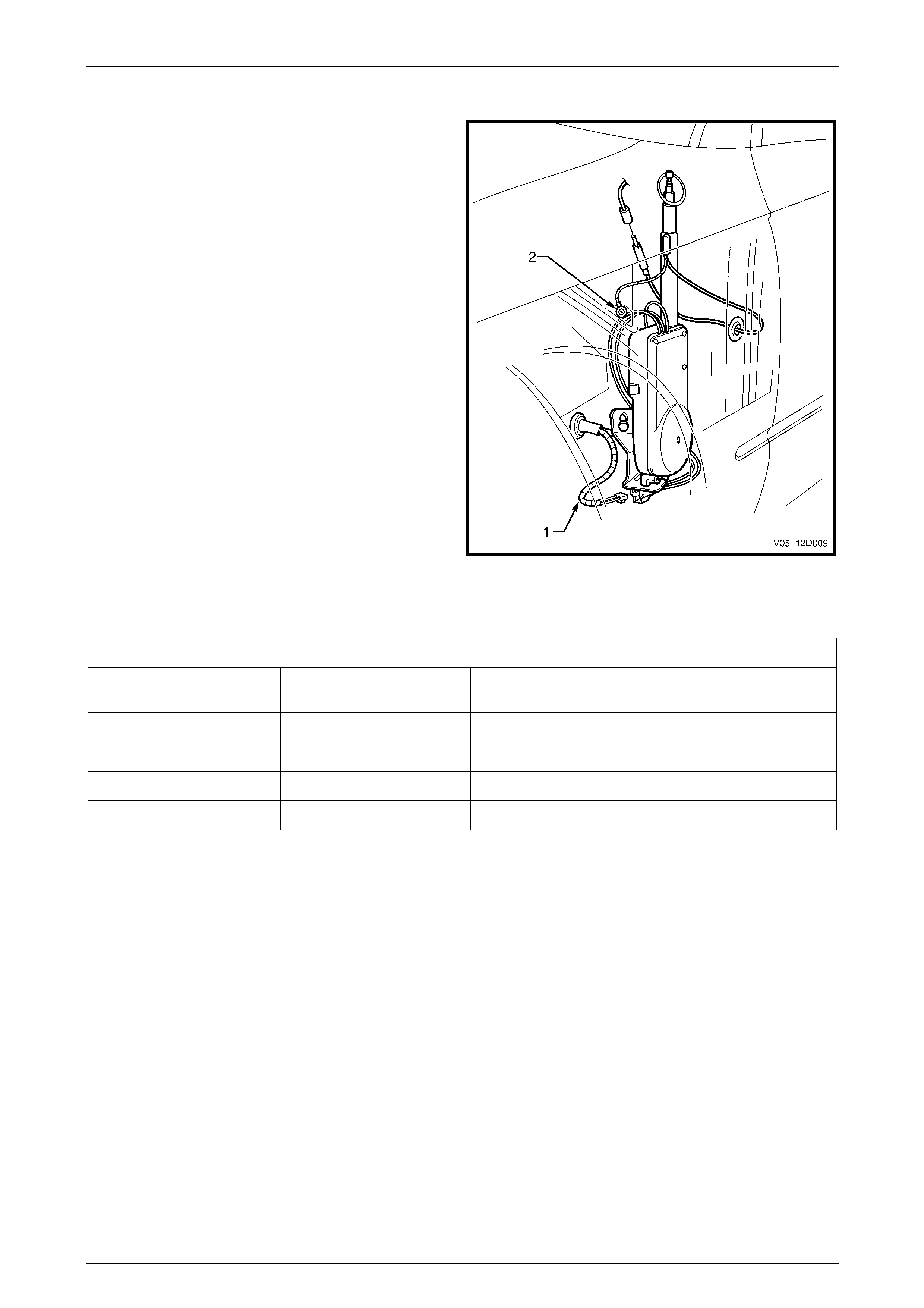
Entertainment System Page 12D–105
Page 12D–105
Antenna Motor Operation Check
NOTE
The following Antenna Motor Operation check
tests are made at the main wiring harness-to-
antenna motor connector located at the antenna
assembly. It will be necessary to remove the
front wheel house liner to gain access to the
connector, refer to Section 1A1 Body.
Legend
1 Main Wiring Harness-to-Antenna Motor Connector
2 Ground Braid
Figure 12D – 41
The voltages shown in the table below are measured between the W6 Power Antenna assembly connect or and a kn own
ground point on the vehicle bod y.
Voltage on Antenna Harness W ires
Circuit 160
(Green) Circuit 161
(Grey) Action
12 V 12 V Antenna extends
12 V 0 V Antenna retracts
0 V 12 V Antenna does not move
0 V 0 V Antenna does not move
If the antenna motor does not correctly respond to the i nputs as specified, ensure a good ground connection is being
made through the mounting bracket by measuring the resistance from the bracket to a good ground point. If more than
1 Ω is recorded, remove the antenna ass embly, refer to 6.10 Power Antenna. Ensure the bracket and body contact
surfaces are clean. If all OK, replace the power antenna assembly. Check the black wire with the forked ground
connector (item 2 in Figure 12D – 41) is securely attached to the antenna mounting bracket.
NOTE
If there is significant noise on the AM band (with
the radio tuned to a weak station outdoors), then
check the ground quality of the antenna at the
points previously mentioned. Also check the
ground quality of the ground braid (ref er to Item 2
of Figure 12D – 41).
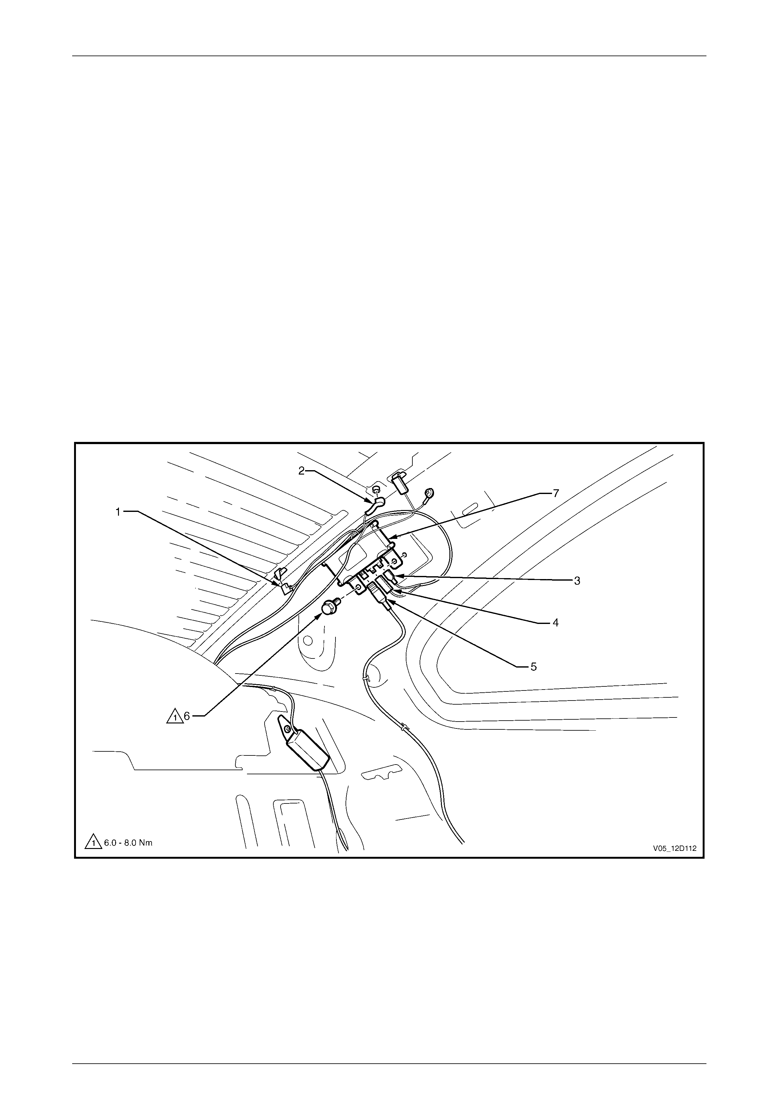
Entertainment System Page 12D–106
Page 12D–106
6.11 Rear Window Antenna System, Coupe
LT Section No. — 09–400
The antenna system consists of an antenna coil assembly L4, an antenna amplifier module A93 and connecting l eads.
The antenna coil assembl y comprises two antennas, one for AM signals and another for FM signals, and these form an
integral part of the rear window glass. The FM antenn a coil is also used as the rear window demister element. The thin
conductors that form each antenna are laid on the inside of the glass, and two connectors are located on the side of the
rear window allowing connection of the antenna coils to the antenna amplifier module.
The antenna amplifier module amplifies the small signals from the antenna coil assembly then transmits the amplified
signal to the radio’s antenna i nput. The module is located beneath the trim on the driver’s side of the rear parcel shelf.
The module is connected to the au dio head unit via a coaxial le ad, circuit 5172.
AM/FM Antenna Coil
Repair
To maintain optimum radio system performance, breaks i n the antenna coils must be repaired. Use a Repair Kit available
from automotive accessory outlets and follow the manufacturer’s instructions carefully.
Antenna Amplifier Module
Figure 12D – 42

Entertainment System Page 12D–107
Page 12D–107
Remove
1 Ensure the audio system is turned off.
2 Remove the left hand side body rear corner garnish, refer to Section 1A8 Headlining and Interior T r im .
3 Disconnect the FM antenna / demister connector (1) and the AM antenna connector (2) from the rear window
connectors, refer to Figure 12D – 42.
4 Disconnect the three connectors (3, 4 and 5) from the antenna amplifier module (7).
5 Remove the two screws (6) securing the antenna am plifier module to the vehicle body and remove the module.
Reinstall
Reinstallation of the antenna amplifier module is the reverse of the removal procedure. Tighten the module mounting
screws to the correct torque specification.
Antenna amplifier module mounting
screw torque specification...........................6.0 – 8.0 Nm

Entertainment System Page 12D–108
Page 12D–108
6.12 Diversity Antenna, Except Coupe
LT Section No. — 09–400
The diversity antenna is an integral part of the rear window assembly. The thin conductors that form the diversity antenna
are laid on the inside of the rear windo w glass in the same manner as the rear window heating elements.
A single terminal is located on the inside of the rear window glass, on the passenger side, to allow connection of the
diversity antenna to the div ersity antenna module, located under the rear parcel shelf trim.
The diversity antenna module amplifies the radio signal received b y the diversity antenna and transmits it to the audio
head unit via coaxial cable.
NOTE
Due to the internal circuitry of the radio receiver,
if the fender mounted mast antenna is retracted,
faulty or disconnected, the radio may not use the
diversity anten na system for radi o reception if the
FM signal is weak.
Test
1 Remove the body lock pillar garnish (rear quarter window trim) from the left-hand side of the vehicle,
refer to Section 1A8 Headlining and Interi or Trim.
2 Disconnect the diversity antenna mod ule connector from the diversity antenna terminal.
3 Using a multimeter set to measure resistance, probe between the diversity antenna terminal and the diversity
antenna conductors on the ins ide of the rear window glass. Resistance should be less than 20 Ω from the diversity
antenna connector to any point on the div ersity antenna conductors.
Avoid using excessive force on the
multimeter probe, as damage to the diversity
antenna conductors will result.
Remove
1 Ensure the audio system is turned off.
2 Remove the following components:
a rear window trim panel assembly,
b left-hand side sill trim and plate assembly,
c left-hand side body lock pillar lower trim, and
d left-hand side hinge pillar trim assembly.
Refer to Section 1A8 Headlining and Interior Trim .
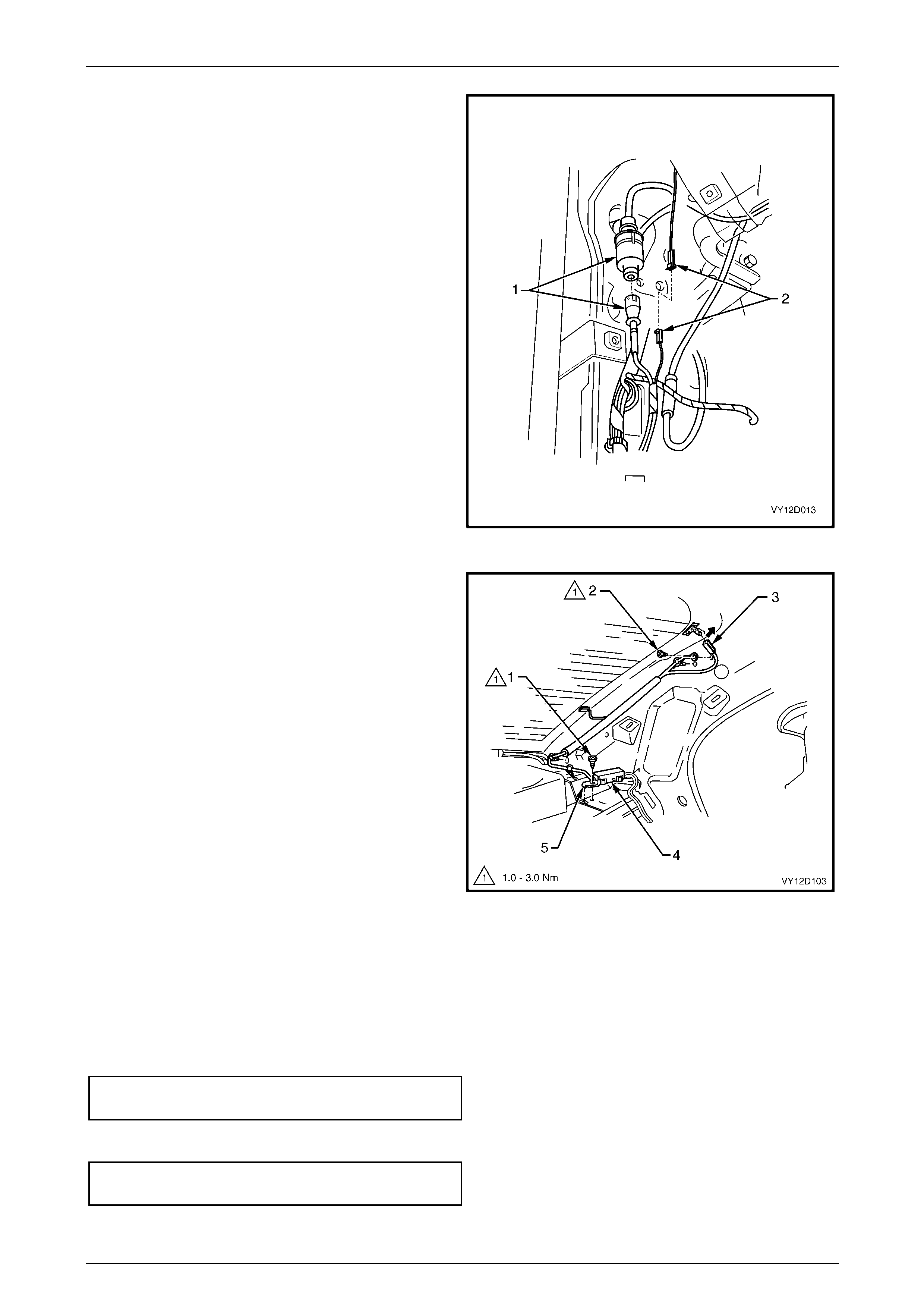
Entertainment System Page 12D–109
Page 12D–109
3 From behind the left-hand side hinge pillar trim
assembly, disconnect the diversity antenna module
coaxial cable (1) from the radio divers ity antenna
extension cabl e connector and the diversity antenna
module power cable (2) to wiring harness connector.
Refer to
Section 12O Fuses, Relays and Wiring Harnesses.
4 Remove the diversity antenna modul e leads from the
retaining clips and remove th e leads from the rocker
panel.
Figure 12D – 43
5 Remove the screw (1) securing the diversity antenna
amplifier (4) to the rear parcel shelf. Remove the
diversity antenna module and leads.
6 Remove the screw (2) securing the diversity antenna
ground terminal to the vehicle body.
7 Remove the diversity antenna modul e connector (3)
from the diversity antenna terminal l ocate d on the rear
window.
Figure 12D – 44
Reinstall
Reinstallation of the diversity antenna module is the reverse of the removal procedure, noting the following:
1 Ensure the mounting tab on the diversity antenna module is correctly engaged into the mounting slot on the rear
parcel shelf.
2 Tighten the diversity antenna module mounting screw to the correct torque specification.
Diversity antenna module mounting
screw torque specification...........................1.0 – 3.0 Nm
3 Tighten the diversit y antenna grounding screw to the correct torque specification.
Diversity antenna grounding
screw torque specification...........................1.0 – 3.0 Nm
4 After installing the diversity antenna connector, bend the tab in the directio n shown, refer to Figure 12D – 44.
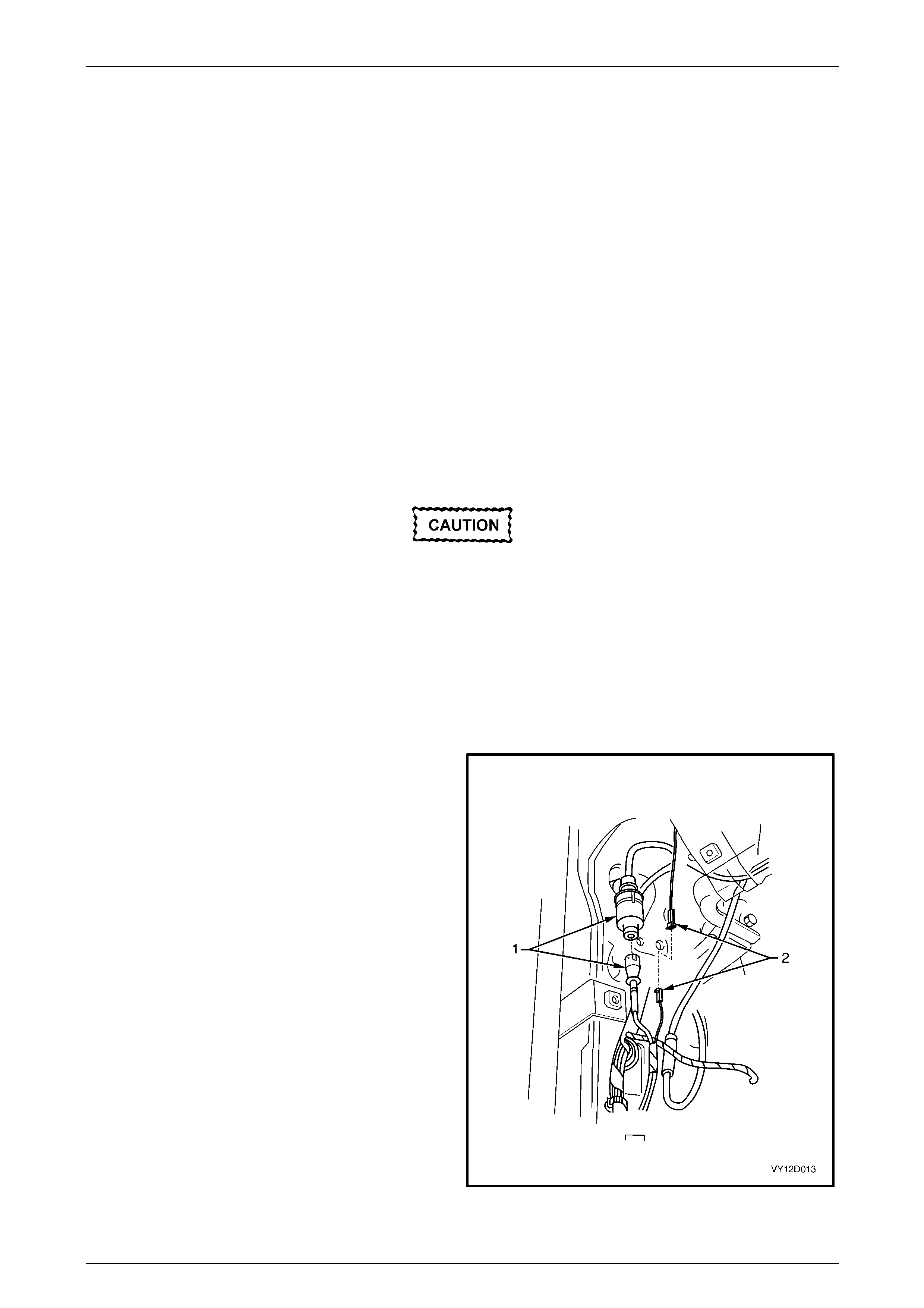
Entertainment System Page 12D–110
Page 12D–110
6.13 Diversity Antenna, Coupe
The diversity antenna is an integral part of the rear window assembly. The thin conductors that form the diversity antenna
are laid on the inside of the rear windo w glass in the same manner as the rear window heating elements.
A single terminal is located on the inside of the rear window glass, on the passenger side, to allow connection of the
diversity antenna to the div ersity antenna module, located under the rear parcel shelf trim.
The diversity antenna module amplifies the radio signal received b y the diversity antenna and transmits it to the audio
head unit via coaxial cable. NOTE
Due to the internal circuitry of the radio receiver,
if the main rear glass antenna is faulty or
disconnected, the radio may n ot use the diversity
antenna system for radio reception if the FM
signal is weak.
Test
1 Remove the left-hand side body rear corner garnish, refer to Section 1A8 Headlinin g and Interior Trim.
2 Disconnect the diversity antenna mod ule connector (4) from the diversity antenn a terminal,
refer to Figure 12D – 44.
3 Using a multimeter set to measure resistance, probe between the diversity antenna terminal and the diversity
antenna conductors on the ins ide of the rear window glass. Resistance should be less than 20 Ω from the diversity
antenna connector to any point on the div ersity antenna conductors.
Avoid using excessive force on the
multimeter probe, as damage to the diversity
antenna conductors will result.
Remove
1 Ensure the audio system is turned off.
2 Remove the following components:
a left-hand side body rear corner garn ish
b left-hand side body hinge pillar trim assembly
Refer to Section 1A8 Headlining and Interior Trim .
3 From behind the left-hand side hinge pillar trim
assembly, disconnect the diversity antenna module
coaxial cable (1) from the radio divers ity antenna
extension cabl e connector and the diversity antenna
module power cable (2) to wiring harness connector.
Refer to
Section 12O Fuses, Relays and Wiring Harnesses.
4 Remove the diversity antenna modul e leads from the
retaining clips and remove th e leads from the rocker
panel.
Figure 12D – 45
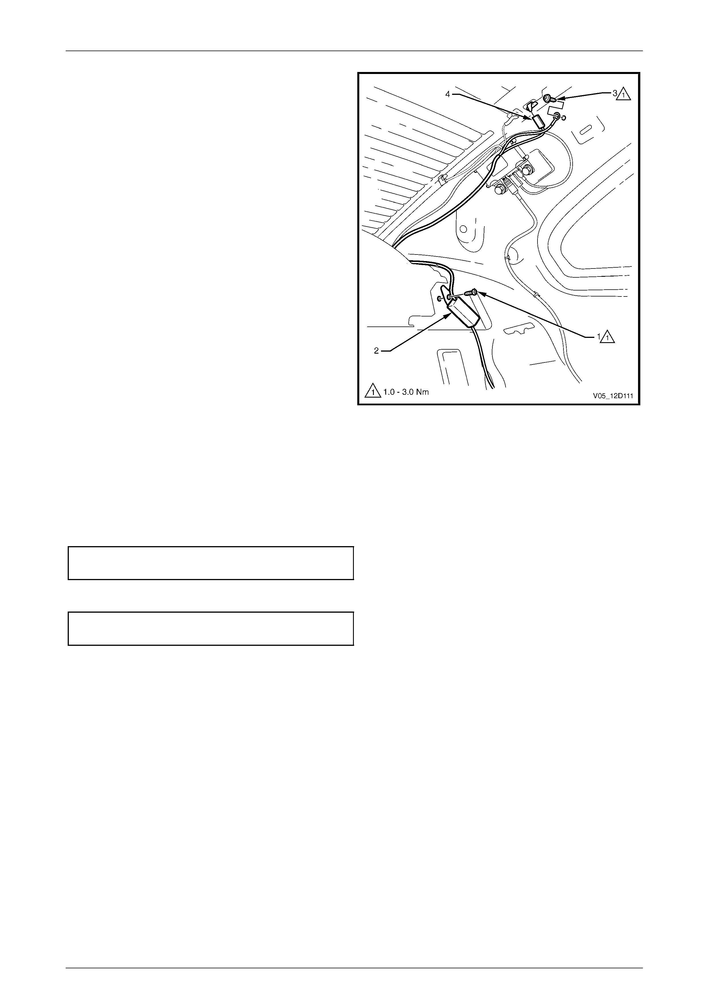
Entertainment System Page 12D–111
Page 12D–111
5 Remove the screw (1) securing the diversity antenna
amplifier (2) to the rear parcel shelf. Remove the
diversity antenna module and leads.
6 Remove the screw (3) securing the diversity antenna
ground terminal to the vehicle body.
7 Remove the diversity antenna modul e connector (4)
from the diversity antenna terminal l ocate d on the rear
window.
Figure 12D – 46
Reinstall
Reinstallation of the diversity antenna module is the reverse of the removal procedure, noting the following:
1 Ensure the mounting tab on the diversity antenna module is correctly engaged into the mounting slot on the rear
parcel shelf.
2 Tighten the diversity antenna module mounting screw to the correct torque specification.
Diversity antenna module mounting
screw torque specification...........................1.0 – 3.0 Nm
3 Tighten the diversit y antenna grounding screw to the correct torque specification.
Diversity antenna grounding
screw torque specification...........................1.0 – 3.0 Nm
4 After installing the diversity antenna connector, bend the tab in the directio n shown, refer to Figure 12D – 44.
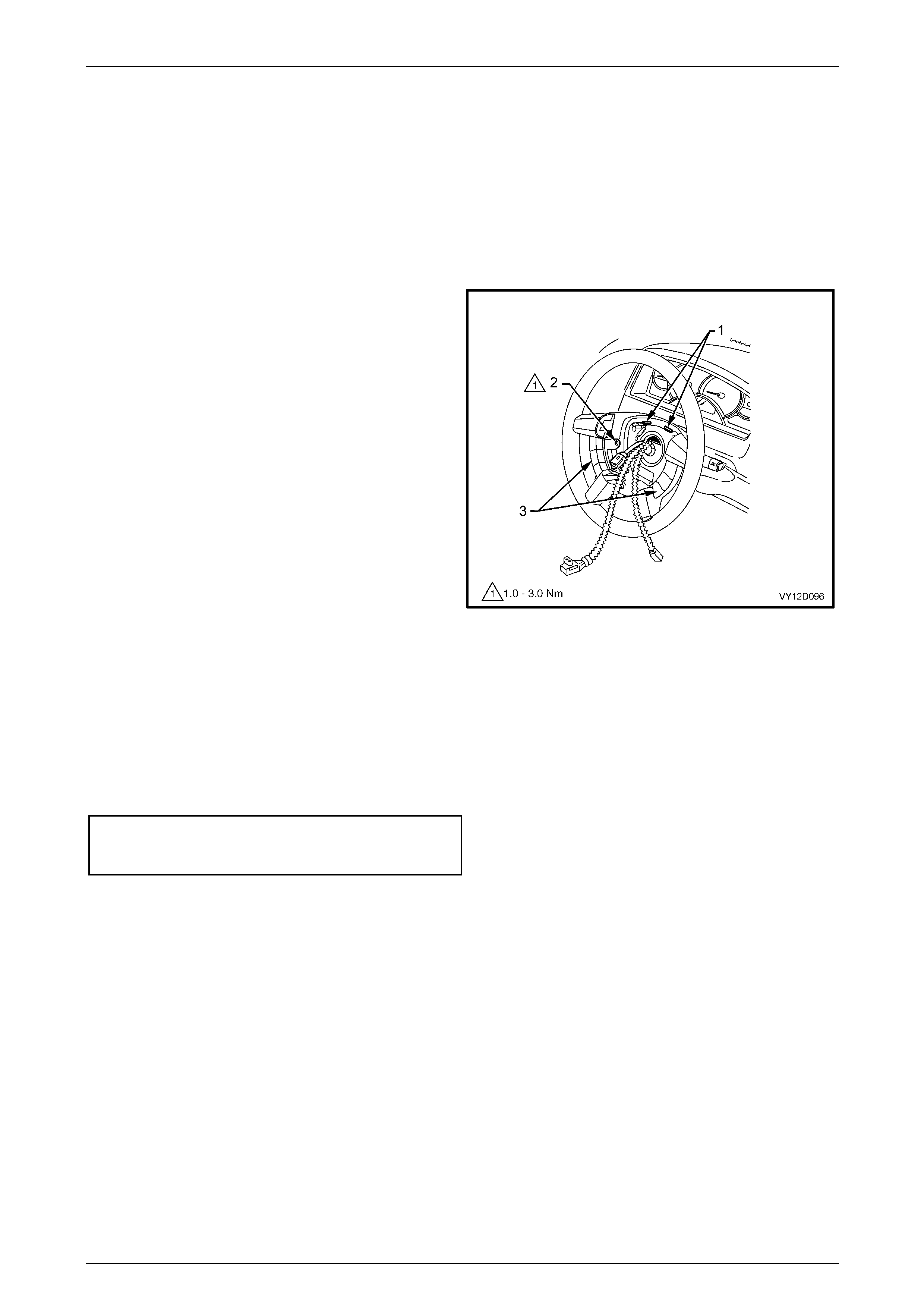
Entertainment System Page 12D–112
Page 12D–112
6.14 Radio Control Switch Assembly
LT Section No. — 09–440
Remove
1 Disable the Occupant Protection System (OPS), refer to Section 12M Occupant Protection System.
2 Remove the airbag assembly from the steering wheel, refer to Section 12M Occupant Protection S ystem.
3 Disconnect the radio control switch har ness (1) from
the steering column harness connector.
4 Remove the screw (2), four places, attaching the radio
control switch assembly (3) to the steering wheel and
remove the radio control switch assembly.
NOTE
The radio control switch assembly consists of
two switch blocks conn ected togeth er by a wiring
harness.
Figure 12D – 47
Reinstall
Reinstallation of the radio c ontrol switch assembly is the reverse of the removal proced ure, noting the following:
1 Ensure the stereo switch connectors seat correctly into the retaining clips on the steering wheel to avoid crushing
when the airbag is installed.
2 Tighten the screws attaching the radio control switch assembly to the steering wheel to the correct torque
specification.
Radio control switch assembly to
steering wheel attaching screw
torque specification.....................................1.0 – 3.0 Nm
3 Enable the OPS, refer to Section 12M Occupant Protection System.
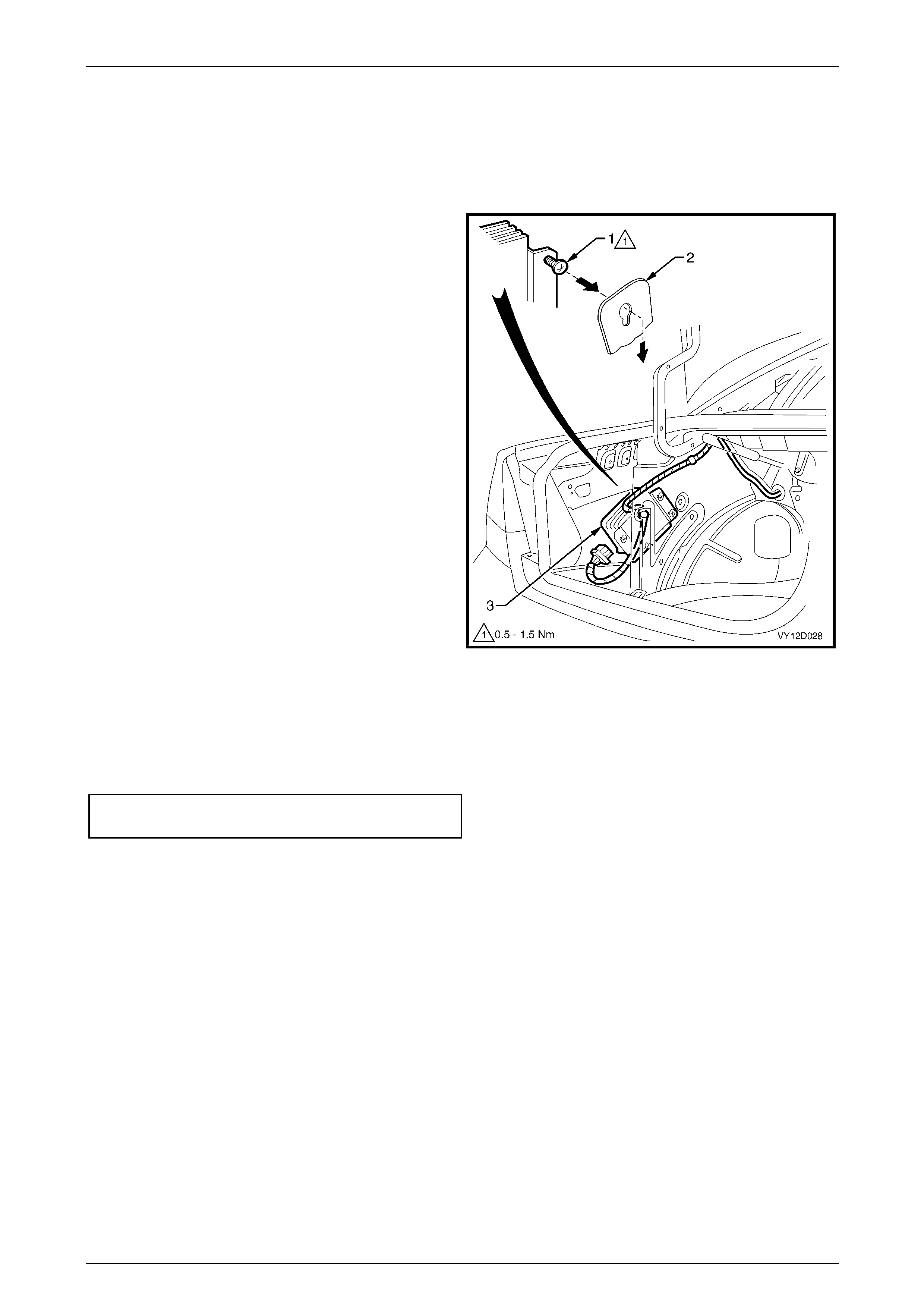
Entertainment System Page 12D–113
Page 12D–113
6.15 Subwoofer Amplifier
LT Section No. — 09–515
Remove
1 Ensure the audio system is turned off.
2 Open the rear compartment and remove the carpet,
refer to Section 1A8 Headlining and Interi or Trim.
3 Remove the trim retainer from the left-hand side of the
rear compartment wheelhouse carpet trim and remove
wheelhouse trim, refer to Section 1A1 Body.
4 Loosen the subwoofer amplifier retain ing screw (1),
four places, and slide the amplifier u pward to release
the screw heads from the slots in the inner side panel
(2).
NOTE
Sedan is shown. Location of Coupe subwoofer
amplifier is similar.
5 Withdraw the subwoofer amplifier assembly (3) from
the rear compartment.
6 Disconnect the side subwoofer amplifier assembly
harness connector.
Figure 12D – 48
Reinstall
Reinstallation of the subwoofer amplifier is the reverse of the removal procedure, noting the following:
1 Tighten the retaining screws to the correct torque specification.
Subwoofer amplifier retaining
screw torque specification...........................0.5 – 1.5 Nm
2 Check the operation of the sub woofer amplifier.
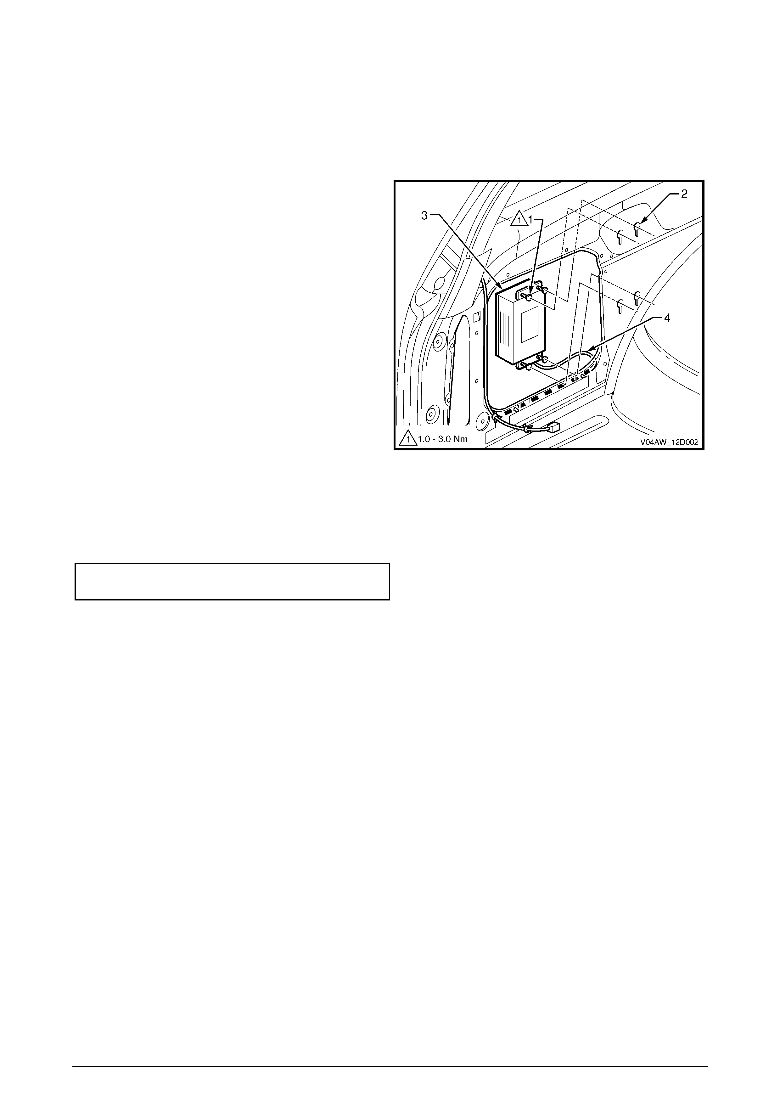
Entertainment System Page 12D–114
Page 12D–114
6.16 Subwoofer Amplifier, LX8 AWD Wagon
LT Section No. — 09–515
Remove
1 Remove the subwoofer speaker, refer to
6.7 Subwoofer Speaker, LX8 AWD Wagon.
2 Loosen the four screws (1) in the key-hole slots (2).
3 Slide the subwoofer amplifier (3) up and back and lift it
clear of the body panel.
4 Disconnect the connector (4) from the subwoofer
amplifier.
Figure 12D – 49
Reinstall
Reinstallation of the subwoofer amplifier is the reverse of the removal procedure. Tighten the subwoofer amplifier
retaining screws to the correct torque specification.
LX8 AWD Wagon Subwoofer amplifi er
retaining screw torque specification............1.0 – 3.0 Nm

Entertainment System Page 12D–115
Page 12D–115
6.17 Audio System Security Code
Code Entry
1 Switch the ignition on.
2 Switch the radio on.
3 The display shows 'CODE 1_ _ _ _ '.
4 Use the preset buttons to enter the PIN code.
Example:
If the PIN code belonging to the radio is 3651.
Press Button Display
Press preset button 3 3 _ _ _
Press preset button 6 3 6 _ _
Press preset button 5 3 6 5 _
Press preset button 1 3 6 5 1
If a wrong PIN code has been entered the display will show 'CODE ERROR WAIT'.
After the waiting time 'CODE 2 _ _ _ _' will be shown on the display indicating that this is the second attempt. The correct
code should now be entered. After three attempts the delay time will be 1 hour. The display will show 'LOCK OUT 1
HOUR'. After the delay time another three attempts at entering the co de will be possible.

Entertainment System Page 12D–116
Page 12D–116
6.18 Audio System Master Reset
Reset Procedure
The following procedure resets the audio syst em parameters to the factory default settings.
1 Switch the ignition on.
2 Switch the audio head unit off.
3 Press and hold the ON button and the Memor y Pres et Station 4 button for at least 2 seconds.
The following table details the audio system parameters and the factory default settings.
Parameter Range Default
Bass -6 to +6 STD (0)
Treble -6 to +6 STD (0)
Balance -6 to +6 STD (0)
Fader -6 to +6 STD (0)
Loudness On / Off On
Equaliser On / Off Off
CD Random On / Off Off
CD Repeat On / Off Off
Local / Distance Local / Distance Distance
Display Mode Clock Adjust / Time Time
Audio Distortion Limiter On / Off On
Confirmation Beeps On / Off On
Speed Dependent Volume 0 to 5 2

Entertainment System Page 12D–117
Page 12D–117
7 Specifications
7.1 Program Code Index Numbers
For code index specifications, refer to 4.8 Program – Audio System.
Audio System Code Index Chart
Vehicle Audio System
Code Index
Number
Executive Type 1 Entertainment System 007
Acclaim Type 2 Entertainment S ystem 007
Commodore SV6 and SV8 Type 1 Entertainment System 007
Commodore SS Type 3 Entertainment System 007
Berlina Type 3 Entertainment System 007
Utility Type 1 Entertainment System 009
Calais Type 4 Entertainment System 010
Coupe CV8 Type 4 Entertainment System 010
Regular Cab Type 1 Entertainment System 007
Crew Cab SS and Cross 8 Type 3 Entertainment System 007
CX8 AWD Wagon Type 3 Entertainment System 007
LX8 AWD Wagon Type 4 Entertainment System 007

Entertainment System Page 12D–118
Page 12D–118
8 Torque Wrench Specifications
Diversity Antenna Grounding Screw.................................................................... 1.0 – 3.0 Nm
Diversity Antenna Module Mounting Screw ......................................................... 1.0 – 3.0 Nm
Front Door Speaker Retaining Screw.................................................................. 1.0 – 3.0 Nm
Rear Door Speaker Retaining Screw................................................................... 1.0 – 3.0 Nm
Rear Quarter Speaker Retaining Screw .............................................................. 1.3 – 3.0 Nm
Subwoofer Speaker Retaining Screw.................................................................. 1.0 – 3.0 Nm
LX8 AWD Wagon Subwoofer Speaker Attaching Screw ..................................... 1.5 – 3.0 Nm
Speaker Mounting Box To Rear Parcel Shelf Retaining Screw........................... 1.0 – 3.0 Nm
Rear Parcel Shelf Speaker To Mounting Box Retaining Screw ........................... 1.5 – 3.0 Nm
Antenna Bracket To Inner Fender Panel Retaining Bolt.................................. 14.5 – 19.5 Nm
Antenna Ground Braid To Inner Fender Panel Retaining Scre w ......................... 1.0 – 3.0 Nm
Antenna Bracket Attaching Bolt........................................................................... 2.0 – 5.0 Nm
Antenna Assembly To Bracket Attaching Nuts.................................................. 5.0 – 12.0 Nm
Antenna Amplifier Module Mounting Screw......................................................... 6.0 – 8.0 Nm
Radio Control Switch Assembly To Steering Wheel Screw................................. 1.0 – 3.0 Nm
Subwoofer Amplifier Retaining Screw.................................................................. 0.5 – 1.5 Nm
LX8 AWD Wagon Subwoofer Amplifier Retaining Screw..................................... 1.0 – 3.0 Nm
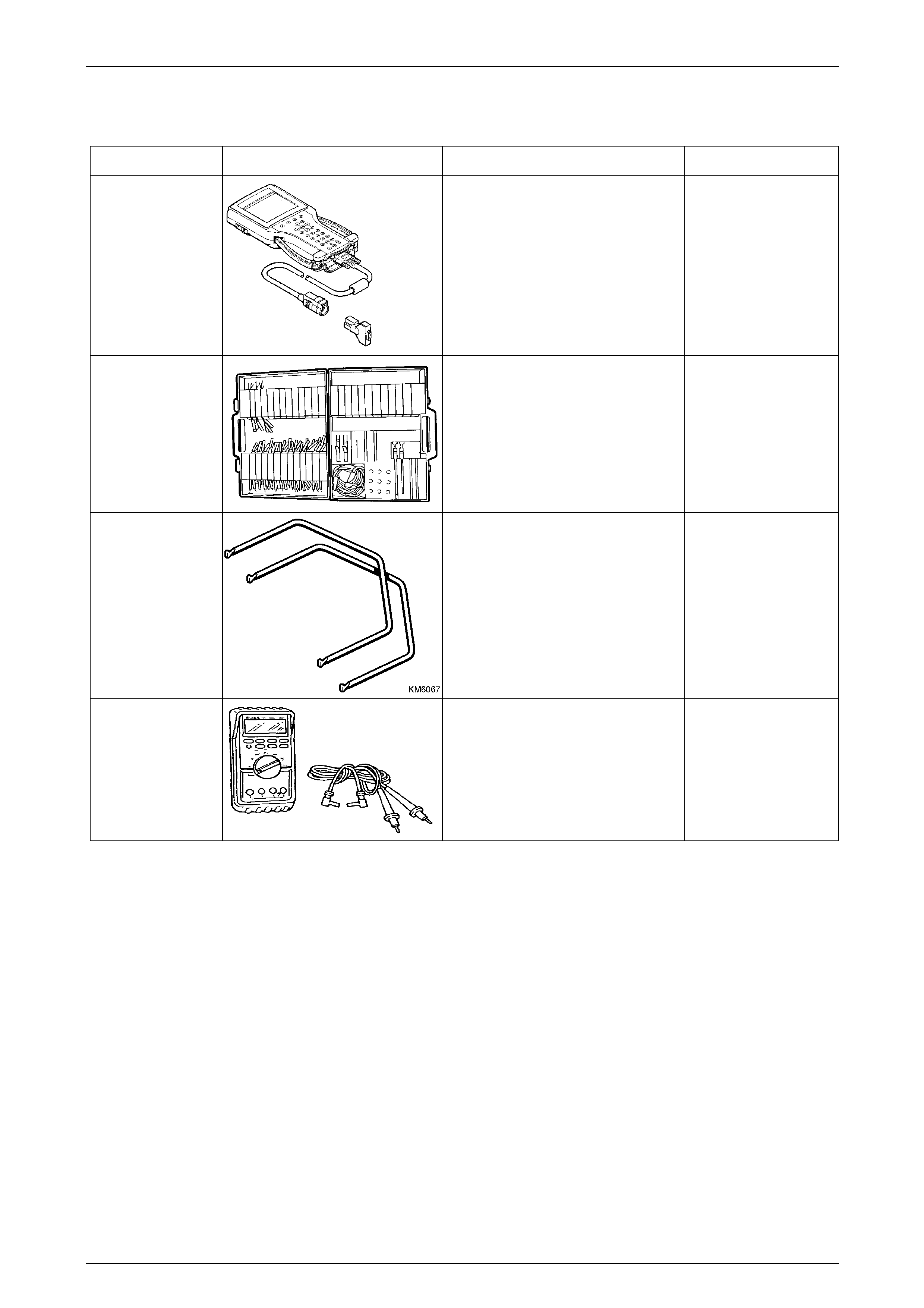
Entertainment System Page 12D–119
Page 12D–119
9 Special Tools
Tool Number Illustration Description Tool Classification
7000086I Tech 2
Diagnostic Scan Tool
Used for diagnosis of vehicle electrical
system.
Previously released.
Mandatory
J35616-A
(KM609)
Connector Test Adaptor Kit
Used when carrying out electric al
diagnostic circuit checks.
Previously released.
Desirable
KM6067 Radio Removal Tools
Used for removing the audio head
unit from it’s mounting location.
Previously released.
Mandatory
3588
(J39200)
Digital Multimeter
Must have at least 10 MΩ input
impedance and be capable of reading
frequencies.
Previously released.
Available