
Cruise Control Page 12E–1
Page 12E–1
Section 12E
Cruise Control
ATTENTION
Before performing any service operation or other procedure described in this Section, refer to Section 00
Warnings, Cautions and Notes for correct workshop practices with regard to safety and /or property damage.
1 General Information ...............................................................................................................................3
1.1 Components........................................................................................................................................................... 3
Components V6...................................................................................................................................................... 3
Cruise Control Switch Assembly........................................................................................................................ 4
Instrument Cluster Assembly ............................................................................................................................. 5
Clutch Pedal Switch (Manual Only).................................................................................................................... 5
Stop Lamp and BTSI Switch Assembly.............................................................................................................. 5
Cruise Control Release and Extended Brake Travel Switch Assembly.............................................................. 5
Powertrain Interface Module .............................................................................................................................. 5
Engine Control Module....................................................................................................................................... 5
Body Control Module (BCM) .............................................................................................................................. 5
Throttle Actuator Assembly ................................................................................................................................ 5
Components GEN III V8......................................................................................................................................... 6
Cruise Control Switch Assembly........................................................................................................................ 7
Instrument Cluster Assembly ............................................................................................................................. 7
Clutch Pedal Switch (Manual Only).................................................................................................................... 7
Stop Lamp and BTSI Switch Assembly.............................................................................................................. 7
Cruise Control Release and Extended Brake Travel Switch Assembly.............................................................. 7
Powertrain Interface Module (PIM)..................................................................................................................... 7
Throttle Actuator Control Module (TACM).......................................................................................................... 8
Body Control Module (BCM) .............................................................................................................................. 8
Powertrain Control Module (PCM)...................................................................................................................... 8
Throttle Actuator Assembly ................................................................................................................................ 8
1.2 System Operation – V6.......................................................................................................................................... 9
Preliminary Information......................................................................................................................................... 9
Enabled and Disabled........................................................................................................................................ 9
Activated and Deactivated................................................................................................................................ 10
Engaging the Cruise Control .............................................................................................................................. 10
Brake Before Cruise ............................................................................................................................................ 10
Activating the Cruise Control ............................................................................................................................. 11
Deactivating the Cruise Control ......................................................................................................................... 11
Pressing the Brake Pedal................................................................................................................................. 11
Pressing the Cruise ON–OFF Button............................................................................................................... 11
Pressing the Clutch Pedal (Manual Vehicles Only).......................................................................................... 11
Decelerating While Cruise Control is Activated................................................................................................ 11
Resuming a Speed After Cruise Control Has Been Deactivated ..................................................................... 11
Accelerating While Cruise Control is Activated................................................................................................ 11
Using the Cruise Control Switch Assembly ...................................................................................................... 11
Pressing the Accelerator Pedal........................................................................................................................ 11
1.3 System Operation – GEN III V8........................................................................................................................... 12
Preliminary Information....................................................................................................................................... 12
Enabled and Disabled...................................................................................................................................... 12
Activated and Deactivated................................................................................................................................ 13
Engaging the Cruise Control .............................................................................................................................. 13
Brake Before Cruise ............................................................................................................................................ 13
Activating the Cruise Control ............................................................................................................................. 14

Cruise Control Page 12E–2
Page 12E–2
Deactivating the Cruise Control ......................................................................................................................... 14
Pressing the Brake Pedal................................................................................................................................. 14
Pressing the Cruise ON–OFF Button............................................................................................................... 14
Pressing the Clutch Pedal (Manual Vehicles Only).......................................................................................... 14
Decelerating While Cruise Control is Activated................................................................................................ 14
Resuming a Speed After Cruise Control Has Been Deactivated ..................................................................... 14
Accelerating While Cruise Control is Activated................................................................................................ 14
Using the Cruise Control Switch Assembly ...................................................................................................... 14
Pressing the Accelerator Pedal........................................................................................................................ 14
2 Diagnostics...........................................................................................................................................15
2.1 Diagnostic General Information.......................................................................................................................... 15
Basic Knowledge Required................................................................................................................................. 15
Basic Diagnostic Tools Required....................................................................................................................... 15
Tech 2 Data List – V6........................................................................................................................................... 16
Tech 2 Data List – Gen III V8............................................................................................................................... 16
2.2 Diagnostic Systems Check................................................................................................................................. 17
Diagnostic Systems Check – V6......................................................................................................................... 17
Diagnostic Systems Check – Gen III V8............................................................................................................. 17
2.3 Wiring Diagrams and Connector Charts............................................................................................................ 18
Wiring Diagram – V6............................................................................................................................................ 18
Connector Chart – V6 .......................................................................................................................................... 19
Wiring Diagram – GEN III V8 ............................................................................................................................... 20
Connector Chart – Gen III V8 .............................................................................................................................. 22
2.4 Cruise Control Inoperative / Malfunctioning – V6............................................................................................. 23
Circuit Description............................................................................................................................................... 23
Manual Vehicles Only.......................................................................................................................................... 23
Test Description................................................................................................................................................... 23
Diagnostic Table Notes ....................................................................................................................................... 23
Diagnostic Table.................................................................................................................................................. 24
2.5 Cruise Control Inoperative / Malfunctioning – GEN III V8 ................................................................................ 29
Circuit Description............................................................................................................................................... 29
Manual Vehicles Only.......................................................................................................................................... 29
Test Description................................................................................................................................................... 29
Diagnostic Table Notes ....................................................................................................................................... 29
Diagnostic Table.................................................................................................................................................. 30
3 Service Operations...............................................................................................................................35
3.1 Cruise Control Switch Assembly........................................................................................................................ 35
Remove................................................................................................................................................................. 35
Test ....................................................................................................................................................................... 35
Terminal Testing............................................................................................................................................... 35
Reinstall................................................................................................................................................................ 35
3.2 Stop Lamp and BTSI Switch Assembly ............................................................................................................. 36
Remove................................................................................................................................................................. 36
Test ....................................................................................................................................................................... 37
Reinstall................................................................................................................................................................ 37
3.3 Cruise Control Release and Extended Brake Travel Switch Assembly.......................................................... 38
Remove................................................................................................................................................................. 38
Test ....................................................................................................................................................................... 39
Reinstall................................................................................................................................................................ 39
3.4 Clutch Pedal Switch............................................................................................................................................. 40
Remove................................................................................................................................................................. 40
Test ....................................................................................................................................................................... 40
Reinstall................................................................................................................................................................ 41
4 Special Tools ........................................................................................................................................42

Cruise Control Page 12E–3
Page 12E–3
1 General Information
A new cruise control system has been introduced due to changes in the powertrain architecture and c omponents. There
is no longer a cruise control modu le, instead the management has been taken over by the engine controllers; engine
control module (ECM) for V6 and powertrain control module (PCM) for GEN III V8. The powertrain interface module
(PIM) and throttle actuator control module (TACM) (GEN III V8 only) also have important roles in the cruise control
system.
To the user, the system operates as previously, with all controls through the cruise control switch assembly and cruise
control messages presented through the instrument cluster. For vehicles fitted with the V6 refer to
1.2 System Operation – V6; for V8 vehicles refer to 1.3 System Operation – GEN III V8.
The cruise control system now has an
additional fail safe feature. The brake pedal
must be pressed in the ignition cycle for the
cruise control to be engaged. The cruise
control will not engage until this is done.
1.1 Components
Components V6
The main components of the electronic cruise control s ystem are:
• cruise control switch assembly (incorporated into the turn signal switch assembly),
• instrument cluster assembly,
• clutch pedal position s witch assembly (manual transmission vehicles only),
• stop lamp and BTSI switch assembly,
• cruise control release and extended brake travel switch assembly,
• powertrain interface module (PIM),
• engine control module (ECM),
• body control module (BCM)
• throttle actuator assembly, and
• electrical wiring (incorporate d into the main wiring harness).
Cruise Control Page 12E–4
Page 12E–4
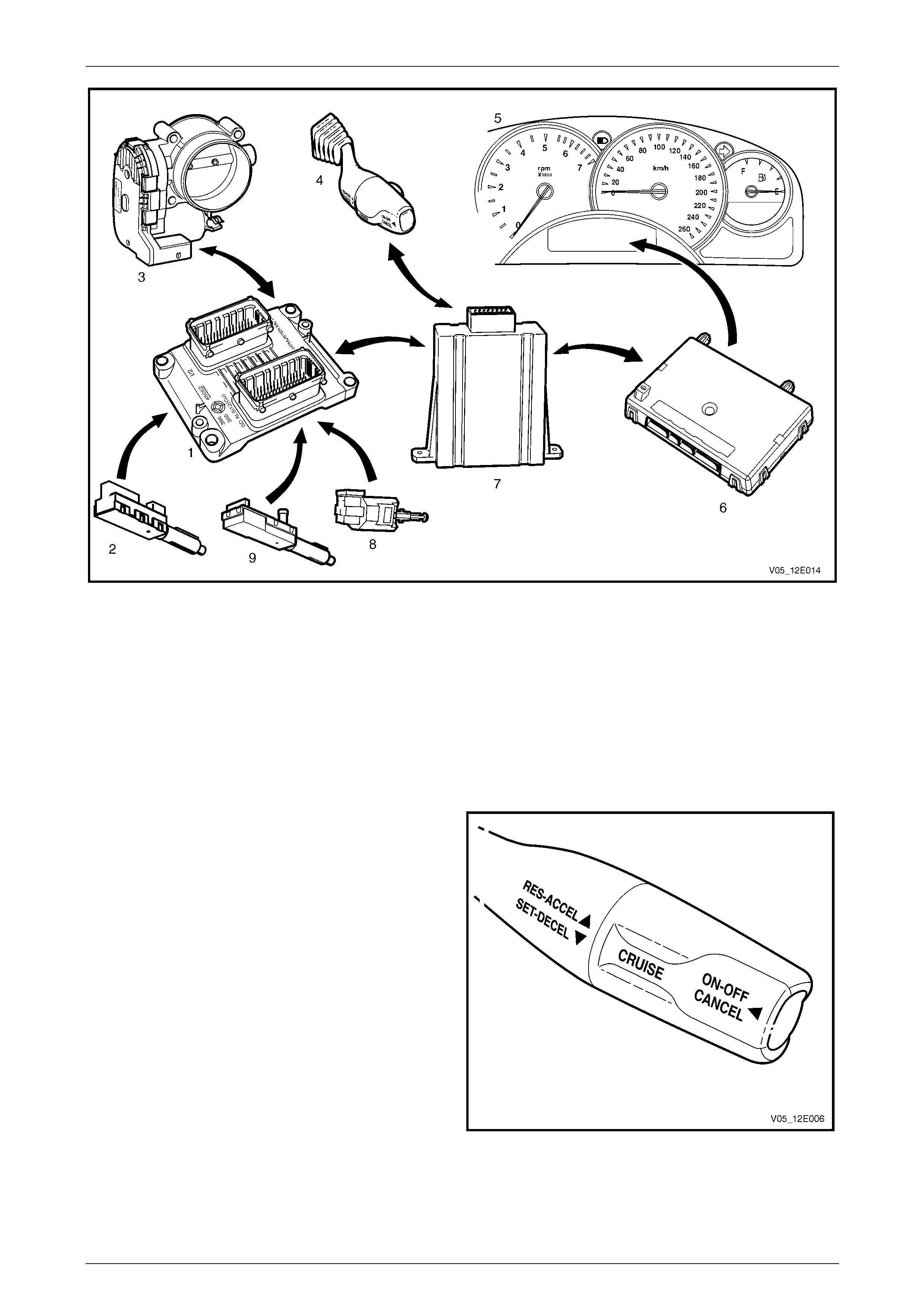
Figure 12E – 1
Legend
1 Engine Control Module
2 Stop Lamp and BTSI Switch Assembly
3 Throttle Actuator Assembly
4 Cruise Control Switch Assembly
5 Instrument Cluster Assembly
6 Body Control Module
7 Powertrain Interface Module
8 Clutch Pedal Position Switch Assembly (Manual Only)
9 Cruise Control Release and Extended Brake Travel Switch
Assembly
Cruise Control Switch Assembly
The cruise control switch assembly is located on the end of
the turn signal switch assembly.
• For harness routing from the cruise control switch
assembly to the powertrain interface module, refer to
Section 12O Fuses, Relays and Wiring Harnesses.
• For wiring and to see how the switch integrates into
the system, refer to Wiring Diagram – V6.
Figure 12E – 2

Cruise Control Page 12E–5
Page 12E–5
Instrument Cluster Assembly
The instrument cluster assembly displa ys the status of the cruise control system as well as other information through its
multi–function display an d warning indicators. Refer to Section 12C Instrumentatio n for further information.
Figure 12E – 3
Clutch Pedal Switch (Manual Only)
There are two clutch pedal switch assem blies, however only one has input to the cruise control system. It is the switch
assembly facing away from the firewall, attached to the clutch pedal support. This switch is normally closed when the
clutch pedal is at rest, opening when the pedal is pressed. Activation of this switch removes the signal to the ECM which
will then deactivate the cruise control.
Stop Lamp and BTSI Switch Assembly
The stop lamp and BTSI s witch assembly is located on the brake pedal support. The function of the switch assembly in
the cruise control system is to deactivate the cruise control when the brake pedal is pr essed. The stop lamp switch is a
normally open switch with the brake pedal at rest; the BTSI a normally closed s witch. The BTSI switch does not have any
control over the cruise control system.
Cruise Control Release and Extended Brake Travel Switch Assembly
The cruise control release and extended brake travel switch assembly is located on the brake ped al su pport. The
function of the switch assembly in the cruise control system is to deactivate the cruise control when the brake pedal is
pressed. Both switches are normally closed when the brake pedal is at rest.
Powertrain Interface Module
The Powertrain Interface Module (PIM) is located on the ins trument pan el driver’s outer bracket. The purpose of the PIM
is to act as an interface between the drivetrai n seria l data bus (GMLAN protocol) and the body side data bus (UART Bus
protocol). All inputs from the cruise control switch assembly are directly wired to the PIM. The PIM then takes these
inputs, converts them to GMLAN protocol and transmits the messages through the data bus to the engi ne control module
(ECM). The PIM also receives signals for the cruise control system from the ECM. When the ECM activates cruise
control, it sends a signal through the PIM (which converts it from GMLAN to UART protocol) to display the various cruise
control messages on the instrument cluster assembly.
For further information on the operation of the PIM, refer to Section 6E1 Powertrain Interface Module – V6.
Engine Control Module
The Engine Control Module (ECM) is mounted on the front of the engine. The role of the ECM is to receive all the i np uts
from various sensors (vehicle speed (VSS) etc.) and switches to manage the engine. When a request is sent to from the
cruise control switch assembly via the PIM to the ECM, the ECM will activate cruise control providing given parameters
are satisfied. Once the cruise is set, the ECM monitors the vehicle speed a nd controls the throttle actuator assembly thus
controlling the spee d of the vehicle.
For further information on the operation of the ECM,
refer to Section 6C1-1 Engine Management – V6 – General Information.
Body Control Module (BCM)
The BCM is lo cated be neath the i nstrumen t cluster t o the right of the st eering colu mn. The role of the body control
module (BCM) in the cruise control system, is to act as bus master.
For further information on the operation of the BCM, refer to Section 12J Body Control Module.
Throttle Actuator Assembly
The throttle actuator assembly is located on the front of the inlet manifold. The throttle actuator assembly receives
signals from the ECM and controls the angle of the throttle plate.
Refer to Section 6C1-1 Engine Management – V6 – General Information for further information.
Cruise Control Page 12E–6
Page 12E–6
Components GEN III V8
The main components of the electronic cruise control s ystem are:
• cruise control switch assembly (incorporated into the turn signal switch assembly),
• instrument cluster assembly,
• clutch pedal position s witch assembly (manual transmission vehicles only),
• stop lamp and BTSI switch assembly,
• cruise control release and extended brake travel switch assembly,
• powertrain interface module (PIM),
• body control module (BCM),
• powertrain control module (PCM),
• throttle actuator control module (TACM)
• throttle actuator assembly, and
• electrical wiring (incorporate d into the main wiring harness).
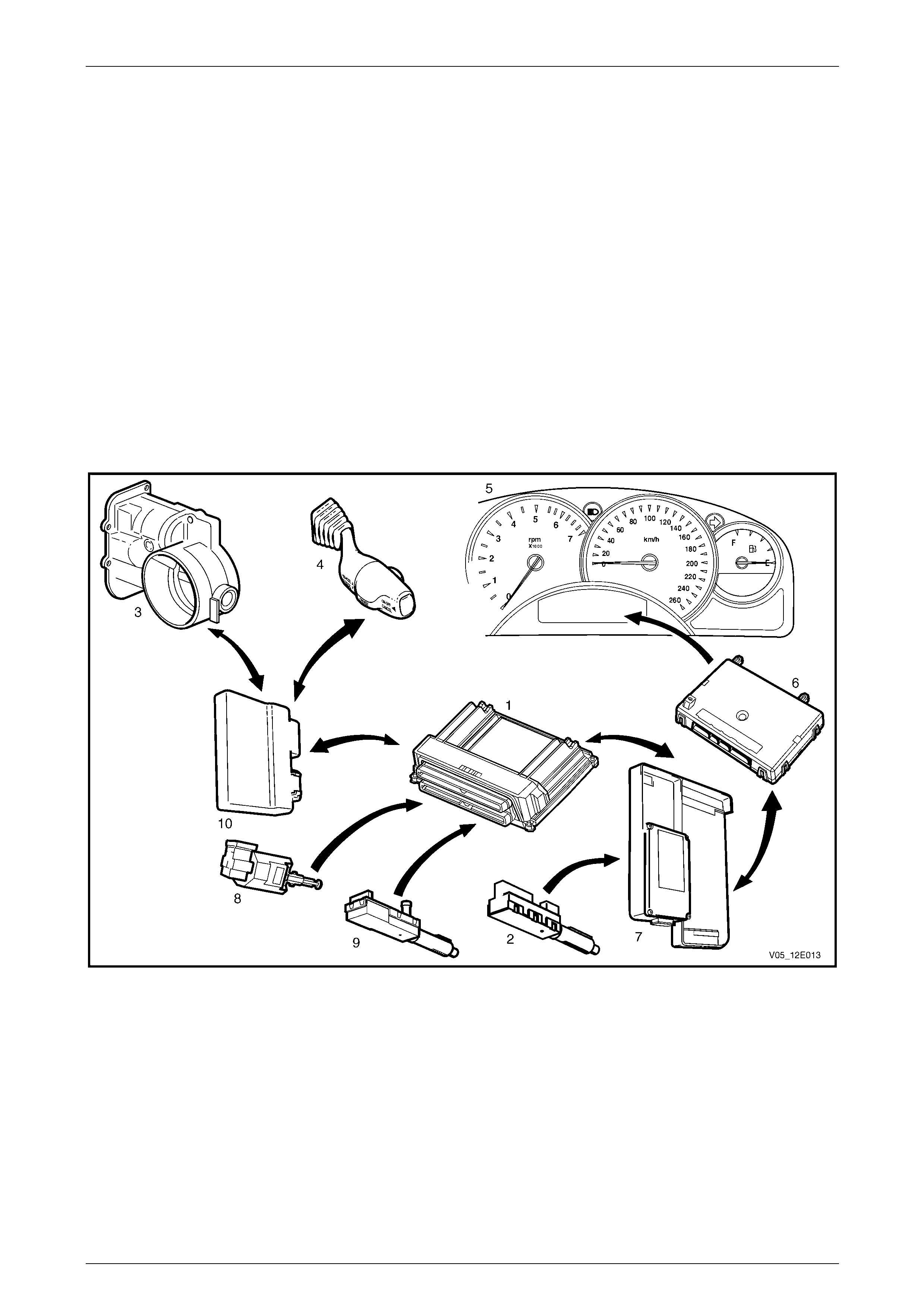
Figure 12E – 4
Legend
1 Powertrain Control Module
2 Stop Lamp and BTSI Switch Assembly
3 Throttle Actuator Assembly
4 Cruise Control Switch Assembly
5 Instrument Cluster Assembly
6 Body Control Module
7 Powertrain Interface Module
8 Clutch Pedal Position Switch Assembly (Manual Only)
9 Cruise Control Release and Extended Brake Travel Switch
Assembly
10 Throttle Actuator Control Module
Cruise Control Page 12E–7
Page 12E–7
Cruise Control Switch Assembly
The cruise control switch assembly is located on the end of
the turn signal switch assembly.
• For harness routing from the cruise control switch
assembly to the powertrain interface module, refer to
Section 12O Fuses, Relays and Wiring Harnesses.
• For wiring and to see how the switch integrates into
the system, refer to Wiring Diagram – GEN III V8.
Figure 12E – 5
Instrument Cluster Assembly
The instrument cluster assembly displa ys the status of the cruise control system as well as other information through its
multi–function display an d warning indicators. Refer to Section 12C Instrumentatio n for further information.
Figure 12E – 6
Clutch Pedal Switch (Manual Only)
The clutch pedal s witch assembl y is attached to the clutch pedal support. This switch is normally closed when the clutch
pedal is at rest, opening when the pedal is pressed. Activation of this switch removes the signal to the PCM which will
then deactivate the cruise control.
Stop Lamp and BTSI Switch Assembly
The stop lamp and BTSI s witch assembly is located on the brake pedal support. The function of the switch assembly in
the cruise control system is to deactivate the cruise control when the brake pedal is pr essed. The stop lamp switch is a
normally open switch with the brake pedal at rest; the BTSI a normally closed s witch. The BTSI switch does not have any
control over the cruise control system.
Cruise Control Release and Extended Brake Travel Switch Assembly
The cruise control release and extended brake travel switch assembly is located on the brake ped al su pport. The
function of the switch assembly in the cruise control system is to deactivate the cruise control when the brake pedal is
pressed. Both switches are normally closed when the brake pedal is at rest.
Powertrain Interface Module (PIM)
The Powertrain Interface Module (PIM) is located on the ins trument pan el driver’s outer bracket. The purpose of the PIM
is to act as an interface between the po wertrain serial data bus (Class 2 protocol) and the body side data bus (UART Bus
protocol). The ON–OFF input from the cruise control switch assembly is dir ectly wired to the PIM. When the PIM receives
this input from the switch assembly, it sends a 12 volt signal to the throttle actuator control module (T ACM). The purpose
of the PIM in this case is to take a momentary input and provide a constant signal. The PIM also receives signals for the
cruise control system from the PCM. When the PCM activates cruise control, it sends a signal through the PIM (which
converts it from Class 2 to UART protocol) to activate the various messages on the instrument cluster.
For further information on the operation of the PIM, refer to Section 6E3 Powertrain Interface Module – GEN III V8.

Cruise Control Page 12E–8
Page 12E–8
Throttle Actuator Control Module (TACM)
The throttle actuator control module (TACM) is located behind the left-hand hinge pillar trim assembly. The purpose of
the TACM is to provide additional functionality due to the introducti on of the electronic throttle actuator. The TACM
receives the following direct inputs from the cruise control switch assembly:
• SET-DECEL,
• RES-ACCEL.
The TACM also receives an input from the PIM when the cruise control has been Enabled / Disabled. The T A CM
converts any signals received from the cruise control switch assembly into Class 2 protocol and transmits them to the
powertrain control module. Connected to the TAC module are electrical inputs from the accelerator pedal assembly and
the throttle actuator assembly. The TACM receives commands from the PCM and controls the throttle actuator assembly.
For further information on the TACM,
refer to Section 6C3-1 Powertrain Management – GEN III V8 – General Information.
Body Control Module (BCM)
The BCM is lo cated be neath the i nstrumen t cluster t o the right of the st eering colu mn. The role of the body control
module (BCM) in the cruise control system, is to act as a bus master.
For further information on the operation of the BCM, refer to Section 12J Body Control Module.
Powertrain Control Module (PCM)
The role of the powertrain control module (PCM) in the cruise control system is to receive the various inputs required to
maintain the correct speed and then control the throttle plate, via the TACM, depending on the load on the engine
(ascending or descending hill s, etc).
For further information on the PCM, refer to Section 6C3-1 Powertrain Management – GEN III V8 – General Information.
Throttle Actuator Assembly
The throttle actuator assembly is located on the front of the inlet manifold. T he throttle actuator assembly controls the
angle of the throttle plate in response to signals from the TACM.
For further information refer to Section 6C3-1 Powertrain Management – GEN III V8 – General Information.
Cruise Control Page 12E–9
Page 12E–9
1.2 System Operation – V6
Preliminary Information
Enabled and Disabled
The cruise control is enabled / disabled by pressing the cruise control switch assembly ON–OFF button. When cruise
control is enabled, the instrument cluster displays Cruise Enabled and the cruise control is ready for a speed to be set
(cruise control activated). When the cruis e control is d isabled, the cruise control cannot be activated.
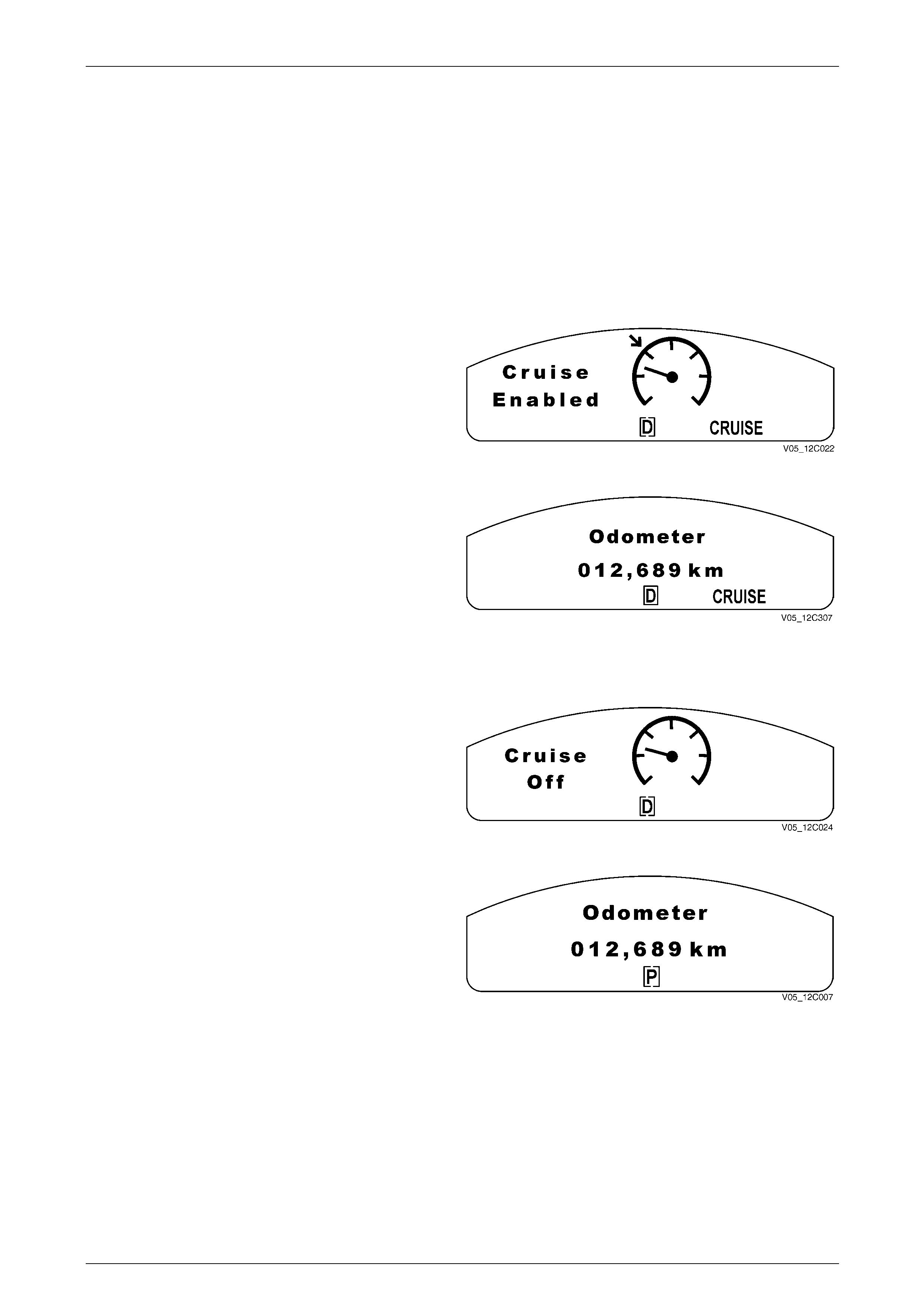
Cruise Enabled
1 When the instrument cluster receives the Cruise ON
signal from the ECM via the body control module
(BCM), the CRUISE icon illuminates and the Cruise
Enabled anima tion is displayed for 2 seconds.
2 The animation is shown initially with the set arrow
flashing.
Figure 12E – 7
After 2 seconds the animated display extinguishes and the
CRUISE icon remains. The display rev erts back to the
previously displayed trip computer screen.
Figure 12E – 8
Cruise Disabled
When Cruise Control is disabl ed, the CRUISE icon
extinguishes immediately and the Cruise Off animation is
displayed for 2 seconds.
Figure 12E – 9
After 2 seconds the animated display extinguishes, and the
display reverts back to the previously displayed trip
computer screen.
Figure 12E – 10

Cruise Control Page 12E–10
Page 12E–10
Activated and Deactivated
When the cruise control is enabled, the vehic le speed is above 40 km/h and the cruise control switch assembly is turned
to SET–DECEL, the cruise control will be activated and the vehicle will maintain the set speed. When deactivated by the
methods described within this section, the vehicle will no longer maintain the set speed, but the cruise control will still be
engaged.
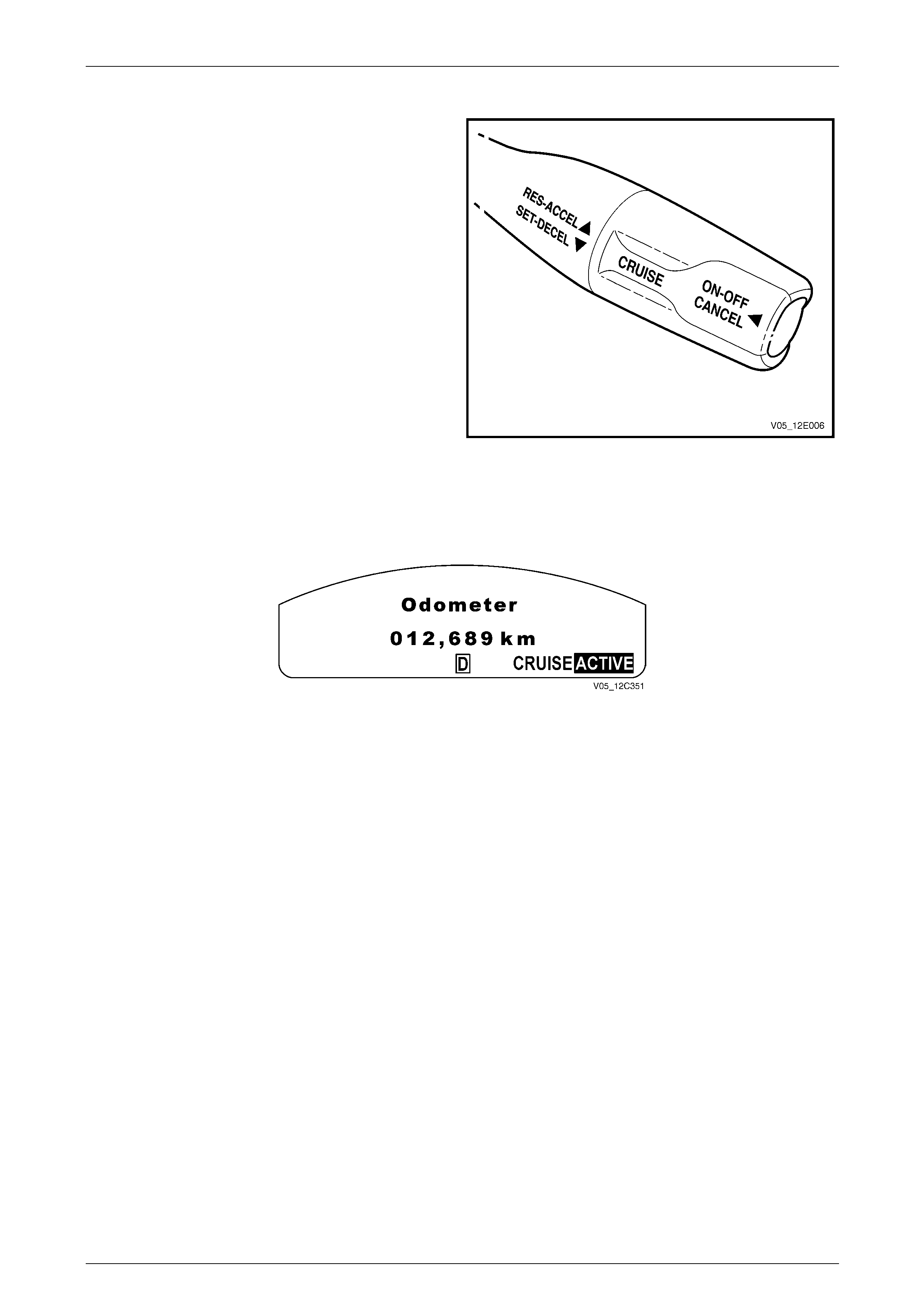
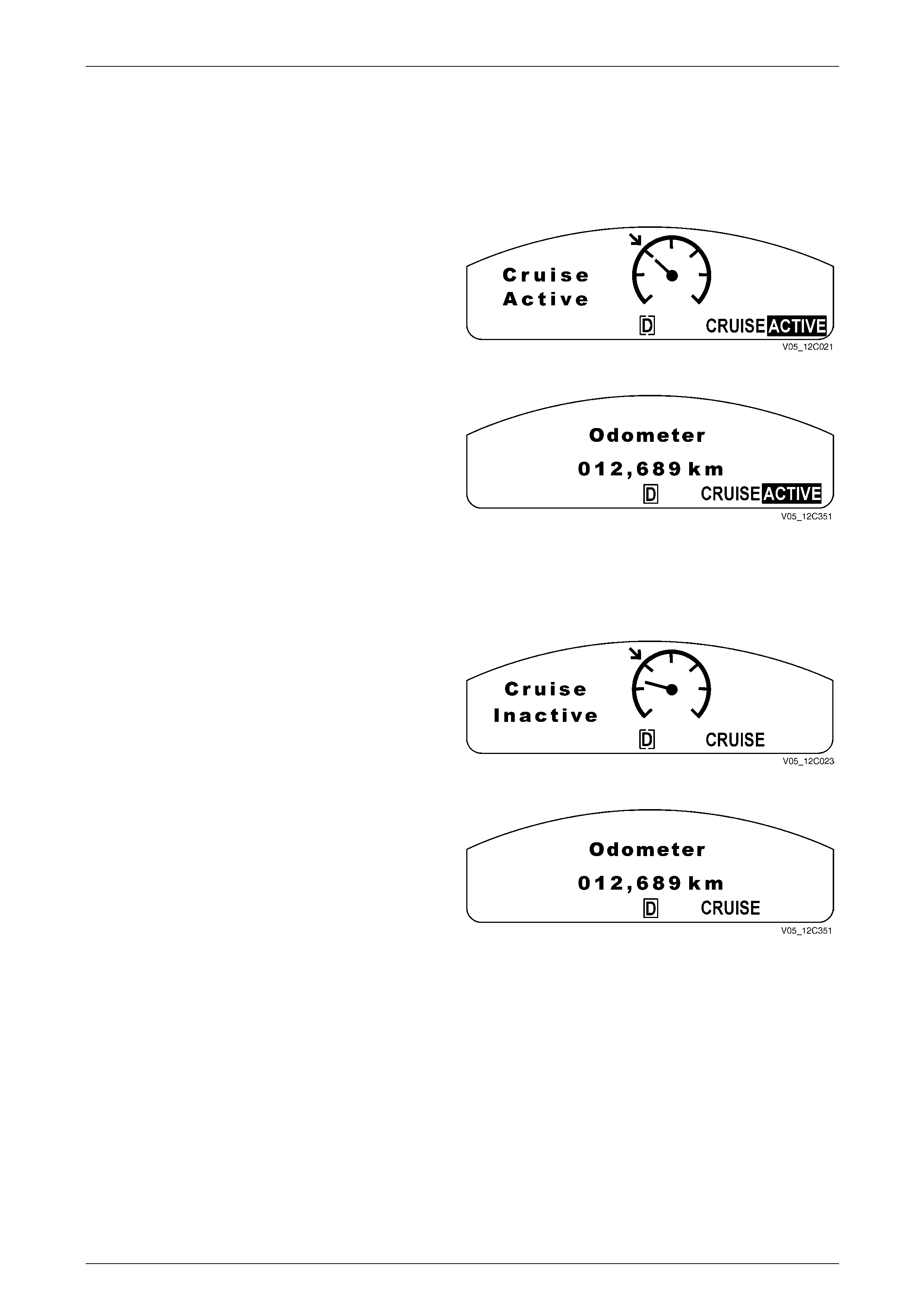
Cruise Active
When the cruise control is activated via the cruise control
switch assembly, the highlighted ACTIVE icon illuminates
and the Cruise Active animation is disp layed for 2 seconds.
The animation is shown initially with speedometer needle
moving toward the set arrow.
Figure 12E – 11
After 2 seconds the animated display extinguishes, the
CRUISE icon, and the highlighted ACTIVE icon remain, the
display reverts to the previous ly displayed trip computer
screen.
Figure 12E – 12
Cruise Deactivated
Upon receiving a signal to deactivate the cruise control the ECM then provides a signal for the instrument cluster, via the
PIM, to inform the user the cruise control is Deactivated.
When the cruise control is deactivated via the cruise control
switch assembly, the brake pedal, or the clutch ped al, the
highlighted ACTI VE icon extinguishes immediately and the
Cruise Inactive animation is displayed for 2 seconds.
Figure 12E – 13
After 2 seconds the animated display extinguishes and the
CRUISE icon remains. The display rev erts back to the
previously displayed trip computer screen.
Figure 12E – 14
Engaging the Cruise Control
Refer to Wiring Diagram – V6 for the following description.
When the ON-OFF button is pressed, 12 V i s applied to the powertrain interface module (PIM) connecto r A5 – X1 pin 4
(circuit 397). This informs the PIM the user has requested the cruise contr ol functio n be engaged or disengage d. This
signal is then output by the PIM as GM LAN protocol along the bus to the engine control modu le (ECM). The ECM
recognises the command from the PIM to engage the cruise control. The ECM then provides a signal for the instrument
cluster, via the PIM, to inform the user the cruise control is engaged.
Brake Before Cruise
Before the cruise control can be activated the driver must have ap plied the brakes and the system received a valid
response at least once per ignition cycle. If the driver manages to drive the vehicle without having used the brakes bef ore
pressing the ON–OFF button, the cruise control can not be activated.

Cruise Control Page 12E–11
Page 12E–11
Activating the Cruise Control
The user activates the cruise control at a desired speed above 40 km/h by rotating the cruise control switch assembly to
SET–DECEL. This provides a 12 V signa l to the PIM through connector A5 – X1 pin 9 (circuit 84). The PIM then outputs
this signal as GM LAN protocol through the data bus to the ECM. If the ECM already has cruise control engaged, upon
receipt of the message from the PIM, the ECM will activate cruise control and set the speed. The ECM receives all the
various inputs required to maintain the correct speed and then controls the throttle plate dependin g on the load on the
engine (ascending or desc en ding hills, etc).
Deactivating the Cruise Control
When the cruise control is activated, it can be deactivated by any of the following:
Pressing the Brake Pedal
When the brake pedal is pr essed, two signals are sent directly to the ECM by the circuits from the brake pedal switch
assembly. The cruise cancel circuit (circuit 86 ) will open (normally closed) thus dropping the supply voltage from the
ECM connector A43 – X2 pin 46. Simultaneo usl y, the stop lamp circuit (circuit 20) will close (normally open) a nd supply
12 V to the ECM at connector A43 – X2 pin 10. This is a double redundancy system so that if either switch or circuit from
the brake pedal switch assembly fails, the cruise control will still be deactivated.
Pressing the Cruise ON–OFF Button
Pressing the cruise control switch assembly ON–OFF button will send a si gnal through the PIM to the ECM to deactivate
the cruise control.
Pressing the Clutch Pedal (Manual Ve hicles Only)
When the clutch pedal is pressed, the cruise control cancel 2 circuit (circuit 379) will open (normally close d) thus
dropping the supply voltage from the ECM connector A43 – X2 pin 53. The ECM then deactivates the cruise control.
Decelerating While Cruise Control is Activated
When the cruise control is activated, the speed can be reduc ed by turning and holding the cruise control switch assembly
to SET–DECEL. When this is done, 12 V is applied to PIM connector A5 – X1 pin 9 (circuit 84). The PIM will then
translate the command to GM LAN protocol and transmit the request to the ECM to reduce the speed. The ECM will then
temporarily disabl e the cruise control and close the throttle plate. The vehicle should then start to decele rate. Once the
operator releases the cruise c ontrol switch assembly, the ECM will receive this signal through the PIM an d will then set
the speed according to the curr ent VSS and maintain that speed.
Resuming a Speed After Cruise Control Has Been Deactivated
If the cruise control system is engaged but deactivated, the last spee d at which it was activated can be resumed. Turning
the cruise control switch assembly to RES–A CCEL will apply 12 V to the PIM at connector A5 – X1 pin 8 (circuit 87). The
PIM will then translate the command to GM LAN protocol and transmit the request to the ECM. The ECM will then rec all
the last stored speed at which the cruise control was activated and increase or reduce engine power to maintain that
speed.
Accelerating While Cruise Control is Activated
Using the Cruise Control Switch Assembly
When the cruise control is active, rotating the cruise control switch assembly to RES–A CCEL will accelerate the vehicle.
The cruise control s witch assembly will supply a 12 V signal to the PIM connector A5 – X1 pin 8 (circuit 87), which is
continuous as long as the switch is held. While the PIM is receiving the 12 V signal, it will continuously transmit to the
ECM to accelerate the vehicle. The ECM will open the throttle plate to accelerate the vehicle. When the de sired speed is
achieved and the cruise control switch assembly is released, the ECM will maintain the vehicle at that speed.
Pressing the Accelerator Pedal
When the cruise control is active, pressing the accelerator pedal will accelerate the vehicle.
Once pressure is removed from the accelerator pedal, the vehicle will return to the last stored speed at which the cruise
control was activated and control the throttle plate to maintain that speed.

Cruise Control Page 12E–12
Page 12E–12
1.3 System Operation – GEN III V8
Preliminary Information
Enabled and Disabled
The cruise control is enable d / disab led by pressing the ON–OFF button. When cruise control is enabled, the instrument
cluster displays Cruise Enabled and the cruise control is ready for a speed to be set (cruise control acti vated). When the
cruise control is disabled, the cruise control c annot be activated.
Cruise Enabled
1 When the instrument cluster receives the Cruise ON
signal from the PIM via the body control module
(BCM), the CRUISE icon illuminates and the Cruise
Enabled anima tion is displayed for 2 seconds.
2 The animation is shown initially with the set arrow
flashing.
Figure 12E – 15
After 2 seconds the animated display extinguishes and the
CRUISE icon remains. The display rev erts back to the
previously displayed trip computer screen.
Figure 12E – 16
Cruise Disabled
When Cruise Control is disabl ed, the CRUISE icon
extinguishes immediately and the Cruise Off animation is
displayed for 2 seconds.
Figure 12E – 17
After 2 seconds the animated display extinguishes, and the
display reverts back to the previously displayed trip
computer screen.
Figure 12E – 18
Cruise Control Page 12E–13
Page 12E–13
Activated and Deactivated
When the cruise control is enabled, the vehic le speed is above 40 km/h and the cruise control switch assembly is turned
to SET–DECEL, the cruise control will be activated and the vehicle will maintain the set speed. When deactivated by the
methods described within this section, the vehicle will no longer maintain the set speed, but the cruise control will still be
engaged.
Cruise Active
When the cruise control is activated via the cruise control
switch assembly, the highlighted ACTIVE icon illuminates
and the Cruise Active animation is disp layed for 2 seconds.
The animation is shown initially with speedometer needle
moving toward the set arrow.
Figure 12E – 19
After 2 seconds the animated display extinguishes, the
CRUISE icon, and the highlighted ACTIVE icon remain, the
display reverts to the previous ly displayed trip computer
screen.
Figure 12E – 20
Cruise Deactivated
Upon receiving a signal to deactivate the cruise control the ECM then provides a signal for the instrument cluster, via the
PIM, to inform the user the cruise control is Deactivated.
When the cruise control is deactivated via the cruise control
switch assembly, the brake pedal, or the clutch ped al, the
highlighted ACTI VE icon extinguishes immediately and the
Cruise Inactive animation is displayed for 2 seconds.
Figure 12E – 21
After 2 seconds the animated display extinguishes and the
CRUISE icon remains. The display rev erts back to the
previously displayed trip computer screen.
Figure 12E – 22
Engaging the Cruise Control
Refer to Wiring Diagram – GEN III V8 for the following description.
When the ON-OFF button is pressed, 12 V i s applied to the powertrain Interface module (PIM) connector A5 – X1 pin 12
(circuit 397). The PIM the sends a 12 volt signal to the TACM connector A 111 – X1 pin 14 (circuit 696). The TACM then
converts this signal into a UART protocol message which is transmitted to the PCM. Upon receipt of this message, the
PCM will then engage cruise control. The PCM then provides a signal for the instrument cluster, via the PIM, to inform
the user the cruise control is engaged.
Brake Before Cruise
Before the cruise control can be activated the driver must have ap plied the brakes and the system received a valid
response at least once per ignition cycle. If the driver manages to drive the vehicle without having used the brakes bef ore
pressing the ON–OFF button, the cruise control can not be activated.

Cruise Control Page 12E–14
Page 12E–14
Activating the Cruise Control
The user activates the cruise control at a desired speed above 40 km/h by rotating the cruise control switch assembly to
SET–DECEL. This provides a 12 V signa l to the TACM through connector A111 – X1 pin 4 (circuit 84). The TACM then
outputs this signal as Class 2 protocol to the PCM. If the PCM already has cruise control enga ged, upon receipt of the
message from the TACM, the PCM will activate cruise cont rol and set the speed. The PCM receives all the various
inputs required to maintain the correct speed and th en controls the throttle plate, via the TACM, depending on the load
on the engine (ascending or descending hills, etc).
Deactivating the Cruise Control
When the cruise control is activated, it can be deactivated by any of the following:
Pressing the Brake Pedal
When the brake pedal is pr essed, two signals are sent to the PCM by the circuits from the brake pedal switch assembl y.
The cruise cancel circuit (circuit 86) will open (normally closed) thus dropping the sup pl y voltage from the PCM connector
A43 – X1 pin 33. Simultaneou s ly, the stop lamp circuit (circuit 20) will close (normally open) and supply 12 V to the PIM
at connector A43 – X1 pin 2. The PIM will then send a message to the TACM (circuit 5371) indicating the brake pedal
has been pressed.
This is a double redundancy system so that if either switch or circuit from the brake pedal switch assembly fails, the
cruise control will still be deactivated.
Pressing the Cruise ON–OFF Button
Pressing the cruise control switch assembly ON–OFF button closes the cruise on-off circuit sending a signal to the PIM
at connector A5 – X1 pin 12 (circuit 39 7). This will deactivate the constant ON–OFF signal (circuit 696) from the PIM
connector A5 – X1 pin 10 to the TACM connector A111 – X1 pin 14.
Pressing the Clutch Pedal (Manual Ve hicles Only)
When the clutch pedal is pressed a signal is sent directly to the PCM. Upon pressing the clutch pedal, the clutch switch
(normally closed) will open thu s dropping the supply voltage from the PCM connector A43 – X1 pin 33 (circuit 86).
Decelerating While Cruise Control is Activated
When the cruise control is active, rotating the cruise control switch assembly to SET –DECEL will decelerate the vehicle.
The cruise control s witch assembly will supply a 12 V signal to TACM connector A111 – X1 pin 4 (circuit 84), which is
continuous as long as the switch is held. The TACM then outputs this signal to the PCM as Class 2 protocol to the PCM.
The PCM will then temporarily disable the cruise control and the TACM will close the throttle plate. The vehicle should
then start to decelerate. Once the operator releases the cru ise control switch assembly, the PCM will receive this signal
through the TACM and will then set the speed according to the current VSS and maintain that speed.
Resuming a Speed After Cruise Control Has Been Deactivated
If the cruise control system is engaged but deactivated, the last spee d at which it was activated can be resumed. Turning
the cruise control switch assembly to RES–A CCEL will apply 12 V to the TACM at connector A111 – X1 pin 5 (circuit 87).
The TACM will then translate the command to Class 2 protocol and transmit the request to the PCM. The PCM will then
recall the last stored speed at which the cruise control was activated and increase or reduce engine power to maintain
that speed.
Accelerating While Cruise Control is Activated
Using the Cruise Control Switch Assembly
When the cruise control is active, rotating the cruise control switch assembly to RES–A CCEL will accelerate the vehicle.
The cruise control s witch assembly will supply a 12 V signal to the TACM at connector A111 – X1 pin 5 (circuit 87), which
is continuous as long as the switch is held. W hile the TACM is receiving the 12 V signal, it will continuously transmit to
the PCM to accelerate the vehicle. The PCM will open the throttle plate to accelerate the vehicle. When the desired
speed is achieved and the cr uise control switch assembly is released, the PCM will maintain the vehicle at that speed.
Pressing the Accelerator Pedal
When the cruise control is active, pressing the accelerator pedal will accelerate the vehicle.
Once pressure is removed from the accelerator pedal, the vehicle will return to the last stored speed at which the cruise
control was activated and control the throttle plate to maintain that speed.

Cruise Control Page 12E–15
Page 12E–15
2 Diagnostics
2.1 Diagnostic General Information
Basic Knowledge Required
A lack of basic understanding regarding
electronics, electrical wiring circuits and use
of electrical circuit testing tools when
performing the cruise control diagnostic
procedures could result in incorrect
diagnostic results or damage to components.
A general understanding of ba sic electronics, electrical wiring circuits and the correct use of the basic cruise control
electrical circuit testing tools is required to perform the diagnostic procedures detailed in this Section. Refer to
Section 12P Wiring Diagrams for information on electrical circuits.
In addition, a general understanding of the cruise control and its component operation is essential to prevent
misdiagnosis and component damage.
Basic Diagnostic Tools Required
Use of incorrect electrical circuit diagnostic
tools when performing the cruise control
diagnostic procedures could result in
incorrect diagnostic results or damage to
components.
The following electrical circuit testing tools are required to perform the diagnostic procedur es detailed in this Section:
• test lamp,
• digital multimeter with 10 mega ohms imp ed ance, and
• connector test adapter kit Tool No. KM609.
For further information on the use of these tools, refer to Section 12P Wiring Diagrams.

Cruise Control Page 12E–16
Page 12E–16
Tech 2 Data List – V6
The Tech 2 displays the status of certain cruise control s ystem input parameters.
To view the data list:
1 Connect Tech 2 to the data link connector (DLC) and turn on the ignition.
2 On Tech 2 select Body / Powertrain Interface Module / Data Display / Data List.
Tech 2 Parameter Units Displayed Typical Display Values
Cruise Control Enable S Inactive / Active Inactive
Cruise Control Off / Enabled Off
Cruise Control Tip Swit Inactive / Res/Accel / Set/Decel Inactive
3 On Tech 2 select Engine / V6 Engine / Data Display / Data List / Cruise/Traction Data.
Tech 2 Parameter Units Displayed Typical Display Values
Brake Lamp Switch Inactive / Active Inactive
Extended Travel Brake P Off / Enabled Off
4 On Tech 2 select Engine / V6 Engine / Data Display / Data List / Engine Data 1.
Tech 2 Parameter Units Displayed Typical Display Values
Clutch Pedal Switch Inactive / Active Inactive
Tech 2 Data List – Gen III V8
The Tech 2 displays the status of certain cruise control s ystem input parameters.
To view the data list:
1 Connect Tech 2 to the data link connector (DLC) and turn on the ignition.
2 On Tech 2 select Body / Powertrain Interface Module / Data Display / Data List.
Tech 2 Parameter Units Displayed Typical Display Values
Cruise Control Enable S Inactive / Active Inactive
Cruise Control Off / Enabled Off
Cruise Control Tip Swit Inactive / Res/Accel / Set/Decel Inactive
Cruise Control Cancel Inactive / Active Inactive
Brake Lamp Switch Inactive / Active Inactive

Cruise Control Page 12E–17
Page 12E–17
2.2 Diagnostic Systems Check
Diagnostic Systems Check – V6
Refer to 2.3 Wiring Diagrams to aid in the dia gnosis of the cruise control system.
For the cruise control system to work effectively the following systems / components need to be serviceable:
Step Action Yes No
1 Is the fault specifically isolated to this system / module? Go to Step 2 Go to Section 0D
Vehicle Diagnostics
2 1 Connect Tech 2 to the DLC.
2 Ignition ON, engine OFF.
3 On Tech 2 select
Body / Powertrain Interface Module / Diagno stic T rouble
codes / Read DTCs’.
Are there any set DTC’s?
Go to the
appropriate DTC
table in Section 6E1
Powertrain Interface
Module – V6. Go to Step 3
3 On Tech 2 select
Engine / V6 Engine / Diagnostic Trouble codes / Read DTCs’.
Are there any set DTC’s?
Go to the
appropriate DTC
table in
6C1-2 Engine
Management – V6 –
Diagnostics Go to Step 4
4 Is the instrument cluster assembly functioning correctly? Go to 2.4 Cruise
Control Inoperative /
Malfunctioning – V6
Refer to
Section 12C
Instrumentation.
Diagnostic Systems Check – Gen III V8
Refer to 2.3 Wiring Diagrams to aid in the dia gnosis of the cruise control system.
For the cruise control system to work effectively the following systems / components need to be serviceable:
Step Action Yes No
1 Is the fault specifically isolated to this system / module? Go to Step 2 Go to Section 0D
Vehicle Diagnostics
2 1 Connect Tech 2 to the DLC.
2 Ignition ON, engine OFF.
3 On Tech 2 select
Body / Powertrain Interface Module / Diagno stic T rouble
codes / Read DTCs’.
Are there any set DTC’s?
Go to the
appropriate DTC
table in Section 6E3
Powertrain Interface
Module – GEN III
V8. Go to Step 3
3 On Tech 2 select
Engine / Gen III / Diagnostic Trouble codes / Read DTCs’.
Are there any set DTC’s?
Go to the
appropriate DTC
table in
Section 6C3-2
Powertrain
Management – GEN
III V8 – Diagnostics Go to Step 4
4 Is the instrument cluster assembly functioning correctly? Go to 2.5 Cruise
Control Inoperative /
Malfunctioning –
GEN III V8
Refer to
Section 12C
Instrumentation.
Cruise Control Page 12E–18
Page 12E–18
2.3 Wiring Diagrams and Connector Charts
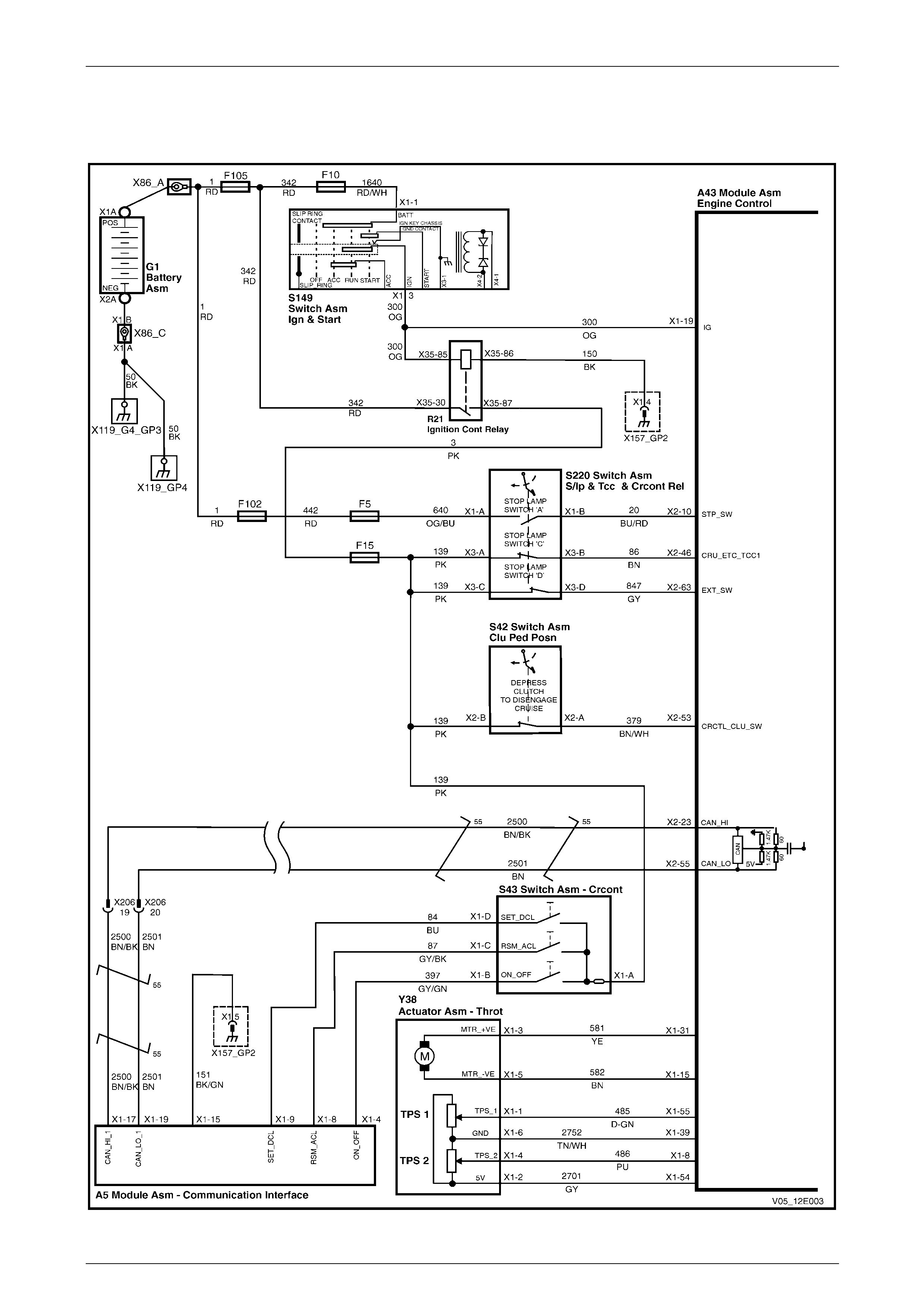
Wiring Diagram – V6
Figure 12E – 23
Cruise Control Page 12E–19
Page 12E–19
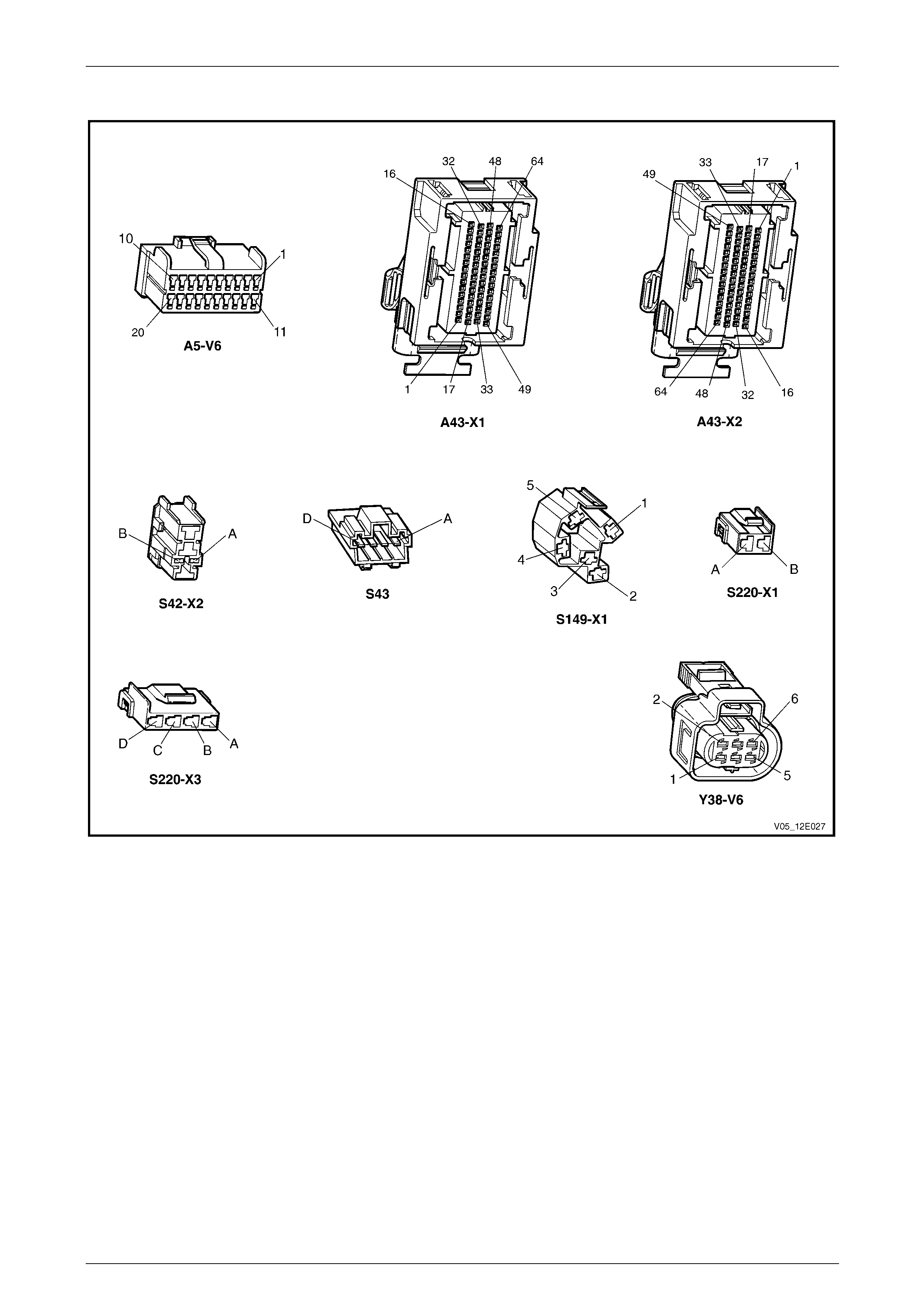
Connector Chart – V6
Figure 12E – 24
Cruise Control Page 12E–20
Page 12E–20
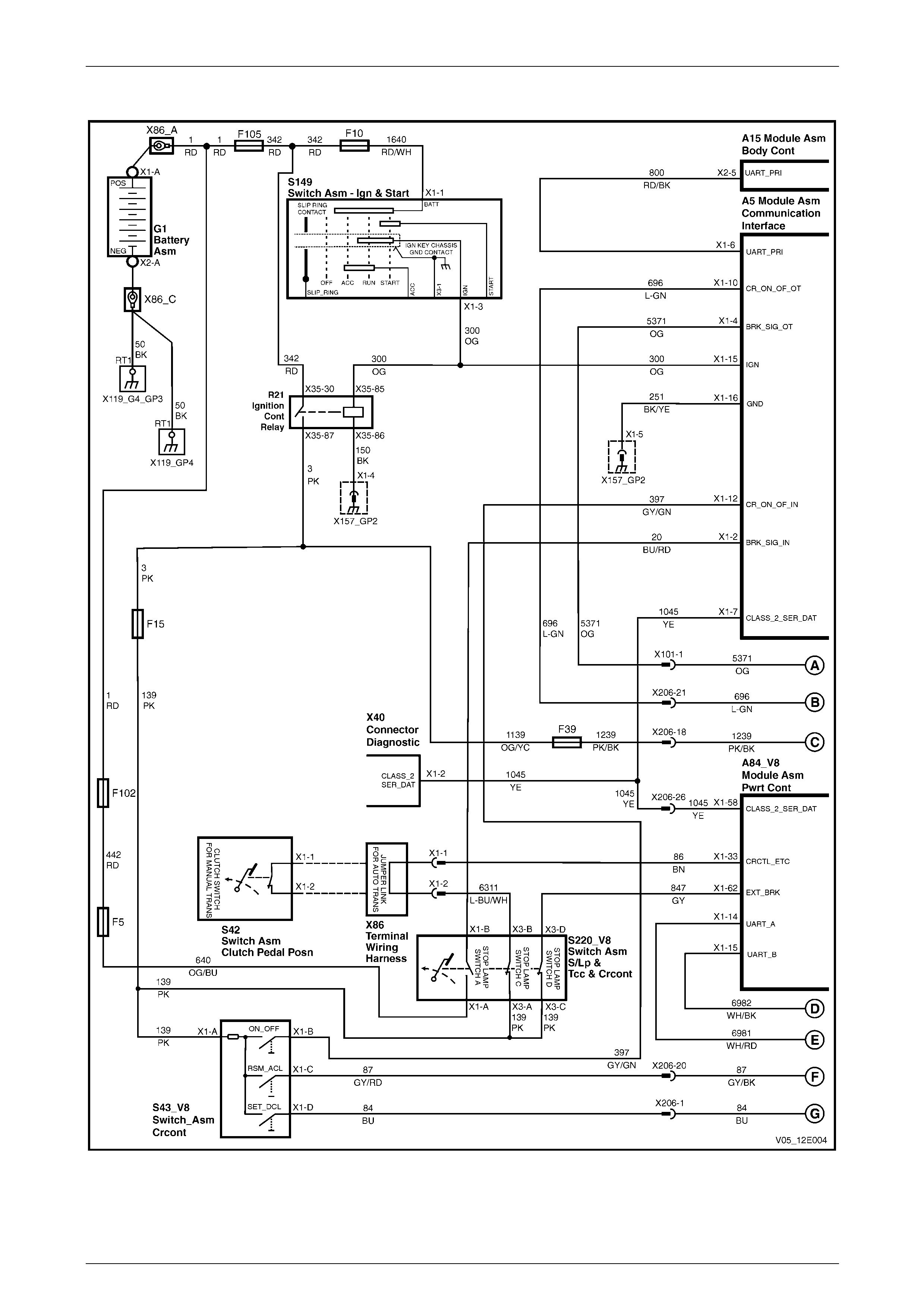
Wiring Diagram – GEN III V8
Figure 12E – 25
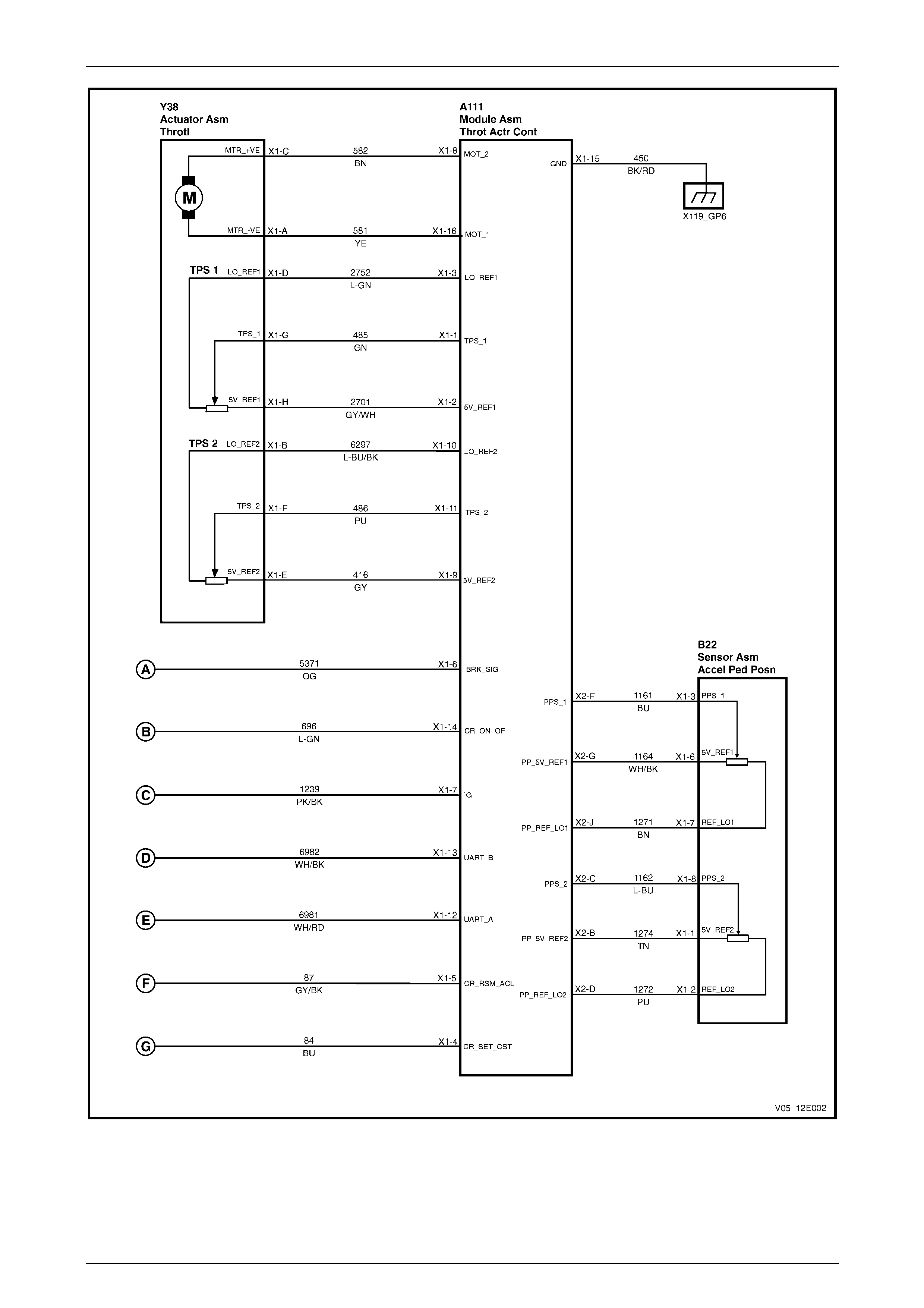
Cruise Control Page 12E–21
Page 12E–21
Figure 12E – 26
Cruise Control Page 12E–22
Page 12E–22
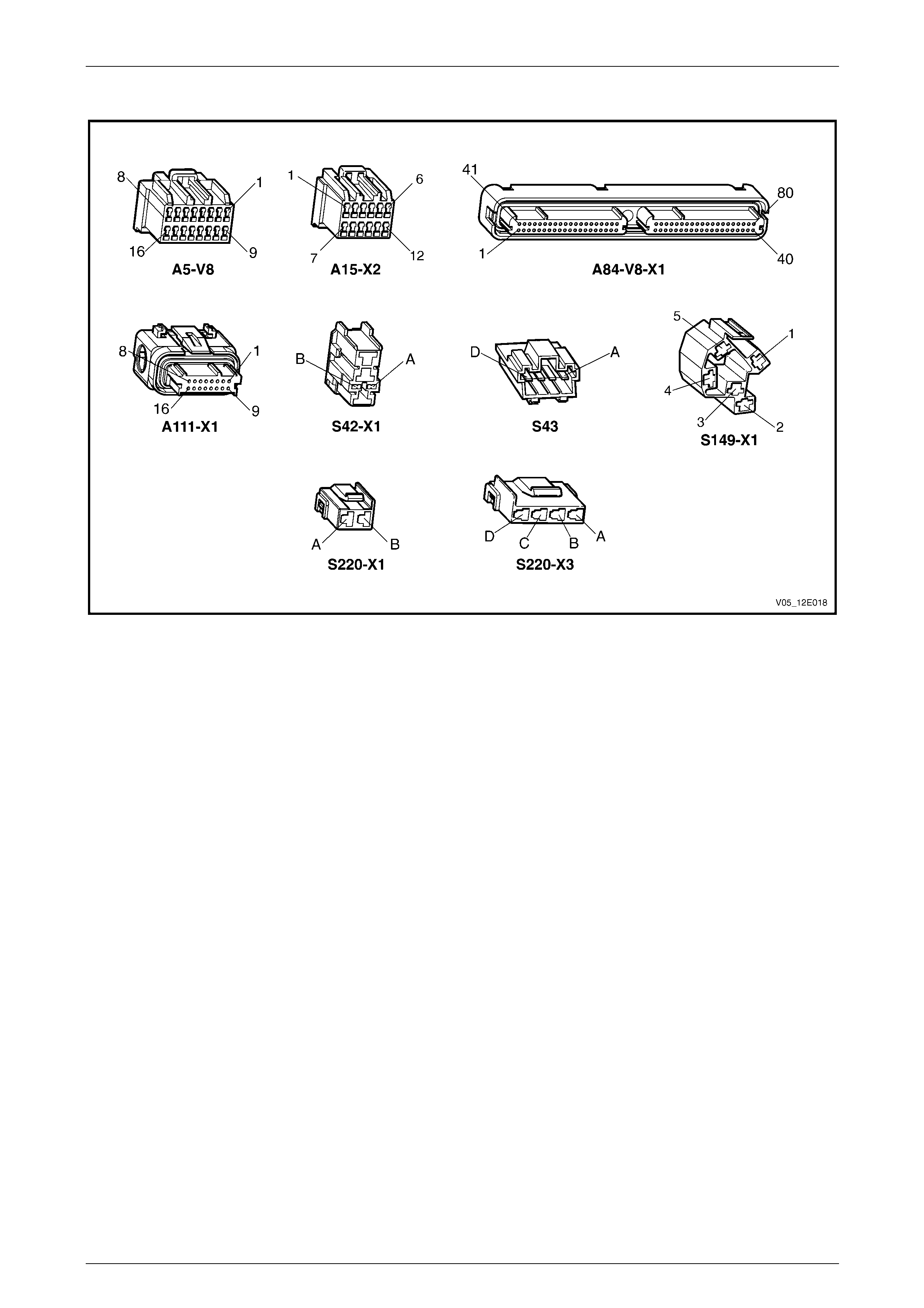
Connector Chart – Gen III V8
Figure 12E – 27

Cruise Control Page 12E–23
Page 12E–23
2.4 Cruise Control Inoperative /
Malfunctioning – V6
Circuit Description
When the ON-OFF button is pressed, 12 V is applied to the Powertrain Interface Module (PIM) connector A5 – X1 pin 4
via circuit 397.
Rotating the cruise control switch to SET–DECEL provides a 12 V signal to the PIM at connector A5 – X1 pin 9 via circuit
84. Turning the cruise control switch to RES–ACCEL will apply a 12 V signal to the PIM at connector A5 – X1 pin 8 via
circuit 87.
Pressing the brake pedal opens cruise cancel circuit (circuit 86) thus droppin g the sup pl y voltage from the ECM
connector A43 – X2 pin 46. Simultaneously, the stop lamp circuit (circuit 20) will close (normally open) and supp ly 12 V
to the ECM at connector A43 – X2 pin 10 and the extended brake pedal position circuit (circuit 847) will close (normally
open) and supply 12 V to the ECM at connector A43 – X2 pin 63.
Manual Vehicles Only
Pressing the clutch pedal opens circuit 397 thus droppi ng the supply voltage from the ECM at connector A43 –
X2 pin 53.
For detailed information refer to Wiring Diagram – V6.
Test Description
The following numbers refer to the step numbers in the diagnostic table:
6–8 Checks the cruise control switch and ass oci ated circuits are functioning corr ectly.
9–10 Checks the brake pedal switch assembly and associated circuit are functioning correctly.
11 Checks the clutch pedal switch assembly and associated circuits are functioning correctl y.
12–21 Covers the testing and replac ement of system components.
22 Checks for a fault in circuits 139 and 397.
23 Checks for a fault in circuits 139 and 87.
24 Checks for a fault in circuits 139 and 84.
25 Checks for a fault in circuits 640 and 20.
26 Checks for a fault in circuits 139 and 86.
27 Checks for a fault in circuits 139 and 847.
28 Checks for a fault in circuits 139 and 379.
29 Checks for intermittent faults in associated circuits and connectors.
Diagnostic Table Notes
1 For all wiring harness fault diagnoses, refer to Section 12P Wiring Diagram s .
2 For wiring harness repairs, refer to Section 12P Wiring Diagrams.
3 Refer to Section 12O Fuses, Relays and Wiring Harnesses for harness routeing.
4 Tech 2 can display a stored history of which system parameter or input caused the cruise control to disengage.
This can aid diagnosis of intermittent faults. Navigate to the Cruise/Traction data within Engine section of the Tech
2 to view this information.

Cruise Control Page 12E–24
Page 12E–24
Diagnostic Table
Step Action Yes No
1 Did you review the System Operation?
Go to Step 2
Go to
1.2 System
Operation
2 Did you read Diagnostic Systems Check – V6?
Go to Step 3
Go to
Diagnostic Systems
Check – V6
3 Inspect fusible link F102, refer to Section 12O Fuses, Relays and
Wiring Harnesses.
Is fusible link F102 blown?
Replace the faulty
fusible link (refer to
Note 3).
If the fusible link
blows again, repair
or replace circuit
442 (refer to Note 2) Go to Step 4
4 Inspect fuse F5, refer to Section 12O Fuses, Relays and Wiring
Harnesses.
Is fuse F5 blown?
Replace the faulty
fuse (refer to
Note 3).
If the fuse blows
again, repair or
replace circuit 640
(refer to Note 2) Go to Step 5
5 Inspect fuse F15, refer to Section 12O Fuses, Relays and Wiring
Harnesses.
Is fuse F15 blown?
Replace the faulty
fuse (refer to
Note 3).
If the fuse blows
again, repair or
replace circuit 139
(refer to Note 2) Go to Step 6
6 1 Connect Tech 2 to the DLC.
2 On Tech 2 select:
Body / Powertrain Interface Module / Data Display / Data
List.
3 Ignition ON, engine OFF.
4 Scroll to Cruise Control Enable S.
5 While monitoring Tech 2, press the cruise c ontrol switch ON–
OFF button.
Does Tech 2 display the fol lowing:
• Inactive and Active as the cruise control switch is toggled? Go to Step 7 Go to Step 12
7 1 Scroll to Cruise Control Tip Swit.
2 While monitoring Tech 2, rotate the cruise control switch.
Does Tech 2 display the fol lowing:
• Inactive when the cruise control switch is in the neutral
position?
• Res / Accel when the cruise control switch is rotated to the
RES–ACCEL. Position? Go to Step 8 Go to Step 13

Cruise Control Page 12E–25
Page 12E–25
Step Action Yes No
8 1 While monitoring Tech 2, rotate the cruise control switch.
Does Tech 2 display the fol lowing:
• Inactive when the cruise control switch is in the neutral
position?
• Set / Decel when the cruise control switch is rotated to the SET–
DECEL. Position? Go to Step 9 Go to Step 14
9 1 Return to the Main Menu on Tech 2.
2 On Tech 2 select:
Engine / V6 Engine / Data Display / Cruise/Traction Data.
3 Scroll to Brake Lamp Switch.
4 While monitoring Tech 2, apply and then release pressure to the
brake pedal.
Does Tech 2 display the fol lowing:
• Active as the brake pedal is pressed?
• Inactive when the pedal is released? Go to Step 10 Go to Step 15
10 1 Scroll to Extended Tra vel Brake P.
2 While monitoring Tech 2, apply and then release pressure to the
brake pedal.
Does Tech 2 display the fol lowing:
• Inactive when the pedal is released?
• Active as the brake pedal is pressed? Go to Step 11 Go to Step 16
11 NOTE
This procedure is only required on vehicles fitted with
manual transmissions. If the vehicle is fitted with an
automatic transmission, go to Step 26.
1 Scroll to Cruise Control Active.
2 While monitoring Tech 2, apply and then release pressure to the
brake pedal.
Does Tech 2 display the fol lowing:
• Active when the pedal is released?
• Inactive as the clutch pedal is pressed? Go to Step 29 Go to Step 17
12 Test the cruise control switch, refer to 3.1 Cruise Control Switch
Assembly.
Is the cruise control switch serviceable? Go to Step 22 Go to Step 18
13 Test the cruise control switch, refer to 3.1 Cruise Control Switch
Assembly.
Is the cruise control switch serviceable? Go to Step 23 Go to Step 18
14 Test the cruise control switch, refer to 3.1 Cruise Control Switch
Assembly.
Is the cruise control switch serviceable? Go to Step 24 Go to Step 18
15 Test the stop lamp and BTSI switch, refer to 3.2 Stop Lamp and BTSI
Switch Assembly.
Is the stop lamp and BTSI switch serviceable? Go to Step 25 Go to Step 19

Cruise Control Page 12E–26
Page 12E–26
Step Action Yes No
16 Test the cruise control release and extended brake travel switch, refer
to 3.3 Cruise Control Release and Extended Brake Travel Switch
Assembly.
Is the cruise control release and extended br ake travel switch
serviceable? Go to Step 26 Go to Step 20
17 NOTE
This procedure is only required on vehicles fitted with
manual transmissions. If the vehicle is fitted with an
automatic transmission go to Step 26.
Test the clutch pedal switch, refer to 3.4 Clutch Pedal Switch.
Is the clutch pedal switch serviceable? Go to Step 28 Go to Step 21
18 Replace the faulty turn signal and cruise control switch assembly with
a serviceable item. To replace the switch assembly, refer to Section
12B Lighting System. Go to Step 32 —
19 Replace the faulty stop lamp and BTSI switch, refer to 3.2 Stop Lamp
and BTSI Switch Assembly Go to Step 32 —
20 Replace the faulty cruise control release a nd extended brake travel
switch, refer to 3.3 Cruise Control Release a nd Extended Brake
Travel Switch Assembly Go to Step 32 —
21 Replace the faulty clutch pedal switch, refer to 3.4 Clutch Pedal
Switch Go to Step 32 —
22 1 Disconnect the PIM connector A5 – X1.
2 Using a multimeter set to measure voltage, back probe between
the harness connector A5 – X1 pin 4 and pin 15.
3 With the aid of an assistant, monitor the voltage on the
multimeter and press and release the cruise control switch ON–
OFF button.
• With the button in the rest position, the multimeter should
display 0 V.
• With the button pressed, the multimeter should d ispl ay
battery voltage.
Does the multimeter display a s described? Go to Step 30
Check for short to
ground or open
circuit on circuit 139
and 397
Repair as required
(refer to Note 2).
Go to Step 32
23 1 Disconnect the PIM connector A5 – X1.
2 Using a multimeter set to measure voltage, back probe between
the harness connector A5 – X1 pin 8 and pin 15.
3 With the aid of an assistant, monitor the voltage on the
multimeter and rotate and release the cruise control switch to
RES–ACCEL button.
• With the switch in the rest position, the multimeter should
display 0 V.
• With the switch rotated, the multimeter should display
battery voltage.
Does the multimeter display a s described? Go to Step 30
Check for short to
ground or open
circuit on circuit 139
and 87
Repair as required
(refer to Note 2).
Go to Step 32

Cruise Control Page 12E–27
Page 12E–27
Step Action Yes No
24 1 Disconnect the PIM connector A5 – X1.
2 Using a multimeter set to measure voltage, back probe between
the harness connector A5 – X1 pin 9 and pin 15.
3 With the aid of an assistant, monitor the voltage on the
multimeter and rotate and release the cruise control switch to
SET–DECEL button.
• With the switch in the rest position, the multimeter should
display 0 V.
• With the switch rotated, the multimeter should display
battery voltage.
Does the multimeter display a s described? Go to Step 30
Check for short to
ground or open
circuit on circuit 139
and 84
Repair as required
(refer to Note 2).
Go to Step 32
25 1 Disconnect the ECM connector A43 – X2.
2 Using a multimeter set to measure voltage, back probe between
the harness connector A43 – X2 pin 10 and ground.
3 With the aid of an assistant, monitor the voltage on the
multimeter and press and release the brake pedal.
• With the brake pedal in the rest position, the multimeter
should display 0 V
• With the brake pedal pressed, the multimeter should
display battery voltage
Does the multimeter display a s described? Go to Step 31
Check for short to
ground or open
circuit on circuit 640
and 20
Repair as required
(refer to Note 2).
Go to Step 32
26 1 Disconnect the ECM connector A43 – X2.
2 Using a multimeter set to measure voltage, back probe between
the harness connector A43 – X2 pin 46 and ground.
3 With the aid of an assistant, monitor the voltage on the
multimeter and press and release the brake pedal.
• With the brake pedal in the rest position, the multimeter
should display battery voltage
• With the brake pedal pressed, the multimeter should
display 0 V.
Does the multimeter display a s described? Go to Step 27
Check for short to
ground or open
circuit on circuit 139
and 86
Repair as required
(refer to Note 2).
Go to Step 32
27 1 Disconnect the ECM connector A43 – X2.
2 Using a multimeter set to measure voltage, back probe between
the harness connector A43 – X2 pin 63 and ground.
3 With the aid of an assistant, monitor the voltage on the
multimeter and press and release the brake pedal.
• With the brake pedal in the rest position, the multimeter
should display battery voltage
• With the brake pedal pressed, the multimeter should
display 0 V.
Does the multimeter display a s described? Go to Step 31
Check for short to
ground or open
circuit on circuit 139
and 847
Repair as required
(refer to Note 2).
Go to Step 32

Cruise Control Page 12E–28
Page 12E–28
Step Action Yes No
28 1 Disconnect the ECM connector A43 – X2.
2 Using a multimeter set to measure voltage, back probe between
the harness connector A43 – X2 pin 53 and ground.
3 With the aid of an assistant, monitor the voltage on the
multimeter and press and release the clutch ped al.
• With the clutch pedal in the rest position, the multimeter
should display battery voltage
• With the clutch pedal pressed, the multimete r should
display 0 V
Does the multimeter display a s described? Go to Step 31
Check for short to
ground or open
circuit on circuit 139
and 379
Repair as required
(refer to Note 2).
Go to Step 32
29 Check all associated circuits and conn ectors for the following:
• Loose or damaged co nnections
• Intermittent faults.
Refer to 12P Wiring Diagra m s and repair as required.
Was the repair completed? Go to Step 32 —
30 Replace the PIM, refer to Section 6E1 Po wertrain Interface Module –
V6.
Was the repair completed? Go to Step 32 —
31 Replace the ECM module, refer to Section 6C1-3 Engine
Management – V6 Service Operations.
Was the repair completed? Go to Step 32 —
32 Operate the system in order to verify the repair.
Did you correct the condition? System OK Go to Step 1

Cruise Control Page 12E–29
Page 12E–29
2.5 Cruise Control Inoperative /
Malfunctioning – GEN III V8
Circuit Description
When the ON-OFF button is pressed, 12 V i s applied to the PIM connector A5 – X1 pin 12 via circuit 39 7.
Rotating the cruise control switch to SET–DECEL provides a 12 V signal to the TACM at connector A111 – X1 pin 4 via
circuit 84. Turning the cruise control switch to RES–ACCEL will apply a 12 V signal to the TACM at connector A111 –
X1 pin 5 via circuit 87.
Pressing the brake pedal opens cruise cancel circuit (circuit 86) thus droppin g the sup pl y voltage from the PCM
connector A84 – X1 pin 33. Simultaneously, the extended brake peda l position circuit (circuit 847) will clo se (normally
open) and supply 12 V to the PCM at connector A84 – X1 pin 62. The stop lamp circuit (circuit 20) will also close
(normally open) and supply 12 V to the PIM at connector A5 – X1 pin 2.
Manual Vehicles Only
Pressing the clutch pedal simultaneo usly opens circuit 86 thus dropping the supply volta ge from the PCM connector
A84 – X1 pin 33.
Test Description
The following numbers refer to the step numbers in the diagnostic table:
6–8 Checks the cruise control switch and ass oci ated circuits are functioning corr ectly.
9–10 Checks the brake pedal switch assembly and associated circuit are functioning correctly.
11 Checks the clutch pedal switch assembly and associated circuits are functioning correctl y.
12–21 Covers the testing and replac ement of system components.
22 Checks for a fault in circuits 139 and 397.
23–24 Checks for a fault in circuit 696.
25 Checks for a fault in circuits 139 and 87.
26 Checks for a fault in circuits 139 and 84.
27 Checks for a fault in circuits 640 and 20.
28–29 Checks for a fault in circuit 5371.
30 Checks for a fault in circuits 139 and 847.
31–32 Checks for a fault in circuits 139, 6311 and 86.
33 Checks for intermittent faults in associated circuits and connectors.
Diagnostic Table Notes
1 For all wiring harness fault diagnoses, refer to Section 12P Wiring Diagram s .
2 For wiring harness repairs, refer to Section 12P Wiring Diagrams.
3 Refer to Section 12O Fuses, Relays and Wiring Harnesses for harness routeing.
4 Tech 2 can display a stored history of which system parameter or input caused the cruise control to disengage.
This can aid diagnosis of intermittent faults. Navigate to the Cruise/Traction data within Engine section of the Tech
2 to view this information.

Cruise Control Page 12E–30
Page 12E–30
Diagnostic Table
Step Action Yes No
1 Did you review the System Operation? Go to Step 2 Go to 1.2 System
Operation.
2 Did you read Diagnostic Systems Check – Gen III?
Go to Step 3
Go to
Diagnostic Systems
Check – Gen III
3 Inspect fusible link F102, refer to Section 12O Fuses, Relays and
Wiring Harnesses.
Is fusible link F102 blown?
Replace the faulty
fusible link (refer to
Note 3).
If the fusible link
blows again, repair
or replace circuit
442 (refer to
Note 2). Go to Step 4
4 Inspect fuse F5, refer to Section 12O Fuses, Relays and Wiring
Harnesses.
Is fuse F5 blown?
Replace the faulty
fuse (refer to
Note 3).
If the fuse blows
again, repair or
replace circuit 640
(refer to Note 2). Go to Step 5
5 Inspect fuse F15, refer to Section 12O Fuses, Relays and Wiring
Harnesses.
Is fuse F15 blown?
Replace the faulty
fuse (refer to
Note 3).
If the fuse blows
again, repair or
replace circuit 139
(refer to Note 2). Go to Step 6
6 1 Connect Tech 2 to the DLC.
2 On Tech 2 select:
Engine / V8 Gen III / Data Display / Cruise Control.
3 Ignition ON, engine OFF.
4 Scroll to Cruise Control.
5 While monitoring Tech 2, press the cruise c ontrol switch ON–
OFF button.
Does Tech 2 display the fol lowing:
ON and Off as the cruise control switch is toggled? Go to Step 7 Go to Step 12
7 1 Scroll to Cruise Resume/Accelerat.
2 While monitoring Tech 2, rotate the cruise control switch.
Does Tech 2 display the fol lowing:
• Inactive when the cruise control switch is in the neutral
position?
• Active when the cruise control switch is rotated to the RES–
ACCEL. Position? Go to Step 8 Go to Step 13
8 1 Scroll to Cruise Set/Decel Swit.
2 While monitoring Tech 2, rotate the cruise control switch.
Does Tech 2 display the fol lowing:
• Inactive when the cruise control switch is in the neutral
position?
• Active when the cruise control switch is rotated to the SET–
DECEL Position? Go to Step 9 Go to Step 14

Cruise Control Page 12E–31
Page 12E–31
Step Action Yes No
9 1 Scroll to Brake Lamp Switch.
2 While monitoring Tech 2, apply and then release pressure to the
brake pedal.
Does Tech 2 display the fol lowing:
• Active as the brake pedal is pressed?
• Inactive when the pedal is released? Go to Step 10 Go to Step 15
10 NOTE
For vehicles fitted with manual transmissions ensure the
clutch pedal is not pressed during this step
1 Scroll to TCC/Cruise Brake Ped al.
2 While monitoring Tech 2, apply and then release pressure to the
brake pedal.
Does Tech 2 display the fol lowing:
• Active as the brake pedal is pressed?
• Inactive when the pedal is released? Go to Step 11 Go to Step 16
11 NOTE
This procedure is only required on vehicles fitted with
manual transmissions. If the vehicle is fitted with an
automatic transmission go to Step 30
1 Remain at TCC/Cruise Brake Pedal.
2 While monitoring Tech 2, apply and then release pressure to the
clutch pedal.
Does Tech 2 display the fol lowing:
• Active as the brake pedal is pressed?
• Inactive when the pedal is released? Go to Step 33 Go to Step 17
12 Test the cruise control switch, refer to 3.1 Cruise Control Switch
Assembly.
Is the cruise control switch serviceable? Go to Step 21 Go to Step 18
13 Test the cruise control switch, refer to 3.1 Cruise Control Switch
Assembly.
Is the cruise control switch serviceable? Go to Step 25 Go to Step 18
14 Test the cruise control switch, refer to 3.1 Cruise Control Switch
Assembly.
Is the cruise control switch serviceable? Go to Step 26 Go to Step 18
15 Test the stop lamp and BTSI switch, refer to 3.2 Stop Lamp and BTSI
Switch Assembly.
Is the stop lamp and BTSI switch serviceable? Go to Step 27 Go to Step 19
16 Test the cruise control release and extended brake travel switch, refer
to 3.3 Cruise Control Release and Extended Brake Travel Switch
Assembly.
Is the cruise control release and extended br ake travel switch
serviceable? Go to Step 30 Go to Step 20
17 Test the clutch pedal switch, refer to 3.4 Clutch Pedal Switch.
Is the clutch pedal switch serviceable? Go to step 32 Go to Step 21
18 Replace the faulty turn signal and cruise control switch assembly with
a serviceable item. To replace the switch assembly, refer to Section
12B Lighting System. Go to Step 37 —
19 Replace the faulty stop lamp and BTSI switch, refer to 3.2 Stop Lamp
and BTSI Switch Assembly Go to Step 37 —

Cruise Control Page 12E–32
Page 12E–32
Step Action Yes No
20 Replace the faulty cruise control release a nd extended brake travel
switch, refer to 3.3 Cruise Control Release a nd Extended Brake
Travel Switch Assembly Go to Step 37 —
21 Replace the faulty clutch pedal switch, refer to 3.4 Clutch Pedal
Switch Go to Step 37 —
22 1 Disconnect the PIM connector A5 – X1.
2 Using a multimeter set to measure voltage, back probe between
the harness connector A5 – X1 pin 12 and pin 16.
3 With the aid of an assistant, monitor the voltage on the
multimeter and press and release the cruise control switch ON–
OFF button.
• With the button in the rest position, the multimeter should
display 0 V.
• With the button pressed, the multimeter should d ispl ay
battery voltage.
4 Reconnect the PIM connector A5 – X1.
Does the multimeter display a s described? Go to Step 23
Check for short to
ground or open
circuit on circuit 139
and circuit 397.
Repair as required
(refer to Note 2).
Go to Step 37
23 1 Disconnect the TACM connector A111 – X1.
2 Using a multimeter set to measure voltage, back probe between
the harness connector A111 – X1 pin 14 and pin 15.
3 With the aid of an assistant, monitor the voltage on the
multimeter and press and release the cruise control switch ON–
OFF button.
• With the button in the rest position, the multimeter should
display 0 V.
• With the button pressed, the multimeter should d ispl ay
battery voltage.
Does the multimeter display a s described? Go to Step 35 Go to Step 24
24 Check for short to ground or open circuit on circuit 696.
Is the circuit serviceable? Go to Step 34
Repair as required
(refer to Note 2).
Go to Step 37
25 1 Disconnect the TACM connector A111 – X1.
2 Using a multimeter set to measure voltage, back probe between
the harness connector A111 – X1 pin 5 a nd ground.
3 With the aid of an assistant, monitor the voltage on the
multimeter and multimeter and rotate the cruise control switch
from rest to RES–ACCEL.
• With the button in the rest position, the multimeter should
display 0 V.
• With the button pressed, the multimeter should d ispl ay
battery voltage.
Does the multimeter display a s described? Go to Step 35
Check for short to
ground or open
circuit on circuit 139
and circuit 87.
Repair as required
(refer to Note 2).
Go to Step 37

Cruise Control Page 12E–33
Page 12E–33
Step Action Yes No
26 1 Disconnect the TACM connector A111 – X1.
2 Using a multimeter set to measure voltage, back probe between
the harness connector A111 – X1 pin 4 a nd ground.
3 With the aid of an assistant, monitor the voltage on the
multimeter and rotate the cruise control switch from rest to SET–
DECEL.
• With the cruise control switch in the rest position, the
multimeter should display 0 V.
• With the cruise control switch rotated, the multimeter
should display battery voltage .
Does the multimeter display a s described? Go to Step 35
Check for short to
ground or open
circuit on circuit 139
and circuit 84.
Repair as required
(refer to Note 2).
Go to Step 37
27 1 Disconnect the PIM connector A5 – X1.
2 Using a multimeter set to measure voltage, back probe between
the harness connector A5 – X1 pin 2 and ground.
3 With the aid of an assistant, monitor the voltage on the
multimeter and press and release the brake pedal.
• With the brake pedal in the rest position, the multimeter
should display 0 V.
• With the brake pedal pressed, the multimeter should
display battery voltag e.
Does the multimeter display a s described? Go to Step 28
Check for short to
ground or open
circuit on circuit 640
and circuit 20.
Repair as required
(refer to Note 2).
Go to Step 37
28 1 Disconnect the TACM connector A111 – X1.
2 Using a multimeter set to measure voltage, back probe between
the harness connector A111 – X1 pin 6 a nd ground.
3 With the aid of an assistant, monitor the voltage on the
multimeter and press and release the brake pedal.
• With the brake pedal in the rest position, the multimeter
should display 0 V.
• With the brake pedal pressed, the multimeter should
display battery voltag e.
Does the multimeter display a s described? Go to Step 35 Go to Step 29
29 Check for short to ground or open circuit on circuit 5371.
Is the circuit serviceable? Go to Step 34
Repair as required.
Go to Step 37
30 1 Disconnect the PCM connector A84 – X1.
2 Using a multimeter set to measure voltage, back probe between
the harness connector A84 – X1 pin 62 and ground.
3 With the aid of an assistant, monitor the voltage on the
multimeter and press and release the brake pedal.
• With the brake pedal in the rest position, the multimeter
should display battery voltage
• With the brake pedal pressed, the multimeter should
display 0 V.
Does the multimeter display a s described? Go to Step 31
Check for short to
ground or open
circuit on circuit 139
and circuit 847.
Repair as required
(refer to Note 2).
Go to Step 37

Cruise Control Page 12E–34
Page 12E–34
Step Action Yes No
31 NOTE
For vehicles fitted with manual transmissions ensure the
clutch pedal is not depressed duri ng this step.
1 Disconnect the PCM connector A84 – X1.
2 Using a multimeter set to measure voltage, back probe between
the harness connector A84 – X1 pin 33 and ground.
3 With the aid of an assistant, monitor the voltage on the
multimeter and press and release the brake pedal.
• With the brake pedal in the rest position, the multimeter
should display battery voltage
• With the brake pedal pressed, the multimeter should
display 0 V.
Does the multimeter display a s described? Go to Step 36
Check for short to
ground or open
circuit on circuit 139,
circuit 6311and
circuit 86.
Repair as required
(refer to Note 2).
Go to Step 37
32 1 Disconnect the PCM connector A84 – X1.
2 Using a multimeter set to measure voltage, back probe between
the harness connector A84 – X1 pin 33 and ground.
3 With the aid of an assistant, monitor the voltage on the
multimeter and press and release the clutch ped al.
• With the clutch pedal in the rest position, the multimeter
should display battery voltage
• With the clutch pedal pressed, the multimete r should
display 0 V
Does the multimeter display a s described? Go to Step 36
Check for short to
ground or open
circuit on circuit 139,
circuit 6311and
circuit 86.
Repair as required
(refer to Note 2).
Go to Step 37
33 Check all associated circuits and conn ectors for the following:
• Loose or damaged co nnections
• Intermittent faults.
Refer to 12P Wiring Diagrams and rep air as required.
Was the repair completed? Go to Step 37 —
34 Replace the PIM, refer to Section 6E3 Po wertrain Interface Module –
GEN III V8.
Was the repair completed? Go to Step 37 —
35 Replace the TACM, refer to Section 6C3-3 Powertrain Management –
GEN III V8 – Service Operations.
Was the repair completed? Go to Step 37 —
36 Replace the PCM, refer to Section 6C3-3 Powertrain Management –
GEN III V8 – Service Operations.
Was the repair completed? Go to Step 37 —
37 Operate the system in order to verify the repair.
Did you correct the conditi on? System OK Go to Step 1
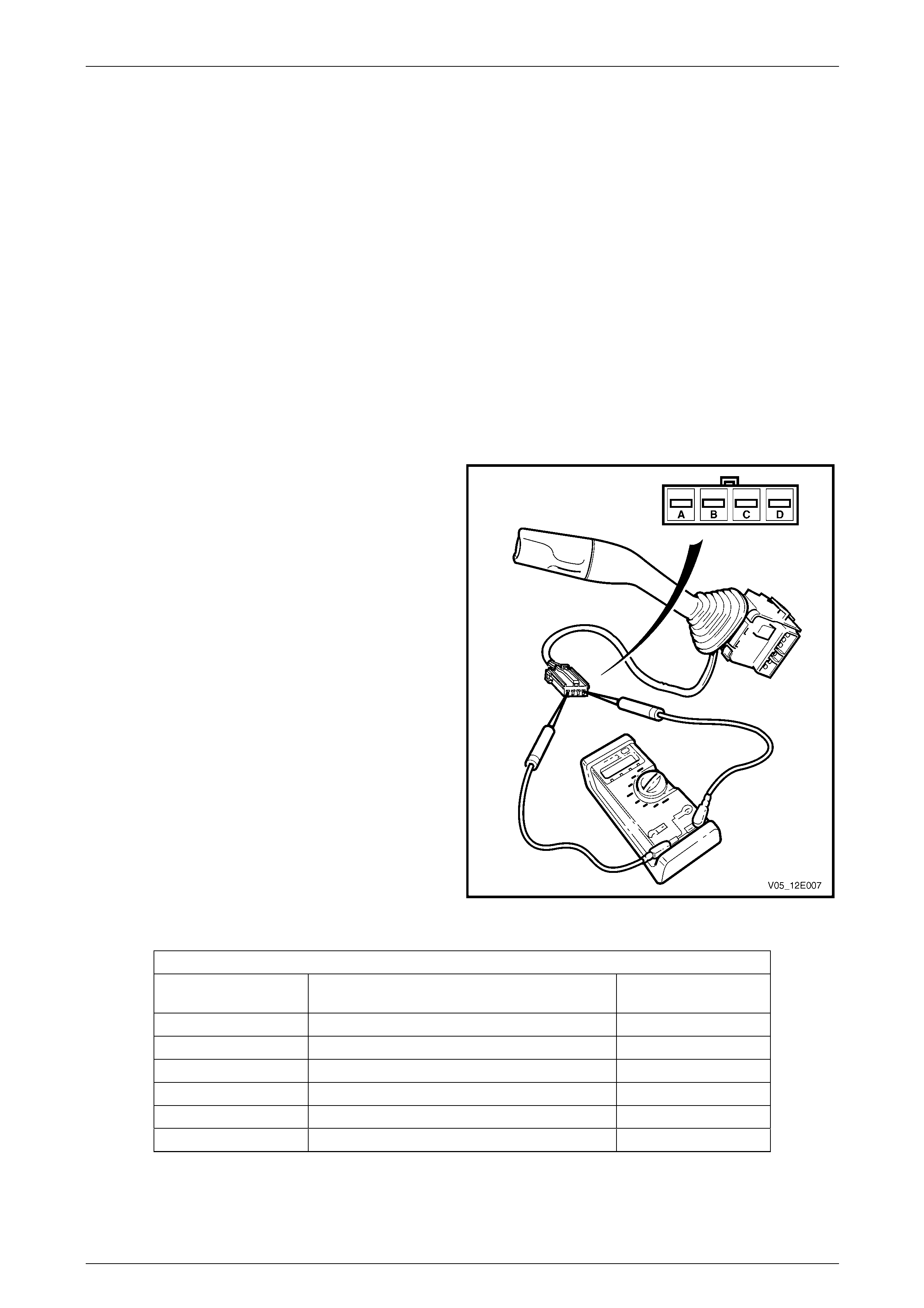
Cruise Control Page 12E–35
Page 12E–35
3 Service Operations
3.1 Cruise Control Switch Assembly
LT Section No. — 03–400
Remove
To remove the cruise control switch assembly, refer to Section 12B Lighting System.
Test
To test the cruise control switch assembly, use an multimeter to check the continuity.
NOTE
To test the turn signal features, refer to
Section 12B Lighting System.
1 Perform the removal procedure for the turn sign al
and cruise control switch assembly, refer to
Section 12B Lighting System, but do not unclip and
remove the switch assembly from the steering column.
With the switch assembly still attached to the steering
column, a stable platform with which to carry out the
testing is provided.
2 Place the turn signal and cruise control switch
assembly into the positions detaile d in the following
table, refer to Terminal Testing. Position the contacts
of the multimeter onto the terminals and take the
reading. Compare the multimeter readings with the
values in the table.
3 If there is continuity between any terminals o t her than
those listed, the turn signal switch and cruis e control
assembly is faulty. If the switch assembly fails any part
of the test, replace the faulty turn signal and cruise
control switch assembly with a serviceable item.
To replace the switch assembly, refer to
Section 12B Lighting System.
4 Perform the reinstallation procedur e, refer to
Section 12B Lighting System.
Figure 12E – 28
Terminal Testing
Cruise Control Switch Assembly
Switch Terminals Switch
Position Indication if Switch
is Serviceable
A and B ON–OFF Pressed Approximately 470 Ω
A and B ON–OFF Released Open Circuit
A and D SET–DECEL Appli ed Approximately 470 Ω
A and D SET–DECEL Released Open Circuit
A and C RES–ACCEL Applied Approximately 470 Ω
A and C RES–ACCEL Released Open Circuit
Reinstall
To reinstall the cruise control switch assembly, refer to Section 12B Lighting System.
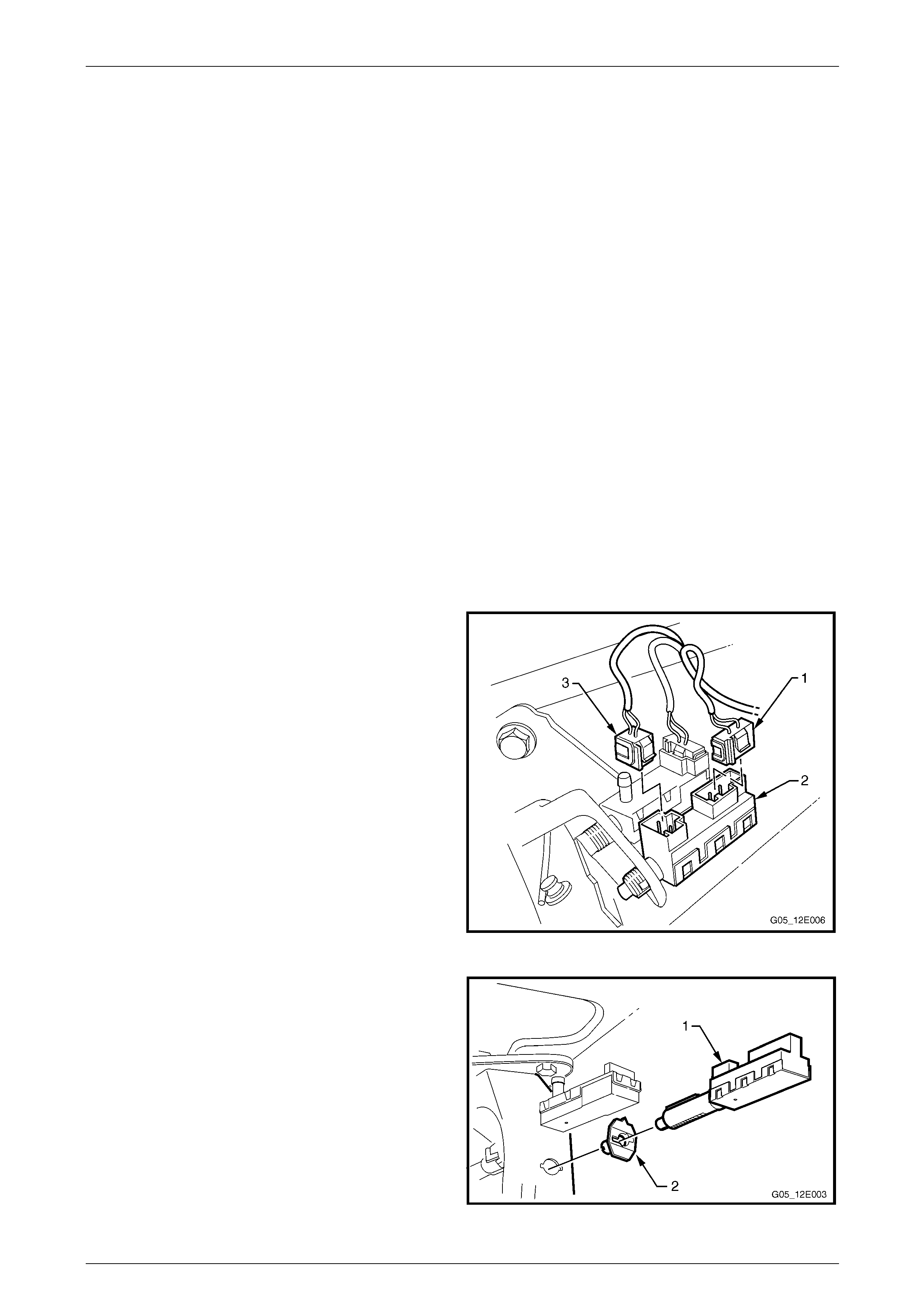
Cruise Control Page 12E–36
Page 12E–36
3.2 Stop Lamp and BTSI Switch Assembly
LT Section No. — 03–400
There are two physical switches fitted to the brake pedal assembly. This proced ure shows the removal, testing, and
installation of the stop lamp and BTSI switch assembly, which is the lower switch assembly when looking straight on at
the brake pedal assembly from the driver’s position.
NOTE
The wiring diagrams treat both physical switches
as one assembly which has been designated as
connector S220, Stop Lamp and Torque
Converter Clutch and Cruise Control Release
Switch Assembly. However, as there are two
physical switches with separate functions, the
procedures have been separated.
NOTE
Adjustment of the switch assembly is performed
during the reinstallation procedure.
Remove
1 Remove the following instrument panel components:
a lower trim panel assembly,
b lower trim plate assembly, and
c lower trim panel retainer, refer to Section 1A3 Instrument Panel and Console.
2 Using a screwdriver, press the connector loc k ing tab
while pulling on the stop lam p conn ector (1) and
remove from the switch assembly (2).
3 Repeat for the BTSI connector (3) where fitted.
Figure 12E – 29
4 Twist the stop lamp and BTSI switch assembly (1)
anticlockwise a quarter of a turn and pull out of the
brake pedal support.
5 If required, remove the plastic clip (2) by pressing the
locking tabs on the rear of the clip and pulling from the
brake pedal support.
Figure 12E – 30

Cruise Control Page 12E–37
Page 12E–37
Test
1 Using a multimeter, probe the pins of the switch
assembly and compare to the table below.
NOTE
The pins are as follo ws:
• S220 – X1 pins A (1) and B (2),
• S220 – X2 pins A (3) and B (4).
NOTE
Holding the plunger (5) with tape will help when
performing the test with the plunger i n the active
position (plunger pressed). Figure 12E – 31
Plunger Position Connector S220 – X1 pins A and B Connector S220 – X2 pins A and B
Neutral position (plunger extended) Continuity Open circuit
Active position (plunger pressed) Open circuit Continuity
Reinstall
1 If removed, install the plastic clip (2) with the arrow pointing upwards, refer to Figure 12E – 30.
2 With the connectors pointing upwards (12 o’clock position), insert the s witch assembly (1) into the plastic clip.
3 Ensure the brake pedal is in the rest positi on .
4 Push the switch assembly (1) so the plunger is
pressed and the end switch barrel is against the brake
pedal (2).
5 Twist the switch assembly clockwise to lock into place.
The distance between the brake pedal and the switch
barrel should be 0.7 ± 0.5 mm.
6 Install the wiring connectors to the switch assembly.
Figure 12E – 32
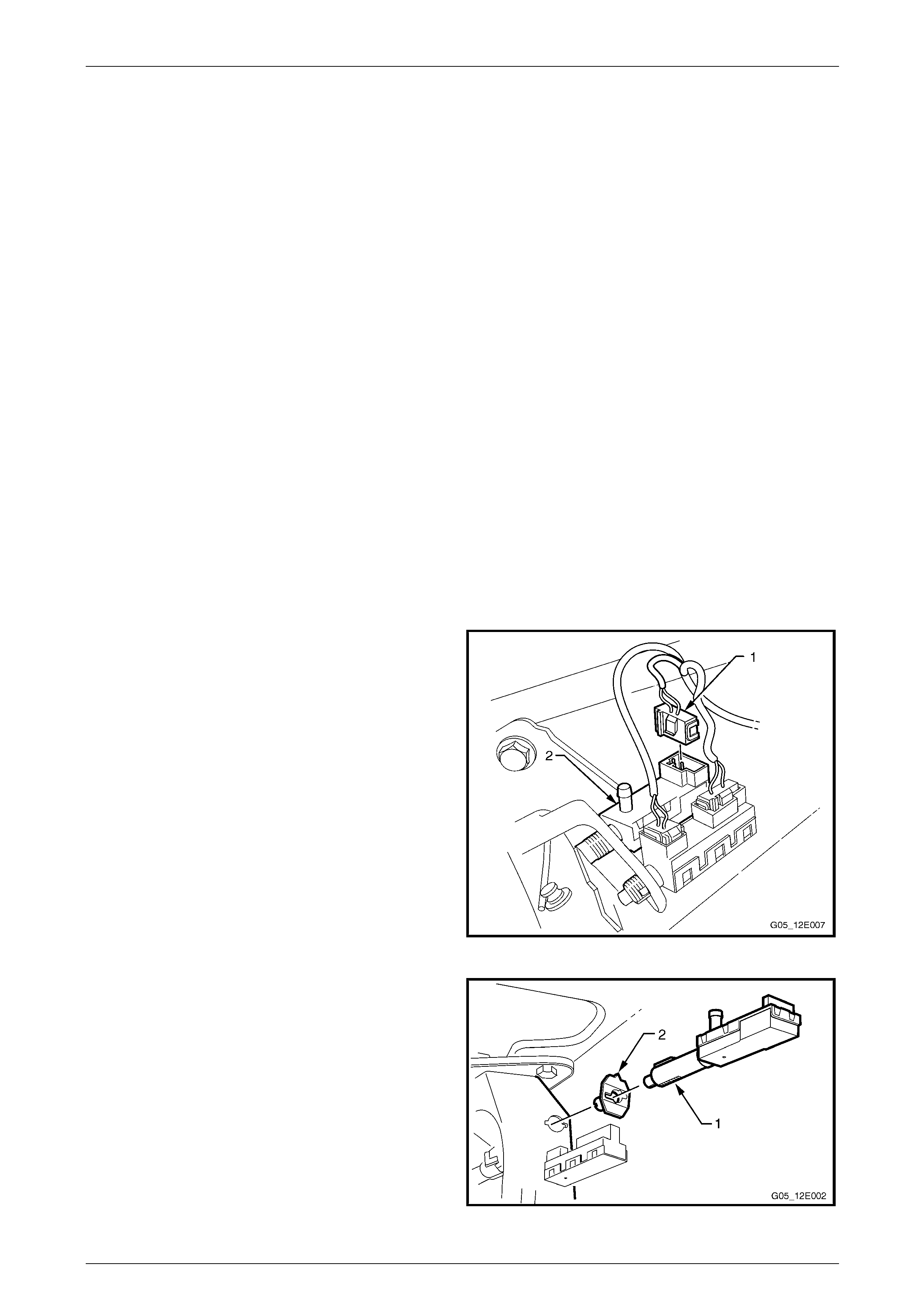
Cruise Control Page 12E–38
Page 12E–38
3.3 Cruise Control Release and Extended
Brake Travel Switch Assembly
LT Section No. — 03–400
There are two physical switches fitted to the brake pedal assembly. This proced ure shows the removal, testing and
installation of the cruise control release a nd extended brake travel switch assembly, which is the upper switch assembly
when looking straight on at the brake pedal assembly from the driver’s position.
NOTE
The wiring diagrams treat both physical switches
as one assembly which has been designated as
S220, Stop Lamp and Torque Converter Clutch
and Cruise Control Release Switch Assembly.
However as there are two physical switches with
separate functions, the procedures have been
separated.
NOTE
Adjustment of the switch assembly is performed
during the reinstallation procedure.
Remove
1 Remove the following instrument panel components:
a lower trim panel assembly,
b lower trim plate assembly, and
c lower trim panel retainer, refer to Section 1A3 Instrument Panel and Console.
2 Using a screwdriver, press the connector loc k ing tab
while pulling on the cruise control release and
extended brake travel switch connector (1) and
remove from the switch assembly (2).
Figure 12E – 33
3 Twist the cruise control release and extended brake
travel switch assembly (1) anticlockwise a quarter of a
turn and pull out of the brake pedal support.
4 If required, remove the plastic clip (2) by pressing the
locking tabs on the rear of the clip and pulling from the
brake pedal support.
Figure 12E – 34
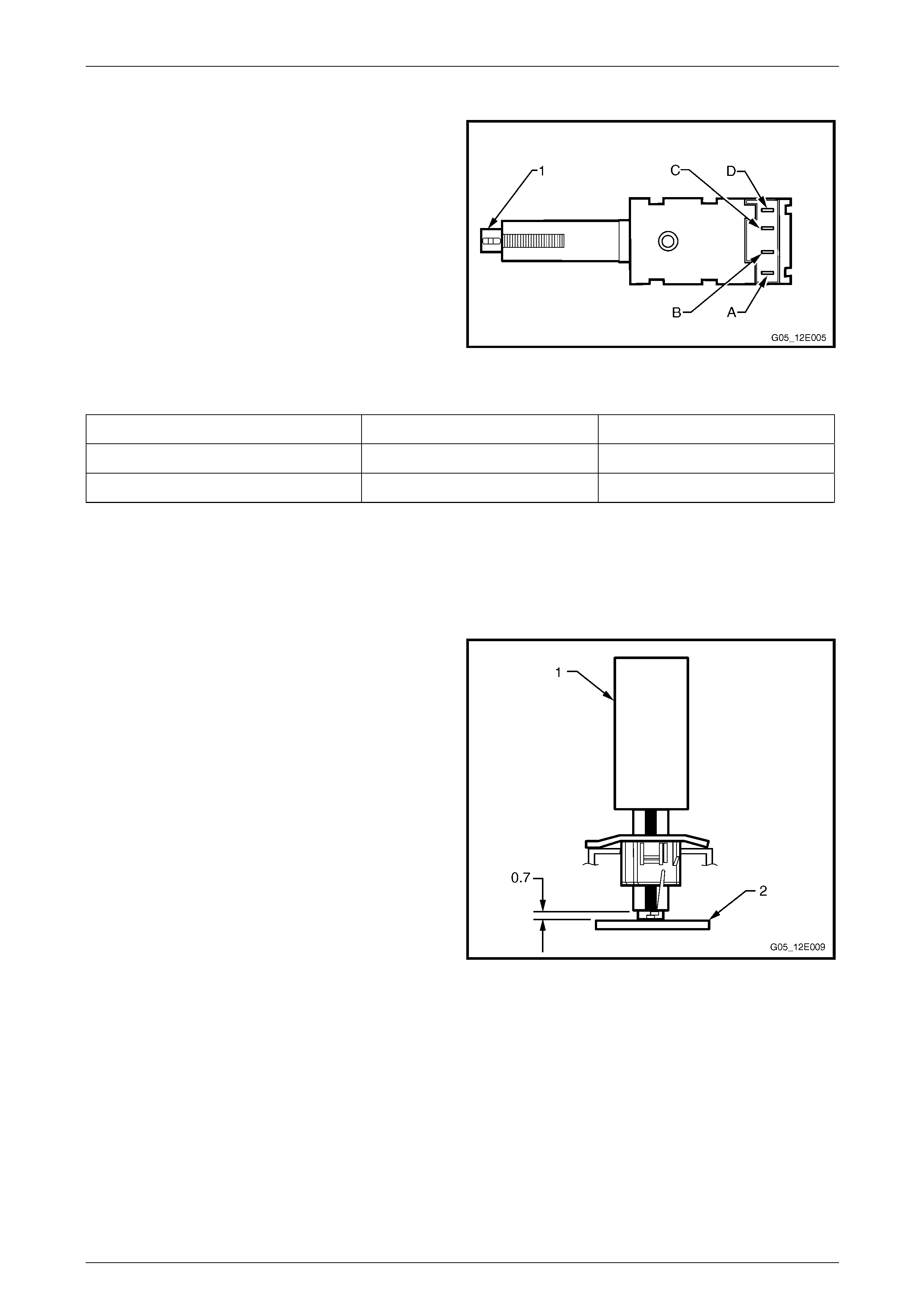
Cruise Control Page 12E–39
Page 12E–39
Test
1 Using a multimeter, probe the pins of the switch
assembly and compare to the table below.
NOTE
Holding the plunger (1) with tape will help when
performing the test with the plunger i n the active
position (plunger pressed).
Figure 12E – 35
Plunger Position Connector S220 – X3 pins A and B Connector S220 – X3 pins C and D
Neutral position (plunger extended) Open circuit Open circuit
Active position (plunger pressed) Continuity Continuity
Reinstall
1 If removed, install the plastic clip (2) with the arrow pointing upwards, refer to Figure 12E – 34.
2 With the connectors pointing upwards (12 o’clock position), insert the s witch assembly (1) into the plastic clip.
3 Ensure the brake pedal is in the rest positi on .
4 Push the switch assembly (1) so the plunger is
pressed and the end switch barrel is against the brake
pedal (2).
5 Twist the switch assembly clockwise to lock into place.
The distance between the brake pedal and the switch
barrel should be 0.7 ± 0.5 mm.
6 Install the wiring connectors to the switch assembly.
Figure 12E – 36
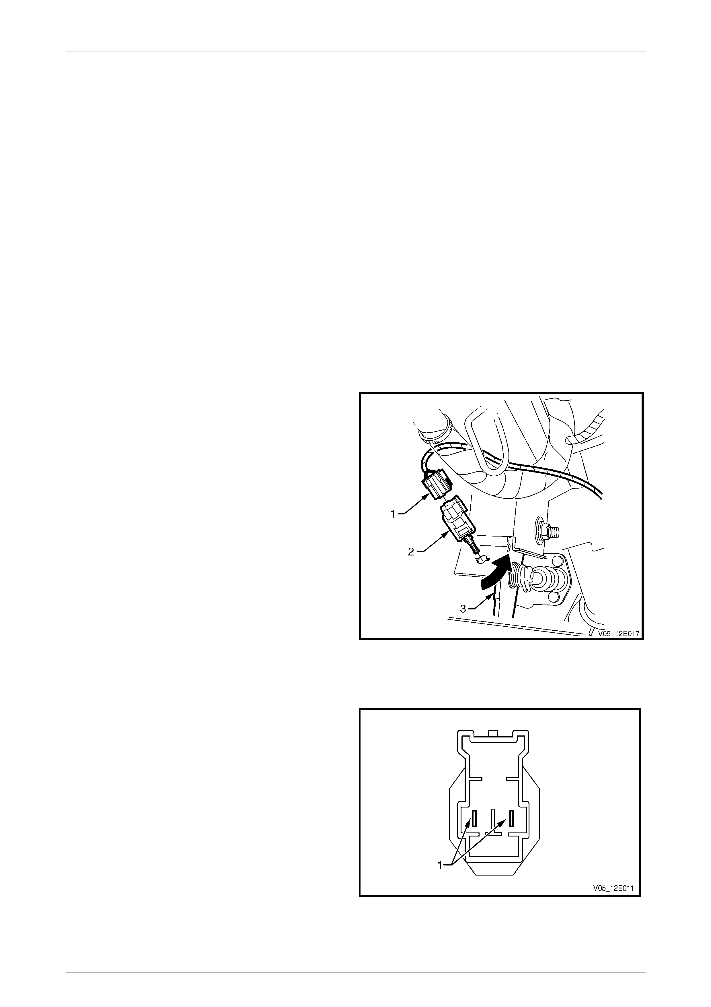
Cruise Control Page 12E–40
Page 12E–40
3.4 Clutch Pedal Switch
LT Section No. — 03–400
Remove
NOTE
V6 Vehicles are fitted with two clutch pedal switch
assemblies. The wiring diagrams treat both
physical s witches as one assembl y designate d as
S42, Clutch Pedal Position Switch Assembly.
However these are two physical switches with
separate functions. One ensures the engine can
only be cranked with the clutch pedal depressed.
One disengages the cruise control when the
clutch is depressed. The switch mounted away
from the firewall is the cruise control disengage
switch.
V8 Vehicles only have one switch fitted.
1 Remove the following instrument panel components:
a lower trim panel assembly,
b lower trim plate assembly, and
c lower trim panel retainer, refer to
Section 1A3 Instrument Panel and Co nsole.
2 Disconnect the wiring harness connectors from the
switch.
3 Turn the switch 90°, then pull the switch assembly out
from the pedal support to remove.
Figure 12E – 37
Test
1 Using a multimeter, probe the pins (1) of the switch
assembly.
2 In the neutral position (plunger extended) there should
be an open circuit across the switch.
3 In the active position (plunger extended) there should
be an closed circuit across the switch.
4 Replace the switch as per the following reinstall
procedure if the tests prove the switch to be faulty.
5 If the test proves the switch to be serviceable,
reinstall it as per the following procedure.
Figure 12E – 38

Cruise Control Page 12E–41
Page 12E–41
Reinstall
1 Install the new switch by pushing the switch assembly through the pedal support and turning the switch 90°.
2 Connect the wiring harness connectors to the clutch switch.
3 Install the instrument panel lower trim assembly and the instrument panel lower trim retainer plate, refer to
Section 1A3 Instrument Panel and Co nsole.
4 Verify the operation of the clutch switch by operating the cruise control and checking the clutch switch stops
operation of the cruise control when the clutch pedal is pressed.
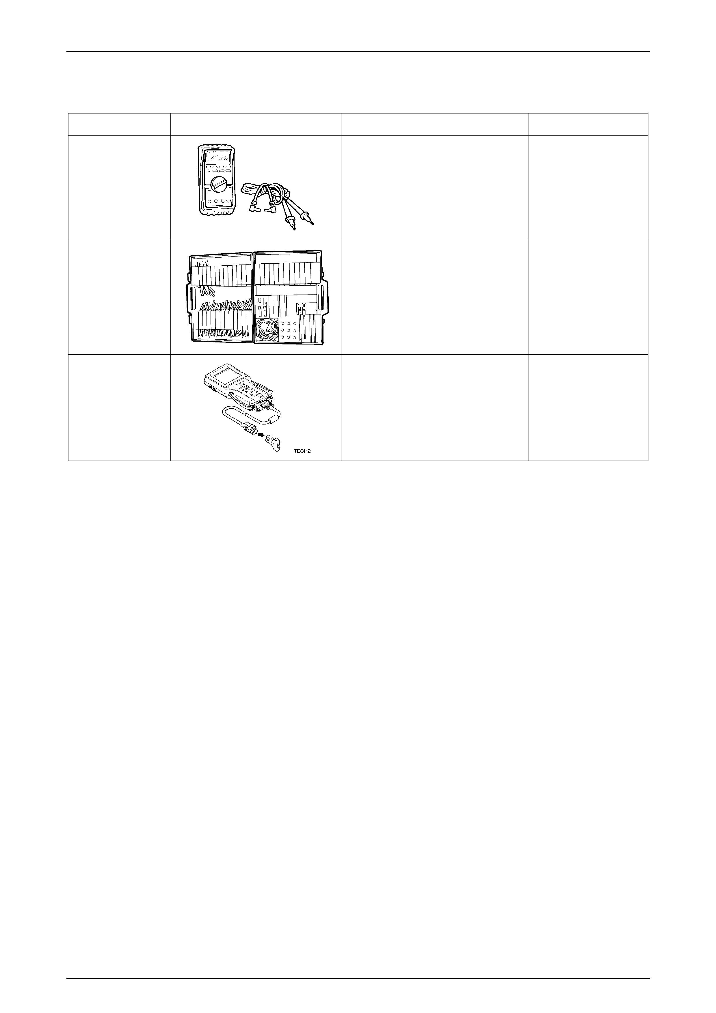
Cruise Control Page 12E–42
Page 12E–42
4 Special Tools
Tool Number Illustration Description Tool Classification
3588
Digital Multimeter
Also Previously released as J 39200
or equivalent.
NOTE: The instrument must have
10 mega ohms impedance and be
capable of reading frequencies.
Mandatory
KM-609
Electronic Kit.
Used in conjunction with a multimeter
for measuring voltages and
resistances without damaging wiring
harness connectors. Desirable.
70000861
Tech 2 Diagnostic Scan Tool
Previously released.
Mandatory