
Rear Park Assist Page 12F1–1
Page 12F1–1
Section 12F1
Rear Park Assist
ATTENTION
Before performing any Service Operation or other procedure described in this Section, refer to Section 00
Warnings, Cautions and Notes for correct workshop practices with regard to safety and/or property damage.
1 General Information ...............................................................................................................................4
1.1 Operation................................................................................................................................................................ 5
Detection and Warning – Rear Objects................................................................................................................ 5
Provisions for Towbar Fitment............................................................................................................................ 5
1.2 Components........................................................................................................................................................... 6
Rear Object Sensor Control Module and Alarm Assembly................................................................................ 6
Sedan................................................................................................................................................................. 6
Coupe................................................................................................................................................................. 6
AWD Wagon ...................................................................................................................................................... 7
Rear Object Sensor Assembly.............................................................................................................................. 8
Sedan................................................................................................................................................................. 8
Coupe................................................................................................................................................................. 9
AWD Wagon .................................................................................................................................................... 10
Wiring Harness Assembly................................................................................................................................... 11
Sedan............................................................................................................................................................... 11
Coupe............................................................................................................................................................... 12
AWD Wagon .................................................................................................................................................... 13
2 Diagnostics...........................................................................................................................................14
2.1 Prerequisites........................................................................................................................................................ 14
Equipment ............................................................................................................................................................ 14
Testing Procedures ............................................................................................................................................. 14
2.2 Wiring Diagrams – V6.......................................................................................................................................... 15
Manual Transmission .......................................................................................................................................... 15
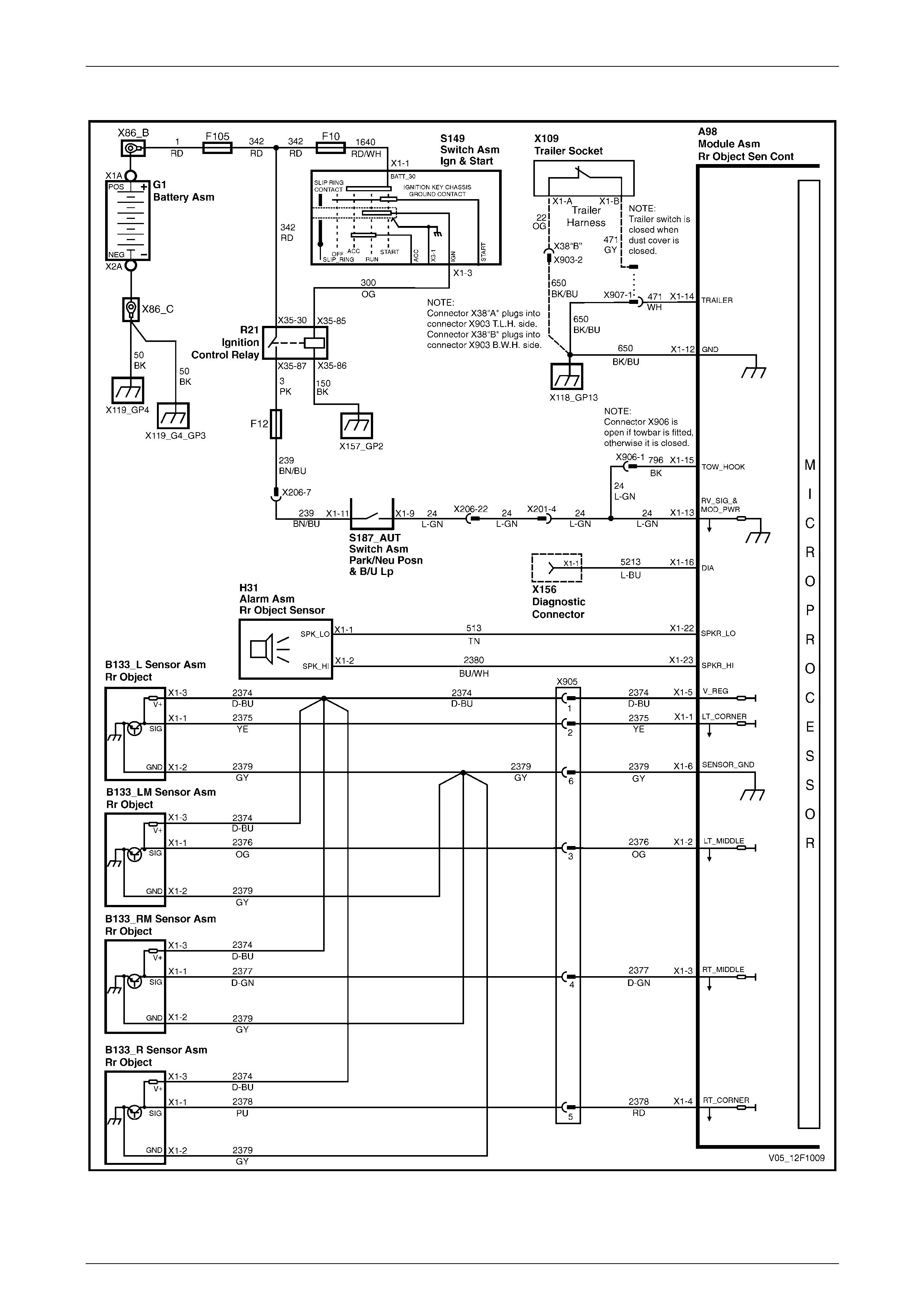
Automatic Transmission 4-Speed...................................................................................................................... 16
Automatic Transmission 5-Speed...................................................................................................................... 17
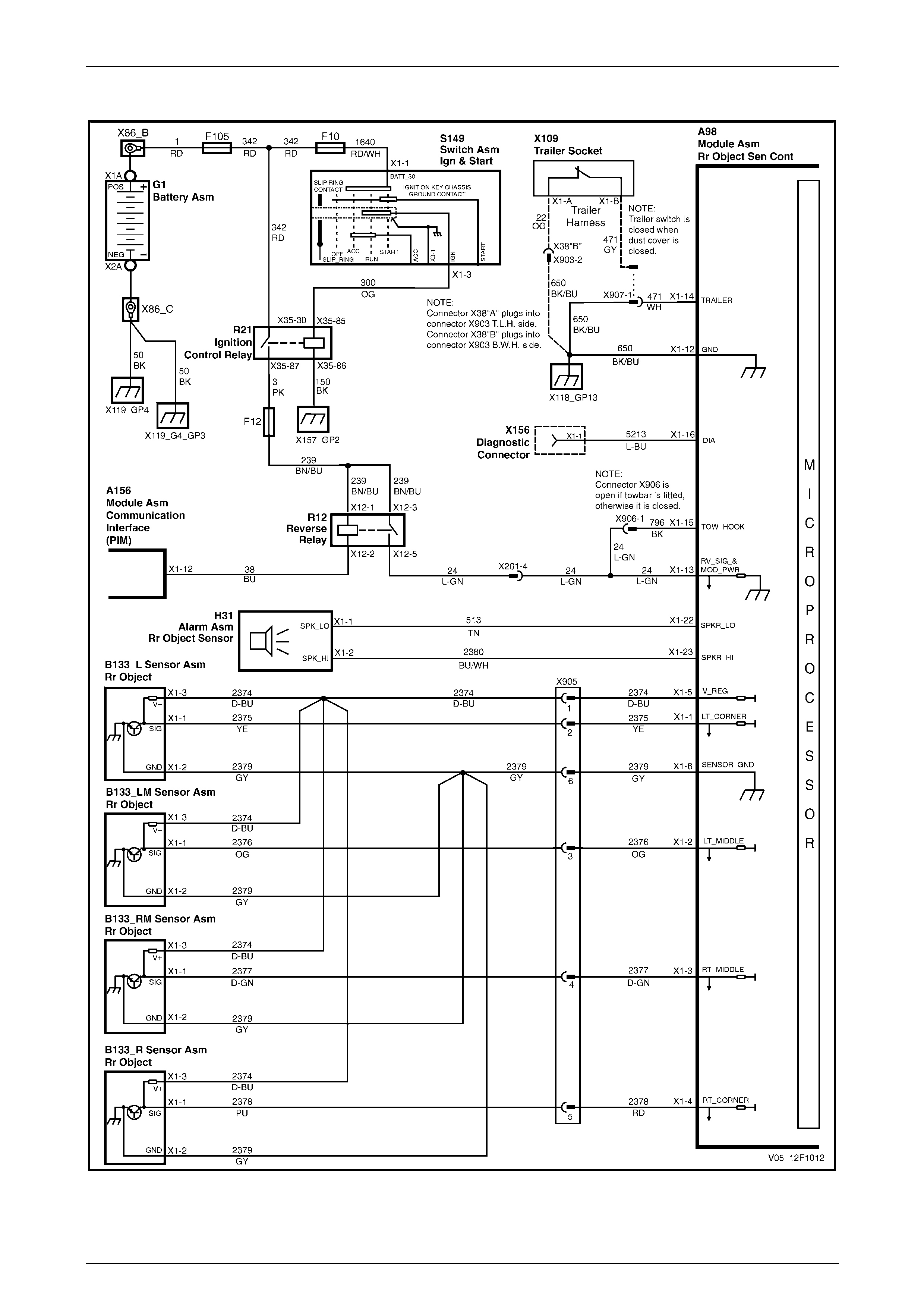
2.3 Wiring Diagrams – V8.......................................................................................................................................... 18
Manual Transmission .......................................................................................................................................... 18
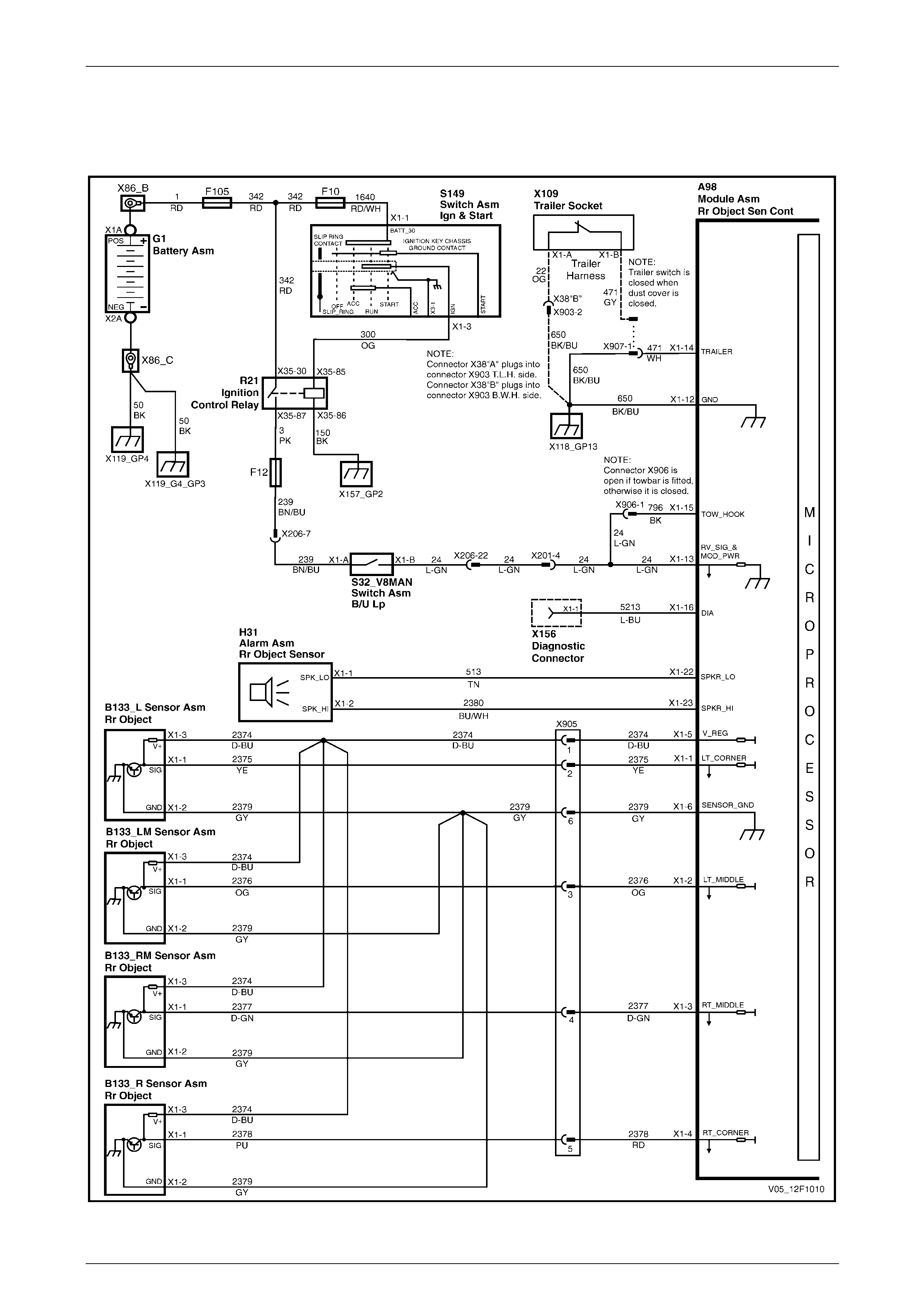
Automatic Transmission 4-Speed...................................................................................................................... 19
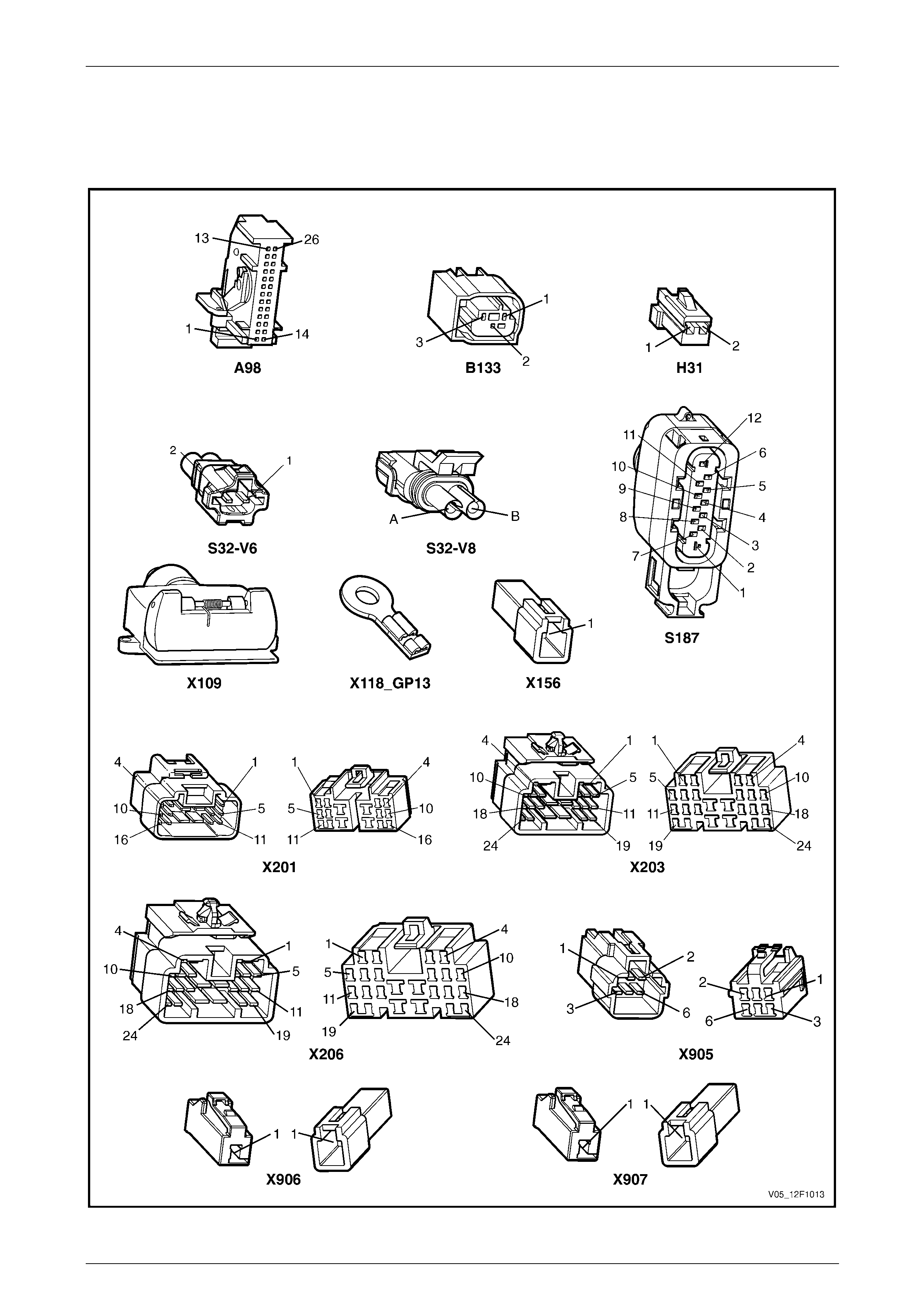
2.4 Connector Charts................................................................................................................................................. 20
All Except V6 Automatic Transmission 5-Speed............................................................................................... 20
V6 Automatic Transmission 5-Speed................................................................................................................. 21
2.5 Electrical Diagnosis............................................................................................................................................. 22
Introduction.......................................................................................................................................................... 22
2.6 Electrical Self Test Diagnosis............................................................................................................................. 23
2.7 Ground Connection Circuit Test......................................................................................................................... 24
Introduction.......................................................................................................................................................... 24
Circuit Description............................................................................................................................................... 24
Test Descriptions................................................................................................................................................. 24
Diagnostic Table Notes ....................................................................................................................................... 24
Diagnostic Table.................................................................................................................................................. 24
Techline

Rear Park Assist Page 12F1–2
Page 12F1–2
2.8 Power Input Circuit Test...................................................................................................................................... 26
V6 Manual Transmission..................................................................................................................................... 26
Introduction ...................................................................................................................................................... 26
Circuit Description............................................................................................................................................ 26
Test Description ............................................................................................................................................... 26
Diagnostic Table Notes .................................................................................................................................... 26
Diagnostic Table............................................................................................................................................... 27
4 Speed Auto Transmission and V8 Manual Transmission ............................................................................. 28
Introduction ...................................................................................................................................................... 28
Circuit Description............................................................................................................................................ 28
Test Description ............................................................................................................................................... 28
Diagnostic Table Notes .................................................................................................................................... 28
Diagnostic Table............................................................................................................................................... 29
5 Speed Auto Transmission................................................................................................................................ 30
Introduction ...................................................................................................................................................... 30
Circuit Description............................................................................................................................................ 30
Test Description ............................................................................................................................................... 30
Diagnostic Table Notes .................................................................................................................................... 30
Diagnostic Table............................................................................................................................................... 30
2.9 Self Diagnosis Circuit Test.................................................................................................................................. 32
Introduction.......................................................................................................................................................... 32
Circuit Description............................................................................................................................................... 32
Diagnostic Table Notes ....................................................................................................................................... 32
Diagnostic Table.................................................................................................................................................. 32
2.10 No Audible Tone From Alarm ............................................................................................................................. 33
Introduction.......................................................................................................................................................... 33
Circuit Description............................................................................................................................................... 33
Diagnostic Table Notes ....................................................................................................................................... 33
Diagnostic Table.................................................................................................................................................. 33
2.11 Object Sensor Circuit Test.................................................................................................................................. 34
Introduction.......................................................................................................................................................... 34
Circuit Description............................................................................................................................................... 34
Test Descriptions................................................................................................................................................. 34
Diagnostic Table Notes ....................................................................................................................................... 34
Diagnostic Table.................................................................................................................................................. 35
2.12 Rear Object Sensor Control Module Pin Assignments .................................................................................... 36
3 Service Operations...............................................................................................................................37
3.1 Rear Object Sensor Control Module Assembly................................................................................................. 37
Sedan.................................................................................................................................................................... 37
Remove............................................................................................................................................................ 37
Reinstall ........................................................................................................................................................... 37
Coupe.................................................................................................................................................................... 38
Remove............................................................................................................................................................ 38
Reinstall ........................................................................................................................................................... 38
AWD Wagon ......................................................................................................................................................... 39
Remove............................................................................................................................................................ 39
Reinstall ........................................................................................................................................................... 39
3.2 Rear Object Sensor Alarm Assembly................................................................................................................. 40
Sedan.................................................................................................................................................................... 40
Remove............................................................................................................................................................ 40
Reinstall ........................................................................................................................................................... 40
Coupe.................................................................................................................................................................... 41
Remove............................................................................................................................................................ 41
Reinstall ........................................................................................................................................................... 41
AWD Wagon ......................................................................................................................................................... 42
Remove............................................................................................................................................................ 42
Reinstall ........................................................................................................................................................... 42

Rear Park Assist Page 12F1–3
Page 12F1–3
3.3 Rear Object Sensor Assembly and Wiring Harness......................................................................................... 43
Sedan.................................................................................................................................................................... 43
Remove............................................................................................................................................................ 43
Reinstall ........................................................................................................................................................... 44
Coupe.................................................................................................................................................................... 44
Remove............................................................................................................................................................ 44
Reinstall ........................................................................................................................................................... 45
AWD Wagon ......................................................................................................................................................... 45
Remove............................................................................................................................................................ 45
Reinstall ........................................................................................................................................................... 46

Rear Park Assist Page 12F1–4
Page 12F1–4
1 General Information
Rear Park Assist (RPA) is an electronic system designed to provide an acoustic tone informing the driver of obstacles at
or near the rear of the vehicle during low speed maneouvres such as parking.
The RPA does not relieve the driver of duty of
care when reversing the vehicle. Caution
must always be exercised w hen driving at any
time.
The RPA primarily consists of four ultrasonic object sensor assemblies mounted to the rear bumper fascia and an
electronic control module assembly which incorpor ates an a larm assembly. Sonar is used to detect the presence of
obstacles within a defined area, b y measuring the time between the transmission and reception (ec ho) of sound waves.
When reverse gear is selected, the sensors sequentially transmit short ultrasonic pulses and then listen for an echo
reflected from an object within range. T he electronic control module uses echo data from one or more sensors to
calculate the distance to the obstacle.
An audible intermittent tone is sounded through the alarm informing the driver that an obstacle has been detected within
the range of the system. As the distance to the obstacle draws closer, the frequency of the tone increases until it
becomes constant at a distance of approximately 30 cm or, for vehicles fitted with a towbar, 45 cm.
NOTE
Some sound absorbing or reflecting material s can
effect the range of detection. In extreme cases,
temporary non-detection of ob stacles can result.
The RPA only signifies the closest detected object.
While operational, the control module constantly monitors the system for faults. Should a fault occur, an audible warning
is indicated to the driver. A dia gnosis system aids the technician in locating the source of the fault.
Rear Park Assist Page 12F1–5
Page 12F1–5
1.1 Operation
Detection and Warning – Rear Objects
When the ignition is on and reverse gear is selected, a tone
will sound from the alarm for a period of 0.5 seconds to
indicate system readiness.
The control module provides a voltage to each sensor
sequentially which is converted into an ultrasonic pulse.
Where an object is within the detection range, the ultrasonic
pulse is reflected (echoed) and received by the same and/or
adjacent sensors.
The echoes are amplified, processed and returned to the
control module as a digital signal. The control module
processes this information and informs the driver of the
object by activating an intermittent acoustic tone through the
alarm.
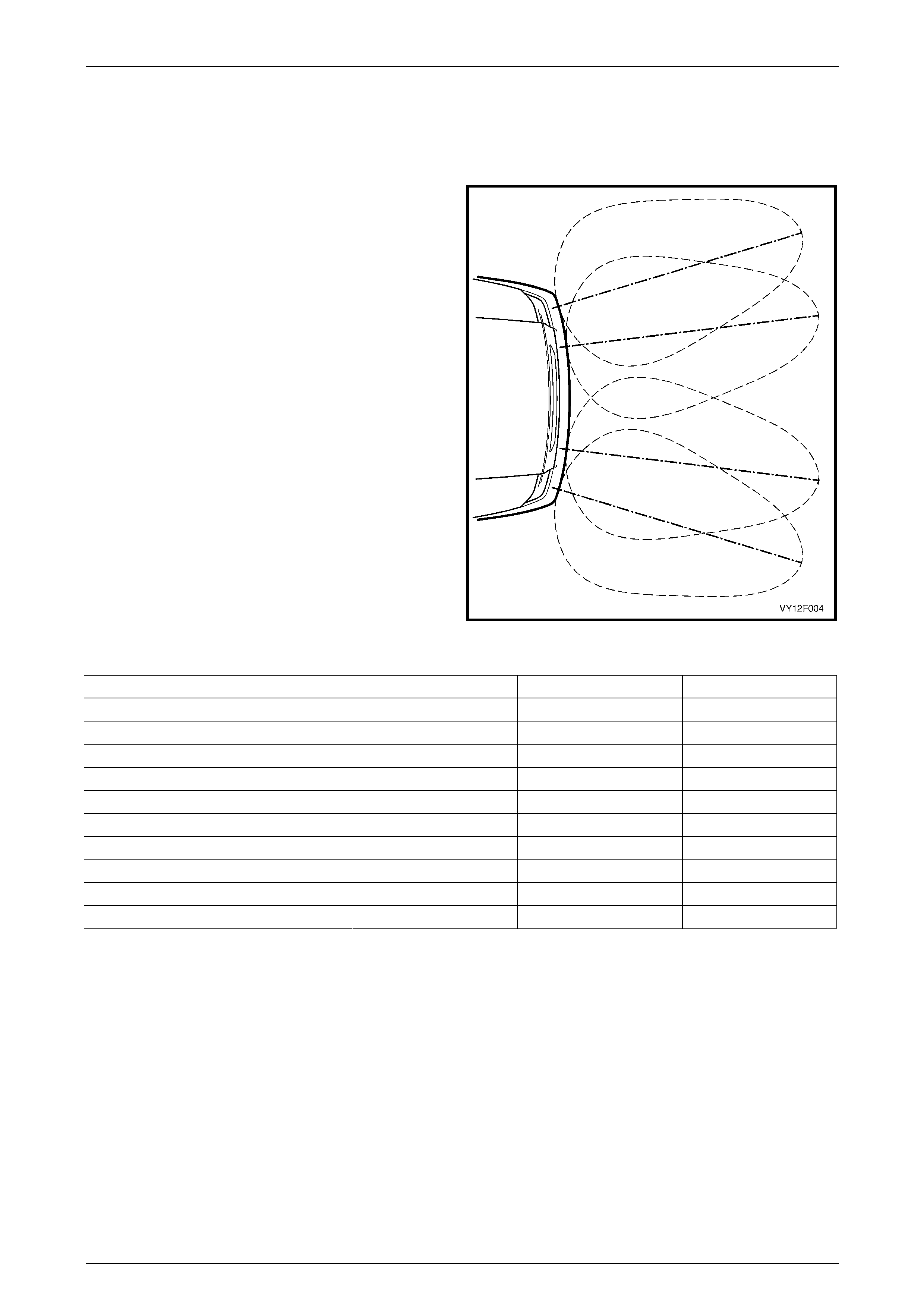
The four sensors are mounted onto the rear bumper fascia
in an arrangement that provid es a slight overlap of the polar
patterns. This provides the best coverage of the detection
area. The maximum detection distance of 150 cm is set by
the control module software.
The detection area is divided into five warning zones. As
listed in the following table, the tone-o n to tone-off peri od
shortens as the distance to the detected object decreases.
Figure 12F1 – 1
Warning Range (cm) Frequency (Hz) Tone On Tone Off
Less than 30 1200 Continuous
30 – 40 1200 75 ms 75 ms
40 – 60 1200 75 ms 150 ms
60 – 80 1200 75 ms 225 ms
80 – 100 1200 75 ms 300 ms
100 – 120 1200 75 ms 375 ms
120 – 150 1200 75 ms 450 ms
Hardware Error 700 Continuous at power up
Error Message 700 Continuous at power up
Ready Tone, Reverse Engage d 1200 0.5 sec
Provisions for Towbar Fitment
When a towbar is fitted, the continuous tone activation area is increased from 30 to 45cm to allow for the length of the
towbar tongue. This is achieved by the towbar installer disconnecting the white wiring connector X9 06 causing an open
in the power supply circuit 24 and 796 to the control module (pin 15).
When the correct accessory trailer wiring harness is installed, the system can be temporarily disabled while towing. The
black connector X907 in circ uit 650 and 471 is also disconnected by the installer and the grey wire in the trailer harness
connected.
While the trailer socket dust-flap is closed, a magnet in the dust-flap closes a reed-switch in the trailer socket which
connects this circuit to ground through circuit 22.
When the dust-flap is opened, as in connecting a trailer plug, the switch opens. The control module detects the open
circuit and disables the system.
If a bicycle carrier is fitted onto the towbar, a licence plate lamp and tail lamp should be fitted to the carrier and plugged
into the trailer socket. This will also temporarily disabl e the system, as it is highly likely the bicycles will cause a
disturbance to the detection field.
The rear park assist can also be disa bled by disconnecting connector X907. In this instance, the presence or absence of
a connector in the trailer socket is ignor ed.

Rear Park Assist Page 12F1–6
Page 12F1–6
1.2 Components
Rear Object Sensor Control Module and Alarm Assembly
The role of the control module is to trigger ultrasonic pulses sequentially from each sensor and monitor the sensors for
any received pulses (ec hoes from an object). The signals are then filtered and the distance of the object is calculated
from the time elapsed bet ween the transmission of the signal and its reception using triangulation d ata from one or more
sensors. The control module also controls th e output tones through the alarm, and has a self-diagnosis function.
The control module also provides a stable voltage supply to the rear object sensors and circuits to protect the sensors
against over-voltage.
Sedan
The rear object sensor control module (1) and alarm (2) are joined together. They are mounted as an assembly to the
rear window panel, refer to Figure 12F1 – 2.
Figure 12F1 – 2
Coupe
The rear object sensor control module and alarm are joined together. They are mounted a s an assembly (1) to the right-
hand rear radio speaker bracket, refer to Figure 12F1 – 3.
Figure 12F1 – 3
Rear Park Assist Page 12F1–7
Page 12F1–7
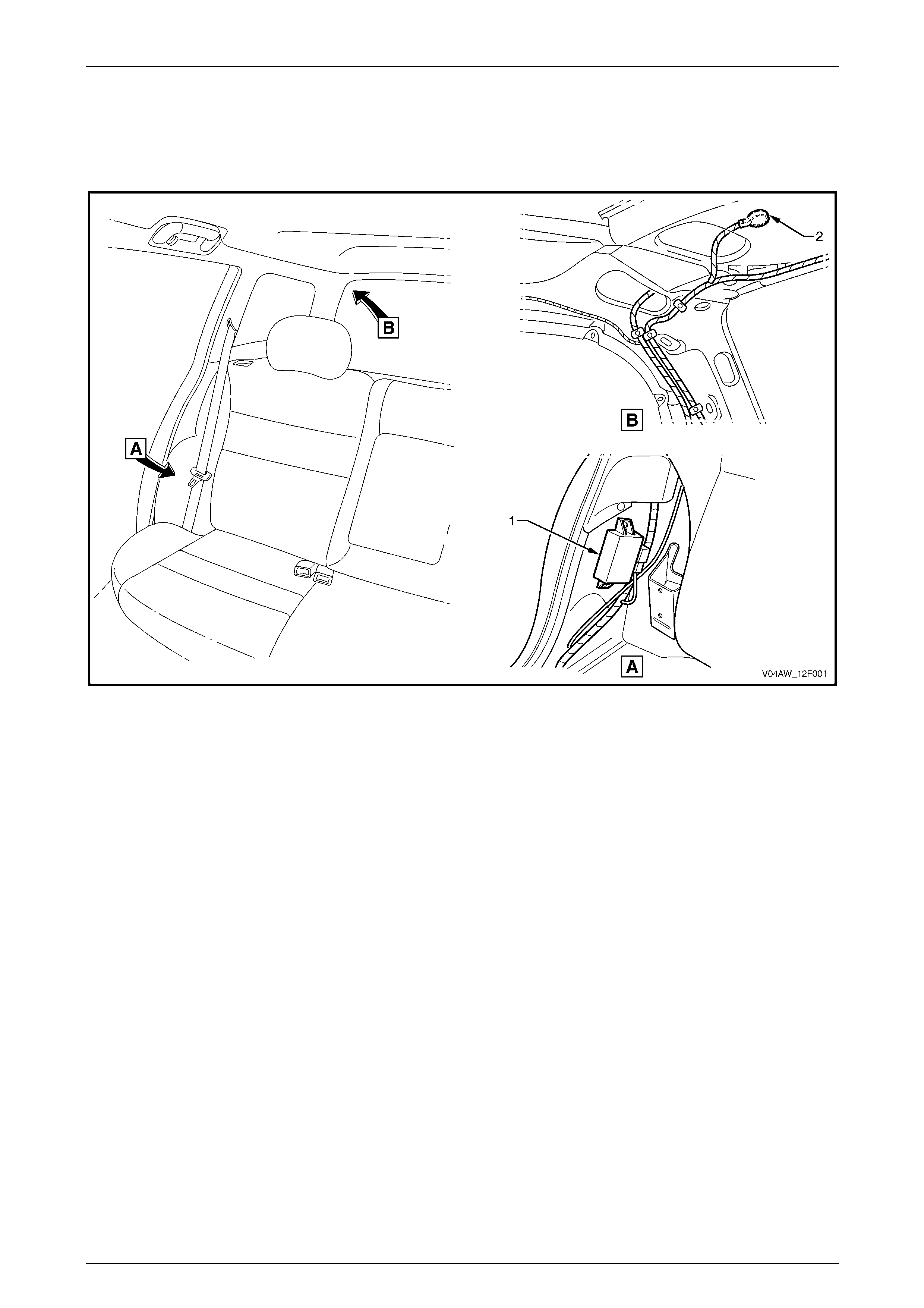
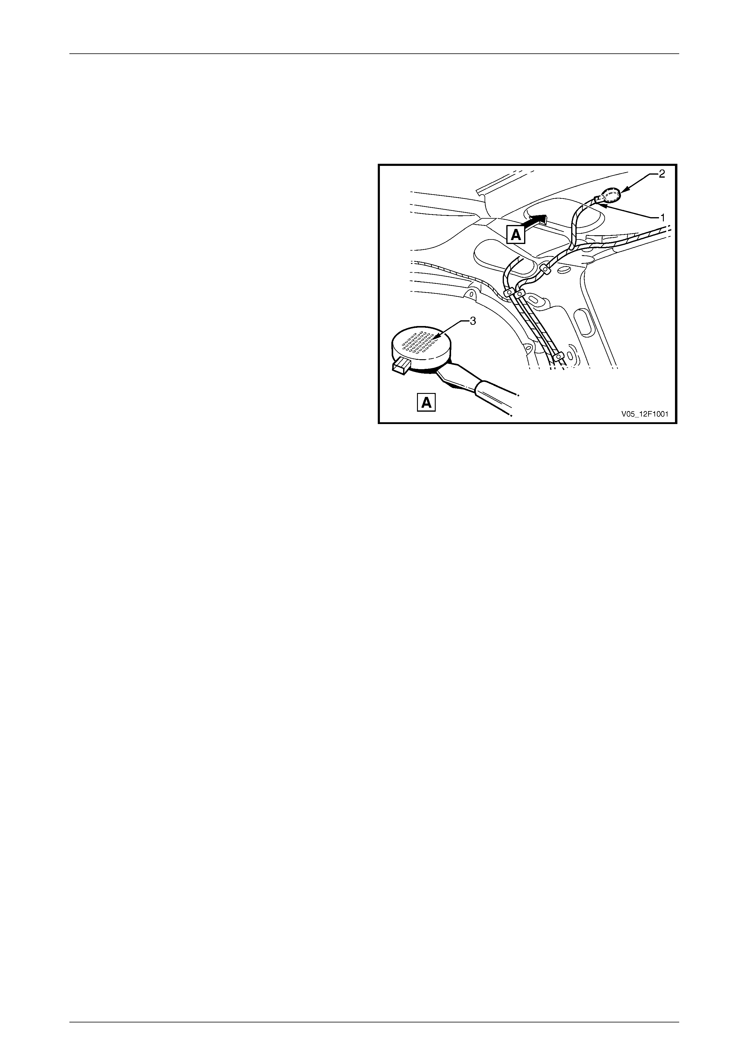
AWD Wagon
The rear object sensor control module (1) is located behind the right-hand rear seat bolster assembly, refer to Figure
12F1 – 4.
The rear object sensor alarm (2) is located in the roof cavity under the headlining at the right-hand rear of the vehicle.
Figure 12F1 – 4
Rear Park Assist Page 12F1–8
Page 12F1–8
Rear Object Sensor Assembly
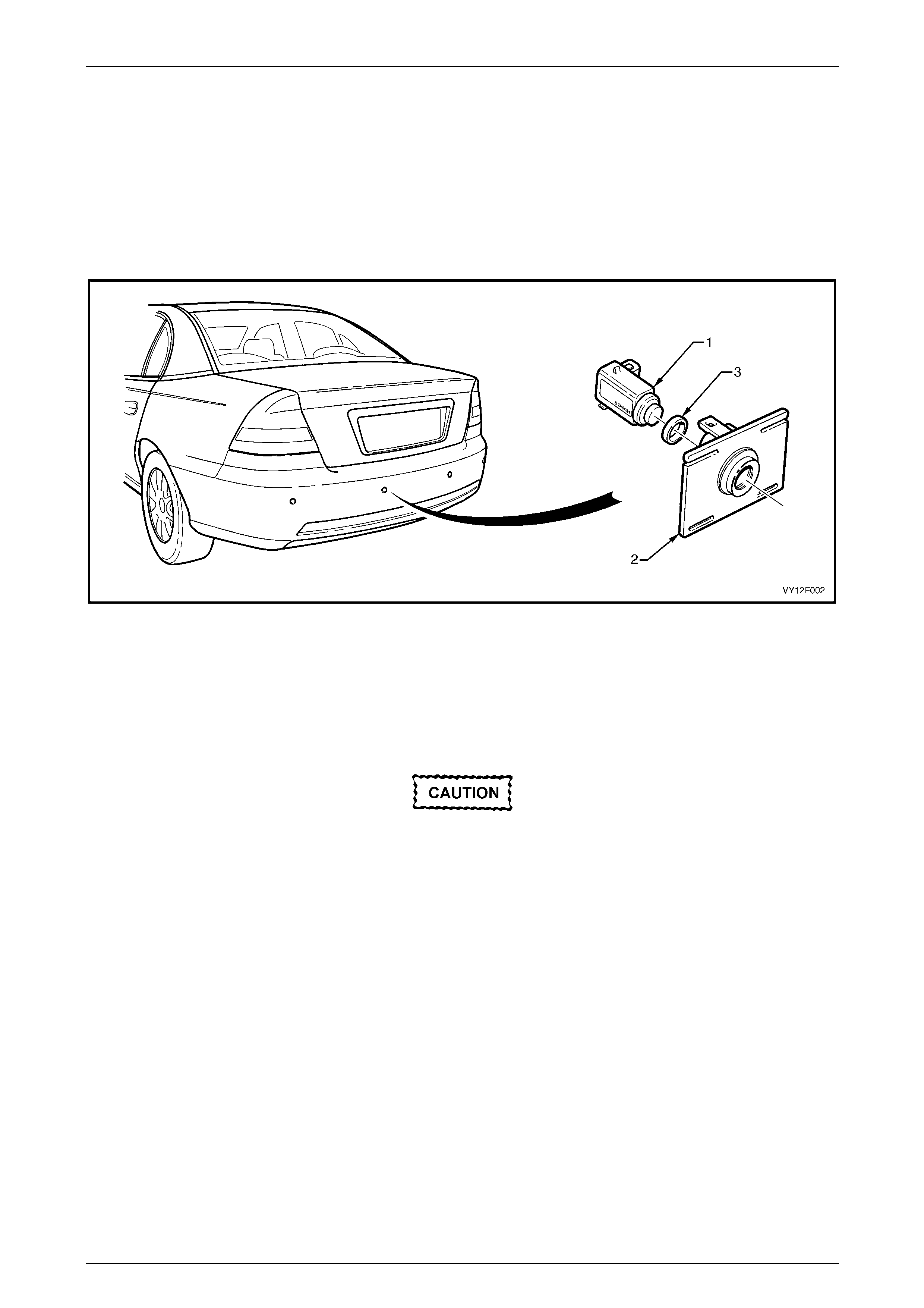
Sedan
There are four sensors mounted in the rear b umper fascia. Each sensor operates as a transmitter and receiver of
ultrasonic pulses. The received electronic pulses (echoes) are amplified, processed and returned to the control module
as a digital signal.
Each of the four rear object sensor assemblies (1) are mounted in a rear object sensor housing (2) which is heat-staked
to the rear bumper fascia. The housings a llow easy removal of the sensor and rear object sensor ring (3), refer to Figure
12F1 – 5.
Figure 12F1 – 5
If the rear bumper fascia assembly is to be replaced, undamaged housings can be removed from the bumper fascia by
cutting the four attaching heat-stakes. T he housing can then be heat-staked onto the new fascia with a soldering iron,
refer to Section 1D Bumper Bars. If the housings are damaged, replac ement parts are available. New housings are to be
painted to match the bumper fascia using similar methods to painting the fascia, refer to Section 1D Bumper Bars.
The rear object sensor is supplied with the exposed surface painted in the vehicle’s bod y c olo ur.
• Replacement rear object sensor
assemblies are sup plied pre-painted in the
vehicle's body colour. Do not apply further
paint to the rear ob ject sensor as semblies,
as it will have a detrimental effect on the
operation of the rear object sensor
assemblies.
• The rear object sensor ring prevents
vibrations from the rear object sensor
assembly being transferred to the
surrounding components. Incorrect
fitment will change the characteristics of
the rear object sensor assembly.
Rear Park Assist Page 12F1–9
Page 12F1–9
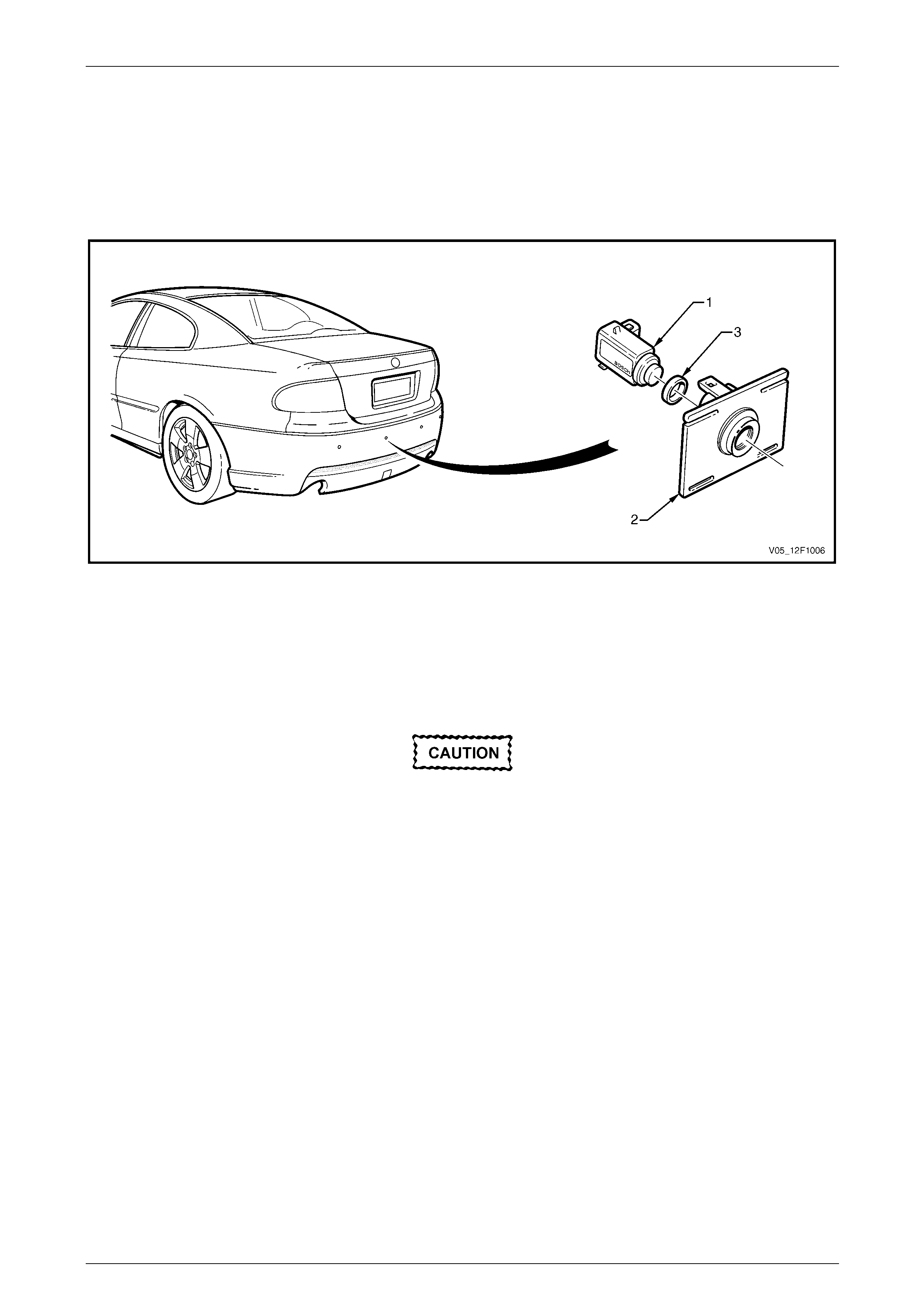
Coupe
There are four sensors mounted in the rear b umper fascia. Each sensor operates as a transmitter and receiver of
ultrasonic pulses. The received electronic pulses (echoes) are amplified, processed and returned to the control module
as a digital signal.
Each of the four rear object sensor assemblies (1) are mounted in a rear object sensor housing (2) which is heat-staked
to the rear bumper fascia. The housings a llow easy removal of the sensor and rear object sensor ring (3), refer to Figure
12F1 – 6.
Figure 12F1 – 6
If the rear bumper fascia assembly is to be replaced, undamaged housings can be removed from the bumper fascia by
cutting the four attaching heat-stakes. T he housing can then be heat-staked onto the new fascia with a soldering iron,
refer to Section 1D Bumper Bars. If the housings are damaged, replac ement parts are available. New housings are to be
painted to match the bumper fascia using similar methods to painting the fascia, refer to Section 1D Bumper Bars.
The rear object sensor is supplied with the exposed surface painted in the vehicle’s bod y c olo ur.
• Replacement rear object sensor
assemblies are sup plied pre-painted in the
vehicle's body colour. Do not apply further
paint to the rear ob ject sensor as semblies,
as it will have a detrimental effect on the
operation of the rear object sensor
assemblies.
• The rear object sensor ring prevents
vibrations from the rear object sensor
assembly being transferred to the
surrounding components. Incorrect
fitment will change the characteristics of
the rear object sensor assembly.
Rear Park Assist Page 12F1–10
Page 12F1–10
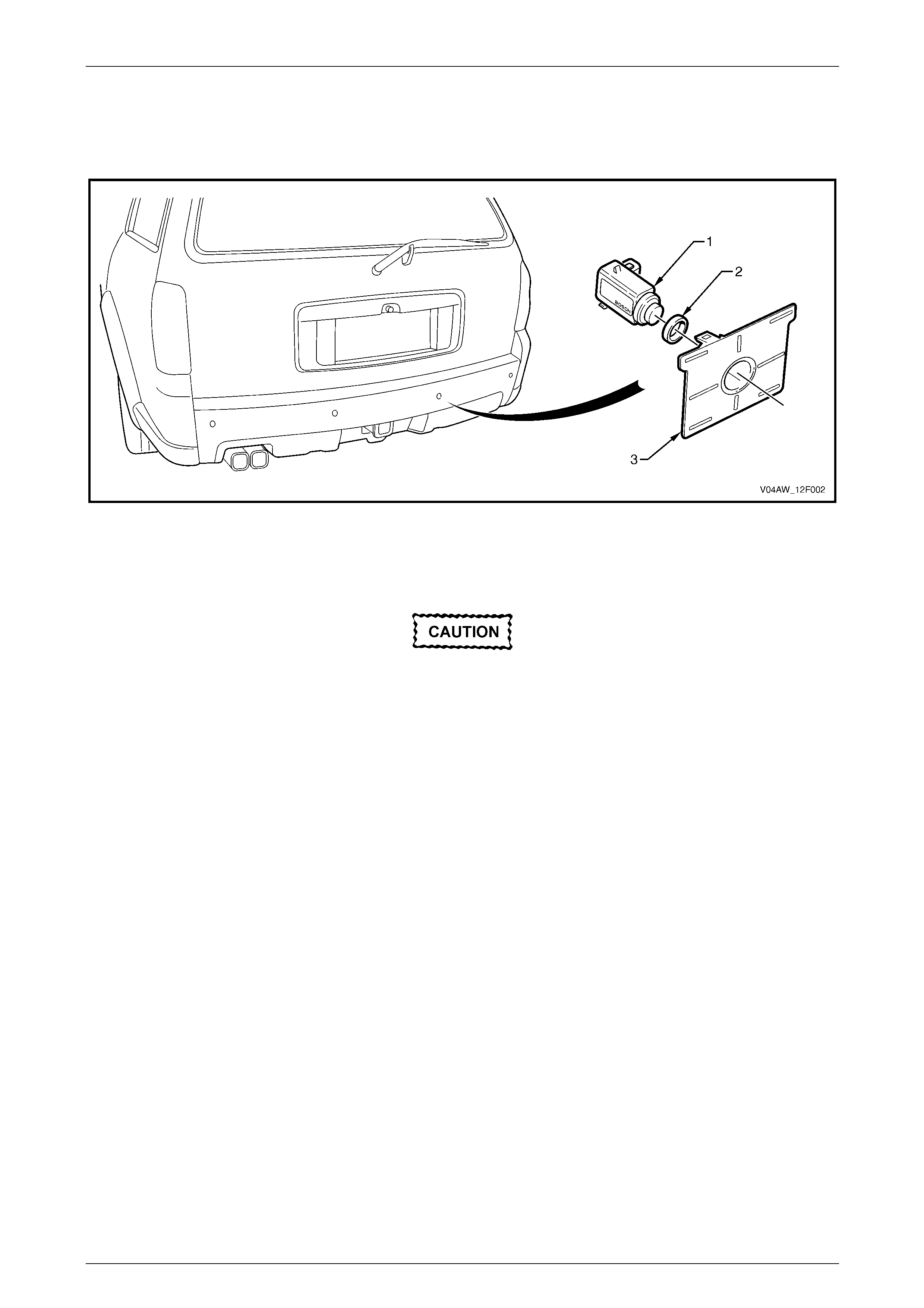
AWD Wagon
Each of the rear object sensor assemblies (1) is mounted in a rear object sensor housing (3), which is retained by clips to
the rear bumper fascia assembly. The rear o bject sensor housings allow for easy removal of the rear object sensor
assembly and the rear object sensor ri ng (2), refer to Figure 12F1 – 7.
Figure 12F1 – 7
Each rear object sensor assembly operates as a transmitter and receiver of ultrasonic pulses. The exposed surface is
supplied painted in the vehicle's colour.
• Replacement rear object sensor
assemblies are sup plied pre-painted in the
vehicle's body colour. Do not apply further
paint to the rear ob ject sensor as semblies,
as it will have a detrimental effect on the
operation of the rear object sensor
assemblies.
• The rear object sensor ring prevents
vibrations from the rear object sensor
assembly being transferred to the
surrounding components. Incorrect
fitment will change the characteristics of
the rear object sensor assembly.
Rear Park Assist Page 12F1–11
Page 12F1–11
Wiring Harness Assembly
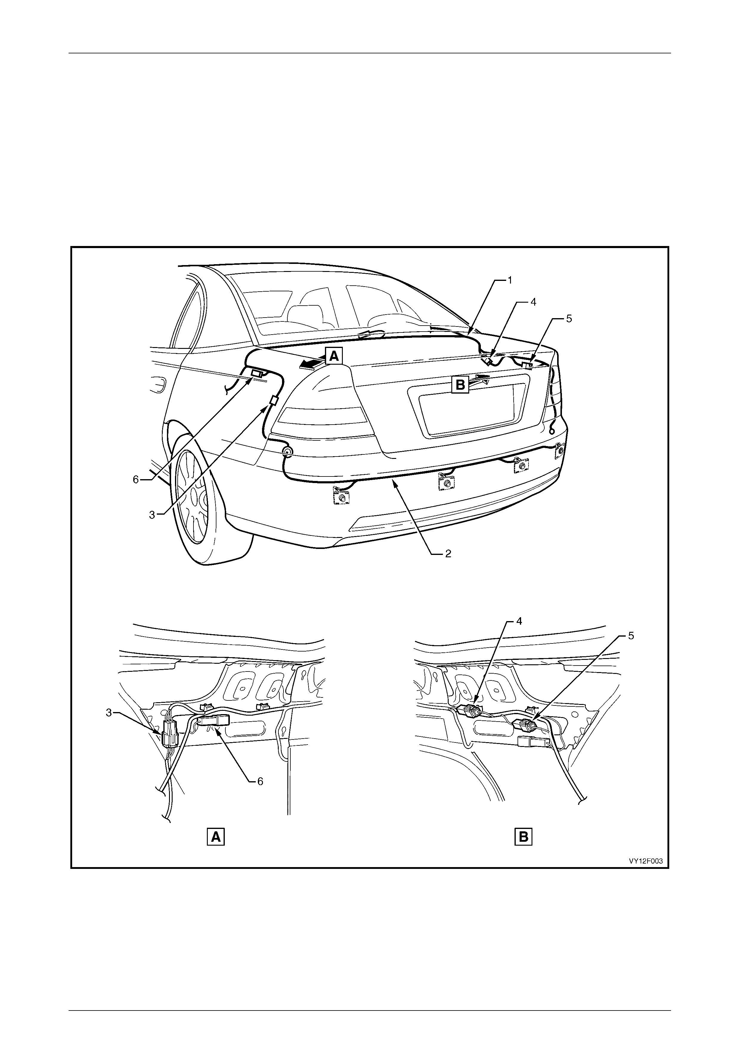
Sedan
The body wiring harness (1) is routed as shown, refer to Figure 12F1 – 8. The rear object sensor harness (2) connects to
the body wiring harness with connector X905 (3) near the left-hand tail lamp assembly and is routed across the inner
side of the rear bumper fascia, connecting each of the four sensors.
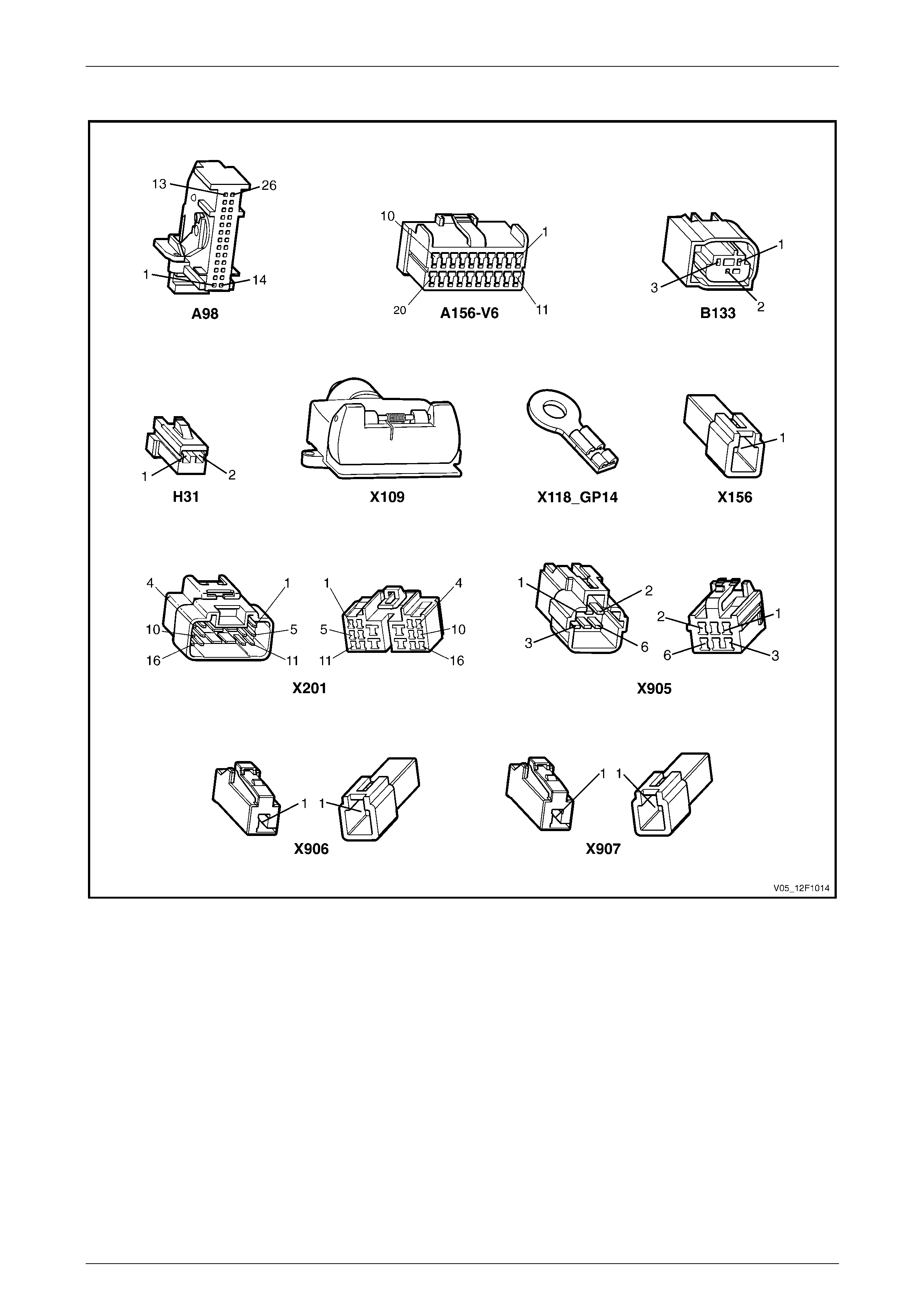
The white wiring connector X9 06 (4) is provided to enable modification of the detection area for the fitment of a towbar
tongue.
The diagnostic connector X156 (6) is locate d on the left-hand side of the rear compartment,
refer to 2.6 Electrical Self Test Diagnosis for further information.
Figure 12F1 – 8
Legend
1 Body Wiring Harness
2 Rear Object Sensor Harness
3 Rear Object Sensor to Body Harness Connector X905
4 Towbar Tongue Modification Connector X906 (white)
5 Trailer Harness Connector X907 (black)
6 Diagnosis Connector X156
Rear Park Assist Page 12F1–12
Page 12F1–12
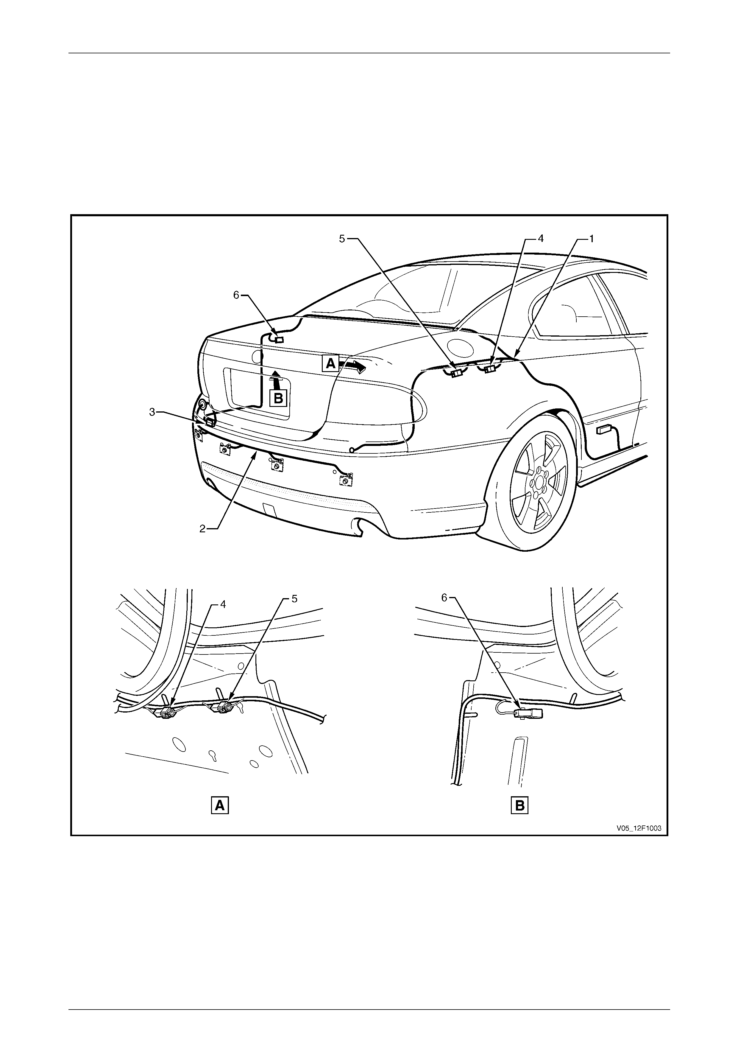
Coupe
The body wiring harness (1) is routed as shown, refer to Figure 12F1 – 9. The rear object sensor harness (2) connects to
the body wiring harness with connector X905 (3) near the left-hand tail lamp assembly and is routed across the inner
side of the rear bumper fascia, connecting each of the four sensors.
The white wiring connector X9 06 (4) is provided to enable modification of the detection area for the fitment of a towbar
tongue.
The diagnostic connector X156 (6) is locate d on the left-hand side of the rear compartment,
refer to 2.6 Electrical Self Test Diagnosis for further information.
Figure 12F1 – 9
Legend
1 Body Wiring Harness
2 Rear Object Sensor Harness
3 Rear Object Sensor to Body Harness Connector X905
4 Towbar Tongue Modification Connector X906 (white)
5 Trailer Harness Connector X907 (black)
6 Diagnosis Connector X156

Rear Park Assist Page 12F1–13
Page 12F1–13
AWD Wagon
The body wiring harness (1) is routed along the right-hand side of the vehicle, refer to Figure 12F1 – 10. The body wiring
harness passes through a gro mmet to the outside of the vehicle and is connected to the rear object sensor harness (2)
using connector X905 (3). The rear object sensor harness is routed across the inside of the rear bumper fascia
assembly, connecting the four rear object sensor assemblies.
The white wiring connector X9 06 (4) is provided to enable modification of the detection area for the fitment of a towbar
tongue.
The diagnosis conn ector X156 (6) is located behind the right-hand quarter trim panel vent (8),
refer to 2.6 Electrical Self Test Diagnosis for further information.
Figure 12F1 – 10
Legend
1 Body Wiring Harness
2 Rear Object Sensor Harness
3 Rear Object Sensor to Body Harness Connector X905
4 Towbar Tongue Modification Connector X906 (white)
5 Trailer Harness Connector X907 (black)
6 Diagnostic Connector X156
7 Rear Object Sensor Control Module
8 Right-hand Quarter Trim Panel Vent
9 Rear Object Sensor Alarm Assembly

Rear Park Assist Page 12F1–14
Page 12F1–14
2 Diagnostics
This Section provides charts to assist in the diagnosis and repa ir of the rear park assist system.
2.1 Prerequisites
Equipment
The following equipment is required to diagnose the rear park assist system:
• an unpowered test lamp with a current draw of less than 3 A, and
• a digital multimeter with a minimum impe dance of 10 MΩ.
Testing Procedures
Adhere to the following points when
performing diagnostic testing on
components:
• Take care when using testing equipment
to diagnose wiring harness connectors.
Backprobe the connector to avoid terminal
damage.
• When tests are required on connector
terminals, use the adapters in the
connector adapter kit KM–609 to prevent
damage to the terminals.
• Unless the multimeter being used has an
auto-ranging function, ensure the correct
range is selected.
• When backpro bing connectors, ensure the
test lamp ground lead is connected to an
appropriate ground point on the vehicle.
Ensure this ground point is not part of the
circuit being tested.
• Where it is possible to touch connector
pins, correct Electro-Static Discharge
(ESD) protection procedures, including the
use of a grounded wrist strap and an anti-
static mat, must be followed.
NOTE
When following the steps in the di agnostic tables,
perform them in the order cited. If the required
nominal value or result is not achi eved, rectif y t he
problem before proceeding.
Rear Park Assist Page 12F1–15
Page 12F1–15
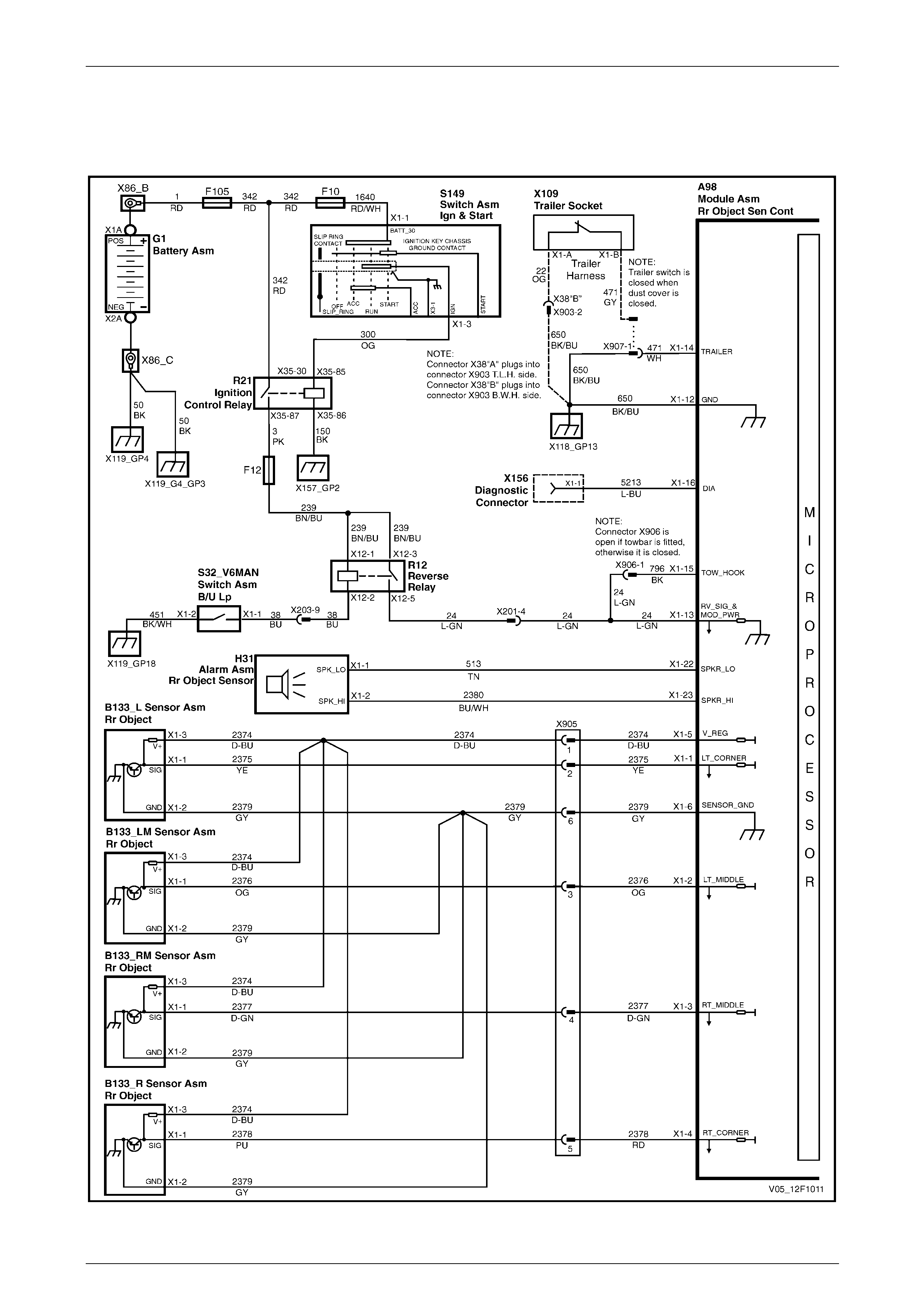
2.2 Wiring Diagrams – V6
Manual Transmission
Figure 12F1 – 11

Rear Park Assist Page 12F1–16
Page 12F1–16
Automatic Transmission 4-Speed
Figure 12F1 – 12
Rear Park Assist Page 12F1–17
Page 12F1–17
Automatic Transmission 5-Speed
Figure 12F1 – 13
Rear Park Assist Page 12F1–18
Page 12F1–18
2.3 Wiring Diagrams – V8
Manual Transmission
Figure 12F1 – 14
Rear Park Assist Page 12F1–19
Page 12F1–19
Automatic Transmission 4-Speed
Figure 12F1 – 15
Rear Park Assist Page 12F1–20
Page 12F1–20
2.4 Connector Charts
All Except V6 Automatic Transmission 5-Speed
Figure 12F1 – 16
Rear Park Assist Page 12F1–21
Page 12F1–21
V6 Automatic Transmission 5-Speed
Figure 12F1 – 17

Rear Park Assist Page 12F1–22
Page 12F1–22
2.5 Electrical Diagnosis
Introduction
The rear park assist system is initialised once the ignition is switched on and reverse gear is selected. A ready tone will
sound for a period of 0.5 seconds. In this state, the rear obje ct sensor control module continuously monitors the system
and should a fault be detected, a continuous 700 Hz tone will sound.

Rear Park Assist Page 12F1–23
Page 12F1–23
2.6 Electrical Self Test Diagnosis
The rear park assist system incorporates a self diagnostic function.
Using this electrical self test may assist in
locating the area where the fault has
occurred, however the relevant circuit
diagnostic test should be consulted before
replacing any components.
NOTE
Faults are stored in non-volatile memory within
the control module while present. Past faults are
not retained.
The rear park assist system is placed in diagnostic mode by the following method:
1 Ground connector X156 – X1 pin 1, located on the left-hand side of the rear compartme nt, refer to Figure 12F1 – 8,
Figure 12F1 – 9 or Figure 12 F 1 – 10.
2 Switch the ignition on. Do not start the engine.
3 Select reverse gear.
4 Note the tones and refer to the relevant diagnostic tables in this Section.
NOTE
If more than one error is detected, the tone will be
output in sequence separated by the End pause.
The sequence of faults will be repeated
continuously while the system remains in self-
diagnosis mode.
No Fault Continuous cyclic tone of 3 seconds On, 3 seconds Off (Start and End tone only)
Sensor 1 (right) Fault Start On Off End
Sensor 2 (right middle) Fault Start On Off On Off End
Sensor 3 (left middle) Fault Start On Off On Off On Off End
Sensor 4 (left) Fault Start On Off On Off On Off On Off End
ECM Fault Start Int Int Int End
Legend
Start – Tone on for three seconds and off for one second.
On – Tone on for one second.
Off – Tone off for one second.
End – Tone off for two seconds.
Int – Interval tone (on / off) for one second.

Rear Park Assist Page 12F1–24
Page 12F1–24
2.7 Ground Connection Circuit Test
Introduction
This test is used by the technician to aid in the diagnosis of the rear park assist system ground circuits.
Circuit Description
The rear object sensor control module is grounded through two circuits. One is a dedicated ground circuit, the other is
provided with a connection to allow integration of a trailer harness switch.
Refer to the wiring diagrams and connector charts in this Section to aid in diagnosis of the rear park assist system and
associated components.
Test Descriptions
The following numbers refer to the step numbers in the diagnostic table:
4 If the switch in the trailer harness is open, the system is disabled.
Diagnostic Table Notes
1 For all wiring harness fault diagnoses, refer to Section 12P Wiring Diagrams.
2 For wiring harness repairs, refer to Section 12P Wiring Diagrams.
3 Refer to Section 12O Fuses, Relays and Wiring Harnesses for harness routeing.
4 If the fault is deemed to be intermittent, refer to Section 12P Wiring Diagr ams.
Diagnostic Table
Step Action Value(s) Yes No
1 1 Disconnect connector A98 – X1 from the rear
object sensor control module.
2 Using a multimeter set to measure resistance,
probe between connector A 98 – X1 pin 12 and a
known ground (refer to Note 1).
Does the multimeter indicate less than the specified
value? 5 Ω
Go to Step 2
Repair or replace
circuit 650 between
connector A98 – X1
pin 12 and ground
point X118_GP14
(refer to Note 2)
2 Using a multimeter set to measure resistance, probe
between connector A98 – X1 pin 14 and a known
ground (refer to Note 1).
Does the multimeter indicate less than the specified
value? 5 Ω Ground circuits are
serviceable Go to Step 3
3 Is the vehicle fitted with a trailer harness?
– Go to Step 4
Repair or replace
circuit 471 or circuit
650 between
connector X907 pin
1 and ground point
X118_GP14 (refer
to Note 2)
4 Inspect the trailer harness socket.
Is anything plugged into the socket or is the socket dust
flap open?
–
The trailer socket
switch is open.
Remove the plug
from the socket or
close the flap.
Repeat Step 2 Go to Step 5

Rear Park Assist Page 12F1–25
Page 12F1–25
Step Action Value(s) Yes No
5 Using a multimeter set to measure resistance, probe
between connectors A98 – X1 pin 14 and X907 pin 1
(refer to Note 1).
Does the multimeter indicate less than the specified
value? 5 Ω Go to Step 6
Repair or replace
circuit 471 (refer to
Note 2)
6 Using a multimeter set to measure resistance, probe
between connectors X9 07 pin 1 and X903 pin 2 (refer to
Note 1).
Does the multimeter indicate less than the specified
value? 5 Ω
Go to Step 7
Repair or replace
the trailer harness
(refer to Note 2)
7 Using a multimeter set to measure resistance, probe
between connector X9 03 pin 2 and a known ground
(refer to Note 1).
Does the multimeter indicate less than the specified
value? 5 Ω Ground circuits are
serviceable
Repair or replace
circuit 650 between
connector X903 pin
2 and ground point
X118_GP14 (refer
to Note 2)
When all diagno sis an d repairs are completed, check the system for c orrect operation.

Rear Park Assist Page 12F1–26
Page 12F1–26
2.8 Power Input Circuit Test
V6 Manual Transmission
NOTE
Prior to performing this test, ensure the ground
circuits function correctly and nothing is
connected into the trailer socket.
Introduction
This test is used by the technician to aid in the diagnosis of the rear park assist system power circuits.
Circuit Description
The rear object sensor control module is provided with power to connector A98 – X1 pins 13 and 15 when the ignition is
on and reverse gear is selected. W hen the module detects voltage at connector A98 – X1 pin 13 but not at pin 15
(because harness connector X906 is d isco nnected) the module modifies the detection area to allow for a towbar tongue.
Refer to the relevant wiring diagram and connector chart in this Section to aid in diagnosis of the rear park assist system
and associated components.
Test Description
The following numbers refer to the step numbers in the diagnostic table:
1 Tests if the towbar tongue modification circuit is serviceable.
2 Tests if the towbar tongue modification connector X906 is correctly set.
7 Tests if the ignition control relay is supplying battery voltage to circuits 3 and 239. If the ignition control relay R21
does not operate, battery voltage will not be available to the rear park assist system. In addition, there will be other
systems inoperable, including engine/powertrain management.
9 Tests if the reverse relay is supplying battery voltage to circuit 24. If the reverse relay R12 does not operate, battery
voltage will not be availa ble to the rear park assist system. In addition, the reverse lights will not operate.
Diagnostic Table Notes
1 For all wiring harness fault diagnoses, refer to Section 12P Wiring Diagrams.
2 For wiring harness repairs, refer to Section 12P Wiring Diagrams.
3 Refer to Section 12O Fuses, Relays and Wiring Harnesses for harness routeing.
4 If the fault is deemed to be intermittent, refer to Section 12P Wiring Diagr ams.

Rear Park Assist Page 12F1–27
Page 12F1–27
Diagnostic Table
Step Action Yes No
1 1 Backprobe connector A98 – X1 pin 15 with a test lamp (refer to
Note 1).
2 Switch the ignition on and select reverse gear.
Does the test lamp illuminate?
If the vehicle is fitted
with a towbar go to
Step 2.
If the vehicle is not
fitted with a towbar
go to Step 5
If the vehicle is fitted
with a towbar go to
Step 5.
If the vehicle is not
fitted with a towbar
go to Step 3
2 Is connector X906 disconnected (to modify the sensor detection range
for the towbar tongue)? –
Disconnect
connector X906.
Go to Step 5
3 Backprobe connector X906 pin 1 with a test lamp (refer to Note 1).
Does the test lamp illuminate? Repair or replace
circuit 796 (refer to
Note 2) Go to Step 4
4 Backprobe connector A98 – X1 pin 13 with a test lamp (refer to
Note 1).
Does the test lamp illuminate?
Repair or replace
circuit 24 (refer to
Note 2) Go to Step 5
5 Backprobe connector A98 – X1 pin 13 with a test lamp (refer to
Note 1).
Does the test lamp illuminate? Power supply is
serviceable Go to Step 6
6 Check Fuse 12 in the passenger compartment fuse and relay panel
assembly and Fuse 105 in the eng ine compartment fuse and relay
panel assembly.
Are the fuses serviceable? Go to Step 7
Replace fuse and
retest. If the fuse
blows again test for
a short to ground
(refer to Note 1)
7 Backprobe connector X129 – X35 pin 87 with a test lamp (refer to
Note 1).
Does the test lamp illuminate?
Go to Step 8
Repair the ignition
control relay R21
control circuits or
replace the relay as
required (refer to
Note 1)
8 Backprobe connector X100 – X12 pin 3 with a test lamp (refer to
Note 1).
Does the test lamp illuminate? Go to Step 9
Repair or replace
circuits 239 or 3
(refer to Note 2)
9 Backprobe connector X100 – X12 pin 5 with a test lamp (refer to
Note 1).
Does the test lamp illuminate?
Repair or replace
circuit 24 (refer to
Note 2) Go to Step 10
10 Backprobe connector X100 – X12 pin 1 with a test lamp (refer to
Note 1).
Does the test lamp illuminate? Go to Step 11
Repair or replace
circuits 239 or 3
(refer to Note 2)
11 1 Remove the reverse relay R12.
2 Using a multimeter set to measure resistance, probe between
connector X100 – X12 pin 2 and a known ground (refer to
Note 1).
Does the multimeter indicate less than 5 Ω? Replace the reverse
relay R12 Go to Step 12
12 Using a multimeter set to measure resistance, probe between
connectors X100 – X12 pin 2 and S32 – X1 pin 1 (refer to Note 1).
Does the multimeter indicate less than 5 Ω? Go to Step 13
Repair or replace
circuit 38 (refer to
Note 2)
13 Using a multimeter set to measure resistance, probe between
connector S32 – X1 pin 2 and a known ground (refer to Note 1).
Does the multimeter indicate less than 5 Ω? Replace the back-
up lamp switch
Repair or replace
circuit 451 (refer to
Note 2)
When all diagno sis an d repairs are completed, check the system for c orrect operation.

Rear Park Assist Page 12F1–28
Page 12F1–28
4 Speed Auto Transmission and V8 Manual Transmission
NOTE
Prior to performing this test, ensure the ground
circuits function correctly and nothing is
connected into the trailer socket.
Introduction
This test is used by the technician to aid in the diagnosis of the rear park assist system power circuits.
Circuit Description
The rear object sensor control module is provided with power to connector A98 – X1 pins 13 and 15 when the ignition is
on and reverse gear is selected. W hen the module detects voltage at connector A98 – X1 pin 13, but not at pin 15
(because harness connector X906 is d isco nnected) the module modifies the detection area to allow for a towbar tongue.
Refer to the relevant wiring diagram and connector chart in this Section to aid in diagnosis of the rear park assist system
and associated components.
Test Description
The following numbers refer to the step numbers in the diagnostic table:
1 Tests if the towbar tongue modification circuit is serviceable.
2 Tests if the towbar tongue modification connector X906 is correctly set.
7 Tests if the ignition control relay is supplying battery voltage to circuits 3 and 239. If the ignition control relay R21
does not operate, battery voltage will not be available to the rear park assist system. In addition, there will be other
systems inoperable, including engine/powertrain management.
Diagnostic Table Notes
1 For all wiring harness fault diagnoses, refer to Section 12P Wiring Diagrams.
2 For wiring harness repairs, refer to Section 12P Wiring Diagrams.
3 Refer to Section 12O Fuses, Relays and Wiring Harnesses for harness routeing.
4 If the fault is deemed to be intermittent, refer to Section 12P Wiring Diagr ams.

Rear Park Assist Page 12F1–29
Page 12F1–29
Diagnostic Table
Step Action Yes No
1 1 Backprobe connector A98 – X1 pin 15 with a test lamp (refer to
Note 1).
2 Switch the ignition on and select reverse gear.
Does the test lamp illuminate?
If the vehicle is fitted
with a towbar go to
Step 2.
If the vehicle is not
fitted with a towbar
go to Step 5
If the vehicle is fitted
with a towbar go to
Step 5.
If the vehicle is not
fitted with a towbar
go to Step 3
2 Is connector X906 disconnected (to modify the sensor detection range
for the towbar tongue)?
–
Disconnect
connector X906.
Go to Step 5
3 Backprobe connector X906 pin 1 with a test lamp (refer to Note 1).
Does the test lamp illuminate?
Repair or replace
circuit 796 (refer to
Note 2) Go to Step 4
4 Backprobe connector A98 – X1 pin 13 with a test lamp (refer to
Note 1).
Does the test lamp illuminate?
Repair or replace
circuit 24 (refer to
Note 2) Go to Step 5
5 Backprobe connector A98 – X1 pin 13 with a test lamp (refer to
Note 1).
Does the test lamp illuminate? Power supply is
serviceable Go to Step 6
6 Check Fuse 12 in the passenger compartment fuse and relay panel
assembly and Fuse 105 in the eng ine compartment fuse and relay
panel assembly.
Are the fuses serviceable? Go to Step 7
Replace fuse and
retest. If the fuse
blows again test for
a short to ground
(refer to Note 1)
7 Backprobe connector X129 – X35 pin 87 with a test lamp (refer to
Note 1).
Does the test lamp illuminate? Go to Step 8
Repair the ignition
control relay R21
control circuits or
replace the relay
(refer to Note 1)
8 Backprobe the following conn ector with a test lamp (refer to Note 1):
• Manual Transmission: S32 – X1 pin A.
• Automatic Transmission: S187 – X1 pin 11.
Does the test lamp illuminate? Go to Step 9
Repair or replace
circuits 239 or 3
(refer to Note 2)
9 Backprobe the following conn ector with a test lamp (refer to Note 1):
• Manual Transmission: S32 – X1 pin B.
• Automatic Transmission: S187 – X1 pin 9.
Does the test lamp illuminate?
Repair or replace
circuit 24 (refer to
Note 2)
Replace the back-
up lamp switch,
refer to the
appropriate
Transmission
Section
When all diagno sis an d repairs are completed, check the system for c orrect operation.

Rear Park Assist Page 12F1–30
Page 12F1–30
5 Speed Auto Transmission
NOTE
Prior to performing this test, ensure the ground
circuits function correctly and nothing is
connected into the trailer socket.
Introduction
This test is used by the technician to aid in the diagnosis of the rear park assist system power circuits.
Circuit Description
The rear object sensor control module is provided with power to connector A98 – X1 pins 13 and 15 when the ignition is
on and reverse gear is selected. W hen the module detects voltage at connector A98 – X1 pin 13 but not at pin 15
(because harness connector X906 is d isco nnected) the module modifies the detection area to allow for a towbar tongue.
Refer to the relevant wiring diagram and connector chart in this Section to aid in diagnosis of the rear park assist system
and associated components.
Test Description
The following numbers refer to the step numbers in the diagnostic table:
1 Tests if the towbar tongue modification circuit is serviceable.
2 Tests if the towbar tongue modification connector X906 is correctly set.
7 Tests if the ignition control relay is supplying battery voltage to circuits 3 and 239. If the ignition control relay R21
does not operate, battery voltage will not be available to the rear park assist system. In addition, there will be other
systems inoperable, including engine/powertrain management.
9 Tests if the reverse relay is supplying battery voltage to circuit 24. If the reverse relay R12 does not operate, battery
voltage will not be availa ble to the rear park assist system. In addition, the reverse lights will not operate.
13 Tests whether there is a fault in the CAN bus communic ation network or the Powertrain Interface Module (PIM), or
if the PIM is receiving the correct signal from the Transmission Control Module (TCM). If the PIM does not ground
circuit 38, there is a fault in either the PIM, the CAN bus communication network, the TCM, or the transmission
selector position switch inside the transmission.
Diagnostic Table Notes
1 For all wiring harness fault diagnoses, refer to Section 12P Wiring Diagrams.
2 For wiring harness repairs, refer to Section 12P Wiring Diagrams.
3 Refer to Section 12O Fuses, Relays and Wiring Harnesses for harness routeing.
4 If the fault is deemed to be intermittent, refer to Section 12P Wiring Diagr ams.
5 For information on using and connecting Tech 2 to the vehicle, refer to Section 0C Tech 2.
Diagnostic Table
Step Action Yes No
1 1 Backprobe connector A98 – X1 pin 15 with a test lamp (refer to
Note 1).
2 Switch the ignition on and select reverse gear.
Does the test lamp illuminate?
If the vehicle is fitted
with a towbar go to
Step 2.
If the vehicle is not
fitted with a towbar
go to Step 5
If the vehicle is fitted
with a towbar go to
Step 5.
If the vehicle is not
fitted with a towbar
go to Step 3
2 Is connector X906 disconnected (to modify the sensor detection range
for the towbar tongue)?
–
Disconnect
connector X906.
Go to Step 5

Rear Park Assist Page 12F1–31
Page 12F1–31
Step Action Yes No
3 Backprobe connector X906 pin 1 with a test lamp (refer to Note 1).
Does the test lamp illuminate?
Repair or replace
circuit 796 (refer to
Note 2) Go to Step 4
4 Backprobe connector A98 – X1 pin 13 with a test lamp (refer to
Note 1).
Does the test lamp illuminate?
Repair or replace
circuit 24 (refer to
Note 2) Go to Step 5
5 Backprobe connector A98 – X1 pin 13 with a test lamp (refer to
Note 1).
Does the test lamp illuminate? Power supply is
serviceable Go to Step 6
6 Check Fuse 12 in the passenger compartment fuse and relay panel
assembly and Fuse 105 in the eng ine compartment fuse and relay
panel assembly.
Are the fuses serviceable? Go to Step 7
Replace fuse and
retest. If the fuse
blows again test for
a short to ground
(refer to Note 1)
7 Backprobe connector X129 – X35 pin 87 with a test lamp (refer to
Note 1).
Does the test lamp illuminate?
Go to Step 8
Repair the ignition
control relay R21
control circuits or
replace the relay as
required (refer to
Note 1)
8 Backprobe connector X100 – X12 pin 3 with a test lamp (refer to
Note 1).
Does the test lamp illuminate? Go to Step 9
Repair or replace
circuits 239 or 3
(refer to Note 2)
9 Backprobe connector X100 – X12 pin 5 with a test lamp (refer to
Note 1).
Does the test lamp illuminate?
Repair or replace
circuit 24 (refer to
Note 2) Go to Step 10
10 Backprobe connector X100 – X12 pin 1 with a test lamp (refer to
Note 1).
Does the test lamp illuminate? Go to Step 11
Repair or replace
circuits 239 or 3
(refer to Note 2)
11 1 Remove the reverse relay R12.
2 Using a multimeter set to measure resistance, probe between
connector X100 – X12 pin 2 and a known ground (refer to
Note 1).
Does the multimeter indicate less than 5 Ω? Replace the reverse
relay R12 Go to Step 12
12 Using a multimeter set to measure resistance, probe between
connectors X100 – X12 pin 2 and A156 – X1 pin 12 (refer to Note 1).
Does the multimeter indicate less than 5 Ω? Go to Step 13
Repair or replace
circuit 38 (refer to
Note 2)
13 1 Connect Tech 2 to the DLC (refer to Note 5).
2 On Tech 2 select:
Body / PIM / Diagnostic Trouble Codes / Read DTC
Information.
Does any of the following DTCs set?
B1000, B1009, B1013, B1014, B1019, U1304, U2100, or U2106.
Refer to 6E1
Powertrain Interface
Module – V6 Go to Step 14
14 On Tech 2 select:
Transmission / Data Display and scroll to Shift Selector Position.
Does Tech 2 display Reverse when the transmission is placed in
Reverse?
Replace the PIM,
refer to 6E1
Powertrain Interface
Module – V6
Refer to 7E2
Automatic
Transmission –
5L40E – Electrical
Diagnosis
When all diagno sis an d repairs are completed, clear all DTCs and check the system for correct operation.

Rear Park Assist Page 12F1–32
Page 12F1–32
2.9 Self Diagnosis Circuit Test
NOTE
Prior to performing this test, ensure the ground
and power circuits function correctly and nothing
is connected into the trailer socket.
Introduction
This test is used by the technician to aid in the diagnosis of the rear park assist system self test circuit.
Circuit Description
When the rear object sensor control module detects low voltage at terminal X1-16 (because circuit 5213 is connected to
ground) the module enters self-test mode.
Refer to the relevant wiring diagram and connector chart in this Section to aid in diagnosis of the rear park assist system
and associated components.
Diagnostic Table Notes
1 For all wiring harness fault diagnoses, refer to Section 12P Wiring Diagrams.
2 For wiring harness repairs, refer to Section 12P Wiring Diagrams.
3 Refer to Section 12O Fuses, Relays and Wiring Harnesses for harness routeing.
4 If the fault is deemed to be intermittent, refer to Section 12P Wiring Diagr ams.
Diagnostic Table
Step Action Value(s) Yes No
1 1 Ground connector X156 – X1 pin 1, located on the
left-hand side of the rear compartment.
2 Switch the ignition on and select reverse gear.
Does the rear object sensor control module enter into
self test mode?
Refer to 2.6
Electrical
Self Test
Diagnosis System Serviceable Go to Step 2
2 Test the rear object sensor alarm assembly, refer to
2.10 No Audible Tone From Alarm.
Is the alarm serviceable? Go to Step 3
Replace the rear
object sensor alarm,
refer to 3.2 Rear
Object Sensor
Alarm Assembly
3 1 Disconnect connector A98 – X1 from the rear
object sensor control module.
2 Using a multimeter set to measure resistance,
probe between connector A 98 – X1 pin 16 and a
known ground (refer to Note 1).
Is the resistance less than the specified value ? 5 Ω
Replace the rear
object sensor
control module,
refer to 3.1 Rear
Object Sensor
Control Module
Assembly
Repair or replace
circuit 5213 (refer to
Note 2)
When all diagno sis an d repairs are completed, check the system for c orrect operation.

Rear Park Assist Page 12F1–33
Page 12F1–33
2.10 No Audible Tone From Alarm
NOTE
Prior to performing this test, ensure the ground
and power circuits function correctly and nothing
is connected into the trailer socket.
Introduction
This test is used by the technician to aid in the diagnosis of the rear park assist system alarm assembly and circuits.
Circuit Description
The rear object sensor alarm assembly is connected to the rear object sensor control module assembly through circuits
513 and 2380.
Refer to the relevant wiring diagram and connector chart in this Section to aid in diagnosis of the rear park assist system
and associated components.
Diagnostic Table Notes
1 For all wiring harness fault diagnoses, refer to Section 12P Wiring Diagrams.
2 For wiring harness repairs, refer to Section 12P Wiring Diagrams.
3 Refer to Section 12O Fuses, Relays and Wiring Harnesses for harness routeing.
4 If the fault is deemed to be intermittent, refer to Section 12P Wiring Diagr ams.
Diagnostic Table
Step Action Value(s) Yes No
1 1 Ground connector X156 – X1 pin 1, located on the
left-hand side of the rear compartment.
2 Switch the ignition on and select reverse gear.
Does an audible tone sound from the alarm?
The rear object
sensor alarm is
serviceable Go to Step 2
2 1 Disconnect connector H31 from the rear object
sensor alarm.
2 Using a multimeter set to measure resistance,
probe across the sensor alarm pins 1 and 2 (refer
to Note 1).
Does the multimeter indicate within the specified range? 95 – 105 Ω Go to Step 3
Replace the rear
object sensor alarm,
refer to 3.2 Rear
Object Sensor
Alarm Assembly
3 1 Disconnect connector A98 – X1 from the control
module.
2 Using a multimeter set to measure resistance,
probe between connectors A 98 – X1 pin 22 and
H31 – X1 pin 1 (refer to Note 1).
Does the multimeter indicate continuity? Go to Step 4
Repair or replace
circuit 513 (refer to
Note 2)
4 Using a multimeter set to measure resistance, probe
between connectors A98 – X1 pin 23 and H31 – X1 pin
2 (refer to Note 1).
Does the multimeter indicate continuity? Go to Step 5
Repair or replace
circuit 2380 (refer to
Note 2)
5 Using a multimeter set to measure resistance, probe
between connector A98 – X1 pin 22 and a known
ground (refer to Note 1).
Does the multimeter indicate contin uity?
Repair or replace
circuit 513 (refer to
Note 2) Go to Step 6
6 Using a multimeter set to measure resistance, probe
between connector A98 – X1 pin 23 and a known
ground (refer to Note 1).
Does the multimeter indicate contin uity?
Repair or replace
circuit 2380 (refer to
Note 2)
Replace the rear
object sensor
control module,
refer to 3.1 Rear
Object Sensor
Control Module
Assembly
When all diagno sis an d repairs are completed, check the system for c orrect operation.

Rear Park Assist Page 12F1–34
Page 12F1–34
2.11 Object Sensor Circuit Test
NOTE
Prior to performing this test, ensure the ground
and power circuits function correctly and nothing
is connected into the trailer socket.
Introduction
This test is used by the technician to aid in the diagnosis of the rear park assist system rear object sensor circuits.
Circuit Description
The rear park assist system rear object sensors share common power and ground circuits. Each rear object sensor has a
dedicated signal return circuit.
Refer to the relevant wiring diagram and connector chart in this Section to aid in diagnosis of the rear park assist system
and associated components.
Test Descriptions
The following numbers refer to the step numbers in the diagnostic table:
2 Checks if the rear object sensor control module is providing voltage to the rear object sensors.
3 Checks if the rear object sensor control module is providing a ground to the rear object sensors.
Diagnostic Table Notes
1 For all wiring harness fault diagnoses, refer to Section 12P Wiring Diagrams.
2 For wiring harness repairs, refer to Section 12P Wiring Diagrams.
3 Refer to Section 12O Fuses, Relays and Wiring Harnesses for harness routeing.
4 If the fault is deemed to be intermittent, refer to Section 12P Wiring Diagr ams.

Rear Park Assist Page 12F1–35
Page 12F1–35
Diagnostic Table
Step Action Value(s) Yes No
1 1 Disconnect connectors B133 from the rear object
sensors.
2 Disconnect connector A98 – X1 from the rear
object sensor control module.
3 Using a multimeter set to measure resistance,
probe between connector A 98 – X1 pin 5 and
each sensor connector B133 – X1 pin 3 (refer to
Note 1).
Does the multimeter indicate continuity? Go to Step 2
Repair or replace
circuit 2374 (refer to
Note 2)
2 Using a multimeter set to measure resistance, probe
between connector A98 – X1 pin 5 and a known ground
(refer to Note 1).
Does the multimeter indicate contin uity?
Repair or replace
circuit 2374 (refer to
Note 2) Go to Step 3
3 1 Switch the ignition on and select reverse gear.
2 Using a multimeter set to measure voltage, probe
between control module A 98 – X1 pin 5 and a
known ground (refer to Note 1).
Does the multimeter indicate within the specified range? 7.8 – 8.2 V Go to Step 4
Replace the rear
object sensor
control module,
refer to 3.1 Rear
Object Sensor
Control Module
Assembly
4 Using a multimeter set to measure resistance, probe
between control module A 98 – X1 pin 6 and a known
ground (refer to Note 1).
Does the multimeter indicate less than the specified
value? 5 Ω Go to Step 5
Replace the rear
object sensor
control module,
refer to 3.1 Rear
Object Sensor
Control Module
Assembly
5 Using a multimeter set to measure resistance, probe
between connector A98 – X1 pin 6 and e ach sensor
connector B133 – X1 pin 2 (refer to Note 1).
Does the multimeter indicate continuity? Go to Step 6
Repair or replace
circuit 2379 (refer to
Note 2)
6 Using a multimeter set to measure resistance, probe
between connector A98 – X1 pins 1, 2, 3, or 4 and the
relevant sensor connector B1 33 – X1 pin 1 (refer to
Note 1).
Does the multimeter indicate continuity in each test? Go to Step 7
Repair or replace
circuit(s) 2375,
2376, 2377, or 2378
as appropriate (refer
to Note 2)
7 Using a multimeter set to measure resistance, probe
between connector A98 – X1 pins 1, 2, 3, or 4 and a
known ground (refer to Note 1).
Does the multimeter indicate continuity in any test?
Repair or replace
circuit(s) 2375,
2376, 2377, or 2378
as appropriate (refer
to Note 2)
Replace the faulty
rear object sensor
as appropriate, refer
to 3.3 Rear Object
Sensor Assembly
and Wiring Harness
When all diagno sis an d repairs are completed, check the system for c orrect operation.

Rear Park Assist Page 12F1–36
Page 12F1–36
2.12 Rear Object Sensor Control Module Pin
Assignments
Pin Number Circuit Number Designation Wire Colour
1 2375 Sensor signal outer left Yellow
2 2376 Sensor signal middle left Orange
3 2377 Sensor signal middle right Dark green
4 2378 Sensor signal outer right Red
5 2374 Sensor voltage supply Dark blue
6 2379 Sensor ground Grey
12 650 Ground Black / Blue
13 24 Reverse input Light green
14 471 System disable White
15 796 Towbar offset Black
16 5213 Diagnostics Light blue
22 513 Alarm - Tan
23 2380 Alarm + Blue / White
Rear Park Assist Page 12F1–37
Page 12F1–37
3 Service Operations
3.1 Rear Object Sensor Control Module
Assembly
LT Section No –
Sedan
NOTE
The rear object sensor control module can be
removed with the rear object sensor alarm
assembly still attached.
Remove
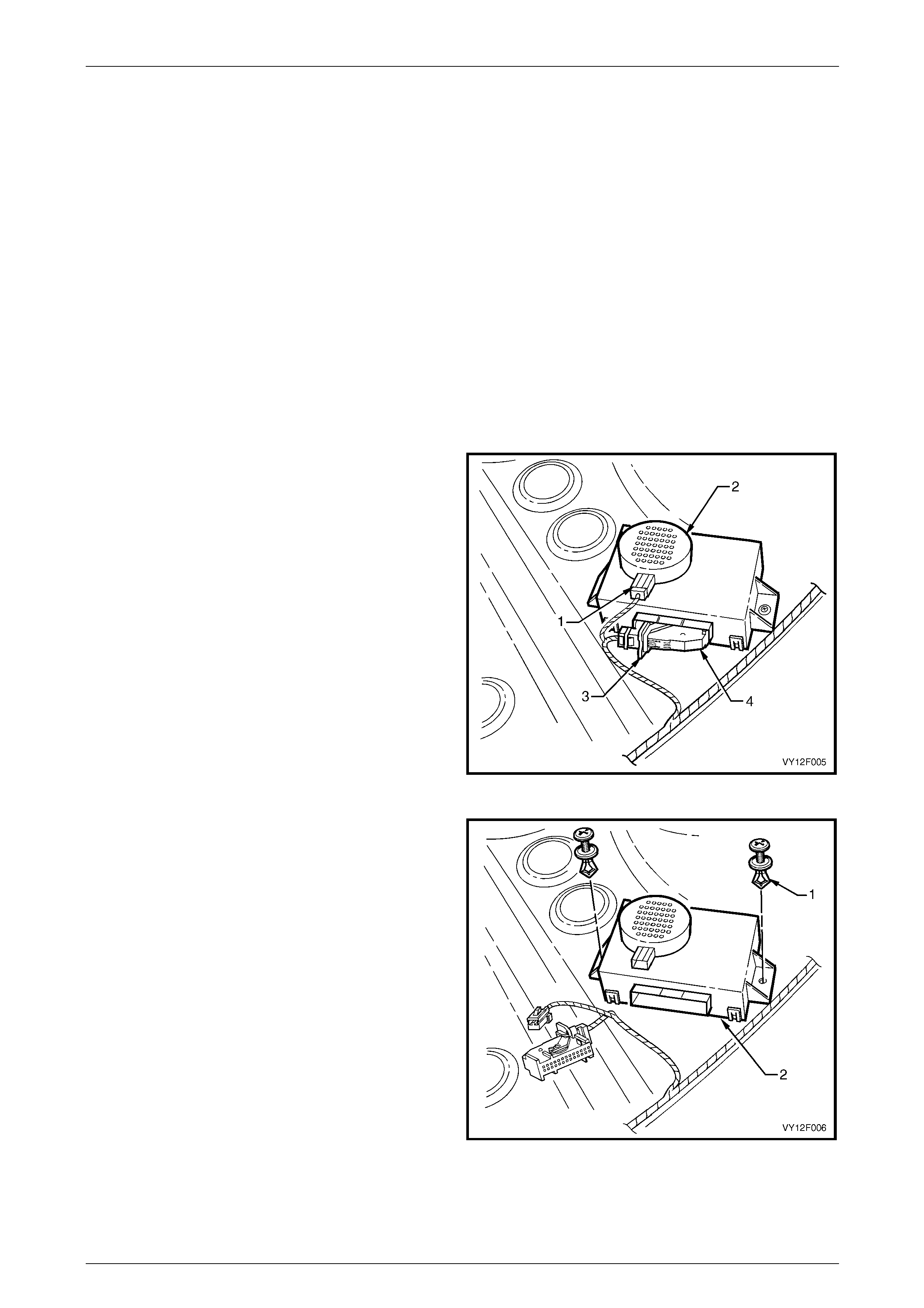
1 Remove the rear window trim panel assembl y, refer to Section 1A8 Hea dlining and Interior Trim.
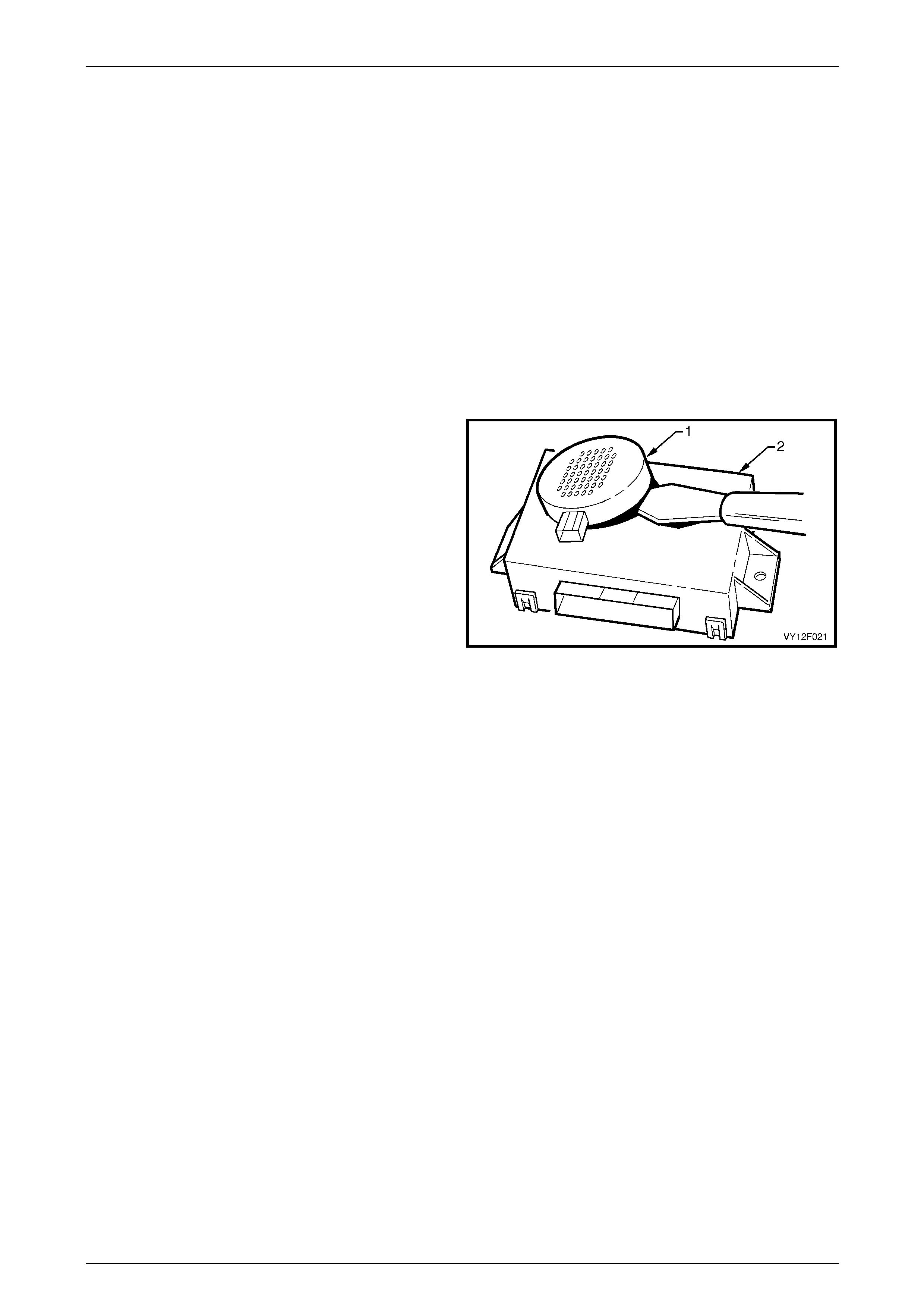
2 Disconnect the wiring connector (1) from the alarm
assembly (2).
3 Unlock the connector lock lever (3) and ope n the lever,
disconnecting the connector (4) from the rear object
sensor control module.
Figure 12F1 – 18
4 Remove the two retainers (1) attaching the c ontrol
module assembly (2) to the back panel uppe r.
5 Remove the control module assembly.
Figure 12F1 – 19
Reinstall
Reinstallation of the rear object sensor control module assembly is the reverse of the removal procedure .
Rear Park Assist Page 12F1–38
Page 12F1–38
Coupe
NOTE
The rear object sensor control module can be
removed with the rear object sensor alarm
assembly still attached.
Remove
1 Remove the right-hand quarter trim panel, refer to Section 1A8 Headlining and Interior Trim.
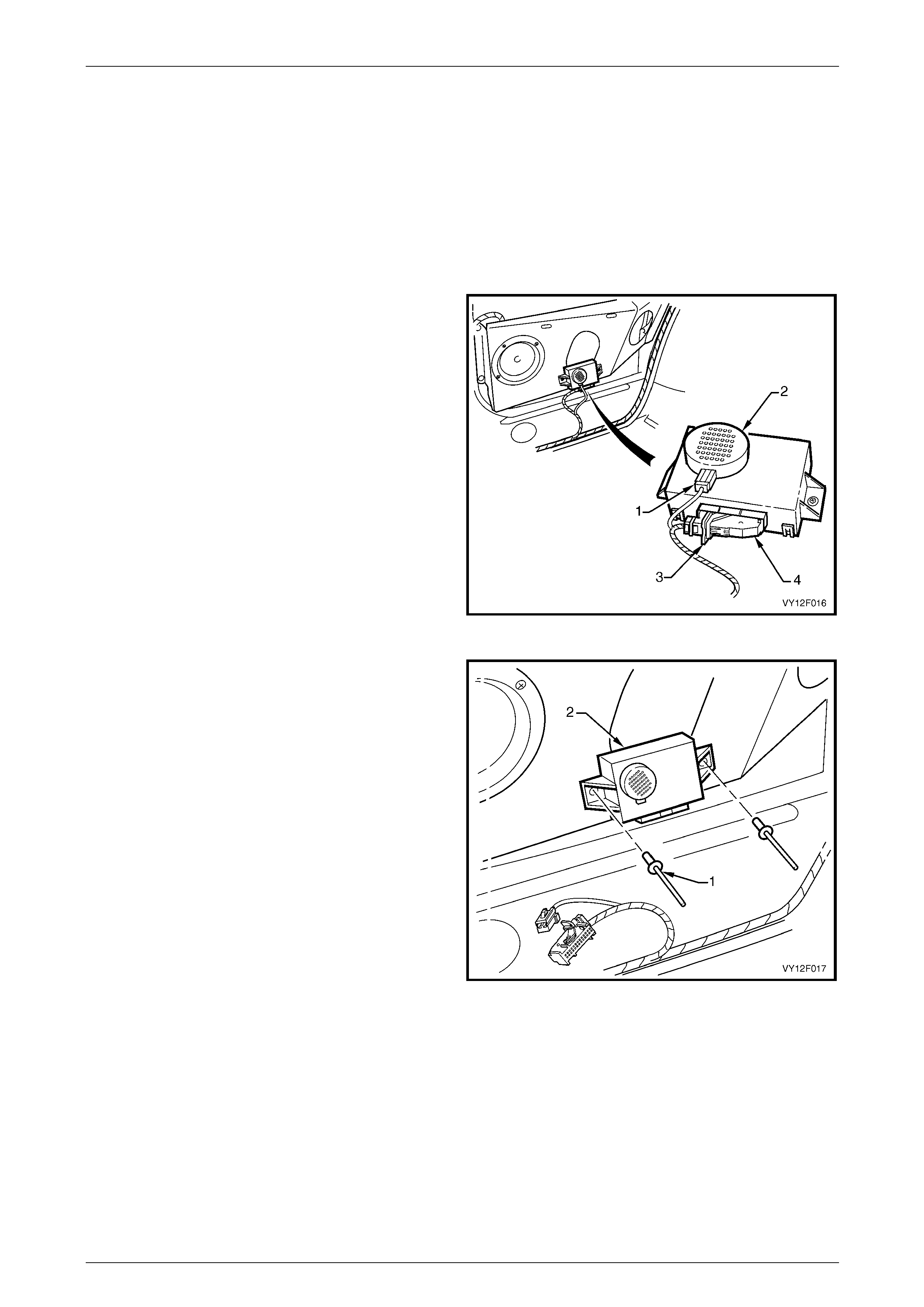
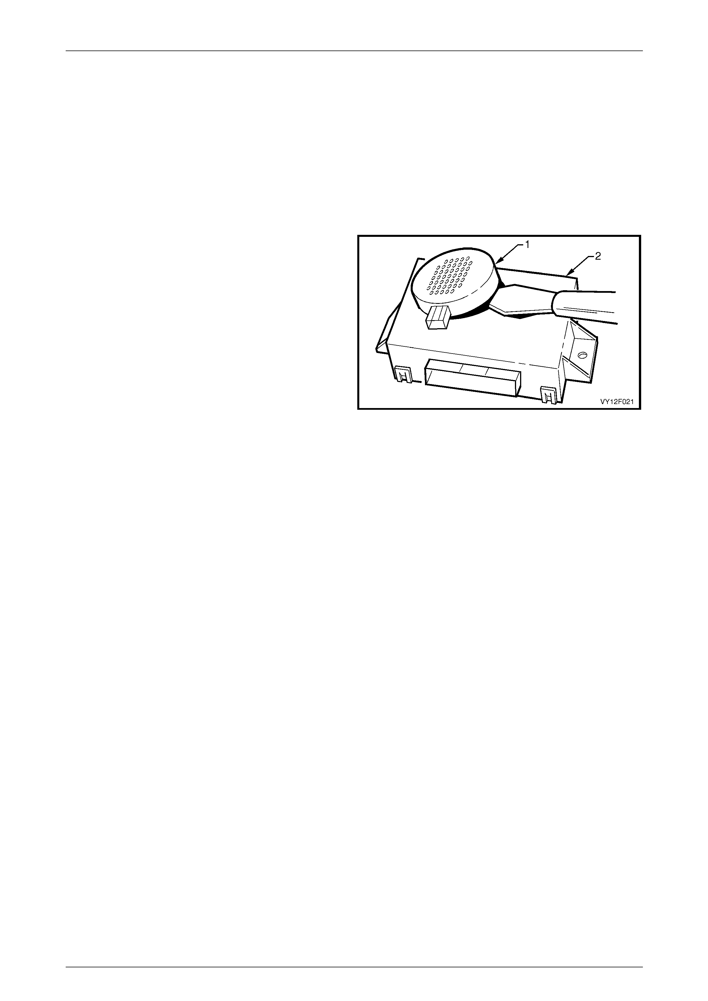
2 Disconnect the wiring connector (1) from the alarm
assembly (2).
3 Unlock the connector lock lever (3) and ope n the lever,
disconnecting the connector (4) from the rear object
sensor control module.
Figure 12F1 – 20
4 Carefully drill out the two pop-rivets (1) attaching the
control module (2) to the radio speaker br acket.
5 Remove the control module.
Figure 12F1 – 21
Reinstall
Reinstallation of the rear object sensor control module assembly is the reverse of the removal proced ure, noting the
following:
1 Use new pop-rivets.
Rear Park Assist Page 12F1–39
Page 12F1–39
AWD Wagon
Remove
1 Remove the right-hand rear seat bolster assembl y, refer to Section 1A7 Seat Assemblies .
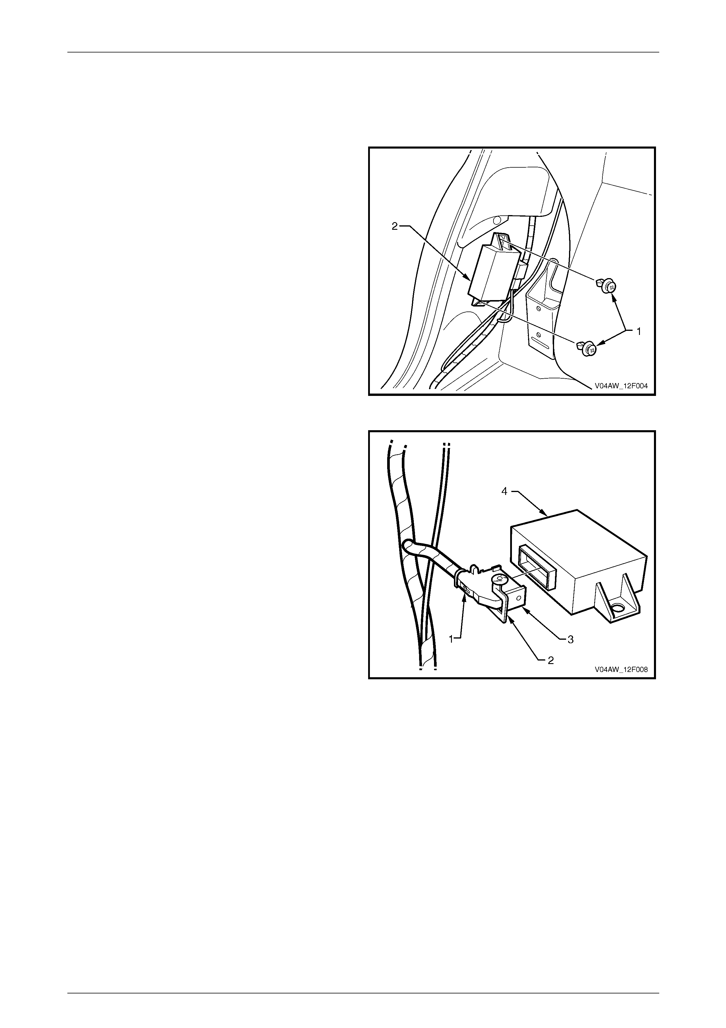
2 Remove the two retainers (1) attaching the rear object
sensor control module (2).
Figure 12F1 – 22
3 Press the tab (1) to unlock the connector lock
lever (2). Open the connector lock lever and rotate to
disconnect the connector (3) from the rear object
sensor control module (4).
Figure 12F1 – 23
Reinstall
Reinstallation of the rear object sensor control module is the reverse of the removal procedure, noting the following:
1 Ensure that the connector lock lever is secured by the tab.
Rear Park Assist Page 12F1–40
Page 12F1–40
3.2 Rear Object Sensor Alarm Assembly
LT Section –
Sedan
NOTE
It is possible to remove the al arm with the modu le
either in place or removed.
Remove
1 Remove the rear window trim panel assembl y, refer to Section 1A8 Hea dlining and Interior Trim.
2 Disconnect the wiring connector (1) from the alarm assembly (2), refer to Figure 12F1 – 18.
3 Using a knife or paint scraper, carefully prise the alarm
assembly (1) from the control module (2), separating
the double-sided tape.
4 Remove the alarm assembly.
Figure 12F1 – 24
Reinstall
Reinstallation of the rear object sensor alarm assembly is the reverse of the removal procedure, noting the following:
1 If reusing the alarm, remove any remaining double-sided tape from the control module and alarm. Apply new tape
such as 3M 4428 or equivalent.
2 Peel off the adhesive backing paper a nd affix the alarm assembly on to the control module, ensuring it is correctly
positioned.
Rear Park Assist Page 12F1–41
Page 12F1–41
Coupe
NOTE
It is possible to remove the al arm with the modu le
either in place or removed.
Remove
1 Remove the right-hand quarter trim panel, refer to Section 1A8 Headlining and Interior Trim.
2 Disconnect the wiring connector (1) from the alarm assembly (2), refer to Figure 12F1 – 20.
3 Using a knife or paint scraper, carefully prise the alarm
assembly (1) from the control module (2), separating
the double-sided tape.
4 Remove the alarm assembly.
Figure 12F1 – 25
Reinstall
Reinstallation of the rear object sensor alarm assembly is the reverse of the removal procedure, noting the following:
1 If reusing the alarm, remove any remaining double-sided tape from the control module and alarm. Apply new tape
such as 3M 4428 or equivalent.
2 Peel off the adhesive backing paper a nd affix the alarm assembly on to the control module, ensuring it is correctly
positioned.
Rear Park Assist Page 12F1–42
Page 12F1–42
AWD Wagon
Remove
1 Lower the right-hand rear of the head lining to gain access to the rear object sensor alarm assembly, refer to
Section 1A8 Headlining and Interior Trim.
2 Remove the connector (1) from the rear objec t sensor
alarm assembly (2).
3 Using a knife or paint scraper, carefully prise the alarm
assembly from the roof cavity, separating the dou ble-
sided tape.
Figure 12F1 – 26
Reinstall
Reinstallation of the rear object sensor alarm assembly is the reverse of the removal procedure, noting the following:
1 If reusing the alarm assembly, remove any remaining double-sided tape from the vehicle a nd the alarm assembly,
ensuring that the mating surfaces are clean. Apply new tape such as 3M 4428 or equivalent to the flat side of the
alarm assembly.
2 Peel the adhesive backing from the double-sided tape and affix the rear object sensor alarm assembly to the
sheetmetal in the roof cavity, with the alarm assembly vents (3) pointing upwards, refer to Figure 12F1 – 26.
Rear Park Assist Page 12F1–43
Page 12F1–43
3.3 Rear Object Sensor Assembly and
Wiring Harness
LT Section –
Sedan
Remove
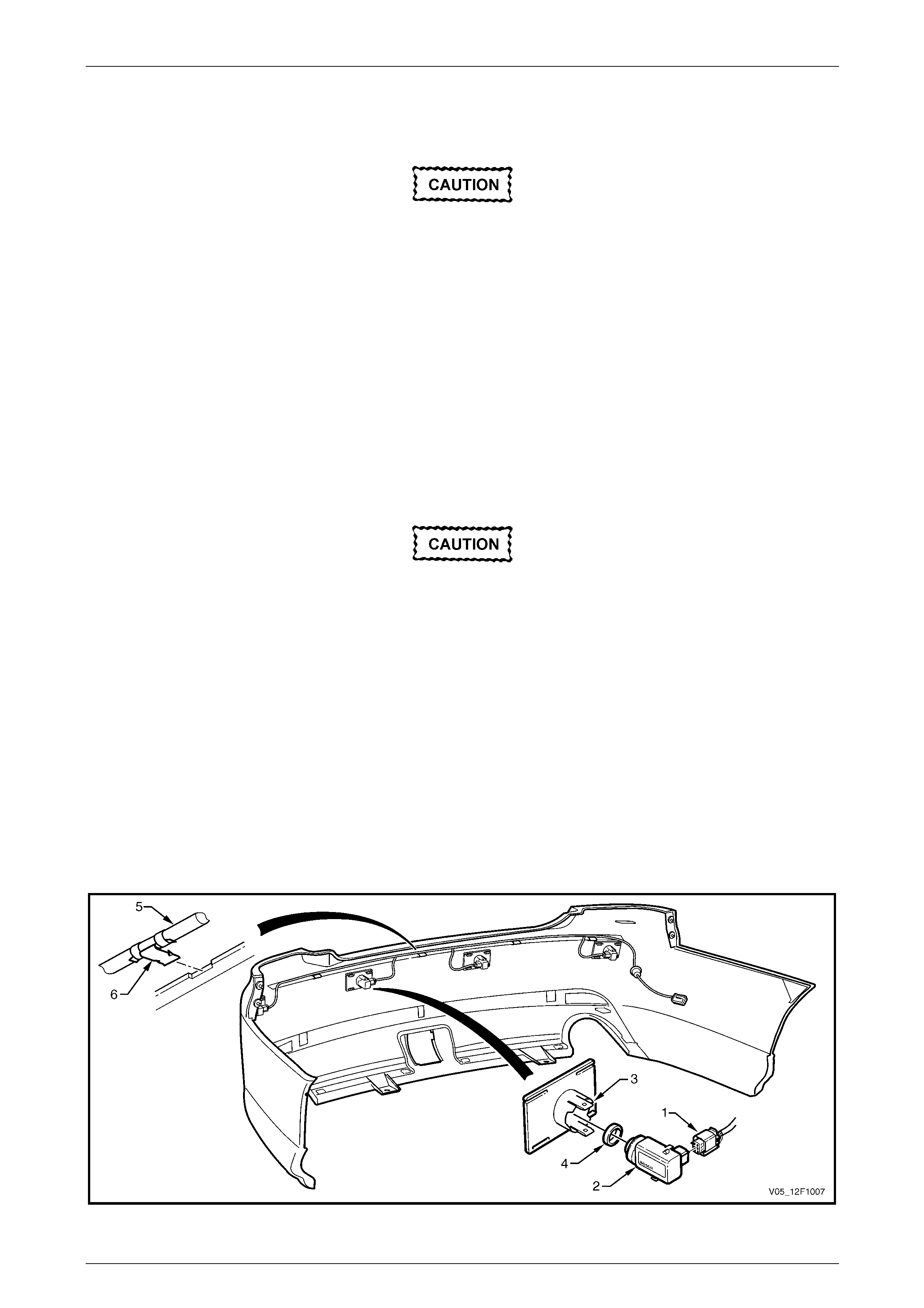
1 Remove the rear bumper fascia assembly, refer to Section 1D Bumper Bars.
Replacement rear object sensor assemblies
are supplied pre-painted in the vehicle's body
colour. Do not apply further paint to the rear
object sensor assemblies, as it will have a
detrimental effect on the operation of the rear
object sensor assemb lies.
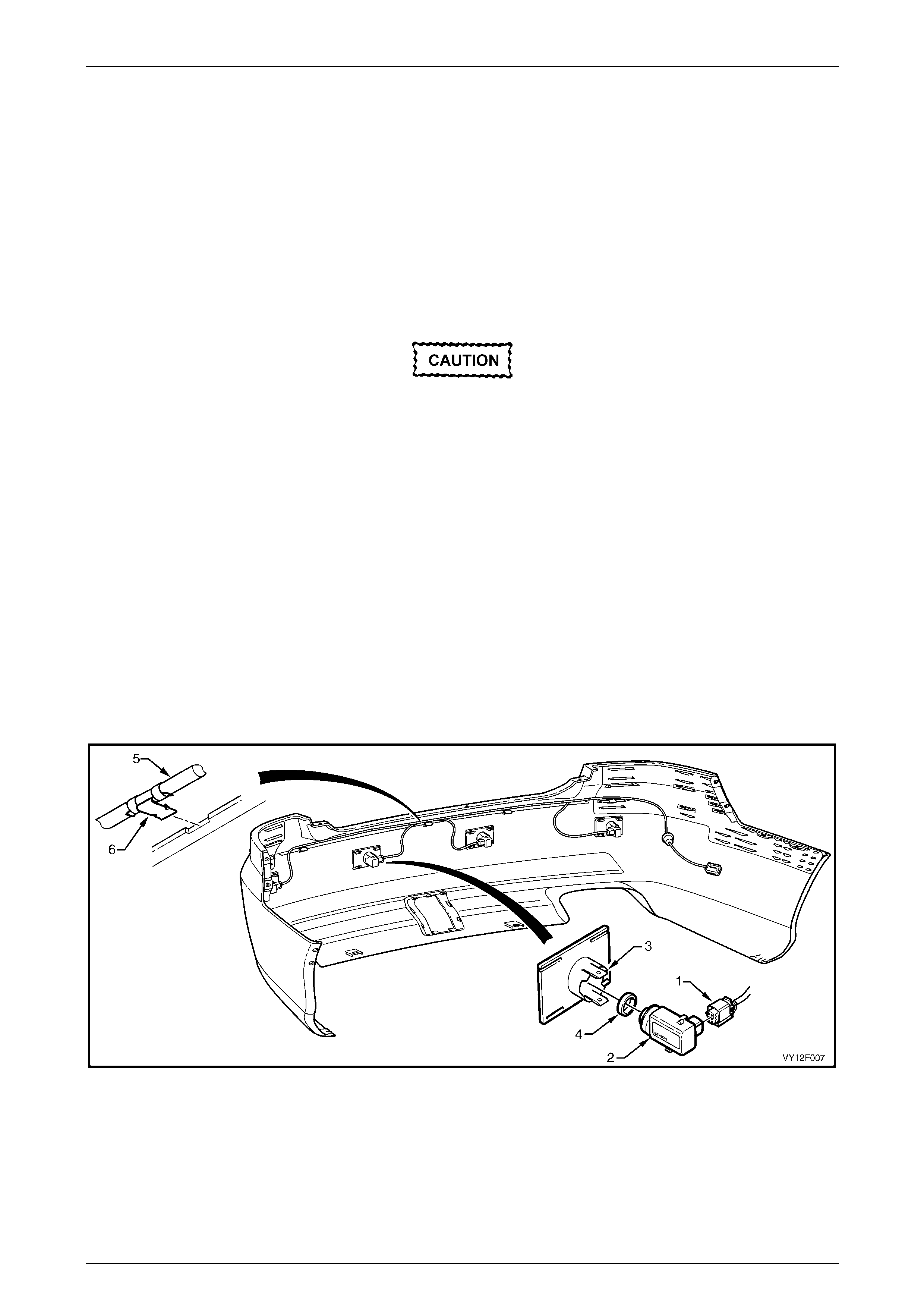
2 Disconnect the wiring connector (1) from the rear object sens or assembly (2), refer to Figure 12F1 – 27.
3 Lift the top and bottom housing tabs (3) and remove the sensor assembly with the rear object sensor ring (4) from
the rear object sensor housing.
4 If required, remove the sensor ring from the sensor.
NOTE
For removal procedures for the rear object
sensor housing assembly, refer to
Section 1D Bumper Bars.
5 If required, remove the wiring harness (5) by prising the clips (6), four places from the bumper fascia rib.
Figure 12F1 – 27
Rear Park Assist Page 12F1–44
Page 12F1–44
Reinstall
Reinstallation of the rear object sensor assembly and wiring harness is the reverse of the removal procedure, noting the
following:
The rear object sensor ring prevents
vibrations from the rear object sensor
assembly being transferred to the
surrounding components. Incorrect fitment
will change the characteristics of the rear
object sensor assembly.
1 Ensure the rear object sensor ring is fitted correctly.
2 Ensure the sensors are correctly installed in the housing with the connector side facing the centreline of the
vehicle.
3 Attach the wiring harness to the upper side of the bumper fascia rib, aligning each clip at the notches.
Coupe
Remove
1 Remove the rear bumper fascia assembly, refer to Section 1D Bumper Bars.
Replacement rear object sensor assemblies
are supplied pre-painted in the vehicle's body
colour. Do not apply further paint to the rear
object sensor assemblies, as it will have a
detrimental effect on the operation of the rear
object sensor assemb lies.
2 Disconnect the wiring connector (1) from the rear object sens or assembly (2), refer to Figure 12F1 – 28.
3 Lift the top and bottom housing tabs (3) and remove the sensor assembly with the rear object sensor ring (4) from
the rear object sensor housing.
4 If required, remove the sensor ring from the sensor.
NOTE
For removal procedures for the rear
object sensor housing assembly, refer to
Section 1D Bumper Bars.
5 If required, remove the wiring harness (5) by prising the clips (6), four places from the bumper fascia rib.
Figure 12F1 – 28

Rear Park Assist Page 12F1–45
Page 12F1–45
Reinstall
Reinstallation of the rear object sensor assembly and wiring harness is the reverse of the removal procedure, noting the
following:
The rear object sensor ring prevents
vibrations from the rear object sensor
assembly being transferred to the
surrounding components. Incorrect fitment
will change the characteristics of the rear
object sensor assembly.
1 Ensure the rear object sensor ring is fitted correctly.
2 Ensure the sensors are correctly installed in the housing with the connector side facing the centreline of the
vehicle.
3 Attach the wiring harness to the upper side of the bumper fascia rib, aligning each clip at the notches.
AWD Wagon
Remove
1 Remove the rear bumper fascia assembly, refer to Section 1D Bumper Bars.
Replacement rear object sensor assemblies
are supplied pre-painted in the vehicle's body
colour. Do not apply further paint to the rear
object sensor assemblies, as it will have a
detrimental effect on the operation of the rear
object sensor assemb lies.
2 Disconnect the wiring connector (1) from the rear object sens or assembly (2), refer to Figure 12F1 – 29.
3 Lift the top and bottom housing tabs (3) and remove the sensor assembly with the rear object sensor ring (4) from
the rear object sensor housing.
3 If required, remove the sensor ring from the sensor.
NOTE
For removal procedures for the rear
object sensor housing assembly, refer to
Section 1D Bumper Bars.
5 If required, remove the wiring harness (5) by prising the clips (6), five places from the bumper fascia rib, and
unclipping the harness connector (7) from the bumper fascia.
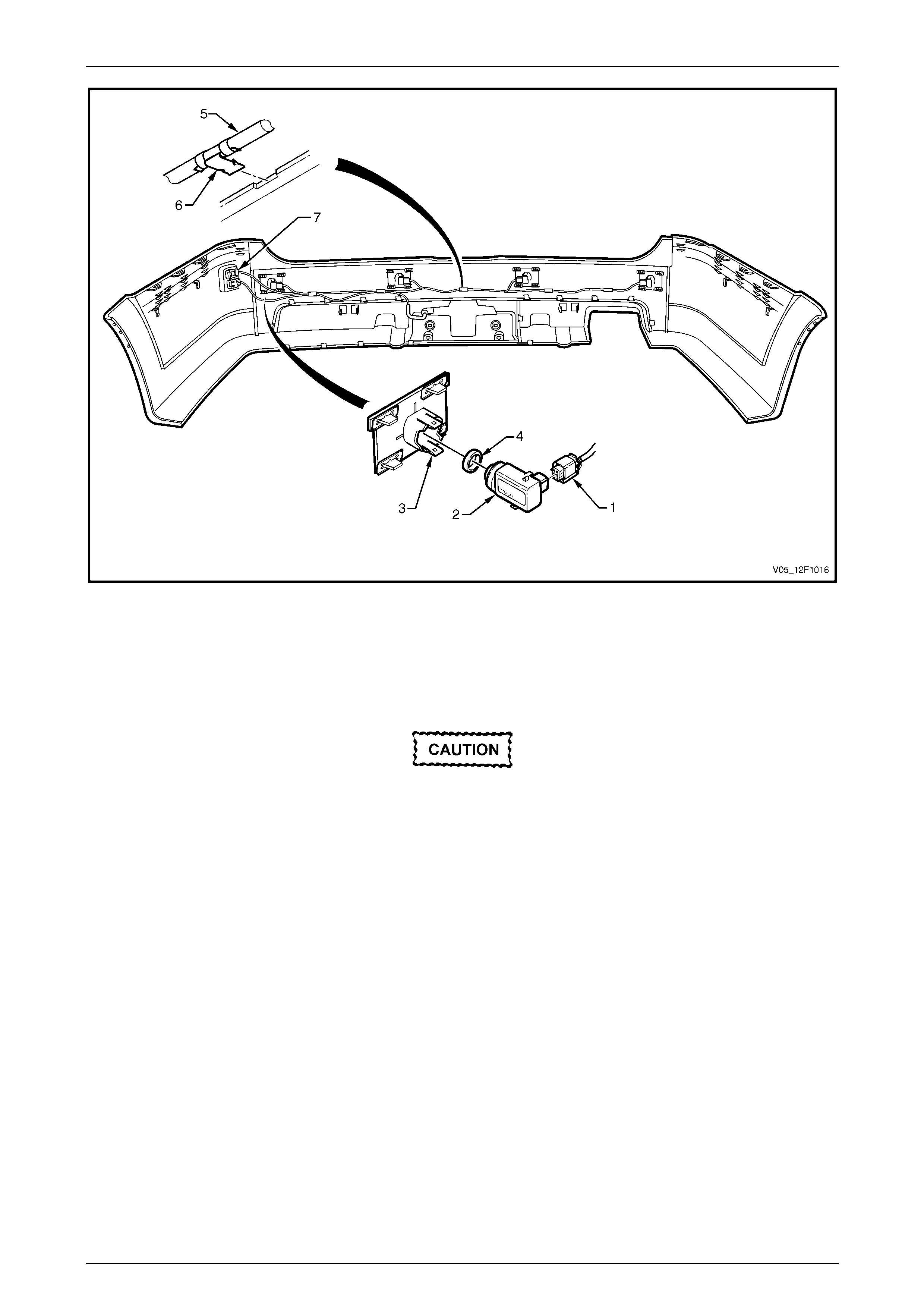
Rear Park Assist Page 12F1–46
Page 12F1–46
Figure 12F1 – 29
Reinstall
Reinstallation of the rear object sensor assembly and wiring harness is the reverse of the removal procedure, noting the
following:
The rear object sensor ring prevents
vibrations from the rear object sensor
assembly being transferred to the
surrounding components. Incorrect fitment
will change the characteristics of the rear
object sensor assembly.
1 Ensure the rear object sensor ring is fitted correctly.
2 Ensure the sensors are correctly installed in the housing with the connector side facing the centreline of the
vehicle.
3 Attach the wiring harness to the upper side of the bumper fascia rib, aligning each clip at the notches.