
Cellular Phone Page 12G–1
Page 12G–1
Section 12G
Cellular Phone
ATTENTION
Before performing any service operation or other procedure described in this Section, refer to Section 00
Warnings, Cautions and Notes for correct workshop practices with regard to safety and/or property damage.
1 General Information ...............................................................................................................................2
1.1 After-market Hands-free Kit Connection ............................................................................................................. 2
Radio Telephone Mute........................................................................................................................................... 2
Radio Telephone Input..........................................................................................................................................2
1.2 After-market Cellular Phone Antenna Location, Coupe and Level 3 Sedan..................................................... 3
2 Service Operations.................................................................................................................................4
2.1 Cellular Phone Connector..................................................................................................................................... 4
2.2 Wiring Diagram ...................................................................................................................................................... 6
2.3 Connector Chart..................................................................................................................................................... 7
3 Torque Wrench Specifications..............................................................................................................8
Techline

Cellular Phone Page 12G–2
Page 12G–2
1 General Information
This Section describes the following cellular phone components:
• After-market hands-free kit connection to the vehicle wiring harness.
• After-market Cellular Phone Antenna Location for Coupe and Level 3 Sedan vehicles.
1.1 After-market Hands-free Kit Connection
A cellular phone wiring connector is taped back to the front body wiring harness and is located at the fro nt of the centre
console on the passenger-side. To access the conn ector, removal of the left-hand instrument panel lower extension side
panel is required, which is describe d in this Section. A connection kit is available through an authorised dealer.
The connector provides constant and accessory position battery power outputs and ground connection for the cellu lar
phone. It also provides the following connections that interface with the entertainment system when a telephone hands-
free kit with the appropriate functions is connected.
Radio Telephone Mute
Whenever a call is made or received, the entertainment system will display VOICE IN and the volum e of the radio will be
muted or the CD will be paused. A suitable hands-free cellular phone kit with a mute outpu t function is required to be
connected to pin X1_4 (mute) of the cellular p hone connector.
Radio Telephone Input
This function allows the audio from a suitable hands-free cellular telephone kit to be reproduced through the vehicle’s
speakers. A suitable hands-free cellular phone kit with mute output and external speaker functions is required and is
connected to pins X1_4 (mute), X1_5 (voice signal) and X1_6 (voice return) of the cellular phon e connector.
The phone input has indepen dent volume and tone from the normal audio sources. The volume, bass, treble, fader and
balance can be adjusted to suit the particular phone / preference whenever VOICE IN is displaye d on the entertainment
system. These settings will then be used whenever the pho ne input is activated, and does not interfere with the settings
for radio or CD playback.
With both functions, the entertainment system returns to the previous playing mode and audio settings when the call
ends.
NOTE
Before connecting a cellul ar phone hands-free kit
to the vehicle, refer to the relevant installation or
operators manual(s) for the correct installation
procedures.
Cellular Phone Page 12G–3
Page 12G–3
1.2 After-market Cellular Phone Antenna
Location, Coupe and Level 3 Sedan
Coupe vehicles are fitted with an FM diversity antenna along with AM and FM antennas in the rear window glass.
Level 3 Sedan vehicles are also fitted with an FM diversity antenna within the rear window glass in addition to a mast-
type AM and FM power antenna fitted to the front fender.
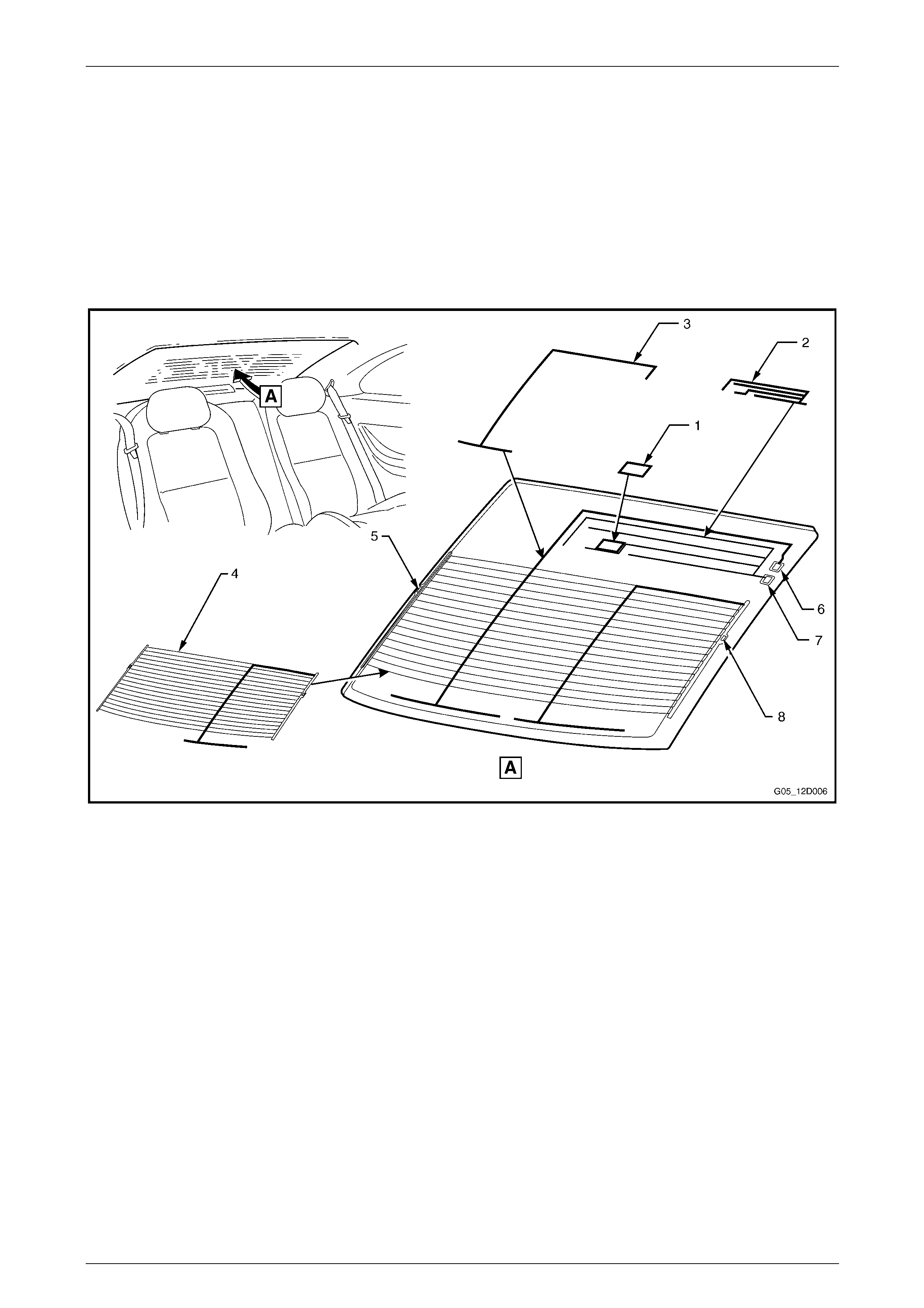
To avoid interference when fitting an after-market cell ular phone antenna, ensure it is mounted in the location shown (1)
for Coupe vehicles, refer to Figure 12G – 1.
For Level 3 Sedan vehicles, the cellular phone antenna is to be located in the same location, noting the rear window
glass does not have the AM and FM antenna elements.
Figure 12G – 1
Legend
1 Cellular Phone Antenna Mounting Location
2 AM Antenna
3 FM Diversity Antenna
4 FM Antenna and Demister Element
5 Demister Element / FM Main Antenna Ground Connection
6 FM Diversity Antenna Connection
7 AM Antenna Connection
8 Demister Element / FM Main Antenna Connection
Cellular Phone Page 12G–4
Page 12G–4
2 Service Operations
NOTE
For diagnosis procedures for the cellular phone
connection circuits refer to
Section 12D Entertainment System.
2.1 Cellular Phone Connector
1 To access the cellular phone connector, perform the following:
a Move the front passenger seat to its most rearward position.
b Remove the instrument panel compartment, refer to Section 1A3 Instrumen t Panel and Console.
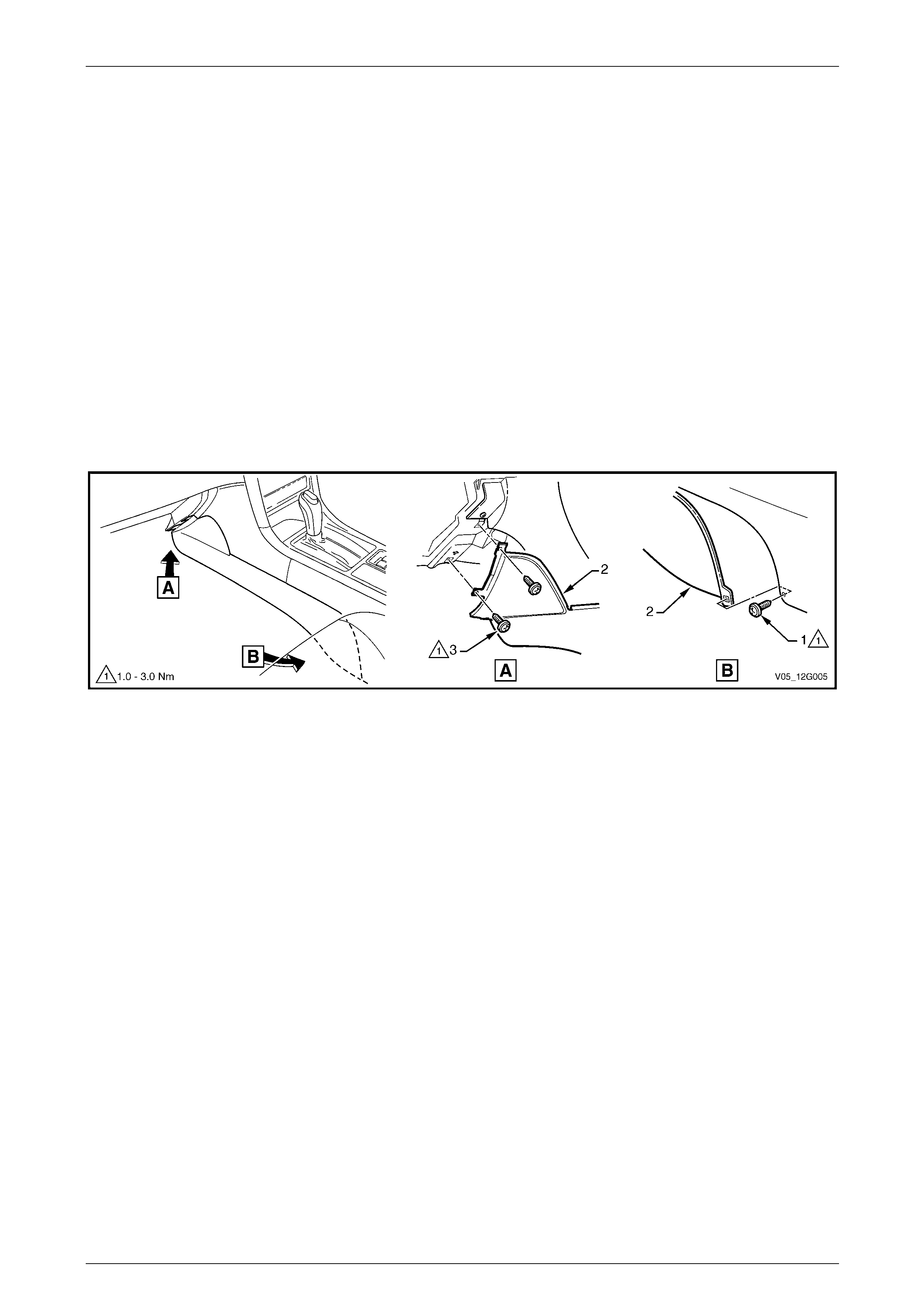
c Remove the screw (1) attaching the left-hand instrument panel lower extension side trim (2) to the floor
console.
d Remove the two screws (3) attaching the side trim to the instrument pan el.
e Remove the side trim.
Figure 12G – 2
Cellular Phone Page 12G–5
Page 12G–5
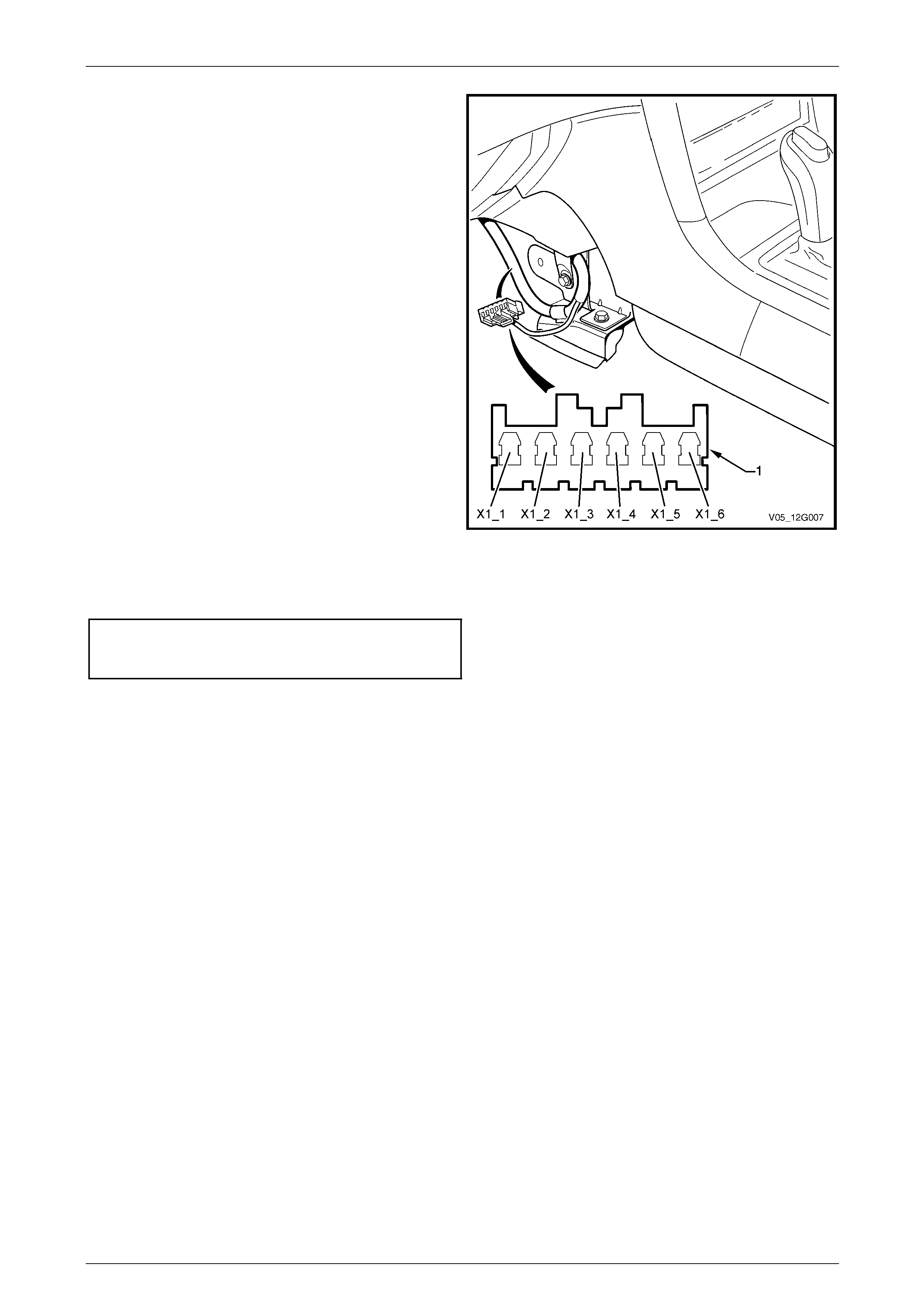
2 Locate the front body wiring harness where it is
clipped to the cockpit module mounting bracket. The
cellular phone connector (1) is taped back to the
harness across the retaining clip.
3 Remove the tape to access the connector.
4 As required, connect the cellul ar pho ne hands-free kit
to the applicable terminals. Also refer to
2.2 Wiring Diagram and 2.3 Connector Ch art.
• X1_1 Battery voltage supply
• X1_2 Vehicle ground
• X1_3 Ignition accessory position voltage supply
• X1_4 Radio mute input
• X1_5 Voice signal
• X1_6 Voice return
5 Securely tape back the cellular phone connector and
additional wiring as required.
6 Reinstall the removed components following the
reverse of the removal procedure.
Figure 12G – 3
7 Tighten the Instrument panel lower extension
side trim panel screws to the correct torque specification.
Instrument panel lower extension
side trim panel attaching screw
torque specification.....................................1.0 – 3.0 Nm
Cellular Phone Page 12G–6
Page 12G–6
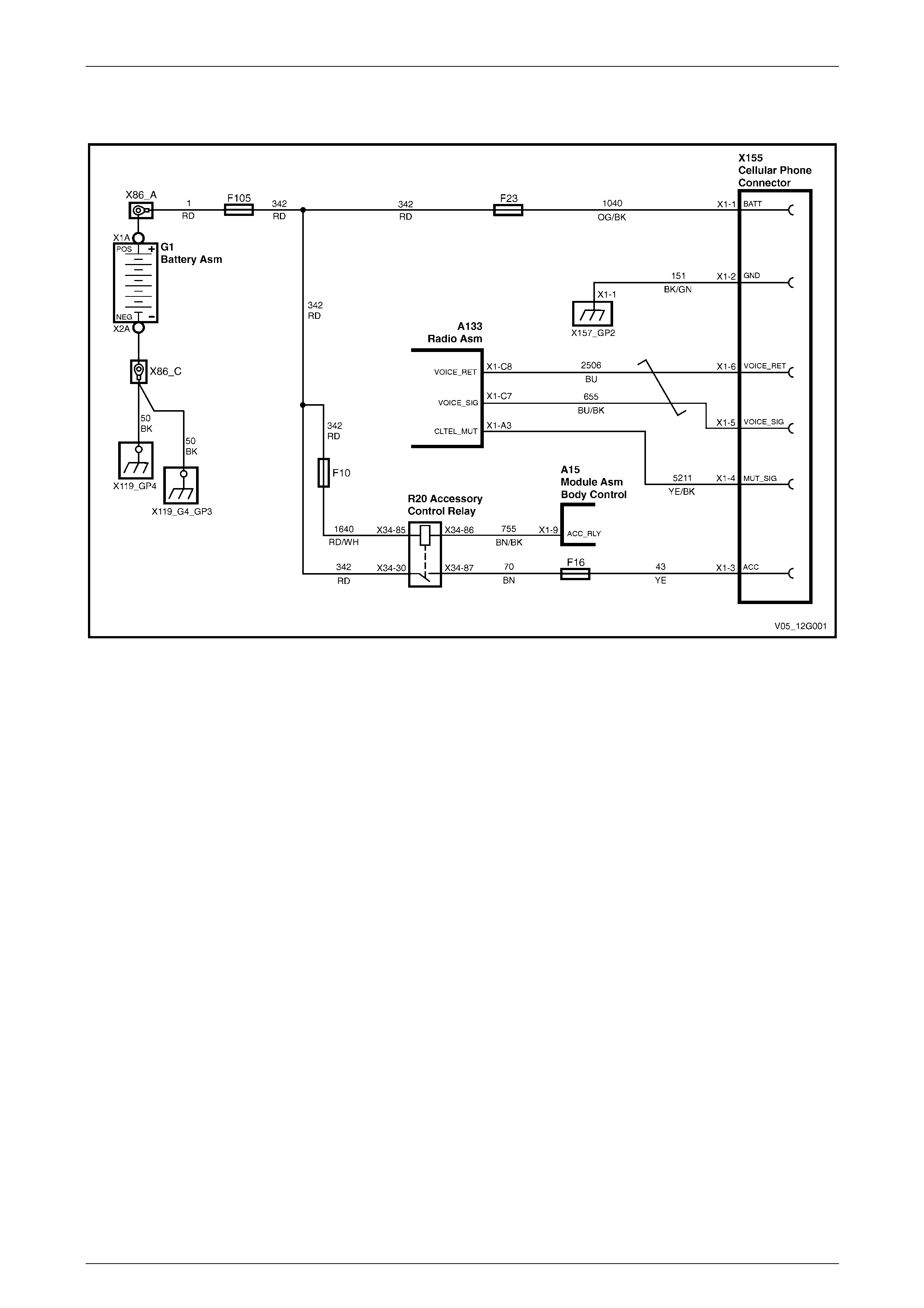
2.2 Wiring Diagram
Figure 12G – 4
Cellular Phone Page 12G–7
Page 12G–7
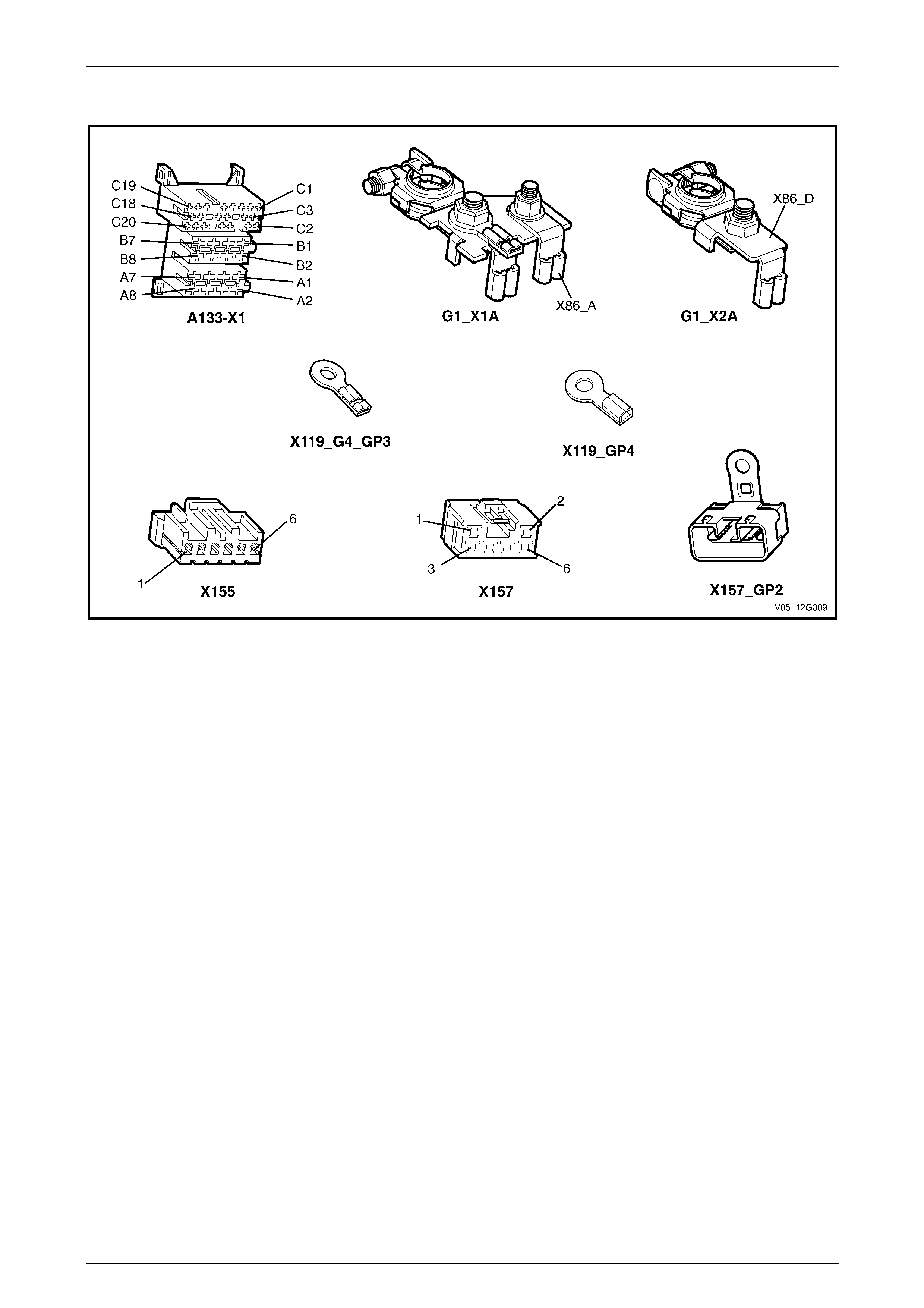
2.3 Connector Chart
Figure 12G – 5

Cellular Phone Page 12G–8
Page 12G–8
3 Torque Wrench Specifications
Instrument Panel Lower Extension Side Trim Panel
Attaching Screw ............................................................................1.0 – 3.0 Nm