
Navigation System Page 12L–1
Page 12L–1
Section 12L
Navigation System
ATTENTION
Before performing any service operation or other procedure described in this Section, refer to Section 00
Warnings, Cautions and Notes for correct workshop practices with regard to safety and/or property damage.
1 General Description ...............................................................................................................................5
Vehicle Speed and Direction................................................................................................................................. 7
Global Positioning System.................................................................................................................................... 7
Digital Road Map.................................................................................................................................................... 7
1.1 General Operation.................................................................................................................................................. 8
1.2 Component Layout................................................................................................................................................ 9
2 System Diagnostics .............................................................................................................................12
2.1 Prerequisites........................................................................................................................................................ 12
Equipment ............................................................................................................................................................ 12
Testing Procedures ............................................................................................................................................. 12
2.2 Wiring Diagram .................................................................................................................................................... 13
2.3 Connector Chart................................................................................................................................................... 15
2.4 Navigation System Does Not Operate................................................................................................................ 16
Condition One – Accessory Power Check......................................................................................................... 16
Introduction ...................................................................................................................................................... 16
Test Description ............................................................................................................................................... 16
Diagnostic Table Notes .................................................................................................................................... 16
Diagnostic Table............................................................................................................................................... 17
Condition Two – Constant Power / Earth Check............................................................................................... 18
Introduction ...................................................................................................................................................... 18
Test Description ............................................................................................................................................... 18
Diagnostic Table Notes .................................................................................................................................... 18
Diagnostic Table............................................................................................................................................... 19
Condition Three – Constant Power, Earth and Accessories Functional, Still No Response ........................ 20
Introduction ...................................................................................................................................................... 20
Test Description ............................................................................................................................................... 20
Diagnostic Table............................................................................................................................................... 21

Navigation System Page 12L–2
Page 12L–2
2.5 No Response From Remote Control .................................................................................................................. 23
No Response From Remote Control .................................................................................................................. 23
Introduction ...................................................................................................................................................... 23
Test Description ............................................................................................................................................... 23
Diagnostic Table............................................................................................................................................... 24
Condition One – No Response When Operated Via Infrared ........................................................................... 25
Introduction ...................................................................................................................................................... 25
Test Description ............................................................................................................................................... 25
Diagnostic Table Notes .................................................................................................................................... 25
Diagnostic Table............................................................................................................................................... 26
Condition Two – No Response When Operated Via Cradle ............................................................................. 27
Introduction ...................................................................................................................................................... 27
Test Description ............................................................................................................................................... 27
Diagnostic Table Notes .................................................................................................................................... 27
Diagnostic Table............................................................................................................................................... 28
2.6 CD–ROM Error...................................................................................................................................................... 29
Condition One – Cannot Select NAVIGATION and ADDRESS Book............................................................... 29
Introduction ...................................................................................................................................................... 29
Test Description ............................................................................................................................................... 29
Diagnostic Table............................................................................................................................................... 29
Condition Two – CD–ROM Automatically Ejects............................................................................................... 30
Introduction ...................................................................................................................................................... 30
Test Description ............................................................................................................................................... 30
Diagnostic Table............................................................................................................................................... 30
Condition Three – Error Reading CD–ROM....................................................................................................... 30
Introduction ...................................................................................................................................................... 30
Test Description ............................................................................................................................................... 30
Diagnostic Table............................................................................................................................................... 30
2.7 Audio Problems ................................................................................................................................................... 31
Introduction.......................................................................................................................................................... 31
Test Description................................................................................................................................................... 31
Diagnostic Table.................................................................................................................................................. 31
2.8 Guidance Problems............................................................................................................................................. 32
Condition One – Processor Input Faults ........................................................................................................... 32
Introduction ...................................................................................................................................................... 32
Test Description ............................................................................................................................................... 32
Diagnostic Table............................................................................................................................................... 33
Condition Two – System Calibration Test ......................................................................................................... 34
Introduction ...................................................................................................................................................... 34
Test Description ............................................................................................................................................... 34
Diagnostic Table............................................................................................................................................... 34
Condition Three – System Calibration Test 2.................................................................................................... 34
Introduction ...................................................................................................................................................... 34
Test Description ............................................................................................................................................... 34
Diagnostic Table............................................................................................................................................... 34
2.9 Display Quality..................................................................................................................................................... 35
Introduction.......................................................................................................................................................... 35
Test Description................................................................................................................................................... 35
Diagnostic Table.................................................................................................................................................. 35
2.10 Display Dimming Inoperative.............................................................................................................................. 36
Introduction.......................................................................................................................................................... 36
Test Description................................................................................................................................................... 36
Diagnostic Table Notes ....................................................................................................................................... 36
Diagnostic Table.................................................................................................................................................. 37

Navigation System Page 12L–3
Page 12L–3
2.11 Vehicle Direction Incorrect.................................................................................................................................. 38
Introduction.......................................................................................................................................................... 38
V6 4 Speed Automatic Transmission................................................................................................................. 38
Test Description ............................................................................................................................................... 38
Diagnostic Table Notes .................................................................................................................................... 38
Diagnostic Table............................................................................................................................................... 39
V6 5 Speed Automatic Transmission................................................................................................................. 40
Test Description ............................................................................................................................................... 40
Diagnostic Table Notes .................................................................................................................................... 40
Diagnostic Table............................................................................................................................................... 41
V8 4 Speed Automatic Transmission................................................................................................................. 43
Test Description ............................................................................................................................................... 43
Diagnostic Table Notes .................................................................................................................................... 43
Diagnostic Table............................................................................................................................................... 44
V6 Manual Transmission..................................................................................................................................... 45
Test Description ............................................................................................................................................... 45
Diagnostic Table Notes .................................................................................................................................... 45
Diagnostic Table............................................................................................................................................... 46
V8 Manual Transmission..................................................................................................................................... 48
Test Description ............................................................................................................................................... 48
Diagnostic Table Notes .................................................................................................................................... 48
Diagnostic Table............................................................................................................................................... 49
3 Processor Diagnostics ........................................................................................................................50
3.1 Accessing Diagnostic Menu ............................................................................................................................... 50
3.2 Read I/O state....................................................................................................................................................... 51
3.3 Set I/O State.......................................................................................................................................................... 52
3.4 Read GPS Data..................................................................................................................................................... 53
3.5 Read Error Memory.............................................................................................................................................. 54
4 Service Operations...............................................................................................................................55
4.1 Processor Assembly ........................................................................................................................................... 55
Processor ............................................................................................................................................................. 55
Remove............................................................................................................................................................ 55
Reinstall ........................................................................................................................................................... 56
Mounting Brackets............................................................................................................................................... 57
Remove............................................................................................................................................................ 57
Reinstall ........................................................................................................................................................... 57
4.2 Remote Control Assembly.................................................................................................................................. 58
Remote Control Cradle with Presenter .............................................................................................................. 58
Remove............................................................................................................................................................ 58
Reinstall ........................................................................................................................................................... 59
4.3 Presenter Mounting Wedge................................................................................................................................. 60
Remove................................................................................................................................................................. 60
Reinstall................................................................................................................................................................ 60
4.4 Display Assembly................................................................................................................................................ 61
Remove................................................................................................................................................................. 61
Disassemble......................................................................................................................................................... 62
Reassemble.......................................................................................................................................................... 63
Reinstall................................................................................................................................................................ 63
4.5 Navigation Speaker Assembly ............................................................................................................................ 64
Remove................................................................................................................................................................. 64
Disassemble......................................................................................................................................................... 64
Reassemble.......................................................................................................................................................... 65
Reinstall................................................................................................................................................................ 65

Navigation System Page 12L–4
Page 12L–4
4.6 Navigation Wiring Harness ................................................................................................................................. 66
Remove................................................................................................................................................................. 66
Reinstall................................................................................................................................................................ 69
4.7 Cockpit Navigation Wiring Harness................................................................................................................... 70
Remove................................................................................................................................................................. 70
Reinstall................................................................................................................................................................ 71
4.8 GPS Antenna Assembly...................................................................................................................................... 72
Remove................................................................................................................................................................. 72
Reinstall................................................................................................................................................................ 72
4.9 Fitting A New Floor Console Cover Assembly.................................................................................................. 73
4.10 Fitting A New Floor Console Assembly............................................................................................................. 74
4.11 Navigation System Calibration........................................................................................................................... 75
5 Torque Wrench Specifications............................................................................................................76
6 Special Tools ........................................................................................................................................77

Navigation System Page 12L–5
Page 12L–5
1 General Description
The Occupant Information Navigation System (navigation system) fitted to Sedan and C oupe vehicles is adapted from
the Siemens VDO Dayton MS 5400 Navigation S ystem. T he MS 5400 has been modified to Holden specifications for
easy vehicle installation.
The navigation system uses three principal technologi es:
• The navigation processor us es the vehicle speed signal (VSS) and an internal gyroscope
• Global Positioning System (GPS)
• Digital road mapping
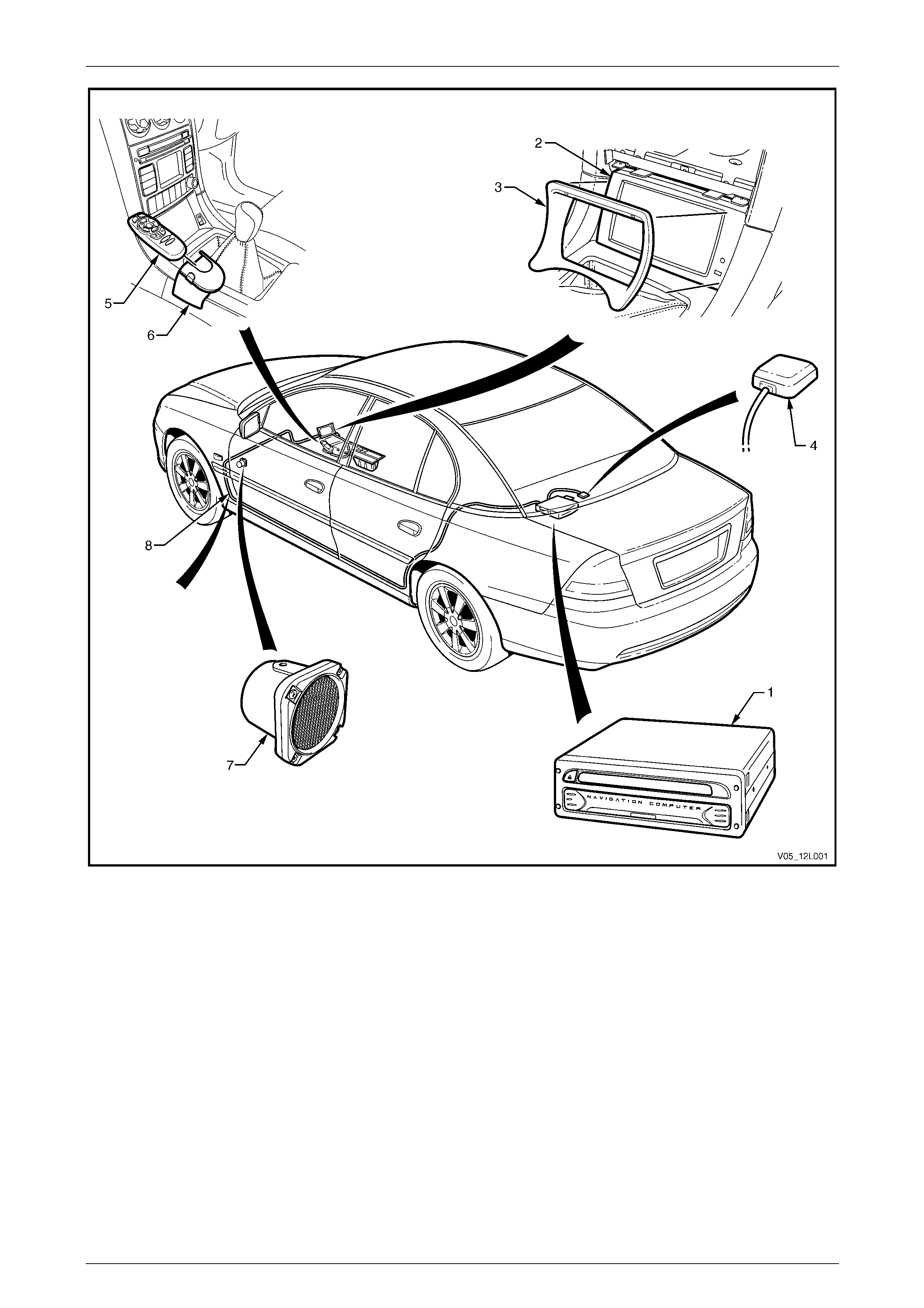
The navigation system consists of the following components (refer to Figure 12L – 1):
• Processor assembly (1)
• Display assembly (2) and escutcheon (3)
• GPS antenna assembly (4)
• Remote control assembly (5) with presenter (6)
• Speaker assembly (7)
• Wiring harness and cockpit wiring h arness (8 )
The following modifications are made to the floor console cover assembly to accommod ate the navigation system:
• Holes are drilled in the floor console cover assembly so the navigation remote control assembly and presenter can
be fitted
• The floor console cover assembly is cut to specific ation to allow for the installation of the navigation display
assembly
NOTE
Although there are obvious interior trim and body
shape differences between the Sedan and
Coupe, the navigation system remains the same
for all except for the h arness lengths and harness
clips.
Navigation System Page 12L–6
Page 12L–6
Figure 12L – 1
Legend
1 Processor Assembly
2 Display Assembly
3 Escutcheon
4 GPS Antenna
5 Remote Control Assembly
6 Remote Control Cradle and Presenter
7 Speaker Assembly
8 Wiring Harness and Cockpit Wiring Harness

Navigation System Page 12L–7
Page 12L–7
Vehicle Speed and Direction
The vehicle speed sensor and the gyroscope work together to provide direction and speed. In conjunction with the
position signal received from the GPS, the vehicle speed sensor and gyroscope provide the processor with the
necessary data to produce vehicle navigation information to the user.
Global Positioning System
The GPS is a series of 27 satellites (nominally 24) which orbit the ground at an altitude o f 20 372 km. The signals from
four satellites must be received by a GPS receiver to get an accurate three-dimensional position. If only three satellite
signals are received a position is attained, but with reduced accuracy. The position calculated by the GPS receiver is
accurate to between 30 and 100 metres. GPS reception may be interrupted, especially due to the nature of the
navigation system, in the following instances:
• between tall buildings;
• in car parks, tunnels or under bridges;
• in forests or avenues;
• during storms;
• in valleys and mountains; and
• if the GPS antenna assembly and the positi on of the satellites are not favourable du e to the satellite’s orbit
Digital Road Map
The digital road map is supplied by Siem ens VDO Dayton. The map is contained on a Compact Disc (CD–ROM), which
is read by the processor assembly. This CD must be inserted into the processor assembly for the system to work.
Update versions of the map are available from Holden Spare Parts Organisation (HSPO).

Navigation System Page 12L–8
Page 12L–8
1.1 General Operation
NOTE
For information on the navigation system
operation, refer to the Satellite Navigation
Handbook Supplement supplied with the
navigation system.
The navigation system operates in the following manner:
• Initially, with power supplied, the navigation display activates and the receiver acquires a GPS signal. This provides
a position accurate to within 30 to 100 metres. T his position is transposed onto the digital road map and shown on
the navigation display in the form of an arrow. Initially, the vehicle may not be shown in its exact position, as the
navigation system may not be calibrated.
• The user can no w enter a dest ination using the navigation system menus. The remote control, which can be used
while in its cradle or pointed at the display, is used to navigate through the navig ation system menus. The map
screen highlights the route to be taken.
• The navigation s ystem begins calibration automatically when the vehicle moves. The VSS provides electrical
pulses which are converted in to distance signals; the gyroscope detects and meas ures any change in direction.
The GPS signal continues to be received and is used as a reference by the navigation system.
• After the navigation system is calibrated, the arrow will be displayed on the map in the correct position and the
correct direction. To get to this stage, one or two changes of direction of the vehicle may be necessar y. The
navigation system supplies audio commands to the user during this time for any direction changes requir ed. Audio
commands are supplied through the speaker assembly, mounted under the instrument pane l assembly on the
instrument panel lower bracket.
• If the driver does not take a recommended turning point, the navigati on system calculates an alternate route and
supply audio command for that route.
Further:
• Calibration takes longer if the vehicle is driven along a straight road for some distance.
• The vehicle’s position is stored by the processor after the vehicle’s ignition is turned off. The navigation system
requires 30 seconds to shut down properly.
• If the vehicle’s position has been stored previously, the navigation system operates without GPS reception and is
still accurate.
• The vehicle’s position remains in memory after the batter y has bee n disconnected, but only if the navigation system
has been allowed 30 seconds to shut down properly before disconnection.

Navigation System Page 12L–9
Page 12L–9
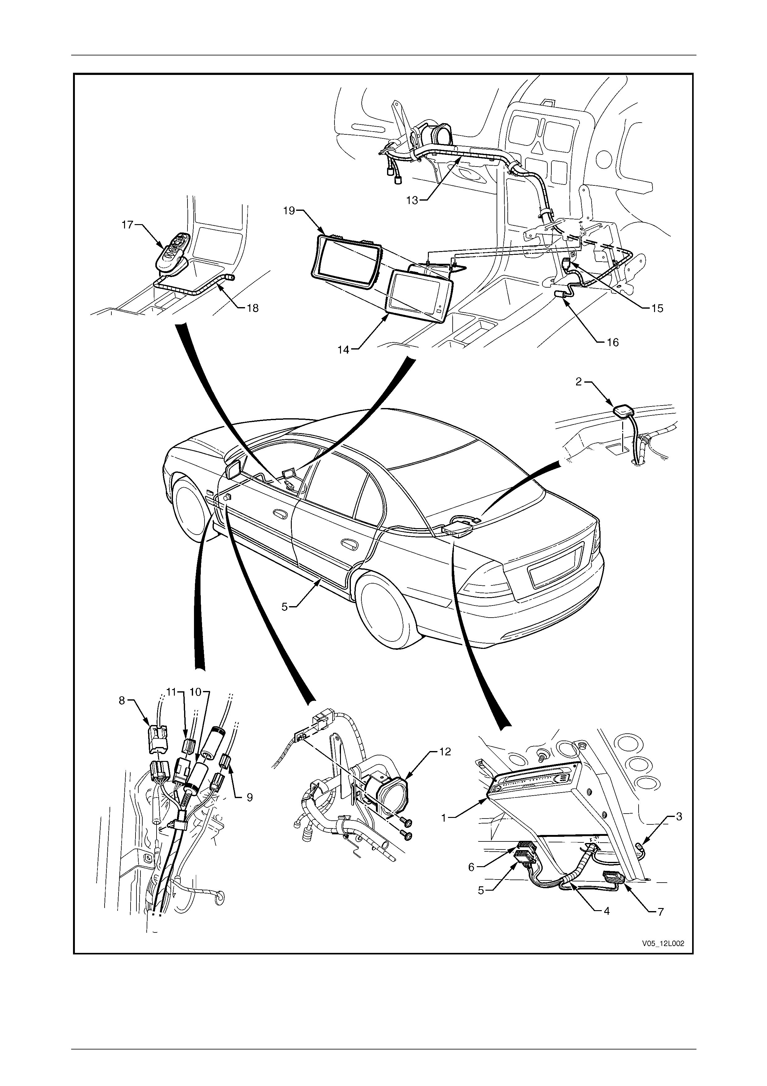
1.2 Component Layout
The navigation system is provided by Siemens VDO Dayton to Holden specifications. This is a brief description of the
layout and functions of equipment, refer to Figure 12L – 2.
The processor assembly (1) is mounted in th e rear compartment below the rear window panel assembly. The processor
assembly contains a CD–ROM and other components required for the navigation system to operate.
The GPS antenna assembly (2) is mounted on top of the rear window panel assembly with double-sided tape. The
harness is routed through the panel and connects to the processor assembly with connector A139 – X4 (3).
The navigation wiring harness (4) is connected at the processor assemb ly by three connectors, A139 – X1 (5), A139 –
X2 (6) and A139 – X3 (7). T he navigatio n wiring harness leads from the processor assembl y, down the left-hand side of
the vehicle and terminates at the left-hand hinge pillar trim assembly. At this point, the navigation wiring harness is split
into connectors X207 (8), XO1 (9), XO2 (10) and B104 (11).
Connector X207 connects the navigation wiring harness to the bod y harness. Through this connecti on, the navigation
system uses the following vehicle resources:
• X207 pin 3 — constant battery power to the processor in all states. This is the supply of power for the navigation
system.
• X207 pin 2 — supplies a signal to the processor assembly when the vehicle is in use. This is active only whe n the
ignition switch is in the ON or ACC position.
• X207 pin 7 — park lam p relay signal which informs the navigation system when the vehic les headlamps are turned
on. This data is used to control the illumination leve l of the display during da ytime or night-time operation.
• X207 pin 5 — backup lamp signal which supplies a signal to the navigation system when the vehicle is moving in
the reverse. This uses either the backup lamp switch (manual transmission) or the neutral / safety backup switch
(automatic transmission) to supply this signal.
• X207 pin 6 — cluster assembly data, which provides VSS pulses for the navigation system. The navigation s ystem
uses this signal to calculate the speed at which the vehicle is travelling.
• X207 pin 8 — ground.
Connector B104 is attached to the speaker a ssembly (12) by a clip. B104 connects the speaker assembly to the
navigation wiring harness.
Connectors XO1 and XO2 connect the nav igation wiring harness to the cockpit nav igation wiring harness (13). The
cockpit navigation wiring harness contains two separate harnesses of connector XO1 and XO2 which are wrapped
together. This harness is routed behind the instrument panel and attached to the instru ment panel bracing.
The cockpit navigation wiring harness terminates at the navigation display assembly (14), and connects to the display
with connector P6 (15).
The cockpit navigation wiring harness terminates under the instrument panel lower extension side trim with connector
A35 (16).
The remote control assembly with presenter (17) is secured to the front console assembly. The remote control cradle
wiring harness (18) is routed under the presenter, behind the transmission selector and to under the right-hand console
extension where it connects to the cockpit navigation wiring harness at connector A35.
The display assembly is mounted to the radio housing with a bracket. For Sedan and Coupe the display assembly has an
escutcheon (refer to Figure 12L – 2, Item 19) placed in front of this to blend it into the centre instrument console. The
front console cover is modified to allow for the display assembly and escutcheon.
Navigation System Page 12L–10
Page 12L–10
Figure 12L – 2

Navigation System Page 12L–11
Page 12L–11
Legend
1 Processor Assembly
2 GPS Antenna Assembly
3 Connector A139 – X4
4 Navigation Wiring Harness
5 Connector A139 – X1
6 Connector A139 – X2
7 Connector A139 – X3
8 Connector X207
9 Connector B104
10 Connector XO1
11 Connector X02
12 Speaker Assembly
13 Cockpit Navigation Wiring Harness
14 Display Assembly
15 Connector P6
16 Connector A35
17 Remote Control Assembly with
Presenter
18 Remote Control Cradle Wiring Harness
19 Escutcheon

Navigation System Page 12L–12
Page 12L–12
2 System Diagnostics
Diagnostic tables contained in this Section, list both technical problems and common faults found due to improper use of
the navigation system. Refer to 2.2 Wiring Diagram and 2.3 Connector Chart to aid in diagnosing the navigation system.
It is advantageous to read the Satellite Navig ation H an dbook Supplement supplied with the navigation system before
performing diagnosis on the system.
NOTE
If the processor assembly needs to be removed
or disconnected from the vehicle power supply,
ensure the processor assembly has shut down
completely. The red LED on the processor
assembly extinguishes when the processor
assembly is shut off. Allow approximately 30
seconds after the ignition is turned off for the
processor assembly to shut down.
2.1 Prerequisites
Equipment
The following equipment is required to diagnose the navigation s ystem:
1 An unpowered test lamp with a current draw of less than 3 A.
2 A digital multimeter with a minimum inp ut imp edance of 10 MΩ.
Testing Procedures
Adhere to the following points when performing diagnostic testing on navigation system components:
1 Take care when using testing equ ipment to diagnose wiring harness connectors. The technician should backprobe
the connector to avoid terminal damage.
2 When tests are required on connector terminals, use the adapters in the connector ad apter kit KM–609 to prevent
damage to the terminals.
3 Unless the multimeter being used has an auto-ranging function, ensure the correct range is selected.
4 When backprobing connectors, ensure the test lamp ground lead is connected to an appropriate ground point on
the vehicle. Ensure this ground point is not part of the circuit being tested.
NOTE
When following the steps in the di agnostic tables,
ensure work is performed in the order in which
they are presented. If the required nominal value
or result is not achieved, rectify the problem
before proceeding.
Navigation System Page 12L–13
Page 12L–13
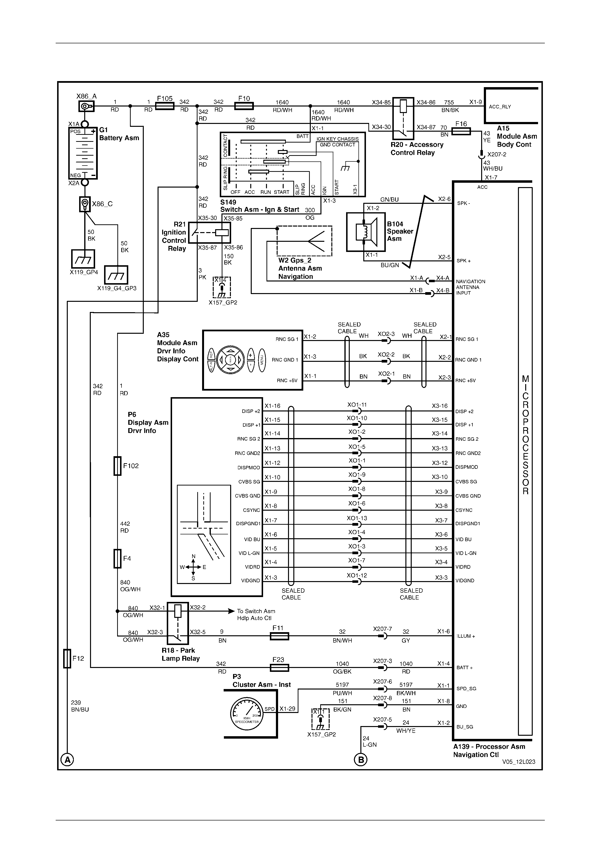
2.2 Wiring Diagram
Figure 12L – 3
Navigation System Page 12L–14
Page 12L–14
Figure 12L – 4
Navigation System Page 12L–15
Page 12L–15
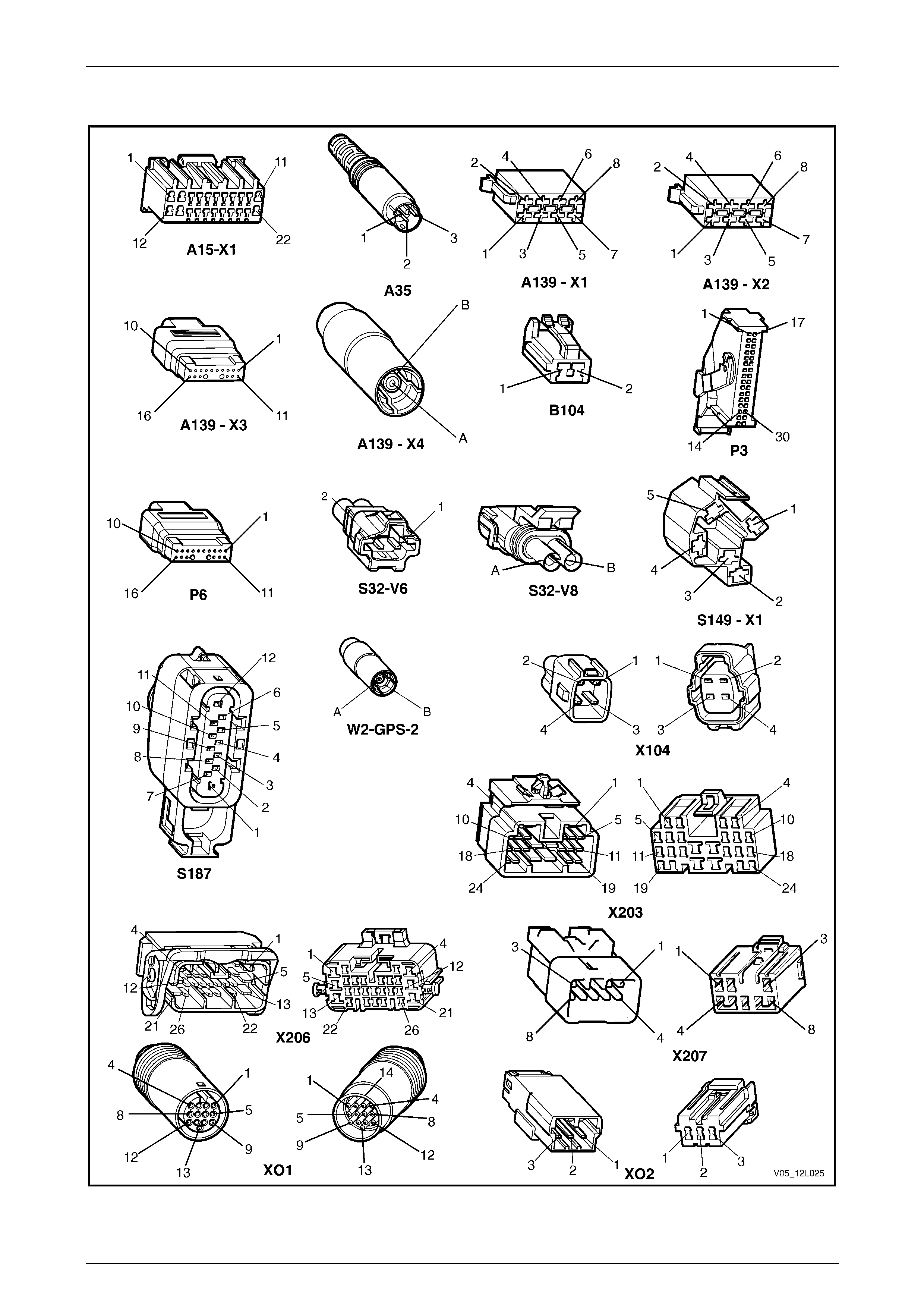
2.3 Connector Chart
Figure 12L – 5

Navigation System Page 12L–16
Page 12L–16
2.4 Navigation System Does Not Operate
Condition One – Accessory Power Check
Introduction
Accessory power is used by the processor as an indication the vehicle is in use and the n avig ation system is required.
The following symptoms are presented when accessory power is not supplied to the processor assembly with the ignition
switch in either the ACC or IGN position:
• The display is blank.
• The red power LED on the proc essor assembly flashes.
• The system does not respond to commands from the remote control.
If the red power LED flashes on the processor assembly, battery power and an earth circuit are present and serviceable.
To assist in diagnosing the navigation system, refer to 2.2 Wiring Diagram and 2.3 Connector Chart.
Test Description
The following numbers refer to the step numbers in the diagnostic table:
2 Checks if fuse F16 on the passenger compartment fuse and relay panel assembly is serviceable.
3 Checks if there is accessory power at the processor assembly. Isolates if the supply of accessory power or the
processor is at fault.
7 Checks if fuse F105 in the engine compartment fuse and relay panel assembly and fuse F10 in the passenger
compartment fuse and relay panel assembly are serviceable. Isolates whether the fuse(s) are the fault effecting the
circuit or if circuit(s) 1, 342 or 1640 are at fault.
9 Checks if there is power at the BCM connector A15 – X1. Isolates whether circuit 755 or the BCMs grounding
circuit is at fault.
10 Checks if there is power at the accessory control relay R20. Isolates whether rela y R20 is a t fault or circuit 342 is at
fault.
Diagnostic Table Notes
1 For all wiring harness fault diagnoses, refer to Section 12P Wiring Diagra m s .
2 For wiring harness repairs, refer to Section 12P Wiring Diagrams.

Navigation System Page 12L–17
Page 12L–17
Diagnostic Table
Step Action Yes No
1 Is the ignition switch in the ACC or IGN position?
Go to Step 2
Turn the ignition
switch to the ACC
or IGN position
2 Inspect fuse F16 in the passenger compartment fuse and relay panel
assembly.
Is the fuse serviceable?
Go to Step 3
Replace fuse and
retest. If the fuse
fails again test for a
short circuit to
ground, refer to
Note 1
3 Backprobe connector A139 – X1 pin 7 with a test lamp, refer to
Note 1.
Does the test lamp illuminate?
The processor
assembly is faulty.
Send the processor
assembly to the
vendor for further
assessment.
Contact Siemens
VDO Customer
Service on
1800 335 – 282 Go to Step 4
4 Backprobe connector X129 – X34 pin 87 with a test lamp, refer to
Note 1.
Does the test lamp illuminate? Go to Step 5 Go to Step 6
5 Backprobe connector X207 pin 2 with a test lamp (refer to Note 1).
Does the test lamp illuminate? Repair or replace
circuit 43 between
connectors X207
and A139 – X1
Repair or replace
circuits 70 and 43
between connectors
X129 – X34 and
X207, refer to
Note 2
6 Backprobe connector X129 – X34 pin 85 with a test lamp, refer to
Note 1.
Does the test lamp illuminate? Go to Step 8 Go to Step 7
7 Inspect fuses F105 in the engine compartme nt fuse and re lay panel
assembly and F10 in the pas senger compartment fuse and relay
panel assembly.
Are the fuses serviceable?
Replace or repair
circuits 1, 342 and
1640, refer to
Note 2
Replace fuse(s) and
retest. If the fuses
fail again test a
short circuit to
ground, refer to
Note 1
8 Backprobe connector X129 – X34 pin 86 with a test lamp, refer to
Note 1.
Does the test lamp illuminate? Go to Step 9 Go to Step 10
9 Backprobe connector A15 – X1 pin 9 with a test lamp, refer to Note 1.
Does the test lamp illuminate?
There is a fault with
the BCM. Refer to
Section 12J Body
Control Module for
further diagnosis
Repair or replace
circuit 755, refer to
Note 2
10 Backprobe connector X129 – X34 pin 30 with a test lamp, refer to
Note 1.
Does the test lamp illuminate?
Replace the
accessory control
relay R20
Repair or replace
circuit 342, refer to
Note 2
When all diagno sis an d repairs are completed, check the system for correct operation.

Navigation System Page 12L–18
Page 12L–18
Condition Two – Constant Power / Earth Check
Introduction
The battery power connection provid es two functions to the navigation system. When the vehicl e ignition switch is in the
ACC or IGN position, the processor determines the vehicle is in use.
When the vehicle’s ignition switch is in the OFF position, the battery supply circuit provides power to the processor
assembly to allow the processor assembl y to store data such as current lo cation etc.
The following symptoms are presente d when battery power is not supplied to the processor assemb ly:
• The display is bla nk until th e ignition switch is in either the ACC or IGN position.
• The red power LED on the processor assembly is extinguished.
To assist in diagnosing the navigation system, refer to 2.2 Wiring Diagram and 2.3 Connector Chart.
Test Description
The following numbers refer to the step numbers in the diagnostic table:
1 Checks if the red power LED is illuminated. If the LED illuminates, the 12 volt power and chassis earth circuits are
operating correctly.
2 Checks if the connector required for battery po wer to be supplied to the processor assembly is in place and
positively connected.
3 Checks if battery voltage is greater than 12 volts. The navigation system requires greater than 12 volts to operate
correctly.
4 Checks if the fuse located on the rear of the processor assembly is serviceable.
5 Checks if fuse F23 located on the passenger compartment fuse and relay panel assembly is servicea ble.
7 Checks if connector X207 is in place and positively connected.
8 Checks if there is battery voltage at connector X207 pin 3. Isolates whether there is a fault between connector
X207 and the processor assembly or between connector X207 and fusib le link F105.
9 Checks if ground circuit 151 is functional or if the processor assembly is at fault.
Diagnostic Table Notes
1 For all wiring harness fault diagnoses, refer to Section 12P Wiring Diagra m s .
2 For wiring harness repairs, refer to Section 12P Wiring Diagrams.
3 Refer to Section 12O Fuses, Relays and Wiring Harnesses for harness routeing.

Navigation System Page 12L–19
Page 12L–19
Diagnostic Table
Step Action Yes No
1 Press the EJECT button on the processor.
Does the red LED illuminate?
If there is no
response from the
system, refer to
CONDITION
THREE in this
Section Go to Step 2
2 Is connector A139 – X1 secure?
Go to Step 3
Ensure that
connector A139 –
X1 is secure
3 Check the battery voltage, refer to Section 12A Battery.
Is the battery voltage greater than 12 V? Go to Step 4
Refer to Section
12A Battery for
further diagnosis
4 Inspect the fuse on the rear of the processor assembly.
Is the fuse on the rear of the processor serviceable?
Go to Step 5
Replace fuse and
retest. If the fuse
fails again test for a
short circuit to
ground (refer to
Note 1)
5 Inspect fuse F23 in the passenger compartment fuse and relay panel
assembly, refer to Note 3.
Is fuse F23 serviceable?
Go to Step 6
Replace fuse and
retest. If the fuse
fails again test for a
short circuit to
ground, refer to
Note 1
6 Backprobe connector A139 – X1 pin 4 with a test lamp, refer to
Note 1.
Does the test lamp illuminate? Go to Step 9 Go to Step 7
7 Remove the left-hand hin ge pillar trim assembly to gain access to
connector X207, refer to Section 1A8 Headlining and Interior Trim.
Is connector X207 secure? Go to Step 8
Ensure that
connector X207 is
secure
8 Backprobe connector X207 pin 3 with a test lamp, refer to Note 1.
Does the test lamp illuminate? Repair or replace
circuit 1040
between connectors
X207 and A13 9 –
X1, refer to Note 2
Repair or replace
circuit 1040 or 342
between connector
X207 and fusible
link F105, refer to
Note 2
9 Using a multimeter set to measure resistance, probe between
connector A139 – X1 pin 8 and a known ground, refer to Note 1.
Does the multimeter indicate contin uity?
The processor
assembly is faulty.
Send the processor
assembly to the
vendor for further
diagnosis.
Contact Siemens
VDO Customer
Service on
1800 335 – 282
Repair or replace
circuit 151 between
connector A139 –
X1 and grounding
point X157_GP2
When all diagno sis an d repairs are completed, check the system for correct operation.

Navigation System Page 12L–20
Page 12L–20
Condition Three – Constant Power, Earth and Accessories Functional, Still No Response
Introduction
When the vehicle ignition switch is in the ACC or IGN position and the battery, accessor y and earth circuits are
serviceable, the red LED on the processor assembly illuminates continuously.
The following conditions exist when there is power to the processor assembly:
• The display is blank.
• The red power LED on the proc essor is illuminated.
To assist in diagnosing the navigation system, refer to 2.2 Wiring Diagram and 2.3 Connector Chart.
Test Description
The following numbers refer to the step numbers in the diagnostic table:
1 Checks if the system is in an idle state. Attempts to restore system operation by using the remote control.
2 Checks if the system is in an idle state. Attempts to restore system operation by using the remote control. If the
system is restored, there is a fault in the remote control assembly when it is being used outside the cradl e.
3 Checks if the battery voltage is greater than 12 V. The navigation system requires gre ater than 12 V to operate
correctly.
4 Navigation control buttons are located on top of the display. If the system responds when these buttons are
pressed, there is a problem with the remote control and associated circuits when the control is operated.
5 Checks if all the connectors required for the navigation system display to function correctly are in place and
positively connected.
6 Checks if there is continuity between connectors A139 – X3 and XO1 which is part of the navigation wiring
harness. This isolates if the navigation wiring harness that supplies power and the display is at fault.
7 Checks if there is continuity between connectors P6 – X1 and XO1 which is part of the cockpit navigation wiring
harness. This isolates if the cockpit navigation wiring harness that supplies power and the displa y is at fault.
8 Checks if the display assembly is the fault in the system. Isolates whether the fault is with the display assembly or
the processor assembly.

Navigation System Page 12L–21
Page 12L–21
Diagnostic Table
Step Action Yes No
1 1 Remove the remote control from the remote control cradle.
2 Point the remote control at the display and press the OK button
to restore display operation.
Does the display function? System serviceable Go to Step 2
2 Seat the remote control in the remote control cradle and press the OK
button on the remote control.
Does the display function?
Refer to 2.5 No
Response From
Remote Control,
Condition One Go to Step 3
3 Check the battery voltage, refer to Section 12A Battery.
Is the battery voltage greater than 12 V? Go to Step 4
Refer to Section
12A Battery for
further diagnosis
4 1 Remove the display assembly and the display assembly
mounting bracket, refer to 4.4 Display Assembly.
2 Connect the connector P6 to the back of the display.
3 Operate the navigation system using the keys on top of the
display.
Does the display function?
Refer to 2.5 No
Response From
Remote Control Go to Step 5
5 1 Remove the left-hand hinge pillar trim assembly to gain acc ess
to connector XO1, refer to Section 1A8 Headlining and Interior
Trim.
2 Are the following connections secure:
• A139 – X3
• X01
• P6 Go to Step 6
Ensure the
connectors
are secure
6 1 Disconnect connector A139 – X3 from the pr ocessor assembly.
2 Using a multimeter set to measure resistance, probe between
the following connectors:
• A139 – X3 pin 3 and X01 pin 12
• A139 – X3 pin 4 and X01 pin 7
• A139 – X3 pin 5 and X01 pin 3
• A139 – X3 pin 6 and X01 pin 4
• A139 – X3 pin 7 and X01 pin 13
• A139 – X3 pin 8 and X01 pin 6
• A139 – X3 pin 9 and X01 pin 8
• S139 – X3 pin 10 and X01 pin 9
• A139 – X3 pin 12 and X01 pin 1
• A139 – X3 pin 13 and X01 pin 5
• A139 – X3 pin 14 and X01 pin 2
• A139 – X3 pin 15 and X01 pin 10
• A139 – X3 pin 16 and X01 pin 11
Does the multimeter indicate continuity in each of the tests? Go to Step 7
Repair or replace
the navigation
display wiring
harness, refer to
Note 2

Navigation System Page 12L–22
Page 12L–22
Step Action Yes No
7 1 Remove the display assembl y, refer to 4.4 Display Assembly.
2 Using a multimeter set to measure resistance, probe between
the following connectors:
• P6 – X1 pin 3 and X01 pin 12
• P6 – X1 pin 4 and X01 pin 7
• P6 – X1 pin 5 and X01 pin 3
• P6 – X1 pin 6 and X01 pin 4
• P6 – X1 pin 7 and X01 pin 13
• P6 – X1 pin 8 and X01 pin 6
• P6 – X1 pin 9 and X01 pin 8
• P6 – X1 pin 10 and X01 pin 9
• P6 – X1 pin 12 and X01 pin 1
• P6 – X1 pin 13 and X01 pin 5
• P6 – X1 pin 14 and X01 pin 2
• P6 – X1 pin 15 and X01 pin 10
• P6 – X1 pin 16 and X01 pin 11
Does the multimeter indicate continuity in each of the tests?
Reconnect
connector A139 –
X3
Go to Step 8
Repair or replace
the cockpit
navigation wiring
harness, refer to
Note 2
8 Replace the display assembly.
Does the display now operate?
System serviceable
The processor
assembly is faulty.
Send the processor
assembly to the
vendor for further
assessment.
Contact Siemens
VDO Customer
Service on
1800 335 – 282
When all diagno sis an d repairs are completed, check the system for correct operation.

Navigation System Page 12L–23
Page 12L–23
2.5 No Response From Remote Control
No Response From Remote Control
Introduction
The remote control sends signals to the pro cessor assembly in either of two methods. In the first method, with the remote
control removed from the remote control cradle and pointed at the display assembly, the signal is received by the display
assembly, then transmitted through the display wiring harness to the processor assembly. In this case the power to
transmit the signal is from the remote control batteries.
The second method is with the remote contr ol situate d in th e remote control crad le. In this case, signals from the remote
control transmit directly through the remote control cradle and its wiring harness to the processor asse mbly. The power
to transmit the signal from the remote control is provided by the vehicle via the processor assembly and remote control
cradle.
The following conditions exist when the remote control is in operative:
• The navigation s ystem is oper ational, with the title screen on the display
• The navigation system does not respond to commands from the remote control
Test Description
The following numbers refer to the step numbers in the diagnostic table:
1 Checks if there is any response from the system when using the remote control in any of its operating conditions.
Isolates whether the remote control or the system that transmits the signal to the processor is at fault.
2 Checks if the remote control functions correctly when operated from the cradle. Isolates if the cradle and
associated circuitry is at fault.
3 Checks if the remote control functions correctly when operated via infrared through the display. Isolates if the
display and associate d circuitry is at fault.
4 Replaces the remote control with a servicea ble item. Isolates whether the remote control or the processor is at
fault.

Navigation System Page 12L–24
Page 12L–24
Diagnostic Table
Step Action Yes No
1 1 Place the remote control in the remote control crad le.
2 Press the OK button on the remote control.
3 Remove the remote control from the remote control cradle.
4 Point the remote control at the display assembly and press the
OK button.
Does the system respond to the remote control during any part of the
procedure? Go to Step 2 Go to Step 4
2 1 Place the remote control in the remote control crad le.
2 Press the OK button on the remote control.
Does the system respond when the remote control is operated from
the cradle? Go to Step 3
Refer to 2.5 No
Response From
Remote Control,
Condition T wo
3 1 Remove the remote control from the remote control cradle.
2 Point the remote control at the display assembly and press the
OK button.
Does the system respond when the remote control is operated via
infrared through the display (that is, when it is not seated in the
cradle)? System serviceable
Refer to 2.5 No
Response From
Remote Control,
Condition One
4 1 Replace the remote control with a servicea ble item.
2 Repeat Steps 1 and 2.
Does the system respond when the remote control is operated?
System serviceable
The processor
assembly is faulty.
Send the processor
assembly to the
vendor for further
assessment.
Contact Siemens
VDO Customer
Service on
1800 335 – 282
When all diagno sis an d repairs are completed, check the system for correct operation

Navigation System Page 12L–25
Page 12L–25
Condition One – No Response When Operated Via Infrared
Introduction
In this condition the title screen appears when the vehicle ignition switch is in the ACC or IGN position. The system does
not respond when the remote control is operated via the display (that is, when it is not seated in the remote control
cradle).
To assist in diagnosing the navigation system, refer to 2.2 Wiring Diagram and 2.3 Connector Chart.
Test Description
The following numbers refer to the step numbers in the diagnostic table:
1 Checks if anything is preventing the transmission of commands between the remote control and the infrared screen
that is part of the display assembly.
2 After the batteries are changed, checks if the system responds when the remote control is operated via the display.
3 Checks if all the connectors required for the remote control to operate effectively are in place and positively
connected.
4 Checks if there is continuity between connectors A139 – X3 and X01. Isolates if the navigation wiring harness is at
fault.
5 Checks if there is continuity between connectors P6 – X1 and X01. Isolates whether the cockpit navigation wiring
harness is at fault.
6 Isolates if the remote control is at fault.
7 Replaces the display assembly with a serviceable item. Isolates whether the display a ssembly or the processor is
at fault.
Diagnostic Table Notes
1 For all wiring harness fault diagnoses, refer to Section 12P Wiring Diagra m s .
2 For wiring harness repairs, refer to Section 12P Wiring Diagrams.
3 Refer to Section 12O Fuses, Relays and Wiring Harnesses for harness routeing.
4 If the fault is deemed to be intermittent, refer to Section 12P Wiring Diagr ams.

Navigation System Page 12L–26
Page 12L–26
Diagnostic Table
Step Action Yes No
1 1 Remove any obstructions in front of the infrared scree n on the
display.
2 Clean the infrared screen on the display.
3 Clean the infrared screen on the remote control.
Does the system respond when the remote control is operated via
infrared through the display (e nsure it is not seated in the cradle). System serviceable Go to Step 2
2 Replace the batteries in the remote control.
Does the system respond when the remote control is operated via
infrared through the display (ensure it is not seated in the cradle). System serviceable Go to Step 3
3 1 Remove the left-hand hinge pillar trim assembly to gain acc ess
to connector XO1, refer to Section 1A8 Headlining and Interior
Trim.
2 Remove the display assembl y, refer to 4.4 Display Assembly.
3 Check the following connectors are secured:
• A139 – X3
• XO1
• P6 Go to Step 4
Ensure the
connectors are
secure
4 1 Disconnect connector A139 – X3 from the pr ocessor assembly.
2 Using a multimeter set to measure resistance probe between the
following connectors:
• A139 – X3 pin 13 and XO1 pin 5
• A139 – X3 pin 14 and XO1 pin 2
Does the multimeter indicate continuity in each of the tests? Go to Step 5
Repair or replace
the navigation
wiring harness,
refer to Note 2
5 Using a multimeter set to measure resistance probe b etween the
following connectors:
• P6 – X1 pin 13 and XO1 pin 5
• P6 – X1 pin 14 and XO1 pin 2
Does the multimeter indicate continuity in each of the tests? Go to Step 6
Repair or replace
the cockpit
navigation wiring
harness, refer to
Note 2
6 Replace the remote control with a servicea ble unit.
Does the system respond when the remote control is operated via
infrared through the display (e nsure it is not seated in the cradle)? System serviceable Go to Step 7
7 Replace the display with a serviceable item.
Does the system respond when the remote control is operated via
infrared through the display (e nsure it is not seated in the cradle)?
System serviceable
The processor
assembly is faulty.
Send the processor
assembly to the
vendor for further
assessment.
Contact Siemens
VDO Customer
Service on
1800 335 – 282
When all diagno sis an d repairs are completed, check the system for correct operation.

Navigation System Page 12L–27
Page 12L–27
Condition Two – No Response When Operated Via Cradle
Introduction
In this condition the title screen appears when the vehicle ignition switch is in the ACC or IGN position.
The following conditions are pr esented:
• The title screen appears.
• The system does not respond when the remote control is operated when installed correctly in the cradle.
To assist in diagnosing the navigation system, refer to 2.2 Wiring Diagram and 2.3 Connector Chart.
Test Description
The following numbers refer to the step numbers in the diagnostic table:
1 Checks if the contacts between the remote control and the remote control cradle are clean and serv iceable.
2 Checks if all connectors required for the remo te control to operate effectively are in place and positively connected.
3 Checks if there is continuity between connectors A139 – X2 and X02. Isolates if the navigation wiring harness is at
fault.
4 Checks if there is continuity between connectors A35 – X1 and X02. Isolates if the navigation wiring harness is at
fault.
5 Isolates if the remote control is at fault.
6 Replaces the remote control cradle with a serviceable item. Isolates whether the remote control cradle or the
processor is at fault.
Diagnostic Table Notes
1 For all wiring harness fault diagnoses, refer to Section 12P Wiring Diagra m s .
2 For wiring harness repairs, refer to Section 12P Wiring Diagrams.
3 Refer to Section 12O Fuses, Relays and Wiring Harnesses for harness routeing.
4 If the fault is deemed to be intermittent, refer to Section 12P Wiring Diagr ams.

Navigation System Page 12L–28
Page 12L–28
Diagnostic Table
Step Action Yes No
1 Inspect the contacts on the base of the remote control and the
corresponding contacts in the remote control cradle.
Are the contacts clean and serv iceable? Go to Step 2
Clean the contacts.
If the contacts are
damaged, replace
the affected part
2 1 Remove the left-hand hinge pillar trim assembly to gain acc ess
to connector XO2, refer to Section 1A8 Headlining and Interior
Trim.
2 Remove the right-hand instrument panel e xtension side trim,
refer to Section 1A3 Instrument Panel.
3 Check the following connectors are secured:
• A139 – X2
• XO2
• A35 Go to Step 3
Ensure the
connectors are
secure
3 1 Disconnect connector A139 – X2 from the pr ocessor assembly.
2 Using a multimeter set to measure resistance probe between the
following connectors:
• A139 – X2 pin 1 and XO2 pin 3
• A139 – X2 pin 2 and XO2 pin 2
• A139 – X2 pin 3 and XO2 pin 1
Does the multimeter indicate continuity in each of the tests? Go to Step 4
Repair or replace
the navigation
wiring harness,
refer to Note 2
4 Using a multimeter set to measure resistance probe b etween the
following connectors:
• A35 – X1 pin 1 to XO2 pin 1
• A35 – X1 pin 2 to XO2 pin 3
• A35 – X1 pin 3 to XO2 pin 2
Does the multimeter indicate continuity in each of the tests? Go to Step 5
Repair or replace
the cockpit
navigation wiring
harness, refer to
Note 2
5 Replace the remote control with a servicea ble unit.
Does the system respond when the remote control is operated via the
remote control cradle? System serviceable Go to Step 6
6 Replace the remote control cradle assembly with a serviceable item,
refer to 4.2 Remote Control Assembly.
Does the system respond when the remote control is operated via the
remote control cradle?
System serviceable
The processor
assembly is faulty.
Send the processor
assembly to the
vendor for further
assessment.
Contact Siemens
VDO Customer
Service on
1800 335 – 282
When all diagno sis an d repairs are completed, check the system for correct operation.

Navigation System Page 12L–29
Page 12L–29
2.6 CD–ROM Error
The CD–ROM is supplied as part of the navigatio n system. It contains all map and relevant information for Australia. The
CD–ROM must be inserted correctly in the processor for the navigation system to operate correctly.
Condition One – Cannot Select NAVIGATION and ADDRESS Book
Introduction
When the vehicle ignition switch is in the ACC or IGN position and the navigation system is operational, the
NAVIGATION and ADDRESS book can not be selected via the remote control.
Test Description
The following numbers refer to the step numbers in the diagnostic table:
1 Checks if there is a CD–ROM inserted in the processor.
2 Checks if the CD–ROM is inserted correctly, or is dirty or damaged. Isolates whether the CD–ROM or the
processor is at fault.
Diagnostic Table
Step Action Yes No
1 Is the map CD–ROM inserted in the processor assembly? Go to Step 2 Insert the CD–ROM
in the processor
2 1 Remove the CD–ROM from the processor.
2 Inspect the CD–ROM surface.
Is the map CD–ROM scratched, dirty, damaged or was it inserted
upside down?
Clean the CD–
ROM. Replace the
CD–ROM as
required
The processor
assembly is faulty.
Send the processor
assembly to the
vendor for further
assessment.
Contact Siemens
VDO Customer
Service on
1800 335 –282
When all diagno sis an d repairs are completed, check the system for correct operation.

Navigation System Page 12L–30
Page 12L–30
Condition Two – CD–ROM Automatically Ejects
Introduction
With the vehicle ignition switch in the ACC or IGN position, the CD–ROM ejects from the processor without the EJECT
button being pressed.
Test Description
The following numbers refer to the step numbers in the diagnostic table:
1 Checks if the CD–ROM is inserted correctly, or is dirty or damaged. Isolates whether the CD–ROM or the
processor is at fault.
Diagnostic Table
Step Action Yes No
1 1 Remove the CD–ROM from the processor.
2 Inspect the CD–ROM surface.
Is the map CD–ROM scratched, dirty, damaged or was it inserted
upside down?
Clean the CD–
ROM. Replace the
CD–ROM as
required
The processor
assembly is faulty.
Send the processor
assembly to the
vendor for further
assessment.
Contact Siemens
VDO Customer
Service on
1800 335 –282
When all diagno sis an d repairs are completed, check the system for correct operation.
Condition Three – Error Reading CD–ROM
Introduction
With the vehicle ignition switch in the ACC or IGN position, a message of Please insert CD or Please insert co rrect CD
is displayed.
Test Description
The following numbers refer to the step numbers in the diagnostic table:
1 Checks if the CD–ROM is inserted correctly, or is dirty or damaged. Isolates whether the CD–ROM or the
processor is at fault.
Diagnostic Table
Step Action Yes No
1 Is the map CD–ROM scratched, dirty, faulty or was it inserted upside
down?
Clean the CD–
ROM. Replace the
CD–ROM as
required
The processor
assembly is faulty.
Send the processor
assembly to the
vendor for further
assessment.
Contact Siemens
VDO Customer
Service on
1800 335 –282
When all diagno sis an d repairs are completed, check the system for correct operation.

Navigation System Page 12L–31
Page 12L–31
2.7 Audio Problems
Introduction
With the vehicle ignition switch in the ACC or IGN position and the system operational and in use, there are no audio
commands heard through the speaker, but the system displa ys the guidance arrow.
Test Description
The following numbers refer to the step numbers in the diagnostic table:
1 Pressing the ‘+’ button on the remote control increases the audi o level of the navigation system. If the s ystem is
muted, pressing the ‘+’ button will resort to audi o guidance. When the system is muted, there is a symbol in the
form of a loudspeaker with a red diagonal line through it displayed.
2 Checks if all the connectors required for the speaker to operate effectively are in place and positively connected.
3 Checks if there is continuity between connectors A139 – X2 and B104 – X1. Isolates if the navigation wiring
harness is at fault.
4 Checks if the speaker has a resistance of 8 Ω across its terminals. Isolates if the processor is at fault.
5 Checks if there is continuity between connector A139 – X2 and speaker assembly B104. Isolates whether the
speaker assembly or the wiring harness is at fault.
Diagnostic Table
Step Action Yes No
1 Press the + button on the remote control eight times.
Is the word ‘louder’ audible through the navigat ion speaker? System serviceable Go to Step 2
2 Check the following connector s are secure:
• A139 – X2
• B104 Go to Step 3
Ensure the
connectors are
secure
3 1 Disconnect connector A139 – X2 from the pr ocessor assembly.
2 Using a multimeter set to measure resistance, probe between
the following connectors:
• A139 – X2 pin 5 to B104 – X1 pin 1
• A139 – X2 pin 6 to B104 – X1 pin 2
Does the multimeter indicate continuity in each of the tests? Go to Step 4
Repair or replace
the navigation
wiring harness as
required
4 1 Disconnect connector A139 – X2 from the pr ocessor assembly.
2 Using a multimeter set to measure resistance, probe across
connector A139 – X2 pins 5 and 6.
Does the multimeter indicate 8 Ω?
The processor
assembly is faulty.
Send the processor
assembly to the
vendor for further
assessment.
Contact Siemens
VDO Customer
Service on
1800 335 –282 Go to Step 5
5 Using a multimeter set to measure resistance, probe between the
following connectors:
• A139 – X2 pin 5 and B104 – X1 pin 1
• A139 – X2 pin 6 and B104 – X1 pin 2
Does the multimeter indicate contin uity? Replace the
speaker assembly
Repair or replace
speaker harness
between connector
A139 – X2 and
speaker assembly
B104
When all diagno sis an d repairs are completed, check the system for correct operation.

Navigation System Page 12L–32
Page 12L–32
2.8 Guidance Problems
The processor continuously calculates the vehicle position. When a destination is entered, the processor calculates the
best possible route dependi ng on the user's preferences. If the user does not follow the directions provi ded by the
processor, the processor must recalcul at e another route, then provide the user with new directions. Problems ma y occur
in guidance when the us er does not follow the processor route instructio ns and makes a number of changes in directi ons
before the processor can recal culate the route. The process or eventually calculates the c orrect route, but must be given
some time. In this case, the user has obviously strayed from processor guidance i nstructions; the processor al ways
maintains the correct location of the vehicle.
Condition One – Processor Input Faults
Introduction
With the navigation system operational and in use, incorrect guidance i nstructions ar e given by the processor.
Test Description
The following numbers refer to the step numbers in the diagnostic table:
1 With the navigation system operational and in MAP mode, the scale is not at a level that shows the correct position
of the vehicle. A change of scale may increase the accurac y of the dis played position.
2 If the system has been driven along straight long roads for excessive periods or has been recently disabled, the
navigation system may need calibrating.
3 Checks if the DIRECTION option in the SET I/O ST ATE menu is set to ACT_HIGH.
4 Checks if the processor is receiving an adequate GPS signal to ensure an accurate calculation of the position of
the vehicle. Isolates if the GPS antenna is at fault.
5 Checks if the processor’s internal gyroscope is faulty.
6 Checks if the CD–ROM is out of date.
7 Checks if the processor is receiving VSS. Isolates whether there is a VSS fault or the processor is fault y. If there is
a VSS fault, the check isolates whether it is contained in the navigation system or within the other systems of the
vehicle.
8 Checks for continuity between connectors X207 and A139 – X1. Isolates whether the fault is in the processor or the
navigation wiring harness.

Navigation System Page 12L–33
Page 12L–33
Diagnostic Table
Step Action Yes No
1 Switch the system display to MAP mode in 100M scale.
Is the vehicle position now accurate? System serviceable Go to Step 2
2 Calibrate the navigation system, refer to 4.11 Navigation System
Calibration.
Is the vehicle position now accurate? System serviceable Go to Step 3
3 1 Using the remote control, access the SET I/O STATE menu,
refer to 3.3 Set I/O State.
2 Check if the DIRECTION is set to ACT_HIGH.
Is the DIRECTION set to ACT_HIGH? Go to Step 4
Change the
DIRECTION to
ACT_HIGH, refer to
3.3 Set I/O State
4 1 Check if connector A139 – X4 is secure to the rear of the
processor.
2 Ensure the vehicle is outside with no major structures around it
that might cause a disruption in GPS reception.
3 Using the remote control, access the READ GPS DATA menu,
refer to 3.4 Read GPS Data.
Is the receiver state in either 3D or 2D POSITION? Go to Step 5
Replace the
antenna, refer to
4.8 GPS Antenna
Assembly
5 Using the remote control, switch the system to MAP mode
Does the position arrow rotate while the vehicle is stationary? Disconnect the
power from the
processor assembly
and allow the
system to reset.
If the vehicle
position arrow still
rotates after the
system has been
reset, send the
processor assembly
to the vendor for
further assessment.
Contact Siemens
VDO Customer
Service on
1800 335 – 282 Go to Step 6
6 1 Replace the CD–ROM.
2 Calibrate the system, refer to 4.11 Navigation System
Calibration.
Is the vehicle position now accurate? System serviceable Go to Step 7
7 1 Using the remote control, access the READ I/O STATE menu,
refer to 3.2 Read I/O state.
2 Drive the vehicle at a speed greater than 5 km/h.
Is the SPEED PULSES reading greater than 0?
The processor
assembly is faulty.
Send the processor
assembly to the
vendor for further
assessment.
Contact Siemens
VDO Customer
Service on
1800 335 – 282
Check the VSS
circuit. Refer to:
Section 6C1 Engine
Management – V6 .
Section 6C3
Powertrain
Management –
GEN III V8.
Go to Step 8 if there
is no fault found
with the VSS circuit
8 1 Disconnect connector A139 – X1 from the pr ocessor assembly.
2 Remove the left-hand hinge pillar trim assembly to gain acc ess
to connector XO1, refer to Section 1A8 Headlining and Interior
Trim.
3 Using a multimeter set to measure resistance, probe between
connectors A139 – X1 pin 1 and X207 pin 6.
Does the multimeter indicate contin uity?
The processor
assembly is faulty.
Send the processor
assembly to the
vendor for further
assessment.
Contact Siemens
VDO Customer
Service on
1800 335 – 282
Repair or replace
the navigation
wiring harness as
required
When all diagno sis an d repairs are completed, check the system for correct operation.

Navigation System Page 12L–34
Page 12L–34
Condition Two – System Calibration Test
Introduction
With the navigation system operational and in use, a destination (eg CIT Y or ROAD etc.) is entered with the remote
control, but is not recognised by the system.
Test Description
The following numbers refer to the step numbers in the diagnostic table:
1 Checks if the destination has been correctly entered.
2 Checks if the street number being entered is correct. Isolates whether the CD–ROM is out of date or the number
being entered is on a road that extends through more than one suburb.
Diagnostic Table
Step Action Yes No
1 Change the search criteria. Search by a regi on (eg Sydney) and then
by the road name.
Is the destination now recognised? System serviceable Go to Step 2
2 Replace the CD–ROM with the current version.
Is the destination now recognised?
System serviceable
When a long road
continues from one
suburb to the next
the house number
may restart in the
new suburb or
continue in
sequence from the
original suburb
When all diagno sis an d repairs are completed, check the system for correct operation.
Condition Three – System Calibration Test 2
Introduction
With the navigation system operational, there are no guidance instructions after the destination has been entered and the
GUIDANCE function selected.
Test Description
The following numbers refer to the step numbers in the diagnostic table:
1 Checks if the GUIDANCE function is selected and active. Checks if the vehicle is on a road held within the
navigation system database and the appropriate section of map is displayed.
Diagnostic Table
Step Action Yes No
1 1 Activate the GUIDANCE function.
2 Ensure the vehicle is on a road held within the navigation
system database. If the vehicle is not on such a road, an arrow
appears in the top right-hand corner of the map screen.
Are guidance instructions restored?
System serviceable
If the location of the
vehicle is incorrect
when it has been
moved to a digitised
road, calibrate the
navigation system,
refer to 4.11
Navigation System
Calibration
When all diagno sis an d repairs are completed, check the system for correct operation.

Navigation System Page 12L–35
Page 12L–35
2.9 Display Quality
Introduction
With the navigation system operational, the display quality is poor.
Test Description
The following numbers refer to the step numbers in the diagnostic table:
1 Checks if there is a problem in the dimming circuit for the display. The display is designed to be bright during the
day and dims when the park lights are turn ed on.
2 Checks if battery voltage is greater than 12 V. T he navig ation system requires greater than 12 V to ope rate
correctly.
3 Checks if the brightness of the display is at its maximum. Brightness can not be controlled by the remote control;
this is controlled from the top of the display.
4 Checks if there is continuity between connectors A139 – X3 and XO1.
5 Checks if there is continuity between connectors XO1 and P6 –X1.
Diagnostic Table
Step Action Yes No
1 Switch on the park lamps.
Is there any change in the display qualit y? Go to Step 2
Refer to 2.10
Display Dimming
Inoperative
2 Check the battery voltage, refer to Section 12A Battery.
Is the battery voltage greater than 12 V? Go to Step 3
Refer to Section
12A Battery for
further diagnosis
3 1 Remove the display assembl y, refer to 4.4 Display Assembly.
2 Connect connector P6 to the rear of the displa y.
3 Using the controls on top of the display, increase the brightness.
Is the quality of the picture increased? System serviceable Go to Step 4
4 1 Remove connector A139 – X3 from the rear of the processor.
2 Remove the left-hand hinge pillar trim assembly to gain acc ess
to connector XO1, refer to Section 1A8 Headlining and Interior
Trim.
3 Check the continuity of the navigation wiring harness between
the processor and the connector XO1, refer to Step 6, 2.4
Navigation System Does Not Operate, Condition Three.
Is the navigation wiring harnes s serviceable? Go to Step 5
Repair or replace
the navigation
wiring harness
5 1 Remove connector P6 from the display.
2 Check the continuity of the cockpit navigation wiring harness,
refer to Step 7, 2.4 Navigation System Does Not Operate,
Condition Three.
Is the cockpit navigation wiring harness serviceab le?
Replace the faulty
display with a
serviceable item
Repair or replace
the cockpit
navigation wiring
harness
When all diagno sis an d repairs are completed, check the system for correct operation.

Navigation System Page 12L–36
Page 12L–36
2.10 Display Dimming Inoperative
The display is designed to be bright during the day and dim when the park lamps are switched on.
Introduction
There are two conditions that can be presented when there is a fault in the circuitry that informs the processor that it is
either daytime or night time.
In the first condition, the display does not dim when the par k lamps are switche d on. In the seco nd condition the display
is dim during the daytime and bright when the park lamps are switched on.
Test Description
The following numbers refer to the step numbers in the diagnostic table:
1 Checks if the park lamps work. The processor receives a signal from the parks lamps when they are on, and dims
the display. Isolates whether the fault is in the park lamp rel ay and its power supply or in the circuit proceeding the
relay.
2 Checks if the LIGHT option in the SET I/O STATE menu is set to ACT _HIGH.
3 Checks if fuse F11 on the passenger compartment fuse and relay panel assembly is serviceable.
4 Checks if there is battery voltage at connector A139 – X1 pin 6. Isolates if the processor or the circuit suppl ying the
signal to the processor is at fault.
5 Checks if there is battery voltage at connector X207 pin 7. Isolates if circuit 32 between connector X207 pin 7 and
A139 – X1 pin 6 is at fault.
6 Checks if there is battery power to fuse F11. Isolates if circuit 32 between fuse F11 and connector X207 pin 7 is at
fault.
7 Checks if relay R18 is serviceable. Isolates whether relay R18, circuit 9 (between relay R18 and fuse F11) or the
power supply to relay R18 is at fault.
Diagnostic Table Notes
1 For all wiring harness fault diagnoses, refer to Section 12P Wiring Diagra m s .
2 For wiring harness repairs, refer to Section 12P Wiring Diagrams.
3 Refer to Section 12O Fuses, Relays and Wiring Harnesses for harness routeing.
4 If the fault is deemed to be intermittent, refer to Section 12P Wiring Diagr ams.

Navigation System Page 12L–37
Page 12L–37
Diagnostic Table
Step Action Yes No
1 Switch the park lamps on.
Are the park lamps illuminated? Go to Step 2 Go to Step 7
2 1 Using the remote control, access the SET I/O STATE menu,
refer to 3.3 Set I/O State.
2 Check if the LIGHT is set to ACT HIGH.
Does the dimming function operate correctly? System serviceable Go to Step 3
3 Inspect fuse F11, refer to Section 12O Fuses, Relays and Wiring
Harnesses .
Is fuse F11 serviceable? Go to Step 4 Replace the fuse
4 1 Switch the park lamps on.
2 Backprobe connector A139 – X1 pin 6 using a test lamp.
Does the test lamp illuminate?
The processor
assembly is faulty.
Send the processor
assembly to the
vendor for further
assessment.
Contact Siemens
VDO Customer
Service on 1800
335 282 Go to Step 5
5 1 Remove the left-hand hinge pillar trim assembly to gain acc ess
to connector XO1, refer to Section 1A8 Headlining and Interior
Trim.
2 Switch the park lamps on.
3 Backprobe connector X207 pin 7 using a test lamp.
Does the test lamp illuminate?
Repair or replace
circuit 32 between
connectors
X207 pin 7 and
A139 – X1 pin 6,
refer to Note 2 Go to Step 6
6 1 Remove fuse F11 from the passenger compartment fuse a nd
relay panel.
2 Backprobe connector X129 – X44 pin 11 using a test lamp, refer
to Note 3.
Does the test lamp illuminate?
Repair or replace
circuit 32 between
fuse F11 and
connector
X207 pin 7, refer to
Note 2 Go to Step 7
7 1 Replace relay R18 l ocated on the passenger compartment fuse
and relay panel, refer to Section 12O Fuses, Relays and Wiring
Harnesses .
2 Switch the park lamps on.
Are the park lamps illuminated? Repair or replace
circuit 9 between
relay R18 and fuse
F11, refer to Note 2
There is a fault in
the power circuit
supplying park lamp
relay R18. Inspect
fuses F4, F102 and
F105. Diagnose
circuits 840, 342, 1
and 442, refer to
Note 1
When all diagno sis an d repairs are completed, check the system for correct operation.

Navigation System Page 12L–38
Page 12L–38
2.11 Vehicle Direction Incorrect
The vehicle direction chan ges 180 degrees when the car is in reverse gea r . T his is represented b y the vehicle icon on
the display changing 180 degrees in direction.
Introduction
There are two conditions that can be presented when the circuitry that transmits vehicle reversing data to the processor
is faulty.
In the first condition, the vehicle icon does not change dir ection by 180 degrees when the vehic le’s tran smission is
placed in reverse. In the seco nd condition the vehicle icon points in the op posite direction to the travel of the vehicle.
V6 4 Speed Automatic Transmission
Test Description
The following numbers refer to the step numbers in the diagnostic table:
1 Checks if the back-up lamps work.
2 Checks if the DIRECTION option in the SET I/O ST ATE menu is set to ACT_HIGH.
3 Checks if fuse F12 on the passenger compartment fuse and relay panel assembl y and fuse F105 in the engine
compartment fuse and relay panel assembl y are s ervice able.
4 Checks if the ignition control rela y is supplying battery voltage to circuits 3 and 329. If the ignition control relay R21
does not operate, battery voltage will not be available to the navigation system. In addition, there will be other
systems inoperable, including engine/powertrain management.
5 Checks if there is a signal to connector A139 – X1 pin 2. Isolates whether the processor or the circuit supplying the
signal to the processor is at fault.
9 Checks if there is power to the neutral start and back-up lamp switch. Isolates if there is a fault in the circuits
supplying power to the switch.
10 Checks if the neutral start and back-up lamp switch is faulty. Isolates whether the switch or circuit 24 is at fault.
Diagnostic Table Notes
1 For all wiring harness fault diagnoses, refer to Section 12P Wiring Diagra m s .
2 For wiring harness repairs, refer to Section 12P Wiring Diagrams.
3 Refer to Section 12O Fuses, Relays and Wiring Harnesses for harness routeing.
4 If the fault is deemed to be intermittent, refer to Section 12P Wiring Diagr ams.

Navigation System Page 12L–39
Page 12L–39
Diagnostic Table
Step Action Yes No
1 1 Turn the ignition switch to the ON position.
2 Move the transmission selector into reverse.
Are the back-up lamps illuminated? Go to Step 2 Go to Step 9
2 Using the remote control, access the SET I/O STATE menu, refer to
3.3 Set I/O State.
Is the DIRECTION set to ACT_HIGH? Go to Step 3
Change the
DIRECTION to
ACT_HIGH, refer to
3.3 Set I/O State
3 Inspect fuse F12 in the passenger compartment fuse and relay panel
assembly and fuse F105 in the engine compartment fuse and relay
panel assembly, refer to Note 3.
Are the fuses is serviceable?
Go to Step 4
Replace the fuse
and retest. If the
fuse fails again test
for a short circuit to
ground, refer to
Note 1
4 Backprobe connector X129 – X31 pin 87 with a test lamp, refer to
Note 1.
Does the test lamp illuminate?
Go to Step 5
Repair the ignition
control relay R21
control circuits or
replace the relay as
required, refer to
Note 1
5 Using a test lamp, backprobe connector A139 – X1 pin 2, refer to Note
1.
Does the test lamp illuminate?
The processor
assembly is faulty.
Send the processor
assembly to the
vendor for further
assessment.
Contact Siemens
VDO Customer
Service on 1800
335 282 Go to Step 6
6 1 Remove the left-hand hinge pillar trim assembly to gain acc ess
to connector X207, refer to Section 1A8 Headlining and Interior
Trim.
2 Using a test lamp, backprobe connector X20 7 pin 5, refer to
Note 1.
Does the test lamp illuminate?
Repair or replace
circuit 24 between
connectors
X207 pin 5 and
A139 – X1 pin 2
(refer to Note 2) Go to Step 7
7 Using a test lamp, backprobe connector X203 pin 10, refer to Note 1.
Does the test lamp illuminate? Repair or replace
circuit 24 between
connectors
X203 pin 10 an d
X207 pin 5, refer to
Note 2 Go to Step 8
8 Using a test lamp, backprobe connector X203 pin 8, refer to Note 1.
Does the test lamp illuminate? Go to Step 9
Replace circuits
239 or 3, refer to
Note 2
9 1 Disconnect connector S187 – X1 from the neutral start and
back-up lamp switch.
2 Using a test lamp, backprobe the connector S187 – X1 pin 11,
refer to Note 1.
Does the test lamp illuminate? Go to Step 10
Repair or replace
circuit 239 between
connector X203 and
switch S187, refer
to Note 2
10 Using a test lamp, backprobe the connector S187 – X1 pin 9.
Does the test lamp illuminate? Repair or replace
circuit 24 between
switch S187 and
connector X203
pin 10, refer to
Note 2
Replace the back-
up lamp switch,
refer to Section 7C4
Automatic
Transmission –
4L60E – On-vehicle
Servicing
When all diagno sis an d repairs are completed, check the system for correct operation.

Navigation System Page 12L–40
Page 12L–40
V6 5 Speed Automatic Transmission
Test Description
The following numbers refer to the step numbers in the diagnostic table:
1 Checks if the back-up lamps work.
2 Checks if the DIRECTION option in the SET I/O ST ATE menu is set to ACT_HIGH.
3 Checks if fuse F12 on the passenger compartment fuse and relay panel assembl y and fuse F105 in the engine
compartment fuse and relay panel assembl y are s ervice able.
4 Checks if the ignition control rela y is supplying battery voltage to circuits 3 and 329. If the ignition control relay R21
does not operate, battery voltage will not be available to the navigation system. In addition, there will be other
systems inoperable, including engine/powertrain management.
5 Checks if there is a signal to connector A139 – X1 pin 2. Isolates whether the processor or the circuit supplying the
signal to the processor is at fault.
7 Checks if the reverse relay R12 is supplying battery voltage to circuit 24. If the reverse relay R12 does not operate,
the navigation system will not oper ate correctly.
8 Checks if reverse relay R12 is being supplied battery voltage. Isolates whether a fault lies in circuits 239 and 3
between the ignition control relay R21 and the reverse relay R12.
11 Checks if circuit 239 or reverse relay R12 is at fault.
12 Tests whether there is a fault in the CAN bus communic ation network or the Powertrain Interface Module (PIM), or
if the PIM is receiving the correct signal from the Transmission Control Module (TCM). If the PIM does not groun d
circuit 38, there is a fault in either the PIM, the CAN bus communication network, the TCM, or the transmission
selector position switch inside the transmission.
Diagnostic Table Notes
1 For all wiring harness fault diagnoses, refer to Section 12P Wiring Diagra m s .
2 For wiring harness repairs, refer to Section 12P Wiring Diagrams.
3 Refer to Section 12O Fuses, Relays and Wiring Harnesses for harness routeing.
4 If the fault is deemed to be intermittent, refer to Section 12P Wiring Diagr ams.

Navigation System Page 12L–41
Page 12L–41
Diagnostic Table
Step Action Yes No
1 1 Place the ignition switch to the ON position.
2 Move the transmission selector into reverse.
Are the back-up lamps illuminated? Go to Step 2 Go to Step 7
2 Using the remote control, access the SET I/O STATE menu, refer to
3.3 Set I/O State.
Is the DIRECTION set to ACT_HIGH? Go to Step 3
Change the
DIRECTION to
ACT_HIGH, refer to
3.3 Set I/O State
3 Inspect fuse F12 in the passenger compartment fuse and relay panel
assembly and fuse F105 in the engine compartment fuse and relay
panel assembly, refer to Note 3.
Are the fuses serviceable? Go to Step 4
Replace the fuse
and retest. If the
fuse fails again test
for a short circuit to
ground, refer to
Note 1
4 Backprobe connector X129 – X35 pin 87 with a test lamp, refer to
Note 1.
Does the test lamp illuminate?
Go to Step 5
Repair the ignition
control relay R21
control circuits or
replace the relay as
required, refer to
Note 1
5 Backprobe connector A139 – X1 pin 2 with a test lamp, refer to
Note 1.
Does the test lamp illuminate?
The processor
assembly is faulty.
Send the processor
assembly to the
vendor for further
assessment.
Contact Siemens
VDO Customer
Service on 1800
335 282 Go to Step 6
6 1 Remove the left-hand hinge pillar trim assembly to gain acc ess
to connector X207, refer to Section 1A8 Headlining and Interior
Trim.
2 Backprobe connector X207 pin 5 with a test lamp, refer to
Note 1.
Does the test lamp illuminate?
Repair or replace
circuit 24 between
connector
X207 pin 5 and
A139 – X1 pin 2,
refer to Note 2 Go to Step 7
7 Backprobe connector X100 – X12 pin 5 with a test lamp, refer to
Note 1.
Does the test lamp illuminate?
Repair or replace
circuit 24 between
connectors
X100 – X12 and
X207 Go to Step 8
8 Backprobe connector X100 – X12 pin 1 with a test lamp, refer to
Note 1.
Does the test lamp illuminate?
Go to Step 9
Repair or replace
circuit 239 or 3
between ignition
control relay R21
and reverse relay
R12, refer to Note 2

Navigation System Page 12L–42
Page 12L–42
Step Action Yes No
9 Backprobe connector X100 – X12 pin 2 with a test lamp, refer to
Note 1.
Go to Step 10 Go to Step 11
10 Backprobe connector A156 – X1 pin 12 with a test lamp, refer to
Note 1.
Does the test lamp illuminate? Go to Step 12
Repair or replace
circuit 38 between
connectors X100 –
X12 and A156 –
X1, refer to Note 2
11 Backprobe connector X100 – X12 pin 3 with a test lamp, refer to
Note 1.
Does the test lamp illuminate? Replace the reverse
relay R12
Repair or replace
circuit 239, refer to
Note 2
12 1 Connect Tech 2 to the DLC, refer to Note 5.
2 On Tech2 select:
Body / PIM / Diagnostic Trouble Codes / Read DTC
Information.
Are any of the following DTCs set?
B1000, B1009, B1013, B1014, B1019, U1304, U2100 or U2106.
Refer to Section
6E1 Powertrain
Interface Module –
V6 Go to Step 13
13 On Tech 2 Select:
Transmission / Data Display and scroll to Shift Selector Position.
Does the display indicate Reverse when the transmission is placed in
Reverse?
Replace the PIM,
refer to Section 6E1
Powertrain Interface
Module – V6
Refer to Section
7E2 Automatic
Transmission –
5L40E – Electrical
Diagnosis
When all diagno sis an d repairs are completed, clear all DTCs and check the system fo r co rrect operation.

Navigation System Page 12L–43
Page 12L–43
V8 4 Speed Automatic Transmission
Test Description
The following numbers refer to the step numbers in the diagnostic table:
1 Checks if the back-up lamps work.
2 Checks if the DIRECTION option in the SET I/O ST ATE menu is set to ACT_HIGH.
3 Checks if fuse F12 on the passenger compartment fuse and relay panel assembl y and fuse F105 in the engine
compartment fuse and relay panel assembl y are s ervice able.
4 Checks if the ignition control rela y is supplying battery voltage to circuits 3 and 329. If the ignition control relay R21
does not operate, battery voltage will not be available to the navigation system. In addition, there will be other
systems inoperable, including engine/powertrain management.
5 Checks if there is a signal to connector A139 – X1 pin 2. Isolates whether the processor or the circuit supplying the
signal to the processor is at fault.
9 Checks if there is power to the neutral start and back-up lamp switch. Isolates if there is a fault in the circuits
supplying power to the switch.
10 Checks if the neutral start and back-up lamp switch is faulty. Isolates whether the switch or circuit 24 is at fault.
Diagnostic Table Notes
1 For all wiring harness fault diagnoses, refer to Section 12P Wiring Diagra m s .
2 For wiring harness repairs, refer to Section 12P Wiring Diagrams.
3 Refer to Section 12O Fuses, Relays and Wiring Harnesses for harness routeing.
4 If the fault is deemed to be intermittent, refer to Section 12P Wiring Diagr ams.

Navigation System Page 12L–44
Page 12L–44
Diagnostic Table
Step Action Yes No
1 1 Place the ignition switch to the ON position.
2 Move the transmission selector into reverse.
Are the back-up lamps illuminated? Go to Step 2 Go to Step 9
2 Using the remote control, access the SET I/O STATE menu, refer to
3.3 Set I/O State.
Is the DIRECTION set to ACT_HIGH? Go to Step 3
Change the
DIRECTION to
ACT_HIGH, refer to
3.3 Set I/O State
3 Inspect fuse F12 in the passenger compartment fuse and relay panel
assembly and fuse F105 in the engine compartment fuse and relay
panel assembly, refer to Note 3.
Are the fuses serviceable?
Go to Step 4
Replace the fuse
and retest. If the
fuse fails again test
for a short circuit to
ground, refer to
Note 1
4 Backprobe connector X129 – X31 pin 87 with a test lamp, refer to
Note 1.
Does the test lamp illuminate?
Go to Step 5
Repair the ignition
control relay R21
control circuits or
replace the relay as
required, refer to
Note 1
5 Backprobe connector A139 – X1 pin 2 with a test lamp, refer to
Note 1.
Does the test lamp illuminate?
The processor
assembly is faulty.
Send the processor
assembly to the
vendor for further
assessment.
Contact Siemens
VDO Customer
Service on 1800
335 282 Go to Step 6
6 1 Remove the left-hand hinge pillar trim assembly to gain acc ess
to connector X207, refer to Section 1A8 Headlining and Interior
Trim.
2 Backprobe connector X207 pin 5 with a test lamp, refer to Note
1.
Does the test lamp illuminate?
Repair or replace
circuit 24 between
connectors
X207 pin 5 and
A139 – X1 pin 2,
refer to Note 2 Go to Step 7
7 Backprobe connector X206 pin 22 with a test lamp, refer to Note 1.
Does the test lamp illuminate? Repair or replace
circuit 24 between
connectors
X206 pin 22 an d
X207 pin 5, refer to
Note 2 Go to Step 8
8 Backprobe connector X206 pin 7 with a test lamp, refer to Note 1.
Does the test lamp illuminate? Go to Step 9
Replace circuits
239 or 3, refer to
Note 2
9 1 Disconnect connector S187 – X1 from the neutral start and
back-up lamp switch.
2 Backprobe the connector S187 – X1 pin 11 with a test lamp,
refer to Note 1.
Does the test lamp illuminate? Go to Step 10
Repair or replace
circuit 239 between
connector X206 and
the back up lamp
switch S187, refer
to Note 2
10 Backprobe the connector S187 – X1 pin 10 with a test lamp, refer to
Note 1.
Does the test lamp illuminate? Repair or replace
circuit 24 between
the switch and
connector X206
pin 22, refer to
Note 2
Replace the back-
up lamp switch,
refer to Section 7C4
Automatic
Transmission –
4L60E – On-vehicle
Servicing
When all diagno sis an d repairs are completed, check the system for correct operation.

Navigation System Page 12L–45
Page 12L–45
V6 Manual Transmission
Test Description
The following numbers refer to the step numbers in the diagnostic table:
1 Checks if the back-up lamps work.
2 Checks if the DIRECTION option in the SET I/O ST ATE menu is set to ACT_HIGH.
3 Checks if fuse F12 on the passenger compartment fuse and relay panel assembl y and fuse F105 in the engine
compartment fuse and relay panel assembl y are s ervice able.
4 Checks if the ignition control rela y is supplying battery voltage to circuits 3 and 329. If the ignition control relay R21
does not operate, battery voltage will not be available to the navigation system. In addition, there will be other
systems inoperable, including engine/powertrain management.
5 Checks if there is a signal to connector A139 – X1 pin 2. Isolates whether the processor or the circuit supplying the
signal to the processor is at fault.
7 Checks if the reverse relay R12 is supplying battery voltage to circuit 24. If the reverse relay R12 does not operate,
the navigation system will not oper ate correctly.
8 Checks if the reverse relay R12 is bein g supplied battery voltage. Isolates whether a fault lies in circuits 239 and 3
between the ignition control relay R21 and the reverse relay R12.
10 Checks if the back-up lamp switch S32 is functioning.
11 Checks if the grounding of circuit 451 is fault y or the back-up lamp switch S32 is at fault
13 Checks if circuit 239 or reverse relay R12 is at fault.
Diagnostic Table Notes
1 For all wiring harness fault diagnoses, refer to Section 12P Wiring Diagra m s .
2 For wiring harness repairs, refer to Section 12P Wiring Diagrams.
3 Refer to Section 12O Fuses, Relays and Wiring Harnesses for harness routeing.
4 If the fault is deemed to be intermittent, refer to Section 12P Wiring Diagr ams.

Navigation System Page 12L–46
Page 12L–46
Diagnostic Table
Step Action Yes No
1 1 Place the ignition switch to the ON position.
2 Move the transmission selector into reverse.
Are the back-up lamps illuminated? Go to Step 2 Go to Step 7
2 Using the remote control, access the SET I/O STATE menu, refer to
3.3 Set I/O State.
2 Check the DIRECTION is set to ACT_HIGH.
Is the DIRECTION set to ACT_HIGH? Go to Step 3
Change the
DIRECTION to
ACT_HIGH, refer to
3.3 Set I/O State
3 Inspect fuse F12 in the passenger compartment fuse and relay panel
assembly and fuse F105 in the engine compartment fuse and relay
panel assembly, refer to Note 3.
Are the fuses serviceable? Go to Step 4
Replace the fuse
and retest. If the
fuse fails again test
for a short circuit to
ground, refer to
Note 1
4 Backprobe connector X129 – X35 pin 87 with a test lamp, refer to
Note 1.
Does the test lamp illuminate?
Go to Step 5
Repair the ignition
control relay R21
control circuits or
replace the relay as
required, refer to
Note 1
5 Backprobe connector A139 – X1 pin 2 with a test lamp, refer to
Note 1.
Does the test lamp illuminate?
The processor
assembly is faulty.
Send the processor
assembly to the
vendor for further
assessment.
Contact Siemens
VDO Customer
Service on 1800
335 282 Go to Step 6
6 1 Remove the left-hand hinge pillar trim assembly to gain acc ess
to connector X207, refer to Section 1A8 Headlining and Interior
Trim.
2 Backprobe connector X207 pin 5 with a test lamp, refer to
Note 1.
Does the test lamp illuminate?
Repair or replace
circuit 24 between
connector
X207 pin 5 and
A139 – X1 pin 2,
refer to Note 2 Go to Step 7
7 Backprobe connector X100 – X12 pin 5 with a test lamp, refer to
Note 1.
Does the test lamp illuminate?
Repair or replace
circuit 24 between
connectors
X100 – X12 and
X207 Go to Step 8

Navigation System Page 12L–47
Page 12L–47
Step Action Yes No
8 Backprobe connector X100 – X12 pin 1 with a test lamp, refer to
Note 1.
Go to Step 9
Repair or replace
circuit 239 or 3
between ignition
control relay R21
and reverse relay
R12, refer to Note 2
9 Backprobe connector X100 – X12 pin 2 with a test lamp, refer to
Note 1.
Does the test lamp illuminate? Go to Step 10 Go to Step 13
10 Backprobe connector S32 – X1 pin 2 with a test lamp, refer to Note 1.
Does the test lamp illuminate?
Repair or replace
circuit 451 between
connector S32 – X1
and ground poi nt
X119_G4_GP3,
refer to Note 2 Go to Step 11
11 Backprobe connector S32 – X1 pin 1 with a test lamp, refer to Note 1.
Does the test lamp illuminate?
Replace the
defective back-up
lamp switch S32 Go to Step 12
12 Backprobe connector X203 pin 9 with a test lamp, refer to Note 1.
Does the test lamp illuminate?
Repair or replace
circuit 38 between
connectors X203
and S32 – X1, refer
to Note 2
Repair or replace
circuit 38 between
connectors X100 –
X12 and X203,
refer to Note 2
13 Backprobe connector X100 – X12 pin 3 with a test lamp, refer to
Note 1.
Does the test lamp illuminate? Replace the reverse
relay R12
Repair or replace
circuit 239, refer to
Note 2
When all diagno sis an d repairs are completed, check the system for correct operation.

Navigation System Page 12L–48
Page 12L–48
V8 Manual Transmission
Test Description
The following numbers refer to the step numbers in the diagnostic table:
1 Checks if the back-up lamps work.
2 Checks if the DIRECTION option in the SET I/O ST ATE menu is set to ACT_HIGH.
3 Checks if fuse F12 on the passenger compartment fuse and relay panel assembl y and fuse F105 in the engine
compartment fuse and relay panel assembl y are s ervice able.
4 Checks if the ignition control rela y is supplying battery voltage to circuits 3 and 329. If the ignition control relay R21
does not operate, battery voltage will not be available to the navigation system. In addition, there will be other
systems inoperable, including engine/powertrain management.
5 Checks if there is a signal at connector A139 – X1 pin 2. Isolates whether the processor or the circuit supplying the
signal to the processor is at fault.
9 Checks if there is power to the back-up lamp switch. Isolates if there is a fault in the circuits supplying power to the
switch.
10 Checks if the back-up lamp switch is faulty. Isolates whether the switch or circuit 24 is at fault.
Diagnostic Table Notes
1 For all wiring harness fault diagnoses, refer to Section 12P Wiring Diagra m s .
2 For wiring harness repairs, refer to Section 12P Wiring Diagrams.
3 Refer to Section 12O Fuses, Relays and Wiring Harnesses for harness routeing.
4 If the fault is deemed to be intermittent, refer to Section 12P Wiring Diagr ams.

Navigation System Page 12L–49
Page 12L–49
Diagnostic Table
Step Action Yes No
1 1 Place the ignition switch to the ON position.
2 Move the transmission selector into reverse.
Are the back-up lamps illuminated? Go to Step 2 Go to Step 9
2 Using the remote control, access the SET I/O STATE menu, refer to
3.3 Set I/O State.
Is the DIRECTION set to ACT_HIGH? Go to Step 3
Change the
DIRECTION to
ACT_HIGH, refer to
3.3 Set I/O State
3 Inspect fuse F12 in the passenger compartment fuse and relay panel
assembly and fuse F105 in the engine compartment fuse and relay
panel assembly, refer to Note 3.
Are the fuses serviceable?
Go to Step 4
Replace the fuse
and retest. If the
fuse fails again test
for a short circuit to
ground, refer to
Note 1
4 Backprobe connector X129 – X31 pin 87 with a test lamp, refer to
Note 1.
Does the test lamp illuminate?
Go to Step 5
Repair the ignition
control relay R21
control circuits or
replace the relay as
required, refer to
Note 1
5 Backprobe connector A139 – X1 pin 2 with a test lamp, refer to Note
1.
Does the test lamp illuminate?
The processor
assembly is faulty.
Send the processor
assembly to the
vendor for further
assessment.
Contact Siemens
VDO Customer
Service on 1800
335 282 Go to Step 6
6 1 Remove the left-hand hinge pillar trim assembly to gain acc ess
to connector X207, refer to Section 1A8 Headlining and Interior
Trim.
2 Backprobe connector X207 pin 5 with a test lamp, refer to Note
1.
Does the test lamp illuminate?
Repair or replace
circuit 24 between
connectors
X207 pin 5 and
A139 – X1 pin 2,
refer to Note 2 Go to Step 7
7 Backprobe connector X206 pin 22 with a test lamp, refer to Note 1.
Does the test lamp illuminate? Repair or replace
circuit 24 between
connectors
X206 pin 22 an d
X207 pin 5, refer to
Note 2 Go to Step 8
8 Backprobe connector X206 pin 7 with a test lamp, refer to Note 1.
Does the test lamp illuminate? Go to Step 9
Replace circuits
239 or 3, refer to
Note 2
9 1 Disconnect connector S32 – X1 from the neutral start and back-
up lamp switch.
2 Using a test lamp, backprobe the connector S32 – X1 pin A,
refer to Note 1.
Does the test lamp illuminate? Go to Step 10
Repair or replace
circuit 239 between
connector X206 and
the back up lamp
switch S32, refer to
Note 2
10 Using a test lamp, backprobe the connector S32 – X1 pin B.
Does the test lamp illuminate? Repair or replace
circuit 24 between
the switch and
connector X206
pin 22, refer to
Note 2
Replace the back-
up lamp switch,
refer to Section 7C4
Automatic
Transmission –
4L60E – On-vehicle
Servicing
When all diagno sis an d repairs are completed, check the system for correct operation.

Navigation System Page 12L–50
Page 12L–50
3 Processor Diagnostics
The navigation processor soft ware features a comprehensive diagnostic menu to monitor system signals and values.
This data can be used to determine if the navig ation processor or vehicle peripherals are the cause of the incorrect
operation. Refer to the diagnostic screens and 2 System Diagnostics to pinpoint the nature and cause of the fault.
3.1 Accessing Diagnostic Menu
Use the remote control to operate the system. To select the various on-screen items, use the up, down, left and right
arrow buttons on the remote control. To activate the items, press the OK button.
1 From the START MENU, select SETTINGS.
2 From the SETTINGS MENU, select SYSTEM INFORMATION.
3 From the SYSTEM INFORMATION MENU, select DIAGNOSIS MENU, press OK, then enter 6330 into the CODE
input screen using the up arrow; press OK.
The screen displays the various sub-menus for system interrogation.
NOTE
Wait for 2 seconds when viewing the values on
the diagnostic screens – the processor ‘polls’ the
various circuits approximately every 1.5 seconds.
Submenu Name Description
Read I/O State Shows the values and state of
each input from the vehicle
electrical system.
Set I/O State Allo ws the processor to react to
positive or negative vehicle
signals.
Read GPS Data Displays the current GPS receiver
condition.
Read Error Shows error event type and
frequency.
Demo Enables and disables the
demonstration mode.
Return Returns to START MENU.

Navigation System Page 12L–51
Page 12L–51
3.2 Read I/O state
This represents the READ I/O STATE screen. The RETURN
field is automatically h ighlighted to return to the START
MENU when OK on the remote control is pressed.
Figure 12L – 6
Function Description Nominal Value Comment
Speed
Pulse Displays the number of
speedometer (VSS) pulses
per second being read by
the processor.
Approximately 100
at 60 km/h. If no pulses are shown while the vehicle is moving,
confirm the integrity of the VSS circuit. If the circuit is
serviceable, replace the processor assembly. The
pulse value should always be positive when the
vehicle is travelling forwards. Check the DIRECTION
on the same screen.
Temperature Displays the temperature
inside the navigation
processor.
45°C at 20°C
outside ambient
temperature.
System delivers specification to 70°C. Intern al
processor fan turns on at 65°C and off at 60°C.
Battery (V) Displays the voltage level
present on the BATT
circuit.
13 – 15 V Low values (below 11 V) cause deteriorati on in
picture quality. Low values (below 10 V) cause
unstable operation.
Eject button Displays the condition of
the eject button located on
the processor front panel.
0 (released)
I (pressed)
Direction Displays the current state
of the reverse lamp circuit. FWD while in P, N,
or FORWARD
gears.
If value displayed is REV while in PARK, NEUTRAL
or FORWARD gear, confirm the value set in SET I/O
STATE is ACT_HIGH. If the setting is incorrect,
change the setting from the SET I/O STATE screen.
Light Displays the current state
of the park lamp circuit. ON (lights on)
OFF (lights off)
If value displayed is ON when lights are off, confirm
the value set in the SET I/O STATE is ACT_HIGH. If
the setting is incorrect, change the setting from the
SET I/O STATE screen.
Acc. pin 1 Optional accessory input 1. OFF Not applicable.
Acc. pin 2 Optional accessory input 2. OFF Not applicable.
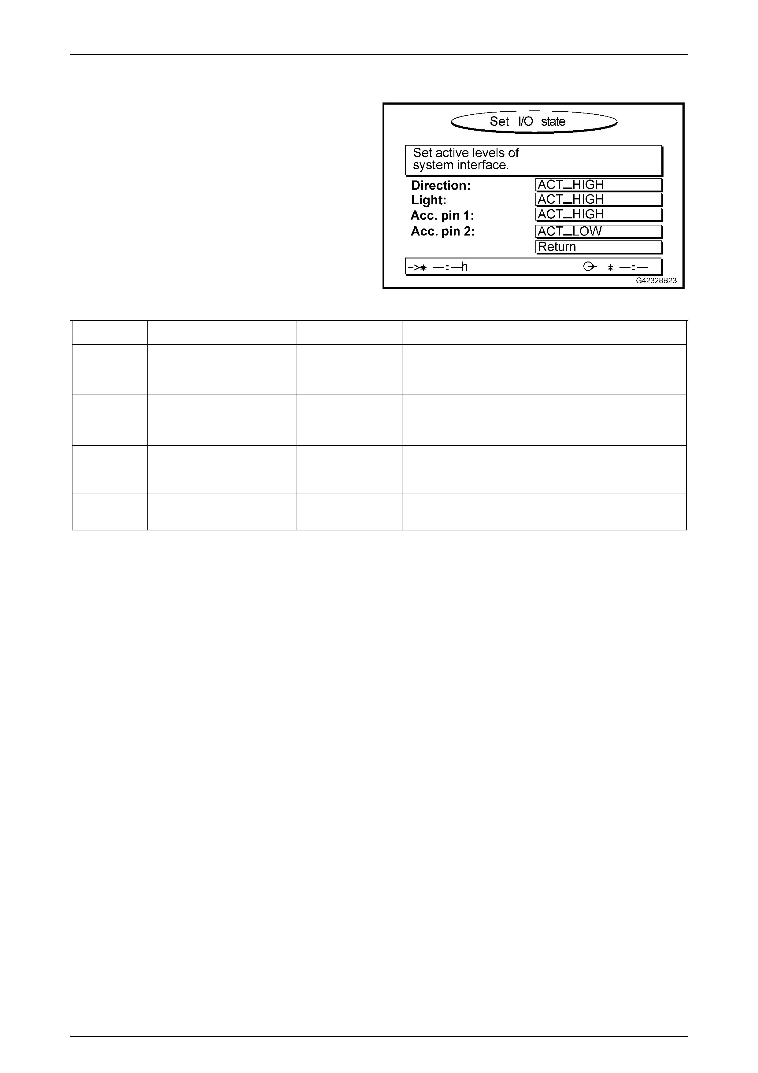
Navigation System Page 12L–52
Page 12L–52
3.3 Set I/O State
This represents the SET I/O STATE screen. The RETURN
field is automatically h ighlighted to return to the START
MENU when the OK button on the remote control is
pressed.
Figure 12L – 7
Function Description Nominal Value Comment
Direction Sets the polarity of the
reverse lamp circuit for
processor purposes.
ACT_HIGH For positive polarity reverse lamps, this is the correct
setting.
Light Sets the polarity of the park
lamp circuit for processor
purposes.
ACT_HIGH For positive polarity park lamps, this is the correct
setting.
Acc. pin 1 Sets the polarity of optional
accessory input 1. ACT_HIGH These values may change when optional
navigation/multimedia accessories are connected.
Acc. pin 2 Sets the polarity of optional
accessory input 2. ACT_LOW These values may change when optional
navigation/multimedia accessories are connected.
For Holden Navigation System installations, DIRECTION and LIGHT should be set to ACT_HIGH. Acc. pin 1 and Acc.
pin 2 are for system upgrades.

Navigation System Page 12L–53
Page 12L–53
3.4 Read GPS Data
Service personnel commonly suspect bad satellite reception as the cause of poor navigation s ystem perf ormance. GPS
data supplied to the processor is processed every few seconds to confirm the positi on calculated by the map-matching
software is correct. Good GPS data is essential to the system when it is first installed in the vehicle or when the vehicle is
moved from one location to another without the navigation system being active.
Within the navigation processor unit, there is a separate GPS receiver which receives GPS data from the antenna and
transmits calculated data to the processor. If the internal GPS receiver is faulty, the navigation processor must be
replaced.
Receiver State Description Comment
3D Position 3D data on the location of the vehicle is
available when the system receives data
from four or more satellites.
In this condition, the satellite icon on the guidance
screen is GREEN. This is the normal condition.
2D Position 2D data on the location of the vehicle is
available when the system receives data
from three or more satellites.
No geographic height can be determined in this
mode. Positional accuracy is reduced.
The satellite icon on the guidance screen is RED.
This is not the normal condition, but indicates poor
or reduced reception.
Tracking Data from one satellite has be en received by
the system. This condition is normally encountered when the
system is first powered up. The GPS receiver is in
this mode for up to 10 minutes depending upon
reception conditions.
The satellite icon on the guidance screen is RED.
Search SAT The system has a valid almanac and is
searching for satellites. This condition is normally encountered when the
system is first powered up. The GPS receiver is in
this mode for up to 10 minutes depending upon
reception conditions.
The satellite icon on the guidance screen is RED.
REC Error The system does not receive satellite sign als. This condition usuall y occu rs if the GPS antenna is
not connected or the cable is damaged. If the GPS
antenna and cable are serviceable, the GPS
receiver is faulty and should b e repl aced.
The satellite icon on the guidance screen is RED.
COM Error The GPS receiver is not providing any data
to the navigation processor. Internal communication between the GPS receiver
and the navigation proc essor is not possible.
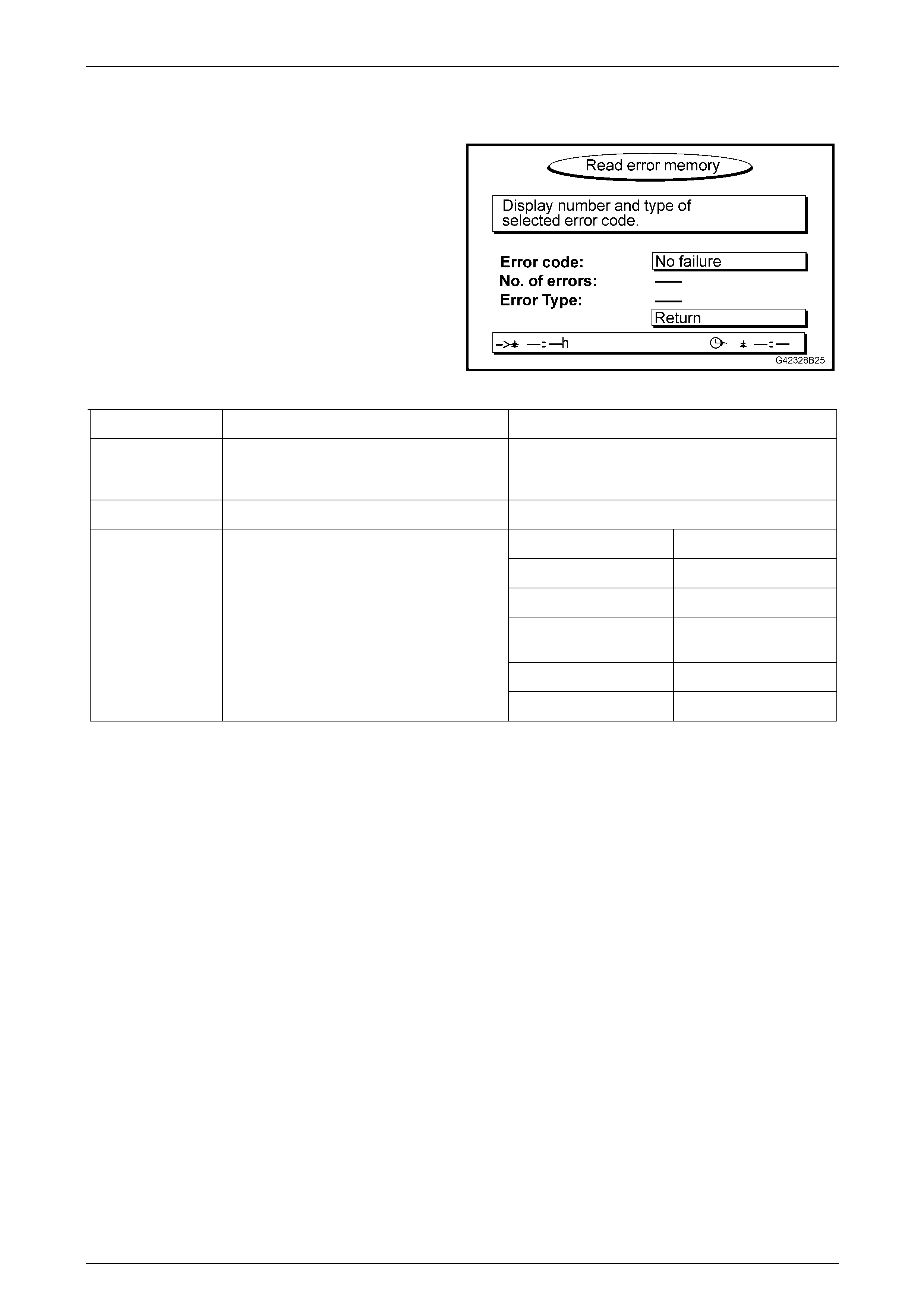
Navigation System Page 12L–54
Page 12L–54
3.5 Read Error Memory
This represents the READ ERROR MEMORY screen. T he
RETURN field is automatically highlighted to return to the
START MENU when the OK button on the remote control is
pressed.
The self-diagnosis function of the processor stores error
events to its internal memory. The errors detected may be
due to internal (processor) or external (environmental or
vehicle) conditions. You may need to view this screen when
asked by a technical consultant during fault diagnosis.
Figure 12L – 8
Menu Item Description Comment
Error Code Lists the errors that have occurred. Scroll through the errors using the < and > buttons.
Press OK when each error is highlighted to see a
description of the error.
No. of Errors The number of times the error has occurred.
SW Software error.
HW Hardware error.
SENSOR No VSS signal.
TEMP Temperature extreme
has caused system error.
GPS Lack of satellite signal.
Error Type Shows the type of error.
NO FAILURE No errors have occurred.

Navigation System Page 12L–55
Page 12L–55
4 Service Operations
The following Section contains the procedu r es required to remove and reinstall the navigation system components for
Sedan and Coupe. Modification procedures are included for the front floor console cover if a replacement cover is being
fitted.
4.1 Processor Assembly
LT Section No. — 000–2
The processor assembly is located ins ide the rear compartment.
Processor
Remove
The processor can be removed from the vehicle without removing the processor case and assembl y mounting brackets.
1 Remove fuses F23 and F16 from the passen ger compartme nt fuse and re lay assembly, refer to
Section 12O Fuses, Relays and Wiring Harnesses For location details.
2 Open the rear compartment lid and disconne ct the following connectors from the rear of the processor assembl y,
refer to Figure 12L – 9:
• Connector A139 – X1 (1)
• Connector A139 – X2 (2)
• Connector A139 – X3 (3)
• Connector A139 – X4 (4)
3 Using the processor assembly remov al too ls (5) inserted as shown, carefully pull the processor assem bl y out of the
processor assembly case (6). The processor assemb ly removal tool can be obtained from Siemens VDO Dayton or
alternatively, the radio/CD rem oval too l (service tool 179 1308 0000) can be used.
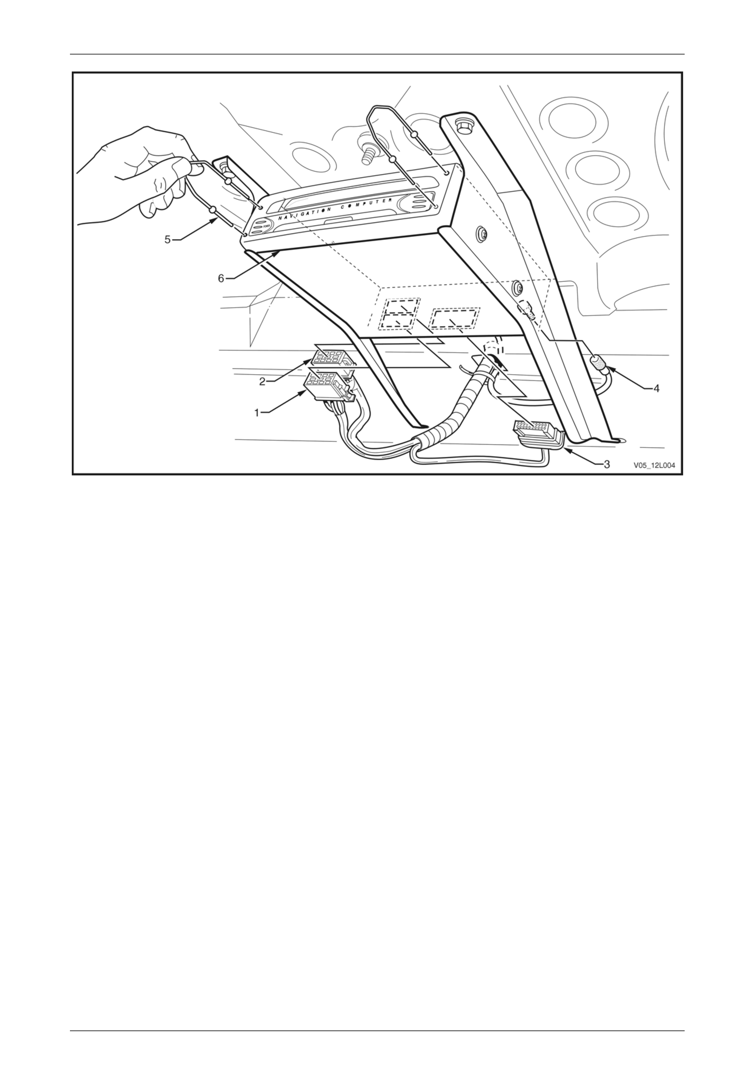
Navigation System Page 12L–56
Page 12L–56
Figure 12L – 9
Legend
1 Connector A139 – X1
2 Connector A139 – X2 3 Connector A139 – X3
4 Connector A139 – X4 5 Processor Assembly Removal Tool
6 Processor Assembly Case
Reinstall
Reinstallation of the process or is the revers e of the removal procedure (upon completion check the operation of the
navigation system).

Navigation System Page 12L–57
Page 12L–57
Mounting Brackets
Remove
The mounting brackets can be removed or reinstalled with the processor installed.
1 Remove fuses F23 and F16 from the passen ger compartment fuse and relay assembly, refer to
Section 12O Fuses, Relays and Wiring Harnesses for location details.
2 Open the rear compartment lid and disconne ct the following connectors from the rear of the processor assembl y,
refer to Figure 12L – 9:
• Connector A139 – X1 (1)
• Connector A139 – X2 (2)
• Connector A139 – X3 (3)
• Connector A139 – X4 (4)
Support the processor assembly and
brackets when removing the screws (1). After
removing these screws, the processor
assembly will drop away from the rear
window panel assembly unless supported.
3 Remove the two screws (1) securing the brackets to
the rear window panel assembly.
4 Lower the processor assembly and pu ll away from the
retaining holes (3).
5 If required, remove the two screws (2), each side,
attaching the brackets to the processor assembly
case.
Figure 12L – 10
Reinstall
Reinstallation of the mounting brackets is the reverse of the removal procedure. Tighten the attaching screws to the
specified torque.
Processor assembly mounting bracket to
rear window panel assembly attaching
screw torque specification...........................4.0 – 4.8 Nm
Processor assembly to
mounting bracket attaching
screw torque specification...........................1.2 – 1.5 Nm
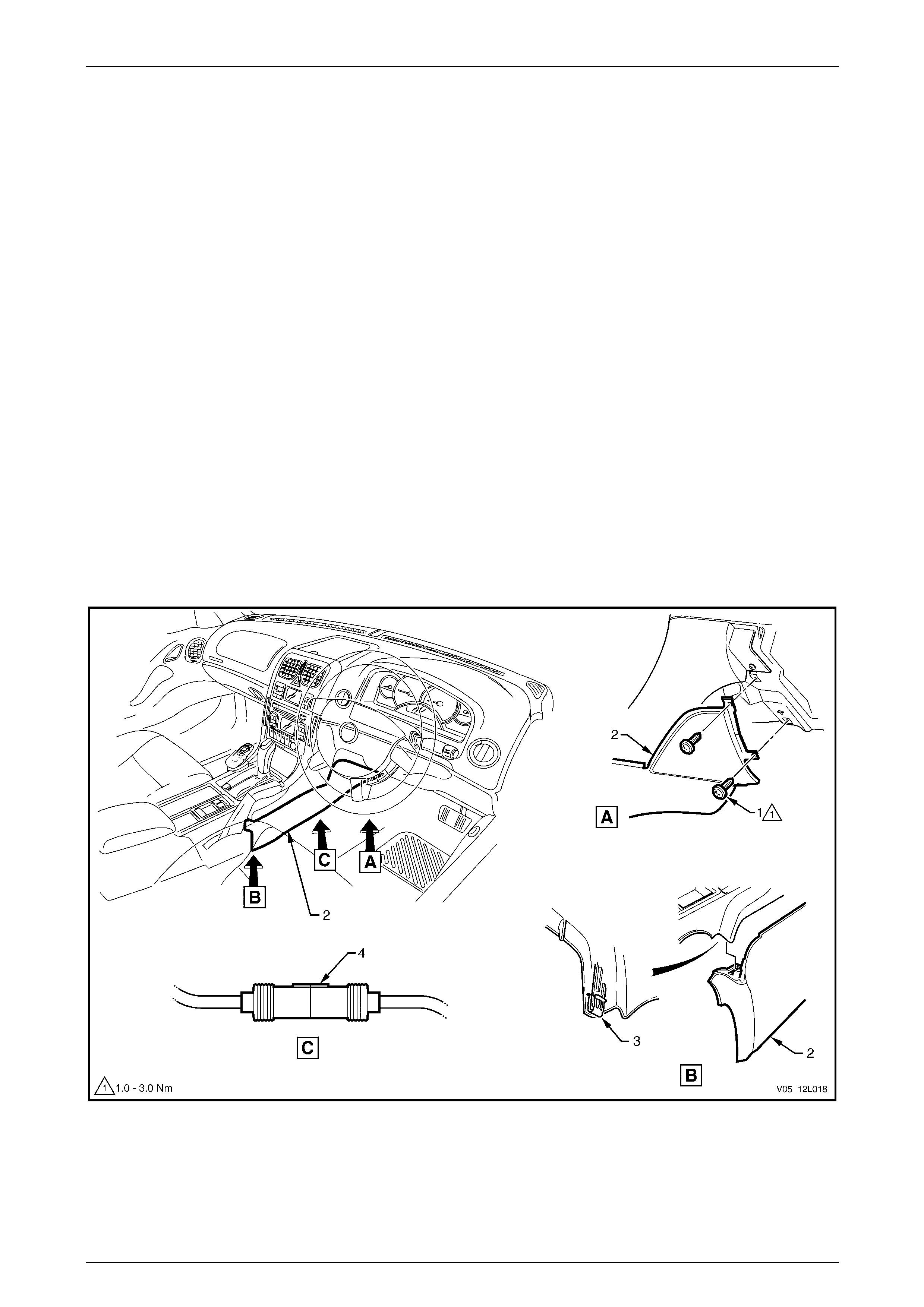
Navigation System Page 12L–58
Page 12L–58
4.2 Remote Control Assembly
LT Section No. — 000–2
The remote control assembly is locate d on the floor console assembly, in front of the automatic transmission selector or
manual gear lever assembly and consists of the following items, refer to Figure 12L – 12:
• Remote control (1)
• Remote control cradle (2)
• Presenter (5)
• Presenter mounting wedge (8)
Remote Control Cradle with Presenter
Remove
1 Ensure the ignition switch is in the OFF position.
2 Remove fuses F23 and F16 from the passen ger compartme nt fuse and re lay assembly, refer to
Section 12O Fuses, Relays and Wiring Harnesses for location details.
3 Remove fusible link F102 following fusible link from the engine compartment fuse and re lay panel assembly,
refer to Section 12O Fuses, Relays and Wiring Harnesses.
4 Remove the Instrument panel lower extension side trim, refer to Section 1A3 Instrument Pane l and Console.
5 Disconnect connector A35 (4) from the remote control cradle wiring harness, refer to Figure 1 2L – 11.
Figure 12L – 11
Legend
1 Screws
2 Instrument Panel Lower Extension Side Trim, Right-hand
Side
3 Floor Console Retaining Clip
4 Connector A35

Navigation System Page 12L–59
Page 12L–59
6 Remove the remote control (1) from the remote control cradle (2), refer to Figure 12L – 12.
Do not pull or tug on the remote control
cradle wiring harness.
7 Remove the three screws (3) and lift the cradle and place to one side.
8 Remove the two screws (4) and lift the presenter (5) and place to one side.
9 Remove the floor console cover, refer to Section 1A3 Instrument Panel and Console.
10 Feed the remote control cradle wiring har ness and connector (6) through the aperture in the floor console cover
assembly.
Reinstall
Reinstallation of the remote control cradle with presenter is the reverse of the removal procedur e.
1 Tighten the attaching screws (4) to the specif ied torque.
2 Replace the escutcheon foam tape if required.
Presenter attaching screw
torque specification.....................................0.6 – 1.0 Nm
3 Do not pull or tug on the remote control cradle cable wiring harness when routeing to the navigation main wiring
harness connector.
4 Tighten the attaching screws (3) to the specif ied torque.
Remote control cradle attaching
screws torque specification.........................0.7 – 1.0 Nm
Figure 12L – 12
Legend
1 Remote Control
2 Remote Control Cradle
3 Screw
4 Screw
5 Presenter
6 Remote Control Cradle Wiring Harness
Connector
7 Screw
8 Presenter Mounting Wedge

Navigation System Page 12L–60
Page 12L–60
4.3 Presenter Mounting Wedge
Remove
1 Remove the remote control cradle with presenter, refer to 4.2 Remote Control Assembly.
2 Remove the two screws (7) that secure the presenter mounter wedge (8) to the floor console cover assembly and
remove the presenter mounter wedge, refer to Figure 12L – 12.
Reinstall
Reinstallation of the presente r mounting wedge is the reverse of the removal proc edure. Tighten the attaching scre ws to
the specified torque.
Presenter mounting wedge attaching
screw torque specification...........................0.8 – 1.0 Nm
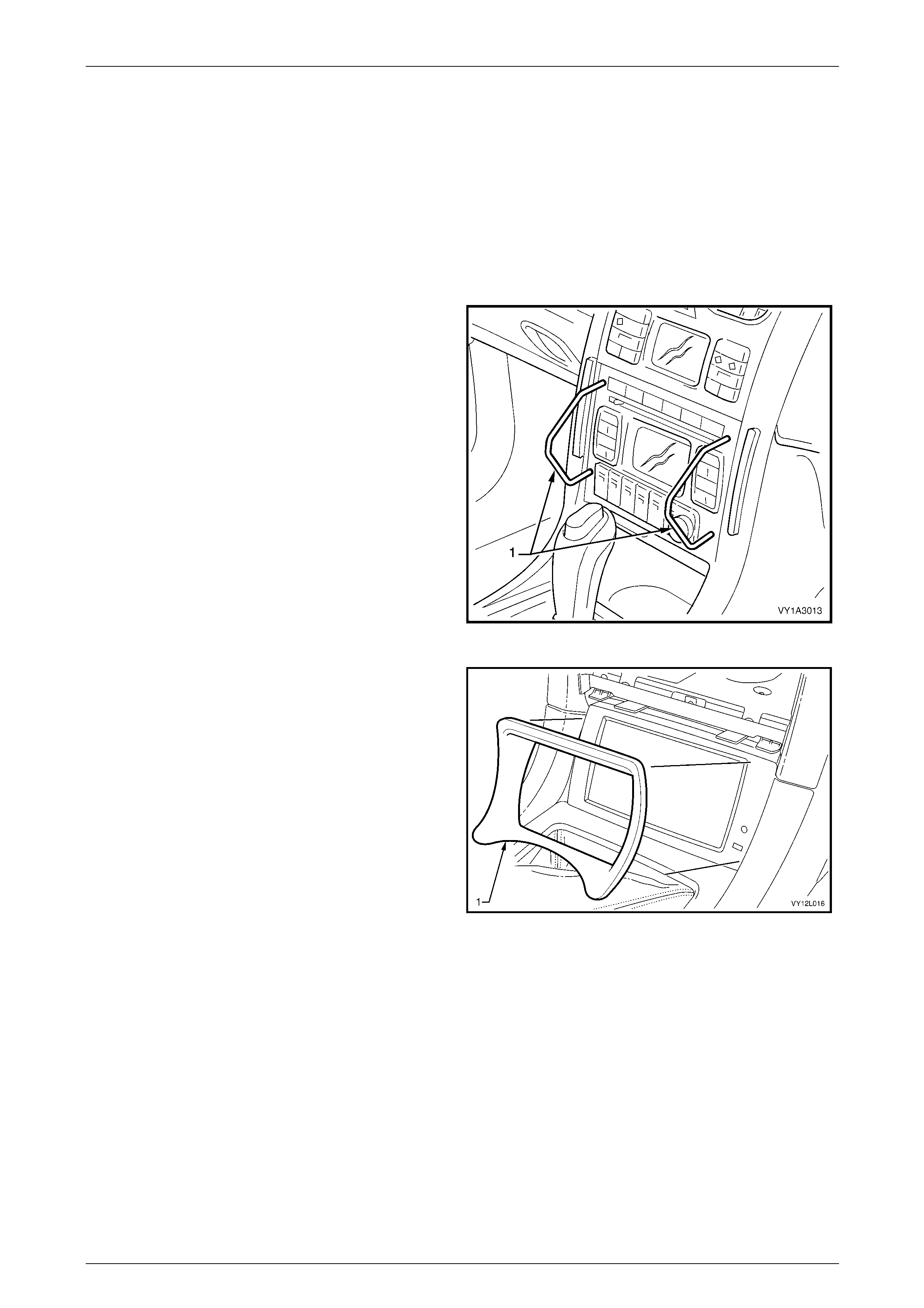
Navigation System Page 12L–61
Page 12L–61
4.4 Display Assembly
LT Section No. — 000–1
The display assembly is located in the floor console assembly.
Remove
1 Remove the fuses F23 and F16 from the passenger compartment fuse and relay assembly, refer to
Section 12O Fuses, Relays and Wiring Harnesses for location details.
2 Insert the special tools KM6067 (1) into the holes on
each side of the radio assembl y.
3 While applying outwards pressure on the tools
(towards each outer side of the vehicle), pull the radio
assembly out of the radio housing.
NOTE
The wiring connectors remain attached to the
radio housing and disconnect when the radio
assembly is removed.
Figure 12L – 13
4 Remove the escutcheon (1).
5 Inspect the foam tape on the escutcheon for
serviceability.
Figure 12L – 14
6 Remove the three nuts (1) securing the display assembly mounting bracket to the radio housing, refer to
Figure 12L – 15.
7 Slowly pivot the lower part of the display assembly up and to the rear of the vehicle.
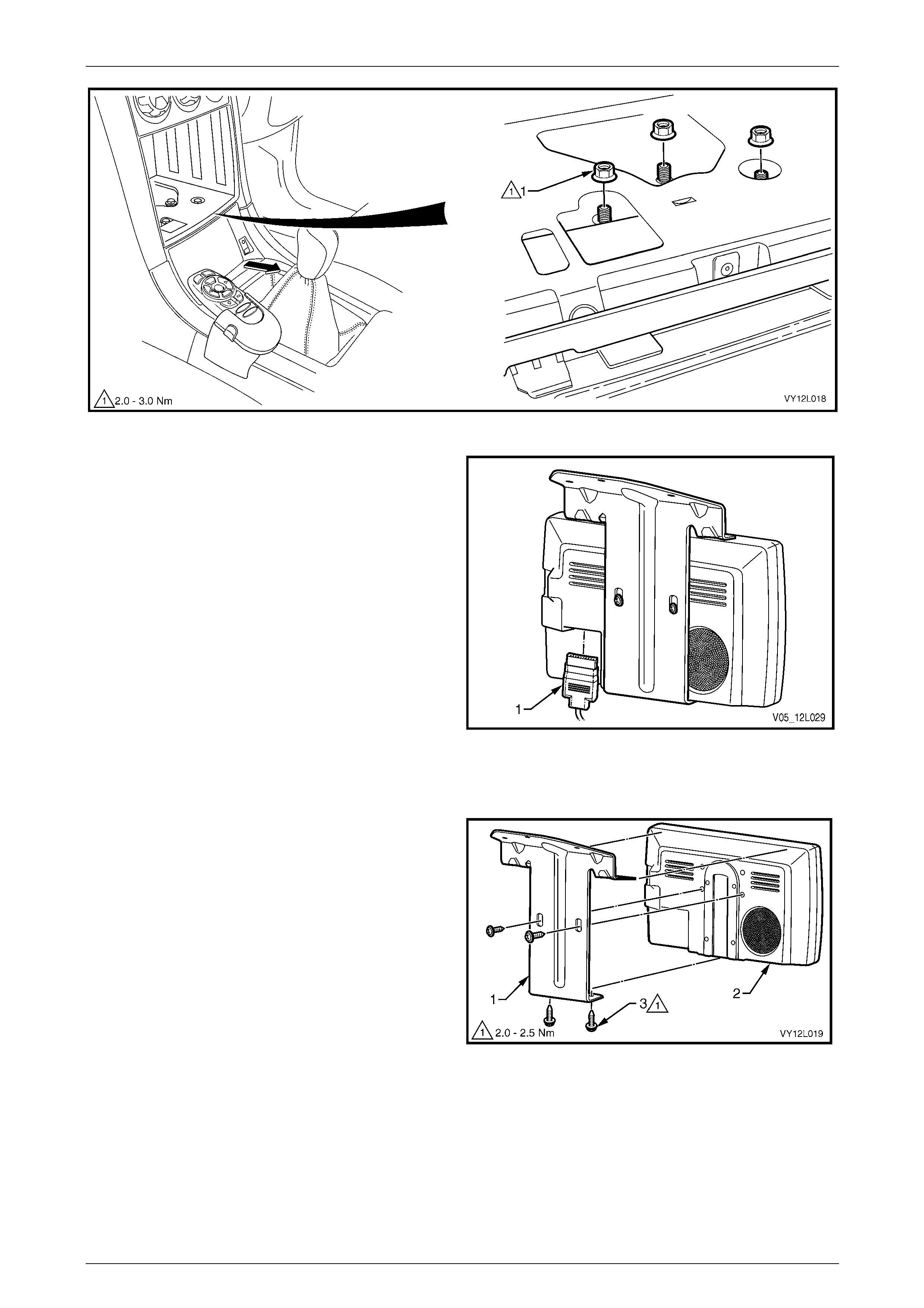
Navigation System Page 12L–62
Page 12L–62
Figure 12L – 15
8 Disconnect connector P6 (1) from the displa y
assembly.
9 Remove the display assembly.
Figure 12L – 16
Disassemble
Remove the four screws (3) securing the display assembly
mounting bracket (1) to the display assembly (2).
Figure 12L – 17

Navigation System Page 12L–63
Page 12L–63
Reassemble
Reassembly of the display assembly is the reverse of the disassembly procedure. Tighten the attaching screws to the
specified torque.
Display assembly mounting bracket
to display attaching screw
torque specification.....................................2.0 – 2.5 Nm
Reinstall
Reinstallation of the displ ay assembly is the reverse of the removal proced ure, noting the following:
1 Tighten the attaching nuts to the spec ified torque.
Display assembly mounting bracket
attaching nut torque specification................2.0 – 3.0 Nm
2 Replace the escutcheon foam tape if required.
3 Check the display for correct operation.
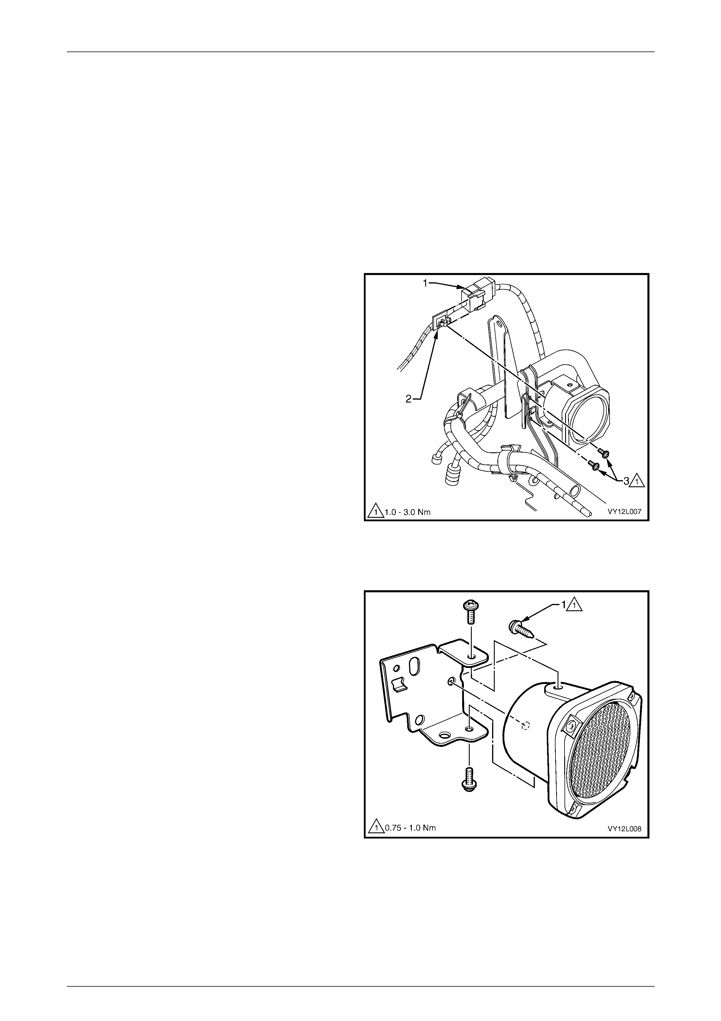
Navigation System Page 12L–64
Page 12L–64
4.5 Navigation Speaker Assembly
LT Section No. — 000–2
Remove
1 Remove the fuses F23 and F16 from the passenger compartment fuse and relay assembly,
refer to Section 12O Fuses, Relays and Wiring Harnesses for location details.
2 Remove the left-hand instrument panel lower trim panel assembly,
refer to Section 1A3 Instrument Panel and Consol e.
3 Remove the instrument panel compartment assembly, refer to Section 1A3 Instrument Panel and Console.
4 Disconnect connector B104 (1) from the nav igation
speaker assembly.
5 Remove the clip (2) from the speaker assembl y plate.
6 Remove the two screws (3) attaching the speaker
assembly to the vehicles.
Figure 12L – 18
Disassemble
Remove the three screws (1) securing the speaker to the
speaker assembly plate an d separate the two items.
Figure 12L – 19

Navigation System Page 12L–65
Page 12L–65
Reassemble
Reassembly of the speaker a ssembly is the reverse of the disassembly proced ure. Tighten the attaching scre ws to the
specified torque.
Speaker to speaker assembly plate
attaching screws torque specification .......0.75 – 1.0 Nm
Reinstall
Reinstallation of the navigation speaker assembly is the reverse of the removal procedure. Tighten the attaching screws
to the specified torque.
Speaker assembly attaching
screw torque specification...........................1.0 – 3.0 Nm
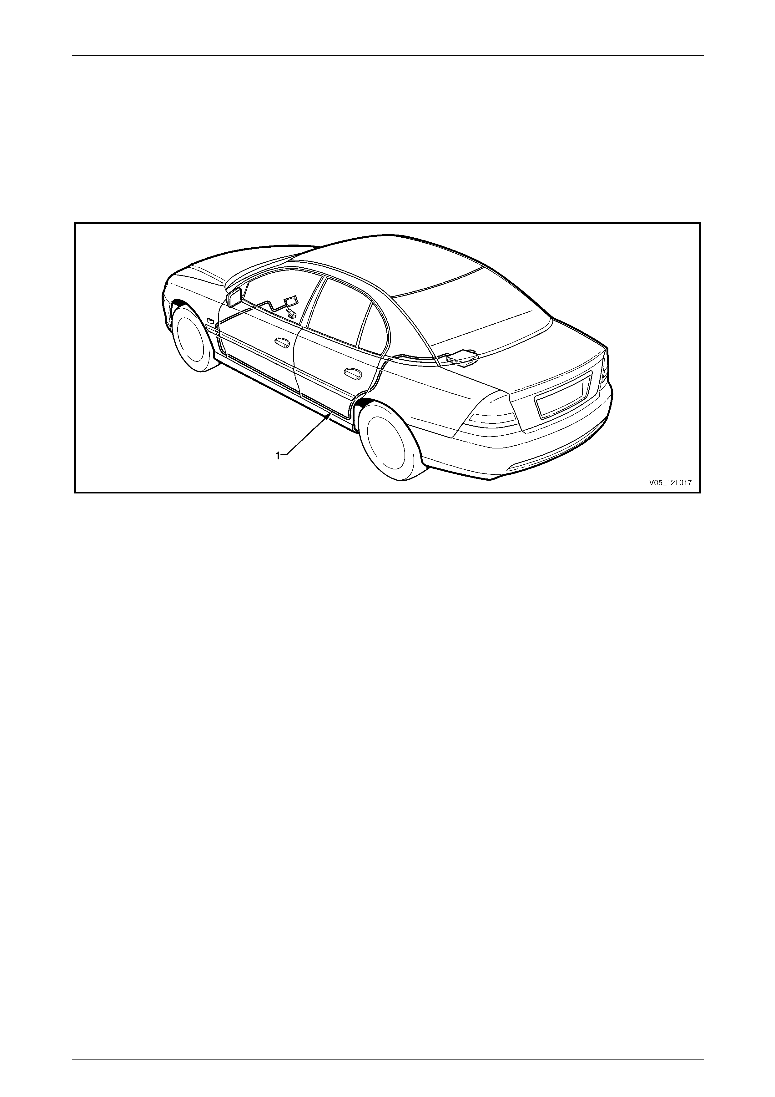
Navigation System Page 12L–66
Page 12L–66
4.6 Navigation Wiring Harness
LT Section No. — 000–2
The navigation wiring harness (1) is routed from the rear compartment, along the left-hand side of the vehicle and
terminates at the hinge pillar trim assembly, refer to Figure 12L – 20. Here, the harness co nnects to the body wiring
harness of the vehicle at connector X207 and the cockpit navigation wiring harness with connectors XO1, XO2 and
B104.
Figure 12L – 20
Remove
1 Remove the fuses F23 and F16 from the passenger compartment fuse and relay assembly,
refer to Section 12O Fuses, Relays and Wiring Harnesses for location details.
2 Open the rear compartment lid and disconne ct the following connectors from the rear of the processor, refer to
Figure 12L – 9:
• Connector A139 – X1 (1)
• Connector A139 – X2 (2)
• Connector A139 – X3 (3)
• Connector A139 – X4 (4)
3 Remove the rear seat cushion and seat assembly back, refer to Section 1A7 Seat Assemblies.
4 Remove the rear window trim panel assembl y, refer to Section 1A8 Hea dlining and Interior Trim .
5 Remove the left-hand side sill trim and plate, refer to Section 1A8 Headlining and Interior Trim.
6 Remove the left-hand hin ge pillar trim assembly, refer to Section 1A8 Headlining an d Interior Trim.
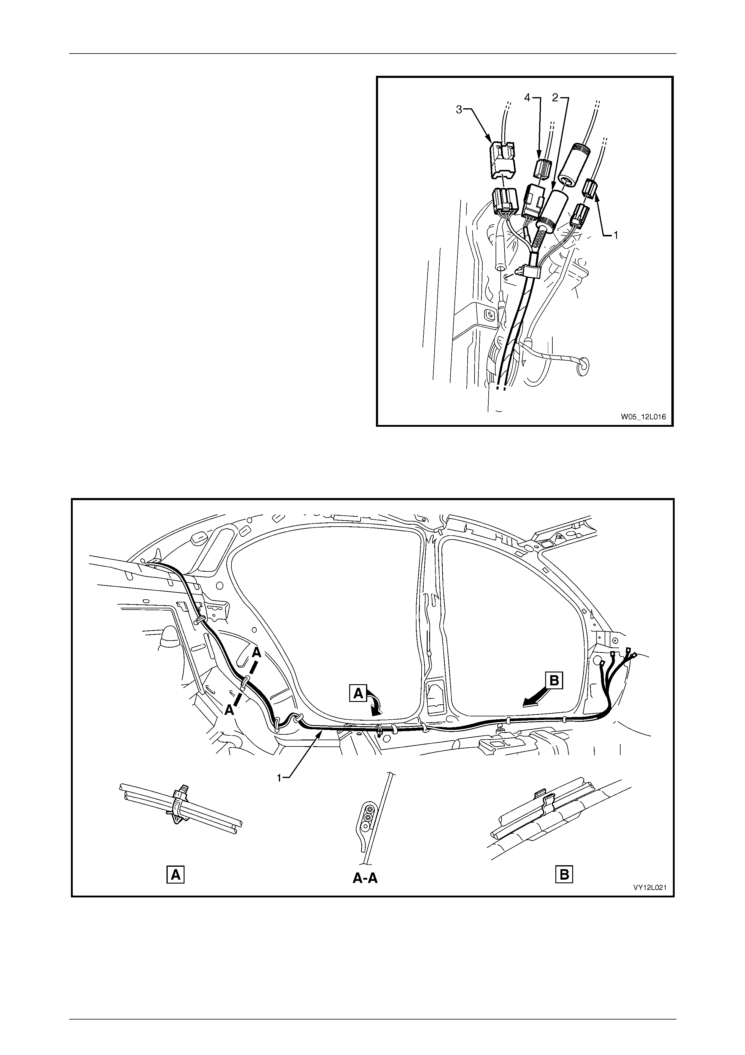
Navigation System Page 12L–67
Page 12L–67
7 Disconnect the following connectors at the le ft-hand
hinge pillar trim assembly:
• B104 (1)
• X01 (2)
• X207 (3)
• X02 (4)
Figure 12L – 21
8 As required, cut the cable ties securing the navigation wiring harness (1) to the sheet metal, refer to
Figure 12L – 22 for Sedan and Figure 12L – 23 for Coupe.
Figure 12L – 22
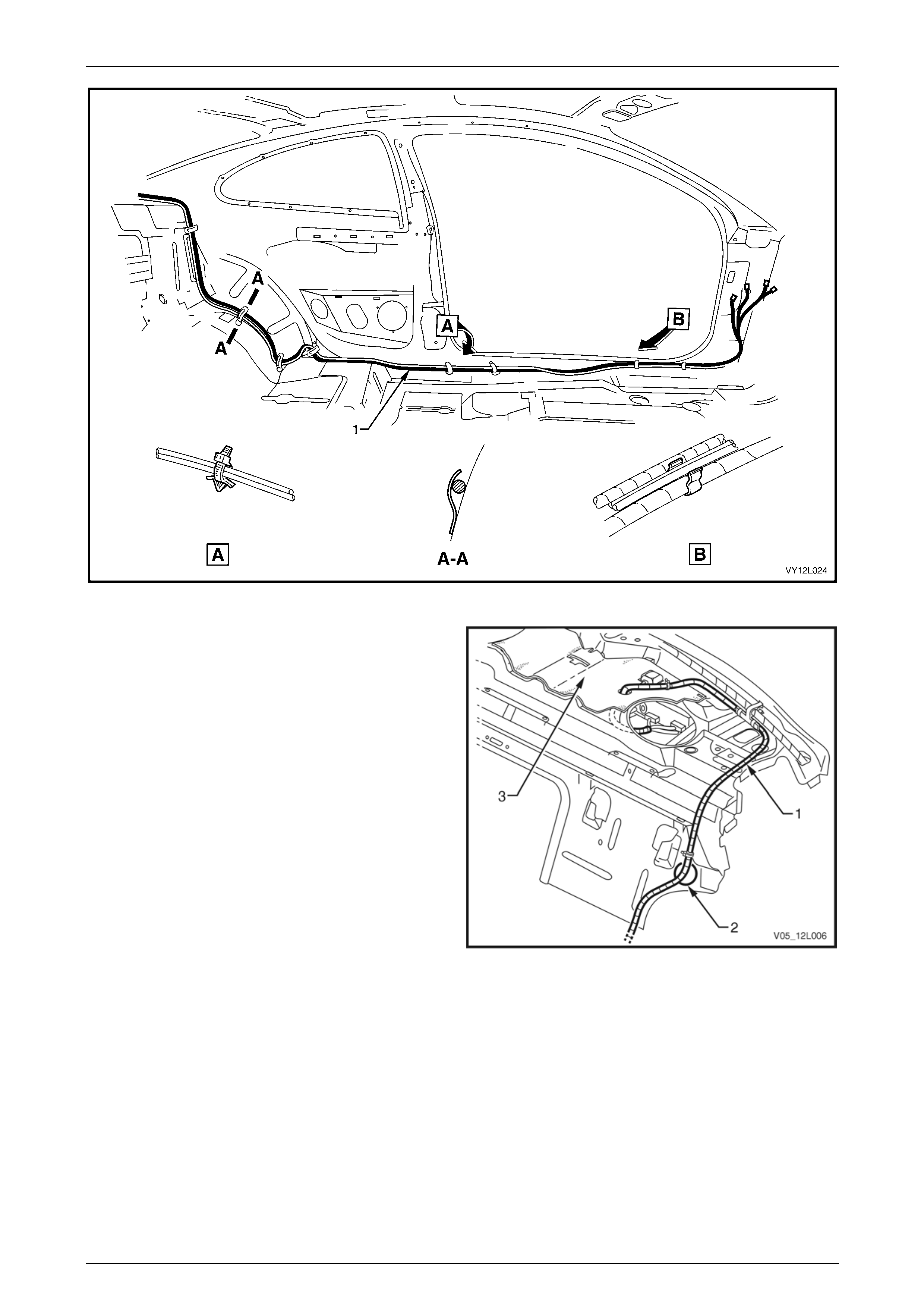
Navigation System Page 12L–68
Page 12L–68
Figure 12L – 23
9 For sedan, remove all clips attaching the navigation
wiring harness (1) to the rear windo w panel assemb ly.
Feed the navigation wiring harness through the rear
window panel assembly.
NOTE
The navigation wiring harness is too long for
sedan vehicles. Any excess harness is carefully
looped and tied together, and placed through the
panel assembly at the design ated po int (2).
Figure 12L – 24
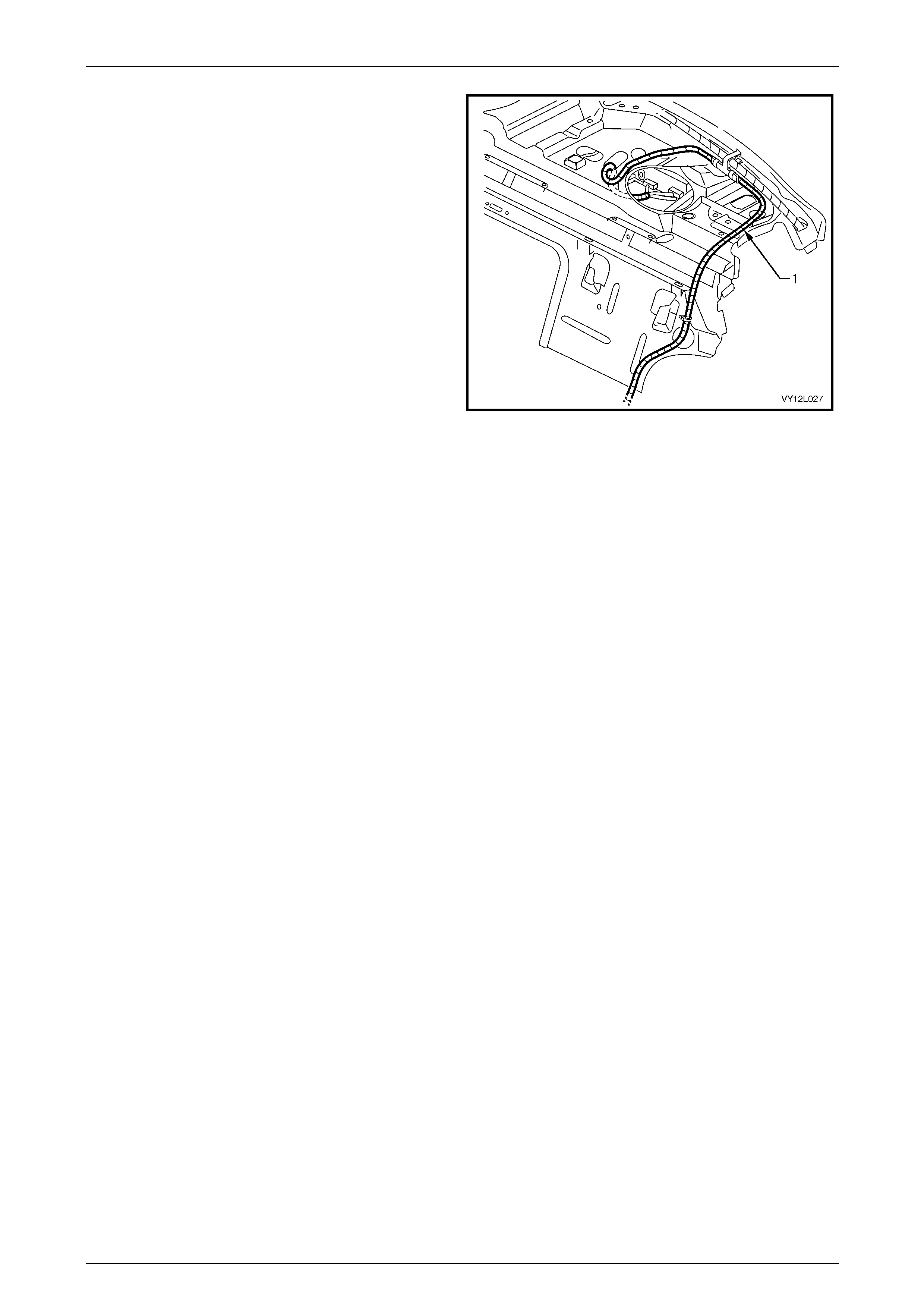
Navigation System Page 12L–69
Page 12L–69
10 For Coupe:
a Lift the rear window panel insulator (3) to gain
access to the navigation wiring harness.
b Remove all clips attaching the navi gation wiring
harness to the rear window panel assembly.
c Feed the navigation wiring harness through the
rear window panel assembly.
11 Remove the navigation wiring harness from the
vehicle.
Figure 12L – 25
Reinstall
Reinstallation of the navi gation wiring harness is the reverse of the removal procedure, noting the following:
1 Replace all clips and ties where required.
2 Ensure excess wiring harness is looped, tied and placed through the rear window panel assembly at the
designated point (2), refer to Figure 12L – 24.
3 Connect all electrical connectors and check the operation of the navigation system before installing the seat and
trim assemblies.
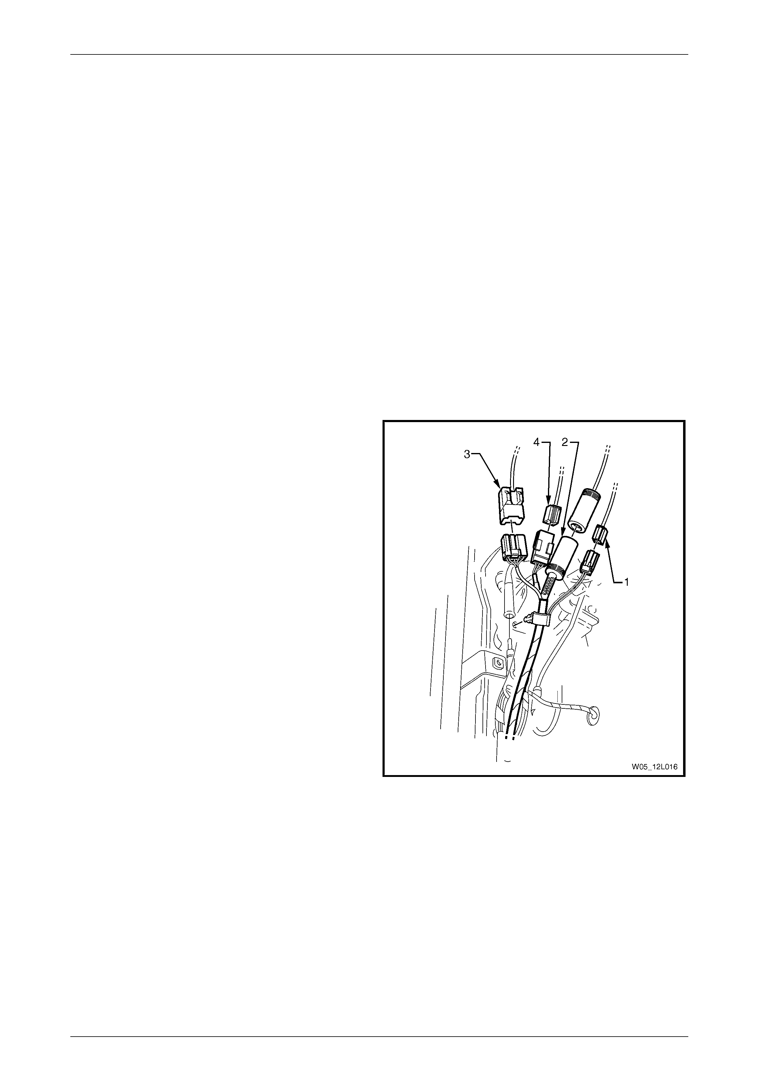
Navigation System Page 12L–70
Page 12L–70
4.7 Cockpit Navigation Wiring Harness
LT Section No. — 000–2
The cockpit navigation wiring harness connects to the navigation wiring harness under the left-hand hinge pillar trim
assembly, using connectors XO1 and XO2. The cockpit navigation wiring harness is routed under the hinge pillar trim
assembly, along the instrument panel lower bracket, behind the radio housing and terminates under the front right-hand
side of the floor console cover assembly.
Remove
1 Remove the display assembly, refer to 4.4 Display Assembly.
2 Remove both the instrument panel lower extensions, refer to Section 1A3 Instrument Panel and Console.
3 Remove the right-hand instrument panel lower extension side trim,
refer to Section 1A3 Instrument Panel and Consol e.
4 Remove the left-hand instrument panel lower trim plate assembly,
refer to Section 1A3 Instrument Panel and Consol e.
5 Remove the instrument panel compartment assembly, refer to Section 1A3 Instrument Panel and Console.
6 Remove the left-hand hin ge pillar trim assembly, refer to Section 1A8 Headlining an d Interior Trim.
7 Disconnect the following connectors from be neath the
left-hand hinge pillar trim asse mbly:
• XO1 (2)
• X207 (3)
• XO2 (4)
Figure 12L – 26
8 Disconnect connector A35 (1) from the remote control cradle, refer to Figure 12L – 27.
9 As required, cut the cable ties securing the cockpit navigation wiring harness (2) to the vehicle a nd remove the
harness.
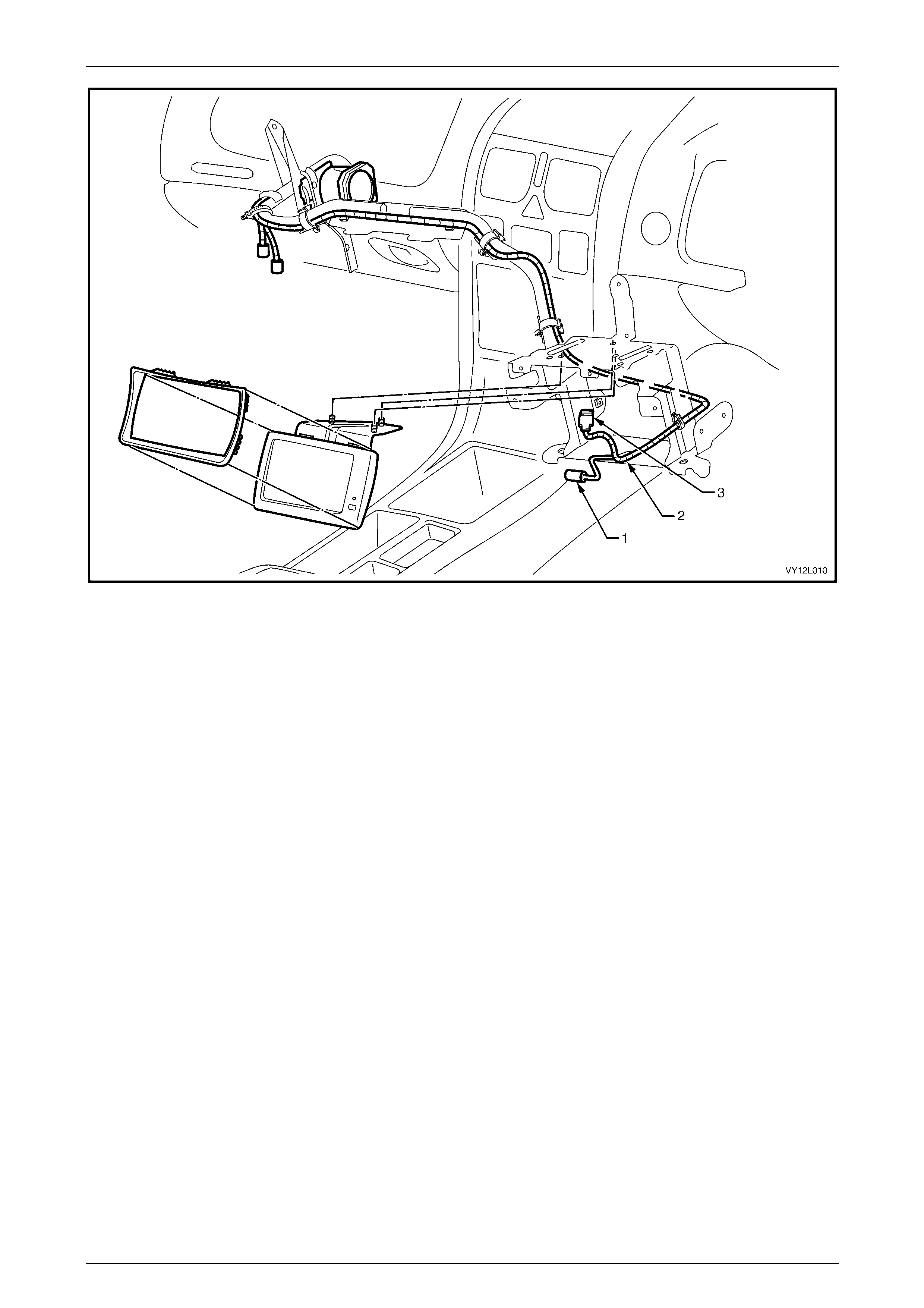
Navigation System Page 12L–71
Page 12L–71
Figure 12L – 27
Legend
1 Connector A35
2 Cockpit Navigation Wiring Harness 3 Connector P6
Reinstall
Reinstallation of the cockpit navig ation wiring harness is the reverse of removal procedure, noting the following:
1 Ensure all clips and ties are in stalled in the correct locations.
2 Check the operation of the na vigation system.
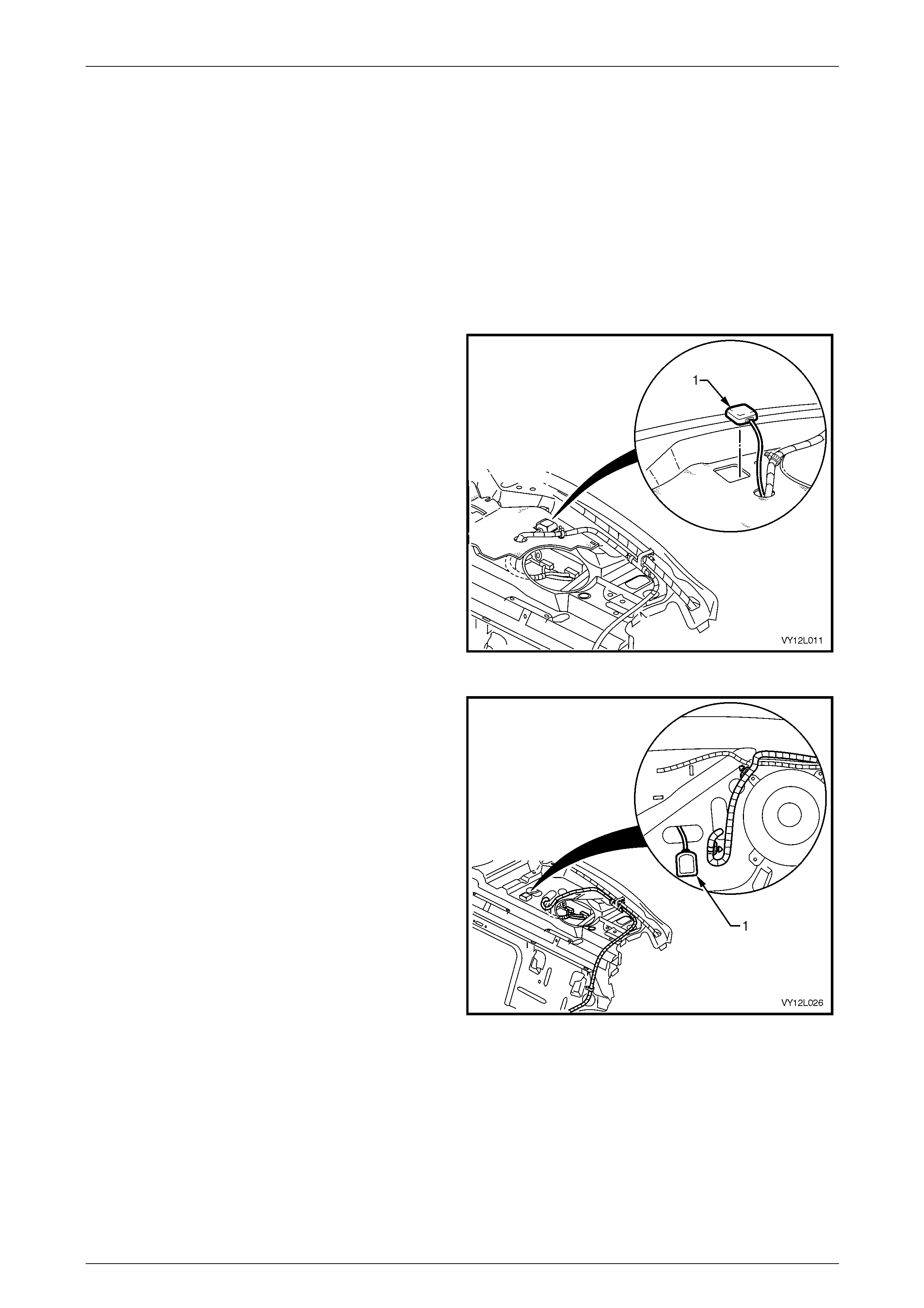
Navigation System Page 12L–72
Page 12L–72
4.8 GPS Antenna Assembly
LT Section No. — 000–2
Remove
1 Remove fuses F23 and F16 from the passen ger compartme nt fuse and re lay assembly, refer to
Section 12O Fuses, Relays and Wiring Harnesses for location details.
2 Disconnect connector A139 – X4 from the rear of the processor assembly, refer to F igure 12L – 9.
3 Remove the rear window trim panel assembl y, refer to Section 1A8 Hea dlining and Interior Trim .
4 For Sedan, using a flat blade screwdriver, carefully
prise the antenna (1) from the rear window panel
assembly.
NOTE
The GPS antenna assembly is secured in place
with double-sided tape.
Figure 12L – 28
5 For Coupe:
a Lift the rear window panel insulator to gain
access to the navigation wiring harness.
b Using a flat blade screwdriver, carefully prise the
antenna (1) from the rear window panel
assembly.
NOTE
The GPS antenna assembly is secured in place
with double-sided tape.
6 Pull the GPS antenna assembly cable through the
rear window panel assembly and remove the antenna.
Figure 12L – 29
Reinstall
Reinstallation of the GPS antenna assembly is the reverse of the removal procedur e, noting the following:
1 Clean the rear window panel assembly to remove any residue of the double-sid ed tape.
2 Replace the double-sided tape on the navigation antenna with 3M® brand 4428 or equivalent.
3 Ensure the GPS antenna assembly is secured to the rear window panel assembl y.
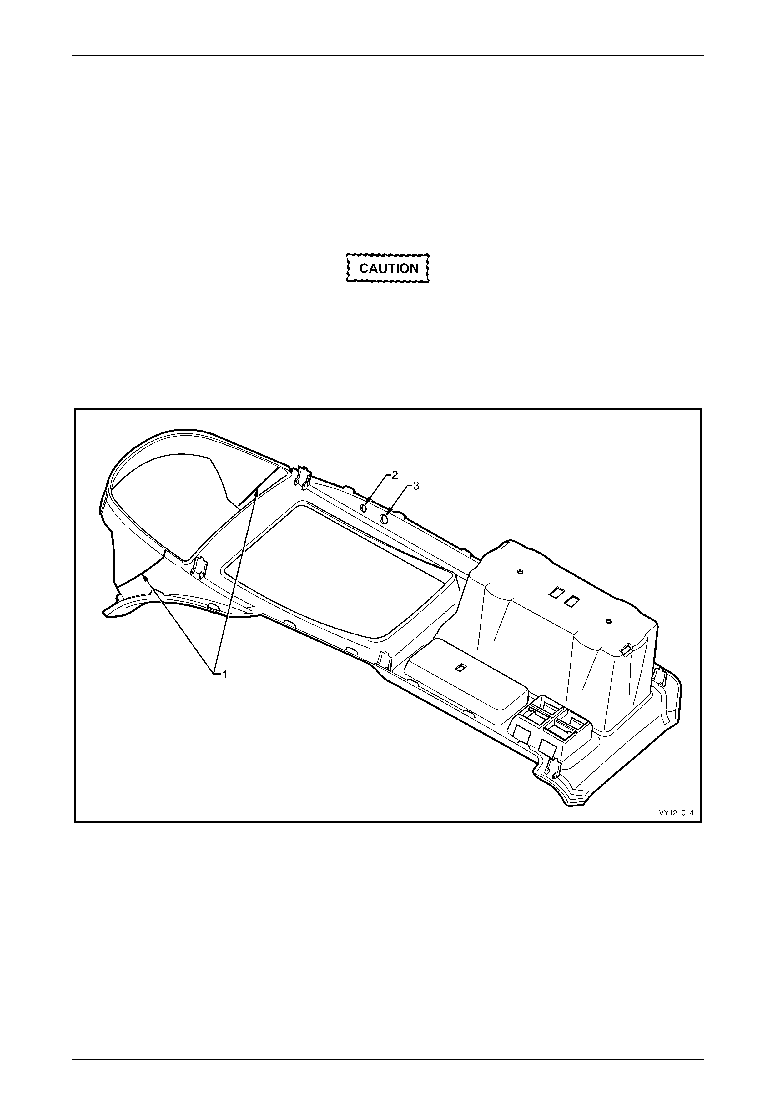
Navigation System Page 12L–73
Page 12L–73
4.9 Fitting A New Floor Console Cover
Assembly
LT Section No. — 000–2
The following procedure d etails how to modify the floor console cover asse mbly to allow for installation of the navigation
system.
1 Cut through the two lines (1) marked on the underside of the floor console cover assembly, refer to
Figure 12L – 30.
Use blunt drill bits to avoid the plastic
splitting.
2 Drill two pilot holes through the floor cons ole cover assembly at the marks (2 and 3) on the und erside.
3 Enlarge the hole (2) to 10 mm and the hol e (3) to 14 mm.
4 Remove any burrs from both holes.
Figure 12L – 30

Navigation System Page 12L–74
Page 12L–74
4.10 Fitting A New Floor Console Assembly
LT Section No. — 000–2
If a floor console assembly needs to be replac ed on a navigation system-equippe d vehicle, the new floor console
assembly does not have the nutserts require d for the attach ment of the presenter mounting wedge. Two nutserts and
screws are used to attach the presenter mounting wedge, refer to Figure 12L – 12. The nutserts can be used from the
previous console assembly or new nutserts can be ordered.

Navigation System Page 12L–75
Page 12L–75
4.11 Navigation System Calibration
LT Section No. — 000–2
The navigation system requires calibration only if the vehicle has be en moved without the navigation s ystem functioning
or if the vehicle’s battery has been disconnected without allowing the system to shut do wn properly. The navigation
system requires 30 seconds to shut down before disconnection.
Calibration of the navigation system is performed automatically when the vehicle is moving and the navigation system
functioning. Calibration does not need to be performed by the technician, but if the customer is unaware of calibration
requirements, they may believe the system is not functioning correctly.
For the system to calibrate, the following must be performed:
• The navigation system must be functioning.
• The vehicle must be driven unt il the arrow representing the vehicle is correctly aligned with the digital map
displayed on the monitor.
NOTE
The more turns taken during calibration, the
faster the system calibrates.

Navigation System Page 12L–76
Page 12L–76
5 Torque Wrench Specifications
Processor Assembly Mounting Bracket To Rear Windo w
Panel Assembly Attaching Screw .................................................4.0 – 4.8 Nm
Processor Assembly To Mounting Bracket Attaching Screw.........1.2 – 1.5 Nm
Presenter Attaching Screw............................................................0.6 – 1.0 Nm
Remote Control Cradle Attaching Screw........................................0.7 –1.0 Nm
Presenter Mounting Wedge Attaching Screw................................0.8 – 1.0 Nm
Display Assembly Mounting Bracket To Display Attaching Screw.2.0 – 2.5 Nm
Display Assembly Mounting Bracket Attaching Nut.......................2.0 – 3.0 Nm
Speaker To Speaker Assembly Plate Attaching Screw...............0.75 – 1.0 Nm
Speaker Assembly Attaching Screw..............................................1.0 – 3.0 Nm

Navigation System Page 12L–77
Page 12L–77
6 Special Tools
Tool Number Illustration Description Tool Classification
179 1308 0000
Processor Assembly Removal Tool
Used for removing navigation
processor from its mounting location.
Previously released.
Mandatory
KM6067
Radio Removal Tool
Used for removing audio unit from its
mounting location.
Mandatory
KM-609
(J35616-A)
Electronic Kit
Used in conjunction with a multimeter
for measuring voltages and
resistances without damaging wiring
harness connectors.
Desirable