
Occupant Protection System Page 12M–1
Page 12M–1
Section 12M
Occupant Protection System
ATTENTION
Before performing any Service Operation or other procedure described in this Section, refer to Section 00
Warnings, Cautions and Notes for correct workshop practices with regard to safety and/or property damage.
1 General Information .............................................................................................................................10
1.1 General Description............................................................................................................................................. 13
Front Seatbelt Pretensioners.............................................................................................................................. 14
Steering Wheel Inflatable Restraint.................................................................................................................... 15
Instrument Panel Inflatable Restraint................................................................................................................. 16
Side-Impact Inflatable Restraints ....................................................................................................................... 17
1.2 Components......................................................................................................................................................... 18
Sensing and Diagnostic Module (SDM) ............................................................................................................. 18
Side-impact Sensor Assembly............................................................................................................................ 20
Seatbelt Pretensioners........................................................................................................................................ 21
Clock Spring Coil Assembly............................................................................................................................... 22
Steering Wheel Inflatable Restraint Assembly.................................................................................................. 22
Inflator Assembly.............................................................................................................................................. 23
Instrument Panel Inflatable Restraint Assembly............................................................................................... 24
Inflator Assembly.............................................................................................................................................. 24
Side-impact Inflatable Restraint Assembly........................................................................................................ 26
Inflator Assembly.............................................................................................................................................. 26
Airbag Warning Indicator.................................................................................................................................... 27
Multi-function Display ......................................................................................................................................... 28
Chime Alert........................................................................................................................................................... 28
Seatbelt Warning Indicator..................................................................................................... ............................. 28
Seatbelt Buckle Switch........................................................................................................................................ 28
Warning Labels.................................................................................................................................................... 29
Wiring Harness..................................................................................................................................................... 30
1.3 System Operation – Inflatable Restraint and Pretensioner Assemblies......................................................... 31
Firing Mode 1........................................................................................................................................................ 32
Firing Mode 2........................................................................................................................................................ 33
Firing Mode 3........................................................................................................................................................ 34
Firing Loop Monitoring........................................................................................................................................ 34
1.4 Repairs and Inspections Required After a Collision......................................................................................... 35
No Pretensioner or Inflatable Restraint Assembly Deployment...................................................................... 35
Pretensioner Only Deployment........................................................................................................................... 35
Pretensioner and Front Inflatable Restraint Assembly Deployment............................................................... 36
Side-impact Inflatable Restraint Assembly Deployment.................................................................................. 36
2 Diagnostics...........................................................................................................................................37
2.1 Prerequisites........................................................................................................................................................ 37
Equipment ............................................................................................................................................................ 37
Testing Procedures ............................................................................................................................................. 37
2.2 Wiring Diagram .................................................................................................................................................... 38
2.3 Connector Chart................................................................................................................................................... 39
2.4 System Self Diagnosis ........................................................................................................................................ 40
DTCs – Current..................................................................................................................................................... 40
DTCs – History..................................................................................................................................................... 40
Erasing DTCs ....................................................................................................................................................... 40
Data Display ......................................................................................................................................................... 41
Techline

Occupant Protection System Page 12M–2
Page 12M–2
2.5 Preliminary System Diagnosis............................................................................................................................ 44
2.6 Electrical Diagnosis............................................................................................................................................. 45
Introduction.......................................................................................................................................................... 45
System Diagnostic Check................................................................................................................................... 47
Introduction ...................................................................................................................................................... 47
Test Description ............................................................................................................................................... 47
Diagnostic Table Notes .................................................................................................................................... 47
Diagnostic Table............................................................................................................................................... 47
Airbag Warning Indicator Inoperative................................................................................................................ 48
Introduction ...................................................................................................................................................... 48
Circuit Description............................................................................................................................................ 48
Test Description ............................................................................................................................................... 48
Diagnostic Table Notes .................................................................................................................................... 48
Diagnostic Table............................................................................................................................................... 48
Airbag Warning Indicator Illuminated (No DTC Stored) ................................................................................... 49
Introduction ...................................................................................................................................................... 49
Circuit Description............................................................................................................................................ 49
Test Description ............................................................................................................................................... 49
Diagnostic Table Notes .................................................................................................................................... 50
Diagnostic Table............................................................................................................................................... 50
No Communications from SDM.......................................................................................................................... 52
Introduction ...................................................................................................................................................... 52
Circuit Description............................................................................................................................................ 52
Test Description ............................................................................................................................................... 52
Diagnostic Table Notes .................................................................................................................................... 52
Diagnostic Table............................................................................................................................................... 53
2.7 Steering Wheel Inflatable Restraint Assembly DTCs........................................................................................ 54
DTC 17 – Driver Airbag Circuit Short to Battery................................................................................................ 54
Introduction ...................................................................................................................................................... 54
Circuit Description............................................................................................................................................ 54
Test Description ............................................................................................................................................... 54
Diagnostic Table Notes .................................................................................................................................... 54
Diagnostic Table............................................................................................................................................... 55
DTC 18 – Driver Airbag Circuit Short to Ground............................................................................................... 56
Introduction ...................................................................................................................................................... 56
Circuit Description............................................................................................................................................ 56
Test Description ............................................................................................................................................... 56
Diagnostic Table Notes .................................................................................................................................... 56
Diagnostic Table............................................................................................................................................... 57
DTC 19 – Driver Airbag Circuit Capacitance Too High..................................................................................... 58
Introduction ...................................................................................................................................................... 58
Circuit Description............................................................................................................................................ 58
Action Required................................................................................................................................................ 58
DTC 20 – Driver Airbag Circuit Capacitance Too Low...................................................................................... 58
Introduction ...................................................................................................................................................... 58
Circuit Description............................................................................................................................................ 58
Action Required................................................................................................................................................ 58
DTC 21 – Driver Airbag Circuit Resistance Too High ....................................................................................... 59
Introduction ...................................................................................................................................................... 59
Circuit Description............................................................................................................................................ 59
Test Description ............................................................................................................................................... 59
Diagnostic Table Notes .................................................................................................................................... 59
Diagnostic Table............................................................................................................................................... 60

Occupant Protection System Page 12M–3
Page 12M–3
DTC 22 – Driver Airbag Circuit Resistance Too Low........................................................................................ 61
Introduction ...................................................................................................................................................... 61
Circuit Description............................................................................................................................................ 61
Test Description ............................................................................................................................................... 61
Diagnostic Table Notes .................................................................................................................................... 61
Diagnostic Table............................................................................................................................................... 62
DTC 247 – Driver Airbag Circuit Power Stage Error ......................................................................................... 63
Introduction ...................................................................................................................................................... 63
Circuit Description............................................................................................................................................ 63
Action Required................................................................................................................................................ 63
Diagnostic Table Notes .................................................................................................................................... 63
Diagnostic Table............................................................................................................................................... 64
2.8 Instrument Panel Inflatable Restraint Assembly DTCs .................................................................................... 65
DTC 33 – Passenger Airbag Circuit Short to Battery........................................................................................ 65
Introduction ...................................................................................................................................................... 65
Circuit Description............................................................................................................................................ 65
Test Description ............................................................................................................................................... 65
Diagnostic Table Notes .................................................................................................................................... 65
Diagnostic Table............................................................................................................................................... 66
DTC 34 – Passenger Airbag Circuit Short to Ground....................................................................................... 67
Introduction ...................................................................................................................................................... 67
Circuit Description............................................................................................................................................ 67
Test Description ............................................................................................................................................... 67
Diagnostic Table Notes .................................................................................................................................... 67
Diagnostic Table............................................................................................................................................... 68
DTC 35 – Passenger Airbag Circuit Capacitance Too High ............................................................................. 69
Introduction ...................................................................................................................................................... 69
Circuit Description............................................................................................................................................ 69
Action Required................................................................................................................................................ 69
DTC 36 – Passenger Airbag Circuit Capacitance Too Low.............................................................................. 69
Introduction ...................................................................................................................................................... 69
Circuit Description............................................................................................................................................ 69
Action Required................................................................................................................................................ 69
DTC 37 – Passenger Airbag Circuit Resistance Too High ............................................................................... 70
Introduction ...................................................................................................................................................... 70
Circuit Description............................................................................................................................................ 70
Test Description ............................................................................................................................................... 70
Diagnostic Table Notes .................................................................................................................................... 70
Diagnostic Table............................................................................................................................................... 71
DTC 38 – Passenger Airbag Circuit Resistance Too Low ................................................................................ 72
Introduction ...................................................................................................................................................... 72
Circuit Description............................................................................................................................................ 72
Test Description ............................................................................................................................................... 72
Diagnostic Table Notes .................................................................................................................................... 72
Diagnostic Table............................................................................................................................................... 73
DTC 247 – Passenger Airbag Circuit Power Stage Error.................................................................................. 74
Introduction ...................................................................................................................................................... 74
Circuit Description............................................................................................................................................ 74
Action Required................................................................................................................................................ 74
Diagnostic Table Notes .................................................................................................................................... 74
Diagnostic Table............................................................................................................................................... 75

Occupant Protection System Page 12M–4
Page 12M–4
2.9 Left-hand Pretensioner DTCs ............................................................................................................................. 76
DTC 49 – Left Hand Pretensioner Circuit Short to Battery............................................................................... 76
Introduction ...................................................................................................................................................... 76
Circuit Description............................................................................................................................................ 76
Test Description ............................................................................................................................................... 76
Diagnostic Table Notes .................................................................................................................................... 76
Diagnostic Table............................................................................................................................................... 77
DTC 50 – Left Hand Pretensioner Circuit Short to Ground .............................................................................. 78
Introduction ...................................................................................................................................................... 78
Circuit Description............................................................................................................................................ 78
Test Description ............................................................................................................................................... 78
Diagnostic Table Notes .................................................................................................................................... 78
Diagnostic Table............................................................................................................................................... 79
DTC 51 – Left Hand Pretensioner Circuit Capacitance Too High ....................................................................80
Introduction ...................................................................................................................................................... 80
Circuit Description............................................................................................................................................ 80
Action Required................................................................................................................................................ 80
DTC 52 – Left Hand Pretensioner Circuit Capacitance Too Low.....................................................................81
Introduction ...................................................................................................................................................... 81
Circuit Description............................................................................................................................................ 81
Action Required................................................................................................................................................ 81
DTC 53 – Left Hand Pretensioner Circuit Resistance Too High....................................................................... 82
Introduction ...................................................................................................................................................... 82
Circuit Description............................................................................................................................................ 82
Test Description ............................................................................................................................................... 82
Diagnostic Table Notes .................................................................................................................................... 82
Diagnostic Table............................................................................................................................................... 83
DTC 54 – Left Hand Pretensioner Circuit Resistance Too Low ....................................................................... 84
Introduction ...................................................................................................................................................... 84
Circuit Description............................................................................................................................................ 84
Test Description ............................................................................................................................................... 84
Diagnostic Table Notes .................................................................................................................................... 84
Diagnostic Table............................................................................................................................................... 85
DTC 247 – Left Hand Pretensioner Circuit Power Stage Error......................................................................... 86
Introduction ...................................................................................................................................................... 86
Circuit Description............................................................................................................................................ 86
Action Required................................................................................................................................................ 86
Diagnostic Table Notes .................................................................................................................................... 86
Diagnostic Table............................................................................................................................................... 87
2.10 Right-hand Pretensioner DTCs........................................................................................................................... 88
DTC 65 – Right Hand Pretensioner Circuit Short to Battery ............................................................................ 88
Introduction ...................................................................................................................................................... 88
Circuit Description............................................................................................................................................ 88
Test Description ............................................................................................................................................... 88
Diagnostic Table Notes .................................................................................................................................... 88
Diagnostic Table............................................................................................................................................... 89
DTC 66 – Right Hand Pretensioner Circuit Short to Ground............................................................................ 90
Introduction ...................................................................................................................................................... 90
Circuit Description............................................................................................................................................ 90
Test Description ............................................................................................................................................... 90
Diagnostic Table Notes .................................................................................................................................... 90
Diagnostic Table............................................................................................................................................... 91
DTC 67 – Right Hand Pretensioner Circuit Capacitance Too High.................................................................. 92
Introduction ...................................................................................................................................................... 92
Circuit Description............................................................................................................................................ 92
Action Required................................................................................................................................................ 92
DTC 68 – Right Hand Pretensioner Circuit Capacitance Too Low................................................................... 93
Introduction ...................................................................................................................................................... 93
Circuit Description............................................................................................................................................ 93
Action Required................................................................................................................................................ 93

Occupant Protection System Page 12M–5
Page 12M–5
DTC 69 – Right Hand Pretensioner Circuit Resistance Too High....................................................................94
Introduction ...................................................................................................................................................... 94
Circuit Description............................................................................................................................................ 94
Test Description ............................................................................................................................................... 94
Diagnostic Table Notes .................................................................................................................................... 94
Diagnostic Table............................................................................................................................................... 95
DTC 70 – Right Hand Pretensioner Circuit Resistance Too Low.....................................................................96
Introduction ...................................................................................................................................................... 96
Circuit Description............................................................................................................................................ 96
Test Description ............................................................................................................................................... 96
Diagnostic Table Notes .................................................................................................................................... 96
Diagnostic Table............................................................................................................................................... 97
DTC 247 – Right Hand Pretensioner Circuit Power Stage Error...................................................................... 98
Introduction ...................................................................................................................................................... 98
Circuit Description............................................................................................................................................ 98
Action Required................................................................................................................................................ 98
Diagnostic Table Notes .................................................................................................................................... 98
Diagnostic Table............................................................................................................................................... 99
2.11 Left-hand Side-impact Inflatable Restraint DTCs............................................................................................ 100
DTC 81 – Left Hand Side Airbag Circuit Short to Battery............................................................................... 100
Introduction .................................................................................................................................................... 100
Circuit Description.......................................................................................................................................... 100
Test Description ............................................................................................................................................. 100
Diagnostic Table Notes .................................................................................................................................. 101
Diagnostic Table............................................................................................................................................. 101
DTC 82 – Left Hand Side Airbag Circuit Short to Ground.............................................................................. 102
Introduction .................................................................................................................................................... 102
Circuit Description.......................................................................................................................................... 102
Test Description ............................................................................................................................................. 102
Diagnostic Table Notes .................................................................................................................................. 102
Diagnostic Table............................................................................................................................................. 103
DTC 83 – Left Hand Side Airbag Circuit Capacitance Too High .................................................................... 104
Introduction .................................................................................................................................................... 104
Circuit Description.......................................................................................................................................... 104
Action Required.............................................................................................................................................. 104
DTC 84 – Left Hand Side Airbag Circuit Capacitance Too Low..................................................................... 104
Introduction .................................................................................................................................................... 104
Circuit Description.......................................................................................................................................... 104
Action Required.............................................................................................................................................. 104
DTC 85 – Left Hand Side Airbag Circuit Resistance Too High....................................................................... 105
Introduction .................................................................................................................................................... 105
Circuit Description.......................................................................................................................................... 105
Test Description ............................................................................................................................................. 105
Diagnostic Table Notes .................................................................................................................................. 105
Diagnostic Table............................................................................................................................................. 106
DTC 86 – Left Hand Side Airbag Circuit Resistance Too Low ....................................................................... 107
Introduction .................................................................................................................................................... 107
Circuit Description.......................................................................................................................................... 107
Test Description ............................................................................................................................................. 107
Diagnostic Table Notes .................................................................................................................................. 107
Diagnostic Table............................................................................................................................................. 108
DTC 247 – Left Hand Side Airbag Circuit Power Stage Error......................................................................... 109
Introduction .................................................................................................................................................... 109
Circuit Description.......................................................................................................................................... 109
Action Required.............................................................................................................................................. 109
Diagnostic Table Notes .................................................................................................................................. 109
Diagnostic Table............................................................................................................................................. 110

Occupant Protection System Page 12M–6
Page 12M–6
2.12 Right-hand Side-impact Inflatable Restraint DTCs ......................................................................................... 111
DTC 97 – Right Hand Side Airbag Circuit Short to Battery ............................................................................ 111
Introduction .................................................................................................................................................... 111
Circuit Description.......................................................................................................................................... 111
Test Description ............................................................................................................................................. 111
Diagnostic Table Notes .................................................................................................................................. 112
Diagnostic Table............................................................................................................................................. 112
DTC 98 – Right Hand Side Airbag Circuit Short to Ground............................................................................ 113
Introduction .................................................................................................................................................... 113
Circuit Description.......................................................................................................................................... 113
Test Description ............................................................................................................................................. 113
Diagnostic Table Notes .................................................................................................................................. 113
Diagnostic Table............................................................................................................................................. 114
DTC 99 – Right Hand Side Airbag Circuit Capacitance Too High.................................................................. 115
Introduction .................................................................................................................................................... 115
Circuit Description.......................................................................................................................................... 115
Action Required.............................................................................................................................................. 115
DTC 100 – Right Hand Side Airbag Circuit Capacitance Too Low................................................................. 115
Introduction .................................................................................................................................................... 115
Circuit Description.......................................................................................................................................... 115
Action Required.............................................................................................................................................. 115
DTC 101 – Right Hand Side Airbag Circuit Resistance Too High.................................................................. 116
Introduction .................................................................................................................................................... 116
Circuit Description.......................................................................................................................................... 116
Test Description ............................................................................................................................................. 116
Diagnostic Table Notes .................................................................................................................................. 116
Diagnostic Table............................................................................................................................................. 117
DTC 102 – Right Hand Side Airbag Circuit Resistance Too Low................................................................... 118
Introduction .................................................................................................................................................... 118
Circuit Description.......................................................................................................................................... 118
Test Description ............................................................................................................................................. 118
Diagnostic Table Notes .................................................................................................................................. 118
Diagnostic Table............................................................................................................................................. 119
DTC 247 – Right Hand Side Airbag Circuit Power Stage Error...................................................................... 120
Introduction .................................................................................................................................................... 120
Circuit Description.......................................................................................................................................... 120
Action Required.............................................................................................................................................. 120
Diagnostic Table Notes .................................................................................................................................. 120
Diagnostic Table............................................................................................................................................. 121
2.13 Peripheral Acceleration Sensor DTCs ............................................................................................................. 122
DTC 129 – Left Peripheral Acceleration Sensor Line Fault............................................................................ 122
Introduction .................................................................................................................................................... 122
Circuit Description.......................................................................................................................................... 122
Test Description ............................................................................................................................................. 122
Diagnostic Table Notes .................................................................................................................................. 122
Diagnostic Table............................................................................................................................................. 123
DTC 130 – Right Peripheral Acceleration Sensor Line Fault ......................................................................... 124
Introduction .................................................................................................................................................... 124
Circuit Description.......................................................................................................................................... 124
Test Description ............................................................................................................................................. 124
Diagnostic Table Notes .................................................................................................................................. 124
Diagnostic Table............................................................................................................................................. 125
DTC 131 – Left Peripheral Acceleration Sensor Communication Fault ........................................................ 126
Introduction .................................................................................................................................................... 126
Circuit Description.......................................................................................................................................... 126
Test Description ............................................................................................................................................. 126
Diagnostic Table Notes .................................................................................................................................. 126
Diagnostic Table............................................................................................................................................. 127

Occupant Protection System Page 12M–7
Page 12M–7
DTC 132 – Right Peripheral Acceleration Sensor Communication Fault...................................................... 128
Introduction .................................................................................................................................................... 128
Circuit Description.......................................................................................................................................... 128
Test Description ............................................................................................................................................. 128
Diagnostic Table Notes .................................................................................................................................. 128
Diagnostic Table............................................................................................................................................. 129
DTC 133 – Left Peripheral Acceleration Sensor Identification Fault............................................................. 130
Introduction .................................................................................................................................................... 130
Action Required.............................................................................................................................................. 130
DTC 134 – Right Peripheral Acceleration Sensor Identification Fault........................................................... 130
Introduction .................................................................................................................................................... 130
Action Required.............................................................................................................................................. 130
DTC 135 – Left Peripheral Acceleration Sensor Hardware Fault................................................................... 130
Introduction .................................................................................................................................................... 130
Circuit Description.......................................................................................................................................... 130
Action Required.............................................................................................................................................. 130
DTC 136 – Right Peripheral Acceleration Sensor Hardware Fault................................................................. 131
Introduction .................................................................................................................................................... 131
Circuit Description.......................................................................................................................................... 131
Action Required.............................................................................................................................................. 131
2.14 Miscellaneous DTCs.......................................................................................................................................... 132
DTC 161 – Configuration Mismatch: Too Little or Too Many Loops in OPS................................................. 132
Introduction .................................................................................................................................................... 132
Action Required.............................................................................................................................................. 132
DTC 163 – SDM Internal Fault........................................................................................................................... 132
Introduction .................................................................................................................................................... 132
Action Required.............................................................................................................................................. 132
2.15 Seatbelt Buckle Switch...................................................................................................................................... 133
Wiring Diagrams, Except Coupe....................................................................................................................... 133
Four-way Seat................................................................................................................................................ 133
Eight-way Seat – Non-memory ...................................................................................................................... 134
Eight-way Seat – Memory.............................................................................................................................. 134
Wiring Diagrams, Coupe ................................................................................................................................... 135
Eight-way Seat – Memory.............................................................................................................................. 135
Connector Chart................................................................................................................................................. 136
Circuit Description............................................................................................................................................. 137
Test Description................................................................................................................................................. 137
Diagnostic Table Notes ..................................................................................................................................... 137
Diagnostic Table................................................................................................................................................ 138
3 Service Operations – Inflatable Restraint and Pretensioner Assemblies ....................................139
3.1 Safety Precautions............................................................................................................................................. 139
After a Collision ................................................................................................................................................. 139
Fasteners............................................................................................................................................................ 139
Windshield.......................................................................................................................................................... 139
SDM..................................................................................................................................................................... 139
Side-impact Sensor ........................................................................................................................................... 140
Inflatable Restraint and Pretensioner Assemblies.......................................................................................... 140
OPS Wiring Repairs........................................................................................................................................... 141
3.2 SDM Disabling and Enabling Procedure.......................................................................................................... 142
Disabling............................................................................................................................................................. 142
Enabling.............................................................................................................................................................. 142
3.3 Sensing and Diagnostic Module (SDM) ........................................................................................................... 143
Remove............................................................................................................................................................... 143
Reinstall.............................................................................................................................................................. 144
3.4 Side-impact Sensor ........................................................................................................................................... 145
Remove............................................................................................................................................................... 145
Reinstall.............................................................................................................................................................. 145

Occupant Protection System Page 12M–8
Page 12M–8
3.5 Seatbelt Buckle and Pretensioner Assembly.................................................................................................. 146
Remove............................................................................................................................................................... 146
Reinstall.............................................................................................................................................................. 146
Disposal Procedure........................................................................................................................................... 147
3.6 Steering Wheel Inflatable Restraint Assembly................................................................................................ 150
Remove............................................................................................................................................................... 150
Reinstall.............................................................................................................................................................. 151
Disposal Procedure........................................................................................................................................... 152
3.7 Clock Spring Coil Assembly............................................................................................................................. 157
Remove............................................................................................................................................................... 157
Disassemble....................................................................................................................................................... 158
Clock Spring Coil Centring ............................................................................................................................... 159
Reassemble........................................................................................................................................................ 160
Reinstall.............................................................................................................................................................. 161
3.8 Instrument Panel Inflatable Restraint Assembly............................................................................................. 162
Remove............................................................................................................................................................... 162
Reinstall.............................................................................................................................................................. 163
Disposal Procedure........................................................................................................................................... 164
3.9 Side-impact Inflatable Restraint Assembly...................................................................................................... 170
Remove............................................................................................................................................................... 170
Reinstall.............................................................................................................................................................. 170
Disposal Procedure........................................................................................................................................... 171
4 Service Operations – Front Seatbelts ..............................................................................................178
4.1 Front Seatbelts – Except Utility, Regular Cab and Coupe.............................................................................. 178
Front Seatbelt Assembly................................................................................................................................... 178
Remove.......................................................................................................................................................... 179
Reinstall ......................................................................................................................................................... 181
Front Seatbelt Buckle and Pretensioner Assembly........................................................................................ 181
4.2 Front Seatbelts – Utility and Regular Cab........................................................................................................ 182
Front Seatbelt Assembly................................................................................................................................... 182
Remove.......................................................................................................................................................... 183
Reinstall ......................................................................................................................................................... 184
Front Seatbelt Buckle and Pretensioner Assembly........................................................................................ 184
4.3 Front Seatbelts – Coupe.................................................................................................................................... 185
Front Seatbelt Assembly................................................................................................................................... 185
Remove.......................................................................................................................................................... 186
Reinstall ......................................................................................................................................................... 188
Front Seatbelt Buckle and Pretensioner Assembly........................................................................................ 188
5 Service Operations – Rear Seatbelts ...............................................................................................189
5.1 Rear Seatbelts – Sedan ..................................................................................................................................... 189
Rear Seatbelt Assembly – Outboard................................................................................................................ 189
Remove.......................................................................................................................................................... 190
Reinstall ......................................................................................................................................................... 191
Rear Seatbelt Assembly – Centre..................................................................................................................... 191
Remove.......................................................................................................................................................... 192
Reinstall ......................................................................................................................................................... 192
Rear Seatbelt Buckle Assembly ....................................................................................................................... 193
Right-hand Side.............................................................................................................................................. 193
Left-hand Side................................................................................................................................................ 193

Occupant Protection System Page 12M–9
Page 12M–9
5.2 Rear Seatbelts – Wagon and AWD Wagon...................................................................................................... 194
Rear Seatbelt Assembly – Outboard................................................................................................................ 194
Remove.......................................................................................................................................................... 195
Reinstall ......................................................................................................................................................... 195
Rear Seatbelt Assembly – Centre..................................................................................................................... 196
Remove.......................................................................................................................................................... 196
Reinstall ......................................................................................................................................................... 201
Rear Seatbelt Buckle Assembly ....................................................................................................................... 202
Right-hand Side.............................................................................................................................................. 202
Left-hand Side................................................................................................................................................ 203
5.3 Rear Seatbelts – Coupe..................................................................................................................................... 204
Rear Seatbelt Assembly.................................................................................................................................... 204
Remove.......................................................................................................................................................... 205
Reinstall ......................................................................................................................................................... 206
Rear Seatbelt Buckle Assembly ....................................................................................................................... 206
Remove.......................................................................................................................................................... 206
Reinstall ......................................................................................................................................................... 206
5.4 Rear Seatbelts – Crew Cab, AWD Crew Cab.................................................................................................... 207
Rear Seatbelt Assembly.................................................................................................................................... 207
Remove.......................................................................................................................................................... 209
Reinstall ......................................................................................................................................................... 210
Rear Seatbelt Buckle Assembly ....................................................................................................................... 211
Left-hand Side................................................................................................................................................ 211
Right-hand Side.............................................................................................................................................. 211
6 Service Operations – Child Seat Anchors.......................................................................................212
6.1 Child Seat Anchors – Sedan............................................................................................................................. 212
Remove............................................................................................................................................................... 212
Reinstall.............................................................................................................................................................. 212
6.2 Child Seat Anchors – Wagon and AWD Wagon.............................................................................................. 213
Remove............................................................................................................................................................... 213
Reinstall.............................................................................................................................................................. 213
6.3 Child Seat Anchors – Utility and Regular Cab................................................................................................. 214
Remove............................................................................................................................................................... 214
Reinstall.............................................................................................................................................................. 214
6.4 Child Seat Anchors – Coupe............................................................................................................................. 215
Remove............................................................................................................................................................... 215
Reinstall.............................................................................................................................................................. 215
6.5 Child Seat Anchors – Crew Cab and A WD Crew Cab..................................................................................... 216
7 Torque Wrench Specifications..........................................................................................................217
8 Special Tools ......................................................................................................................................218

Occupant Protection System Page 12M–10
Page 12M–10
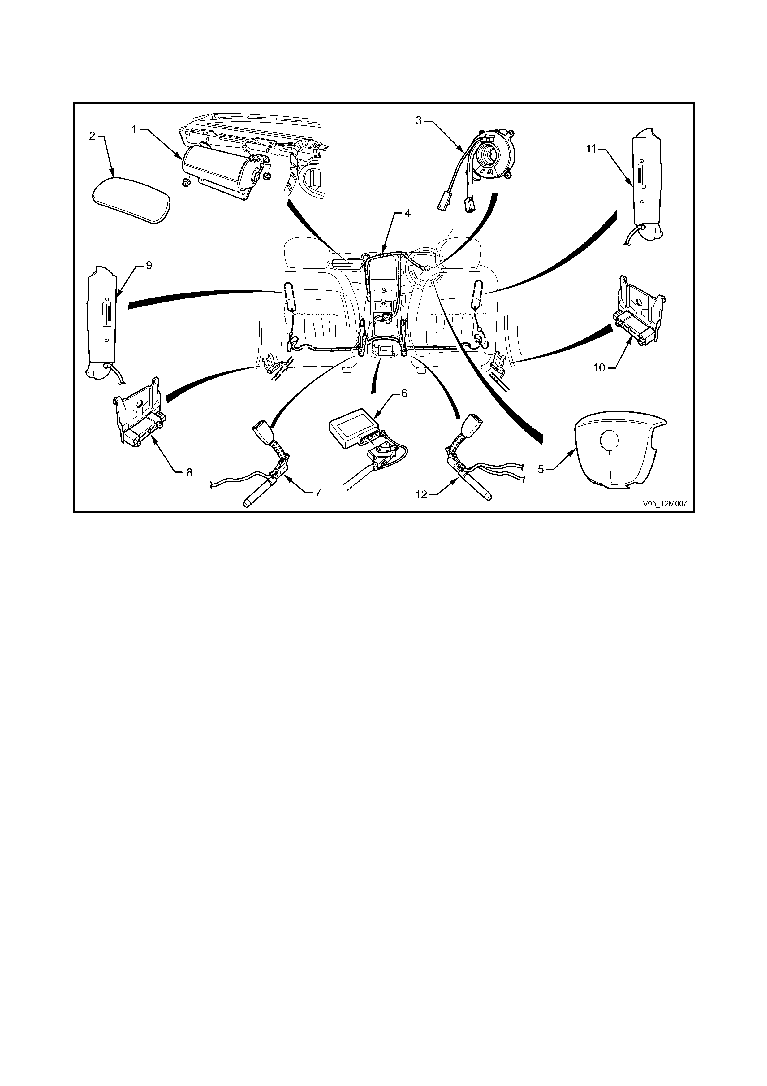
1 General Information
The Occupant Protection System (OPS) is designed to restrain and protect occupants of the vehicle duri ng a collision.
This is achieved by the use of:
• lap-sash inertia reel seatbelt assemblies fitted in all seating positions,
• front seatbelt pretensioners incorpor ated in the front driver and passenger seatbelt buckle,
• a steering wheel inflatable restraint (also known as a driver airb ag) for the driver,
• an instrument panel inflatable restraint (also known as a passenger airbag), where fitted, for the front passenger,
and
• a side impact inflatable restraint (also known as a side airbag), where fitted, for the driver and front passenger.
Some models are also fitted with active head restraints that are incorporated in the front seat assemblies. For further
information on active head restraints refer to Section 1A7 Seat Assemblies.
Locking of the inertia reel seatbelts is automatic. Deployment of the seatbelt pretensioners and inflatable restraints is
controlled by a sensing diag nostic module (SDM), which is mounted on the floor pa nel beneath the centre console. The
SDM incorporates a frontal collision sensor, while side impact sensor assemblies fitted to each si de of the vehicle detect
side impacts.
• Inflatable restraints do not provide
protection to the occupants on their own
and must be used in conjunction with
seatbelts.
• The rear seat is the safest place for
children.
• Never fit a rear facing child seat in a front
seat.
Occupant Protection System Page 12M–11
Page 12M–11
Refer to Figure 12M – 1 for the location of the seatbelt pretensioners and inflatable restraint components.
Figure 12M – 1
Legend
1 Instrument Panel Inflatable Restraint (passenger airbag)
Assembly
2 Instrument Panel Inflatable Restraint Opening Trim Cover
3 Clock Spring Coil Assembly
4 OPS Wiring Harness (part of front body wiring harness)
5 Steering Wheel Inflatable Restraint (driver airbag) Assembly
6 Sensing and Diagnostic Module (SDM)
7 Left-hand Seat Belt Pretensioner Assembly
8 Left Side-impact Sensor (peripheral acceleration sensor)
9 Left Side-impact Inflatable Restraint (side-impact airbag)
Assembly
10 Right Side-impact Sensor (peripheral acceleration sensor)
11 Right Side-impact Inflatable Restraint (side-impact airbag)
Assembly
12 Right-hand Seat Belt Pretensioner Assembly
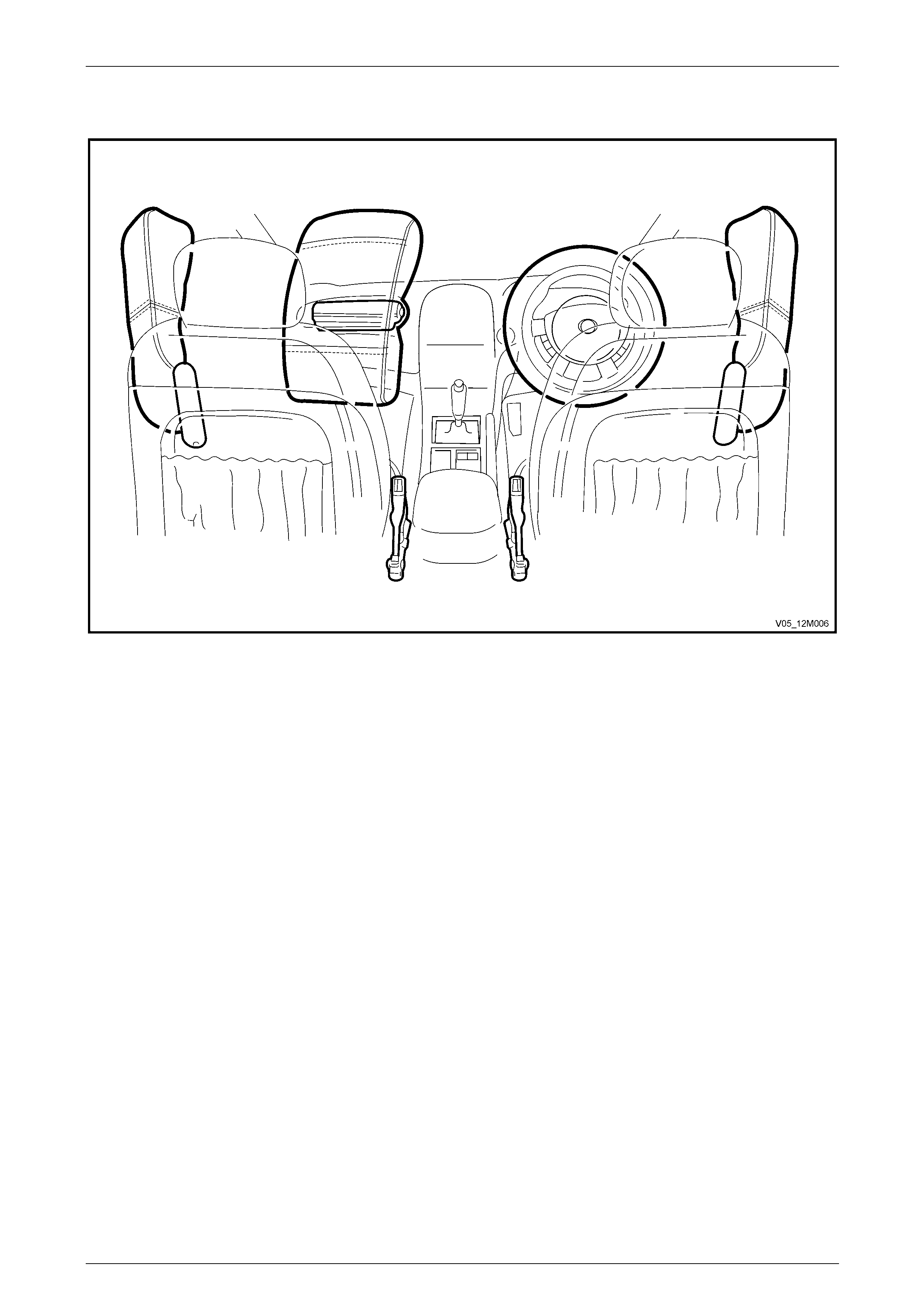
Occupant Protection System Page 12M–12
Page 12M–12
Figure 12M – 2 shows the location of the seatbelt prete nsi oners, and the inflatable restraint assemblie s in the fully
inflated mode.
Figure 12M – 2

Occupant Protection System Page 12M–13
Page 12M–13
1.1 General Description
All seating positions are provided with an emergency locki ng retractor lap-sash seatbelt assembly. The emergency
locking retractor mechanism locks the seatbel t webbing under one or more of the following conditi ons:
• Angle of the retractor assembly (vehicle),
• Acceleration or deceleration of the vehicle, and / or
• Acceleration of the webbing.
Certain models have the option of height adjustable upper guide for the front seatbelts.
Both front seats also have a pyrotechn ic seatbelt pretensioner incorporated in the buckle assembly.
The conditions that determine the operation of seatbelt pretensioners an d inflatable restraints are difficult to quantify in
terms of speed or angles of impact. There are many other f actors involved, such as size of the object, the object’s ability
(or inability) to absorb some or all of the impact force, the speed at which the other object may have been travelling, etc.
Ultimately it is the impact force, or crash pulse, that is detected by the SDM or side-impact sensors which will trigger t he
pretensioners and inflatable restraints. Activation is n ot designed to occur in situations that would not provide a ny driver /
front passenger protection benefit.
It is normal in a low speed frontal or near frontal coll ision that none of the pretensioners or inflatable restraints will deploy,
as the crash pulse has not been great enough. In this situation the seatbelts should provide ade quate protection if worn
correctly.
In other situations, only the pretensioners may deploy as the crash pulse has been greater than the programmed
threshold to deploy the pretensioners, but not great enough to deploy the inflatable restraints which would deploy at a
higher programmed threshold.
Similarly, side-impact inflatabl e restraints will only deploy in situations where there is risk of serious injury to the
occupant, and only on the relevant sid e.
NOTE
A side-impact inflatable restraint will deploy
independently of the other inflatable restraints
and pretensioners.
The following table indicates the approximate tension / inflation times for the seatbelt pretensioners and inflatable
restraints:
Device Tension / Inflation Time
Pretensioner 5 ms
Steering Wheel and Instrument Panel Inflata ble R estraints 30 ms
Side-impact Inflatable Restraints 20 ms
Regular maintenance of the OPS is not required. Ho wever, if at any time the airbag warning indicator (located on th e
instrument cluster):
• illuminates while driving, or
• does not illuminate when the vehicle is started, or
• remains illuminated after 5 seconds from when the ignition is turned on,
there is a system fault, and this must be rectified as soon as possible, refer to 2 Diagnostics.
The diagnostic scan tool Tech 2 is programmed to assist with electrical diagnosis and problem solving. Tech 2 connects
to the SDM serial data communication using t he Serial Data Link Connector (DLC) located below the steering column.
For additional information on DLC location and system diagnosis, refer to 2 Diagnostics. For more specific and
comprehensive information regarding Tech 2, refer to Section 0C Tech 2.
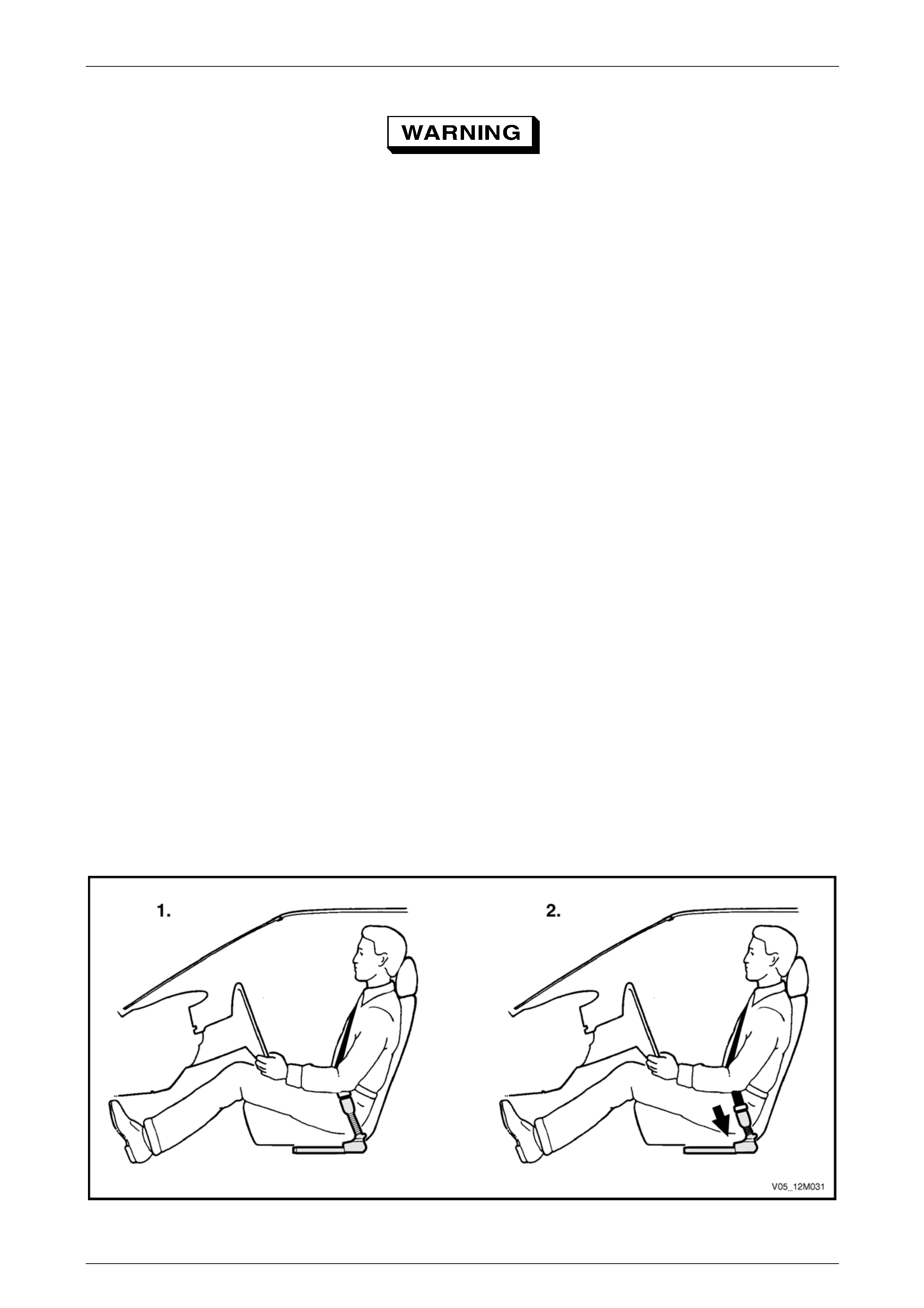
Occupant Protection System Page 12M–14
Page 12M–14
• Accessory type or after-market bull bars or
such devices not approved may adversely
affect the vehicle's desired threshold
characteristics for restraint device
deployment.
• Accessory type or after-market type dash
panel carpet covers or the like must not be
installed, as they will greatly inhibit the
performance of the inflatable restraint
assembly and front passenger's safety in
the event of an inflatable restraint
deployment.
• Fitting of accessories such as drink
holders, cassette racks, add itional mirrors,
etc. are not permitted in the immediate
deployment area of the front instrument
panel inflatable restraints. These items
may be dislodged and propelled towards
the vehicle's occupants when the
inflatable restraint assembly is deployed.
• Only approved accessor y and after-market
seat covers may be fitted to a vehicle w ith
side-impact inflatable restraints. Seat
covers that are not approved could greatly
inhibit the performance of the side-impact
inflatable restraint and occupant safety in
the event of side-impact in flatable restrai nt
deployment.
Front Seatbelt Pretensioners
The front seatbelt pretensione r assemblies deploy in two stages to protect the driver or front seat passe nger during
certain collisions, refer to Figure 12M – 3.
1 Before Deployment:
• The pretensioner is in a state of readiness unless the SDM detects a fault, in which case the pretensioner
may not operate, and the airbag warning indicator on the instrument cluster will illuminate.
2 Fully Deployed:
• The front seat belt pretensioner is fully retracted and the SDM records the data related to the prevaili ng
conditions and operation.
Figure 12M – 3
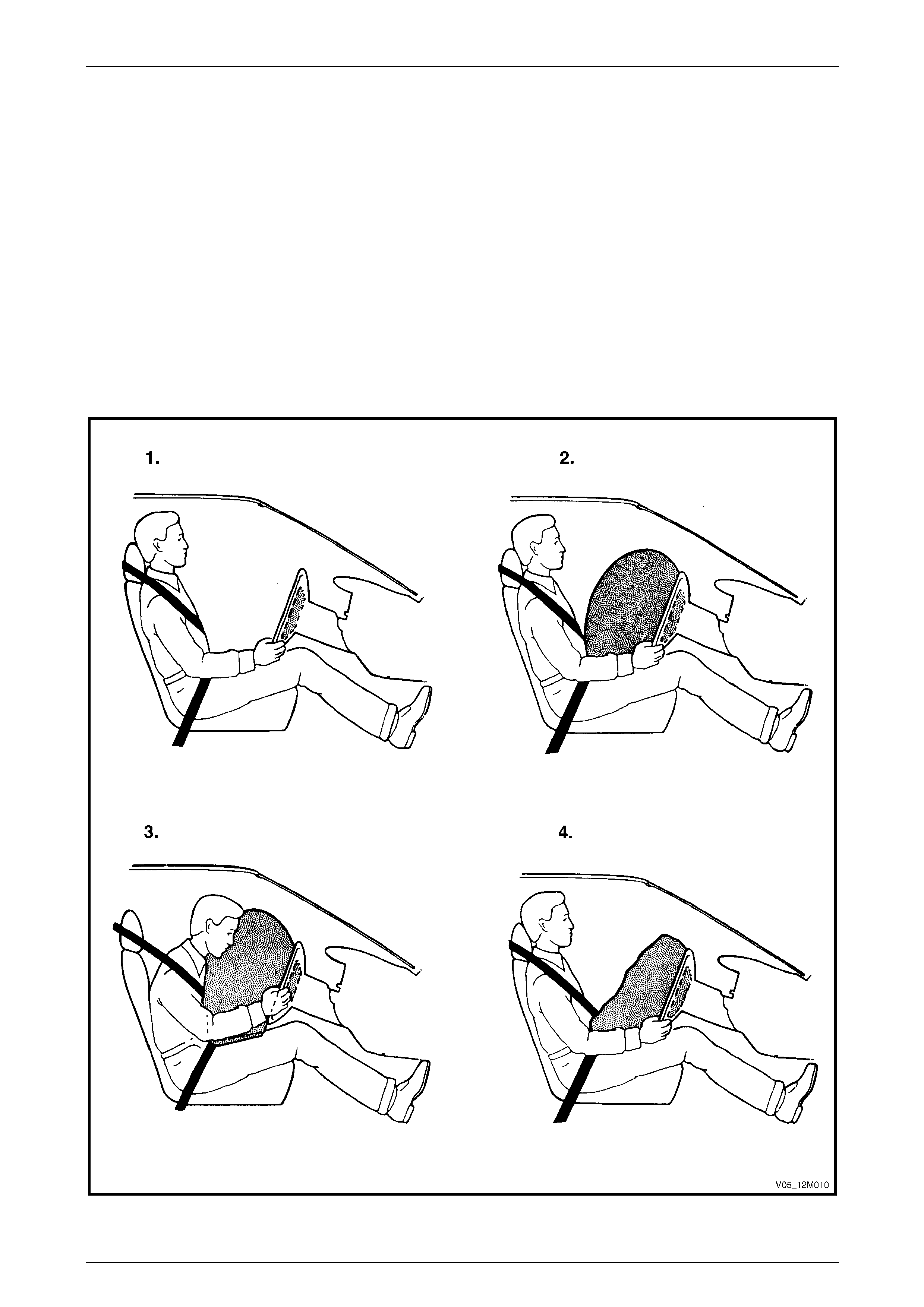
Occupant Protection System Page 12M–15
Page 12M–15
Steering Wheel Inflatable Restraint
The steering wheel inflatable restraint assembly deploys to protect the driver during certain collisions, refer to
Figure 12M – 4.
1 Before Deployment:
• The steering wheel inflatable restraint is in a state of readin ess unl ess the SDM detects a fault, in which case
the steering wheel inflatable restraint may not operate, a nd the airbag warning indicator on the instrument
cluster will illuminate.
2 Fully Deployed:
• The steering wheel inflatable restraint assembly is inflated and the SDM records the data related to the
prevailing conditions and operation.
3 During Restraint:
• The force of the collision causes the he ad and upper torso of the driver to move for ward into the infl ated
restraint assembly. Gas is vented from the thorax or chest region of the bag to the head region, red ucing the
chest loads and providing support for the head and neck.
4 End of Collision:
• The steering wheel inflatable restraint assembly deflates fully.
Figure 12M – 4
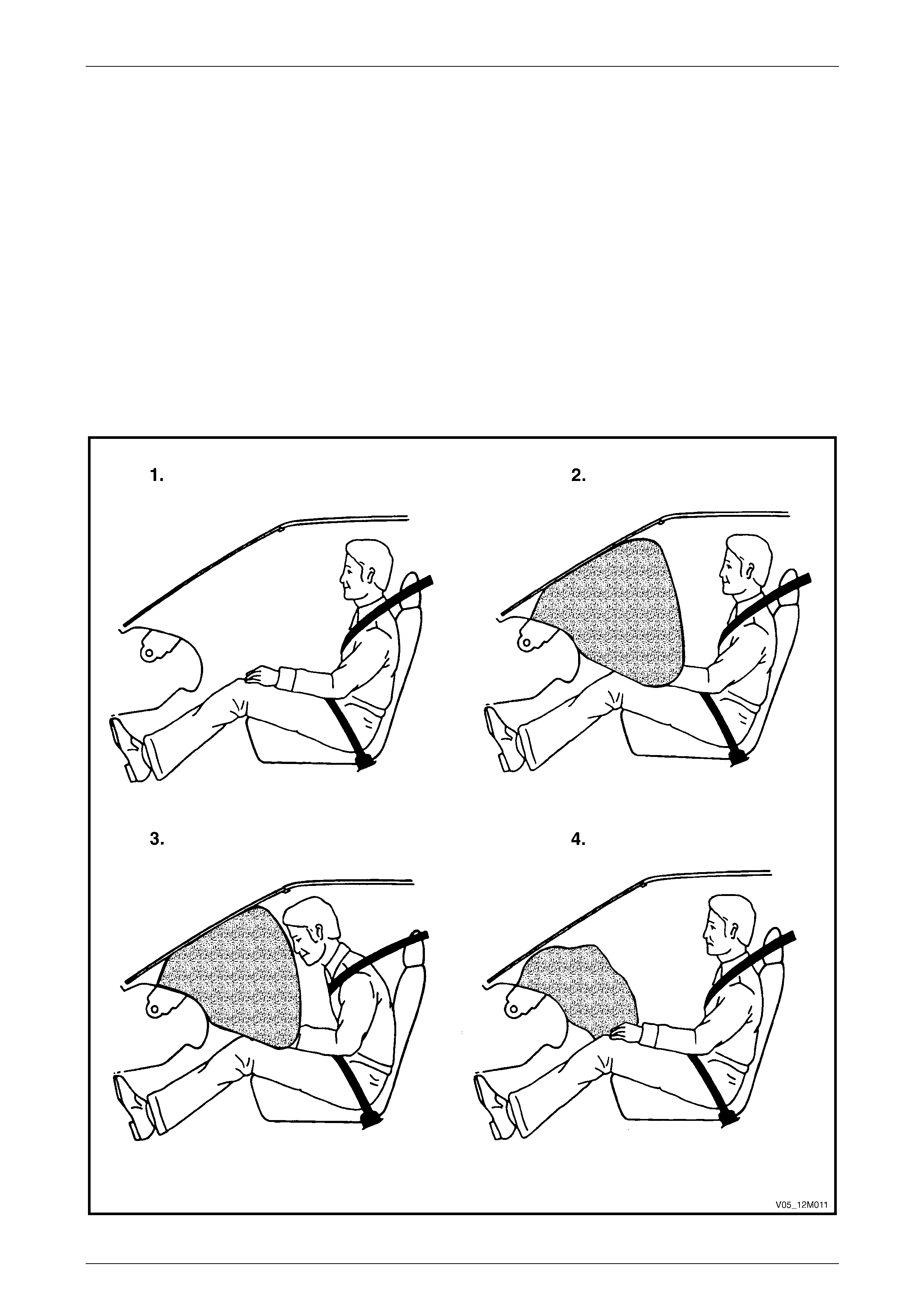
Occupant Protection System Page 12M–16
Page 12M–16
Instrument Panel Inflatable Restraint
The instrument panel inflatable restraint assembly deploys to protect the front passenger during certain collisions, refer to
Figure 12M – 5.
1 Before Deployment:
• The instrument panel inflatable restraint is in a state of readiness unless the SDM detects a fault, in which
case the instrument panel inflatable restraint may not operate, and the airbag warning indicator on the
instrument cluster will illuminate.
2 Fully Deployed:
• The instrument panel inflatable restraint assembly is inflated and the SDM records the data related to the
prevailing conditions and operation.
3 During Restraint:
• The force of the collision causes the he ad and upper torso of the passenger to move forward into the inflated
restraint assembly. Gas is vented from the thorax or chest region of the bag to the head region, red ucing the
chest loads and providing support for the head and neck.
4 End of Collision:
• The instrument panel inflatabl e rest raint assembly deflates fully.
Figure 12M – 5
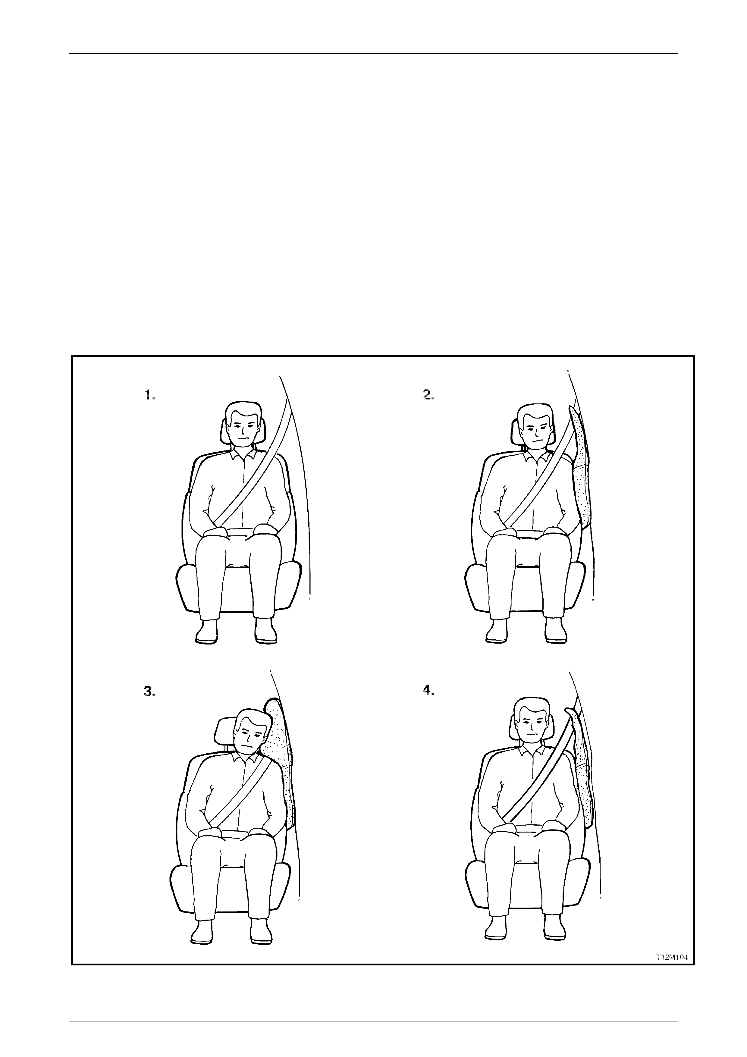
Occupant Protection System Page 12M–17
Page 12M–17
Side-Impact Inflatable Restraints
The side-impact inflatable res t raint assembly deploys to protect the driver or passenger during certain collisions, refer to
Figure 12M – 6.
1 Before Deployment:
• The side-impact inflatable res t raint is in a state of readiness unless the SDM detects a fault, in which case the
side-impact inflatable restraint may not operate, and the airbag warning indicator on the instrument cluster will
illuminate.
2 Fully Deployed:
• The side-impact inflatable res t raint assembly is inflated and the SDM records the data related to the
prevailing conditions and operation.
3 During Restraint:
• The force of the collision causes the he ad and upper torso of the driver or passenger to move sideways into
the inflated restraint assembly. Gas is vented from the thorax or chest region of the bag to the head region,
reducing the chest loads and providing support for the head and neck.
4 End of Collision:
• The side-impact inflatable res t raint assembly deflates fully.
Figure 12M – 6
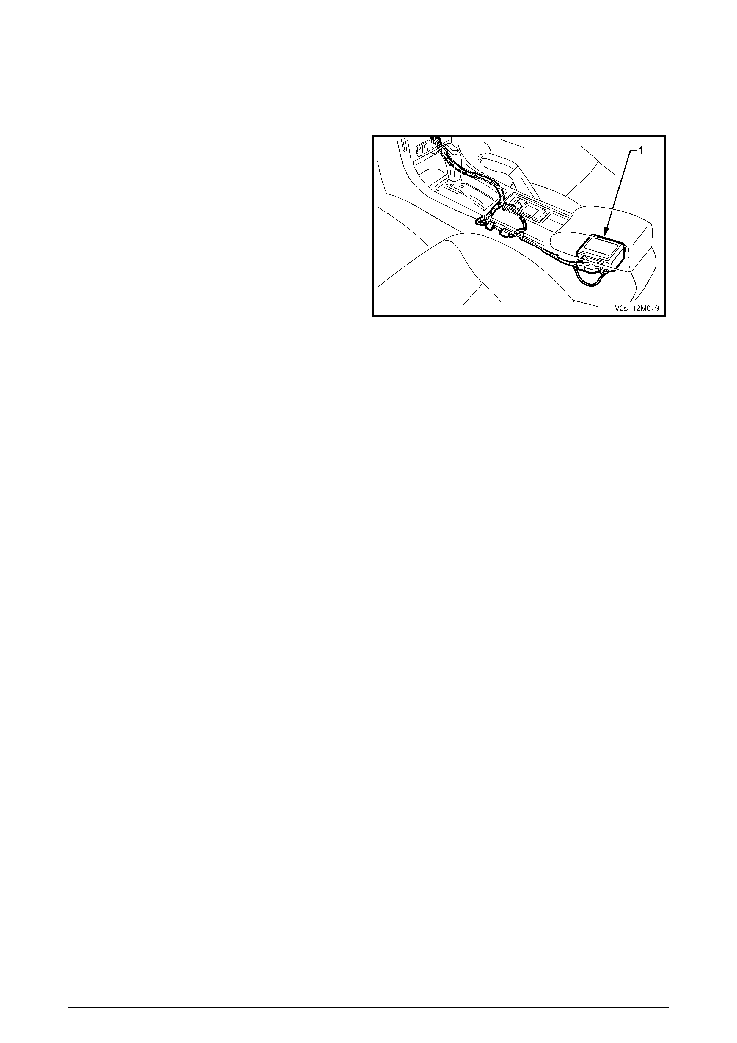
Occupant Protection System Page 12M–18
Page 12M–18
1.2 Components
Sensing and Diagnostic Module (SDM)
The Sensing and Diagnostic Module (SDM) (1) is a
centralised, self contained collision sensing and triggering
system that, with exception of the two side-impact sensors
for detecting lateral acceleration for the side-impact
inflatable restraint where fitted, requires no additional
external sensing inp uts.
The SDM is mounted under the floor conso le assembly and
consists of an electronic acceleration sensor system,
electronic control system, and ener gy storage devices. It's
electronics are capable of self diagnostics, fault memory
and collision event recording.
The primary function of the SDM is to sense collisi on events
and discriminate between those requiring and those not
requiring deployment of the pretension er and/or inflatable
restraint assemblies. Figure 12M – 7
In the case of a deployment event, the function of the SDM is to initiate the pretensioners, or the pretensioners and
inflatable restraint assemblies, in a timely manner in order to protect the vehicle occupants.
The SDM has the ability to command some aspects of the restraint devices indepe ndently of each other:
• Deployment of the front seatbelt pretensione rs only, or
• Front seatbelt pretensioners and inflatable restraint assemblies, or
• Side-impact inflatable restraint assemblies.
The SDM also performs continual tests on the pretens ioner and inflatable restraint electrical circuits.
NOTE
The SDM is designed for a one-time deployment
use only and must be replaced after a
deployment. If deployment occurs and the SDM
is not replaced, the airbag warning indicator in
the instrument cluster will be continually
illuminated.
Integrated into the SDM are two piezoelect ric sensors (accelerometers) that constantly monitor the acceleratio n data of
the vehicle. Microprocessors wit hin th e SDM run the outputs from the accelerometers through a complex mathematical
algorithm. The respective outputs are compared to a set of stored values in the processor memory. If the processed
values exceed their set of stored values, the SDM provides an AC output signal to ignite the pyrotechnic gas generators
of the relevant OPS components.
The SDM electronic diagnostic function performs the following:
• Continuously monitors the el ectrical circuits of the restraint devices.
• Controls the airbag warning i ndicator in the instrument cluster to alert the driver of a detected system fault.
• Provides a power reserve, in the form of a capac itor, to operate the restraint devices in case the vehicle s ystem
power is lost during a collision.
During deployment the SDM records and stores the foll owing OPS and collision event informatio n:
• Diagnostic Trouble Codes (DTCs) for detected faults.
• Airbag warning indicator operation data.
• Pretensioner and inflatable restraint deployment event data.
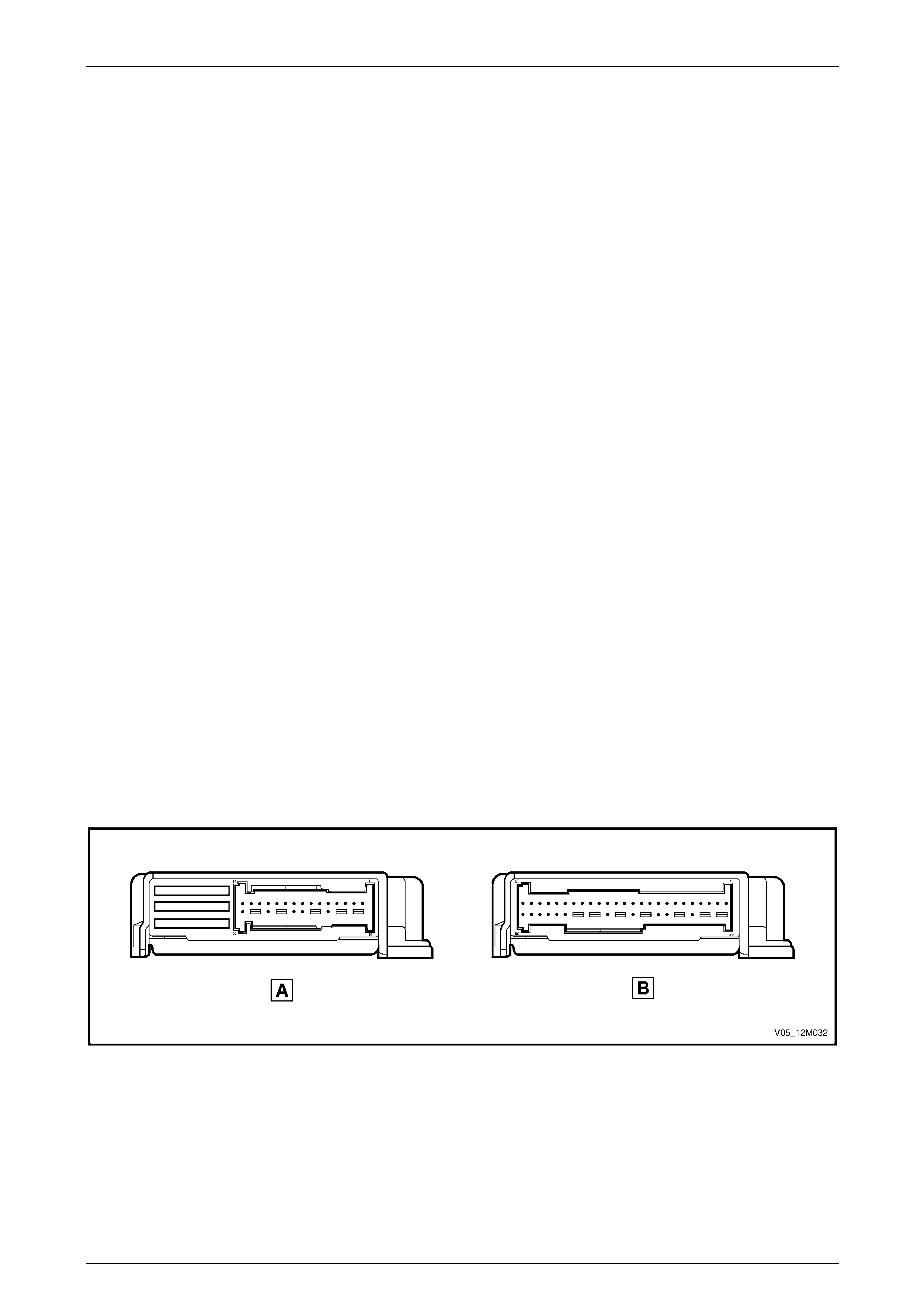
Occupant Protection System Page 12M–19
Page 12M–19
The SDM communicates diag nostic information through the Serial Data Li nk Connector (DLC) for the follo wing purposes:
• System checks at the vehicle assembly plant.
• Service diagnosis (using Tech 2).
• Transmitting of collision event recording data for post collision analysis.
Additionally, in the event of restraint device deployment, the SDM will send serial data using the auxiliary serial data bus
(circuit 774) to advise various vehicle systems to take appropriate shutdown action.
The Powertrain Control Module (PCM) or Engine Contro l Module (ECM) monitors this serial data and p erforms a vehicle
shutdown once the appropriate data is identified and the vehicle speed is zero for more than 10 seconds.
The Body Control Module (BCM) also monitors this serial data and performs the following actions once the appropriate
data is identified and the vehic le speed is zero for more than 10 seconds:
1 Turns the interior compartment lamp on continuously.
2 Unlocks all doors.
NOTE
This is only effective for the ignition cycle in which
the deployment(s) occurred. Providing the
vehicle's electrical system is functional, cycling
the ignition will restore normal function.
There are three different, non-interchangeable SDM configurations. These can be identified by the last digit of the part
number:
3 − 3 loop system for pretensioners and steering wheel inflatable restraint only.
4 − 4 loop system for pretensioners, steering wheel inflatable restraint, and instrument panel inflatable restraint.
6 − 6 loop system for pretensioners, steering wheel inflatable restraint, instrument panel inflatable restraint, and side-
impact inflatable restraints.
NOTE
Always refer to the latest MY 2005 VZ spare
parts information for the latest part numbers
when ordering OPS components.
Figure 12M – 8 illustrates the SDM connector pins without side-impact inflatable restraints (A) and the SDM conn ector
pins with side-impact inflatable restraints (B).
Figure 12M – 8
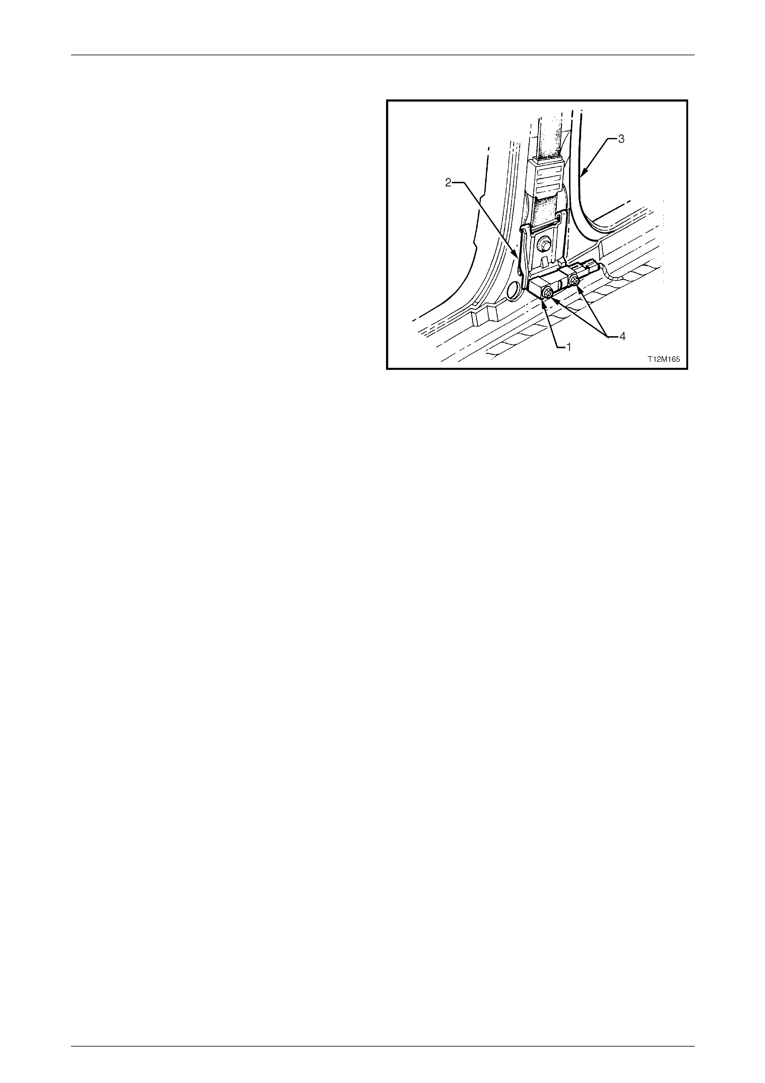
Occupant Protection System Page 12M–20
Page 12M–20
Side-impact Sensor Assembly
The inflatable restraint side-impact sensor assembly (1),
also known as a peripheral acceleration sensor, is a sensing
component mounted on a bracket (2) attached to the centre
pillar (3) on each side of the vehicle.
The side-impact sensor is able to detect lateral acceleration,
recognise a collision, and s en d a sign al to the SDM that a
side-impact inflatable restraint deployment situation exists.
The SDM will then determine wheth er or not to deploy the
relevant side-impact inflatabl e restraint assembly.
Side-impact sensors are only fitted to vehicles with side-
impact inflatable restraints.
NOTE
Due to the critical nature of the torque
specification of the two nuts (4) attaching the
side-impact sensor to the mounting bracket, the
side-impact sensor is serviced with the mounting
bracket as an assembly only.
If there is a need to remove the side-impact sensor from the
vehicle, it must be removed as an assembly with the
mounting bracket attached.
Figure 12M – 9
NOTE
• A side-impact sensor is designed for a one-
time deployment use only. If a side-impact
inflatable restraint deploys, the side-impact
sensor and mounting bracket assembly on the
same side as the deployed inflatable restraint
must be replaced.
• Figure 12M – 9 shows the RHS side-impact
sensor and the wiring harness facing the rear
of the vehicle. The side-impact sensors are
uni-directional. The LHS side-impact sensor
has the wiring harness facing the front of the
vehicle.
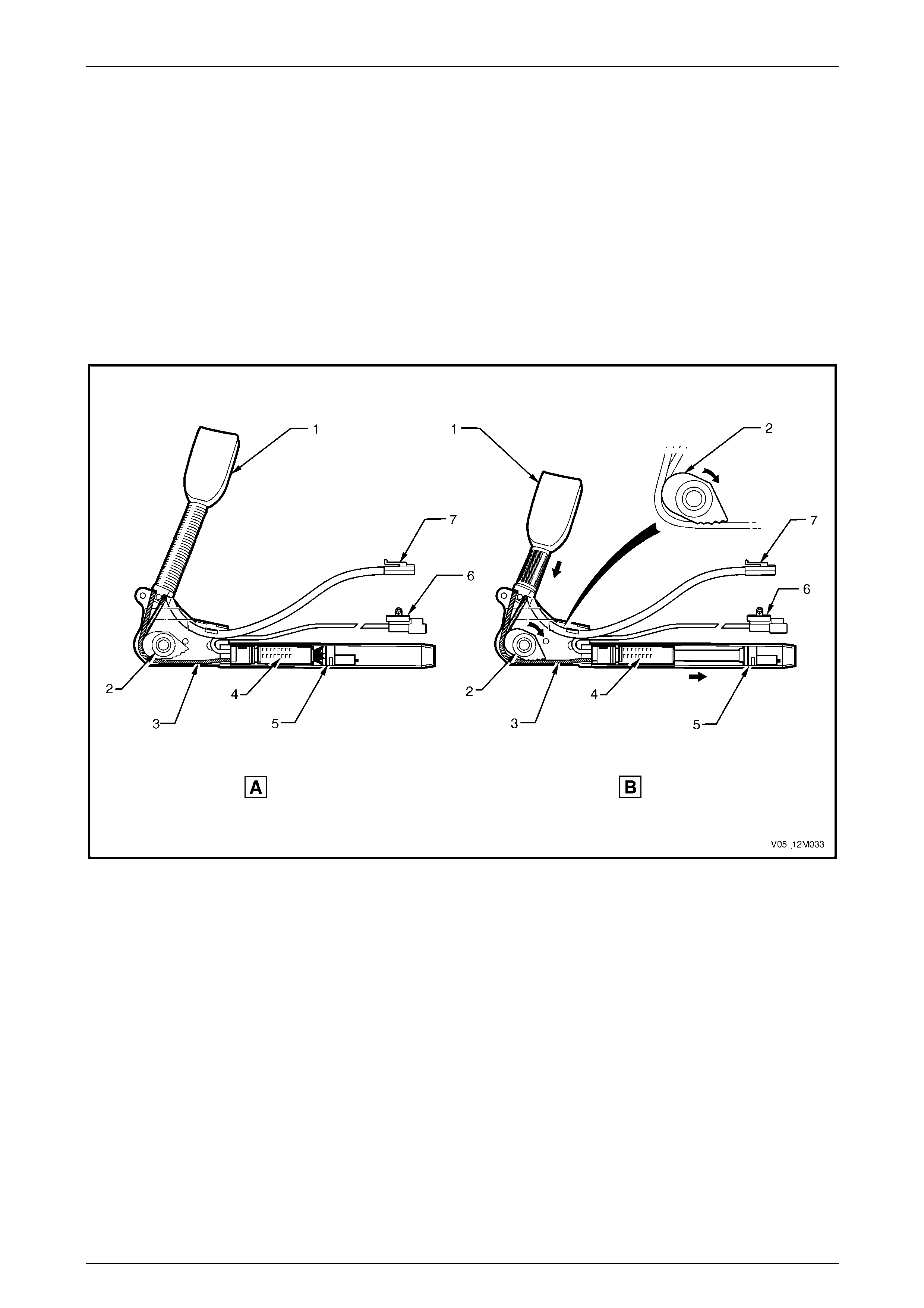
Occupant Protection System Page 12M–21
Page 12M–21
Seatbelt Pretensioners
Each front seatbelt is equipped with a pyrotechnic seatbelt pretensioner. The purpose of the pretensioner is to remove all
webbing slack from the seatbelt before the occupa nt has moved forward as the result of a frontal collision.
Refer to Figure 12M – 10 for the following.
The pretensioner has an igniter and gas generator (4) contained within a cylinder. Inside the cylinder is the retractor
cable piston (5) connected to both ends of the buckl e retractor cable (3). The cable passes through the retractor cable
interlocking cam (2) and then forms a loop internally in the seatbelt buckle assembly (1).
NOTE
The seatbelt buckle switch (7), is only fitted to
driver side seat pretensioner assembli es.
Figure 12M – 10
Legend
1 Buckle Assembly
2 Retractor Cable Interlocking Cam
3 Buckle Retractor Cable
4 Igniter and Gas Generator
5 Retractor Cable Piston
6 Pretensioner Wiring Connector
7 Seatbelt Buckle Switch Connector (driver side only)
A Seatbelt and Pretensioner Assembly Being Deployed
B Seatbelt and Pretensioner Assembly Fully Deployed
When an ignition signal from the SDM is sen t to the igniter, the gas generator is activated driving the retractor cable
piston down the cylinder. This action pulls the cable through the retractor cable interlocking cam and pulls the buckle
towards the seat, taking up the slack in the seatbelt. The retractor cable along with the piston is prevented from moving
back up the cylinder by the retractor cable interlocking cam. Once a load ha s been applied in the opposite direction of
deployment, the clamping action of the interlocking cam directly on the cable prevents further moveme nt.
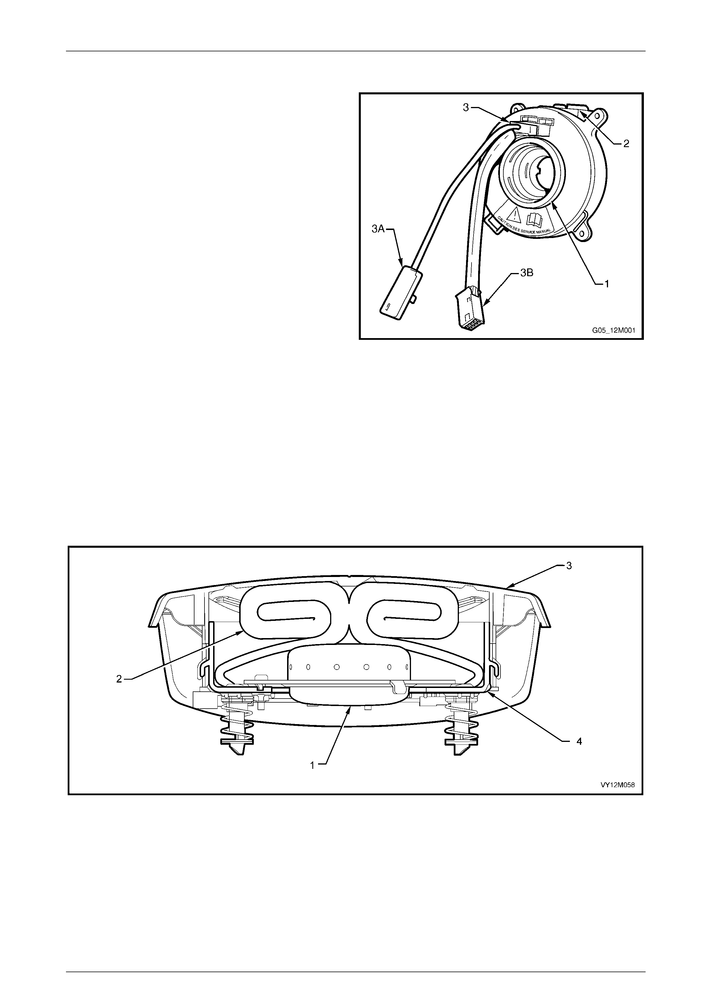
Occupant Protection System Page 12M–22
Page 12M–22
Clock Spring Coil Assembly
The clock spring coil assembly consists of the following
parts:
• A rotating inner hub (1) which eng ages with the rear of
the steering wheel.
• A wiring harness connector (2) which is incorporated
within the clock spring coil out er housing.
• A wiring harness (3) that connects to the steering
wheel inflatable restraint assembly (3A) and the
steering wheel horn bar and remote rad io co ntrols
(3B).
• An internal ribbon wire assembly (not shown) that
provides an unbroken connection between the
connector (2) and harness (3) as the steering wheel is
rotated.
The coil assembly operates i n the following manner:
• When the steering wheel is in the straight-ahead
position, the inner hub and outer housing are aligned
to provide approximatel y 2.5 turns of the steerin g
wheel in either direction.
Figure 12M – 11
• When the steering wheel is turned i n a clockwise direction (right turn), the inner h ub winds the ribbon wire as it
rotates with the steering wheel.
• When the steering wheel is turned i n an a nti-clockwise direction (left turn), the inner hub unwinds the ribbon wire as
it rotates with the steering wheel.
Steering Wheel Inflatable Restraint Assembly
The steering wheel inflatable restraint assembly contains four main components, refer to Figure 12M – 12.
The inflatable restraint assembly deploys through the steering wheel inflatable restraint trim cover.
Figure 12M – 12
Legend
1 Inflator Assembly
2 Fabric Cushion 3 Trim Cover
4 Base Plate and Locating Legs
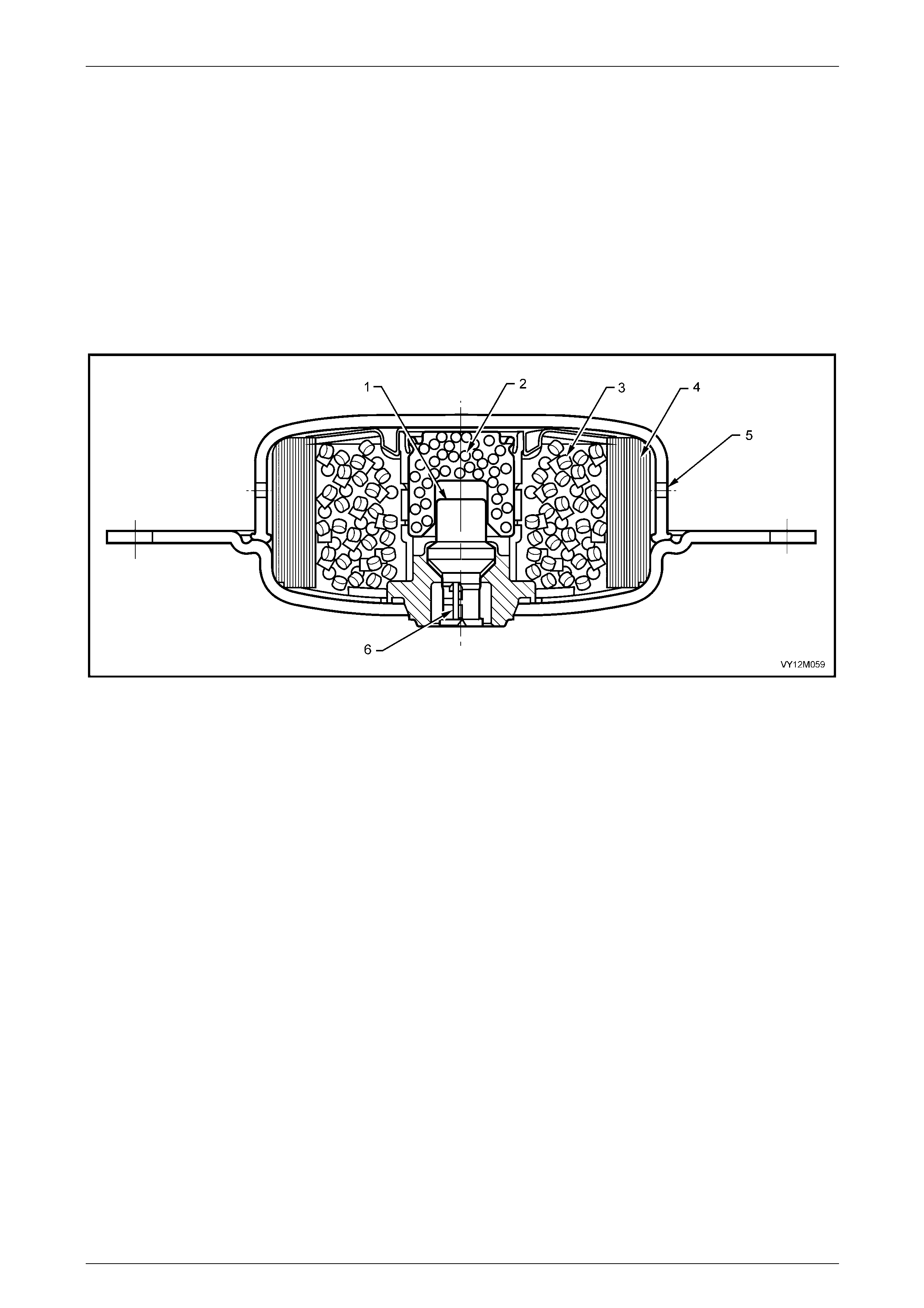
Occupant Protection System Page 12M–23
Page 12M–23
Inflator Assembly
Referring to Figure 12M – 13, the inflator assembl y contains the following:
• An Electro Explosive Device (EED) (1). The EED consists of an electrical heating element (called a squi b) and a
small amount of lead styphnate covered with a mixture of titanium hydride and potassium perch lorate.
• An enhancer pack (2) with appro ximately 3 grams of barium potassium nitrate.
• A carbon based non-toxic composite propellant (3).
• A fine particle filter (4).
• Nitrogen gas exhaust ports (5) for the inflatable restra int assembly cushion.
• EED wiring connector pins (6).
Figure 12M – 13
During deployment, the inflatable restraint assembly operates in the foll owing sequence:
1 The EED receives electric current from the SDM and begins a chemical reaction by igniting the lead st yphnate and
the mixture of titanium hydride and potassium perchlorate.
2 The reaction of the lead styphnate, titanium hydride and potassium perchlorate ignites the barium potassium nitrate
in the enhancer pack.
3 The enhancer pack chem ical reaction causes the carbon based non-toxic composite propellant to rapidly produce
nitrogen gas that expels through the outlets.
4 The nitrogen gas fills the inflatable restraint assembly cushion, which separates the steering wheel trim cover and
inflates.
5 As the inflatable restraint assembly cushion expands, some of the nitrogen begins to exit into the passenger
compartment through vent holes of a calibrated size at the base of the cushion. This permits the gas to escape,
enhancing the cushioning effect, and provides deflation of the cushion.
After deployment, the surface of the cushion may contain a powdery residue. This powder consists primarily of
cornstarch (used to lubricate the cushi on) and by-products of the chemical reaction, such as carbon mo noxide (CO),
nitrogen (N), carbon dioxide (CO2), water (H2O), with trace amounts of oxides of nitrogen (NOΧ) and ammonia (NH 3). As
a precaution, gloves and safety glasses are recommended when handling a deployed inflatable restraint assembly to
prevent any possible irritation of the skin or eyes.
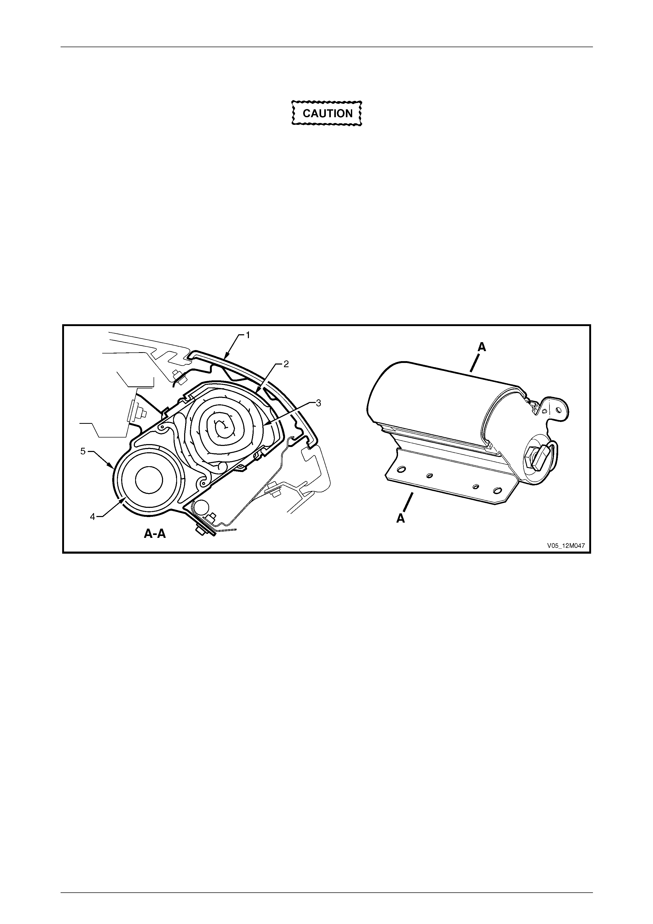
Occupant Protection System Page 12M–24
Page 12M–24
Instrument Panel Inflatable Restraint Assembly
Components of the instrument panel
inflatable restraint assembly are not
repairable. Under no circumstances are the
components of the instrument panel inflatable
restraint assembly to be disassembled. The
inflatable restraint assembly contains a
pyrotechnic gas generator and the inflatable
restraint assembly cushion fold is critical to
inflatable restraint assemb ly performance an d
front passenger's safety.
The instrument panel inflatable restraint assembly contains five main components, refer to Figure 12M – 14.
The inflatable restraint assembly deploys through the instrument pan el inflatable restraint openin g trim cover. The
opening trim cover is a PVC and foam laminate over a n in jection moulded plastic insert, with a sheetmetal hinge heat
staked to the rear surface. This assembly is then attached to the instrument pane l pad assembly with four screws.
Figure 12M – 14
Legend
1 Instrument Panel Inflatable Restraint Opening Trim Cover
2 Instrument Panel Inflatable Restraint Assembly Plastic
Protective Cover
3 Cloth Cushion
4 Inflator Assembly
5 Instrument Panel Inflatable Restraint Assembly
Inflator Assembly
Referring to Figure 12M – 15, the inflator assembl y contains the following:
• EED wiring connector pins (1).
• An Electro Explosive Device (EED) (2). The EED consists of an electrical heating element (called a squi b) and a
small amount of lead styphnate covered with a mixture of titanium hydride and potassium perch lorate.
• Exhaust ports (3).
• Diffuser (4), which is a hollow circular mesh that reduces the turbulence of the gas exiting through the exhaust
ports.
• Burst Disc (5).
• Actuator piston, striking primers and enha ncer pack (6)
• Hybrid propellent (7).
• Radial holes (8), which allow the gases to flow throughout the assem bly.
• Argon gas (9).
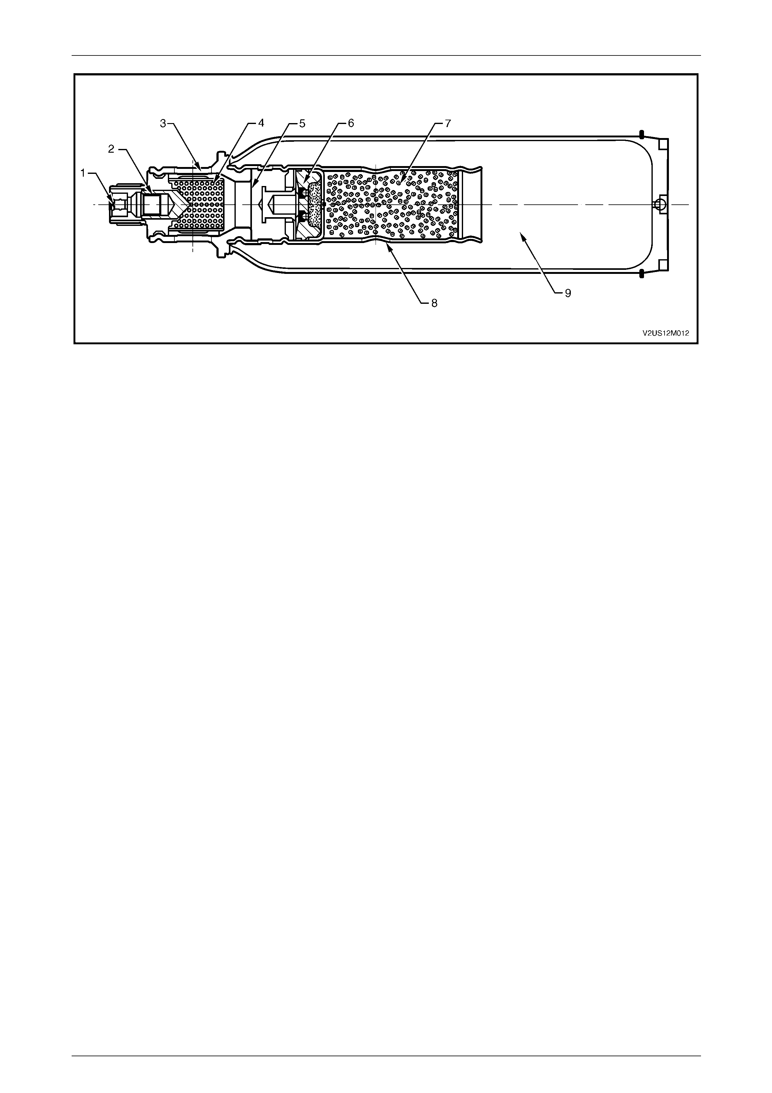
Occupant Protection System Page 12M–25
Page 12M–25
Figure 12M – 15
During deployment, the inflatable restraint assembly operates in the foll owing sequence:
1 The EED receives electric current from the SDM and detonates the charge, firing the squib through the burst disc.
2 Once the burst disc is ruptured, argon gas begins to flow through the radial holes and the diffuser into the cushion.
The force produced by the gas and the rapidly inflating cushion separates the protective cover, and then forces the
hinged instrument panel i nflatable restraint opening trim cover open to fully deploy the inflatable restraint assembly
cushion.
3 In the same instance, the squib impacts with the actuator piston, detonating the striking primers and ign iting the
hybrid propellent.
4 Heat and nitrogen are genera ted by the chemical reaction of the hybrid propellent. The argon is heated and
expands which, with the nitrogen produced by the propellent, further inflates the cushion.
Internal tethering controls the fill and placement of the inflatable restraint assembly cushion to maximise the benefits to
the front passenger.
The windshield is used to support and position the inflatable restraint assembly cushion. In some deplo yment cond itio ns,
the windshield may be broken by the opening of the instrument panel inflatable restraint open ing trim cover when the
inflatable restraint assembly cushion deploys.
After deployment, the surface of the cushion may contain a powdery residue. This powder consists primarily of
cornstarch (used to lubricate the cushi on) and by-products of the chemical reaction such as carbon monoxide (CO),
nitrogen (N), carbon dioxide (CO2), water (H2O), with trace amounts of oxides of nitrogen (NOΧ) and ammonia (NH 3). As
a precaution, gloves and safety glasses are recommended when handling a deployed inflatable restraint assembly to
prevent any possible irritation of the skin or eyes.
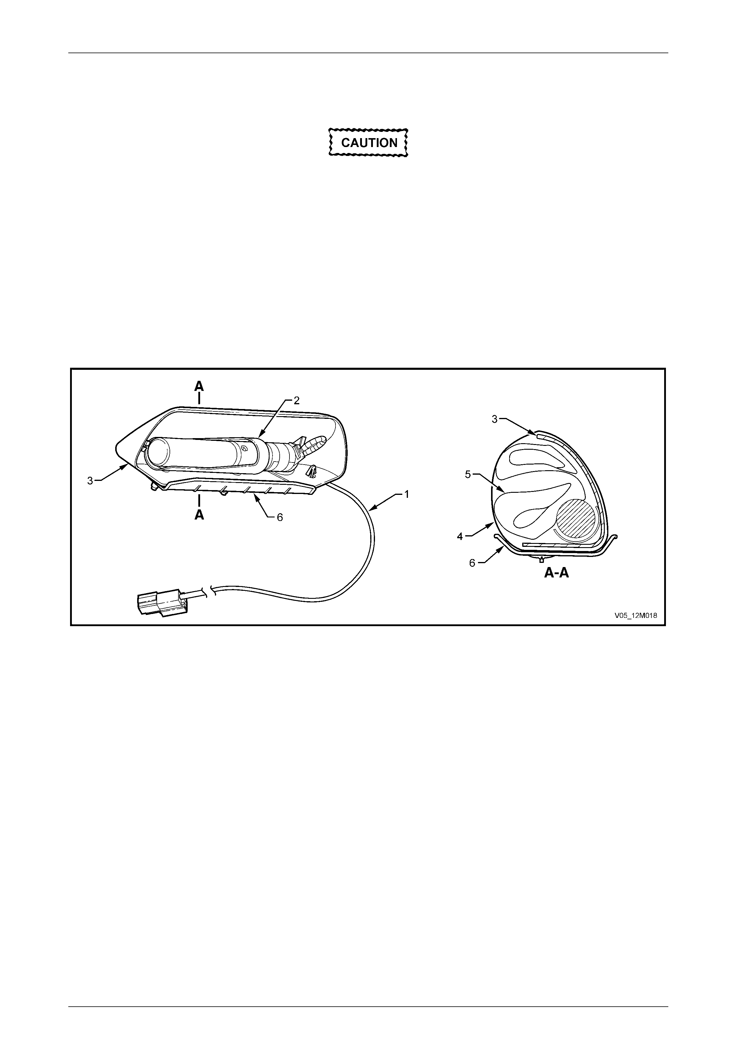
Occupant Protection System Page 12M–26
Page 12M–26
Side-impact Inflatable Restraint Assembly
Components of the side-impact inflatable
restraint assembly are not repairable. Under
no circumstances are the components of the
side-impact inflatable restraint assemb l y to be
disassembled. The inflatable restraint
assembly contains compressed gas and a
small pyrotechnic charge. Additionally, the
inflatable restraint cushion fold is critical to
inflatable restraint performance and front
occupant safety.
The side-impact inflatable res t raint assembly contains five main components, refer to Figure 12M – 16.
The inflatable restraint assembly deploys through the seat back foam an d seat back fabric at the forward side seam,
providing a protective barrier between the occupant and the vehicle door.
Figure 12M – 16
Legend
1 Wiring Harness
2 Inflator and Housing (nylon fabric cushion removed for
clarity)
3 Plastic Container
4 Protective Reinforcement Paper (Tyvek) Cover
5 Nylon Fabric Cushion
6 Barrier
Inflator Assembly
Referring to Figure 12M – 17, the inflator assembl y contains the following:
• A small amount of oxidiser (1).
• A small amount of fuel (ethanol) (2).
• Compressed inert gas (t ypically Argon) in a sealed chamber (3).
• An initiator (4), which consists of an electrical heati ng element (called a squib), covered with a mixture of sensitive
pyrotechnical charge.
• Burst Discs (5) and (6).
• Diffuser (7), which is a hollow circular mesh that reduces the turbulence of the gas exiting through the exhaust
ports.
• Exhaust ports (8).
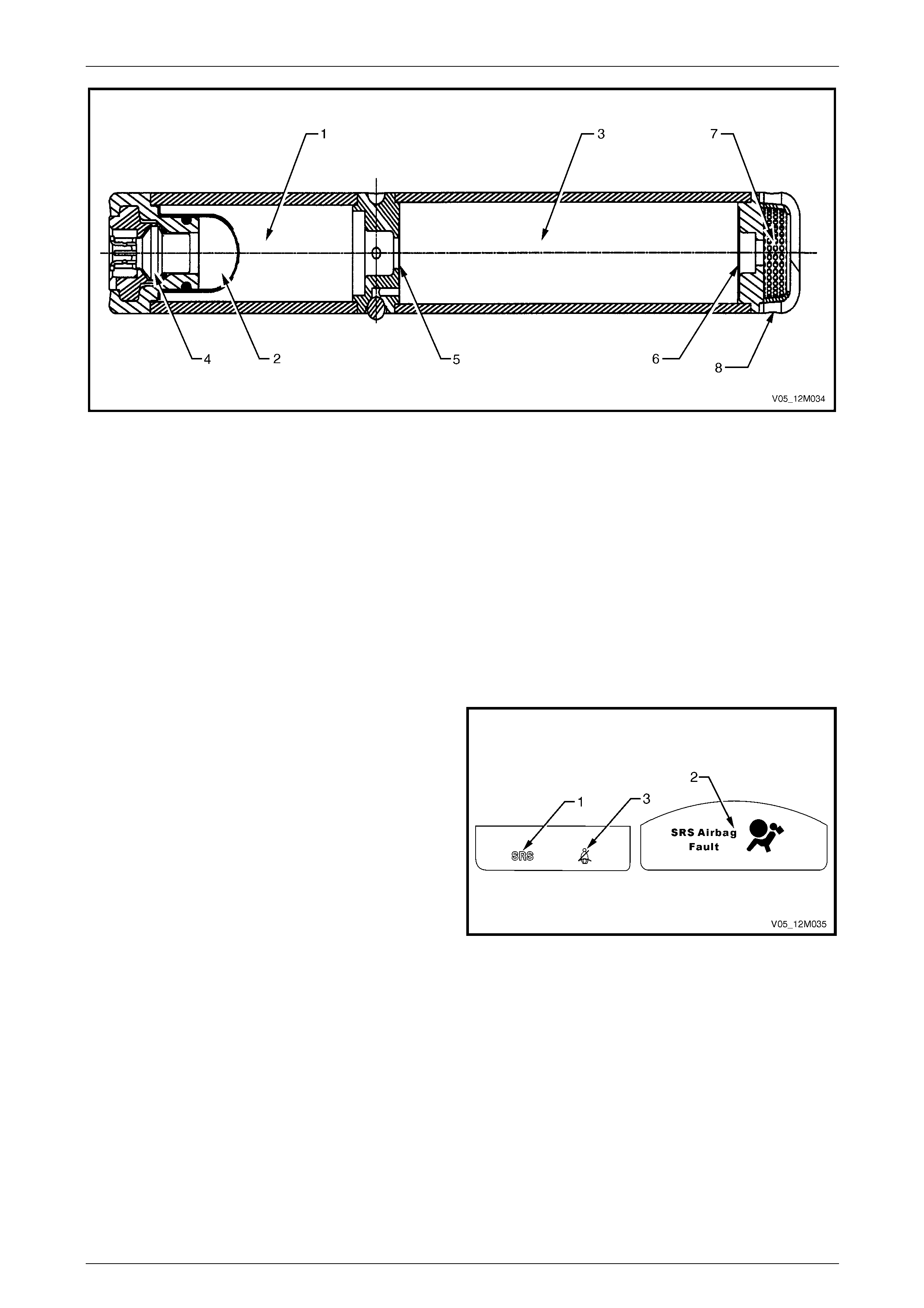
Occupant Protection System Page 12M–27
Page 12M–27
Figure 12M – 17
During deployment, the side- impact airbag inflator operates in three stages:
1 The initiator receives electric current from the SDM, heating the sensitive pyrotechnic charge, which ignites the fuel.
2 The combustion of the fuel and oxidiser creates enough pressure to burst the disks, heating the compressed gas
and allowing it to escape into the cushion.
3 The heated expanding gas starts to unfold the inflatable restraint cushion, which separates the protective cover, the
seatback foam and the seatback fabric, and inflates.
As the cushion inflates, some of the gas begins to exit into the passenger’s compartment through vent holes or through
the pores of the cushion fabric. Internal tethering controls the fill and placement of the airbag to maximise the benefits to
the front occupant.
Airbag Warning Indicator
The airbag warning indicator is located in the instrument
cluster.
Legend
1 Airbag Warning Indicator (Airbag Warning Lamp)
2 Multi Function Display (MFD)
3 Seatbelt Warning Indicator
Figure 12M – 18
The airbag warning indicator is controlled by the SDM using the serial data circuit and will illuminate to warn the driver
the system has been disabled or there is a fault in the system.

Occupant Protection System Page 12M–28
Page 12M–28
The airbag warning ind icator will illuminate when:
• The ignition is switched on. The airbag warning indicator will be illuminated for approximately five seconds to
indicate the system start-up sequence. During this period the SDM performs a system wiring and self check. If no
system faults are detected, the airbag warning indicator will be switched off.
• If communication is lost between the SDM and the instrument cluster (for example SDM wiring harness
disconnected or no BCM pol l) the airbag warning indicator will be illuminated when the ignition is first switched on
and then commanded on constantly until the fault is remedied (communication resumed) (No DTC will set).
• If an inflatable restraint assembly and/or pretensioner is deployed, the airbag warning indicator will be illuminate d
until the problem is resolved (No DTC will set).
• If one or more current or history Diagnostic Trouble Codes (DTCs) are detected when the ignition is s witched on,
the airbag warning indicator will illuminate a nd remain illuminated until the DT C is cleared. Additionally, 3 seconds
after the ignition is switched on, an audible warning chime will sound.
• During an ignition cycle, if the SDM detects a current DTC, the airbag warning indicator will be illuminated. If during
this cycle, the current DTC fault condition clears, a history DTC will be logged i n the SDM and the airbag warning
indicator will still remain illuminated.
• When Tech 2 is communicating with the SDM, the airbag warning indicator will be illuminated and the inflatable
restraint assemblies and pret ensioners will be disabled.
For details on all DTCs, refer to 2 Diagnostics in this Section.
Multi-function Display
In addition to the airbag warning indicator, the instrument cluster has a Multi-function Display (MFD), which displays a
warning message Airbag Fault (2) to alert the driver of a possible fault with the system, refer to Figure 12M – 18.
The MFD warning message is controlled by the BCM. The MFD warning message is activated by the BCM when the
SDM sets a poll response message, using the serial data circ uit.
For more information, refer to Section 12C Instruments.
Chime Alert
The airbag warning indicator and MFD are complemented by a warning chi m e to alert the driver audibly of a possible
fault with the system.
The warning chime alert is controlled by the BCM. The warning chime alert is activated by the BCM when the SDM sets
a poll response message usin g the serial data circuit.
For more information, refer to Section 12C Instruments.
Seatbelt Warning Indicator
The seatbelt warning indicato r (3), refer to Figure 12M – 18, uses a ground circuit provided by the driver’s seatbelt b uckle
switch to turn off the indicator. Whenever the ignition is turned on, the seatbelt warning ind icator LED illuminates
continuously for 60 seconds. If the seatbelt has not been fastened during this period, the indicator will flash for a further
90 seconds at which point it will extinguish, e ven if the seatb elt is not fasten ed.
When illuminated, the indicator will extinguish as soon as the driver’s seat belt is fastened.
If the seat belt is removed after having been fastened, the indicator illuminates continuously again, and the cycle repeats.
For information on the seatbelt buckle switch, refer to Seatbelt Buckle Switch in this Section.
Seatbelt Buckle Switch
The seatbelt buckle switch is a microswitch located in the buckle part of the pretensioner assembly. It is only fitted to the
driver’s pretensioner assembl y. The switch is not connected to the SDM.
The switch provides a ground circuit for the seatbelt warning indicator on the instrument cluster, when the seatbelt is not
inserted into the buckle. When the seatbelt is inserted into the buckle, the contact on the microswitch is broken and the
path to ground is open-circuit, refer to 2.15 Seatbelt Buckle Switch in this Section.
For further information on the seatbelt warning indicator, refer to Seatbelt Warning Indicator in this Section.
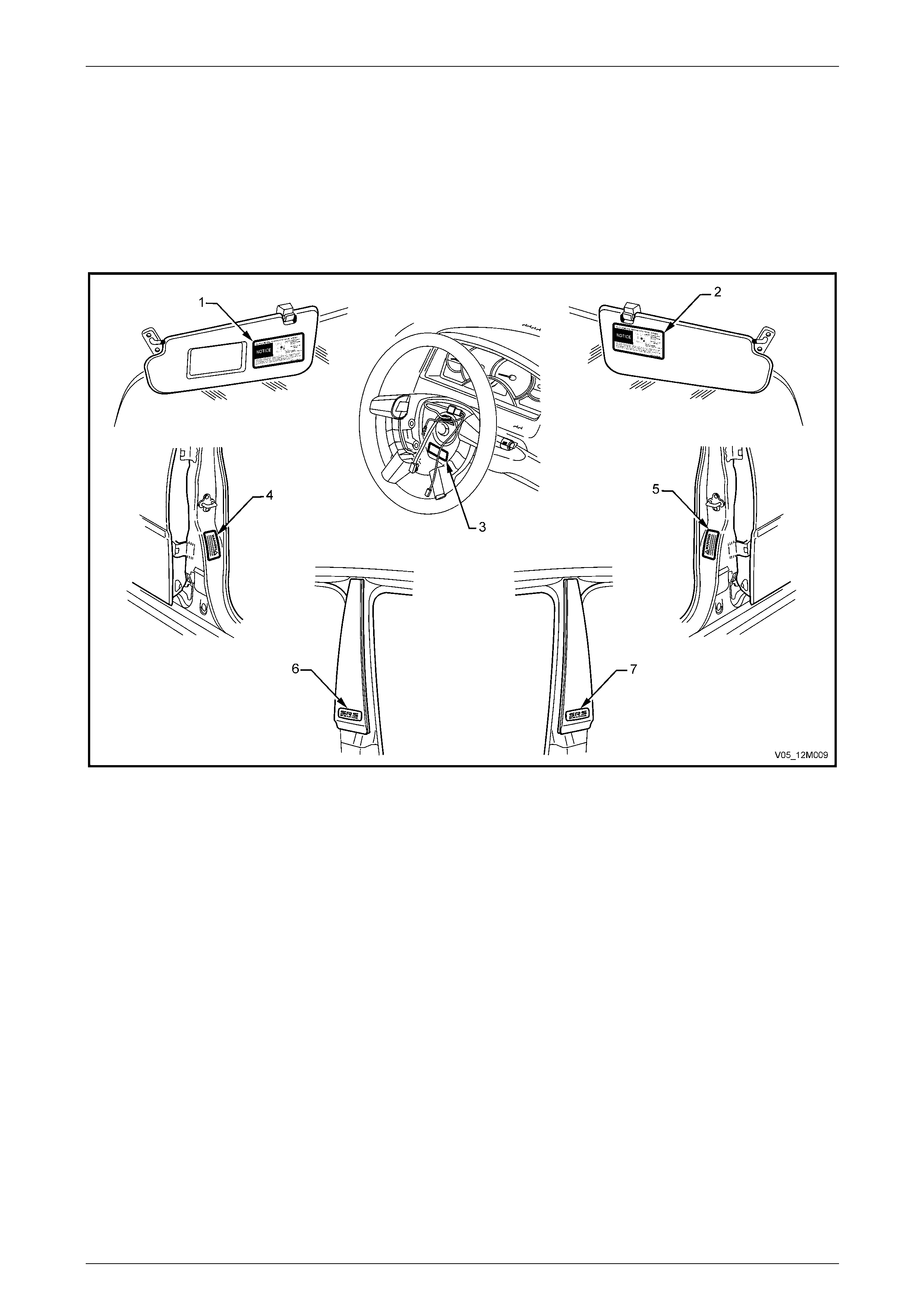
Occupant Protection System Page 12M–29
Page 12M–29
Warning Labels
In order to provide adequate warning of the OPS operation and service requirement to the vehicle's owner, driver or
service technicians, OPS warning labels are located on various comp onents of the vehicle, refer to Figure 12M – 19.
NOTE
If at any time any these components are
replaced, ensure the appropriate warning label is
applied to the replacement part.
Figure 12M – 19
Legend
1 Passenger Side Sunvisor
2 Driver Side Sunvisor
3 Steering Wheel (inflatable restraint assembly removed)
4 Right-hand Centre Pillar (vehicles with side impact inflatable
restraints)
5 Left-hand Centre Pillar (vehicles with side impact inflatable
restraints)
6 Right-hand Centre Pillar Upper Finisher (vehicles with side
impact inflatable restraints)
7 Left-hand Centre Pillar Upper Finisher (vehicles with side
impact inflatable restraints)
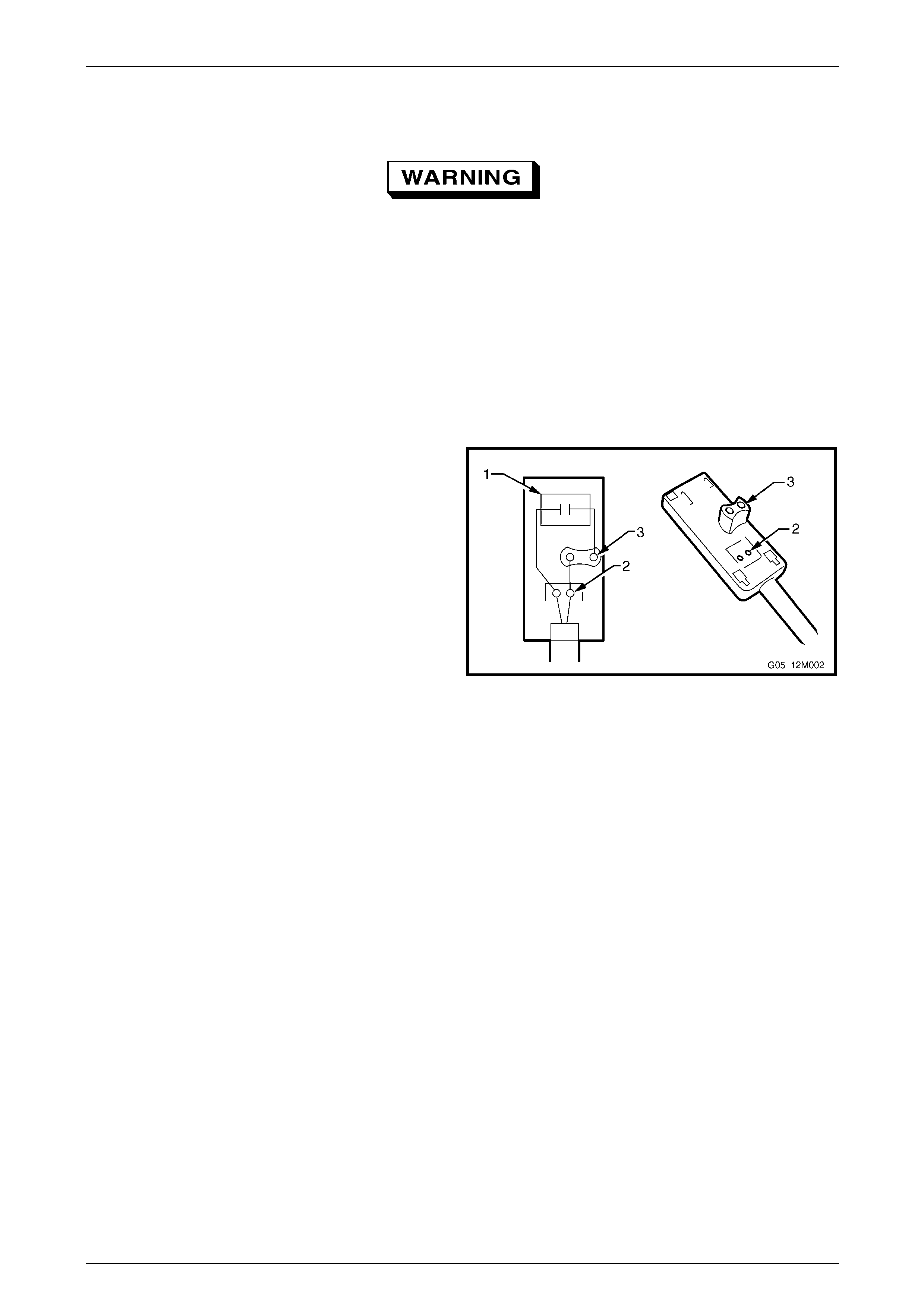
Occupant Protection System Page 12M–30
Page 12M–30
Wiring Harness
Due to the sensitive nature of the circuitry for
restraint devices, special wiring repair
procedures have been developed, refer to
Section 12P Wiring Diagrams. These are the
only recommended and approved wiring
repair methods for restraint devices.
The wiring harness for restraint devices can be identified by the yellow PVC tubing or yellow tape covering the harness
wiring. Specific wiring harness connectors for restraint devices are either coloured yellow, mustard or orange, or have a
yellow retaining clip or slide to identify them.
The connectors on the wiring harness for restraint devices, which interface with the igniters, have an in-built capacitor,
which is connected in series with the trigger circuit. The purpose of the capacitor is to prevent unintentional triggering of
the restraint devices by blocking an y Direct Current (DC) in the circuit.
Figure 12M – 20 illustrates the wiring harness connector
with an in-built capacitor. The connector consists of:
• Capacitor (1).
• Service holes to aid in diagno s is of the system (2).
• Connector Pins (3).
Figure 12M – 20

Occupant Protection System Page 12M–31
Page 12M–31
1.3 System Operation – Inflatable Restraint
and Pretensioner Assemblies
Each of the inflatable restraint assemblies and pretensioners has a built in capacitor as part of the circuit.
This capacitor acts as a safety function within the circuit so that if either of the two wires that form the harness are
shorted to ground or battery, there will be no current flow and therefore the inflatable restraint assembly will not deploy.
A capacitor will only allow current flow with an alternating current (AC) supply. As the battery is direct current (DC) the
capacitor will not allow current flo w if it is shorted to a DC suppl y.
Within the SDM, a ‘H’ bridge circuit is used to supply the inflatable restraint assembly with an AC supply when the SDM
senses an impact that requires deployment of the restraint assembly. The 'H' bridge circuit is used to allow readiness in
the case of single wiring harness faults. The bridge structur e allows several firing paths so the restraint assembly can be
deployed even if one of the four power transistors is faulty.
NOTE
S1, S2, S3, and S4 denote the four transistors
that form the ‘H’ bridge circuit, refer to
Figure 12M – 21, which sho ws the steeri ng wheel
inflatable restraint assembly wiring diagram. All
firing loops function in the same manner.
The ‘H’ bridge has two sources of supply; the internal capacitor (ER) of the SDM, which is the energy reserve sup pl y,
and battery positive. The function of the energy reserve, which stores 45 V, is to provide power for restraint assembly
deployment in the situation where battery positive is not available to the SDM (if the battery positive supply is interrupted
during an impact).
The following firing modes are a breakdown of the SDM converting DC into AC and the supply of that AC to the inflatable
restraint assembly to cause a deployme nt.
Firing Modes 1 and 2 are activated alternately for several cycles respectively. If the voltage at the po wer stages has
dropped to below 25 V, Mode 3 is started. If the energy res erve is not avai lable for any reason when firing is required,
only battery voltage at the power stage is present, and firing occurs immediately with Firing Mode 3.
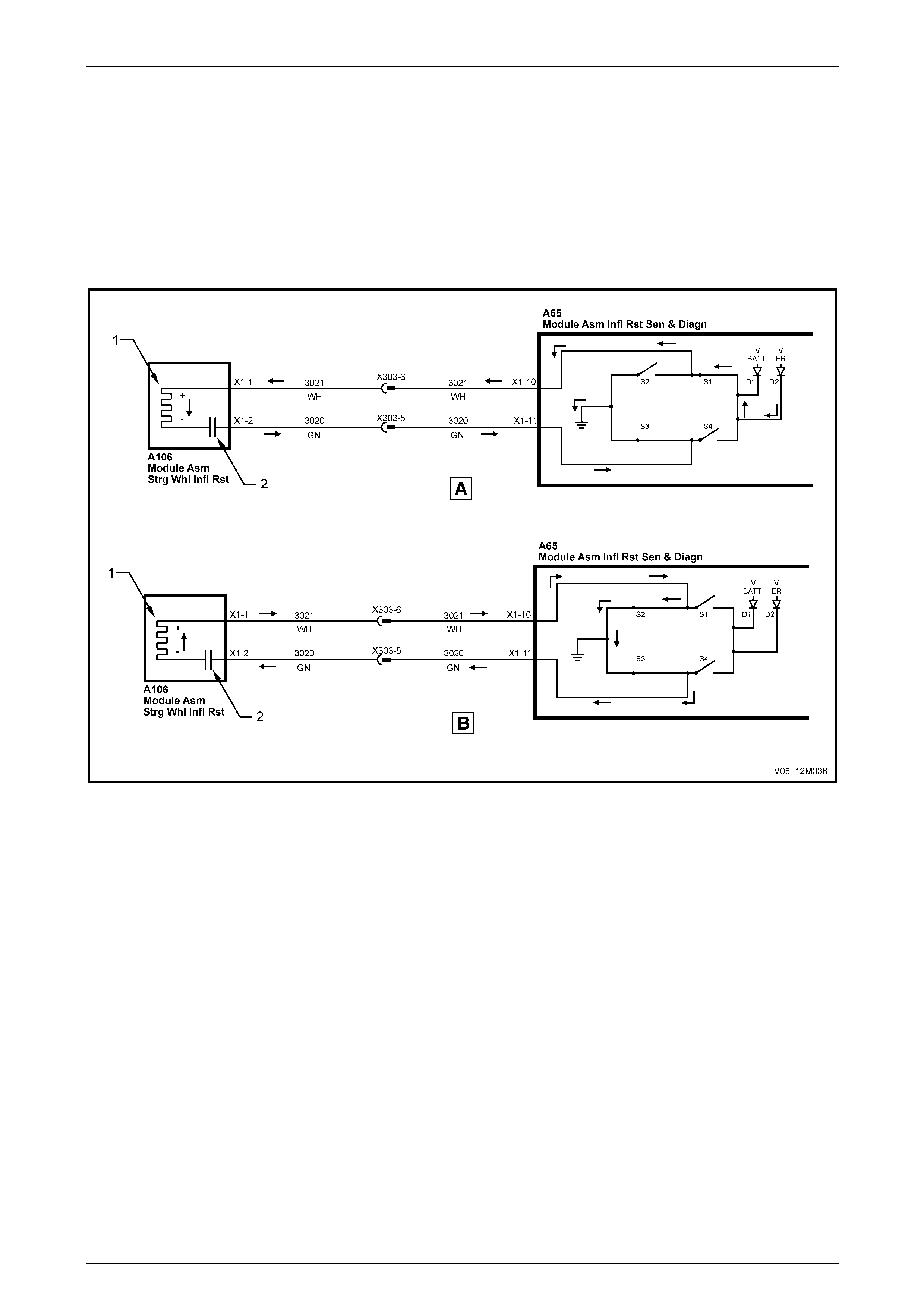
Occupant Protection System Page 12M–32
Page 12M–32
Firing Mode 1
Firing Mode 1 is designed to activate the initiator (1) in the event the negative side of the firing loop (circuit 3020) is
shorted to ground or battery, refer to Figure 12M – 21. Throughout Firing Mode 1, S3 grounds this side of the circuit.
When the circuit is charging (A), the ER supplies power to the positive side of the firing loop (circuit 3021) through switch
S1.
When the circuit discharges (B), S1 opens and S2 closes providing a ground circuit for the positive side of the firing loop.
The charging and disc harging (the opening and closing of S1 and S2) is every 5 µs. The AC created by the alternating
switching of the ‘H’ bridge will cause current flow through the capacitor (2) and the initiator to activate.
Figure 12M – 21
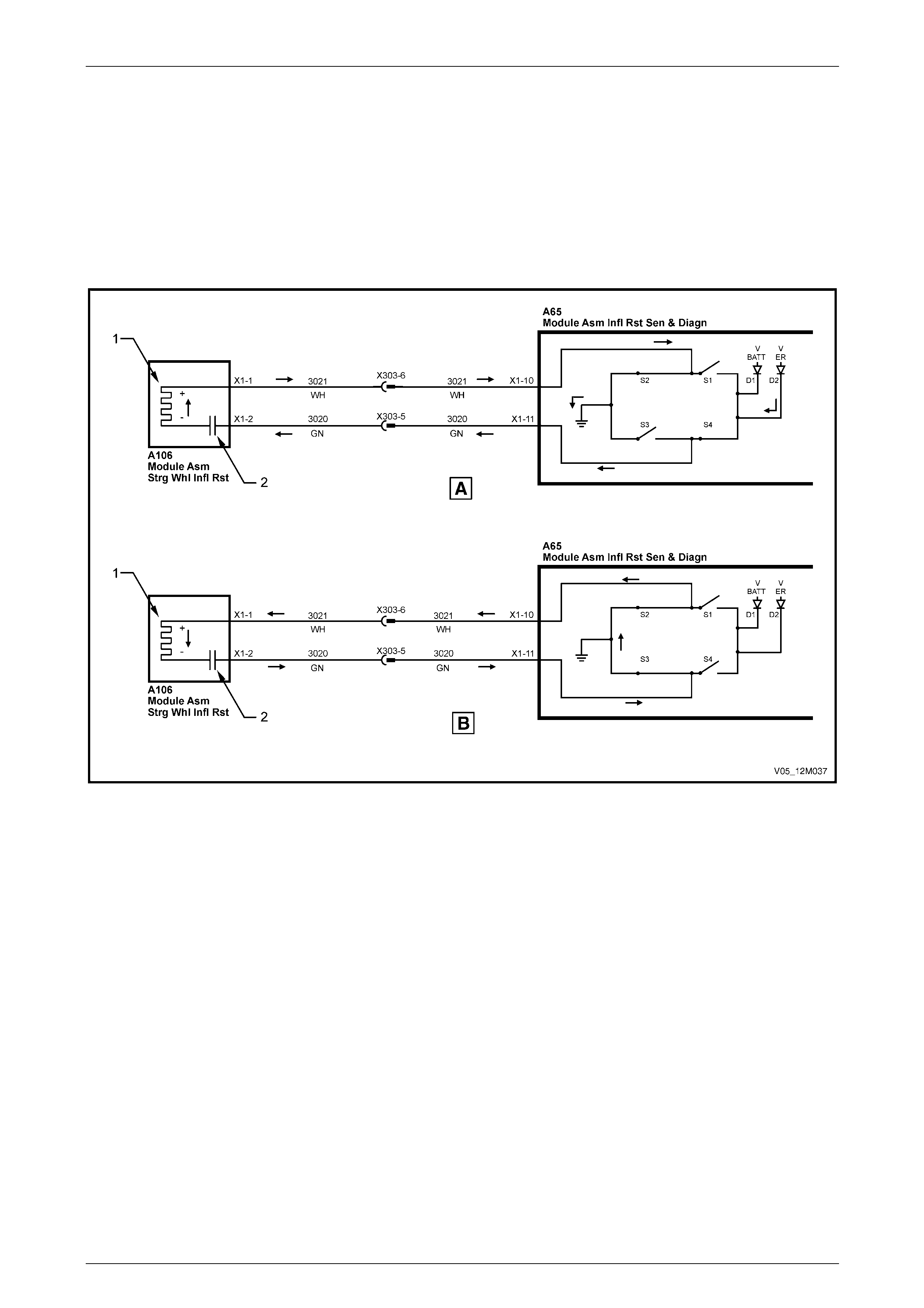
Occupant Protection System Page 12M–33
Page 12M–33
Firing Mode 2
Firing Mode 2 is designed to activate the initiator (1) in the event the positive side of the firing loop (circu it 3021) is
shorted to ground or battery, refer to Figure 12M – 22. Throughout Firing Mode 2, S2 grounds this side of the circuit.
When the circuit is charging (A), the ER supplies power to the negative side of the firing loop (circuit 3020) through
switch S4.
When the circuit discharges (B), S3 opens and S4 closes providing a ground circuit for the negative side of the firing
loop. The charging and disch arging (the opening a closing of S3 and S4) is every 5 µs. The AC created by the alternating
switching of the ‘H’ bridge will cause current flow through the capacitor (2) and the initiator to activate.
Figure 12M – 22
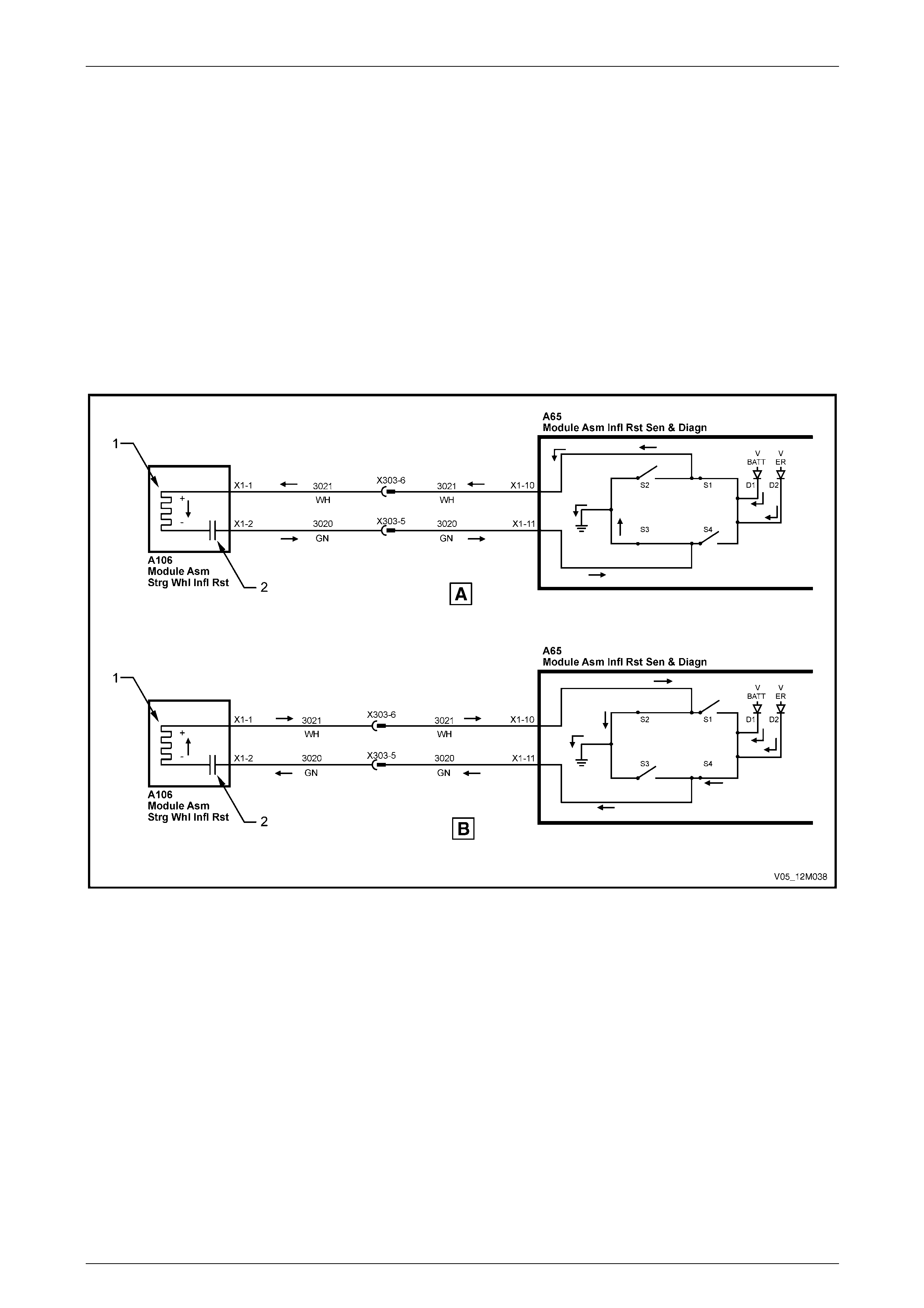
Occupant Protection System Page 12M–34
Page 12M–34
Firing Mode 3
Firing Mode 3 is designed to charge and discharge both the positiv e and negative side of the firing loop when the Energy
Reserve (ER) falls below 25 V.
When charging (A), S1 is closed al lowing both battery and ER power through the positive side (circuit 3021), refer to
Figure 12M – 23. During this cycle, S3 is closed, provi ding a ground for circuit 3020. S2 and S4 are both open.
When discharging (B), S4 is closed allowing both battery and ER power through the negative side (circuit 3020). During
this cycle, S2 is closed, providing a ground for circuit 3021. S1 and S3 ar e both open
The charging and disc harging (the opening a closing of S1 a nd S3; S2 and S4) is every 5 µs. Due to this charging of the
capacitor (2) via the firing element from posi t ive voltage to negative voltage, the firing voltage of this mode can be
considered to be doubled to 2 x ER (Energ y Reserve Voltage) or 2 x VBAT (Battery Voltage). As a result, AC firing from
battery voltage is possible.
The AC created by the alternating switching of the ‘H’ bridge will cause current flo w through the capacitor and the initiator
(1) to activate.
Figure 12M – 23
Firing Loop Monitoring
The firing loop monitoring e nsures that failures in the firing leads and initiators that could affect triggering are identified.
The following errors in the firing loops or initia tors are detected:
• Short circuit or leakage resistance to ground or battery voltage.
• Short circuit or shunt circuit between firing leads of the firing loop.
• Resistance of the initiator too high or too lo w.
• Capacitance of the firing loop capacitor too high or too low.
When the SDM detects any of the above faults, it will produce a Diagnostic Trouble Code (DTC) and illuminate the airbag
warning indicator. For further details refer to 2 Diagnostics.

Occupant Protection System Page 12M–35
Page 12M–35
1.4 Repairs and Inspections Required After
a Collision
If any OPS components are damaged, they must be replaced. If OPS component mount ing points are damaged, they
must be repaired or replaced.
• Do not use OPS components from another
vehicle.
• Proper operation of the OPS requires that
any repairs to the vehicle structure must
return it to its original production
configuration.
• Damaged or defective OPS components
must not be repaired, but must always be
replaced.
No Pretensioner or Inflatable Restraint Assembly Deployment
If a vehicle is involved in a collision, the following components must be inspected:
• The SDM mounting must be checked for deformation. If the floor panel is deformed where the SDM is mounted, the
panel must be repaired or repl aced.
• The pretensioners, steering wheel inflatable restraint assembly, instrument panel inflatable restraint assembly and
SDM that have not been deployed must be checked for damage.
• The steering column must be dimensionally inspected, refer to 9 Steering.
• Inspect any seatbelt assembly in use during the collision. Check the a nchor plates, guides, retractor assembly and
the seatbelt buckle and pretensioner assem bly for damage and correct operation, and the webbing for abrasions,
fraying, cuts, etc. Replace the complete seatbelt assembly if any parts are damaged.
Pretensioner Only Deployment
1 If a vehicle is involved in a collision which was severe enough to deplo y the prete nsioners but not severe enough to
deploy inflatable restraint assemblies, the following compon ents must be replaced:
• Front seatbelt pretensioners, refer to 3.5 Seatbelt Buckle and Pretensioner Assembly.
• Seat track and height adjust assembly in any front seat occupied d urin g pretensioner deployment, refer to
Section 1A7 Seat Assemblies.
• SDM, refer to 3.3 Sensing and Diagnostic Modu le (SDM) . Also inspect the SDM Mounting for deformation.
• Any seatbelt worn in the collision, refer to 4 Service Operations – Front Seatbelts and / or
5 Service Operations – Rear Seatbelts.
2 The steering column must be dimensionally inspected, refer to 9 Steering.

Occupant Protection System Page 12M–36
Page 12M–36
Pretensioner and Front Inflatable Restraint Assembly Deployment
If a vehicle is involved in a collision where the front seatbelt pretensioners and the inflata ble restraint assemblies have
deployed, the following components must be replaced:
The same components as in a pretension er o nly deployment, plus:
• Steering wheel inflatable restraint assembly, refer to 3.6 Steering Wheel Inflatable Restraint Assembly.
• Clock spring coil assembly, refer to 3.7 Clock Spring Coil Assembly.
• Steering wheel, refer to Section 9 Steering.
• Steering column, refer to Section 9 Steering.
• Instrument panel inflatable restraint assembly, refer to 3.8 Instrument Panel Inflatable Restraint Assembly.
• Instrument panel pad assembly, instrument p anel inflatable restraint openin g trim cover, and instrument panel
lower bracket assembly, refer to Section 1A3 Instrument Panel and Console.
Side-impact Inflatable Restraint Assembly Deployment
If a vehicle is involved in a collision where a side-impact inflatable restraint is deployed, the following components must
be replaced:
• Relevant side-impact inflatable restraint assembly, refer to 3.9 Side-impact Inflatable Restraint Assemb ly.
• Relevant side-impact sensor (peri pheral acceleration sensor), refer to 3.4 Side-impact Sensor.
• SDM, refer to 3.3 Sensing and Diagnostic Modu le (SDM) .
• Relevant side front seat assembly, refer to Section 1A7 Seat Assemblies.
• Any seatbelt worn in the collision, refer to 4 Service Operations – Front Seatbelts and / or
5 Service Operations – Rear Seatbelts.

Occupant Protection System Page 12M–37
Page 12M–37
2 Diagnostics
2.1 Prerequisites
Equipment
The technician should have, and be able to use, the following equipment:
1 An unpowered test lamp with a current draw of less than 3 A.
2 A digital multimeter with a minimum impe dance of 10 MΩ.
3 Tech 2 Diagnostic Scan T ool, refer to Section 0C Tech 2.
4 A jumper lead to test circuits.
5 Connector test adaptor kit Tool No. KM-609.
6 Test lead set Tool No. KM609-20.
7 Dummy loads Tool Nos. SD2828 0B (AU471), AU485, and EL47787.
Testing Procedures
Adhere to the following points when
performing diagnostic testing on
components:
• Take care when using testing equipment
to diagnose wiring harness connectors.
Backprobe the connector to avoid terminal
damage.
• When tests are required on connector
terminals, use the adapters in the
connector adapter kit KM–609 to prevent
damage to the terminals.
• Unless the multimeter being used has an
auto-ranging function, ensure the correct
range is selected.
• When backpro bing connectors, ensure the
test lamp ground lead is connected to an
appropriate ground point on the vehicle.
Ensure this ground point is not part of the
circuit being tested.
NOTE
When following the steps in the di agnostic tables,
perform them in the order cited. If the required
nominal value or result is not achi eved, rectif y t he
problem before proceeding.
Before attempting to diagnose the Occupant Protection System (OPS) the technicia n must have a good understanding of
electrical system basics and the use of circuit testing tools. Without this basic knowledge it will be difficult to use the
diagnostic procedur es detailed in this Section.
Some electrical basics, as well as basic troubleshooting procedures and hints of the use of circuit testing tools are
covered in Section 12P Wiring Diagrams.
The technician should understand the following:
• The meaning of voltage (V), current (A), and resistance (Ω),
• basic theory of electricity, direct current (DC) theory, series and parallel circuits, and voltage drops acros s series
resistors,
• alternating current (AC) theory including in ductance, capacitance and impedance,
• what happens in a circuit with an open or shorted wire (shorted either to voltage or ground), and
• be able to read and interpret a wiring diagram.
The tables in this Section are used by the technician in the aid of diagnosing faults in the OPS. To aid in the use of the
diagnostic tables refer to 2.2 Wiring Diagr am and 2.3 Connector Chart.
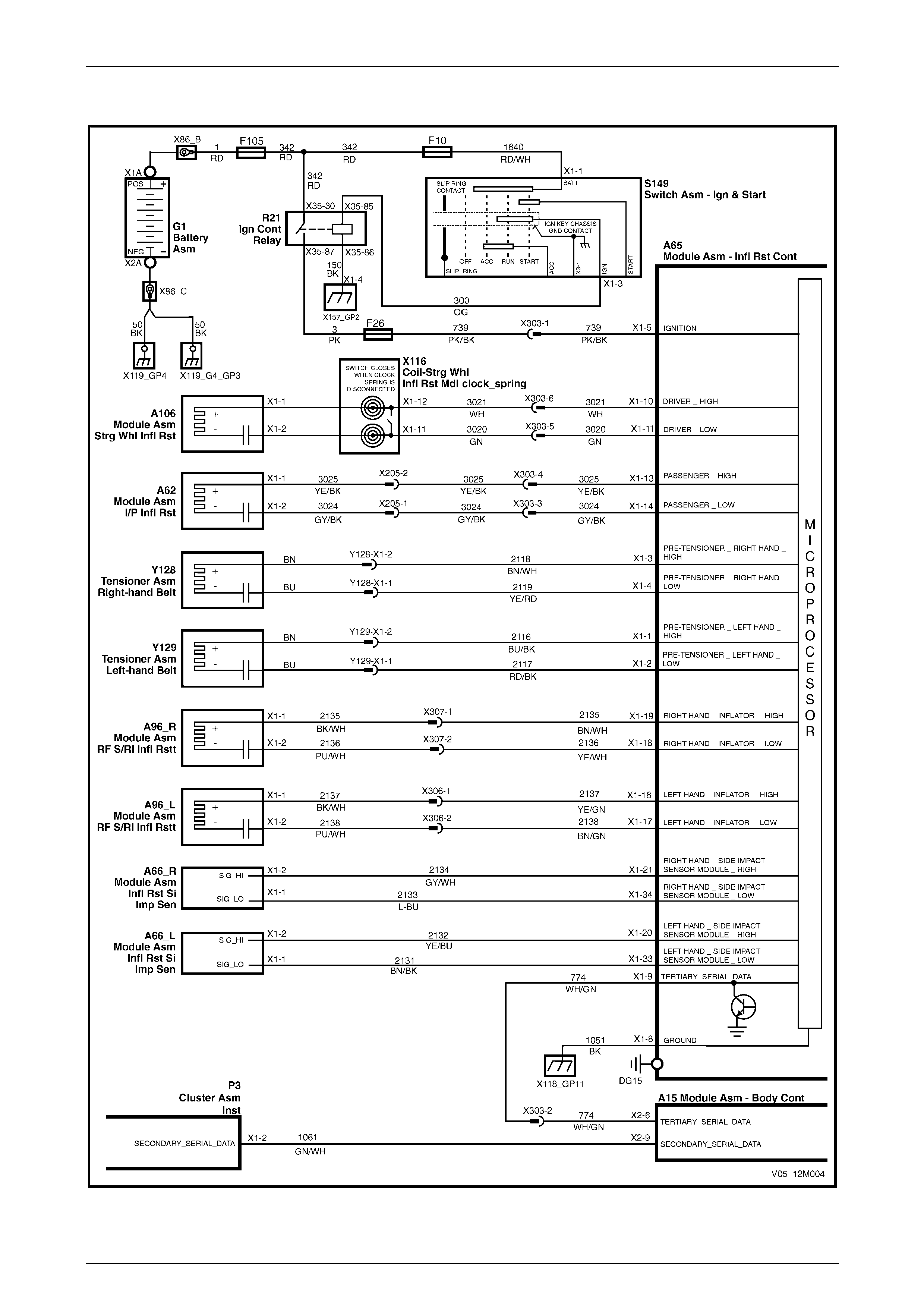
Occupant Protection System Page 12M–38
Page 12M–38
2.2 Wiring Diagram
Figure 12M – 24
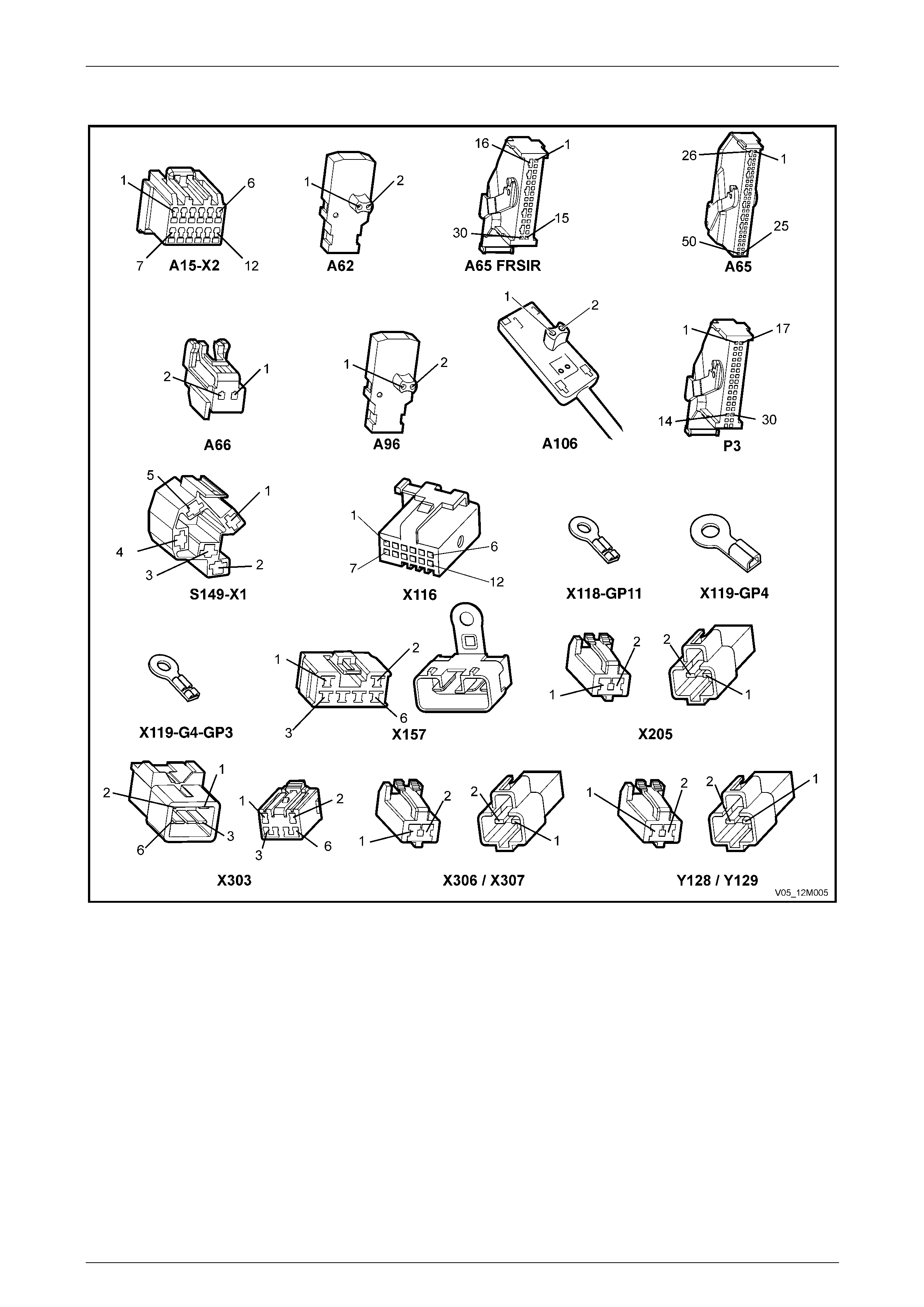
Occupant Protection System Page 12M–39
Page 12M–39
2.3 Connector Chart
Figure 12M – 25

Occupant Protection System Page 12M–40
Page 12M–40
2.4 System Self Diagnosis
The Sensing and Diagnostic Module (SDM) has a self-diagnostic facility that can detect and isolate system problems or
failures. When a condition or failur e is detect ed, the SDM sets a fault code that represents that particular condition or
failure. Fault codes will cause the airbag warning indicator to be illuminated and an airbag fault message is displayed by
the Multi Function Display (MFD) located in the instrument cluster. Depending on the fault, the SDM ma y disable the
inflatable restraint and pretensioner assemblies.
If present, diagnosable system faults are detected by the SDM during an initial isation process when the ignition is first
turned on. Upon first detection of a system fault condition, the SDM records the failure and classes the failure as
intermittent. If the condition is maintained to meet the failure duration conditions for the indivi dual system fault
(approximately 3 to 5 seconds), the fault then becomes a current Diagnostic Trouble Code (DTC). If the fault duration
conditions are not met, the intermittent fault i s cleare d from the SDM.
Current DTCs are permanentl y stored in the SDM memory. When the fault conditions are no longer met, the DTC will
become a History DTC.
DTCs – Current
Current DTCs, when detected, are stored in the SDM memory during the current ignition cycle and then maintained in an
EEPROM.
Current DTCs are set or cleared based on conditions in the OPS during ignition on or continuous monitoring of the
current ignition cycle.
NOTE
A current DTC can be identified on Tech 2
display by the word Current between the DTC
number and the DTC description. The word
History between the DTC number and the DTC
description indicates the DTC displayed is a
history DTC.
Current DTCs will be reset to history DTCs upon the next diagnostic test sequence the fault conditions are not met.
Current DTCs can be cleared (changed to history DTC) by removing the fault conditio ns.
Tech 2 is unable to clear current DT Cs if the fault conditions still exist; Tech 2 will display Clear DTC Information
Failed.
DTCs stored in the SDM memory can only be displ ayed and / or cleared using Tech 2 diagnostic scan tool.
Tech 2 communicates with SDM serial data usin g the Seri al Data Link Connector (DLC), which is attached to the
instrument panel lower left-hand trim retainer, refer to Section 0C Tech 2.
DTCs – History
History DTCs are set upon the cleari ng of a current DTC fault condition. History DTCs are maintained b y the SDM over
multiple ignition cycles in the EEPROM. The SDM can only clear history DTCs from its EEPROM by a Clear DTCs serial
data message from Tech 2.
Erasing DTCs
Once any system fault has been rectified, using Tech 2 Clear DTCs selection will erase any fault codes stored in the
SDM memory, refer to Section 0C Tech 2.
NOTE
Once DTCs have been cleared, be sure to verify
proper system operation and absence of an y fault
codes when clearing procedure is completed. If
Tech 2 displays Clear DTC Information Failed
after attempting to clear DTCs, the fault condition
still exists.

Occupant Protection System Page 12M–41
Page 12M–41
Data Display
Tech 2 can display the status of inputs and outputs of the OPS. The following table lists each item contained in the data
stream together with a brief description of its meaning.
Data Stream / Screen Display Description
Battery Voltage Displays the current vehicle system input voltage to the SDM (approximately 12 V).
• If the voltage is below 8 V for more than 3 seconds, the airbag warning indicator
illuminates.
• If the voltage is above 21.2 V for more than 3 seconds, the airbag warning
indicator illuminates.
Driver Airbag Loop
Capacitance Displays capacitance in the steeri ng wheel inflatable restraint assembly cir cuit. T he
capacitance should be approximately 470 nF.
• If the capacitance reading is greater than 549.9 nF for more than 3 seconds or
less than 1 second during an ignition on cycle, DTC 19 will set.
• If the capacitance reading is less than 390.1 nF for more than 3 seconds or less
than 1 second during an ignition/key on cycle, DT C 20 will set.
Driver Airbag Loop Resistance Displays the resistance in the steering wheel inflatable restraint assembly circuit. The
resistance should be approxim ately 2 Ω.
• If resistance of this circuit is greater than 8.4 Ω for more than 3 seconds, DTC 21
will set.
• If resistance of this circuit is less than 1 Ω for more than 3 seconds, DTC 22 will
set.
Passenger Airbag Loop
Capacitance Displays capacitance in the instrument pan el inflatable restraint assembly circuit. The
capacitance should be approximately 470 nF.
• If the capacitance reading is greater than 549.9 nF for more than 3 seconds or
less than 1 second during an ignition on cycle, DTC 35 will set.
• If the capacitance reading is less than 390.1 nF for more than 3 seconds or less
than 1 second during an ignition/key on cycle, DT C 36 will set.
Passenger Airbag Loop
Resistance Displays resistance in the instrument panel inflatable restraint assembly circuit. T he
resistance should be approxim ately 2 Ω.
• If resistance of this circuit is greater than 8.4 Ω for more than 3 seconds, DTC 37
will set.
• If resistance of this circuit is less than 0.6 Ω for more than 3 seconds, DTC 38 will
set.
Left Hand Pretensioner Loop
Capacitance Displays capacitance in the left-hand pretensioner circuit. The capacitance should be
approximately 470 nF.
• If the capacitance reading is greater than 549.9 nF for more than 3 seconds or
less than 1 second during an i gnition/key on cycle, DTC 51 will set.
• If the capacitance reading is less than 390.1 nF for more than 3 seconds or less
than 1 second during an ignition/key on cycle, DT C 52 will set.
Left Hand Pretensioner Loop
Resistance Displays resistance in the left-hand pretensioner circuit. T he resistance should be
approximately 2 Ω.
• If the resistance of this circuit is greater than 8.4 Ω for more than 3 seconds,
DTC 53 will set.
• If the resistance of this circuit is less than 0.6 Ω for more than 3 seconds, DTC 54
will set.

Occupant Protection System Page 12M–42
Page 12M–42
Data Stream / Screen Display Description
Right Hand Pretensioner Loo p
Capacitance Displays capacitance in the right-hand pretensioner circuit. The cap acita nce should be
approximately 470 nF.
• If the capacitance reading is greater than 549.9 nF for more than 3 seconds or
less than 1 second during an i gnition/key on cycle, DTC 67 will set.
• If the capacitance reading is less than 390.1 nF for more than 3 seconds or less
than 1 second during an ignition/key on cycle, DT C 68 will set.
Right Hand Pretensioner Loo p
Resistance Displays resistance in the right-hand pretensioner circuit. The resistance shou ld be
approximately 2 Ω.
• If the resistance of this circuit is greater than 8.4 Ω for more than 3 seconds,
DTC 69 will set.
• If the resistance of this circuit is less than 0.6 Ω for more than 3 seconds, DTC 70
will set.
Left Hand Side Airbag Loop
Resistance Displays the resistance in the left-hand side-i mpact inflata ble restraint assembly circuit.
The resistance should be approximately 2 Ω.
• If resistance of this circuit is greater than 8.4 Ω for more than 3 seconds, DTC 85
will set.
• If resistance of this circuit is less than 0.6 Ω for more than 3 seconds, DTC 86 will
set.
Left Hand Side Airbag Loop
Capacitance Displays capacitance in the left-hand side-impact inflatable restraint assembly circuit.
The capacitance should be approximately 47 0 nF .
• If the capacitance reading is greater than 550 nF for more than 3 seconds or less
than 1 second during an ignition on cycle, DTC 83 will set.
• If the capacitance reading is less than 390 nF for more than 3 seconds or less
than 1 second during an ignition/key on cycle, DT C 84 will set.
Right Hand Side Airbag Loop
Resistance Displays the resistance in the right-hand side-impact inflatable restraint assembly circuit.
The resistance should be approximately 2 Ω.
• If resistance of this circuit is greater than 8.4 Ω for more than 3 seconds, DTC 101
will set.
• If resistance of this circuit is less than 0.6 Ω for more than 3 seconds, DTC 102 will
set.
Right Hand Side Airbag Loop
Capacitance Displays capacitance in the right-hand side-impact inflatable restraint assembly circuit.
The capacitance should be approximately 47 0 nF .
• If the capacitance reading is greater than 550 nF for more than 3 seconds or less
than 1 second during an ignition on cycle, DTC 99 will set.
• If the capacitance reading is less than 390 nF for more than 3 seconds or less
than 1 second during an ignition/key on cycle, DT C 100 will set.
Driver Airbag Loop Display indicates whether the SDM has been programmed for the steering wheel
inflatable restraint assembly loop circuit.
• Enabled / Disabled.
Passenger Airbag Loop Display indicates whether the SDM has bee n programmed for the instrument panel
inflatable restraint assembly loop circuit.
• Enabled / Disabled.
Left Hand Pretensioner Loop Display indicates whether the SDM has bee n programmed for the left-hand pretensioner
loop circuit.
• Enabled / Disabled.
Right Hand Pretensioner Loo p Display indicates whether the SDM has been programmed for the right-hand
pretensioner loop circuit.
• Enabled / Disabled.

Occupant Protection System Page 12M–43
Page 12M–43
Data Stream / Screen Display Description
SRS Indicator Displays the current state of the driver, inside the SDM, for the airb ag warning indicator.
• On / Off.
Indicator Check Display indicates the status of the airbag warning indicator during the indicator check for
the first five seconds after the ignition is turned on.
• On / Off.
Battery Voltage (after 3
seconds) Display indicates the vehic le input voltage to the SDM. If voltage is below 9 V or above
20 V for more than 3 seconds, the airbag warning ind icator will illuminate.
• Okay / Not Okay.
Energy Reserve Display indicates status of the energy reserve. If the battery voltage fal ls b elow 7.5 V,
the energy reserve will be switched on.
• On / Off.
Serial Data From Instrument Display indicates whether the instrument configuration of the OPS is correct.
• Yes / No.
BCM Poll Display indicates whether the SDM is receiving a request (a poll via the serial data lin e)
from the BCM for its status of deployment and malfunction data.
• Received / Not Received.
Module has deployed Display indicates whether the SDM has deployed any pretensioners / inflatable restraint
assemblies.
• Yes / No.

Occupant Protection System Page 12M–44
Page 12M–44
2.5 Preliminary System Diagnosis
Prior to starting any diagnosis, the technician should be familiar with the OPS components and operation. For a
description of the components and the system operation, refer to 1 General Information.
When investigating any complaint of a pro blem or malfunction, always begin diagnosis with a circuit check, refer to
System Diagnostic Check.
The diagnostic circuit check ensures the SDM is communicating on the serial data line, assists identification of the
problem, and helps ascertain the appropriate diagnostic table.

Occupant Protection System Page 12M–45
Page 12M–45
2.6 Electrical Diagnosis
Introduction
The following diagnostic table s are designed to aid fast and efficient fault location and remedy. The dia gnostic tables
include a table, pertinent information, and where necessary, the steps are explained by the corresponding numbered
paragraphs.
To aid in the use of the diagnostic tables, refer to 2.2 Wiring Diagram and 2.3 Connector Chart.
When performing wiring checks as directed to by the diagnostic tables, rat her than probe pins and connectors with
incorrect sized multimeter connectio ns, use the ad apters contained in connector test adaptor kit Tool No. KM-609 and
test lead set Tool No. KM609-20. This will prevent any possibility of spreading or damaging wiring harness pins which
may cause a system intermittent failure.
Figure 12M – 26 illustrates the correct use and instal lation of the various diagnostic tools (Tool No. SD28280B, Tool No.
AU485, Tool No. EL47787 and test lead set Tool No. KM609-20).
Under no circumstances is 12 V to be applied
to the dummy load, Tool No. SD28280B, Tool
No. EL47787, or Tool No. AU485, as this will
damage the internal resistor in the load,
rendering the dummy load useless for any
further diagnostic work.
Ensure at the completion of any diagnostic proced ure, all di agnostic tools are removed and all OPS compon ents are
correctly reconnected.

Occupant Protection System Page 12M–46
Page 12M–46
Figure 12M – 26

Occupant Protection System Page 12M–47
Page 12M–47
System Diagnostic Check
Introduction
When investigating any concern with the OPS, always begin diagnosis with the following diagnostic circuit check. This
checks for a fault with the airbag warning indicator, regardless of whether the OPS is serviceable or not.
Test Description
The following numbers refer to the step numbers in the diagnostic table:
2-3 Checks if the airbag warning indicator illuminates when the ignition is turned on. The SDM performs a self-check of
the OPS when the ignition is turned on. During this check, the SDM through the serial dat a bus, instructs the
instrument cluster to illuminate the airba g warning indicator for 5 seconds. If there is a fault in the OPS, the SDM
will instruct the airbag warning indicator to stay on. Isolates whether there is a problem with the airbag warning
indicator or if the fault is in the OPS.
4 Checks if any DTCs have been set. Isolates if a DT C has been set causing the airbag warning indicator to remain
illuminated.
Diagnostic Table Notes
1 For all wiring harness fault diagnoses, refer to Section 12P Wiring Diagrams.
2 For wiring harness repairs, refer to Section 12P Wiring Diagrams.
3 Refer to Section 12O Fuses, Relays and Wiring Harnesses for harness routeing.
4 If the fault is deemed to be intermittent, refer to Section 12P Wiring Diagr ams.
5 For information on using and connecting Tech 2 to the vehicle, refer to Section 0C Tech 2.
Diagnostic Table
Step Action Yes No
1 Is the fault specifically isolated to this system / module? Go to Step 2 Go to Section 0D
Vehicle Diagnostics
2 Turn the ignition on with the engi ne not running and monitor the airbag
warning indicator in the instrument cluster.
Does the airbag warning indicator illuminate? Go to Step 3
Go to Airbag
Warning Indicator
Inoperative in this
Section
3 After five seconds of the ignition being turned on with the engine not
running, does the airbag warning indicator extinguish? System serviceable Go to Step 4
4 1 Connect Tech 2 to the DLC (refer to Note 5).
2 On Tech 2 select:
Body / SRS / Diagnostic Trouble Codes / Read DTC
Information.
Have any DTCs been set?
Check and repair
fault causing DTC to
set, refer to the
relevant DTC
diagnostic table in
this Section
Go to Airbag
Warning Indicator
Illuminated (No DTC
Stored) in this
Section
When all diagno sis an d repairs are completed, clear all DTCs and check the system for correct operation.

Occupant Protection System Page 12M–48
Page 12M–48
Airbag Warning Indicator Inoperative
Introduction
This test is used by the technician to aid in diagnosis when the air bag warning indicator is inoperativ e.
Circuit Description
Battery voltage is supplied to the airbag warning indicator through fuse F 13 (located on the passenger compartment fuse
and relay panel assembly) when the ignition switch is in the IGN or ST ART positions. The airbag indicator in the
instrument cluster is illuminated and extinguished by serial data from the SDM.
The airbag warning ind icator will illuminate:
• When the ignition is turned to the ON position (system wiring and self-check). The airbag warning indicator will be
turned off after this self-check if no current or history Diagnostic Tr ouble Codes (DTCs) are detected.
• If communication is lost between the SDM and the instrum ent cluster.
• If the instrument cluster has not been programmed for the vehicle configuration.
• If the SDM detects a current DTC during an ignition cycle.
• When the battery voltage is belo w 8 V or above 21.2 V.
• If the pretensioners or inflatable restraint assemblies have deployed.
• If the energy reserve in the SDM is activated (battery voltage is less than 7.5 V).
• If the SDM does not receive a poll from the BCM.
Refer to 2.2 Wiring Diagram and 2.3 Connec tor Chart to aid in diagnosis of the airbag warning indicator and associated
components.
Test Description
The following numbers refer to the step numbers in the diagnostic table:
2 Checks if the instrument cluster is powered and receiving data from other vehicle systems.
3 Checks whether the airbag warning indicator or the SDM is faulty.
Diagnostic Table Notes
1 For all wiring harness fault diagnoses, refer to Section 12P Wiring Diagrams.
2 For wiring harness repairs, refer to Section 12P Wiring Diagrams.
3 Refer to Section 12O Fuses, Relays and Wiring Harnesses for harness routeing.
4 If the fault is deemed to be intermittent, refer to Section 12P Wiring Diagr ams.
5 For information on using and connecting Tech 2 to the vehicle, refer to Section 0C Tech 2.
Diagnostic Table
Step Action Yes No
1 Was the System Diagnostic Check performed? Go to Step 2 Refer to System
Diagnostic Check
2 1 Turn the ignition on with the engine not running.
2 Monitor the ABS warning indicator.
Does the ABS warning indicator illuminate? Go to Step 3
There is a fault with
the instrument
cluster, refer to
Section 12C
Instruments
3 1 Connect Tech 2 to the DLC (refer to Note 5).
2 On Tech 2 select:
Body / Instrument / Miscellaneous Tests / Warnings / SRS
Airbag Fault, and command the airbag warning indicator on.
Does the airbag warning indicator illuminate?
Replace the SDM,
refer to 3.3 Sensing
and Diagnostic
Module (SDM)
There is a fault with
the instrument
cluster, refer to
Section 12C
Instruments
When all diagno sis an d repairs are completed, clear all DTCs and check the system for correct operation.

Occupant Protection System Page 12M–49
Page 12M–49
Airbag Warning Indicator Illuminated (No DTC Stored)
Introduction
This test ensures the SDM is communicating on the serial data line, to identify a failure or malfunction an d to provid e a
reference to the appropriate diag nostic table in this Section.
Circuit Description
With Tech 2 connected to the DLC and the ignition on, Tech 2 should display serial data communication, refer to
Section 0C Tech 2. If Tech 2 does not display serial data, the serial data circuit maybe open-circuite d or short-circuited.
There are several other control modules that are connected to the serial data line (PCM, BCM, ABS/ETC, instrument
cluster and the SDM). Any one of these control modules could cause a fault on the serial data line. This fault cou ld result
in Tech 2 not being able to displa y serial data.
Battery voltage is supplied to the airbag warning indicator through fuse F 13 (located in the passenger compartment fuse
and relay panel assembly) with the ignition switch in the IGN or START positions. To illuminate the indicator, the SDM
sends a serial data message to the BCM via circuit 774 and the BCM sends a serial data message to the instrument
cluster via circuit 1061, requesting the airbag indicator to illuminate.
When the ignition is switched on, the airbag warning indicator should illuminate for approximately 5 seconds to indicate
the system start up sequence / system wiring and self check. If no system faults are detected, the airbag warning
indicator will then be switched off.
If a fault is detected (either during this system check or during the ignition cycle), the airbag warning indic ator will either
remain on until the fault is remedied or, if a DTC has been set, until the DTC is cleared. If a fault is remedied during an
ignition cycle, unless the fault caused a DTC to set, the airbag warning indicator will turn off immediately.
The airbag warning ind icator will illuminate:
• When the ignition is turned to the ON position (system wiring and self-check). The airbag warning indicator will be
turned off after this self-check if no current or history Diagnostic Tr ouble Codes (DTCs) are detected.
• If communication is lost between the SDM and the instrum ent cluster.
• If the instrument cluster has not been programmed for the vehicle configuration.
• If the SDM detects a current DTC during an ignition cycle.
• When the battery voltage is belo w 8 V or above 21.2 V.
• If the pretensioners or inflatable restraint assemblies have deployed.
• If the energy reserve in the SDM is activated (battery voltage is less than 7.5 V).
• If the SDM does not receive a poll from the BCM.
• The airbag warning indicator will a lso be illuminated if communication is lost (no serial data) between the SDM and
the instrument cluster.
Refer to 2.2 Wiring Diagram and 2.3 Connec tor Chart to aid in diagnosis of the cause of the airbag warning indicator
being illuminated.
Test Description
The following numbers refer to the step numbers in the diagnostic table:
2 The SDM performs a self-check of the OPS when the ignition is turned on. During this check, the SDM through the
serial data bus, instructs the instrument cluster to illuminate the air bag warning indicator for 5 seconds. If there is a
fault in the OPS, the SDM will instruct the airbag warning indicator to stay on. Isolates whether the fault is in the
OPS or there is an intermittent fault (this check has already been performed in S ystem Diagnostic Check).
3 Checks if there is serial data communication between the SDM and Tech 2. This also verifies if the SDM has power
and a ground circuit.
4 Checks if any DTCs have been set. Isolates if a DT C has been set causing the airbag warning indicator to remain
illuminated.
5 Checks if the BCM has polled the SDM.
6 Checks if the instrument cluster is configured for the OPS.
8 Checks if the energy reserve has been activated. If the voltage supply to the SDM falls below 7.5 V, the energy
reserve in the SDM is switched on.
9 Checks the voltage supply to the SDM. If the battery voltage to the SDM falls below 8 V or rises above 21.2 V for
more than 3 seconds, the airbag warning indicator will illumi nate.

Occupant Protection System Page 12M–50
Page 12M–50
Diagnostic Table Notes
1 For all wiring harness fault diagnoses, refer to Section 12P Wiring Diagrams.
2 For wiring harness repairs, refer to Section 12P Wiring Diagrams.
3 Refer to Section 12O Fuses, Relays and Wiring Harnesses for harness routeing.
4 If the fault is deemed to be intermittent, refer to Section 12P Wiring Diagr ams.
5 For information on using and connecting Tech 2 to the vehicle, refer to Section 0C Tech 2.
Diagnostic Table
Step Action Yes No
1 Was the System Diagnostic Check performed? Go to Step 2 Refer to System
Diagnostic Check
2 Turn the ignition to the ON position with the engine not running.
Does the airbag warning indicator remain illuminated after 5 seconds ? Go to Step 3
The fault is
intermittent (refer to
Note 4)
3 1 Turn the ignition to the OFF position.
2 Connect Tech 2 to the DLC.
3 On Tech 2 select:
Body / SRS
4 Turn the Ignition on.
Does Tech 2 display S ystem Identification (i.e. SDM part number)? Go to Step 4
Refer to No
Communications
from SDM in this
Section
4 On Tech 2 select:
Body / SRS / Diagnostic Trouble Codes / Read DTC Information.
Have any DTCs been set?
Check and repair
fault causing DTC to
set, refer to the
relevant DTC
diagnostic table in
this Section Go to Step 5
5 On Tech 2 select:
Body / SRS / Data Display, and scroll to BCM Poll.
Has the SDM received a BCM poll? Go to Step 6
Refer to No
Communications
from SDM in this
Section
6 On Tech 2 select:
Body / SRS / Data Display, and scroll to Serial Data From
Instrument.
Is the instrument cluster configured to the OPS? Go to Step 7 Refer to Section
12C Instruments
7 On Tech 2 select:
Body / SRS / Data Display, and scroll to Module Has Deployed.
Has the module deploye d?
Refer to 1.4
Repairs and
Inspections
Required After a
Collision Go to Step 8
8 On Tech 2 select:
Body / SRS / Data Display, and scroll to Energy Reserve.
Has the energy reserve been activated ? Go to Step 10 Go to Step 9

Occupant Protection System Page 12M–51
Page 12M–51
Step Action Yes No
9 On Tech 2 select:
Body / SRS / Data Display / Battery Voltage (after 3 seconds).
Does Tech 2 display battery voltage is Okay (after 3 seconds)?
Go to Step 15
Recycle the ignition
and perform the
initial check, refer to
System Diagnostic
Check in this
Section
If the fault still
occurs replace the
SDM, refer to 3.3
Sensing and
Diagnostic Module
(SDM)
10 Check the serviceabilit y of the battery, refer to Section 12A Battery.
Is the battery serviceable? Go to Step 11
Replace the battery,
refer to Section 12A
Battery
11 Carry out checks of generator output, refer to Section 6D1-1 Charging
System – V6 Engine or Section 6D3-1 Charging System – Gen III V8
Engine.
Is generator output within specifications?
Go to Step 12
Repair the
generator as
necessary, refer to
Section 6D1-1
Charging System –
V6 Engine or
Section 6D3-1
Charging System –
Gen III V8 Engine
12 1 Disconnect connector A65 – X1 from the S DM.
2 Start the engine, turn the headlamps on a nd raise the engine
idle speed to approx imately 2500 RPM.
3 Using a multimeter set to measure voltage, probe b etween
connector A65 – X1 pin 5 and a known ground (refer to Note 1).
Does the multimeter indicate approximately the same voltage as
measured during Step 10 (ge nerator o utput tests)? Go to Step 15 Go to Step 13
13 Check Fuse 26 in the passenger compartment fuse and relay pane l
assembly, and Fuse 105 in the engin e compartment fuse and relay
panel assembly.
Are the fuses serviceable? Go to Step 14
Replace fuse and
retest. If the fuse
blows again test for
a short to ground
(refer to Note 1)
14 Using a multimeter set to measure voltage, probe between connector
X129 – X35 pin 87 and a known ground (refer to Note 1).
Does the multimeter indicate approximately the same voltage as
measured during Step 10 (ge nerator o utput tests)?
Repair or replace
circuit 739 or circuit
3 as required (refer
to Note 2).
Repair or replace
power supply
circuit(s) as required
(refer to Note 2)
15 1 Turn the ignition to the OFF position.
2 With SDM connector A65 – X1 disconnected and using a
multimeter set to measure resistance, probe between connector
A65 – X1 pin 8 and a known ground (refer to Note 1).
Does the multimeter indicate contin uity?
Replace the SDM,
refer to 3.3 Sensing
and Diagnostic
Module (SDM)
Repair or replace
circuit 1051 (refer to
Note 2)
When all diagno sis an d repairs are completed, clear all DTCs and check the system for correct operation.

Occupant Protection System Page 12M–52
Page 12M–52
No Communications from SDM
Introduction
This test is used by the technician to aid in diagnosis when the air bag warning indicator will illuminate due to a missing
signal between the BCM and the SDM.
Circuit Description
The BCM polls the tertiary serial data bus (circuit 774) for SDM information. The airbag warning indicator will illuminate if
there is no poll from the BCM requesting information from the SDM.
Refer to 2.2 Wiring Diagram and 2.3 Connec tor Chart to aid in diagnosis of the serial data bus and associated
components.
Test Description
The following numbers refer to the step numbers in the diagnostic table:
2 Checks if the initial check of the system was performed.
3 Checks if Tech 2 is able to communicate with other modules in the vehicle. Isolates whether the problem is with the
SDM alone, or there is a problem with the serial data bus.
4 Checks if the fuse F26 is serviceable. Isolates if there is a short to ground in circuit 739.
5 Checks if there is battery voltage at harness connector A65 – X1 pin 5. Isolates if there is an open-circuit in circuit
739 that supplies battery voltage to the SDM.
6 Checks if there is continuity from harness connector A65 – X1 pin 8 to the ground connector GP11. Isolates if there
is an open circuit in circuit 1051.
7 Checks for continuity between connectors A65 – X1 pin 9 and A15 – X2 pin 6. Isolates if there is an open circuit in
circuit 774.
Diagnostic Table Notes
1 For all wiring harness fault diagnoses, refer to Section 12P Wiring Diagrams.
2 For wiring harness repairs, refer to Section 12P Wiring Diagrams.
3 Refer to Section 12O Fuses, Relays and Wiring Harnesses for harness routeing.
4 If the fault is deemed to be intermittent, refer to Section 12P Wiring Diagr ams.
5 For information on using and connecting Tech 2 to the vehicle, refer to Section 0C Tech 2.

Occupant Protection System Page 12M–53
Page 12M–53
Diagnostic Table
Step Action Yes No
1 Was the System Diagnostic Check performed? Go to Step 2 Refer to System
Diagnostic Check
2 1 Connect Tech 2 to the DLC (refer to Note 5).
2 Turn the ignition on with the engine not running.
3 On Tech 2 select:
Body / Body Control Module.
4 On Tech 2 select:
Body / Powertrain Interface Module.
If No Communications is displayed for a control module, then there
is no communication bet ween Tech 2 and that particular control
module.
Can Tech 2 communicate with the BCM and the PIM of the vehicle? Go to Step 3
Refer to Section 12J
Body Control
Module
3 1 Turn off the ignition switch.
2 Check the SDM fuse F26 on the passenger compartment fuse
and relay panel assembly.
Is the fuse serviceable? Go to Step 4
Replace fuse F26. If
the fuse blows
again, check for a
short to ground in
circuit 739 (refer to
Note 2)
4 1 Disconnect connector A65 – X1 from the S DM.
2 Turn the ignition on with the engine not running.
3 Using a multimeter set to measure voltage, probe b etween
connector A65 – X1 pin 5 and a known ground (refer to Note 1).
Does the multimeter indicate battery voltage? Go to Step 5
Repair or replace
circuit 739 (refer to
Note 2)
5 Using a multimeter set to measure resistance, probe between
connector A65 – X1 pin 8 and ground point X118_GP11 (refer to Note
1).
Does the multimeter indicate continuity? Go to Step 6
Repair or replace
circuit 1051 (refer to
Note 2)
6 Using a multimeter set to measure resistance, probe between
connectors A15 – X2 pin 6 and A65 – X1 pin 9 (refer to Note 1).
Does the multimeter indicate contin uity?
Replace the SDM,
refer to 3.3 Sensing
and Diagnostic
Module (SDM).
If there is still no
communication
between the SDM
and the BCM,
replace the BCM,
refer to Section 12J
BCM
Repair or replace
circuit 774 (refer to
Note 2)
When all diagno sis an d repairs are completed, clear all DTCs and check the system for correct operation.

Occupant Protection System Page 12M–54
Page 12M–54
2.7 Steering Wheel Inflatable Restraint
Assembly DTCs
DTC 17 – Driver Airbag Circuit Short to Battery
Introduction
This test is used by the technician to aid in diagnosis when DT C 17 has been logged.
Circuit Description
With the ignition turned on, and on a constan t monitoring cycle of every 500 milliseconds during the ignition cycle, the
SDM performs a system self check.
A current DTC 17 will set and the airbag warning indicator will illuminate when the SDM detects the resistance to
battery positive is less than 5 kΩ in eith er the positive and/or the negative circuit for more than 3 – 5 seco nds.
A current DTC 17 will set and the airbag warning indicator will illuminat e whe n circuit 3021 and/or circuit 3020 are
shorted to battery positive.
When DTC 17 sets, the SDM illuminates the airbag warning indicator and sets a current D TC 17. Should the fault
conditions detected by the SDM clear during the same ignition cycle, the current code will clear and become a history
DTC 17. The airbag warning i ndicator will remain on for the remainder of the ignition cycle.
If DTC 17 is set, the airbag warning indicator will illuminate on each ignition cycle (even if the DTC is set as a history
DTC) until the fault conditions for setting DT C 17 are rectified and the DTC (current or hist ory) can then be cleared from
the SDM using Tech 2.
If DTC 17 is set, the steering wheel inflatable restraint assembly will still be operational due to the reserve energy supply
stored in the SDM.
Refer to 2.2 Wiring Diagram and 2.3 Connec tor Chart to aid in diagnosis of the steering wheel inflatable restraint
assembly and associated components.
Test Description
The following numbers refer to the step numbers in the diagnostic table:
2 Checks whether DTC 17 is current or history.
3 Checks for a short-circuit to battery positive in circuit 3021.
4 Checks for a short-circuit to battery positive in circuit 3020. Isolates whether circuit 3020 or the SDM is at fault.
Diagnostic Table Notes
1 For all wiring harness fault diagnoses, refer to Section 12P Wiring Diagrams.
2 For wiring harness repairs, refer to Section 12P Wiring Diagrams.
3 Refer to Section 12O Fuses, Relays and Wiring Harnesses for harness routeing.
4 If the fault is deemed to be intermittent, refer to Section 12P Wiring Diagr ams.
5 For information on using and connecting Tech 2 to the vehicle, refer to Section 0C Tech 2.
6 Resistance can not be measured between the two pins in connector A10 6 – X1 as the i n-bu ilt capacitor blocks
measurement. A service hole is incorporated into the connector for fault tracing. Refer to Wiring Harness in this
Section for more details on this type of connector.

Occupant Protection System Page 12M–55
Page 12M–55
Diagnostic Table
Step Action Yes No
1 Was the System Diagnostic Check performed? Go to Step 2 Refer to System
Diagnostic Check
2 1 Connect Tech 2 to the DLC (refer to Note 5).
2 On Tech 2 select:
Body / SRS / Diagnostic Trouble Codes / Read DTC
Information.
Is DTC 17 current? Go to Step 3
Fault is intermittent
(refer to Note 4)
Clear the DTC and
recheck the system
3 1 Disable the SDM, refer to 3.2 SDM Disabling and Enabl ing
Procedure.
2 Remove the steering wheel inflatabl e restraint assembly, refer to
3.6 Steering Wheel Inflatable Restraint Assembly.
3 Disconnect connector A65 – X1 from the S DM.
4 Connect the battery.
5 Using a multimeter set to measure voltage, probe b etween
connector A65 – X1 pin 10 and a known ground (refer to Note
1).
Does the multimeter indicate battery voltage?
Repair or replace
circuit 3021 (refer to
Note 2) Go to Step 4
4 Using a multimeter set to measure voltage, probe between connector
A65 – X1 pin 11 and a known ground (refer to Note 1).
Does the multimeter indicate battery voltage?
Repair or replace
circuit 3020 (refer to
Note 2)
Replace the SDM,
refer to 3.3 Sensing
and Diagnostic
Module (SDM)
When all diagno sis an d repairs are completed, clear all DTCs and check the system for correct operation.

Occupant Protection System Page 12M–56
Page 12M–56
DTC 18 – Driver Airbag Circuit Short to Ground
Introduction
This test is used by the technician to aid in the diagnosis of the steering wheel inflatable restraint assembly positive and
negative power supply circ uits.
Circuit Description
With the ignition turned on, and on a constan t monitoring cycle of every 500 milliseconds during the ignition cycle, the
SDM performs a system self check.
A current DTC 18 will set and the airbag warning indicator will illuminate when the SDM detects the resistance to ground
is less than 3 kΩ in either the positive or negative inflator circuit for more than 3 – 5 sec onds, refer to
2.4 System Self Diagnosis for more details.
A current DTC 18 will set and the airbag warning indicator will illuminat e whe n circuit 3021 and/or circuit 3020 are
shorted to ground.
When DTC 18 sets, the SDM illuminates the airbag warning indicator and sets a current D TC 18. Should the fault
conditions detected by the SDM clear during the same ignition cycle, the current code will clear and become a history
DTC 18. The airbag warning i ndicator will remain on for the remainder of the ignition cycle.
If DTC 18 is set, the airbag warning indicator will illuminate on each ignition cycle (even if the DTC is set as a history
DTC) until the fault conditions for setting DT C 18 are rectified and the DTC (current or hist ory) can then be cleared from
the SDM using Tech 2.
If DTC 18 is set, the steering wheel inflatable restraint assembly will still be operational due to the reserve energy supply
stored in the SDM.
Refer to 2.2 Wiring Diagram and 2.3 Connec tor Chart to aid in diagnosis of the steering wheel inflatable restraint
assembly and associated components.
Test Description
The following numbers refer to the step numbers in the diagnostic table:
2 Checks whether DTC 18 is current or history.
3 Tech 2 in this mode should di splay approximately 2.0 – 6.4 Ω if the steering wheel inflatable restraint as sembly
loop circuit is serviceable.
4 Tool No. SD28280B is a dum my load taking the place of the steering wheel inflatable restraint assembly. If Tech 2
displays the resistance of the dummy load, the system fault is in the steering wheel inflatable restraint assembly.
5 Checks for a short to ground in circuit 3021.
6 Check for a short to ground in circuit 3020. Isolates whether circuit 3020 or the SDM is at fault.
Diagnostic Table Notes
1 For all wiring harness fault diagnoses, refer to Section 12P Wiring Diagrams.
2 For wiring harness repairs, refer to Section 12P Wiring Diagrams.
3 Refer to Section 12O Fuses, Relays and Wiring Harnesses for harness routeing.
4 If the fault is deemed to be intermittent, refer to Section 12P Wiring Diagr ams.
5 For information on using and connecting Tech 2 to the vehicle, refer to Section 0C Tech 2.
6 Resistance can not be measured between the two pins in connector A10 6 – X1 as the i n-bu ilt capacitor blocks
measurement. A service hole is incorporated into the connector for fault tracing. Refer to Wiring Harness in this
Section for more details on this type of connector.

Occupant Protection System Page 12M–57
Page 12M–57
Diagnostic Table
Step Action Yes No
1 Was the System Diagnostic Check performed? Go to Step 2 Refer to System
Diagnostic Check
2 1 Connect Tech 2 to the DLC (refer to Note 5).
2 On Tech 2 select:
Body / SRS / Diagnostic Trouble Codes / Read DTC
Information.
Is DTC 18 current? Go to Step 3
Fault is intermittent
(refer to Note 4)
Clear the DTC and
recheck the system
3 On Tech 2 select:
Body / SRS / Data Display, and scroll to Driver Airbag Loop
Resistance.
Tech 2 should indicate ap proximately 2.0 – 6.4 Ω. Is the value
displayed as specified?
Fault is intermittent
(refer to Note 4)
Clear the DTC and
recheck the system Go to Step 4
4 1 Disable the SDM, refer to 3.2 SDM Disabling and Enabl ing
Procedure.
2 Remove the steering wheel inflatabl e restraint assembly, refer to
3.6 Steering Wheel Inflatable Restraint Assembly.
3 Connect Tool No. SD28280B to connector A106 – X1.
4 Connect the battery.
5 On Tech 2 select:
Body / SRS / Data Display, and scroll to Driver Airbag Loop
Resistance.
Tech 2 should indicate ap proximately 3.0 Ω. Is the value displayed as
specified?
Replace steering
wheel inflatable
restraint assembly,
refer to 3.6 Steering
Wheel Inflatable
Restraint Assembly Go to Step 5
5 1 Disable the SDM, refer to 3.2 SDM Disabling and Enabl ing
Procedure.
2 Disconnect connector A65 – X1 from the S DM.
3 Remove Tool No. SD28280B from connector A106 – X1.
4 Using a multimeter set to measure resistance, probe between
connector A65 – X1 pin 10 and a known ground (refer to Note
1).
Does the multimeter indicate contin uity?
Repair or replace
circuit 3021 (refer to
Note 2) Go to Step 6
6 Using a multimeter set to measure resistance, probe between
connector A65 – X1 pin 11 and a known ground (refer to Note 1).
Does the multimeter indicate contin uity?
Repair or replace
circuit 3020 (refer to
Note 2)
Replace the SDM,
refer to 3.3 Sensing
and Diagnostic
Module (SDM)
When all diagno sis an d repairs are completed, clear all DTCs and check the system for correct operation.

Occupant Protection System Page 12M–58
Page 12M–58
DTC 19 – Driver Airbag Circuit Capacitance Too High
Introduction
This test is used by the technician to aid in the diagnosis of the clock spring coil assem bly.
Circuit Description
With the ignition turned on, and on a constan t monitoring cycle of every 500 milliseconds during the ignition cycle, the
SDM performs a system self check.
A current DTC 19 will set and the airbag warning indicator will illuminate when the SDM detects the capacitance in the
steering wheel inflatable restraint assem bl y circuit is too high (greater than 550 nF) for longer than 3 – 5 seconds, refer to
2.4 System Self Diagnosis for more details.
A current DTC 19 will set if the in-built capacitor in connecto r A106 – X1 is faulty.
When DTC 19 sets, the SDM illuminates the airbag warning indicator and sets a current D TC 19. Should the fault
conditions detected by the SDM clear during the same ignition cycle, the current code will clear and become a history
DTC 19. The airbag warning i ndicator will remain on for the remainder of the ignition cycle.
If DTC 19 is set, the airbag warning indicator will illuminate on each ignition cycle (even if the DTC is set as a history
DTC) until the fault conditions for setting DT C 19 are rectified and the DTC (current or hist ory) can then be cleared from
the SDM using Tech 2.
Action Required
If DTC 19 is set, the steering wheel inflatable restraint assembly may not operate. The clock spring coil assembly must
be replaced as connector A106 – X1, with the in-built capacitor, is part of the clock spring coil assembly.
Refer to 3.7 Clock Spring Coil Assembly for the correct procedure on replacing the cl ock spring coil assembly.
After the clock spring coil assembly has been replaced, ensure all OPS components are reconnected, and the SDM is
enabled. Clear any DTCs, then verify the correct operation of the system (i.e. airbag warning indicator not illuminated
after 5 seconds of ignition being turne d on).
DTC 20 – Driver Airbag Circuit Capacitance Too Low
Introduction
This test is used by the technician to aid in the diagnosis of the clock spring coil assem bly.
Circuit Description
With the ignition turned on, and on a constan t monitoring cycle of every 500 milliseconds during the ignition cycle, the
SDM performs a system self check.
A current DTC 20 will set and the airbag warning indicator will illuminate when the SDM detects the capacitance in the
steering wheel inflatable restraint assem bl y circuit is too low (less than 390 nF) for longer than 3 – 5 seconds, refer to
2.4 System Self Diagnosis for more details.
A current DTC 20 will set if the in-built capacitor in connecto r A106 – X1 is faulty.
When DTC 20 sets, the SDM illuminates the airbag warning indicator and sets a current D TC 20. Should the fault
conditions detected by the SDM clear during the same ignition cycle, the current code will clear and become a history
DTC 20. The airbag warning i ndicator will remain on for the remainder of the ignition cycle.
If DTC 20 is set, the airbag warning indicator will illuminate on each ignition cycle, even if the DTC is set as a history
DTC, until the fault conditions for setting DTC 20 are rectified and the DTC (current or hist ory) can then be cleared from
the SDM using Tech 2.
Action Required
If DTC 20 is set, the steering wheel inflatable restraint assembly may not operate. The clock spring coil assembly must
be replaced as connector A106 – X1, with the in-built capacitor, is part of the clock spring coil assembly.
Refer to 3.7 Clock Spring Coil Assembly for the correct procedure on replacing the cl ock spring coil assembly.
After the clock spring coil assembly has been replaced, ensure all OPS components are reconnected, and enable the
SDM. Clear any DTCs, then verify the correct operation of the system (i.e. airbag warning indicator not illuminated after
5 seconds of ignition being turned on).

Occupant Protection System Page 12M–59
Page 12M–59
DTC 21 – Driver Airbag Circuit Resistance Too High
Introduction
This test is used by the technician to aid in the diagnosis of the steering wheel inflatable restraint assembly.
Circuit Description
With the ignition turned on, and on a constan t monitoring cycle of every 500 milliseconds during the ignition cycle, the
SDM performs a system self check.
A current DTC 21 will set and the airbag warning indicator will illuminate when the SDM detects the resistance in the
steering wheel inflatable restraint assem bl y circuit is too high (greater than 8.4 Ω) for longer than 3 – 5 seconds.
A current DTC 21 will set and the airbag warning indicator will illuminat e whe n circuit 3021 or circuit 3020 (including the
steering wheel inflatable restraint assem bl y and the clock spring coil) are open-circuit.
When DTC 21 sets, the SDM illuminates the airbag warning indicator and sets a current D TC 21. Should the fault
conditions detected by the SDM clear during the same ignition cycle, the current code will clear and become a history
DTC 21. The airbag warning i ndicator will remain on for the remainder of the ignition cycle.
If DTC 21 is set, the airbag warning indicator will illuminate on each ignition cycle (even if the DTC is set as a history
DTC) until the fault conditions for setting DT C 21 are rectified and the DTC (current or hist ory) can then be cleared from
the SDM using Tech 2.
If DTC 21 is set, dependent on where the fault is, the steering wheel inflatable restraint assembly may not operate.
Refer to 2.2 Wiring Diagram and 2.3 Connec tor Chart to aid in diagnosis of the steering wheel inflatable restraint
assembly and associated components.
Test Description
The following numbers refer to the step numbers in the diagnostic table:
2 Checks whether DTC 21 is current or history.
3 Tool No. SD28280B is a dum my load taking the place of the steering wheel inflatable restraint assembly. If DTC 21
becomes a history DTC with the dummy load connected, the system fault is in the steering wheel inflat able restraint
assembly.
4 Checks if there is an open-circuit in the clock spring coil. If the clock spring coil is disconnected from the system,
and connector X116 – X1 pins 11 and 12 are bridged together, DTC 21 will become a history DTC if the clock
spring coil is faulty.
5 Checks for an open-circuit in circuit 3021.
6 Checks for an open-circuit in circuit 3020. Isolates whether circuit 3020 or the SDM is at fault.
Diagnostic Table Notes
1 For all wiring harness fault diagnoses, refer to Section 12P Wiring Diagrams.
2 For wiring harness repairs, refer to Section 12P Wiring Diagrams.
3 Refer to Section 12O Fuses, Relays and Wiring Harnesses for harness routeing.
4 If the fault is deemed to be intermittent, refer to Section 12P Wiring Diagr ams.
5 For information on using and connecting Tech 2 to the vehicle, refer to Section 0C Tech 2.
6 Resistance can not be measured between the two pins in connector A10 6 – X1 as the i n-bu ilt capacitor blocks
measurement. A service hole is incorporated into the connector for fault tracing. Refer to Wiring Harness for more
details on this type of connector.

Occupant Protection System Page 12M–60
Page 12M–60
Diagnostic Table
Step Action Yes No
1 Was the System Diagnostic Check performed? Go to Step 2 Refer to System
Diagnostic Check
2 1 Connect Tech 2 to the DLC (refer to Note 5).
2 On Tech 2 select:
Body / SRS / Diagnostic Trouble Codes / Read DTC
Information.
Is DTC 21 current? Go to Step 3
Fault is intermittent
(refer to Note 4).
Clear the DTC and
recheck the system
3 1 Disable the SDM, refer to 3.2 SDM Disabling and Enabl ing
Procedure.
2 Remove the steering wheel inflatabl e restraint assembly, refer to
3.6 Steering Wheel Inflatable Restraint Assembly.
3 Connect Tool No. SD28280B to connector A106 – X1.
4 Connect the battery.
5 On Tech 2 select:
Body / SRS / Diagnostic Trouble Codes / Read DTC
Information.
Is DTC 21 current? Go to Step 4
Replace steering
wheel inflatable
restraint assembly,
refer to 3.6 Steering
Wheel Inflatable
Restraint Assembly
4 1 Disable the SDM, refer to 3.2 SDM Disabling and Enabl ing
Procedure.
2 Disconnect connector X116 – X1 from clock spring coil
assembly.
3 Using a suitable jumper wire, bridge connector X116 – X1 pins
11 and 12 together (refer to Note 1).
NOTE
This step may set a current DTC 22. This should be
ignored, and cleared after any repairs ar e completed.
4 Connect the battery.
5 On Tech 2 select:
Body / SRS / Diagnostic Trouble Codes / Read DTC
Information.
Does DTC 21 become histor y?
Replace clock
spring coil
assembly, refer to
3.7 Clock Spring
Coil Assembly Go to Step 5
5 1 Disable the SDM, refer to 3.2 SDM Disabling and Enabl ing
Procedure.
2 Disconnect connector A65 – X1 from the S DM.
3 Remove Tool No. SD28280B from connector A106 – X1.
4 Using a multimeter set to measure resistance, probe between
connectors A65 – X1 pin 10 and X116 – X1 pin 12 (refer to Note
1).
Does the multimeter indicate continuity? Go to Step 6
Repair or replace
circuit 3021 (refer to
Note 2)
6 Using a multimeter set to measure resistance, probe between
connectors A65 – X1 pin 11 and X116 – X1 pin 11 (refer to Note 1).
Does the multimeter indicate contin uity?
Replace the SDM,
refer to 3.3 Sensing
and Diagnostic
Module (SDM)
Repair or replace
circuit 3020 (refer to
Note 2)
When all diagno sis an d repairs are completed, clear all DTCs and check the system for correct operation.

Occupant Protection System Page 12M–61
Page 12M–61
DTC 22 – Driver Airbag Circuit Resistance Too Low
Introduction
This test is used by the technician to aid in the diagnosis of the steering wheel inflatable restraint assembly.
Circuit Description
With the ignition turned on, and on a constan t monitoring cycle of every 500 milliseconds during the ignition cycle, the
SDM performs a system self check.
A current DTC 22 will set and the airbag warning indicator will illuminate when the SDM detects the resistance in the
steering wheel inflatable restraint assem bl y circuit is too low (less than 1 Ω) for longer than 3 – 5 seconds.
A current DTC 22 will set and the airbag warning indicator will illuminat e whe n circuit 3021 or circuit 3020 (including the
steering wheel inflatable restraint assem bly and the clock spring coil) are shorted together.
When DTC 22 sets, the SDM illuminates the airbag warning indicator and sets a current D TC 22. Should the fault
conditions detected by the SDM clear during the same ignition cycle, the current code will clear and become a history
DTC 22. The airbag warning i ndicator will remain on for the remainder of the ignition cycle.
If DTC 22 is set, the airbag warning indicator will illuminate on each ignition cycle (even if the DTC is set as a history
DTC) until the fault conditions for setting DT C 22 are rectified and the DTC (current or hist ory) can then be cleared from
the SDM using Tech 2.
If DTC 22 is set, dependent on where the fault is, the steering wheel inflatable restraint assembly may not operate.
Refer to 2.2 Wiring Diagram and 2.3 Connec tor Chart to aid in diagnosis of the steering wheel inflatable restraint
assembly and associated components.
Test Description
The following numbers refer to the step numbers in the diagnostic table:
2 Checks whether DTC 22 is current or history.
3 Tool No. SD28280B is a dum my load taking the place of the steering wheel inflatable restraint assembly. If DTC 22
becomes a history DTC with the dummy load connected, the system fault is in the steering wheel inflat able restraint
module.
4 Checks if there is a short-circuit in the clock spring coil. If the clock spring coil is disconnected from the system,
DTC 21 (open-circuit) will set and DTC 22 will become history. If DTC 21 sets and DTC 22 becomes history, the
clock spring coil is faulty.
5 Checks for a short-circuit between circuit 3021 and circuit 3020. Isolates whether there is a short-circuit between
circuit 3021 and 3020, or the SDM is at fault.
Diagnostic Table Notes
1 For all wiring harness fault diagnoses, refer to Section 12P Wiring Diagrams.
2 For wiring harness repairs, refer to Section 12P Wiring Diagrams.
3 Refer to Section 12O Fuses, Relays and Wiring Harnesses for harness routeing.
4 If the fault is deemed to be intermittent, refer to Section 12P Wiring Diagr ams.
5 For information on using and connecting Tech 2 to the vehicle, refer to Section 0C Tech 2.
6 Resistance cannot be measured between the two pins in connector A106 – X1 as the in-built capacit or blocks
measurement. A service hole is incorporated into the connector for fault tracing. Refer to Wiring Harness in this
section for more details on this type of connector.

Occupant Protection System Page 12M–62
Page 12M–62
Diagnostic Table
Step Action Yes No
1 Was the System Diagnostic Check performed? Go to Step 2 Refer to System
Diagnostic Check
2 1 Connect Tech 2 to the DLC (refer to Note 5).
2 On Tech 2 select:
Body / SRS / Diagnostic Trouble Codes / Read DTC
Information.
Is DTC 22 current? Go to Step 3
Fault is intermittent
(refer to Note 4)
Clear the DTC and
recheck the system
3 1 Disable the SDM, refer to 3.2 SDM Disabling and Enabl ing
Procedure.
2 Remove the steering wheel inflatabl e restraint assembly, refer to
3.6 Steering Wheel Inflatable Restraint Assembly.
3 Connect Tool No. SD28280B to connector A106 – X1.
4 Connect the battery.
5 On Tech 2 select:
Body / SRS / Diagnostic Trouble Codes / Read DTC
Information.
Is DTC 22 current? Go to Step 4
Replace steering
wheel inflatable
restraint assembly,
refer to 3.6 Steering
Wheel Inflatable
Restraint Assembly
4 1 Disable the SDM, refer to 3.2 SDM Disabling and Enabl ing
Procedure.
2 Disconnect wiring harness connector X116 – X1 from the clock
spring coil assembly.
3 Connect the battery.
4 On Tech 2 select:
Body / SRS / Diagnostic Trouble Codes / Read DTC
Information.
Does DTC 22 become histor y?
Replace clock
spring coil
assembly, refer to
3.7 Clock Spring
Coil Assembly Go to Step 5
5 1 Disable the SDM, refer to 3.2 SDM Disabling and Enabl ing
Procedure.
2 Disconnect connector A65 – X1 from the S DM.
3 Remove Tool No. SD28280B from connector A106 – X1.
4 Using a multimeter set to measure resistance, probe between
connector A65 – X1 pins 10 and 11 (refer to Note 1).
Does the multimeter indicate contin uity?
Repair or replace
circuits 3021 and
3020 (refer to
Note 2)
Replace the SDM,
refer to 3.3 Sensing
and Diagnostic
Module (SDM)
When all diagno sis an d repairs are completed, clear all DTCs and check the system for correct operation.

Occupant Protection System Page 12M–63
Page 12M–63
DTC 247 – Driver Airbag Circuit Power Stage Error
Introduction
This test is used by the technician to aid in the diagnosis of the SDM.
Circuit Description
With the ignition turned on, the SDM performs an initial system self check of the SDM power stages. If during this initial
self-test the SDM detects a fault with the steering wheel inflatable restraint assembly power stage, a current DTC 247
Driver Airbag Circuit Power Stage Error will set. On completion of the initial system self-test, the SDM then performs a
test of the steering wheel inflatable restraint assembly circuit. If the SDM detects a problem with this circuit, the
associated steering wheel inflatable restraint assembly circuit DTC will set and DTC 247 Driver Airbag Circuit Power
Stage Error will become a history DTC.
DTC 247 Driver Airbag Circuit Power Stage Error will set if a fault occurs in the steering wheel inflatable restraint
assembly circuit, clock spring coil assembly with the in-built capacitor connector A106 – X1, connector X116 – X1,
connector X303, the wiring harness, connector A65 – X1 or the SDM.
When a history DTC 247 Driver Airbag Circuit Power Stage Error sets, the SDM illuminates the airbag warning indicator.
Should the fault conditions det ected by the SDM clear during the same ignition cycle, the code will remain a history
DTC 247 Driver Airbag Circuit Power Stage Error for all ignition cycles until cleare d. The airbag warning indicator will
remain on for the remainder of the ignitio n cycle.
When DTC 247 Driver Airbag Circuit Power Stage Error sets, the SDM illuminates the airbag warning indicator for the
remainder of the ignition cycle. Should the fault conditions detected by the SDM clear during the same ignition cycle, the
code will remain a history DTC 247 Driver Airbag Circuit Power St age Error for all ignition cycles until cleared. T he airbag
warning indicator will also remain illuminated until the history DTC 247 Driver Airbag Circuit Power Stage Error is
cleared.
If DTC 247 Driver Airbag Circuit Power Stage Error is set, dependent on where the fault is , the steering wheel inflatable
restraint assembly may not operate.
Refer to 2.2 Wiring Diagram and 2.3 Connec tor Chart to aid in diagnosis of the SDM and associated components.
Action Required
If DTC 247 Driver Airbag Circuit Power Stage Error and any other DTC are set then the diagnostics for the other DTC
should be carried out first. For example if DTC 247 Driver Airbag Circuit Power Stage Error and DTC 21 are set, the
diagnostics for DTC 21 should be carried out first.
If only DTC 247 Driver Airbag Circuit Po wer Stage Error is set then repl ace the SDM.
NOTE
An intermittent fault in the steering wheel
inflatable restraint assembly circuit may cause
DTC 247 Drivers Airbag Circuit Power Stage
Error to set.
After the fault has been rectified, ensure all OPS component s are reconnected, and enable the SDM. Clear any DTCs,
then verify the correct operation of the system (i.e. airbag warning indicator not illuminated after 5 seconds of ignition
being turned on).
Diagnostic Table Notes
1 For all wiring harness fault diagnoses, refer to Section 12P Wiring Diagrams.
2 For wiring harness repairs, refer to Section 12P Wiring Diagrams.
3 Refer to Section 12O Fuses, Relays and Wiring Harnesses for harness routeing.
4 If the fault is deemed to be intermittent, refer to Section 12P Wiring Diagr ams.
5 For information on using and connecting Tech 2 to the vehicle, refer to Section 0C Tech 2.

Occupant Protection System Page 12M–64
Page 12M–64
Diagnostic Table
Step Action Yes No
1 Was the System Diagnostic Check performed? Go to Step 2 Refer to System
Diagnostic Check
2 1 Connect Tech 2 to the DLC (refer to Note 5).
2 On Tech 2 select:
Body / SRS / Diagnostic Trouble Codes / Read DTC
Information.
Is only DTC 247 (driver airbag circuit power stage error) history DTC
set?
Fault is intermittent
(refer to Note 4)
Clear the DTC and
recheck the system Go to Step 3
3 On Tech 2 select:
Body / SRS / Diagnostic Trouble Codes / Read DTC Information.
Is DTC 247 (driver airbag circuit power stage error) history DTC set
along with any other steeri ng wheel inflatable restraint assembly
DTCs?
Go to appropriate
steering wheel
inflatable restraint
assembly DTC
diagnostic table(s) Go to Step 4
4 Is DTC 247 (driver airbag circuit power stage error) current? Replace the SDM,
refer to 3.3 Sensing
and Diagnostic
Module (SDM) –
When all diagno sis an d repairs are completed, clear all DTCs and check the system for correct operation.

Occupant Protection System Page 12M–65
Page 12M–65
2.8 Instrument Panel Inflatable Restraint
Assembly DTCs
DTC 33 – Passenger Airbag Circuit Short to Battery
Introduction
This test is used by the technician to aid in the diagnosis of the instrument panel inflatable restraint assembly positive
and negative power supply circuits.
Circuit Description
With the ignition turned on, and on a constan t monitoring cycle of every 500 milliseconds during the ignition cycle, the
SDM performs a system self check.
A current DTC 33 will set and the airbag warning indicator will illuminate when the SDM detects the resistance to
battery positive is less than 5 kΩ in eith er the positive and/or negative circuit for more than 3 – 5 seco nds, refer to
2.4 System Self Diagnosis for more details.
A current DTC 33 will set and the airbag warning indicator will illuminat e whe n circuit 3025 and/or circuit 3024 are
shorted to battery positive.
When DTC 33 sets, the SDM illuminates the airbag warning indicator and sets a current D TC 33. Should the fault
conditions detected by the SDM clear during the same ignition cycle, the current code will clear and become a history
DTC 33. The airbag warning i ndicator will remain on for the remainder of the ignition cycle.
If DTC 33 is set, the airbag warning indicator will illuminate on each ignition cycle (even if the DTC is set as a history
DTC) until the fault conditions for setting DT C 33 are rectified and the DTC (current or hist ory) can then be cleared from
the SDM using Tech 2.
If DTC 33 is set, the instrument panel inflatable restraint assembly will still be operational due to the reserve energ y
supply stored in the SDM.
Refer to 2.2 Wiring Diagram and 2.3 Connec tor Chart to aid in diagnosis of the instrument pane l inflatable restraint
assembly and associated components.
Test Description
The following numbers refer to the step numbers in the diagnostic table:
2 Checks whether DTC 33 is current or history.
3 Checks for a short-circuit to battery positive in circuit 3025.
4 Checks for a short-circuit to battery positive in circuit 3024. Isolates whether circuit 3024 or the SDM is at fault.
Diagnostic Table Notes
1 For all wiring harness fault diagnoses, refer to Section 12P Wiring Diagrams.
2 For wiring harness repairs, refer to Section 12P Wiring Diagrams.
3 Refer to Section 12O Fuses, Relays and Wiring Harnesses for harness routeing.
4 If the fault is deemed to be intermittent, refer to Section 12P Wiring Diagr ams.
5 For information on using and connecting Tech 2 to the vehicle, refer to Section 0C Tech 2.
6 Resistance can not be measured between the two pins in connector A62 – X1 as the in-built capacitor blocks
measurement. A service hole is incorporated into the connector for fault tracing. Refer to Wiring Harness in this
Section for more details on this type of connector.

Occupant Protection System Page 12M–66
Page 12M–66
Diagnostic Table
Step Action Yes No
1 Was the System Diagnostic Check performed? Go to Step 2 Refer to System
Diagnostic Check
2 1 Connect Tech 2 to the DLC (refer to Note 5).
2 On Tech 2 select:
Body / SRS / Diagnostic Trouble Codes / Read DTC
Information.
Is DTC 33 current? Go to Step 3
Fault is intermittent
(refer to Note 4)
Clear the DTC and
recheck the system
3 1 Disable the SDM, refer to 3.2 SDM Disabling and Enabl ing
Procedure.
2 Disconnect connector A62 – X1 from the i nstrument panel
inflatable restraint assembly.
3 Disconnect connector A65 – X1 from the S DM.
4 Connect the battery.
5 Using a multimeter set to measure voltage, probe b etween
connector A65 – X1 pin 13 and a known ground (refer to Note
1).
Does the multimeter indicate battery voltage?
Repair or replace
circuit 3025 (refer to
Note 2) Go to Step 4
4 Using a multimeter set to measure voltage, probe between connector
A65 – X1 pin 14 and a known ground (refer to Note 1).
Does the multimeter indicate battery voltage?
Repair or replace
circuit 3024 (refer to
Note 2)
Replace the SDM,
refer to 3.3 Sensing
and Diagnostic
Module (SDM)
When all diagno sis an d repairs are completed, clear all DTCs and check the system for correct operation.

Occupant Protection System Page 12M–67
Page 12M–67
DTC 34 – Passenger Airbag Circuit Short to Ground
Introduction
This test is used by the technician to aid in the diagnosis of the instrument panel inflatable restraint assembly positive
and negative power supply circuits.
Circuit Description
With the ignition turned on, and on a constan t monitoring cycle of every 500 milliseconds during the ignition cycle, the
SDM performs a system self check.
A current DTC 34 will set and the airbag warning indicator will illuminate when the SDM detects the resistance to ground
is less than 3 kΩ in either the positive or negative inflator circuit for more than 3 – 5 seconds.
A current DTC 34 will set and the airbag warning indicator will illuminat e whe n circuit 3025 and/or circuit 3024 are
shorted to ground.
When DTC 34 sets, the SDM illuminates the airbag warning indicator and sets a current D TC 34. Should the fault
conditions detected by the SDM clear during the same ignition cycle, the current code will clear and become a history
DTC 34. The airbag warning i ndicator will remain on for the remainder of the ignition cycle.
If DTC 34 is set, the airbag warning indicator will illuminate on each ignition cycle (even if the DTC is set as a history
DTC) until the fault conditions for setting DT C 34 are rectified and the DTC (current or hist ory) can then be cleared from
the SDM using Tech 2
If DTC 34 is set, the instrument panel inflatable restraint assembly will still be operational due to the reserve energ y
supply stored in the SDM.
Refer to 2.2 Wiring Diagram and 2.3 Connec tor Chart to aid in diagnosis of the instrument pane l inflatable restraint
assembly and associated components.
Test Description
The following numbers refer to the step numbers in the diagnostic table:
2 Checks whether DTC 34 is current or history.
3 Tech 2 in this mode should di splay approximately 1.6 – 6.4 Ω if the instrument panel inflatable restraint assembly
loop circuit is serviceable.
4 Tool No. SD28280B is a dum my load taking the place of the instrument panel inflatable restraint assembly. If Tech
2 displays the correct resistance of the dummy load, the system fault is in the instrument panel inflatable restraint
assembly.
5 Checks for a short to ground in circuit 3025.
6 Checks for a short to ground in circuit 3024. Isolates whether circuit 3024 or the SDM is at fault.
Diagnostic Table Notes
1 For all wiring harness fault diagnoses, refer to Section 12P Wiring Diagrams.
2 For wiring harness repairs, refer to Section 12P Wiring Diagrams.
3 Refer to Section 12O Fuses, Relays and Wiring Harnesses for harness routeing.
4 If the fault is deemed to be intermittent, refer to Section 12P Wiring Diagr ams.
5 For information on using and connecting Tech 2 to the vehicle, refer to Section 0C Tech 2.
6 Resistance can not be measured between the two pins in connector A62 – X1 as the in-built capacitor blocks
measurement. A service hole is incorporated into the connector for fault tracing. Refer to Wiring Harness in this
Section for more details on this type of connector.

Occupant Protection System Page 12M–68
Page 12M–68
Diagnostic Table
Step Action Yes No
1 Was the System Diagnostic Check performed? Go to Step 2 Refer to System
Diagnostic Check
2 1 Connect Tech 2 to the DLC (refer to Note 5).
2 On Tech 2 select:
Body / SRS / Diagnostic Trouble Codes / Read DTC
Information.
Is DTC 34 current? Go to Step 3
Fault is intermittent
(refer to Note 4)
Clear the DTC and
recheck the system
3 On Tech 2 select:
Body / SRS / Data Display, and scroll to Passenger Airbag Loop
Resistance.
Tech 2 should indicate ap proximately 1.6 – 6.4 Ω. Is the value
displayed as specified?
Fault is intermittent
(refer to Note 4)
Clear the DTC and
recheck the system Go to Step 4
4 1 Disable the SDM, refer to 3.2 SDM Disabling and Enabl ing
Procedure.
2 Disconnect connector A62 – X1 from the i nstrument panel
inflatable restraint assembly.
3 Connect Tool No. SD28280B to connector A62 – X1.
4 Connect the battery.
5 On Tech 2 select:
Body / SRS / Data Display, and scroll to Passenger Airbag
Loop Resistance.
Tech 2 should indicate ap proximately 3.0 Ω. Is the value displayed as
specified?
Replace the
instrument panel
inflatable restraint
assembly, refer to
3.8 Instrument
Panel Inflatable
Restraint Assembly Go to Step 5
5 1 Disable the SDM, refer to 3.2 SDM Disabling and Enabl ing
Procedure.
2 Disconnect connector A65 – X1 from the S DM.
3 Remove Tool No. SD28280B from connector A62 – X1.
4 Using a multimeter set to measure resistance, probe between
connector A65 – X1 pin 13 and a known ground (refer to Note
1).
Does the multimeter indicate contin uity?
Repair or replace
circuit 3025 (refer to
Note 2) Go to Step 6
6 Using a multimeter set to measure resistance, probe between
connector A65 – X1 pin 14 and a known ground (refer to Note 1).
Does the multimeter indicate contin uity?
Repair or replace
circuit 3024 (refer to
Note 2)
Replace the SDM,
refer to 3.3 Sensing
and Diagnostic
Module (SDM)
When all diagno sis an d repairs are completed, clear all DTCs and check the system for correct operation.

Occupant Protection System Page 12M–69
Page 12M–69
DTC 35 – Passenger Airbag Circuit Capacitance Too High
Introduction
This test is used by the technician to aid in the diagnosis of the instrument panel inflatable restraint assembly wiring
harness.
Circuit Description
With the ignition turned on, and on a constan t monitoring cycle of every 500 milliseconds during the ignition cycle, the
SDM performs a system self check.
A current DTC 35 will set and the airbag warning indicator will illuminate when the SDM detects the capacitance in the
instrument panel inflatable res t raint assembly circuit is too high (greater than 550 nF) for longer than 3 – 5 seconds, refer
to 2.4 System Self Diagnosis for more details.
A current DTC 35 will set if the in-built capacitor in connector A62 – X1 is faulty.
When DTC 35 sets, the SDM illuminates the airbag warning indicator and sets a current D TC 35. Should the fault
conditions detected by the SDM clear during the same ignition cycle, the current code will clear and become a history
DTC 35. The airbag warning i ndicator will remain on for the remainder of the ignition cycle.
If DTC 35 is set, the airbag warning indicator will illuminate on each ignition cycle (even if the DTC is set as a history
DTC) until the fault conditions for setting DT C 35 are rectified and the DTC (current or hist ory) can then be cleared from
the SDM using Tech 2.
Action Required
If DTC 35 is set, the instrument panel inflatable restraint assembly may not operate. The wiring harness, with connectors
A62 – X1 and X205 (between the instrument panel inflatable restraint assembly and main wiring harness), must be
replaced.
After the wiring harness between the instrument pan el inflatable restraint assembly and the main wiring harness has
been replaced, ensure all OPS components are reconnected, and e nable the SDM. Clear any DTCs, then verify the
correct operation of the system (i.e. airbag warning indicator not illuminated after 5 seconds of ignition being turned on).
DTC 36 – Passenger Airbag Circuit Capacitance Too Low
Introduction
This test is used by the technician to aid in the diagnosis of the instrument panel inflatable restraint assembly wiring
harness.
Circuit Description
With the ignition turned on, and on a constan t monitoring cycle of every 500 milliseconds during the ignition cycle, the
SDM performs a system self check.
A current DTC 36 will set and the airbag warning indicator will illuminate when the SDM detects the capacitance in the
instrument panel inflatable res t raint assembly circuit is too low (less than 390 nF) for longer than 3 – 5 seconds, refer to
2.4 System Self Diagnosis for more details.
A current DTC 36 will set if the in-built capacitor in connector A62 – X1 is faulty.
When DTC 36 sets, the SDM illuminates the airbag warning indicator and sets a current D TC 36. Should the fault
conditions detected by the SDM clear during the same ignition cycle, the current code will clear and become a history
DTC 36. The airbag warning i ndicator will remain on for the remainder of the ignition cycle.
If DTC 36 is set, the airbag warning indicator will illuminate on each ignition cycle (even if the DTC is set as a history
DTC) until the fault conditions for setting DT C 36 are rectified and the DTC (current or hist ory) can then be cleared from
the SDM using Tech 2.
Action Required
If DTC 36 is set, the instrument panel inflatable restraint assembly may not operate. The wiring harness, with connectors
A62 – X1 and X205 (between the instrument panel inflatable restraint assembly and main wiring harness), must be
replaced, refer to 3.8 Instrument Panel Inflatabl e Restraint Assembly.
After the wiring harness between the instrument pan el inflatable restraint assembly and the main wiring harness has
been replaced, ensure all OPS components are reconnected, and e nable the SDM. Clear any DTCs, then verify the
correct operation of the system (i.e. airbag warning indicator not illuminated after 5 seconds of ignition being turned on).

Occupant Protection System Page 12M–70
Page 12M–70
DTC 37 – Passenger Airbag Circuit Resistance Too High
Introduction
This test is used by the technician to aid in the diagnosis of the instrument panel inflatable restraint assembly.
Circuit Description
With the ignition turned on, and on a constan t monitoring cycle of every 500 milliseconds during the ignition cycle, the
SDM performs a system self check.
A current DTC 37 will set and the airbag warning indicator will illuminate when the SDM detects the resistance in the
instrument panel inflatable res t raint assembly circuit is too high (greater than 8.4 Ω) for longer than 3 – 5 seconds.
A current DTC 37 will set and the airbag warning indicator will illuminat e whe n circuit 3025 or circuit 3024 (including the
instrument panel inflatable res t raint assembly) are open-circuit.
When DTC 37 sets, the SDM illuminates the airbag warning indicator and sets a current D TC 37. Should the fault
conditions detected by the SDM clear during the same ignition cycle, the current code will clear and become a history
DTC 37. The airbag warning i ndicator will remain on for the remainder of the ignition cycle.
If DTC 37 is set, the airbag warning indicator will illuminate on each ignition cycle (even if the DTC is set as a history
DTC) until the fault conditions for setting DT C 37 are rectified and the DTC (current or hist ory) can then be cleared from
the SDM using Tech 2.
If DTC 37 is set, dependent on where the fault is, the instrument panel inflatable restraint assembly may not operate.
Refer to 2.2 Wiring Diagram and 2.3 Connec tor Chart to aid in diagnosis of the instrument pane l inflatable restraint
assembly and associated components.
Test Description
The following numbers refer to the step numbers in the diagnostic table:
2 Checks if DTC 37 is current or history.
3 Tool No. SD28280B is a dum my load taking the place of the instrument panel inflatable restraint assembly. If
DTC 37 becomes a histor y DTC with the dummy load connected, the system fault is in the instrument panel
inflatable restraint assembly.
4 Checks for an open-circuit in circuit 3025
5 Checks for an open-circuit in circuit 3024. Isolates whether circuit 3024 or the SDM is at fault.
Diagnostic Table Notes
1 For all wiring harness fault diagnoses, refer to Section 12P Wiring Diagrams.
2 For wiring harness repairs, refer to Section 12P Wiring Diagrams.
3 Refer to Section 12O Fuses, Relays and Wiring Harnesses for harness routeing.
4 If the fault is deemed to be intermittent, refer to Section 12P Wiring Diagr ams.
5 For information on using and connecting Tech 2 to the vehicle, refer to Section 0C Tech 2.
6 Resistance can not be measured between the two pins in connector A62 – X1 as the in-built capacitor blocks
measurement. A service hole is incorporated into the connector for fault tracing. Refer to Wiring Harness in this
Section for more details on this type of connector.

Occupant Protection System Page 12M–71
Page 12M–71
Diagnostic Table
Step Action Yes No
1 Was the System Diagnostic Check performed? Go to Step 2 Refer to System
Diagnostic Check
2 1 Connect Tech 2 to the DLC (refer to Note 5).
2 On Tech 2 select:
Body / SRS / Diagnostic Trouble Codes / Read DTC
Information.
Is DTC 37 current? Go to Step 3
Fault is intermittent
(refer to Note 4)
Clear the DTC and
recheck the system
3 1 Disable the SDM, refer to 3.2 SDM Disabling and Enabl ing
Procedure.
2 Disconnect connector A62 – X1 from the i nstrument panel
inflatable restraint assembly.
3 Connect Tool No. SD28280B to connector A62 – X1.
4 Connect the battery.
5 On Tech 2 select:
Body / SRS / Diagnostic Trouble Codes / Read DTC
Information.
Is DTC 37 current? Go to Step 4
Replace the
instrument panel
inflatable restraint
assembly, refer to
3.8 Instrument
Panel Inflatable
Restraint Assembly
4 1 Disable the SDM, refer to 3.2 SDM Disabling and Enabl ing
Procedure.
2 Disconnect connector A65 – X1 from the S DM.
3 Remove Tool No. SD28280B from connector A62 – X1.
4 Using a multimeter set to measure resistance, probe between
connectors A65 – X1 pin 13 and A62 – X1 pin 1 (refer to Note
1).
Does the multimeter indicate continuity? Go to Step 5
Repair or replace
circuit 3025 (refer to
Note 2)
5 Using a multimeter set to measure resistance, probe between
connectors A65 – X1 pin 14 and A62 – X1 pin 2 (refer to Note 1).
Does the multimeter indicate contin uity?
Repair or replace
circuit 3024 (refer to
Note 2)
Replace the SDM,
refer to 3.3 Sensing
and Diagnostic
Module (SDM)
When all diagno sis an d repairs are completed, clear all DTCs and check the system for correct operation.

Occupant Protection System Page 12M–72
Page 12M–72
DTC 38 – Passenger Airbag Circuit Resistance Too Low
Introduction
This test is used by the technician to aid in the diagnosis of the instrument panel inflatable restraint assembly.
Circuit Description
With the ignition turned on, and on a constan t monitoring cycle of every 500 milliseconds during the ignition cycle, the
SDM performs a system self check.
A current DTC 38 will set and the airbag warning indicator will illuminate when the SDM detects the resistance in the
instrument panel inflatable res t raint assembly circuit is too low (less than 0.6 Ω) for longer than 3 – 5 seconds.
A current DTC 38 will set and the airbag warning indicator will illuminat e whe n circuit 3025 or circuit 3024 (including the
instrument panel inflatable res t raint assembly) are shorted together.
When DTC 38 sets, the SDM illuminates the airbag warning indicator and sets a current D TC 38. Should the fault
conditions detected by the SDM clear during the same ignition cycle, the current code will clear and become a history
DTC 38. The airbag warning i ndicator will remain on for the remainder of the ignition cycle.
If DTC 38 is set, the airbag warning indicator will illuminate on each ignition cycle (even if the DTC is set as a history
DTC) until the fault conditions for setting DT C 38 are rectified and the DTC (current or hist ory) can then be cleared from
the SDM using Tech 2.
If DTC 38 is set, dependent on where the fault is, the instrument panel inflatable restraint assembly may not operate.
Refer to 2.2 Wiring Diagram and 2.3 Connec tor Chart to aid in diagnosis of the instrument pane l inflatable restraint
assembly and associated components.
Test Description
The following numbers refer to the step numbers in the diagnostic table:
2 Checks whether DTC 38 is current or history.
3 Tool No. SD28280B is a dum my load taking the place of the instrument panel inflatable restraint assembly. If
DTC 34 becomes a histor y DTC with the dummy load connected, the system fault is in the instrument panel
inflatable restraint assembly.
4 Checks for a short-circuit in between circuit 302 5 and circuit 3024. Isolates whether there is a short-circuit between
circuit 3025 and 3024, or the SDM is at fault.
Diagnostic Table Notes
1 For all wiring harness fault diagnoses, refer to Section 12P Wiring Diagrams.
2 For wiring harness repairs, refer to Section 12P Wiring Diagrams.
3 Refer to Section 12O Fuses, Relays and Wiring Harnesses for harness routeing.
4 If the fault is deemed to be intermittent, refer to Section 12P Wiring Diagr ams.
5 For information on using and connecting Tech 2 to the vehicle, refer to Section 0C Tech 2.
6 Resistance can not be measured between the two pins in connector A62 – X1 as the in-built capacitor blocks
measurement. A service hole is incorporated into the connector for fault tracing. Refer to Wiring Harness in this
Section for more details on this type of connector.

Occupant Protection System Page 12M–73
Page 12M–73
Diagnostic Table
Step Action Yes No
1 Was the System Diagnostic Check performed? Go to Step 2 Refer to System
Diagnostic Check
2 1 Connect Tech 2 to the DLC (refer to Note 5).
2 On Tech 2 select:
Body / SRS / Diagnostic Trouble Codes / Read DTC
Information.
Is DTC 38 current? Go to Step 3
Fault is intermittent
(refer to Note 4)
Clear the DTC and
recheck the system
3 1 Disable the SDM, refer to 3.2 SDM Disabling and Enabl ing
Procedure.
2 Disconnect connector A62 – X1 from the i nstrument panel
inflatable restraint assembly.
3 Connect Tool No. SD28280B to connector A62 – X1.
4 Connect the battery.
5 On Tech 2 select:
Body / SRS / Diagnostic Trouble Codes / Read DTC
Information.
Is DTC 38 current? Go to Step 4
Replace the
instrument panel
inflatable restraint
assembly, refer to
3.8 Instrument
Panel Inflatable
Restraint Assembly
4 1 Disable the SDM, refer to 3.2 SDM Disabling and Enabl ing
Procedure.
2 Disconnect connector A65 – X1 from the S DM.
3 Remove Tool No. SD28280B from connector A62 – X1.
4 Using a multimeter set to measure resistance, probe between
connector A65 – X1 pins 13 and 14 (refer to Note 1).
Does the multimeter indicate contin uity?
Repair or replace
circuits 3025 and
3024 (refer to
Note 2)
Replace the SDM,
refer to 3.3 Sensing
and Diagnostic
Module (SDM)
When all diagno sis an d repairs are completed, clear all DTCs and check the system for correct operation.

Occupant Protection System Page 12M–74
Page 12M–74
DTC 247 – Passenger Airbag Circuit Power Stage Error
Introduction
This test is used by the technician to aid in the diagnosis of the SDM.
Circuit Description
With the ignition turned on, the SDM performs an initial system self check of the SDM power stages. If during this initial
self-test the SDM detects a fault with the instrument panel inflatable restraint assembly power stage, a current DTC 247
Instrument Panel Inflatable Restraint Assembly Circuit Power Stage Error will set. On completion of the initial system
self-test, the SDM then performs a test of the instrument panel inflatable restraint assembly circuit. If the SDM detects a
problem with this circuit, the associated instrument panel inflatabl e restraint assembly circuit DTC will set and DTC 247
Passenger Airbag Circuit Power Stage Error will become a history DTC.
DTC 247 Passenger Airbag Circuit Power Stage Error will set if a fault occurs in the instrument panel inflatable restraint
assembly circuit, connector A62 – X1 with the in-built capacitor, connector X205, connector X303, the wiring harness,
connector A65 – X1 or the SDM.
When a history DTC 247 Passenger Airbag Circuit Power Stage Error sets, the SDM illumi nates the airbag warning
indicator. Should the fault conditions detected b y the SDM clear during the same ignition cycle, the code will remain a
history DTC 247 Passenger Airbag C ircuit Po wer Stage Erro r for all ign ition cycles until cleared. The airbag warning
indicator will remain on for the remainder of the ignition cycle.
When DTC 247 Passenger Airbag Circuit Power Stage Error sets, the SDM illuminates the air bag warning indicator for
the remainder of the ignition cycle. Should th e fault conditions detected by the SDM clear during the same ignition c ycle,
the code will remain a history DT C 247 Passenger Airbag Circuit Power Stage Error for all ignition cycles until cleared.
The airbag warning indicator will also remain illumin ated until the history DTC 247 Passenger Airbag Circuit Power Stage
Error is cleared.
If DTC 247 Passenger Airbag Circuit Po wer Stage Error is set, dependent on where the fault is, the instrument panel
inflatable restraint assembly may not operate.
Refer to 2.2 Wiring Diagram and 2.3 Connec tor Chart to aid in diagnosis of the SDM and associated components.
Action Required
If DTC 247 Passenger Airbag Circuit Po wer Stage Error and any other DTC are set then the diagnostics for the other
DTC should be carried out first. For example if DTC 247 Passenger Airbag Circuit Power Stage Error an d DTC 37 are
set, the diagnostics for DTC 37 should be carried out first.
If only DTC 247 Passenger Airbag Circuit Power Stage Erro r is set then the SDM should be replaced.
NOTE
An intermittent fault in the instrument panel
inflatable restraint assembly circuit may cause
DTC 247 Passenger Airbag Circuit Power Stage
Error to set.
After the fault has been rectified, ensure all OPS component s are reconnected, and enable the SDM. Clear any DTCs,
then verify the correct operation of the system (i.e. airbag warning indicator not illuminated after 5 seconds of ignition
being turned on).
Diagnostic Table Notes
1 For all wiring harness fault diagnoses, refer to Section 12P Wiring Diagrams.
2 For wiring harness repairs, refer to Section 12P Wiring Diagrams.
3 Refer to Section 12O Fuses, Relays and Wiring Harnesses for harness routeing.
4 If the fault is deemed to be intermittent, refer to Section 12P Wiring Diagr ams.
5 For information on using and connecting Tech 2 to the vehicle, refer to Section 0C Tech 2.

Occupant Protection System Page 12M–75
Page 12M–75
Diagnostic Table
Step Action Yes No
1 Was the System Diagnostic Check performed? Go to Step 2 Refer to System
Diagnostic Check
2 1 Connect Tech 2 to the DLC (refer to Note 5).
2 On Tech 2 select:
Body / SRS / Diagnostic Trouble Codes / Read DTC
Information.
Is only DTC 247 (passenger airba g circuit po wer stage error) history
DTC set?
Fault is intermittent
(refer to Note 4)
Clear the DTC and
recheck the system Go to Step 3
3 On Tech 2 select:
Body / SRS / Diagnostic Trouble Codes / Read DTC Information.
Is DTC 247 (passenger airbag circuit power stage error) history DTC
set along with any other passenger inflatable restraint assembl y
DTCs?
Go to appropriate
instrument panel
inflatable restraint
assembly DTC
diagnostic table(s) Go to Step 4
4 Is DTC 247 (passenger airbag circuit power stage error) current? Replace the SDM,
refer to 3.3 Sensing
and Diagnostic
Module (SDM) –
When all diagno sis an d repairs are completed, clear all DTCs and check the system for correct operation.

Occupant Protection System Page 12M–76
Page 12M–76
2.9 Left-hand Pretensioner DTCs
DTC 49 – Left Hand Pretensioner Circuit Short to Battery
Introduction
This test is used by the technician to aid in the diagnosis of the left-hand pretensioner positive power supply circuits.
Circuit Description
With the ignition turned on, and on a constan t monitoring cycle of every 500 milliseconds during the ignition cycle, the
SDM performs a system self check.
A current DTC 49 will set and the airbag warning indicator will illuminate when the SDM detects the resistance to
battery positive is less than 5 kΩ in eith er the positive and/or negative circuit for more than 3 – 5 seco nds, refer to
2.4 System Self Diagnosis for more details.
A current DTC 49 will set and the airbag warning indicator will illuminat e whe n circuit 2116 and/or circuit 2117 are
shorted to battery positive.
When DTC 49 sets, the SDM illuminates the airbag warning indicator and sets a current D TC 49. Should the fault
conditions detected by the SDM clear during the same ignition cycle, the current code will clear and become a history
DTC 49. The airbag warning i ndicator will remain on for the remainder of the ignition cycle.
If DTC 49 is set, the airbag warning indicator will illuminate on each ignition cycle (even if the DTC is set as a history
DTC) until the fault conditions for setting DT C 49 are rectified and the DTC (current or hist ory) can then be cleared from
the SDM using Tech 2.
If DTC 49 is set, the left-hand pretensioner assembly will still be operational due to the reserve energy supply stored in
the SDM.
Refer to 2.2 Wiring Diagram and 2.3 Connec tor Chart to aid in diagnosis of the left-hand pretensioner and associated
components.
Test Description
The following numbers refer to the step numbers in the diagnostic table:
2 Checks whether DTC 49 is current or history.
3 Checks for a short-circuit to battery positive in circuit 2116.
4 Checks for a short-circuit to battery in circuit 2117. Isolates whether circuit 2117 or the SDM is at fault.
Diagnostic Table Notes
1 For all wiring harness fault diagnoses, refer to Section 12P Wiring Diagrams.
2 For wiring harness repairs, refer to Section 12P Wiring Diagrams.
3 Refer to Section 12O Fuses, Relays and Wiring Harnesses for harness routeing.
4 If the fault is deemed to be intermittent, refer to Section 12P Wiring Diagr ams.
5 For information on using and connecting Tech 2 to the vehicle, refer to Section 0C Tech 2.

Occupant Protection System Page 12M–77
Page 12M–77
Diagnostic Table
Step Action Yes No
1 Was the System Diagnostic Check performed? Go to Step 2 Refer to System
Diagnostic Check
2 1 Connect Tech 2 to the DLC (refer to Note 5).
2 On Tech 2 select:
Body / SRS / Diagnostic Trouble Codes / Read DTC
Information.
Is DTC 49 current? Go to Step 3
Fault is intermittent
(refer to Note 4)
Clear the DTC and
recheck the system
3 1 Disable the SDM, refer to 3.2 SDM Disabling and Enabl ing
Procedure.
2 Disconnect connector Y129 – X1 from the left-hand pretensioner
assembly.
3 Disconnect connector A65 – X1 from the S DM.
4 Connect the battery.
5 Using a multimeter set to measure voltage, probe b etween
connector A65 – X1 pin 1 and a known ground (refer note 1).
Does the multimeter indicate battery voltage?
Repair or replace
circuit 2116 (refer to
Note 2) Go to Step 4
4 Using a multimeter set to measure voltage, probe between connector
A65 – X1 pin 2 and a known ground (refer to Note 1).
Does the multimeter indicate battery voltage?
Repair or replace
circuit 2117 (refer to
Note 2)
Replace the SDM,
refer to 3.3 Sensing
and Diagnostic
Module (SDM)
When all diagno sis an d repairs are completed, clear all DTCs and check the system for correct operation.

Occupant Protection System Page 12M–78
Page 12M–78
DTC 50 – Left Hand Pretensioner Circuit Short to Ground
Introduction
This test is used by the technician to aid in th e diagnosis of the left-hand pretensioner positive and negative power
supply circuits.
Circuit Description
With the ignition turned on, and on a constan t monitoring cycle of every 500 milliseconds during the ignition cycle, the
SDM performs a system self check.
A current DTC 50 will set and the airbag warning indicator will illuminate when the SDM detects the resistance to ground
is less than 3 kΩ in either the positive or negative circuit for more than 3 – 5 secon ds, refer to 2.4 System Self Diagnosis
for more details.
A current DTC 50 will set and the airbag warning indicator will illuminat e whe n circuit 2116 and or circuit 2117 are
shorted to ground.
When DTC 50 sets, the SDM illuminates the airbag warning indicator and sets a current D TC 50. Should the fault
conditions detected by the SDM clear during the same ignition cycle, the current code will clear and become a history
DTC 50. The airbag warning i ndicator will remain on for the remainder of the ignition cycle.
If DTC 50 is set, the airbag warning indicator will illuminate on each ignition cycle (even if the DTC is set as a history
DTC) until the fault conditions for setting DT C 50 are rectified and the DTC (current or hist ory) can then be cleared from
the SDM using Tech 2.
If DTC 50 is set, the left-hand pretensioner will still be operational due to the reserve energy supply stored in the SDM.
Refer to 2.2 Wiring Diagram and 2.3 Connec tor Chart to aid in diagnosis of the left-hand pretensioner and associated
components.
Test Description
The following numbers refer to the step numbers in the diagnostic table:
2 Checks whether DTC 50 is current or history.
3 Tech 2 in this mode should di splay approximately 1.6 – 6.4 Ω if the left-hand pretensioner loop circuit is
serviceable.
4 Tool No. EL47787 is a dummy load taking the place of the pretension er assembly. If Tech 2 displays the correct
resistance of the dummy load, the system fault is in the pretensioner assembly.
5 Checks for a short to ground in circuit 2116.
6 Checks for a short to ground in circuit 2117. Isolates whether circuit 2117 or SDM is at fault.
Diagnostic Table Notes
1 For all wiring harness fault diagnoses, refer to Section 12P Wiring Diagrams.
2 For wiring harness repairs, refer to Section 12P Wiring Diagrams.
3 Refer to Section 12O Fuses, Relays and Wiring Harnesses for harness routeing.
4 If the fault is deemed to be intermittent, refer to Section 12P Wiring Diagr ams.
5 For information on using and connecting Tech 2 to the vehicle, refer to Section 0C Tech 2.

Occupant Protection System Page 12M–79
Page 12M–79
Diagnostic Table
Step Action Yes No
1 Was the System Diagnostic Check performed? Go to Step 2 Refer to System
Diagnostic Check
2 1 Connect Tech 2 to the DLC (refer to Note 5).
2 On Tech 2 select:
Body / SRS / Diagnostic Trouble Codes / Read DTC
Information.
Is DTC 50 current? Go to Step 3
Fault is intermittent
(refer to Note 4)
Clear the DTC and
recheck the system
3 On Tech 2 select:
Body / SRS / Data Display, and scroll to Left Hand Side
Pretensioner Loop Resistance.
Tech 2 should indicate ap proximately 1.6 – 6.4 Ω. Is the value
displayed as specified?
Fault is intermittent
(refer to Note 4).
Clear the DTC and
recheck the system Go to Step 4
4 1 Disable the SDM, refer to 3.2 SDM Disabling and Enabl ing
Procedure.
2 Disconnect connector Y129 – X1 from the left-hand
pretensioner.
3 Connect Tool No. EL47787 to connector Y129 – X1.
4 Connect the battery.
5 On Tech 2 select:
Body / SRS / Data Display, and scroll to Left Hand
Pretensioner Loop Resistance.
Tech 2 should indicate ap proximately 3.0 Ω. Is the value displayed as
specified?
Replace the left-
hand pretensioner
assembly, refer to
3.5 Seatbelt Buckle
and Pretensioner
Assembly Go to Step 5
5 1 Disable the SDM, refer to 3.2 SDM Disabling and Enabl ing
Procedure.
2 Disconnect connector A65 – X1 from the S DM.
3 Disconnect Tool No. EL4778 7 from connector Y129 – X1.
4 Using a multimeter set to measure resistance, probe between
connector A65 – X1 pin 1 and a known ground (refer to Note 1).
Does the multimeter indicate contin uity?
Repair or replace
circuit 2116 (refer to
Note 2) Go to Step 6
6 Using a multimeter set to measure resistance, probe between
connector A65 – X1 pin 2 and a known ground (refer to Note 1).
Does the multimeter indicate contin uity?
Repair or replace
circuit 2117 (refer to
Note 2)
Replace the SDM,
refer to 3.3 Sensing
and Diagnostic
Module (SDM)
When all diagno sis an d repairs are completed, clear all DTCs and check the system for correct operation.

Occupant Protection System Page 12M–80
Page 12M–80
DTC 51 – Left Hand Pretensioner Circuit Capacitance Too High
Introduction
This test is used by the technician to aid in th e diagnosis of the left-hand pretensioner wiring harness.
Circuit Description
With the ignition turned on, and on a constan t monitoring cycle of every 500 milliseconds during the ignition cycle, the
SDM performs a system self check.
A current DTC 51 will set and the airbag warning indicator will illuminate when the SDM detects the capacitance in the
left-hand pretensioner circuit is too high (greater than 550 nF) for longer than 3 – 5 secon ds.
A current DTC 51 will set if the in-built capacitor in the left-hand pretensioner is faulty.
When DTC 51 sets, the SDM illuminates the airbag warning indicator and sets a current D TC 51. Should the fault
conditions detected by the SDM clear during the same ignition cycle, the current code will clear and become a history
DTC 51. The airbag warning i ndicator will remain on for the remainder of the ignition cycle.
If DTC 51 is set, the airbag warning indicator will illuminate on each ignition cycle (even if the DTC is set as a history
DTC) until the fault conditions for setting DT C 51 are rectified and the DTC (current or hist ory) can then be cleared from
the SDM using Tech 2.
Action Required
If DTC 51 is set, the left-hand pretensioner may not operate. The seatbelt buckle and pretensioner assembly must be
replaced.
NOTE
Before removing the seatbelt buckle and
pretensioner assembly, take note of wiring
harness routeing.
After the seatbelt buckle and pretensioner a ssembly has been replaced, ensure all OPS components are reconnected,
and enable the SDM. Clear any DTCs, then verify the correct operation of the system (i.e. airba g warning indicator not
illuminated after 5 seconds of ignition being turned on).
NOTE
After the seatbelt buckle and pretensioner
assembly has been replaced, the front seat
should be put through its full adjustment
(forward/backwards, full recline and up and
down) to ensure the wiring harness does not foul
with any of the seat components.

Occupant Protection System Page 12M–81
Page 12M–81
DTC 52 – Left Hand Pretensioner Circuit Capacitance Too Low
Introduction
This test is used by the technician to aid in th e diagnosis of the left-hand pretensioner wiring harness.
Circuit Description
With the ignition turned on, and on a constan t monitoring cycle of every 500 milliseconds during the ignition cycle, the
SDM performs a system self check.
A current DTC 52 will set and the airbag warning indicator will illuminate when the SDM detects the capacitance in the
left-hand pretensioner circuit is too lo w (less than 390 nF ) for longer than 3 – 5 seconds, refer to
2.4 System Self Diagnosis for more details.
A current DTC 52 will set if the in-built capacitor in the left-hand pretensioner is faulty.
When DTC 52 sets, the SDM illuminates the airbag warning indicator and sets a current D TC 52. Should the fault
conditions detected by the SDM clear during the same ignition cycle, the current code will clear and become a history
DTC 52. The airbag warning i ndicator will remain on for the remainder of the ignition cycle.
If DTC 52 is set, the airbag warning indicator will illuminate on each ignition cycle (even if the DTC is set as a history
DTC) until the fault conditions for setting DT C 52 are rectified and the DTC (current or hist ory) can then be cleared from
the SDM using Tech 2.
Action Required
If DTC 52 is set, the left-hand pretensioner may not operate. The seatbelt buckle and pretensioner assembly must be
replaced.
NOTE
Before removing the seatbelt buckle and
pretensioner assembly, take note of wiring
harness routeing.
After the seatbelt buckle and pretensioner a ssembly has been replaced, ensure all OPS components are reconnected,
and enable the SDM. Clear any DTCs, then verify the correct operation of the system (i.e. airba g warning indicator not
illuminated after 5 seconds of ignition being turned on).
NOTE
After the seatbelt buckle and pretensioner
assembly has been replaced, the front seat
should be put through its full adjustment
(forward/backwards, full recline and up and
down) to ensure the wiring harness does not foul
with any of the seat components.

Occupant Protection System Page 12M–82
Page 12M–82
DTC 53 – Left Hand Pretensioner Circuit Resistance Too High
Introduction
This test is used by the technician to aid in the diagnosis of the left-hand pretensioner assembl y.
Circuit Description
With the ignition turned on, and on a constan t monitoring cycle of every 500 milliseconds during the ignition cycle, the
SDM performs a system self check.
A current DTC 53 will set and the airbag warning indicator will illuminate whe n the SDM detects the resistance in the left-
hand pretensioner circuit is too high (greater than 8.4 Ω) for longer than 3 – 5 seconds, refer to
2.4 System Self Diagnosis for more details.
A current DTC 53 will set and the airbag warning indicator will illuminat e whe n circuit 2116 or circuit 2117 (including the
left-hand pretensioner assembly) are open-circuit.
When DTC 53 sets, the SDM illuminates the airbag warning indicator and sets a current D TC 53. Should the fault
conditions detected by the SDM clear during the same ignition cycle, the current code will clear and become a history
DTC 53. The airbag warning i ndicator will remain on for the remainder of the ignition cycle.
If DTC 53 is set, the airbag warning indicator will illuminate on each ignition cycle (even if the DTC is set as a history
DTC) until the fault conditions for setting DT C 53 are rectified and the DTC (current or hist ory) can then be cleared from
the SDM using Tech 2.
If DTC 53 is set, dependent on where the fault is, the left-hand pretens ioner may not operate.
Refer to 2.2 Wiring Diagram and 2.3 Connec tor Chart to aid in diagnosis of the left-hand pretensioner and associated
components.
Test Description
The following numbers refer to the step numbers in the diagnostic table:
2 Checks whether DTC 53 is current or history.
3 Tool No. EL47787 is a dumm y load taking the place of the left-hand pr etensioner assembly. If DTC 53 becomes a
history DTC with the dummy load connected, the system fault is in the left-hand pretensio ner assembly.
4 Checks if there is an open-circuit in the OPS connector harness. If connector Y129 – X1 is disconnected and its
pins are bridged together, DTC 53 will become a history DTC if this connector harness is faulty.
5 Checks for an open-circuit in circuit 2116.
6 Checks for an open-circuit in circuit 2117. Isolates whether circuit 2117 or the SDM is at fault.
Diagnostic Table Notes
1 For all wiring harness fault diagnoses, refer to Section 12P Wiring Diagrams.
2 For wiring harness repairs, refer to Section 12P Wiring Diagrams.
3 Refer to Section 12O Fuses, Relays and Wiring Harnesses for harness routeing.
4 If the fault is deemed to be intermittent, refer to Section 12P Wiring Diagr ams.
5 For information on using and connecting Tech 2 to the vehicle, refer to Section 0C Tech 2.

Occupant Protection System Page 12M–83
Page 12M–83
Diagnostic Table
Step Action Yes No
1 Was the System Diagnostic Check performed? Go to Step 2 Refer to System
Diagnostic Check
2 1 Connect Tech 2 to the DLC (refer to Note 5).
2 On Tech 2 select:
Body / SRS / Diagnostic Trouble Codes / Read DTC
Information.
Is DTC 53 current? Go to Step 3
Fault is intermittent
(refer to Note 4)
Clear the DTC and
recheck the system
3 1 Disable the SDM, refer to 3.2 SDM Disabling and Enabl ing
Procedure.
2 Disconnect connector Y129 – X1 from the left-hand pretensioner
assembly.
3 Connect Tool No. EL47787 to connector Y129 – X1.
4 Connect the battery.
5 On Tech 2 select:
Body / SRS / Diagnostic Trouble Codes / Read DTC
Information.
Is DTC 53 current? Go to Step 4
Replace the left-
hand pretensioner
assembly, refer to
3.5 Seatbelt Buckle
and Pretensioner
Assembly
4 1 Disable the SDM, refer to 3.2 SDM Disabling and Enabl ing
Procedure.
2 Disconnect Tool No. EL4778 7 from connector Y129 – X1.
3 Using a suitable jumper wire, bridge connector Y129 – X1 pins 1
and 2 together (refer to Note 1).
NOTE
This step may set a current DTC 54. This should be
ignored, and cleared after any repairs ar e completed.
4 Connect the battery.
5 On Tech 2 select:
Body / SRS / Diagnostic Trouble Codes / Read DTC
Information.
Does DTC 53 become histor y?
Replace the left-
hand pretensioner
assembly, refer to
3.5 Seatbelt Buckle
and Pretensioner
Assembly Go to Step 5
5 1 Disable the SDM, refer to 3.2 SDM Disabling and Enabl ing
Procedure.
2 Disconnect connector A65 – X1 from the S DM.
3 Using a multimeter set to measure resistance, probe between
connectors A65 – X1 pin 1 and Y129 – X1 pin 2 (refer to Note
1).
Does the multimeter indicate continuity? Go to Step 6
Repair or replace
circuit 2116 (refer to
Note 2)
6 Using a multimeter set to measure resistance, probe between
connectors A65 – X1 pin 2 and Y129 – X1 pin 1 (refer to Note 1).
Does the multimeter indicate contin uity?
Replace the SDM,
refer to 3.3 Sensing
and Diagnostic
Module (SDM)
Repair or replace
circuit 2117 (refer to
Note 2)
When all diagno sis an d repairs are completed, clear all DTCs and check the system for correct operation.

Occupant Protection System Page 12M–84
Page 12M–84
DTC 54 – Left Hand Pretensioner Circuit Resistance Too Low
Introduction
This test is used by the technician to aid in the diagnosis of the left-hand pretensioner assembl y.
Circuit Description
With the ignition turned on, and on a constan t monitoring cycle of every 500 milliseconds during the ignition cycle, the
SDM performs a system self check.
A current DTC 54 will set and the airbag warning indicator will illuminate whe n the SDM detects the resistance in the left-
hand pretensioner circuit is too lo w (less than 0.6 Ω) for longer than 3 – 5 seconds, refer to 2.4 S ystem Self Diagnosis
for more details.
A current DTC 54 will set and the airbag warning indicator will illuminat e whe n circuit 2116 or circuit 2117 (including the
pretensioner assembly) are shorted tog ether.
When DTC 54 sets, the SDM illuminates the airbag warning indicator and sets a current D TC 54. Should the fault
conditions detected by the SDM clear during the same ignition cycle, the current code will clear and become a history
DTC 54. The airbag warning i ndicator will remain on for the remainder of the ignition cycle.
If DTC 54 is set, the airbag warning indicator will illuminate on each ignition cycle (even if the DTC is set as a history
DTC) until the fault conditions for setting DT C 54 are rectified and the DTC (current or hist ory) can then be cleared from
the SDM using Tech 2.
If DTC 54 is set, dependent on where the fault is, the left-hand pretens ioner may not operate.
Refer to 2.2 Wiring Diagram and 2.3 Connec tor Chart to aid in diagnosis of the left-hand pretensioner and associated
components.
Test Description
The following numbers refer to the step numbers in the diagnostic table:
2 Checks whether DTC 54 is current or history.
3 Tool No. EL47787 is a dumm y load taking the place of the left-hand pr etensioner assembly. If DTC 54 becomes a
history DTC with the dummy load connected, the system fault is in the left-hand pretensio ner assembly.
4 Checks for a short-circuit between circuit 2116 and circuit 2117. Isolates whether there is a short-circuit between
circuit 2116 and 2117, or the SDM is at fault.
Diagnostic Table Notes
1 For all wiring harness fault diagnoses, refer to Section 12P Wiring Diagrams.
2 For wiring harness repairs, refer to Section 12P Wiring Diagrams.
3 Refer to Section 12O Fuses, Relays and Wiring Harnesses for harness routeing.
4 If the fault is deemed to be intermittent, refer to Section 12P Wiring Diagr ams.
5 For information on using and connecting Tech 2 to the vehicle, refer to Section 0C Tech 2.

Occupant Protection System Page 12M–85
Page 12M–85
Diagnostic Table
Step Action Yes No
1 Was the System Diagnostic Check performed? Go to Step 2 Refer to System
Diagnostic Check
2 1 Connect Tech 2 to the DLC.
2 On Tech 2 select:
Body / SRS / Diagnostic Trouble Codes / Read DTC
Information.
Is DTC 54 current? Go to Step 3
Fault is intermittent
(refer to Note 4)
Clear the DTC and
recheck the system
3 1 Disable the SDM, refer to 3.2 SDM Disabling and Enabl ing
Procedure.
2 Disconnect connector Y129 – X1 from the left-hand pretensioner
assembly.
3 Connect Tool No. EL47787 to connector Y129 – X1.
4 Connect the battery.
5 On Tech 2 select:
Body / SRS / Diagnostic Trouble Codes / Read DTC
Information.
Is DTC 54 current? Go to Step 4
Replace the left-
hand pretensioner
assembly, refer to
3.5 Seatbelt Buckle
and Pretensioner
Assembly
4 1 Disable the SDM, refer to 3.2 SDM Disabling and Enabl ing
Procedure.
2 Disconnect connector A65 – X1 from the S DM.
3 Disconnect Tool No. EL4778 7 from connector Y129 – X1.
4 Using a multimeter set to measure resistance, probe between
connector A65 – X1 pins 1 and 2 (refer to No te 1).
Does the multimeter indicate contin uity?
Repair or replace
circuits 2116 and
2117 (refer to
Note 2)
Replace the SDM,
refer to 3.3 Sensing
and Diagnostic
Module (SDM)
When all diagno sis an d repairs are completed, clear all DTCs and check the system for correct operation.

Occupant Protection System Page 12M–86
Page 12M–86
DTC 247 – Left Hand Pretensioner Circuit Power Stage Error
Introduction
This test is used by the technician to aid in the diagnosis of the SDM.
Circuit Description
With the ignition turned on, the SDM performs an initial system self check of the SDM power stages. If during this initial
self-test the SDM detects a fault with the left-hand pretensioner circuit power stage, a current DTC 247 Left Hand
Pretensioner Circuit Power Stage Error will set. On completion of the initial system self-test, the SDM then performs a
test of the left-hand pretensioner circuit. If the SDM detects a problem with this circuit, the associated left-hand
pretensioner circuit DTC will set and DTC 247 Left Hand Pretensioner Circuit Power Stage Error will become a history
DTC.
DTC 247 Left Hand Pretensioner Circuit Power Stage Erro r will set if a fault occurs in the left-hand pretensioner with the
in-built capacitor, connector Y129 – X1, the OPS wiring harness, connector A65 – X1 or the SDM.
When a history DTC 247 Left Hand Pretensioner Circuit Power Stage Error sets, the SDM illuminates the airbag warning
indicator. Should the fault conditions detected b y the SDM clear during the same ignition cycle, the code will remain a
history DTC 247 Left Hand Pretensioner Circuit Power Stage Error for all ignition cycles until cleared. The airbag warning
indicator will remain on for the remainder of the ignition cycle.
When DTC 247 Left Hand Pretensioner Circuit Power Stage Error sets, the SDM illuminates the airbag warning indicator
for the remainder of the ignition cycle. Should the fault conditions detected by the SDM clear during the same ignition
cycle, the code will remain a histor y DTC 247 Left Hand Pretensioner Circuit Power Stage Error for all ignition cycles until
cleared. The airbag warning indicator will also remain illuminated until the history DTC 247 Left Hand Pretensioner
Circuit Power Stage Error is cleared.
If DTC 247 Left Hand Pretensioner Circuit Power Stage Error is set, dependent on where the fault is, the left-hand
pretensioner may not operate.
Refer to 2.2 Wiring Diagram and 2.3 Connec tor Chart to aid in diagnosis of the left-hand pretensioner and associated
components.
Action Required
If DTC 247 Left Hand Pretensioner Circuit Power Stage Error and any other DTC are set then the diagnostics for the
other DTC should be carried out first. For example if DTC 247 Left Hand P r etensioner Circuit Power Stage Error and
DTC 53 are set, the diagnostics for DTC 53 should be carried out first.
If only DTC 247 Left Hand Pretensioner Circuit Power Stage Error is set, the SDM should be replaced.
NOTE
An intermittent fault in the left-hand pretensioner
circuit may cause DTC 247 Left Hand
Pretensioner Circuit Power Stage Error to set.
After the fault has been rectified, ensure all OPS component s are reconnected, and enable the SDM. Clear any DTCs,
then verify the correct operation of the system (i.e. airbag warning indicator not illuminated after 5 seconds of ignition
being turned on).
Diagnostic Table Notes
1 For all wiring harness fault diagnoses, refer to Section 12P Wiring Diagrams.
2 For wiring harness repairs, refer to Section 12P Wiring Diagrams.
3 Refer to Section 12O Fuses, Relays and Wiring Harnesses for harness routeing.
4 If the fault is deemed to be intermittent, refer to Section 12P Wiring Diagr ams.
5 For information on using and connecting Tech 2 to the vehicle, refer to Section 0C Tech 2.

Occupant Protection System Page 12M–87
Page 12M–87
Diagnostic Table
Step Action Yes No
1 Was the System Diagnostic Check performed? Go to Step 2 Refer to System
Diagnostic Check
2 1 Connect Tech 2 to the DLC (refer to Note 5).
2 On Tech 2 select:
Body / SRS / Diagnostic Trouble Codes / Read DTC
Information.
Is only DTC 247 (left hand pretensio ner circuit power stage error)
history DTC set?
Fault is intermittent
(refer to Note 4)
Clear the DTC and
recheck the system Go to Step 3
3 On Tech 2 select:
Body / SRS / Diagnostic Trouble Codes / Read DTC Information.
Is DTC 247 (left hand pretensi oner circuit power stage error) history
DTC set along with any other left-hand pretensioner DTCs?
Go to appropriate
left-hand
pretensioner DT C
diagnostic table(s) Go to Step 4
4 Is DTC 247 (left hand pretensi oner circuit power stage error) current? Replace the SDM,
refer to 3.3 Sensing
and Diagnostic
Module (SDM) –
When all diagno sis an d repairs are completed, clear all DTCs and check the system for correct operation.

Occupant Protection System Page 12M–88
Page 12M–88
2.10 Right-hand Pretensioner DTCs
DTC 65 – Right Hand Pretensioner Circuit Short to Battery
Introduction
This test is used by the technician to aid in the diagnosis of the right-hand pretensioner positive power supply circuits.
Circuit Description
With the ignition turned on, and on a constan t monitoring cycle of every 500 milliseconds during the ignition cycle, the
SDM performs a system self check.
A current DTC 65 will set and the airbag warning indicator will illuminate when the SDM detects the resistance to
battery positive is less than 5 kΩ in eith er the positive and/or negative circuit for more than 3 – 5 seco nds, refer to
2.4 System Self Diagnosis for more details.
A current DTC 65 will set and the airbag warning indicator will illuminat e whe n circuit 2118 and/or circuit 2119 are
shorted to battery positive.
When DTC 65 sets, the SDM illuminates the airbag warning indicator and sets a current D TC 65. Should the fault
conditions detected by the SDM clear during the same ignition cycle, the current code will clear and become a history
DTC 65. The airbag warning i ndicator will remain on for the remainder of the ignition cycle.
If DTC 65 is set, the airbag warning indicator will illuminate on each ignition cycle (even if the DTC is set as a history
DTC) until the fault conditions for setting DT C 65 are rectified and the DTC (current or hist ory) can then be cleared from
the SDM using Tech 2.
If DTC 65 is set, the right-hand pretensioner assembly will still be operational du e to the reserve energy supply stored in
the SDM.
Refer to 2.2 Wiring Diagram and 2.3 Connec tor Chart to aid in diagnosis of the right-hand pretensioner and associated
components.
Test Description
The following numbers refer to the step numbers in the diagnostic table:
2 Checks whether DTC 65 is current or history.
3 Checks for a short-circuit to battery positive in circuit 2118.
4 Checks for a short-circuit to battery positive in circuit 2119. Isolates whether circuit 2119 or the SDM is at fault.
Diagnostic Table Notes
1 For all wiring harness fault diagnoses, refer to Section 12P Wiring Diagrams.
2 For wiring harness repairs, refer to Section 12P Wiring Diagrams.
3 Refer to Section 12O Fuses, Relays and Wiring Harnesses for harness routeing.
4 If the fault is deemed to be intermittent, refer to Section 12P Wiring Diagr ams.
5 For information on using and connecting Tech 2 to the vehicle, refer to Section 0C Tech 2.

Occupant Protection System Page 12M–89
Page 12M–89
Diagnostic Table
Step Action Yes No
1 Was the System Diagnostic Check performed? Go to Step 2 Refer to System
Diagnostic Check
2 1 Connect Tech 2 to the DLC (refer to Note 5).
2 On Tech 2 select:
Body / SRS / Diagnostic Trouble Codes / Read DTC
Information.
Is DTC 65 current? Go to Step 3
Fault is intermittent
(refer to Note 4)
Clear the DTC and
recheck the system
3 1 Disable the SDM, refer to 3.2 SDM Disabling and Enabl ing
Procedure.
2 Disconnect connector Y128 – X1 from the right-hand
pretensioner assembly.
3 Disconnect connector A65 – X1 from the S DM.
4 Connect the battery.
5 Using a multimeter set to measure voltage, probe b etween
connector A65 – X1 pin 3 and a known ground.
Is battery voltage present?
Repair or replace
circuit 2118 (refer to
Note 2) Go to Step 4
4 Using a multimeter set to measure voltage, probe between connector
A65 – X1 pin 4 and a known ground (refer to Note 1).
Is battery voltage present?
Repair or replace
circuit 2119 (refer to
Note 2)
Replace the SDM,
refer to 3.3 Sensing
and Diagnostic
Module (SDM)
When all diagno sis an d repairs are completed, clear all DTCs and check the system for correct operation.

Occupant Protection System Page 12M–90
Page 12M–90
DTC 66 – Right Hand Pretensioner Circuit Short to Ground
Introduction
This test is used by the technician to aid in the diagnosis of the right-hand pretensioner positive and ne gative power
supply circuits.
Circuit Description
With the ignition turned on, and on a constan t monitoring cycle of every 500 milliseconds during the ignition cycle, the
SDM performs a system self check.
A current DTC 66 will set and the airbag warning indicator will illuminate when the SDM detects the resistance to ground
is less than 3 kΩ in either the positive or negative circuit for more than 3 – 5 secon ds, refer to 2.4 System Self Diagnosis
for more details.
A current DTC 66 will set and the airbag warning indicator will illuminat e whe n circuit 2118 and/or circuit 2119 are
shorted to ground.
When DTC 66 sets, the SDM illuminates the airbag warning indicator and sets a current D TC 66. Should the fault
conditions detected by the SDM clear during the same ignition cycle, the current code will clear and become a history
DTC 66. The airbag warning i ndicator will remain on for the remainder of the ignition cycle.
If DTC 66 is set, the airbag warning indicator will illuminate on each ignition cycle (even if the DTC is set as a history
DTC) until the fault conditions for setting DT C 66 are rectified and the DTC (current or hist ory) can then be cleared from
the SDM using Tech 2.
If DTC 66 is set, the right-hand pretensioner assembly will still be operational du e to the reserve energy supply stored in
the SDM.
Refer to 2.2 Wiring Diagram and 2.3 Connec tor Chart to aid in diagnosis of the right-hand pretensioner and associated
components.
Test Description
The following numbers refer to the step numbers in the diagnostic table:
2 Checks whether DTC 66 is current or history.
3 Tech 2 in this mode should di splay approximately 1.6 – 6.4 Ω if the right-hand pretensioner loop circuit is
serviceable.
4 Tool No. EL47787 is a dummy load taking the place of the pretension er assembly. If Tech 2 displays the correct
resistance of the dummy load, the system fault is in the pretensioner assembly.
5 Checks for a short to ground in circuit 2118.
6 Checks for a short to ground in circuit 2119. Isolates whether circuit 2119 or the SDM is at fault.
Diagnostic Table Notes
1 For all wiring harness fault diagnoses, refer to Section 12P Wiring Diagrams.
2 For wiring harness repairs, refer to Section 12P Wiring Diagrams.
3 Refer to Section 12O Fuses, Relays and Wiring Harnesses for harness routeing.
4 If the fault is deemed to be intermittent, refer to Section 12P Wiring Diagr ams.
5 For information on using and connecting Tech 2 to the vehicle, refer to Section 0C Tech 2.

Occupant Protection System Page 12M–91
Page 12M–91
Diagnostic Table
Step Action Yes No
1 Was the System Diagnostic Check performed? Go to Step 2 Refer to System
Diagnostic Check
2 1 Connect Tech 2 to the DLC.
2 On Tech 2 select:
Body / SRS / Diagnostic Trouble Codes / Read DTC
Information.
Is DTC 66 current? Go to Step 3 Fault is intermittent
(refer to Note 4)
3 On Tech 2 select:
Body / SRS / Data Display, and scroll to Right Hand Pretensioner
Loop Resistance.
Tech 2 should indicate ap proximately 1.6 – 6.4 Ω. Is the value
displayed as specified? Fault is intermittent
(refer to Note 4) Go to Step 4
4 1 Disable the SDM, refer to 3.2 SDM Disabling and Enabl ing
Procedure.
2 Disconnect connector Y128 – X1 from the right-hand
pretensioner assembly.
3 Connect Tool No. EL47787 to connector Y128 – X1.
4 Connect the battery.
5 On Tech 2 select:
Body / SRS / Data Display, and scroll to Right Hand
Pretensioner Loop Resistance.
Tech 2 should indicate ap proximately 3.0 Ω. Is the value displayed as
specified?
Replace the right-
hand pretensioner
assembly, refer to
3.5 Seatbelt Buckle
and Pretensioner
Assembly Go to Step 5
5 1 Disable the SDM, refer to 3.2 SDM Disabling and Enabl ing
Procedure.
2 Disconnect connector A65 – X1 from the S DM.
3 Disconnect Tool No. EL4778 7 from connector Y128 – X1.
4 Using a multimeter set to measure resistance, probe between
connector A65 – X1 pin 3 and a known ground (refer to Note 1).
Does the multimeter indicate contin uity?
Repair or replace
circuit 2118 (refer to
Note 2) Go to Step 6
6 Using a multimeter set to measure resistance, probe between
connector A65 – X1 pin 4 and a known ground (refer to Note 1).
Does the multimeter indicate contin uity?
Repair or replace
circuit 2119 (refer to
Note 2)
Replace the SDM,
refer to 3.3 Sensing
and Diagnostic
Module (SDM)
When all diagno sis an d repairs are completed, clear all DTCs and check the system for correct operation.

Occupant Protection System Page 12M–92
Page 12M–92
DTC 67 – Right Hand Pretensioner Circuit Capacitance Too High
Introduction
This test is used by the technician to aid in the diagnosis of the right-hand pretensioner wiring harness.
Circuit Description
With the ignition turned on, and on a constan t monitoring cycle of every 500 milliseconds during the ignition cycle, the
SDM performs a system self check.
A current DTC 67 will set and the airbag warning indicator will illuminate when the SDM detects the capacitance in the
right-hand pretensi oner circuit is too high (greater than 550 nF) for longer than 3 – 5 seconds, refer to
2.4 System Self Diagnosis for more details.
A current DTC 67 will set if the in-built capacitor in the right-hand pretensioner is faulty.
When DTC 67 sets, the SDM illuminates the airbag warning indicator and sets a current D TC 67. Should the fault
conditions detected by the SDM clear during the same ignition cycle, the current code will clear and become a history
DTC 67. The airbag warning i ndicator will remain on for the remainder of the ignition cycle.
If DTC 67 is set, the airbag warning indicator will illuminate on each ignition cycle (even if the DTC is set as a history
DTC) until the fault conditions for setting DT C 67 are rectified and the DTC (current or hist ory) can then be cleared from
the SDM using Tech 2.
Action Required
If DTC 67 is set, the right-hand pretensioner may not operate. The seatbelt buckle and pretensioner assembly must be
replaced.
NOTE
Before removing the seatbelt buckle and
pretensioner assembly, take note of wiring
harness routeing.
After the seatbelt buckle and pretensioner a ssembly has been replaced, ensure all OPS components are reconnected,
and enable the SDM. Clear any DTCs, then verify the correct operation of the system (i.e. airba g warning indicator not
illuminated after 5 seconds of ignition being turned on).
NOTE
After the seatbelt buckle and pretensioner
assembly has been replaced, the front seat
should be put through its full adjustment
(forward/backwards, full recline and up and
down) to ensure the wiring harness does not foul
with any of the seat components.

Occupant Protection System Page 12M–93
Page 12M–93
DTC 68 – Right Hand Pretensioner Circuit Capacitance Too Low
Introduction
This test is used by the technician to aid in the diagnosis of the right-hand pretensioner wiring harness.
Circuit Description
With the ignition turned on, and on a constan t monitoring cycle of every 500 milliseconds during the ignition cycle, the
SDM performs a system self check.
A current DTC 68 will set and the airbag warning indicator will illuminate when the SDM detects the capacitance in the
right-hand pretensi oner circuit is too low (less than 390 nF) for long er than 3 – 5 seconds, refer to
2.4 System Self Diagnosis for more details.
A current DTC 68 will set if the in-built capacitor in the right-hand pretensioner is faulty.
When DTC 68 sets, the SDM illuminates the airbag warning indicator and sets a current D TC 68. Should the fault
conditions detected by the SDM clear during the same ignition cycle, the current code will clear and become a history
DTC 68. The airbag warning i ndicator will remain on for the remainder of the ignition cycle.
If DTC 68 is set, the airbag warning indicator will illuminate on each ignition cycle (even if the DTC is set as a history
DTC) until the fault conditions for setting DT C 68 are rectified and the DTC (current or hist ory) can then be cleared from
the SDM using Tech 2.
Action Required
If DTC 68 is set, the right-hand pretensioner may not operate. The seatbelt buckle and pretensioner assembly must be
replaced.
NOTE
Before removing the seatbelt buckle and
pretensioner assembly, take note of wiring
harness routeing.
After the seatbelt buckle and pretensioner a ssembly has been replaced, ensure all OPS components are reconnected,
and enable the SDM. Clear any DTCs, then verify the correct operation of the system (i.e. airba g warning indicator not
illuminated after 5 seconds of ignition being turned on).
NOTE
After the seatbelt buckle and pretensioner
assembly has been replaced, the front seat
should be put through its full adjustment
(forward/backwards, full recline and up and
down) to ensure the wiring harness does not foul
with any of the seat components.

Occupant Protection System Page 12M–94
Page 12M–94
DTC 69 – Right Hand Pretensioner Circuit Resistance Too High
Introduction
This test is used by the technician to aid in the diagnosis of the right-hand p retensioner assembly.
Circuit Description
With the ignition turned on, and on a constan t monitoring cycle of every 500 milliseconds during the ignition cycle, the
SDM performs a system self check.
A current DTC 69 will set and the airbag warning indicator will illuminate when the SDM detects the resistance in the
right-hand pretensi oner circuit is too high (greater than 8.4 Ω) for longer than 3 – 5 seconds, refer to
2.4 System Self Diagnosis for more details.
A current DTC 69 will set and the airbag warning indicator will illuminat e whe n circuit 2118 or circuit 2119 (including the
right-hand pretensi oner assembly) are open-circuit.
When DTC 69 sets, the SDM illuminates the airbag warning indicator and sets a current DTC. Should the fault conditions
detected by the SDM clear during the same ignition cycle, the current code will clear and become a history DTC 69. The
airbag warning indicator will remain on for the remainder of the ignition cycle.
If DTC 69 is set, the airbag warning indicator will illuminate on each ignition cycle (even if the DTC is set as a history
DTC) until the fault conditions for setting DT C 69 are rectified and the DTC (current or hist ory) can then be cleared from
the SDM using Tech 2.
If DTC 69 is set, dependent on where the fault is, the right-hand pretensio ner may not operate.
Refer to 2.2 Wiring Diagram and 2.3 Connec tor Chart to aid in diagnosis of the right-hand pretensioner and associated
components.
Test Description
The following numbers refer to the step numbers in the diagnostic table:
2 Checks whether DTC 69 is current or history.
3 Tool No. EL47787 is a dumm y load taking the place of the right-hand pretensioner assembly. If DTC 69 becomes a
history DTC with the dummy load connected, the system fault is in the right-hand pretens ioner assembly.
4 Checks if there is an open-circuit in the OPS connector harness. If connector Y128 – X1 is disconnected and its
pins are bridged together, DTC 69 will become a history DTC if this connector harness is faulty.
5 Checks for an open-circuit in circuit 2118.
6 Checks for an open-circuit in circuit 2119. Isolates whether circuit 2119 or the SDM is at fault.
Diagnostic Table Notes
1 For all wiring harness fault diagnoses, refer to Section 12P Wiring Diagrams.
2 For wiring harness repairs, refer to Section 12P Wiring Diagrams.
3 Refer to Section 12O Fuses, Relays and Wiring Harnesses for harness routeing.
4 If the fault is deemed to be intermittent, refer to Section 12P Wiring Diagr ams.
5 For information on using and connecting Tech 2 to the vehicle, refer to Section 0C Tech 2.

Occupant Protection System Page 12M–95
Page 12M–95
Diagnostic Table
Step Action Yes No
1 Was the System Diagnostic Check performed? Go to Step 2 Refer to System
Diagnostic Check
2 1 Connect Tech 2 to the DLC.
2 On Tech 2 select:
Body / SRS / Diagnostic Trouble Codes / Read DTC
Information.
Is DTC 69 current? Go to Step 3 Fault is intermittent
(refer to Note 4)
3 1 Disable the SDM, refer to 3.2 SDM Disabling and Enabl ing
Procedure.
2 Disconnect connector Y128 – X1 from the right-hand
pretensioner assembly.
3 Connect Tool No. EL47787 to connector Y128 – X1.
4 Connect the battery.
5 On Tech 2 select:
Body / SRS / Diagnostic Trouble Codes / Read DTC
Information.
Is DTC 69 current? Go to Step 4
Replace the right-
hand pretensioner
assembly, refer to
3.5 Seatbelt Buckle
and Pretensioner
Assembly
4 1 Disable the SDM, refer to 3.2 SDM Disabling and Enabl ing
Procedure.
2 Disconnect Tool No. EL4778 7 from connector Y128 – X1.
3 Using a suitable jumper wire, bridge connector Y128 – X1 pins 1
and 2 together (refer to Note 1).
NOTE
This step may set a current DTC 70. This should be
ignored, and cleared after any repairs ar e completed.
4 Connect the battery.
5 On Tech 2 select:
Body / SRS / Diagnostic Trouble Codes / Read DTC
Information.
Does DTC 69 become histor y?
Replace the right-
hand pretensioner
assembly, refer to
3.5 Seatbelt Buckle
and Pretensioner
Assembly Go to Step 5
5 1 Disable the SDM, refer to 3.2 SDM Disabling and Enabl ing
Procedure.
2 Disconnect connector A65 – X1 from the S DM.
3 Using a multimeter set to measure resistance, probe between
connectors A65 – X1 pin 3 and Y128 – X1 pin 2 (refer to Note
1).
Does the multimeter indicate continuity? Go to Step 6
Repair or replace
circuit 2118 (refer to
Note 2).
6 Using a multimeter set to measure resistance, probe between
connectors A65 – X1 pin 4 and Y128 – X1 pin 1 (refer to Note 1).
Does the multimeter indicate contin uity?
Replace the SDM,
refer to 3.3 Sensing
and Diagnostic
Module (SDM)
Repair or replace
circuit 2119 (refer to
Note 2).
When all diagno sis an d repairs are completed, clear all DTCs and check the system for correct operation.

Occupant Protection System Page 12M–96
Page 12M–96
DTC 70 – Right Hand Pretensioner Circuit Resistance Too Low
Introduction
This test is used by the technician to aid in the diagnosis of the right-hand p retensioner assembly.
Circuit Description
With the ignition turned on, and on a constan t monitoring cycle of every 500 milliseconds during the ignition cycle, the
SDM performs a system self check.
A current DTC 70 will set and the airbag warning indicator will illuminate when the SDM detects the resistance in the
right-hand pretensioner circuit is too lo w (less than 0.6 Ω) for longer than 3 – 5 seconds, refer to
2.4 System Self Diagnosis for more details.
A current DTC 70 will set and the airbag warning indicator will illuminat e whe n circuit 2118 and circuit 2119 (including the
pretensioner assembly) are shorted tog ether.
When DTC 70 sets, the SDM illuminates the airbag warning indicator and sets a current D TC 70. Should the fault
conditions detected by the SDM clear during the same ignition cycle, the current code will clear and become a history
DTC 70. The airbag warning i ndicator will remain on for the remainder of the ignition cycle.
If DTC 70 is set, the airbag warning indicator will illuminate on each ignition cycle (even if the DTC is set as a history
DTC) until the fault conditions for setting DT C 70 are rectified and the DTC (current or hist ory) can then be cleared from
the SDM using Tech 2.
If DTC 70 is set, dependent on where the fault is, the right-hand pretensio ner may not operate.
Refer to 2.2 Wiring Diagram and 2.3 Connec tor Chart to aid in diagnosis of the right-hand pretensioner and associated
components.
Test Description
The following numbers refer to the step numbers in the diagnostic table:
2 Checks whether DTC 70 is current or history.
3 Tool No. EL47787 is a dumm y load taking the place of the right-hand pretensioner assembly. If DTC 70 becomes a
history DTC with the dummy load connected, the system fault is in the right-hand pretens ioner assembly.
4 Checks for a short-circuit between circuit 2118 and circuit 2119. Isolates whether there is a short-circuit between
circuit 2118 and 2119, or the SDM is at fault.
Diagnostic Table Notes
1 For all wiring harness fault diagnoses, refer to Section 12P Wiring Diagrams.
2 For wiring harness repairs, refer to Section 12P Wiring Diagrams.
3 Refer to Section 12O Fuses, Relays and Wiring Harnesses for harness routeing.
4 If the fault is deemed to be intermittent, refer to Section 12P Wiring Diagr ams.
5 For information on using and connecting Tech 2 to the vehicle, refer to Section 0C Tech 2.

Occupant Protection System Page 12M–97
Page 12M–97
Diagnostic Table
Step Action Yes No
1 Was the System Diagnostic Check performed? Go to Step 2 Refer to System
Diagnostic Check
2 1 Connect Tech 2 to the DLC.
2 On Tech 2 select:
Body / SRS / Diagnostic Trouble Codes / Read DTC
Information.
Is DTC 70 current? Go to Step 3
Fault is intermittent
(refer to Note 4)
Clear the DTC and
recheck the system
3 1 Disable the SDM, refer to 3.2 SDM Disabling and Enabl ing
Procedure.
2 Disconnect connector Y128 – X1 from the right-hand
pretensioner assembly.
3 Connect Tool No. EL47787 to connector Y128 – X1.
4 Connect the battery.
5 On Tech 2 select:
Body / SRS / Diagnostic Trouble Codes / Read DTC
Information.
Is DTC 70 current? Go to Step 4
Replace the right-
hand pretensioner
assembly, refer to
3.5 Seatbelt Buckle
and Pretensioner
Assembly
4 1 Disable the SDM, refer to 3.2 SDM Disabling and Enabl ing
Procedure.
2 Disconnect connector A65 – X1 from the S DM.
3 Disconnect Tool No. EL4778 7 from connector Y128 – X1.
4 Using a multimeter set to measure resistance, probe between
connector A65 – X1 pins 3 and 4 (refer to No te 1).
Does the multimeter indicate contin uity?
Repair or replace
circuits 2118 and
2119 (refer to
Note 2)
Replace the SDM,
refer to 3.3 Sensing
and Diagnostic
Module (SDM)
When all diagno sis an d repairs are completed, clear all DTCs and check the system for correct operation.

Occupant Protection System Page 12M–98
Page 12M–98
DTC 247 – Right Hand Pretensioner Circuit Power Stage Error
Introduction
This test is used by the technician to aid in the diagnosis of the SDM.
Circuit Description
With the ignition turned on, the SDM performs an initial system self check of the SDM power stages. If during this initial
self-test the SDM detects a fault with the right-hand pretensioner circuit power stage, a current DTC 247 Right Hand
Pretensioner Circuit Power Stage Error will set. On completion of the initial system self-test, the SDM then performs a
test of the right-hand pretensioner circuit. If the SDM detects a problem with this circuit, the associated right-hand
pretensioner circuit DT C will set and DTC 247 Right Hand Pretensioner Circuit Power Stage Error will become a history
DTC.
DTC 247 Right Hand Pretensi oner Circuit Power Stage Error will set if a fault occurs in the right-hand pretension er,
connector Y128 – X1, the wiring harness, connector A65 – X1 or the SDM.
When a history DTC 247 Righ t Hand Pretensioner Circuit Power Stage Error sets, the SDM illuminates t he airbag
warning indicator. Should the fault conditions detected by the SDM clear during the same ignition cycle, the code will
remain a history DTC 247 Right Hand Pretensioner Circu it Power Stage Error for all ignition cycles until cleared. The
airbag warning indicator will remain on for the remainder of the ignition cycle.
When DTC 247 Right Hand Pretensi oner Circuit Power Stage Error sets, the SDM illuminates the airbag warning
indicator for the remainder of the ignition cycle. Should the fault conditions detected by the SDM clear during the same
ignition cycle, the code will remain a history DTC 247 Right Hand Pretensioner Circuit Power Stage Error for all ignition
cycles until cleared. The airbag warning indicator will also remain illuminated until the history DTC 247 Right Hand
Pretensioner Circuit Power Stage Error is cleared.
If DTC 247 Right Hand Pretensioner Circuit Power Stage Error is set, dependent on where the fault is, the right-hand
pretensioner may not operate.
Refer to 2.2 Wiring Diagram and 2.3 Connec tor Chart to aid in diagnosis of the right-hand pretensioner and associated
components.
Action Required
If DTC 247 Right Hand Pretensioner Circuit Power Stage Error and any other DTC are set then the diagnostics for the
other DTC should be carried out first. For example if DTC 247 Right Ha nd Pretensioner Circuit Power Stage Error and
DTC 69 are set, the diagnostics for DTC 69 should be carried out first.
If only DTC 247 Right Hand Pretensioner Circuit Power Stage Error is set then replace the SDM.
NOTE
An intermittent fault in the right-hand pretensioner
circuit may cause DTC 247 Right Hand
Pretensioner Circuit Power Stage Error to set.
After the fault has been rectified, ensure all OPS component s are reconnected, and enable the SDM. Clear any DTCs,
then verify the correct operation of the system (i.e. airbag warning indicator not illuminated after 5 seconds of ignition
being turned on).
Diagnostic Table Notes
1 For all wiring harness fault diagnoses, refer to Section 12P Wiring Diagrams.
2 For wiring harness repairs, refer to Section 12P Wiring Diagrams.
3 Refer to Section 12O Fuses, Relays and Wiring Harnesses for harness routeing.
4 If the fault is deemed to be intermittent, refer to Section 12P Wiring Diagr ams.
5 For information on using and connecting Tech 2 to the vehicle, refer to Section 0C Tech 2.

Occupant Protection System Page 12M–99
Page 12M–99
Diagnostic Table
Step Action Yes No
1 Was the System Diagnostic Check performed? Go to Step 2 Refer to System
Diagnostic Check
2 1 Connect Tech 2 to the DLC (refer to Note 5).
2 On Tech 2 select:
Body / SRS / Diagnostic Trouble Codes / Read DTC
Information.
Is only DTC 247 (right hand pretensi oner power stage error) history
DTC set? Fault is intermittent
(refer to Note 4) Go to Step 3
3 On Tech 2 select:
Body / SRS / Diagnostic Trouble Codes / Read DTC Information.
Is DTC 247 (right hand pretensioner circuit power stage error) history
DTC set along with any other driver pretensioner DTCs?
Go to the
appropriate right-
hand pretensioner
DTC diagnostic
table(s) Go to Step 4
4 Is DTC 247 (right hand pretensioner circuit power stage error)
current? Replace the SDM,
refer to 3.3 Sensing
and Diagnostic
Module (SDM) –
When all diagno sis an d repairs are completed, clear all DTCs and check the system for correct operation.

Occupant Protection System Page 12M–100
Page 12M–100
2.11 Left-hand Side-impact Inflatable
Restraint DTCs
NOTE
Due to the design of the anti-back-out connector
A96_L – X1 on the side-imp act inflatable res traint
assembly, the connector cannot be disconnected
from the side-impact inflatable restraint assembly
without damaging the assembly. Therefore,
repairs to the OPS pigtail wiring harness that run
through the front seat are not to be attempted
(this includes the capacitor in connector A96_L –
X1). If this pigtail har ness is damag ed in an y way,
the harness and side-impact inflatable restraint
assembly must be replaced as an assembl y.
DTC 81 – Left Hand Side Airbag Circuit Short to Battery
Introduction
This test is used by the technician to aid in the diagnosis of the left-hand side-impact inflatable restraint assembly
positive power supply circuits.
Circuit Description
With the ignition turned on, and on a constan t monitoring cycle of every 500 milliseconds during the ignition cycle, the
inflatable restraint control module (SDM) per forms a system self check.
If the SDM detects a resistance to battery supply is less than 5 kΩ in either the positive and/or negativ e circuit for mo re
than 3 – 5 seconds, a current DTC 81 will set, refer to 2.4 System Self Diagnosis for more details.
DTC 81 will set if circuits 2137 (side-impact in flatable restraint, positive side) and/or 2138 (side-impact inflatable restraint,
negative side) are shorted to battery positive.
When DTC 81 sets, the SDM illuminates the airbag warning indicator and sets a current D TC 81. Should the fault
conditions detected by the SDM clear during the same ignition cycle, the current code will clear and become a history
DTC 81. The airbag warning i ndicator will remain on for the remainder of the ignition cycle.
If DTC 81 is set, the airbag warning indicator will illuminate on each ignition cycle, even if the DTC is set as a history
DTC, until the fault conditions for setting DTC 81 are rectified and the DTC (current or hist ory) can then be cleared from
the SDM using Tech 2.
If DTC 81 is set, the OPS, including the left-hand side-impact inflatable restraint assembly, may still be operational d ue to
the reserve energy supply stored in the SDM.
Refer to 2.2 Wiring Diagram and 2.3 Connec tor Chart to aid in diagnosis of the left-hand side-impact inflatable restraint
assembly and associated components.
Test Description
The following numbers refer to the step numbers in the diagnostic table:
2 Checks whether DTC 81 is current or history.
3 Tool AU485 is a dummy load taking the place of the left-hand side-impact inflata ble restraint assembly. If DTC 81
becomes a history DTC with dummy load connected, the system fault is in the side-impact inflatable restraint
assembly.
4 Checks for a short circuit to battery in circuit 2137.
5 Checks for a short circuit to battery in circuit 2138. Isolates whether circuit 2138 or the SDM is at fault.

Occupant Protection System Page 12M–101
Page 12M–101
Diagnostic Table Notes
1 For all wiring harness fault diagnoses, refer to Section 12P Wiring Diagrams.
2 For wiring harness repairs, refer to Section 12P Wiring Diagrams.
3 Refer to Section 12O Fuses, Relays and Wiring Harnesses for harness routeing.
4 If the fault is deemed to be intermittent, refer to Section 12P Wiring Diagr ams.
5 For information on using and connecting Tech 2 to the vehicle, refer to Section 0C Tech 2.
Diagnostic Table
Step Action Yes No
1 Was the System Diagnostic Check performed? Go to Step 2 Refer to System
Diagnostic Check
2 1 Connect Tech 2 to the DLC (refer to Note 5).
2 On Tech 2 select:
Body / SRS / Diagnostic Trouble Codes / Read DTC
Information.
Is DTC 81 current? Go to Step 3 Fault is intermittent
(refer to Note 4)
3 1 Disable the SDM, refer to 3.2 SDM Disabling and Enabl ing
Procedure.
2 Disconnect connector X306 from the left-hand side-impact
inflatable restraint assembly.
3 Connect Tool No. AU485 to connector X306.
4 Connect the battery.
5 On Tech 2 select:
Body / SRS / Diagnostic Trouble Codes / Read DTC
Information.
Is DTC 81 still current? Go to Step 4
Replace the left-
hand side-impact
inflatable restraint
assembly, refer to
3.9 Side-impact
Inflatable Restraint
Assembly
4 1 Disable the SDM, refer to 3.2 SDM Disabling and Enabl ing
Procedure.
2 Disconnect connector A65 – X1 from the S DM.
3 Disconnect Tool No. AU485 from connector X306.
4 Connect the battery.
5 Using a multimeter set to measure voltage, probe b etween
connector A65 – X1 pin 16 and a known ground (refer to Note
1).
Does the multimeter indicate battery voltage?
Repair or replace
circuit 2137 (refer to
Note 2) Go to Step 5
5 Using a multimeter set to measure voltage, probe between connector
A65 – X1 pin 17 and a known ground (refer to Note 1).
Does the multimeter indicate battery voltage?
Repair or replace
circuit 2138 (refer to
Note 2)
Replace the SDM,
refer to 3.3 Sensing
and Diagnostic
Module (SDM)
When all diagno sis an d repairs are completed, clear all DTCs and check the system for correct operation.

Occupant Protection System Page 12M–102
Page 12M–102
DTC 82 – Left Hand Side Airbag Circuit Short to Ground
Introduction
This test is used by the technician to aid in the diagnosis of the left-hand side-impact inflatable restraint assembly
positive and negative power supply circuits.
Circuit Description
With the ignition turned on, and on a constan t monitoring cycle of every 500 milliseconds during the ignition cycle, the
inflatable restraint control module (SDM) per forms a system self check.
A current DTC 82 will set and the airbag warning indicator will illuminate when the SDM detects the resistance to ground
is less than 3 kΩ in either the positive or negative inflator circuit for more than 3 – 5 seconds.
A current DTC 82 will set and the airbag warning indicator will illuminat e whe n circuit 2137 and/or circuit 2138 are
shorted to ground.
When DTC 82 sets, the SDM illuminates the SRS warning indicator and sets a current DTC 82. Should the fault
conditions detected by the SDM clear during the same ignition cycle, the current code will clear and become a history
DTC 82. The SRS warning indicator will remain on for the remainder of the ignition cycle.
If DTC 82 is set, the SRS warning indicator will illuminate on each ignition cycle, even if the DTC is set as a history DTC,
until the fault conditions for setting DTC 82 are rectified a nd the DTC (current or history) can then be cleared from the
SDM using Tech 2.
If DTC 82 is set, the left-hand side-impact inflatable restraint assembly will still be operational due to the reserve ener gy
supply stored in the SDM.
Refer to 2.2 Wiring Diagram and 2.3 Connec tor Chart to aid in diagnosis of the left-hand side-impact inflatable restraint
assembly and associated components.
Test Description
The following numbers refer to the step numbers in the diagnostic table:
2 Checks whether DTC 82 is current or history.
3 Tech 2 in this mode should di splay approximately 1.6 – 6.4 Ω if the left-hand side-impact inflatable restraint
assembly loop circuit is serviceable.
4 Tool No. AU485 is a dummy load taking the place of the left-hand side-impact inflatable re straint assembly. If Tech
2 displays the correct resistance of the dum my load, the system fault is in the left-hand side-impact inflatable
restraint assembly.
5 Checks for a short to ground in circuit 2137.
6 Checks for a short to ground in circuit 2138. Isolates whether circuit 2138 or the SDM is at fault.
Diagnostic Table Notes
1 For all wiring harness fault diagnoses, refer to Section 12P Wiring Diagrams.
2 For wiring harness repairs, refer to Section 12P Wiring Diagrams.
3 Refer to Section 12O Fuses, Relays and Wiring Harnesses for harness routeing.
4 If the fault is deemed to be intermittent, refer to Section 12P Wiring Diagr ams.
5 For information on using and connecting Tech 2 to the vehicle, refer to Section 0C Tech 2.

Occupant Protection System Page 12M–103
Page 12M–103
Diagnostic Table
Step Action Yes No
1 Was the System Diagnostic Check performed? Go to Step 2 Refer to System
Diagnostic Check
2 1 Connect Tech 2 to the DLC (refer to Note 5).
2 On Tech 2 select:
Body / SRS / Diagnostic Trouble Codes / Read DTC
Information.
Does Tech 2 display DTC 98 as a Current DTC? Go to Step 3 Fault is intermittent
(refer to Note 4)
3 On Tech 2 select:
Body / SRS / Data Display, and scroll to Left Hand Side Airbag
Loop Resistance.
Tech 2 should indicate ap proximately 1.6 – 6.4 Ω. Is the value
displayed as specified? Fault is intermittent
(refer to Note 4) Go to Step 4
4 1 Disable the SDM, refer to 3.2 SDM Disabling and Enabl ing
Procedure.
2 Disconnect connector X306 from the left-hand side-impact
inflatable restraint assembly.
3 Connect Tool No. AU485 to connector X306.
4 Connect the battery.
5 On Tech 2 select:
Body / SRS / Data Display, and scroll to Left Hand Side
Airbag Loop Resistance.
Tech 2 should indicate ap proximately 2.0 Ω. Is the value displayed as
specified?
Replace the left-
hand side-impact
inflatable restraint
assembly, refer to
3.9 Side-impact
Inflatable Restraint
Assembly Go to Step 5
5 1 Disable the SDM, refer to 3.2 SDM Disabling and Enabl ing
Procedure.
2 Disconnect connector A65 – X1 from the S DM.
3 Remove Tool AU485 from connector X306.
4 Using a multimeter set to measure resistance, probe between
connector A65 – X1 pin 16 and a known ground (refer to Note
1).
Does the multimeter indicate contin uity?
Repair or replace
circuit 2137 (refer to
Note 2) Go to Step 6
6 Using a multimeter set to measure resistance, probe between
connector A65 – X1 pin 17 and a known ground (refer to Note 1).
Does the multimeter indicate contin uity?
Repair or replace
circuit 2138 (refer to
Note 2)
Replace the SDM,
refer to 3.3 Sensing
and Diagnostic
Module (SDM)
When all diagno sis an d repairs are completed, clear all DTCs and check the system for correct operation.

Occupant Protection System Page 12M–104
Page 12M–104
DTC 83 – Left Hand Side Airbag Circuit Capacitance Too High
Introduction
This test is used by the technician to aid in the diagnosis of the left-hand side-impact inflatable restraint assembl y wiring
harness.
Circuit Description
With the ignition turned on, and on a constan t monitoring cycle of every 500 milliseconds during the ignition cycle, the
SDM performs a system self check.
A current DTC 83 will set and the airbag warning indicator will illuminate when the SDM detects the capacitance in the
left-hand side-impact inflatable restraint assembly circuit is too high (greater than 550 nF) for longer than 3 – 5 second s,
refer to 2.4 System Self Diagnosis for more details.
A current DTC 83 will set if the in-built capacitor in connector A96 – X1 is faulty.
When DTC 83 sets, the SDM illuminates the airbag warning indicator and sets a current D TC 83. Should the fault
conditions detected by the SDM clear during the same ignition cycle, the current code will clear and become a history
DTC 83. The airbag warning i ndicator will remain on for the remainder of the ignition cycle.
If DTC 83 is set, the airbag warning indicator will illuminate on each ignition cycle, even if the DTC is set as a history
DTC, until the fault conditions for setting DTC 83 are rectified and the DTC (current or hist ory) can then be cleared from
the SDM using Tech 2.
Action Required
If DTC 83 is set, the left-hand side-impact inflatable restraint assembly may not operate and must be repl aced, refer to
3.9 Side-impact Inflatable Restraint Assemb ly.
After the side-impact inflatable restraint assembly has been replaced, e nsure all OPS components are reconnected, and
enable the SDM. Clear any DTCs, then verify the correct operation of the system (i.e. warning indicator not illuminated
after five seconds of ignition being switched on).
DTC 84 – Left Hand Side Airbag Circuit Capacitance Too Low
Introduction
This test is used by the technician to aid in the diagnosis of the left-hand side-impact inflatable restraint assembl y wiring
harness.
Circuit Description
With the ignition turned on, and on a constan t monitoring cycle of every 500 milliseconds during the ignition cycle, the
SDM performs a system self check.
A current DTC 84 will set and the airbag warning indicator will illuminate when the SDM detects the capacitance in the
left-hand side-impact inflatable restraint assembly circuit is too low (less than 390 nF) for longer than 3 – 5 seconds, refer
to 2.4 System Self Diagnosis for more details.
A current DTC 84 will set if the in-built capacitor in connector A96 – X1 is faulty.
When DTC 84 sets, the SDM illuminates the airbag warning indicator and sets a current D TC 84. Should the fault
conditions detected by the SDM clear during the same ignition cycle, the current code will clear and become a history
DTC 84. The airbag warning i ndicator will remain on for the remainder of the ignition cycle.
If DTC 84 is set, the airbag warning indicator will illuminate on each ignition cycle, even if the DTC is set as a history
DTC, until the fault conditions for setting DTC 84 are rectified and the DTC (current or hist ory) can then be cleared from
the SDM using Tech 2.
Action Required
If DTC 84 is set, the left-hand side-impact inflatable restraint assembly may not operate and must be repl aced, refer to
3.9 Side-impact Inflatable Restraint Assemb ly.
After the side-impact inflatable restraint assembly has been replaced, e nsure all OPS components are reconnected, and
enable the SDM. Clear any DTCs, then verify the correct operation of the system (i.e. warning indicator not illuminated
after five seconds of ignition being switched on).

Occupant Protection System Page 12M–105
Page 12M–105
DTC 85 – Left Hand Side Airbag Circuit Resistance Too High
Introduction
This test is used by the technician to aid in the diagnosis of the left-hand side-impact inflatable restraint assembly.
Circuit Description
With the ignition turned on, and on a constan t monitoring cycle of every 500 milliseconds during the ignition cycle, the
SDM performs a system self check.
A current DTC 85 will set and the airbag warning indicator will illuminate whe n the SDM detects the resistance in the left-
hand side-impact inflatable restraint assembly circuit is too high (greater than 8.4 Ω) for longer than 3 – 5 seconds.
A current DTC 85 will set and the airbag warning indicator will illuminat e whe n circuit 2137 or circuit 2138 (including the
left-hand side-impact inflatable restraint assembl y) ar e open-circuit.
When DTC 85 sets, the SDM illuminates the airbag warning indicator and sets a current D TC 85. Should the fault
conditions detected by the SDM clear during the same ignition cycle, the current code will clear and become a history
DTC 85. The airbag warning i ndicator will remain on for the remainder of the ignition cycle.
If DTC 85 is set, the airbag warning indicator will illuminate on each ignition cycle, even if the DTC is set as a history
DTC, until the fault conditions for setting DTC 85 are rectified and the DTC (current or hist ory) can then be cleared from
the SDM using Tech 2.
If DTC 85 is set, dependent on where the fault is, the left-hand side-impact inflatable restraint assembly may not operate.
Refer to 2.2 Wiring Diagram and 2.3 Connec tor Chart to aid in diagnosis of the left-hand side-impact inflatable restraint
assembly and associated components.
Test Description
The following numbers refer to the step numbers in the diagnostic table:
2 Checks whether DTC 85 is current or history.
3 Tool AU485 is a dummy lo ad taking the place of the side-impact inflatable restraint assembly. If DTC 85 becomes a
history DTC with dummy load connected, the system fault is in the side-impact inflatable restraint assembly.
4 Checks for an open-circuit in circuit 2137.
5 Checks for an open-circuit in circuit 2138. Isolates whether circuit 2138 or the SDM is at fault.
Diagnostic Table Notes
1 For all wiring harness fault diagnoses, refer to Section 12P Wiring Diagrams.
2 For wiring harness repairs, refer to Section 12P Wiring Diagrams.
3 Refer to Section 12O Fuses, Relays and Wiring Harnesses for harness routeing.
4 If the fault is deemed to be intermittent, refer to Section 12P Wiring Diagr ams.
5 For information on using and connecting Tech 2 to the vehicle, refer to Section 0C Tech 2.

Occupant Protection System Page 12M–106
Page 12M–106
Diagnostic Table
Step Action Yes No
1 Was the System Diagnostic Check performed? Go to Step 2 Refer to System
Diagnostic Check
2 1 Connect Tech 2 to the DLC (refer to Note 5).
2 On Tech 2 select:
Body / SRS / Diagnostic Trouble Codes / Read DTC
Information.
Is DTC 85 current? Go to Step 3 Fault is intermittent
(refer to Note 4)
3 1 Disable the SDM, refer to 3.2 SDM Disabling and Enabl ing
Procedure.
2 Disconnect connector X306 from the left-hand side-impact
inflatable restraint assembly.
3 Connect Tool No. AU485 to connector X306.
4 Connect the battery.
5 On Tech 2 select:
Body / SRS / Diagnostic Trouble Codes / Read DTC
Information.
Is DTC 85 still current? Go to Step 4
Replace the left-
hand side-impact
inflatable restraint
assembly, refer to
3.9 Side-impact
Inflatable Restraint
Assembly
4 1 Disable the SDM, refer to 3.2 SDM Disabling and Enabl ing
Procedure.
2 Disconnect connector A65 – X1 from the S DM.
3 Remove Tool No. AU485 from connector X306.
4 Using a multimeter set to measure resistance, probe between
connectors A65 – X1 pin 16 and X306 pin 1 (refer to Note 1).
Does the multimeter indicate contin uity? Go to Step 5
Repair or replace
circuit 2137 (refer to
Note 2)
5 1 Using a multimeter set to measure resistance, probe between
connectors A65 – X1 pin 17 and X306 pin 2 (refer to Note 1).
Does the multimeter indicate contin uity?
Replace the SDM,
refer to 3.3 Sensing
and Diagnostic
Module (SDM)
Repair or replace
circuit 2138 (refer to
Note 2)
When all diagno sis an d repairs are completed, clear all DTCs and check the system for correct operation.

Occupant Protection System Page 12M–107
Page 12M–107
DTC 86 – Left Hand Side Airbag Circuit Resistance Too Low
Introduction
This test is used by the technician to aid in the diagnosis of the left-hand side-impact inflatable restraint assembly.
Circuit Description
With the ignition turned on, and on a constan t monitoring cycle of every 500 milliseconds during the ignition cycle, the
SDM performs a system self check.
A current DTC 86 will set and the airbag warning indicator will illuminate whe n the SDM detects the resistance in the left-
hand side-impact inflatable restraint assembly circuit is too low (less than 0.6 Ω) for longer than 3 – 5 seconds.
A current DTC 86 will set and the airbag warning indicator will illuminat e whe n circuit 2137 or circuit 2138 (including the
left-hand side-impact inflatable restraint assembly) are shorted together.
When DTC 86 sets, the SDM illuminates the airbag warning indicator and sets a current D TC 86. Should the fault
conditions detected by the SDM clear during the same ignition cycle, the current code will clear and become a history
DTC 86. The airbag warning i ndicator will remain on for the remainder of the ignition cycle.
If DTC 86 is set, the airbag warning indicator will illuminate on each ignition cycle, even if the DTC is set as a history
DTC, until the fault conditions for setting DTC 86 are rectified and the DTC (current or hist ory) can then be cleared from
the SDM using Tech 2.
If DTC 86 is set, dependent on where the fault is, the left-hand side-impact inflatable restraint assembly may not operate.
Refer to 2.2 Wiring Diagram and 2.3 Connec tor Chart to aid in diagnosis of the left-hand side-impact inflatable restraint
assembly and associated components.
Test Description
The following numbers refer to the step numbers in the diagnostic table:
2 Checks whether DTC 86 is current or history.
3 Tool No. AU485 is a dummy load taking the place of the side-impact inflatable restraint assembly. If DTC 85
becomes a history DTC with the dummy load connected, the system fault is in the side-impact inflatable restraint
assembly.
4 Checks for a short-circuit between circuit 2138 and circuit 2137. Isolates whether there is a short-circuit between
circuit 2137 and 2138, or the SDM is at fault.
Diagnostic Table Notes
1 For all wiring harness fault diagnoses, refer to Section 12P Wiring Diagrams.
2 For wiring harness repairs, refer to Section 12P Wiring Diagrams.
3 Refer to Section 12O Fuses, Relays and Wiring Harnesses for harness routeing.
4 If the fault is deemed to be intermittent, refer to Section 12P Wiring Diagr ams.
5 For information on using and connecting Tech 2 to the vehicle, refer to Section 0C Tech 2.

Occupant Protection System Page 12M–108
Page 12M–108
Diagnostic Table
Step Action Yes No
1 Was the System Diagnostic Check performed? Go to Step 2 Refer to System
Diagnostic Check
2 1 Connect Tech 2 to the DLC (refer to Note 5).
2 On Tech 2 select:
Body / SRS / Diagnostic Trouble Codes / Read DTC
Information.
Is DTC 86 current? Go to Step 3 Fault is intermittent
(refer to Note 4)
3 1 Disable the SDM, refer to 3.2 SDM Disabling and Enabl ing
Procedure.
2 Disconnect connector X306 from the left-hand side-impact
inflatable restraint assembly.
3 Connect Tool No. AU485 to connector X306.
4 Connect the battery.
5 On Tech 2 select:
Body / SRS / Diagnostic Trouble Codes / Read DTC
Information.
Is DTC 86 current? Go to Step 4
Replace the left-
hand side-impact
inflatable restraint
assembly, refer to
3.9 Side-impact
Inflatable Restraint
Assembly
4 1 Disable the SDM, refer to 3.2 SDM Disabling and Enabl ing
Procedure.
2 Disconnect connector A65 – X1 from the S DM.
3 Remove Tool No. AU485 from connector X306.
4 Using a multimeter set to measure resistance, probe between
connector A65 – X1 pins 17 and 16 (refer to Note 1).
Does the multimeter indicate contin uity?
Repair or replace
circuits 2137 and
2138 (refer to
Note 2)
Replace the SDM,
refer to 3.3 Sensing
and Diagnostic
Module (SDM)
When all diagno sis an d repairs are completed, clear all DTCs and check the system for correct operation.

Occupant Protection System Page 12M–109
Page 12M–109
DTC 247 – Left Hand Side Airbag Circuit Power Stage Error
Introduction
This test is used by the technician to aid in the diagnosis of the SDM.
Circuit Description
With the ignition turned on, the SDM performs an initial system self check of the SDM power stages. If during this initial
self test the SDM detects a fault with the left-hand side-impact inflatable restraint assembly circuit po wer stage a current
DTC 247 Left Hand Side Airbag Circuit Power Stage Error will set. On completion of the initial system self test the SDM
then performs a test of the left-hand side-impact inflatabl e restraint assembly circuit. If the SDM detects a problem with
this circuit the associated left-hand side-imp act inflatable restraint assembly circuit DTC will set and DTC 247 Left Hand
Side Airbag Circuit Power Stage Error will become a history DTC.
DTC 247 Left-hand Side-impact Airbag C ircuit Power Stage Error will set if a fault occurs in the left-hand side- impact
inflatable restraint assembly, connector A96L – X1 with the in-built capac itor, connector X306, the OPS wiring harness,
connector A65 – X1 or the SDM.
When a history DTC 247 Left Hand Side A irb ag Circuit Power Stage Error sets, the SDM illuminates the airbag warning
indicator. Should the fault conditions detected b y the SDM clear during the same ignition cycle the code will remain a
history DTC 247 for all ignition cycles until cleared. The airbag warning indic ator will also remain illuminated for the
remainder of the ignition cycle.
When DTC 247 Left Hand Side Airb ag Circuit Power Stage Error sets, the SDM illuminates the airbag warning indicator
for the remainder of the ignition cycle. Should the fault conditions detected by the SDM clear during the same ignition
cycle the code will remain a history DTC 247 for all ignition cycl es until cleared. The airbag warning in dicator will also
remain illuminated until the history DTC 247 Left Hand Side Airba g Circu it Power Stage Error is cleared.
If DTC 247 Left Hand Side Airbag Circuit Power Stage Erro r is set, dependent on where the fault is, the left-hand side-
impact inflatable restraint assembly may not operate.
Refer to 2.2 Wiring Diagram and 2.3 Connec tor Chart to aid in diagnosis of the SDM and associated components.
Action Required
If DTC 247 Left Hand Side Airbag Circuit Power Stage Erro r and an y other DTC is set then the diagnostics for the other
DTC should be carried out first. For example if DTC 247 Left Hand Side Airbag Circuit Power Stage Erro r and DTC 85
are set, the diagnostics for DTC 85 should be carried out first.
If only DTC 247 Left Hand Side Airbag Circuit Power Stage Error is set then the SDM should be replaced.
NOTE
An intermittent fault in the left-hand side-impact
inflatable restraint circuit may cause DTC 247
Left Hand Side Airbag Circuit Power Stage Error
to set.
After the fault has been rectified, ensure all OPS component s are reconnected, and enable the SDM. Clear any DTCs,
then verify the correct operation of the system (i.e. warning indicator not illuminated after five seconds of ignition being
switched on).
Diagnostic Table Notes
1 For all wiring harness fault diagnoses, refer to Section 12P Wiring Diagrams.
2 For wiring harness repairs, refer to Section 12P Wiring Diagrams.
3 Refer to Section 12O Fuses, Relays and Wiring Harnesses for harness routeing.
4 If the fault is deemed to be intermittent, refer to Section 12P Wiring Diagr ams.
5 For information on using and connecting Tech 2 to the vehicle, refer to Section 0C Tech 2.

Occupant Protection System Page 12M–110
Page 12M–110
Diagnostic Table
Step Action Yes No
1 Was the System Diagnostic Check performed? Go to Step 2 Refer to System
Diagnostic Check
2 1 Connect Tech 2 to the DLC (refer to Note 5).
2 On Tech 2 select:
Body / SRS / Diagnostic Trouble Codes / Read DTC
Information.
Is only DTC 247 (left hand side airbag circu it power stage error)
history DTC set? Fault is intermittent
(refer to Note 4) Go to Step 3
3 On Tech 2 select:
Body / SRS / Diagnostic Trouble Codes / Read DTC Information.
Is DTC 247 (left hand side airbag circuit power stage error) history
DTC set along with any other left-hand side-impact inflatable restraint
assembly DTCs?
Go to the
appropriate left-
hand side-impact
inflatable restraint
assembly DTC
diagnostic table(s) Go to Step 4
4 Is DTC 247 (left hand side airbag circuit power stage error) current? Replace the SDM,
refer to 3.3 Sensing
and Diagnostic
Module (SDM) –
When all diagno sis an d repairs are completed, clear all DTCs and check the system for correct operation.

Occupant Protection System Page 12M–111
Page 12M–111
2.12 Right-hand Side-impact Inflatable
Restraint DTCs
NOTE
Due to the design of the anti-back-out connector
A96_R – X1 o n the side-impact inflatable restraint
assembly, the connector cannot be disconnected
from the side-impact inflatable restraint assembly
without damaging the assembly. Therefore,
repairs to the OPS pigtail wiring harness that run
through the front seat are not to be attempted
(this includes the cap acitor in connector A96_R –
X1). If this pigtail har ness is damag ed in an y way,
the harness and side-impact inflatable restraint
assembly must be replaced as an assembl y.
DTC 97 – Right Hand Side Airbag Circuit Short to Battery
Introduction
This test is used by the technician to aid in the diagnosis of the right-hand side-impact inflatable restraint assembly
positive power supply circuits.
Circuit Description
With the ignition turned on, and on a constan t monitoring cycle of every 500 milliseconds during the ignition cycle, the
inflatable restraint control module (SDM) per forms a system self check.
If the SDM detects a resistance to battery supply is less than 5 kΩ in either the positive and/or negativ e circuit for mo re
than 3 – 5 seconds, a current DTC 97 will set, refer to 2.4 System Self Diagnosis for more details.
DTC 97 will set if circuits 2135 (side-impact in flatable restraint, positive side) and/or 2136 (side-impact inflatable restraint,
negative side) are shorted to battery positive.
When DTC 97 sets, the SDM illuminates the airbag warning indicator and sets a current D TC 97. Should the fault
conditions detected by the SDM clear during the same ignition cycle, the current code will clear and become a history
DTC 97. The airbag warning i ndicator will remain on for the remainder of the ignition cycle.
If DTC 97 is set, the airbag warning indicator will illuminate on each ignition cycle, even if the DTC is set as a history
DTC, until the fault conditions for setting DTC 97 are rectified and the DTC (current or hist ory) can then be cleared from
the SDM using Tech 2.
If DTC 97 is set, the OPS, including the right-hand side-impact inflatable restraint assembly, may still be operational due
to the reserve energy supply stored in the SDM.
Refer to 2.2 Wiring Diagram and 2.3 Connec tor Chart to aid in diagnosis of the right-hand side-impact inflatable
restraint assembly and associated components.
Test Description
The following numbers refer to the step numbers in the diagnostic table:
2 Uses Tech 2 to check whether DTC 97 is current or history.
3 Tool AU485 is a dummy lo ad taking the place of the right-hand side-impact inflatable restraint assembly. If DTC 97
becomes a history DTC with dummy load connected, the system fault is in the side-impact inflatable restraint
assembly.
4 Checks for a short circuit to battery in circuit 2135.
5 Checks for a short circuit to battery in circuit 2136. Isolates whether circuit 2136 or the SDM is at fault.

Occupant Protection System Page 12M–112
Page 12M–112
Diagnostic Table Notes
1 For all wiring harness fault diagnoses, refer to Section 12P Wiring Diagrams.
2 For wiring harness repairs, refer to Section 12P Wiring Diagrams.
3 Refer to Section 12O Fuses, Relays and Wiring Harnesses for harness routeing.
4 If the fault is deemed to be intermittent, refer to Section 12P Wiring Diagr ams.
5 For information on using and connecting Tech 2 to the vehicle, refer to Section 0C Tech 2.
Diagnostic Table
Step Action Yes No
1 Was the System Diagnostic Check performed? Go to Step 2 Refer to System
Diagnostic Check
2 1 Connect Tech 2 to the DLC (refer to Note 5).
2 On Tech 2 select:
Body / SRS / Diagnostic Trouble Codes / Read DTC
Information.
Is DTC 97 current? Go to Step 3 Fault is intermittent
(refer to Note 4)
3 1 Disable the SDM, refer to 3.2 SDM Disabling and Enabl ing
Procedure.
2 Disconnect connector X307 from the right-hand side-impac t
inflatable restraint assembly.
3 Connect Tool No. AU485 to connector X307.
4 Connect the battery.
5 On Tech 2 select:
Body / SRS / Diagnostic Trouble Codes / Read DTC
Information.
Is DTC 97 still current? Go to Step 4
Replace the right-
hand side-impact
inflatable restraint
assembly, refer to
3.9 Side-impact
Inflatable Restraint
Assembly
4 1 Disable the SDM, refer to 3.2 SDM Disabling and Enabl ing
Procedure.
2 Disconnect connector A65 – X1 from the S DM.
3 Disconnect Tool No. AU485 from connector X307.
4 Connect the battery.
5 Using a multimeter set to measure voltage, probe b etween
connector A65 – X1 pin 19 and a known ground (refer to Note
1).
Does the multimeter indicate battery voltage?
Repair or replace
circuit 2135 (refer to
Note 2) Go to Step 5
5 Using a multimeter set to measure voltage, probe between connector
A65 – X1 pin 18 and a known ground (refer to Note 1).
Does the multimeter indicate battery voltage?
Repair or replace
circuit 2136 (refer to
Note 2)
Replace the SDM,
refer to 3.3 Sensing
and Diagnostic
Module (SDM)
When all diagno sis an d repairs are completed, clear all DTCs and check the system for correct operation.

Occupant Protection System Page 12M–113
Page 12M–113
DTC 98 – Right Hand Side Airbag Circuit Short to Ground
Introduction
This test is used by the technician to aid in the diagnosis of the right-hand side-impact inflatable restraint assembly
positive and negative power supply circuits.
Circuit Description
With the ignition turned on, and on a constan t monitoring cycle of every 500 milliseconds during the ignition cycle, the
SDM performs a system self check.
A current DTC 98 will set and the airbag warning indicator will illuminate when the SDM detects the resistance to ground
is less than 3 kΩ in either the positive or negative inflator circuit for more than 3 – 5 seconds.
A current DTC 98 will set and the airbag warning indicator will illuminat e whe n circuit 2135 and/or circuit 2136 are
shorted to ground.
When DTC 98 sets, the SDM illuminates the SRS warning indicator and sets a current DTC 98. Should the fault
conditions detected by the SDM clear during the same ignition cycle, the current code will clear and become a history
DTC 98. The airbag warning i ndicator will remain on for the remainder of the ignition cycle.
If DTC 98 is set, the airbag warning indicator will illuminate on each ignition cycle, even if the DTC is set as a history
DTC, until the fault conditions for setting DTC 98 are rectified and the DTC (current or hist ory) can then be cleared from
the SDM using Tech 2.
If DTC 98 is set, the right-hand side-impact inflatable restra int assembly will still be operational due to the reserve e nergy
supply stored in the SDM.
Refer to 2.2 Wiring Diagram and 2.3 Connec tor Chart to aid in diagnosis of the right-hand side-impact inflatable
restraint assembly and associated components.
Test Description
The following numbers refer to the step numbers in the diagnostic table:
2 Checks whether DTC 98 is current or history.
3 Tech 2 in this mode should di splay approximately 1.6 – 6.4 Ω if the right-hand side-impact inflatable restraint
assembly loop circuit is serviceable.
4 Tool AU485 is a dummy lo ad taking the place of the side-impac t inflatable restraint assembly. If Tech 2 displays the
correct resistance of the dummy load, the system fault is in the side-impact inflatable restraint assembly.
5 Checks for a short to ground in circuit 2136.
6 Checks for a short to ground in circuit 2135. Isolates whether circuit 2135 or the SDM is at fault.
Diagnostic Table Notes
1 For all wiring harness fault diagnoses, refer to Section 12P Wiring Diagrams.
2 For wiring harness repairs, refer to Section 12P Wiring Diagrams.
3 Refer to Section 12O Fuses, Relays and Wiring Harnesses for harness routeing.
4 If the fault is deemed to be intermittent, refer to Section 12P Wiring Diagr ams.
5 For information on using and connecting Tech 2 to the vehicle, refer to Section 0C Tech 2.

Occupant Protection System Page 12M–114
Page 12M–114
Diagnostic Table
Step Action Yes No
1 Was the System Diagnostic Check performed? Go to Step 2 Refer to System
Diagnostic Check
2 1 Connect Tech 2 to the DLC (refer to Note 5).
2 On Tech 2 select:
Body / SRS / Diagnostic Trouble Codes / Read DTC
Information.
Does Tech 2 display DTC 98 as a Current DTC? Go to Step 3 Fault is intermittent
(refer to Note 4)
3 1 On Tech 2 select:
Body / SRS / Data Display, and scroll to Right Hand Side
Airbag Loop Resistance.
Tech 2 should indicate ap proximately 1.6 – 6.4 Ω. Is the value
displayed as specified?
Fault is intermittent
(refer to Note 4)
Clear the DTC and
recheck the system Go to Step 4
4 1 Disable the SDM, refer to 3.2 SDM Disabling and Enabl ing
Procedure.
2 Disconnect connector X307 from the right-hand side-impac t
inflatable restraint assembly.
3 Connect Tool No. AU485 to connector X307.
4 Connect the battery.
5 On Tech 2 select:
Body / SRS / Data Display, and scroll to Right Hand Side
Airbag Loop Resistance.
Tech 2 should indicate ap proximately 2.0 Ω. Is the value displayed as
specified?
Replace the right-
hand side-impact
inflatable restraint
assembly, refer to
3.9 Side-impact
Inflatable Restraint
Assembly Go to Step 5
5 1 Disable the SDM, refer to 3.2 SDM Disabling and Enabl ing
Procedure.
2 Disconnect connector A65 – X1 from the S DM.
3 Remove Tool AU485 from connector X307.
4 Using a multimeter set to measure resistance, probe between
connector A65 – X1 pin 18 and a known ground (refer to Note
1).
Does the multimeter indicate contin uity?
Repair or replace
circuit 2136 (refer to
Note 2) Go to Step 6
6 Using a multimeter set to measure resistance, probe between
connector A65 – X1 pin 19 and a known ground (refer to Note 1).
Does the multimeter indicate contin uity?
Repair or replace
circuit 2135 (refer to
Note 2)
Replace the SDM,
refer to 3.3 Sensing
and Diagnostic
Module (SDM)
When all diagno sis an d repairs are completed, clear all DTCs and check the system for correct operation.

Occupant Protection System Page 12M–115
Page 12M–115
DTC 99 – Right Hand Side Airbag Circuit Capacitance Too High
Introduction
This test is used by the technician to aid in the diagnosis of the right-hand side-impact inflatable restra int assembly wiring
harness.
Circuit Description
With the ignition turned on, and on a constan t monitoring cycle of every 500 milliseconds during the ignition cycle, the
SDM performs a system self check.
A current DTC 99 will set and the airbag warning indicator will illuminate when the SDM detects the capacitance in the
right-hand side-impact inflatable restraint assembly circuit is too high (greater than 550 nF) for longer than 3 – 5 seconds,
refer to 2.4 System Self Diagnosis for more details.
A current DTC 99 will set if the in-built capacitor in connector A96_R – X1 i s faulty.
When DTC 99 sets, the SDM illuminates the airbag warning indicator and sets a current D TC 99. Should the fault
conditions detected by the SDM clear during the same ignition cycle, the current code will clear and become a history
DTC 99. The airbag warning i ndicator will remain on for the remainder of the ignition cycle.
If DTC 99 is set, the airbag warning indicator will illuminate on each ignition cycle, even if the DTC is set as a history
DTC, until the fault conditions for setting DTC 99 are rectified and the DTC (current or hist ory) can then be cleared from
the SDM using Tech 2.
Action Required
If DTC 99 is set, the right-hand side-impact inflatable restra int assembly may not operate and must be replaced, refer to
3.9 Side-impact Inflatable Restraint Assemb ly.
After the side-impact inflatable restraint assembly has been replaced, e nsure all OPS components are reconnected, and
enable the SDM. Clear any DTCs, then verify the correct operation of the system (i.e. warning indicator not illuminated
after five seconds of ignition being switched on).
DTC 100 – Right Hand Side Airbag Circuit Capacitance Too Low
Introduction
This test is used by the technician to aid in the diagnosis of the right-hand side-impact inflatable restra int assembly wiring
harness.
Circuit Description
With the ignition turned on, and on a constan t monitoring cycle of every 500 milliseconds during the ignition cycle, the
SDM performs a system self check.
A current DTC 84 will set and the airbag warning indicator will illuminate when the SDM detects the capacitance in the
right-hand side-impact inflatable restraint assembly circuit is too low (less than 390 nF) for longer than 3 – 5 seconds,
refer to 2.4 System Self Diagnosis for more details.
A current DTC 100 will set if the in-built capacitor in con nector A96_R – X1 is faulty.
When DTC 100 sets, the SDM illuminates the airbag warning indicator and sets a current DTC 100. Should the fault
conditions detected by the SDM clear during the same ignition cycle, the current code will clear and become a history
DTC 100. The airbag warning indicator will remain on for the remainder of the ignition cycle.
If DTC 100 is set, the airbag warning indicat or will illuminate on each ignition cycle, even if the DTC is set as a history
DTC, until the fault conditions for setting DTC 100 are rectified and the DTC (current or history) can then be cleared from
the SDM using Tech 2.
Action Required
If DTC 100 is set, the right-hand side-impact inflatable restraint assembly may not operate and must be replaced, refer to
3.9 Side-impact Inflatable Restraint Assemb ly.
After the side-impact inflatable restraint (including the ‘pigtail’ wiring harness) assembly has been replaced, ensure al l
OPS components are reconnected, and enable the SDM. Clear any DTCs, then verif y the correct operati on of the system
(i.e. warning indicator not illuminated after five seconds of ignition being switched on).

Occupant Protection System Page 12M–116
Page 12M–116
DTC 101 – Right Hand Side Airbag Circuit Resistance Too High
Introduction
This test is used by the technician to aid in the diagnosis of the right-hand side-impact inflatable restraint assembly.
Circuit Description
With the ignition turned on, and on a constan t monitoring cycle of every 500 milliseconds during the ignition cycle, the
SDM performs a system self check.
A current DTC 101 will set and the airbag warning indicator will illuminate when the SDM detects the resistance in the
right-hand side-impact inflatable restraint assembly circuit is too high (greater than 8.4 Ω) for longer than 3 – 5 seconds.
A current DTC 101 will set and the airbag warning indicator will illuminate when circuit 2135 or circuit 2136 (including the
right-hand side-impact inflatable restraint assembly) are open-circuit.
When DTC 101 sets, the SDM illuminates the airbag warning indicator and sets a current DTC 101. Should the fault
conditions detected by the SDM clear during the same ignition cycle, the current code will clear and become a history
DTC 101. The airbag warning indicator will remain on for the remainder of the ignition cycle.
If DTC 101 is set, the airbag warning indicat or will illuminate on each ignition cycle, even if the DTC is set as a history
DTC, until the fault conditions for setting DTC 101 are rectified and the DTC (current or history) can then be cleared from
the SDM using Tech 2.
If DTC 101 is set, dependent on where the fault is, the right-hand side-impact inflatable restraint assemb ly may not
operate.
Refer to 2.2 Wiring Diagram and 2.3 Connec tor Chart to aid in diagnosis of the right-hand side-impact inflatable
restraint assembly and associated components.
Test Description
The following numbers refer to the step numbers in the diagnostic table:
2 Checks whether DTC 101 is current or histor y.
3 Tool AU485 is a dummy lo ad taking the place of the side-impact inflatable restraint assembly. If DTC 101 becomes
a history DTC with dummy load con nected, the system fault is in the side-impact inflatable restraint assembly.
4 Checks for an open circuit in circuit 2135.
5 Checks for an open circuit in circuit 2136. Isolates whether circuit 2136 or the SDM is at fault.
Diagnostic Table Notes
1 For all wiring harness fault diagnoses, refer to Section 12P Wiring Diagrams.
2 For wiring harness repairs, refer to Section 12P Wiring Diagrams.
3 Refer to Section 12O Fuses, Relays and Wiring Harnesses for harness routeing.
4 If the fault is deemed to be intermittent, refer to Section 12P Wiring Diagr ams.
5 For information on using and connecting Tech 2 to the vehicle, refer to Section 0C Tech 2.

Occupant Protection System Page 12M–117
Page 12M–117
Diagnostic Table
Step Action Yes No
1 Was the System Diagnostic Check performed? Go to Step 2 Refer to System
Diagnostic Check
2 1 Connect Tech 2 to the DLC (refer to Note 5).
2 On Tech 2 select:
Body / SRS / Diagnostic Trouble Codes / Read DTC
Information.
Is DTC 101 current? Go to Step 3 Fault is intermittent
(refer to Note 4)
3 1 Disable the SDM, refer to 3.2 SDM Disabling and Enabl ing
Procedure.
2 Disconnect connector X307 from the right-hand side-impac t
inflatable restraint assembly.
3 Connect Tool No. AU485 to connector X307.
4 Connect the battery.
5 On Tech 2 select:
Body / SRS / Diagnostic Trouble Codes / Read DTC
Information.
Is DTC 101 still current? Go to Step 4
Replace the right-
hand side-impact
inflatable restraint
assembly, refer to
3.9 Side-impact
Inflatable Restraint
Assembly
4 1 Disable the SDM, refer to 3.2 SDM Disabling and Enabl ing
Procedure.
2 Disconnect connector A65 – X1 from the S DM
3 Remove Tool No. AU485 from connector X307.
4 Using a multimeter set to measure resistance, probe between
connectors A65 – X1 pin 19 and X307 pin 1 (refer to Note 1).
Does the multimeter indicate contin uity? Go to Step 5
Repair or replace
circuit 2135 (refer to
Note 2)
5 Using a multimeter set to measure resistance, probe between
connectors A65 – X1 pin 18 and X307 pin 2 (refer to Note 1).
Does the multimeter indicate contin uity?
Replace the SDM,
refer to 3.3 Sensing
and Diagnostic
Module (SDM)
Repair or replace
circuit 2136 (refer to
Note 2)
When all diagno sis an d repairs are completed, clear all DTCs and check the system for correct operation.

Occupant Protection System Page 12M–118
Page 12M–118
DTC 102 – Right Hand Side Airbag Circuit Resistance Too Low
Introduction
This test is used by the technician to aid in the diagnosis of the right-hand side-impact inflatable restraint assembly.
Circuit Description
With the ignition turned on, and on a constan t monitoring cycle of every 500 milliseconds during the ignition cycle, the
SDM performs a system self check.
A current DTC 102 will set and the airbag warning indicator will illuminate when the SDM detects the resistance in the
right-hand side-impact inflatable restraint assembly circuit is too low (less than 0.6 Ω) for longer than 3 – 5 seconds.
A current DTC 102 will set and the airbag warning indicator will illuminate when circuit 2135 or circuit 2136 (including the
right-hand side-impact inflatable restraint assembly) are shorted together.
When DTC 102 sets, the SDM illuminates the airbag warning indicator and sets a current DTC 102. Should the fault
conditions detected by the SDM clear during the same ignition cycle, the current code will clear and become a history
DTC 102. The airbag warning indicator will remain on for the remainder of the ignition cycle.
If DTC 102 is set, the airbag warning indicat or will illuminate on each ignition cycle, even if the DTC is set as a history
DTC, until the fault conditions for setting DTC 102 are rectified and the DTC (current or history) can then be cleared from
the SDM using Tech 2.
If DTC 102 is set, dependent on where the fault is, the right-hand side-impact inflatable restraint assemb ly may not
operate.
Refer to 2.2 Wiring Diagram and 2.3 Connec tor Chart to aid in diagnosis of the right-hand side-impact inflatable
restraint assembly and associated components.
Test Description
The following numbers refer to the step numbers in the diagnostic table:
2 Checks whether DTC 102 is current or histor y.
3 Tool AU485 is a dummy lo ad taking the place of the side-impact inflatable restraint assembly. If DTC 102 becomes
a history DTC with dummy load con nected, the system fault is in the side-impact inflatable restraint assembly.
4 Checks for a short-circuit between circuit 2135 and 2136. Isolates whether there is a short-circuit between circuit
2135 and 2136, or the SDM is at fault.
Diagnostic Table Notes
1 For all wiring harness fault diagnoses, refer to Section 12P Wiring Diagrams.
2 For wiring harness repairs, refer to Section 12P Wiring Diagrams.
3 Refer to Section 12O Fuses, Relays and Wiring Harnesses for harness routeing.
4 If the fault is deemed to be intermittent, refer to Section 12P Wiring Diagr ams.
5 For information on using and connecting Tech 2 to the vehicle, refer to Section 0C Tech 2.

Occupant Protection System Page 12M–119
Page 12M–119
Diagnostic Table
Step Action Yes No
1 Was the System Diagnostic Check performed? Go to Step 2 Refer to System
Diagnostic Check
2 1 Connect Tech 2 to the DLC (refer to Note 5).
2 On Tech 2 select:
Body / SRS / Diagnostic Trouble Codes / Read DTC
Information.
Is DTC 102 current? Go to Step 3 Fault is intermittent
(refer to Note 4)
3 1 Disable the SDM, refer to 3.2 SDM Disabling and Enabl ing
Procedure.
2 Disconnect connector X307 from the right-hand side-impac t
inflatable restraint assembly.
3 Connect Tool No. AU485 to connector X307.
4 Connect the battery.
5 On Tech 2 select:
Body / SRS / Diagnostic Trouble Codes / Read DTC
Information.
Is DTC 102 still current? Go to Step 4
Replace the right-
hand side-impact
inflatable restraint
assembly, refer to
3.9 Side-impact
Inflatable Restraint
Assembly
4 1 Disable the SDM, refer to 3.2 SDM Disabling and Enabl ing
Procedure.
2 Disconnect connector A65 – X1 from the S DM
3 Remove Tool No. AU485 from connector X307.
4 Using a multimeter set to measure resistance, probe between
connector A65 – X1 pins 18 and 19 (refer to Note 1).
Does the multimeter indicate contin uity?
Repair or replace
circuits 2135 and
2136 (refer to
Note 2)
Replace the SDM,
refer to 3.3 Sensing
and Diagnostic
Module (SDM)
When all diagno sis an d repairs are completed, clear all DTCs and check the system for correct operation.

Occupant Protection System Page 12M–120
Page 12M–120
DTC 247 – Right Hand Side Airbag Circuit Powe r Stage Error
Introduction
This test is used by the technician to aid in the diagnosis of the SDM.
Circuit Description
With the ignition turned on, the SDM performs an initial system self check of the SDM power stages. If during this initial
self-test the SDM detects a fault with the right-hand side-impact inflatable restraint assembl y circuit power stage a
current DTC 247 Right Hand Side Airbag Circuit Power Stage Error will set. On completion of the initial system self test
the SDM then performs a test of the right-hand side-impact inflatable restraint circuit. If the SDM detects a problem with
this circuit the associated right-hand side-impact inflatable restraint assembly DTC will set and DTC 247 Right Hand Side
Airbag Circuit Power Stage Error will become a history DTC.
DTC 247 Right Hand Side Airbag Circuit Power Stage Error will set if a fault occurs in the right-hand side-impact
inflatable restraint assembly, connector A96_R – X1 with the in-built capacitor, connector X307, the OPS wiring harness,
connector A65 – X1 or SDM.
When a history DTC 247 Right Hand Side Airbag Circuit Power Stage Error sets, the SDM illuminates the airbag warning
indicator. Should the fault conditions detected b y the SDM clear during the same ignition cycle the code will remain a
history DTC 247 for all ignition cycles until cleared. The airbag warning indic ator will also remain illuminated for the
remainder of the ignition cycle.
When DTC 247 Right Hand Side Airbag Circuit Power Stage Error sets, the SDM illumina t es the airbag warning indicat or
for the remainder of the ignition cycle. Should the fault conditions detected by the SDM clear during the same ignition
cycle the code will remain a hi story DTC 247 Right Hand Side Airbag Circu it Power Stage Error for all ignition cycles until
cleared. The airbag warning indicator will also remain illuminated until the history DTC 247 Right Hand Side Airbag
Circuit Power Stage Error is cleared.
If DTC 247 Right Hand Side Airbag Circuit Power Stage is set, dependent on where the fault is, the right-hand side-
impact inflatable restraint assembly may not operate.
Refer to 2.2 Wiring Diagram and 2.3 Connec tor Chart to aid in diagnosis of the SDM and associated components.
Action Required
If DTC 247 Right Hand Side Airbag Circuit Power Stage Error and any other DTC is set, then the diagnostics for the
other DTC should be carried out first. For example, if DTC 247 Right Hand Side Airbag Circuit Power Stage Error and
DTC 85 are set, the diagnostics for the DTC 85 should be carried out first.
If only DTC 247 Right Hand Side Airbag Circuit Power Stage Error is set then the SDM should be replac ed.
NOTE
An intermittent fault in the right-hand side-impact
inflatable restraint circuit may cause DTC 247
Right Hand Side Airbag Circuit Power Stage
Error to set.
After the fault has been rectified, ensure all OPS component s are reconnected, and enable the SDM. Clear any DTCs,
then verify the correct operation of the system (i.e. warning indicator not illuminated after five seconds of ignition being
switched on).
Diagnostic Table Notes
1 For all wiring harness fault diagnoses, refer to Section 12P Wiring Diagrams.
2 For wiring harness repairs, refer to Section 12P Wiring Diagrams.
3 Refer to Section 12O Fuses, Relays and Wiring Harnesses for harness routeing.
4 If the fault is deemed to be intermittent, refer to Section 12P Wiring Diagr ams.
5 For information on using and connecting Tech 2 to the vehicle, refer to Section 0C Tech 2.

Occupant Protection System Page 12M–121
Page 12M–121
Diagnostic Table
Step Action Yes No
1 Was the System Diagnostic Check performed? Go to Step 2 Refer to System
Diagnostic Check
2 1 Connect Tech 2 to the DLC (refer to Note 5).
2 On Tech 2 select:
Body / SRS / Diagnostic Trouble Codes / Read DTC
Information.
Is only DTC 247 (right hand side air bag circuit power stage error)
history DTC set? Fault is intermittent
(refer to Note 4) Go to Step 3
3 On Tech 2 select:
Body / SRS / Diagnostic Trouble Codes / Read DTC Information.
Is DTC 247 (right hand side airbag circuit power stage error) history
DTC set along with any other right-hand side-impact inflatable
restraint assembly DTCs?
Go to appropriate
right-hand side-
impact inflatable
restraint assembly
DTC diagnostic
table(s) Go to Step 4
4 Is DTC 247 (right hand side airbag circuit power stage error) current? Replace the SDM,
refer to 3.3 Sensing
and Diagnostic
Module (SDM) –
When all diagno sis an d repairs are completed, clear all DTCs and check the system for correct operation.

Occupant Protection System Page 12M–122
Page 12M–122
2.13 Peripheral Acceleration Sensor DTCs
DTC 129 – Left Peripheral Acceleration Sensor Line Fault
Introduction
This test is used by the technician to aid in the diagnosis of the left-hand peripheral acceleration sensor wiring harness.
Circuit Description
The peripheral acceleratio n se nsor communicates continuously with the SDM by modulating the consumed current at a
constant voltage.
If this communication is interrupted or disturbed by a short circuit to ground between the SDM and the left-han d
peripheral acceler ation for lo nger than 3 – 5 seconds, a current DTC 129 is set.
DTC 129 will set if circuit 2132 is shorted to ground.
When DTC 129 sets, the SDM illuminates the airbag warning indicator and sets a current DTC 129. Should the fault
conditions detected by the SDM clear during the same ignition cycle, the current code will clear and become a history
DTC 129. The airbag warning indicator will remain on for the remainder of the ignition cycle.
If DTC 129 is set, the airbag warning indicat or will illuminate on each ignition cycle, even if the DTC is set as a history
DTC, until the fault conditions for setting DTC 129 are rectified and the DTC (current or history) can then be cleared from
the SDM using Tech 2.
If DTC 129 is set the left-hand side-impact inflatable restraint assembly may not operate.
Refer to 2.2 Wiring Diagram and 2.3 Connec tor Chart to aid in diagnosis of the left-hand peripheral acceleration sensor
and associated components.
Test Description
The following numbers refer to the step numbers in the diagnostic table:
2 Checks whether DTC 129 is current or histor y.
3 Checks for short to ground in circuit 2132 .
4 Swapping the left-hand periph eral acceleration sensor with a known good one (right-hand peripheral acceleration
sensor) determines whether the peripheral acceleration sens or or the SDM is causing the problem.
Diagnostic Table Notes
1 For all wiring harness fault diagnoses, refer to Section 12P Wiring Diagrams.
2 For wiring harness repairs, refer to Section 12P Wiring Diagrams.
3 Refer to Section 12O Fuses, Relays and Wiring Harnesses for harness routeing.
4 If the fault is deemed to be intermittent, refer to Section 12P Wiring Diagr ams.
5 For information on using and connecting Tech 2 to the vehicle, refer to Section 0C Tech 2.

Occupant Protection System Page 12M–123
Page 12M–123
Diagnostic Table
Step Action Yes No
1 Was the System Diagnostic Check performed? Go to Step 2 Refer to System
Diagnostic Check
2 1 Connect Tech 2 to the DLC (refer to Note 5).
2 On Tech 2 select:
Body / SRS / Diagnostic Trouble Codes / Read DTC
Information.
Is DTC 129 current? Go to Step 3 Fault is intermittent
(refer to Note 4)
3 1 Disable the SDM, refer to 3.2 SDM Disabling and Enabl ing
Procedure.
2 Disconnect connector A66_L – X1 from the left-hand peri pheral
acceleration sensor.
3 Disconnect connector A65 – X1 from the S DM.
4 Using a multimeter set to measure resistance, probe between
connector A65 – X1 pin 20 and a known ground (refer to Note
1).
Does the multimeter indicate contin uity?
Repair or replace
circuit 2132 (refer to
Note 2) Go to Step 4
4 1 Connect connector A65 – X1 to the SDM.
2 Connect a known good peripheral acceleration sensor (right-
hand peripheral acceleration sensor a nd bracket assembly) to
connector A66_L – X1.
3 Connect the battery.
4 On Tech 2 select:
Body / SRS / Diagnostic Trouble Codes / Read DTC
Information.
Is DTC 129 current?
Replace the SDM,
refer to 3.3 Sensing
and Diagnostic
Module (SDM)
Replace the left-
hand peripheral
acceleration sensor
and bracket
assembly, refer to
3.4 Side-impact
Sensor
When all diagno sis an d repairs are completed, clear all DTCs and check the system for correct operation.

Occupant Protection System Page 12M–124
Page 12M–124
DTC 130 – Right Peripheral Acceleration Sensor Line Fault
Introduction
This test is used by the technician to aid in the diagnosis of the right-hand peripheral acceleration sensor wiring harness.
Circuit Description
The peripheral acceleratio n se nsor communicates continuously with the SDM by modulating the consumed current at a
constant voltage.
If this communication is interrupted or disturbed by a short circuit to ground, between the SDM and the rig ht-hand
peripheral acceler ation se nsor for longer than 3 – 5 seconds, a current DTC 130 is set.
DTC 130 will set if circuit 2134 is shorted to ground.
When DTC 130 sets, the SDM illuminates the airbag warning indicator and sets a current DTC 130. Should the fault
conditions detected by the SDM clear during the same ignition cycle, the current code will clear and become a history
DTC 130. The airbag warning indicator will remain on for the remainder of the ignition cycle.
If DTC 130 is set, the airbag warning indicat or will illuminate on each ignition cycle, even if the DTC is set as a history
DTC, until the fault conditions for setting DTC 130 are rectified and the DTC (current or history) can then be cleared from
the SDM using Tech 2.
If DTC 130 is set the right-hand side-impact inflatable restra int may not operate.
Refer to 2.2 Wiring Diagram and 2.3 Connec tor Chart to aid in diagnosis of the right-hand peripheral acceleration
sensor and associated components.
Test Description
The following numbers refer to the step numbers in the diagnostic table:
2 Checks whether DTC 130 is current or histor y.
3 Checks for short to ground in circuit 2134.
4 Swapping the right-hand peripheral acceleration sensor with a known good one (left-hand side peripheral
acceleration sensor) determines whether the perip heral acceleration sensor or the SDM is causing the pr oblem.
Diagnostic Table Notes
1 For all wiring harness fault diagnoses, refer to Section 12P Wiring Diagrams.
2 For wiring harness repairs, refer to Section 12P Wiring Diagrams.
3 Refer to Section 12O Fuses, Relays and Wiring Harnesses for harness routeing.
4 If the fault is deemed to be intermittent, refer to Section 12P Wiring Diagr ams.
5 For information on using and connecting Tech 2 to the vehicle, refer to Section 0C Tech 2.

Occupant Protection System Page 12M–125
Page 12M–125
Diagnostic Table
Step Action Yes No
1 Was the System Diagnostic Check performed? Go to Step 2 Refer to System
Diagnostic Check
2 1 Connect Tech 2 to the DLC (refer to Note 5).
2 On Tech 2 select:
Body / SRS / Diagnostic Trouble Codes / Read DTC
Information.
Is DTC 130 current? Go to Step 3 Fault is intermittent
(refer to Note 4)
3 1 Disable the SDM, refer to 3.2 SDM Disabling and Enabl ing
Procedure.
2 Disconnect connector A66_R – X1 from the right-hand
peripheral acceler ation sensor.
3 Disconnect connector A65 – X1 from the S DM.
4 Using a multimeter set to measure resistance, probe between
connector A65 – X1 pin 21 and a known ground (refer to Note
1).
Does the multimeter indicate contin uity?
Repair or replace
circuit 2134 (refer to
Note 2) Go to Step 4
4 1 Connect connector A65 – X1 to the SDM.
2 Connect a known good peripheral acceleration sensor (left
peripheral acceler ation se nsor and bracket assembly) to
connector A66_R – X1.
3 Connect the battery.
4 On Tech 2 select:
Body / SRS / Diagnostic Trouble Codes / Read DTC
Information.
Is DTC 130 current?
Replace the SDM,
refer to 3.3 Sensing
and Diagnostic
Module (SDM)
Replace the right-
hand peripheral
acceleration sensor
and bracket
assembly, refer to
3.4 Side-impact
Sensor
When all diagno sis an d repairs are completed, clear all DTCs and check the system for correct operation.

Occupant Protection System Page 12M–126
Page 12M–126
DTC 131 – Left Peripheral Acceleration Sensor Communication Fault
Introduction
This test is used by the technician to aid in the diagnosis of the left-hand peripheral acceleration sensor wiring harness.
Circuit Description
The peripheral acceleratio n se nsor communicates continuously with the SDM by modulating the consumed current at a
constant voltage.
If this communication is interrupted between the SDM and the left-hand peripher al acceleration sensor for longer than 3 –
5 seconds, a current DTC 131 is set.
DTC 131 will set if circuits 2132 or 2131 (including the peripheral acceleration sensor) are ope n circuit.
When DTC 131 sets, the SDM illuminates the airbag warning indicator and sets a current DTC 131. Should the fault
conditions detected by the SDM clear during the same ignition cycle, the current code will clear and become a history
DTC 131. The airbag warning indicator will remain on for the remainder of the ignition cycle.
If DTC 131 is set, the airbag warning indicat or will illuminate on each ignition cycle, even if the DTC is set as a history
DTC, until the fault conditions for setting DTC 131 are rectified and the DTC (current or history) can then be cleared from
the SDM using Tech 2.
If DTC 131 is set, the left-hand side-impact inflatable restraint ma y not operate.
Refer to 2.2 Wiring Diagram and 2.3 Connec tor Chart to aid in diagnosis of the left-hand peripheral acceleration sensor
and associated components.
Test Description
The following numbers refer to the step numbers in the diagnostic table:
2 Checks whether DTC 131 is current or histor y.
3 Checks for an open circuit in circuit 2132.
4 Checks for an open circuit in circuit 2131.
5 Swapping the left-hand periph eral acceleration sensor with a known good one (right-hand side peripheral
acceleration sensor) determines whether the perip heral acceleration sensor or the SDM is causing the pr oblem.
Diagnostic Table Notes
1 For all wiring harness fault diagnoses, refer to Section 12P Wiring Diagrams.
2 For wiring harness repairs, refer to Section 12P Wiring Diagrams.
3 Refer to Section 12O Fuses, Relays and Wiring Harnesses for harness routeing.
4 If the fault is deemed to be intermittent, refer to Section 12P Wiring Diagr ams.
5 For information on using and connecting Tech 2 to the vehicle, refer to Section 0C Tech 2.

Occupant Protection System Page 12M–127
Page 12M–127
Diagnostic Table
Step Action Yes No
1 Was the System Diagnostic Check performed? Go to Step 2 Refer to System
Diagnostic Check
2 1 Connect Tech 2 to the DLC (refer to Note 5).
2 On Tech 2 select:
Body / SRS / Diagnostic Trouble Codes / Read DTC
Information.
Is DTC 131 current? Go to Step 3 Fault is intermittent
(refer to Note 4)
3 1 Disable the SDM, refer to 3.2 SDM Disabling and Enabl ing
Procedure.
2 Disconnect connector A66_L – X1 from the left-hand peri pheral
acceleration sensor.
3 Disconnect connector A65 – X1 from the S DM.
4 Using a multimeter set to measure resistance, probe between
connectors A65 – X1 pin 20 and A66_L – X1 pin 2 (refer to Note
1).
Does the multimeter indicate contin uity? Go to Step 4
Repair or replace
circuit 2132 (refer to
Note 2)
4 Using a multimeter set to measure resistance, probe between
connectors A65 – X1 pin 33 and A66_L – X1 pin 1 (refer to Note 1).
Does the multimeter indicate continuity? Go to Step 5
Repair or replace
circuit 2131 (refer to
Note 2)
5 1 Connect connector A65 – X1 to the SDM.
2 Connect a known good peripheral acceleration sensor (right-
hand peripheral acceleration sensor a nd bracket assembly) to
connector A66_L – X1.
3 Connect the battery.
4 On Tech 2 select:
Body / SRS / Diagnostic Trouble Codes / Read DTC
Information.
Is DTC 131 current?
Replace the SDM,
refer to 3.3 Sensing
and Diagnostic
Module (SDM)
Replace the left-
hand peripheral
acceleration sensor
and bracket
assembly, refer to
3.4 Side-impact
Sensor
When all diagno sis an d repairs are completed, clear all DTCs and check the system for correct operation.

Occupant Protection System Page 12M–128
Page 12M–128
DTC 132 – Right Peripheral Acceleration Sensor Communication Fault
Introduction
This test is used by the technician to aid in the diagnosis of the right-hand peripheral acceleration sensor wiring harness.
Circuit Description
The peripheral acceleratio n se nsor communicates continuously with the SDM by modulating the consumed current at a
constant voltage.
If this communication is interrupted bet ween the SDM and th e right-hand peripheral acceleration se nsor for longer than 3
– 5 seconds, a current DTC 132 is set.
DTC 132 will set if circuits 2134 or 2133 (including the peripheral acceleration sensor) are ope n circuit.
When DTC 132 sets, the SDM illuminates the airbag warning indicator and sets a current DTC 132. Should the fault
conditions detected by the SDM clear during the same ignition cycle, the current code will clear and become a history
DTC 132. The airbag warning indicator will remain on for the remainder of the ignition cycle.
If DTC 132 is set, the airbag warning indicat or will illuminate on each ignition cycle, even if the DTC is set as a history
DTC, until the fault conditions for setting DTC 132 are rectified and the DTC (current or history) can then be cleared from
the SDM using Tech 2.
If DTC 132 is set, the right-hand side-impact inflatable restraint may not operate.
Refer to 2.2 Wiring Diagram and 2.3 Connec tor Chart to aid in diagnosis of the right-hand peripheral acceleration
sensor and associated components.
Test Description
The following numbers refer to the step numbers in the diagnostic table:
2 Checks whether DTC 132 is current or histor y.
3 Checks for an open circuit in circuit 2134.
4 Checks for an open circuit in circuit 2133.
5 Swapping the right-hand peripheral acceleration sensor with a known good one (left-hand side peripheral
acceleration sensor) determines whether the perip heral acceleration sensor or the SDM is causing the pr oblem.
Diagnostic Table Notes
1 For all wiring harness fault diagnoses, refer to Section 12P Wiring Diagrams.
2 For wiring harness repairs, refer to Section 12P Wiring Diagrams.
3 Refer to Section 12O Fuses, Relays and Wiring Harnesses for harness routeing.
4 If the fault is deemed to be intermittent, refer to Section 12P Wiring Diagr ams.
5 For information on using and connecting Tech 2 to the vehicle, refer to Section 0C Tech 2.

Occupant Protection System Page 12M–129
Page 12M–129
Diagnostic Table
Step Action Yes No
1 Was the System Diagnostic Check performed? Go to Step 2 Refer to System
Diagnostic Check
2 1 Connect Tech 2 to the DLC (refer to Note 5).
2 On Tech 2 select:
Body / SRS / Diagnostic Trouble Codes / Read DTC
Information.
Is DTC 132 current? Go to Step 3 Fault is intermittent
(refer to Note 4)
3 1 Disable the SDM, refer to 3.2 SDM Disabling and Enabl ing
Procedure.
2 Disconnect connector A66_R – X1 from the right-hand
peripheral acceler ation sensor.
3 Disconnect connector A65 – X1 from the S DM.
4 Using a multimeter set to measure resistance, probe between
connectors A65 – X1 pin 21 and A66_R – X1 pin 2 (refer to
Note 1).
Does the multimeter indicate contin uity? Go to Step 4
Repair or replace
circuit 2134 (refer to
Note 2)
4 Using a multimeter set to measure resistance, probe between
connectors A65 – X1 pin 34 and A66_R – X1 pin 1 (refer to Note 1).
Does the multimeter indicate continuity? Go to Step 5
Repair or replace
circuit 2133 (refer to
Note 2)
5 1 Connect connector A65 – X1 to the SDM.
2 Connect a known good peripheral acceleration sensor (left
peripheral acceler ation se nsor and bracket assembly) to
connector A66_R – X1.
3 Connect the battery.
4 On Tech 2 select:
Body / SRS / Diagnostic Trouble Codes / Read DTC
Information.
Is DTC 132 current?
Replace the SDM,
refer to 3.3 Sensing
and Diagnostic
Module (SDM)
Replace the right-
hand peripheral
acceleration sensor
and bracket
assembly, refer to
3.4 Side-impact
Sensor
When all diagno sis an d repairs are completed, clear all DTCs and check the system for correct operation.

Occupant Protection System Page 12M–130
Page 12M–130
DTC 133 – Left Peripheral Acceleration Sensor Identification Fault
Introduction
Side-impact sensors are progr ammed during manufacture for a particular vehicle / applica tion type. During this process,
the side-impact sensor is given a unique identification code, which corresponds with the SDM. If this code does not
correspond with the SDM, a current DTC 133 will set and the airbag warning indicator will illuminate with the ignition
turned on.
Action Required
If DTC 133 is set, the left-hand side-impact inflatable restra int ma y not operate. The left-hand side-impact sensor and
bracket assembly must be replaced.
Always refer to the latest Holden spare parts information (Part Finder) for the correct part number of the side-impact
sensor and bracket assembly for a particul ar vehicl e. To replace the side-impact sensor and bracket assembly, refer to
3.4 Side-impact Sensor.
After the peripheral acceleration sensor and bracket assembly have been replaced, e nsure all OPS components are
reconnected, and enable the SDM. Clear any DTCs, then verify the correct operation of the system (i.e. warning indicator
not illuminated after five seconds of ignition b eing switched on).
DTC 134 – Right Peripheral Acceleration Sensor Identification Fault
Introduction
Side-impact sensors are progr ammed during manufacture for a particular vehicle / applica tion type. During this process,
the side-impact sensor is given a unique identification code, which corresponds with the SDM. If this code does not
correspond with the SDM, a current DTC 134 will set and the airbag warning indicator will illuminate with the ignition
turned on.
Action Required
If DTC 134 is set, the right-hand side-impact inflatable restraint may not operate. The right-hand side-impact sensor and
bracket assembly must be replaced.
Always refer to the latest Holden spare parts information (Part Finder) for the correct part number of the peripheral
acceleration sensor and bracket assembly for a particular vehicle. To replace the peripheral acceleratio n sensor a nd
bracket assembly, refer to 3.4 Side-impact Sensor.
After the peripheral acceleration sensor and bracket assembly have been replaced, e nsure all OPS components are
reconnected, and enable the SDM. Clear any DTCs, then verify the correct operation of the system (i.e. warning indicator
not illuminated after five seconds of ignition b eing switched on).
DTC 135 – Left Peripheral Acceleration Sensor Hardware Fault
Introduction
This test is used by the technician to aid in the diagnosis of the left-hand p eripheral acceleration sensor.
Circuit Description
With the ignition turned on, and on a constan t monitoring cycle of every 500 milliseconds during the ignition cycle, the
SDM performs a system self check. If the SDM detects an internal fault in the left-hand peripheral acceleration sensor,
DTC 135 will set and the airb ag warning indicator will illuminate continuously with the ignition on.
Action Required
If DTC 135 is set, the left-hand side-impact inflatable restra int ma y not operate. The left-hand peripheral acceleratio n
sensor and bracket assembly must be repl aced, refer to 3.4 Side-impact Sensor.
After the peripheral acceleration sensor and bracket assembly have been replaced, e nsure all OPS components are
reconnected, and enable the SDM. Clear any DTCs, then verify the correct operation of the system (i.e. warning indicator
not illuminated after five seconds of ignition b eing switched on).

Occupant Protection System Page 12M–131
Page 12M–131
DTC 136 – Right Peripheral Acceleration Sensor Hardware Fault
Introduction
This test is used by the technician to aid in the diagnosis of the right-hand peripheral acceleration sensor.
Circuit Description
With the ignition turned on, and on a constan t monitoring cycle of every 500 milliseconds during the ignition cycle, the
SDM performs a system self check. If the SDM detects an internal fault in the right-hand peripheral acceleration sensor,
DTC 136 will set and the airb ag warning indicator will illuminate continuously with the ignition on.
Action Required
If DTC 136 is set, the right-hand side-impact inflatable restraint may not operate. The right-hand peripheral acceleration
sensor and bracket assembly must be repl aced, refer to 3.4 Side-impact Sensor.
After the peripheral acceleration sensor and bracket assembly have been replaced, e nsure all OPS components are
reconnected, and enable the SDM. Clear any DTCs, then verify the correct operation of the system (i.e. warning indicator
not illuminated after five seconds of ignition b eing switched on).

Occupant Protection System Page 12M–132
Page 12M–132
2.14 Miscellaneous DTCs
DTC 161 – Configuration Mismatch: Too Little or Too Many Loops in OPS
Introduction
NOTE
DTC 161 will only be set and displ ayed b y Tech 2
as a history DTC even if it is current.
NOTE
The instrument cluster must be programmed for
the correct vehicle configuration, refer to
Section 12C Instruments for the procedure on
programming the instrument cluster.
The SDM will set a history DTC 161 because it has been internally configured for a four loop system, for example, but at
the same time has detected a mismatch with the actual ve hicle configuration.
NOTE
Always refer to the latest Holden spare parts
information for the correct part number when
ordering OPS components.
Tech 2 is capable of displa ying the SDM part number. To do this, connect Tech 2 to the DLC, select Diagnosis / Body /
SRS / Turn Ignition On and the system identification screen will display the SDM part number.
Action Required
To diagnose the source of the mismatch, check for other DT Cs set in the system. Rectify faults setting other DTCs, clear
all DTCs from the SDM and retest the s ystem to determine if DTC 161 sets again. If the DTC sets again, install the
correct SDM.
DTC 163 – SDM Internal Fault
Introduction
NOTE
DTC 163 will only be set and displ ayed b y Tech 2
as a history DTC even if it is current.
With the ignition turned on, and on a constan t monitoring cycle of every 500 milliseco nds during the ignition cycle, the
SDM performs a system self check. If the SDM detects an internal fault, DTC 163 will set and the airbag warning
indicator will illuminate continuously with the ignition on.
Action Required
If DTC 163 is set, the OPS may not operate. The SDM must be replaced.
Techline
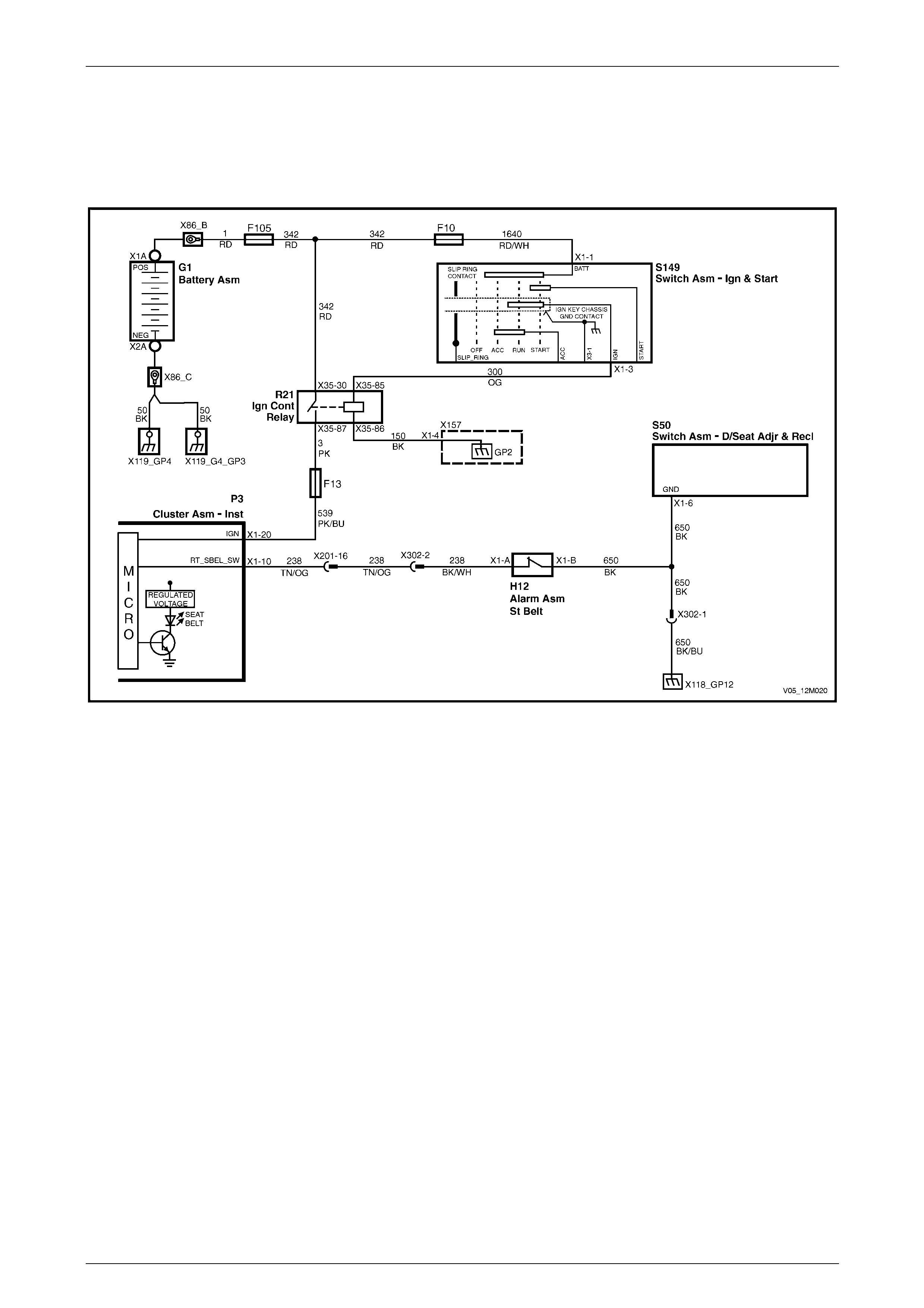
Occupant Protection System Page 12M–133
Page 12M–133
2.15 Seatbelt Buckle Switch
Wiring Diagrams, Except Coupe
Four-way Seat
Figure 12M – 27
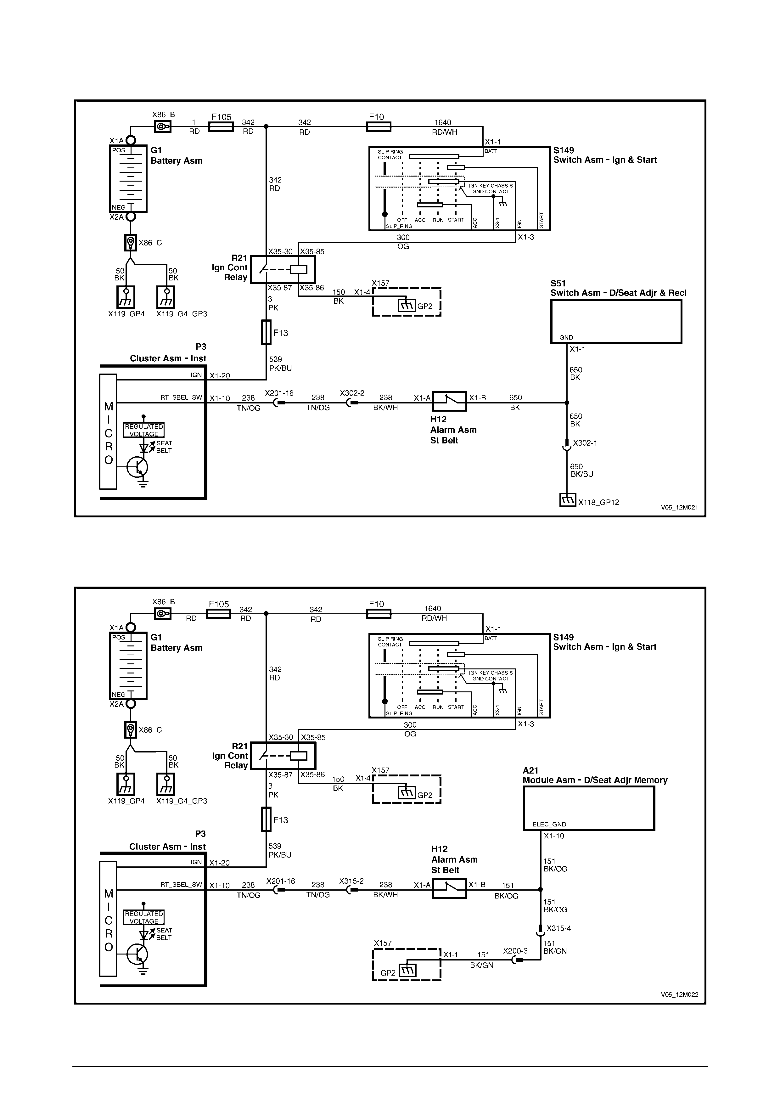
Occupant Protection System Page 12M–134
Page 12M–134
Eight-way Seat – Non-memory
Figure 12M – 28
Eight-way Seat – Memory
Figure 12M – 29
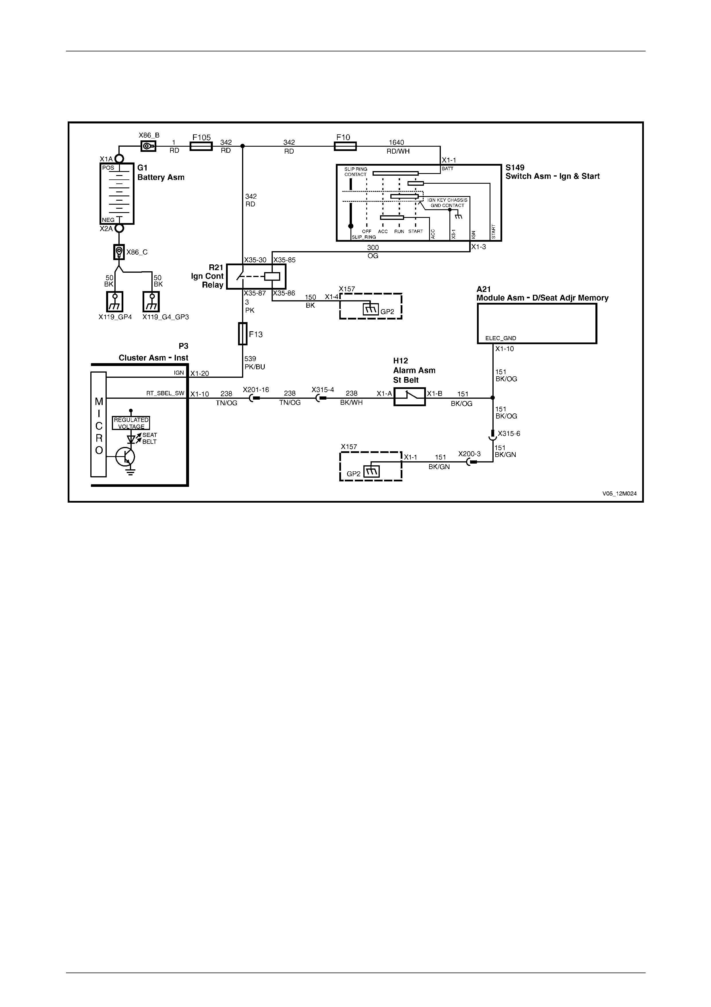
Occupant Protection System Page 12M–135
Page 12M–135
Wiring Diagrams, Coupe
Eight-way Seat – Memory
Figure 12M – 30
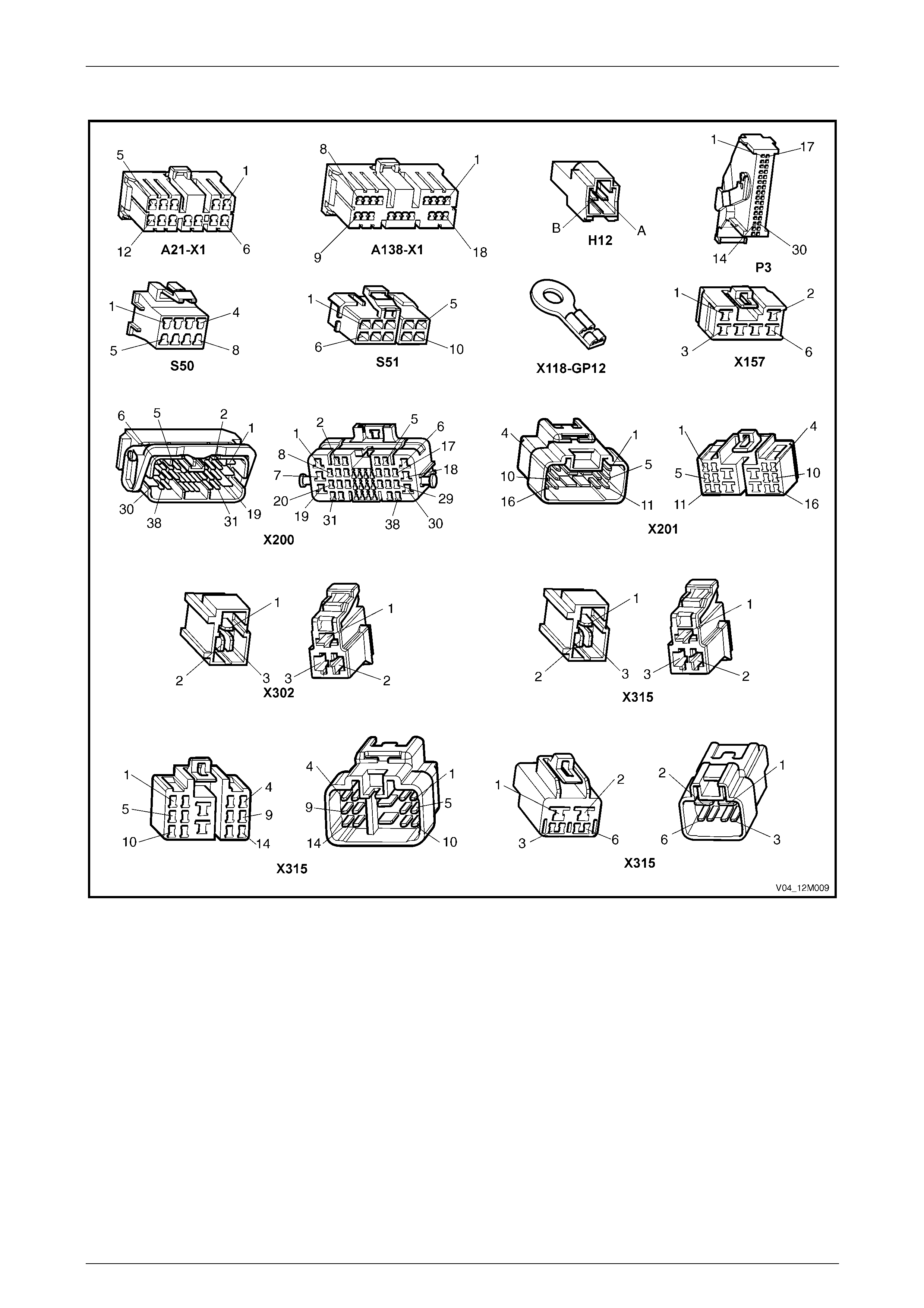
Occupant Protection System Page 12M–136
Page 12M–136
Connector Chart
Figure 12M – 31

Occupant Protection System Page 12M–137
Page 12M–137
Circuit Description
The purpose of the driver's seatbelt buckle warning indicato r switch, H12, is to activate a seatbelt warning indicator
located in the instrument cluster assembly. The in dicator illuminates when the ignition is turned to the ON position and
the seatbelt is disengaged from the buckle.
When the seatbelt is buckled, the warning indicator switch is in an open cir c uit condition and when unbuckled the switch
is in a closed circuit condition.
Tech 2 can be used to check the driver's seatbelt buckle warning indicator switch operation. Tech 2 will only display
Buckled or Un-buckled.
The seatbelt warning indicato r will illuminate for four seconds when the igni tion switch is turned to the ON position,
irrespective of the status of the driver's seatbelt buckle warning indicator switch.
Test Description
The following numbers refer to the step numbers in the diagnostic table:
1 Checks if the seatbelt indicator illuminates when the ignition is turned on. This can indicate either a faulty
instrument cluster assembly or a faulty power circuit.
2 Checks if there is an intermittent fault in the circuit.
3 Checks if there is a faulty power circuit.
4 Checks the operation of the driver's seatbelt buckle warning indicator switch.
5 Checks continuity of circuit 650 (for all non-memory seats).
6 Checks continuity of circuit 151 (only for eight-way memory seats).
7 Checks continuity of circuit 238.
8 Checks the operation of the driver's seatbelt buckle warning indicator switch.
9 Checks for short circuit to ground in circuit 238.
Diagnostic Table Notes
1 For all wiring harness fault diagnosis, refer to Section 12P Wiring Diagrams .
2 For wiring harness repairs, refer to Section 12P Wiring Diagrams.
3 Refer to Section 12O Fuses, Relays and Wiring Harnesses for harness routeing.
4 If at any time the fault is deemed to be intermittent, refer to Section 12P Wiring Diagra m s.
5 For information on using and connecting Tech 2 to the vehicle, refer to Section 0C Tech 2.

Occupant Protection System Page 12M–138
Page 12M–138
Diagnostic Table
Step Action Yes No
1 1 Connect Tech 2 to the DLC (refer to Note 5).
2 On Tech 2 select:
Body / Instruments / Data Display / Instruments / Drivers
Seatbelt.
3 Unbuckle the driver's seatbelt.
4 Turn the ignition on with the engine off.
Does the seatbelt warning indicator illuminate, and does Tech 2
display Un-buckled? Go to Step 2 Go to Step 3
2 1 Turn the ignition switch off.
2 Buckle the driver's seatbelt.
3 Turn the ignition on with the engine off.
Does the seatbelt warning indicator e xtinguish after four seconds and
does Tech 2 display Buckled?
Operation appears
to be normal. Check
for an intermittent
fault (refer to Note
4) Go to Step 8
3 Check the following warning indicators illuminate when the ignition is
switched on with the engine off:
• ABS
• Brake
• SRS
• Generator
Do the above warning indic ators illuminate when the ignition switch is
turned on with the engine off? Go to Step 4 Refer to Section
12C Instruments
4 1 Turn the ignition off and disconnect con nector H12.
2 Using a multimeter set to measure resistance, probe across the
driver's seatbelt buckle warning indicator switch terminals at
connector H12 (refer to Note 1).
3 The multimeter should indicate continuity when the seatbelt is
unbuckled and no continuity (open circuit) when the seatbelt is
buckled.
Does the multimeter indicate as specified?
Go to Step 5 for all
non-memory seats
Go to Step 6 for all
eight-way memory
seats
Replace the driver's
seatbelt buckle and
pretensioner
assembly, refer to
3.5 Seatbelt Buckle
and Pretensioner
Assembly
5 Using a multimeter set to measure resistance, probe between
connector H12 – X1 pin B and a known ground (refer to Note 1).
Does the multimeter indicate continuity? Go to Step 7
Repair or replace
circuit 650 (refer to
Note 2)
6 Using a multimeter set to measure resistance, probe between
connector H12 – X1 pin B and a known ground (refer to Note 1).
Does the multimeter indicate continuity? Go to step 7
Repair or replace
circuit 151 (refer to
Note 2)
7 1 Disconnect connector P3 – X1.
2 Using a multimeter set to measure resistance, probe between
connectors H12 – X1 pin A and P3 – X1 pin 10 (refer to Note 1).
Does the multimeter indicate contin uity?
Replace the
instrument cluster
assembly, refer to
Section 12C
Instruments
Repair or replace
circuit 238 (refer to
Note 2)
8 1 Turn the ignition switch off and disconnect connector H12.
2 Turn the ignition on with the engine off.
Does the seatbelt warning indicator e xtinguish after four seconds and
does Tech 2 display Buckled? Go to Step 4 Go to Step 9
9 1 Disconnect connector P3 – X1.
2 Using a multimeter set to measure resistance, probe between
connector H12 – X1 pin A and a known ground (refer to Note 1).
Does the multimeter indicate contin uity?
Repair or replace
circuit 238 (refer to
Note 4)
Replace the
instrument cluster
assembly, refer to
Section 12C
Instruments
When all diagno sis an d repairs are completed, clear all DTCs and check the system for correct operation.

Occupant Protection System Page 12M–139
Page 12M–139
3 Service Operations – Inflatable
Restraint and Pretensioner
Assemblies
3.1 Safety Precautions
When performing service on or around
restraint devices or wiring, follow the
procedures listed in this Section to
temporarily disable the SDM. Failure to follow
these procedures could result in possible
restraint device deployment, personal injury
or otherwise unnecessary repairs.
1 Do not use an external battery charger for starting the vehicle.
2 Do not disconnect the battery from the vehicle's electrical s ystem while the eng ine is running.
3 Disconnect the battery from the vehicle's elec trical s ystem before any external battery charging.
4 Do not disconnect or connect the SDM connector with the ignition turned on.
5 Disconnecting the battery will not immed iately deactivate the SDM. A residual energy reserve in the SDM is
incorporated to enable the pr etensioners and inflatable restraint/s to deploy in the event of a battery failure. The
SDM has sufficient power to deploy the pretensioners and inflatabl e restraint/s for up to 10 seconds after the
battery has been disconnected or the ignition turned off. Many of the service operations require disconnection of
the battery to avoid an accidental de ployment of the pretensioners or inflatable restraint/s.
After a Collision
After a collision, OPS components need to be checked for service ability, refer to
1.4 Repairs and Inspections Require d After a Coll ision.
Fasteners
1 When fasteners are removed, always reinstall them in the same location from which they were removed.
2 If a fastener requires replacement, use a fastener with the correct part number for that application. If a fastener with
the correct part number is not available, a fastener of equal size an d strength (or stronger) may be used. The
correct torque value must be used when inst alling fasteners. If these conditions are not adhered to, parts or system
damage could result.
Windshield
The windshield plays an activ e part duri ng the deployment of the instrument panel inflata ble restraint assembly. The
strength of the windshield and its urethane adhesive is critical to ensure the front seat passenger is correctly protected
during deployment, and must be replaced using the correct repair methods and parts. For further information, refer to
Section 1A6 Stationary Windows.
SDM
Take care when handling the SDM. Do not strike or jar the module or body structure adjacent to the module in a manner
which could cause depl oyment of the pretensioner or inflatable restraints. If an SDM is dropp ed from a height greater
than one metre, it must be replaced.

Occupant Protection System Page 12M–140
Page 12M–140
Side-impact Sensor
Take care when handling a side-imp act sensor. Never strike or jar the sensor or body structure adjacent to the sensor i n
a manner which could cause deployment of a side-impact inflatab le restraint. Never carry a side-impact sensor by the
wiring harness leads. If a side-impact sensor is dropped from a height greater than one metre, it must be replaced.
Inflatable Restraint and Pretensioner Assemblies
Refer to Figure 12M – 32 for the following:
1 When carrying a live (undeployed) inflatable restraint assembly, ensure it is pointed away from you. In case of an
accidental deplo yment, the infl atable restraint assembly will then deploy with minimal chance of injury.
2 When placing a live inflatable restraint assembly on a bench or other surface, always face the assembly up, away
from the surface. This is necessary in order to provide free space for the inflatable restraint assembly to expand, in
case of accidental deployment. Also, do not place anything on top of the inflatable restraint assembly.
3 Do not carry a seatbelt pretension er by it's wiring harness lead.
4 Do not apply po wer to an inflatable restraint except as specified in this Sect ion.
5 Do not attempt to make any repairs to the inflatable restraint assembl ies, pretensioners, SDM, or side-impact
sensors. A damaged or defective component must be replaced.
6 Do not weld, solder, braze, hammer, machine, drill, or other wise heat any OPS component.
7 When handling a deployed inflatable restraint assembl y or pr etensioner:
a Always wear gloves and safet y glasses.
b Wash hands with mild soap and water afterwards. The surface of these components may contain chemicals
as a result of the gas generated during combustion which can irritate your skin.
8 When handling a steering co lumn:
a During any service op eration that requires removal and reinstallati on of a steering column fitted with an
inflatable restraint assembly, always carry the steering column with two hands and with the steering wheel
away from your body.
b Do not set a steering column on the floor with the steering wheel facing toward the floor.
During any service operation that requires
removal of a steering column, ensure the
steering shaft is locked to the column to
prevent any possibility of allowing the
steering shaft to rotate and possibly
damaging the clock spring coil ribbon wire.
9 When carrying out steering gear removal and installation procedures, remove the ignition key from the ignition lock
and ensure the steering column is locked. If this operation is not carried out and the steer ing wheel is spun while
the steering gear is removed, the clock spring coil will be destroyed. This will result in the SDM setting a DTC, and
non-deployment of the steering wheel inflatable restraint assembly.
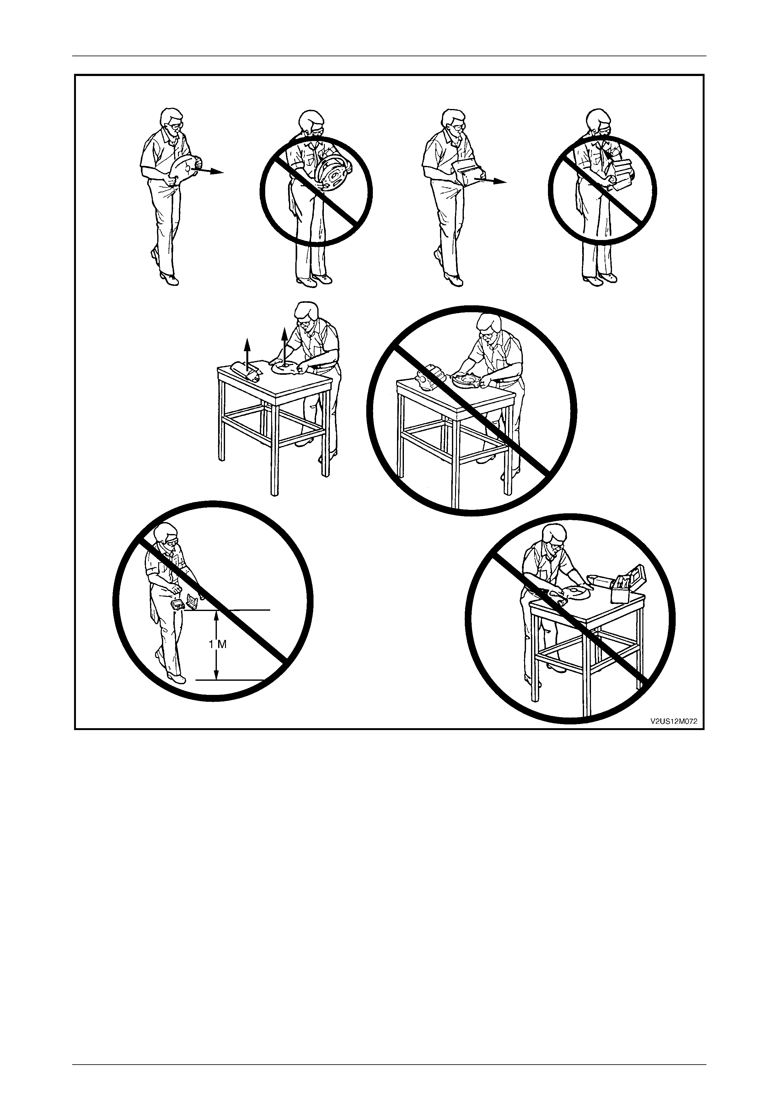
Occupant Protection System Page 12M–141
Page 12M–141
Figure 12M – 32
OPS Wiring Repairs
Special wiring harness repair procedures have been developed for use on the OPS due to the sensitive nature of the
circuitry. For further information, refer to Section 12P Wiring Diagrams.
NOTE
• The pigtail wiring harness that connects the
side-impact inflatable restraint assembly to
the body harness is part of the assembly and
is not serviced separately, due to the design
of the anti-back-out connector on the
inflatable restraint assembly.
• If this pigtail wiring harness becomes
damaged, no wire, connector or terminal
repairs are to be attempted. The side-impact
inflatable restraint assembly and pigtail wiring
harness assembly must be replaced.
Occupant Protection System Page 12M–142
Page 12M–142
3.2 SDM Disabling and Enabling Procedure
Disabling
The SDM can maintain sufficient voltage to
cause inflatable restraint assembly and/or
pretensioner deployment for up to 10 seconds
after the ignition switch is turned to the OFF
position or the battery is disconnected.
Disconnection of the battery affects vehicle
electronic systems, refer to
Section 00 Warnings, Cautions and Notes
before disconnecting the battery.
Disconnect both the battery positive and negative leads and wait at least 10 seconds before performing an y work on the
vehicle.
Enabling
Ensure all wiring harness connectors are
connected before reconnecting the battery
leads.
1 Reconnect both the battery positive and negative le ads.
2 Switch the ignition on, and ob s erve the airbag warning indicator in the instrument cluster. The warning indicator
should be illuminated for approximately 5 seconds. During this per iod the SDM performs a wiring and self-check.
3 If no system faults are detected, the airbag warning indicator will be s witched off. If the warning indicator remains
illuminated and an audible alarm chimes, or the airbag warning indicator illuminates 2 seconds after it was originally
switched off, an OPS fault is present. Refer to 2 Diagnostics to rectify the fault.
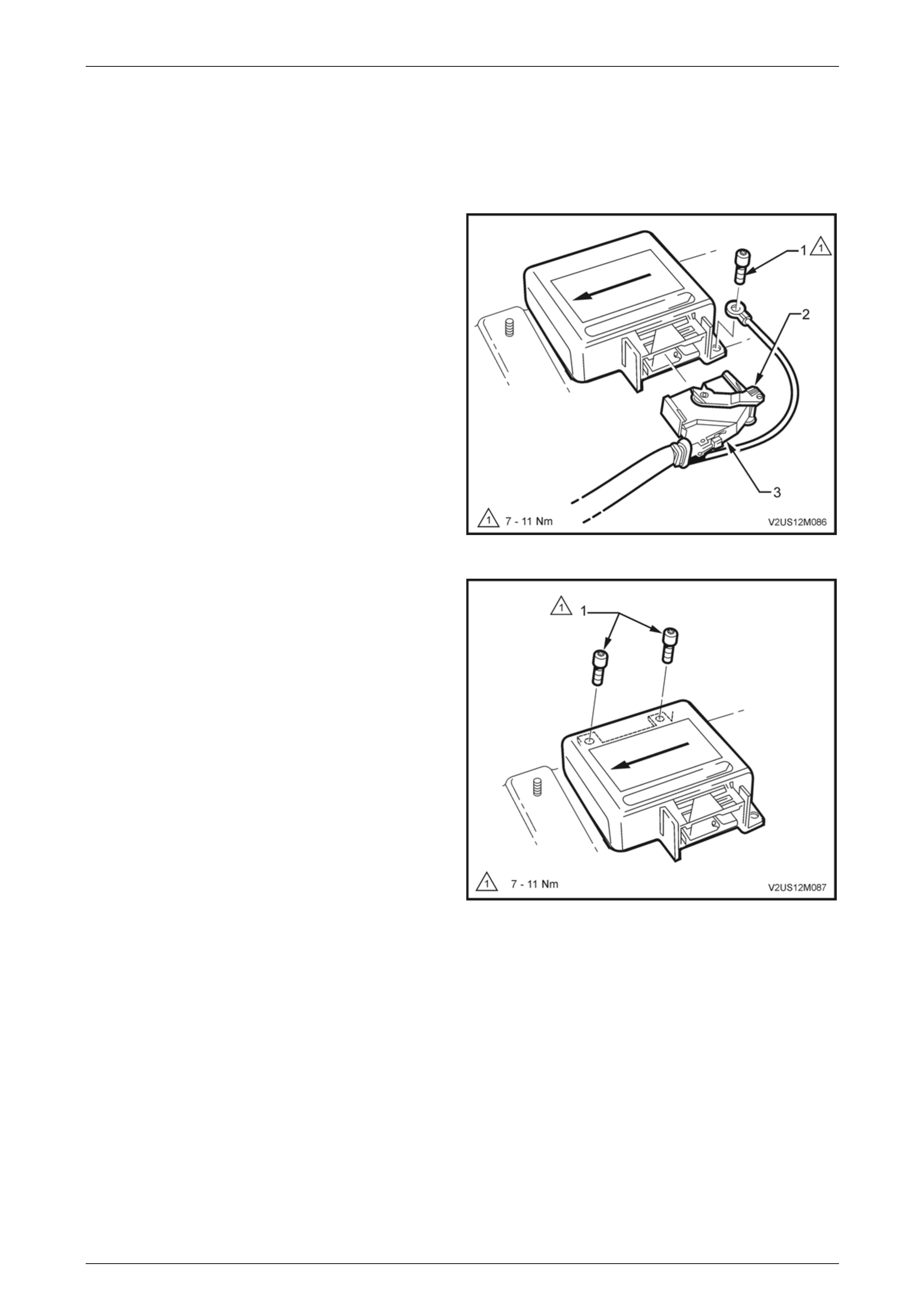
Occupant Protection System Page 12M–143
Page 12M–143
3.3 Sensing and Diagnostic Module (SDM)
LT Section No. — 06–225
Remove
1 Disable the Sensing an d Diagnostic Module (SDM),
refer to 3.2 SDM Disabling and Enablin g Procedure.
2 Remove the floor console assembly, refer to
Section 1A3 Instrument Panel and Co nsole.
3 Using a number T30H Torx bit, Tool No. ETX30H and
suitable holder such as Tool No. J2535 9-8, loosen and
remove the SDM to floor attaching screw (1) with the
ground lead attached to it.
4 Press the locking tab (3) and move the locking lever
(2) rearward while removing the connector from the
SDM.
Figure 12M – 33
5 Using the number T30H Torx bit, Tool No. ETX30H
and suitable holder such as Tool No. J25359-8, loosen
and remove the remaining two SDM to floor attaching
screws (1).
6 Remove the SDM.
Figure 12M – 34

Occupant Protection System Page 12M–144
Page 12M–144
Reinstall
Reinstallation of the SDM is the revers e of the removal procedure, noting the following:
1 Ensure the directional arro w on the SDM identification label is pointing towards the front of the vehicle.
2 Install the wiring harness ground lead to the left-hand rear SDM retaining screw.
3 Using a number T30H Torx bit, Tool No. ETX30H and suitable holder suc h as Tool No. J25359-8, tighten the SDM
to floor attaching screws to the correct torque specification.
It is very important that the SDM is mounted
securely to the floor. The screws must be
tightened to the correct torque specification
and not exceeded.
SDM retaining screw
torque specification...................................7.0 – 11.0 Nm
4 Connect the wiring harness connector, ensuring the connector is fully seat ed into SDM and the locking lever is
locked in place.
5 Enable the SDM, refer to 3.2 SDM Disabling and Enabling Procedure.
6 Switch the ignition on, and ob s erve the airbag warning indicator in the instrument cluster. The warning indicator
should be illuminated for approximately five seconds. During this period the SDM performs a wiring and self-check.
If no system faults are detected, the airbag warning indicator will be switched off.
If the warning indicator remains illuminated, a warning is shown in the instrument cluster multi-function display and
an audible alarm chimes, or the warning indicator illuminates t wo seconds after it was originally switched off, an
OPS fault is present. Refer to Section 2 Diagnostics to rectify any fault.
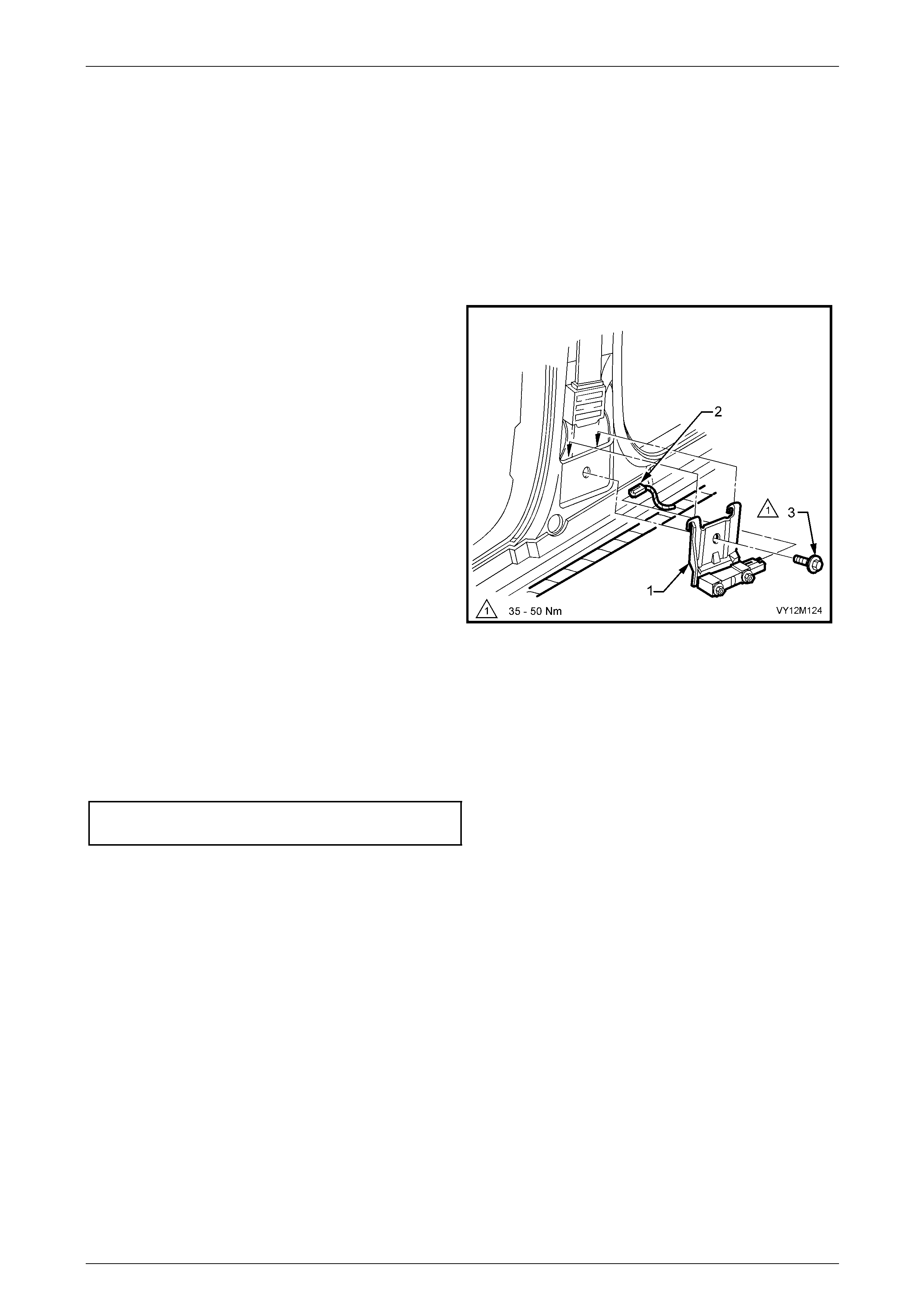
Occupant Protection System Page 12M–145
Page 12M–145
3.4 Side-impact Sensor
LT Section No. — 06–225
Remove
1 Disable the SDM, refer to 3.2 SDM Disabling and Enabling Procedure.
2 Remove the centre pillar lower trim, and the side sill trim and plate, refer to
Section 1A8 Headlining and Interior Trim .
3 Disconnect the side-impact sensor wiring harness
connector (2) from the side-impact sensor and bracket
assembly (1).
4 Remove the bolt (3) retaining the side-impact sensor
and bracket assembly (together with seat bel t retractor
assembly) to the centre pillar.
NOTE
Do not loosen or unscrew the two nuts retaining
the side-impact sensor to the mounting bracket.
The side-impact sensor is only serviced with the
mounting bracket as an assembly.
5 Remove the side-impact sensor and bracket assembly
from the centre pillar.
Figure 12M – 35
Reinstall
Reinstallation of the side-im pact sensor and bracket assembly is the reverse of the removal procedur e, noting the
following:
1 Tighten side-impact sensor and mo unting bracket assembly retaining bolt (front seat belt retractor retai nin g bolt) to
the correct torque specification.
Side-impact sensor retaining
bolt torque specification..........................35.0 – 50.0 Nm
2 Enable the SDM, refer to 3.2 SDM Disabling and Enabling Procedure.
3 Switch the ignition on, and ob s erve the airbag warning indicator in the instrument cluster. The warning indicator
should be illuminated for approximately five seconds. During this period the SDM performs a wiring and self-check.
If no system faults are detected, the airbag warning indicator will be switched off.
If the warning indicator remains illuminated, a warning is shown in the instrument cluster multi-function display and
an audible alarm chimes, or the warning indicator illuminates t wo seconds after it was originally switched off, an
OPS fault is present. Refer to 2 Diagnostics in this Section to rectify any fault.
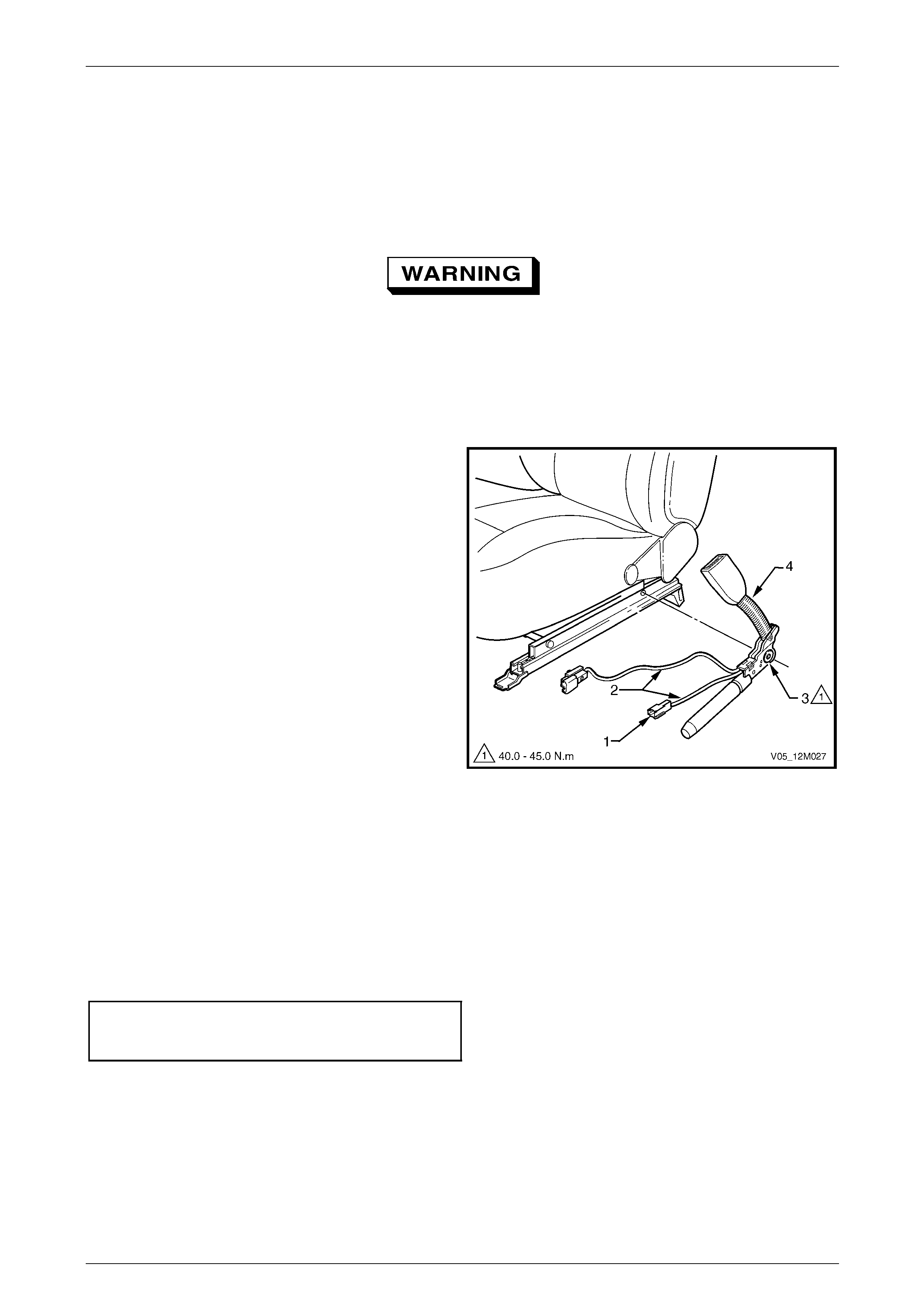
Occupant Protection System Page 12M–146
Page 12M–146
3.5 Seatbelt Buckle and Pretensioner
Assembly
LT Section No. — 14–400
Remove
If a seatbelt buckle and pretensioner
assembly is deployed, the assembly together
with the track and height adjuster assembly
must be replaced.
1 Disable the SDM, refer to Section 3.2 SDM Disabling and Enabling Procedure.
2 Remove the front seat from the vehicle, refer to Section 1A7 Seat Assemblies.
3 For the driver’s seatbelt buckle and pr etensioner
assembly, disconnect the seatbelt buckl e switch
connector (1) from the seat assembly.
4 Unclip the seatbelt buckle and pretensioner assembly
wiring harness (2) from the underside of the seat
assembly.
5 Unscrew the Torx-head screw (3) attaching the
seatbelt buckle and pretensio ner assembly (4) to the
seat.
NOTE
The screw is captive to the assembly.
6 Remove the seatbelt buckle and prete nsi oner
assembly and withdraw the wiring harness from the
seat.
NOTE
Store the seatbelt buckle and pretensioner
assembly in a safe place. Figure 12M – 36
Reinstall
Reinstallation of the seatbelt buckle and pretensioner assembly is the reverse of the removal procedure, noting the
following:
1 When installing the seatbelt buckle and pretensioner asse mbly, ensure the front locating pin is aligned with the seat
frame.
2 Install the seatbelt buckle and pretension er a ssembly attaching bolt and tighten to the correct torque specification.
Seatbelt buckle and pretens ioner
assembly attaching bolt torque
specification............................................40.0 – 45.0 Nm
3 Enable the SDM, refer to 3.2 SDM Disabling and Enabling Procedure.
4 Switch the ignition on, and ob s erve the airbag warning indicator in the instrument cluster. The warning indicator
should be illuminated for approximately five seconds. During this period the SDM performs a wiring and self-check.
If no system faults are detected, the airbag warning indicator will be switched off.
If the warning indicator remains illuminated, a warning is shown in the instrument cluster multi-function display and
an audible alarm chimes, or the warning indicator illuminates 2 seconds after it was originally switched off, an OPS
fault is present. Refer to 2 Diagnostics to rectify any fault.

Occupant Protection System Page 12M–147
Page 12M–147
Disposal Procedure
During the course of a vehicle's useful life, certain situations may arise which will necess itate the disposal of a live
(undeployed) seatbelt buckle and pretensioner assembly. These situations may include damage to the seatbelt buckle
and pretensioner assembly or the assembly being diagnosed as faulty. The following information covers proper
procedures for deployi ng a live assembly.
• Failure to follow proper seatbelt buckle
and pretensioner assembly disposal
procedures can result in pretensioner
deployment, which may cause personal
injury.
• The seatbelt buckle and pretensioner
assembly must never be deployed inside
the vehicle.
• Failure to follow the procedures in the
order listed may result in personal injury.
Read the procedure fully before attempting
to dispose of the seatbelt buckle and
pretensioner assembly. Do not connect
the deployment harness to any power
source before connecting the deployment
harness to the seatbelt buckle and
pretensioner assembly. The deployment
harness must remain shorted and not be
connected to a power source until the
seatbelt buckle and pretensioner assemb ly
is ready to be deployed. The seatbelt
buckle and pretensioner assembly will
immediately deploy when a power source
is connected to it. Wear s afety gl asses an d
gloves throughout this entire deployment
and disposal procedure and follow proper
handling procedures or injury may occur.
• The following procedure requires use of
Tool No. J213526-1 deployment harness
with adaptor Tool No. E1992. Do not
attempt this procedure without Tool No.
J213526-1 and T ool No. AU596 as this may
cause the inflatable restraint assembly to
deploy prematurely.
1 Disable the SDM, refer to 3.2 SDM Disabling and Enabling Procedure.
2 Inspect Tool No. J213526-1 d eployment harness and adaptor Tool No. AU596 for damage. If harness or adaptor is
damaged, discard and obtain a replacement.
The deployment h arness must remain sh orted
and not connected to a power source until the
inflatable restraint assembly is to be
deployed. The seatbelt buckle and
pretensioner assembly will immediately
deploy when a power source is connected to
it, refer to Figure 12M – 39.
3 Short the two deployment harness leads together by fully seatin g one banana plug into the other. The deployment
harness must remain shorted and not connected to a power source until the inflatable restraint assembly is to be
deployed, refer to F igure 12M – 37.
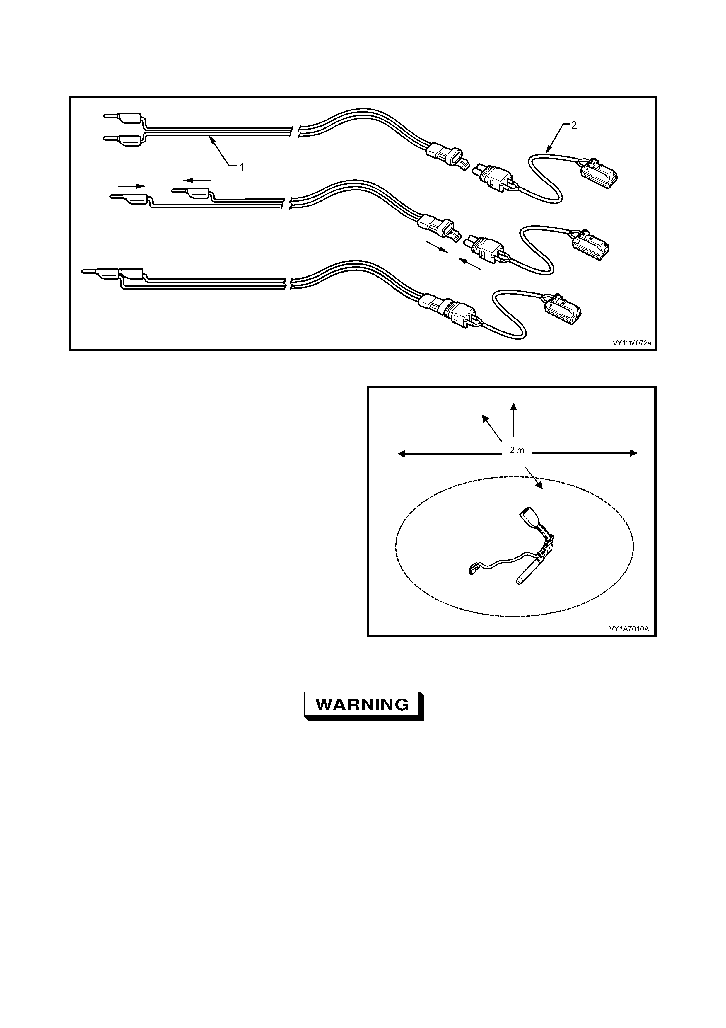
Occupant Protection System Page 12M–148
Page 12M–148
4 Connect the deployment harness Tool No. J213526–1 (1) to the adaptor Tool No. AU59 6 (2).
Figure 12M – 37
5 Remove the appropriate pretensioner assembly from
the vehicle, refer to Remove in this Section.
NOTE
Leave pretensioner to seat assembly retaining
bolt installed in the pretensioner once removed
from the seat assembly.
6 Clear a space on the ground of at least 2 metres in
diameter where the assembly is to deploy. A paved,
outdoor location where there is no activity is preferred.
If an outdoor location is not availa ble, a space on the
workshop floor where there is no activity and sufficient
ventilation is recommended. Ensure no lo ose or
flammable objects are within the deployment area.
Figure 12M – 38
The deployment harness (1) must be laid out
to its full length (A) to allow the technician
maximum distance from the seatbelt buckle
and pretensioner assembly to be deployed,
refer to Figure 12M – 39. This minimises any
chance of injury to the technician.
7 Stretch the deployment harness and adaptor from the pretensioner assembly to its full length.
8 Place a power source near the shorted end of the deployment harness. The recomm ended application is 12-14 V,
with a minimum of 2 A (a vehicle battery is suggested).
9 Connect the adaptor Tool No. AU596 and deployment harness lead T ool No. J213526-1 to the seatbelt buckle and
pretensioner assembly.
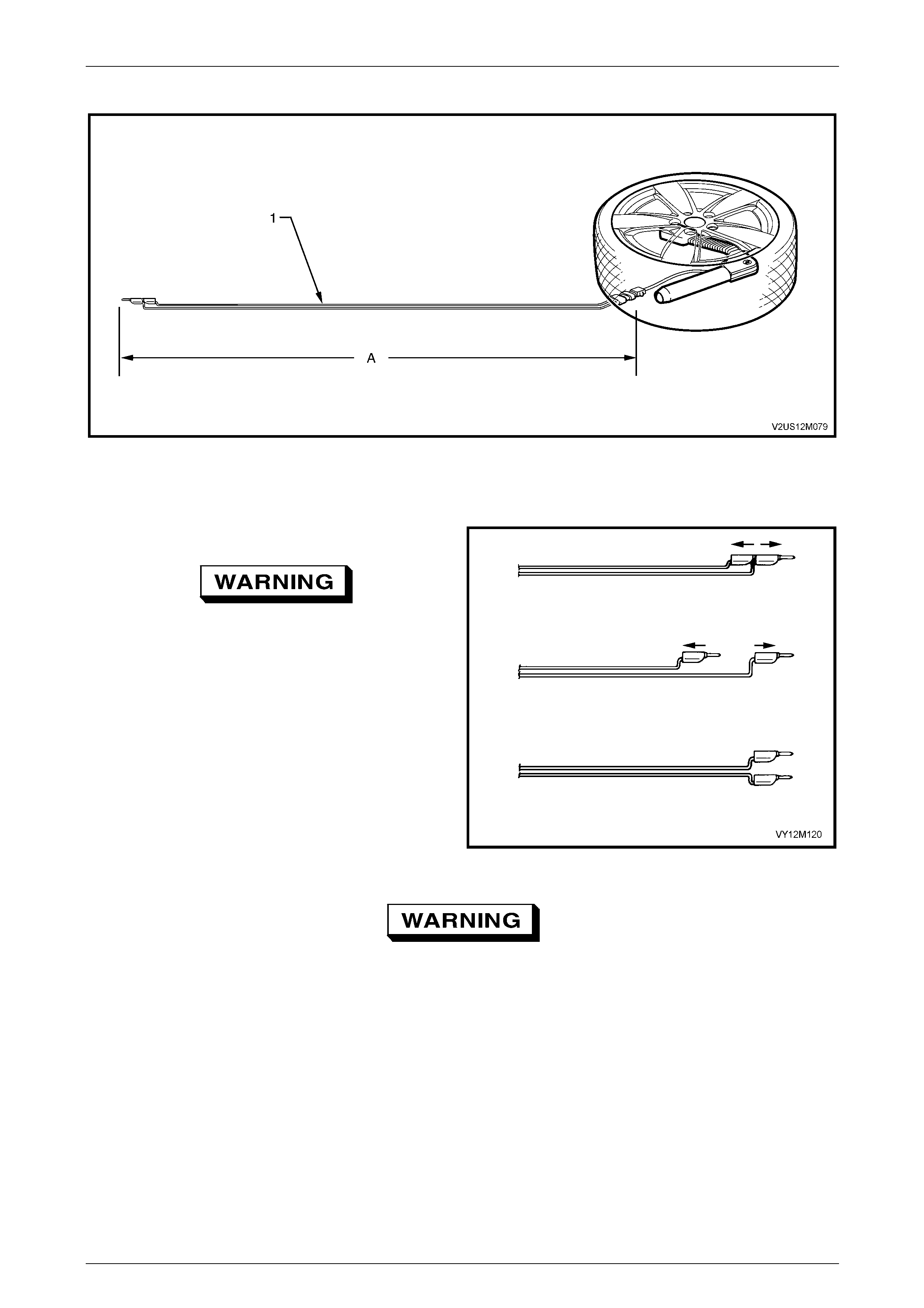
Occupant Protection System Page 12M–149
Page 12M–149
10 Position a wheel and tyre assembly over the pretensioner assembly, refer to Figure 12M – 39.
Figure 12M – 39
11 Verify the area around the pretensioner assembly is clear of all people and loose or flamm able objects.
12 Notify all people in the immediate area that you inte nd to deploy the seatbelt buckle and pretension er assembly.
The deployment will be accompan ied by an explosion, which may startle others.
13 Separate the two banana plugs on the deplo yment
harness.
When the seatbelt buckle and pretensioner
assembly deploys, the rapid gas expansion
will create an explosion. Notify all people in
the immediate area that you intend to deploy
the pretensioner assemb ly.
14 Connect deployment harn ess leads to the power
source to immediately deploy the pretensioner
assembly.
15 Disconnect the deployment harness from the power
source.
16 Short the two deployment harness le ads together by
fully seating one banana plug into the other.
17 Ensure you are wearing gloves to protect your hands
from heat when handling the deployed seatbelt buckle
and pretensioner assembly.
Figure 12M – 40
Safety precautions must be observed when
handling a deployed seatbelt buckle and
pretensioner assembly. After deployment, the
metal surfaces of the assembly will be very
hot. Do not touch these metal areas of the
module for approximately 10 minutes after
deployment. Do not place the deployed
seatbelt buckle and pretensioner assembly
near any flammable objects. If the deployed
seatbelt buckle and pretensioner assembly
must be moved before it has cooled, wear
gloves and handle by the inflatable restraint
assembly plastic components.
18 To prevent damage to the a daptor or deployment harness, disconnect the adaptor Tool No. AU596 from the
pretensioner as soon as poss ible after deployment. The adaptor an d deployment harness are designed to be
reused. They should, however, be inspected for damage after each deplo yment and replaced if necessary.
19 Dispose of the deployed pretensioner assembl y throu gh normal refuse channels.
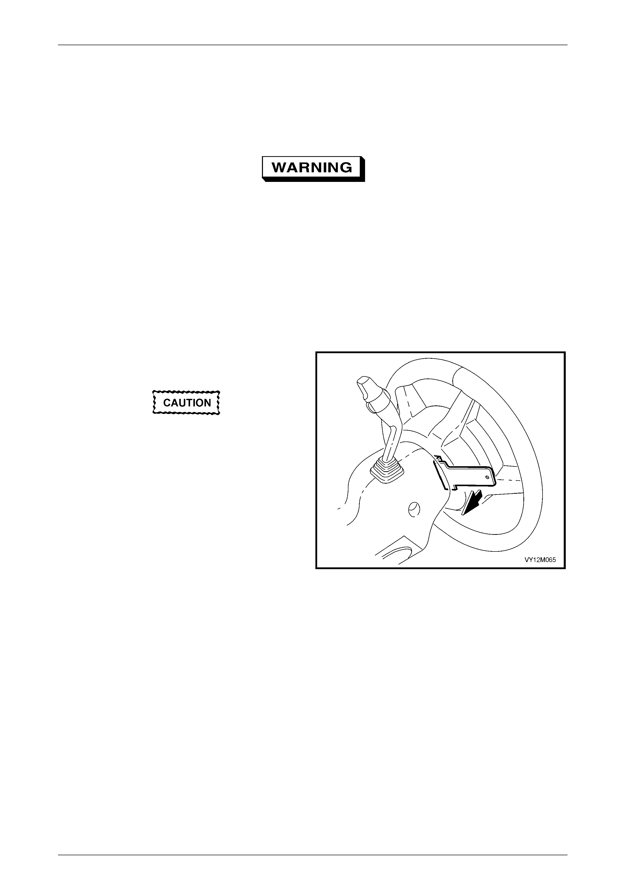
Occupant Protection System Page 12M–150
Page 12M–150
3.6 Steering Wheel Inflatable Restraint
Assembly
LT Section No. — 06–225
If conducting the following operation on an
inflatable restraint assembly that has
deployed, wear safety glasses and gloves to
protect your eyes and hands from possible
irritation when handling the deployed
inflatable restraint assembly.
After deployment, the surface of the cushion may contain a powdery residue. This powder consists primarily of
cornstarch (used to lubricate the cushi on) and by-products of the chemical reaction. The by-products of inflatable
restraint assembly module deployment are carbo n monoxide (CO), nitrog en (N), carbon dioxide (CO2), water (H2O) with
trace amounts of oxides of nitrogen (NOΧ) and ammonia (NH 3).
Remove
1 Disable the SDM, refer to 3.2 SDM Disabling and
Enabling Procedure.
If the steering wheel inflatable restraint
module is to be removed without removing
the steering column covers, then wrap Tool
No. AU595 with a rag or tape to ensure the
steering column covers do not get scratched.
2 Rotate the steering wheel 90 degrees from the
straight-ahead position to expose two of the four
access aperture holes in the rear of the steering wheel
hub.
3 Fit Tool No. AU595 into the apertures and pivot the
tool toward the instrument panel to move the tangs of
the tool in an outward direction. This will relieve the
tension on the spring-loaded retaining clips. The
inflatable restraint assembly will move slig htly away
from the steering wheel.
Figure 12M – 41
4 Rotate the steering wheel 180 degrees to expose the remaining t wo access aperture holes. Repeat Step 3.
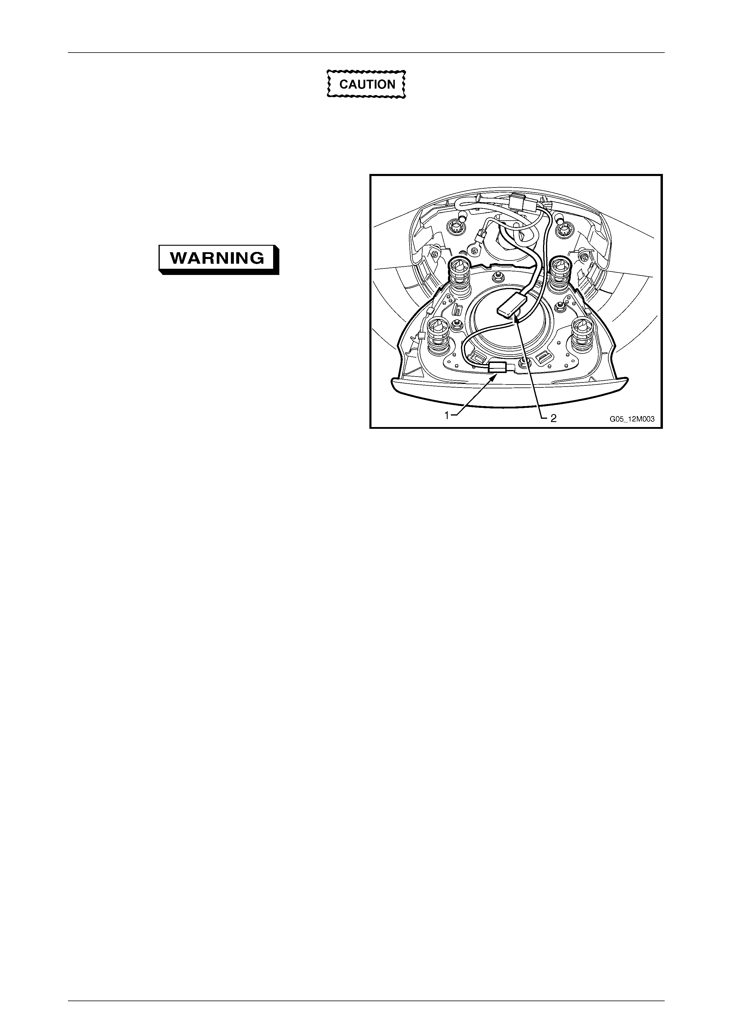
Occupant Protection System Page 12M–151
Page 12M–151
When removing a steering wheel inflatable
restraint assembly from the steering wheel,
take extreme care when disconnecting the
wiring connectors as damage could result.
5 Carefully lift the steering wheel inflatable restraint
assembly from the steering wheel and discon nect the
wiring harness connector (1) a nd yellow inflator
assembly connector (2) from the rear of assembly.
• When carrying a live (undeployed)
steering wheel inflatable restraint
assembly, make sure the trim cover is
pointed away from you. In case of an
accidental deployment, the inflatable
restraint cushion will then deploy with
minimal chance of inju ry.
• When placing a live steering wheel
inflatable restraint assembly on a bench
or other surface, always face the trim
cover up, away from the surface. This is
necessary so that a free space is provided
to allow the inflatable restraint assembly
cushion to expan d in the unlikely event of
accidental deployment. Otherwise,
personal injury may result.
Figure 12M – 42
6 Remove the steering wheel inflatable restraint assembly and place in a saf e location.
Reinstall
1 Offer the steering wheel inflatable restraint assembly up to steering wheel hub and reconnect all wiring harness
connectors to the rear of the assembly.
2 Locate the steering wheel inflatable restraint assembly to the four spring loaded retainin g clip mounting points
located in the base of the steering wheel hub.
3 Ensure all wiring harness connectors and wiring is not exposed or trapped between the inflatable restraint
assembly and the steering wheel hub.
4 Pressing firmly on the steering wheel inflatable restraint assembly, push the module toward the steering wheel hub
until the spring-loaded retaining clips lock and retai n the inflatable restraint assembly in place.
5 Enable the SDM, refer to 3.2 SDM Disabling and Enabl ing Procedure.
6 Switch the ignition on, and ob s erve the airbag warning indicator in the instrument cluster. The warning indicator
should be illuminated for approximately 5 seconds. During t his period of time the SDM performs a wiring and self-
check. If no system faults are detected, the airbag warning indicator will be switched off.
If the warning indicator remains illuminated, a warning is shown in the instrument cluster multi-function display and
an audible alarm chimes, or the warning indicator illuminates 2 seconds after it was originally switched off, an OPS
fault is present. Refer to 2 Diagnostics to rectify any fault.

Occupant Protection System Page 12M–152
Page 12M–152
Disposal Procedure
During the course of a vehicle's useful life, certain situations may arise which will necess itate the disposal of a live
(undeployed) steering wheel inflatable restraint assembly. These situations may include damage to the i nflatab le restraint
assembly or the assembly being diag nosed as faulty. The following information covers proper pr ocedures for deploying a
live assembly.
• Failure to follow proper steering wheel
inflatable restraint assembly disposal
procedures can result in inflatable
restraint assembly deployment, which may
cause personal injury. The undeployed
inflatable restraint assembly contains
substances that can cause severe illness
or personal injury if the sealed container is
damaged during disposal.
• The inflatable restraint assembly must
never be deployed inside the vehicle.
• Failure to follow the procedures in the
order listed may result in personal injury.
Read the procedure fully before attempting
to dispose of the inflatable restraint
assembly. Do not connect the deployment
harness to any power source before
connecting the deployment harness to the
steering wheel inflatable restraint
assembly. The deployment harness must
remain shorted and not be connected to a
power source until the steering wheel
inflatable restraint assembly is ready to be
deployed. The inflatable restraint
assembly will immediately deploy when a
power source is connected to it. Wear
safety glasses and gloves throughout this
entire deployment and disposal procedure
and follow proper handling procedures or
injury may occur.
• The following procedure requires use of
Tool No. J213526-1 deployment harness
with adaptor Tool No. E1992. Do not
attempt this procedure without Tool No.
J213526-1 and Tool No. E1992 as this may
cause the inflatable restraint assembly to
deploy prematurely.
1 Disable the SDM, refer to 3.2 SDM Disabling and Enabling Procedure.
2 Inspect Tool No. J213526-1 d eployment harness and adaptor, Tool No. E1992 for dama ge. If harness or adaptor is
damaged, discard and obtain a replacement.
The deployment h arness must remain sh orted
and not connected to a power source until the
inflatable restraint assembly is to be
deployed, refer to Figure 12M – 43. The
inflatable restraint assembly will immediately
deploy when a power source is connected to
it.
3 Short the two deployment harness leads together by fully seatin g one banana plug into the other. The deployment
harness must remain shorted and not connected to a power source until the inflatable restraint assembly is to be
deployed, refer to F igure 12M – 43.
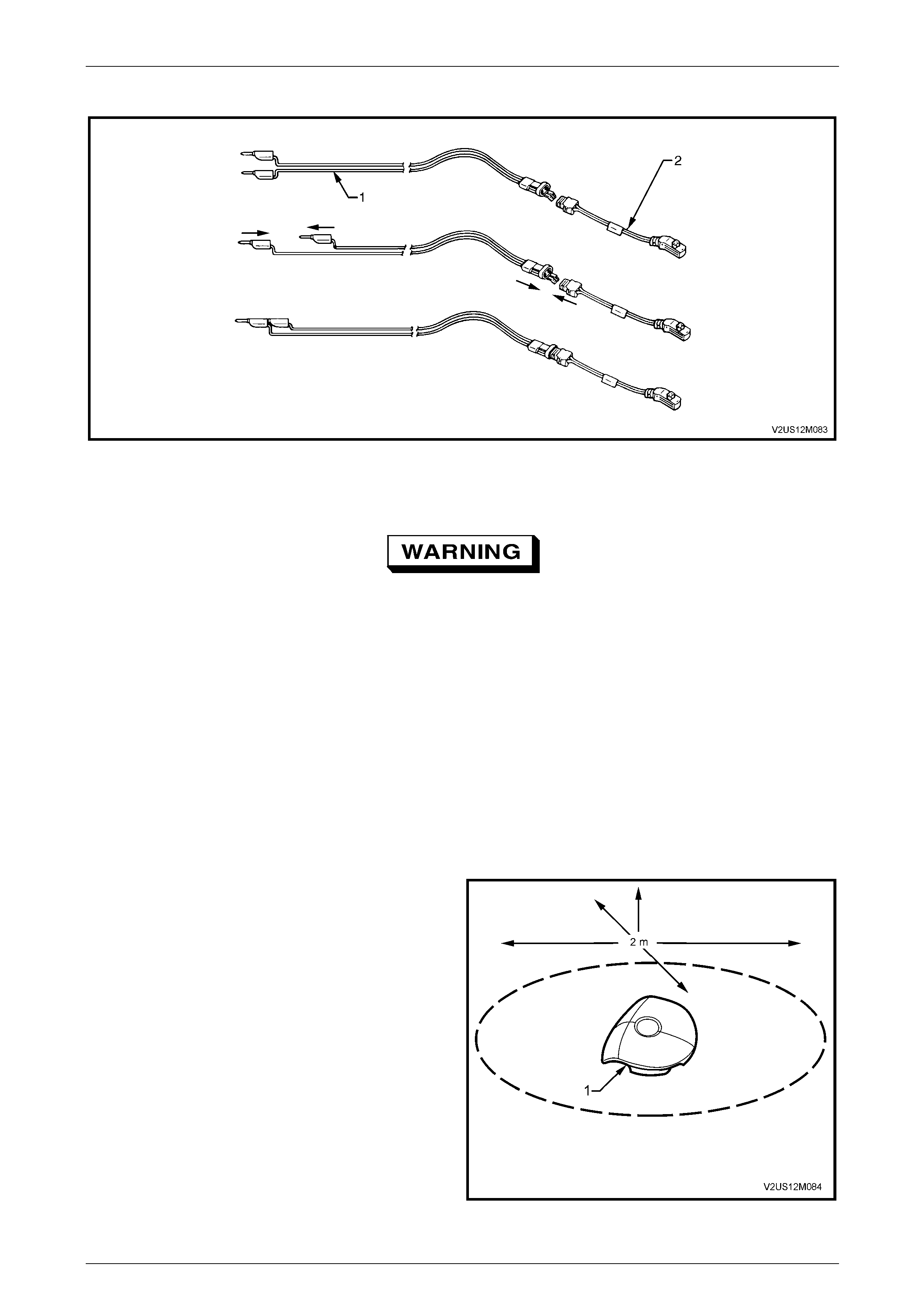
Occupant Protection System Page 12M–153
Page 12M–153
4 Connect the deployment harness Tool No. J213526–1 (1) to the adaptor Tool No. E199 2 (2).
Figure 12M – 43
5 Remove the steering wheel inflatable restraint assembly from the vehicle as describ ed in this Section.
• When storing a live steering wheel
inflatable restraint assembly or when
leaving a live assembly unattended on a
bench or other surface, always face the
assembly with the trim cover up and away
from the surface. This is necessar y so that
a free space is provided to allow the
inflatable restraint assembly cushion to
expand in the unlikely event of accidental
deployment. Failure to follow procedures
may result in personal injury.
• Ensure other personnel working in the
area are informed where the live inflatable
restraint assembly is and to take care
when working in proximately to the
inflatable restraint assembly.
6 Place the assembly on a workbench or other surface
away from all loose or flammable objects with its trim
cover facing up, away from the surface.
7 Clear a space on the ground of at least 2 metres in
diameter where the assembly is to deploy. A paved,
outdoor location where there is no activity is preferred.
If an outdoor location is not availa ble, a space on the
workshop floor where there is no activity and sufficient
ventilation is recommended. Ensure no lo ose or
flammable objects are within the deployment area.
8 Place the assembly, with its trim cover facing up, on
the ground in the space just cleared.
Figure 12M – 44
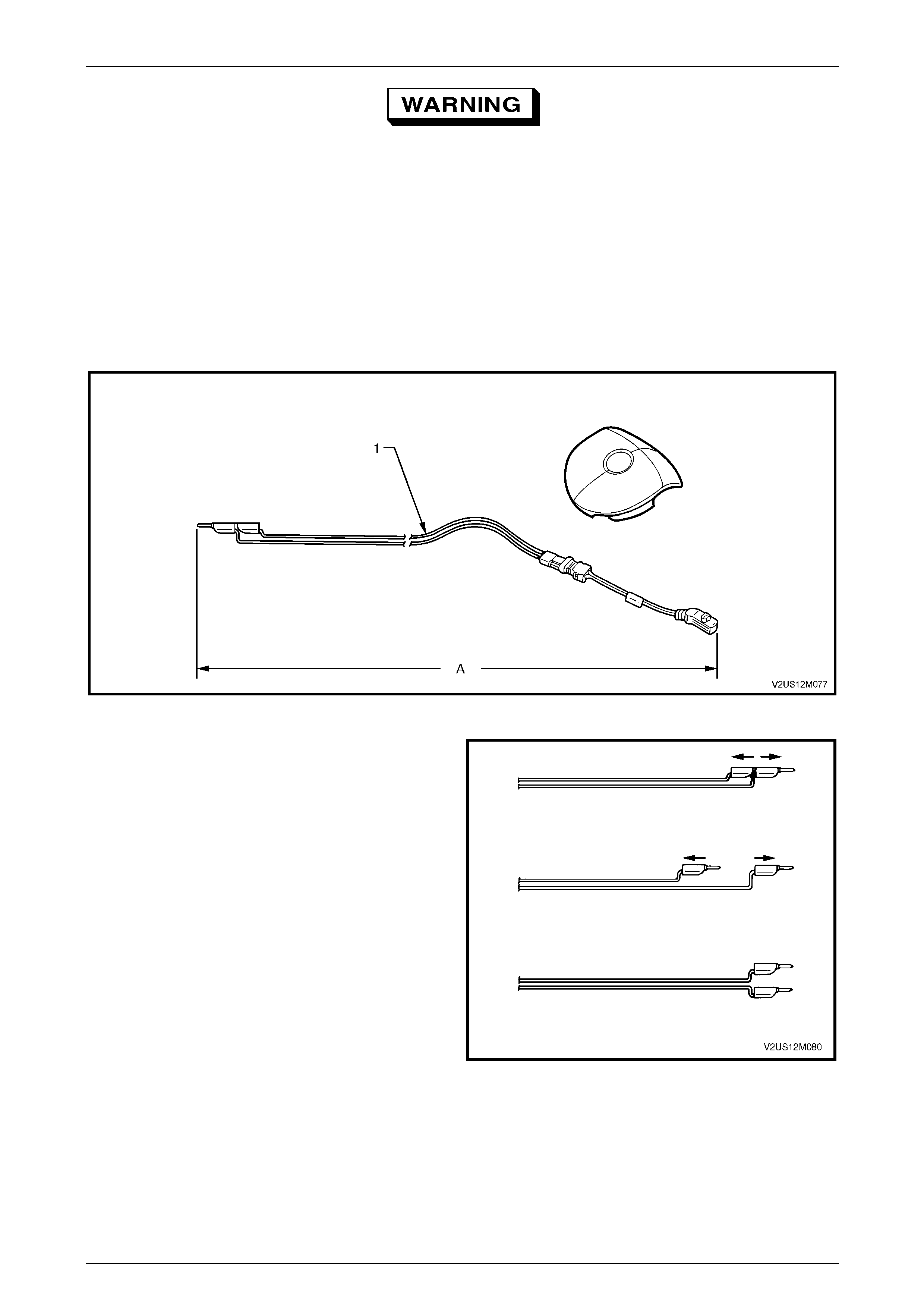
Occupant Protection System Page 12M–154
Page 12M–154
The deployment harness (1) must be laid out
to its full length (A) to allow the technician
maximum distance from the inflatable
restraint assembly to be deployed, refer to
Figure 12M – 45. This minimises any chance
of injury to the technician.
9 Stretch the deployment harness and adaptor from the steering wheel inflatable restraint assembly to its full length.
10 Place a power source near th e shorted end of the deployment harness. The recommended application is 12-14 V,
with a minimum of 2 A (a vehicle battery is suggested).
11 Connect the adaptor Tool No. E1992 and deployment harne ss lead Tool No. J213526-1 to the steerin g wheel
inflatable restraint assembly.
Figure 12M – 45
12 Verify the area around the steering wheel inflatable
restraint assembly is clear of all people and loose or
flammable objects.
13 Verify the steering wheel inflatable restraint assembly
is resting with trim cover facing up.
14 Notify all people in the immediate area that you intend
to deploy the steering wheel inflatable restraint
assembly. The deployment will be accompanied by an
explosion, which may startle others.
15 Separate the two banana plugs on the deplo yment
harness.
Figure 12M – 46
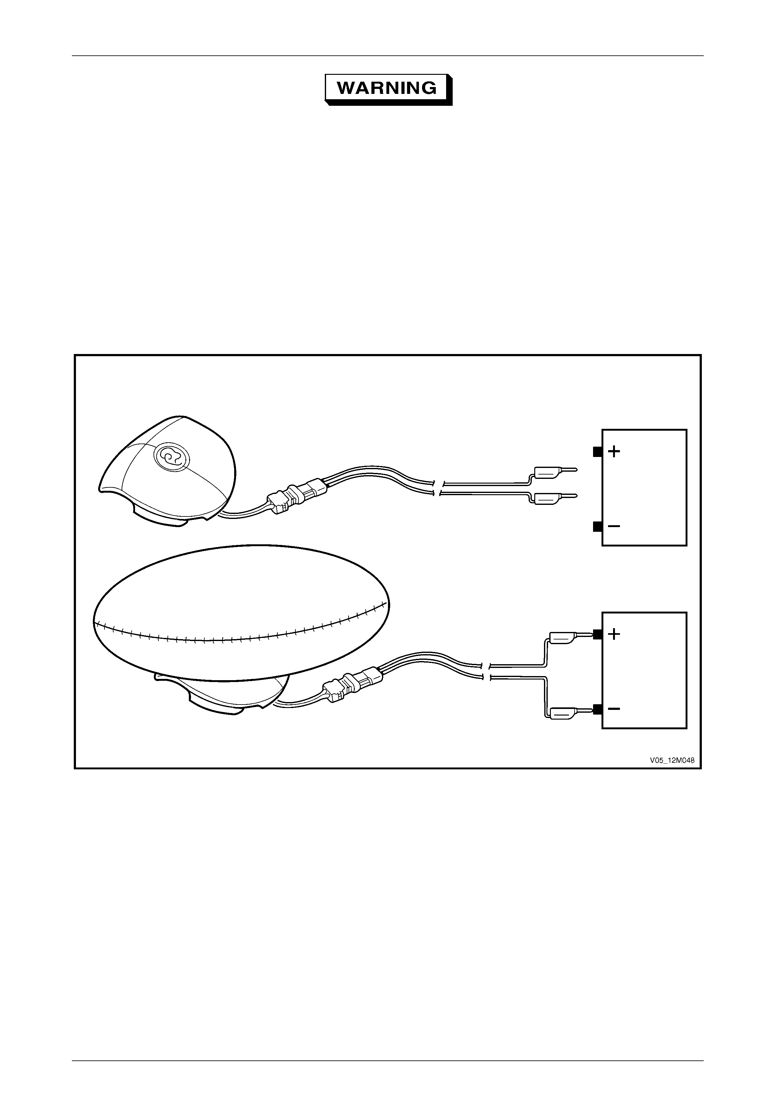
Occupant Protection System Page 12M–155
Page 12M–155
When the inflatable restraint assembly
deploys, the rapid gas expansion will create
an explosion. Notify all people in the
immediate area that you intend to deploy the
inflatable restraint assembly.
16 Connect deployment harn ess leads to the power source to immediately deploy the steering wheel inflatable
restraint assembly, refer to Figure 12M – 47.
NOTE
When the inflatable restraint assembly deploys,
the assembly may jump up to 30 cm vertically.
This is a normal reaction of the assembly to the
force of the rapid gas expansion inside the
inflatable restraint assembly cushion.
Figure 12M – 47
17 Disconnect the deployment harness from the power source.
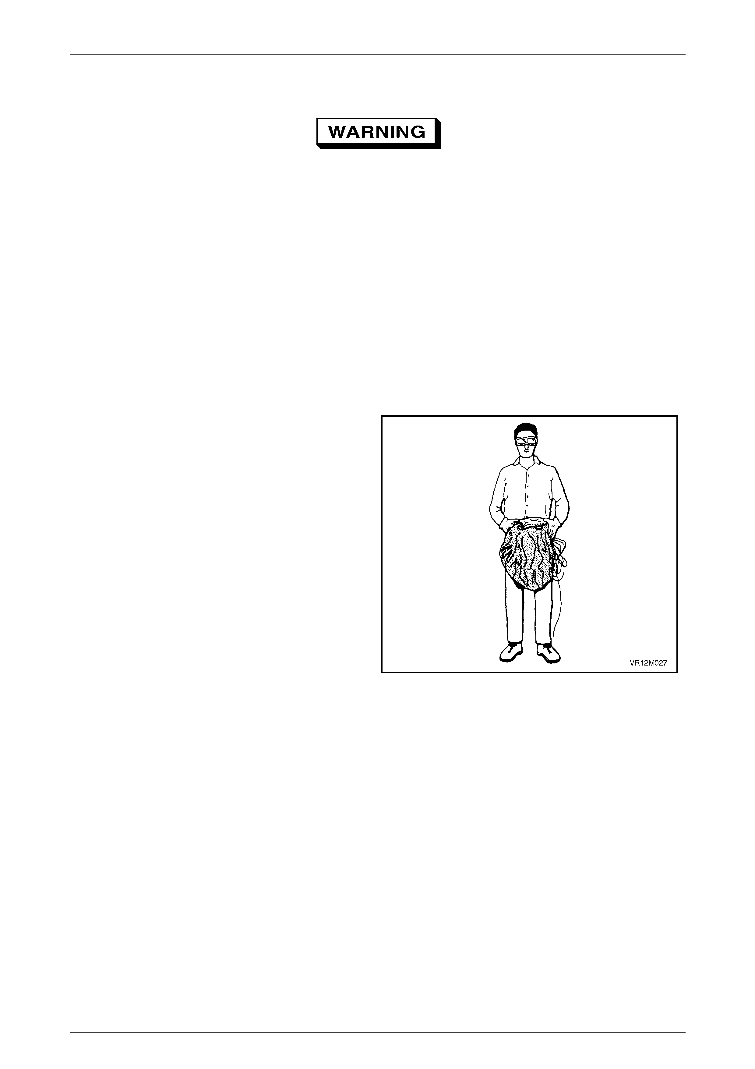
Occupant Protection System Page 12M–156
Page 12M–156
18 Short the two deplo yment harness le ads together by fully seating one ba nana plug into the other.
• Safety precautions must be observed
when handling a deployed steering wheel
inflatable restraint assembly. After
deployment, the metal surfaces of the
module will be very hot. Do not touch
these metal areas of the module for about
10 minutes after deployment. Do not place
the deployed steering wheel inflatable
restraint assembly near any flammable
objects. If the deployed steering wheel
inflatable restraint assembly must be
moved before it has cooled, wear gloves
and handle by the inflatable restraint
assembly cushio n o r the trim cover.
• Ensure you are wearing safety glasses and
gloves to protect your eyes and hands
from possible irritation and heat when
handling the deployed steering wheel
inflatable restraint assembly.
NOTE
After deployment, the surface of the cushion
may contain a powdery residue. This powder
consists primarily of cor n starc h (used to l ubr icate
the cushion) and by-products of the chemical
reaction. The by-products of inflatable restraint
assembly module deployment are carbon
monoxide (CO), nitrogen (N), carbon dioxide
(CO2), water (H2O) with trace amounts of oxides
of nitrogen (NOΧ) and ammonia (NH3).
Figure 12M – 48
19 Disconnect the adaptor Tool No. E1992 from the assembly as soon as possibl e after deployment. This will prevent
damage to the adaptor or depl oyment harness due to possible contact with any hot objects. T he adaptor and
deployment harnesses are designed to be reused. They should however, be inspected for damage after each
deployment and replaced if necessary.
20 Dispose of the deployed steering wheel inflatable restraint assembly throug h normal refuse channels after it has
cooled for at least 10 minutes.
21 Wash your hands with mild soap and water afterward.
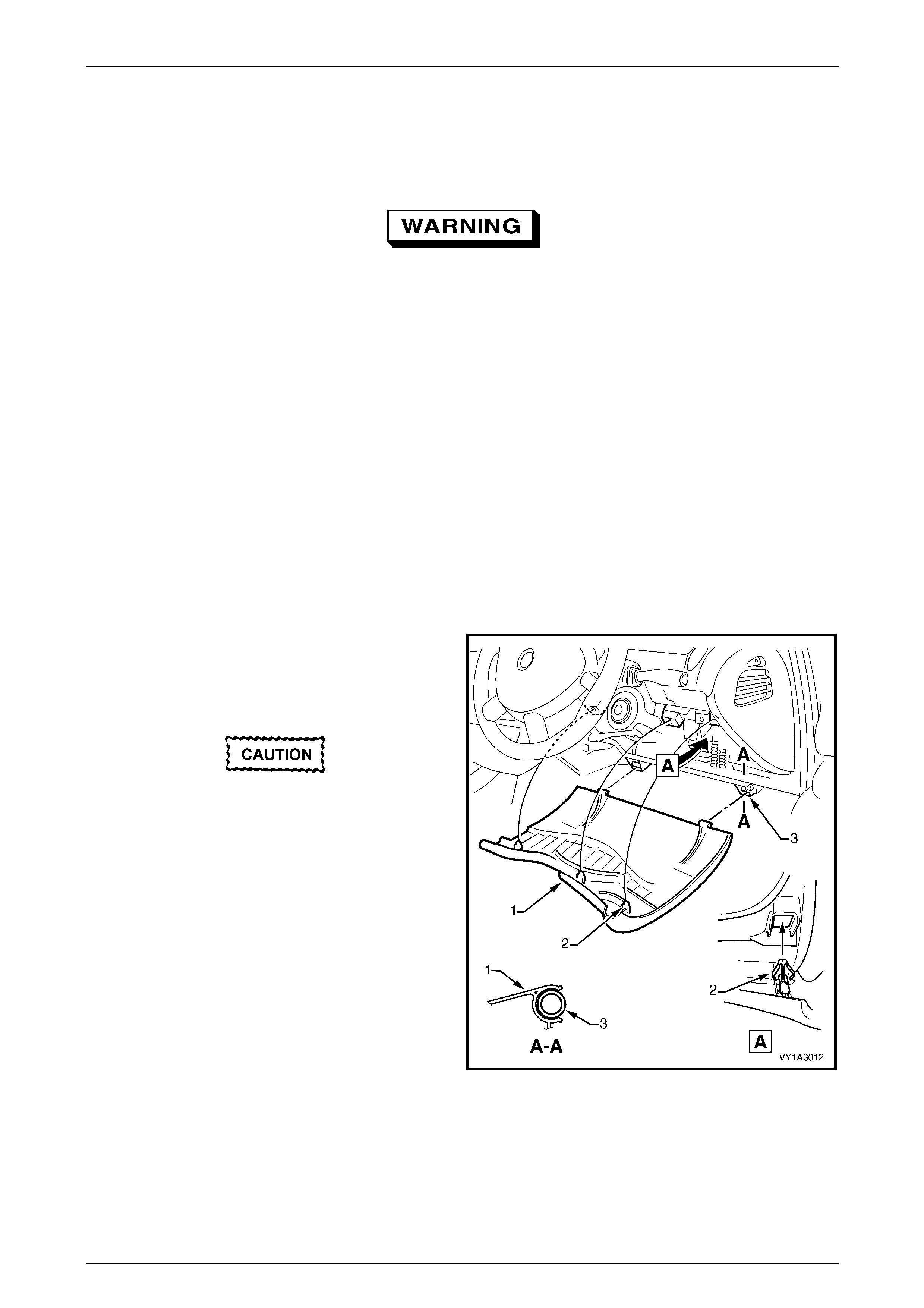
Occupant Protection System Page 12M–157
Page 12M–157
3.7 Clock Spring Coil Assembly
LT Section No. — 06–225
• Improper alignment of the clock spring
coil assembly may cause damage
resulting in occupant protection system
malfunction.
• Absolutely no wire, connector or pin
repairs are to be attempted on the clock
spring coil. If the clock spring coil is
damaged in any way, it must be replaced.
Remove
1 Disable the SDM, refer to 3.2 SDM Disabling and Enabling Procedure.
2 Remove steering wheel inflatable restraint assembly, refer to 3.6 Steering Wheel Inflatable Restraint Assembly.
3 Remove the steering wheel, refer to Section 9 Steering.
NOTE
When the steering wheel is removed, the inner
clock spring coil inner hub should automatically
lock in the centralised position.
4 Grasp the upper edge of the instrument pan el lower
trim panel assembly (1) and pull outwards to
disengage the three retaini ng clips (2).
5 Swing the panel assembly open.
When disengaging the instrument panel
lower trim panel from the hinge clip, do not
pull the left-hand side of the panel too far
away from the instrument panel before
disengaging the panel from the hinge pin on
the right-hand side of the panel retainer,
otherwise damage to the hinge pin will occur.
6 If required remove the instrument panel lower trim
panel by holding each side of the panel assembly, and
pulling it rearwards to disengage it from the instrument
panel lower trim panel retainer (3).
7 Remove the steering column covers, refer to
Section 9 Steering.
8 Disconnect the wiring from the back of the clockspring.
Figure 12M – 49
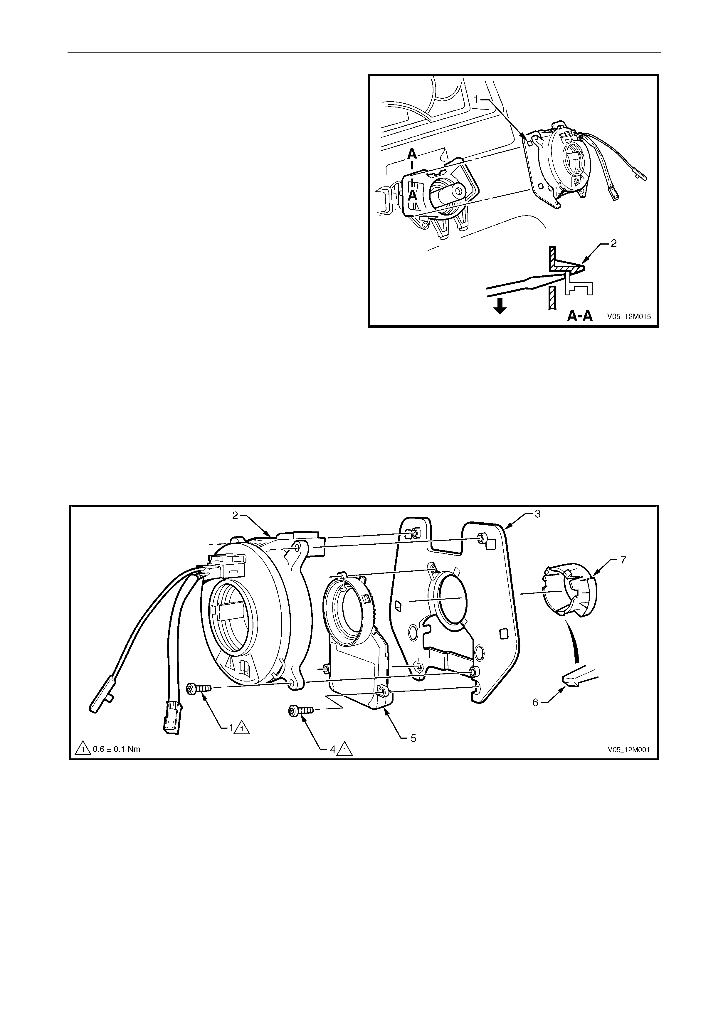
Occupant Protection System Page 12M–158
Page 12M–158
9 Insert a fine flat-blade screwdriver through the
opening (1) in the clock spring coil assembly and
disengage the retaining tang (2) by gently levering in
the direction shown.
10 Repeat for the remaining three places and then
remove clock spring coil assembly from the steering
column.
Figure 12M – 50
Disassemble
1 Remove the screw (1), three places, attaching the clock spring coil assembly (2) to the adaptor plate (3) and
remove the coil assembly, refer to Figure 12M – 51.
2 If required, remove the screw (4), three places, attaching the steering angle sensor assembly (5), where fitted, to
the adaptor plate and remov e the sensor assembly.
3 Depress the retaining tab (6), three places, attaching the turn signal cancel cam (7) to the adaptor plate and
remove.
Figure 12M – 51
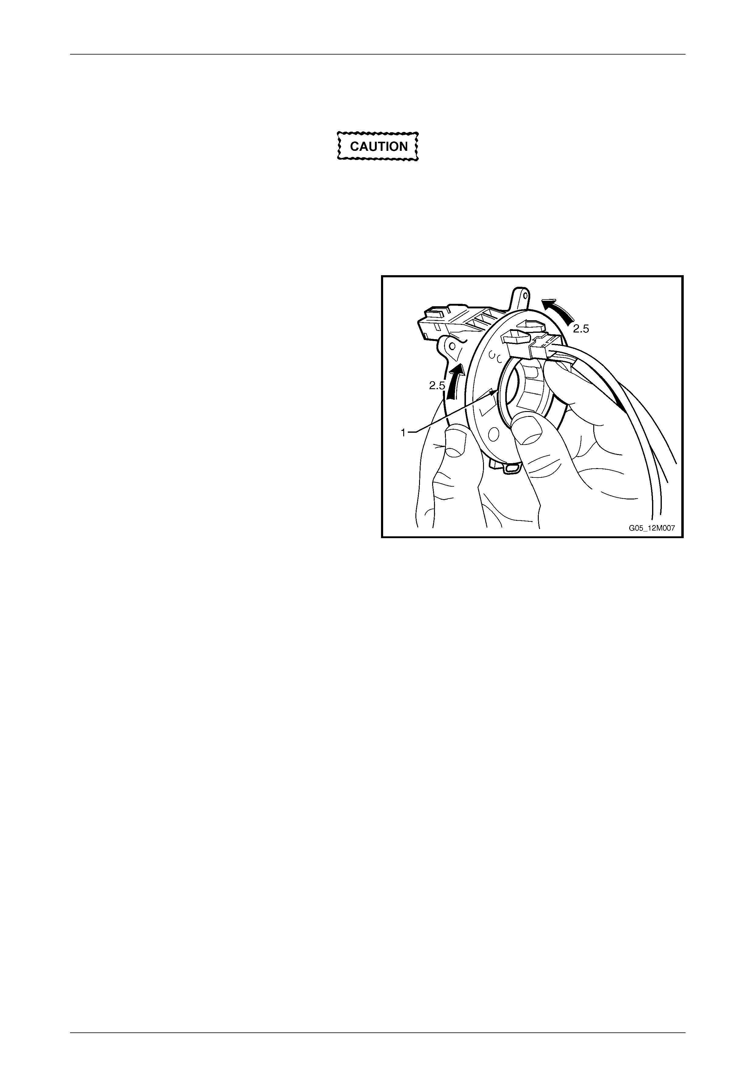
Occupant Protection System Page 12M–159
Page 12M–159
Clock Spring Coil Centring
Failure to correctly centre the clock spring
coil will result in damage to the clock spring
coil assembly and malfunction of the
occupant protection system.
The following procedure must be performed when reusing a clock spring coil that has been removed from a steering
column and there is doubt that it has remained locked in the central position.
1 Hold the clock spring coil outer housing by one hand
while depressing the inner hu b locking ring (1) with the
other.
2 Carefully rotate the inner hub of the clock spring coil in
a clockwise direction until a st op is felt.
3 While still holding the locking ring, rotate the inner hub
in an anti-clockwise direction for appr oximately 2.5
turns, until the wiring harness is aligned at the top of
the clock spring.
4 Release the locking ring and the inner hub should b e
locked to the outer housing.
Figure 12M – 52
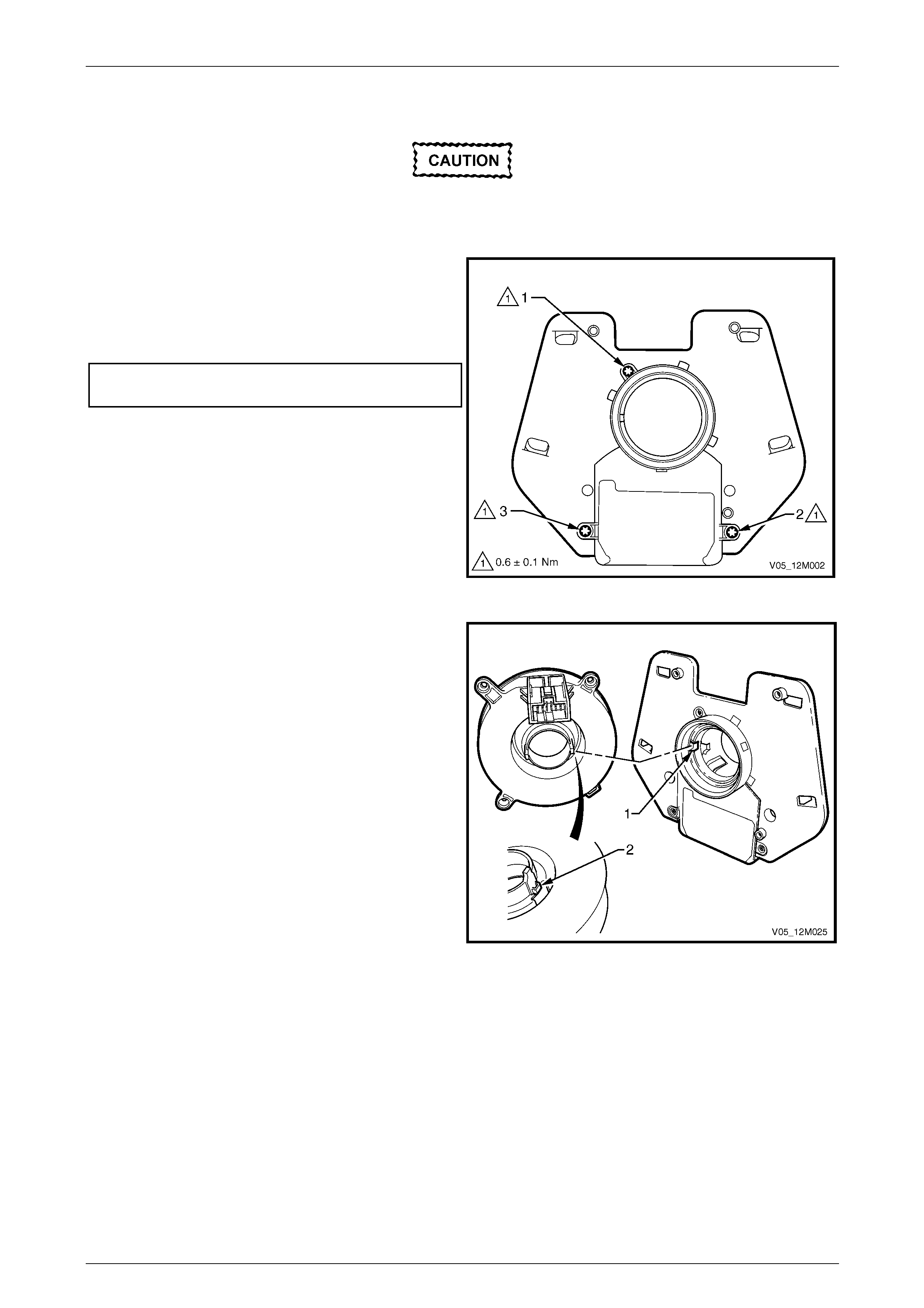
Occupant Protection System Page 12M–160
Page 12M–160
Reassemble
To ensure correct operation, the clock spring
coil assembly must be reassembled in the
following sequence.
1 If fitted, position the steering angle sensor assembly
onto the adaptor plate, ensuring correct orientation.
2 Start each of the attaching screws and then tighten
each screw to the specified torque in the correct
sequence (1, 2 and then 3).
Steering angle sensor attaching screw
torque specification.....................................0.6 ± 0.1 Nm
Figure 12M – 53
3 Where fitted, ensure the notch (1) in the steering angle
sensor is aligned with the tang (2) on the rear of the
clock spring coil assembly.
4 Position the clock spring coil assembly onto the
adaptor plate, ensuring correct orientation.
Figure 12M – 54
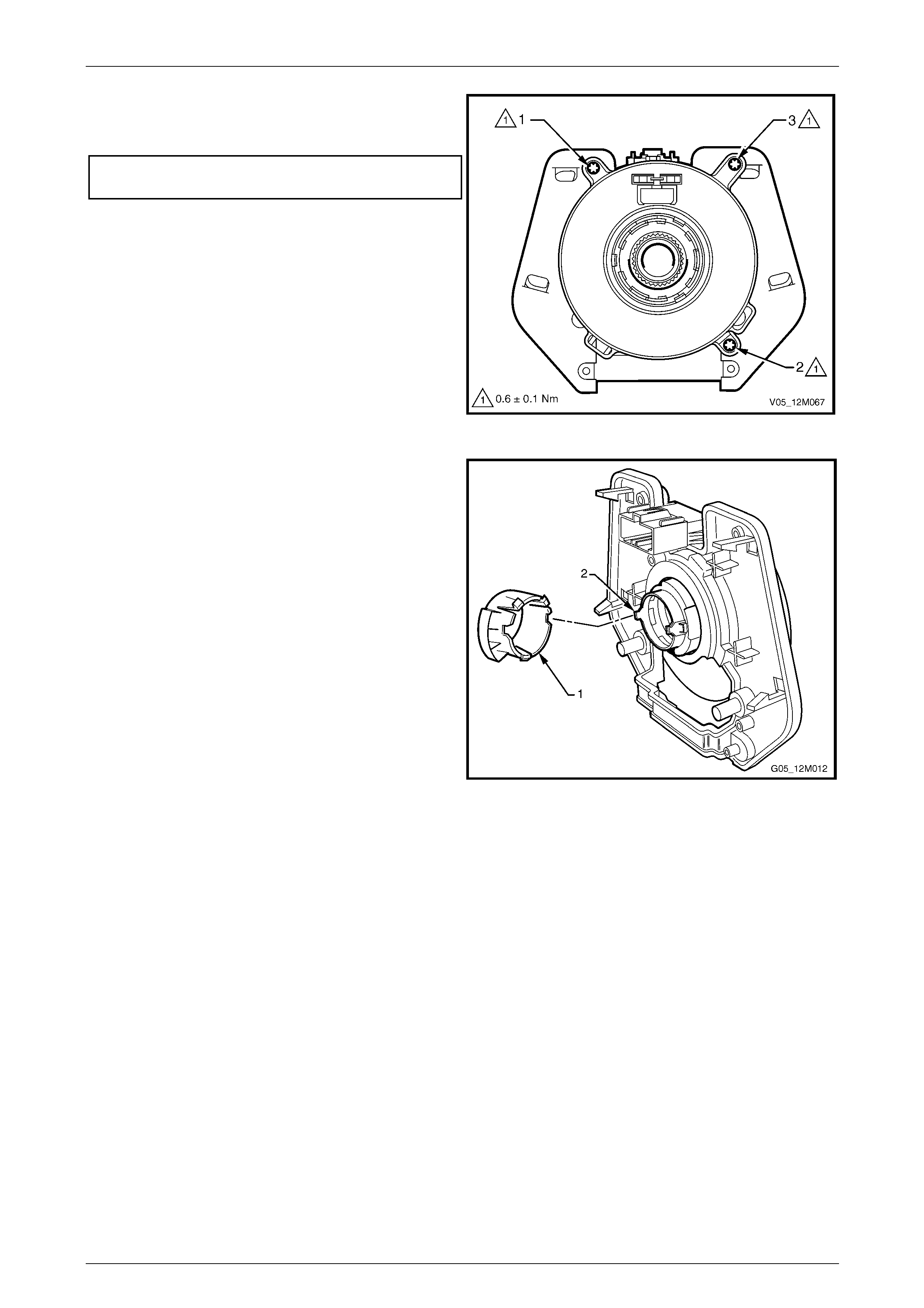
Occupant Protection System Page 12M–161
Page 12M–161
5 Start each of the attaching screws and then tighten
each screw to the specified torque in the correct
sequence (1, 2 and then 3).
Clock spring coil attaching screw
torque specification.....................................0.6 ± 0.1 Nm
Figure 12M – 55
6 From the rear, align the two notches in the turn signal
cancel cam (1) with the tangs on the rear of the clock
spring coil assembly (2).
7 Clip the turn signal cancel ca m onto the adaptor plate.
Figure 12M – 56
Reinstall
Reinstallation of the clock spr ing coil is the reverse of the removal procedure, noting the following:
1 With the clock spring coil assembly locked in the centralised positi on, install it over the steering column, aligning the
lower locating lugs on the clock spring coil adaptor plate with the matching holes in the steerin g column switch
housing.
2 Push the clock spring coil assembly onto the switch housing until the four locking tangs fully engage.
3 Enable the SDM, refer to 3.2 SDM Disabling and Enabling Procedure.
4 Switch the ignition on, and ob s erve the airbag warning indicator in the instrument cluster. The warning indicator
should be illuminated for approximately 5 seconds. During t his period of time the SDM performs a wiring and self-
check. If no system faults are detected, the airbag warning indicator will be switched off.
If the warning indicator remains illuminated, a warning is shown in the instrument cluster multi-function display and
an audible alarm chimes, or the warning indicator illuminates 2 seconds after it was originally switched off, an OPS
fault is present.
Refer to 2 Diagnostics to rectify the fault.
5 Calibrate the steering an gle sensor, if fitted, refer to Section 5B4 ABS-TCS and ESP – V6.
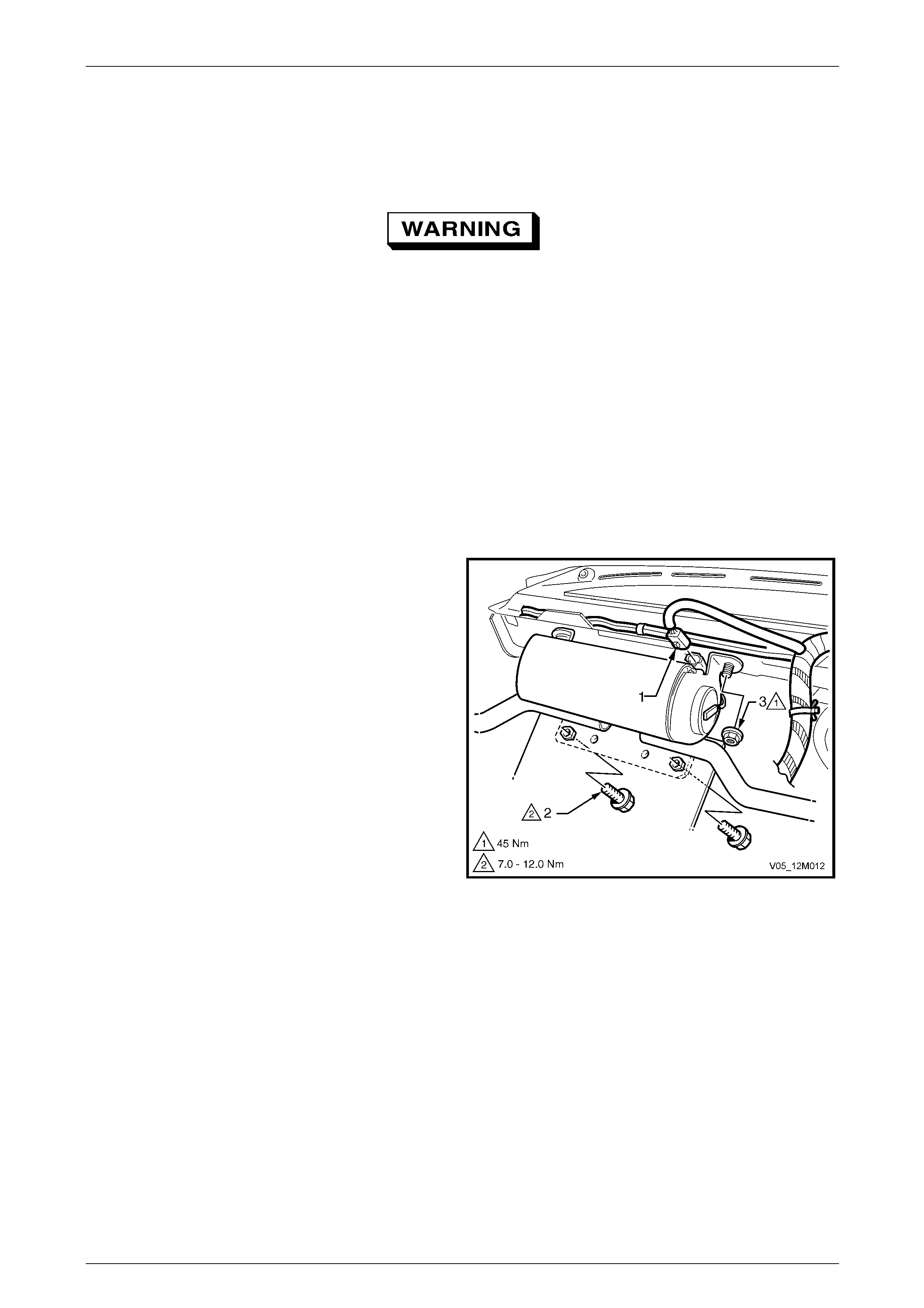
Occupant Protection System Page 12M–162
Page 12M–162
3.8 Instrument Panel Inflatable Restraint
Assembly
LT Section No. — 06–225
If conducting the following operation on an
inflatable restraint assembly that has
deployed, wear safety glasses and gloves to
protect your eyes and hands from possible
irritation when handling the deployed
inflatable restraint assembly.
After deployment, the surface of the cushion may contain a powdery residue. This powder consists primarily of
cornstarch (used to lubricate the cushi on) and by-products of the chemical reaction. The by-products of inflatable
restraint assembly module deployment are carbo n monoxide (CO), nitrog en (N), carbon dioxide (CO2), water (H2O) with
trace amounts of oxides of nitrogen (NOΧ) and ammonia (NH 3).
Remove
1 Disable the SDM, refer to 3.2 SDM Disabling and Enabling Procedure.
2 Remove the instrument panel pad assembly, refer to Section 1A3 Instrument Panel and Console.
3 Disconnect the instrument panel inflatable restraint
assembly wiring harness connector X205 (1) from
inflatable restraint assembly.
NOTE
Do not disconnect the instrument pan el inflat able
restraint assembly wiring harness connector
A62 − X1 from the assembly.
4 Remove instrument panel inflatable restraint assembly
to lower bracket attaching bolts (2).
5 Remove instrument panel inflatable restraint assembly
to upper dash panel attaching nuts (3).
Figure 12M – 57
Occupant Protection System Page 12M–163
Page 12M–163
• When carrying a live (undeployed)
instrument panel inflatable restraint
assembly, make sure the inflatable
restraint cushion opening is pointed away
from you. In case of an accidental
deployment, the inflatable restraint
cushion will then deploy with minimal
chance of injury.
• When placing a live instrument panel
inflatable restraint assemb ly on a bench o r
other surface, always face with the
inflatable restraint assembly cushion up,
away from the surface. Do not rest the
inflatable restraint assembly with the
inflatable restraint cushion face down.
This is necessary so that a free space is
provided to allow the inflatable restraint
assembly cushion to expand in the
unlikely event of accidental deployment.
Otherwise, personal injury may result.
6 Remove the instrument panel inflatable restraint assembly and place in a safe location.
Reinstall
1 Place the instrument panel inflatable restraint assembly on the dash panel upp er two mounting studs.
2 Install instrument panel inflata ble restra int assembly to upper dash panel attaching nuts and tighten to the correct
torque specification.
Instrument panel inflatable rest raint
assembly to upper dash panel
attaching nut torque specification.......................45.0 Nm
3 Install the instrument panel inflatabl e restraint assembly to lower bracket attaching bolts and tighten to the correct
torque specification.
Instrument panel inflatable rest raint
assembly to lower bracket
attaching bolt torque specification.............7.0 – 12.0 Nm
4 Connect the instrument panel inflatable restraint assembly wiring harness conn ector X205 to the inflatable restraint
assembly.
5 Install the instrument panel pad assem bly, refer to Section 1A3 Instrument Panel and Console.
6 Enable the SDM, refer to 3.2 SDM Disabling and Enabling Procedure.
7 Switch the ignition on, and ob s erve the airbag warning indicator in the instrument cluster. The warning indicator
should be illuminated for approximately 5 seconds. During this period the SDM performs a wiring and self-check. If
no system faults are detected, the airbag warning indicator will be switched off.
If the warning indicator remains illuminated, a warning is shown in the instrument cluster multi-function display and
an audible alarm chimes, or the warning indicator illuminates 2 seconds after it was originally switched off, an OPS
fault is present. Refer to 2 Diagnostics to rectify any fault.

Occupant Protection System Page 12M–164
Page 12M–164
Disposal Procedure
During the course of a vehicle's useful life, certain situations may arise which will necess itate the disposal of a live
(undeployed) instrument panel inflatable restraint assembly. T hese situations may include damage to the inflatable
restraint assembly or the assembly being diagn osed as faulty. The following information covers proper procedures for
deploying a live assembly.
• Failure to follow proper instrument panel
inflatable restraint assembly disposal
procedures can result in inflatable
restraint assembly deployment, which may
cause personal injury. The undeployed
inflatable restraint assembly contains
substances that can cause severe illness
or personal injury if the sealed container is
damaged during disposal.
• The inflatable restraint assembly must
never be deployed inside the vehicle.
• Failure to follow the procedures in the
order listed may result in personal injury.
Read the procedure fully before attempting
to dispose of the inflatable restraint
assembly. Do not connect the deployment
harness to any power source before
connecting the deployment harness to the
instrument panel inflatable restraint
assembly. The deployment harness must
remain shorted and not be connected to a
power source until the instrument panel
inflatable restraint assembly is ready to be
deployed. The inflatable restraint
assembly will immediately deploy when a
power source is connected to it. Wear
safety glasses and gloves throughout this
entire deployment and disposal procedure
and follow proper handling procedures or
injury may occur.
• The following procedure requires use of
Tool No. J213526-1 deployment harness
with adaptor Tool No. E1992. Do not
attempt this procedure without Tool No.
J213526-1 and Tool No. E1992 as this may
cause the inflatable restraint assembly to
deploy prematurely.
1 Disable the SDM, refer to 3.2 SDM Disabling and Enabling Procedure.
2 Inspect Tool No. J213526-1 d eployment harness and adaptor, Tool No. E1992 for damage. If the harness or
adaptor is damaged, discard and o btain a replacement.
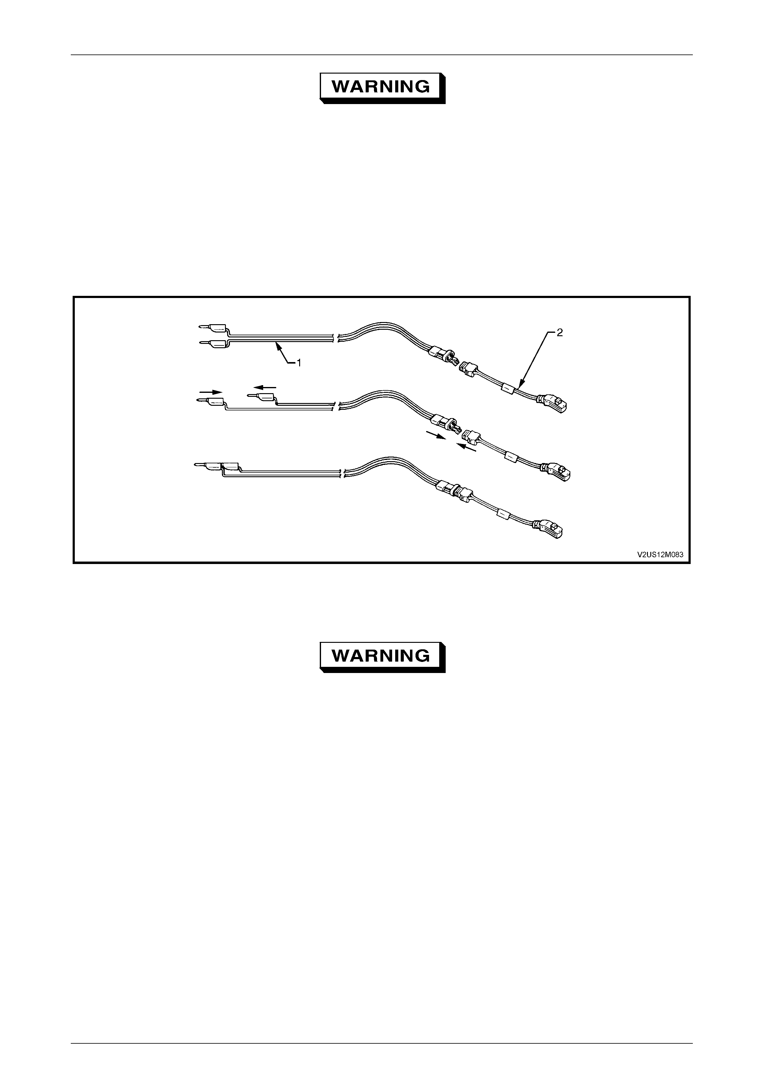
Occupant Protection System Page 12M–165
Page 12M–165
The deployment h arness must remain sh orted
and not connected to a power source until the
inflatable restraint assembly is to be
deployed, refer to Figure 12M – 58. The
inflatable restraint assembly will immediately
deploy when a power source is connected to
it.
3 Short the two deployment harness leads together by fully seatin g one banana plug into the other. The deployment
harness must remain shorted and not connected to a power source until the inflatable restraint assembly is to be
deployed, refer to F igure 12M – 58.
4 Connect the deployment harness Tool No. J213526–1 (1) to the adaptor Tool No. E1992 (2).
Figure 12M – 58
5 Remove the instrument panel inflatable restraint assembly from vehicle as detailed in this Section.
• When storing a live instrument panel
inflatable restraint assembly or when
leaving a live assembly unattended on a
bench or other surface, always face the
assembly with the trim cover up and away
from the surface. This is necessar y so that
a free space is provided to allow the
inflatable restraint assembly cushion to
expand in the unlikely event of accidental
deployment. Failure to follow procedures
may result in personal injury.
• Ensure other personnel working in the
area are informed where the live inflatable
restraint assembly is and to take care
when working in proximately to the
inflatable restraint assembly.
6 Using a 2 metre long square steel tube with suitable sized and positioned hol es, bolt the tubing to the lower bracket
of the instrument panel inflatable restraint assembly, refer to Figure 12M – 59.
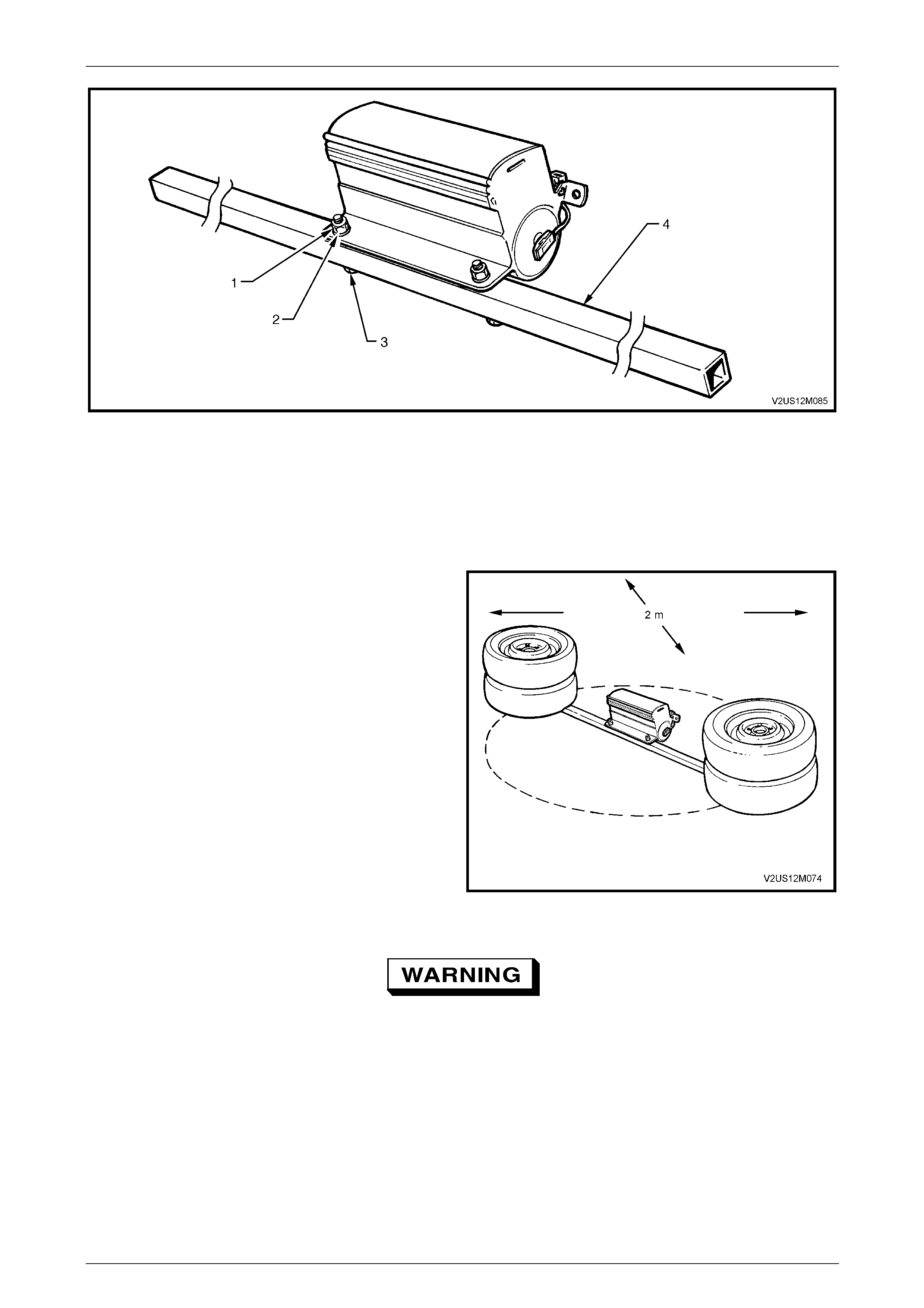
Occupant Protection System Page 12M–166
Page 12M–166
Figure 12M – 59
Legend
1 Nut
2 Washer 3 Bolt
4 Square steel tubing − 2 m long
7 Clear a space on the ground of at least 2 metres in
diameter where the assembly is to be deployed. A
paved, outdoor location where there is no activity is
preferred. If an outdoor location is not available, a
space on the workshop floor where there is no activity
and sufficient ventilation is rec ommen ded. Ensure no
loose or flammable obj ects are within the deployment
area.
8 Position two wheel and tyre assemblies on each end
of the tubing.
9 Ensure the instrument panel inflatab le restraint
assembly is positioned with its inflatable restraint
assembly cushion facing up.
Figure 12M – 60
The deployment harness (1) must be laid out
to its full length (A) to allow the technician
maximum distance from the inflatable
restraint assembly to be deployed, refer to
Figure 12M – 61. This minimises any chance
of injury to the technician.
10 Stretch the deployment harne ss and adaptor from the instrument panel i nflatable restraint assembly to its full
length.
11 Place a power source near th e shorted end of the deployment harness. The recommended application is 12-14 V,
with a minimum of 2 A (a vehicle battery is suggested).
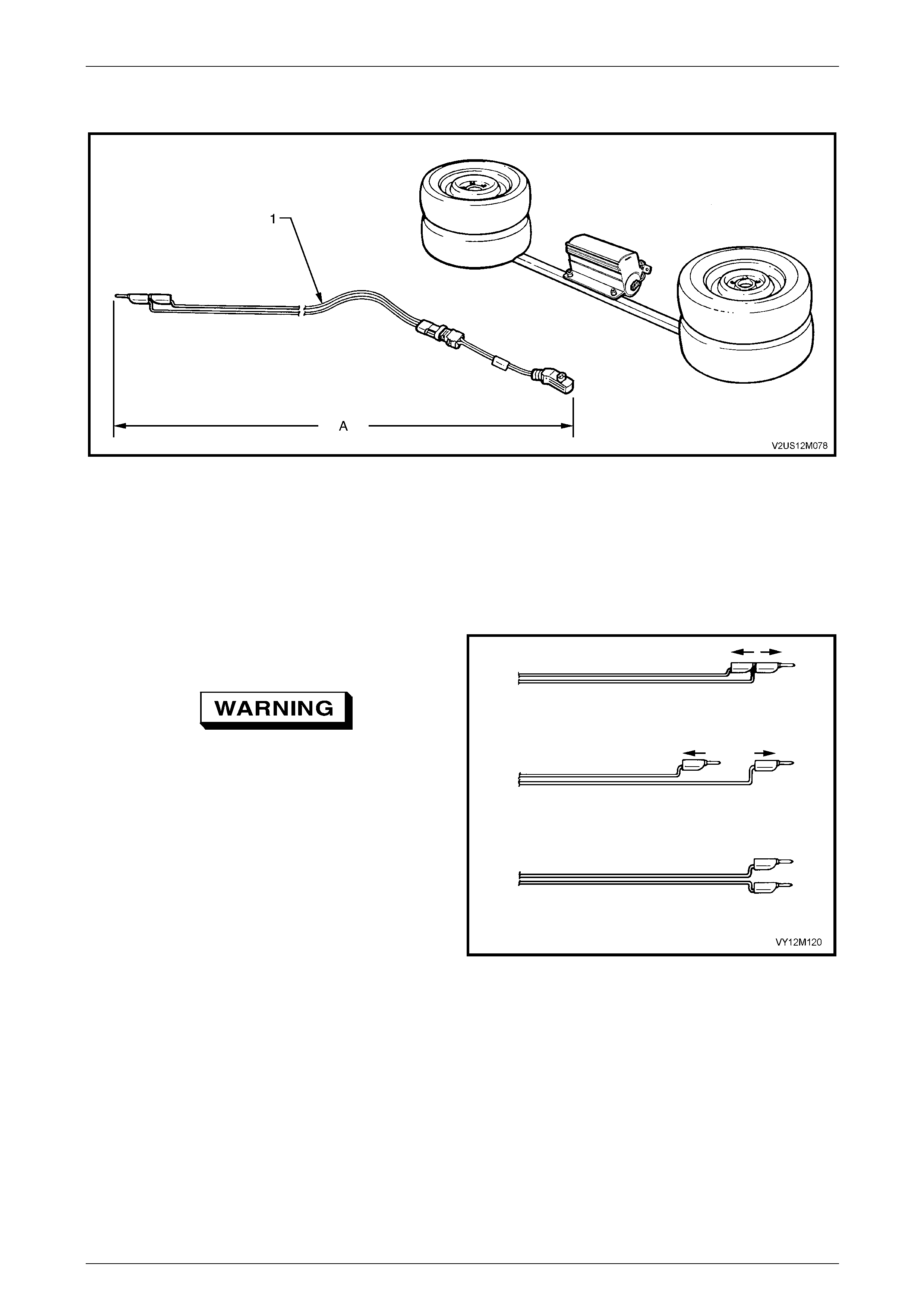
Occupant Protection System Page 12M–167
Page 12M–167
12 Connect adaptor Tool No. E1992 and deplo yment harness lead Tool No. J213526-1 to the instrument panel
inflatable restraint assembly.
Figure 12M – 61
13 Verify the area around the instrument panel inflatable restraint assembl y is clear of all people and loose or
flammable objects.
14 Verify the instrument pane l inflatable restraint assembly is resting with inflatable restraint assembly cushion facing
up.
15 Notify all people in the immediate area that you intend to deploy the inflatable restraint assembly. The depl oyment
will be accompanied by an explosion, which may startle others.
16 Separate the two banana plugs on the deplo yment
harness.
When the inflatable restraint assembly
deploys, the rapid gas expansion will create
an explosion. Notify all people in the
immediate area that you intend to deploy the
inflatable restraint assembly.
17 Connect deployment harn ess leads to the power
source to immediately deploy the instrument panel
inflatable restraint assembly, refer to Figure 12M – 63.
Figure 12M – 62
NOTE
When the inflatable restraint assembly deploys,
the assembly may jump vertically. This is a
normal reaction of the module to the force of the
rapid gas expansion ins ide the inflatable restraint
assembly cushion.
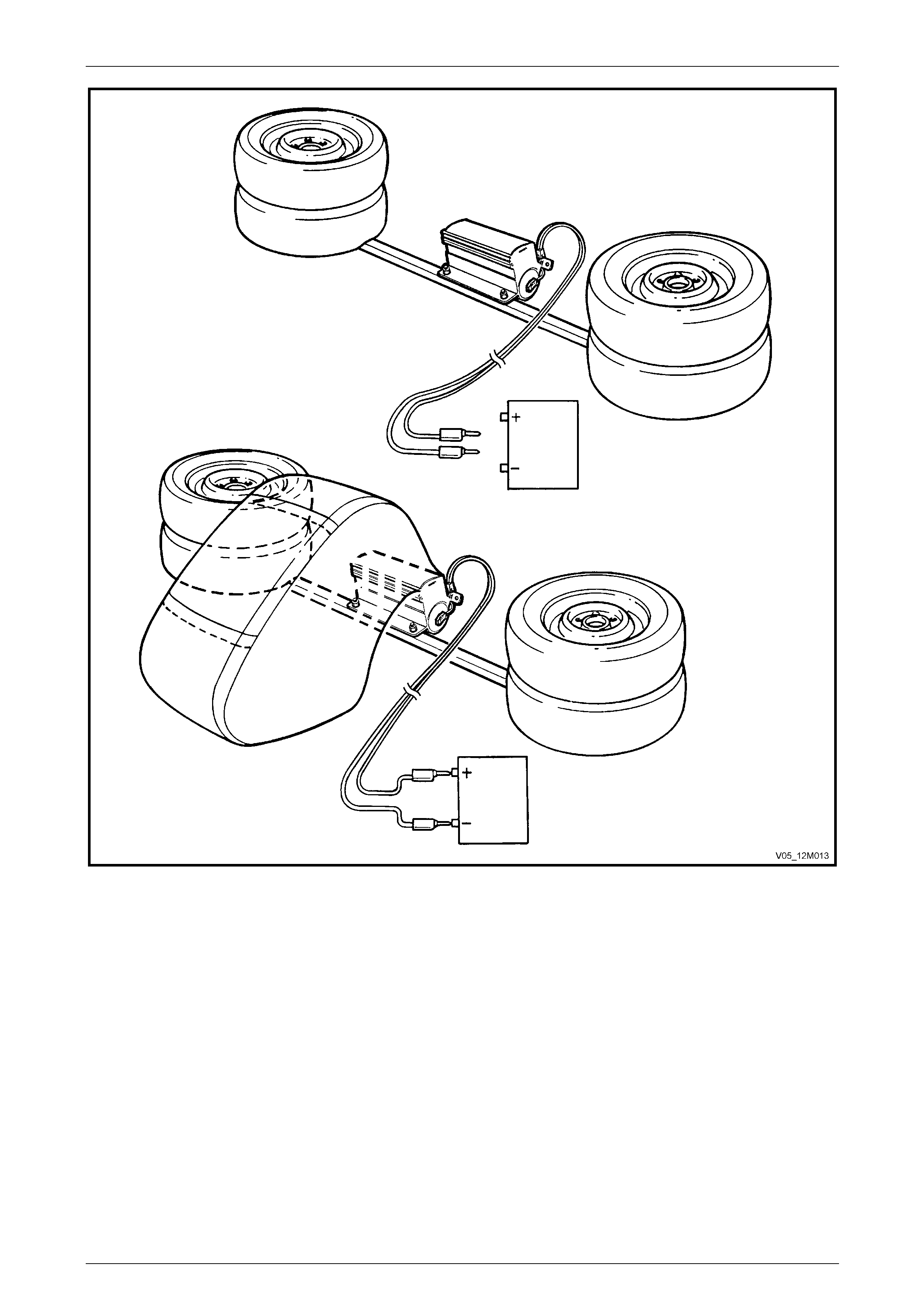
Occupant Protection System Page 12M–168
Page 12M–168
Figure 12M – 63
18 Disconnect the deployment harness from the power source.
19 Short the two deplo yment harness le ads together by fully seating one ba nana plug into the other.
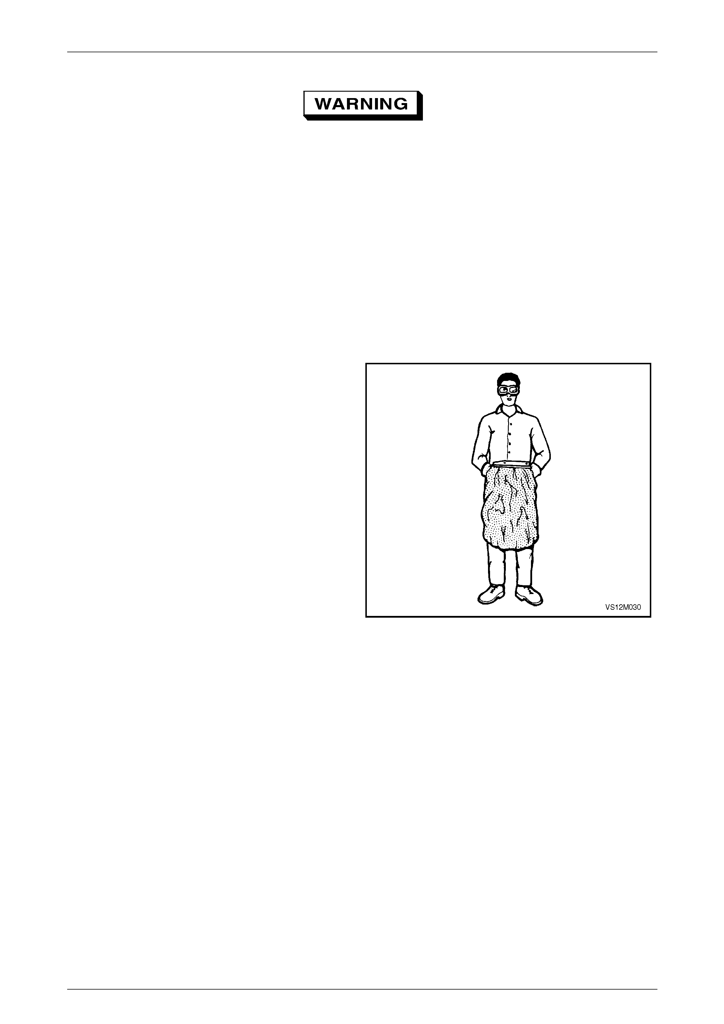
Occupant Protection System Page 12M–169
Page 12M–169
• Safety precautions must be observed
when handling a deployed inflatable
restraint assembly. After deployment, the
metal surfaces of the module will be very
hot. Do not touch these metal areas of the
module for about 10 minutes after
deployment. Do not place the deployed
inflatable restraint assembly near any
flammable objects. If the deployed
inflatable restraint assembly must be
moved before it has cooled, wear gloves
and handle by the inflatable restraint
assembly cushio n o r the trim cover.
• Ensure you are wearing safety glasses and
gloves to protect your eyes and hands
from possible irritation and heat when
handling the deployed instrument panel
inflatable restraint assembly.
NOTE
After deployment, the surface of the cushion
may contain a powdery residue. This powder
consists primarily of cor n starc h (used to l ubr icate
the cushion) and by-products of the chemical
reaction. The by-products of inflatable restraint
assembly module deployment are carbon
monoxide (CO), nitrogen (N), carbon dioxide
(CO2), water (H2O) with trace amounts of oxides
of nitrogen (NOΧ) and ammonia (NH3).
Figure 12M – 64
20 Disconnect the adaptor Tool No. E1992 from the assembly as soon as possibl e after deployment. This will prevent
damage to the adaptor or depl oyment harness due to possible contact with the any hot objects. The adaptor and
deployment harness are designed to be reused. They should however, be inspected for damage after each
deployment and replaced if necessary.
21 Dispose of the deployed inflatable restraint assembly through normal refuse channels after it has coole d for at least
10 minutes.
22 Wash your hands with mild soap and water afterward.

Occupant Protection System Page 12M–170
Page 12M–170
3.9 Side-impact Inflatable Restraint
Assembly
LT Section No. — 06–225
If conducting the following operation on an
inflatable restraint assembly that has
deployed, wear safety glasses and gloves to
protect your eyes and hands from possible
irritation when handling the deployed
inflatable restraint assembly.
After deployment, the surface of the cushion may contain a powdery residue. This powder consists primarily of
cornstarch (used to lubricate the cushi on) and by-products of the chemical reaction. The by-products of inflatable
restraint assembly module deployment are carbo n monoxide (CO), nitrog en (N), carbon dioxide (CO2), water (H2O) with
trace amounts of oxides of nitrogen (NOΧ) and ammonia (NH 3).
Remove
1 Disable the SDM, refer to Section 3.2 SDM Disabling and Enabling Procedure.
2 Refer to Section 1A7 Seat Assemblies for the procedure for removing the side-impact inflatable restraint assembly.
• When carrying a live (undeployed) side-
impact inflatable restraint assembly, make
sure the inflatable restraint cushion
opening is pointed away from you. Never
carry the side-impact inflatable restraint
assembly by the wiring harness or
connectors. In case of an accidental
deployment, the inflatable restraint will
then deploy with minimal chance of injury.
• When placing a live side-impact inflatable
restraint assembly on a bench or other
surface, always face the inflatab le restrai nt
opening up, away from the surface. Never
rest the inflatable restraint assembly with
the opening face down. This is necessary
so that a free space is provided to allow
the inflatable restraint to expand in the
unlikely event of accidental deployment.
Otherwise, personal injury may result.
Reinstall
Reinstallation of the side-im pact inflatable restraint assembly is the reverse of the removal procedure, not ing the
following.
If the side-impact inflatable restraint
assembly's wiring harness is not routed and
retained correctly, damage to the wiring
harness may occur, resulting in the side-
impact inflatable restraint assemb ly beco ming
inoperative and a DTC being set

Occupant Protection System Page 12M–171
Page 12M–171
1 Enable the SDM, refer to 3.2 SDM Disabling and Enabling Procedure.
2 Check operation of front seat mechanical and electrical adjustments / operation. While checking the seat
adjustment / operation, also check to ensure the side-impact inflatable restraint assembly pigtail harness does not
foul with any of the seats moveable components (i.e. seat motor drive shafts, etc.).
3 Switch the ignition on, and ob s erve the airbag warning indicator in the instrument cluster. The warning indicator
should be illuminated for approximately 5 seconds. During this period the SDM performs a wiring and self-check. If
no system faults are detected, the airbag warning indicator will be switched off.
If the warning indicator remains illuminated, a warning is shown in the instrument cluster multi-function display and
an audible alarm chimes, or the warning indicator illuminates 2 seconds after it was originally switched off, an OPS
fault is present. Refer to 2 Diagnostics to rectify any fault.
Disposal Procedure
During the course of a vehicle's useful life, certain situations may arise which will necess itate the disposal of a live
(undeployed) side-impact inflatable restraint assembly. These situations may include damage to the inflatable restraint
assembly or the assembly being diag nosed as faulty. The following information covers proper pr ocedures for deploying a
live side-impact inflatable restraint assembly.
• Failure to follow proper side-impact
inflatable restraint assembly disposal
procedures can result in inflatable
restraint deployment which may cause
personal injury. The undeployed inflatable
restraint assembly contains substances
that can cause severe illness or personal
injury if the sealed container is damaged
during disposal.
• The inflatable restraint assembly must
never be deployed inside the vehicle.
• Failure to follow the procedures in the
order listed may result in personal injury.
Read the procedure fully before attempting
to dispose of the inflatable restraint
assembly. Do not connect the deployment
harness to any power source before
connecting the deployment harness to the
side-impact inflatable restraint assembly.
The deployment harness must remain
shorted and not be connected to a power
source until the side-impact inflatable
restraint assembly is ready to be
deployed. The inflatable restraint
assembly will immediately deploy when a
power source is connected to it. Wear
safety glasses and gloves throughout this
entire deployment and disposal procedure
and follow proper handling procedures or
injury may occur.
• The following procedure requires use of
Tool No. J213526-1 deployment harness
with adaptor Tool No. E1992. Do not
attempt this procedure without Tool No.
J213526-1 and Tool No. E1992 as this may
cause the inflatable restraint assembly to
deploy prematurely.
1 Disable the SDM, refer to 3.2 SDM Disabling and Enabling Procedure.
2 Inspect Tool No. J213526-1 d eployment harness and adaptor, Tool No. E1992 for damage. If the harness or
adaptor is damaged, discard and o btain a replacement.
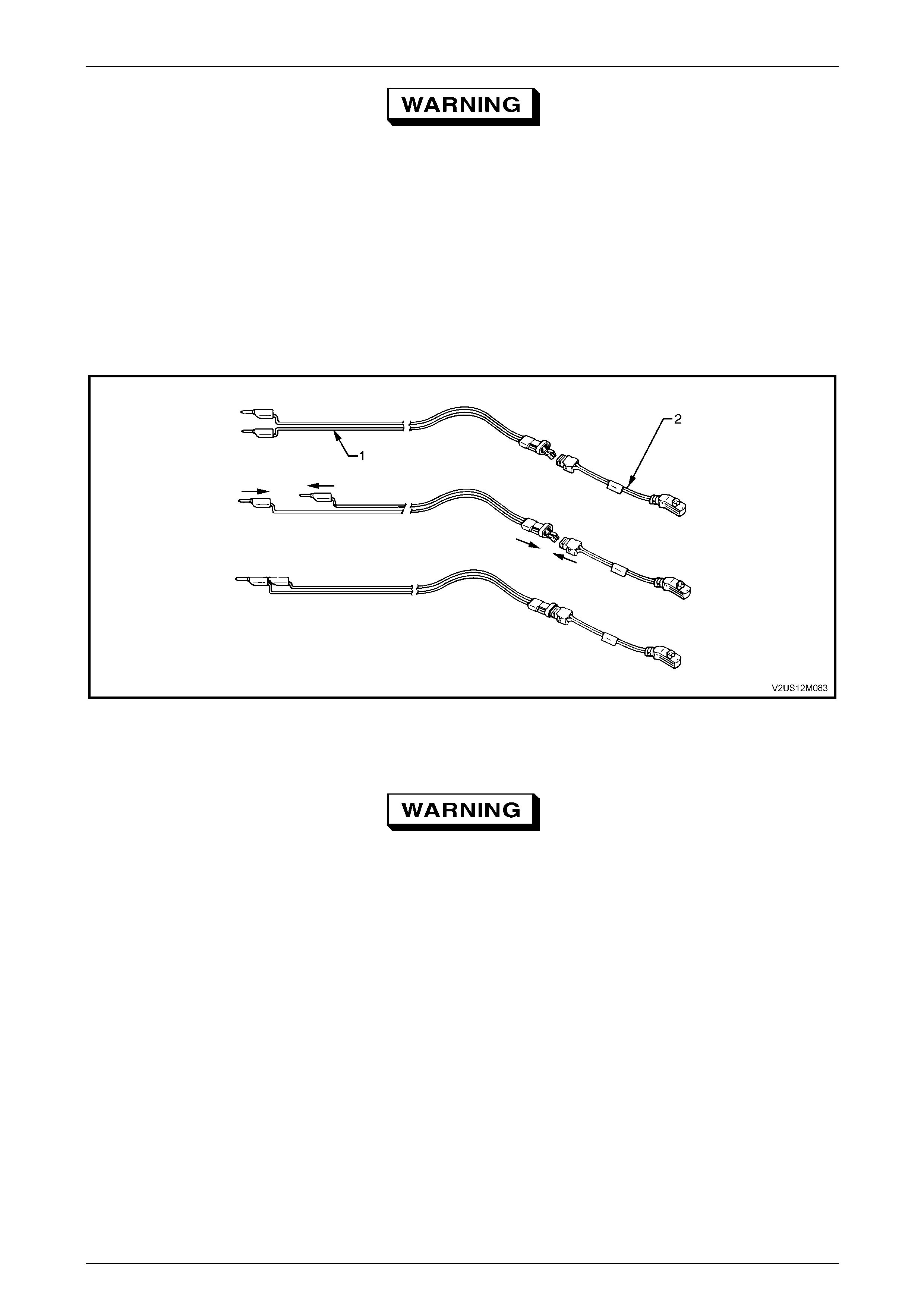
Occupant Protection System Page 12M–172
Page 12M–172
The deployment h arness must remain sh orted
and not connected to a power source until the
inflatable restraint assembly is to be
deployed, refer to Figure 12M – 65. The
inflatable restraint assembly will immediately
deploy when a power source is connected to
it.
3 Short the two deployment harness leads together by fully seatin g one banana plug into the other. The deployment
harness must remain shorted and not connected to a power source until the inflatable restraint is to be deployed,
refer to Figure 12M – 65.
4 Connect the deployment harness Tool No. J213526–1 (1) to the adaptor Tool No. E199 2 (2).
Figure 12M – 65
5 Remove relevant side-impact inflatable restraint assembly from the vehicle as detailed in this Section.
• When storing a live side-impact inflatable
restraint assembly or when leaving a live
side-impact inflatable restraint assembly
on a bench or other surface, always face
the inflatable restraint opening up and
away from the surface. Never rest the
inflatable restraint assembly with the
opening face down. This is necessary so
that a free space is provided to allow the
inflatable restraint to expand in the
unlikely event of accidental deployment.
Failure to follow procedures may result in
personal injury.
• Ensure other personnel working in the
area are informed where the live inflatable
restraint assembly is and to take care
when working in proximately to the
inflatable restraint assembly.
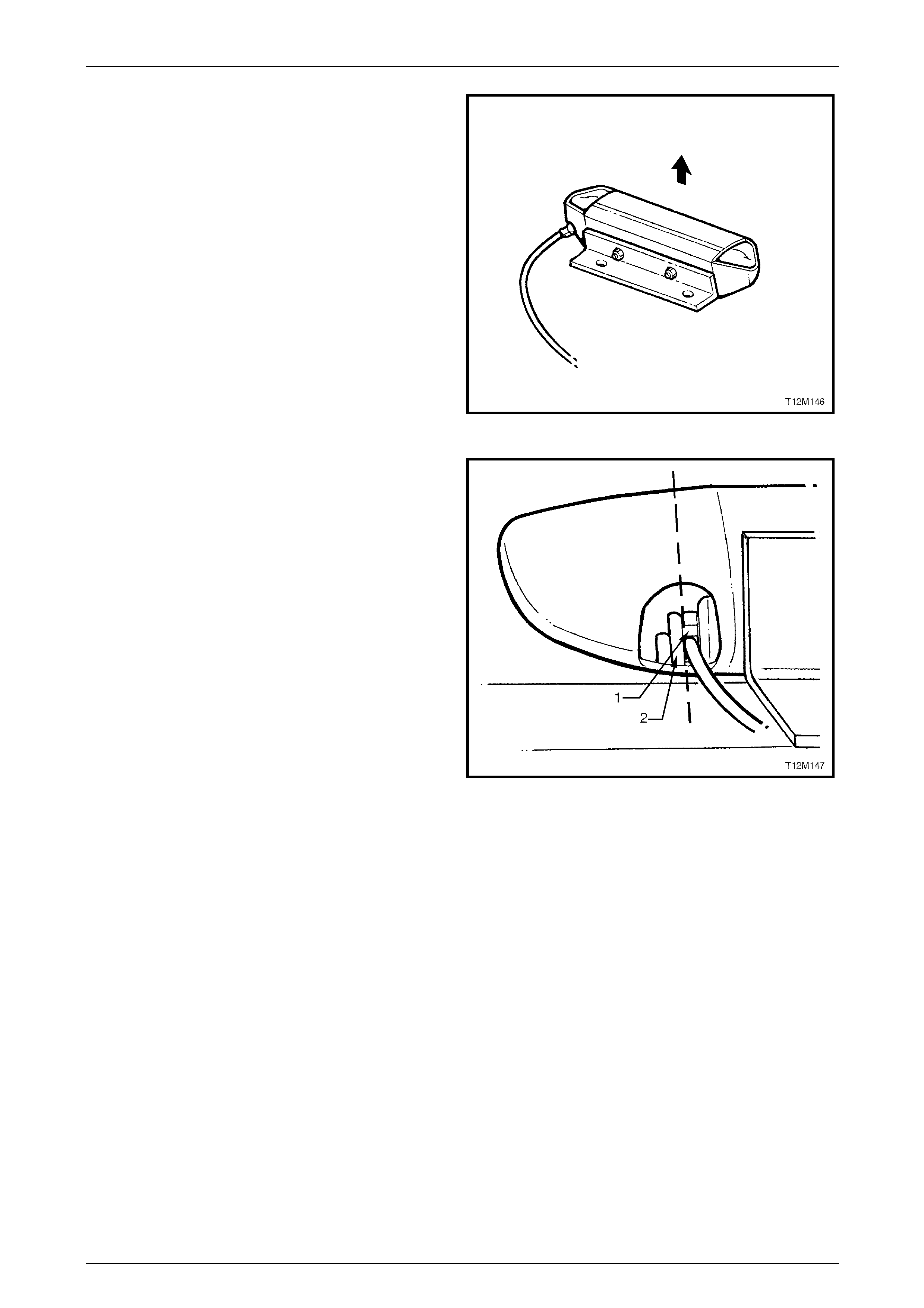
Occupant Protection System Page 12M–173
Page 12M–173
6 Using a piece of angle iron (approximately 60cm long)
drill two holes on one surface that will allow it to be
bolted to a piece of square steel tubing (refer to Step 9
and Step 11).
7 On the other surface of the angle iron, drill two more
holes that are suitably sized and positioned to allow
the side-impact inflatable restraint assembly to be
attached to it.
8 Using the existing side-impact inflatable restr aint
assembly retaining studs and appropriate nuts, attach
the side-impact inflatable restraint assembly to the
angle iron, ensuring the opening of the inflatable
restraint will be able to face upwards when bolted to
the square steel tubing.
Figure 12M – 66
NOTE
The side-impact inflatable restraint assembly
plastic housing has an anti-back-out lug (2)
moulded into it which will prevent the OPS wiring
harness connector (1) from being disconnected.
Due to the in-built capacitor in this connector, a
side-impact inflatable restraint assembly cannot
be intentionally deployed with this connector in
the circuit. Therefore, it will be necessary to cut
part of the side-impact inflatable restraint
housing away from the side-impact inflatable
restraint assembly to allow the OPS wiring
harness connector be disconnected.
9 Clamp the angle iron (with the side-impact inflatable
restraint assembly attached) in a vice with the
inflatable restraint opening facing u pwards. Using a
hack saw, cut the end off the side-impact inflatable
restraint assembly plastic housing, to allow the OPS
wiring harness connector (1), with in-built capacitor, to
be disconnected from the side-impact infl atable
restraint assembly.
10 Disconnect the OPS wiring harness from the side-
impact inflatable restraint assembly.
Figure 12M – 67
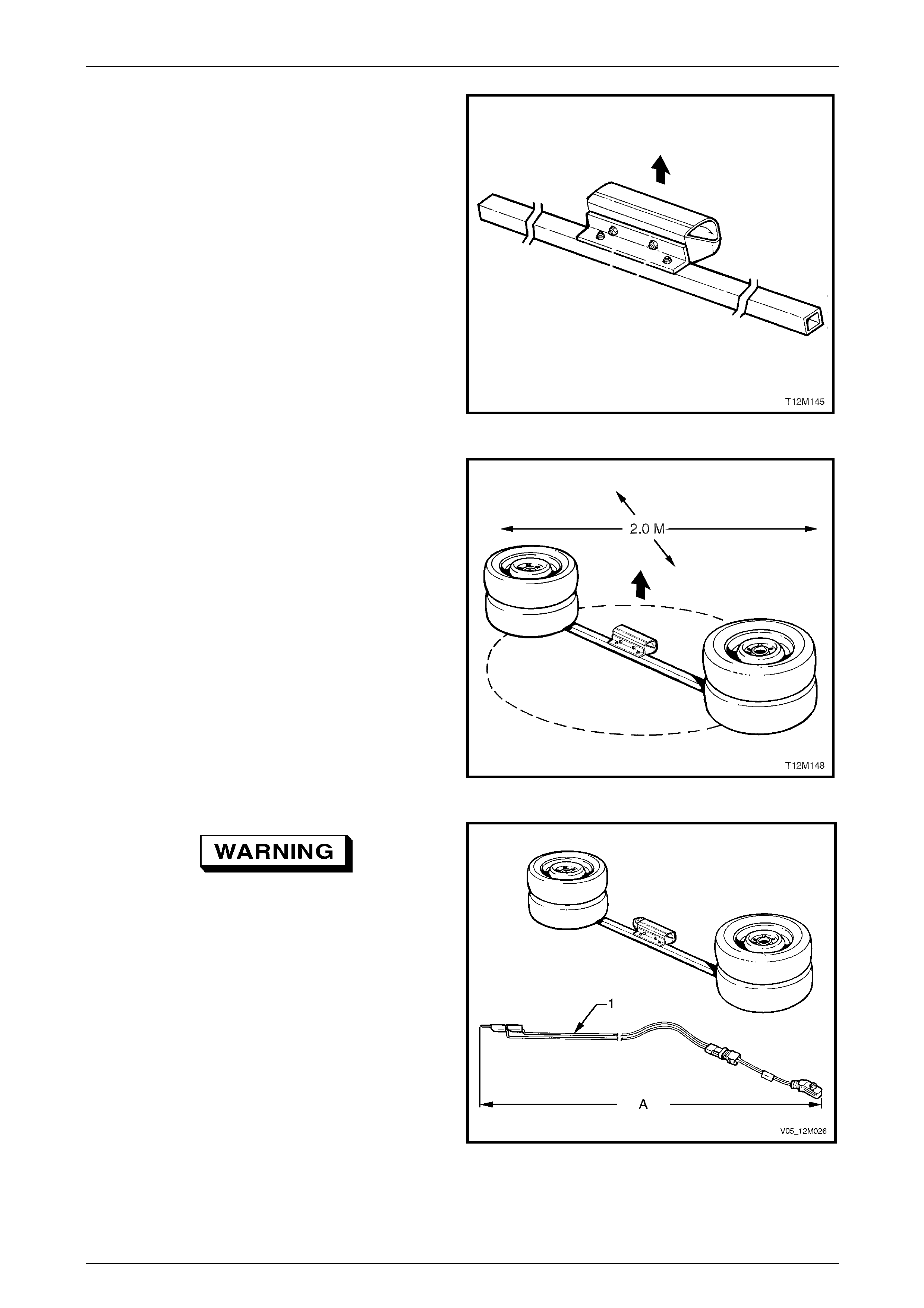
Occupant Protection System Page 12M–174
Page 12M–174
11 Using a 2 metre long square steel tube and suitable
nuts and bolts, attach the angle iron and si de-impact
inflatable restraint assembly to the centre of the
square steel tube.
Figure 12M – 68
12 Clear a space on the gro und about two metres in
diameter where the assembly is to be deployed. A
paved, outdoor location where there is no activity is
preferred. If an outdoor location is not available, a
space on the workshop floor where there is no activity
and sufficient ventilation is rec ommen ded. Ensure no
loose or flammable obj ects are within the deployment
area.
13 Position two whee l and tyre assemblies on each end
of the square steel tubing, ens uring the side-impact
inflatable restraint assembly opening is facing
upwards.
Figure 12M – 69
The deployment harness (1) must be laid out
to its full length (A) to allow the technician
maximum distance from the inflatable
restraint assembly to be deployed. This
minimises any chance of injury to the
technician.
14 Extend the deployment harness and adaptor to its full
length from the side-impact inflatable restraint
assembly.
15 Place a power source near th e shorted end of the
deployment harness. The recommen ded application
is 12-14 V, with a minimum of 2 A (a vehicle battery is
suggested).
Figure 12M – 70
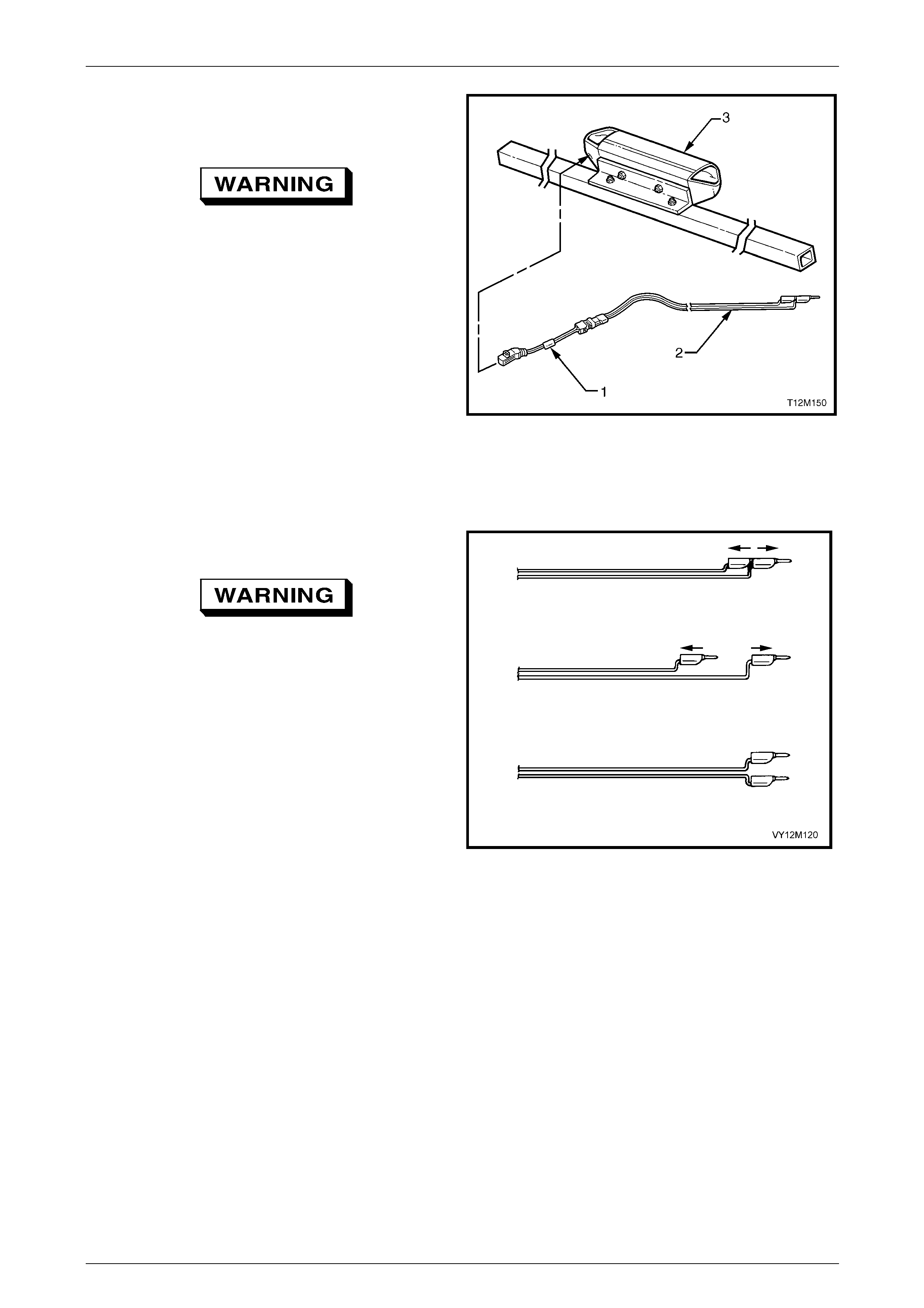
Occupant Protection System Page 12M–175
Page 12M–175
16 Connect the adaptor E1992 (1) and deployment
harness lead J213526-1 (2) to the side-impact
inflatable restraint assembly (3).
The deployment harness must remain
shorted and not connected to a power source
until the inflatable restr aint assembly is to be
deployed. The inflatable restraint assembly
will immed iately de ploy w hen a pow er source
is connected to it.
17 Verify the area around the side-impact airbag module
assembly is clear of all people and lo ose or flammable
objects.
18 Verify the side-impact inflatable restraint assembly is
resting with the inflatable restraint assembly cushion
facing up.
19 Notify all people in the immediate area that you intend
to deploy the side-impact inflatable restraint assembly.
The deployment will be accompan ied by an explosion,
which may startle others.
Figure 12M – 71
20 Separate the two banana plugs on the deplo yment
harness.
When the inflatable restraint deploys, the
rapid gas expansio n will create an explo sion.
Notify all people in the immediate area that
you intend to deploy the inflatable restraint.
21 Connect deployment harn ess leads to the power
source to immediately deploy the side-impact
inflatable restraint assembly, refer to Figure 12M – 73.
NOTE
When the inflatable restraint deploys, the
assembly may jump vertically. This is a normal
reaction of the assembly to the force of the rapid
gas expansion inside the inflatable restraint. Figure 12M – 72
Occupant Protection System Page 12M–176
Page 12M–176
Figure 12M – 73
22 Disconnect the deployment harness from the power source.
23 Short the two deplo yment harness le ads together by fully seating one ba nana plug into the other.

Occupant Protection System Page 12M–177
Page 12M–177
• Safety precautions must be observed
when handling a deployed inflatable
restraint assembly. After deployment, the
metal surfaces of the module will be very
hot. Do not touch these metal areas of the
module for about 10 minutes after
deployment. Do not place the deployed
inflatable restraint assembly near any
flammable objects. If the deployed
inflatable restraint assembly must be
moved before it has cooled, wear gloves
and handle by the inflatable restraint
assembly cushio n o r the trim cover.
• Ensure you are wearing safety glasses and
gloves to protect your eyes and hands
from possible irritation and heat when
handling the deployed side-impact
inflatable restraint assembly.
NOTE
After deployment, the surface of the cushion
may contain a powdery residue. This powder
consists primarily of cor n starc h (used to l ubr icate
the cushion) and by-products of the chemical
reaction. The by-products of inflatable restraint
assembly module deployment are carbon
monoxide (CO), nitrogen (N), carbon dioxide
(CO2), water (H2O) with trace amounts of oxides
of nitrogen (NOΧ) and ammonia (NH3).
Figure 12M – 74
24 Disconnect the adaptor E1992 from the inflatable restraint assembly as soon as possibl e after deployment. This will
prevent damage to the adaptor or deployment harness. The adaptor and deployment harness are desig ned to be
reused. They should, however, be inspected for damage after each deplo yment and replaced if necessary.
25 Dispose of the deployed steering wheel inflatable restraint assembly throug h normal refuse channels after it has
cooled for at least 10 minutes.
26 Wash your hands with mild soap and water afterward.
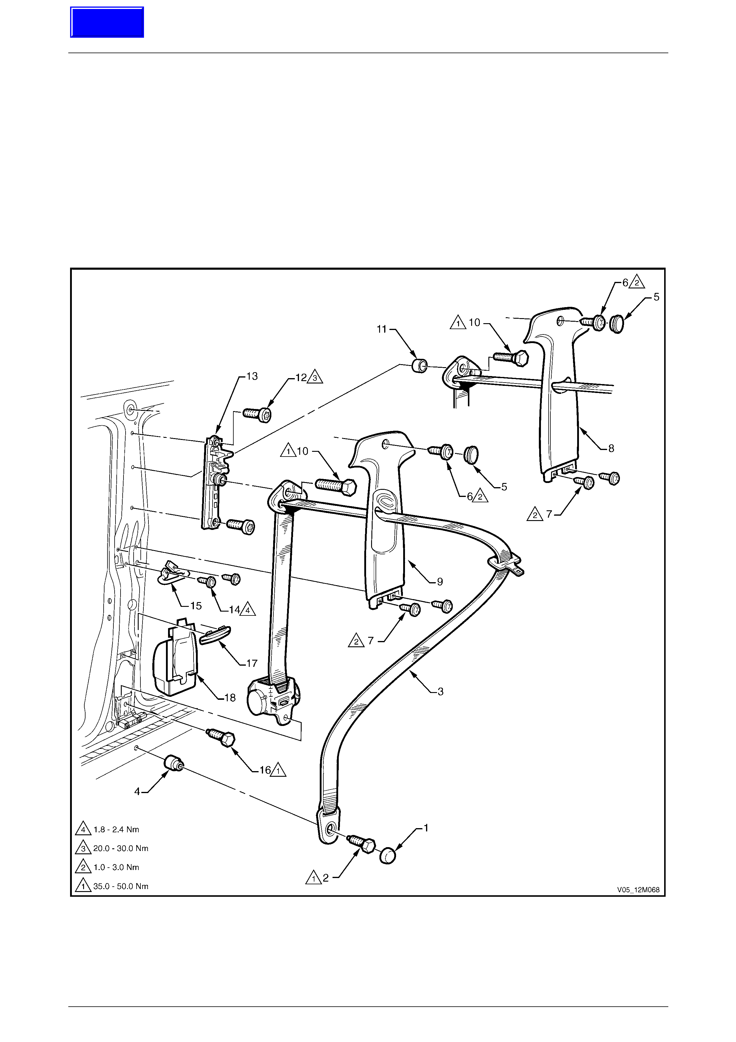
Occupant Protection System Page 12M–178
Page 12M–178
4 Service Operations – Front
Seatbelts
4.1 Front Seatbelts – Except Utility, Regular
Cab and Coupe
LT Section No. — 14–400
Front Seatbelt Assembly
Figure 12M – 75
Techline
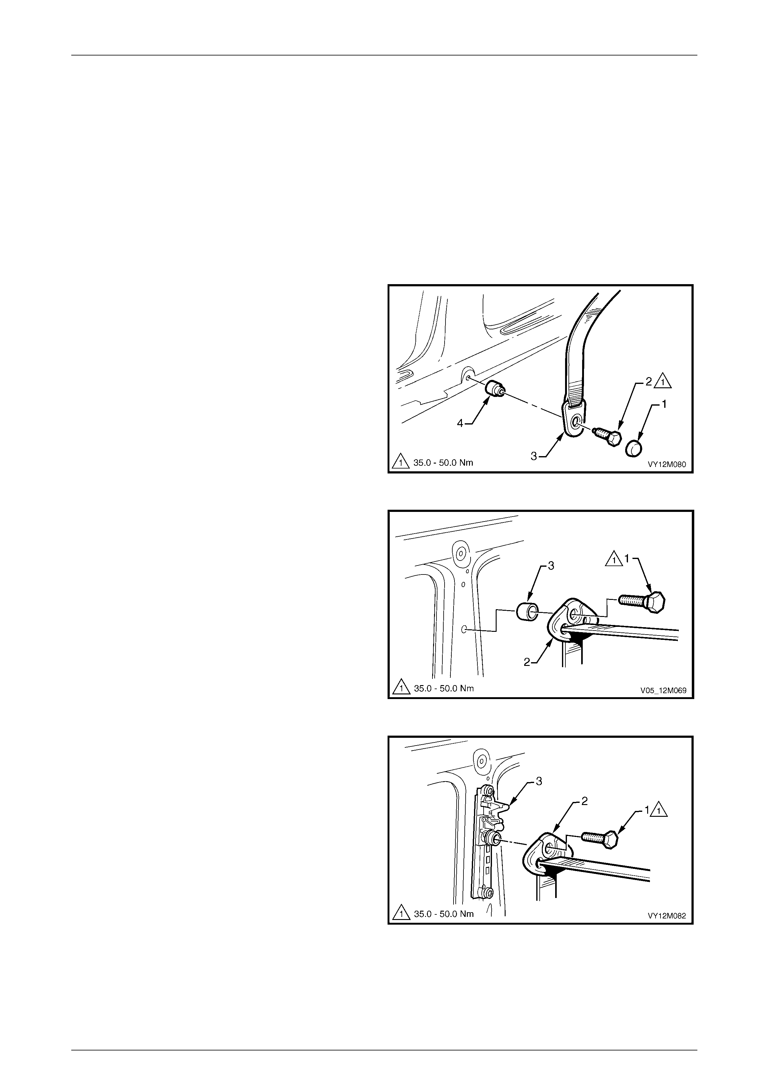
Occupant Protection System Page 12M–179
Page 12M–179
Legend
1 Seatbelt Anchor Attaching Bolt Cap
2 Seatbelt Anchor Attaching Bolt
3 Front Seatbelt Assembly
4 Seatbelt Anchor Spacer
5 Centre Pillar Trim Screw Cap
6 Centre Pillar Trim Upper Attaching Screw
7 Centre Pillar Trim Lower Attaching Screw
8 Centre Pillar Trim, Without Height Adjuster
9 Centre Pillar Trim, With Height Adjuster
10 Upper Seatbelt Guide Attaching Bolt
11 Upper Seatbelt Guide Spacer
12 Seatbelt Height Adjuster Attaching Bolt
13 Seatbelt Height Adjuster Assembly
14 Intermediate Seatbelt Guide Attaching Screw
15 Intermediate Seatbelt Guide
16 Seatbelt Retractor Attaching Bolt
17 Lower Seatbelt Guide
18 Seatbelt Retractor Dust Cap
Remove
1 Prise the cap (1) from the lower anchor bolt (2).
2 Remove the bolt attaching the seatbelt lower anchor
(3) to the vehicle. Ensure the spacer (4) remains with
the bolt.
3 Remove the centre pillar lower trim, centre pill ar upper
trim and side sill trim, refer to
Section 1A8 Headlining and Interior Trim .
Figure 12M – 76
4 For vehicles without a seatbelt height adjuste r:
a Remove the bolt (1) attaching the upper seatbelt
guide (2) to the vehicle. Ensure the spac er (3)
remains with the bolt.
Figure 12M – 77
5 For vehicles with a seatbelt height adjuster:
a Remove the bolt (1) attaching the upper seatbelt
guide (2) to the height adjuster assembl y (3).
Figure 12M – 78
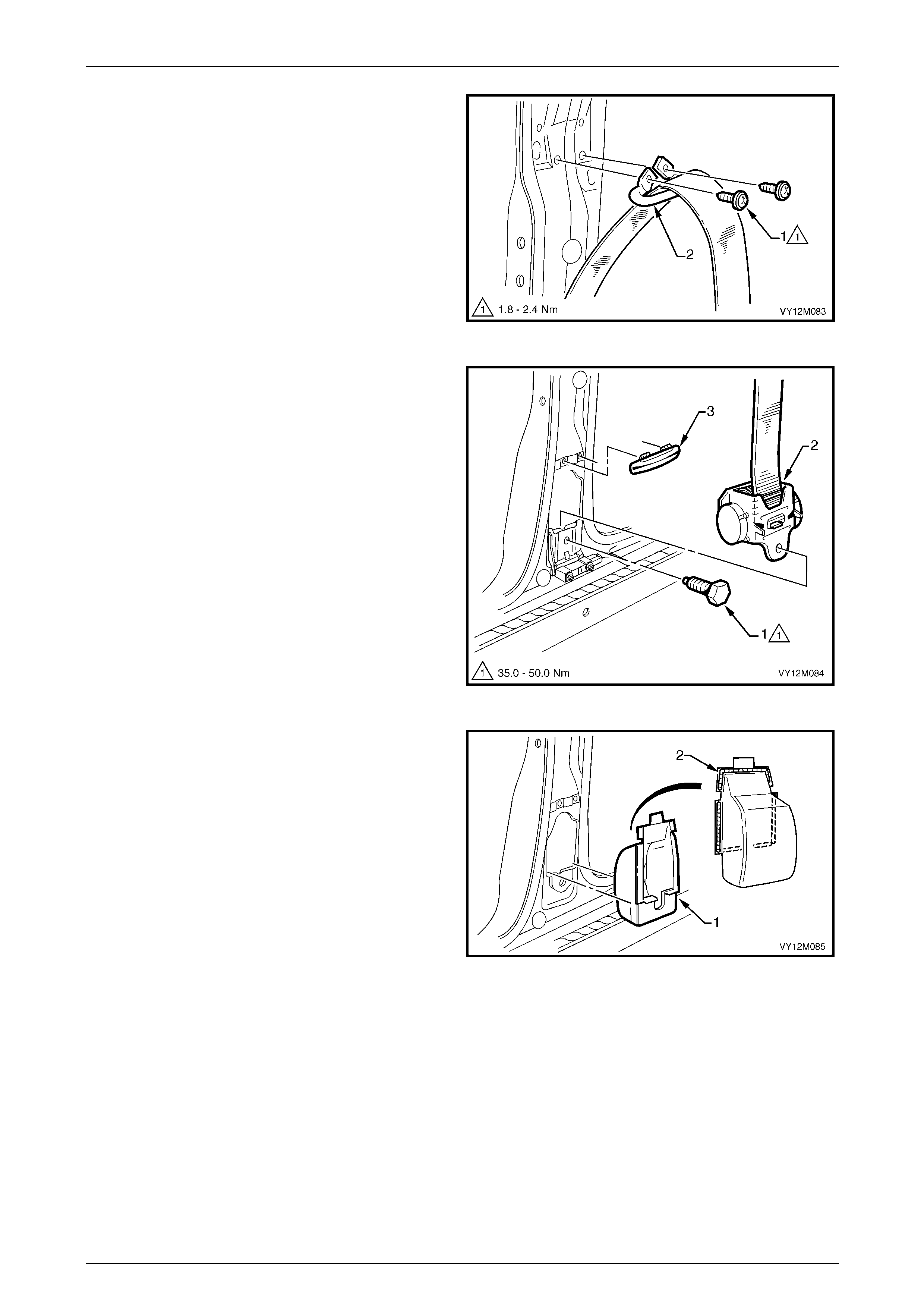
Occupant Protection System Page 12M–180
Page 12M–180
6 Remove the two screws (1) attaching the inte rmediate
seatbelt guide (2) to the vehicle.
Figure 12M – 79
7 Remove the bolt (1) attaching the retractor assembly
(2) to the vehicle and remove the seatbelt assembly
from within the pillar cavity.
8 If required, unclip the lo wer guide (3) by prising with a
fine flat-blade screwdriver.
Figure 12M – 80
9 If required, carefully remove the retractor dust cap (1)
from the pillar cavity by breaking the sealer (2) around
the perimeter.
Figure 12M – 81
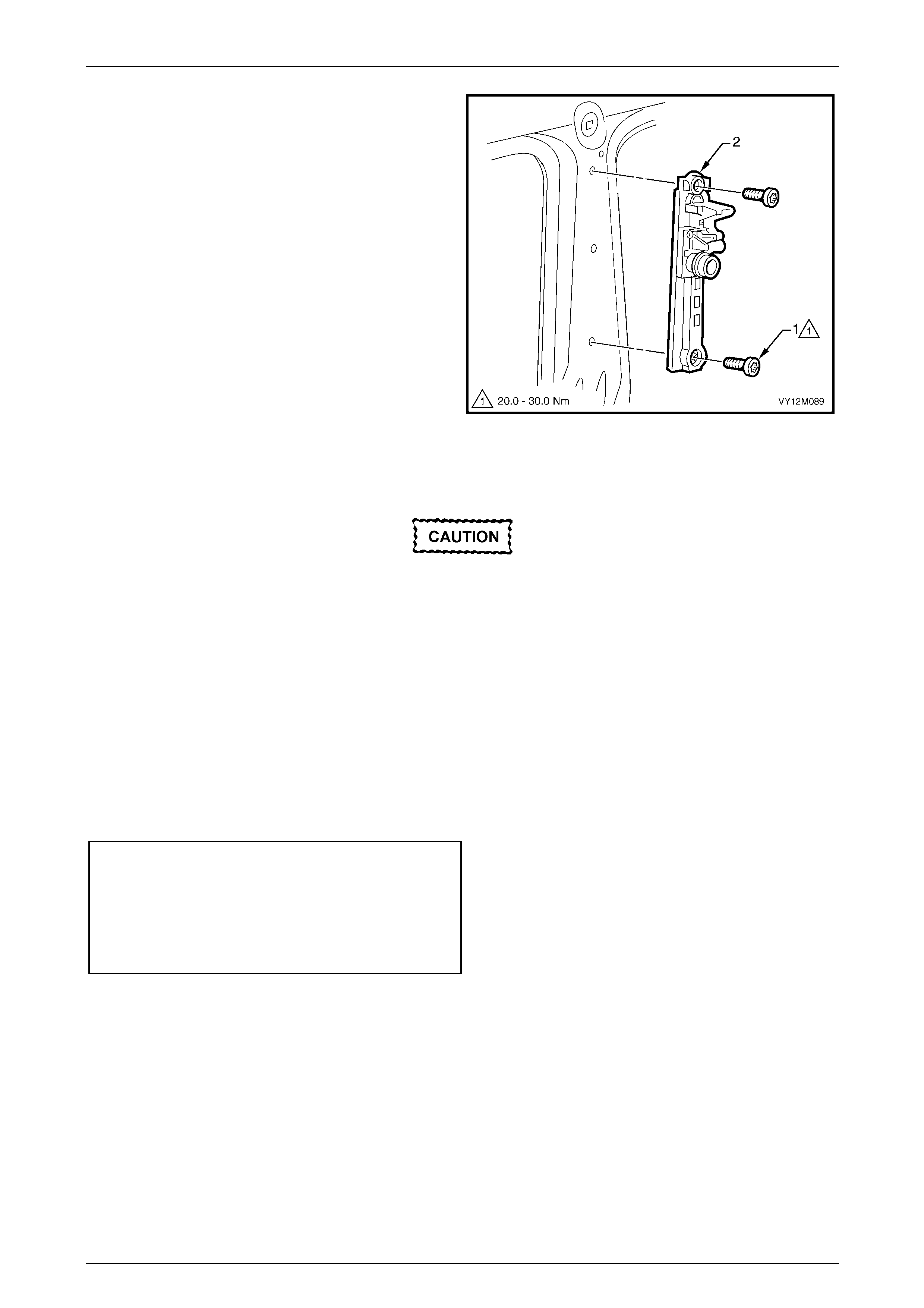
Occupant Protection System Page 12M–181
Page 12M–181
10 If required and fitted, remove the two bolts (1)
attaching the seatbelt height adjuster assembly to the
vehicle, and remove the adjus t er assembly.
Figure 12M – 82
Reinstall
If reinstalling the same retractor assembly,
inspect the anchor plates, guides and
retractor assembly for damage and the
webbing for abrasions, fraying, cuts etc.
Replace the seatbelt ass em bl y wi th a new part
if any part is damaged.
Reinstallation of the front seat belt assembly is the reverse of the removal procedure, noting the follo wing:
1 Apply a bead of non-hardening sealer (windscreen sealer) around the perimeter of the retractor dust cap, refer to
Figure 12M – 81.
2 Ensure the webbing is not twisted and the anchor plate is installed in the correct orientation.
3 Hand tighten all seatbelt bolts a minimum of five turns before using tools.
4 Tighten the bolts to the specified torque.
Seatbelt assembly mounting bolt
torque specification.................................35.0 – 50.0 Nm
Intermediate seatbelt guide attaching
screw torque specification...........................1.8 – 2.4 Nm
Seatbelt height adjuster ass embly
attaching bolt torque specification...........20.0 – 30.0 Nm
5 If fitted, set the seatbelt height adjuster to the full up position prior to installation of the centre pillar upper trim.
6 Perform a functional check of the seatbelt to ensure correct operation.
Front Seatbelt Buckle and Pretensioner Assembly
For service operations for the seatbelt buckle and pretensioner assembly, refer to
3.5 Seatbelt Buckle and Pretensioner Assembly.
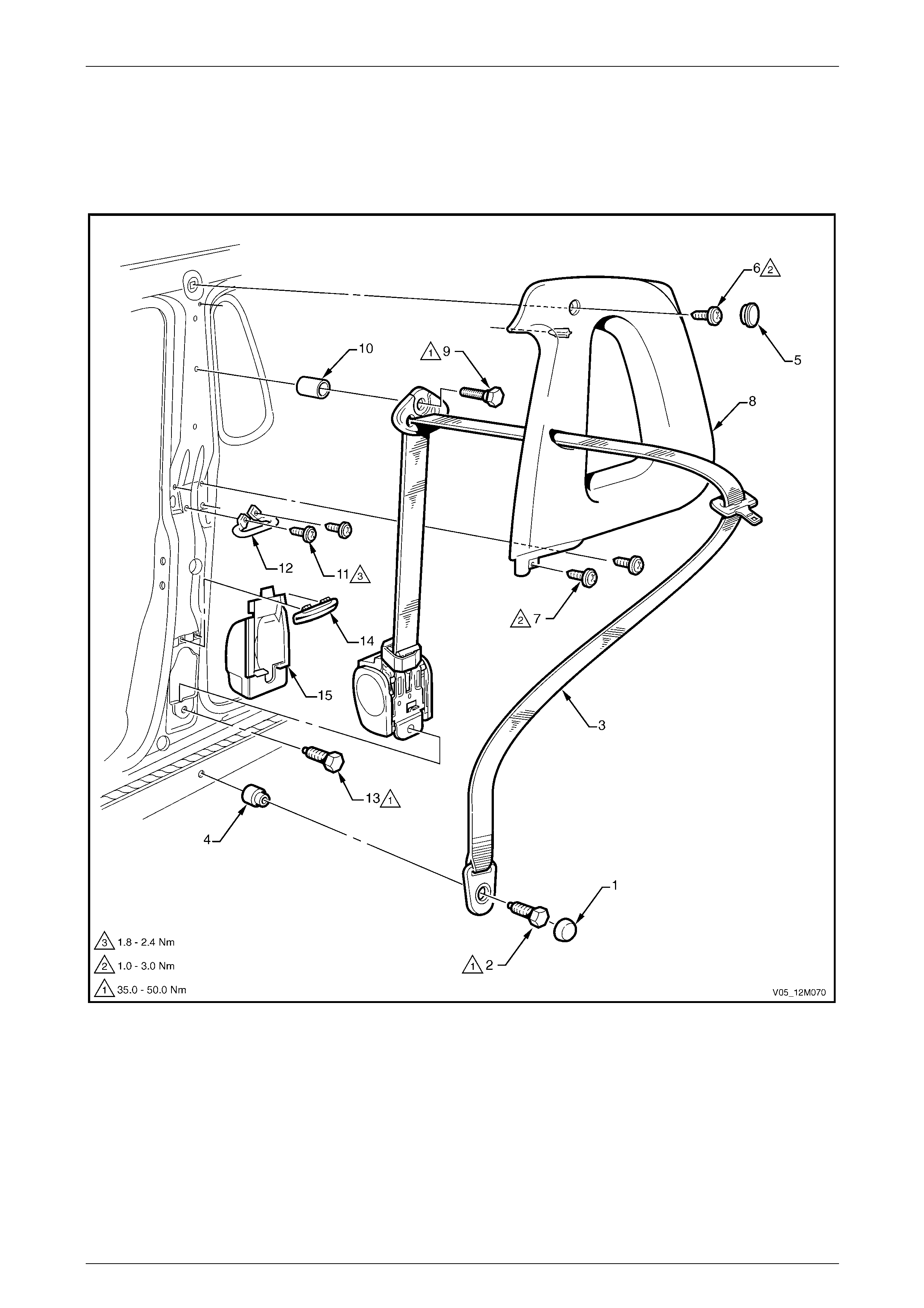
Occupant Protection System Page 12M–182
Page 12M–182
4.2 Front Seatbelts – Utility and Regular Cab
LT Section No. — 14–400
Front Seatbelt Assembly
Figure 12M – 83
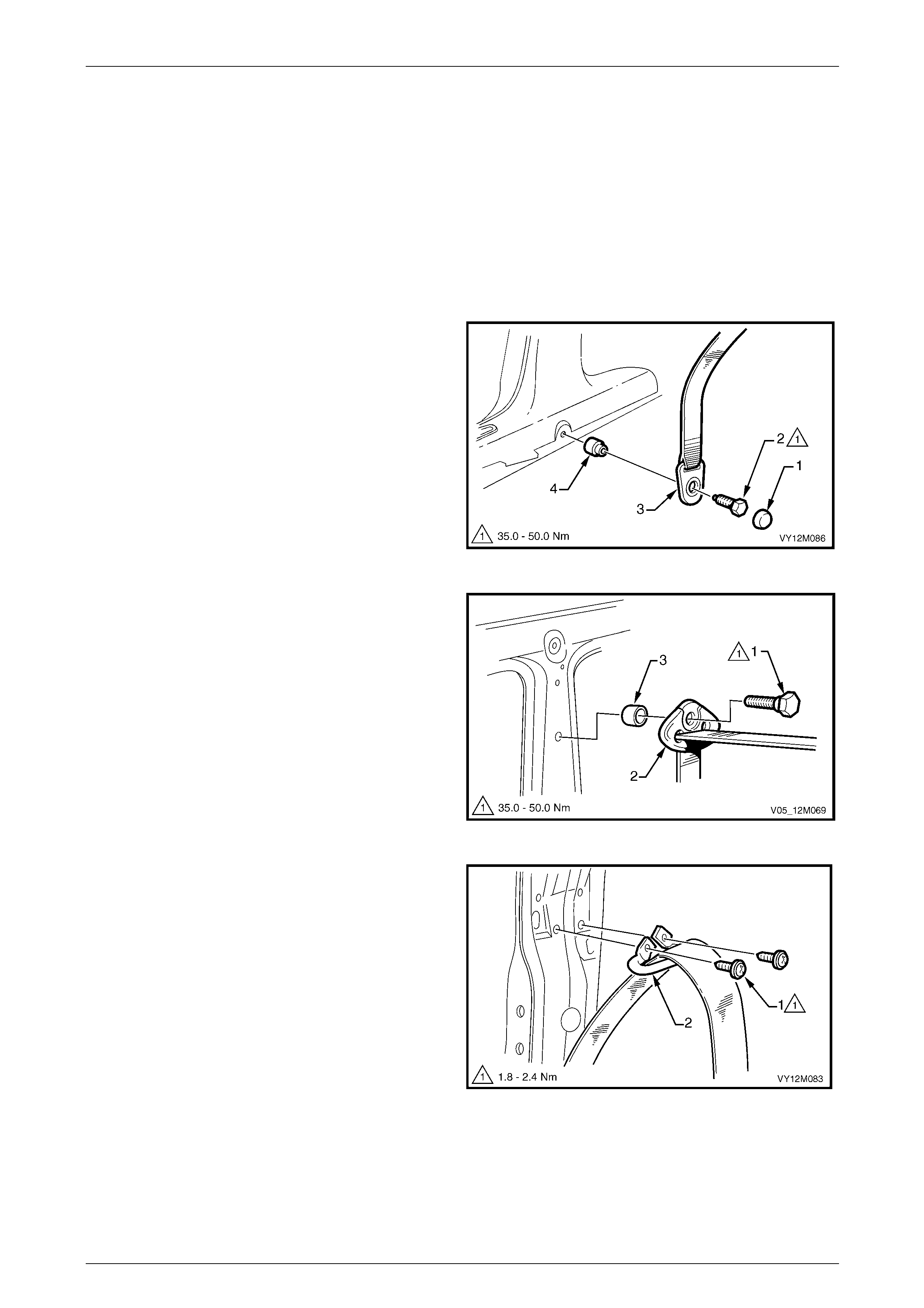
Occupant Protection System Page 12M–183
Page 12M–183
Legend
1 Seatbelt Anchor Attaching Bolt Cap
2 Seatbelt Anchor Attaching Bolt
3 Front Seatbelt Assembly
4 Seatbelt Anchor Spacer
5 Body Lock Pillar Trim Screw Cap
6 Body Lock Pillar Trim Attaching Screw
7 Body Lock Pillar Trim Lower Attaching Screw
8 Body Lock Pillar Trim
9 Upper Seatbelt Guide Attaching Bolt
10 Upper Seatbelt Guide Spacer
11 Intermediate Seatbelt Guide Attaching Screw
12 Intermediate Seatbelt Guide
13 Seatbelt Retractor Attaching Screw
14 Lower Seatbelt Guide
15 Seatbelt Retractor Dust Cap
Remove
1 Prise the cap (1) from the lower anchor bolt (2).
2 Remove the bolt attaching the seatbelt lower anchor
(3) to the vehicle. Ensure the spacer (4) remains with
the bolt.
3 Remove the centre pillar lower trim, bod y lock pillar
upper trim and side sill trim, refer to
Section 1A8 Headlining and Interior Trim .
Figure 12M – 84
4 Remove the bolt (1) attaching the upper seatbelt guide
(2) to the vehicle. Ensure the spacer (3) remains with
the screw.
Figure 12M – 85
5 Remove the two screws (1) attaching the inte rmediate
seatbelt guide (2) to the vehicle.
Figure 12M – 86
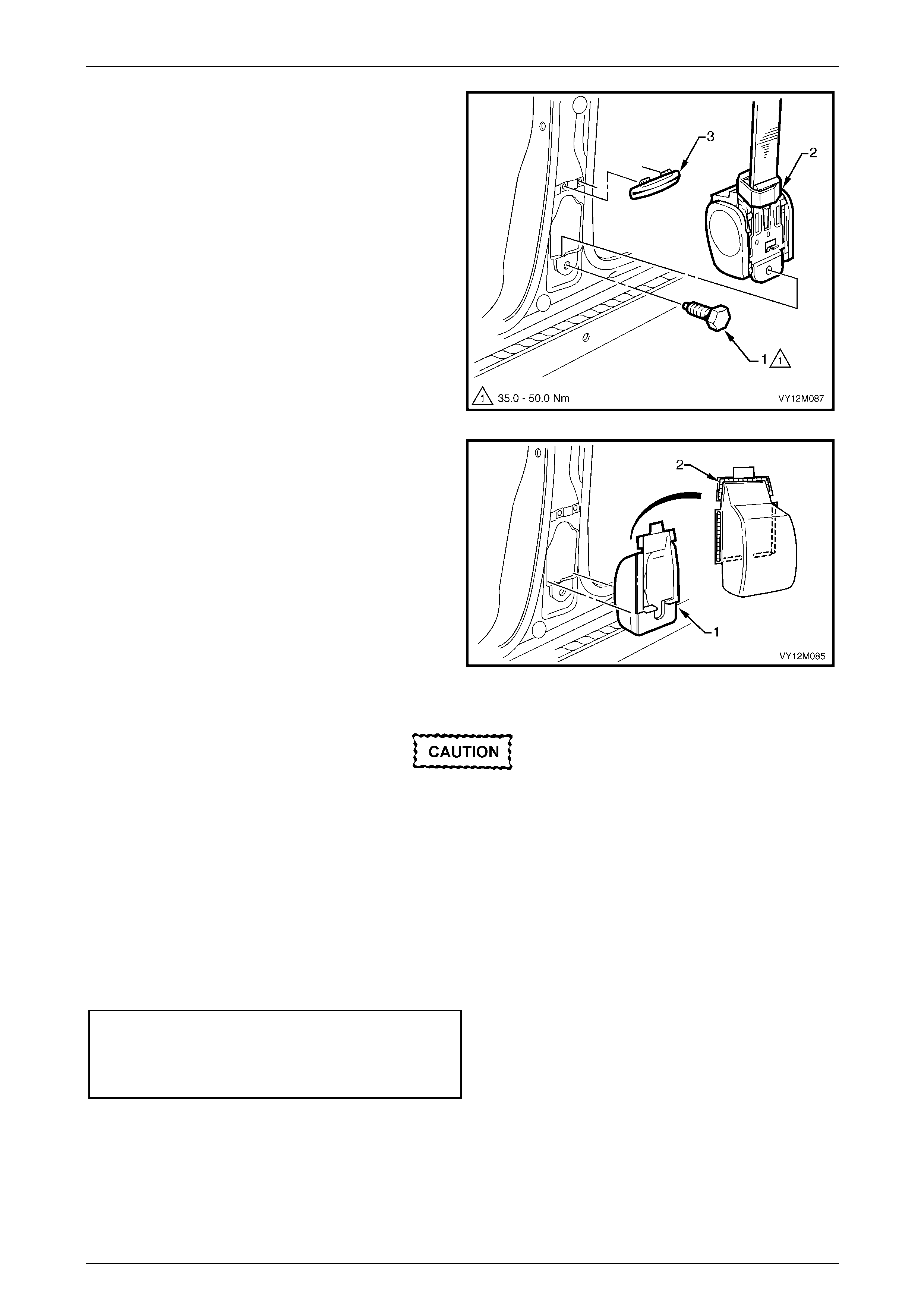
Occupant Protection System Page 12M–184
Page 12M–184
6 Remove the bolt (1) attaching the retractor assembly
(2) to the vehicle and remove the seatbelt assembly
from within the pillar cavity.
7 If required, unclip the lo wer guide (3) by prising with a
fine flat-blade screwdriver.
Figure 12M – 87
8 If required, carefully remove the retractor dust cap (1)
from the pillar cavity by breaking the sealer (2) around
the perimeter.
Figure 12M – 88
Reinstall
If reinstalling the same retractor assembly,
inspect the anchor plates, guides and
retractor assembly for damage, and the
webbing for abrasions, fraying, cuts, etc.
Replace the seatbelt ass em bl y wi th a new part
if any damage, etc. is found.
Reinstallation of the front seat belt assembly is the reverse of the removal procedure, noting the follo wing:
1 Apply a bead of non-hardening sealer (windscreen sealer) around the perimeter of the retractor dust cap, refer to
Figure 12M – 88.
2 Ensure the webbing is not twisted and the anchor plate is installed in the correct orientation.
3 Hand tighten all seatbelt bolts a minimum of five turns before using tools.
4 Tighten the bolts to the specified torque.
Seatbelt assembly mounting bolt
torque specification.................................35.0 – 50.0 Nm
Intermediate seatbelt guide attaching
screw torque specification...........................1.8 – 2.4 Nm
5 Perform a functional check of the seatbelt to ensure correct operation.
Front Seatbelt Buckle and Pretensioner Assembly
For service operations for the seatbelt buckle and pretensioner assembly, refer to
3.5 Seatbelt Buckle and Pretensioner Assembly.
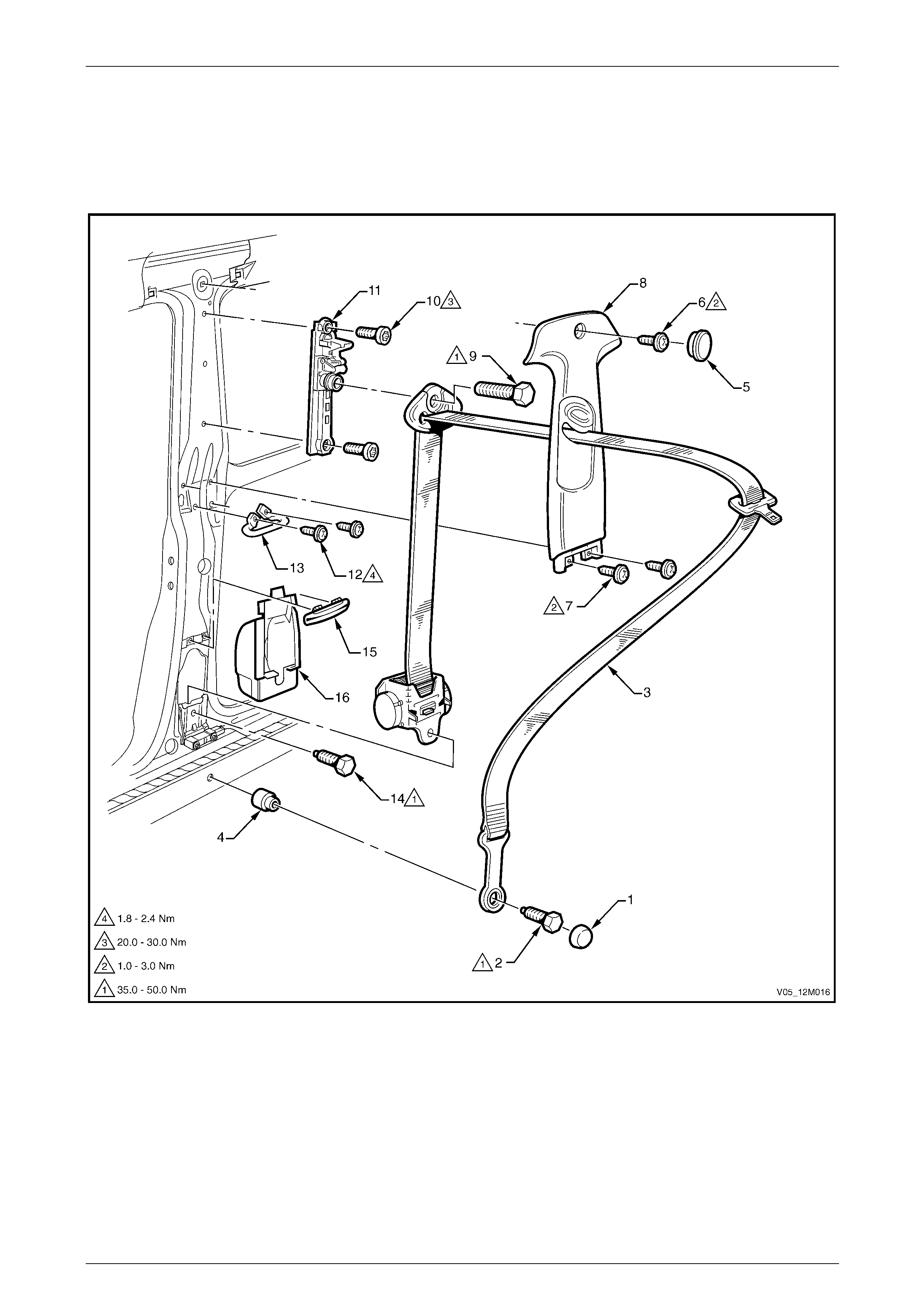
Occupant Protection System Page 12M–185
Page 12M–185
4.3 Front Seatbelts – Coupe
LT Section No. — 14–400
Front Seatbelt Assembly
Figure 12M – 89
Legend
1 Seatbelt Anchor Attaching Bolt Cap
2 Seatbelt Anchor Attaching Bolt
3 Front Seatbelt Assembly
4 Seatbelt Anchor Spacer
5 Centre Pillar Trim Screw Cap
6 Centre Pillar Trim Upper Attaching Screw
7 Centre Pillar Trim Lower Attaching Screw
8 Centre Pillar Trim, With Height Adjuster
9 Upper Seatbelt Guide Attaching Bolt
10 Seatbelt Height Adjuster Attaching Bolt
11 Seatbelt Height Adjuster Assembly
12 Intermediate Seatbelt Guide Attaching Screw
13 Intermediate Seatbelt Guide
14 Seatbelt Retractor Attaching Bolt
15 Lower Seatbelt Guide
16 Seatbelt Retractor Dust Cap
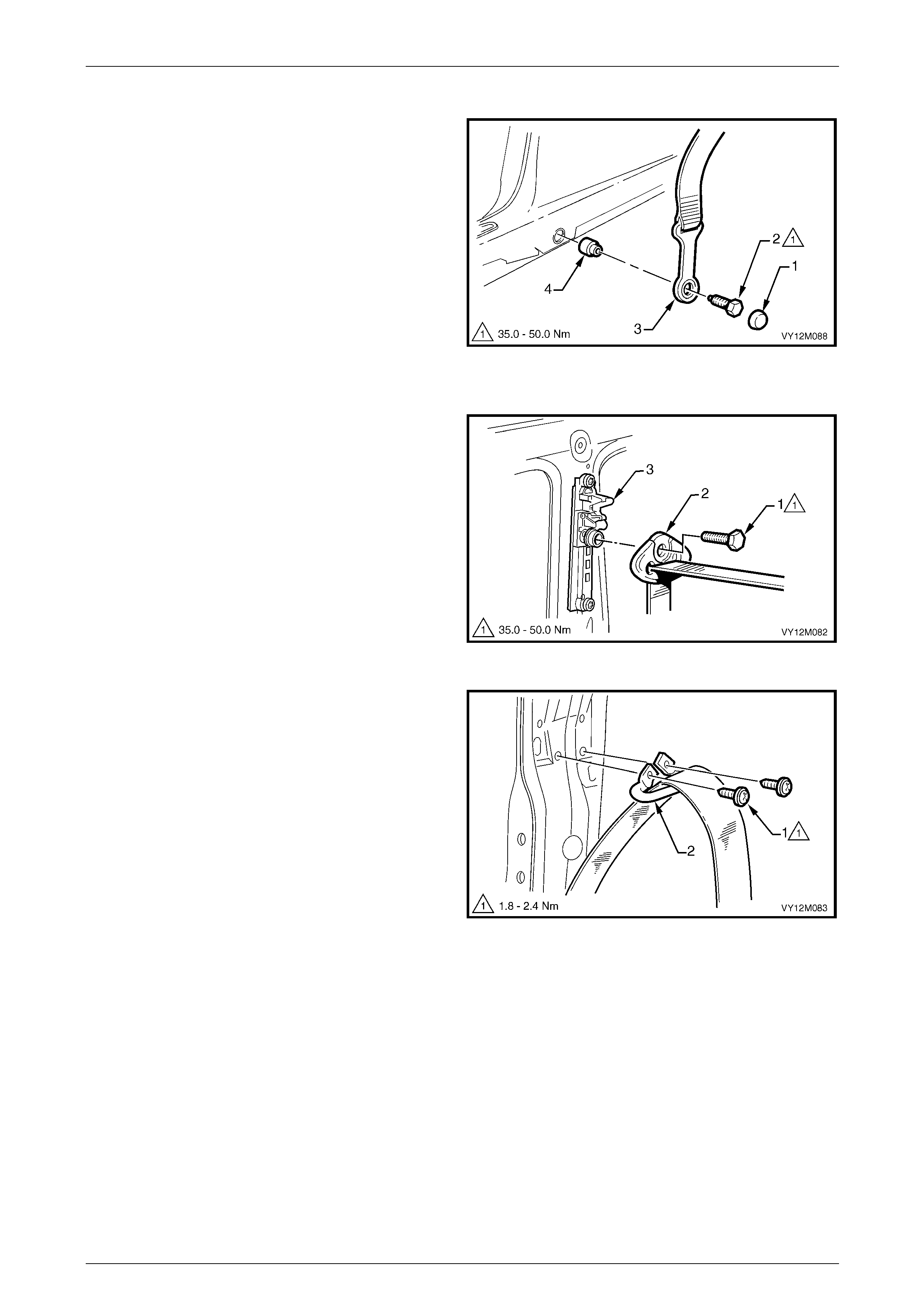
Occupant Protection System Page 12M–186
Page 12M–186
Remove
1 Prise the cap (1) from the seatbelt anchor bolt (2).
2 Remove the bolt attaching the seatbelt lower
anchor (3) to the vehicle. Ensure the seatbelt
spacer (4) remains with the bolt.
3 Remove the following:
a Rear seat cushion, refer to
Section 1A7 Seat Assemblies.
b Side sill trim, refer to
Section 1A8 Headlining and Interior Trim .
c Quarter panel trim assembly, refer to
Section 1A8 Headlining and Interior Trim .
d Centre pillar upper trim refer to
Section 1A8 Headlining and Interior Trim .
Figure 12M – 90
4 Remove the upper seatbelt guide attachin g bolt (1)
attaching the upper seatbelt guide (2) to the hei ght
adjuster assembly (3).
Figure 12M – 91
5 Remove the two intermediate seatbelt guide attaching
screws (1) attaching the intermediate seatb elt gui de
(2) to the vehicle.
Figure 12M – 92

Occupant Protection System Page 12M–187
Page 12M–187
6 Remove the seatbelt retractor attaching bo lt (1)
attaching the retractor assembly (2) to the vehicle then
remove the seatbelt assembly from within the pillar
cavity.
7 If required, unclip the lo wer guide (3) by prising with a
fine flat-blade screwdriver.
Figure 12M – 93
8 If required, carefully remove the retractor assembly
dust cap (1) from the pillar cavit y by breaki ng the
sealer (2) around the perimeter.
Figure 12M – 94
9 If required, remove the two seatbelt height adjuster
attaching bolts (1) attaching the seatbelt height
adjuster assembly to the vehicle, and remove the
seatbelt height adjuster assembly.
Figure 12M – 95

Occupant Protection System Page 12M–188
Page 12M–188
Reinstall
If reinstalling the same retractor assembly,
inspect the anchor plates, guides and
retractor assembly for damage and the
webbing for abrasions, fraying, cuts etc.
Replace the seatbelt ass em bl y wi th a new part
if any part is damaged.
Reinstallation of the front seat belt assembly is the reverse of the removal procedure, noting the follo wing:
1 Apply a bead of non-hardening sealer (windscreen sealer) around the perim eter of the seatbelt retractor dust cap,
refer to Figure 12M – 94.
2 Ensure the webbing is not twisted and the anchor plate is installed in the correct orientation.
3 Hand tighten all seatbelt bolts a minimum of five turns before using tools.
4 Tighten the bolts to the specified torque.
Seatbelt assembly mounting bolt
torque specification.................................35.0 – 50.0 Nm
Intermediate seatbelt guide attaching
screw torque specification...........................1.8 – 2.4 Nm
Seatbelt height adjuster ass embly
attaching bolt torque specification...........20.0 – 30.0 Nm
5 Set the seatbelt height adjuster to the full up position prior to instal latio n of the centre pillar upper trim.
6 Perform a functional check of the seatbelt to ensure correct operation.
Front Seatbelt Buckle and Pretensioner Assembly
For service operations for the seatbelt buckle and pretensioner assembly, refer to
3.5 Seatbelt Buckle and Pretensioner Assembly.
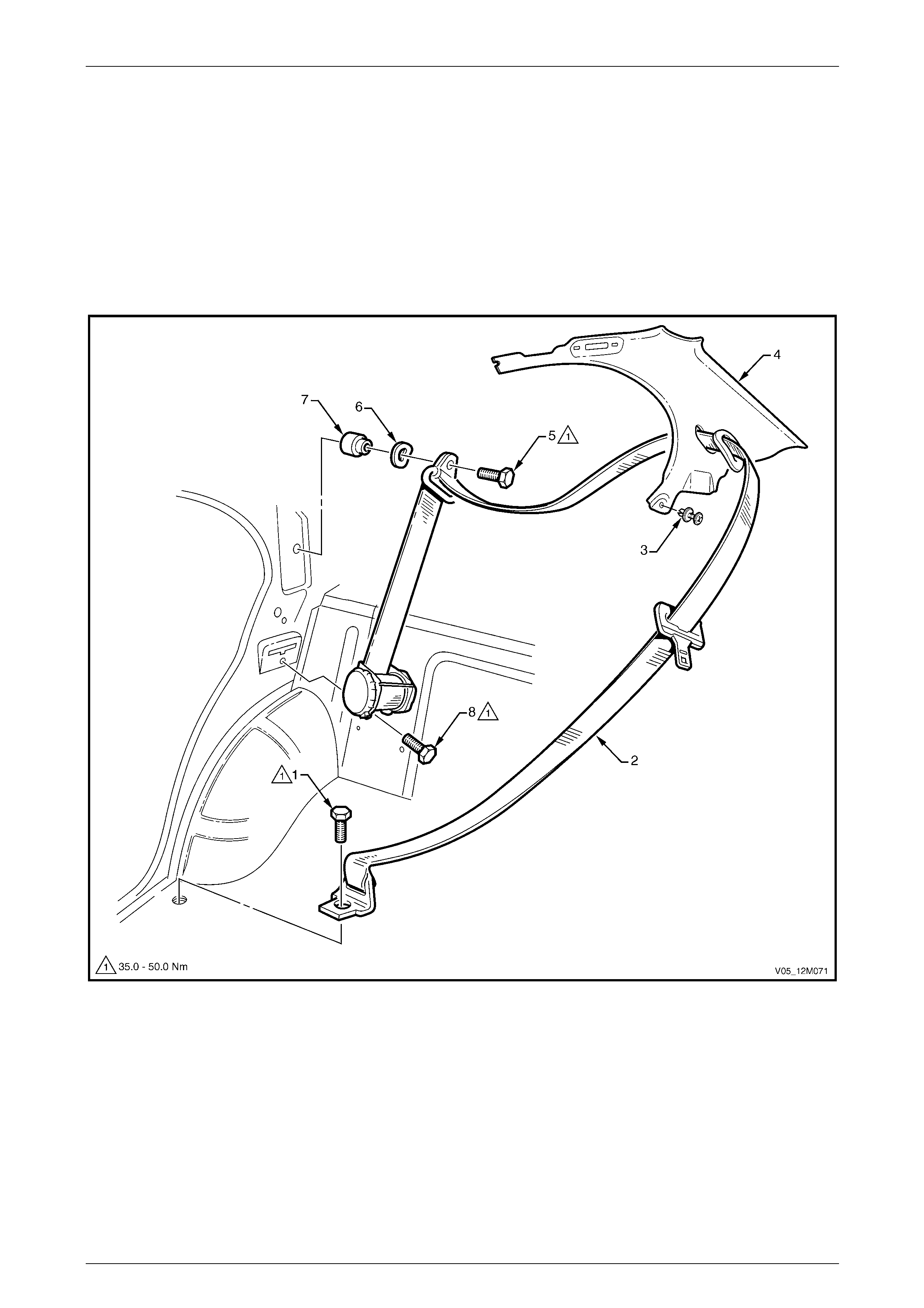
Occupant Protection System Page 12M–189
Page 12M–189
5 Service Operations – Rear
Seatbelts
5.1 Rear Seatbelts – Sedan
LT Section No. — 14–425
Rear Seatbelt Assembly – Outboard
Figure 12M – 96
Legend
1 Seatbelt Anchor Attaching Bolt
2 Rear Seatbelt Assembly, Outer
3 Body Lock Pillar Garnish Retainer
4 Body Lock Pillar Garnish
5 Upper Seatbelt Guide Attaching Bolt
6 Upper Seatbelt Guide Wave Washer
7 Upper Seatbelt Guide Spacer
8 Seatbelt Retractor Attaching Bolt
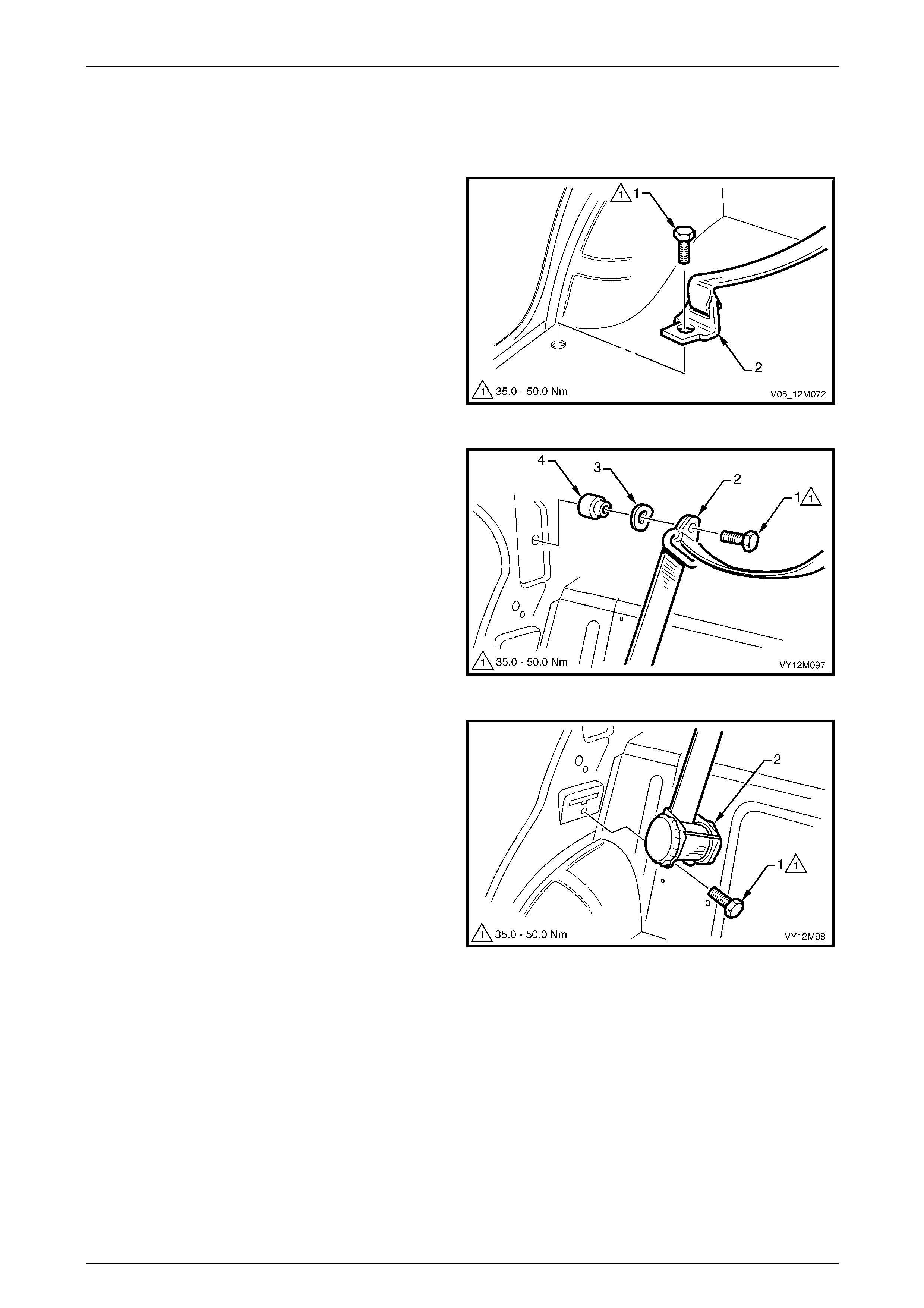
Occupant Protection System Page 12M–190
Page 12M–190
Remove
1 Remove the rear seat cushion and either the left or right-hand rear seat back assembly as applicable, refer to
Section 1A7 Seat Assemblies.
2 Remove the bolt (1) attaching the seatbelt lower
anchor (2) to the vehicle.
3 Remove the body lock pillar garnish, refer to
Section 1A8 Headlining and Interior Trim .
Figure 12M – 97
4 Remove the bolt (1) attaching the upper seatbelt guide
(2) to the vehicle. Ensure the wave washer (3) and
spacer (4) remain with the bolt.
Figure 12M – 98
5 Remove the bolt (1) attaching the retractor assembly
(2) to the vehicle and remove the seatbelt assembly.
Figure 12M – 99

Occupant Protection System Page 12M–191
Page 12M–191
Reinstall
If reinstalling the same retractor assembly,
inspect the anchor plates, guides and
retractor assembly for damage and the
webbing for abrasions, fraying, cuts etc.
Replace the seatbelt ass em bl y wi th a new part
if any part is damaged.
Reinstallation of the rear seatbelt assembly is the reverse of the removal procedure, noting the following:
1 Ensure the webbing is not twisted and the anchor plate is installed in the correct orientation.
2 Hand tighten all seatbelt bolts a minimum of five turns before using tools.
3 Tighten the bolts to the specified torque.
Seatbelt assembly mounting bolt
torque specification.................................35.0 – 50.0 Nm
4 Perform a functional check of the seatbelt to ensure correct operation.
Rear Seatbelt Assembly – Centre
NOTE
The following chart is included to assist with
component identification.
Figure 12M – 100
Legend
1 Seatbelt Anchor Attaching Bolt and Washer
2 Rear Centre Seatbelt Assembly 3 Insulator
4 Seatbelt Retractor Attaching Bolt
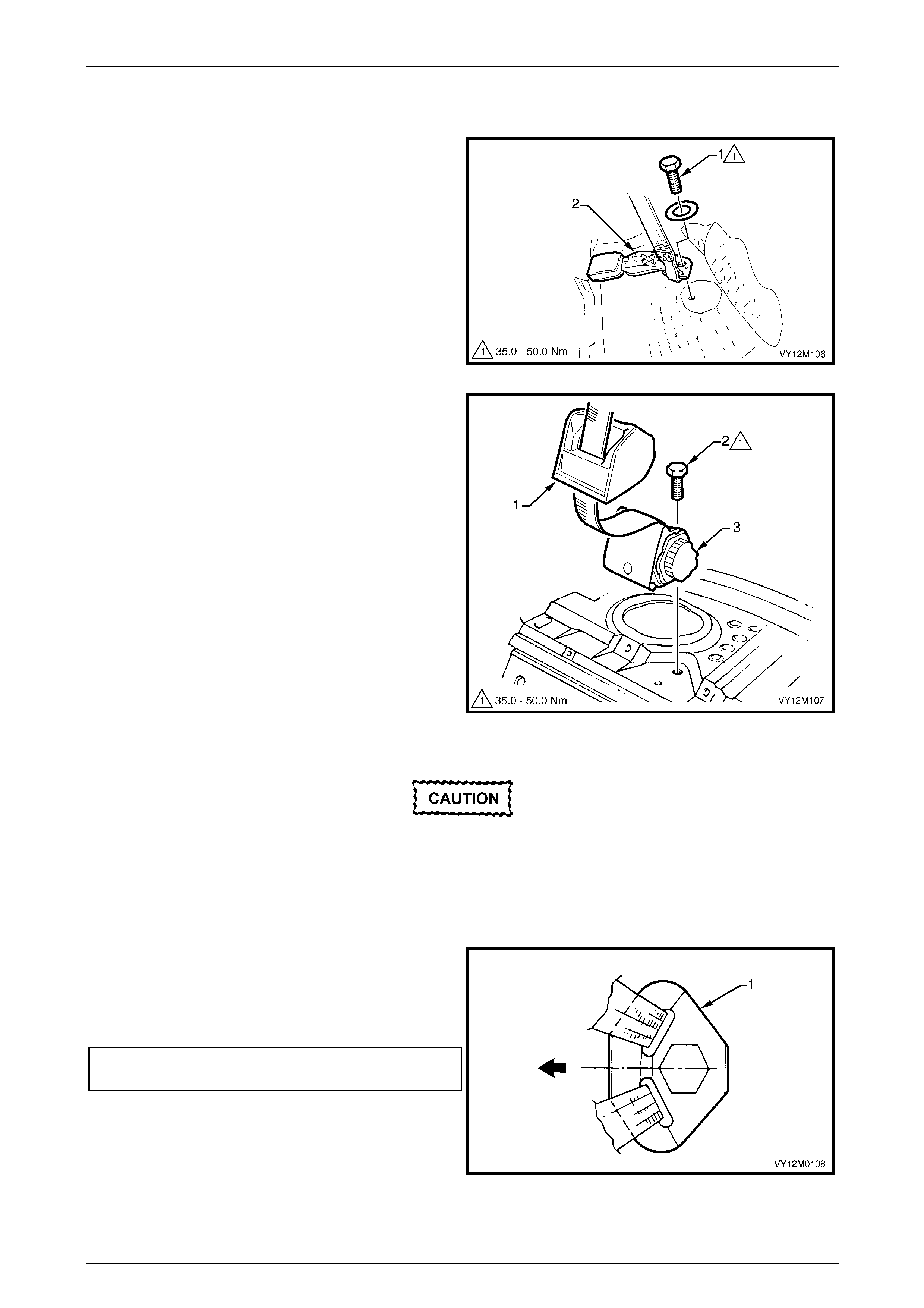
Occupant Protection System Page 12M–192
Page 12M–192
Remove
1 Remove the rear seat cushion, refer to Section 1A7 Seat Assemblies.
2 Remove the bolt and washer (1) attaching the seatbelt
lower anchor (2) to the vehicle.
3 Remove the rear window trim panel, refer to
Section 1A8 Headlining and Interior Trim .
Figure 12M – 101
4 Lift off the insulator (1).
5 Remove the bolt (2) attaching the retractor assembly
(3) to the vehicle and remove the seatbelt assembly.
Figure 12M – 102
Reinstall
If reinstalling the same retractor assembly,
inspect the anchor plates, guides and
retractor assembly for damage and the
webbing for abrasions, fraying, cuts etc.
Replace the seatbelt ass em bl y wi th a new part
if any part is damaged.
Reinstallation of the rear seatbelt assembly is the reverse of the removal procedure, noting the following:
1 Ensure the webbing is not twisted and the anchor
plate (1) is installed in the correct orientation.
2 Hand tighten all seatbelt bolts a minimum of five turns
before using tools.
3 Tighten the bolts to the specified torque.
Seatbelt assembly mounting bolt
torque specification.................................35.0 – 50.0 Nm
4 Perform a functional check of the seatb elt to ensure
correct operation.
Figure 12M – 103
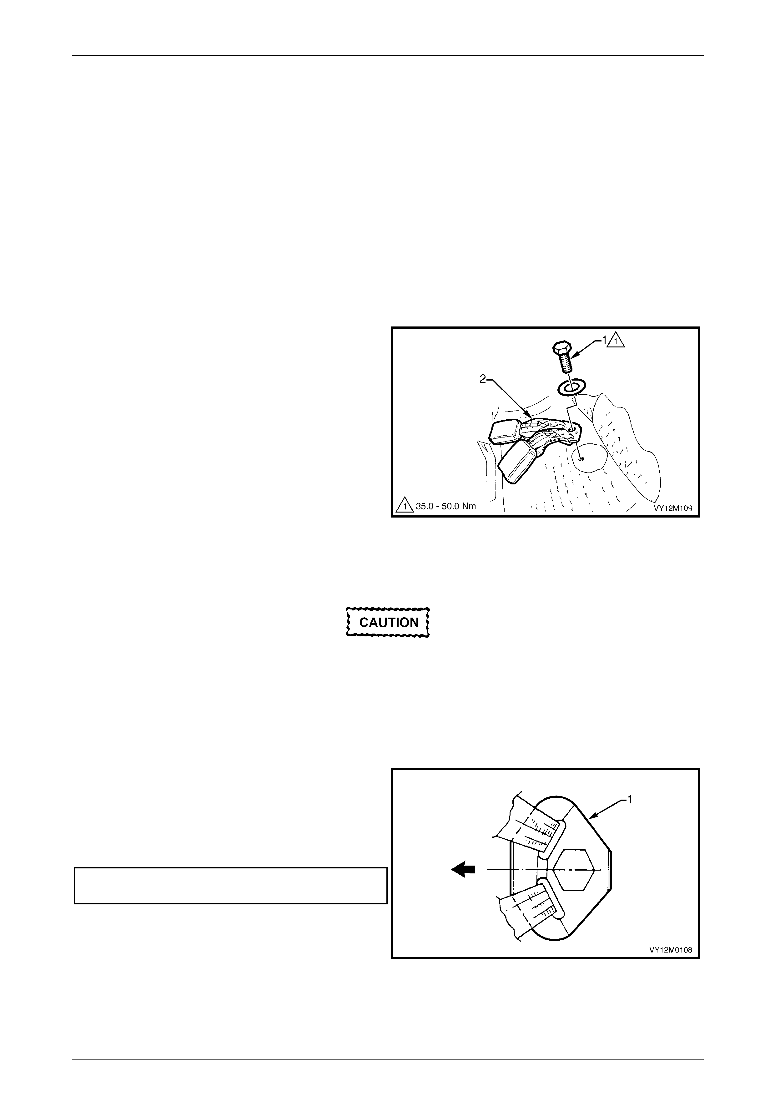
Occupant Protection System Page 12M–193
Page 12M–193
Rear Seatbelt Buckle Assembly
Right-hand Side
NOTE
The right-hand rear seatbelt buckle is part of the
centre rear seatbelt assembly.
For service procedure refer to
Rear Seatbelt Assembly – Centre.
Left-hand Side
Remove
1 Remove the rear seat cushion, refer to Section 1A7 Seat Assemblies.
2 Remove the bolt and washer (1) attaching the rear
seatbelt buckle anchor assem bl y (2) to the vehicle.
3 Remove the buckle assembly.
Figure 12M – 104
Reinstall
If reinstalling the same retractor assembly,
inspect the anchor plates, guides and
retractor assembly for damage and the
webbing for abrasions, fraying, cuts etc.
Replace the seatbelt ass em bl y wi th a new part
if any part is damaged.
Reinstallation of the front seat belt assembly is the reverse of the removal procedure, noting the follo wing:
1 Ensure the webbing is not twisted and the anchor
plate (1) is installed in the correct orientation.
2 Hand tighten all seatbelt bolts a minimum of five turns
before using tools.
3 Tighten the bolts to the specified torque.
Seatbelt assembly mounting bolt
torque specification.................................35.0 – 50.0 Nm
4 Perform a functional check of the seatb elt to ensure
correct operation.
Figure 12M – 105

Occupant Protection System Page 12M–194
Page 12M–194
5.2 Rear Seatbelts – Wagon and AWD
Wagon
LT Section No. — 14–425
Rear Seatbelt Assembly – Outboard
Figure 12M – 106
Legend
1 Seatbelt Anchor Attaching Bolt and Washer
2 Rear Seatbelt Assembly, Outer
3 Body Lock Pillar Garnish Screw Cap
4 Body Lock Pillar Garnish Upper Screw
5 Body Lock Pillar Garnish Lower Screw
6 Body Lock Pillar Garnish
7 Upper Seatbelt Guide Attaching Bolt
8 Upper Seatbelt Guide Wave Washer
9 Upper Seatbelt Guide Spacer
10 Seatbelt Retractor Attaching Bolt
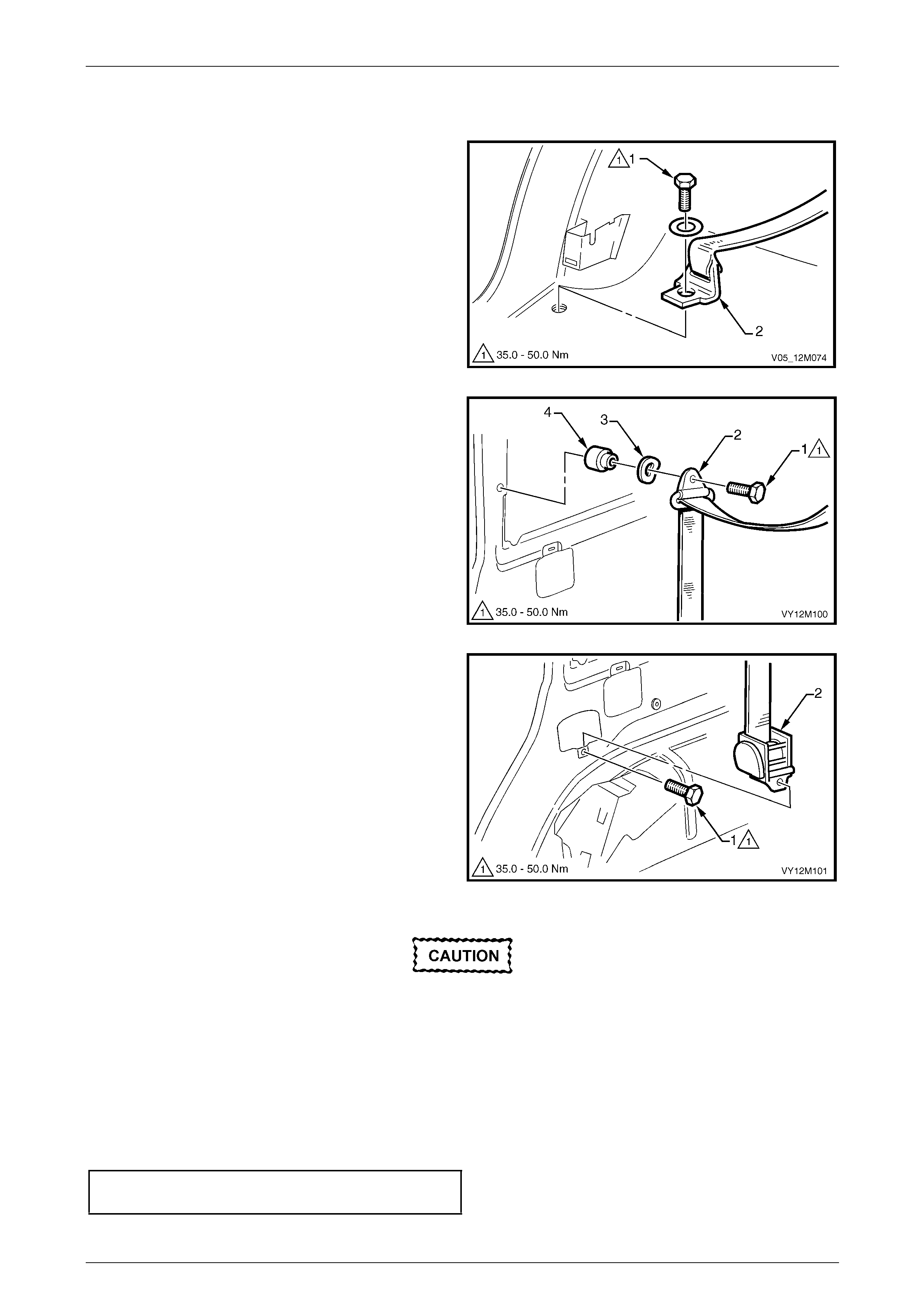
Occupant Protection System Page 12M–195
Page 12M–195
Remove
1 Remove rear seat cushion, refer to Section 1A7 Seat Assemblies.
2 Remove the bolt and washer (1) attaching the seatbelt
lower anchor (2) to the vehicle.
3 Remove the body lock pillar garnish, refer to
Section 1A8 Headlining and Interior Trim .
Figure 12M – 107
4 Remove the bolt (1) attaching the upper seatbelt guide
(2) to the vehicle. Ensure the wave washer (3) and
spacer (4) remain with the bolt.
Figure 12M – 108
5 Remove the bolt (1) attaching the retractor assembly
(2) to the vehicle and remove the seatbelt assembly
from within the inner side panel cavity.
Figure 12M – 109
Reinstall
If reinstalling the same retractor assembly,
inspect the anchor plates, guides and
retractor assembly for damage, and the
webbing for abrasions, fraying, cuts, etc.
Replace the seatbelt ass em bl y wi th a new part
if any damage, etc. is found.
Reinstallation of the front seat belt assembly is the reverse of the removal procedure, noting the follo wing:
1 Ensure the webbing is not twisted and the anchor plate is installed in the correct orientation.
2 Hand tighten all seatbelt bolts a minimum of five turns before using tools.
3 Tighten the bolts to the specified torque.
Seatbelt assembly mounting bolt
torque specification.................................35.0 – 50.0 Nm
4 Perform a functional check of the seatbelt to ensure correct operation.
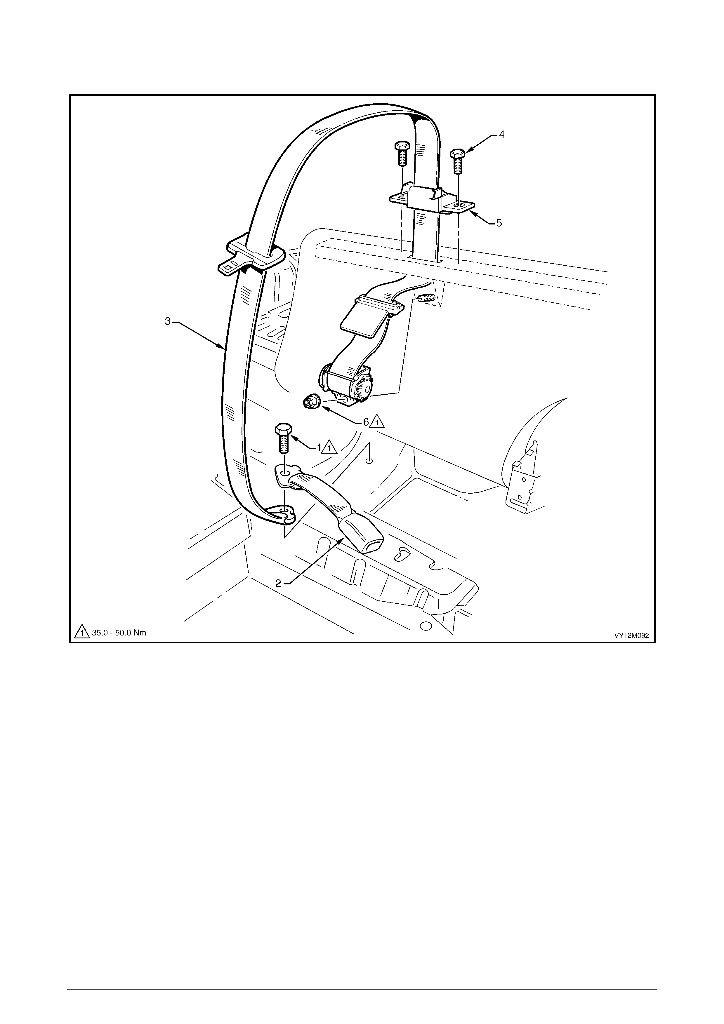
Occupant Protection System Page 12M–196
Page 12M–196
Rear Seatbelt Assembly – Centre
Figure 12M – 110
Legend
1 Seatbelt Anchor Attaching Bolt
2 Left-hand Side Seatbelt Buckle
3 Rear Seatbelt Assembly, Centre
4 Seatbelt Guide Bracket Bolt
5 Seatbelt Guide Bracket
6 Seatbelt Retractor Attaching Nut
Remove
1 Remove the rear seat cushion, refer to Section 1A7 Seat Assemblies.
2 Remove the bolt (1) attaching the centre re ar seatbelt anchor plate to the vehicle floor, refer to Figure 12M – 110.
3 Fold the rear seat back down.
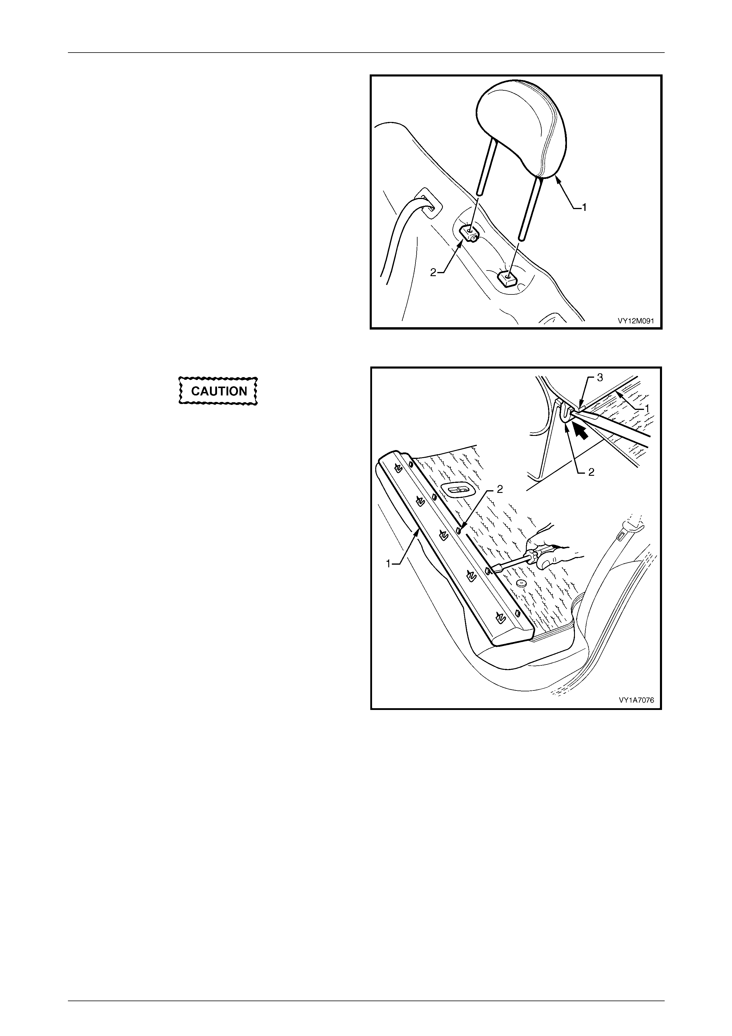
Occupant Protection System Page 12M–197
Page 12M–197
4 If fitted, remove the head restraint (1) by depressing
the head restraint guide height adjuster lock (2), pull
the head restraint completely out of the guid e.
5 Fold the rear seat back down.
Figure 12M – 111
Care must be taken not to break the lower
retaining tabs from the rear seat back trim
cover, otherwise a replacement part will be
required.
6 Carefully remove the rear seat back trim cover (1), by
inserting a small screwdriver at the tab (2) position,
highlighted by small polished areas (3). Push in to
disengage the retaining tabs (3), five places, on the
left-hand seat and three places on the right-hand seat.
7 Start at one end to disengage the cover away from the
seat back and work your way along until all retaining
tabs have been disengaged.
Figure 12M – 112
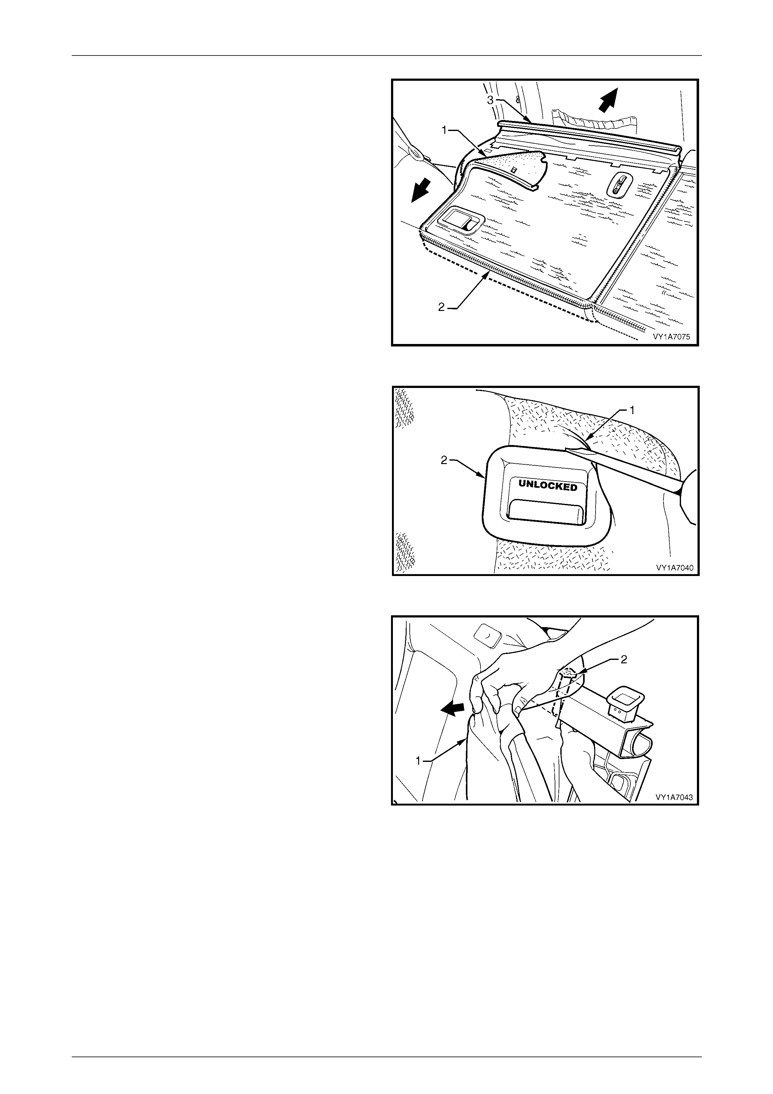
Occupant Protection System Page 12M–198
Page 12M–198
8 Partly remove the rear seat back cover (1), unzip (2)
the cover down one side of the rear seat back.
9 Pull the outer top finisher strip (3) from the rear seat
back frame.
NOTE
To ease in the removal of the top finisher strip,
gently lever the strip away from the frame using
a screwdriver.
Figure 12M – 113
10 Lever the cover and pa d assembly (1) over the release
button (2).
Figure 12M – 114
11 Pull the top corner of the cove r and pad assembly (1)
down to allow for the removal of the head restraint
guides (2), if fitted.
Figure 12M – 115
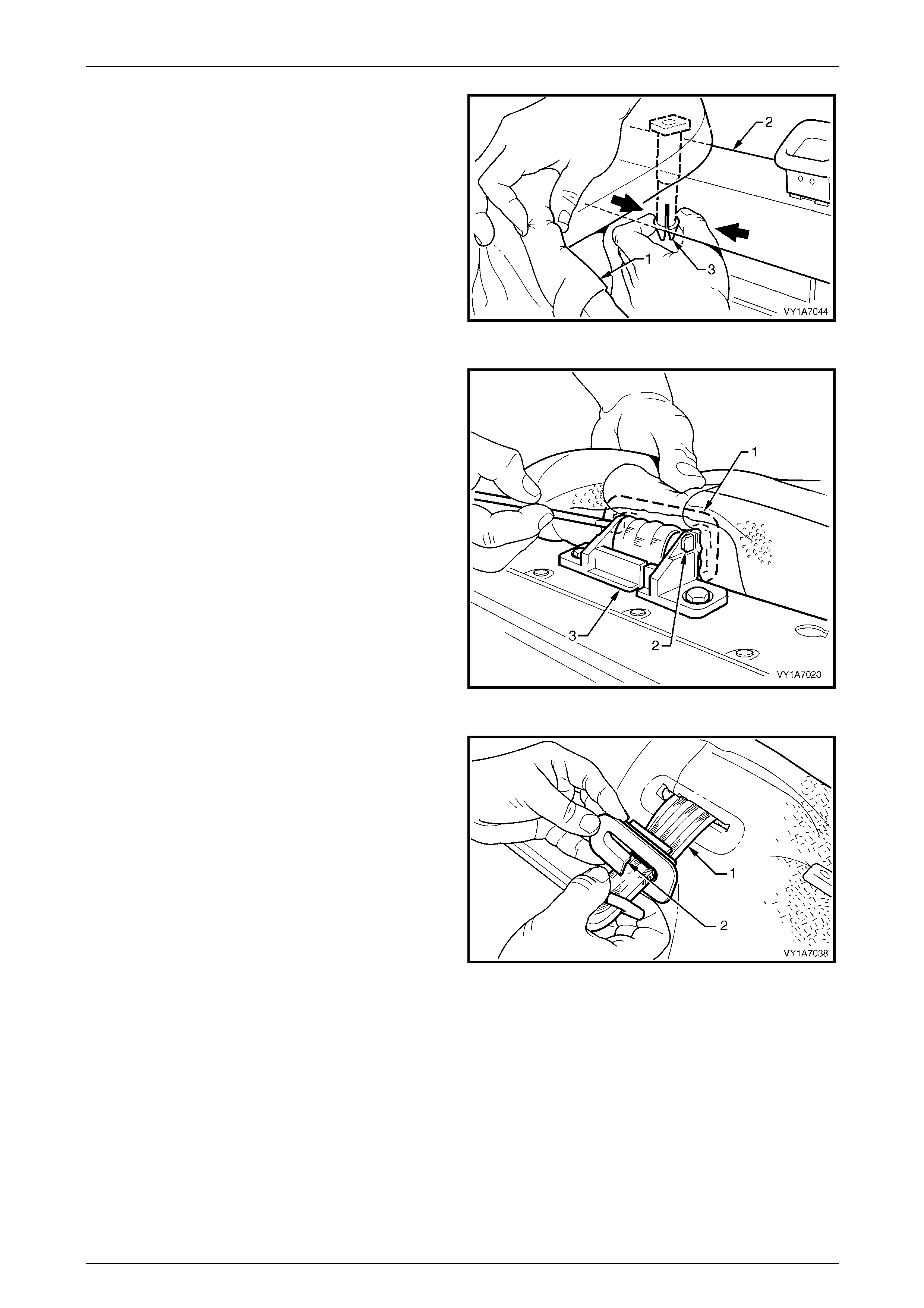
Occupant Protection System Page 12M–199
Page 12M–199
12 While holding the cover and pad assembly (1), reach
in between the seat back frame (2) and the p ad
assembly.
13 Squeeze the head restraint guide locating prongs (3)
together and remove the guide up and out of the seat
back assembly.
Figure 12M – 116
14 Using a scre wdriver, release the centre seatbelt
escutcheon (1) from inside the rear seat bac k by
pushing the tangs (2) of the escutcheon through the
seatbelt guide bracket (3).
NOTE
Care must be taken not to break the attaching
tangs from the escutcheon.
Figure 12M – 117
15 Remove the escutcheo n (1) from the seatbelt (2).
Figure 12M – 118
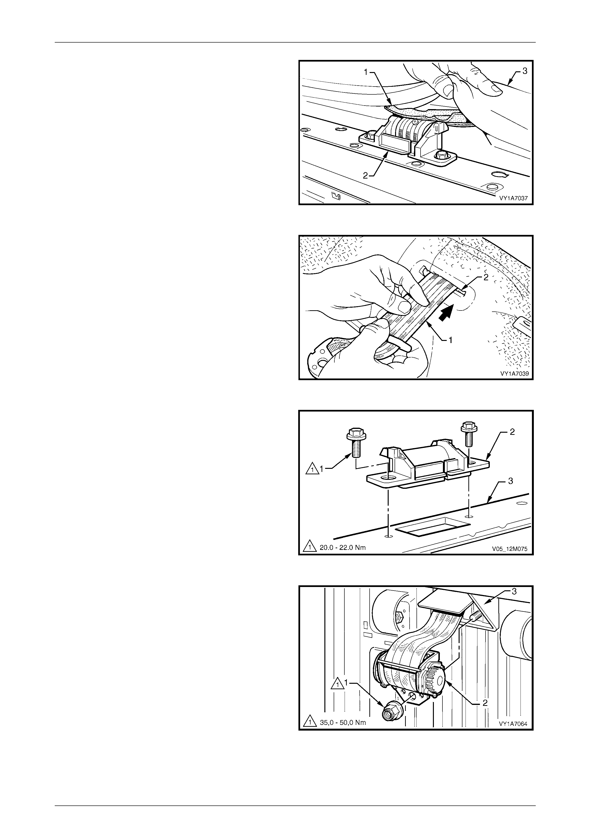
Occupant Protection System Page 12M–200
Page 12M–200
16 Feed the seat back cover flap (1), over the seatbelt
guide bracket assembly (2) and throu gh the pad
assembly (3).
Figure 12M – 119
17 Feed the seatbelt (1) through the slot (2) in the cover
and pad assembly.
18 Remove the cover and pad assembly away from the
seat back frame to gain access to the seatbel t
retractor and guide.
Figure 12M – 120
19 Remove the two bolts (1) attachin g the seatbelt guide
bracket (2) to the top of the seat back frame (3).
20 Remove seatbelt guide bracket by feeding the seatbelt
webbing through the slot in the seatbelt guide bracket.
Figure 12M – 121
21 Remove the nut (1) retaining the seatbelt retractor (2)
to the rear seat back frame (3).
22 Remove seatbelt retractor from the stud in the seat
back frame.
Figure 12M – 122
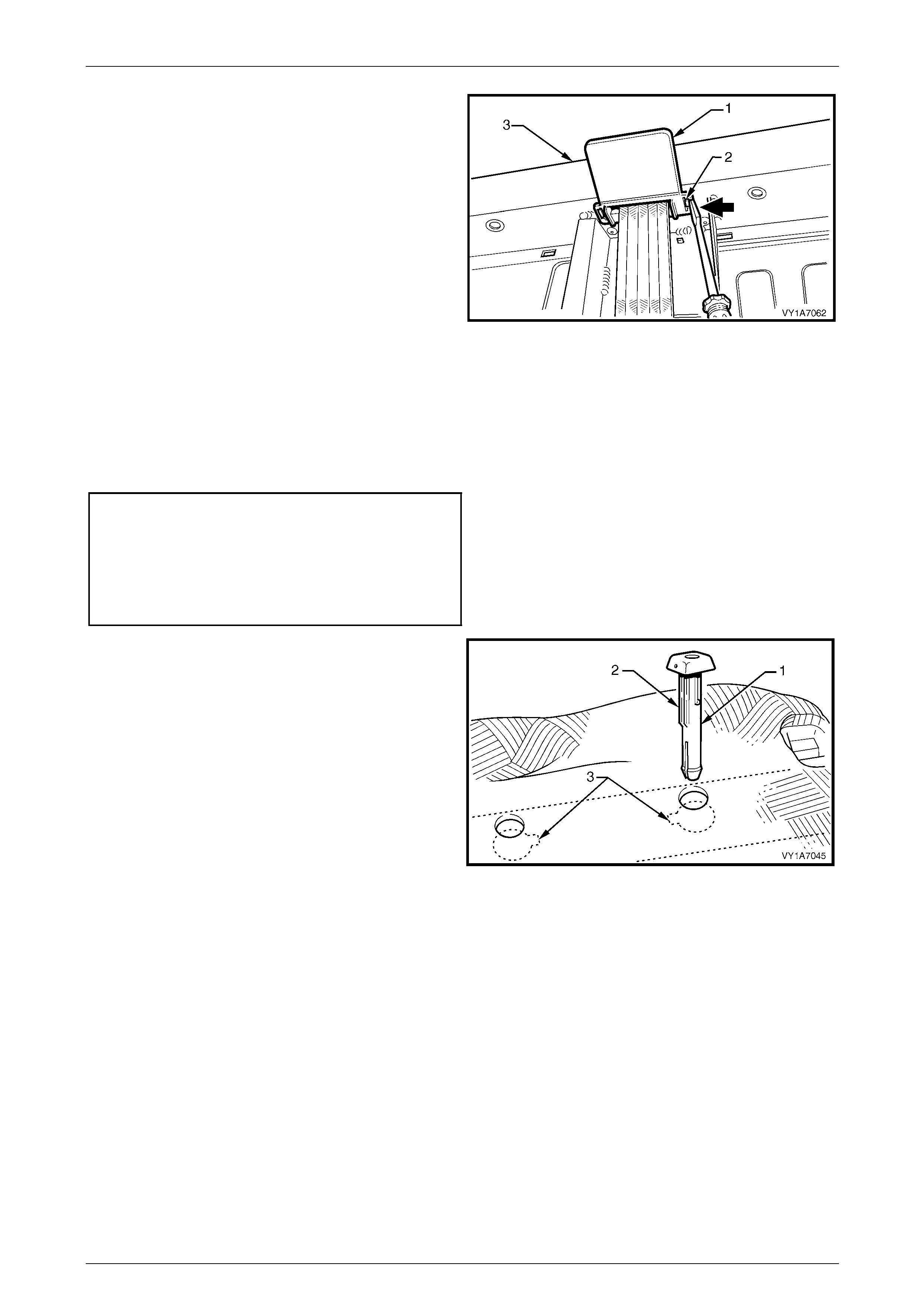
Occupant Protection System Page 12M–201
Page 12M–201
23 Remove the seatbelt retractor escutcheon (1) by
pushing in the tangs (2) and releasing it from the seat
back frame (3).
24 Feed the seatbelt webbing through seat back frame
and remove the retractor assembly.
NOTE
The seatbelt retractor will not function unless the
seat back is in an upright position.
Figure 12M – 123
Reinstall
Reinstallation of the centre rear seatbelt assembly is the reverse of the removal procedure, noting the follo wing:
1 If a new centre rear seatbelt assembly is fitted, ensure the web clip is removed after the retaining nut is tightened.
2 Ensure all fasteners are tightene d to the correct torque specification.
Seatbelt guide bracket attaching
bolt torque specification..........................20.0 – 22.0 Nm
Seatbelt retractor retaining nut
torque specification.................................35.0 – 50.0 Nm
Seatbelt assembly mounting bolt
torque specification.................................35.0 – 50.0 Nm
3 When installing the hea d restraint guide (1), if fitted,
align the locating ribs (2) with the key-way (3) in the
seat-back frame.
NOTE
Ensure the guide with the height adjuster lock is
installed on the side that corresponds to the
notches in the head restraint shaft.
Figure 12M – 124
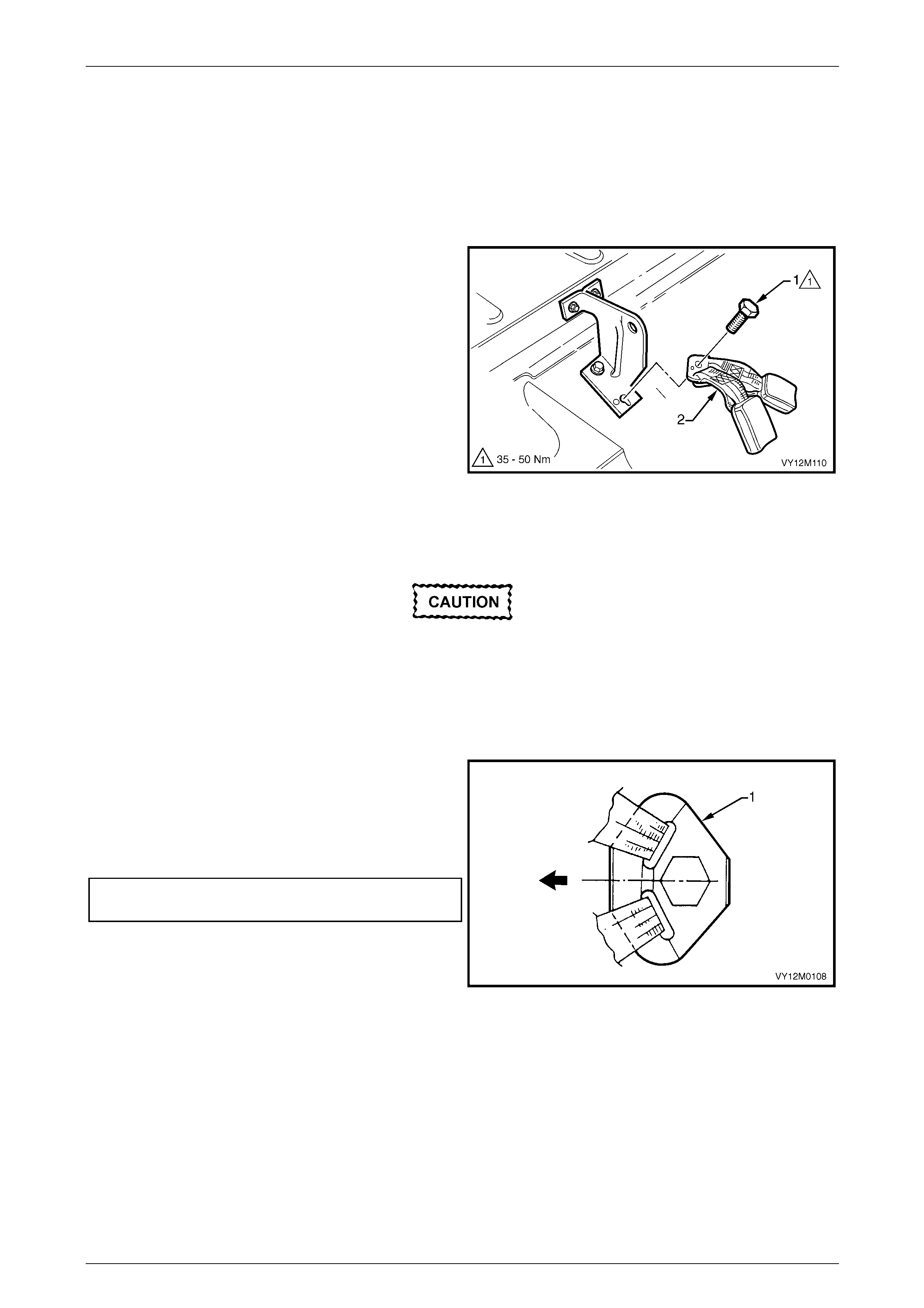
Occupant Protection System Page 12M–202
Page 12M–202
Rear Seatbelt Buckle Assembly
Right-hand Side
Remove
1 Remove the rear seat cushion, refer to Section 1A7 Seat Assemblies.
2 Remove the bolt (1) attaching the rear seat belt buckle
anchor assembly (2) to the vehicle.
3 Remove the buckle assembly.
Figure 12M – 125
Reinstall
If reinstalling the same seatbelt buckle
assembly, inspect for damage, abrasions,
fraying, cuts, etc. Replace the seatbelt buckle
assembly with a new part if any damage, etc.
is found.
Reinstallation of the seatbelt buckle assembly is the reverse of the removal procedure, noting the following:
1 Ensure the anchor plate (1) is installed in the correct
orientation.
2 Hand tighten all seatbelt bolts a minimum of five turns
before using tools.
3 Tighten the bolts to the specified torque.
Seatbelt assembly mounting bolt
torque specification.................................35.0 – 50.0 Nm
4 Perform a functional check of the seatb elt to ensure
correct operation.
Figure 12M – 126

Occupant Protection System Page 12M–203
Page 12M–203
Left-hand Side
Remove
1 Remove the rear seat cushion, refer to
Section 1A7 Seat Assemblies.
2 Remove the bolt (1) attaching the left-hand re ar
seatbelt buckle (2) and centre rear seatbelt anchor
assembly (3) to the vehicle.
3 Remove the buckle and belt assembl y.
Figure 12M – 127
Reinstall
If reinstalling the same seatbelt buckle
assembly, inspect for damage, abrasions,
fraying, cuts, etc. Replace the seatbelt buckle
assembly with a new part if any damage, etc.
is found.
Reinstallation of the seatbelt buckle assembly is the reverse of the removal procedure, noting the following:
1 Ensure the anchor plate (1) is installed in the correct
orientation.
2 Hand tighten all seatbelt bolts a minimum of five turns
before using tools.
3 Tighten the bolts to the specified torque.
Seatbelt assembly mounting bolt
torque specification.................................35.0 – 50.0 Nm
4 Perform a functional check of the seatb elt to ensure
correct operation.
Figure 12M – 128

Occupant Protection System Page 12M–204
Page 12M–204
5.3 Rear Seatbelts – Coupe
LT Section No. — 14–425
Rear Seatbelt Assembly
Figure 12M – 129
Legend
1 Seatbelt Anchor Attaching Bolt
2 Rear Seatbelt Assembly
3 Body Rear Corner Garnish Retainer
4 Body Rear Corner Garnish
5 Upper Seatbelt Guide Attaching Bolt
6 Upper Seatbelt Guide Wave Washer
7 Upper Seatbelt Guide Spacer
8 Seatbelt Retractor Attaching Bolt
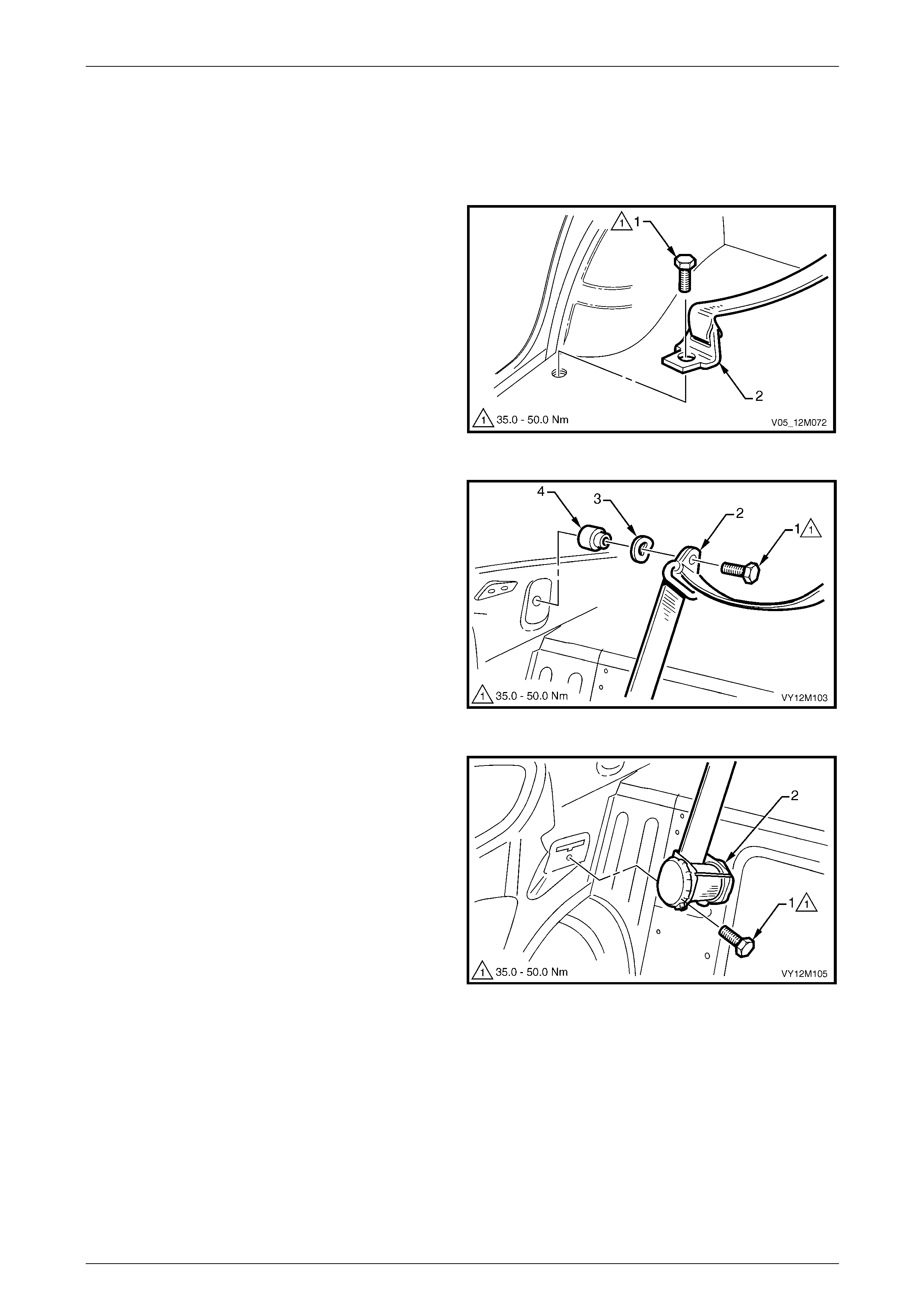
Occupant Protection System Page 12M–205
Page 12M–205
Remove
1 As applicable, remove either the left or right-hand rear se at cushion back assembly, refer to
Section 1A7 Seat Assemblies.
2 Remove the rear seat back assembly, refer to Section 1A7 Seat Assemblies.
3 Remove the seatbelt anchor attaching b olt (1 )
attaching the seatbelt lo wer anchor (2) to the vehicl e.
4 Remove the body rear corner garnish, refer to
Section 1A8 Headlining and Interior Trim .
Figure 12M – 130
5 Remove the upper seatbelt guide attachin g bolt (1)
attaching the upper seatbelt guide (2) to the vehicl e.
Ensure the upper seatbelt guide wave washer (3) and
spacer (4) remains with the bolt.
Figure 12M – 131
6 Remove the seatbelt retractor attaching bo lt (1)
attaching the retractor assembly (2) to the vehicle an d
remove the seatbelt assembly.
Figure 12M – 132
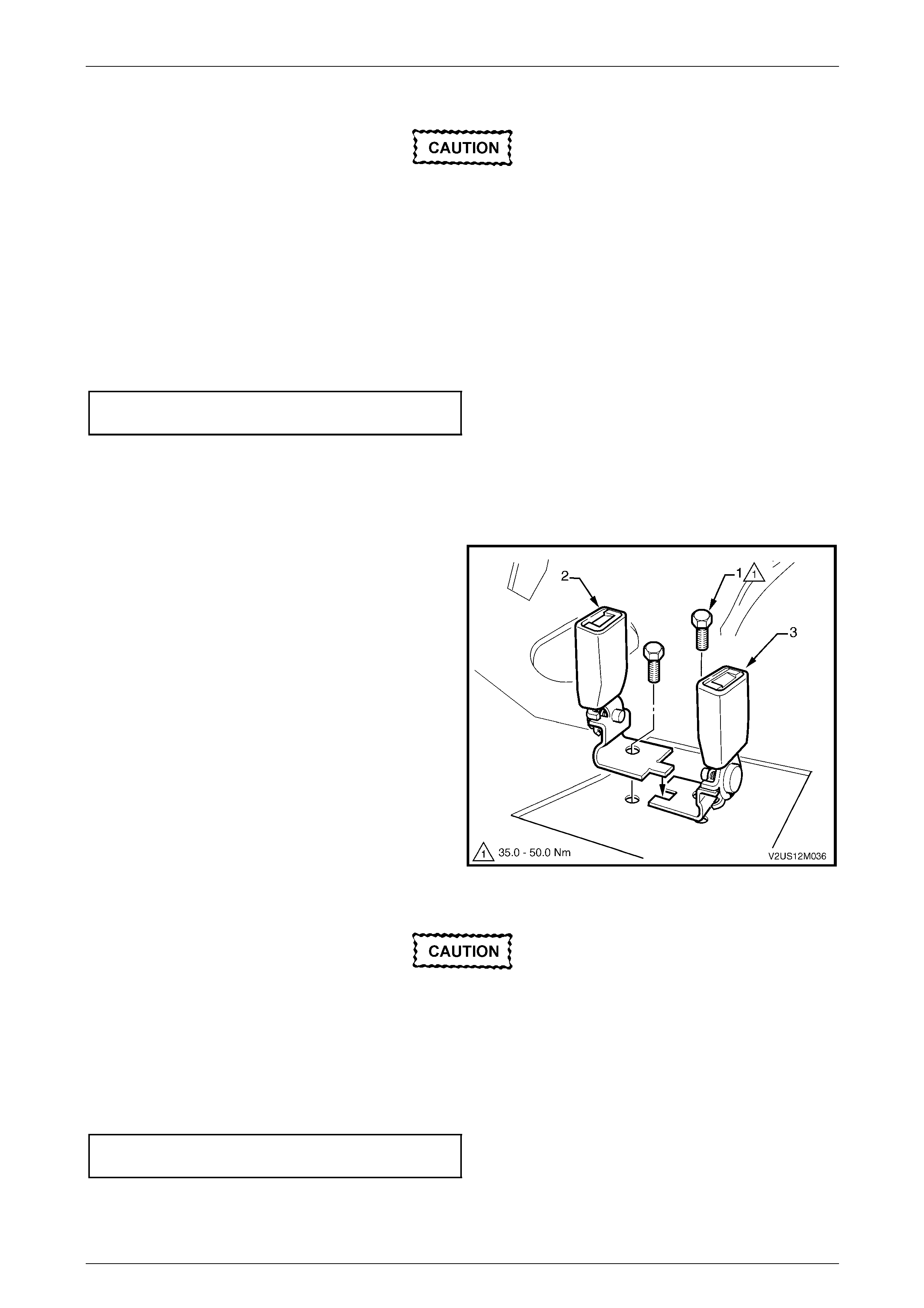
Occupant Protection System Page 12M–206
Page 12M–206
Reinstall
If reinstalling the same retractor assembly,
inspect the anchor plates, guides and
retractor assembly for damage and the
webbing for abrasions, fraying, cuts etc.
Replace the seatbelt ass em bl y wi th a new part
if any part is damaged.
Reinstallation of the rear seatbelt assembly is the reverse of the removal procedure, noting the following:
1 Ensure the webbing is not twisted and the anchor plate is installed in the correct orientation.
2 Hand tighten all seatbelt bolts a minimum of five turns before using tools.
3 Tighten the bolts to the specified torque.
4 Perform a functional check of the seatbelt to ensure correct operation.
Seatbelt assembly mounting bolt
torque specification.................................35.0 – 50.0 Nm
Rear Seatbelt Buckle Assembly
Remove
1 Remove the rear seat cushion, refer to Section 1A7 Seat Assemblies.
2 Remove the appropriate bolt (1) attaching the
right-hand (2) or left-hand seatbelt buckle (3) to the
vehicle.
Figure 12M – 133
Reinstall
If reinstalling the same seatbelt buckle
assembly, inspect for damage, abrasions etc.
Replace the seatbelt buckle assembly with a
new part if any part is damaged.
Reinstallation of the seatbelt buckle assembly is the reverse of the removal procedure, noting the fo llowing:
1 Ensure the anchor plates are install ed in the correct orientation.
2 Hand tighten all seatbelt bolts a minimum of five turns before using any tools to tighten.
3 Tighten the bolts to the specified torque.
Seatbelt assembly mounting bolt
torque specification.................................35.0 – 50.0 Nm
4 Perform a functional check of the seatbelt to ensure correct operation.

Occupant Protection System Page 12M–207
Page 12M–207
5.4 Rear Seatbelts – Crew Cab, AWD Crew
Cab
LT Section No. — 14–425
Rear Seatbelt Assembly
ATTENTION
The following fasteners have either micro encapsulation or incorporate a mechanical thread lock and should
only be used once. If in doubt, replacement is recommended when performing this operation:
Seatbelt Guide Attaching Bolt
Seatbelt Lower Anchor Bolt
Seatbelt Retractor Bracket Bolt
Seatbelt Buckle Assembly Attaching Bolt
NOTE
The following chart is included to assist with
component identification.
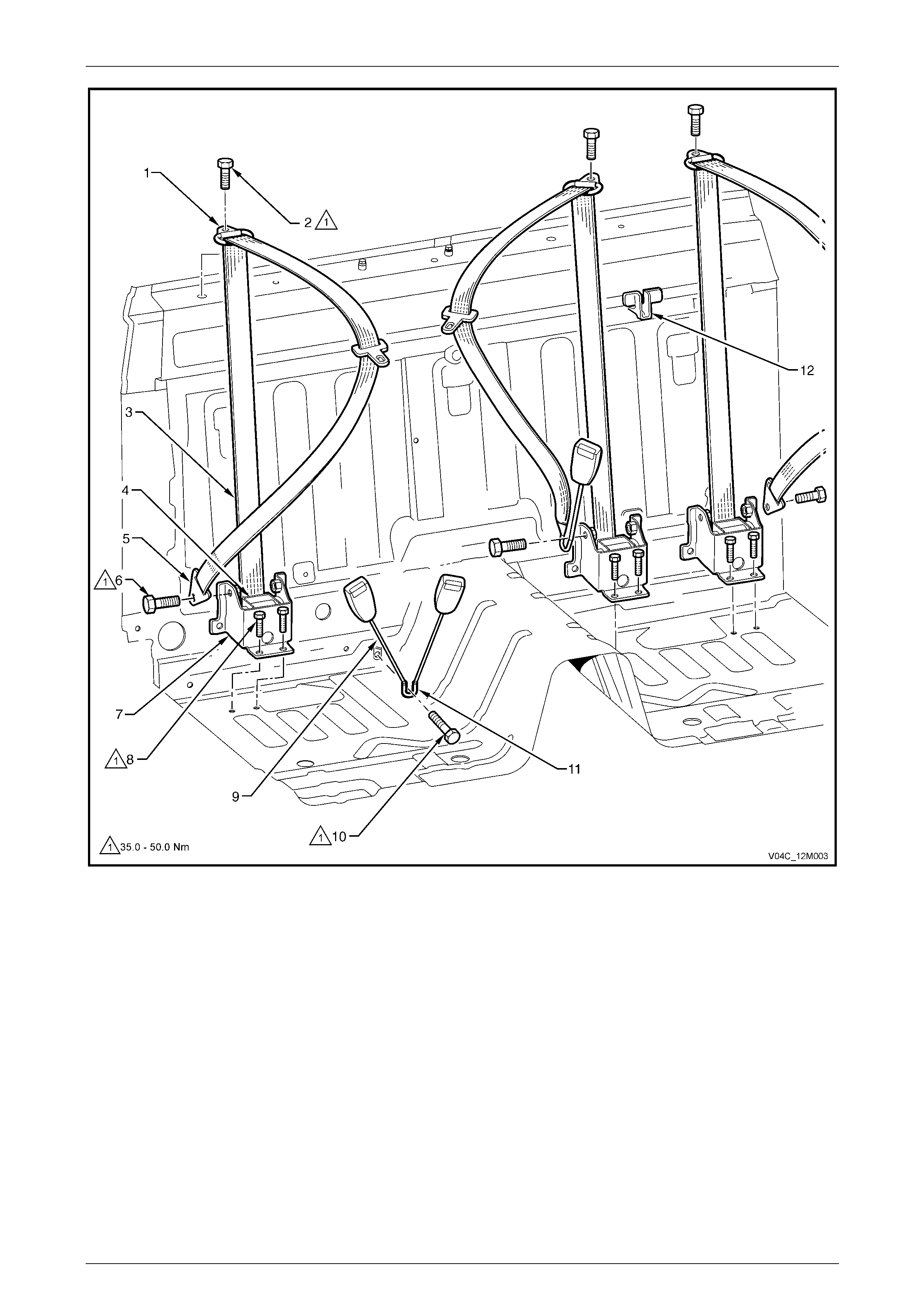
Occupant Protection System Page 12M–208
Page 12M–208
Figure 12M – 134
Legend
1 Seatbelt Guide
2 Seatbelt Guide Attaching Bolt
3 Seatbelt
4 Seatbelt Retractor
5 Seatbelt Lower Anchor
6 Seatbelt Lower Anchor Bolt
7 Seatbelt Retractor Bracket
8 Seatbelt Retractor Bracket Bolt
9 Seatbelt Buckle Assembly
10 Seatbelt Buckle Assembly Attaching Bolt
11 Seatbelt Buckle Bracket
12 Child Seat Anchor
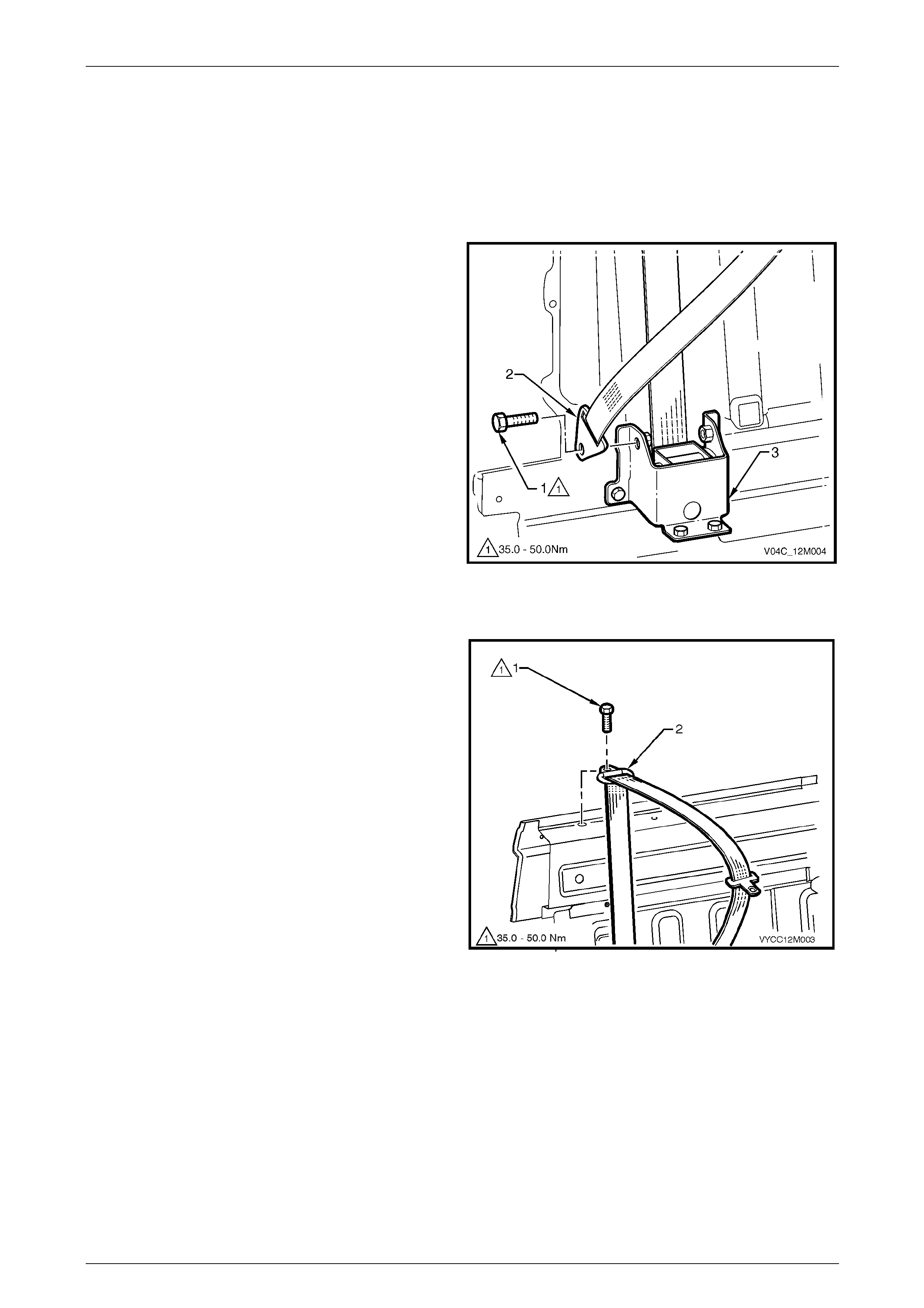
Occupant Protection System Page 12M–209
Page 12M–209
Remove
NOTE
The seatbelt assemblies ar e similar in each of the
rear seating positions. The left-hand belt buckle
assembly is attached to the rear centre seatbelt
assembly.
1 Remove the rear seat cushion, refer to
Section 1A7 Seat Assemblies.
2 Remove the bolt (1) attaching the seatbelt anchor (2)
to the retractor bracket (3).
3 Remove the rear seat back, refer to
Section 1A7 Seat Assemblies.
4 Remove the upper cross-beam cover, refer to
Section 1A8 Headlining and Interior Trim .
Figure 12M – 135
5 Remove the bolt (1) attaching the seatbelt guide (2) to
the upper cross-beam.
Figure 12M – 136
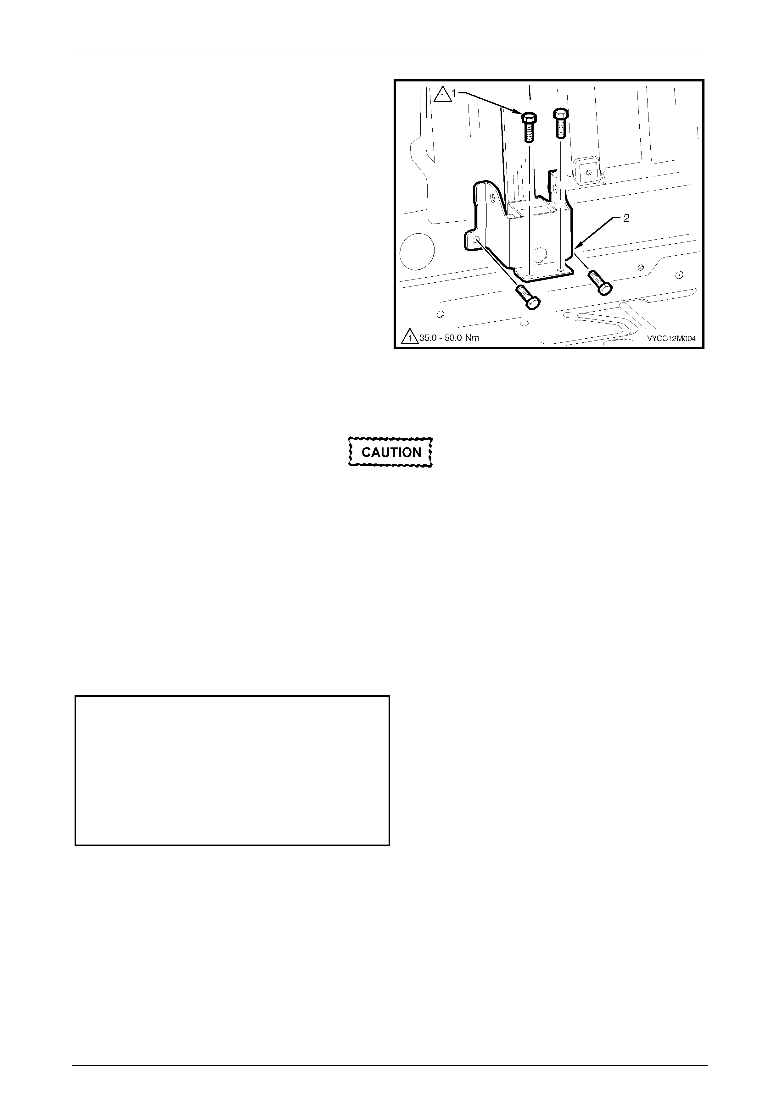
Occupant Protection System Page 12M–210
Page 12M–210
6 Remove the four bolts (1) attaching the retractor
bracket assembly (2) to the vehicle.
7 Remove the seatbelt assembly.
NOTE
The retractor is permanently riveted to the
bracket.
Figure 12M – 137
Reinstall
If reinstalling the same retractor assembly,
inspect the anchor plates, guides and
retractor assembly for damage, and the
webbing for abrasions, fraying, cuts, etc.
Replace the seatbelt ass em bl y wi th a new part
if any damage, etc. is found.
Reinstallation of the seatbelt assembly is the reverse of the removal procedure, noting the foll owing:
1 Ensure the webbing is not twisted.
2 Renew any bolts removed.
3 Hand tighten all seatbelt bolts a minimum of five turns before using tools.
4 Tighten the bolts to the specified torque.
Seatbelt retractor bracket
mounting bolt torque specification...........35.0 – 50.0 Nm
Seatbelt guide attaching
bolt torque specification..........................35.0 – 50.0 Nm
Seatbelt lower anchor mounting
bolt torque specification..........................35.0 – 50.0 Nm
Seatbelt buckle attaching
bolt torque specification..........................35.0 – 50.0 Nm
5 Perform a functional check of the seatbelt to ensure correct operation.
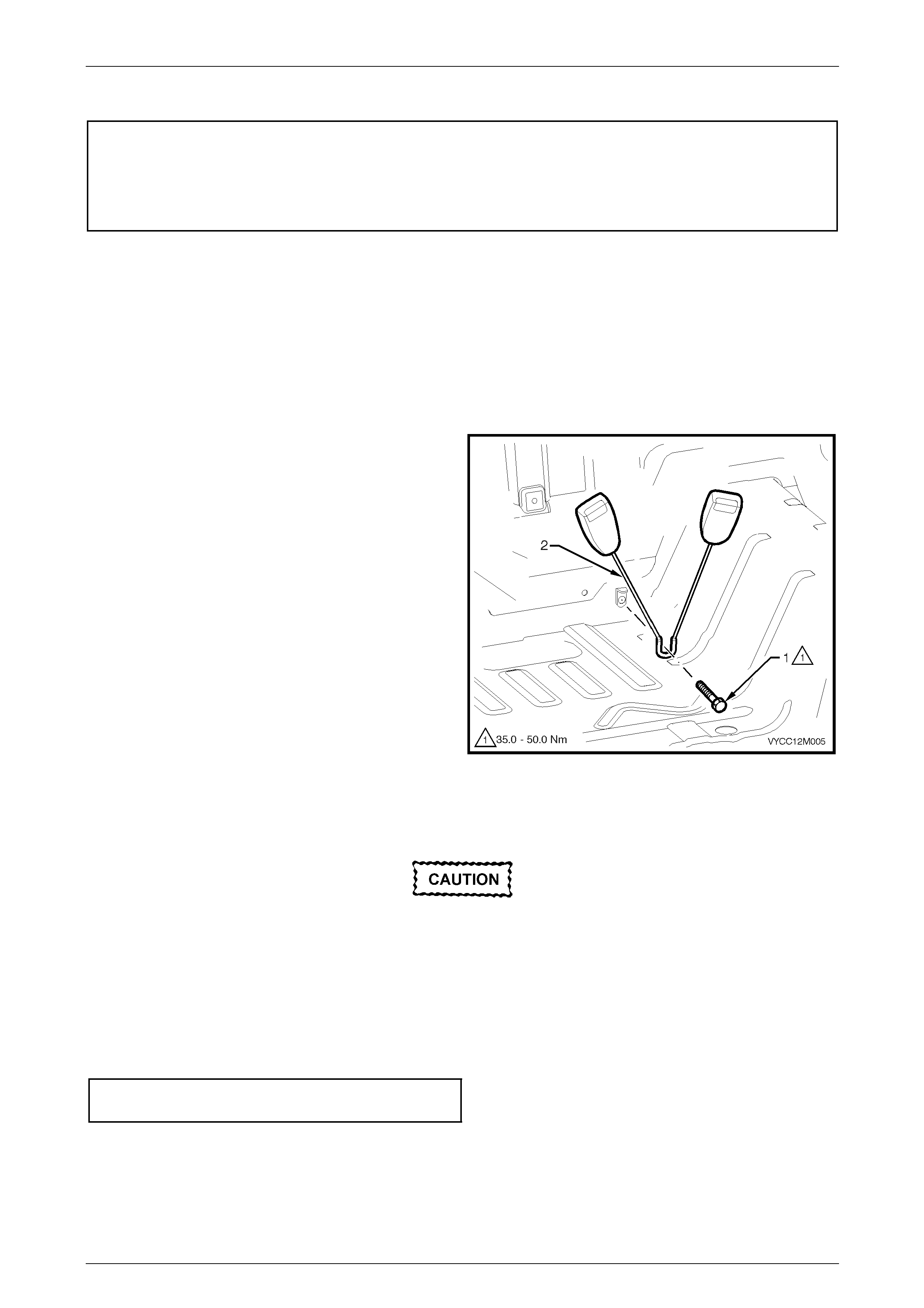
Occupant Protection System Page 12M–211
Page 12M–211
Rear Seatbelt Buckle Assembly
ATTENTION
The following fasteners have either micro encapsulation or incorporate a mechanical thread lock and should
only be used once. If in doubt, replacement is recommended when performing this operation:
Seatbelt buckle assembly mounting bolt
Left-hand Side
The left-hand rear seatbelt buckle is part of the rear centre seatbelt assem bl y. For the service procedure, refer to
Rear Seatbelt Assembly.
Right-hand Side
Remove
1 Remove the rear seat cushion, refer to Section 1A7 Seat Assemblies.
2 Remove the bolt (1) attaching the rear seat belt buckle
anchor assembly (2) to the vehicle.
3 Remove the buckle assembly.
Figure 12M – 138
Reinstall
If reinstalling the same buckle assembly,
inspect the buckle for any damage. Replace
the buckle assembly with a new part if any
damage is found.
Reinstallation of the seatbelt buckle assembly is the reverse of removal noting the following.
1 Hand tighten the new seatbelt bolt a minimum of five turns before usi ng tools.
2 Tighten the bolt to the specified torque.
Seatbelt buckle assembly mounting
bolt torque specification..........................35.0 – 50.0 Nm
3 Perform a functional check of the seatbelt to ensure correct operation.
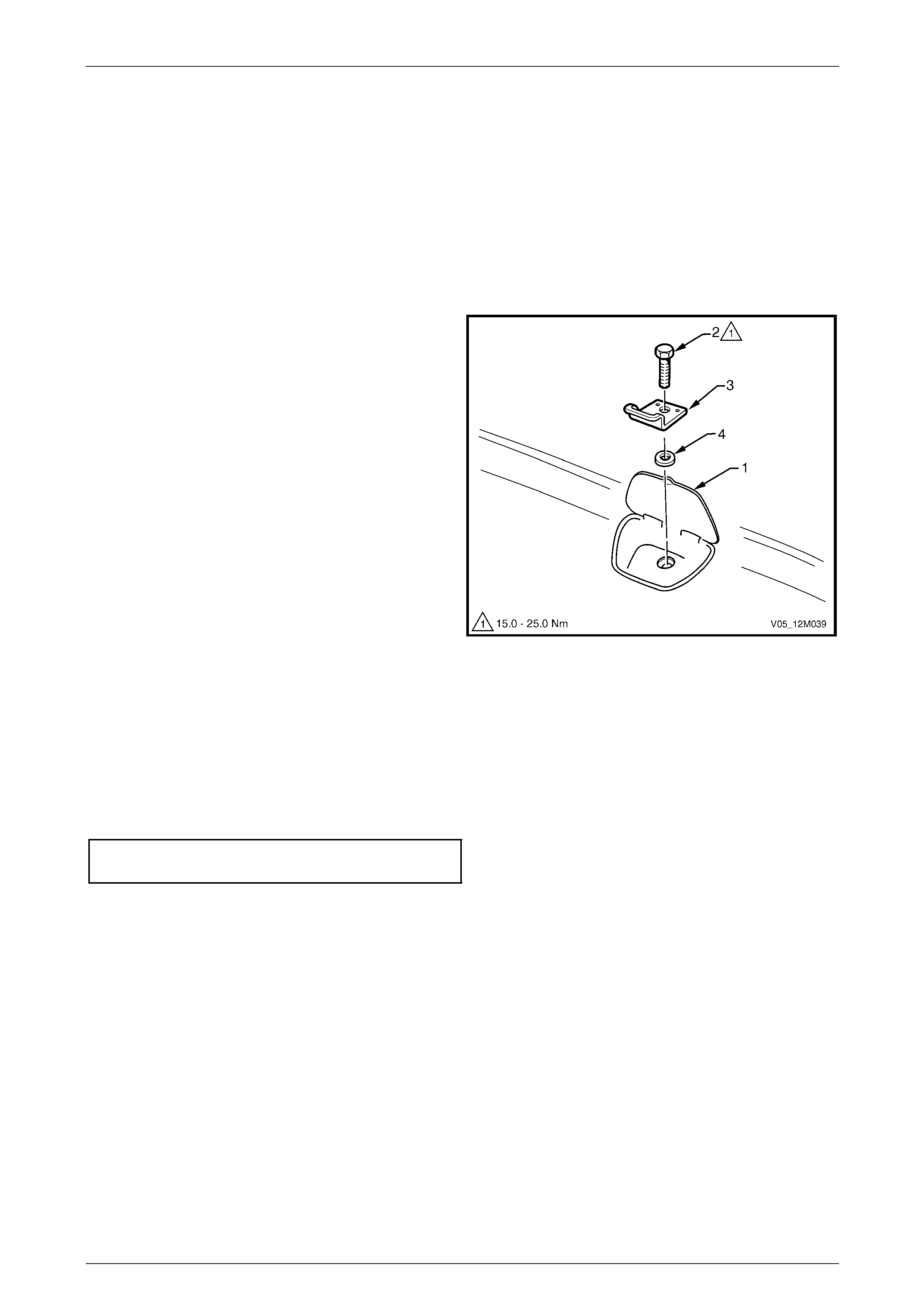
Occupant Protection System Page 12M–212
Page 12M–212
6 Service Operations – Child Seat
Anchors
6.1 Child Seat Anchors – Sedan
LT Section No. — AA–020
Remove
1 Open the flap (1) in the rear window trim panel.
2 Remove the bolt (2) attaching the anchor (3) and
washer (4) to the vehicle and remove.
Figure 12M – 139
Reinstall
Reinstallation of the child s ea t anchors is the reverse of the removal procedure, noting the following:
1 Ensure the anchors are installed in the correct orientation.
2 Hand tighten the bolt a minimum of five turns before using tools.
3 Tighten the bolt to the specified torque.
Child seat anchor mounting bolt
torque specification.................................15.0 – 25.0 Nm
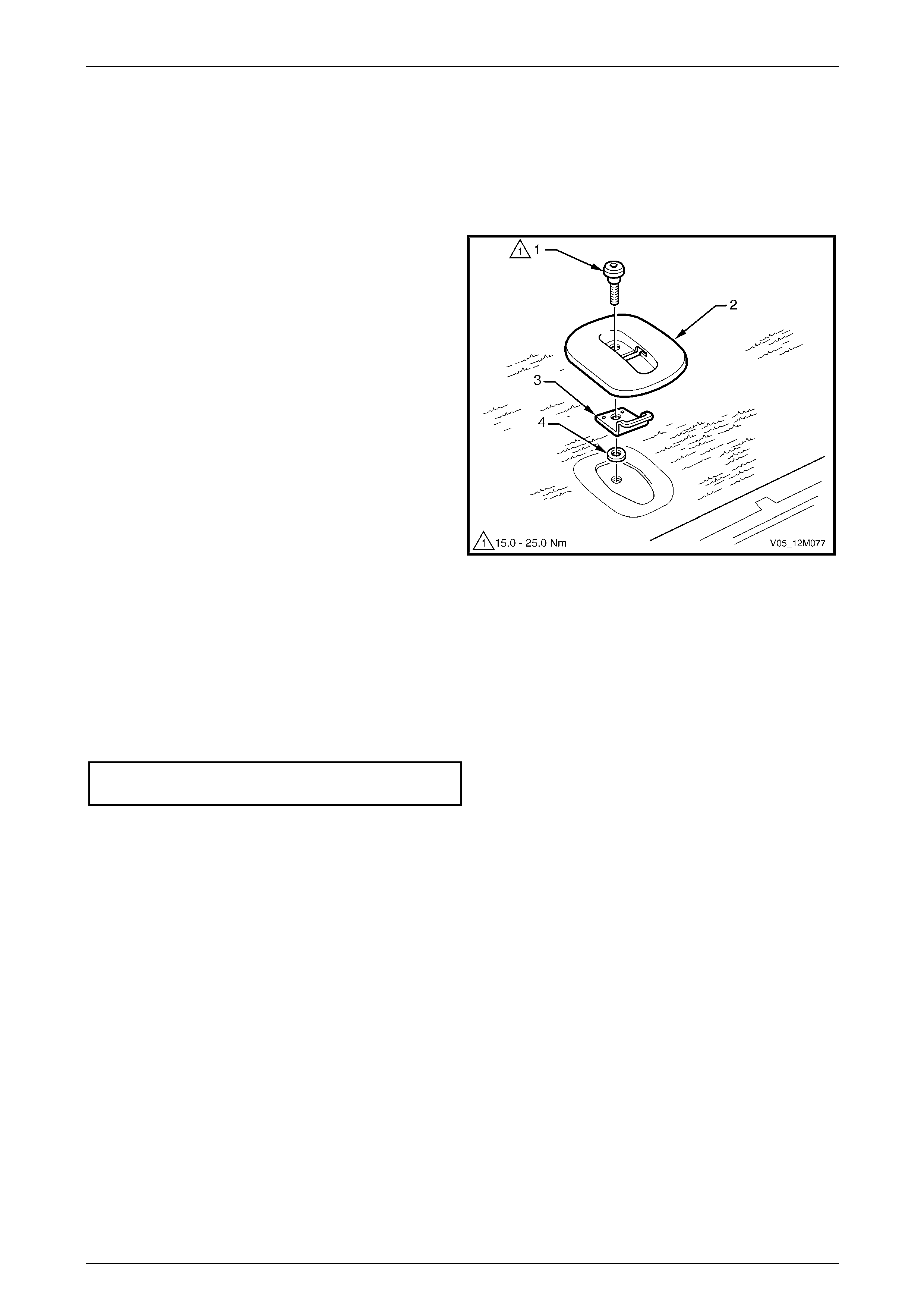
Occupant Protection System Page 12M–213
Page 12M–213
6.2 Child Seat Anchors – Wagon and AWD
Wagon
LT Section No. — AA–020
Remove
1 From the rear of the rear seat back, remove the bolt
(1) attaching the escutcheon (2), anchor (3) and
washer (4) to the seat back and remove.
Figure 12M – 140
Reinstall
Reinstallation of the child s ea t anchors is the reverse of the removal procedure, noting the following:
1 Ensure the anchors are installed in the correct orientation.
2 Hand tighten the bolt a minimum of five turns before usin g any tools to tighten.
3 Tighten the bolt to the specified torque.
Child seat anchor mounting bolt
torque specification.................................15.0 – 25.0 Nm
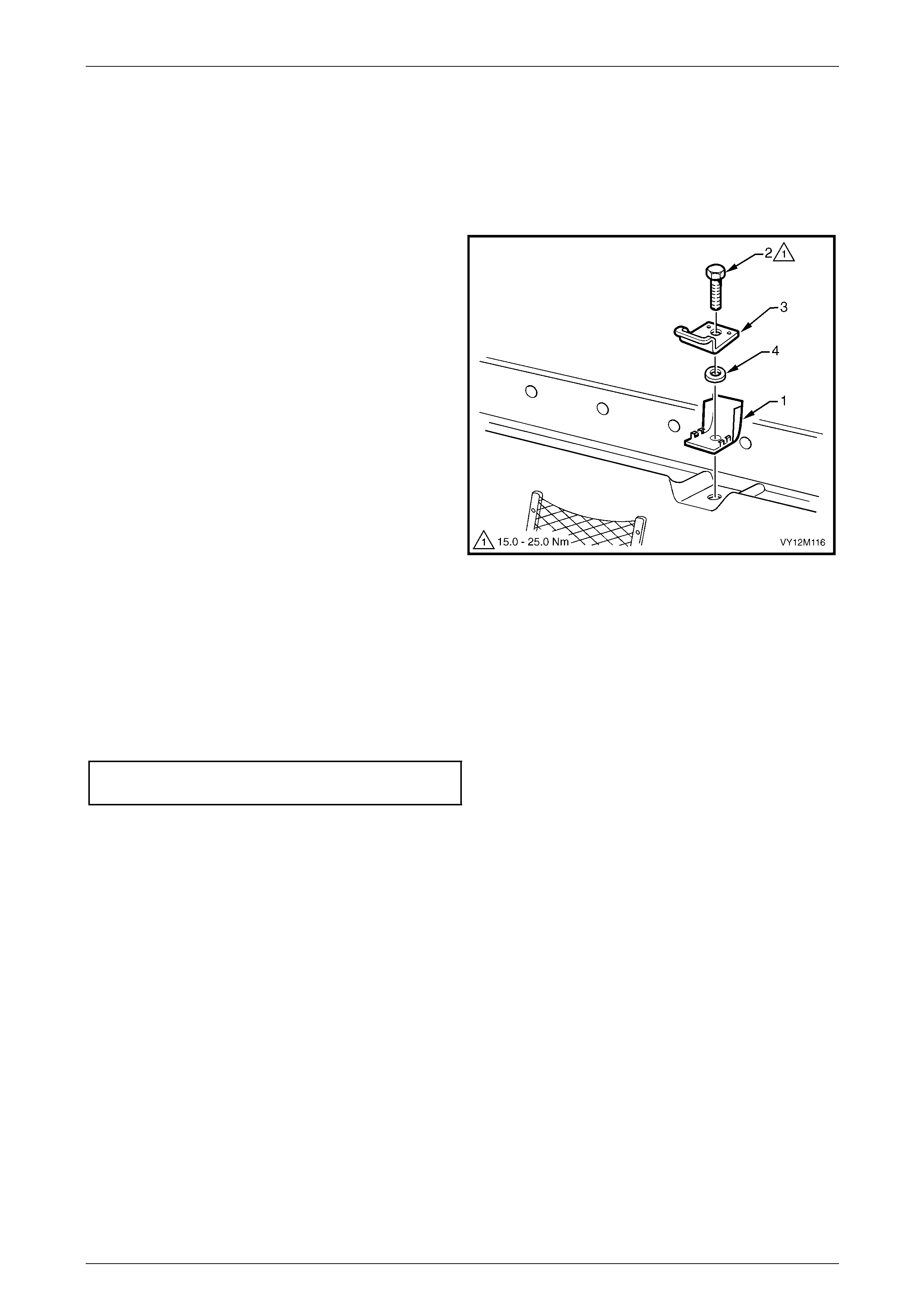
Occupant Protection System Page 12M–214
Page 12M–214
6.3 Child Seat Anchors – Utility and Regular
Cab
LT Section No. — AA–020
Remove
1 Prise open the child seat anc hor cover (1).
2 Remove the bolt (2) attaching the anchor (3) and
washer (4) to the vehicle and remove.
Figure 12M – 141
Reinstall
Reinstallation of the child s ea t anchors is the reverse of the removal procedure, noting the following:
1 Ensure the anchors are installed in the correct orientation.
2 Hand tighten the bolt a minimum of five turns before usin g any tools to tighten.
3 Tighten the bolt to the specified torque.
Child seat anchor mounting bolt
torque specification.................................15.0 – 25.0 Nm
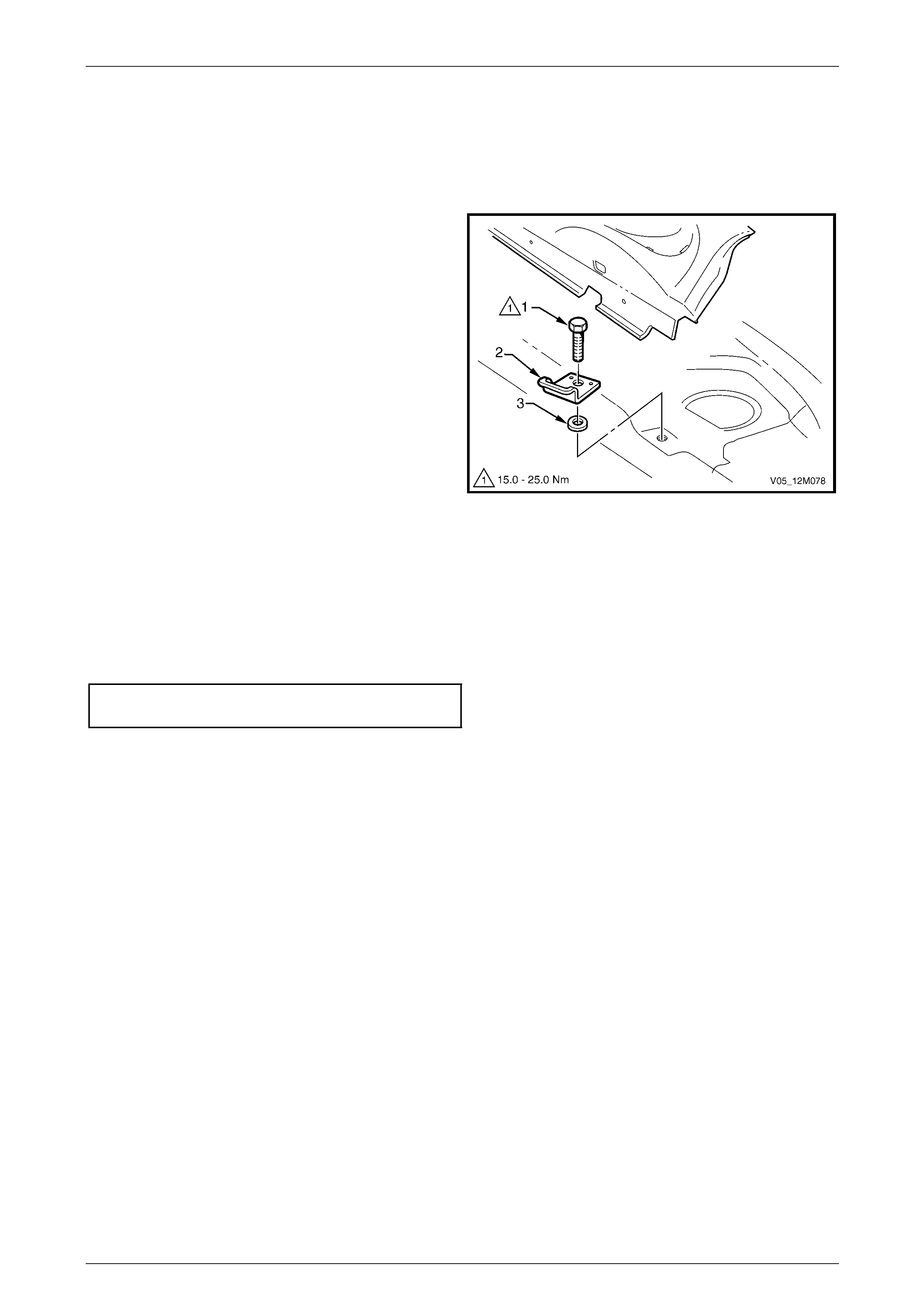
Occupant Protection System Page 12M–215
Page 12M–215
6.4 Child Seat Anchors – Coupe
LT Section No. — AA–020
Remove
1 Remove the rear window trim panel, refer to
Section 1A8 Headlining and Interior Trim .
2 Remove the bolt (1) attaching the anchor (2) and
washer (3) to the vehicle and remove.
Figure 12M – 142
Reinstall
Reinstallation of the child s ea t anchors is the reverse of the removal procedure, noting the following:
1 Ensure the anchors are installed in the correct orientation.
2 Hand tighten the bolt a minimum of five turns before usin g any tools to tighten.
3 Tighten the bolt to the specified torque.
Child seat anchor mounting bolt
torque specification.................................15.0 – 25.0 Nm
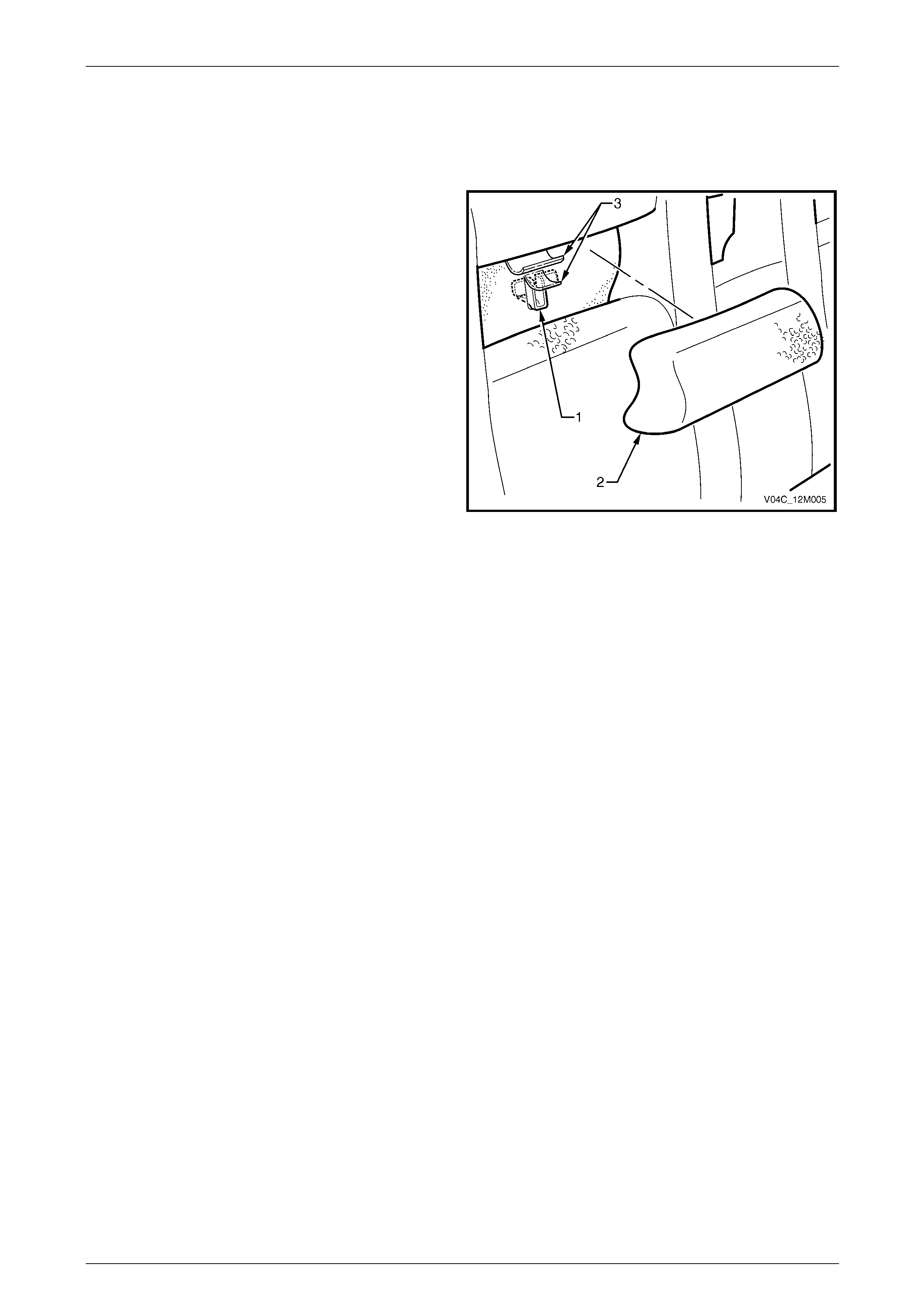
Occupant Protection System Page 12M–216
Page 12M–216
6.5 Child Seat Anchors – Crew Cab and
AWD Crew Cab
LT Section No. — AA–020
Three child seat anchors are permanently attached to the
vehicle. They are not serviced separately from the upper
rear body inner panel.
Access to each child seat anchor (1) is gaine d b y removing
the appropriate rear seat-back insert (2), refer to
Section 1A7 Seat Assemblies, and lifting the material flaps
(3) covering the anchor.
When the child seat anchors are not in use, the rear seat-
back inserts should be fitted into place.
Figure 12M – 143

Occupant Protection System Page 12M–217
Page 12M–217
7 Torque Wrench Specifications
SDM Retaining Screw .................................................................7.0 – 11.0 Nm
Side-impact Sensor Retaining Bolt............................................35.0 – 50.0 Nm
Seatbelt Buckle and Pretensioner Assembly Attaching Bolt......40.0 – 45.0 Nm
Steering Angle Sensor Attaching Screw........................................0.6 ± 0.1 Nm
Clock Spring Coil Attaching Screw................................................0.6 ± 0.1 Nm
Instrument Panel Inflatable Restraint Assembly Attaching Nut.............45.0 Nm
Instrument Panel Inflatable Restraint Assembly Attaching Bolt...7.0 – 12.0 Nm
Seatbelt Assembly Mounting Bolt..............................................35.0 – 50.0 Nm
Intermediate Seatbelt Guide Attaching Screw...............................1.8 – 2.4 Nm
Seatbelt Height Adjuster Assembly Attaching Bolt....................20.0 – 30.0 Nm
Seatbelt Guide Bracket Attaching Bolt.......................................20.0 – 22.0 Nm
Seatbelt Retractor Retaining Nut...............................................35.0 – 50.0 Nm
Seatbelt Retractor Bracket Mounting Bolt..................................35.0 – 50.0 Nm
Seatbelt Guide Attaching Bolt....................................................35.0 – 50.0 Nm
Seatbelt Lower Anchor Mounting Bolt.......................................35.0 – 50.0 Nm
Seatbelt Buckle Attaching Bolt ..................................................35.0 – 50.0 Nm
Child Seat Anchor Mounting Bolt...............................................15.0 – 25.0 Nm
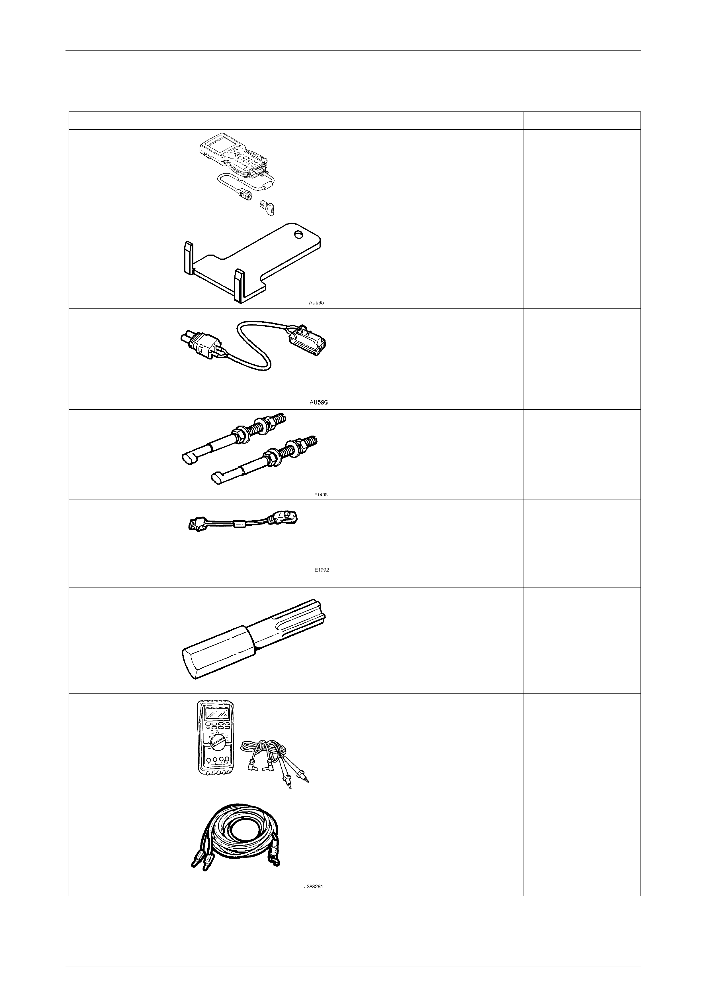
Occupant Protection System Page 12M–218
Page 12M–218
8 Special Tools
Tool Number Illustration Description Tool Classification
7000086I
Tech 2 Diagnostic Scan Tool
Used for diagnosis of vehicle electrical
system.
Previously released.
Mandatory
AU595
Steering Wheel Inflatable Res t raint
Assembly Removal Tool
Used for removing the steering wheel
inflatable restraint assembly from the
steering wheel hub.
New release.
Mandatory
AU596
Deployment Harness Adaptor For
Seatbelt Pretensioner
Used in conjunction with deplo yment
harness Tool No. J213526-1 for
deploying seatbelt pretensioner when
removed from the vehicle.
New release.
Available
E1408
Steering Wheel Puller Legs
Used in conjunction with a suitable
steering wheel puller such as J1858-A
or 7245 for removing steering wheel.
Previously released.
Desirable
E1992
Deployment Harness Adaptor
Used in conjunction with deplo yment
harness Tool No. J213526-1 for
deploying OPS components when
removed from the vehicle
Previously released.
Available
ETX30H
T30H Torx Bit
Used in conjunction with Torx bit
holder Tool No. J25359-8 (or
ETX55HLD)
Also commercially available as a
T30H Torx bit.
Previously released.
Mandatory
J213200
Digital Multimeter
Used for various measurement
functions. Must have at least 10 MΩ
input impedance and be capable of
reading capacitance.
Previously released (or use
commercial equivalent).
Available
J213526-1
Deployment Harness
Used in conjunction with deplo yment
harness adaptors T ool No. E1992 and
Tool No. AU596 for deploying OPS
components when removed from the
vehicle
Previously released
Available
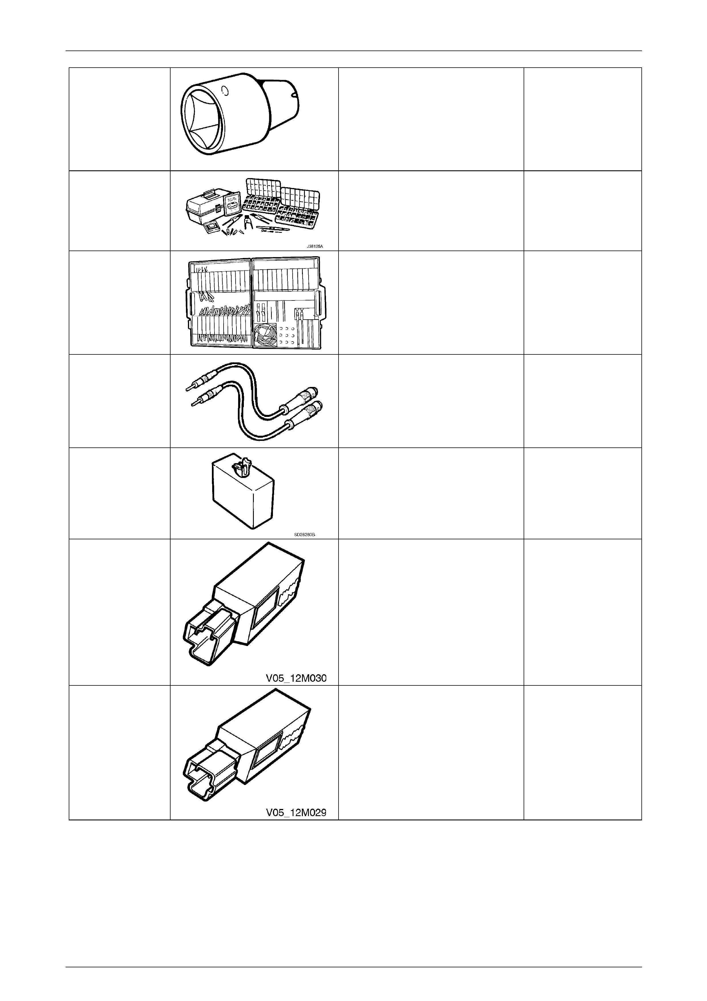
Occupant Protection System Page 12M–219
Page 12M–219
J25359-8
Torx Bit Holder
Commercially available.
Previously released.
Mandatory
J38125-A
Pin Repair Kit
Must be used when repairing OPS
wiring.
Previously released.
Available
KM-609
(J35616-A)
Electronic Kit
Used in conjunction with a multimeter
for measuring voltages and
resistances without damaging wiring
harness connectors.
Desirable
KM609-20
Test Leads
Used when carrying out diagnostic
circuit check on the OPS system.
Previously released.
Mandatory
SD28280B
(AU471)
Dummy Load
For steering wheel inflatable restraint
assembly and instrument panel
inflatable restraint assembly.
Mandatory
EL47787
Dummy Load
For seat belt pretensioner assembly. Mandatory
AU485
Dummy Load
For side-impact inflatable restraint
assembly.
Mandatory