
Fuses, Relays and Wiring Harnesses Page 12O–1
Section 12O
Fuses, Relays and Wiring Harnesses
ATTENTION
Before performing any service operation or other procedure described in this Section, refer to Section 00
Warnings, Cautions and Notes for correct workshop practices with regard to safety and/or property damage.
1 General Information ...............................................................................................................................7
1.1 Fuses ...................................................................................................................................................................... 7
1.2 Circuit Breakers................................................................................................................................................... 10
1.3 Fusible Links........................................................................................................................................................ 11
1.4 Relays ................................................................................................................................................................... 13
Passenger Compartment Relays........................................................................................................................ 13
Engine Compartment Relays.............................................................................................................................. 14
1.5 Diodes................................................................................................................................................................... 15
1.6 Wiring Harnesses................................................................................................................................................. 16
1.7 Wiring Harness Connectors................................................................................................................................ 19
1.8 Electronic Control Device Locations ................................................................................................................. 20
2 Service Operations...............................................................................................................................25
2.1 Fuses .................................................................................................................................................................... 25
Passenger Compartment Fuse and Relay Panel Assembly.............................................................................25
Engine Compartment Fuse and Relay Panel Assembly................................................................................... 26
2.2 Circuit Breakers................................................................................................................................................... 27
Remove................................................................................................................................................................. 27
Test ....................................................................................................................................................................... 27
Reinstall................................................................................................................................................................ 27
2.3 Fusible Links........................................................................................................................................................ 28
All Plug-in Type Fusible Links Except F104...................................................................................................... 28
Plug-in Type Fusible Link F104 ................................................................................................. ......................... 29
One-Wire Type Fusible Link................................................................................................................................ 30
2.4 Relays ................................................................................................................................................................... 31
Passenger Compartment Relays........................................................................................................................ 31
Engine Compartment Relays.............................................................................................................................. 32
2.5 Diodes................................................................................................................................................................... 33
A/C Compressor Suppression Diode................................................................................................................. 33
2.6 Wiring Repairs...................................................................................................................................................... 34
3 Wiring Installation Diagrams – Utility.................................................................................................35
3.1 Battery Wiring Harness – 1 ................................................................................................................................. 36
V6 Engine ............................................................................................................................................................. 36
3.2 Battery Wiring Harness – 2 ................................................................................................................................. 37
V6 Engine ............................................................................................................................................................. 37
3.3 Battery Wiring Harness – 3 ................................................................................................................................. 38
V8 Engine ............................................................................................................................................................. 38
3.4 Battery Wiring Harness – 4 ................................................................................................................................. 39
V8 Engine ............................................................................................................................................................. 39
3.5 Engine Harness – 1.............................................................................................................................................. 40
V6 Engine ............................................................................................................................................................. 40
3.6 Engine Harness – 2.............................................................................................................................................. 42
V6 Engine ............................................................................................................................................................. 42
3.7 Engine Harness – 3.............................................................................................................................................. 43
V6 Engine ............................................................................................................................................................. 43
Page 12O–1

Fuses, Relays and Wiring Harnesses Page 12O–2
3.8 Engine Harness – 4.............................................................................................................................................. 45
MY06 V6 Engine................................................................................................................................................... 45
3.9 Engine Harness – 5.............................................................................................................................................. 46
V6 Engine ............................................................................................................................................................. 46
3.10 Engine Harness – 6.............................................................................................................................................. 48
V6 Engine ............................................................................................................................................................. 48
3.11 Engine Harness – 7.............................................................................................................................................. 49
V6 Engine ............................................................................................................................................................. 49
3.12 Transmission Harness – 1 .................................................................................................................................. 50
V6 Engine ............................................................................................................................................................. 50
3.13 Transmission Harness – 2 .................................................................................................................................. 51
V6 Engine – 4 Speed Automatic Transmission................................................................................................. 51
3.14 Transmission Harness – 3 .................................................................................................................................. 52
V6 Engine – 4 Speed Automatic Transmission................................................................................................. 52
3.15 Transmission Harness – 4 .................................................................................................................................. 53
V6 Engine – MY2006 Alloytec – 4 Speed Automatic Transmission................................................................. 53
3.16 Transmission Harness – 5 .................................................................................................................................. 54
V6 Engine – 6 Speed Manual Transmission ...................................................................................................... 54
3.17 Transmission Harness – 6 .................................................................................................................................. 55
V6 Engine – 6 Speed Manual Transmission ...................................................................................................... 55
3.18 Powertrain Harness – 1 ....................................................................................................................................... 56
GEN III V8 Engine................................................................................................................................................. 56
3.19 Powertrain Harness – 2 ....................................................................................................................................... 57
GEN III V8 Engine................................................................................................................................................. 57
3.20 Powertrain Harness – 3 ....................................................................................................................................... 58
GEN III V8 Engine................................................................................................................................................. 58
3.21 Powertrain Harness – 4 ....................................................................................................................................... 59
GEN III V8 Engine................................................................................................................................................. 59
3.22 Powertrain Harness – 5 ....................................................................................................................................... 60
GEN III V8 Engine – Automatic Transmission................................................................................................... 60
3.23 Powertrain Harness – 6 ....................................................................................................................................... 61
GEN III V8 Engine – Automatic Transmission................................................................................................... 61
3.24 Powertrain Harness – 7 ....................................................................................................................................... 63
GEN III V8 Engine – Manual Transmission ........................................................................................................ 63
3.25 Powertrain Harness – 8 ....................................................................................................................................... 64
GEN III V8 Engine – Manual Transmission ........................................................................................................ 64
3.26 Powertrain Harness – 9 ....................................................................................................................................... 66
GEN IV V8 Engine ................................................................................................................................................ 66
3.27 Powertrain Harness – 10 ..................................................................................................................................... 67
GEN IV V8 Engine ................................................................................................................................................ 67
3.28 Powertrain Harness – 11 ..................................................................................................................................... 68
GEN IV V8 Engine ................................................................................................................................................ 68
3.29 Powertrain Harness – 12 ..................................................................................................................................... 69
GEN IV V8 Engine ................................................................................................................................................ 69
3.30 Powertrain Harness – 13 ..................................................................................................................................... 70
GEN IV V8 Engine ................................................................................................................................................ 70
3.31 Powertrain Harness – 14 ..................................................................................................................................... 71
GEN IV V8 Engine ................................................................................................................................................ 71
3.32 Powertrain Harness – 15 ..................................................................................................................................... 72
GEN IV V8 Engine ................................................................................................................................................ 72
3.33 Powertrain Harness – 16 ..................................................................................................................................... 73
GEN IV V8 Engine ................................................................................................................................................ 73
3.34 Powertrain Harness – 17 ..................................................................................................................................... 74
GEN IV V8 Engine ................................................................................................................................................ 74
3.35 Powertrain Harness – 18 ..................................................................................................................................... 75
GEN IV V8 Engine ................................................................................................................................................ 75
3.36 Front Body Harness – 1....................................................................................................................................... 76
V6 Engine – Engine Compartment ..................................................................................................................... 76
3.37 Front Body Harness – 2....................................................................................................................................... 77
GEN III V8 Engine – Engine Compartment......................................................................................................... 77
Page 12O–2

Fuses, Relays and Wiring Harnesses Page 12O–3
3.38 Front Body Harness – 3....................................................................................................................................... 78
GEN IV V8 Engine – Engine Compartment ........................................................................................................ 78
3.39 Front Body Harness – 4....................................................................................................................................... 79
Protector Assembly, Brake Master Cylinder and Booster................................................................................ 79
3.40 Front Body Harness – 5....................................................................................................................................... 80
Under Hood Fuse and Relay Panel and Wiper Motor ....................................................................................... 80
3.41 Front Body Harness – 6....................................................................................................................................... 81
Body Ground and Washer Pump........................................................................................................................ 81
3.42 Front Body Harness – 7....................................................................................................................................... 82
Headlamp, Park Lamp and Turn Indicator – Level 1......................................................................................... 82
3.43 Front Body Harness – 8....................................................................................................................................... 83
Headlamp, Park Lamp and Turn Indicator – Level 2......................................................................................... 83
3.44 Front Body Harness – 9....................................................................................................................................... 84
V6 Engine – Standard Fans and Theft Deterrent Connectors.......................................................................... 84
3.45 Front Body Harness – 10..................................................................................................................................... 85
V6 Engine – 400W Fans and Theft Deterrent Connectors................................................................................ 85
3.46 Front Body Harness – 11..................................................................................................................................... 86
V8 Engine – 400W Fans and Theft Deterrent Connectors................................................................................ 86
3.47 Front Body Harness – 12..................................................................................................................................... 87
V8 Engine – 430W Fans and Theft Deterrent Connectors................................................................................ 87
3.48 Front Body Harness – 13..................................................................................................................................... 88
Ambient Sensor, Fan and Theft Deterrent Connectors .................................................................................... 88
3.49 Front Body Harness – 14..................................................................................................................................... 89
Front Lamps, Fog Lamps and Horn Connectors............................................................................................... 89
3.50 Front Body Harness – 15..................................................................................................................................... 90
V6 Engine – Engine Control Module .................................................................................................................. 90
3.51 Front Body Harness – 16..................................................................................................................................... 91
GEN IV V8 Engine – Engine Control Module ..................................................................................................... 91
3.52 Front Body Harness – 17..................................................................................................................................... 92
V6 Engine – ABS, Air Intake and Front Wheel Speed Sensor.......................................................................... 92
3.53 Front Body Harness – 18..................................................................................................................................... 93
GEN III V8 Engine – ABS, Air Intake and Front Wheel Speed Sensor ............................................................. 93
3.54 Front Body Harness – 19..................................................................................................................................... 94
GEN IV V8 Engine – ABS, Air Intake and Front Wheel Speed Sensor............................................................. 94
3.55 Front Body Harness – 20..................................................................................................................................... 96
V6 Engine – Cockpit Module............................................................................................................................... 96
3.56 Front Body Harness – 21..................................................................................................................................... 98
GEN III V8 Engine – Cockpit Module – Manual Air-conditioning ..................................................................... 98
3.57 Front Body Harness – 22................................................................................................................................... 100
GEN III V8 Engine – Cockpit Module – Auto Air-conditioning........................................................................ 100
3.58 Front Body Harness – 23................................................................................................................................... 102
GEN IV V8 Engine – Cockpit Module................................................................................................................ 102
3.59 Front Body Harness – 24................................................................................................................................... 104
Cockpit Module.................................................................................................................................................. 104
3.60 Front Body Harness – 25................................................................................................................................... 105
Cockpit Module.................................................................................................................................................. 105
3.61 Front Body Harness – 26................................................................................................................................... 106
V6 & GEN IV Engine – Fuse Block, BCM and PIM........................................................................................... 106
3.62 Front Body Harness – 27................................................................................................................................... 107
GEN III V8 Engine – Fuse Block, PIM, TAC and BCM...................................................................................... 107
3.63 Front Body Harness – 28................................................................................................................................... 109
V6 Engine – Steering Column........................................................................................................................... 109
3.64 Front Body Harness – 29................................................................................................................................... 110
V8 Engine – Steering Column........................................................................................................................... 110
3.65 Front Body Harness – 30................................................................................................................................... 111
Ignition Lock and Theft Dete rrent Receiver..................................................................................................... 111
3.66 Front Body Harness – 31................................................................................................................................... 112
V6 Engine – Manual Transmission – Cruise Control, Stop Lamp Switches and Data Link Connector...... 112
3.67 Front Body Harness – 32................................................................................................................................... 113
V6 Engine – Automatic Transmission – Cruise Control, Stop Lamp Switches and Data Link Connector. 113
Page 12O–3

Fuses, Relays and Wiring Harnesses Page 12O–4
3.68 Front Body Harness – 33................................................................................................................................... 114
V8 Engine – Manual Transmission – Cruise Control, Stop Lamp Switches and Data Link Connector...... 114
3.69 Front Body Harness – 34................................................................................................................................... 115
V8 Engine – Automatic Transmission – Cruise Control, Stop Lamp Switches and Data Link Connector. 115
3.70 Front Body Harness – 35................................................................................................................................... 116
Accelerator Pedal Position ............................................................................................................................... 116
3.71 Front Body Harness – 36................................................................................................................................... 117
Inside Air Temperature Sensor and Floor Console ........................................................................................ 117
3.72 Front Body Harness – 37................................................................................................................................... 118
Instrument Cluster Assembly........................................................................................................................... 118
3.73 Front Body Harness – 38................................................................................................................................... 119
Air-conditioning and Heating Controls............................................................................................................ 119
3.74 Front Body Harness – 39................................................................................................................................... 120
Daytime Running Lamp Control....................................................................................................................... 120
3.75 Front Body Harness – 40................................................................................................................................... 121
Instrument Panel Facia Trim Switches ............................................................................................................ 121
3.76 Front Body Harness – 41................................................................................................................................... 122
Radio Assembly................................................................................................................................................. 122
3.77 Front Body Harness – 42................................................................................................................................... 123
V6 Engine – Passenger Side Airbag and Radio/Mobile Telephone Connectors .......................................... 123
3.78 Front Body Harness – 43................................................................................................................................... 125
GEN III V8 Engine – Passenger Side Airbag and Radio/Mobile Telephone Connectors.............................. 125
3.79 Front Body Harness – 44................................................................................................................................... 127
GEN IV V8 Engine – Passenger Side Airbag and Radio/Mobile Telephone Connectors ............................. 127
3.80 Front Body Harness – 45................................................................................................................................... 129
Light Sensor/Key Receiver Module and Instrument Panel Speakers............................................................ 129
3.81 Front Body Harness – 46................................................................................................................................... 130
HVAC Climate Control (Manual A/C) ................................................................................................................ 130
3.82 Front Body Harness – 47................................................................................................................................... 131
HVAC Occupant Climate Control (Auto A/C)................................................................................................... 131
3.83 Front Body Harness – 48................................................................................................................................... 133
Instrument Panel Compartment........................................................................................................................ 133
3.84 Front Body Harness – 49................................................................................................................................... 134
Interior ................................................................................................................................................................ 134
3.85 Front Body Harness – 50................................................................................................................................... 135
Transmission Selector Connectors .................................................................................................................. 135
3.86 Body Wiring Harness – 1................................................................................................................................... 136
Interior ................................................................................................................................................................ 136
3.87 Body Wiring Harness – 2................................................................................................................................... 137
3.88 Body Wiring Harness – 3................................................................................................................................... 138
Interior ................................................................................................................................................................ 138
3.89 Body Wiring Harness – 4................................................................................................................................... 139
Fuel Tank............................................................................................................................................................ 139
3.90 Body Wiring Harness – 5................................................................................................................................... 140
Speakers............................................................................................................................................................. 140
3.91 Body Wiring Harness – 6................................................................................................................................... 141
Load Compartment............................................................................................................................................ 141
3.92 Body Wiring Harness – 7................................................................................................................................... 142
ABS ..................................................................................................................................................................... 142
3.93 Body Wiring Harness – 8................................................................................................................................... 143
Trailer Connectors............................................................................................................................................. 143
3.94 Body & Roof Lamp Harnesses – 1.................................................................................................................... 144
Interior ................................................................................................................................................................ 144
3.95 Body & Roof Lamp Harnesses – 2.................................................................................................................... 145
3.96 Roof Lamp Harness........................................................................................................................................... 146
3.97 Radio Antenna Wiring ....................................................................................................................................... 147
3.98 Door Wiring Harness......................................................................................................................................... 149
3.99 9C1 Option – 1.................................................................................................................................................... 151
3.100 9C1 Option – 2.................................................................................................................................................... 153
Page 12O–4

Fuses, Relays and Wiring Harnesses Page 12O–5
4 Wiring Installation Diagrams – Regular Cab ...................................................................................154
4.1 Transmission Harness ...................................................................................................................................... 155
V6 Engine – 4 Speed Automatic Transmission............................................................................................... 155
4.2 Body Wiring Harness – 1 ................................................................................................................................... 156
Speakers............................................................................................................................................................. 156
4.3 Body Wiring Harness – 2 ................................................................................................................................... 157
Load Compartment and Trailer Connectors.................................................................................................... 157
4.4 Body & Roof Lamp Harnesses.......................................................................................................................... 159
Interior ................................................................................................................................................................ 159
4.5 Rear Body Wiring Harness................................................................................................................................ 160
Fuel Tank............................................................................................................................................................ 160
4.6 Rear Body Wiring Harness................................................................................................................................ 162
ABS ..................................................................................................................................................................... 162
5 Wiring Installation Diagrams – Crew Cab........................................................................................164
5.1 Transmission Harness ...................................................................................................................................... 165
V6 Engine – 4 Speed Automatic Transmission............................................................................................... 165
5.2 Body Wiring Harness – 1 ................................................................................................................................... 166
Interior ................................................................................................................................................................ 166
5.3 Body Wiring Harness – 2 ................................................................................................................................... 168
Speakers............................................................................................................................................................. 168
5.4 Body Wiring Harness – 3 ................................................................................................................................... 169
Load Compartment............................................................................................................................................ 169
5.5 Body Wiring Harness – 4 ................................................................................................................................... 171
Trailer Connectors............................................................................................................................................. 171
5.6 Body & Roof Lamp Harnesses.......................................................................................................................... 172
Interior ................................................................................................................................................................ 172
5.7 Roof Lamp Harness – 1..................................................................................................................................... 174
5.8 Roof Lamp Harness – 2..................................................................................................................................... 175
5.9 Rear Wiring Harness.......................................................................................................................................... 176
Fuel Tank and ABS............................................................................................................................................ 176
5.10 Rear Door Wiring Harness ................................................................................................................................ 178
6 Wiring Installation Diagrams – Regular & Crew Cab AWD............................................................179
6.1 Battery Wiring Harness – 1 ............................................................................................................................... 180
V6 Engine ........................................................................................................................................................... 180
6.2 Battery Wiring Harness – 2 ............................................................................................................................... 181
V6 Engine ........................................................................................................................................................... 181
6.3 Battery Wiring Harness – 3 ............................................................................................................................... 182
GEN III V8 Engine............................................................................................................................................... 182
6.4 Engine Harness – 1............................................................................................................................................ 183
V6 Engine ........................................................................................................................................................... 183
6.5 Engine Harness – 2............................................................................................................................................ 185
V6 Engine ........................................................................................................................................................... 185
6.6 Engine Harness – 3............................................................................................................................................ 186
V6 Engine ........................................................................................................................................................... 186
6.7 Engine Harness – 4............................................................................................................................................ 188
V6 Engine ........................................................................................................................................................... 188
6.8 Engine Harness – 5............................................................................................................................................ 190
V6 Engine ........................................................................................................................................................... 190
6.9 Engine Harness – 6............................................................................................................................................ 191
V6 Engine ........................................................................................................................................................... 191
6.10 Transmission Harness ...................................................................................................................................... 193
V6 Engine – Automatic Transmission.............................................................................................................. 193
6.11 Powertrain Harness – 1 ..................................................................................................................................... 194
GEN III V8 Engine............................................................................................................................................... 194
6.12 Powertrain Harness – 2 ..................................................................................................................................... 195
GEN III V8 Engine – Automatic Transmission................................................................................................. 195
Page 12O–5

Fuses, Relays and Wiring Harnesses Page 12O–6
6.13 Powertrain Harness – 3 ..................................................................................................................................... 196
GEN III V8 Engine – Automatic Transmission................................................................................................. 196
6.14 Front Body Harness – 1..................................................................................................................................... 198
V6 Engine – Engine Control Module ................................................................................................................ 198
6.15 Front Body Harness – 2..................................................................................................................................... 199
V6 Engine – ABS, Air Intake and Front Wheel Speed Sensor........................................................................ 199
6.16 Front Body Harness – 3..................................................................................................................................... 200
GEN III V8 Engine – ABS, Air Intake and Front Wheel Speed Sensor ........................................................... 200
6.17 Front Body Harness – 4..................................................................................................................................... 201
V6 Engine – Cockpit Module............................................................................................................................. 201
6.18 Front Body Harness – 5..................................................................................................................................... 203
GEN III V8 Engine – Cockpit Module – Manual Air-conditioning ................................................................... 203
6.19 Front Body Harness – 6..................................................................................................................................... 205
GEN III V8 Engine – Cockpit Module – Auto Air-conditioning........................................................................ 205
6.20 Front Body Harness – 7..................................................................................................................................... 207
Auxiliary Sports Gauges................................................................................................................................... 207
6.21 Front Body Harness – 8..................................................................................................................................... 208
Interior ................................................................................................................................................................ 208
6.22 Body Wiring Harness......................................................................................................................................... 209
Interior ................................................................................................................................................................ 209
Page 12O–6
Fuses, Relays and Wiring Harnesses Page 12O–7
1 General Information
All electrical circuits are protected again st damage that might occur due to short circuits or overloads in the wiring system
by fuses, circuit breakers, fusible links and relays.
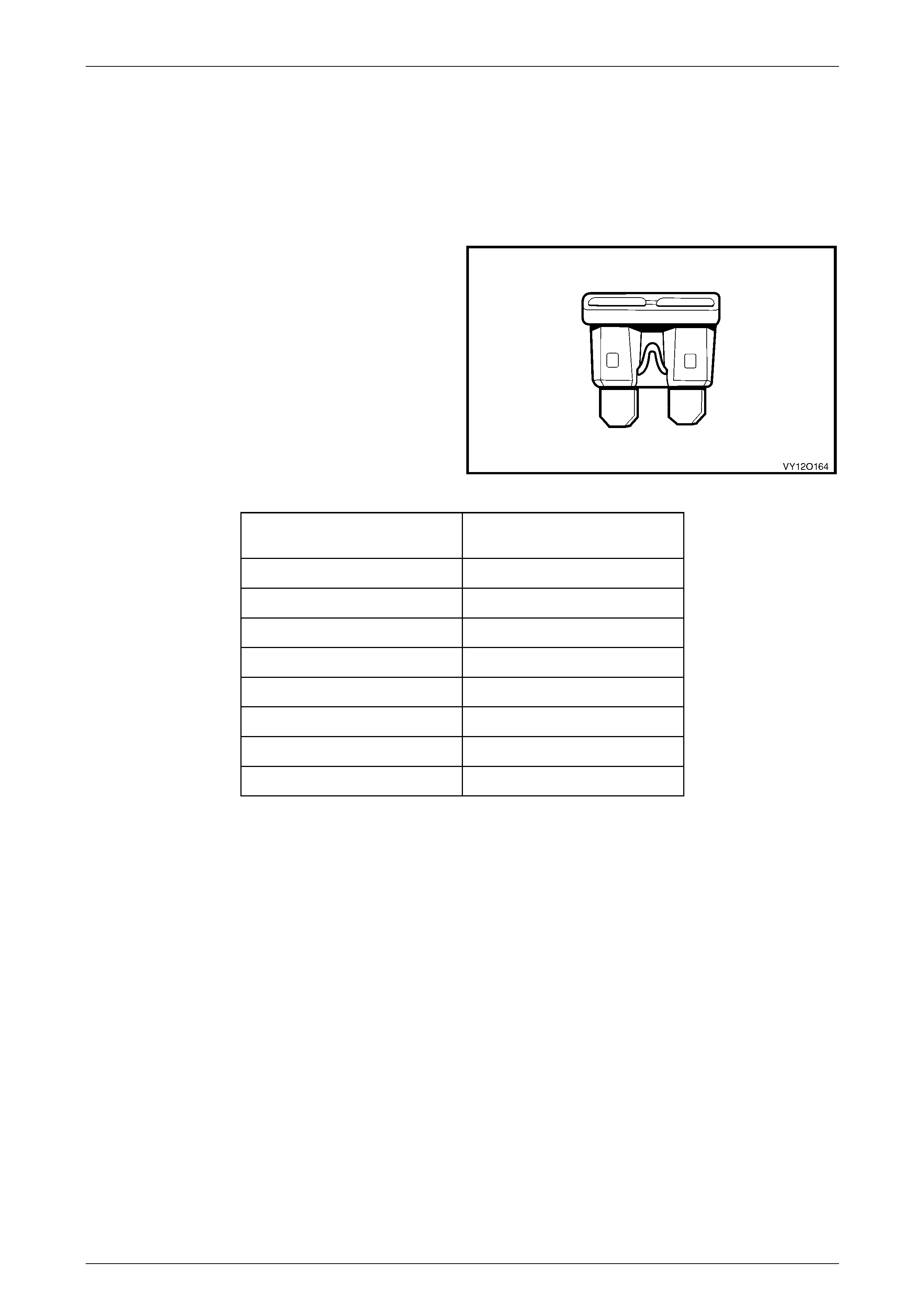
1.1 Fuses
Fuses are a blade type mini construction, with the current
rating in amps indicated on the top of the fuse assembly,
above the element, or identified by the plastic body colour of
the fuse. The fuse current ratings and corres ponding colour
are listed in the following table.
Figure 12O – 1
Current Rating
(Amps) Fuse Colour
3 Violet
5 Tan
7.5 Brown
10 Red
15 Blue
20 Yellow
25 White
30 Green
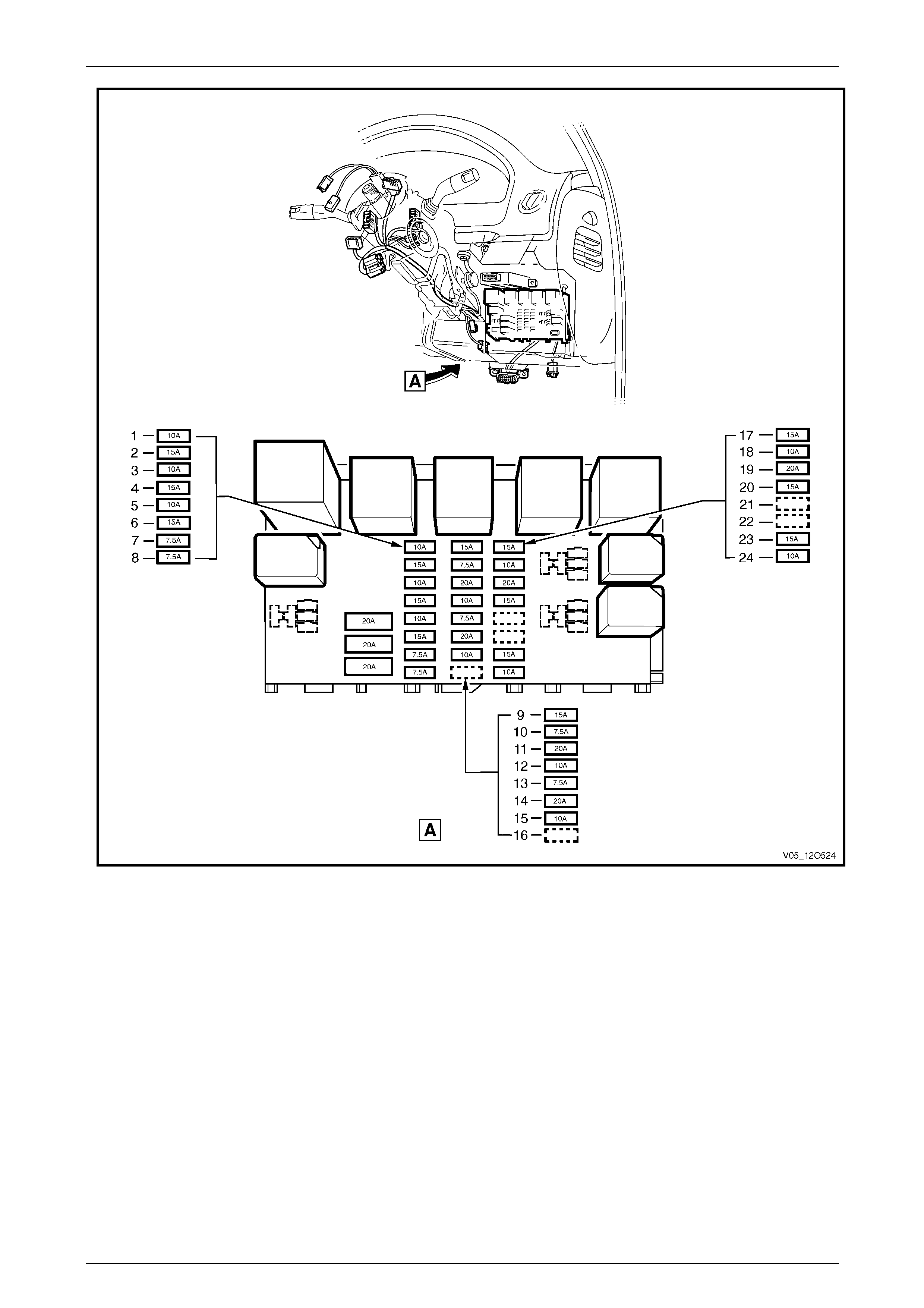
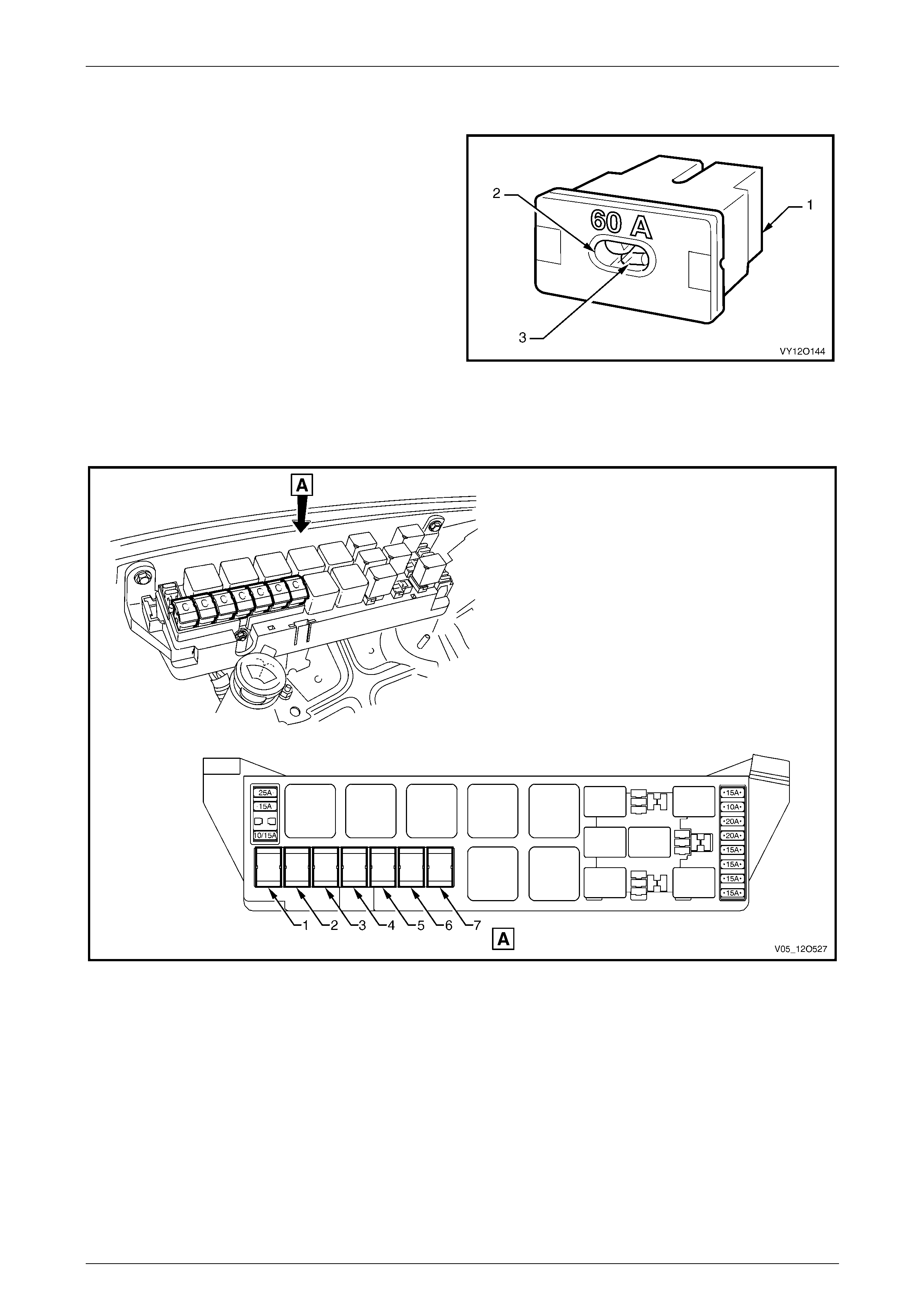
Fuses are located in two positions on the vehicle. One group is located in the passenger compartment fuse and relay
panel assembly. Refer to Figure 12O – 2. A label on the inside of the instrument panel lower cover indicates the circuits
protected by each fuse.
Page 12O–7
Fuses, Relays and Wiring Harnesses Page 12O–8
Figure 12O – 2
Legend
1 F4 – Park Lamps Fuse (10A)
2 F5 – Stop Lamps Fuse (15A)
3 F6 – Interior Illumination Fuse (10A)
4 F7 – Hazard Lamps/Antenna Drive Fuse (15A)
5 F8 – Automatic Transmission (V6 & GEN IV V8) Fuse (10A)
6 F9 – Horn Fuse (15A)
7 F10 – Ignition Fuse (7.5A)
8 F11 – Instrument Illumination Fuse (7.5A)
9 F12 – Turn Signals & Back-up Lamps Fuse (15A)
10 F13 – Heated Rear Window, HVAC & Instruments Fuse
(7.5A)
11 F14 – Cigar Lighter Fuse (20A)
12 F15 – Cruise Control, Power Mirrors & Engine (V6) Fuse
(10A)
13 F16 – Radio & Cell Phone Fuse (7.5A)
14 F17 – Accessory Socket Fuse (20A)
15 F18 – Wiper Washer Fuse (20A)
16 F19 – Spare
17 F20 – Power Locks, Power Windows & Theft Horn Fuse
(15A)
18 F21 – Instruments & Climate Control Fuse (10A)
19 F22 – Heated Rear Window & Blower Fan Fuse (20A)
20 F23 – Radio & Cell Phone Fuse (15A)
21 F24 – Spare
22 F25 – Spare
23 F26 – SRS Fuse (15A)
24 F27 – ABS Fuse (10A)
Page 12O–8
Fuses, Relays and Wiring Harnesses Page 12O–9
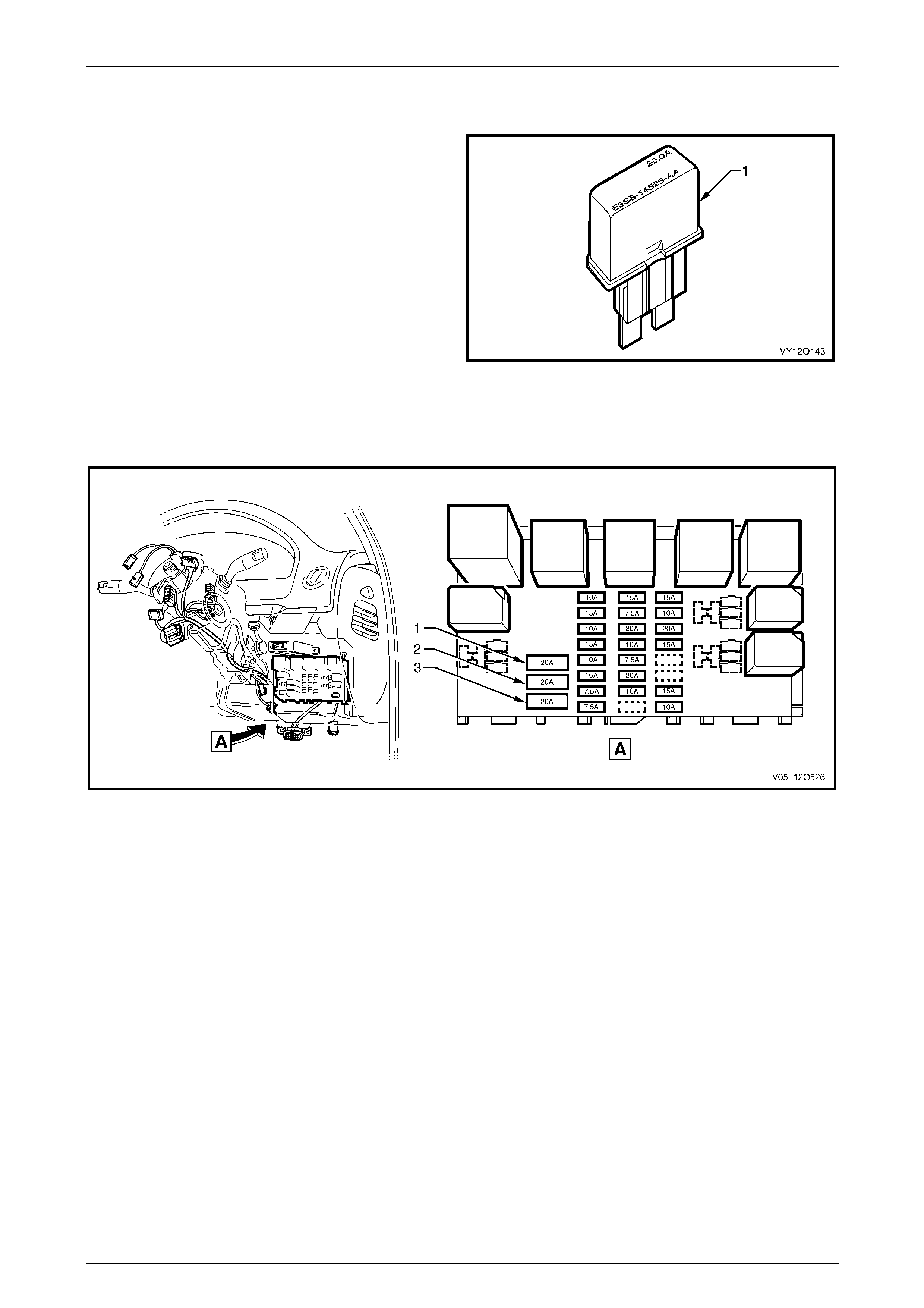
The second group of fuses ar e located in the engine compartment fuse and relay panel assembly, situated forward of
the right-hand side front suspension strut tower. A label on the insid e of the panel cover indicates the circuits protected
by each fuse. Refer to Figure 12O – 3.
Figure 12O – 3
Legend
1 F36 – ABS & TCS Fuse (25A)
2 F37 – Engine Sensors 2 (V6) Fuse (15A)
3 F38 – Spare
4 F39 – AC Clutch (V6) Fuse (10A) / TAC Module (V8) Fuse
(15A)
5 F28 – Fuel Pump Fuse (15A)
6 F29 – Engine, BCM & Automatic Transmission (V6) Fuse
(10A)
7 F30 – Right-hand Headlamp Fuse (20A)
8 F31 – Left-hand Headlamp Fuse (20A)
9 F32 – Automatic Transmission (V8) / ECM (V6 & V8) Fuse
(V6 & GEN III V8 - 15A) (GEN IV V8 – 10A)
10 F33 – Engine Sensors Fuse (15A)
11 F34 – Fuel Injectors & Ignition Modules Fuse
(V6 & GEN III V8 - 15A) (GEN IV V8 – 20A)
12 F35 – Fuel Injectors & Ignition Modules Fuse
(V6 & GEN III V8 - 15A) (GEN IV V8 – 20A)
Page 12O–9
Fuses, Relays and Wiring Harnesses Page 12O–10
1.2 Circuit Breakers
A circuit breaker is a circuit protection device that will trip
when the circuit current exceeds its rating. The circuit
breaker is activated by heat and will reset after being
allowed to cool. The circuit breaker has a limited number of
tripping cycles before its tripping time will change. The
circuit breaker will continue to open a nd close until the
cause of the excess current is corrected.
Figure 12O – 4
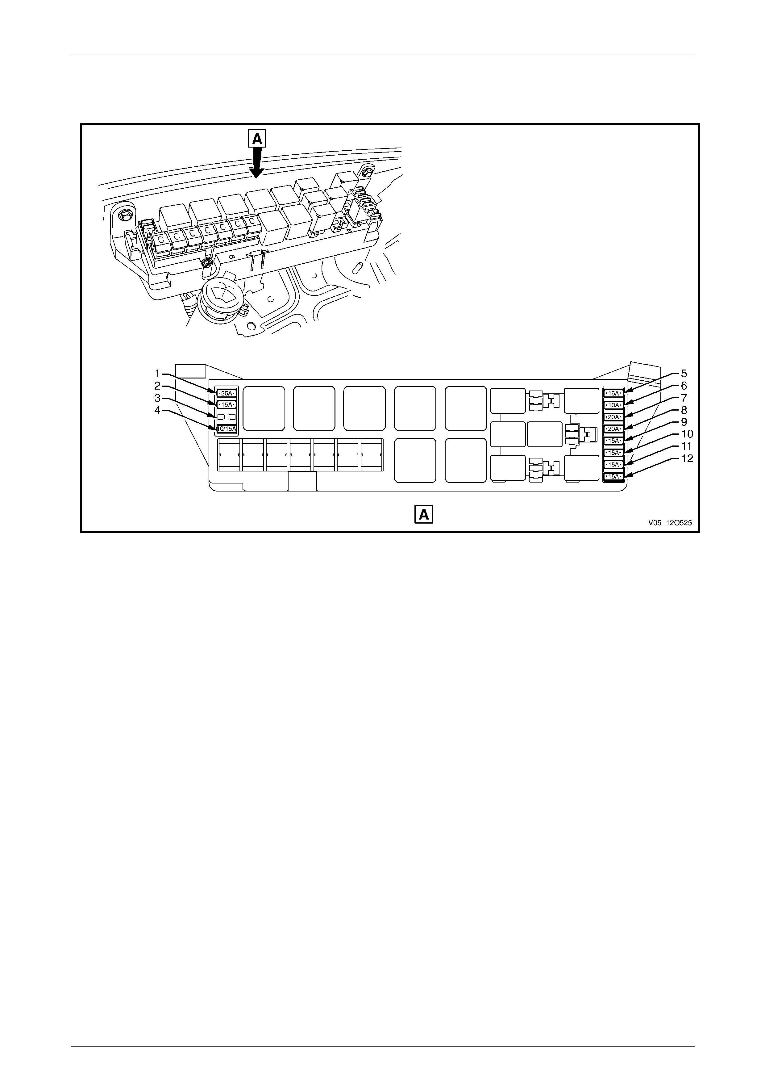
All the circuit breakers are located in the passenger compartment fuse and relay panel assembly and have a 20A current
rating. A label on the inside of the panel cover indicates the circuits protected by each circuit breaker. Refer to
Figure 12O – 5.
Figure 12O – 5
Legend
1 F1 – Power Windows Circuit Breaker (20A)
2 F2 – Power Seats Circuit Breaker (20A) 3 F3 – Sunroof Circuit Breaker (20A)
Page 12O–10
Fuses, Relays and Wiring Harnesses Page 12O–11
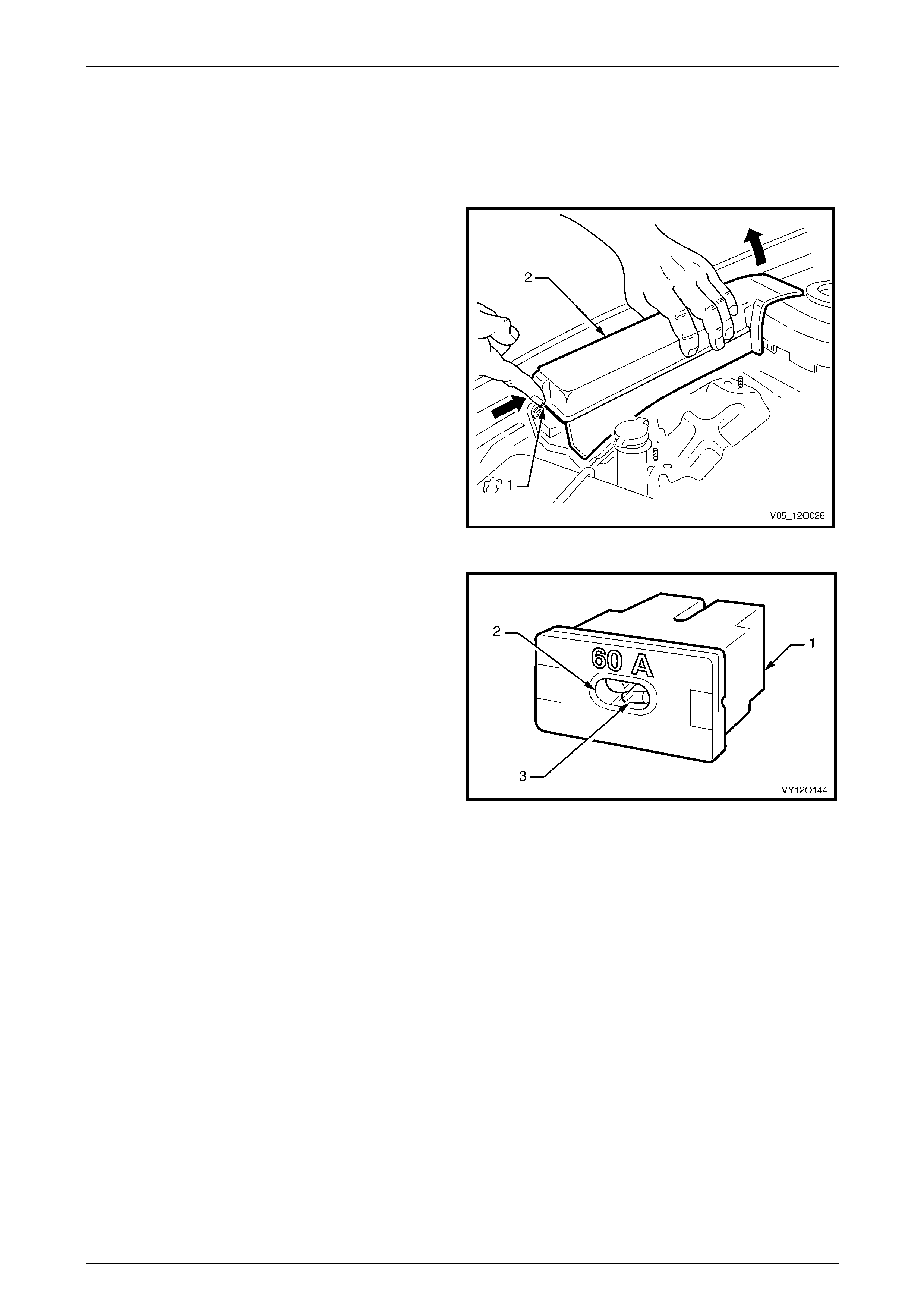
1.3 Fusible Links
The chassis and engine electrical wiring is protected against
short circuit damage by fusible links.
Plug-in type fusible links (1) have an insp ection window (2)
that allows a visual check of the condition of the element (3).
Figure 12O – 6
The plug-in type fusible links are located in the engine compartment fuse and relay panel assembly. Refer to
Figure 12O – 7 for the location and usage of the fusible links. A label on the inside of the panel cover indicates the
circuits protected by each fusible li nk.
Figure 12O – 7
Legend
1 F101 – Engine Cooling Large Fan (30A)
2 F102 – Lighting (60A)
3 F103 – Anti-lock Brakes (V6 & GEN IV V8 – 40A) /
(GEN III V8 – 60A)
4 F104 – Engine (60A)
5 F105 – Main (60A)
6 F106 – Blower Fan (40A)
7 F107 – Engine Cooling Small Fan (30A)
Page 12O–11
Fuses, Relays and Wiring Harnesses Page 12O–12
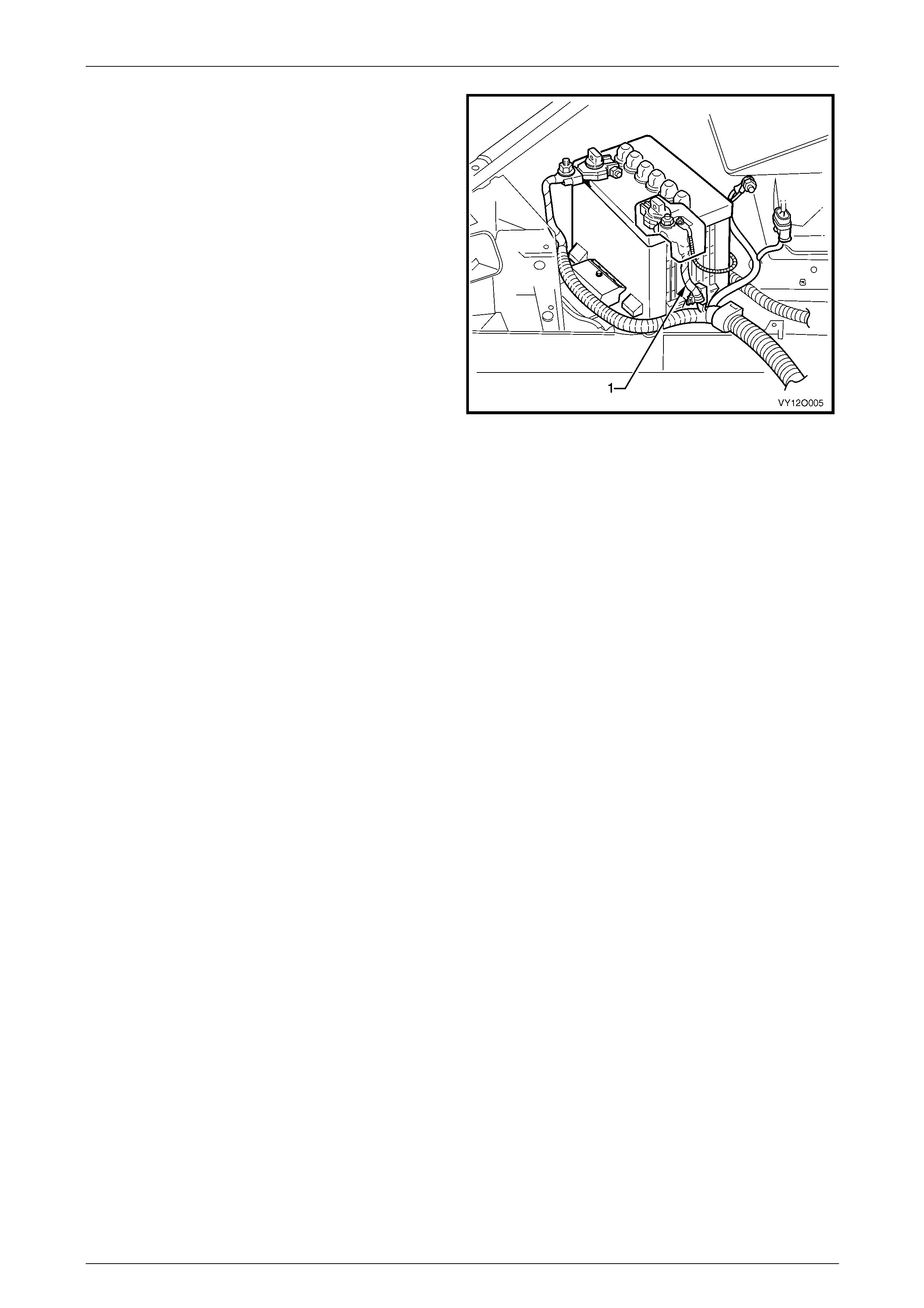
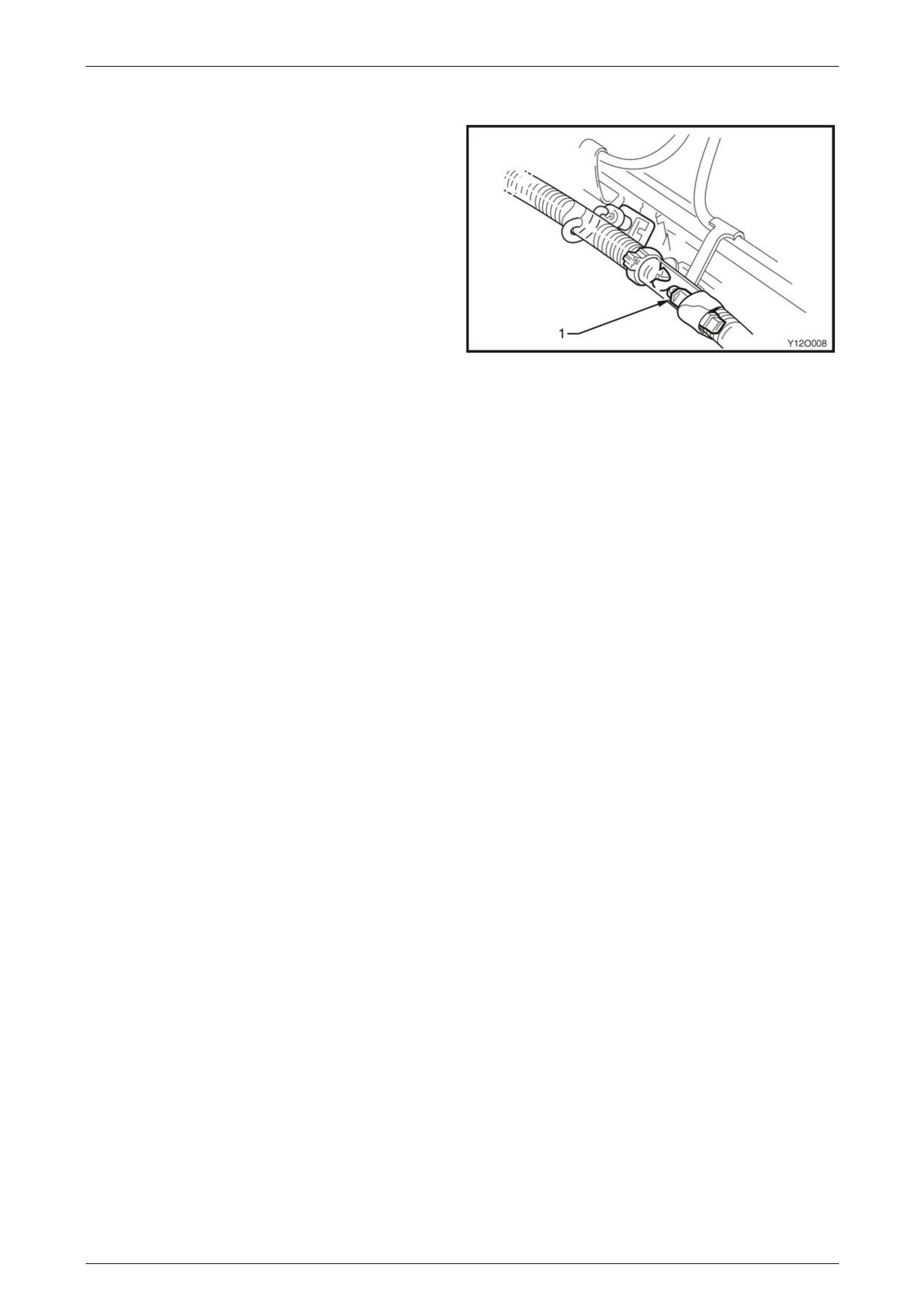
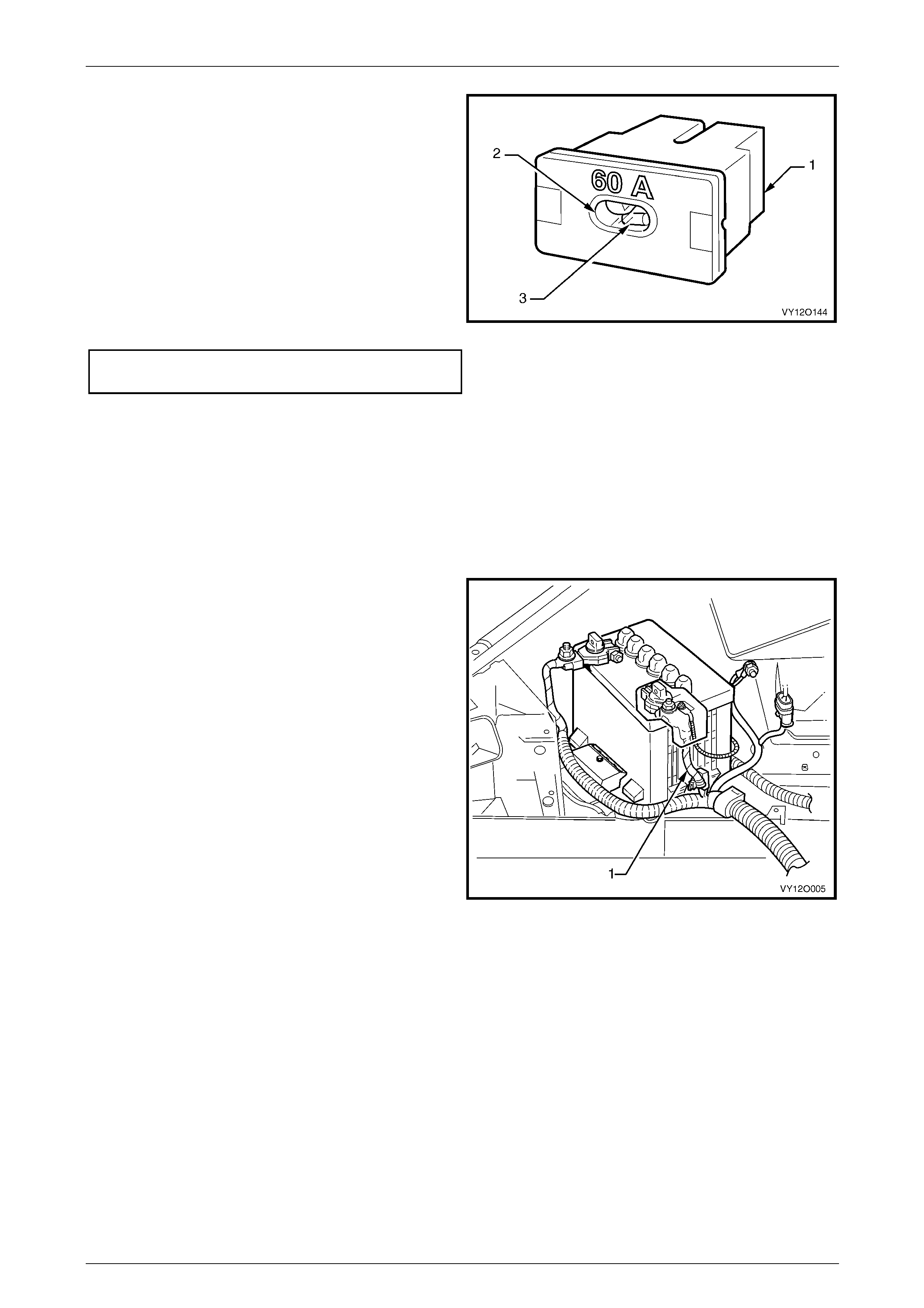
A one-wire type fusible link, c onsisting of an insulated fuse
wire (1) is attached to the battery harness with cable ties.
This is integrated as part of the battery harne ss and is
located adjacent to the battery harness positive terminal.
Figure 12O – 8
Page 12O–12
Fuses, Relays and Wiring Harnesses Page 12O–13
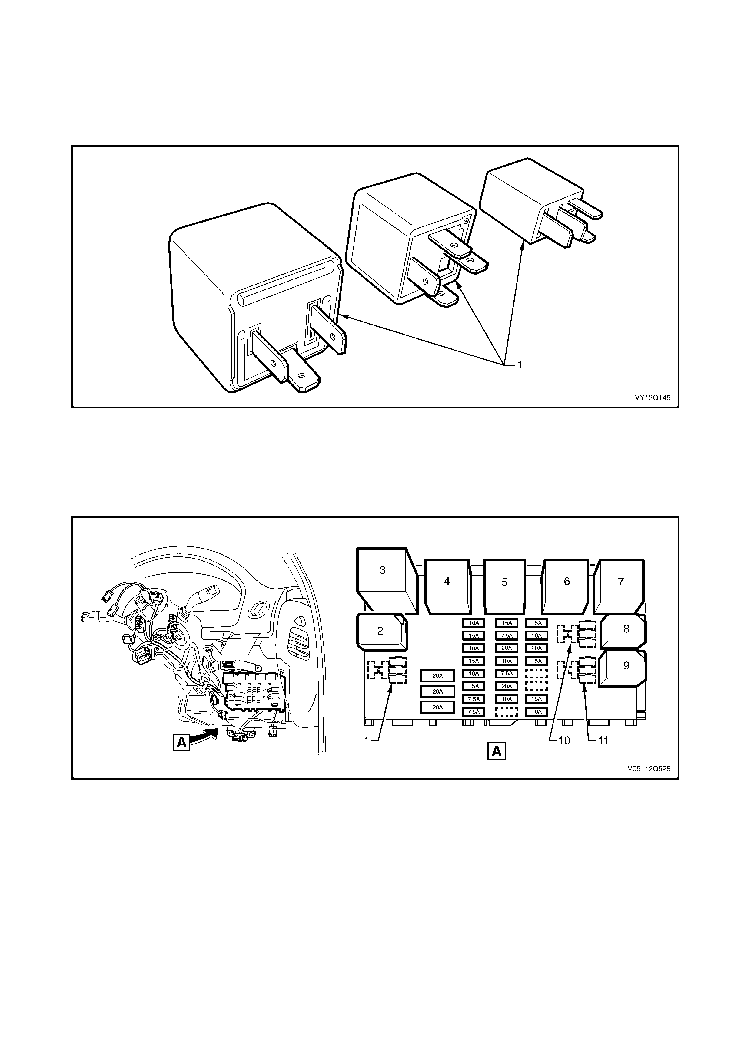
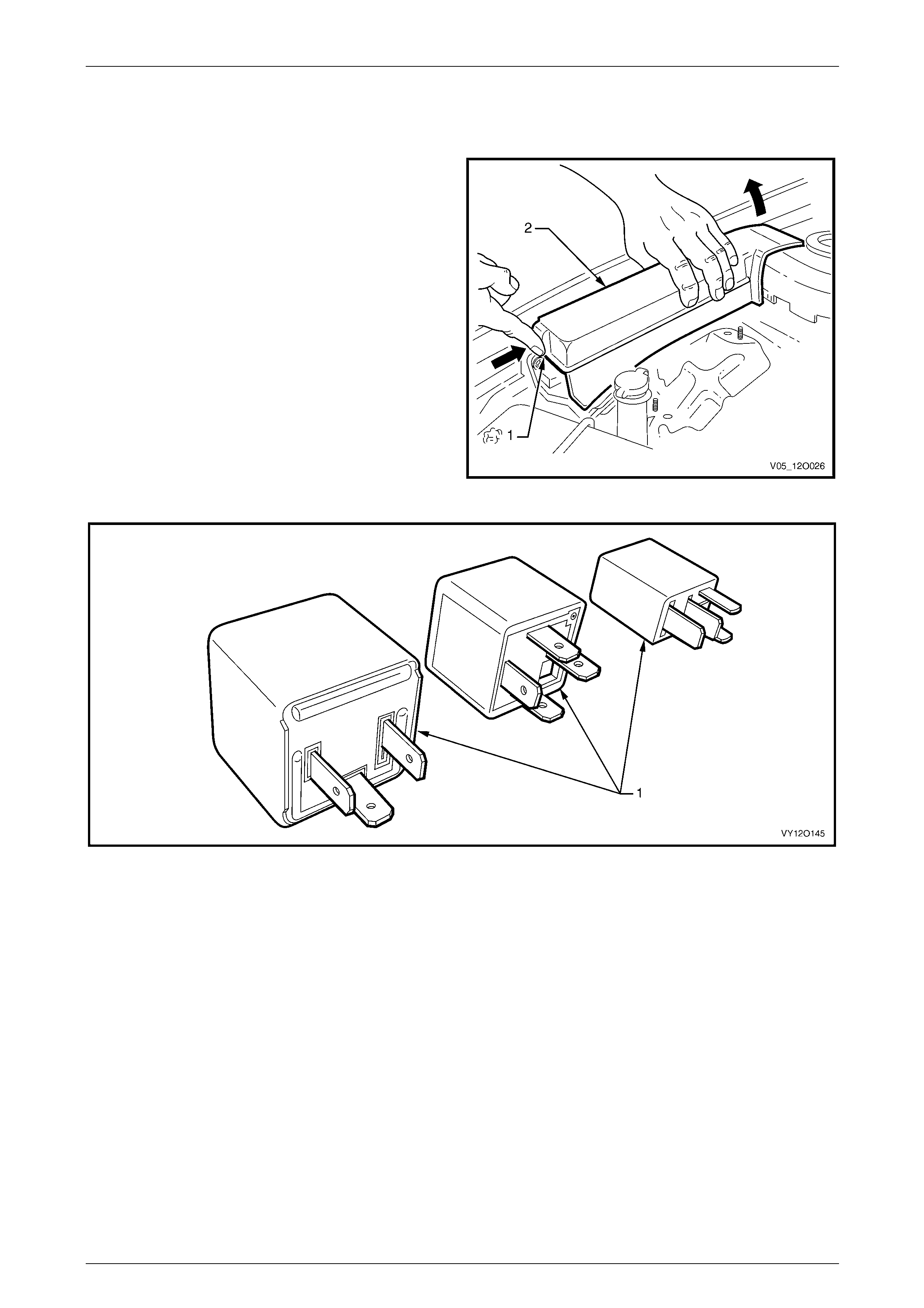
1.4 Relays
There are a variety of relay assemblies (1) used in the vehicle. The relays a r e located in the engine compartment and
passenger compartment fuse and relay panel assemblies.
Figure 12O – 9
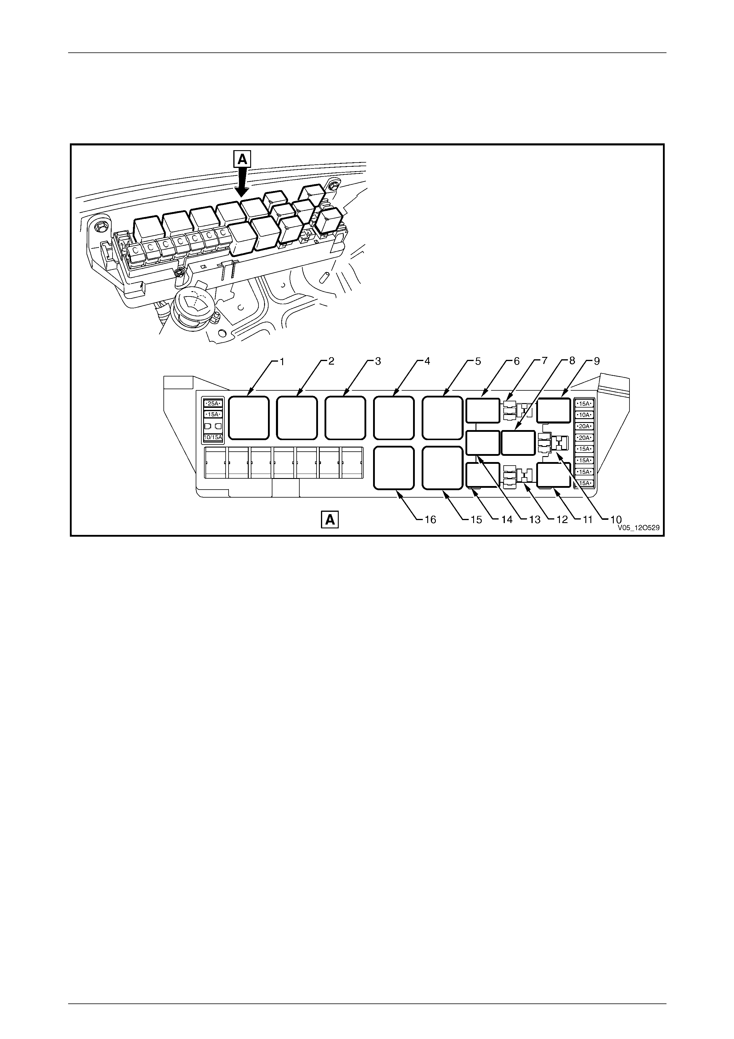
Passenger Compartment Relays
The passenger compartment fuse an d relay panel assembly is located be hin d the instrument panel lower cover. A label
on the inside of the cover indicates the relay location and the circuits protected by each relay. Refer to Figure 12O – 10.
Figure 12O – 10
Legend
1 R17 – Spare
2 R18 – Relay Assembly – Park Lamps (4 Pin Micro)
3 R19 – Flasher Assembly – Turn Signal (3 Pin)
4 R20 – Relay Assembly – Accessory Control (4 Pin Mini)
5 R21 – Relay Assembly – Ignition Control (4 Pin Mini)
6 R22 – Relay Assembly – Power Windows (4 Pin Mini)
7 R23 – Relay Assembly – Blower Inhibit (4 Pin Mini)
8 R24 – Relay Assembly – Interior Illumination (4 Pin Micro)
9 R25 – Relay Assembly – Defog (4 Pin Micro)
10 R26 – Spare
11 R27 – Spare
Page 12O–13
Fuses, Relays and Wiring Harnesses Page 12O–14
Engine Compartment Relays
The engine compartment fuse and relay panel assembly is located forward of the right-hand side front suspensio n strut
tower. A label on the inside of the cover lists the relay location and the circuits protected by each relay. Refer to
Figure 12O – 11.
Figure 12O – 11
Legend
1 R1 – Start Relay (4 Pin)
2 R2 – Blower Relay (4 Pin)
3 R3 – Headlamp Hi-beam Relay (4 Pin)
4 R4 – Engine Control Relay (4 Pin)
5 R5 – Engine Cooling Fan Relay 2 – High Speed (4 Pin)
[Engine Cooling Fan Relay 1 – Low Speed – 430W Fans]
6 R8 – Horn Relay (4 Pin Micro)
7 R9 – Spare
8 R12 – Reverse Relay (4 Pin)
9 R10 – Fog Lamp Relay (4 Pin Micro)
10 R13 – Spare
11 R16 – Fuel Pump Relay (4 Pin Micro)
12 R15 – Spare
13 R11 – A/C Relay (4 Pin Micro)
14 R14 – Headlamp Lo-beam Relay (4 Pin Micro)
15 R7 – Engine Cooling Fan Relay 1 – Low Speed (5 Pin)
[Engine Cooling Fan Relay 2 – High Speed – 430W Fans]
16 R6 – Engine Cooling Fan Relay 3 – High Speed – 430W
Fans (5 Pin)
Page 12O–14
Fuses, Relays and Wiring Harnesses Page 12O–15
1.5 Diodes
All vehicles with air conditioni ng have an air-conditioning
compressor clutch suppression diode (1) fitted to the engine
harness.
For location of the air-conditioning compress or clutch
feedback diode, refer to the following figures:
a Figure 12O – 45, item 8.
B Figure 12O – 59, item 6.
Figure 12O – 12
Page 12O–15
Fuses, Relays and Wiring Harnesses Page 12O–16
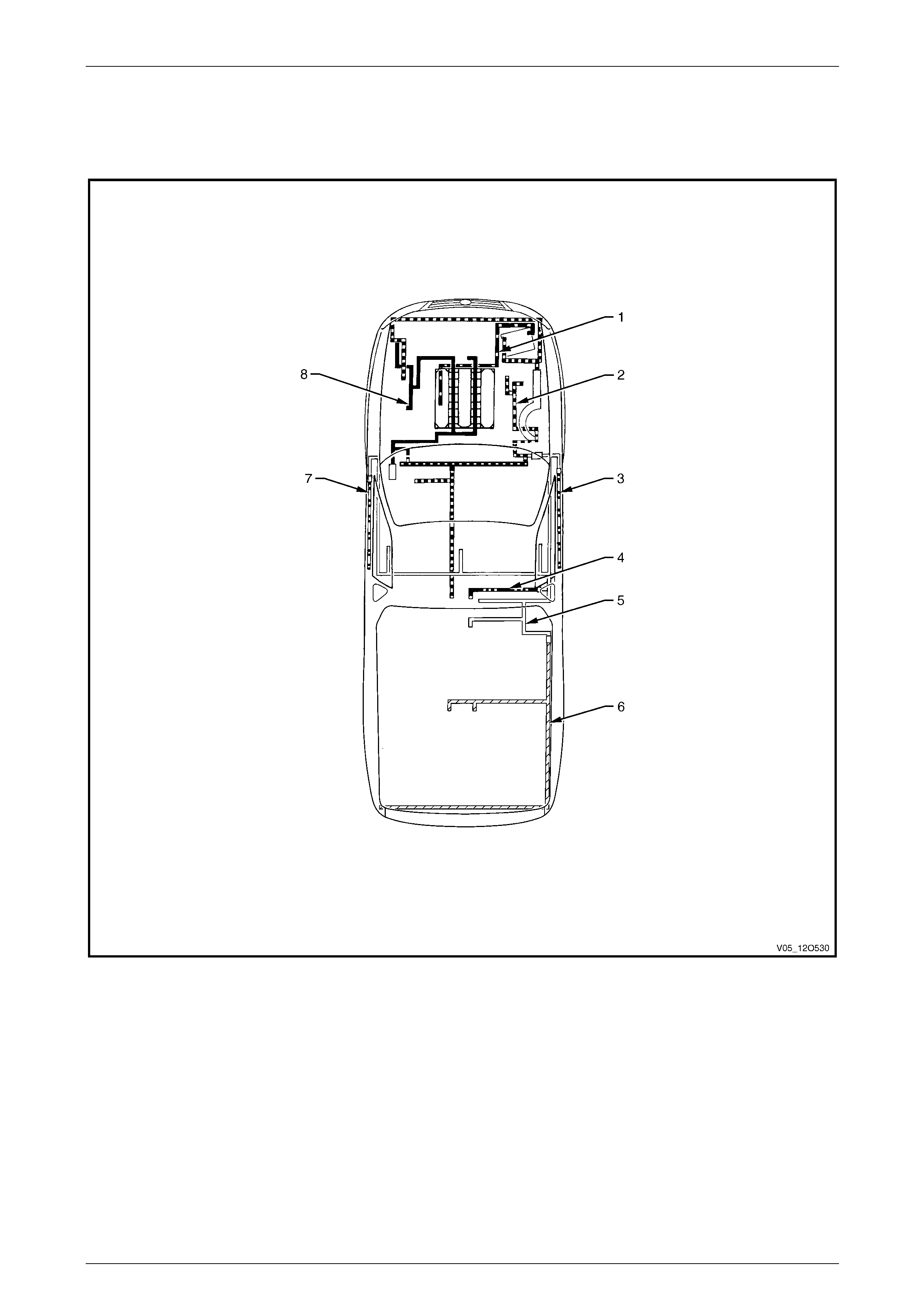
1.6 Wiring Harnesses
Refer to Figure 12O – 13 for the location of the wiring harnesses used in Utility vehicles. For a detailed layout of the
various wiring harnesses and connectors, refer to 3 Wiring Installation Diagrams – Utility.
Figure 12O – 13
Legend
1 Battery Wiring Harness
2 Front Body Harness
3 Right-hand Door Wiring Harness
4 Roof Lamp Harness
5 Body Wiring Harness
6 Rear Body Wiring Harness
7 Left-hand Door Wiring Harness
8 Powertrain Harness
Page 12O–16
Fuses, Relays and Wiring Harnesses Page 12O–17
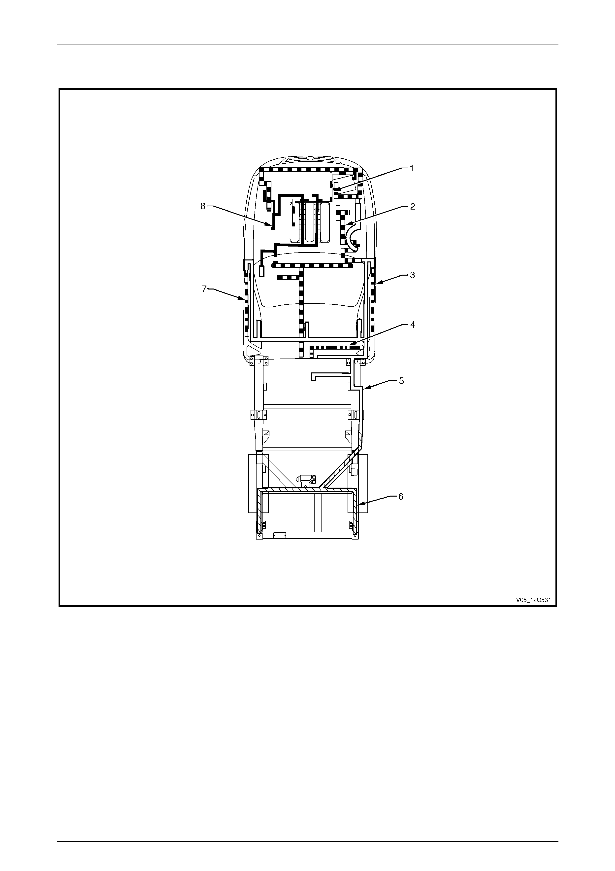
Refer to Figure 12O – 13 for the location of the wiring harnesses used in Regular Cab vehicles. For a detailed layout of
the various wiring harnesses and connectors, refer to 4 Wiring Installation Diagrams – Regular Cab.
Figure 12O – 14
Legend
1 Battery Wiring Harness
2 Front Body Harness
3 Right-hand Door Wiring Harness
4 Roof Lamp Harness
5 Body Wiring Harness
6 Rear Body Wiring Harness
7 Left-hand Door Wiring Harness
8 Powertrain Harness
Page 12O–17
Fuses, Relays and Wiring Harnesses Page 12O–18
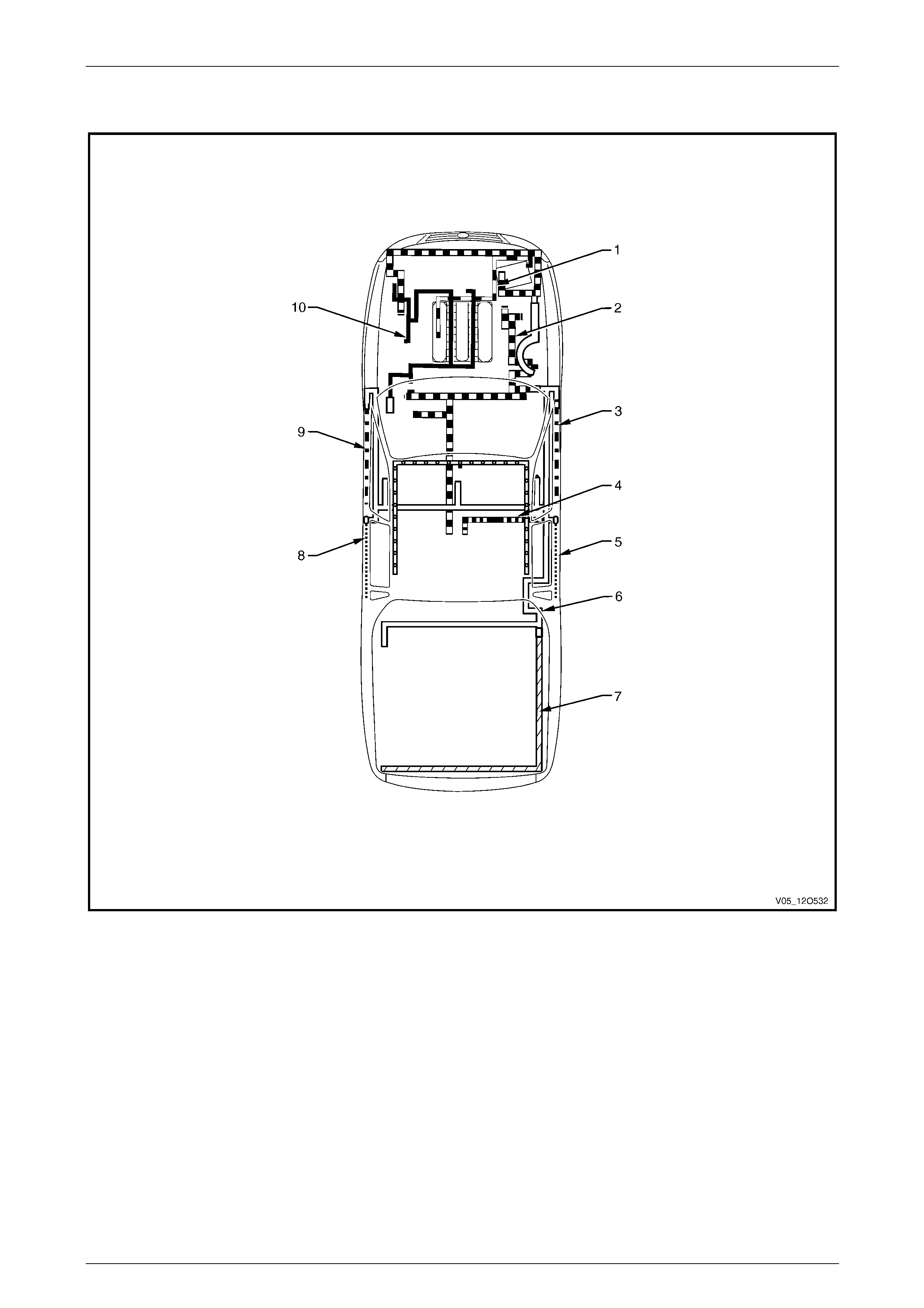
Refer to Figure 12O – 13 for the location of the wiring harnesses used in Crew Cab vehicles. For a detailed layo ut of the
various wiring harnesses and connectors, refer to 5 Wiring Installation Diagrams – Crew Cab.
Figure 12O – 15
Legend
1 Battery Wiring Harness
2 Front Body Harness
3 Right-hand Front Door Wiring Harness
4 Roof Lamp Harness
5 Right-hand Rear Door Wiring Harness
6 Body Wiring Harness
7 Rear Body Wiring Harness
8 Left-hand Rear Door Wiring Harness
9 Left-hand Front Door Wiring Harness
10 Powertrain Harness
Page 12O–18

Fuses, Relays and Wiring Harnesses Page 12O–19
1.7 Wiring Harness Connectors
The majority of the wiring har ness connectors used are of an interlocking design.
The male and female conn ector bodies, when pushed together, cannot be pulled apart due to the prese nce of a locking
tang on the connector body. Some connectors have anti-backout combs fitted for increased connector terminal security.
Page 12O–19
Fuses, Relays and Wiring Harnesses Page 12O–20
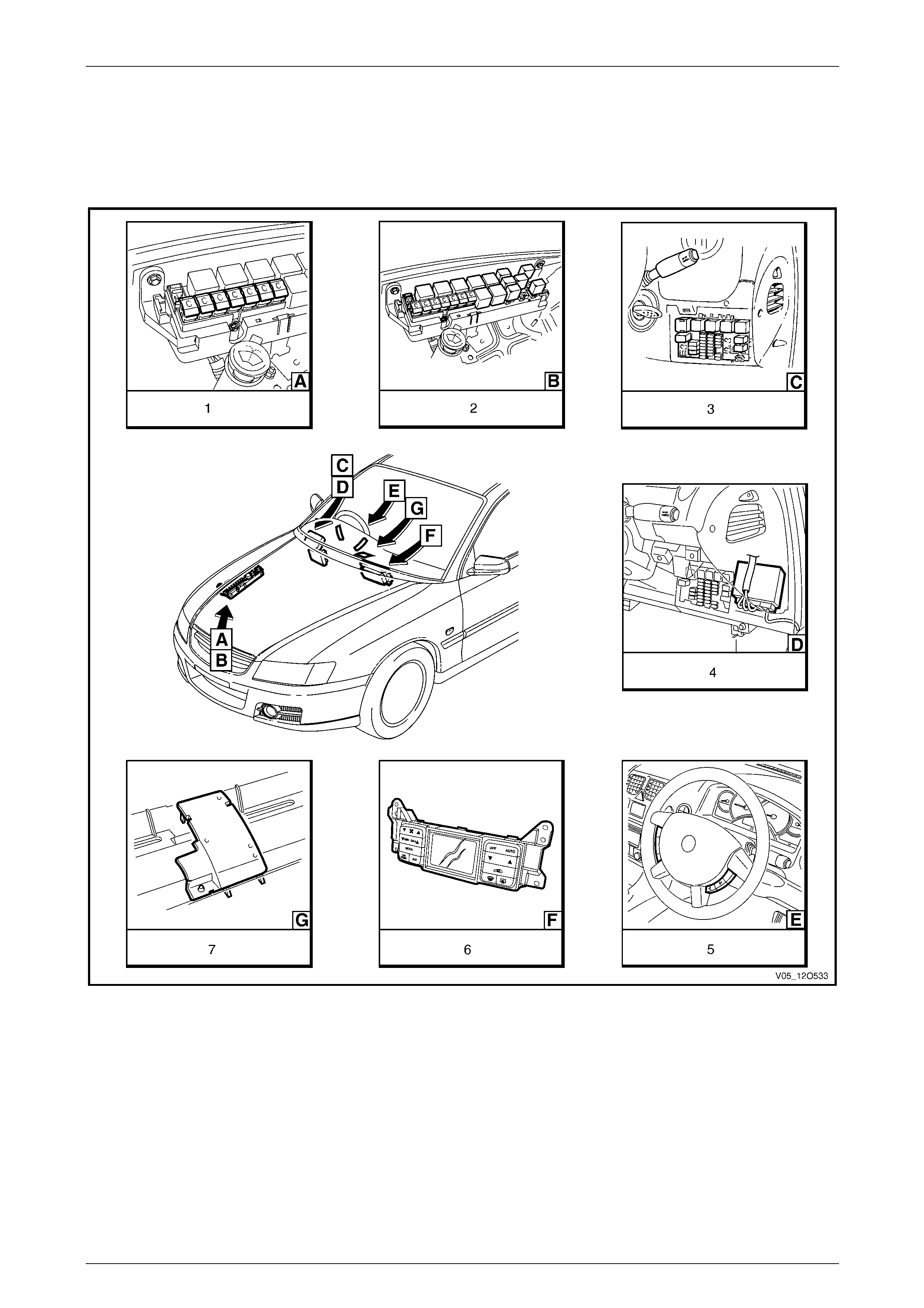
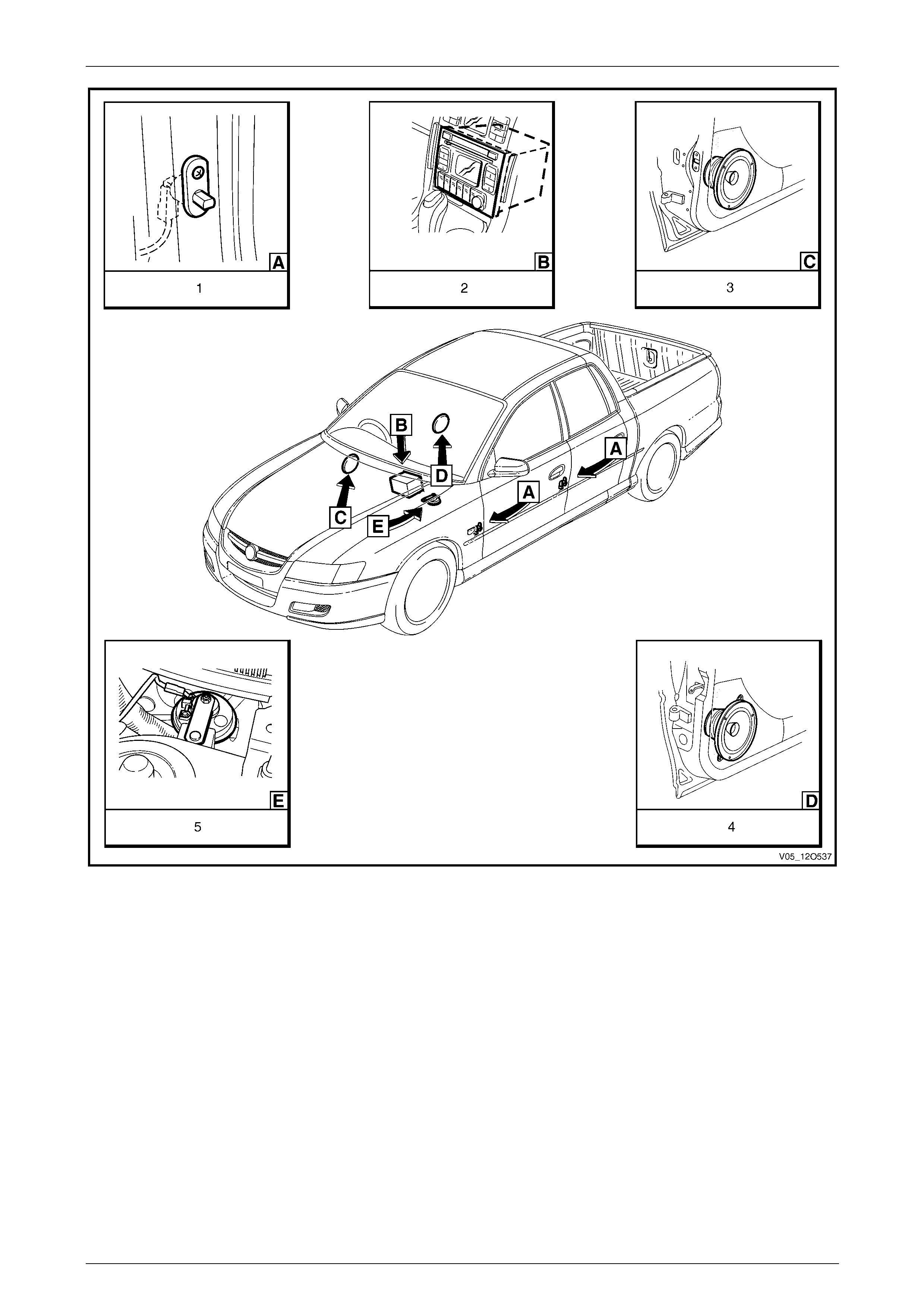
1.8 Electronic Control Device Locations
The following figures illustrate the locati on of the various electronic control devices fitted.
Ensure the precautionar y and special handling instructions are followed (where applicable) for each electronic control
device as described in the corresponding sections.
Figure 12O – 16
Legend
1 Fusible Links – Engine compartment
2 Relays & Fuses – Engine compartment
3 Relays & Fuses – Instrument Panel
4 Body Control Module
5 Steering Wheel Radio & CD Player Controls
6 Climate Control Module
7 Ambient Light Sensor
Page 12O–20
Fuses, Relays and Wiring Harnesses Page 12O–21
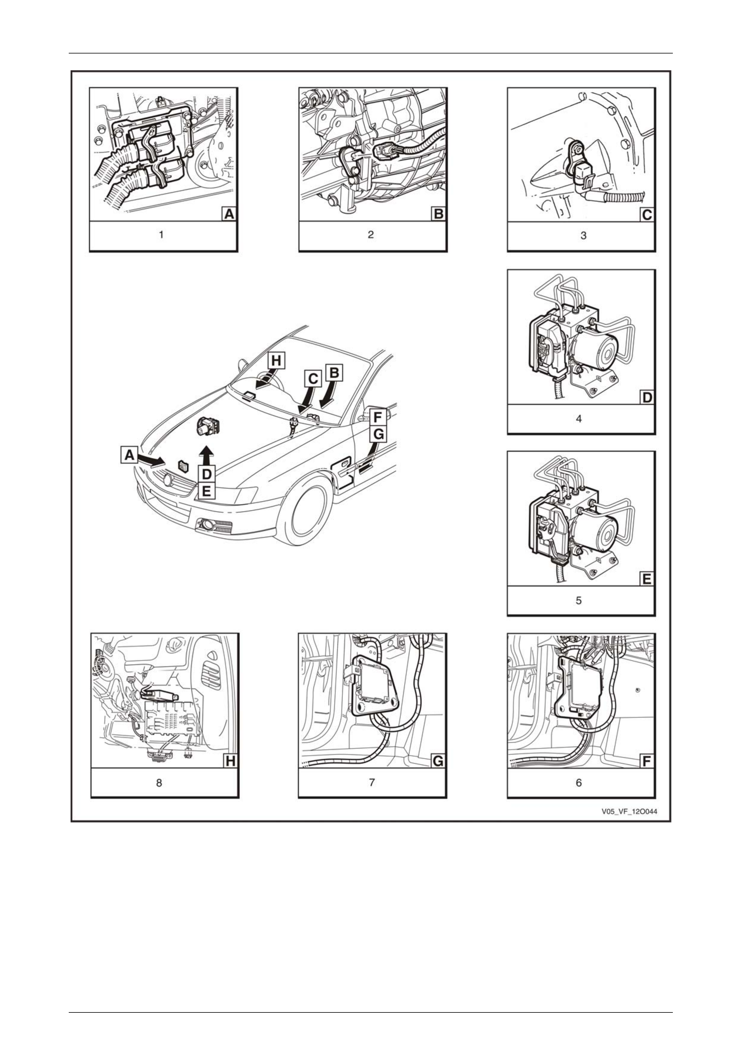
Figure 12O – 17
Legend
1 Engine Control Module (V6)
2 Vehicle Speed Sensor – Manual Transmission (V6)
3 Vehicle Speed Sensor – Automatic Transmission (V6)
4 ABS Electronic Control Unit (V6)
5 ABS-TCS Electronic Control Unit (V6 & GEN IV V8)
6 Transmission Control Module – 5 Speed Automatic
Transmission (V6)
7 Transmission Control Module – 4 Speed Automatic
Transmission (V6 & GEN IV V8)
8 Powertrain Interface Module (V6 & GEN IV V8)
Page 12O–21
Fuses, Relays and Wiring Harnesses Page 12O–22
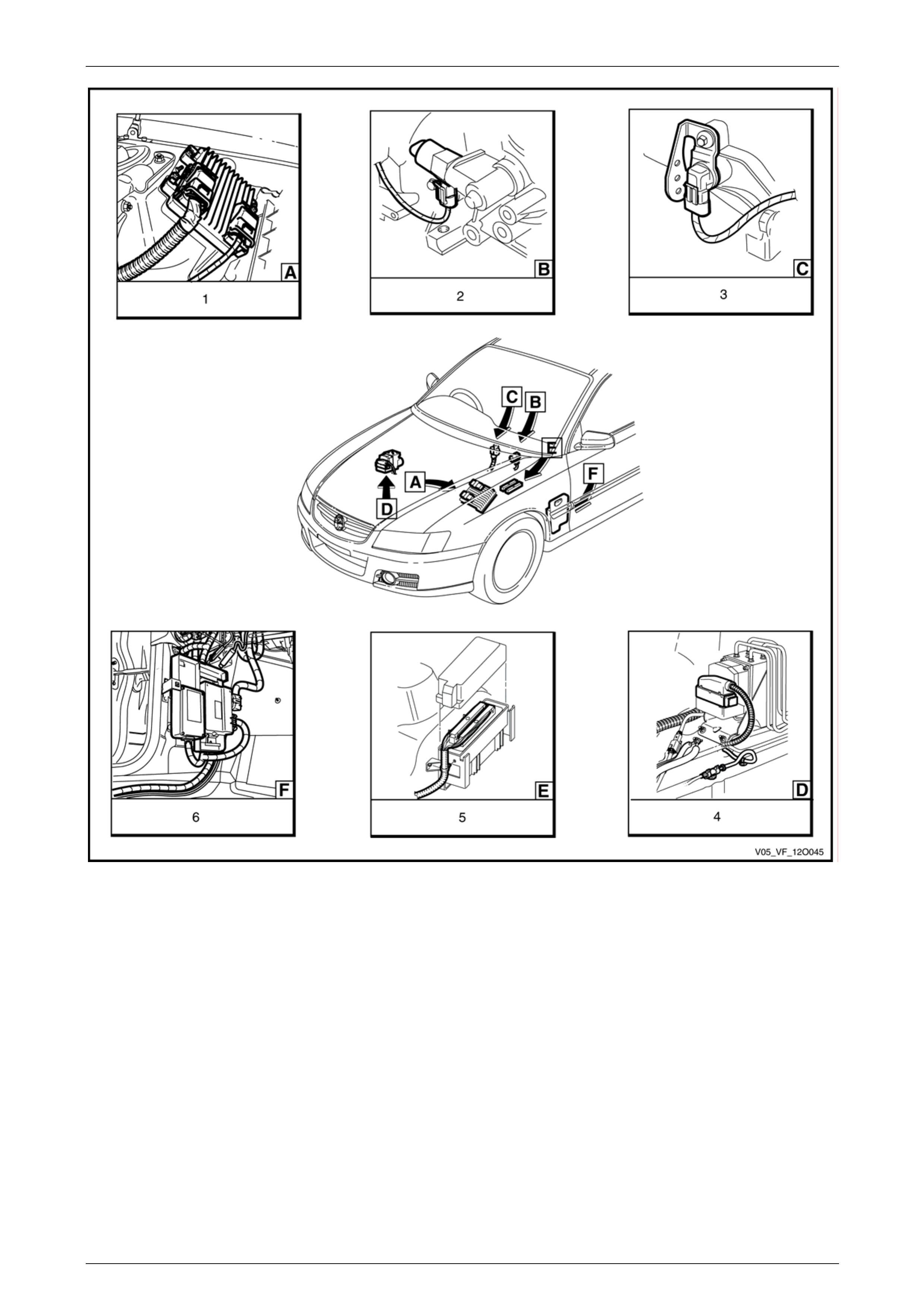
Figure 12O – 18
Legend
1 Engine Control Module (GEN IV V8)
2 Vehicle Speed Sensor – Manual Transmission (V8)
3 Vehicle Speed Sensor – Automatic Transmission (V8)
4 ABS & Traction Control Module (GEN III V8)
5 Powertrain Control Module (GEN III V8)
6 Powertrain Interface Module & Throttle Actuator Control
Module (GEN III V8)
Page 12O–22
Fuses, Relays and Wiring Harnesses Page 12O–23
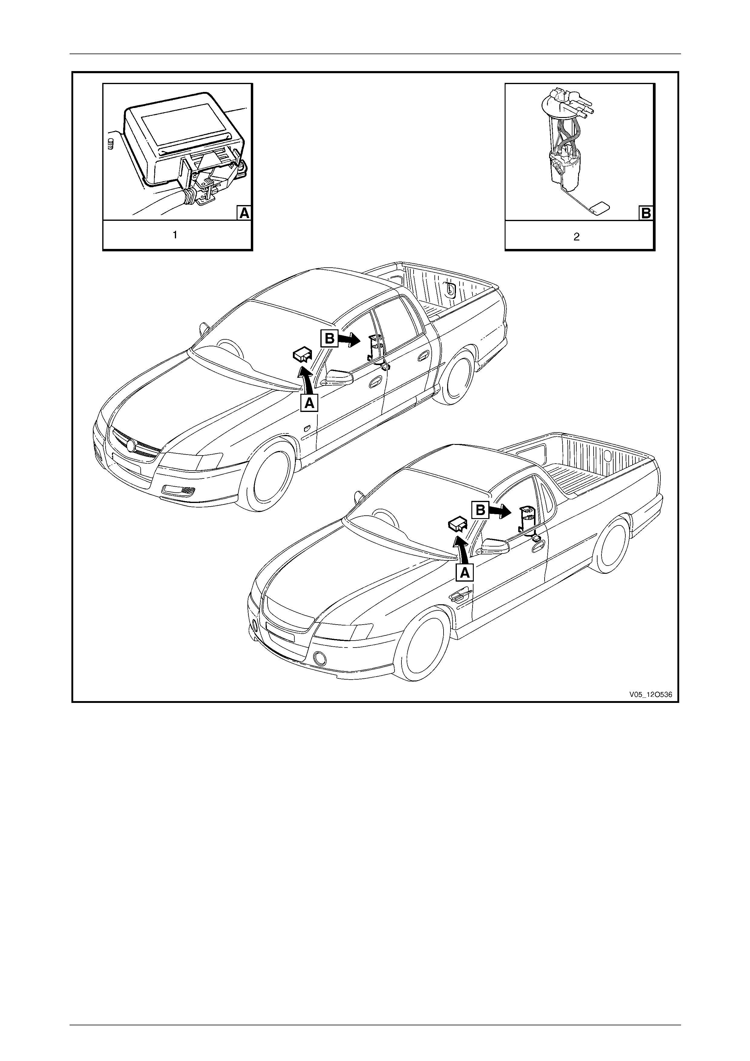
Figure 12O – 19
Legend
1 Sensing & Diagnostic Module – Occupant
Protection System 2 Modular Fuel Pump & Sender Assembly
Page 12O–23
Fuses, Relays and Wiring Harnesses Page 12O–24
Figure 12O – 20
Legend
1 Door Ajar Warning Switch Assembly
2 Radio Assembly
3 Front Door Speaker Assembly
4 Rear Door Speaker Assembly (2 places)
5 Theft Deterrent Horn
Page 12O–24
Fuses, Relays and Wiring Harnesses Page 12O–25
2 Service Operations
2.1 Fuses
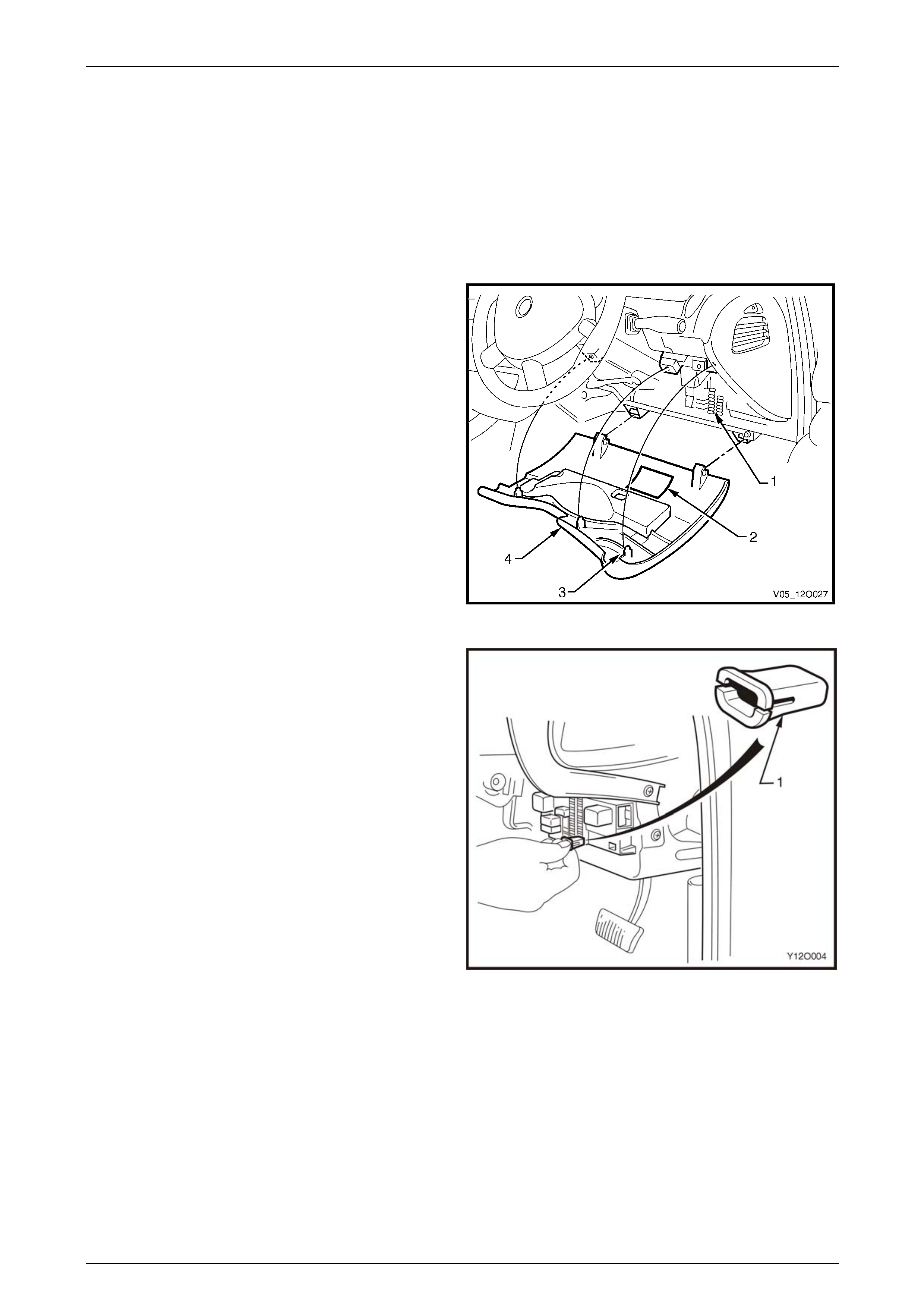
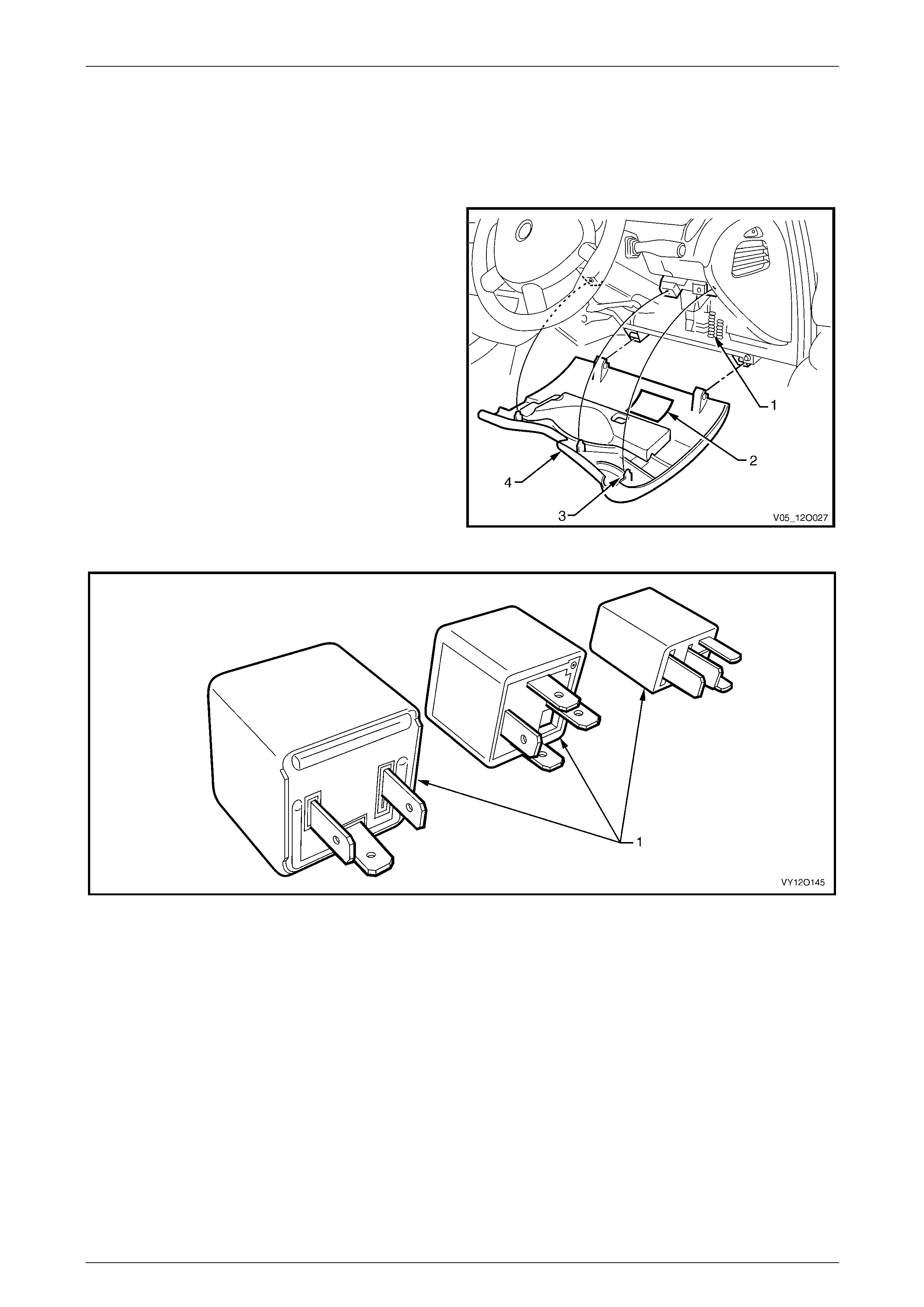
Passenger Compartment Fuse and Relay Panel Assembly
Replace
1 To gain access to the passenger compartme nt fuse
and relay panel assembly (1) move the steering
column to the upmost position. Firmly grasp the
instrument panel lower cover (4) and pull the cover
downwards to disengage the locating clips (3).
2 Refer to the label (2) on the inside of the instrument
panel lower cover to identify the circuits protected by
each fuse.
Figure 12O – 21
3 Use the fuse remover (1) located in the passenger
compartment fuse and relay panel assembly to
remove the suspect fuse. To use, pull the remover
from its location in the panel assembly and f ully insert
the remover over the top of the fuse and pull the fuse
from the panel.
Figure 12O – 22
Page 12O–25
Fuses, Relays and Wiring Harnesses Page 12O–26
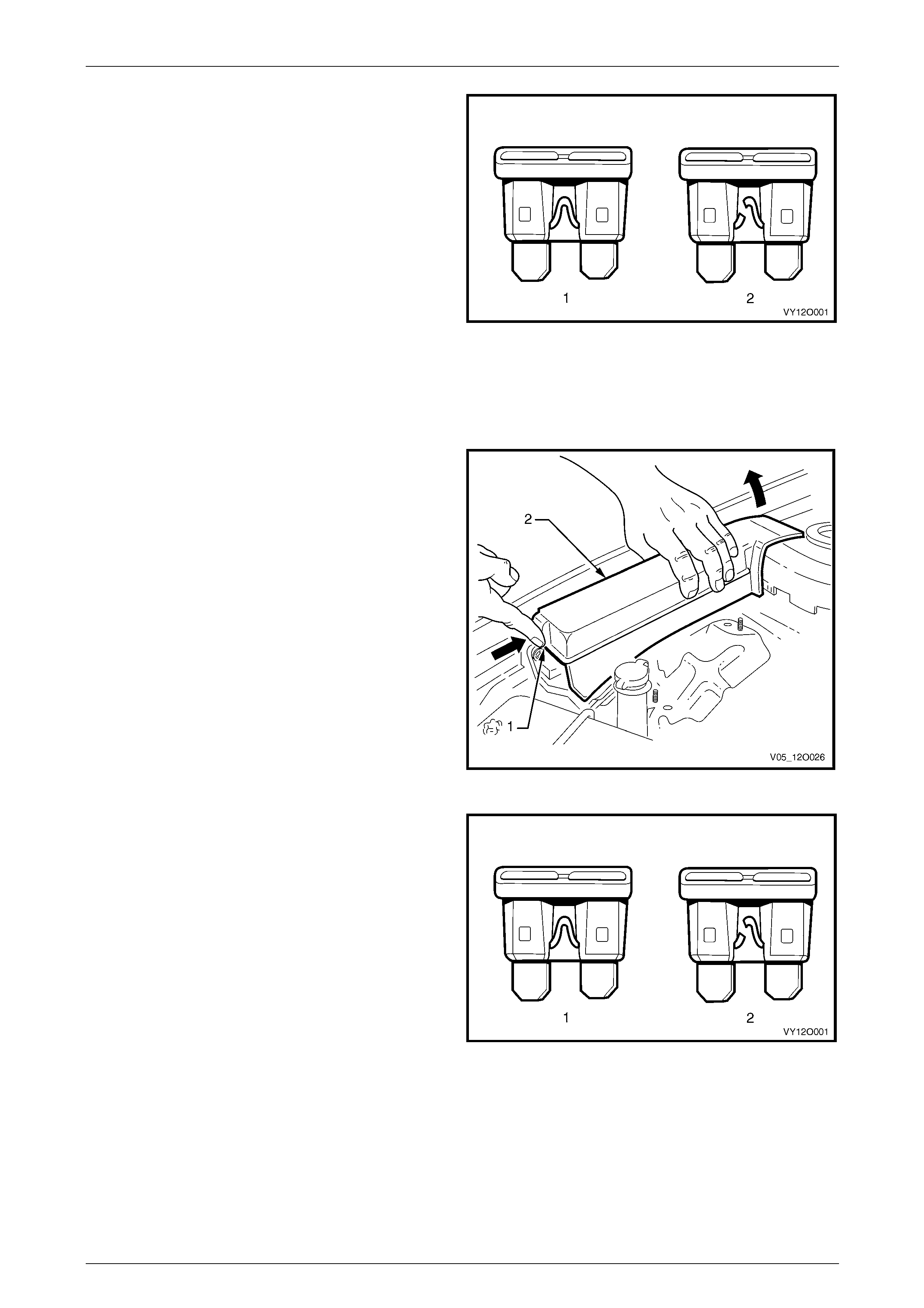
4 Determine if the fuse has blown by examining the
element for a break:
a A good fuse (1) has an intact element.
b A blown fuse (2) has a broken element.
5 Replace a blown fuse with a fuse of the same current
rating. If the replacement fuse blows rectify the fault
within the circuit before replacing the fus e again.
6 Close the instrument panel lower cover. Ensure the
locating clips are correctly alig ned and slot into the
corresponding mating retainer s securely.
Figure 12O – 23
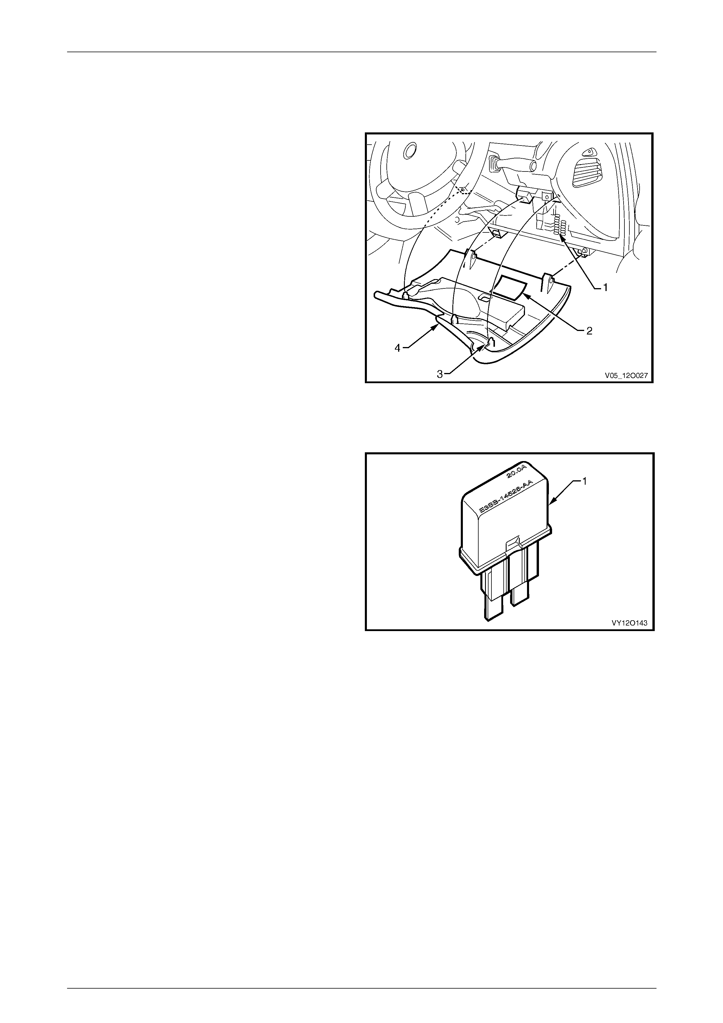
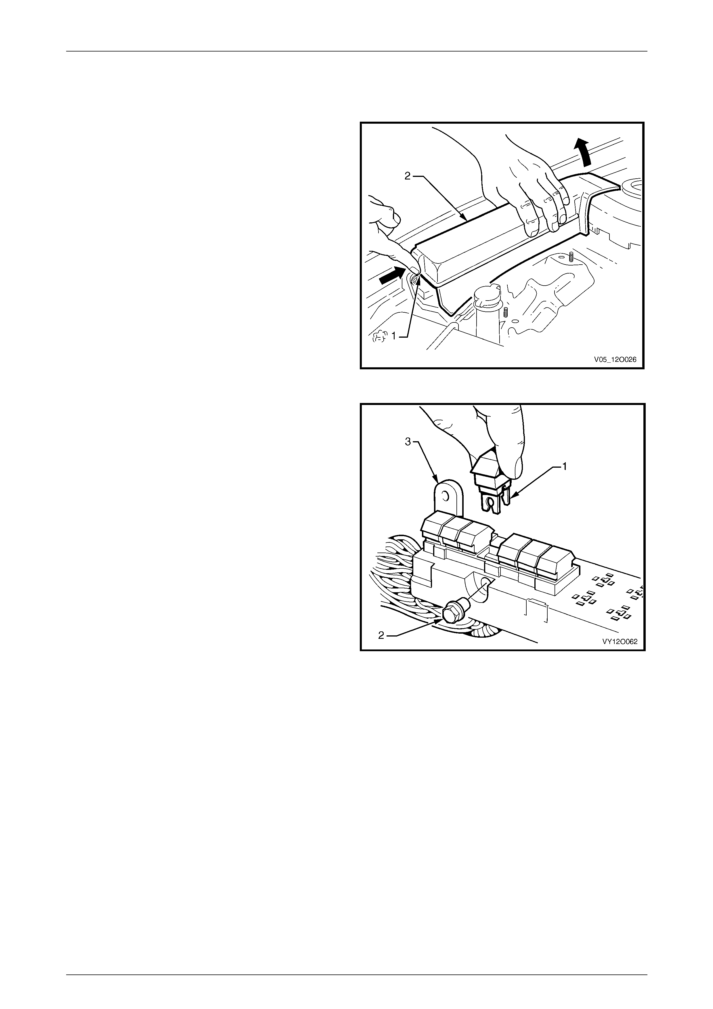
Engine Compartment Fuse and Relay Panel Assembly
Replace
1 Remove the engine compartment fuse an d relay panel
assembly cover (2) by releasing the retaining tang (1)
and lifting the cover up and towards the sus pension
strut tower.
2 Refer to the label on the inside cover of the engine
compartment fuse and relay panel assembl y to identify
the circuits protected by each fuse.
3 Use the fuse remover located in the passeng er
compartment fuse and relay panel assembly to
remove the suspect fuse. Refer to Passenger
Compartment Fuse and Relay Pa nel Assembly
for the location and usage of the fuse remover.
Figure 12O – 24
4 Determine if the fuse has blown by examining the
element for a break:
a A good fuse (1) has an intact element.
b A blown fuse (2) has a broken element.
5 Replace a blown fuse with a fuse of the same current
rating. If the replacement fuse blows rectify the fault
before replacing the fuse agai n.
6 Replace the engine compartm ent fuse and relay panel
assembly cover. Ensure the retaining tang locks into
place.
Figure 12O – 25
Page 12O–26
Fuses, Relays and Wiring Harnesses Page 12O–27
2.2 Circuit Breakers
Remove
1 To gain access to the passenger compartme nt fuse
and relay panel assembly (1) move the steering
column to the upmost position. Firmly grasp the
instrument panel lower cover (4) and pull the cover
downwards to disengage the locating clips (3).
2 Refer to the label (2) on the inside of the instrument
panel lower cover to identify the circuits protected by
each fuse.
3 Pull the suspect circuit breaker from the passenger
compartment fuse and relay panel assembly.
Figure 12O – 26
Test
1 Remove the circuit breaker as described in this
Section.
2 Perform a continuity check on the circuit breaker. If
there is no continuity wait 15 seconds and check the
circuit breaker again.
a If continuity exists after 15 seconds have
elapsed the circuit breaker has reset and can be
replaced in the passenger compartment fuse
and relay panel assembly. If the circuit breaker
trips again there is a problem within th e circuit it
is protecting and the problem should be rectified
before continuing.
b If there is no continuity after 15 seconds have
elapsed, the circuit breaker has blown and must
be replaced with another circuit breaker of the
same current rating.
3 Install the circuit breaker as described in this Section.
Figure 12O – 27
Reinstall
Replace the passenger compartment fuse and relay panel assembly cover, ensuring the retaining tang locks into place.
Page 12O–27
Fuses, Relays and Wiring Harnesses Page 12O–28
2.3 Fusible Links
All Plug-in Type Fusible Links Except F104
Replace
1 Remove the engine compartment fuse an d relay panel
assembly cover by releasing the retaining tang (1) on
the cover (2) and lifting the cover up and to wards the
suspension strut tower.
2 Refer to the label on the inside of the engine
compartment fuse and relay panel assembly cov er to
identify the circuits protected by each fusible link.
Figure 12O – 28
3 Pull the suspect fusible link (1) from the panel
assembly and perform a visual check of the element
(3) through the inspection window (2) to determine
whether or not it has blown.
a A good fusible link has an intact element.
b A blown fusible link has a broken element.
4 Replace a blown fusible link with one of the same
current rating. If the replacement fusible link blows this
indicates a problem with the circuit it is protecting.
Rectify this fault before replacing the fusible link again.
5 Replace the engine compartm ent fuse and relay panel
assembly cover. Ensure the retaining tang locks into
place. Figure 12O – 29
Page 12O–28
Fuses, Relays and Wiring Harnesses Page 12O–29
Plug-in Type Fusible Link F104
Replace
1 Remove the engine compartment fuse an d relay panel
assembly cover by releasing the retaining tang (1) on
the cover (2) and lifting the cover up and to wards the
suspension strut tower.
2 Refer to the label on the inside of the engine
compartment fuse and relay panel assembly cov er to
identify the circuits protected by each fusible link.
Figure 12O – 30
3 Remove the fusible link terminal attaching screw (2)
and pull fusible link F104 (1) from engine compartment
fuse and relay panel assembly (3).
Figure 12O – 31
Page 12O–29
Fuses, Relays and Wiring Harnesses Page 12O–30
4 Perform a visual check of the element (3) through the
inspection window (2) to determine whether or not it
has blown.
a A good fusible link has an intact element.
b A blown fusible link has a broken element.
5 Replace a blown fusible link with another with a 60A
current rating. If the replacement fusible link blows this
indicates a problem within the engine circuitry it is
protecting. Rectify this fault before replacing the
fusible link again.
6 Tighten the fusible link terminal attachi ng screw to the
correct torque specification.
Fusible link terminal attaching
screw torque specification 5.0 – 6.0 Nm
7 Replace the engine compartm ent fuse and relay panel
assembly cover. Ensure the retaining tang locks into
place.
Figure 12O – 32
One-Wire Type Fusible Link
Replace
1 Disconnect the end of the fusible link (1) further from
the positive battery terminal by cutting the cable tie.
2 Test for a voltage drop bet ween the positive battery
terminal and the end of the fusible link.
a If there is a voltage drop the fusible link has
blown and must be replac ed. If the new fusible
link blows this indicates a fault in the circuit a nd it
should be rectified before replacing the fusible
link again.
b If there is no voltage drop the fusible link has not
blown and the problem lies elsewhere.
3 Reattach the fusible link to the battery wiring harness.
Use new cable ties to fasten the fusible link to the
battery wiring harness and cut the cable tie ends to a
suitable length.
Figure 12O – 33
Page 12O–30
Fuses, Relays and Wiring Harnesses Page 12O–31
2.4 Relays
Passenger Compartment Relays
Replace
1 To gain access to the passenger compartme nt fuse
and relay panel assembly (1) move the steering
column to the upmost position. Then firml y grasp the
instrument panel lower cover (4) and pull the cover
downwards to disengage the locating clips (3).
2 Use the label (2) on the insid e of the instru ment panel
lower cover to identify the circuits protected by each
relay.
Figure 12O – 34
Figure 12O – 35
3 Pull the suspect relay assembly (1) from the passenger compartment fuse and relay panel assembly by hand and
replace it with a relay of the same type, refer to Figure 12O – 35.
4 If the circuit functions as normal the problem was with the relay and has been rectified.
5 If the circuit does not function as normal or functions for a short time then stops it can be assumed the problem lies
within the circuit and must be rectified before replacing the relay again.
6 Close the instrument panel lower cover. Ensure the locating clips are correctl y aligned and slot into the
corresponding mating retainer s securely.
Page 12O–31
Fuses, Relays and Wiring Harnesses Page 12O–32
Engine Compartment Relays
Remove
1 Remove the engine compartment fuse an d relay panel
assembly cover (2) by releasing the retaining tang (1)
and lifting the cover up and towards the sus pension
strut tower.
2 Refer to the label on the inside cover of the engine
compartment fuse and relay panel assembl y to identify
the circuits protected by each relay.
Figure 12O – 36
Figure 12O – 37
3 Pull the suspect relay assembly (1) from the passenger compartment fuse and relay panel assembly by hand and
replace it with a relay of the same type, refer to Figure 12O – 37.
4 If the circuit function as normal the problem was with the relay and has been rectified.
5 If the circuit does not functions as normal or functions for a short time then stops it can be assumed the problem
lies within the circuit and must be rectified before replacing the relay again.
6 Close the instrument panel lower cover. Ensure the locating clips are correctl y aligned and slot into the
corresponding mating retainer s securely.
Page 12O–32
Fuses, Relays and Wiring Harnesses Page 12O–33
2.5 Diodes
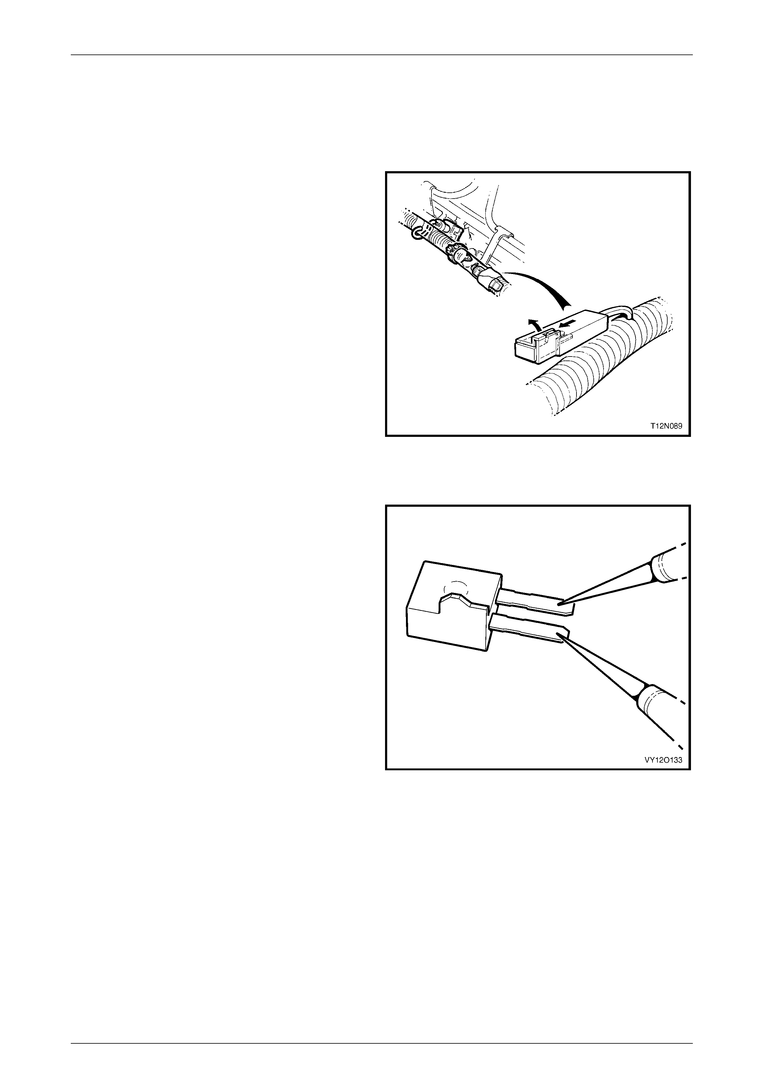
A/C Compressor Suppression Diode
Remove
1 Locate the diode on the engi ne harness at the
injectors, refer to 1.5 Diodes.
2 Remove the tape securing the diode co nnector to the
wiring harness conduit.
3 Pull back the diode retainer on the diode connector
and use a pair of fine long nosed pliers to pull the
diode out of the connector.
Figure 12O – 38
Test
1 Remove the diode as described in this Section.
2 Select ‘diode testing’ on a digital multimeter (DMM)
probably marked with a diode symbol.
3 Measure the resistance acr oss the diode.
4 Reverse the multimeter probes and measure the
resistance again to determine the condition of the
diode.
a If a finite and an infinite measurement are
obtained the diode does n ot require
replacement.
b If both measurements are infinite or are both
very low resistances the diode must be replaced.
5 Reinstall the diodes as described in this Section.
Figure 12O – 39
Reinstall
1 Insert the diode into the connector aligning the tab on the side of the diode with the connector retainer.
2 Using suitable tape, secure diode connector to wiring harness conduit.
Page 12O–33


Fuses, Relays and Wiring Harnesses Page 12O–35
3 Wiring Installation Diagrams –
Utility
The following figures illustrate the vehic le wiring installation diagrams for Utility vehicles.
NOTE
Some of the following wiring installation diagrams
illustrate the upper level harnesses which
incorporate all necessary wiring harness
connectors for all production options. Depending
on equipment level and vehicle model, some of
the connectors may be taped back to the h arness
when a particular option is not fitted, or the
particular level of harness fitted to the vehicle
may not incorporate some of the connectors
illustrated.
Page 12O–35
Fuses, Relays and Wiring Harnesses Page 12O–36
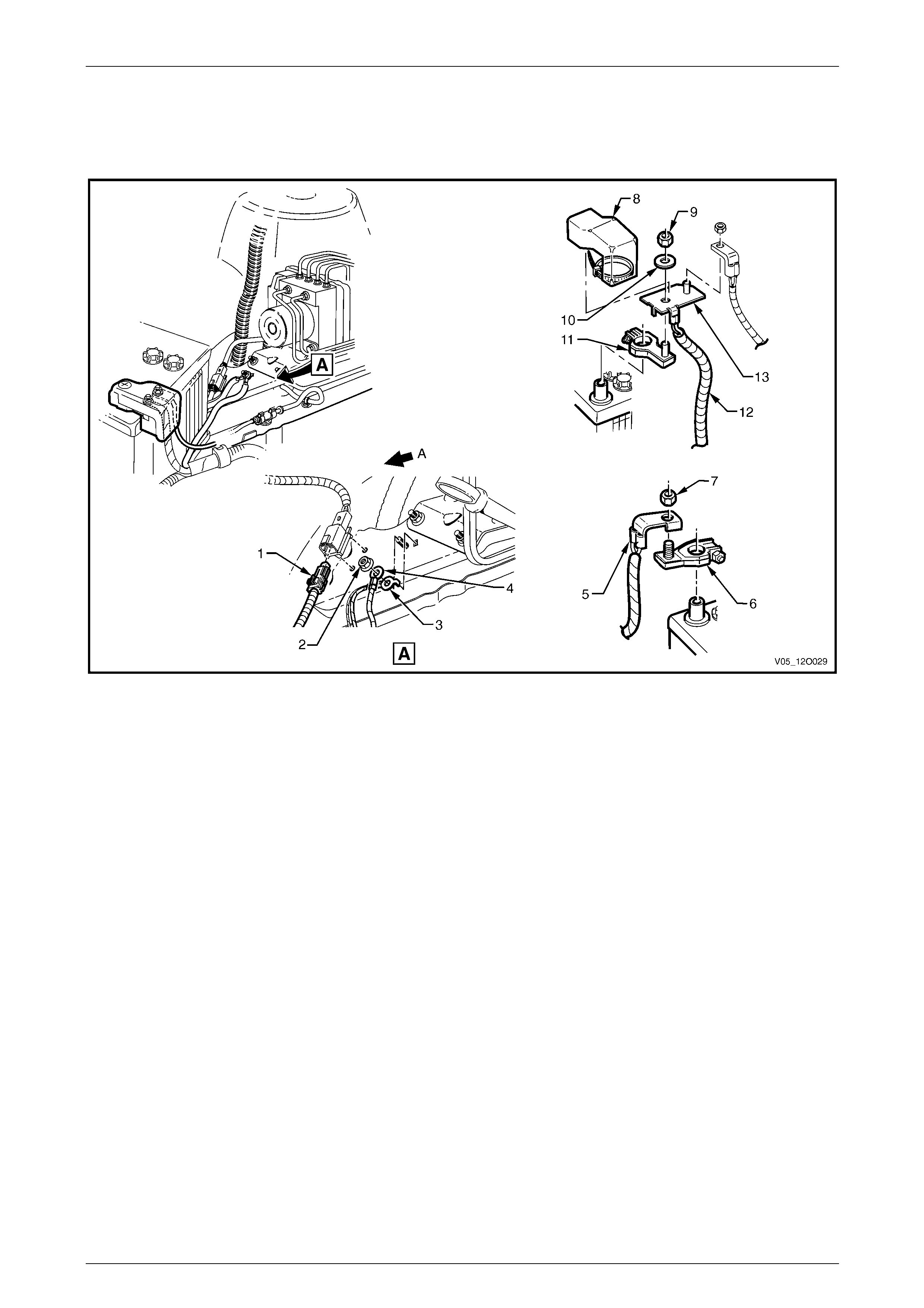
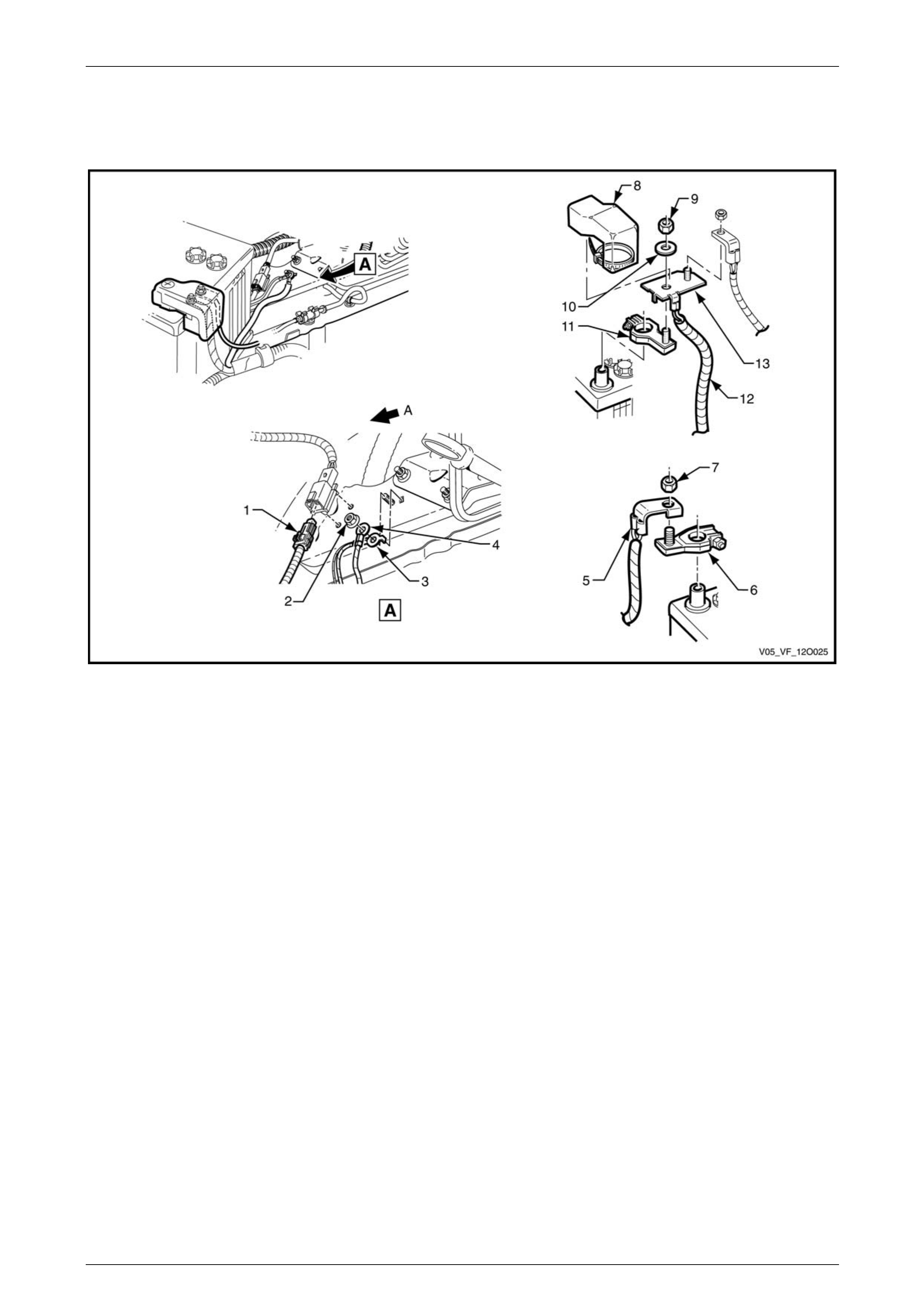
3.1 Battery Wiring Harness – 1
V6 Engine
Figure 12O – 40
Legend
1 Battery Wiring Harness to Front Body Harness Co nnector
(X106)
2 Nut
3 Body Ground Terminal (X119 – G3 – GP3)
4 Battery Ground Terminal (X119 – G4 – GP3)
5 Battery Wiring Harness Terminal (X86 – C)
6 Battery Negative Terminal (G1 – X2 – GP1)
7 Nut
8 Battery Positive Terminal Cover
9 Nut
10 Washer
11 Battery Wiring Harness Positive Terminal (G1 – X1)
12 Battery Wiring Harness to Starter Motor and Generator
13 Battery Positive Post Assembly (X86 – B)
A Front of vehicle.
Page 12O–36
Fuses, Relays and Wiring Harnesses Page 12O–37
3.2 Battery Wiring Harness – 2
V6 Engine
Figure 12O – 41
Legend
1 Engine Block Ground Bolt
2 Engine Ground Terminal (X119 – GP4)
3 Starter Motor Terminal (M15 – X2)
4 Nut
5 Starter Motor Terminal Connector (M15 – X1 – V6)
6 Battery Wiring Harness
7 Nut
8 Generator Terminal (G8 – X1)
Page 12O–37
Fuses, Relays and Wiring Harnesses Page 12O–38
3.3 Battery Wiring Harness – 3
V8 Engine
Figure 12O – 42
Legend
1 Battery Wiring Harness to Front Body Harness Co nnector
(X106)
2 Nut
3 Body Ground Terminal (X119 – G3 – GP3)
4 Battery Ground Terminal (X119 – G4 – GP3)
5 Battery Wiring Harness Terminal (X86 – C)
6 Battery Negative Terminal (G1 – X2 – GP1)
7 Nut
8 Battery Positive Terminal Cover
9 Nut
10 Washer
11 Battery Wiring Harness Positive Terminal (G1–X1)
12 Battery Wiring Harness to Starter Motor and Generator
13 Battery Positive Post Assembly (X86 – B)
A Front of vehicle.
Page 12O–38
Fuses, Relays and Wiring Harnesses Page 12O–39
3.4 Battery Wiring Harness – 4
V8 Engine
Figure 12O – 43
Legend
1 Battery Wiring Harness Bracket to Engine Mounting Screw
2 Engine Ground Terminal (X119 – GP4)
3 Battery Wiring Harness Ground to Block Screw
4 Battery Wiring Harness Bracket
5 Starter Motor Terminal (M15 – X2)
6 Starter Motor Terminal Attaching Nut
7 Starter Motor Terminal Connector (M15 – X1 – V8)
8 Battery Wiring Harness
9 Battery Wiring Harness to Generator B+ Terminal Nut
10 Generator Terminal (G8 – X1)
A GEN III V8 Engine shown, GEN IV V8 similar
Page 12O–39
Fuses, Relays and Wiring Harnesses Page 12O–40
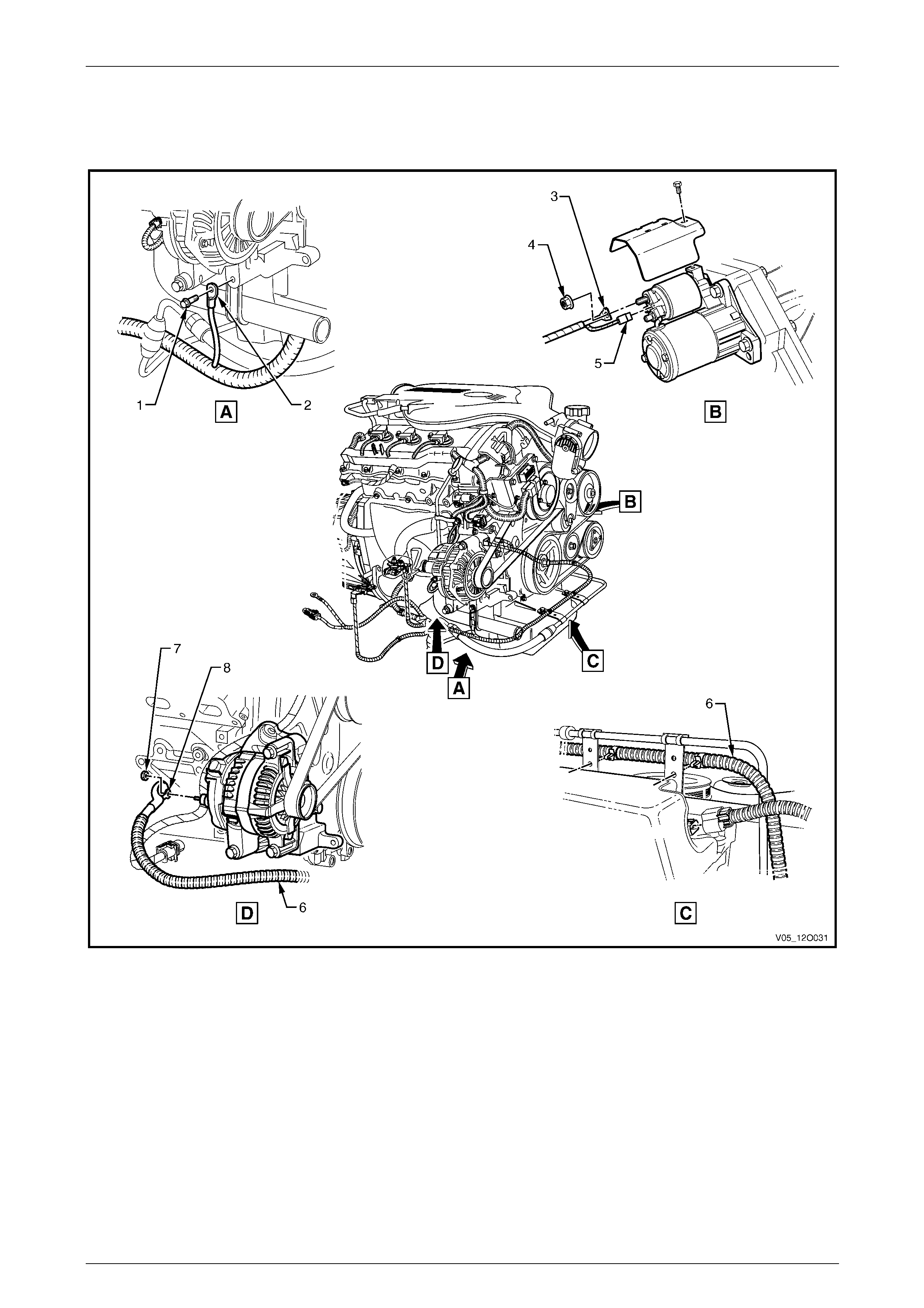
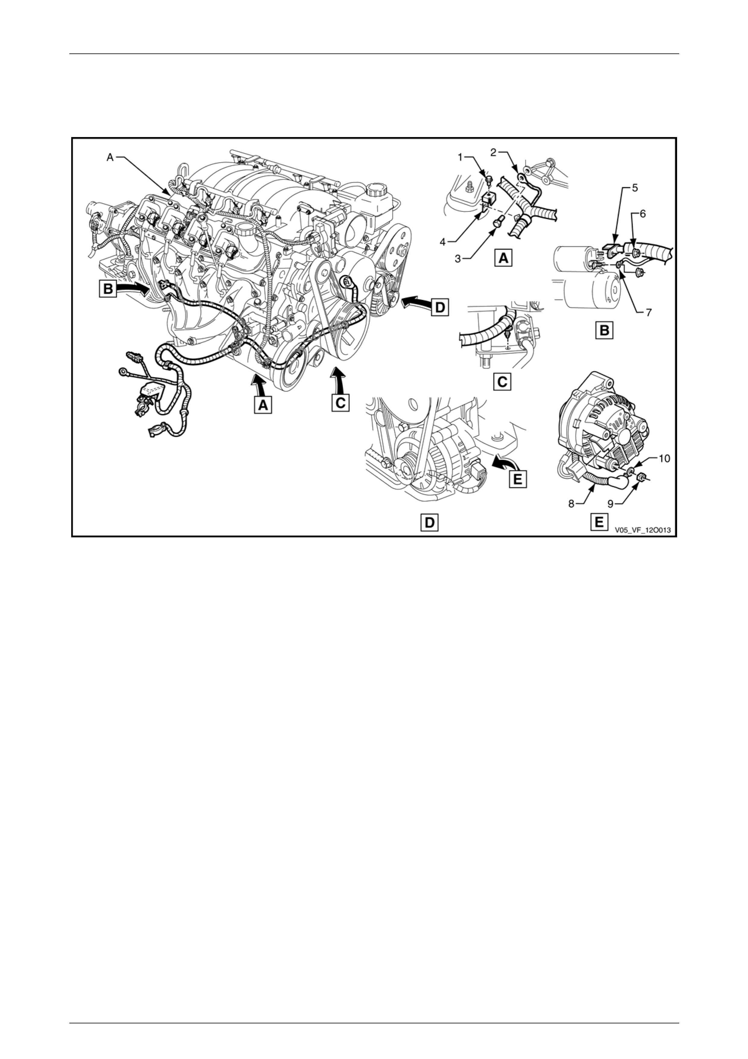
3.5 Engine Harness – 1
V6 Engine
Figure 12O – 44
Page 12O–40

Fuses, Relays and Wiring Harnesses Page 12O–41
Legend
1 Engine Harness to Transmission Harness Connector (X104)
2 Engine Harness Former, Rear
3 Engine Harness Former Rear Attaching Bolts
4 Engine Harness Former, Right-hand Side
5 Engine Harness Ground Terminal Attaching Bolt
6 Engine Harness Ground Terminals (X119 – GP 19A and
X119 – GP19B)
7 Throttle Actuator Connector (Y38 – V6)
8 Engine Harness Former, Left-hand Side
9 Engine Harness Ground Terminals (X119 – GP 20A and
X119 – GP20&B)
10 Engine Harness Ground Terminal Attaching Bolt
A Front of vehicle.
Page 12O–41
Fuses, Relays and Wiring Harnesses Page 12O–42
3.6 Engine Harness – 2
V6 Engine
Figure 12O – 45
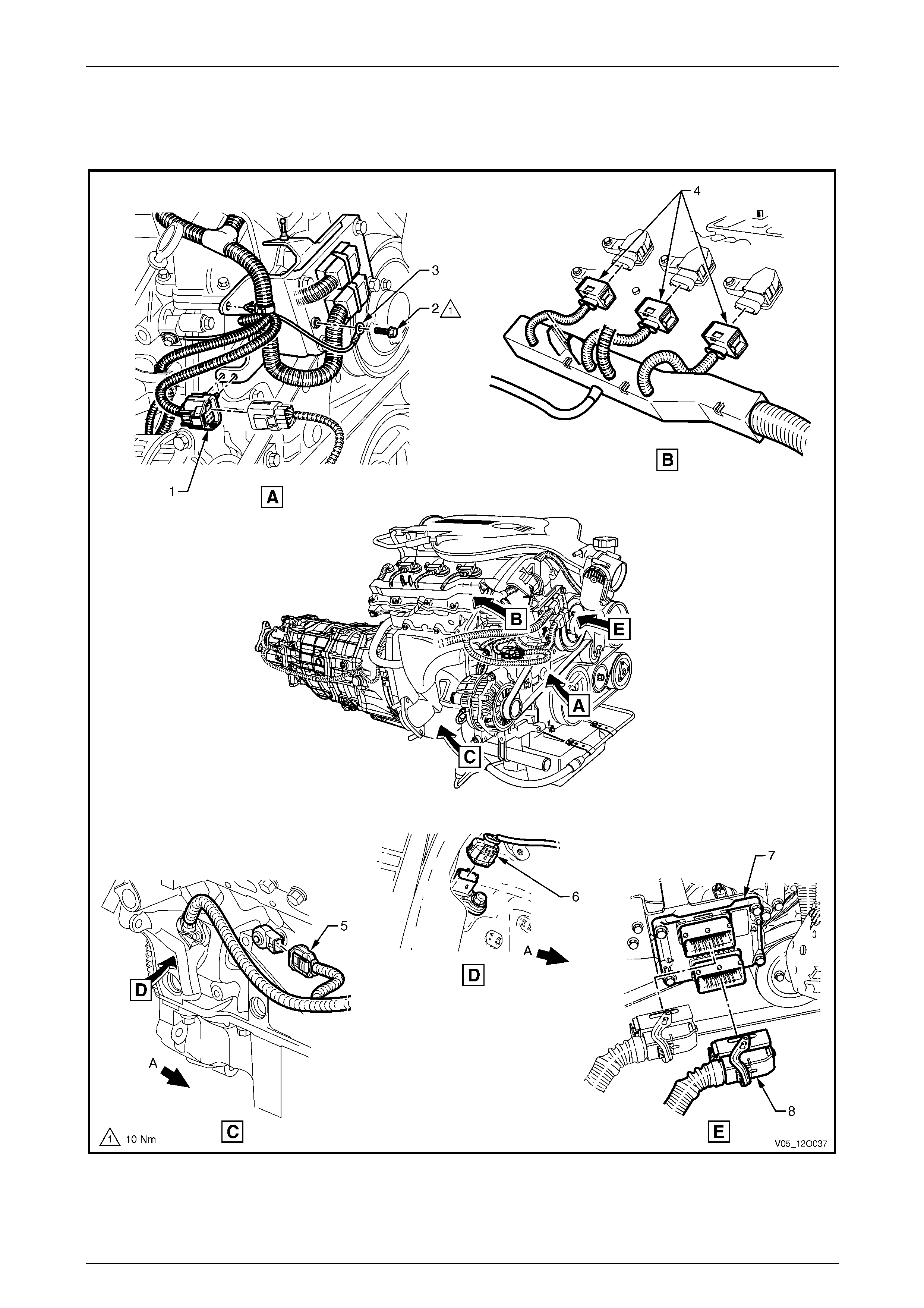
Legend
1 Engine Harness Ground Terminal (X119 – GP18)
2 Engine Harness Ground Terminal Attaching Bolt
3 Oil Level Indicator Tube Attaching Bolt
4 Engine Harness Former Attaching Bolt
5 Generator Connector (G8 – X2)
6 Engine Harness Former
7 Engine Oil Level Sensor Connector (B41)
8 Suppression Diode A/C Compressor (V5)
9 A/C Clutch Connector (L7)
Page 12O–42
Fuses, Relays and Wiring Harnesses Page 12O–43
3.7 Engine Harness – 3
V6 Engine
Figure 12O – 46
Page 12O–43

Fuses, Relays and Wiring Harnesses Page 12O–44
Legend
1 Engine Harness to Front Body Harness Connector (X103)
2 Engine Harness to ECM Bracket Ground Terminal Attaching
Bolt
3 Engine Harness to ECM Bracket Ground (X119 – GP17)
4 Ignition Coil Connectors, Right-hand Side (L3)
5 Knock Sensor Connector, Right-hand Side (B65 – V6)
6 Crankshaft Position Sensor Connector (B30 – V6)
7 Engine Control Module
8 Engine Control Module Connector (A43 – X1)
A Front of vehicle.
Page 12O–44
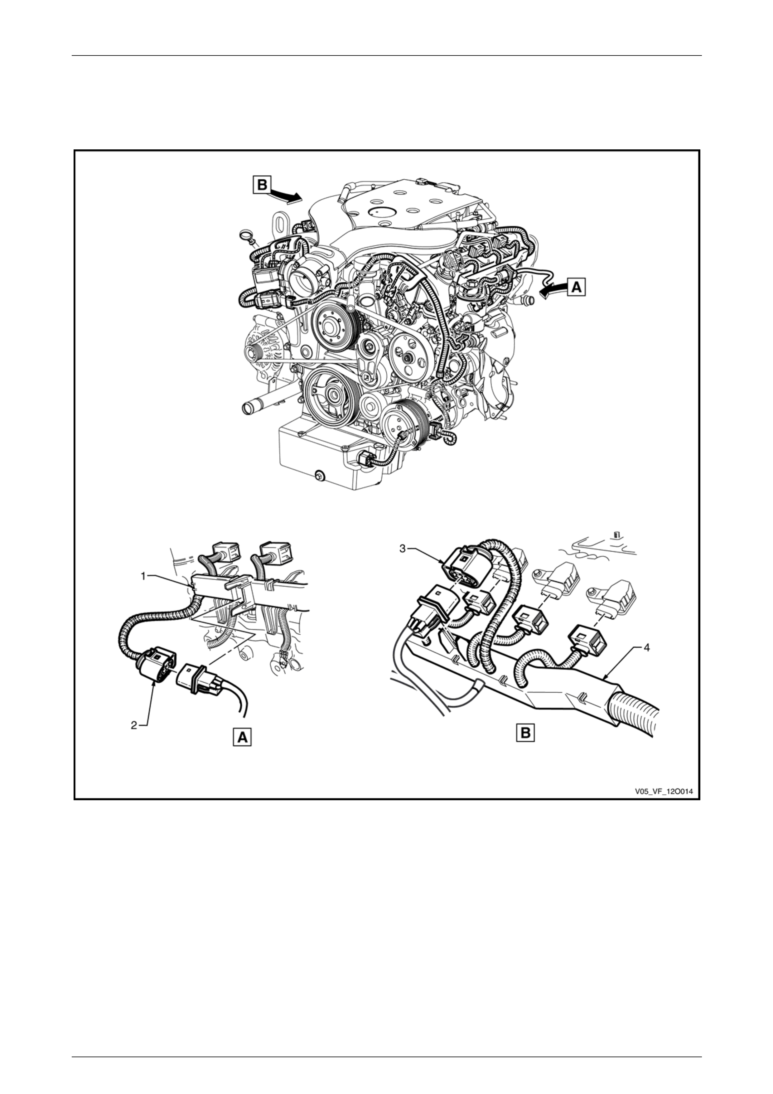
Fuses, Relays and Wiring Harnesses Page 12O–45
3.8 Engine Harness – 4
MY06 V6 Engine
Figure 12O – 47
Legend
1 Engine Harness Former, Left-hand Side
2 Pre-O2 Sensor Connector, 2, 4 & 6 (B57 – V6) 3 Pre-O2 Sensor Connector, 1, 3 & 5 (B166 – V6)
4 Engine Harness Former, Right-hand Side
Page 12O–45
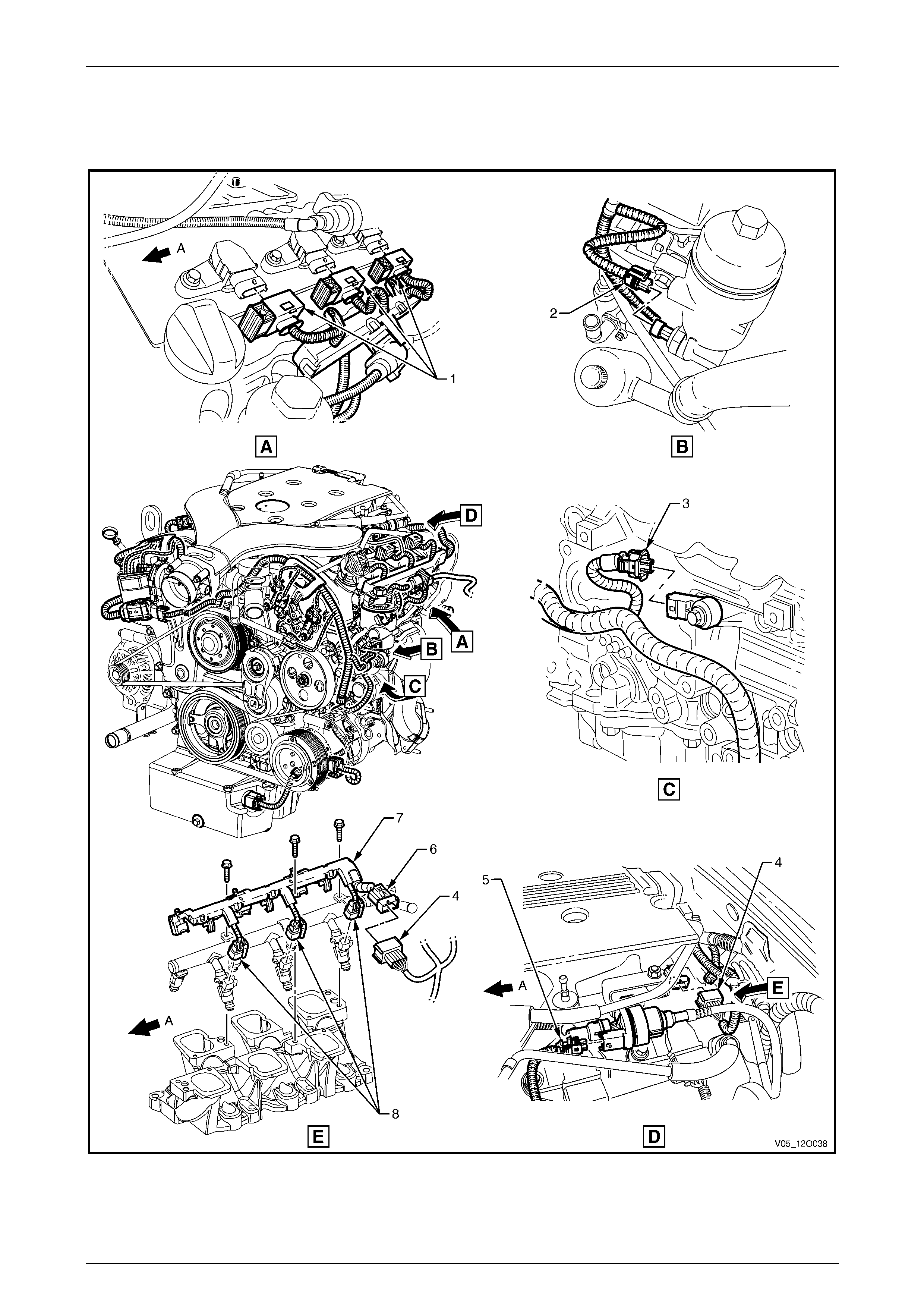
Fuses, Relays and Wiring Harnesses Page 12O–46
3.9 Engine Harness – 5
V6 Engine
Figure 12O – 48
Page 12O–46

Fuses, Relays and Wiring Harnesses Page 12O–47
Legend
1 Ignition Coil Connectors, Left-hand Side (L3)
2 Engine Oil Pressure Sensor Connector (B42)
3 Knock Sensor Connector, Left-hand Side (B65 – V6)
4 Engine Harness to Fuel Injector Harness Connector (X102)
5 Canister Purge Solenoid Valve Connector (Y123 – V6)
6 Fuel Injector Harness to Engine Harness Connector (X102)
7 Fuel Injector Harness
8 Fuel Injector Connector (L2 – V6)
A Front of vehicle.
Page 12O–47
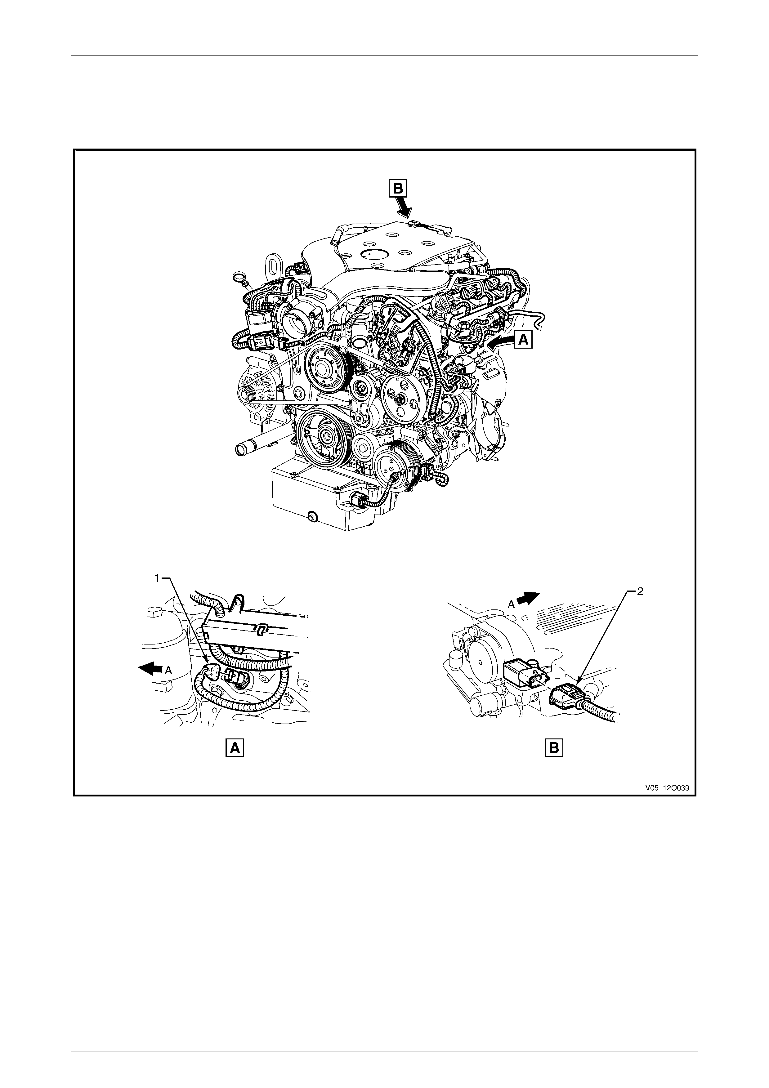
Fuses, Relays and Wiring Harnesses Page 12O–48
3.10 Engine Harness – 6
V6 Engine
Figure 12O – 49
Legend
1 Engine Coolant Temperature Sensor Connector (B39 – V6)
2 M.A.P. Sensor Connector (B67 – V6) A Front of vehicle.
Page 12O–48
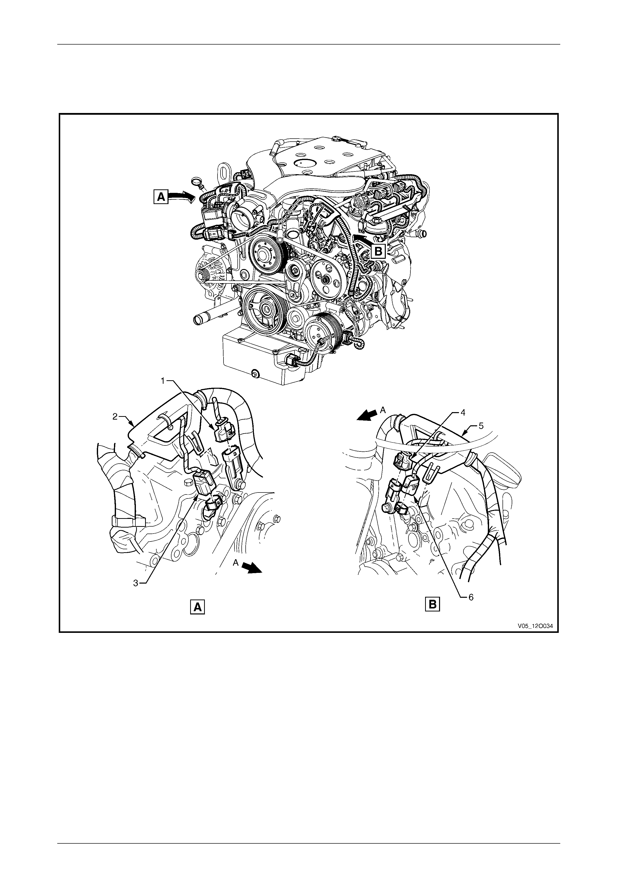
Fuses, Relays and Wiring Harnesses Page 12O–49
3.11 Engine Harness – 7
V6 Engine
Figure 12O – 50
Legend
1 Camshaft Position Sensor Connector, Intake 1, 3 & 5
(B28 – V6)
2 Engine Harness Former, Right-hand Side Front
3 Camshaft Position Actuator Connector, Intake 1, 3 & 5 (Y4)
4 Camshaft Position Sensor Connector, Intake 2, 4 & 6
(B28 – V6)
5 Engine Harness Former, Left-hand Side Front
6 Camshaft Position Actuator Connector, Intake 2, 4 & 6 (Y4)
A Front of vehicle.
Page 12O–49
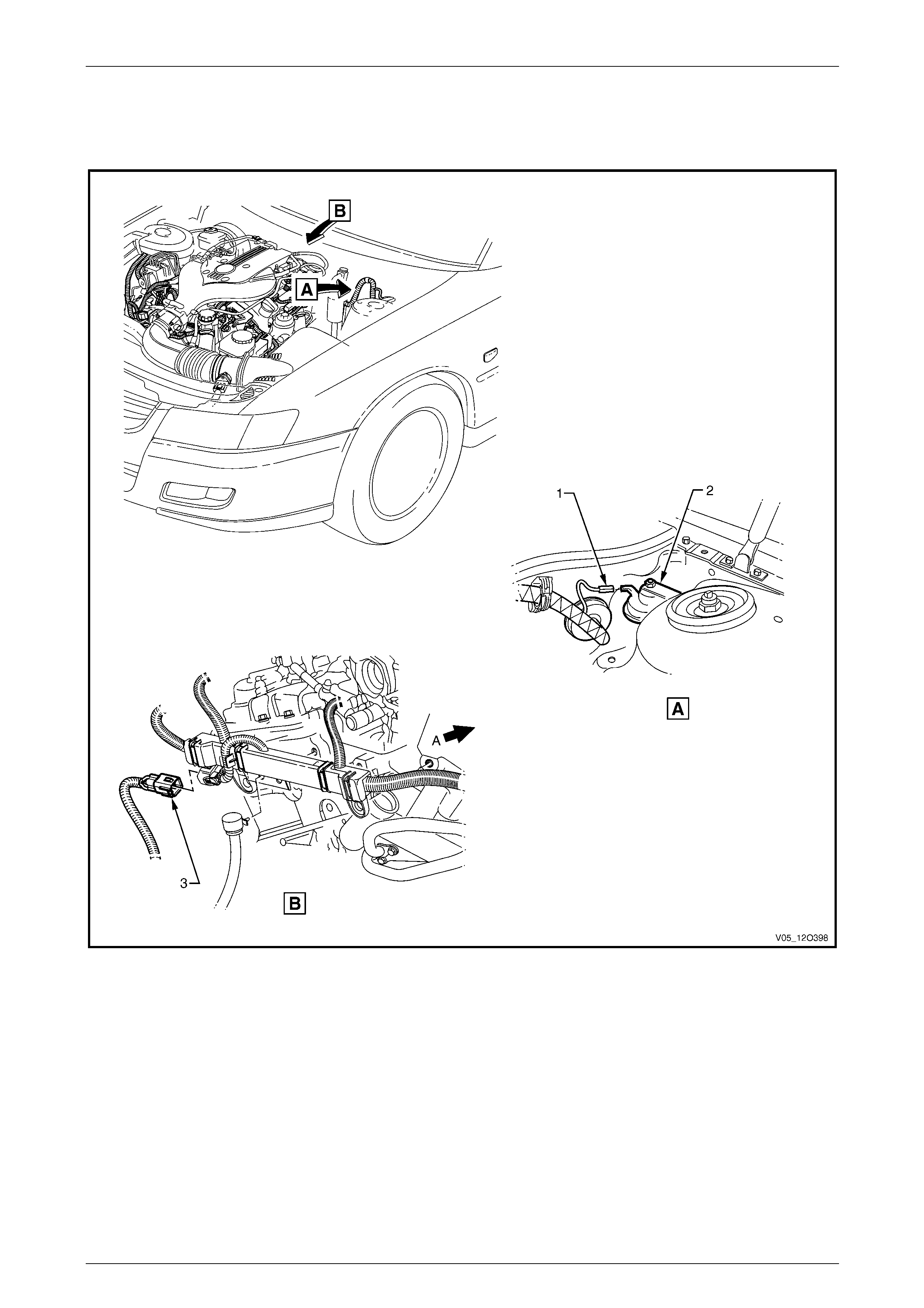
Fuses, Relays and Wiring Harnesses Page 12O–50
3.12 Transmission Harness – 1
V6 Engine
Figure 12O – 51
Legend
1 Theft Deterrent Horn Connector (B9)
2 Theft Deterrent Horn 3 Transmission Harness to Engine Harness Connector (X104)
A Front of vehicle.
Page 12O–50
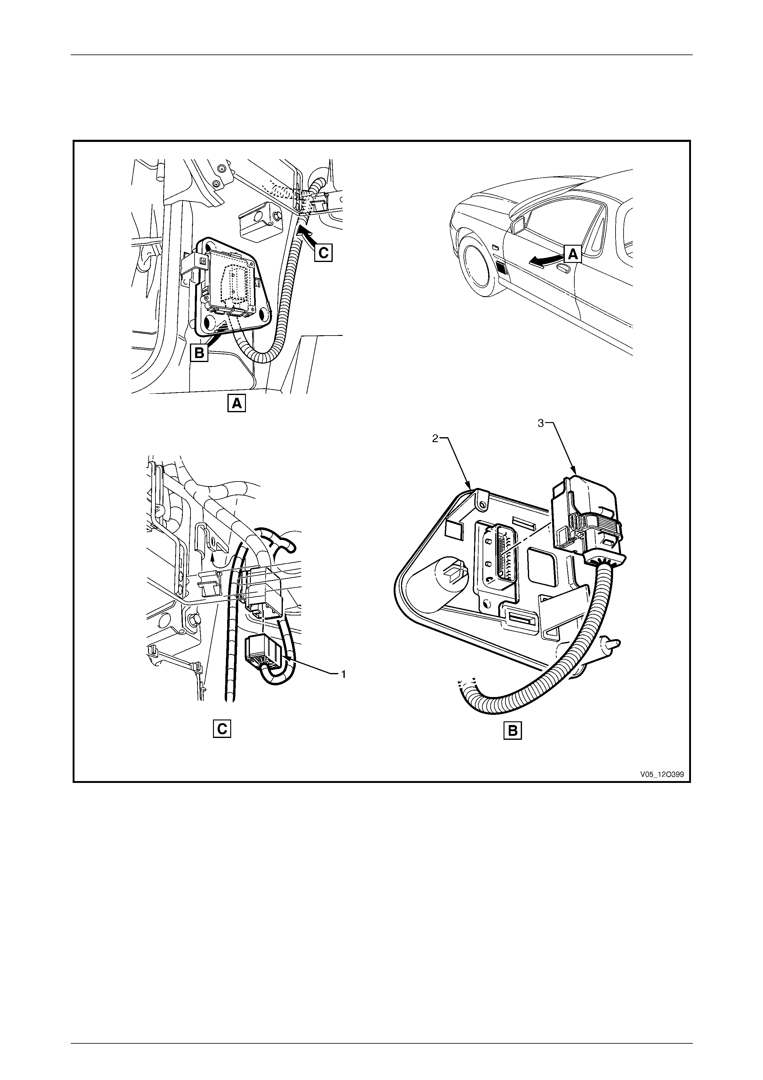
Fuses, Relays and Wiring Harnesses Page 12O–51
3.13 Transmission Harness – 2
V6 Engine – 4 Speed Automatic Transmission
Figure 12O – 52
Legend
1 Transmission Harness to Front Body Harness
Connector (X203)
2 Transmission Control Module
3 Transmission Control Module Connector (A112 – 4SPD)
Page 12O–51
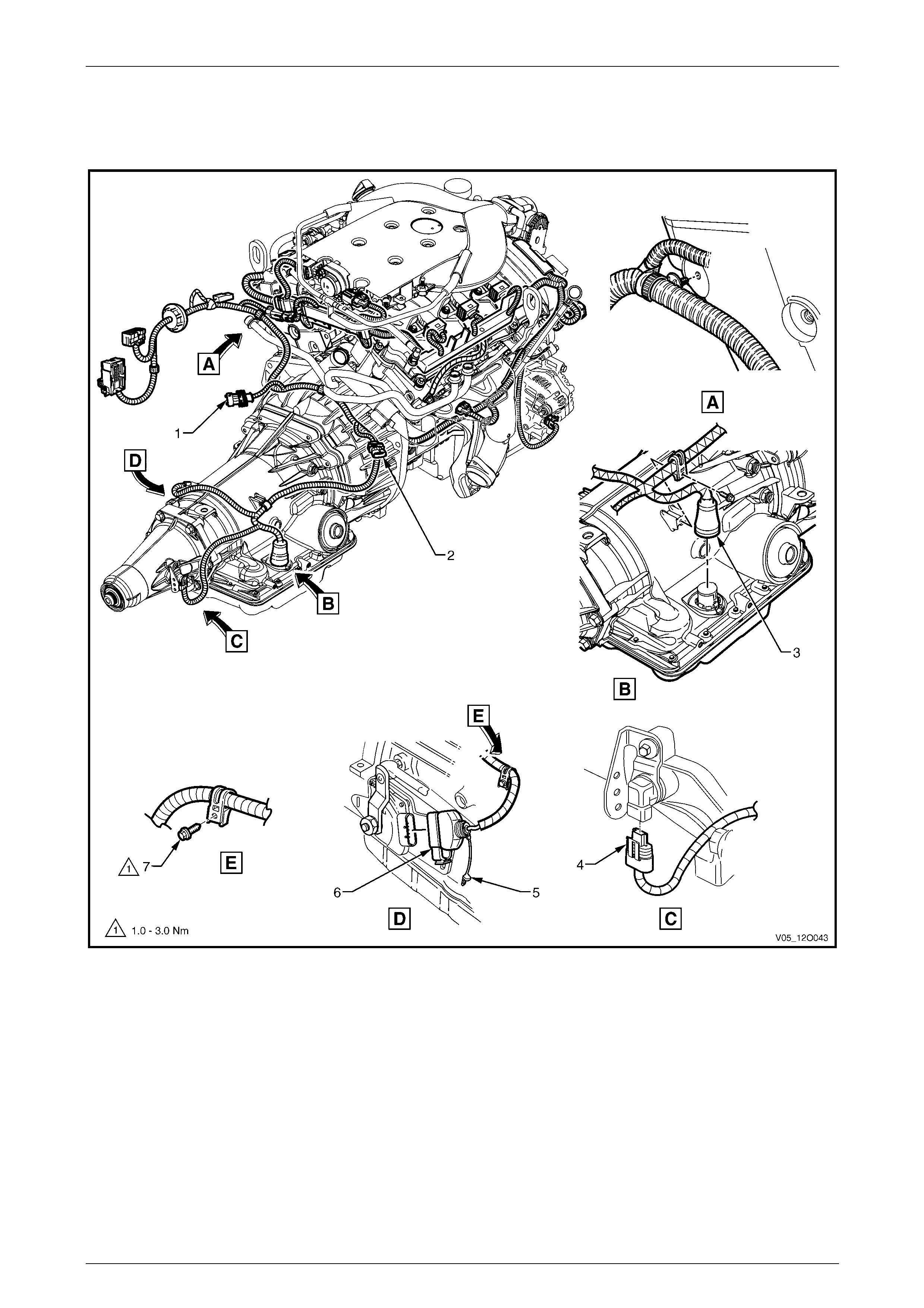
Fuses, Relays and Wiring Harnesses Page 12O–52
3.14 Transmission Harness – 3
V6 Engine – 4 Speed Automatic Transmission
Figure 12O – 53
Legend
1 Pre-Left-hand O2 Sensor Connec tor (B56 – V6)
2 Pre-Right-hand O2 Sensor Connector (B58 – V6)
3 Transmission Assembly Connector (X121 – 4SPD)
4 Vehicle Speed Sensor Connector (B83)
5 C.P.A. Lock
6 Park/Neutral Position and Back-up Lamp Connector (S187)
7 Bolt
Page 12O–52
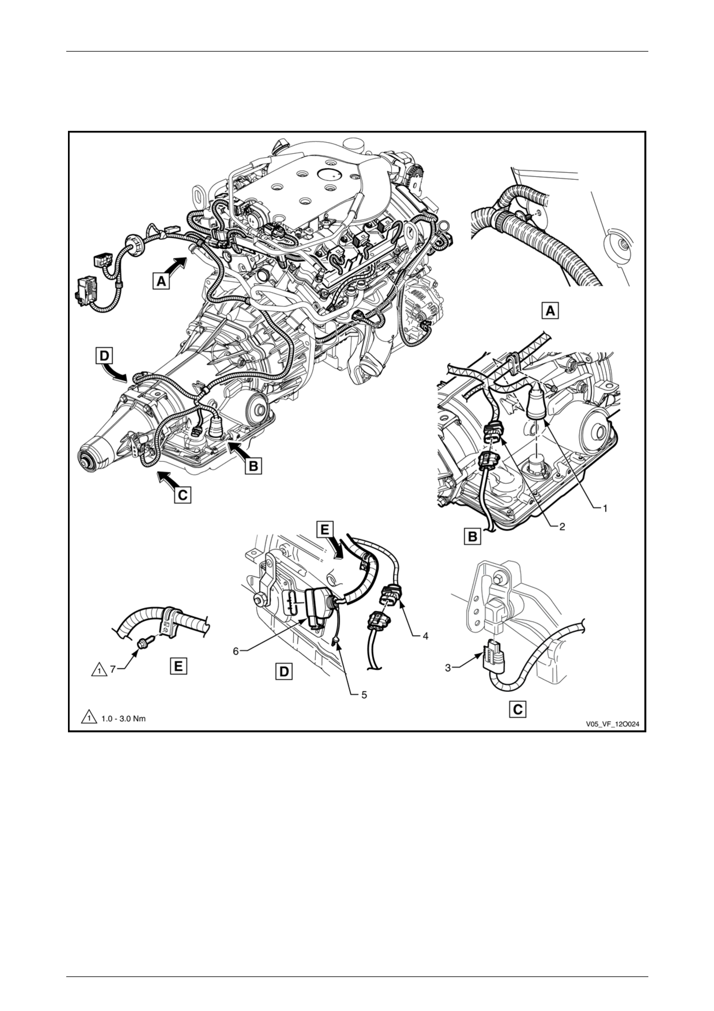
Fuses, Relays and Wiring Harnesses Page 12O–53
3.15 Transmission Harness – 4
V6 Engine – MY2006 Alloytec – 4 Speed Automatic Transmission
Figure 12O – 54
Legend
1 Transmission Assembly Connector (X121 – 4SPD)
2 Post-Right-hand O2 Sensor Connector (B58 – V6)
3 Vehicle Speed Sensor Connector (B83)
4 Post-Left-hand O2 Sensor Connector (B56 – V6)
5 C.P.A. Lock
6 Park/Neutral Position and Back-up Lamp Connector (S187)
7 Bolt
Page 12O–53
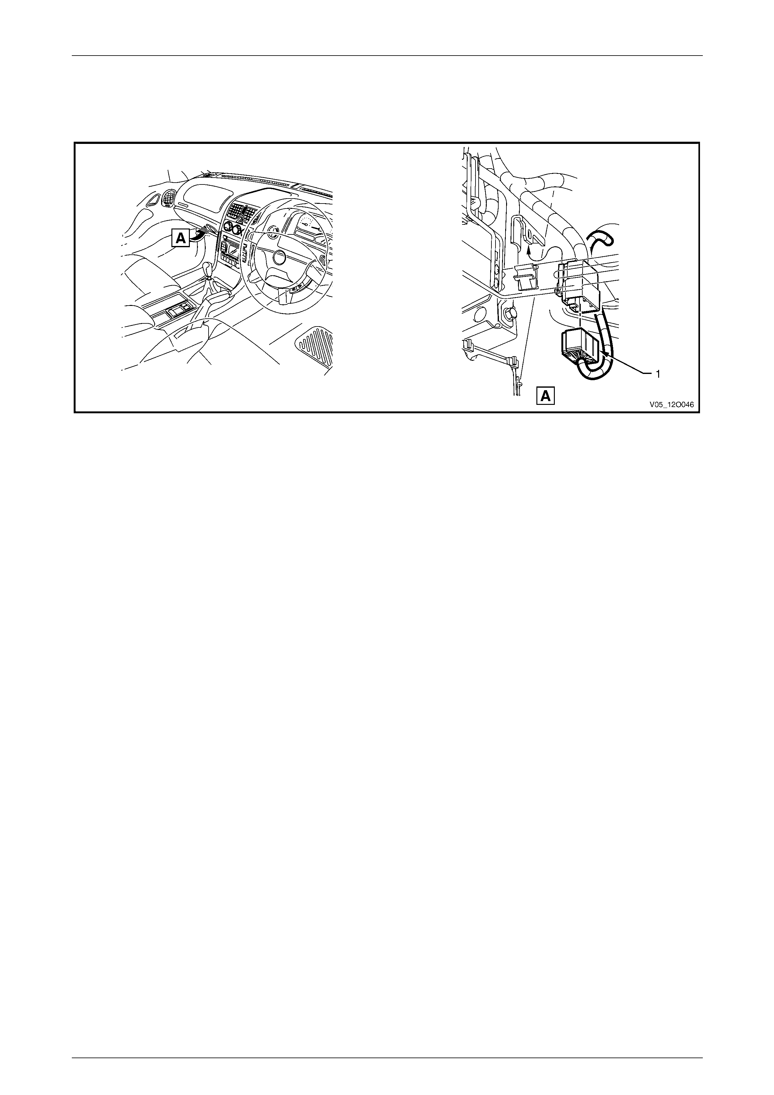
Fuses, Relays and Wiring Harnesses Page 12O–54
3.16 Transmission Harness – 5
V6 Engine – 6 Speed Manual Transmission
Figure 12O – 55
1 Transmission Harness to Front Body Harness Connector
(X203)
Page 12O–54
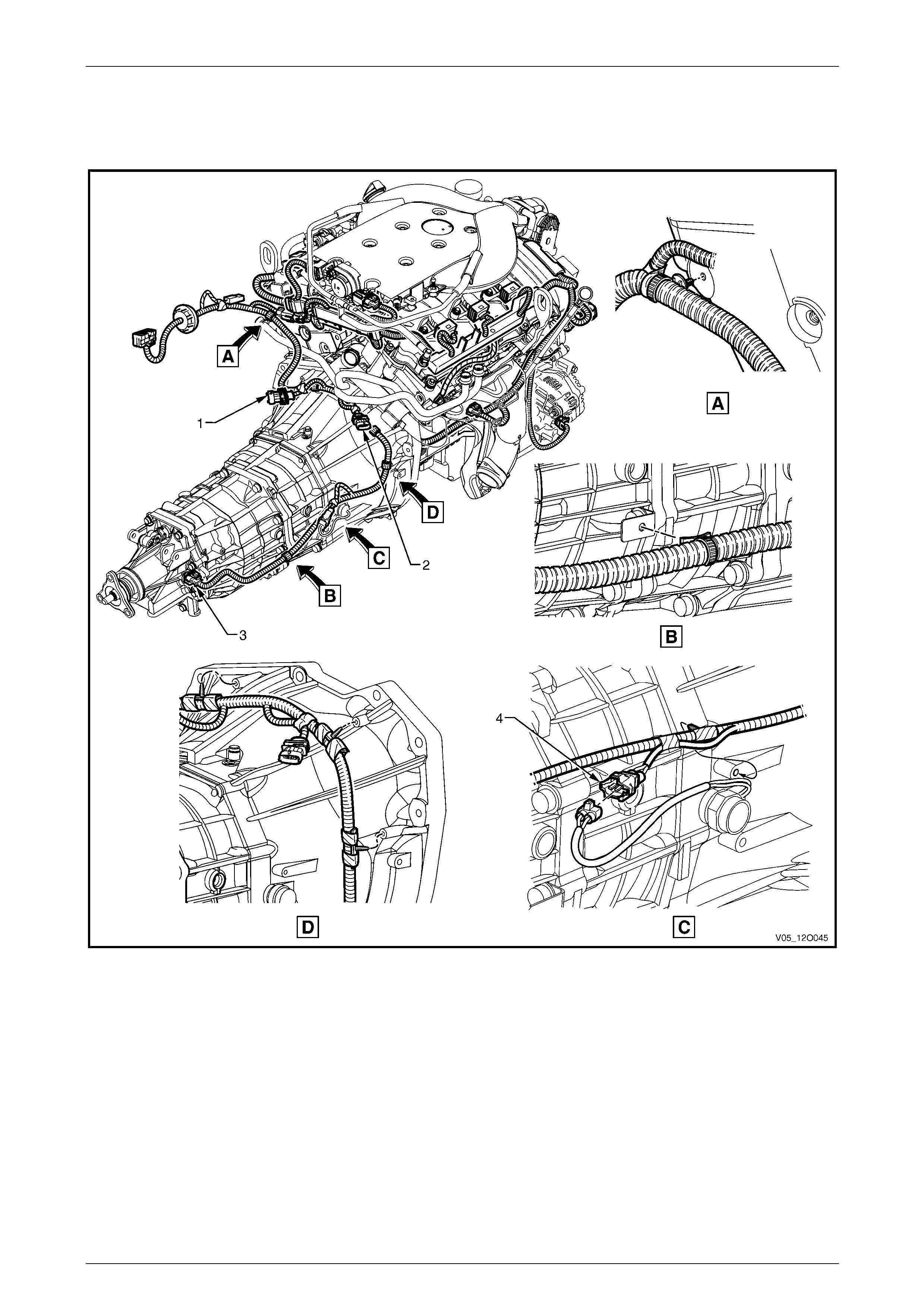
Fuses, Relays and Wiring Harnesses Page 12O–55
3.17 Transmission Harness – 6
V6 Engine – 6 Speed Manual Transmission
Figure 12O – 56
Legend
1 Pre-Left-hand O2 Sensor Connec tor (B56 – V6)
2 Pre-Right-hand O2 Sensor Connector (B58 – V6) 3 Vehicle Speed Sensor Connector (B83)
4 Back-up Lamp Switch Connector (S32 – V6)
Page 12O–55
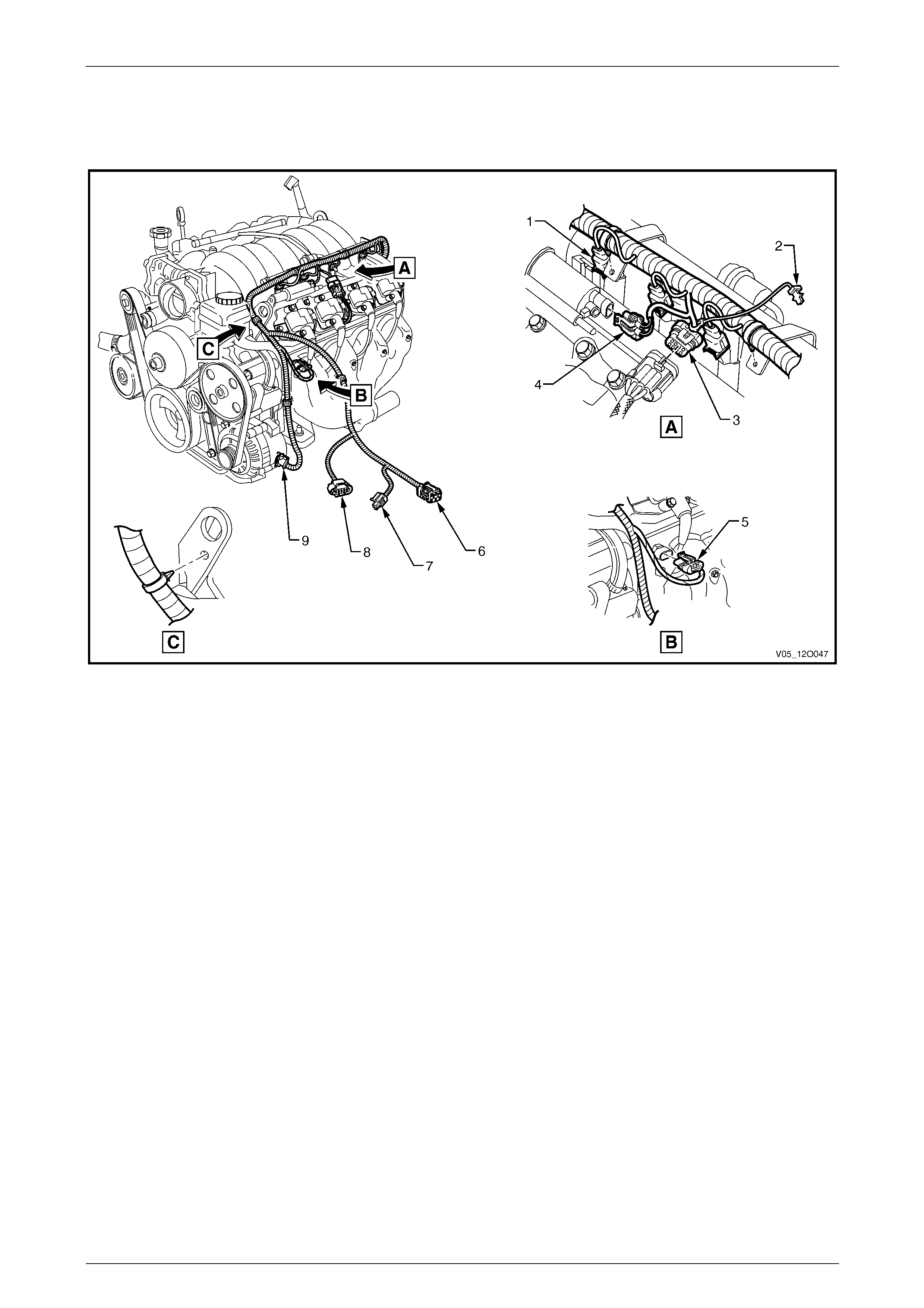
Fuses, Relays and Wiring Harnesses Page 12O–56
3.18 Powertrain Harness – 1
GEN III V8 Engine
Figure 12O – 57
Legend
1 Fuel Injector Connector (L2 – V8)
2 C.P.A. Lock
3 Electronic Ignition Control Module Connector (A40 – L)
4 Canister Purge Solenoid Valve Connector (Y123 – V8)
5 Engine Coolant Temperature Sensor Connector (B39 – V8)
6 Powertrain Harness to Front Body Harness Connector
(X101)
7 A/C Pressure Sensor Connector (B18 – V8)
8 Mass Airflow and Intake Air Temperature Sensor Connector
(B69 – V8)
9 Generator Connector (G8 – X2)
Page 12O–56
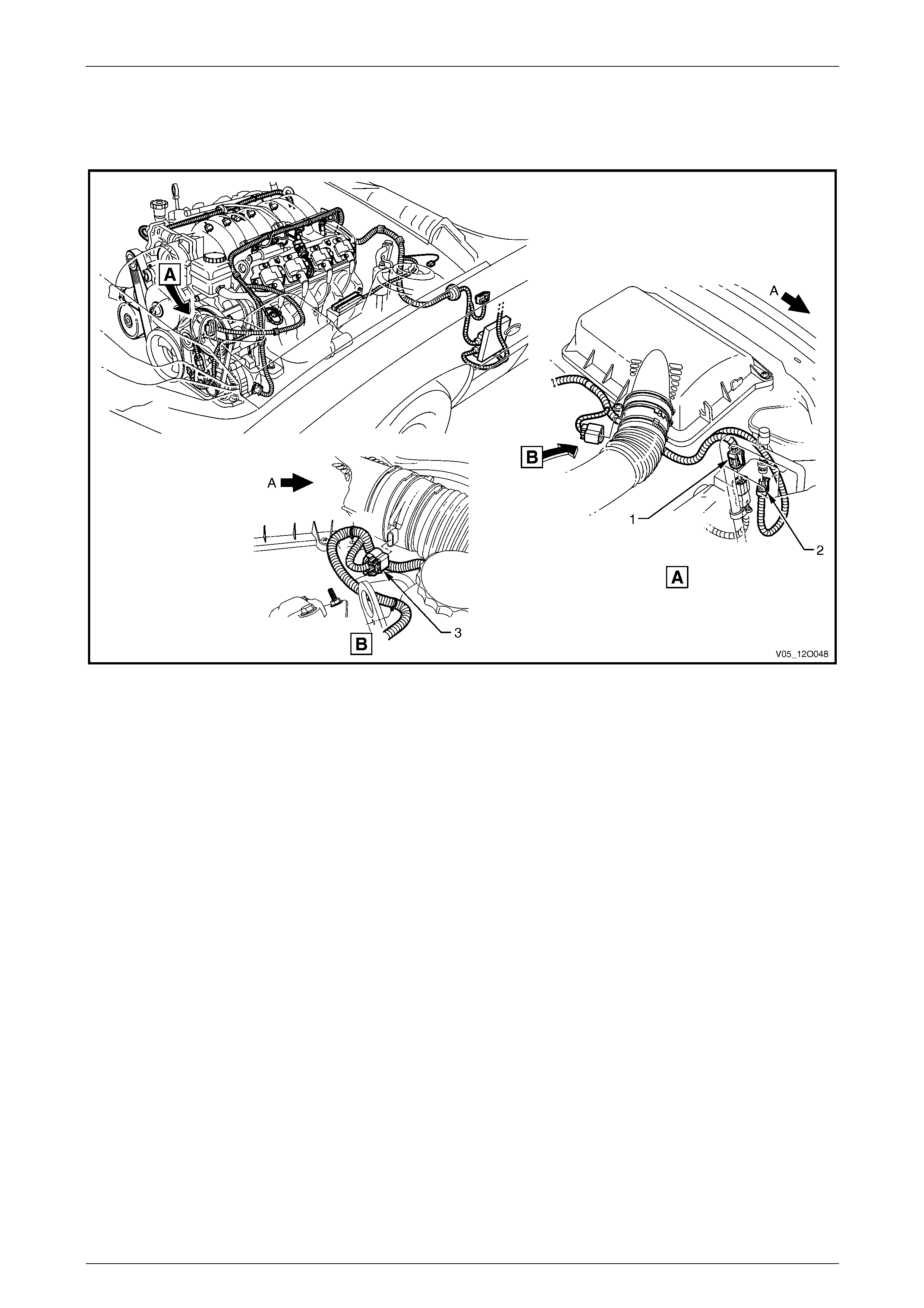
Fuses, Relays and Wiring Harnesses Page 12O–57
3.19 Powertrain Harness – 2
GEN III V8 Engine
Figure 12O – 58
Legend
1 Powertrain Harness to Front Body Harness Connector
(X101)
2 A/C Pressure Sensor Connector (B18 – V8)
3 Mass Airflow and Intake Air Temperature Sensor Connector
(B69 – V8)
A Front of vehicle.
Page 12O–57
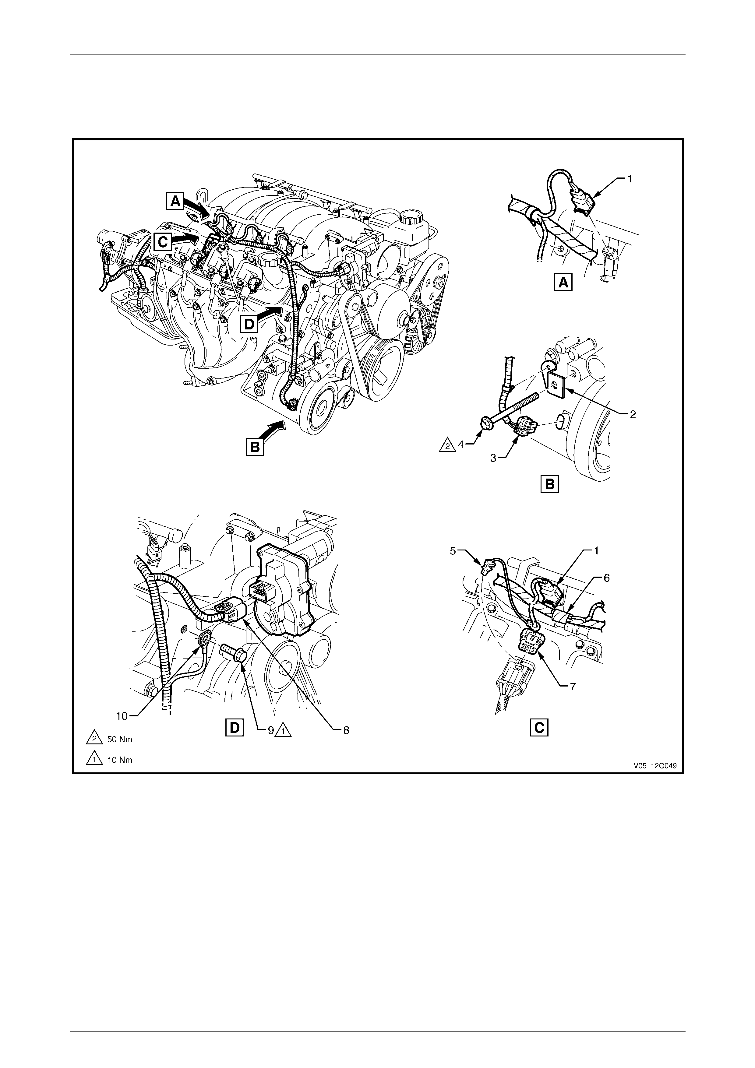
Fuses, Relays and Wiring Harnesses Page 12O–58
3.20 Powertrain Harness – 3
GEN III V8 Engine
Figure 12O – 59
Legend
1 Fuel Injector Connector (L2 – V8)
2 A/C Compressor Powertrain Harness Support Bracket
3 A/C Clutch Connector (L7)
4 A/C Compressor Mounting Bolt
5 C.P.A. Lock
6 Suppression Diode, A/C Compressor (V5)
7 Electronic Ignition Control Module Connector (A40 – R)
8 Throttle Actuator Connector (Y38 – V8)
9 Ground Terminal Attaching Bolt
10 Powertrain Harness Ground Terminal (X119 – GP5)
Page 12O–58
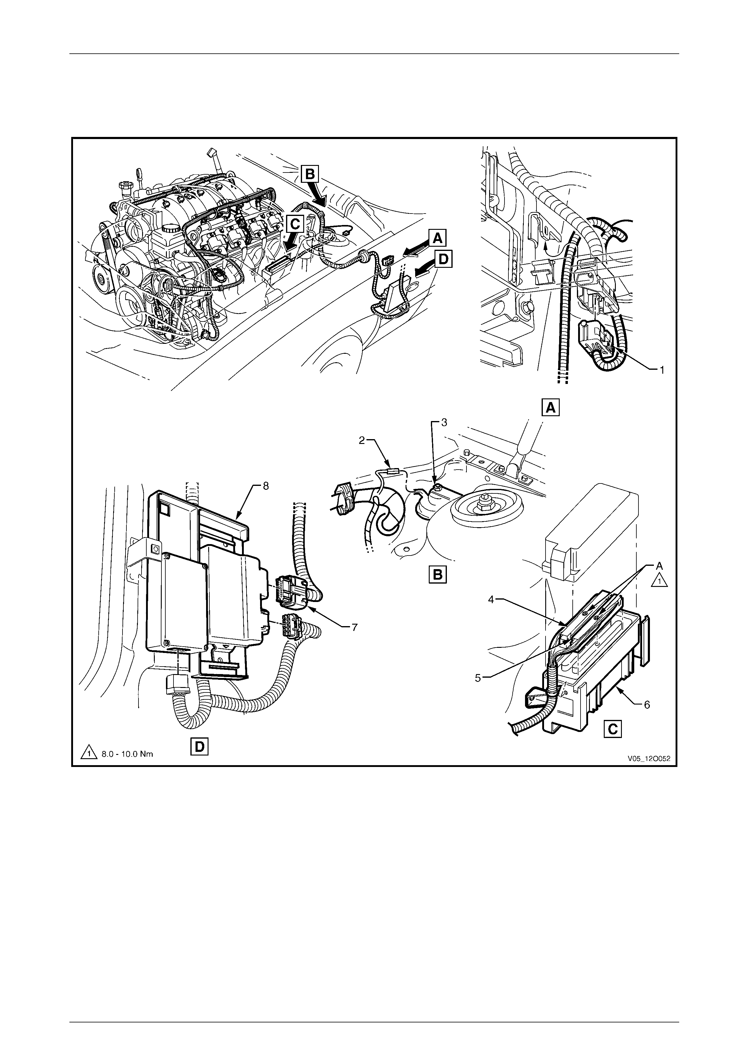
Fuses, Relays and Wiring Harnesses Page 12O–59
3.21 Powertrain Harness – 4
GEN III V8 Engine
Figure 12O – 60
Legend
1 Powertrain Harness to Front Body Harness Connector
(X206)
2 Theft Deterrent Horn Connector (B9)
3 Theft Deterrent Horn
4 Powertrain Control Module Connector (A84 – X2)
5 Powertrain Control Module Connector (A84 – X1)
6 Powertrain Control Module
7 Throttle Actuator Control Module Connector (A111 – X1)
8 Throttle Actuator Control Module
A Ensure PCM connector attaching bolts are not over
tightened.
Page 12O–59
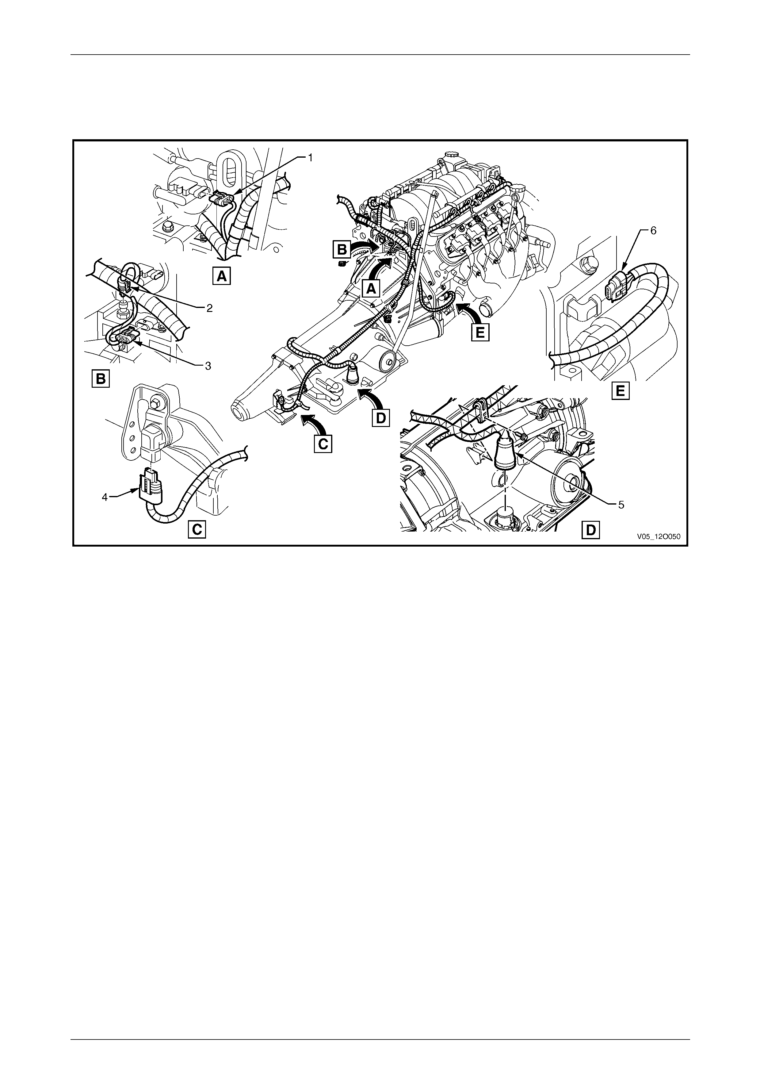
Fuses, Relays and Wiring Harnesses Page 12O–60
3.22 Powertrain Harness – 5
GEN III V8 Engine – Automatic Transmission
Figure 12O – 61
Legend
1 M.A.P. Sensor Connector (B67 – V8)
2 Engine Oil Pressure Sensor Connector (B42)
3 Camshaft Position Sensor Connector (B28 – V8)
4 Vehicle Speed Sensor Connector (B83)
5 Transmission Assembly Connector (X121 – 4SPD)
6 Crankshaft Position Sensor Connector (B30 – V8)
Page 12O–60
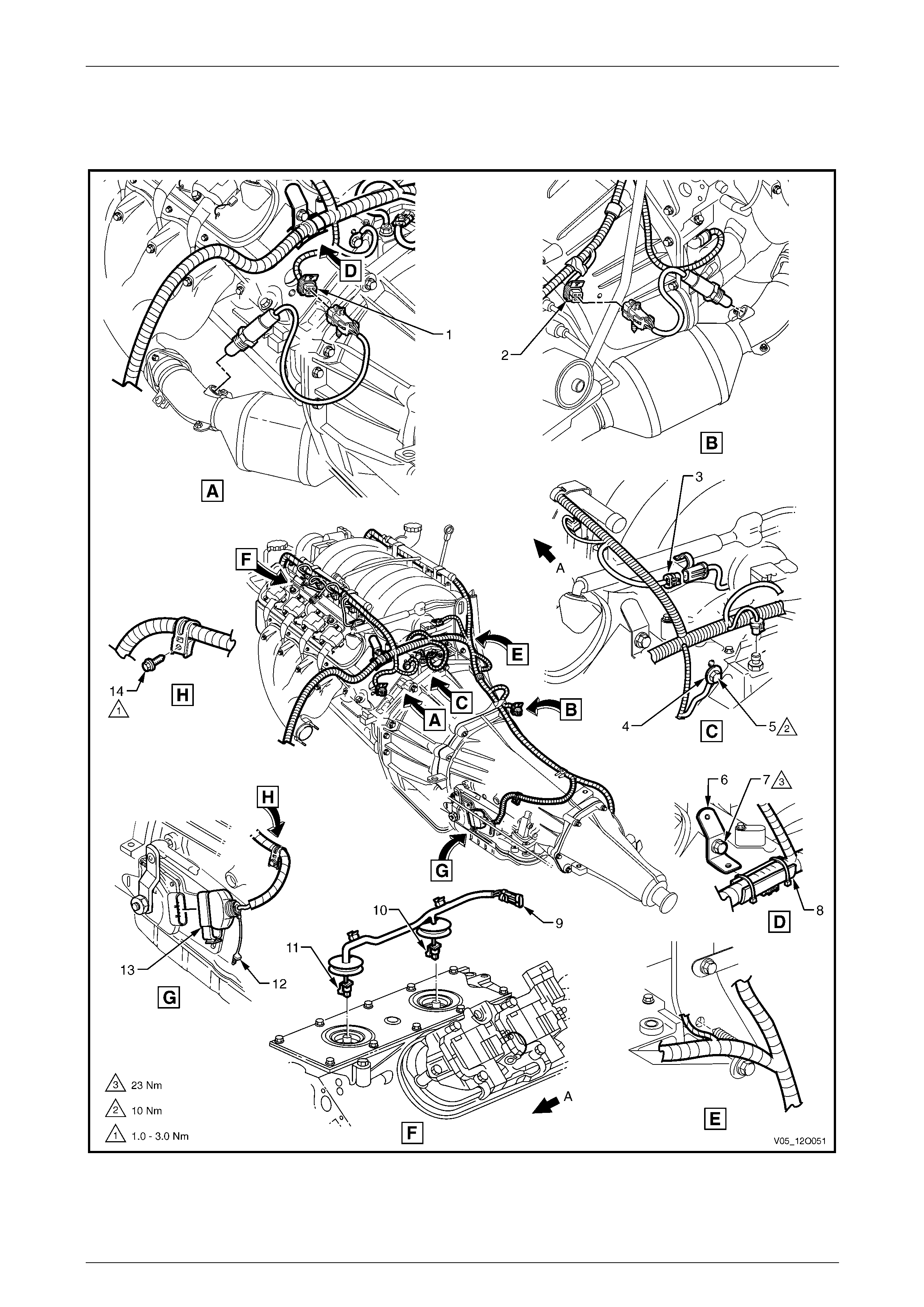
Fuses, Relays and Wiring Harnesses Page 12O–61
3.23 Powertrain Harness – 6
GEN III V8 Engine – Automatic Transmission
Figure 12O – 62
Page 12O–61

Fuses, Relays and Wiring Harnesses Page 12O–62
Legend
1 Left-hand O2 Sensor Connector (B57 – V8)
2 Right-hand O2 Sensor Connector (B166 – V8)
3 Powertrain Harness to Knock Sensor Harness Connector
(X107)
4 Engine Ground Terminal (X119 – GP6)
5 Engine Ground Terminal Attaching Bolt
6 Powertrain Harness Support Bracket
7 Powertrain Harness Support Bracket Attaching Bolt
8 Powertrain Harness Former
9 Knock Sensor Harness to Powertrain Harness Connector
(X107)
10 Knock Sensor Connector (B65 – SNSR2)
11 Knock Sensor Connector (B65 – SNSR1)
12 C.P.A. Lock
13 Park/Neutral Position and Back-up Lamp Switch Connector
(S187)
14 Bolt
A Front of vehicle.
Page 12O–62
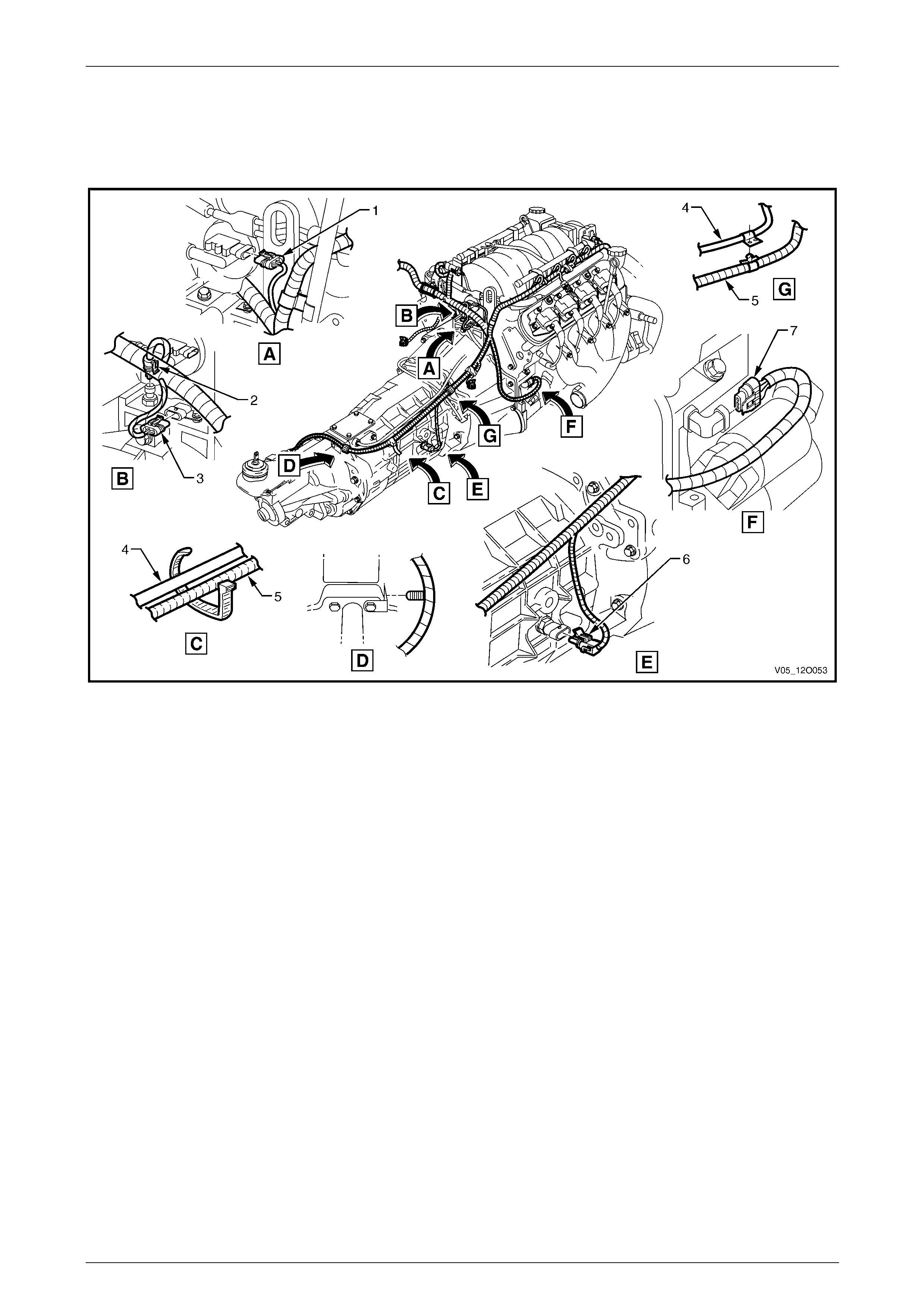
Fuses, Relays and Wiring Harnesses Page 12O–63
3.24 Powertrain Harness – 7
GEN III V8 Engine – Manual Transmission
Figure 12O – 63
Legend
1 M.A.P. Sensor Connector (B67 – V8)
2 Engine Oil Pressure Sensor Connector (B42)
3 Camshaft Position Sensor Connector (B28 – V8)
4 Transmission Breather Assembly
5 Powertrain Harness
6 Back-up Lamp Switch Connector (S32)
7 Crankshaft Position Sensor Connector (B30 – V8)
Page 12O–63
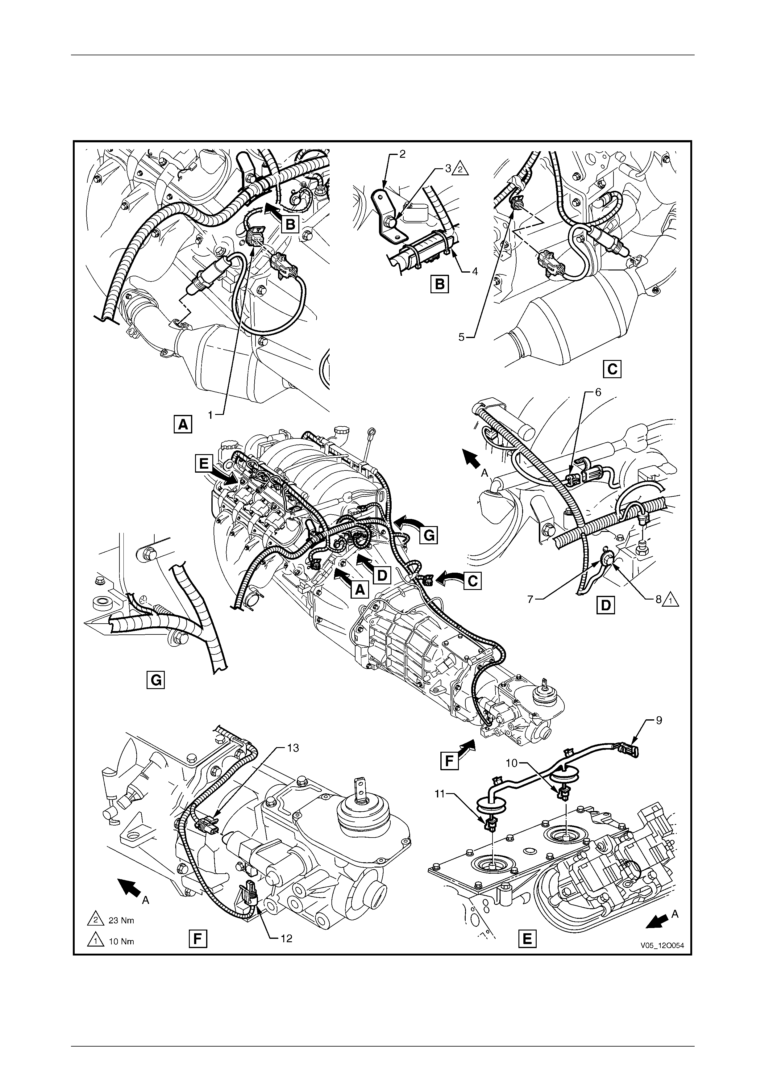
Fuses, Relays and Wiring Harnesses Page 12O–64
3.25 Powertrain Harness – 8
GEN III V8 Engine – Manual Transmission
Figure 12O – 64
Page 12O–64

Fuses, Relays and Wiring Harnesses Page 12O–65
Legend
1 Left-hand O2 Sensor Connector (B57 – V8)
2 Powertrain Harness Support Bracket
3 Powertrain Harness Support Bracket Attaching Bolt
4 Powertrain Harness Former
5 Right-hand O2 Sensor Connector (B166 – V8)
6 Powertrain Harness to Knock Sensor Harness Connector
(X107)
7 Engine Ground Terminal (X119 – GP6)
8 Engine Ground Terminal Attaching Bolt
9 Knock Sensor Harness to Powertrain Harness Connector
(X107)
10 Knock Sensor Connector (B65 – SNSR2)
11 Knock Sensor Connector (B65 – SNSR1)
12 Vehicle Speed Sensor Connector (B83)
13 Reverse Lockout Solenoid Connector (Y144)
A Front of vehicle.
Page 12O–65
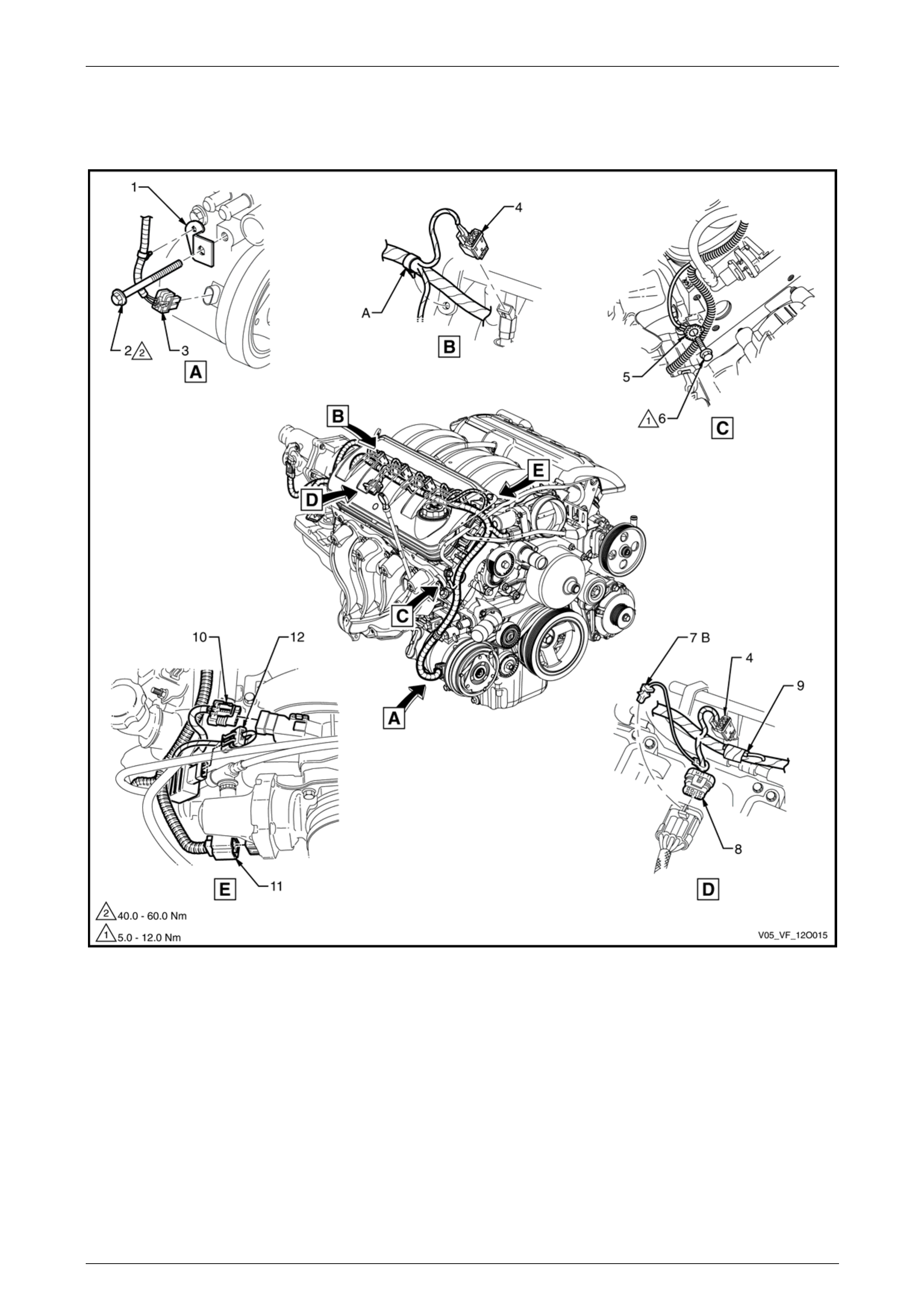
Fuses, Relays and Wiring Harnesses Page 12O–66
3.26 Powertrain Harness – 9
GEN IV V8 Engine
Figure 12O – 65
Legend
1 Air-conditioning Compressor Powertrain Harness Support
Bracket
2 Air-conditioning Compressor Mounting Bolt
3 A/C Clutch Connector (L7)
4 Fuel Injector Connector (L2)
5 Powertrain Harness to Engine Ground Terminal (X119 –
GP5)
6 Ground Terminal Attaching Bolt
7 CPA Lock
8 Electronic Ignition Control Module Connector (A40 – R)
9 Suppression Diode A/C Compressor Connector (V5)
10 MAP Sensor Connector (B67)
11 Throttle Body Connector (Y38)
12 Canister Purge Solenoid Valve Connector (Y123)
A Powertrain harness is secured to bracket in two places on
right-hand side.
B CPA Lock is part of the powertrain harness and is inserted
into the ignition module connector on assembly.
Page 12O–66
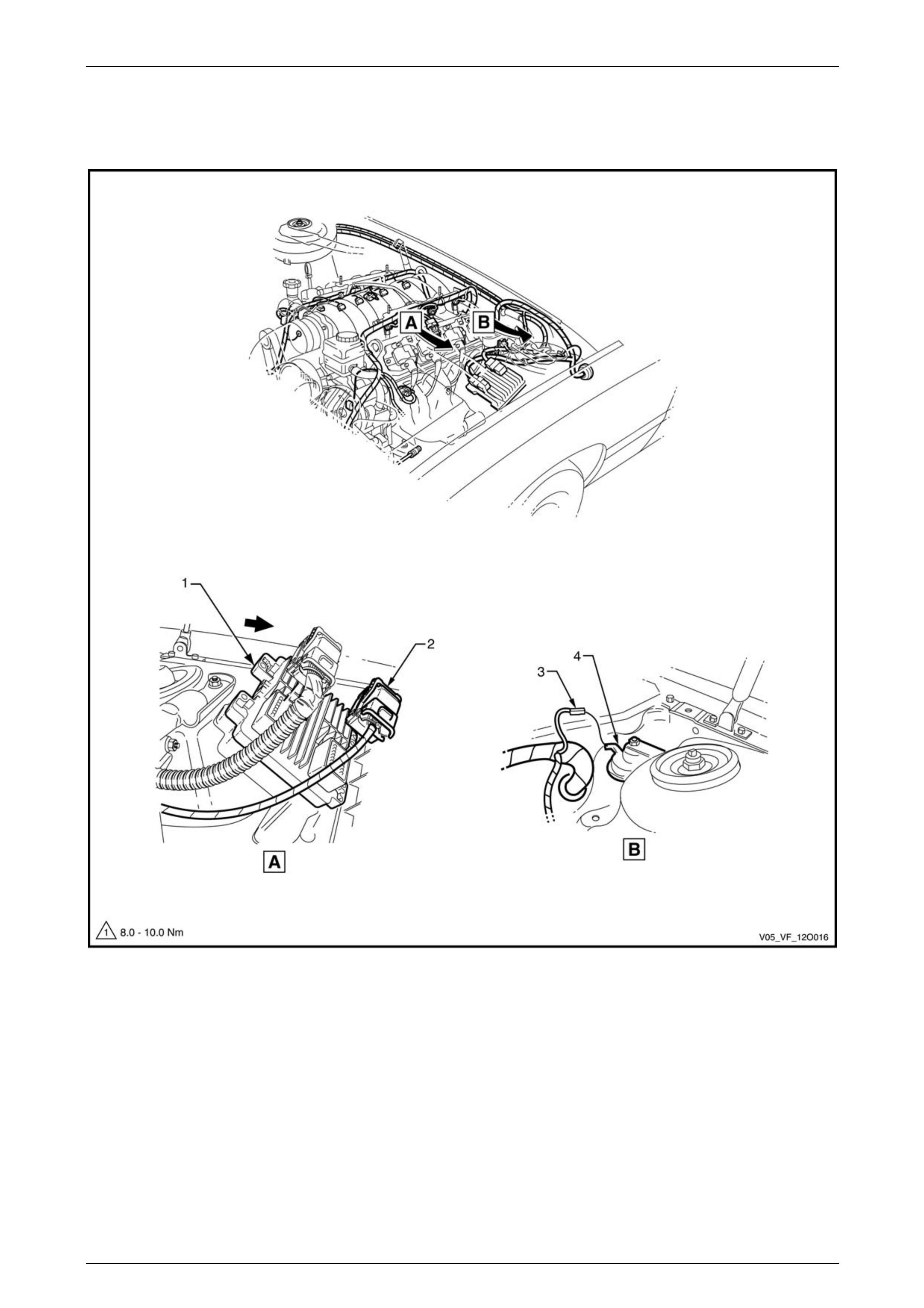
Fuses, Relays and Wiring Harnesses Page 12O–67
3.27 Powertrain Harness – 10
GEN IV V8 Engine
Figure 12O – 66
Legend
1 Engine Control Unit
2 Engine Control Unit Connector (A43 – X2) 3 Horn Connector (B9)
4 Theft Deterrent Horn
Page 12O–67
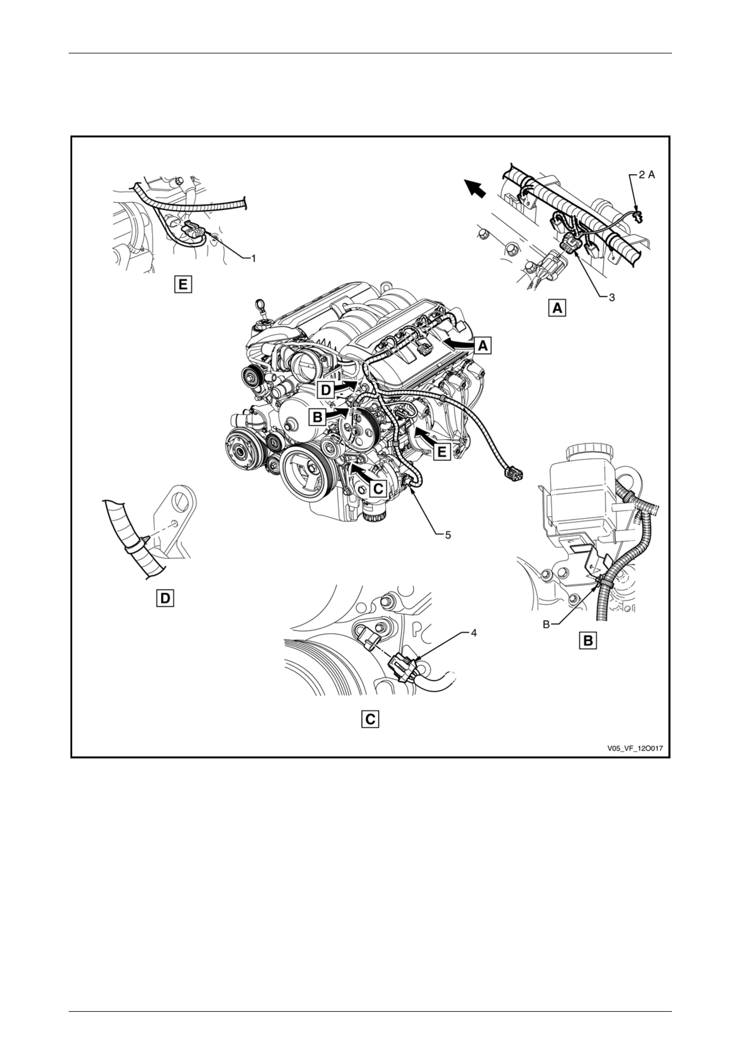
Fuses, Relays and Wiring Harnesses Page 12O–68
3.28 Powertrain Harness – 11
GEN IV V8 Engine
Figure 12O – 67
Legend
1 Engine Coolant Temperature Sensor Connector (B39)
2 CPA Lock
3 Electronic Ignition Module Connector (A40 – L)
4 Camshaft Position Sensor Connector (B28)
5 Generator Connector (G8-X2)
A CPA Lock is part of the powertrain harness and is inserted
into the ignition module connector on assembly.
B Clip fitted to bracket before surge tank is fitted.
Page 12O–68
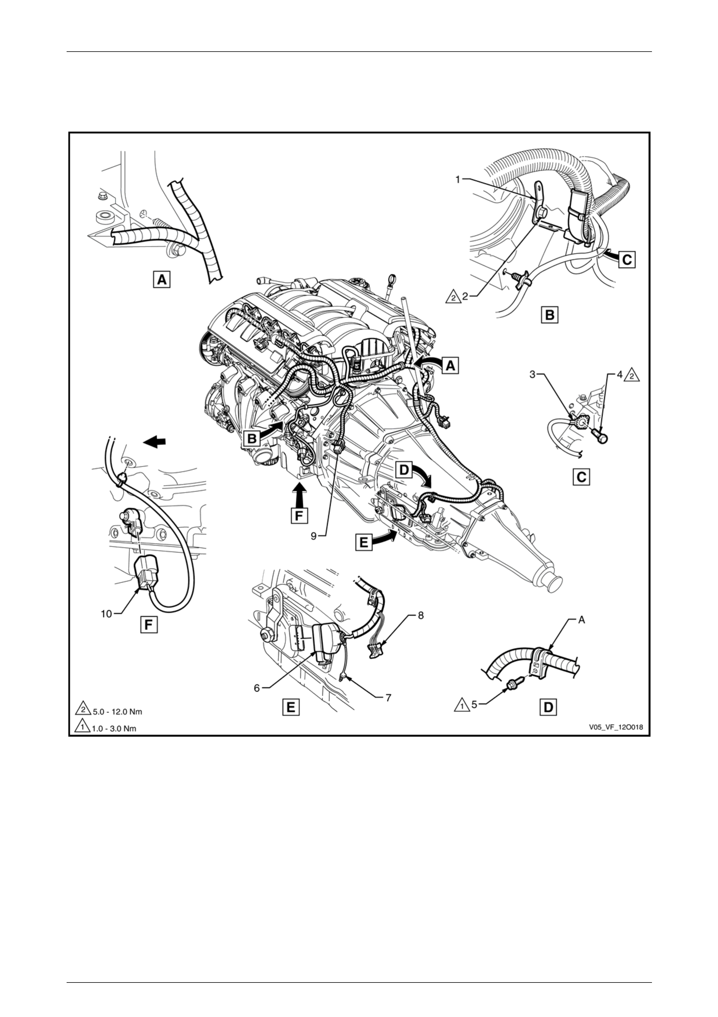
Fuses, Relays and Wiring Harnesses Page 12O–69
3.29 Powertrain Harness – 12
GEN IV V8 Engine
Figure 12O – 68
Legend
1 Powertrain Harness Support Bracket
2 Bolt
3 Engine Ground Terminal (X119 – GP6)
4 Powertrain Harness Ground Terminal Attaching Bolt
5 Powertrain Harness Attaching Bolt (2 Places)
6 Park/Neutral Position and Back Up Switch Connector (S187)
7 CPA Lock
8 Heated Oxygen Sensor Connector (B57 – LT – RR)
9 Heated Oxygen Sensor Connector (B166 – LT – FR)
10 Knock Sensor Connector (B65)
A Clip (two places) bent over after fitting to harness assembly.
Page 12O–69
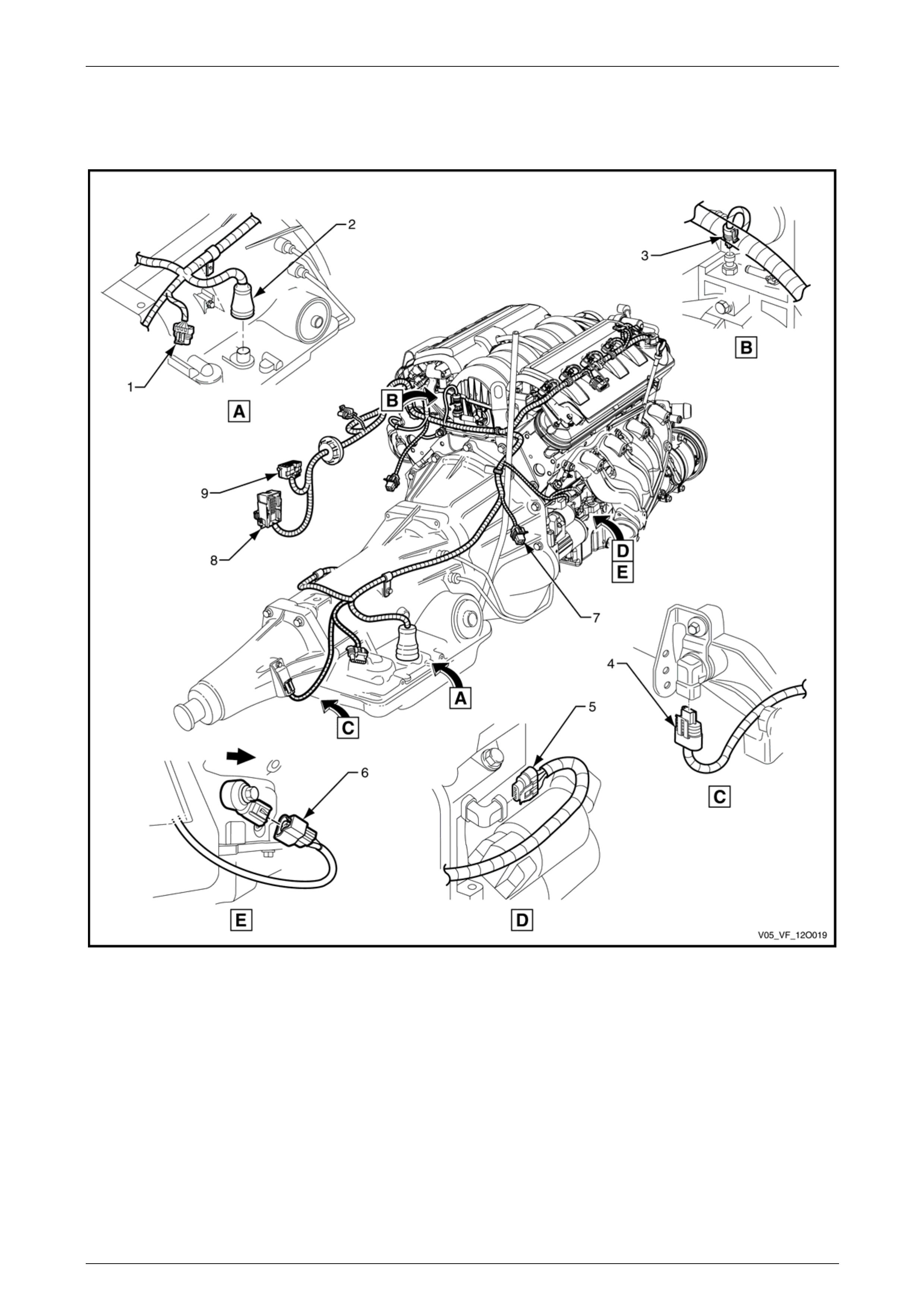
Fuses, Relays and Wiring Harnesses Page 12O–70
3.30 Powertrain Harness – 13
GEN IV V8 Engine
Figure 12O – 69
Legend
1 Heated Oxygen Sensor Connector (B57 – RT – RR)
2 Transmission Assembly Connector (X121)
3 Engine Oil Pressure Sensor Connector (B42)
4 Speed Sender Connector (B83)
5 Crank Shaft Position Sensor Connector (B30)
6 Knock Sensor Connector (B65)
7 Heated Oxygen Sensor Connector (B166 – RT – FR)
8 Transmission Control Module Connector (A112)
9 Powertrain Harness to Front Body Harness Connector
(X211)
Page 12O–70
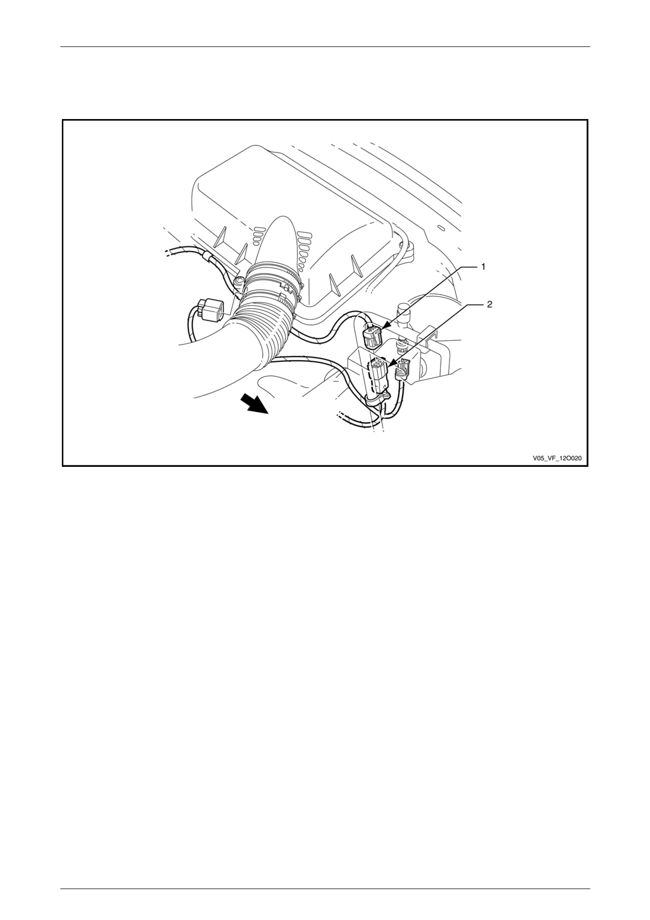
Fuses, Relays and Wiring Harnesses Page 12O–71
3.31 Powertrain Harness – 14
GEN IV V8 Engine
Figure 12O – 70
Legend
1 Powertrain Harness to Front Body Harness Connector
(X101) 2 Front Body Harness to Powertrain Harness Connector
(X101)
Page 12O–71
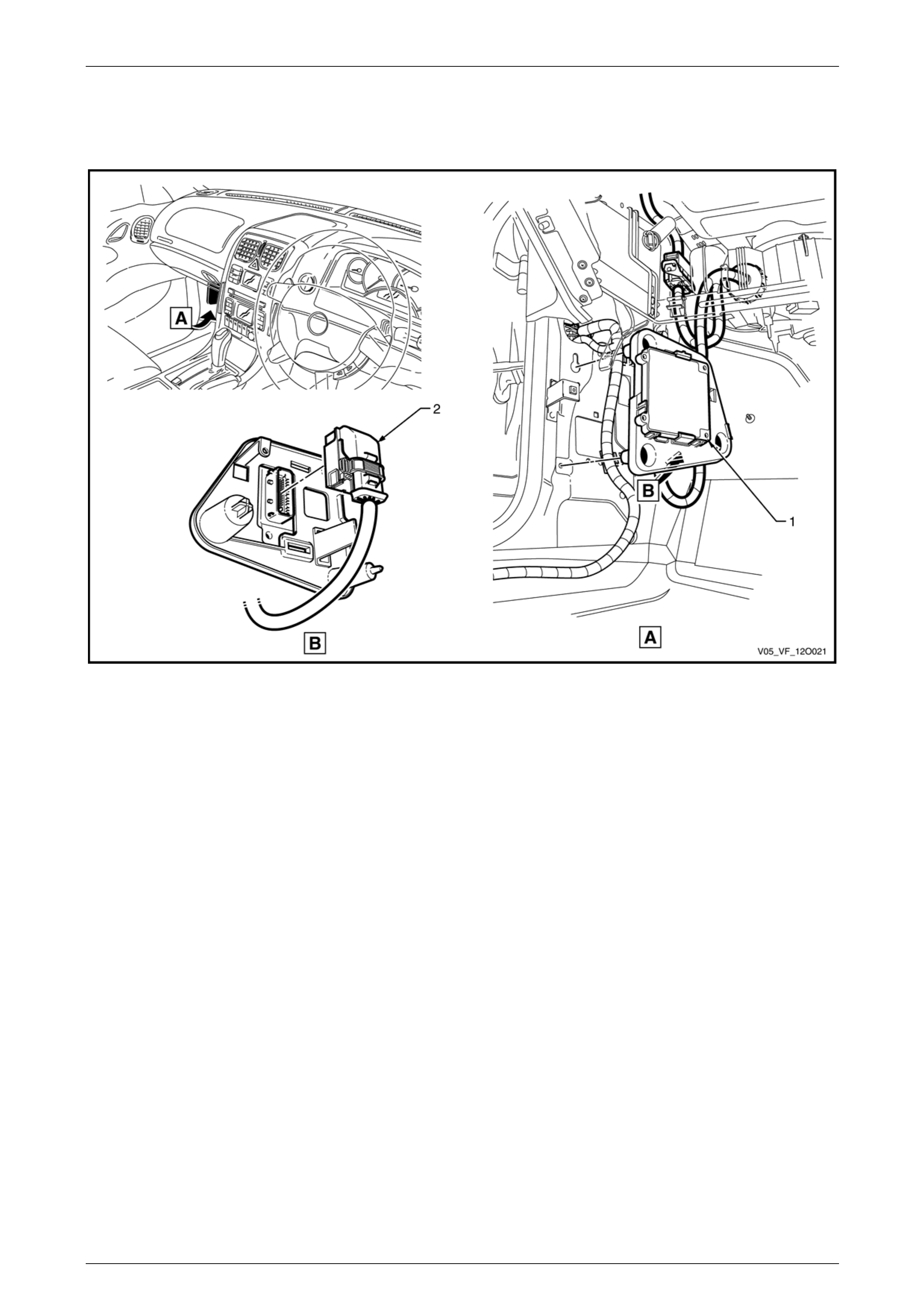
Fuses, Relays and Wiring Harnesses Page 12O–72
3.32 Powertrain Harness – 15
GEN IV V8 Engine
Figure 12O – 71
Legend
1 Transmission Control Module 2 Transmission Control Module Connector (A112)
Page 12O–72
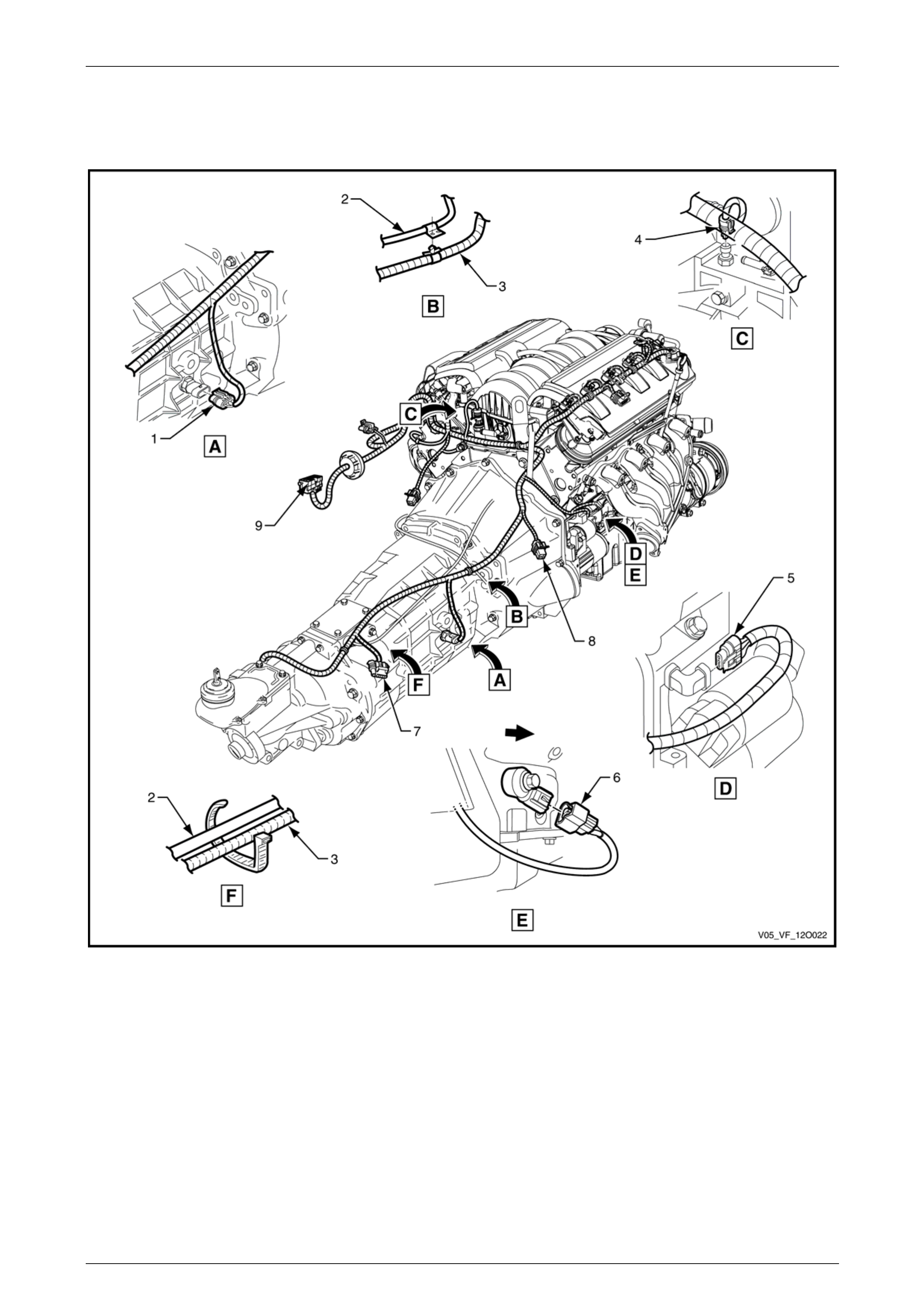
Fuses, Relays and Wiring Harnesses Page 12O–73
3.33 Powertrain Harness – 16
GEN IV V8 Engine
Figure 12O – 72
Legend
1 Back-up Lamp Switch Connector (S32)
2 Transmission Breather Assembly
3 Powertrain Harness
4 Engine Oil Pressure Sensor Connector (B42)
5 Crankshaft Position Sensor Connector (B30)
6 Knock Sensor Connector (B65)
7 Heated Oxygen Sensor Connector (B57 – RT – RR)
8 Heated Oxygen Sensor Connector (B166 – RT – FR)
9 Powertrain Harness to Front Body Harness Connector
(X206)
Page 12O–73
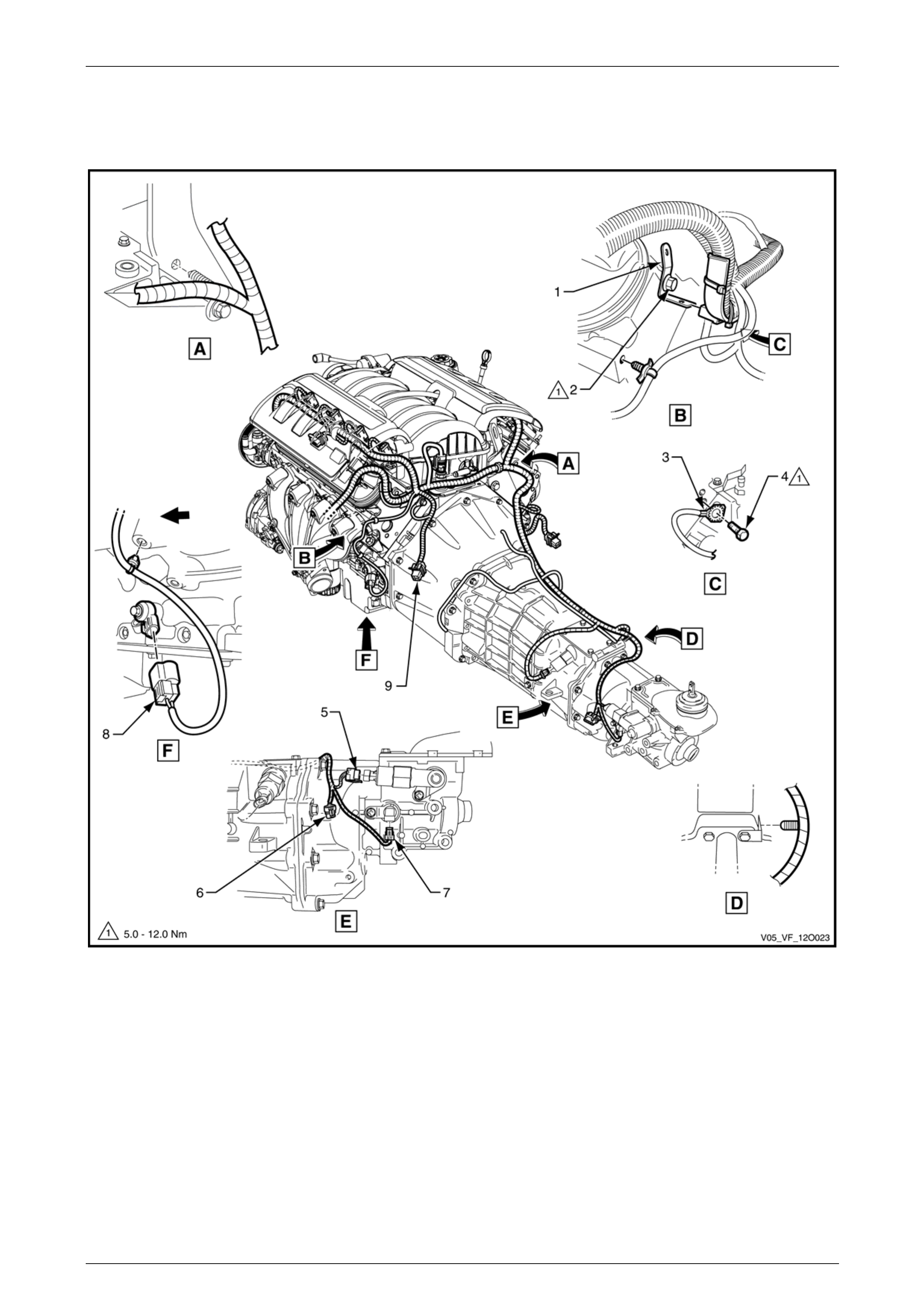
Fuses, Relays and Wiring Harnesses Page 12O–74
3.34 Powertrain Harness – 17
GEN IV V8 Engine
Figure 12O – 73
Legend
1 Powertrain Harness Support Bracket
2 Bolt
3 Engine Ground Terminal (X119 – GP6)
4 Bolt
5 Reverse Lockout Solenoid Connector (Y144)
6 Heated Oxygen Sensor Connector (B57 – LT – RR)
7 Speed Sensor Connector (B83)
8 Knock Sensor Connector (B65)
9 Heated Oxygen Sensor Connector (B166 – LT – FR)
Page 12O–74
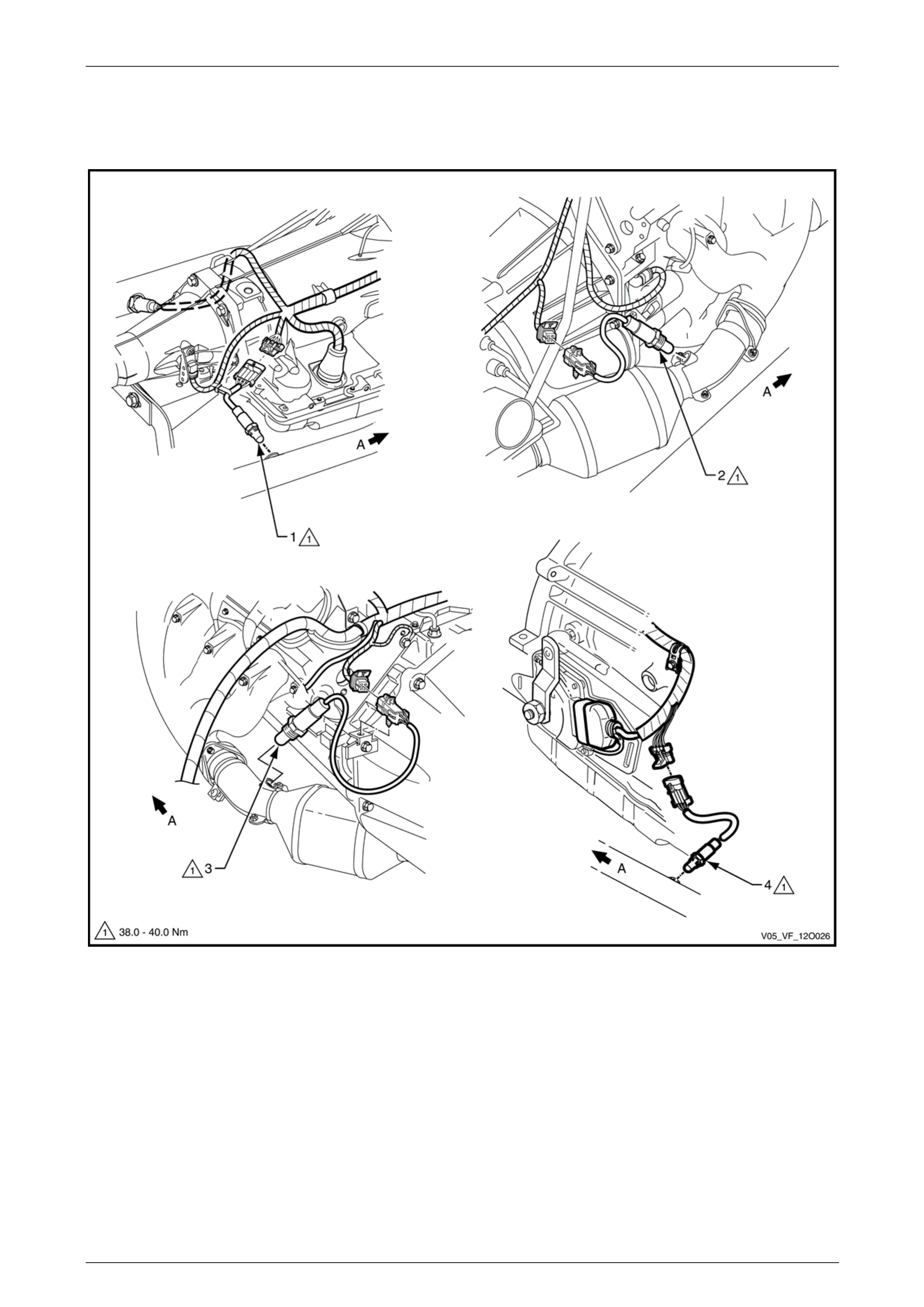
Fuses, Relays and Wiring Harnesses Page 12O–75
3.35 Powertrain Harness – 18
GEN IV V8 Engine
Figure 12O – 74
Legend
1 Heated Oxygen Sensor – Rear Right-hand Side
2 Heated Oxygen Sensor – Front Right-hand Side
3 Heated Oxygen Sensor – Front Left-hand Side
4 Heated Oxygen Sensor – Rear Left-hand Side
A Front of vehicle.
Page 12O–75
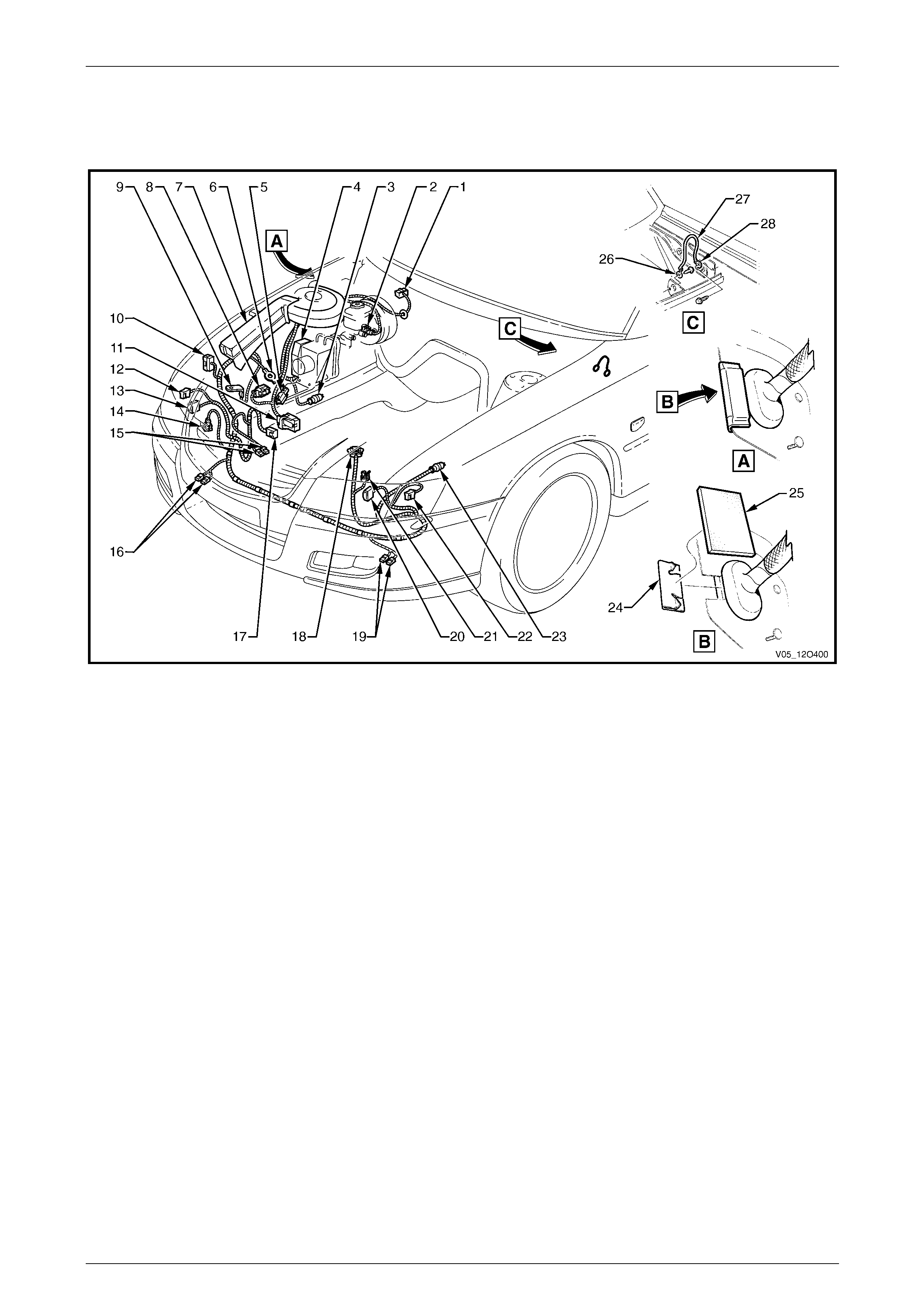
Fuses, Relays and Wiring Harnesses Page 12O–76
3.36 Front Body Harn ess – 1
V6 Engine – Engine Compartment
Figure 12O – 75
Legend
1 Windshield Wiper Motor Connector (M17)
2 Brake Fluid Level Indicator Switch Connector (S36)
3 Front Wheel Speed Sensor Connector (B52 – R)
4 Electronic Brake and Traction Control module Connector
(A38) or Vehicle Control Module Connector (A116)
5 Front Body Harness to Battery Wiring Harness Connector
(X106)
6 Body Ground Terminal (X119 – G3 – GP3)
7 Front Body Harness Junction Connector (X100)
8 Front Body Harness to Engine Harness Connector (X103)
9 Fusible Link Supply Connector (X86 – A)
10 Ground Connector (X157)
11 Engine Control Module Connector (A43 – X2)
12 Turn Signal Lamp Connector (E76 – R)
13 Headlamp Connector (E119 – R)
14 Windshield Washer Motor Connector (M19)
15 Hood Theft Deterrent Switch Connectors (S135)
16 Horn Connectors (B9)
17 Engine Cooling Fan Connector (M7 – X1)
18 Mass Airflow and Intake Air Temperature Sensor Connector
(B69 – V6)
19 Horn Connectors (B9)
20 Headlamp Connector (E119 – L)
21 A/C Pressure Sensor Connector (B18 – V6)
22 Turn Signal Lamp Connector (E76 – L)
23 Front Wheel Speed Sensor Connector (B52 – L)
24 Sealing Patch Grommet
25 Grommet Insert
26 Instrument Panel to Body Ground Strap Terminal
(X118 – GP9)
27 Body to Instrument Panel Ground Strap
28 Body to Instrument Panel Ground Strap Terminal
(X119 – GP10)
Page 12O–76
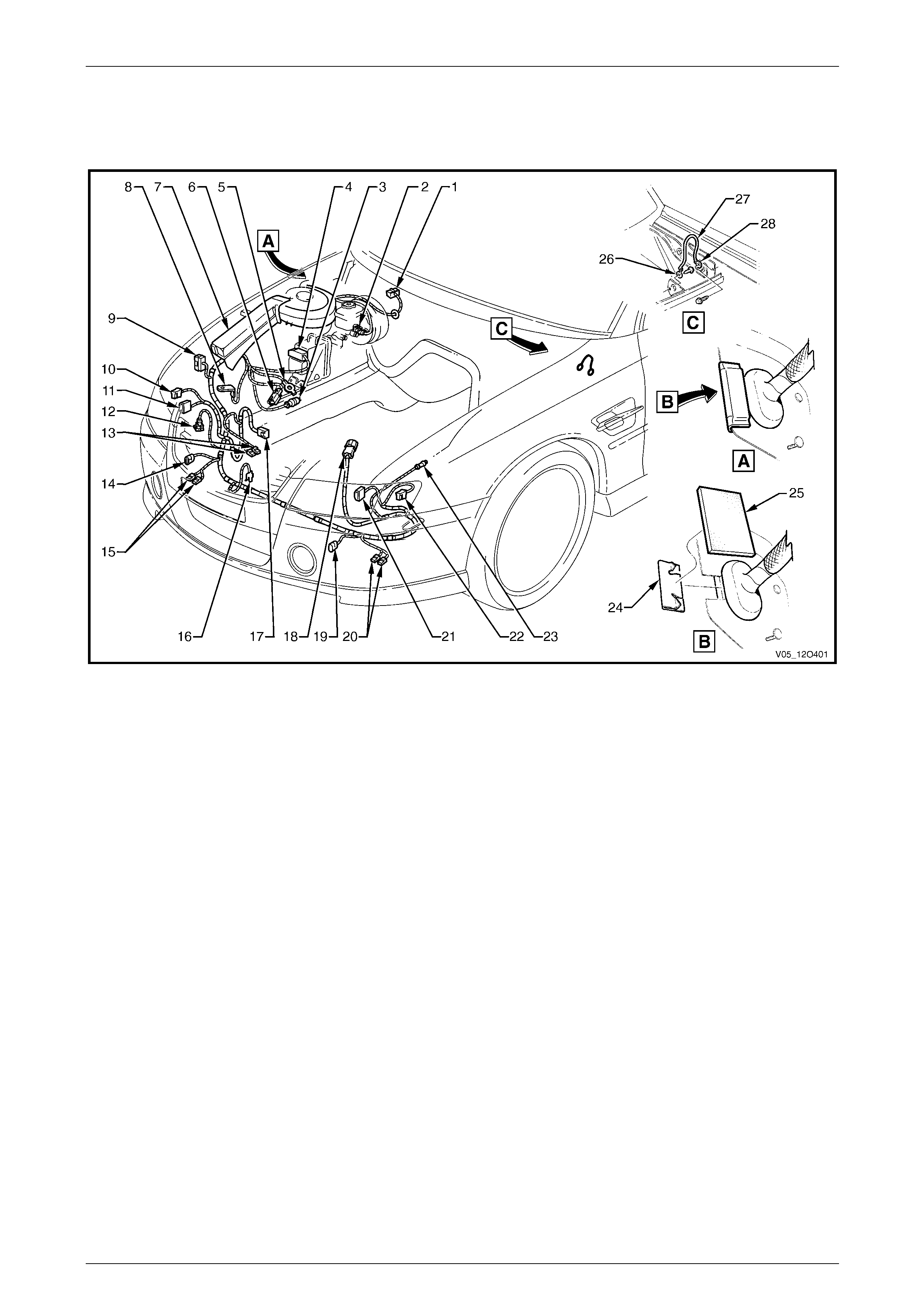
Fuses, Relays and Wiring Harnesses Page 12O–77
3.37 Front Body Harn ess – 2
GEN III V8 Engine – Engine Compartment
Figure 12O – 76
Legend
1 Windshield Wiper Motor Connector (M17)
2 Brake Fluid Level Indicator Switch Connector (S36)
3 Front Wheel Speed Sensor Connector (B52 – R)
4 Electronic Brake and Traction Control Module Connector
(A37)
5 Body Ground Terminal (X119 – G3 – GP3)
6 Front Body Harness to Battery Wiring Harness Connector
(X106)
7 Front Body Harness Junction Connector (X100)
8 Fusible Link Supply Connector (X86 – A)
9 Ground Connector (X157)
10 Turn Signal Lamp Connector (E76 – R)
11 Headlamp Connector (E119 – R)
12 Windshield Washer Motor Connector (M19)
13 Hood Theft Deterrent Switch Connectors (S135)
14 Fog Lamp Connector (E69 – R)
15 Horn Connectors (B9)
16 Ambient Air Temperature Sensor Connector (B23)
17 Engine Cooling Fan Connector (M7 – X1)
18 Front Body Harness to Powertrain Harness Connector
(X101)
19 Fog Lamp Connector (E69 – L)
20 Horn Connectors (B9)
21 Headlamp Connector (E119 – L)
22 Turn Signal Lamp Connector (E76 – L)
23 Front Wheel Speed Sensor Connector (B52 – L)
24 Sealing Patch Grommet
25 Grommet Insert
26 Instrument Panel to Body Ground Strap Terminal
(X118 – GP9)
27 Body to Instrument Panel Ground Strap
28 Body to Instrument Panel Ground Strap Terminal
(X119 – GP10)
Page 12O–77
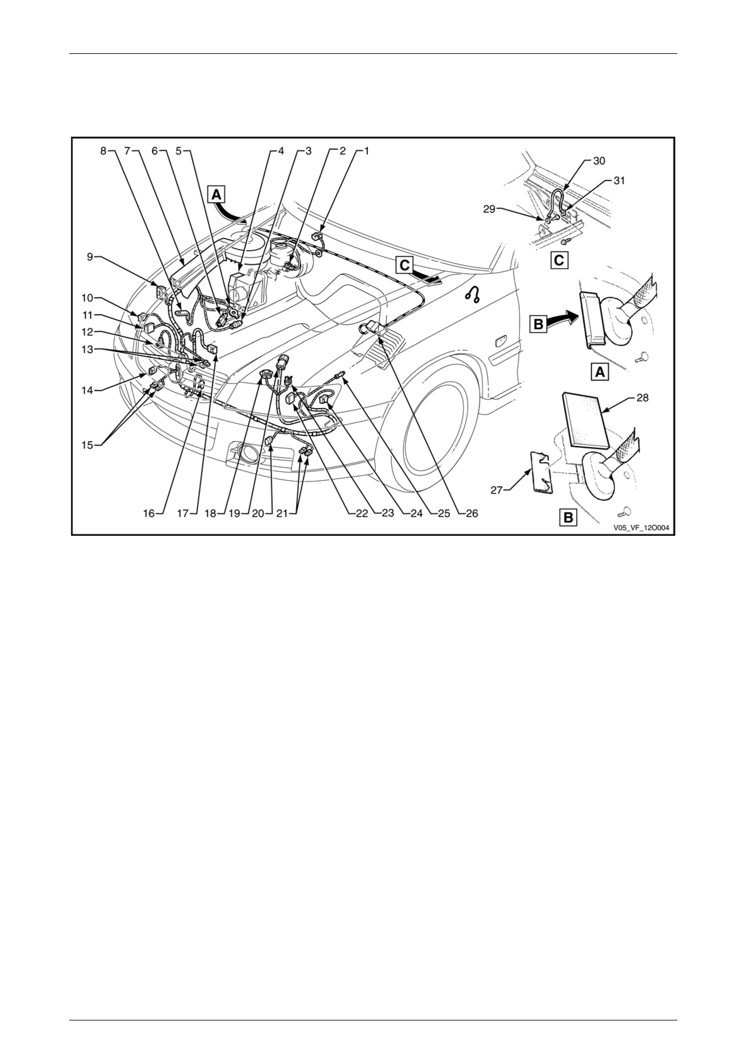
Fuses, Relays and Wiring Harnesses Page 12O–78
3.38 Front Body Harn ess – 3
GEN IV V8 Engine – Engine Compartment
Figure 12O – 77
Legend
1 Windshield Wiper Motor Connector (M17)
2 Brake Fluid Level Indicator Switch Connector (S36)
3 Front Wheel Speed Sensor Connector (B52 – R)
4 Electronic Brake and Traction Control Module Connector
(A37)
5 Body Ground Terminal (X119 – G3 – GP3)
6 Front Body Harness to Battery Wiring Harness Connector
(X106)
7 Front Body Harness Junction Connector (X100)
8 Fusible Link Supply Connector (X86 – A)
9 Ground Connector (X157)
10 Turn Signal Lamp Connector (E76 – R)
11 Headlamp Connector (E119 – R)
12 Windshield Washer Motor Connector (M19)
13 Hood Theft Deterrent Switch Connectors (S135)
14 Fog Lamp Connector (E69 – R)
15 Horn Connectors (B9)
16 Ambient Air Temperature Sensor Connector (B23)
17 Engine Cooling Fan Connector (M7 – X1)
18 Mass Airflow and Intake Air Temperature Sensor Connector
(B69)
19 Front Body Harness to Powertrain Harness Connector
(X101)
20 Fog Lamp Connector (E69 – L)
21 Horn Connectors (B9)
22 Headlamp Connector (E119 – L)
23 A/C Pressure Sensor Connector (B18)
24 Turn Signal Lamp Connector (E76 – L)
25 Front Wheel Speed Sensor Connector (B52 – L)
26 Engine Control Module Connector (A43 – X2)
27 Sealing Patch Grommet
28 Grommet Insert
29 Instrument Panel to Body Ground Strap Terminal
(X118 – GP9)
30 Body to Instrument Panel Ground Strap
31 Body to Instrument Panel Ground Strap Terminal
(X119 – GP10)
Page 12O–78
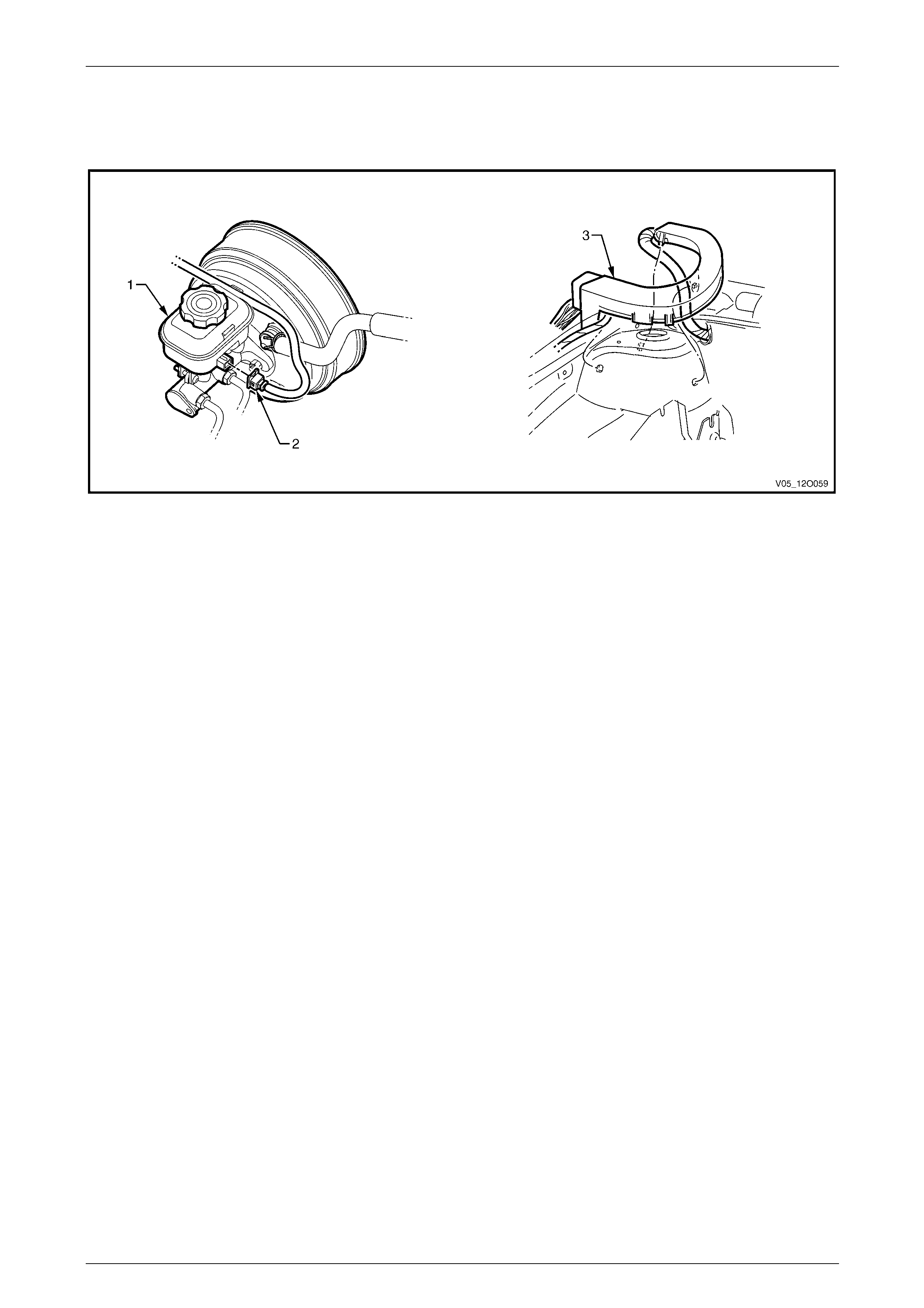
Fuses, Relays and Wiring Harnesses Page 12O–79
3.39 Front Body Harn ess – 4
Protector Assembly, Brake Master Cylinder and Booster
Figure 12O – 78
Legend
1 Brake Master Cylinder and Brake Booster
2 Brake Fluid Level Indicator Switch Connector (S36) 3 Front Body Harness Former
Page 12O–79
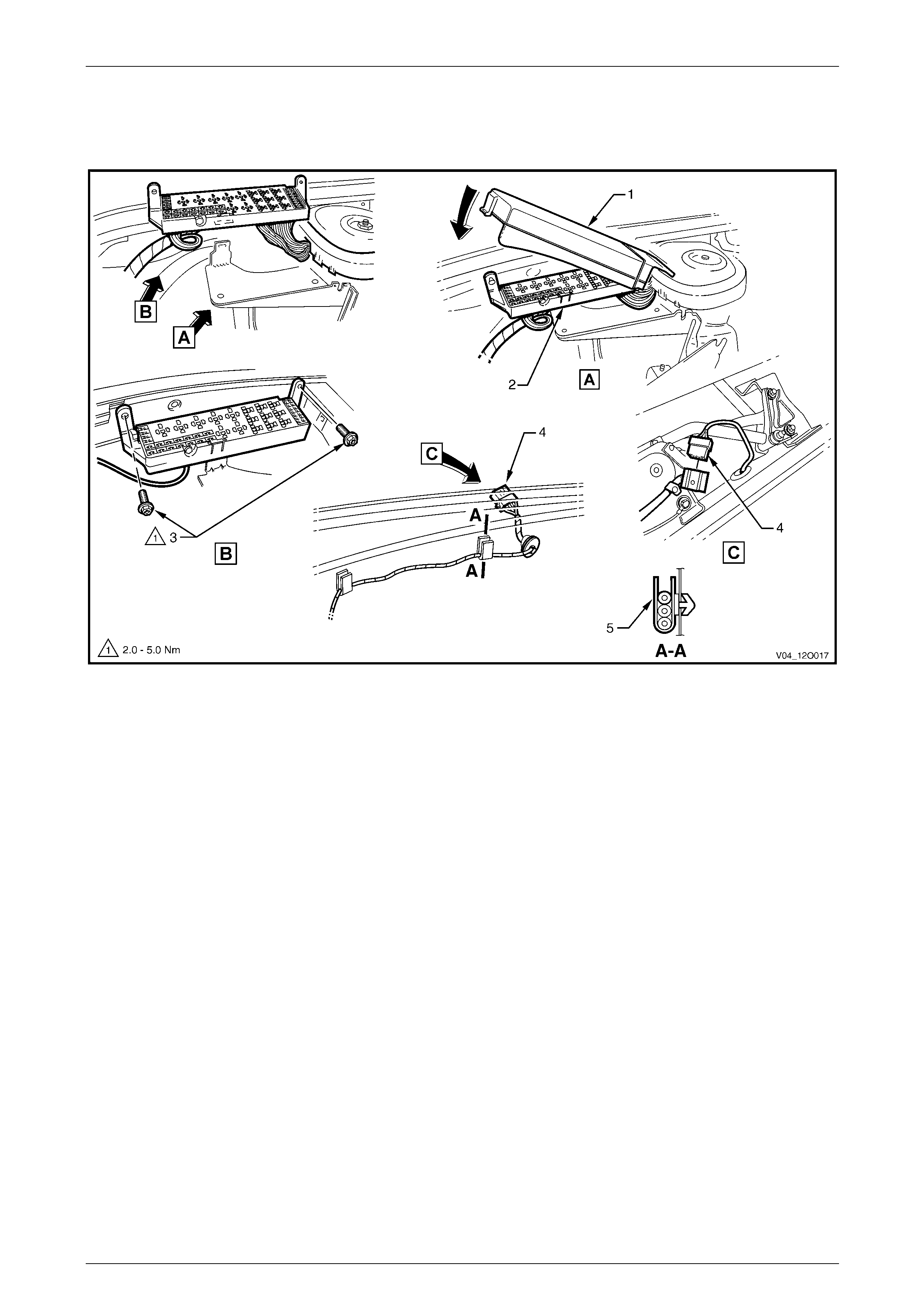
Fuses, Relays and Wiring Harnesses Page 12O–80
3.40 Front Body Harn ess – 5
Under Hood Fuse and Relay Panel and Wiper Motor
Figure 12O – 79
Legend
1 Front Body Harness Junction Connector Cover
2 Front Body Harness Junction Connector (X100)
3 Attaching Screw
4 Windshield Wiper Motor Connector (M17)
5 Firewall Clip (2 places)
Page 12O–80
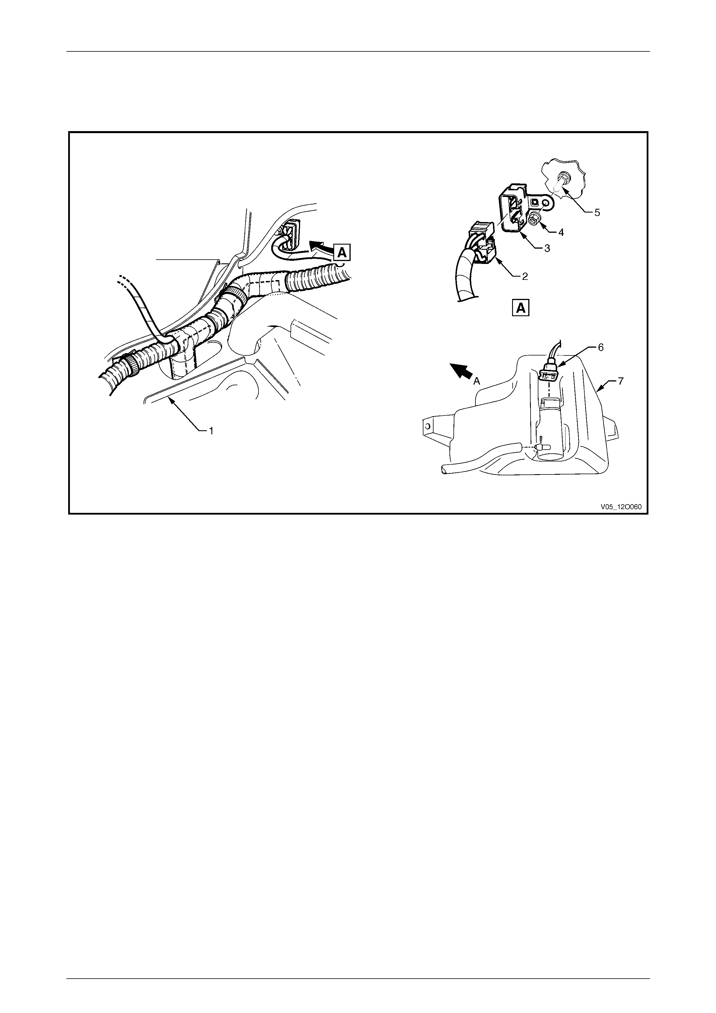
Fuses, Relays and Wiring Harnesses Page 12O–81
3.41 Front Body Harn ess – 6
Body Ground and Washer Pump
Figure 12O – 80
Legend
1 Battery Tray
2 Body Ground Connector (X157)
3 Body Ground Connector (X157 – GP2)
4 Attaching Nut, Body Ground
5 Attaching Stud, Body Ground
6 Windshield Washer Motor Connector (M19)
7 Windshield Washer Reservoir
A Front of vehicle.
Page 12O–81
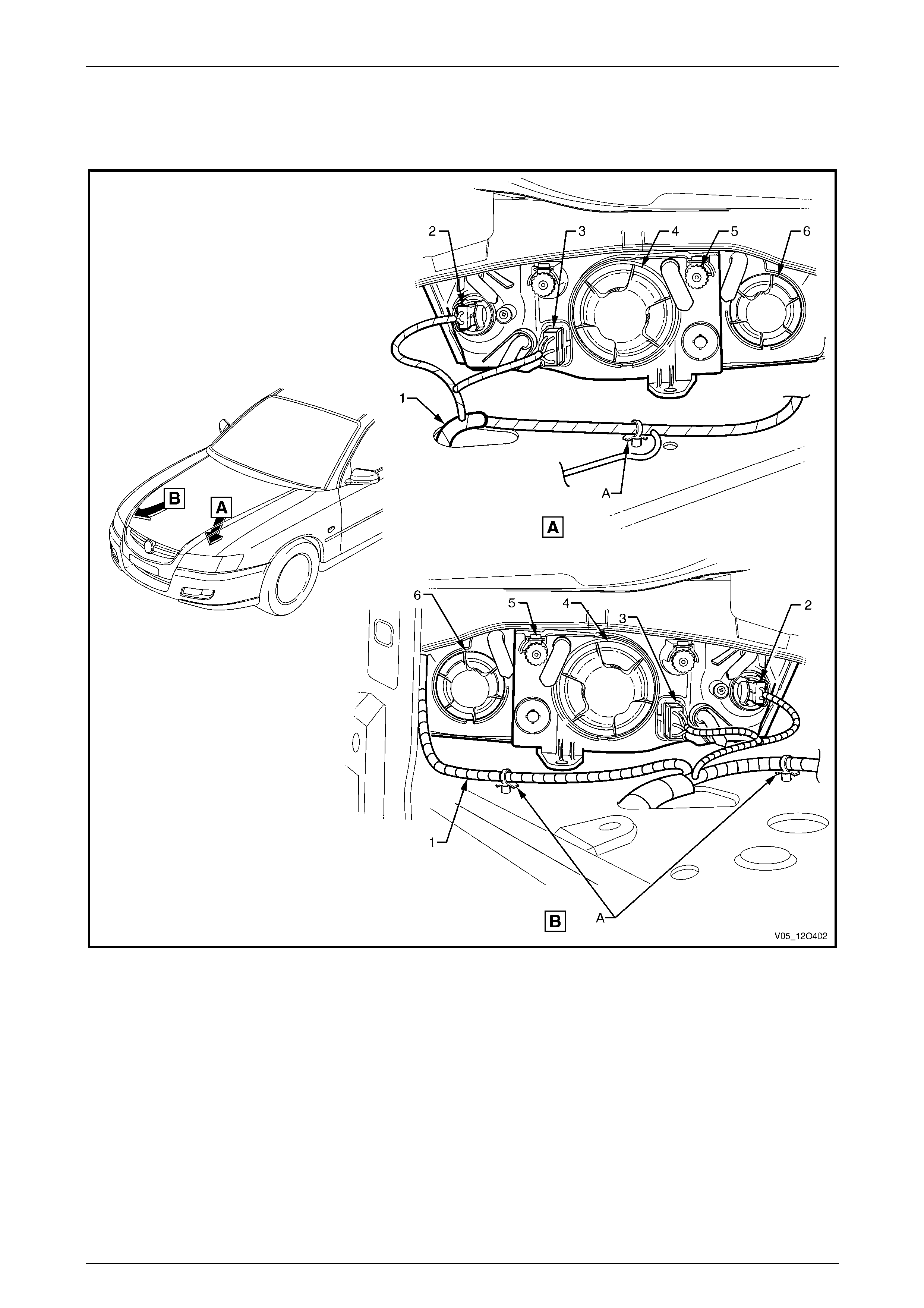
Fuses, Relays and Wiring Harnesses Page 12O–82
3.42 Front Body Harn ess – 7
Headlamp, Park Lamp and Turn Indicator – Level 1
Figure 12O – 81
Legend
1 Front Body Harness
2 Turn Signal Lamp Connector (E76)
3 Headlamp Connector (E119)
4 Headlamp Low Beam Dust Cover
5 Headlamp Adjuster
6 Headlamp High Beam Dust Cover
A Harness leads attached to wheelhouse as shown.
Page 12O–82
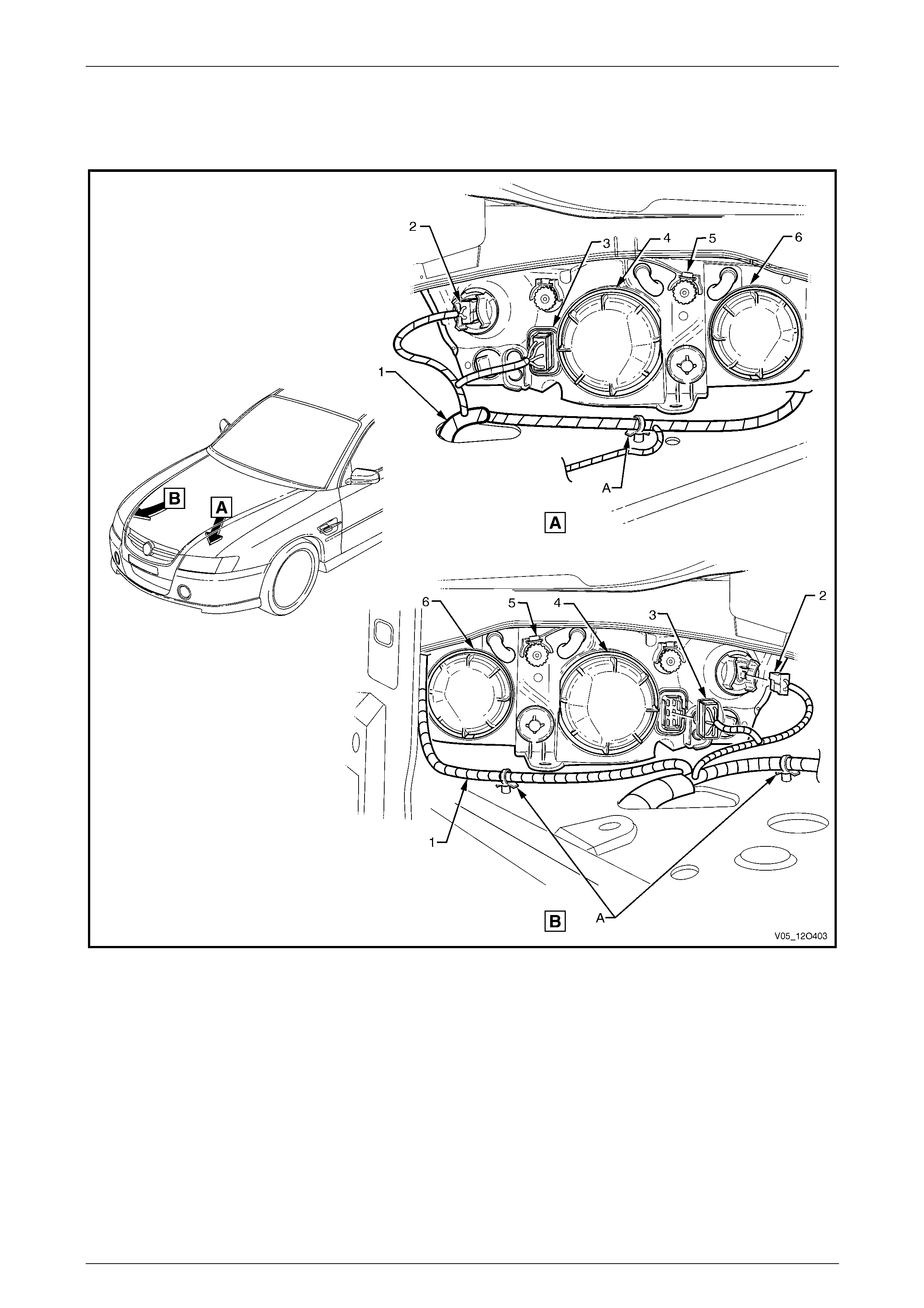
Fuses, Relays and Wiring Harnesses Page 12O–83
3.43 Front Body Harn ess – 8
Headlamp, Park Lamp and Turn Indicator – Level 2
Figure 12O – 82
Legend
1 Front Body Harness
2 Turn Signal Lamp Connector (E76)
3 Headlamp Connector (E119)
4 Headlamp Low Beam Dust Cover
5 Headlamp Adjuster
6 Headlamp High Beam Dust Cover
A Harness leads attached to wheelhouse as shown.
Page 12O–83
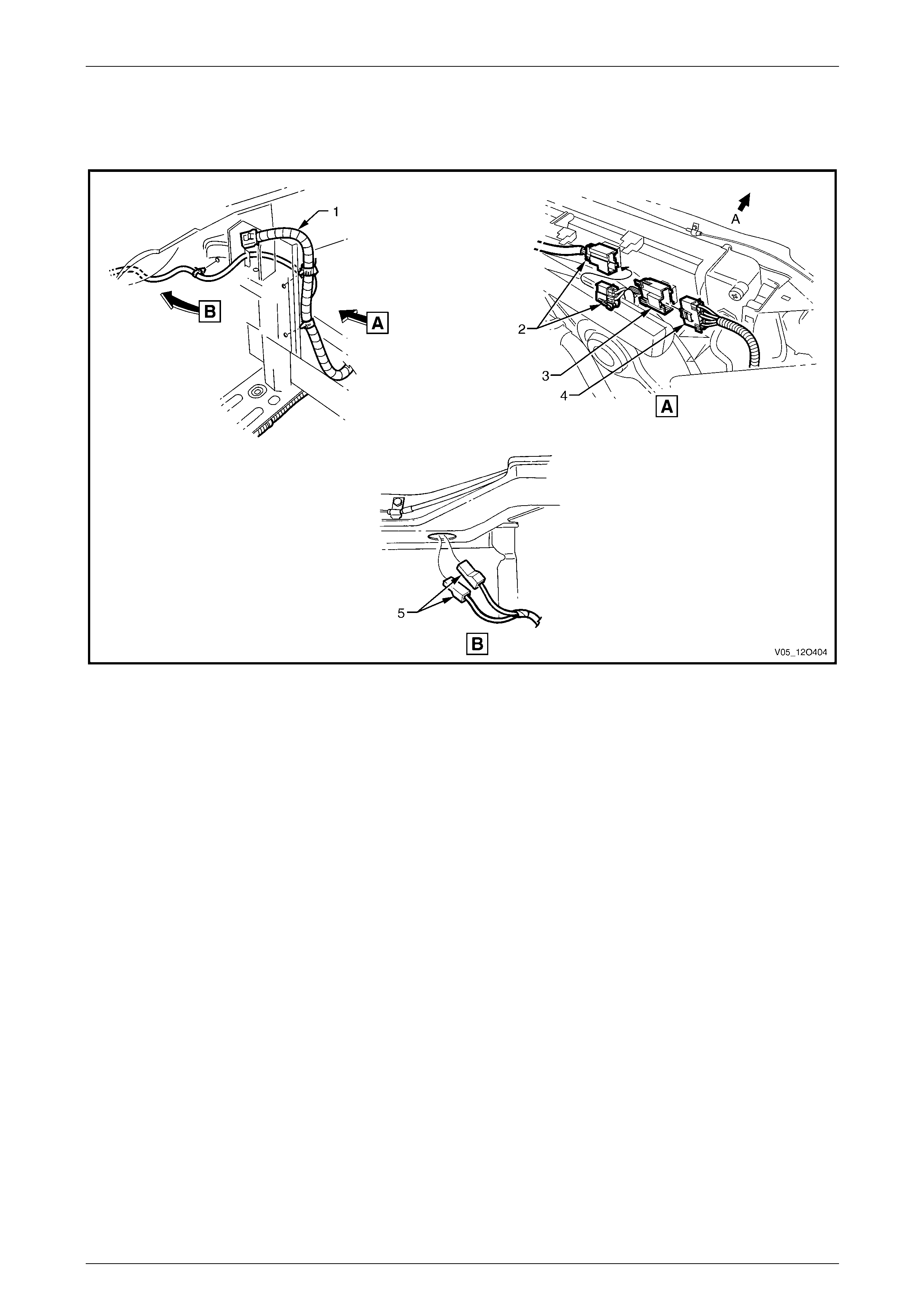
Fuses, Relays and Wiring Harnesses Page 12O–84
3.44 Front Body Harn ess – 9
V6 Engine – Standard Fans and Theft Deterrent Connectors
Figure 12O – 83
Legend
1 Front Body Harness
2 Engine Cooling Fan Connectors (M7 – X2 – V6)
3 Engine Cooling Fan Assembly to Front Body Harness
Connector (M7 – X1)
4 Front Body Harness to Engine Cooling Fan Assembly
Connector (M7 – X1)
5 Hood Theft Deterrent Switch Connectors (S135)
A Front of vehicle.
Page 12O–84
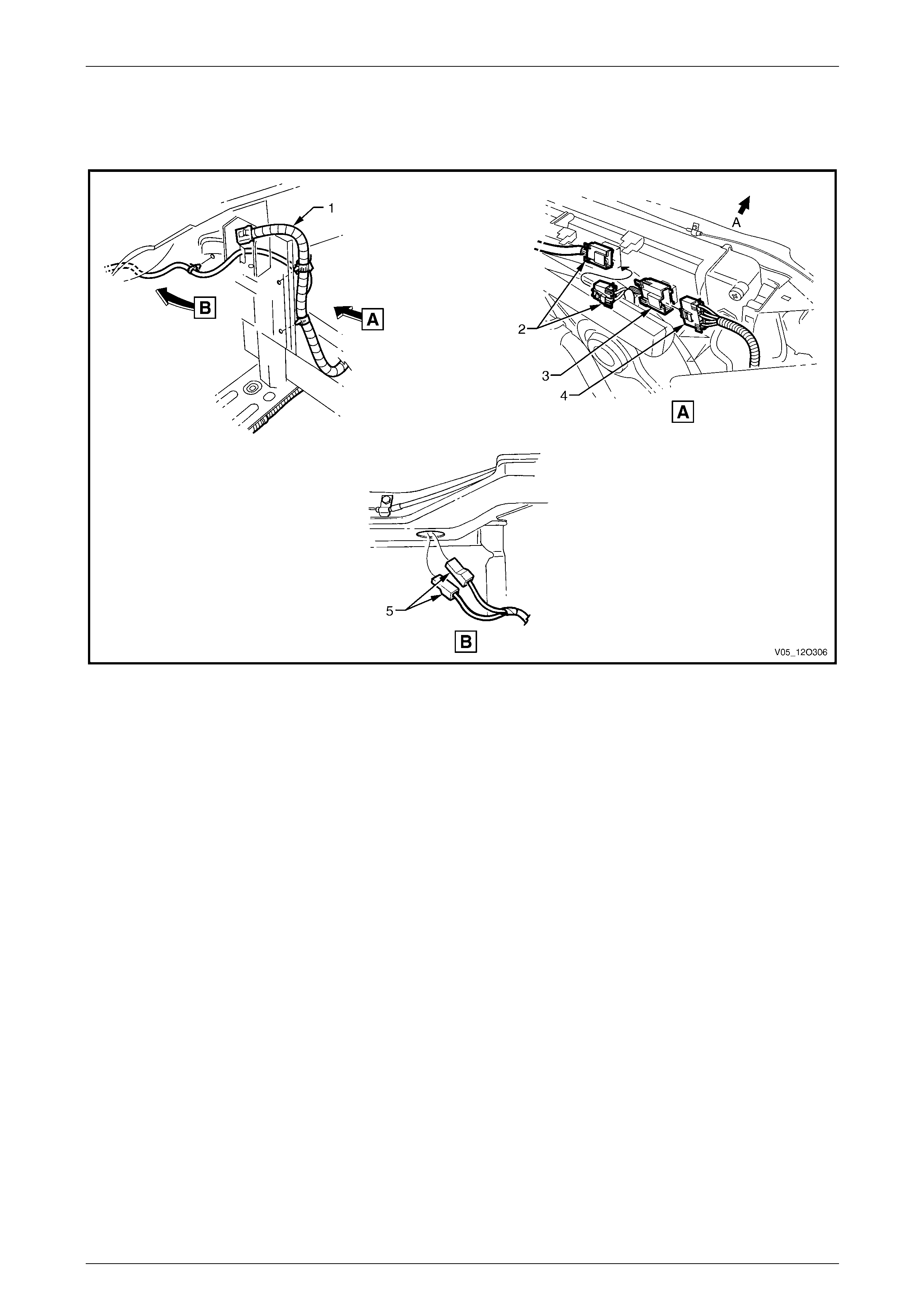
Fuses, Relays and Wiring Harnesses Page 12O–85
3.45 Front Body Harn ess – 10
V6 Engine – 400W Fans and Theft Deterrent Connectors
Figure 12O – 84
Legend
1 Front Body Harness
2 Engine Cooling Fan Connectors (M7 – X2 – V6HP)
3 Engine Cooling Fan Assembly to Front Body Harness
Connector (M7 – X1)
4 Front Body Harness to Engine Cooling Fan Assembly
Connector (M7 – X1)
5 Hood Theft Deterrent Switch Connectors (S135)
A Front of vehicle.
Page 12O–85

Fuses, Relays and Wiring Harnesses Page 12O–86
3.46 Front Body Harn ess – 11
V8 Engine – 400W Fans and Theft Deterrent Connectors
Figure 12O – 85
Legend
1 Front Body Harness
2 Engine Cooling Fan Connectors (M7 – X2 – V8)
3 Engine Cooling Fan Assembly to Front Body Harness
Connector (M7 – X1)
4 Front Body Harness to Engine Cooling Fan Assembly
Connector (M7 – X1)
5 Ambient Air Temperature Sensor Connector (B23)
6 Hood Theft Deterrent Switch Connectors (S135)
A Front of vehicle.
B Harness attached to front wheelhouse panel bracket as
shown.
Page 12O–86
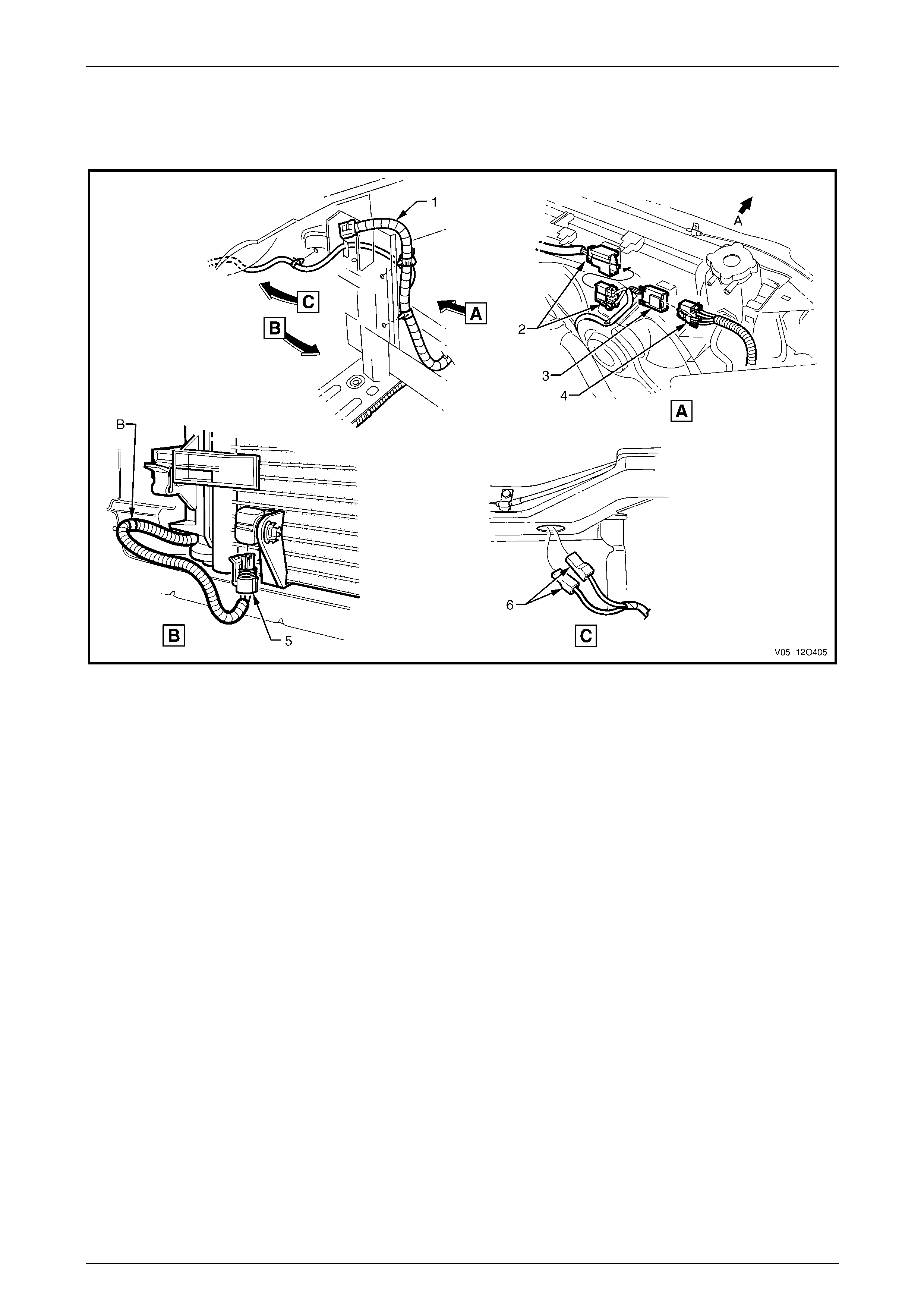
Fuses, Relays and Wiring Harnesses Page 12O–87
3.47 Front Body Harn ess – 12
V8 Engine – 430W Fans and Theft Deterrent Connectors
Figure 12O – 86
Legend
1 Front Body Harness
2 Engine Cooling Fan Connectors (M7 – X2 – V8)
3 Engine Cooling Fan Assembly to Front Body Harness
Connector (M7 – X1)
4 Front Body Harness to Engine Cooling Fan Assembly
Connector (M7 – X1)
5 Ambient Air Temperature Sensor Connector (B23)
6 Hood Theft Deterrent Switch Connectors (S135)
A Front of vehicle.
B Harness attached to front wheelhouse panel bracket as
shown.
Page 12O–87
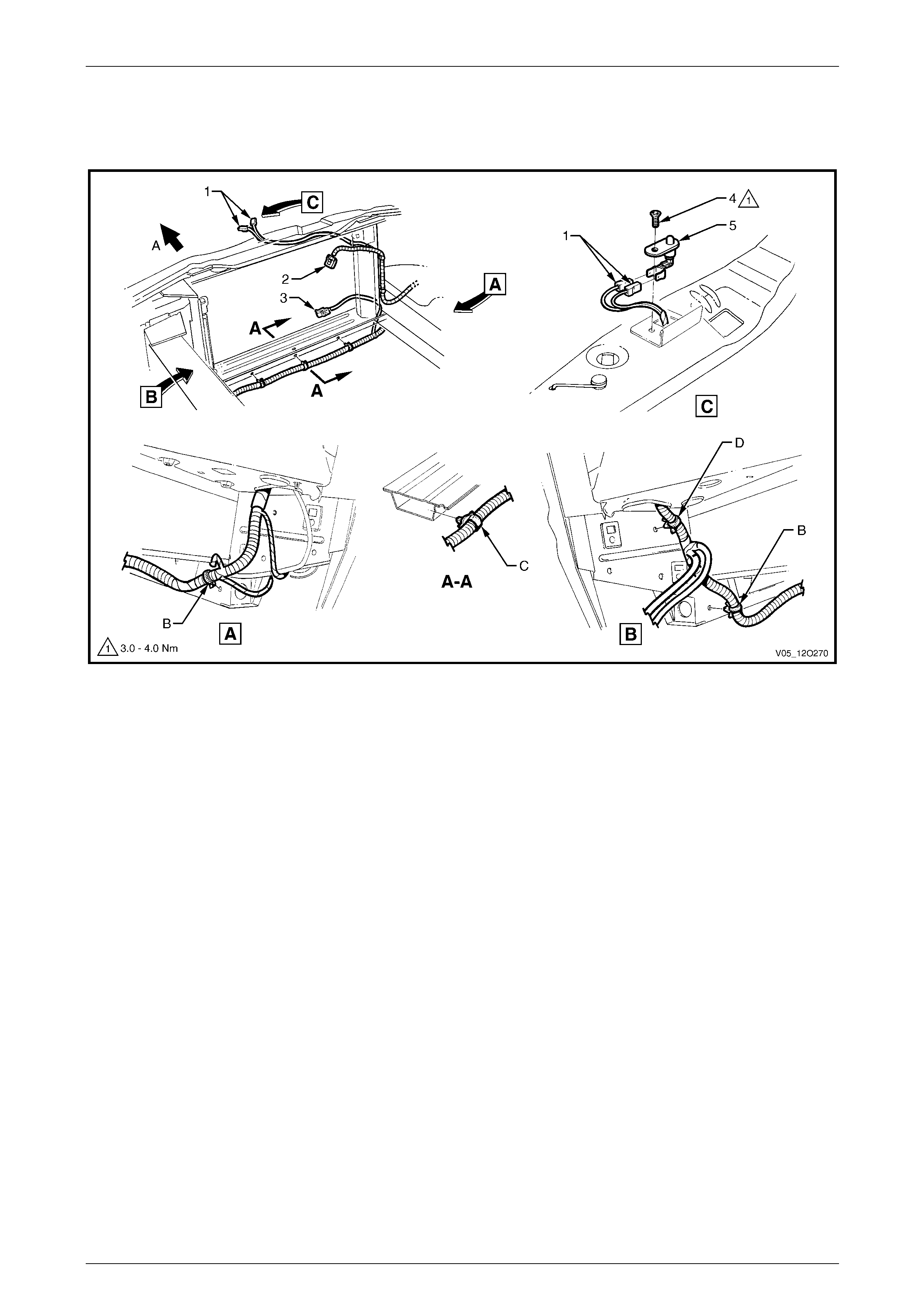
Fuses, Relays and Wiring Harnesses Page 12O–88
3.48 Front Body Harn ess – 13
Ambient Sensor, Fan and Theft Deterrent Connectors
Figure 12O – 87
Legend
1 Hood Anti-theft Deterrent Switch Connectors (S135)
2 Front Body Harness to Engine Cooling Fan Assembly
Connector (M7 – X1)
3 Ambient Air Temperature Sensor Connector (B23)
4 Attaching Screw, Hood Theft Deterrent Switch
5 Hood Anti-theft Switch
A Front of vehicle.
B Harness attached to radiator lower support assembly as
shown (5 places).
C Blue strap to be aligned with centre line of vehicle as shown.
D Harness attached to side rail assembly as shown.
Page 12O–88
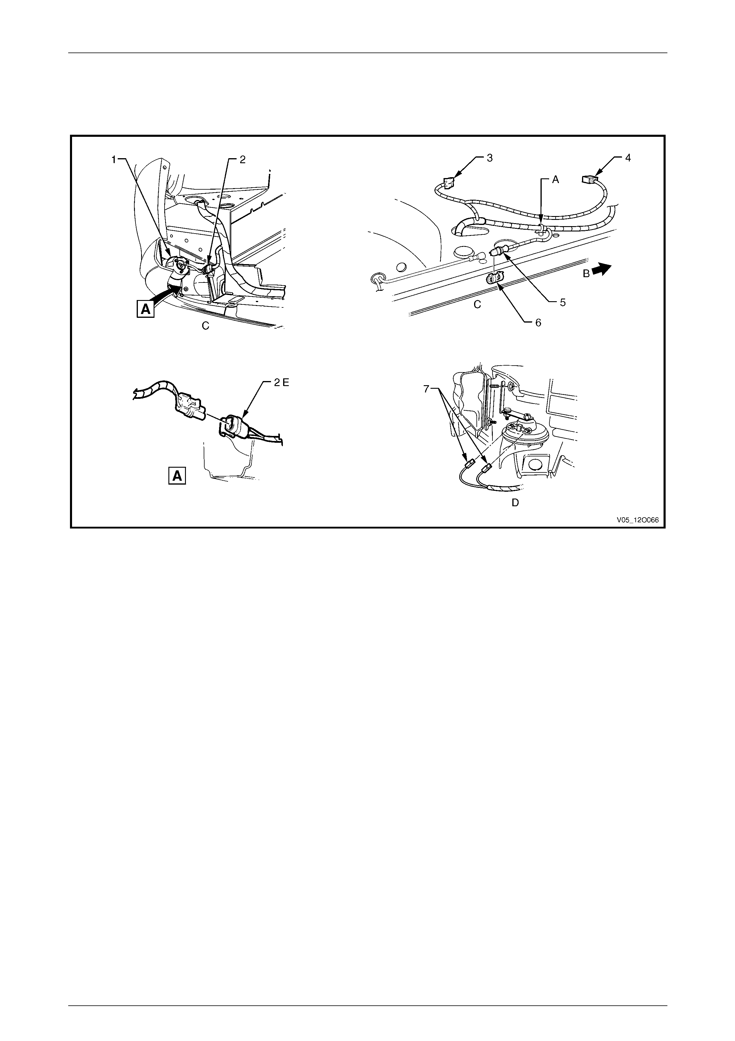
Fuses, Relays and Wiring Harnesses Page 12O–89
3.49 Front Body Harn ess – 14
Front Lamps, Fog Lamps and Horn Connectors
Figure 12O – 88
Legend
1 Front Fog Lamp
2 Front Fog Lamp Connector (E69)
3 Turn Signal Lamp Connector (E76)
4 Headlamp Connector (E119)
5 Front Wheel Speed Sensor Connector (B52)
6 Clip
7 Horn Connectors (B9)
A Harness attached to wheelhouse panel as shown.
B Front of vehicle.
C Left-hand side shown.
D Right-hand side shown.
E Connector clipped to body as shown.
Page 12O–89
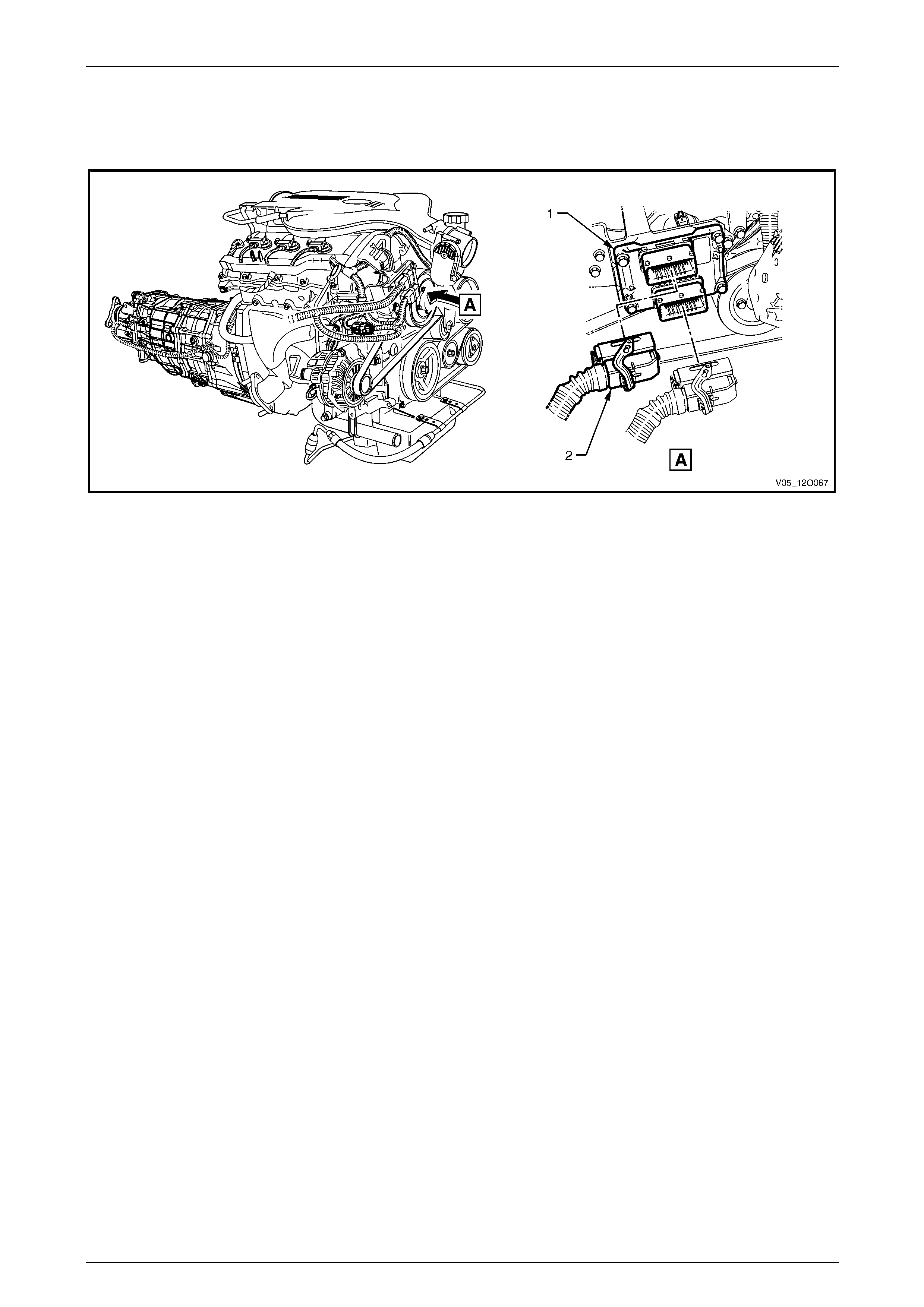
Fuses, Relays and Wiring Harnesses Page 12O–90
3.50 Front Body Harn ess – 15
V6 Engine – Engine Control Module
Figure 12O – 89
Legend
1 Engine Control Module 2 Engine Control Module Connector (A43 – X2)
Page 12O–90
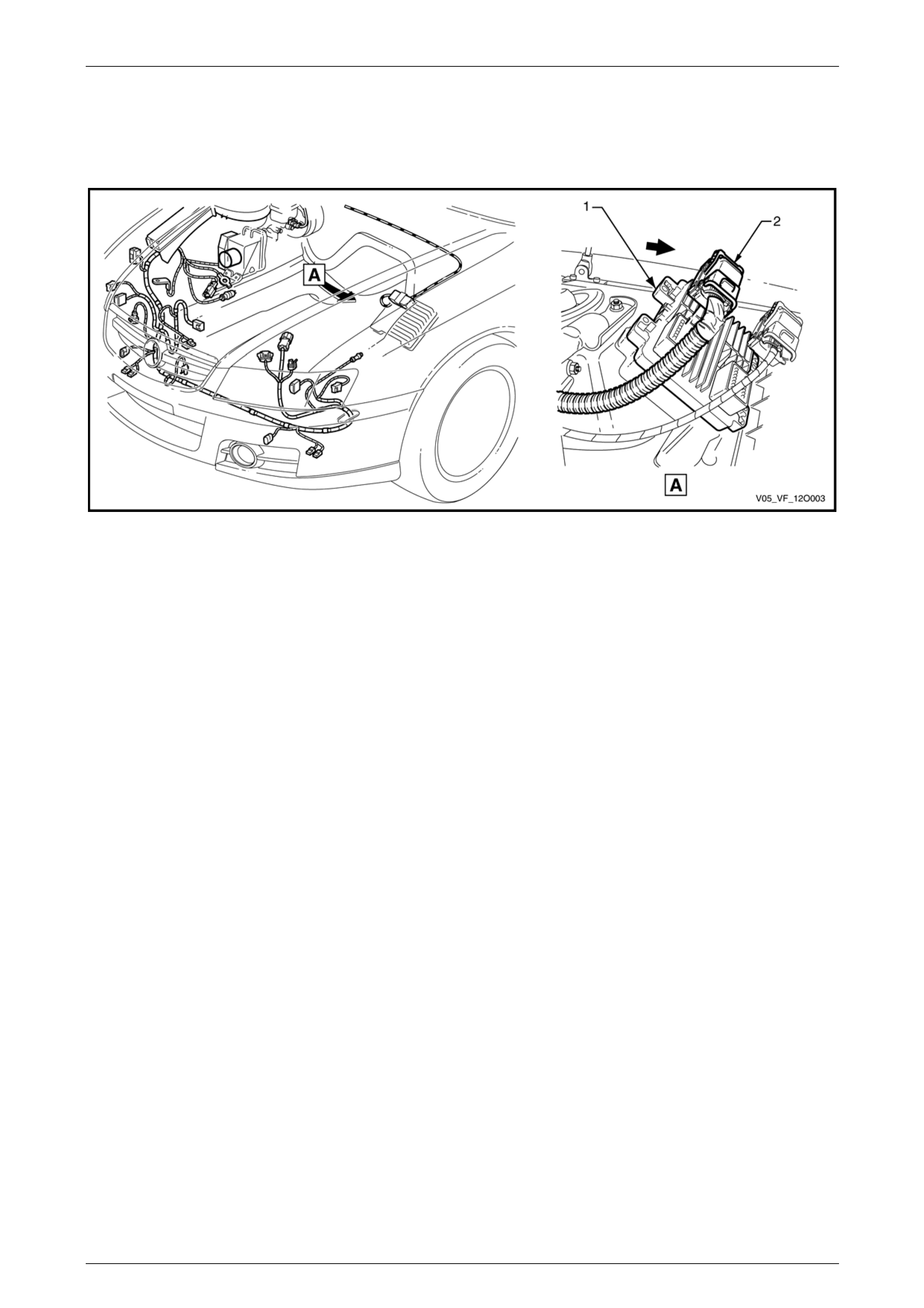
Fuses, Relays and Wiring Harnesses Page 12O–91
3.51 Front Body Harn ess – 16
GEN IV V8 Engine – Engine Control Module
Figure 12O – 90
Legend
1 Engine Control Module 2 Engine Control Module Connector (A43 – X1)
Page 12O–91
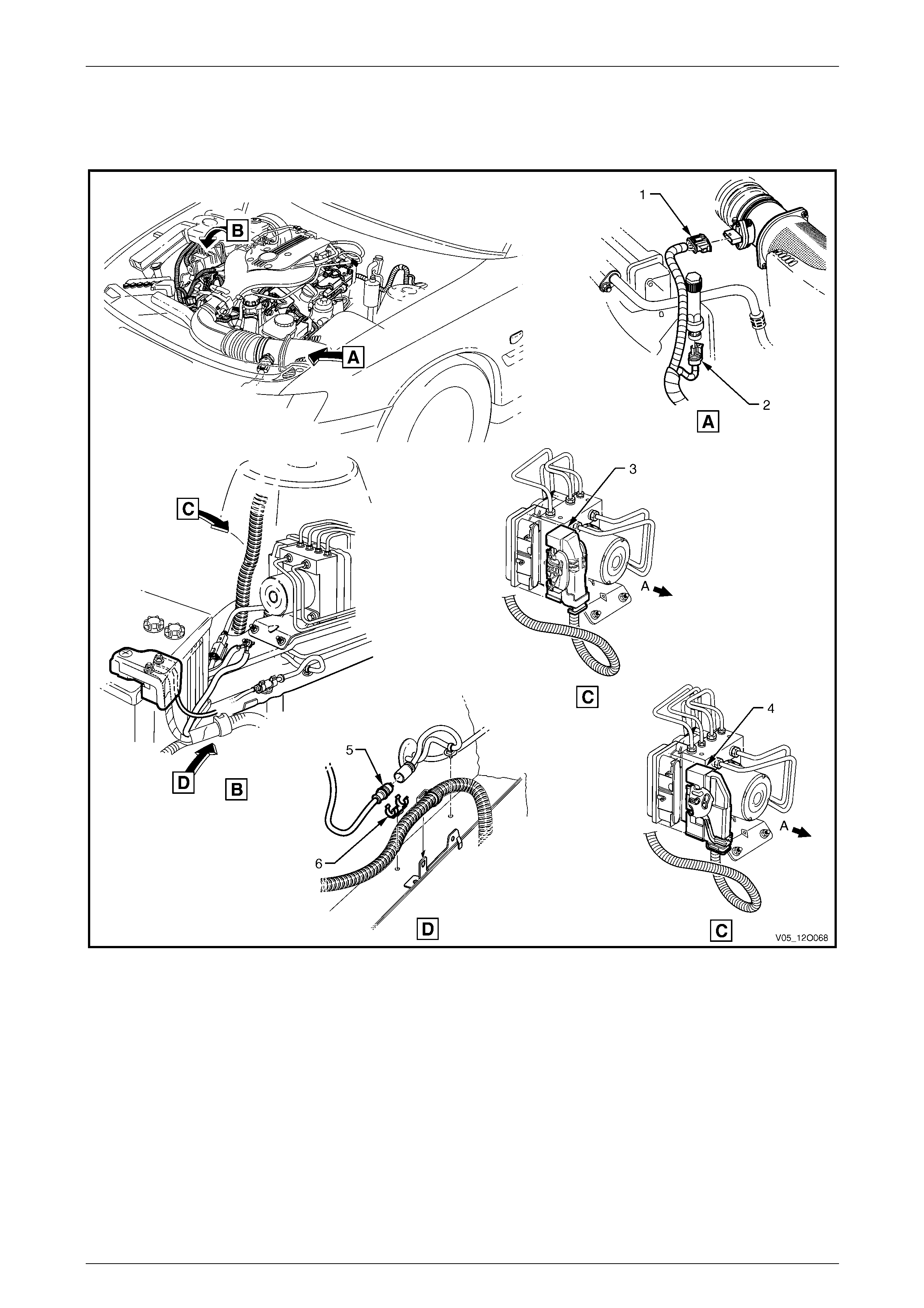
Fuses, Relays and Wiring Harnesses Page 12O–92
3.52 Front Body Harn ess – 17
V6 Engine – ABS, Air Intake and Front Wheel Speed Sensor
Figure 12O – 91
Legend
1 Mass Airflow and Air Intake Temperature Sensor
Connector (B69 – V6)
2 A/C Pressure Sensor Connector (B18 – V6)
3 Electronic Brake and Traction Control Module Connector
(A38)
4 Vehicle Control Module Connector (A116)
5 Front Wheel Speed Sensor Connector (B52)
6 Clip
A Front of vehicle.
Page 12O–92
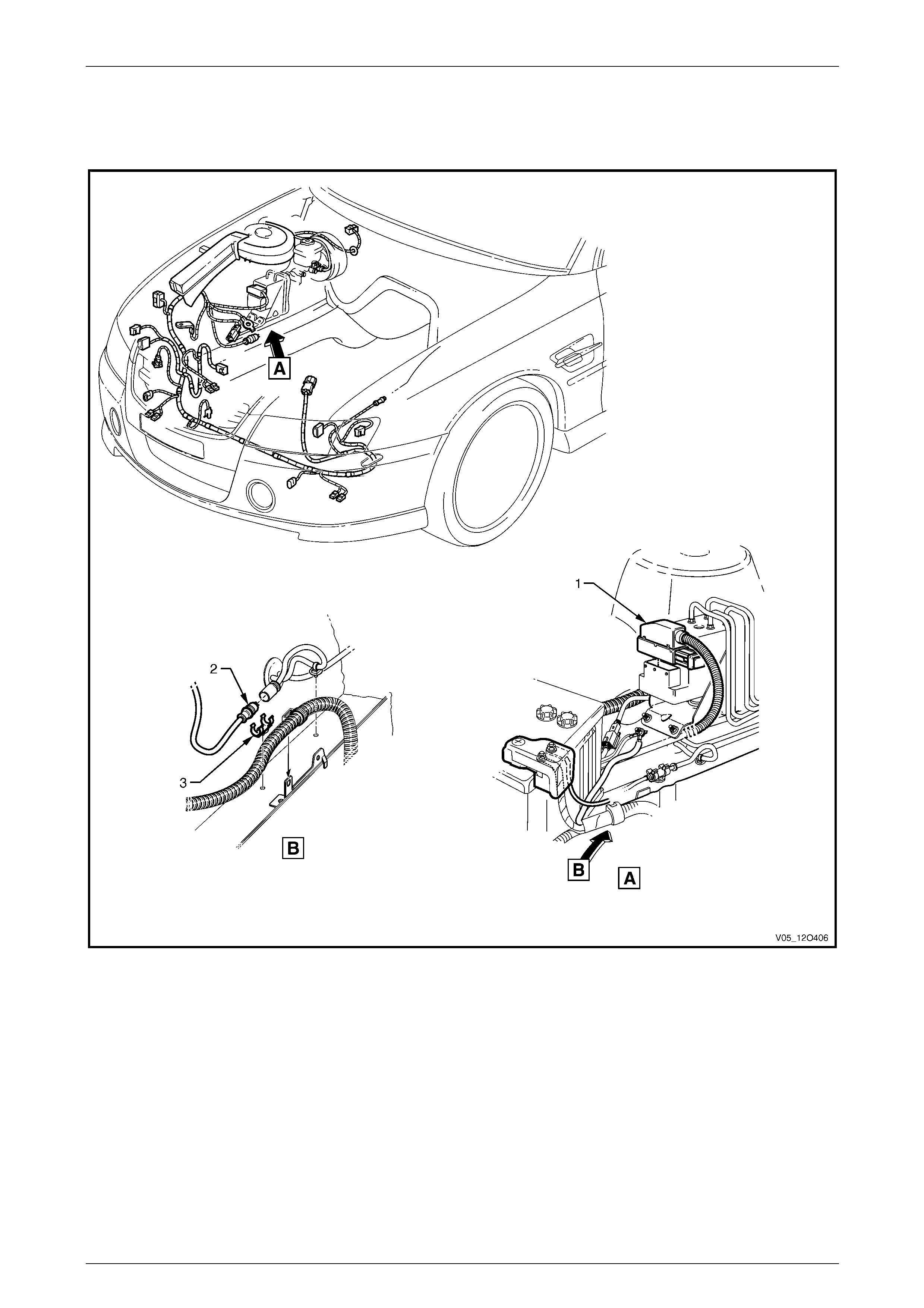
Fuses, Relays and Wiring Harnesses Page 12O–93
3.53 Front Body Harn ess – 18
GEN III V8 Engine – ABS, Air Intake and Front Wheel Speed Sensor
Figure 12O – 92
Legend
1 Electronic Brake and Traction Control Module
Connector (A37) 2 Front Wheel Speed Sensor Connector (B52)
3 Clip
Page 12O–93
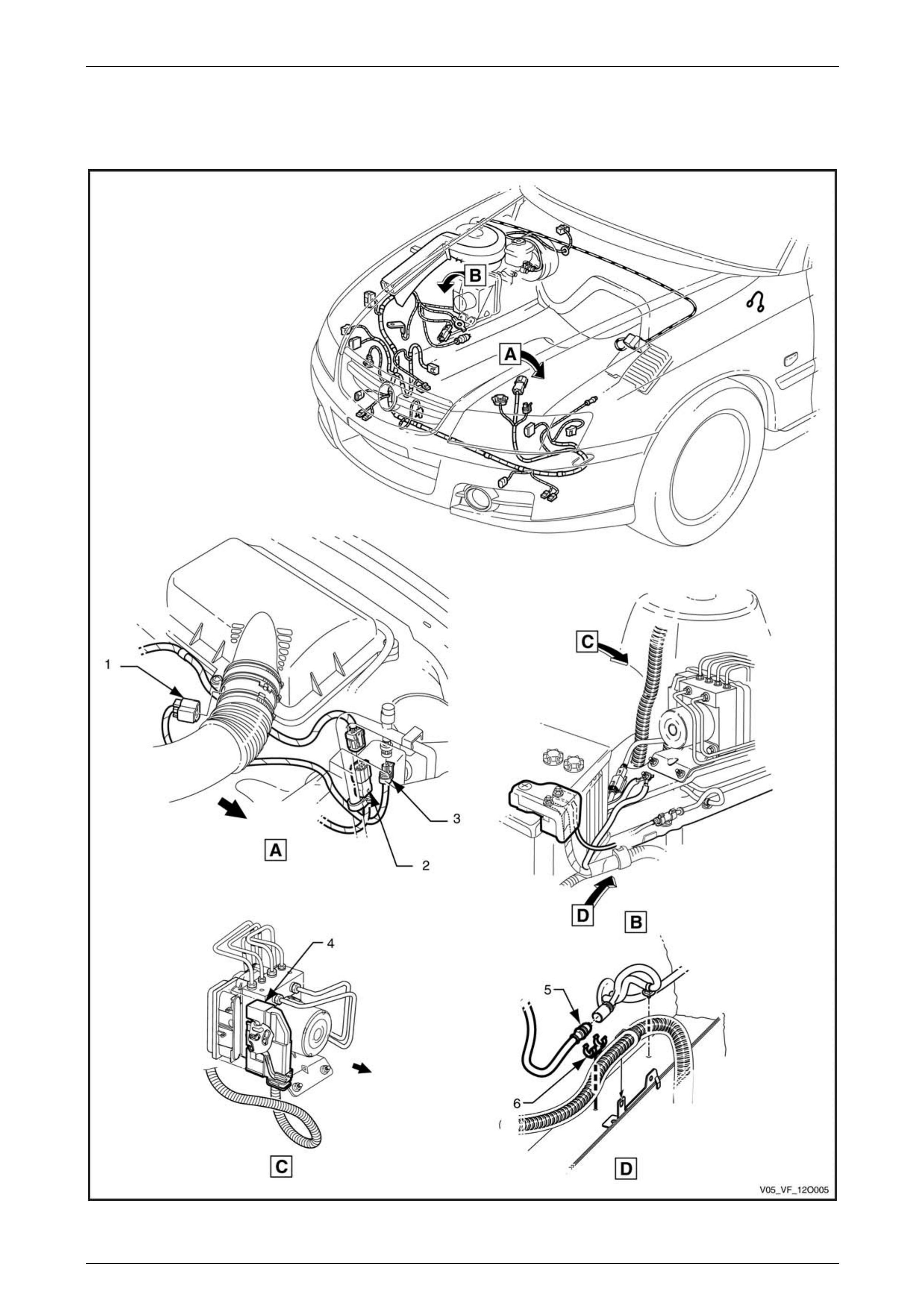
Fuses, Relays and Wiring Harnesses Page 12O–94
3.54 Front Body Harn ess – 19
GEN IV V8 Engine – ABS, Air Intake and Front Wheel Speed Sensor
Figure 12O – 93
Page 12O–94

Fuses, Relays and Wiring Harnesses Page 12O–95
Legend
1 Mass Airflow and Air Intake Temperature Sensor
Connector (B69 – V6)
2 Front Body Harness to Powertrain Harness Connector
(X101)
3 A/C Pressure Sensor Connector (B18 – V6)
4 Vehicle Control Module Connector (A116)
5 Front Wheel Speed Sensor Connector (B52)
6 Clip
Page 12O–95
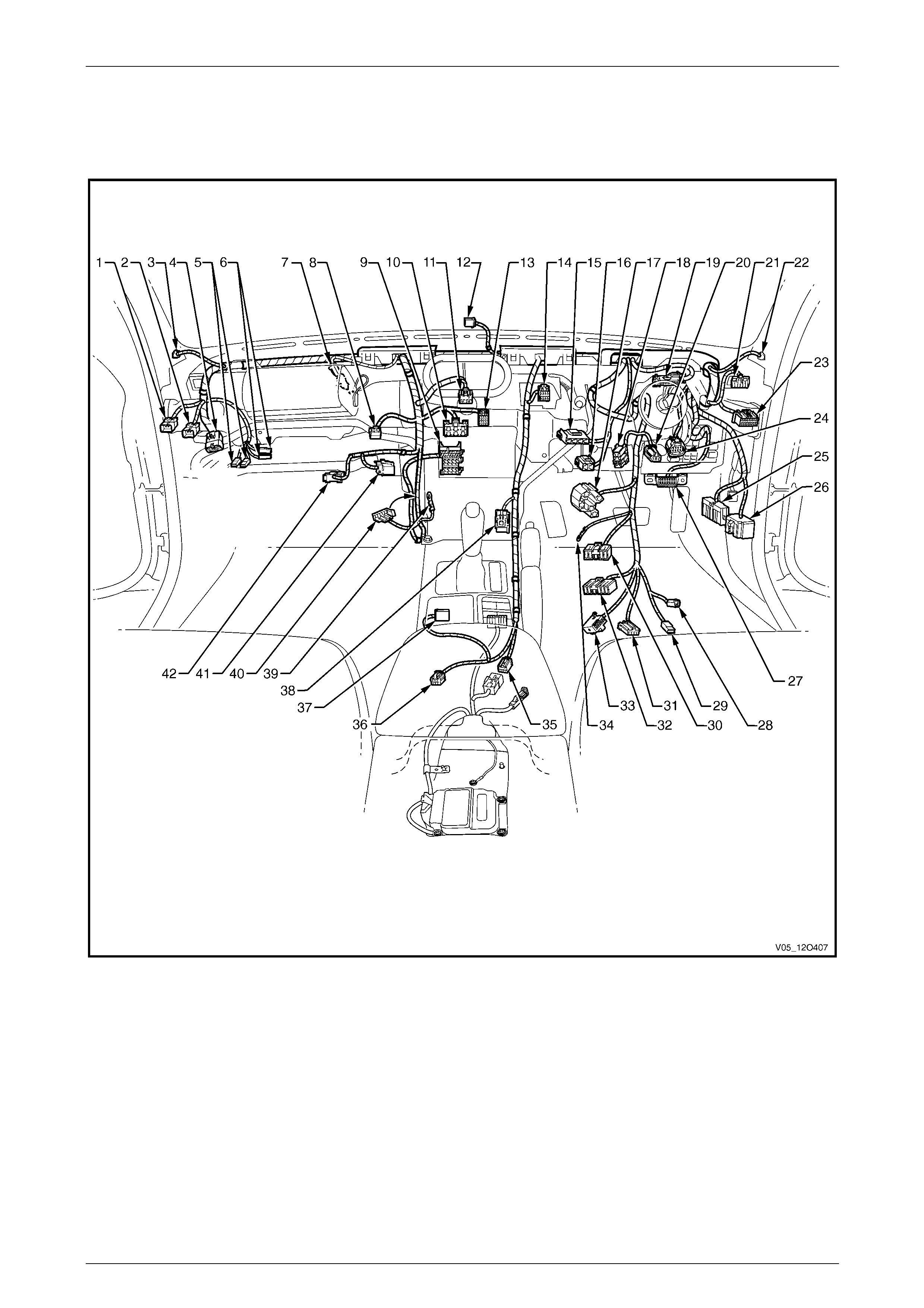
Fuses, Relays and Wiring Harnesses Page 12O–96
3.55 Front Body Harn ess – 20
V6 Engine – Cockpit Module
Figure 12O – 94
Page 12O–96

Fuses, Relays and Wiring Harnesses Page 12O–97
Legend
1 LPG to Front Body Wiring Patch Harness Connector
2 Front Body Harness to Global Positioning System Harness
Connector (X207)
3 Radio Front Speaker Dash Upper Connector (B112 – L)
4 Front Body Harness to Transmission Harness Connector
(X203)
5 Instrument Panel Compartment Lamp Connectors (E82)
6 Instrument Panel Compartment Lamp Switch Connectors
(S142)
7 Front Body Harness to Passenger Airbag Harness
Connector (X205)
8 Rear Compartment Lid Release Switch Connector (S195)
9 Radio, Clock & CD Player Connector (A133 – X1)
10 Heater & A/C Evaporator Module Connector (A60 – X1)
11 Hazard Warning Switch Connector (S120)
12 Ambient Light Sensor Connector (B55)
13 Heater & A/C Evaporator Module Connector (A60 – X2)
14 Trip Odometer Reset Switch Connector (S237)
15 Stop Lamp, Traction & Cruise Control Release Switch
Connector (S220 – X3)
16 Stop Lamp, Traction & Cruise Control Release Switch
Connector (S220 – X1)
17 Ignition & Start Switch Connector (S149 – X1)
18 Clutch Pedal Position Switch Connector (S42 – X2)
19 Instruments Connector (P3)
20 Front Body Harness to Clutch Extension Harness
Connector (X210)
21 Headlamp Automatic Control Switch Connector (S125)
22 Radio Front Speaker Dash Upper Connector (B112 – R)
23 Powertrain Interface Module Connector (A5 – V6)
24 Accelerator Pedal Position Sensor Connector (B22)
25 Front Body Harness to Body Wiring Harness Connector
(X200)
26 Front Body Harness to Body Wiring Harness Connector
(X201)
27 Wiring (Diagnostics) Connector (X40)
28 Ignition Lock Cylinder Bulb Connector (E30)
29 Ignition & Start Switch Connector (S149 – X2)
30 Windshield Wiper and Washer Switch Connector (S247)
31 Cruise Control Switch Connector (S43)
32 Turn Signal & Headlamp Switch Connector (S231)
33 Steering Wheel Clock Spring Coil Connector (X116)
34 Ignition & Start Switch Connector (S149 – GP15 – X3)
35 Front Body Harness to Body Wiring Harness Connector
(X303)
36 Front Body Harness to Console Wiring Harness Connector
(X309)
37 Front Body Harness to Transmission Selector Harness
Connector (X301)
38 Front Cigar Lighter Connector (X113 – F)
39 Radio Ground Terminal (X118 – GP8)
40 Inline to Radio & Mobile Telephone Connector (X155)
41 Blower Motor Resistor Connector (R6)
42 Front Body Harness to Blower Motor Harness Connector
(X204)
Page 12O–97

Fuses, Relays and Wiring Harnesses Page 12O–98
3.56 Front Body Harn ess – 21
GEN III V8 Engine – Cockpit Module – Manual Air-conditioning
Figure 12O – 95
Page 12O–98

Fuses, Relays and Wiring Harnesses Page 12O–99
Legend
1 Front Body Harness to Global Positioning System Harness
Connector (X207)
2 Radio Front Speaker Dash Upper Connector (B112 – L)
3 Front Body Harness to Powertrain Harness Connector
(X206)
4 Instrument Panel Compartment Lamp Connectors (E82)
5 Instrument Panel Compartment Lamp Switch Connectors
(S142)
6 Front Body Harness to Passenger Airbag Harness
Connector (X205)
7 Rear Compartment Lid Release Switch Connector (S195)
8 Radio, Clock & CD Player Connector (A133 – X1)
9 Heater & A/C Evaporator Module Connector (A60 – X1)
10 Hazard Warning Switch Connector (S120)
11 Ambient Light Sensor Connector (B55)
12 Heater & A/C Evaporator Module Connector (A60 – X2)
13 Trip Odometer Reset Switch Connector (S237)
14 Stop Lamp, Traction & Cruise Control Release Switch
Connector (S220 – X3)
15 Stop Lamp, Traction & Cruise Control Release Switch
Connector (S220 – X1)
16 Ignition & Start Switch Connector (S149 – X1)
17 Cruise Cancel Switch – Clutch Patch Harness Connector
(X86 – V8)
18 Instruments Connector (P3)
19 Headlamp Automatic Control Switch Connector (S125)
20 Radio Front Speaker Dash Upper Connector (B112 – R)
21 Accelerator Pedal Position Sensor Connector (B22)
22 Front Body Harness to Body Wiring Harness Connector
(X200)
23 Front Body Harness to Body Wiring Harness Connector
(X201)
24 Wiring (Diagnostics) Connector (X40)
25 Ignition Lock Cylinder Bulb Connector (E30)
26 Ignition & Start Switch Connector (S149 – X2)
27 Windshield Wiper and Washer Switch Connector (S247)
28 Cruise Control Switch Connector (S43)
29 Turn Signal & Headlamp Switch Connector (S231)
30 Steering Wheel Clock Spring Coil Connector (X116)
31 Ignition & Start Switch Connector (S149 – GP15 – X3)
32 Front Body Harness to Body Wiring Harness Connector
(X303)
33 Front Body Harness to Console Wiring Harness Connector
(X309)
34 Front Body Harness to Transmission Selector Harness
Connector (X301)
35 Front Cigar Lighter Connector (X113 – F)
36 Radio Ground Terminal (X118 – GP8)
37 Inline to Radio & Mobile Telephone Connector (X155)
38 Blower Motor Resistor Connector (R6)
39 Front Body Harness to Blower Motor Harness Connector
(X204)
40 Powertrain Interface Module Connector (A5 – V8)
41 Throttle Actuator Control Module Connector (A111 – X2)
Page 12O–99
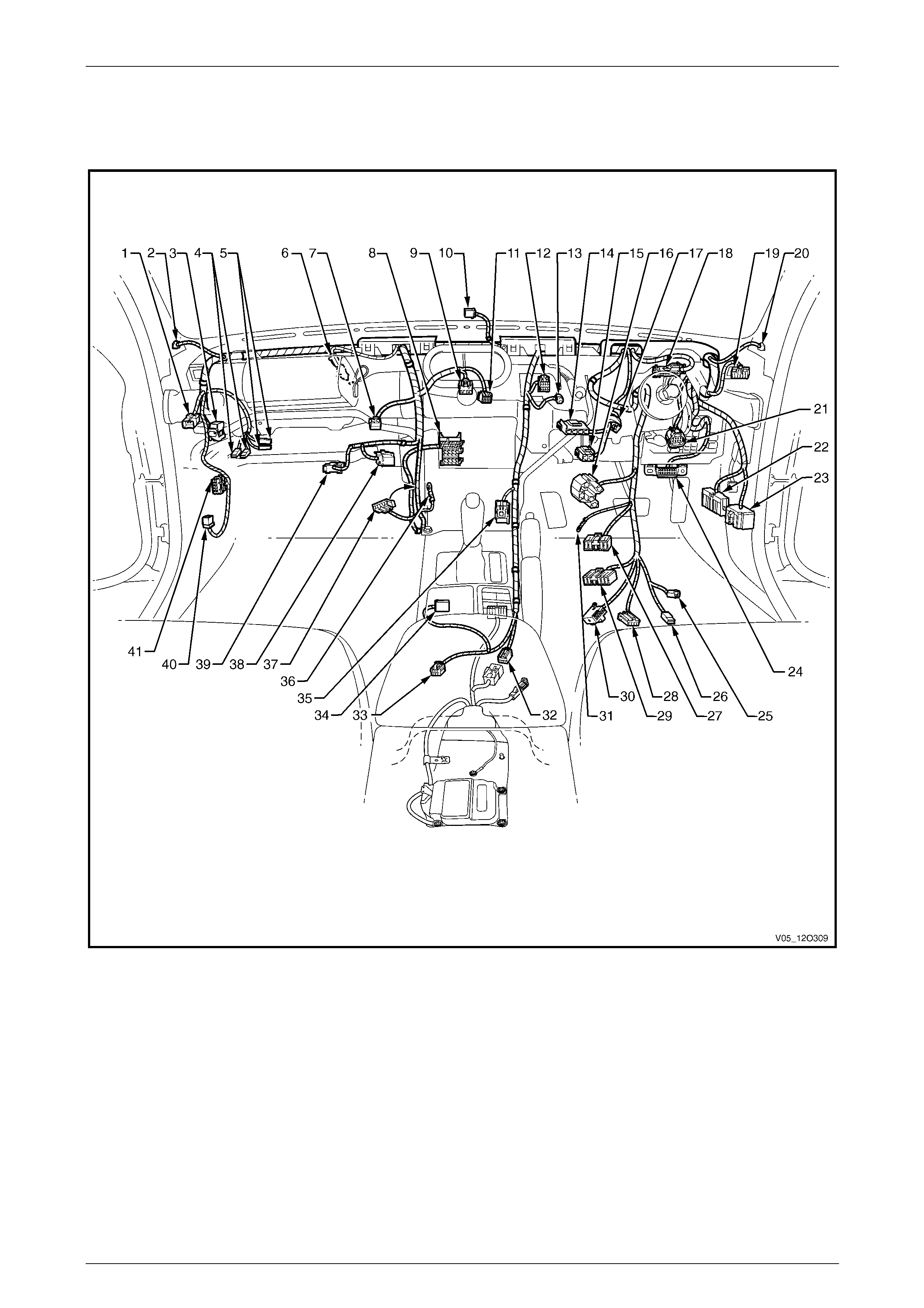
Fuses, Relays and Wiring Harnesses Page 12O–100
3.57 Front Body Harn ess – 22
GEN III V8 Engine – Cockpit Module – Auto Air-conditioning
Figure 12O – 96
Page 12O–100

Fuses, Relays and Wiring Harnesses Page 12O–101
Legend
1 Front Body Harness to Global Positioning System Harness
Connector (X207)
2 Radio Front Speaker Dash Upper Connector (B112 – L)
3 Front Body Harness to Powertrain Harness Connector
(X206)
4 Instrument Panel Compartment Lamp Connectors (E82)
5 Instrument Panel Compartment Lamp Switch Connectors
(S142)
6 Front Body Harness to Passenger Airbag Harness
Connector (X205)
7 Rear Compartment Lid Release Switch Connector (S195)
8 Radio, Clock & CD Player Connector (A133 – X1)
9 Hazard Warning Switch Connector (S120)
10 Ambient Light Sensor Connector (B55)
11 Blower Motor & A/C Compressor Connector (A14 – X1)
12 Trip Odometer Reset Switch Connector (S237)
13 Inside Air Temperature Sensor Connector (B59)
14 Stop Lamp, Traction & Cruise Control Release Switch
Connector (S220 – X3)
15 Stop Lamp, Traction & Cruise Control Release Switch
Connector (S220 – X1)
16 Ignition & Start Switch Connector (S149 – X1)
17 Cruise Cancel Switch – Clutch Patch Harness Connector
(X86 – V8)
18 Instruments Connector (P3)
19 Headlamp Automatic Control Switch Connector (S125)
20 Radio Front Speaker Dash Upper Connector (B112 – R)
21 Accelerator Pedal Position Sensor Connector (B22)
22 Front Body Harness to Body Wiring Harness Connector
(X200)
23 Front Body Harness to Body Wiring Harness Connector
(X201)
24 Wiring (Diagnostics) Connector (X40)
25 Ignition Lock Cylinder Bulb Connector (E30)
26 Ignition & Start Switch Connector (S149 – X2)
27 Windshield Wiper and Washer Switch Connector (S247)
28 Cruise Control Switch Connector (S43)
29 Turn Signal & Headlamp Switch Connector (S231)
30 Steering Wheel Clock Spring Coil Connector (X116)
31 Ignition & Start Switch Connector (S149 – GP15 – X3)
32 Front Body Harness to Body Wiring Harness Connector
(X303)
33 Front Body Harness to Console Wiring Harness Connector
(X309)
34 Front Body Harness to Transmission Selector Harness
Connector (X301)
35 Front Cigar Lighter Connector (X113 – F)
36 Radio Ground Terminal (X118 – GP8)
37 Inline to Radio & Mobile Telephone Connector (X155)
38 Blower & Air Inlet Connector (A13 – RHD)
39 Front Body Harness to Blower Motor Harness Connector
(X204)
40 Powertrain Interface Module Connector (A5 – V8)
41 Throttle Actuator Control Module Connector (A111 – X2)
Page 12O–101
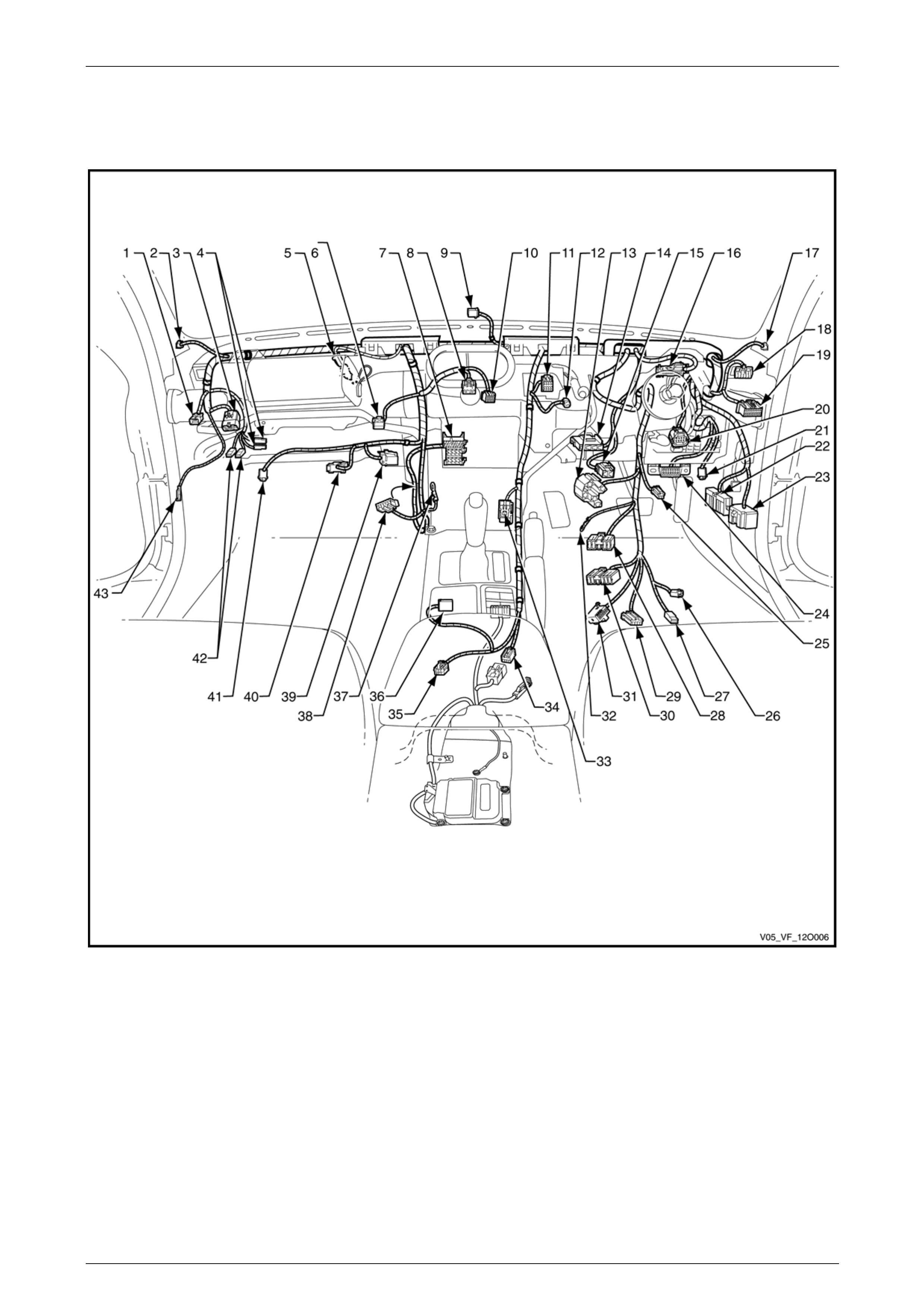
Fuses, Relays and Wiring Harnesses Page 12O–102
3.58 Front Body Harn ess – 23
GEN IV V8 Engine – Cockpit Module
Figure 12O – 97
Page 12O–102

Fuses, Relays and Wiring Harnesses Page 12O–103
Legend
1 Front Body Harness to Global Positioning System Harness
Connector (X207)
2 Radio Front Speaker Dash Upper Connector (B112 – L)
3 Front Body Harness to Powertrain Harness Connector
(X206)
4 Instrument Panel Compartment Lamp Switch Connectors
(S142)
5 Front Body Harness to Passenger Airbag Harness
Connector (X205)
6 Rear Compartment Lid Release Switch Connector (S195)
7 Radio, Clock & CD Player Connector (A133 – X1)
8 Hazard Warning Switch Connector (S120)
9 Ambient Light Sensor Connector (B55)
10 Blower Motor & A/C Compressor Connector (A14 – X1)
11 Trip Odometer Reset Switch Connector (S237)
12 Inside Air Temperature Sensor Connector (B59)
13 Ignition & Start Switch Connector (S149 – X1)
14 Stop Lamp, Traction & Cruise Control Release Switch
Connector (S220 – X3)
15 Stop Lamp, Traction & Cruise Control Release Switch
Connector (S220 – X1)
16 Instruments Connector (P3)
17 Radio Front Speaker Dash Upper Connector (B112 – R)
18 Headlamp Automatic Control Switch Connector (S125)
19 Accelerator Pedal Position Sensor Connector (B22)
20 Powertrain Interface Module Connector (A5)
21 Right-hand Front Stepwell Lamp Connector (E105)
22 Front Body Harness to Body Wiring Harness Connector
(X200)
23 Front Body Harness to Body Wiring Harness Connector
(X201)
24 Wiring (Diagnostics) Connector (X40)
25 Windshield Wiper Dwell Module Connector (A121)
26 Ignition Lock Cylinder Bulb Connector (E30)
27 Ignition & Start Switch Connector (S149 – X2)
28 Windshield Wiper and Washer Switch Connector (S247)
29 Cruise Control Switch Connector (S43)
30 Turn Signal & Headlamp Switch Connector (S231)
31 Steering Wheel Clock Spring Coil Connector (X116)
32 Ignition & Start Switch Connector (S149 – GP15 – X3)
33 Front Cigar Lighter Connector (X113 – F)
34 Front Body Harness to Body Wiring Harness Connector
(X303)
35 Front Body Harness to Console Wiring Harness Connector
(X309)
36 Front Body Harness to Transmission Selector Harness
Connector (X301)
37 Radio Ground Terminal (X118 – GP8)
38 Inline to Radio & Mobile Telephone Connector (X155)
39 Blower & Air Inlet Connector (A13 – RHD)
40 Blower Motor Connector (M3 – RHD)
41 Left-hand Front Stepwell Lamp Connector (E105)
42 Instrument Panel Compartment Lamp Connectors (E82)
43 Radio Antenna Amplifier Connector (N3)
Page 12O–103
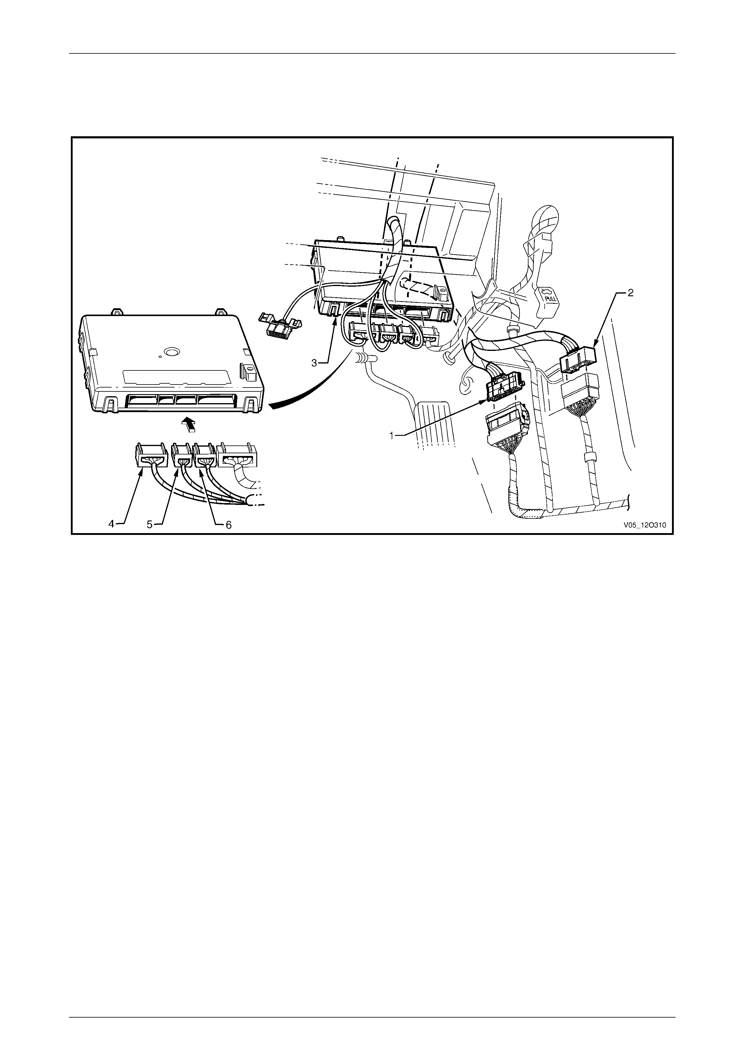
Fuses, Relays and Wiring Harnesses Page 12O–104
3.59 Front Body Harn ess – 24
Cockpit Module
Figure 12O – 98
Legend
1 Front Body Harness to Body Wiring Harness Connector
(X200)
2 Front Body Harness to Body Wiring Harness Connector
(X201)
3 Body Control Module
4 Body Control Module Connector (A15 – X1)
5 Body Control Module Connector (A15 – X2)
6 Body Control Module Connector (A15 – X3)
Page 12O–104
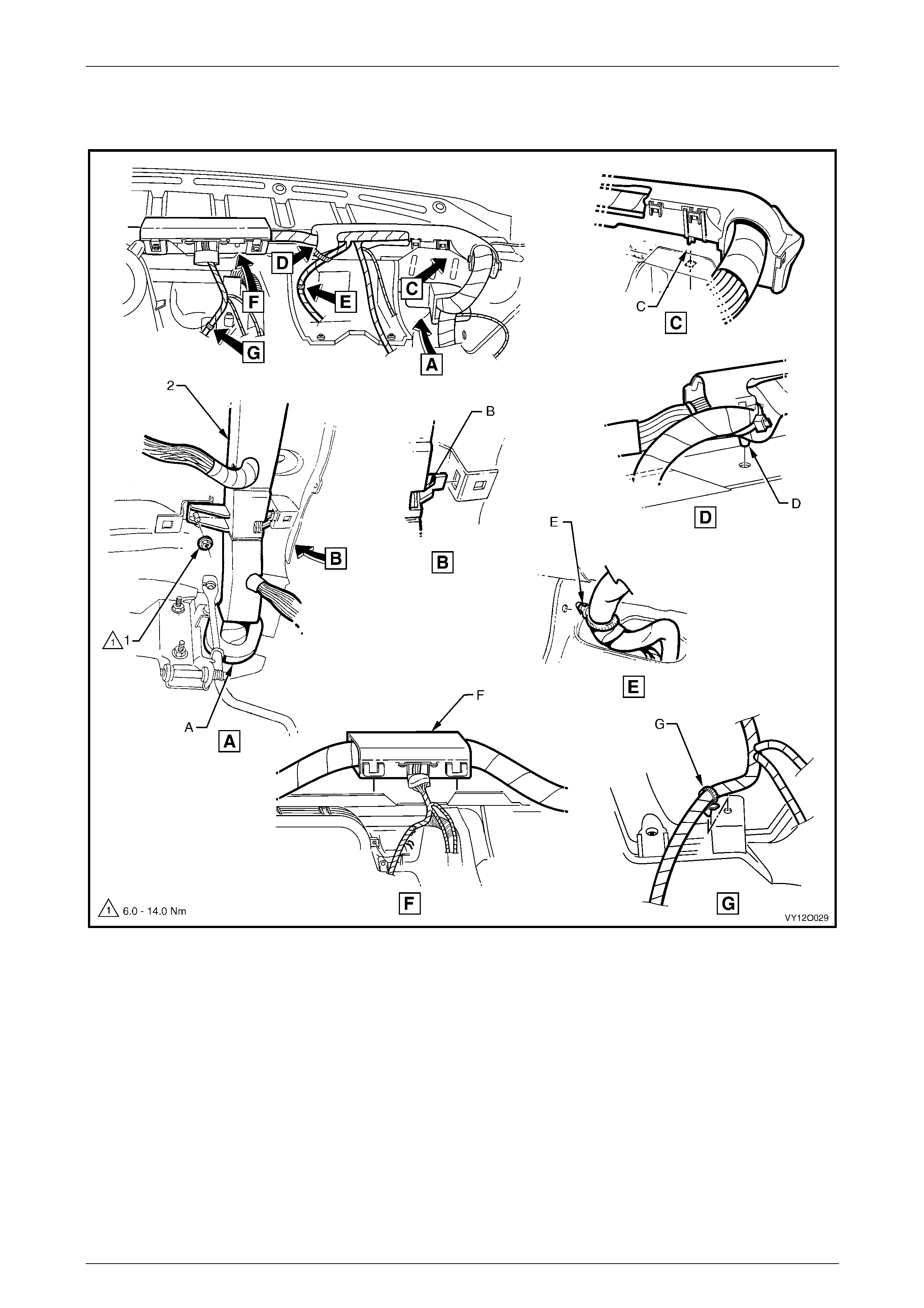
Fuses, Relays and Wiring Harnesses Page 12O–105
3.60 Front Body Harn ess – 25
Cockpit Module
Figure 12O – 99
Legend
1 Attaching Nut – Wiring Harness Retainer to Instrument
Panel
2 Front Body Harness Cable Retainer
A Refer to 3.36 Front Body Harness – 1 for sealing patch
grommet and insert installation.
B Front body harness former attached to instrument panel
cover assembly as shown.
C Front body harness former attached to instrument panel
cover assembly as shown.
D Front body harness former attached to instrument panel
cover assembly as shown.
E Front body harness retainer attached to steering column
bracket as shown.
F Front body harness former attached to instrument panel
cover assembly as shown.
G Front body harness retainer attached to vehicle as shown.
Page 12O–105
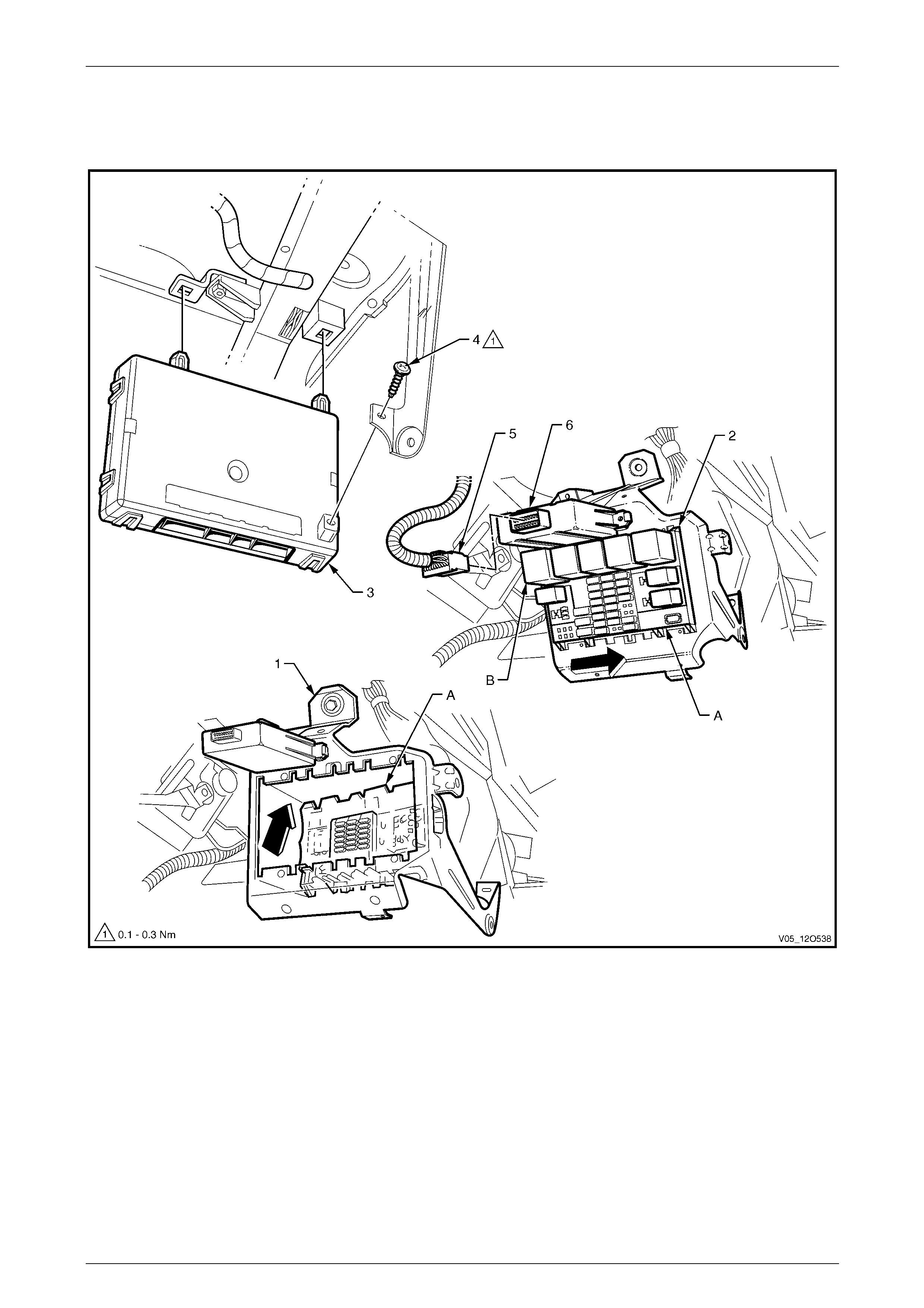
Fuses, Relays and Wiring Harnesses Page 12O–106
3.61 Front Body Harn ess – 26
V6 & GEN IV Engine – Fuse Block, BCM and PIM
Figure 12O – 100
Legend
1 Instrument Panel Wiring Harness Fuse Block Support
Bracket
2 Instrument Panel Compartment Fuse & Relay Panel (X129)
3 Body Control Module
4 Attaching Screw, Body Control Module Mounting to Support
5 Powertrain Interface Module Connector (A5 – V6)
6 Powertrain Interface Module
A Instrument panel wiring harness fuse block – installed as
shown.
B For installation of relays, fuses and circuit breakers refer to
1 General Information.
Page 12O–106
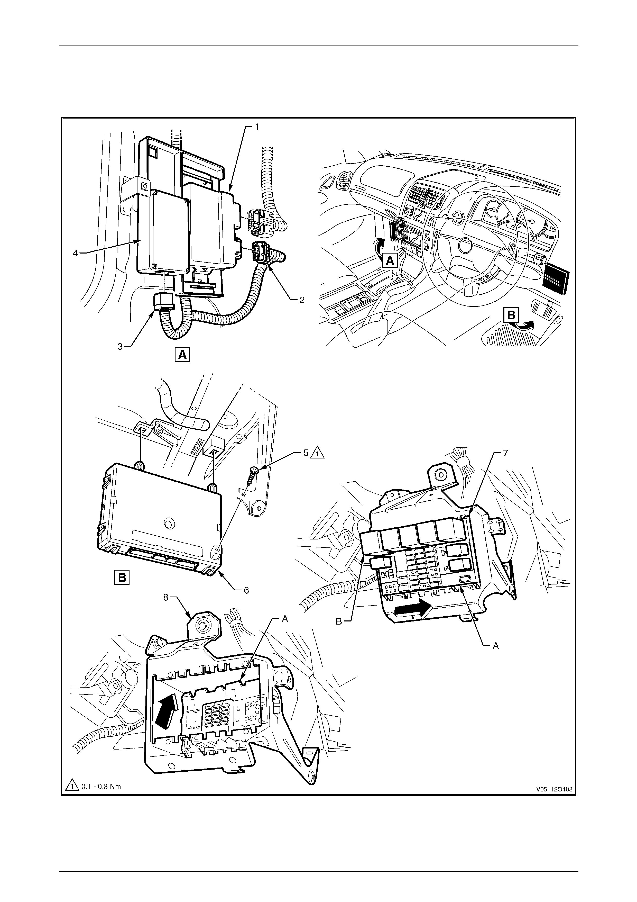
Fuses, Relays and Wiring Harnesses Page 12O–107
3.62 Front Body Harn ess – 27
GEN III V8 Engine – Fuse Block, PIM, TAC and BCM
Figure 12O – 101
Page 12O–107

Fuses, Relays and Wiring Harnesses Page 12O–108
Legend
1 Throttle Actuator Control Module
2 Throttle Actuator Control Module Connector (A111 – X2)
3 Powertrain Interface Module Connector (A5 – V8)
4 Powertrain Interface Module
5 Attaching Screw, Body Control Module Mounting to Support
6 Body Control Module
7 Instrument Panel Compartment Fuse & Relay Panel (X129)
8 Instrument Panel Compartment Fuse & Relay Panel Support
Bracket
A Instrument panel wiring harness fuse block installed as
shown.
B For installation of relays, fuses and circuit breakers, refer to
1 General Information.
Page 12O–108
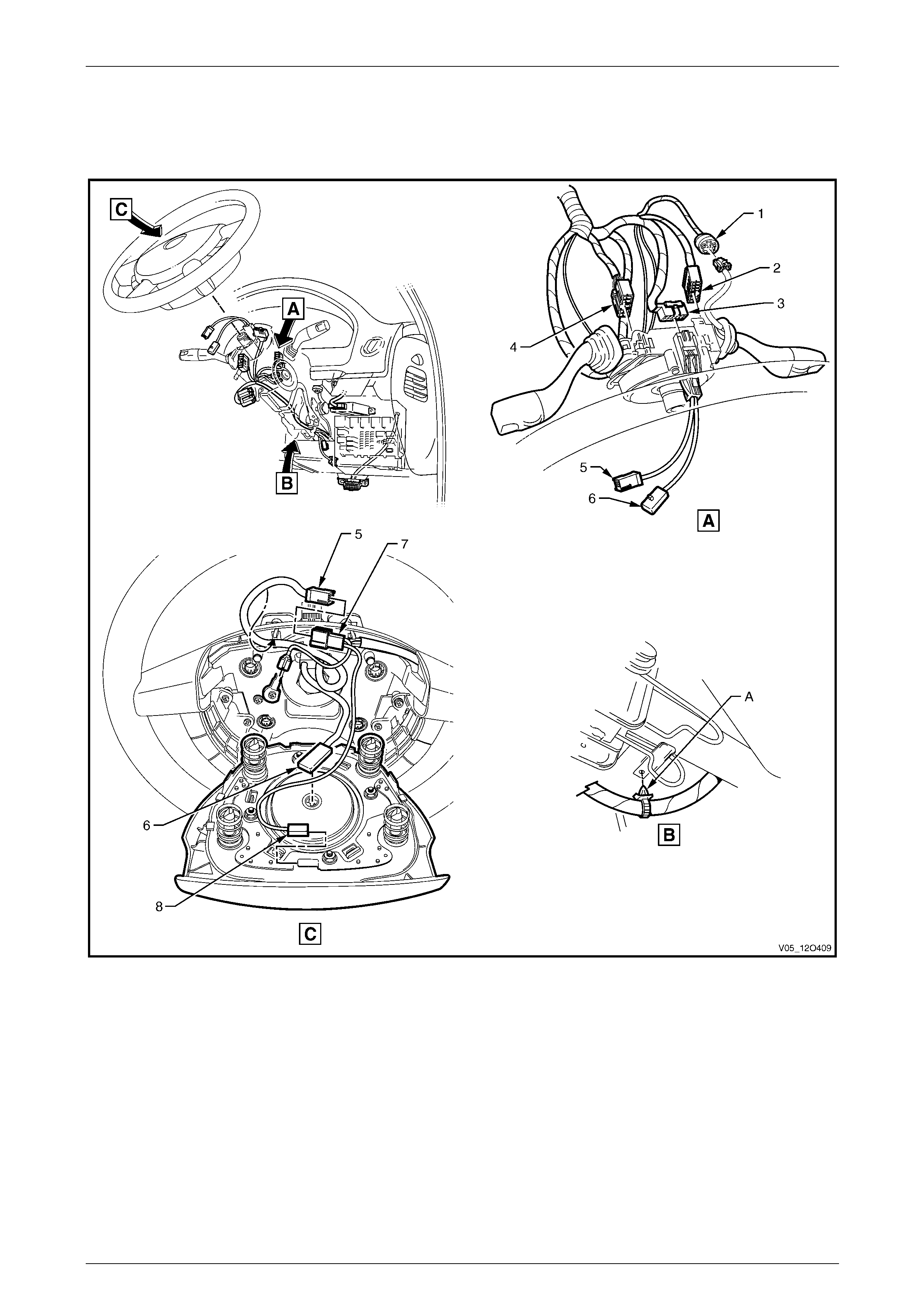
Fuses, Relays and Wiring Harnesses Page 12O–109
3.63 Front Body Harn ess – 28
V6 Engine – Steering Column
Figure 12O – 102
Legend
1 Cruise Control Switch Connector (S43)
2 Turn Signal and Headlamp Switch Connector (S231)
3 Steering Wheel Clock Spring Coil Connector (X116)
4 Windshield Wiper and Washer Switch Connector (S247)
5 Clock Spring Harness to Steering Wheel Harness Connector
(S208)
6 Steering Wheel Horn Connector (S7)
A Front body harness attached to steering column as shown.
Page 12O–109
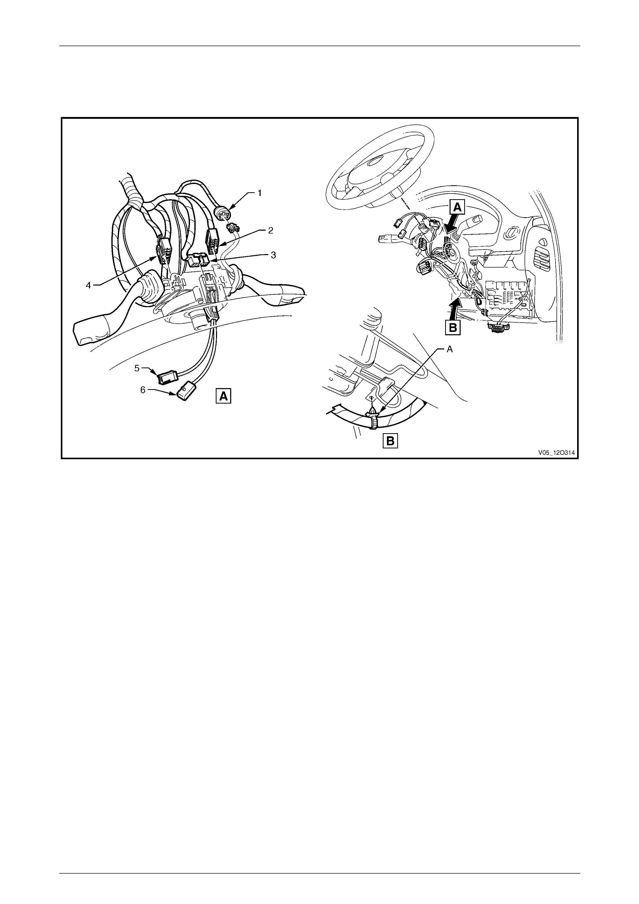
Fuses, Relays and Wiring Harnesses Page 12O–110
3.64 Front Body Harn ess – 29
V8 Engine – Steering Column
Figure 12O – 103
Legend
1 Cruise Control Switch Connector (S43)
2 Turn Signal and Headlamp Switch Connector (S231)
3 Steering Wheel Clock Spring Coil Connector (X116)
4 Windshield Wiper and Washer Switch Connector (S247)
5 Clock Spring Harness to Steering Wheel Harness Connector
(S208)
6 Steering Wheel Inflator Restraint Module Connector (A106)
A Front body harness attached to steering column as shown.
Page 12O–110
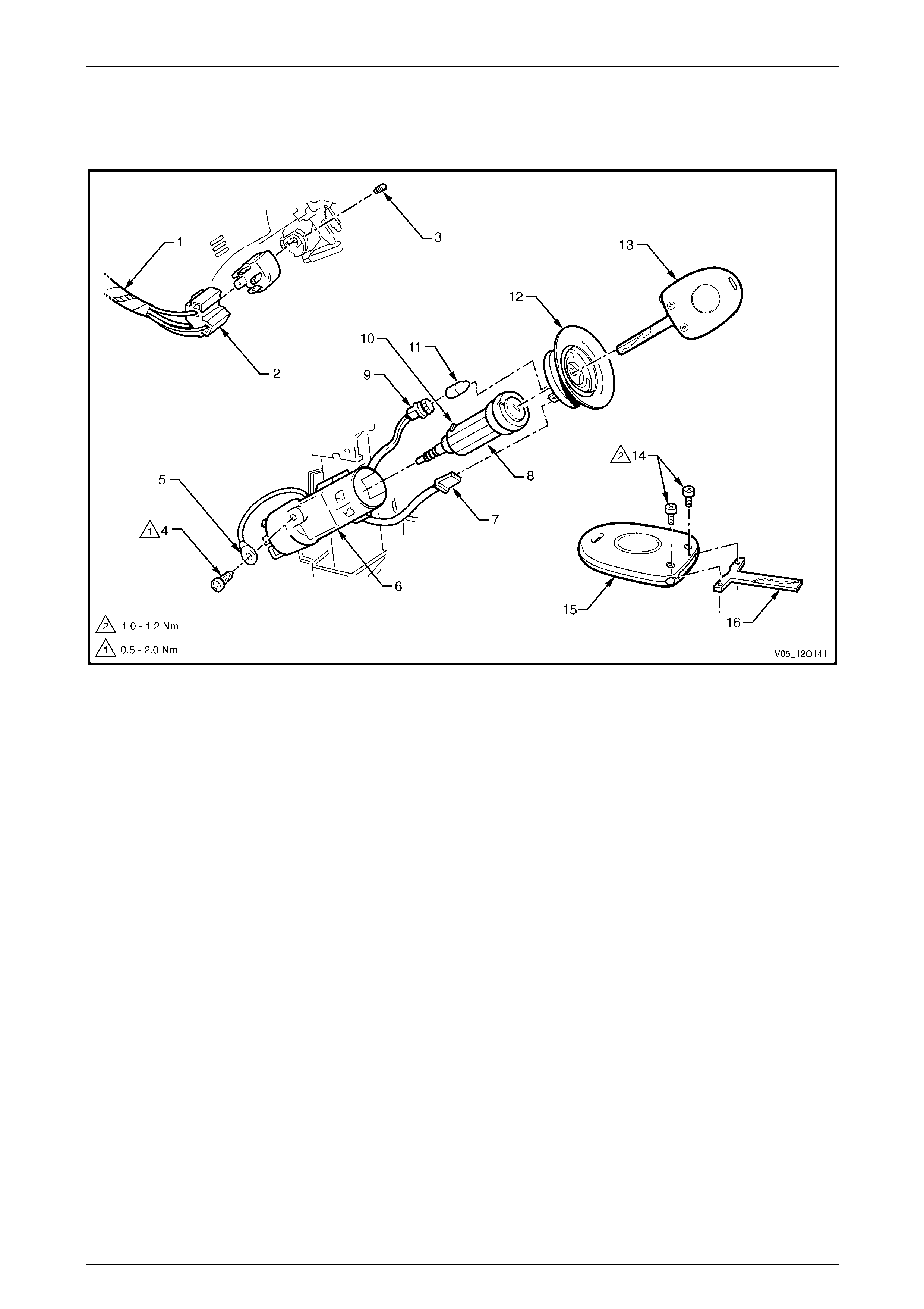
Fuses, Relays and Wiring Harnesses Page 12O–111
3.65 Front Body Harn ess – 30
Ignition Lock and Theft Deterrent Receiver
Figure 12O – 104
Legend
1 Front Body Harness
2 Ignition and Start Switch Connector (S149 – X1)
3 Ignition and Start Switch to Ignition Lock Retaining Screw
4 Ground Terminal to Ignition Key Attaching Screw
5 Ignition and Start Switch Terminal (S149 – GP15 – X3)
6 Ignition Lock Housing
7 Ignition and Start Switch Connector (S149 – X2)
8 Ignition Lock
9 Ignition Lock Cylinder Bulb Connector (E30)
10 Ignition Lock Locking Pin
11 Ignition Lock Cylinder Bulb
12 Theft Deterrent Receiver Assembly
13 Coded Key Assembly
14 Coded Key Assembly Attaching Screw
15 Remote Control Transmitter
16 Key
Page 12O–111
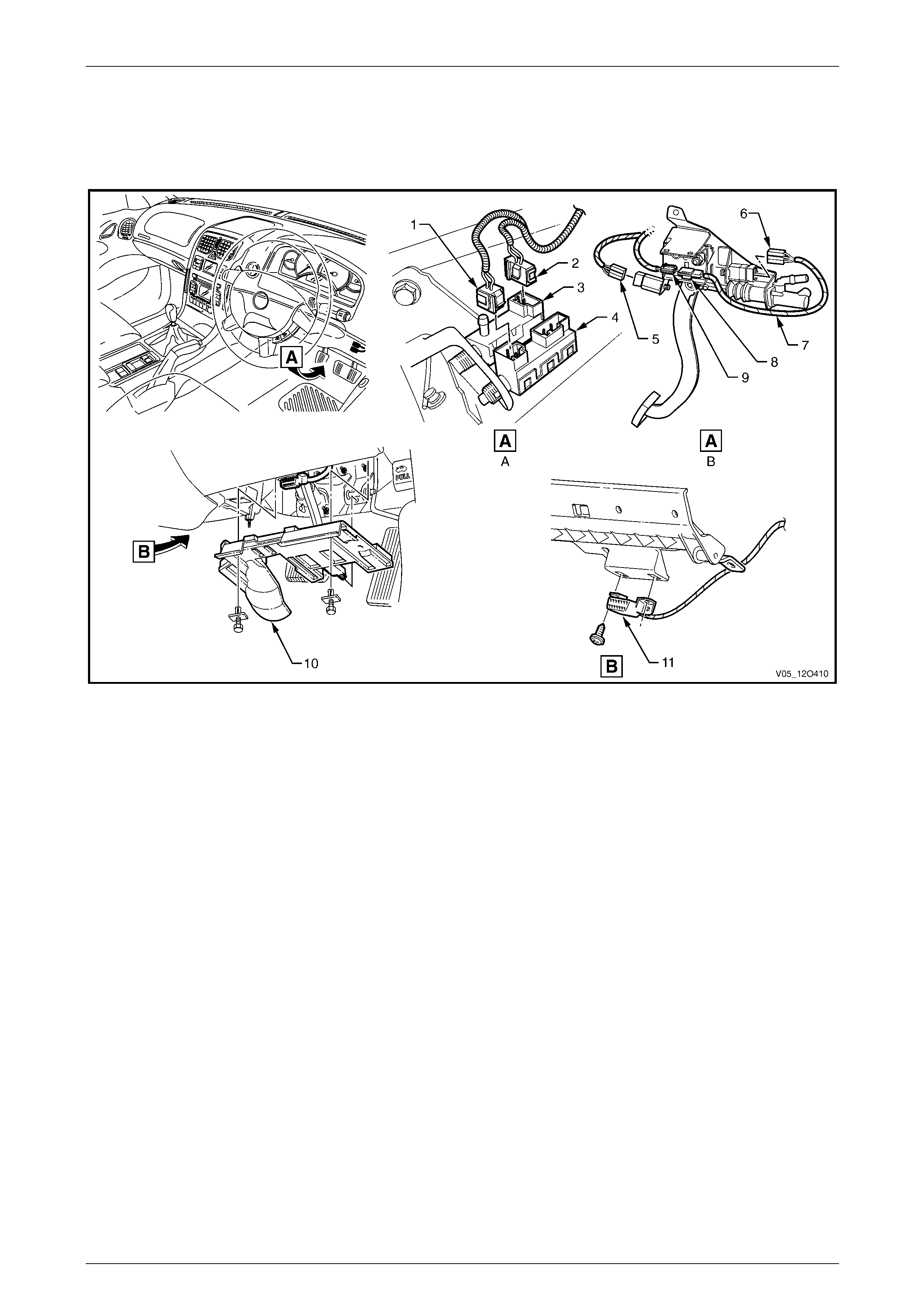
Fuses, Relays and Wiring Harnesses Page 12O–112
3.66 Front Body Harn ess – 31
V6 Engine – Manual Transmission – Cruise Control, Stop Lamp Switches and Data Link
Connector
Figure 12O – 105
Legend
1 Stop Lamp, Traction Control and Cruise Control Release
Switch Connector (S220 – X1)
2 Stop Lamp, Traction Control and Cruise Control Release
Switch Connector (S220 – X3)
3 Cruise Control Release Switch
4 Stop Lamp Switch
5 Clutch Pedal Position Switch Connector (S42 – X2)
6 Clutch Pedal Position Switch Connector (S42 – X1)
7 Clutch Extension Harness
8 Front Body Harness to Clutch Extension Harness Connector
(X210)
9 Clutch Extension Harness to Front Body Harness Connector
(X210)
10 Instrument Panel Lower Cover – Right-hand Side
11 Wiring (Diagnostics) Connector (X40)
A Brake pedal.
B Clutch pedal.
Page 12O–112
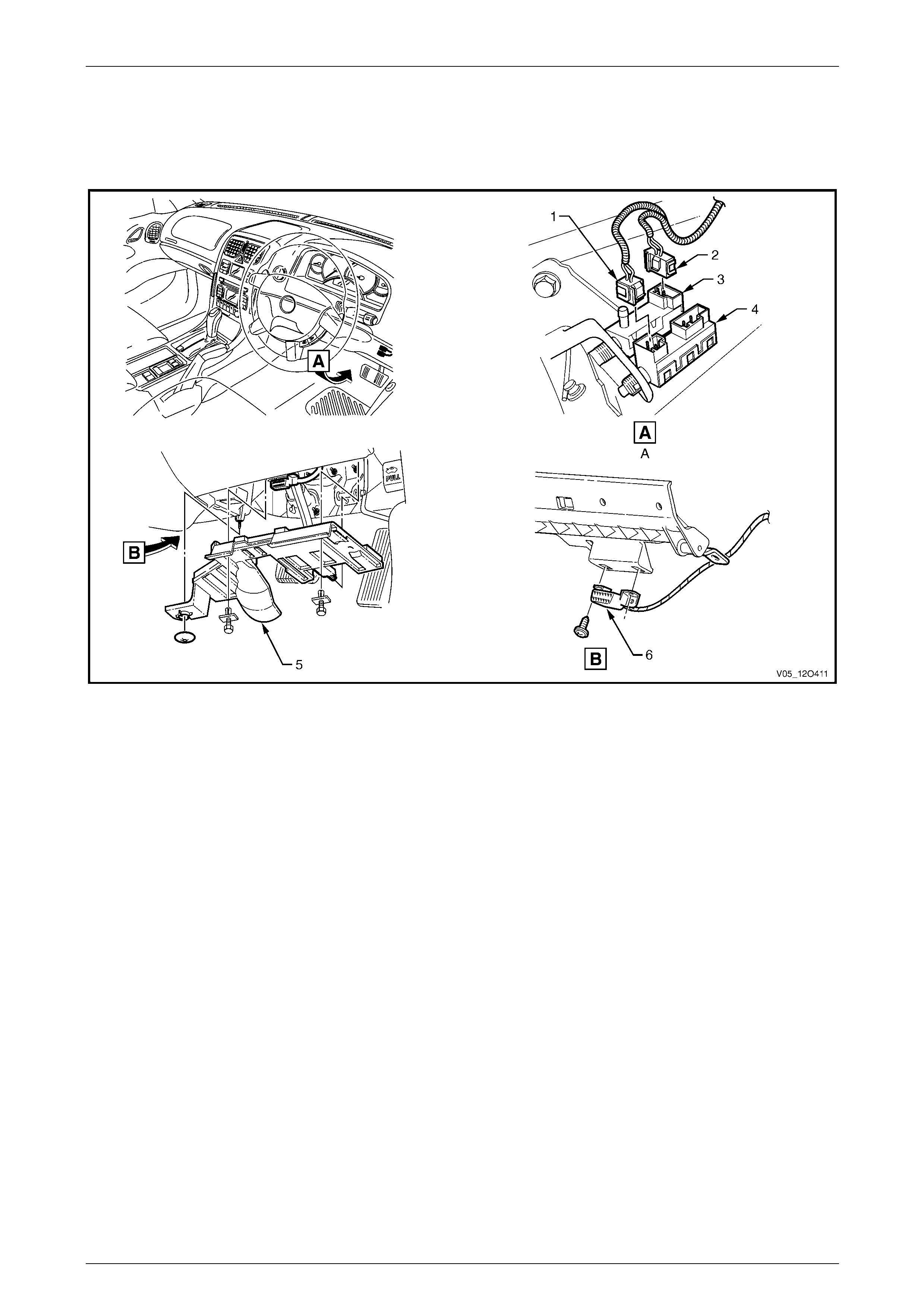
Fuses, Relays and Wiring Harnesses Page 12O–113
3.67 Front Body Harn ess – 32
V6 Engine – Automatic Transmission – Cruise Control, Stop Lamp Switches and Data Link
Connector
Figure 12O – 106
Legend
1 Stop Lamp, Traction Control and Cruise Control Release
Switch Connector (S220 – X1)
2 Stop Lamp, Traction Control and Cruise Control Release
Switch Connector (S220 – X3)
3 Cruise Control Release Switch
4 Stop Lamp Switch
5 Instrument Panel Lower Cover – Right-hand Side
6 Wiring (Diagnostics) Connector (X40)
A Brake pedal.
Page 12O–113
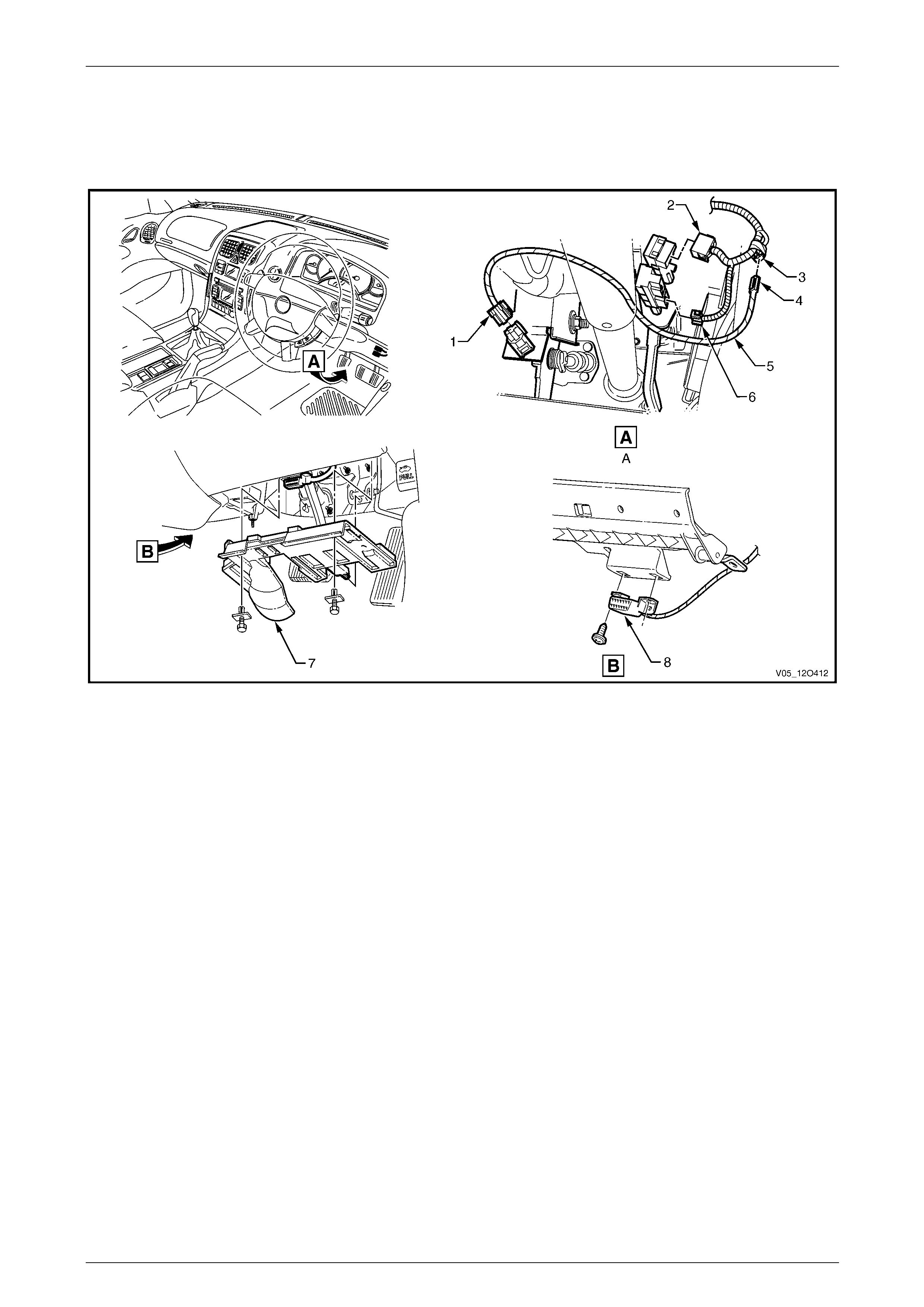
Fuses, Relays and Wiring Harnesses Page 12O–114
3.68 Front Body Harn ess – 33
V8 Engine – Manual Transmission – Cruise Control, Stop Lamp Switches and Data Link
Connector
Figure 12O – 107
Legend
1 Clutch Pedal Position Switch Connector (S42 – X2)
2 Stop Lamp, Traction Control and Cruise Control Release
Switch Connector (S220 – X3)
3 Cruise Cancel Switch – Clutch Patch Connector (X86 – V8)
4 Cruise Cancel Switch – Clutch Patch Connector (X86 – V8)
5 Cruise Control Patch Harness
6 Stop Lamp, Traction Control and Cruise Control Release
Switch Connector (S220 – X1)
7 Instrument Panel Lower Cover – Right-hand Side
8 Wiring (Diagnostics) Connector (X40)
A Brake and clutch pedals.
Page 12O–114
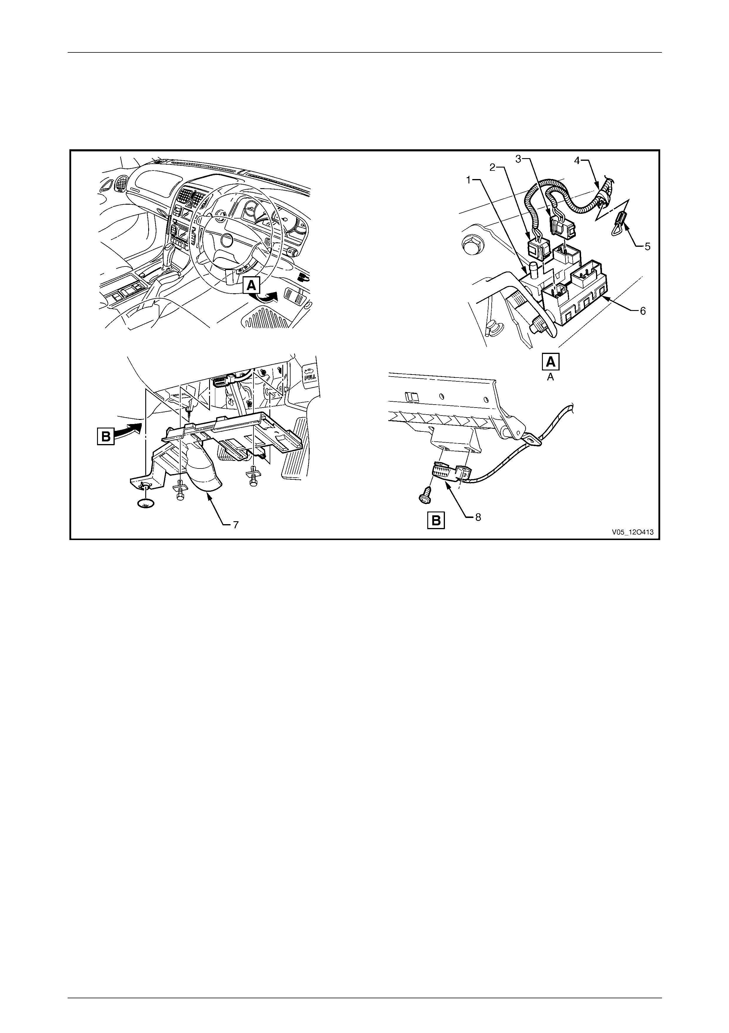
Fuses, Relays and Wiring Harnesses Page 12O–115
3.69 Front Body Harn ess – 34
V8 Engine – Automatic Transmission – Cruise Control, Stop Lamp Switches and Data Link
Connector
Figure 12O – 108
Legend
1 Cruise Control Release Switch
2 Stop Lamp, Traction Control and Cruise Control Release
Switch Connector (S220 – X1)
3 Stop Lamp, Traction Control and Cruise Control Release
Switch Connector (S220 – X3)
4 Cruise Cancel Switch – Clutch Patch Connector (X86 – V8)
5 Cruise Cancel Switch – Clutch Patch Connector (X86 – V8)
6 Stop Lamp Switch
7 Instrument Panel Lower Cover – Right-hand Side
8 Wiring (Diagnostics) Connector (X40)
A Automatic brake pedal.
Page 12O–115
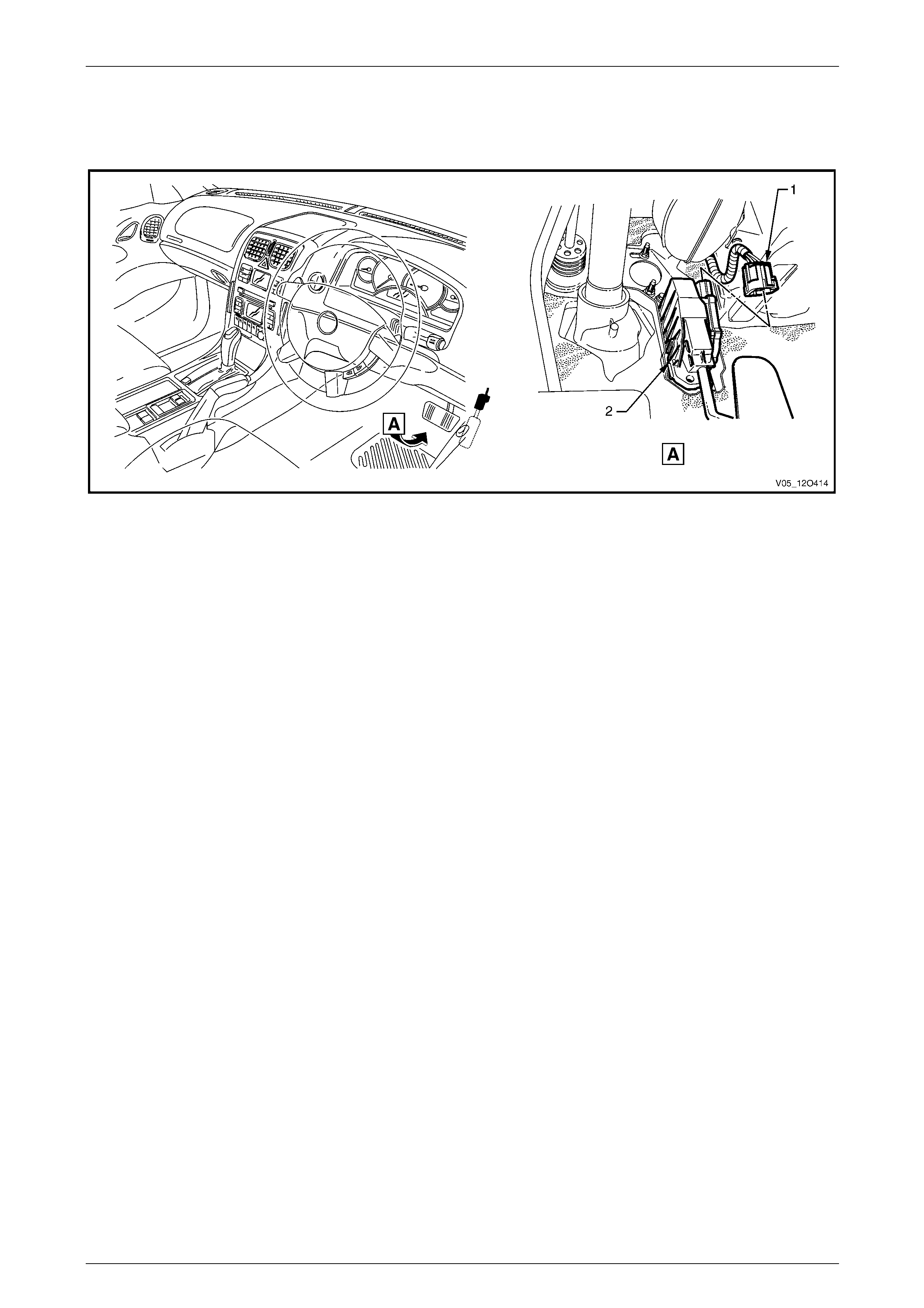
Fuses, Relays and Wiring Harnesses Page 12O–116
3.70 Front Body Harn ess – 35
Accelerator Pedal Position
Figure 12O – 109
Legend
1 Accelerator Pedal Position Sensor Connector (B22) 2 Accelerator Pedal Position Sensor
Page 12O–116
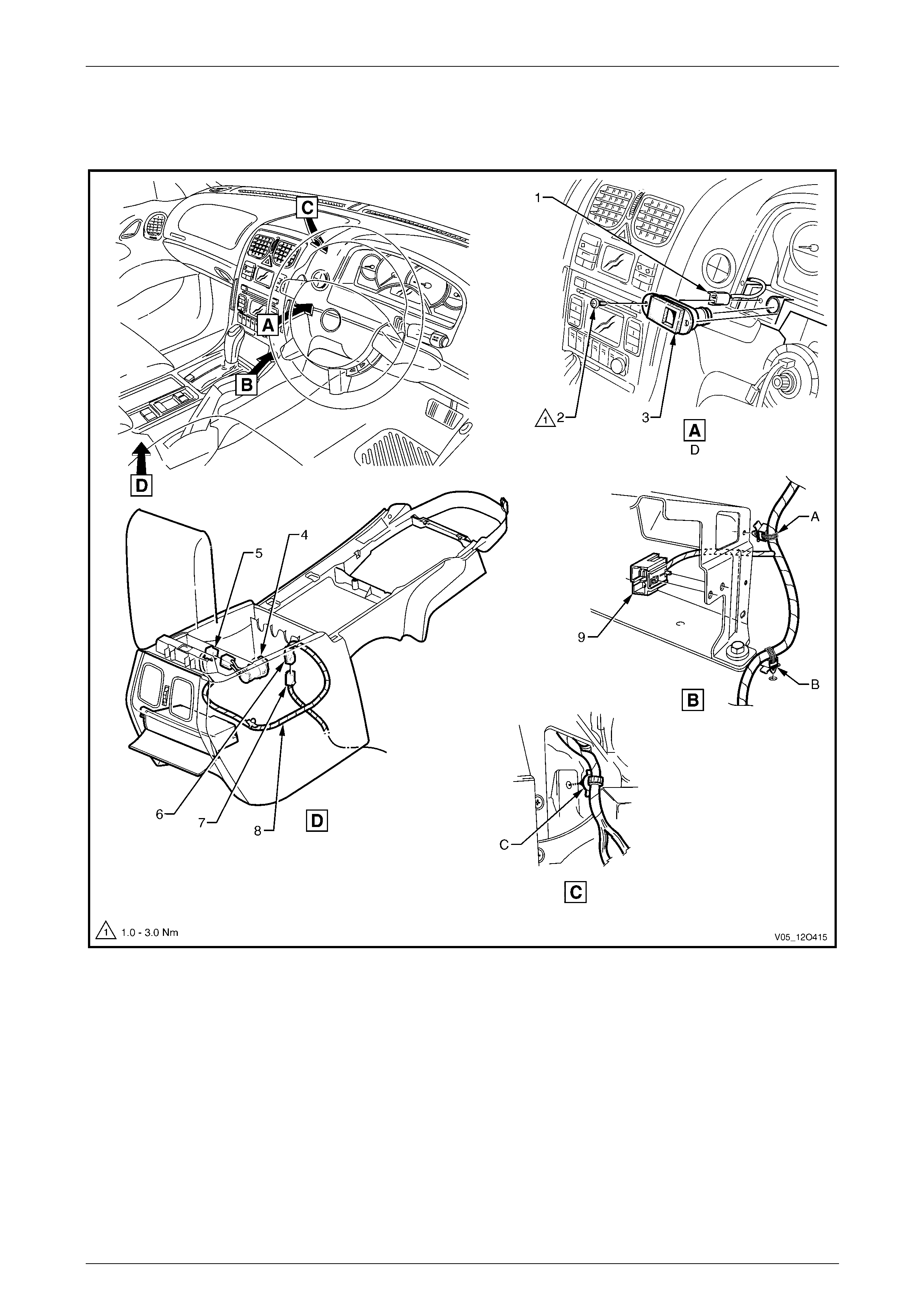
Fuses, Relays and Wiring Harnesses Page 12O–117
3.71 Front Body Harn ess – 36
Inside Air Temperature Sensor and Floor Console
Figure 12O – 110
Legend
1 Inside Air Temperature Sensor Connector (B59)
2 Inside Air Temperature Sensor Attaching Screw
3 Inside Air Temperature Sensor
4 Accessory Power Socket
5 Accessory Power Connector (X112 – AUX)
6 Console Wiring Harness to Front Body Harness Connector
(X309)
7 Front Body Harness to Console Wiring Harness Connector
(X309)
8 Console Wiring Harness
9 Front Cigar Lighter Connector (X113 – F)
A Harness attached to lower radio bracket as shown.
B Harness attached as shown.
C Harness attached to instrument panel as shown.
D Where fitted.
Page 12O–117
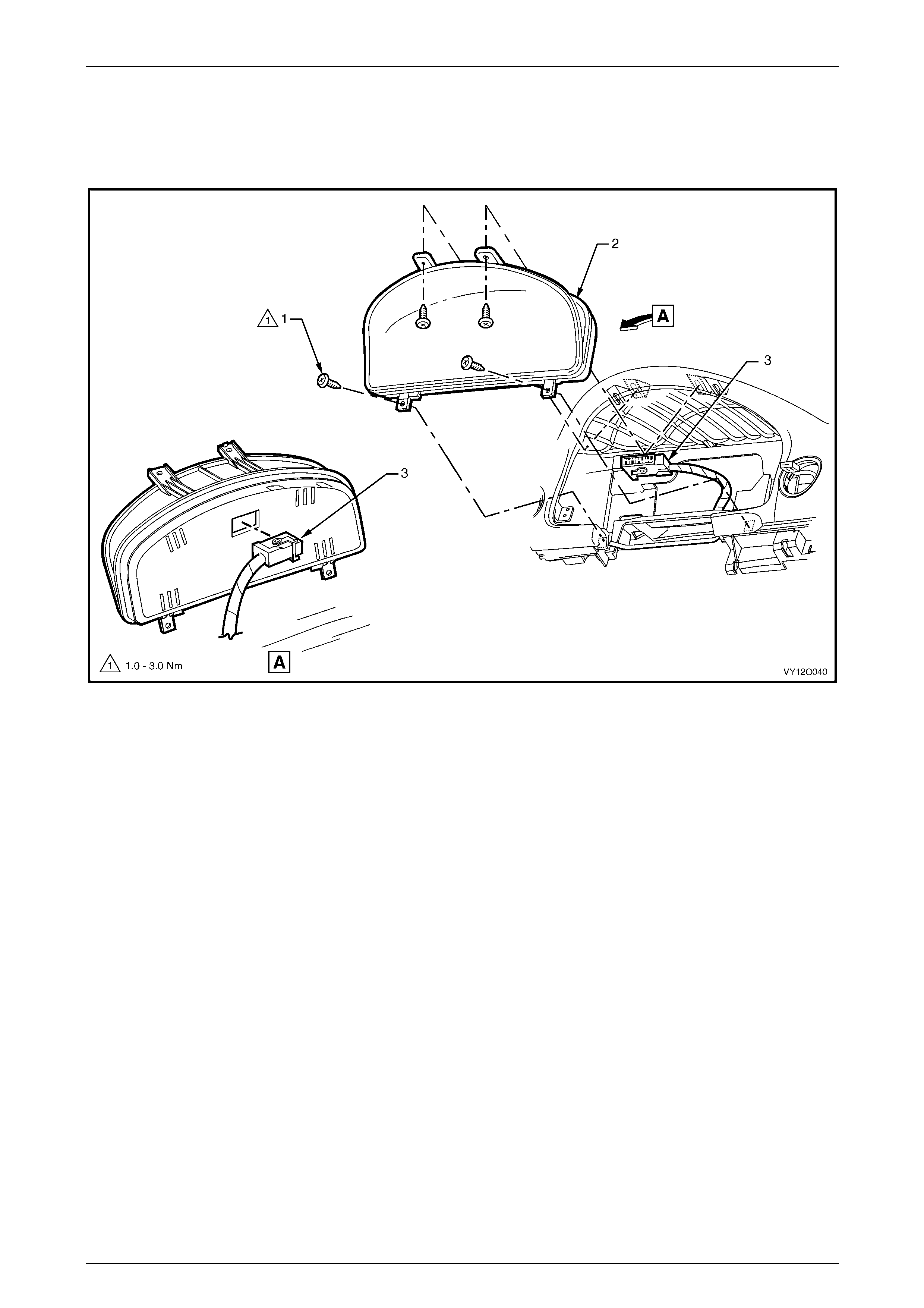
Fuses, Relays and Wiring Harnesses Page 12O–118
3.72 Front Body Harn ess – 37
Instrument Cluster Assembly
Figure 12O – 111
Legend
1 Instrument Cluster Attaching Screws (4 places)
2 Instrument Cluster Assembly 3 Instrument Cluster Connector (P3)
Page 12O–118
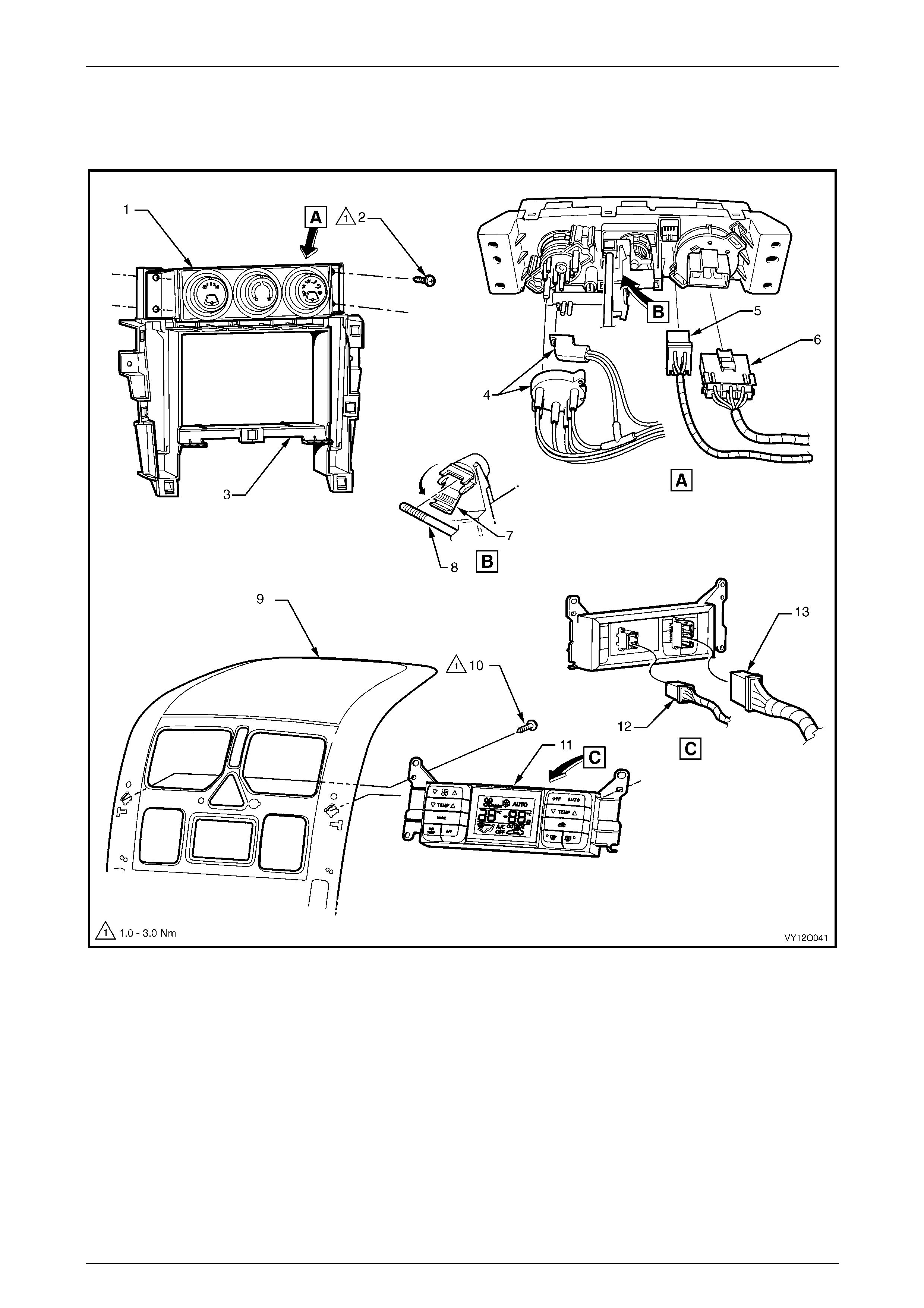
Fuses, Relays and Wiring Harnesses Page 12O–119
3.73 Front Body Harn ess – 38
Air-conditioning and Heating Controls
Figure 12O – 112
Legend
1 Heater and A/C Evaporative Module
2 Attaching Screw (4 places)
3 Radio Carrier
4 Vacuum Manifold Plug
5 Heater and A/C Evaporator Module Connector (A60 – X2)
6 Heater and A/C Evaporator Module Connector (A60 – X1)
7 Control Assembly
8 Heating and A/C Evaporative Module Rod
9 Centre Facia Escutcheon Assembly
10 Attaching Screws (4 places)
11 Electronic Climate Control Module
12 Blower Motor and A/C Compressor Connector (A14 – X1)
13 Blower Motor and A/C Compressor Connector (A14 – X2)
Page 12O–119
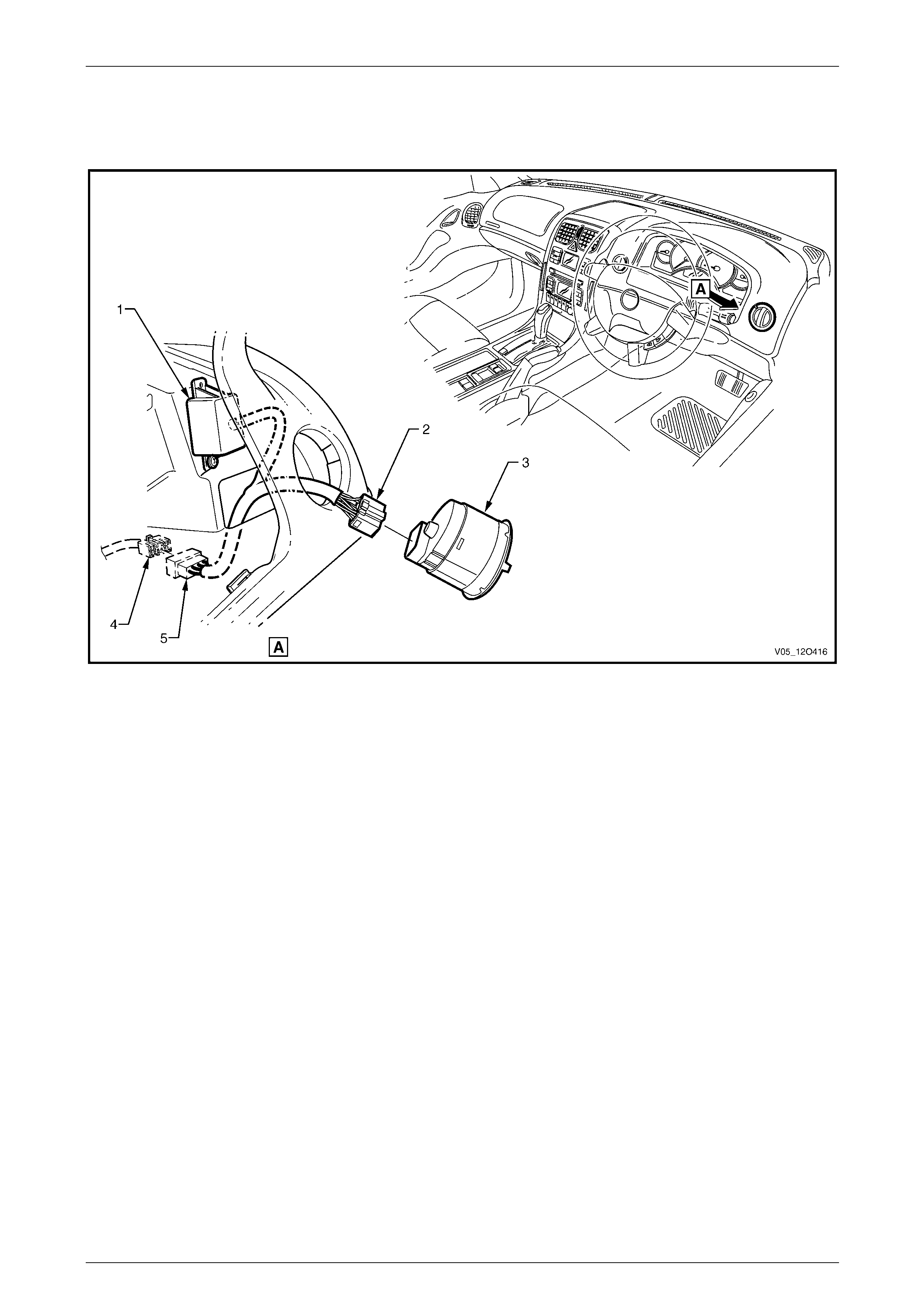
Fuses, Relays and Wiring Harnesses Page 12O–120
3.74 Front Body Harn ess – 39
Daytime Running Lamp Control
Figure 12O – 113
Legend
1 Daytime Running Lamp Control Module Assembly
2 Daytime Running Lamp Control Connector (A25 – X2)
3 Headlamp Automatic Control Switch
4 Headlamp Automatic Control Switch Connector (S125)
5 Daytime Running Lamp Control Connector (A25 – X1)
Page 12O–120
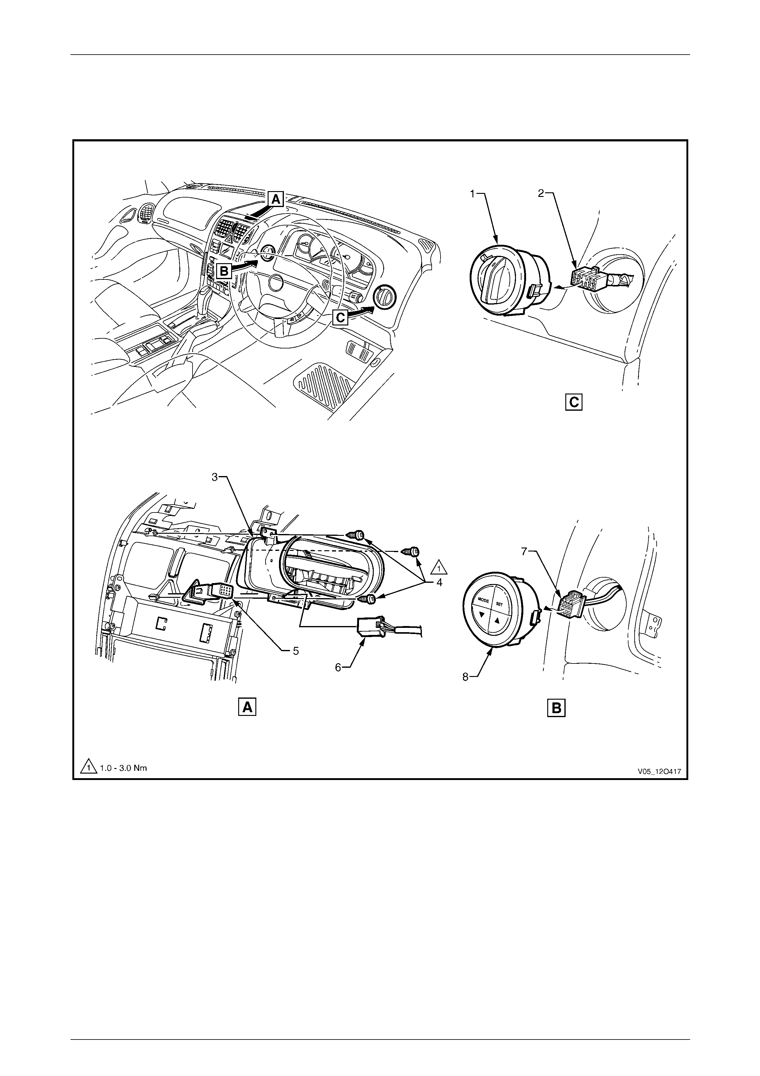
Fuses, Relays and Wiring Harnesses Page 12O–121
3.75 Front Body Harn ess – 40
Instrument Panel Facia Trim Switches
Figure 12O – 114
Legend
1 Headlamp Automatic Control Switch
2 Headlamp Automatic Control Switch Connector (S125)
3 Centre Air Outlet Assembly
4 Attaching Screws (3 places)
5 Hazard Warning Switch
6 Hazard Warning Switch Connector (S120)
7 Trip Odometer Reset Switch Connector (S237)
8 Trip Odometer Reset Switch
Page 12O–121
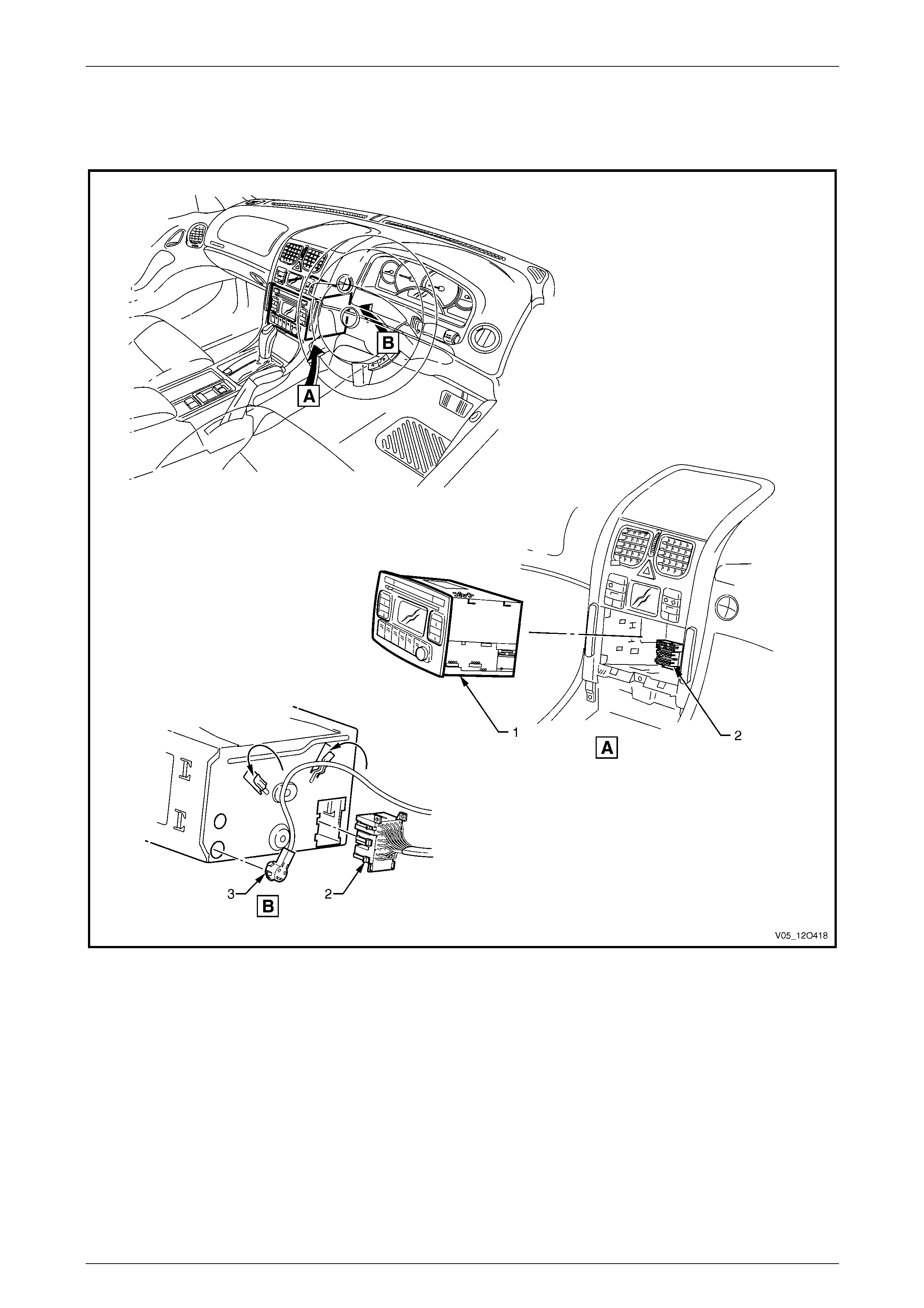
Fuses, Relays and Wiring Harnesses Page 12O–122
3.76 Front Body Harn ess – 41
Radio Assembly
Figure 12O – 115
Legend
1 Radio, Clock and CD Player Assembly
2 Radio, Clock and CD Player Connector (A133 – X1) 3 Power Antenna Connector (A133 – X2)
Page 12O–122
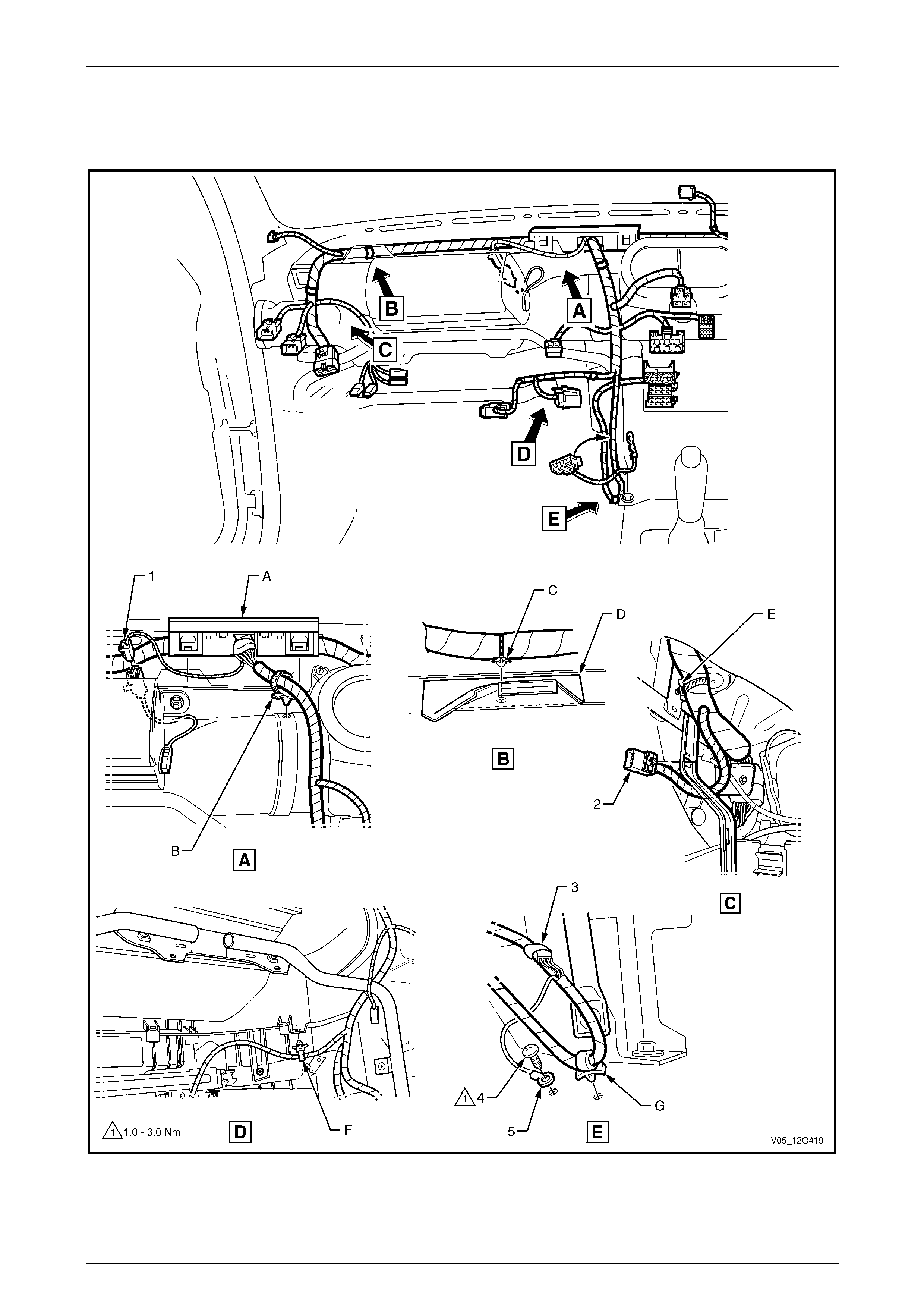
Fuses, Relays and Wiring Harnesses Page 12O–123
3.77 Front Body Harn ess – 42
V6 Engine – Passenger Side Airbag and Radio/Mobile Telephone Connectors
Figure 12O – 116
Page 12O–123

Fuses, Relays and Wiring Harnesses Page 12O–124
Legend
1 Front Body Harness to Passenger Air Bag Harness
Connector (X205)
2 Front Body Harness to Global Positioning System Harness
Connector (X207)
3 Inline to Radio and Mobile Telephone Connector (X155)
4 Radio Ground Terminal Attaching Screw
5 Radio Ground Terminal (X118 – GP8)
A Harness former attached to instrument panel cover
assembly as shown (2 places).
B Harness attached to heating, ventilation and air-conditioning
unit as shown.
C Harness attached to instrument panel cover assembly as
shown.
D Instrument panel cover assembly.
E Harness attached to bracket as shown.
F Harness attached to vehicle as shown.
G Harness attached to vehicle as shown.
Page 12O–124

Fuses, Relays and Wiring Harnesses Page 12O–125
3.78 Front Body Harn ess – 43
GEN III V8 Engine – Passenger Side Airbag and Radio/Mobile Telephone Connectors
Figure 12O – 117
Page 12O–125

Fuses, Relays and Wiring Harnesses Page 12O–126
Legend
1 Front Body Harness to Passenger Air Bag Harness
Connector (X205)
2 Front Body Harness to Global Positioning System Harness
Connector (X207)
3 Inline to Radio and Mobile Telephone Connector (X155)
4 Radio Ground Terminal Attaching Screw
5 Radio Ground Terminal (X118 – GP8)
A Harness former attached to instrument panel cover
assembly as shown (2 places).
B Harness attached to heating, ventilation and air-conditioning
unit as shown.
C Harness attached to instrument panel cover assembly as
shown.
D Instrument panel cover assembly.
E Harness attached to bracket as shown.
F Harness attached to vehicle as shown.
G Harness attached to vehicle as shown.
Page 12O–126
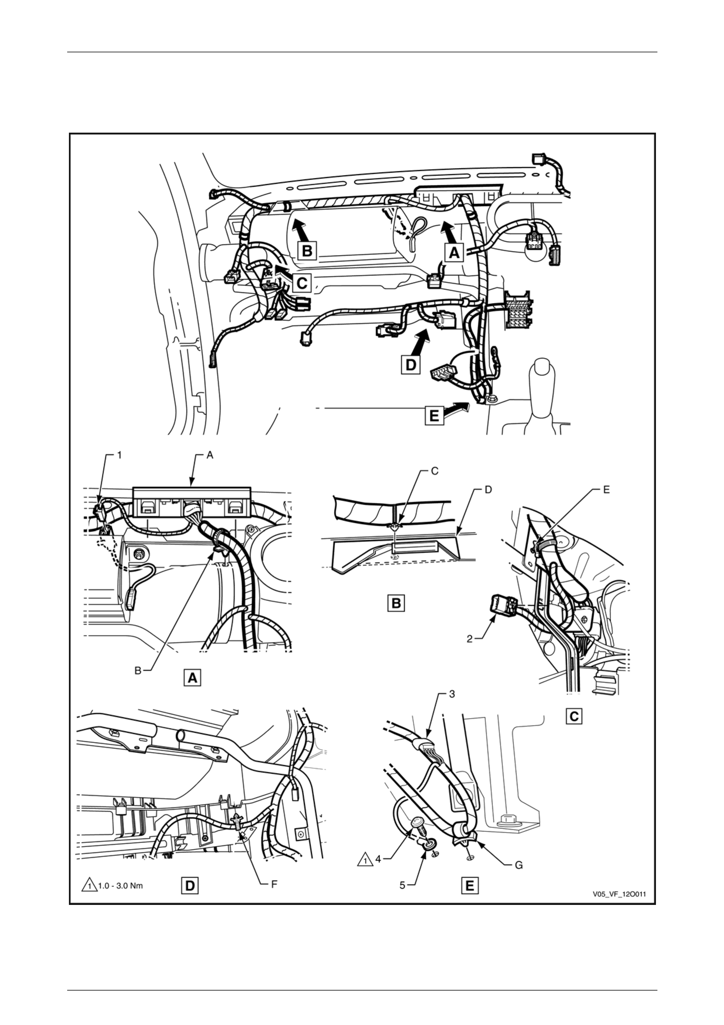
Fuses, Relays and Wiring Harnesses Page 12O–127
3.79 Front Body Harn ess – 44
GEN IV V8 Engine – Passenger Side Airbag and Radio/Mobile Telephone Connectors
Figure 12O – 118
Page 12O–127

Fuses, Relays and Wiring Harnesses Page 12O–128
Legend
1 Front Body Harness to Passenger Air Bag Harness
Connector (X205)
2 Front Body Harness to Global Positioning System Harness
Connector (X207)
3 Inline to Radio and Mobile Telephone Connector (X155)
4 Radio Ground Terminal Attaching Screw
5 Radio Ground Terminal (X118 – GP8)
A Harness former attached to instrument panel cover
assembly as shown (2 places).
B Harness attached to heating, ventilation and air-conditioning
unit as shown.
C Harness attached to instrument panel cover assembly as
shown.
D Instrument panel cover assembly.
E Harness attached to bracket as shown.
F Harness attached to vehicle as shown.
G Harness attached to vehicle as shown.
Page 12O–128
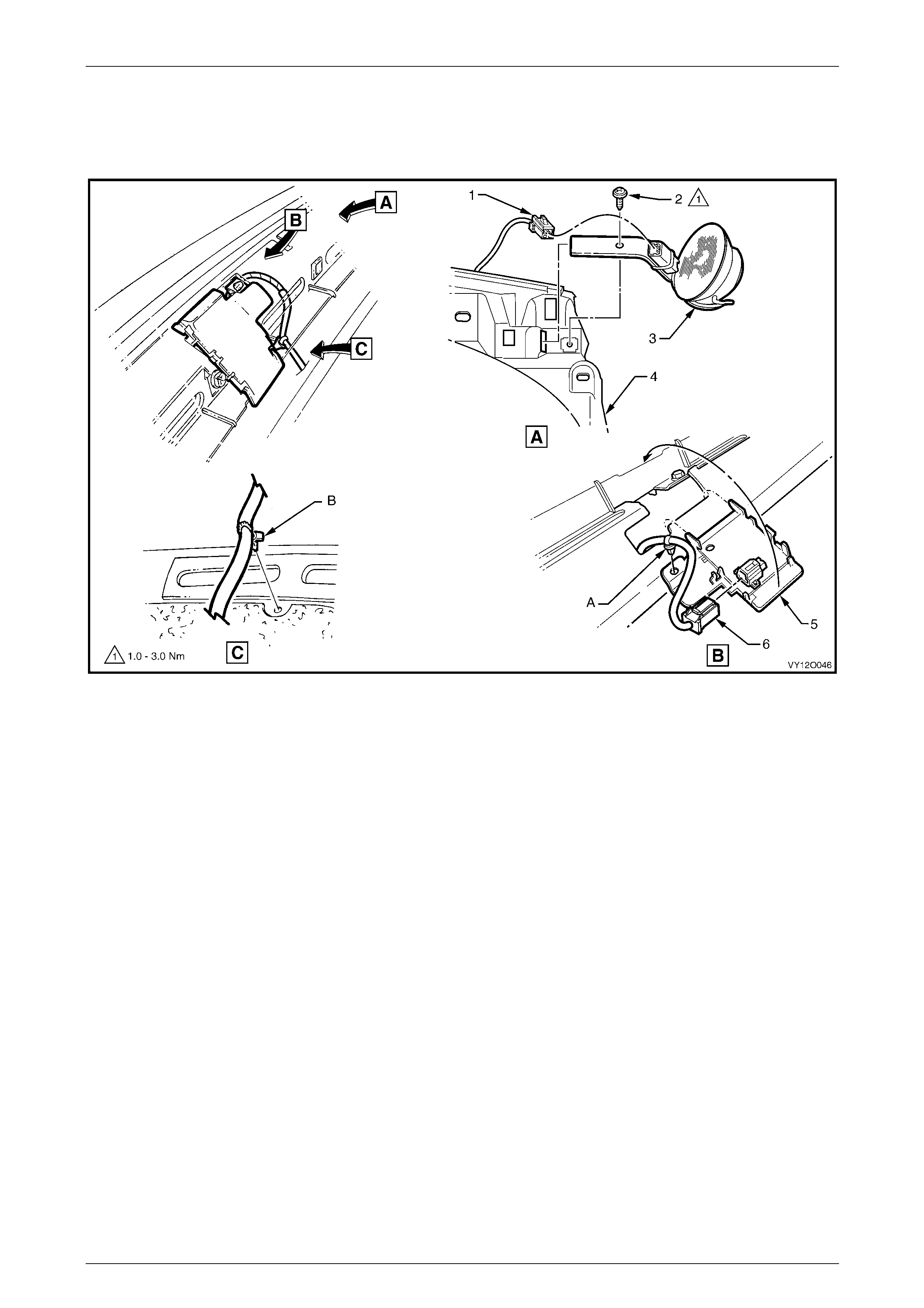
Fuses, Relays and Wiring Harnesses Page 12O–129
3.80 Front Body Harn ess – 45
Light Sensor/Key Receiver Module and Instrument Panel Speakers
Figure 12O – 119
Legend
1 Radio Front Speaker Dash Upper Connector (B112)
2 Attaching Screw
3 Radio Front Speaker Dash Upper
4 Carrier Instrument Panel Pad
5 Ambient Light Sensor and Key Receiver Module
6 Ambient Light Sensor and Key Receiver Module Connector
(B55)
A Harness attached to light sensor and key receiver module as
shown.
B Harness attached as shown.
Page 12O–129
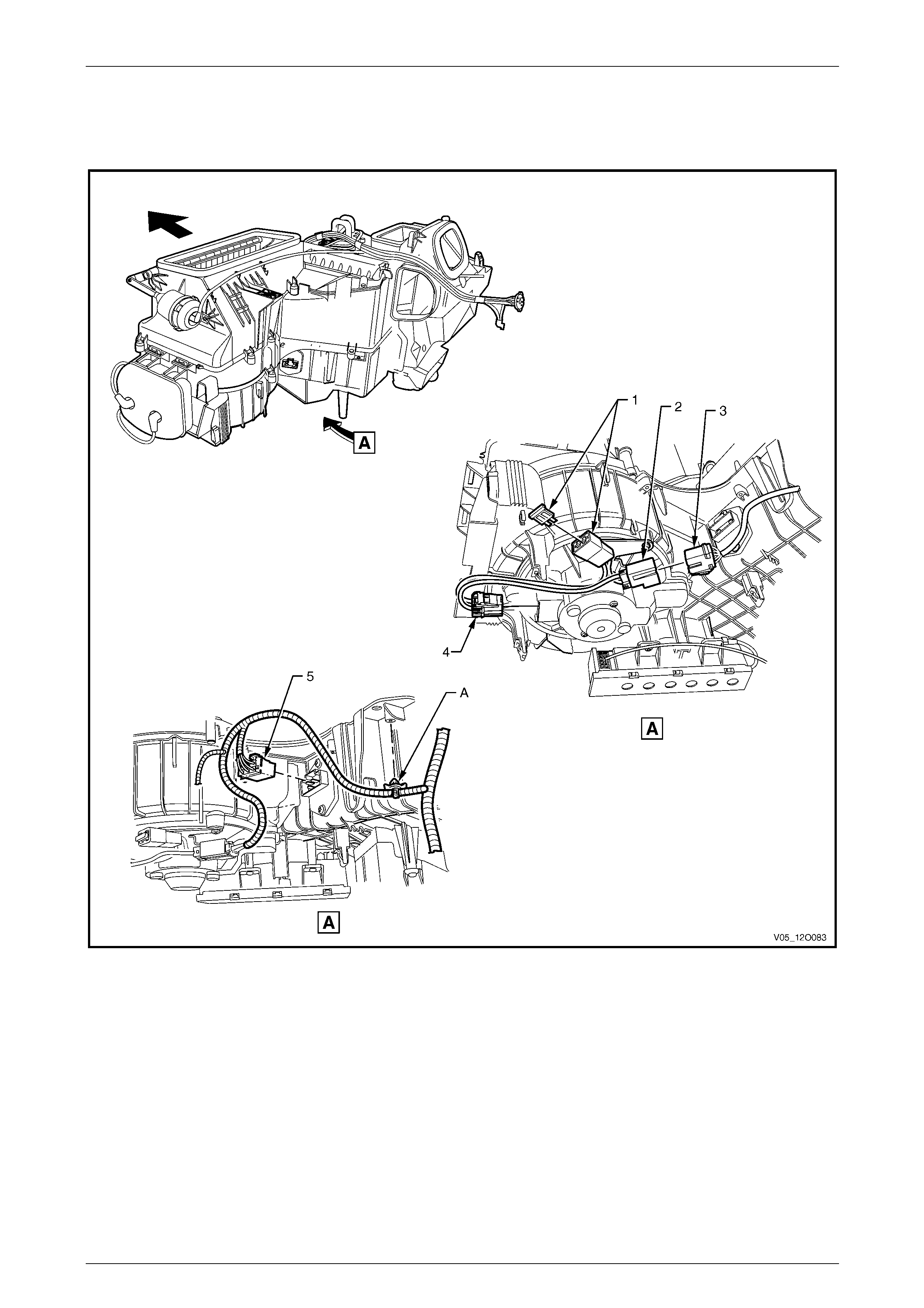
Fuses, Relays and Wiring Harnesses Page 12O–130
3.81 Front Body Harn ess – 46
HVAC Climate Control (Manual A/C)
Figure 12O – 120
Legend
1 Blower Motor Connector (X126 – BLO – MOT)
2 Blower Motor Harness to Front Body Harness Connector
(X204)
3 Front Body Harness to Blower Motor Harness Connector
(X204)
4 Blower Motor Connector (M3)
5 Blower Motor Resistor Connector (R6)
A Harness attached to body as shown.
Page 12O–130
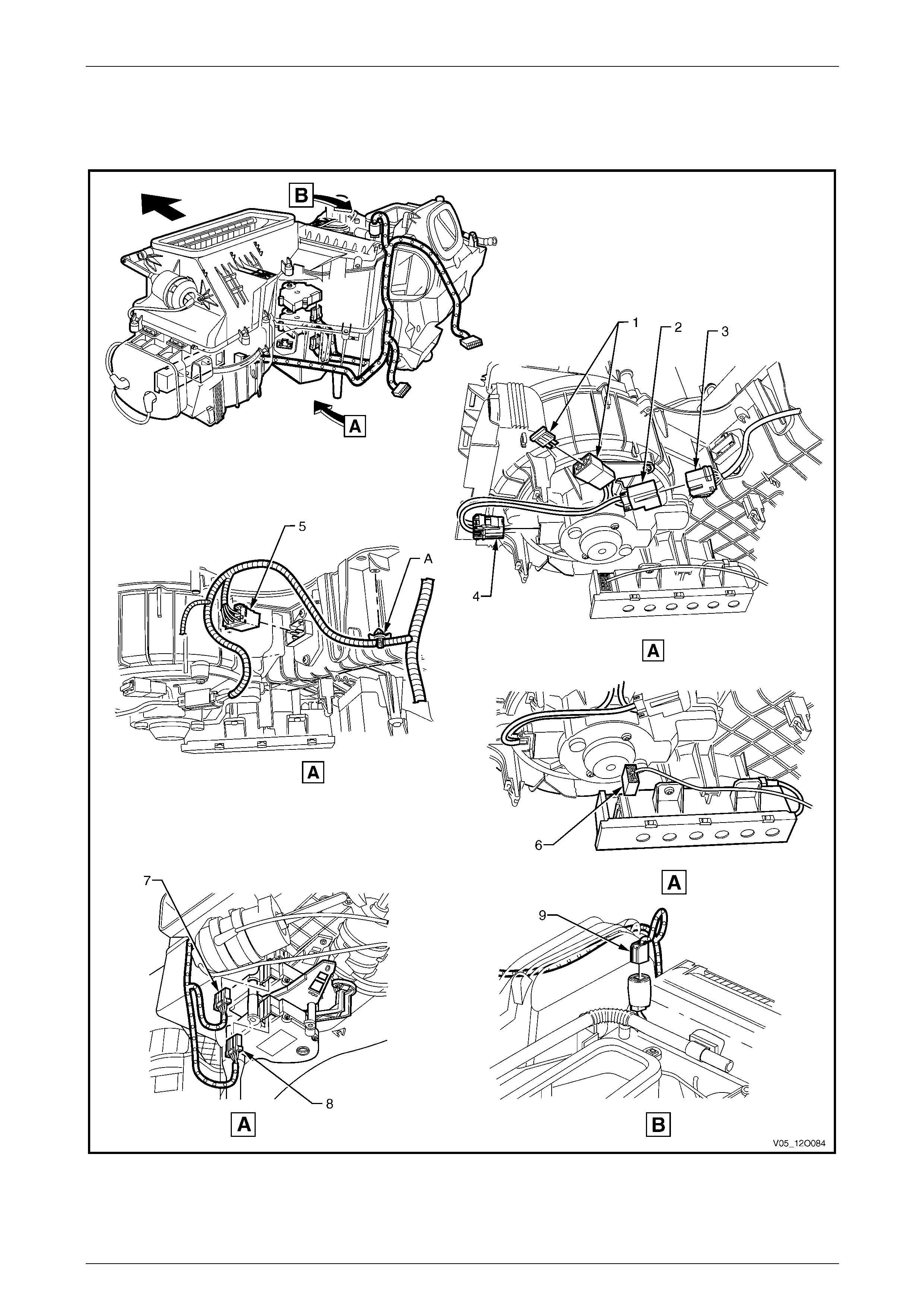
Fuses, Relays and Wiring Harnesses Page 12O–131
3.82 Front Body Harn ess – 47
HVAC Occupant Climate Control (Auto A/C)
Figure 12O – 121
Page 12O–131

Fuses, Relays and Wiring Harnesses Page 12O–132
Legend
1 Blower Motor Connector (X126 – BLO – MOT)
2 Blower Motor Harness to Front Body Harness Connector
(X204)
3 Front Body Harness to Blower Motor Harness Connector
(X204)
4 Blower Motor Connector (M3)
5 Blower and Air Inlet Connector (A13)
6 Inside Air Valve Vacuum Solenoid Pack Connector (Y19)
7 Actuator Temperature Valve Connector (Y37 – L)
8 Actuator Temperature Valve Connector (Y37 – R)
9 Duct Air Temperature Sensor (B34)
A Harness attached to body as shown.
Page 12O–132
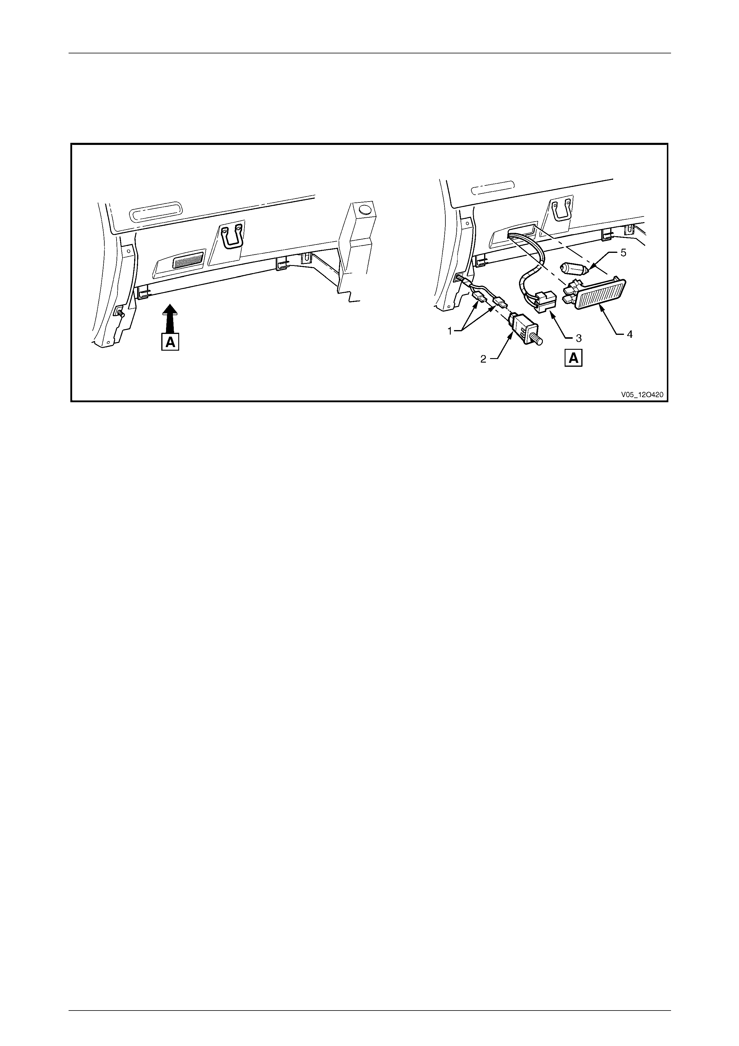
Fuses, Relays and Wiring Harnesses Page 12O–133
3.83 Front Body Harn ess – 48
Instrument Panel Compartment
Figure 12O – 122
Legend
1 Instrument Panel Compartment Lamp Switch Connectors
(S142)
2 Instrument Panel Compartment Lamp Switch
3 Instrument Panel Compartment Lamp Connector (E82)
4 Instrument Panel Compartment Lamp
5 Instrument Panel Compartment Lamp Bulb
Page 12O–133
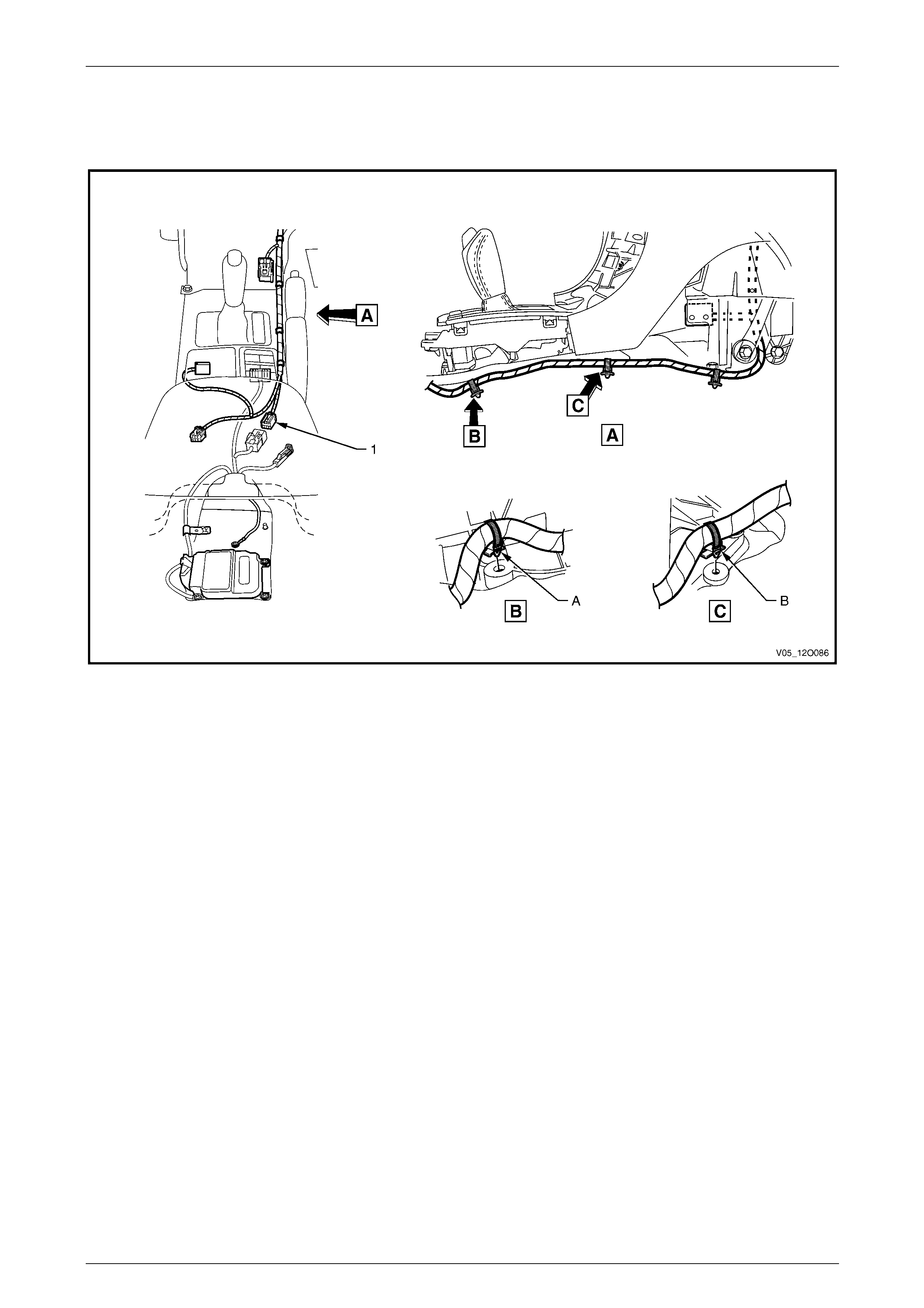
Fuses, Relays and Wiring Harnesses Page 12O–134
3.84 Front Body Harn ess – 49
Interior
Figure 12O – 123
Legend
1 Front Body Harness to Body Wiring Harness Connector
(X303) A Front body harness attached to tunnel as shown.
B Front body harness attached to tunnel as shown.
Page 12O–134
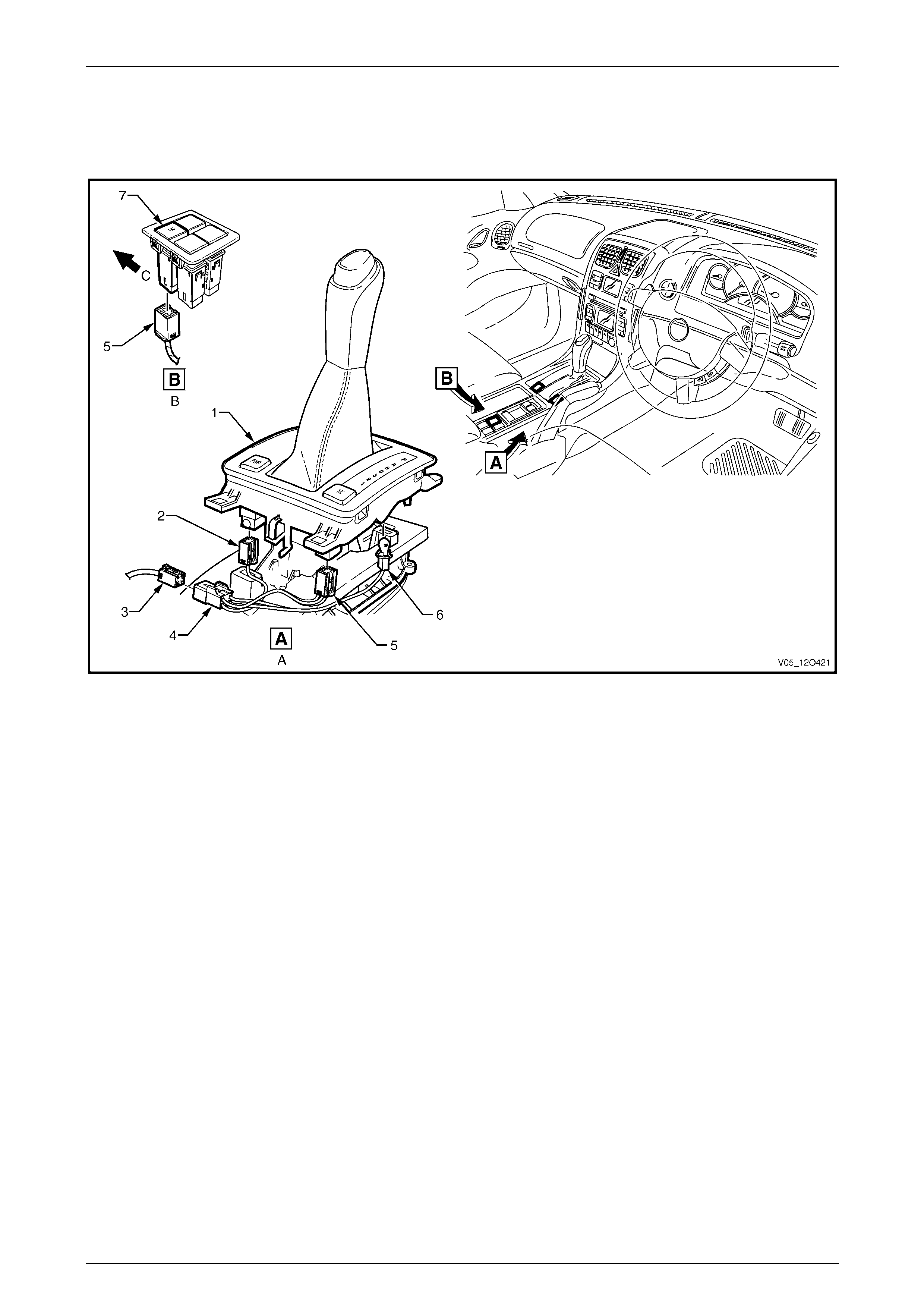
Fuses, Relays and Wiring Harnesses Page 12O–135
3.85 Front Body Harn ess – 50
Transmission Selector Connectors
Figure 12O – 124
Legend
1 PRNDL Selector Housing
2 Automatic Transmission Shift Program Switch Connector
(S22)
3 Front Body Harness to Transmission Selector Harness
Connector (X301)
4 Transmission Selector Harness to Front Body Harness
Connector (X301)
5 Electronic Traction Control Switch Connector (S73)
6 Automatic Transmission Control Position Indicator Lamp
Connector (E125)
7 Electronic Traction Control Switch
A Automatic transmission selector.
B Manual transmission.
C Front of vehicle.
Page 12O–135
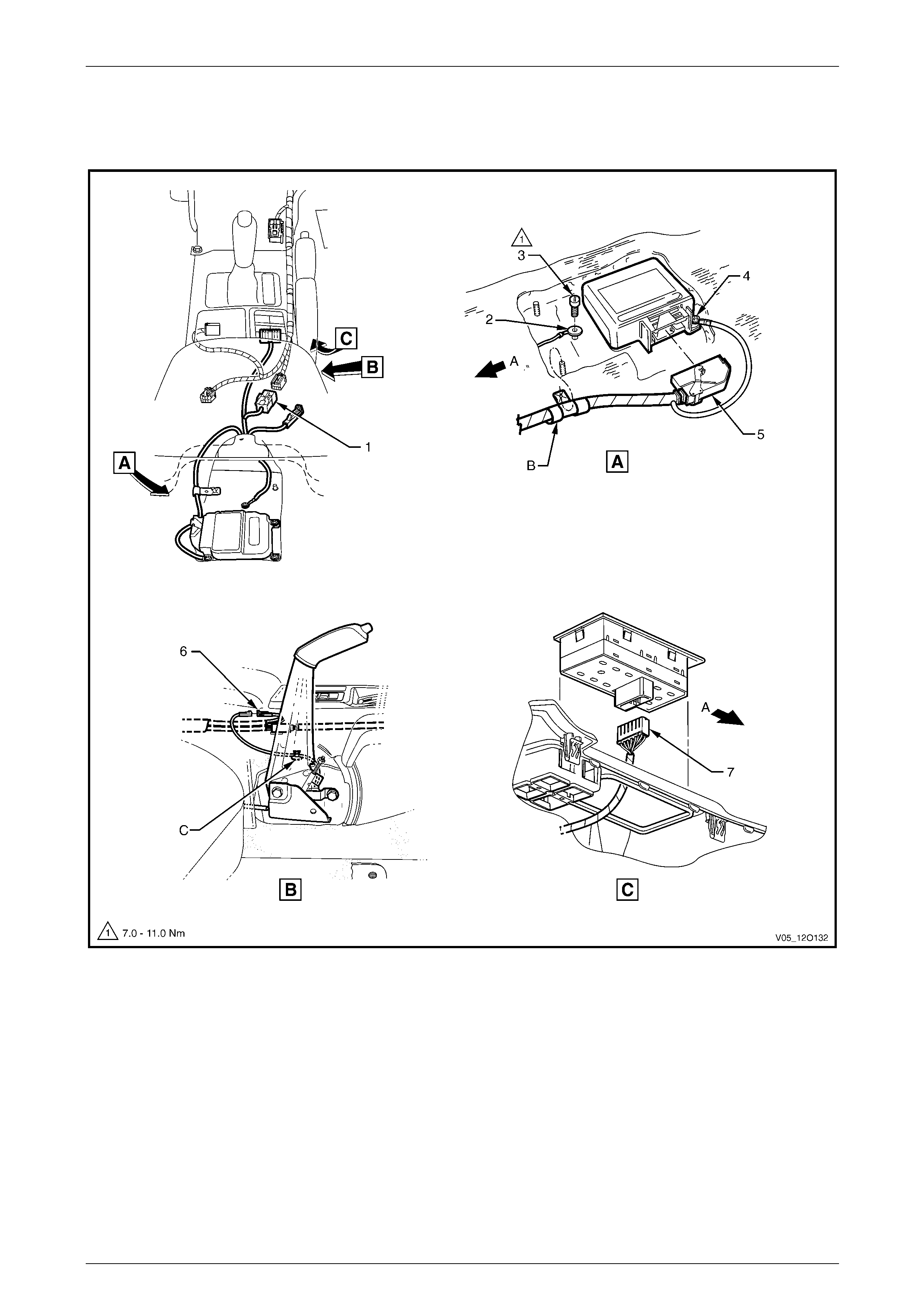
Fuses, Relays and Wiring Harnesses Page 12O–136
3.86 Body Wiring Harness – 1
Interior
Figure 12O – 125
Legend
1 Body Wiring Harness to Front Body Harness Connector
(X303)
2 Ground Terminal (X118 – GP12)
3 Body Wiring Harness Ground Terminal Attaching Screw
4 Ground Terminal (X118 – GP11)
5 Inflation Restraint Sensor Connector (A65)
6 Park Brake Switch Connector (S181)
7 Side Window (Master) Switch Connector (S222)
A Front of vehicle.
B Body wiring harness attached to tunnel as shown.
C Lead clipped as shown.
Page 12O–136
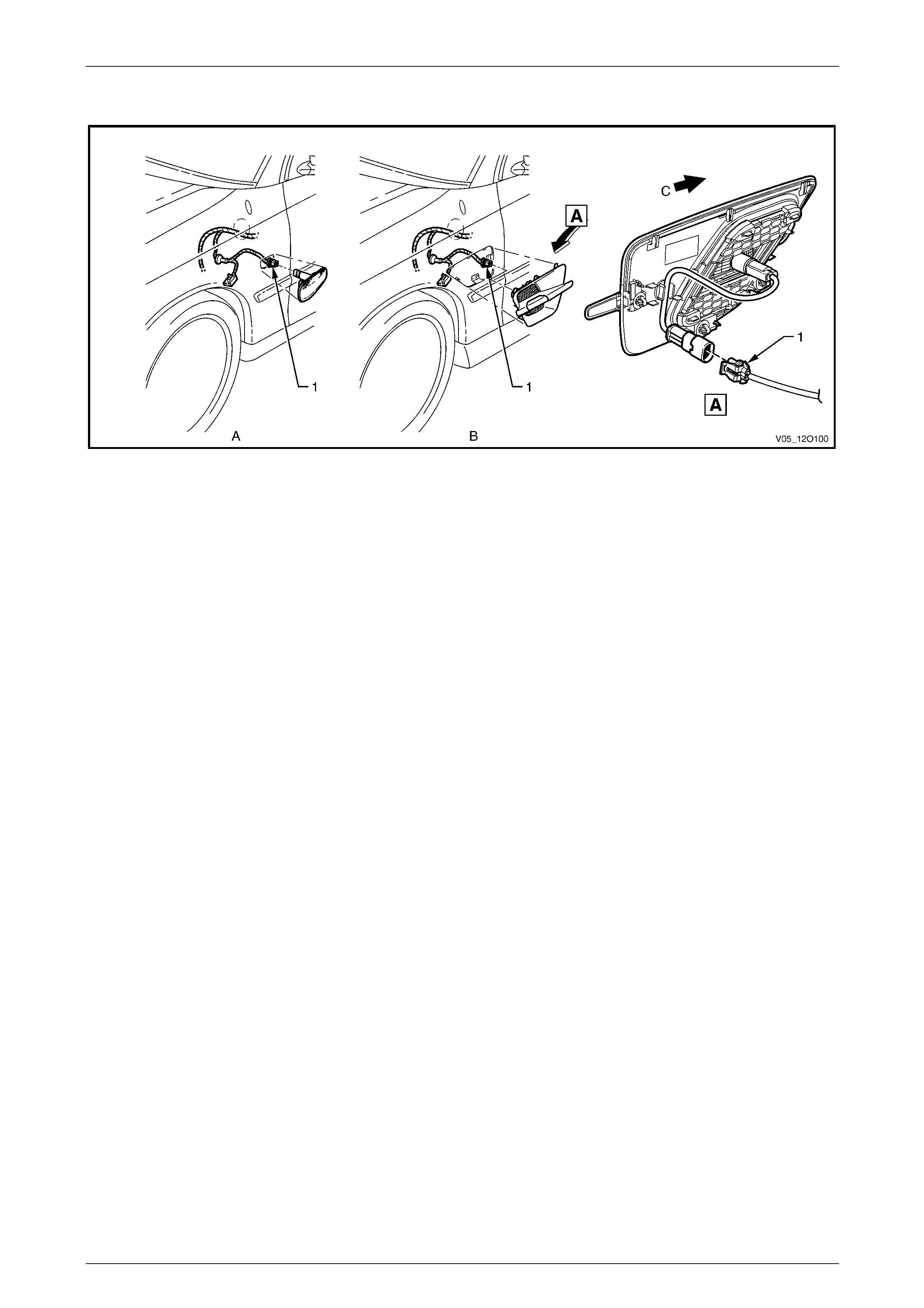
Fuses, Relays and Wiring Harnesses Page 12O–137
3.87 Body Wiring Harness – 2
Figure 12O – 126
Legend
1 Front Side Turn Signal Lamp Connector (E75) A Left-hand side shown.
B Left-hand Side SS shown.
C Front of vehicle.
Page 12O–137
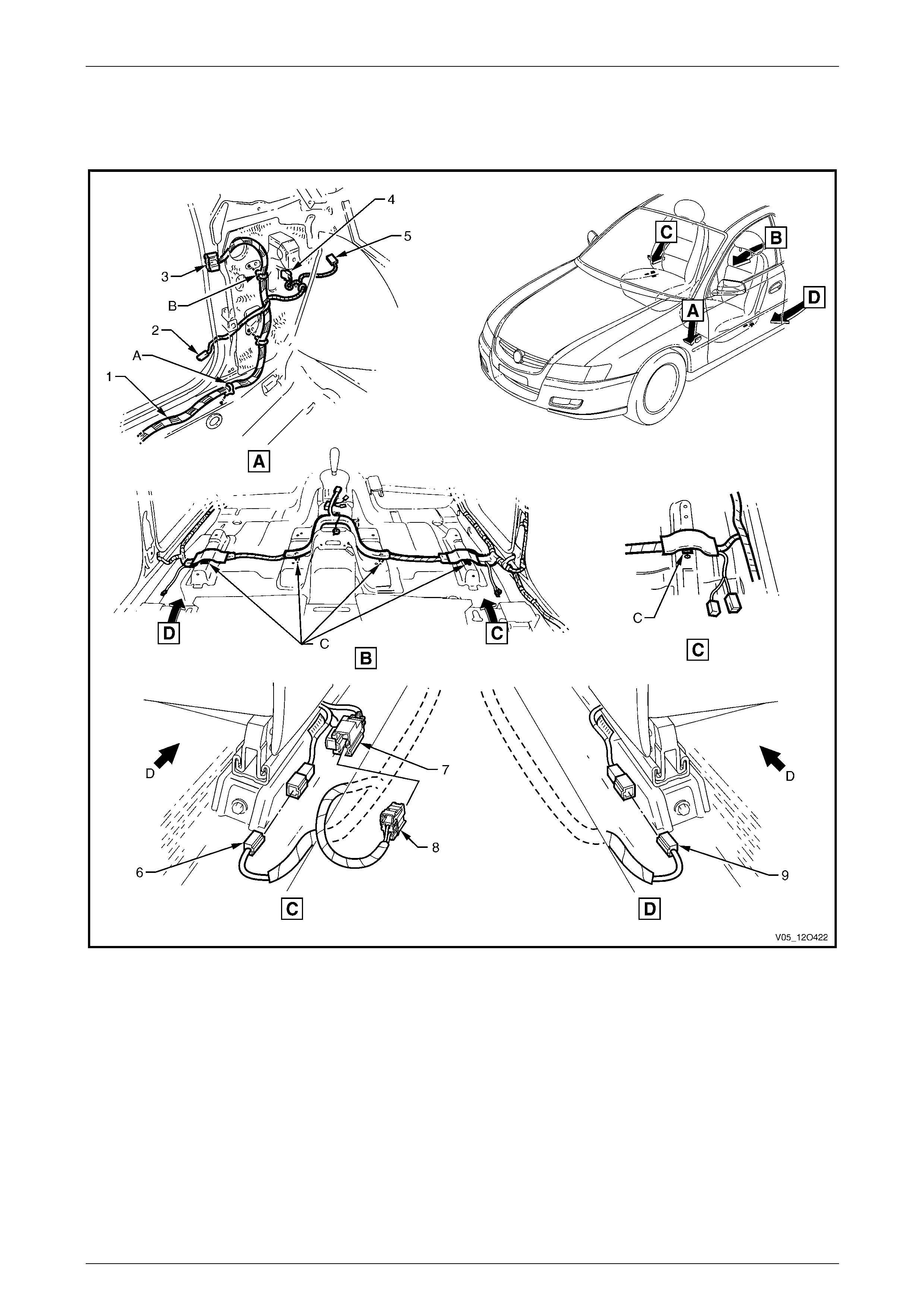
Fuses, Relays and Wiring Harnesses Page 12O–138
3.88 Body Wiring Harness – 3
Interior
Figure 12O – 127
Legend
1 Body Wiring Harness
2 Door Ajar Indicator Switch Connector (S156)
3 Body Wiring Harness to Left-hand Door Wiring Harness
Connector (X500)
4 Front Side Turn Signal Lamp Connector (E75 – L)
5 Radio Power Antenna Connector (W6 – X1)
6 Seat Belt Pre-tensioner Connector (Y128 – R)
7 Power Seat Harness to Body Wiring Harness Connector
(X302)
8 Body Wiring Harness to Power Seat Harness Connector
(X302)
9 Seat Belt Pre-tensioner Connector (Y129 – L)
A Body wiring harness attached to underbody as shown
(6 places).
B Attach body wiring harness to shroud side panel (2 places).
C Harness clipped to underbody as shown (4 places).
D Front of vehicle.
Page 12O–138
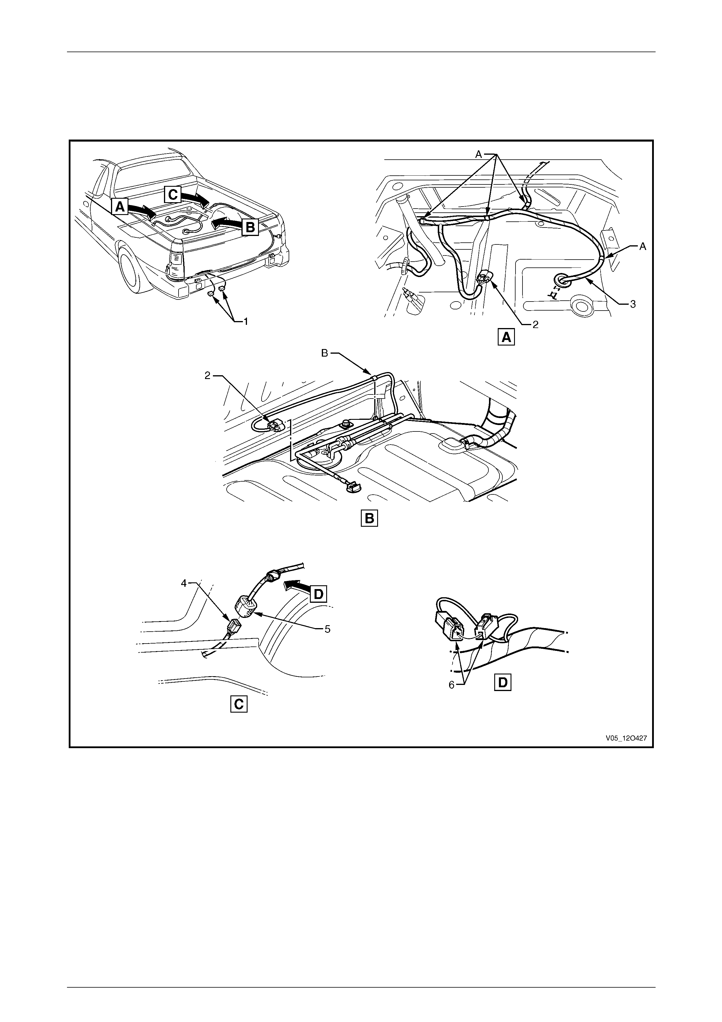
Fuses, Relays and Wiring Harnesses Page 12O–139
3.89 Body Wiring Harness – 4
Fuel Tank
Figure 12O – 128
Legend
1 Rear Licence Plate Lamp Connectors (E44 – U)
2 Fuel Pump Motor Connector (M8)
3 Body Wiring Harness
4 Body Wiring Harness to Rear Body Wiring Harness
Connector (X403)
5 Rear Body Wiring Harness to Body Wiring Harness
Connector (X403)
6 Ground Voltage Drop Connector (X148)
A Harness clipped to sheet metal (4 places).
B Harness clipped to fuel tank.
Page 12O–139
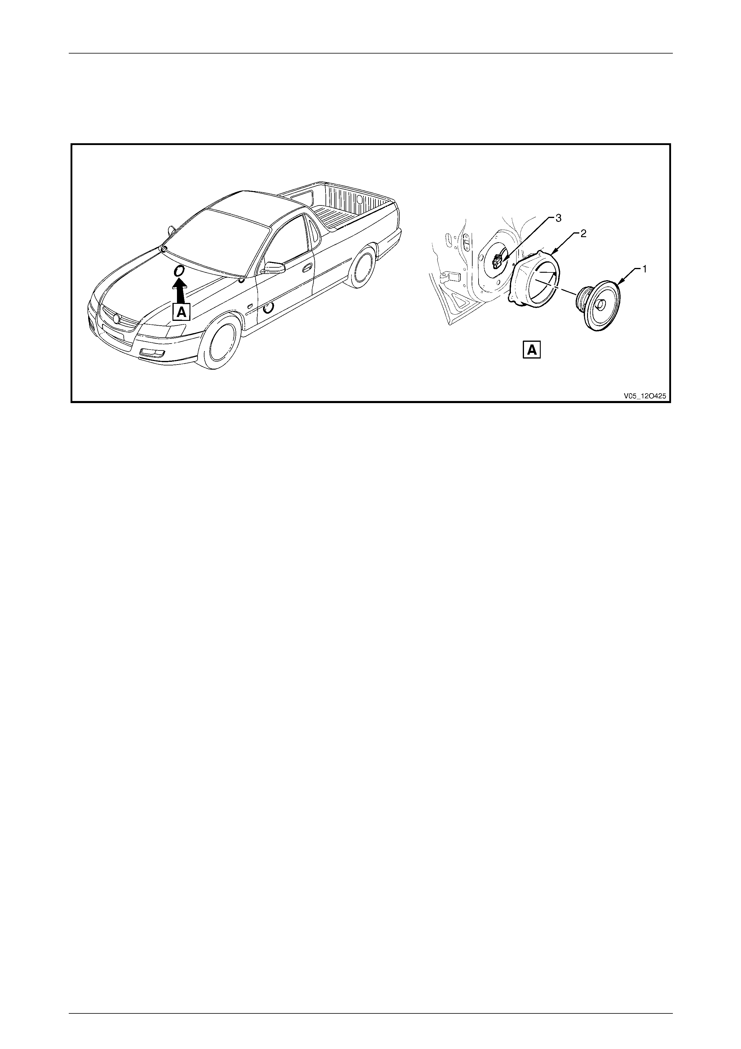
Fuses, Relays and Wiring Harnesses Page 12O–140
3.90 Body Wiring Harness – 5
Speakers
Figure 12O – 129
Legend
1 Door Radio Speaker Assembly
2 Door Radio Speaker Mounting Box Assembly 3 Door Radio Speaker Connector (B108)
Page 12O–140
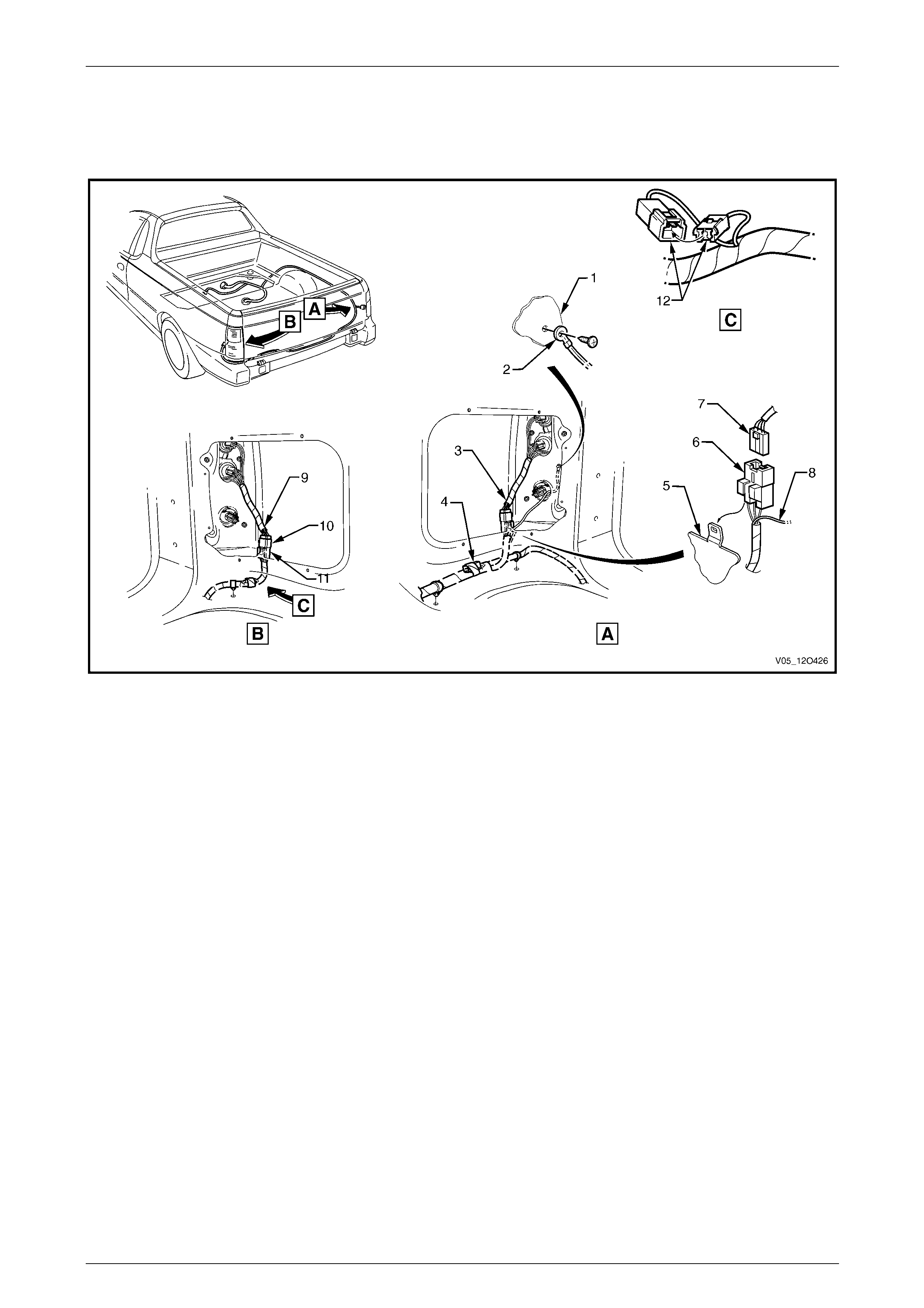
Fuses, Relays and Wiring Harnesses Page 12O–141
3.91 Body Wiring Harness – 6
Load Compartment
Figure 12O – 130
Legend
1 Side Panel Inner Extension
2 Body Ground Lead Terminal (X118 – GP14)
3 Right-hand Tail Lamp Harness
4 Body Wiring Harness to Trailer Wiring Harness Connector
(X908)
5 Side Inner Upper Panel
6 Body Wiring Harness to Tail Lamp Harness Connector
(X903)
7 Tail Lamp Harness to Body Wiring Harness Connector
(X903)
8 Body Ground Lead
9 Left-hand Tail Lamp Harness
10 Tail Lamp Harness to Body Wiring Harness Connector
(X904)
11 Body Wiring Harness to Tail Lamp Harness Connector
(X904)
12 Licence Plate Lamp Interconnect Connector (X909)
Page 12O–141
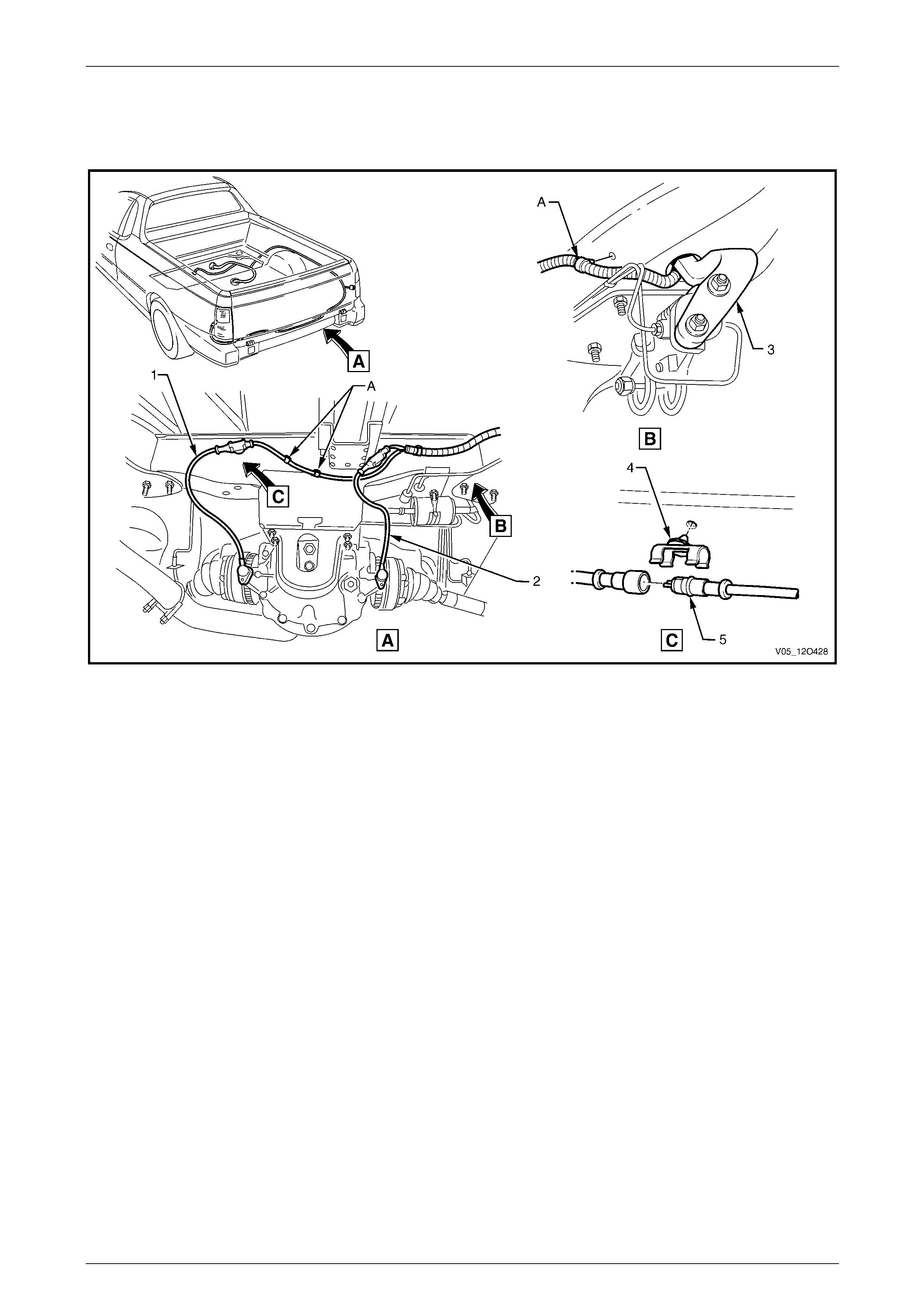
Fuses, Relays and Wiring Harnesses Page 12O–142
3.92 Body Wiring Harness – 7
ABS
Figure 12O – 131
Legend
1 Right-hand Rear A.B.S. Speed Sensor
2 Left-hand Rear A.B.S. Speed Sensor
3 Load Sensing Proportion Valve
4 Speed Sensor Connector Clip (2 places)
5 Rear Wheel Speed sensor Connector (B76)
A Harness clipped to rear cross member (3 places).
Page 12O–142
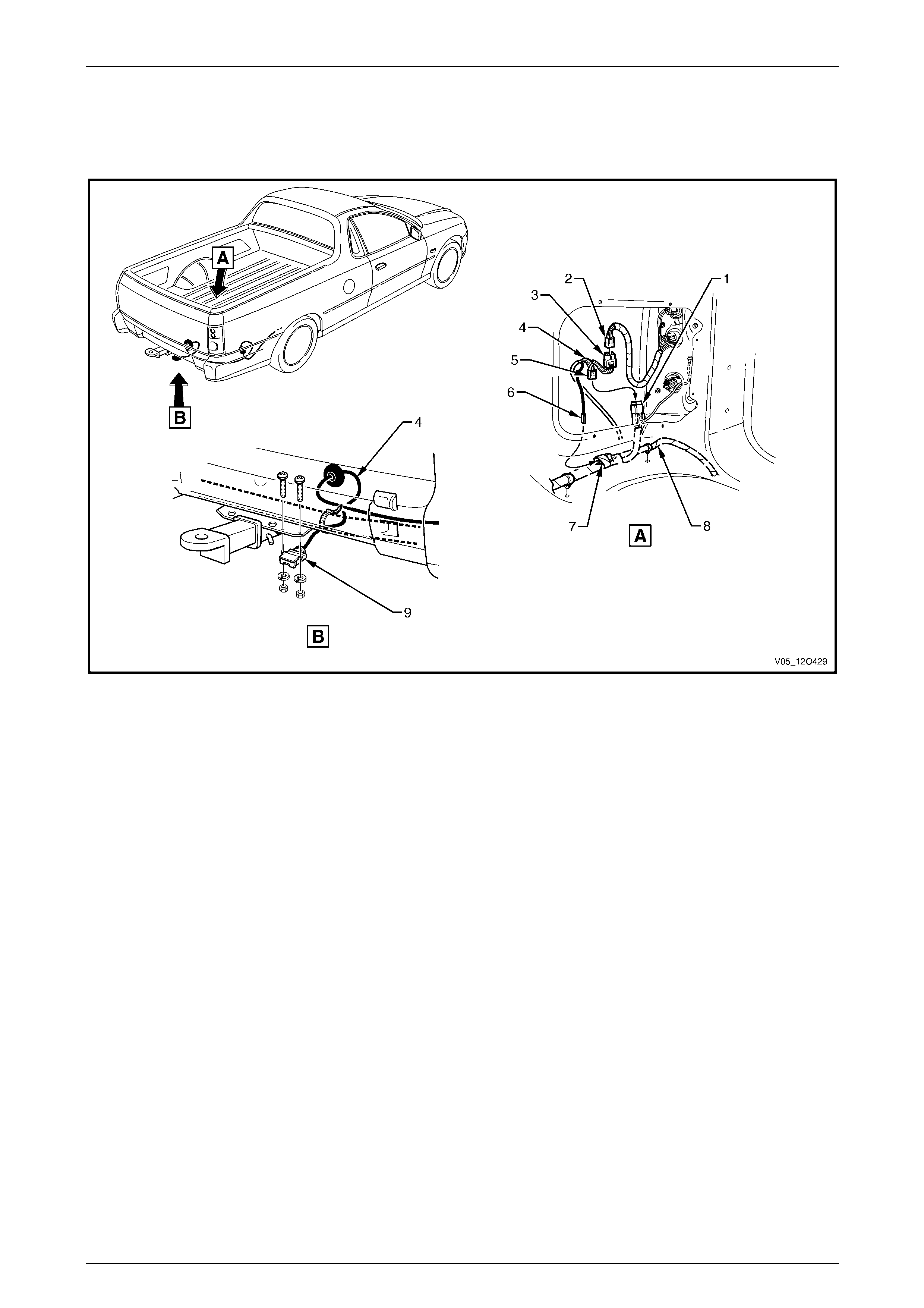
Fuses, Relays and Wiring Harnesses Page 12O–143
3.93 Body Wiring Harness – 8
Trailer Connectors
Figure 12O – 132
Legend
1 Rear Body Wiring Harness to Tail Lamp Harness Connector
(X903)
2 Tail Lamp Harness to Rear Body Wiring Harness Connector
(X903)
3 Trailer Lamp Harness to Right-hand Tail Lamp Harness
Connector (X38 – A)
4 Trailer Lamp Harness
5 Trailer Lamp Harness to Rear Body Wiring Harness
Connector (X38 – B)
6 Trailer Lamp Harness to Rear Body Wiring Harness
Connector (X908)
7 Rear Body Wiring Harness to Trailer Lamp Harness
Connector (X908)
8 Rear Body Wiring Harness
9 Trailer Lamp Harness Connector (X109)
Page 12O–143
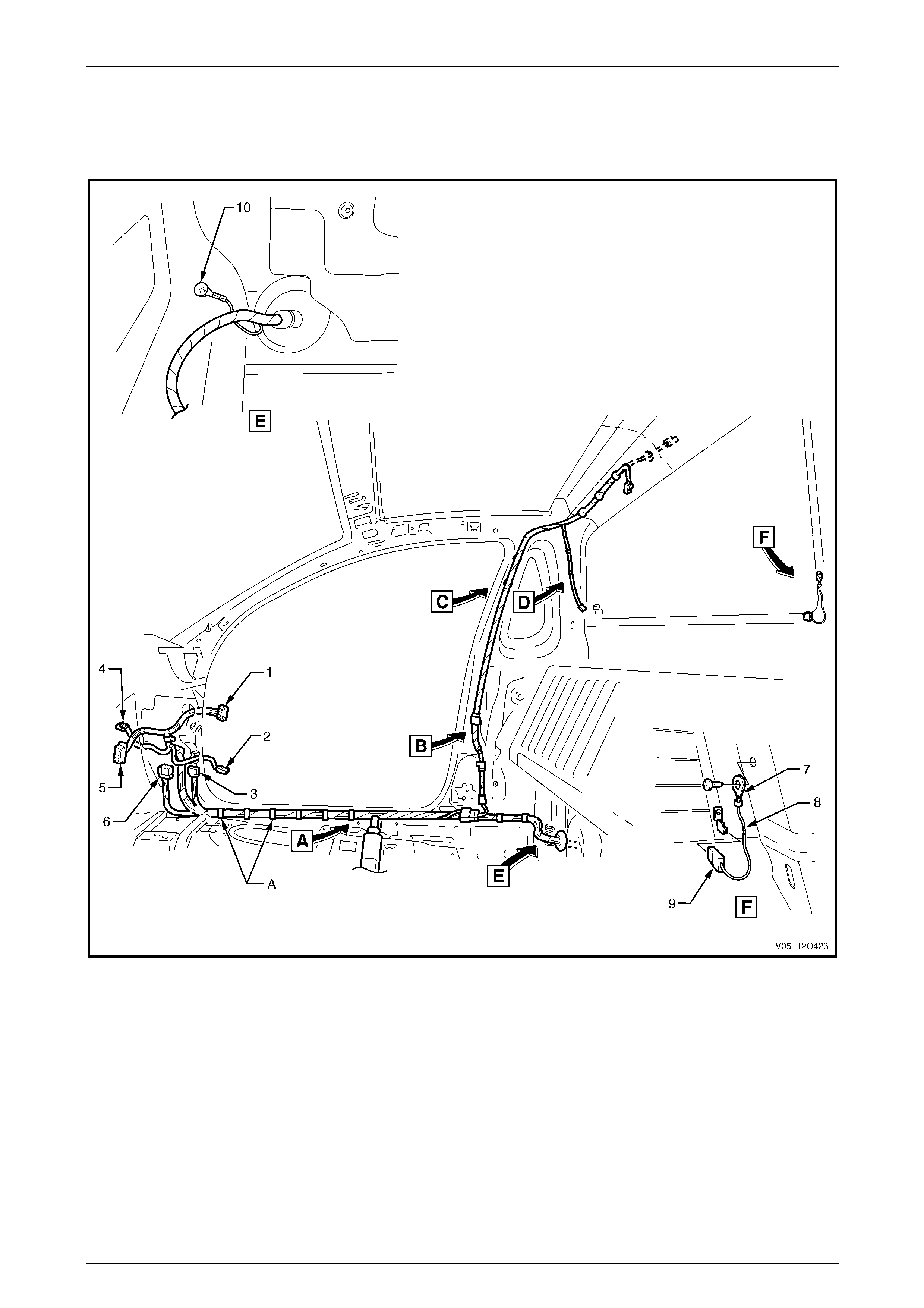
Fuses, Relays and Wiring Harnesses Page 12O–144
3.94 Body & Roof Lamp Harnesses – 1
Interior
Figure 12O – 133
Legend
1 Body Wiring Harness to Right-hand Door Wiring Harness
Connector (X600)
2 Door Ajar Indicator Switch Connector (S156)
3 Body Wiring Harness to Front Body Harness Connector
(X201)
4 Front Side Turn Signal Lamp Connector (E75 – R)
5 Body Control Module Connector (A15 – X4)
6 Body Wiring Harness to Front Body Harness Connector
(X200)
7 Ground Lead Terminal (X118 –GP7)
8 Rear Window Defog Grid Ground Lead
9 Rear Window Defog Grid Ground Lead Connector
(R22 – X2)
10 Ground Lead Terminal (X118 –GP13)
A Harness clipped to underbody (10 places).
For views A to D, refer to 3.95 Body & Roof Lamp Harnesses – 2.
Page 12O–144
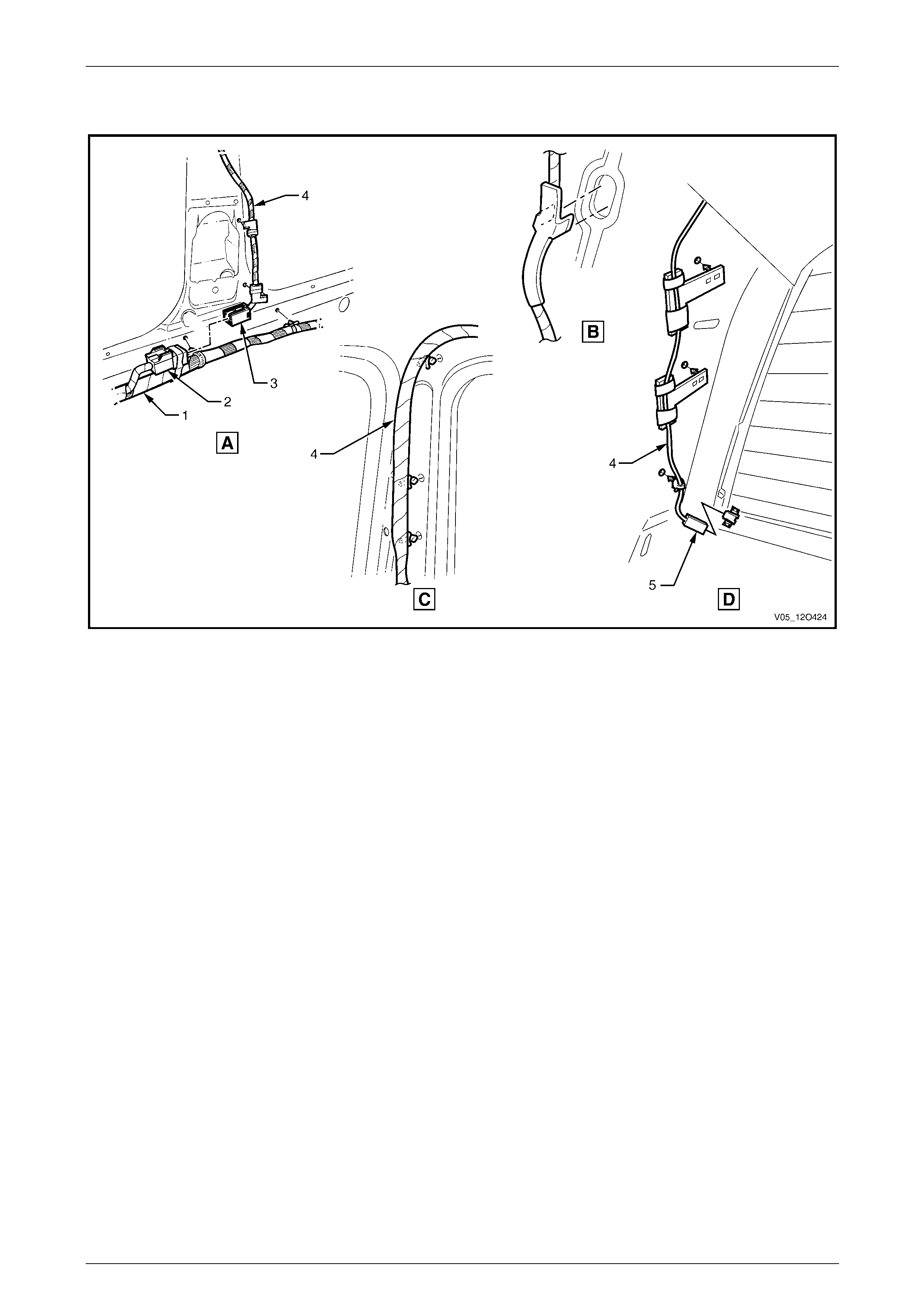
Fuses, Relays and Wiring Harnesses Page 12O–145
3.95 Body & Roof Lamp Harnesses – 2
Figure 12O – 134
Legend
1 Body Wiring Harness
2 Body Wiring Harness to Roof Lamp Harness Connector
(X300)
3 Roof Lamp Harness to Body Wiring Harness Connector
(X300)
4 Roof Lamp Harness
5 Rear Window Defog Grid Connector (R22 – X1)
Page 12O–145
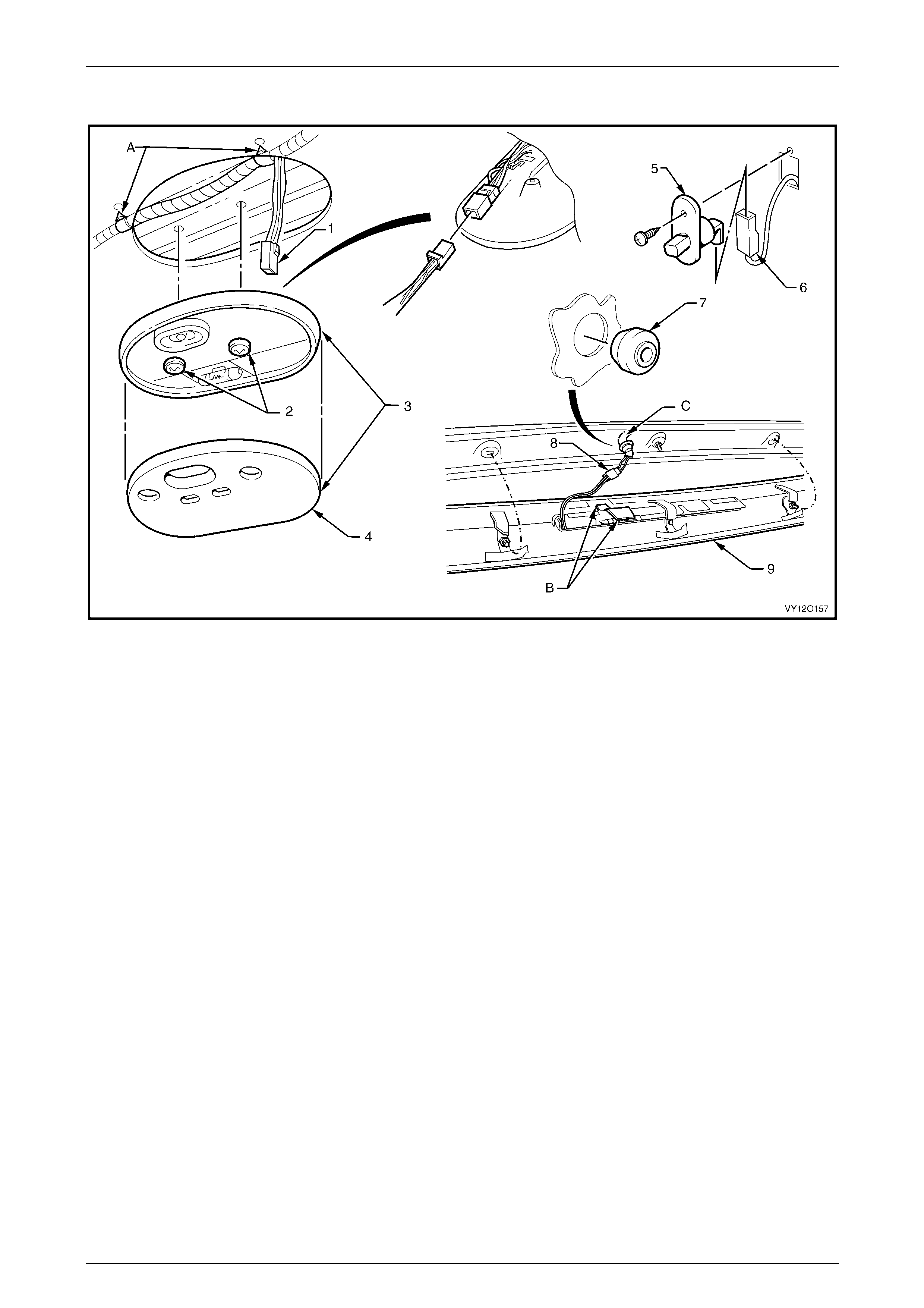
Fuses, Relays and Wiring Harnesses Page 12O–146
3.96 Roof Lamp Harness
Figure 12O – 135
Legend
1 Dome Lamp Connector (E67)
2 Dome Lamp Screws
3 Dome Lamp Assembly
4 Dome Lamp Lens
5 Door Ajar Indicator Switch
6 Door Ajar Indicator Switch Connector (S156)
7 Harness Blanking Plug
8 High Mount Stop Lamp Connector (E79 – U)
9 Roof Rear Centre Capping
A Harness clipped to rear roof header reinforcement
(3 places).
B High level stop lamp harness stowed into roof centre
capping rib.
C For roof lamp harness continuation, refer to
3.94 Body & Roof Lamp Harnesses – 1.
Page 12O–146
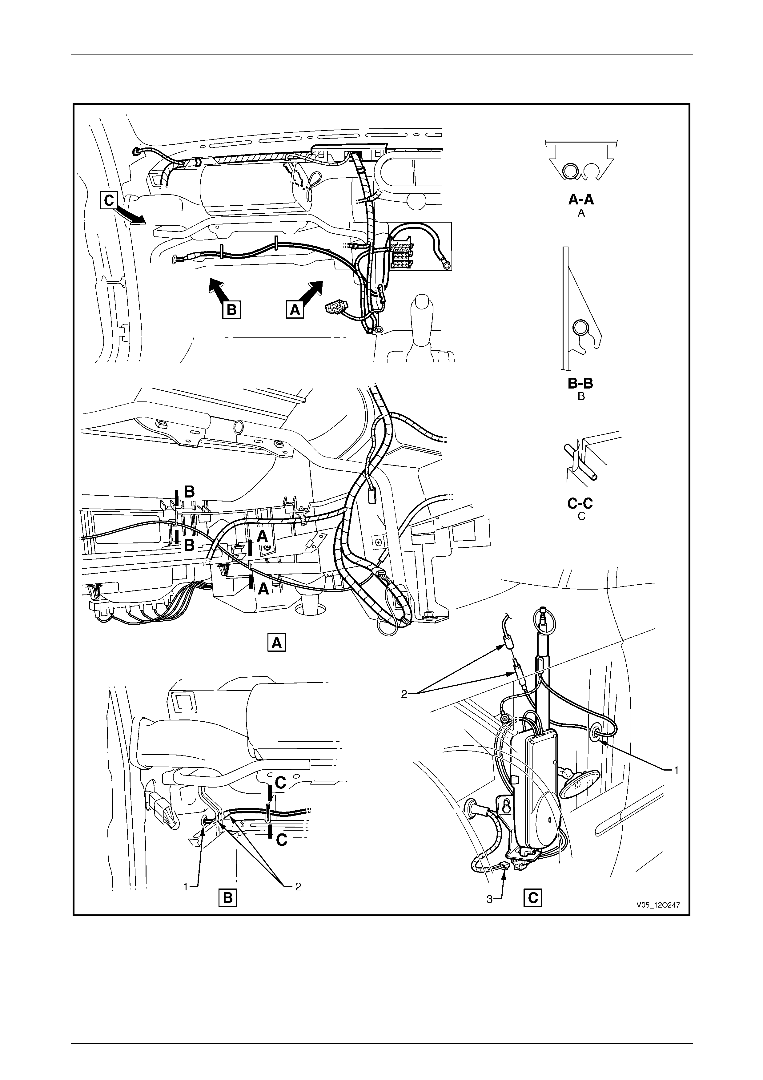
Fuses, Relays and Wiring Harnesses Page 12O–147
3.97 Radio Antenna Wiring
Figure 12O – 136
Page 12O–147

Fuses, Relays and Wiring Harnesses Page 12O–148
Legend
1 Antenna Lead Panel Blanking Grommet
2 Power Antenna Lead Connector (X209)
3 Radio Power Antenna Connector (W6 – X1)
A Leads clipped to underside of heating, ventilation and
air-conditioning assembly as shown.
B Leads clipped to front side of heating, ventilation and
air-conditioning assembly as shown.
C Leads tucked behind routing post on heating, ventilation and
air-conditioning assembly as shown.
Page 12O–148
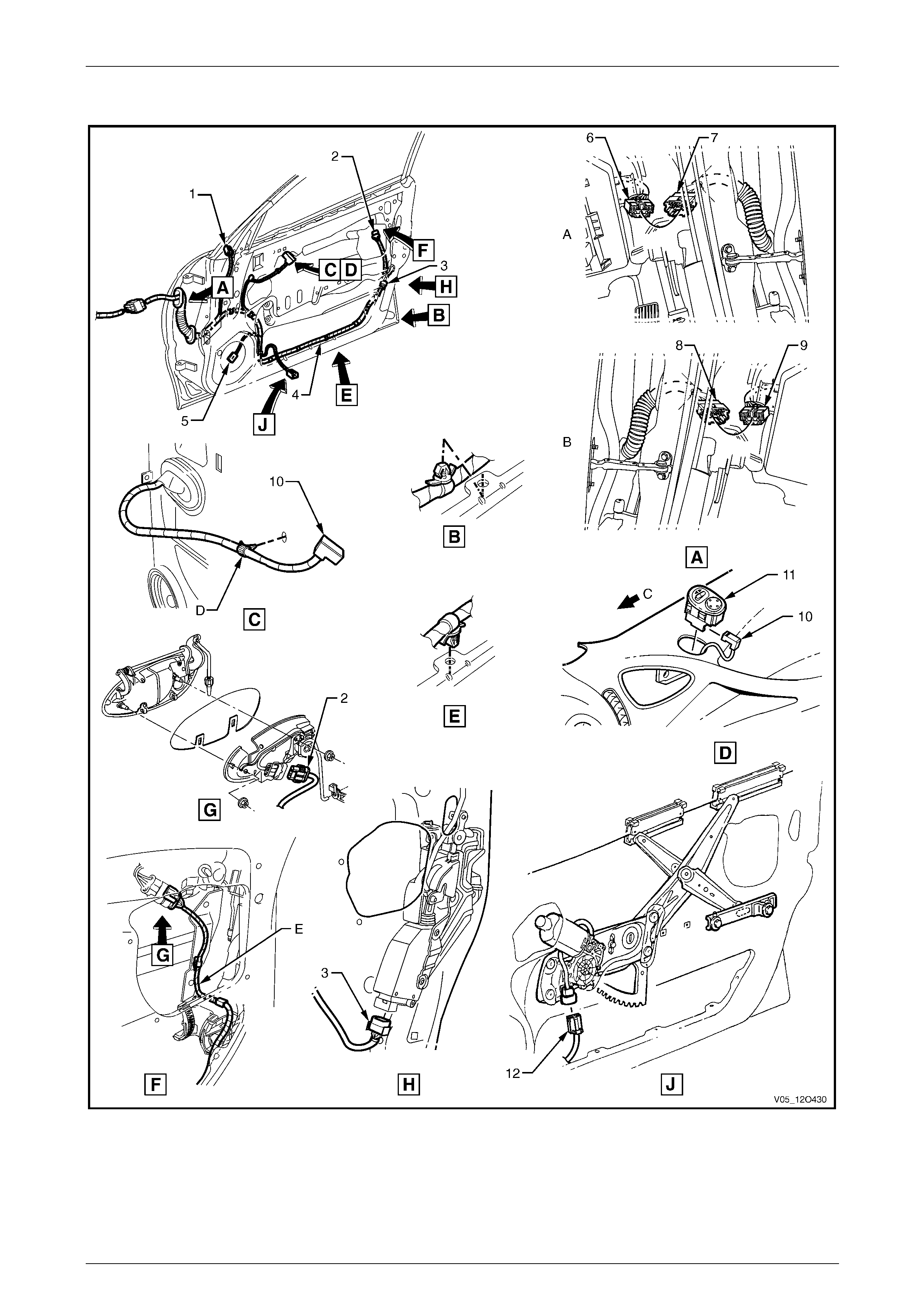
Fuses, Relays and Wiring Harnesses Page 12O–149
3.98 Door Wiring Harness
Figure 12O – 137
Page 12O–149

Fuses, Relays and Wiring Harnesses Page 12O–150
Legend
1 Outside Rear-view Mirror Motor Connector (M11)
2 Door Lock Switch Connector (S63)
3 Door Lock Actuator Connector (Y13)
4 Door Wiring Harness
5 Door Radio Speaker Connector (B108)
6 Body Wiring Harness to Right-hand Door Wiring Harness
Connector (X600)
7 Right-hand Door Wiring Harness to Body Wiring Harness
Connector (X600)
8 Left-hand Door Wiring Harness to Body Wiring Harness
Connector (X500)
9 Body Wiring Harness to Left-hand Door Wiring Harness
Connector (X500)
10 Outside Rear-view Mirror Remote Control Switch Connector
(S169)
11 Outside Rear-view Mirror Remote Control Switch
12 Door Window Regulator Connector (M10)
A Right-hand door shown.
B Left-hand door shown.
C Front of vehicle.
D Harness clipped to inner door panel as shown.
E Harness routed as shown.
Page 12O–150
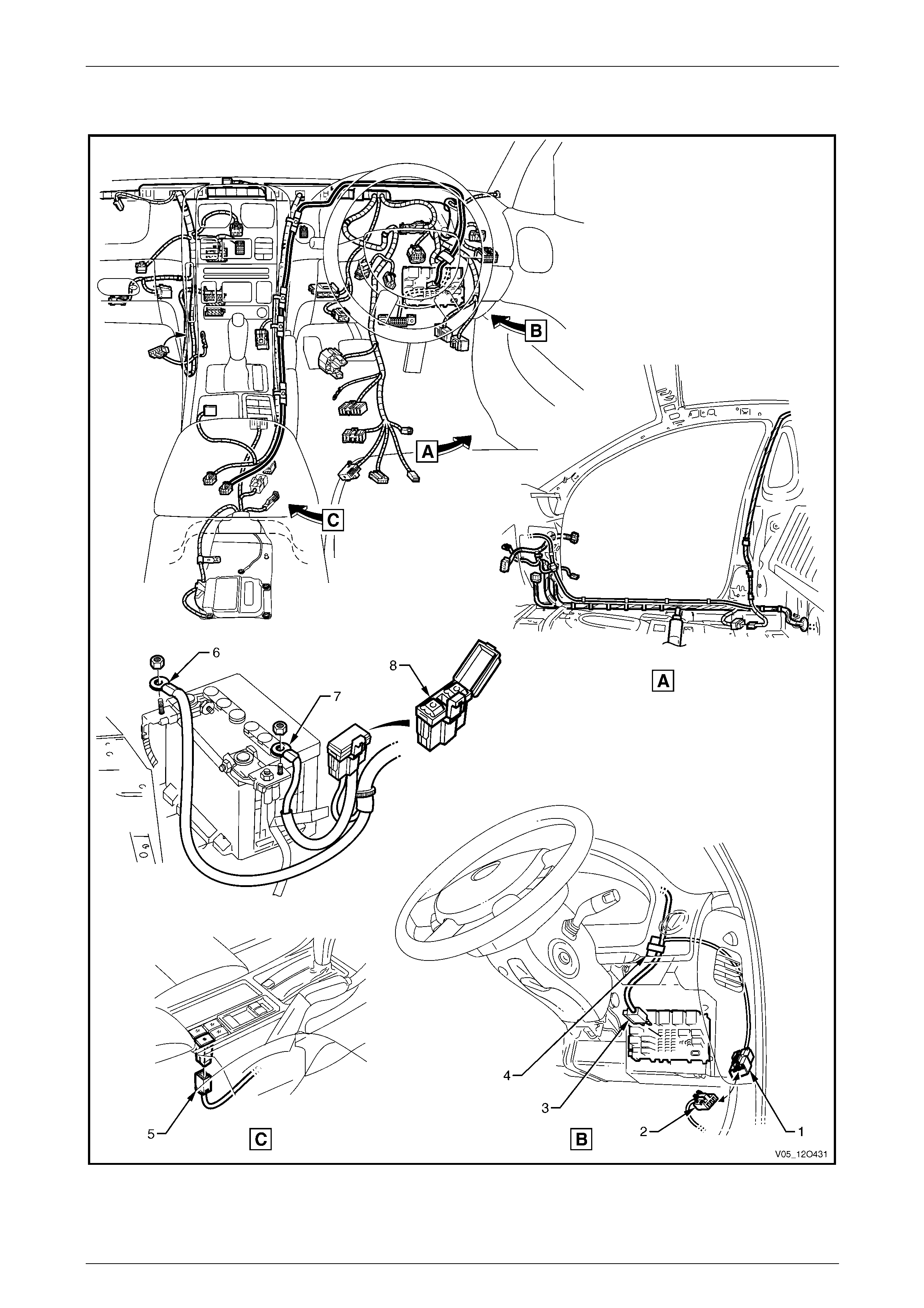
Fuses, Relays and Wiring Harnesses Page 12O–151
3.99 9C1 Option – 1
Figure 12O – 138
Page 12O–151

Fuses, Relays and Wiring Harnesses Page 12O–152
Legend
1 Lights Out Harness to Roof Lamp Harness Connector
(X317)
2 Roof Lamp Harness to Lights Out Harness Connector
(X317)
3 Fuse (X7)
4 Fuse Block (X133)
5 Interior Lights Over-ride Switch Connector (S156 – 9C1)
6 Auxiliary Negative Terminal (X86 – F)
7 Auxiliary Positive Terminal (X86 – E)
8 Fuse Block Assembly (X126 – AUX)
Page 12O–152
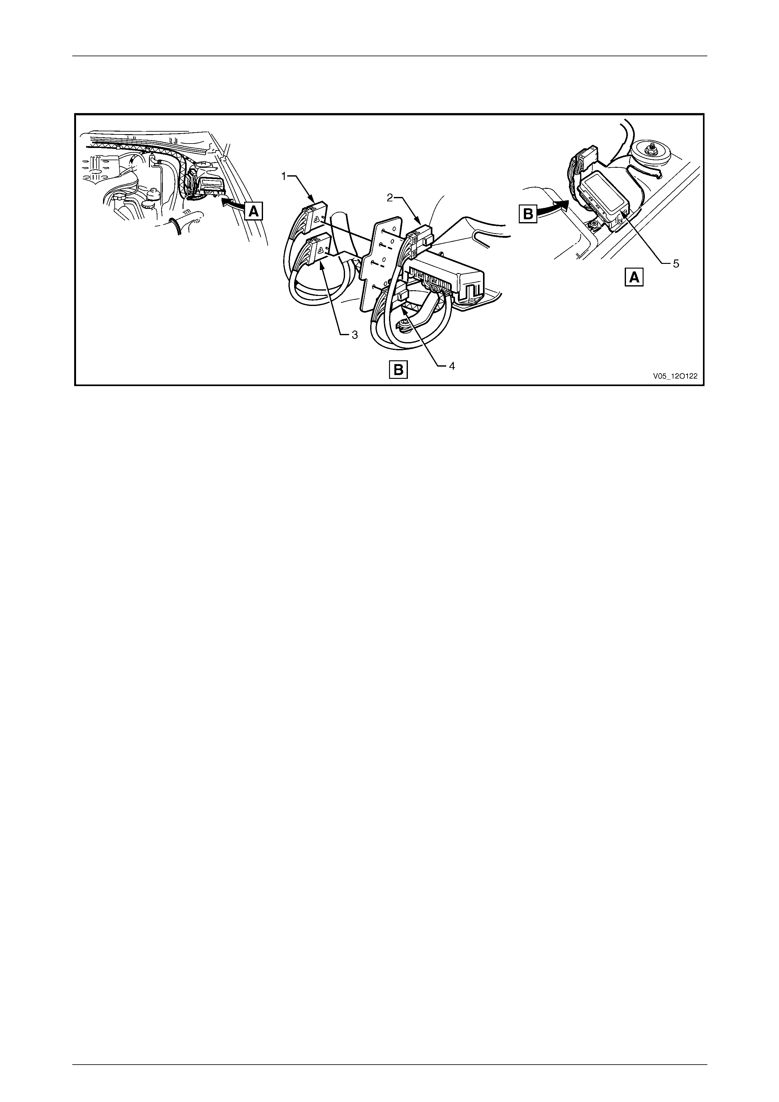
Fuses, Relays and Wiring Harnesses Page 12O–153
3.100 9C1 Option – 2
Figure 12O – 139
Legend
1 Battery Negative Cable Junction Block Connector
(X91 – AUX4)
2 Battery Positive Cable Junction Block Connector
(X89 – AUX1)
3 Battery Negative Cable Junction Block Connector
(X91 – AUX3)
4 Battery Positive Cable Junction Block Connector
(X89 – AUX2)
5 Auxiliary Battery Harness Junction Block (X94)
Page 12O–153

Fuses, Relays and Wiring Harnesses Page 12O–154
4 Wiring Installation Diagrams –
Regular Cab
The following figures illustrate the vehicle wiring installation diagrams for Regular Cab veh icles.
For information relating to the wiring harness installation diagrams not prov ided in this section, refer to
3 Wiring Installation Diagrams – Utility.
Page 12O–154
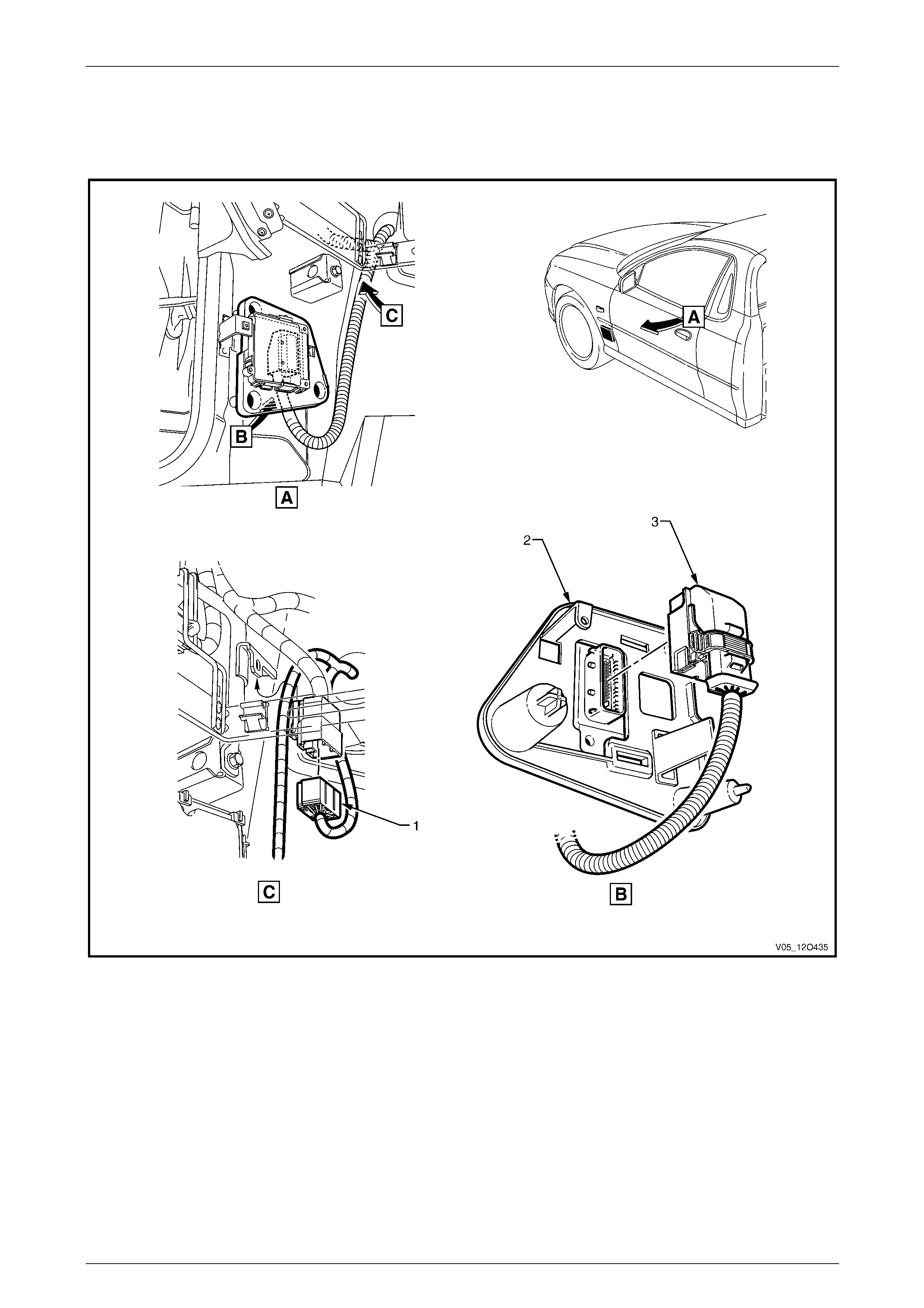
Fuses, Relays and Wiring Harnesses Page 12O–155
4.1 Transmission Harness
V6 Engine – 4 Speed Automatic Transmission
Figure 12O – 140
Legend
1 Transmission Harness to Front Body Harness Connector
(X203)
2 Transmission Control Module
3 Transmission Control Module Connector (A112 – 4SPD)
Page 12O–155
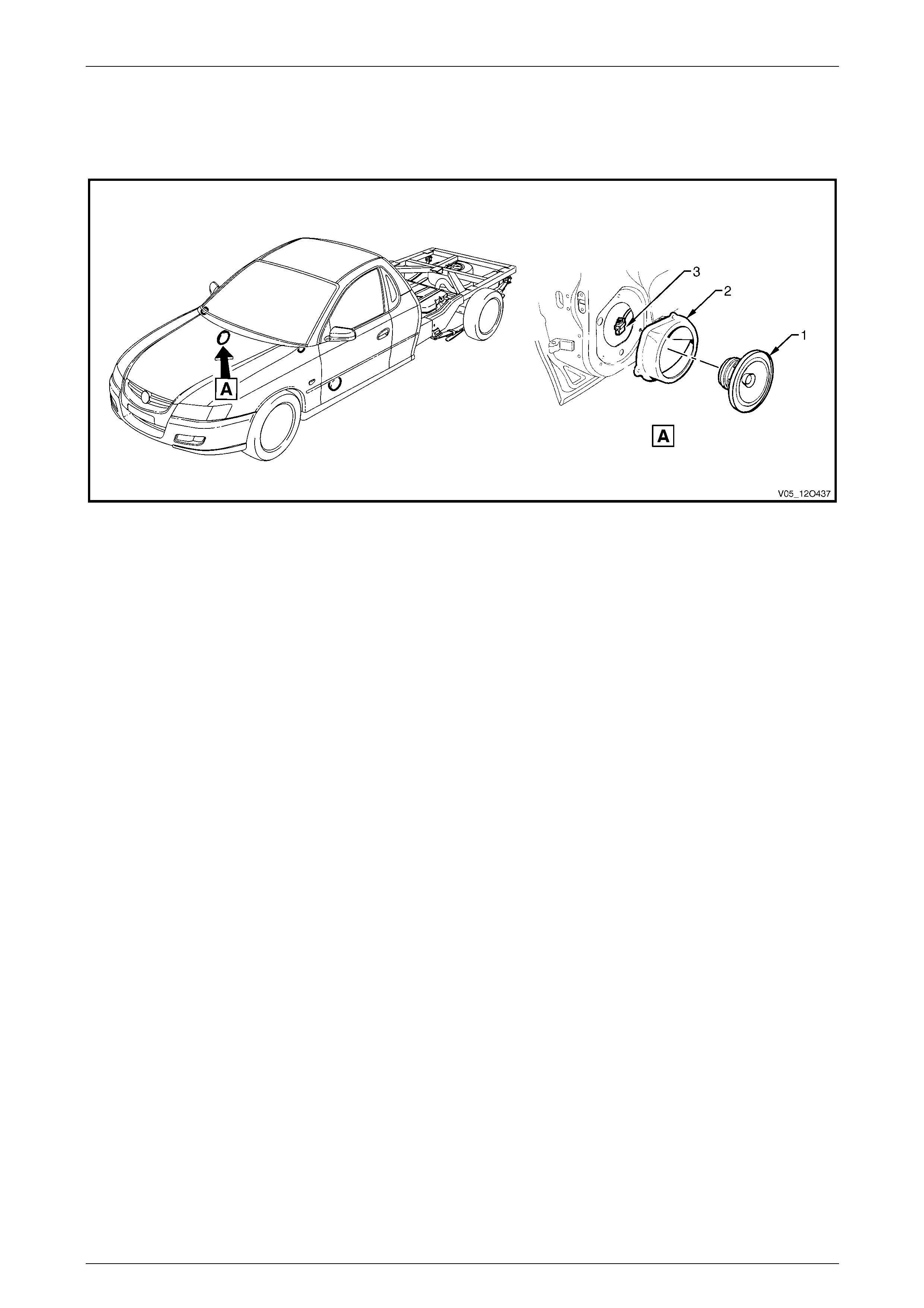
Fuses, Relays and Wiring Harnesses Page 12O–156
4.2 Body Wiring Harness – 1
Speakers
Figure 12O – 141
Legend
1 Door Radio Speaker Assembly
2 Door Radio Speaker Mounting Box Assembly 3 Door Radio Speaker Connector (B108)
Page 12O–156
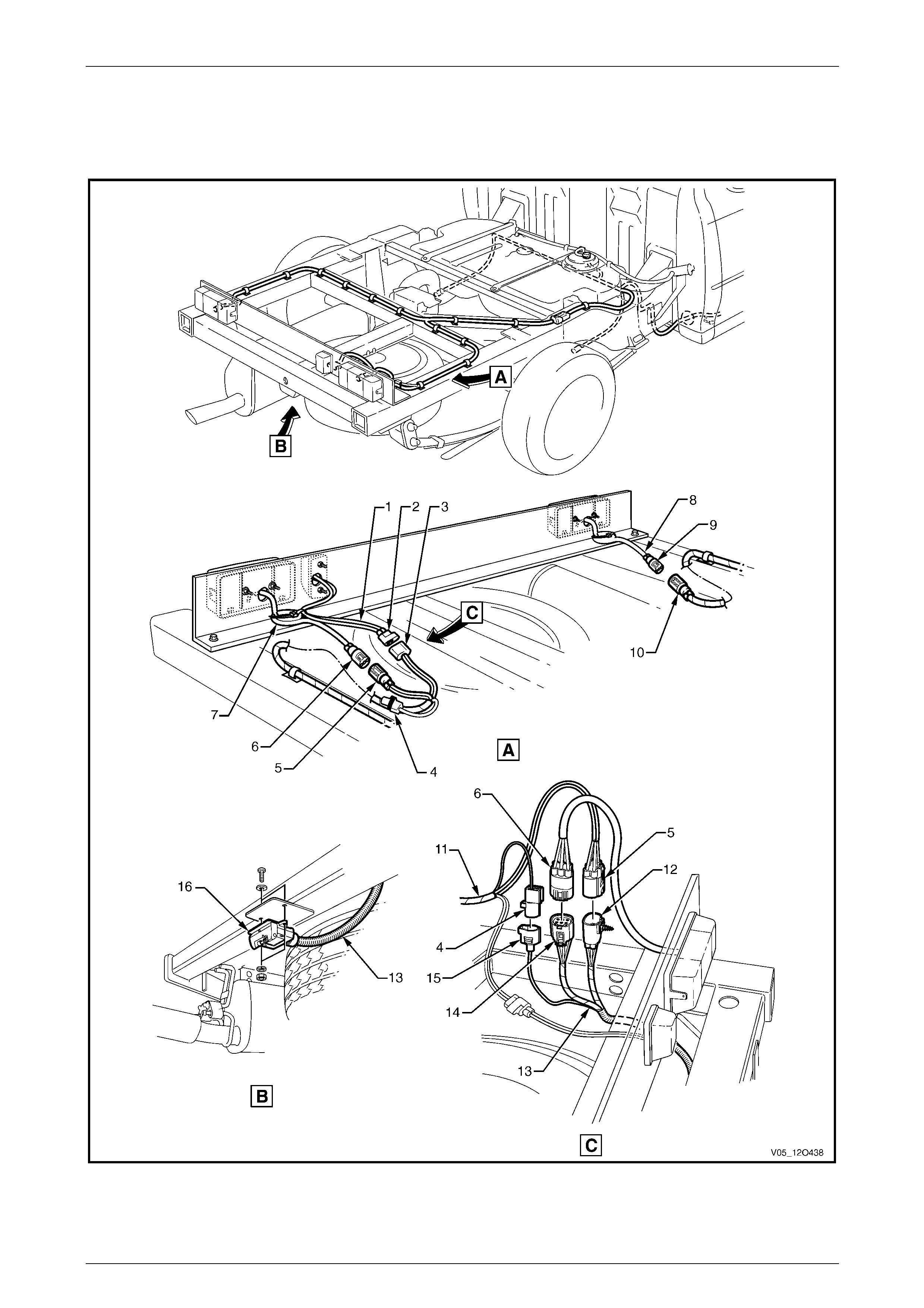
Fuses, Relays and Wiring Harnesses Page 12O–157
4.3 Body Wiring Harness – 2
Load Compartment and Trailer Connectors
Figure 12O – 142
Page 12O–157

Fuses, Relays and Wiring Harnesses Page 12O–158
Legend
1 Licence Plate Lamp Harness
2 Licence Plate Lamp Harness to Rear Body Wiring Harness
Connector (X909)
3 Rear Body Wiring Harness to Licence Plate Lamp Harness
Connector (X909)
4 Rear Body Wiring Harness to Trailer Wiring Harness
Connector (X908)
5 Rear Body Wiring Harness to Right-hand Tail Lamp Harness
Connector (X903)
6 Right-hand Tail Lamp Harness to Rear Body Wiring Harness
Connector (X903)
7 Right-hand Tail Lamp Harness
8 Left-hand Tail Lamp Harness
9 Left-hand Tail Lamp Harness to Rear Body Wiring Harness
Connector (X904)
10 Rear Body Wiring Harness to Left-hand Tail Lamp Harness
Connector (X904)
11 Rear Body Wiring Harness
12 Trailer Wiring Harness to Rear Body Wiring Harness
Connector (X38A)
13 Trailer Wiring Harness
14 Trailer Wiring Harness to Right-hand Tail Lamp Harness
Connector (X38B)
15 Trailer Wiring Harness to Rear Body Wiring Harness
Connector (X908)
16 Trailer Wiring Connector (X109)
Page 12O–158
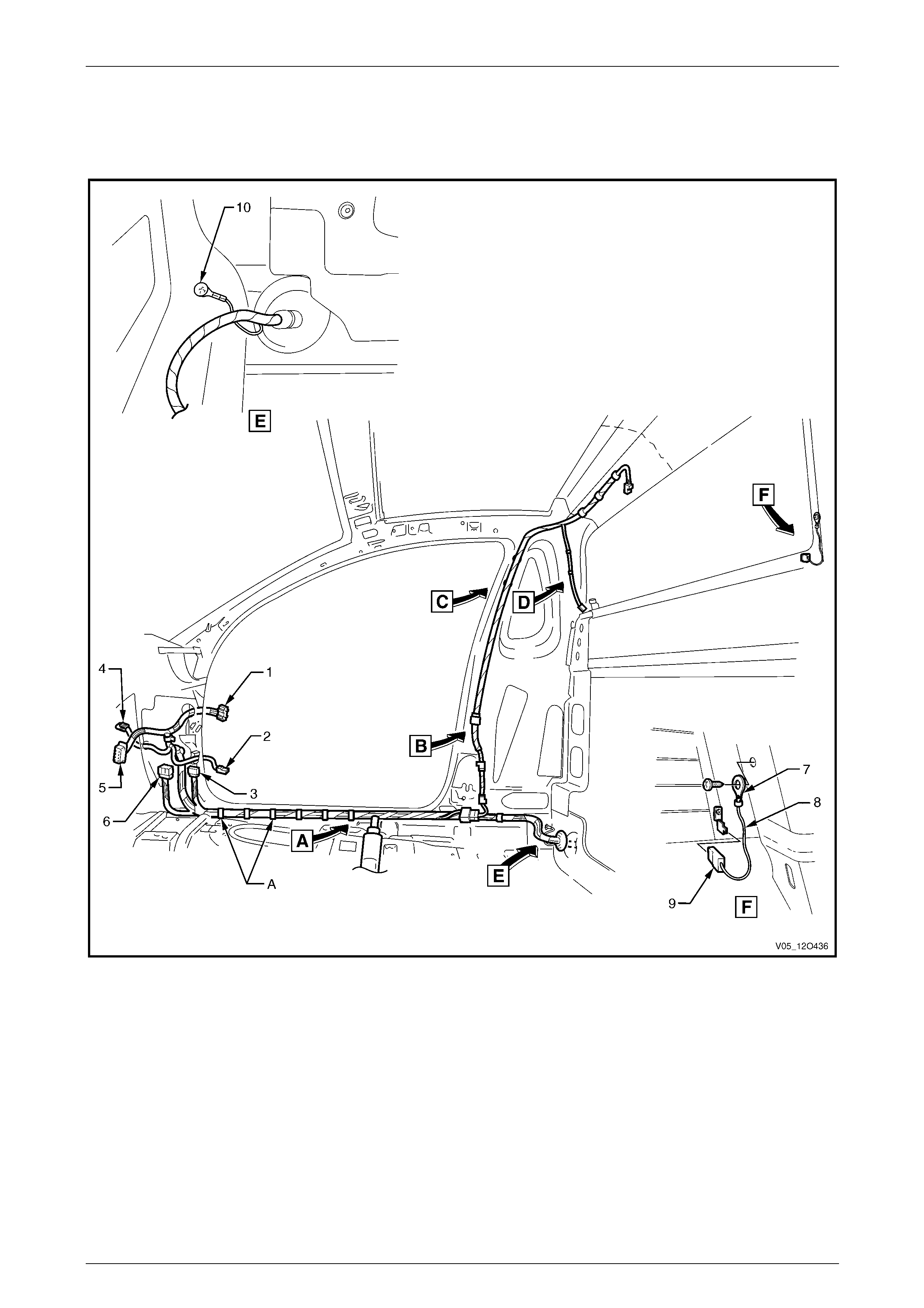
Fuses, Relays and Wiring Harnesses Page 12O–159
4.4 Body & Roof Lamp Harnesses
Interior
Figure 12O – 143
Legend
1 Body Wiring Harness to Right-hand Door Wiring Harness
Connector (X600)
2 Door Ajar Indicator Switch Connector (S156)
3 Body Wiring Harness to Front Body Harness Connector
(X201)
4 Front Side Turn Signal Lamp Connector (E75 – R)
5 Body Control Module Connector (A15 – X4)
6 Body Wiring Harness to Front Body Harness Connector
(X200)
7 Ground Lead Terminal (X118 –GP7)
8 Rear Window Defog Grid Ground Lead
9 Rear Window Defog Grid Ground Lead Connector
(R22 – X2)
10 Ground Lead Terminal (X118 –GP13)
A Harness clipped to underbody (10 places).
For views A to D, refer to 3.95 Body & Roof Lamp Harnesses – 2.
Page 12O–159
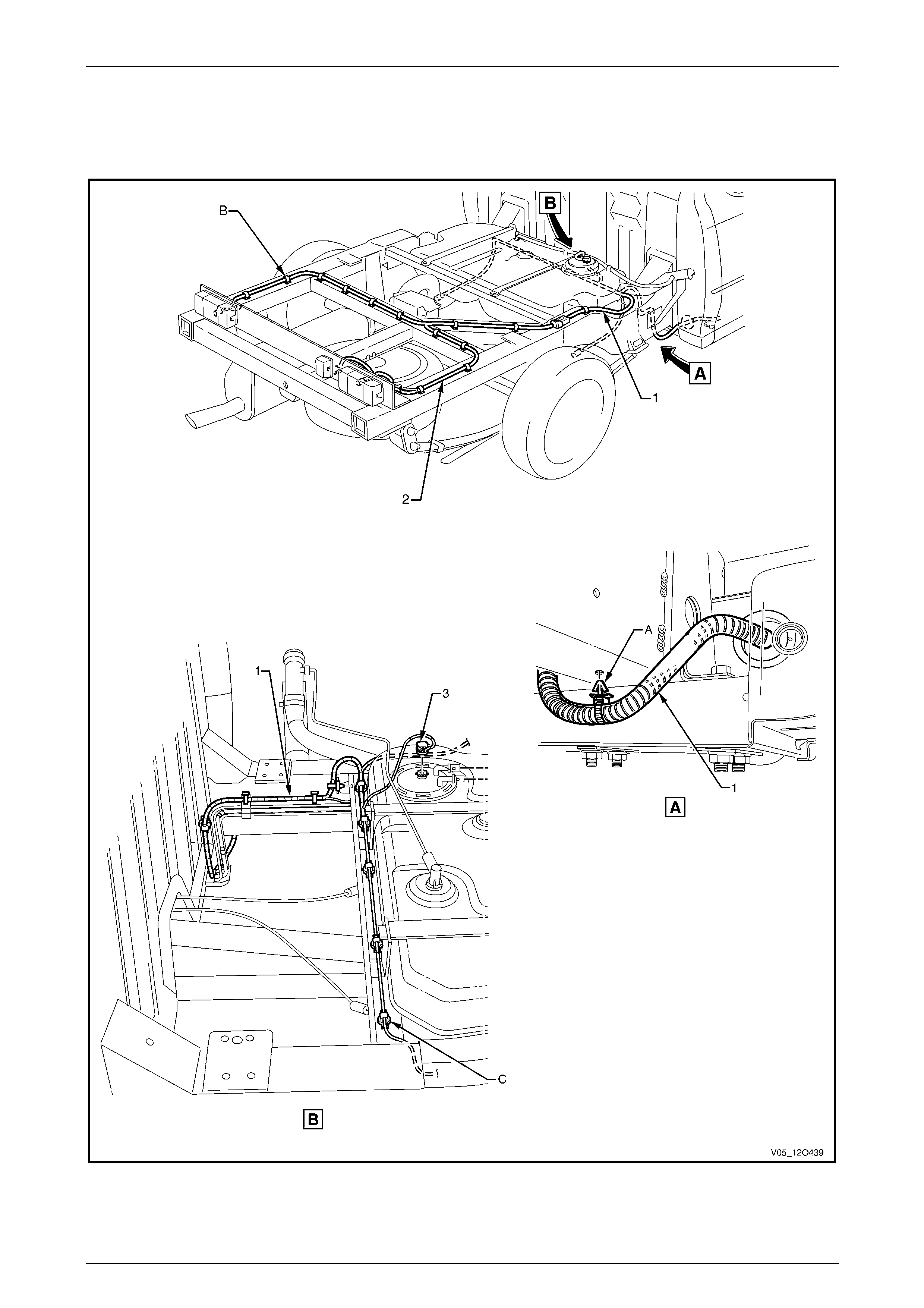
Fuses, Relays and Wiring Harnesses Page 12O–160
4.5 Rear Body Wiring Harness
Fuel Tank
Figure 12O – 144
Page 12O–160

Fuses, Relays and Wiring Harnesses Page 12O–161
Legend
1 Body Wiring Harness
2 Rear Body Wiring Harness
3 Fuel Pump Motor Connector (M8)
A Body wiring harness clipped to underside of subframe
assembly as shown.
B Rear body wiring harness clipped to subframe assembly as
shown (12 places).
C Body wiring harness clipped to subframe assembly as
shown (9 places).
Page 12O–161
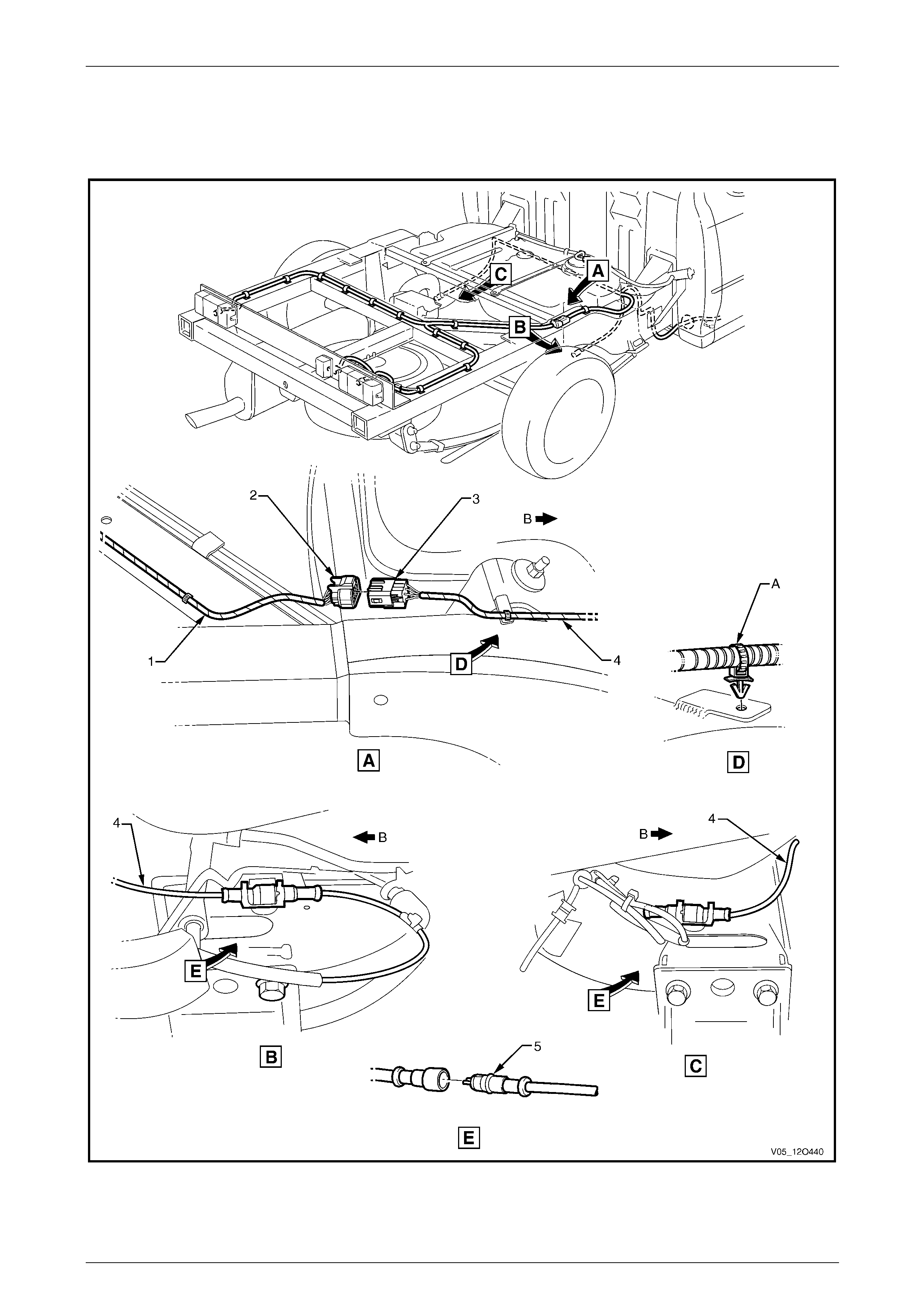
Fuses, Relays and Wiring Harnesses Page 12O–162
4.6 Rear Body Wiring Harness
ABS
Figure 12O – 145
Page 12O–162

Fuses, Relays and Wiring Harnesses Page 12O–163
Legend
1 Rear Body Wiring Harness
2 Rear Body Wiring Harness to Body Wiring Harness
Connector (X403)
3 Body Wiring Harness to Rear Body Wiring Harness
Connector (X403)
4 Body Wiring Harness
5 Rear Wheel Speed sensor Connector (B76)
A Body wiring harness clipped to subframe assembly as
shown.
B Front of vehicle.
Page 12O–163

Fuses, Relays and Wiring Harnesses Page 12O–164
5 Wiring Installation Diagrams –
Crew Cab
The following figures illustrate the vehicle wiring installation diagrams for Crew Cab vehicles.
For information relating to the wiring harness installation diagrams not prov ided in this section, refer to
3 Wiring Installation Diagrams – Utility.
Page 12O–164

Fuses, Relays and Wiring Harnesses Page 12O–165
5.1 Transmission Harness
V6 Engine – 4 Speed Automatic Transmission
Figure 12O – 146
Legend
1 Transmission Harness to Front Body Harness Connector
(X203)
2 Transmission Control Module
3 Transmission Control Module Connector (A112 – 4SPD)
Page 12O–165
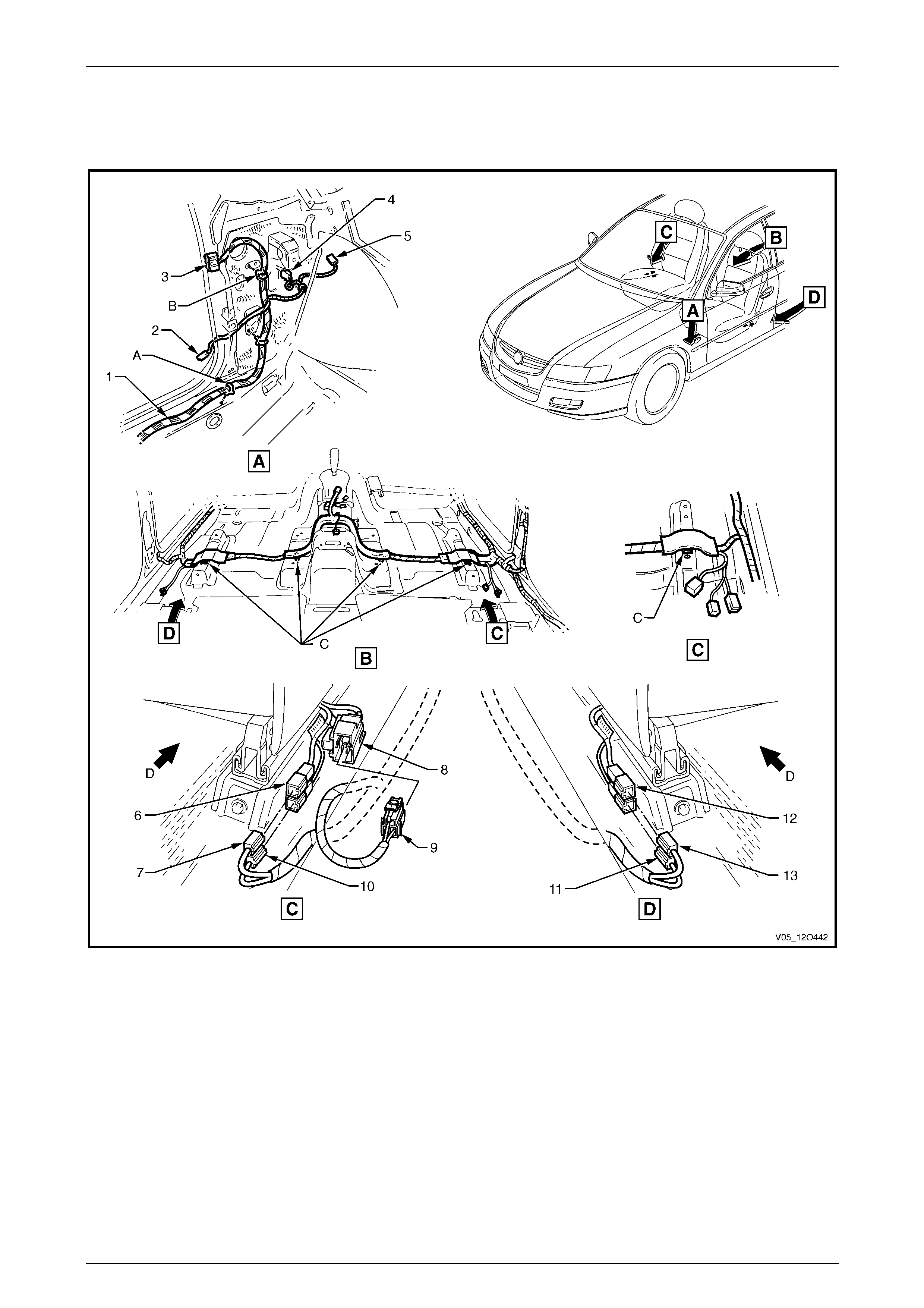
Fuses, Relays and Wiring Harnesses Page 12O–166
5.2 Body Wiring Harness – 1
Interior
Figure 12O – 147
Page 12O–166

Fuses, Relays and Wiring Harnesses Page 12O–167
Legend
1 Body Wiring Harness
2 Door Ajar Indicator Switch Connector (S156)
3 Body Wiring Harness to Left-hand Front Door Wiring
Harness Connector (X500)
4 Front Side Turn Signal Lamp Connector (E75 – L)
5 Radio Power Antenna Connector (W6 – X1)
6 Side Airbag Harness to Body Wiring Harness Connector
(X307 – R)
7 Body Wiring Harness to Side Airbag Harness Connector
(X307 – R)
8 Power Seat Harness to Body Wiring Harness Connector
(X302)
9 Body Wiring Harness to Power Seat Harness Connector
(X302)
10 Seat Belt Pre-tensioner Connector (Y128 – R)
11 Seat Belt Pre-tensioner Connector (Y129 – L)
12 Side Airbag Harness to Body Wiring Harness Connector
(X306 – L)
13 Body Wiring Harness to Side Airbag Harness Connector
(X306 – L)
A Body wiring harness attached to underbody as shown
(6 places).
B Attach body wiring harness to shroud side panel (2 places).
C Harness clipped to underbody as shown (4 places).
D Front of vehicle.
Page 12O–167
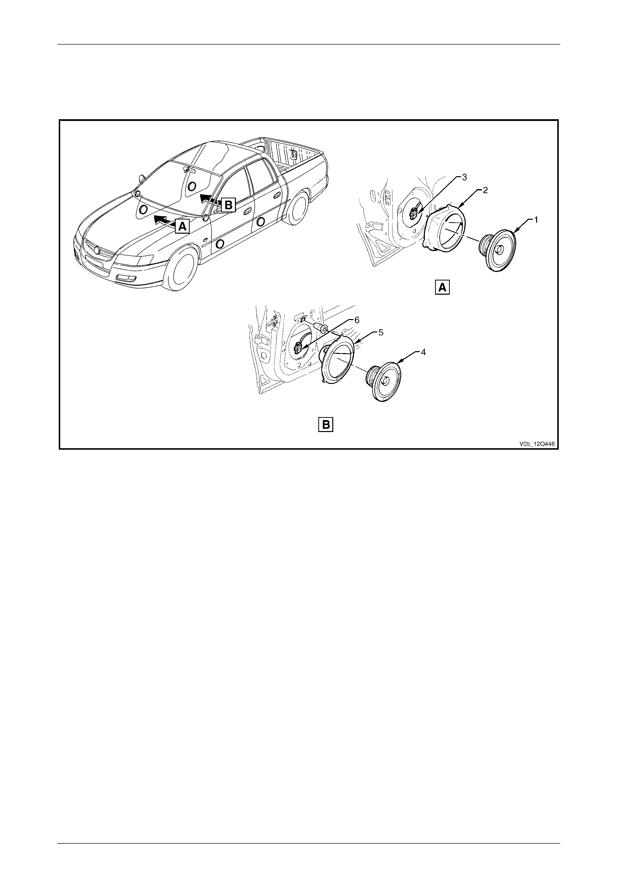
Fuses, Relays and Wiring Harnesses Page 12O–168
5.3 Body Wiring Harness – 2
Speakers
Figure 12O – 148
Legend
1 Front Door Radio Speaker Assembly
2 Front Door Radio Speaker Mounting Box Assembly
3 Front Door Radio Speaker Connector (B108)
4 Rear Door Radio Speaker Assembly
5 Rear Door Radio Speaker Mounting Box Assembly
6 Rear Door Radio Speaker Connector (B117)
Page 12O–168
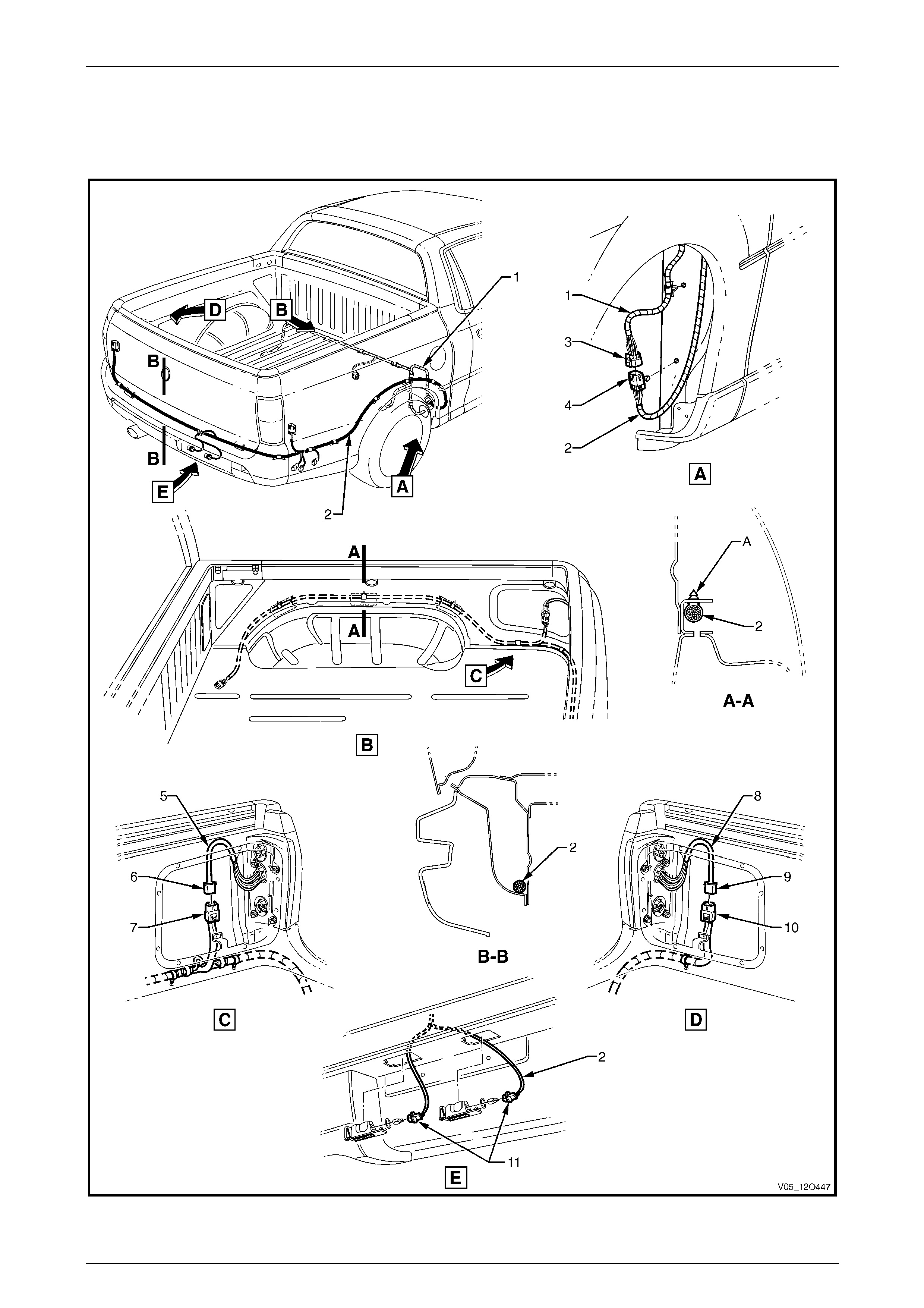
Fuses, Relays and Wiring Harnesses Page 12O–169
5.4 Body Wiring Harness – 3
Load Compartment
Figure 12O – 149
Page 12O–169

Fuses, Relays and Wiring Harnesses Page 12O–170
Legend
1 Body Wiring Harness
2 Rear Body Wiring Harness
3 Body Wiring Harness to Rear Body Wiring Harness
Connector (X403)
4 Rear Body Wiring Harness to Body Wiring Harness
Connector (X403)
5 Right-hand Tail Lamp Harness
6 Right-hand Tail Lamp Harness to Rear Body Wiring
Harness Connector (X903)
7 Rear Body Harness to Right-hand Tail Lamp Wiring
Harness Connector (X903)
8 Left-hand Tail Lamp Harness
9 Left-hand Tail Lamp Harness to Rear Body Wiring
Harness Connector (X904)
10 Rear Body Harness to Left-hand Tail Lamp Wiring
Harness Connector (X904)
11 Licence Plate Lamp Connectors (E44)
A Rear body wiring harness clipped as shown (3 places).
Page 12O–170
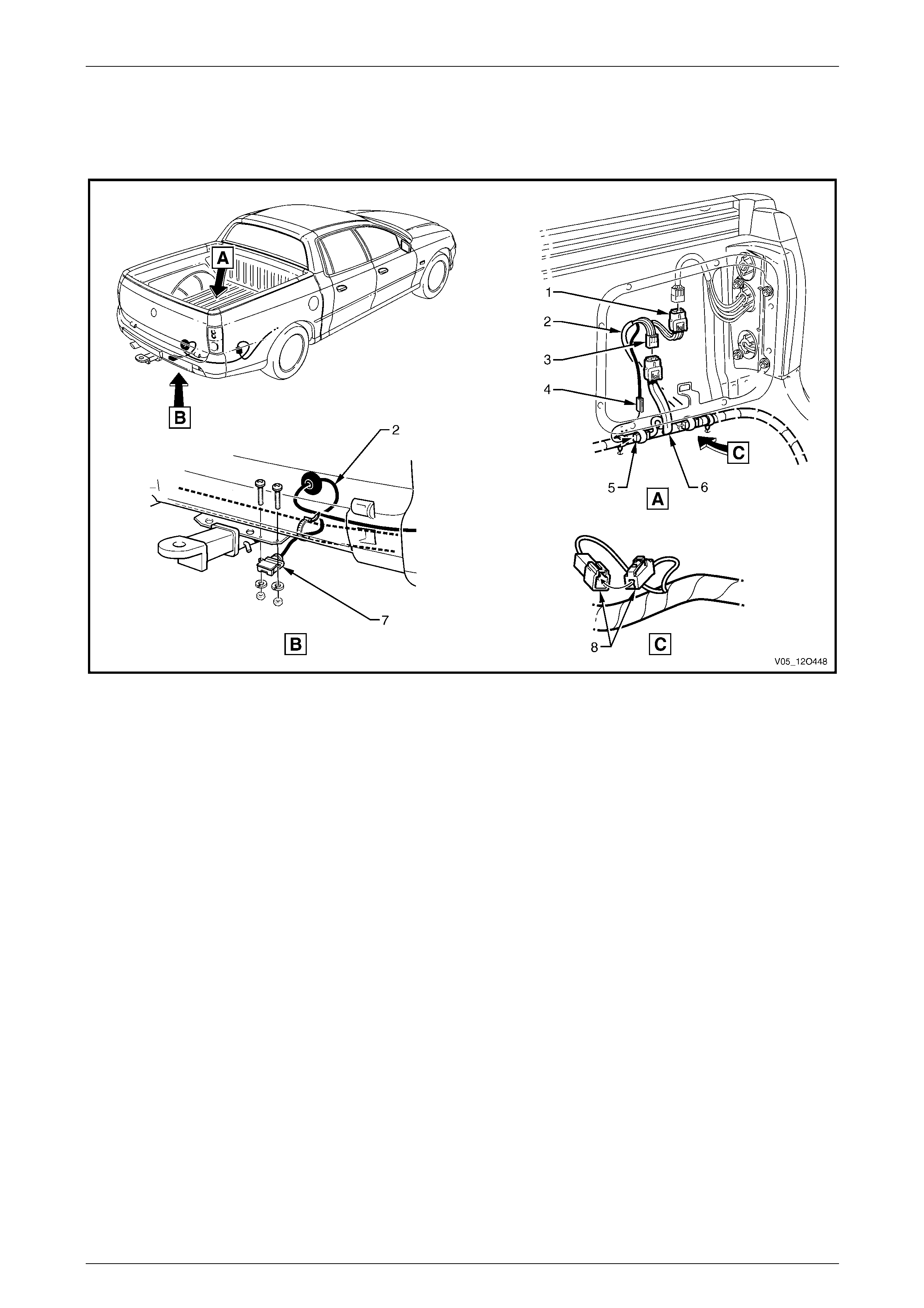
Fuses, Relays and Wiring Harnesses Page 12O–171
5.5 Body Wiring Harness – 4
Trailer Connectors
Figure 12O – 150
Legend
1 Trailer Lamp Harness to Right-hand Tail Lamp Harness
Connector (X38 – A)
2 Trailer Lamp Harness
3 Trailer Lamp Harness to Rear Body Wiring Harness
Connector (X38 – B)
4 Trailer Lamp Harness to Rear Body Wiring Harness
Connector (X908)
5 Rear Body Wiring Harness to Trailer Lamp Harness
Connector (X908)
6 Rear Body Wiring Harness
7 Trailer Lamp Harness Connector (X109)
8 Ground Voltage Drop Connector 148)
Page 12O–171
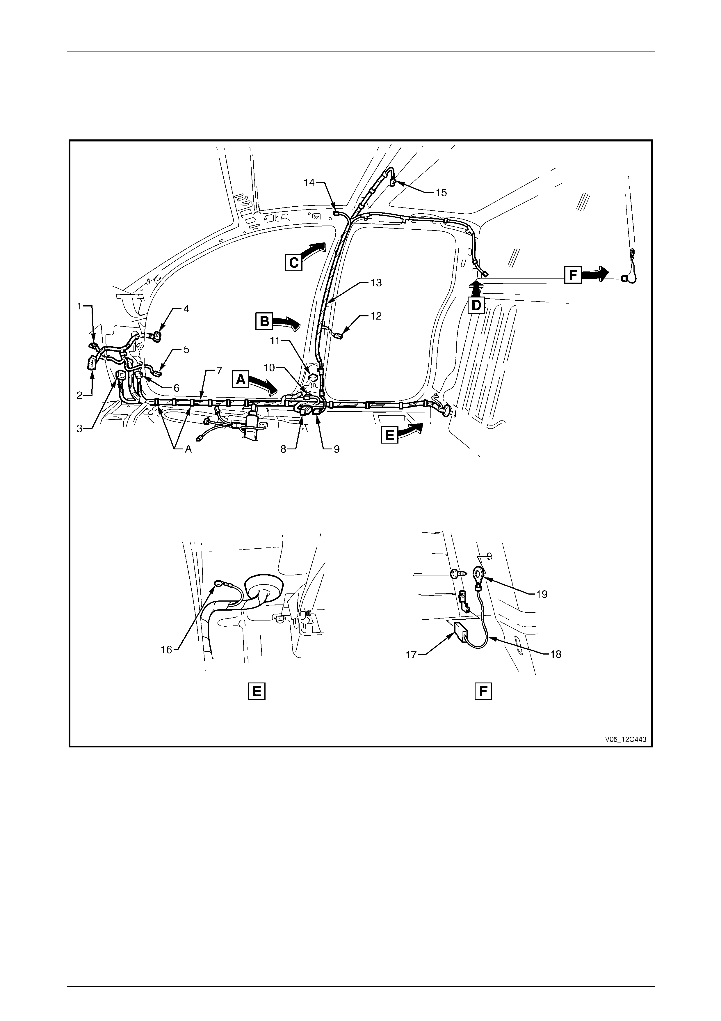
Fuses, Relays and Wiring Harnesses Page 12O–172
5.6 Body & Roof Lamp Harnesses
Interior
Figure 12O – 151
Page 12O–172

Fuses, Relays and Wiring Harnesses Page 12O–173
Legend
1 Front Side Turn Signal Lamp Connector (E75 – R)
2 Body Control Module Connector (A15 – X4)
3 Body Wiring Harness to Front Body Harness Connector
(X200)
4 Body Wiring Harness to Right-hand Front Door Wiring
Harness Connector (X600)
5 Door Ajar Indicator Switch Connector (S156)
6 Body Wiring Harness to Front Body Harness Connector
(X201)
7 Body Wiring Harness
8 Body Wiring Harness to Roof Lamp Harness Connector
(X300)
9 Roof Lamp Harness to Body Wiring Harness Connector
(X300)
10 Inflation Restraint Side Impact Sensor Connector (A66)
11 Body Wiring Harness to Right-hand Rear Door Wiring
Harness Connector (X800)
12 Door Ajar Indicator Switch Connector (S156)
13 Roof Lamp Harness
14 Roof Lamp Harness to Visor Lamp Harness (X310)
15 Dome Lamp Connector (E67)
16 Ground Lead Terminal (X118 –GP13)
17 Rear Window Defog Grid Ground Lead Connector
(R22 – X2)
18 Rear Window Defog Grid Ground Lead
19 Ground Lead Terminal (X118 –GP7)
For views A to D, refer to 5.7 Roof Lamp Harness – 1.
Page 12O–173
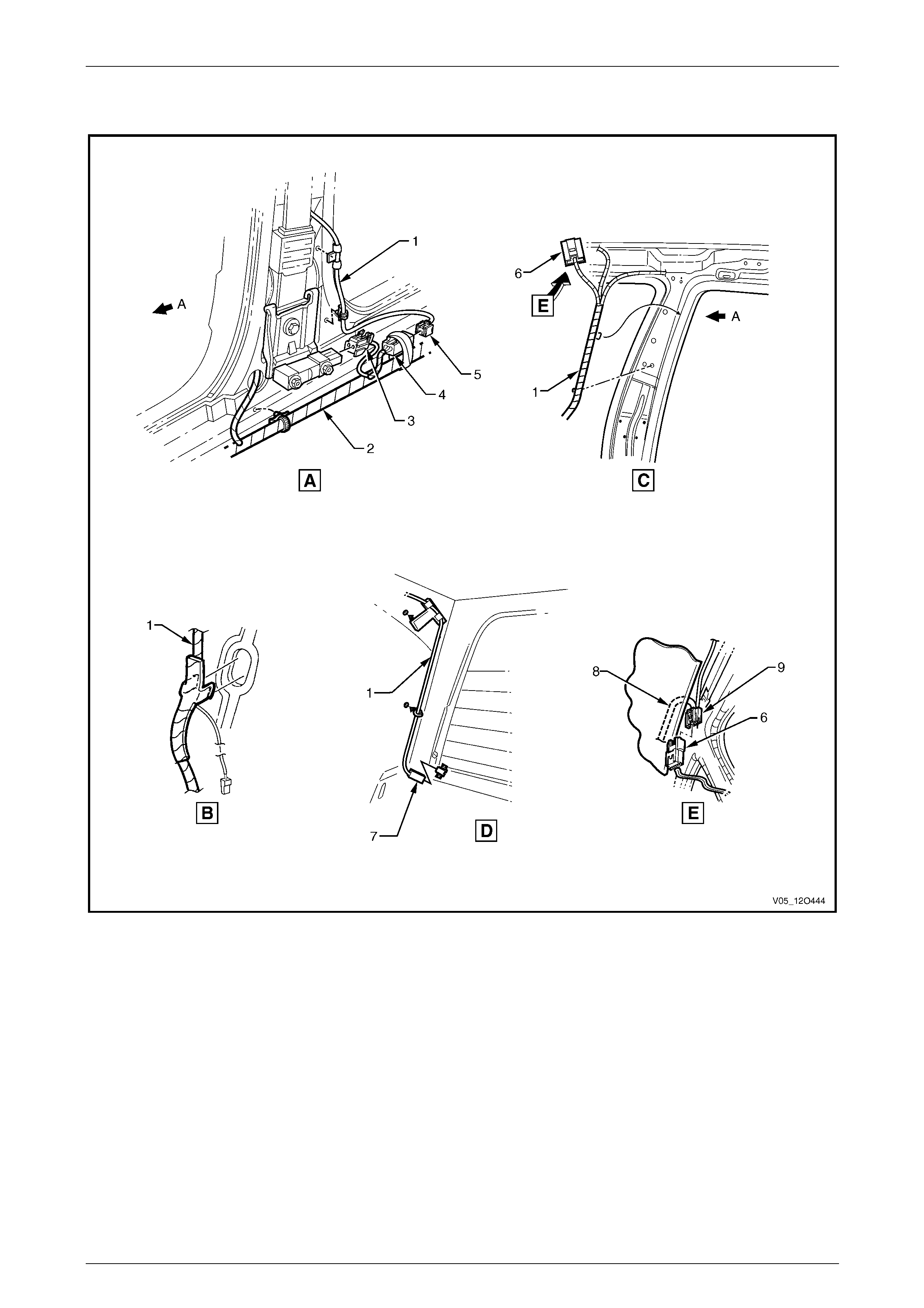
Fuses, Relays and Wiring Harnesses Page 12O–174
5.7 Roof Lamp Harness – 1
Figure 12O – 152
Legend
1 Roof Lamp Harness
2 Body Wiring Harness
3 Inflation Restraint Side Impact Sensor Connector (A66)
4 Body Wiring Harness to Roof Lamp Harness Connector
(X300)
5 Roof Lamp Harness to Body Wiring Harness Connector
(X300)
6 Roof Lamp Harness to Visor Lamp Harness Connector
(X310)
7 Rear Window Defog Grid Connector (R22 – X1)
8 Visor Lamp Harness
9 Visor Lamp Harness to Roof Lamp Harness Connector
(X310)
A Front of vehicle.
For location of views A to D, refer to 5.6 Body & Roof Lamp
Harnesses.
Page 12O–174
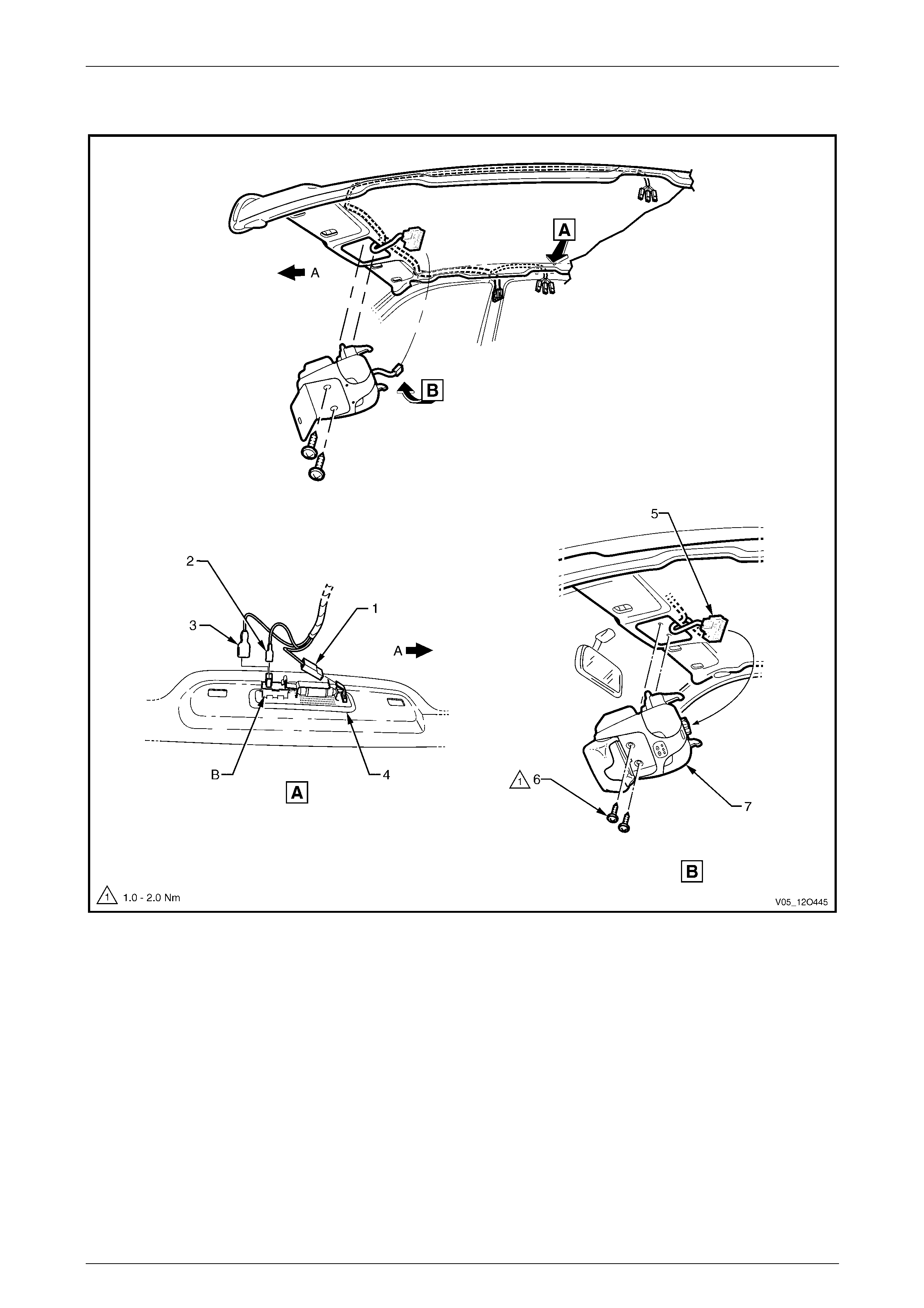
Fuses, Relays and Wiring Harnesses Page 12O–175
5.8 Roof Lamp Harness – 2
Figure 12O – 153
Legend
1 Reading Lamp Connector (E94 – X1)
2 Reading Lamp Connector (E94 – X2)
3 Reading Lamp Connector (E94 – X3)
4 Reading Lamp Assembly
5 Roof Console Lamp Connector (E67)
6 Attaching Screws Roof Console
7 Roof Console
A Front of vehicle.
Page 12O–175
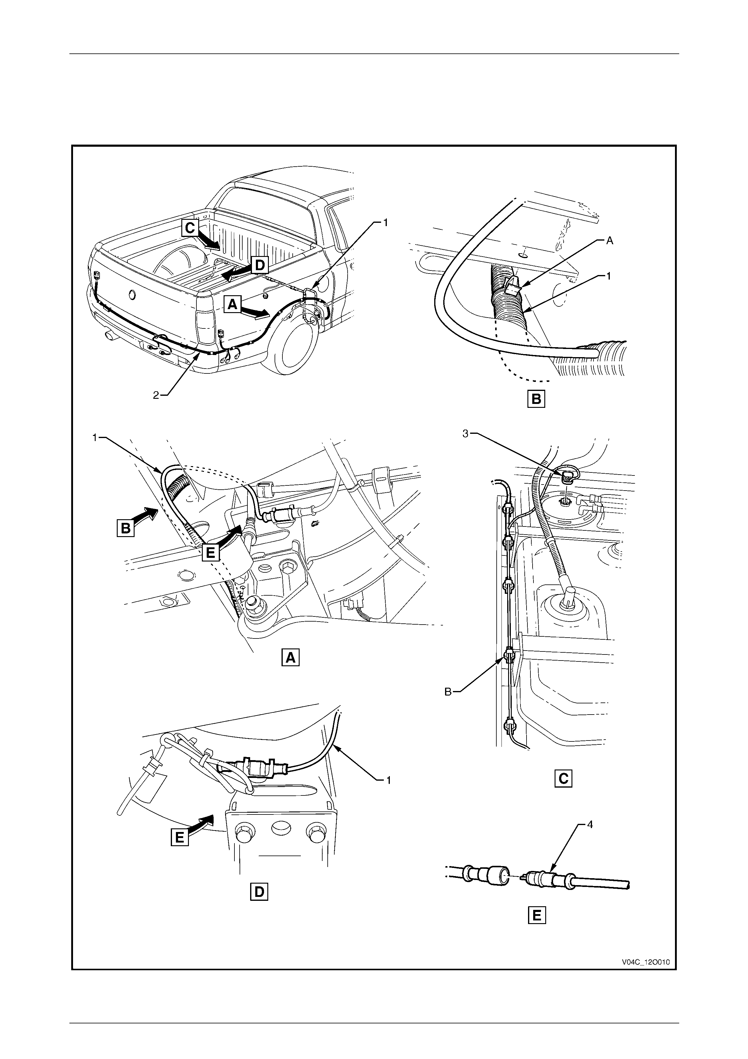
Fuses, Relays and Wiring Harnesses Page 12O–176
5.9 Rear Wiring Harness
Fuel Tank and ABS
Figure 12O – 154
Page 12O–176

Fuses, Relays and Wiring Harnesses Page 12O–177
Legend
1 Body Wiring Harness
2 Rear Body Wiring Harness
3 Fuel Pump Assembly Connector (M8)
4 Rear Wheel Speed Sensor Connector (B76)
A Body wiring harness clipped to underside of subframe
assembly as shown.
B Body wiring harness clipped to subframe assembly as
shown.
Page 12O–177
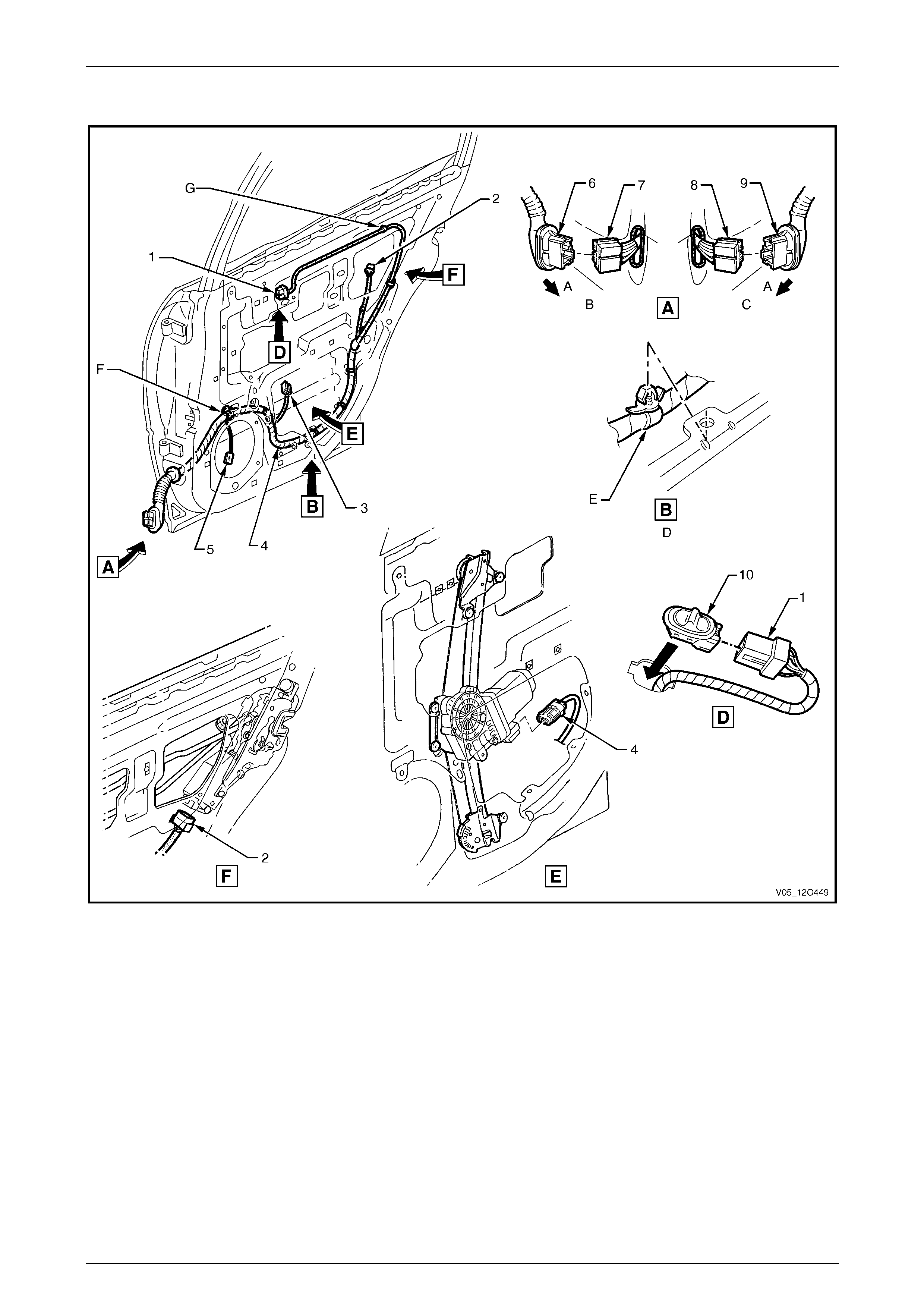
Fuses, Relays and Wiring Harnesses Page 12O–178
5.10 Rear Door Wiring Harness
Figure 12O – 155
Legend
1 Side Window Switch Connector (S221)
2 Rear Door Lock Actuator Connector (Y31)
3 Rear Door Window Regulator Connector (M14)
4 Door Wiring Harness
5 Door Radio Speaker Connector (B117)
6 Left-hand Rear Door Wiring Harness Connector to Body
Wiring Harness Connector (X700)
7 Body Wiring Harness to Left-hand Rear Door Wiring
Harness Connector (X700)
8 Body Wiring Harness to Right-hand rear Door Wiring
Harness Connector (X800)
9 Right-hand Rear Door Wiring Harness to Body Wiri ng
Harness Connector (X800)
10 Rear Door Window Switch
A Front of vehicle.
B Left-hand door shown.
C Right-hand door shown.
D Typical (8 places).
E Door wiring harness clipped to door inner panel as shown.
F Door wiring harness clipped to door inner panel.
G Rear door inner seal pierced and then door harness clipped
to rear door inner panel (2 places).
Page 12O–178

Fuses, Relays and Wiring Harnesses Page 12O–179
6 Wiring Installation Diagrams –
Regular & Crew Cab AWD
The following figures illustrate the vehicle wiring installation diagrams for Regular & Crew Cab AWD vehicles.
For information relating to the wiring harness installation diagrams not prov ided in this section, refer to
3 Wiring Installation Diagrams – Utility.
Page 12O–179
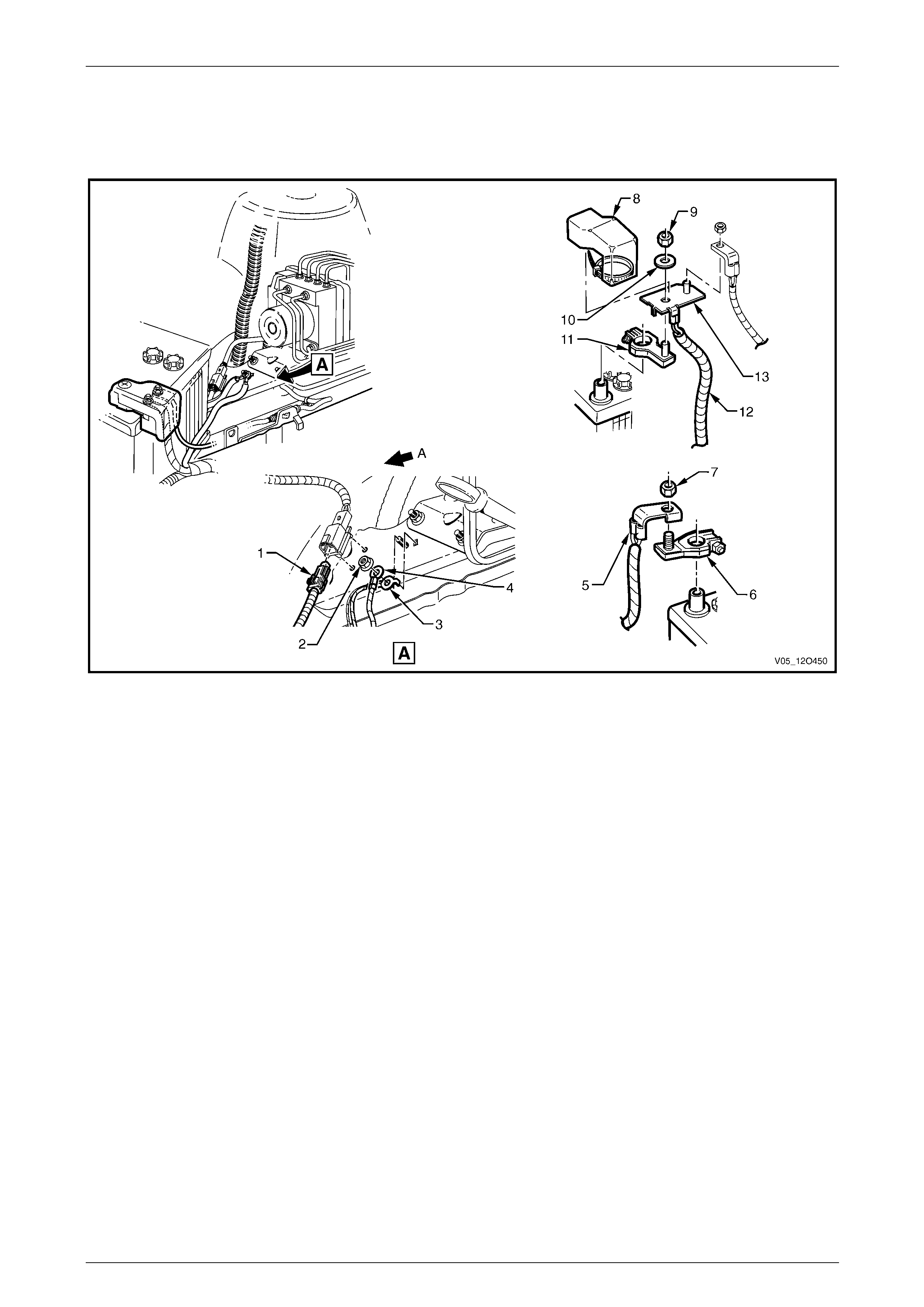
Fuses, Relays and Wiring Harnesses Page 12O–180
6.1 Battery Wiring Harness – 1
V6 Engine
Figure 12O – 156
Legend
1 Battery Wiring Harness to Front Body Harness Co nnector
(X106)
2 Nut
3 Body Ground Terminal (X119 – G3 – GP3)
4 Battery Ground Terminal (X119 – G4 – GP3)
5 Battery Wiring Harness Terminal (X86 – C)
6 Battery Negative Terminal (G1 – X2 – GP1)
7 Nut
8 Battery Positive Terminal Cover
9 Nut
10 Washer
11 Battery Wiring Harness Positive Terminal (G1 – X1)
12 Battery Wiring Harness to Starter Motor and Generator
13 Battery Positive Post Assembly (X86 – B)
A Front of vehicle.
Page 12O–180
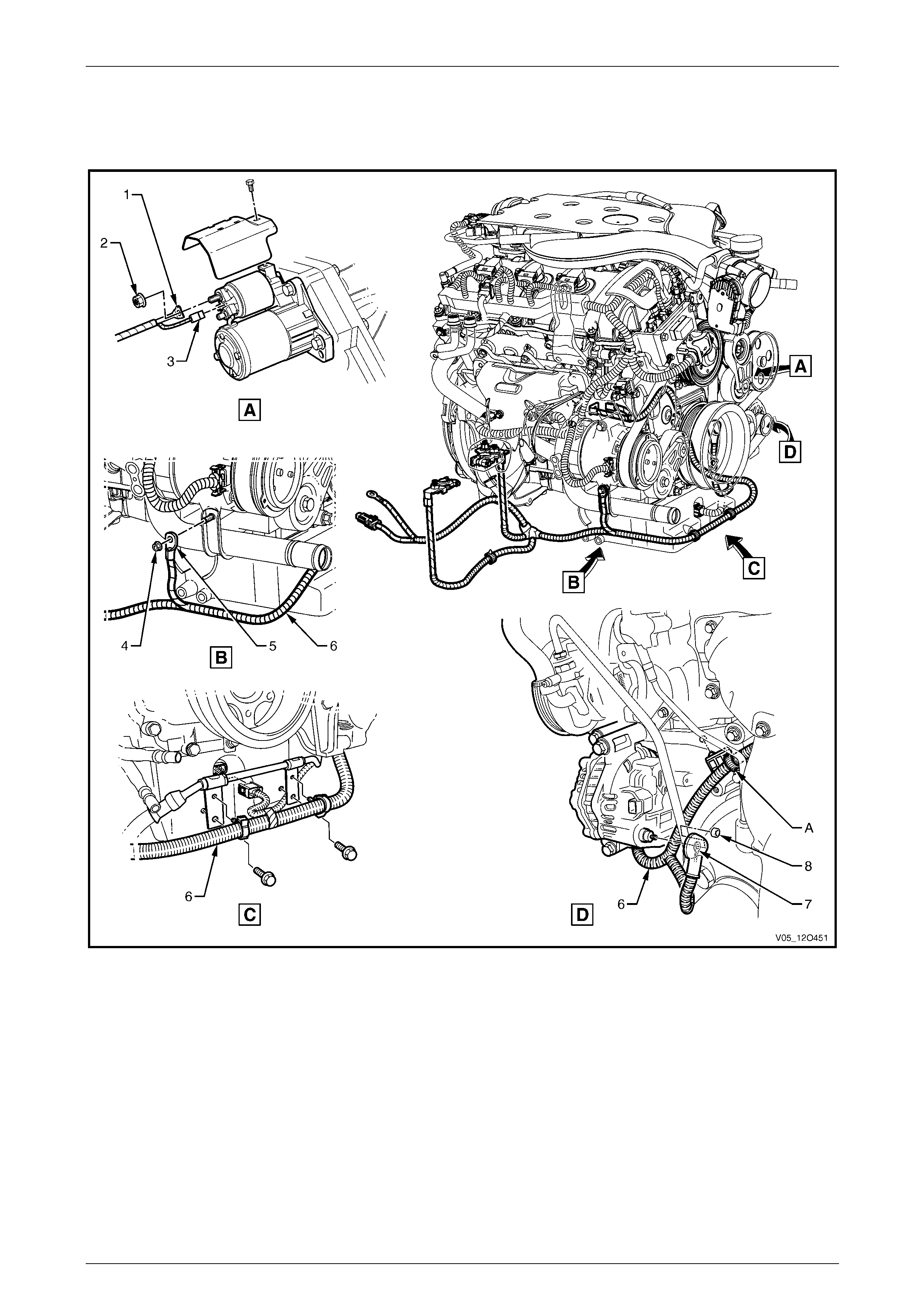
Fuses, Relays and Wiring Harnesses Page 12O–181
6.2 Battery Wiring Harness – 2
V6 Engine
Figure 12O – 157
Legend
1 Starter Motor Terminal (M15 – X2)
2 Nut
3 Starter Motor Terminal Connector (M15 – X1 – V6)
4 Engine Block Ground Bolt
5 Engine Ground Terminal (X119 – GP4)
6 Battery Wiring Harness
7 Generator Terminal (G8 – X1)
8 Nut
A Battery wiring harness attached to engine block as shown.
Page 12O–181
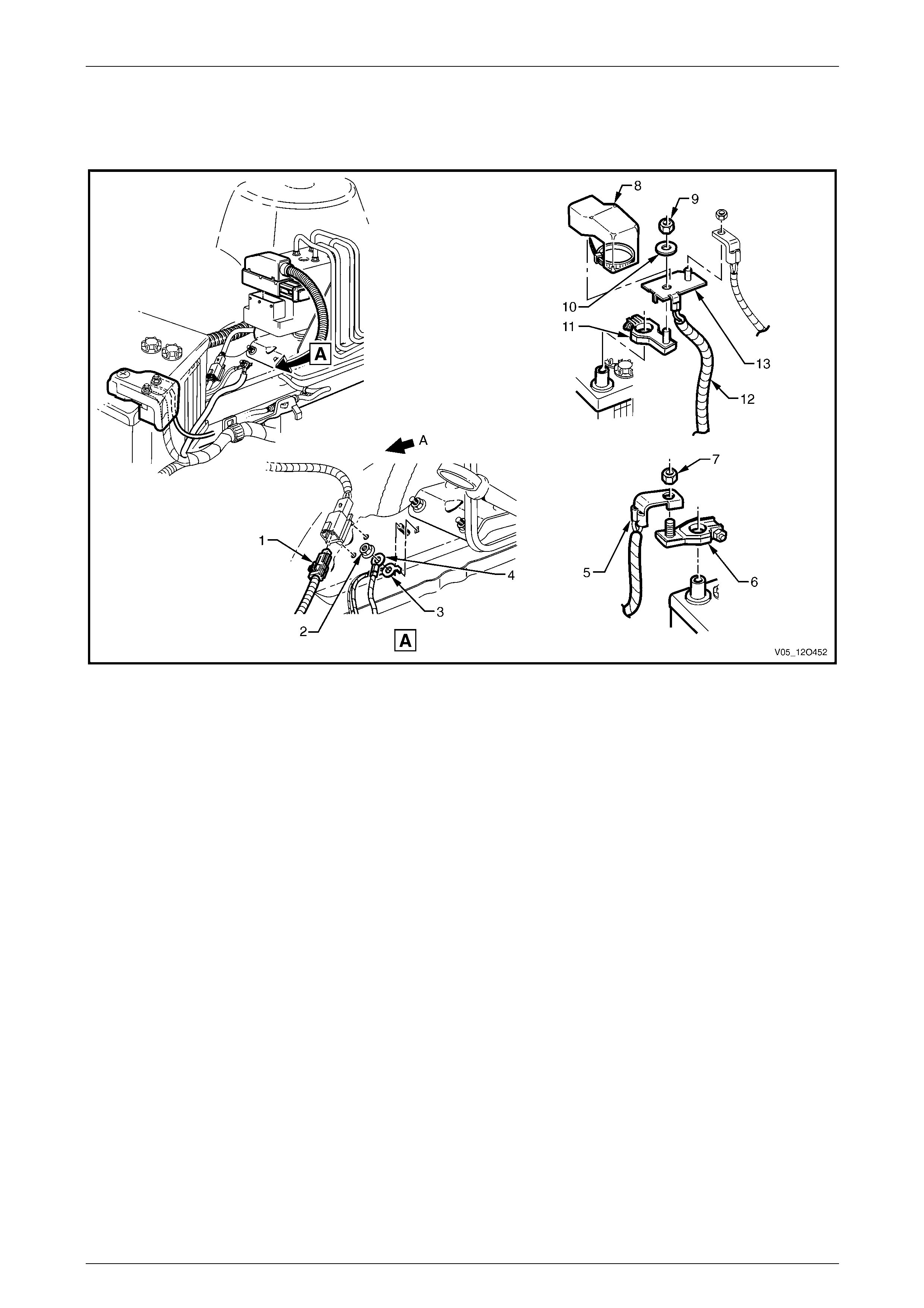
Fuses, Relays and Wiring Harnesses Page 12O–182
6.3 Battery Wiring Harness – 3
GEN III V8 Engine
Figure 12O – 158
Legend
1 Battery Wiring Harness to Front Body Harness Co nnector
(X106)
2 Nut
3 Body Ground Terminal (X119 – G3 – GP3)
4 Battery Ground Terminal (X119 – G4 – GP3)
5 Battery Wiring Harness Terminal (X86 – C)
6 Battery Negative Terminal (G1 – X2 – GP1)
7 Nut
8 Battery Positive Terminal Cover
9 Nut
10 Washer
11 Battery Wiring Harness Positive Terminal (G1–X1)
12 Battery Wiring Harness to Starter Motor and Generator
13 Battery Positive Post Assembly (X86 – B)
A Front of vehicle.
Page 12O–182
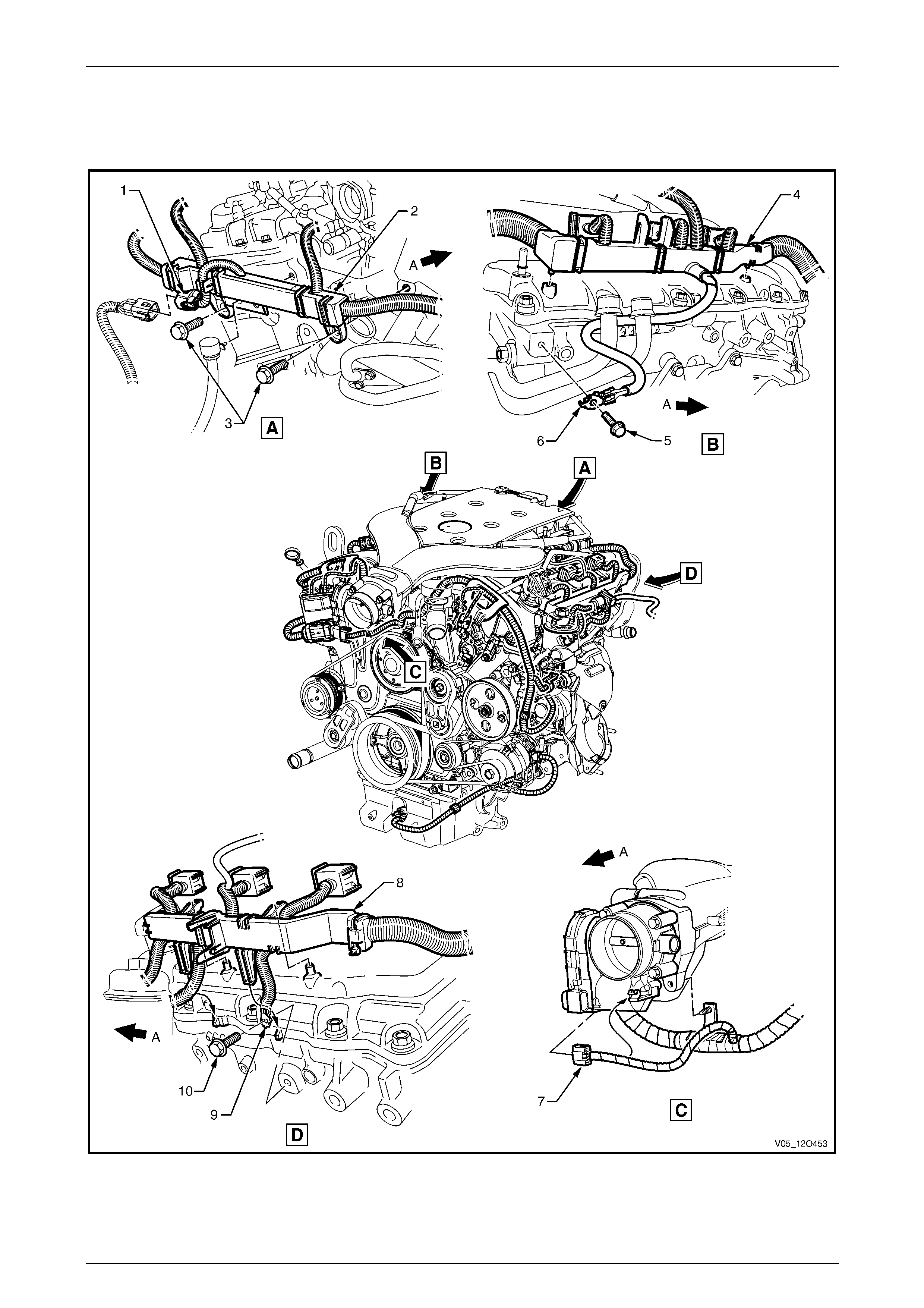
Fuses, Relays and Wiring Harnesses Page 12O–183
6.4 Engine Harness – 1
V6 Engine
Figure 12O – 159
Page 12O–183

Fuses, Relays and Wiring Harnesses Page 12O–184
Legend
1 Engine Harness to Transmission Harness Connector (X104)
2 Engine Harness Former, Rear
3 Engine Harness Former Rear Attaching Bolts
4 Engine Harness Former, Right-hand Side
5 Engine Harness Ground Terminal Attaching Bolt
6 Engine Harness Ground Terminals (X119 – GP 19A and
X119 – GP19B)
7 Throttle Actuator Connector (Y38 – V6)
8 Engine Harness Former, Left-hand Side
9 Engine Harness Ground Terminals (X119 – GP 20A and
X119 – GP20&B)
10 Engine Harness Ground Terminal Attaching Bolt
A Front of vehicle.
Page 12O–184
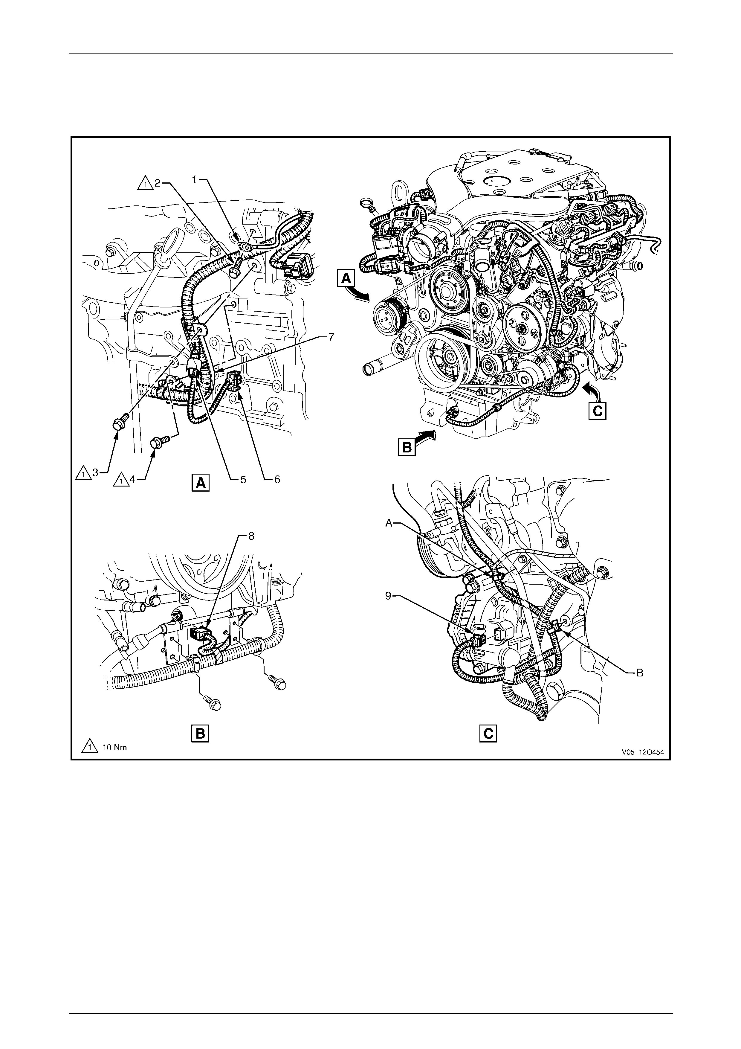
Fuses, Relays and Wiring Harnesses Page 12O–185
6.5 Engine Harness – 2
V6 Engine
Figure 12O – 160
Legend
1 Engine Harness Ground Terminal (X119 – GP18)
2 Engine Harness Ground Terminal Attaching Bolt
3 Oil Level Indicator Tube Attaching Bolt
4 Engine Harness Former Attaching Bolt
5 Suppression Diode A/C Compressor (V5)
6 A/C Clutch Connector (L7)
7 Engine Harness Former
8 Engine Oil Level Sensor Connector (B41)
9 Generator Connector (G8 – X2)
A Harness attached to engine block as shown.
B Harness attached to engine block as shown.
Page 12O–185
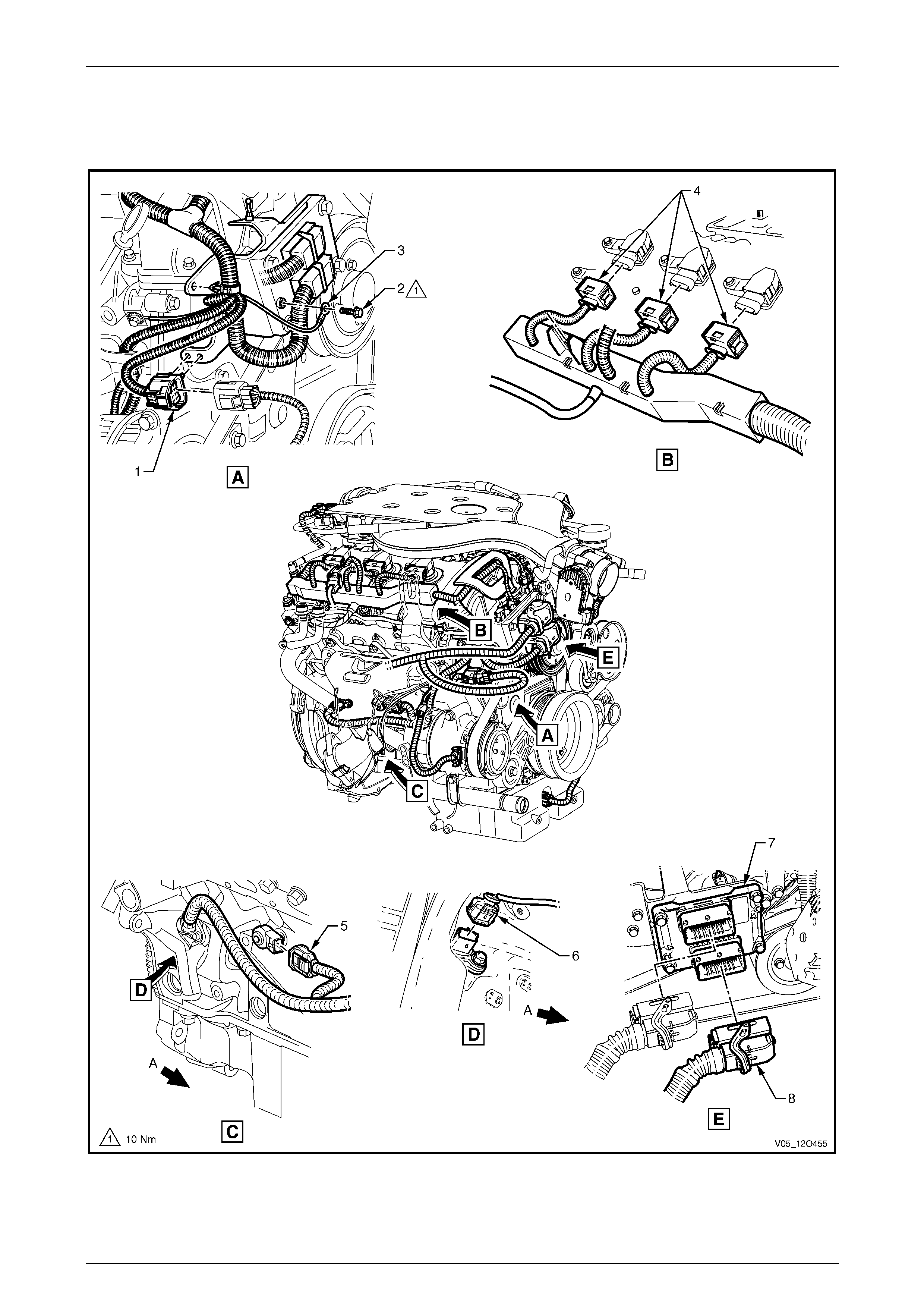
Fuses, Relays and Wiring Harnesses Page 12O–186
6.6 Engine Harness – 3
V6 Engine
Figure 12O – 161
Page 12O–186

Fuses, Relays and Wiring Harnesses Page 12O–187
Legend
1 Engine Harness to Front Body Harness Connector (X103)
2 Engine Harness to ECM Bracket Ground Terminal Attaching
Bolt
3 Engine Harness to ECM Bracket Ground (X119 – GP17)
4 Ignition Coil Connectors, Right-hand Side (L3)
5 Knock Sensor Connector, Right-hand Side (B65 – V6)
6 Crankshaft Position Sensor Connector (B30 – V6)
7 Engine Control Module
8 Engine Control Module Connector (A43 – X1)
A Front of vehicle.
Page 12O–187
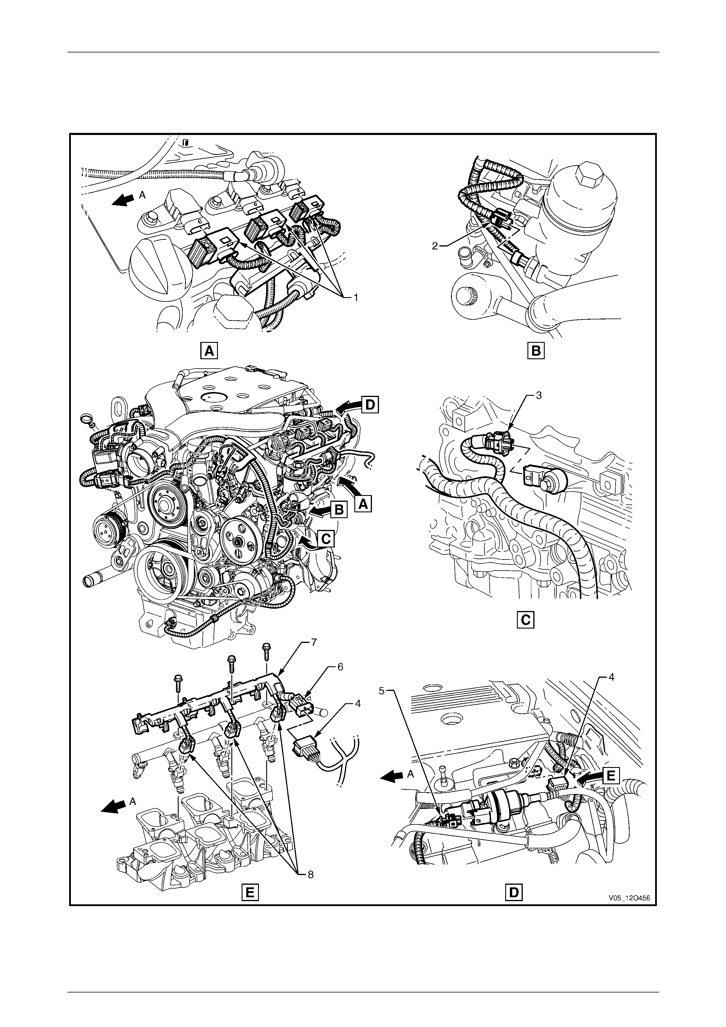
Fuses, Relays and Wiring Harnesses Page 12O–188
6.7 Engine Harness – 4
V6 Engine
Figure 12O – 162
Page 12O–188

Fuses, Relays and Wiring Harnesses Page 12O–189
Legend
1 Ignition Coil Connectors, Left-hand Side (L3)
2 Engine Oil Pressure Sensor Connector (B42)
3 Knock Sensor Connector, Left-hand Side (B65 – V6)
4 Engine Harness to Fuel Injector Harness Connector (X102)
5 Canister Purge Solenoid Valve Connector (Y123 – V6)
6 Fuel Injector Harness to Engine Harness Connector (X102)
7 Fuel Injector Harness
8 Fuel Injector Connector (L2 – V6)
A Front of vehicle.
Page 12O–189
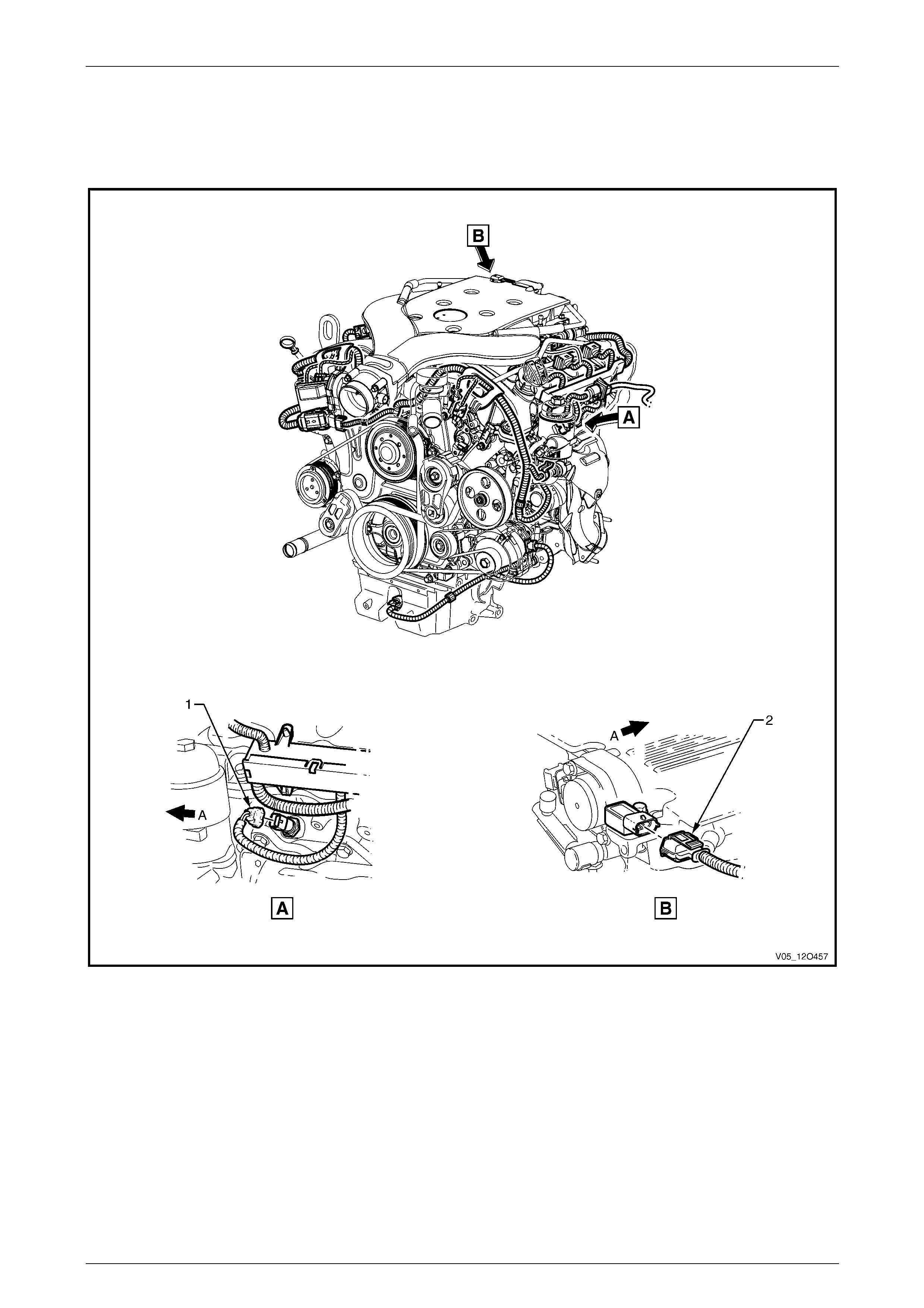
Fuses, Relays and Wiring Harnesses Page 12O–190
6.8 Engine Harness – 5
V6 Engine
Figure 12O – 163
Legend
1 Engine Coolant Temperature Sensor Connector (B39 – V6)
2 M.A.P. Sensor Connector (B67 – V6) A Front of vehicle.
Page 12O–190
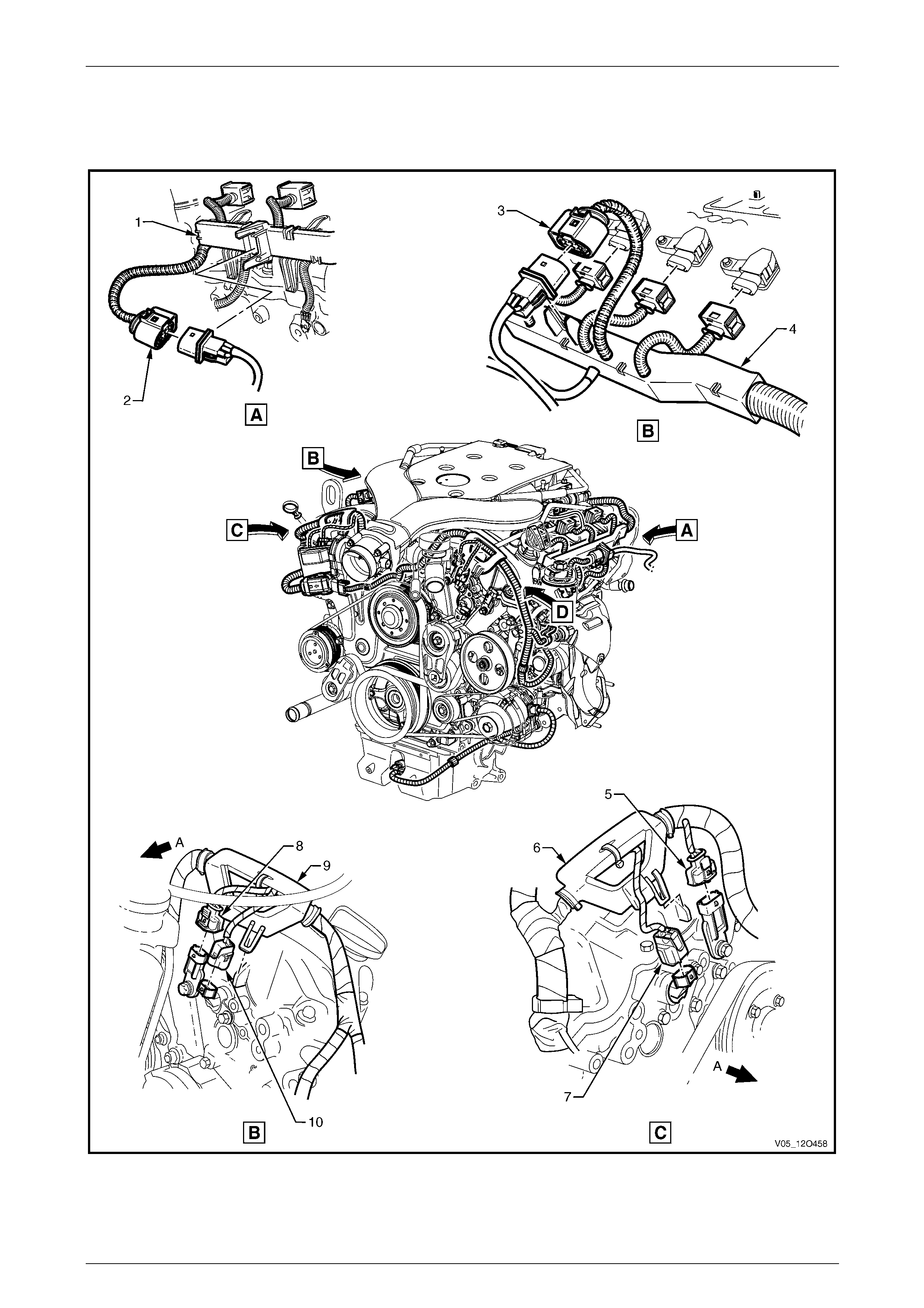
Fuses, Relays and Wiring Harnesses Page 12O–191
6.9 Engine Harness – 6
V6 Engine
Figure 12O – 164
Page 12O–191

Fuses, Relays and Wiring Harnesses Page 12O–192
Legend
1 Engine Harness Former – Left-hand Side
2 Pre-O2 Sensor Connector 2, 4 & 6 (B57 – V6)
3 Pre-O2 Sensor Connector 1, 3 & 5 (B166 – V6)
4 Engine Harness Former – Right-hand Side
5 Camshaft Position Sensor Connector, Intake 1, 3 & 5 (B28 –
V6)
6 Engine Harness Former – Right-hand Side Fro nt
7 Camshaft Position Actuator Connector, Intake 1, 3 & 5 (Y4)
8 Camshaft Position Sensor Connector, Intake 2, 4 & 6 (B28 –
V6)
9 Engine Harness Former – Left-hand Side Front
10 Camshaft Position Actuator Connector, Intake 2, 4 & 6 (Y4)
A Front of vehicle.
Page 12O–192
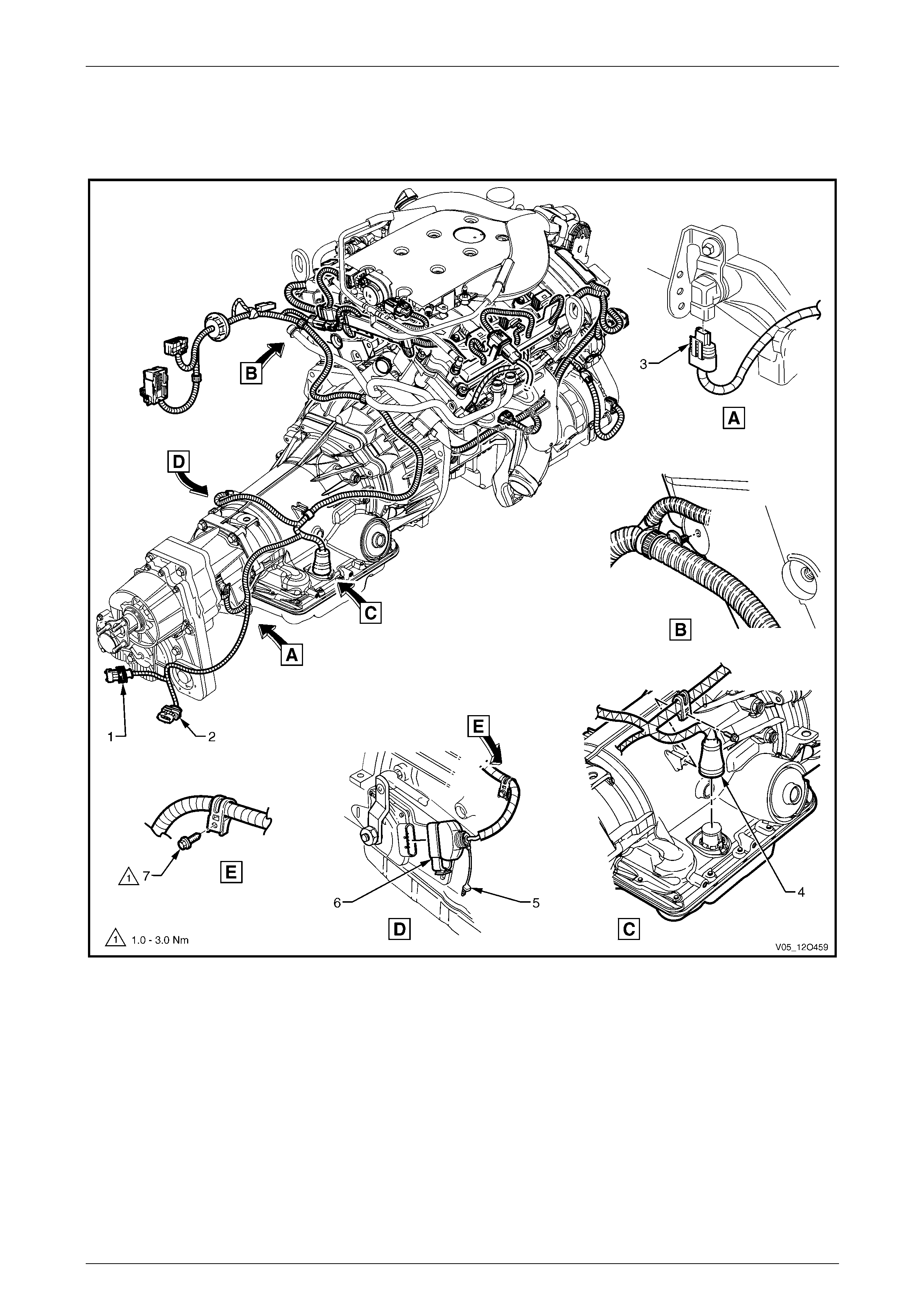
Fuses, Relays and Wiring Harnesses Page 12O–193
6.10 Transmission Harness
V6 Engine – Automatic Transmission
Figure 12O – 165
Legend
1 Post-Left-hand O2 Sensor Connector (B56 – V6)
2 Post-Right-hand O2 Sensor Connector (B58 – V6)
3 Vehicle Speed Sensor Connector (B83)
4 Transmission Assembly Connector (X121 – 4SPD)
5 C.P.A. Lock
6 Park/Neutral Position and Back-up Lamp Connector (S187)
7 Bolt
Page 12O–193
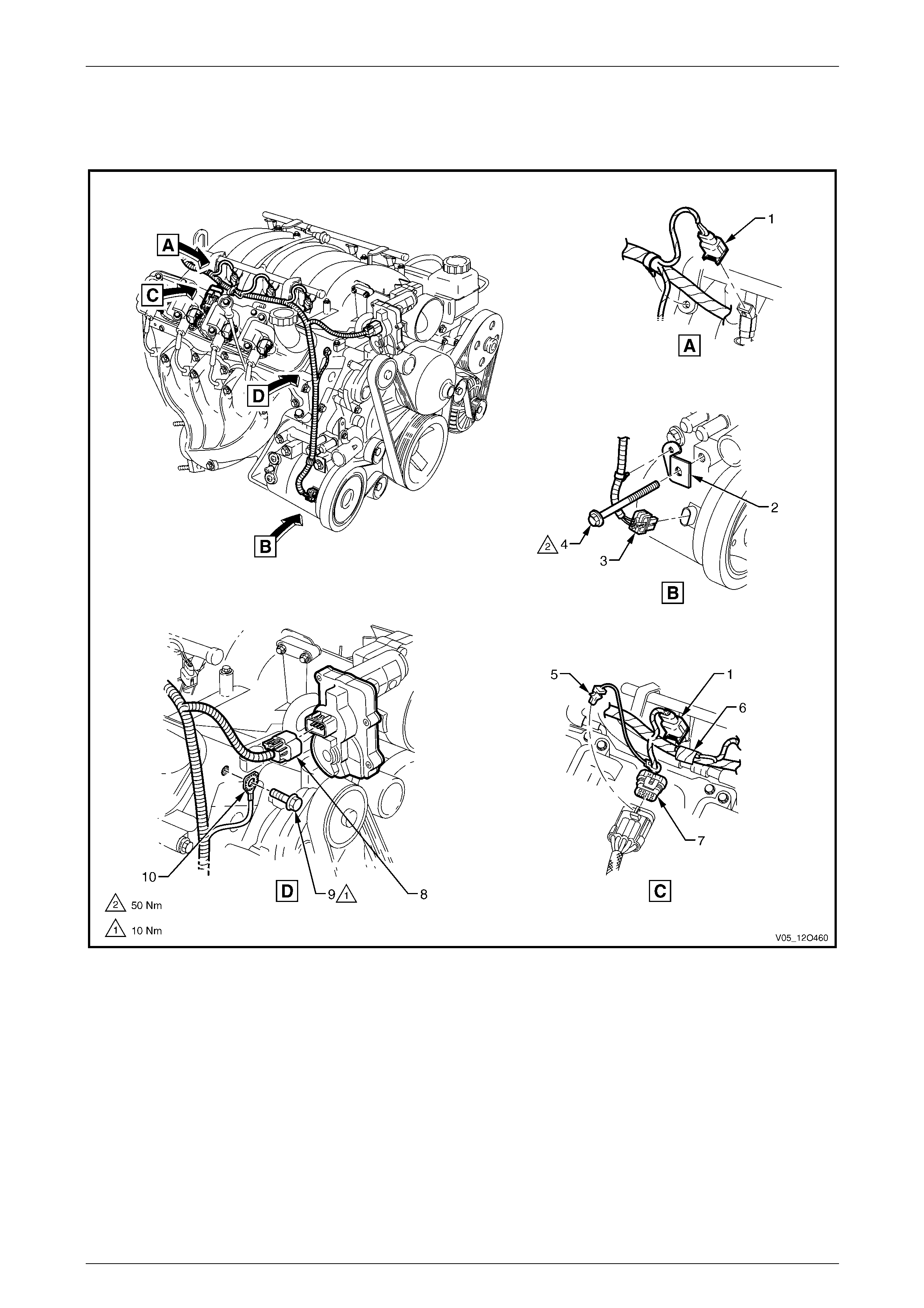
Fuses, Relays and Wiring Harnesses Page 12O–194
6.11 Powertrain Harness – 1
GEN III V8 Engine
Figure 12O – 166
Legend
1 Fuel Injector Connector (L2 – V8)
2 A/C Compressor Powertrain Harness Support Bracket
3 A/C Clutch Connector (L7)
4 A/C Compressor Mounting Bolt
5 C.P.A. Lock
6 Suppression Diode, A/C Compressor (V5)
7 Electronic Ignition Control Module Connector (A40 – R)
8 Throttle Actuator Connector (Y38 – V8)
9 Ground Terminal Attaching Bolt
10 Powertrain Harness Ground Terminal (X119 – GP5)
Page 12O–194
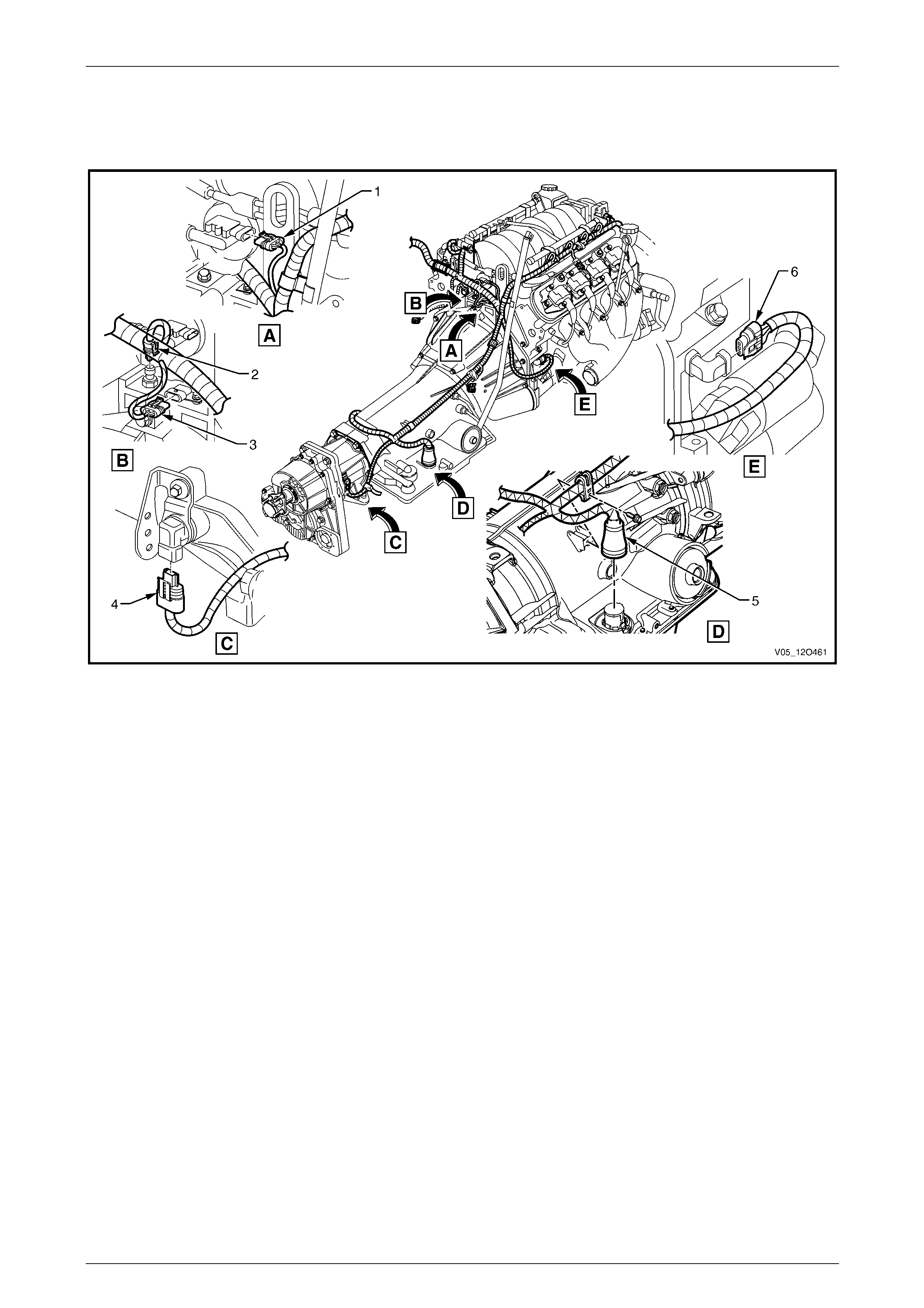
Fuses, Relays and Wiring Harnesses Page 12O–195
6.12 Powertrain Harness – 2
GEN III V8 Engine – Automatic Transmission
Figure 12O – 167
Legend
1 M.A.P. Sensor Connector (B67 – V8)
2 Engine Oil Pressure Sensor Connector (B42)
3 Camshaft Position Sensor Connector (B28 – V8)
4 Vehicle Speed Sensor Connector (B83)
5 Transmission Assembly Connector (X121 – 4SPD)
6 Crankshaft Position Sensor Connector (B30 – V8)
Page 12O–195
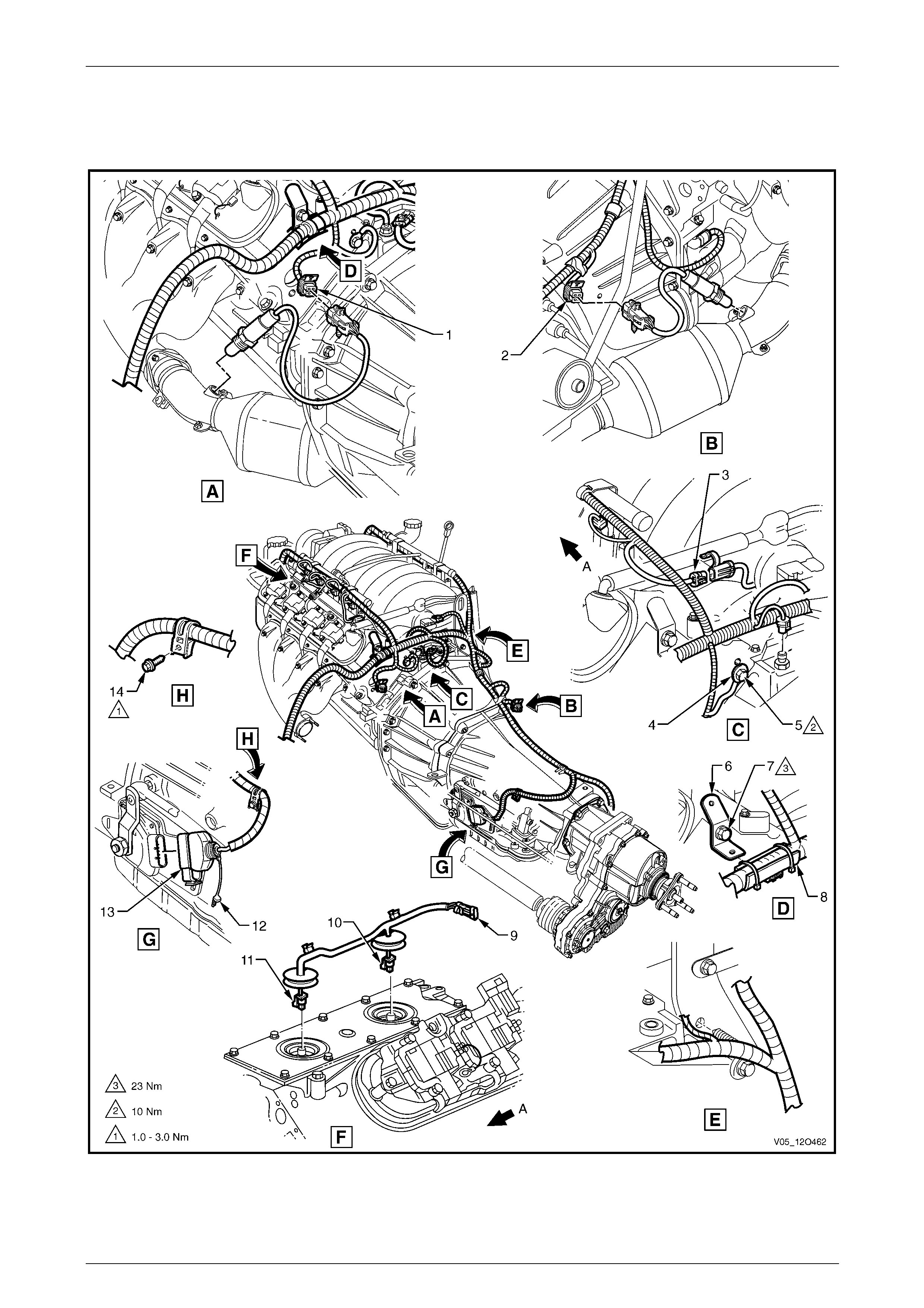
Fuses, Relays and Wiring Harnesses Page 12O–196
6.13 Powertrain Harness – 3
GEN III V8 Engine – Automatic Transmission
Figure 12O – 168
Page 12O–196

Fuses, Relays and Wiring Harnesses Page 12O–197
Legend
1 Left-hand O2 Sensor Connector (B57 – V8)
2 Right-hand O2 Sensor Connector (B166 – V8)
3 Powertrain Harness to Knock Sensor Harness Connector
(X107)
4 Engine Ground Terminal (X119 – GP6)
5 Engine Ground Terminal Attaching Bolt
6 Powertrain Harness Support Bracket
7 Powertrain Harness Support Bracket Attaching Bolt
8 Powertrain Harness Former
9 Knock Sensor Harness to Powertrain Harness Connector
(X107)
10 Knock Sensor Connector (B65 – SNSR2)
11 Knock Sensor Connector (B65 – SNSR1)
12 C.P.A. Lock
13 Park/Neutral Position and Back-up Lamp Switch Connector
(S187)
14 Bolt
A Front of vehicle.
Page 12O–197
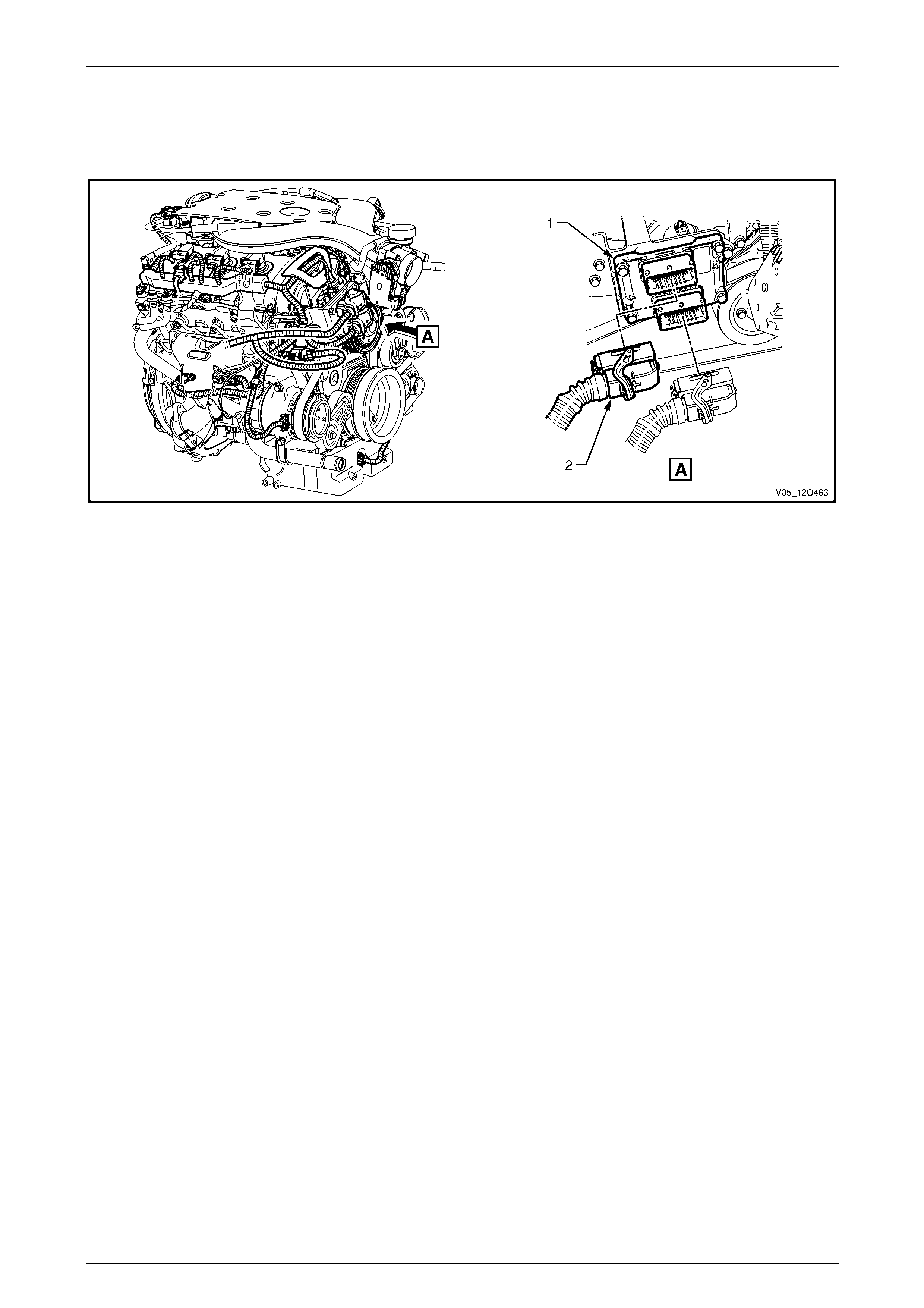
Fuses, Relays and Wiring Harnesses Page 12O–198
6.14 Front Body Harn ess – 1
V6 Engine – Engine Control Module
Figure 12O – 169
Legend
1 Engine Control Module 2 Engine Control Module Connector (A43 – X2)
Page 12O–198
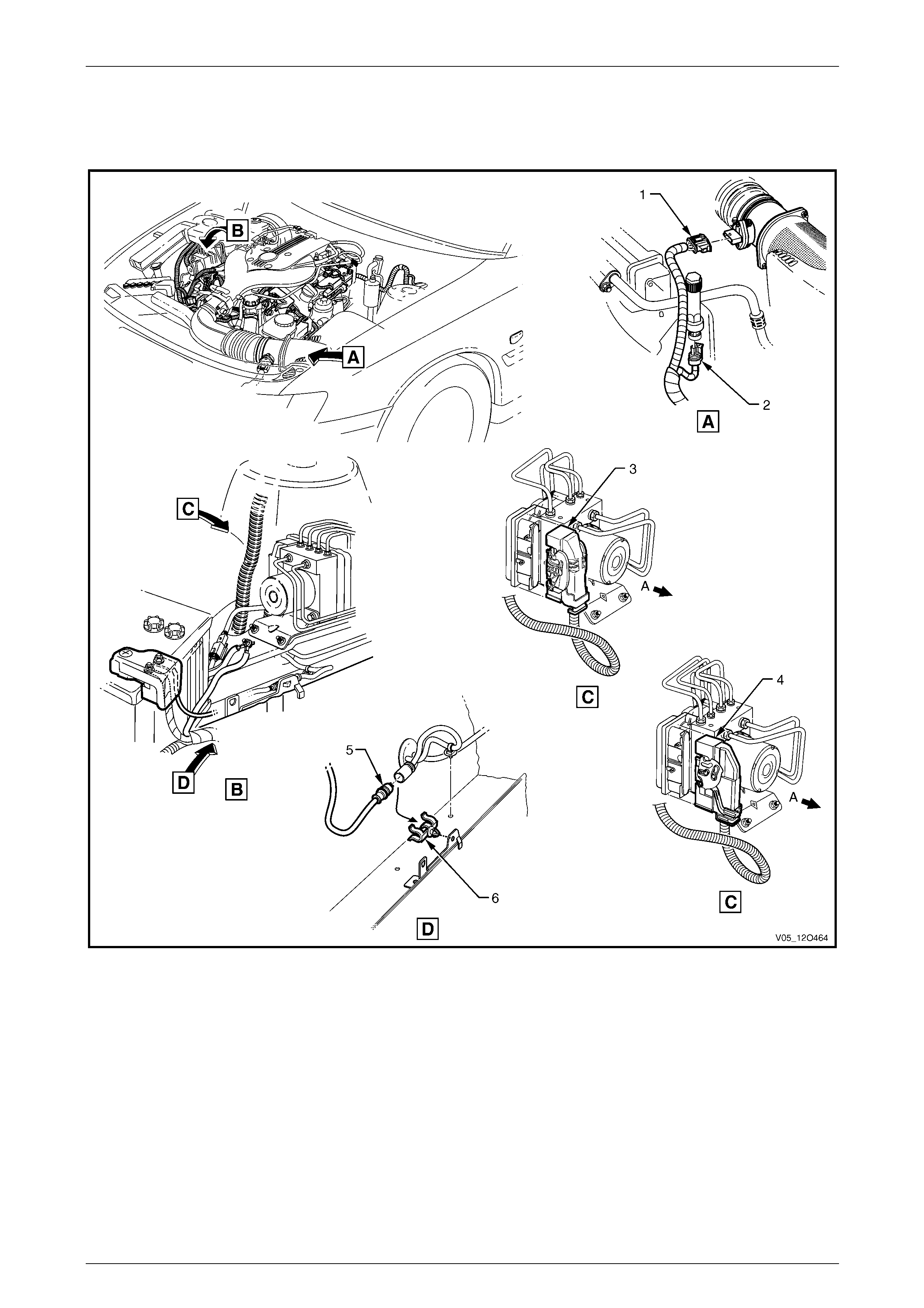
Fuses, Relays and Wiring Harnesses Page 12O–199
6.15 Front Body Harn ess – 2
V6 Engine – ABS, Air Intake and Front Wheel Speed Sensor
Figure 12O – 170
Legend
1 Mass Airflow and Air Intake Temperature Sensor Connector
(B69 – V6)
2 A/C Pressure Sensor Connector (B18 – V6)
3 Electronic Brake and Traction Control Module Connector
(A38)
4 Vehicle Control Module Connector (A116)
5 Front Wheel Speed Sensor Connector (B52)
6 Clip
A Front of vehicle.
Page 12O–199
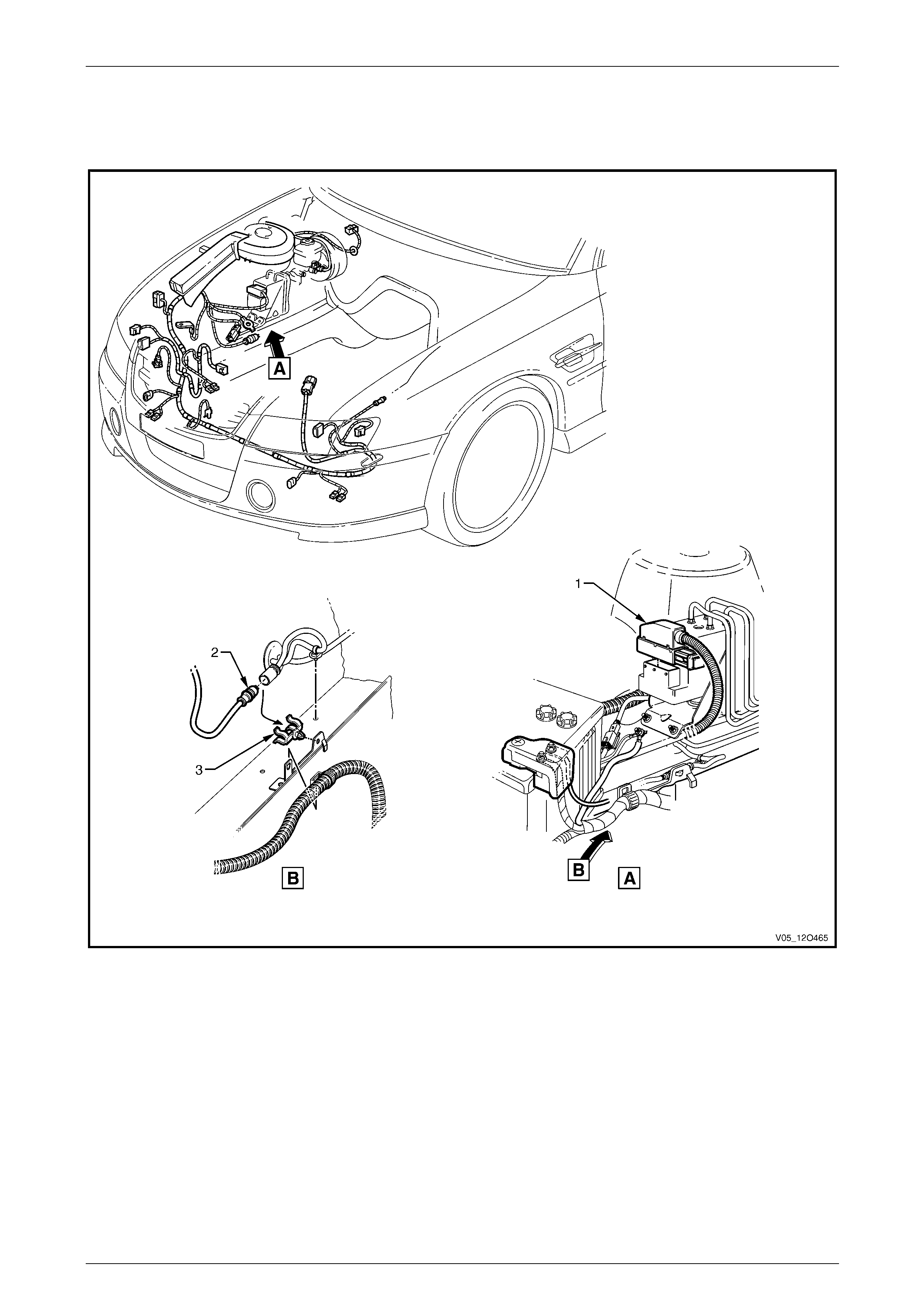
Fuses, Relays and Wiring Harnesses Page 12O–200
6.16 Front Body Harn ess – 3
GEN III V8 Engine – ABS, Air Intake and Front Wheel Speed Sensor
Figure 12O – 171
Legend
1 Electronic Brake and Traction Control Module Connector
(A37) 2 Front Wheel Speed Sensor Connector (B52)
3 Clip
Page 12O–200
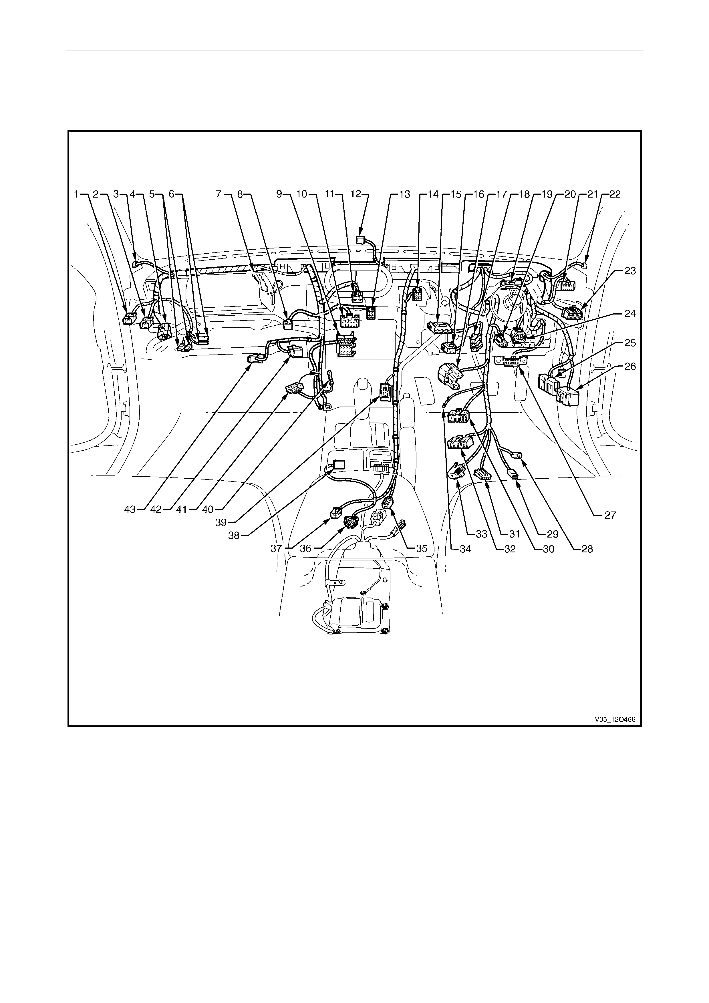
Fuses, Relays and Wiring Harnesses Page 12O–201
6.17 Front Body Harn ess – 4
V6 Engine – Cockpit Module
Figure 12O – 172
Page 12O–201

Fuses, Relays and Wiring Harnesses Page 12O–202
Legend
1 LPG to Front Body Wiring Patch Harness Connector
2 Front Body Harness to Global Positioning System Harness
Connector (X207)
3 Radio Front Speaker Dash Upper Connector (B112 – L)
4 Front Body Harness to Transmission Harness Connector
(X203)
5 Instrument Panel Compartment Lamp Connectors (E82)
6 Instrument Panel Compartment Lamp Switch Connectors
(S142)
7 Front Body Harness to Passenger Airbag Harness
Connector (X205)
8 Rear Compartment Lid Release Switch Connector (S195)
9 Radio, Clock & CD Player Connector (A133 – X1)
10 Heater & A/C Evaporator Module Connector (A60 – X1)
11 Hazard Warning Switch Connector (S120)
12 Ambient Light Sensor Connector (B55)
13 Heater & A/C Evaporator Module Connector (A60 – X2)
14 Trip Odometer Reset Switch Connector (S237)
15 Stop Lamp, Traction & Cruise Control Release Switch
Connector (S220 – X3)
16 Stop Lamp, Traction & Cruise Control Release Switch
Connector (S220 – X1)
17 Ignition & Start Switch Connector (S149 – X1)
18 Clutch Pedal Position Switch Connector (S42 – X2)
19 Instruments Connector (P3)
20 Front Body Harness to Clutch Extension Harness Connector
(X210)
21 Headlamp Automatic Control Switch Connector (S125)
22 Radio Front Speaker Dash Upper Connector (B112 – R)
23 Powertrain Interface Module Connector (A5 – V6)
24 Accelerator Pedal Position Sensor Connector (B22)
25 Front Body Harness to Body Wiring Harness Connector
(X200)
26 Front Body Harness to Body Wiring Harness Connector
(X201)
27 Wiring (Diagnostics) Connector (X40)
28 Ignition Lock Cylinder Bulb Connector (E30)
29 Ignition & Start Switch Connector (S149 – X2)
30 Windshield Wiper and Washer Switch Connector (S247)
31 Cruise Control Switch Connector (S43)
32 Turn Signal & Headlamp Switch Connector (S231)
33 Steering Wheel Clock Spring Coil Connector (X116)
34 Ignition & Start Switch Connector (S149 – GP15 – X3)
35 Front Body Harness to Body Wiring Harness Connector
(X303)
36 Accelerometer Connector (B1)
37 Front Body Harness to Console Wiring Harness Connector
(X309)
38 Front Body Harness to Transmission Selector Harness
Connector (X301)
39 Front Cigar Lighter Connector (X113 – F)
40 Radio Ground Terminal (X118 – GP8)
41 Inline to Radio & Mobile Telephone Connector (X155)
42 Blower Motor Resistor Connector (R6)
43 Front Body Harness to Blower Motor Harness Connector
(X204)
Page 12O–202
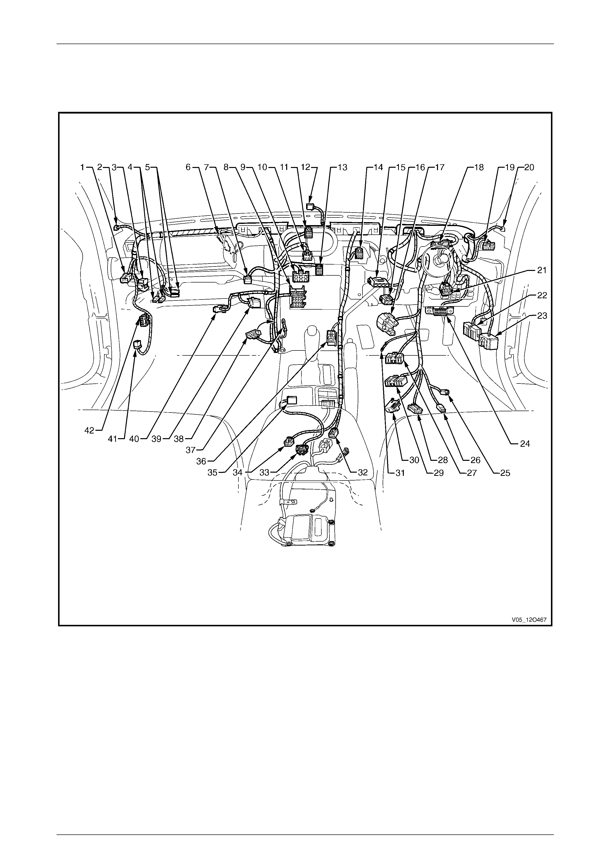
Fuses, Relays and Wiring Harnesses Page 12O–203
6.18 Front Body Harn ess – 5
GEN III V8 Engine – Cockpit Module – Manual Air-conditioning
Figure 12O – 173
Page 12O–203

Fuses, Relays and Wiring Harnesses Page 12O–204
Legend
1 Front Body Harness to Global Positioning System Harness
Connector (X207)
2 Radio Front Speaker Dash Upper Connector (B112 – L)
3 Front Body Harness to Powertrain Harness Connector
(X206)
4 Instrument Panel Compartment Lamp Connectors (E82)
5 Instrument Panel Compartment Lamp Switch Connectors
(S142)
6 Front Body Harness to Passenger Airbag Harness
Connector (X205)
7 Rear Compartment Lid Release Switch Connector (S195)
8 Radio, Clock & CD Player Connector (A133 – X1)
9 Heater & A/C Evaporator Module Connector (A60 – X1)
10 Hazard Warning Switch Connector (S120)
11 Auxiliary Gauges Connector (P2)
12 Ambient Light Sensor Connector (B55)
13 Heater & A/C Evaporator Module Connector (A60 – X2)
14 Trip Odometer Reset Switch Connector (S237)
15 Stop Lamp, Traction & Cruise Control Release Switch
Connector (S220 – X3)
16 Stop Lamp, Traction & Cruise Control Release Switch
Connector (S220 – X1)
17 Ignition & Start Switch Connector (S149 – X1)
18 Instruments Connector (P3)
19 Headlamp Automatic Control Switch Connector (S125)
20 Radio Front Speaker Dash Upper Connector (B112 – R)
21 Accelerator Pedal Position Sensor Connector (B22)
22 Front Body Harness to Body Wiring Harness Connector
(X200)
23 Front Body Harness to Body Wiring Harness Connector
(X201)
24 Wiring (Diagnostics) Connector (X40)
25 Ignition Lock Cylinder Bulb Connector (E30)
26 Ignition & Start Switch Connector (S149 – X2)
27 Windshield Wiper and Washer Switch Connector (S247)
28 Cruise Control Switch Connector (S43)
29 Turn Signal & Headlamp Switch Connector (S231)
30 Steering Wheel Clock Spring Coil Connector (X116)
31 Ignition & Start Switch Connector (S149 – GP15 – X3)
32 Front Body Harness to Body Wiring Harness Connector
(X303)
33 Accelerometer Connector (B1)
34 Front Body Harness to Console Wiring Harness Connector
(X309)
35 Front Body Harness to Transmission Selector Harness
Connector (X301)
36 Front Cigar Lighter Connector (X113 – F)
37 Radio Ground Terminal (X118 – GP8)
38 Inline to Radio & Mobile Telephone Connector (X155)
39 Blower Motor Resistor Connector (R6)
40 Front Body Harness to Blower Motor Harness Connector
(X204)
41 Powertrain Interface Module Connector (A5 – V8)
42 Throttle Actuator Control Module Connector (A111 – X2)
Page 12O–204
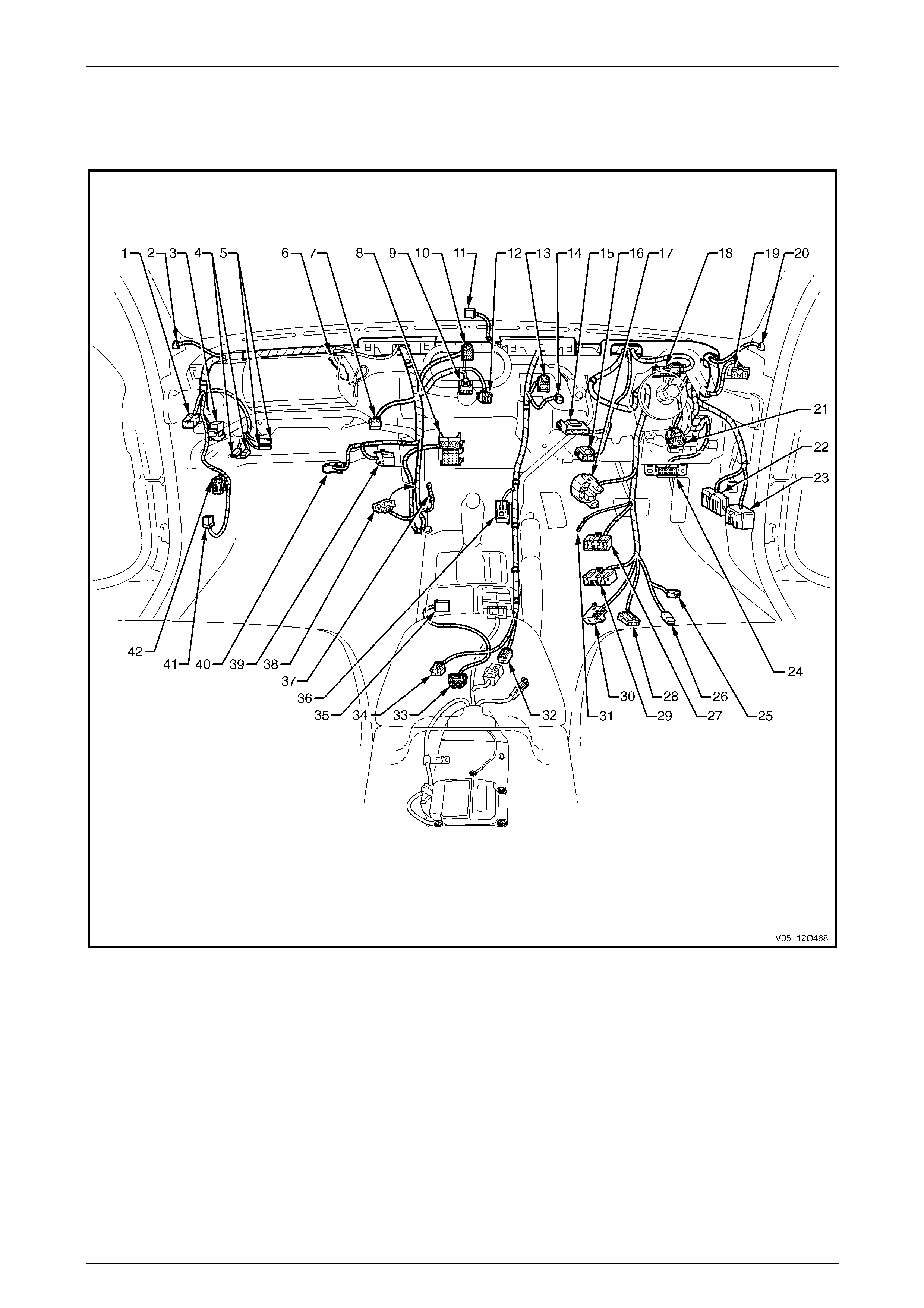
Fuses, Relays and Wiring Harnesses Page 12O–205
6.19 Front Body Harn ess – 6
GEN III V8 Engine – Cockpit Module – Auto Air-conditioning
Figure 12O – 174
Page 12O–205

Fuses, Relays and Wiring Harnesses Page 12O–206
Legend
1 Front Body Harness to Global Positioning System Harness
Connector (X207)
2 Radio Front Speaker Dash Upper Connector (B112 – L)
3 Front Body Harness to Powertrain Harness Connector
(X206)
4 Instrument Panel Compartment Lamp Connectors (E82)
5 Instrument Panel Compartment Lamp Switch Connectors
(S142)
6 Front Body Harness to Passenger Airbag Harness
Connector (X205)
7 Rear Compartment Lid Release Switch Connector (S195)
8 Radio, Clock & CD Player Connector (A133 – X1)
9 Hazard Warning Switch Connector (S120)
10 Auxiliary Gauges Connector (P2)
11 Ambient Light Sensor Connector (B55)
12 Blower Motor & A/C Compressor Connector (A14 – X1)
13 Trip Odometer Reset Switch Connector (S237)
14 Inside Air Temperature Sensor Connector (B59)
15 Stop Lamp, Traction & Cruise Control Release Switch
Connector (S220 – X3)
16 Stop Lamp, Traction & Cruise Control Release Switch
Connector (S220 – X1)
17 Ignition & Start Switch Connector (S149 – X1)
18 Instruments Connector (P3)
19 Headlamp Automatic Control Switch Connector (S125)
20 Radio Front Speaker Dash Upper Connector (B112 – R)
21 Accelerator Pedal Position Sensor Connector (B22)
22 Front Body Harness to Body Wiring Harness Connector
(X200)
23 Front Body Harness to Body Wiring Harness Connector
(X201)
24 Wiring (Diagnostics) Connector (X40)
25 Ignition Lock Cylinder Bulb Connector (E30)
26 Ignition & Start Switch Connector (S149 – X2)
27 Windshield Wiper and Washer Switch Connector (S247)
28 Cruise Control Switch Connector (S43)
29 Turn Signal & Headlamp Switch Connector (S231)
30 Steering Wheel Clock Spring Coil Connector (X116)
31 Ignition & Start Switch Connector (S149 – GP15 – X3)
32 Front Body Harness to Body Wiring Harness Connector
(X303)
33 Accelerometer Connector (B1)
34 Front Body Harness to Console Wiring Harness Connector
(X309)
35 Front Body Harness to Transmission Selector Harness
Connector (X301)
36 Front Cigar Lighter Connector (X113 – F)
37 Radio Ground Terminal (X118 – GP8)
38 Inline to Radio & Mobile Telephone Connector (X155)
39 Blower & Air Inlet Connector (A13 – RHD)
40 Front Body Harness to Blower Motor Harness Connector
(X204)
41 Powertrain Interface Module Connector (A5 – V8)
42 Throttle Actuator Control Module Connector (A111 – X2)
Page 12O–206
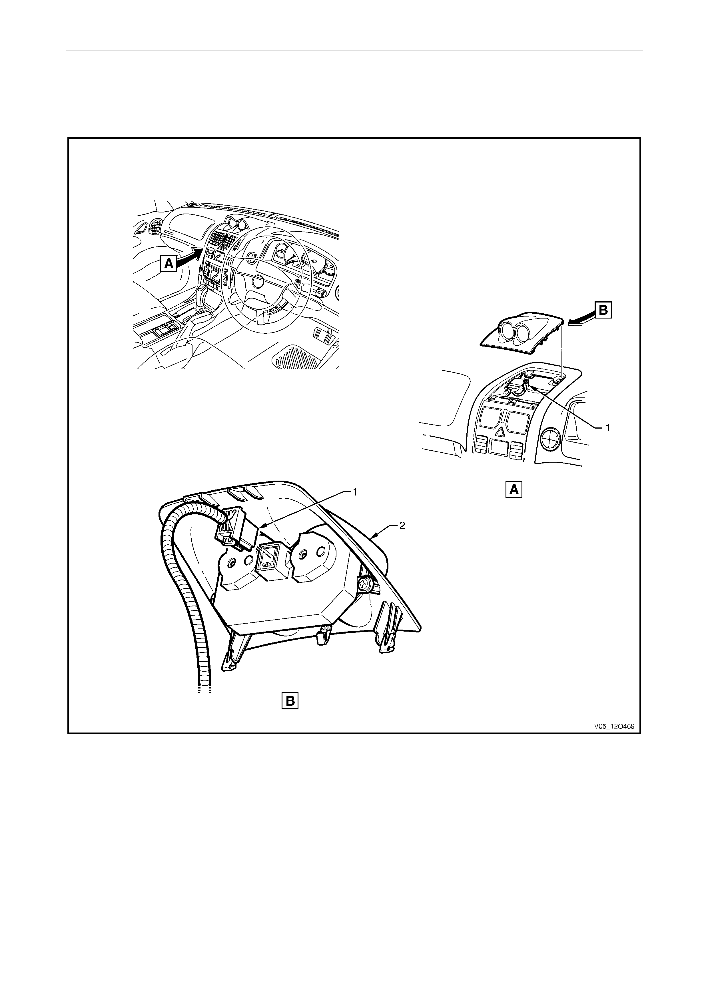
Fuses, Relays and Wiring Harnesses Page 12O–207
6.20 Front Body Harn ess – 7
Auxiliary Sports Gauges
Figure 12O – 175
Legend
1 Auxiliary Sports Gauges Connector (P2) 2 Auxiliary Sports Gauges
Page 12O–207
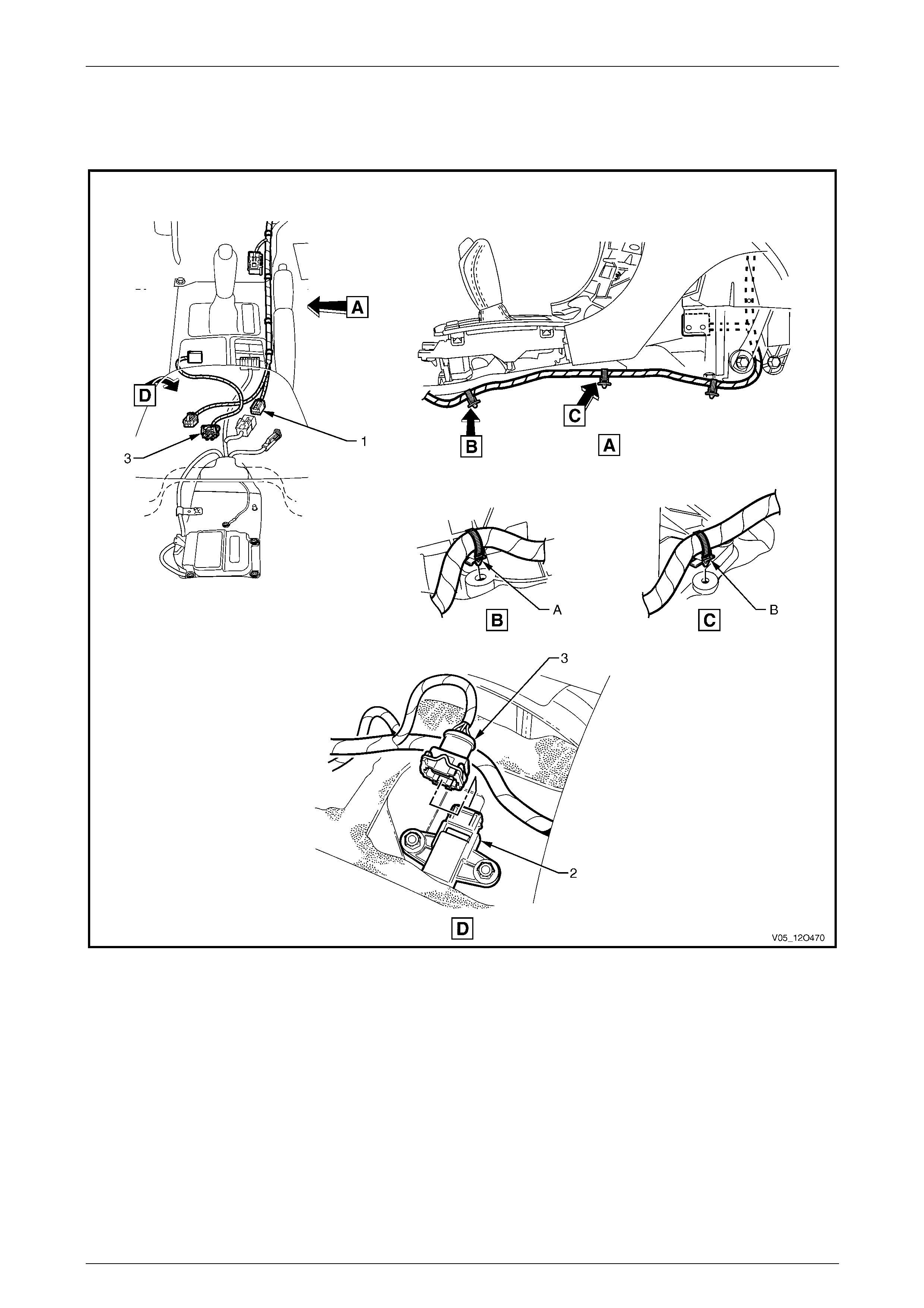
Fuses, Relays and Wiring Harnesses Page 12O–208
6.21 Front Body Harn ess – 8
Interior
Figure 12O – 176
Legend
1 Front Body Harness to Body Wiring Harness Connector
(X303)
2 Accelerometer Module
3 Accelerometer Module Connector (B1)
A Front body harness attached to tunnel as shown.
B Front body harness attached to tunnel as shown.
Page 12O–208
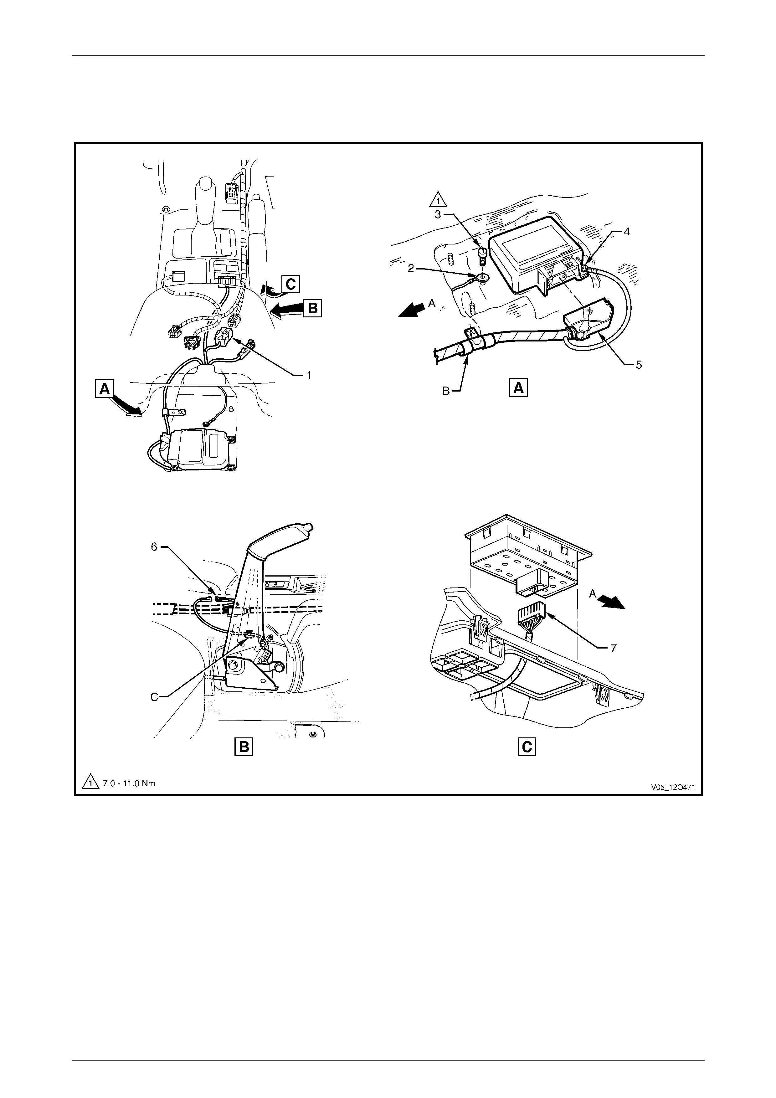
Fuses, Relays and Wiring Harnesses Page 12O–209
6.22 Body Wiring Harness
Interior
Figure 12O – 177
Legend
1 Body Wiring Harness to Front Body Harness Connector
(X303)
2 Ground Terminal (X118 – GP12)
3 Body Wiring Harness Ground Terminal Attaching Screw
4 Ground Terminal (X118 – GP11)
5 Inflation Restraint Sensor Connector (A65)
6 Park Brake Switch Connector (S181)
7 Side Window (Master) Switch Connector (S222)
A Front of vehicle.
B Body wiring harness attached to tunnel as shown.
C Lead clipped as shown.
Page 12O–209