
HVAC Occupant Climate Control (Auto A/C) – Description and Operation Page 2D-1
Page 2D-1
Section 2D
HVAC Occupant Climate Control (Auto A/C) –
Description and Operation
ATTENTION
Before performing any service operation or other procedure described in this Section, refer to Section 00
Warnings, Cautions and Notes for correct workshop practices with regard to safety and / or property damage.
1 General Information ...............................................................................................................................3
2 General Description ...............................................................................................................................4
2.1 OCC Control Module.............................................................................................................................................. 5
Input Data ............................................................................................................................................................... 5
Output Data ............................................................................................................................................................ 6
OCC Control Module Configuration..................................................................................................................... 6
Single Zone........................................................................................................................................................ 6
Dual Zone – RWD.............................................................................................................................................. 7
Dual Zone – AWD .............................................................................................................................................. 7
OCC Control Module Switch Configuration......................................................................................................... 8
Single Zone........................................................................................................................................................ 8
Dual Zone........................................................................................................................................................... 8
Liquid Crystal Display Screen .............................................................................................................................. 9
OCC Control Module Components..................................................................................................................... 10
3 OCC System Sensors ..........................................................................................................................11
3.1 In-car Temperature Sensor ................................................................................................................................. 12
Aspirator Tube and Venturi................................................................................................................................. 12
3.2 Evaporator Temperature Sensor........................................................................................................................ 13
Evaporator Temperature Control........................................................................................................................ 13
3.3 Ambient Temperature Sensor............................................................................................................................. 14
3.4 Sun Load Sensor ................................................................................................................................................. 15
4 System Operation.................................................................................................................................16
4.1 Overview............................................................................................................................................................... 16
Recommended Settings...................................................................................................................................... 16
Dual Zone Operation............................................................................................................................................ 16
Link Mode......................................................................................................................................................... 16
Unlink Mode ..................................................................................................................................................... 16
Mode Control.................................................................................................................................................... 16
Fan Speed Control........................................................................................................................................... 16
Blower Fan Control.............................................................................................................................................. 17
Automatic Mode ............................................................................................................................................... 17
Air Distribution Control....................................................................................................................................... 18
Automatic Mode ............................................................................................................................................... 18
Air Inlet Control.................................................................................................................................................... 18
Automatic Mode ............................................................................................................................................... 18
Vent Air Temperature Control............................................................................................................................. 19
Manual Mode ................................................................................................................................................... 19
Automatic Mode ............................................................................................................................................... 19
OCC Cold Start-up Routines............................................................................................................................... 20
Sensor Malfunction Indicator.............................................................................................................................. 20
Default Mode: Vacuum Leak............................................................................................................................... 20
Automatic Operation ........................................................................................................................................... 20
Techline

HVAC Occupant Climate Control (Auto A/C) – Description and Operation Page 2D-2
Page 2D-2
4.2 OCC System Activation....................................................................................................................................... 22
4.3 HVAC Unit Airflow Modes – Single Zone........................................................................................................... 23
HVAC Airflow Diagram ........................................................................................................................................ 23
Recirculation Mode.............................................................................................................................................. 24
Full Cold........................................................................................................................................................... 24
Full Heat........................................................................................................................................................... 25
Face Mode ............................................................................................................................................................ 26
Full Cold........................................................................................................................................................... 26
Full Heat........................................................................................................................................................... 26
Bi-level Mode........................................................................................................................................................ 27
Full Cold........................................................................................................................................................... 27
Full Heat........................................................................................................................................................... 27
Floor Mode............................................................................................................................................................ 28
Full Cold........................................................................................................................................................... 28
Full Heat........................................................................................................................................................... 28
Blend Mode........................................................................................................................................................... 29
Full Cold........................................................................................................................................................... 29
Full Heat........................................................................................................................................................... 29
Demist Mode......................................................................................................................................................... 30
Full Heat and A/C Activated ............................................................................................................................. 30
Default Mode ........................................................................................................................................................ 31
Loss of Vacuum Supply to HVAC Unit ............................................................................................................. 31
4.4 HVAC Unit Airflow Modes – Dual Zone.............................................................................................................. 32
HVAC Airflow Diagram ........................................................................................................................................ 32
Recirculation Mode.............................................................................................................................................. 33
Full Cold........................................................................................................................................................... 33
Full Heat........................................................................................................................................................... 34
Face Mode ............................................................................................................................................................ 35
Full Cold........................................................................................................................................................... 35
Full Heat........................................................................................................................................................... 35
Bi-level Mode........................................................................................................................................................ 36
Full Cold........................................................................................................................................................... 36
Full Heat........................................................................................................................................................... 36
Floor Mode............................................................................................................................................................ 37
Full Cold........................................................................................................................................................... 37
Full Heat........................................................................................................................................................... 37
Blend Mode........................................................................................................................................................... 38
Full Cold........................................................................................................................................................... 38
Full Heat........................................................................................................................................................... 38
Demist Mode......................................................................................................................................................... 39
Full Heat and A/C Activated ............................................................................................................................. 39
Default Mode ........................................................................................................................................................ 40
Loss of Vacuum Supply to HVAC Unit ............................................................................................................. 40
5 Specifications.......................................................................................................................................41

HVAC Occupant Climate Control (Auto A/C) – Description and Operation Page 2D-3
Page 2D-3
1 General Information
This Section provides a gener al description of the operation of the electronic control components of the occupant climat e
control system. For the general descr iption of the operation of the heater and air-conditioner system, except the
electronic control system refer to Section 2A HVAC Climate Control (Manual A/C) – Description and Operation

HVAC Occupant Climate Control (Auto A/C) – Description and Operation Page 2D-4
Page 2D-4
2 General Description
The occupant climate control (OCC) system uses the following compon ents to control the operation of the heater a nd air-
conditioning system:
• push button occupant climate c ontrol (OCC) control module,
• in-car temperature sensor,
• sun load sensor,
• ambient temperature sensor,
• evaporative temperature sensor,
• vacuum solenoid pack, and
• air mix door motor.
The OCC system can maintain a preset level of cooling or heating regardless of inside or outside temperature
fluctuations. The electronic sensors listed above al low the system to respond to various changes in ambient temperature,
evaporator temperature, interior cabin temperature and sun load.
The OCC system has the capabilit y to use recirculated air in conjunction with all other ventilation mode s. The OCC
system will adjust automatically to any climate and temperature chang es to maintain the vehicle cabin interior within the
selected temperature range. This is achieved by automaticall y controlling:
• heater water valve opening and closing,
• air mix door movement,
• fresh/recirculation door positio n,
• blower fan speeds, and
• ventilation mode selection.
Air-conditioner compressor cycling is controlled by the engine control module (ECM) for V6 engine or the powertrain
control module (PCM) for GEN III V8 engine, in accordance with the pressure signal sent to it by the air-conditioner
pressure transducer and serial data communication with the body control module (BCM). Engine cooling/condenser fan
operation is controlled by the ECM (V6) or the PCM (GEN III V8).
The dual zone OCC module is fitted with two temperature control buttons. This allows both the driver and the front seat
passenger to individually sele ct their desired comfort level of temperature setting. When dual zone mode is operating, the
temperature of the air flowing from the passenger’s floor, face and side vents will be different from the driver’s floor, face
and side vents.
HVAC Occupant Climate Control (Auto A/C) – Description and Operation Page 2D-5
Page 2D-5
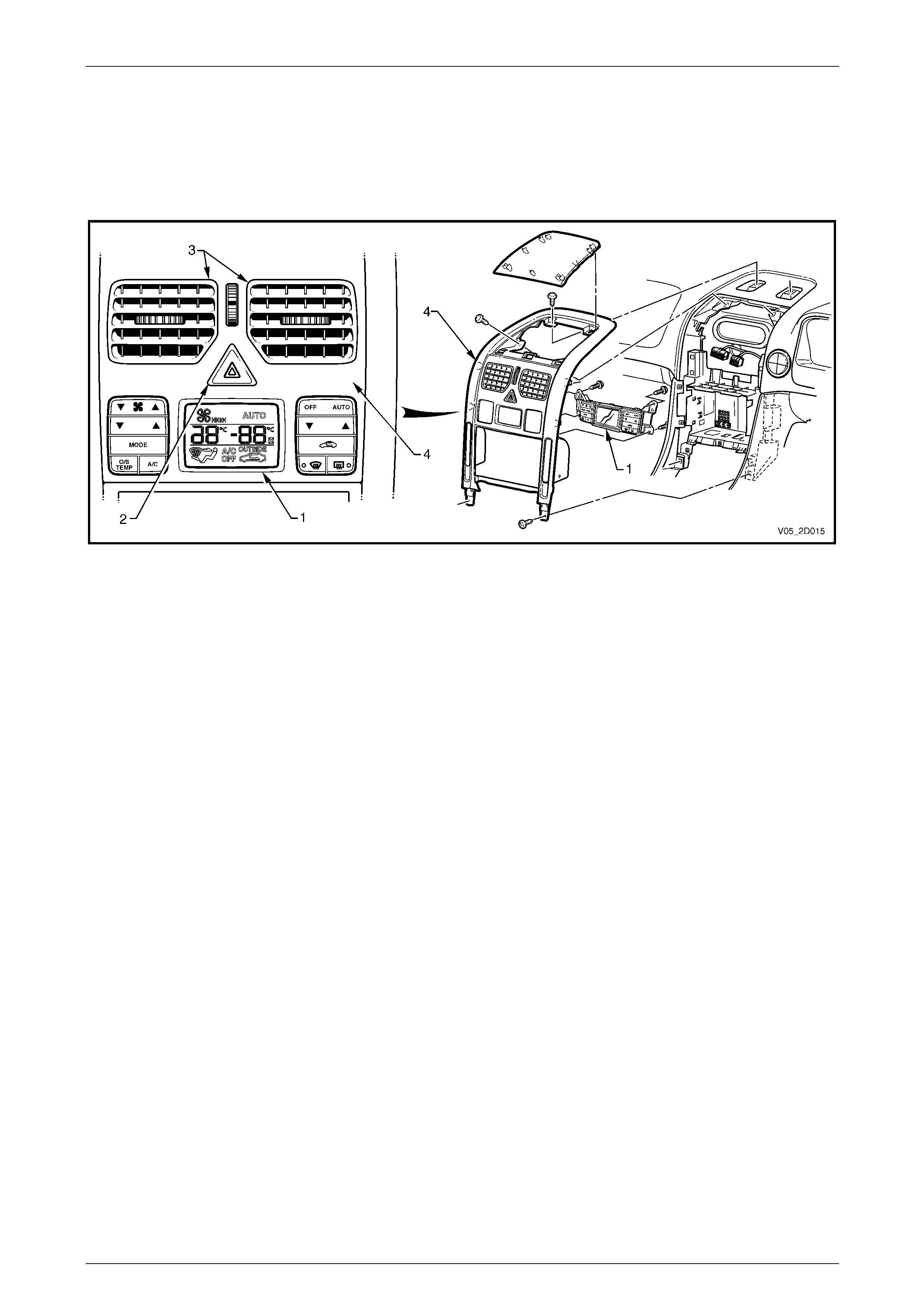
2.1 OCC Control Module
The OCC control module (1) is located bel ow the hazard switch (2) and face level centre vents (3) and is attached to the
back of the instrument panel centre fascia (4) , refer to F igure 2D – 1. Contain ed within the module is the software
required to control the OCC system in conjunction with the bod y control module (BCM) a nd the engine control module
(ECM) for V6 engine or the powertrain control module (PCM) for GEN III V8 engine.
Figure 2D – 1
The OCC control module oper ates the desired HVAC functions, operating modes and ca bin temperature. Included in its
functions are switches for windscreen demisting mode and the heated rear window. LED switch illumination is provided
when the windscreen demister and he ated rear window are activated. All wording and ico ns on the buttons are
illuminated when the park lamps are activated. Their illumination level is adjusted by the same means and to the same
level as the instrumentation illumination.
The OCC control module incorporates a microprocessor to monitor inputs, process data and thus control outputs.
Input Data
• Engine RPM.
• Coolant temperature.
• Road speed.
• A/C pressure from the ECM (V6) or the PCM (GEN III V8).
• Sun load sensor.
• In-car temperature sensor.
• Ambient temperature sensor.
• Evaporative temperature sensor.
• Air mix potentiometer.
• Ignition Voltage.
• Blower Fan Voltage.
• Occupant settings by way of the OCC control module buttons.
HVAC Occupant Climate Control (Auto A/C) – Description and Operation Page 2D-6
Page 2D-6
Output Data
• A/C request to the ECM (V6) or the PCM (GEN III V8).
• Air Distribution Mode (by controlli ng the logic of the vacuum solenoi ds):
• Demist,
• Foot,
• Foot and face (bi-level),
• Face.
• Vent air temperature by controlling the position of the air mix doors between approximately 5°C with A/C on and
approximately 70°C with a warm engine.
• Air Inlet Mode (fresh or recirculated) by controlling a vacuu m solenoid.
• Water valve operation by controlling a vacuum solenoid.
• Blower fan speed by an analogue signal sent to the electronic blower motor controller, which amplifies this signal
and thus controls the blo wer voltage.
• Maximum blower relay.
• Rear window demist relay.
OCC Control Module Configuration
Single Zone
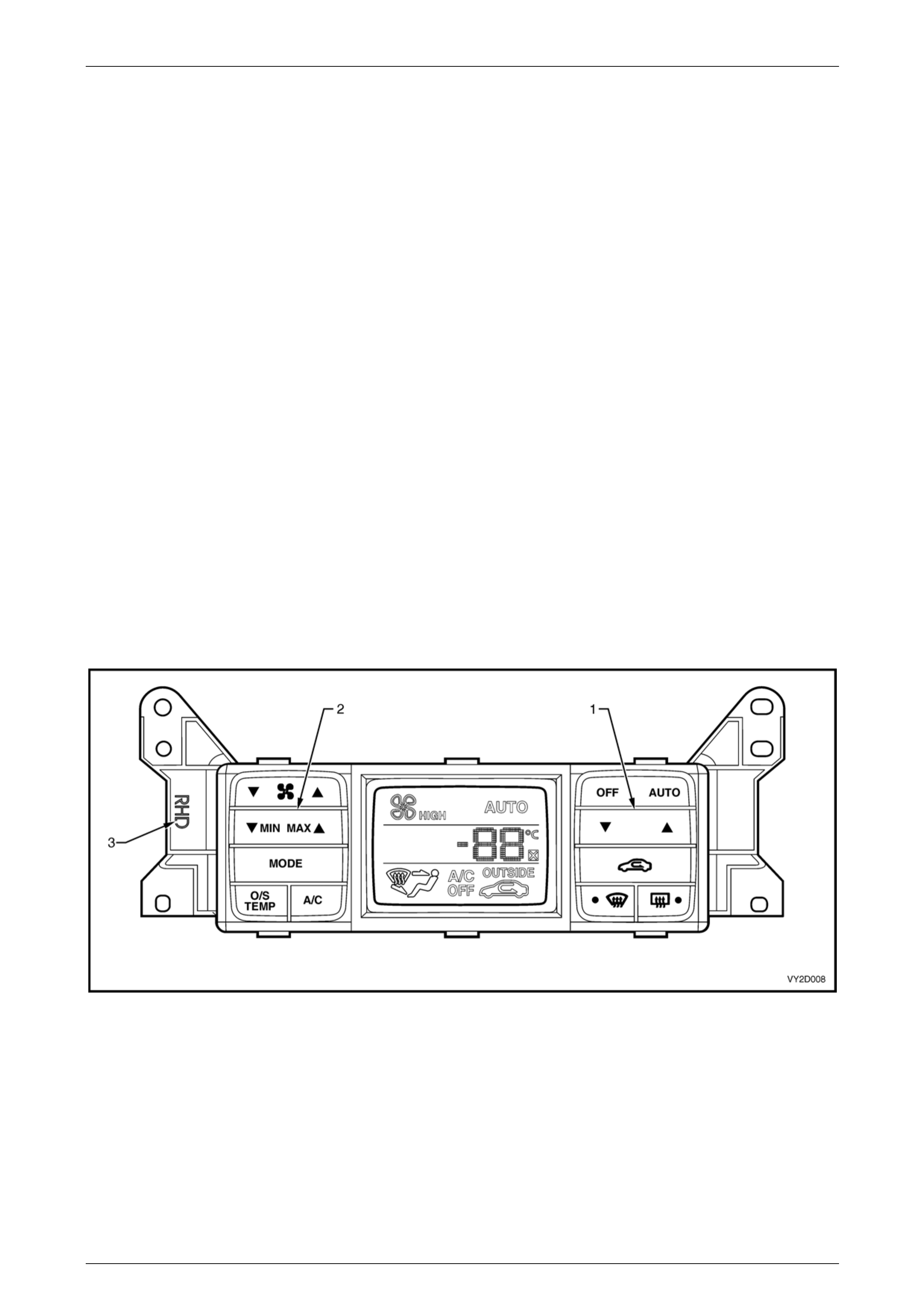
The OCC control module inclu des push buttons for the operator to control the OCC syste m, refer to F igure 2D – 2. The
Set temperature button (1) is on the right-hand side and the MIN / MAX uncontrolled te mperature switch (2) is on the left-
hand side. A RHD marking (3) is moulded to the facia to indicate that the module is for right-hand drive application.
Figure 2D – 2
HVAC Occupant Climate Control (Auto A/C) – Description and Operation Page 2D-7
Page 2D-7
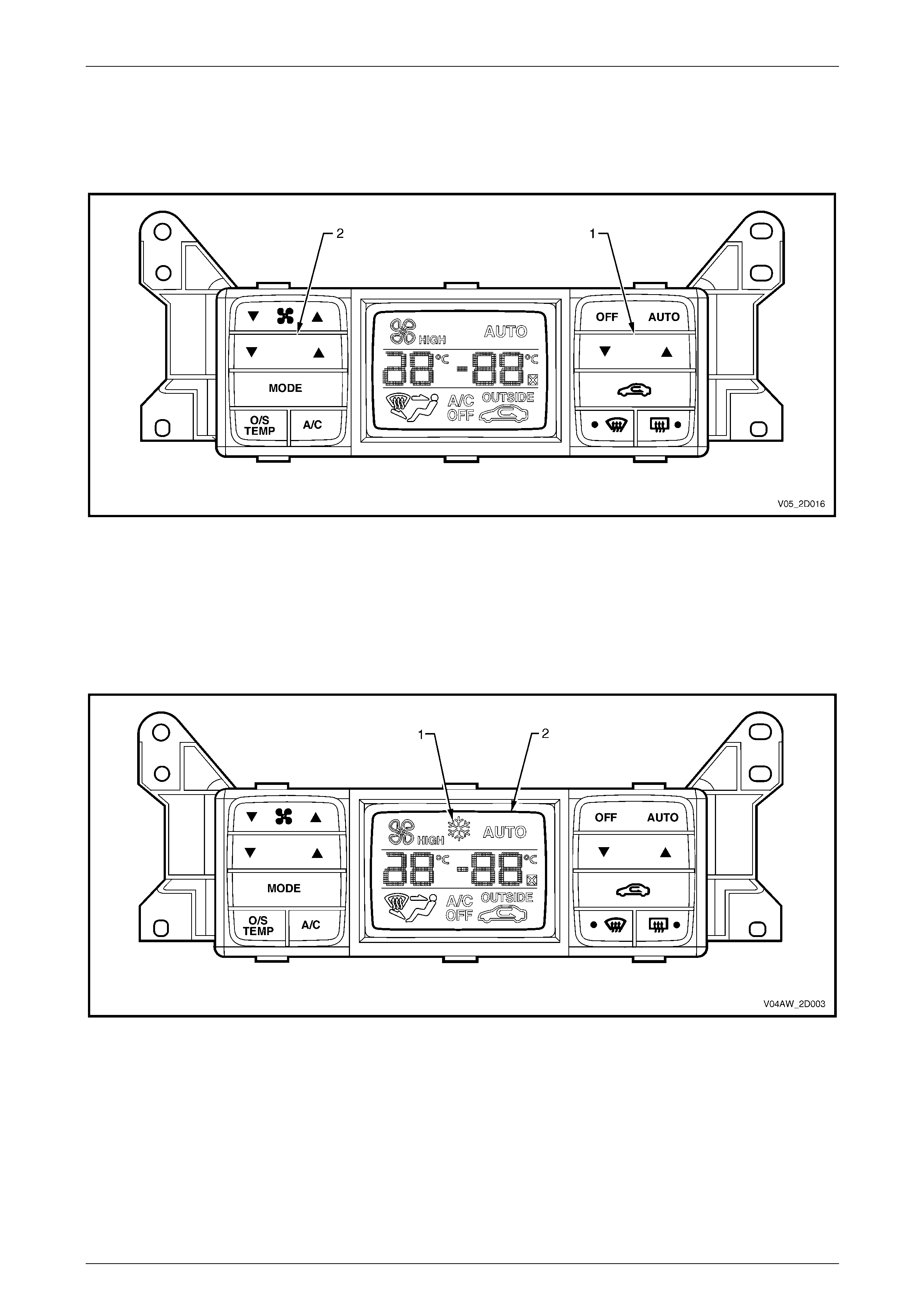
Dual Zone – RWD
The OCC control module inclu des push buttons for the operator to control the OCC syste m, refer to F igure 2D – 3. The
driver's set temperature button (1) is on the right-ha nd side and the front passenger's temperature switch (2) is on the
left-hand side.
Figure 2D – 3
Dual Zone – AWD
All the OCC modules fitted to AWD Wagon vehicle range display an additional driving condition to the driver in the form
of a snowflake, refer to Figure 2D – 4. This ice warning symbol (1) will be displayed on the LCD screen (2) when the
outside temperature is approximatel y 2°C or below. It is provided to alert the driver that the road surface may be
hazardous. The symbol will turn off when the outside temperature rises above 4°C. The outside tempera t ure information
is relayed to the OCC module by the ambie nt temperature sensor.
Figure 2D – 4
HVAC Occupant Climate Control (Auto A/C) – Description and Operation Page 2D-8
Page 2D-8
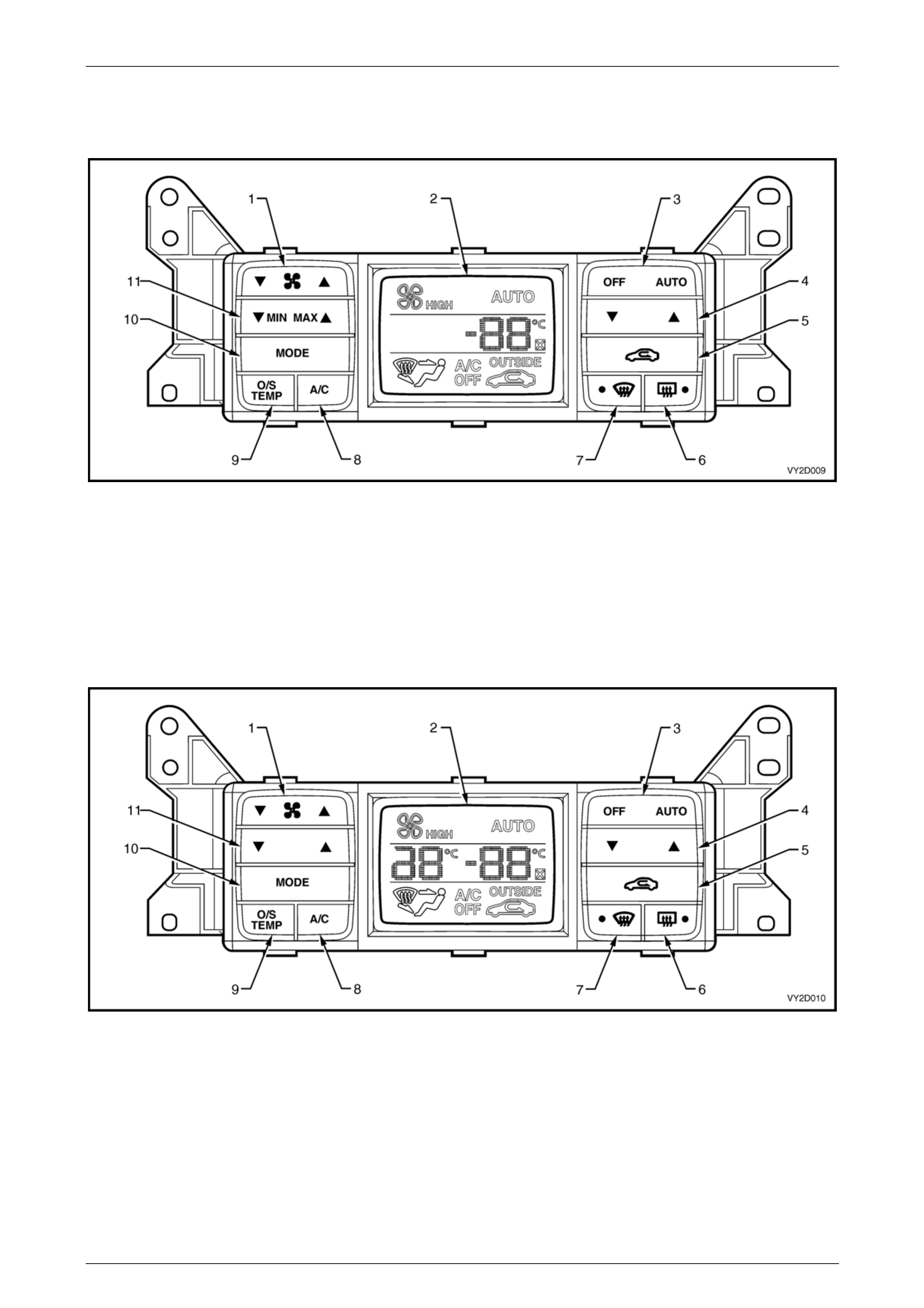
OCC Control Module Switch Configuration
Single Zone
Figure 2D – 5
Legend
1 Blower Fan Speed Switch
2 Liquid Crystal Display (LCD) Screen
3 OCC System ON/OFF, Auto Function ON Switch
4 Set Temperature Switch
5 Fresh/Recirculation Mode Position Switch
6 Heated Rear Window Switch and Indicator LED
7 Windscreen Demist Mode Switch and Indicator LED
8 Air Conditioning ON / OFF Switch
9 Outside Temperature Indicator Select Switch
10 Ventilation Mode Selection Switch
11 Min (Cold), Max (Hot), Uncontrolled Temperature Setting
Dual Zone
Figure 2D – 6
Legend
1 Blower Fan Speed Switch
2 Liquid Crystal Display (LCD) Screen
3 OCC System ON/OFF, Auto Function ON Switch
4 Set Temperature Switch – Driver's Side
5 Fresh/Recirculation Mode Position Switch
6 Heated Rear Window Switch and Indicator LED
7 Windscreen Demist Mode Switch and Indicator LED
8 Air Conditioning ON / OFF Switch
9 Outside Temperature Indicator Select Switch
10 Ventilation Mode Selection Switch
11 Set Temperature Switch – Front Passenger's Side
HVAC Occupant Climate Control (Auto A/C) – Description and Operation Page 2D-9
Page 2D-9
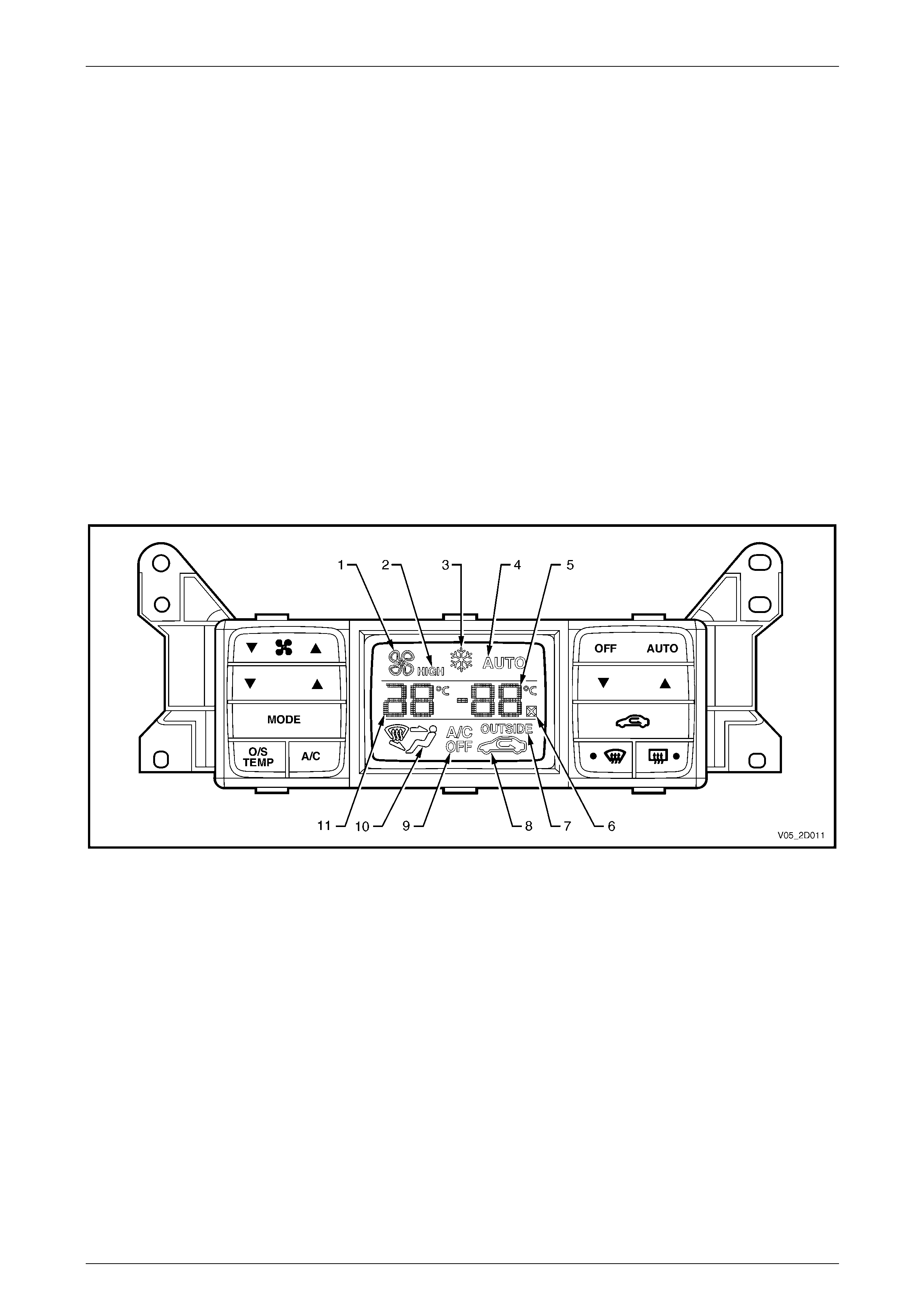
Liquid Crystal Display Screen
The OCC control module incorporates a liquid crystal display (LCD) scree n to indicate which modes and f unctions have
been selected, refer to Figure 2D – 7. Depending on the mode chosen, the LCD will also display the vehicle cabin
temperature as selected by the driver, the vehicle cabin temperature as selected by the front passenger on a dual zone
system, or the temperature as set by the OCC system when in Auto mode.
An outside temperature indica tor is displayed when the O/S TEMP button is held on. This function operates whether the
OCC system is on or off.
When selected, the recirculation mode symbol is displayed on the LCD even if the OCC system is off.
All OCC modules fitted to AWD Wagon and Crew Cab vehicle range displ ay an additional driving conditi on icon to the
driver in the form of a snowflake. This ‘Ice Warning’ symbol (3) will be displayed on the LCD screen when the outside
temperature is approximately 2 °C or below. It is provided to alert the driver that the road surface may be hazar dous. The
symbol will turn off when the outside temper ature rises above 4 °C. The outside temperature informati on is relayed to the
OCC module by the ambient temperature se nsor.
For further information on the LCD screen and to view typical screen displays, refer to 4 System Operation.
The illumination level of the LCD is controlled by the BCM via the auxiliary serial bus. The LCD brightness is maintaine d
at a similar level to the instruments and audio system displ a ys. For further informatio n,
refer to Section 12J Body Control Module.
The LCD is also capable of displaying a self-diagnostic message if the OCC system develops a fault. When an OCC
sensor input is not received, an X symbol appears on the LCD screen beside the right-hand temperature numera ls,
regardless if the OCC system is on or off. For further information relating to OCC system self-diagnosis, refer to
Section 2E HVAC Occupant Climate Control (Auto A/C) – Diagnostics.
Figure 2D – 7
Legend
1 Blower Fan Active
2 Blower Fan High Speed
3 Ice Warning Indicator (AWD)
4 OCC System in Auto Mode
5 Temperature Setting – Driver's Side (dual zone) or cabin
(single zone) and Outside Temperature
6 Self Diagnostic Symbol
7 Outside Temperature Indicator
8 Recirculation Mode Position Indicator
9 Air Conditioning OFF Indicator
10 Ventilation Mode Indicator
11 Temperature Setting – Front Passenger's Side (dual zone)
HVAC Occupant Climate Control (Auto A/C) – Description and Operation Page 2D-10
Page 2D-10
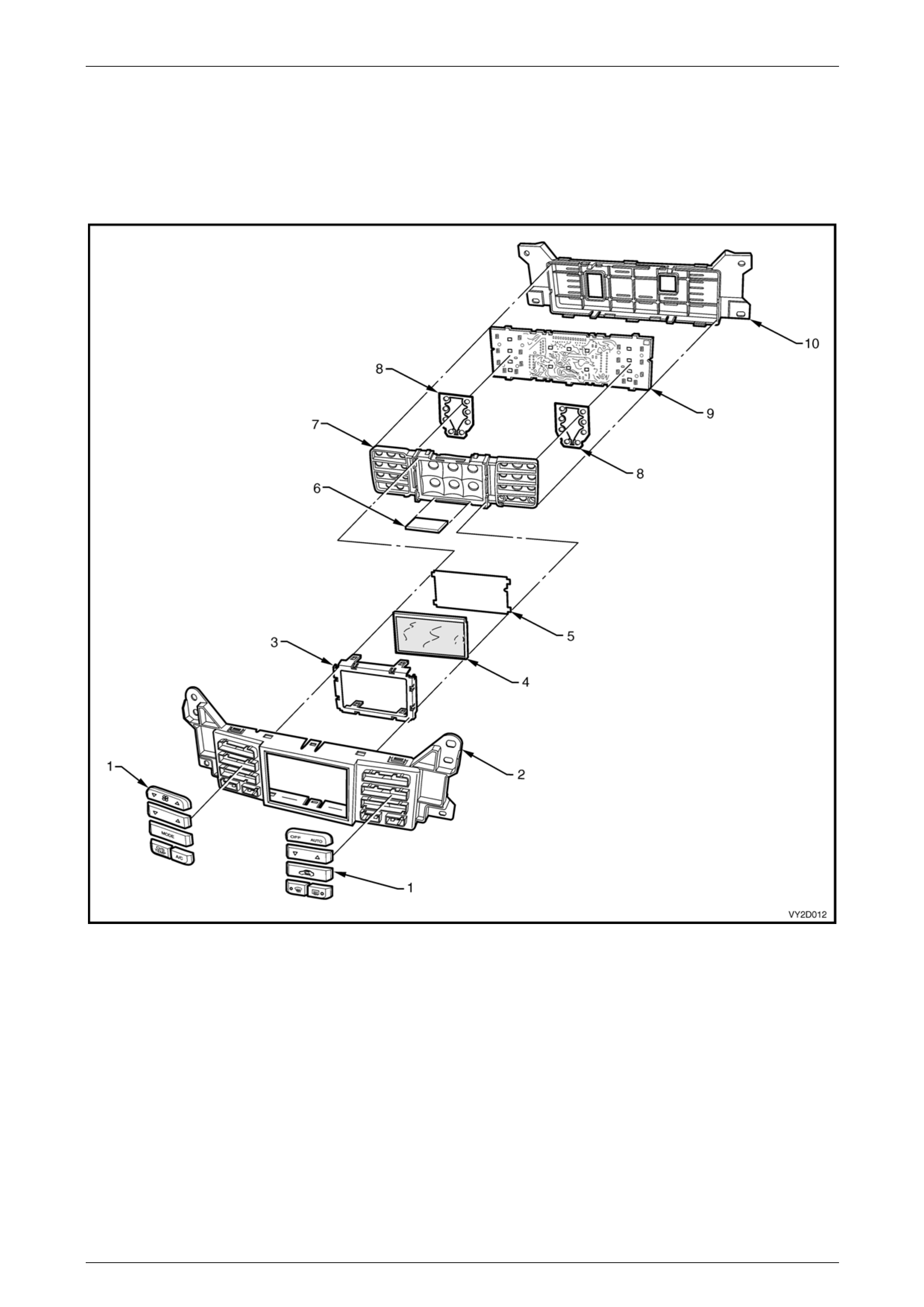
OCC Control Module Components
The OCC control module contains a printed circuit board with the LCD screen. Information from the circuit board is
transferred to the LCD screen through a carbon zebra strip. A 12 pin and a 20 pin el ectrical connectors are bonded
directly to rear of the circuit board and protrude through a pe r tures of the module’s rear housing. T here are no
replaceable bulbs within the OCC control module; LEDs are used to provide illumination where necessary.
The module has no serviceable items. If any component fails the module must be repl aced.
Figure 2D – 8
Legend
1 Control Buttons
2 Front Facia
3 LCD Frame
4 LCD Screen
5 LCD Diffuser
6 Carbon Zebra Strip
7 LCD and Silicone Switch Carrier
8 Silicone Switches
9 Circuit Board
10 Rear Housing
HVAC Occupant Climate Control (Auto A/C) – Description and Operation Page 2D-11
Page 2D-11
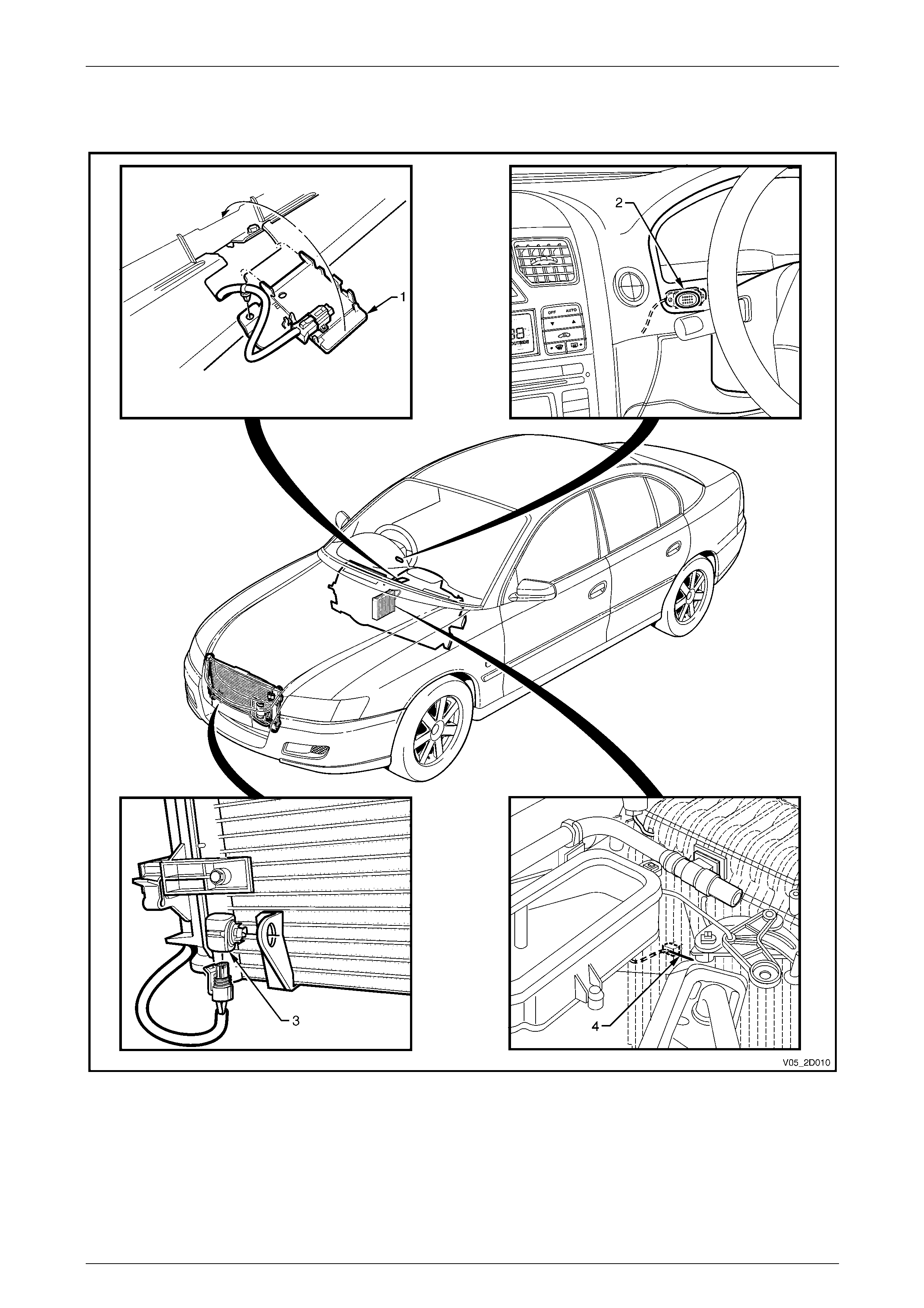
3 OCC System Sensors
Figure 2D – 9
Legend
1 Sun Load Sensor
2 In-car Temperature Sensor 3 Ambient Temperature Sensor
4 Evaporative Temperature Sensor
HVAC Occupant Climate Control (Auto A/C) – Description and Operation Page 2D-12
Page 2D-12
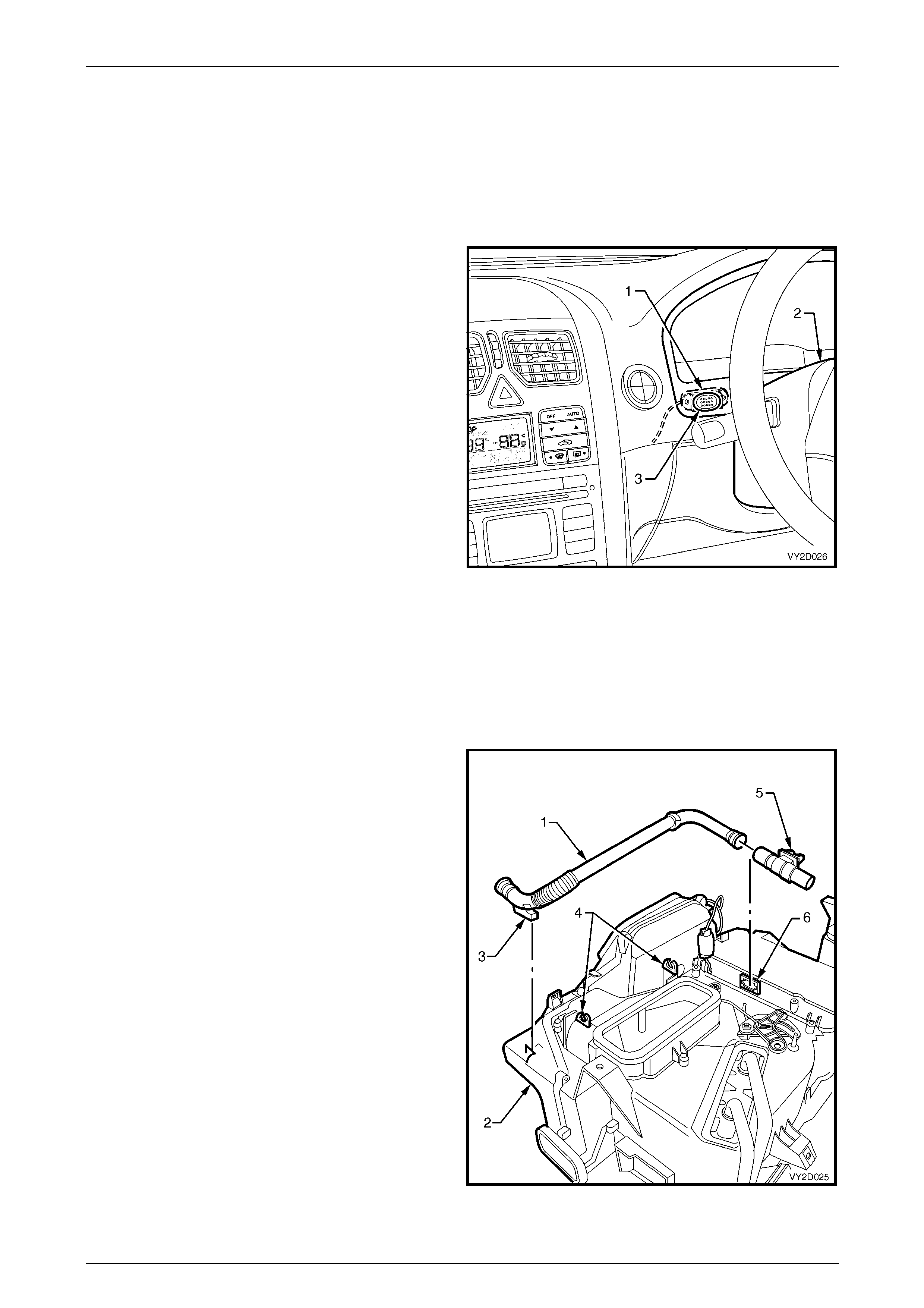
3.1 In-car Temperature Sensor
The in-car temperature sensor is a negative temperature co- efficient (NTC) thermistor used to monitor the vehicle’s
interior air temperature. Resistance signals are constantly m onitored by the OCC control module and are used for
subsequent control of the OCC system.
It is essential the venturi and aspirator tube assembly be properly connected to the in-car temperature sensor if the
sensor is to provide correct information to the OCC control module, refer to Aspirator Tube and Venturi in this Sectio n for
further information.
The in-car temperature sensor (1) is located on the left-hand
side of the steering column (2) behind the a ir holes (3) on
the instrument cluster trim assembly.
Figure 2D – 10
Aspirator Tube and Venturi
The aspirator tube is a formed plastic tube that is installed between the in-car temperature sensor and a venturi located
on the top of the HVAC case. When the blower fan is operating, positive air pressure is forced through the venturi. This
causes air to be drawn from the vehicle inter ior throu gh the in-car temperature sensor to the venturi via the aspirator
tube. The inducted air is used to aid the in-car temperature sensor to react quickly to any temperature changes taking
place within the vehicle int erior.
The aspirator tube (1) is located on th e top o f the HVAC
case (2). The front section of the tube is retained to the cas e
by a locating lug (3). Two retainin g clips (4) moulded to the
case retain the centre section of the tube.
The rear of the tube is fitted into the induction port of the
venturi (5) The base of the venturi (inlet port) is installed to
the venturi air hole (6) located in the evaporator cover of the
HVAC case.
Figure 2D – 11
HVAC Occupant Climate Control (Auto A/C) – Description and Operation Page 2D-13
Page 2D-13
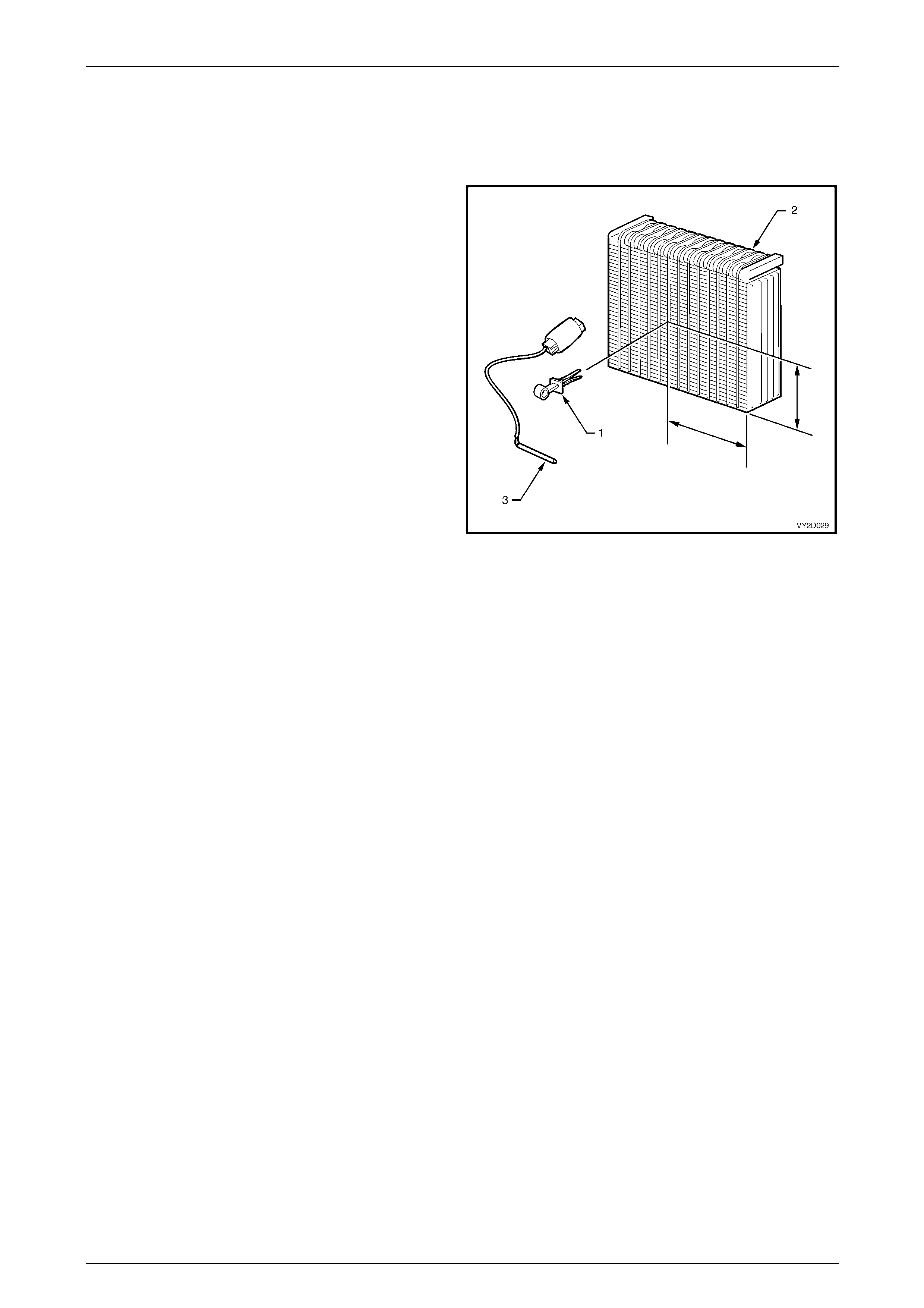
3.2 Evaporator Temperature Sensor
The evaporator temperature sensor is a negative temperature co-efficient (NTC) thermistor used to monitor the
temperature of the air into the HVAC unit after it has passed through the evaporator. Resistance values are constantly
monitored by the OCC control module and a r e used for subsequent control of the OCC system.
The evaporator temperature sensor (1) is located on
evaporator (2) by a plastic retaining clip (3). The installation
point of the sensor to the evaporator is critical for correct
OCC system performance. Refer to Section 2F HVAC
Occupant Climate Control (Aut o A/C) – Removal and
Installation for the specified installati on dimensions.
Figure 2D – 12
Evaporator Temperature Control
As the air-conditioning system uses a varia bl e stroke compressor, the evaporator temperature sens or is only used to
sense A/C temperature for the OCC control module software calculations, not to cycle the compressor on or off. Anti ice-
up is governed by the evaporator pressure control valve located within the compress or.
HVAC Occupant Climate Control (Auto A/C) – Description and Operation Page 2D-14
Page 2D-14
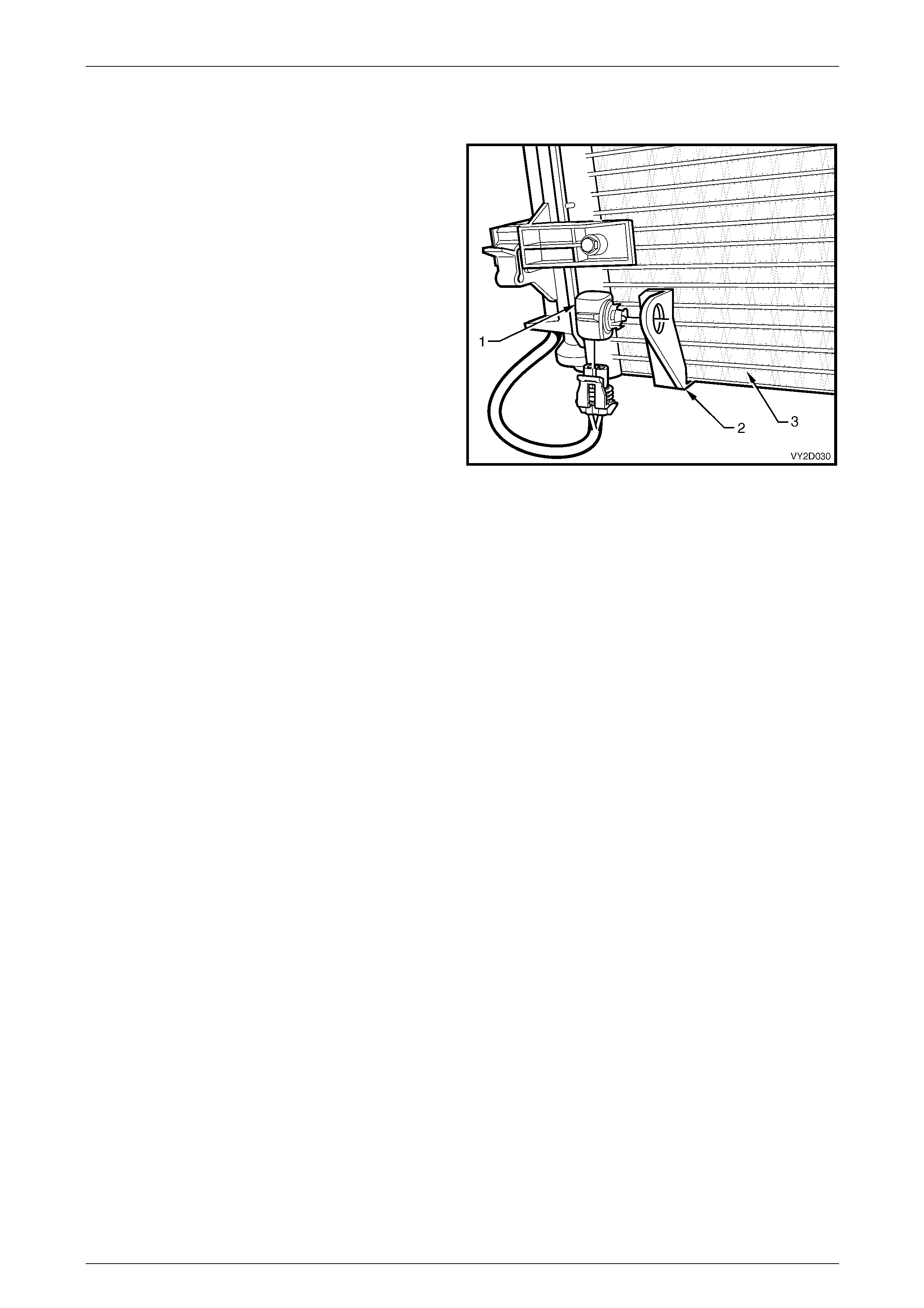
3.3 Ambient Temperature Sensor
The ambient temperature sen sor (1) is installed on a bracket
(2) that is permanently attached to the front of the air-
conditioning condenser (3) on the lower right-hand side.
It is a negative temperature co-efficient (NTC) thermistor
used to monitor the ambient (outside) temperature. This
sensor is slow reacting due to the dens e plastic housing
surrounding it. The OCC control module takes into account
road speed before up dating the temperature display to avoid
false readings in heavy traffic or extended idle conditions.
Figure 2D – 13
HVAC Occupant Climate Control (Auto A/C) – Description and Operation Page 2D-15
Page 2D-15
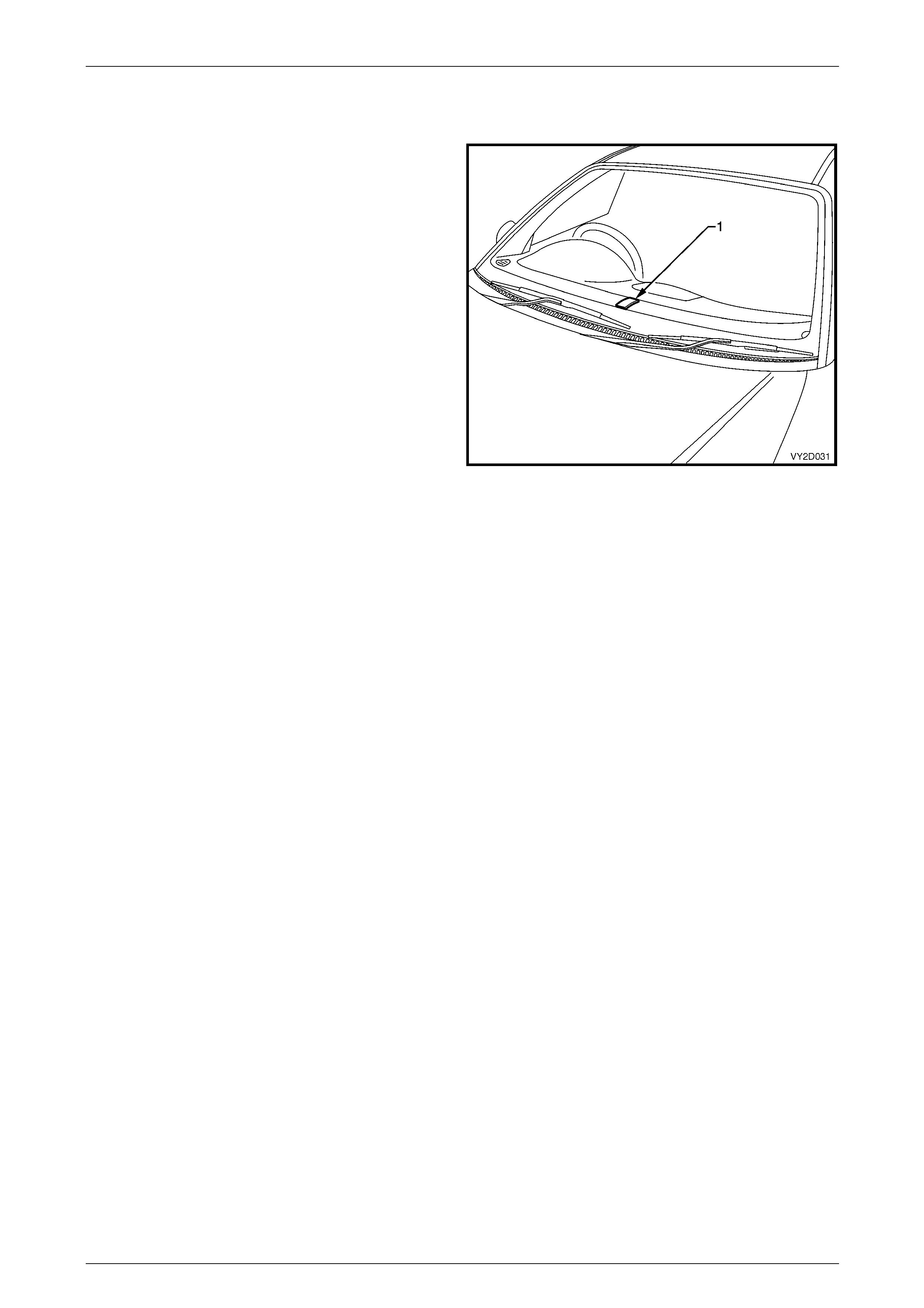
3.4 Sun Load Sensor
The sun load sensor (1) is incorporated into the remote
receiver module and is located in the ce ntre of the demist
grilles. For the purposes of the OCC system, it is used to
monitor the sun’s heating load upon the veh icle.
It is a photochemical type sensor, meaning that a small
electrical current will be gener ated, which depends on the
sun load (strength) over it. When the sun’s intensity is high,
the OCC control module will select a higher blower fan
speed and increased veh icle cooling automatically.
Likewise, when the sun load is low, such as going into an
underground car park, the OCC control module will
automatically reduce the fan speeds and inc rease heating
slightly.
Signals are sent from the sun load sensor directly to the
BCM then to the OCC control module via the serial data line
input.
Figure 2D – 14

HVAC Occupant Climate Control (Auto A/C) – Description and Operation Page 2D-16
Page 2D-16
4 System Operation
4.1 Overview
Recommended Settings
The customer should be encouraged to operate the OCC system in full Auto Mode (orange Auto LED on) and a set
temperature of 23°C.
Changing the set temperature to suit different conditions could cause the OCC system to beh ave differently from what
the customer expects (eg. setting to 17°C on a hot day could cause the customer to complain the blower speed is too
high on hot days). This shoul d be discouraged.
Dual Zone Operation
Link Mode
The link mode refers to the mode when the operation of both the passenger and dr iver air mix motors are synchronised.
When the driver ‘set’ temperat ure is changed, likewise the passenger ‘set’ temperature changes to the same value. To
access the link mode, press and hold the AUT O button for more than two seconds.
Unlink Mode
This mode is when the passenger sets their desired temperature independent of the driver. To access Unlink Mode,
press the passenger side temperatur e button.
NOTE
If the OCC was previously operating in Link
Mode, this action will switch the system to Unlink
Mode.
Mode Control
It is not possible for the passenger to alter the mode positions such as Floor, Demist, and Centre Vent etc. There is no
individual control, mode p ositi ons will be the same for both passenger and driver.
Fan Speed Control
As with the mode control, it is not possible for the passenger to alter the blower fan speeds as an individual function.
Once the blower speeds have bee n selected, blower speeds for both the passeng er and driver will be the same.

HVAC Occupant Climate Control (Auto A/C) – Description and Operation Page 2D-17
Page 2D-17
Blower Fan Control
There are step-less blo wer fan speeds available in the automatic mode and five speeds in the Manual Mode. Manual fifth
speed is the same as highest automatic blower fan speed.
To improve battery life, when the engi ne is not running the actual blower speed will not be higher than fan speed 3.
Automatic Mode
The blower fan speed will vary according to:
• in-car temperature,
• ambient temperature,
• sun load,
• manually selected set temper ature,
• coolant temperature, and
• air distribution mode.
If the cabin is at the required temperature, the blower speed will be at a minimum. An increase in sun l oad in these
conditions would cause the blower speed to increase. If heating of the cabi n is required (eg. after a cold night), the
blower would gradu ally increase as the coolant temperature increased to a pproximately 70°C. Then, as the in-car
temperature increased, the blower would decrease.
If extreme cooling of the cabin were required, the blower would increase to maximum speed (over about 15 seconds).
Then, as the in-car temperature decreased, the blower would also decrease. If cooling of the cabin is req uire d, an
increase in sun load will cause the blower speed to increase. If heating of the cabin is requir ed, an increase in sun load
will normally cause the blower speed to decrease.
If the air distribution mode changes, (eg. from Face to Face / Floor) the fan speed may also change. In order to maintain
a constant airflow, the blower voltage is compensated for:
• road speed,
• air inlet Mode, and / or
• ignition voltage.

HVAC Occupant Climate Control (Auto A/C) – Description and Operation Page 2D-18
Page 2D-18
Air Distribution Control
There are five distribution modes that can be selected either automatic ally or manually:
• face,
• bi-level,
• floor,
• blend, and
• demist.
Automatic Mode
The air distribution mode sele cted will vary according to:
• in-car temperature,
• ambient temperature,
• sun load,
• manually selected set temperature, and
• start up conditions.
If the cabin is at the desired temperature, the OCC control module will select either Foot / Face or Face Mode
(depending if the cabin need ed to be warmed or cooled).
If cooling of the cabin were required, Foot Mode may be selected for a short time (A/C purge), followed by Face Mode.
If heating of the cabin is required, Demist Mode would be selected until the coolant is warm enough (demist delay),
followed by Foot / Demist. Then, as the In-car temperature increased, the Mode should change to Foot / Face.
If heating is required and the coolant is warm, Foot Mode may be selected for a short time (purge), followed by
Foot / Face Mode (or Foot / Demist Mode depending on conditions).
Air Inlet Control
When Recirculate is selected either manually or automatically, the OCC system will return the air inlet to Fresh Air Mode
after approximately 40 minute s . T his is to avoid stuffiness i n the car. The customer can return to recirculate by pressing
the Recirculate button.
Automatic Mode
The air inlet Mode selected will vary according to:
• in-car temperature,
• ambient temperature,
• sun load,
• manually selected set temper ature,
• start up conditions,
• evaporator temperature,
• A/C pressure, and
• coolant temperature.
If the cabin does not require cooling or A/C is off, fresh air will be selected.
If extreme cooling of the cabin were required, fresh air may be selected for a short time (fresh de lay), then Recirculation
Mode will be selected until the cabin has cooled sufficiently. Then, Fresh Air Mode will be selected.
If the cabin requires cooling, air mix is at full cold, the evapo rator temperature is high and the A/C pressure is high,
Recirculation Mode may be selected (e.g. heavy traffic on a hot day). T hen, as the in-car temperature decreases to a
suitable level, Fresh Air Mode will be selected.
If the coolant temperature gets very high, Recirculation Mode ma y be selected to increase the cooling capacity of the
radiator.

HVAC Occupant Climate Control (Auto A/C) – Description and Operation Page 2D-19
Page 2D-19
Vent Air Temperature Control
The vent temperature will vary between approximately 5°C (with A/C on and air mix door at minimum) and approximately
70°C (with 90°C coolant and air mix door at maximum).
Manual Mode
When the set temperature is scrolled lower than 17°C or higher than 30°C, the OCC s ystem changes to manual mode
with full uncontrolled cooling or full uncontrolled heating respectively.
If the Set temperature is set to C, the air mix door will be set to minimum.
If the Set temperature is set to H, the air mix door will be set to maximum.
Automatic Mode
When a Set temperature of between 17°C and 30°C is selected, the vent air temper ature will be controlled automatically.
The vent air temperature will vary according to:
• in-car temperature,
• ambient temperature,
• sun load, and
• set temperature.
When the cabin is at the desired temperature, the average vent air tempera t ure should be approximatel y the same as th e
set temperature.
If the cabin requires cooling, the OCC control module will control the vent temperature to less than the set temperature.
The more cooling required, the lower the vent temperature should be.
If the cabin requires heating, the OCC control module will control the vent temperature to be more than the set
temperature. The more coolin g required, the higher the vent temperature shou ld be.
Generally, the automatic blower will be at a fairly low level (l ess than 50%) before the OCC control module starts to
control the temperature. For example, when extreme cooling is required, the blower will st art on maximum and the air
mix will start at minimum. As the cabin cools down the blower will decrease gradually, while the air mix will stay at
minimum, then, when the blower is appro ximately 40%, the air mix door maybe ope ned to turn the water valve on. Then
as the cabin keeps cooling down, the blower is gradually decreased as the vent temperature is increased.
• Increasing the set temperature will increase the vent temperature (provided air mix is not at maximum).
• Decreasing the set temperature will decrease the vent temperature (provided air mix is no t at minimum).
• As the in-car temperature increases the vent temperatur e will decrease.
• As the in-car temperature decreases the vent temperature will increase.
• As the sun load increases the vent temperature will decrease.
• As the sun load decreases the vent temperature will increase.
• As the ambient temperature increases the vent temperature will decrease.
• As the ambient temperature decreases the vent temperature will increase.
The OCC control module controls the air mix position to achieve the req uired vent temperature, compens ating for:
• evaporator temperature,
• coolant temperature,
• inlet mode, and
• air distribution mode.

HVAC Occupant Climate Control (Auto A/C) – Description and Operation Page 2D-20
Page 2D-20
OCC Cold Start-up Routines
There are four cold start-up routines incorporated in the OCC system logic to cater for various conditions on first starting
the vehicle, typically at low ambient temperatures.
Each routine has its own respective criteria to satisfy before the routine is executed:
• Recirculation delay: Automatically defaults to recirculation mode to prevent cold air from entering the vehicle
interior.
• Demist delay: To eliminate cold air at floor durin g warm-up and prevents the driver’s breath from fogging front
windscreen.
• Purge: Allows coolant to heat the heater core and avoid humidity to face / windscreen when the blower fan is
activated.
• A/C Purge: To avoid hot air blowing on face when the blower fan is activated.
• Fresh delay: Uses cooler outside a ir to purge hot air from the vehicle.
Sensor Malfunction Indicator
If a sensor input is not received, an X symbol will appear on the OCC control module LCD display. This X s ymbol will
disappear once the problem has been rectified.
Default Mode: Vacuum Leak
When a leak is apparent in the vacuum system, the air direction will automatically default to demist and fresh air.
Refer to Default Mode for further information.
Automatic Operation
In automatic mode, the microprocessor uses the sunlight, in-car temperatu re, ambie nt temperature, evaporator
temperature and Set temperature to deci de and control the amount of blower voltage and the air inlet mode.
The Auto button contains an orang e LED that:
• when ON, indicates the OCC system is in full Auto mode (all functions are controlled automaticall y), and
• when OFF, indicates the OCC system is in part Manual mode (at least one function is not being co ntrolled
automatically).
Any of the Auto functions can be manually o verridden by pressing the appropriate button.
NOTE
If one function has been se lected manually, other
functions still operate automaticall y.

HVAC Occupant Climate Control (Auto A/C) – Description and Operation Page 2D-21
Page 2D-21
The OCC control module uses the in-car temperature sens or, the ambient temperature sensor, the sun load inp ut from
the body control module (BCM) and the set temperature to determine if the cabi n temperature requires warming, cooli ng
or maintaining. The following tables provide examples of what the OCC system will attempt under various conditions:
The OCC control module will t ry to maintain the cabin temp in the following situations:
Set Temp In-Car Temp Ambient Temp Sun Load Typical Situation
23°C 25°C 23°C Low Driving for a while on a warm night
23°C 27°C 12°C Low Driving for a while on a cold night
23°C 23°C 23°C Medium Driving for a while on a spring afternoon
The OCC control module will cool the cabin in the following situations:
Set Temp In-Car Temp Ambient Temp Sun Load Typical Situation
23°C 40°C 23°C Low Dusk, car has been sitting in the sun
23°C 23°C 23°C High Been driving for a while in early afternoon sun
23°C 23°C 30°C Low Been driving for a while on a h ot night
23°C 55°C 30°C High Car has been sitting in sun on a hot summer’s
day. Extreme cooling is required
17°C 23°C 23°C Low Driver wants to cool down quickly
The OCC control module will heat the cabin in the following situations:
Set Temp In-Car Temp Ambient Temp Sun Load Typical Situation
23°C 15°C 15°C Medium Morning drive after a cool night
23°C 20°C 20°C Low Early morning drive after a mild night
23°C 23°C 10°C Low Been driving for a while on a cold night
23°C 5°C 5°C Low Morning drive after a cold night
Extreme heating is required
30°C 25°C 20°C Low Driver wants to warm up quickly
HVAC Occupant Climate Control (Auto A/C) – Description and Operation Page 2D-22
Page 2D-22
4.2 OCC System Activation
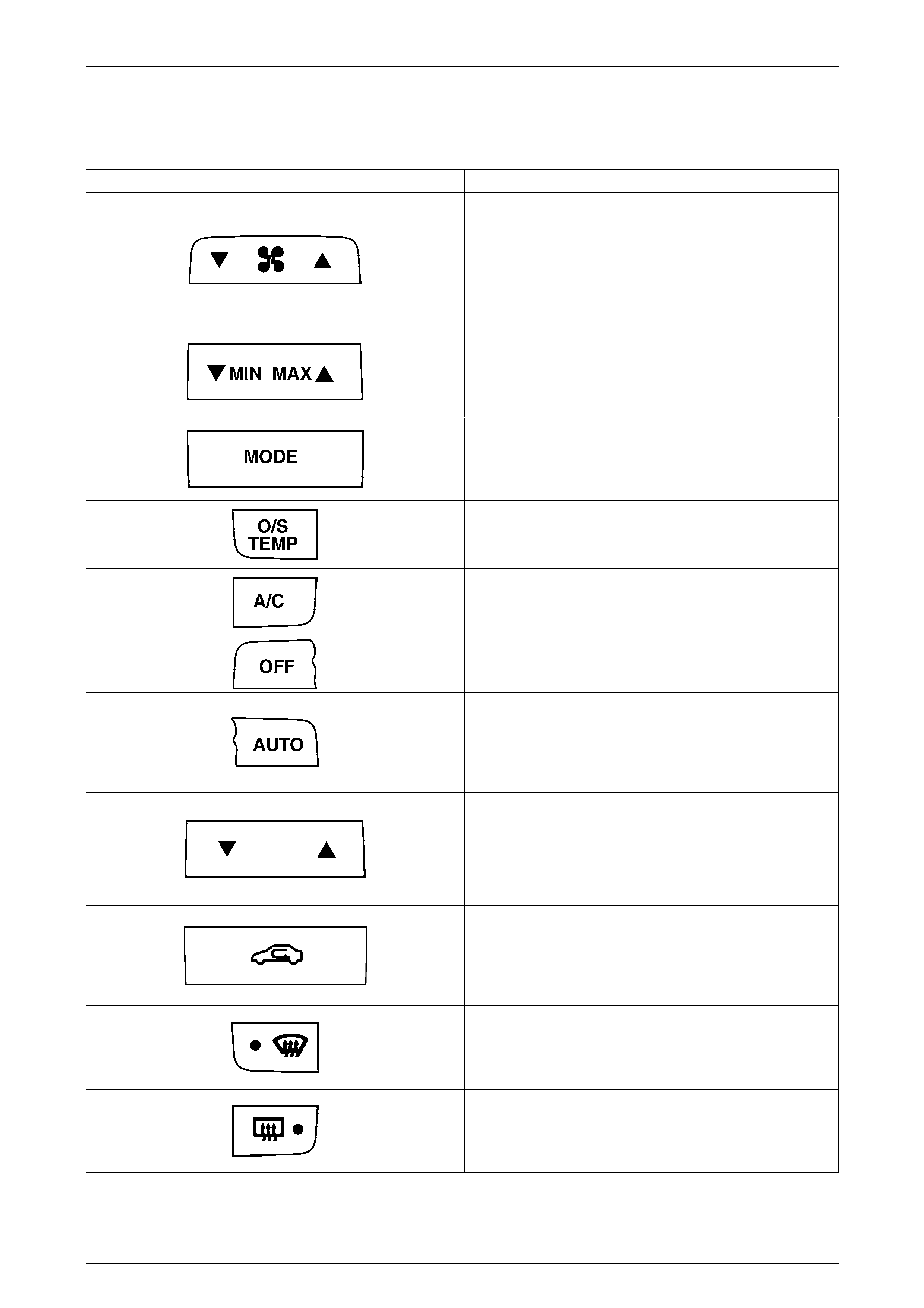
The following table provides a summary of button functions:
Button Function
Blower fan
Manual operation – 5 speed
Automatic operation – step-less
T = speed decrease
S = speed increase
Will turn on the OCC system when selected.
Uncontrolled Temperature Setting (single zone)
T min = uncontrolled coolin g
S max = uncontrolled heatin g
Will turn on the OCC system when selected.
Air Distribution
When selected the OCC system will scroll through F ace,
Bi-level, Floor or Blend mode settings.
Will turn on the OCC system when selected.
Outside Temperature
Displays outside temperature on the LCD when held on.
Will not turn on the OCC system when selected.
Air Conditioning
Turns A/C system on or off.
Will turn on the OCC system when selected.
OCC System Off
Will turn the OCC system on or off when selected.
Automatic Operation
The OCC system will operate in the Automatic Mode,
controlling the blower fan speed, air distribution, air inlet
function and air outlet temperature.
Will turn on the OCC system when selected.
Set Temperature Button
Allows cabin temperature sele ction between 17° and 30°C.
T = Set temperature decrease
S = Set temperature increase
Will turn on the OCC system when selected.
Recirculation
Prevents outside air entering the vehicle cabin when
activated. Function can be selected whether OCC system is
on or off when ignition is on.
Will not turn on the OCC system when selected.
Windscreen Demist
Directs air to the windscreen. Orange LED illuminates when
activated.
Will turn on the OCC system when selected.
Rear Window Demist
Provides rear window heatin g. Orange LED illuminates
when activated.
Will not turn on the OCC system when selected.
HVAC Occupant Climate Control (Auto A/C) – Description and Operation Page 2D-23
Page 2D-23
4.3 HVAC Unit Airflow Modes – Single Zone
HVAC Airflow Diagram
The HVAC unit has seven different possible modes:
• recirculation
• face,
• bi-level,
• floor,
• blend,
• demist, and
• default.
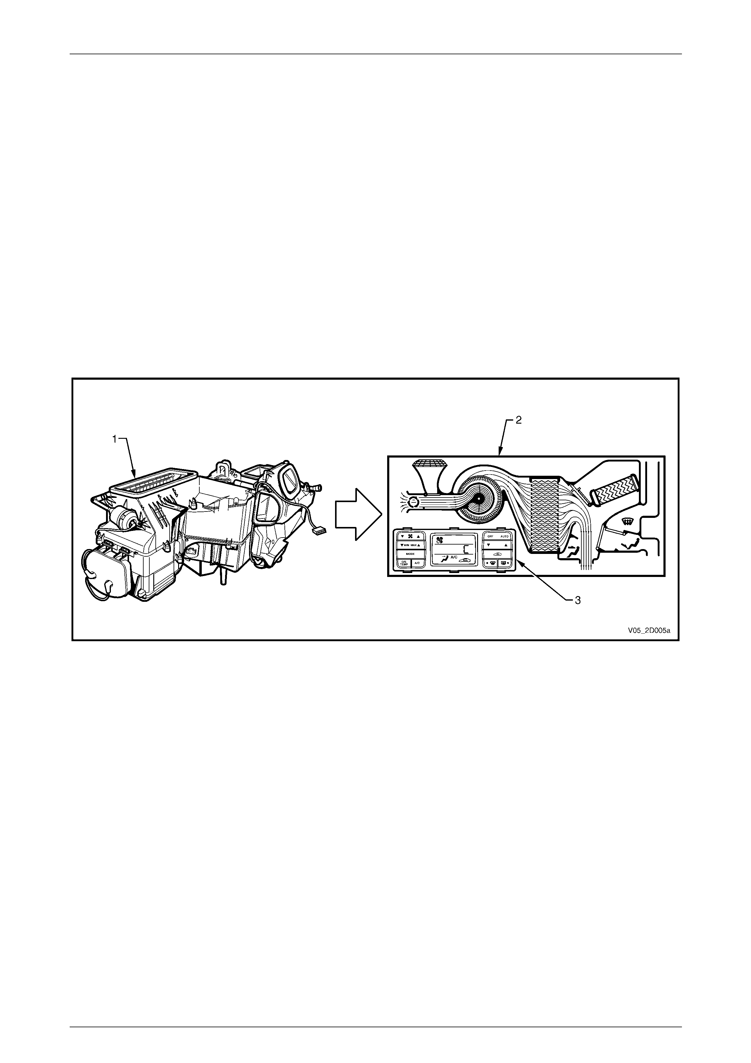
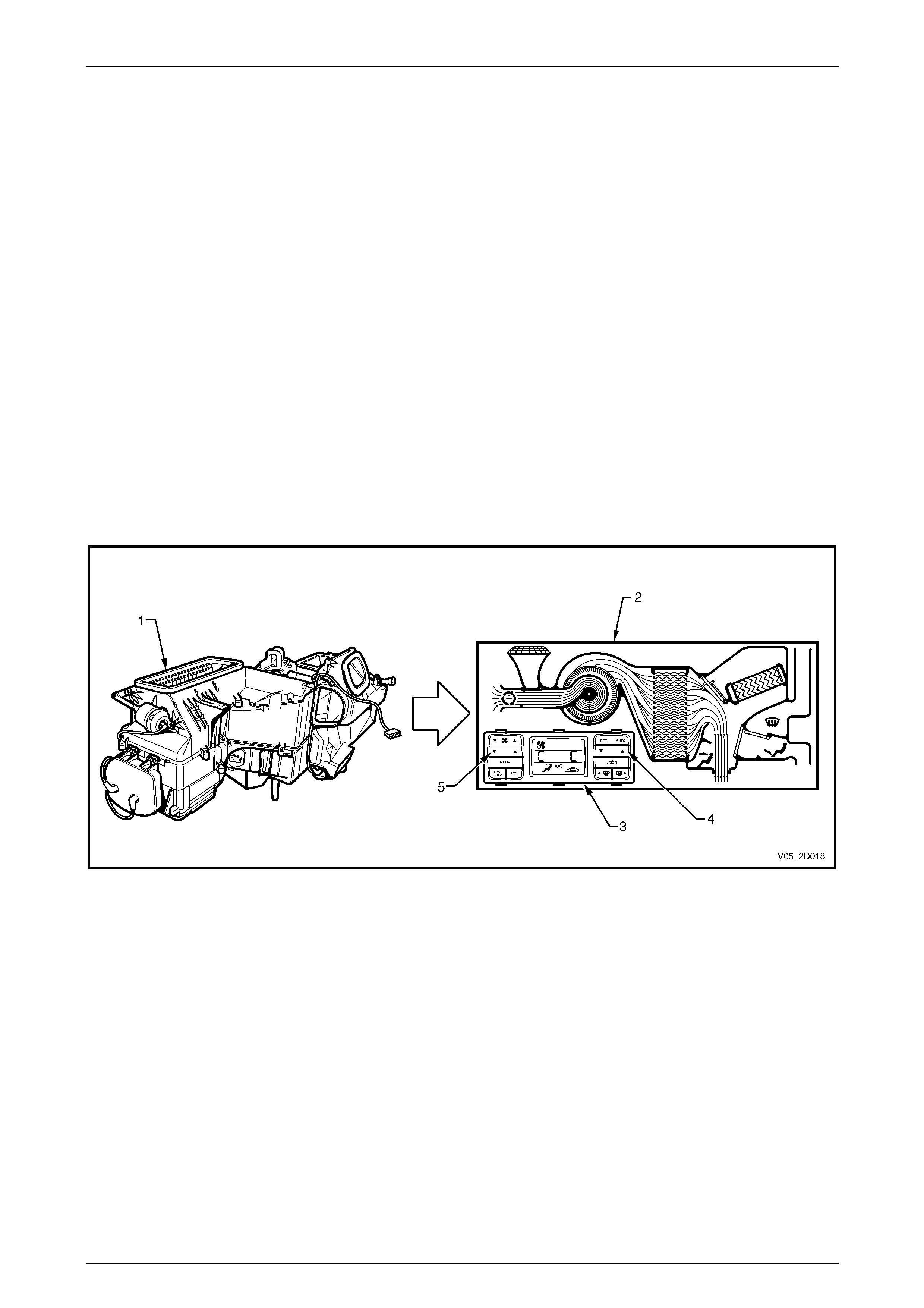
The following airflow mode diagrams provide a schematic representation of ho w cold and heated air flows through the
HVAC unit during the seven different possible modes. Each schematic has a graphic representation of the OCC control
module matching the given m ode.
Figure 2D – 15
Legend
1 HVAC Unit
2 Airflow Schematic 3 OCC Control Module
HVAC Occupant Climate Control (Auto A/C) – Description and Operation Page 2D-24
Page 2D-24
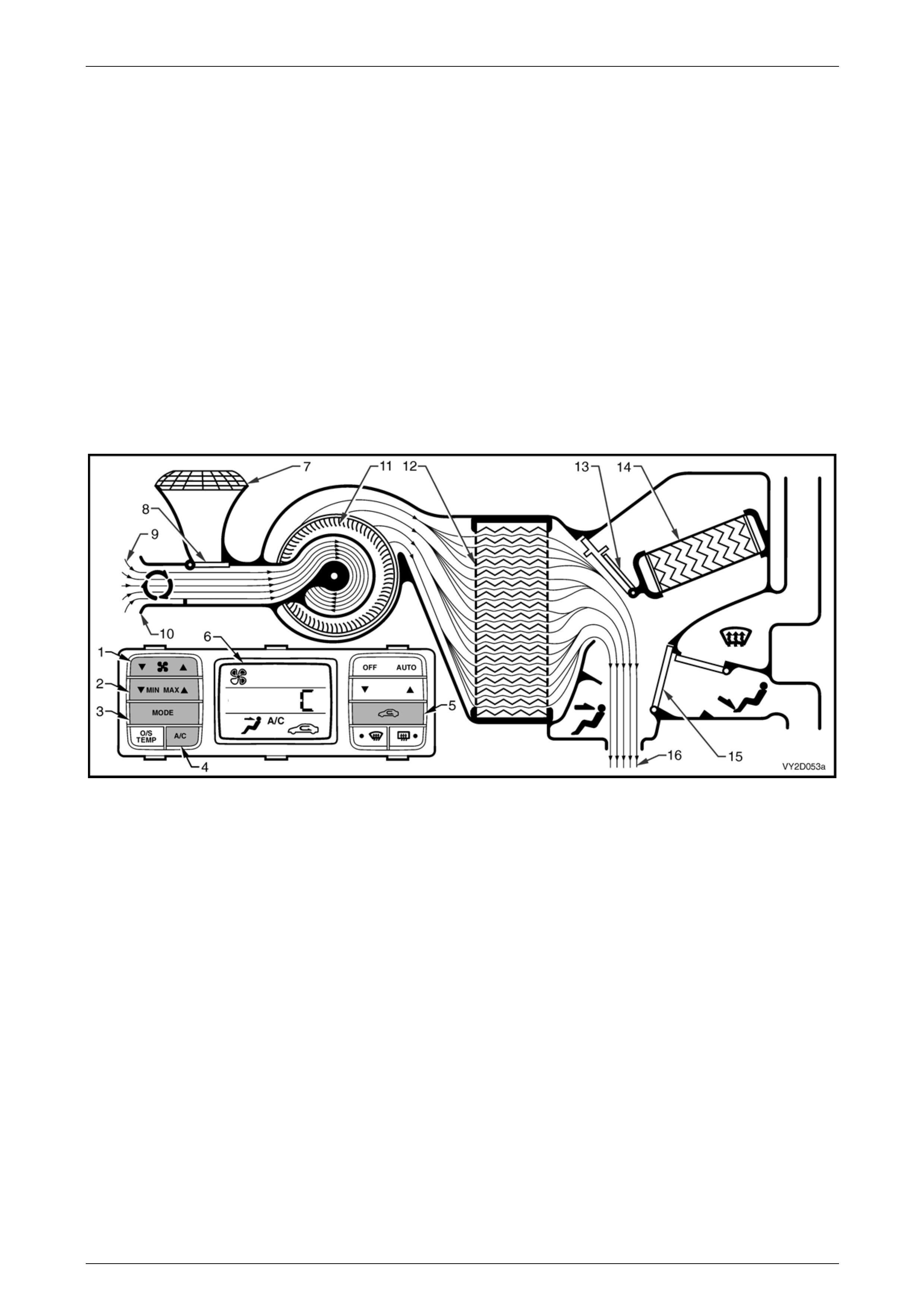
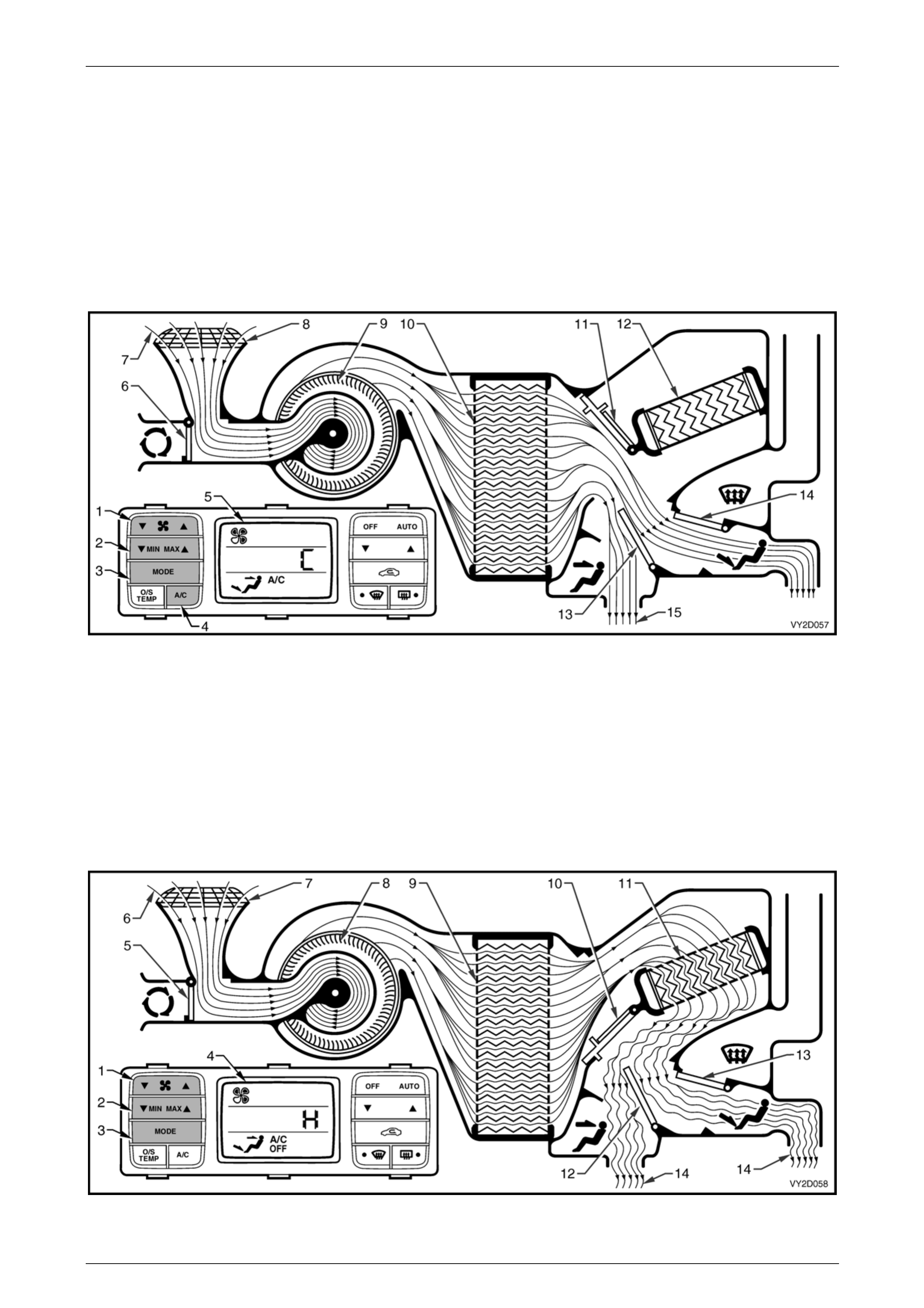
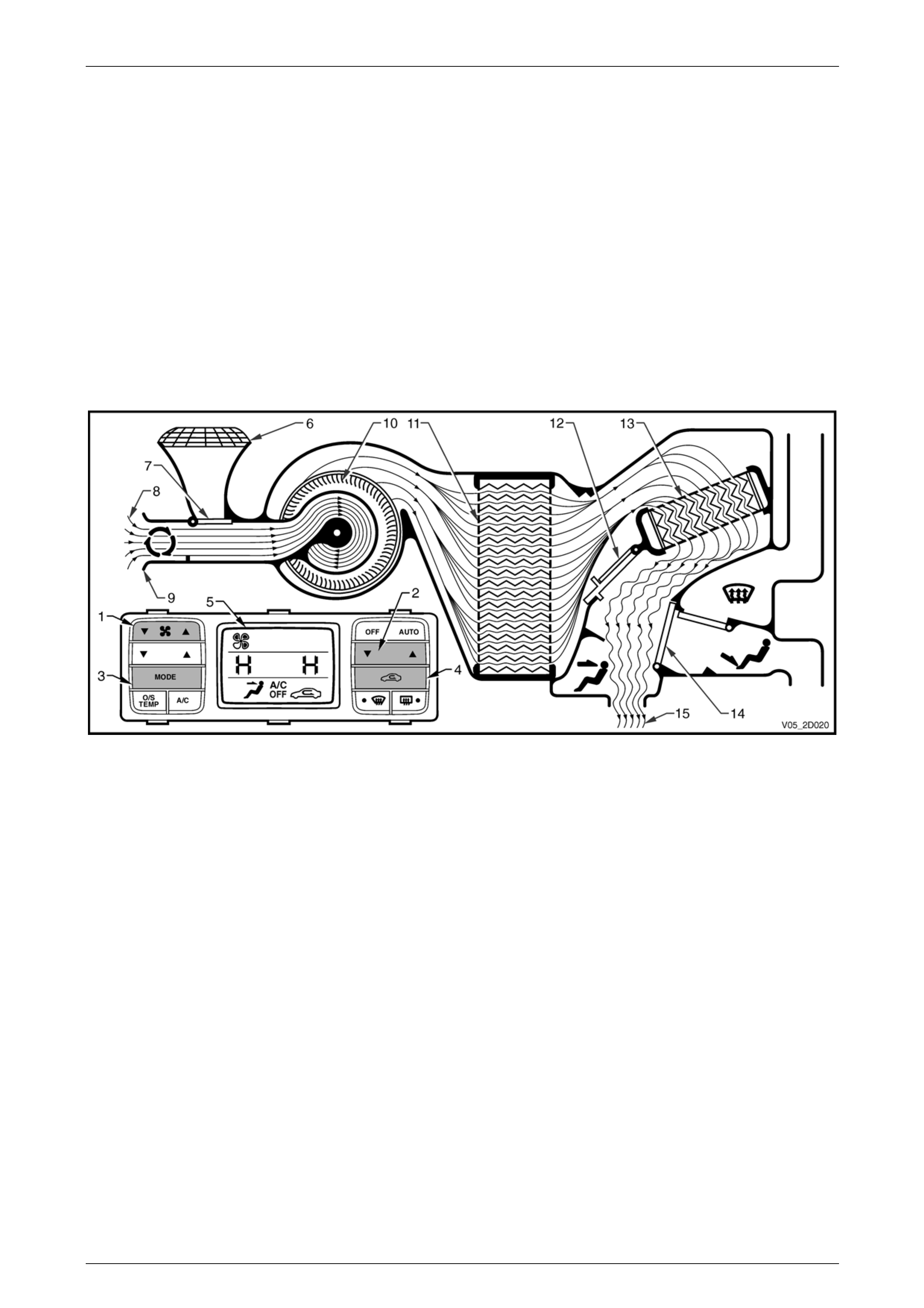
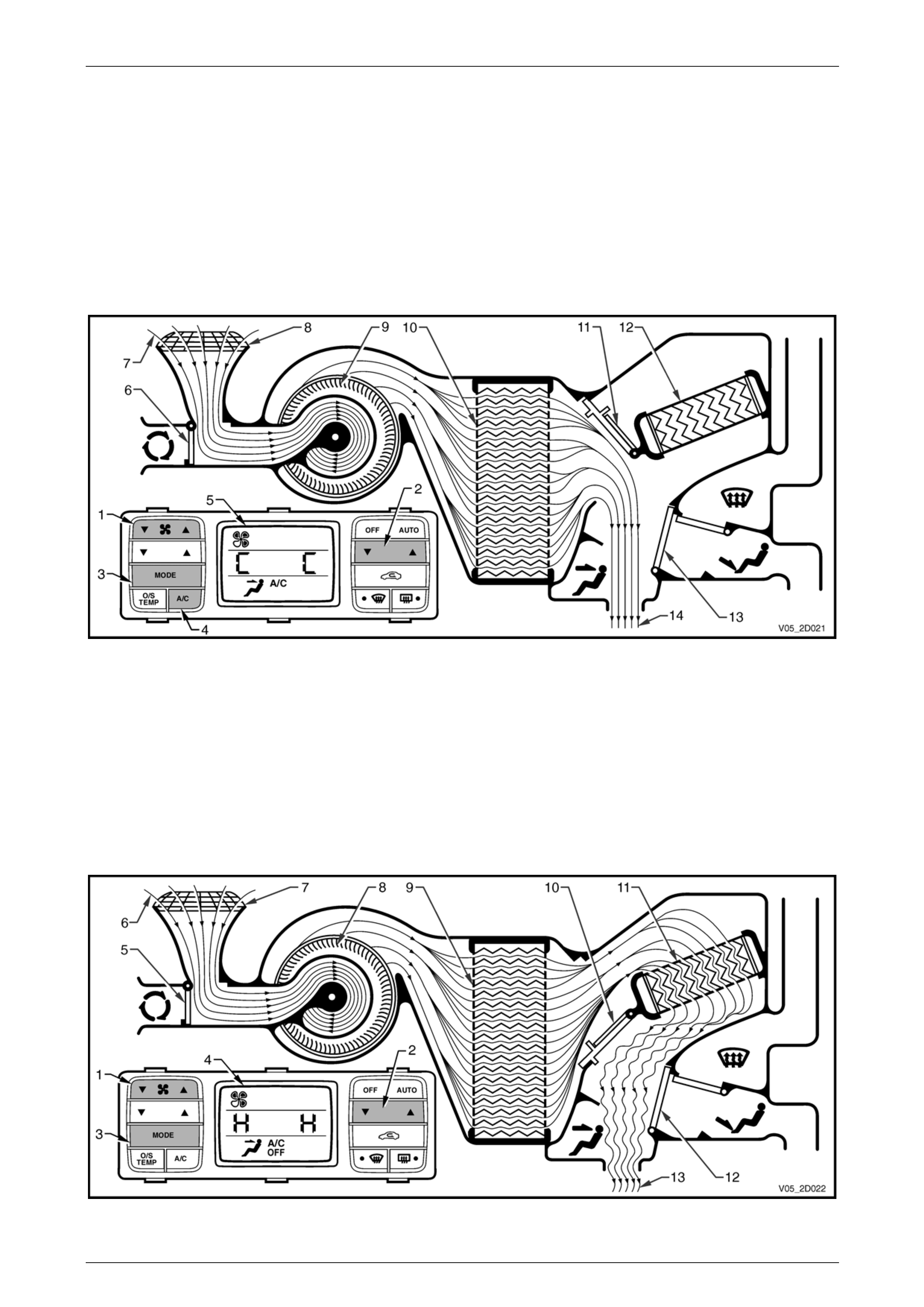
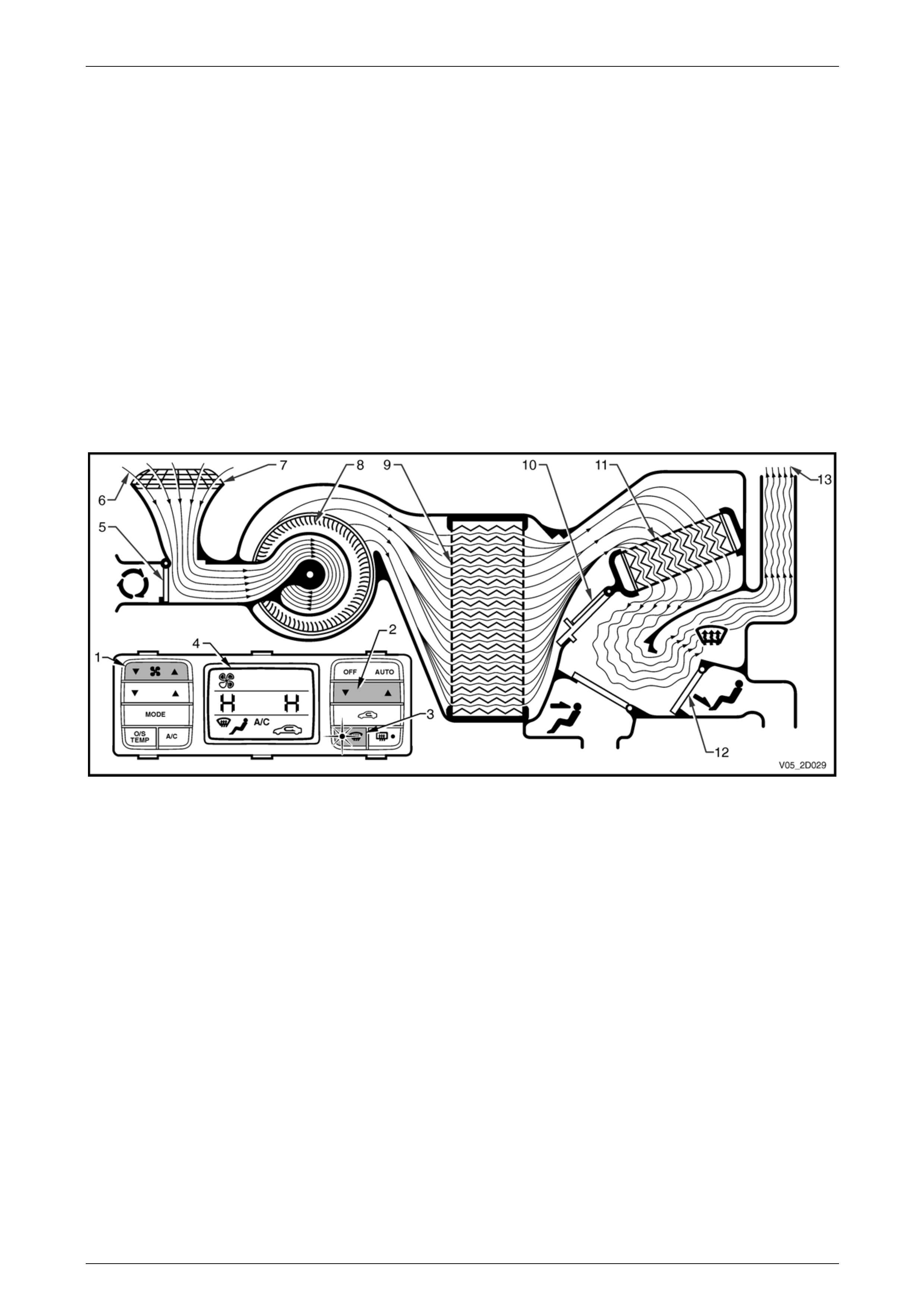
Recirculation Mode
Full Cold
The fan switch (1) is used to select any one of five speeds, refer to Figure 2D – 16. The side T of the MIN MAX switch
(2) has been selected resulting in full, uncontrolled coolin g. The mode control switch (3) is set to face mode. The A/C
switch (4) is on and the recirculation switch (5) has also been selected. All of these settings are displayed on the LCD
screen (6).
NOTE
Recirculation mode can be selected
independently of all other air distribution modes
excluding dem ist mode.
The plenum chamber (outside air) inlet (7) to the HVAC unit is closed off by the recirculation door (8). Interior air (9) is
drawn into the HVAC unit through the recircu lation inlet (10) by the blower motor fan (11), and is then forced throu gh the
cold evaporator fins (12). In full cold mode the air mix doors (13) are positioned to allow all air to bypass the heater
core (14). The air travels through the open face door (15). The cold air (16) is then directed out of the HVAC unit to the
centre and side vents.
Figure 2D – 16
HVAC Occupant Climate Control (Auto A/C) – Description and Operation Page 2D-25
Page 2D-25
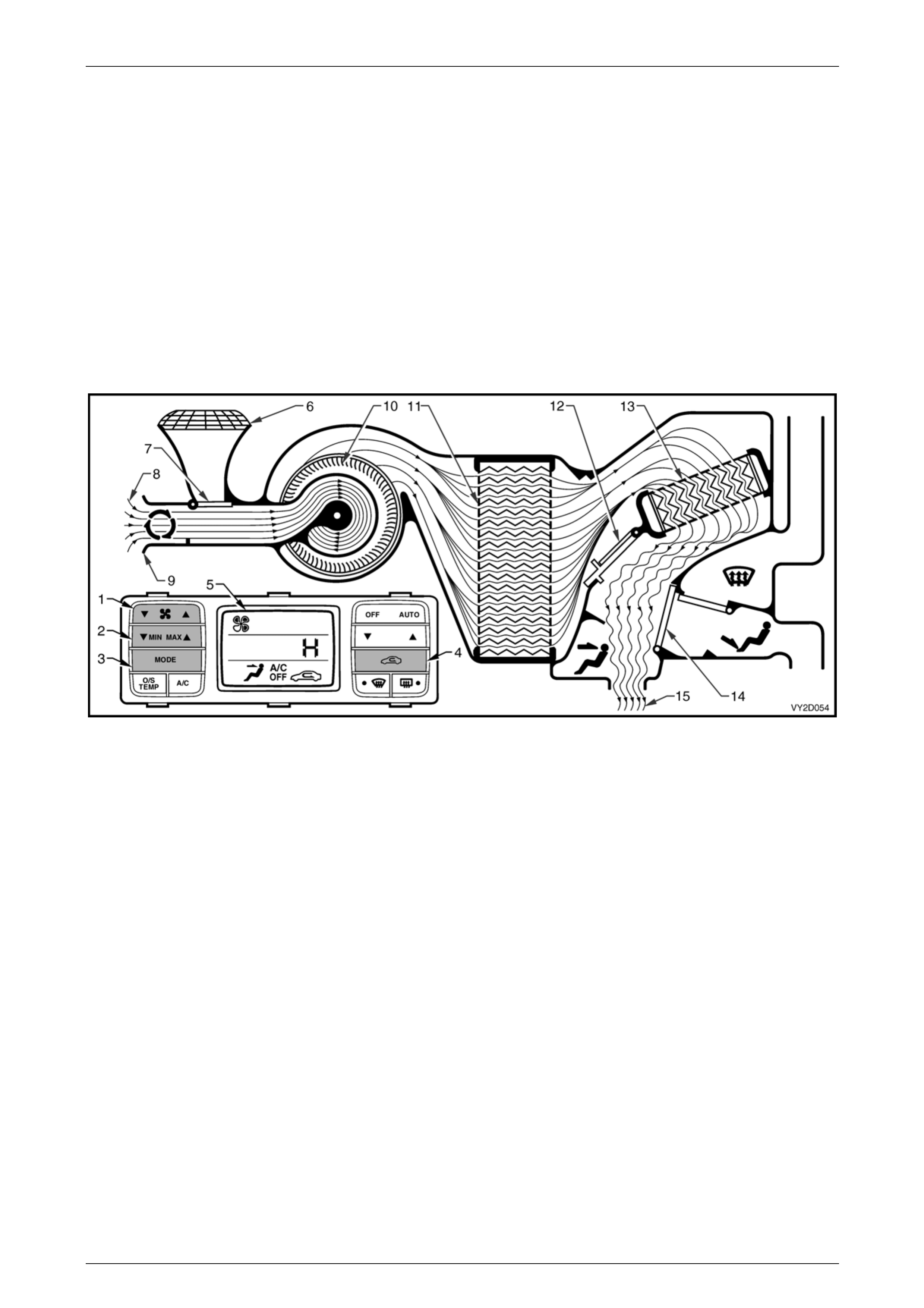
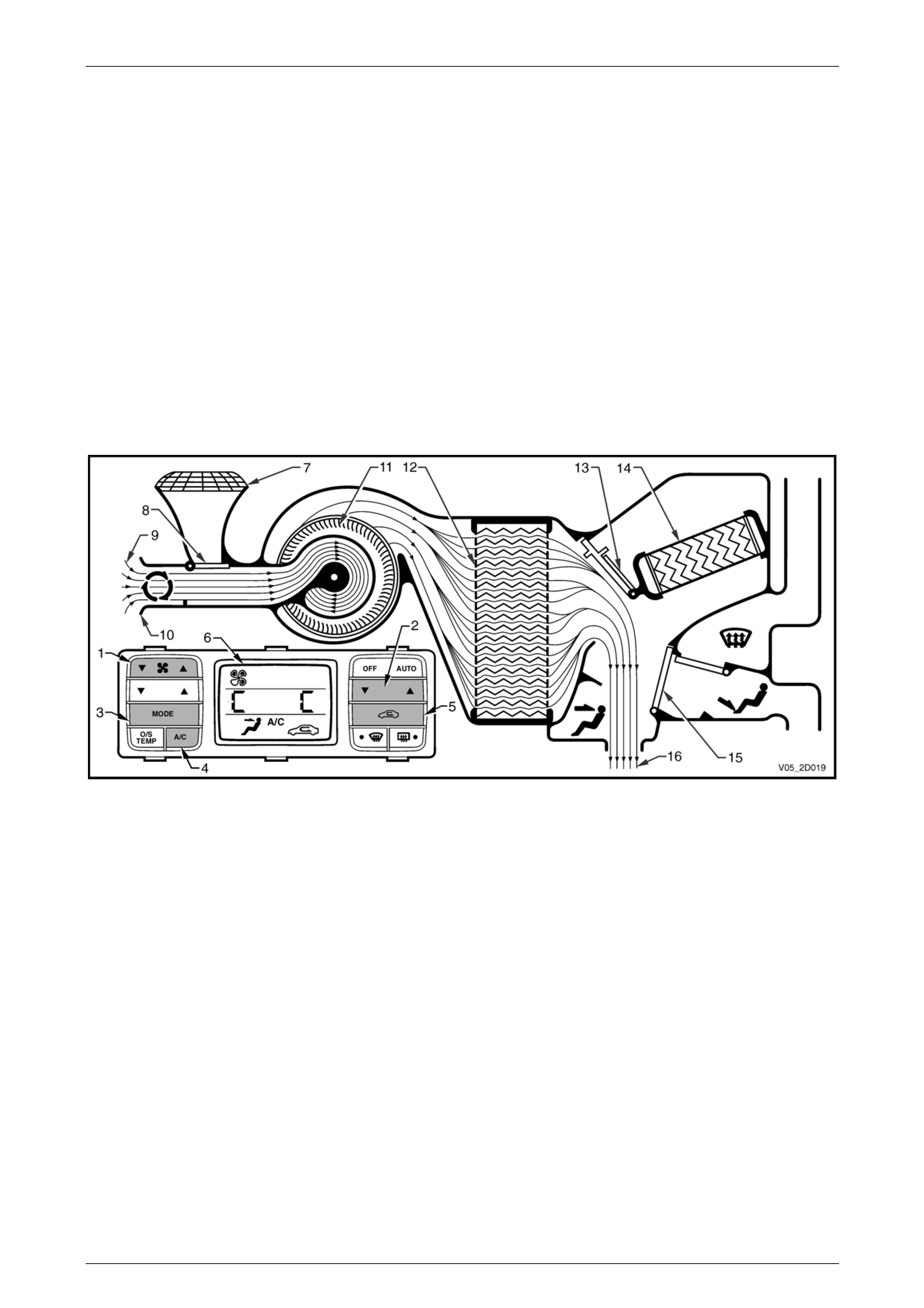
Full Heat
The fan switch (1) is used to select any one of five speeds, refer to Figure 2D – 17. The side S of the MIN MAX switch
(2) has been selected resulting in full, uncontrolled heatin g. The mode control switch (3) has been switched to Face
mode. The recirculation switch (4) has been selected. All of these settings are displayed o n the LCD scre en (5).
NOTE
Recirculation mode can be selected
independently of all other air distribution modes
excluding dem ist mode.
The plenum chamber (outside air) inlet (6) to the HVAC unit is closed off by the recirculation door (7). Interior air (8) is
drawn into the HVAC unit through the recircu lation inlet (9) by the blower motor fan (10), and is then forced through the
evaporator fins (11). In full heat mode, the air mix doors (12) will be positioned so that all incomi ng air is directed through
the heater core (13). The air travels throug h the open face door (14). The heated air (15) is then directed out through the
centre and side vents.
Figure 2D – 17
HVAC Occupant Climate Control (Auto A/C) – Description and Operation Page 2D-26
Page 2D-26
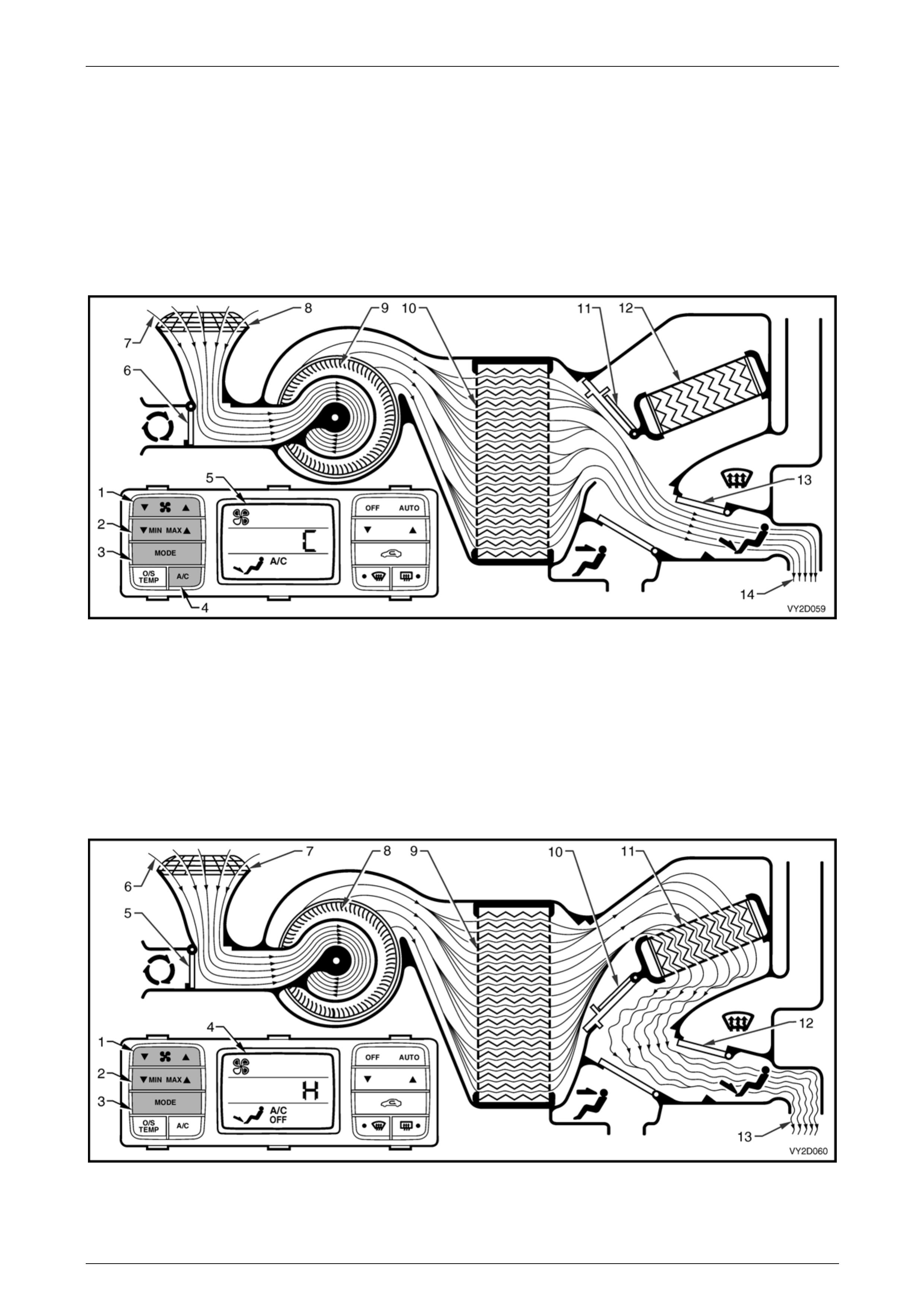
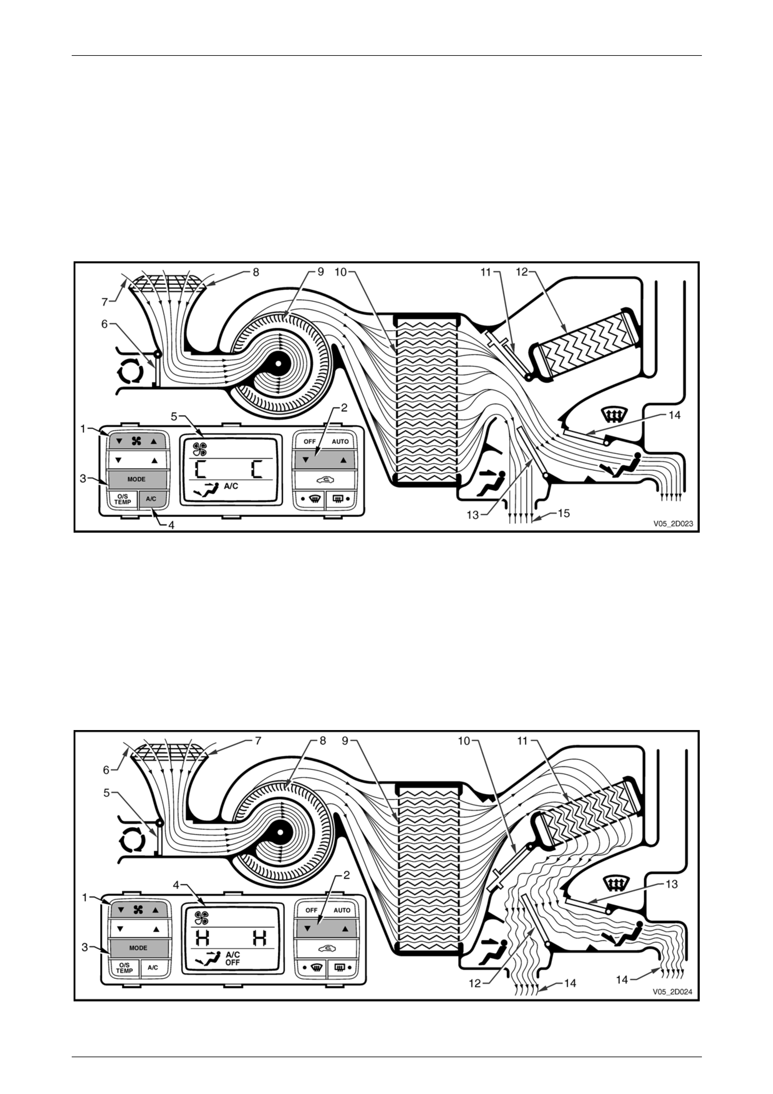
Face Mode
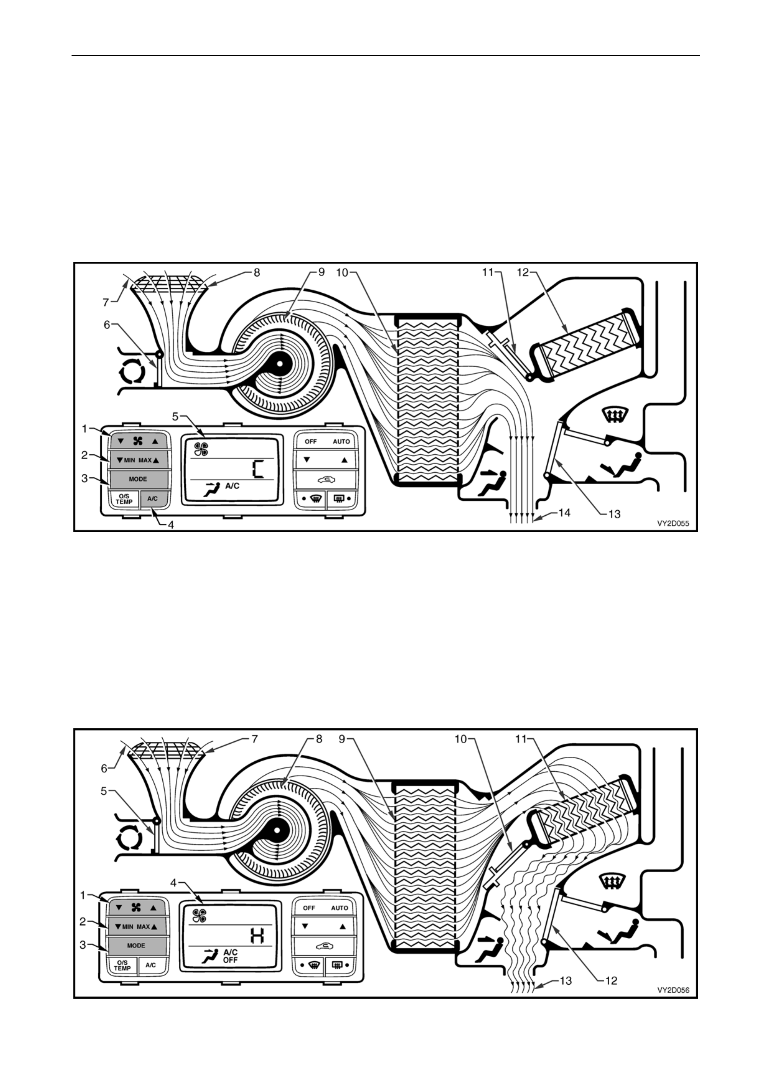
Full Cold
The fan switch (1) is used to select any one of five speeds, refer to Figure 2D – 18. The side T of the MIN MAX switch
(2) has been selected resulting in full, uncontrolled coolin g. The mode control s witch (3) has been switched to face mode
and the A/C switch (4) is on. All of these settings are displayed on the LCD screen (5).
The recirculation door (6) is closed allowing outside air (7) to enter and flow into the HVAC unit via the plenum chamber
inlet (8). Air is drawn into the HVAC unit by the blower motor (9), and is then forced through the cold evaporator fins (10).
In full cold mode, the air mix doors (11) are positioned to allow all air to bypass the heater core (12). The air travels
through the open face door (13). The cold air (14) is then directed through the centre and side vents.
Figure 2D – 18
Full Heat
The fan switch (1) is used to select any one of five speeds, refer to Figure 2D – 19. The side S of the MIN MAX switch
(2) has been selected resulting in full, uncontrolled heatin g. The mode control switch (3) has been switched to face
mode. All of these settings are displayed on the LCD screen (4).
The recirculation door (5) is closed allowing outside air (6) to enter and flow into the HVAC unit via the plenum chamber
inlet (7). Air is drawn into the HVAC unit by the blower motor (8). This air is then forced through the evaporator core fins
(9). In full heat mode, the air mix doors (10) will be positioned so that all incoming air is directed through the heater core
(11). The air travels through the open face door (12). The heated air (13) is then directed out through the centre and side
vents.
Figure 2D – 19
HVAC Occupant Climate Control (Auto A/C) – Description and Operation Page 2D-27
Page 2D-27
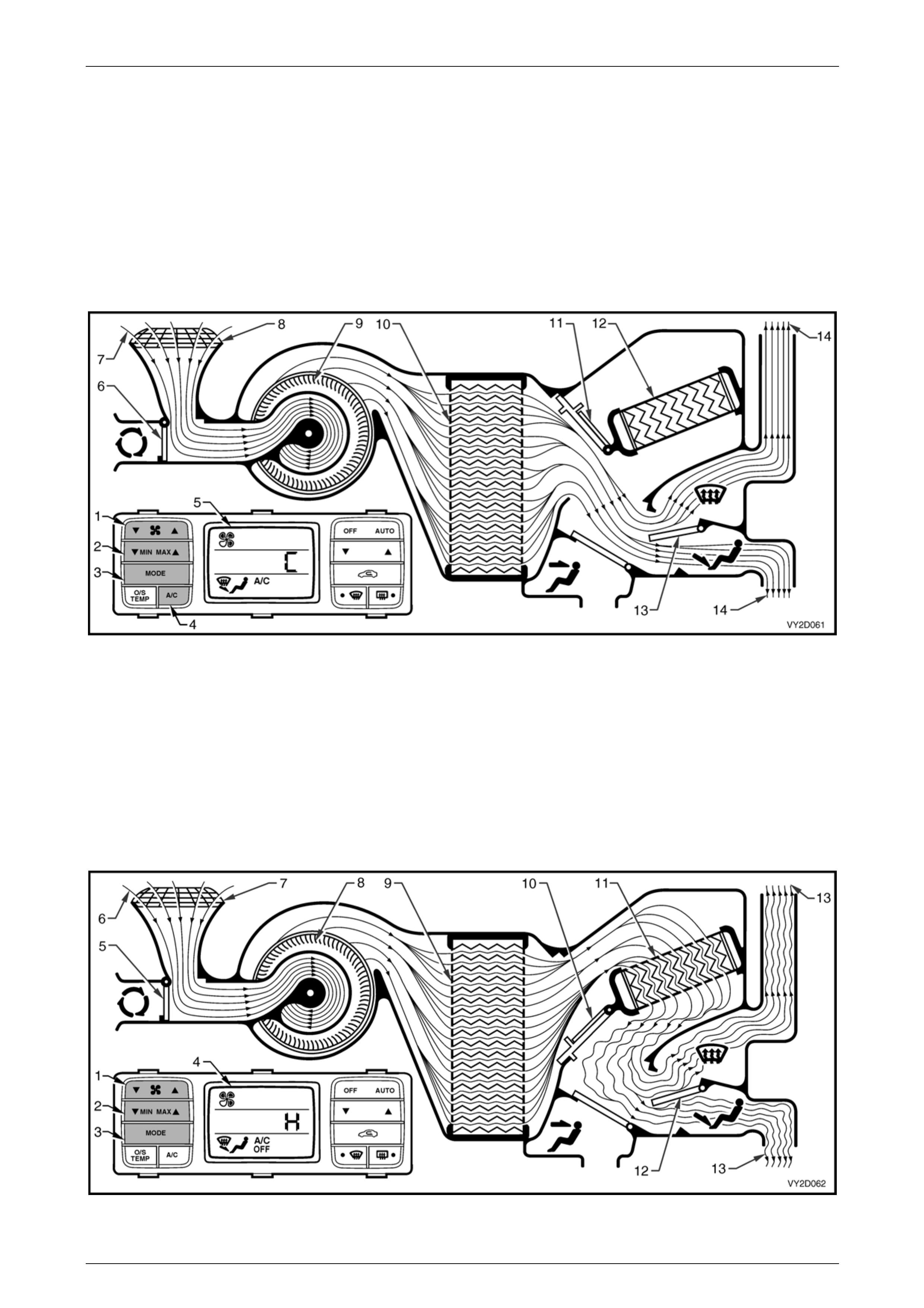
Bi-level Mode
Full Cold
The fan switch (1) is used to select any one of five speeds, refer to Figure 2D – 20. The side T of the MIN MAX switch
(2) has been selected resulting in full, uncontrolled cooling. The mode control switch (3) has been switched to bi-level
mode and the A/C switch (4) is on. All of these settings are displayed on the LCD screen (5).
The recirculation doors(6) are closed allowing outside air (7) to enter an d flow into the HVAC unit via the plenum
chamber inlet (8). Air is drawn into the HVAC unit by the blower motor (9), and is then forced through the cold evaporator
fins (10). In full cold mode, the air mix doors (11) are positioned to allow all air to bypass the heater core (12). The air
travels through the half opened face door (13 ) and the fully opened demist /floor door (14). The cold air (15) is then
directed through the centre and side vents as well as to the floor ducts.
Figure 2D – 20
Full Heat
The fan switch (1) is used to select any one of five speeds, refer to Figure 2D – 21. The side S of the MIN MAX switch
(2) has been selected resulting in full, uncontrolled heating. The mode control switch (3) has been switched to bi-level
mode. All of these settings are displayed on the LCD screen (4).
The recirculation door (5) is closed allowing outside air (6) to enter and flow into the HVAC unit via the plenum chamber
inlet (7). Air is drawn into the HVAC unit by the blower motor (8). This air is then forced through the evaporator core fins
(9). In full heat mode, the air mix doors (10) will be positioned so that all incoming air is directed through the heater core
(11). The air travels through the half opened face door (12) and the fully opened demist/floor door (13). The heated air
(14) is then directed through the centre a nd side vents as well as to the floor ducts.
Figure 2D – 21
HVAC Occupant Climate Control (Auto A/C) – Description and Operation Page 2D-28
Page 2D-28
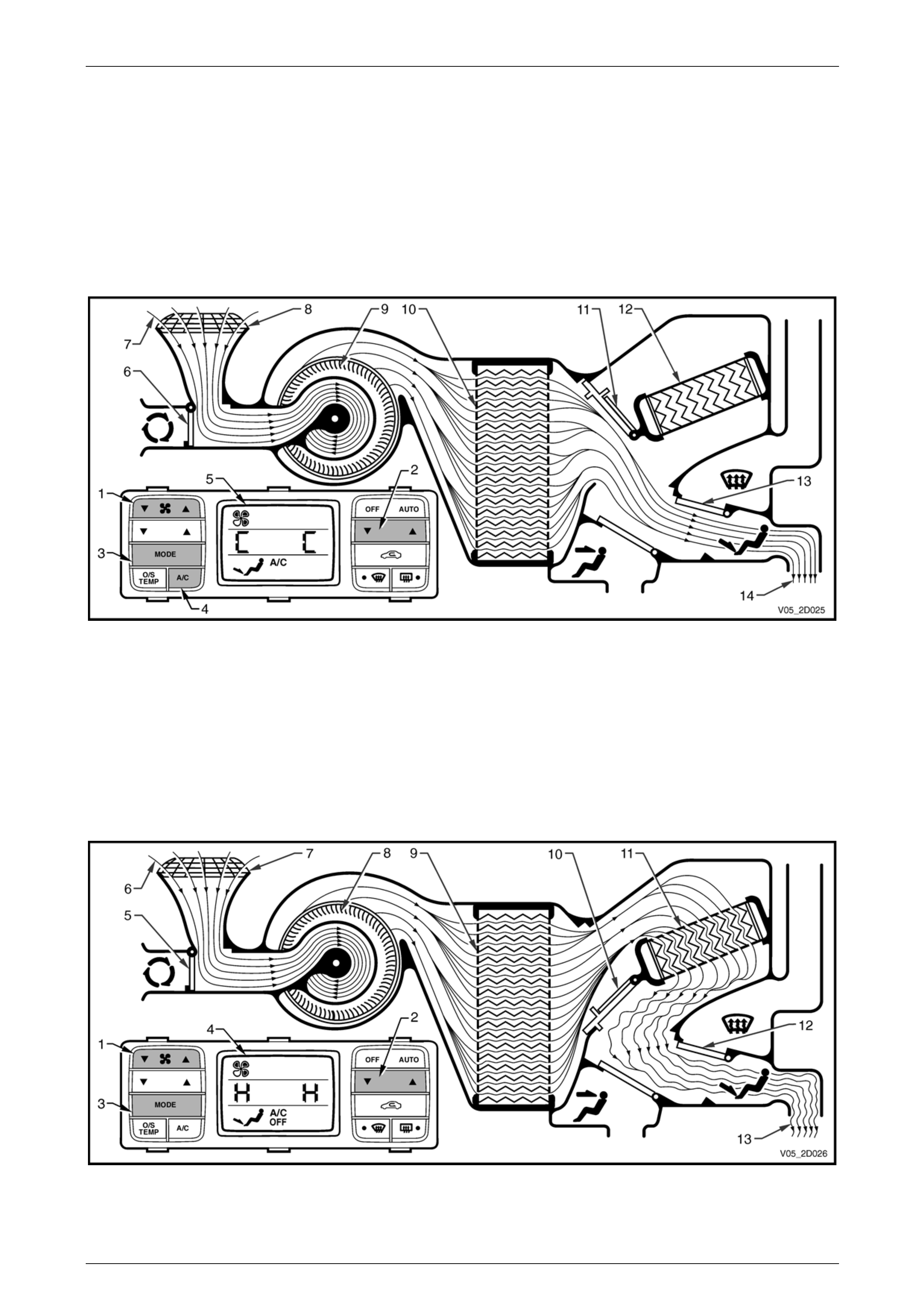
Floor Mode
Full Cold
The fan switch (1) is used to select any one of five speeds, refer to Figure 2D – 22. The side T of the MIN MAX switch
(2) has been selected resulting in full, uncontrolled coolin g. The mode control switch (3) has been switched to floor mode
and the A/C switch (4) is on. All of these settings are displayed on the LCD screen (5).
The recirculation door (6) is closed allowing outside air (7) to enter and flow into the HVAC unit via the plenum chamber
inlet (8). Air is drawn into the HVAC unit by the blower motor (9), and is then forced through the cold evaporator fins (10).
In full cold mode, the air mix doors (11) are positioned to allow all air to bypass the heater core (12). The air travels
through the demist/floor door (13). The cold air (14) is then directed to the floor ducts.
Figure 2D – 22
Full Heat
The fan switch (1) is used to select any one of five speeds, refer to Figure 2D – 23. The side S of the MIN MAX switch
(2) has been selected resulting in full, uncontrolled heatin g. The mode control switch (3) has been switched to floor
mode. All of these settings are displayed on the LCD screen (4).
The recirculation door (5) is closed allowing outside air (6) to enter and flow into the HVAC unit via the plenum chamber
inlet (7). Air is drawn into the HVAC unit by the blower motor (8). This air is then forced through the evaporator core fins
(9). In full heat mode, the air mix doors (10) will be positioned so that all incoming air is directed through the heater core
(11). The air travels through the demist/floor door (12). The heated air (13) is then directed to the floor ducts.
Figure 2D – 23
HVAC Occupant Climate Control (Auto A/C) – Description and Operation Page 2D-29
Page 2D-29
Blend Mode
Full Cold
The fan switch (1) is used to select any one of five speeds, refer to Figure 2D – 24. The side T of the MIN MAX switch
(2) has been selected resulting in full, uncontrolled coolin g. The mode control switch (3) has been switched to blend
mode and the A/C switch (4) is on. All of these settings are displayed on the LCD screen (5).
The recirculation door (6) is closed allowing outside air (7) to enter and flow into the HVAC unit via the plenum chamber
inlet (8). Air is drawn into the HVAC unit by the blower motor (9), and is then forced through the cold evaporator fins (10).
In full cold mode, the air mix doors (11) are positioned to allow all air to bypass the heater core (12). The air travels
through the demist/floor door (13) which is positioned half wa y between demist and floor modes. The cold air (14) is then
directed to both the front windscreen and the floor ducts.
Figure 2D – 24
Full Heat
The fan switch (1) is used to select any one of five speeds, refer to Figure 2D – 25. The side S of the MIN MAX switch
(2) has been selected resulting in full, uncontrolled heatin g. The mode control switch (3) has been switched to blend
mode. All of these settings are displayed on the LCD screen (4).
The recirculation door (5) is closed allowing outside air (6) to enter and flow into the HVAC unit via the plenum chamber
inlet (7). Air is drawn into the HVAC unit by the blower motor (8). This air is then forced through the evaporator core fins
(9). In full heat mode, the air mix doors (10) will be positioned so that all incoming air is directed through the heater core
(11). The air travels through the demist/floor door (12) which is positioned half way between demist and floor modes. The
heated air (13) is then directed to both the front windscreen and the floor ducts.
Figure 2D – 25
HVAC Occupant Climate Control (Auto A/C) – Description and Operation Page 2D-30
Page 2D-30
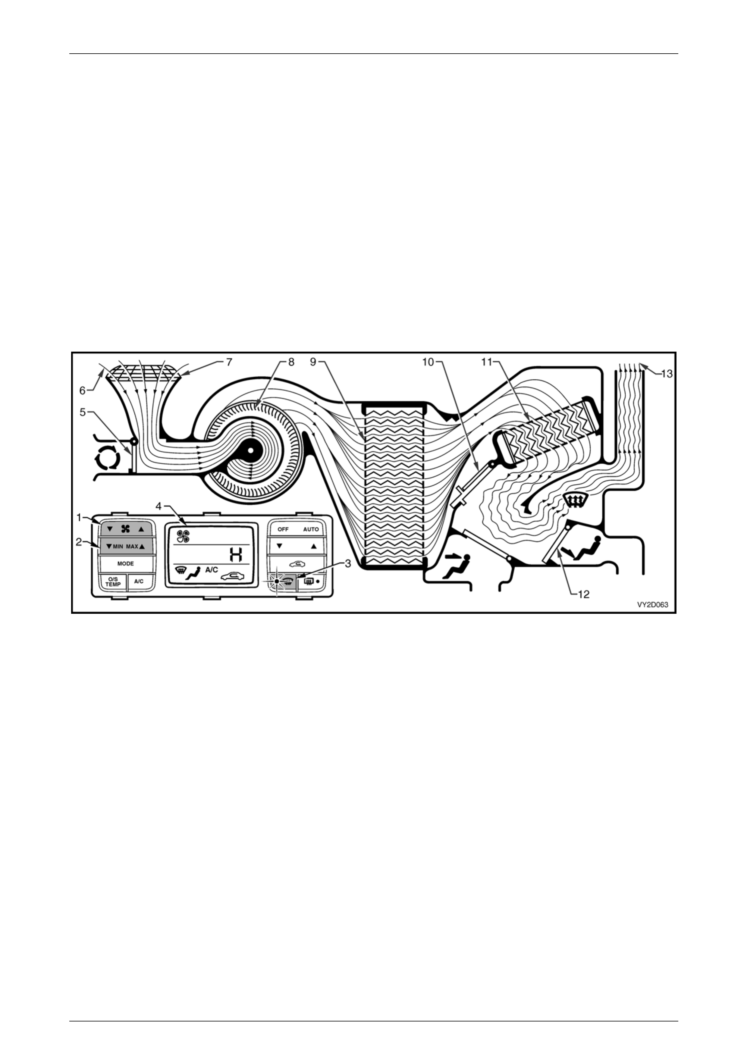
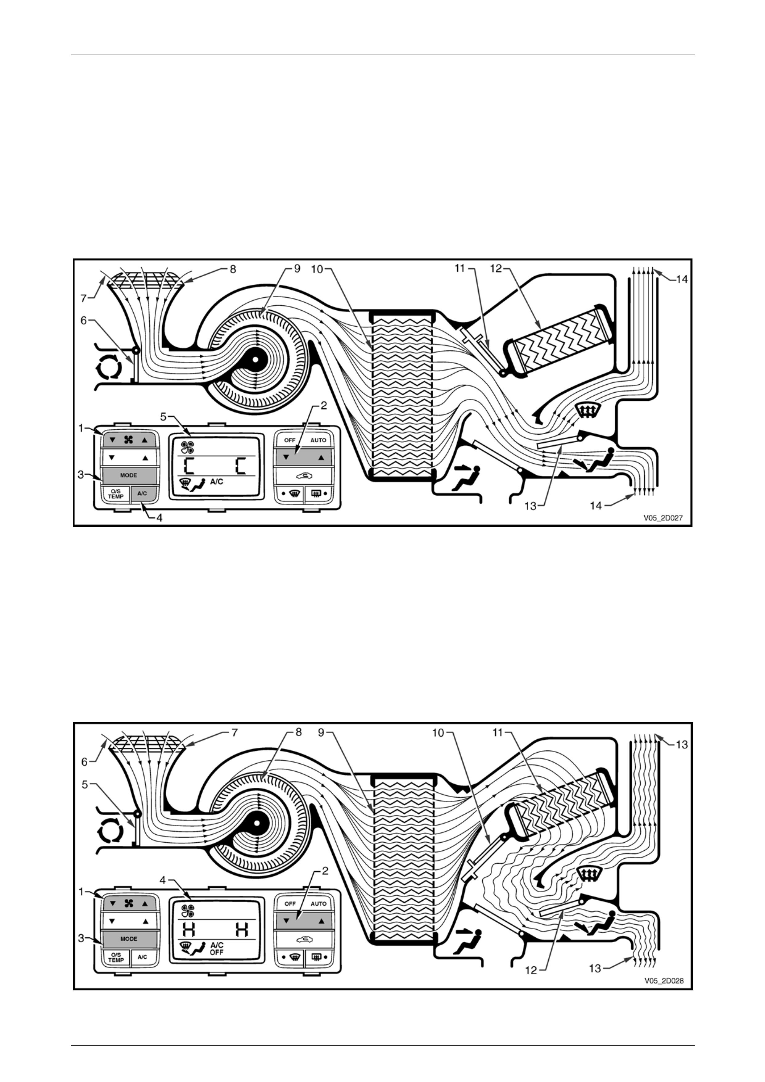
Demist Mode
Full Heat and A/C Activated
The fan switch (1) is used to select any one of five speeds, refer to Figure 2D – 26. The side S of the MIN MAX switch
(2) has been selected resulting in full, uncontrolled heatin g. The demist switch (3) has been switched on and the A/C
system has been switched on automatically. All of these sett ings are displayed on the LCD screen (4).
The recirculation door (5) is closed allowing outside air (6) to enter and flow into the HVAC unit via the plenum chamber
inlet (7). Air is drawn into the HVAC unit by the blower motor (8). This air is then forced through the cold evaporator core
fins (9) removing moisture from the air. In full heat mode, the air mix doors (10) are positioned to direct this dehumidified
incoming air through the heater core (11). The air travels through the open demist/floor door (12). The heated air (13) is
then directed to the front windscreen via the demist vents.
NOTE
By turning on the A/C system in this mode,
dehumidification of incoming air will take place,
demisting the front windscreen and side windows
in a shorter period.
Figure 2D – 26
HVAC Occupant Climate Control (Auto A/C) – Description and Operation Page 2D-31
Page 2D-31
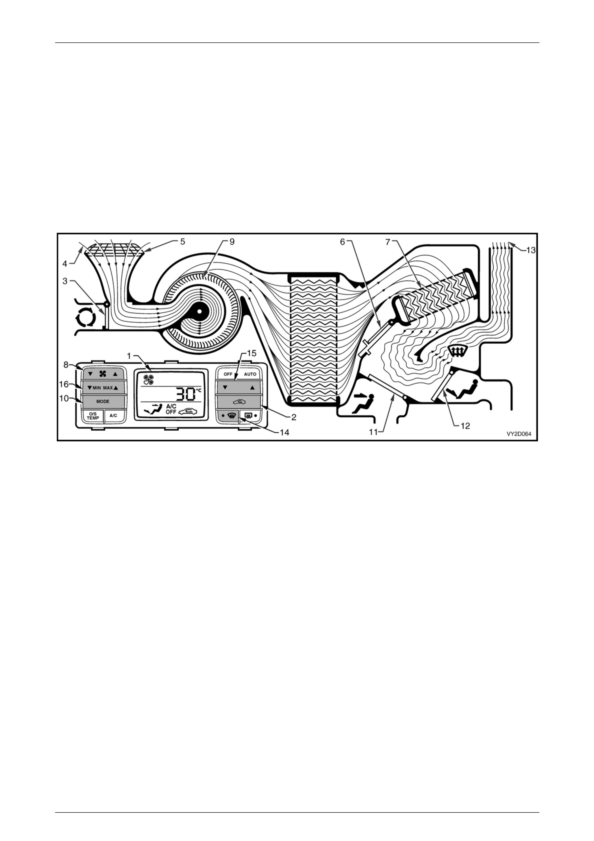
Default Mode
Loss of Vacuum Supply to HV AC Unit
If a loss of vacuum occurs within the OCC system, the HVAC unit will default to the following settings. T he ventilatio n
mode settings will remain constant regardless of what is displayed on the LCD screen (1), refer to Figure 2D – 27.
Regardless of recirculation switch (2) selection, the recirculation door (3) will remain closed allo wing outside air (4) to
enter and flow into the HVAC unit via the plenum chamber inlet (5). The position of the air mix doors (6) will remain
controllable as their function is electrically operated by the air mix motor. Heated coolant will flow through the heater core
(7), as vacuum is required to maintain the water valve in the cold (closed) position. The fan switch (8) will operate the
blower fan (9) as normal. In any position of the mode switch (10), the face door (11) will remain closed. The demist/floor
door (12) will be positioned so that all air (13) leaving the HVAC unit will be directed to the demist ducts whether or not
the demist switch (14) is selected. Depending on the selected setting of temperature switch (15) and/or the MIN MAX
switch (16), this air may be cold, warm or hot air.
Figure 2D – 27
HVAC Occupant Climate Control (Auto A/C) – Description and Operation Page 2D-32
Page 2D-32
4.4 HVAC Unit Airflow Modes – Dual Zone
HVAC Airflow Diagram
The HVAC unit has seven different possible modes:
• recirculation,
• face,
• bi-level,
• floor,
• blend,
• demist, and
• default.
The following airflow mode diagrams provide a schematic representation of ho w cold and heated air flows through the
HVAC unit during the seven different possible modes. Each schematic has a graphic representation of the OCC control
module matching the given m ode.
When the set temperature is scrolled lower than 17°C or higher than 30°C, the OCC s ystem changes to manual mode
with full uncontrolled cooling or full uncontrolled heating respectively, for the driver and front passenger sides with
switch (4) and the front passenger side only with switch (5). Refer to Figure 2D – 28.
Figure 2D – 28
Legend
1 HVAC Unit
2 Airflow Schematic
3 OCC Control Module
4 Set Temperature Switch – Driver's Side
5 Set Temperature Switch – Front Passenger's Side
HVAC Occupant Climate Control (Auto A/C) – Description and Operation Page 2D-33
Page 2D-33
Recirculation Mode
Full Cold
The fan switch (1) is used to select any one of five speeds, refer to Figure 2D – 29. The side T of the set temperature
switch (2) has been scrolled lower than 17°C resulting in full, uncontrolled cool ing. The mode control switch (3) is set to
face mode. The A/C switch (4) is on and the recirculatio n switch (5) has also been selected. All of these settings are
displayed on the LCD screen (6).
NOTE
Recirculation mode can be selected
independently of all other air distribution modes
excluding dem ist mode.
The plenum chamber (outside air) inlet (7) to the HVAC unit is closed off by the recirculation door (8). Interior air (9) is
drawn into the HVAC unit through the recircu lation inlet (10) by the blower motor fan (11), and is then forced throu gh the
cold evaporator fins (12). In full cold mode the air mix doors (13) are positioned to allow all air to bypass the heater
core (14). The air travels through the open face door (15). The cold air (16) is then directed out of the HVAC unit to the
centre and side vents.
Figure 2D – 29
HVAC Occupant Climate Control (Auto A/C) – Description and Operation Page 2D-34
Page 2D-34
Full Heat
The fan switch (1) is used to select any one of five speeds, refer to Figure 2D – 30. The side S of the set temperature
switch (2) has been scrolled high er than 30°C resulting in full, uncontrolled heating. The mode control switch (3) has
been switched to Face mode. T he recirculation switch (4) has been selected. All of these settings are displayed on the
LCD screen (5).
NOTE
Recirculation mode can be selected
independently of all other air distribution modes
excluding dem ist mode.
The plenum chamber (outside air) inlet (6) to the HVAC unit is closed off by the recirculation door (7). Interior air (8) is
drawn into the HVAC unit through the recircu lation inlet (9) by the blower motor fan (10), and is then forced through the
evaporator fins (11). In full heat mode, the air mix doors (12) will be positioned so that all incomi ng air is directed through
the heater core (13). The air travels throug h the open face door (14). The heated air (15) is then directed out through the
centre and side vents.
Figure 2D – 30
HVAC Occupant Climate Control (Auto A/C) – Description and Operation Page 2D-35
Page 2D-35
Face Mode
Full Cold
The fan switch (1) is used to select any one of five speeds, refer to Figure 2D – 31. The side T of the set temperature
switch (2) has been scrolled lower than 17°C resulting in full, uncontrolled cool ing. The mode control switch (3) has been
switched to face mode and the A/C switch (4) is on. All of these settings are displayed on the LCD screen (5).
The recirculation door (6) is closed allowing outside air (7) to enter and flow into the HVAC unit via the plenum chamber
inlet (8). Air is drawn into the HVAC unit by the blower motor (9), and is then forced through the cold evaporator fins (10).
In full cold mode, the air mix doors (11) are positioned to allow all air to bypass the heater core (12). The air travels
through the open face door (13). The cold air (14) is then directed through the centre and side vents.
Figure 2D – 31
Full Heat
The fan switch (1) is used to select any one of five speeds, refer to Figure 2D – 32. The side S of the set temperature
switch (2) has been scrolled high er than 30°C resulting in full, uncontrolled heating. The mode control switch (3) has
been switched to face mode. All of these sett ings are displayed on the LCD screen (4).
The recirculation door (5) is closed allowing outside air (6) to enter and flow into the HVAC unit via the plenum chamber
inlet (7). Air is drawn into the HVAC unit by the blower motor (8). This air is then forced through the evaporator core
fins (9). In full heat mode, the air mix doors (10) will be positioned so that all incoming air is directed through the heater
core (11). The air travels through the open face door (12). The heated air (13) is then directed out through the centre and
side vents.
Figure 2D – 32
HVAC Occupant Climate Control (Auto A/C) – Description and Operation Page 2D-36
Page 2D-36
Bi-level Mode
Full Cold
The fan switch (1) is used to select any one of five speeds, refer to Figure 2D – 33. The side T of the set temperature
switch (2) has been scrolled lower than 17°C resulting in full, uncontrolled cool ing. The mode control switch (3) has been
switched to bi-level mode and the A/C switch (4) is on. All of these settings are displayed o n the LCD screen (5).
The recirculation door (6) is closed allowing outside air (7) to enter and flow into the HVAC unit via the plenum chamber
inlet (8). Air is drawn into the HVAC unit by the blower motor (9), and is then forced through the cold evaporator fins (10).
In full cold mode, the air mix doors (11) are positioned to allow all air to bypass the heater core (12). The air travels
through the half opened face door (13) and the fully opened demist/floor door (14). The cold air (15) is then directed
through the centre and side vents as well as to the floor ducts.
Figure 2D – 33
Full Heat
The fan switch (1) is used to select any one of five speeds, refer to Figure 2D – 34. The side S of the set temperature
switch (2) has been scrolled high er than 30°C resulting in full, uncontrolled heating. The mode control switch (3) has
been switched to bi-level mode. All of these settings are displayed on the LCD screen (4).
The recirculation door(5) is closed allowing outside air (6) to enter and flow into the HVAC unit via the plenum chamber
inlet (7). Air is drawn into the HVAC unit by the blower motor (8). This air is then forced through the evaporator core
fins (9). In full heat mode, the air mix doors (10) will be positioned so that all incoming air is directed through the heater
core (11). The air travels through the half opened face door (12) and the fully opened demist/floor door (13). The heated
air (14) is then directed through the centre and side vents as well as to the floor ducts.
Figure 2D – 34
HVAC Occupant Climate Control (Auto A/C) – Description and Operation Page 2D-37
Page 2D-37
Floor Mode
Full Cold
The fan switch (1) is used to select any one of five speeds, refer to Figure 2D – 35. The side T of the set temperature
switch (2) has been scrolled lower than 17°C resulting in full, uncontrolled cool ing. The mode control switch (3) has been
switched to floor mode and the A/C switch (4) is on. All of these settings are displayed on the LCD screen (5).
The recirculation door (6) is closed allowing outside air (7) to enter and flow into the HVAC unit via the plenum chamber
inlet (8). Air is drawn into the HVAC unit by the blower motor (9), and is then forced through the cold evaporator fins (10).
In full cold mode, the air mix doors (11) are positioned to allow all air to bypass the heater core (12). The air travels
through the demist/floor door (13). The cold air (14) is then directed to the floor ducts.
Figure 2D – 35
Full Heat
The fan switch (1) is used to select any one of five speeds, refer to Figure 2D – 36. The side S of the set temperature
switch (2) has been scrolled high er than 30°C resulting in full, uncontrolled heating. The mode control switch (3) has
been switched to floor mode. All of these settings are displaye d on the LCD screen (4).
The recirculation door (5) is closed allowing outside air (6) to enter and flow into the HVAC unit via the plenum chamber
inlet (7). Air is drawn into the HVAC unit by the blower motor (8). This air is then forced through the evaporator core
fins (9). In full heat mode, the air mix doors (10) will be positioned so that all incoming air is directed through the heater
core (11). The air travels through the demist/floor door (12). The heated air (13) is then directed to the floor ducts.
Figure 2D – 36
HVAC Occupant Climate Control (Auto A/C) – Description and Operation Page 2D-38
Page 2D-38
Blend Mode
Full Cold
The fan switch (1) is used to select any one of five speeds, refer to Figure 2D – 37. The side T of the set temperature
switch (2) has been scrolled lower than 17°C resulting in full, uncontrolled cool ing. The mode control switch (3) has been
switched to blend mode and the A/C switch (4) is on. All of these settings are displayed on the LCD screen (5).
The recirculation door (6) is closed allowing outside air (7) to enter and flow into the HVAC unit via the plenum chamber
inlet (8). Air is drawn into the HVAC unit by the blower motor (9), and is then forced through the cold evaporator fins (10).
In full cold mode, the air mix doors (11) are positioned to allow all air to bypass the heater core (12). The air travels
through the demist/floor door (13) which is positioned half wa y between demist and floor modes. The cold air (14) is then
directed to both the front windscreen and the floor ducts.
Figure 2D – 37
Full Heat
The fan switch (1) is used to select any one of five speeds, refer to Figure 2D – 38. The side S of the set temperature
switch (2) has been scrolled high er than 30°C resulting in full, uncontrolled heating. The mode control switch (3) has
been switched to blend mode. All of these se ttings are displayed on the LCD screen (4).
The recirculation door (5) is closed allowing outside air (6) to enter and flow into the HVAC unit via the plenum chamber
inlet (7). Air is drawn into the HVAC unit by the blower motor (8). This air is then forced through the evaporator core
fins (9). In full heat mode, the air mix doors (10) will be positioned so that all incoming air is directed through the heater
core (11). The air travels through the demist/floor door (12) which is positioned half way between demist and floor
modes. The heated air (13) is then dir ected to both the front windscreen and the floor d ucts.
Figure 2D – 38
HVAC Occupant Climate Control (Auto A/C) – Description and Operation Page 2D-39
Page 2D-39
Demist Mode
Full Heat and A/C Activated
The fan switch (1) is used to select any one of five speeds, refer to Figure 2D – 39. The side S of the set temperature
switch (2) has been scrolled high er than 30°C resulting in full, uncontrol led heating. The demist switch (3) has been
switched on and the A/C system has been switched on automaticall y. All of these settings are displayed on the LCD
screen (4).
The recirculation door (5) is closed allowing outside air (6) to enter and flow into the HVAC unit via the plenum chamber
inlet (7). Air is drawn into the HVAC unit by the blower motor (8). This air is then forced through the cold evaporator core
fins (9) removing moisture from the air. In full heat mode, the air mix doors (10) are positioned to direct this dehumidified
incoming air through the heater core (11). The air travels through the open demist/floor door (12). The heated air (13) is
then directed to the front windscreen via the demist vents.
NOTE
By turning on the A/C system in this mode,
dehumidification of incoming air will take place,
demisting the front windscreen and side windows
in a shorter period.
Figure 2D – 39

HVAC Occupant Climate Control (Auto A/C) – Description and Operation Page 2D-40
Page 2D-40
Default Mode
Loss of Vacuum Supply to HV AC Unit
If a loss of vacuum occurs within the OCC system, the HVAC unit will default to the following settings. T he ventilatio n
mode settings will remain constant regardless of what is displayed on the LCD screen (1), refer to Figure 2D – 40.
Regardless of recirculation switch (2) selection, the recirculation door (3) will remain closed allo wing outside air (4) to
enter and flow into the HVAC unit via the plenum chamber inlet (5). The position of the air mix doors (6) will remain
controllable as their function is electrically operated b y the air mix motor. Heated coolant will flow throug h the he ater
core (7), as vacuum is required to maintain the water valve in the cold (clo sed) position. The fan switch (8) will operate
the blower fan (9) as normal. In any position of the mode switch (10), the face door (11) will remain close d. The
demist/floor door (12) will be positioned so that all air (13) leaving the HVAC unit will be directed to the demist ducts
whether or not the demist switch (14) is select ed. Depending on the selected setting of driver's side temperature
switch (15) and/or the front passenger's side temperature switch (16), this air may be cold, warm or hot.
Figure 2D – 40
