
Front Suspension Page 3A – 1
Section 3A
Front Suspension
IMPORTANT
Before performing any Service Operation or other procedure described in this Section, refer to 00 Warnings,
Cautions and Notes for correct workshop practices with regard to safety and/or property damage.
1 General Description...............................................................................................................................2
2 Service Operations.................................................................................................................................4
2.1 Service Notes and Cautions.................................................................................................................................. 4
2.2 Jacking Precautions.............................................................................................................................................. 5
2.3 Wheel Alignment Checking and Adjustment....................................................................................................... 6
Preliminary Inspection .......................................................................................................................................... 6
Caster Adjustment................................................................................................................................................. 6
Camber Adjustment............................................................................................................................................... 7
Toe Adjustment...................................................................................................................................................... 8
2.4 Suspension and Trim Height, Check.................................................................................................................... 9
Preliminary Inspection .......................................................................................................................................... 9
Procedure............................................................................................................................................................. 10
Front and Rear Suspen sion Height Comparison .............................................................................................. 10
2.5 Front Strut Assembly .......................................................................................................................................... 11
Remove................................................................................................................................................................. 11
Disassemble......................................................................................................................................................... 12
Reinstall................................................................................................................................................................ 13
2.6 Stabiliser Bar Link ............................................................................................................................................... 15
Remove................................................................................................................................................................. 15
Reinstall................................................................................................................................................................ 16
3 Specifications.......................................................................................................................................17
Front Spring Details............................................................................................................................................. 17
Front Stabiliser Bar Details................................................................................................................................. 17
Front Strut Details................................................................................................................................................ 18
Suspension and Trim Height Specifications..................................................................................................... 18
Front Wheel Alignment........................................................................................................................................ 20
4 Torque Wrench Specifications............................................................................................................21
5 Special Tools ........................................................................................................................................22
Page 3A-1

Front Suspension Page 3A – 2
1 General Description
The front suspension fitted to all MY 2006 V Z Update Series vehicles, carries over from previous models, with the
exception of RWD Crewman vehicles, which is detailed in this Section. For service information relating to other RWD
vehicles front suspension that is not detailed in this Section, refer to MY2006, Section 3A Front Suspension.
Changes to the front suspension fitted to all Crewman vehicles are:
• The stabiliser bar upper mount has reverted to an earlier design.
• This stabiliser shaft upper link mounting change, requires the strut mounting bracket to also change.
• The front shock absorber rating has also been modified.
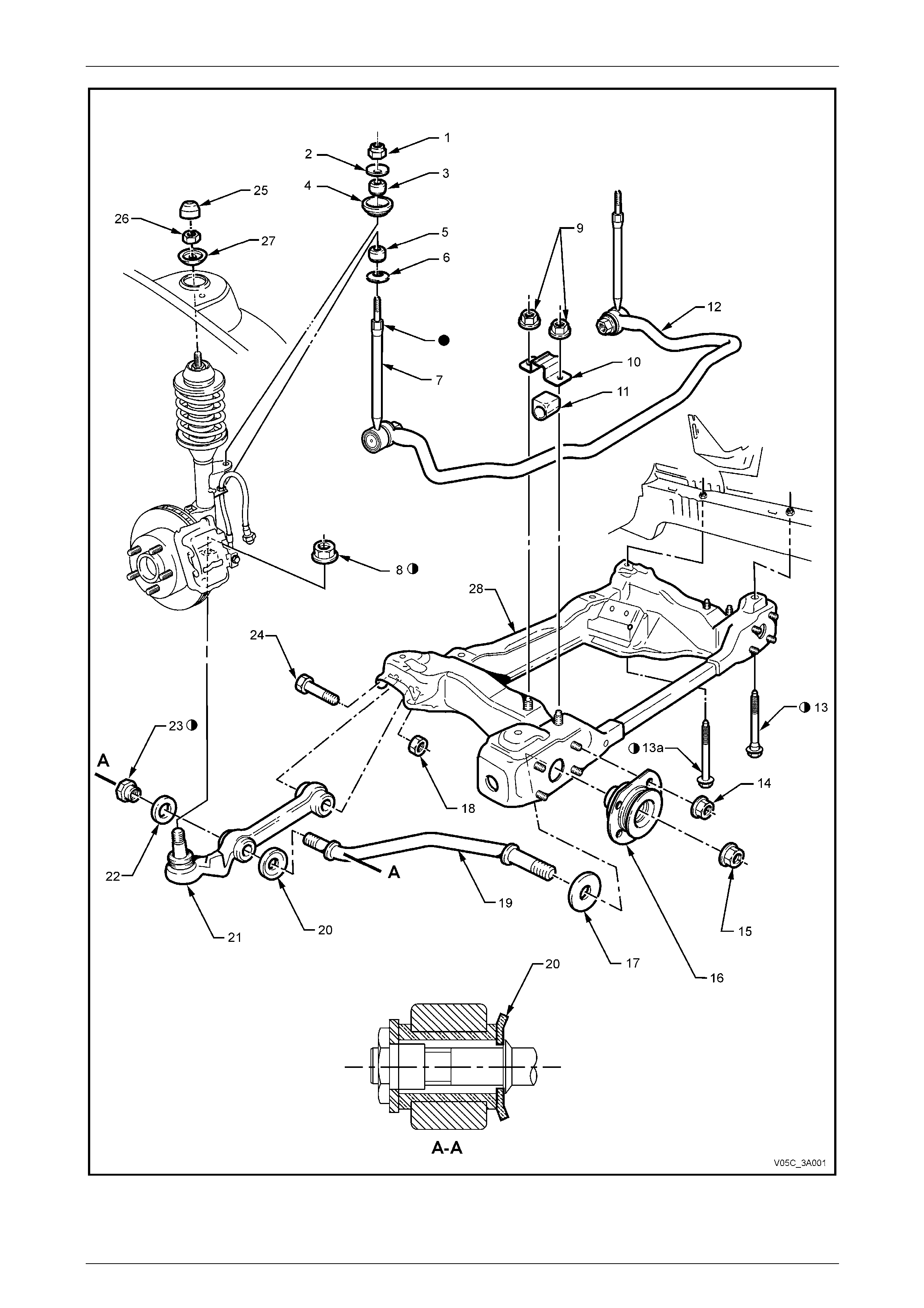
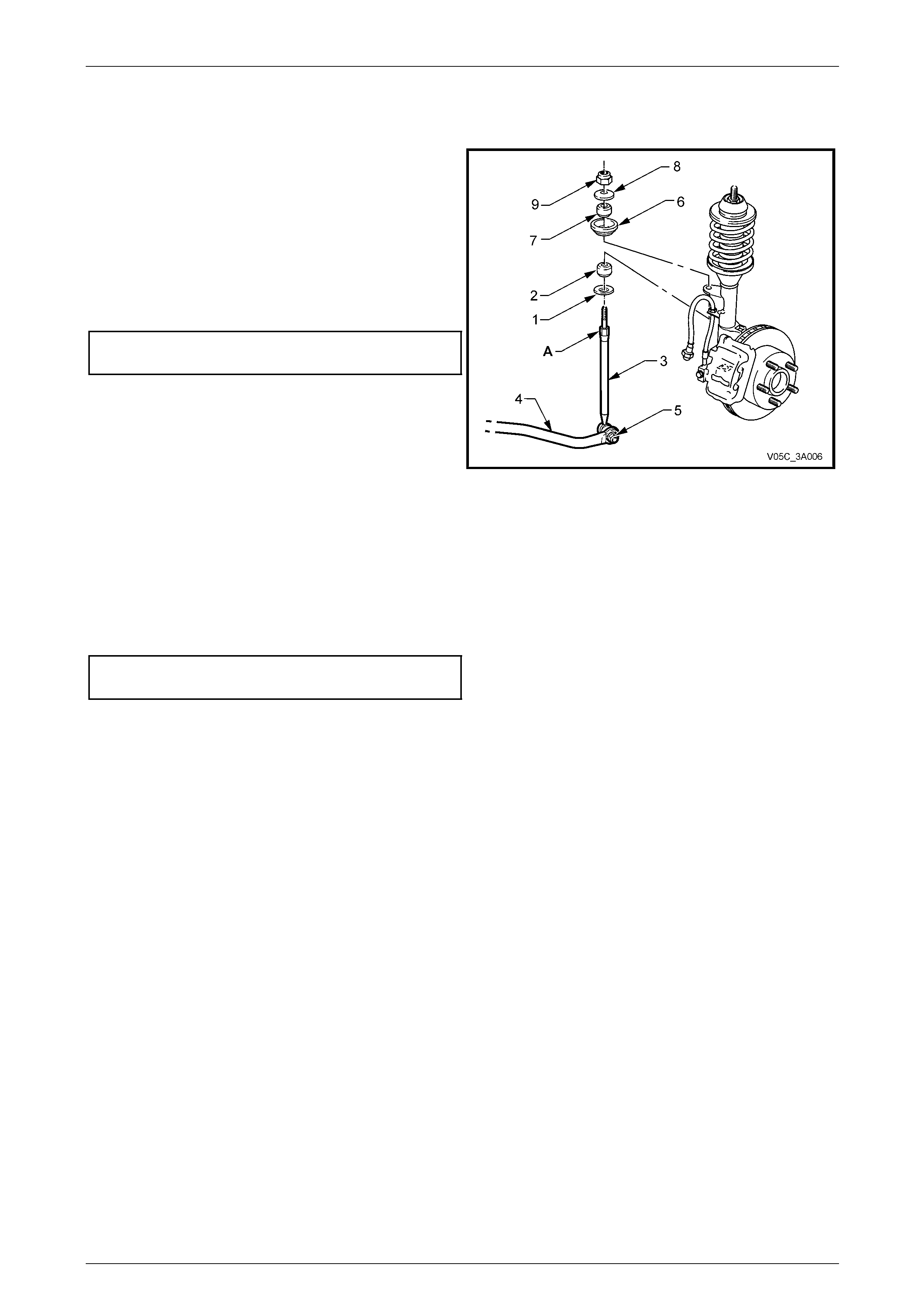
Refer to Figure 3A – 1 for exploded views of the revised layout.
Legend for Figure 3A – 1
1 Nut (2 places)
2 Washer – Cupped (2 places)
3 Insulator (2 places)
4 Seat (2 places)
5 Insulator (2 places)
6 Washer – Cupped (2 places)
7 Link – Stabiliser Bar (2 places)
8 Nut (2 places)
9 Nut (4 Places)
10 Bracket (2 Places)
11 Insulator – Stabiliser Bar (2 places)
12 Bar – Stabiliser
13 Bolt – Stepped Shank (2 places)
13a Bolt – Plain Shanked (2 places)
14 Nut (8 places)
15 Nut (2 places)
16 Insulator Bushing – Front Control Arm
Rod (2 places)
17 Washer (1 On Driver’s Side Only)
18 Nut (2 Places)
19 Control Arm Rod (2 places)
20 Washer – Cupped (2 places)
21 Control Arm (2 places)
22 Washer (2 places)
23 Nut – Stepped (2 places)
24 Bolt (2 Places)
25 Cover – Dust (2 Places)
26 Nut (2 Places)
27 Locating Disc (2 Places)
28 Front Suspension Crossmember
‘A-A’ - Assemble washer ‘20’ as shown.
Fastener must be new and assembled dry.
Stud to be held while nuts are being tightened to specification
Page 3A-2
Front Suspension Page 3A – 3
Figure 3A – 1 – All RWD VZ Crew man
Page 3A-3
Front Suspension Page 3A – 4
2 Service Operations
ATTENTION
All front suspension fasteners are important attaching parts as they affect the performance of vital
components and/or could result in major repair expense. Where specified in this Section, fasteners MUST be
replaced with parts of the same part nu mber or a GM app roved equivalent . Do not use fastene rs of an in ferior
quality or substitute design
Torque values must be used as specified during reassembly to ensure proper retention of all front
suspension components.
Throughout this Section, fastener torque wrench specifications may be accompanied with the following
identification marks:
Fasteners must be repl aced after loosening .
Vehicle must be at curb height before final tightening.
Fasteners either have micro encapsulated sealant applied or incorporate a mechanical thread lock and
should only be re-used once. If in doubt, replacement is recommended.
If one of these identification marks is present alongside a fastener torque wrench specification, the
recommendation regarding that fastener must be adhered to.
2.1 Service Notes and Cautions
Road Wheels
• Whenever a road wheel is removed from or installed to any MY 2006½ VZ Series vehicle, it MUST
be done in accordance with the procedure provided in Section 10 Wheels and Tyres.
• Whenever a road w heel is removed from the vehicle, the relationshi p of the road wheel to the hub
MUST be marked with a felt tipped pen or similar, to allow those parts to be reinstalled in their
original positions. This is critical to minimise the road wheel runout dimension.
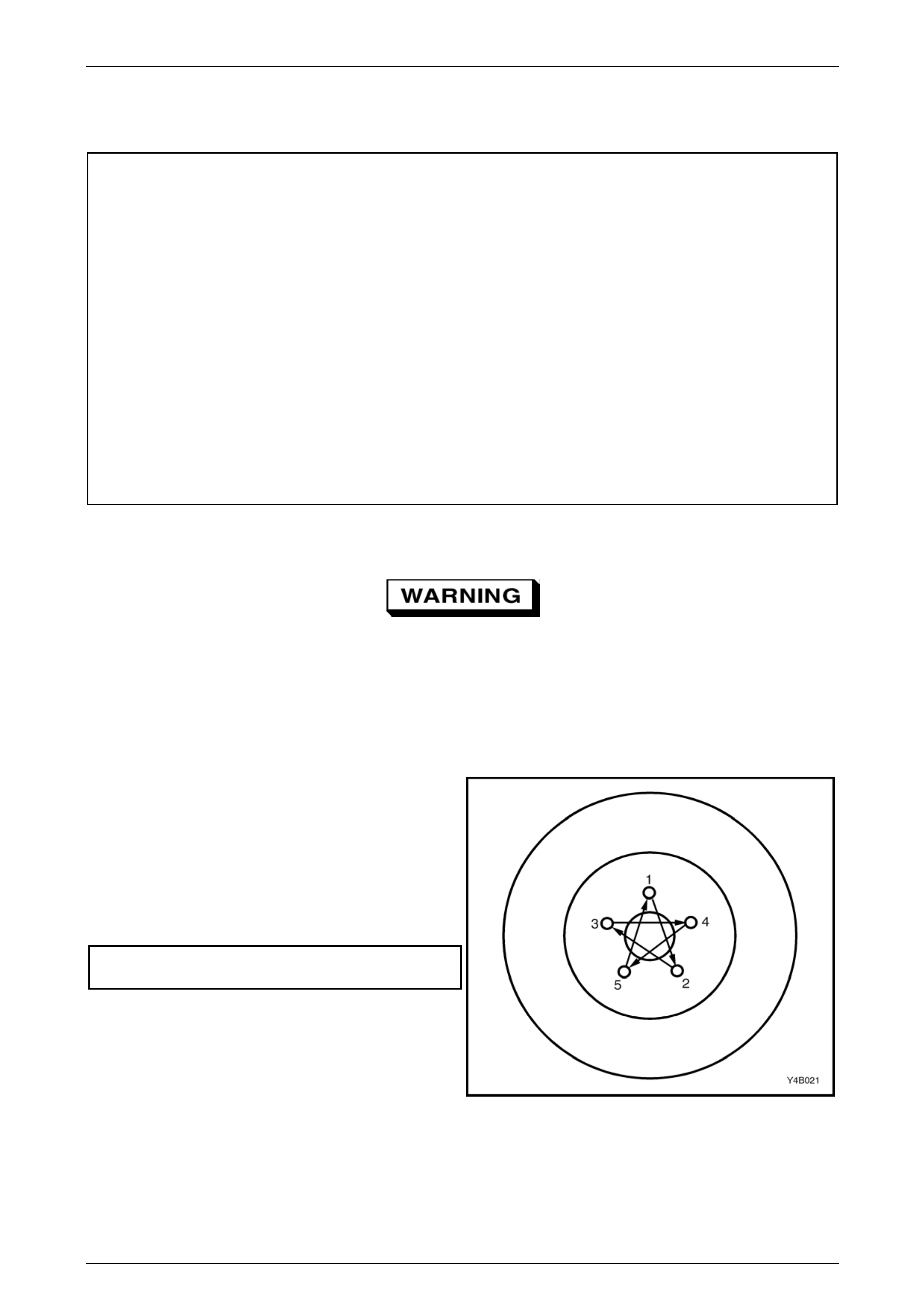
• When reinstalling road wheels, do not use
an impact gun to tighten wheel nuts
unless the impact gun is fitted with a
torque limiter socket (Tool No. AU 534 or
a commercial equivalent). Failure to
correctly tighten w heel nuts to the correct
torque specification and in the correct
order (as shown), may result in a
distorted brake disc, leading to the
development of brake shudder.
Road wheel attaching nut
torque specification...................................110 – 140 Nm
Figure 3A – 2
ABS Components
• Whenever any component that forms part of the ABS, is disturbed during Service Operations, it is
vital that the complete ABS system be checked, refer to Section 5B ABS.
Page 3A-4
Front Suspension Page 3A – 5
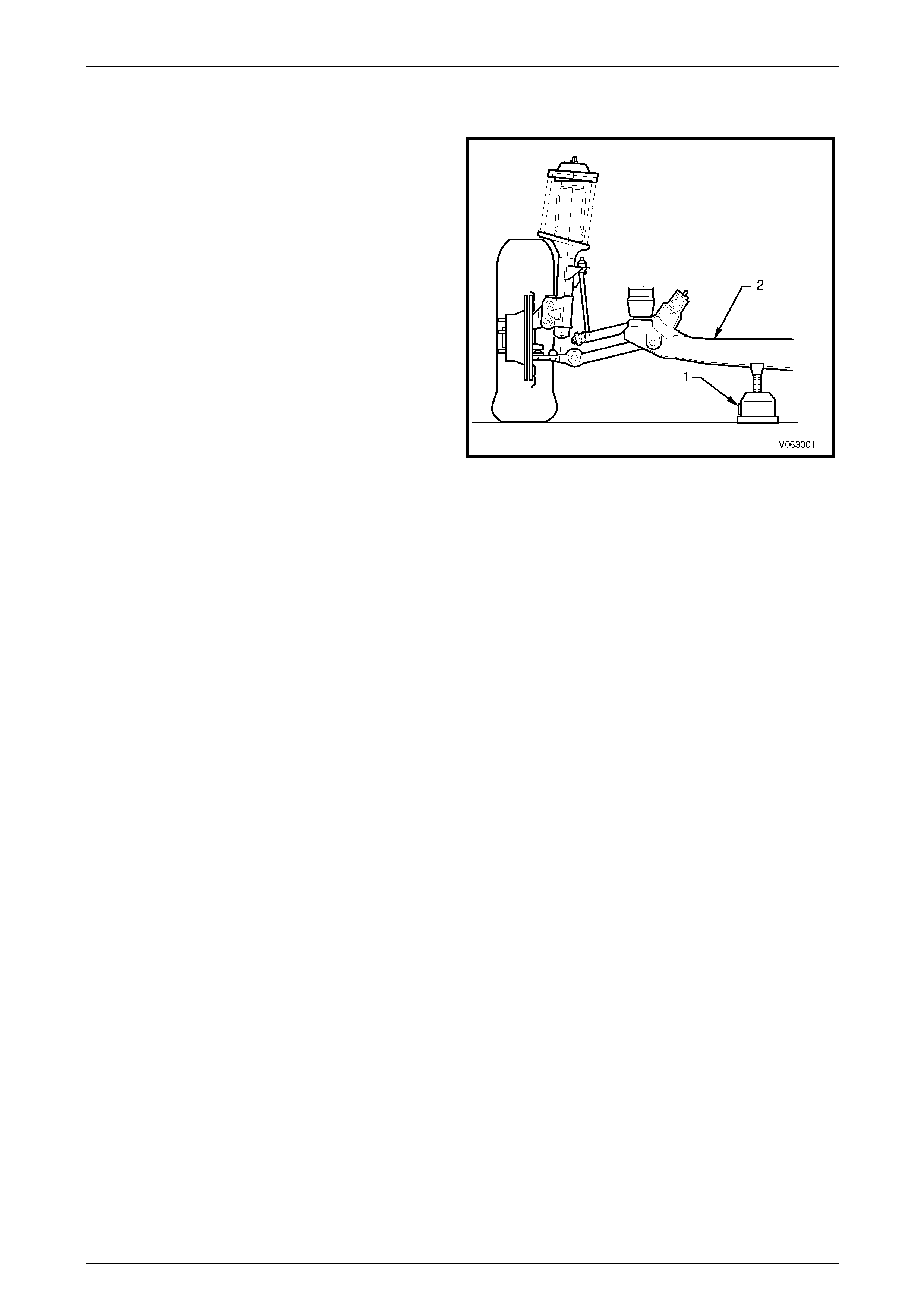
2.2 Jacking Precautions
When raising the front of the vehicl e with a jack (1), the jack
should be placed under the centre of the front crossmember
(2). The weight of the vehicle MUST NOT be lifted under the
control arms.
When the vehicle is raised on the jack, it must be firmly
supported on safety stands located under the frame side
members before any work is attempted. If a vehicle is not
correctly supported by safety stands, serious injury can
result if the vehicle should slip off the jack.
For further information relating to the location of jacking and
support points, refer to Section 0A General Information.
Figure 3A – 3
Page 3A-5
Front Suspension Page 3A – 6
2.3 Wheel Alignment Checking and
Adjustment
ATTENTION
The following fasteners MU ST be replaced when performin g these operations:
Steering knuckle to strut attachin g nuts and bolts.
Preliminary Inspection
Before any attempt is made to check camber, caster or toe-in, these preliminary checks should be carried out.
1 Check tyre and tyre mountings. Always check camber and toe-in at the mean run-out position on the tyre or rim.
2 Check and adjust tyre pressures to recommended values.
3 Front wheel bearing end float is to be checked to ensure it is within specification, as detailed in 2.4 F ront Wheel
Hub Assembly End Float Che cking Procedure, in Section 3A Front Suspension of the MY2005 VZ service
information.
4 The front control arm ball joints should be checked for wear, refer to 3.11 F ront Control Arm Ball Joint, in
Section 3A Front Suspension of the MY2005 VZ service information.
5 Check steering gear mounting bolts for tightness and steering tie rod ends for wear, refer to 3.6 Power Steering
Gear in Section 9 Steering.
6 The vehicle should be at curb weight, fuel tank full, without driver, passengers or luggage etc.
7 Check for improperly operating front struts or rear shock absorbers.
8 Check for loose or missing stabiliser bar or front control ar m rod attachments.
9 Before checking the front wheel alignment, refer to 2.11 Re ar W heel Alignment Checking in
Section 4A1 Rear Suspens ion for rear wheel alignment details.
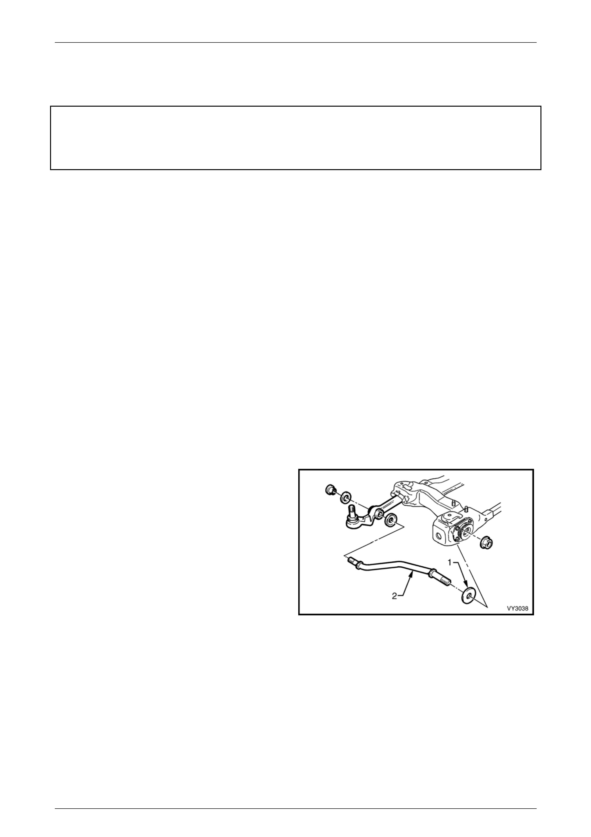
Caster Adjustment
While one bright finished spaced washer (1) will be fitted to
the driver’s side front control arm rod (2), the fitment of an
additional washer is permitted to correct minor caster
adjustments
NOTE
Only one additional spac er washer is to be fitted
and is to be added to the side with the higher
caster reading.
Figure 3A – 4
Page 3A-6
Front Suspension Page 3A – 7
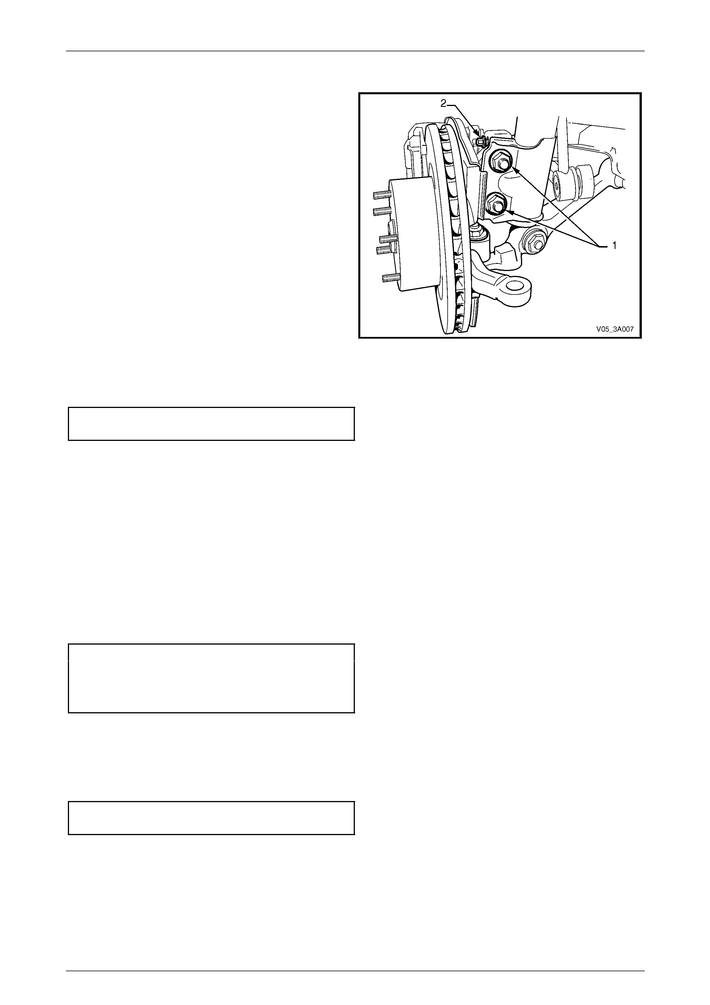
Camber Adjustment
1 Raise the front of the vehicle and support on safety
stands under the front side members. Refer to
2.2 Jacking Precautions in this Section.
2 Remove the centre wheel nut cover and mark the
relationship of the wheel to the hub stud, usin g a felt
tipped pen or similar.
3 Remove the wheel attaching nuts and remove the
wheel.
4 Loosen, remove and discard the two lower strut
attaching bolts and nuts (1).
5 Install NEW lower strut attaching bolts and nuts but
do not tighten fully to specificat ion until after the
camber has been adjusted to the recommended
specification.
6 Install the road wheel, alignin g the previously made
marks.
Figure 3A – 5
7 Tighten road wheel attaching nuts to the correct torque specification, working in a ‘star ’ pa ttern, refer to
2.1 Service Warnings Cautions and Notes, in this Section.
Road wheel attaching
nut torque specification.............................110 – 140 Nm
8 Lower the vehicle to the ground and bounce several times t o settle the suspension.
9 Check the camber angle.
10 If required, adjust the camber by turning the camber adjusting screw (2) in the required direction; clockwise to
reduce negative camber, anti- clockwise to reduce positive camber.
NOTE
The camber adjusting screw has thread sealant
applied in the form of micro-encapsulation and
does not require a lock nut.
11 Raise vehicle once again, support on safety stands and remove the front road wheels.
12 Tighten both steering knuckle bolts and nuts to the correct torque specification.
Steering knuckle to strut bolts
and nuts torque specification ..Stage 1.................85 Nm
Stage 2...............100 Nm
Stage 3 Turn through 90°
13 Install the road wheels, aligning the marks made prior to removal.
14 Remove the jack stands and lower the vehicle.
15 Tighten the road wheel attaching nuts to the correct tor que specification, working in a ‘star ’ pattern. Refer to
2.1 Service Notes and Cautions, in this Section.
Road wheel attaching
nut torque specification.............................110 – 140 Nm
16 Reinstall the centre wheel nut cover.
17 Check the camber angle again to ensure that it is still within specification.
Page 3A-7
Front Suspension Page 3A – 8
Toe Adjustment
Toe of both front wheels, is checked with the wheels in the straight ahead position.
Adjustment is achieved by windi ng the steering linkage tie rods in or out of the steering linkage tie rod ends, increasing or
decreasing their length, changing the wheel toe setting.
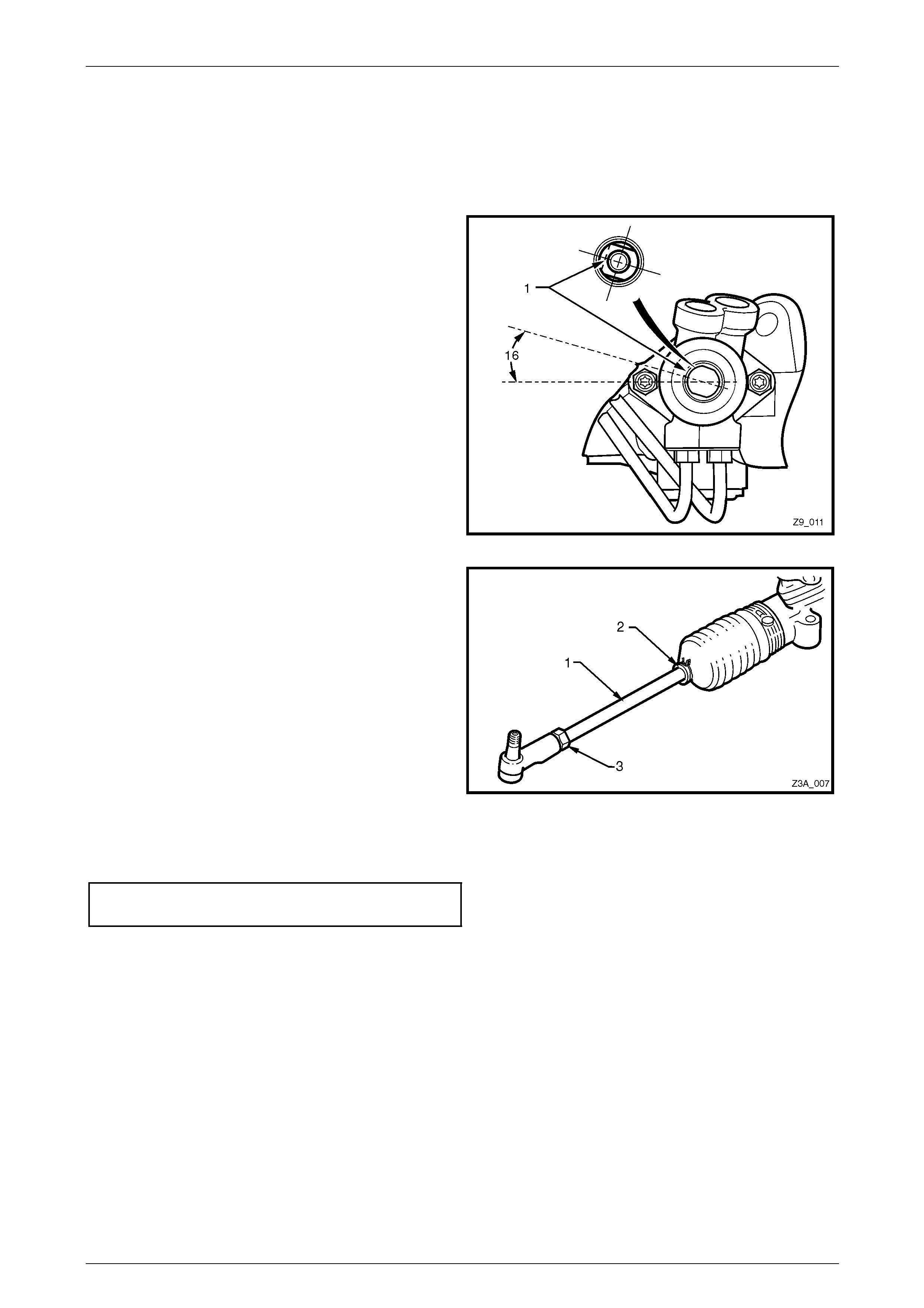
1 Set steering gear and wheels in straight ahead position.
2 To check if steering gear is in straight ahead position
(on-centre), the pinion (input) shaft (1) should be
aligned as shown.
Figure 3A – 6
3 Before adjusting the steerin g linkage tie rods (1),
disconnect the steering gear boot, outer clips (2).
4 While holding the tie rod e nd with a 19 mm set
spanner across the flats provided, loose n the lock nut
(3) at the end of each steering linkage tie ro d.
5 Turn each steering linkage tie rod (1) as required, until
the correct toe is obtained.
NOTE
During the toe adjustment, ensure that the
steering wheel is held in the straight ahead
position.
6 Tighten the lock nuts (21 mm) to the correct torque
specification, while holding the tie rod ends with a 19
mm set spanner to maintain ball stud alignment.
Figure 3A – 7
Steering linkage tie rod to tie rod
end lock nut torque specification...........................50 Nm
7 Reinstall the outer boot clips securely, maki ng sure that the convolutions of the boots are not distorted.
8 With the steering gear in the straight ahead position, ensure that the steering wheel is centralised. If not, remove
and reposition the steering wheel, refer to Section 9A Steering.
Page 3A-8

Front Suspension Page 3A – 9
2.4 Suspension and Trim Height, Check
• Good judgement must be exercised before
replacing a spring or springs from a
vehicle whose height is within the limits
quoted.
• Even if a vehicle's dimensions should
prove to be slightly outside these
tolerances, the vehicle could well be in a
serviceable condition.
• Spring replacement under conditions of
excessive weight due to non-standard
fittings, undercoating, road dirt, etc; will
assist very little in restoring the vehicle to
its specified height.
The suspension and trim height dimensions for RWD Crewman vehicles, are provided in 3 Specifications in this Section.
The dimensions are for a new vehicle built to standard specification a nd are only intended as a guide when checking
suspension and trim height dimensions at no rmal curb weight.
Preliminary Inspection
The following procedure sh ould be followed before checking an y suspension or trim height.
1 Vehicle curb weight is defined as:
• Tyre pressures are to specification.
• Fuel tank is full – add additional weight in the rear compartment to compensate if necessary.
• All fluids are at the specified levels.
• Spare tyre is included.
• Tyre and wheel rim sizes are to specification.
• Vehicle contains no passengers.
2 Accumulated dirt, distance travelled, etc., must also be taken into consideration when checking vehicle heights.
3 Vehicle must be on a level surface.
4 It must be confirmed that the vehicle has not been subjected to accident d amage.
NOTE
It is normal for the vehicle to sit approximately 4
mm lower on one side, because of the vehicle's
battery weight.
Page 3A-9
Front Suspension Page 3A – 10
Procedure
1 Push the vehicle up and down several times at the front bumper bar with a decreasing force and then gently
remove hands, allowing vehicle to settle on its own.
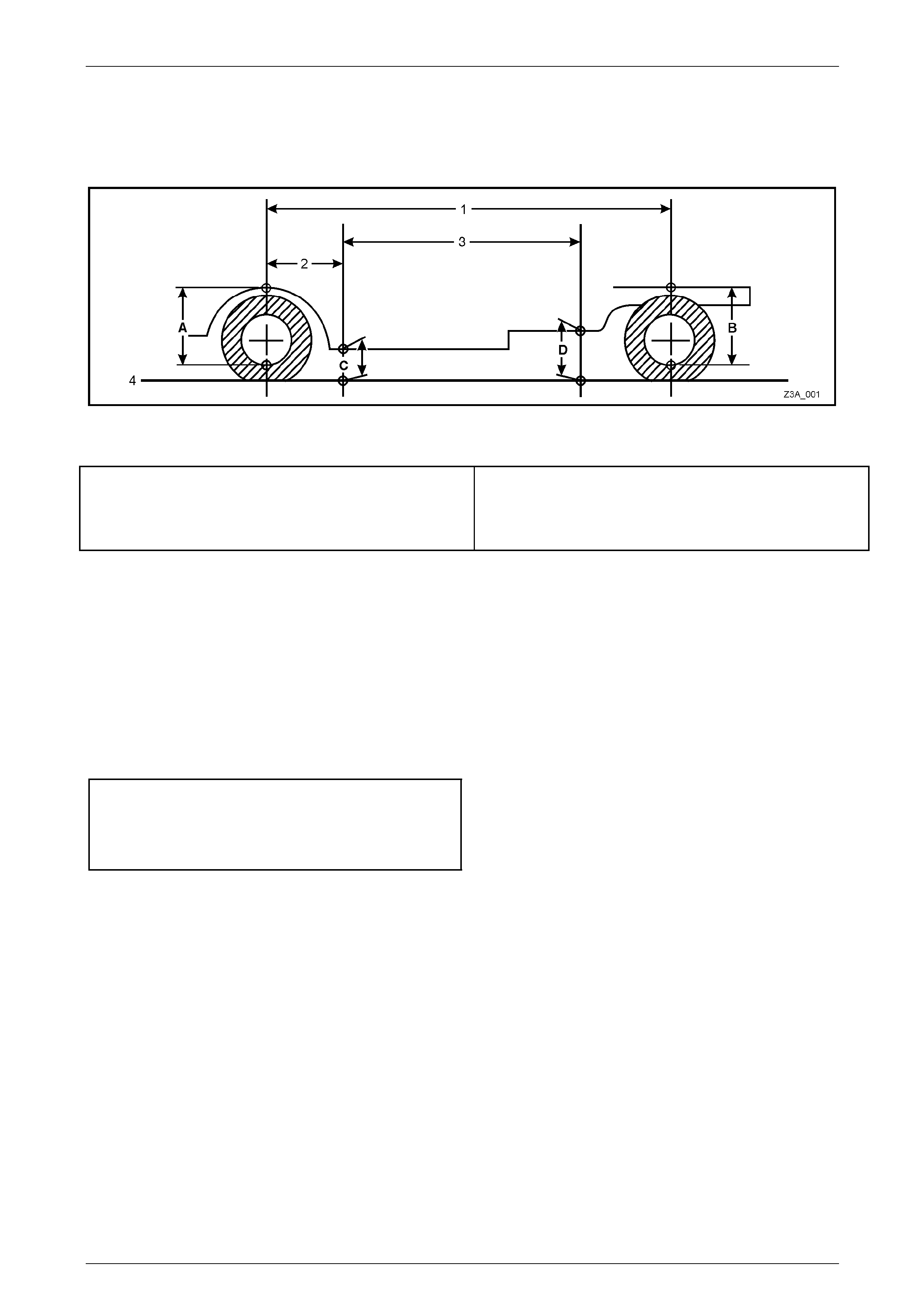
2 Carry out front suspension and trim height check, at ‘A’ and ‘C’ respectively; refer to Figure 3A–8.
Figure 3A – 8
Legend
A Front Suspension Height Location
B Rear Suspension Height Location
C Trim Height Checking Location – Front
D Trim Height Checking Location – Rear
1 Wheelbase – 3,206 mm
2 Reference Point – 584.5 mm
3 Trim Height Spacing – 1,500 mm
4 Ground Level
3 Push the vehicle up and do wn several times at the rear with a decreasing force and then gently remove hands,
allowing vehicle to settle on its own.
4 Carry out vehicle rear suspension and trim height check, at ‘B’ and ‘D’, respectivel y; refer to 3A–8.
Front and Rear Suspension Height Comparison
1 When checking a vehicle's suspension height, the following tolerances must also be taken into account, before any
spring is replaced. Compare the front and rear suspension height measurements between:
• Front to rear.
• Side to side
Ride Height Variations from Specification
Front to Rear.....................................................± 20 mm
Side To Side ..................................................... ± 10 mm
Normal Spring Settling........................................ ± 5 mm
NOTE
Ride height variatio n may also be due to any one
or a combination of the follo wing:
• Spring seat location on the suspens ion/body.
• Incorrect springs. Check spring identification
against the table shown in 3 Specifications in
this Section.
• Non-standard, additional vehicle weight, such
as a tow bar and/or after-market LPG fitment.
• Any combination of the above.
Page 3A-10
Front Suspension Page 3A – 11
2.5 Front Strut Assembly
LT Section No. – 06-212
ATTENTION
The following fasteners MU ST be replaced when performin g these operations:
Upper strut locating plate retaining nut
Steering knuckle to strut attachin g nuts and bolts.
Brake caliper to steering knu ckle retaining bolts.
Remove
1 Observing the jacking precautions as outlin ed in 2.2 Jacking Precautions in this Section, ra ise the front of the
vehicle and support on safety stands.
2 Remove the wheel cover or decorative wheel nut caps, as required.
3 Mark the relationship of the road wheel to hub or brake rotor. Loosen, then remove the road wheel attaching nuts.
Remove the road wheel.
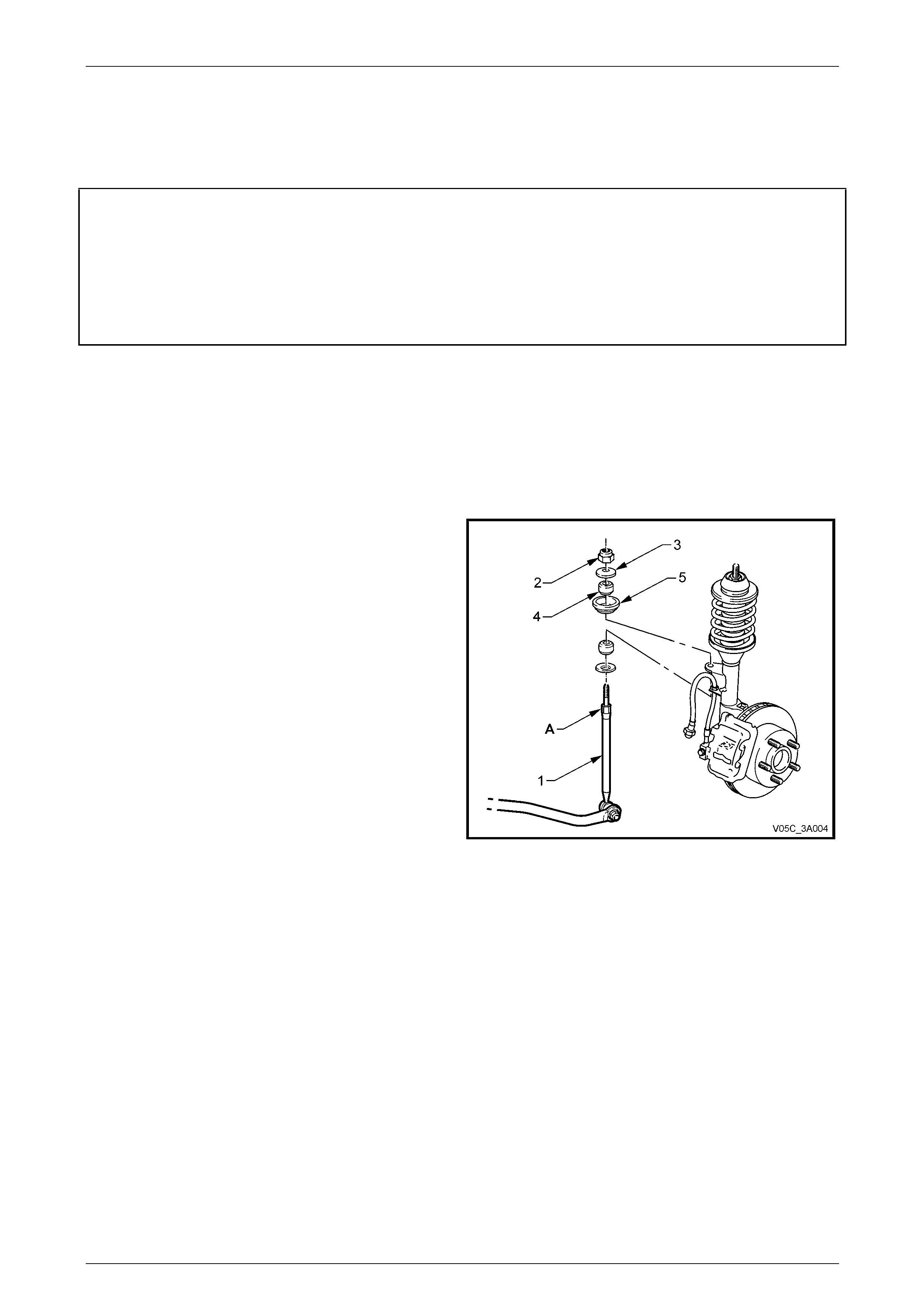
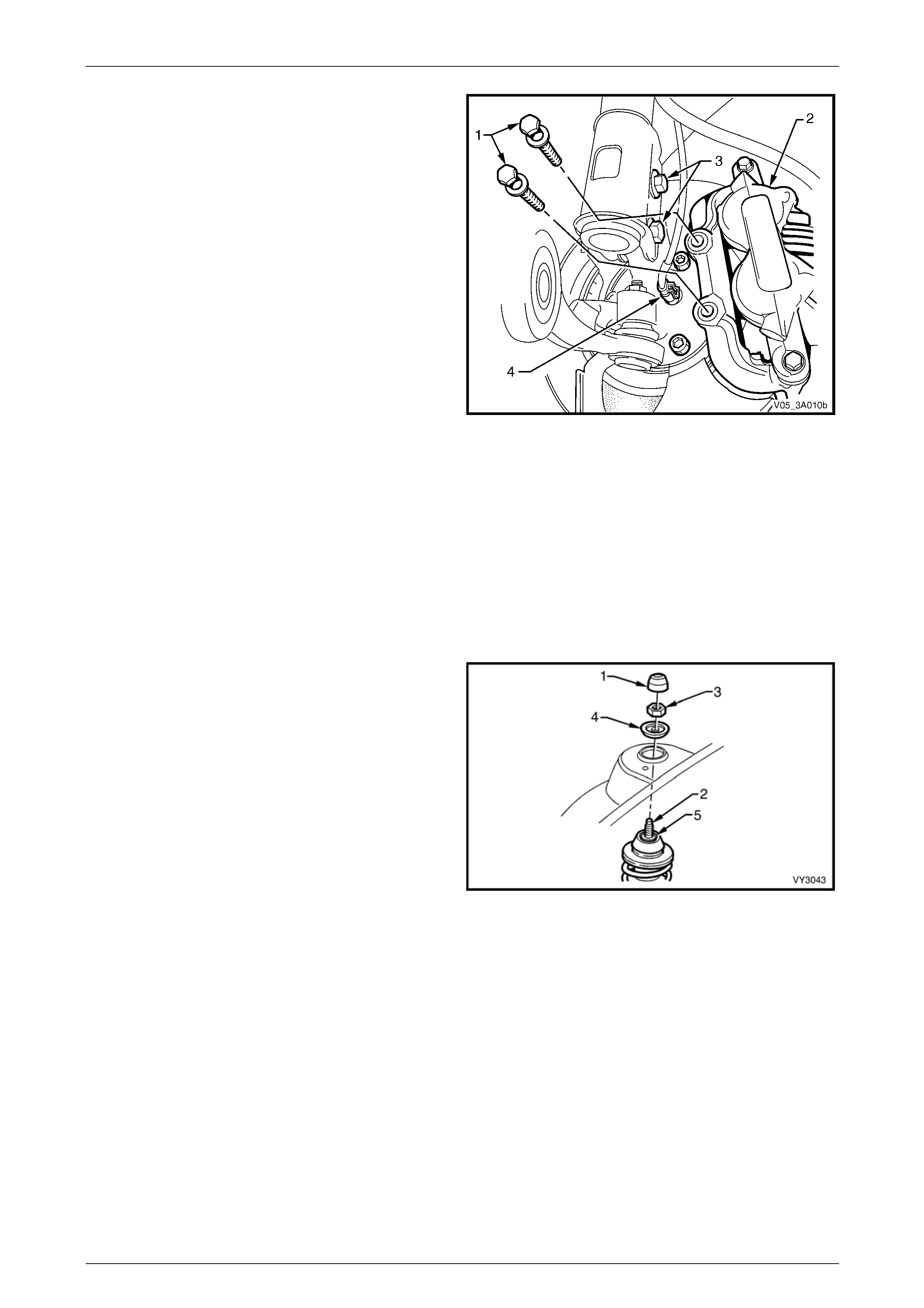
4 Position a suitable size open end spa nner to hold the
stabiliser bar spacer stud (1) at ‘A’, then use another
spanner to loosen and remov e the upper nut (2),
washer (3), insulator (4) and seat (5).
Figure 3A – 9
Page 3A-11
Front Suspension Page 3A – 12
5 Remove the brake caliper retaining bolts and washers
(1), lift the caliper assembly (2) from the brake rotor
and support in such a way that no strain is placed on
the brake hose. THE BRAKE CALIPER IS NOT TO
HANG BY THE BRAKE HOSE.
NOTE
This step is necessary to gain access to the
lower strut mounting bolts and nuts (3).
6 If required, remove the brake rotor from the wheel hu b
assembly.
NOTE
• The brake rotor to hub re lationship is marked
during production. T o ensure this relationship
is maintained, ensure that the rotor to hub
position is clearly visible. If not, use a felt
tipped pen or similar to mark the brake rotor
and hub.
• T his is necessary to overcome the possibility
of inducing a brake shudder condition after
reassembly.
Figure 3A – 10
7 Remove the brake hose from the strut housi ng bracket by turning the plastic sleeve on th e hose until the flats on
the sleeve align with the bracket opening.
8 Remove the wheel speed sens or connector from the front hub and remove the sensor lead from the strut bracket.
9 Position a suitable floor jack fitted with a block of wood on the lift pad u nder the control arm, and raise it sufficiently
to support the weight.
10 Loosen, remove and discard the two lower strut to knuckle attaching bolts and nuts (‘3’ in Figure 3A – 1 0).
11 Pull the steering knuckle clear of the strut.
12 Remove the dust cover (1) from the upper strut
support, in the engine compartment.
13 While holding the strut rod shaft (2) with a 10 mm
socket, remove the self-locking nut (3), using a 24 mm
ring spanner, then remove the locating disc (4).
Discard the removed strut rod nut.
14 Carefully lower the strut from the tower, manipulate
the strut to remove the stabiliser stud from the bracket
on the strut and remove the assembly from the
vehicle.
Figure 3A – 11
Disassemble
Should the strut, spring or other components in the strut assembly require replacement, refer to Section 3A Front Suspe nsio n,
in the MY2006 VZ Service Information.
Page 3A-12
Front Suspension Page 3A – 13
Reinstall
The torque of the strut bearing retaining nut
(‘5’ in Figure 3A-11) MUST be checked for
correct tightness BEFORE installing the strut
into the vehicle.
Upper strut bearing retaining
nut torque specification.........................................78 Nm
1 Lift the strut assembly into the spring strut tower.
2 Install the locating disc an d partially install a NEW upper nut to the strut rod. Do not tighten at this time.
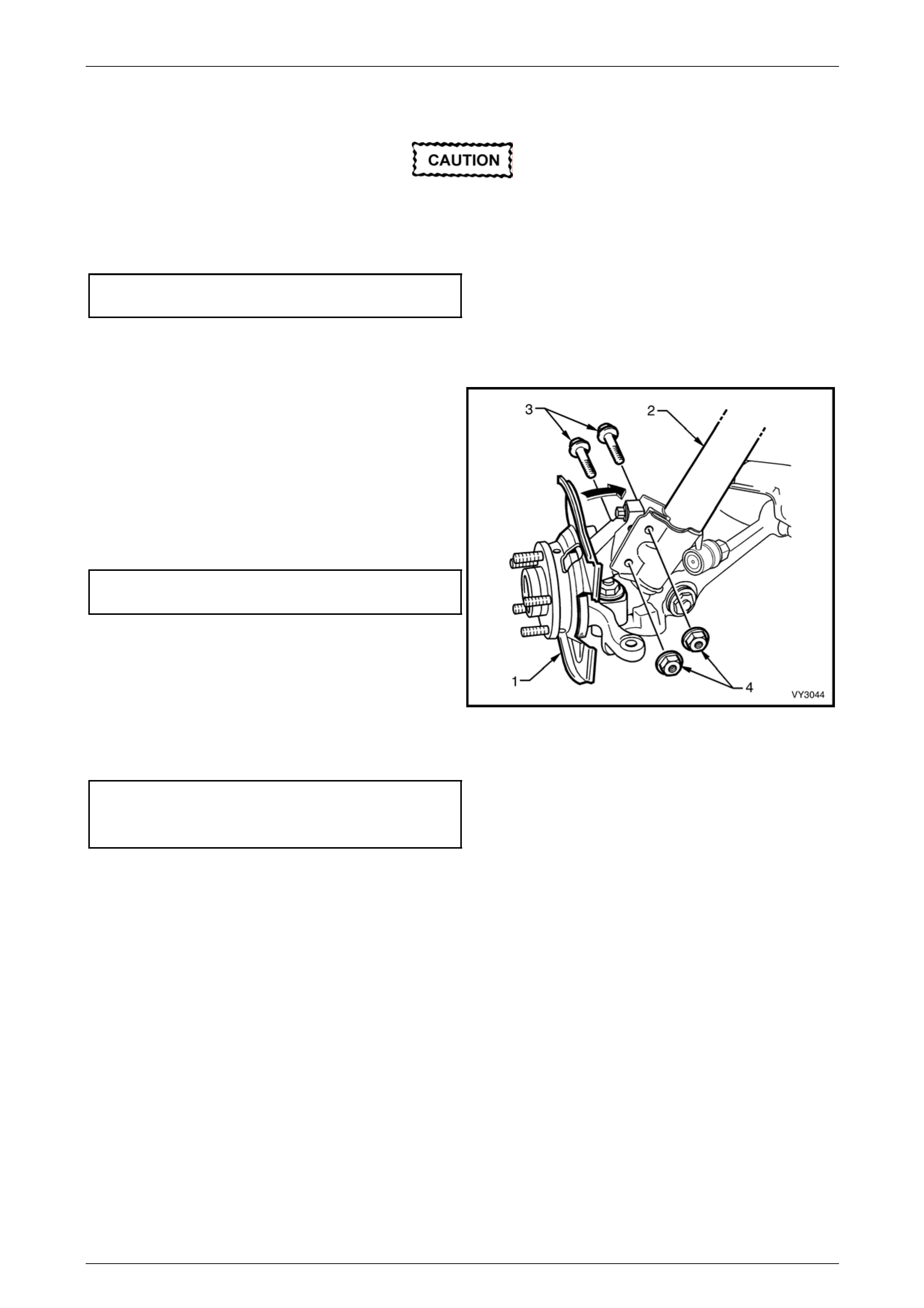
3 Pivot the hub and steering knuckle ass embly (1),
sufficiently to line up the bolt holes in the steering
knuckle and the lower end of the strut assembly (2).
4 Install NEW retaining bolts (3) and nuts (4), and
tighten to a preliminary torque of 85 Nm.
5 Use a 10 mm socket to hold the strut rod from turning,
then tighten the upper strut rod retaining nut (‘3’ in
Figure 3A-11) to the correct torque specification, using
a 24 mm ring spanner with a torque wrench attached.
Upper strut locating plate retaining
nut torque specification.........................................55 Nm
6 Install the brake hose to the strut bracket by turning
the plastic sleeve on the hose until the flats on the
sleeve align with the bracket opening.
7 If removed, install the brake rotor, alignin g the marks
made prior to removal. Figure 3A – 12
8 Install the brake caliper, tightening t he attaching bolts to specification.
Brake caliper anchor plate
bolt torque specification...............................85 Nm, then
Turn through 45°
9 Reinstall the wheel speed sensor connector, pushing firmly onto the sensor until the retaining tang is secure. Then,
install the sensor lead and ins ulator i nto the strut mounting bracket.
Page 3A-13
Front Suspension Page 3A – 14
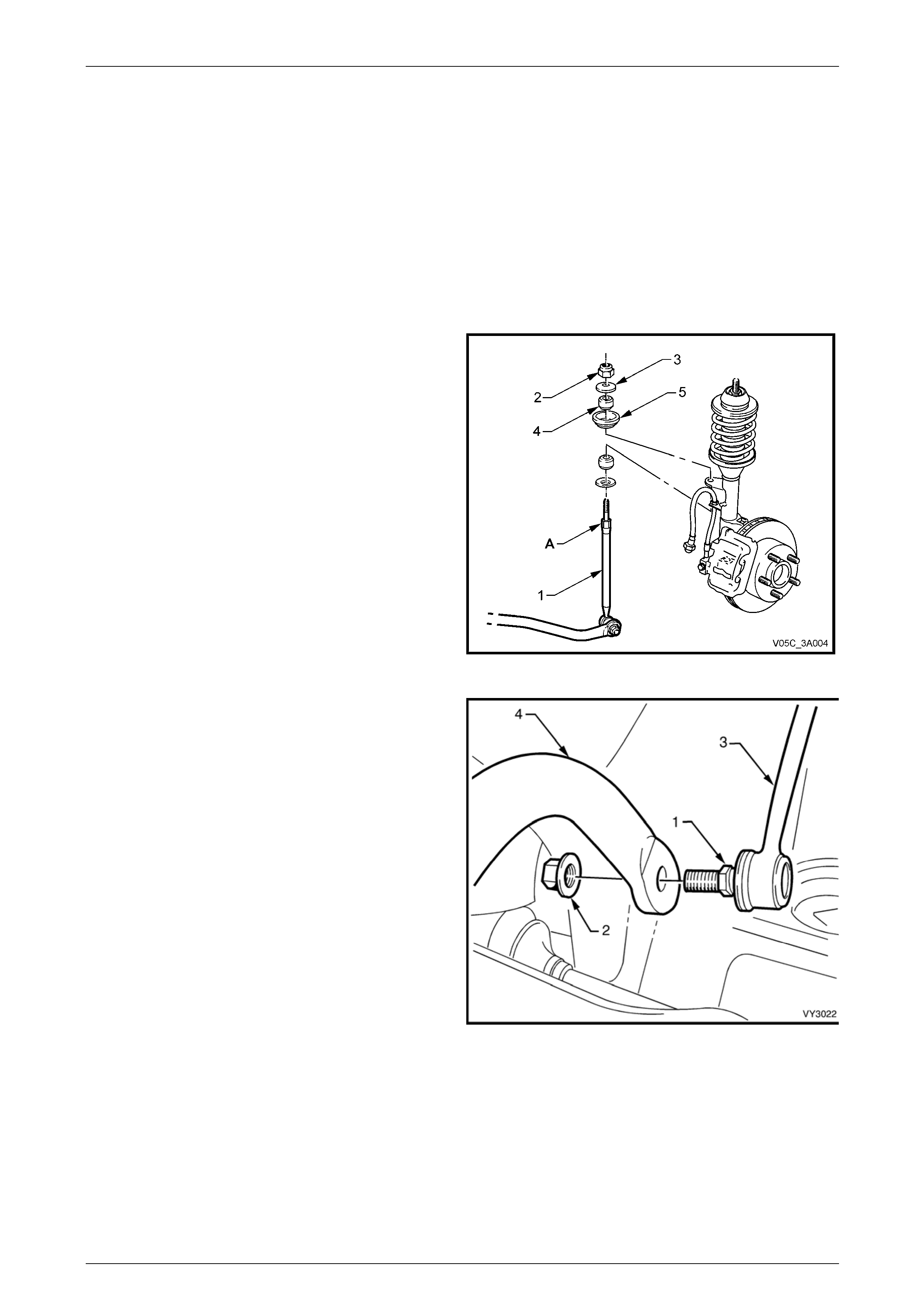
10 Reinstall the stabiliser b ar spacer stud nut (1) after
ensuring that all the compone nts are assembled as
shown.
11 While holding the spacer stud (2) with a suitable open
end spanner at ‘A’, use another spanner to tighten the
upper retaining nut until the end of the threa d on the
stud is contacted.
NOTE
Do not use power tools for this tightening
operation, otherwise thread damage will result.
Figure 3A – 13
12 Reinstall the road wheel, alig ning the marks made prior to removal.
13 Lower the vehicle to the ground.
14 Tighten road wheel attaching nuts to the correct torque specification, working in a ‘star’ pattern, refer to
2.1 Service Notes and Cautions, in this Section.
Road wheel attaching
nut torque specification.............................110 – 140 Nm
15 Reinstall the wheel cover or decorative road wheel retaining nut caps, as required.
16 Bounce the vehicle up and down several times to settle the suspension.
17 Check the wheel alignment, a s detailed in 2.3 Wheel Alignment Check ing and Adjustment in this Section.
18 Tighten the steering knuckle to strut bolts and nuts to the specified torque values.
Steering knuckle to strut bolts
and nuts torque specification ..Stage 1.................. 85 Nm
Stage 2................ 100 Nm
Stage 3. .Turn through 90°
Page 3A-14
Front Suspension Page 3A – 15
2.6 Stabiliser Bar Link
LT Section No. – 06-205
Remove
1 Raise the front of the vehicle and support in a safe manner. Refer to 2.2 Jacking Precautions, in this Section.
2 Remove the wheel covers or decorative wheel nut caps.
3 Mark the relationship of the road wheel to hub or brake rotor. Loosen, then remove the road wheel attaching nuts,
working in a 'star' pattern. Refer to 2.1 Service Notes and Cautions , in this Section.
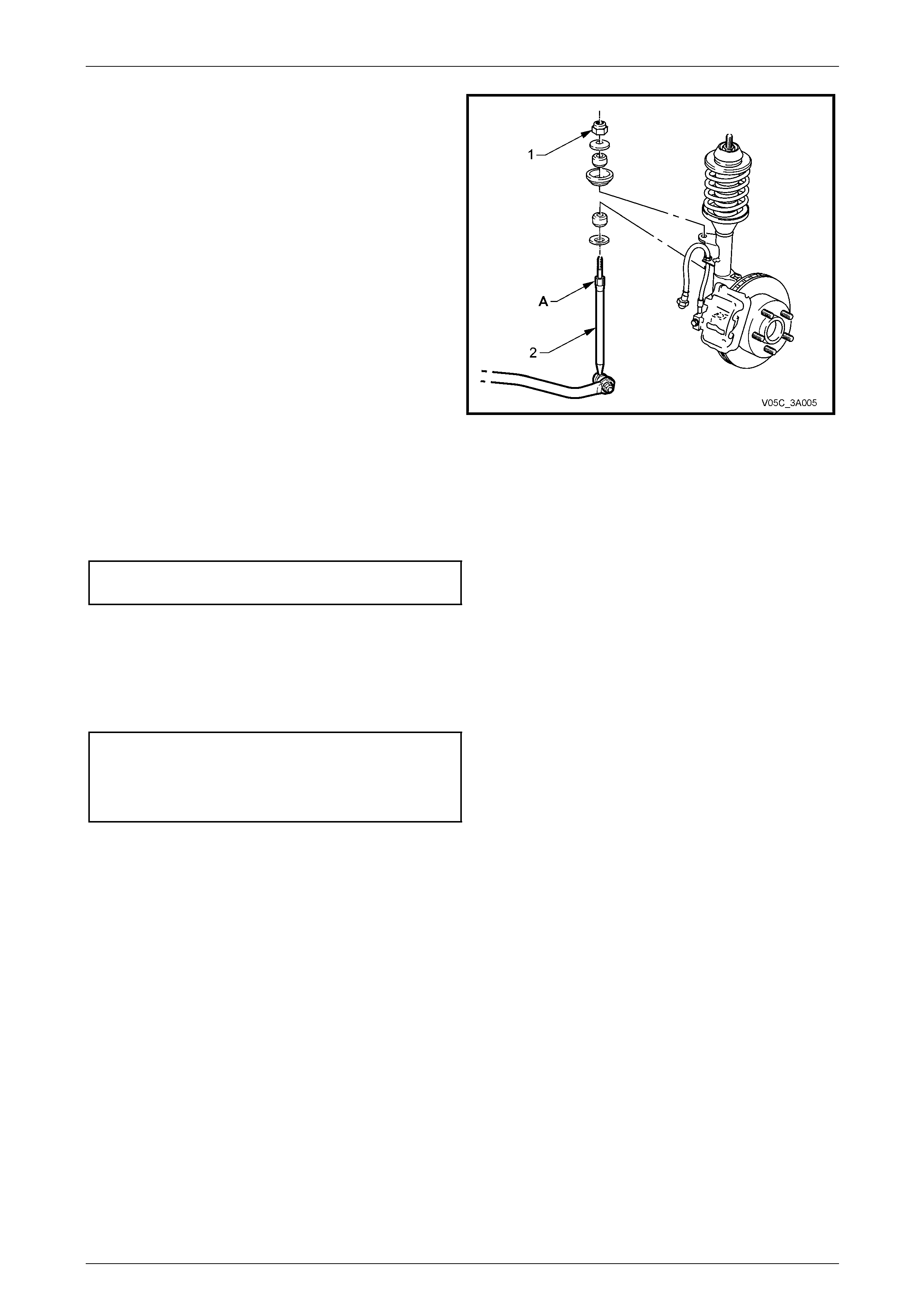
4 Using a suitable size spanner, hold the sta biliser bar
spacer stud (1) at ‘A’, then use another spanner to
loosen and remove the stabil iser bar spacer stud nut
(2).
5 Remove the upper washer (3), upper insulator (4) and
centre washer (5).
Figure 3A – 14
6 With a backing set spanner holding the stabiliser bar
link inner stud hexago n (1), use a second spanner to
loosen then remove the retaining nut (2).
7 Separate the stabiliser bar link (3) from the stabiliser
bar (4).
8 Separate the stabiliser bar link (3) from the stabiliser
bar (4) and remove from the vehicle.
Figure 3A – 15
Page 3A-15
Front Suspension Page 3A – 16
Reinstall
The installation procedure is the reverse to removal, except for the following points:
9 As required, replace the lower link washer (1) and
insulator (2).
10 Before reinstallation of the stabiliser bar link ( 3) to the
stabiliser bar (4), insert the upper threaded end of the
link into the strut mounting bracket.
11 Reinstall the link ball socket stud to the stabiliser bar
(4), tighten the retaining nut (5) to the correct torque
specification, while holding the inner stud hexagon ('1'
in Figure 3A – 15 with a set spanner.
Stabiliser bar link ball socket retaining
nut torque specification.........................................50 Nm
12 Reinstall the upper seat (6), upper insul ator (7) and
washer (8).
13 Reinstall the upper link retaining nut (9).
14 While holding the spacer stud (3) with a suitable open
end spanner at ‘A’, use another spanner to tighten the
upper retaining nut (9) until the end of the thread on
the stud is contacted. Do not over-tighten.
Figure 3A – 16
15 Install the road wheels, aligning the marks made prior to removal, and secure with the wheel attaching nuts, but do
not tighten to specification at this time.
16 Lower the vehicle to the ground.
17 Tighten the road wheel attaching nuts to the correct tor que specification, working in a ‘star ’ pattern. Refer to
2.1 Service Notes and Cautions, in this Section.
Road wheel attaching
nut torque specification.............................110 – 140 Nm
18 Install the wheel cover or decorative wheel nut caps.
Page 3A-16
Front Suspension Page 3A – 17
3 Specifications
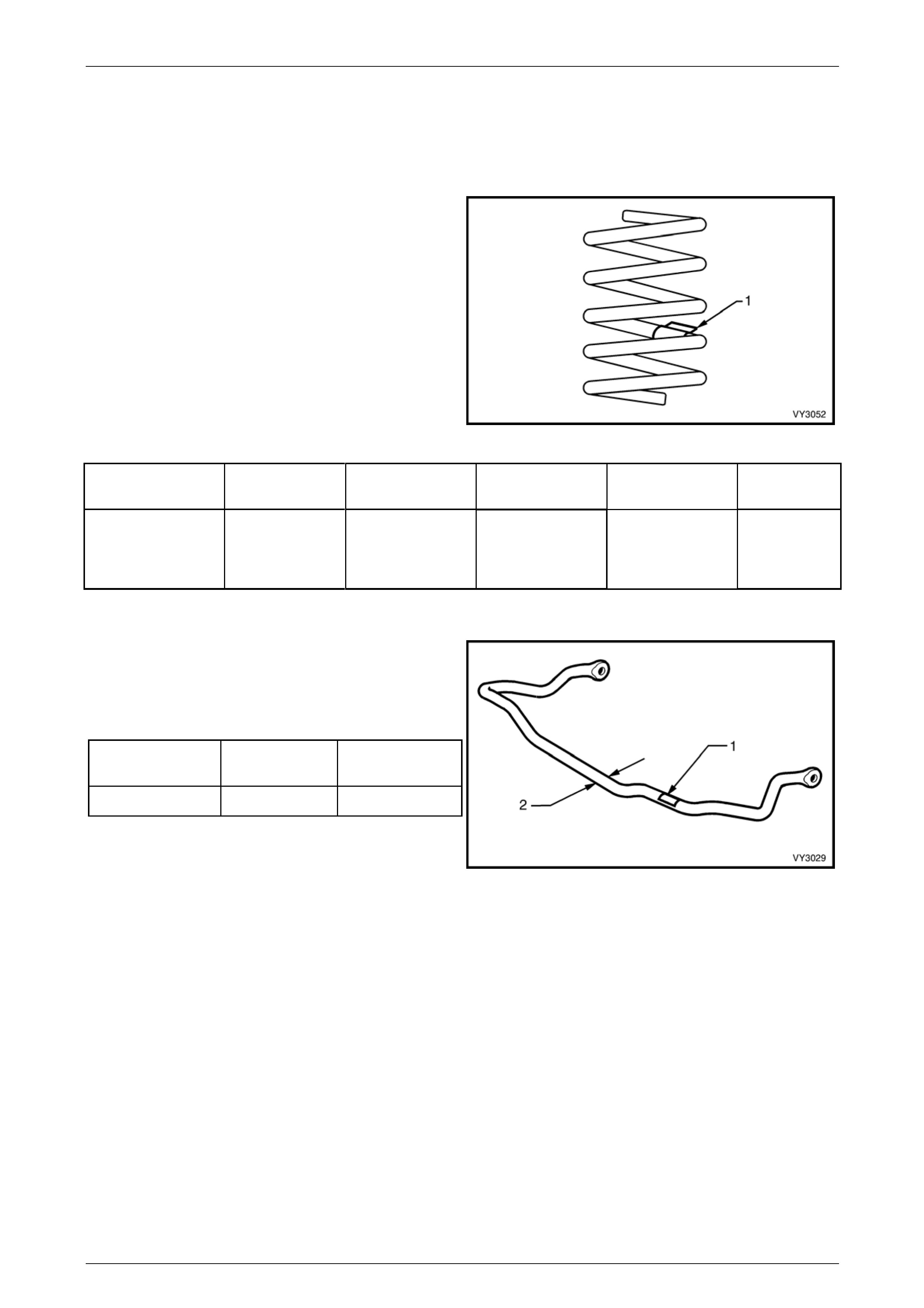
Front Spring Details
Identification of the front spring fitted to a par ticular vehicle
can be achieved by cross-referenci ng the two digit code
provided on the production id entificati on tag (1) with the
table below.
Figure 3A – 17
Suspension
Configuration Number of
Coils Free Length
(mm) Inside Diameter Spring Rate and
Type Production
I.D. Code
Crew Cab - All 5.74 367 136 ± 1.5 mm
Variable
27 – 35 N/mm
(3600 ± 110 N
@ 230 mm)
JN
Front Stabiliser Bar Details
Identification of the front stabiliser bar fitted to a particul ar
vehicle can be achieved by cross-referencing the two digit
code provided on the production identification tag (1) with
the table below.
The table also provides stabiliser bar diameters (2).
Suspension
Configuration Diameter Production I.D.
Code
Crew Cab – All 28 AA
Figure 3A – 18
Page 3A-17
Front Suspension Page 3A – 18
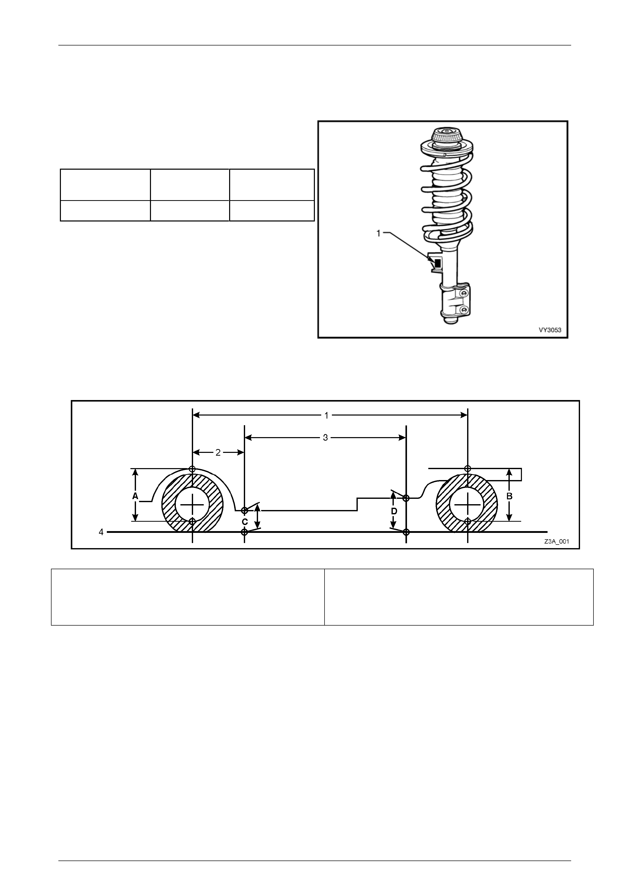
Front Strut Details
Type Wet strut – non-serviceable
Piston Diameter 30 mm
Identification of the front strut assemblies fitted to a
particular vehicle can be achie ved by cross-referencing the
two digit code provided on th e prod uction identification tag
(1) with the table below.
Suspension
Configuration Left Side
I.D. Code Right Side
I.D. Code
Crew Cab – All AWU AWU
Figure 3A – 19
Suspension and Trim Height Specifications
Figure 3A – 20
A Front Suspension Height Location
B Rear Suspension Height Location
C Front Trim Height Check Location
D Rear Trim Height Check Location
1 Wheelbase -3,206 mm
2 Reference Point - 584.5 mm
3 Trim Height Spacing – 1,500 mm
4 Ground Level
Page 3A-18
Front Suspension Page 3A – 19
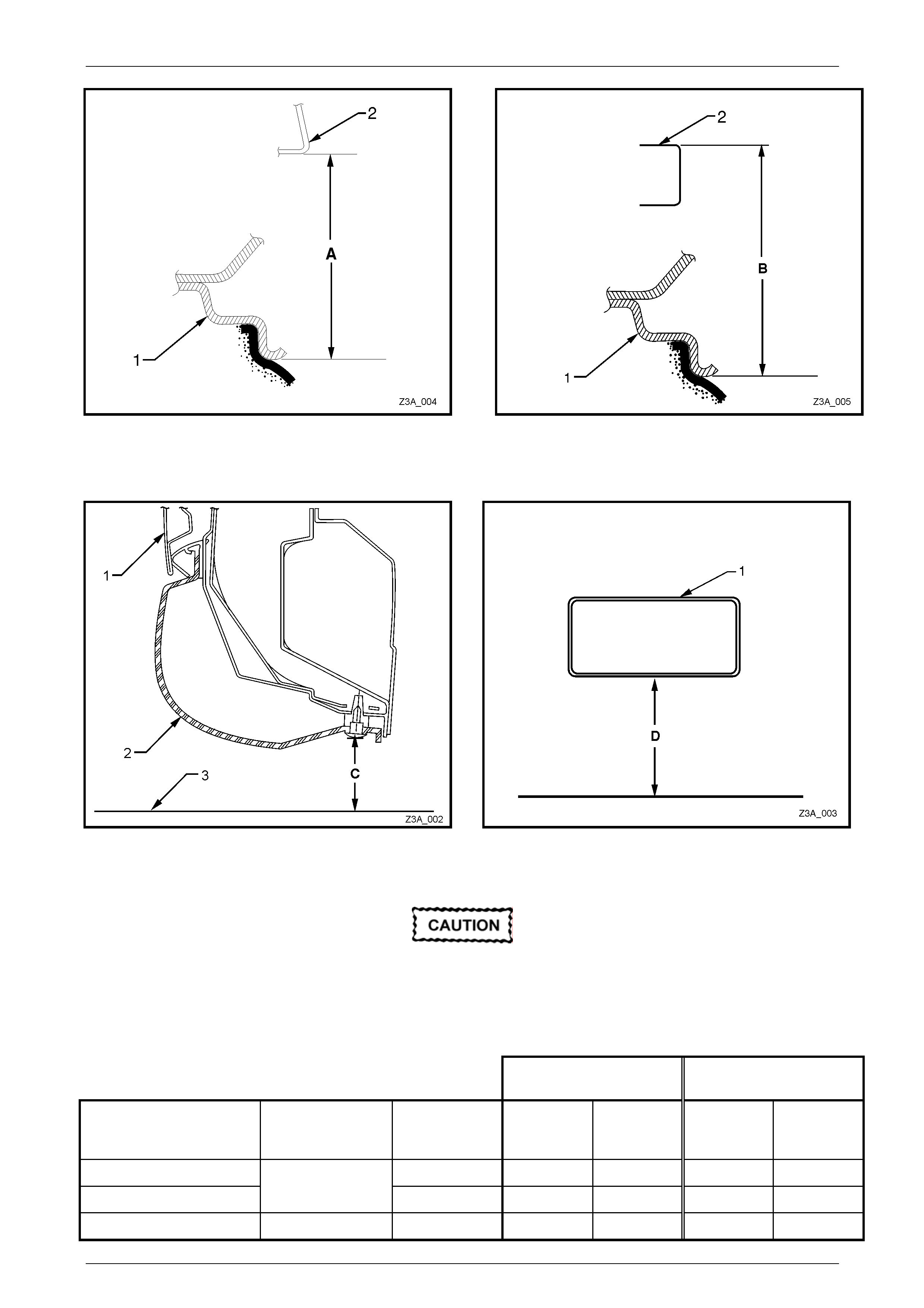
Figure 3A – 21 – Front Su spension Height Check
Location
Figure 3A – 22 – Rear Suspension Height Check
Location
1 Front Wheel Rim ‘A’ Front Suspension Height
2 Front Wheel Arch 1 Rear Wheel Rim ‘B’ Rear Suspension Height
2 Top Surface of Subframe Above Wheel Centre)
Figure 3A – 23 – Front Trim Height Check Locatio n
Figure 3A – 24 – Rear Trim Height Check L ocation
1 Door 3 Ground Line
2 Trim ‘C’ Front Trim Height 1 Section Through Rear Subframe
‘D’ Rear Trim Height
The following u nladen suspension/trim height
dimensions are for reference only and are
only intended to be a guide. Refer to
2.4 Suspension and Trim Height, Check for
ride height variations and additional
procedures.
Suspension Height
(mm) Trim Height (mm)
Vehicle Description Transmission Suspension Front
(‘A’ in Fig.
3A – 21)
Rear
(‘B’ in Fig.
3A – 22)
Front
(‘C’ in Fig.
3A – 23)
Rear
(‘D in Fig.
3A – 24)
Crew Cab – Base FE2 592 670 210 240
Crew Cab – ‘S’ V6 FE2 600 680 216 256
Crew Cab – ‘SS’ V8 FE2 616 692 210 256
Page 3A-19

Front Suspension Page 3A – 20
Front Wheel Alignment
Camber.........................................................................................................................0° ± 30’
Caster.................................................................................................................7° 45’ ± 1° 15’
Front Wheel Toe – Degrees Total ......................................................................0° 10’ ± 0° 10’
Front Wheel Toe – Degrees Per Wheel................................................................. 0° 5’ ± 0° 5’
Page 3A-20

Front Suspension Page 3A – 21
4 Torque Wrench Specifications
ATTENTION
Throughout this section, fastener torque wrench specifications may be accompanied with the following
identification marks:
Fasteners must be replaced after loosening.
Vehicle must be at curb height before final tightening.
Fasteners either have micro encapsulated sealant applied o r incorporate a mechanical thread lock and
should only be re-used once. If in doubt, replacement is recommended.
If one of these identification marks is present alongside a fastener torque wrench specification, the
recommendation regarding that fastener must be adhered to.
Brake Caliper Anchor Plate Bolts .......................Stage 1:....................85 Nm
Stage 2:....Turn through 45°
Road Wheel Attaching Nut .......................................................110 – 140 Nm
Stabiliser Bar Link Ball Joint Stud Retaining Nut (Both) .......................50 Nm
Steering Knuckle To Strut Attaching Bolt............Stage 1: ....................85 Nm
Stage 2:..................100 Nm
Stage 3:....Turn through 90°
Tie Rod End to Steering Arm Nyloc Nut ...............................................70 Nm
Tie Rod to Tie Rod End Lock Nut.........................................................50 Nm
Upper Strut Bearing Retaining Nut.......................................................78 Nm
Upper Strut Locating Plate Retaining Nut.............................................55 Nm
Page 3A-21
Front Suspension Page 3A – 22
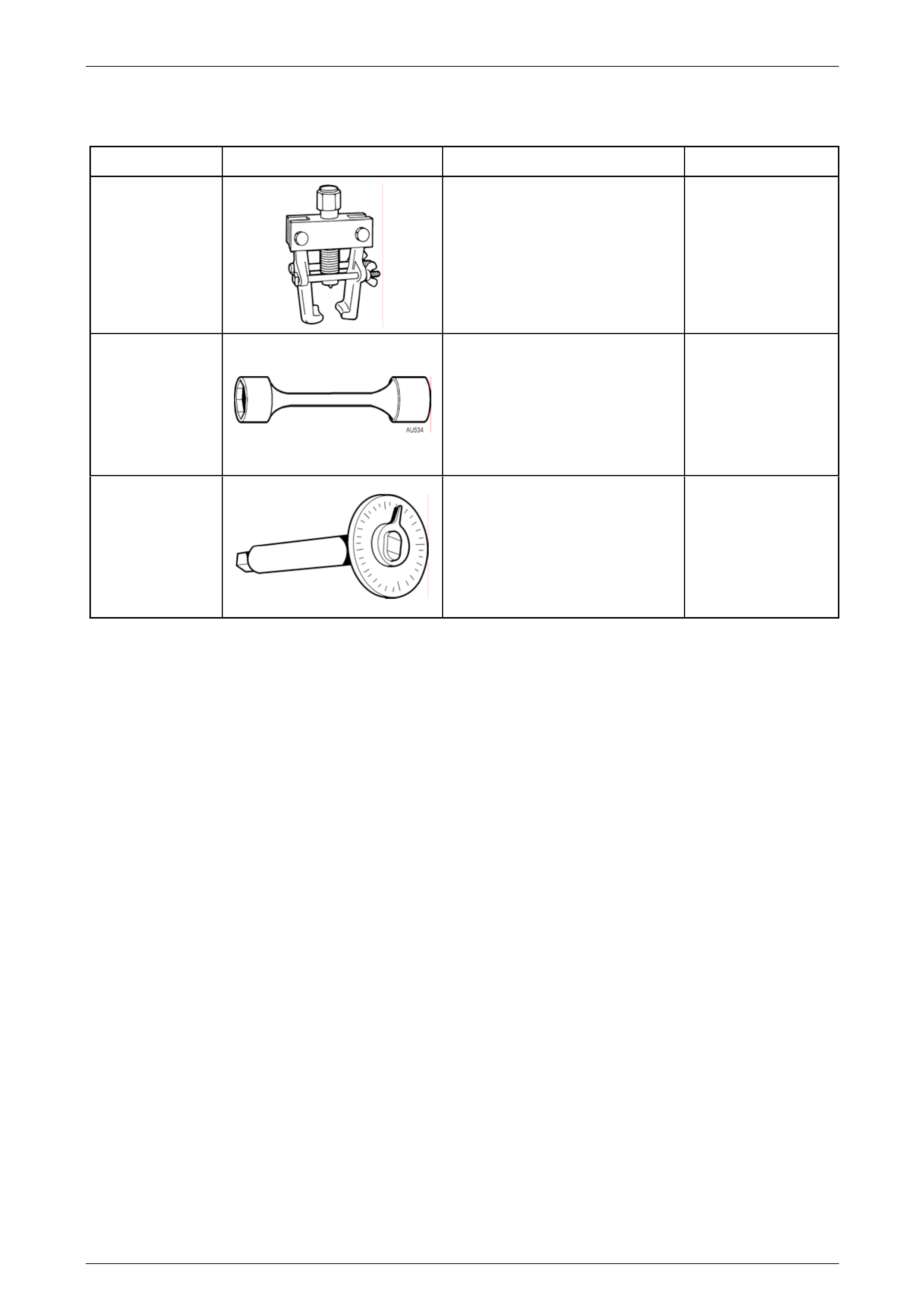
5 Special Tools
Tool Number Illustration Description Tool Classification
7311
Universal Puller
Used to remove the steering linkage
outer tie rod end from the steering
arm.
Previously released.
Desirable
AU534
Torque Limiting Socket
Used in conjunction with an impact
gun to tighten wheel nuts.
Previously released.
Mandatory
E7115
Angle Wrench
Used to tighten component fasteners
when angle torque is required.
Previously released.
Mandatory
Page 3A-22